a bio-friendly and economical technique for chronic implantation of multiple microelectrode arrays
TRANSCRIPT

Am
Pa
b
c
d
a
ARRA
KBMNS
1
srecnebsatrtu
B
(
0d
Journal of Neuroscience Methods 188 (2010) 187–194
Contents lists available at ScienceDirect
Journal of Neuroscience Methods
journa l homepage: www.e lsev ier .com/ locate / jneumeth
bio-friendly and economical technique for chronic implantation of multipleicroelectrode arrays
ratik Y. Chhatbara,b, Lee M. von Krausa,c, Mulugeta Semeworka,c, Joseph T. Francisa,b,c,d,∗
Department of Physiology and Pharmacology, SUNY Downstate Medical Center, Brooklyn, 450 Clarkson Av, Box# 31, Brooklyn, NY 11203, USAGraduate Program in Biomedical Engineering, SUNY Downstate Medical Center, Brooklyn, 450 Clarkson Av, Box# 41, Brooklyn, NY 11203, USAGraduate Program in Neurobiology and Behavior, SUNY Downstate Medical Center, Brooklyn, 450 Clarkson Av, Box# 41, Brooklyn, NY 11203, USAThe Robert Furchgott Center for Neural and Behavioral Sciences, SUNY Downstate Medical Center, Brooklyn, 450 Clarkson Av, Box# 93, Brooklyn, NY 11203, USA
r t i c l e i n f o
rticle history:eceived 18 September 2009eceived in revised form 3 February 2010ccepted 3 February 2010
eywords:rain–machine interfaceicroelectrode arrayeurophysiology
a b s t r a c t
Many neurophysiological experiments on rodents and non-human primates involve the implantationof more than one multi-electrode array to record from many regions of the brain. So called ‘floating’microelectrode arrays are implanted in cortical regions of interest and are coupled via a flexible cable totheir connectors which are fixed to the skull by a cement cap or a titanium pedestal, such as the Cereportsystem, which has been approved for human use. The use of bone cement has several disadvantagesincluding the creation of infection prone areas at the interface with the skull and surrounding skin.Alternatively, the more biocompatible Cereport has a limited carrying capacity and is far more expensive.
In this paper, we describe a new implantation technique, which combines the biocompatibility of
urgical methods titanium, a high carrying capacity with a minimal skull footprint, and a decreased chance of infection,all in a relatively inexpensive package. This technique utilizes an in-house fabricated ‘Nesting Platform’(NP), mounted on a titanium headpost to hold multiple connectors above the skin, making the headpostthe only transcutaneous object. The use of delrin, a durable, lightweight and easily machinable material,allows easy customization of the NP for a wide variety of floating electrodes and their connectors. Theultimate result is a longer survival time with superior neural recordings that can potentially last longer
lanta
than with traditional imp. Introduction
For the past several decades, researchers have made greattrides in our understanding of the brain by utilizing chronic neu-al recordings taken from awake behaving animals (Dolbakyant al., 1977; Nicolelis et al., 2003). Until recently most of thesehronic implants had been conducted on rodents while primateeurophysiology had primarily been implemented using acutelectrode insertion through chronically implanted recording cham-ers (Baker et al., 1999), allowing recording sessions of onlyeveral hours at a time on restrained animals. Today laboratoriesround the world are chronically implanting arrays of microelec-
rodes into non-human primates and even humans with goodesults (Donoghue et al., 2007; Hochberg et al., 2006). However,he risk of infection is still high when employing the commonlysed cement ‘cap’ method of electrode/connector attachment in∗ Corresponding author at: SUNY Downstate Medical Center, 450 Clarkson Av,ox# 31, Brooklyn, NY 11203, USA. Tel.: +1 718 270 6338; fax: +1 718 270 3103.
E-mail addresses: [email protected], [email protected]. Francis).
165-0270/$ – see front matter. Published by Elsevier B.V.oi:10.1016/j.jneumeth.2010.02.006
tion techniques.Published by Elsevier B.V.
which quick drying acrylic is used in combination with skullscrews.
The three major issues with chronic electrode implantationsare (1) the long-term stability of the implant attachment to theskull, (2) prevention of infections and (3) the long-term stabilityof electrodes within the neural tissue. We will address the firsttwo of these difficulties. Both the acrylic/cement cap (Carmenaet al., 2003; Nicolelis et al., 1998; Dolbakyan et al., 1977) andthe titanium pedestal (Fellows and Suner, 2006; Normann et al.,1999; Donoghue et al., 2007; Hochberg et al., 2006) techniquesare widely used for chronic electrode implantation, but each hastheir own limitations. Acrylic is exothermic and also believed tobe toxic during the settling period (Albrektsson and Linder, 1984)and the newer antibiotic (Gentamycin) impregnated bone cementslike Palacose (Heraeus Medical GmbH, Wehrheim, Germany) haveonly limited anti-bacterial effectiveness, due to low surficial con-tact with surrounding bacteria. The alternative, a titanium pedestal
like the Cereport (Blackrock Microsystems, Salt Lake City, UT), isbiocompatible and interfaces well with surrounding bone (Adamset al., 2007). However the limited carrying capacity of each Cere-port (up to 96 channels per device) requires multiple Cereportpedestal implantations for a larger number of electrode implants.
188 P.Y. Chhatbar et al. / Journal of Neuroscience Methods 188 (2010) 187–194
F nnect3 e horif
Tii
mhmtcrcctmt2nmctb
2
2
nmmupIh
ig. 1. 3D drawing of the NP. Note the small screw holes (a) to snugly fit ICS-96 coholes give freedom to adjust the height and clearance from the animal’s skull. Th
rom the arrays to the connectors.
herefore, the Cereport option ultimately provides little decreasen skin margins or required skull real estate as the number ofmplanted electrodes increases.
To avoid the disadvantages of these previously mentionedethods we have designed and manufactured a novel apparatus in
ouse. This apparatus, which consists of a ‘nesting platform’ (NP)ounted on a single titanium post, maintains the advantages of a
raditional titanium Cereport while simultaneously increasing thearrying capacity by four times (4 × 96 electrode connectors) andeducing the transcutaneous cross section and cost. This designoncept is very adaptable, and with appropriate changes in scale,ould be used on animals of any size for any electrode coupledo its connector by a flexible wire; For instance floating cortical
icroelectrode arrays (as described here) or depth electrodes forhalamic/hippocampal implants (Behrens et al., 1994; Simuni et al.,002). Finally, this attachment method is also very durable and doesot require or impose any specific restrictions on animal move-ent. During the recording sessions, head movement restrictions
an be imposed in order to prevent detachment of headstages fromhe connectors and prevent movement artifacts in the recordings,ut is not required.
. Methods
.1. Nesting platform (NP) design
The goals of this project were to create an implantation tech-ique that would allow the implantation of up to four 96-channelicroelectrode arrays while maintaining a minimal skull footprint,
inimal transcutaneous cross section, and would not require these of acrylic cement. Fig. 1 shows our final design of the NP com-lex, a titanium headpost (model: 6-FHP-2XF, Crist Instrument Co.,
nc., Hagerstown, MD) mated with an in-house fabricated NP thatolds the electrode connectors above the surface of the scalp. All
or screws, big screw holes (b) in the midline to fit 6-FHP-2XF headpost screw. Thezontal channels (c) created at the bottom are for passing the wire bundles running
designs were created using Rhinoceros v3.0 and milled out of whitedelrin (density 1.42 g/cm3) using an EGX-300 Desktop Engraver(Roland DG Corporation). A .3dm file format model of the NP designcan be found in the online Supplementary Information.
The NP is 5.2 cm long, 4.05 cm wide, .68 cm thick, and 18.07 gin weight. This NP is mounted on a titanium headpost 6-FHP-X2F (weight 13.3 g) using the screw supplied with the headpost.Four ICS-96 connectors are then mounted onto the NP by screwingdirectly into appropriately positioned holes. Each of these con-nectors weighs ∼9 g, making the total weight of the NP with fourconnectors to be ∼67.4 g. This low weight caused no problems forour usage, but should a lower weight be desired, the NP could bemade thinner and nonessential material (for instance the regionsbelow the mounted connectors) could be removed with little effecton structural integrity. In addition, should one need to glue any-thing additional to the NP, we recommend CyPox glue (Gowest2International, Arlington, OH) which, unlike most glues, bonds veryeffectively to delrin.
The effective grip between the NP and the ICS-96 connectors isprovided by the self-tapping Ø .082 in. ICS-96 connector screws intothe .075 in. diameter holes of the NP. If desired, one can modify theNP design to have slots for small nuts to keep the screws in place.However we have found over the course of a 6-month experimentthat the structural integrity of the entire connector/NP complexwas very stable.
2.2. Implantation technique
All animal procedures were approved by SUNY Downstate Med-
ical Center IACUC and conformed to National Institutes of Healthguidelines. Female Bonnet Macaques (Macaca radiata), weighingbetween 4 and 7 kg, were used for the experiments. Prior to attach-ment of the headpost to the skull, its four titanium foot processeswere trimmed to adjust their length in accordance with the space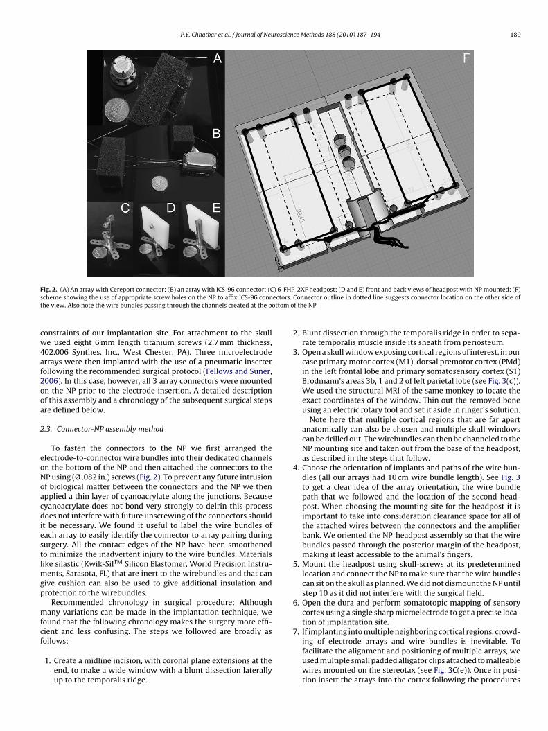
P.Y. Chhatbar et al. / Journal of Neuroscience Methods 188 (2010) 187–194 189
F ) 6-FHs ectorst ottom
cw4af2ooa
2
eoNoacdiestlmgp
mfcf
ig. 2. (A) An array with Cereport connector; (B) an array with ICS-96 connector; (Ccheme showing the use of appropriate screw holes on the NP to affix ICS-96 connhe view. Also note the wire bundles passing through the channels created at the b
onstraints of our implantation site. For attachment to the skulle used eight 6 mm length titanium screws (2.7 mm thickness,
02.006 Synthes, Inc., West Chester, PA). Three microelectroderrays were then implanted with the use of a pneumatic inserterollowing the recommended surgical protocol (Fellows and Suner,006). In this case, however, all 3 array connectors were mountedn the NP prior to the electrode insertion. A detailed descriptionf this assembly and a chronology of the subsequent surgical stepsre defined below.
.3. Connector-NP assembly method
To fasten the connectors to the NP we first arranged thelectrode-to-connector wire bundles into their dedicated channelsn the bottom of the NP and then attached the connectors to theP using (Ø .082 in.) screws (Fig. 2). To prevent any future intrusionf biological matter between the connectors and the NP we thenpplied a thin layer of cyanoacrylate along the junctions. Becauseyanoacrylate does not bond very strongly to delrin this processoes not interfere with future unscrewing of the connectors should
t be necessary. We found it useful to label the wire bundles ofach array to easily identify the connector to array pairing duringurgery. All the contact edges of the NP have been smoothenedo minimize the inadvertent injury to the wire bundles. Materialsike silastic (Kwik-SilTM Silicon Elastomer, World Precision Instru-
ents, Sarasota, FL) that are inert to the wirebundles and that canive cushion can also be used to give additional insulation androtection to the wirebundles.
Recommended chronology in surgical procedure: Althoughany variations can be made in the implantation technique, we
ound that the following chronology makes the surgery more effi-ient and less confusing. The steps we followed are broadly as
ollows:1. Create a midline incision, with coronal plane extensions at theend, to make a wide window with a blunt dissection laterallyup to the temporalis ridge.
P-2XF headpost; (D and E) front and back views of headpost with NP mounted; (F). Connector outline in dotted line suggests connector location on the other side ofof the NP.
2. Blunt dissection through the temporalis ridge in order to sepa-rate temporalis muscle inside its sheath from periosteum.
3. Open a skull window exposing cortical regions of interest, in ourcase primary motor cortex (M1), dorsal premotor cortex (PMd)in the left frontal lobe and primary somatosensory cortex (S1)Brodmann’s areas 3b, 1 and 2 of left parietal lobe (see Fig. 3(c)).We used the structural MRI of the same monkey to locate theexact coordinates of the window. Thin out the removed boneusing an electric rotary tool and set it aside in ringer’s solution.
Note here that multiple cortical regions that are far apartanatomically can also be chosen and multiple skull windowscan be drilled out. The wirebundles can then be channeled to theNP mounting site and taken out from the base of the headpost,as described in the steps that follow.
4. Choose the orientation of implants and paths of the wire bun-dles (all our arrays had 10 cm wire bundle length). See Fig. 3to get a clear idea of the array orientation, the wire bundlepath that we followed and the location of the second head-post. When choosing the mounting site for the headpost it isimportant to take into consideration clearance space for all ofthe attached wires between the connectors and the amplifierbank. We oriented the NP-headpost assembly so that the wirebundles passed through the posterior margin of the headpost,making it least accessible to the animal’s fingers.
5. Mount the headpost using skull-screws at its predeterminedlocation and connect the NP to make sure that the wire bundlescan sit on the skull as planned. We did not dismount the NP untilstep 10 as it did not interfere with the surgical field.
6. Open the dura and perform somatotopic mapping of sensorycortex using a single sharp microelectrode to get a precise loca-tion of implantation site.
7. If implanting into multiple neighboring cortical regions, crowd-
ing of electrode arrays and wire bundles is inevitable. Tofacilitate the alignment and positioning of multiple arrays, weused multiple small padded alligator clips attached to malleablewires mounted on the stereotax (see Fig. 3C(e)). Once in posi-tion insert the arrays into the cortex following the procedures
190 P.Y. Chhatbar et al. / Journal of Neuroscience Methods 188 (2010) 187–194
Fig. 3. (A) Second headpost implanted on the anterior side of the skull—note the orientation of the headpost is such that the NP fits on it from the posterior side, so thatthe wire bundles pass posterior to the headpost stem, making them less reachable to the animal. White arrows show medial margin of the skull window; (B) NP-connectorassembly mounted on the headpost using the headpost screw (in the middle) using the top screw hole on the NP. The microelectrode arrays are yet to get implanted (seewwip
Fsta
ire bundle going behind (white arrow), passing through the slits created in the spongeire bundles partially fixed on the skull using titanium straps and silastic(d) and padded a
s accomplished by first placing a layer of GORE PRECLUDE(R) membrane (artificial periclacing a second layer of GORE PRECLUDE(R) membrane between the dura and the skull
ig. 4. (A) Closure of the implantation window created on the skull using thinned out bone flitting between the dura mater and the bone flap; (B) anterior view and (C) posterior vhe wire bundles (black arrow) going under scalp posterior to the headpost stem; (D) posnterior headpost. Note that posterior headpost (white arrow) was implanted slightly ab
); (C) all 3 microelectrode arrays implanted in PMd(a), M1(b) and S1(c) and theirlligator clips(e) were used to keep the wire bundles in place until then; (D) closureardium) between the array and the dura (b) followed by closing the dura (a) and
(shown in next figure) as instructed in the Blackrock surgical manual).
ap using titanium straps(a). Note another layer of GORE PRECLUDE(R) membrane(b)iew of the headpost-NP-connector assembly after closure of galea and skin. Notet-operative lateral view of monkey with the NP-connector assembly sitting on the
ove the occipital ridge a few months ago.

P.Y. Chhatbar et al. / Journal of Neuroscie
Fig. 5. Comparison of NP method of chronic MEA implantation with other methods.(A) The skin margin stays the same with NP method irrespective of number of arraysused, and that it is less than other methods. (B) The surface area occupied by thefeet of the titanium headpost is greater than two Cereport connectors—this will givegreater stability to the assembly because of bone-friendly nature of the titanium.Note that surface area of cement cap will not positively contribute to the stability oftcm
1
1
he connector assembly impregnated into it. (C) Expenses incurred by both NP andement cap method are the same and are almost half the expenses by the Cereportethod.
recommended by the surgical manual (Fellows and Suner,2006).
8. Fix the wire bundles on the skull using titanium straps andscrews (P4ST-08-48 and SCR4-04-05, Bioplate, Inc., Los Angeles,CA) and silastic (Kwik-SilTM Silicon Elastomer, World PrecisionInstruments, Sarasota, FL). We recommend the use of minimumamounts of silastic, making sure there are no pockets betweensilastic and skull, as these can be potential sites for pathogensto thrive.
9. Use GORE PRECLUDE(R) membrane (GORE PRECLUDE(R) Peri-cardial membrane, W.L. Gore & Associates, Inc., Flagstaff, AZ)as described in the Blackrock Microsystems’ surgical man-ual (Fellows and Suner, 2006). Then close the window withthe thinned out bone attached (from step 3) and titaniumstraps. Finally, seal the open edge with a thin layer of silastic(Fig. 4A).
0. To allow ease of scalp closure around the headpost, temporarilydismount the NP taking care not to pull on the electrode wirebundles fixed on the skull. Maneuver the NP to get the closestpossible scalp closure around the headpost.
1. After suturing and topical antibiotic application, mount the NP
back on headpost (Fig. 4), check the headpost and NP stability,and finally fill any gaps between headpost, NP, and connectorsusing cyanoacrylate glue to discourage microorganism growth.Be careful to avoid cyanoacrylate contact with the ICS-96 con-nector cover, as it can damage certain plastics.nce Methods 188 (2010) 187–194 191
3. Results
We have implanted this single nesting platform with three1.5 mm length microelectrode arrays in cortical areas PMd, M1,and S1 on a female Bonnet Macaque (M. radiata) weighing 4.2 kgon February 19, 2009 and she has been completely healthy todate (August 08, 2009); see recordings in Fig. 7. She was givensystemic antibiotics daily up to day-10 post-implantation withno later antibiotic applications needed. This animal is our thirdanimal with the Utah array implant, but the first one utilizingthe nesting platform (see the section below for more details).Her recordings have been consistent and in fact better than ourpreviously implanted two animals with the same type arrays(1.0 mm microelectrode length) implanted with the traditionalcement cap covering (Palacos).
3.1. Comparison with other techniques
3.1.1. Cement capOur lab has experience with the chronic microelectrode implan-
tation of five non-human primates (M. radiata), and over 50 rats.Below is a summary of the non-human primate implants and prog-nosis.
1. Cap created with dental acrylic; microwire array implantation;infection occurred ∼6-months after implantation.
2. Cap created with dental acrylic; microwire array implantation;infection occurred ∼6-months after implantation.
3. Cap created with palacos cement with impregnated antibiotics;1.0 mm Utah array, microwires and multi-site ceramic arraysimplantation; infection occurred ∼6-months after implantation.
4. Cap created with palacos cement with impregnated antibiotics,1.0 mm Utah array and multi-site ceramic arrays implantationand a standard recording chamber; lost recordings at 6 monthsafter implantation, but the animal and the cap are healthy after11 months.
5. See the next section for the NP implantation.
When an infection was suspected we would clean the skinmargin with betadine and nolvasan and apply topical antibioticointment daily. In addition, systemic antibiotics were given. If ananimal was healthy the skin margin was left undisturbed. Animalswere individually housed in very large baboon cages convenientlysituated to allow grooming between neighboring animals. In addi-tion, the animals were given free time to run around and explorethe housing space. As the cement cap is not a biological tissue,antibiotics given systemically barely reach the infection site. Also,due to the unyielding nature of the cement cap, unlike scalp, thediagnosis of infection may be delayed until behavioral changes areobserved, or the infection is sensed via olfaction, visual evidenceor presumed via fever, in which case it is generally too late for anyeffective intervention, because by then a biofilm has already beenformed between the scalp and the cap. This makes it impossibleto replace the cement cap as the skull underneath is not healthyenough to support the new bone screws needed to attach a newcap. In addition, the implant site would be compromised once theoriginal cement cap is removed along with the microelectrode con-nectors impregnated within. There are several labs that have beensuccessfully using cement caps in their preparations for the chronicmicroelectrode array implants with good results, and without theanimal becoming infected. In the above statements we are merely
pointing out situations we have experienced and know others haveas well (personal communications).A second problem that our lab has encountered with the cementcap method was the lifting of our floating microelectrode arraysout of the cortex. During post mortem analysis we found that the
192 P.Y. Chhatbar et al. / Journal of Neuroscience Methods 188 (2010) 187–194
n app
mufilatusdn
3
(pcppsibt
3
iUaoeffm
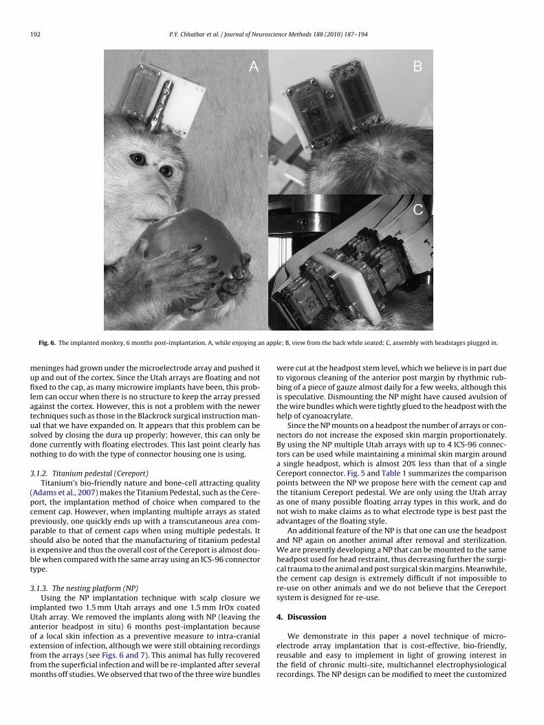
Fig. 6. The implanted monkey, 6 months post-implantation. A, while enjoying a
eninges had grown under the microelectrode array and pushed itp and out of the cortex. Since the Utah arrays are floating and notxed to the cap, as many microwire implants have been, this prob-
em can occur when there is no structure to keep the array pressedgainst the cortex. However, this is not a problem with the newerechniques such as those in the Blackrock surgical instruction man-al that we have expanded on. It appears that this problem can beolved by closing the dura up properly; however, this can only beone currently with floating electrodes. This last point clearly hasothing to do with the type of connector housing one is using.
.1.2. Titanium pedestal (Cereport)Titanium’s bio-friendly nature and bone-cell attracting quality
Adams et al., 2007) makes the Titanium Pedestal, such as the Cere-ort, the implantation method of choice when compared to theement cap. However, when implanting multiple arrays as statedreviously, one quickly ends up with a transcutaneous area com-arable to that of cement caps when using multiple pedestals. Ithould also be noted that the manufacturing of titanium pedestals expensive and thus the overall cost of the Cereport is almost dou-le when compared with the same array using an ICS-96 connectorype.
.1.3. The nesting platform (NP)Using the NP implantation technique with scalp closure we
mplanted two 1.5 mm Utah arrays and one 1.5 mm IrOx coatedtah array. We removed the implants along with NP (leaving thenterior headpost in situ) 6 months post-implantation because
f a local skin infection as a preventive measure to intra-cranialxtension of infection, although we were still obtaining recordingsrom the arrays (see Figs. 6 and 7). This animal has fully recoveredrom the superficial infection and will be re-implanted after severalonths off studies. We observed that two of the three wire bundles
le; B, view from the back while seated; C, assembly with headstages plugged in.
were cut at the headpost stem level, which we believe is in part dueto vigorous cleaning of the anterior post margin by rhythmic rub-bing of a piece of gauze almost daily for a few weeks, although thisis speculative. Dismounting the NP might have caused avulsion ofthe wire bundles which were tightly glued to the headpost with thehelp of cyanoacrylate.
Since the NP mounts on a headpost the number of arrays or con-nectors do not increase the exposed skin margin proportionately.By using the NP multiple Utah arrays with up to 4 ICS-96 connec-tors can be used while maintaining a minimal skin margin arounda single headpost, which is almost 20% less than that of a singleCereport connector. Fig. 5 and Table 1 summarizes the comparisonpoints between the NP we propose here with the cement cap andthe titanium Cereport pedestal. We are only using the Utah arrayas one of many possible floating array types in this work, and donot wish to make claims as to what electrode type is best past theadvantages of the floating style.
An additional feature of the NP is that one can use the headpostand NP again on another animal after removal and sterilization.We are presently developing a NP that can be mounted to the sameheadpost used for head restraint, thus decreasing further the surgi-cal trauma to the animal and post surgical skin margins. Meanwhile,the cement cap design is extremely difficult if not impossible tore-use on other animals and we do not believe that the Cereportsystem is designed for re-use.
4. Discussion
We demonstrate in this paper a novel technique of micro-electrode array implantation that is cost-effective, bio-friendly,reusable and easy to implement in light of growing interest inthe field of chronic multi-site, multichannel electrophysiologicalrecordings. The NP design can be modified to meet the customized
P.Y. Chhatbar et al. / Journal of Neuroscience Methods 188 (2010) 187–194 193
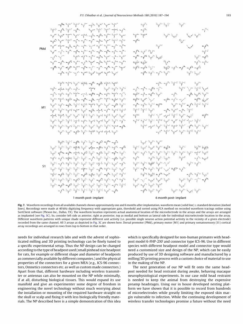
Fig. 7. Waveform recordings from all available channels shown approximately one and 6 months after implantation, waveform mean (solid line) ± standard deviation (dashedlines). Recordings were made at 40 kHz digitizing frequency with appropriate gain, threshold and sorted using PCA method on recorded waveform tracings online usingSortClient software (Plexon Inc., Dallas, TX). The waveform location represents actual anatomical location of the microelectrode in the arrays and the arrays are arrangeda as meD i.e. por . Dorsa
ntaafaptAtimettr
s implanted (see Fig. 3C). So, consider left side as anterior, right as posterior, topifferent waveform patterns with unique shade represent different unit activity (
ecorded from the same channel. All 3 arrays as depicted in Fig. 3C are shown hererray recordings are arranged in rows from top to bottom in that order.
eeds for individual research labs and with the advent of sophis-icated milling and 3D printing technology can be finely tuned tospecific experimental setup. Thus the NP design can be changed
ccording to the type of headpost used (small pinhead size headpostor rats, for example or different shape and diameter of headpostss commercially available by different companies.) and the physicalroperties of the connectors for a given MEA (e.g., ICS-96 connec-ors, Omnetics connectors etc. as well as custom made connectors.)part from that, different hardware including wireless transmit-
er or antennas can also be mounted on the NP while minimally,f at all, disturbing biological tissues. This would expand its use
anifold and give an experimenter some degree of freedom inngineering the novel technology without much worrying abouthe installation or mounting of the required hardware straight onhe skull or scalp and fixing it with less biologically friendly mate-ials. The NP described here is a simple demonstration of this idea
dial and bottom as lateral side for individual microelectrode location in the array.ssible single neuron action potential activity in the vicinity of a given electrode)al premotor (PMd), primary motor (M1) and primary somatosensory (S1) cortical
which is specifically designed for non-human primates with head-post model 6-FHP-2XF and connector type ICS-96. Use in differentspecies with different headpost model and connector type wouldneed a customized size and design of the NP, which can be easilyproduced by use of 3D designing software and manufactured by amilling/3D printing process with a custom choice of material to usein the making of the NP.
The next generation of our NP will fit onto the same head-post needed for head restraint during awake, behaving macaqueneurophysiological experiments. In our case mild head restraintis needed to keep the animal from destroying the expensive
preamp headstages. Using our in house developed nesting plat-form we have shown that it is possible to record from hundredsof microelectrodes while greatly limiting the exposed skin mar-gin vulnerable to infection. While the continuing development ofwireless transfer technologies promise a future without the need
194 P.Y. Chhatbar et al. / Journal of Neuroscience Methods 188 (2010) 187–194
Table 1Showing comparison between three different chronic microelectrode array implant techniques. 6.77418 cm2 is the area of ICS-96 (1.5 × .7 in.); price calculations are basedon: NP raw cost ∼100$, Headpost price ∼600$, single bone screw price ∼50$, bone cement price ∼500$; Cereport price ∼4500$, ICS-96 price ∼2250$.
Parameter NP Cereport Cement cap
Surface area (cm2) covered on skull Foot process length dependent Base diameter (∼2 cm) dependent Variable, at least thesizeofICS-96
Single array 8.03 3.14 >7Double array 8.03 6.28 >15Triple array 8.03 9.42 >22Quad array 8.03 12.57 >30
Skin margin (cm) Post diameter dependent (∼.94 Neck diameter dependent Variable, at least the perimeter of ICS
Single array 2.953 3.691 >11.2Double array 2.953 7.383 >15.3Triple array 2.953 11.074 >18.4Quad array 2.953 14.765 >22.5
Approximate total price (USD) Platform + Headpost + Array + 10 screws Cereport + 10 screws per array Bone cement + 10 screws
Single array 3450 5000 3250Double array 5700 10,000 5500Triple array 7950 15,000 8250Quad array 10,200 20,000 10,000
fi(acm
C
c
A
NtwEpAs
A
t
R
A
Simuni T, Jaggi JL, Mulholland H, Hurtig HI, Colcher A, Siderowf AD, et al. Bilateralstimulation of the subthalamic nucleus in patients with Parkinson disease: astudy of efficacy and safety. J Neurosurg 2002;96(4):666.
Approximate savings if recycled (USD) NP + Headpost + 10 screws
1200
or trans-cutaneous protrusions, realization of such implants is ints nascent stage with their capacity limited to a few channelsSong et al., 2009). In the meantime the described nesting platformllows possibly the most bio-friendly and economical means ofonducting chronic neurophysiological experiments with multipleicroeletrode arrays.
onflict of interest statement
At the time of publication, no authors have any real or potentialonflict of interest.
cknowledgements
We would like to thank Shaohua Xu, Allison Maurice, Carolovotney and Elizabeth Rivera for their continuous support
hroughout the course of the surgery and animal care. In additione would like to thank John Chapin for allowing us the use of the
GX-300 desktop-engraver for making the NP. The work is sup-orted by NYS Department of Health SCIRBs #C022048, Nationalcademies Keck Futures Initiative NAFKI SP09 and SUNY Down-tate Medical Center.
ppendix A. Supplementary data
Supplementary data associated with this article can be found, inhe online version, at doi:10.1016/j.jneumeth.2010.02.006.
eferences
dams DL, Economides JR, Jocson CM, Horton JC. A biocompatible titanium headpostfor stabilizing behaving monkeys. J Neurophysiol 2007;98:993–1001.
10 screws per array 10 screws
500 per array 500
Albrektsson T, Linder L. Bone injury caused by curing bone cement. A vitalmicroscopic study in the rabbit tibia. Clin Orthop Relat Res 1984:280–7.
Baker SN, Philbin N, Spinks R, Pinches EM, Wolpert DM, MacManus DG, et al. Multiplesingle unit recording in the cortex of monkeys using independently moveablemicroelectrodes. J Neurosci Methods 1999;94:5–17.
Behrens E, Zentner J, van Roost D, Hufnagel A, Elger CE, Schramm J. Subdural anddepth electrodes in the presurgical evaluation of epilepsy. Acta Neurochir (Wien)1994;128(1–4):84.
Carmena JM, Lebedev MA, Crist RE, O’Doherty JE, Santucci DM, Dimitrov DF, etal. Learning to control a brain-machine interface for reaching and grasping byprimates. PLoS Biol 2003;1:E42.
Dolbakyan E, Hernandez-Mesa N, Bures J. Skilled forelimb movements andunit activity in motor cortex and caudate nucleus in rats. Neuroscience1977;2:73–80.
Donoghue JP, Nurmikko A, Black M, Hochberg LR. Assistive technologyand robotic control using motor cortex ensemble-based neural inter-face systems in humans with tetraplegia. J Physiol 2007;579:603–11.
Fellows M, Suner S. Cyberkinetics array surgical implant procedure training manual.Salt Lake City, UT: Cyberkinetics, Inc; 2006, version 4.
Hochberg LR, Serruya MD, Friehs GM, Mukand JA, Saleh M, Caplan AH, et al. Neuronalensemble control of prosthetic devices by a human with tetraplegia. Nature2006;442:164–71.
Nicolelis MA, Dimitrov D, Carmena JM, Crist R, Lehew G, Kralik JD, et al. Chronic,multisite, multielectrode recordings in macaque monkeys. Proc Natl Acad SciUSA 2003;100:11041–6.
Nicolelis MA, Ghazanfar AA, Stambaugh CR, Oliveira LM, Laubach M, Chapin JK, etal. Simultaneous encoding of tactile information by three primate cortical areas.Nat Neurosci 1998;1:621–30.
Normann RA, Maynard EM, Rousche PJ, Warren DJ. A neural interface for a corticalvision prosthesis. Vision Res 1999;39:2577–87.
Song YK, Borton DA, Park S, Patterson WR, Bull CW, Laiwalla F, et al. Active micro-electronic neurosensor arrays for implantable brain communication interfaces.IEEE Trans Neural Syst Rehabil Eng 2009;17:339–45.