97-06 jeep wrangler tj rock ready ii 6” pallet kit
TRANSCRIPT
Before beginning the installation, thoroughly & completely read these instructions & the enclosed driver’s WARNING NOTICE. Affix the WARNING decal in the passenger compartment in clear view of all occupants. Please refer to the Parts List to insure that all parts & hardware are received prior to the disassembly of the vehicle. If any parts are found to be missing, contact SKYJACKER® Customer Service at 318-388-0816 to obtain the needed items. If you have any questions or reservations about installing this lift kit, call SKYJACKER® Technical Assistance at 318-388-0816.
Make sure you park the vehicle on a level concrete or asphalt surface. Many times a vehicle is not level (side-to-side) from the factory & is usually not noticed until a lift kit has been installed, which makes the difference more visible. Using a measuring tape, measure the front & rear (both sides) from the ground up to the center of the fender opening above the axle. Record this information below for future reference.
Driver Side Front: Passenger Side Front:
Driver Side Rear: Passenger Side Rear:
IMPORTANT NOTES:
• This lift is determined from the amount of lift to the front of the vehicle, while only lifting the rear to a position level with the front.
• If larger tires (10% more than the stock diameter) are installed, speedometer recalibration
will be necessary. Contact your local Jeep dealer or an authorized dealer for details.
• After installation a qualified alignment facility is required to align the vehicle to factory specifications.
• 6-Speed transmission models may require additional modifications, contact Skyjacker @
318-388-0816 for additional information.
97-06 Jeep Wrangler TJRock Ready II 6” Pallet Kit
Suspension LiftInstallation Instructions
RequIRed TooL LIST:
* Safety Glasses* Metric / Standard Wrenches & Sockets* Allen Wrenches* drill & Assorted drill Bits* Grinder / Cut off Wheel* Pipe Wrench* Floor Jack* Jack Stands* Measuring Tape* Torque Wrench
www.skyjacker.com
I-TJ676X 3-09 Pg 1
• exhaust modifications may be necessary.
• A slip yoke eliminator kit (Part # RR231) & a rear C.V. drive shaft are required.
• Rubicon models require a C.V. yoke (Part # CVR680) & a replacement C.V. drive shaft.
• 2003-2006 models with an automatic transmission must remove the front transmission skid plate for driveshaft clearance.
Pg 2I-TJ676X
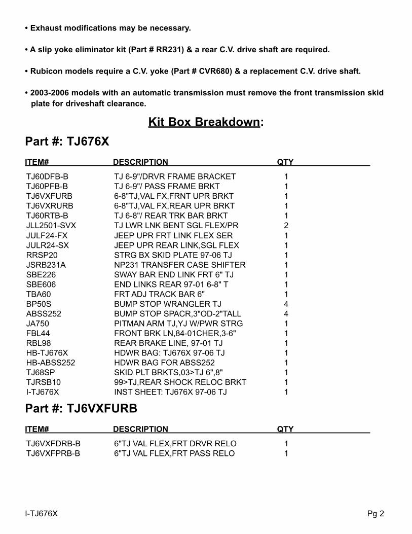
Kit Box Breakdown:Part #: TJ676X ITeM# deSCRIPTIoN qTY
TJ60DFB-B TJ 6-9"/DRVR FRAME BRACKET 1TJ60PFB-B TJ 6-9"/ PASS FRAME BRKT 1TJ6VXFURB 6-8"TJ,VAL FX,FRNT UPR BRKT 1TJ6VXRURB 6-8"TJ,VAL FX,REAR UPR BRKT 1TJ60RTB-B TJ 6-8"/ REAR TRK BAR BRKT 1JLL2501-SVX TJ LWR LNK BENT SGL FLEX/PR 2JULF24-FX JEEP UPR FRT LINK FLEX SER 1JULR24-SX JEEP UPR REAR LINK,SGL FLEX 1RRSP20 STRG BX SKID PLATE 97-06 TJ 1JSRB231A NP231 TRANSFER CASE SHIFTER 1SBE226 SWAY BAR END LINK FRT 6" TJ 1SBE606 END LINKS REAR 97-01 6-8" T 1TBA60 FRT ADJ TRACK BAR 6" 1BP50S BUMP STOP WRANGLER TJ 4ABSS252 BUMP STOP SPACR,3"OD-2"TALL 4JA750 PITMAN ARM TJ,YJ W/PWR STRG 1FBL44 FRONT BRK LN,84-01CHER,3-6" 1RBL98 REAR BRAKE LINE, 97-01 TJ 1HB-TJ676X HDWR BAG: TJ676X 97-06 TJ 1HB-ABSS252 HDWR BAG FOR ABSS252 1TJ68SP SKID PLT BRKTS,03>TJ 6",8" 1TJRSB10 99>TJ,REAR SHOCK RELOC BRKT 1I-TJ676X INST SHEET: TJ676X 97-06 TJ 1
Part #: TJ6VXFuRB ITeM# deSCRIPTIoN qTY
TJ6VXFDRB-B 6"TJ VAL FLEX,FRT DRVR RELO 1TJ6VXFPRB-B 6"TJ VAL FLEX,FRT PASS RELO 1
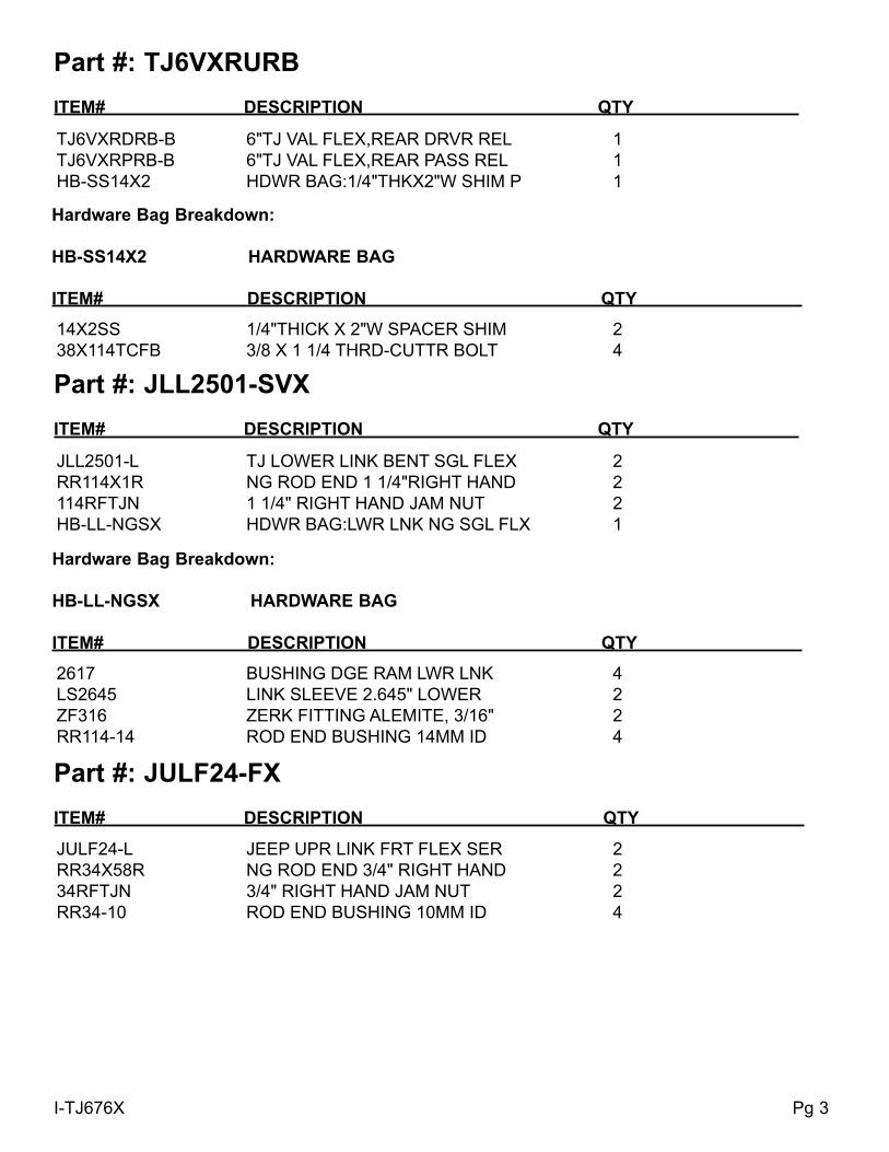
Part #: TJ6VXRuRB ITeM# deSCRIPTIoN qTY
TJ6VXRDRB-B 6"TJ VAL FLEX,REAR DRVR REL 1TJ6VXRPRB-B 6"TJ VAL FLEX,REAR PASS REL 1HB-SS14X2 HDWR BAG:1/4"THKX2"W SHIM P 1
Hardware Bag Breakdown:
HB-SS14X2 HARdWARe BAG
ITeM# deSCRIPTIoN qTY
14X2SS 1/4"THICK X 2"W SPACER SHIM 238X114TCFB 3/8 X 1 1/4 THRD-CUTTR BOLT 4
Hardware Bag Breakdown:
HB-LL-NGSX HARdWARe BAG
ITeM# deSCRIPTIoN qTY
2617 BUSHING DGE RAM LWR LNK 4LS2645 LINK SLEEVE 2.645" LOWER 2ZF316 ZERK FITTING ALEMITE, 3/16" 2RR114-14 ROD END BUSHING 14MM ID 4
Part #: JLL2501-SVX ITeM# deSCRIPTIoN qTY
JLL2501-L TJ LOWER LINK BENT SGL FLEX 2RR114X1R NG ROD END 1 1/4"RIGHT HAND 2114RFTJN 1 1/4" RIGHT HAND JAM NUT 2HB-LL-NGSX HDWR BAG:LWR LNK NG SGL FLX 1
Part #: JuLF24-FX ITeM# deSCRIPTIoN qTY
JULF24-L JEEP UPR LINK FRT FLEX SER 2RR34X58R NG ROD END 3/4" RIGHT HAND 234RFTJN 3/4" RIGHT HAND JAM NUT 2RR34-10 ROD END BUSHING 10MM ID 4
Pg 3I-TJ676X

Pg 4I-TJ676X
Part #: JSRB231A ITeM# deSCRIPTIoN qTY
TJSRB-1 TJ MAIN SHIFT RELOCATE BRKT 1TJSRB-2 TJ AUX. SHIFT RELOCATE BRKT 1HB-JSRB231A HDWR BAG: JSRB231A T/C BRKT 1I-JSRB231 INST. SHEET FOR JSRB231 1
Part #: JuLR24-FX ITeM# deSCRIPTIoN qTY
JULR24-SX-L JEEP UPR LINK 2-4" SGL FLEX 2RR34X58R NG ROD END 3/4" RIGHT HAND 234RFTJN 3/4" RIGHT HAND JAM NUT 2RR34-10 ROD END BUSHING 10MM ID 4HB-JULR-FX HDWR BAG/JEEP UPR RR FLEX 1
2887 BUSHING UPR REAR TJ SX LINK 4JULRS-FX JEEP UPR LK RR SLV,FLEX SER 2ZF316 ZERK FITTING ALEMITE, 3/16" 2
Hardware Bag Breakdown:
HB-JuLR-FX HARdWARe BAG
ITeM# deSCRIPTIoN qTY
Part #: RRSP20 ITeM# deSCRIPTIoN qTY
RRSP20-S STRG GEAR BX SKID PLATE R/R 1HB-SSP10 HARDWARE BAG FOR SSP10 1I-SSP10 INSTRUCTIONS FOR SSP10 1
58SP 5/8" SPACER - 1 1/4" O.D. 138X2FTB 3/8 X 2 FINE THD BOLT, GR8 138FTN 3/8-24 FINE N/I LOCK NUT 138SAEW 3/8 SAE WASHER 1516X34TCFB 5/16 X 3/4 THD CUT FLG BOLT 112SAEW 1/2 SAE WASHER 2
Hardware Bag Breakdown:
HB-SSP10 HARdWARe BAG
ITeM# deSCRIPTIoN qTY
Hardware Bag Breakdown:
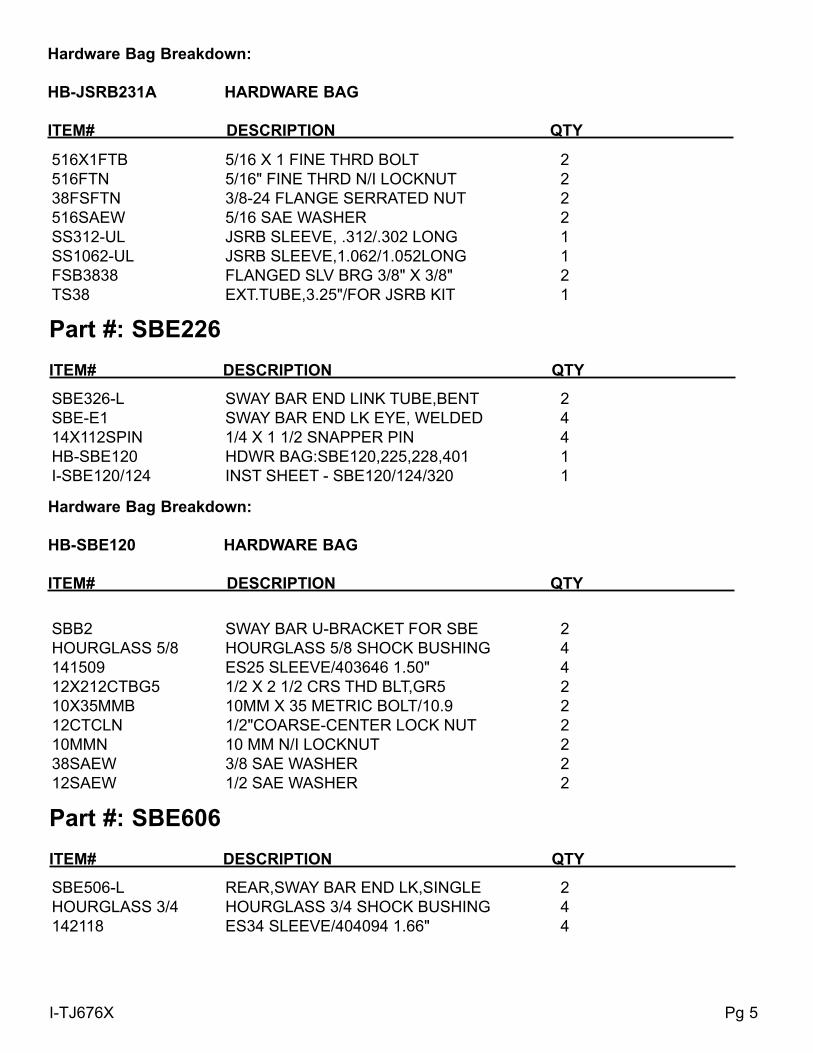
HB-JSRB231A HARdWARe BAG
ITeM# deSCRIPTIoN qTY
516X1FTB 5/16 X 1 FINE THRD BOLT 2516FTN 5/16" FINE THRD N/I LOCKNUT 238FSFTN 3/8-24 FLANGE SERRATED NUT 2516SAEW 5/16 SAE WASHER 2SS312-UL JSRB SLEEVE, .312/.302 LONG 1SS1062-UL JSRB SLEEVE,1.062/1.052LONG 1FSB3838 FLANGED SLV BRG 3/8" X 3/8" 2TS38 EXT.TUBE,3.25"/FOR JSRB KIT 1
Part #: SBe226 ITeM# deSCRIPTIoN qTY
SBE326-L SWAY BAR END LINK TUBE,BENT 2SBE-E1 SWAY BAR END LK EYE, WELDED 414X112SPIN 1/4 X 1 1/2 SNAPPER PIN 4HB-SBE120 HDWR BAG:SBE120,225,228,401 1I-SBE120/124 INST SHEET - SBE120/124/320 1
SBB2 SWAY BAR U-BRACKET FOR SBE 2HOURGLASS 5/8 HOURGLASS 5/8 SHOCK BUSHING 4141509 ES25 SLEEVE/403646 1.50" 412X212CTBG5 1/2 X 2 1/2 CRS THD BLT,GR5 210X35MMB 10MM X 35 METRIC BOLT/10.9 212CTCLN 1/2"COARSE-CENTER LOCK NUT 210MMN 10 MM N/I LOCKNUT 238SAEW 3/8 SAE WASHER 212SAEW 1/2 SAE WASHER 2
Hardware Bag Breakdown:
HB-SBe120 HARdWARe BAG
ITeM# deSCRIPTIoN qTY
Part #: SBe606 ITeM# deSCRIPTIoN qTY
SBE506-L REAR,SWAY BAR END LK,SINGLE 2HOURGLASS 3/4 HOURGLASS 3/4 SHOCK BUSHING 4142118 ES34 SLEEVE/404094 1.66" 4
Pg 5I-TJ676X
I-TJ676X Pg 6
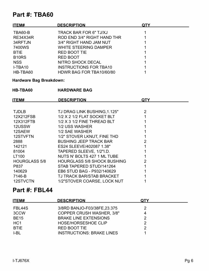
Part #: TBA60 ITeM# deSCRIPTIoN qTY
TBA60-B TRACK BAR FOR 6" TJ/XJ 1RE34X34R ROD END 3/4" RIGHT HAND THR 134RFTJN 3/4" RIGHT HAND JAM NUT 17400WS WHITE STEERING DAMPER 1BTIE RED BOOT TIE 1B10RS RED BOOT 1NSS NITRO SHOCK DECAL 1I-TBA10 INSTRUCTIONS FOR TBA10 1HB-TBA60 HDWR BAG FOR TBA10/60/80 1
TJDLB TJ DRAG LINK BUSHING,1.125" 212X212FSB 1/2 X 2 1/2 FLAT SOCKET BLT 112X312FTB 1/2 X 3 1/2 FINE THREAD BLT 112USSW 1/2 USS WASHER 112SAEW 1/2 SAE WASHER 112STVFTN 1/2" STOVER LKNUT, FINE THD 12888 BUSHING JEEP TRACK BAR 2142121 ES24 SLEEVE/402087 1.38" 181004 TAPERED SLEEVE, 1/2"I.D. 1LT100 NUTS N' BOLTS 427 1 ML TUBE 1HOURGLASS 5/8 HOURGLASS 5/8 SHOCK BUSHING 2P837 STAB TAPERED STUD/141264 1140629 EB6 STUD BAG - P932/140629 17146-B TJ TRACK BAR/STAB BRACKET 112STVCTN 1/2"STOVER COARSE, LOCK NUT 1
Hardware Bag Breakdown:
HB-TBA60 HARdWARe BAG
ITeM# deSCRIPTIoN qTY
Part #: FBL44 ITeM# deSCRIPTIoN qTY
FBL44S 3/8RD BANJO-F03/38FE,23.375 23CCW COPPER CRUSH WASHER, 3/8" 4BE15 BRAKE LINE EXTENSIONS 2HC1 HOSE/HORSESHOE CLIP 2BTIE RED BOOT TIE 2I-BL INSTRUCTIONS: BRAKE LINES 1
I-TJ676X Pg 7
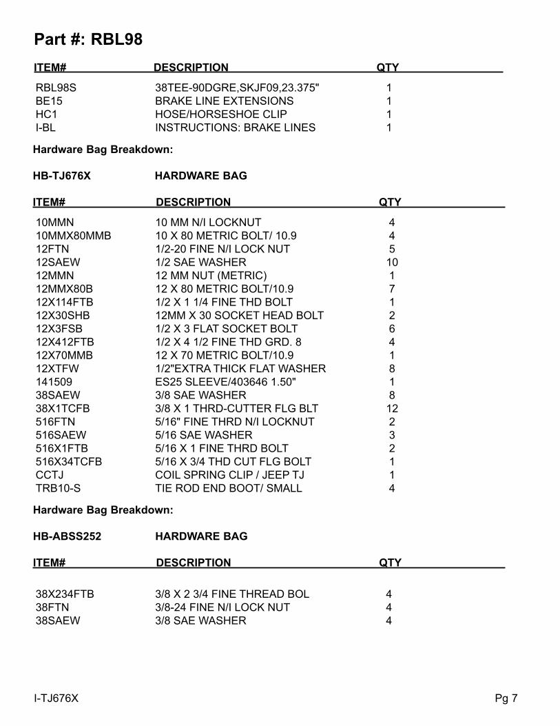
Part #: RBL98 ITeM# deSCRIPTIoN qTY
RBL98S 38TEE-90DGRE,SKJF09,23.375" 1BE15 BRAKE LINE EXTENSIONS 1HC1 HOSE/HORSESHOE CLIP 1I-BL INSTRUCTIONS: BRAKE LINES 1
Hardware Bag Breakdown:
HB-TJ676X HARdWARe BAG
ITeM# deSCRIPTIoN qTY
10MMN 10 MM N/I LOCKNUT 410MMX80MMB 10 X 80 METRIC BOLT/ 10.9 412FTN 1/2-20 FINE N/I LOCK NUT 512SAEW 1/2 SAE WASHER 1012MMN 12 MM NUT (METRIC) 112MMX80B 12 X 80 METRIC BOLT/10.9 712X114FTB 1/2 X 1 1/4 FINE THD BOLT 112X30SHB 12MM X 30 SOCKET HEAD BOLT 212X3FSB 1/2 X 3 FLAT SOCKET BOLT 612X412FTB 1/2 X 4 1/2 FINE THD GRD. 8 412X70MMB 12 X 70 METRIC BOLT/10.9 112XTFW 1/2"EXTRA THICK FLAT WASHER 8141509 ES25 SLEEVE/403646 1.50" 138SAEW 3/8 SAE WASHER 838X1TCFB 3/8 X 1 THRD-CUTTER FLG BLT 12516FTN 5/16" FINE THRD N/I LOCKNUT 2516SAEW 5/16 SAE WASHER 3516X1FTB 5/16 X 1 FINE THRD BOLT 2516X34TCFB 5/16 X 3/4 THD CUT FLG BOLT 1CCTJ COIL SPRING CLIP / JEEP TJ 1TRB10-S TIE ROD END BOOT/ SMALL 4
38X234FTB 3/8 X 2 3/4 FINE THREAD BOL 438FTN 3/8-24 FINE N/I LOCK NUT 438SAEW 3/8 SAE WASHER 4
Hardware Bag Breakdown:
HB-ABSS252 HARdWARe BAG
ITeM# deSCRIPTIoN qTY
I-TJ676X Pg 8
Hardware Bag Breakdown:
HB-TJRSB10 HARdWARe BAG
ITeM# deSCRIPTIoN qTY
12X3FTB 1/2 X 3 FINE THREAD BOLT 438X1FTB 3/8 X 1 FINE THREAD BOLT 212FTN 1/2-20 FINE N/I LOCK NUT 438FTN 3/8-24 FINE N/I LOCK NUT 212SAEW 1/2 SAE WASHER 838SAEW 3/8 SAE WASHER 412XTFW 1/2"EXTRA THICK FLAT WASHER 4142121 ES24 SLEEVE/402087 1.38" 2
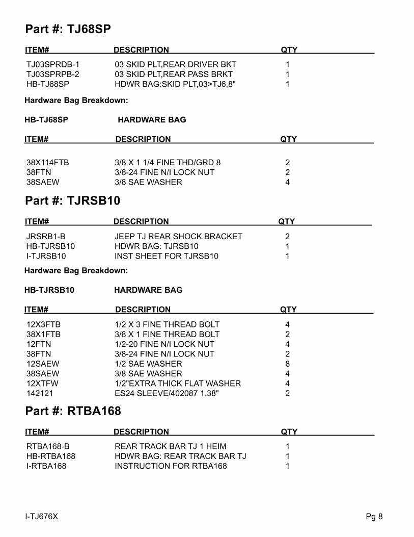
Part #: TJRSB10 ITeM# deSCRIPTIoN qTY
JRSRB1-B JEEP TJ REAR SHOCK BRACKET 2HB-TJRSB10 HDWR BAG: TJRSB10 1I-TJRSB10 INST SHEET FOR TJRSB10 1
38X114FTB 3/8 X 1 1/4 FINE THD/GRD 8 238FTN 3/8-24 FINE N/I LOCK NUT 238SAEW 3/8 SAE WASHER 4
Hardware Bag Breakdown:
HB-TJ68SP HARdWARe BAG
ITeM# deSCRIPTIoN qTY
Part #: TJ68SP ITeM# deSCRIPTIoN qTY
TJ03SPRDB-1 03 SKID PLT,REAR DRIVER BKT 1TJ03SPRPB-2 03 SKID PLT,REAR PASS BRKT 1HB-TJ68SP HDWR BAG:SKID PLT,03>TJ6,8" 1
Part #: RTBA168 ITeM# deSCRIPTIoN qTY
RTBA168-B REAR TRACK BAR TJ 1 HEIM 1HB-RTBA168 HDWR BAG: REAR TRACK BAR TJ 1I-RTBA168 INSTRUCTION FOR RTBA168 1

I-TJ676X Pg 9
HD34X34DTB H.DUTY 3/4ROD END/DGE T-BAR 134RFTJN 3/4" RIGHT HAND JAM NUT 1TJDLB TJ DRAG LINK BUSHING,1.125" 22888 BUSHING JEEP TRACK BAR 2TBS1625 .625"ODX .5"IDX1.625"SLEEVE 112X3FTB 1/2 X 3 FINE THREAD BOLT 212FTN 1/2-20 FINE N/I LOCK NUT 212SAEW 1/2 SAE WASHER 4
Hardware Bag Breakdown:
HB-RTBA168 HARdWARe BAG
ITeM# deSCRIPTIoN qTY
Part #: SP176 ITeM# deSCRIPTIoN qTY
SP176-S SKID PLATE ASSEMBLY 97-06TJ 1EB2834-S SP283/SP284 EXHAUST BRACKET 1TM2834-S SP283/SP284 TRANS MOUNT 1SP2834-S-4 AIR COMP BRACKET BENT 1SP2834-S-5 AIR COMP BRACKET FLAT 1HB-SP283 HDWR BAG: SP283 AND SP284 1I-SP283 INST SHEET: SP283 AND SP284 1
516X1FTB 5/16 X 1 FINE THRD BOLT 4516SAEW 5/16 SAE WASHER 12516X1BHB 5/16 X 1 BUTTON HEAD BOLT 4516FTN 5/16" FINE THRD N/I LOCKNUT 4516CTN 5/16-18 COARSE N/I LOCK NUT 4716X1FTB 7/16 X 1 BOLT,FINE THD GRD8 4716SAEW 7/16 SAE WASHER 8716FTN 7/16-20 FINE N/I LOCK NUT 4
Hardware Bag Breakdown:
HB-SP283 HARdWARe BAG
ITeM# deSCRIPTIoN qTY
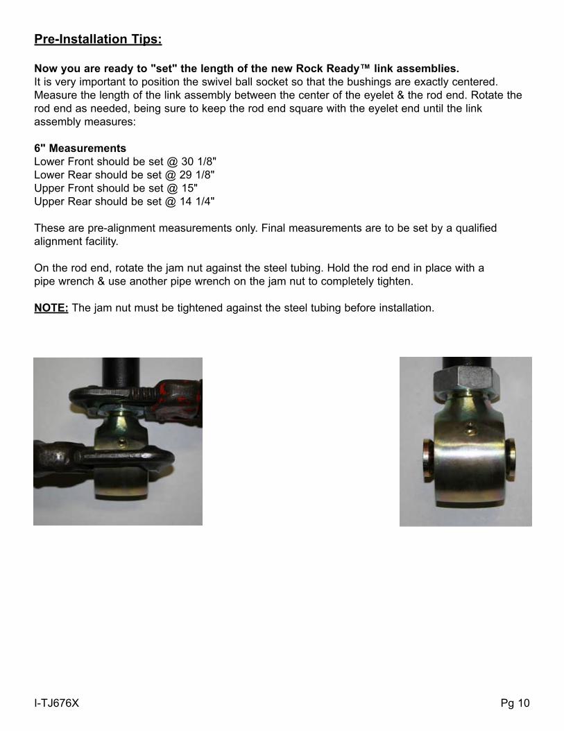
Pre-Installation Tips:
Now you are ready to "set" the length of the new Rock Ready™ link assemblies.It is very important to position the swivel ball socket so that the bushings are exactly centered.Measure the length of the link assembly between the center of the eyelet & the rod end. Rotate the rod end as needed, being sure to keep the rod end square with the eyelet end until the link assembly measures:
6" MeasurementsLower Front should be set @ 30 1/8"Lower Rear should be set @ 29 1/8"Upper Front should be set @ 15"Upper Rear should be set @ 14 1/4"
These are pre-alignment measurements only. Final measurements are to be set by a qualified alignment facility.
On the rod end, rotate the jam nut against the steel tubing. Hold the rod end in place with a pipe wrench & use another pipe wrench on the jam nut to completely tighten.
NOTE: The jam nut must be tightened against the steel tubing before installation.
I-TJ676X Pg 10
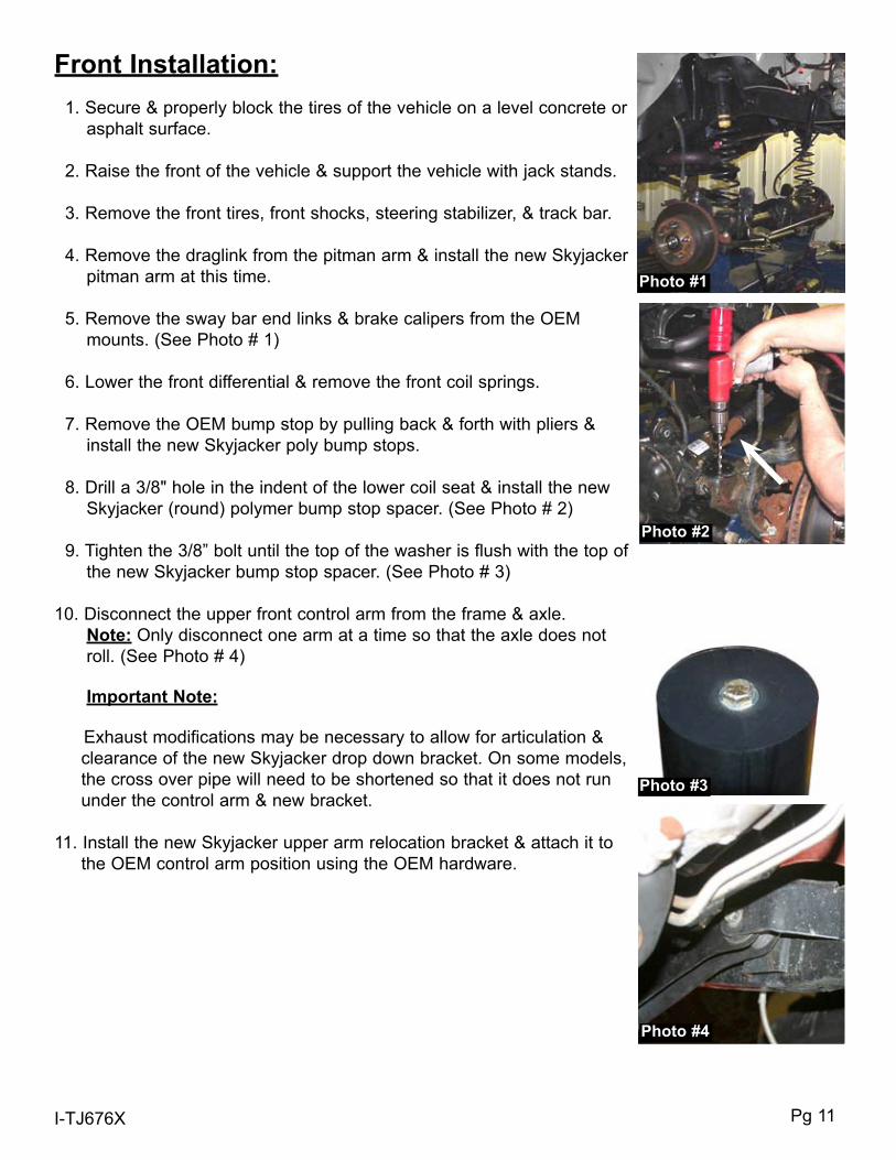
Front Installation: 1. Secure & properly block the tires of the vehicle on a level concrete or asphalt surface.
2. Raise the front of the vehicle & support the vehicle with jack stands.
3. Remove the front tires, front shocks, steering stabilizer, & track bar.
4. Remove the draglink from the pitman arm & install the new Skyjacker pitman arm at this time.
5. Remove the sway bar end links & brake calipers from the OEM mounts. (See Photo # 1)
6. Lower the front differential & remove the front coil springs.
7. Remove the OEM bump stop by pulling back & forth with pliers & install the new Skyjacker poly bump stops.
8. Drill a 3/8" hole in the indent of the lower coil seat & install the new Skyjacker (round) polymer bump stop spacer. (See Photo # 2)
9. Tighten the 3/8” bolt until the top of the washer is flush with the top of the new Skyjacker bump stop spacer. (See Photo # 3)
10. Disconnect the upper front control arm from the frame & axle. Note: Only disconnect one arm at a time so that the axle does not roll. (See Photo # 4)
Important Note:
Exhaust modifications may be necessary to allow for articulation & clearance of the new Skyjacker drop down bracket. On some models, the cross over pipe will need to be shortened so that it does not run under the control arm & new bracket.
11. Install the new Skyjacker upper arm relocation bracket & attach it to the OEM control arm position using the OEM hardware.
I-TJ676X Pg 11
Photo #1
Photo #2
Photo #3
Photo #4

I-TJ676X Pg 12
12. Attach the new Skyjacker upper control arm to the new Skyjacker bracket using the 10mm x 80mm bolt supplied. Attach the new Skyjacker upper control arm to the axle using the OEM hardware. There are four more mounting locations that attach this bracket to the frame. Two on the outside & two on the bottom. With the bracket sitting flush on the frame, drill these locations using a 9/32” drill bit. Once drilled, install the 3/8" x 1” thread cutter bolts in these locations. (See Photo # 5 & # 6) Note: Some models may have a slight gap between the bottom of the new Skyjacker bracket & the frame on the driver side. If this occurs, this gap can be taken up using the 1/4” plastic shim provided. Place the shim between the bracket & the frame. Using a C-Clamp, pull the bracket & shim flush to the frame. (See Arrow in Photo # 20) Drill through the plastic shim & the frame. Mount using the 3/8" x 1 1/4” thread cutter bolts provided.
13. Remove the front lower control arms. Using care, grind off the OEM lower control arm mounts & paint the exposed surface. (See Photo # 7)
14. Place a jack under the transmission skid plate. Remove the mounting hardware & lower the skid plate two inches.
15. Place the new Skyjacker left & right sub frames between the bottom of the frame & install the new Skyjacker high clearance skid plate using the instructions provided. Fasten using the 1/2" x 3” flat socket bolts on 97-02 models & use the 12mm x 80mm bolts on the 03-06 models. (See Photo # 8) Note: On some models it may be necessary to grind down the OEM rear step bar nut insert on the outside of the frame. This will allow for the subframe rail to mount flush.
16. Install the new Skyjacker transfer case shifter bracket (Part # JSRB231A) using the instructions provided.
Photo #6
Photo #5
Photo #7
Passenger Side Sub-Frame
Front
Front
Rear
Rear
1
12
2 3
3
4
4
5
5Photo #8
Note: Skyjacker sub frames are designed to work on 1997-2006 Jeep TJ’s. Therefore, each sub frame will have multiple
mounting holes.• 1997-2002 models use mounting holes 1,3, & 5. • 2003-2006 models use holes 2 & 4. See I-TJ68SP instruction for
the 3rd mounting bolt & skid plate modifications.
driver Side Sub-Frame
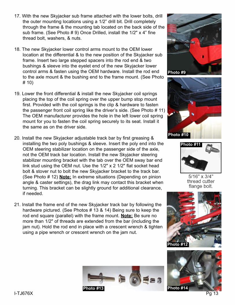
17. With the new Skyjacker sub frame attached with the lower bolts, drill the outer mounting locations using a 1/2” drill bit. Drill completely through the frame & the mounting tab located on the back side of the sub frame. (See Photo # 9) Once Drilled, install the 1/2" x 4” fine thread bolt, washers, & nuts.
18. The new Skyjacker lower control arms mount to the OEM lower location at the differential & to the new position of the Skyjacker sub frame. Insert two large stepped spacers into the rod end & two bushings & sleeve into the eyelet end of the new Skyjacker lower control arms & fasten using the OEM hardware. Install the rod end to the axle mount & the bushing end to the frame mount. (See Photo # 10)
19. Lower the front differential & install the new Skyjacker coil springs placing the top of the coil spring over the upper bump stop mount first. Provided with the coil springs is the clip & hardware to fasten the passenger front coil spring like the driver’s side. (See Photo # 11) The OEM manufacturer provides the hole in the left lower coil spring mount for you to fasten the coil spring securely to its seat. Install it the same as on the driver side.
20. Install the new Skyjacker adjustable track bar by first greasing & installing the two poly bushings & sleeve. Insert the poly end into the OEM steering stabilizer location on the passenger side of the axle, not the OEM track bar location. Install the new Skyjacker steering stabilizer mounting bracket with the tab over the OEM sway bar end link stud using the OEM nut. Use the 1/2" x 2 1/2" flat socket head bolt & stover nut to bolt the new Skyjacker bracket to the track bar. (See Photo # 12) Note: In extreme situations (Depending on pinion angle & caster settings), the drag link may contact this bracket when turning. This bracket can be slightly ground for additional clearance, if needed.
21. Install the frame end of the new Skyjacker track bar by following the hardware pictured. (See Photos # 13 & 14) Being sure to keep the rod end square (parallel) with the frame mount. Note: Be sure no more than 1/2" of threads are extended from the bar (including the jam nut). Hold the rod end in place with a crescent wrench & tighten using a pipe wrench or crescent wrench on the jam nut.
I-TJ676X Pg 13
Photo #11
Photo #12
Photo #14Photo #13
Photo #9
Photo #10
I-TJ676X Pg 14
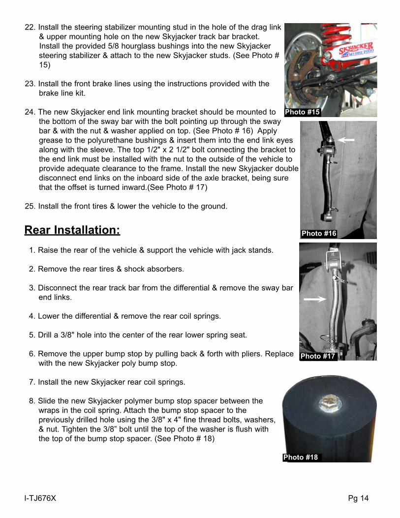
22. Install the steering stabilizer mounting stud in the hole of the drag link & upper mounting hole on the new Skyjacker track bar bracket.
Install the provided 5/8 hourglass bushings into the new Skyjacker steering stabilizer & attach to the new Skyjacker studs. (See Photo # 15)
23. Install the front brake lines using the instructions provided with the brake line kit.
24. The new Skyjacker end link mounting bracket should be mounted to the bottom of the sway bar with the bolt pointing up through the sway bar & with the nut & washer applied on top. (See Photo # 16) Apply grease to the polyurethane bushings & insert them into the end link eyes along with the sleeve. The top 1/2" x 2 1/2" bolt connecting the bracket to the end link must be installed with the nut to the outside of the vehicle to provide adequate clearance to the frame. Install the new Skyjacker double disconnect end links on the inboard side of the axle bracket, being sure that the offset is turned inward.(See Photo # 17)
25. Install the front tires & lower the vehicle to the ground.
Rear Installation: 1. Raise the rear of the vehicle & support the vehicle with jack stands.
2. Remove the rear tires & shock absorbers.
3. Disconnect the rear track bar from the differential & remove the sway bar end links.
4. Lower the differential & remove the rear coil springs.
5. Drill a 3/8" hole into the center of the rear lower spring seat.
6. Remove the upper bump stop by pulling back & forth with pliers. Replace with the new Skyjacker poly bump stop.
7. Install the new Skyjacker rear coil springs.
8. Slide the new Skyjacker polymer bump stop spacer between the wraps in the coil spring. Attach the bump stop spacer to the previously drilled hole using the 3/8" x 4" fine thread bolts, washers, & nut. Tighten the 3/8” bolt until the top of the washer is flush with the top of the bump stop spacer. (See Photo # 18)
Photo #16
Photo #17
Photo #15
Photo #18
I-TJ676X Pg 15
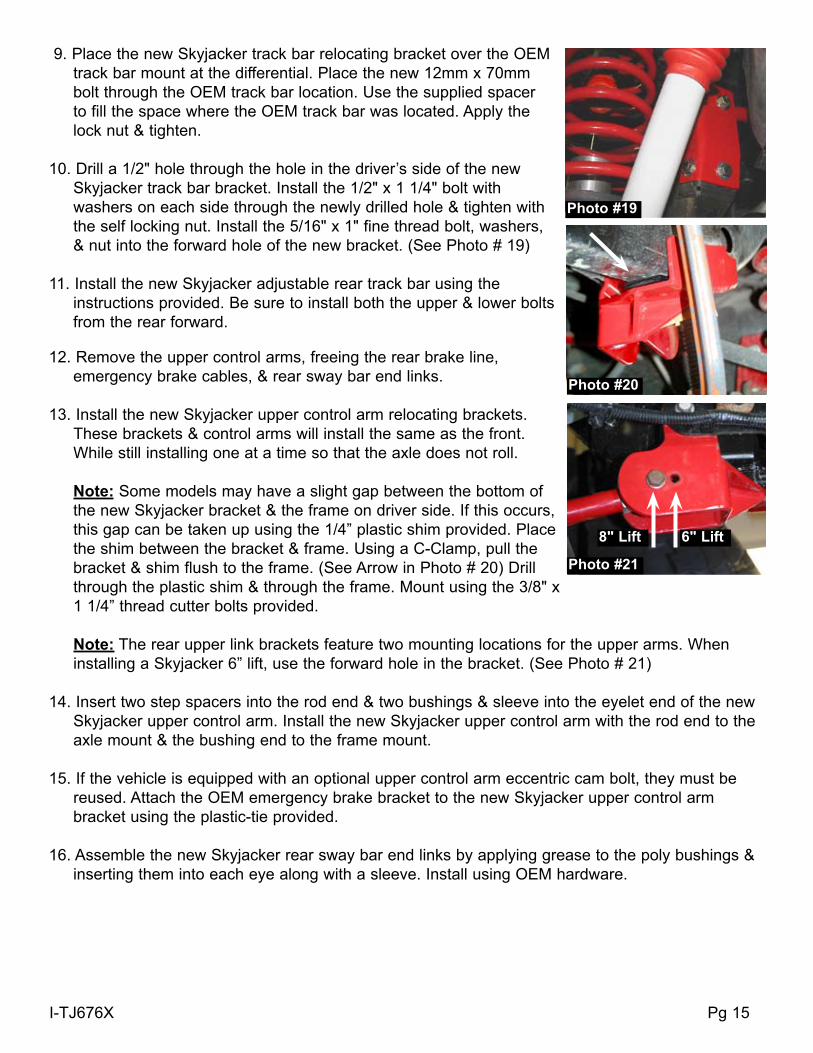
9. Place the new Skyjacker track bar relocating bracket over the OEM track bar mount at the differential. Place the new 12mm x 70mm
bolt through the OEM track bar location. Use the supplied spacer to fill the space where the OEM track bar was located. Apply the lock nut & tighten.
10. Drill a 1/2" hole through the hole in the driver’s side of the new Skyjacker track bar bracket. Install the 1/2" x 1 1/4" bolt with washers on each side through the newly drilled hole & tighten with the self locking nut. Install the 5/16" x 1" fine thread bolt, washers, & nut into the forward hole of the new bracket. (See Photo # 19)
11. Install the new Skyjacker adjustable rear track bar using the instructions provided. Be sure to install both the upper & lower bolts from the rear forward.
12. Remove the upper control arms, freeing the rear brake line, emergency brake cables, & rear sway bar end links.
13. Install the new Skyjacker upper control arm relocating brackets. These brackets & control arms will install the same as the front. While still installing one at a time so that the axle does not roll.
Note: Some models may have a slight gap between the bottom of the new Skyjacker bracket & the frame on driver side. If this occurs,
this gap can be taken up using the 1/4” plastic shim provided. Place the shim between the bracket & frame. Using a C-Clamp, pull the
bracket & shim flush to the frame. (See Arrow in Photo # 20) Drill through the plastic shim & through the frame. Mount using the 3/8" x 1 1/4” thread cutter bolts provided.
Note: The rear upper link brackets feature two mounting locations for the upper arms. When
installing a Skyjacker 6” lift, use the forward hole in the bracket. (See Photo # 21)
14. Insert two step spacers into the rod end & two bushings & sleeve into the eyelet end of the new Skyjacker upper control arm. Install the new Skyjacker upper control arm with the rod end to the axle mount & the bushing end to the frame mount.
15. If the vehicle is equipped with an optional upper control arm eccentric cam bolt, they must be reused. Attach the OEM emergency brake bracket to the new Skyjacker upper control arm
bracket using the plastic-tie provided.
16. Assemble the new Skyjacker rear sway bar end links by applying grease to the poly bushings & inserting them into each eye along with a sleeve. Install using OEM hardware.
Photo #19
Photo #20
Photo #21
6" Lift8" Lift
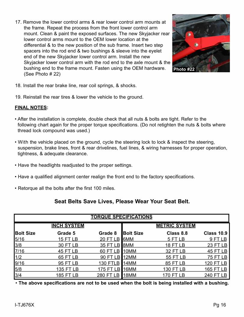
17. Remove the lower control arms & rear lower control arm mounts at the frame. Repeat the process from the front lower control arm mount. Clean & paint the exposed surfaces. The new Skyjacker rear lower control arms mount to the OEM lower location at the differential & to the new position of the sub frame. Insert two step spacers into the rod end & two bushings & sleeve into the eyelet end of the new Skyjacker lower control arm. Install the new Skyjacker lower control arm with the rod end to the axle mount & the bushing end to the frame mount. Fasten using the OEM hardware. (See Photo # 22)
18. Install the rear brake line, rear coil springs, & shocks. 19. Reinstall the rear tires & lower the vehicle to the ground.
I-TJ676X Pg 16
Photo #22
FINAL NoTeS:
• After the installation is complete, double check that all nuts & bolts are tight. Refer to the following chart again for the proper torque specifications. (Do not retighten the nuts & bolts where thread lock compound was used.) • With the vehicle placed on the ground, cycle the steering lock to lock & inspect the steering, suspension, brake lines, front & rear drivelines, fuel lines, & wiring harnesses for proper operation, tightness, & adequate clearance. • Have the headlights readjusted to the proper settings. • Have a qualified alignment center realign the front end to the factory specifications. • Retorque all the bolts after the first 100 miles.
Seat Belts Save Lives, Please Wear Your Seat Belt.
ToRque SPeCIFICATIoNS
INCH SYSTeMBolt Size Grade 5 Grade 85/16 15 FT LB 20 FT LB3/8 30 FT LB 35 FT LB7/16 45 FT LB 60 FT LB1/2 65 FT LB 90 FT LB9/16 95 FT LB 130 FTLB5/8 135 FT LB 175 FT LB3/4 185 FT LB 280 FT LB
MeTRIC SYSTeMBolt Size Class 8.8 Class 10.9 6MM 5 FT LB 9 FT LB8MM 18 FT LB 23 FT LB10MM 32 FT LB 45 FT LB12 MM 55 FT LB 75 FT LB14MM 85 FT LB 120 FT LB16MM 130 FT LB 165 FT LB18MM 170 FT LB 240 FT LB
• The above specifications are not to be used when the bolt is being installed with a bushing.

Part # TJ676XPN
I-TJ676X Pg 17
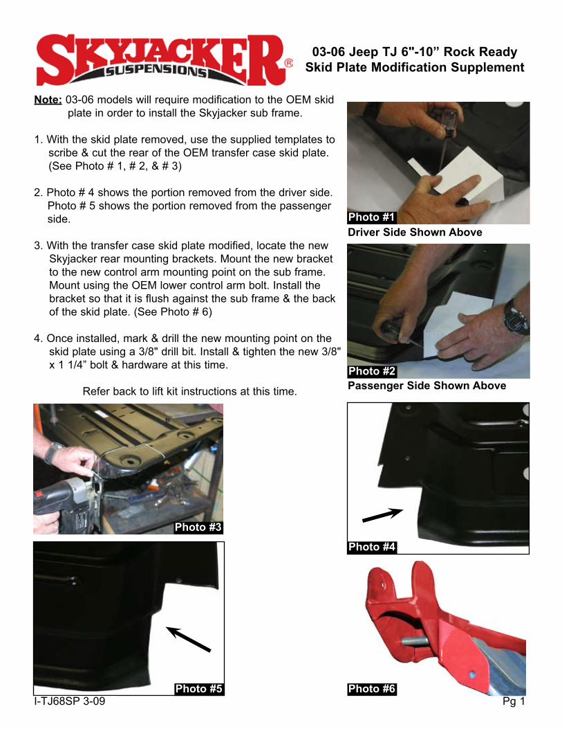
03-06 Jeep TJ 6"-10” Rock ReadySkid Plate Modification Supplement
Note: 03-06 models will require modification to the OEM skid plate in order to install the Skyjacker sub frame.
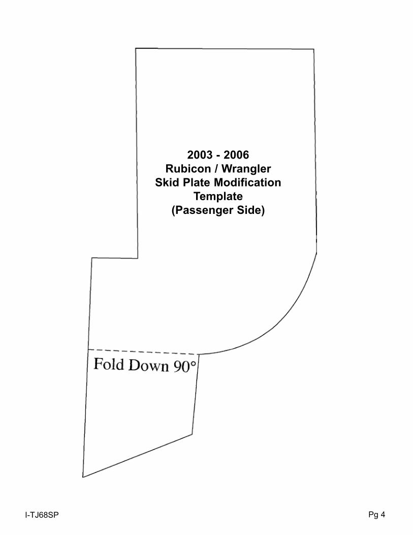
1. With the skid plate removed, use the supplied templates to scribe & cut the rear of the OEM transfer case skid plate. (See Photo # 1, # 2, & # 3)
2. Photo # 4 shows the portion removed from the driver side. Photo # 5 shows the portion removed from the passenger side.
3. With the transfer case skid plate modified, locate the new Skyjacker rear mounting brackets. Mount the new bracket to the new control arm mounting point on the sub frame. Mount using the OEM lower control arm bolt. Install the bracket so that it is flush against the sub frame & the back of the skid plate. (See Photo # 6)
4. Once installed, mark & drill the new mounting point on the skid plate using a 3/8" drill bit. Install & tighten the new 3/8" x 1 1/4” bolt & hardware at this time.
Refer back to lift kit instructions at this time.
Photo #1driver Side Shown Above
Passenger Side Shown AbovePhoto #2
Photo #3
Photo #4
Photo #5Pg 1I-TJ68SP 3-09
Photo #6

Pg 2I-TJ68SP
2003 - 2006Rubicon / Wrangler
Skid Plate ModificationTemplate
(driver Side)

Pg 3I-TJ68SP
Pg 4I-TJ68SP
2003 - 2006Rubicon / Wrangler
Skid Plate ModificationTemplate
(Passenger Side)

Pg 5I-TJ68SP
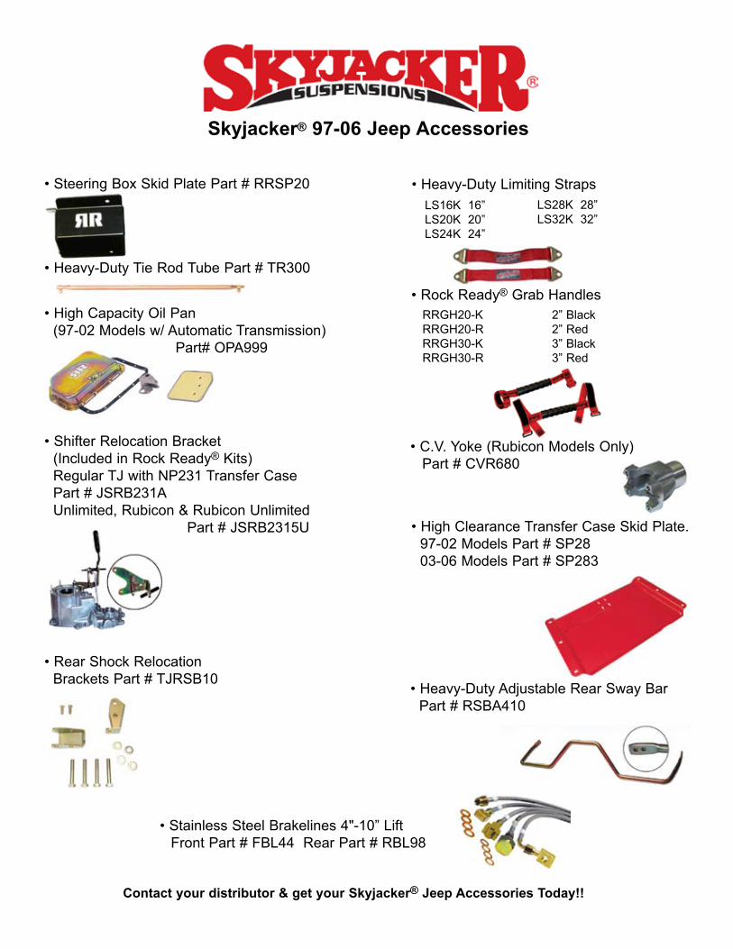
Skyjacker® 97-06 Jeep Accessories
• Steering Box Skid Plate Part # RRSP20
• Heavy-Duty Tie Rod Tube Part # TR300
• High Capacity Oil Pan (97-02 Models w/ Automatic Transmission)
Part# OPA999
• Shifter Relocation Bracket (Included in Rock Ready® Kits) Regular TJ with NP231 Transfer Case Part # JSRB231A Unlimited, Rubicon & Rubicon Unlimited
Part # JSRB2315U
• Heavy-Duty Limiting Straps
• Rock Ready® Grab Handles
LS16K 16”LS20K 20”LS24K 24”
LS28K 28”LS32K 32”
RRGH20-K 2” BlackRRGH20-R 2” RedRRGH30-K 3” BlackRRGH30-R 3” Red
• High Clearance Transfer Case Skid Plate. 97-02 Models Part # SP28 03-06 Models Part # SP283
• C.V. Yoke (Rubicon Models Only) Part # CVR680
• Heavy-Duty Adjustable Rear Sway Bar Part # RSBA410
• Rear Shock Relocation Brackets Part # TJRSB10
• Stainless Steel Brakelines 4"-10” Lift Front Part # FBL44 Rear Part # RBL98
Contact your distributor & get your Skyjacker® Jeep Accessories Today!!