881a fx programming manual ii - farnell
TRANSCRIPT
PROGRAMMING MANUAL II
THE FX SERIES OF PROGRAMMABLE CONTROLLER(FX1S, FX1N, FX2N, FX2NC)
i
FX Series Programmable Controllers
Programming Manual
Manual number : JY992D88101
Manual revision : A
Date : April 2000
FX Series Programmable Controllers
Foreword
• This manual contains text, diagrams and explanations which will guide the reader inthe correct programming and operation of the PLC.
• Before attempting to install or use the PLC this manual should be read andunderstood.
• If in doubt at any stage of the installation of the PLC always consult a professionalelectrical engineer who is qualified and trained to the local and national standardswhich apply to the installation site.
• If in doubt about the operation or use of the PLC please consult the nearestMitsubishi Electric distributor.
• This manual is subject to change without notice.

FX Series Programmable Controllers
ii

FAX BACK - Combined Programming Manual (J)
Mitsubishi has a world wide reputation for its efforts in continually developing and pushing backthe frontiers of industrial automation. What is sometimes overlooked by the user is the careand attention to detail that is taken with the documentation. However,to continue this processof improvement, the comments of the Mitsubishi users are always welcomed. This page hasbeen designed for you,the reader,to fill in your comments and fax them back to us. We look for-ward to hearing from you.
Please tick the box of your choice;
Fax numbers: Your name....................................................
Mitsubishi Electric.... .....................................................................
America (01) 847-478-2253 Your company ..............................................
Australia (02) 638-7072 .....................................................................
Germany (0 21 02) 4 86-1 12 Your location: ...............................................
South Africa (0111) 444-8304 .....................................................................
United Kingdom (01707) 278-695
What condition did the manual arrive in? Good Minor damage Unusable
Will you be using a folder to store the manual? Yes No
What do you think to the manual presentation? Tidy Un-friendly
Are the explanations understandable? Yes Not too bad Unusable
Which explanation was most difficult to understand: ......................................................................................................................................................................................................................
Are there any diagrams which are not clear? Yes No
If so,which:..................................................................................................................................
What do you think to the manual layout? Good Not too bad Un-helpful
If there one thing you would like to see improved,what is it?..............................................................................................................................................................................................................................................................................................................................................................
Could you find the information you required easily using the index and/or the contents,if possi-ble please identify your experience: ...........................................................................................................................................................................................................................................................................................................................................................................................................................................................................................................................................................................................................................................................................................................
Do you have any comments in general about the Mitsubishi manuals? .....................................................................................................................................................................................................................................................................................................................................................................................................................................................................................................................................................................................................................................................
Thank you for taking the time to fill out this questionnaire. We hope you found both the productand this manual easy to use.
FX Series Programmable Controllers
iii

FX Series Programmable Controllers
iv
FX Series Programmable Controllers
Guidelines for the Safety of the User and Protection of the Programmable Controller (PLC)
This manual provides information for the use of the FX family of PLC’s. The manual has beenwritten to be used by trained and competent personnel. The definition of such a person orpersons is as follows;
a) Any engineer who is responsible for the planning, design and construction of automaticequipment using the product associated with this manual should be of a competentnature, trained and qualified to the local and national standards required to fulfill thatrole. These engineers should be fully aware of all aspects of safety with regards toautomated equipment.
b) Any commissioning or service engineer must be of a competent nature, trained andqualified to the local and national standards required to fulfill that job. These engineersshould also be trained in the use and maintenance of the completed product. Thisincludes being completely familiar with all associated documentation for the saidproduct. All maintenance should be carried out in accordance with established safetypractices.
c) All operators of the completed equipment should be trained to use that product in a safeand coordinated manner in compliance to established safety practices. The operatorsshould also be familiar with documentation which is connected with the actual operationof the completed equipment.
Note : the term ‘completed equipment’ refers to a third party constructed device whichcontains or uses the product associated with this manual.
Note’s on the Symbols used in this Manual
At various times through out this manual certain symbols will be used to highlight points ofinformation which are intended to ensure the users personal safety and protect the integrity ofequipment. Whenever any of the following symbols are encountered its associated note mustbe read and understood. Each of the symbols used will now be listed with a brief description ofits meaning.
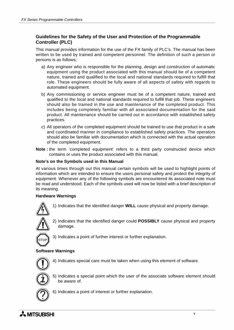
Hardware Warnings
1) Indicates that the identified danger WILL cause physical and property damage.
2) Indicates that the identified danger could POSSIBLY cause physical and propertydamage.
3) Indicates a point of further interest or further explanation.
Software Warnings
4) Indicates special care must be taken when using this element of software.
5) Indicates a special point which the user of the associate software element shouldbe aware of.
6) Indicates a point of interest or further explanation.
v

FX Series Programmable Controllers
vi
FX Series Programmable controllers
Contents
1. Introduction............................................................................................1-11.1 Overview.............................................................................................................. 1-11.2 What is a Programmable Controller? .................................................................. 1-21.3 What do You Need to Program a PLC? .............................................................. 1-21.4 Special considerations for programming equipment ........................................... 1-3
1.4.1 Current Generation CPU all versions ....................................................................... 1-31.5 Assocciated Manuals........................................................................................... 1-4
2. Basic Program Instructions ...................................................................2-12.1 What is a Program?............................................................................................. 2-12.2 Outline of Basic Devices Used in Programming.................................................. 2-12.3 How to Read Ladder Logic .................................................................................. 2-22.4 Load, Load Inverse.............................................................................................. 2-32.5 Out ....................................................................................................................... 2-4
2.5.1 Timer and Counter Variations ................................................................................... 2-42.5.2 Double Coil Designation ............................................................................................ 2-5
2.6 And, And Inverse ................................................................................................. 2-62.7 Or, Or Inverse...................................................................................................... 2-72.8 Load Pulse, Load Trailing Pulse.......................................................................... 2-82.9 And Pulse, And Trailing Pulse ............................................................................. 2-92.10 Or Pulse, Or Trailing Pulse................................................................................ 2-102.11 Or Block............................................................................................................. 2-112.12 And Block .......................................................................................................... 2-122.13 MPS, MRD and MPP......................................................................................... 2-132.14 Master Control and Reset.................................................................................. 2-152.15 Set and Reset .................................................................................................... 2-172.16 Timer, Counter (Out & Reset)............................................................................ 2-18
2.16.1 Basic Timers, Retentive Timers And Counters........................................................ 2-182.16.2 Normal 32 bit Counters ........................................................................................... 2-192.16.3 High Speed Counters .............................................................................................. 2-19
2.17 Leading and Trailing Pulse ................................................................................ 2-202.18 Inverse............................................................................................................... 2-212.19 No Operation ..................................................................................................... 2-222.20 End .................................................................................................................... 2-23
i
3. STL Programming .................................................................................3-13.1 What is STL, SFC And IEC1131 Part 3?............................................................. 3-13.2 How STL Operates .............................................................................................. 3-2
3.2.1 Each step is a program ............................................................................................. 3-23.3 How To Start And End An STL Program ............................................................. 3-3
3.3.1 Embedded STL programs ......................................................................................... 3-33.3.2 Activating new states................................................................................................. 3-33.3.3 Terminating an STL Program .................................................................................... 3-4
3.4 Moving Between STL Steps ................................................................................ 3-53.4.1 Using SET to drive an STL coil ................................................................................. 3-53.4.2 Using OUT to drive an STL coil ................................................................................. 3-6
3.5 Rules and Techniques For STL programs........................................................... 3-73.5.1 Basic Notes On The Behavior Of STL programs....................................................... 3-73.5.2 Single Signal Step Control ........................................................................................ 3-9
3.6 Restrictions Of Some Instructions When Used With STL.................................. 3-103.7 Using STL To Select The Most Appropriate Program ....................................... 3-113.8 Using STL To Activate Multiple Flows Simultaneously...................................... 3-123.9 General Rules For Successful STL Branching .................................................. 3-143.10 General Precautions When Using The FX-PCS/AT-EE Software ..................... 3-153.11 Programming Examples .................................................................................... 3-16
3.11.1 A Simple STL Flow.................................................................................................. 3-163.11.2 A Selective Branch/ First State Merge Example Program....................................... 3-18
3.12 Advanced STL Use............................................................................................ 3-20
4. Devices in Detail....................................................................................4-14.1 Inputs................................................................................................................... 4-14.2 Outputs ................................................................................................................ 4-24.3 Auxiliary Relays ................................................................................................... 4-3
4.3.1 General Stable State Auxiliary Relays ...................................................................... 4-34.3.2 Battery Backed/ Latched Auxiliary Relays................................................................. 4-44.3.3 Special Diagnostic Auxiliary Relays .......................................................................... 4-54.3.4 Special Single Operation Pulse Relays..................................................................... 4-5
4.4 State Relays ........................................................................................................ 4-64.4.1 General Stable State - State Relays ......................................................................... 4-64.4.2 Battery Backed/ Latched State Relays...................................................................... 4-74.4.3 STL Step Relays ....................................................................................................... 4-84.4.4 Annunciator Flags ..................................................................................................... 4-9
4.5 Pointers ............................................................................................................. 4-104.6 Interrupt Pointers ............................................................................................... 4-11
4.6.1 Input Interrupts ........................................................................................................ 4-124.6.2 Timer Interrupts ....................................................................................................... 4-124.6.3 Disabling Individual Interrupts ................................................................................. 4-134.6.4 Counter Interrupts ................................................................................................... 4-13
4.7 Constant K......................................................................................................... 4-144.8 Constant H......................................................................................................... 4-144.9 Timers................................................................................................................ 4-15
4.9.1 General timer operation........................................................................................... 4-164.9.2 Selectable Timers.................................................................................................... 4-164.9.3 Retentive Timers ..................................................................................................... 4-174.9.4 Timers Used in Interrupt and ‘CALL’ Subroutines ................................................... 4-184.9.5 Timer Accuracy ....................................................................................................... 4-18
4.10 Counters ............................................................................................................ 4-194.10.1 General/ Latched 16bit UP Counters ...................................................................... 4-204.10.2 General/ Latched 32bit Bi-directional Counters....................................................... 4-21
ii
4.11 High Speed Counters ........................................................................................ 4-224.11.1 Basic High Speed Counter Operation ..................................................................... 4-234.11.2 Availability of High Speed Counters ....................................................................... 4-244.11.3 1 Phase Counters - User Start and Reset (C235 - C240) ....................................... 4-264.11.4 1 Phase Counters - Assigned Start and Reset (C241 to C245) .............................. 4-274.11.5 2 Phase Bi-directional Counters (C246 to C250) .................................................... 4-284.11.6 A/B Phase Counters (C252 to C255) ...................................................................... 4-29
4.12 Data Registers................................................................................................... 4-304.12.1 General Use Registers ............................................................................................ 4-314.12.2 Battery Backed/ Latched Registers ......................................................................... 4-324.12.3 Special Diagnostic Registers................................................................................... 4-324.12.4 File Registers .......................................................................................................... 4-334.12.5 Externally Adjusted Registers ................................................................................. 4-34
4.13 Index Registers.................................................................................................. 4-354.13.1 Modifying a Constant............................................................................................... 4-364.13.2 Misuse of the Modifiers ........................................................................................... 4-364.13.3 Using Multiple Index Registers ................................................................................ 4-36
4.14 Bits, Words, BCD and Hexadecimal .................................................................. 4-374.14.1 Bit Devices, Individual and Grouped ....................................................................... 4-374.14.2 Word Devices .......................................................................................................... 4-394.14.3 Interpreting Word Data ............................................................................................ 4-394.14.4 Two’s Compliment ................................................................................................... 4-42
4.15 Floating Point And Scientific Notation ............................................................... 4-434.15.1 Scientific Notation.................................................................................................... 4-444.15.2 Floating Point Format .............................................................................................. 4-454.15.3 Summary Of The Scientific Notation and Floating Point Numbers.......................... 4-46
5. Applied Instructions ...............................................................................5-15.1 Program Flow-Functions 00 to 09 ....................................................................... 5-4
5.1.1 CJ (FNC 00) .............................................................................................................. 5-55.1.2 CALL (FNC 01).......................................................................................................... 5-75.1.3 SRET (FNC 02) ......................................................................................................... 5-85.1.4 IRET, EI, DI (FNC 03, 04, 05) ................................................................................... 5-95.1.5 FEND (FNC 06) ....................................................................................................... 5-115.1.6 WDT (FNC 07) ........................................................................................................ 5-125.1.7 FOR, NEXT (FNC 08, 09) ....................................................................................... 5-13
5.2 Move And Compare - Functions 10 to 19.......................................................... 5-165.2.1 CMP (FNC 10)......................................................................................................... 5-175.2.2 ZCP (FNC 11) ......................................................................................................... 5-175.2.3 MOV (FNC 12) ........................................................................................................ 5-185.2.4 SMOV (FNC 13) ...................................................................................................... 5-185.2.5 CML (FNC 14) ......................................................................................................... 5-195.2.6 BMOV (FNC 15) ..................................................................................................... 5-205.2.7 FMOV (FNC 16) ...................................................................................................... 5-215.2.8 XCH (FNC 17) ......................................................................................................... 5-215.2.9 BCD (FNC18) .......................................................................................................... 5-225.2.10 BIN (FNC 19)........................................................................................................... 5-22
5.3 Arithmetic And Logical Operations - Functions 20 to 29 ................................... 5-245.3.1 ADD (FNC 20) ......................................................................................................... 5-255.3.2 SUB (FNC 21) ........................................................................................................ 5-265.3.3 MUL (FNC 22) ......................................................................................................... 5-275.3.4 DIV (FNC 23)........................................................................................................... 5-285.3.5 INC (FNC 24) ......................................................................................................... 5-295.3.6 DEC (FNC 24) ........................................................................................................ 5-295.3.7 WAND (FNC 26)...................................................................................................... 5-305.3.8 WOR (FNC 27) ........................................................................................................ 5-30
iii
5.3.9 WXOR (FNC 28) ..................................................................................................... 5-315.3.10 NEG (FNC 29) ........................................................................................................ 5-31
5.4 Rotation And Shift - Functions 30 to 39............................................................. 5-345.4.1 ROR (FNC 30)......................................................................................................... 5-355.4.2 ROL (FNC 31) ......................................................................................................... 5-355.4.3 RCR (FNC 32) ......................................................................................................... 5-365.4.4 RCL (FNC 33) ......................................................................................................... 5-365.4.5 SFTR (FNC 34) ....................................................................................................... 5-375.4.6 SFTL (FNC 35) ........................................................................................................ 5-375.4.7 WSFR (FNC 36) ...................................................................................................... 5-385.4.8 WSFL (FNC 37)....................................................................................................... 5-385.4.9 SFWR (FNC 38) ...................................................................................................... 5-395.4.10 SFRD (FNC 39) ....................................................................................................... 5-40
5.5 Data Operation - Functions 40 to 49 ................................................................. 5-425.5.1 ZRST (FNC 40) ....................................................................................................... 5-435.5.2 DECO (FNC 41) ...................................................................................................... 5-435.5.3 ENCO (FNC 42) ...................................................................................................... 5-445.5.4 SUM (FNC 43)......................................................................................................... 5-455.5.5 BON (FNC 44) ......................................................................................................... 5-455.5.6 MEAN (FNC 45) ...................................................................................................... 5-465.5.7 ANS (FNC 46) ......................................................................................................... 5-475.5.8 ANR (FNC 47) ......................................................................................................... 5-475.5.9 SQR (FNC 48) ......................................................................................................... 5-485.5.10 FLT (FNC 49) .......................................................................................................... 5-49
5.6 High Speed Processing - Functions 50 to 59 .................................................... 5-525.6.1 REF (FNC 50) ......................................................................................................... 5-535.6.2 REFF (FNC 51) ....................................................................................................... 5-535.6.3 MTR (FNC 52) ......................................................................................................... 5-545.6.4 HSCS (FNC 53)....................................................................................................... 5-555.6.5 HSCR (FNC 54) ...................................................................................................... 5-565.6.6 HSZ (FNC 55) ......................................................................................................... 5-575.6.7 SPD (FNC 56) ......................................................................................................... 5-605.6.8 PLSY (FNC 57) ....................................................................................................... 5-615.6.9 PWM (FNC 58) ........................................................................................................ 5-625.6.10 PLSR (FNC 59) ....................................................................................................... 5-63
5.7 Handy Instructions - Functions 60 to 69 ............................................................ 5-665.7.1 IST (FNC 60) ........................................................................................................... 5-675.7.2 SER (FNC 61) ......................................................................................................... 5-695.7.3 ABSD (FNC 62) ....................................................................................................... 5-705.7.4 INCD (FNC 63) ........................................................................................................ 5-715.7.5 TTMR (FNC 64)....................................................................................................... 5-725.7.6 STMR (FNC 65) ...................................................................................................... 5-725.7.7 ALT (FNC 66) .......................................................................................................... 5-735.7.8 RAMP (FNC 67) ...................................................................................................... 5-735.7.9 ROTC (FNC 68) ...................................................................................................... 5-755.7.10 SORT (FNC 69)....................................................................................................... 5-77
5.8 External FX I/O Devices - Functions 70 to 79 ................................................... 5-805.8.1 TKY (FNC 70).......................................................................................................... 5-815.8.2 HKY (FNC 71) ......................................................................................................... 5-825.8.3 DSW (FNC 72) ........................................................................................................ 5-835.8.4 SEGD (FNC 73) ...................................................................................................... 5-845.8.5 SEGL (FNC 74) ....................................................................................................... 5-855.8.6 ARWS (FNC 75) ...................................................................................................... 5-875.8.7 ASC (FNC 76) ......................................................................................................... 5-885.8.8 PR (FNC 77)............................................................................................................ 5-895.8.9 FROM (FNC 78) ...................................................................................................... 5-905.8.10 TO (FNC 79)............................................................................................................ 5-91
iv
5.9 External FX Serial Devices - Functions 80 to 89 ............................................... 5-945.9.1 RS (FNC 80)............................................................................................................ 5-955.9.2 RUN (FNC 81) ......................................................................................................... 5-965.9.3 ASCI (FNC 82) ........................................................................................................ 5-985.9.4 HEX (FNC 83) ......................................................................................................... 5-995.9.5 CCD (FNC 84) ....................................................................................................... 5-1005.9.6 VRRD (FNC 85) .................................................................................................... 5-1015.9.7 VRSD (FNC 86)..................................................................................................... 5-1015.9.8 PID (FNC 88)......................................................................................................... 5-102
5.10 Floating Point 1 & 2 - Functions 110 to 129 .................................................... 5-1105.10.1 ECMP (FNC 110) .................................................................................................. 5-1115.10.2 EZCP (FNC 111) ................................................................................................... 5-1115.10.3 EBCD (FNC 118)................................................................................................... 5-1125.10.4 EBIN (FNC 119) .................................................................................................... 5-1125.10.5 EADD (FNC 120)................................................................................................... 5-1135.10.6 EAUB (FNC 121) ................................................................................................... 5-1145.10.7 EMUL (FNC 122)................................................................................................... 5-1145.10.8 EDIV (FNC 123) .................................................................................................... 5-1155.10.9 ESQR (FNC 127) .................................................................................................. 5-1155.10.10INT (FNC 129) ...................................................................................................... 5-116
5.11 Trigonometry - FNC 130 to FNC 139 .............................................................. 5-1185.11.1 SIN (FNC 130)....................................................................................................... 5-1195.11.2 COS (FNC 131) ..................................................................................................... 5-1205.11.3 TAN (FNC 132) ..................................................................................................... 5-120
5.12 Data Operations 2 - FNC 140 to FNC 149 ...................................................... 5-1225.12.1 SWAP (FNC 147) .................................................................................................. 5-123
5.13 FX1S & FX1N Positioning Control - FNC 150 to FNC 159.............................. 5-1265.13.1 ABS (FNC 155) ..................................................................................................... 5-1275.13.2 ZRN (FNC 156) ..................................................................................................... 5-1285.13.3 PLSV(FNC157) ..................................................................................................... 5-1295.13.4 DRVI (FNC 158) .................................................................................................... 5-1305.13.5 DRVA(FNC 159).................................................................................................... 5-132
5.14 Real Time Clock Control - FNC 160 to FNC 169............................................. 5-1365.14.1 TCMP (FNC 160) .................................................................................................. 5-1375.14.2 TZCP (FNC 161) ................................................................................................... 5-1385.14.3 TADD (FNC 162) ................................................................................................... 5-1395.14.4 TSUB (FNC 163) ................................................................................................... 5-1405.14.5 TRD (FNC 166) ..................................................................................................... 5-1415.14.6 TWR (FNC 167) .................................................................................................... 5-1425.14.7 Hour(FNC 169) ...................................................................................................... 5-143
5.15 Gray Codes - FNC 170 to FNC 179 ................................................................ 5-1465.15.1 GRY (FNC 170) ..................................................................................................... 5-1475.15.2 GBIN (FNC 171) .................................................................................................... 5-1475.15.3 RD3A (FNC 176) ................................................................................................... 5-1485.15.4 WR3A (FNC 177) .................................................................................................. 5-148
5.16 Inline Comparisons - FNC 220 to FNC 249..................................................... 5-1505.16.1 LD compare (FNC 224 to 230) .............................................................................. 5-1515.16.2 AND compare (FNC 232 to 238) ........................................................................... 5-1525.16.3 OR compare (FNC 240 to 246) ............................................................................. 5-153
v
6. Diagnostic Devices................................................................................6-16.1 PLC Status (M8000 to M8009 and D8000 to D8009).......................................... 6-26.2 Clock Devices (M8010 to M8019 and D8010 to D8019) .................................... 6-36.3 Operation Flags ................................................................................................... 6-46.4 PLC Operation Mode (M8030 to M8039 and D8030 to D8039) ......................... 6-56.5 Step Ladder (STL) Flags (M8040 to M8049 and D8040 to D8049) .................... 6-66.6 Interrupt Control Flags (M8050 to M8059 and D8050 to D8059) ...................... 6-76.7 Error Detection Devices (M8060 to M8069 and D8060 to D6069) ..................... 6-86.8 Link and Special Operation Devices (M8070 to M8099 and D8070 to D8099) .. 6-96.9 Miscellaneous Devices (M8100 to M8119 and D8100 to D8119) ..................... 6-106.10 Communication Adapter Devices, i.e. 232ADP, 485ADP.................................. 6-106.11 High Speed Zone Compare Table Comparison Flags....................................... 6-116.12 Miscellaneous Devices (M8160 to M8199) ....................................................... 6-126.13 Index Registers (D8180 to D8199) ................................................................... 6-136.14 Up/Down Counter Control (M8200 to M8234 and M8200 to D8234) ............... 6-146.15 High Speed Counter Control (M8235 to M8255 and D8235 to D8255) ............ 6-146.16 Error Code Tables ............................................................................................. 6-15
7. Execution Times And InstructionalHierarchy ...............................................................................................7-1
7.1 Basic Instructions ................................................................................................ 7-17.2 Applied Instructions ............................................................................................ 7-37.3 Hierarchical Relationships Of Basic Program Instructions ................................ 7-117.4 Batch Processing............................................................................................... 7-137.5 Summary of Device Memory Allocations........................................................... 7-137.6 Limits Of Instruction Usage ............................................................................... 7-14
7.6.1 Instructions Which Can Only Be Used Once In The Main Program Area ............... 7-147.6.2 Instructions Which Are Not Suitable For Use With 110V AC Input Units ................ 7-15
8. PLC Device Tables................................................................................8-18.1 Performance Specification Of The FX1S ............................................................ 8-18.2 Performance Specification Of The FX1N ............................................................ 8-28.3 Performance Specification Of The FX2N and the FX2NC PLC’s ........................ 8-4
9. Assigning System Devices ....................................................................9-19.1 Addressing Extension Modules ........................................................................... 9-19.2 Real Time Clock Function ................................................................................... 9-2
9.2.1 Setting the real time clock ......................................................................................... 9-2
vi
10.Points Of Technique...........................................................................10-110.1 Advanced Programming Points ......................................................................... 10-110.2 Users of DC Powered FX Units ......................................................................... 10-110.3 Using The Forced RUN/STOP Flags................................................................. 10-2
10.3.1 A RUN/STOP push button configuration ................................................................. 10-210.3.2 Remote RUN/STOP control .................................................................................... 10-3
10.4 Constant Scan Mode ......................................................................................... 10-410.5 Alternating ON/OFF States................................................................................ 10-410.6 Using Battery Backed Devices For Maximum Advantage ................................. 10-510.7 Indexing Through Multiple Display Data Values................................................ 10-510.8 Reading And Manipulating Thumbwheel Data .................................................. 10-610.9 Measuring a High Speed Pulse Input ................................................................ 10-6
10.9.1 A 1 msec timer pulse measurement ........................................................................ 10-610.9.2 A 0.1 msec timer pulse measurement ..................................................................... 10-7
10.10Using The Execution Complete Flag, M8029 ................................................... 10-710.11Creating a User Defined MTR Instruction ......................................................... 10-810.12An Example System Application Using STL And IST Program Control ............ 10-810.13Using The PWM Instruction For Motor Control ............................................... 10-1510.14Communication Format................................................................................... 10-18
10.14.1Specification of the communication parameters: .................................................. 10-1810.14.2Header and Terminator Characters ...................................................................... 10-1910.14.3Timing diagrams for communications: .................................................................. 10-2010.14.48 bit or 16 bit communications. ............................................................................. 10-23
10.15PID Programming Techniques........................................................................ 10-2410.15.1Keeping MV within a set range............................................................................. 10-2410.15.2Manual/Automatic change over ............................................................................ 10-2410.15.3Using the PID alarm signals ................................................................................. 10-2510.15.4Other tips for PID programming............................................................................ 10-25
10.16Additional PID functions.................................................................................. 10-2610.16.1Output Value range control (S3+1 b5).................................................................. 10-26
10.17Pre-tuning operation ....................................................................................... 10-2710.17.1Variable Constants ............................................................................................... 10-27
10.18Example Autotuning Program ......................................................................... 10-2810.19Using the FX1N-5DM Display module. ........................................................... 10-29
10.19.1Outline of functions. .............................................................................................. 10-2910.19.2Control devices for 5DM ....................................................................................... 10-3010.19.3Display screen protect function............................................................................. 10-3010.19.4Specified device monitor....................................................................................... 10-3110.19.5Specified device edit............................................................................................. 10-3210.19.6Automatic Backlight OFF...................................................................................... 10-3310.19.7Error display enable / disable ............................................................................... 10-33
1. Index....................................................................................................11-11.1 Index.................................................................................................................. 11-11.2 ASCII Character Codes ..................................................................................... 11-91.3 Applied Instruction List .................................................................................... 11-10
vii

viii
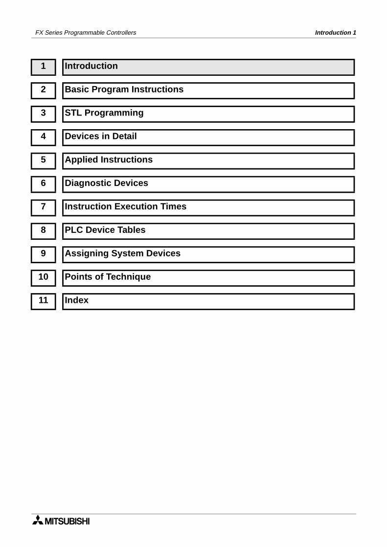
1 Introduction
2 Basic Program Instructions
3 STL Programming
4 Devices in Detail
5 Applied Instructions
6 Diagnostic Devices
7 Instruction Execution Times
8 PLC Device Tables
9 Assigning System Devices
10 Points of Technique
11 Index
FX Series Programmable Controllers Introduction 1
FX Series Programmable Controllers Introduction 1
Chapter Contents
1. Introduction............................................................................................1-11.1 Overview.............................................................................................................. 1-11.2 What is a ProgrammableController? ................................................................... 1-21.3 What do You Need to Program a PC? ................................................................ 1-21.4 Curent Generation CPU’s, All versions ............................................................... 1-31.5 Associated Manuals ............................................................................................ 1-4
Introduction 1
FX1S FX1N FX2N FX2NC
1. Introduction
1.1 Overview
1) Scope of this manualThis manual gives details on all aspects of operation and programming for FX1S, FX1N,FX2N and FX2NC programmable controllers (PLCs). For all information relating to the PLChardware and installation, refer to the appropriate manual supplied with the unit.
2) How to use this manualThis manual covers all the functions of the highest specification Programmable (Logic)Controller (PLC). For this reason, the following indicator is included in relevant section titlesto show which PLCs that section applies to;
Shaded boxes indicate the applicable PLC type
- “FX1S)” - All FX1S PLCs
- “FX1N” - All FX1N PLCs
- “FX2N” - All FX2N PLCs
- “FX2NC” - All FX2NC PLCs
If an indicator box is half shaded, as shown to theleft, this means that not all the functions described inthe current section apply to that PLC. The textexplains in further detail or makes an independentreference.
If there are no indicator boxes then assume the section applies to all PLC types unlessotherwise stated.
3) FX familyThis is a generic term which is often used to describe all Programmable Controllers withoutidentifying individual types or model names.
4) CPU version numbers and programming supportAs Mitsubishi upgrades each model different versions have different capabilities.
- Please refer to section 1.4 for details about peripheral support for each model.
FX1S FX1N FX2N FX2NC
FX1S FX1N FX2N FX2NC
1-1
Introduction 1
1.2 What is a Programmable Controller?
A Programmable Logic Controller (PLC or programmable controller) is a device that a user canprogram to perform a series or sequence of events. These events are triggered by stimuli(usually called inputs) received at the PLC or through delayed actions such as time delays orcounted occur-rences. Once an event triggers, it actuates in the outside world by switching ONor OFF electronic control gear or the physical actuation of devices. A programmable controllerwill continually ‘loop’ through its internal ‘user defined’ program waiting for inputs and givingoutputs at the programmed specific times.
Note on terminology:
The term programmable controller is a generic word used to bring all the elements making thecontrol system under one descriptive name. Sometimes engineers use the term‘Programmable Logic Controller’, ‘PLC’ or ‘programmable controller’ to describe the samecontrol system.The construction of a programmable controller can be broken down into component parts. Theelement where the program is loaded, stored and processed is often known as the MainProcessing Unit or MPU. Other terms commonly heard to describe this device are ‘base unit’,‘controller’ and ‘CPU’. The term CPU is a little misleading as todays more advanced productsmay contain local CPU devices. A Main CPU (or more correctly a Main Processing Unit)controls these local CPUs through a communication network or bus.
1.3 What do You Need to Program a PLC?
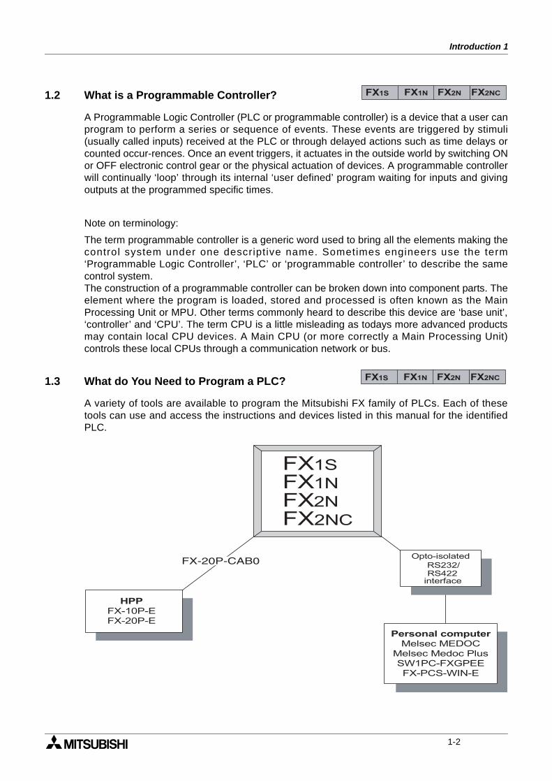
A variety of tools are available to program the Mitsubishi FX family of PLCs. Each of thesetools can use and access the instructions and devices listed in this manual for the identifiedPLC.
FX1S FX1N FX2N FX2NC
FX1S FX1N FX2N FX2NC
HPP
FX-10P-E
FX-20P-E
Personal computer
Melsec MEDOC
Melsec Medoc Plus
SW1PC-FXGPEE
FX-PCS-WIN-E
FX1S
FXFX2NFX1N
2NC
Opto-isolated
RS422interface
RS232/
1-2
Introduction 1
1.4 Special considerations for programming equipment
1.4.1 Current Generation CPU all versions
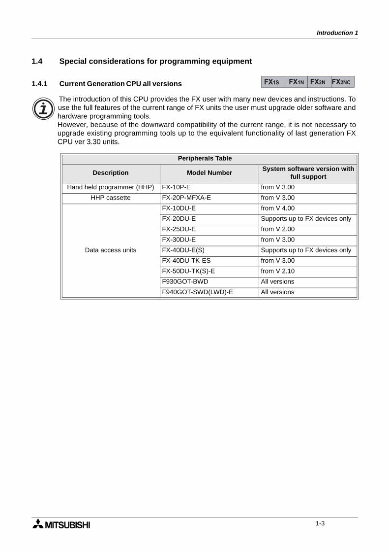
Peripherals Table
Description Model NumberSystem software version with
full support
Hand held programmer (HHP) FX-10P-E from V 3.00
HHP cassette FX-20P-MFXA-E from V 3.00
Data access units
FX-10DU-E from V 4.00
FX-20DU-E Supports up to FX devices only
FX-25DU-E from V 2.00
FX-30DU-E from V 3.00
FX-40DU-E(S) Supports up to FX devices only
FX-40DU-TK-ES from V 3.00
FX-50DU-TK(S)-E from V 2.10
F930GOT-BWD All versions
F940GOT-SWD(LWD)-E All versions
FX1S FX1N FX2N FX2NC
The introduction of this CPU provides the FX user with many new devices and instructions. Touse the full features of the current range of FX units the user must upgrade older software andhardware programming tools.However, because of the downward compatibility of the current range, it is not necessary toupgrade existing programming tools up to the equivalent functionality of last generation FXCPU ver 3.30 units.
1-3
Introduction 1
1.5 Assocciated Manuals
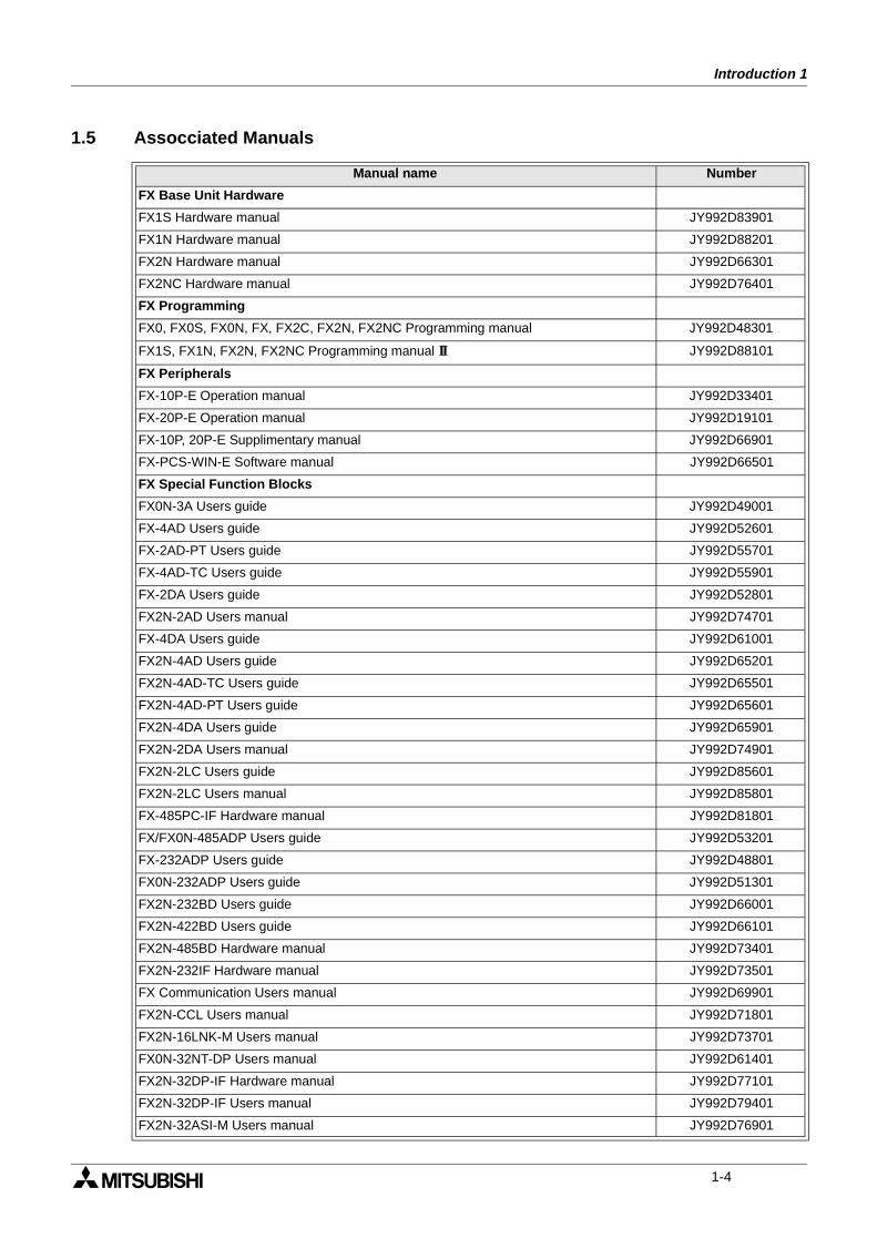
Manual name Number
FX Base Unit Hardware
FX1S Hardware manual JY992D83901
FX1N Hardware manual JY992D88201
FX2N Hardware manual JY992D66301
FX2NC Hardware manual JY992D76401
FX Programming
FX0, FX0S, FX0N, FX, FX2C, FX2N, FX2NC Programming manual JY992D48301
FX1S, FX1N, FX2N, FX2NC Programming manual II JY992D88101
FX Peripherals
FX-10P-E Operation manual JY992D33401
FX-20P-E Operation manual JY992D19101
FX-10P, 20P-E Supplimentary manual JY992D66901
FX-PCS-WIN-E Software manual JY992D66501
FX Special Function Blocks
FX0N-3A Users guide JY992D49001
FX-4AD Users guide JY992D52601
FX-2AD-PT Users guide JY992D55701
FX-4AD-TC Users guide JY992D55901
FX-2DA Users guide JY992D52801
FX2N-2AD Users manual JY992D74701
FX-4DA Users guide JY992D61001
FX2N-4AD Users guide JY992D65201
FX2N-4AD-TC Users guide JY992D65501
FX2N-4AD-PT Users guide JY992D65601
FX2N-4DA Users guide JY992D65901
FX2N-2DA Users manual JY992D74901
FX2N-2LC Users guide JY992D85601
FX2N-2LC Users manual JY992D85801
FX-485PC-IF Hardware manual JY992D81801
FX/FX0N-485ADP Users guide JY992D53201
FX-232ADP Users guide JY992D48801
FX0N-232ADP Users guide JY992D51301
FX2N-232BD Users guide JY992D66001
FX2N-422BD Users guide JY992D66101
FX2N-485BD Hardware manual JY992D73401
FX2N-232IF Hardware manual JY992D73501
FX Communication Users manual JY992D69901
FX2N-CCL Users manual JY992D71801
FX2N-16LNK-M Users manual JY992D73701
FX0N-32NT-DP Users manual JY992D61401
FX2N-32DP-IF Hardware manual JY992D77101
FX2N-32DP-IF Users manual JY992D79401
FX2N-32ASI-M Users manual JY992D76901
1-4
Introduction 1
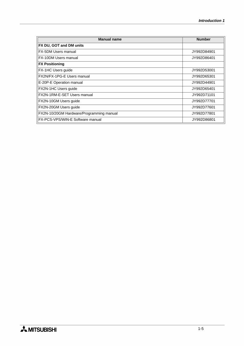
FX DU, GOT and DM units
FX-5DM Users manual JY992D84901
FX-10DM Users manual JY992D86401
FX Positioning
FX-1HC Users guide JY992D53001
FX2N/FX-1PG-E Users manual JY992D65301
E-20P-E Operation manual JY992D44901
FX2N-1HC Users guide JY992D65401
FX2N-1RM-E-SET Users manual JY992D71101
FX2N-10GM Users guide JY992D77701
FX2N-20GM Users guide JY992D77601
FX2N-10/20GM Hardware/Programming manual JY992D77801
FX-PCS-VPS/WIN-E Software manual JY992D86801
Manual name Number
1-5
Introduction 1
Memo
1-6
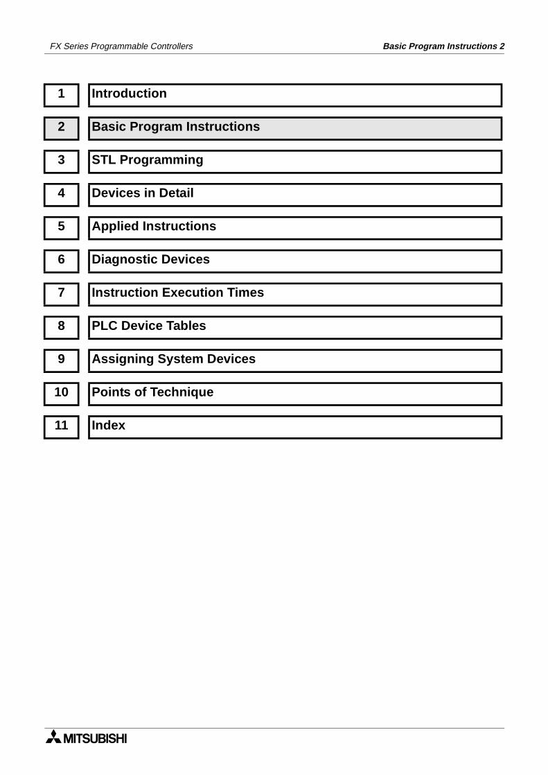
1 Introduction
2 Basic Program Instructions
3 STL Programming
4 Devices in Detail
5 Applied Instructions
6 Diagnostic Devices
7 Instruction Execution Times
8 PLC Device Tables
9 Assigning System Devices
10 Points of Technique
11 Index
FX Series Programmable Controllers Basic Program Instructions 2
FX Series Programmable Controllers Basic Program Instructions 2
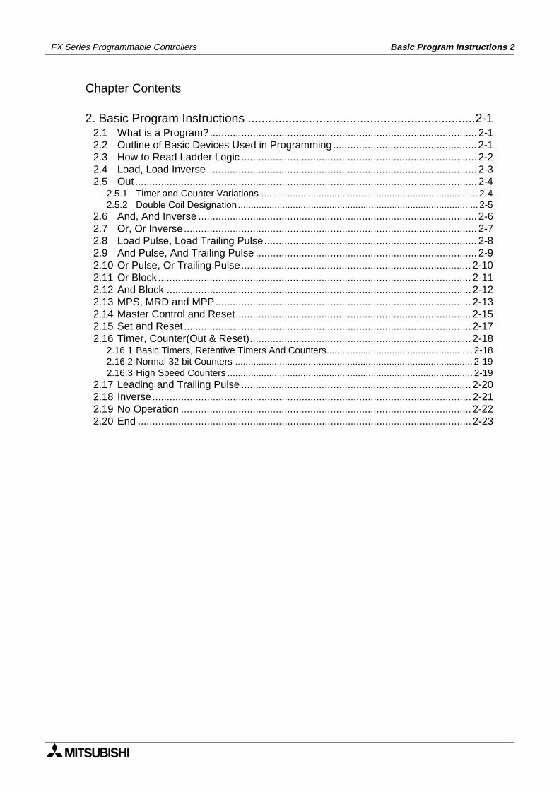
Chapter Contents
2. Basic Program Instructions ...................................................................2-12.1 What is a Program?............................................................................................. 2-12.2 Outline of Basic Devices Used in Programming.................................................. 2-12.3 How to Read Ladder Logic .................................................................................. 2-22.4 Load, Load Inverse.............................................................................................. 2-32.5 Out ....................................................................................................................... 2-4
2.5.1 Timer and Counter Variations ................................................................................... 2-42.5.2 Double Coil Designation ............................................................................................ 2-5
2.6 And, And Inverse ................................................................................................. 2-62.7 Or, Or Inverse...................................................................................................... 2-72.8 Load Pulse, Load Trailing Pulse.......................................................................... 2-82.9 And Pulse, And Trailing Pulse ............................................................................. 2-92.10 Or Pulse, Or Trailing Pulse................................................................................ 2-102.11 Or Block............................................................................................................. 2-112.12 And Block .......................................................................................................... 2-122.13 MPS, MRD and MPP......................................................................................... 2-132.14 Master Control and Reset.................................................................................. 2-152.15 Set and Reset .................................................................................................... 2-172.16 Timer, Counter(Out & Reset)............................................................................. 2-18
2.16.1 Basic Timers, Retentive Timers And Counters........................................................ 2-182.16.2 Normal 32 bit Counters ........................................................................................... 2-192.16.3 High Speed Counters .............................................................................................. 2-19
2.17 Leading and Trailing Pulse ................................................................................ 2-202.18 Inverse............................................................................................................... 2-212.19 No Operation ..................................................................................................... 2-222.20 End .................................................................................................................... 2-23
Basic Program Instructions 2FX Series Programmable Controllers
2. Basic Program Instructions
2.1 What is a Program?
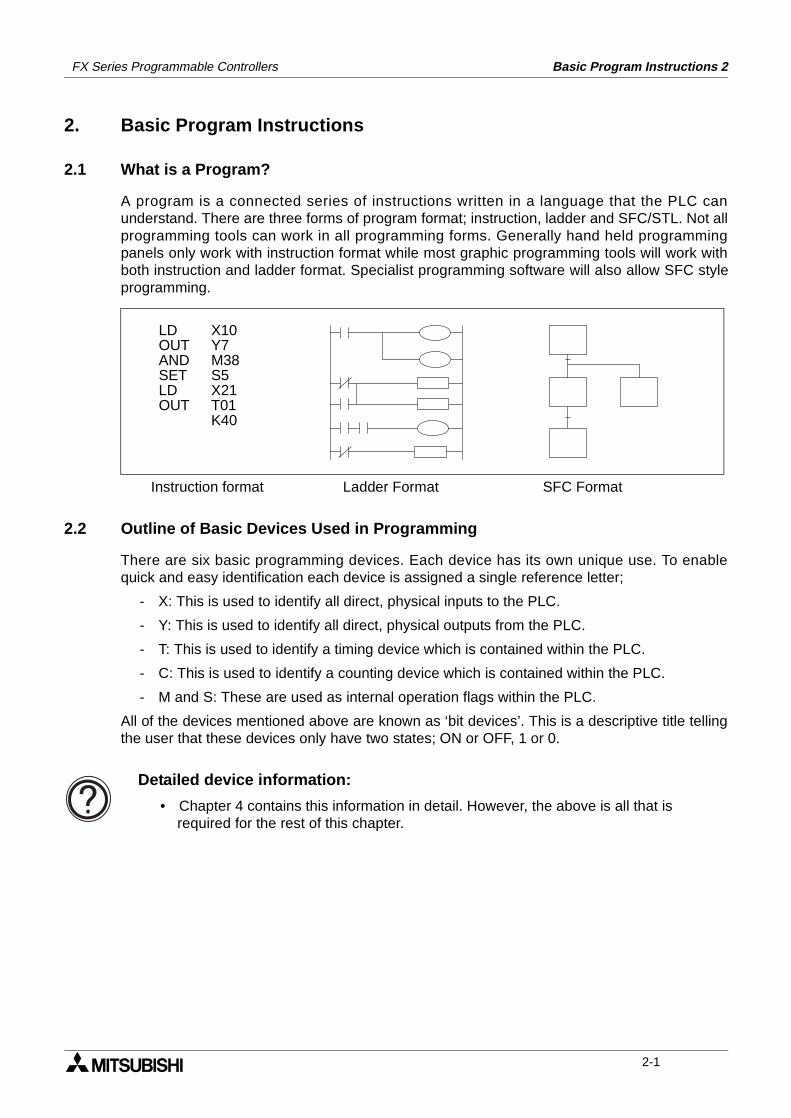
A program is a connected series of instructions written in a language that the PLC canunderstand. There are three forms of program format; instruction, ladder and SFC/STL. Not allprogramming tools can work in all programming forms. Generally hand held programmingpanels only work with instruction format while most graphic programming tools will work withboth instruction and ladder format. Specialist programming software will also allow SFC styleprogramming.
2.2 Outline of Basic Devices Used in Programming
There are six basic programming devices. Each device has its own unique use. To enablequick and easy identification each device is assigned a single reference letter;
- X: This is used to identify all direct, physical inputs to the PLC.
- Y: This is used to identify all direct, physical outputs from the PLC.
- T: This is used to identify a timing device which is contained within the PLC.
- C: This is used to identify a counting device which is contained within the PLC.
- M and S: These are used as internal operation flags within the PLC.
All of the devices mentioned above are known as ‘bit devices’. This is a descriptive title tellingthe user that these devices only have two states; ON or OFF, 1 or 0.
LDOUTANDSETLDOUT
X10Y7M38S5X21T01K40
Instruction format Ladder Format SFC Format
Detailed device information:
• Chapter 4 contains this information in detail. However, the above is all that is required for the rest of this chapter.
2-1
FX Series Programmable Controllers Basic Program Instructions 2
2.3 How to Read Ladder Logic
Ladder logic is very closely associated to basic relay logic. There are both contacts and coilsthat can be loaded and driven in different configurations. However, the basic principle remainsthe same.
A coil drives direct outputs of the PLC (ex. a Y device) or drives internal timers, counters orflags (ex. T, C, M and S devices). Each coil has associated contacts. These contacts areavailable in both “normally open” (NO) and “normally closed” (NC) configurations.
The term “normal(ly)” refers to the status of the contacts when the coil is not energized. Usinga relay analogy, when the coil is OFF, a NO contact would have no current flow, that is, a loadbeing supplied through a NO contact would not operate. However, a NC contact would allowcurrent to flow, hence the connected load would be active.
Activating the coil reverses the contact status, that is, the current would flow in a NO contactand a NC contact would inhibit the flow.
Physical inputs to the PLC (X devices) have no programmable coil. These devices may only beused in a contact format (NO and NC types are available).
Example:
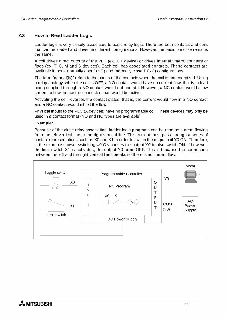
Because of the close relay association, ladder logic programs can be read as current flowingfrom the left vertical line to the right vertical line. This current must pass through a series ofcontact representations such as X0 and X1 in order to switch the output coil Y0 ON. Therefore,in the example shown, switching X0 ON causes the output Y0 to also switch ON. If however,the limit switch X1 is activates, the output Y0 turns OFF. This is because the connectionbetween the left and the right vertical lines breaks so there is no current flow.
X0 X1
Y0
PC ProgramINPUT
OUTPUT
Programmable Controller
DC Power Supply
X0
X1
Y0
ACPowerSupply
COM(Y0)
Toggle switch
Limit switch
Motor
2-2
FX Series Programmable Controllers Basic Program Instructions 2
2.4 Load, Load Inverse
Program example:
Basic points to remember:
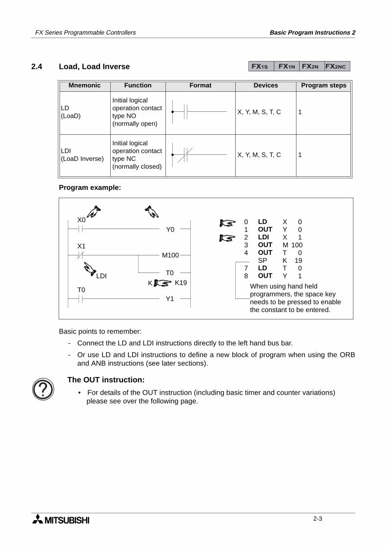
- Connect the LD and LDI instructions directly to the left hand bus bar.
- Or use LD and LDI instructions to define a new block of program when using the ORBand ANB instructions (see later sections).
Mnemonic Function Format Devices Program steps
LD(LoaD)
Initial logical operation contact type NO (normally open)
X, Y, M, S, T, C 1
LDI(LoaD Inverse)
Initial logical operation contact type NC (normally closed)
X, Y, M, S, T, C 1
FX1S FX1N FX2N FX2NC
X0Y0
X1M100
T0
T0Y1
K19LDI
K
XYXMTKTY
LDOUTLDIOUTOUTSPLDOUT
01234
78
001
1000
1901
When using hand heldprogrammers, the space keyneeds to be pressed to enablethe constant to be entered.
The OUT instruction:
• For details of the OUT instruction (including basic timer and counter variations) please see over the following page.
2-3
FX Series Programmable Controllers Basic Program Instructions 2
2.5 Out
Basic points to remember:
- Connect the OUT instruction directly to the right hand bus bar.
- It is not possible to use the OUT instruction to drive ‘X’ type input devices.
- It is possible to connect multiple OUT instructions in parallel (for example see theprevious page; M100/T0 configuration)
2.5.1 Timer and Counter Variations
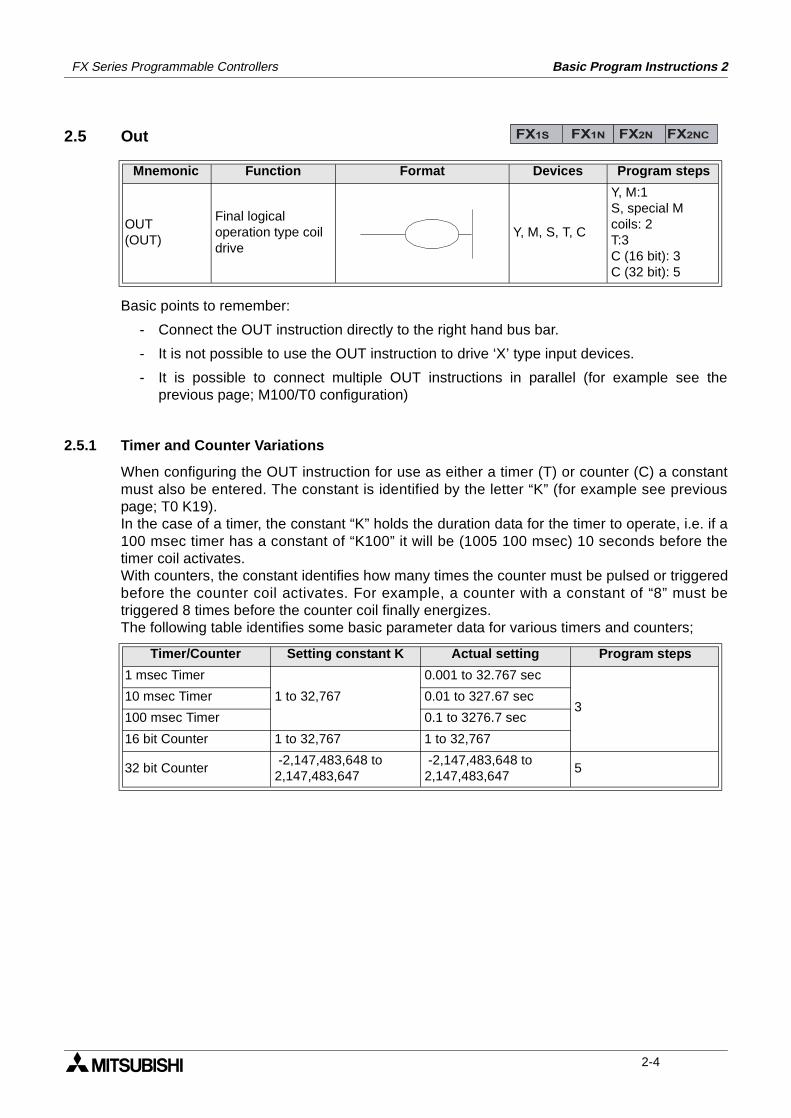
When configuring the OUT instruction for use as either a timer (T) or counter (C) a constantmust also be entered. The constant is identified by the letter “K” (for example see previouspage; T0 K19).In the case of a timer, the constant “K” holds the duration data for the timer to operate, i.e. if a100 msec timer has a constant of “K100” it will be (1005 100 msec) 10 seconds before thetimer coil activates.With counters, the constant identifies how many times the counter must be pulsed or triggeredbefore the counter coil activates. For example, a counter with a constant of “8” must betriggered 8 times before the counter coil finally energizes.The following table identifies some basic parameter data for various timers and counters;
Mnemonic Function Format Devices Program steps
OUT(OUT)
Final logical operation type coil drive
Y, M, S, T, C
Y, M:1S, special Mcoils: 2T:3C (16 bit): 3C (32 bit): 5
Timer/Counter Setting constant K Actual setting Program steps
1 msec Timer
1 to 32,767
0.001 to 32.767 sec
310 msec Timer 0.01 to 327.67 sec
100 msec Timer 0.1 to 3276.7 sec
16 bit Counter 1 to 32,767 1 to 32,767
32 bit Counter -2,147,483,648 to2,147,483,647
-2,147,483,648 to 2,147,483,647
5
FX1S FX1N FX2N FX2NC
2-4
FX Series Programmable Controllers Basic Program Instructions 2
2.5.2 Double Coil Designation
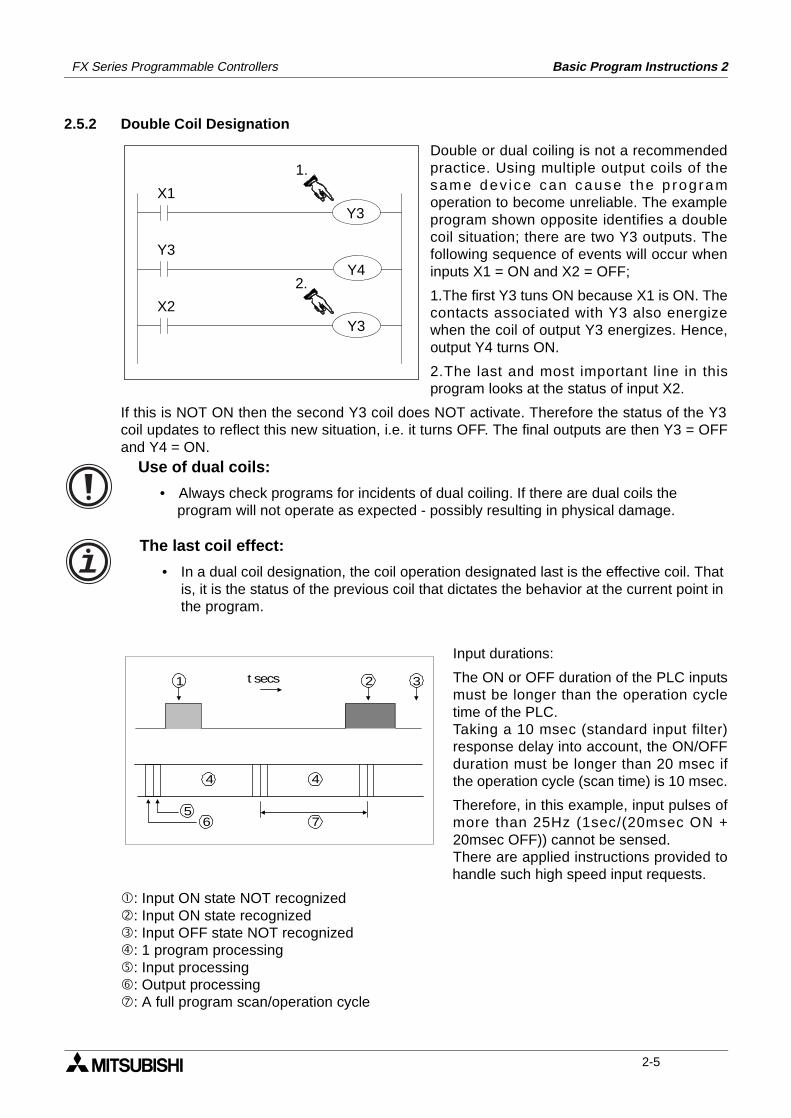
Double or dual coiling is not a recommendedpractice. Using multiple output coils of thesame dev ice can cause the p rogramoperation to become unreliable. The exampleprogram shown opposite identifies a doublecoil situation; there are two Y3 outputs. Thefollowing sequence of events will occur wheninputs X1 = ON and X2 = OFF;
1.The first Y3 tuns ON because X1 is ON. Thecontacts associated with Y3 also energizewhen the coil of output Y3 energizes. Hence,output Y4 turns ON.
2.The last and most important line in thisprogram looks at the status of input X2.
If this is NOT ON then the second Y3 coil does NOT activate. Therefore the status of the Y3coil updates to reflect this new situation, i.e. it turns OFF. The final outputs are then Y3 = OFFand Y4 = ON.
Input durations:
The ON or OFF duration of the PLC inputsmust be longer than the operation cycletime of the PLC.Taking a 10 msec (standard input filter)response delay into account, the ON/OFFduration must be longer than 20 msec ifthe operation cycle (scan time) is 10 msec.
Therefore, in this example, input pulses ofmore than 25Hz (1sec/(20msec ON +20msec OFF)) cannot be sensed.There are applied instructions provided tohandle such high speed input requests.
: Input ON state NOT recognized: Input ON state recognized: Input OFF state NOT recognized: 1 program processing: Input processing: Output processing: A full program scan/operation cycle
X1
Y3
X2
1.
2.
Y3
Y3
Y4
Use of dual coils:
• Always check programs for incidents of dual coiling. If there are dual coils the program will not operate as expected - possibly resulting in physical damage.
The last coil effect:
• In a dual coil designation, the coil operation designated last is the effective coil. That is, it is the status of the previous coil that dictates the behavior at the current point in the program.
1 2 3
56
4 4
7
t secs
2-5
FX Series Programmable Controllers Basic Program Instructions 2
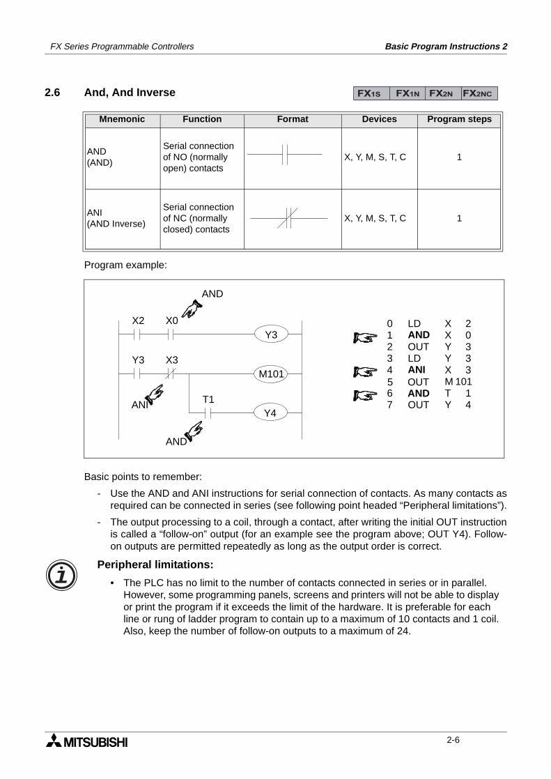
2.6 And, And Inverse
Program example:
Basic points to remember:
- Use the AND and ANI instructions for serial connection of contacts. As many contacts asrequired can be connected in series (see following point headed “Peripheral limitations”).
- The output processing to a coil, through a contact, after writing the initial OUT instructionis called a “follow-on” output (for an example see the program above; OUT Y4). Follow-on outputs are permitted repeatedly as long as the output order is correct.
Mnemonic Function Format Devices Program steps
AND(AND)
Serial connection of NO (normally open) contacts
X, Y, M, S, T, C 1
ANI(AND Inverse)
Serial connection of NC (normally closed) contacts
X, Y, M, S, T, C 1
FX1S FX1N FX2N FX2NC
XXYYXMTY
X2
Y3
AND
X0
X3
T1ANI
AND
20333
10114
LDANDOUTLDANI
OUT
OUTAND
01234
67
5
Y3
M101
Y4
Peripheral limitations:
• The PLC has no limit to the number of contacts connected in series or in parallel. However, some programming panels, screens and printers will not be able to display or print the program if it exceeds the limit of the hardware. It is preferable for each line or rung of ladder program to contain up to a maximum of 10 contacts and 1 coil. Also, keep the number of follow-on outputs to a maximum of 24.
2-6

FX Series Programmable Controllers Basic Program Instructions 2
2.7 Or, Or Inverse
Program example:
Basic points to remember:
- Use the OR and ORI instructions for parallel connection of contacts. To connect a blockthat contains more than one contact connected in series to another circuit block inparallel, use an ORB instruction.
- Connect one side of the OR/ORI instruction to the left hand bus bar.
Mnemonic Function Format Devices Program steps
OR(OR)
Parallel connection of NO (normally open) contacts
X, Y, M, S, T, C 1
ORI(OR Inverse)
Parallel connection of NC (normally closed) contacts
X, Y, M, S, T, C 1
FX1S FX1N FX2N FX2NC
X4
X6
M102
Y5 X7 X10
M103
M110
OR
ORI
LDORORIOUTLDI
ANI
ANDOR
01234
67
5
89
OROUT
XXMYYXMXMM
46
10255
10310
7
110103
Y5
M103
Peripheral limitations:
• The PLC has no limit to the number of contacts connected in series or in parallel. However, some programming panels, screens and printers will not be able to display or print the program if it exceeds the limit of the hardware. It is preferable for each line or rung of ladder program to contain up to a maximum of 10 contacts and 1 coil. Also keep number of follow-on outputs to a maximum of 24.
2-7
FX Series Programmable Controllers Basic Program Instructions 2
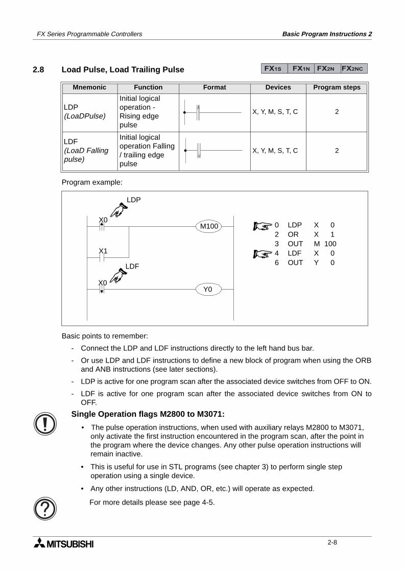
2.8 Load Pulse, Load Trailing Pulse
Program example:
Basic points to remember:
- Connect the LDP and LDF instructions directly to the left hand bus bar.
- Or use LDP and LDF instructions to define a new block of program when using the ORBand ANB instructions (see later sections).
- LDP is active for one program scan after the associated device switches from OFF to ON.
- LDF is active for one program scan after the associated device switches from ON toOFF.
Mnemonic Function Format Devices Program steps
LDP(LoaDPulse)
Initial logical operation - Rising edge pulse
X, Y, M, S, T, C 2
LDF(LoaD Falling pulse)
Initial logical operation Falling / trailing edge pulse
X, Y, M, S, T, C 2
FX1S FX1N FX2N FX2NC
LDF
LDP
X0
Y0
M100
X1
X0
0 LDP X 02 OR X 13 OUT M 1004 LDF X 06 OUT Y 0
Single Operation flags M2800 to M3071:
• The pulse operation instructions, when used with auxiliary relays M2800 to M3071, only activate the first instruction encountered in the program scan, after the point in the program where the device changes. Any other pulse operation instructions will remain inactive.
• This is useful for use in STL programs (see chapter 3) to perform single step operation using a single device.
• Any other instructions (LD, AND, OR, etc.) will operate as expected.
For more details please see page 4-5.
2-8
FX Series Programmable Controllers Basic Program Instructions 2
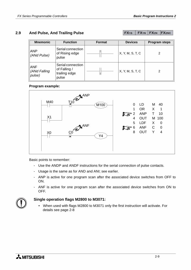
2.9 And Pulse, And Trailing Pulse
Program example:
Basic points to remember:
- Use the ANDP and ANDF instructions for the serial connection of pulse contacts.
- Usage is the same as for AND and ANI; see earlier.
- ANP is active for one program scan after the associated device switches from OFF toON.
- ANF is active for one program scan after the associated device switches from ON toOFF.
Mnemonic Function Format Devices Program steps
ANP(ANd Pulse)
Serial connection of Rising edge pulse
X, Y, M, S, T, C 2
ANF(ANd Falling pulse)
Serial connection of Falling / trailing edge pulse
X, Y, M, S, T, C 2
FX1S FX1N FX2N FX2NC
ANP
T10
Y4
M100
X1
X0
0 LD M 401 OR X 12 ANP T 104 OUT M 1005 LDF X 06 ANF C 08 OUT Y 4
M40
ANF
C0
Single operation flags M2800 to M3071:
• When used with flags M2800 to M3071 only the first instruction will activate. For details see page 2-8
2-9
FX Series Programmable Controllers Basic Program Instructions 2
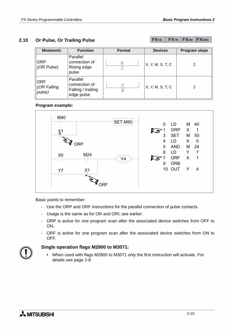
2.10 Or Pulse, Or Trailing Pulse
Program example:
Basic points to remember:
- Use the ORP and ORF instructions for the parallel connection of pulse contacts.
- Usage is the same as for OR and ORI; see earlier.
- ORP is active for one program scan after the associated device switches from OFF toON.
- ORF is active for one program scan after the associated device switches from ON toOFF.
Mnemonic Function Format Devices Program steps
ORP(OR Pulse)
Parallel connection of Rising edge pulse
X, Y, M, S, T, C 2
ORF(OR Falling pulse)
Parallel connection of Falling / trailing edge pulse
X, Y, M, S, T, C 2
FX1S FX1N FX2N FX2NC
ORP
Y4
X1
X0
0 LD M 401 ORP X 13 SET M 504 LD X 05 AND M 246 LD Y 77 ORF X 19 ORB10 OUT Y 4
M40
ORF
M24
SET M50
X1Y7
Single operation flags M2800 to M3071:
• When used with flags M2800 to M3071 only the first instruction will activate. For details see page 2-8
2-10
FX Series Programmable Controllers Basic Program Instructions 2
2.11 Or Block
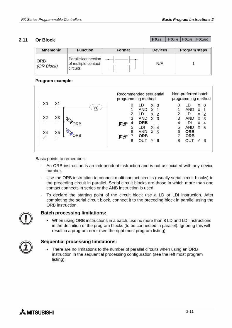
Program example:
Basic points to remember:
- An ORB instruction is an independent instruction and is not associated with any devicenumber.
- Use the ORB instruction to connect multi-contact circuits (usually serial circuit blocks) tothe preceding circuit in parallel. Serial circuit blocks are those in which more than onecontact connects in series or the ANB instruction is used.
- To declare the starting point of the circuit block use a LD or LDI instruction. Aftercompleting the serial circuit block, connect it to the preceding block in parallel using theORB instruction.
Mnemonic Function Format Devices Program steps
ORB(OR Block)
Parallel connection of multiple contact circuits
N/A 1
FX1S FX1N FX2N FX2NC
X0 X1
X2 X3
ORB
X4 X5ORB
LDANDLDANDORB
ORB
LDIAND
01234
67
5
8 OUT
XXXX
X
0123
4
Y
X 5
6
LDANDLDANDLDI
ORB
ANDORB
01234
67
5
8 OUT
XXXX
X
0123
5
Y 6
X 4
Recommended sequentialprogramming method
Non-preferred batchprogramming method
Y6
Batch processing limitations:
• When using ORB instructions in a batch, use no more than 8 LD and LDI instructions in the definition of the program blocks (to be connected in parallel). Ignoring this will result in a program error (see the right most program listing).
Sequential processing limitations:
• There are no limitations to the number of parallel circuits when using an ORB instruction in the sequential processing configuration (see the left most program listing).
2-11
FX Series Programmable Controllers Basic Program Instructions 2
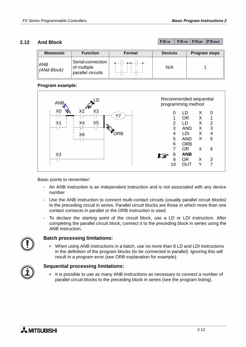
2.12 And Block
Program example:
Basic points to remember:
- An ANB instruction is an independent instruction and is not associated with any devicenumber
- Use the ANB instruction to connect multi-contact circuits (usually parallel circuit blocks)to the preceding circuit in series. Parallel circuit blocks are those in which more than onecontact connects in parallel or the ORB instruction is used.
- To declare the starting point of the circuit block, use a LD or LDI instruction. Aftercompleting the parallel circuit block, connect it to the preceding block in series using theANB instruction.
Mnemonic Function Format Devices Program steps
ANB(ANd Block)
Serial connection of multiple parallel circuits
N/A 1
FX1S FX1N FX2N FX2NC
X0
X1
X3
X2 X3
X4 X5
X6
ANBLD
ORB
LDORLDANDLDI
OR
ANDORB
01234
67
5
8 ANB
XXXXXX
X
01234
6
5
910
OROUT
XY
37
Recommended sequentialprogramming method
Y7
Batch processing limitations:
• When using ANB instructions in a batch, use no more than 8 LD and LDI instructions in the definition of the program blocks (to be connected in parallel). Ignoring this will result in a program error (see ORB explanation for example).
Sequential processing limitations:
• It is possible to use as many ANB instructions as necessary to connect a number of parallel circuit blocks to the preceding block in series (see the program listing).
2-12
FX Series Programmable Controllers Basic Program Instructions 2
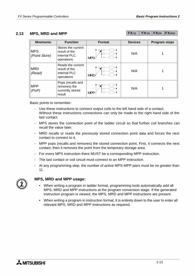
2.13 MPS, MRD and MPP
Basic points to remember:
- Use these instructions to connect output coils to the left hand side of a contact.Without these instructions connections can only be made to the right hand side of thelast contact.
- MPS stores the connection point of the ladder circuit so that further coil branches canrecall the value later.
- MRD recalls or reads the previously stored connection point data and forces the nextcontact to connect to it.
- MPP pops (recalls and removes) the stored connection point. First, it connects the nextcontact, then it removes the point from the temporary storage area.
- For every MPS instruction there MUST be a corresponding MPP instruction.
- The last contact or coil circuit must connect to an MPP instruction.
- At any programming step, the number of active MPS-MPP pairs must be no greater than11.
Mnemonic Function Format Devices Program steps
MPS(Point Store)
Stores the current result of the internal PLC operations
N/A 1
MRD(Read)
Reads the current result of the internal PLC operations
N/A 1
MPP(PoP)
Pops (recalls and removes) the currently stored result
N/A 1
FX1S FX1N FX2N FX2NC
MPS
MRD
MPP
MPS, MRD and MPP usage:
• When writing a program in ladder format, programming tools automatically add all MPS, MRD and MPP instructions at the program conversion stage. If the generated instruction program is viewed, the MPS, MRD and MPP instructions are present.
• When writing a program in instruction format, it is entirely down to the user to enter all relevant MPS, MRD and MPP instructions as required.
2-13
FX Series Programmable Controllers Basic Program Instructions 2
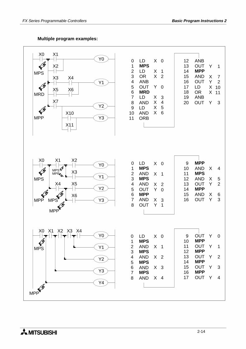
Multiple program examples:
X0 X1
X2
X4
X6
X7
X3
X5
X10
X11
MPS
MRD
MPP
X0 X1
X3
X2
X4 X5
X6
MPS
MPP
MPP
MPS
X0 X1 X2 X3 X4
MPP
MPS
MPSMPP
1
7
10
3
2
11
Y
X
X
Y
Y
X
ANBOUTMPPANDOUT
ANB
LDOR
OUT
1213141516
1819
17
20
01234
67
5
89
1011
LDMPSLDORANB
LD
OUTMRD
ANDLDANDORB
X
XX
Y
XX
XX
0
12
0
43
56
01234
67
5
8
LDMPSANDMPSAND
AND
OUTMPP
OUT
X
X
Y
YX
X
0
1
0
13
2
910111213141516
MPPANDMPSANDOUTMPPANDOUT
X
XY
XY
4
52
63
LDMPSANDMPSAND
MPS
MPSAND
AND
01234
67
5
8
X
X
X
X
X
0
1
2
3
4
910111213141516
OUTMPPOUTMPPOUTMPPOUTMPP
17 OUT
Y
Y
Y
Y
Y
0
1
2
3
4
Y0
Y1
Y2
Y3
Y0
Y1
Y2
Y3
Y0
Y1
Y2
Y3
Y4
2-14
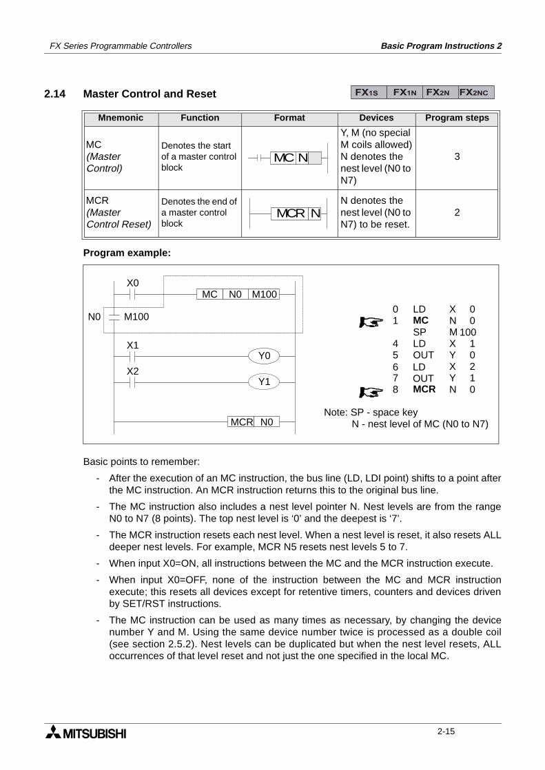
FX Series Programmable Controllers Basic Program Instructions 2
2.14 Master Control and Reset
Program example:
Basic points to remember:
- After the execution of an MC instruction, the bus line (LD, LDI point) shifts to a point afterthe MC instruction. An MCR instruction returns this to the original bus line.
- The MC instruction also includes a nest level pointer N. Nest levels are from the rangeN0 to N7 (8 points). The top nest level is ‘0’ and the deepest is ‘7’.
- The MCR instruction resets each nest level. When a nest level is reset, it also resets ALLdeeper nest levels. For example, MCR N5 resets nest levels 5 to 7.
- When input X0=ON, all instructions between the MC and the MCR instruction execute.
- When input X0=OFF, none of the instruction between the MC and MCR instructionexecute; this resets all devices except for retentive timers, counters and devices drivenby SET/RST instructions.
- The MC instruction can be used as many times as necessary, by changing the devicenumber Y and M. Using the same device number twice is processed as a double coil(see section 2.5.2). Nest levels can be duplicated but when the nest level resets, ALLoccurrences of that level reset and not just the one specified in the local MC.
Mnemonic Function Format Devices Program steps
MC(Master Control)
Denotes the start of a master control block
Y, M (no special M coils allowed)N denotes the nest level (N0 to N7)
3
MCR(MasterControl Reset)
Denotes the end of a master control block
N denotes the nest level (N0 to N7) to be reset.
2
FX1S FX1N FX2N FX2NC
MC N
MCR N
X0
X1
M100N0MC
X2
N0MCR
M100N0XNMXYXYN
00
10010210
LDMCSPLDOUT
MCR
LDOUT
01
45
78
6
Note: SP - space key N - nest level of MC (N0 to N7)
Y1
Y0
2-15
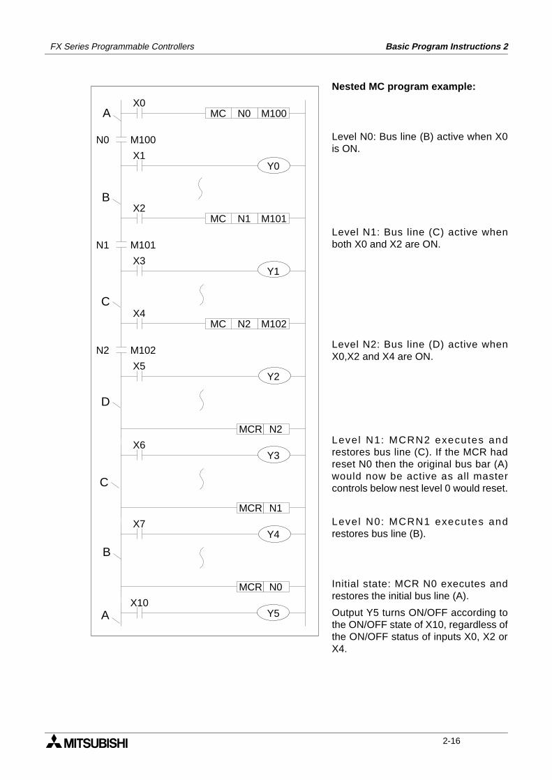
FX Series Programmable Controllers Basic Program Instructions 2
Nested MC program example:
Level N0: Bus line (B) active when X0is ON.
Level N1: Bus line (C) active whenboth X0 and X2 are ON.
Level N2: Bus line (D) active whenX0,X2 and X4 are ON.
Level N1: MCRN2 executes andrestores bus line (C). If the MCR hadreset N0 then the original bus bar (A)would now be active as all mastercontrols below nest level 0 would reset.
Level N0: MCRN1 executes andrestores bus line (B).
Initial state: MCR N0 executes andrestores the initial bus line (A).
Output Y5 turns ON/OFF according tothe ON/OFF state of X10, regardless ofthe ON/OFF status of inputs X0, X2 orX4.
X0
X1
M100N0MC
MCR
M100N0
X2
X3
M101N1MC
M101N1
X4
X5
M102N2MC
M102N2
MCR
X6
MCR
X7
X10
D
C
C
B
B
A
A
Y0
N2
Y1
Y2
N1
Y3
N0
Y4
Y5
2-16
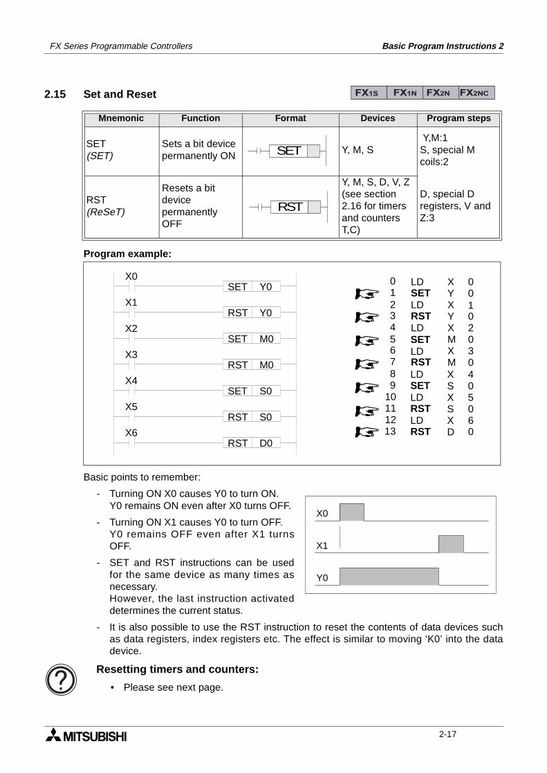
FX Series Programmable Controllers Basic Program Instructions 2
2.15 Set and Reset
Program example:
Basic points to remember:
- Turning ON X0 causes Y0 to turn ON.Y0 remains ON even after X0 turns OFF.
- Turning ON X1 causes Y0 to turn OFF.Y0 remains OFF even after X1 turnsOFF.
- SET and RST instructions can be usedfor the same device as many times asnecessary.However, the last instruction activateddetermines the current status.
- It is also possible to use the RST instruction to reset the contents of data devices suchas data registers, index registers etc. The effect is similar to moving ‘K0’ into the datadevice.
Mnemonic Function Format Devices Program steps
SET(SET)
Sets a bit device permanently ON
Y, M, S Y,M:1S, special Mcoils:2
RST(ReSeT)
Resets a bit device permanently OFF
Y, M, S, D, V, Z(see section 2.16 for timers and counters T,C)
D, special Dregisters, V and Z:3
FX1S FX1N FX2N FX2NC
SET
RST
X0SET Y0
X1RST Y0
X2SET M0
X3RST M0
X4SET S0
X5RST S0
X6RST D0
XYXYXMXM
00
02030
LDSETLDRSTLD
RST
SETLD
01
34
67
5
2
89
101112
LDSETLDRSTLDRST13
XSXSXD
1
405060
X0
X1
Y0
Resetting timers and counters:
• Please see next page.
2-17
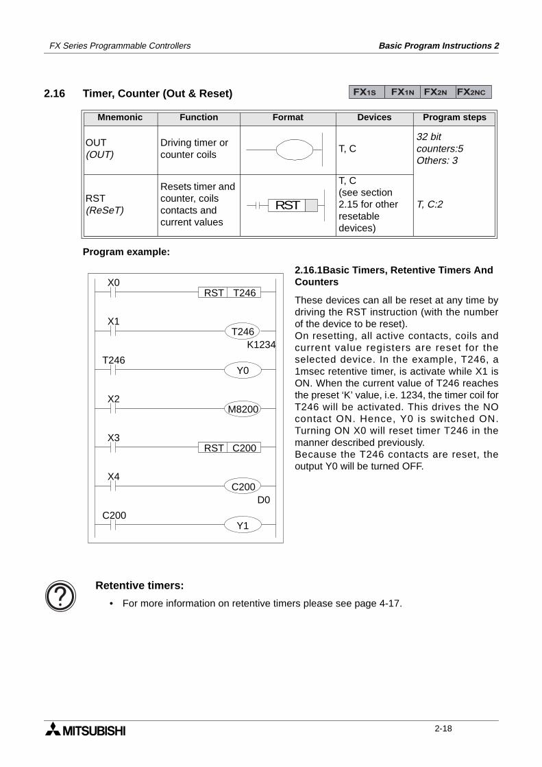
FX Series Programmable Controllers Basic Program Instructions 2
2.16 Timer, Counter (Out & Reset)
Program example:
2.16.1Basic Timers, Retentive Timers And Counters
These devices can all be reset at any time bydriving the RST instruction (with the numberof the device to be reset).On resetting, all active contacts, coils andcurrent value registers are reset for theselected device. In the example, T246, a1msec retentive timer, is activate while X1 isON. When the current value of T246 reachesthe preset ‘K’ value, i.e. 1234, the timer coil forT246 will be activated. This drives the NOcontact ON. Hence, Y0 is switched ON.Turning ON X0 will reset timer T246 in themanner described previously.Because the T246 contacts are reset, theoutput Y0 will be turned OFF.
Mnemonic Function Format Devices Program steps
OUT(OUT)
Driving timer or counter coils
T, C32 bitcounters:5Others: 3
RST(ReSeT)
Resets timer and counter, coils contacts and current values
T, C(see section 2.15 for other resetable devices)
T, C:2
FX1S FX1N FX2N FX2NC
RST
X0RST T246
X1
K1234
T246
X2
X3RST
X4
D0
C200
T246
Y0
M8200
C200
C200
Y1
Retentive timers:
• For more information on retentive timers please see page 4-17.
2-18
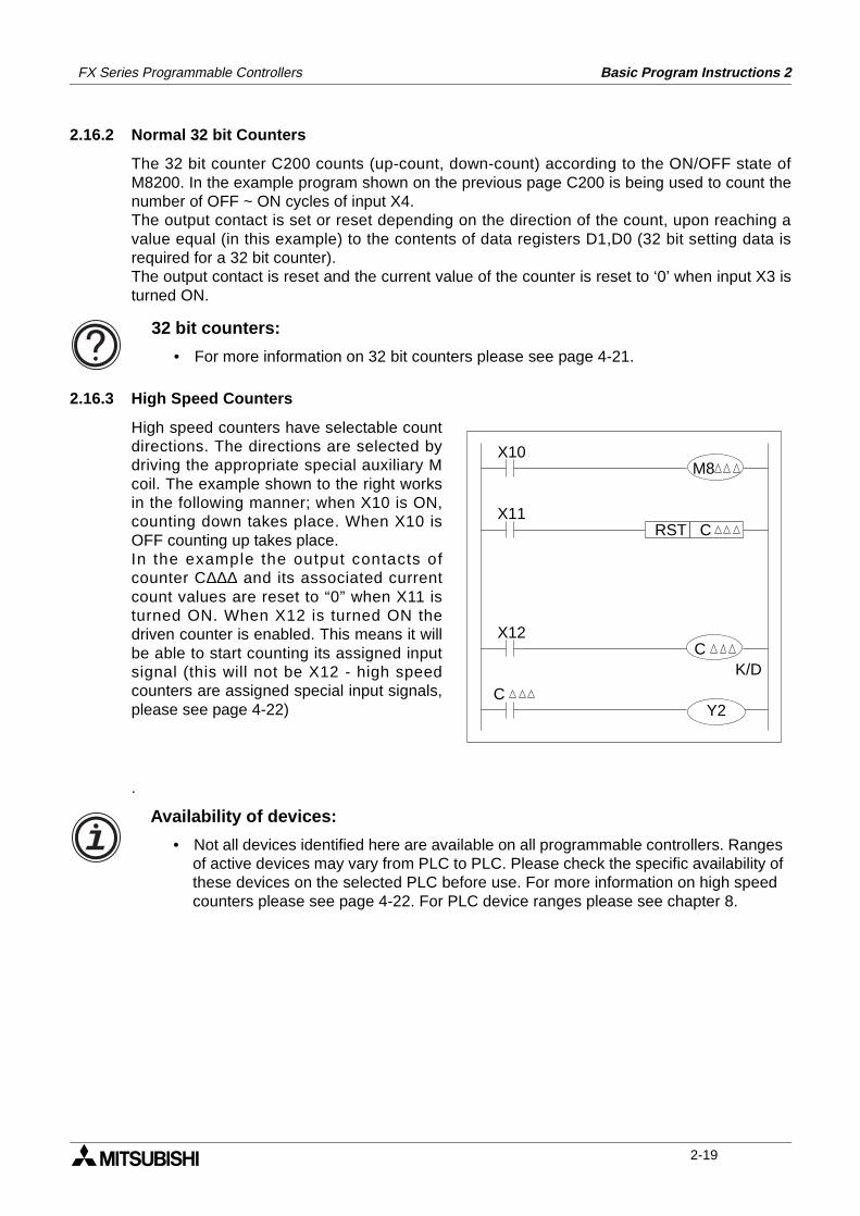
FX Series Programmable Controllers Basic Program Instructions 2
2.16.2 Normal 32 bit Counters
The 32 bit counter C200 counts (up-count, down-count) according to the ON/OFF state ofM8200. In the example program shown on the previous page C200 is being used to count thenumber of OFF ~ ON cycles of input X4.The output contact is set or reset depending on the direction of the count, upon reaching avalue equal (in this example) to the contents of data registers D1,D0 (32 bit setting data isrequired for a 32 bit counter).The output contact is reset and the current value of the counter is reset to ‘0’ when input X3 isturned ON.
2.16.3 High Speed Counters
High speed counters have selectable countdirections. The directions are selected bydriving the appropriate special auxiliary Mcoil. The example shown to the right worksin the following manner; when X10 is ON,counting down takes place. When X10 isOFF counting up takes place.In the example the output contacts ofcounter C∆∆∆ and its associated currentcount values are reset to “0” when X11 isturned ON. When X12 is turned ON thedriven counter is enabled. This means it willbe able to start counting its assigned inputsignal (this will not be X12 - high speedcounters are assigned special input signals,please see page 4-22)
.
32 bit counters:
• For more information on 32 bit counters please see page 4-21.
X10
X11RST
X12
K/D
C
M8
C
C
Y2
Availability of devices:
• Not all devices identified here are available on all programmable controllers. Ranges of active devices may vary from PLC to PLC. Please check the specific availability of these devices on the selected PLC before use. For more information on high speed counters please see page 4-22. For PLC device ranges please see chapter 8.
2-19
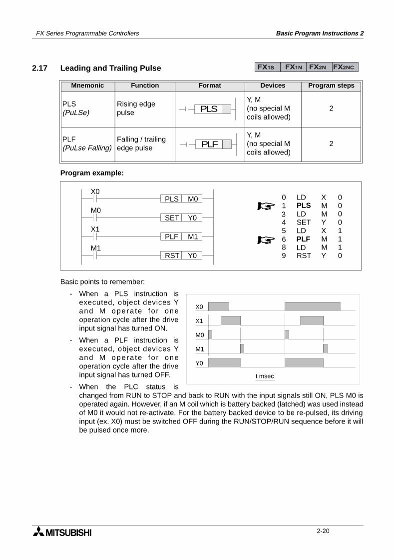
FX Series Programmable Controllers Basic Program Instructions 2
2.17 Leading and Trailing Pulse
Program example:
Basic points to remember:
- When a PLS instruction isexecuted, object devices Yand M opera te fo r oneoperation cycle after the driveinput signal has turned ON.
- When a PLF instruction isexecuted, object devices Yand M opera te fo r oneoperation cycle after the driveinput signal has turned OFF.
- When the PLC status ischanged from RUN to STOP and back to RUN with the input signals still ON, PLS M0 isoperated again. However, if an M coil which is battery backed (latched) was used insteadof M0 it would not re-activate. For the battery backed device to be re-pulsed, its drivinginput (ex. X0) must be switched OFF during the RUN/STOP/RUN sequence before it willbe pulsed once more.
Mnemonic Function Format Devices Program steps
PLS(PuLSe)
Rising edge pulse
Y, M(no special M coils allowed)
2
PLF(PuLse Falling)
Falling / trailing edge pulse
Y, M(no special M coils allowed)
2
FX1S FX1N FX2N FX2NC
PLS
PLF
X0PLS M0
M0SET Y0
X1PLF M1
M1RST Y0
00
01110
LDPLSLDSETLD
RST
PLFLD
01
45
89
6
3 0
XM
MMY
MYX
X0
X1
M0
M1
Y0
t msec
2-20
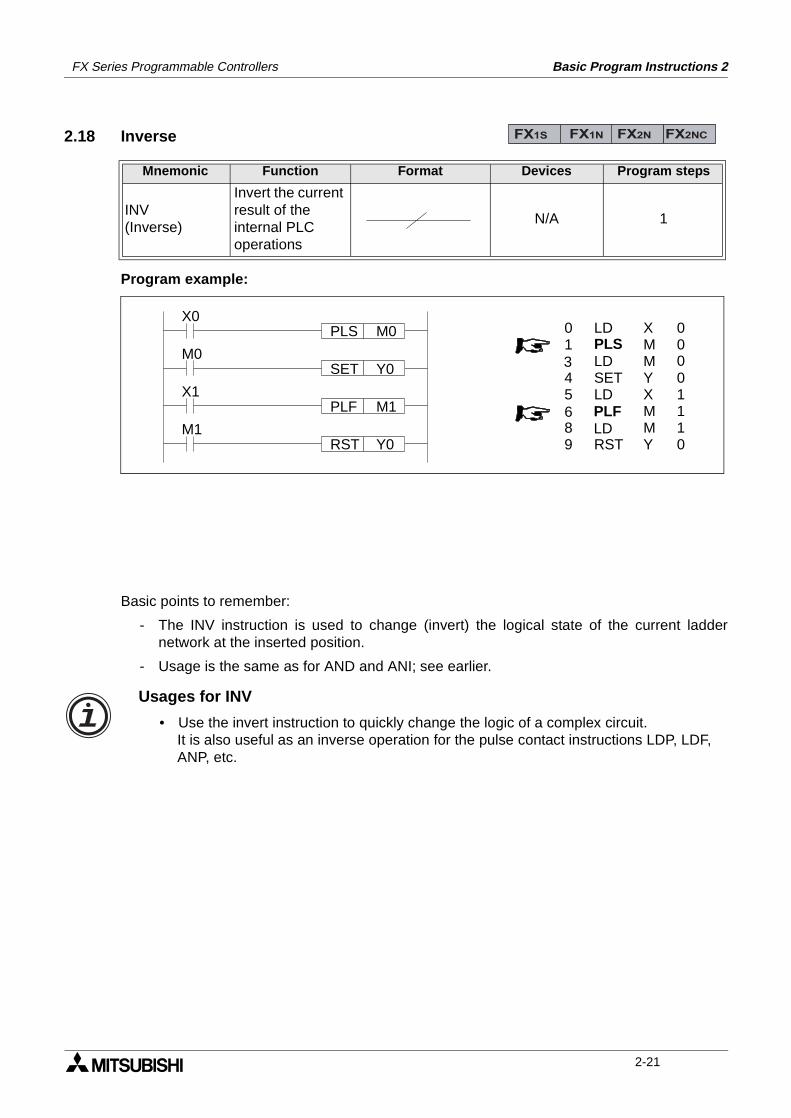
FX Series Programmable Controllers Basic Program Instructions 2
2.18 Inverse
Program example:
Basic points to remember:
- The INV instruction is used to change (invert) the logical state of the current laddernetwork at the inserted position.
- Usage is the same as for AND and ANI; see earlier.
Mnemonic Function Format Devices Program steps
INV(Inverse)
Invert the current result of the internal PLC operations
N/A 1
FX1S FX1N FX2N FX2NC
X0PLS M0
M0SET Y0
X1PLF M1
M1RST Y0
00
01110
LDPLSLDSETLD
RST
PLFLD
01
45
89
6
3 0
XM
MMY
MYX
Usages for INV
• Use the invert instruction to quickly change the logic of a complex circuit.It is also useful as an inverse operation for the pulse contact instructions LDP, LDF, ANP, etc.
2-21
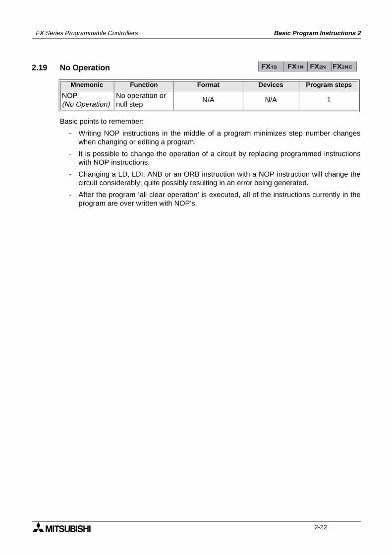
FX Series Programmable Controllers Basic Program Instructions 2
2.19 No Operation
Basic points to remember:
- Writing NOP instructions in the middle of a program minimizes step number changeswhen changing or editing a program.
- It is possible to change the operation of a circuit by replacing programmed instructionswith NOP instructions.
- Changing a LD, LDI, ANB or an ORB instruction with a NOP instruction will change thecircuit considerably; quite possibly resulting in an error being generated.
- After the program ‘all clear operation’ is executed, all of the instructions currently in theprogram are over written with NOP’s.
Mnemonic Function Format Devices Program steps
NOP(No Operation)
No operation or null step
N/A N/A 1
FX1S FX1N FX2N FX2NC
2-22
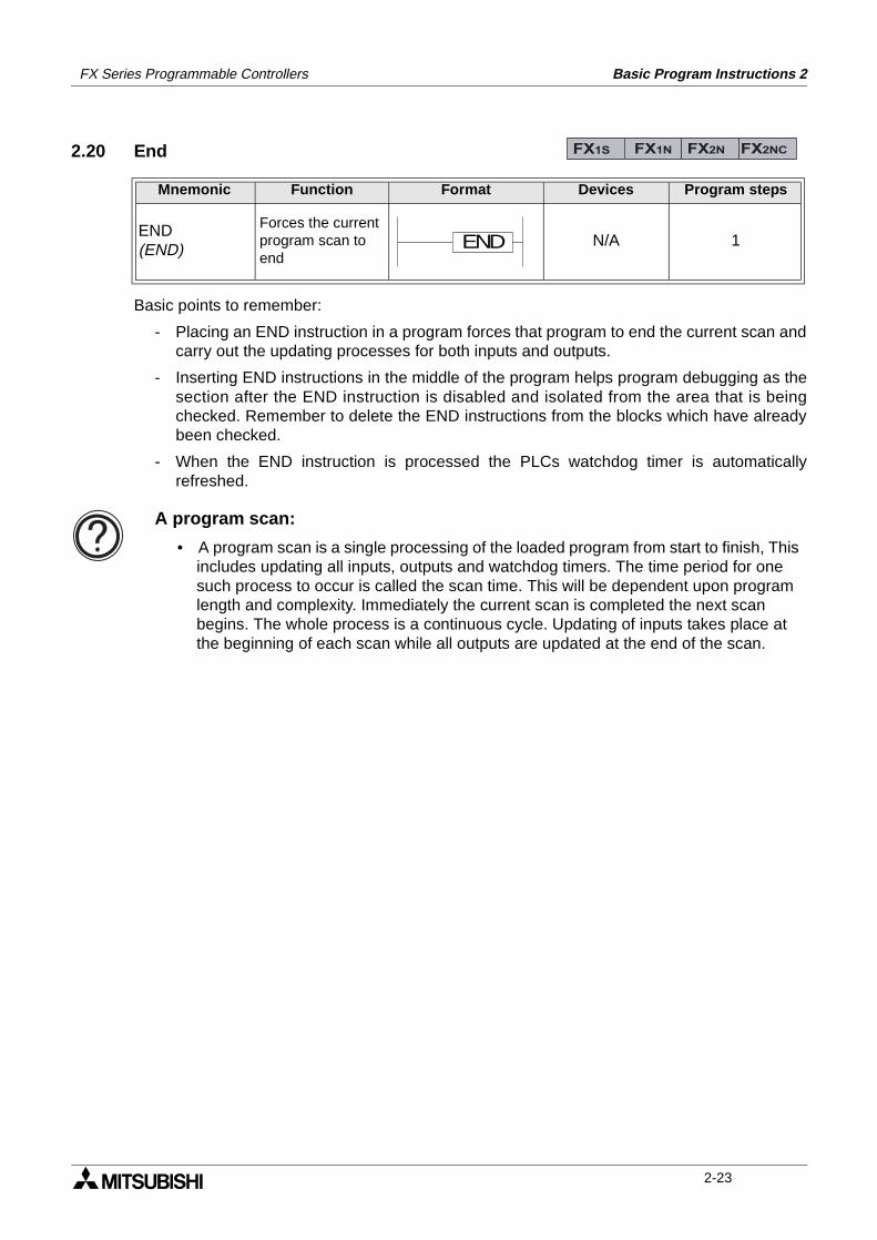
FX Series Programmable Controllers Basic Program Instructions 2
2.20 End
Basic points to remember:
- Placing an END instruction in a program forces that program to end the current scan andcarry out the updating processes for both inputs and outputs.
- Inserting END instructions in the middle of the program helps program debugging as thesection after the END instruction is disabled and isolated from the area that is beingchecked. Remember to delete the END instructions from the blocks which have alreadybeen checked.
- When the END instruction is processed the PLCs watchdog timer is automaticallyrefreshed.
Mnemonic Function Format Devices Program steps
END(END)
Forces the current program scan to end
N/A 1
FX1S FX1N FX2N FX2NC
END
A program scan:
• A program scan is a single processing of the loaded program from start to finish, This includes updating all inputs, outputs and watchdog timers. The time period for one such process to occur is called the scan time. This will be dependent upon program length and complexity. Immediately the current scan is completed the next scan begins. The whole process is a continuous cycle. Updating of inputs takes place at the beginning of each scan while all outputs are updated at the end of the scan.
2-23
FX Series Programmable Controllers Basic Program Instructions 2
MEMO
2-24
1 Introduction
2 Basic Program Instructions
3 STL Programming
4 Devices in Detail
5 Applied Instructions
6 Diagnostic Devices
7 Instruction Execution Times
8 PLC Device Tables
9 Assigning System Devices
10 Points of Technique
11 Index
FX Series Programmable Controllers STL Programming 3
FX Series Programmable Controllers STL Programming 3
Chapter Contents
3. STL Programming .................................................................................3-13.1 What is STL, SFC And IEC1131 Part 3?............................................................. 3-13.2 How STL Operates .............................................................................................. 3-2
3.2.1 Each step is a program ............................................................................................. 3-23.3 How To Start And End An STL Program ............................................................. 3-3
3.3.1 Embedded STL programs ......................................................................................... 3-33.3.2 Activating new states................................................................................................. 3-33.3.3 Terminating an STL Program .................................................................................... 3-4
3.4 Moving Between STL Steps ................................................................................ 3-53.4.1 Using SET to drive an STL coil ................................................................................. 3-53.4.2 Using OUT to drive an STL coil ................................................................................. 3-6
3.5 Rules and Techniques For STL programs........................................................... 3-73.5.1 Basic Notes On The Behavior Of STL programs....................................................... 3-73.5.2 Single Signal Step Control ........................................................................................ 3-9
3.6 Restrictions Of Some Instructions When Used With STL.................................. 3-103.7 Using STL To Select The Most Appropriate Program ....................................... 3-113.8 Using STL To Activate Multiple Flows Simultaneously...................................... 3-123.9 General Rules For Successful STL Branching .................................................. 3-143.10 General Precautions When Using The FX-PCS/AT-EE Software ..................... 3-153.11 Programming Examples .................................................................................... 3-16
3.11.1 A Simple STL Flow.................................................................................................. 3-163.11.2 A Selective Branch/ First State Merge Example Program....................................... 3-18
3.12 Advanced STL Use............................................................................................ 3-20
STL Programming 3FX Series Programmable Controllers
3. STL Programming
This chapter differs from the rest of the contents in this manual as it has been written with atraining aspect in mind. STL/SFC programming, although having been available for manyyears, is still misunderstood and misrepresented. We at Mitsubishi would like to take thisopportunity to try to correct this oversight as we see STL/SFC programming becoming asimportant as ladder style programming.
3.1 What is STL, SFC And IEC1131 Part 3?
The following explanation is very brief but is designed to quickly outline the differences andsimilarities between STL, SFC and IEC1131 part 3.In recent years Sequential Function Chart (or SFC) style programming (including other similarstyles such as Grafcet and Funktionplan) have become very popular through out Europe andhave prompted the creation of IEC1131 part 3.The IEC1131 SFC standard has been designed to become an interchangeable programminglanguage. The idea being that a program written to IEC1131 SFC standards on onemanufacturers PLC can be easily transferred (converted) for use on a second manufacturersPLC.STL programming is one of the basic programming instructions included in all FX PLC familymembers. The abbreviation STL actually means STep Ladder programming.STL programming is a very simple concept to understand yet can provide the user with one ofthe most powerful programming techniques possible. The key to STL lies in its ability to allowthe programmer to create an operational program which ‘flows’ and works in almost exactly thesame manner as SFC. This is not a coincidence as this programming technique has beendeveloped deliberately to achieve an easy to program and monitor system.One of the key differences to Mitsubishi’s STL programming system is that it can be enteredinto a PLC in 3 formats. These are:
Ι) Instruction - a word/mnemonic entry system
ΙΙ) Ladder - a graphical program construction method using a relay logic symbols
ΙΙΙ) SFC - a flow chart style of STL program entry (similar to SFC)
Examples of these programming methods can be seen on page 2-1.
FX1S FX1N FX2N FX2NC
General note:
• IEC1131-3: 03.1993 Programmable controllers; part 3: programming languages.The above standard is technically identical to the ‘Euro-Norm’EN61131-3: 07.1993
3-1
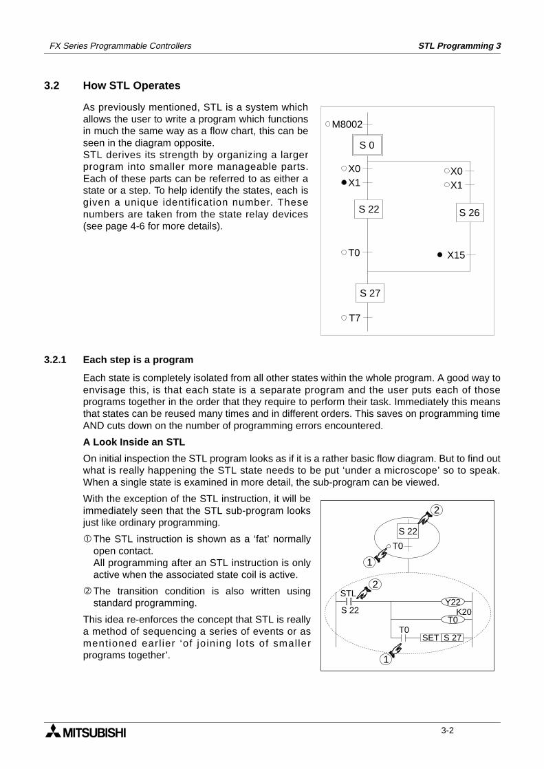
FX Series Programmable Controllers STL Programming 3
3.2 How STL Operates
As previously mentioned, STL is a system whichallows the user to write a program which functionsin much the same way as a flow chart, this can beseen in the diagram opposite.STL derives its strength by organizing a largerprogram into smaller more manageable parts.Each of these parts can be referred to as either astate or a step. To help identify the states, each isgiven a unique identification number. Thesenumbers are taken from the state relay devices(see page 4-6 for more details).
3.2.1 Each step is a program
Each state is completely isolated from all other states within the whole program. A good way toenvisage this, is that each state is a separate program and the user puts each of thoseprograms together in the order that they require to perform their task. Immediately this meansthat states can be reused many times and in different orders. This saves on programming timeAND cuts down on the number of programming errors encountered.
A Look Inside an STL
On initial inspection the STL program looks as if it is a rather basic flow diagram. But to find outwhat is really happening the STL state needs to be put ‘under a microscope’ so to speak.When a single state is examined in more detail, the sub-program can be viewed.
With the exception of the STL instruction, it will beimmediately seen that the STL sub-program looksjust like ordinary programming.
The STL instruction is shown as a ‘fat’ normallyopen contact.All programming after an STL instruction is onlyactive when the associated state coil is active.
The transition condition is also written usingstandard programming.
This idea re-enforces the concept that STL is reallya method of sequencing a series of events or asmentioned earl ier ‘of joining lots of smallerprograms together’.
M8002
X0X1
S 0
S 26
X0X1
X15
S 22
S 27
T0
T7
S 22
T0
1
2
STL
S 22
SET S 27T0
Y22K20
2
1
T0
3-2
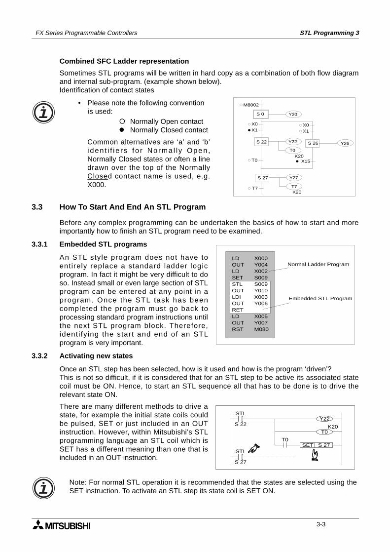
FX Series Programmable Controllers STL Programming 3
Combined SFC Ladder representation
Sometimes STL programs will be written in hard copy as a combination of both flow diagramand internal sub-program. (example shown below).Identification of contact states
3.3 How To Start And End An STL Program
Before any complex programming can be undertaken the basics of how to start and moreimportantly how to finish an STL program need to be examined.
3.3.1 Embedded STL programs
An STL style program does not have toentirely replace a standard ladder logicprogram. In fact it might be very difficult to doso. Instead small or even large section of STLprogram can be entered at any point in aprogram. Once the STL task has beencompleted the program must go back toprocessing standard program instructions untilthe next STL program block. Therefore,ident i fy ing the start and end of an STLprogram is very important.
3.3.2 Activating new states
Once an STL step has been selected, how is it used and how is the program ‘driven’?This is not so difficult, if it is considered that for an STL step to be active its associated statecoil must be ON. Hence, to start an STL sequence all that has to be done is to drive therelevant state ON.
There are many different methods to drive astate, for example the initial state coils couldbe pulsed, SET or just included in an OUTinstruction. However, within Mitsubishi’s STLprogramming language an STL coil which isSET has a different meaning than one that isincluded in an OUT instruction.
M8002
X0X1
S 0
S 26
X0X1
X15
S 22
S 27
K20
K20
T0
T7
Y22
T0
Y27
T7
Y20
Y26
• Please note the following convention is used:
Normally Open contact Normally Closed contact
Common alternatives are ‘a’ and ‘b’i den t i f i e rs fo r No rma l ly Open,Normally Closed states or often a linedrawn over the top of the NormallyClosed contact name is used, e.g.X000.
LDOUTLDSETSTLOUTLDIOUTRETLDOUTRST
X000Y004X002S009S009Y010X003Y006
X005Y007M080
Normal Ladder Program
Embedded STL Program
STL
S 22
SET S 27T0
Y22
T0K20
STL
S 27
Note: For normal STL operation it is recommended that the states are selected using theSET instruction. To activate an STL step its state coil is SET ON.
3-3
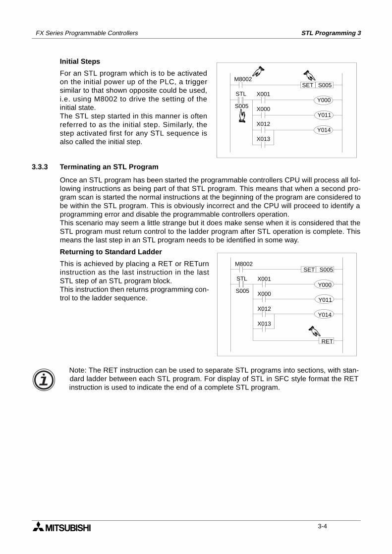
FX Series Programmable Controllers STL Programming 3
Initial Steps
For an STL program which is to be activatedon the initial power up of the PLC, a triggersimilar to that shown opposite could be used,i.e. using M8002 to drive the setting of theinitial state.The STL step started in this manner is oftenreferred to as the initial step. Similarly, thestep activated first for any STL sequence isalso called the initial step.
3.3.3 Terminating an STL Program
Once an STL program has been started the programmable controllers CPU will process all fol-lowing instructions as being part of that STL program. This means that when a second pro-gram scan is started the normal instructions at the beginning of the program are considered tobe within the STL program. This is obviously incorrect and the CPU will proceed to identify aprogramming error and disable the programmable controllers operation.This scenario may seem a little strange but it does make sense when it is considered that theSTL program must return control to the ladder program after STL operation is complete. Thismeans the last step in an STL program needs to be identified in some way.
Returning to Standard Ladder
This is achieved by placing a RET or RETurninstruction as the last instruction in the lastSTL step of an STL program block.This instruction then returns programming con-trol to the ladder sequence.
STL
S005
M8002SET S005
X001
X000
X012
X013
Y000
Y011
Y014
STL
S005
M8002SET S005
X001
X000
X012
X013
Y000
Y011
Y014
RET
Note: The RET instruction can be used to separate STL programs into sections, with stan-dard ladder between each STL program. For display of STL in SFC style format the RETinstruction is used to indicate the end of a complete STL program.
3-4
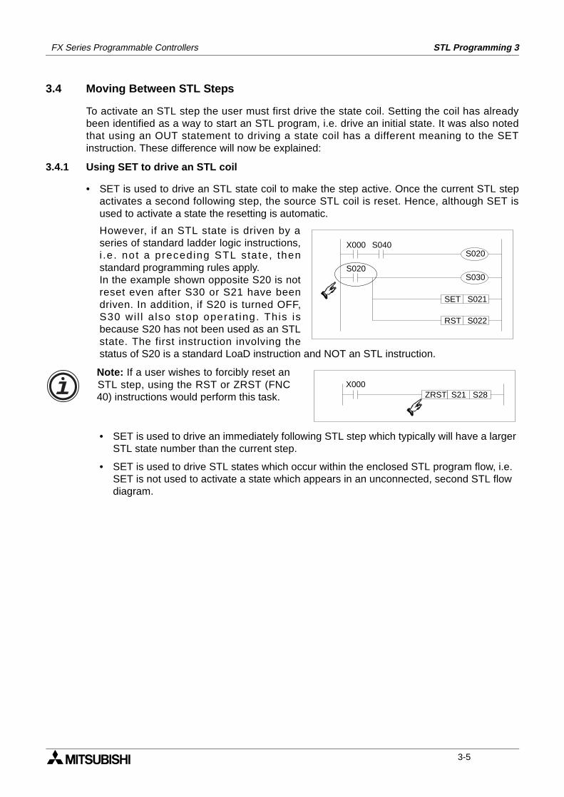
FX Series Programmable Controllers STL Programming 3
3.4 Moving Between STL Steps
To activate an STL step the user must first drive the state coil. Setting the coil has alreadybeen identified as a way to start an STL program, i.e. drive an initial state. It was also notedthat using an OUT statement to driving a state coil has a different meaning to the SETinstruction. These difference will now be explained:
3.4.1 Using SET to drive an STL coil
• SET is used to drive an STL state coil to make the step active. Once the current STL stepactivates a second following step, the source STL coil is reset. Hence, although SET isused to activate a state the resetting is automatic.
However, if an STL state is driven by aseries of standard ladder logic instructions,i .e . not a preceding STL sta te, thenstandard programming rules apply.In the example shown opposite S20 is notreset even after S30 or S21 have beendriven. In addition, if S20 is turned OFF,S30 wi l l a lso stop operat ing. This isbecause S20 has not been used as an STLstate. The first instruction involving thestatus of S20 is a standard LoaD instruction and NOT an STL instruction.
• SET is used to drive an immediately following STL step which typically will have a larger STL state number than the current step.
• SET is used to drive STL states which occur within the enclosed STL program flow, i.e. SET is not used to activate a state which appears in an unconnected, second STL flow diagram.
X000
SET S021
S040S020
RST S022
S020S030
X000ZRST S21 S28
Note: If a user wishes to forcibly reset anSTL step, using the RST or ZRST (FNC40) instructions would perform this task.
3-5
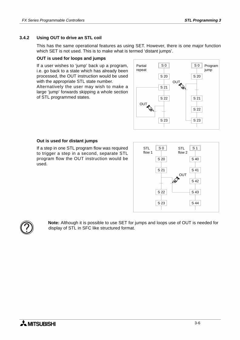
FX Series Programmable Controllers STL Programming 3
3.4.2 Using OUT to drive an STL coil
This has the same operational features as using SET. However, there is one major functionwhich SET is not used. This is to make what is termed ‘distant jumps’.
OUT is used for loops and jumps
If a user wishes to ‘jump’ back up a program,i.e. go back to a state which has already beenprocessed, the OUT instruction would be usedwith the appropriate STL state number.Alternatively the user may wish to make alarge ‘jump’ forwards skipping a whole sectionof STL programmed states.
Out is used for distant jumps
If a step in one STL program flow was requiredto trigger a step in a second, separate STLprogram flow the OUT instruction would beused.
S 0
S 22
S 20
S 21
OUT
S 23
S 0
S 20
S 21
S 23
S 22
OUT
Partialrepeat
Programjump
S 0
S 20
S 21
S 23
S 22
OUT
S 1
S 40
S 41
S 44
S 43
S 42
STLflow 1
STLflow 2
Note: Although it is possible to use SET for jumps and loops use of OUT is needed fordisplay of STL in SFC like structured format.
3-6
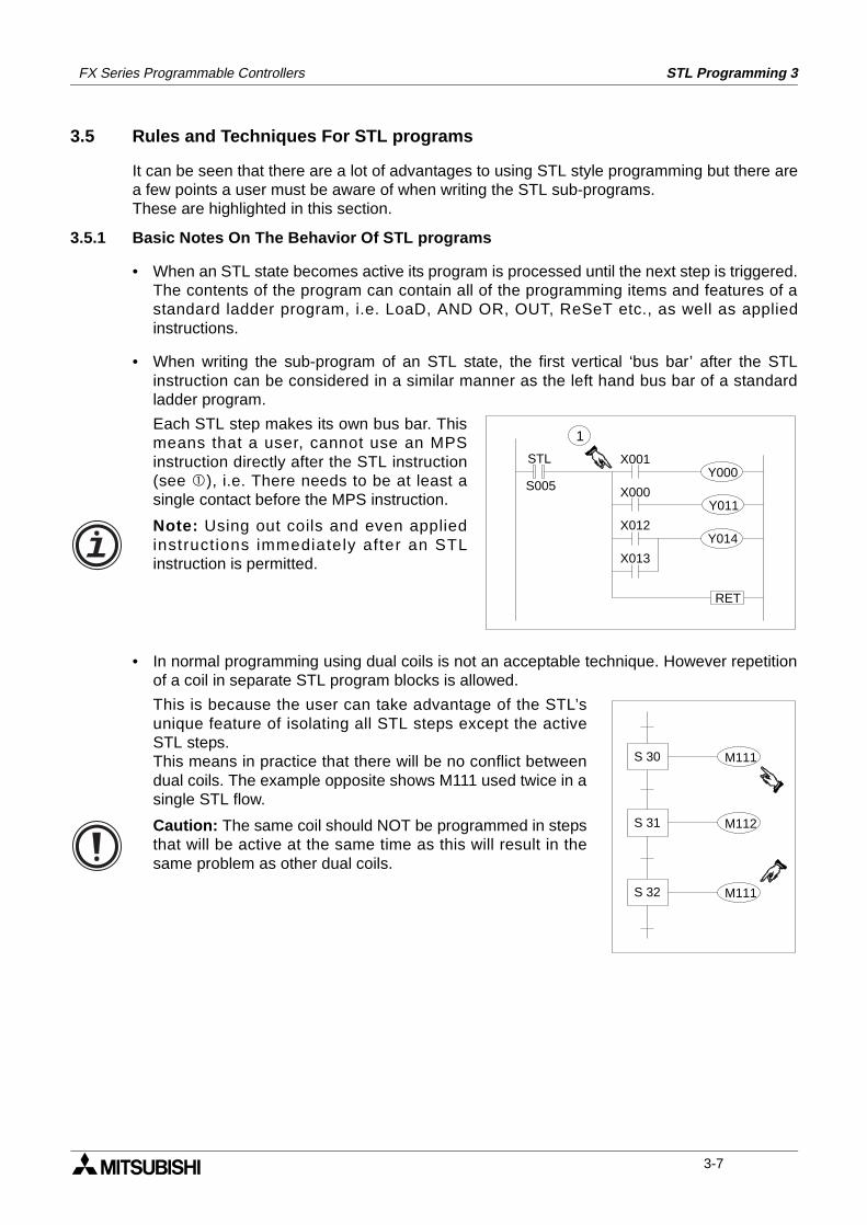
FX Series Programmable Controllers STL Programming 3
3.5 Rules and Techniques For STL programs
It can be seen that there are a lot of advantages to using STL style programming but there area few points a user must be aware of when writing the STL sub-programs.These are highlighted in this section.
3.5.1 Basic Notes On The Behavior Of STL programs
• When an STL state becomes active its program is processed until the next step is triggered.The contents of the program can contain all of the programming items and features of astandard ladder program, i.e. LoaD, AND OR, OUT, ReSeT etc., as well as appliedinstructions.
• When writing the sub-program of an STL state, the first vertical ‘bus bar’ after the STLinstruction can be considered in a similar manner as the left hand bus bar of a standardladder program.
• In normal programming using dual coils is not an acceptable technique. However repetitionof a coil in separate STL program blocks is allowed.
STL
S005Y000
Y011
Y014
RET
X001
X000
X012
X013
1Each STL step makes its own bus bar. Thismeans that a user, cannot use an MPSinstruction directly after the STL instruction(see ), i.e. There needs to be at least asingle contact before the MPS instruction.
Note: Using out coils and even appliedinstructions immediately after an STLinstruction is permitted.
M111S 30
S 31
S 32 M111
M112
This is because the user can take advantage of the STL’sunique feature of isolating all STL steps except the activeSTL steps.This means in practice that there will be no conflict betweendual coils. The example opposite shows M111 used twice in asingle STL flow.
Caution: The same coil should NOT be programmed in stepsthat will be active at the same time as this will result in thesame problem as other dual coils.
3-7
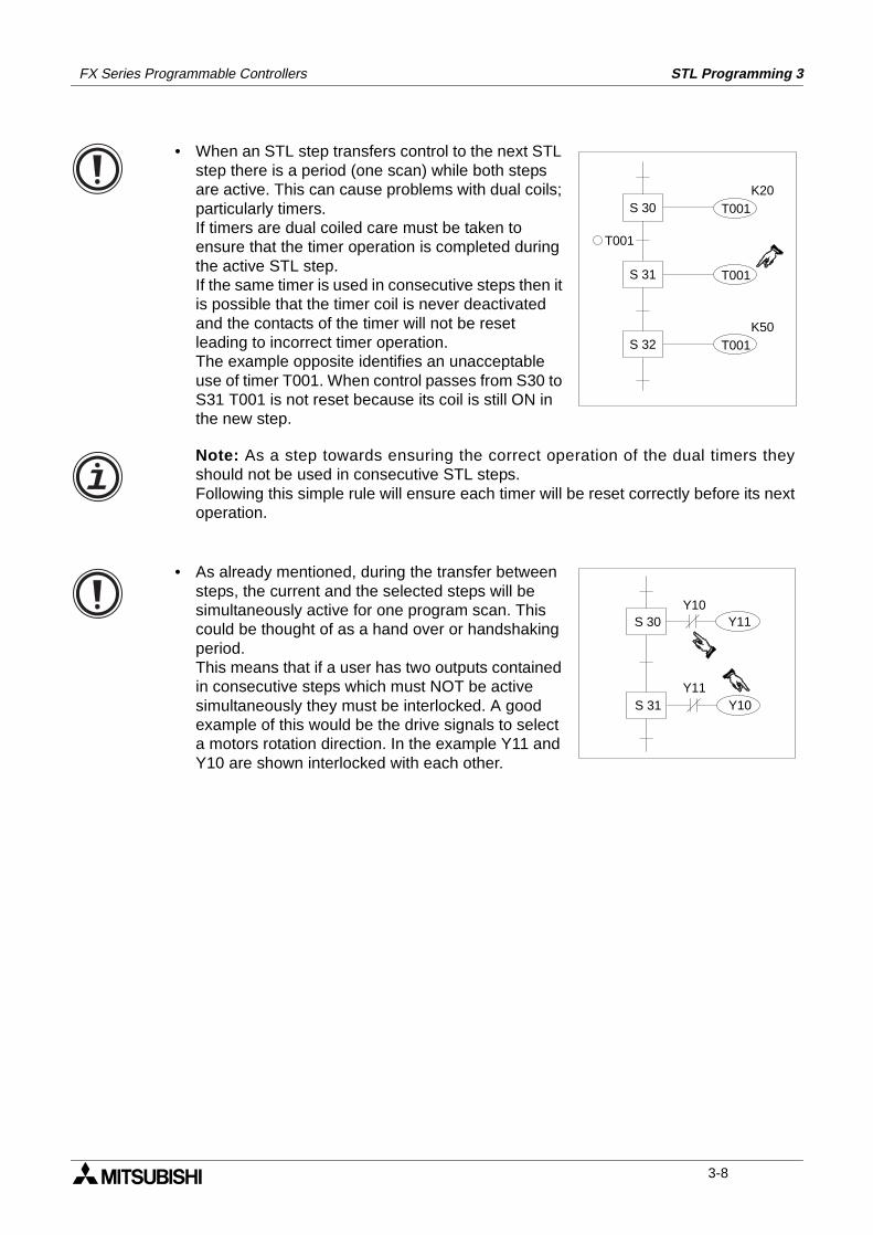
FX Series Programmable Controllers STL Programming 3
T001S 30
S 31
T001
S 32
K20
T001K50
T001
Y11S 30
S 31 Y10
Y10
Y11
• When an STL step transfers control to the next STL step there is a period (one scan) while both steps are active. This can cause problems with dual coils; particularly timers.If timers are dual coiled care must be taken to ensure that the timer operation is completed during the active STL step.If the same timer is used in consecutive steps then it is possible that the timer coil is never deactivated and the contacts of the timer will not be reset leading to incorrect timer operation.The example opposite identifies an unacceptable use of timer T001. When control passes from S30 to S31 T001 is not reset because its coil is still ON in the new step.
Note: As a step towards ensuring the correct operation of the dual timers theyshould not be used in consecutive STL steps.Following this simple rule will ensure each timer will be reset correctly before its nextoperation.
• As already mentioned, during the transfer between steps, the current and the selected steps will be simultaneously active for one program scan. This could be thought of as a hand over or handshaking period.This means that if a user has two outputs contained in consecutive steps which must NOT be active simultaneously they must be interlocked. A good example of this would be the drive signals to select a motors rotation direction. In the example Y11 and Y10 are shown interlocked with each other.
3-8
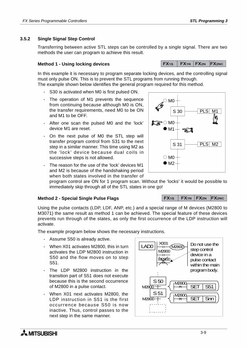
FX Series Programmable Controllers STL Programming 3
3.5.2 Single Signal Step Control
Transferring between active STL steps can be controlled by a single signal. There are twomethods the user can program to achieve this result.
Method 1 - Using locking devices
In this example it is necessary to program separate locking devices, and the controlling signalmust only pulse ON. This is to prevent the STL programs from running through.The example shown below identifies the general program required for this method.
- S30 is activated when M0 is first pulsed ON.
- The operation of M1 prevents the sequencefrom continuing because although M0 is ON,the transfer requirements, need M0 to be ONand M1 to be OFF.
- After one scan the pulsed M0 and the ‘lock’device M1 are reset.
- On the next pulse of M0 the STL step willtransfer program control from S31 to the nextstep in a similar manner. This time using M2 asthe ‘ lock ’ device because dual coi ls insuccessive steps is not allowed.
- The reason for the use of the ‘lock’ devices M1and M2 is because of the handshaking periodwhen both states involved in the transfer ofprogram control are ON for 1 program scan. Without the ‘locks’ it would be possible toimmediately skip through all of the STL states in one go!
Method 2 - Special Single Pulse Flags
Using the pulse contacts (LDP, LDF, ANP, etc.) and a special range of M devices (M2800 toM3071) the same result as method 1 can be achieved. The special feature of these devicesprevents run through of the states, as only the first occurrence of the LDP instruction willactivate.
The example program below shows the necessary instructions.
- Assume S50 is already active.
- When X01 activates M2800, this in turnactivates the LDP M2800 instruction inS50 and the flow moves on to stepS51.
- The LDP M2800 instruction in thetransition part of S51 does not executebecause this is the second occurrenceof M2800 in a pulse contact.
- When X01 next activates M2800, theLDP instruction in S51 is the firstoccurrence because S50 is nowinactive. Thus, control passes to thenext step in the same manner.
FX1S FX1N FX2N FX2NC
M1PLS
M0
S 30
S 31 M2PLS
M1
M2M0
M0
FX1S FX1N FX2N FX2NC
S 50
S 51M2800
M2800
LAD0
M2800
M2800M2800
X001
SET S51M2800
SET SnnM2800
Do not use thestep controldevice in apulse contactwithin the mainprogram body.
3-9
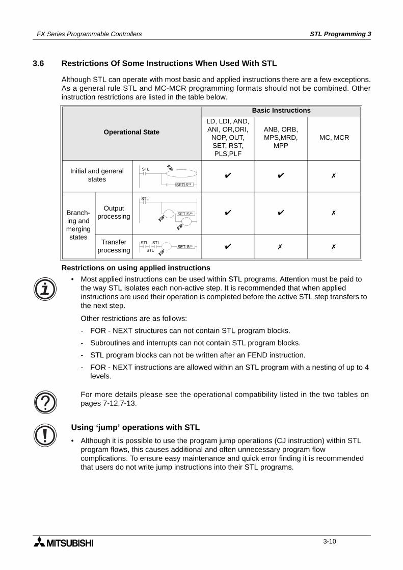
FX Series Programmable Controllers STL Programming 3
3.6 Restrictions Of Some Instructions When Used With STL
Although STL can operate with most basic and applied instructions there are a few exceptions.As a general rule STL and MC-MCR programming formats should not be combined. Otherinstruction restrictions are listed in the table below.
Restrictions on using applied instructions
Operational State
Basic Instructions
LD, LDI, AND, ANI, OR,ORI,
NOP, OUT, SET, RST, PLS,PLF
ANB, ORB, MPS,MRD,
MPPMC, MCR
Initial and general states
Branch-ing and merging states
Output processing
Transfer processing
STL
S**SET
STL
S**SET
STL
STL
STLS**SET
• Most applied instructions can be used within STL programs. Attention must be paid to the way STL isolates each non-active step. It is recommended that when applied instructions are used their operation is completed before the active STL step transfers to the next step.
Other restrictions are as follows:
- FOR - NEXT structures can not contain STL program blocks.
- Subroutines and interrupts can not contain STL program blocks.
- STL program blocks can not be written after an FEND instruction.
- FOR - NEXT instructions are allowed within an STL program with a nesting of up to 4levels.
For more details please see the operational compatibility listed in the two tables onpages 7-12,7-13.
Using ‘jump’ operations with STL
• Although it is possible to use the program jump operations (CJ instruction) within STL program flows, this causes additional and often unnecessary program flow complications. To ensure easy maintenance and quick error finding it is recommended that users do not write jump instructions into their STL programs.
3-10
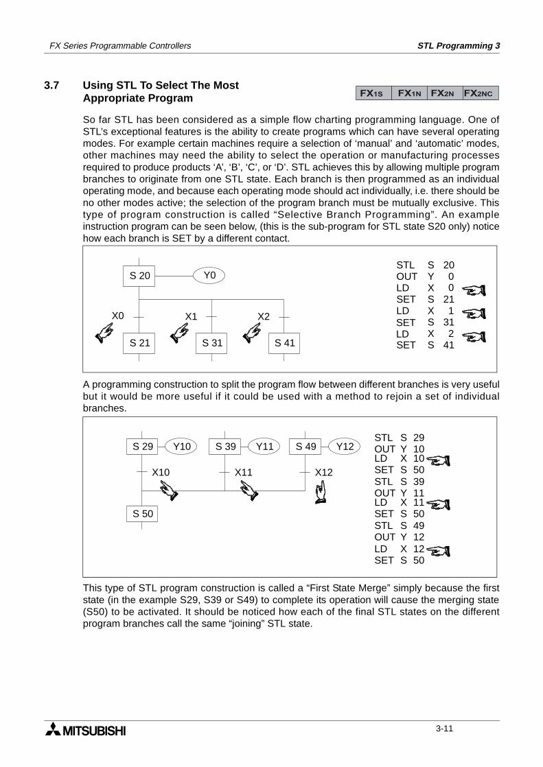
FX Series Programmable Controllers STL Programming 3
3.7 Using STL To Select The Most Appropriate Program
So far STL has been considered as a simple flow charting programming language. One ofSTL’s exceptional features is the ability to create programs which can have several operatingmodes. For example certain machines require a selection of ‘manual’ and ‘automatic’ modes,other machines may need the ability to select the operation or manufacturing processesrequired to produce products ‘A’, ‘B’, ‘C’, or ‘D’. STL achieves this by allowing multiple programbranches to originate from one STL state. Each branch is then programmed as an individualoperating mode, and because each operating mode should act individually, i.e. there should beno other modes active; the selection of the program branch must be mutually exclusive. Thistype of program construction is called “Selective Branch Programming”. An exampleinstruction program can be seen below, (this is the sub-program for STL state S20 only) noticehow each branch is SET by a different contact.
A programming construction to split the program flow between different branches is very usefulbut it would be more useful if it could be used with a method to rejoin a set of individualbranches.
This type of STL program construction is called a “First State Merge” simply because the firststate (in the example S29, S39 or S49) to complete its operation will cause the merging state(S50) to be activated. It should be noticed how each of the final STL states on the differentprogram branches call the same “joining” STL state.
FX1S FX1N FX2N FX2NC
Y0
X0 X1 X2
SYXSXSXS
200
211
312
41
STLOUTLDSETLD
SET
SETLD
0
S 21 S 31 S 41
S 20
Y10S 29
X10
S 39 S 49
X11 X12
Y11 Y12
S 50
STLOUT
SY
3911
STLOUT
SY
4912
LDSET
XS
1050
LDSET
XS
1150
LDSET
XS
1250
STLOUT
SY
2910
3-11
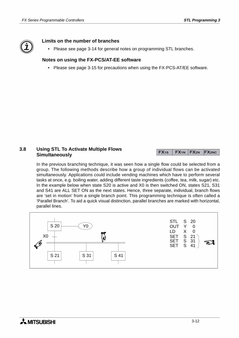
FX Series Programmable Controllers STL Programming 3
3.8 Using STL To Activate Multiple FlowsSimultaneously
In the previous branching technique, it was seen how a single flow could be selected from agroup. The following methods describe how a group of individual flows can be activatedsimultaneously. Applications could include vending machines which have to perform severaltasks at once, e.g. boiling water, adding different taste ingredients (coffee, tea, milk, sugar) etc.In the example below when state S20 is active and X0 is then switched ON, states S21, S31and S41 are ALL SET ON as the next states. Hence, three separate, individual, branch flowsare ‘set in motion’ from a single branch point. This programming technique is often called a‘Parallel Branch’. To aid a quick visual distinction, parallel branches are marked with horizontal,parallel lines.
Limits on the number of branches
• Please see page 3-14 for general notes on programming STL branches.
Notes on using the FX-PCS/AT-EE software
• Please see page 3-15 for precautions when using the FX-PCS-AT/EE software.
FX1S FX1N FX2N FX2NC
Y0
X0
SYXS
200
21
STLOUTLDSET
0
S 21 S 31 S 41
S 20
SETSET
3141
SS
3-12
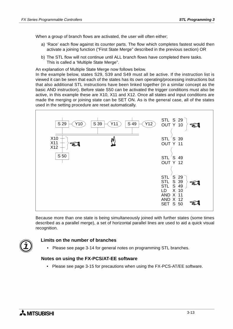
FX Series Programmable Controllers STL Programming 3
When a group of branch flows are activated, the user will often either;
a) ‘Race’ each flow against its counter parts. The flow which completes fastest would thenactivate a joining function (“First State Merge” described in the previous section) OR
b) The STL flow will not continue until ALL branch flows have completed there tasks.This is called a ‘Multiple State Merge”.
An explanation of Multiple State Merge now follows below.In the example below, states S29, S39 and S49 must all be active. If the instruction list isviewed it can be seen that each of the states has its own operating/processing instructions butthat also additional STL instructions have been linked together (in a similar concept as thebasic AND instruction). Before state S50 can be activated the trigger conditions must also beactive, in this example these are X10, X11 and X12. Once all states and input conditions aremade the merging or joining state can be SET ON. As is the general case, all of the statesused in the setting procedure are reset automatically.
Because more than one state is being simultaneously joined with further states (some timesdescribed as a parallel merge), a set of horizontal parallel lines are used to aid a quick visualrecognition.
Y10S 29 S 39 S 49Y11 Y12
S 50
STLOUT
SY
3911
STLOUT
SY
4912
STLOUT
SY
2910
X10X11X12
STLSTLSTLLDANDANDSET
SSSXXXS
29394910111250
Limits on the number of branches
• Please see page 3-14 for general notes on programming STL branches.
Notes on using the FX-PCS/AT-EE software
• Please see page 3-15 for precautions when using the FX-PCS-AT/EE software.
3-13
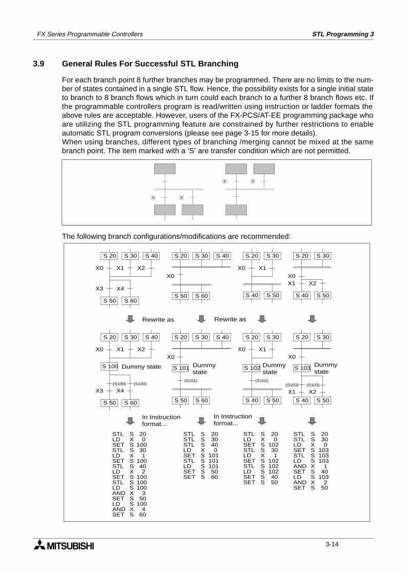
FX Series Programmable Controllers STL Programming 3
3.9 General Rules For Successful STL Branching
For each branch point 8 further branches may be programmed. There are no limits to the num-ber of states contained in a single STL flow. Hence, the possibility exists for a single initial stateto branch to 8 branch flows which in turn could each branch to a further 8 branch flows etc. Ifthe programmable controllers program is read/written using instruction or ladder formats theabove rules are acceptable. However, users of the FX-PCS/AT-EE programming package whoare utilizing the STL programming feature are constrained by further restrictions to enableautomatic STL program conversions (please see page 3-15 for more details).When using branches, different types of branching /merging cannot be mixed at the samebranch point. The item marked with a ‘S’ are transfer condition which are not permitted.
The following branch configurations/modifications are recommended:
S 40S 30S 20
S 60S 50
X0
X0 X1
S 30S 20 S 30S 20
X2X1X0
X0 X1 X2
S 60S 50
X3 X4
S 30 S 40S 20
X0 X1 X2
S 60S 50
X3 X4
S 30 S 40S 20
S 100
(S100)(S100)
S 40S 30S 20
S 60S 50
X0
S 101
(S101)
200
100301
100402
100100100
350
1004
60
SXSSXSSXSSSXSSXS
STLLDSETSTLLDSETSTLLDSETSTLLDANDSETLDANDSET
S 50S 40 S 50S 40
X0 X1
S 30S 20
(S102)
S 50S 40
S 30S 20
X1 X2(S103)
S 103S 102
(S103)
X0
S 50S 40
2030400
1011011015060
SSSXSSSSS
STLSTLSTLLDSETSTLLDSETSET
STLLDSETSTLLDSETSTLLDSETSET
SXSSXSSSSS
200
10230
1021021024050
1
STLSTLLD
SSXSSSXSSXS
SETSTLLDANDSETLDANDSET
20300
103103103
140
1032
50
Rewrite as Rewrite as
Dummy state Dummystate
Dummystate
Dummystate
In Instructionformat...
In Instructionformat...
3-14
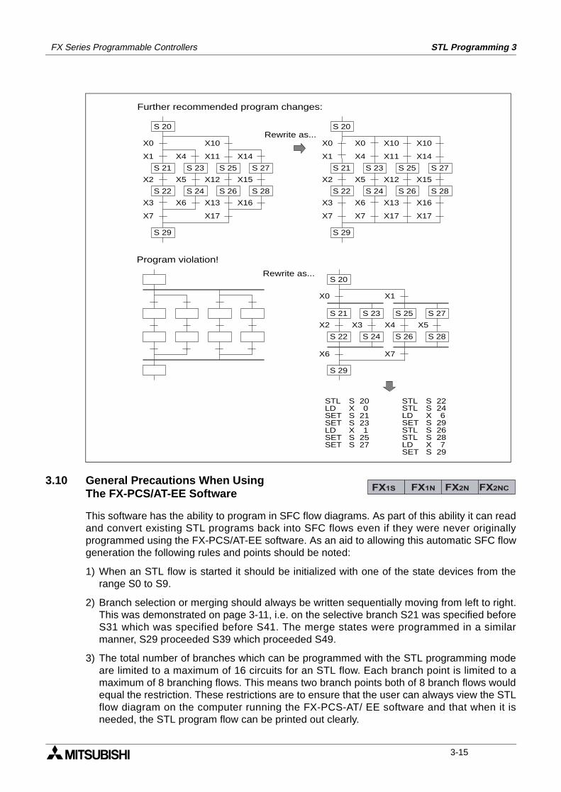
FX Series Programmable Controllers STL Programming 3
3.10 General Precautions When UsingThe FX-PCS/AT-EE Software
This software has the ability to program in SFC flow diagrams. As part of this ability it can readand convert existing STL programs back into SFC flows even if they were never originallyprogrammed using the FX-PCS/AT-EE software. As an aid to allowing this automatic SFC flowgeneration the following rules and points should be noted:
1) When an STL flow is started it should be initialized with one of the state devices from therange S0 to S9.
2) Branch selection or merging should always be written sequentially moving from left to right.This was demonstrated on page 3-11, i.e. on the selective branch S21 was specified beforeS31 which was specified before S41. The merge states were programmed in a similarmanner, S29 proceeded S39 which proceeded S49.
3) The total number of branches which can be programmed with the STL programming modeare limited to a maximum of 16 circuits for an STL flow. Each branch point is limited to amaximum of 8 branching flows. This means two branch points both of 8 branch flows wouldequal the restriction. These restrictions are to ensure that the user can always view the STLflow diagram on the computer running the FX-PCS-AT/ EE software and that when it isneeded, the STL program flow can be printed out clearly.
X0
X2
X3
S 21
S 22
S 20
X7
S 29
X1
X5
X6
S 23
S 24
X4
X10
X12
X13
S 25
S 26
X17
X11
X15
X16
S 27
S 28
X14
X2
X3
S 21
S 22
X1
X5
X6
S 23
S 24
X4
X12
X13
S 25
S 26
X11
X15
X16
S 27
S 28
X14
X0 X0 X10 X10
S 20
X7 X7 X17 X17
S 29
X0
S 20
X6
S 29
X1
X7
X2
S 21
S 22
X3
S 23
S 24
X4
S 25
S 26
X5
S 27
S 28
200
21231
2527
SXSSXSS
STLLDSETSETLDSETSET
22SSTL246
2926287
29
SXSSSXS
STLLDSETSTLSTLLDSET
Further recommended program changes:
Rewrite as...
Rewrite as...
Program violation!
FX1S FX1N FX2N FX2NC
3-15
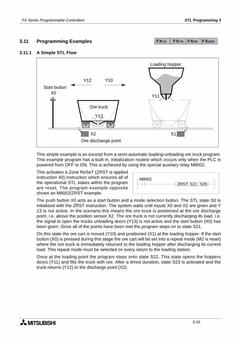
FX Series Programmable Controllers STL Programming 3
3.11 Programming Examples
3.11.1 A Simple STL Flow
This simple example is an excerpt from a semi-automatic loading-unloading ore truck program.This example program has a built in, initialization routine which occurs only when the PLC ispowered from OFF to ON. This is achieved by using the special auxiliary relay M8002.
This activates a Zone ReSeT (ZRST is appliedinstruction 40) instruction which ensures all ofthe operational STL states within the programare reset. The program example oppositeshows an M8002/ZRST example.
The push button X0 acts as a start button and a mode selection button. The STL state S0 isinitialized with the ZRST instruction. The system waits until inputs X0 and X2 are given and Y13 is not active. In the scenario this means the ore truck is positioned at the ore dischargepoint, i.e. above the position sensor X2. The ore truck is not currently discharging its load, i.e.the signal to open the trucks unloading doors (Y13) is not active and the start button (X0) hasbeen given. Once all of the points have been met the program steps on to state S21.
On this state the ore cart is moved (Y10) and positioned (X1) at the loading hopper. If the startbutton (X0) is pressed during this stage the ore cart will be set into a repeat mode (M2 is reset)where the ore truck is immediately returned to the loading hopper after discharging its currentload. This repeat mode must be selected on every return to the loading station.
Once at the loading point the program steps onto state S22. This state opens the hoppersdoors (Y11) and fills the truck with ore. After a timed duration, state S23 is activated and thetruck returns (Y12) to the discharge point (X2).
FX1S FX1N FX2N FX2NC
Y13
X0
Y10Y12
X2 X1
Y11
Loading hopper
Ore truck
Ore dischange point
Start button
M8002ZRST S21 S25
3-16
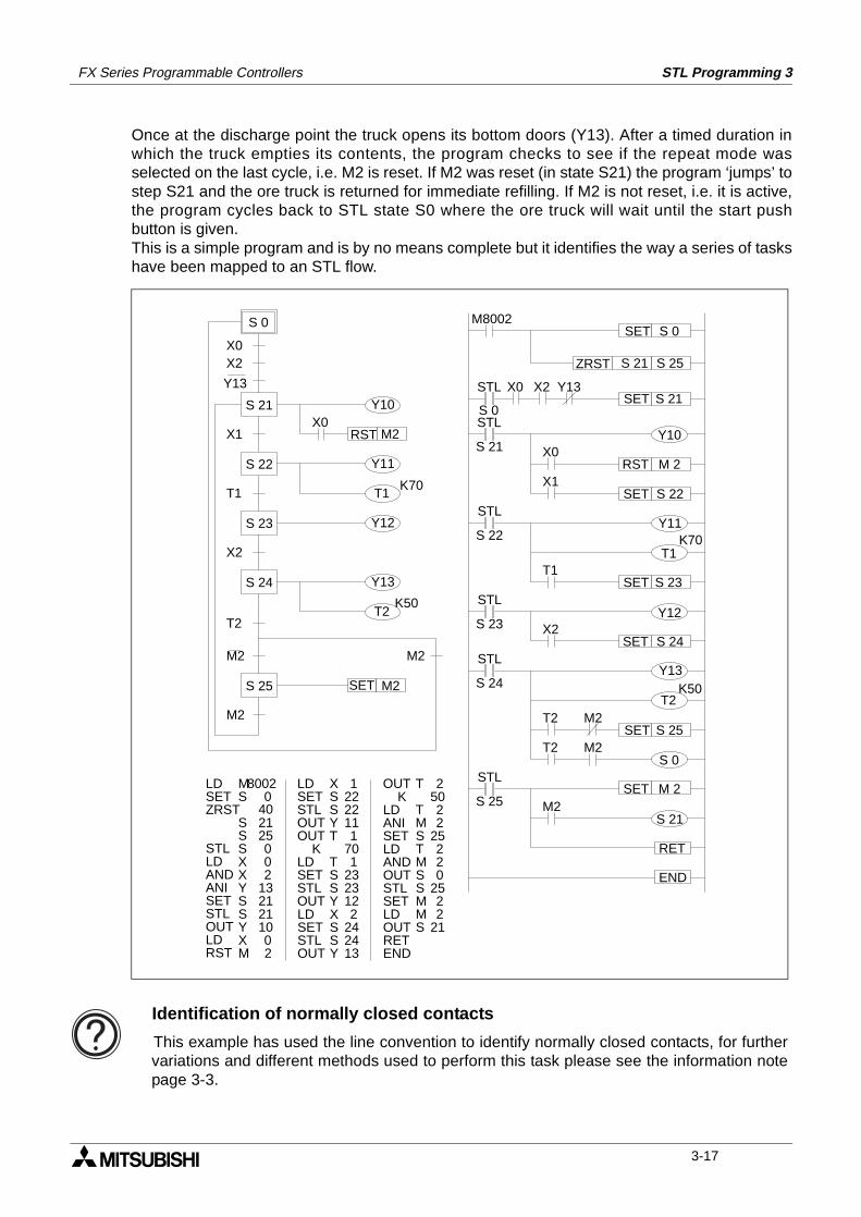
FX Series Programmable Controllers STL Programming 3
Once at the discharge point the truck opens its bottom doors (Y13). After a timed duration inwhich the truck empties its contents, the program checks to see if the repeat mode wasselected on the last cycle, i.e. M2 is reset. If M2 was reset (in state S21) the program ‘jumps’ tostep S21 and the ore truck is returned for immediate refilling. If M2 is not reset, i.e. it is active,the program cycles back to STL state S0 where the ore truck will wait until the start pushbutton is given.This is a simple program and is by no means complete but it identifies the way a series of taskshave been mapped to an STL flow.
Y10
X1
Y11
X0
T1
Y12
X2
ZRST S 25
STL
SET S 21
S 21Y10
RST M 2X0
STL
S 22Y11
SET S 23T1
SET S 22
STL
S 23Y12
SET S 24X2
X1
STL
S 24Y13
T2
M2
STL
S 25
RET
END
STL
S 0
X2X0 Y13
T1K70
T2K50
M2
T2SET S 25
M2SET M 2
SET S 0M8002
S 21
S 0
RST M2
X0X2
Y13
T1K70
Y13
T2K50
M2 M2
SET M2
M2
25022
25220
2522
21
OUTK
LDANISETLDANDOUTSTLSETLDOUTRETEND
T
TMSTMSSMMS
12222111
701
2323122
242413
XSSYT
TSSYXSSY
LDSETSTLOUTOUT
KLDSETSTLOUTLDSETSTLOUT
80020
2140
25002
1321211002
MS
SSSXXYSSYXM
LDSETZRST
STLLD
ANIAND
SETSTLOUTLDRST
S 21
S 22
S 23
S 24
S 25
T2
S 0
S 21
Identification of normally closed contacts
This example has used the line convention to identify normally closed contacts, for furthervariations and different methods used to perform this task please see the information notepage 3-3.
3-17
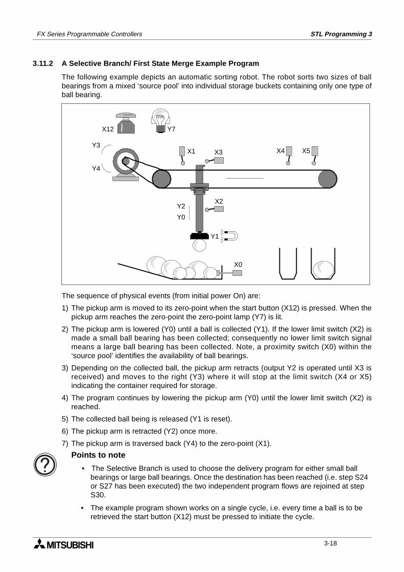
FX Series Programmable Controllers STL Programming 3
3.11.2 A Selective Branch/ First State Merge Example Program
The following example depicts an automatic sorting robot. The robot sorts two sizes of ballbearings from a mixed ‘source pool’ into individual storage buckets containing only one type ofball bearing.
The sequence of physical events (from initial power On) are:
1) The pickup arm is moved to its zero-point when the start button (X12) is pressed. When thepickup arm reaches the zero-point the zero-point lamp (Y7) is lit.
2) The pickup arm is lowered (Y0) until a ball is collected (Y1). If the lower limit switch (X2) ismade a small ball bearing has been collected; consequently no lower limit switch signalmeans a large ball bearing has been collected. Note, a proximity switch (X0) within the‘source pool’ identifies the availability of ball bearings.
3) Depending on the collected ball, the pickup arm retracts (output Y2 is operated until X3 isreceived) and moves to the right (Y3) where it will stop at the limit switch (X4 or X5)indicating the container required for storage.
4) The program continues by lowering the pickup arm (Y0) until the lower limit switch (X2) isreached.
5) The collected ball being is released (Y1 is reset).
6) The pickup arm is retracted (Y2) once more.
7) The pickup arm is traversed back (Y4) to the zero-point (X1).
Y3
Y4
X12 Y7
X1 X3 X4 X5
X2
X0
Y1
Y2
Y0
Points to note
• The Selective Branch is used to choose the delivery program for either small ball bearings or large ball bearings. Once the destination has been reached (i.e. step S24 or S27 has been executed) the two independent program flows are rejoined at step S30.
• The example program shown works on a single cycle, i.e. every time a ball is to be retrieved the start button (X12) must be pressed to initiate the cycle.
3-18
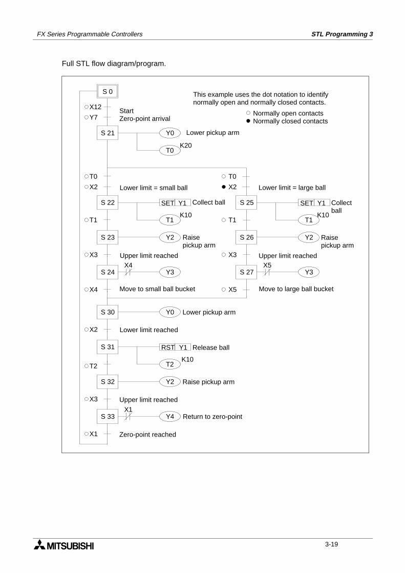
FX Series Programmable Controllers STL Programming 3
Full STL flow diagram/program.
Y0
T0
T1
S 0
X12
Y7
X2
T0
Y2
Y3
X4
RST Y1
K20
S 21
S 22 SET Y1
K10
S 23
T1
S 24
T2
X3
T0
T1
X2
Y2
Y3
X5
S 25 SET Y1
K10
S 26
T1
S 27
X3
X4 X5
T2
S 32 Y2
K10
S 30
X2
S 31
Y0
X3
S 33 Y4X1
X1
StartZero-point arrival
Lower pickup arm
This example uses the dot notation to identifynormally open and normally closed contacts.
Normally open contactsNormally closed contacts
Lower limit = small ball
Collect ball
Raisepickup arm
Upper limit reached
Move to small ball bucket
Lower limit = large ball
Collectball
Raisepickup arm
Upper limit reached
Move to large ball bucket
Lower pickup arm
Lower limit reached
Release ball
Raise pickup arm
Upper limit reached
Return to zero-point
Zero-point reached
3-19
FX Series Programmable Controllers STL Programming 3
3.12 Advanced STL Use
STL programming can be enhanced by using the Initial State Applied Instruction. Thisinstruction has a mnemonic abbreviation of IST and a special function number of 60. When theIST instruction is used an automatic assignment of state relays, special auxiliary relays (Mcoils) is made. The IST instruction provides the user with a pre-formatted way of creating amulti-mode program. The modes available are:
a) Automatic:
- Single step
- Single cycle
- Continuous
b) Manual:
- Operator controlled
- Zero return
More details on this instruction can be found on page 5-67.
3-20
1 Introduction
2 Basic Program Instructions
3 STL Programming
4 Devices in Detail
5 Applied Instructions
6 Diagnostic Devices
7 Instruction Execution Times
8 PLC Device Tables
9 Assigning System Devices
10 Points of Technique
11 Index
FX Series Programmable Controllers Devices in Detail 4
FX Series Programmable Controllers Devices in Detail 4
Chapter Contents
4. Devices in Detail....................................................................................4-14.1 Inputs................................................................................................................... 4-14.2 Outputs ................................................................................................................ 4-24.3 Auxiliary Relays ................................................................................................... 4-3
4.3.1 General Stable State Auxiliary Relays ...................................................................... 4-34.3.2 Battery Backed/ Latched Auxiliary Relays................................................................. 4-44.3.3 Special Diagnostic Auxiliary Relays .......................................................................... 4-54.3.4 Special Single Operation Pulse Relays..................................................................... 4-5
4.4 State Relays ........................................................................................................ 4-64.4.1 General Stable State - State Relays ......................................................................... 4-64.4.2 Battery Backed/ Latched State Relays...................................................................... 4-74.4.3 STL Step Relays ....................................................................................................... 4-84.4.4 Annunciator Flags ..................................................................................................... 4-9
4.5 Pointers ............................................................................................................. 4-104.6 Interrupt Pointers ............................................................................................... 4-11
4.6.1 Input Interrupts ........................................................................................................ 4-124.6.2 Timer Interrupts ....................................................................................................... 4-124.6.3 Disabling Individual Interrupts ................................................................................. 4-134.6.4 Counter Interrupts ................................................................................................... 4-13
4.7 Constant K......................................................................................................... 4-144.8 Constant H......................................................................................................... 4-144.9 Timers................................................................................................................ 4-15
4.9.1 General timer operation........................................................................................... 4-164.9.2 Selectable Timers.................................................................................................... 4-164.9.3 Retentive Timers ..................................................................................................... 4-174.9.4 Timers Used in Interrupt and ‘CALL’ Subroutines ................................................... 4-184.9.5 Timer Accuracy ....................................................................................................... 4-18
4.10 Counters ............................................................................................................ 4-194.10.1 General/ Latched 16bit UP Counters ...................................................................... 4-204.10.2 General/ Latched 32bit Bi-directional Counters....................................................... 4-21
4.11 High Speed Counters ........................................................................................ 4-224.11.1 Basic High Speed Counter Operation ..................................................................... 4-234.11.2 Availability of High Speed Counters ....................................................................... 4-244.11.3 1 Phase Counters - User Start and Reset (C235 - C240) ....................................... 4-264.11.4 1 Phase Counters - Assigned Start and Reset (C246 to C250) .............................. 4-274.11.5 2 Phase Bi-directional Counters (C246 to C250) .................................................... 4-284.11.6 A/B Phase Counters (C252 to C255) ...................................................................... 4-29
4.12 Data Registers................................................................................................... 4-304.12.1 General Use Registers ............................................................................................ 4-314.12.2 Battery Backed/ Latched Registers ......................................................................... 4-324.12.3 Special Diagnostic Registers................................................................................... 4-324.12.4 File Registers .......................................................................................................... 4-334.12.5 Externally Adjusted Registers ................................................................................. 4-34
4.13 Index Registers.................................................................................................. 4-354.13.1 Modifying a Constant............................................................................................... 4-364.13.2 Misuse of the Modifiers ........................................................................................... 4-364.13.3 Using Multiple Index Registers ................................................................................ 4-36
4.14 Bits, Words, BCD and Hexadecimal .................................................................. 4-374.14.1 Bit Devices, Individual and Grouped ....................................................................... 4-374.14.2 Word Devices .......................................................................................................... 4-394.14.3 Interpreting Word Data ............................................................................................ 4-394.14.4 Two’s Compliment ................................................................................................... 4-42
4.15 Floating Point And Scientific Notation ............................................................... 4-434.15.1 Scientific Notation.................................................................................................... 4-444.15.2 Floating Point Format .............................................................................................. 4-454.15.3 Summary Of The Scientific Notation and Floating Point Numbers.......................... 4-46
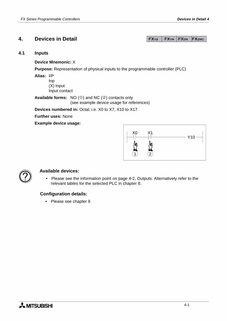
Devices in Detail 4FX Series Programmable Controllers
4. Devices in Detail
4.1 Inputs
Device Mnemonic: X
Purpose: Representation of physical inputs to the programmable controller (PLC)
Alias: I/PInp(X) InputInput contact
Available forms: NO () and NC () contacts only(see example device usage for references)
Devices numbered in: Octal, i.e. X0 to X7, X10 to X17
Further uses: None
Example device usage:
FX1S FX1N FX2N FX2NC
X0 X1Y10
21
Available devices:
• Please see the information point on page 4-2, Outputs. Alternatively refer to the relevant tables for the selected PLC in chapter 8.
Configuration details:
• Please see chapter 9
4-1
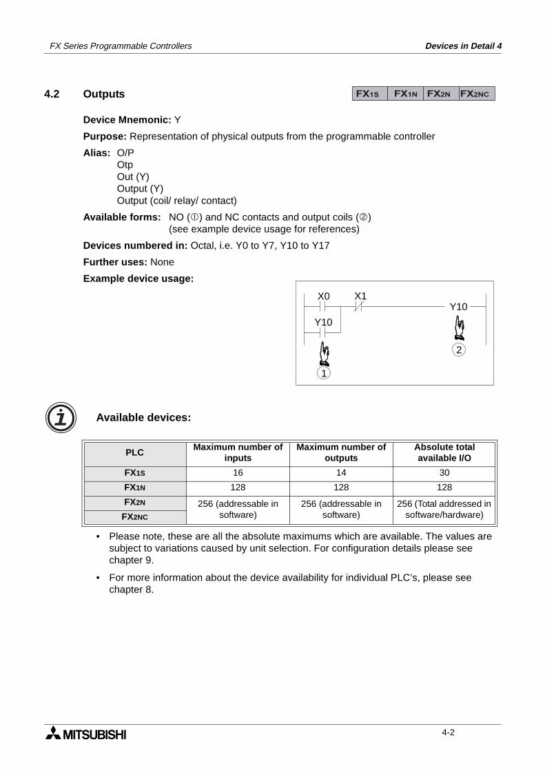
FX Series Programmable Controllers Devices in Detail 4
4.2 Outputs
Device Mnemonic: Y
Purpose: Representation of physical outputs from the programmable controller
Alias: O/POtpOut (Y)Output (Y)Output (coil/ relay/ contact)
Available forms: NO () and NC contacts and output coils ()(see example device usage for references)
Devices numbered in: Octal, i.e. Y0 to Y7, Y10 to Y17
Further uses: None
Example device usage:
• Please note, these are all the absolute maximums which are available. The values are subject to variations caused by unit selection. For configuration details please see chapter 9.
• For more information about the device availability for individual PLC’s, please see chapter 8.
PLCMaximum number of
inputsMaximum number of
outputsAbsolute totalavailable I/O
FX1S 16 14 30
FX1N 128 128 128
FX2N 256 (addressable in software)
256 (addressable in software)
256 (Total addressed in software/hardware)FX2NC
FX1S FX1N FX2N FX2NC
X0 X1Y10
1
Y10
2
Available devices:
4-2
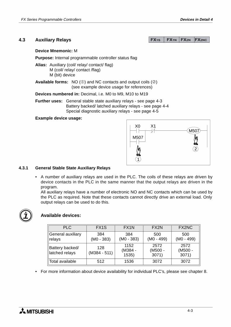
FX Series Programmable Controllers Devices in Detail 4
4.3 Auxiliary Relays
Device Mnemonic: M
Purpose: Internal programmable controller status flag
Alias: Auxiliary (coil/ relay/ contact/ flag)M (coil/ relay/ contact /flag)M (bit) device
Available forms: NO () and NC contacts and output coils ()(see example device usage for references)
Devices numbered in: Decimal, i.e. M0 to M9, M10 to M19
Further uses: General stable state auxiliary relays - see page 4-3Battery backed/ latched auxiliary relays - see page 4-4Special diagnostic auxiliary relays - see page 4-5
Example device usage:
4.3.1 General Stable State Auxiliary Relays
• A number of auxiliary relays are used in the PLC. The coils of these relays are driven bydevice contacts in the PLC in the same manner that the output relays are driven in theprogram.All auxiliary relays have a number of electronic NO and NC contacts which can be used bythe PLC as required. Note that these contacts cannot directly drive an external load. Onlyoutput relays can be used to do this.
• For more information about device availability for individual PLC’s, please see chapter 8.
PLC FX1S FX1N FX2N FX2NC
General auxiliaryrelays
384(M0 - 383)
384(M0 - 383)
500(M0 - 499)
500(M0 - 499)
Battery backed/latched relays
128(M384 - 511)
1152(M384 - 1535)
2572(M500 - 3071)
2572(M500 - 3071)
Total available 512 1536 3072 3072
FX1S FX1N FX2N FX2NC
X0 X1
1
M507
2
M507
Available devices:
4-3
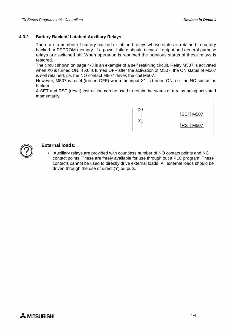
FX Series Programmable Controllers Devices in Detail 4
4.3.2 Battery Backed/ Latched Auxiliary Relays
There are a number of battery backed or latched relays whose status is retained in batterybacked or EEPROM memory. If a power failure should occur all output and general purposerelays are switched off. When operation is resumed the previous status of these relays isrestored.The circuit shown on page 4-3 is an example of a self retaining circuit. Relay M507 is activatedwhen X0 is turned ON. If X0 is turned OFF after the activation of M507, the ON status of M507is self retained, i.e. the NO contact M507 drives the coil M507.However, M507 is reset (turned OFF) when the input X1 is turned ON, i.e. the NC contact isbroken.A SET and RST (reset) instruction can be used to retain the status of a relay being activatedmomentarily.
X0SET M507
RST M507X1
External loads:
• Auxiliary relays are provided with countless number of NO contact points and NC contact points. These are freely available for use through out a PLC program. These contacts cannot be used to directly drive external loads. All external loads should be driven through the use of direct (Y) outputs.
4-4
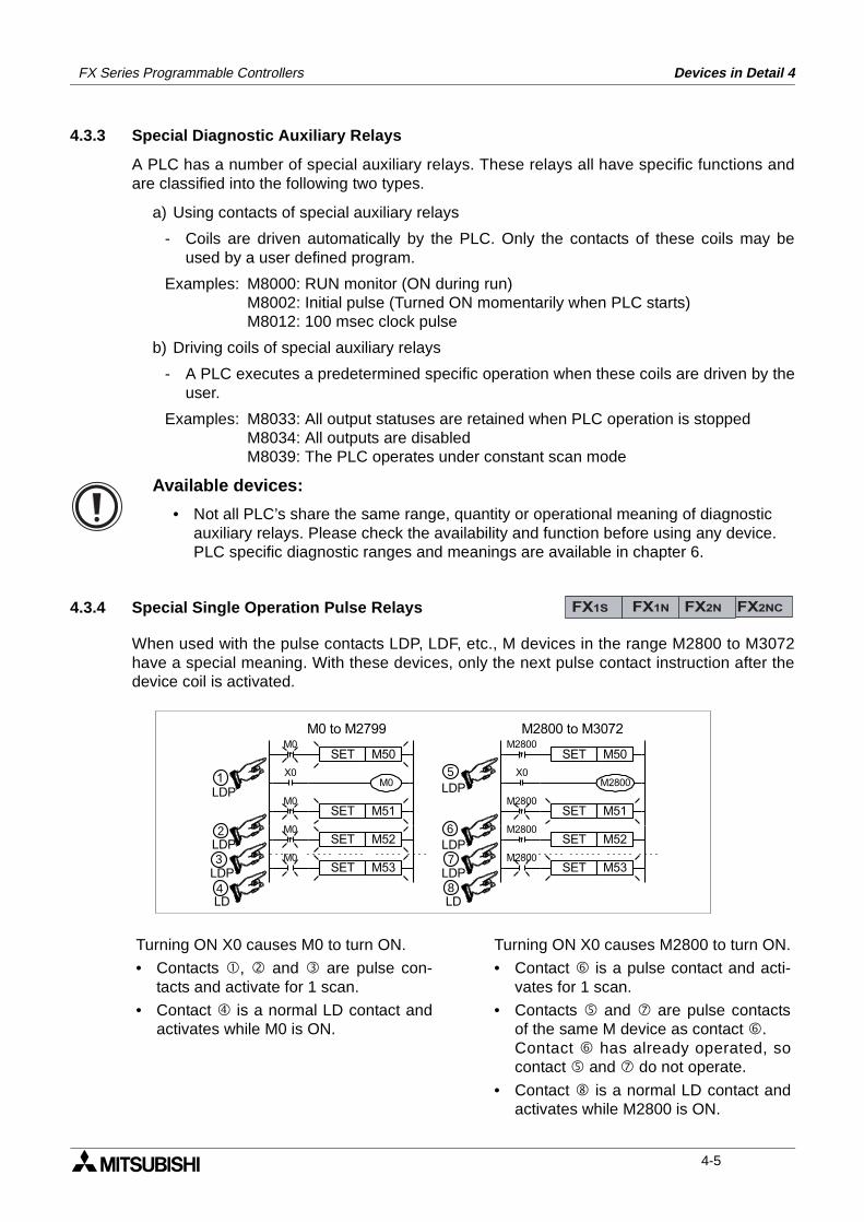
FX Series Programmable Controllers Devices in Detail 4
4.3.3 Special Diagnostic Auxiliary Relays
A PLC has a number of special auxiliary relays. These relays all have specific functions andare classified into the following two types.
a) Using contacts of special auxiliary relays
- Coils are driven automatically by the PLC. Only the contacts of these coils may beused by a user defined program.
Examples: M8000: RUN monitor (ON during run)M8002: Initial pulse (Turned ON momentarily when PLC starts)M8012: 100 msec clock pulse
b) Driving coils of special auxiliary relays
- A PLC executes a predetermined specific operation when these coils are driven by theuser.
Examples: M8033: All output statuses are retained when PLC operation is stoppedM8034: All outputs are disabledM8039: The PLC operates under constant scan mode
4.3.4 Special Single Operation Pulse Relays
When used with the pulse contacts LDP, LDF, etc., M devices in the range M2800 to M3072have a special meaning. With these devices, only the next pulse contact instruction after thedevice coil is activated.
Available devices:
• Not all PLC’s share the same range, quantity or operational meaning of diagnostic auxiliary relays. Please check the availability and function before using any device.PLC specific diagnostic ranges and meanings are available in chapter 6.
FX1S FX1N FX2N FX2NC
M0
M0
M0
M0
SET M50
X0
SET M51
SET M52
SET M53
M0
LDP
LDP
LDP
LD
1
4
3
2
M2800
M2800
M2800
M2800
X0
SET M52
SET M50
SET M53
M2800LDP
LDP
LDP
LD
5
8
7
6
SET M51
M2800 to M3072M0 to M2799
Turning ON X0 causes M0 to turn ON.
• Contacts , and are pulse con-tacts and activate for 1 scan.
• Contact is a normal LD contact andactivates while M0 is ON.
Turning ON X0 causes M2800 to turn ON.
• Contact is a pulse contact and acti-vates for 1 scan.
• Contacts and are pulse contactsof the same M device as contact .Contact has already operated, socontact and do not operate.
• Contact is a normal LD contact andactivates while M2800 is ON.
4-5
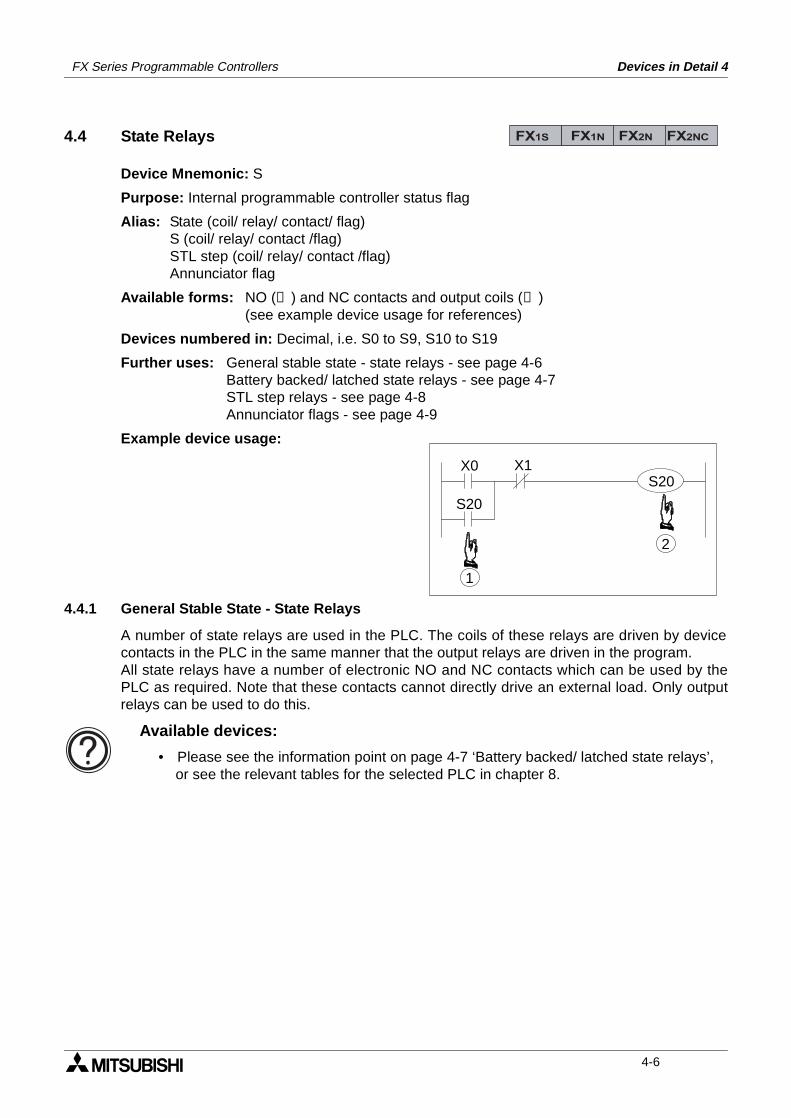
FX Series Programmable Controllers Devices in Detail 4
4.4 State Relays
Device Mnemonic: S
Purpose: Internal programmable controller status flag
Alias: State (coil/ relay/ contact/ flag)S (coil/ relay/ contact /flag)STL step (coil/ relay/ contact /flag)Annunciator flag
Available forms: NO (➀ ) and NC contacts and output coils (➁ )(see example device usage for references)
Devices numbered in: Decimal, i.e. S0 to S9, S10 to S19
Further uses: General stable state - state relays - see page 4-6Battery backed/ latched state relays - see page 4-7STL step relays - see page 4-8Annunciator flags - see page 4-9
Example device usage:
4.4.1 General Stable State - State Relays
A number of state relays are used in the PLC. The coils of these relays are driven by devicecontacts in the PLC in the same manner that the output relays are driven in the program.All state relays have a number of electronic NO and NC contacts which can be used by thePLC as required. Note that these contacts cannot directly drive an external load. Only outputrelays can be used to do this.
FX1S FX1N FX2N FX2NC
X0 X1
1
S20
2
S20
Available devices:
• Please see the information point on page 4-7 ‘Battery backed/ latched state relays’, or see the relevant tables for the selected PLC in chapter 8.
4-6
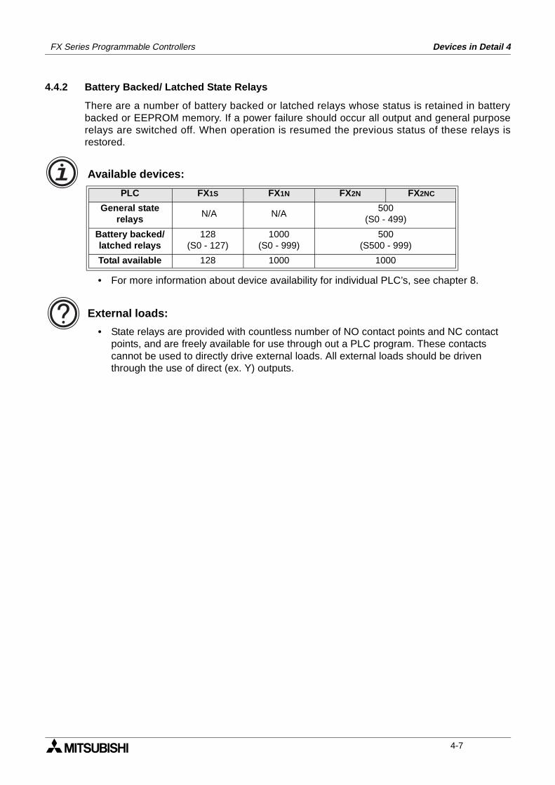
FX Series Programmable Controllers Devices in Detail 4
4.4.2 Battery Backed/ Latched State Relays
There are a number of battery backed or latched relays whose status is retained in batterybacked or EEPROM memory. If a power failure should occur all output and general purposerelays are switched off. When operation is resumed the previous status of these relays isrestored.
Available devices:
• For more information about device availability for individual PLC’s, see chapter 8.
External loads:
• State relays are provided with countless number of NO contact points and NC contact points, and are freely available for use through out a PLC program. These contacts cannot be used to directly drive external loads. All external loads should be driven through the use of direct (ex. Y) outputs.
PLC FX1S FX1N FX2N FX2NC
General state relays
N/A N/A500
(S0 - 499)
Battery backed/latched relays
128(S0 - 127)
1000(S0 - 999)
500(S500 - 999)
Total available 128 1000 1000
4-7
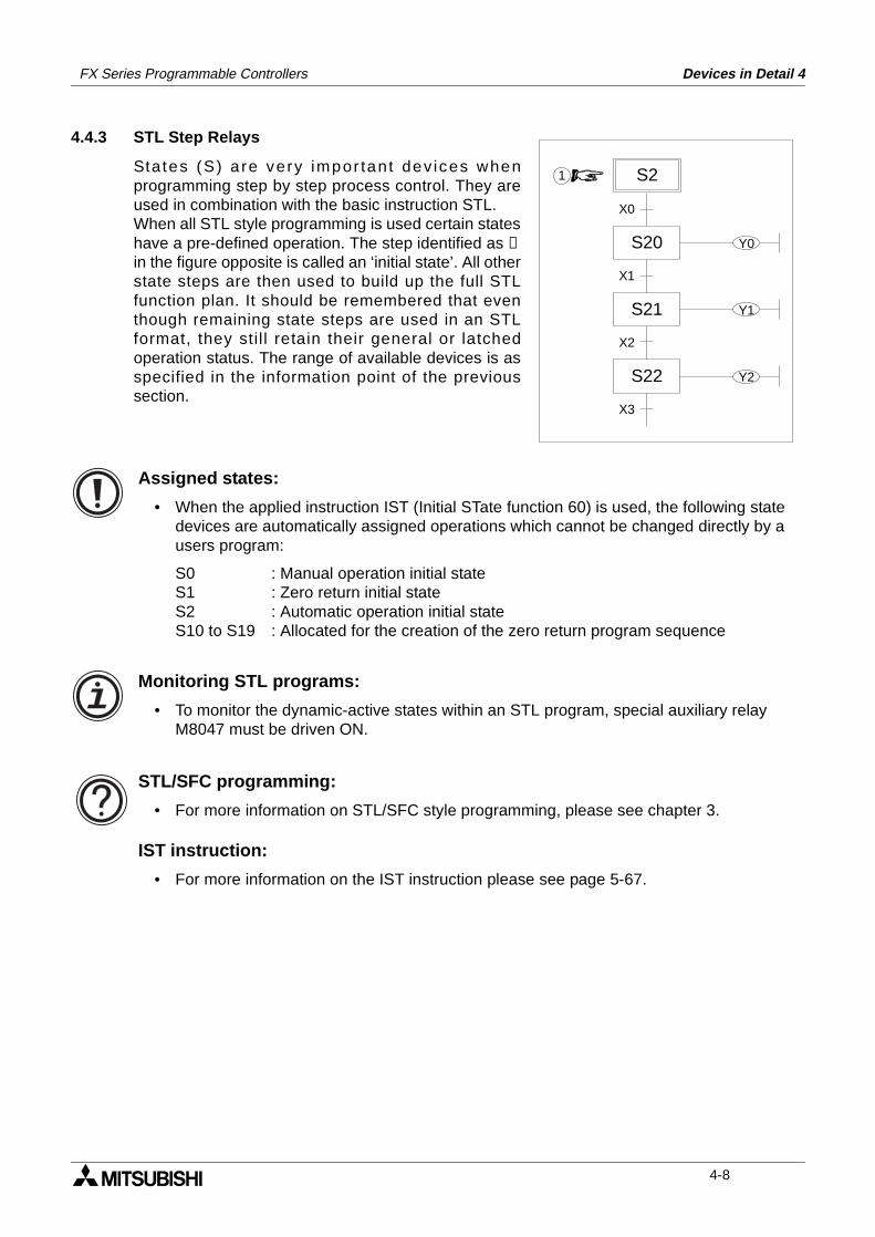
FX Series Programmable Controllers Devices in Detail 4
4.4.3 STL Step Relays
States (S) a re very impor tant dev ices whenprogramming step by step process control. They areused in combination with the basic instruction STL.When all STL style programming is used certain stateshave a pre-defined operation. The step identified as ➀in the figure opposite is called an ‘initial state’. All otherstate steps are then used to build up the full STLfunction plan. It should be remembered that eventhough remaining state steps are used in an STLformat, they stil l retain their general or latchedoperation status. The range of available devices is asspecified in the information point of the previoussection.
Assigned states:
• When the applied instruction IST (Initial STate function 60) is used, the following state devices are automatically assigned operations which cannot be changed directly by a users program:
S0 : Manual operation initial stateS1 : Zero return initial stateS2 : Automatic operation initial stateS10 to S19 : Allocated for the creation of the zero return program sequence
Monitoring STL programs:
• To monitor the dynamic-active states within an STL program, special auxiliary relay M8047 must be driven ON.
STL/SFC programming:
• For more information on STL/SFC style programming, please see chapter 3.
IST instruction:
• For more information on the IST instruction please see page 5-67.
S2
X0
X1
X2
X3
1
S20
S21
S22
Y0
Y1
Y2
4-8
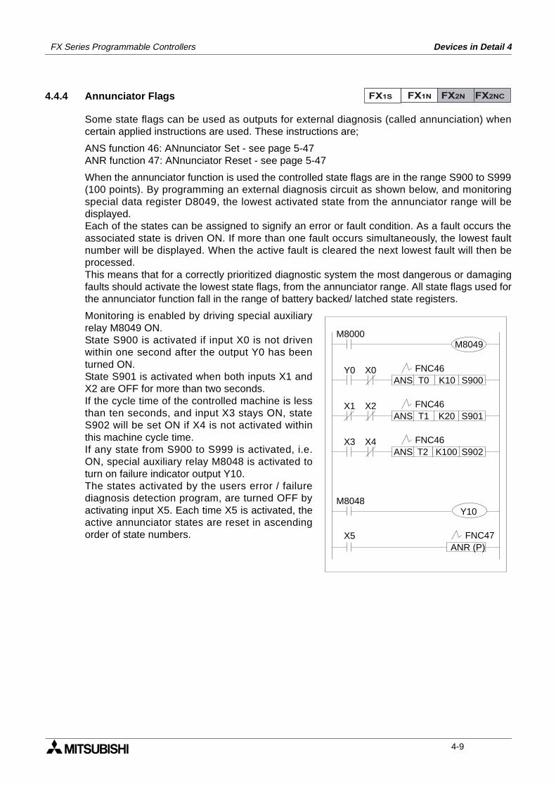
FX Series Programmable Controllers Devices in Detail 4
4.4.4 Annunciator Flags
Some state flags can be used as outputs for external diagnosis (called annunciation) whencertain applied instructions are used. These instructions are;
ANS function 46: ANnunciator Set - see page 5-47ANR function 47: ANnunciator Reset - see page 5-47
When the annunciator function is used the controlled state flags are in the range S900 to S999(100 points). By programming an external diagnosis circuit as shown below, and monitoringspecial data register D8049, the lowest activated state from the annunciator range will bedisplayed.Each of the states can be assigned to signify an error or fault condition. As a fault occurs theassociated state is driven ON. If more than one fault occurs simultaneously, the lowest faultnumber will be displayed. When the active fault is cleared the next lowest fault will then beprocessed.This means that for a correctly prioritized diagnostic system the most dangerous or damagingfaults should activate the lowest state flags, from the annunciator range. All state flags used forthe annunciator function fall in the range of battery backed/ latched state registers.
Monitoring is enabled by driving special auxiliaryrelay M8049 ON.State S900 is activated if input X0 is not drivenwithin one second after the output Y0 has beenturned ON.State S901 is activated when both inputs X1 andX2 are OFF for more than two seconds.If the cycle time of the controlled machine is lessthan ten seconds, and input X3 stays ON, stateS902 will be set ON if X4 is not activated withinthis machine cycle time.If any state from S900 to S999 is activated, i.e.ON, special auxiliary relay M8048 is activated toturn on failure indicator output Y10.The states activated by the users error / failurediagnosis detection program, are turned OFF byactivating input X5. Each time X5 is activated, theactive annunciator states are reset in ascendingorder of state numbers.
FX1S FX1N FX2N FX2NC
M8000
Y0 X0S900K10T0ANS
X1 X2S901K20T1ANS
X3 X4S902K100T2ANS
FNC46
FNC46
FNC46
M8048
X5ANR (P)
FNC47
Y10
M8049
4-9
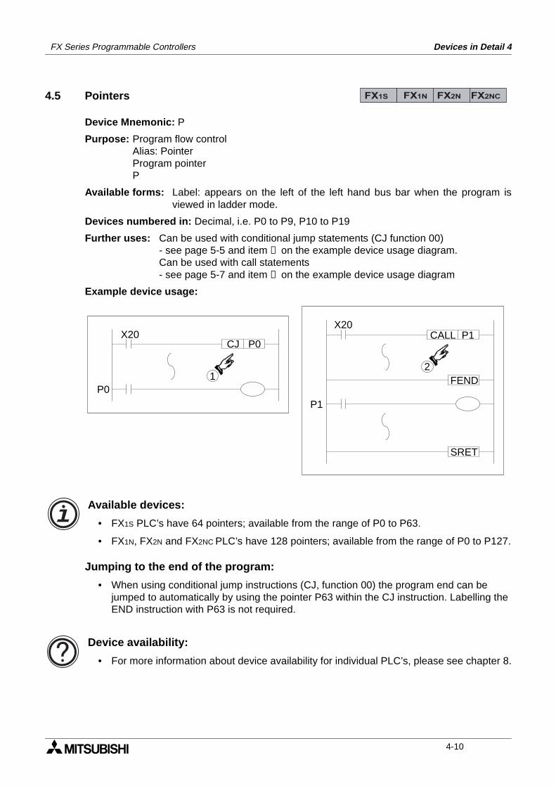
FX Series Programmable Controllers Devices in Detail 4
4.5 Pointers
Device Mnemonic: P
Purpose: Program flow controlAlias: PointerProgram pointerP
Available forms: Label: appears on the left of the left hand bus bar when the program isviewed in ladder mode.
Devices numbered in: Decimal, i.e. P0 to P9, P10 to P19
Further uses: Can be used with conditional jump statements (CJ function 00)- see page 5-5 and item ➀ on the example device usage diagram.Can be used with call statements - see page 5-7 and item ➁ on the example device usage diagram
Example device usage:
Available devices:
• FX1S PLC’s have 64 pointers; available from the range of P0 to P63.
• FX1N, FX2N and FX2NC PLC’s have 128 pointers; available from the range of P0 to P127.
Jumping to the end of the program:
• When using conditional jump instructions (CJ, function 00) the program end can be jumped to automatically by using the pointer P63 within the CJ instruction. Labelling the END instruction with P63 is not required.
Device availability:
• For more information about device availability for individual PLC’s, please see chapter 8.
FX1S FX1N FX2N FX2NC
X20CJ P0
1P0
X20CALL P1
2
P1
SRET
FEND
4-10
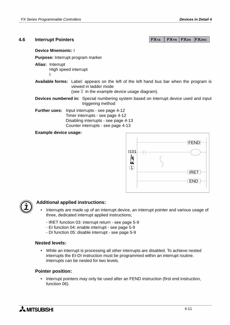
FX Series Programmable Controllers Devices in Detail 4
4.6 Interrupt Pointers
Device Mnemonic: I
Purpose: Interrupt program marker
Alias: InterruptHigh speed interruptI
Available forms: Label: appears on the left of the left hand bus bar when the program isviewed in ladder mode (see ➀ in the example device usage diagram).
Devices numbered in: Special numbering system based on interrupt device used and inputtriggering method
Further uses: Input interrupts - see page 4-12Timer interrupts - see page 4-12Disabling interrupts - see page 4-13Counter interrupts - see page 4-13
Example device usage:
Additional applied instructions:
• Interrupts are made up of an interrupt device, an interrupt pointer and various usage of three, dedicated interrupt applied instructions;
- IRET function 03: interrupt return - see page 5-9- EI function 04: enable interrupt - see page 5-9- DI function 05: disable interrupt - see page 5-9
Nested levels:
• While an interrupt is processing all other interrupts are disabled. To achieve nested interrupts the EI-DI instruction must be programmed within an interrupt routine.Interrupts can be nested for two levels.
Pointer position:
• Interrupt pointers may only be used after an FEND instruction (first end instruction, function 06).
FX1S FX1N FX2N FX2NC
I101
IRET
FEND
1
END
4-11
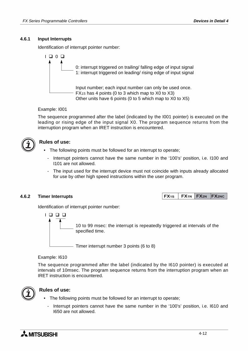
FX Series Programmable Controllers Devices in Detail 4
4.6.1 Input Interrupts
Identification of interrupt pointer number:
Example: I001
The sequence programmed after the label (indicated by the I001 pointer) is executed on theleading or rising edge of the input signal X0. The program sequence returns from theinterruption program when an IRET instruction is encountered.
Rules of use:
• The following points must be followed for an interrupt to operate;
- Interrupt pointers cannot have the same number in the ‘100’s’ position, i.e. I100 andI101 are not allowed.
- The input used for the interrupt device must not coincide with inputs already allocatedfor use by other high speed instructions within the user program.
4.6.2 Timer Interrupts
Identification of interrupt pointer number:
Example: I610
The sequence programmed after the label (indicated by the I610 pointer) is executed atintervals of 10msec. The program sequence returns from the interruption program when anIRET instruction is encountered.
Rules of use:
• The following points must be followed for an interrupt to operate;
- Interrupt pointers cannot have the same number in the ‘100’s’ position, i.e. I610 andI650 are not allowed.
I 0
0: interrupt triggered on trailing/ falling edge of input signal1: interrupt triggered on leading/ rising edge of input signal
Input number; each input number can only be used once.FX1S has 4 points (0 to 3 which map to X0 to X3)Other units have 6 points (0 to 5 which map to X0 to X5)
FX1S FX1N FX2N FX2NC
I
10 to 99 msec: the interrupt is repeatedly triggered at intervals of thespecified time.
Timer interrupt number 3 points (6 to 8)
4-12
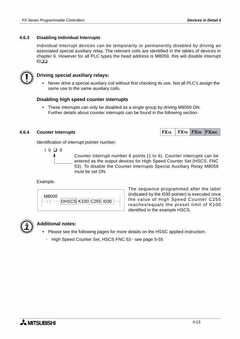
FX Series Programmable Controllers Devices in Detail 4
4.6.3 Disabling Individual Interrupts
Individual interrupt devices can be temporarily or permanently disabled by driving anassociated special auxiliary relay. The relevant coils are identified in the tables of devices inchapter 6. However for all PLC types the head address is M8050, this will disable interruptI0.
Driving special auxiliary relays:
• Never drive a special auxiliary coil without first checking its use. Not all PLC’s assign the same use to the same auxiliary coils.
Disabling high speed counter interrupts
• These interrupts can only be disabled as a single group by driving M8059 ON.Further details about counter interrupts can be found in the following section.
4.6.4 Counter Interrupts
Identification of interrupt pointer number:
Example:
The sequence programmed after the label(indicated by the I030 pointer) is executed oncethe va lue of High Speed Counter C255reaches/equals the preset l imit of K100identified in the example HSCS.
Additional notes:
• Please see the following pages for more details on the HSSC applied instruction.
- High Speed Counter Set, HSCS FNC 53 - see page 5-55
FX1S FX1N FX2N FX2NC
I 0 0Counter interrupt number 6 points (1 to 6). Counter interrupts can beentered as the output devices for High Speed Counter Set (HSCS, FNC53). To disable the Counter Interrupts Special Auxiliary Relay M8059must be set ON.
M8000C255 I030K100DHSCS
4-13
FX Series Programmable Controllers Devices in Detail 4
4.7 Constant K
Device Mnemonic: K
Purpose: Identification of constant decimal values
Alias: ConstantK (value/ constant)K
Available forms: Numeric data value, when used for 16bit data, values can be selected fromthe range -32,768 to +32,767For 32bit data, values from the range -2,147,483,648 to + 2,147,483,647can be used.
Devices numbered in: N/A. This device is a method of local instruction data entry.There is no limit to the number of times it can be used.
Further uses: K values can be used with timers, counters and applied instructions
Example device usage: N/A
4.8 Constant H
Device Mnemonic: H
Purpose: Identification of constant hexadecimal values
Alias: ConstantH (value/ constant)Hex (value/ constant)H
Available forms: Alpha-numeric data value, i.e. 0 to 9 and A to F (base 16).When used for 16bit data, values can be selected from the range 0 toFFFF.For 32bit data, values from the range 0 to FFFFFFFF can be used.
Devices numbered in: N/A. This device is a method of local instruction data entry.There is no limit to the number of times it can be used.
Further uses: Hex values can be used with applied instructions
Example device usage: N/A
FX1S FX1N FX2N FX2NC
FX1S FX1N FX2N FX2NC
4-14
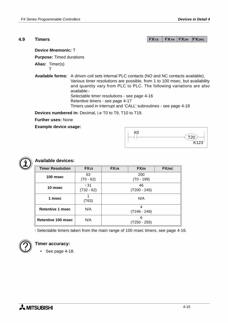
FX Series Programmable Controllers Devices in Detail 4
4.9 Timers
Device Mnemonic: T
Purpose: Timed durations
Alias: Timer(s)T
Available forms: A driven coil sets internal PLC contacts (NO and NC contacts available).Various timer resolutions are possible, from 1 to 100 msec, but availabilityand quantity vary from PLC to PLC. The following variations are alsoavailable:-Selectable timer resolutions - see page 4-16Retentive timers - see page 4-17Timers used in interrupt and ‘CALL’ subroutines - see page 4-18
Devices numbered in: Decimal, i.e T0 to T9, T10 to T19.
Further uses: None
Example device usage:
Available devices:
\ Selectable timers taken from the main range of 100 msec timers, see page 4-16.
Timer accuracy:
• See page 4-18.
Timer Resolution FX1S FX1N FX2N FX2NC
100 msec63
(T0 - 62)200
(T0 - 199)
10 msec\ 31
(T32 - 62)46
(T200 - 245)
1 msec1
(T63)N/A
Retentive 1 msec N/A4
(T246 - 249)
Retentive 100 msec N/A6
(T250 - 255)
FX1S FX1N FX2N FX2NC
X0T20
K123
4-15
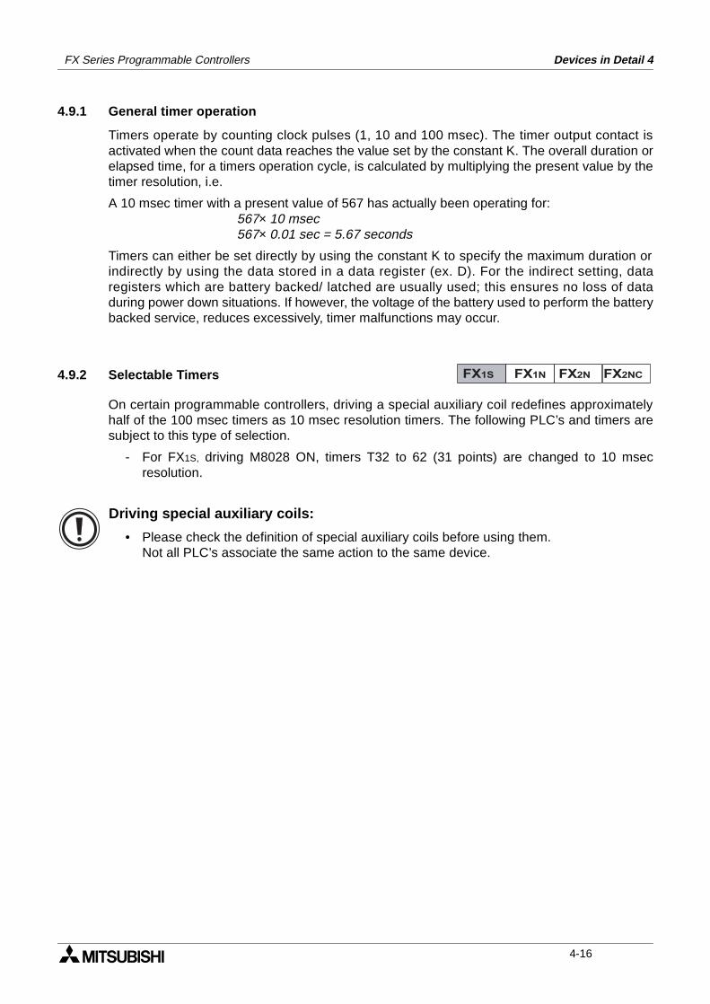
FX Series Programmable Controllers Devices in Detail 4
4.9.1 General timer operation
Timers operate by counting clock pulses (1, 10 and 100 msec). The timer output contact isactivated when the count data reaches the value set by the constant K. The overall duration orelapsed time, for a timers operation cycle, is calculated by multiplying the present value by thetimer resolution, i.e.
A 10 msec timer with a present value of 567 has actually been operating for:567× 10 msec567× 0.01 sec = 5.67 seconds
Timers can either be set directly by using the constant K to specify the maximum duration orindirectly by using the data stored in a data register (ex. D). For the indirect setting, dataregisters which are battery backed/ latched are usually used; this ensures no loss of dataduring power down situations. If however, the voltage of the battery used to perform the batterybacked service, reduces excessively, timer malfunctions may occur.
4.9.2 Selectable Timers
On certain programmable controllers, driving a special auxiliary coil redefines approximatelyhalf of the 100 msec timers as 10 msec resolution timers. The following PLC’s and timers aresubject to this type of selection.
- For FX1S, driving M8028 ON, timers T32 to 62 (31 points) are changed to 10 msecresolution.
Driving special auxiliary coils:
• Please check the definition of special auxiliary coils before using them.Not all PLC’s associate the same action to the same device.
FX1S FX1N FX2N FX2NC
4-16
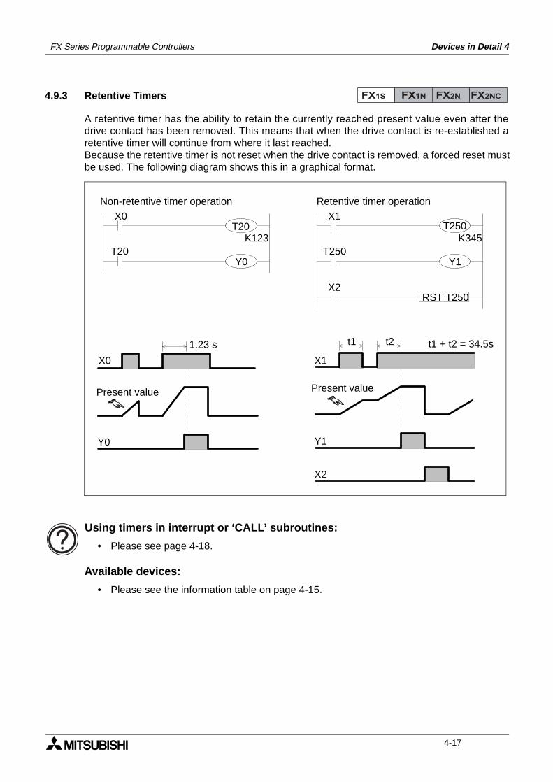
FX Series Programmable Controllers Devices in Detail 4
4.9.3 Retentive Timers
A retentive timer has the ability to retain the currently reached present value even after thedrive contact has been removed. This means that when the drive contact is re-established aretentive timer will continue from where it last reached.Because the retentive timer is not reset when the drive contact is removed, a forced reset mustbe used. The following diagram shows this in a graphical format.
Using timers in interrupt or ‘CALL’ subroutines:
• Please see page 4-18.
Available devices:
• Please see the information table on page 4-15.
FX1S FX1N FX2N FX2NC
X0
Y0
1.23 s t1 t2
X1
Y1
X2
t1 + t2 = 34.5s
X0T20
T20K123
X1
T250K345
X2T250RST
Y0 Y1
T250
Present value Present value
Non-retentive timer operation Retentive timer operation
4-17
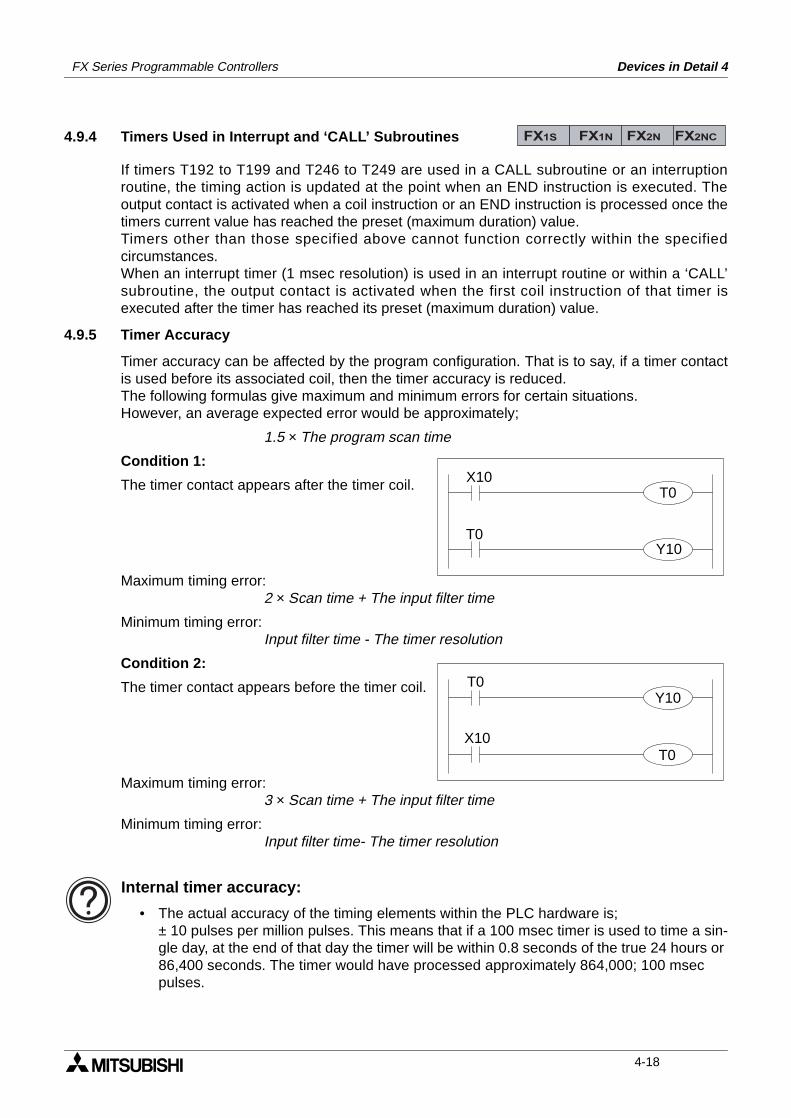
FX Series Programmable Controllers Devices in Detail 4
4.9.4 Timers Used in Interrupt and ‘CALL’ Subroutines
If timers T192 to T199 and T246 to T249 are used in a CALL subroutine or an interruptionroutine, the timing action is updated at the point when an END instruction is executed. Theoutput contact is activated when a coil instruction or an END instruction is processed once thetimers current value has reached the preset (maximum duration) value.Timers other than those specified above cannot function correctly within the specifiedcircumstances.When an interrupt timer (1 msec resolution) is used in an interrupt routine or within a ‘CALL’subroutine, the output contact is activated when the first coil instruction of that timer isexecuted after the timer has reached its preset (maximum duration) value.
4.9.5 Timer Accuracy
Timer accuracy can be affected by the program configuration. That is to say, if a timer contactis used before its associated coil, then the timer accuracy is reduced.The following formulas give maximum and minimum errors for certain situations.However, an average expected error would be approximately;
1.5 × The program scan time
Condition 1:
The timer contact appears after the timer coil.
Maximum timing error:2 × Scan time + The input filter time
Minimum timing error:Input filter time - The timer resolution
Condition 2:
The timer contact appears before the timer coil.
Maximum timing error:3 × Scan time + The input filter time
Minimum timing error:Input filter time- The timer resolution
Internal timer accuracy:
• The actual accuracy of the timing elements within the PLC hardware is;± 10 pulses per million pulses. This means that if a 100 msec timer is used to time a sin-gle day, at the end of that day the timer will be within 0.8 seconds of the true 24 hours or 86,400 seconds. The timer would have processed approximately 864,000; 100 msec pulses.
FX1S FX1N FX2N FX2NC
X10T0
T0Y10
X10
T0Y10
T0
4-18
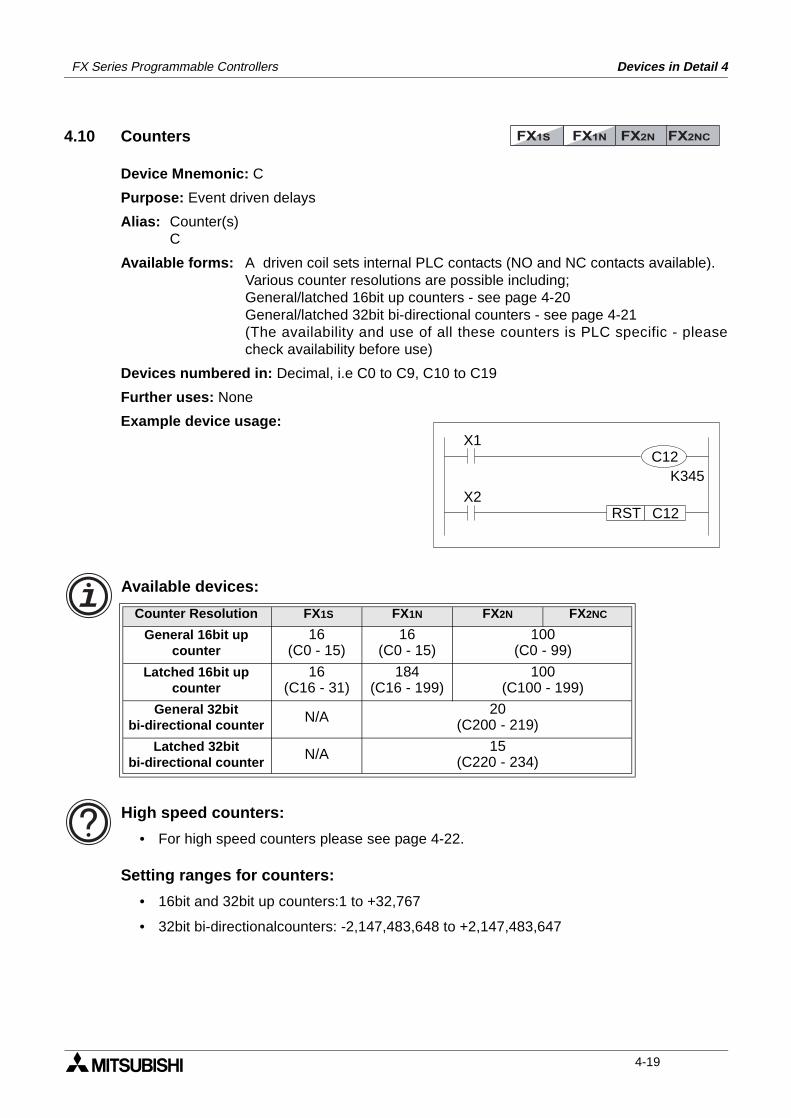
FX Series Programmable Controllers Devices in Detail 4
4.10 Counters
Device Mnemonic: C
Purpose: Event driven delays
Alias: Counter(s)C
Available forms: A driven coil sets internal PLC contacts (NO and NC contacts available).Various counter resolutions are possible including;General/latched 16bit up counters - see page 4-20General/latched 32bit bi-directional counters - see page 4-21(The availability and use of all these counters is PLC specific - pleasecheck availability before use)
Devices numbered in: Decimal, i.e C0 to C9, C10 to C19
Further uses: None
Example device usage:
Available devices:
High speed counters:
• For high speed counters please see page 4-22.
Setting ranges for counters:
• 16bit and 32bit up counters:1 to +32,767
• 32bit bi-directionalcounters: -2,147,483,648 to +2,147,483,647
Counter Resolution FX1S FX1N FX2N FX2NC
General 16bit upcounter
16(C0 - 15)
16(C0 - 15)
100(C0 - 99)
Latched 16bit upcounter
16(C16 - 31)
184(C16 - 199)
100(C100 - 199)
General 32bitbi-directional counter
N/A 20(C200 - 219)
Latched 32bitbi-directional counter
N/A 15(C220 - 234)
FX1S FX1N FX2N FX2NC
X1
K345X2
C12RST
C12
4-19
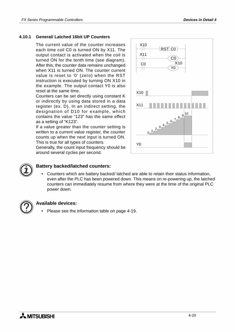
FX Series Programmable Controllers Devices in Detail 4
4.10.1 General/ Latched 16bit UP Counters
The current value of the counter increaseseach time coil C0 is turned ON by X11. Theoutput contact is activated when the coil isturned ON for the tenth time (see diagram).After this, the counter data remains unchangedwhen X11 is turned ON. The counter currentvalue is reset to ‘0’ (zero) when the RSTinstruction is executed by turning ON X10 inthe example. The output contact Y0 is alsoreset at the same time.Counters can be set directly using constant Kor indirectly by using data stored in a dataregister (ex. D). In an indirect setting, thedesignat ion of D10 for example, whichcontains the value “123” has the same effectas a setting of “K123”.If a value greater than the counter setting iswritten to a current value register, the countercounts up when the next input is turned ON.This is true for all types of counters.Generally, the count input frequency should bearound several cycles per second.
Battery backed/latched counters:
• Counters which are battery backed/ latched are able to retain their status information, even after the PLC has been powered down. This means on re-powering up, the latched counters can immediately resume from where they were at the time of the original PLC power down.
Available devices:
• Please see the information table on page 4-19.
01
23
45
67
89
10
X10
X11
Y0
X11
K10
X10C0RST
C0C0
Y0
4-20
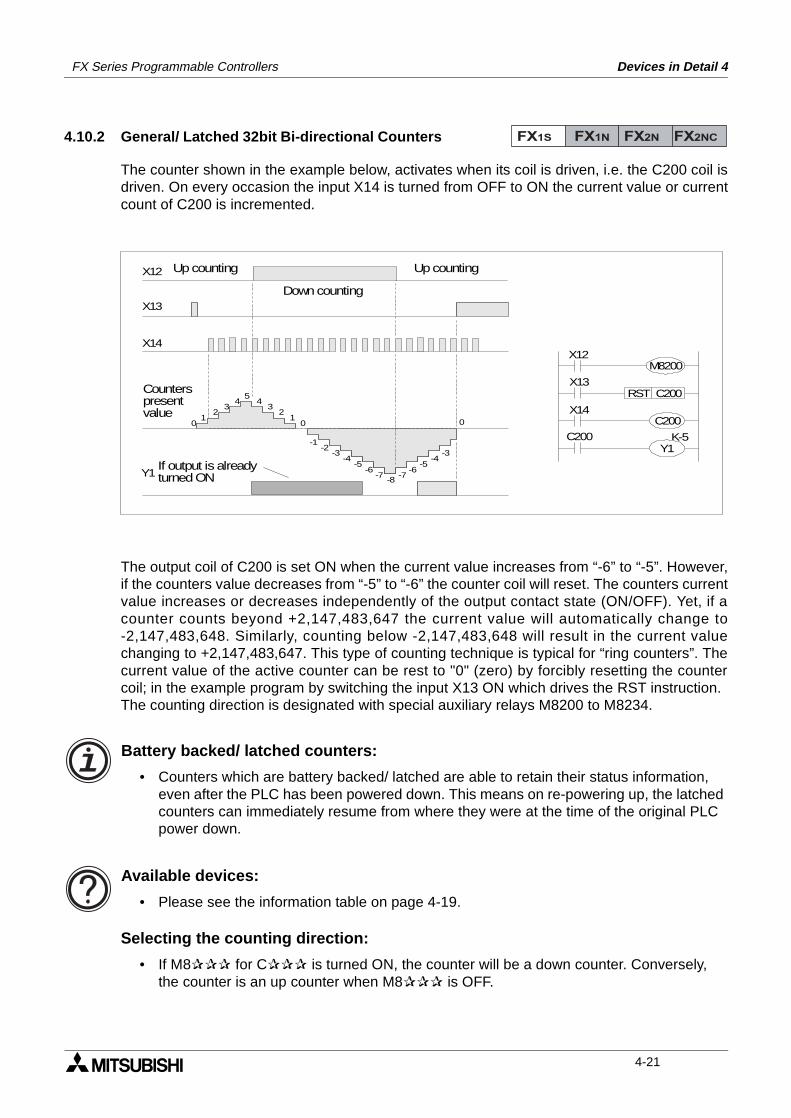
FX Series Programmable Controllers Devices in Detail 4
4.10.2 General/ Latched 32bit Bi-directional Counters
The counter shown in the example below, activates when its coil is driven, i.e. the C200 coil isdriven. On every occasion the input X14 is turned from OFF to ON the current value or currentcount of C200 is incremented.
The output coil of C200 is set ON when the current value increases from “-6” to “-5”. However,if the counters value decreases from “-5” to “-6” the counter coil will reset. The counters currentvalue increases or decreases independently of the output contact state (ON/OFF). Yet, if acounter counts beyond +2,147,483,647 the current value will automatically change to-2,147,483,648. Similarly, counting below -2,147,483,648 will result in the current valuechanging to +2,147,483,647. This type of counting technique is typical for “ring counters”. Thecurrent value of the active counter can be rest to "0" (zero) by forcibly resetting the countercoil; in the example program by switching the input X13 ON which drives the RST instruction.The counting direction is designated with special auxiliary relays M8200 to M8234.
Battery backed/ latched counters:
• Counters which are battery backed/ latched are able to retain their status information, even after the PLC has been powered down. This means on re-powering up, the latched counters can immediately resume from where they were at the time of the original PLC power down.
Available devices:
• Please see the information table on page 4-19.
Selecting the counting direction:
• If M8 for C is turned ON, the counter will be a down counter. Conversely,the counter is an up counter when M8 is OFF.
FX1S FX1N FX2N FX2NC
X13
X14
01
23
45
01
23
4
-6-5
-4-3
-2-1
-7-8
-6-5
-4-3
-7
0
Y1
X12
X14
K-5
X13C200RST
C200
X12M8200
C200
Y1
If output is alreadyturned ON
Counterspresentvalue
Up counting
Down counting
Up counting
4-21
FX Series Programmable Controllers Devices in Detail 4
4.11 High Speed Counters
Device Mnemonic: C
Purpose: High speed event driven delays
Alias: Counter (s)CHigh speed counter (s)Phase counters
Available forms: A driven coil sets internal PLC contacts (NO and NC contacts available).There are various types of high speed counter available but the quantityand function vary from PLC to PLC. Please check the following sections fordevice availability;
FX1S and FX1N - see page 4-24FX2N and FX2NC - see page 4-25
The following sections refer to counter types;1 phase counters (user start and reset) - see page 4-291 phase counters (assigned start and reset) - see page 4-302 phase bi-directional counters - see page 4-31A/B phase counters - see page 4-32
Devices numbered in: Decimal, i.e C235 to C255
Further uses: None
Example device usage:For examples on each of the available forms please see the relevantsections.
Basic high speed counter operation:
• For information on basic high speed counters please see page 4-23.
FX1S FX1N FX2N FX2NC
4-22
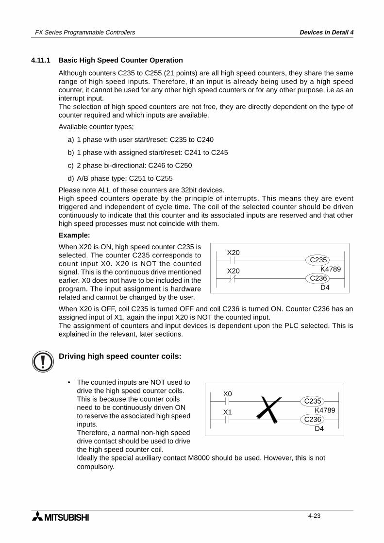
FX Series Programmable Controllers Devices in Detail 4
4.11.1 Basic High Speed Counter Operation
Although counters C235 to C255 (21 points) are all high speed counters, they share the samerange of high speed inputs. Therefore, if an input is already being used by a high speedcounter, it cannot be used for any other high speed counters or for any other purpose, i.e as aninterrupt input.The selection of high speed counters are not free, they are directly dependent on the type ofcounter required and which inputs are available.
Available counter types;
a) 1 phase with user start/reset: C235 to C240
b) 1 phase with assigned start/reset: C241 to C245
c) 2 phase bi-directional: C246 to C250
d) A/B phase type: C251 to C255
Please note ALL of these counters are 32bit devices.High speed counters operate by the principle of interrupts. This means they are eventtriggered and independent of cycle time. The coil of the selected counter should be drivencontinuously to indicate that this counter and its associated inputs are reserved and that otherhigh speed processes must not coincide with them.
Example:
When X20 is ON, high speed counter C235 isselected. The counter C235 corresponds tocount input X0. X20 is NOT the countedsignal. This is the continuous drive mentionedearlier. X0 does not have to be included in theprogram. The input assignment is hardwarerelated and cannot be changed by the user.
When X20 is OFF, coil C235 is turned OFF and coil C236 is turned ON. Counter C236 has anassigned input of X1, again the input X20 is NOT the counted input.The assignment of counters and input devices is dependent upon the PLC selected. This isexplained in the relevant, later sections.
Driving high speed counter coils:
• The counted inputs are NOT used to drive the high speed counter coils.This is because the counter coils need to be continuously driven ON to reserve the associated high speed inputs.Therefore, a normal non-high speed drive contact should be used to drive the high speed counter coil.Ideally the special auxiliary contact M8000 should be used. However, this is not compulsory.
X20
K4789X20
D4
C235
C236
X0
K4789X1
D4
C235
C236
4-23
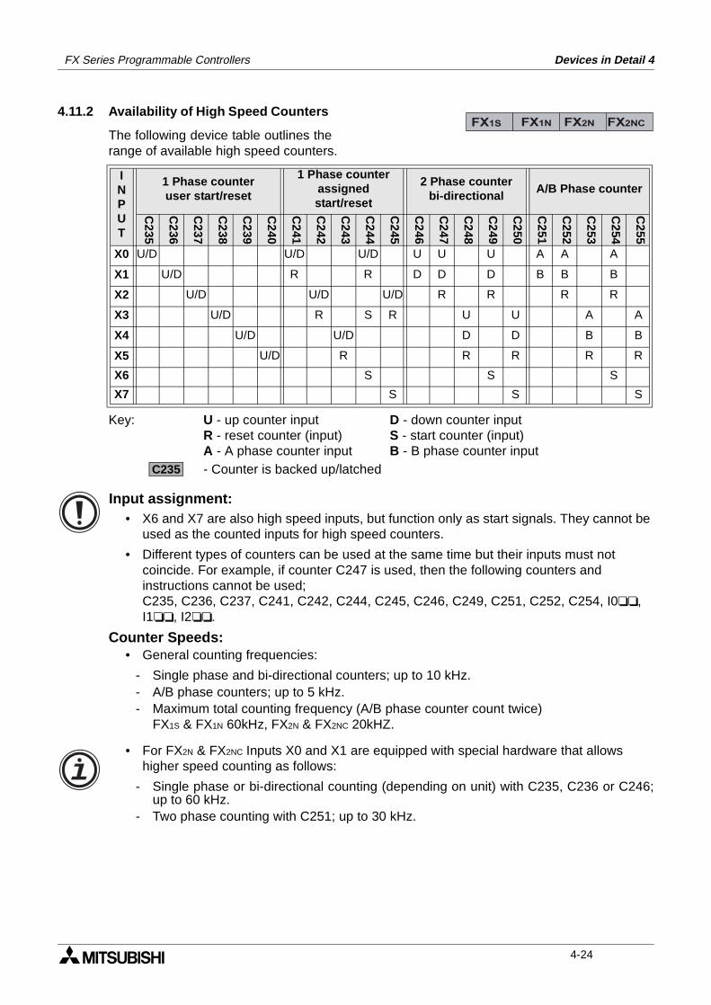
FX Series Programmable Controllers Devices in Detail 4
4.11.2 Availability of High Speed Counters
The following device table outlines therange of available high speed counters.
Key: U - up counter input D - down counter inputR - reset counter (input) S - start counter (input)A - A phase counter input B - B phase counter input- Counter is backed up/latched
Input assignment:• X6 and X7 are also high speed inputs, but function only as start signals. They cannot be
used as the counted inputs for high speed counters.
• Different types of counters can be used at the same time but their inputs must not coincide. For example, if counter C247 is used, then the following counters and instructions cannot be used;C235, C236, C237, C241, C242, C244, C245, C246, C249, C251, C252, C254, I0, I1, I2.
Counter Speeds:• General counting frequencies:
- Single phase and bi-directional counters; up to 10 kHz.- A/B phase counters; up to 5 kHz.- Maximum total counting frequency (A/B phase counter count twice)
FX1S & FX1N 60kHz, FX2N & FX2NC 20kHZ.
• For FX2N & FX2NC Inputs X0 and X1 are equipped with special hardware that allows higher speed counting as follows:
- Single phase or bi-directional counting (depending on unit) with C235, C236 or C246;up to 60 kHz.
- Two phase counting with C251; up to 30 kHz.
INPUT
1 Phase counteruser start/reset
1 Phase counterassignedstart/reset
2 Phase counterbi-directional
A/B Phase counter
C235
C236
C237
C238
C239
C240
C241
C242
C243
C244
C245
C246
C247
C248
C249
C250
C251
C252
C253
C254
C255
X0 U/D U/D U/D U U U A A A
X1 U/D R R D D D B B B
X2 U/D U/D U/D R R R R
X3 U/D R S R U U A A
X4 U/D U/D D D B B
X5 U/D R R R R R
X6 S S S
X7 S S S
FX1S FX1N FX2N FX2NC
C235
4-24
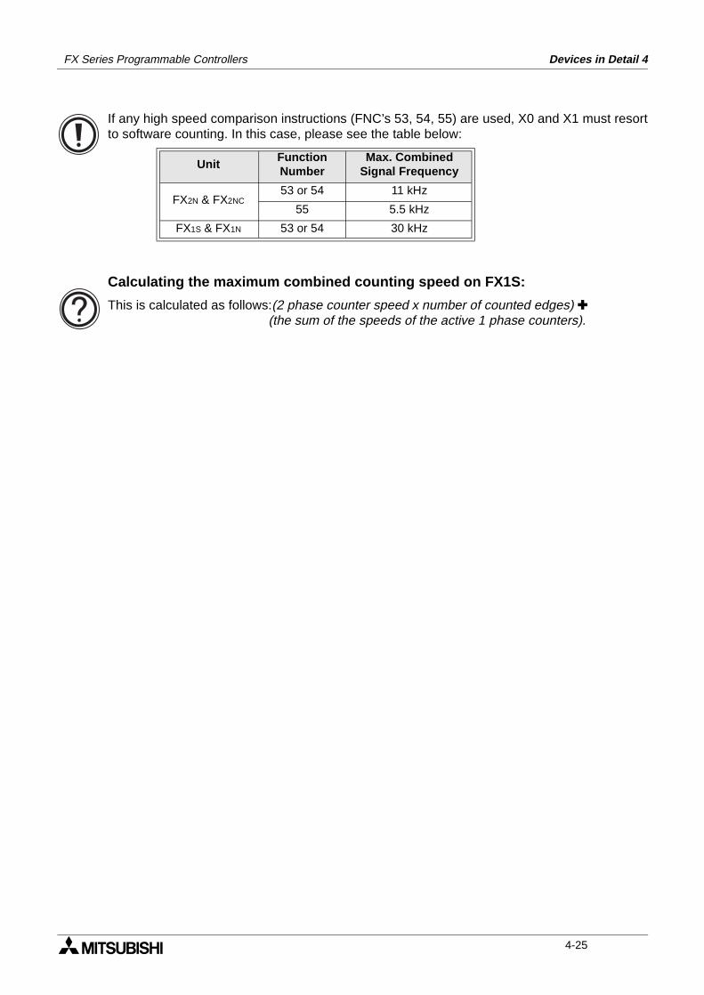
FX Series Programmable Controllers Devices in Detail 4
If any high speed comparison instructions (FNC’s 53, 54, 55) are used, X0 and X1 must resortto software counting. In this case, please see the table below:
UnitFunctionNumber
Max. Combined Signal Frequency
FX2N & FX2NC53 or 54 11 kHz
55 5.5 kHz
FX1S & FX1N 53 or 54 30 kHz
Calculating the maximum combined counting speed on FX1S:
This is calculated as follows:(2 phase counter speed x number of counted edges) (the sum of the speeds of the active 1 phase counters).
4-25
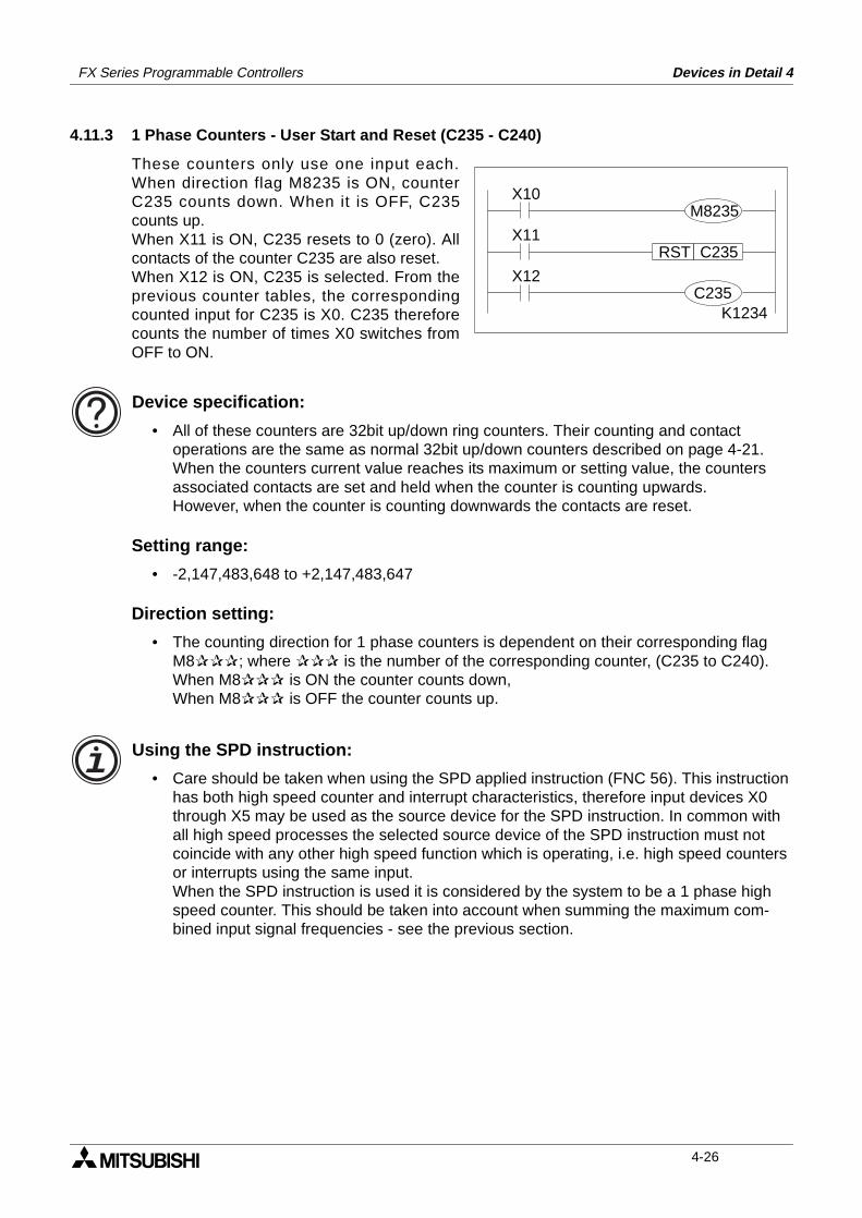
FX Series Programmable Controllers Devices in Detail 4
4.11.3 1 Phase Counters - User Start and Reset (C235 - C240)
These counters only use one input each.When direction flag M8235 is ON, counterC235 counts down. When it is OFF, C235counts up.When X11 is ON, C235 resets to 0 (zero). Allcontacts of the counter C235 are also reset.When X12 is ON, C235 is selected. From theprevious counter tables, the correspondingcounted input for C235 is X0. C235 thereforecounts the number of times X0 switches fromOFF to ON.
Device specification:
• All of these counters are 32bit up/down ring counters. Their counting and contact operations are the same as normal 32bit up/down counters described on page 4-21.When the counters current value reaches its maximum or setting value, the counters associated contacts are set and held when the counter is counting upwards.However, when the counter is counting downwards the contacts are reset.
Setting range:
• -2,147,483,648 to +2,147,483,647
Direction setting:
• The counting direction for 1 phase counters is dependent on their corresponding flag M8; where is the number of the corresponding counter, (C235 to C240).When M8 is ON the counter counts down,When M8 is OFF the counter counts up.
Using the SPD instruction:
• Care should be taken when using the SPD applied instruction (FNC 56). This instruction has both high speed counter and interrupt characteristics, therefore input devices X0 through X5 may be used as the source device for the SPD instruction. In common with all high speed processes the selected source device of the SPD instruction must not coincide with any other high speed function which is operating, i.e. high speed counters or interrupts using the same input.When the SPD instruction is used it is considered by the system to be a 1 phase high speed counter. This should be taken into account when summing the maximum com-bined input signal frequencies - see the previous section.
X12
K1234
C235RST
X10
X11
M8235
C235
4-26
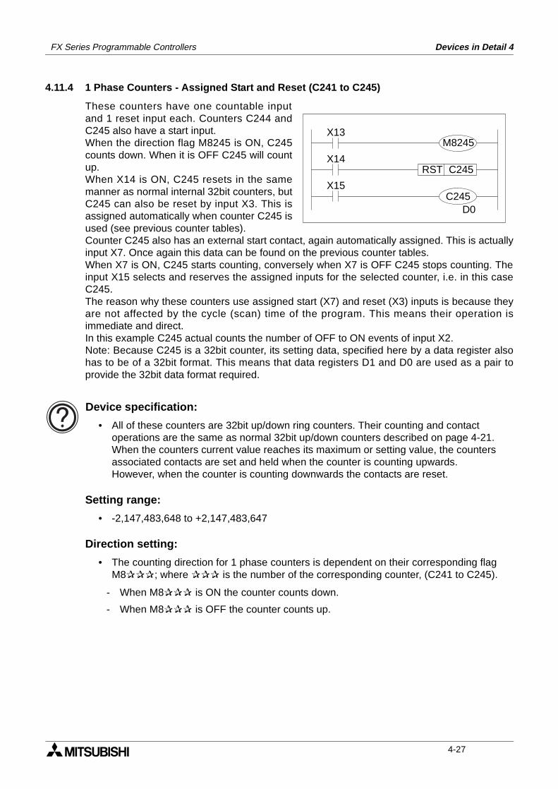
FX Series Programmable Controllers Devices in Detail 4
4.11.4 1 Phase Counters - Assigned Start and Reset (C241 to C245)
These counters have one countable inputand 1 reset input each. Counters C244 andC245 also have a start input.When the direction flag M8245 is ON, C245counts down. When it is OFF C245 will countup.When X14 is ON, C245 resets in the samemanner as normal internal 32bit counters, butC245 can also be reset by input X3. This isassigned automatically when counter C245 isused (see previous counter tables).Counter C245 also has an external start contact, again automatically assigned. This is actuallyinput X7. Once again this data can be found on the previous counter tables.When X7 is ON, C245 starts counting, conversely when X7 is OFF C245 stops counting. Theinput X15 selects and reserves the assigned inputs for the selected counter, i.e. in this caseC245.The reason why these counters use assigned start (X7) and reset (X3) inputs is because theyare not affected by the cycle (scan) time of the program. This means their operation isimmediate and direct.In this example C245 actual counts the number of OFF to ON events of input X2.Note: Because C245 is a 32bit counter, its setting data, specified here by a data register alsohas to be of a 32bit format. This means that data registers D1 and D0 are used as a pair toprovide the 32bit data format required.
Device specification:
• All of these counters are 32bit up/down ring counters. Their counting and contact operations are the same as normal 32bit up/down counters described on page 4-21.When the counters current value reaches its maximum or setting value, the counters associated contacts are set and held when the counter is counting upwards.However, when the counter is counting downwards the contacts are reset.
Setting range:
• -2,147,483,648 to +2,147,483,647
Direction setting:
• The counting direction for 1 phase counters is dependent on their corresponding flag M8; where is the number of the corresponding counter, (C241 to C245).
- When M8 is ON the counter counts down.
- When M8 is OFF the counter counts up.
X15
D0
C245RST
X13
X14
M8245
C245
4-27
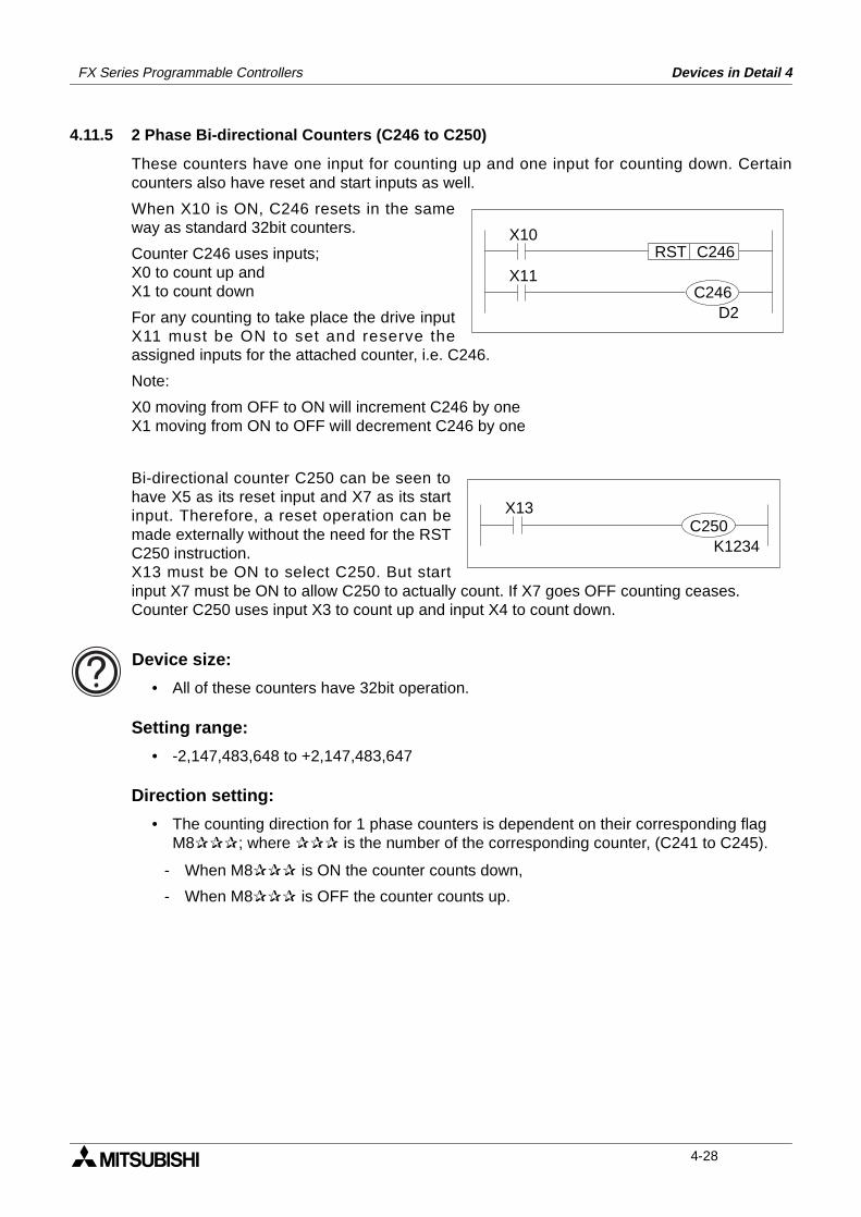
FX Series Programmable Controllers Devices in Detail 4
4.11.5 2 Phase Bi-directional Counters (C246 to C250)
These counters have one input for counting up and one input for counting down. Certaincounters also have reset and start inputs as well.
When X10 is ON, C246 resets in the sameway as standard 32bit counters.
Counter C246 uses inputs;X0 to count up andX1 to count down
For any counting to take place the drive inputX11 must be ON to set and reserve theassigned inputs for the attached counter, i.e. C246.
Note:
X0 moving from OFF to ON will increment C246 by oneX1 moving from ON to OFF will decrement C246 by one
Bi-directional counter C250 can be seen tohave X5 as its reset input and X7 as its startinput. Therefore, a reset operation can bemade externally without the need for the RSTC250 instruction.X13 must be ON to select C250. But startinput X7 must be ON to allow C250 to actually count. If X7 goes OFF counting ceases.Counter C250 uses input X3 to count up and input X4 to count down.
Device size:
• All of these counters have 32bit operation.
Setting range:
• -2,147,483,648 to +2,147,483,647
Direction setting:
• The counting direction for 1 phase counters is dependent on their corresponding flag M8; where is the number of the corresponding counter, (C241 to C245).
- When M8 is ON the counter counts down,
- When M8 is OFF the counter counts up.
X11
D2
C246RSTX10
C246
X13
K1234C250
4-28
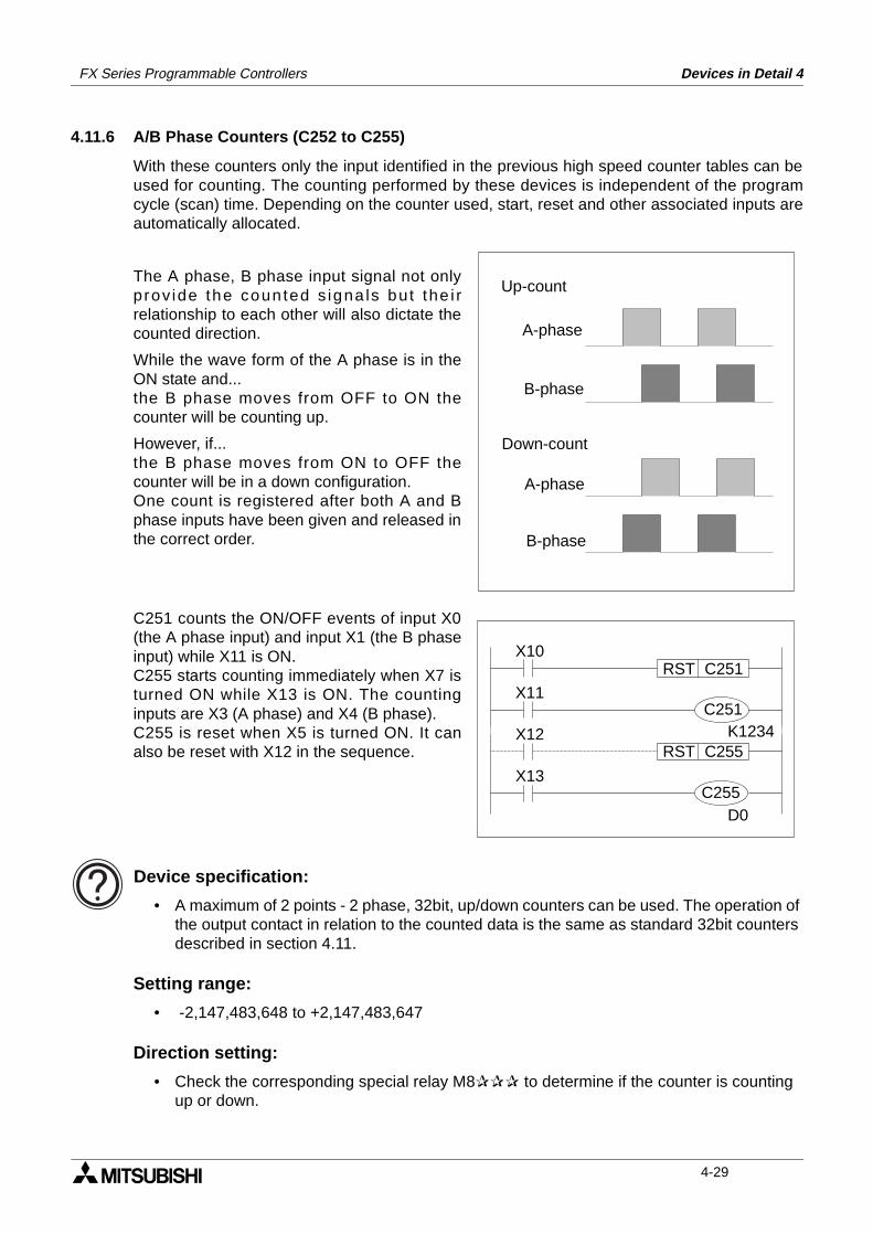
FX Series Programmable Controllers Devices in Detail 4
4.11.6 A/B Phase Counters (C252 to C255)
With these counters only the input identified in the previous high speed counter tables can beused for counting. The counting performed by these devices is independent of the programcycle (scan) time. Depending on the counter used, start, reset and other associated inputs areautomatically allocated.
The A phase, B phase input signal not onlyprov ide the coun ted s igna ls but the i rrelationship to each other will also dictate thecounted direction.
While the wave form of the A phase is in theON state and...the B phase moves from OFF to ON thecounter will be counting up.
However, if...the B phase moves from ON to OFF thecounter will be in a down configuration.One count is registered after both A and Bphase inputs have been given and released inthe correct order.
C251 counts the ON/OFF events of input X0(the A phase input) and input X1 (the B phaseinput) while X11 is ON.C255 starts counting immediately when X7 isturned ON while X13 is ON. The countinginputs are X3 (A phase) and X4 (B phase).C255 is reset when X5 is turned ON. It canalso be reset with X12 in the sequence.
Device specification:
• A maximum of 2 points - 2 phase, 32bit, up/down counters can be used. The operation of the output contact in relation to the counted data is the same as standard 32bit counters described in section 4.11.
Setting range:
• -2,147,483,648 to +2,147,483,647
Direction setting:
• Check the corresponding special relay M8 to determine if the counter is counting up or down.
A-phase
B-phase
A-phase
B-phase
Up-count
Down-count
X11
K1234
C251RSTX10
X13
D0
C255RSTX12
C251
C255
4-29
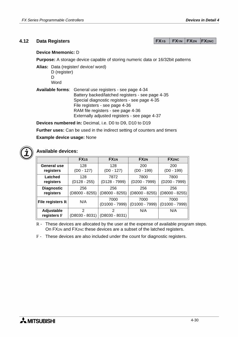
FX Series Programmable Controllers Devices in Detail 4
4.12 Data Registers
Device Mnemonic: D
Purpose: A storage device capable of storing numeric data or 16/32bit patterns
Alias: Data (register/ device/ word)D (register)DWord
Available forms: General use registers - see page 4-34Battery backed/latched registers - see page 4-35Special diagnostic registers - see page 4-35File registers - see page 4-36RAM file registers - see page 4-36Externally adjusted registers - see page 4-37
Devices numbered in: Decimal, i.e. D0 to D9, D10 to D19
Further uses: Can be used in the indirect setting of counters and timers
Example device usage: None
Available devices:
R - These devices are allocated by the user at the expense of available program steps.On FX2N and FX2NC these devices are a subset of the latched registers.
F - These devices are also included under the count for diagnostic registers.
FX1S FX1N FX2N FX2NC
General useregisters
128(D0 - 127)
128(D0 - 127)
200(D0 - 199)
200(D0 - 199)
Latchedregisters
128(D128 - 255)
7872(D128 - 7999)
7800(D200 - 7999)
7800(D200 - 7999)
Diagnosticregisters
256(D8000 - 8255)
256(D8000 - 8255)
256(D8000 - 8255)
256(D8000 - 8255)
File registers R N/A7000
(D1000 - 7999)7000
(D1000 - 7999)7000
(D1000 - 7999)
Adjustableregisters F
2(D8030 - 8031)
2(D8030 - 8031)
N/A N/A
FX1S FX1N FX2N FX2NC
4-30
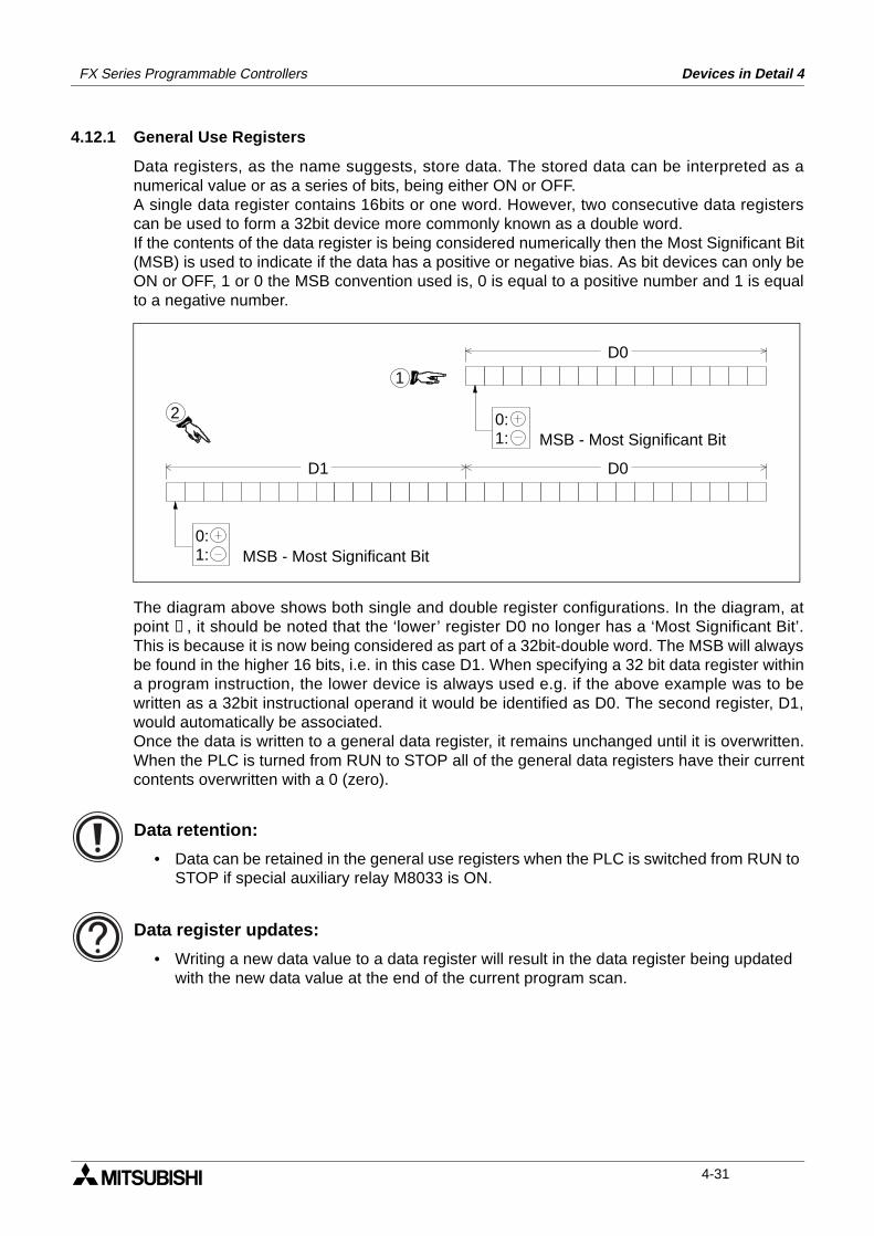
FX Series Programmable Controllers Devices in Detail 4
4.12.1 General Use Registers
Data registers, as the name suggests, store data. The stored data can be interpreted as anumerical value or as a series of bits, being either ON or OFF.A single data register contains 16bits or one word. However, two consecutive data registerscan be used to form a 32bit device more commonly known as a double word.If the contents of the data register is being considered numerically then the Most Significant Bit(MSB) is used to indicate if the data has a positive or negative bias. As bit devices can only beON or OFF, 1 or 0 the MSB convention used is, 0 is equal to a positive number and 1 is equalto a negative number.
The diagram above shows both single and double register configurations. In the diagram, atpoint ➁, it should be noted that the ‘lower’ register D0 no longer has a ‘Most Significant Bit’.This is because it is now being considered as part of a 32bit-double word. The MSB will alwaysbe found in the higher 16 bits, i.e. in this case D1. When specifying a 32 bit data register withina program instruction, the lower device is always used e.g. if the above example was to bewritten as a 32bit instructional operand it would be identified as D0. The second register, D1,would automatically be associated.Once the data is written to a general data register, it remains unchanged until it is overwritten.When the PLC is turned from RUN to STOP all of the general data registers have their currentcontents overwritten with a 0 (zero).
Data retention:
• Data can be retained in the general use registers when the PLC is switched from RUN to STOP if special auxiliary relay M8033 is ON.
Data register updates:
• Writing a new data value to a data register will result in the data register being updated with the new data value at the end of the current program scan.
D1 D0
D0
0:1:
0:1:
2
1
MSB - Most Significant Bit
MSB - Most Significant Bit
4-31
FX Series Programmable Controllers Devices in Detail 4
4.12.2 Battery Backed/ Latched Registers
Once data is written to a battery backed register, it remains unchanged until it is overwritten.When the PLC’s status is changed from RUN to STOP, the data in these registers is retained.The range of devices that are battery backed can be changed by adjusting the parameters ofthe PLC. For details of how to do this please refer to the appropriate programming toolsmanual.
Using the FX2-40AW/AP:
• When using an FX with either the FX2-40AW or the FX2-40AP a proportion of the latched data registers are automatically assigned for communications use by the FX2-40AW/AP module.
Communication between Master and Slave 100 points M800 to M89910 points D490 to D499
Communication between Slave and Master 100 points M900 to M99910 points D500 to D509
4.12.3 Special Diagnostic Registers
Special registers are used to control or monitor various modes or devices inside the PLC. Datawritten in these registers are set to the default values when the power supply to the PLC isturned ON.
- Note: When the power is turned ON, all registers are first cleared to 0 (zero) and then thedefault values are automatically written to the appropriate registers by the systemsoftware. For example, the watchdog timer data is written to D8000 by the systemsoftware. To change the setting, the user must write the required value over what iscurrently stored in D8000.
Data stored in the special diagnostic registers will remain unchanged when the PLC isswitched from STOP mode into RUN.
Use of diagnostic registers:
• On no account should unidentified devices be used. If a device is used, it should only be for the purpose identified in this manual. Please see chapter 6 for tables containing data and descriptions of the available devices for each PLC.
4-32
FX Series Programmable Controllers Devices in Detail 4
4.12.4 File Registers
Program memory registers
File registers can be secured in the program memory (EEPROM or EPROM) in units of 500points. These registers can be accessed with a peripheral device. While the PLC is operating,data in the file registers can be read to the general-use/ battery backed/ latched registers byusing the BMOV instruction.File registers are actually setup in the parameter area of the PLC. For every block of 500 fileregisters allocated and equivalent block of 500 program steps are lost.
Note: The device range for file registers in the FX1N, FX2N and FX2NC overlaps with the latcheddata registers. The allocation of these devices as file registers ensures that the data is keptwith the program.
Writing to file registers:
• FX1S file register data can only be changed by a peripheral device such as a hand held programmer or a personal computer running the appropriate software.For details of how to carry out the changes please reference the relevant operation manual for guidance.
• FX1N, FX2N and FX2NC file register data can also be changed by the program using the BMOV instruction.
Special caution when using FX1S:
• No file registers can be modified during RUN.
Available devices:
• Please refer to the table on page 4-33 or chapters 6 and 8, where further details of the availability of devices can be found.
FX1S FX1N FX2N FX2NC
4-33
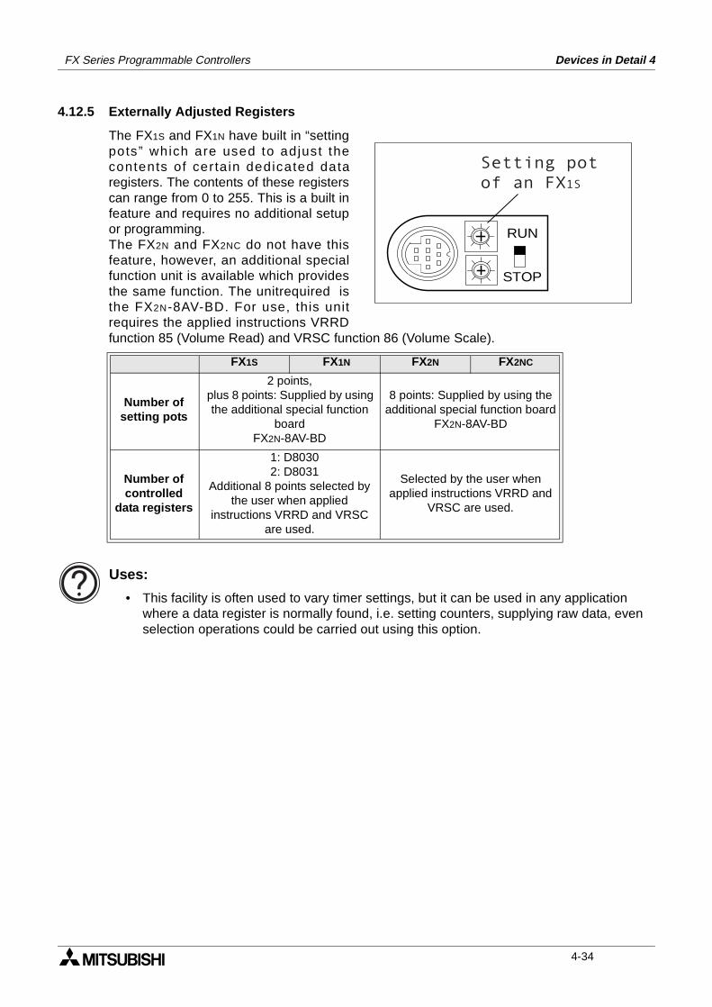
FX Series Programmable Controllers Devices in Detail 4
4.12.5 Externally Adjusted Registers
The FX1S and FX1N have built in “settingpots” which are used to adjust thecontents of cer ta in dedicated dataregisters. The contents of these registerscan range from 0 to 255. This is a built infeature and requires no additional setupor programming.The FX2N and FX2NC do not have thisfeature, however, an additional specialfunction unit is available which providesthe same function. The unitrequired isthe FX2N-8AV-BD. For use, this unitrequires the applied instructions VRRDfunction 85 (Volume Read) and VRSC function 86 (Volume Scale).
Uses:
• This facility is often used to vary timer settings, but it can be used in any application where a data register is normally found, i.e. setting counters, supplying raw data, even selection operations could be carried out using this option.
FX1S FX1N FX2N FX2NC
Number ofsetting pots
2 points, plus 8 points: Supplied by using
the additional special function board
FX2N-8AV-BD
8 points: Supplied by using the additional special function board
FX2N-8AV-BD
Number of controlled
data registers
1: D8030 2: D8031
Additional 8 points selected by the user when applied
instructions VRRD and VRSC are used.
Selected by the user when applied instructions VRRD and
VRSC are used.
RUN
STOP
Setting pot
of an FX1S
4-34
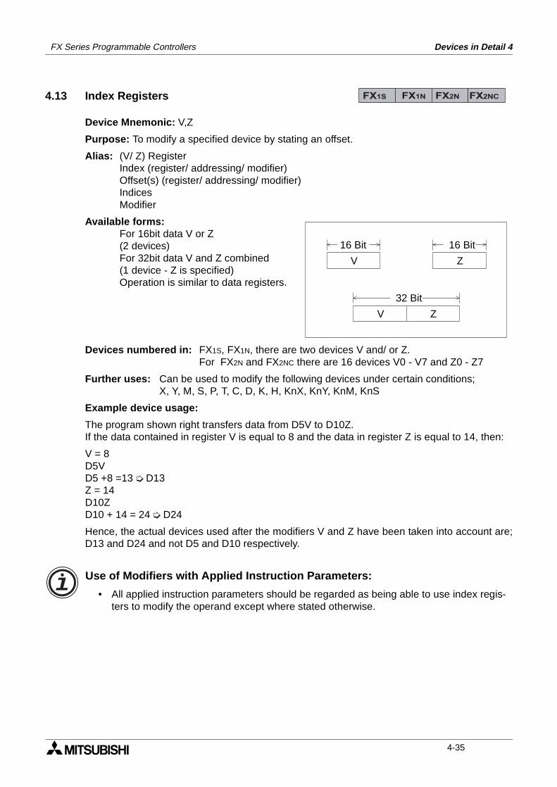
FX Series Programmable Controllers Devices in Detail 4
4.13 Index Registers
Device Mnemonic: V,Z
Purpose: To modify a specified device by stating an offset.
Alias: (V/ Z) RegisterIndex (register/ addressing/ modifier)Offset(s) (register/ addressing/ modifier)IndicesModifier
Available forms:For 16bit data V or Z(2 devices)For 32bit data V and Z combined(1 device - Z is specified)Operation is similar to data registers.
Devices numbered in: FX1S, FX1N, there are two devices V and/ or Z.For FX2N and FX2NC there are 16 devices V0 - V7 and Z0 - Z7
Further uses: Can be used to modify the following devices under certain conditions;X, Y, M, S, P, T, C, D, K, H, KnX, KnY, KnM, KnS
Example device usage:
The program shown right transfers data from D5V to D10Z.If the data contained in register V is equal to 8 and the data in register Z is equal to 14, then:
V = 8D5VD5 +8 =13 D13Z = 14D10ZD10 + 14 = 24 D24
Hence, the actual devices used after the modifiers V and Z have been taken into account are;D13 and D24 and not D5 and D10 respectively.
Use of Modifiers with Applied Instruction Parameters:
• All applied instruction parameters should be regarded as being able to use index regis-ters to modify the operand except where stated otherwise.
FX1S FX1N FX2N FX2NC
V Z
V Z
32 Bit
16 Bit 16 Bit
4-35
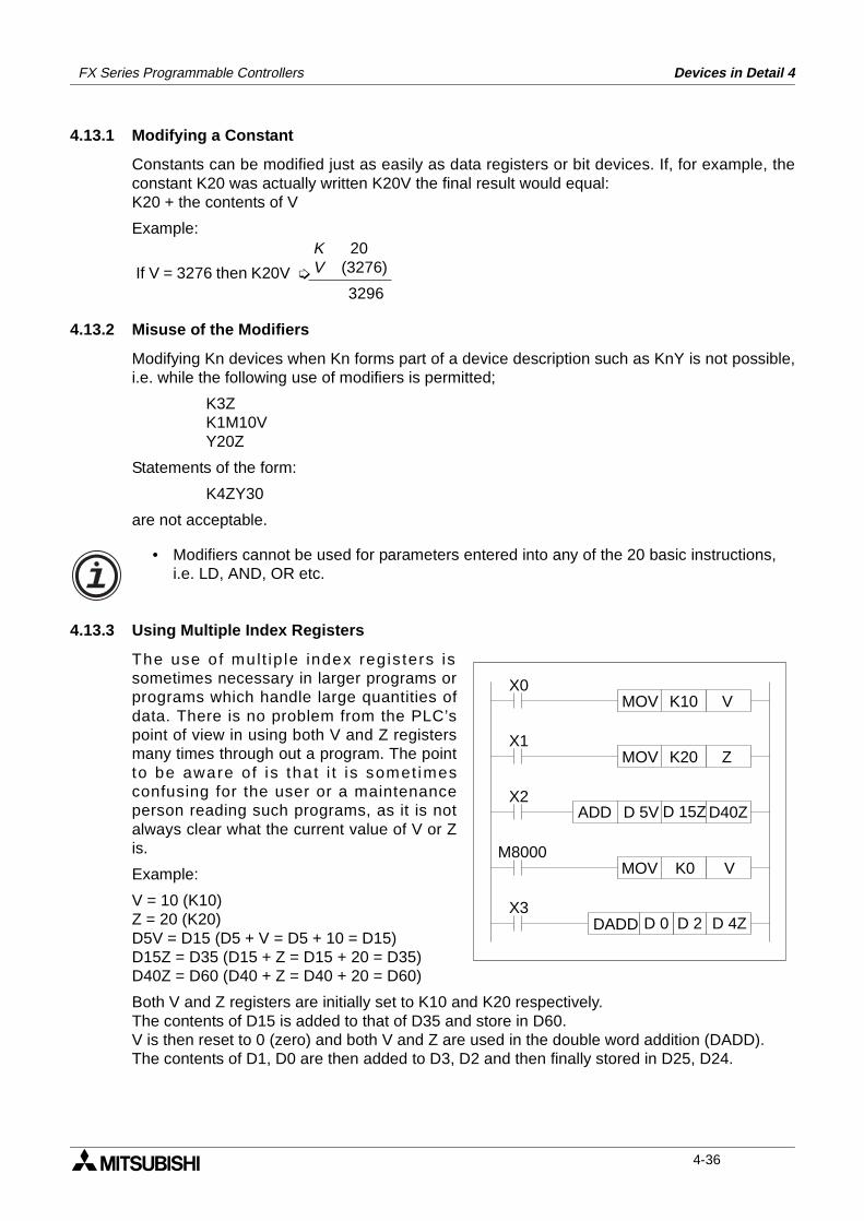
FX Series Programmable Controllers Devices in Detail 4
4.13.1 Modifying a Constant
Constants can be modified just as easily as data registers or bit devices. If, for example, theconstant K20 was actually written K20V the final result would equal: K20 + the contents of V
Example:
4.13.2 Misuse of the Modifiers
Modifying Kn devices when Kn forms part of a device description such as KnY is not possible,i.e. while the following use of modifiers is permitted;
K3ZK1M10VY20Z
Statements of the form:
K4ZY30
are not acceptable.
• Modifiers cannot be used for parameters entered into any of the 20 basic instructions, i.e. LD, AND, OR etc.
4.13.3 Using Multiple Index Registers
The use o f mult ip le index regis ters issometimes necessary in larger programs orprograms which handle large quantities ofdata. There is no problem from the PLC’spoint of view in using both V and Z registersmany times through out a program. The pointto be aware of is that i t is somet imesconfusing for the user or a maintenanceperson reading such programs, as it is notalways clear what the current value of V or Zis.
Example:
V = 10 (K10)Z = 20 (K20)D5V = D15 (D5 + V = D5 + 10 = D15)D15Z = D35 (D15 + Z = D15 + 20 = D35)D40Z = D60 (D40 + Z = D40 + 20 = D60)
Both V and Z registers are initially set to K10 and K20 respectively.The contents of D15 is added to that of D35 and store in D60.V is then reset to 0 (zero) and both V and Z are used in the double word addition (DADD).The contents of D1, D0 are then added to D3, D2 and then finally stored in D25, D24.
If V = 3276 then K20V
K 20V (3276)
3296
X0
D40ZX2
ADD D 5V D 15Z
MOV K10 V
X1MOV K20 Z
M8000MOV K0 V
D 4ZX3
DADD D 0 D 2
4-36
FX Series Programmable Controllers Devices in Detail 4
4.14 Bits, Words, BCD and Hexadecimal
The following section details general topics relating to good device understanding. The sectionis split into several smaller parts with each covering one topic or small group of topics. Some ofthe covered topics are;
Bit devices, individual and grouped - see page 4-40Word devices - see page 4-42Interpreting word data - see page 4-42Two’s compliment - see page 4-45
Available devices:
• For PLC specific available devices please see chapter 8.
4.14.1 Bit Devices, Individual and Grouped
Devices such as X, Y, M and S are bit devices. Bit devices are bi-stable, this means there areonly two states, ON and OFF or 1 and 0. Bit devices can be grouped together to form biggerrepresentations of data, for example 8 consecutive bit devices are some-times referred to as abyte. Further more, 16 consecutive bit devices are referred to as a word and 32 consecutive bitdevices are a double word.The PLC identifies groups of bit devices which should be regarded as a single entity by lookingfor a range marker followed by a head address. This is of the form KnP where P represents thehead address of the bit devices to be used. The Kn portion of the statement identifies therange of devices enclosed. “n” can be a number from the range 0 to 8. Each “n” digit actualrepresents 4 bit devices, i.e K1 = 4 bit devices and K8 = 32 bit devices. Hence all groups of bitdevices are divisible by 4.The diagram and example on the following page explain this idea further........
FX1S FX1N FX2N FX2NC
4-37
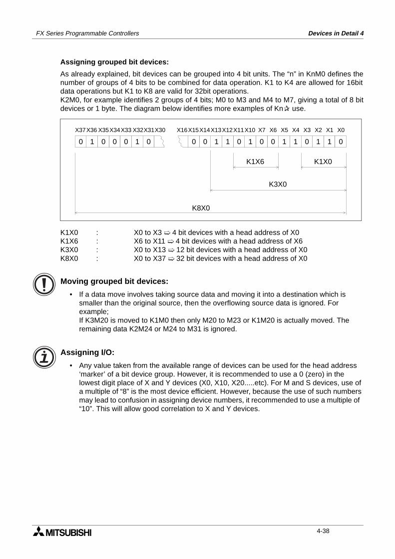
FX Series Programmable Controllers Devices in Detail 4
Assigning grouped bit devices:
As already explained, bit devices can be grouped into 4 bit units. The “n” in KnM0 defines thenumber of groups of 4 bits to be combined for data operation. K1 to K4 are allowed for 16bitdata operations but K1 to K8 are valid for 32bit operations.K2M0, for example identifies 2 groups of 4 bits; M0 to M3 and M4 to M7, giving a total of 8 bitdevices or 1 byte. The diagram below identifies more examples of Kn use.
K1X0 : X0 to X3 4 bit devices with a head address of X0K1X6 : X6 to X11 4 bit devices with a head address of X6K3X0 : X0 to X13 12 bit devices with a head address of X0K8X0 : X0 to X37 32 bit devices with a head address of X0
Moving grouped bit devices:
• If a data move involves taking source data and moving it into a destination which is smaller than the original source, then the overflowing source data is ignored. For example;If K3M20 is moved to K1M0 then only M20 to M23 or K1M20 is actually moved. The remaining data K2M24 or M24 to M31 is ignored.
Assigning I/O:
• Any value taken from the available range of devices can be used for the head address ‘marker’ of a bit device group. However, it is recommended to use a 0 (zero) in the lowest digit place of X and Y devices (X0, X10, X20.....etc). For M and S devices, use of a multiple of “8” is the most device efficient. However, because the use of such numbers may lead to confusion in assigning device numbers, it recommended to use a multiple of “10”. This will allow good correlation to X and Y devices.
1 011 010010110010 00 0 1 0
X0X1X2X3X4X5X6X7X10X11X12X13X14X15X16X31X32X33X34X35X36 X30X37
K1X0K1X6
K3X0
K8X0
4-38
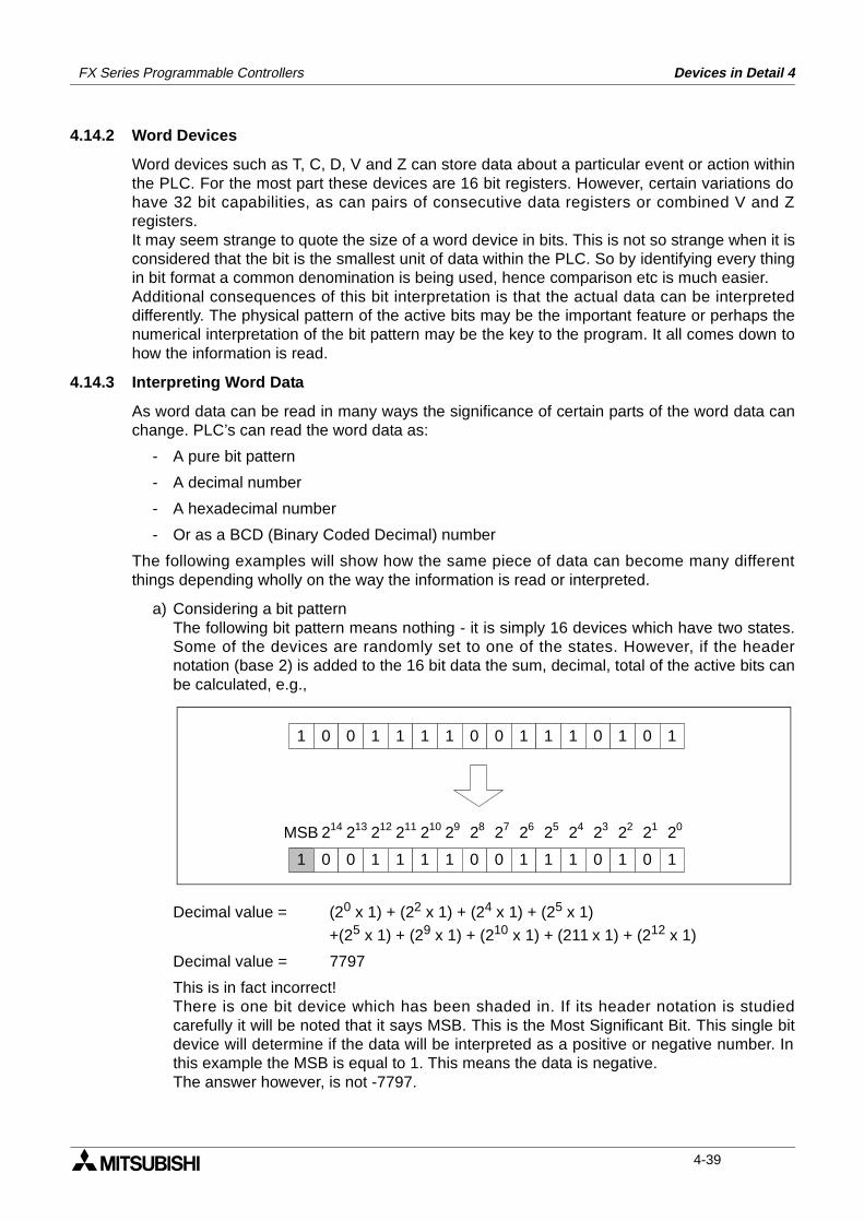
FX Series Programmable Controllers Devices in Detail 4
4.14.2 Word Devices
Word devices such as T, C, D, V and Z can store data about a particular event or action withinthe PLC. For the most part these devices are 16 bit registers. However, certain variations dohave 32 bit capabilities, as can pairs of consecutive data registers or combined V and Zregisters.It may seem strange to quote the size of a word device in bits. This is not so strange when it isconsidered that the bit is the smallest unit of data within the PLC. So by identifying every thingin bit format a common denomination is being used, hence comparison etc is much easier.Additional consequences of this bit interpretation is that the actual data can be interpreteddifferently. The physical pattern of the active bits may be the important feature or perhaps thenumerical interpretation of the bit pattern may be the key to the program. It all comes down tohow the information is read.
4.14.3 Interpreting Word Data
As word data can be read in many ways the significance of certain parts of the word data canchange. PLC’s can read the word data as:
- A pure bit pattern
- A decimal number
- A hexadecimal number
- Or as a BCD (Binary Coded Decimal) number
The following examples will show how the same piece of data can become many differentthings depending wholly on the way the information is read or interpreted.
a) Considering a bit patternThe following bit pattern means nothing - it is simply 16 devices which have two states.Some of the devices are randomly set to one of the states. However, if the headernotation (base 2) is added to the 16 bit data the sum, decimal, total of the active bits canbe calculated, e.g.,
Decimal value = (20 x 1) + (22 x 1) + (24 x 1) + (25 x 1)
+(25 x 1) + (29 x 1) + (210 x 1) + (211 x 1) + (212 x 1)
Decimal value = 7797
This is in fact incorrect!There is one bit device which has been shaded in. If its header notation is studiedcarefully it will be noted that it says MSB. This is the Most Significant Bit. This single bitdevice will determine if the data will be interpreted as a positive or negative number. Inthis example the MSB is equal to 1. This means the data is negative.The answer however, is not -7797.
1 0 0 1 1 1 1 0 0 1 1 1 0 1 0 1
1 0 0 1 1 1 1 0 0 1 1 1 0 1 0 1
2 2 2 2 2 2 2 2 2 2 2 2 2 2 201234567891011121314MSB
4-39
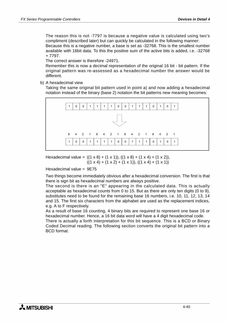
FX Series Programmable Controllers Devices in Detail 4
The reason this is not -7797 is because a negative value is calculated using two’scompliment (described later) but can quickly be calculated in the following manner:Because this is a negative number, a base is set as -32768. This is the smallest numberavailable with 16bit data. To this the positive sum of the active bits is added, i.e. -32768+ 7797.The correct answer is therefore -24971.Remember this is now a decimal representation of the original 16 bit - bit pattern. If theoriginal pattern was re-assessed as a hexadecimal number the answer would bedifferent.
b) A hexadecimal viewTaking the same original bit pattern used in point a) and now adding a hexadecimalnotation instead of the binary (base 2) notation the bit patterns new meaning becomes:
Hexadecimal value = ((1 x 8) + (1 x 1)), ((1 x 8) + (1 x 4) + (1 x 2)),((1 x 4) + (1 x 2) + (1 x 1)), ((1 x 4) + (1 x 1))
Hexadecimal value = 9E75
Two things become immediately obvious after a hexadecimal conversion. The first is thatthere is sign bit as hexadecimal numbers are always positive.The second is there is an "E" appearing in the calculated data. This is actuallyacceptable as hexadecimal counts from 0 to 15. But as there are only ten digits (0 to 9),substitutes need to be found for the remaining base 16 numbers, i.e. 10, 11, 12, 13, 14and 15. The first six characters from the alphabet are used as the replacement indices,e.g. A to F respectively.As a result of base 16 counting, 4 binary bits are required to represent one base 16 orhexadecimal number. Hence, a 16 bit data word will have a 4 digit hexadecimal code.There is actually a forth interpretation for this bit sequence. This is a BCD or BinaryCoded Decimal reading. The following section converts the original bit pattern into aBCD format.
1 0 0 1 1 1 1 0 0 1 1 1 0 1 0 1
8 4 2 18 4 2 18 4 2 18 4 2 1
1 0 0 1 1 1 1 0 0 1 1 1 0 1 0 1
4-40
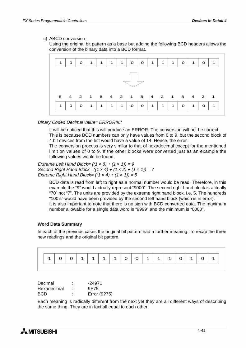
FX Series Programmable Controllers Devices in Detail 4
c) ABCD conversionUsing the original bit pattern as a base but adding the following BCD headers allows theconversion of the binary data into a BCD format.
Binary Coded Decimal value= ERROR!!!!!
It will be noticed that this will produce an ERROR. The conversion will not be correct.This is because BCD numbers can only have values from 0 to 9, but the second block of4 bit devices from the left would have a value of 14. Hence, the error.The conversion process is very similar to that of hexadecimal except for the mentionedlimit on values of 0 to 9. If the other blocks were converted just as an example thefollowing values would be found;
Extreme Left Hand Block= ((1 × 8) + (1 × 1)) = 9Second Right Hand Block= ((1 × 4) + (1 × 2) + (1 × 1)) = 7Extreme Right Hand Block= ((1 × 4) + (1 × 1)) = 5
BCD data is read from left to right as a normal number would be read. Therefore, in thisexample the “9” would actually represent “9000”. The second right hand block is actually“70” not “7”. The units are provided by the extreme right hand block, i.e. 5. The hundreds“100’s” would have been provided by the second left hand block (which is in error).It is also important to note that there is no sign with BCD converted data. The maximumnumber allowable for a single data word is “9999” and the minimum is “0000”.
Word Data Summary
In each of the previous cases the original bit pattern had a further meaning. To recap the threenew readings and the original bit pattern,
Decimal : -24971Hexadecimal : 9E75BCD : Error (9?75)
Each meaning is radically different from the next yet they are all different ways of describingthe same thing. They are in fact all equal to each other!
1 0 0 1 1 1 1 0 0 1 1 1 0 1 0 1
8 4 2 18 4 2 18 4 2 18 4 2 1
1 0 0 1 1 1 1 0 0 1 1 1 0 1 0 1
1 0 0 1 1 1 1 0 0 1 1 1 0 1 0 1
4-41
FX Series Programmable Controllers Devices in Detail 4
4.14.4 Two’s Compliment
Programmable controllers, computers etc, use a format called 2’s compliment. This is amathematical procedure which is more suited to the micro processors operational hardwarerequirements. It is used to represent negative numbers and to perform subtraction operations.The procedure is very simple, in the following example “15 - 7” is going to be solved:
Step1: Find the binary values (this example uses 8 bits)15 = 000011117 = 00000111
Step2: Find the inversion of the value to be subtracted.Procedure: invert all 1ís to 0ís and all 0ís to 1’s.
7 = 00000111Inverted 7 = 11111000
Step3: Add 1 to the inverted number.Procedure: add 1 to the right hand most bit. Remember this is binary addition hence, when avalue of 2 is obtained 1 is moved in to the next left hand position and the remainder is set to 0(zero);
Inverted7 11111000Additional1 00000001Answer 11111001
This result is actually the same as the negative value for 7 i.e. -7.
Step4: Add the answer to the number the subtraction is being made from (i.e. 15).Procedure: Remember 1+1 = 0 carry 1 in base 2 (binary).
Original value15 00001111Answer found in step3 11111001Solution (1)00001000
The “(1)” is a carried “1” and is ignored as this example is only dealing with 8 bits.
Step 5: Convert the answer back.00001000 = 8
The answer is positive because the MSB (the most left hand bit) is a 0 (zero). If a quick mentalcheck is made of the problem it is indeed found that “15-7 = 8”.
In fact no subtraction has taken place. Each of the steps has either converted some data orperformed an addition. Yet the answer is correct 15 - 7 is 8. This example calculation wasbased on 8 bit numbers but it will work equally well on any other quantity of bits.
4-42
FX Series Programmable Controllers Devices in Detail 4
4.15 Floating Point And Scientific Notation
PLC’s can use many different systems and methods to store data.The most common have already been discussed in previous sections e.g. BCD, Binary,Decimal, Hex. These are what is known as ‘integer’ formats or ‘whole number formats’.As the titles suggest these formats use only whole numbers with no representation of fractionalparts. However, there are two further formats which are becoming increasingly important andthey are:
a) Floating point and
b) Scientific notation
Both of these formats are in fact closely related. They both lend themselves to creating verylarge or very small numbers which can describe both whole and fractional components.
General note:
• Sometimes the words ‘Format’, ‘Mode’ and ‘Notation’ are interchanged when descrip-tions of these numerical processes are made. However, all of these words are providing the same descriptive value and as such users should be aware of their existence.
Some useful constants
π 3.141 100
2π 6.283 100
π/4 7.853 10-1
π2 9.869 100
The speed of light 2.997 108 m/sGravity, g 9.807 100 m/s2
e 2.718 100
Fixed points:Boiling point of liquid oxygen -1.8297 102 °CMelting point of ice 0.00 100 °CTriple point of water 1.00 10-2 °CBoiling point of water 1.00 102 °C
FX1S FX1N FX2N FX2NC
4-43
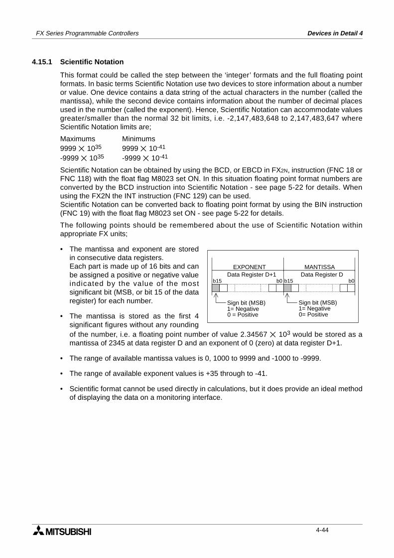
FX Series Programmable Controllers Devices in Detail 4
4.15.1 Scientific Notation
This format could be called the step between the ‘integer’ formats and the full floating pointformats. In basic terms Scientific Notation use two devices to store information about a numberor value. One device contains a data string of the actual characters in the number (called themantissa), while the second device contains information about the number of decimal placesused in the number (called the exponent). Hence, Scientific Notation can accommodate valuesgreater/smaller than the normal 32 bit limits, i.e. -2,147,483,648 to 2,147,483,647 whereScientific Notation limits are;
Maximums Minimums9999 1035 9999 10-41
-9999 1035 -9999 10-41
Scientific Notation can be obtained by using the BCD, or EBCD in FX2N, instruction (FNC 18 orFNC 118) with the float flag M8023 set ON. In this situation floating point format numbers areconverted by the BCD instruction into Scientific Notation - see page 5-22 for details. Whenusing the FX2N the INT instruction (FNC 129) can be used.Scientific Notation can be converted back to floating point format by using the BIN instruction(FNC 19) with the float flag M8023 set ON - see page 5-22 for details.
The following points should be remembered about the use of Scientific Notation withinappropriate FX units;
• The mantissa and exponent are storedin consecutive data registers.Each part is made up of 16 bits and canbe assigned a positive or negative valueindicated by the value of the mostsignificant bit (MSB, or bit 15 of the dataregister) for each number.
• The mantissa is stored as the first 4significant figures without any roundingof the number, i.e. a floating point number of value 2.34567 103 would be stored as amantissa of 2345 at data register D and an exponent of 0 (zero) at data register D+1.
• The range of available mantissa values is 0, 1000 to 9999 and -1000 to -9999.
• The range of available exponent values is +35 through to -41.
• Scientific format cannot be used directly in calculations, but it does provide an ideal methodof displaying the data on a monitoring interface.
b0b15 b15 b0
EXPONENT MANTISSA
Sign bit (MSB)1= Negative0 = Positive
Sign bit (MSB)1= Negative0= Positive
Data Register D+1 Data Register D
4-44
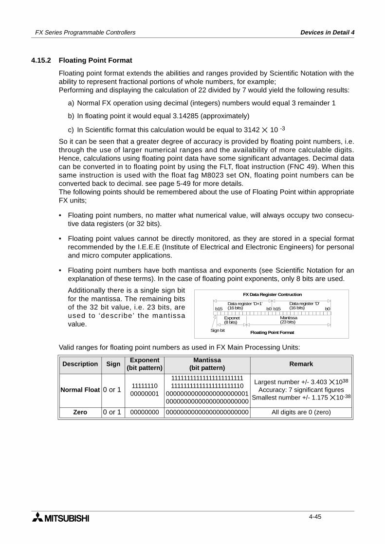
FX Series Programmable Controllers Devices in Detail 4
4.15.2 Floating Point Format
Floating point format extends the abilities and ranges provided by Scientific Notation with theability to represent fractional portions of whole numbers, for example;Performing and displaying the calculation of 22 divided by 7 would yield the following results:
a) Normal FX operation using decimal (integers) numbers would equal 3 remainder 1
b) In floating point it would equal 3.14285 (approximately)
c) In Scientific format this calculation would be equal to 3142 10 -3
So it can be seen that a greater degree of accuracy is provided by floating point numbers, i.e.through the use of larger numerical ranges and the availability of more calculable digits.Hence, calculations using floating point data have some significant advantages. Decimal datacan be converted in to floating point by using the FLT, float instruction (FNC 49). When thissame instruction is used with the float fag M8023 set ON, floating point numbers can beconverted back to decimal. see page 5-49 for more details.The following points should be remembered about the use of Floating Point within appropriateFX units;
• Floating point numbers, no matter what numerical value, will always occupy two consecu-tive data registers (or 32 bits).
• Floating point values cannot be directly monitored, as they are stored in a special formatrecommended by the I.E.E.E (Institute of Electrical and Electronic Engineers) for personaland micro computer applications.
• Floating point numbers have both mantissa and exponents (see Scientific Notation for anexplanation of these terms). In the case of floating point exponents, only 8 bits are used.
Additionally there is a single sign bitfor the mantissa. The remaining bitsof the 32 bit value, i.e. 23 bits, areused to ‘describe’ the mantissavalue.
Valid ranges for floating point numbers as used in FX Main Processing Units:
Description SignExponent
(bit pattern)Mantissa
(bit pattern)Remark
Normal Float 0 or 1 1111111000000001
1111111111111111111111111111111111111111111110
0000000000000000000000100000000000000000000000
Largest number +/- 3.403 1038
Accuracy: 7 significant figuresSmallest number +/- 1.175 10-38
Zero 0 or 1 00000000 00000000000000000000000 All digits are 0 (zero)
b15 b0Data register ’D+1’(16 bits) b15 b0
Data register ’D’(16 bits)
Sign bit
Exponet(8 bits)
Mantissa(23 bits)
FX Data Register Contruction
Floating Point Format
4-45
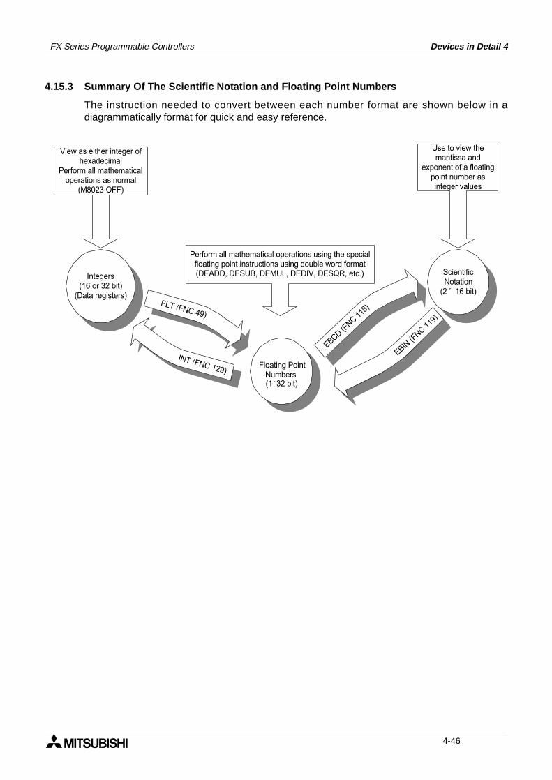
FX Series Programmable Controllers Devices in Detail 4
4.15.3 Summary Of The Scientific Notation and Floating Point Numbers
The instruction needed to convert between each number format are shown below in adiagrammatically format for quick and easy reference.
(16 or 32 bit)
Integers
(Data registers)
INT (FNC 129)Floating Point
Numbers
´(1 32 bit)
EBCD
(FNC
118)
EBIN(FNC
119)
´
Scientific
Notation
(2 16 bit)
View as either integer of
hexadecimal
Perform all mathematical
operations as normal
(M8023 OFF)
Use to view the
mantissa and
exponent of a floating
point number as
integer values
Perform all mathematical operations using the special
floating point instructions using double word format
(DEADD, DESUB, DEMUL, DEDIV, DESQR, etc.)
FLT (FNC 49)
4-46
1 Introduction
2 Basic Program Instructions
3 STL Programming
4 Devices in Detail
5 Applied Instructions
6 Diagnostic Devices
7 Instruction Execution Times
8 PLC Device Tables
9 Assigning System Devices
10 Points of Technique
11 Index
FX Series Programmable Controllers Applied Instructions 5
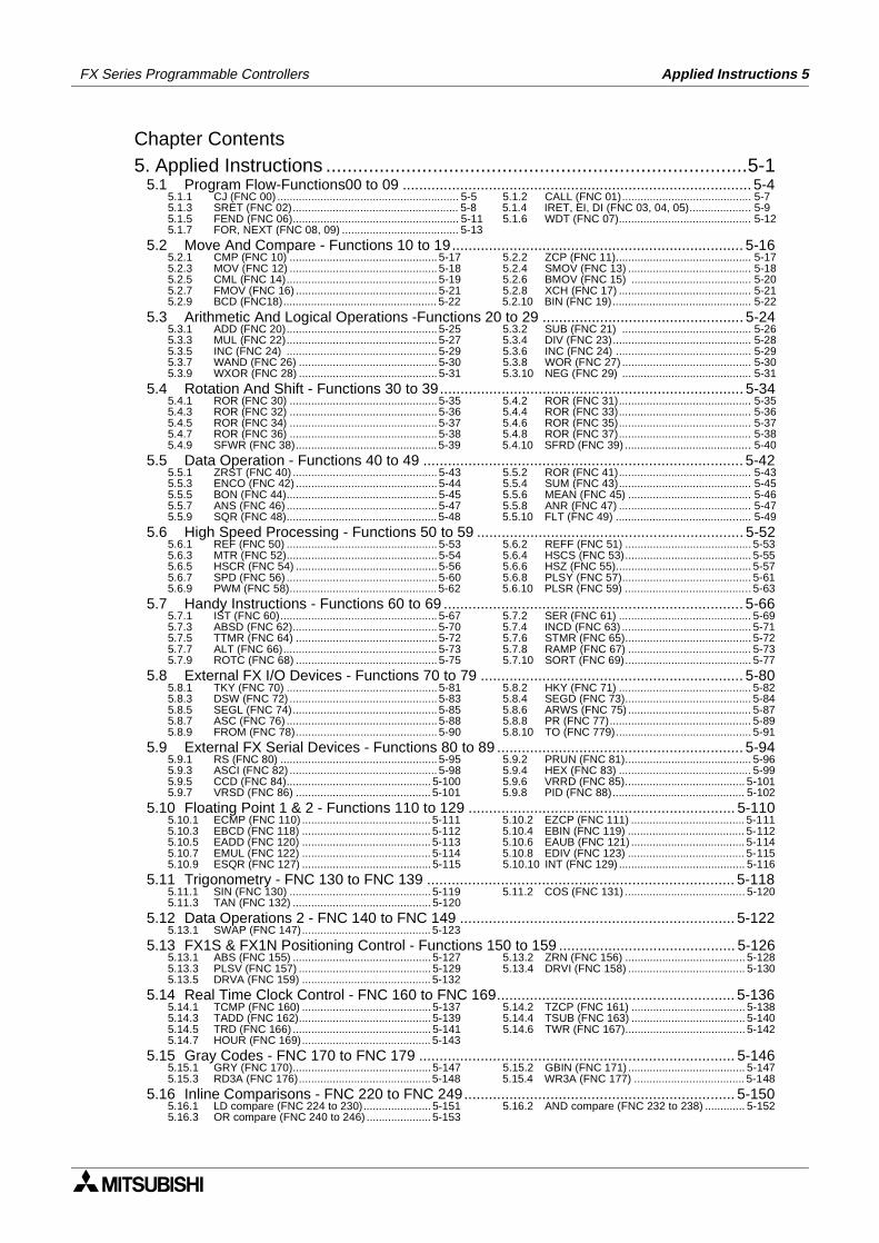
FX Series Programmable Controllers Applied Instructions 5
Chapter Contents5. Applied Instructions ...............................................................................5-1
5.1 Program Flow-Functions00 to 09 ..................................................................................... 5-45.1.1 CJ (FNC 00) ........................................................... 5-5 5.1.2 CALL (FNC 01).......................................... 5-75.1.3 SRET (FNC 02)...................................................... 5-8 5.1.4 IRET, EI, DI (FNC 03, 04, 05).................... 5-95.1.5 FEND (FNC 06)...................................................... 5-11 5.1.6 WDT (FNC 07)........................................... 5-125.1.7 FOR, NEXT (FNC 08, 09) ...................................... 5-13
5.2 Move And Compare - Functions 10 to 19....................................................................... 5-165.2.1 CMP (FNC 10) ................................................ 5-17 5.2.2 ZCP (FNC 11)............................................ 5-175.2.3 MOV (FNC 12) ................................................ 5-18 5.2.4 SMOV (FNC 13) ........................................ 5-185.2.5 CML (FNC 14)................................................. 5-19 5.2.6 BMOV (FNC 15) ....................................... 5-205.2.7 FMOV (FNC 16) .............................................. 5-21 5.2.8 XCH (FNC 17) ........................................... 5-215.2.9 BCD (FNC18).................................................. 5-22 5.2.10 BIN (FNC 19)............................................. 5-22
5.3 Arithmetic And Logical Operations -Functions 20 to 29 ................................................. 5-245.3.1 ADD (FNC 20)................................................. 5-25 5.3.2 SUB (FNC 21) .......................................... 5-265.3.3 MUL (FNC 22)................................................. 5-27 5.3.4 DIV (FNC 23)............................................. 5-285.3.5 INC (FNC 24) ................................................. 5-29 5.3.6 INC (FNC 24) ............................................ 5-295.3.7 WAND (FNC 26) ............................................. 5-30 5.3.8 WOR (FNC 27) .......................................... 5-305.3.9 WXOR (FNC 28) ............................................. 5-31 5.3.10 NEG (FNC 29) .......................................... 5-31
5.4 Rotation And Shift - Functions 30 to 39.......................................................................... 5-345.4.1 ROR (FNC 30) ................................................ 5-35 5.4.2 ROR (FNC 31)........................................... 5-355.4.3 ROR (FNC 32) ................................................ 5-36 5.4.4 ROR (FNC 33)........................................... 5-365.4.5 ROR (FNC 34) ................................................ 5-37 5.4.6 ROR (FNC 35)........................................... 5-375.4.7 ROR (FNC 36) ................................................ 5-38 5.4.8 ROR (FNC 37)........................................... 5-385.4.9 SFWR (FNC 38).............................................. 5-39 5.4.10 SFRD (FNC 39) ......................................... 5-40
5.5 Data Operation - Functions 40 to 49 .............................................................................. 5-425.5.1 ZRST (FNC 40) ............................................... 5-43 5.5.2 ROR (FNC 41)........................................... 5-435.5.3 ENCO (FNC 42) .............................................. 5-44 5.5.4 SUM (FNC 43)........................................... 5-455.5.5 BON (FNC 44)................................................. 5-45 5.5.6 MEAN (FNC 45) ........................................ 5-465.5.7 ANS (FNC 46) ................................................. 5-47 5.5.8 ANR (FNC 47) ........................................... 5-475.5.9 SQR (FNC 48)................................................. 5-48 5.5.10 FLT (FNC 49) ............................................ 5-49
5.6 High Speed Processing - Functions 50 to 59 ................................................................. 5-525.6.1 REF (FNC 50) ................................................. 5-53 5.6.2 REFF (FNC 51) ......................................... 5-535.6.3 MTR (FNC 52)................................................. 5-54 5.6.4 HSCS (FNC 53)......................................... 5-555.6.5 HSCR (FNC 54) .............................................. 5-56 5.6.6 HSZ (FNC 55)............................................ 5-575.6.7 SPD (FNC 56) ................................................. 5-60 5.6.8 PLSY (FNC 57).......................................... 5-615.6.9 PWM (FNC 58)................................................ 5-62 5.6.10 PLSR (FNC 59) ......................................... 5-63
5.7 Handy Instructions - Functions 60 to 69 ......................................................................... 5-665.7.1 IST (FNC 60)................................................... 5-67 5.7.2 SER (FNC 61) ........................................... 5-695.7.3 ABSD (FNC 62)............................................... 5-70 5.7.4 INCD (FNC 63) .......................................... 5-715.7.5 TTMR (FNC 64) .............................................. 5-72 5.7.6 STMR (FNC 65)......................................... 5-725.7.7 ALT (FNC 66).................................................. 5-73 5.7.8 RAMP (FNC 67) ........................................ 5-735.7.9 ROTC (FNC 68) .............................................. 5-75 5.7.10 SORT (FNC 69)......................................... 5-77
5.8 External FX I/O Devices - Functions 70 to 79 ................................................................ 5-805.8.1 TKY (FNC 70) ................................................. 5-81 5.8.2 HKY (FNC 71) ........................................... 5-825.8.3 DSW (FNC 72) ................................................ 5-83 5.8.4 SEGD (FNC 73)......................................... 5-845.8.5 SEGL (FNC 74)............................................... 5-85 5.8.6 ARWS (FNC 75) ........................................ 5-875.8.7 ASC (FNC 76) ................................................. 5-88 5.8.8 PR (FNC 77).............................................. 5-895.8.9 FROM (FNC 78).............................................. 5-90 5.8.10 TO (FNC 779)............................................ 5-91
5.9 External FX Serial Devices - Functions 80 to 89 ............................................................ 5-945.9.1 RS (FNC 80) ................................................... 5-95 5.9.2 PRUN (FNC 81)......................................... 5-965.9.3 ASCI (FNC 82) ................................................ 5-98 5.9.4 HEX (FNC 83) ........................................... 5-995.9.5 CCD (FNC 84)............................................... 5-100 5.9.6 VRRD (FNC 85)....................................... 5-1015.9.7 VRSD (FNC 86) ............................................ 5-101 5.9.8 PID (FNC 88)........................................... 5-102
5.10 Floating Point 1 & 2 - Functions 110 to 129 ................................................................. 5-1105.10.1 ECMP (FNC 110) .......................................... 5-111 5.10.2 EZCP (FNC 111) ..................................... 5-1115.10.3 EBCD (FNC 118) .......................................... 5-112 5.10.4 EBIN (FNC 119) ...................................... 5-1125.10.5 EADD (FNC 120) .......................................... 5-113 5.10.6 EAUB (FNC 121) ..................................... 5-1145.10.7 EMUL (FNC 122) .......................................... 5-114 5.10.8 EDIV (FNC 123) ...................................... 5-1155.10.9 ESQR (FNC 127) .......................................... 5-115 5.10.10 INT (FNC 129) ......................................... 5-116
5.11 Trigonometry - FNC 130 to FNC 139 ........................................................................... 5-1185.11.1 SIN (FNC 130) .............................................. 5-119 5.11.2 COS (FNC 131) ....................................... 5-1205.11.3 TAN (FNC 132) ............................................. 5-120
5.12 Data Operations 2 - FNC 140 to FNC 149 ................................................................... 5-1225.13.1 SWAP (FNC 147).......................................... 5-123
5.13 FX1S & FX1N Positioning Control - Functions 150 to 159 ........................................... 5-1265.13.1 ABS (FNC 155) ............................................. 5-127 5.13.2 ZRN (FNC 156) ....................................... 5-1285.13.3 PLSV (FNC 157) ........................................... 5-129 5.13.4 DRVI (FNC 158) ...................................... 5-1305.13.5 DRVA (FNC 159) .......................................... 5-132
5.14 Real Time Clock Control - FNC 160 to FNC 169.......................................................... 5-1365.14.1 TCMP (FNC 160) .......................................... 5-137 5.14.2 TZCP (FNC 161) ..................................... 5-1385.14.3 TADD (FNC 162)........................................... 5-139 5.14.4 TSUB (FNC 163) ..................................... 5-1405.14.5 TRD (FNC 166) ............................................. 5-141 5.14.6 TWR (FNC 167)....................................... 5-1425.14.7 HOUR (FNC 169).......................................... 5-143
5.15 Gray Codes - FNC 170 to FNC 179 ............................................................................. 5-1465.15.1 GRY (FNC 170)............................................. 5-147 5.15.2 GBIN (FNC 171) ...................................... 5-1475.15.3 RD3A (FNC 176)........................................... 5-148 5.15.4 WR3A (FNC 177) .................................... 5-148
5.16 Inline Comparisons - FNC 220 to FNC 249.................................................................. 5-1505.16.1 LD compare (FNC 224 to 230)...................... 5-151 5.16.2 AND compare (FNC 232 to 238) ............. 5-1525.16.3 OR compare (FNC 240 to 246) ..................... 5-153
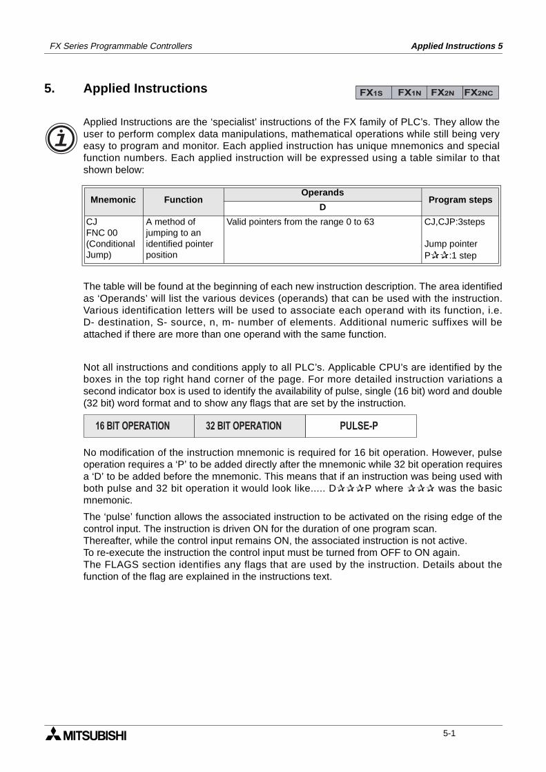
Applied Instructions 5FX Series Programmable Controllers
5. Applied Instructions
The table will be found at the beginning of each new instruction description. The area identifiedas ‘Operands’ will list the various devices (operands) that can be used with the instruction.Various identification letters will be used to associate each operand with its function, i.e.D- destination, S- source, n, m- number of elements. Additional numeric suffixes will beattached if there are more than one operand with the same function.
Not all instructions and conditions apply to all PLC’s. Applicable CPU’s are identified by theboxes in the top right hand corner of the page. For more detailed instruction variations asecond indicator box is used to identify the availability of pulse, single (16 bit) word and double(32 bit) word format and to show any flags that are set by the instruction.
No modification of the instruction mnemonic is required for 16 bit operation. However, pulseoperation requires a ‘P’ to be added directly after the mnemonic while 32 bit operation requiresa ‘D’ to be added before the mnemonic. This means that if an instruction was being used withboth pulse and 32 bit operation it would look like..... DP where was the basicmnemonic.
The ‘pulse’ function allows the associated instruction to be activated on the rising edge of thecontrol input. The instruction is driven ON for the duration of one program scan.Thereafter, while the control input remains ON, the associated instruction is not active.To re-execute the instruction the control input must be turned from OFF to ON again.The FLAGS section identifies any flags that are used by the instruction. Details about thefunction of the flag are explained in the instructions text.
Mnemonic Function Operands
Program stepsD
CJFNC 00(Conditional Jump)
A method ofjumping to anidentified pointerposition
Valid pointers from the range 0 to 63 CJ,CJP:3steps
Jump pointerP:1 step
FX1S FX1N FX2N FX2NC
Applied Instructions are the ‘specialist’ instructions of the FX family of PLC’s. They allow theuser to perform complex data manipulations, mathematical operations while still being veryeasy to program and monitor. Each applied instruction has unique mnemonics and specialfunction numbers. Each applied instruction will be expressed using a table similar to thatshown below:
PULSE-P16 BIT OPERATION 32 BIT OPERATION
5-1
FX Series Programmable Controlers Applied Instructions 5
• For instructions that operate continuously, i.e. on every scan of the program the instructionwill operate and provide a new, different result, the following identification symbol will beused ‘’ to represent a high speed changing state. Typical instructions covered by thissituation have a strong incremental, indexable element to their operation.
• In most cases the operands of applied instructions can be indexed by a users program. Forthose operands which cannot be indexed, the symbol ‘’ has been used to signify anoperand as being ‘fixed’ after it has been written.
• Certain instructions utilize additional data registers and/or status flags for example a mathfunction such as ADD (FNC 20) can identify a zero result, borrow and carry conditions byusing preset auxiliary relays, M8020 to M8021 respectively.
5-2
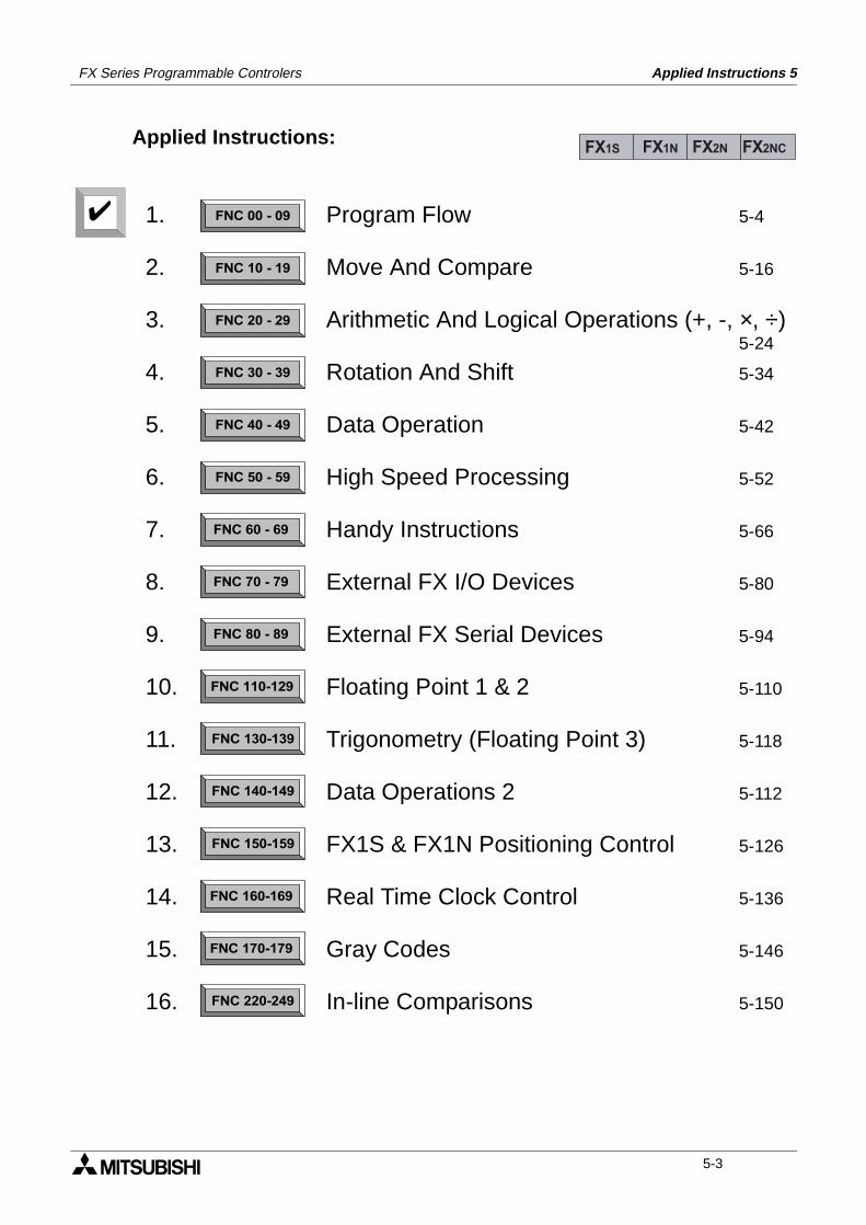
FX Series Programmable Controlers Applied Instructions 5
Applied Instructions:FX1S FX1N FX2N FX2NC
FNC 00 - 09
FNC 10 - 19
FNC 20 - 29
FNC 30 - 39
FNC 40 - 49
FNC 50 - 59
FNC 60 - 69
FNC 70 - 79
FNC 80 - 89
FNC 110-129
FNC 130-139
FNC 140-149
FNC 160-169
FNC 170-179
FNC 220-249
FNC 150-159
1.
2.
3.
4.
5.
6.
7.
8.
9.
10.
11.
12.
13.
14.
15.
16.
Program Flow 5-4
Move And Compare 5-16
Arithmetic And Logical Operations (+, -, ×, ÷)5-24
Rotation And Shift 5-34
Data Operation 5-42
High Speed Processing 5-52
Handy Instructions 5-66
External FX I/O Devices 5-80
External FX Serial Devices 5-94
Floating Point 1 & 2 5-110
Trigonometry (Floating Point 3) 5-118
Data Operations 2 5-112
FX1S & FX1N Positioning Control 5-126
Real Time Clock Control 5-136
Gray Codes 5-146
In-line Comparisons 5-150
5-3
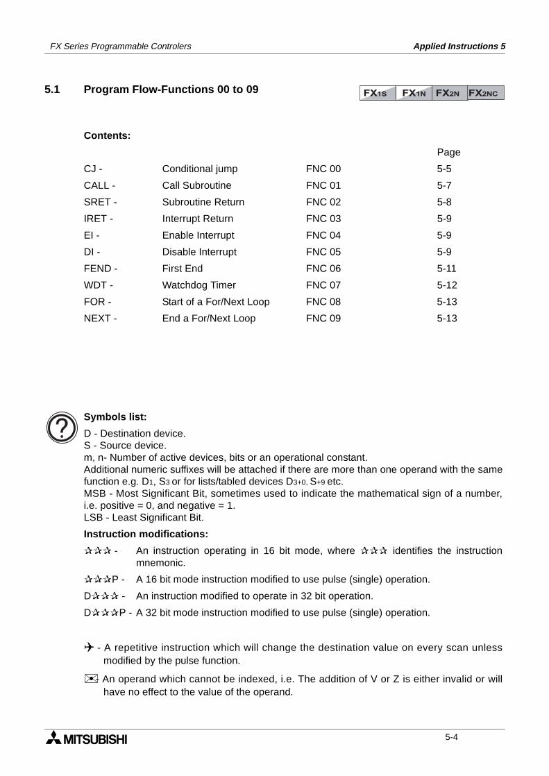
FX Series Programmable Controlers Applied Instructions 5
5.1 Program Flow-Functions 00 to 09
Contents:
Page
CJ - Conditional jump FNC 00 5-5
CALL - Call Subroutine FNC 01 5-7
SRET - Subroutine Return FNC 02 5-8
IRET - Interrupt Return FNC 03 5-9
EI - Enable Interrupt FNC 04 5-9
DI - Disable Interrupt FNC 05 5-9
FEND - First End FNC 06 5-11
WDT - Watchdog Timer FNC 07 5-12
FOR - Start of a For/Next Loop FNC 08 5-13
NEXT - End a For/Next Loop FNC 09 5-13
FX1S FX1N FX2N FX2NC
Symbols list:
D - Destination device.S - Source device.m, n- Number of active devices, bits or an operational constant.Additional numeric suffixes will be attached if there are more than one operand with the samefunction e.g. D1, S3 or for lists/tabled devices D3+0, S+9 etc.MSB - Most Significant Bit, sometimes used to indicate the mathematical sign of a number,i.e. positive = 0, and negative = 1.LSB - Least Significant Bit.
Instruction modifications:
- An instruction operating in 16 bit mode, where identifies the instructionmnemonic.
P - A 16 bit mode instruction modified to use pulse (single) operation.
D - An instruction modified to operate in 32 bit operation.
DP - A 32 bit mode instruction modified to use pulse (single) operation.
- A repetitive instruction which will change the destination value on every scan unlessmodified by the pulse function.
- An operand which cannot be indexed, i.e. The addition of V or Z is either invalid or willhave no effect to the value of the operand.
5-4
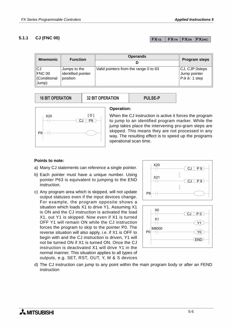
FX Series Programmable Controlers Applied Instructions 5
5.1.1 CJ (FNC 00)
Mnemonic Function Operands
Program stepsD
CJFNC 00(Conditional Jump)
Jumps to theidentified pointerposition
Valid pointers from the range 0 to 63 CJ, CJP:3stepsJump pointerP: 1 step
FX1S FX1N FX2N FX2NC
P9 CJ
P9
X20 [ D ]
X21P 9
P 9CJ
P9
X20
CJ
X1
P 0CJ
P0
X0
M8000
Y1
Y0
END
PULSE-P16 BIT OPERATION 32 BIT OPERATION
Operation:
When the CJ instruction is active it forces the programto jump to an identified program marker. While thejump takes place the intervening pro-gram steps areskipped. This means they are not processed in anyway. The resulting effect is to speed up the programsoperational scan time.
Points to note:
a) Many CJ statements can reference a single pointer.
b) Each pointer must have a unique number. Usingpointer P63 is equivalent to jumping to the ENDinstruction.
c) Any program area which is skipped, will not updateoutput statuses even if the input devices change.For example, the program opposite shows asituation which loads X1 to drive Y1. Assuming X1is ON and the CJ instruction is activated the loadX1, out Y1 is skipped. Now even if X1 is turnedOFF Y1 will remain ON while the CJ instructionforces the program to skip to the pointer P0. Thereverse situation will also apply, i.e. if X1 is OFF tobegin with and the CJ instruction is driven, Y1 willnot be turned ON if X1 is turned ON. Once the CJinstruction is deactivated X1 will drive Y1 in thenormal manner. This situation applies to all types ofoutputs, e.g. SET, RST, OUT, Y, M & S devices
d) The CJ instruction can jump to any point within the main program body or after an FENDinstruction
5-5
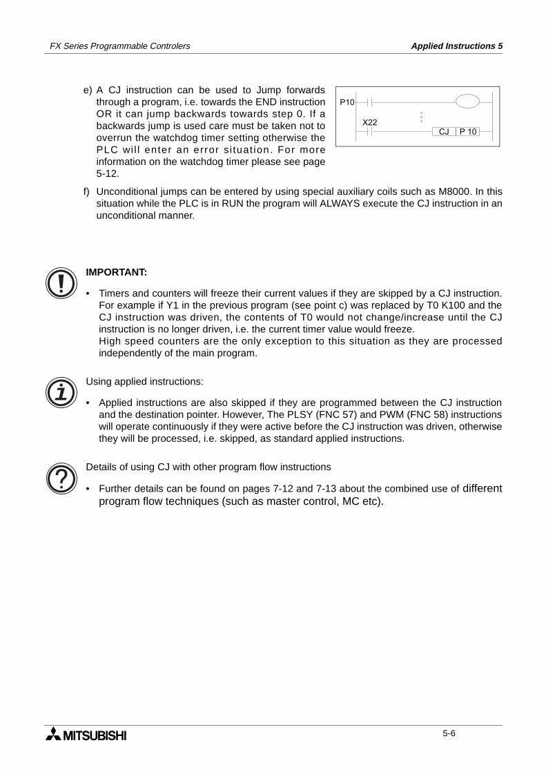
FX Series Programmable Controlers Applied Instructions 5
X22P 10CJ
P10
e) A CJ instruction can be used to Jump forwardsthrough a program, i.e. towards the END instructionOR it can jump backwards towards step 0. If abackwards jump is used care must be taken not tooverrun the watchdog timer setting otherwise thePLC wi l l enter an error si tuat ion. For moreinformation on the watchdog timer please see page5-12.
f) Unconditional jumps can be entered by using special auxiliary coils such as M8000. In thissituation while the PLC is in RUN the program will ALWAYS execute the CJ instruction in anunconditional manner.
IMPORTANT:
• Timers and counters will freeze their current values if they are skipped by a CJ instruction.For example if Y1 in the previous program (see point c) was replaced by T0 K100 and theCJ instruction was driven, the contents of T0 would not change/increase until the CJinstruction is no longer driven, i.e. the current timer value would freeze.High speed counters are the only exception to this situation as they are processedindependently of the main program.
Using applied instructions:
• Applied instructions are also skipped if they are programmed between the CJ instructionand the destination pointer. However, The PLSY (FNC 57) and PWM (FNC 58) instructionswill operate continuously if they were active before the CJ instruction was driven, otherwisethey will be processed, i.e. skipped, as standard applied instructions.
Details of using CJ with other program flow instructions
• Further details can be found on pages 7-12 and 7-13 about the combined use of differentprogram flow techniques (such as master control, MC etc).
5-6
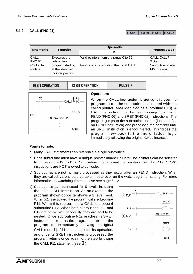
FX Series Programmable Controlers Applied Instructions 5
5.1.2 CALL (FNC 01)
Points to note:
a) Many CALL statements can reference a single subroutine.
b) Each subroutine must have a unique pointer number. Subroutine pointers can be selectedfrom the range P0 to P62. Subroutine pointers and the pointers used for CJ (FNC 00)instructions are NOT allowed to coincide.
c) Subroutines are not normally processed as they occur after an FEND instruction. Whenthey are called, care should be taken not to overrun the watchdog timer setting. For moreinformation on watchdog timers please see page 5-12.
d) Subroutines can be nested for 5 levels includingthe initial CALL instruction. As an example theprogram shown opposite shows a 2 level nest.When X1 is activated the program calls subroutineP11. Within this subroutine is a CALL to a secondsubroutine P12. When both subroutines P11 andP12 are active simultaneously, they are said to benested. Once subroutine P12 reaches its SRETinstruction it returns the program control to theprogram step immediately following its originalCALL (see ➀). P11 then completes its operation,and once its SRET instruction is processed theprogram returns once again to the step followingthe CALL P11 statement (see ➁).
Mnemonic Function Operands
Program stepsD
CALLFNC 01(Call sub-routine)
Executes the subroutine program starting at the identified pointer position
Valid pointers from the range 0 to 62
Nest levels: 5 including the initial CALL
CALL, CALLP:3 stepSubroutine pointerPPP: 1 steps
FX1S FX1N FX2N FX2NC
X0P 10CALL
FEND
SRET
P10
[ D ]
Subroutine D10
Operation:
When the CALL instruction is active it forces theprogram to run the subroutine associated with thecalled pointer (area identified as subroutine P10). ACALL instruction must be used in conjunction withFEND (FNC 06) and SRET (FNC 02) instructions. Theprogram jumps to the subroutine pointer (located afteran FEND instruction) and processes the contents untilan SRET instruction is encountered. This forces theprogram f low back to the l ine of ladder logicimmediately following the original CALL instruction.
PULSE-P16 BIT OPERATION 32 BIT OPERATION
X1P 11CALL
FEND
SRET
P11
P 12CALL
SRET
P12
1
2
5-7
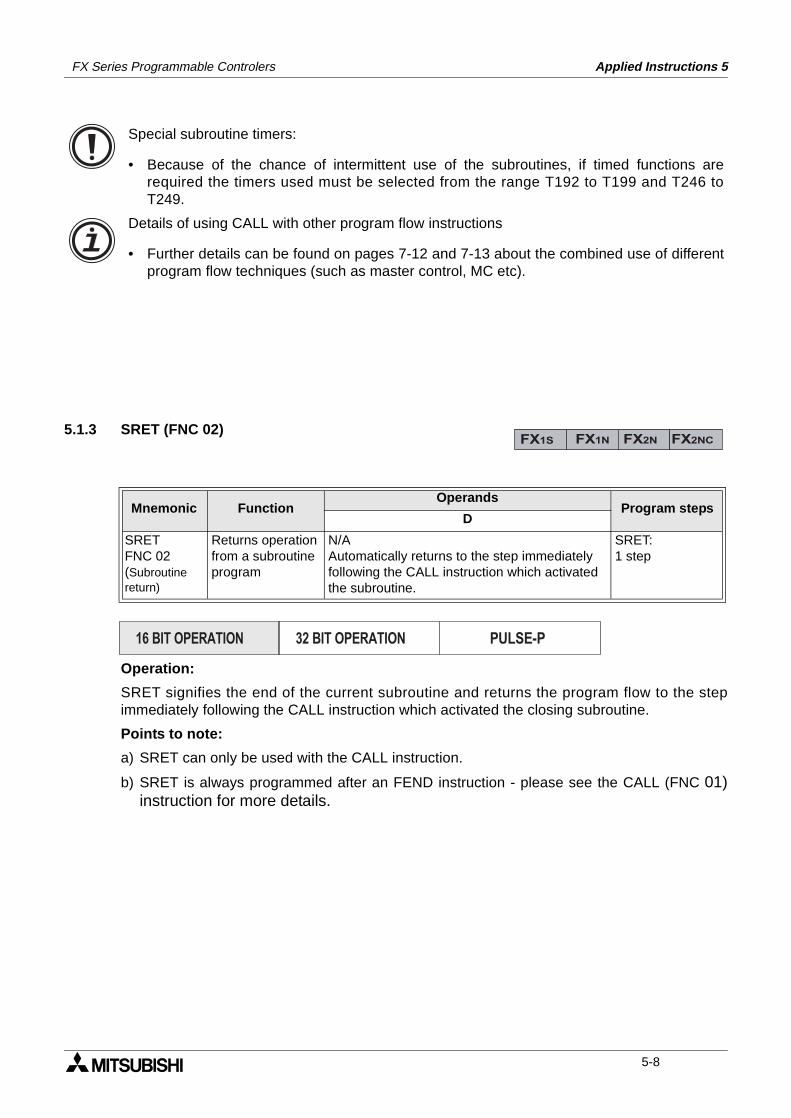
FX Series Programmable Controlers Applied Instructions 5
5.1.3 SRET (FNC 02)
Operation:
SRET signifies the end of the current subroutine and returns the program flow to the stepimmediately following the CALL instruction which activated the closing subroutine.
Points to note:
a) SRET can only be used with the CALL instruction.
b) SRET is always programmed after an FEND instruction - please see the CALL (FNC 01)instruction for more details.
Mnemonic Function Operands
Program stepsD
SRETFNC 02(Subroutine return)
Returns operationfrom a subroutineprogram
N/AAutomatically returns to the step immediately following the CALL instruction which activated the subroutine.
SRET:1 step
Special subroutine timers:
• Because of the chance of intermittent use of the subroutines, if timed functions arerequired the timers used must be selected from the range T192 to T199 and T246 toT249.
Details of using CALL with other program flow instructions
• Further details can be found on pages 7-12 and 7-13 about the combined use of differentprogram flow techniques (such as master control, MC etc).
FX1S FX1N FX2N FX2NC
PULSE-P16 BIT OPERATION 32 BIT OPERATION
5-8
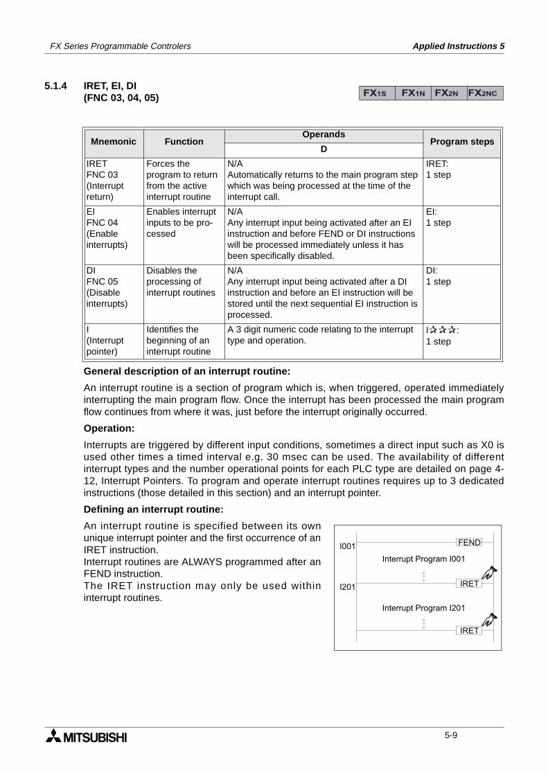
FX Series Programmable Controlers Applied Instructions 5
5.1.4 IRET, EI, DI(FNC 03, 04, 05)
General description of an interrupt routine:
An interrupt routine is a section of program which is, when triggered, operated immediatelyinterrupting the main program flow. Once the interrupt has been processed the main programflow continues from where it was, just before the interrupt originally occurred.
Operation:
Interrupts are triggered by different input conditions, sometimes a direct input such as X0 isused other times a timed interval e.g. 30 msec can be used. The availability of differentinterrupt types and the number operational points for each PLC type are detailed on page 4-12, Interrupt Pointers. To program and operate interrupt routines requires up to 3 dedicatedinstructions (those detailed in this section) and an interrupt pointer.
Defining an interrupt routine:
An interrupt routine is specified between its ownunique interrupt pointer and the first occurrence of anIRET instruction.Interrupt routines are ALWAYS programmed after anFEND instruction.The IRET instruction may only be used withininterrupt routines.
Mnemonic Function Operands
Program stepsD
IRETFNC 03(Interruptreturn)
Forces theprogram to returnfrom the activeinterrupt routine
N/AAutomatically returns to the main program step which was being processed at the time of the interrupt call.
IRET:1 step
EIFNC 04(Enableinterrupts)
Enables interrupt inputs to be pro-cessed
N/AAny interrupt input being activated after an EI instruction and before FEND or DI instructions will be processed immediately unless it has been specifically disabled.
EI:1 step
DIFNC 05(Disableinterrupts)
Disables theprocessing ofinterrupt routines
N/AAny interrupt input being activated after a DI instruction and before an EI instruction will be stored until the next sequential EI instruction is processed.
DI:1 step
I(Interruptpointer)
Identifies thebeginning of aninterrupt routine
A 3 digit numeric code relating to the interrupt type and operation.
I:1 step
FX1S FX1N FX2N FX2NC
FENDI001
IRET
IRET
I201
Interrupt Program I001
Interrupt Program I201
5-9
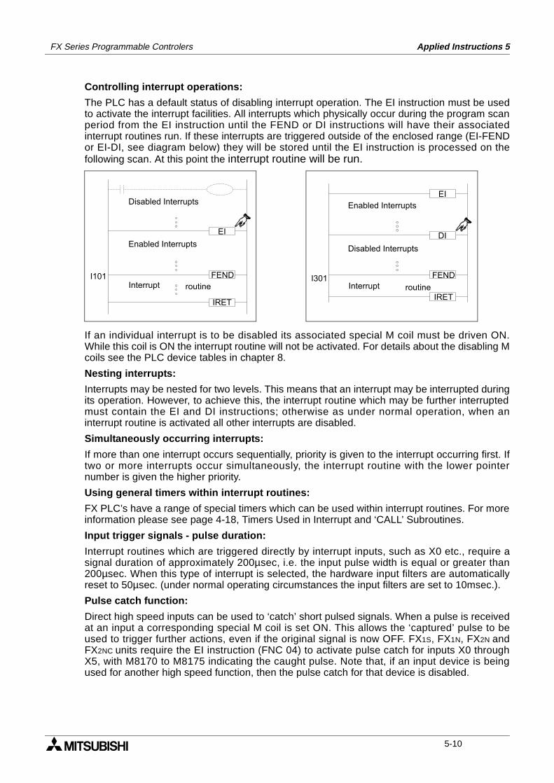
FX Series Programmable Controlers Applied Instructions 5
Controlling interrupt operations:
The PLC has a default status of disabling interrupt operation. The EI instruction must be usedto activate the interrupt facilities. All interrupts which physically occur during the program scanperiod from the EI instruction until the FEND or DI instructions will have their associatedinterrupt routines run. If these interrupts are triggered outside of the enclosed range (EI-FENDor EI-DI, see diagram below) they will be stored until the EI instruction is processed on thefollowing scan. At this point the interrupt routine will be run.
If an individual interrupt is to be disabled its associated special M coil must be driven ON.While this coil is ON the interrupt routine will not be activated. For details about the disabling Mcoils see the PLC device tables in chapter 8.
Nesting interrupts:
Interrupts may be nested for two levels. This means that an interrupt may be interrupted duringits operation. However, to achieve this, the interrupt routine which may be further interruptedmust contain the EI and DI instructions; otherwise as under normal operation, when aninterrupt routine is activated all other interrupts are disabled.
Simultaneously occurring interrupts:
If more than one interrupt occurs sequentially, priority is given to the interrupt occurring first. Iftwo or more interrupts occur simultaneously, the interrupt routine with the lower pointernumber is given the higher priority.
Using general timers within interrupt routines:
FX PLC’s have a range of special timers which can be used within interrupt routines. For moreinformation please see page 4-18, Timers Used in Interrupt and ‘CALL’ Subroutines.
Input trigger signals - pulse duration:
Interrupt routines which are triggered directly by interrupt inputs, such as X0 etc., require asignal duration of approximately 200µsec, i.e. the input pulse width is equal or greater than200µsec. When this type of interrupt is selected, the hardware input filters are automaticallyreset to 50µsec. (under normal operating circumstances the input filters are set to 10msec.).
Pulse catch function:
Direct high speed inputs can be used to ‘catch’ short pulsed signals. When a pulse is receivedat an input a corresponding special M coil is set ON. This allows the ‘captured’ pulse to beused to trigger further actions, even if the original signal is now OFF. FX1S, FX1N, FX2N andFX2NC units require the EI instruction (FNC 04) to activate pulse catch for inputs X0 throughX5, with M8170 to M8175 indicating the caught pulse. Note that, if an input device is beingused for another high speed function, then the pulse catch for that device is disabled.
EI
DI
FENDI301
IRET
Disabled Interrupts
Enabled Interrupts
routineInterrupt
EI
FEND
IRET
I101
Disabled Interrupts
Enabled Interrupts
routineInterrupt
5-10
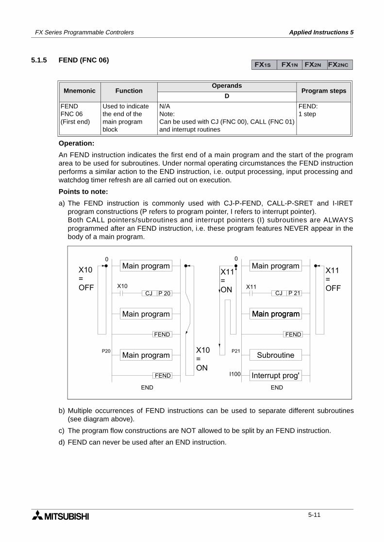
FX Series Programmable Controlers Applied Instructions 5
5.1.5 FEND (FNC 06)
Operation:
An FEND instruction indicates the first end of a main program and the start of the programarea to be used for subroutines. Under normal operating circumstances the FEND instructionperforms a similar action to the END instruction, i.e. output processing, input processing andwatchdog timer refresh are all carried out on execution.
Points to note:
a) The FEND instruction is commonly used with CJ-P-FEND, CALL-P-SRET and I-IRETprogram constructions (P refers to program pointer, I refers to interrupt pointer).Both CALL pointers/subroutines and interrupt pointers (I) subroutines are ALWAYSprogrammed after an FEND instruction, i.e. these program features NEVER appear in thebody of a main program.
b) Multiple occurrences of FEND instructions can be used to separate different subroutines(see diagram above).
c) The program flow constructions are NOT allowed to be split by an FEND instruction.
d) FEND can never be used after an END instruction.
Mnemonic Function Operands
Program stepsD
FENDFNC 06(First end)
Used to indicatethe end of themain program block
N/ANote:Can be used with CJ (FNC 00), CALL (FNC 01)and interrupt routines
FEND:1 step
FX1S FX1N FX2N FX2NC
FEND
X10P 20CJ
FEND
FEND
X11P 21CJ
END END
P20 P21
0 0
I100
Main program
Main program
Main program Main program
Subroutine
Main programMain program
Interrupt prog'
X10=OFF
X10=ON
X11=ON
X11=OFF
5-11
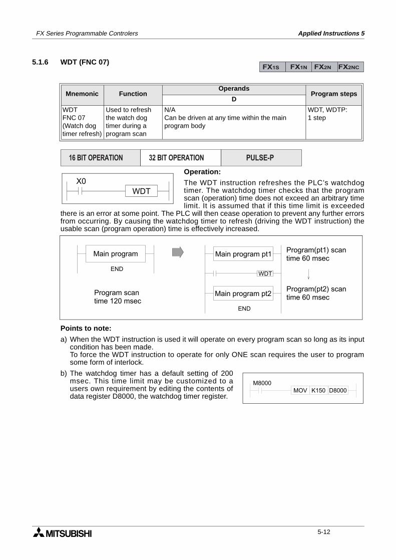
FX Series Programmable Controlers Applied Instructions 5
5.1.6 WDT (FNC 07)
Operation:
The WDT instruction refreshes the PLC’s watchdogtimer. The watchdog timer checks that the programscan (operation) time does not exceed an arbitrary timelimit. It is assumed that if this time limit is exceeded
there is an error at some point. The PLC will then cease operation to prevent any further errorsfrom occurring. By causing the watchdog timer to refresh (driving the WDT instruction) theusable scan (program operation) time is effectively increased.
Points to note:
a) When the WDT instruction is used it will operate on every program scan so long as its inputcondition has been made.To force the WDT instruction to operate for only ONE scan requires the user to programsome form of interlock.
b) The watchdog timer has a default setting of 200msec. This time limit may be customized to ausers own requirement by editing the contents ofdata register D8000, the watchdog timer register.
Mnemonic Function Operands
Program stepsD
WDTFNC 07(Watch dog timer refresh)
Used to refreshthe watch dogtimer during aprogram scan
N/ACan be driven at any time within the mainprogram body
WDT, WDTP:1 step
FX1S FX1N FX2N FX2NC
PULSE-P16 BIT OPERATION 32 BIT OPERATION
X0WDT
END
END
WDT
Main program Main program pt1
Main program pt2Program scantime 120 msec
Program(pt2) scantime 60 msec
Program(pt1) scantime 60 msec
M8000MOV K150 D8000
5-12
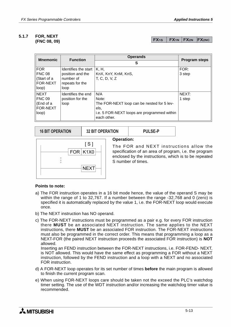
FX Series Programmable Controlers Applied Instructions 5
5.1.7 FOR, NEXT(FNC 08, 09)
Operation:
The FOR and NEXT ins t ruc t ions a l l ow thespecification of an area of program, i.e. the programenclosed by the instructions, which is to be repeatedS number of times.
Points to note:
a) The FOR instruction operates in a 16 bit mode hence, the value of the operand S may bewithin the range of 1 to 32,767. If a number between the range -32,768 and 0 (zero) isspecified it is automatically replaced by the value 1, i.e. the FOR-NEXT loop would executeonce.
b) The NEXT instruction has NO operand.
c) The FOR-NEXT instructions must be programmed as a pair e.g. for every FOR instructionthere MUST be an associated NEXT instruction. The same applies to the NEXTinstructions, there MUST be an associated FOR instruction. The FOR-NEXT instructionsmust also be programmed in the correct order. This means that programming a loop as aNEXT-FOR (the paired NEXT instruction proceeds the associated FOR instruction) is NOTallowed.Inserting an FEND instruction between the FOR-NEXT instructions, i.e. FOR-FEND- NEXT,is NOT allowed. This would have the same effect as programming a FOR without a NEXTinstruction, followed by the FEND instruction and a loop with a NEXT and no associatedFOR instruction.
d) A FOR-NEXT loop operates for its set number of times before the main program is allowedto finish the current program scan.
e) When using FOR-NEXT loops care should be taken not the exceed the PLC’s watchdogtimer setting. The use of the WDT instruction and/or increasing the watchdog timer value isrecommended.
Mnemonic Function Operands
Program stepsS
FORFNC 08(Start of aFOR-NEXTloop)
Identifies the startposition and thenumber ofrepeats for theloop
K, H,KnX, KnY, KnM, KnS,T, C, D, V, Z
FOR:3 step
NEXTFNC 09(End of aFOR-NEXTloop)
Identifies the endposition for theloop
N/ANote:The FOR-NEXT loop can be nested for 5 lev-els,i.e. 5 FOR-NEXT loops are programmed within each other.
NEXT:1 step
FX1S FX1N FX2N FX2NC
PULSE-P16 BIT OPERATION 32 BIT OPERATION
FOR K1X0
NEXT
[ S ]
5-13
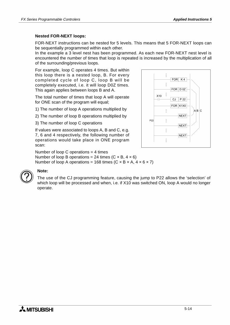
FX Series Programmable Controlers Applied Instructions 5
Nested FOR-NEXT loops:
FOR-NEXT instructions can be nested for 5 levels. This means that 5 FOR-NEXT loops canbe sequentially programmed within each other. In the example a 3 level nest has been programmed. As each new FOR-NEXT nest level isencountered the number of times that loop is repeated is increased by the multiplication of allof the surrounding/previous loops.
For example, loop C operates 4 times. But withinthis loop there is a nested loop, B. For everycompleted cycle of loop C, loop B wi l l becompletely executed, i.e. it will loop D0Z times.This again applies between loops B and A.
The total number of times that loop A will operatefor ONE scan of the program will equal;
1) The number of loop A operations multiplied by
2) The number of loop B operations multiplied by
3) The number of loop C operations
If values were associated to loops A, B and C, e.g.7, 6 and 4 respectively, the following number ofoperations would take place in ONE programscan:
Number of loop C operations = 4 timesNumber of loop B operations = 24 times (C × B, 4 × 6)Number of loop A operations = 168 times (C × B × A, 4 × 6 × 7)
FOR K 4
FOR D 0Z
X10CJ P 22
FOR K1X0
NEXT
NEXT
NEXT
P22
A B C
Note:
The use of the CJ programming feature, causing the jump to P22 allows the ‘selection’ ofwhich loop will be processed and when, i.e. if X10 was switched ON, loop A would no longeroperate.
5-14
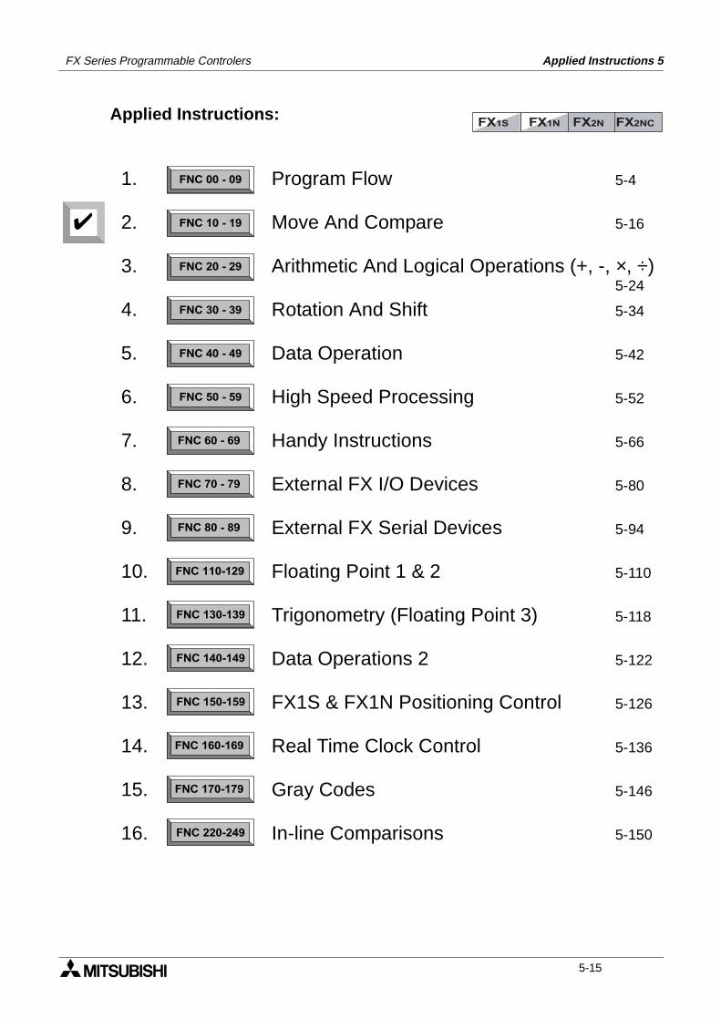
FX Series Programmable Controlers Applied Instructions 5
Applied Instructions:FX1S FX1N FX2N FX2NC
FNC 00 - 09
FNC 10 - 19
FNC 20 - 29
FNC 30 - 39
FNC 40 - 49
FNC 50 - 59
FNC 60 - 69
FNC 70 - 79
FNC 80 - 89
FNC 110-129
FNC 130-139
FNC 140-149
FNC 160-169
FNC 170-179
FNC 220-249
FNC 150-159
1.
2.
3.
4.
5.
6.
7.
8.
9.
10.
11.
12.
13.
14.
15.
16.
Program Flow 5-4
Move And Compare 5-16
Arithmetic And Logical Operations (+, -, ×, ÷)5-24
Rotation And Shift 5-34
Data Operation 5-42
High Speed Processing 5-52
Handy Instructions 5-66
External FX I/O Devices 5-80
External FX Serial Devices 5-94
Floating Point 1 & 2 5-110
Trigonometry (Floating Point 3) 5-118
Data Operations 2 5-122
FX1S & FX1N Positioning Control 5-126
Real Time Clock Control 5-136
Gray Codes 5-146
In-line Comparisons 5-150
5-15
FX Series Programmable Controlers Applied Instructions 5
5.2 Move And Compare - Functions 10 to 19
Contents:
Page
CMP - Compare FNC 10 5-17ZCP - Zone Compare FNC 11 5-17MOV - Move FNC 12 5-18SMOV - Shift Move FNC 13 5-18CML - Compliment FNC 14 5-19BMOV - Block Move FNC 15 5-20FMOV - Fill Move FNC 16 5-21XCH - Exchange FNC 17 5-21BCD - Binary Coded Decimal FNC 18 5-22BIN - Binary FNC 19 5-22
Symbols list:
D - Destination device.S - Source device.m, n- Number of active devices, bits or an operational constant.Additional numeric suffixes will be attached if there are more than one operand with the samefunction e.g. D1, S3 or for lists/tabled devices D3+0, S+9 etc.MSB - Most Significant Bit, sometimes used to indicate the mathematical sign of a number,i.e. positive = 0, and negative = 1.LSB - Least Significant Bit.
Instruction modifications:
- An instruction operating in 16 bit mode, where identifies the instructionmnemonic.
P - A 16 bit mode instruction modified to use pulse (single) operation.
D - An instruction modified to operate in 32 bit operation.
DP - A 32 bit mode instruction modified to use pulse (single) operation.
- A repetitive instruction which will change the destination value on every scan unlessmodified by the pulse function.
- An operand which cannot be indexed, i.e. The addition of V or Z is either invalid or willhave no effect to the value of the operand.
5-16
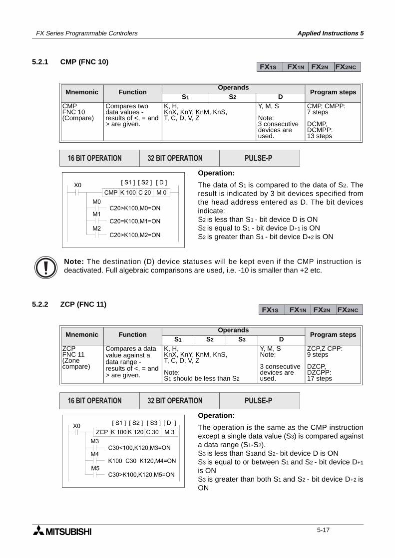
FX Series Programmable Controlers Applied Instructions 5
5.2.1 CMP (FNC 10)
Operation:
The data of S1 is compared to the data of S2. Theresult is indicated by 3 bit devices specified fromthe head address entered as D. The bit devicesindicate:S2 is less than S1 - bit device D is ON S2 is equal to S1 - bit device D+1 is ONS2 is greater than S1 - bit device D+2 is ON
5.2.2 ZCP (FNC 11)
Operation:
The operation is the same as the CMP instructionexcept a single data value (S3) is compared againsta data range (S1-S2). S3 is less than S1and S2- bit device D is ONS3 is equal to or between S1 and S2 - bit device D+1
is ONS3 is greater than both S1 and S2 - bit device D+2 isON
Mnemonic Function Operands
Program stepsS1 S2 D
CMPFNC 10(Compare)
Compares twodata values -results of <, = and> are given.
K, H,KnX, KnY, KnM, KnS,T, C, D, V, Z
Y, M, S
Note:3 consecutivedevices areused.
CMP, CMPP:7 steps
DCMP,DCMPP:13 steps
Mnemonic Function Operands
Program stepsS1 S2 S3 D
ZCPFNC 11(Zonecompare)
Compares a datavalue against adata range -results of <, = and> are given.
K, H,KnX, KnY, KnM, KnS,T, C, D, V, Z
Note: S1 should be less than S2
Y, M, SNote:
3 consecutivedevices areused.
ZCP,Z CPP:9 steps
DZCP,DZCPP:17 steps
FX1S FX1N FX2N FX2NC
PULSE-P16 BIT OPERATION 32 BIT OPERATION
X0C 20 M 0
[ S2 ] [ D ][ S1 ]
K 100CMP
M0
M1
M2
C20>K100,M0=ON
C20=K100,M1=ON
C20>K100,M2=ON
Note: The destination (D) device statuses will be kept even if the CMP instruction isdeactivated. Full algebraic comparisons are used, i.e. -10 is smaller than +2 etc.
FX1S FX1N FX2N FX2NC
PULSE-P16 BIT OPERATION 32 BIT OPERATION
X0K 120 M 3
[ S2 ] [ D ][ S1 ]
K 100ZCP
M3
M4
M5
C 30
[ S3 ]
C30<100,K120,M3=ON
K100 C30 K120,M4=ON
C30>K100,K120,M5=ON
5-17
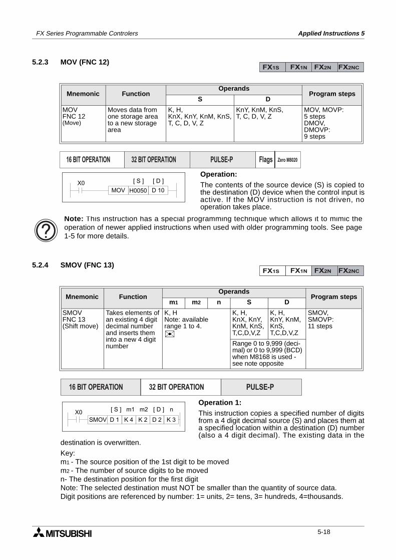
FX Series Programmable Controlers Applied Instructions 5
5.2.3 MOV (FNC 12)
Operation:The contents of the source device (S) is copied tothe destination (D) device when the control input isactive. If the MOV instruction is not driven, nooperation takes place.
5.2.4 SMOV (FNC 13)
Operation 1:This instruction copies a specified number of digitsfrom a 4 digit decimal source (S) and places them ata specified location within a destination (D) number(also a 4 digit decimal). The existing data in the
destination is overwritten.
Key:m1 - The source position of the 1st digit to be movedm2 - The number of source digits to be movedn- The destination position for the first digitNote: The selected destination must NOT be smaller than the quantity of source data.Digit positions are referenced by number: 1= units, 2= tens, 3= hundreds, 4=thousands.
Mnemonic Function Operands
Program stepsS D
MOVFNC 12(Move)
Moves data fromone storage areato a new storagearea
K, H,KnX, KnY, KnM, KnS,T, C, D, V, Z
KnY, KnM, KnS,T, C, D, V, Z
MOV, MOVP:5 stepsDMOV,DMOVP:9 steps
Mnemonic Function Operands
Program stepsm1 m2 n S D
SMOVFNC 13(Shift move)
Takes elements ofan existing 4 digitdecimal numberand inserts theminto a new 4 digitnumber
K, HNote: availablerange 1 to 4.
K, H,KnX, KnY,KnM, KnS,T,C,D,V,Z
K, H,KnY, KnM, KnS,T,C,D,V,Z
SMOV,SMOVP:11 steps
Range 0 to 9,999 (deci-mal) or 0 to 9,999 (BCD) when M8168 is used - see note opposite
FX1S FX1N FX2N FX2NC
PULSE-P16 BIT OPERATION 32 BIT OPERATION Flags Zero M8020
X0MOV H0050 D 10
[ S ] [ D ]
Note: This instruction has a special programming technique which allows it to mimic theoperation of newer applied instructions when used with older programming tools. See page1-5 for more details.
FX1S FX1N FX2N FX2NC
PULSE-P16 BIT OPERATION 32 BIT OPERATION
X0SMOV D 1 K 4
[ S ] [ D ]
K 2 D 2 K 3
nm1 m2
5-18
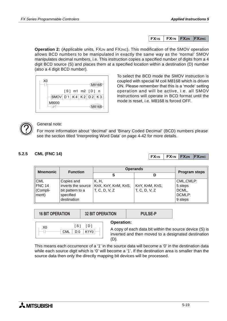
FX Series Programmable Controlers Applied Instructions 5
Operation 2: (Applicable units, FX2N and FX2NC). This modification of the SMOV operationallows BCD numbers to be manipulated in exactly the same way as the ‘normal’ SMOVmanipulates decimal numbers, i.e. This instruction copies a specified number of digits from a 4digit BCD source (S) and places them at a specified location within a destination (D) number(also a 4 digit BCD number).
To select the BCD mode the SMOV instruction iscoupled with special M coil M8168 which is drivenON. Please remember that this is a ‘mode’ settingoperation and wil l be active, i.e. all SMOVinstructions will operate in BCD format until themode is reset, i.e. M8168 is forced OFF.
5.2.5 CML (FNC 14)
Operation:
A copy of each data bit within the source device (S) isinverted and then moved to a designated destination(D).
This means each occurrence of a ‘1’ in the source data will become a ‘0’ in the destination datawhile each source digit which is ‘0’ will become a ‘1’. If the destination area is smaller than thesource data then only the directly mapping bit devices will be processed.
Mnemonic Function Operands
Program stepsS D
CMLFNC 14(Compli-ment)
Copies andinverts the sourcebit pattern to aspecifieddestination
K, H,KnX, KnY, KnM, KnS,T, C, D, V, Z
KnY, KnM, KnS,T, C, D, V, Z
CML,CMLP:5 stepsDCML,DCMLP:9 steps
FX1S FX1N FX2N FX2NC
X0M8168
SMOV D 1 K 4
[ S ] [ D ]
K 2 D 2 K 3
nm1 m2
M8000M8168
General note:
For more information about ‘decimal’ and ‘Binary Coded Decimal’ (BCD) numbers pleasesee the section titled ‘Interpreting Word Data’ on page 4-42 for more details.
FX1S FX1N FX2N FX2NC
PULSE-P16 BIT OPERATION 32 BIT OPERATION
X0CML D 0 K1Y0
[ S ] [ D ]
5-19
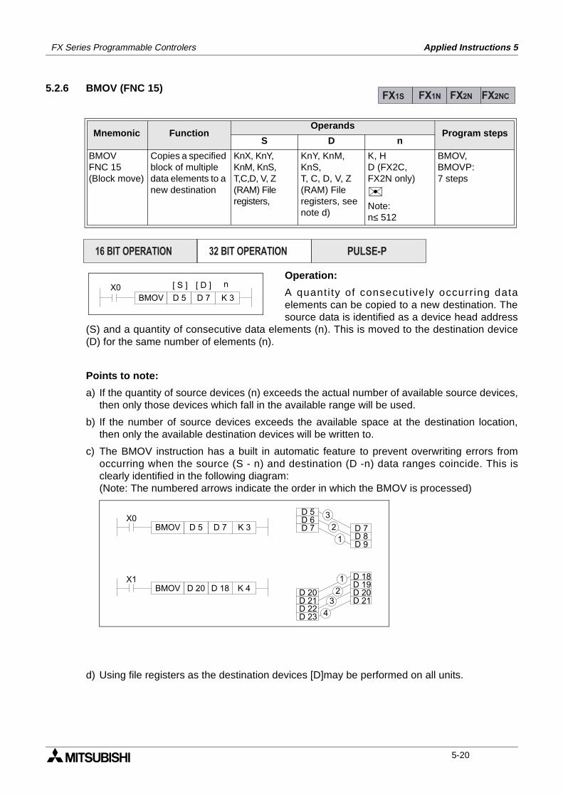
FX Series Programmable Controlers Applied Instructions 5
5.2.6 BMOV (FNC 15)
Operation:
A quanti ty of consecut ively occurr ing dataelements can be copied to a new destination. Thesource data is identified as a device head address
(S) and a quantity of consecutive data elements (n). This is moved to the destination device(D) for the same number of elements (n).
Points to note:
a) If the quantity of source devices (n) exceeds the actual number of available source devices,then only those devices which fall in the available range will be used.
b) If the number of source devices exceeds the available space at the destination location,then only the available destination devices will be written to.
c) The BMOV instruction has a built in automatic feature to prevent overwriting errors fromoccurring when the source (S - n) and destination (D -n) data ranges coincide. This isclearly identified in the following diagram:(Note: The numbered arrows indicate the order in which the BMOV is processed)
d) Using file registers as the destination devices [D]may be performed on all units.
Mnemonic Function Operands
Program stepsS D n
BMOVFNC 15(Block move)
Copies a specified block of multiple data elements to a new destination
KnX, KnY,KnM, KnS,T,C,D, V, Z(RAM) Fileregisters,
KnY, KnM, KnS,T, C, D, V, Z(RAM) Fileregisters, seenote d)
K, HD (FX2C, FX2N only)
Note:n≤ 512
BMOV,BMOVP:7 steps
FX1S FX1N FX2N FX2NC
PULSE-P16 BIT OPERATION 32 BIT OPERATION
X0BMOV D 5 D 7 K 3
[ S ] [ D ] n
D 5D 6D 7
D 20D 21D 22
D 18D 19D 20
X0BMOV D 5 D 7
X1
K 3
BMOV D 20 D 18 K 4
D 23
D 21
D 7D 8D 9
1
3
2
1
23
4
5-20
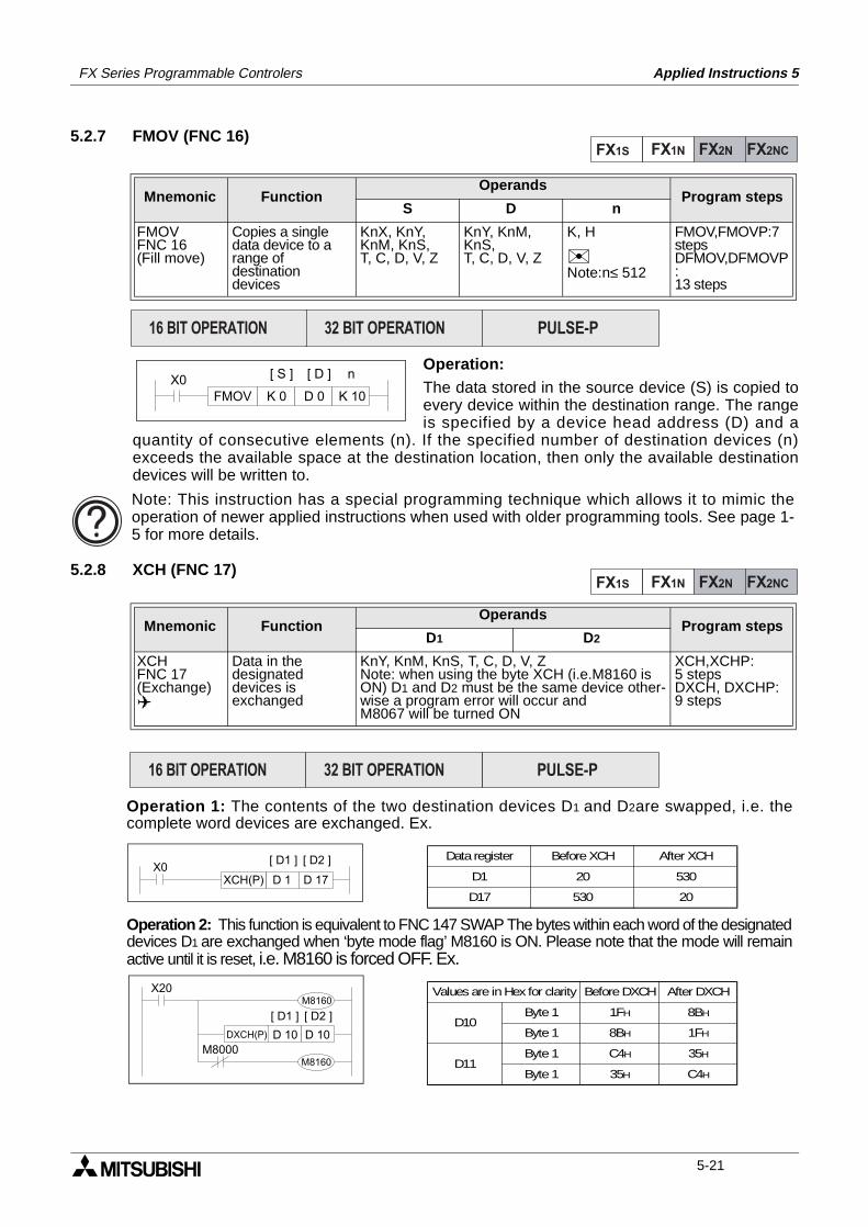
FX Series Programmable Controlers Applied Instructions 5
5.2.7 FMOV (FNC 16)
Operation:The data stored in the source device (S) is copied toevery device within the destination range. The rangeis specified by a device head address (D) and a
quantity of consecutive elements (n). If the specified number of destination devices (n)exceeds the available space at the destination location, then only the available destinationdevices will be written to.
5.2.8 XCH (FNC 17)
Mnemonic Function Operands
Program stepsS D n
FMOVFNC 16(Fill move)
Copies a singledata device to arange of destination devices
KnX, KnY, KnM, KnS,T, C, D, V, Z
KnY, KnM, KnS,T, C, D, V, Z
K, H
Note:n≤ 512
FMOV,FMOVP:7stepsDFMOV,DFMOVP:13 steps
Mnemonic Function Operands
Program stepsD1 D2
XCHFNC 17(Exchange)
Data in the designateddevices is exchanged
KnY, KnM, KnS, T, C, D, V, ZNote: when using the byte XCH (i.e.M8160 is ON) D1 and D2 must be the same device other-wise a program error will occur andM8067 will be turned ON
XCH,XCHP:5 stepsDXCH, DXCHP:9 steps
FX1S FX1N FX2N FX2NC
PULSE-P16 BIT OPERATION 32 BIT OPERATION
X0FMOV K 0 D 0
[ S ] [ D ]
K 10
n
Note: This instruction has a special programming technique which allows it to mimic theoperation of newer applied instructions when used with older programming tools. See page 1-5 for more details.
FX1S FX1N FX2N FX2NC
X0XCH(P) D 1 D 17
[ D1 ] [ D2 ]
X20
DXCH(P) D 10 D 10
[ D1 ] [ D2 ]
M8160
M8000M8160
Data register Before XCH After XCH
D1
D17
20
530
530
20
Operation 1: The contents of the two destination devices D1 and D2are swapped, i.e. thecomplete word devices are exchanged. Ex.
Operation 2: This function is equivalent to FNC 147 SWAP The bytes within each word of the designateddevices D1 are exchanged when ‘byte mode flag’ M8160 is ON. Please note that the mode will remainactive until it is reset, i.e. M8160 is forced OFF. Ex.
D10Byte 1 1FH 8BH
Byte 1
D11Byte 1
Byte 1
8BH
C4H
35H
1FH
35H
C4H
Values are in Hex for clarity Before DXCH After DXCH
PULSE-P16 BIT OPERATION 32 BIT OPERATION
5-21
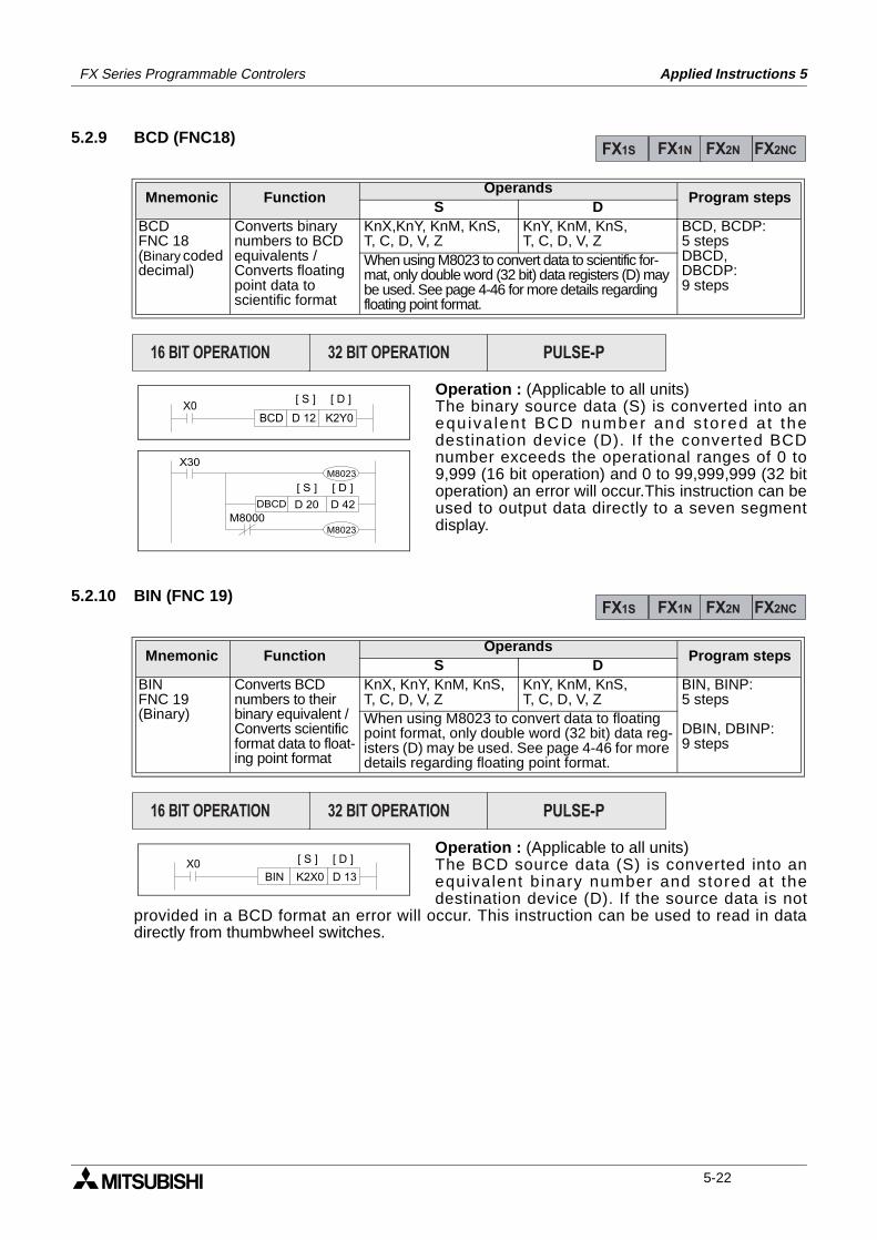
FX Series Programmable Controlers Applied Instructions 5
5.2.9 BCD (FNC18)
Operation : (Applicable to all units)The binary source data (S) is converted into anequ iva len t BCD number and s tored a t thedestination device (D). If the converted BCDnumber exceeds the operational ranges of 0 to9,999 (16 bit operation) and 0 to 99,999,999 (32 bitoperation) an error will occur.This instruction can beused to output data directly to a seven segmentdisplay.
5.2.10 BIN (FNC 19)
Operation : (Applicable to all units)The BCD source data (S) is converted into anequivalent b inary number and stored at thedestination device (D). If the source data is not
provided in a BCD format an error will occur. This instruction can be used to read in datadirectly from thumbwheel switches.
Mnemonic Function Operands
Program stepsS D
BCDFNC 18(Binary coded decimal)
Converts binarynumbers to BCDequivalents /Converts floatingpoint data toscientific format
KnX,KnY, KnM, KnS,T, C, D, V, Z
KnY, KnM, KnS,T, C, D, V, Z
BCD, BCDP:5 stepsDBCD,DBCDP:9 steps
When using M8023 to convert data to scientific for-mat, only double word (32 bit) data registers (D) may be used. See page 4-46 for more details regarding floating point format.
Mnemonic Function Operands
Program stepsS D
BINFNC 19(Binary)
Converts BCD numbers to their binary equivalent / Converts scientific format data to float-ing point format
KnX, KnY, KnM, KnS,T, C, D, V, Z
KnY, KnM, KnS,T, C, D, V, Z
BIN, BINP:5 steps
DBIN, DBINP:9 steps
When using M8023 to convert data to floating point format, only double word (32 bit) data reg-isters (D) may be used. See page 4-46 for more details regarding floating point format.
FX1S FX1N FX2N FX2NC
PULSE-P16 BIT OPERATION 32 BIT OPERATION
X0BCD D 12 K2Y0
[ S ] [ D ]
X30M8023
M8000M8023
DBCD D 42D 20
[ S ] [ D ]
FX1S FX1N FX2N FX2NC
PULSE-P16 BIT OPERATION 32 BIT OPERATION
X0BIN D 13K2X0
[ S ] [ D ]
5-22

FX Series Programmable Controlers Applied Instructions 5
Applied Instructions:FX1S FX1N FX2N FX2NC
FNC 00 - 09
FNC 10 - 19
FNC 20 - 29
FNC 30 - 39
FNC 40 - 49
FNC 50 - 59
FNC 60 - 69
FNC 70 - 79
FNC 80 - 89
FNC 110-129
FNC 130-139
FNC 140-149
FNC 160-169
FNC 170-179
FNC 220-249
FNC 150-159
1.
2.
3.
4.
5.
6.
7.
8.
9.
10.
11.
12.
13.
14.
15.
16.
Program Flow 5-4
Move And Compare 5-16
Arithmetic And Logical Operations (+, -, ×, ÷)5-24
Rotation And Shift 5-34
Data Operation 5-42
High Speed Processing 5-52
Handy Instructions 5-66
External FX I/O Devices 5-80
External FX Serial Devices 5-94
Floating Point 1 & 2 5-110
Trigonometry (Floating Point 3) 5-118
Data Operations 2 5-122
FX1S & FX1N Positioning Control 5-126
Real Time Clock Control 5-136
Gray Codes 5-146
In-line Comparisons 5-150
5-23
FX Series Programmable Controlers Applied Instructions 5
5.3 Arithmetic And Logical Operations -Functions 20 to 29
Contents:
PageADD - Addition FNC 20 5-25SUB - Subtraction FNC 21 5-26MUL - Multiplication FNC 22 5-27DIV - Division FNC 23 5-28INC - Increment FNC 24 5-29DEC - Decrement FNC 25 5-29WAND - Word AND FNC 26 5-30WOR - Word OR FNC 27 5-30WXOR - Word Exclusive OR FNC 28 5-31NEG - Negation FNC 29 5-31
Symbols list:
D - Destination device.S - Source device.m, n- Number of active devices, bits or an operational constant.Additional numeric suffixes will be attached if there are more than one operand with the samefunction e.g. D1, S3 or for lists/tabled devices D3+0, S+9 etc.MSB - Most Significant Bit, sometimes used to indicate the mathematical sign of a number,i.e. positive = 0, and negative = 1.LSB - Least Significant Bit.
Instruction modifications:
- An instruction operating in 16 bit mode, where identifies the instructionmnemonic.
P - A 16 bit mode instruction modified to use pulse (single) operation.
D - An instruction modified to operate in 32 bit operation.
DP - A 32 bit mode instruction modified to use pulse (single) operation.
- A repetitive instruction which will change the destination value on every scan unlessmodified by the pulse function.
- An operand which cannot be indexed, i.e. The addition of V or Z is either invalid or willhave no effect to the value of the operand.
5-24
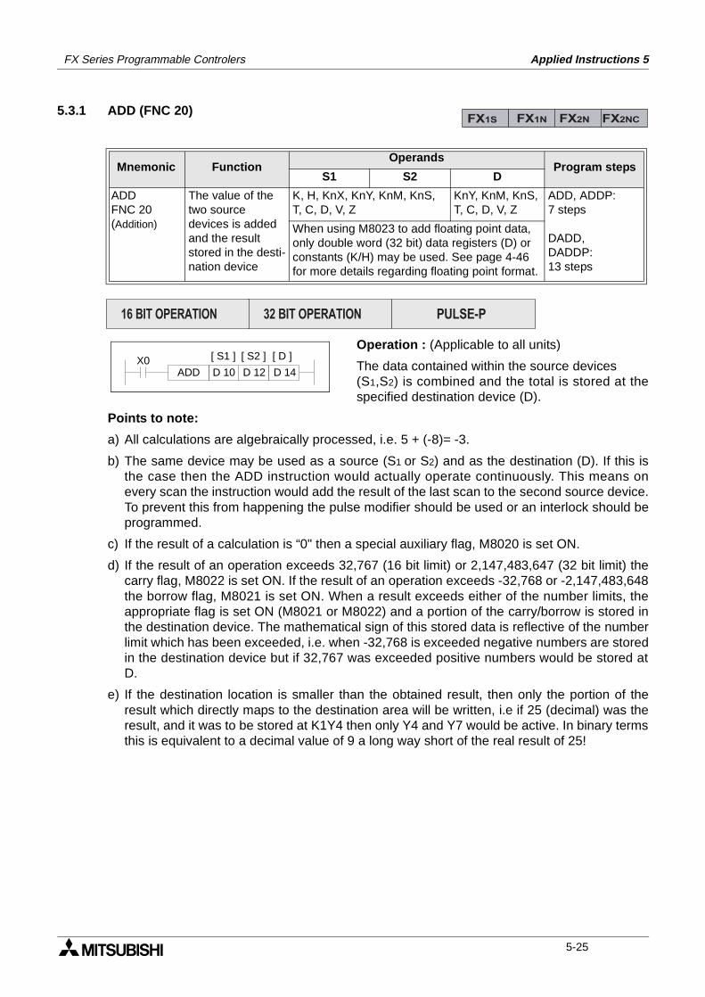
FX Series Programmable Controlers Applied Instructions 5
5.3.1 ADD (FNC 20)
Operation : (Applicable to all units)
The data contained within the source devices (S1,S2) is combined and the total is stored at thespecified destination device (D).
Points to note:
a) All calculations are algebraically processed, i.e. 5 + (-8)= -3.
b) The same device may be used as a source (S1 or S2) and as the destination (D). If this isthe case then the ADD instruction would actually operate continuously. This means onevery scan the instruction would add the result of the last scan to the second source device.To prevent this from happening the pulse modifier should be used or an interlock should beprogrammed.
c) If the result of a calculation is “0" then a special auxiliary flag, M8020 is set ON.
d) If the result of an operation exceeds 32,767 (16 bit limit) or 2,147,483,647 (32 bit limit) thecarry flag, M8022 is set ON. If the result of an operation exceeds -32,768 or -2,147,483,648the borrow flag, M8021 is set ON. When a result exceeds either of the number limits, theappropriate flag is set ON (M8021 or M8022) and a portion of the carry/borrow is stored inthe destination device. The mathematical sign of this stored data is reflective of the numberlimit which has been exceeded, i.e. when -32,768 is exceeded negative numbers are storedin the destination device but if 32,767 was exceeded positive numbers would be stored atD.
e) If the destination location is smaller than the obtained result, then only the portion of theresult which directly maps to the destination area will be written, i.e if 25 (decimal) was theresult, and it was to be stored at K1Y4 then only Y4 and Y7 would be active. In binary termsthis is equivalent to a decimal value of 9 a long way short of the real result of 25!
Mnemonic Function Operands
Program stepsS1 S2 D
ADDFNC 20(Addition)
The value of the two source devices is added and the result stored in the desti-nation device
K, H, KnX, KnY, KnM, KnS,T, C, D, V, Z
KnY, KnM, KnS,T, C, D, V, Z
ADD, ADDP:7 steps
DADD,DADDP:13 steps
When using M8023 to add floating point data, only double word (32 bit) data registers (D) or constants (K/H) may be used. See page 4-46 for more details regarding floating point format.
FX1S FX1N FX2N FX2NC
PULSE-P16 BIT OPERATION 32 BIT OPERATION
X0ADD D 10 D 12
[ S1 ] [ D ]
D 14
[ S2 ]
5-25
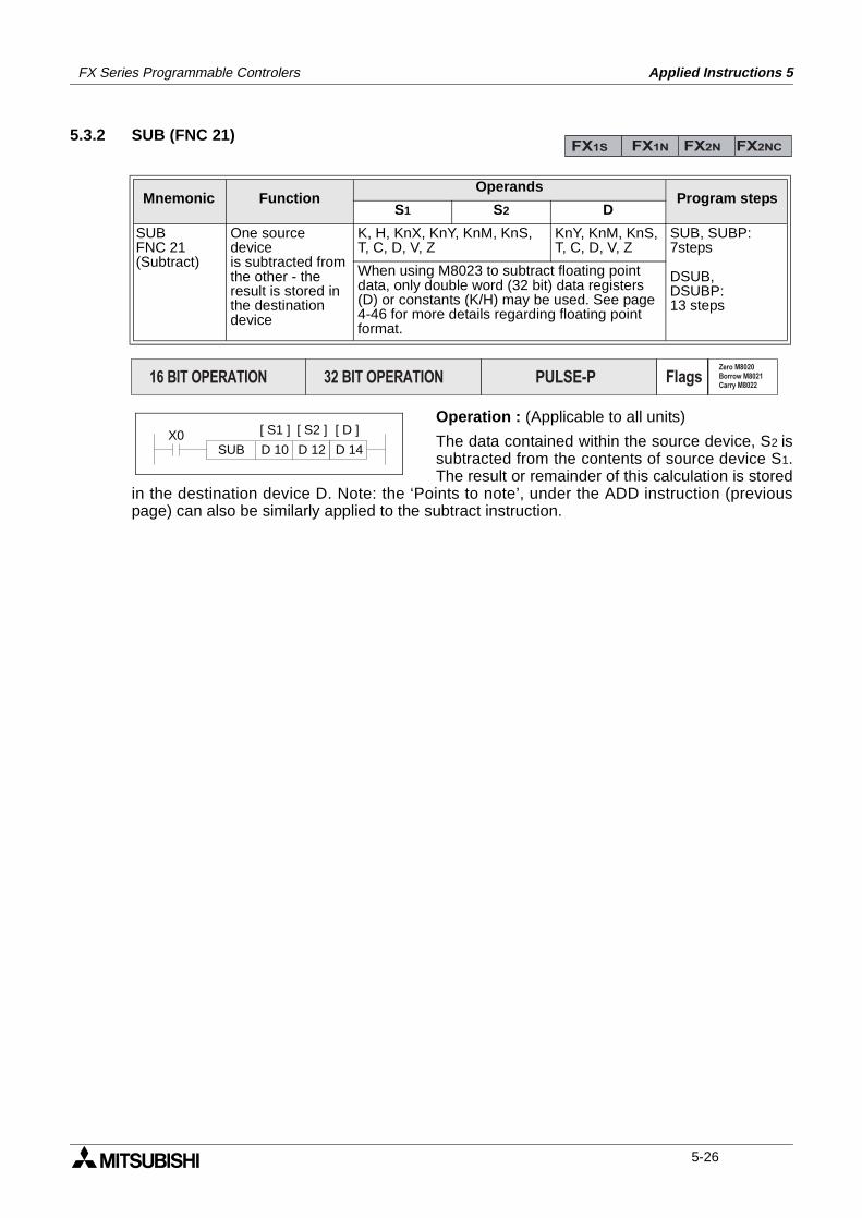
FX Series Programmable Controlers Applied Instructions 5
5.3.2 SUB (FNC 21)
Operation : (Applicable to all units)
The data contained within the source device, S2 issubtracted from the contents of source device S1.The result or remainder of this calculation is stored
in the destination device D. Note: the ‘Points to note’, under the ADD instruction (previouspage) can also be similarly applied to the subtract instruction.
Mnemonic Function Operands
Program stepsS1 S2 D
SUBFNC 21(Subtract)
One source deviceis subtracted fromthe other - theresult is stored inthe destinationdevice
K, H, KnX, KnY, KnM, KnS,T, C, D, V, Z
KnY, KnM, KnS,T, C, D, V, Z
SUB, SUBP:7steps
DSUB,DSUBP:13 steps
When using M8023 to subtract floating point data, only double word (32 bit) data registers (D) or constants (K/H) may be used. See page 4-46 for more details regarding floating point format.
FX1S FX1N FX2N FX2NC
PULSE-P16 BIT OPERATION 32 BIT OPERATION FlagsZero M8020Borrow M8021Carry M8022
X0SUB D 10 D 12
[ S1 ] [ D ]
D 14
[ S2 ]
5-26
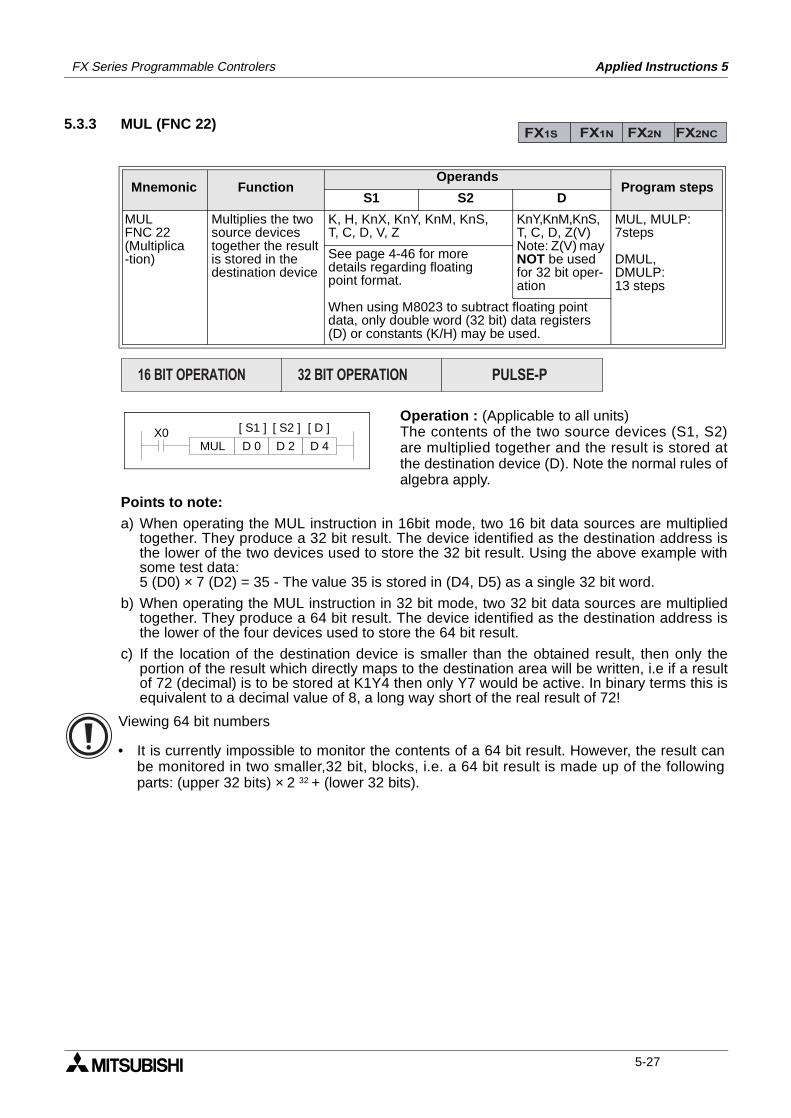
FX Series Programmable Controlers Applied Instructions 5
5.3.3 MUL (FNC 22)
Operation : (Applicable to all units)The contents of the two source devices (S1, S2)are multiplied together and the result is stored atthe destination device (D). Note the normal rules ofalgebra apply.
Points to note:a) When operating the MUL instruction in 16bit mode, two 16 bit data sources are multiplied
together. They produce a 32 bit result. The device identified as the destination address isthe lower of the two devices used to store the 32 bit result. Using the above example withsome test data:5 (D0) × 7 (D2) = 35 - The value 35 is stored in (D4, D5) as a single 32 bit word.
b) When operating the MUL instruction in 32 bit mode, two 32 bit data sources are multipliedtogether. They produce a 64 bit result. The device identified as the destination address isthe lower of the four devices used to store the 64 bit result.
c) If the location of the destination device is smaller than the obtained result, then only theportion of the result which directly maps to the destination area will be written, i.e if a resultof 72 (decimal) is to be stored at K1Y4 then only Y7 would be active. In binary terms this isequivalent to a decimal value of 8, a long way short of the real result of 72!
Mnemonic Function Operands
Program stepsS1 S2 D
MULFNC 22(Multiplica-tion)
Multiplies the twosource devicestogether the resultis stored in thedestination device
K, H, KnX, KnY, KnM, KnS,T, C, D, V, Z
KnY,KnM,KnS,T, C, D, Z(V) Note: Z(V) may NOT be used for 32 bit oper-ation
MUL, MULP:7steps
DMUL,DMULP:13 steps
See page 4-46 for moredetails regarding floatingpoint format.
When using M8023 to subtract floating point data, only double word (32 bit) data registers (D) or constants (K/H) may be used.
FX1S FX1N FX2N FX2NC
PULSE-P16 BIT OPERATION 32 BIT OPERATION
X0MUL D 0 D 2
[ S1 ] [ D ]
D 4
[ S2 ]
Viewing 64 bit numbers
• It is currently impossible to monitor the contents of a 64 bit result. However, the result canbe monitored in two smaller,32 bit, blocks, i.e. a 64 bit result is made up of the followingparts: (upper 32 bits) × 2 32 + (lower 32 bits).
5-27
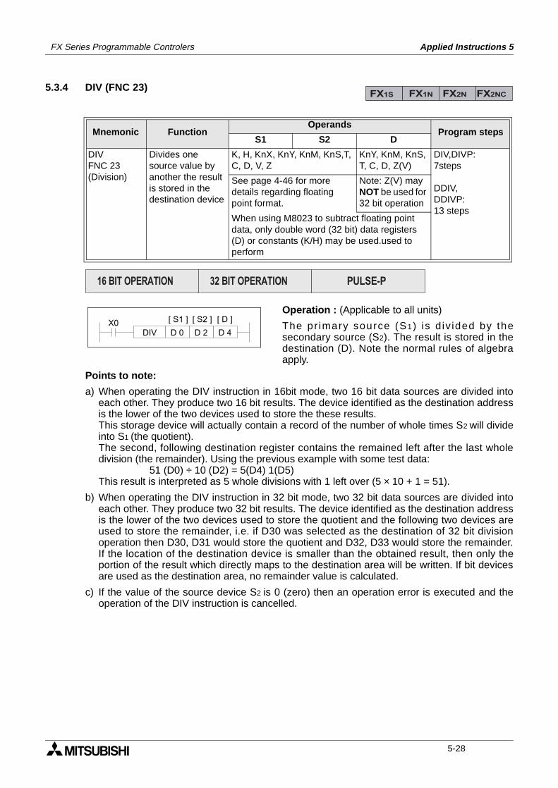
FX Series Programmable Controlers Applied Instructions 5
5.3.4 DIV (FNC 23)
Operation : (Applicable to all units)
The pr imary source (S1) is d iv ided by thesecondary source (S2). The result is stored in thedestination (D). Note the normal rules of algebraapply.
Points to note:
a) When operating the DIV instruction in 16bit mode, two 16 bit data sources are divided intoeach other. They produce two 16 bit results. The device identified as the destination addressis the lower of the two devices used to store the these results.This storage device will actually contain a record of the number of whole times S2 will divideinto S1 (the quotient).The second, following destination register contains the remained left after the last wholedivision (the remainder). Using the previous example with some test data:
51 (D0) ÷ 10 (D2) = 5(D4) 1(D5)This result is interpreted as 5 whole divisions with 1 left over (5 × 10 + 1 = 51).
b) When operating the DIV instruction in 32 bit mode, two 32 bit data sources are divided intoeach other. They produce two 32 bit results. The device identified as the destination addressis the lower of the two devices used to store the quotient and the following two devices areused to store the remainder, i.e. if D30 was selected as the destination of 32 bit divisionoperation then D30, D31 would store the quotient and D32, D33 would store the remainder.If the location of the destination device is smaller than the obtained result, then only theportion of the result which directly maps to the destination area will be written. If bit devicesare used as the destination area, no remainder value is calculated.
c) If the value of the source device S2 is 0 (zero) then an operation error is executed and theoperation of the DIV instruction is cancelled.
Mnemonic Function Operands
Program stepsS1 S2 D
DIVFNC 23(Division)
Divides onesource value byanother the resultis stored in thedestination device
K, H, KnX, KnY, KnM, KnS,T, C, D, V, Z
KnY, KnM, KnS,T, C, D, Z(V)
DIV,DIVP:7steps
DDIV,DDIVP:13 steps
See page 4-46 for moredetails regarding floatingpoint format.
Note: Z(V) may NOT be used for 32 bit operation
When using M8023 to subtract floating point data, only double word (32 bit) data registers (D) or constants (K/H) may be used.used to perform
FX1S FX1N FX2N FX2NC
PULSE-P16 BIT OPERATION 32 BIT OPERATION
X0DIV D 0 D 2
[ S1 ] [ D ]
D 4
[ S2 ]
5-28
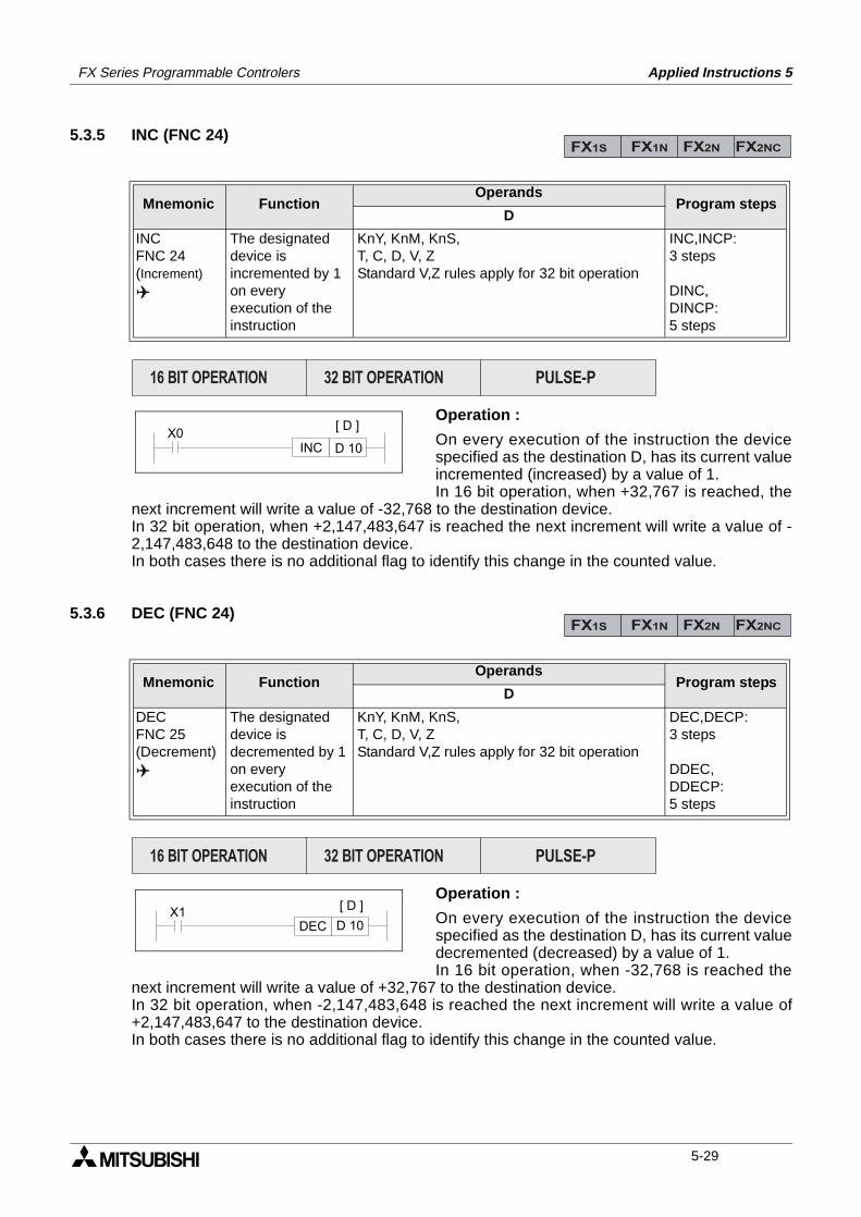
FX Series Programmable Controlers Applied Instructions 5
5.3.5 INC (FNC 24)
Operation :
On every execution of the instruction the devicespecified as the destination D, has its current valueincremented (increased) by a value of 1.In 16 bit operation, when +32,767 is reached, the
next increment will write a value of -32,768 to the destination device.In 32 bit operation, when +2,147,483,647 is reached the next increment will write a value of -2,147,483,648 to the destination device.In both cases there is no additional flag to identify this change in the counted value.
5.3.6 DEC (FNC 24)
Operation :
On every execution of the instruction the devicespecified as the destination D, has its current valuedecremented (decreased) by a value of 1.In 16 bit operation, when -32,768 is reached the
next increment will write a value of +32,767 to the destination device.In 32 bit operation, when -2,147,483,648 is reached the next increment will write a value of+2,147,483,647 to the destination device.In both cases there is no additional flag to identify this change in the counted value.
Mnemonic Function Operands
Program stepsD
INCFNC 24(Increment)
The designateddevice isincremented by 1on everyexecution of theinstruction
KnY, KnM, KnS,T, C, D, V, ZStandard V,Z rules apply for 32 bit operation
INC,INCP:3 steps
DINC,DINCP:5 steps
Mnemonic Function Operands
Program stepsD
DECFNC 25(Decrement)
The designateddevice isdecremented by 1on everyexecution of theinstruction
KnY, KnM, KnS,T, C, D, V, ZStandard V,Z rules apply for 32 bit operation
DEC,DECP:3 steps
DDEC,DDECP:5 steps
FX1S FX1N FX2N FX2NC
PULSE-P16 BIT OPERATION 32 BIT OPERATION
X0[ D ]
D 10INC
FX1S FX1N FX2N FX2NC
PULSE-P16 BIT OPERATION 32 BIT OPERATION
X1 [ D ]
D 10DEC
5-29
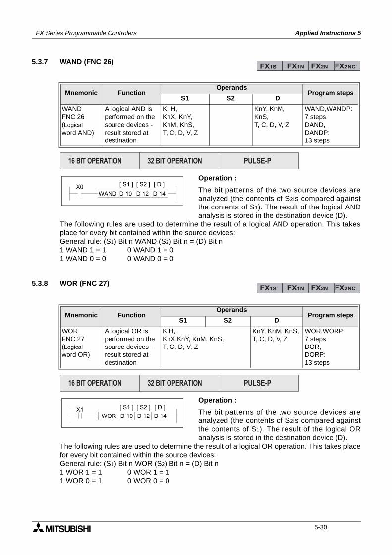
FX Series Programmable Controlers Applied Instructions 5
5.3.7 WAND (FNC 26)
Operation :
The bit patterns of the two source devices areanalyzed (the contents of S2is compared againstthe contents of S1). The result of the logical ANDanalysis is stored in the destination device (D).
The following rules are used to determine the result of a logical AND operation. This takesplace for every bit contained within the source devices:General rule: (S1) Bit n WAND (S2) Bit n = (D) Bit n1 WAND 1 = 1 0 WAND 1 = 01 WAND 0 = 0 0 WAND 0 = 0
5.3.8 WOR (FNC 27)
Operation :
The bit patterns of the two source devices areanalyzed (the contents of S2is compared againstthe contents of S1). The result of the logical ORanalysis is stored in the destination device (D).
The following rules are used to determine the result of a logical OR operation. This takes placefor every bit contained within the source devices: General rule: (S1) Bit n WOR (S2) Bit n = (D) Bit n1 WOR 1 = 1 0 WOR 1 = 11 WOR 0 = 1 0 WOR 0 = 0
Mnemonic Function Operands
Program stepsS1 S2 D
WANDFNC 26(Logicalword AND)
A logical AND isperformed on thesource devices -result stored at destination
K, H,KnX, KnY, KnM, KnS,T, C, D, V, Z
KnY, KnM, KnS, T, C, D, V, Z
WAND,WANDP:7 stepsDAND,DANDP:13 steps
Mnemonic Function Operands
Program stepsS1 S2 D
WORFNC 27(Logicalword OR)
A logical OR isperformed on thesource devices -result stored atdestination
K,H,KnX,KnY, KnM, KnS,T, C, D, V, Z
KnY, KnM, KnS,T, C, D, V, Z
WOR,WORP:7 stepsDOR,DORP:13 steps
FX1S FX1N FX2N FX2NC
PULSE-P16 BIT OPERATION 32 BIT OPERATION
X0WAND D 10 D 12 D 14
[ S1 ] [ D ][ S2 ]
FX1S FX1N FX2N FX2NC
PULSE-P16 BIT OPERATION 32 BIT OPERATION
X1WOR D 10 D 12 D 14
[ S1 ] [ D ][ S2 ]
5-30
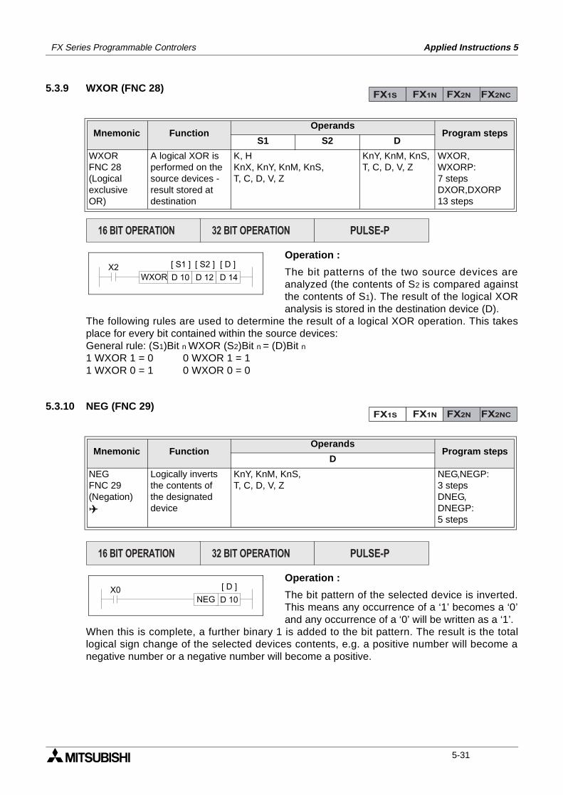
FX Series Programmable Controlers Applied Instructions 5
5.3.9 WXOR (FNC 28)
Operation :
The bit patterns of the two source devices areanalyzed (the contents of S2 is compared againstthe contents of S1). The result of the logical XORanalysis is stored in the destination device (D).
The following rules are used to determine the result of a logical XOR operation. This takesplace for every bit contained within the source devices:General rule: (S1)Bit n WXOR (S2)Bit n = (D)Bit n1 WXOR 1 = 0 0 WXOR 1 = 11 WXOR 0 = 1 0 WXOR 0 = 0
5.3.10 NEG (FNC 29)
Operation :
The bit pattern of the selected device is inverted.This means any occurrence of a ‘1’ becomes a ‘0’and any occurrence of a ‘0’ will be written as a ‘1’.
When this is complete, a further binary 1 is added to the bit pattern. The result is the totallogical sign change of the selected devices contents, e.g. a positive number will become anegative number or a negative number will become a positive.
Mnemonic Function Operands
Program stepsS1 S2 D
WXORFNC 28(Logicalexclusive OR)
A logical XOR isperformed on thesource devices -result stored atdestination
K, HKnX, KnY, KnM, KnS,T, C, D, V, Z
KnY, KnM, KnS,T, C, D, V, Z
WXOR,WXORP:7 stepsDXOR,DXORP13 steps
Mnemonic Function Operands
Program stepsD
NEGFNC 29(Negation)
Logically invertsthe contents ofthe designateddevice
KnY, KnM, KnS,T, C, D, V, Z
NEG,NEGP:3 stepsDNEG,DNEGP:5 steps
FX1S FX1N FX2N FX2NC
PULSE-P16 BIT OPERATION 32 BIT OPERATION
X2WXOR D 10 D 12 D 14
[ S1 ] [ D ][ S2 ]
FX1S FX1N FX2N FX2NC
PULSE-P16 BIT OPERATION 32 BIT OPERATION
X0 [ D ]
D 10NEG
5-31

FX Series Programmable Controlers Applied Instructions 5
MEMO
5-32
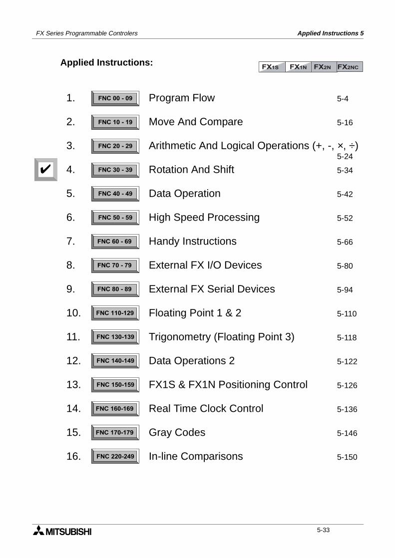
FX Series Programmable Controlers Applied Instructions 5
Applied Instructions:FX1S FX1N FX2N FX2NC
FNC 00 - 09
FNC 10 - 19
FNC 20 - 29
FNC 30 - 39
FNC 40 - 49
FNC 50 - 59
FNC 60 - 69
FNC 70 - 79
FNC 80 - 89
FNC 110-129
FNC 130-139
FNC 140-149
FNC 160-169
FNC 170-179
FNC 220-249
FNC 150-159
1.
2.
3.
4.
5.
6.
7.
8.
9.
10.
11.
12.
13.
14.
15.
16.
Program Flow 5-4
Move And Compare 5-16
Arithmetic And Logical Operations (+, -, ×, ÷)5-24
Rotation And Shift 5-34
Data Operation 5-42
High Speed Processing 5-52
Handy Instructions 5-66
External FX I/O Devices 5-80
External FX Serial Devices 5-94
Floating Point 1 & 2 5-110
Trigonometry (Floating Point 3) 5-118
Data Operations 2 5-122
FX1S & FX1N Positioning Control 5-126
Real Time Clock Control 5-136
Gray Codes 5-146
In-line Comparisons 5-150
5-33

FX Series Programmable Controlers Applied Instructions 5
5.4 Rotation And Shift - Functions 30 to 39
Contents:
Page
ROR - Rotation Right FNC 30 5-35
ROL - Rotation Left FNC 31 5-35
RCR - Rotation Right with Carry FNC 32 5-36
RCL - Rotation Left with Carry FNC 33 5-36
SFTR - (Bit) Shift Right FNC 34 5-37
SFTL - (Bit) Shift Left FNC 35 5-37
WSFR - Word Shift Right FNC 36 5-38
WSFL - Word Shift Left FNC 37 5-38
SFWR - Shift Register Write FNC 38 5-39
SFRD - Shift Register Read FNC 39 5-40
Symbols list:
D - Destination device.S - Source device.m, n- Number of active devices, bits or an operational constant.Additional numeric suffixes will be attached if there are more than one operand with the samefunction e.g. D1, S3 or for lists/tabled devices D3+0, S+9 etc.MSB - Most Significant Bit, sometimes used to indicate the mathematical sign of a number,i.e. positive = 0, and negative = 1.LSB - Least Significant Bit.
Instruction modifications:
- An instruction operating in 16 bit mode, where identifies the instructionmnemonic.
P - A 16 bit mode instruction modified to use pulse (single) operation.
D - An instruction modified to operate in 32 bit operation.
DP - A 32 bit mode instruction modified to use pulse (single) operation.
- A repetitive instruction which will change the destination value on every scan unlessmodified by the pulse function.
- An operand which cannot be indexed, i.e. The addition of V or Z is either invalid or willhave no effect to the value of the operand.
5-34
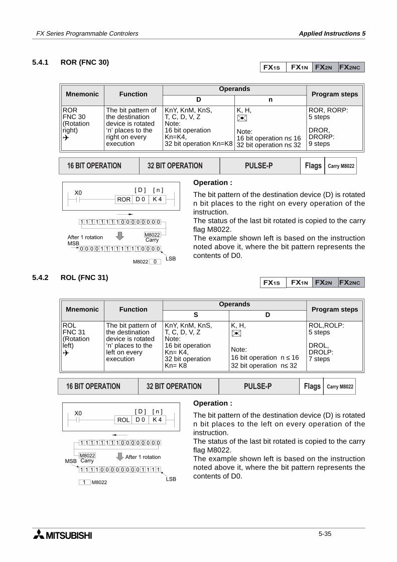
FX Series Programmable Controlers Applied Instructions 5
5.4.1 ROR (FNC 30)
Operation :
The bit pattern of the destination device (D) is rotatedn bit places to the right on every operation of theinstruction. The status of the last bit rotated is copied to the carryflag M8022.The example shown left is based on the instructionnoted above it, where the bit pattern represents thecontents of D0.
5.4.2 ROL (FNC 31)
Operation :
The bit pattern of the destination device (D) is rotatedn bit places to the left on every operation of theinstruction.The status of the last bit rotated is copied to the carryflag M8022.The example shown left is based on the instructionnoted above it, where the bit pattern represents thecontents of D0.
Mnemonic Function Operands
Program stepsD n
RORFNC 30(Rotationright)
The bit pattern ofthe destinationdevice is rotated‘n’ places to theright on everyexecution
KnY, KnM, KnS,T, C, D, V, ZNote:16 bit operation Kn=K4,32 bit operation Kn=K8
K, H,
Note:16 bit operation n≤ 1632 bit operation n≤ 32
ROR, RORP:5 steps
DROR,DRORP:9 steps
Mnemonic Function Operands
Program stepsS D
ROLFNC 31(Rotationleft)
The bit pattern ofthe destinationdevice is rotated‘n’ places to theleft on everyexecution
KnY, KnM, KnS,T, C, D, V, ZNote:16 bit operation Kn= K4,32 bit operation Kn= K8
K, H,
Note:16 bit operation n ≤ 1632 bit operation n≤ 32
ROL,ROLP:5 steps
DROL,DROLP:7 steps
FX1S FX1N FX2N FX2NC
PULSE-P16 BIT OPERATION 32 BIT OPERATION Flags Carry M8022
[ D ] [ n ]X0D 0 K 4ROR
M8022
0
Carry
M8022
1 1 1 1 1 1 1 1 0 0 0 0 0 0 0 0
0000111111110000
After 1 rotationMSB
LSB
FX1S FX1N FX2N FX2NC
PULSE-P16 BIT OPERATION 32 BIT OPERATION Flags Carry M8022
X0D 0
[ D ]
K 4
[ n ]
ROL
1 1 1 1 1 1 1 1 0 0 0 0 0 0 0 0
1 1 1 1 0 0 0 0 0 0 0 0 1 1 1 1
M8022
1
Carry
M8022
After 1 rotation
LSB
MSB
5-35
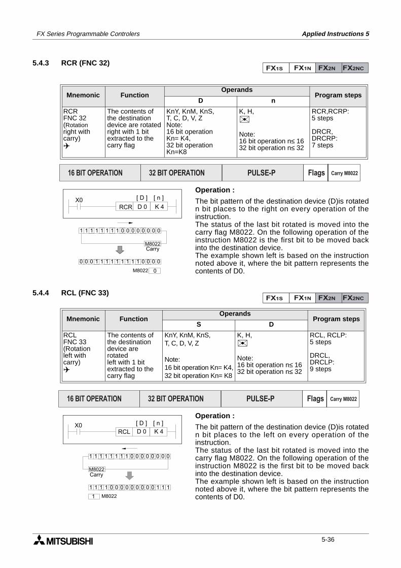
FX Series Programmable Controlers Applied Instructions 5
5.4.3 RCR (FNC 32)
Operation :
The bit pattern of the destination device (D)is rotatedn bit places to the right on every operation of theinstruction.The status of the last bit rotated is moved into thecarry flag M8022. On the following operation of theinstruction M8022 is the first bit to be moved backinto the destination device.The example shown left is based on the instructionnoted above it, where the bit pattern represents thecontents of D0.
5.4.4 RCL (FNC 33)
Operation :
The bit pattern of the destination device (D)is rotatedn bit places to the left on every operation of theinstruction.The status of the last bit rotated is moved into thecarry flag M8022. On the following operation of theinstruction M8022 is the first bit to be moved backinto the destination device.The example shown left is based on the instructionnoted above it, where the bit pattern represents thecontents of D0.
Mnemonic Function Operands
Program stepsD n
RCRFNC 32(Rotationright withcarry)
The contents ofthe destinationdevice are rotatedright with 1 bitextracted to thecarry flag
KnY, KnM, KnS,T, C, D, V, ZNote:16 bit operation Kn= K4,32 bit operationKn=K8
K, H,
Note:16 bit operation n≤ 1632 bit operation n≤ 32
RCR,RCRP:5 steps
DRCR,DRCRP:7 steps
Mnemonic Function Operands
Program stepsS D
RCLFNC 33(Rotationleft withcarry)
The contents ofthe destinationdevice are rotatedleft with 1 bitextracted to thecarry flag
KnY, KnM, KnS,T, C, D, V, Z
Note:16 bit operation Kn= K4,32 bit operation Kn= K8
K, H,
Note:16 bit operation n≤ 1632 bit operation n≤ 32
RCL, RCLP:5 steps
DRCL,DRCLP:9 steps
FX1S FX1N FX2N FX2NC
PULSE-P16 BIT OPERATION 32 BIT OPERATION Flags Carry M8022
[ D ] [ n ]X0D 0 K 4RCR
M8022
0
Carry
M8022
1 1 1 1 1 1 1 1 0 0 0 0 0 0 0 0
0000111111111000
FX1S FX1N FX2N FX2NC
PULSE-P16 BIT OPERATION 32 BIT OPERATION Flags Carry M8022
X0D 0
[ D ]
K 4
[ n ]
RCL
1 1 1 1 1 1 1 1 0 0 0 0 0 0 0 0
1 1 1 1 0 0 0 0 0 0 0 0 0 1 1 1
M8022
1
Carry
M8022
5-36
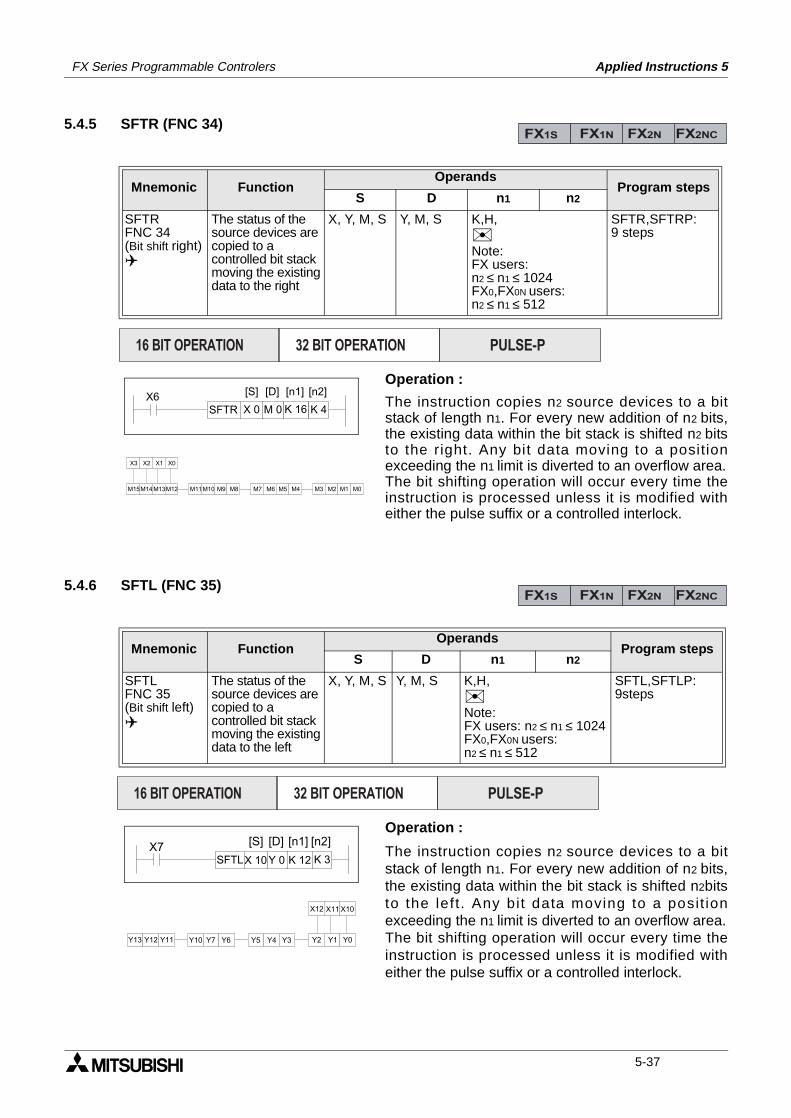
FX Series Programmable Controlers Applied Instructions 5
5.4.5 SFTR (FNC 34)
Operation :
The instruction copies n2 source devices to a bitstack of length n1. For every new addition of n2 bits,the existing data within the bit stack is shifted n2 bitsto the right. Any bit data moving to a positionexceeding the n1 limit is diverted to an overflow area.The bit shifting operation will occur every time theinstruction is processed unless it is modified witheither the pulse suffix or a controlled interlock.
5.4.6 SFTL (FNC 35)
Operation :
The instruction copies n2 source devices to a bitstack of length n1. For every new addition of n2 bits,the existing data within the bit stack is shifted n2bitsto the left. Any bit data moving to a posit ionexceeding the n1 limit is diverted to an overflow area.The bit shifting operation will occur every time theinstruction is processed unless it is modified witheither the pulse suffix or a controlled interlock.
Mnemonic Function Operands
Program stepsS D n1 n2
SFTRFNC 34(Bit shift right)
The status of thesource devices arecopied to acontrolled bit stackmoving the existingdata to the right
X, Y, M, S Y, M, S K,H,Note:FX users: n2 ≤ n1 ≤ 1024FX0,FX0N users:n2 ≤ n1 ≤ 512
SFTR,SFTRP:9 steps
Mnemonic Function Operands
Program stepsS D n1 n2
SFTLFNC 35(Bit shift left)
The status of thesource devices arecopied to acontrolled bit stackmoving the existingdata to the left
X, Y, M, S Y, M, S K,H,Note:FX users: n2 ≤ n1 ≤ 1024FX0,FX0N users:n2 ≤ n1 ≤ 512
SFTL,SFTLP:9steps
FX1S FX1N FX2N FX2NC
PULSE-P16 BIT OPERATION 32 BIT OPERATION
X6SFTR X 0 M 0 K 16 K 4
[S] [D] [n1] [n2]
X3 X2 X1 X0
M15M14 M13M12 M11M10 M9 M8 M7 M6 M5 M4 M3 M2 M1 M0
FX1S FX1N FX2N FX2NC
PULSE-P16 BIT OPERATION 32 BIT OPERATION
X7SFTLX 10Y 0 K 12 K 3
[S] [D] [n1] [n2]
Y2 Y1 Y0
X12 X11 X10
Y5 Y4 Y3Y10 Y7 Y6Y13 Y12 Y11
5-37
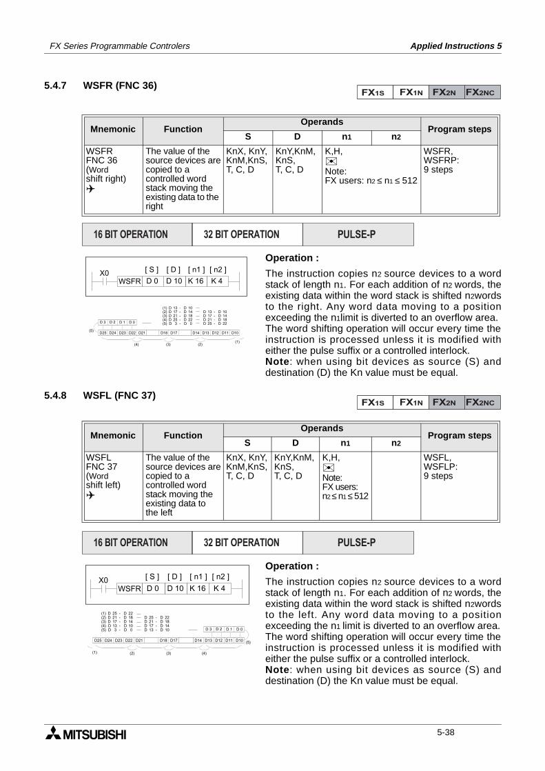
FX Series Programmable Controlers Applied Instructions 5
5.4.7 WSFR (FNC 36)
Operation :
The instruction copies n2 source devices to a wordstack of length n1. For each addition of n2 words, theexisting data within the word stack is shifted n2wordsto the right. Any word data moving to a positionexceeding the n1limit is diverted to an overflow area.The word shifting operation will occur every time theinstruction is processed unless it is modified witheither the pulse suffix or a controlled interlock.Note: when using bit devices as source (S) anddestination (D) the Kn value must be equal.
5.4.8 WSFL (FNC 37)
Operation :
The instruction copies n2 source devices to a wordstack of length n1. For each addition of n2 words, theexisting data within the word stack is shifted n2wordsto the left. Any word data moving to a positionexceeding the n1 limit is diverted to an overflow area.The word shifting operation will occur every time theinstruction is processed unless it is modified witheither the pulse suffix or a controlled interlock.Note: when using bit devices as source (S) anddestination (D) the Kn value must be equal.
Mnemonic Function Operands
Program stepsS D n1 n2
WSFRFNC 36(Wordshift right)
The value of thesource devices arecopied to acontrolled word stack moving theexisting data to the right
KnX, KnY,KnM,KnS,T, C, D
KnY,KnM,KnS,T, C, D
K,H,Note:FX users: n2 ≤ n1 ≤ 512
WSFR,WSFRP:9 steps
Mnemonic Function Operands
Program stepsS D n1 n2
WSFLFNC 37(Word shift left)
The value of thesource devices arecopied to acontrolled word stack moving theexisting data to the left
KnX, KnY,KnM,KnS,T, C, D
KnY,KnM,KnS,T, C, D
K,H,Note:FX users: n2 ≤ n1 ≤ 512
WSFL,WSFLP:9 steps
FX1S FX1N FX2N FX2NC
PULSE-P16 BIT OPERATION 32 BIT OPERATION
X0WSFR D 10 K 16 K 4
[ S ] [ D ]
D 0
[ n1 ] [ n2 ]
(1)(2)(3)(4)
(5)
DDDDD
(1)(2)(3)(4)(5)
131721253
-----
DDDDD
101418220
DDDD
13172125
----
DDDD
10141822D 3 D 2 D 1 D 0
D25 D24 D23 D22 D18D21 D14D17 D13 D12 D11 D10
FX1S FX1N FX2N FX2NC
PULSE-P16 BIT OPERATION 32 BIT OPERATION
X0WSFR D 10 K 16 K 4
[ S ] [ D ]
D 0
[ n1 ] [ n2 ]
(5)
(1) (2) (3) (4)
DDDDD
(1)(2)(3)(4)(5)
252117133
-----
DDDDD
DDDD
25211713
----
DDDD
22181410
221814100 D 3 D 2 D 1 D 0
D13 D12 D11 D10D14D17D18D21D25 D24 D23 D22
5-38
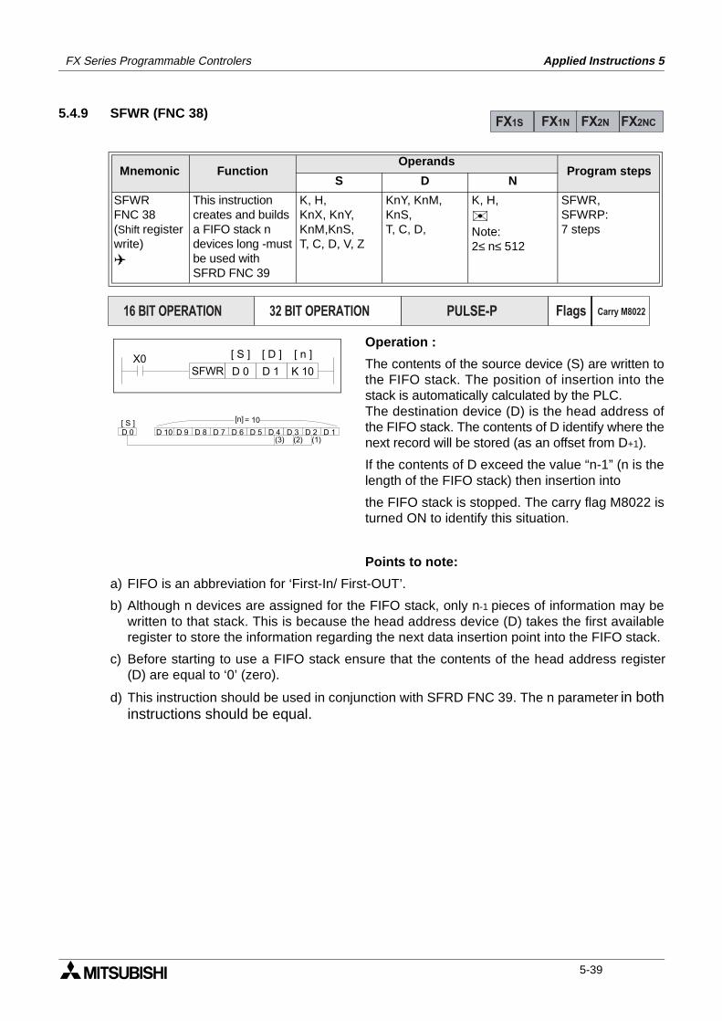
FX Series Programmable Controlers Applied Instructions 5
5.4.9 SFWR (FNC 38)
Operation :
The contents of the source device (S) are written tothe FIFO stack. The position of insertion into thestack is automatically calculated by the PLC.The destination device (D) is the head address ofthe FIFO stack. The contents of D identify where thenext record will be stored (as an offset from D+1).
If the contents of D exceed the value “n-1” (n is thelength of the FIFO stack) then insertion into
the FIFO stack is stopped. The carry flag M8022 isturned ON to identify this situation.
Points to note:
a) FIFO is an abbreviation for ‘First-In/ First-OUT’.
b) Although n devices are assigned for the FIFO stack, only n-1 pieces of information may bewritten to that stack. This is because the head address device (D) takes the first availableregister to store the information regarding the next data insertion point into the FIFO stack.
c) Before starting to use a FIFO stack ensure that the contents of the head address register(D) are equal to ‘0’ (zero).
d) This instruction should be used in conjunction with SFRD FNC 39. The n parameter in bothinstructions should be equal.
Mnemonic Function Operands
Program stepsS D N
SFWRFNC 38(Shift registerwrite)
This instructioncreates and buildsa FIFO stack ndevices long -mustbe used withSFRD FNC 39
K, H,KnX, KnY, KnM,KnS,T, C, D, V, Z
KnY, KnM,KnS,T, C, D,
K, H,Note:2≤ n≤ 512
SFWR,SFWRP:7 steps
FX1S FX1N FX2N FX2NC
PULSE-P16 BIT OPERATION 32 BIT OPERATION Flags Carry M8022
X0SFWR D 1 K 10
[ S ] [ D ]
D 0
[ n ]
D 0 D 10 D 9 D 8 D 7 D 6 D 5 D 4 D 3 D 2 D 1[ S ] = 10
(3) (2) (1)
[n]
5-39
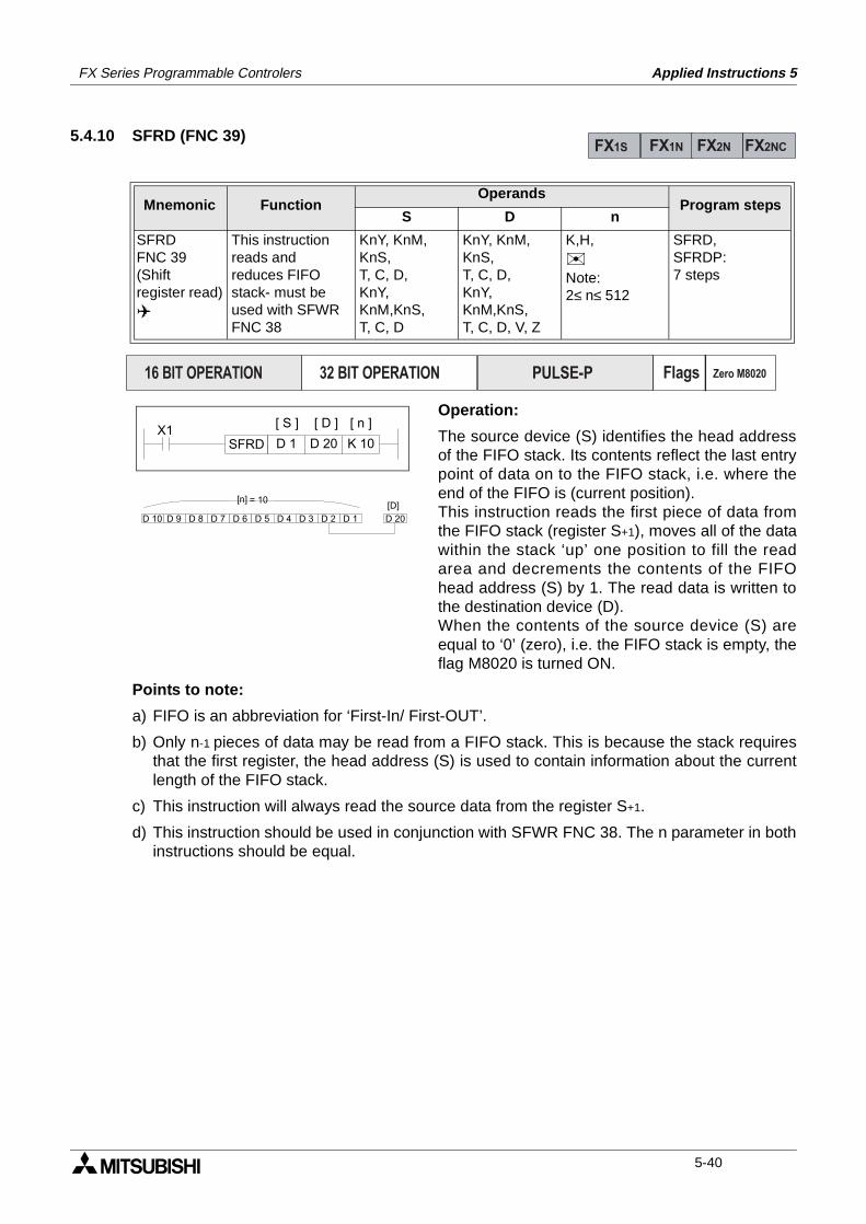
FX Series Programmable Controlers Applied Instructions 5
5.4.10 SFRD (FNC 39)
Operation:
The source device (S) identifies the head addressof the FIFO stack. Its contents reflect the last entrypoint of data on to the FIFO stack, i.e. where theend of the FIFO is (current position).This instruction reads the first piece of data fromthe FIFO stack (register S+1), moves all of the datawithin the stack ‘up’ one position to fill the readarea and decrements the contents of the FIFOhead address (S) by 1. The read data is written tothe destination device (D). When the contents of the source device (S) areequal to ‘0’ (zero), i.e. the FIFO stack is empty, theflag M8020 is turned ON.
Points to note:
a) FIFO is an abbreviation for ‘First-In/ First-OUT’.
b) Only n-1 pieces of data may be read from a FIFO stack. This is because the stack requiresthat the first register, the head address (S) is used to contain information about the currentlength of the FIFO stack.
c) This instruction will always read the source data from the register S+1.
d) This instruction should be used in conjunction with SFWR FNC 38. The n parameter in bothinstructions should be equal.
Mnemonic Function Operands
Program stepsS D n
SFRDFNC 39(Shiftregister read)
This instructionreads andreduces FIFOstack- must beused with SFWRFNC 38
KnY, KnM, KnS,T, C, D,KnY, KnM,KnS,T, C, D
KnY, KnM,KnS,T, C, D,KnY, KnM,KnS,T, C, D, V, Z
K,H,Note:2≤ n≤ 512
SFRD,SFRDP:7 steps
FX1S FX1N FX2N FX2NC
PULSE-P16 BIT OPERATION 32 BIT OPERATION Flags Zero M8020
X1SFRD D 20 K 10
[ S ] [ D ]
D 1
[ n ]
D 20D 10 D 9 D 8 D 7 D 6 D 5 D 4 D 3 D 2 D 1
[D]= 10[n]
5-40

FX Series Programmable Controlers Applied Instructions 5
Applied Instructions:FX1S FX1N FX2N FX2NC
FNC 00 - 09
FNC 10 - 19
FNC 20 - 29
FNC 30 - 39
FNC 40 - 49
FNC 50 - 59
FNC 60 - 69
FNC 70 - 79
FNC 80 - 89
FNC 110-129
FNC 130-139
FNC 140-149
FNC 160-169
FNC 170-179
FNC 220-249
FNC 150-159
1.
2.
3.
4.
5.
6.
7.
8.
9.
10.
11.
12.
13.
14.
15.
16.
Program Flow 5-4
Move And Compare 5-16
Arithmetic And Logical Operations (+, -, ×, ÷)5-24
Rotation And Shift 5-34
Data Operation 5-42
High Speed Processing 5-52
Handy Instructions 5-66
External FX I/O Devices 5-80
External FX Serial Devices 5-94
Floating Point 1 & 2 5-110
Trigonometry (Floating Point 3) 5-118
Data Operations 2 5-122
FX1S & FX1N Positioning Control 5-126
Real Time Clock Control 5-136
Gray Codes 5-146
In-line Comparisons 5-150
5-41
FX Series Programmable Controlers Applied Instructions 5
5.5 Data Operation - Functions 40 to 49
Contents:
Page
ZRST - Zone Reset FNC 40 5-43
DECO - Decode FNC 41 5-43
ENCO - Encode FNC 42 5-44
SUM - The Sum Of Active Bits FNC 43 5-45
BON - Check Specified Bit Status FNC 44 5-45
MEAN - Mean FNC 45 5-46
ANS - (Timed) Annunciator Set FNC 46 5-47
ANR - Annunciator Reset FNC 47 5-47
SQR - Square Root FNC 48 5-48
FLT - Float, (Floating Point) FNC 49 5-49
Symbols list:
D - Destination device.S - Source device.m, n- Number of active devices, bits or an operational constant.Additional numeric suffixes will be attached if there are more than one operand with the samefunction e.g. D1, S3 or for lists/tabled devices D3+0, S+9 etc.MSB - Most Significant Bit, sometimes used to indicate the mathematical sign of a number,i.e. positive = 0, and negative = 1.LSB - Least Significant Bit.
Instruction modifications:
- An instruction operating in 16 bit mode, where identifies the instructionmnemonic.
P - A 16 bit mode instruction modified to use pulse (single) operation.
D - An instruction modified to operate in 32 bit operation.
DP - A 32 bit mode instruction modified to use pulse (single) operation.
- A repetitive instruction which will change the destination value on every scan unlessmodified by the pulse function.
- An operand which cannot be indexed, i.e. The addition of V or Z is either invalid or willhave no effect to the value of the operand.
5-42
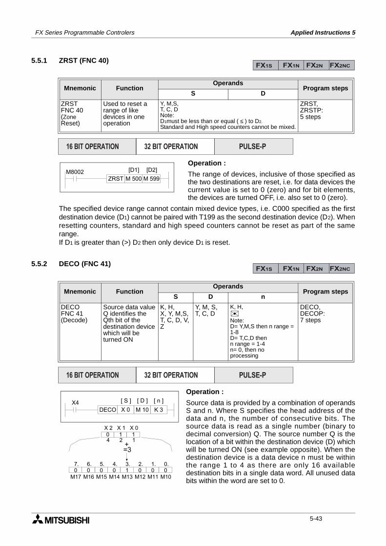
FX Series Programmable Controlers Applied Instructions 5
5.5.1 ZRST (FNC 40)
Operation :
The range of devices, inclusive of those specified asthe two destinations are reset, i.e. for data devices thecurrent value is set to 0 (zero) and for bit elements,the devices are turned OFF, i.e. also set to 0 (zero).
The specified device range cannot contain mixed device types, i.e. C000 specified as the firstdestination device (D1) cannot be paired with T199 as the second destination device (D2). Whenresetting counters, standard and high speed counters cannot be reset as part of the samerange.If D1 is greater than (>) D2 then only device D1 is reset.
5.5.2 DECO (FNC 41)
Operation :
Source data is provided by a combination of operandsS and n. Where S specifies the head address of thedata and n, the number of consecutive bits. Thesource data is read as a single number (binary todecimal conversion) Q. The source number Q is thelocation of a bit within the destination device (D) whichwill be turned ON (see example opposite). When thedestination device is a data device n must be withinthe range 1 to 4 as there are only 16 availabledestination bits in a single data word. All unused databits within the word are set to 0.
Mnemonic Function Operands
Program stepsS D
ZRSTFNC 40(ZoneReset)
Used to reset arange of likedevices in oneoperation
Y, M,S,T, C, DNote:D1must be less than or equal ( ≤ ) to D2.
Standard and High speed counters cannot be mixed.
ZRST,ZRSTP:5 steps
Mnemonic Function Operands
Program stepsS D n
DECOFNC 41(Decode)
Source data valueQ identifies theQth bit of thedestination devicewhich will beturned ON
K, H,X, Y, M,S,T, C, D, V,Z
Y, M, S,T, C, D
K, H,Note:D= Y,M,S then n range = 1-8D= T,C,D then n range = 1-4n= 0, then no processing
DECO,DECOP:7 steps
FX1S FX1N FX2N FX2NC
PULSE-P16 BIT OPERATION 32 BIT OPERATION
M8002ZRST M 500 M 599
[D1] [D2]
FX1S FX1N FX2N FX2NC
PULSE-P16 BIT OPERATION 32 BIT OPERATION
X4M 10 K 3
[ S ] [ D ]
X 0
[ n ]
DECO
M15 M14 M13 M12 M11 M10M16M170 10 0 0 0 0 07. 6. 5. 4. 3. 2. 1. 0.
4 2 10 1 1
X 2 X 1 X 0
=3+
5-43
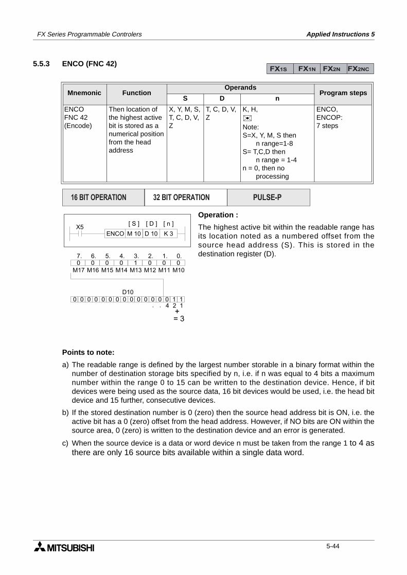
FX Series Programmable Controlers Applied Instructions 5
5.5.3 ENCO (FNC 42)
Operation :
The highest active bit within the readable range hasits location noted as a numbered offset from thesource head address (S). This is stored in thedestination register (D).
Points to note:
a) The readable range is defined by the largest number storable in a binary format within thenumber of destination storage bits specified by n, i.e. if n was equal to 4 bits a maximumnumber within the range 0 to 15 can be written to the destination device. Hence, if bitdevices were being used as the source data, 16 bit devices would be used, i.e. the head bitdevice and 15 further, consecutive devices.
b) If the stored destination number is 0 (zero) then the source head address bit is ON, i.e. theactive bit has a 0 (zero) offset from the head address. However, if NO bits are ON within thesource area, 0 (zero) is written to the destination device and an error is generated.
c) When the source device is a data or word device n must be taken from the range 1 to 4 asthere are only 16 source bits available within a single data word.
Mnemonic Function Operands
Program stepsS D n
ENCOFNC 42(Encode)
Then location ofthe highest activebit is stored as anumerical positionfrom the headaddress
X, Y, M, S,T, C, D, V,Z
T, C, D, V,Z
K, H,Note:S=X, Y, M, S then n range=1-8S= T,C,D then n range = 1-4n = 0, then no processing
ENCO,ENCOP:7 steps
FX1S FX1N FX2N FX2NC
PULSE-P16 BIT OPERATION 32 BIT OPERATION
X5D 10 K 3
[ S ] [ D ]
M 10
[ n ]
ENCO
M15 M14 M13 M12 M11 M10M16M170 10 0 0 0 0 07. 6. 5. 4. 3. 2. 1. 0.
0 0 0 0 0 0 0 0 0 0 0 0 0 0 1 1D10
4 2 1. .+= 3
5-44
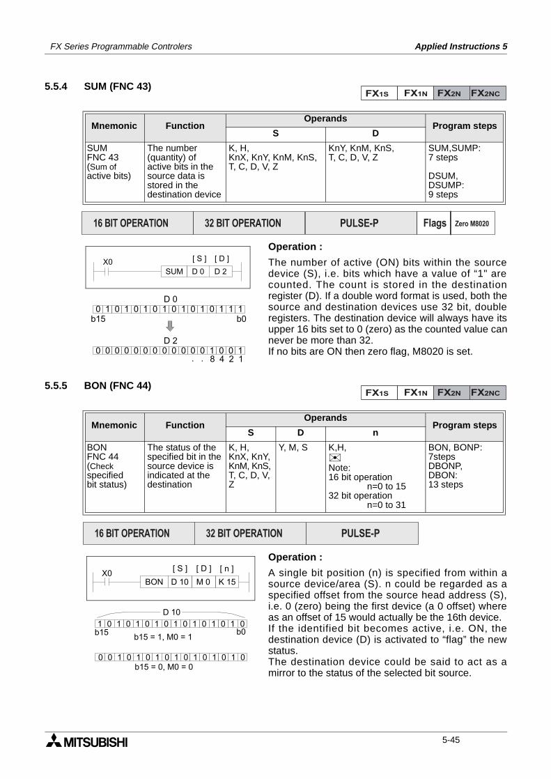
FX Series Programmable Controlers Applied Instructions 5
5.5.4 SUM (FNC 43)
Operation :
The number of active (ON) bits within the sourcedevice (S), i.e. bits which have a value of “1" arecounted. The count is stored in the destinationregister (D). If a double word format is used, both thesource and destination devices use 32 bit, doubleregisters. The destination device will always have itsupper 16 bits set to 0 (zero) as the counted value cannever be more than 32.If no bits are ON then zero flag, M8020 is set.
5.5.5 BON (FNC 44)
Operation :
A single bit position (n) is specified from within asource device/area (S). n could be regarded as aspecified offset from the source head address (S),i.e. 0 (zero) being the first device (a 0 offset) whereas an offset of 15 would actually be the 16th device.If the identified bit becomes active, i.e. ON, thedestination device (D) is activated to “flag” the newstatus.The destination device could be said to act as amirror to the status of the selected bit source.
Mnemonic Function Operands
Program stepsS D
SUMFNC 43(Sum ofactive bits)
The number(quantity) ofactive bits in thesource data isstored in thedestination device
K, H,KnX, KnY, KnM, KnS,T, C, D, V, Z
KnY, KnM, KnS,T, C, D, V, Z
SUM,SUMP:7 steps
DSUM,DSUMP:9 steps
Mnemonic Function Operands
Program stepsS D n
BONFNC 44(Checkspecifiedbit status)
The status of thespecified bit in thesource device isindicated at thedestination
K, H,KnX, KnY,KnM, KnS,T, C, D, V,Z
Y, M, S K,H,Note:16 bit operation n=0 to 1532 bit operation n=0 to 31
BON, BONP:7stepsDBONP,DBON:13 steps
FX1S FX1N FX2N FX2NC
PULSE-P16 BIT OPERATION 32 BIT OPERATION Flags Zero M8020
X0D 2
[ S ] [ D ]
D 0SUM
0 0 0 0 0 0 0 0 0 0 0 0 1 0 0 1
0 1 0 1 0 1 0 1 0 1 0 1 0 1 1 1b15 b0
D 0
8 4 2 1. .
D 2
FX1S FX1N FX2N FX2NC
PULSE-P16 BIT OPERATION 32 BIT OPERATION
X0M 0 K 15
[ S ] [ D ]
D 10
[ n ]
BON
1 0 1 0 1 0 1 0 1 0 1 0 1 0 1 0b15 b0
D 10
0 0 1 0 1 0 1 0 1 0 1 0 1 0 1 0b15 = 0, M0 = 0
b15 = 1, M0 = 1
5-45
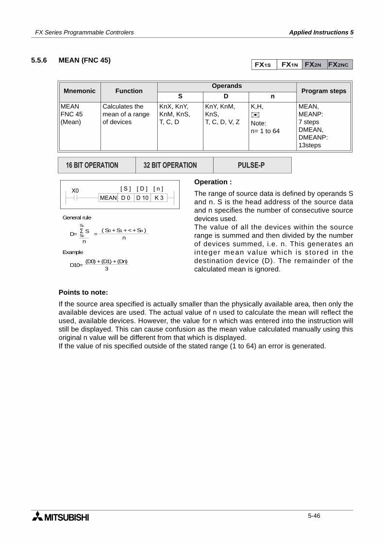
FX Series Programmable Controlers Applied Instructions 5
5.5.6 MEAN (FNC 45)
Operation :
The range of source data is defined by operands Sand n. S is the head address of the source dataand n specifies the number of consecutive sourcedevices used.The value of all the devices within the sourcerange is summed and then divided by the numberof devices summed, i.e. n. This generates anin teger mean value which is s tored in thedestination device (D). The remainder of thecalculated mean is ignored.
Points to note:
If the source area specified is actually smaller than the physically available area, then only theavailable devices are used. The actual value of n used to calculate the mean will reflect theused, available devices. However, the value for n which was entered into the instruction willstill be displayed. This can cause confusion as the mean value calculated manually using thisoriginal n value will be different from that which is displayed.If the value of nis specified outside of the stated range (1 to 64) an error is generated.
Mnemonic Function Operands
Program stepsS D n
MEANFNC 45(Mean)
Calculates themean of a rangeof devices
KnX, KnY, KnM, KnS,T, C, D
KnY, KnM, KnS,T, C, D, V, Z
K,H,Note:n= 1 to 64
MEAN,MEANP:7 stepsDMEAN,DMEANP:13steps
FX1S FX1N FX2N FX2NC
PULSE-P16 BIT OPERATION 32 BIT OPERATION
X0D 10 K 3
[ S ] [ D ]
D 0
[ n ]
MEAN
General rule
Example
D= =( S0 + S1 + < + Sn )
nΣ SS0
n
Sn
D10=(D0) + (D1) + (Dn)
3
5-46
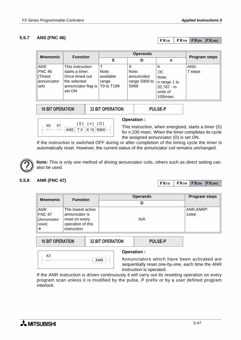
FX Series Programmable Controlers Applied Instructions 5
5.5.7 ANS (FNC 46)
Operation :
This instruction, when energized, starts a timer (S)for n,100 msec. When the timer completes its cyclethe assigned annunciator (D) is set ON.
If the instruction is switched OFF during or after completion of the timing cycle the timer isautomatically reset. However, the current status of the annunciator coil remains unchanged.
5.5.8 ANR (FNC 47)
Operation :
Annunciators which have been activated aresequentially reset one-by-one, each time the ANRinstruction is operated.
If the ANR instruction is driven continuously it will carry out its resetting operation on everyprogram scan unless it is modified by the pulse, P prefix or by a user defined programinterlock.
Mnemonic Function Operands
Program stepsS D n
ANSFNC 46(Timedannunciator set)
This instructionstarts a timer.Once timed outthe selectedannunciator flag isset ON
TNote:available rangeT0 to T199
SNote:annunciatorrange S900 to S999
KNote:n range 1 to32,767 - in units of 100msec
ANS:7 steps
Mnemonic Function Operands Program steps
D
ANRFNC 47(Annunciator reset)
The lowest activeannunciator isreset on everyoperation of thisinstruction
N/A
ANR,ANRP:1step
FX1S FX1N FX2N FX2NC
PULSE-P16 BIT OPERATION 32 BIT OPERATION
X0K 10 S900
[ S ] [ D ]
T 0ANS
[ n ]X1
Note: This is only one method of driving annunciator coils, others such as direct setting canalso be used.
FX1S FX1N FX2N FX2NC
PULSE-P16 BIT OPERATION 32 BIT OPERATION
X3ANR
5-47
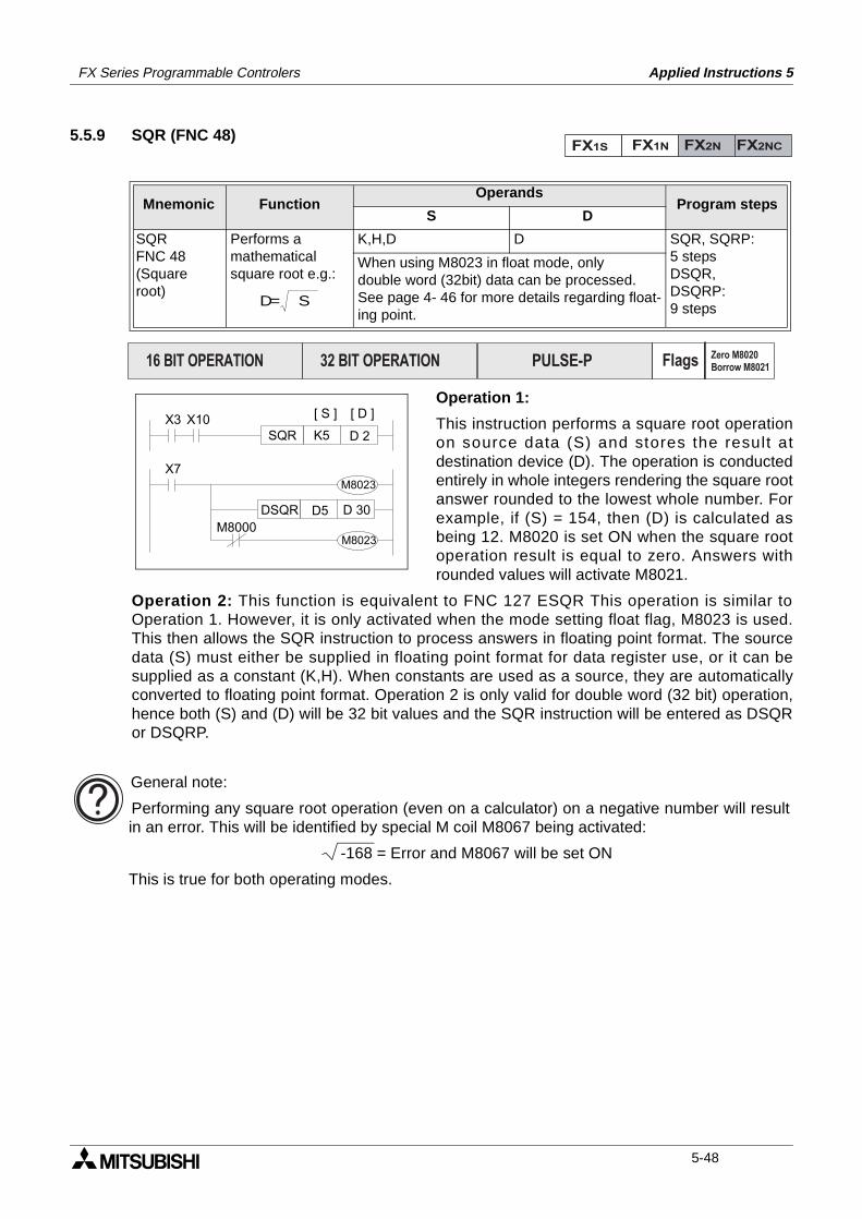
FX Series Programmable Controlers Applied Instructions 5
5.5.9 SQR (FNC 48)
Operation 1:
This instruction performs a square root operationon source data (S) and stores the result atdestination device (D). The operation is conductedentirely in whole integers rendering the square rootanswer rounded to the lowest whole number. Forexample, if (S) = 154, then (D) is calculated asbeing 12. M8020 is set ON when the square rootoperation result is equal to zero. Answers withrounded values will activate M8021.
Operation 2: This function is equivalent to FNC 127 ESQR This operation is similar toOperation 1. However, it is only activated when the mode setting float flag, M8023 is used.This then allows the SQR instruction to process answers in floating point format. The sourcedata (S) must either be supplied in floating point format for data register use, or it can besupplied as a constant (K,H). When constants are used as a source, they are automaticallyconverted to floating point format. Operation 2 is only valid for double word (32 bit) operation,hence both (S) and (D) will be 32 bit values and the SQR instruction will be entered as DSQRor DSQRP.
Mnemonic Function Operands
Program stepsS D
SQRFNC 48(Squareroot)
Performs amathematicalsquare root e.g.:
K,H,D D SQR, SQRP:5 stepsDSQR,DSQRP:9 steps
When using M8023 in float mode, only double word (32bit) data can be processed. See page 4- 46 for more details regarding float-ing point.
FX1S FX1N FX2N FX2NC
D= S
PULSE-P16 BIT OPERATION 32 BIT OPERATION Flags Zero M8020
Borrow M8021
X3D 2
[ S ] [ D ]
K5SQRX10
X7M8023
M8000M8023
D 30D5DSQR
General note:
Performing any square root operation (even on a calculator) on a negative number will resultin an error. This will be identified by special M coil M8067 being activated:
-168 = Error and M8067 will be set ON
This is true for both operating modes.
5-48
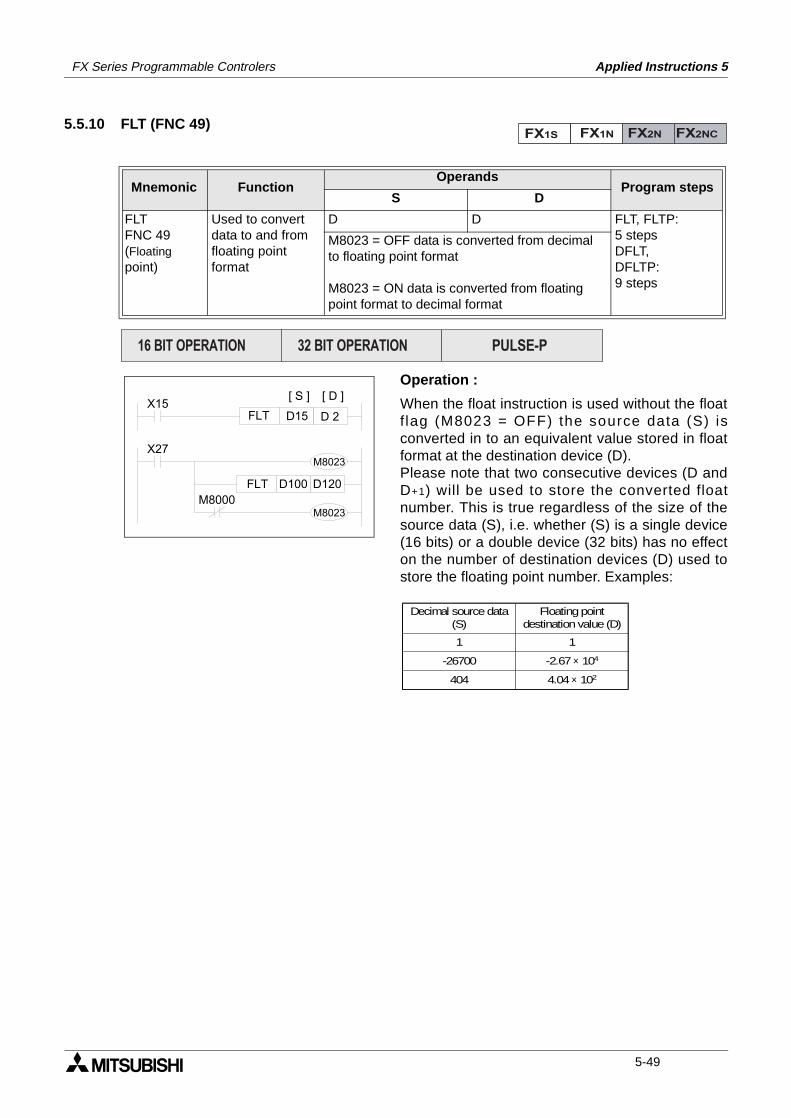
FX Series Programmable Controlers Applied Instructions 5
5.5.10 FLT (FNC 49)
Operation :
When the float instruction is used without the floatf lag (M8023 = OFF) the source data (S) isconverted in to an equivalent value stored in floatformat at the destination device (D).Please note that two consecutive devices (D andD+1) will be used to store the converted floatnumber. This is true regardless of the size of thesource data (S), i.e. whether (S) is a single device(16 bits) or a double device (32 bits) has no effecton the number of destination devices (D) used tostore the floating point number. Examples:
Mnemonic Function Operands
Program stepsS D
FLTFNC 49(Floatingpoint)
Used to convertdata to and fromfloating pointformat
D D FLT, FLTP:5 stepsDFLT,DFLTP:9 steps
M8023 = OFF data is converted from decimalto floating point format
M8023 = ON data is converted from floatingpoint format to decimal format
FX1S FX1N FX2N FX2NC
PULSE-P16 BIT OPERATION 32 BIT OPERATION
X15D 2
[ S ] [ D ]
D15FLT
X27M8023
M8000M8023
D120D100FLT
Decimal source data(S)
Floating pointdestination value (D)
-26700
404
-2.67 × 10⁴
4.04 × 10²
1 1
5-49

FX Series Programmable Controlers Applied Instructions 5
MEMO
5-50
FX Series Programmable Controlers Applied Instructions 5
Applied Instructions:FX1S FX1N FX2N FX2NC
FNC 00 - 09
FNC 10 - 19
FNC 20 - 29
FNC 30 - 39
FNC 40 - 49
FNC 50 - 59
FNC 60 - 69
FNC 70 - 79
FNC 80 - 89
FNC 110-129
FNC 130-139
FNC 140-149
FNC 160-169
FNC 170-179
FNC 220-249
FNC 150-159
1.
2.
3.
4.
5.
6.
7.
8.
9.
10.
11.
12.
13.
14.
15.
16.
Program Flow 5-4
Move And Compare 5-16
Arithmetic And Logical Operations (+, -, ×, ÷)5-24
Rotation And Shift 5-34
Data Operation 5-42
High Speed Processing 5-52
Handy Instructions 5-66
External FX I/O Devices 5-80
External FX Serial Devices 5-94
Floating Point 1 & 2 5-110
Trigonometry (Floating Point 3) 5-118
Data Operations 2 5-122
FX1S & FX1N Positioning Control 5-126
Real Time Clock Control 5-136
Gray Codes 5-146
In-line Comparisons 5-150
5-51
FX Series Programmable Controlers Applied Instructions 5
5.6 High Speed Processing - Functions 50 to 59
Contents:
Page
REF - Refresh FNC 50 5-53
REFF - Refresh and filter adjust FNC 51 5-53
MTR - Input matrix FNC 52 5-54
HSCS - High speed counter set FNC 53 5-55
HSCR - High speed counter reset FNC 54 5-56
HSZ - High speed counter
zone compare FNC 55 5-57
SPD - Speed detect FNC 56 5-60
PLSY - Pulse Y output FNC 57 5-61
PWM - Pulse width modulation FNC 58 5-62
PLSR - Ramp Pulse output FNC 59 5-63
Symbols list:
D - Destination device.S - Source device.m, n- Number of active devices, bits or an operational constant.Additional numeric suffixes will be attached if there are more than one operand with the samefunction e.g. D1, S3 or for lists/tabled devices D3+0, S+9 etc.MSB - Most Significant Bit, sometimes used to indicate the mathematical sign of a number,i.e. positive = 0, and negative = 1.LSB - Least Significant Bit.
Instruction modifications:
- An instruction operating in 16 bit mode, where identifies the instructionmnemonic.
P - A 16 bit mode instruction modified to use pulse (single) operation.
D - An instruction modified to operate in 32 bit operation.
DP - A 32 bit mode instruction modified to use pulse (single) operation.
- A repetitive instruction which will change the destination value on every scan unlessmodified by the pulse function.
- An operand which cannot be indexed, i.e. The addition of V or Z is either invalid or willhave no effect to the value of the operand.
5-52
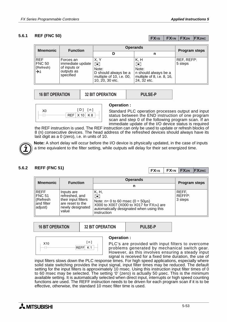
FX Series Programmable Controlers Applied Instructions 5
5.6.1 REF (FNC 50)
Operation :Standard PLC operation processes output and inputstatus between the END instruction of one programscan and step 0 of the following program scan. If animmediate update of the I/O device status is required
the REF instruction is used. The REF instruction can only be used to update or refresh blocks of8 (n) consecutive devices. The head address of the refreshed devices should always have itslast digit as a 0 (zero), i.e. in units of 10.
5.6.2 REFF (FNC 51)
Operation :PLC’s are provided with input filters to overcomeproblems generated by mechanical switch gear.However, as this involves ensuring a steady inputsignal is received for a fixed time duration, the use of
input filters slows down the PLC response times. For high speed applications, especially wheresolid state switching provides the input signal, input filter times may be reduced. The defaultsetting for the input filters is approximately 10 msec. Using this instruction input filter times of 0to 60 msec may be selected. The setting ‘0’ (zero) is actually 50 µsec. This is the minimumavailable setting. It is automatically selected when direct input, interrupts or high speed countingfunctions are used. The REFF instruction needs to be driven for each program scan if it is to beeffective, otherwise, the standard 10 msec filter time is used.
Mnemonic Function Operands
Program stepsD n
REFFNC 50(Refresh)å
Forces animmediate updateof inputs oroutputs asspecified
X, YNote:D should always be amultiple of 10, i.e. 00,10, 20, 30 etc.
K, HNote:n should always be amultiple of 8, i.e. 8, 16,24, 32 etc.
REF, REFP:5 steps
Mnemonic Function Operands
Program stepsn
REFFFNC 51(Refreshand filteradjust)
Inputs arerefreshed, andtheir input filtersare reset to thenewly designatedvalue
K, H,Note: n= 0 to 60 msec (0 = 50µs)X000 to X007 (X000 to X017 for FX2N) areautomatically designated when using thisinstruction
REFF,REFFP:3 steps
FX1S FX1N FX2N FX2NC
PULSE-P16 BIT OPERATION 32 BIT OPERATION
X0X 10
[ D ]
K 8REF
[ n ]
Note: A short delay will occur before the I/O device is physically updated, in the case of inputsa time equivalent to the filter setting, while outputs will delay for their set energized time.
FX1S FX1N FX2N FX2NC
PULSE-P16 BIT OPERATION 32 BIT OPERATION
X10K 1REFF
[ n ]
5-53
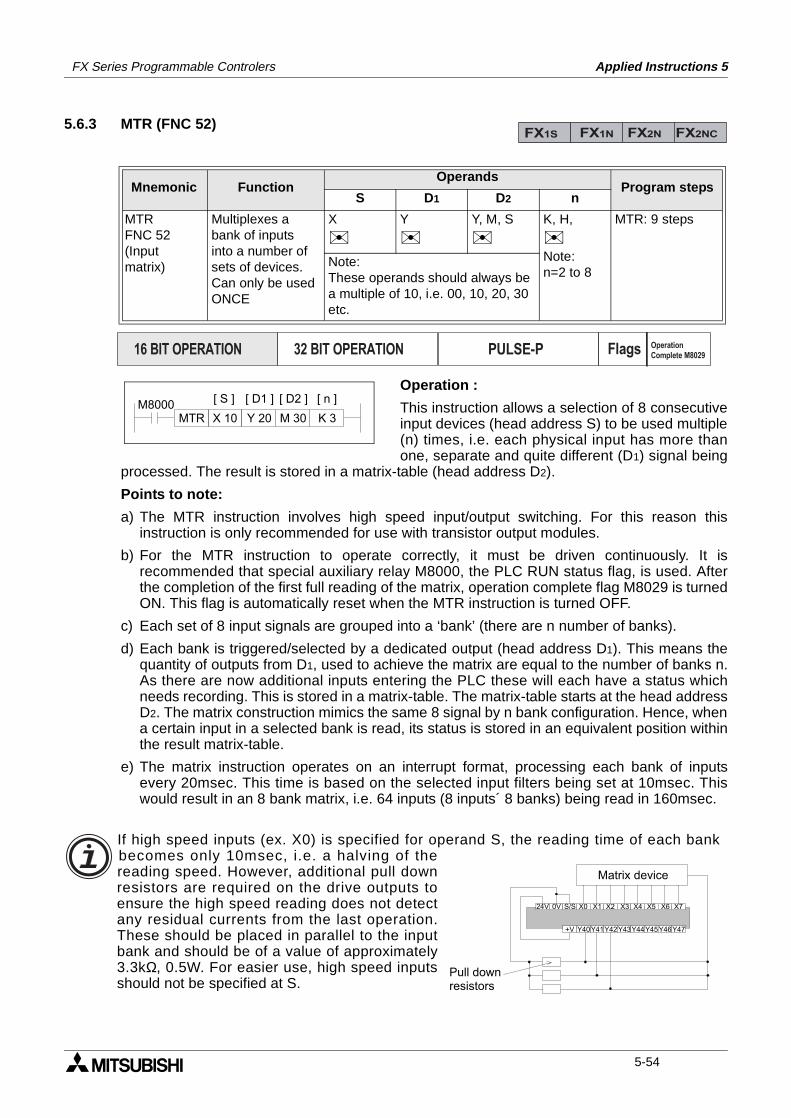
FX Series Programmable Controlers Applied Instructions 5
5.6.3 MTR (FNC 52)
Operation :
This instruction allows a selection of 8 consecutiveinput devices (head address S) to be used multiple(n) times, i.e. each physical input has more thanone, separate and quite different (D1) signal being
processed. The result is stored in a matrix-table (head address D2).
Points to note:
a) The MTR instruction involves high speed input/output switching. For this reason thisinstruction is only recommended for use with transistor output modules.
b) For the MTR instruction to operate correctly, it must be driven continuously. It isrecommended that special auxiliary relay M8000, the PLC RUN status flag, is used. Afterthe completion of the first full reading of the matrix, operation complete flag M8029 is turnedON. This flag is automatically reset when the MTR instruction is turned OFF.
c) Each set of 8 input signals are grouped into a ‘bank’ (there are n number of banks).
d) Each bank is triggered/selected by a dedicated output (head address D1). This means thequantity of outputs from D1, used to achieve the matrix are equal to the number of banks n.As there are now additional inputs entering the PLC these will each have a status whichneeds recording. This is stored in a matrix-table. The matrix-table starts at the head addressD2. The matrix construction mimics the same 8 signal by n bank configuration. Hence, whena certain input in a selected bank is read, its status is stored in an equivalent position withinthe result matrix-table.
e) The matrix instruction operates on an interrupt format, processing each bank of inputsevery 20msec. This time is based on the selected input filters being set at 10msec. Thiswould result in an 8 bank matrix, i.e. 64 inputs (8 inputs´ 8 banks) being read in 160msec.
Mnemonic Function Operands
Program stepsS D1 D2 n
MTRFNC 52(Inputmatrix)
Multiplexes abank of inputsinto a number ofsets of devices.Can only be usedONCE
X
Y
Y, M, S
K, H,
Note:n=2 to 8
MTR: 9 steps
Note:These operands should always be a multiple of 10, i.e. 00, 10, 20, 30 etc.
FX1S FX1N FX2N FX2NC
PULSE-P16 BIT OPERATION 32 BIT OPERATION Flags Operation
Complete M8029
M8000M 30 K 3
[ S ] [ D2 ]
Y 20
[ n ]
X 10MTR
[ D1 ]
If high speed inputs (ex. X0) is specified for operand S, the reading time of each bankbecomes only 10msec, i.e. a halving of thereading speed. However, additional pull downresistors are required on the drive outputs toensure the high speed reading does not detectany residual currents from the last operation.These should be placed in parallel to the inputbank and should be of a value of approximately3.3kΩ, 0.5W. For easier use, high speed inputsshould not be specified at S.
Y42Y43Y44Y45Y46Y47+V Y40Y41
X0 X1 X2 X3 X4 X5 X6 X724V 0V S/S
Matrix device
Pull downresistors
5-54
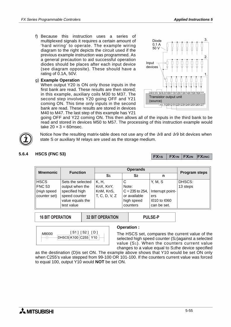
FX Series Programmable Controlers Applied Instructions 5
f) Because this instruction uses a series ofmultiplexed signals it requires a certain amount of‘hard wiring’ to operate. The example wiringdiagram to the right depicts the circuit used if theprevious example instruction was programmed. Asa general precaution to aid successful operationdiodes should be places after each input device(see diagram opposite). These should have arating of 0.1A, 50V.
g) Example OperationWhen output Y20 is ON only those inputs in thefirst bank are read. These results are then stored;in this example, auxiliary coils M30 to M37. Thesecond step involves Y20 going OFF and Y21coming ON. This time only inputs in the secondbank are read. These results are stored in devicesM40 to M47. The last step of this example has Y21going OFF and Y22 coming ON. This then allows all of the inputs in the third bank to beread and stored in devices M50 to M57. The processing of this instruction example wouldtake 20 × 3 = 60msec.
5.6.4 HSCS (FNC 53)
Operation :
The HSCS set, compares the current value of theselected high speed counter (S2)against a selectedvalue (S1). When the counters current valuechanges to a value equal to S1the device specified
as the destination (D)is set ON. The example above shows that Y10 would be set ON onlywhen C255’s value stepped from 99-100 OR 101-100. If the counters current value was forcedto equal 100, output Y10 would NOT be set ON.
Mnemonic Function Operands
Program stepsS1 S2 n
HSCSFNC 53(High speedcounter set)
Sets the selectedoutput when thespecified highspeed countervalue equals thetest value
K, H,KnX, KnY, KnM, KnS,T, C, D, V, Z
CNote:C = 235 to 254,or available high speed counters
Y, M, S
Interrupt point-ersI010 to I060can be set.
DHSCS:13 steps
X10X11X12X13X14X15X16X1724V 0V S/S
Y22Y23Y24Y25Y26Y27+V Y20Y21
3.
2.
1.
0,1 A50 V
Diode
Inputdevices
Transistor output unit(source)
Notice how the resulting matrix-table does not use any of the 8 and 9 bit devices whenstate S or auxiliary M relays are used as the storage medium.
FX1S FX1N FX2N FX2NC
PULSE-P16 BIT OPERATION 32 BIT OPERATION
M8000C255 Y10
[ S1 ] [ S2 ]
K100
[ D ]
DHSCS
5-55
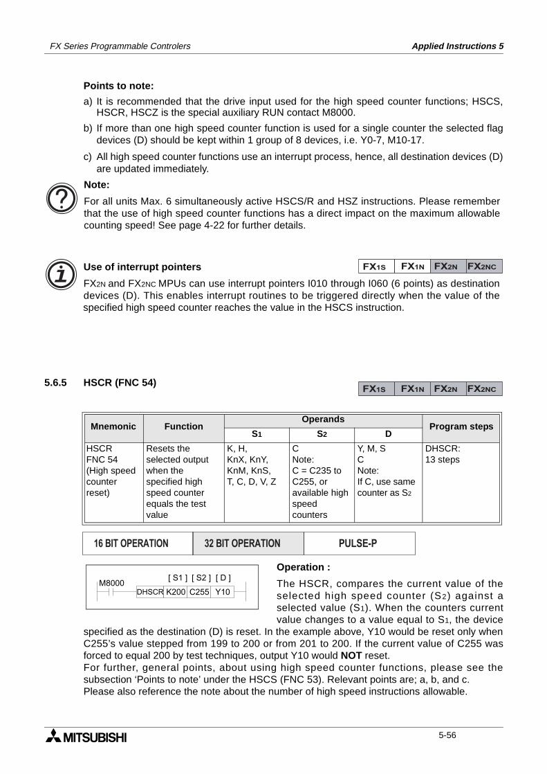
FX Series Programmable Controlers Applied Instructions 5
Points to note:
a) It is recommended that the drive input used for the high speed counter functions; HSCS,HSCR, HSCZ is the special auxiliary RUN contact M8000.
b) If more than one high speed counter function is used for a single counter the selected flagdevices (D) should be kept within 1 group of 8 devices, i.e. Y0-7, M10-17.
c) All high speed counter functions use an interrupt process, hence, all destination devices (D)are updated immediately.
5.6.5 HSCR (FNC 54)
Operation :
The HSCR, compares the current value of theselected high speed counter (S2) against aselected value (S1). When the counters currentvalue changes to a value equal to S1, the device
specified as the destination (D) is reset. In the example above, Y10 would be reset only whenC255’s value stepped from 199 to 200 or from 201 to 200. If the current value of C255 wasforced to equal 200 by test techniques, output Y10 would NOT reset. For further, general points, about using high speed counter functions, please see thesubsection ‘Points to note’ under the HSCS (FNC 53). Relevant points are; a, b, and c.Please also reference the note about the number of high speed instructions allowable.
Mnemonic Function Operands
Program stepsS1 S2 D
HSCRFNC 54(High speedcounterreset)
Resets theselected outputwhen thespecified highspeed counterequals the testvalue
K, H,KnX, KnY, KnM, KnS,T, C, D, V, Z
CNote:C = C235 toC255, oravailable highspeedcounters
Y, M, SCNote:If C, use samecounter as S2
DHSCR:13 steps
Use of interrupt pointers
FX2N and FX2NC MPUs can use interrupt pointers I010 through I060 (6 points) as destinationdevices (D). This enables interrupt routines to be triggered directly when the value of thespecified high speed counter reaches the value in the HSCS instruction.
Note:
For all units Max. 6 simultaneously active HSCS/R and HSZ instructions. Please rememberthat the use of high speed counter functions has a direct impact on the maximum allowablecounting speed! See page 4-22 for further details.
FX1S FX1N FX2N FX2NC
FX1S FX1N FX2N FX2NC
PULSE-P16 BIT OPERATION 32 BIT OPERATION
M8000C255 Y10
[ S1 ] [ S2 ]
K200
[ D ]
DHSCR
5-56
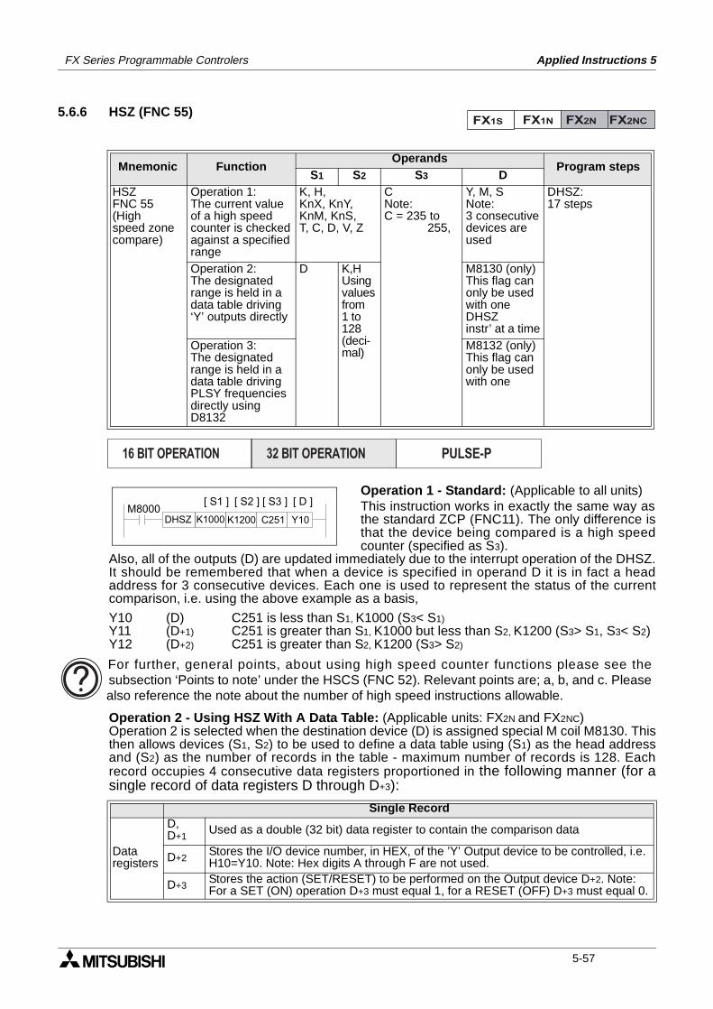
FX Series Programmable Controlers Applied Instructions 5
5.6.6 HSZ (FNC 55)
Operation 1 - Standard: (Applicable to all units)This instruction works in exactly the same way asthe standard ZCP (FNC11). The only difference isthat the device being compared is a high speedcounter (specified as S3).
Also, all of the outputs (D) are updated immediately due to the interrupt operation of the DHSZ.It should be remembered that when a device is specified in operand D it is in fact a headaddress for 3 consecutive devices. Each one is used to represent the status of the currentcomparison, i.e. using the above example as a basis,
Y10 (D) C251 is less than S1, K1000 (S3< S1)Y11 (D+1) C251 is greater than S1, K1000 but less than S2, K1200 (S3> S1, S3< S2)Y12 (D+2) C251 is greater than S2, K1200 (S3> S2)
Operation 2 - Using HSZ With A Data Table: (Applicable units: FX2N and FX2NC)Operation 2 is selected when the destination device (D) is assigned special M coil M8130. Thisthen allows devices (S1, S2) to be used to define a data table using (S1) as the head addressand (S2) as the number of records in the table - maximum number of records is 128. Eachrecord occupies 4 consecutive data registers proportioned in the following manner (for asingle record of data registers D through D+3):
Mnemonic Function Operands
Program stepsS1 S2 S3 D
HSZFNC 55(Highspeed zonecompare)
Operation 1:The current valueof a high speedcounter is checkedagainst a specifiedrange
K, H,KnX, KnY, KnM, KnS,T, C, D, V, Z
CNote:C = 235 to 255,
Y, M, SNote:3 consecutivedevices areused
DHSZ:17 steps
Operation 2:The designatedrange is held in adata table driving‘Y’ outputs directly
D K,HUsingvaluesfrom1 to 128(deci-mal)
M8130 (only)This flag canonly be usedwith one DHSZinstr’ at a time
Operation 3:The designatedrange is held in adata table drivingPLSY frequenciesdirectly usingD8132
M8132 (only)This flag canonly be usedwith one
Single Record
Data registers
D, D+1
Used as a double (32 bit) data register to contain the comparison data
D+2Stores the I/O device number, in HEX, of the ’Y’ Output device to be controlled, i.e. H10=Y10. Note: Hex digits A through F are not used.
D+3Stores the action (SET/RESET) to be performed on the Output device D+2. Note: For a SET (ON) operation D+3 must equal 1, for a RESET (OFF) D+3 must equal 0.
FX1S FX1N FX2N FX2NC
PULSE-P16 BIT OPERATION 32 BIT OPERATION
M8000C251 Y10K1000DHSZ K1200
[ S1 ] [ S2 ] [ S3 ] [ D ]
For further, general points, about using high speed counter functions please see thesubsection ‘Points to note’ under the HSCS (FNC 52). Relevant points are; a, b, and c. Pleasealso reference the note about the number of high speed instructions allowable.
5-57
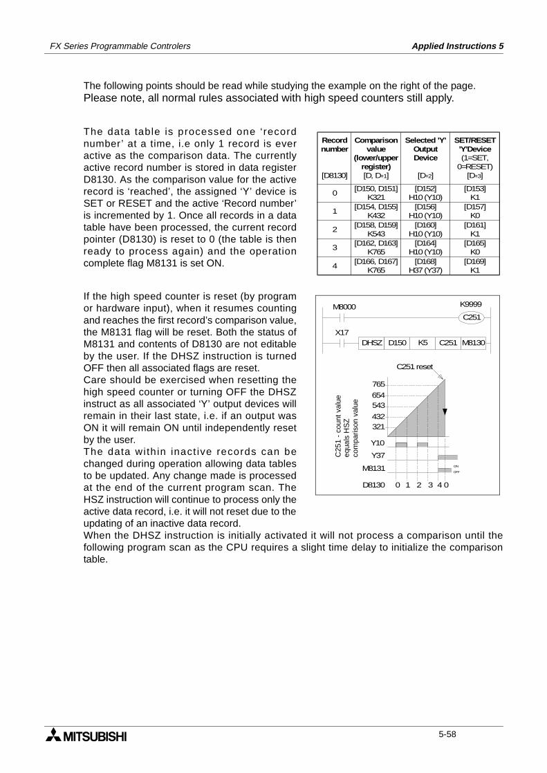
FX Series Programmable Controlers Applied Instructions 5
The following points should be read while studying the example on the right of the page.Please note, all normal rules associated with high speed counters still apply.
The data table is processed one ‘recordnumber’ at a time, i.e only 1 record is everactive as the comparison data. The currentlyactive record number is stored in data registerD8130. As the comparison value for the activerecord is ‘reached’, the assigned ‘Y’ device isSET or RESET and the active ‘Record number’is incremented by 1. Once all records in a datatable have been processed, the current recordpointer (D8130) is reset to 0 (the table is thenready to process again) and the operationcomplete flag M8131 is set ON.
If the high speed counter is reset (by programor hardware input), when it resumes countingand reaches the first record’s comparison value,the M8131 flag will be reset. Both the status ofM8131 and contents of D8130 are not editableby the user. If the DHSZ instruction is turnedOFF then all associated flags are reset. Care should be exercised when resetting thehigh speed counter or turning OFF the DHSZinstruct as all associated ‘Y’ output devices willremain in their last state, i.e. if an output wasON it will remain ON until independently resetby the user. The data with in inact ive records can bechanged during operation allowing data tablesto be updated. Any change made is processedat the end of the current program scan. TheHSZ instruction will continue to process only theactive data record, i.e. it will not reset due to theupdating of an inactive data record. When the DHSZ instruction is initially activated it will not process a comparison until thefollowing program scan as the CPU requires a slight time delay to initialize the comparisontable.
0[D150, D151]
K321
1
Recordnumber
[D8130]
Selected ’Y’OutputDevice
[D+2]
SET/RESET’Y’Device(1=SET,
0=RESET)[D+3]
Comparisonvalue
(lower/upperregister)[D, D+1]
2
3
4
[D154, D155]K432
[D158, D159]K543
[D162, D163]K765
[D166, D167]K765
[D152]H10 (Y10)
[D156]H10 (Y10)
[D160]H10 (Y10)
[D164]H10 (Y10)
[D168]H37 (Y37)
[D153]K1
[D157]K0
[D161]K1
[D165]K0
[D169]K1
321432
543654
765
Y10
Y37ON
OFFM8131
D8130 0 1 2 3 4 0
C25
1 -
coun
t val
ueeq
uals
HS
Zco
mpa
rison
val
ue
C251 reset
M8000 K9999
M8130C251DHSZ D150 K5
C251
X17
5-58
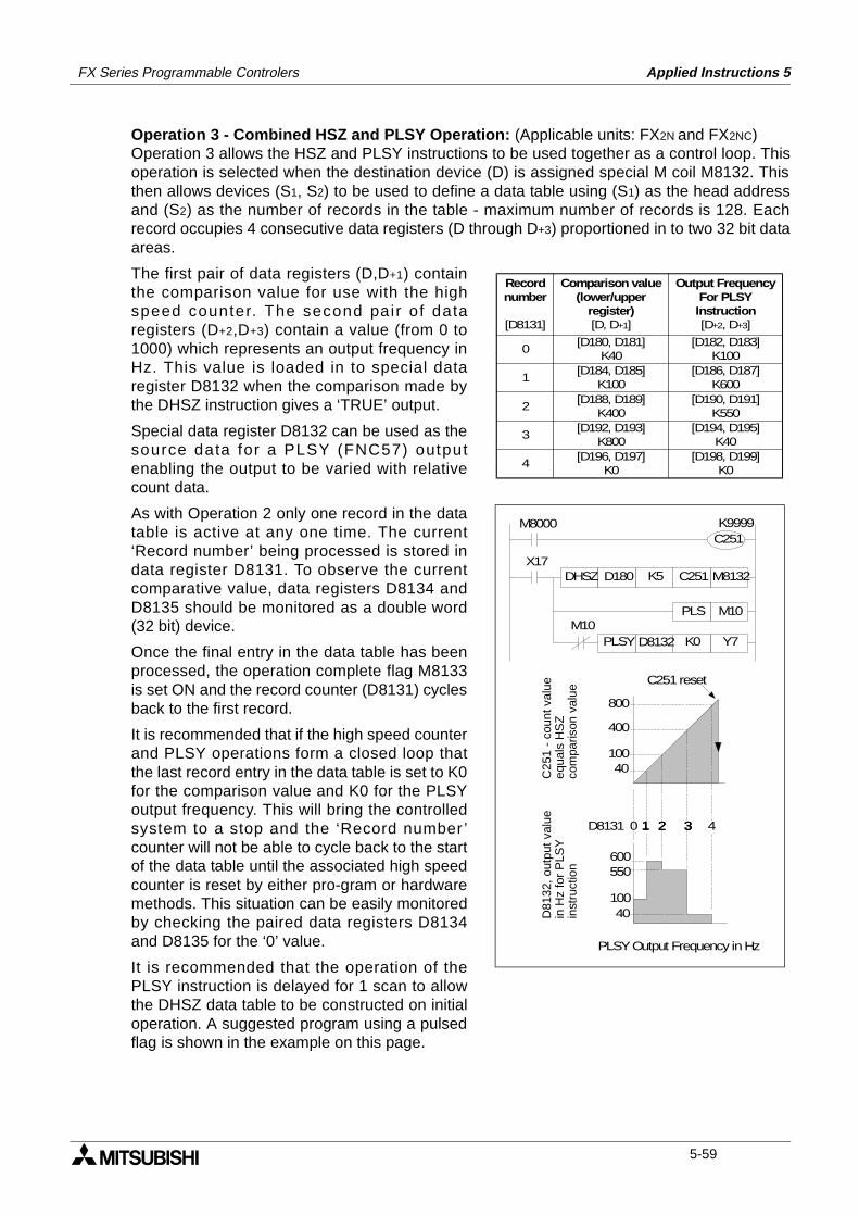
FX Series Programmable Controlers Applied Instructions 5
Operation 3 - Combined HSZ and PLSY Operation: (Applicable units: FX2N and FX2NC)Operation 3 allows the HSZ and PLSY instructions to be used together as a control loop. Thisoperation is selected when the destination device (D) is assigned special M coil M8132. Thisthen allows devices (S1, S2) to be used to define a data table using (S1) as the head addressand (S2) as the number of records in the table - maximum number of records is 128. Eachrecord occupies 4 consecutive data registers (D through D+3) proportioned in to two 32 bit dataareas.
The first pair of data registers (D,D+1) containthe comparison value for use with the highspeed counter. The second pair of dataregisters (D+2,D+3) contain a value (from 0 to1000) which represents an output frequency inHz. This value is loaded in to special dataregister D8132 when the comparison made bythe DHSZ instruction gives a ‘TRUE’ output.
Special data register D8132 can be used as thesource data for a PLSY (FNC57) outputenabling the output to be varied with relativecount data.
As with Operation 2 only one record in the datatable is active at any one time. The current‘Record number’ being processed is stored indata register D8131. To observe the currentcomparative value, data registers D8134 andD8135 should be monitored as a double word(32 bit) device.
Once the final entry in the data table has beenprocessed, the operation complete flag M8133is set ON and the record counter (D8131) cyclesback to the first record.
It is recommended that if the high speed counterand PLSY operations form a closed loop thatthe last record entry in the data table is set to K0for the comparison value and K0 for the PLSYoutput frequency. This will bring the controlledsystem to a stop and the ‘Record number ’counter will not be able to cycle back to the startof the data table until the associated high speedcounter is reset by either pro-gram or hardwaremethods. This situation can be easily monitoredby checking the paired data registers D8134and D8135 for the ‘0’ value.
It is recommended that the operation of thePLSY instruction is delayed for 1 scan to allowthe DHSZ data table to be constructed on initialoperation. A suggested program using a pulsedflag is shown in the example on this page.
0
1
Recordnumber
[D8131]
Comparison value(lower/upper
register)[D, D+1]
Output FrequencyFor PLSYInstruction[D+2, D+3]
2
3
4
[D180, D181]K40
[D184, D185]K100
[D188, D189]K400
[D192, D193]K800
[D196, D197]K0
[D182, D183]K100
[D186, D187]K600
[D190, D191]K550
[D194, D195]K40
[D198, D199]K0
40100
400
800
D8131
C25
1 -
coun
t val
ueeq
uals
HS
Zco
mpa
rison
val
ue
C251 reset
M8000 K9999
M8132C251DHSZ D180 K5
C251
X17
100
600550
40
PLSY Output Frequency in Hz
0 1 32 4
D81
32, o
utpu
t val
uein
Hz
for
PLS
Yin
stru
ctio
n
M10PLS M10
PLSY D8132 K0 Y7
1 321 32
5-59
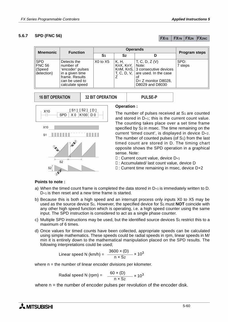
FX Series Programmable Controlers Applied Instructions 5
5.6.7 SPD (FNC 56)
Operation :
The number of pulses received at S1 are countedand stored in D+1; this is the current count value.The counting takes place over a set time framespecified by S2 in msec. The time remaining on thecurrent ‘timed count’, is displayed in device D+2.The number of counted pulses (of S1) from the lasttimed count are stored in D. The timing chartopposite shows the SPD operation in a graphicalsense. Note:➀: Current count value, device D+1
➁: Accumulated/ last count value, device D➂: Current time remaining in msec, device D+2
Points to note :
a) When the timed count frame is completed the data stored in D+1 is immediately written to D.D+1 is then reset and a new time frame is started.
b) Because this is both a high speed and an interrupt process only inputs X0 to X5 may beused as the source device S1. However, the specified device for S1 must NOT coincide withany other high speed function which is operating, i.e. a high speed counter using the sameinput. The SPD instruction is considered to act as a single phase counter.
c) Multiple SPD instructions may be used, but the identified source devices S1 restrict this to amaximum of 6 times.
d) Once values for timed counts have been collected, appropriate speeds can be calculatedusing simple mathematics. These speeds could be radial speeds in rpm, linear speeds in M/min it is entirely down to the mathematical manipulation placed on the SPD results. Thefollowing interpretations could be used;
Mnemonic Function Operands
Program stepsS1 S2 D
SPDFNC 56(Speeddetection)
Detects thenumber of‘encoder’ pulsesin a given timeframe. Resultscan be used tocalculate speed
X0 to X5 K, H,KnX, KnY,KnM, KnS,T, C, D, V, Z
T, C, D, Z (V)Note:3 consecutive devices are used. In the case ofD= Z monitor D8028,D8029 and D8030
SPD:7 steps
FX1S FX1N FX2N FX2NC
PULSE-P16 BIT OPERATION 32 BIT OPERATION
X10K100X 0 D 0SPD
[ S1 ] [ S2 ] [ D ]
2
1
3
X10
S1
S2
S2
Linear speed N (km/h) =3600 × (D)
n × S2× 103
Radial speed N (rpm) = 60 × (D)n × S2
× 103
where n = the number of encoder pulses per revolution of the encoder disk.
where n = the number of linear encoder divisions per kilometer.
5-60
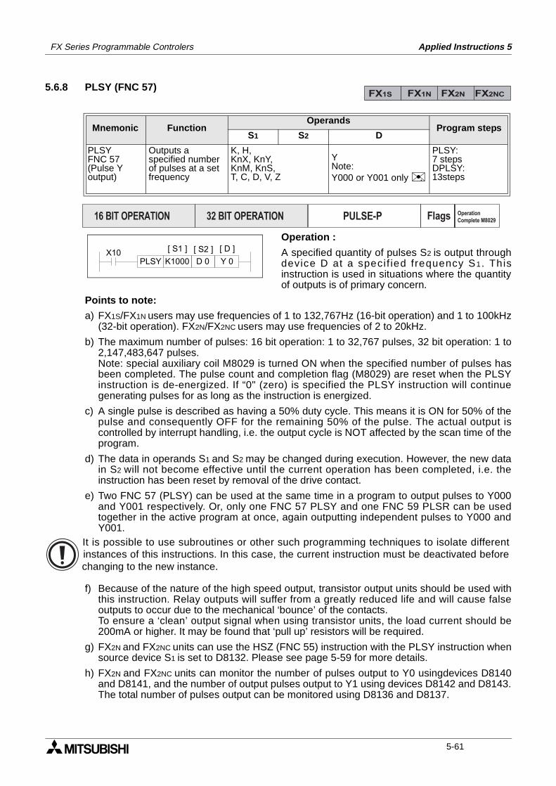
FX Series Programmable Controlers Applied Instructions 5
5.6.8 PLSY (FNC 57)
Operation :
A specified quantity of pulses S2 is output throughdevice D at a specif ied frequency S1. Thisinstruction is used in situations where the quantityof outputs is of primary concern.
Points to note:
a) FX1S/FX1N users may use frequencies of 1 to 132,767Hz (16-bit operation) and 1 to 100kHz(32-bit operation). FX2N/FX2NC users may use frequencies of 2 to 20kHz.
b) The maximum number of pulses: 16 bit operation: 1 to 32,767 pulses, 32 bit operation: 1 to2,147,483,647 pulses. Note: special auxiliary coil M8029 is turned ON when the specified number of pulses hasbeen completed. The pulse count and completion flag (M8029) are reset when the PLSYinstruction is de-energized. If “0" (zero) is specified the PLSY instruction will continuegenerating pulses for as long as the instruction is energized.
c) A single pulse is described as having a 50% duty cycle. This means it is ON for 50% of thepulse and consequently OFF for the remaining 50% of the pulse. The actual output iscontrolled by interrupt handling, i.e. the output cycle is NOT affected by the scan time of theprogram.
d) The data in operands S1 and S2 may be changed during execution. However, the new datain S2 will not become effective until the current operation has been completed, i.e. theinstruction has been reset by removal of the drive contact.
e) Two FNC 57 (PLSY) can be used at the same time in a program to output pulses to Y000and Y001 respectively. Or, only one FNC 57 PLSY and one FNC 59 PLSR can be usedtogether in the active program at once, again outputting independent pulses to Y000 andY001.
f) Because of the nature of the high speed output, transistor output units should be used withthis instruction. Relay outputs will suffer from a greatly reduced life and will cause falseoutputs to occur due to the mechanical ‘bounce’ of the contacts. To ensure a ‘clean’ output signal when using transistor units, the load current should be200mA or higher. It may be found that ‘pull up’ resistors will be required.
g) FX2N and FX2NC units can use the HSZ (FNC 55) instruction with the PLSY instruction whensource device S1 is set to D8132. Please see page 5-59 for more details.
h) FX2N and FX2NC units can monitor the number of pulses output to Y0 usingdevices D8140and D8141, and the number of output pulses output to Y1 using devices D8142 and D8143.The total number of pulses output can be monitored using D8136 and D8137.
Mnemonic Function Operands
Program stepsS1 S2 D
PLSYFNC 57(Pulse Youtput)
Outputs aspecified numberof pulses at a setfrequency
K, H,KnX, KnY,KnM, KnS,T, C, D, V, Z
YNote:Y000 or Y001 only .
PLSY:7 stepsDPLSY:13steps
FX1S FX1N FX2N FX2NC
PULSE-P16 BIT OPERATION 32 BIT OPERATION Flags Operation
Complete M8029
X10D 0K1000 Y 0PLSY
[ S1 ] [ S2 ] [ D ]
It is possible to use subroutines or other such programming techniques to isolate differentinstances of this instructions. In this case, the current instruction must be deactivated beforechanging to the new instance.
5-61
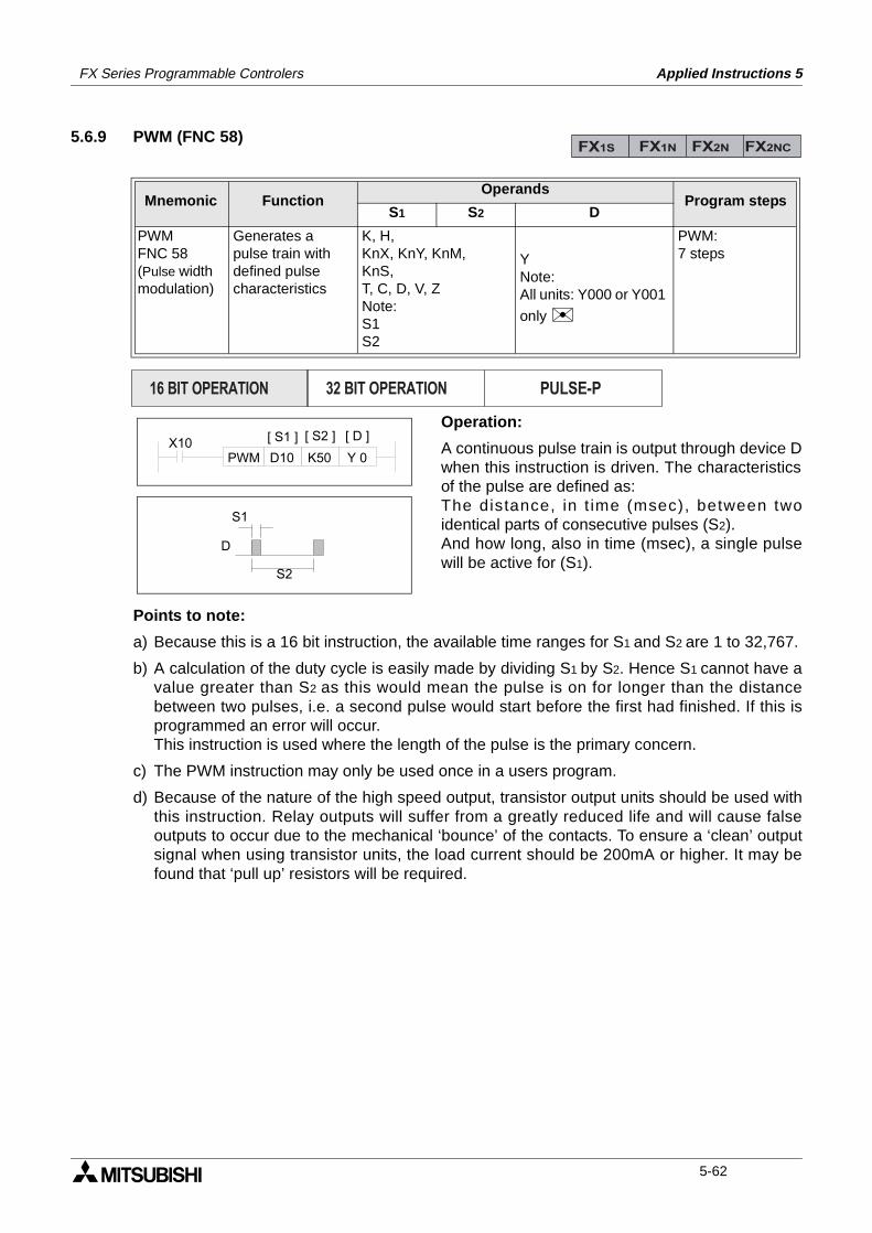
FX Series Programmable Controlers Applied Instructions 5
5.6.9 PWM (FNC 58)
Operation:
A continuous pulse train is output through device Dwhen this instruction is driven. The characteristicsof the pulse are defined as:The distance, in t ime (msec), between twoidentical parts of consecutive pulses (S2).And how long, also in time (msec), a single pulsewill be active for (S1).
Points to note:
a) Because this is a 16 bit instruction, the available time ranges for S1 and S2 are 1 to 32,767.
b) A calculation of the duty cycle is easily made by dividing S1 by S2. Hence S1 cannot have avalue greater than S2 as this would mean the pulse is on for longer than the distancebetween two pulses, i.e. a second pulse would start before the first had finished. If this isprogrammed an error will occur. This instruction is used where the length of the pulse is the primary concern.
c) The PWM instruction may only be used once in a users program.
d) Because of the nature of the high speed output, transistor output units should be used withthis instruction. Relay outputs will suffer from a greatly reduced life and will cause falseoutputs to occur due to the mechanical ‘bounce’ of the contacts. To ensure a ‘clean’ outputsignal when using transistor units, the load current should be 200mA or higher. It may befound that ‘pull up’ resistors will be required.
Mnemonic Function Operands
Program stepsS1 S2 D
PWMFNC 58(Pulse widthmodulation)
Generates apulse train withdefined pulsecharacteristics
K, H,KnX, KnY, KnM,KnS,T, C, D, V, ZNote:S1S2
YNote:All units: Y000 or Y001
only
PWM:7 steps
FX1S FX1N FX2N FX2NC
PULSE-P16 BIT OPERATION 32 BIT OPERATION
X10K50D10 Y 0PWM
[ S1 ] [ S2 ] [ D ]
D
S1
S2
5-62
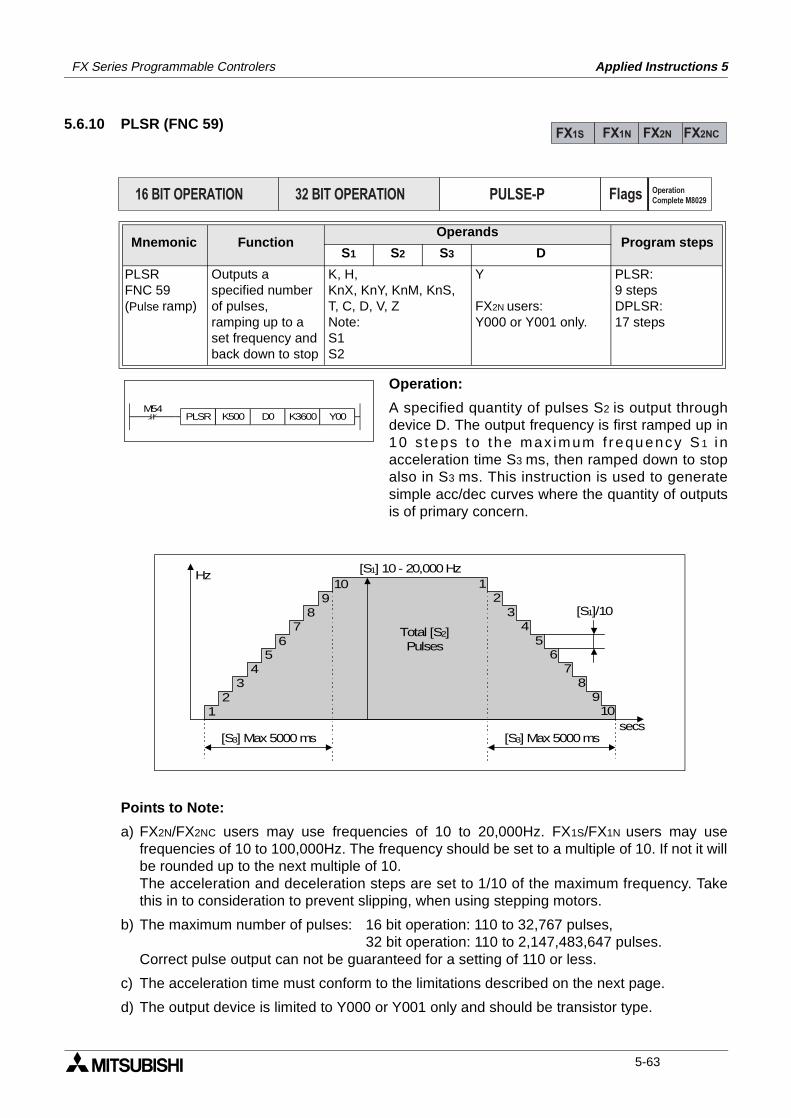
FX Series Programmable Controlers Applied Instructions 5
5.6.10 PLSR (FNC 59)
Operation:
A specified quantity of pulses S2 is output throughdevice D. The output frequency is first ramped up in10 s teps to the max imum f requency S 1 i nacceleration time S3 ms, then ramped down to stopalso in S3 ms. This instruction is used to generatesimple acc/dec curves where the quantity of outputsis of primary concern.
Points to Note:
a) FX2N/FX2NC users may use frequencies of 10 to 20,000Hz. FX1S/FX1N users may usefrequencies of 10 to 100,000Hz. The frequency should be set to a multiple of 10. If not it willbe rounded up to the next multiple of 10.The acceleration and deceleration steps are set to 1/10 of the maximum frequency. Takethis in to consideration to prevent slipping, when using stepping motors.
b) The maximum number of pulses: 16 bit operation: 110 to 32,767 pulses, 32 bit operation: 110 to 2,147,483,647 pulses.
Correct pulse output can not be guaranteed for a setting of 110 or less.
c) The acceleration time must conform to the limitations described on the next page.
d) The output device is limited to Y000 or Y001 only and should be transistor type.
Mnemonic Function Operands
Program stepsS1 S2 S3 D
PLSRFNC 59(Pulse ramp)
Outputs aspecified numberof pulses,ramping up to aset frequency andback down to stop
K, H,KnX, KnY, KnM, KnS,T, C, D, V, ZNote:S1S2
Y
FX2N users: Y000 or Y001 only.
PLSR:9 stepsDPLSR:17 steps
FX1S FX1N FX2N FX2NC
PULSE-P16 BIT OPERATION 32 BIT OPERATION Flags Operation
Complete M8029
M54K500 D0 K3600 Y00PLSR
[S1] 10 - 20,000 Hz
12
34
56
78
910 1
23
45
67
89
10
[S3] Max 5000 ms
Total [S2]Pulses
Hz
[S3] Max 5000 ms
[S1]/10
secs
5-63
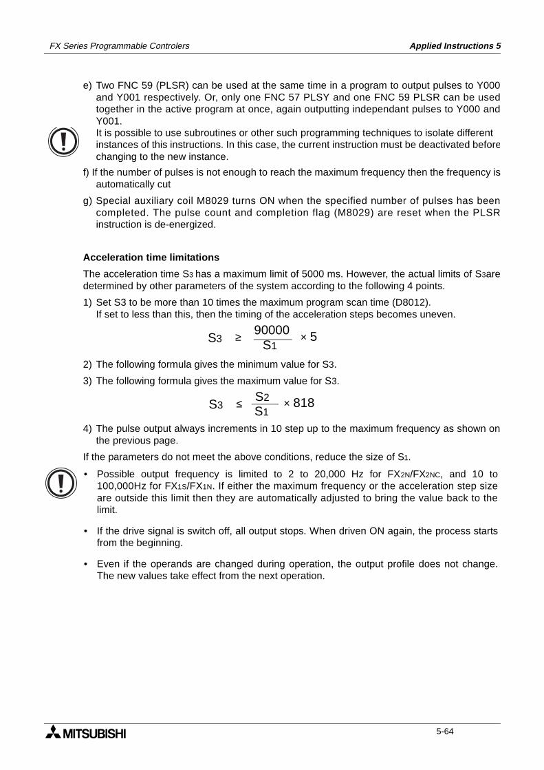
FX Series Programmable Controlers Applied Instructions 5
e) Two FNC 59 (PLSR) can be used at the same time in a program to output pulses to Y000and Y001 respectively. Or, only one FNC 57 PLSY and one FNC 59 PLSR can be usedtogether in the active program at once, again outputting independant pulses to Y000 andY001.
f) If the number of pulses is not enough to reach the maximum frequency then the frequency isautomatically cut
g) Special auxiliary coil M8029 turns ON when the specified number of pulses has beencompleted. The pulse count and completion flag (M8029) are reset when the PLSRinstruction is de-energized.
Acceleration time limitations
The acceleration time S3 has a maximum limit of 5000 ms. However, the actual limits of S3aredetermined by other parameters of the system according to the following 4 points.
1) Set S3 to be more than 10 times the maximum program scan time (D8012). If set to less than this, then the timing of the acceleration steps becomes uneven.
2) The following formula gives the minimum value for S3.
3) The following formula gives the maximum value for S3.
4) The pulse output always increments in 10 step up to the maximum frequency as shown onthe previous page.
If the parameters do not meet the above conditions, reduce the size of S1.
It is possible to use subroutines or other such programming techniques to isolate different instances of this instructions. In this case, the current instruction must be deactivated beforechanging to the new instance.
S3 ≥ S1
90000 × 5
S3 ≤ S1S2 × 818
• Possible output frequency is limited to 2 to 20,000 Hz for FX2N/FX2NC, and 10 to100,000Hz for FX1S/FX1N. If either the maximum frequency or the acceleration step sizeare outside this limit then they are automatically adjusted to bring the value back to thelimit.
• If the drive signal is switch off, all output stops. When driven ON again, the process startsfrom the beginning.
• Even if the operands are changed during operation, the output profile does not change.The new values take effect from the next operation.
5-64
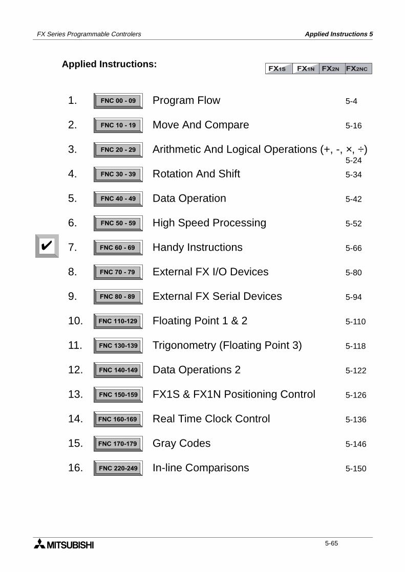
FX Series Programmable Controlers Applied Instructions 5
Applied Instructions:FX1S FX1N FX2N FX2NC
FNC 00 - 09
FNC 10 - 19
FNC 20 - 29
FNC 30 - 39
FNC 40 - 49
FNC 50 - 59
FNC 60 - 69
FNC 70 - 79
FNC 80 - 89
FNC 110-129
FNC 130-139
FNC 140-149
FNC 160-169
FNC 170-179
FNC 220-249
FNC 150-159
1.
2.
3.
4.
5.
6.
7.
8.
9.
10.
11.
12.
13.
14.
15.
16.
Program Flow 5-4
Move And Compare 5-16
Arithmetic And Logical Operations (+, -, ×, ÷)5-24
Rotation And Shift 5-34
Data Operation 5-42
High Speed Processing 5-52
Handy Instructions 5-66
External FX I/O Devices 5-80
External FX Serial Devices 5-94
Floating Point 1 & 2 5-110
Trigonometry (Floating Point 3) 5-118
Data Operations 2 5-122
FX1S & FX1N Positioning Control 5-126
Real Time Clock Control 5-136
Gray Codes 5-146
In-line Comparisons 5-150
5-65
FX Series Programmable Controlers Applied Instructions 5
5.7 Handy Instructions - Functions 60 to 69
Contents:
Page
IST - Initial State FNC 60 5-67
SER - Search FNC 61 5-69
ABSD - Absolute Drum FNC 62 5-70
INCD - Incremental Drum FNC 63 5-71
TTMR - Teaching Timer FNC 64 5-72
STMR - Special Timer - Definable FNC 65 5-72
ALT - Alternate State FNC 66 5-73
RAMP - Ramp - Variable Value FNC 67 5-73
ROTC - Rotary Table Control FNC 68 5-75
SORT - Sort Data FNC 69 5-77
Symbols list:
D - Destination device.S - Source device.m, n- Number of active devices, bits or an operational constant.Additional numeric suffixes will be attached if there are more than one operand with the samefunction e.g. D1, S3 or for lists/tabled devices D3+0, S+9 etc.MSB - Most Significant Bit, sometimes used to indicate the mathematical sign of a number,i.e. positive = 0, and negative = 1.LSB - Least Significant Bit.
Instruction modifications:
- An instruction operating in 16 bit mode, where identifies the instructionmnemonic.
P - A 16 bit mode instruction modified to use pulse (single) operation.
D - An instruction modified to operate in 32 bit operation.
DP - A 32 bit mode instruction modified to use pulse (single) operation.
- A repetitive instruction which will change the destination value on every scan unlessmodified by the pulse function.
- An operand which cannot be indexed, i.e. The addition of V or Z is either invalid or willhave no effect to the value of the operand.
5-66
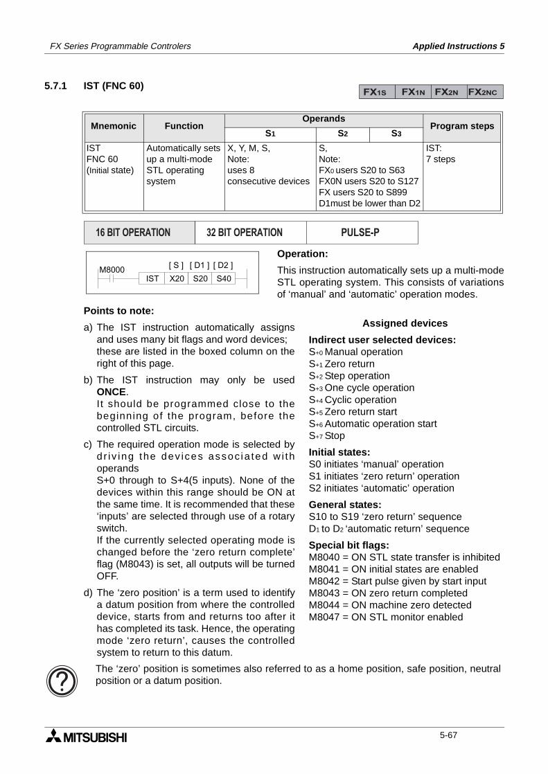
FX Series Programmable Controlers Applied Instructions 5
5.7.1 IST (FNC 60)
Operation:
This instruction automatically sets up a multi-modeSTL operating system. This consists of variationsof ‘manual’ and ‘automatic’ operation modes.
Points to note:
a) The IST instruction automatically assignsand uses many bit flags and word devices;these are listed in the boxed column on theright of this page.
b) The IST instruction may only be usedONCE.I t should be programmed close to thebeginning of the program, before thecontrolled STL circuits.
c) The required operation mode is selected bydr iv ing the dev ices assoc ia ted w i thoperandsS+0 through to S+4(5 inputs). None of thedevices within this range should be ON atthe same time. It is recommended that these‘inputs’ are selected through use of a rotaryswitch.If the currently selected operating mode ischanged before the ‘zero return complete’flag (M8043) is set, all outputs will be turnedOFF.
d) The ‘zero position’ is a term used to identifya datum position from where the controlleddevice, starts from and returns too after ithas completed its task. Hence, the operatingmode ‘zero return’, causes the controlledsystem to return to this datum.
Mnemonic Function Operands
Program stepsS1 S2 S3
ISTFNC 60(Initial state)
Automatically setsup a multi-modeSTL operatingsystem
X, Y, M, S,Note:uses 8 consecutive devices
S,Note:FX0 users S20 to S63FX0N users S20 to S127FX users S20 to S899D1must be lower than D2
IST:7 steps
FX1S FX1N FX2N FX2NC
PULSE-P16 BIT OPERATION 32 BIT OPERATION
M8000S20X20 S40IST
[ S ] [ D1 ] [ D2 ]
Assigned devices
Indirect user selected devices:S+0 Manual operationS+1 Zero returnS+2 Step operationS+3 One cycle operationS+4 Cyclic operationS+5 Zero return startS+6 Automatic operation startS+7 Stop
Initial states:S0 initiates ‘manual’ operationS1 initiates ‘zero return’ operationS2 initiates ‘automatic’ operation
General states:S10 to S19 ‘zero return’ sequenceD1 to D2 ‘automatic return’ sequence
Special bit flags:M8040 = ON STL state transfer is inhibitedM8041 = ON initial states are enabledM8042 = Start pulse given by start inputM8043 = ON zero return completedM8044 = ON machine zero detectedM8047 = ON STL monitor enabled
The ‘zero’ position is sometimes also referred to as a home position, safe position, neutralposition or a datum position.
5-67
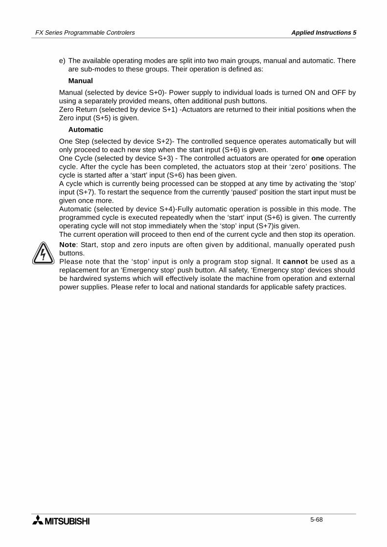
FX Series Programmable Controlers Applied Instructions 5
e) The available operating modes are split into two main groups, manual and automatic. Thereare sub-modes to these groups. Their operation is defined as:
Manual
Manual (selected by device S+0)- Power supply to individual loads is turned ON and OFF byusing a separately provided means, often additional push buttons.Zero Return (selected by device S+1) -Actuators are returned to their initial positions when theZero input (S+5) is given.
Automatic
One Step (selected by device S+2)- The controlled sequence operates automatically but willonly proceed to each new step when the start input (S+6) is given.One Cycle (selected by device S+3) - The controlled actuators are operated for one operationcycle. After the cycle has been completed, the actuators stop at their ‘zero’ positions. Thecycle is started after a ‘start’ input (S+6) has been given.A cycle which is currently being processed can be stopped at any time by activating the ‘stop’input (S+7). To restart the sequence from the currently ‘paused’ position the start input must begiven once more.Automatic (selected by device S+4)-Fully automatic operation is possible in this mode. Theprogrammed cycle is executed repeatedly when the ‘start’ input (S+6) is given. The currentlyoperating cycle will not stop immediately when the ‘stop’ input (S+7)is given. The current operation will proceed to then end of the current cycle and then stop its operation.
Note: Start, stop and zero inputs are often given by additional, manually operated pushbuttons. Please note that the ‘stop’ input is only a program stop signal. It cannot be used as areplacement for an ‘Emergency stop’ push button. All safety, ‘Emergency stop’ devices shouldbe hardwired systems which will effectively isolate the machine from operation and externalpower supplies. Please refer to local and national standards for applicable safety practices.
5-68
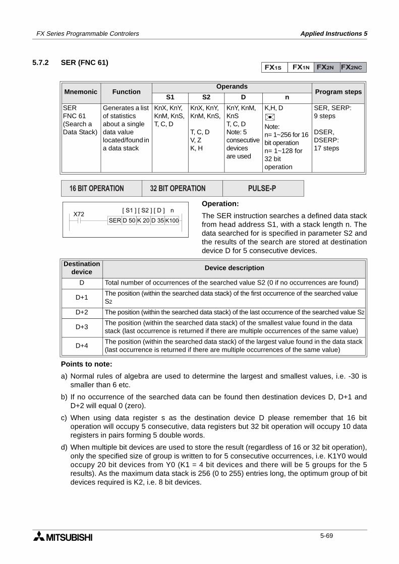
FX Series Programmable Controlers Applied Instructions 5
5.7.2 SER (FNC 61)
Operation:
The SER instruction searches a defined data stackfrom head address S1, with a stack length n. Thedata searched for is specified in parameter S2 andthe results of the search are stored at destinationdevice D for 5 consecutive devices.
Points to note:
a) Normal rules of algebra are used to determine the largest and smallest values, i.e. -30 issmaller than 6 etc.
b) If no occurrence of the searched data can be found then destination devices D, D+1 andD+2 will equal 0 (zero).
c) When using data register s as the destination device D please remember that 16 bitoperation will occupy 5 consecutive, data registers but 32 bit operation will occupy 10 dataregisters in pairs forming 5 double words.
d) When multiple bit devices are used to store the result (regardless of 16 or 32 bit operation),only the specified size of group is written to for 5 consecutive occurrences, i.e. K1Y0 wouldoccupy 20 bit devices from Y0 (K1 = 4 bit devices and there will be 5 groups for the 5results). As the maximum data stack is 256 (0 to 255) entries long, the optimum group of bitdevices required is K2, i.e. 8 bit devices.
Mnemonic Function Operands
Program stepsS1 S2 D n
SERFNC 61(Search aData Stack)
Generates a list of statistics about a single data value located/found in a data stack
KnX, KnY,KnM, KnS,T, C, D
KnX, KnY,KnM, KnS,
T, C, DV, ZK, H
KnY, KnM,KnST, C, DNote: 5 consecutive devicesare used
K,H, D
Note:n= 1~256 for 16 bit operationn= 1~128 for 32 bit operation
SER, SERP:9 steps
DSER,DSERP:17 steps
Destination device
Device description
D Total number of occurrences of the searched value S2 (0 if no occurrences are found)
D+1The position (within the searched data stack) of the first occurrence of the searched value S2
D+2 The position (within the searched data stack) of the last occurrence of the searched value S2
D+3The position (within the searched data stack) of the smallest value found in the data stack (last occurrence is returned if there are multiple occurrences of the same value)
D+4The position (within the searched data stack) of the largest value found in the data stack (last occurrence is returned if there are multiple occurrences of the same value)
FX1S FX1N FX2N FX2NC
PULSE-P16 BIT OPERATION 32 BIT OPERATION
X72SER D 50 K 20
[ S1 ] [ D ]
D 35 K100
n[ S2 ]
5-69
FX Series Programmable Controlers Applied Instructions 5
5.7.3 ABSD (FNC 62)
Operation:
This instruction generates a variety of outputpatterns (there are n number of addressedoutputs) in response to the current value of aselected counter, S2.
Points to note:
a) The current value of the selected counter (S2) is compared against a user defined datatable. This data table has a head address identified by operand S1. S1should always havean even device number.
b) For each destination bit (D) there are two consecutive values stored in the data table. Thefirst allocated value represents the event number when the destination device (D) will beturned ON. The second identifies the reset event. The data table values are allocated as aconsecutive pair for each sequential element between D and D+n.
c) The data table has a length equal to 2 × n data entries. Depending on the format of the datatable, a single entry can be one data word such as D300 or a group of 16 bit devices e.g.K4X000.
d) Values from 0 to 32,767 may be used in the data table.
e) The ABSD instruction may only be used ONCE.
From the example instruction and the data table below, the following timing diagram forelements M0 to M3 can be constructed.
Mnemonic Function Operands
Program stepsS1 S2 D n
ABSDFNC 62(Absolutedrumsequencer)
Generatesmultiple outputpatterns inresponse tocounter data
KnX, KnY,KnM, KnS,(in groups of 8)T, C, D
C Y,M,S
Note:n consecutivedevices are used
K,H
Note:n≤ 64
ABSD:9 steps
DABSD:17 steps.see f).Note: High speed
counters are not allowed
FX1S FX1N FX2N FX2NC
PULSE-P16 BIT OPERATION 32 BIT OPERATION
X0C 0D300 M 0
[ S1 ] [ S2 ] [ D ]
K 4
[ n ]
ABSD
D300 - 40
When counter S2 equals thevalue below, the destination
device D is
Assigneddestinationdevice D
D302 - 100
D304 - 160
D306 - 240
D301 - 140
D303 - 200
D305 - 60
D307 - 280
M0
M1
M2
M3
turned ON turned OFFM 0
M 1
M 2
M 3
40 140
100 200
60 160
240 280
0 180 360
Count value
ON OFF
5-70
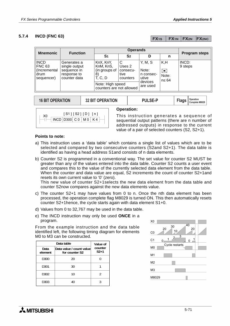
FX Series Programmable Controlers Applied Instructions 5
5.7.4 INCD (FNC 63)
Operation:
This ins t ruct ion generates a sequence o fsequential output patterns (there are n number ofaddressed outputs) in response to the currentvalue of a pair of selected counters (S2, S2+1).
Points to note:
a) This instruction uses a ‘data table’ which contains a single list of values which are to beselected and compared by two consecutive counters (S2and S2+1). The data table isidentified as having a head address S1and consists of n data elements.
b) Counter S2 is programmed in a conventional way. The set value for counter S2 MUST begreater than any of the values entered into the data table. Counter S2 counts a user eventand compares this to the value of the currently selected data element from the data table.When the counter and data value are equal, S2 increments the count of counter S2+1andresets its own current value to ‘0’ (zero).This new value of counter S2+1selects the new data element from the data table andcounter S2now compares against the new data elements value.
c) The counter S2+1 may have values from 0 to n. Once the nth data element has beenprocessed, the operation complete flag M8029 is turned ON. This then automatically resetscounter S2+1hence, the cycle starts again with data element S1+0.
d) Values from 0 to 32,767 may be used in the data table.
e) The INCD instruction may only be used ONCE in aprogram.
From the example instruction and the data tableidentified left, the following timing diagram for elementsM0 to M3 can be constructed.
Mnemonic Function Operands
Program stepsS1 S2 D n
INCDFNC 63(Incrementaldrumsequencer)
Generates asingle outputsequence inresponse tocounter data
KnX, KnY,KnM, KnS,(in groups of 8)T, C, D
CUses 2consecu-tivecounters
Y, M, S
Note:n consec-utivedevices are used
K,H
Note:n≤ 64
INCD:9 steps
Note: High speedcounters are not allowed
FX1S FX1N FX2N FX2NC
PULSE-P16 BIT OPERATION 32 BIT OPERATION Flags Operation
Complete M8029
X0C 0D300 M 0
[ S1 ] [ S2 ] [ D ]
K 4
[ n ]
INCD
X0
C0
C1
M0
M1
M2
M3
M8029
0 1 2 3
0 1
2030 40
1020
Cycle restarts
D300
Data table Value ofcounter
S2+1
D301
D302
D303
20
30
10
40
0
1
2
3
Dataelement
Data value / count valuefor counter S2
5-71
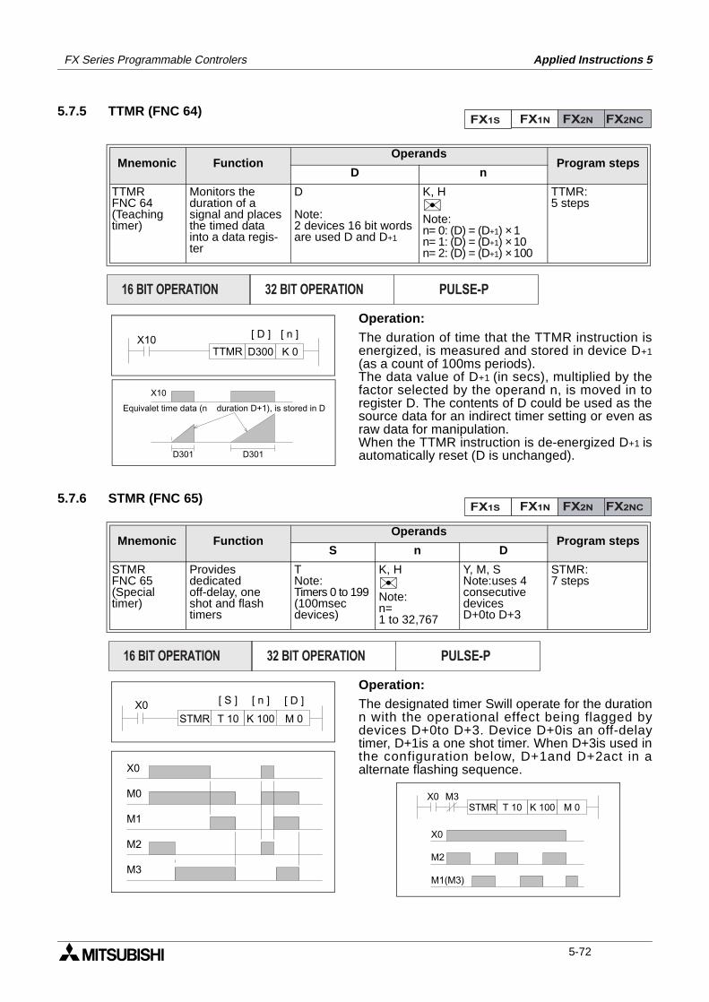
FX Series Programmable Controlers Applied Instructions 5
5.7.5 TTMR (FNC 64)
Operation:The duration of time that the TTMR instruction isenergized, is measured and stored in device D+1(as a count of 100ms periods).The data value of D+1 (in secs), multiplied by thefactor selected by the operand n, is moved in toregister D. The contents of D could be used as thesource data for an indirect timer setting or even asraw data for manipulation.When the TTMR instruction is de-energized D+1 isautomatically reset (D is unchanged).
5.7.6 STMR (FNC 65)
Operation:The designated timer Swill operate for the durationn with the operational effect being flagged bydevices D+0to D+3. Device D+0is an off-delaytimer, D+1is a one shot timer. When D+3is used inthe configuration below, D+1and D+2act in aalternate flashing sequence.
Mnemonic Function Operands
Program stepsD n
TTMRFNC 64(Teachingtimer)
Monitors theduration of asignal and placesthe timed datainto a data regis-ter
D
Note:2 devices 16 bit words are used D and D+1
K, HNote:n= 0: (D) = (D+1) × 1n= 1: (D) = (D+1) × 10n= 2: (D) = (D+1) × 100
TTMR:5 steps
Mnemonic Function Operands
Program stepsS n D
STMRFNC 65(Specialtimer)
Providesdedicatedoff-delay, oneshot and flashtimers
TNote:Timers 0 to 199(100msec devices)
K, HNote:n= 1 to 32,767
Y, M, SNote:uses 4consecutivedevicesD+0to D+3
STMR:7 steps
FX1S FX1N FX2N FX2NC
PULSE-P16 BIT OPERATION 32 BIT OPERATION
X10D300
[ D ]
K 0
[ n ]
TTMR
D301 D301
X10
Equivalet time data (n duration D+1), is stored in D
FX1S FX1N FX2N FX2NC
PULSE-P16 BIT OPERATION 32 BIT OPERATION
X0K 100 M 0
[ S ] [ D ]
T 10STMR
[ n ]
X0
M0
M1
M2
M3
X0K 100 M 0T 10STMR
M3
X0
M2
M1(M3)
5-72
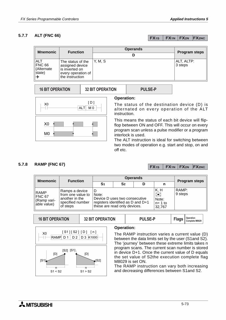
FX Series Programmable Controlers Applied Instructions 5
5.7.7 ALT (FNC 66)
Operation:
The status of the dest inat ion device (D) isa l te rnated on every operat ion o f the ALTinstruction.
This means the status of each bit device will flip-flop between ON and OFF. This will occur on everyprogram scan unless a pulse modifier or a programinterlock is used.The ALT instruction is ideal for switching betweentwo modes of operation e.g. start and stop, on andoff etc.
5.7.8 RAMP (FNC 67)
Operation:
The RAMP instruction varies a current value (D)between the data limits set by the user (S1and S2).The ‘journey’ between these extreme limits takes nprogram scans. The current scan number is storedin device D+1. Once the current value of D equalsthe set value of S2the execution complete flagM8029 is set ON.The RAMP instruction can vary both increasingand decreasing differences between S1and S2.
Mnemonic Function Operands
Program stepsD
ALTFNC 66(Alternatestate)
The status of theassigned deviceis inverted onevery operation ofthe instruction
Y, M, S ALT, ALTP:3 steps
Mnemonic Function Operands
Program stepsS1 S2 D n
RAMPFNC 67(Ramp vari-able value)
Ramps a devicefrom one value toanother in thespecified numberof steps
DNote:Device D uses two consecutiveregisters identified as D and D+1these are read only devices.
K, HNote:n= 1 to 32,767
RAMP:9 steps
FX1S FX1N FX2N FX2NC
PULSE-P16 BIT OPERATION 32 BIT OPERATION
ALT M 0X0 [ D ]
M0
X0
FX1S FX1N FX2N FX2NC
PULSE-P16 BIT OPERATION 32 BIT OPERATION Flags Operation
Complete M8029
X0D 2D 1 D 3
[ S1 ] [ S2 ] [ D ]
K1000
[ n ]
RAMP
n n
[S1]
[S2][D]
[S2]
[S1][D]
S1 < S2 S1 > S2
5-73
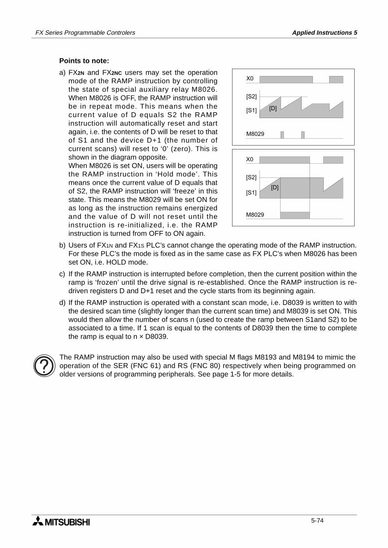
FX Series Programmable Controlers Applied Instructions 5
Points to note:
a) FX2N and FX2NC users may set the operationmode of the RAMP instruction by controllingthe state of special auxiliary relay M8026.When M8026 is OFF, the RAMP instruction willbe in repeat mode. This means when thecurrent value of D equals S2 the RAMPinstruction will automatically reset and startagain, i.e. the contents of D will be reset to thatof S1 and the device D+1 (the number ofcurrent scans) will reset to ‘0’ (zero). This isshown in the diagram opposite.When M8026 is set ON, users will be operatingthe RAMP instruction in ‘Hold mode’. Thismeans once the current value of D equals thatof S2, the RAMP instruction will ‘freeze’ in thisstate. This means the M8029 will be set ON foras long as the instruction remains energizedand the value of D will not reset until theinstruction is re-initialized, i.e. the RAMPinstruction is turned from OFF to ON again.
b) Users of FX1N and FX1S PLC’s cannot change the operating mode of the RAMP instruction.For these PLC’s the mode is fixed as in the same case as FX PLC’s when M8026 has beenset ON, i.e. HOLD mode.
c) If the RAMP instruction is interrupted before completion, then the current position within theramp is ‘frozen’ until the drive signal is re-established. Once the RAMP instruction is re-driven registers D and D+1 reset and the cycle starts from its beginning again.
d) If the RAMP instruction is operated with a constant scan mode, i.e. D8039 is written to withthe desired scan time (slightly longer than the current scan time) and M8039 is set ON. Thiswould then allow the number of scans n (used to create the ramp between S1and S2) to beassociated to a time. If 1 scan is equal to the contents of D8039 then the time to completethe ramp is equal to n × D8039.
X0
[S2]
M8029
[D][S1]
X0
[S2]
[S1]
M8029
[D]
The RAMP instruction may also be used with special M flags M8193 and M8194 to mimic theoperation of the SER (FNC 61) and RS (FNC 80) respectively when being programmed onolder versions of programming peripherals. See page 1-5 for more details.
5-74
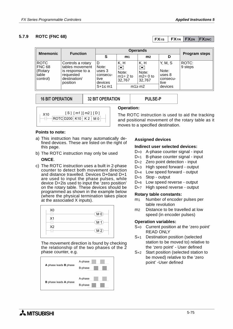
FX Series Programmable Controlers Applied Instructions 5
5.7.9 ROTC (FNC 68)
Operation:
The ROTC instruction is used to aid the trackingand positional movement of the rotary table as itmoves to a specified destination.
Points to note:a) This instruction has many automatically de-
fined devices. These are listed on the right ofthis page.
b) The ROTC instruction may only be used
ONCE.
c) The ROTC instruction uses a built in 2-phasecounter to detect both movement directionand distance travelled. Devices D+0and D+1are used to input the phase pulses, whiledevice D+2is used to input the ‘zero position’on the rotary table. These devices should beprogrammed as shown in the example below(where the physical termination takes placeat the associated X inputs).
The movement direction is found by checkingthe relationship of the two phases of the 2phase counter, e.g.
Mnemonic Function Operands
Program stepsS m1 m2 D
ROTCFNC 68(Rotarytable control)
Controls a rotarytables movementis response to arequesteddestination/position
DNote:uses 3consecu-tivedevicesS+1≤ m1
K, HNote:m1= 2 to32,767
K, HNote:m2= 0 to32,767
Y, M, S
Note:uses 8consecu-tivedevices
ROTC:9 steps
m1≥ m2
FX1S FX1N FX2N FX2NC
PULSE-P16 BIT OPERATION 32 BIT OPERATION
X10K10D200 K 2
[ S ] [ m1 ] [ D ]
M 0ROTC
[ m2 ]
Assigned devices
Indirect user selected devices:D+0 A-phase counter signal - inputD+1 B-phase counter signal - inputD+2 Zero point detection - inputD+3 High speed forward - outputD+4 Low speed forward - outputD+5 Stop - outputD+6 Low speed reverse - outputD+7 High speed reverse - output
Rotary table constants:m1 Number of encoder pulses per
table revolutionm2 Distance to be travelled at low
speed (in encoder pulses)
Operation variables:S+0 Current position at the ‘zero point’
READ ONLYS+1 Destination position (selected
station to be moved to) relative to the ‘zero point’ - User defined
S+2 Start position (selected station to be moved) relative to the ‘zero point’ -User defined
X1
X2
X0M 0
M 1
M 2
A-phase
B-phase
A-phase
B-phase
A phase leads B phase
B phase leads A phase
5-75
FX Series Programmable Controlers Applied Instructions 5
d) When the ‘zero point’ input (D+2) is received the contents of device S+0is reset to ‘0’ (zero).Before starting any new operation it is advisable to ensure the rotary table is initialized bymoving the ‘zero point’ drive dog or marker around to the ‘zero point’ sensor. This could beconsidered as a calibration technique. The re-calibration of the rotary table should becarried out periodically to ensure a consistent/accurate operation.
e) Devices D+3 to D+7 are automatically set by the ROTC instruction during its operation.These are used as flags to indicate the operation which should be carried out next.
f) All positions are entered in the form of the required encoder pulses. This can be seen in thefollowing example:
- Example:
A rotary table has an encoder which outputs 400 (m1) pulses per revolution. There are 8stations (0 to 7) on the rotary table. This means that when the rotary table moves from onestation to its immediately following station, 50 encoder pulses are counted. The ‘zeroposition’ is station ‘0’ (zero). To move the item located at station 7 to station 3 the followingvalues must be written to the ROTC
instruction:S+1=3 × 50 = 150 (station 3’s position in encoder pulses from the zero point)S+2=7 × 50 = 350 (station 7’s position in encoder pulses from the zero point)m1= 400 (total number of encoder pulses per rev)The rotary table is required approach the destination station at a slow speed starting from1.5 stations before the destination. Therefore;m2= 1.5 × 50 = 75 slow speed distance either side of the destination station (in encoderpulses)
5-76
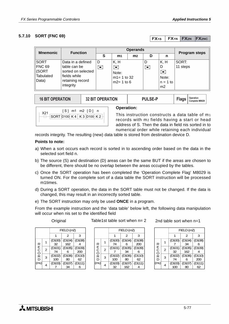
FX Series Programmable Controlers Applied Instructions 5
5.7.10 SORT (FNC 69)
Operation:
This instruction constructs a data table of m1
records with m2 fields having a start or headaddress of S. Then the data in field nis sorted in tonumerical order while retaining each individual
records integrity. The resulting (new) data table is stored from destination device D.
Points to note:
a) When a sort occurs each record is sorted in to ascending order based on the data in theselected sort field n.
b) The source (S) and destination (D) areas can be the same BUT if the areas are chosen tobe different, there should be no overlap between the areas occupied by the tables.
c) Once the SORT operation has been completed the ‘Operation Complete Flag’ M8029 isturned ON. For the complete sort of a data table the SORT instruction will be processedm1times.
d) During a SORT operation, the data in the SORT table must not be changed. If the data ischanged, this may result in an incorrectly sorted table.
e) The SORT instruction may only be used ONCE in a program.
From the example instruction and the ‘data table’ below left, the following data manipulationwill occur when nis set to the identified field
Mnemonic Function Operands
Program stepsS m1 m2 D n
SORTFNC 69(SORTTabulatedData)
Data in a definedtable can besorted on selected fields while retaining recordintegrity
D
K, H
Note:m1= 1 to 32m2= 1 to 6
D
K, HD
Note:n = 1 tom2
SORT:11 steps
FX1S FX1N FX2N FX2NC
PULSE-P16 BIT OPERATION 32 BIT OPERATION Flags Operation
Complete M8029
X21SORT D100 K 4
[ S ] [ D ]
K 3 D100 K 2
nm1 m2
4
1
2
3
1 2 3
FIELD (m2)
(D100)32
(D101)74
(D102)100
(D103)7
(D104)162
(D105)6
(D106)80
(D107)34
(D108)4
(D109)200
(D110)62
(D111)6
RECORD
(m1)4
1
2
3
1 2 3
FIELD (m2)
(D100)74
(D101)7
(D102)100
(D103)32
(D104)6
(D105)34
(D106)80
(D107)162
(D108)200
(D109)6
(D110)62
(D111)4
RECORD
(m1)4
1
2
3
1 2 3
FIELD (m2)
(D100)7
(D101)32
(D102)74
(D103)100
(D104)34
(D105)162
(D106)6
(D107)80
(D108)6
(D109)4
(D110)200
(D111)62
RECORD
(m1)
Original Table1st table sort when n= 2 2nd table sort when n=1
5-77

FX Series Programmable Controlers Applied Instructions 5
MEMO
5-78
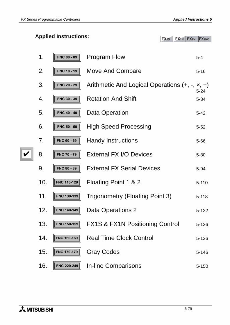
FX Series Programmable Controlers Applied Instructions 5
Applied Instructions:FX1S FX1N FX2N FX2NC
FNC 00 - 09
FNC 10 - 19
FNC 20 - 29
FNC 30 - 39
FNC 40 - 49
FNC 50 - 59
FNC 60 - 69
FNC 70 - 79
FNC 80 - 89
FNC 110-129
FNC 130-139
FNC 140-149
FNC 160-169
FNC 170-179
FNC 220-249
FNC 150-159
1.
2.
3.
4.
5.
6.
7.
8.
9.
10.
11.
12.
13.
14.
15.
16.
Program Flow 5-4
Move And Compare 5-16
Arithmetic And Logical Operations (+, -, ×, ÷)5-24
Rotation And Shift 5-34
Data Operation 5-42
High Speed Processing 5-52
Handy Instructions 5-66
External FX I/O Devices 5-80
External FX Serial Devices 5-94
Floating Point 1 & 2 5-110
Trigonometry (Floating Point 3) 5-118
Data Operations 2 5-122
FX1S & FX1N Positioning Control 5-126
Real Time Clock Control 5-136
Gray Codes 5-146
In-line Comparisons 5-150
5-79
FX Series Programmable Controlers Applied Instructions 5
5.8 External FX I/O Devices - Functions 70 to 79
Contents:
Page
TKY - Ten Key Input FNC 70 5-81
HKY - Hexadecimal Input FNC 71 5-82
DSW - Digital Switch
(Thumbwheel input) FNC 72 5-83
SEGD - Seven Segment Decoder FNC 73 5-84
SEGL - Seven Segment
With Latch FNC 74 5-85
ARWS - Arrow Switch FNC 75 5-87
ASC - ASCII Code FNC 76 5-88
PR- ‘Print’ To A Display FNC 77 5-89
FROM - Read From A Special
Function Block FNC 78 5-90
TO - Write To A Special
Function Block FNC 79 5-91
Symbols list:
D - Destination device.S - Source device.m, n- Number of active devices, bits or an operational constant.Additional numeric suffixes will be attached if there are more than one operand with the samefunction e.g. D1, S3 or for lists/tabled devices D3+0, S+9 etc.MSB - Most Significant Bit, sometimes used to indicate the mathematical sign of a number,i.e. positive = 0, and negative = 1.LSB - Least Significant Bit.
Instruction modifications:
- An instruction operating in 16 bit mode, where identifies the instructionmnemonic.
P - A 16 bit mode instruction modified to use pulse (single) operation.
D - An instruction modified to operate in 32 bit operation.
DP - A 32 bit mode instruction modified to use pulse (single) operation.
- A repetitive instruction which will change the destination value on every scan unlessmodified by the pulse function.
- An operand which cannot be indexed, i.e. The addition of V or Z is either invalid or willhave no effect to the value of the operand.
5-80
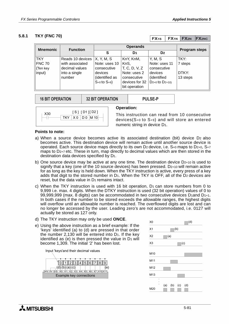
FX Series Programmable Controlers Applied Instructions 5
5.8.1 TKY (FNC 70)
Operation:
This instruction can read from 10 consecutivedevices(S+0 to S+9) and will store an enterednumeric string in device D1.
Points to note:
a) When a source device becomes active its associated destination (bit) device D2 alsobecomes active. This destination device will remain active until another source device isoperated. Each source device maps directly to its own D2 device, i.e. S+0 maps to D2+0, S+7
maps to D2+7 etc. These in turn, map directly to decimal values which are then stored in thedestination data devices specified by D1.
b) One source device may be active at any one time. The destination device D2+10 is used tosignify that a key (one of the 10 source devices) has been pressed. D2+10 will remain activefor as long as the key is held down. When the TKY instruction is active, every press of a keyadds that digit to the stored number in D1. When the TKY is OFF, all of the D2 devices arereset, but the data value in D1 remains intact.
c) When the TKY instruction is used with 16 bit operation, D1 can store numbers from 0 to9,999 i.e. max. 4 digits. When the DTKY instruction is used (32 bit operation) values of 0 to99,999,999 (max. 8 digits) can be accommodated in two consecutive devices D1and D1+1.In both cases if the number to be stored exceeds the allowable ranges, the highest digitswill overflow until an allowable number is reached. The overflowed digits are lost and canno longer be accessed by the user. Leading zero’s are not accommodated, i.e. 0127 willactually be stored as 127 only.
d) The TKY instruction may only be used ONCE.
e) Using the above instruction as a brief example: If the‘keys’ identified (a) to (d) are pressed in that orderthe number 2,130 will be entered into D1. If the keyidentified as (e) is then pressed the value in D1 willbecome 1,309. The initial ‘2’ has been lost.
Mnemonic Function Operands
Program stepsS D1 D2
TKYFNC 70(Ten key input)
Reads 10 deviceswith associateddecimal valuesinto a singlenumber
X, Y, M, SNote: uses 10consecutivedevices(identified as S+0 to S+9)
KnY, KnM, KnS,T, C, D, V, ZNote: uses 2consecutivedevices for 32bit operation
Y, M, SNote: uses 11consecutivedevices (identifiedD2+0 to D2+10)
TKY:7 steps
DTKY:13 steps
FX1S FX1N FX2N FX2NC
PULSE-P16 BIT OPERATION 32 BIT OPERATION
X30X 0 D 0
[ S ] [ D2 ]
M 10TKY
[ D1 ]
M10
M11
M12
M13
M20(a) (b) (c) (d)
(a)
(b)
(c)
(d)X0
X1
X2
X3
.
.
.
X11X0 X1 X2 X3 X4 X524V 0V S/S X6 X7
0 1 2 3 4 5 6 7 8 9
X10
(a)(b) (c)(d) (e)
Example key connections
Input 'keys'and their decimal values
5-81
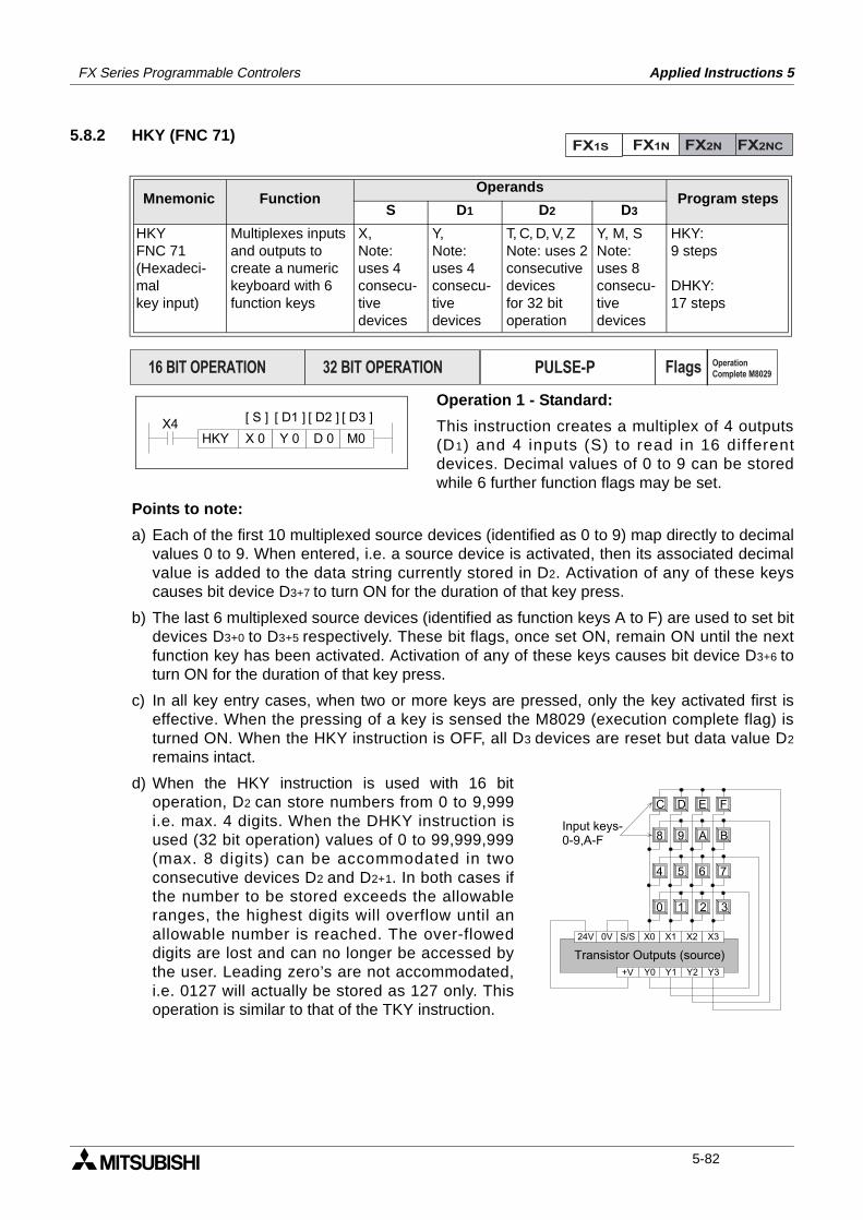
FX Series Programmable Controlers Applied Instructions 5
5.8.2 HKY (FNC 71)
Operation 1 - Standard:
This instruction creates a multiplex of 4 outputs(D1) and 4 inputs (S) to read in 16 differentdevices. Decimal values of 0 to 9 can be storedwhile 6 further function flags may be set.
Points to note:
a) Each of the first 10 multiplexed source devices (identified as 0 to 9) map directly to decimalvalues 0 to 9. When entered, i.e. a source device is activated, then its associated decimalvalue is added to the data string currently stored in D2. Activation of any of these keyscauses bit device D3+7 to turn ON for the duration of that key press.
b) The last 6 multiplexed source devices (identified as function keys A to F) are used to set bitdevices D3+0 to D3+5 respectively. These bit flags, once set ON, remain ON until the nextfunction key has been activated. Activation of any of these keys causes bit device D3+6 toturn ON for the duration of that key press.
c) In all key entry cases, when two or more keys are pressed, only the key activated first iseffective. When the pressing of a key is sensed the M8029 (execution complete flag) isturned ON. When the HKY instruction is OFF, all D3 devices are reset but data value D2
remains intact.
d) When the HKY instruction is used with 16 bitoperation, D2 can store numbers from 0 to 9,999i.e. max. 4 digits. When the DHKY instruction isused (32 bit operation) values of 0 to 99,999,999(max. 8 digits) can be accommodated in twoconsecutive devices D2 and D2+1. In both cases ifthe number to be stored exceeds the allowableranges, the highest digits will overflow until anallowable number is reached. The over-floweddigits are lost and can no longer be accessed bythe user. Leading zero’s are not accommodated,i.e. 0127 will actually be stored as 127 only. Thisoperation is similar to that of the TKY instruction.
Mnemonic Function Operands
Program stepsS D1 D2 D3
HKYFNC 71(Hexadeci-malkey input)
Multiplexes inputsand outputs tocreate a numerickeyboard with 6function keys
X,Note:uses 4consecu-tivedevices
Y,Note:uses 4consecu-tivedevices
T, C, D, V, ZNote: uses 2consecutivedevicesfor 32 bitoperation
Y, M, SNote:uses 8consecu-tivedevices
HKY:9 steps
DHKY:17 steps
FX1S FX1N FX2N FX2NC
PULSE-P16 BIT OPERATION 32 BIT OPERATION Flags Operation
Complete M8029
X4Y 0 D 0
[ D2 ]
M0HKY
[ D1 ]
X 0
[ S ] [ D3 ]
X0 X1 X2 X324V 0V S/S
Y2 Y3+V Y0 Y1
1 2 3
4 5 6 7
9
0
D
8
C
BA
E F
Input keys-0-9,A-F
Transistor Outputs (source)
5-82
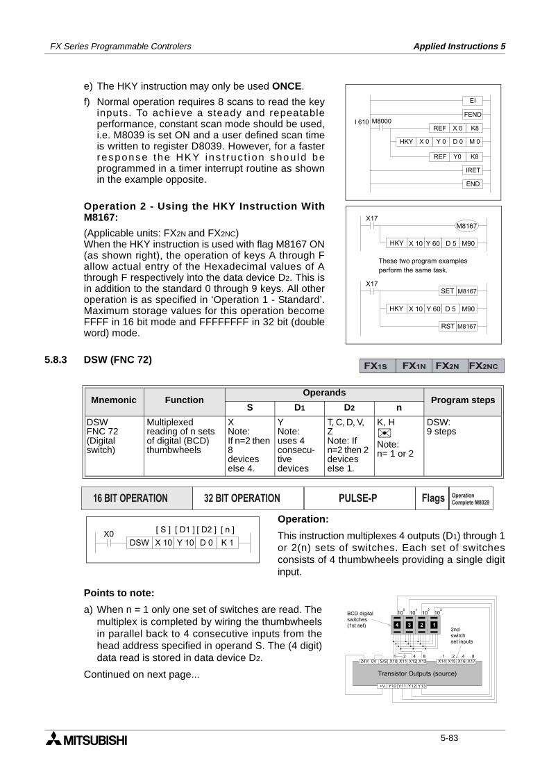
FX Series Programmable Controlers Applied Instructions 5
e) The HKY instruction may only be used ONCE.
f) Normal operation requires 8 scans to read the keyinputs. To achieve a steady and repeatableperformance, constant scan mode should be used,i.e. M8039 is set ON and a user defined scan timeis written to register D8039. However, for a fasterresponse the HKY ins t ruc t i on shou ld beprogrammed in a timer interrupt routine as shownin the example opposite.
Operation 2 - Using the HKY Instruction WithM8167:
(Applicable units: FX2N and FX2NC)When the HKY instruction is used with flag M8167 ON(as shown right), the operation of keys A through Fallow actual entry of the Hexadecimal values of Athrough F respectively into the data device D2. This isin addition to the standard 0 through 9 keys. All otheroperation is as specified in ‘Operation 1 - Standard’.Maximum storage values for this operation becomeFFFF in 16 bit mode and FFFFFFFF in 32 bit (doubleword) mode.
5.8.3 DSW (FNC 72)
Operation:
This instruction multiplexes 4 outputs (D1) through 1or 2(n) sets of switches. Each set of switchesconsists of 4 thumbwheels providing a single digitinput.
Points to note:
a) When n = 1 only one set of switches are read. Themultiplex is completed by wiring the thumbwheelsin parallel back to 4 consecutive inputs from thehead address specified in operand S. The (4 digit)data read is stored in data device D2.
Continued on next page...
Mnemonic Function Operands
Program stepsS D1 D2 n
DSWFNC 72(Digital switch)
Multiplexedreading of n setsof digital (BCD)thumbwheels
XNote:If n=2 then 8deviceselse 4.
YNote:uses 4consecu-tivedevices
T, C, D, V, ZNote: Ifn=2 then 2deviceselse 1.
K, HNote:n= 1 or 2
DSW:9 steps
Y 0 D 0 M 0HKY X 0
EI
FEND
K8REF X 0
K8REF Y0
IRET
END
M8000I 610
X17
Y 60 D 5 M90HKY X 10
M8167
X17
Y 60 D 5 M90HKY X 10
SET M8167
RST M8167
These two program examples
perform the same task.
FX1S FX1N FX2N FX2NC
PULSE-P16 BIT OPERATION 32 BIT OPERATION Flags Operation
Complete M8029
X0Y 10 D 0
[ D2 ]
K 1DSW
[ D1 ]
X 10
[ S ] [ n ]
1 2 4 8
4 2 1
10 10 100 1 2
3
X11 X12 X1324V 0V S/S X14 X15 X16 X17
Y12 Y13+V Y10 Y11
1 2 4 8X10
310
Transistor Outputs (source)
BCD digital switches(1st set)
2nd switchset inputs
5-83
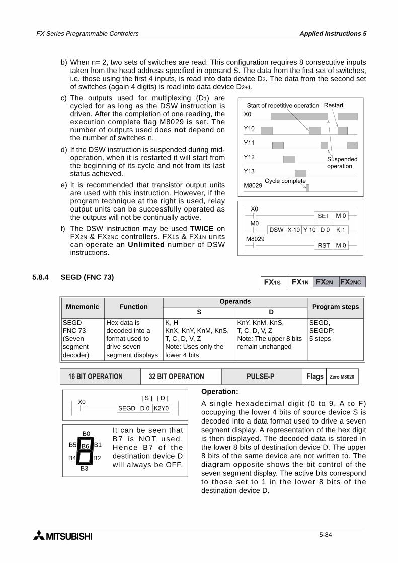
FX Series Programmable Controlers Applied Instructions 5
b) When n= 2, two sets of switches are read. This configuration requires 8 consecutive inputstaken from the head address specified in operand S. The data from the first set of switches,i.e. those using the first 4 inputs, is read into data device D2. The data from the second setof switches (again 4 digits) is read into data device D2+1.
c) The outputs used for multiplexing (D1) arecycled for as long as the DSW instruction isdriven. After the completion of one reading, theexecution complete flag M8029 is set. Thenumber of outputs used does not depend onthe number of switches n.
d) If the DSW instruction is suspended during mid-operation, when it is restarted it will start fromthe beginning of its cycle and not from its laststatus achieved.
e) It is recommended that transistor output unitsare used with this instruction. However, if theprogram technique at the right is used, relayoutput units can be successfully operated asthe outputs will not be continually active.
f) The DSW instruction may be used TWICE onFX2N & FX2NC controllers. FX1S & FX1N unitscan operate an Unlimited number of DSWinstructions.
5.8.4 SEGD (FNC 73)
Operation:
A single hexadecimal dig i t (0 to 9, A to F)occupying the lower 4 bits of source device S isdecoded into a data format used to drive a sevensegment display. A representation of the hex digitis then displayed. The decoded data is stored inthe lower 8 bits of destination device D. The upper8 bits of the same device are not written to. Thediagram opposite shows the bit control of theseven segment display. The active bits correspondto those set to 1 in the lower 8 b i ts of thedestination device D.
Mnemonic Function Operands
Program stepsS D
SEGDFNC 73(Sevensegmentdecoder)
Hex data isdecoded into aformat used todrive sevensegment displays
K, HKnX, KnY, KnM, KnS,T, C, D, V, ZNote: Uses only thelower 4 bits
KnY, KnM, KnS,T, C, D, V, ZNote: The upper 8 bitsremain unchanged
SEGD,SEGDP:5 steps
X0
Y10
Y11
Y12
Y13
M8029
Start of repetitive operation Restart
Suspendedoperation
Cycle complete
Y 10 D 0 K 1DSW X 10M0
M8029
X0
RST M 0
SET M 0
FX1S FX1N FX2N FX2NC
PULSE-P16 BIT OPERATION 32 BIT OPERATION Flags Zero M8020
X0D 0 K2Y0SEGD
[ D ][ S ]
B0
B1
B2
B3
B4
B5 B6
It can be seen thatB7 i s NOT used .Hence B7 o f thedestination device Dwill always be OFF,
5-84
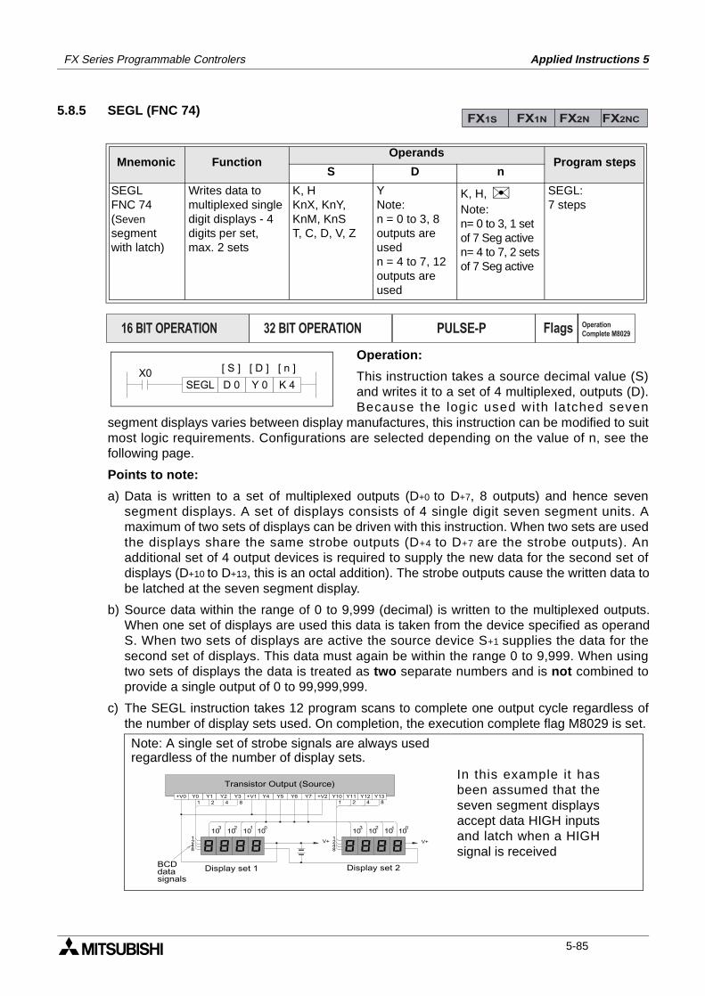
FX Series Programmable Controlers Applied Instructions 5
5.8.5 SEGL (FNC 74)
Operation:
This instruction takes a source decimal value (S)and writes it to a set of 4 multiplexed, outputs (D).Because the logic used with latched seven
segment displays varies between display manufactures, this instruction can be modified to suitmost logic requirements. Configurations are selected depending on the value of n, see thefollowing page.
Points to note:
a) Data is written to a set of multiplexed outputs (D+0 to D+7, 8 outputs) and hence sevensegment displays. A set of displays consists of 4 single digit seven segment units. Amaximum of two sets of displays can be driven with this instruction. When two sets are usedthe displays share the same strobe outputs (D+4 to D+7 are the strobe outputs). Anadditional set of 4 output devices is required to supply the new data for the second set ofdisplays (D+10 to D+13, this is an octal addition). The strobe outputs cause the written data tobe latched at the seven segment display.
b) Source data within the range of 0 to 9,999 (decimal) is written to the multiplexed outputs.When one set of displays are used this data is taken from the device specified as operandS. When two sets of displays are active the source device S+1 supplies the data for thesecond set of displays. This data must again be within the range 0 to 9,999. When usingtwo sets of displays the data is treated as two separate numbers and is not combined toprovide a single output of 0 to 99,999,999.
c) The SEGL instruction takes 12 program scans to complete one output cycle regardless ofthe number of display sets used. On completion, the execution complete flag M8029 is set.
Mnemonic Function Operands
Program stepsS D n
SEGLFNC 74(Sevensegmentwith latch)
Writes data tomultiplexed singledigit displays - 4digits per set,max. 2 sets
K, HKnX, KnY, KnM, KnST, C, D, V, Z
YNote:n = 0 to 3, 8outputs areusedn = 4 to 7, 12outputs areused
K, H, Note:n= 0 to 3, 1 setof 7 Seg activen= 4 to 7, 2 setsof 7 Seg active
SEGL:7 steps
FX1S FX1N FX2N FX2NC
PULSE-P16 BIT OPERATION 32 BIT OPERATION Flags Operation
Complete M8029
X0D 0 Y 0 K 4SEGL
[ D ][ S ] [ n ]
101010103 012
Y2 Y3+V0 Y0 Y1 Y6 Y7+V1 Y4 Y5 Y12 Y13+V2 Y10 Y111 2 4 8
101010103 012
V+ V+1248
1248
1 2 4 8
Transistor Output (Source)
BCD data signals
Display set 2Display set 1
In this example it hasbeen assumed that theseven segment displaysaccept data HIGH inputsand latch when a HIGHsignal is received
Note: A single set of strobe signals are always used regardless of the number of display sets.
5-85
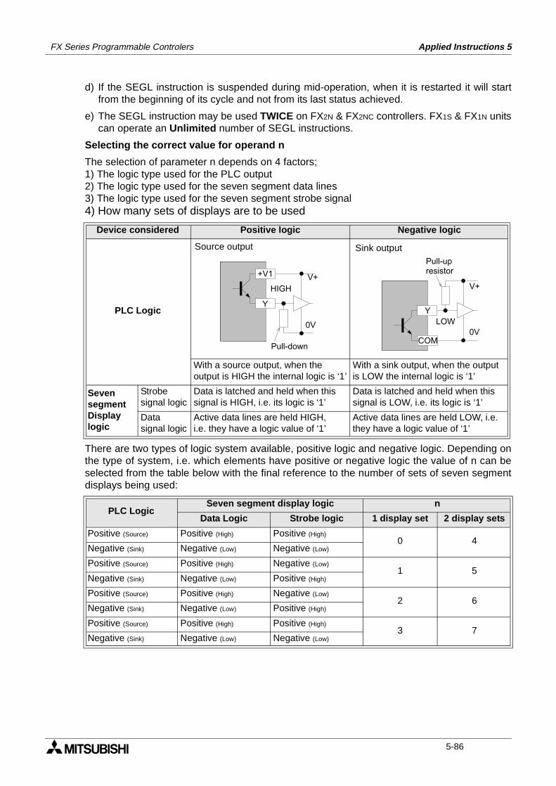
FX Series Programmable Controlers Applied Instructions 5
d) If the SEGL instruction is suspended during mid-operation, when it is restarted it will startfrom the beginning of its cycle and not from its last status achieved.
e) The SEGL instruction may be used TWICE on FX2N & FX2NC controllers. FX1S & FX1N unitscan operate an Unlimited number of SEGL instructions.
Selecting the correct value for operand n
The selection of parameter n depends on 4 factors;1) The logic type used for the PLC output2) The logic type used for the seven segment data lines3) The logic type used for the seven segment strobe signal4) How many sets of displays are to be used
There are two types of logic system available, positive logic and negative logic. Depending onthe type of system, i.e. which elements have positive or negative logic the value of n can beselected from the table below with the final reference to the number of sets of seven segmentdisplays being used:
Device considered Positive logic Negative logic
PLC Logic
With a source output, when theoutput is HIGH the internal logic is ‘1’
With a sink output, when the output is LOW the internal logic is ‘1’
SevensegmentDisplaylogic
Strobesignal logic
Data is latched and held when thissignal is HIGH, i.e. its logic is ‘1’
Data is latched and held when thissignal is LOW, i.e. its logic is ‘1’
Datasignal logic
Active data lines are held HIGH,i.e. they have a logic value of ‘1’
Active data lines are held LOW, i.e. they have a logic value of ‘1’
PLC Logic Seven segment display logic n
Data Logic Strobe logic 1 display set 2 display sets
Positive (Source) Positive (High) Positive (High)0 4
Negative (Sink) Negative (Low) Negative (Low)
Positive (Source) Positive (High) Negative (Low)1 5
Negative (Sink) Negative (Low) Positive (High)
Positive (Source) Positive (High) Negative (Low)2 6
Negative (Sink) Negative (Low) Positive (High)
Positive (Source) Positive (High) Positive (High)3 7
Negative (Sink) Negative (Low) Negative (Low)
V+
0V
Y
+V1
HIGH
Pull-down
Source output
COM
Y
V+
0VLOW
Pull-upresistor
Sink output
5-86
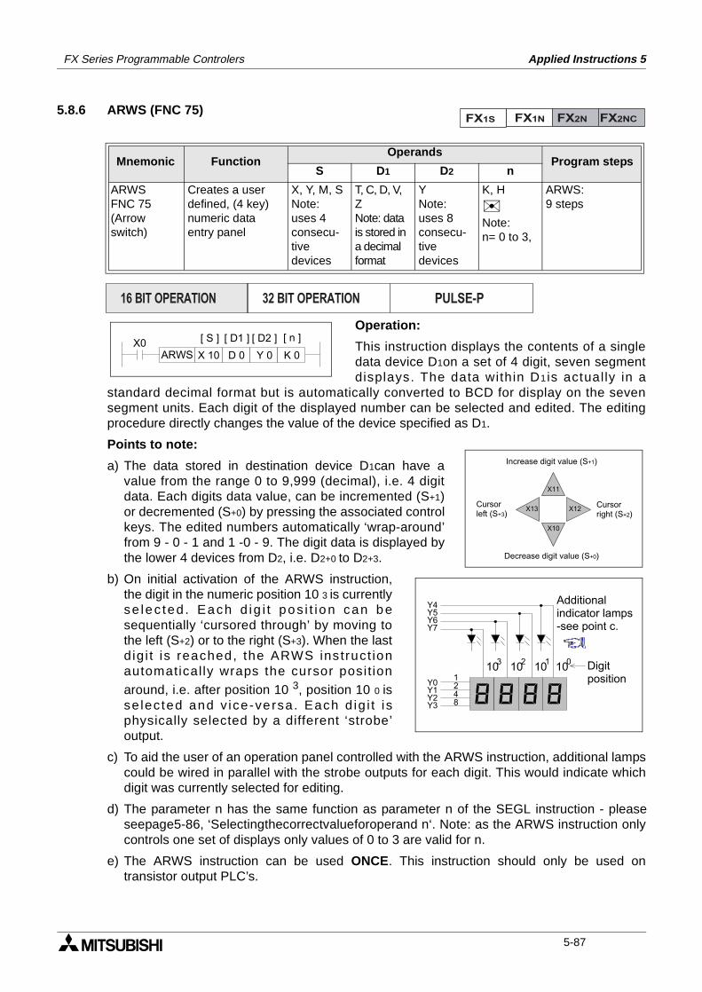
FX Series Programmable Controlers Applied Instructions 5
5.8.6 ARWS (FNC 75)
Operation:
This instruction displays the contents of a singledata device D1on a set of 4 digit, seven segmentdisplays. The data within D1is actually in a
standard decimal format but is automatically converted to BCD for display on the sevensegment units. Each digit of the displayed number can be selected and edited. The editingprocedure directly changes the value of the device specified as D1.
Points to note:
a) The data stored in destination device D1can have avalue from the range 0 to 9,999 (decimal), i.e. 4 digitdata. Each digits data value, can be incremented (S+1)or decremented (S+0) by pressing the associated controlkeys. The edited numbers automatically ‘wrap-around’from 9 - 0 - 1 and 1 -0 - 9. The digit data is displayed bythe lower 4 devices from D2, i.e. D2+0 to D2+3.
b) On initial activation of the ARWS instruction,the digit in the numeric position 10 3 is currentlyse lec ted . Each d ig i t pos i t ion can besequentially ‘cursored through’ by moving tothe left (S+2) or to the right (S+3). When the lastd ig i t is reached, the ARWS ins truct ionautomatically wraps the cursor posit ion
around, i.e. after position 10 3, position 10 0 isse lec ted and v ice-versa. Each d ig i t i sphysically selected by a different ‘strobe’output.
c) To aid the user of an operation panel controlled with the ARWS instruction, additional lampscould be wired in parallel with the strobe outputs for each digit. This would indicate whichdigit was currently selected for editing.
d) The parameter n has the same function as parameter n of the SEGL instruction - pleaseseepage5-86, ‘Selectingthecorrectvalueforoperand n‘. Note: as the ARWS instruction onlycontrols one set of displays only values of 0 to 3 are valid for n.
e) The ARWS instruction can be used ONCE. This instruction should only be used ontransistor output PLC’s.
Mnemonic Function Operands
Program stepsS D1 D2 n
ARWSFNC 75(Arrow switch)
Creates a userdefined, (4 key)numeric dataentry panel
X, Y, M, SNote:uses 4consecu-tivedevices
T, C, D, V, ZNote: data is stored ina decimalformat
YNote:uses 8consecu-tivedevices
K, H
Note:n= 0 to 3,
ARWS:9 steps
FX1S FX1N FX2N FX2NC
PULSE-P16 BIT OPERATION 32 BIT OPERATION
X0D 0 Y 0
[ D2 ]
K 0ARWS
[ D1 ]
X 10
[ S ] [ n ]
X10
X11
X12X13Cursorleft (S+3)
Cursorright (S+2)
Increase digit value (S+1)
Decrease digit value (S+0)
101010103 012
Y0Y1Y2Y3
1248
Y4Y5Y6Y7
Additionalindicator lamps-see point c.
Digitposition
5-87
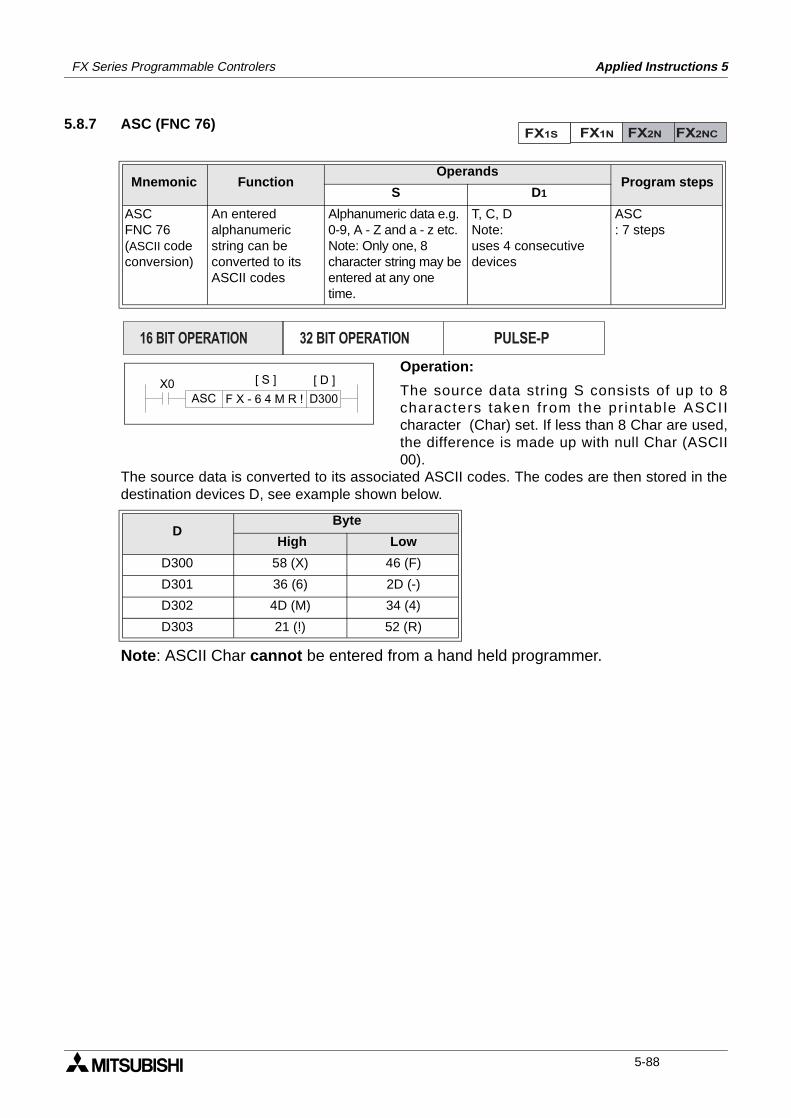
FX Series Programmable Controlers Applied Instructions 5
5.8.7 ASC (FNC 76)
Operation:
The source data string S consists of up to 8characters taken from the pr intable ASCIIcharacter (Char) set. If less than 8 Char are used,the difference is made up with null Char (ASCII00).
The source data is converted to its associated ASCII codes. The codes are then stored in thedestination devices D, see example shown below.
Note: ASCII Char cannot be entered from a hand held programmer.
Mnemonic Function Operands
Program stepsS D1
ASCFNC 76(ASCII codeconversion)
An enteredalphanumericstring can beconverted to itsASCII codes
Alphanumeric data e.g.0-9, A - Z and a - z etc.Note: Only one, 8character string may beentered at any one time.
T, C, DNote:uses 4 consecutivedevices
ASC: 7 steps
DByte
High Low
D300 58 (X) 46 (F)
D301 36 (6) 2D (-)
D302 4D (M) 34 (4)
D303 21 (!) 52 (R)
FX1S FX1N FX2N FX2NC
PULSE-P16 BIT OPERATION 32 BIT OPERATION
X0D300ASC
[ D ][ S ]
F X - 6 4 M R !
5-88
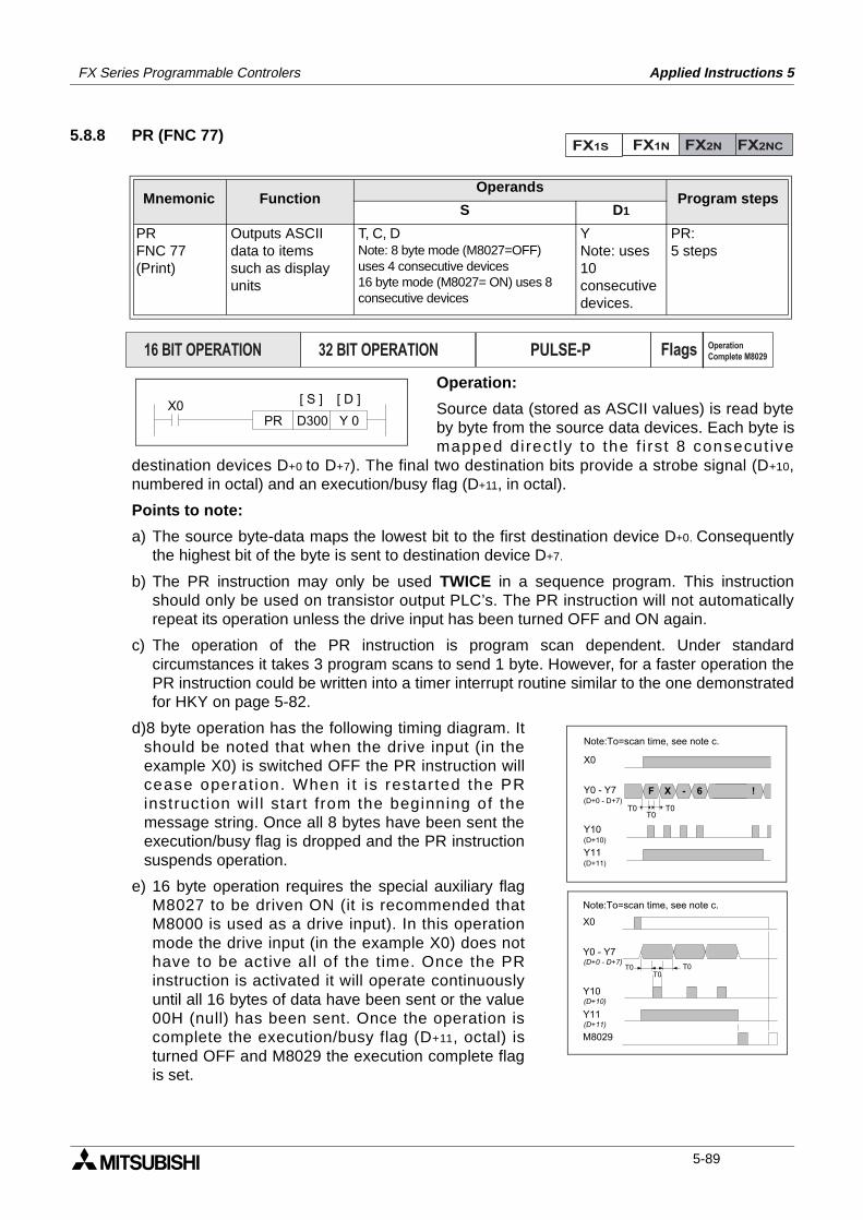
FX Series Programmable Controlers Applied Instructions 5
5.8.8 PR (FNC 77)
Operation:
Source data (stored as ASCII values) is read byteby byte from the source data devices. Each byte ismapped di rect ly to the f i rs t 8 consecut ive
destination devices D+0 to D+7). The final two destination bits provide a strobe signal (D+10,numbered in octal) and an execution/busy flag (D+11, in octal).
Points to note:
a) The source byte-data maps the lowest bit to the first destination device D+0. Consequentlythe highest bit of the byte is sent to destination device D+7.
b) The PR instruction may only be used TWICE in a sequence program. This instructionshould only be used on transistor output PLC’s. The PR instruction will not automaticallyrepeat its operation unless the drive input has been turned OFF and ON again.
c) The operation of the PR instruction is program scan dependent. Under standardcircumstances it takes 3 program scans to send 1 byte. However, for a faster operation thePR instruction could be written into a timer interrupt routine similar to the one demonstratedfor HKY on page 5-82.
d)8 byte operation has the following timing diagram. Itshould be noted that when the drive input (in theexample X0) is switched OFF the PR instruction willcease operat ion. When i t is restarted the PRinstruction wil l start from the beginning of themessage string. Once all 8 bytes have been sent theexecution/busy flag is dropped and the PR instructionsuspends operation.
e) 16 byte operation requires the special auxiliary flagM8027 to be driven ON (it is recommended thatM8000 is used as a drive input). In this operationmode the drive input (in the example X0) does nothave to be active all of the time. Once the PRinstruction is activated it will operate continuouslyuntil all 16 bytes of data have been sent or the value00H (null) has been sent. Once the operation iscomplete the execution/busy flag (D+11, octal) isturned OFF and M8029 the execution complete flagis set.
Mnemonic Function Operands
Program stepsS D1
PRFNC 77(Print)
Outputs ASCIIdata to itemssuch as displayunits
T, C, DNote: 8 byte mode (M8027=OFF)uses 4 consecutive devices16 byte mode (M8027= ON) uses 8consecutive devices
YNote: uses10consecutivedevices.
PR:5 steps
FX1S FX1N FX2N FX2NC
PULSE-P16 BIT OPERATION 32 BIT OPERATION Flags Operation
Complete M8029
X0D300PR
[ D ][ S ]
Y 0
F X - 6 !
T0 T0T0
X0
Y0 - Y7
Y10
Y11
(D+0 - D+7)
(D+10)
(D+11)
Note:To=scan time, see note c.
T0 T0T0
X0
Y0 - Y7
Y10
Y11
M8029
(D+0 - D+7)
(D+10)
(D+11)
Note:To=scan time, see note c.
5-89
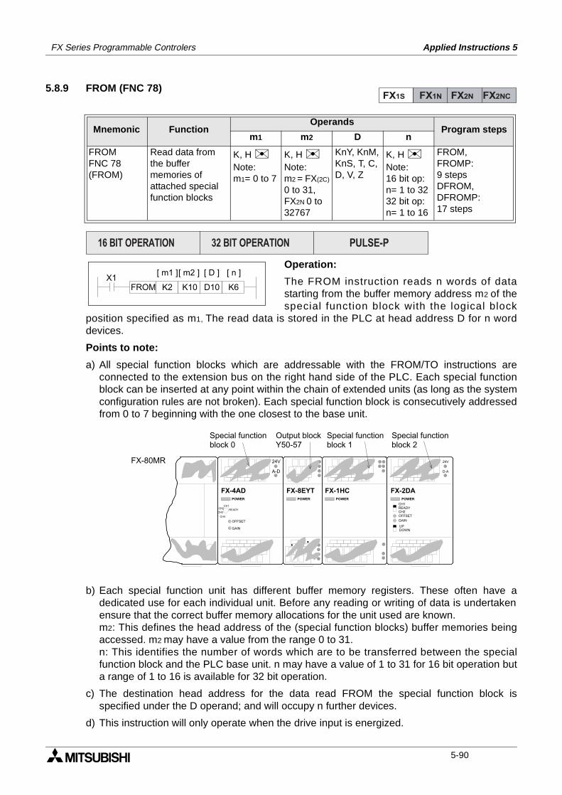
FX Series Programmable Controlers Applied Instructions 5
5.8.9 FROM (FNC 78)
Operation:
The FROM instruction reads n words of datastarting from the buffer memory address m2 of thespecial function block with the logical block
position specified as m1, The read data is stored in the PLC at head address D for n worddevices.
Points to note:
a) All special function blocks which are addressable with the FROM/TO instructions areconnected to the extension bus on the right hand side of the PLC. Each special functionblock can be inserted at any point within the chain of extended units (as long as the systemconfiguration rules are not broken). Each special function block is consecutively addressedfrom 0 to 7 beginning with the one closest to the base unit.
b) Each special function unit has different buffer memory registers. These often have adedicated use for each individual unit. Before any reading or writing of data is undertakenensure that the correct buffer memory allocations for the unit used are known.m2: This defines the head address of the (special function blocks) buffer memories beingaccessed. m2 may have a value from the range 0 to 31.n: This identifies the number of words which are to be transferred between the specialfunction block and the PLC base unit. n may have a value of 1 to 31 for 16 bit operation buta range of 1 to 16 is available for 32 bit operation.
c) The destination head address for the data read FROM the special function block isspecified under the D operand; and will occupy n further devices.
d) This instruction will only operate when the drive input is energized.
Mnemonic Function Operands
Program stepsm1 m2 D n
FROMFNC 78(FROM)
Read data fromthe buffermemories ofattached specialfunction blocks
K, H Note:m1= 0 to 7
K, H Note:m2 = FX(2C)
0 to 31,FX2N 0 to32767
KnY, KnM,KnS, T, C,D, V, Z
K, H Note:16 bit op:n= 1 to 3232 bit op:n= 1 to 16
FROM,FROMP:9 stepsDFROM,DFROMP:17 steps
FX1S FX1N FX2N FX2NC
PULSE-P16 BIT OPERATION 32 BIT OPERATION
FROM K2 D10K10 K6
[ m1 ][ m2 ] [ D ] [ n ]X1
POWER
FX-8EYTPOWER
FX-4ADPOWER
FX-1HCPOWER
FX-2DA
24V
A-D
OFFSET
GAIN
READY
CH1CH2
CH3
CH4
24V
D-A
OFFSET
GAIN
UPDOWN
CH1READYCH2
Special functionblock 0
Output blockY50-57
Special functionblock 1
Special functionblock 2
FX-80MR
5-90
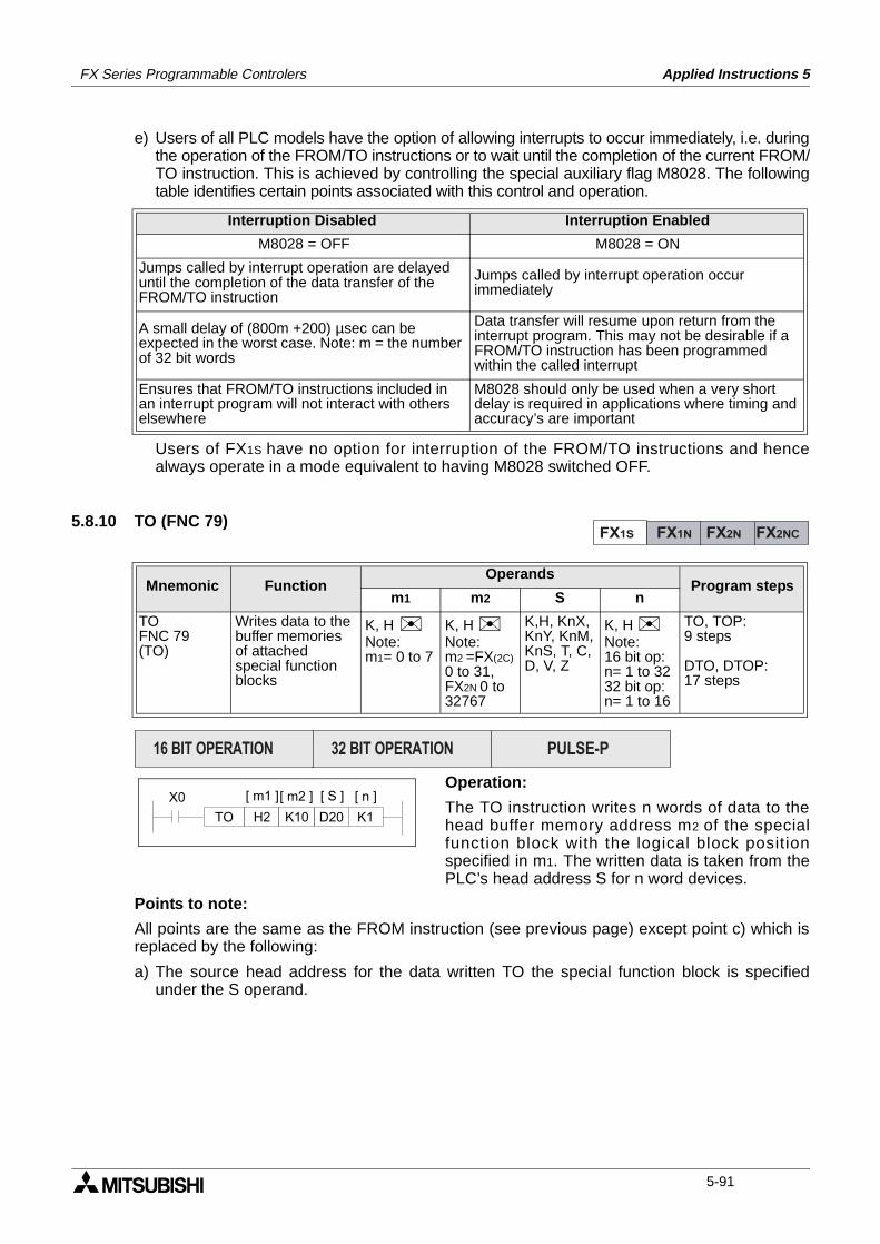
FX Series Programmable Controlers Applied Instructions 5
e) Users of all PLC models have the option of allowing interrupts to occur immediately, i.e. duringthe operation of the FROM/TO instructions or to wait until the completion of the current FROM/TO instruction. This is achieved by controlling the special auxiliary flag M8028. The followingtable identifies certain points associated with this control and operation.
Users of FX1S have no option for interruption of the FROM/TO instructions and hencealways operate in a mode equivalent to having M8028 switched OFF.
5.8.10 TO (FNC 79)
Operation:
The TO instruction writes n words of data to thehead buffer memory address m2 of the specialfunction block with the logical block positionspecified in m1. The written data is taken from thePLC’s head address S for n word devices.
Points to note:
All points are the same as the FROM instruction (see previous page) except point c) which isreplaced by the following:
a) The source head address for the data written TO the special function block is specifiedunder the S operand.
Interruption Disabled Interruption Enabled
M8028 = OFF M8028 = ON
Jumps called by interrupt operation are delayed until the completion of the data transfer of the FROM/TO instruction
Jumps called by interrupt operation occur immediately
A small delay of (800m +200) µsec can be expected in the worst case. Note: m = the number of 32 bit words
Data transfer will resume upon return from the interrupt program. This may not be desirable if a FROM/TO instruction has been programmed within the called interrupt
Ensures that FROM/TO instructions included in an interrupt program will not interact with others elsewhere
M8028 should only be used when a very short delay is required in applications where timing and accuracy’s are important
Mnemonic Function Operands
Program stepsm1 m2 S n
TOFNC 79(TO)
Writes data to thebuffer memoriesof attachedspecial functionblocks
K, H Note:m1= 0 to 7
K, H Note:m2 =FX(2C)0 to 31,FX2N 0 to32767
K,H, KnX,KnY, KnM,KnS, T, C,D, V, Z
K, H Note:16 bit op:n= 1 to 3232 bit op:n= 1 to 16
TO, TOP:9 steps
DTO, DTOP:17 steps
FX1S FX1N FX2N FX2NC
PULSE-P16 BIT OPERATION 32 BIT OPERATION
TO H2 D20K10 K1
[ m1 ][ m2 ] [ S ] [ n ]X0
5-91

FX Series Programmable Controlers Applied Instructions 5
MEMO
5-92
FX Series Programmable Controlers Applied Instructions 5
Applied Instructions:FX1S FX1N FX2N FX2NC
FNC 00 - 09
FNC 10 - 19
FNC 20 - 29
FNC 30 - 39
FNC 40 - 49
FNC 50 - 59
FNC 60 - 69
FNC 70 - 79
FNC 80 - 89
FNC 110-129
FNC 130-139
FNC 140-149
FNC 160-169
FNC 170-179
FNC 220-249
FNC 150-159
1.
2.
3.
4.
5.
6.
7.
8.
9.
10.
11.
12.
13.
14.
15.
16.
Program Flow 5-4
Move And Compare 5-16
Arithmetic And Logical Operations (+, -, ×, ÷)5-24
Rotation And Shift 5-34
Data Operation 5-42
High Speed Processing 5-52
Handy Instructions 5-66
External FX I/O Devices 5-80
External FX Serial Devices 5-94
Floating Point 1 & 2 5-110
Trigonometry (Floating Point 3) 5-118
Data Operations 2 5-122
FX1S & FX1N Positioning Control 5-126
Real Time Clock Control 5-136
Gray Codes 5-146
In-line Comparisons 5-150
5-93

FX Series Programmable Controlers Applied Instructions 5
5.9 External FX Serial Devices - Functions 80 to 89
Contents:
Page
RS - RS Communications FNC 80 5-95
PRUN - FX2-40AP Parallel Run FNC 81 5-96
ASCI - Hexadecimal to ASCII FNC 82 5-98
HEX - ASCII to Hexadecimal FNC 83 5-99
CCD - Check Code FNC 84 5-100
VRRD - FX-8AV Volume Read FNC 85 5-101
VRSD - FX-8AV Volume Scale FNC 86 5-101
- Not Available FNC 87
PID - PID Control Loop FNC 88 5-102
- Not Available FNC 89
Symbols list:
D - Destination device.S - Source device.m, n- Number of active devices, bits or an operational constant.Additional numeric suffixes will be attached if there are more than one operand with the samefunction e.g. D1, S3 or for lists/tabled devices D3+0, S+9 etc.MSB - Most Significant Bit, sometimes used to indicate the mathematical sign of a number,i.e. positive = 0, and negative = 1.LSB - Least Significant Bit.
Instruction modifications:
- An instruction operating in 16 bit mode, where identifies the instructionmnemonic.
P - A 16 bit mode instruction modified to use pulse (single) operation.
D - An instruction modified to operate in 32 bit operation.
DP - A 32 bit mode instruction modified to use pulse (single) operation.
- A repetitive instruction which will change the destination value on every scan unlessmodified by the pulse function.
- An operand which cannot be indexed, i.e. The addition of V or Z is either invalid or willhave no effect to the value of the operand.
5-94
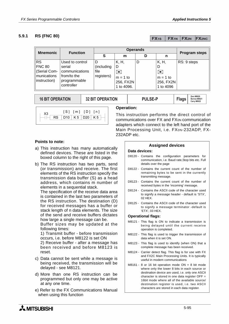
FX Series Programmable Controlers Applied Instructions 5
5.9.1 RS (FNC 80)
Operation:
This instruction performs the direct control ofcommunications over FX and FX0N communicationadapters which connect to the left hand port of theMain Processing Unit, i.e. FX0N-232ADP, FX-232ADP etc.
Points to note:
a) This instruction has many automaticallydefined devices. These are listed in theboxed column to the right of this page.
b) The RS instruction has two parts, send(or transmission) and receive. The firstelements of the RS instruction specify thetransmission data buffer (S) as a headaddress, which contains m number ofelements in a sequential stack.The specification of the receive data areais contained in the last two parameters ofthe RS instruction. The destination (D)for received messages has a buffer orstack length of n data elements. The sizeof the send and receive buffers dictateshow large a single message can be.Buffer sizes may be updated at thefollowing times:1) Transmit buffer - before transmissionoccurs, i.e. before M8122 is set ON2) Receive buffer - after a message hasbeen received and before M8123 isreset.
c) Data cannot be sent while a message isbeing received, the transmission will bedelayed - see M8121.
d) More than one RS instruction can beprogrammed but only one may be activeat any one time.
e) Refer to the FX Communications Manualwhen using this function
Mnemonic Function Operands
Program stepsS m D n
RSFNC 80(Serial Com-municationsinstruction)
Used to controlserial communicationsfrom/to theprogrammablecontroller
D(includingfileregisters)
K, H,D
m = 1 to256, FX2N1 to 4096.
D K, H,D
m = 1 to256, FX2N1 to 4096
RS: 9 steps
FX1S FX1N FX2N FX2NC
PULSE-P16 BIT OPERATION 32 BIT OPERATION FlagsZero M8020Borrow M8021Carry M8022
X3K 5
[ S ] [ D ]
D20RS K 5D10
[ m ] [ n ]
Assigned devicesData devices:D8120 - Contains the configuration parameters for
communication, i.e. Baud rate,Stop bits etc. Fulldetails over the page
D8122 - Contains the current count of the number ofremaining bytes to be sent in the currentlytransmitting message.
D8123 - Contains the current count of the number ofreceived bytes in the ‘incoming’ message.
D8124 - Contains the ASCII code of the character usedto signify a message header - default is ‘STX’,02 HEX.
D8125 - Contains the ASCII code of the character usedto signify a message terminator -default is‘ETX’, 03 HEX.
Operational flags:M8121 - This flag is ON to indicate a transmission is
being delayed unt i l the current rece iveoperation is completed.
M8122 - This flag is used to trigger the transmission ofdata when it is set ON.
M8123 - This flag is used to identify (when ON) that acomplete message has been received.
M8124 - Carrier detect flag. This flag is for use with FXand FX2C Main Processing Units. It is typicallyuseful in modem communications
M8161 - 8 or 16 bit operation mode ON = 8 bit modewhere only the lower 8 bits in each source ordestination device are used, i.e. only one ASCIIcharacter is stored in one data register OFF =16bit mode where all of the available source/destination register is used, i.e. two ASCIIcharacters are stored in each data register.
5-95
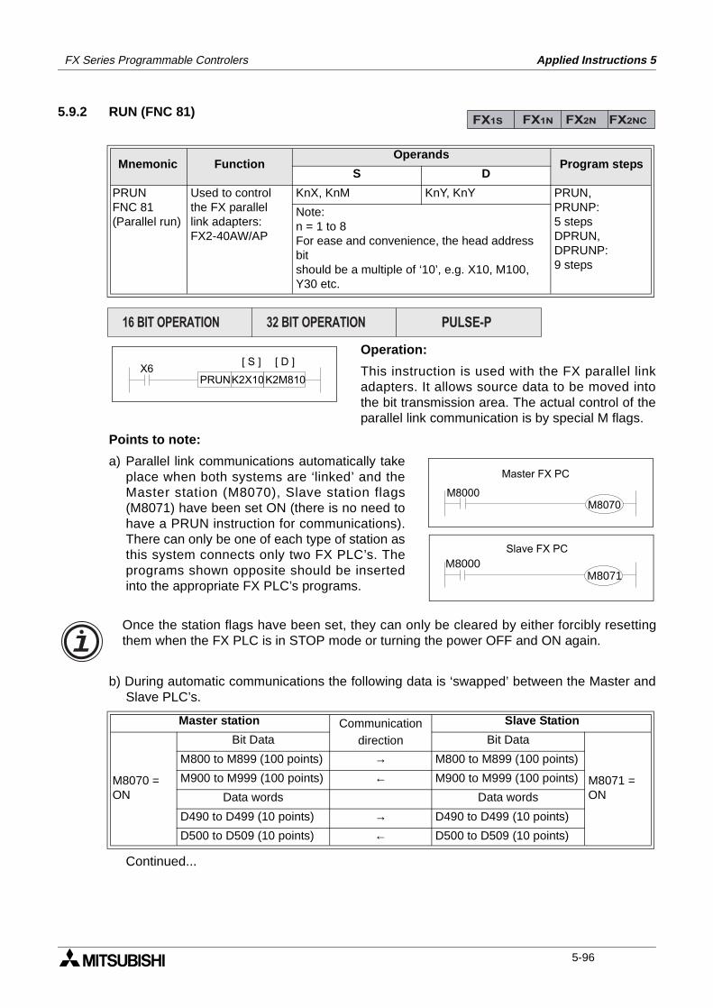
FX Series Programmable Controlers Applied Instructions 5
5.9.2 RUN (FNC 81)
Operation:
This instruction is used with the FX parallel linkadapters. It allows source data to be moved intothe bit transmission area. The actual control of theparallel link communication is by special M flags.
Points to note:
a) Parallel link communications automatically takeplace when both systems are ‘linked’ and theMaster station (M8070), Slave station flags(M8071) have been set ON (there is no need tohave a PRUN instruction for communications).There can only be one of each type of station asthis system connects only two FX PLC’s. Theprograms shown opposite should be insertedinto the appropriate FX PLC’s programs.
b) During automatic communications the following data is ‘swapped’ between the Master andSlave PLC’s.
Continued...
Mnemonic Function Operands
Program stepsS D
PRUNFNC 81(Parallel run)
Used to controlthe FX parallellink adapters:FX2-40AW/AP
KnX, KnM KnY, KnY PRUN,PRUNP:5 stepsDPRUN,DPRUNP:9 steps
Note:n = 1 to 8For ease and convenience, the head address bitshould be a multiple of ‘10’, e.g. X10, M100, Y30 etc.
Master station Communicationdirection
Slave Station
M8070 =ON
Bit Data Bit Data
M8071 =ON
M800 to M899 (100 points) → M800 to M899 (100 points)
M900 to M999 (100 points) ← M900 to M999 (100 points)
Data words Data words
D490 to D499 (10 points) → D490 to D499 (10 points)
D500 to D509 (10 points) ← D500 to D509 (10 points)
FX1S FX1N FX2N FX2NC
PULSE-P16 BIT OPERATION 32 BIT OPERATION
X6K2X10PRUN
[ D ][ S ]
K2M810
M8000M8070
Master FX PC
Slave FX PC
M8000M8071
Once the station flags have been set, they can only be cleared by either forcibly resettingthem when the FX PLC is in STOP mode or turning the power OFF and ON again.
5-96
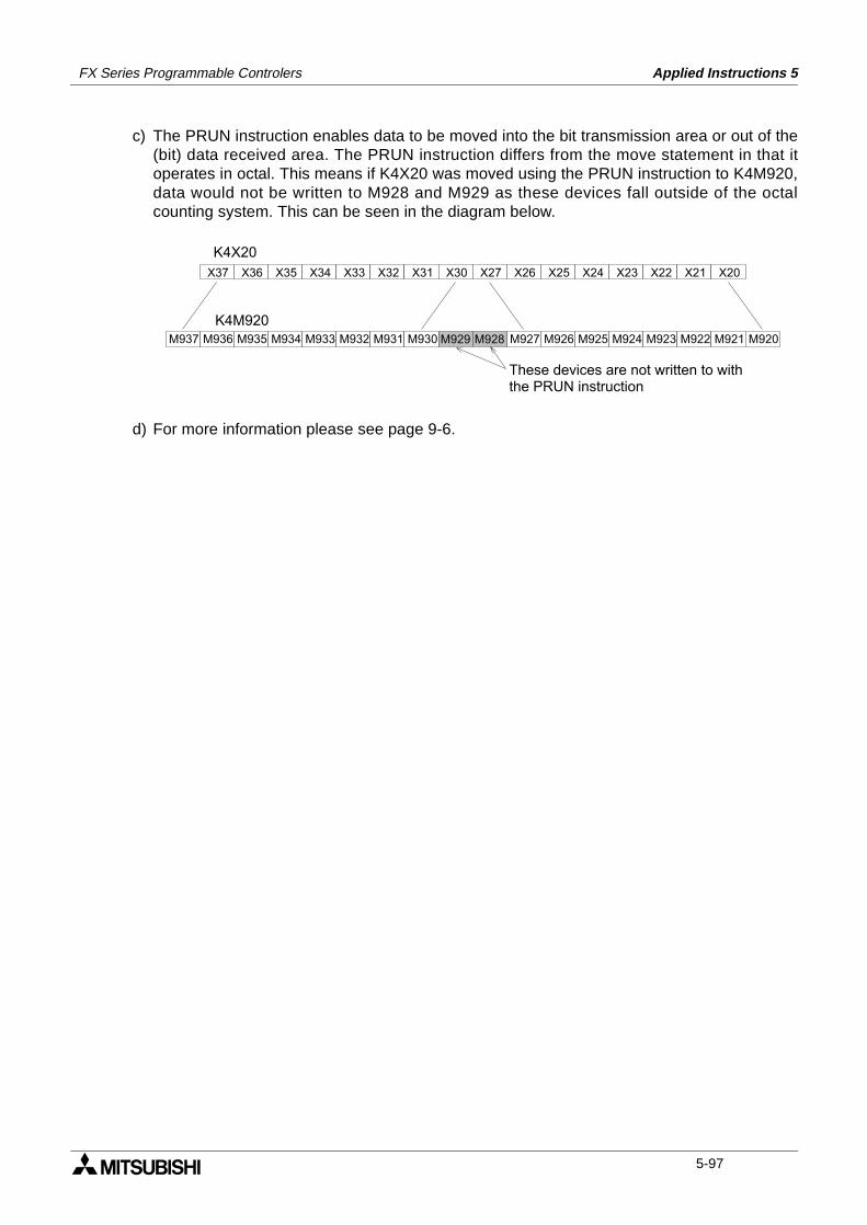
FX Series Programmable Controlers Applied Instructions 5
c) The PRUN instruction enables data to be moved into the bit transmission area or out of the(bit) data received area. The PRUN instruction differs from the move statement in that itoperates in octal. This means if K4X20 was moved using the PRUN instruction to K4M920,data would not be written to M928 and M929 as these devices fall outside of the octalcounting system. This can be seen in the diagram below.
d) For more information please see page 9-6.
M936 M935 M934 M933 M932 M931 M930 M927 M926 M925 M924 M923 M922 M921
X37 X36 X35 X34 X33 X32 X31 X30 X27 X26 X25 X24 X23 X22 X21 X20
K4X20
K4M920M937 M920M928M929
These devices are not written to with the PRUN instruction
5-97
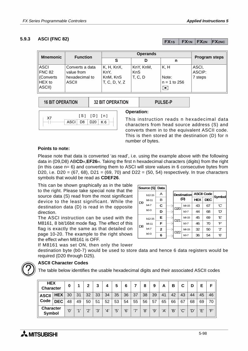
FX Series Programmable Controlers Applied Instructions 5
5.9.3 ASCI (FNC 82)
Operation:
This instruct ion reads n hexadecimal datacharacters from head source address (S) andconverts them in to the equivalent ASCII code.This is then stored at the destination (D) for nnumber of bytes.
Points to note:
Please note that data is converted ‘as read’, i.e. using the example above with the followingdata in (D9,D8) ABCDH,EF26H. Taking the first n hexadecimal characters (digits) from the right(in this case n= 6) and converting them to ASCI will store values in 6 consecutive bytes fromD20, i.e. D20 = (67, 68), D21 = (69, 70) and D22 = (50, 54) respectively. In true characterssymbols that would be read as CDEF26.
This can be shown graphically as in the tableto the right. Please take special note that thesource data (S) read from the most significantdevice to the least significant. While thedestination data (D) is read in the oppositedirection.The ASCI instruction can be used with theM8161, 8 bit/16bit mode flag. The effect of thisflag is exactly the same as that detailed onpage 10-20. The example to the right showsthe effect when M8161 is OFF.If M8161 was set ON, then only the lowerdestination byte (b0-7) would be used to store data and hence 6 data registers would berequired (D20 through D25).
Mnemonic Function Operands
Program stepsS D n
ASCIFNC 82(ConvertsHEX toASCII)
Converts a datavalue fromhexadecimal toASCII
K, H, KnX, KnY,KnM, KnST, C, D, V, Z
KnY, KnM, KnST, C, D
K, H
Note:n = 1 to 256
ASCI,ASCIP:7 steps
HEXCharacter
0 1 2 3 4 5 6 7 8 9 A B C D E F
ASCIICode
HEX 30 31 32 33 34 35 36 37 38 39 41 42 43 44 45 46
DEC 48 49 50 51 52 53 54 55 56 57 65 66 67 68 69 70
Character Symbol
’0’ ’1’ ’2’ ’3’ ’4’ ’5’ ’6’ ’7’ ’8’ ’9’ ’A’ ’B’ ’C’ ’D’ ’E’ ’F’
FX1S FX1N FX2N FX2NC
PULSE-P16 BIT OPERATION 32 BIT OPERATION
X7K 6
[ S ] [ D ]
D20ASCI D8
[ n ]
Source (S) Data
D9
A
B
C
D
b12-15
b8-11
b4-7
b0-3
D8
E
F
2
6
b12-15
b8-11
b4-7
b0-3
D20
D21
D22
Destination(D) HEX DEC
ASCII Code
b8-15
b0-7
b8-15
b0-7
b8-15
b0-7
43
44
45
46
32
36
67
68
69
70
50
54
Symbol
’C’
’D’
’E’
’F’
’2’
’6’
ASCII Character Codes
The table below identifies the usable hexadecimal digits and their associated ASCII codes
5-98
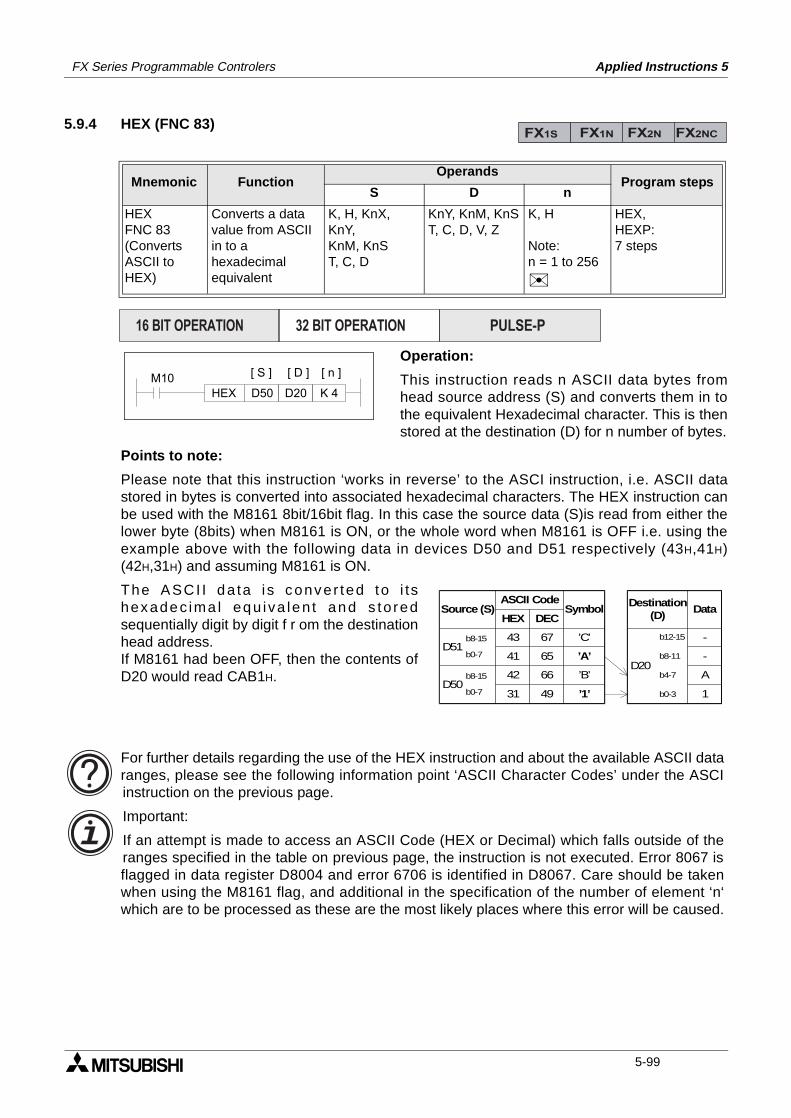
FX Series Programmable Controlers Applied Instructions 5
5.9.4 HEX (FNC 83)
Operation:
This instruction reads n ASCII data bytes fromhead source address (S) and converts them in tothe equivalent Hexadecimal character. This is thenstored at the destination (D) for n number of bytes.
Points to note:
Please note that this instruction ‘works in reverse’ to the ASCI instruction, i.e. ASCII datastored in bytes is converted into associated hexadecimal characters. The HEX instruction canbe used with the M8161 8bit/16bit flag. In this case the source data (S)is read from either thelower byte (8bits) when M8161 is ON, or the whole word when M8161 is OFF i.e. using theexample above with the following data in devices D50 and D51 respectively (43H,41H)(42H,31H) and assuming M8161 is ON.
The ASCI I da ta i s conver ted to i tshexadec ima l equ iva len t and s to redsequentially digit by digit f r om the destinationhead address. If M8161 had been OFF, then the contents ofD20 would read CAB1H.
Mnemonic Function Operands
Program stepsS D n
HEXFNC 83(ConvertsASCII toHEX)
Converts a datavalue from ASCIIin to ahexadecimalequivalent
K, H, KnX, KnY,KnM, KnST, C, D
KnY, KnM, KnST, C, D, V, Z
K, H
Note:n = 1 to 256
HEX,HEXP:7 steps
FX1S FX1N FX2N FX2NC
PULSE-P16 BIT OPERATION 32 BIT OPERATION
M10K 4
[ S ] [ D ]
D20HEX D50
[ n ]
Source (S)
D51b8-15
b0-7
D20
Destination(D)
b12-15
b8-11
b4-7
b0-3
Data
-
-
A
1
HEX DEC
ASCII Code
43
41
42
31
67
65
66
49
Symbol
’C’
’A’
’B’
’1’ D50
b8-15
b0-7
For further details regarding the use of the HEX instruction and about the available ASCII dataranges, please see the following information point ‘ASCII Character Codes’ under the ASCIinstruction on the previous page.
Important:
If an attempt is made to access an ASCII Code (HEX or Decimal) which falls outside of theranges specified in the table on previous page, the instruction is not executed. Error 8067 isflagged in data register D8004 and error 6706 is identified in D8067. Care should be takenwhen using the M8161 flag, and additional in the specification of the number of element ‘n‘which are to be processed as these are the most likely places where this error will be caused.
5-99
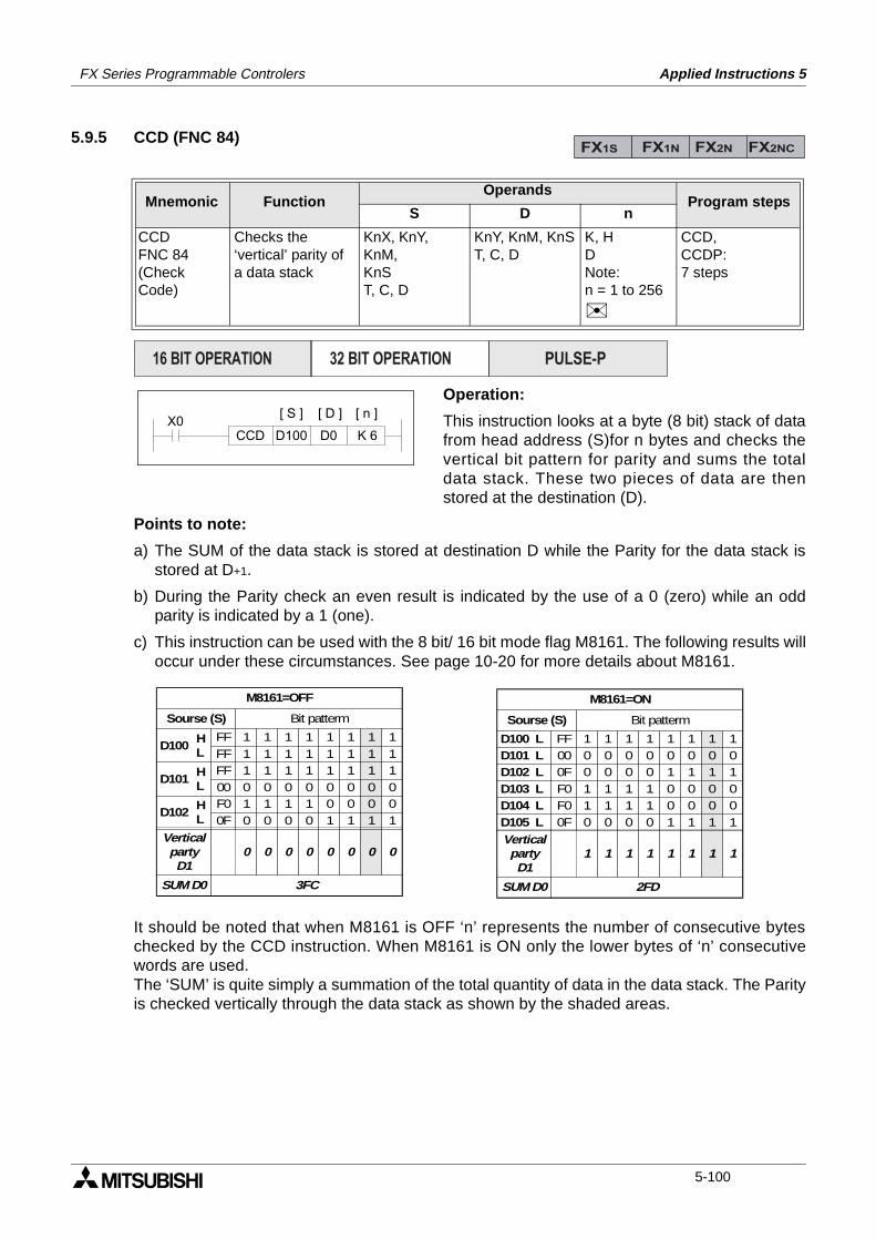
FX Series Programmable Controlers Applied Instructions 5
5.9.5 CCD (FNC 84)
Operation:
This instruction looks at a byte (8 bit) stack of datafrom head address (S)for n bytes and checks thevertical bit pattern for parity and sums the totaldata stack. These two pieces of data are thenstored at the destination (D).
Points to note:
a) The SUM of the data stack is stored at destination D while the Parity for the data stack isstored at D+1.
b) During the Parity check an even result is indicated by the use of a 0 (zero) while an oddparity is indicated by a 1 (one).
c) This instruction can be used with the 8 bit/ 16 bit mode flag M8161. The following results willoccur under these circumstances. See page 10-20 for more details about M8161.
It should be noted that when M8161 is OFF ‘n’ represents the number of consecutive byteschecked by the CCD instruction. When M8161 is ON only the lower bytes of ‘n’ consecutivewords are used.The ‘SUM’ is quite simply a summation of the total quantity of data in the data stack. The Parityis checked vertically through the data stack as shown by the shaded areas.
Mnemonic Function Operands
Program stepsS D n
CCDFNC 84(CheckCode)
Checks the‘vertical’ parity ofa data stack
KnX, KnY, KnM,KnST, C, D
KnY, KnM, KnST, C, D
K, HDNote:n = 1 to 256
CCD,CCDP:7 steps
FX1S FX1N FX2N FX2NC
PULSE-P16 BIT OPERATION 32 BIT OPERATION
X0K 6
[ S ] [ D ]
D0CCD D100
[ n ]
D100
M8161=OFF
1
Sourse (S) Bit patterm
HL 1
11
11
11
11
11
11
FFFF
11
1 1 1 1 1 1 1FF 10 0 0 0 0 0 000 01 1 1 1 0 0 0 00 0 0 0 1 1 1 1
F00F
D101HL
D102HL
VerticalpartyD1
0 0 0 0 0 0 0 0
SUM D0 3FC
D100 L
M8161=ON
1
Sourse (S) Bit patterm
1 1 1 1 1 1FF 100
1 1 1 1 0 0 0 00 0 0 0 1 1 1 1
F00F
VerticalpartyD1
1 1 1 1 1 1 1 1
SUM D0 2FD
D101 L D102 L D103 L D104 L D105 L
F00F
1 1 1 1 0 0 0 00 0 0 0 1 1 1 10 0 0 0 0 0 0 0
5-100
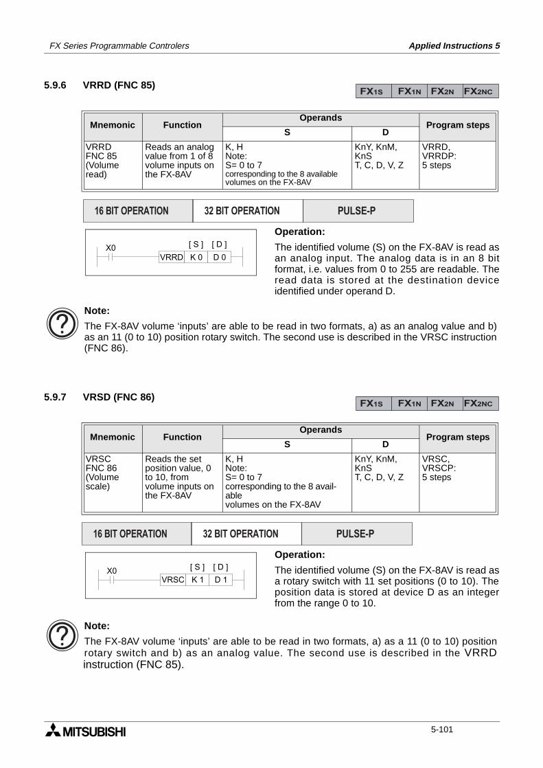
FX Series Programmable Controlers Applied Instructions 5
5.9.6 VRRD (FNC 85)
Operation:
The identified volume (S) on the FX-8AV is read asan analog input. The analog data is in an 8 bitformat, i.e. values from 0 to 255 are readable. Theread data is stored at the destination deviceidentified under operand D.
5.9.7 VRSD (FNC 86)
Operation:
The identified volume (S) on the FX-8AV is read asa rotary switch with 11 set positions (0 to 10). Theposition data is stored at device D as an integerfrom the range 0 to 10.
Mnemonic Function Operands
Program stepsS D
VRRDFNC 85(Volumeread)
Reads an analogvalue from 1 of 8volume inputs onthe FX-8AV
K, HNote:S= 0 to 7corresponding to the 8 availablevolumes on the FX-8AV
KnY, KnM, KnST, C, D, V, Z
VRRD,VRRDP:5 steps
Mnemonic Function Operands
Program stepsS D
VRSCFNC 86(Volumescale)
Reads the setposition value, 0to 10, fromvolume inputs onthe FX-8AV
K, HNote:S= 0 to 7corresponding to the 8 avail-ablevolumes on the FX-8AV
KnY, KnM, KnST, C, D, V, Z
VRSC,VRSCP:5 steps
FX1S FX1N FX2N FX2NC
PULSE-P16 BIT OPERATION 32 BIT OPERATION
X0VRRD K 0 D 0
[ S ] [ D ]
Note:
The FX-8AV volume ‘inputs’ are able to be read in two formats, a) as an analog value and b)as an 11 (0 to 10) position rotary switch. The second use is described in the VRSC instruction(FNC 86).
FX1S FX1N FX2N FX2NC
PULSE-P16 BIT OPERATION 32 BIT OPERATION
[ S ] [ D ]X0VRSC K 1 D 1
Note:
The FX-8AV volume ‘inputs’ are able to be read in two formats, a) as a 11 (0 to 10) positionrotary switch and b) as an analog value. The second use is described in the VRRDinstruction (FNC 85).
5-101
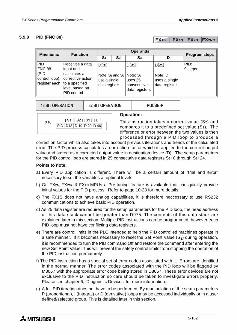
FX Series Programmable Controlers Applied Instructions 5
5.9.8 PID (FNC 88)
Operation:
This instruction takes a current value (S2) andcompares it to a predefined set value (S1). Thedifference or error between the two values is thenprocessed through a PID loop to produce a
correction factor which also takes into account previous iterations and trends of the calculatederror. The PID process calculates a correction factor which is applied to the current outputvalue and stored as a corrected output value in destination device (D). The setup parametersfor the PID control loop are stored in 25 consecutive data registers S3+0 through S3+24.
Points to note:
a) Every PID application is different. There will be a certain amount of “trial and error”necessary to set the variables at optimal levels.
b) On FX2N, FX2NC & FX1N MPUs a Pre-tuning feature is available that can quickly provideinitial values for the PID process. Refer to page 10-28 for more details.
c) The FX1S does not have analog capabilities, it is therefore neccessary to use RS232communications to achieve basic PID operation.
d) As 25 data register are required for the setup parameters for the PID loop, the head addressof this data stack cannot be greater than D975. The contents of this data stack areexplained later in this section. Multiple PID instructions can be programmed, however eachPID loop must not have conflicting data registers.
e) There are control limits in the PLC intended to help the PID controlled machines operate ina safe manner. If it becomes necessary to reset the Set Point Value (S1) during operation,it is recommended to turn the PID command Off and restore the command after entering thenew Set Point Value. This will prevent the safety control limits from stopping the operation ofthe PID instruction prematurely.
f) The PID instruction has a special set of error codes associated with it. Errors are identifiedin the normal manner. The error codes associated with the PID loop will be flagged byM8067 with the appropriate error code being stored in D8067. These error devices are notexclusive to the PID instruction so care should be taken to investigate errors properly.Please see chapter 6, ‘Diagnostic Devices’ for more information.
g) A full PID iteration does not have to be performed. By manipulation of the setup parametersP (proportional), I (Integral) or D (derivative) loops may be accessed individually or in a userdefined/selected group. This is detailed later in this section.
Mnemonic Function Operands
Program stepsS1 S2 S3 D
PIDFNC 88(PIDcontrol loop)register each
Receives a datainput andcalculates acorrective actionto a specifiedlevel based onPID control
D
Note: S1 and S2
use a single data register
D
Note: S3
uses 25consecutivedata registers
D
Note: Duses a singledata register
PID:9 steps
FX1S FX1N FX2N FX2NC
PULSE-P16 BIT OPERATION 32 BIT OPERATION
X10D 19D18PID
[ S1 ] [ S2 ] [ D ]
D 20 D 46
[ S3 ]
5-102
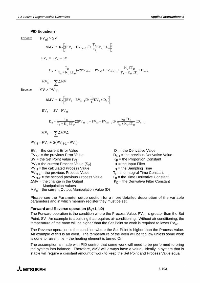
FX Series Programmable Controlers Applied Instructions 5
PID Equations
PVnf = PVn + α(PVnf-1 - PVn)
EVn = the current Error Value Dn = the Derivative ValueEVn-1 = the previous Error Value Dn-1 = the previous Derivative ValueSV = the Set Point Value (S1) KP = the Proportion ConstantPVn = the current Process Value (S2) α = the Input FilterPVnf = the calculated Process Value TS = the Sampling TimePVnf-1 = the previous Process Value TI = the Integral Time ConstantPVnf-2 = the second previous Process Value TD = the Time Derivative Constant∆MV = the change in the Output KD = the Derivative Filter Constant Manipulation Values MVn = the current Output Manipulation Value (D)
Please see the Parameter setup section for a more detailed description of the variableparameters and in which memory register they must be set.
Forward and Reverse operation (S3+1, b0)The Forward operation is the condition where the Process Value, PVnf, is greater than the SetPoint, SV. An example is a building that requires air conditioning. Without air conditioning, thetemperature of the room will be higher than the Set Point so work is required to lower PVnf.
The Reverse operation is the condition where the Set Point is higher than the Process Value.An example of this is an oven. The temperature of the oven will be too low unless some workis done to raise it, i.e. - the heating element is turned On.
The assumption is made with PID control that some work will need to be performed to bringthe system into balance. Therefore, ∆MV will always have a value. Ideally, a system that isstable will require a constant amount of work to keep the Set Point and Process Value equal.
Forward PVnf > SV
Reverse SV > PVnf
∆MV KP EVn( EV n 1–( )– )TS
TI
------EVn Dn+ +
=
EVn PVnf SV–=
Dn
TD
TS KD TD⋅+------------------------------- 2PV– nf 1– PVnf PVnf 2–+ +( )
KD TD⋅TS KD TD⋅+------------------------------- Dn 1–⋅+=
MVn ∆MV∑=
∆MV KP EVn EVn 1––( )TS
TI
------EVn+ Dn+
=
EVn SV PVnf–=
Dn
TD
TS KD+ TD⋅-------------------------------= 2PVnf 1– PVnf– PVnf 2––( )
KD TD⋅TS KD+ TD⋅-------------------------------+ Dn 1–⋅
MVn ∆MV∆∑=
5-103
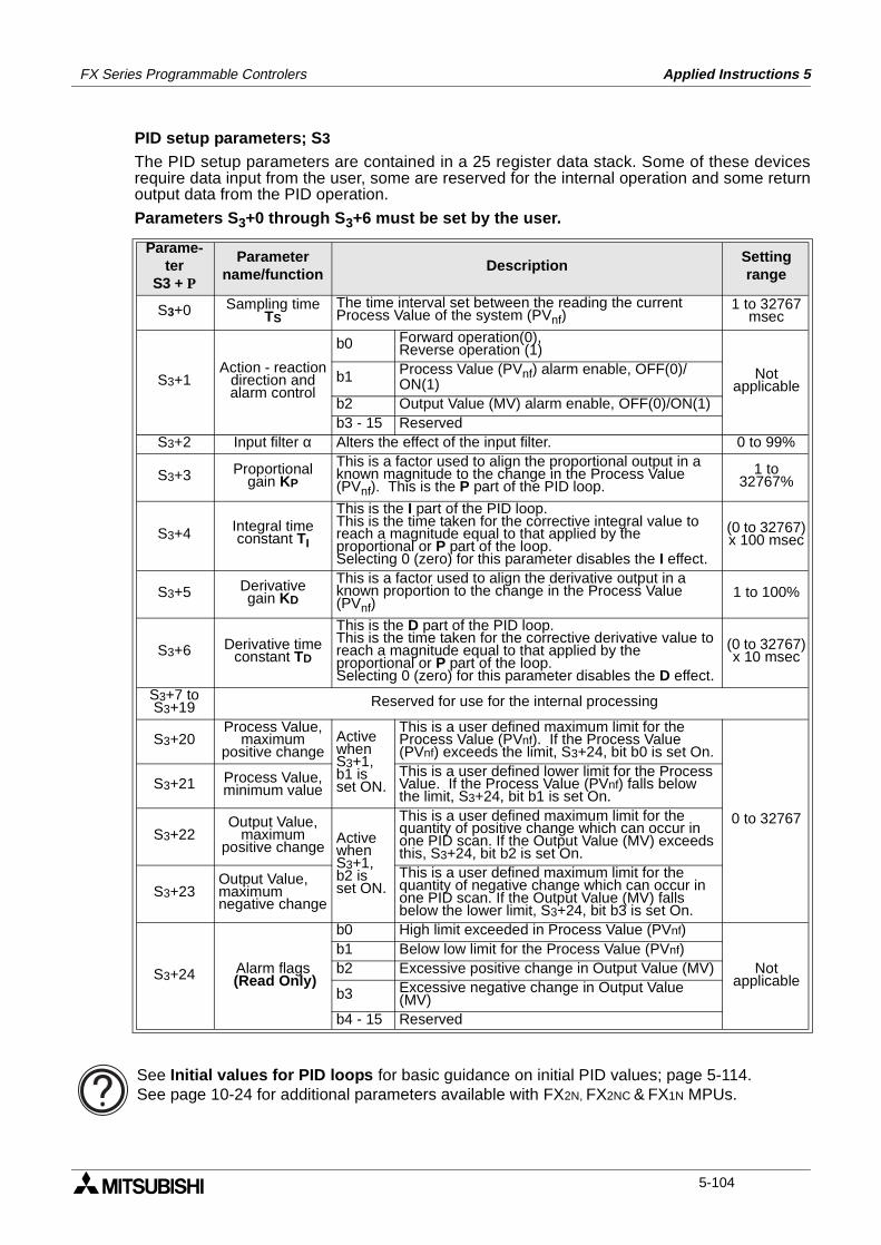
FX Series Programmable Controlers Applied Instructions 5
PID setup parameters; S3
The PID setup parameters are contained in a 25 register data stack. Some of these devicesrequire data input from the user, some are reserved for the internal operation and some returnoutput data from the PID operation.
Parameters S3+0 through S3+6 must be set by the user.
Parame-ter
S3 + P
Parametername/function
DescriptionSettingrange
S3+0 Sampling timeTS
The time interval set between the reading the current Process Value of the system (PVnf)
1 to 32767msec
S3+1Action - reaction
direction andalarm control
b0 Forward operation(0),Reverse operation (1)
Notapplicable
b1 Process Value (PVnf) alarm enable, OFF(0)/ON(1)
b2 Output Value (MV) alarm enable, OFF(0)/ON(1)b3 - 15 Reserved
S3+2 Input filter α Alters the effect of the input filter. 0 to 99%
S3+3 Proportionalgain KP
This is a factor used to align the proportional output in aknown magnitude to the change in the Process Value (PVnf). This is the P part of the PID loop.
1 to 32767%
S3+4 Integral timeconstant TI
This is the I part of the PID loop.This is the time taken for the corrective integral value to reach a magnitude equal to that applied by the proportional or P part of the loop. Selecting 0 (zero) for this parameter disables the I effect.
(0 to 32767)x 100 msec
S3+5 Derivativegain KD
This is a factor used to align the derivative output in aknown proportion to the change in the Process Value (PVnf)
1 to 100%
S3+6 Derivative timeconstant TD
This is the D part of the PID loop.This is the time taken for the corrective derivative value toreach a magnitude equal to that applied by theproportional or P part of the loop.Selecting 0 (zero) for this parameter disables the D effect.
(0 to 32767)x 10 msec
S3+7 toS3+19 Reserved for use for the internal processing
S3+20Process Value,
maximumpositive change
ActivewhenS3+1,b1 isset ON.
This is a user defined maximum limit for the Process Value (PVnf). If the Process Value (PVnf) exceeds the limit, S3+24, bit b0 is set On.
0 to 32767
S3+21 Process Value,minimum value
This is a user defined lower limit for the Process Value. If the Process Value (PVnf) falls below the limit, S3+24, bit b1 is set On.
S3+22Output Value,
maximumpositive change
ActivewhenS3+1,b2 isset ON.
This is a user defined maximum limit for the quantity of positive change which can occur in one PID scan. If the Output Value (MV) exceeds this, S3+24, bit b2 is set On.
S3+23Output Value,maximumnegative change
This is a user defined maximum limit for the quantity of negative change which can occur in one PID scan. If the Output Value (MV) falls below the lower limit, S3+24, bit b3 is set On.
S3+24 Alarm flags (Read Only)
b0 High limit exceeded in Process Value (PVnf)
Notapplicable
b1 Below low limit for the Process Value (PVnf)b2 Excessive positive change in Output Value (MV)
b3 Excessive negative change in Output Value (MV)
b4 - 15 Reserved
See Initial values for PID loops for basic guidance on initial PID values; page 5-114.See page 10-24 for additional parameters available with FX2N, FX2NC & FX1N MPUs.
5-104
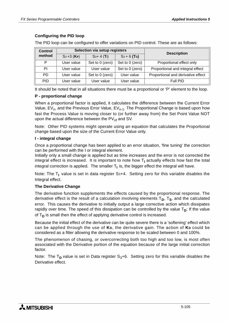
FX Series Programmable Controlers Applied Instructions 5
Configuring the PID loop
The PID loop can be configured to offer variations on PID control. These are as follows:
It should be noted that in all situations there must be a proportional or ‘P’ element to the loop.
P - proportional change
When a proportional factor is applied, it calculates the difference between the Current ErrorValue, EVn, and the Previous Error Value, EVn-1. The Proportional Change is based upon howfast the Process Value is moving closer to (or further away from) the Set Point Value NOTupon the actual difference between the PVnf and SV.
Note: Other PID systems might operate using an equation that calculates the Proportionalchange based upon the size of the Current Error Value only.
I - integral change
Once a proportional change has been applied to an error situation, ‘fine tuning’ the correctioncan be performed with the I or integral element.Initially only a small change is applied but as time increases and the error is not corrected theintegral effect is increased. It is important to note how TI actually effects how fast the totalintegral correction is applied. The smaller TI is, the bigger effect the integral will have.
Note: The TI value is set in data register S3+4. Setting zero for this variable disables theIntegral effect.
The Derivative Change
The derivative function supplements the effects caused by the proportional response. Thederivative effect is the result of a calculation involving elements TD, TS, and the calculatederror. This causes the derivative to initially output a large corrective action which dissipatesrapidly over time. The speed of this dissipation can be controlled by the value TD: If the valueof TD is small then the effect of applying derivative control is increased.
Because the initial effect of the derivative can be quite severe there is a ‘softening’ effect whichcan be applied through the use of KD, the derivative gain. The action of KD could beconsidered as a filter allowing the derivative response to be scaled between 0 and 100%.
The phenomenon of chasing, or overcorrecting both too high and too low, is most oftenassociated with the Derivative portion of the equation because of the large initial correctionfactor.
Note: The TD value is set in Data register S3+6. Setting zero for this variable disables theDerivative effect.
Controlmethod
Selection via setup registersDescription
S3 +3 (KP) S3+ 4 (TI) S3 + 6 (TD)
P User value Set to 0 (zero) Set to 0 (zero) Proportional effect only
PI User value User value Set to 0 (zero) Proportional and integral effect
PD User value Set to 0 (zero) User value Proportional and derivative effect
PID User value User value User value Full PID
5-105
FX Series Programmable Controlers Applied Instructions 5
Effective use of the input filter α S3+2
To prevent the PID instruction from reacting immediately and wildly to any errors on theCurrent Value, there is a filtering mechanism which allows the PID instruction to observe andaccount for any significant fluctuations over three samples.The quantitative effect of the input filter is to calculate a filtered Input Value to the PIDinstruction taken from a defined percentage of the Current Value and the previous two filteredInput Values.This type of filtering is often called first-order lag filter. It is particularly useful for removing theeffects of high frequency noise which may appear on input signals received from sensors.The greater the filter percentage is set the longer the lag time. When the input filter is set tozero, this effectively removes all filtering and allows the Current Value to be used directly asthe Input Value.
Initial values for PID loops
The PID instruction has many parameters which can be set and configured to the user’sneeds. The difficulty is to find a good point from which to start the fine tuning of the PID loop tothe system requirements. The following suggestions will not be ideal for all situations andapplications but will at least give users of the PID instruction a reasonable points from which tostart. A value should be given to all the variables listed below before turning the PID instruction ON.Values should be chosen so that the Output Manipulated Value does not exceed ± 32767.Recommended initial settings:
TS = Should be equal to the total program scan time or a multiple of that scan time, i.e. 2 times,5 times, etc.α = 50%KP = This should be adjusted to a value dependent upon the maximum corrective actionto reach the set point - values should be experimented with from an arbitrary 75%TI = This should ideally be 4 to 10 times greater than the TD timeKD = 50%TD = This is set dependent upon the total system response, i.e. not only how fast theprogrammable controller reacts but also any valves, pumps or motors.For a fast system reaction TD will be set to a quick or small time, this should however never beless than TS. A slower reacting system will require the TD duration to be longer. Abeginning value can be TD twice the value of TS.
Care should be taken when adjusting PID variables to ensure the safety of the operator andavoid damage to the equipment.
With ALL PID values there is a degree of experimentation required to tune the PID loopto the exact local conditions. A sensible approach to this is to adjust one parameter at atime by fixed percentages, i.e. say increasing (or decreasing) the KP value in steps of10%. Selecting PID parameters without due consideration will result in a badlyconfigured system which does not perform as required and will cause the user tobecome frustrated. Please remember the PID process is a purely mathematicalcalculation and as such has no regard for the ‘quality’ of the variable data supplied bythe user/system - the PID will always process its PID mathematical function with thedata available.
On FX2N MPUs pre-tuning feature is available that can quickly provide initial values for thePID process. Refer to page 10-28 for more details.
5-106
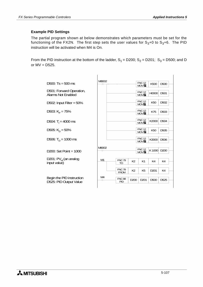
FX Series Programmable Controlers Applied Instructions 5
Example PID Settings
The partial program shown at below demonstrates which parameters must be set for thefunctioning of the FX2N. The first step sets the user values for S3+0 to S3+6. The PIDinstruction will be activated when M4 is On.
From the PID instruction at the bottom of the ladder, S1 = D200; S2 = D201; S3 = D500; and Dor MV = D525.
K500 D500 FNC 12 MOV P
H0000 D501 FNC 12 MOV P
K50 D502 FNC 12 MOVP
K75 D503 FNC 12 MOV P
K50 D505 FNC 12 MOV P
K3000 D506 FNC 12 MOV P
K2000 D504 FNC 12 MOVP
M8002K 1000 D200 FNC 12
MOV P
M4 FNC 88 PID
D200 D201 D500 D525
M1 FNC 79 TO
K2 K1 K4 K4
FNC 78 FROM
K2 K5 D201 K4
M8002D500: Ts = 500 ms
D501: Forward Operation,Alarms Not Enabled
D502: Input Filter = 50%
D503: KP = 75%
D504: TI = 4000 ms
D505: KD = 50%
D506: TD = 1000 ms
D200: Set Point = 1000
D201: PVnf (an analoginput value)
Begin the PID instructionD525: PID Output Value
5-107
FX Series Programmable Controlers Applied Instructions 5
MEMO
5-108
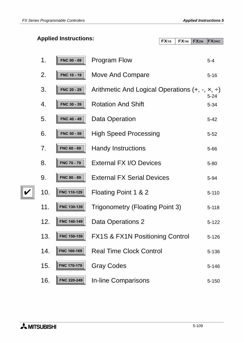
FX Series Programmable Controlers Applied Instructions 5
Applied Instructions:FX1S FX1N FX2N FX2NC
FNC 00 - 09
FNC 10 - 19
FNC 20 - 29
FNC 30 - 39
FNC 40 - 49
FNC 50 - 59
FNC 60 - 69
FNC 70 - 79
FNC 80 - 89
FNC 110-129
FNC 130-139
FNC 140-149
FNC 160-169
FNC 170-179
FNC 220-249
FNC 150-159
1.
2.
3.
4.
5.
6.
7.
8.
9.
10.
11.
12.
13.
14.
15.
16.
Program Flow 5-4
Move And Compare 5-16
Arithmetic And Logical Operations (+, -, ×, ÷)5-24
Rotation And Shift 5-34
Data Operation 5-42
High Speed Processing 5-52
Handy Instructions 5-66
External FX I/O Devices 5-80
External FX Serial Devices 5-94
Floating Point 1 & 2 5-110
Trigonometry (Floating Point 3) 5-118
Data Operations 2 5-122
FX1S & FX1N Positioning Control 5-126
Real Time Clock Control 5-136
Gray Codes 5-146
In-line Comparisons 5-150
5-109
FX Series Programmable Controlers Applied Instructions 5
5.10 Floating Point 1 & 2 - Functions 110 to 129
Contents:
Floating Point 1 Page
ECMP - Float Compare FNC 110 5-111
EZCP - Float Zone Compare FNC 111 5-111
- Not Available FNC 112 to 117
EBCD - Float to Scientific FNC 118 5-112
EBIN - Scientific to Float FNC 119 5-112
Floating Point 2
EADD - Float Add FNC 120 5-113
ESUB - Float Subtract FNC 121 5-114
EMUL - Float Multiplication FNC 122 5-114
EDIV - Float Division FNC 123 5-115
- Not Available FNC 124 to 126
ESQR - Float Square Root FNC 127 5-115
- Not Available FNC 128
INT - Float to Integer FNC 129 5-116
Symbols list:
D - Destination device.S - Source device.m, n- Number of active devices, bits or an operational constant.Additional numeric suffixes will be attached if there are more than one operand with the samefunction e.g. D1, S3 or for lists/tabled devices D3+0, S+9 etc.MSB - Most Significant Bit, sometimes used to indicate the mathematical sign of a number,i.e. positive = 0, and negative = 1.LSB - Least Significant Bit.
Instruction modifications:
- An instruction operating in 16 bit mode, where identifies the instructionmnemonic.
P - A 16 bit mode instruction modified to use pulse (single) operation.
D - An instruction modified to operate in 32 bit operation.
DP - A 32 bit mode instruction modified to use pulse (single) operation.
- A repetitive instruction which will change the destination value on every scan unlessmodified by the pulse function.
- An operand which cannot be indexed, i.e. The addition of V or Z is either invalid or willhave no effect to the value of the operand.
5-110
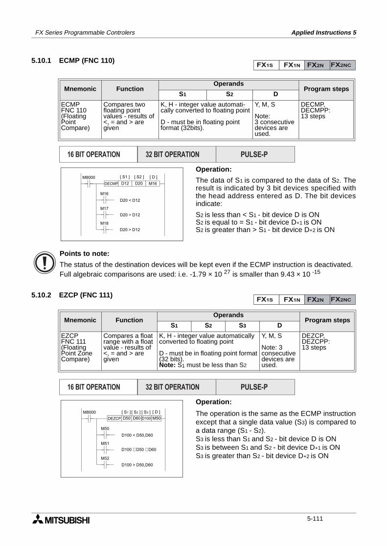
FX Series Programmable Controlers Applied Instructions 5
5.10.1 ECMP (FNC 110)
Operation:
The data of S1 is compared to the data of S2. Theresult is indicated by 3 bit devices specified withthe head address entered as D. The bit devicesindicate:
S2 is less than < S1 - bit device D is ONS2 is equal to = S1 - bit device D+1 is ONS2 is greater than > S1 - bit device D+2 is ON
5.10.2 EZCP (FNC 111)
Operation:
The operation is the same as the ECMP instructionexcept that a single data value (S3) is compared toa data range (S1 - S2).S3 is less than S1 and S2 - bit device D is ONS3 is between S1 and S2 - bit device D+1 is ONS3 is greater than S2 - bit device D+2 is ON
Mnemonic Function Operands
Program stepsS1 S2 D
ECMPFNC 110(FloatingPointCompare)
Compares twofloating pointvalues - results of<, = and > aregiven
K, H - integer value automati-cally converted to floating point
D - must be in floating pointformat (32bits).
Y, M, S
Note:3 consecutivedevices areused.
DECMP,DECMPP:13 steps
Mnemonic Function Operands
Program stepsS1 S2 S3 D
EZCPFNC 111(FloatingPoint ZoneCompare)
Compares a floatrange with a floatvalue - results of<, = and > aregiven
K, H - integer value automaticallyconverted to floating point
D - must be in floating point format(32 bits).Note: S1 must be less than S2
Y, M, S
Note: 3consecutive devices are used.
DEZCP,DEZCPP:13 steps
FX1S FX1N FX2N FX2NC
PULSE-P16 BIT OPERATION 32 BIT OPERATION
DECMP
M8000
M16
M17
M18
D12 D20 M16
[ S1 ] [ S2 ] [ D ]
D20 < D12
D20 = D12
D20 > D12
Points to note:
The status of the destination devices will be kept even if the ECMP instruction is deactivated.Full algebraic comparisons are used: i.e. -1.79 × 10 27 is smaller than 9.43 × 10 -15
FX1S FX1N FX2N FX2NC
PULSE-P16 BIT OPERATION 32 BIT OPERATION
DEZCP
M8000
M50
M51
M52
D50 D60 D100 M50
[ S1 ] [ S2 ] [ S3 ] [ D ]
D100 < D50,D60
D100 £ D50 £ D60
D100 > D50,D60
5-111
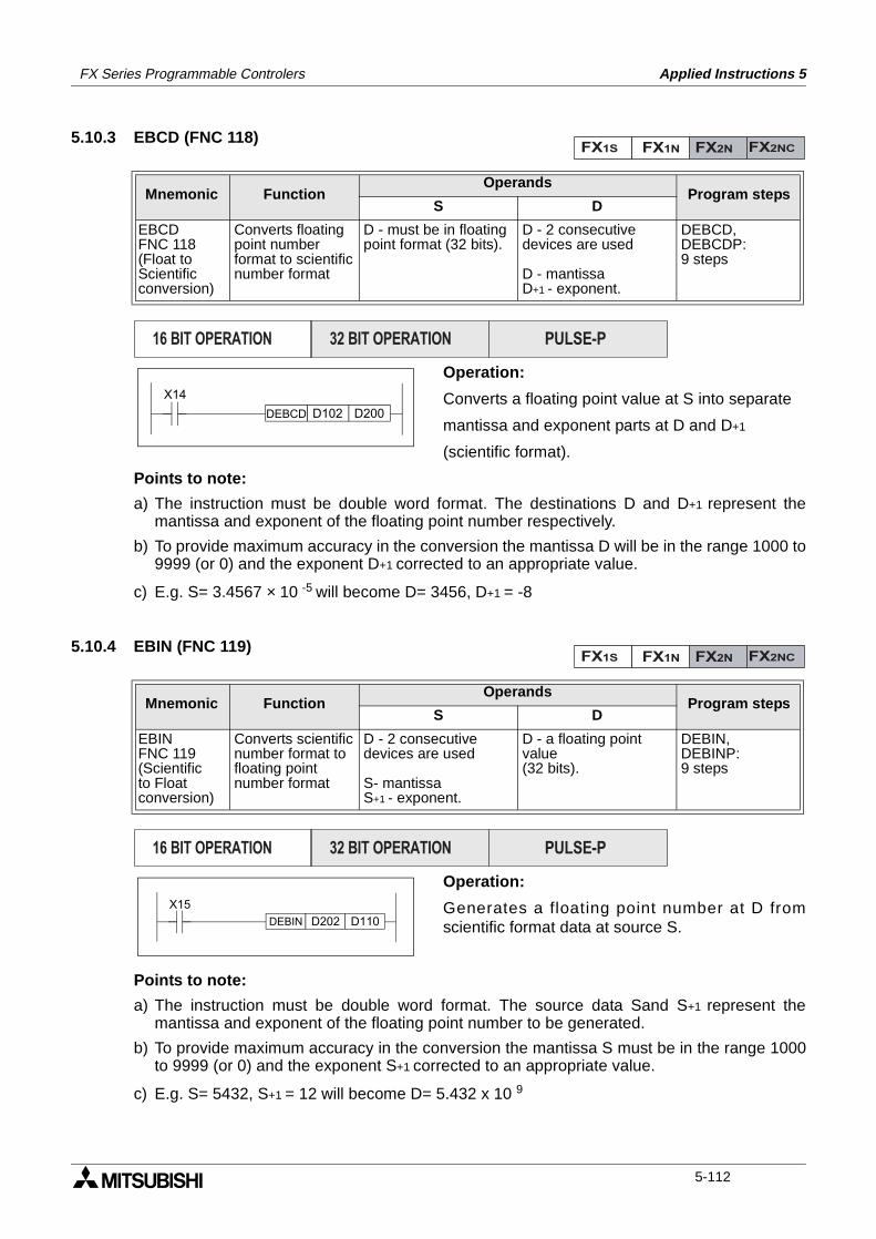
FX Series Programmable Controlers Applied Instructions 5
5.10.3 EBCD (FNC 118)
Operation:
Converts a floating point value at S into separate
mantissa and exponent parts at D and D+1
(scientific format).
Points to note:
a) The instruction must be double word format. The destinations D and D+1 represent themantissa and exponent of the floating point number respectively.
b) To provide maximum accuracy in the conversion the mantissa D will be in the range 1000 to9999 (or 0) and the exponent D+1 corrected to an appropriate value.
c) E.g. S= 3.4567 × 10 -5 will become D= 3456, D+1 = -8
5.10.4 EBIN (FNC 119)
Operation:
Generates a floating point number at D fromscientific format data at source S.
Points to note:
a) The instruction must be double word format. The source data Sand S+1 represent themantissa and exponent of the floating point number to be generated.
b) To provide maximum accuracy in the conversion the mantissa S must be in the range 1000to 9999 (or 0) and the exponent S+1 corrected to an appropriate value.
c) E.g. S= 5432, S+1 = 12 will become D= 5.432 x 10 9
Mnemonic Function Operands
Program stepsS D
EBCDFNC 118(Float toScientificconversion)
Converts floatingpoint numberformat to scientificnumber format
D - must be in floatingpoint format (32 bits).
D - 2 consecutivedevices are used
D - mantissaD+1 - exponent.
DEBCD,DEBCDP:9 steps
Mnemonic Function Operands
Program stepsS D
EBINFNC 119(Scientificto Floatconversion)
Converts scientificnumber format tofloating pointnumber format
D - 2 consecutivedevices are used
S- mantissaS+1 - exponent.
D - a floating point value(32 bits).
DEBIN,DEBINP:9 steps
FX1S FX1N FX2N FX2NC
PULSE-P16 BIT OPERATION 32 BIT OPERATION
DEBCD
X14
D102 D200
FX1S FX1N FX2N FX2NC
PULSE-P16 BIT OPERATION 32 BIT OPERATION
DEBIN
X15
D202 D110
5-112
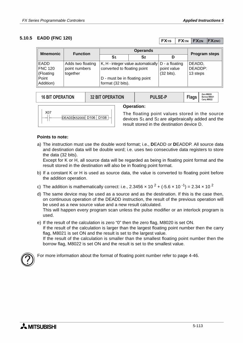
FX Series Programmable Controlers Applied Instructions 5
5.10.5 EADD (FNC 120)
Operation:
The floating point values stored in the sourcedevices S1 and S2 are algebraically added and theresult stored in the destination device D.
Points to note:
a) The instruction must use the double word format; i.e., DEADD or DEADDP. All source dataand destination data will be double word; i.e. uses two consecutive data registers to storethe data (32 bits).Except for K or H, all source data will be regarded as being in floating point format and theresult stored in the destination will also be in floating point format.
b) If a constant K or H is used as source data, the value is converted to floating point beforethe addition operation.
c) The addition is mathematically correct: i.e., 2.3456 × 10 2 + (-5.6 × 10 -1) = 2.34 × 10 2
d) The same device may be used as a source and as the destination. If this is the case then,on continuous operation of the DEADD instruction, the result of the previous operation willbe used as a new source value and a new result calculated.This will happen every program scan unless the pulse modifier or an interlock program isused.
e) If the result of the calculation is zero “0” then the zero flag, M8020 is set ON. If the result of the calculation is larger than the largest floating point number then the carryflag, M8021 is set ON and the result is set to the largest value.If the result of the calculation is smaller than the smallest floating point number then theborrow flag, M8022 is set ON and the result is set to the smallest value.
Mnemonic Function Operands
Program stepsS1 S2 D
EADDFNC 120(FloatingPointAddition)
Adds two floatingpoint numberstogether
K, H - integer value automaticallyconverted to floating point
D - must be in floating pointformat (32 bits).
D - a floatingpoint value(32 bits).
DEADD,DEADDP:13 steps
FX1S FX1N FX2N FX2NC
PULSE-P16 BIT OPERATION 32 BIT OPERATION FlagsZero M8020Borrow M8021Carry M8022
DEADD
X07
K52000 D106 D108
For more information about the format of floating point number refer to page 4-46.
5-113
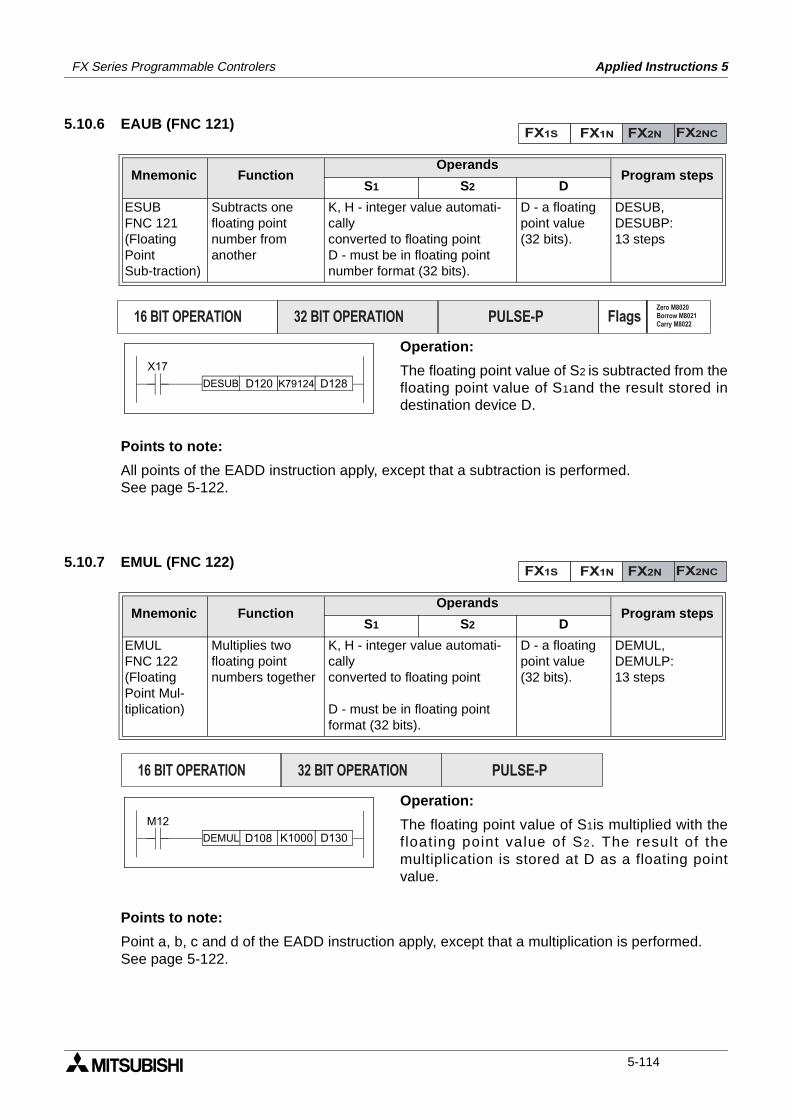
FX Series Programmable Controlers Applied Instructions 5
5.10.6 EAUB (FNC 121)
Operation:
The floating point value of S2 is subtracted from thefloating point value of S1and the result stored indestination device D.
Points to note:
All points of the EADD instruction apply, except that a subtraction is performed.See page 5-122.
5.10.7 EMUL (FNC 122)
Operation:
The floating point value of S1is multiplied with thefloating point value of S2. The result of themultiplication is stored at D as a floating pointvalue.
Points to note:
Point a, b, c and d of the EADD instruction apply, except that a multiplication is performed. See page 5-122.
Mnemonic Function Operands
Program stepsS1 S2 D
ESUBFNC 121(FloatingPointSub-traction)
Subtracts onefloating pointnumber fromanother
K, H - integer value automati-callyconverted to floating pointD - must be in floating pointnumber format (32 bits).
D - a floatingpoint value(32 bits).
DESUB,DESUBP:13 steps
Mnemonic Function Operands
Program stepsS1 S2 D
EMULFNC 122(FloatingPoint Mul-tiplication)
Multiplies twofloating pointnumbers together
K, H - integer value automati-callyconverted to floating point
D - must be in floating pointformat (32 bits).
D - a floatingpoint value(32 bits).
DEMUL,DEMULP:13 steps
FX1S FX1N FX2N FX2NC
PULSE-P16 BIT OPERATION 32 BIT OPERATION FlagsZero M8020Borrow M8021Carry M8022
DESUB
X17
D120 K79124 D128
FX1S FX1N FX2N FX2NC
PULSE-P16 BIT OPERATION 32 BIT OPERATION
DEMUL
M12
D108 K1000 D130
5-114
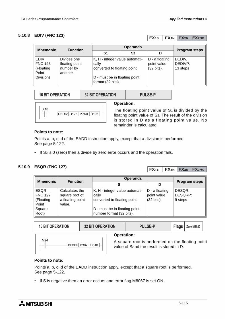
FX Series Programmable Controlers Applied Instructions 5
5.10.8 EDIV (FNC 123)
Operation:
The floating point value of S1 is divided by thefloating point value of S2. The result of the divisionis stored in D as a f loat ing point value. Noremainder is calculated.
Points to note:
Points a, b, c, d of the EADD instruction apply, except that a division is performed.See page 5-122.
• If S2 is 0 (zero) then a divide by zero error occurs and the operation fails.
5.10.9 ESQR (FNC 127)
Operation:
A square root is performed on the floating pointvalue of Sand the result is stored in D.
Points to note:
Points a, b, c, d of the EADD instruction apply, except that a square root is performed.See page 5-122.
• If S is negative then an error occurs and error flag M8067 is set ON.
Mnemonic Function Operands
Program stepsS1 S2 D
EDIVFNC 123(FloatingPointDivision)
Divides onefloating pointnumber by another.
K, H - integer value automati-callyconverted to floating point
D - must be in floating pointformat (32 bits).
D - a floatingpoint value(32 bits).
DEDIV,DEDIVP:13 steps
Mnemonic Function Operands
Program stepsS D
ESQRFNC 127(FloatingPointSquareRoot)
Calculates thesquare root ofa floating pointvalue.
K, H - integer value automati-callyconverted to floating point
D - must be in floating pointnumber format (32 bits).
D - a floatingpoint value(32 bits).
DESQR,DESQRP:9 steps
FX1S FX1N FX2N FX2NC
PULSE-P16 BIT OPERATION 32 BIT OPERATION
DEDIV
X10
D128 K500 D106
FX1S FX1N FX2N FX2NC
PULSE-P16 BIT OPERATION 32 BIT OPERATION Flags Zero M8020
DESQR
M24
D302 D510
5-115
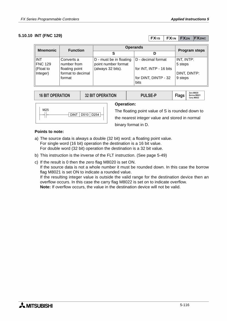
FX Series Programmable Controlers Applied Instructions 5
5.10.10 INT (FNC 129)
Operation:
The floating point value of S is rounded down to
the nearest integer value and stored in normal
binary format in D.
Points to note:
a) The source data is always a double (32 bit) word; a floating point value. For single word (16 bit) operation the destination is a 16 bit value.For double word (32 bit) operation the destination is a 32 bit value.
b) This instruction is the inverse of the FLT instruction. (See page 5-49)
c) If the result is 0 then the zero flag M8020 is set ON.If the source data is not a whole number it must be rounded down. In this case the borrowflag M8021 is set ON to indicate a rounded value.If the resulting integer value is outside the valid range for the destination device then anoverflow occurs. In this case the carry flag M8022 is set on to indicate overflow.Note: If overflow occurs, the value in the destination device will not be valid.
Mnemonic Function Operands
Program stepsS D
INTFNC 129(Float toInteger)
Converts anumber fromfloating pointformat to decimalformat
D - must be in floatingpoint number format(always 32 bits).
D - decimal format
for INT, INTP - 16 bits
for DINT, DINTP - 32 bits
INT, INTP:5 steps
DINT, DINTP:9 steps
FX1S FX1N FX2N FX2NC
PULSE-P16 BIT OPERATION 32 BIT OPERATION FlagsZero M8020Borrow M8021Carry M8022
DINT
M25
D510 D254
5-116
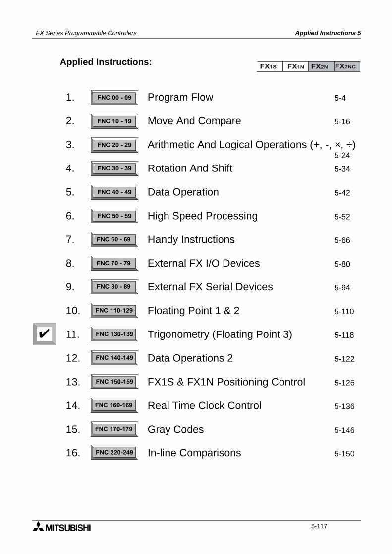
FX Series Programmable Controlers Applied Instructions 5
Applied Instructions:FX1S FX1N FX2N FX2NC
FNC 00 - 09
FNC 10 - 19
FNC 20 - 29
FNC 30 - 39
FNC 40 - 49
FNC 50 - 59
FNC 60 - 69
FNC 70 - 79
FNC 80 - 89
FNC 110-129
FNC 130-139
FNC 140-149
FNC 160-169
FNC 170-179
FNC 220-249
FNC 150-159
1.
2.
3.
4.
5.
6.
7.
8.
9.
10.
11.
12.
13.
14.
15.
16.
Program Flow 5-4
Move And Compare 5-16
Arithmetic And Logical Operations (+, -, ×, ÷)5-24
Rotation And Shift 5-34
Data Operation 5-42
High Speed Processing 5-52
Handy Instructions 5-66
External FX I/O Devices 5-80
External FX Serial Devices 5-94
Floating Point 1 & 2 5-110
Trigonometry (Floating Point 3) 5-118
Data Operations 2 5-122
FX1S & FX1N Positioning Control 5-126
Real Time Clock Control 5-136
Gray Codes 5-146
In-line Comparisons 5-150
5-117
FX Series Programmable Controlers Applied Instructions 5
5.11 Trigonometry - FNC 130 to FNC 139
Contents:
Floating point 3 Page
SIN - Sine FNC 130 5-119
COS - Cosine FNC 131 5-120
TAN - Tangent FNC 132 5-120
- Not Available FNC 133 to 139
Symbols list:
D - Destination device.S - Source device.m, n- Number of active devices, bits or an operational constant.Additional numeric suffixes will be attached if there are more than one operand with the samefunction e.g. D1, S3 or for lists/tabled devices D3+0, S+9 etc.MSB - Most Significant Bit, sometimes used to indicate the mathematical sign of a number,i.e. positive = 0, and negative = 1.LSB - Least Significant Bit.
Instruction modifications:
- An instruction operating in 16 bit mode, where identifies the instructionmnemonic.
P - A 16 bit mode instruction modified to use pulse (single) operation.
D - An instruction modified to operate in 32 bit operation.
DP - A 32 bit mode instruction modified to use pulse (single) operation.
- A repetitive instruction which will change the destination value on every scan unlessmodified by the pulse function.
- An operand which cannot be indexed, i.e. The addition of V or Z is either invalid or willhave no effect to the value of the operand.
5-118
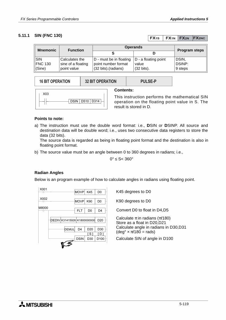
FX Series Programmable Controlers Applied Instructions 5
5.11.1 SIN (FNC 130)
Contents:
This instruction performs the mathematical SINoperation on the floating point value in S. Theresult is stored in D.
Points to note:
a) The instruction must use the double word format: i.e., DSIN or DSINP. All source anddestination data will be double word; i.e., uses two consecutive data registers to store thedata (32 bits).The source data is regarded as being in floating point format and the destination is also infloating point format.
b) The source value must be an angle between 0 to 360 degrees in radians; i.e.,
0° ≤ S< 360°
Radian Angles
Below is an program example of how to calculate angles in radians using floating point.
Mnemonic Function Operands
Program stepsS D
SINFNC 130(Sine)
Calculates thesine of a floatingpoint value
D - must be in floatingpoint number format(32 bits).(radians)
D - a floating point value(32 bits).
DSIN,DSINP:9 steps
FX1S FX1N FX2N FX2NC
PULSE-P16 BIT OPERATION 32 BIT OPERATION
DSIN
X03
D510 D314
X001K45 D0MOVP
X002
D0 D4FLT
K90 D0MOVP
M8000
K31415926 K1800000000 D20DEDIV
D4 D20 D30DEMUL
D30 D100DSIN
[ S ] [ D ]
K45 degrees to D0
Convert D0 to float in D4,D5
K90 degrees to D0
Calculate π in radians (π/180)Store as a float in D20,D21Calculate angle in radians in D30,D31(deg° × π/180 = rads)
Calculate SIN of angle in D100
5-119
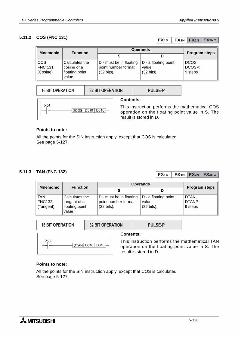
FX Series Programmable Controlers Applied Instructions 5
5.11.2 COS (FNC 131)
Contents:
This instruction performs the mathematical COSoperation on the floating point value in S. Theresult is stored in D.
Points to note:
All the points for the SIN instruction apply, except that COS is calculated.See page 5-127.
5.11.3 TAN (FNC 132)
Contents:
This instruction performs the mathematical TANoperation on the floating point value in S. Theresult is stored in D.
Points to note:
All the points for the SIN instruction apply, except that COS is calculated.See page 5-127.
Mnemonic Function Operands
Program stepsS D
COSFNC 131(Cosine)
Calculates thecosine of afloating point value
D - must be in floatingpoint number format (32 bits).
D - a floating point value(32 bits).
DCOS,DCOSP:9 steps
Mnemonic Function Operands
Program stepsS D
TANFNC132(Tangent)
Calculates thetangent of afloating point value
D - must be in floatingpoint number format (32 bits).
D - a floating point value(32 bits).
DTAN,DTANP:9 steps
FX1S FX1N FX2N FX2NC
PULSE-P16 BIT OPERATION 32 BIT OPERATION
DCOS
X04
D510 D316
FX1S FX1N FX2N FX2NC
PULSE-P16 BIT OPERATION 32 BIT OPERATION
DTAN
X05
D510 D318
5-120
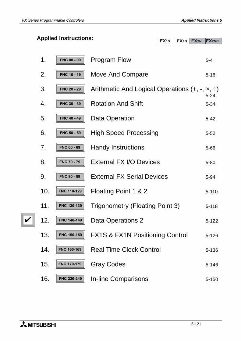
FX Series Programmable Controlers Applied Instructions 5
Applied Instructions:FX1S FX1N FX2N FX2NC
FNC 00 - 09
FNC 10 - 19
FNC 20 - 29
FNC 30 - 39
FNC 40 - 49
FNC 50 - 59
FNC 60 - 69
FNC 70 - 79
FNC 80 - 89
FNC 110-129
FNC 130-139
FNC 140-149
FNC 160-169
FNC 170-179
FNC 220-249
FNC 150-159
1.
2.
3.
4.
5.
6.
7.
8.
9.
10.
11.
12.
13.
14.
15.
16.
Program Flow 5-4
Move And Compare 5-16
Arithmetic And Logical Operations (+, -, ×, ÷)5-24
Rotation And Shift 5-34
Data Operation 5-42
High Speed Processing 5-52
Handy Instructions 5-66
External FX I/O Devices 5-80
External FX Serial Devices 5-94
Floating Point 1 & 2 5-110
Trigonometry (Floating Point 3) 5-118
Data Operations 2 5-122
FX1S & FX1N Positioning Control 5-126
Real Time Clock Control 5-136
Gray Codes 5-146
In-line Comparisons 5-150
5-121
FX Series Programmable Controlers Applied Instructions 5
5.12 Data Operations 2 - FNC 140 to FNC 149
Contents:
Page
- Not Available FNC 140 to 146
SWAP - Float to Scientific FNC 147 5-123
- Not Available FNC 148 to 149
Symbols list:
D - Destination device.S - Source device.m, n- Number of active devices, bits or an operational constant.Additional numeric suffixes will be attached if there are more than one operand with the samefunction e.g. D1, S3 or for lists/tabled devices D3+0, S+9 etc.MSB - Most Significant Bit, sometimes used to indicate the mathematical sign of a number,i.e. positive = 0, and negative = 1.LSB - Least Significant Bit.
Instruction modifications:
- An instruction operating in 16 bit mode, where identifies the instructionmnemonic.
P - A 16 bit mode instruction modified to use pulse (single) operation.
D - An instruction modified to operate in 32 bit operation.
DP - A 32 bit mode instruction modified to use pulse (single) operation.
- A repetitive instruction which will change the destination value on every scan unlessmodified by the pulse function.
- An operand which cannot be indexed, i.e. The addition of V or Z is either invalid or willhave no effect to the value of the operand.
5-122
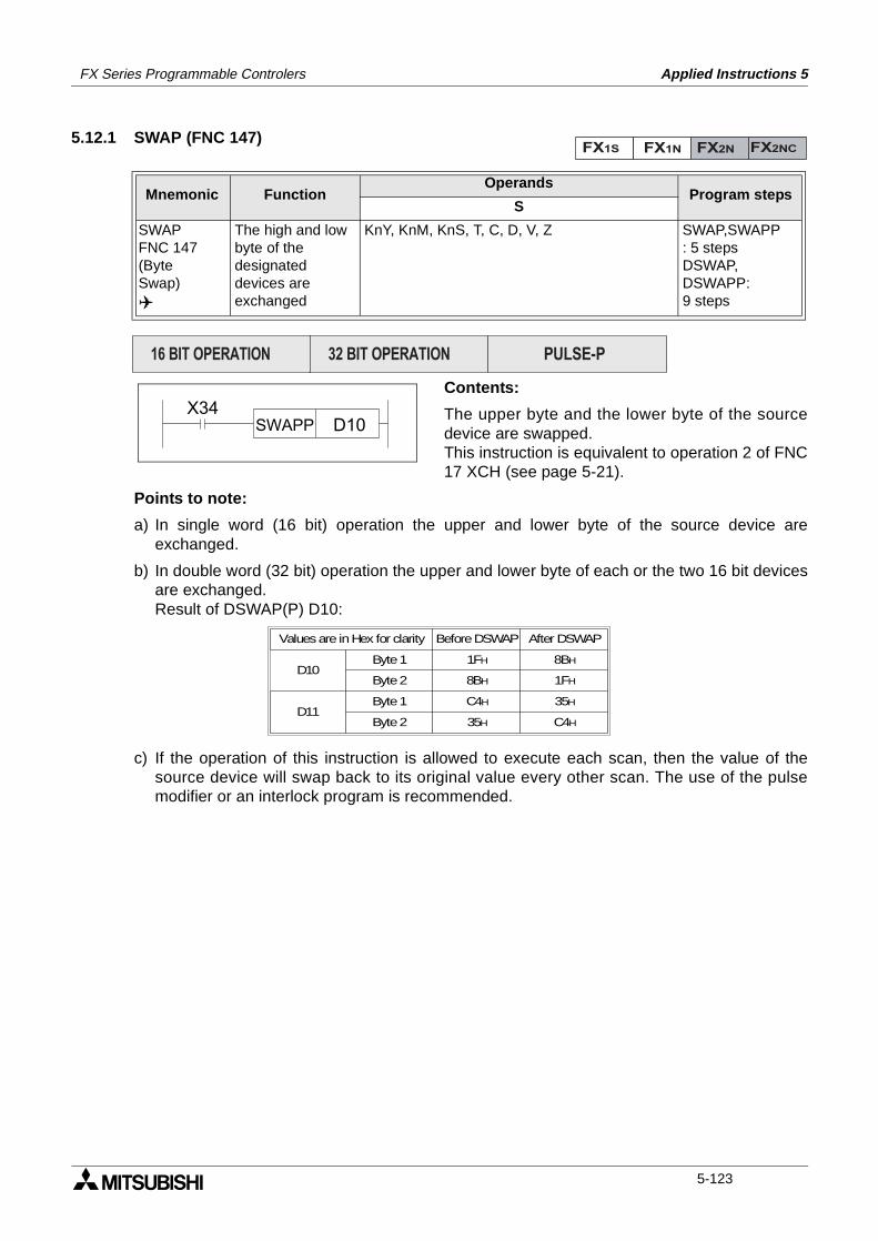
FX Series Programmable Controlers Applied Instructions 5
5.12.1 SWAP (FNC 147)
Contents:
The upper byte and the lower byte of the sourcedevice are swapped. This instruction is equivalent to operation 2 of FNC17 XCH (see page 5-21).
Points to note:
a) In single word (16 bit) operation the upper and lower byte of the source device areexchanged.
b) In double word (32 bit) operation the upper and lower byte of each or the two 16 bit devicesare exchanged.Result of DSWAP(P) D10:
c) If the operation of this instruction is allowed to execute each scan, then the value of thesource device will swap back to its original value every other scan. The use of the pulsemodifier or an interlock program is recommended.
Mnemonic Function Operands
Program stepsS
SWAPFNC 147(ByteSwap)
The high and lowbyte of thedesignateddevices areexchanged
KnY, KnM, KnS, T, C, D, V, Z SWAP,SWAPP: 5 stepsDSWAP,DSWAPP:9 steps
FX1S FX1N FX2N FX2NC
PULSE-P16 BIT OPERATION 32 BIT OPERATION
X34D10SWAPP
D10Byte 1
Values are in Hex for clarity
Byte 2
D11Byte 1
Byte 2
Before DSWAP After DSWAP
1FH
8BH
C4H
35H
1FH
8BH
C4H
35H
5-123

FX Series Programmable Controlers Applied Instructions 5
MEMO
5-124

FX Series Programmable Controlers Applied Instructions 5
Applied Instructions:FX1S FX1N FX2N FX2NC
FNC 00 - 09
FNC 10 - 19
FNC 20 - 29
FNC 30 - 39
FNC 40 - 49
FNC 50 - 59
FNC 60 - 69
FNC 70 - 79
FNC 80 - 89
FNC 110-129
FNC 130-139
FNC 140-149
FNC 160-169
FNC 170-179
FNC 220-249
FNC 150-159
1.
2.
3.
4.
5.
6.
7.
8.
9.
10.
11.
12.
13.
14.
15.
16.
Program Flow 5-4
Move And Compare 5-16
Arithmetic And Logical Operations (+, -, ×, ÷)5-24
Rotation And Shift 5-34
Data Operation 5-42
High Speed Processing 5-52
Handy Instructions 5-66
External FX I/O Devices 5-80
External FX Serial Devices 5-94
Floating Point 1 & 2 5-110
Trigonometry (Floating Point 3) 5-118
Data Operations 2 5-122
FX1S & FX1N Positioning Control 5-126
Real Time Clock Control 5-136
Gray Codes 5-146
In-line Comparisons 5-150
5-125
FX Series Programmable Controlers Applied Instructions 5
5.13 FX1S & FX1N Positioning Control - FNC 150 to FNC 159
Contents:
Page
- Not Available FNC 150 to 154
ABS - Absolute current value read FNC 155 5-127
ZRN - Zero return FNC 156 5-128
PLSV - Pulse V FNC 157 5-129
DRVI - Drive to increment FNC 158 5-130
DRVA - Drive to absolute FNC 159 5-132
Symbols list:
D - Destination device.S - Source device.m, n- Number of active devices, bits or an operational constant.Additional numeric suffixes will be attached if there are more than one operand with the samefunction e.g. D1, S3 or for lists/tabled devices D3+0, S+9 etc.MSB - Most Significant Bit, sometimes used to indicate the mathematical sign of a number, i.e.positive = 0, and negative = 1.LSB - Least Significant Bit.
Instruction modifications:
- An instruction operating in 16 bit mode, where identifies the instructionmnemonic.
P - A 16 bit mode instruction modified to use pulse (single) operation.
D - An instruction modified to operate in 32 bit operation.
DP - A 32 bit mode instruction modified to use pulse (single) operation.
- A repetitive instruction which will change the destination value on every scan unlessmodified by the pulse function.
- An operand which cannot be indexed, i.e. The addition of V or Z is either invalid or willhave no effect to the value of the operand.
5-126
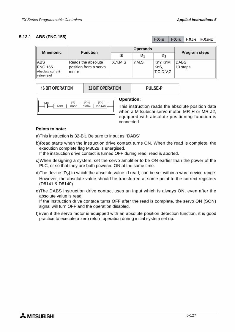
FX Series Programmable Controlers Applied Instructions 5
5.13.1 ABS (FNC 155)
Operation:
This instruction reads the absolute position datawhen a Mitsubishi servo motor, MR-H or MR-J2,equipped with absolute positioning function isconnected.
Points to note:
a)This instruction is 32-Bit. Be sure to input as “DABS”
b)Read starts when the instruction drive contact turns ON. When the read is complete, theexecution complete flag M8029 is energised. If the instruction drive contact is turned OFF during read, read is aborted.
c)When designing a system, set the servo amplifier to be ON earlier than the power of thePLC, or so that they are both powered ON at the same time.
d)The device [D2] to which the absolute value id read, can be set within a word device range.However, the absolute value should be transferred at some point to the correct registers(D8141 & D8140)
e)The DABS instruction drive contact uses an input which is always ON, even after theabsolute value is read. If the instruction drive contace turns OFF after the read is complete, the servo ON (SON)signal will turn OFF and the operation disabled.
f)Even if the servo motor is equipped with an absolute position detection function, it is goodpractice to execute a zero return operation during initial system set up.
Mnemonic Function Operands
Program stepsS D1 D2
ABSFNC 155Absolute currentvalue read
Reads the absolute position from a servo motor
X,Y,M,S Y,M,S KnY,KnMKnS,T,C,D,V,Z
DABS13 steps
FX1S FX1N FX2N FX2NC
PULSE-P16 BIT OPERATION 32 BIT OPERATION
ABS X000 Y004 D8140
[S] [D2][D1]M0
5-127
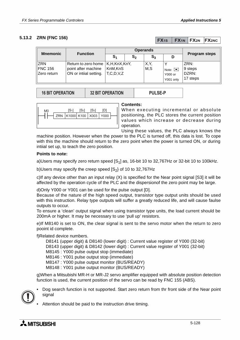
FX Series Programmable Controlers Applied Instructions 5
5.13.2 ZRN (FNC 156)
Contents:When execu t ing inc rementa l o r abso lu tepositioning, the PLC stores the current positionvalues which increase or decrease dur ingoperation.Using these values, the PLC always knows the
machine position. However when the power to the PLC is turned off, this data is lost. To copewith this the machine should return to the zero point when the power is turned ON, or duringintiial set up, to teach the zero position.
Points to note:
a)Users may specify zero return speed [S1] as, 16-bit 10 to 32,767Hz or 32-bit 10 to 100kHz.
b)Users may specify the creep speed [S2 of 10 to 32,767Hz
c)If any device other than an input relay (X) is specified for the Near point signal [S3] it will beaffected by the operation cycle of the PLC and the dispersionof the zero point may be large.
d)Only Y000 or Y001 can be used for the pulse output [D].Because of the nature of the high speed output, transistor type output units should be usedwith this instruction. Relay type outputs will suffer a greatly reduced life, and will cause faulseoutputs to occur.To ensure a ‘clean’ output signal when using transistor type units, the load current should be200mA or higher. It may be necessary to use ‘pull up’ resistors.
e)If M8140 is set to ON, the clear signal is sent to the servo motor when the return to zeropooint id complete.
f)Related device numbers.D8141 (upper digit) & D8140 (lower digit) : Current value register of Y000 (32-bit)D8143 (upper digit) & D8142 (lower digit) : Current value register of Y001 (32-bit)M8145 : Y000 pulse output stop (immediate)M8146 : Y001 pulse output stop (immediate)M8147 : Y000 pulse output monitor (BUS/READY)M8148 : Y001 pulse output monitor (BUS/READY)
g)When a Mitsubishi MR-H or MR-J2 servo amplifier equipped with absolute position detectionfunction is used, the current position of the servo can be read by FNC 155 (ABS).
• Dog search function is not supported. Start zero return from thr front side of the Near pointsignal
• Attention should be paid to the instruction drive timing.
Mnemonic Function Operands
Program stepsS1 S2 S3 D
ZRNFNC 156Zero return
Return to zero home point after machine ON or intiial setting.
K,H,KnX,KnY,KnM,KnST,C,D,V,Z
X,Y,M,S
Y Note: Y000 or
Y001 only
ZRN:9 stepsDZRN:17 steps
FX1S FX1N FX2N FX2NC
PULSE-P16 BIT OPERATION 32 BIT OPERATION
ZRN K1000 K100 Y000
[D][S2][S1]M0
X003
[S3]
5-128
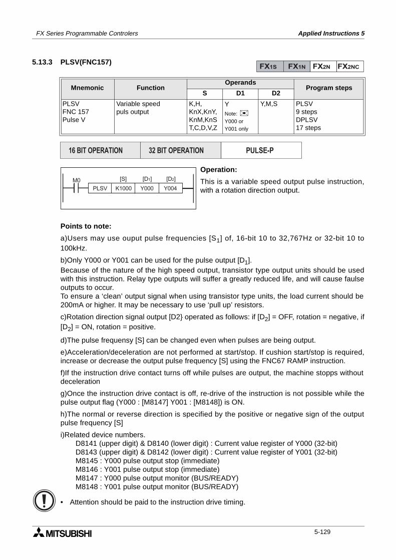
FX Series Programmable Controlers Applied Instructions 5
5.13.3 PLSV(FNC157)
Operation:
This is a variable speed output pulse instruction,with a rotation direction output.
Points to note:
a)Users may use ouput pulse frequencies [S1] of, 16-bit 10 to 32,767Hz or 32-bit 10 to100kHz.
b)Only Y000 or Y001 can be used for the pulse output [D1].Because of the nature of the high speed output, transistor type output units should be usedwith this instruction. Relay type outputs will suffer a greatly reduced life, and will cause faulseoutputs to occur.To ensure a ‘clean’ output signal when using transistor type units, the load current should be200mA or higher. It may be necessary to use ‘pull up’ resistors.
c)Rotation direction signal output [D2 operated as follows: if [D2] = OFF, rotation = negative, if[D2] = ON, rotation = positive.
d)The pulse frequensy [S] can be changed even when pulses are being output.
e)Acceleration/deceleration are not performed at start/stop. If cushion start/stop is required,increase or decrease the output pulse frequency [S] using the FNC67 RAMP instruction.
f)If the instruction drive contact turns off while pulses are output, the machine stopps withoutdeceleration
g)Once the instruction drive contact is off, re-drive of the instruction is not possible while thepulse output flag (Y000 : [M8147] Y001 : [M8148]) is ON.
h)The normal or reverse direction is specified by the positive or negative sign of the outputpulse frequency [S]
i)Related device numbers.D8141 (upper digit) & D8140 (lower digit) : Current value register of Y000 (32-bit)D8143 (upper digit) & D8142 (lower digit) : Current value register of Y001 (32-bit)M8145 : Y000 pulse output stop (immediate)M8146 : Y001 pulse output stop (immediate)M8147 : Y000 pulse output monitor (BUS/READY)M8148 : Y001 pulse output monitor (BUS/READY)
• Attention should be paid to the instruction drive timing.
Mnemonic Function Operands
Program stepsS D1 D2
PLSVFNC 157Pulse V
Variable speedpuls output
K,H,KnX,KnY,KnM,KnST,C,D,V,Z
Y Note: Y000 or Y001 only
Y,M,S PLSV9 stepsDPLSV17 steps
FX1S FX1N FX2N FX2NC
PULSE-P16 BIT OPERATION 32 BIT OPERATION
PLSV K1000 Y000 Y004
[S] [D2][D1]M0
5-129
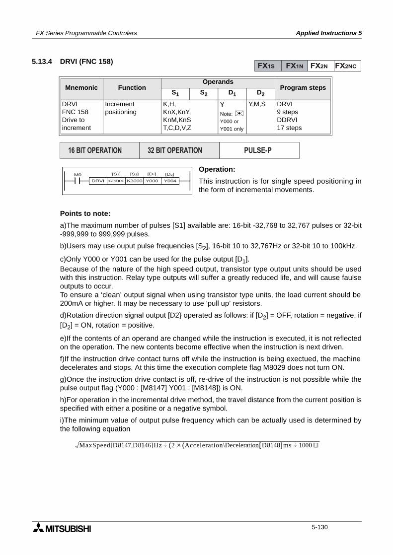
FX Series Programmable Controlers Applied Instructions 5
5.13.4 DRVI (FNC 158)
Operation:
This instruction is for single speed positioning inthe form of incremental movements.
Points to note:
a)The maximum number of pulses [S1] available are: 16-bit -32,768 to 32,767 pulses or 32-bit-999,999 to 999,999 pulses.
b)Users may use ouput pulse frequencies [S2], 16-bit 10 to 32,767Hz or 32-bit 10 to 100kHz.
c)Only Y000 or Y001 can be used for the pulse output [D1].Because of the nature of the high speed output, transistor type output units should be usedwith this instruction. Relay type outputs will suffer a greatly reduced life, and will cause faulseoutputs to occur.To ensure a ‘clean’ output signal when using transistor type units, the load current should be200mA or higher. It may be necessary to use ‘pull up’ resistors.
d)Rotation direction signal output [D2 operated as follows: if [D2] = OFF, rotation = negative, if[D2] = ON, rotation = positive.
e)If the contents of an operand are changed while the instruction is executed, it is not reflectedon the operation. The new contents become effective when the instruction is next driven.
f)If the instruction drive contact turns off while the instruction is being exectued, the machinedecelerates and stops. At this time the execution complete flag M8029 does not turn ON.
g)Once the instruction drive contact is off, re-drive of the instruction is not possible while thepulse output flag (Y000 : [M8147] Y001 : [M8148]) is ON.
h)For operation in the incremental drive method, the travel distance from the current position isspecified with either a positine or a negative symbol.
i)The minimum value of output pulse frequency which can be actually used is determined bythe following equation
Mnemonic Function Operands
Program stepsS1 S2 D1 D2
DRVIFNC 158Drive toincrement
Increment positioning
K,H,KnX,KnY,KnM,KnST,C,D,V,Z
Y Note: Y000 or Y001 only
Y,M,S DRVI9 stepsDDRVI17 steps
FX1S FX1N FX2N FX2NC
PULSE-P16 BIT OPERATION 32 BIT OPERATION
[S2][S1]M0 [D1] [D2]
DRVI K25000 K3000 Y004Y000
MaxSpeed D8147 D8146[ , ]Hz 2( Acceleration\Deceleration D8148[ ]ms(× 1000 ) )÷÷
5-130
FX Series Programmable Controlers Applied Instructions 5
f)Related device numbers.D8145 : Bias speed adopted when either FNC158, DRVI or FNC159, DRVA are executedD8147 (upper digit) & D8146 (lower digit) : Maximum speed when FNC158 or FNC159are ececuted 100~100,000Hz.D8148 : Acceleration/Deceleration time adopted when either FNC158 or FNC159 areexecutedM8145 : Y000 pulse output stop (immediate)M8146 : Y001 pulse output stop (immediate)M8147 : Y000 pulse output monitor (BUS/READY)M8148 : Y001 pulse output monitor (BUS/READY)
• Attention should be paid to the instruction drive timing.
5-131
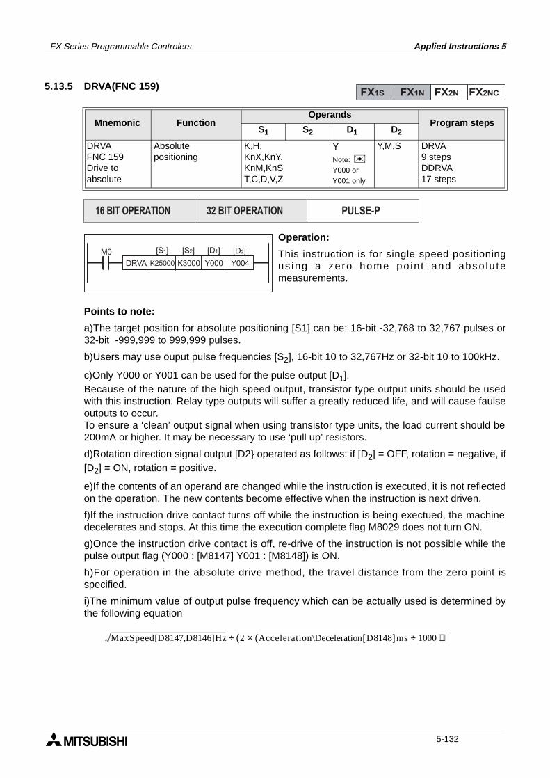
FX Series Programmable Controlers Applied Instructions 5
5.13.5 DRVA(FNC 159)
Operation:
This instruction is for single speed positioningus ing a ze ro home po in t and abso lu temeasurements.
Points to note:
a)The target position for absolute positioning [S1] can be: 16-bit -32,768 to 32,767 pulses or32-bit -999,999 to 999,999 pulses.
b)Users may use ouput pulse frequencies [S2], 16-bit 10 to 32,767Hz or 32-bit 10 to 100kHz.
c)Only Y000 or Y001 can be used for the pulse output [D1].Because of the nature of the high speed output, transistor type output units should be usedwith this instruction. Relay type outputs will suffer a greatly reduced life, and will cause faulseoutputs to occur.To ensure a ‘clean’ output signal when using transistor type units, the load current should be200mA or higher. It may be necessary to use ‘pull up’ resistors.
d)Rotation direction signal output [D2 operated as follows: if [D2] = OFF, rotation = negative, if[D2] = ON, rotation = positive.
e)If the contents of an operand are changed while the instruction is executed, it is not reflectedon the operation. The new contents become effective when the instruction is next driven.
f)If the instruction drive contact turns off while the instruction is being exectued, the machinedecelerates and stops. At this time the execution complete flag M8029 does not turn ON.
g)Once the instruction drive contact is off, re-drive of the instruction is not possible while thepulse output flag (Y000 : [M8147] Y001 : [M8148]) is ON.
h)For operation in the absolute drive method, the travel distance from the zero point isspecified.
i)The minimum value of output pulse frequency which can be actually used is determined bythe following equation
Mnemonic Function Operands
Program stepsS1 S2 D1 D2
DRVAFNC 159Drive to absolute
Absolutepositioning
K,H,KnX,KnY,KnM,KnST,C,D,V,Z
Y Note: Y000 or Y001 only
Y,M,S DRVA9 stepsDDRVA17 steps
FX1S FX1N FX2N FX2NC
PULSE-P16 BIT OPERATION 32 BIT OPERATION
DRVA K25000 K3000 Y004
[S2][S1]M0
Y000
[D1] [D2]
MaxSpeed D8147 D8146[ , ]Hz 2( Acceleration\Deceleration D8148[ ]ms(× 1000 ) )÷÷
5-132

FX Series Programmable Controlers Applied Instructions 5
f)Related device numbers.D8145 : Bias speed adopted when either FNC158, DRVI or FNC159, DRVA are executedD8147 (upper digit) & D8146 (lower digit) : Maximum speed when FNC158 or FNC159are ececuted 100~100,000Hz.D8148 : Acceleration/Deceleration time adopted when either FNC158 or FNC159 areexecutedM8145 : Y000 pulse output stop (immediate)M8146 : Y001 pulse output stop (immediate)M8147 : Y000 pulse output monitor (BUS/READY)M8148 : Y001 pulse output monitor (BUS/READY)
• Attention should be paid to the instruction drive timing.
5-133

FX Series Programmable Controlers Applied Instructions 5
Memo
5-134
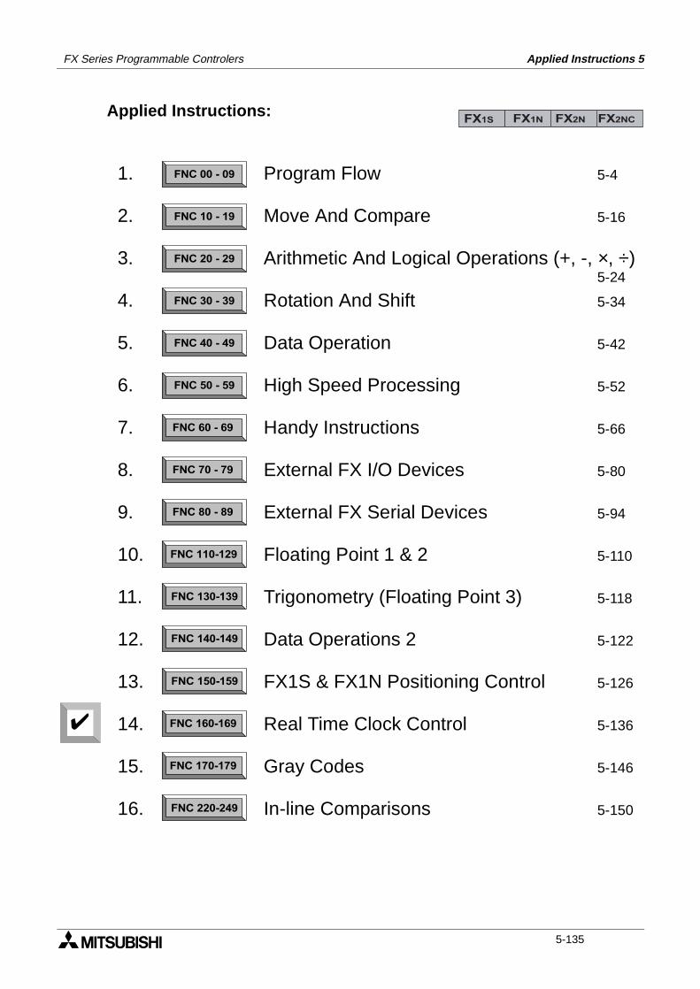
FX Series Programmable Controlers Applied Instructions 5
Applied Instructions:FX1S FX1N FX2N FX2NC
FNC 00 - 09
FNC 10 - 19
FNC 20 - 29
FNC 30 - 39
FNC 40 - 49
FNC 50 - 59
FNC 60 - 69
FNC 70 - 79
FNC 80 - 89
FNC 110-129
FNC 130-139
FNC 140-149
FNC 160-169
FNC 170-179
FNC 220-249
FNC 150-159
1.
2.
3.
4.
5.
6.
7.
8.
9.
10.
11.
12.
13.
14.
15.
16.
Program Flow 5-4
Move And Compare 5-16
Arithmetic And Logical Operations (+, -, ×, ÷)5-24
Rotation And Shift 5-34
Data Operation 5-42
High Speed Processing 5-52
Handy Instructions 5-66
External FX I/O Devices 5-80
External FX Serial Devices 5-94
Floating Point 1 & 2 5-110
Trigonometry (Floating Point 3) 5-118
Data Operations 2 5-122
FX1S & FX1N Positioning Control 5-126
Real Time Clock Control 5-136
Gray Codes 5-146
In-line Comparisons 5-150
5-135
FX Series Programmable Controlers Applied Instructions 5
5.14 Real Time Clock Control - FNC 160 to FNC 169
Contents:
Page
TCMP - Time Compare FNC 160 5-137
TZCP - Time Zone Compare FNC 161 5-138
TADD - Time Add FNC 162 5-139
TSUB - Time Subtract FNC 163 5-140
- Not Available FNC 164 to 165
TRD - Read RTC data FNC 166 5-141
TWR - Set RTC data FNC 167 5-142
- Not Available FNC 168
HOUR - Hour meter FNC 169 5-143
Symbols list:
D - Destination device.S - Source device.m, n- Number of active devices, bits or an operational constant.Additional numeric suffixes will be attached if there are more than one operand with the samefunction e.g. D1, S3 or for lists/tabled devices D3+0, S+9 etc.MSB - Most Significant Bit, sometimes used to indicate the mathematical sign of a number,i.e. positive = 0, and negative = 1.LSB - Least Significant Bit.
Instruction modifications:
- An instruction operating in 16 bit mode, where identifies the instructionmnemonic.
P - A 16 bit mode instruction modified to use pulse (single) operation.
D - An instruction modified to operate in 32 bit operation.
DP - A 32 bit mode instruction modified to use pulse (single) operation.
- A repetitive instruction which will change the destination value on every scan unlessmodified by the pulse function.
- An operand which cannot be indexed, i.e. The addition of V or Z is either invalid or willhave no effect to the value of the operand.
5-136
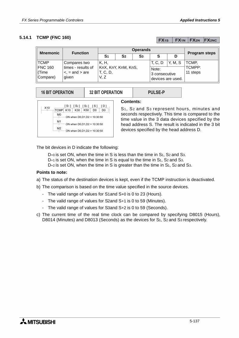
FX Series Programmable Controlers Applied Instructions 5
5.14.1 TCMP (FNC 160)
Contents:
S1, S2 and S3 represent hours, minutes andseconds respectively. This time is compared to thetime value in the 3 data devices specified by thehead address S. The result is indicated in the 3 bitdevices specified by the head address D.
The bit devices in D indicate the following:
D+0 is set ON, when the time in S is less than the time in S1, S2 and S3.D+1 is set ON, when the time in S is equal to the time in S1, S2 and S3.D+2 is set ON, when the time in S is greater than the time in S1, S2 and S3.
Points to note:
a) The status of the destination devices is kept, even if the TCMP instruction is deactivated.
b) The comparison is based on the time value specified in the source devices.
- The valid range of values for S1and S+0 is 0 to 23 (Hours).
- The valid range of values for S2and S+1 is 0 to 59 (Minutes).
- The valid range of values for S3and S+2 is 0 to 59 (Seconds).
c) The current time of the real time clock can be compared by specifying D8015 (Hours),D8014 (Minutes) and D8013 (Seconds) as the devices for S1, S2 and S3 respectively.
Mnemonic Function Operands
Program stepsS1 S2 S3 S D
TCMPFNC 160(TimeCompare)
Compares twotimes - results of<, = and > aregiven
K, H,KnX, KnY, KnM, KnS,T, C, D,V, Z
T, C, D Y, M, S TCMP,TCMPP:11 steps
Note:3 consecutivedevices are used.
FX1S FX1N FX2N FX2NC
PULSE-P16 BIT OPERATION 32 BIT OPERATION
X10K10 K30 K50 D0 D0TCMP
M0
M1
M2
[ S1 ] [ S2 ] [ S ][ S3 ] [ D ]
ON when D0,D1,D2 < 10:30:50
ON when D0,D1,D2 = 10:30:50
ON when D0,D1,D2 > 10:30:50
5-137
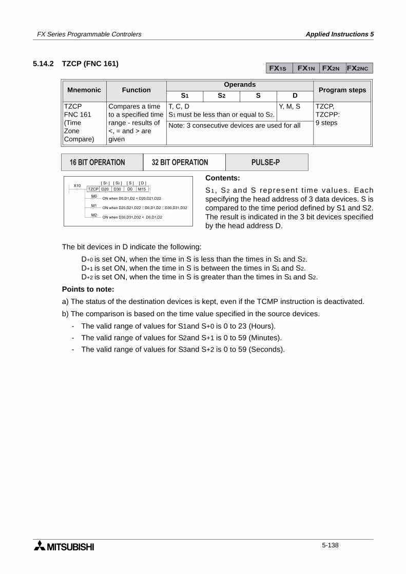
FX Series Programmable Controlers Applied Instructions 5
5.14.2 TZCP (FNC 161)
Contents:
S1, S2 and S represent t ime va lues. Eachspecifying the head address of 3 data devices. S iscompared to the time period defined by S1 and S2.The result is indicated in the 3 bit devices specifiedby the head address D.
The bit devices in D indicate the following:
D+0 is set ON, when the time in S is less than the times in S1 and S2.D+1 is set ON, when the time in S is between the times in S1 and S2.D+2 is set ON, when the time in S is greater than the times in S1 and S2.
Points to note:
a) The status of the destination devices is kept, even if the TCMP instruction is deactivated.
b) The comparison is based on the time value specified in the source devices.
- The valid range of values for S1and S+0 is 0 to 23 (Hours).
- The valid range of values for S2and S+1 is 0 to 59 (Minutes).
- The valid range of values for S3and S+2 is 0 to 59 (Seconds).
Mnemonic Function Operands
Program stepsS1 S2 S D
TZCPFNC 161(TimeZoneCompare)
Compares a timeto a specified timerange - results of<, = and > aregiven
T, C, DS1 must be less than or equal to S2.
Y, M, S TZCP,TZCPP:9 stepsNote: 3 consecutive devices are used for all
FX1S FX1N FX2N FX2NC
PULSE-P16 BIT OPERATION 32 BIT OPERATION
X10D20 D30 D0 M15TZCP
M0
M1
M2
[ S1 ] [ S2 ] [ S ] [ D ]
ON when D0,D1,D2 < D20,D21,D22
ON when D20,D21,D22 £ D0,D1,D2 £ D30,D31,D32
ON when D30,D31,D32 < D0,D1,D2
5-138
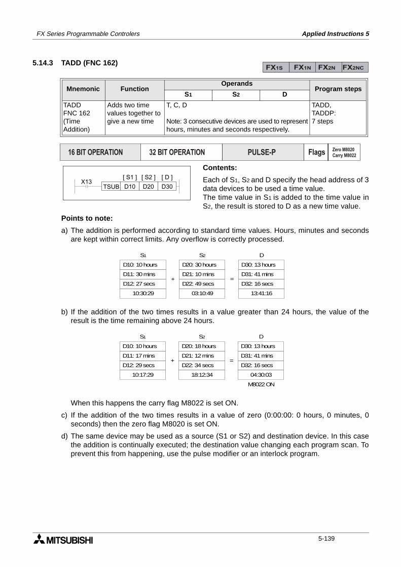
FX Series Programmable Controlers Applied Instructions 5
5.14.3 TADD (FNC 162)
Contents:
Each of S1, S2 and D specify the head address of 3data devices to be used a time value. The time value in S1 is added to the time value inS2, the result is stored to D as a new time value.
Points to note:
a) The addition is performed according to standard time values. Hours, minutes and secondsare kept within correct limits. Any overflow is correctly processed.
b) If the addition of the two times results in a value greater than 24 hours, the value of theresult is the time remaining above 24 hours.
When this happens the carry flag M8022 is set ON.
c) If the addition of the two times results in a value of zero (0:00:00: 0 hours, 0 minutes, 0seconds) then the zero flag M8020 is set ON.
d) The same device may be used as a source (S1 or S2) and destination device. In this casethe addition is continually executed; the destination value changing each program scan. Toprevent this from happening, use the pulse modifier or an interlock program.
Mnemonic Function Operands
Program stepsS1 S2 D
TADDFNC 162(TimeAddition)
Adds two timevalues together togive a new time
T, C, D
Note: 3 consecutive devices are used to representhours, minutes and seconds respectively.
TADD,TADDP:7 steps
FX1S FX1N FX2N FX2NC
PULSE-P16 BIT OPERATION 32 BIT OPERATION Flags Zero M8020
Carry M8022
D10 D20 D30TSUBX13
[ S1 ] [ S2 ] [ D ]
D10: 10 hours
D11: 30 mins
D12: 27 secs
10:30:29
S1
+
D20: 30 hours
D21: 10 mins
D22: 49 secs
03:10:49
S2
=
D30: 13 hours
D31: 41 mins
D32: 16 secs
13:41:16
D
D10: 10 hours
D11: 17 mins
D12: 29 secs
10:17:29
S1
+
D20: 18 hours
D21: 12 mins
D22: 34 secs
18:12:34
S2
=
D30: 13 hours
D31: 41 mins
D32: 16 secs
04:30:03
D
M8022 ON
5-139
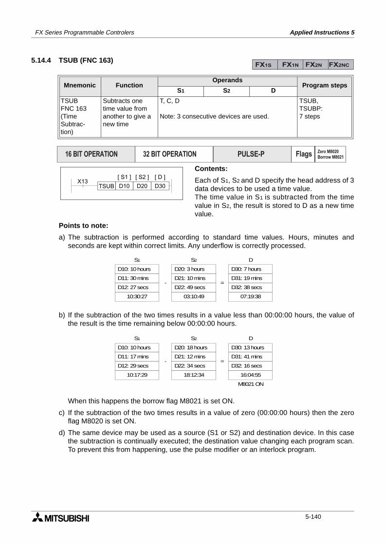
FX Series Programmable Controlers Applied Instructions 5
5.14.4 TSUB (FNC 163)
Contents:
Each of S1, S2 and D specify the head address of 3data devices to be used a time value.The time value in S1 is subtracted from the timevalue in S2, the result is stored to D as a new timevalue.
Points to note:
a) The subtraction is performed according to standard time values. Hours, minutes andseconds are kept within correct limits. Any underflow is correctly processed.
b) If the subtraction of the two times results in a value less than 00:00:00 hours, the value ofthe result is the time remaining below 00:00:00 hours.
When this happens the borrow flag M8021 is set ON.
c) If the subtraction of the two times results in a value of zero (00:00:00 hours) then the zeroflag M8020 is set ON.
d) The same device may be used as a source (S1 or S2) and destination device. In this casethe subtraction is continually executed; the destination value changing each program scan.To prevent this from happening, use the pulse modifier or an interlock program.
Mnemonic Function Operands
Program stepsS1 S2 D
TSUBFNC 163(TimeSubtrac-tion)
Subtracts onetime value fromanother to give anew time
T, C, D
Note: 3 consecutive devices are used.
TSUB,TSUBP:7 steps
FX1S FX1N FX2N FX2NC
PULSE-P16 BIT OPERATION 32 BIT OPERATION Flags Zero M8020
Borrow M8021
D10 D20 D30TSUBX13
[ S1 ] [ S2 ] [ D ]
D10: 10 hours
D11: 30 mins
D12: 27 secs
10:30:27
S1
-
D20: 3 hours
D21: 10 mins
D22: 49 secs
03:10:49
S2
=
D30: 7 hours
D31: 19 mins
D32: 38 secs
07:19:38
D
D10: 10 hours
D11: 17 mins
D12: 29 secs
10:17:29
S1
-
D20: 18 hours
D21: 12 mins
D22: 34 secs
18:12:34
S2
=
D30: 13 hours
D31: 41 mins
D32: 16 secs
16:04:55
D
M8021 ON
5-140
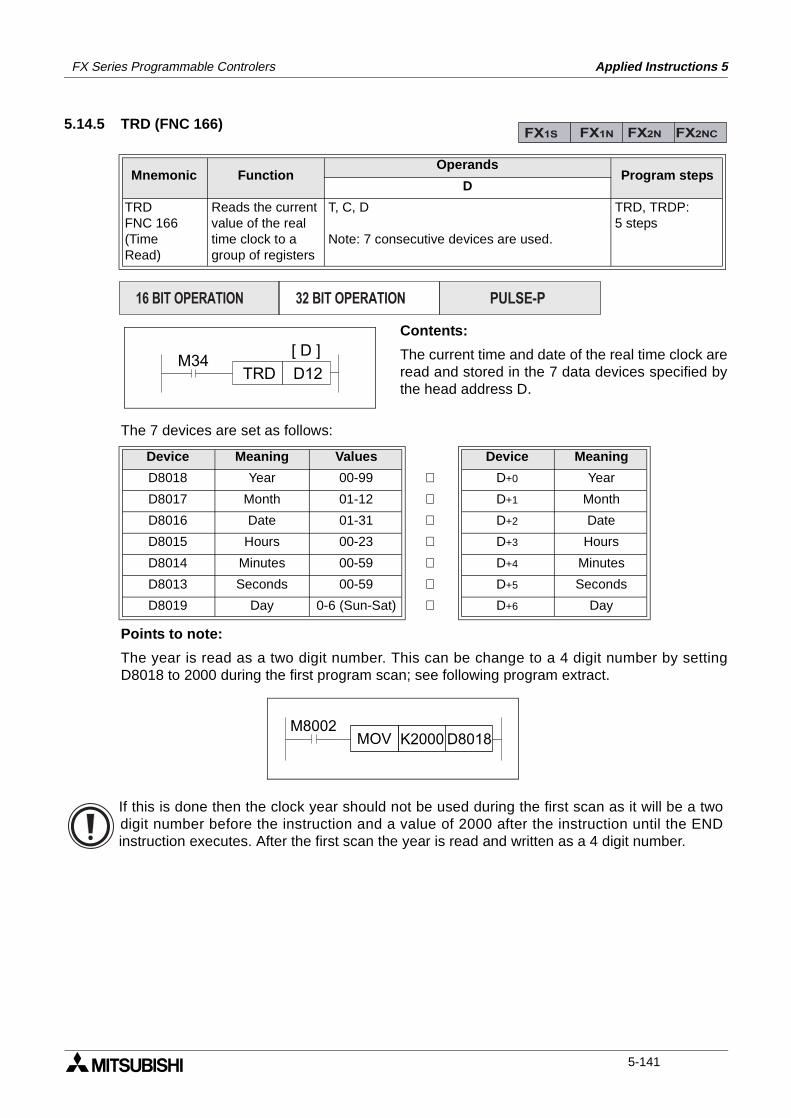
FX Series Programmable Controlers Applied Instructions 5
5.14.5 TRD (FNC 166)
Contents:
The current time and date of the real time clock areread and stored in the 7 data devices specified bythe head address D.
The 7 devices are set as follows:
Points to note:
The year is read as a two digit number. This can be change to a 4 digit number by settingD8018 to 2000 during the first program scan; see following program extract.
Mnemonic Function Operands
Program stepsD
TRDFNC 166(TimeRead)
Reads the currentvalue of the realtime clock to agroup of registers
T, C, D
Note: 7 consecutive devices are used.
TRD, TRDP:5 steps
Device Meaning Values Device Meaning
D8018 Year 00-99 ⇒ D+0 Year
D8017 Month 01-12 ⇒ D+1 Month
D8016 Date 01-31 ⇒ D+2 Date
D8015 Hours 00-23 ⇒ D+3 Hours
D8014 Minutes 00-59 ⇒ D+4 Minutes
D8013 Seconds 00-59 ⇒ D+5 Seconds
D8019 Day 0-6 (Sun-Sat) ⇒ D+6 Day
FX1S FX1N FX2N FX2NC
PULSE-P16 BIT OPERATION 32 BIT OPERATION
M34D12TRD
[ D ]
M8002K2000 D8018MOV
If this is done then the clock year should not be used during the first scan as it will be a twodigit number before the instruction and a value of 2000 after the instruction until the ENDinstruction executes. After the first scan the year is read and written as a 4 digit number.
5-141
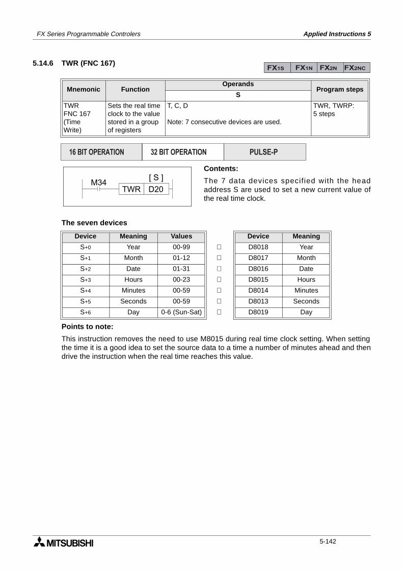
FX Series Programmable Controlers Applied Instructions 5
5.14.6 TWR (FNC 167)
Contents:
The 7 data devices specif ied with the headaddress S are used to set a new current value ofthe real time clock.
The seven devices
Points to note:
This instruction removes the need to use M8015 during real time clock setting. When settingthe time it is a good idea to set the source data to a time a number of minutes ahead and thendrive the instruction when the real time reaches this value.
Mnemonic Function Operands
Program stepsS
TWRFNC 167(TimeWrite)
Sets the real timeclock to the valuestored in a groupof registers
T, C, D
Note: 7 consecutive devices are used.
TWR, TWRP:5 steps
Device Meaning Values Device Meaning
S+0 Year 00-99 ⇒ D8018 Year
S+1 Month 01-12 ⇒ D8017 Month
S+2 Date 01-31 ⇒ D8016 Date
S+3 Hours 00-23 ⇒ D8015 Hours
S+4 Minutes 00-59 ⇒ D8014 Minutes
S+5 Seconds 00-59 ⇒ D8013 Seconds
S+6 Day 0-6 (Sun-Sat) ⇒ D8019 Day
FX1S FX1N FX2N FX2NC
PULSE-P16 BIT OPERATION 32 BIT OPERATION
M34D20TWR
[ S ]
5-142
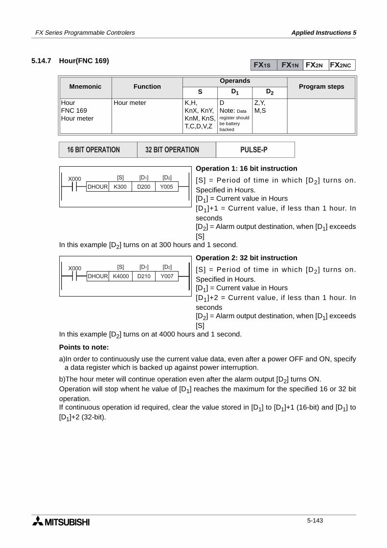
FX Series Programmable Controlers Applied Instructions 5
5.14.7 Hour(FNC 169)
Operation 1: 16 bit instruction
[S] = Period of t ime in which [D2] turns on.Specified in Hours.[D1] = Current value in Hours[D1]+1 = Current value, if less than 1 hour. Inseconds[D2] = Alarm output destination, when [D1] exceeds[S]
In this example [D2] turns on at 300 hours and 1 second.
Operation 2: 32 bit instruction
[S] = Period of t ime in which [D2] turns on.Specified in Hours.[D1] = Current value in Hours[D1]+2 = Current value, if less than 1 hour. Inseconds[D2] = Alarm output destination, when [D1] exceeds[S]
In this example [D2] turns on at 4000 hours and 1 second.
Points to note:
a)In order to continuously use the current value data, even after a power OFF and ON, specifya data register which is backed up against power interruption.
b)The hour meter will continue operation even after the alarm output [D2] turns ON.Operation will stop whent he value of [D1] reaches the maximum for the specified 16 or 32 bitoperation.If continuous operation id required, clear the value stored in [D1] to [D1]+1 (16-bit) and [D1] to[D1]+2 (32-bit).
Mnemonic Function Operands
Program stepsS D1 D2
HourFNC 169Hour meter
Hour meter K,H,KnX, KnY,KnM, KnS,T,C,D,V,Z
DNote: Data
register should be battery backed
Z,Y,M,S
FX1S FX1N FX2N FX2NC
PULSE-P16 BIT OPERATION 32 BIT OPERATION
DHOUR K300 D200 Y005
[S] [D2][D1]X000
DHOUR K4000 D210 Y007
[S] [D2][D1]X000
5-143

FX Series Programmable Controlers Applied Instructions 5
Memo
5-144
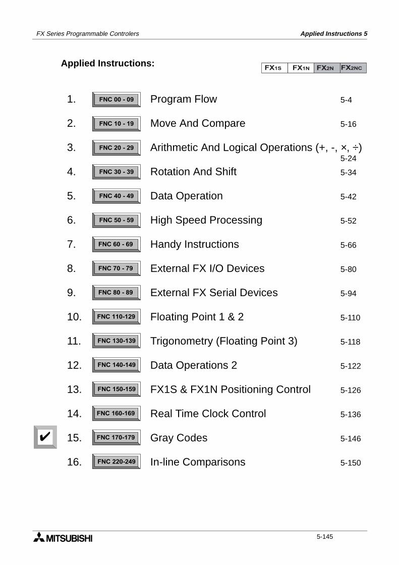
FX Series Programmable Controlers Applied Instructions 5
Applied Instructions:FX1S FX1N FX2N FX2NC
FNC 00 - 09
FNC 10 - 19
FNC 20 - 29
FNC 30 - 39
FNC 40 - 49
FNC 50 - 59
FNC 60 - 69
FNC 70 - 79
FNC 80 - 89
FNC 110-129
FNC 130-139
FNC 140-149
FNC 160-169
FNC 170-179
FNC 220-249
FNC 150-159
1.
2.
3.
4.
5.
6.
7.
8.
9.
10.
11.
12.
13.
14.
15.
16.
Program Flow 5-4
Move And Compare 5-16
Arithmetic And Logical Operations (+, -, ×, ÷)5-24
Rotation And Shift 5-34
Data Operation 5-42
High Speed Processing 5-52
Handy Instructions 5-66
External FX I/O Devices 5-80
External FX Serial Devices 5-94
Floating Point 1 & 2 5-110
Trigonometry (Floating Point 3) 5-118
Data Operations 2 5-122
FX1S & FX1N Positioning Control 5-126
Real Time Clock Control 5-136
Gray Codes 5-146
In-line Comparisons 5-150
5-145
FX Series Programmable Controlers Applied Instructions 5
5.15 Gray Codes - FNC 170 to FNC 179
Contents:
Page
GRY - Decimal to Gray Code FNC 170 5-147
GBIN - Gray Code to Decimal FNC 171 5-147
- Not Available FNC 172 to 175
RD3A - Read FX0N-3A FNC 176 5-148
WR3A - Write to FX0N-3A FNC 177 5-148
Symbols list:
D - Destination device.S - Source device.m, n- Number of active devices, bits or an operational constant.Additional numeric suffixes will be attached if there are more than one operand with the samefunction e.g. D1, S3 or for lists/tabled devices D3+0, S+9 etc.MSB - Most Significant Bit, sometimes used to indicate the mathematical sign of a number,i.e. positive = 0, and negative = 1.LSB - Least Significant Bit.
Instruction modifications:
- An instruction operating in 16 bit mode, where identifies the instructionmnemonic.
P - A 16 bit mode instruction modified to use pulse (single) operation.
D - An instruction modified to operate in 32 bit operation.
DP - A 32 bit mode instruction modified to use pulse (single) operation.
- A repetitive instruction which will change the destination value on every scan unlessmodified by the pulse function.
- An operand which cannot be indexed, i.e. The addition of V or Z is either invalid or willhave no effect to the value of the operand.
5-146
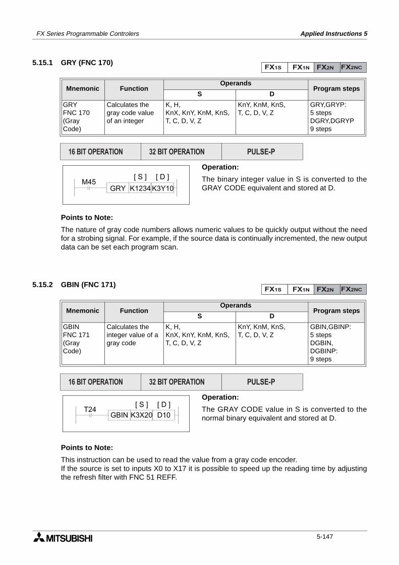
FX Series Programmable Controlers Applied Instructions 5
5.15.1 GRY (FNC 170)
Operation:
The binary integer value in S is converted to theGRAY CODE equivalent and stored at D.
Points to Note:
The nature of gray code numbers allows numeric values to be quickly output without the needfor a strobing signal. For example, if the source data is continually incremented, the new outputdata can be set each program scan.
5.15.2 GBIN (FNC 171)
Operation:
The GRAY CODE value in S is converted to thenormal binary equivalent and stored at D.
Points to Note:
This instruction can be used to read the value from a gray code encoder. If the source is set to inputs X0 to X17 it is possible to speed up the reading time by adjustingthe refresh filter with FNC 51 REFF.
Mnemonic Function Operands
Program stepsS D
GRYFNC 170(GrayCode)
Calculates thegray code valueof an integer
K, H,KnX, KnY, KnM, KnS,T, C, D, V, Z
KnY, KnM, KnS,T, C, D, V, Z
GRY,GRYP:5 stepsDGRY,DGRYP9 steps
Mnemonic Function Operands
Program stepsS D
GBINFNC 171(GrayCode)
Calculates theinteger value of agray code
K, H,KnX, KnY, KnM, KnS,T, C, D, V, Z
KnY, KnM, KnS,T, C, D, V, Z
GBIN,GBINP:5 stepsDGBIN,DGBINP:9 steps
FX1S FX1N FX2N FX2NC
PULSE-P16 BIT OPERATION 32 BIT OPERATION
M45K1234 K3Y10GRY
[ S ] [ D ]
FX1S FX1N FX2N FX2NC
PULSE-P16 BIT OPERATION 32 BIT OPERATION
T24K3X20 D10GBIN
[ S ] [ D ]
5-147
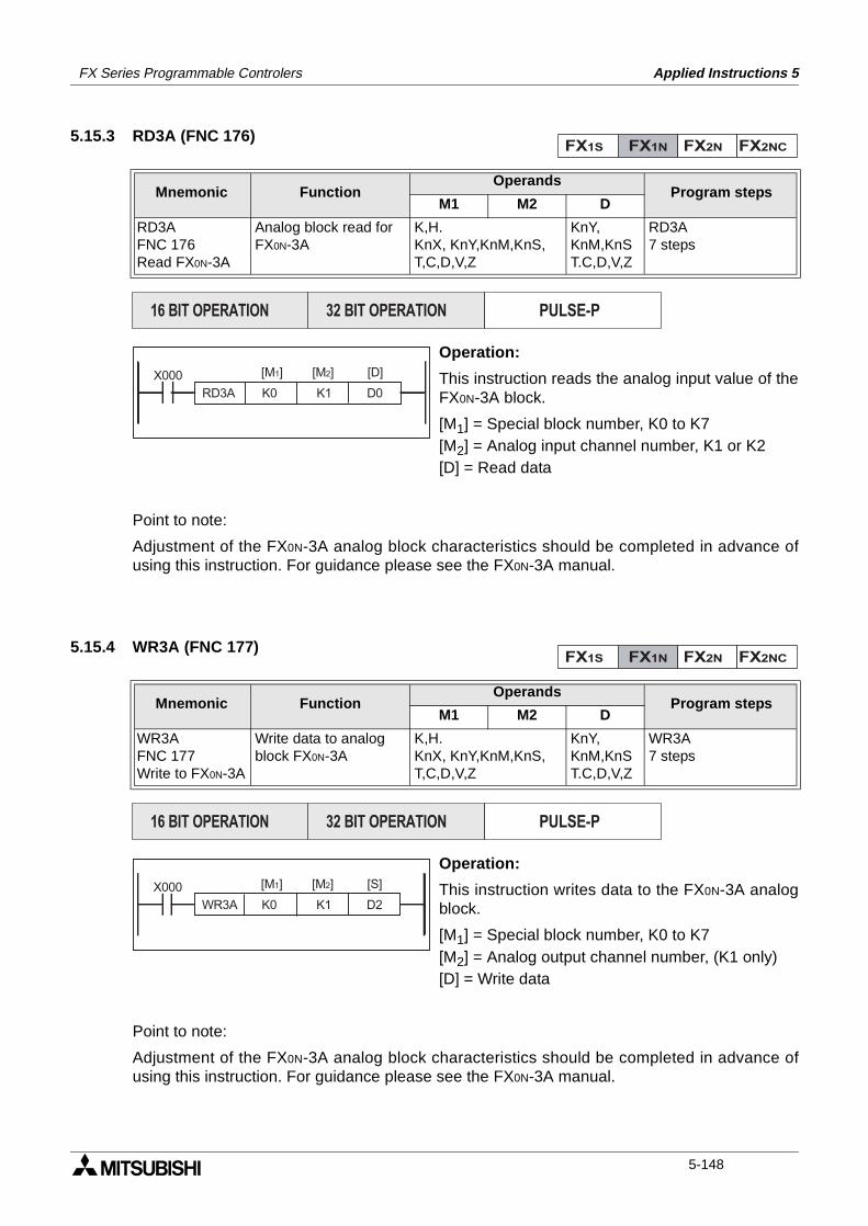
FX Series Programmable Controlers Applied Instructions 5
5.15.3 RD3A (FNC 176)
Operation:
This instruction reads the analog input value of theFX0N-3A block.
[M1] = Special block number, K0 to K7[M2] = Analog input channel number, K1 or K2[D] = Read data
Point to note:
Adjustment of the FX0N-3A analog block characteristics should be completed in advance ofusing this instruction. For guidance please see the FX0N-3A manual.
5.15.4 WR3A (FNC 177)
Operation:
This instruction writes data to the FX0N-3A analogblock.
[M1] = Special block number, K0 to K7[M2] = Analog output channel number, (K1 only)[D] = Write data
Point to note:
Adjustment of the FX0N-3A analog block characteristics should be completed in advance ofusing this instruction. For guidance please see the FX0N-3A manual.
Mnemonic Function Operands
Program stepsM1 M2 D
RD3AFNC 176Read FX0N-3A
Analog block read forFX0N-3A
K,H.KnX, KnY,KnM,KnS,T,C,D,V,Z
KnY,KnM,KnST.C,D,V,Z
RD3A7 steps
Mnemonic Function Operands
Program stepsM1 M2 D
WR3AFNC 177Write to FX0N-3A
Write data to analog block FX0N-3A
K,H.KnX, KnY,KnM,KnS,T,C,D,V,Z
KnY,KnM,KnST.C,D,V,Z
WR3A7 steps
FX1S FX1N FX2N FX2NC
PULSE-P16 BIT OPERATION 32 BIT OPERATION
RD3A K0 K1 D0
[M1] [D][M2]X000
FX1S FX1N FX2N FX2NC
PULSE-P16 BIT OPERATION 32 BIT OPERATION
WR3A K0 K1 D2
[M1] [S][M2]X000
5-148
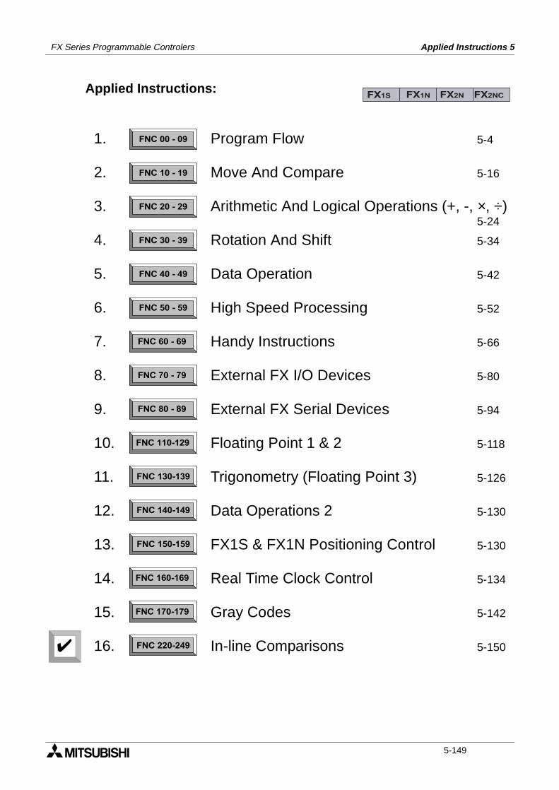
FX Series Programmable Controlers Applied Instructions 5
Applied Instructions:FX1S FX1N FX2N FX2NC
FNC 00 - 09
FNC 10 - 19
FNC 20 - 29
FNC 30 - 39
FNC 40 - 49
FNC 50 - 59
FNC 60 - 69
FNC 70 - 79
FNC 80 - 89
FNC 110-129
FNC 130-139
FNC 140-149
FNC 160-169
FNC 170-179
FNC 220-249
FNC 150-159
1.
2.
3.
4.
5.
6.
7.
8.
9.
10.
11.
12.
13.
14.
15.
16.
Program Flow 5-4
Move And Compare 5-16
Arithmetic And Logical Operations (+, -, ×, ÷)5-24
Rotation And Shift 5-34
Data Operation 5-42
High Speed Processing 5-52
Handy Instructions 5-66
External FX I/O Devices 5-80
External FX Serial Devices 5-94
Floating Point 1 & 2 5-118
Trigonometry (Floating Point 3) 5-126
Data Operations 2 5-130
FX1S & FX1N Positioning Control 5-130
Real Time Clock Control 5-134
Gray Codes 5-142
In-line Comparisons 5-150
5-149
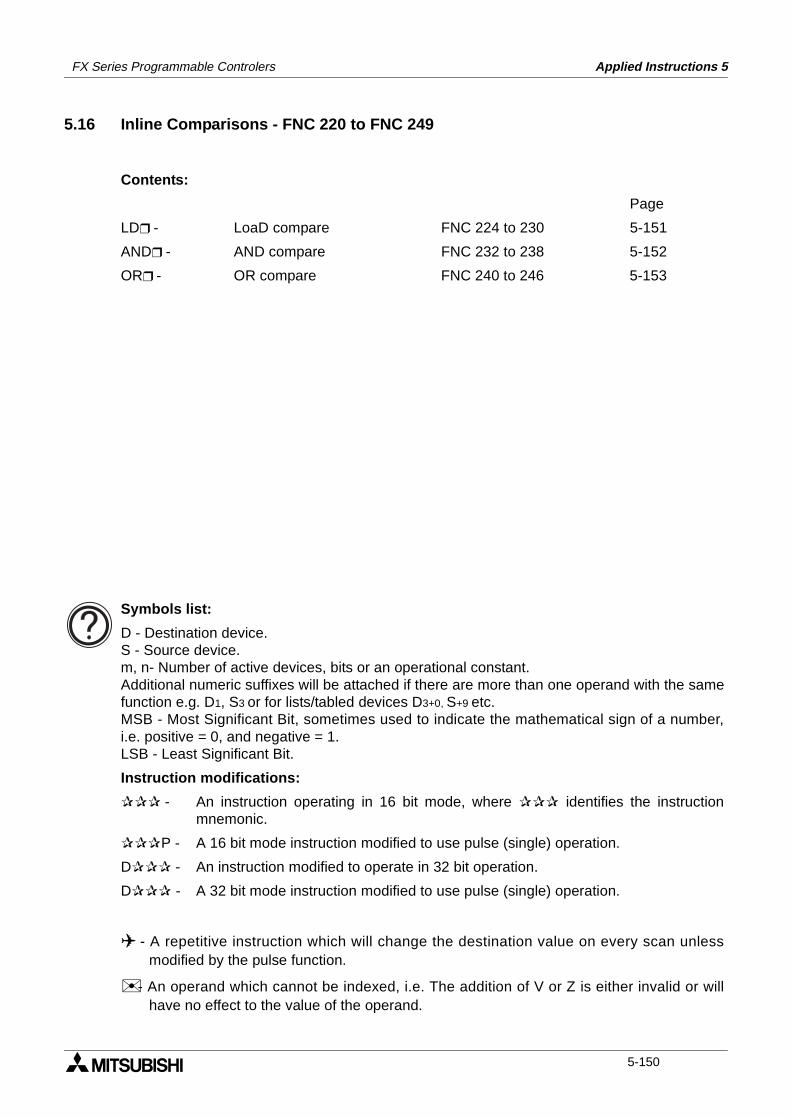
FX Series Programmable Controlers Applied Instructions 5
5.16 Inline Comparisons - FNC 220 to FNC 249
Contents:
Page
LD - LoaD compare FNC 224 to 230 5-151
AND - AND compare FNC 232 to 238 5-152
OR - OR compare FNC 240 to 246 5-153
Symbols list:
D - Destination device.S - Source device.m, n- Number of active devices, bits or an operational constant.Additional numeric suffixes will be attached if there are more than one operand with the samefunction e.g. D1, S3 or for lists/tabled devices D3+0, S+9 etc.MSB - Most Significant Bit, sometimes used to indicate the mathematical sign of a number,i.e. positive = 0, and negative = 1.LSB - Least Significant Bit.
Instruction modifications:
- An instruction operating in 16 bit mode, where identifies the instructionmnemonic.
P - A 16 bit mode instruction modified to use pulse (single) operation.
D - An instruction modified to operate in 32 bit operation.
D - A 32 bit mode instruction modified to use pulse (single) operation.
- A repetitive instruction which will change the destination value on every scan unlessmodified by the pulse function.
- An operand which cannot be indexed, i.e. The addition of V or Z is either invalid or willhave no effect to the value of the operand.
5-150
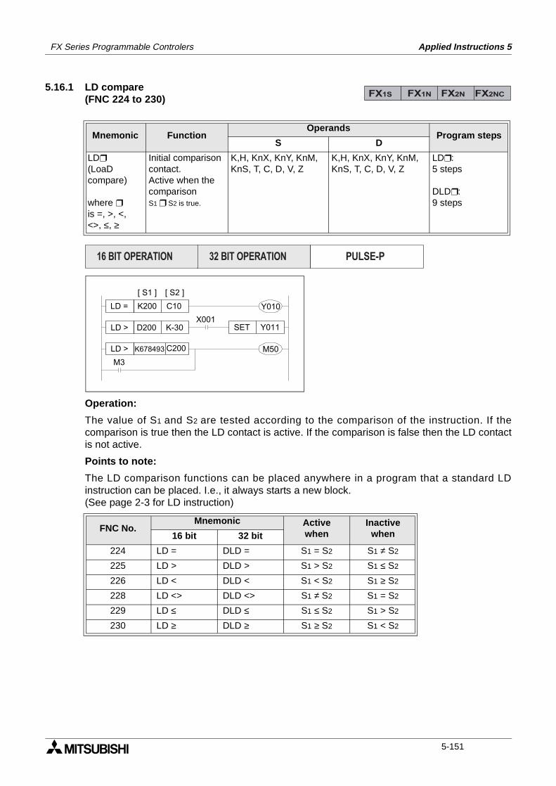
FX Series Programmable Controlers Applied Instructions 5
5.16.1 LD compare (FNC 224 to 230)
Operation:
The value of S1 and S2 are tested according to the comparison of the instruction. If thecomparison is true then the LD contact is active. If the comparison is false then the LD contactis not active.
Points to note:
The LD comparison functions can be placed anywhere in a program that a standard LDinstruction can be placed. I.e., it always starts a new block. (See page 2-3 for LD instruction)
Mnemonic Function Operands
Program stepsS D
LD
(LoaDcompare)
where is =, >, <,<>, ≤, ≥
Initial comparisoncontact.Active when thecomparisonS1 S2 is true.
K,H, KnX, KnY, KnM,KnS, T, C, D, V, Z
K,H, KnX, KnY, KnM,KnS, T, C, D, V, Z
LD:5 steps
DLD:9 steps
FNC No.Mnemonic Active
whenInactive
when16 bit 32 bit
224 LD = DLD = S1 = S2 S1 ≠ S2
225 LD > DLD > S1 > S2 S1 ≤ S2
226 LD < DLD < S1 < S2 S1 ≥ S2
228 LD <> DLD <> S1 ≠ S2 S1 = S2
229 LD ≤ DLD ≤ S1 ≤ S2 S1 > S2
230 LD ≥ DLD ≥ S1 ≥ S2 S1 < S2
FX1S FX1N FX2N FX2NC
K200 C10LD =
D200 K-30LD >
M3
M50
X001Y011SET
Y010
[ S1 ] [ S2 ]
K678493 C200LD >
PULSE-P16 BIT OPERATION 32 BIT OPERATION
5-151
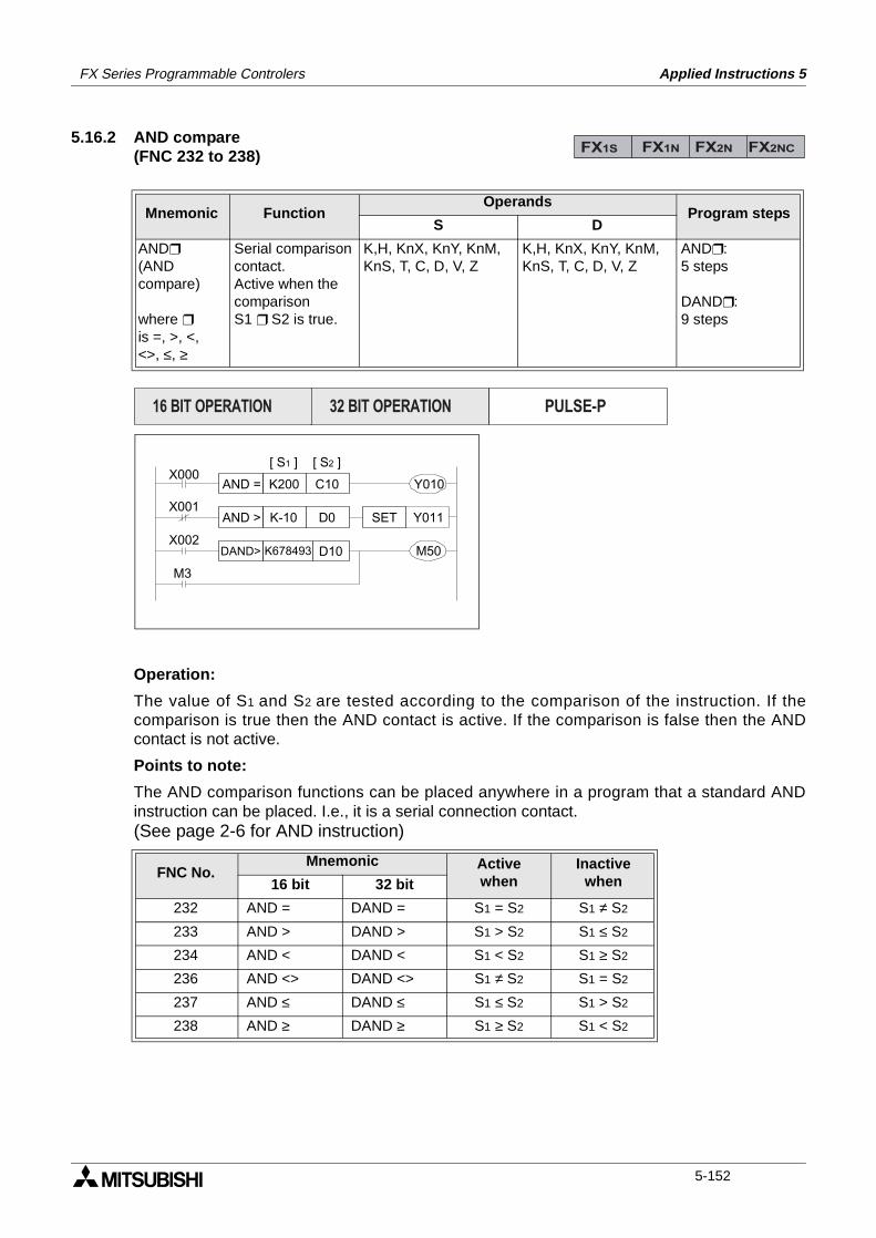
FX Series Programmable Controlers Applied Instructions 5
5.16.2 AND compare (FNC 232 to 238)
Operation:
The value of S1 and S2 are tested according to the comparison of the instruction. If thecomparison is true then the AND contact is active. If the comparison is false then the ANDcontact is not active.
Points to note:
The AND comparison functions can be placed anywhere in a program that a standard ANDinstruction can be placed. I.e., it is a serial connection contact. (See page 2-6 for AND instruction)
Mnemonic Function Operands
Program stepsS D
AND
(ANDcompare)
where is =, >, <,<>, ≤, ≥
Serial comparisoncontact.Active when thecomparisonS1 S2 is true.
K,H, KnX, KnY, KnM,KnS, T, C, D, V, Z
K,H, KnX, KnY, KnM,KnS, T, C, D, V, Z
AND:5 steps
DAND:9 steps
FNC No.Mnemonic Active
whenInactive
when16 bit 32 bit
232 AND = DAND = S1 = S2 S1 ≠ S2
233 AND > DAND > S1 > S2 S1 ≤ S2
234 AND < DAND < S1 < S2 S1 ≥ S2
236 AND <> DAND <> S1 ≠ S2 S1 = S2
237 AND ≤ DAND ≤ S1 ≤ S2 S1 > S2
238 AND ≥ DAND ≥ S1 ≥ S2 S1 < S2
FX1S FX1N FX2N FX2NC
K200 C10AND =
K-10 D0AND >
M3
M50
Y011SET
Y010
[ S1 ] [ S2 ]X000
X001
X002K678493 D10DAND>
PULSE-P16 BIT OPERATION 32 BIT OPERATION
5-152
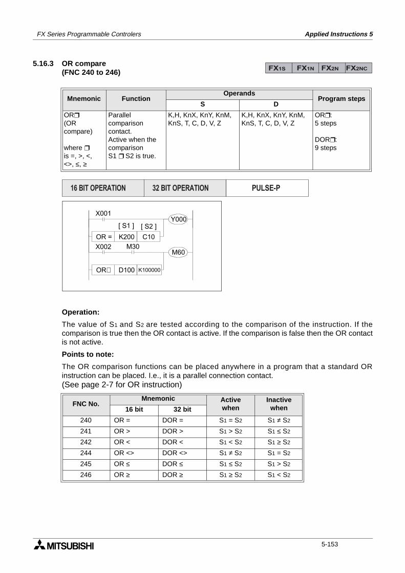
FX Series Programmable Controlers Applied Instructions 5
5.16.3 OR compare (FNC 240 to 246)
Operation:
The value of S1 and S2 are tested according to the comparison of the instruction. If thecomparison is true then the OR contact is active. If the comparison is false then the OR contactis not active.
Points to note:
The OR comparison functions can be placed anywhere in a program that a standard ORinstruction can be placed. I.e., it is a parallel connection contact.(See page 2-7 for OR instruction)
Mnemonic Function Operands
Program stepsS D
OR
(ORcompare)
where is =, >, <,<>, ≤, ≥
Parallelcomparisoncontact.Active when thecomparisonS1 S2 is true.
K,H, KnX, KnY, KnM,KnS, T, C, D, V, Z
K,H, KnX, KnY, KnM,KnS, T, C, D, V, Z
OR:5 steps
DOR:9 steps
FNC No.Mnemonic Active
whenInactive
when16 bit 32 bit
240 OR = DOR = S1 = S2 S1 ≠ S2
241 OR > DOR > S1 > S2 S1 ≤ S2
242 OR < DOR < S1 < S2 S1 ≥ S2
244 OR <> DOR <> S1 ≠ S2 S1 = S2
245 OR ≤ DOR ≤ S1 ≤ S2 S1 > S2
246 OR ≥ DOR ≥ S1 ≥ S2 S1 < S2
FX1S FX1N FX2N FX2NC
X001
K200 C10OR =
Y000
X002 M30M60
[ S1 ] [ S2 ]
D100 K100000OR£
PULSE-P16 BIT OPERATION 32 BIT OPERATION
5-153

FX Series Programmable Controlers Applied Instructions 5
MEMO
5-154
1 Introduction
2 Basic Program Instructions
3 STL Programming
4 Devices in Detail
5 Applied Instructions
6 Diagnostic Devices
7 Instruction Execution Times
8 PLC Device Tables
9 Assigning System Devices
10 Points of Technique
11 Index
FX Series Programmable Controllers Diagnostic Devices 6
FX Series Programmable Controllers Diagnostic Devices 6
Chapter Contents
6. Diagnostic Devices................................................................................6-16.1 PC Status (M8000 to M8009 and D8000 to D8009)............................................ 6-26.2 Clock Devices (M8010 to M8019 and D8010 to D8019) .................................... 6-36.3 Operation Flags ................................................................................................... 6-46.4 PLC Operation Mode (M8030 to M8039 and D8030 to D8039) ......................... 6-56.5 Step Ladder (STL) Flags (M8040 to M8049 and D8040 to D8049) .................... 6-66.6 Interrupt Control Flags (M8050 to M8059 and D8050 to D8059) ....................... 6-76.7 Error Detection Devices (M8060 to M8069 and D8060 to D6069) ..................... 6-86.8 Link And Special Operation Devices (M8070 to M8099 and D8070 to D8099) .. 6-96.9 Miscellaneous Devices (M8100 to M8119 and D8100 to D8119) ..................... 6-106.10 Communication Adapter Devices, i.e. 232ADP, 485ADP
(M8120 to M8129 and D8120 to D8129) ........................................................... 6-106.11 High Speed Zone Compare Table Comparison Flags
(M8130 to M8139 and D8130 to D8139) .......................................................... 6-116.12 Miscellaneous Devices (M8160 to M8199) ....................................................... 6-126.13 Index Registers (D8180 to D8199) ................................................................... 6-136.14 Up/Down Counter Control (M8200 to M8234 and M8200 to D8234) ............... 6-146.15 High Speed Counter Control (M8235 to M8255 and D8235 to D8255) ............ 6-146.16 Error Code Tables ............................................................................................. 6-15
Diagnostic Devices 6FX Series Programmable Controller
6. Diagnostic Devices
The following special devices are used by the PLC to highlight the current operational statusand identify any faults or errors that may be occurring. There are some variations in theapplication of these devices to members of the FX PLC family, these are noted whereappropriate.The Internal diagnostic devices consist of both auxiliary (M) coils and data (D) registers.Often there is a correlation between both M and D diagnostic devices for example M8039identifies that the PLC is in constant scan mode but D8039 contains the value or length of theset constant scan.
Devices unable to be set by user:
Any device of type M or D that is marked with a “( )” cannot be set by a users program. In thecase of M devices this means the associated coil cannot be driven BUT all contacts can beread. And for data devices (D) new values cannot be written to the register by a user BUT theregister contents can be used in a data comparison.
Default Resetting Devices:
• Certain devices reset to their default status when the PLC is turned from OFF to ON.These are identified by the following symbol “()”.
Symbol summary:
• not able to be set by user
• automatically reset to default at power ON.
• R Also reset to default when CPU is switched to RUN.
• S Also reset to default when CPU is switched to STOP.
FX1S FX1N FX2N FX2NC
6-1
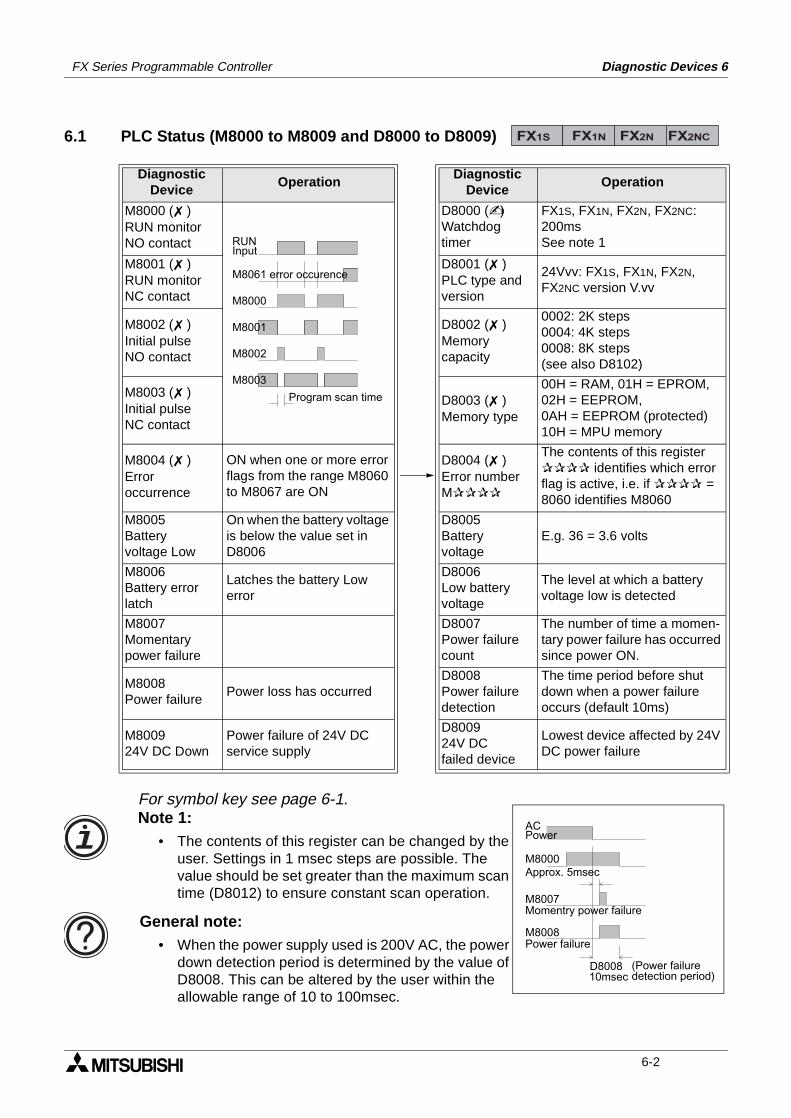
FX Series Programmable Controller Diagnostic Devices 6
6.1 PLC Status (M8000 to M8009 and D8000 to D8009)
DiagnosticDevice
OperationDiagnostic
DeviceOperation
M8000 ( )RUN monitorNO contact
D8000 ()Watchdogtimer
FX1S, FX1N, FX2N, FX2NC: 200msSee note 1
M8001 ( )RUN monitorNC contact
D8001 ( )PLC type andversion
24Vvv: FX1S, FX1N, FX2N, FX2NC version V.vv
M8002 ( )Initial pulseNO contact
D8002 ( )Memorycapacity
0002: 2K steps0004: 4K steps0008: 8K steps(see also D8102)
M8003 ( )Initial pulseNC contact
D8003 ( )Memory type
00H = RAM, 01H = EPROM,02H = EEPROM,0AH = EEPROM (protected)10H = MPU memory
M8004 ( )Erroroccurrence
ON when one or more error flags from the range M8060 to M8067 are ON
D8004 ( )Error numberM
The contents of this register identifies which error flag is active, i.e. if = 8060 identifies M8060
M8005Batteryvoltage Low
On when the battery voltage is below the value set in D8006
D8005Batteryvoltage
E.g. 36 = 3.6 volts
M8006Battery errorlatch
Latches the battery Low error
D8006Low batteryvoltage
The level at which a battery voltage low is detected
M8007Momentarypower failure
D8007Power failurecount
The number of time a momen-tary power failure has occurred since power ON.
M8008Power failure
Power loss has occurred D8008Power failuredetection
The time period before shut down when a power failure occurs (default 10ms)
M800924V DC Down
Power failure of 24V DC service supply
D800924V DCfailed device
Lowest device affected by 24V DC power failure
FX1S FX1N FX2N FX2NC
RUNInput
M8061 error occurence
M8000
M8001
M8002
M8003
Program scan time
ACPower
M8000
M8007
Approx. 5msec
Momentry power failure
M8008Power failure
D800810msec
(Power failuredetection period)
For symbol key see page 6-1.Note 1:
• The contents of this register can be changed by the user. Settings in 1 msec steps are possible. The value should be set greater than the maximum scan time (D8012) to ensure constant scan operation.
General note:• When the power supply used is 200V AC, the power
down detection period is determined by the value of D8008. This can be altered by the user within the allowable range of 10 to 100msec.
6-2
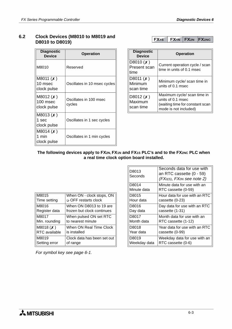
FX Series Programmable Controller Diagnostic Devices 6
6.2 Clock Devices (M8010 to M8019 and D8010 to D8019)
For symbol key see page 6-1.
DiagnosticDevice
OperationDiagnostic
DeviceOperation
M8010 ReservedD8010 ( )Present scantime
Current operation cycle / scan time in units of 0.1 msec
M8011 ( )10 msecclock pulse
Oscillates in 10 msec cyclesD8011 ( )Minimumscan time
Minimum cycle/ scan time in units of 0.1 msec
M8012 ( )100 msecclock pulse
Oscillates in 100 msec cycles
D8012 ( )Maximumscan time
Maximum cycle/ scan time in units of 0.1 msec(waiting time for constant scan mode is not included)
M8013 ( )1 secclock pulse
Oscillates in 1 sec cycles
M8014 ( )1 minclock pulse
Oscillates in 1 min cycles
The following devices apply to FX2N, FX1N and FX1S PLC’s and to the FX 2NC PLC when a real time clock option board installed.
D8013Seconds
Seconds data for use with an RTC cassette (0 - 59)(FX0(S), FX0N see note 2)
D8014Minute data
Minute data for use with an RTC cassette (0-59)
M8015Time setting
When ON - clock stops, ON OFF restarts clock
D8015Hour data
Hour data for use with an RTC cassette (0-23)
M8016Register data
When ON D8013 to 19 are frozen but clock continues
D8016Day data
Day data for use with an RTC cassette (1-31)
M8017Min. rounding
When pulsed ON set RTC to nearest minute
D8017Month data
Month data for use with an RTC cassette (1-12)
M8018 ( )RTC available
When ON Real Time Clock is installed
D8018Year data
Year data for use with an RTC cassette (0-99)
M8019Setting error
Clock data has been set out of range
D8019Weekday data
Weekday data for use with an RTC cassette (0-6)
FX1S FX1N FX2N FX2NC
6-3
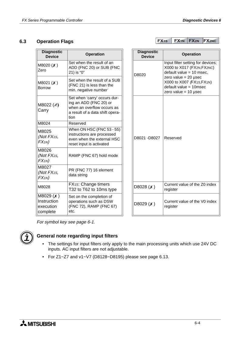
FX Series Programmable Controller Diagnostic Devices 6
6.3 Operation Flags
For symbol key see page 6-1.
General note regarding input filters
• The settings for input filters only apply to the main processing units which use 24V DC inputs. AC input filters are not adjustable.
• For Z1~Z7 and v1~V7 (D8128~D8195) please see page 6.13.
DiagnosticDevice
OperationDiagnostic
DeviceOperation
M8020 ( )Zero
Set when the result of an ADD (FNC 20) or SUB (FNC 21) is “0”
D8020
Input filter setting for devices; X000 to X017 (FX2N,FX2NC) default value = 10 msec,zero value = 20 µsecX000 to X007 (FX1S,FX1N) default value = 10mseczero value = 10 µsec
M8021 ( )Borrow
Set when the result of a SUB (FNC 21) is less than the min. negative number
M8022 ()Carry
Set when ‘carry’ occurs dur-ing an ADD (FNC 20) or when an overflow occurs as a result of a data shift opera-tion
D8021 -D8027 Reserved
M8024 Reserved
M8025(Not FX1S, FX1N)
When ON HSC (FNC 53 - 55) instructions are processed even when the external HSC reset input is activated
M8026(Not FX1S, FX1N)
RAMP (FNC 67) hold mode
M8027(Not FX1S, FX1N)
PR (FNC 77) 16 element data string
M8028FX1S: Change timersT32 to T62 to 10ms type
D8028 ( ) Current value of the Z0 index register
M8029 ( )Instructionexecutioncomplete
Set on the completion of operations such as DSW (FNC 72), RAMP (FNC 67) etc.
D8029 ( ) Current value of the V0 index register
FX1S FX1N FX2N FX2NC
6-4
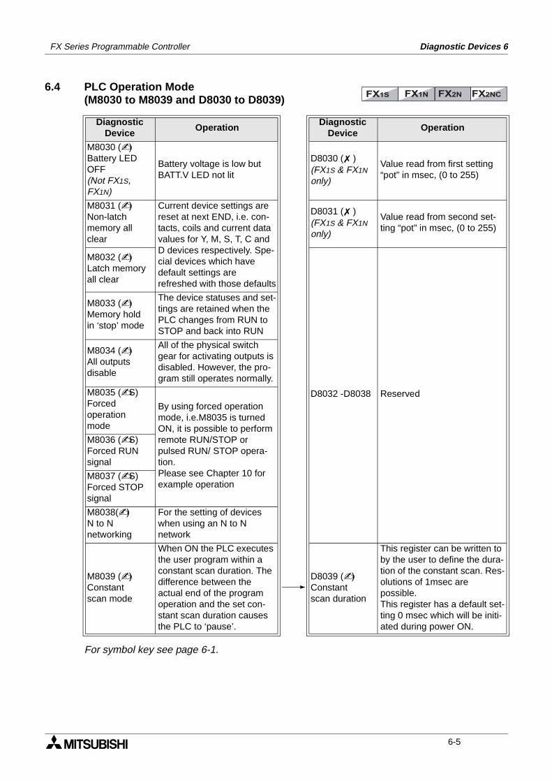
FX Series Programmable Controller Diagnostic Devices 6
6.4 PLC Operation Mode(M8030 to M8039 and D8030 to D8039)
For symbol key see page 6-1.
DiagnosticDevice
OperationDiagnostic
DeviceOperation
M8030 ()Battery LED OFF(Not FX1S, FX1N)
Battery voltage is low but BATT.V LED not lit
D8030 ( )(FX1S & FX1N only)
Value read from first setting “pot” in msec, (0 to 255)
M8031 ()Non-latchmemory all clear
Current device settings are reset at next END, i.e. con-tacts, coils and current data values for Y, M, S, T, C and D devices respectively. Spe-cial devices which have default settings are refreshed with those defaults
D8031 ( )(FX1S & FX1N only)
Value read from second set-ting “pot” in msec, (0 to 255)
M8032 ()Latch memoryall clear
D8032 -D8038 Reserved
M8033 ()Memory holdin ‘stop’ mode
The device statuses and set-tings are retained when the PLC changes from RUN to STOP and back into RUN
M8034 ()All outputsdisable
All of the physical switch gear for activating outputs is disabled. However, the pro-gram still operates normally.
M8035 (S)Forcedoperationmode
By using forced operation mode, i.e.M8035 is turned ON, it is possible to perform remote RUN/STOP or pulsed RUN/ STOP opera-tion.Please see Chapter 10 for example operation
M8036 (S)Forced RUNsignal
M8037 (S)Forced STOPsignal
M8038()N to N networking
For the setting of devices when using an N to N network
M8039 ()Constantscan mode
When ON the PLC executes the user program within a constant scan duration. The difference between the actual end of the program operation and the set con-stant scan duration causes the PLC to ‘pause’.
D8039 ()Constantscan duration
This register can be written to by the user to define the dura-tion of the constant scan. Res-olutions of 1msec are possible.This register has a default set-ting 0 msec which will be initi-ated during power ON.
FX1S FX1N FX2N FX2NC
6-5
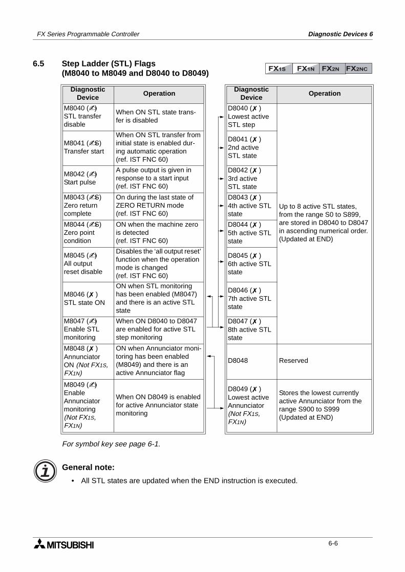
FX Series Programmable Controller Diagnostic Devices 6
6.5 Step Ladder (STL) Flags (M8040 to M8049 and D8040 to D8049)
For symbol key see page 6-1.
General note:
• All STL states are updated when the END instruction is executed.
DiagnosticDevice
OperationDiagnostic
DeviceOperation
M8040 ()STL transferdisable
When ON STL state trans-fer is disabled
D8040 ( )Lowest activeSTL step
Up to 8 active STL states, from the range S0 to S899, are stored in D8040 to D8047 in ascending numerical order. (Updated at END)
M8041 (S)Transfer start
When ON STL transfer from initial state is enabled dur-ing automatic operation(ref. IST FNC 60)
D8041 ( )2nd activeSTL state
M8042 ()Start pulse
A pulse output is given in response to a start input(ref. IST FNC 60)
D8042 ( )3rd activeSTL state
M8043 (S)Zero returncomplete
On during the last state of ZERO RETURN mode(ref. IST FNC 60)
D8043 ( )4th active STLstate
M8044 (S)Zero pointcondition
ON when the machine zero is detected(ref. IST FNC 60)
D8044 ( )5th active STLstate
M8045 ()All outputreset disable
Disables the ‘all output reset’ function when the operation mode is changed(ref. IST FNC 60)
D8045 ( )6th active STLstate
M8046 ( )STL state ON
ON when STL monitoring has been enabled (M8047) and there is an active STL state
D8046 ( )7th active STLstate
M8047 ()Enable STLmonitoring
When ON D8040 to D8047 are enabled for active STL step monitoring
D8047 ( )8th active STLstate
M8048 ( )AnnunciatorON (Not FX1S, FX1N)
ON when Annunciator moni-toring has been enabled (M8049) and there is an active Annunciator flag
D8048 Reserved
M8049 ()EnableAnnunciatormonitoring(Not FX1S, FX1N)
When ON D8049 is enabled for active Annunciator state monitoring
D8049 ( )Lowest activeAnnunciator(Not FX1S, FX1N)
Stores the lowest currently active Annunciator from the range S900 to S999(Updated at END)
FX1S FX1N FX2N FX2NC
6-6
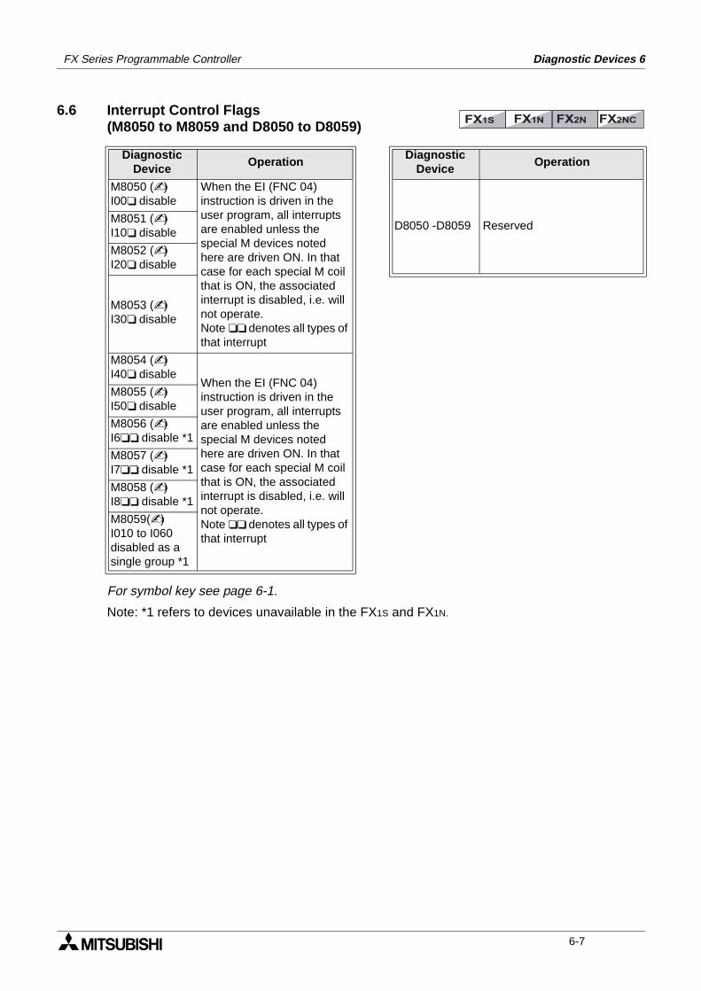
FX Series Programmable Controller Diagnostic Devices 6
6.6 Interrupt Control Flags(M8050 to M8059 and D8050 to D8059)
For symbol key see page 6-1.
Note: *1 refers to devices unavailable in the FX1S and FX1N.
DiagnosticDevice
OperationDiagnostic
DeviceOperation
M8050 ()I00 disable
When the EI (FNC 04) instruction is driven in the user program, all interrupts are enabled unless the special M devices noted here are driven ON. In that case for each special M coil that is ON, the associated interrupt is disabled, i.e. will not operate.Note denotes all types of that interrupt
D8050 -D8059 ReservedM8051 ()I10 disable
M8052 ()I20 disable
M8053 ()I30 disable
M8054 ()I40 disable
When the EI (FNC 04) instruction is driven in the user program, all interrupts are enabled unless the special M devices noted here are driven ON. In that case for each special M coil that is ON, the associated interrupt is disabled, i.e. will not operate.Note denotes all types of that interrupt
M8055 ()I50 disable
M8056 ()I6 disable *1
M8057 ()I7 disable *1
M8058 ()I8 disable *1
M8059()I010 to I060disabled as asingle group *1
FX1S FX1N FX2N FX2NC
6-7
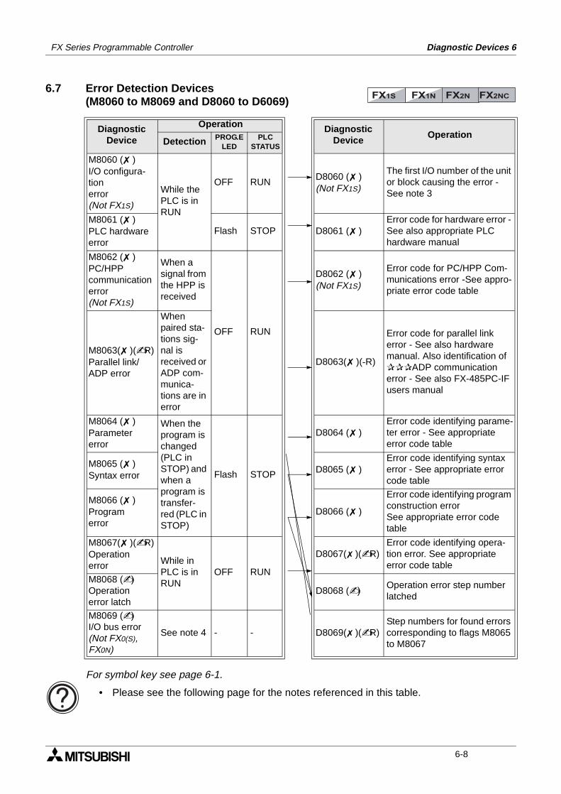
FX Series Programmable Controller Diagnostic Devices 6
6.7 Error Detection Devices(M8060 to M8069 and D8060 to D6069)
For symbol key see page 6-1.
• Please see the following page for the notes referenced in this table.
DiagnosticDevice
Operation DiagnosticDevice
OperationDetection PROG.E
LEDPLC
STATUS
M8060 ( )I/O configura-tionerror(Not FX1S)
While the PLC is in RUN
OFF RUND8060 ( )(Not FX1S)
The first I/O number of the unit or block causing the error - See note 3
M8061 ( )PLC hardwareerror
Flash STOP D8061 ( )Error code for hardware error - See also appropriate PLC hardware manual
M8062 ( )PC/HPPcommunicationerror(Not FX1S)
When a signal from the HPP is received
OFF RUN
D8062 ( )(Not FX1S)
Error code for PC/HPP Com-munications error -See appro-priate error code table
M8063( )(R)Parallel link/ADP error
When paired sta-tions sig-nal is received or ADP com-munica-tions are in error
D8063( )(-R)
Error code for parallel link error - See also hardware manual. Also identification of ADP communication error - See also FX-485PC-IF users manual
M8064 ( )Parametererror
When the program is changed (PLC in STOP) and when a program is transfer-red (PLC in STOP)
Flash STOP
D8064 ( )Error code identifying parame-ter error - See appropriate error code table
M8065 ( )Syntax error
D8065 ( )Error code identifying syntax error - See appropriate error code table
M8066 ( )Programerror
D8066 ( )
Error code identifying program construction errorSee appropriate error code table
M8067( )(R)Operationerror While in
PLC is in RUN
OFF RUN
D8067( )(R)Error code identifying opera-tion error. See appropriate error code table
M8068 ()Operationerror latch
D8068 ()Operation error step number latched
M8069 ()I/O bus error(Not FX0(S), FX0N)
See note 4 - - D8069( )(R)Step numbers for found errors corresponding to flags M8065 to M8067
FX1S FX1N FX2N FX2NC
6-8
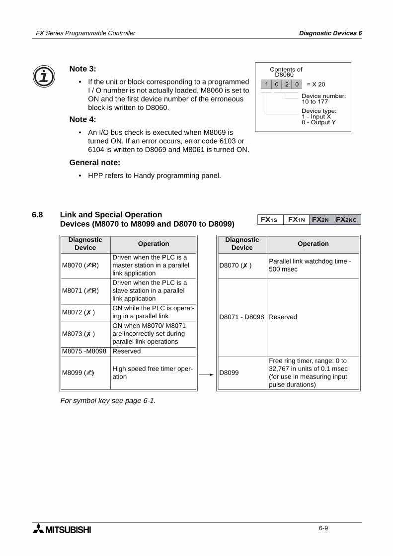
FX Series Programmable Controller Diagnostic Devices 6
6.8 Link and Special OperationDevices (M8070 to M8099 and D8070 to D8099)
For symbol key see page 6-1.
DiagnosticDevice
OperationDiagnostic
DeviceOperation
M8070 (R)Driven when the PLC is a master station in a parallel link application
D8070 ( )Parallel link watchdog time - 500 msec
M8071 (R)Driven when the PLC is a slave station in a parallel link application
D8071 - D8098 ReservedM8072 ( )
ON while the PLC is operat-ing in a parallel link
M8073 ( )ON when M8070/ M8071 are incorrectly set during parallel link operations
M8075 -M8098 Reserved
M8099 ()High speed free timer oper-ation
D8099
Free ring timer, range: 0 to 32,767 in units of 0.1 msec (for use in measuring input pulse durations)
Note 3:
• If the unit or block corresponding to a programmed I / O number is not actually loaded, M8060 is set to ON and the first device number of the erroneous block is written to D8060.
2 001
Device number:10 to 177
Device type:1 - Input X0 - Output Y
= X 20
Contents ofD8060
Note 4:
• An I/O bus check is executed when M8069 is turned ON. If an error occurs, error code 6103 or 6104 is written to D8069 and M8061 is turned ON.
General note:
• HPP refers to Handy programming panel.
FX1S FX1N FX2N FX2NC
6-9
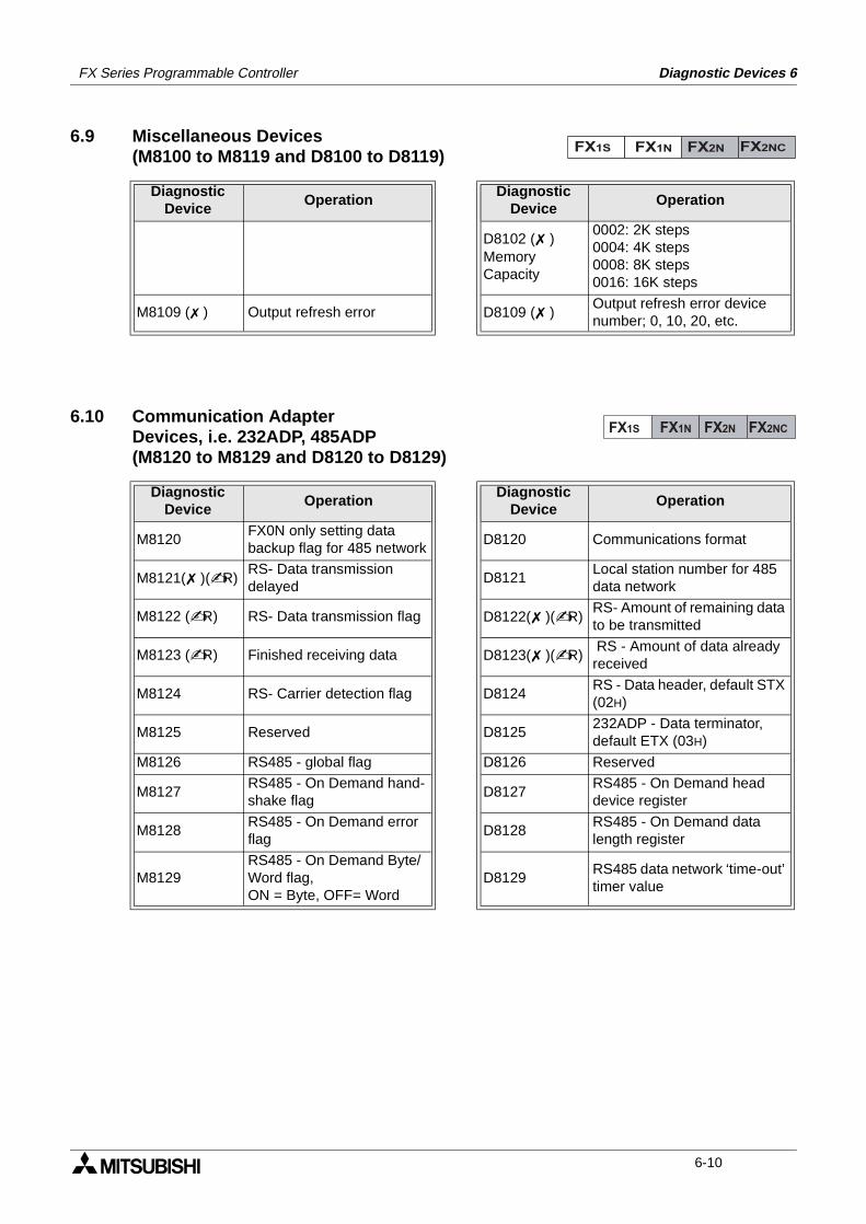
FX Series Programmable Controller Diagnostic Devices 6
6.9 Miscellaneous Devices(M8100 to M8119 and D8100 to D8119)
6.10 Communication AdapterDevices, i.e. 232ADP, 485ADP(M8120 to M8129 and D8120 to D8129)
DiagnosticDevice
OperationDiagnostic
DeviceOperation
D8102 ( )MemoryCapacity
0002: 2K steps0004: 4K steps0008: 8K steps0016: 16K steps
M8109 ( ) Output refresh error D8109 ( )Output refresh error device number; 0, 10, 20, etc.
DiagnosticDevice
OperationDiagnostic
DeviceOperation
M8120FX0N only setting data backup flag for 485 network
D8120 Communications format
M8121( )(R)RS- Data transmission delayed
D8121Local station number for 485 data network
M8122 (R) RS- Data transmission flag D8122( )(R)RS- Amount of remaining data to be transmitted
M8123 (R) Finished receiving data D8123( )(R) RS - Amount of data already received
M8124 RS- Carrier detection flag D8124RS - Data header, default STX (02H)
M8125 Reserved D8125232ADP - Data terminator, default ETX (03H)
M8126 RS485 - global flag D8126 Reserved
M8127RS485 - On Demand hand-shake flag
D8127RS485 - On Demand head device register
M8128RS485 - On Demand error flag
D8128RS485 - On Demand data length register
M8129RS485 - On Demand Byte/Word flag,ON = Byte, OFF= Word
D8129RS485 data network ‘time-out’ timer value
FX1S FX1N FX2N FX2NC
FX1S FX1N FX2N FX2NC
6-10
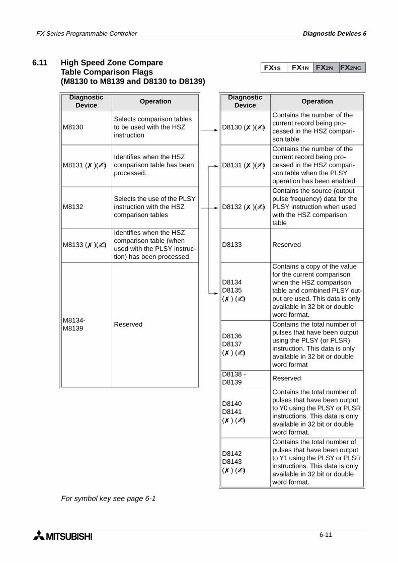
FX Series Programmable Controller Diagnostic Devices 6
6.11 High Speed Zone CompareTable Comparison Flags(M8130 to M8139 and D8130 to D8139)
For symbol key see page 6-1
DiagnosticDevice
OperationDiagnostic
DeviceOperation
M8130Selects comparison tables to be used with the HSZ instruction
D8130 ( )()
Contains the number of the current record being pro-cessed in the HSZ compari-son table
M8131 ( )()Identifies when the HSZ comparison table has been processed.
D8131 ( )()
Contains the number of the current record being pro-cessed in the HSZ compari-son table when the PLSY operation has been enabled
M8132Selects the use of the PLSY instruction with the HSZ comparison tables
D8132 ( )()
Contains the source (output pulse frequency) data for the PLSY instruction when used with the HSZ comparison table
M8133 ( )()
Identifies when the HSZ comparison table (when used with the PLSY instruc-tion) has been processed.
D8133 Reserved
M8134-M8139
Reserved
D8134D8135( ) ()
Contains a copy of the value for the current comparison when the HSZ comparison table and combined PLSY out-put are used. This data is only available in 32 bit or double word format.
D8136D8137( ) ()
Contains the total number of pulses that have been output using the PLSY (or PLSR) instruction. This data is only available in 32 bit or double word format
D8138 -D8139
Reserved
D8140D8141( ) ()
Contains the total number of pulses that have been output to Y0 using the PLSY or PLSR instructions. This data is only available in 32 bit or double word format.
D8142D8143( ) ()
Contains the total number of pulses that have been output to Y1 using the PLSY or PLSR instructions. This data is only available in 32 bit or double word format.
FX1S FX1N FX2N FX2NC
6-11
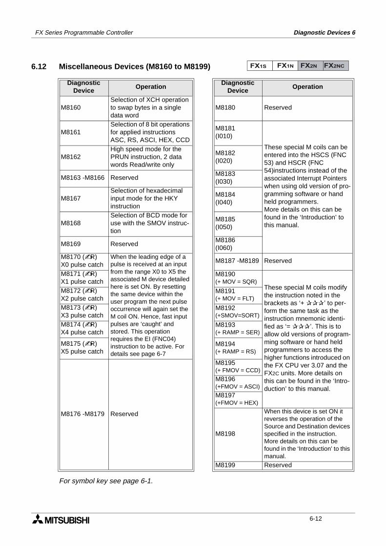
FX Series Programmable Controller Diagnostic Devices 6
6.12 Miscellaneous Devices (M8160 to M8199)
For symbol key see page 6-1.
DiagnosticDevice
OperationDiagnostic
DeviceOperation
M8160Selection of XCH operation to swap bytes in a single data word
M8180 Reserved
M8161Selection of 8 bit operations for applied instructions ASC, RS, ASCI, HEX, CCD
M8181(I010)
These special M coils can be entered into the HSCS (FNC 53) and HSCR (FNC 54)instructions instead of the associated Interrupt Pointers when using old version of pro-gramming software or hand held programmers.More details on this can be found in the ‘Introduction’ to this manual.
M8162High speed mode for the PRUN instruction, 2 data words Read/write only
M8182(I020)
M8163 -M8166 ReservedM8183(I030)
M8167Selection of hexadecimal input mode for the HKY instruction
M8184(I040)
M8168Selection of BCD mode for use with the SMOV instruc-tion
M8185(I050)
M8169 ReservedM8186(I060)
M8170 (R)X0 pulse catch
When the leading edge of a pulse is received at an input from the range X0 to X5 the associated M device detailed here is set ON. By resetting the same device within the user program the next pulse occurrence will again set the M coil ON. Hence, fast input pulses are ‘caught’ and stored. This operation requires the EI (FNC04) instruction to be active. For details see page 6-7
M8187 -M8189 Reserved
M8171 (R)X1 pulse catch
M8190(+ MOV = SQR)
These special M coils modify the instruction noted in the brackets as ‘+ ’ to per-form the same task as the instruction mnemonic identi-fied as ‘= ’. This is to allow old versions of program-ming software or hand held programmers to access the higher functions introduced on the FX CPU ver 3.07 and the FX2C units. More details on this can be found in the ‘Intro-duction’ to this manual.
M8172 (R)X2 pulse catch
M8191(+ MOV = FLT)
M8173 (R)X3 pulse catch
M8192(+SMOV=SORT)
M8174 (R)X4 pulse catch
M8193(+ RAMP = SER)
M8175 (R)X5 pulse catch
M8194(+ RAMP = RS)
M8176 -M8179 Reserved
M8195(+ FMOV = CCD)
M8196(+FMOV = ASCI)
M8197(+FMOV = HEX)
M8198
When this device is set ON it reverses the operation of the Source and Destination devices specified in the instruction.More details on this can be found in the ‘Introduction’ to this manual.
M8199 Reserved
FX1S FX1N FX2N FX2NC
6-12
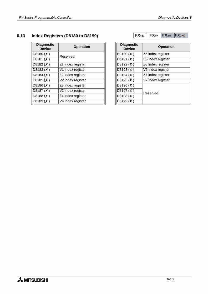
FX Series Programmable Controller Diagnostic Devices 6
6.13 Index Registers (D8180 to D8199)
DiagnosticDevice
OperationDiagnostic
DeviceOperation
D8180 ( )Reserved
D8190 ( ) Z5 index register
D8181 ( ) D8191 ( ) V5 index register
D8182 ( ) Z1 index register D8192 ( ) Z6 index register
D8183 ( ) V1 index register D8193 ( ) V6 index register
D8184 ( ) Z2 index register D8194 ( ) Z7 index register
D8185 ( ) V2 index register D8195 ( ) V7 index register
D8186 ( ) Z3 index register D8196 ( )
ReservedD8187 ( ) V3 index register D8197 ( )
D8188 ( ) Z4 index register D8198 ( )
D8189 ( ) V4 index register D8199 ( )
FX1S FX1N FX2N FX2NC
6-13
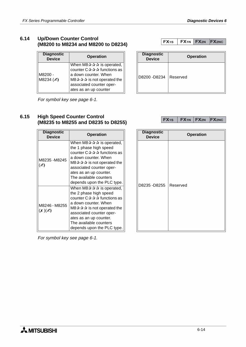
FX Series Programmable Controller Diagnostic Devices 6
6.14 Up/Down Counter Control(M8200 to M8234 and M8200 to D8234)
For symbol key see page 6-1.
6.15 High Speed Counter Control(M8235 to M8255 and D8235 to D8255)
For symbol key see page 6-1.
DiagnosticDevice
OperationDiagnostic
DeviceOperation
M8200 - M8234 ()
When M8 is operated, counter C functions as a down counter. When M8 is not operated the associated counter oper-ates as an up counter
D8200 -D8234 Reserved
DiagnosticDevice
OperationDiagnostic
DeviceOperation
M8235 -M8245 ()
When M8 is operated, the 1 phase high speed counter C functions as a down counter. When M8 is not operated the associated counter oper-ates as an up counter.The available counters depends upon the PLC type.
D8235 -D8255 Reserved
M8246 - M8255 ( )()
When M8 is operated, the 2 phase high speed counter C functions as a down counter. When M8 is not operated the associated counter oper-ates as an up counter.The available counters depends upon the PLC type.
FX1S FX1N FX2N FX2NC
FX1S FX1N FX2N FX2NC
6-14
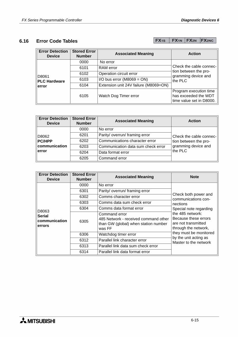
FX Series Programmable Controller Diagnostic Devices 6
6.16 Error Code Tables
Error DetectionDevice
Stored ErrorNumber
Associated Meaning Action
D8061PLC Hardware error
0000 No errorCheck the cable connec-tion between the pro-gramming device and the PLC
6101 RAM error
6102 Operation circuit error
6103 I/O bus error (M8069 = ON)
6104 Extension unit 24V failure (M8069=ON)
6105 Watch Dog Timer errorProgram execution time has exceeded the WDT time value set in D8000.
Error DetectionDevice
Stored ErrorNumber
Associated Meaning Action
D8062PC/HPPcommunication error
0000 No error
Check the cable connec-tion between the pro-gramming device and the PLC
6201 Parity/ overrun/ framing error
6202 Communications character error
6203 Communication data sum check error
6204 Data format error
6205 Command error
Error DetectionDevice
Stored ErrorNumber
Associated Meaning Note
D8063Serial communication errors
0000 No error
Check both power and communications con-nectionsSpecial note regarding the 485 network:Because these errors are not transmitted through the network, they must be monitored by the unit acting as Master to the network
6301 Parity/ overrun/ framing error
6302 Comms character error
6303 Comms data sum check error
6304 Comms data format error
6305
Command error485 Network - received command other than GW (global) when station number was FF
6306 Watchdog timer error
6312 Parallel link character error
6313 Parallel link data sum check error
6314 Parallel link data format error
FX1S FX1N FX2N FX2NC
6-15
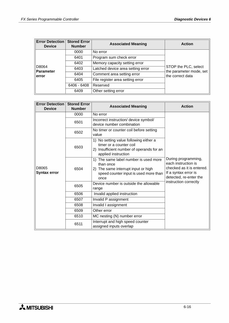
FX Series Programmable Controller Diagnostic Devices 6
Error DetectionDevice
Stored ErrorNumber
Associated Meaning Action
D8064Parametererror
0000 No error
STOP the PLC, select the parameter mode, set the correct data
6401 Program sum check error
6402 Memory capacity setting error
6403 Latched device area setting error
6404 Comment area setting error
6405 File register area setting error
6406 - 6408 Reserved
6409 Other setting error
Error DetectionDevice
Stored ErrorNumber
Associated Meaning Action
D8065Syntax error
0000 No error
During programming, each instruction is checked as it is entered. If a syntax error is detected, re-enter the instruction correctly
6501Incorrect instruction/ device symbol/ device number combination
6502No timer or counter coil before setting value
6503
1) No setting value following either a timer or a counter coil
2) Insufficient number of operands for an applied instruction
6504
1) The same label number is used more than once
2) The same interrupt input or high speed counter input is used more than once
6505Device number is outside the allowable range
6506 Invalid applied instruction
6507 Invalid P assignment
6508 Invalid I assignment
6509 Other error
6510 MC nesting (N) number error
6511Interrupt and high speed counter assigned inputs overlap
6-16
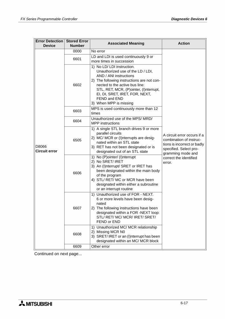
FX Series Programmable Controller Diagnostic Devices 6
Continued on next page...
Error DetectionDevice
Stored ErrorNumber
Associated Meaning Action
D8066Circuit error
0000 No error
A circuit error occurs if a combination of instruc-tions is incorrect or badly specified. Select pro-gramming mode and correct the identified error.
6601LD and LDI is used continuously 9 or more times in succession
6602
1) No LD/ LDI instruction.Unauthorized use of the LD / LDI, AND / ANI instructions
2) The following instructions are not con-nected to the active bus line:STL, RET, MCR, (P)ointer, (I)nterrupt, EI, DI, SRET, IRET, FOR, NEXT, FEND and END
3) When MPP is missing
6603MPS is used continuously more than 12 times
6604Unauthorized use of the MPS/ MRD/ MPP instructions
6505
1) A single STL branch drives 9 or more parallel circuits
2) MC/ MCR or (I)nterrupts are desig-nated within an STL state
3) RET has not been designated or is designated out of an STL state
6606
1) No (P)ointer/ (I)nterrupt2) No SRET/ IRET3) An (I)nterrupt/ SRET or IRET has
been designated within the main body of the program
4) STL/ RET/ MC or MCR have been designated within either a subroutine or an interrupt routine
6607
1) Unauthorized use of FOR - NEXT.6 or more levels have been desig-nated
2) The following instructions have been designated within a FOR -NEXT loop:STL/ RET/ MC/ MCR/ IRET/ SRET/ FEND or END
6608
1) Unauthorized MC/ MCR relationship2) Missing MCR N03) SRET/ IRET or an (I)nterrupt has been
designated within an MC/ MCR block
6609 Other error
6-17
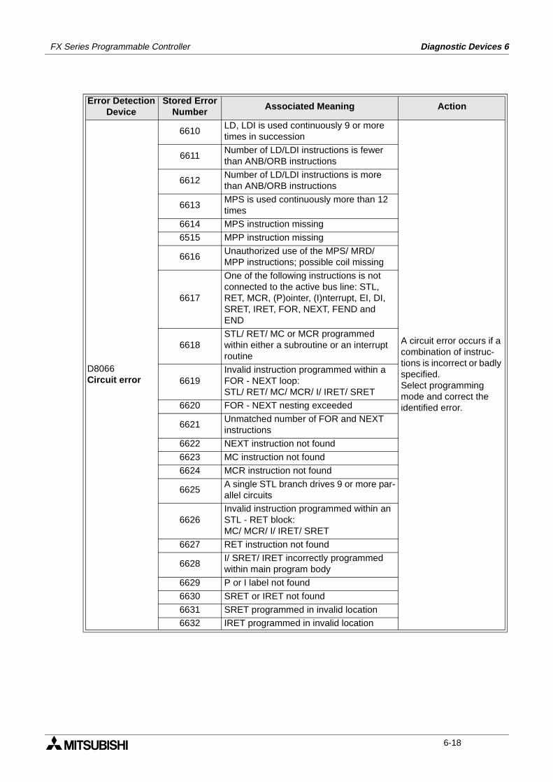
FX Series Programmable Controller Diagnostic Devices 6
Error DetectionDevice
Stored ErrorNumber
Associated Meaning Action
D8066Circuit error
6610LD, LDI is used continuously 9 or more times in succession
A circuit error occurs if a combination of instruc-tions is incorrect or badly specified.Select programming mode and correct the identified error.
6611Number of LD/LDI instructions is fewer than ANB/ORB instructions
6612Number of LD/LDI instructions is more than ANB/ORB instructions
6613MPS is used continuously more than 12 times
6614 MPS instruction missing
6515 MPP instruction missing
6616Unauthorized use of the MPS/ MRD/ MPP instructions; possible coil missing
6617
One of the following instructions is not connected to the active bus line: STL, RET, MCR, (P)ointer, (I)nterrupt, EI, DI, SRET, IRET, FOR, NEXT, FEND and END
6618STL/ RET/ MC or MCR programmed within either a subroutine or an interrupt routine
6619Invalid instruction programmed within a FOR - NEXT loop:STL/ RET/ MC/ MCR/ I/ IRET/ SRET
6620 FOR - NEXT nesting exceeded
6621Unmatched number of FOR and NEXT instructions
6622 NEXT instruction not found
6623 MC instruction not found
6624 MCR instruction not found
6625A single STL branch drives 9 or more par-allel circuits
6626Invalid instruction programmed within an STL - RET block:MC/ MCR/ I/ IRET/ SRET
6627 RET instruction not found
6628I/ SRET/ IRET incorrectly programmed within main program body
6629 P or I label not found
6630 SRET or IRET not found
6631 SRET programmed in invalid location
6632 IRET programmed in invalid location
6-18
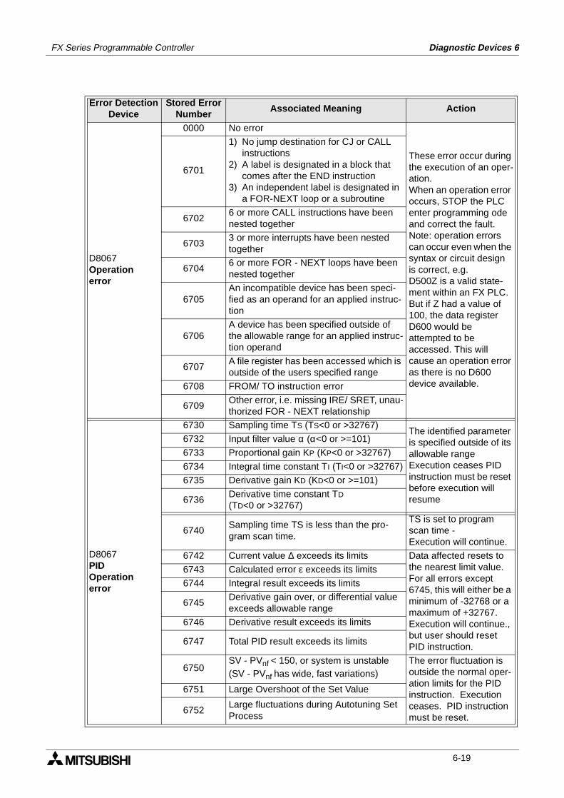
FX Series Programmable Controller Diagnostic Devices 6
Error DetectionDevice
Stored ErrorNumber
Associated Meaning Action
D8067Operationerror
0000 No error
These error occur during the execution of an oper-ation.When an operation error occurs, STOP the PLC enter programming ode and correct the fault.Note: operation errors can occur even when the syntax or circuit design is correct, e.g.D500Z is a valid state-ment within an FX PLC. But if Z had a value of 100, the data register D600 would be attempted to be accessed. This will cause an operation error as there is no D600 device available.
6701
1) No jump destination for CJ or CALL instructions
2) A label is designated in a block that comes after the END instruction
3) An independent label is designated in a FOR-NEXT loop or a subroutine
67026 or more CALL instructions have been nested together
67033 or more interrupts have been nested together
67046 or more FOR - NEXT loops have been nested together
6705An incompatible device has been speci-fied as an operand for an applied instruc-tion
6706A device has been specified outside of the allowable range for an applied instruc-tion operand
6707A file register has been accessed which is outside of the users specified range
6708 FROM/ TO instruction error
6709Other error, i.e. missing IRE/ SRET, unau-thorized FOR - NEXT relationship
D8067PIDOperationerror
6730 Sampling time TS (TS<0 or >32767)The identified parameter is specified outside of its allowable rangeExecution ceases PID instruction must be reset before execution will resume
6732 Input filter value α (α<0 or >=101)
6733 Proportional gain KP (KP<0 or >32767)
6734 Integral time constant TI (TI<0 or >32767)
6735 Derivative gain KD (KD<0 or >=101)
6736Derivative time constant TD
(TD<0 or >32767)
6740Sampling time TS is less than the pro-gram scan time.
TS is set to program scan time -Execution will continue.
6742 Current value ∆ exceeds its limits Data affected resets to the nearest limit value.For all errors except 6745, this will either be a minimum of -32768 or a maximum of +32767.Execution will continue., but user should reset PID instruction.
6743 Calculated error ε exceeds its limits
6744 Integral result exceeds its limits
6745Derivative gain over, or differential value exceeds allowable range
6746 Derivative result exceeds its limits
6747 Total PID result exceeds its limits
6750SV - PVnf < 150, or system is unstable (SV - PVnf has wide, fast variations)
The error fluctuation is outside the normal oper-ation limits for the PID instruction. Execution ceases. PID instruction must be reset.
6751 Large Overshoot of the Set Value
6752Large fluctuations during Autotuning Set Process
6-19
FX Series Programmable Controller Diagnostic Devices 6
MEMO
6-20
1 Introduction
2 Basic Program Instructions
3 STL Programming
4 Devices in Detail
5 Applied Instructions
6 Diagnostic Devices
7 Instruction Execution Times
8 PLC Device Tables
9 Assigning System Devices
10 Points of Technique
11 Index
FX Series Programmable Controllers Instruction Execution Times 7
FX Series Programmable Controllers Instruction Execution Times 7
Chapter Contents
7. Execution Times And Instructional Hierarchy........................................7-17.1 Basic Instructions ................................................................................................ 7-17.2 Applied Instructions ............................................................................................ 7-37.3 Hierarchical Relationships Of Basic Program Instructions ................................ 7-117.4 Batch Processing............................................................................................... 7-137.5 Summary of Device Memory Allocations........................................................... 7-137.6 Limits Of Instruction Usage ............................................................................... 7-15
7.6.1 Instructions Which Can Only Be Used Once In The Main Program Area ............... 7-157.6.2 Instructions Which Are Not Suitable For Use With 110V AC Input Units ................ 7-15
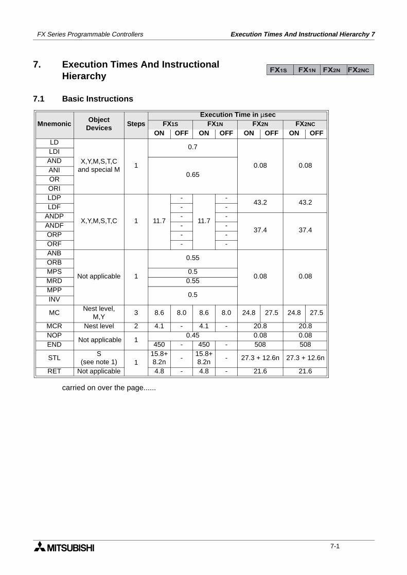
Execution Times And Instructional Hierarchy 7FX Series Programmable Controllers
7. Execution Times And InstructionalHierarchy
7.1 Basic Instructions
carried on over the page......
MnemonicObject
DevicesSteps
Execution Time in µsecFX1S FX1N FX2N FX2NC
ON OFF ON OFF ON OFF ON OFFLD
X,Y,M,S,T,Cand special M
1
0.7
0.08 0.08
LDIAND
0.65ANIORORILDP
X,Y,M,S,T,C 1 11.7
-
11.7
-43.2 43.2
LDF - -ANDP - -
37.4 37.4ANDF - -ORP - -ORF - -ANB
Not applicable 1
0.55
0.08 0.08
ORBMPS 0.5MRD 0.55MPP
0.5INV
MCNest level,
M,Y3 8.6 8.0 8.6 8.0 24.8 27.5 24.8 27.5
MCR Nest level 2 4.1 - 4.1 - 20.8 20.8NOP
Not applicable 10.45 0.08 0.08
END 450 - 450 - 508 508
STLS
(see note 1) 115.8+8.2n
-15.8+8.2n
- 27.3 + 12.6n 27.3 + 12.6n
RET Not applicable 4.8 - 4.8 - 21.6 21.6
FX1S FX1N FX2N FX2NC
7-1
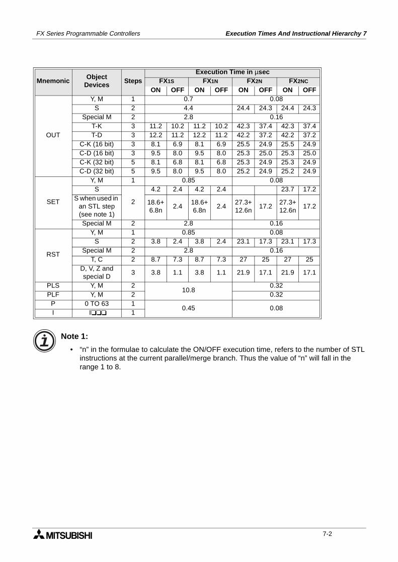
FX Series Programmable Controllers Execution Times And Instructional Hierarchy 7
Note 1:
• “n” in the formulae to calculate the ON/OFF execution time, refers to the number of STL instructions at the current parallel/merge branch. Thus the value of “n” will fall in the range 1 to 8.
MnemonicObject
DevicesSteps
Execution Time in µsecFX1S FX1N FX2N FX2NC
ON OFF ON OFF ON OFF ON OFF
OUT
Y, M 1 0.7 0.08S 2 4.4 24.4 24.3 24.4 24.3
Special M 2 2.8 0.16T-K 3 11.2 10.2 11.2 10.2 42.3 37.4 42.3 37.4T-D 3 12.2 11.2 12.2 11.2 42.2 37.2 42.2 37.2
C-K (16 bit) 3 8.1 6.9 8.1 6.9 25.5 24.9 25.5 24.9C-D (16 bit) 3 9.5 8.0 9.5 8.0 25.3 25.0 25.3 25.0C-K (32 bit) 5 8.1 6.8 8.1 6.8 25.3 24.9 25.3 24.9C-D (32 bit) 5 9.5 8.0 9.5 8.0 25.2 24.9 25.2 24.9
SET
Y, M 1 0.85 0.08S
2
4.2 2.4 4.2 2.4 23.7 17.2S when used in
an STL step (see note 1)
18.6+6.8n
2.418.6+6.8n
2.427.3+12.6n
17.227.3+12.6n
17.2
Special M 2 2.8 0.16
RST
Y, M 1 0.85 0.08S 2 3.8 2.4 3.8 2.4 23.1 17.3 23.1 17.3
Special M 2 2.8 0.16T, C 2 8.7 7.3 8.7 7.3 27 25 27 25
D, V, Z and special D
3 3.8 1.1 3.8 1.1 21.9 17.1 21.9 17.1
PLS Y, M 210.8
0.32PLF Y, M 2 0.32
P 0 TO 63 10.45 0.08
I I 1
7-2
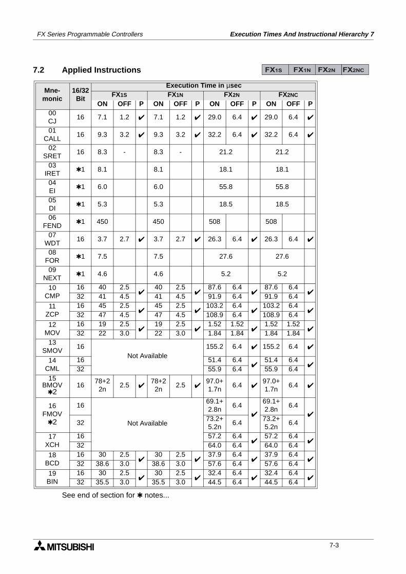
FX Series Programmable Controllers Execution Times And Instructional Hierarchy 7
7.2 Applied Instructions
See end of section for notes...
Mne-monic
16/32Bit
Execution Time in µsecFX1S FX1N FX2N FX2NC
ON OFF P ON OFF P ON OFF P ON OFF P00CJ
16 7.1 1.2 7.1 1.2 29.0 6.4 29.0 6.4
01CALL
16 9.3 3.2 9.3 3.2 32.2 6.4 32.2 6.4
02SRET
16 8.3 - 8.3 - 21.2 21.2
03IRET
1 8.1 8.1 18.1 18.1
04EI
1 6.0 6.0 55.8 55.8
05DI
1 5.3 5.3 18.5 18.5
06FEND
1 450 450 508 508
07WDT
16 3.7 2.7 3.7 2.7 26.3 6.4 26.3 6.4
08FOR
1 7.5 7.5 27.6 27.6
09NEXT
1 4.6 4.6 5.2 5.2
10CMP
16 40 2.5
40 2.5
87.6 6.4
87.6 6.4
32 41 4.5 41 4.5 91.9 6.4 91.9 6.411
ZCP16 45 2.5
45 2.5
103.2 6.4
103.2 6.4
32 47 4.5 47 4.5 108.9 6.4 108.9 6.4
12MOV
16 19 2.5
19 2.5
1.52 1.52
1.52 1.52
32 22 3.0 22 3.0 1.84 1.84 1.84 1.8413
SMOV16
Not Available155.2 6.4 155.2 6.4
14CML
16 51.4 6.4
51.4 6.4
32 55.9 6.4 55.9 6.415
BMOV2
1678+2
2n2.5
78+22n
2.5 97.0+1.7n
6.4 97.0+1.7n
6.4
16FMOV
2
16
Not Available
69.1+2.8n
6.4
69.1+2.8n
6.4
3273.2+5.2n
6.473.2+5.2n
6.4
17XCH
16 57.2 6.4
57.2 6.4
32 64.0 6.4 64.0 6.418
BCD16 30 2.5
30 2.5
37.9 6.4
37.9 6.4
32 38.6 3.0 38.6 3.0 57.6 6.4 57.6 6.4
19BIN
16 30 2.5
30 2.5
32.4 6.4
32.4 6.4
32 35.5 3.0 35.5 3.0 44.5 6.4 44.5 6.4
FX1S FX1N FX2N FX2NC
7-3
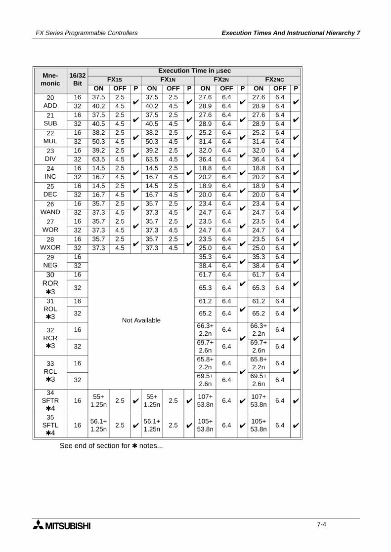
FX Series Programmable Controllers Execution Times And Instructional Hierarchy 7
See end of section for notes...
Mne-monic
16/32Bit
Execution Time in µsecFX1S FX1N FX2N FX2NC
ON OFF P ON OFF P ON OFF P ON OFF P20
ADD16 37.5 2.5
37.5 2.5
27.6 6.4
27.6 6.4
32 40.2 4.5 40.2 4.5 28.9 6.4 28.9 6.4
21SUB
16 37.5 2.5
37.5 2.5
27.6 6.4
27.6 6.4
32 40.5 4.5 40.5 4.5 28.9 6.4 28.9 6.422
MUL16 38.2 2.5
38.2 2.5
25.2 6.4
25.2 6.4
32 50.3 4.5 50.3 4.5 31.4 6.4 31.4 6.4
23DIV
16 39.2 2.5
39.2 2.5
32.0 6.4
32.0 6.4
32 63.5 4.5 63.5 4.5 36.4 6.4 36.4 6.424
INC16 14.5 2.5
14.5 2.5
18.8 6.4
18.8 6.4
32 16.7 4.5 16.7 4.5 20.2 6.4 20.2 6.4
25DEC
16 14.5 2.5
14.5 2.5
18.9 6.4
18.9 6.4
32 16.7 4.5 16.7 4.5 20.0 6.4 20.0 6.426
WAND16 35.7 2.5
35.7 2.5
23.4 6.4
23.4 6.4
32 37.3 4.5 37.3 4.5 24.7 6.4 24.7 6.4
27WOR
16 35.7 2.5
35.7 2.5
23.5 6.4
23.5 6.4
32 37.3 4.5 37.3 4.5 24.7 6.4 24.7 6.428
WXOR16 35.7 2.5
35.7 2.5
23.5 6.4
23.5 6.4
32 37.3 4.5 37.3 4.5 25.0 6.4 25.0 6.4
29NEG
16
Not Available
35.3 6.4
35.3 6.4
32 38.4 6.4 38.4 6.430
ROR3
16 61.7 6.4
61.7 6.4
32 65.3 6.4 65.3 6.4
31ROL3
16 61.2 6.4
61.2 6.4
32 65.2 6.4 65.2 6.4
32RCR3
1666.3+2.2n
6.4
66.3+2.2n
6.4
3269.7+2.6n
6.469.7+2.6n
6.4
33RCL3
1665.8+2.2n
6.4
65.8+2.2n
6.4
3269.5+2.6n
6.469.5+2.6n
6.4
34SFTR4
1655+
1.25n2.5
55+ 1.25n
2.5 107+53.8n
6.4 107+53.8n
6.4
35SFTL4
1656.1+1.25n
2.5 56.1+1.25n
2.5 105+53.8n
6.4 105+53.8n
6.4
7-4
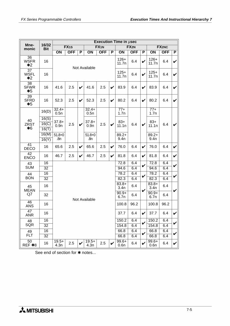
FX Series Programmable Controllers Execution Times And Instructional Hierarchy 7
See end of section for notes...
Mne-monic
16/32Bit
Execution Time in µsecFX1S FX1N FX2N FX2NC
ON OFF P ON OFF P ON OFF P ON OFF P36
WSFR2
16
Not Available
126+11.7n 6.4
126+11.7n 6.4
37WSFL
216 125+
11.7n 6.4 125+11.7n 6.4
38SFWR
516 41.6 2.5 41.6 2.5 83.9 6.4 83.9 6.4
39SFRD
516 52.3 2.5 52.3 2.5 80.2 6.4 80.2 6.4
40ZRST6
16(D) 32.4+0.5n
2.5
32.4+0.5n
2.5
77+1.7n
6.4
77+1.7n
6.4
16(S)37.8+0.9n
37.8+0.9n
83+11.1n
83+11.1n16(C)
16(T)16(M) 51.8+0
.8n51.8+0
.8n89.2+9.4n
89.2+9.4n16(Y)
41DECO 16 65.6 2.5 65.6 2.5 76.0 6.4 76.0 6.4
42ENCO 16 46.7 2.5 46.7 2.5 81.8 6.4 81.8 6.4
43SUM
16
Not Available
72.8 6.4
72.8 6.4
32 94.6 6.4 94.6 6.4
44BON
16 78.2 6.4
78.2 6.4
32 82.3 6.4 82.3 6.4
45MEAN
Q7
16 83.8+3.4n 6.4
83.8+3.4n 6.4
32 90.9+
6.7n 6.4 90.9+6.7n 6.4
46ANS 16 100.8 96.2 100.8 96.2
47ANR 16 37.7 6.4 37.7 6.4
48SQR
16 150.2 6.4
150.2 6.4
32 154.8 6.4 154.8 6.4
49FLT
16 66.8 6.4
66.8 6.4
32 66.8 6.4 66.8 6.450
REF 8 16 19.5+4.3n 2.5
19.5+4.3n 2.5
99.6+0.6n 6.4
99.6+0.6n 6.4
7-5
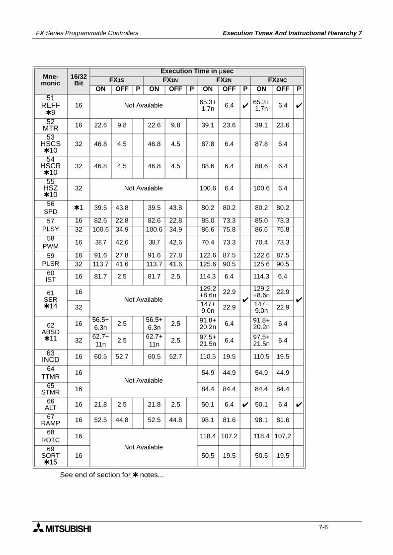
FX Series Programmable Controllers Execution Times And Instructional Hierarchy 7
See end of section for notes...
Mne-monic
16/32Bit
Execution Time in µsecFX1S FX1N FX2N FX2NC
ON OFF P ON OFF P ON OFF P ON OFF P51
REFF9
16 Not Available 65.3+1.7n 6.4
65.3+1.7n 6.4
52MTR 16 22.6 9.8 22.6 9.8 39.1 23.6 39.1 23.6
53HSCS10
32 46.8 4.5 46.8 4.5 87.8 6.4 87.8 6.4
54HSCR10
32 46.8 4.5 46.8 4.5 88.6 6.4 88.6 6.4
55HSZ10
32 Not Available 100.6 6.4 100.6 6.4
56SPD
1 39.5 43.8 39.5 43.8 80.2 80.2 80.2 80.2
57PLSY
16 82.6 22.8 82.6 22.8 85.0 73.3 85.0 73.332 100.6 34.9 100.6 34.9 86.6 75.8 86.6 75.8
58PWM
16 38.7 42.6 38.7 42.6 70.4 73.3 70.4 73.3
59PLSR
16 91.6 27.8 91.6 27.8 122.6 87.5 122.6 87.532 113.7 41.6 113.7 41.6 125.6 90.5 125.6 90.5
60IST 16 81.7 2.5 81.7 2.5 114.3 6.4 114.3 6.4
61SER14
16Not Available
129.2+8.6n 22.9
129.2+8.6n 22.9
32 147+
9.0n 22.9 147+9.0n 22.9
62ABSD11
1656.5+6.3n
2.556.5+6.3n
2.5 91.8+20.2n 6.4 91.8+
20.2n 6.4
3262.7+11n
2.562.7+11n
2.5 97.5+21.5n 6.4 97.5+
21.5n 6.4
63INCD 16 60.5 52.7 60.5 52.7 110.5 19.5 110.5 19.5
64TTMR
16Not Available
54.9 44.9 54.9 44.9
65STMR 16 84.4 84.4 84.4 84.4
66ALT 16 21.8 2.5 21.8 2.5 50.1 6.4 50.1 6.4
67RAMP 16 52.5 44.8 52.5 44.8 98.1 81.6 98.1 81.6
68ROTC
16
Not Available
118.4 107.2 118.4 107.2
69SORT15
16 50.5 19.5 50.5 19.5
7-6
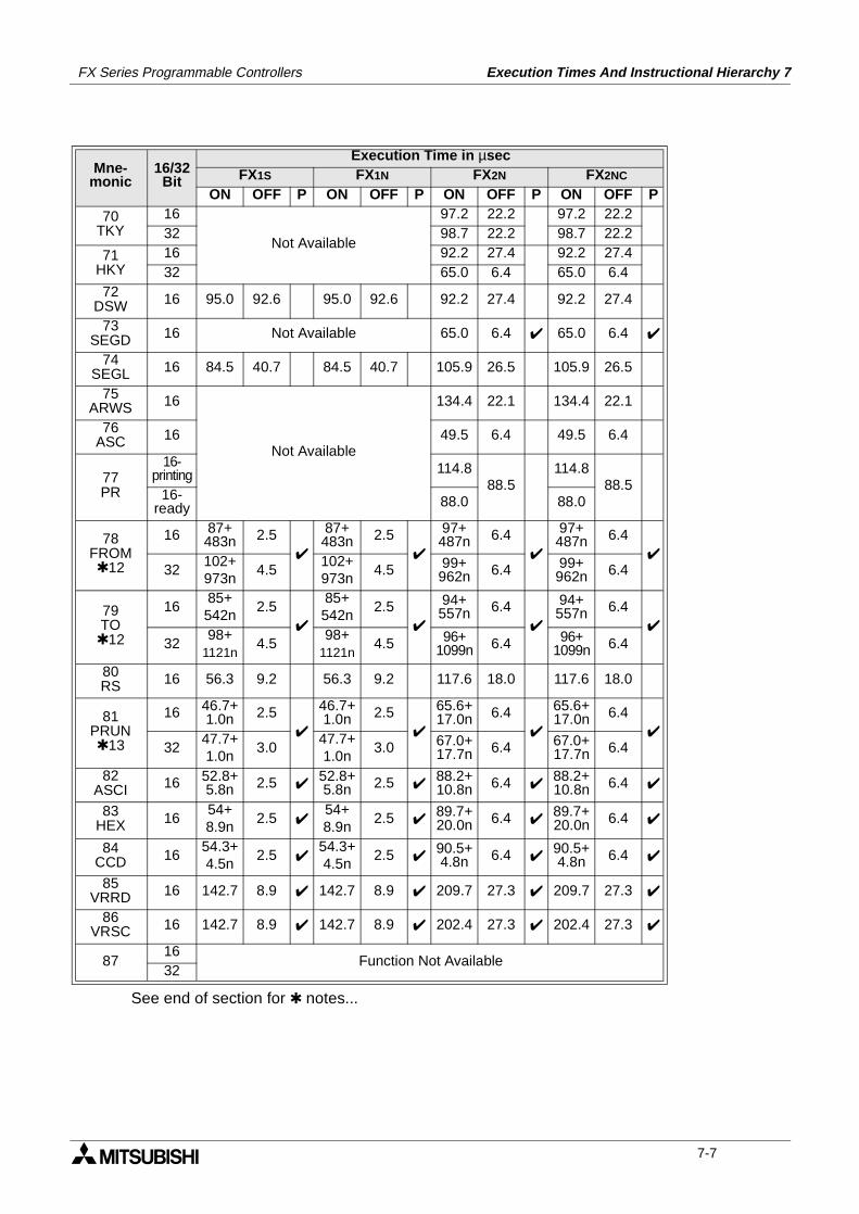
FX Series Programmable Controllers Execution Times And Instructional Hierarchy 7
See end of section for notes...
Mne-monic
16/32Bit
Execution Time in µsecFX1S FX1N FX2N FX2NC
ON OFF P ON OFF P ON OFF P ON OFF P
70TKY
16
Not Available
97.2 22.2 97.2 22.232 98.7 22.2 98.7 22.2
71HKY
16 92.2 27.4 92.2 27.432 65.0 6.4 65.0 6.4
72DSW 16 95.0 92.6 95.0 92.6 92.2 27.4 92.2 27.4
73SEGD 16 Not Available 65.0 6.4 65.0 6.4
74SEGL 16 84.5 40.7 84.5 40.7 105.9 26.5 105.9 26.5
75ARWS 16
Not Available
134.4 22.1 134.4 22.1
76ASC 16 49.5 6.4 49.5 6.4
77PR
16-printing 114.8
88.5114.8
88.516-
ready 88.0 88.0
78FROM12
16 87+ 483n 2.5
87+ 483n 2.5
97+487n 6.4
97+487n 6.4
32
102+973n
4.5102+973n
4.5 99+962n 6.4 99+
962n 6.4
79TO12
1685+ 542n
2.5
85+ 542n
2.5
94+557n 6.4
94+557n 6.4
3298+
1121n4.5
98+ 1121n
4.5 96+1099n 6.4 96+
1099n 6.4
80RS 16 56.3 9.2 56.3 9.2 117.6 18.0 117.6 18.0
81PRUN13
16 46.7+1.0n 2.5
46.7+1.0n 2.5
65.6+17.0n 6.4
65.6+17.0n 6.4
32
47.7+1.0n
3.047.7+1.0n
3.0 67.0+17.7n 6.4 67.0+
17.7n 6.4
82ASCI 16 52.8+
5.8n 2.5 52.8+5.8n 2.5
88.2+10.8n 6.4
88.2+10.8n 6.4
83HEX 16
54+ 8.9n
2.5 54+ 8.9n
2.5 89.7+20.0n 6.4
89.7+20.0n 6.4
84CCD 16
54.3+4.5n
2.5 54.3+4.5n
2.5 90.5+4.8n 6.4
90.5+4.8n 6.4
85VRRD 16 142.7 8.9 142.7 8.9 209.7 27.3 209.7 27.3
86VRSC 16 142.7 8.9 142.7 8.9 202.4 27.3 202.4 27.3
8716
Function Not Available32
7-7
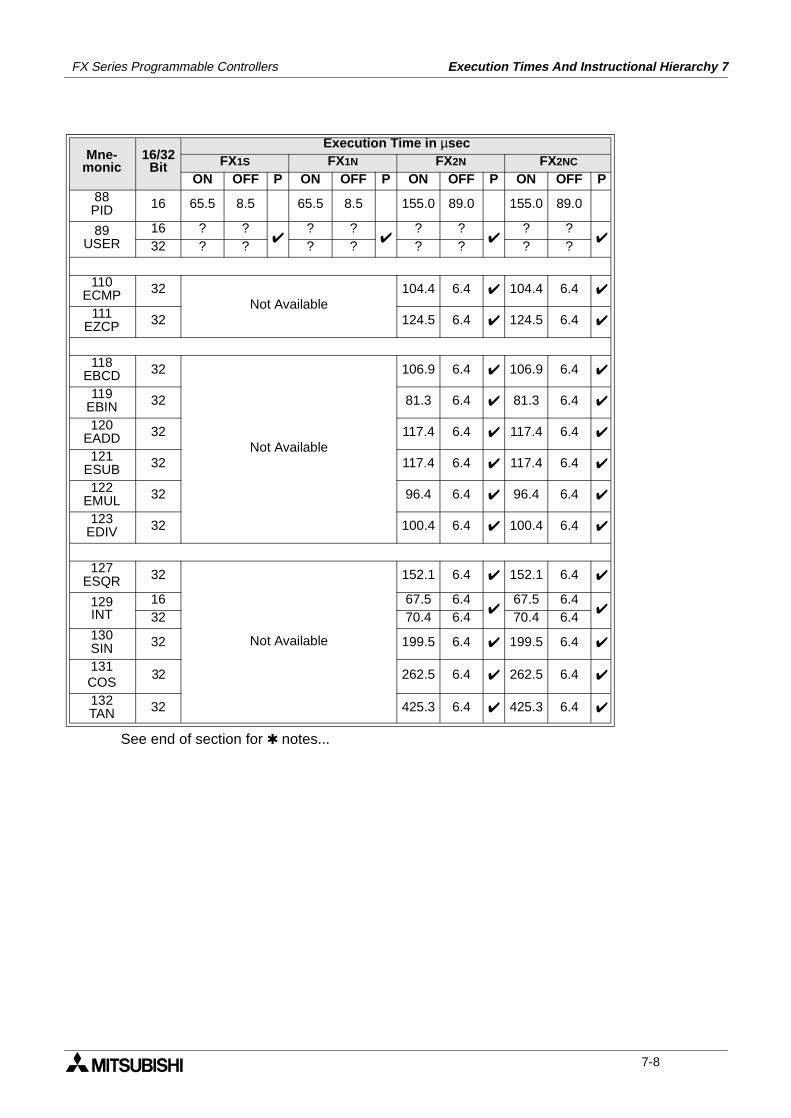
FX Series Programmable Controllers Execution Times And Instructional Hierarchy 7
See end of section for notes...
Mne-monic
16/32Bit
Execution Time in µsecFX1S FX1N FX2N FX2NC
ON OFF P ON OFF P ON OFF P ON OFF P88PID 16 65.5 8.5 65.5 8.5 155.0 89.0 155.0 89.0
89USER
16 ? ?
? ?
? ?
? ?
32 ? ? ? ? ? ? ? ?
110ECMP 32
Not Available104.4 6.4 104.4 6.4
111EZCP 32 124.5 6.4 124.5 6.4
118EBCD 32
Not Available
106.9 6.4 106.9 6.4
119EBIN 32 81.3 6.4 81.3 6.4
120EADD 32 117.4 6.4 117.4 6.4
121ESUB 32 117.4 6.4 117.4 6.4
122EMUL 32 96.4 6.4 96.4 6.4
123EDIV 32 100.4 6.4 100.4 6.4
127ESQR 32
Not Available
152.1 6.4 152.1 6.4
129INT
16 67.5 6.4
67.5 6.4
32 70.4 6.4 70.4 6.4130SIN 32 199.5 6.4 199.5 6.4
131COS
32 262.5 6.4 262.5 6.4
132TAN 32 425.3 6.4 425.3 6.4
7-8
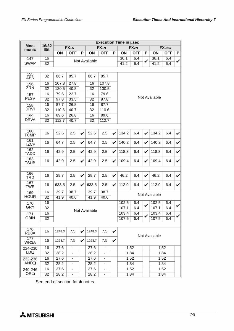
FX Series Programmable Controllers Execution Times And Instructional Hierarchy 7
See end of section for notes...
Mne-monic
16/32Bit
Execution Time in µsecFX1S FX1N FX2N FX2NC
ON OFF P ON OFF P ON OFF P ON OFF P147
SWAP16
Not Available36.1 6.4
36.1 6.4
32 41.2 6.4 41.2 6.4
155ABS 32 86.7 85.7 86.7 85.7
Not Available
156ZRN
16 107.8 27.8 16 107.832 130.5 40.8 32 130.5
157PLSV
16 79.6 22.7 16 79.632 97.8 33.5 32 97.8
158DRVI
16 87.7 26.8 16 87.732 110.6 40.7 32 110.6
159DRVA
16 89.6 26.8 16 89.632 112.7 40.7 32 112.7
160TCMP 16 52.6 2.5 52.6 2.5 134.2 6.4 134.2 6.4
161TZCP 16 64.7 2.5 64.7 2.5 140.2 6.4 140.2 6.4
162TADD 16 42.9 2.5 42.9 2.5 118.8 6.4 118.8 6.4
163TSUB 16 42.9 2.5 42.9 2.5 109.4 6.4 109.4 6.4
166TRD 16 29.7 2.5 29.7 2.5 46.2 6.4 46.2 6.4
167TWR 16 633.5 2.5 633.5 2.5 112.0 6.4 112.0 6.4
169HOUR
16 39.7 38.7 39.7 38.7Not Available
32 41.9 40.6 41.9 40.6
170GRY
16
Not Available
102.5 6.4
102.5 6.4
32 107.1 6.4 107.1 6.4
171GBIN
16 103.4 6.4
103.4 6.4
32 107.5 6.4 107.5 6.4
176RD3A 16 1248.3 7.5 1248.3 7.5
Not Available177
WR3A 16 1263.7 7.5 1263.7 7.5
224-230LD
16 27.6 - 27.6 - 1.52 1.5232 28.2 - 28.2 - 1.84 1.84
232-238AND
16 27.6 - 27.6 - 1.52 1.5232 28.2 - 28.2 - 1.84 1.84
240-246OR
16 27.6 - 27.6 - 1.52 1.5232 28.2 - 28.2 - 1.84 1.84
7-9
FX Series Programmable Controllers Execution Times And Instructional Hierarchy 7
1:
• These instructions require NO preliminary contact devices such as LD, AND, OR etc.
2:
• Where “n” is referred to this identifies the quantity of registers to be manipulated.“n” can be equal or less than 512.
3:
• Where “n” is referred to this identifies the quantity of bit devices to be manipulated.“n” can be equal or less than selected operating mode, i.e. if 32 bit mode is selected then “n” canhave a value equal or less than 32.
4:
• Where "n" is referred to this identifies the quantity of bit devices to be manipulated.When an FX1N PLC is used "n" can be equal or less than 1536.However, when an FX1S controller is used "n" can be equal or less than 512.
5:
• Where "n" is referred to this identifies the quantity devices to be manipulated. "n" can have any valuetaken from the range 2 through 512.
6:
• Where "n" is referred to this identifies the range of devices to be reset. The device type being reset isidentified by the device letter in brackets in the '16/32 bit' column.
7:
• Where "n" is referred to this identifies the number of devices the mean is to be calculated from. Thevalue of "n" can be taken from the range 1 through 64.
8:
• Where "n" is referred to this identifies the range of devices to be refreshed. The value of "n" is alwaysspecified in units of 8, i.e 8, 16, 24.....128. The maximum allowable range is dependent on thenumber of available inputs/outputs.
9:
• Where "n" is referred to this identifies the time setting for the input filters operation."n" can be selected from the range 0 through to 60 msec.
10:
• There are limits to the total combined use of these instructions. For FX1S and FX1N there should beno more than 4 simultaneously active instructions. However, FX2N and FX2Nc can have 6simultaneously active instructions.
11:
• Where "n" is referred to this identifies the number of output points. "n" may have a value equal or lessthan 64.
12:
• Where "n" is referred to this identifies the number of words read or written FROM/TO the specialfunction blocks.
13:
• Where "n" is referred to this identifies the number of octal (8 bit) words read or written when two FXPLC’s are involved in a parallel running function.
14:
• Where "n" is referred to this identifies the number of elements in a stack, for 16 bit operation n has amaximum of 256. However, for 32 bit operation n has a maximum of 128.
15:
• Where "m1" is referred to this identifies the number of elements in the data table.Values of m1 are taken from the range 1 to 32. For a the SORT instruction to completely process thedata table the SORT instruction will be processed m1 times.
7-10

FX Series Programmable Controllers Execution Times And Instructional Hierarchy 7
7.3 Hierarchical RelationshipsOf Basic Program Instructions
The fo l lowing table ident i f ies an ’inc lusiverelationship’. This means the secondary programconstruction is included within the completeoperating boundaries of the primary programconstruction, e.g.:
: Instruction combination is acceptable - for restrictions see appropriate note
: Instruction combination is not allowed - bracketed number is the error code
: Instruction combination is not recommended for use even though there is no operationalerror
The combination of instructions with an ’inclusive relationship’ is allowable. However please beaware of the following exceptions:
1) MC-MCR and STL-RET constructions cannot be used within FOR-NEXT loops, P-SRET orI-IRET subroutines.
2) Program flow may not be discontinued by using any of the following methods while insideMC-MCR, FOR-NEXT, P-SRET, I-IRET program constructions, i.e. using interrupts (I),IRET, SRET, FEND or the END instruction is not allowed.
PrimaryProgram
Construction
Secondary program construction
MC-MCR CJ - P EI - DIFOR -NEXT
STL -RET
P - SRET I - IRETFEND -
END
MC - MCR - 8 nest
levels - (6608) - (6608) - (6608)
CJ - P - (6701)
EI - DI ➀
FOR - NEXT -(6607)
- 5 nest
levels - (6607) - (6607) - (6607) - (6607)
STL - RET - (6605)
-(within 1
STL step) - (6605) - (6605) - (6605)
P - SRET - (6606) - (6606) - (6606) - (6606) - (6709)
I - IRET - (6606) - (6606) - (6606) - (6606) - (6606)
FEND - END ➁
0 - FEND - (6606) - (6606) ➁
0 - END(no FEND)
- (6606) - (6606) ➁
FX1S FX1N FX2N FX2NC
FOR
EI
DI
NEXT
Primaryprogram construction
Secondaryprogram construction
7-11
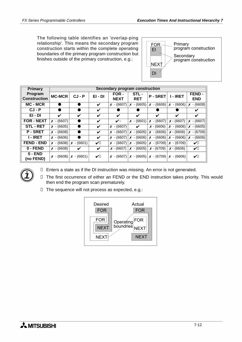
FX Series Programmable Controllers Execution Times And Instructional Hierarchy 7
The following table identifies an ’overlap-pingrelationship’. This means the secondary programconstruction starts within the complete operatingboundaries of the primary program construction butfinishes outside of the primary construction, e.g.:
➀ Enters a state as if the DI instruction was missing. An error is not generated.
② The first occurrence of either an FEND or the END instruction takes priority. This wouldthen end the program scan prematurely.
③ The sequence will not process as expected, e.g.:
PrimaryProgram
Construction
Secondary program construction
MC-MCR CJ - P EI - DIFOR -NEXT
STL -RET
P - SRET I - IRETFEND -
ENDMC - MCR - (6607) - (6605) - (6606) - (6606) - (6608)
CJ - P
EI - DI
FOR - NEXT - (6607) ¬ - (6601) - (6607) - (6607) - (6607)
STL - RET - (6605) - (6607) - (6606) - (6606) - (6605)
P - SRET - (6608) - (6607) - (6605) - (6606) - (6606) - (6709)
I - IRET - (6606) - (6607) - (6606) - (6606) - (6606) - (6606)
FEND - END - (6608) - (6601) ➀ - (6607) - (6605) - (6709) - (6709) ➁
0 - FEND - (6608) - (6607) - (6605) - (6709) - (6606) ➁
0 - END(no FEND)
- (6608) - (6601) ➀ - (6607) - (6605) - (6709) - (6606) ➁
FOREI
DI
NEXT
Primaryprogram construction
Secondaryprogram construction
FOR
NEXT
FOR
NEXT
Desired
FOR
NEXT
FOR
NEXT
Actual
Operatingboundries
7-12
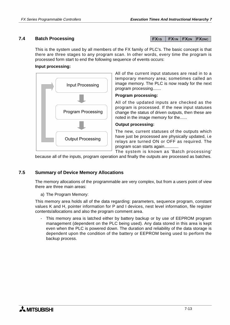
FX Series Programmable Controllers Execution Times And Instructional Hierarchy 7
7.4 Batch Processing
This is the system used by all members of the FX family of PLC’s. The basic concept is thatthere are three stages to any program scan. In other words, every time the program isprocessed form start to end the following sequence of events occurs:
Input processing:
All of the current input statuses are read in to atemporary memory area; sometimes called animage memory. The PLC is now ready for the nextprogram processing.......
Program processing:
All of the updated inputs are checked as theprogram is processed. If the new input statuseschange the status of driven outputs, then these arenoted in the image memory for the......
Output processing:
The new, current statuses of the outputs whichhave just be processed are physically updated, i.erelays are turned ON or OFF as required. Theprogram scan starts again............The system is known as 'Batch processing'
because all of the inputs, program operation and finally the outputs are processed as batches.
7.5 Summary of Device Memory Allocations
The memory allocations of the programmable are very complex, but from a users point of viewthere are three main areas:
a) The Program Memory:
This memory area holds all of the data regarding: parameters, sequence program, constantvalues K and H, pointer information for P and I devices, nest level information, file registercontents/allocations and also the program comment area.
- This memory area is latched either by battery backup or by use of EEPROM programmanagement (dependent on the PLC being used). Any data stored in this area is kepteven when the PLC is powered down. The duration and reliability of the data storage isdependent upon the condition of the battery or EEPROM being used to perform thebackup process.
FX1S FX1N FX2N FX2NC
Input Processing
Program Processing
Output Processing
7-13
FX Series Programmable Controllers Execution Times And Instructional Hierarchy 7
b) Data Memory
This memory area contains, as the title suggests, all of the data values associated with:data registers (normal and special), Index registers, current timer values, retentive timervalues (if available) and current counter values.
- All of the devices which are designated as being latched (including retentive timers) arebacked up in a similar method to the one mentioned under point a).
- Index registers and special data registers (D8000 to D8255) operate in the specifiedmanner under the following circumstances:
- All other devices such as current values of non latched data registers, timers andcounters behave in the following manner:
c) Bit Memory
This memory area contains the contact status of all inputs, outputs, auxiliary relays, state coils,timers and counters.
- All of the devices which are designated as being latched (including retentive timers) arebacked up in a similar method to the one mentioned under point a).
- Special auxiliary relays (M8000 to M8255) act in a similar way to the special dataregisters mentioned under point b).
- All other devices are subject to the same changes as the current values of data registers,timers and counter (see the last point and table under section b).
Summary
7.6 Limits Of Instruction Usage
7.6.1 Instructions Which Can Only Be Used Once In The Main Program Area
The following instructions can only be used once in the main program area. For PLCapplicability please check either the detailed explanations of the instructions or the instructionexecution tables list earlier.
Circumstance ReactionPLC’s power is turned OFF All data is clearedPLC’s power is turned ON Certain devices are reset to their defaults see chapter 6
PLC is switched from STOP to RUNCertain devices are reset to their defaults see chapter 6
PLC is switched from RUN to STOP
Circumstance ReactionPLC’s power is turned OFF
All data is clearedPLC’s power is turned ON
PLC is switched from STOP to RUN No changePLC is switched from RUN to STOP Cleared (unless special M coil M8033 is active)
Memory typePower PLC
OFF OFF ON STOP RUN RUN STOPAll devices backed by battery Not changed
Special M and D devices (8000 to 8255) and index registers V and Z
Cleared Default Not changed
All other devices Cleared Not changed Cleared
Not changed when M8033 is set
FX1S FX1N FX2N FX2NC
7-14
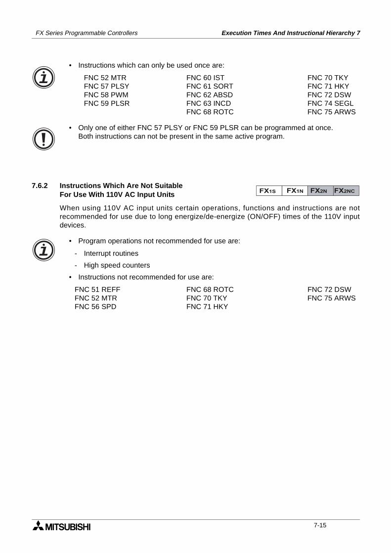
FX Series Programmable Controllers Execution Times And Instructional Hierarchy 7
• Instructions which can only be used once are:
FNC 52 MTR FNC 60 IST FNC 70 TKYFNC 57 PLSY FNC 61 SORT FNC 71 HKYFNC 58 PWM FNC 62 ABSD FNC 72 DSWFNC 59 PLSR FNC 63 INCD FNC 74 SEGL
FNC 68 ROTC FNC 75 ARWS
• Only one of either FNC 57 PLSY or FNC 59 PLSR can be programmed at once.Both instructions can not be present in the same active program.
7.6.2 Instructions Which Are Not SuitableFor Use With 110V AC Input Units
When using 110V AC input units certain operations, functions and instructions are notrecommended for use due to long energize/de-energize (ON/OFF) times of the 110V inputdevices.
• Program operations not recommended for use are:
- Interrupt routines
- High speed counters
• Instructions not recommended for use are:
FNC 51 REFF FNC 68 ROTC FNC 72 DSWFNC 52 MTR FNC 70 TKY FNC 75 ARWSFNC 56 SPD FNC 71 HKY
FX1S FX1N FX2N FX2NC
7-15
FX Series Programmable Controllers Execution Times And Instructional Hierarchy 7
MEMO
7-16

1 Introduction
2 Basic Program Instructions
3 STL Programming
4 Devices in Detail
5 Applied Instructions
6 Diagnostic Devices
7 Instruction Execution Times
8 PLC Device Tables
9 Assigning System Devices
10 Points of Technique
11 Index
FX Series Programmable Controllers PLC Device Tables 8
FX Series Programmable Controllers PLC Device Tables 8
Chapter Contents
8. PC Device Tables..................................................................................8-18.1 Performance Specification Of the FX1S .............................................................. 8-18.2 Performance Specification Of The FX1N ............................................................. 8-28.3 Performance Specification Of The FX2N and FX2NC PLC’s ................................ 8-4
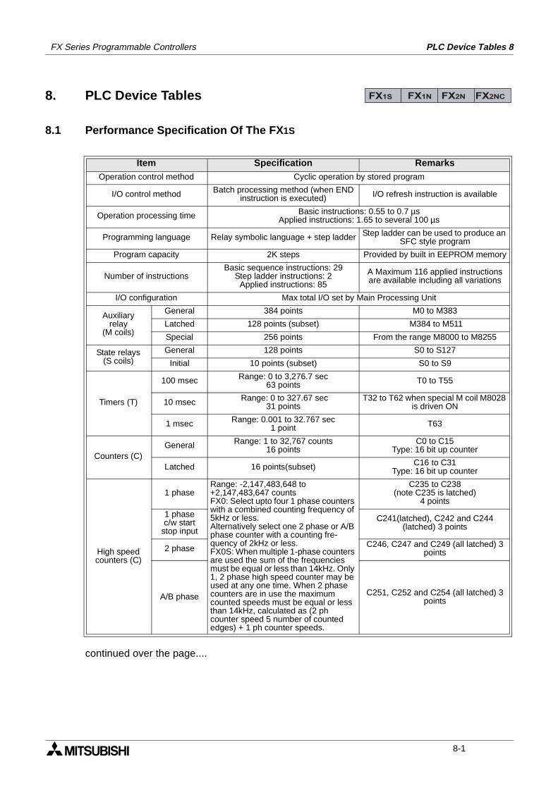
PLC Device Tables 8FX Series Programmable Controllers
8. PLC Device Tables
8.1 Performance Specification Of The FX1S
Item Specification RemarksOperation control method Cyclic operation by stored program
I/O control method Batch processing method (when END instruction is executed) I/O refresh instruction is available
Operation processing time Basic instructions: 0.55 to 0.7 µsApplied instructions: 1.65 to several 100 µs
Programming language Relay symbolic language + step ladder Step ladder can be used to produce an SFC style program
Program capacity 2K steps Provided by built in EEPROM memory
Number of instructionsBasic sequence instructions: 29
Step ladder instructions: 2Applied instructions: 85
A Maximum 116 applied instructions are available including all variations
I/O configuration Max total I/O set by Main Processing Unit
Auxiliaryrelay
(M coils)
General 384 points M0 to M383
Latched 128 points (subset) M384 to M511
Special 256 points From the range M8000 to M8255
State relays(S coils)
General 128 points S0 to S127
Initial 10 points (subset) S0 to S9
Timers (T)
100 msec Range: 0 to 3,276.7 sec63 points T0 to T55
10 msec Range: 0 to 327.67 sec31 points
T32 to T62 when special M coil M8028 is driven ON
1 msec Range: 0.001 to 32.767 sec1 point T63
Counters (C)General Range: 1 to 32,767 counts
16 pointsC0 to C15
Type: 16 bit up counter
Latched 16 points(subset) C16 to C31Type: 16 bit up counter
High speedcounters (C)
1 phaseRange: -2,147,483,648 to +2,147,483,647 countsFX0: Select upto four 1 phase counters with a combined counting frequency of 5kHz or less.Alternatively select one 2 phase or A/B phase counter with a counting fre-quency of 2kHz or less.FX0S: When multiple 1-phase counters are used the sum of the frequencies must be equal or less than 14kHz. Only 1, 2 phase high speed counter may be used at any one time. When 2 phase counters are in use the maximum counted speeds must be equal or less than 14kHz, calculated as (2 ph counter speed 5 number of counted edges) + 1 ph counter speeds.
C235 to C238(note C235 is latched)
4 points
1 phasec/w start
stop input
C241(latched), C242 and C244 (latched) 3 points
2 phase C246, C247 and C249 (all latched) 3 points
A/B phase C251, C252 and C254 (all latched) 3 points
FX1S FX1N FX2N FX2NC
continued over the page....
8-1
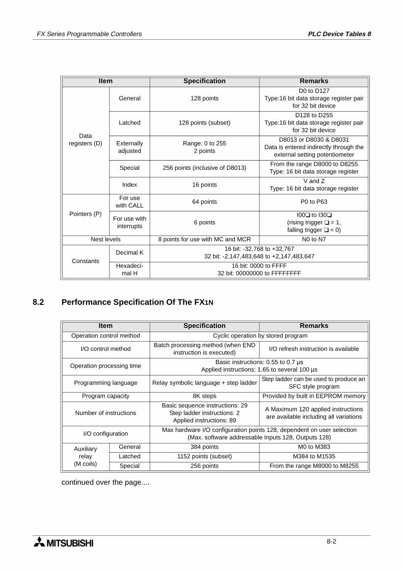
FX Series Programmable Controllers PLC Device Tables 8
8.2 Performance Specification Of The FX1N
continued over the page....
Item Specification Remarks
Dataregisters (D)
General 128 pointsD0 to D127
Type:16 bit data storage register pair for 32 bit device
Latched 128 points (subset)D128 to D255
Type:16 bit data storage register pair for 32 bit device
Externallyadjusted
Range: 0 to 2552 points
D8013 or D8030 & D8031Data is entered indirectly through the
external setting potentiometer
Special 256 points (inclusive of D8013)From the range D8000 to D8255Type: 16 bit data storage register
Index 16 pointsV and Z
Type: 16 bit data storage register
Pointers (P)
For usewith CALL
64 points P0 to P63
For use withinterrupts
6 pointsI00 to I30
(rising trigger = 1, falling trigger = 0)
Nest levels 8 points for use with MC and MCR N0 to N7
ConstantsDecimal K
16 bit: -32,768 to +32,76732 bit: -2,147,483,648 to +2,147,483,647
Hexadeci-mal H
16 bit: 0000 to FFFF32 bit: 00000000 to FFFFFFFF
Item Specification RemarksOperation control method Cyclic operation by stored program
I/O control methodBatch processing method (when END
instruction is executed)I/O refresh instruction is available
Operation processing timeBasic instructions: 0.55 to 0.7 µs
Applied instructions: 1.65 to several 100 µs
Programming language Relay symbolic language + step ladderStep ladder can be used to produce an
SFC style program
Program capacity 8K steps Provided by built in EEPROM memory
Number of instructionsBasic sequence instructions: 29
Step ladder instructions: 2Applied instructions: 89
A Maximum 120 applied instructions are available including all variations
I/O configurationMax hardware I/O configuration points 128, dependent on user selection
(Max. software addressable Inputs 128, Outputs 128)
Auxiliaryrelay
(M coils)
General 384 points M0 to M383
Latched 1152 points (subset) M384 to M1535
Special 256 points From the range M8000 to M8255
8-2
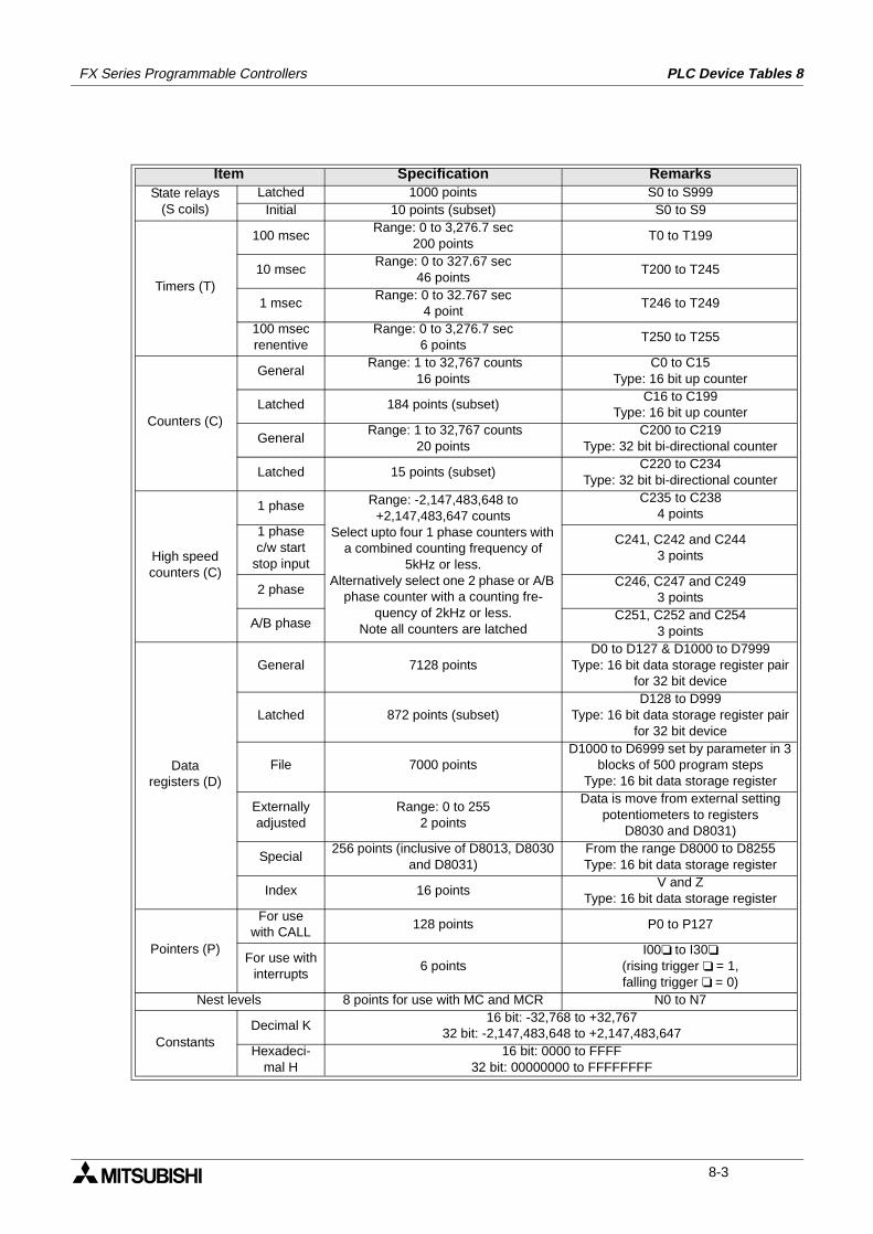
FX Series Programmable Controllers PLC Device Tables 8
Item Specification RemarksState relays
(S coils)Latched 1000 points S0 to S999
Initial 10 points (subset) S0 to S9
Timers (T)
100 msecRange: 0 to 3,276.7 sec
200 points T0 to T199
10 msecRange: 0 to 327.67 sec
46 pointsT200 to T245
1 msecRange: 0 to 32.767 sec
4 pointT246 to T249
100 msecrenentive
Range: 0 to 3,276.7 sec6 points
T250 to T255
Counters (C)
General Range: 1 to 32,767 counts
16 pointsC0 to C15
Type: 16 bit up counter
Latched 184 points (subset)C16 to C199
Type: 16 bit up counter
General Range: 1 to 32,767 counts
20 pointsC200 to C219
Type: 32 bit bi-directional counter
Latched 15 points (subset)C220 to C234
Type: 32 bit bi-directional counter
High speedcounters (C)
1 phase Range: -2,147,483,648 to +2,147,483,647 counts
Select upto four 1 phase counters with a combined counting frequency of
5kHz or less.Alternatively select one 2 phase or A/B
phase counter with a counting fre-quency of 2kHz or less.
Note all counters are latched
C235 to C2384 points
1 phasec/w start
stop input
C241, C242 and C2443 points
2 phaseC246, C247 and C249
3 points
A/B phaseC251, C252 and C254
3 points
Dataregisters (D)
General 7128 pointsD0 to D127 & D1000 to D7999
Type: 16 bit data storage register pair for 32 bit device
Latched 872 points (subset)D128 to D999
Type: 16 bit data storage register pair for 32 bit device
File 7000 pointsD1000 to D6999 set by parameter in 3
blocks of 500 program stepsType: 16 bit data storage register
Externallyadjusted
Range: 0 to 2552 points
Data is move from external setting potentiometers to registers
D8030 and D8031)
Special256 points (inclusive of D8013, D8030
and D8031)From the range D8000 to D8255Type: 16 bit data storage register
Index 16 pointsV and Z
Type: 16 bit data storage register
Pointers (P)
For usewith CALL
128 points P0 to P127
For use withinterrupts
6 pointsI00 to I30
(rising trigger = 1,falling trigger = 0)
Nest levels 8 points for use with MC and MCR N0 to N7
ConstantsDecimal K
16 bit: -32,768 to +32,76732 bit: -2,147,483,648 to +2,147,483,647
Hexadeci-mal H
16 bit: 0000 to FFFF32 bit: 00000000 to FFFFFFFF
8-3
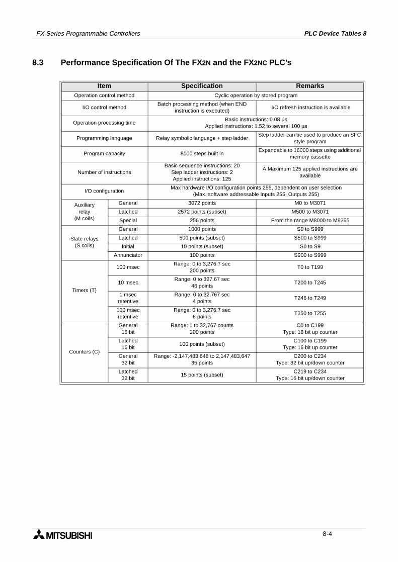
FX Series Programmable Controllers PLC Device Tables 8
8.3 Performance Specification Of The FX2N and the FX2NC PLC’s
Item Specification RemarksOperation control method Cyclic operation by stored program
I/O control methodBatch processing method (when END
instruction is executed) I/O refresh instruction is available
Operation processing timeBasic instructions: 0.08 µs
Applied instructions: 1.52 to several 100 µs
Programming language Relay symbolic language + step ladderStep ladder can be used to produce an SFC
style program
Program capacity 8000 steps built inExpandable to 16000 steps using additional
memory cassette
Number of instructionsBasic sequence instructions: 20
Step ladder instructions: 2Applied instructions: 125
A Maximum 125 applied instructions are available
I/O configurationMax hardware I/O configuration points 255, dependent on user selection
(Max. software addressable Inputs 255, Outputs 255)
Auxiliaryrelay
(M coils)
General 3072 points M0 to M3071
Latched 2572 points (subset) M500 to M3071
Special 256 points From the range M8000 to M8255
State relays(S coils)
General 1000 points S0 to S999
Latched 500 points (subset) S500 to S999
Initial 10 points (subset) S0 to S9
Annunciator 100 points S900 to S999
Timers (T)
100 msecRange: 0 to 3,276.7 sec
200 pointsT0 to T199
10 msecRange: 0 to 327.67 sec
46 pointsT200 to T245
1 msecretentive
Range: 0 to 32.767 sec4 points
T246 to T249
100 msecretentive
Range: 0 to 3,276.7 sec6 points
T250 to T255
Counters (C)
General16 bit
Range: 1 to 32,767 counts200 points
C0 to C199Type: 16 bit up counter
Latched16 bit
100 points (subset)C100 to C199
Type: 16 bit up counter
General32 bit
Range: -2,147,483,648 to 2,147,483,64735 points
C200 to C234Type: 32 bit up/down counter
Latched32 bit
15 points (subset)C219 to C234
Type: 16 bit up/down counter
8-4
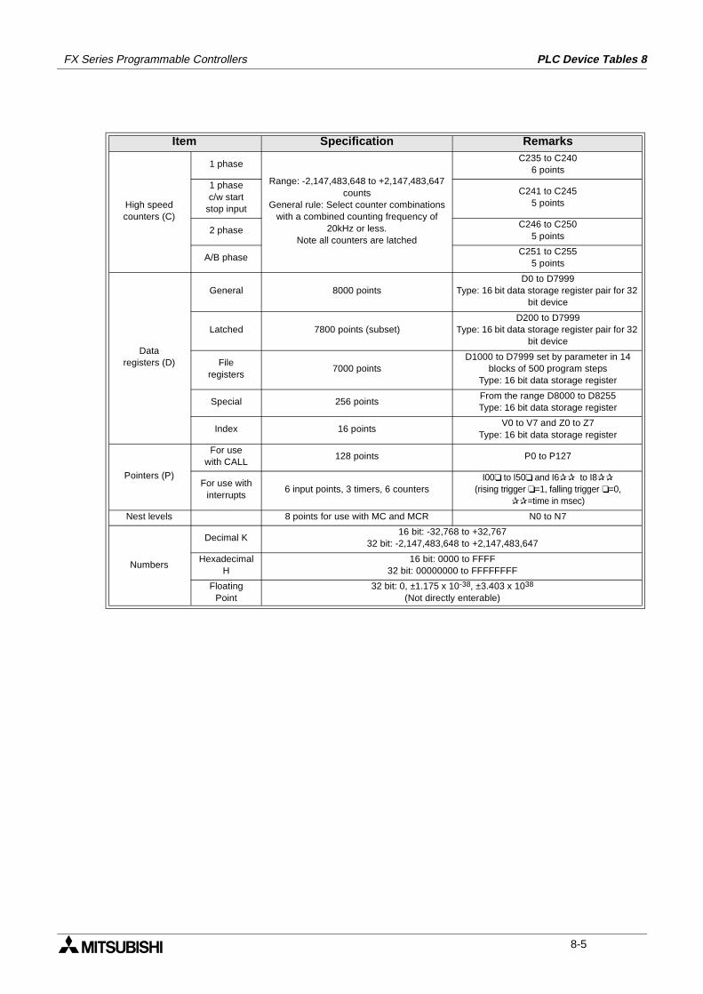
FX Series Programmable Controllers PLC Device Tables 8
Item Specification Remarks
High speedcounters (C)
1 phase
Range: -2,147,483,648 to +2,147,483,647 counts
General rule: Select counter combinations with a combined counting frequency of
20kHz or less.Note all counters are latched
C235 to C2406 points
1 phasec/w start
stop input
C241 to C2455 points
2 phaseC246 to C250
5 points
A/B phaseC251 to C255
5 points
Dataregisters (D)
General 8000 pointsD0 to D7999
Type: 16 bit data storage register pair for 32 bit device
Latched 7800 points (subset)D200 to D7999
Type: 16 bit data storage register pair for 32 bit device
Fileregisters
7000 pointsD1000 to D7999 set by parameter in 14
blocks of 500 program stepsType: 16 bit data storage register
Special 256 pointsFrom the range D8000 to D8255Type: 16 bit data storage register
Index 16 pointsV0 to V7 and Z0 to Z7
Type: 16 bit data storage register
Pointers (P)
For usewith CALL
128 points P0 to P127
For use withinterrupts
6 input points, 3 timers, 6 countersI00 to I50 and I6 to I8
(rising trigger =1, falling trigger =0, =time in msec)
Nest levels 8 points for use with MC and MCR N0 to N7
Numbers
Decimal K16 bit: -32,768 to +32,767
32 bit: -2,147,483,648 to +2,147,483,647
Hexadecimal H
16 bit: 0000 to FFFF32 bit: 00000000 to FFFFFFFF
FloatingPoint
32 bit: 0, ±1.175 x 10-38, ±3.403 x 1038
(Not directly enterable)
8-5
FX Series Programmable Controllers PLC Device Tables 8
Memo
8-6
1 Introduction
2 Basic Program Instructions
3 STL Programming
4 Devices in Detail
5 Applied Instructions
6 Diagnostic Devices
7 Instruction Execution Times
8 PLC Device Tables
9 Assigning System Devices
10 Points of Technique
11 Index
FX Series Programmable Controllers Assigning System Devices 9
FX Series Programmable Controllers Assigning System Devices 9
Chapter Contents
9. Assigning System Devices ....................................................................9-19.1 Addressing Extension Modules ........................................................................... 9-19.2 Real Time Clock Function ................................................................................... 9-2
9.2.1 Setting the real time clock ......................................................................................... 9-2
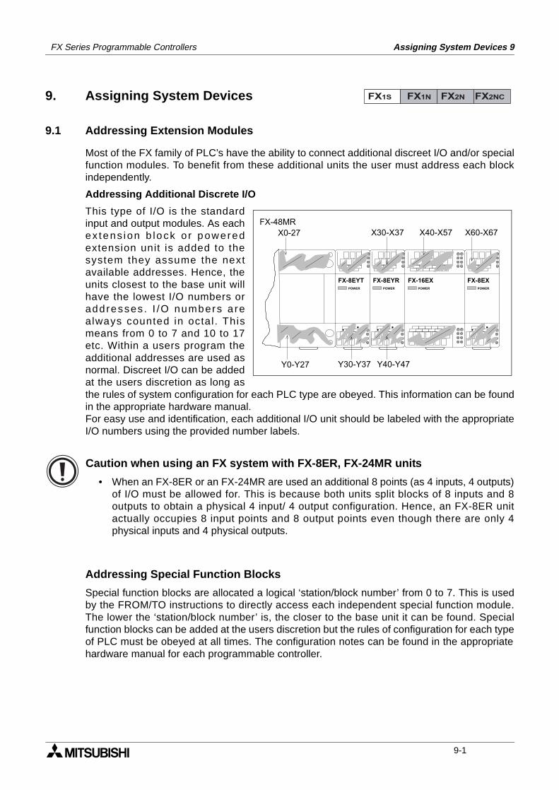
Assigning System Devices 9FX Series Programmable Controllers
9. Assigning System Devices
9.1 Addressing Extension Modules
Most of the FX family of PLC’s have the ability to connect additional discreet I/O and/or specialfunction modules. To benefit from these additional units the user must address each blockindependently.
Addressing Additional Discrete I/O
This type of I/O is the standardinput and output modules. As eachex tens ion b lock o r poweredextension unit is added to thesystem they assume the nextavailable addresses. Hence, theunits closest to the base unit willhave the lowest I/O numbers oraddresses . I /O numbers a realways counted in octal . Thismeans from 0 to 7 and 10 to 17etc. Within a users program theadditional addresses are used asnormal. Discreet I/O can be addedat the users discretion as long asthe rules of system configuration for each PLC type are obeyed. This information can be foundin the appropriate hardware manual.For easy use and identification, each additional I/O unit should be labeled with the appropriateI/O numbers using the provided number labels.
Caution when using an FX system with FX-8ER, FX-24MR units
• When an FX-8ER or an FX-24MR are used an additional 8 points (as 4 inputs, 4 outputs)of I/O must be allowed for. This is because both units split blocks of 8 inputs and 8outputs to obtain a physical 4 input/ 4 output configuration. Hence, an FX-8ER unitactually occupies 8 input points and 8 output points even though there are only 4physical inputs and 4 physical outputs.
Addressing Special Function Blocks
Special function blocks are allocated a logical ‘station/block number’ from 0 to 7. This is usedby the FROM/TO instructions to directly access each independent special function module.The lower the ‘station/block number’ is, the closer to the base unit it can be found. Specialfunction blocks can be added at the users discretion but the rules of configuration for each typeof PLC must be obeyed at all times. The configuration notes can be found in the appropriatehardware manual for each programmable controller.
FX1S FX1N FX2N FX2NC
POWER
FX-16EXPOWER
FX-8EXPOWER
FX-8EYTPOWER
FX-8EYR
FX-48MRX0-27 X30-X37 X40-X57 X60-X67
Y0-Y27 Y30-Y37 Y40-Y47
9-1
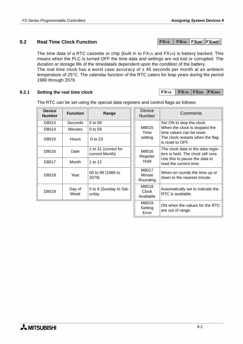
FX Series Programmable Controllers Assigning System Devices 9
9.2 Real Time Clock Function
The time data of a RTC cassette or chip (built in to FX1S and FX1N) is battery backed. Thismeans when the PLC is turned OFF the time data and settings are not lost or corrupted. Theduration or storage life of the timedatails dependent upon the condition of the battery. The real time clock has a worst case accuracy of ± 45 seconds per month at an ambienttemperature of 25°C. The calendar function of the RTC caters for leap years during the period1980 through 2079.
9.2.1 Setting the real time clock
The RTC can be set using the special data registers and control flags as follows:
DeviceNumber
Function RangeDeviceNumber
Comments
D8013 Seconds 0 to 59M8015Time
setting
Set ON to stop the clock.When the clock is stopped the time values can be reset.The clock restarts when the flag is reset to OFF.
D8014 Minutes 0 to 59
D8015 Hours 0 to 23
D8016 Date1 to 31 (correct for current Month)
M8016Register
Hold
The clock data in the data regis-ters is held. The clock still runs. Use this to pause the data to read the current time.D8017 Month 1 to 12
D8018 Year00 to 99 (1980 to 2079)
M8017Minute
Rounding
When on rounds the time up or down to the nearest minute.
D8019Day of Week
0 to 6 (Sunday to Sat-urday
M8018Clock
Available
Automatically set to indicate the RTC is available.
M8019SettingError
ON when the values for the RTC are out of range.
FX1S FX1N FX2N FX2NC
FX1S FX1N FX2N FX2NC
9-2
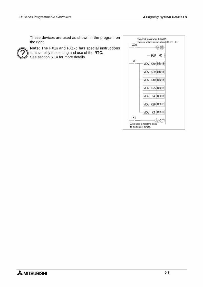
FX Series Programmable Controllers Assigning System Devices 9
X00M8015
M0K30 D8013MOV
K20 D8014MOV
K10 D8015MOV
K25 D8016MOV
K4 D8017MOV
K96 D8018MOV
K4 D8019MOV
M8017X1
M0PLF
The clock stops when X0 is ON.The new values are set when X0 turns OFF.
X1 is used to reset the clockto the nearest minute.
These devices are used as shown in the program onthe right.
Note: The FX2N and FX2NC has special instructionsthat simplify the setting and use of the RTC.See section 5.14 for more details.
9-3

FX Series Programmable Controllers Assigning System Devices 9
MEMO
9-4

1 Introduction
2 Basic Program Instructions
3 STL Programming
4 Devices in Detail
5 Applied Instructions
6 Diagnostic Devices
7 Instruction Execution Times
8 PLC Device Tables
9 Assigning System Devices
10 Points of Technique
11 Index
FX Series Programmable Controllers Points of Technique 10
FX Series Programmable Controllers Points of Technique 10
Chapter Contents
10.Points Of Technique...........................................................................10-110.1 Advanced Programming Points ......................................................................... 10-110.2 Users of DC Powered FX Units ......................................................................... 10-110.3 Using The Forced RUN/STOP Flags................................................................. 10-2
10.3.1 A RUN/STOP push button configuration ................................................................. 10-210.3.2 Remote RUN/STOP control .................................................................................... 10-3
10.4 Constant Scan Mode ......................................................................................... 10-410.5 Alternating ON/OFF States................................................................................ 10-410.6 Using Battery Backed Devices For Maximum Advantage ................................. 10-510.7 Indexing Through Multiple Display Data Values................................................ 10-510.8 Reading And Manipulating Thumbwheel Data .................................................. 10-610.9 Measuring a High Speed Pulse Input ................................................................ 10-6
10.9.1 A 1 msec timer pulse measurement ........................................................................ 10-610.9.2 A 0.1 msec timer pulse measurement ..................................................................... 10-7
10.10 Using The Execution Complete Flag, M8029 .................................................. 10-710.11 Creating a User Defined MTR Instruction ........................................................ 10-810.12 An Example System Application Using STL And IST Program Control ........... 10-810.13 Using The PWM Instruction For Motor Control .............................................. 10-1510.14 Communication Format.................................................................................. 10-18
10.14.1 Specification of the communication parameters .................................................. 10-1810.14.2 Header and Terminator Characters ..................................................................... 10-1910.14.3 Timing diagrams for communications .................................................................. 10-2010.14.4 8 bit or 16 bit communications. ............................................................................ 10-23
10.15 PID programming techniques ........................................................................ 10-2410.15.1 Keeping MV within a set range ............................................................................ 10-2410.15.2 Manual / Automatic change over ......................................................................... 10-2410.15.3 Using the PID alarm signals ................................................................................ 10-2510.15.4 Other tips for PID programming........................................................................... 10-25
10.16 Additional PID functions................................................................................. 10-2610.16.1 Output Value range control.................................................................................. 10-26
10.17 Pre-tuning operation ...................................................................................... 10-2710.17.1 Variable control.................................................................................................... 10-27
10.18 Example Autotuning program ........................................................................ 10-2810.19 Using the FX1N-5DM Display module............................................................. 10-29
10.19.1 Outline of functions .............................................................................................. 10-2910.19.2 Control devices for 5DM ...................................................................................... 10-3010.19.3 Display screen protection function....................................................................... 10-3010.19.4 Specified device monitor...................................................................................... 10-3110.19.5 Specified device edit............................................................................................ 10-3210.19.6 Automatic Backlight OFF..................................................................................... 10-3310.19.7 Error display enable / disable .............................................................................. 10-33
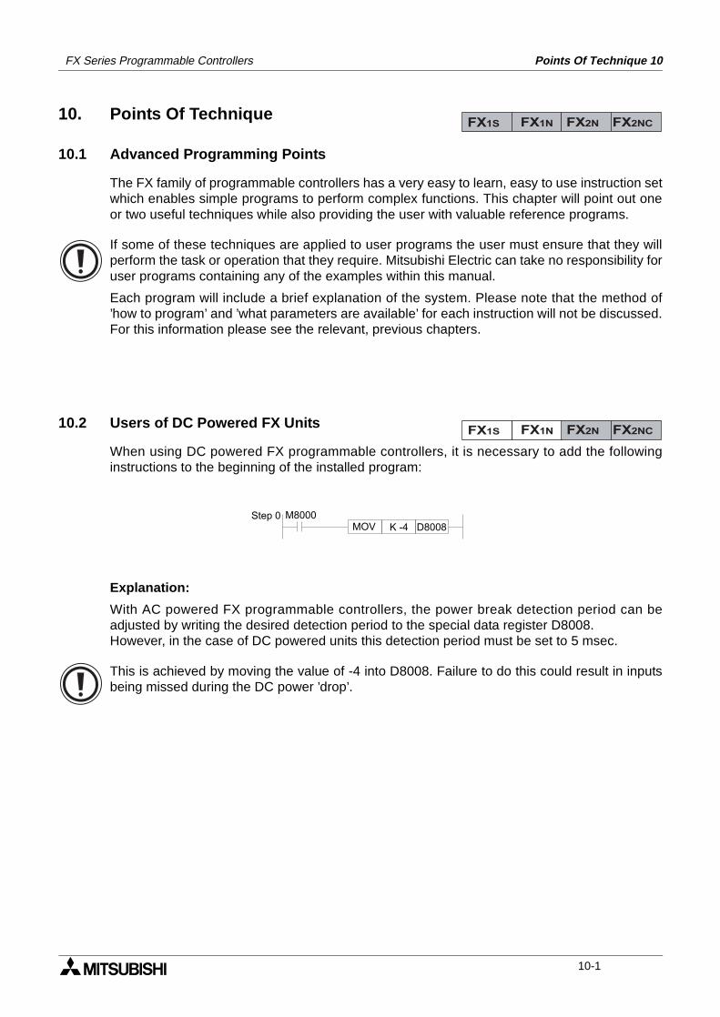
Points Of Technique 10FX Series Programmable Controllers
10. Points Of Technique
10.1 Advanced Programming Points
The FX family of programmable controllers has a very easy to learn, easy to use instruction setwhich enables simple programs to perform complex functions. This chapter will point out oneor two useful techniques while also providing the user with valuable reference programs.
If some of these techniques are applied to user programs the user must ensure that they willperform the task or operation that they require. Mitsubishi Electric can take no responsibility foruser programs containing any of the examples within this manual.
Each program will include a brief explanation of the system. Please note that the method of’how to program’ and ’what parameters are available’ for each instruction will not be discussed.For this information please see the relevant, previous chapters.
10.2 Users of DC Powered FX Units
When using DC powered FX programmable controllers, it is necessary to add the followinginstructions to the beginning of the installed program:
Explanation:
With AC powered FX programmable controllers, the power break detection period can beadjusted by writing the desired detection period to the special data register D8008.However, in the case of DC powered units this detection period must be set to 5 msec.
This is achieved by moving the value of -4 into D8008. Failure to do this could result in inputsbeing missed during the DC power ’drop’.
FX1S FX1N FX2N FX2NC
FX1S FX1N FX2N FX2NC
M8000MOV K -4 D8008
Step 0
10-1
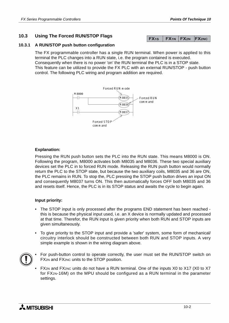
FX Series Programmable Controllers Points Of Technique 10
10.3 Using The Forced RUN/STOP Flags
10.3.1 A RUN/STOP push button configuration
The FX programmable controller has a single RUN terminal. When power is applied to thisterminal the PLC changes into a RUN state, i.e. the program contained is executed.Consequently when there is no power ’on’ the RUN terminal the PLC is in a STOP state.This feature can be utilized to provide the FX PLC with an external RUN/STOP - push buttoncontrol. The following PLC wiring and program addition are required.
Explanation:
Pressing the RUN push button sets the PLC into the RUN state. This means M8000 is ON.Following the program, M8000 activates both M8035 and M8036. These two special auxiliarydevices set the PLC in to forced RUN mode. Releasing the RUN push button would normallyreturn the PLC to the STOP state, but because the two auxiliary coils, M8035 and 36 are ON,the PLC remains in RUN. To stop the, PLC pressing the STOP push button drives an input ONand consequently M8037 turns ON. This then automatically forces OFF both M8035 and 36and resets itself. Hence, the PLC is in its STOP status and awaits the cycle to begin again.
Input priority:
• The STOP input is only processed after the programs END statement has been reached -this is because the physical input used, i.e. an X device is normally updated and processedat that time. Therefor, the RUN input is given priority when both RUN and STOP inputs aregiven simultaneously.
• To give priority to the STOP input and provide a 'safer' system, some form of mechanical/circuitry interlock should be constructed between both RUN and STOP inputs. A verysimple example is shown in the wiring diagram above.
• For push-button control to operate correctly, the user must set the RUN/STOP switch onFX2N and FX2NC units to the STOP position.
• FX2N and FX2NC units do not have a RUN terminal. One of the inputs X0 to X17 (X0 to X7for FX2N-16M) on the MPU should be configured as a RUN terminal in the parametersettings.
FX1S FX1N FX2N FX2NC
M 8 0 0 0
M 8 0 3 5
X 1
M 8 0 3 6
M 8 0 3 7
F o r c e d S T O P
c o m m a n d
F o r c e d R U N
c o m m a n d
F o r c e d R U N m o d e
10-2
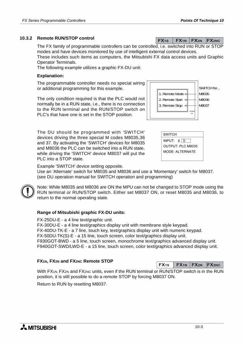
FX Series Programmable Controllers Points Of Technique 10
10.3.2 Remote RUN/STOP control
The FX family of programmable controllers can be controlled, i.e. switched into RUN or STOPmodes and have devices monitored by use of intelligent external control devices.These includes such items as computers, the Mitsubishi FX data access units and GraphicOperator Terminals.The following example utilizes a graphic FX-DU unit:
Explanation:
The programmable controller needs no special wiringor additional programming for this example.
The only condition required is that the PLC would notnormally be in a RUN state, i.e., there is no connectionto the RUN terminal and the RUN/STOP switch onPLC’s that have one is set in the STOP position.
The DU should be programmed with 'SWITCH'devices driving the three special M codes M8035,36and 37. By activating the 'SWITCH' devices for M8035and M8036 the PLC can be switched into a RUN state,while driving the 'SWITCH' device M8037 will put thePLC into a STOP state.
Example 'SWITCH' device setting opposite.Use an 'Alternate' switch for M8035 and M8036 and use a 'Momentary' switch for M8037.(see DU operation manual for SWITCH operation and programming)
Note: While M8035 and M8036 are ON the MPU can not be changed to STOP mode using theRUN terminal or RUN/STOP switch. Either set M8037 ON, or reset M8035 and M8036, toreturn to the normal operating state.
Range of Mitsubishi graphic FX-DU units:
FX-25DU-E - a 4 line text/graphic unit.FX-30DU-E - a 4 line text/graphics display unit with membrane style keypad.FX-40DU-TK-E - a 7 line, touch key, text/graphics display unit with numeric keypad.FX-50DU-TK(S)-E - a 15 line, touch screen, color text/graphics display unit.F930GOT-BWD - a 5 line, touch screen, monochrome text/graphics advanced display unit.F940GOT-SWD/LWD-E - a 15 line, touch screen, color text/graphics advanced display unit.
FX1N, FX2N and FX2NC Remote STOP
With FX1N, FX2N and FX2NC units, even if the RUN terminal or RUN/STOP switch is in the RUNposition, it is still possible to do a remote STOP by forcing M8037 ON.
Return to RUN by resetting M8037.
FX1S FX1N FX2N FX2NC
POWER
1. Remote Mode
2. Remote Start
3. Remote Stop
M8035
M8036
M8037
SWITCH for...
SWITCH
INPUT: 0
OUTPUT: PLC M8035
MODE: ALTERNATE
FX1S FX1N FX2N FX2NC
10-3
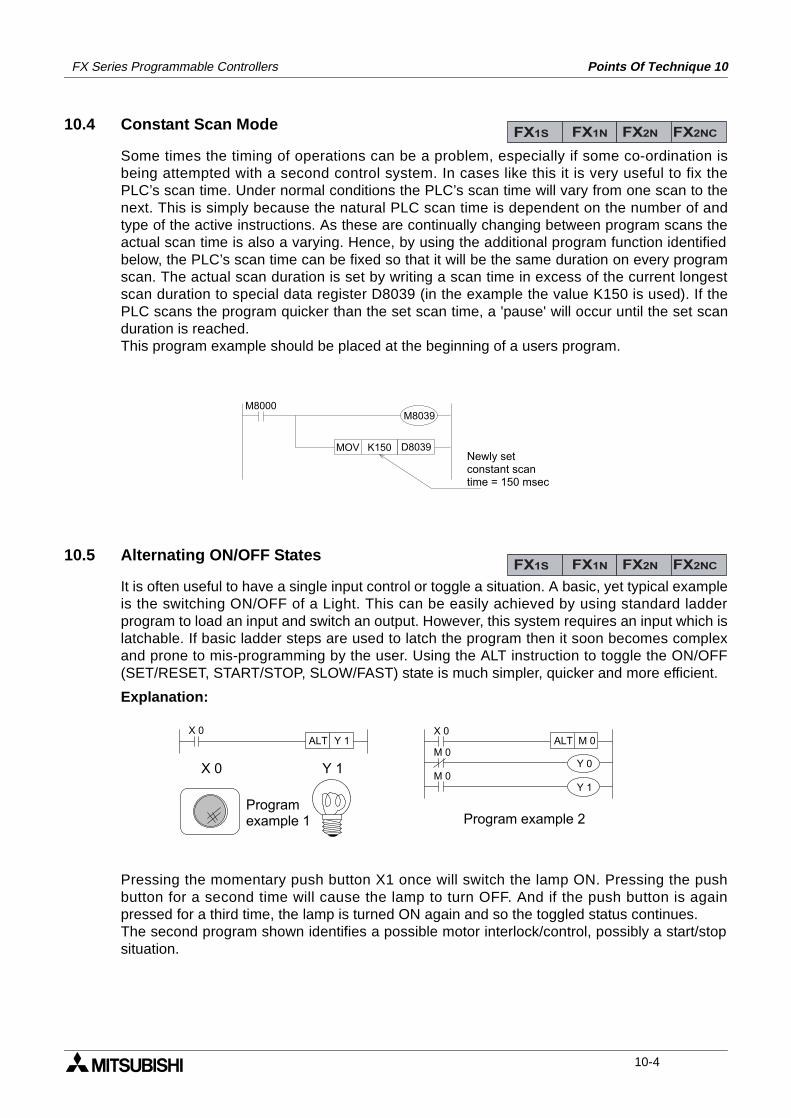
FX Series Programmable Controllers Points Of Technique 10
10.4 Constant Scan Mode
Some times the timing of operations can be a problem, especially if some co-ordination isbeing attempted with a second control system. In cases like this it is very useful to fix thePLC’s scan time. Under normal conditions the PLC’s scan time will vary from one scan to thenext. This is simply because the natural PLC scan time is dependent on the number of andtype of the active instructions. As these are continually changing between program scans theactual scan time is also a varying. Hence, by using the additional program function identifiedbelow, the PLC’s scan time can be fixed so that it will be the same duration on every programscan. The actual scan duration is set by writing a scan time in excess of the current longestscan duration to special data register D8039 (in the example the value K150 is used). If thePLC scans the program quicker than the set scan time, a 'pause' will occur until the set scanduration is reached.This program example should be placed at the beginning of a users program.
10.5 Alternating ON/OFF States
It is often useful to have a single input control or toggle a situation. A basic, yet typical exampleis the switching ON/OFF of a Light. This can be easily achieved by using standard ladderprogram to load an input and switch an output. However, this system requires an input which islatchable. If basic ladder steps are used to latch the program then it soon becomes complexand prone to mis-programming by the user. Using the ALT instruction to toggle the ON/OFF(SET/RESET, START/STOP, SLOW/FAST) state is much simpler, quicker and more efficient.
Explanation:
Pressing the momentary push button X1 once will switch the lamp ON. Pressing the pushbutton for a second time will cause the lamp to turn OFF. And if the push button is againpressed for a third time, the lamp is turned ON again and so the toggled status continues.The second program shown identifies a possible motor interlock/control, possibly a start/stopsituation.
FX1S FX1N FX2N FX2NC
M8000M8039
MOV K150 D8039Newly setconstant scantime = 150 msec
FX1S FX1N FX2N FX2NC
X 0ALT Y 1
X 0 Y 1
X 0
Y 0
Y 1M 0
M 0ALT M 0
Programexample 1 Program example 2
10-4
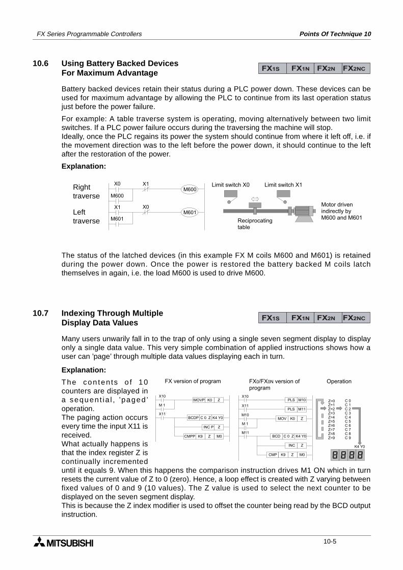
FX Series Programmable Controllers Points Of Technique 10
10.6 Using Battery Backed Devices For Maximum Advantage
Battery backed devices retain their status during a PLC power down. These devices can beused for maximum advantage by allowing the PLC to continue from its last operation statusjust before the power failure.
For example: A table traverse system is operating, moving alternatively between two limitswitches. If a PLC power failure occurs during the traversing the machine will stop.Ideally, once the PLC regains its power the system should continue from where it left off, i.e. ifthe movement direction was to the left before the power down, it should continue to the leftafter the restoration of the power.
Explanation:
The status of the latched devices (in this example FX M coils M600 and M601) is retainedduring the power down. Once the power is restored the battery backed M coils latchthemselves in again, i.e. the load M600 is used to drive M600.
10.7 Indexing Through MultipleDisplay Data Values
Many users unwarily fall in to the trap of only using a single seven segment display to displayonly a single data value. This very simple combination of applied instructions shows how auser can ’page’ through multiple data values displaying each in turn.
Explanation:
The con ten ts o f 10counters are displayed ina sequen t ia l , ’paged ’operation.The paging action occursevery time the input X11 isreceived.What actually happens isthat the index register Z iscontinually incrementeduntil it equals 9. When this happens the comparison instruction drives M1 ON which in turnresets the current value of Z to 0 (zero). Hence, a loop effect is created with Z varying betweenfixed values of 0 and 9 (10 values). The Z value is used to select the next counter to bedisplayed on the seven segment display.This is because the Z index modifier is used to offset the counter being read by the BCD outputinstruction.
FX1S FX1N FX2N FX2NC
X0
X1
M600
M601
X0M601
X1M600
Limit switch X0 Limit switch X1
Reciprocatingtable
Motor drivenindirectly byM600 and M601
Righttraverse
Lefttraverse
FX1S FX1N FX2N FX2NC
X10
X11
M 1
MOVP K0 Z
CMPP K9 Z
BCDP
M0
Z
C 0 Z K4 Y0
INC P
M10
M11
M 1
MOV K0 Z
CMP K9 Z
BCD
M0
Z
C 0 Z K4 Y0
INC
X11PLS M11
X10PLS M10 C 0
C 1C 2C 3C 4C 5C 6C 7C 8C 9
Z=0Z=1Z=2Z=3Z=4Z=5Z=6Z=7Z=8Z=9
K4 Y0
FX version of program FX0/FX0N version ofprogram
Operation
10-5
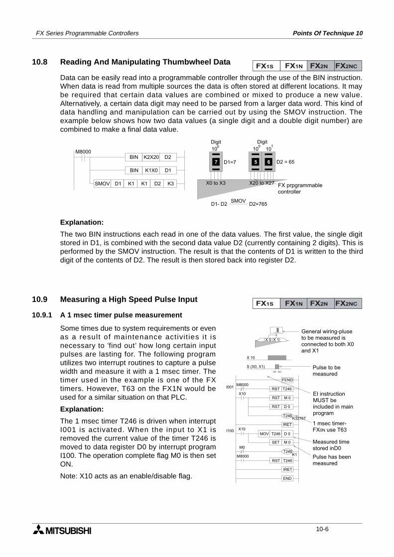
FX Series Programmable Controllers Points Of Technique 10
10.8 Reading And Manipulating Thumbwheel Data
Data can be easily read into a programmable controller through the use of the BIN instruction.When data is read from multiple sources the data is often stored at different locations. It maybe required that certain data values are combined or mixed to produce a new value.Alternatively, a certain data digit may need to be parsed from a larger data word. This kind ofdata handling and manipulation can be carried out by using the SMOV instruction. Theexample below shows how two data values (a single digit and a double digit number) arecombined to make a final data value.
Explanation:
The two BIN instructions each read in one of the data values. The first value, the single digitstored in D1, is combined with the second data value D2 (currently containing 2 digits). This isperformed by the SMOV instruction. The result is that the contents of D1 is written to the thirddigit of the contents of D2. The result is then stored back into register D2.
10.9 Measuring a High Speed Pulse Input
10.9.1 A 1 msec timer pulse measurement
Some times due to system requirements or evenas a result of maintenance activit ies i t isnecessary to ’find out’ how long certain inputpulses are lasting for. The following programutilizes two interrupt routines to capture a pulsewidth and measure it with a 1 msec timer. Thetimer used in the example is one of the FXtimers. However, T63 on the FX1N would beused for a similar situation on that PLC.
Explanation:
The 1 msec timer T246 is driven when interruptI001 is activated. When the input to X1 isremoved the current value of the timer T246 ismoved to data register D0 by interrupt programI100. The operation complete flag M0 is then setON.
Note: X10 acts as an enable/disable flag.
FX1S FX1N FX2N FX2NC
M8000
SMOV D1 K1
BIN
K1
K2X20 D2
BIN K1X0 D1
D2 K3
657
X0 to X3 X20 to X27
D2 = 65D1=7
D1- D2 D2=765
100 10
Digit
10 10
Digit
SMOV
FX prpgrammablecontroller
FX1S FX1N FX2N FX2NC
X 10
S (X0, X1)
X 0 X 1
FENDM8000
RST T246X10
RST M 0
RST D 0
IRETX10
D 0MOV T246
SET M 0M0
K1
RST T246M8000
IRET
END
I001
I100
T246K32767
T246
General wiring-pluse to be measured is connected to both X0 and X1
Pulse to be measured
EI instructionMUST beincluded in mainprogram
Pulse has beenmeasured
1 msec timer-FX0N use T63
Measured timestored inD0
10-6
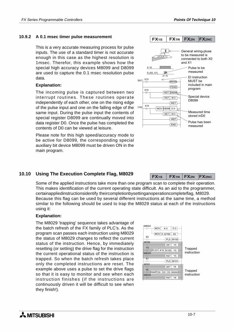
FX Series Programmable Controllers Points Of Technique 10
10.9.2 A 0.1 msec timer pulse measurement
This is a very accurate measuring process for pulseinputs. The use of a standard timer is not accurateenough in this case as the highest resolution is1msec. Therefor, this example shows how thespecial high accuracy devices M8099 and D8099are used to capture the 0.1 msec resolution pulsedata.
Explanation:
The incoming pulse is captured between twointerrupt rout ines. These rout ines operateindependently of each other, one on the rising edgeof the pulse input and one on the falling edge of thesame input. During the pulse input the contents ofspecial register D8099 are continually moved intodata register D0. Once the pulse has completed thecontents of D0 can be viewed at leisure.
Please note for this high speed/accuracy mode tobe active for D8099, the corresponding specialauxiliary bit device M8099 must be driven ON in themain program.
10.10 Using The Execution Complete Flag, M8029
Some of the applied instructions take more than one program scan to complete their operation.This makes identification of the current operating state difficult. As an aid to the programmer,certainappliedinstructionsidentify theircompletionbysettinganoperationcompleteflag, M8029.Because this flag can be used by several different instructions at the same time, a methodsimilar to the following should be used to trap the M8029 status at each of the instructionsusing it:
Explanation:
The M8029 'trapping’ sequence takes advantage ofthe batch refresh of the FX family of PLC’s. As theprogram scan passes each instruction using M8029the status of M8029 changes to reflect the currentstatus of the instruction. Hence, by immediatelyresetting (or setting) the drive flag for the instructionthe current operational status of the instruction istrapped. So when the batch refresh takes placeonly the completed instructions are reset. Theexample above uses a pulse to set the drive flagsso that it is easy to monitor and see when eachinstruct ion f in ishes ( i f the instruct ions arecontinuously driven it will be difficult to see whenthey finish!).
FX1S FX1N FX2N FX2NC
General wiring-pluse to be measured is connected to both X0 and X1
Pulse to be measured
EI instructionMUST beincluded in mainprogram
Pulse has beenmeasured
Special deviceD8099
Measured timestored inD0
FEND
X10
X10RST D8099
RST M 0
IRETX10
D 0MOV D8099
SET M 0
IRET
END
X 10
S (X0, X1)
I001
I100
M8099
X 0 X 1
FX1S FX1N FX2N FX2NC
M8002
X0
D 0MOV
D2K 32766MOV
K 0
M100PLSM100
Y5SET
K100K10PLSY Y0Y5
M8029Y5RST
M101PLS
M101Y6SET
Y6
M8029Y6RST
X1
D2D0RAMP D3 K8000Trapped instruction
Trapped instruction
10-7
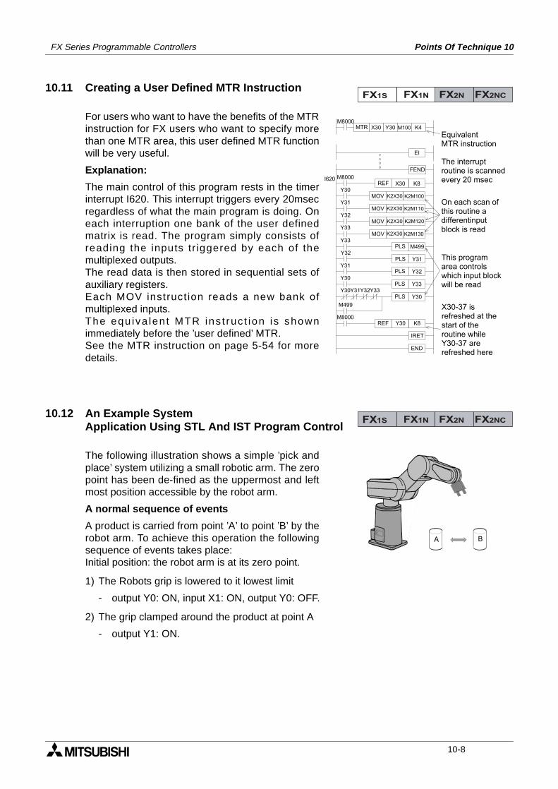
FX Series Programmable Controllers Points Of Technique 10
10.11 Creating a User Defined MTR Instruction
For users who want to have the benefits of the MTRinstruction for FX users who want to specify morethan one MTR area, this user defined MTR functionwill be very useful.
Explanation:
The main control of this program rests in the timerinterrupt I620. This interrupt triggers every 20msecregardless of what the main program is doing. Oneach interruption one bank of the user definedmatrix is read. The program simply consists ofreading the inputs tr iggered by each of themultiplexed outputs.The read data is then stored in sequential sets ofauxiliary registers.Each MOV instruct ion reads a new bank ofmultiplexed inputs.The equ iva len t MTR ins t ruc t ion is shownimmediately before the ’user defined’ MTR.See the MTR instruction on page 5-54 for moredetails.
10.12 An Example SystemApplication Using STL And IST Program Control
The following illustration shows a simple ’pick andplace’ system utilizing a small robotic arm. The zeropoint has been de-fined as the uppermost and leftmost position accessible by the robot arm.
A normal sequence of events
A product is carried from point ’A’ to point ’B’ by therobot arm. To achieve this operation the followingsequence of events takes place:Initial position: the robot arm is at its zero point.
1) The Robots grip is lowered to it lowest limit
- output Y0: ON, input X1: ON, output Y0: OFF.
2) The grip clamped around the product at point A
- output Y1: ON.
FX1S FX1N FX2N FX2NC
On each scan ofthis routine a differentinputblock is read
M8000
EI
FEND
X30MTR
M8000
Y30REF
Y31
Y30 M100 K4
I620K8X30
MOV K2M100K2X30
MOV K2M110K2X30Y32
Y33MOV K2M120K2X30
MOV K2M130K2X30Y33
PLS M499Y32
PLS
IRET
Y31PLS
END
Y30PLS Y33
M8000REF K8Y30
PLS Y30Y30Y31Y32Y33
M499
Y31
Y32
EquivalentMTR instruction
The interruptroutine is scannedevery 20 msec
This programarea controlswhich input blockwill be read
X30-37 isrefreshed at the start of theroutine whileY30-37 are refreshed here
FX1S FX1N FX2N FX2NC
A B
10-8
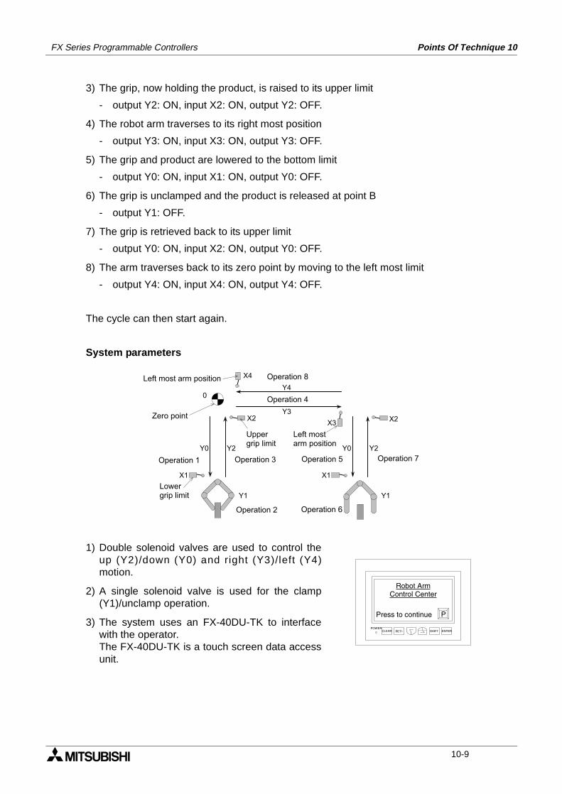
FX Series Programmable Controllers Points Of Technique 10
3) The grip, now holding the product, is raised to its upper limit
- output Y2: ON, input X2: ON, output Y2: OFF.
4) The robot arm traverses to its right most position
- output Y3: ON, input X3: ON, output Y3: OFF.
5) The grip and product are lowered to the bottom limit
- output Y0: ON, input X1: ON, output Y0: OFF.
6) The grip is unclamped and the product is released at point B
- output Y1: OFF.
7) The grip is retrieved back to its upper limit
- output Y0: ON, input X2: ON, output Y0: OFF.
8) The arm traverses back to its zero point by moving to the left most limit
- output Y4: ON, input X4: ON, output Y4: OFF.
The cycle can then start again.
System parameters
1) Double solenoid valves are used to control theup (Y2)/down (Y0) and right (Y3)/left (Y4)motion.
2) A single solenoid valve is used for the clamp(Y1)/unclamp operation.
3) The system uses an FX-40DU-TK to interfacewith the operator.The FX-40DU-TK is a touch screen data accessunit.
X2 X2
X1 X1
X4
X3
Y4
Y3
Y0 Y2 Y0 Y2
0
Y1 Y1
Operation 8
Operation 4
Left most arm position
Zero point
Lowergrip limit
Operation 1 Operation 3 Operation 5 Operation 7
Operation 2 Operation 6
Left mostarm position
Upper grip limit
POWERCLEAR SET/- SHIFT ENTER
Robot Arm
Control Center
Press to continue P
10-9
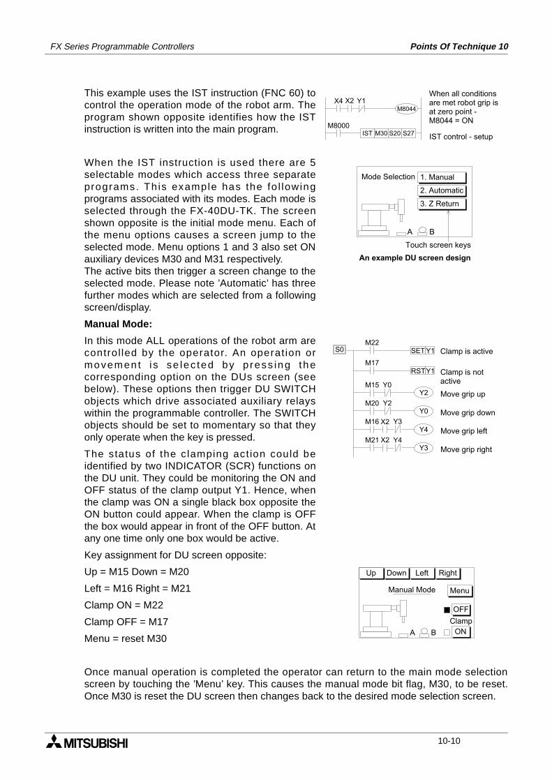
FX Series Programmable Controllers Points Of Technique 10
This example uses the IST instruction (FNC 60) tocontrol the operation mode of the robot arm. Theprogram shown opposite identifies how the ISTinstruction is written into the main program.
When the IST instruction is used there are 5selectable modes which access three separateprograms. Th is example has the fo l lowingprograms associated with its modes. Each mode isselected through the FX-40DU-TK. The screenshown opposite is the initial mode menu. Each ofthe menu options causes a screen jump to theselected mode. Menu options 1 and 3 also set ONauxiliary devices M30 and M31 respectively.The active bits then trigger a screen change to theselected mode. Please note ’Automatic’ has threefurther modes which are selected from a followingscreen/display.
Manual Mode:
In this mode ALL operations of the robot arm arecontro l led by the operator. An operat ion ormovemen t i s se lec ted by p ress ing thecorresponding option on the DUs screen (seebelow). These options then trigger DU SWITCHobjects which drive associated auxiliary relayswithin the programmable controller. The SWITCHobjects should be set to momentary so that theyonly operate when the key is pressed.
The status of the c lamping act ion could beidentified by two INDICATOR (SCR) functions onthe DU unit. They could be monitoring the ON andOFF status of the clamp output Y1. Hence, whenthe clamp was ON a single black box opposite theON button could appear. When the clamp is OFFthe box would appear in front of the OFF button. Atany one time only one box would be active.
Key assignment for DU screen opposite:
Up = M15 Down = M20
Left = M16 Right = M21
Clamp ON = M22
Clamp OFF = M17
Menu = reset M30
Once manual operation is completed the operator can return to the main mode selectionscreen by touching the ’Menu’ key. This causes the manual mode bit flag, M30, to be reset.Once M30 is reset the DU screen then changes back to the desired mode selection screen.
X4 X2 Y1
M8000IST M30 S27S20
M8044
When all conditionsare met robot grip isat zero point -M8044 = ON
IST control - setup
Mode Selection
3. Z Return
A B
1. Manual
2. Automatic
Touch screen keys
An example DU screen design
M22
M17
S0
M15 Y0
M20 Y2
Y3M16 X2
Y4M21 X2
SET Y1
RSTY1
Y2
Y0
Y4
Y3
Clamp is active
Clamp is not active
Move grip up
Move grip down
Move grip left
Move grip right
Manual Mode
A B
Up
Clamp
Down Left Right
OFF
ON
Menu
10-10
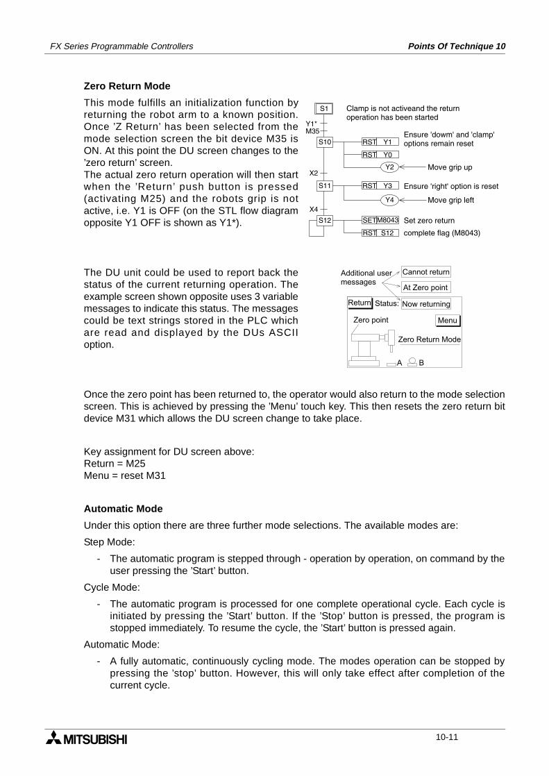
FX Series Programmable Controllers Points Of Technique 10
Zero Return Mode
This mode fulfills an initialization function byreturning the robot arm to a known position.Once ’Z Return’ has been selected from themode selection screen the bit device M35 isON. At this point the DU screen changes to the’zero return’ screen.The actual zero return operation will then startwhen the ’Return’ push button is pressed(activating M25) and the robots grip is notactive, i.e. Y1 is OFF (on the STL flow diagramopposite Y1 OFF is shown as Y1*).
The DU unit could be used to report back thestatus of the current returning operation. Theexample screen shown opposite uses 3 variablemessages to indicate this status. The messagescould be text strings stored in the PLC whichare read and displayed by the DUs ASCIIoption.
Once the zero point has been returned to, the operator would also return to the mode selectionscreen. This is achieved by pressing the ’Menu’ touch key. This then resets the zero return bitdevice M31 which allows the DU screen change to take place.
Key assignment for DU screen above:Return = M25Menu = reset M31
Automatic Mode
Under this option there are three further mode selections. The available modes are:
Step Mode:
- The automatic program is stepped through - operation by operation, on command by theuser pressing the ’Start’ button.
Cycle Mode:
- The automatic program is processed for one complete operational cycle. Each cycle isinitiated by pressing the ’Start’ button. If the ’Stop’ button is pressed, the program isstopped immediately. To resume the cycle, the ’Start’ button is pressed again.
Automatic Mode:
- A fully automatic, continuously cycling mode. The modes operation can be stopped bypressing the ’stop’ button. However, this will only take effect after completion of thecurrent cycle.
RST Y1
RST Y3
S10
S1
RST Y0
S11
S12 SETM8043
RST S12
X4
X2
M35Y1*
Y2
Y4
Clamp is not activeand the returnoperation has been started
Ensure 'dowm' and 'clamp'options remain reset
Move grip up
Ensure 'right' option is reset
Set zero return
Move grip left
complete flag (M8043)
Zero Return Mode
A B
Menu
Return Status: Now returning
At Zero point
Cannot return
Zero point
Additional usermessages
10-11
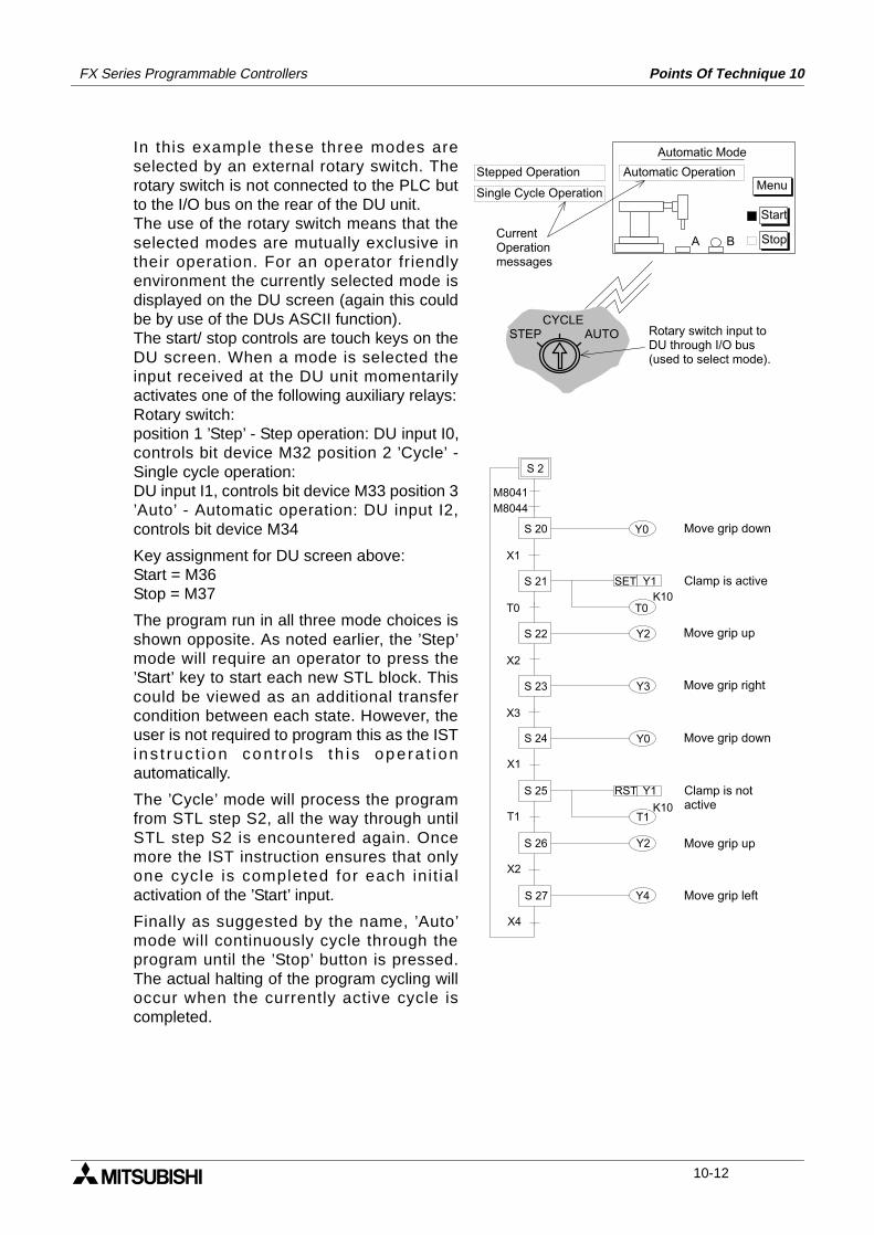
FX Series Programmable Controllers Points Of Technique 10
In this example these three modes areselected by an external rotary switch. Therotary switch is not connected to the PLC butto the I/O bus on the rear of the DU unit.The use of the rotary switch means that theselected modes are mutually exclusive intheir operation. For an operator friendlyenvironment the currently selected mode isdisplayed on the DU screen (again this couldbe by use of the DUs ASCII function).The start/ stop controls are touch keys on theDU screen. When a mode is selected theinput received at the DU unit momentarilyactivates one of the following auxiliary relays:Rotary switch:position 1 ’Step’ - Step operation: DU input I0,controls bit device M32 position 2 ’Cycle’ -Single cycle operation:DU input I1, controls bit device M33 position 3’Auto’ - Automatic operation: DU input I2,controls bit device M34
Key assignment for DU screen above:Start = M36Stop = M37
The program run in all three mode choices isshown opposite. As noted earlier, the ’Step’mode will require an operator to press the’Start’ key to start each new STL block. Thiscould be viewed as an additional transfercondition between each state. However, theuser is not required to program this as the ISTins t ruc t ion con t ro l s th i s opera t ionautomatically.
The ’Cycle’ mode will process the programfrom STL step S2, all the way through untilSTL step S2 is encountered again. Oncemore the IST instruction ensures that onlyone cycle is completed for each ini t ialactivation of the ’Start’ input.
Finally as suggested by the name, ’Auto’mode will continuously cycle through theprogram until the ’Stop’ button is pressed.The actual halting of the program cycling willoccur when the currently active cycle iscompleted.
Automatic Mode
A B
Menu
Start
Stop
Automatic Operation
Single Cycle Operation
Stepped Operation
AUTOSTEPCYCLE
CurrentOperationmessages
Rotary switch input toDU through I/O bus (used to select mode).
Y0
X1
T0
Y2
X2
S 2
SET Y1
M8041
M8044
T0K10
Y3
S 20
S 21
S 22
S 23
T1
RST Y1
T1K10
X3
Y0S 24
X1
S 25
Y2S 26
X2
Y4
X4
S 27
Move grip down
Clamp is active
Move grip up
Move grip right
Move grip down
Clamp is notactive
Move grip up
Move grip left
10-12
FX Series Programmable Controllers Points Of Technique 10
Points of interest:
a) Users of the IST instruction will be aware that only one of the operation modes should beactive at one time. In this example program the isolation of ’Manual’ and ’Zero return’modes by the use of separate DU control screens, and the use of a rotary switch toisolate the three automatic modes achieves this objective. Alternatively all of theoperation modes could be selected by a rotary switch.
b) For users who would like to test this example using simulator switches (i.e., without usinga data access unit) the appropriate program changes are noted next to the full programlisting later in this section. Alternatively, the original program could be used with all of theinput conditions being given by forcing ON the contacts with a programming device e.g.a hand held programmer, Medoc etc.
c) Special flags used in this program are:
• M8040: State transfer inhibit
- Manual mode: Always ON.Zero return and Cycle modes: Once the 'Stop' input is given the current state isretained until the 'Start' input is received.Step mode: This flag is OFF when the 'Start' input is ON. At all other times M8040 isON, this enables the single STL step operation to be achieved.Auto mode: M8040 is ON initially when the PLC is switched into RUN. It is resetwhen the 'Start' input is given.
• M8041: State transfer start
- Manual and Zero return modes: This flag is not used.Step and Cycle modes: This flag is only active while the 'Start' input is received.Auto mode: The flag is set ON after the 'Start' input is received. It is reset after the'Stop' input is received.
• M8042: Start pulse
- This is momentarily active after the 'Start' input is received.
• M8043: Zero return complete
- This is a user activated device which should be controlled within the users program.
• M8044: At Zero position/ condition
- This is a user activated device which should be controlled within the users program.
10-13
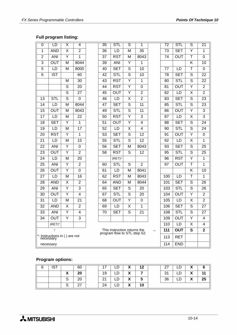
FX Series Programmable Controllers Points Of Technique 10
Full program listing:
Program options:
0 LD X 4 35 STL S 1 72 STL S 21
1 AND X 2 36 LD M 35 73 SET Y 1
2 ANI Y 1 37 RST M 8043 74 OUT T 0
3 OUT M 8044 39 ANI Y 1 K 10
5 LD M 8000 40 SET S 10 77 LD T 0
6 IST 60 42 STL S 10 78 SET S 22
M 30 43 RST Y 1 80 STL S 22
S 20 44 RST Y 0 81 OUT Y 2
S 27 45 OUT Y 2 82 LD X 2
13 STL S 0 46 LD X 2 83 SET S 23
14 LD M 8044 47 SET S 11 85 STL S 23
15 OUT M 8043 49 STL S 11 86 OUT Y 3
17 LD M 22 50 RST Y 3 87 LD X 3
18 SET Y 1 51 OUT Y 4 88 SET S 24
19 LD M 17 52 LD X 4 90 STL S 24
20 RST Y 1 53 SET S 12 91 OUT Y 0
21 LD M 15 55 STL S 12 92 LD X 1
22 ANI Y 0 56 SET M 8043 93 SET S 25
23 OUT Y 2 58 RST S 12 95 STL S 25
24 LD M 20 (RET)* 96 RST Y 1
25 ANI Y 2 60 STL S 2 97 OUT T 1
26 OUT Y 0 61 LD M 8041 K 10
27 LD M 16 62 RST M 8043 100 LD T 1
28 AND X 2 64 AND M 8044 101 SET S 26
29 ANI Y 3 65 SET S 20 103 STL S 26
30 OUT Y 4 67 STL S 20 104 OUT Y 2
31 LD M 21 68 OUT Y 0 105 LD X 2
32 AND X 2 69 LD X 1 106 SET S 27
33 ANI Y 4 70 SET S 21 108 STL S 27
34 OUT Y 3 109 OUT Y 4
(RET)* 110 LD X 4
↑ This instruction returns the program flow to STL step S2.
→ 111 OUT S 2*: Instructions in ( ) are not necessary 113 RET
necessary 114 END
6 IST 60 17 LD X 12 27 LD X 6
X 20 19 LD X 7 31 LD X 11
S 20 21 LD X 5 36 LD X 25
S 27 24 LD X 10
10-14
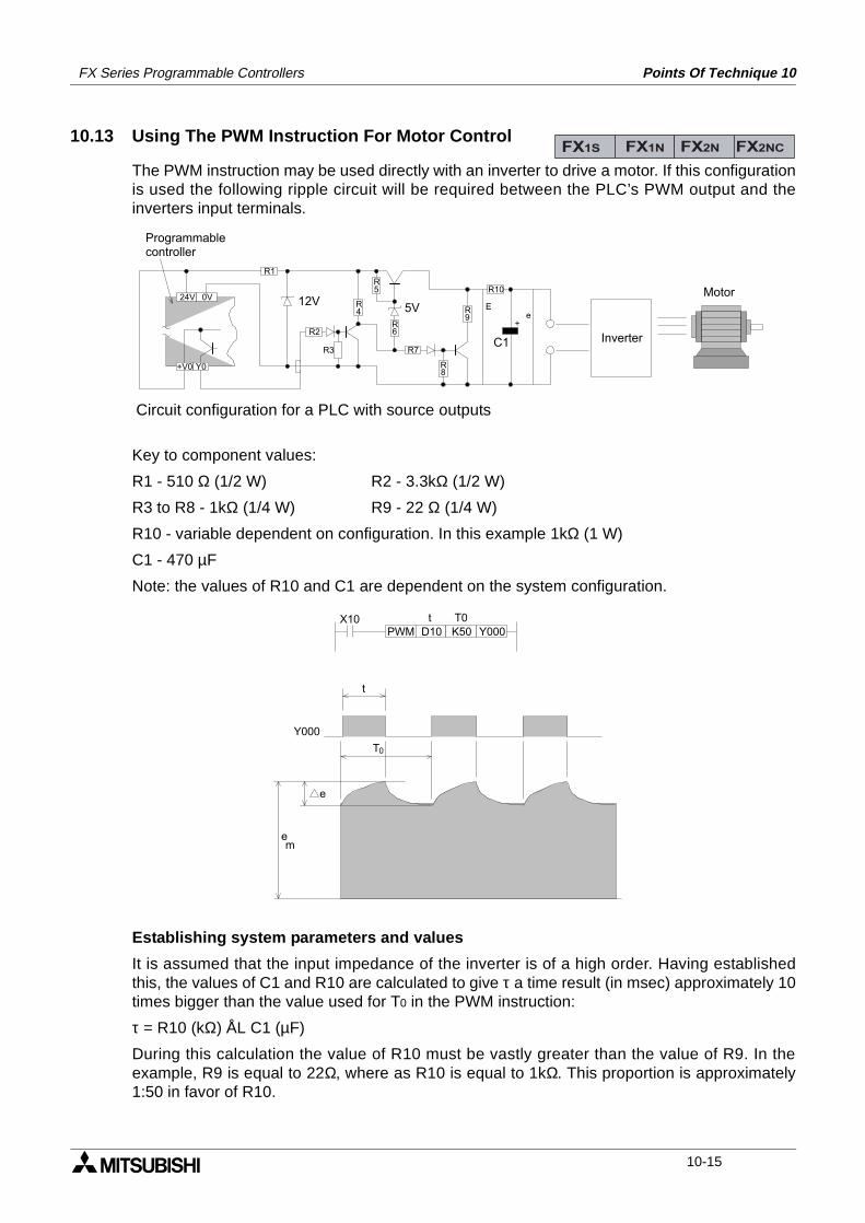
FX Series Programmable Controllers Points Of Technique 10
10.13 Using The PWM Instruction For Motor Control
The PWM instruction may be used directly with an inverter to drive a motor. If this configurationis used the following ripple circuit will be required between the PLC’s PWM output and theinverters input terminals.
Key to component values:
R1 - 510 Ω (1/2 W) R2 - 3.3kΩ (1/2 W)
R3 to R8 - 1kΩ (1/4 W) R9 - 22 Ω (1/4 W)
R10 - variable dependent on configuration. In this example 1kΩ (1 W)
C1 - 470 µF
Note: the values of R10 and C1 are dependent on the system configuration.
Establishing system parameters and values
It is assumed that the input impedance of the inverter is of a high order. Having establishedthis, the values of C1 and R10 are calculated to give τ a time result (in msec) approximately 10times bigger than the value used for T0 in the PWM instruction:
τ = R10 (kΩ) ÅL C1 (µF)
During this calculation the value of R10 must be vastly greater than the value of R9. In theexample, R9 is equal to 22Ω, where as R10 is equal to 1kΩ. This proportion is approximately1:50 in favor of R10.
FX1S FX1N FX2N FX2NC
Y0+V0
24V 0V
+
Ee
R1
R2
R3 R7
R10
R4
R5
R6
R9
R8
InverterC1
5V12V
Programmablecontroller
Motor
Circuit configuration for a PLC with source outputs
e
em
Y000
t
T0
PWM D10 K50 Y000X10 t T0
10-15
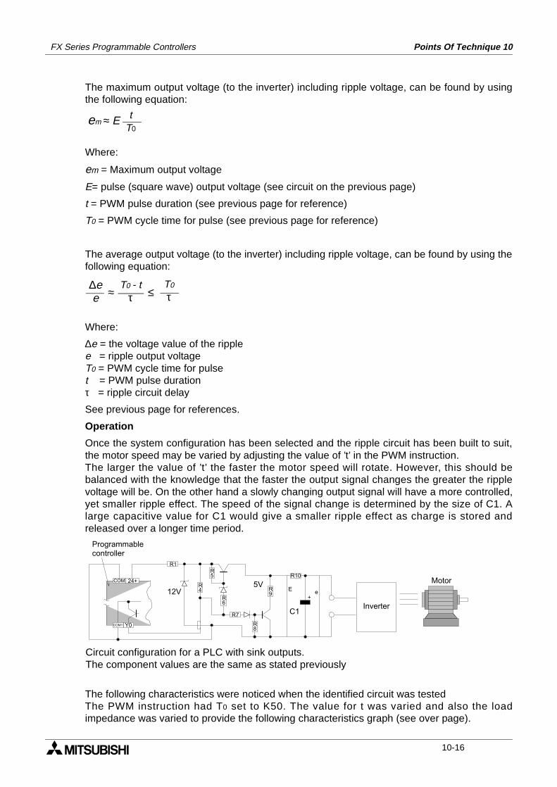
FX Series Programmable Controllers Points Of Technique 10
The maximum output voltage (to the inverter) including ripple voltage, can be found by usingthe following equation:
Where:
em = Maximum output voltage
E= pulse (square wave) output voltage (see circuit on the previous page)
t = PWM pulse duration (see previous page for reference)
T0 = PWM cycle time for pulse (see previous page for reference)
The average output voltage (to the inverter) including ripple voltage, can be found by using thefollowing equation:
Where:
∆e = the voltage value of the ripplee = ripple output voltageT0 = PWM cycle time for pulset = PWM pulse durationτ = ripple circuit delay
See previous page for references.
Operation
Once the system configuration has been selected and the ripple circuit has been built to suit,the motor speed may be varied by adjusting the value of ’t’ in the PWM instruction.The larger the value of ’t’ the faster the motor speed will rotate. However, this should bebalanced with the knowledge that the faster the output signal changes the greater the ripplevoltage will be. On the other hand a slowly changing output signal will have a more controlled,yet smaller ripple effect. The speed of the signal change is determined by the size of C1. Alarge capacitive value for C1 would give a smaller ripple effect as charge is stored andreleased over a longer time period.
The following characteristics were noticed when the identified circuit was testedThe PWM instruction had T0 set to K50. The value for t was varied and also the loadimpedance was varied to provide the following characteristics graph (see over page).
em ≈ E tT0
T0 - tτ
∆ee ≈
T0
τ≤
Y0COM1
COM 24+
+
Ee
R1
R10
R7
R4
R5
R6
R9
R8
Motor
InverterC1
5V12V
Programmablecontroller
Circuit configuration for a PLC with sink outputs.The component values are the same as stated previously
10-16
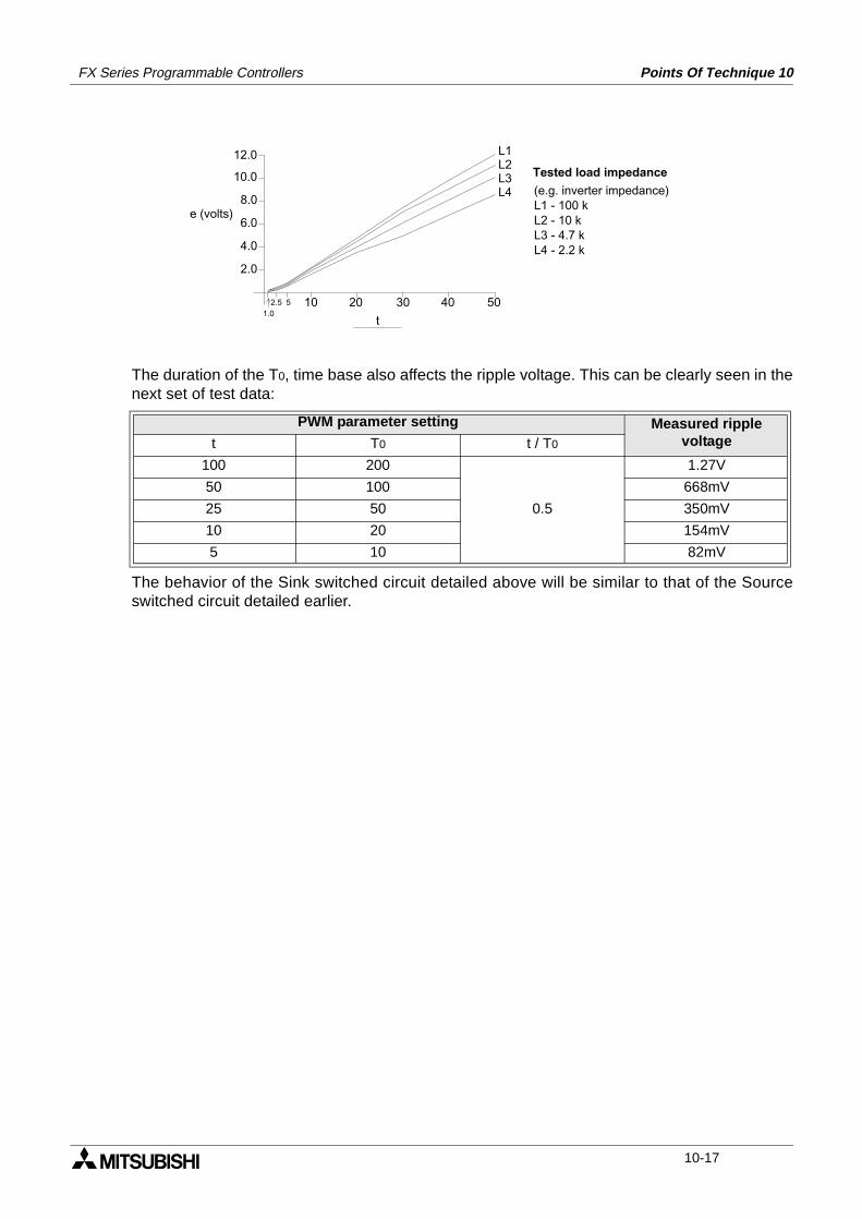
FX Series Programmable Controllers Points Of Technique 10
The duration of the T0, time base also affects the ripple voltage. This can be clearly seen in thenext set of test data:
The behavior of the Sink switched circuit detailed above will be similar to that of the Sourceswitched circuit detailed earlier.
PWM parameter setting Measured ripplevoltaget T0 t / T0
100 200
0.5
1.27V
50 100 668mV
25 50 350mV
10 20 154mV
5 10 82mV
20 301052.5
1.040 50
t
2.0
4.0
6.0
8.0
10.0
12.0
e (volts)
L1L2L3L4
Tested load impedance(e.g. inverter impedance)L1 - 100 kL2 - 10 kL3 - 4.7 kL4 - 2.2 k
10-17
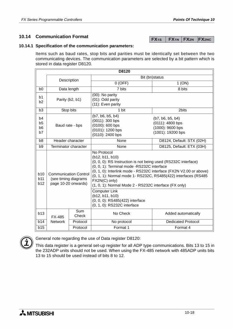
FX Series Programmable Controllers Points Of Technique 10
10.14 Communication Format
10.14.1 Specification of the communication parameters:
Items such as baud rates, stop bits and parities must be identically set between the twocommunicating devices. The communication parameters are selected by a bit pattern which isstored in data register D8120.
General note regarding the use of Data register D8120:
This data register is a general set-up register for all ADP type communications. Bits 13 to 15 inthe 232ADP units should not be used. When using the FX-485 network with 485ADP units bits13 to 15 should be used instead of bits 8 to 12.
D8120
DescriptionBit (bn)status
0 (OFF) 1 (ON)
b0 Data length 7 bits 8 bits
b1b2
Parity (b2, b1)(00): No parity(01): Odd parity(11): Even parity
b3 Stop bits 1 bit 2bits
b4b5b6b7
Baud rate - bps
(b7, b6, b5, b4)(0011): 300 bps(0100): 600 bps(0101): 1200 bps(0110): 2400 bps
(b7, b6, b5, b4)(0111): 4800 bps(1000): 9600 bps(1001): 19200 bps
b8 Header character None D8124, Default: STX (02H)
b9 Terminator character None D8125, Default: ETX (03H)
b10b11b12
Communication Control(see timing diagrams page 10-20 onwards)
No Protocol(b12, b11, b10)(0, 0, 0): RS Instruction is not being used (RS232C interface)(0, 0, 1): Terminal mode -RS232C interface(0, 1, 0): Interlink mode - RS232C interface (FX2N V2.00 or above)(0, 1, 1): Normal mode 1- RS232C, RS485(422) interfaces (RS485 FX2N(C) only)(1, 0, 1): Normal Mode 2 - RS232C interface (FX only)
Computer Link(b12, b11, b10)(0, 0, 0): RS485(422) interface(0, 1, 0): RS232C interface
b13FX-485Network
Sum Check
No Check Added automatically
b14 Protocol No protocol Dedicated Protocol
b15 Protocol Format 1 Format 4
FX1S FX1N FX2N FX2NC
10-18
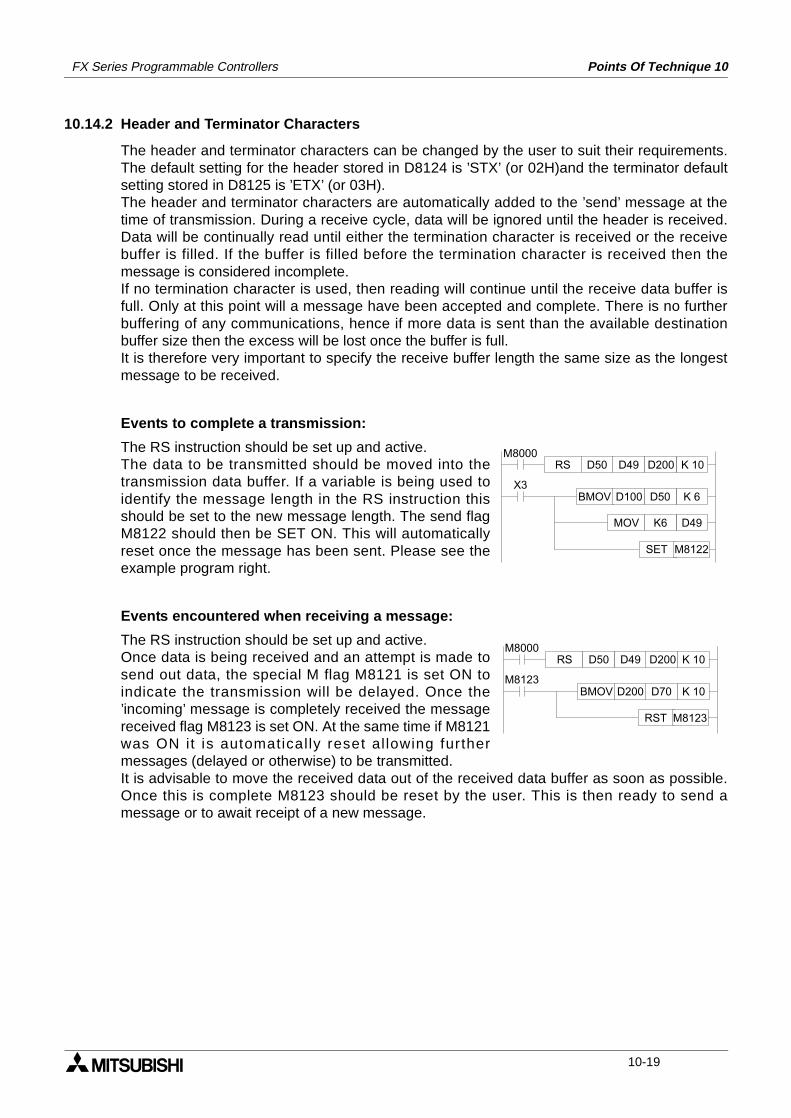
FX Series Programmable Controllers Points Of Technique 10
10.14.2 Header and Terminator Characters
The header and terminator characters can be changed by the user to suit their requirements.The default setting for the header stored in D8124 is ’STX’ (or 02H)and the terminator defaultsetting stored in D8125 is ’ETX’ (or 03H).The header and terminator characters are automatically added to the ’send’ message at thetime of transmission. During a receive cycle, data will be ignored until the header is received.Data will be continually read until either the termination character is received or the receivebuffer is filled. If the buffer is filled before the termination character is received then themessage is considered incomplete.If no termination character is used, then reading will continue until the receive data buffer isfull. Only at this point will a message have been accepted and complete. There is no furtherbuffering of any communications, hence if more data is sent than the available destinationbuffer size then the excess will be lost once the buffer is full.It is therefore very important to specify the receive buffer length the same size as the longestmessage to be received.
Events to complete a transmission:
The RS instruction should be set up and active.The data to be transmitted should be moved into thetransmission data buffer. If a variable is being used toidentify the message length in the RS instruction thisshould be set to the new message length. The send flagM8122 should then be SET ON. This will automaticallyreset once the message has been sent. Please see theexample program right.
Events encountered when receiving a message:
The RS instruction should be set up and active.Once data is being received and an attempt is made tosend out data, the special M flag M8121 is set ON toindicate the transmission will be delayed. Once the’incoming’ message is completely received the messagereceived flag M8123 is set ON. At the same time if M8121was ON it is automatically reset al lowing furthermessages (delayed or otherwise) to be transmitted.It is advisable to move the received data out of the received data buffer as soon as possible.Once this is complete M8123 should be reset by the user. This is then ready to send amessage or to await receipt of a new message.
K 10D200RS D49D50M8000
X3BMOV K 6D50D100
MOV D49K6
SET M8122
K 10D200RS D49D50M8000
M8123BMOV K 10D70D200
RST M8123
10-19
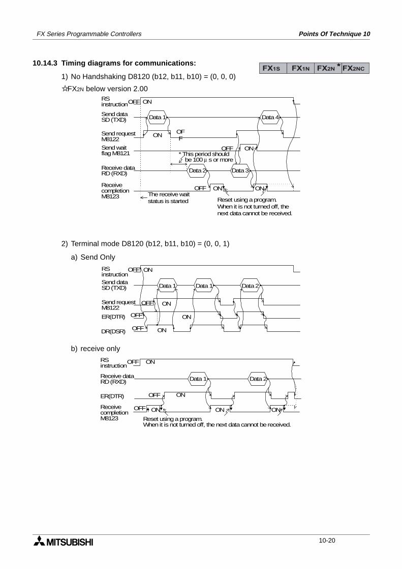
FX Series Programmable Controllers Points Of Technique 10
10.14.3 Timing diagrams for communications:
1) No Handshaking D8120 (b12, b11, b10) = (0, 0, 0)
FX2N below version 2.00
2) Terminal mode D8120 (b12, b11, b10) = (0, 0, 1)
a) Send Only
b) receive only
FX1S FX1N FX2N FX2NC
Reset using a program.When it is not turned off, thenext data cannot be received.
Data 1
RSinstruction
Send waitflag M8121
Send dataSD (TXD)
OFF ON
Data 4
Data 2 Data 3
OFF
ONSend requestM8122
Receive dataRD (RXD)
ReceivecompletionM8123
OFF ON ON
ONOFF* This period should be 100 µ s or more
The receive waitstatus is started
Data 1
RSinstructionSend dataSD (TXD)
OFF ON
Data 2
Send requestM8122
ONOFF
Data 1
ER(DTR) OFF
OFF
ON
ONDR(DSR)
Reset using a program.When it is not turned off, the next data cannot be received.
Data 1
OFF ON
OFF ON
ON
Data 2
OFF ONRSinstruction
Receive dataRD (RXD)
ER(DTR)
ONReceivecompletionM8123
10-20
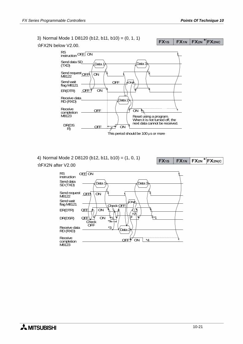
FX Series Programmable Controllers Points Of Technique 10
3) Normal Mode 1 D8120 (b12, b11, b10) = (0, 1, 1)
FX2N below V2.00.
4) Normal Mode 2 D8120 (b12, b11, b10) = (1, 0, 1)
FX2N after V2.00
FX1S FX1N FX2N FX2NC
Reset using a program.When it is not turned off, thenext data cannot be received.
Data 1
RSinstruction
Send waitflag M8121
Send data SD(TXD)
OFF ON
Data 3
Data 2
OFF ONSend requestM8122
Receive dataRD (RXD)
ReceivecompletionM8123
OFF ON
ONOFF
ON
ON
OFF
OFF
This period should be 100 µs or more
ER(DTR)
DR(DSR)
FX1S FX1N FX2N FX2N(C
Data 1
RSinstruction
Send waitflag M8121
Send dataSD (TXD)
OFF ON
Data 3
Data 2
OFF ONSend requestM8122
Receive dataRD (RXD)
ReceivecompletionM8123
OFF ON
ON
ONOFF
OFF
ER(DTR)
DR(DSR)
*4
*5*1
*2
*3
*1CheckOFF
ON
Check OFF
10-21
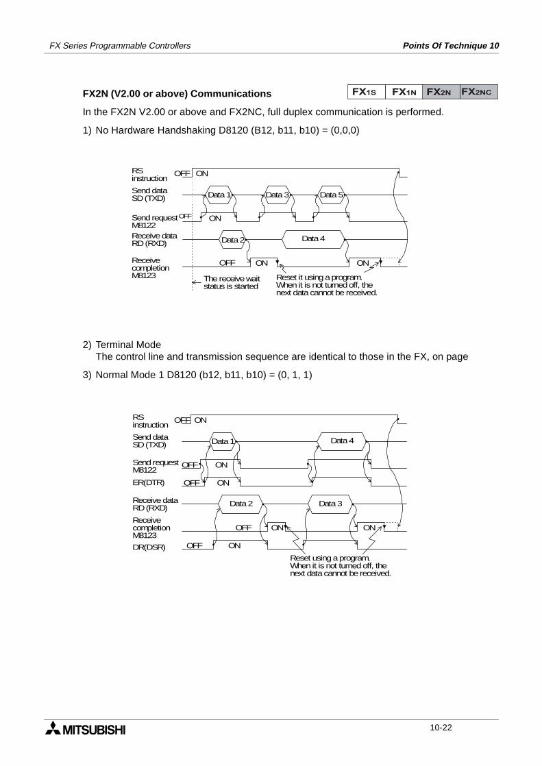
FX Series Programmable Controllers Points Of Technique 10
FX2N (V2.00 or above) Communications
In the FX2N V2.00 or above and FX2NC, full duplex communication is performed.
1) No Hardware Handshaking D8120 (B12, b11, b10) = (0,0,0)
2) Terminal ModeThe control line and transmission sequence are identical to those in the FX, on page
3) Normal Mode 1 D8120 (b12, b11, b10) = (0, 1, 1)
FX1S FX1N FX2N FX2NC
Reset it using a program.When it is not turned off, thenext data cannot be received.
Data 1
RSinstruction
Send dataSD (TXD)
OFF ON
Data 5
OFF ONSend requestM8122
ReceivecompletionM8123
Data 3
Data 2 Data 4
OFF ON ON
The receive waitstatus is started
Receive dataRD (RXD)
Reset using a program.When it is not turned off, thenext data cannot be received.
Data 1
OFF
OFF ON
ON
Data 4
OFF ONRSinstruction
Send dataSD (TXD)
ER(DTR)
ONReceivecompletionM8123
OFF ON
Data 2 Data 3Receive dataRD (RXD)
OFF ON
Send requestM8122
DR(DSR)
10-22
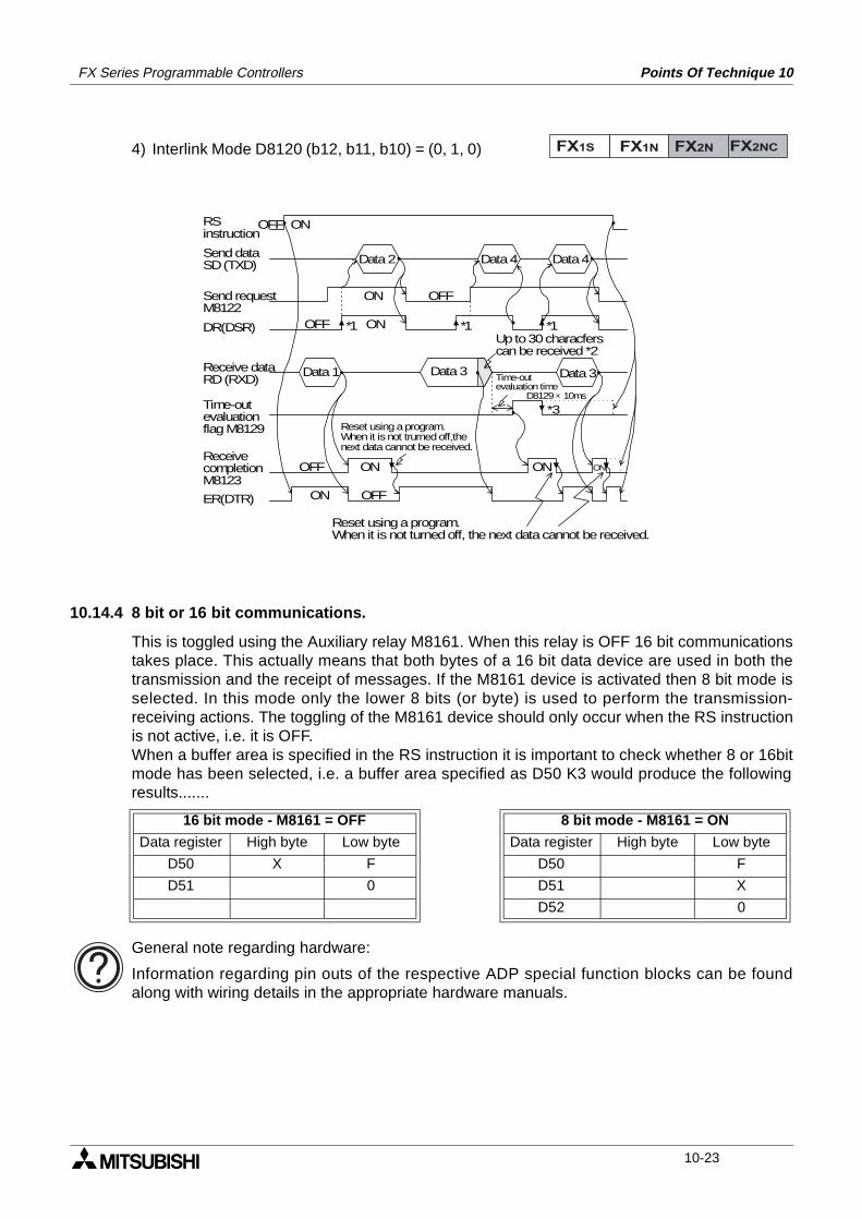
FX Series Programmable Controllers Points Of Technique 10
4) Interlink Mode D8120 (b12, b11, b10) = (0, 1, 0)
10.14.4 8 bit or 16 bit communications.
This is toggled using the Auxiliary relay M8161. When this relay is OFF 16 bit communicationstakes place. This actually means that both bytes of a 16 bit data device are used in both thetransmission and the receipt of messages. If the M8161 device is activated then 8 bit mode isselected. In this mode only the lower 8 bits (or byte) is used to perform the transmission-receiving actions. The toggling of the M8161 device should only occur when the RS instructionis not active, i.e. it is OFF.When a buffer area is specified in the RS instruction it is important to check whether 8 or 16bitmode has been selected, i.e. a buffer area specified as D50 K3 would produce the followingresults.......
General note regarding hardware:
Information regarding pin outs of the respective ADP special function blocks can be foundalong with wiring details in the appropriate hardware manuals.
16 bit mode - M8161 = OFF 8 bit mode - M8161 = ON
Data register High byte Low byte Data register High byte Low byte
D50 X F D50 F
D51 0 D51 X
D52 0
FX1S FX1N FX2N FX2NC
Reset using a program.When it is not trurned off,thenext data cannot be received.
Data 2
RSinstruction
Send dataSD (TXD)
OFF ON
Data 4
OFFONSend requestM8122
ReceivecompletionM8123
Data 4
Data 1 Data 3Receive dataRD (RXD)
OFF ON*1 *1 *1
Data 3
*3
Time-outevaluation time D8129 × 10ms
OFF ON ON ON
Reset using a program.When it is not turned off, the next data cannot be received.
OFFON
DR(DSR)
Time-outevaluationflag M8129
Up to 30 characferscan be received *2
ER(DTR)
10-23
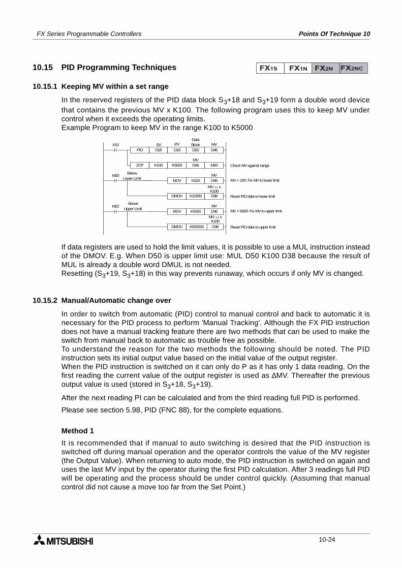
FX Series Programmable Controllers Points Of Technique 10
10.15 PID Programming Techniques
10.15.1 Keeping MV within a set range
In the reserved registers of the PID data block S3+18 and S3+19 form a double word devicethat contains the previous MV x K100. The following program uses this to keep MV undercontrol when it exceeds the operating limits.Example Program to keep MV in the range K100 to K5000
If data registers are used to hold the limit values, it is possible to use a MUL instruction insteadof the DMOV. E.g. When D50 is upper limit use: MUL D50 K100 D38 because the result ofMUL is already a double word DMUL is not needed.Resetting (S3+19, S3+18) in this way prevents runaway, which occurs if only MV is changed.
10.15.2 Manual/Automatic change over
In order to switch from automatic (PID) control to manual control and back to automatic it isnecessary for the PID process to perform ’Manual Tracking’. Although the FX PID instructiondoes not have a manual tracking feature there are two methods that can be used to make theswitch from manual back to automatic as trouble free as possible.To understand the reason for the two methods the following should be noted. The PIDinstruction sets its initial output value based on the initial value of the output register.When the PID instruction is switched on it can only do P as it has only 1 data reading. On thefirst reading the current value of the output register is used as ∆MV. Thereafter the previousoutput value is used (stored in S3+18, S3+19).
After the next reading PI can be calculated and from the third reading full PID is performed.
Please see section 5.98, PID (FNC 88), for the complete equations.
Method 1
It is recommended that if manual to auto switching is desired that the PID instruction isswitched off during manual operation and the operator controls the value of the MV register(the Output Value). When returning to auto mode, the PID instruction is switched on again anduses the last MV input by the operator during the first PID calculation. After 3 readings full PIDwill be operating and the process should be under control quickly. (Assuming that manualcontrol did not cause a move too far from the Set Point.)
FX1S FX1N FX2N FX2NC
X10D18 D19 D20 D46PID
K100 K5000 D46 M20ZCP
M20K100 D46MOV
K10000 D38DMOV
M22K5000 D46MOV
K500000 D38DMOV
SV PVDataBlock MV
MV
MV
MV
MV n-1 xK100
MV n-1 xK100
BelowLower Limit
AboveUpper Limit
Reset PID data to upper limit
MV > 5000: Fix MV to upper limit
Reset PID data to lower limit
MV < 100: Fix MV to lower limit
Check MV against range
10-24
FX Series Programmable Controllers Points Of Technique 10
Method 2
During manual operations the PID instruction is kept running but the calculated MV is ignored;instead the operator controls MV. In order to prevent the PID instruction from running out ofcontrol the MV value set by the operator should be fed in to the MVn-1 registers of the PID datablock in the same way as for MV range control earlier (i.e. Set S3+18, S3+19 to MV x 100).When switching back to PID control the internal values of the PID instruction are already setand full PID operation starts immediately.
10.15.3 Using the PID alarm signals
Included as part of the data block there are four alarm values. These set the maximum positiveand negative change that should occur to MV and PV. The PID alarm signals are used to warnof the system going out of control.When the system is starting from cold it is usually not good to include the Derivative numbersof the in the calculation; the changes to PV are large and the Derivative introduces too muchcorrection. Also, if the system starts to move rapidly away from the SV then sometimes the useof D can over correct and cause chasing.By having an ’alarm’ flag for the change in PV and MV it is possible to monitor the state of thesystem and adjust the PID parameters to appropriate settings.When the system is close to the SP the changes in PV (and MV) should be minimal.In this situation using full PID is very useful in keeping the system close to the SP. (Full PID isappropriate).However, if the conditions change (e.g. opening a refrigerator door, adding ingredients to amixture, cold start, etc.) the system reacts. In some cases (especially cold start) the reaction istoo much for the D to be useful (PI or sometimes just P only is better). In these cases the alarmflags can be used to change to PI control until the system returns to a more stable condition,when full PID can then be used.Basically, rather than use actual values of the PV to determine the change over point from PI toPID (or PID to PI), use the size of the change in PV (or MV). This means changes to the SetPoint do not require different ranges for the PI - PID change over point (at least, in theory).
10.15.4 Other tips for PID programming
• It is recommended that an input value for PV is read before the PID is activated. Otherwise,the PID will see a big change from 0 to the first value and calculate as if a big error isoccurring.
• The PID instruction is not interrupt processed. It is scan dependent and as such thesampling can not occur faster the FX scan time. It is recommended that TS is set to amultiple of the program scan time.
• To keep timing errors to a minimum it is recommended that constant scan is used.
• To improve sampling rates it is possible to put the PID instruction inside a timer interruptroutine.
• It is better to have the PID only perform P until the input value (PV) reaches the workingrange.
• When setting up it is a good idea to monitor the input and output of the PID instruction andcheck that they are about the expected values.
• If the PID system is not operating properly check the error flags for PID errors (D8067).
10-25
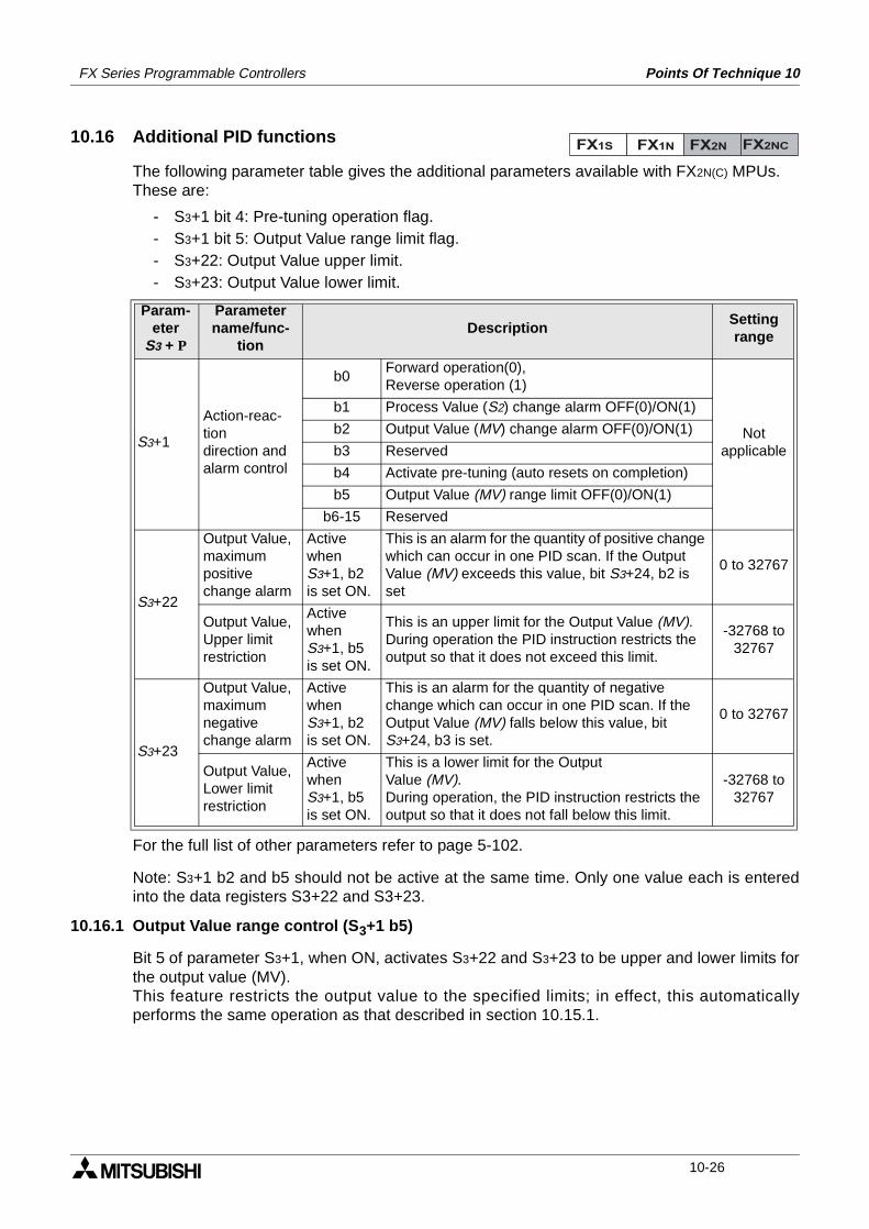
FX Series Programmable Controllers Points Of Technique 10
10.16 Additional PID functions
The following parameter table gives the additional parameters available with FX2N(C) MPUs.These are:
- S3+1 bit 4: Pre-tuning operation flag.- S3+1 bit 5: Output Value range limit flag.- S3+22: Output Value upper limit.- S3+23: Output Value lower limit.
For the full list of other parameters refer to page 5-102.
Note: S3+1 b2 and b5 should not be active at the same time. Only one value each is enteredinto the data registers S3+22 and S3+23.
10.16.1 Output Value range control (S3+1 b5)
Bit 5 of parameter S3+1, when ON, activates S3+22 and S3+23 to be upper and lower limits forthe output value (MV).This feature restricts the output value to the specified limits; in effect, this automaticallyperforms the same operation as that described in section 10.15.1.
Param-eter
S3 + P
Parametername/func-
tionDescription
Settingrange
S3+1
Action-reac-tiondirection andalarm control
b0Forward operation(0),Reverse operation (1)
Notapplicable
b1 Process Value (S2) change alarm OFF(0)/ON(1)
b2 Output Value (MV) change alarm OFF(0)/ON(1)
b3 Reserved
b4 Activate pre-tuning (auto resets on completion)
b5 Output Value (MV) range limit OFF(0)/ON(1)
b6-15 Reserved
S3+22
Output Value,maximumpositive change alarm
Active when S3+1, b2 is set ON.
This is an alarm for the quantity of positive change which can occur in one PID scan. If the Output Value (MV) exceeds this value, bit S3+24, b2 is set
0 to 32767
Output Value,Upper limit restriction
ActivewhenS3+1, b5 is set ON.
This is an upper limit for the Output Value (MV).During operation the PID instruction restricts the output so that it does not exceed this limit.
-32768 to32767
S3+23
Output Value,maximumnegative change alarm
ActivewhenS3+1, b2 is set ON.
This is an alarm for the quantity of negative change which can occur in one PID scan. If the Output Value (MV) falls below this value, bit S3+24, b3 is set.
0 to 32767
Output Value,Lower limit restriction
ActivewhenS3+1, b5 is set ON.
This is a lower limit for the OutputValue (MV).During operation, the PID instruction restricts the output so that it does not fall below this limit.
-32768 to32767
FX1S FX1N FX2N FX2NC
10-26
FX Series Programmable Controllers Points Of Technique 10
10.17 Pre-tuning operation
10.17.1 Variable Constants
The Pre-tuning operation can be used to automatically set values for the following variables:
- The direction of the process; Forward or Reverse (S3+1, bit 0)
- The proportional gain constant; KP (S3+3)
- The integral time constant; TI (S3+4)
- The derivative time constant; TD (S3+6)
Setting bit 4 of S3+1 starts the pre-tuning process. Before starting, set all values that are notset by the pre-tuning operation: the sample time, Ts (S3+0); the input filter α (S3+2); theDerivative gain, KD (S3+5); the Set Point, SV (S1); and any alarm or limit values, (S3+20-23).
The Pre-tuning operation measures how fast the system will correct itself when in error.Because the P, I, and D equations all react with differing speed, the initial error must be largeso that effective calculations can be made for each type of equation. The difference in valuesbetween SP and PVnf must be a minimum of 150 for the Pre-tuning to operate effectively. If thisis not the case, then please change SV to a suitable value for the purpose of pre-tuning.
The system keeps the output value (MV) at the initial value, monitoring the process value untilit reaches one third of the way to the Set Point. At this point the pre-tuning flag (bit 4) is resetand normal PID operation resumes. SV can be returned to the normal setting without turningthe PID command Off.
During the course of normal operation, the Pre-tuning will NOT automatically set new values ifthe SV is changed. The PID command must be turned Off, and the Pre-Tuning functionrestarted if it is necessary to use the Pre-tune function to calculate new values.
• Caution: The Pre-tuning can be used as many times as necessary. Because the flag resets,the set bit can be turned On again and new values will be calculated. If the system isrunning an oven heater and the SV is reduced from 250 to 200 C, the temperature mustdrop below 200 or the “Forward/Reverse” flag will be set in the wrong direction. In addition,the system error value must be large for the pre-tune variable calculations to work correctly.
• Note: Set the sampling time to greater than 1 second (1000 ms) during the pre-tuningoperation. It is recommended that the sampling time is generally set to a value muchgreater than the program scan time.
• Note: The system should be in a stable condition before starting the pre-tuning operation.An unstable system can cause the Pre-tuning operation to produce invalid results. (e.g.opening a refrigerator door, adding ingredients to a mixture, cold start, etc.)
• Note: Even though Pre-tuning can set the above mentioned variables, additional logic maybe needed in the program to "scale" all operating values to those capable of beingprocessed by the special function devices being used.
FX1S FX1N FX2N FX2NC
10-27
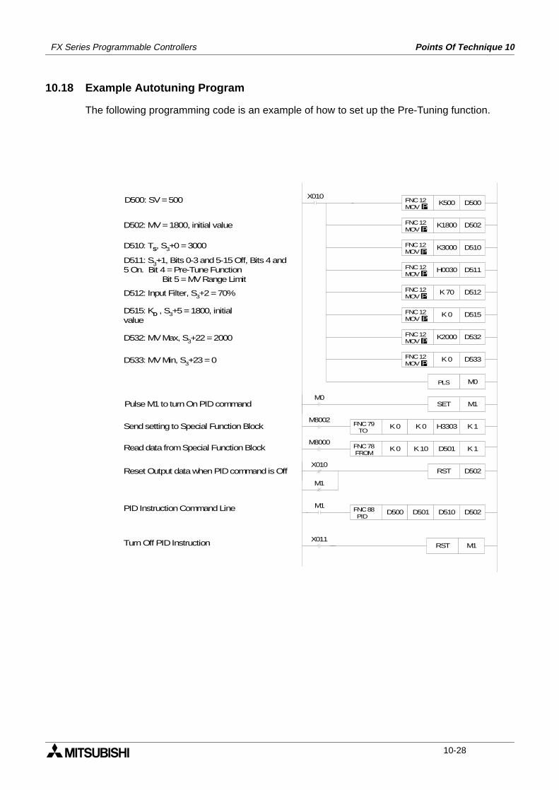
FX Series Programmable Controllers Points Of Technique 10
10.18 Example Autotuning Program
The following programming code is an example of how to set up the Pre-Tuning function.
K500 D500 FNC 12 MOV P
K1800 D502 FNC 12 MOV P
K3000 D510 FNC 12 MOV P
H0030 D511 FNC 12 MOV P
K 0 D515 FNC 12 MOV P
K 0 D533 FNC 12 MOV P
K2000 D532 FNC 12 MOV P
SET M1M0
FNC 79 TO
K 0 K 0 H3303 K 1
FNC 78 FROM
K 0 K 10 D501 K 1
M8002
M8000
K 70 D512 FNC 12 MOV P
RST D502X010
M1
FNC 88 PID
D500 D501 D510 D502M1
X010
M0 PLS
D500: SV = 500
D502: MV = 1800, initial value
D510: TS, S3+0 = 3000
D511: S3+1, Bits 0-3 and 5-15 Off, Bits 4 and5 On. Bit 4 = Pre-Tune Function Bit 5 = MV Range Limit
D512: Input Filter, S3+2 = 70%
D515: KD , S3+5 = 1800, initialvalue
D532: MV Max, S3+22 = 2000
D533: MV Min, S3+23 = 0
Pulse M1 to turn On PID command
Send setting to Special Function Block
Read data from Special Function Block
Reset Output data when PID command is Off
PID Instruction Command Line
X011RST M1Turn Off PID Instruction
10-28
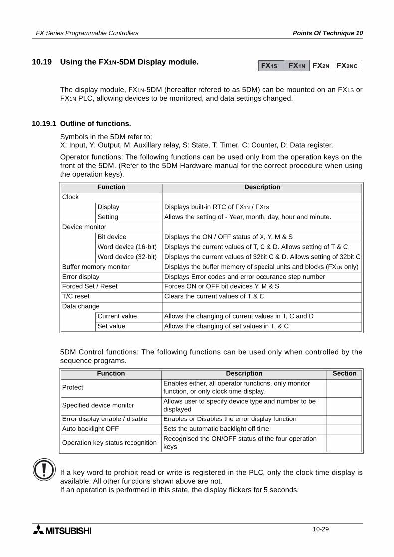
FX Series Programmable Controllers Points Of Technique 10
10.19 Using the FX1N-5DM Display module.
The display module, FX1N-5DM (hereafter refered to as 5DM) can be mounted on an FX1S orFX1N PLC, allowing devices to be monitored, and data settings changed.
10.19.1 Outline of functions.
Symbols in the 5DM refer to;X: Input, Y: Output, M: Auxillary relay, S: State, T: Timer, C: Counter, D: Data register.
Operator functions: The following functions can be used only from the operation keys on thefront of the 5DM. (Refer to the 5DM Hardware manual for the correct procedure when usingthe operation keys).
5DM Control functions: The following functions can be used only when controlled by thesequence programs.
If a key word to prohibit read or write is registered in the PLC, only the clock time display isavailable. All other functions shown above are not.If an operation is performed in this state, the display flickers for 5 seconds.
Function Description
Clock
Display Displays built-in RTC of FX1N / FX1S
Setting Allows the setting of - Year, month, day, hour and minute.
Device monitor
Bit device Displays the ON / OFF status of X, Y, M & S
Word device (16-bit) Displays the current values of T, C & D. Allows setting of T & C
Word device (32-bit) Displays the current values of 32bit C & D. Allows setting of 32bit C
Buffer memory monitor Displays the buffer memory of special units and blocks (FX1N only)
Error display Displays Error codes and error occurance step number
Forced Set / Reset Forces ON or OFF bit devices Y, M & S
T/C reset Clears the current values of T & C
Data change
Current value Allows the changing of current values in T, C and D
Set value Allows the changing of set values in T, & C
Function Description Section
ProtectEnables either, all operator functions, only monitor function, or only clock time display.
Specified device monitorAllows user to specify device type and number to be displayed
Error display enable / disable Enables or Disables the error display function
Auto backlight OFF Sets the automatic backlight off time
Operation key status recognitionRecognised the ON/OFF status of the four operation keys
FX1S FX1N FX2N FX2NC
10-29
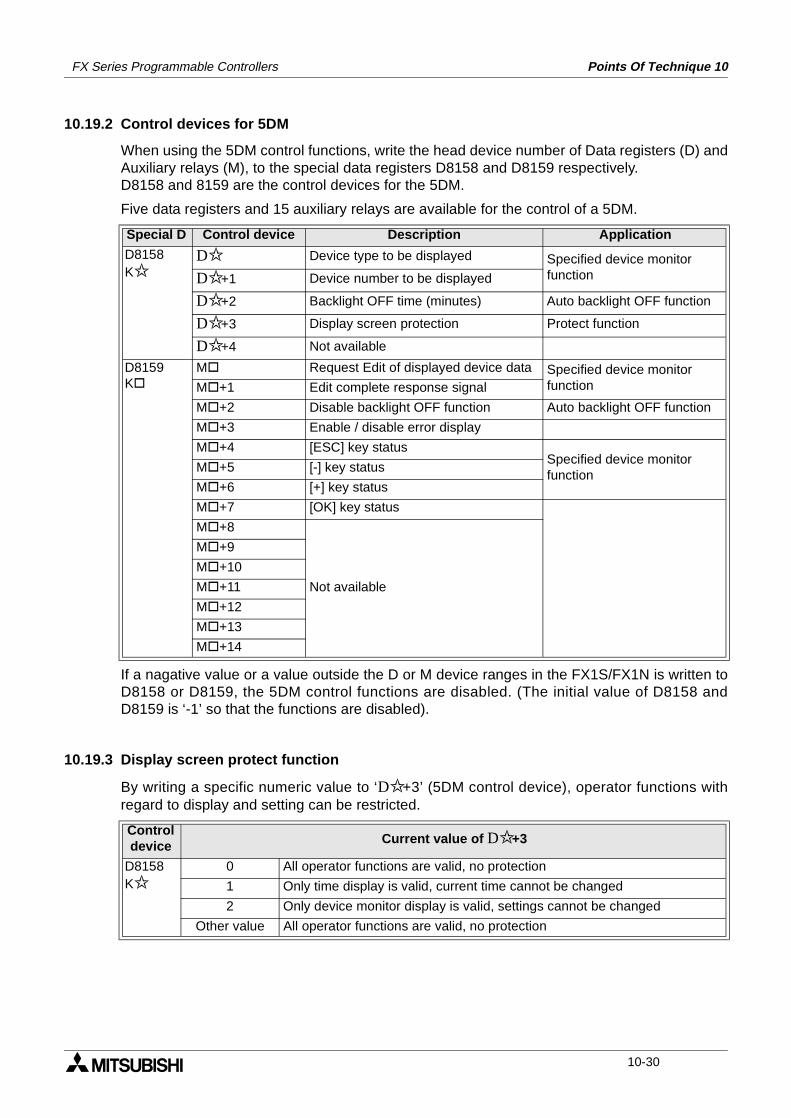
FX Series Programmable Controllers Points Of Technique 10
10.19.2 Control devices for 5DM
When using the 5DM control functions, write the head device number of Data registers (D) andAuxiliary relays (M), to the special data registers D8158 and D8159 respectively. D8158 and 8159 are the control devices for the 5DM.
Five data registers and 15 auxiliary relays are available for the control of a 5DM.
If a nagative value or a value outside the D or M device ranges in the FX1S/FX1N is written toD8158 or D8159, the 5DM control functions are disabled. (The initial value of D8158 andD8159 is ‘-1’ so that the functions are disabled).
10.19.3 Display screen protect function
By writing a specific numeric value to ‘D+3’ (5DM control device), operator functions withregard to display and setting can be restricted.
Special D Control device Description Application
D8158K
D Device type to be displayed Specified device monitor functionD+1 Device number to be displayed
D+2 Backlight OFF time (minutes) Auto backlight OFF function
D+3 Display screen protection Protect function
D+4 Not available
D8159K
M Request Edit of displayed device data Specified device monitor functionM +1 Edit complete response signal
M +2 Disable backlight OFF function Auto backlight OFF function
M +3 Enable / disable error display
M +4 [ESC] key statusSpecified device monitor function
M +5 [-] key status
M +6 [+] key status
M +7 [OK] key status
M +8
Not available
M +9
M +10
M +11
M +12
M +13
M +14
Control device Current value of D+3
D8158K
0 All operator functions are valid, no protection
1 Only time display is valid, current time cannot be changed
2 Only device monitor display is valid, settings cannot be changed
Other value All operator functions are valid, no protection
10-30
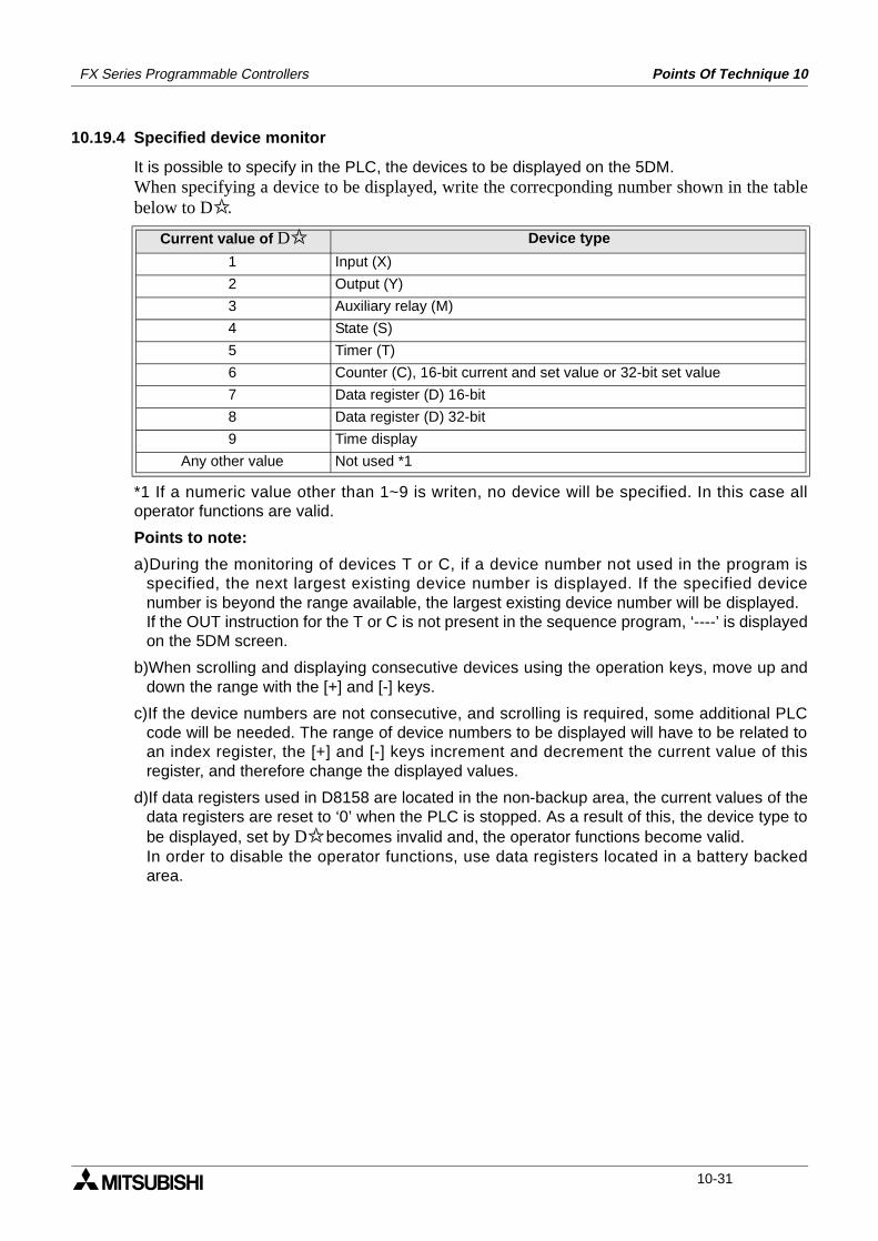
FX Series Programmable Controllers Points Of Technique 10
10.19.4 Specified device monitor
It is possible to specify in the PLC, the devices to be displayed on the 5DM.When specifying a device to be displayed, write the correcponding number shown in the tablebelow to D.
*1 If a numeric value other than 1~9 is writen, no device will be specified. In this case alloperator functions are valid.
Points to note:
a)During the monitoring of devices T or C, if a device number not used in the program isspecified, the next largest existing device number is displayed. If the specified devicenumber is beyond the range available, the largest existing device number will be displayed.If the OUT instruction for the T or C is not present in the sequence program, ‘----’ is displayedon the 5DM screen.
b)When scrolling and displaying consecutive devices using the operation keys, move up anddown the range with the [+] and [-] keys.
c)If the device numbers are not consecutive, and scrolling is required, some additional PLCcode will be needed. The range of device numbers to be displayed will have to be related toan index register, the [+] and [-] keys increment and decrement the current value of thisregister, and therefore change the displayed values.
d)If data registers used in D8158 are located in the non-backup area, the current values of thedata registers are reset to ‘0’ when the PLC is stopped. As a result of this, the device type tobe displayed, set by D becomes invalid and, the operator functions become valid.In order to disable the operator functions, use data registers located in a battery backedarea.
Current value of D Device type
1 Input (X)
2 Output (Y)
3 Auxiliary relay (M)
4 State (S)
5 Timer (T)
6 Counter (C), 16-bit current and set value or 32-bit set value
7 Data register (D) 16-bit
8 Data register (D) 32-bit
9 Time display
Any other value Not used *1
10-31
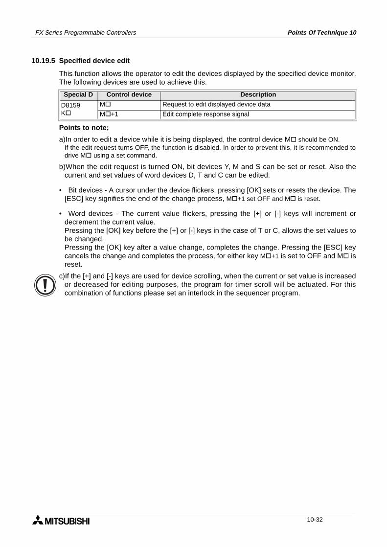
FX Series Programmable Controllers Points Of Technique 10
10.19.5 Specified device edit
This function allows the operator to edit the devices displayed by the specified device monitor.The following devices are used to achieve this.
Points to note;
a)In order to edit a device while it is being displayed, the control device M should be ON.If the edit request turns OFF, the function is disabled. In order to prevent this, it is recommended todrive M using a set command.
b)When the edit request is turned ON, bit devices Y, M and S can be set or reset. Also thecurrent and set values of word devices D, T and C can be edited.
• Bit devices - A cursor under the device flickers, pressing [OK] sets or resets the device. The[ESC] key signifies the end of the change process, M +1 set OFF and M is reset.
• Word devices - The current value flickers, pressing the [+] or [-] keys will increment ordecrement the current value.Pressing the [OK] key before the [+] or [-] keys in the case of T or C, allows the set values tobe changed.Pressing the [OK] key after a value change, completes the change. Pressing the [ESC] keycancels the change and completes the process, for either key M +1 is set to OFF and M isreset.
c)If the [+] and [-] keys are used for device scrolling, when the current or set value is increasedor decreased for editing purposes, the program for timer scroll will be actuated. For thiscombination of functions please set an interlock in the sequencer program.
Special D Control device Description
D8159K
M Request to edit displayed device data
M +1 Edit complete response signal
10-32
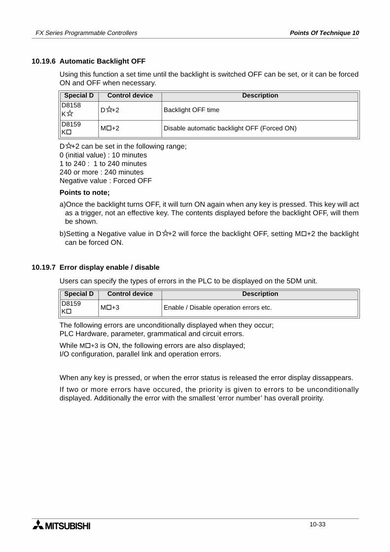
FX Series Programmable Controllers Points Of Technique 10
10.19.6 Automatic Backlight OFF
Using this function a set time until the backlight is switched OFF can be set, or it can be forcedON and OFF when necessary.
D+2 can be set in the following range;0 (initial value) : 10 minutes1 to 240 : 1 to 240 minutes240 or more : 240 minutesNegative value : Forced OFF
Points to note;
a)Once the backlight turns OFF, it will turn ON again when any key is pressed. This key will actas a trigger, not an effective key. The contents displayed before the backlight OFF, will thembe shown.
b)Setting a Negative value in D+2 will force the backlight OFF, setting M +2 the backlightcan be forced ON.
10.19.7 Error display enable / disable
Users can specify the types of errors in the PLC to be displayed on the 5DM unit.
The following errors are unconditionally displayed when they occur;PLC Hardware, parameter, grammatical and circuit errors.
While M +3 is ON, the following errors are also displayed;I/O configuration, parallel link and operation errors.
When any key is pressed, or when the error status is released the error display dissappears.
If two or more errors have occured, the priority is given to errors to be unconditionallydisplayed. Additionally the error with the smallest ‘error number’ has overall proirity.
Special D Control device Description
D8158K
D+2 Backlight OFF time
D8159K
M +2 Disable automatic backlight OFF (Forced ON)
Special D Control device Description
D8159K
M +3 Enable / Disable operation errors etc.
10-33
FX Series Programmable Controllers Points Of Technique 10
Memo
10-34
1 Introduction
2 Basic Program Instructions
3 STL Programming
4 Devices in Detail
5 Applied Instructions
6 Diagnostic Devices
7 Instruction Execution Times
8 PLC Device Tables
9 Assigning System Devices
10 Points of Technique
11 Index
FX Series Programmable Logic Controllers Index 11
FX Series Programmable Logic Controllers Index 11
Chapter contents
11.Index...................................................................................................11-111.1 Index.................................................................................................................. 11-111.2 ASCII Character Codes ..................................................................................... 11-911.3 Applied Instruction List .................................................................................... 11-10
Index 11FX Series Programmable Controllers
11. Index
11.1 Index
A
Absolute current value read, ABS instruction .......................................................................... 5-127Absolute drum sequence, ABSD instruction.............................................................................. 5-70Addition of data values, ADD instruction.................................................................................... 5-25Addressing special function blocks .............................................................................................. 9-1Advanced programming points
Examples and tips ............................................................................................................. 10-1Alternated state, ALT instruction ................................................................................................ 5-73Alternating states using ALT, example ....................................................................................... 10-4ANB ........................................................................................................................................... 2-12And block instruction ................................................................................................................. 2-12And, And inverse instructions ...................................................................................................... 2-6AND, ANI ..................................................................................................................................... 2-6Annunciator reset, ANR instruction ............................................................................................ 5-47Annunciator set, ANS instruction ............................................................................................... 5-47And Pulse, And trailing Pulse instructions ................................................................................... 2-9ANP, ANF..................................................................................................................................... 2-9Applied instr’ which can only be used once ............................................................................... 7-16Applied instruction list .............................................................................................................. 11-10Applied instructions ..................................................................................................................... 5-1Arrow switch, ARWS instruction ................................................................................................ 5-87ASCII character codes ............................................................................................................... 11-9ASCII code (Alpha to ASCII code), ASCI instr’ .......................................................................... 5-88ASCII to HEX conversion using HEX (FNC 83) ......................................................................... 5-99Assigning special function block numbers ................................................................................... 9-1Assigning system devices ............................................................................................................ 9-1Associated Manuals ..................................................................................................................... 1-4Auxiliary relays,
Battery backed/ latched ....................................................................................................... 4-4Device details and example ................................................................................................. 4-3General information on diagnostic devices .......................................................................... 4-5General use ........................................................................................................................ 4-3
B
Basic devicesOutline of basic PLC devices ............................................................................................... 2-1X, Y, T, C, M, S .................................................................................................................... 2-1
Basic devices and instructions..................................................................................................... 2-1BCD data words - reading .......................................................................................................... 4-41BCD output (Binary Coded Decimal), BCD instr’ ...................................................................... 5-22BIN input (Binary), BIN instruction ............................................................................................. 5-22Binary data - reading ................................................................................................................. 4-39Bit devices ................................................................................................................................ 4-37Bit on recognition, BON instruction ............................................................................................ 5-45Bit pattern rotation left, ROL instruction ..................................................................................... 5-35Bit pattern rotation right, ROR instruction .................................................................................. 5-35Bit rotation and carry left, RCL instruction ................................................................................. 5-36Bit rotation and carry right, RCR instruction .............................................................................. 5-36Bit shift left, SFTL instruction .................................................................................................... 5-37Bit shift right, SFTR instruction ................................................................................................. 5-37Block data move, BMOV instruction .......................................................................................... 5-20Byte swap, SWAP instruction .................................................................................................. 5-123
11-1
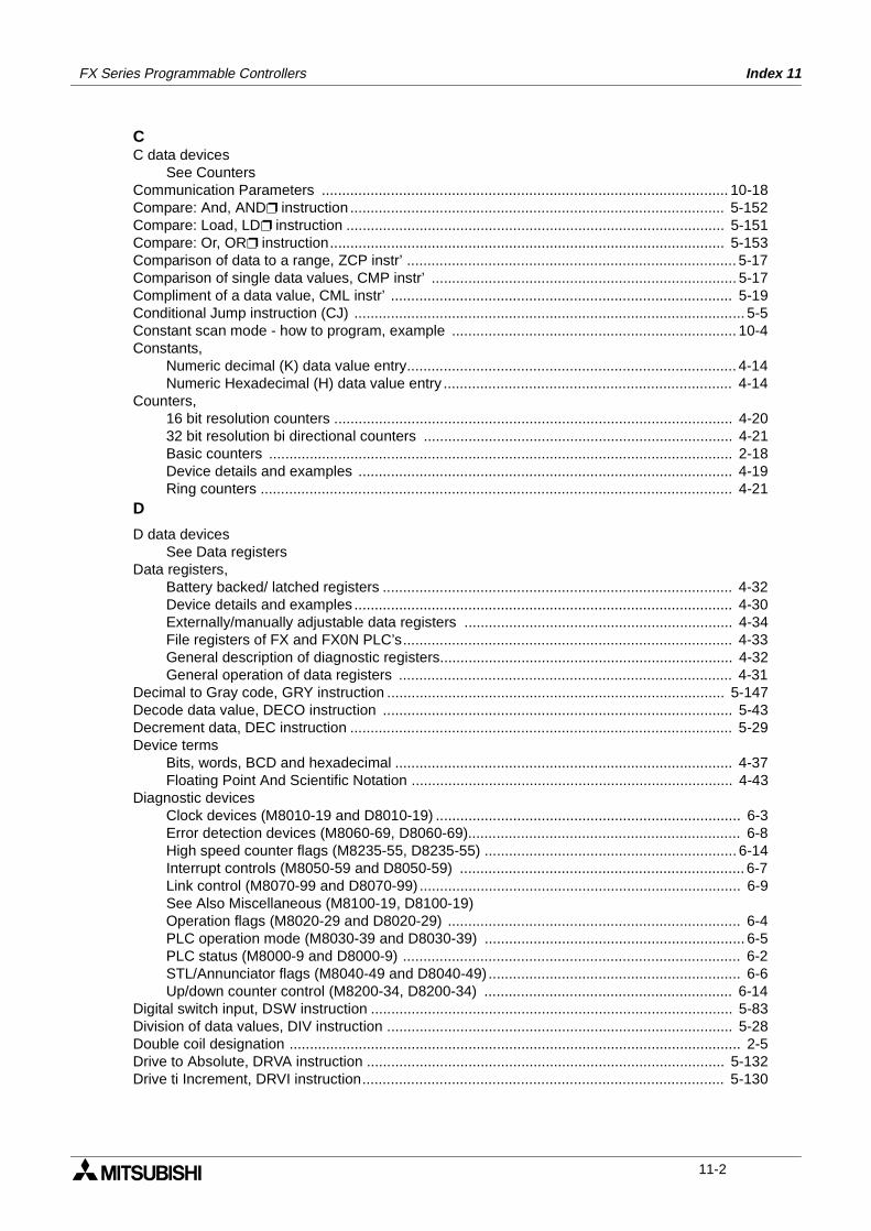
FX Series Programmable Controllers Index 11
CC data devices
See CountersCommunication Parameters .................................................................................................... 10-18Compare: And, AND instruction ............................................................................................ 5-152Compare: Load, LD instruction ............................................................................................. 5-151Compare: Or, OR instruction................................................................................................. 5-153Comparison of data to a range, ZCP instr’ ................................................................................. 5-17Comparison of single data values, CMP instr’ ........................................................................... 5-17Compliment of a data value, CML instr’ .................................................................................... 5-19Conditional Jump instruction (CJ) ................................................................................................ 5-5Constant scan mode - how to program, example ...................................................................... 10-4Constants,
Numeric decimal (K) data value entry................................................................................. 4-14Numeric Hexadecimal (H) data value entry ....................................................................... 4-14
Counters,16 bit resolution counters .................................................................................................. 4-2032 bit resolution bi directional counters ............................................................................ 4-21Basic counters .................................................................................................................. 2-18Device details and examples ............................................................................................ 4-19Ring counters .................................................................................................................... 4-21
D
D data devicesSee Data registers
Data registers,Battery backed/ latched registers ...................................................................................... 4-32Device details and examples ............................................................................................. 4-30Externally/manually adjustable data registers .................................................................. 4-34File registers of FX and FX0N PLC’s................................................................................. 4-33General description of diagnostic registers........................................................................ 4-32General operation of data registers .................................................................................. 4-31
Decimal to Gray code, GRY instruction ................................................................................... 5-147Decode data value, DECO instruction ...................................................................................... 5-43Decrement data, DEC instruction .............................................................................................. 5-29Device terms
Bits, words, BCD and hexadecimal ................................................................................... 4-37Floating Point And Scientific Notation ............................................................................... 4-43
Diagnostic devicesClock devices (M8010-19 and D8010-19) ........................................................................... 6-3Error detection devices (M8060-69, D8060-69)................................................................... 6-8High speed counter flags (M8235-55, D8235-55) .............................................................. 6-14Interrupt controls (M8050-59 and D8050-59) ...................................................................... 6-7Link control (M8070-99 and D8070-99) ............................................................................... 6-9See Also Miscellaneous (M8100-19, D8100-19)Operation flags (M8020-29 and D8020-29) ........................................................................ 6-4PLC operation mode (M8030-39 and D8030-39) ................................................................ 6-5PLC status (M8000-9 and D8000-9) ................................................................................... 6-2STL/Annunciator flags (M8040-49 and D8040-49) .............................................................. 6-6Up/down counter control (M8200-34, D8200-34) ............................................................. 6-14
Digital switch input, DSW instruction ......................................................................................... 5-83Division of data values, DIV instruction ..................................................................................... 5-28Double coil designation ............................................................................................................... 2-5Drive to Absolute, DRVA instruction ........................................................................................ 5-132Drive ti Increment, DRVI instruction......................................................................................... 5-130
11-2
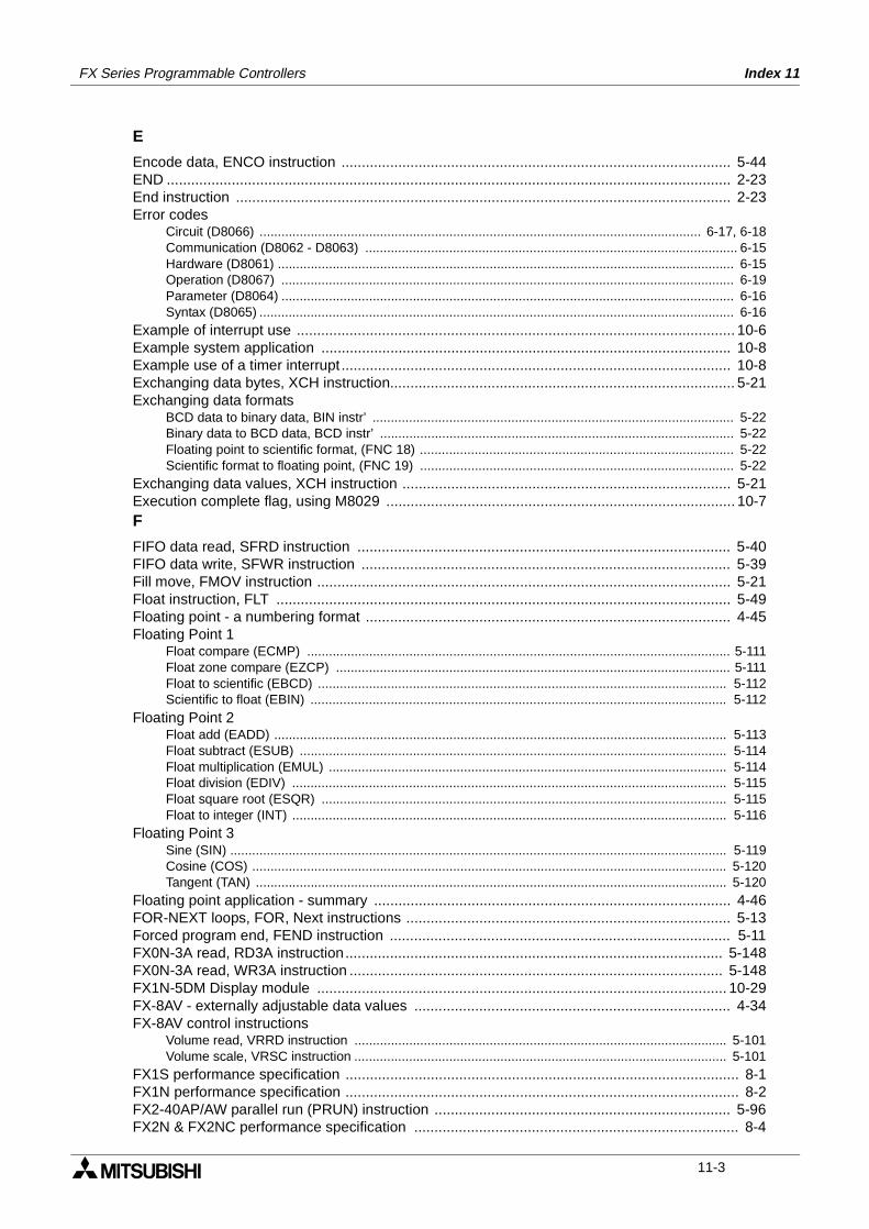
FX Series Programmable Controllers Index 11
E
Encode data, ENCO instruction ................................................................................................ 5-44END ........................................................................................................................................... 2-23End instruction .......................................................................................................................... 2-23Error codes
Circuit (D8066) ......................................................................................................................... 6-17, 6-18Communication (D8062 - D8063) ...................................................................................................... 6-15Hardware (D8061) ............................................................................................................................. 6-15Operation (D8067) ............................................................................................................................ 6-19Parameter (D8064) ............................................................................................................................ 6-16Syntax (D8065) .................................................................................................................................. 6-16
Example of interrupt use ............................................................................................................ 10-6Example system application ..................................................................................................... 10-8Example use of a timer interrupt ................................................................................................ 10-8Exchanging data bytes, XCH instruction..................................................................................... 5-21Exchanging data formats
BCD data to binary data, BIN instr’ ................................................................................................... 5-22Binary data to BCD data, BCD instr’ ................................................................................................. 5-22Floating point to scientific format, (FNC 18) ...................................................................................... 5-22Scientific format to floating point, (FNC 19) ...................................................................................... 5-22
Exchanging data values, XCH instruction ................................................................................. 5-21Execution complete flag, using M8029 ...................................................................................... 10-7F
FIFO data read, SFRD instruction ............................................................................................ 5-40FIFO data write, SFWR instruction ........................................................................................... 5-39Fill move, FMOV instruction ...................................................................................................... 5-21Float instruction, FLT ................................................................................................................ 5-49Floating point - a numbering format .......................................................................................... 4-45Floating Point 1
Float compare (ECMP) .................................................................................................................... 5-111Float zone compare (EZCP) ............................................................................................................ 5-111Float to scientific (EBCD) ................................................................................................................ 5-112Scientific to float (EBIN) .................................................................................................................. 5-112
Floating Point 2Float add (EADD) ............................................................................................................................ 5-113Float subtract (ESUB) ..................................................................................................................... 5-114Float multiplication (EMUL) ............................................................................................................. 5-114Float division (EDIV) ....................................................................................................................... 5-115Float square root (ESQR) ............................................................................................................... 5-115Float to integer (INT) ....................................................................................................................... 5-116
Floating Point 3Sine (SIN) ........................................................................................................................................ 5-119Cosine (COS) .................................................................................................................................. 5-120Tangent (TAN) ................................................................................................................................. 5-120
Floating point application - summary ........................................................................................ 4-46FOR-NEXT loops, FOR, Next instructions ................................................................................ 5-13Forced program end, FEND instruction .................................................................................... 5-11FX0N-3A read, RD3A instruction............................................................................................. 5-148FX0N-3A read, WR3A instruction ............................................................................................ 5-148FX1N-5DM Display module ..................................................................................................... 10-29FX-8AV - externally adjustable data values .............................................................................. 4-34FX-8AV control instructions
Volume read, VRRD instruction ...................................................................................................... 5-101Volume scale, VRSC instruction ...................................................................................................... 5-101
FX1S performance specification ................................................................................................. 8-1FX1N performance specification ................................................................................................. 8-2FX2-40AP/AW parallel run (PRUN) instruction ......................................................................... 5-96FX2N & FX2NC performance specification ................................................................................ 8-4
11-3
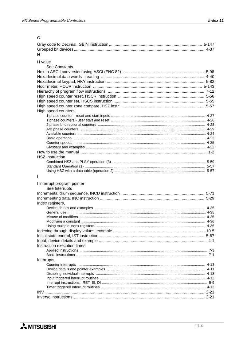
FX Series Programmable Controllers Index 11
G
Gray code to Decimal, GBIN instruction .................................................................................. 5-147Grouped bit devices................................................................................................................... 4-37H
H valueSee Constants
Hex to ASCII conversion using ASCI (FNC 82).......................................................................... 5-98Hexadecimal data words - reading ........................................................................................... 4-40Hexadecimal keypad, HKY instruction ...................................................................................... 5-82Hour meter, HOUR instruction ................................................................................................ 5-143Hierarchy of program flow instructions ..................................................................................... 7-12High speed counter reset, HSCR instruction ............................................................................ 5-56High speed counter set, HSCS instruction ............................................................................... 5-55High speed counter zone compare, HSZ instr’ ......................................................................... 5-57High speed counters,
1 phase counter - reset and start inputs ............................................................................................ 4-271 phase counters - user start and reset ............................................................................................. 4-262 phase bi-directional counters ......................................................................................................... 4-28A/B phase counters ........................................................................................................................... 4-29Available counters .............................................................................................................................. 4-24Basic operation ................................................................................................................................. 4-23Counter speeds ................................................................................................................................. 4-25Glossary and examples...................................................................................................................... 4-22
How to use the manual ................................................................................................................ 1-2HSZ Instruction
Combined HSZ and PLSY operation (3) ........................................................................................... 5-59Standard Operation (1) ...................................................................................................................... 5-57Using HSZ with a data table (operation 2) ........................................................................................ 5-57
I
I interrupt program pointerSee Interrupts
Incremental drum sequence, INCD instruction .......................................................................... 5-71Incrementing data, INC instruction ............................................................................................ 5-29Index registers,
Device details and examples ............................................................................................................ 4-35General use ........................................................................................................................................ 4-35Misuse of modifiers ........................................................................................................................... 4-36Modifying a constant ......................................................................................................................... 4-36Using multiple index registers ........................................................................................................... 4-36
Indexing through display values, example ................................................................................. 10-5Initial state control, IST instruction ............................................................................................ 5-67Input, device details and example ............................................................................................... 4-1Instruction execution times
Applied instructions ............................................................................................................................. 7-3Basic instructions ................................................................................................................................. 7-1
Interrupts,Counter interrupts ............................................................................................................................. 4-13Device details and pointer examples ................................................................................................ 4-11Disabling individual interrupts ........................................................................................................... 4-13Input triggered interrupt routines ....................................................................................................... 4-12Interrupt instructions: IRET, EI, DI ....................................................................................................... 5-9Timer triggered interrupt routines ...................................................................................................... 4-12
INV ............................................................................................................................................. 2-21Inverse instructions .................................................................................................................... 2-21
11-4
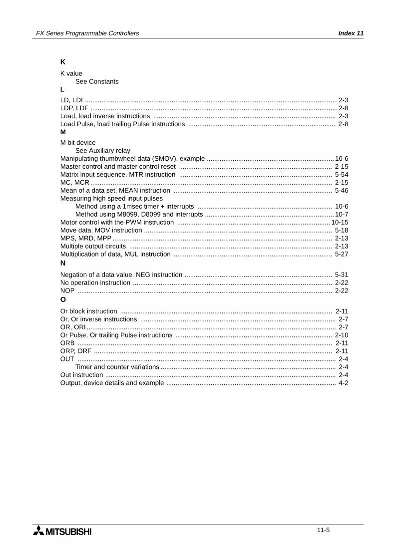
FX Series Programmable Controllers Index 11
K
K valueSee Constants
L
LD, LDI ......................................................................................................................................... 2-3LDP, LDF ...................................................................................................................................... 2-8Load, load inverse instructions ................................................................................................... 2-3Load Pulse, load trailing Pulse instructions ................................................................................ 2-8M
M bit deviceSee Auxiliary relay
Manipulating thumbwheel data (SMOV), example ..................................................................... 10-6Master control and master control reset ................................................................................... 2-15Matrix input sequence, MTR instruction ................................................................................... 5-54MC, MCR ................................................................................................................................... 2-15Mean of a data set, MEAN instruction ...................................................................................... 5-46Measuring high speed input pulses
Method using a 1msec timer + interrupts ......................................................................... 10-6Method using M8099, D8099 and interrupts ...................................................................... 10-7
Motor control with the PWM instruction ................................................................................... 10-15Move data, MOV instruction ...................................................................................................... 5-18MPS, MRD, MPP ....................................................................................................................... 2-13Multiple output circuits .............................................................................................................. 2-13Multiplication of data, MUL instruction ...................................................................................... 5-27N
Negation of a data value, NEG instruction ................................................................................ 5-31No operation instruction ............................................................................................................ 2-22NOP .......................................................................................................................................... 2-22O
Or block instruction ................................................................................................................... 2-11Or, Or inverse instructions .......................................................................................................... 2-7OR, ORI ....................................................................................................................................... 2-7Or Pulse, Or trailing Pulse instructions ..................................................................................... 2-10ORB .......................................................................................................................................... 2-11ORP, ORF ................................................................................................................................. 2-11OUT ............................................................................................................................................ 2-4
Timer and counter variations ............................................................................................... 2-4Out instruction ............................................................................................................................. 2-4Output, device details and example ............................................................................................ 4-2
11-5

FX Series Programmable Controllers Index 11
P
P program pointerSee Pointer P
PLC operation - batch processing ............................................................................................ 7-14PID control
Applied instruction 88 - PID. ............................................................................................ 5-102Configuring the PID loop ................................................................................................. 5-105Example program ........................................................................................................... 10-28PID Setup parameters .................................................................................................... 5-104Program techniques ......................................................................................................... 10-24
PLS, PLF .................................................................................................................................. 2-20Pointer P,Device details and example use .............................................................................................. . 4-10Positive/negative logic .............................................................................................................. 5-86Power failure precautions for FX DC units ................................................................................ 10-1Print to display, PR instruction .................................................................................................. 5-89ProgramHow to read ladder logic ............................................................................................................. 2-2Program scan ........................................................................................................................... 2-23Programming formats: list, ladder, STL/SFC .............................................................................. 2-1What do you need to program a PLC? ....................................................................................... 1-3What is a program? .................................................................................................................... 2-1Program example featuring IST and STL control ..................................................................... 10-8Programmable controllerWhat is a programmable controller .............................................................................................. 1-3Programming tools ....................................................................................................................... 1-3FX-PCS/AT-EE SW operating precautions ................................................................................. 3-15PulseLeading and trailing edge instructions ....................................................................................... 2-20Pulse Ramp (PLSR instruction) ................................................................................................. 5-63Pulse train output, PLSY instruction .......................................................................................... 5-61Pulse V, PLSV instruction ....................................................................................................... 5-129Pulse width modulation, PWM instruction ................................................................................. 5-62R
Ramped values, RAMP instruction ........................................................................................... 5-73Reading from special blocks, FROM instruction ....................................................................... 5-90Real time clock data read, TRD instruction ............................................................................. 5-141Real time clock data write, TWR instruction ........................................................................... 5-142Real time clock memory cassettes ............................................................................................. 9-2Refresh and filter adjust, REFF instruction ............................................................................... 5-53Refresh I/O status, REF instruction. .......................................................................................... 5-53Ripple circuit for use with an inverter ....................................................................................... 10-15Rotary table control, ROTC instruction ..................................................................................... 5-75RS communications function (FNC80) ..................................................................................... 5-95
11-6
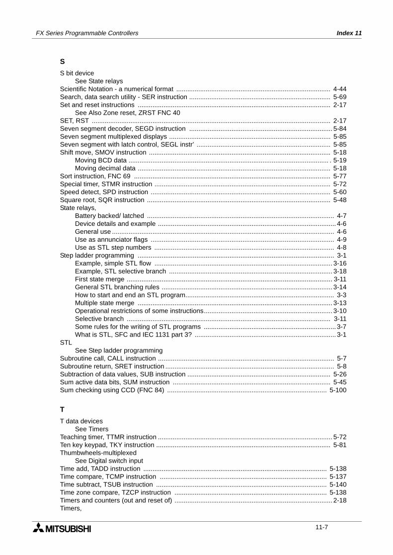
FX Series Programmable Controllers Index 11
S
S bit deviceSee State relays
Scientific Notation - a numerical format .................................................................................... 4-44Search, data search utility - SER instruction ............................................................................. 5-69Set and reset instructions ......................................................................................................... 2-17
See Also Zone reset, ZRST FNC 40SET, RST .................................................................................................................................. 2-17Seven segment decoder, SEGD instruction .............................................................................. 5-84Seven segment multiplexed displays ........................................................................................ 5-85Seven segment with latch control, SEGL instr’ ......................................................................... 5-85Shift move, SMOV instruction ................................................................................................... 5-18
Moving BCD data ............................................................................................................. . 5-19Moving decimal data ......................................................................................................... 5-18
Sort instruction, FNC 69 ........................................................................................................... 5-77Special timer, STMR instruction ................................................................................................ 5-72Speed detect, SPD instruction .................................................................................................. 5-60Square root, SQR instruction .................................................................................................... 5-48State relays,
Battery backed/ latched ...................................................................................................... 4-7Device details and example ................................................................................................. 4-6General use ......................................................................................................................... 4-6Use as annunciator flags .................................................................................................... 4-9Use as STL step numbers .................................................................................................. 4-8
Step ladder programming ........................................................................................................... 3-1Example, simple STL flow ................................................................................................. 3-16Example, STL selective branch ......................................................................................... 3-18First state merge ................................................................................................................ 3-11General STL branching rules ............................................................................................. 3-14How to start and end an STL program................................................................................. 3-3Multiple state merge .......................................................................................................... 3-13Operational restrictions of some instructions...................................................................... 3-10Selective branch ............................................................................................................... 3-11Some rules for the writing of STL programs ........................................................................ 3-7What is STL, SFC and IEC 1131 part 3? ............................................................................. 3-1
STLSee Step ladder programming
Subroutine call, CALL instruction ................................................................................................ 5-7Subroutine return, SRET instruction ............................................................................................ 5-8Subtraction of data values, SUB instruction .............................................................................. 5-26Sum active data bits, SUM instruction ...................................................................................... 5-45Sum checking using CCD (FNC 84) ....................................................................................... 5-100
T
T data devicesSee Timers
Teaching timer, TTMR instruction ............................................................................................... 5-72Ten key keypad, TKY instruction ............................................................................................... 5-81Thumbwheels-multiplexed
See Digital switch inputTime add, TADD instruction .................................................................................................... 5-138Time compare, TCMP instruction ........................................................................................... 5-137Time subtract, TSUB instruction ............................................................................................. 5-140Time zone compare, TZCP instruction ................................................................................... 5-138Timers and counters (out and reset of) ...................................................................................... 2-18Timers,
11-7
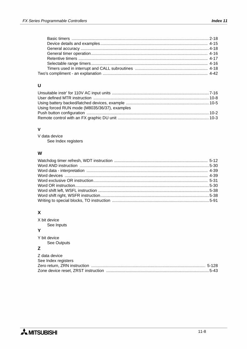
FX Series Programmable Controllers Index 11
Basic timers ....................................................................................................................... 2-18Device details and examples ............................................................................................. 4-15General accuracy ............................................................................................................... 4-18General timer operation ..................................................................................................... 4-16Retentive timers ................................................................................................................ 4-17Selectable range timers ..................................................................................................... 4-16Timers used in interrupt and CALL subroutines ............................................................... 4-18
Two’s compliment - an explanation ........................................................................................... 4-42
U
Unsuitable instr’ for 110V AC input units .................................................................................... 7-16User defined MTR instruction .................................................................................................... 10-8Using battery backed/latched devices, example ........................................................................ 10-5Using forced RUN mode (M8035/36/37), examplesPush button configuration .......................................................................................................... 10-2Remote control with an FX graphic DU unit ............................................................................... 10-3
V
V data deviceSee Index registers
W
Watchdog timer refresh, WDT instruction ................................................................................. 5-12Word AND instruction ................................................................................................................ 5-30Word data - interpretation ......................................................................................................... 4-39Word devices ............................................................................................................................ 4-39Word exclusive OR instruction................................................................................................... 5-31Word OR instruction.................................................................................................................... 5-30Word shift left, WSFL instruction ................................................................................................ 5-38Word shift right, WSFR instruction.............................................................................................. 5-38Writing to special blocks, TO instruction .................................................................................... 5-91
X
X bit deviceSee Inputs
Y
Y bit deviceSee Outputs
Z
Z data deviceSee Index registersZero return, ZRN instruction ................................................................................................... 5-128Zone device reset, ZRST instruction ......................................................................................... 5-43
11-8
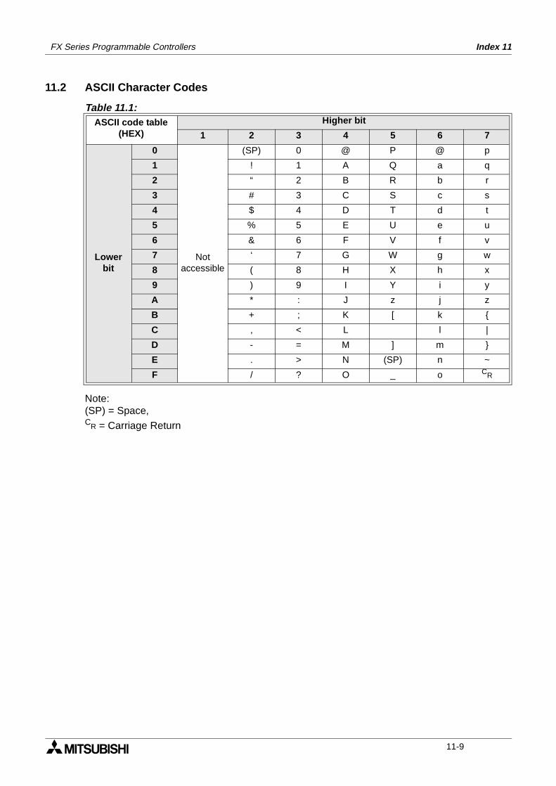
FX Series Programmable Controllers Index 11
11.2 ASCII Character Codes
Note:(SP) = Space,CR = Carriage Return
Table 11.1:ASCII code table
(HEX)Higher bit
1 2 3 4 5 6 7
Lowerbit
0
Notaccessible
(SP) 0 @ P @ p
1 ! 1 A Q a q
2 “ 2 B R b r
3 # 3 C S c s
4 $ 4 D T d t
5 % 5 E U e u
6 & 6 F V f v
7 ‘ 7 G W g w
8 ( 8 H X h x
9 ) 9 I Y i y
A * : J z j z
B + ; K [ k
C , < L l |
D - = M ] m
E . > N (SP) n ~
F / ? O _ o CR
11-9
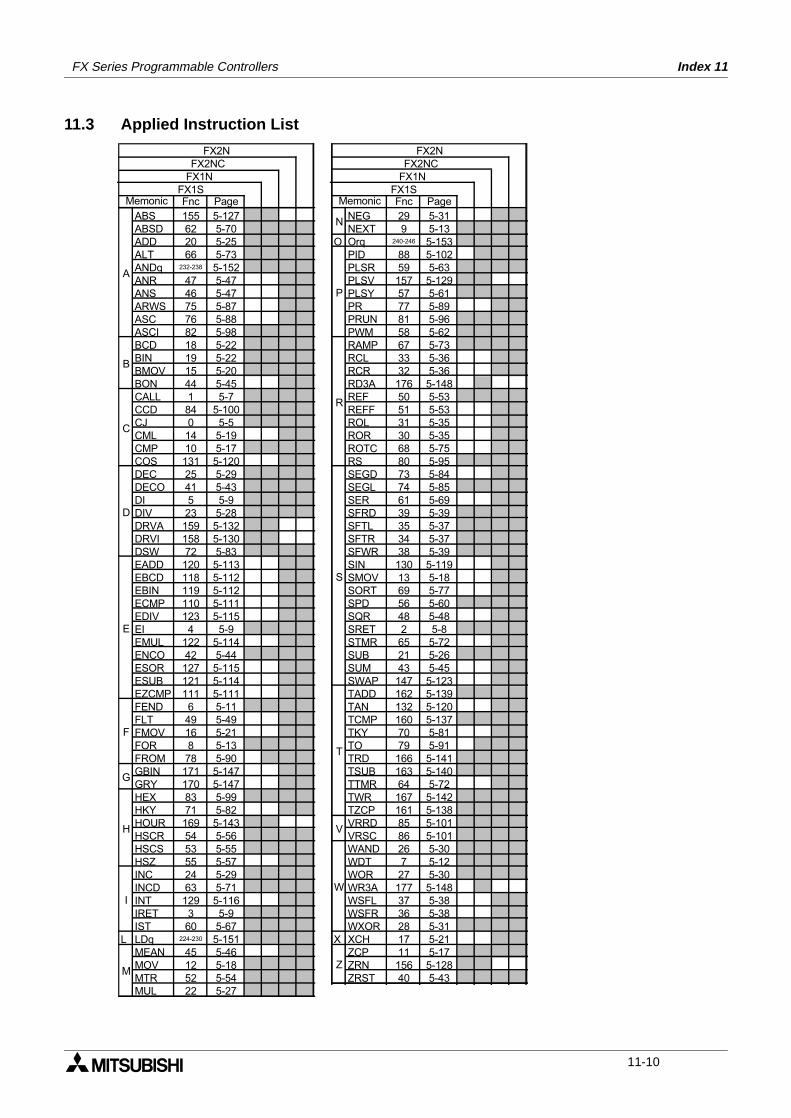
FX Series Programmable Controllers Index 11
11.3 Applied Instruction List
Fnc Page Fnc Page
ABS 155 5-127 NEG 29 5-31
ABSD 62 5-70 NEXT 9 5-13
ADD 20 5-25 O Orq 240-246 5-153
ALT 66 5-73 PID 88 5-102
ANDq 232-238 5-152 PLSR 59 5-63
ANR 47 5-47 PLSV 157 5-129
ANS 46 5-47 PLSY 57 5-61
ARWS 75 5-87 PR 77 5-89
ASC 76 5-88 PRUN 81 5-96
ASCI 82 5-98 PWM 58 5-62
BCD 18 5-22 RAMP 67 5-73
BIN 19 5-22 RCL 33 5-36
BMOV 15 5-20 RCR 32 5-36
BON 44 5-45 RD3A 176 5-148
CALL 1 5-7 REF 50 5-53
CCD 84 5-100 REFF 51 5-53
CJ 0 5-5 ROL 31 5-35
CML 14 5-19 ROR 30 5-35
CMP 10 5-17 ROTC 68 5-75
COS 131 5-120 RS 80 5-95
DEC 25 5-29 SEGD 73 5-84
DECO 41 5-43 SEGL 74 5-85
DI 5 5-9 SER 61 5-69
DIV 23 5-28 SFRD 39 5-39
DRVA 159 5-132 SFTL 35 5-37
DRVI 158 5-130 SFTR 34 5-37
DSW 72 5-83 SFWR 38 5-39
EADD 120 5-113 SIN 130 5-119
EBCD 118 5-112 SMOV 13 5-18
EBIN 119 5-112 SORT 69 5-77
ECMP 110 5-111 SPD 56 5-60
EDIV 123 5-115 SQR 48 5-48
EI 4 5-9 SRET 2 5-8
EMUL 122 5-114 STMR 65 5-72
ENCO 42 5-44 SUB 21 5-26
ESOR 127 5-115 SUM 43 5-45
ESUB 121 5-114 SWAP 147 5-123
EZCMP 111 5-111 TADD 162 5-139
FEND 6 5-11 TAN 132 5-120
FLT 49 5-49 TCMP 160 5-137
FMOV 16 5-21 TKY 70 5-81
FOR 8 5-13 TO 79 5-91
FROM 78 5-90 TRD 166 5-141
GBIN 171 5-147 TSUB 163 5-140
GRY 170 5-147 TTMR 64 5-72
HEX 83 5-99 TWR 167 5-142
HKY 71 5-82 TZCP 161 5-138
HOUR 169 5-143 VRRD 85 5-101
HSCR 54 5-56 VRSC 86 5-101
HSCS 53 5-55 WAND 26 5-30
HSZ 55 5-57 WDT 7 5-12
INC 24 5-29 WOR 27 5-30
INCD 63 5-71 WR3A 177 5-148
INT 129 5-116 WSFL 37 5-38
IRET 3 5-9 WSFR 36 5-38
IST 60 5-67 WXOR 28 5-31
L LDq 224-230 5-151 X XCH 17 5-21
MEAN 45 5-46 ZCP 11 5-17
MOV 12 5-18 ZRN 156 5-128
MTR 52 5-54 ZRST 40 5-43
MUL 22 5-27
FX2N
FX2NC
FX1N
FX1SMemonic
F
E
D
C
M
I
H
G
S
R
P
N
W
Z
V
T
Memonic
B
A
FX1S
FX1N
FX2NC
FX2N
11-10

HEAD OFFICE: MITSUBISHI DENKI BLDG MARUNOUCHI TOKYO 100-8310 TELEX: J24532 CABLE MELCO TOKYOHIMEJI WORKS: 840, CHIYODA CHO, HIMEJI, JAPAN
JY992D88101A(MEE 0003)
Effective April. 2000Specification are subjectto change without notice.
PROGRAMMING MANUAL II
THE FX SERIES OF PROGRAMMABLE CONTROLLER(FX1S, FX1N, FX2N, FX2NC)