electrical interconnections - farnell
TRANSCRIPT

Supplementary Catalog to Full Line Catalogs, Volumes 1/2/5Edition 2014/2
Electrical Interconnections
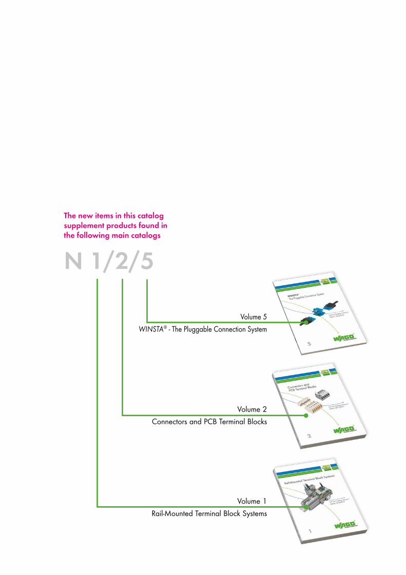
The new items in this catalog supplement products found in the following main catalogs
Volume 1Rail-Mounted Terminal Block Systems
Volume 2Connectors and PCB Terminal Blocks
Volume 5WINSTA - The Pluggable Connection System
N 1/2/5
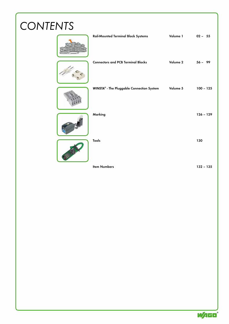
CONTENTSRail-Mounted Terminal Block Systems Volume 1 02 – 55
Connectors and PCB Terminal Blocks Volume 2 56 – 99
WINSTA® - The Pluggable Connection System Volume 5 100 – 125
Marking 126 – 129
Tools 130
Item Numbers 132 – 135
Pol1
Pol1
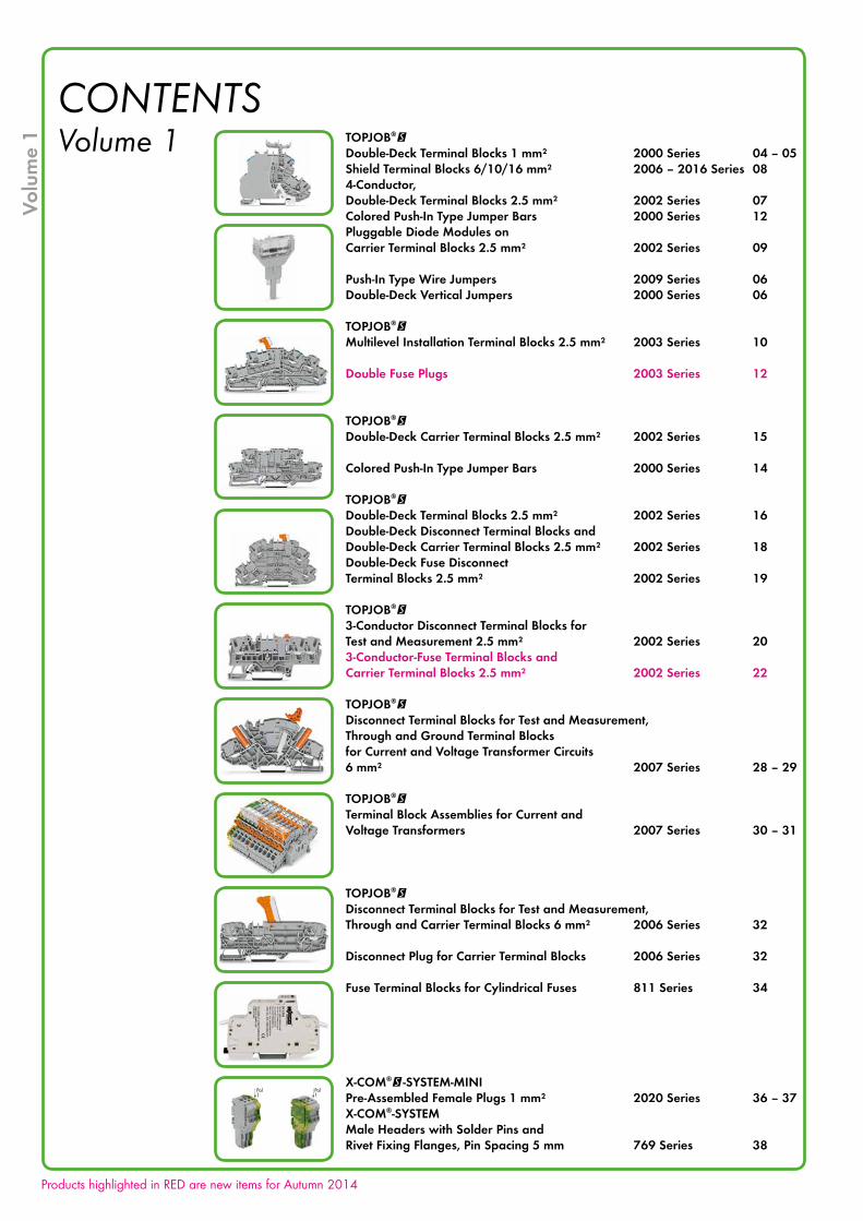
CONTENTSVolume 1 TOPJOB®@
Double-Deck Terminal Blocks 1 mm² 2000 Series 04 – 05Shield Terminal Blocks 6/10/16 mm² 2006 – 2016 Series 084-Conductor, Double-Deck Terminal Blocks 2.5 mm² 2002 Series 07Colored Push-In Type Jumper Bars 2000 Series 12Pluggable Diode Modules on Carrier Terminal Blocks 2.5 mm² 2002 Series 09
Push-In Type Wire Jumpers 2009 Series 06Double-Deck Vertical Jumpers 2000 Series 06
TOPJOB®@Multilevel Installation Terminal Blocks 2.5 mm² 2003 Series 10
Double Fuse Plugs 2003 Series 12
TOPJOB®@Double-Deck Carrier Terminal Blocks 2.5 mm² 2002 Series 15
Colored Push-In Type Jumper Bars 2000 Series 14
TOPJOB®@Double-Deck Terminal Blocks 2.5 mm² 2002 Series 16Double-Deck Disconnect Terminal Blocks and Double-Deck Carrier Terminal Blocks 2.5 mm² 2002 Series 18Double-Deck Fuse Disconnect Terminal Blocks 2.5 mm² 2002 Series 19
TOPJOB®@3-Conductor Disconnect Terminal Blocks forTest and Measurement 2.5 mm² 2002 Series 203-Conductor-Fuse Terminal Blocks and Carrier Terminal Blocks 2.5 mm² 2002 Series 22
TOPJOB®@Disconnect Terminal Blocks for Test and Measurement, Through and Ground Terminal Blocks for Current and Voltage Transformer Circuits 6 mm² 2007 Series 28 – 29
TOPJOB®@Terminal Block Assemblies for Current and Voltage Transformers 2007 Series 30 – 31
TOPJOB®@Disconnect Terminal Blocks for Test and Measurement, Through and Carrier Terminal Blocks 6 mm² 2006 Series 32
Disconnect Plug for Carrier Terminal Blocks 2006 Series 32
Fuse Terminal Blocks for Cylindrical Fuses 811 Series 34
X-COM®@-SYSTEM-MINIPre-Assembled Female Plugs 1 mm² 2020 Series 36 – 37X-COM®-SYSTEMMale Headers with Solder Pins and Rivet Fixing Flanges, Pin Spacing 5 mm 769 Series 38
Volu
me
1
Products highlighted in RED are new items for Autumn 2014
Pol1
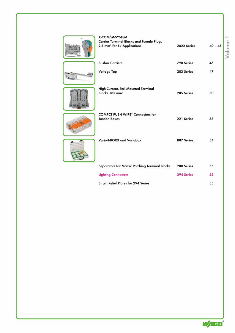
X-COM®@-SYSTEMCarrier Terminal Blocks and Female Plugs 2.5 mm² for Ex Applications 2022 Series 40 – 45
Busbar Carriers 790 Series 46
Voltage Tap 283 Series 47
High-Current, Rail-Mounted Terminal Blocks 185 mm² 285 Series 50
COMPCT PUSH WIRE® Connectors for Juntion Boxes 221 Series 53
Vario-T-BOXX and Variobox 887 Series 54
Separators for Matrix Patching Terminal Blocks 280 Series 55
Lighting Connectors 294 Series 55
Strain Relief Plates for 294 Series 55
Volu
me
1
4
1 !
69,7 mm/2.74 in
51,7
mm/
2.04
in61
,8 m
m/2
.43
in
Volu
me
1
gray
Testing tap, for max. 2.5 mm²
Banana plug, for socket 4 mm Ø, color mixed
gray
Test plug adapter, for 4 mm Ø test plug
gray
Double-deck marker carrier, pivoting
plain
WMB Multi marking system, 10 strips with 10 markers per card, for 3.5 mm terminal block width
white
Marking strip, plain, 11 mm wide, 50 m roll
yellow
Protective warning marker, with high-voltage symbol, black, for 5 terminal blocks
from 1 to 10from 1 to 9from 1 to 8from 1 to 7from 1 to 6from 1 to 5from 1 to 4from 1 to 3
Push-in type jumper bar, insulated, IN 14 A, light gray
10-way9-way8-way7-way6-way5-way4-way3-way2-way
Push-in type jumper bar, insulated, IN 14 A, light gray
grayorange
End and intermediate plate, 0.7 mm thick
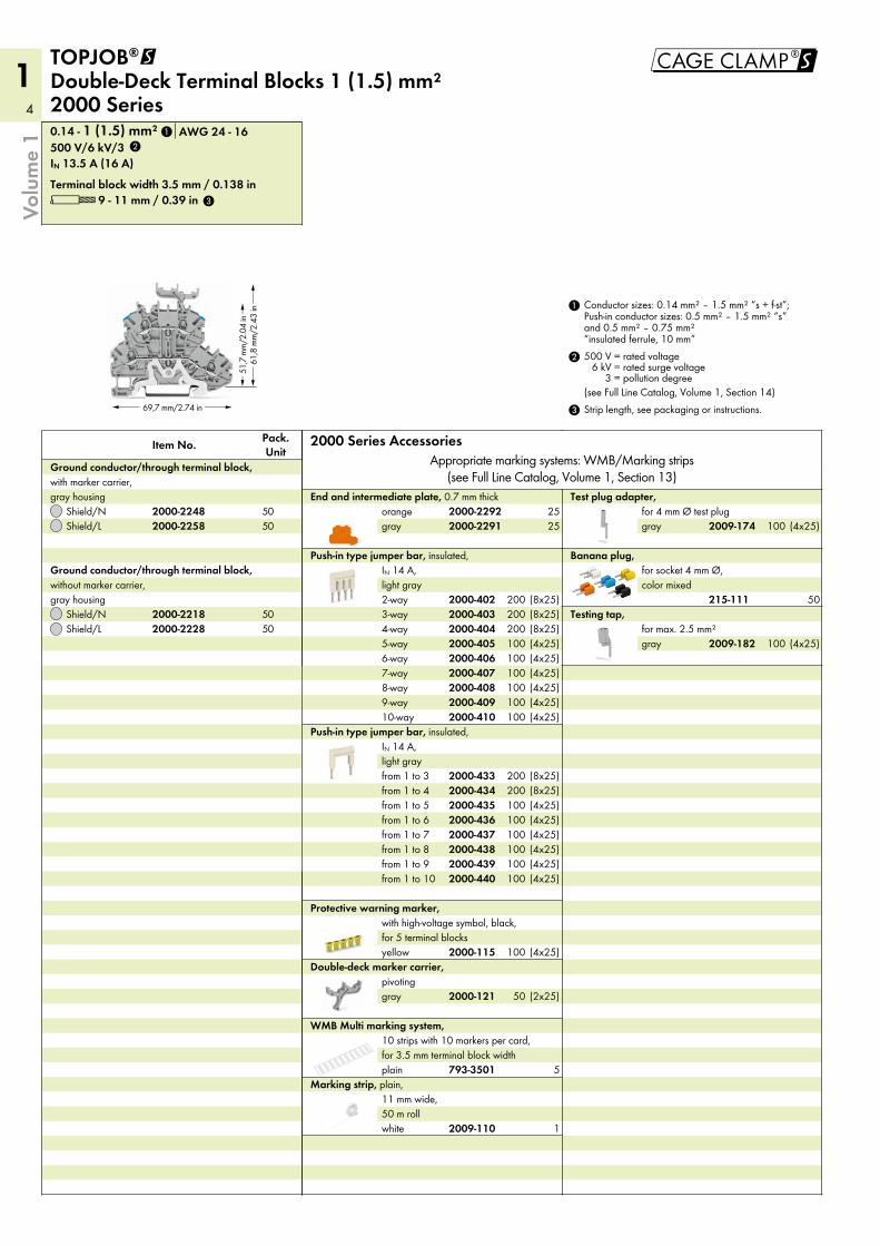
3 Strip length, see packaging or instructions.
2 500 V = rated voltage6 kV = rated surge voltage
3 = pollution degree(see Full Line Catalog, Volume 1, Section 14)
1 Conductor sizes: 0.14 mm² – 1.5 mm² “s + f-st”; Push-in conductor sizes: 0.5 mm² – 1.5 mm² “s” and 0.5 mm² – 0.75 mm² “insulated ferrule, 10 mm”
2000 Series AccessoriesAppropriate marking systems: WMB/Marking strips
(see Full Line Catalog, Volume 1, Section 13)
Shield/LShield/N
Ground conductor/through terminal block, without marker carrier, gray housing
Shield/LShield/N
Ground conductor/through terminal block, with marker carrier, gray housing
L 9 - 11 mm / 0.39 inTerminal block width 3.5 mm / 0.138 in
IN 13.5 A (16 A)500 V/6 kV/30.14 - 1 (1.5) mm² AWG 24 - 16
Pack. UnitItem No.
TOPJOB®@ Double-Deck Terminal Blocks 1 (1.5) mm² 2000 Series
2009-182
215-111
2009-174
2000-121
793-3501
2009-110
2000-115
2000-4402000-4392000-4382000-4372000-4362000-4352000-4342000-433
2000-4102000-4092000-4082000-4072000-4062000-4052000-4042000-4032000-402
2000-22912000-2292
2000-22282000-2218
2000-22582000-2248
2
3
1
5050
5050
(4x25)100(4x25)100(4x25)100(4x25)100(4x25)100(4x25)100(8x25)200(8x25)200(8x25)200
(4x25)100
50
(4x25)100
(4x25)100(4x25)100(4x25)100(4x25)100(4x25)100(4x25)100(8x25)200(8x25)200
(4x25)100
(2x25)50
5
1
2525
5
1!!
69,7 mm/2.74 in
51,7
mm/
2.04
in61
,8 m
m/2
.43
in
Volu
me
1
white
WMB Inline, plain, stretchable 4 - 4.2 mm, 2,000 WMB markers, 4 mm, on roll
violetgreenlight greenorangegrayblueredyellow
WMB Multi marking system, plain, 10 strips with 10 markers per card, stretchable 4 - 4.2 mm
Banana plug, for socket 4 mm Ø, color mixed
gray
Testing tap, for max. 2.5 mm²
gray
Test plug adapter, for 4 mm Ø test plug
white
Marking strip, plain, 11 mm wide, 50 m roll
plain
WMB Multi marking system, 10 strips with 10 markers per card, stretchable 4 - 4.2 mm
gray
Double-deck marker carrier, pivoting
yellow
Protective warning marker, with high-voltage symbol, black, for 5 terminal blocks
from 1 to 10from 1 to 9from 1 to 8from 1 to 7from 1 to 6from 1 to 5from 1 to 4from 1 to 3
Push-in type jumper bar, insulated, IN 18 A, light gray
10-way9-way8-way7-way6-way5-way4-way3-way2-way
Push-in type jumper bar, insulated, IN 18 A, light gray
grayorange
End and intermediate plate, 0.7 mm thick
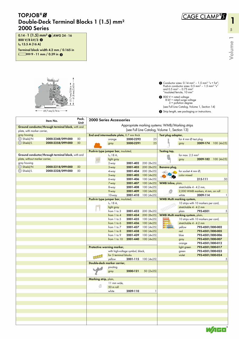
3 Strip length, see packaging or instructions.
2 800 V = rated voltage8 kV = rated surge voltage
3 = pollution degree(see Full Line Catalog, Volume 1, Section 14)
1 Conductor sizes: 0.14 mm² – 1.5 mm² “s + f-st”; Push-in conductor sizes: 0.5 mm² – 1.5 mm² “s” and 0.5 mm² – 0.75 mm² “insulated ferrule, 10 mm”
2000 Series AccessoriesAppropriate marking systems: WMB/Marking strips
(see Full Line Catalog, Volume 1, Section 13)
Shield/LShield/N
Ground conductor/through terminal block, with end plate, without marker carrier, gray housing
Shield/LShield/N
Pack. UnitItem No.
Ground conductor/through terminal block, with end plate, with marker carrier, gray housing
L 9 - 11 mm / 0.39 inTerminal block width 4.2 mm / 0.165 in
IN 13.5 A (16 A)800 V/8 kV/30.14 - 1 (1.5) mm² AWG 24 - 16
TOPJOB®@ Double-Deck Terminal Blocks 1 (1.5) mm² 2000 Series
2009-114
793-4501/000-024793-4501/000-023793-4501/000-017793-4501/000-012793-4501/000-007793-4501/000-006793-4501/000-005793-4501/000-002
215-111
2009-182
2009-174
2009-110
793-4501
2000-121
2001-115
2001-4402001-4392001-4382001-4372001-4362001-4352001-4342001-433
2001-4102001-4092001-4082001-4072001-4062001-4052001-4042001-4032001-402
2000-22912000-2292
2000-2228/099-0002000-2218/099-000
2000-2258/099-0002000-2248/099-000
1
2
3
5050
5050
2525
(4x25)100(4x25)100(4x25)100(4x25)100(4x25)100(4x25)100(8x25)200(8x25)200(8x25)200
(4x25)100(4x25)100(4x25)100(4x25)100(4x25)100(4x25)100(8x25)200(8x25)200
(4x25)100
(2x25)50
1
(4x25)100
(4x25)100
50
1
5
5
6
1
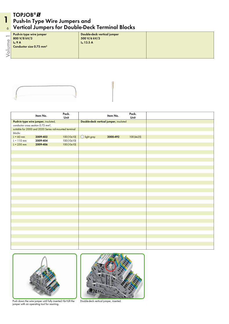
IN 13.5 A500 V/6 kV/3Double-deck vertical jumper
light gray
Pack. UnitItem No.
Double-deck vertical jumper, insulated
Conductor size 0.75 mm²IN 9 A800 V/8 kV/3Push-in type wire jumper
L = 250 mmL = 110 mmL = 60 mm
Pack. UnitItem No.
Push-in type wire jumper, insulated, conductor cross section 0.75 mm², suitable for 2000 and 2020 Series rail-mounted terminal blocks
TOPJOB®@ Push-In Type Wire Jumpers and Vertical Jumpers for Double-Deck Terminal Blocks
Volu
me
1
Double-deck vertical jumper, inserted.Push down the wire jumper until fully inserted.<br>Lift the jumper with an operating tool for rewiring.
2000-492
2009-4062009-4042009-402
(10x10)100(10x10)100(10x10)100 (4x25)100
7
1
52,1
mm
/2.0
5 in
62,7
mm
/2.4
7 in
105,1 mm/4.14 in
!
4
4
light gray
Double-deck vertical jumper, insulated, IN 24 A
gray
TOPJOB®S group marker carrier, snap-on type for jumper slot, 5 mm wide
white
Marking strip, plain, 11 mm wide, 50 m roll
white
WMB Inline, plain, stretchable 5 - 5.2 mm, 1,500 WMB markers, 5 mm, on roll
violetgreenlight greenorangegrayblueredyellow
WMB Multi marking system, plain, 10 strips with 10 markers per card, stretchable 5 - 5.2 mm
plain
WMB Multi marking system, 10 strips with 10 markers per card, stretchable 5 - 5.2 mm
gray
Testing tap, for max. 2.5 mm²
Banana plug, for socket 4 mm Ø, color mixed
gray
Test plug adapter, for 4 mm Ø test plug
yellow
Protective warning marker, with high-voltage symbol, black, for 5 terminal blocks
from 1 to 10from 1 to 9from 1 to 8from 1 to 7from 1 to 6from 1 to 5from 1 to 4from 1 to 3
Push-in type jumper bar, insulated, IN 25 A, light gray
10-way9-way8-way7-way6-way5-way4-way3-way2-way
Push-in type jumper bar, insulated, IN 25 A, light gray
dark gray
Insulation stop, 5 pcs/strip, 0.75 - 1 mm²
light gray
Insulation stop, 5 pcs/strip, 0.25 - 0.5 mm²
gray
Double-deck marker carrier, pivoting
grayorange
End and intermediate plate, 0.8 mm thick
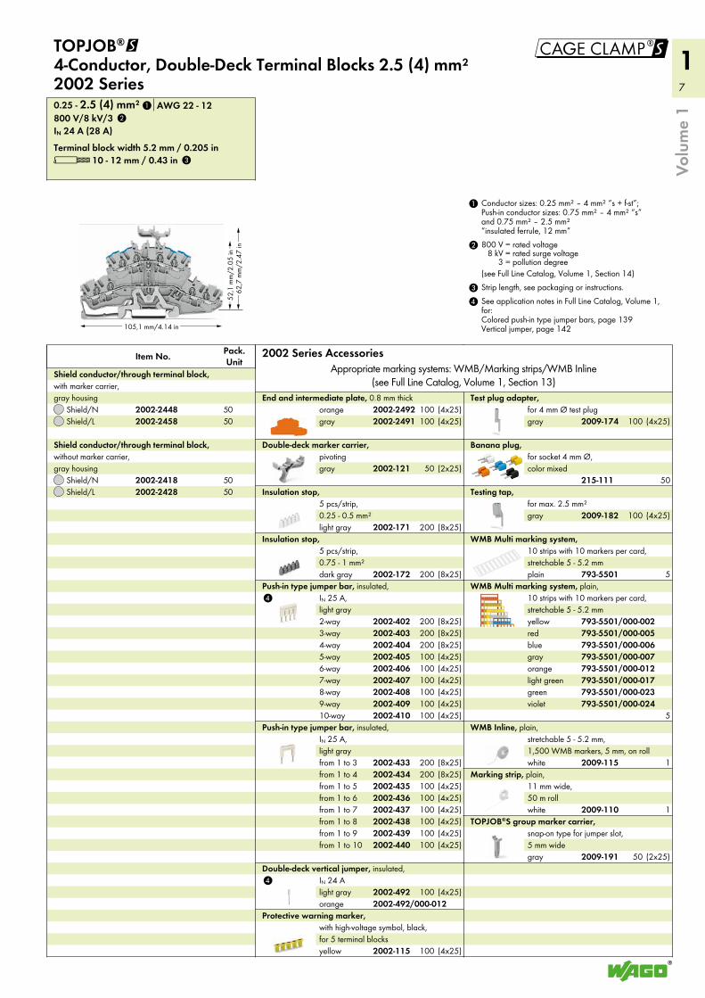
L 10 - 12 mm / 0.43 inTerminal block width 5.2 mm / 0.205 in
IN 24 A (28 A)800 V/8 kV/30.25 - 2.5 (4) mm² AWG 22 - 12
Shield/LShield/N
Shield conductor/through terminal block, without marker carrier, gray housing
Shield/LShield/N
Pack. UnitItem No.
Shield conductor/through terminal block, with marker carrier, gray housing
TOPJOB®@ 4-Conductor, Double-Deck Terminal Blocks 2.5 (4) mm² 2002 Series
4 See application notes in Full Line Catalog, Volume 1, for: Colored push-in type jumper bars, page 139 Vertical jumper, page 142
3 Strip length, see packaging or instructions.
2 800 V = rated voltage8 kV = rated surge voltage
3 = pollution degree(see Full Line Catalog, Volume 1, Section 14)
1 Conductor sizes: 0.25 mm² – 4 mm² “s + f-st”; Push-in conductor sizes: 0.75 mm² – 4 mm² “s” and 0.75 mm² – 2.5 mm² “insulated ferrule, 12 mm”
2002 Series AccessoriesAppropriate marking systems: WMB/Marking strips/WMB Inline
(see Full Line Catalog, Volume 1, Section 13)
Volu
me
1
orange2002-492
2009-191
2009-110
2009-115
793-5501/000-024793-5501/000-023793-5501/000-017793-5501/000-012793-5501/000-007793-5501/000-006793-5501/000-005793-5501/000-002
793-5501
2009-182
215-111
2009-174
2002-115
2002-4402002-4392002-4382002-4372002-4362002-4352002-4342002-433
2002-4102002-4092002-4082002-4072002-4062002-4052002-4042002-4032002-402
2002-172
2002-171
2002-121
2002-24912002-2492
2002-24282002-2418
2002-24582002-2448
1
2
3
50
50
50
50
(4x25)100(4x25)100
(2x25)50
(8x25)200
(8x25)200
(4x25)100(4x25)100(4x25)100(4x25)100(4x25)100(4x25)100(8x25)200(8x25)200(8x25)200
(4x25)100(4x25)100(4x25)100(4x25)100(4x25)100(4x25)100(8x25)200(8x25)200
(4x25)1002002-492/000-012
(4x25)100
(4x25)100
50
(4x25)100
5
(2x25)50
1
1
5
8
1
57,4 mm/2.26 in
32,9
mm
/1.
3 in
24,8 mm/0.98 in67,8 mm/2.67 in
30,8 mm/1.21 in
36,9
mm
/1.
45 in
69,8 mm/2.75 in32,3 mm/1.27 in
36,9
mm
/1.
45 in
Volu
me
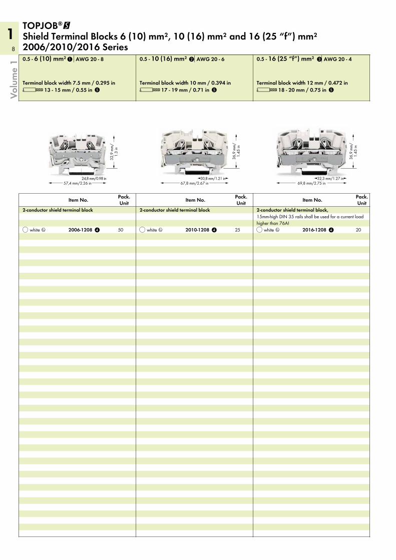
1TOPJOB®@ Shield Terminal Blocks 6 (10) mm², 10 (16) mm² and 16 (25 “f”) mm² 2006/2010/2016 Series
L 13 - 15 mm / 0.55 inTerminal block width 7.5 mm / 0.295 in
0.5 - 6 (10) mm² AWG 20 - 8
white 4
Pack. UnitItem No.
2-conductor shield terminal block
L 17 - 19 mm / 0.71 inTerminal block width 10 mm / 0.394 in
0.5 - 10 (16) mm² AWG 20 - 6
white 4
Pack. UnitItem No.
2-conductor shield terminal block
L 18 - 20 mm / 0.75 inTerminal block width 12 mm / 0.472 in
0.5 - 16 (25 “f”) mm² AWG 20 - 4
white 4
Pack. UnitItem No.
2-conductor shield terminal block, 15mm-high DIN 35 rails shall be used for a current load higher than 76A!
2006-1208 2010-1208 2016-1208
1 2 3
4 4 4
5 5 5
50 25 20
9
1
!
4
4
4
1
2
3
Volu
me
1
Strip length, see packaging or instructions.
Conductor sizes: 0.5 mm² – 10 mm² “s + f-st”; Push-in conductor sizes: 1 mm² – 10 mm² “s” and 1.5 mm² – 6 mm² “insulated ferrule, 12 mm”
1
2
Suitable for Ex e II applications
Conductor sizes: 0.5 mm² – 16 mm² “s + f-st”; Push-in conductor sizes: 2.5 mm² – 16 mm² “s” and 2.5 mm² – 10 mm² “insulated ferrule, 18 mm”
3
4
5
Conductor sizes: 0.5 mm² – 16 mm² “s + f-st”, 25 mm² “f-st”; Push-in conductor sizes: 2.5 mm² – 16 mm² “s” and 2.5 mm² – 16 mm² “insulated ferrule, 18 mm”
12-way11-way10-way9-way8-way7-way6-way5-way4-way3-way2-way
Staggered jumper, insulated, IN 25 A, light gray
from 1 to 10from 1 to 9from 1 to 8from 1 to 7from 1 to 6from 1 to 5from 1 to 4from 1 to 3
Push-in type jumper bar, insulated, IN 25 A, light gray
10-way9-way8-way7-way6-way5-way4-way3-way2-way
Push-in type jumper bar, insulated, IN 25 A, light gray
dark gray
Insulation stop, 5 pcs/strip, 0.75 - 1 mm²
light gray
Insulation stop, 5 pcs/strip, 0.25 - 0.5 mm²
grayorange
End and intermediate plate, 1 mm thickgray
2-conductor carrier terminal block, 0.25 - 2.5 (4) mm² / AWG 22 - 12 Terminal block width 5.2 mm / 0.205 in
grayorange
End and intermediate plate, 1 mm thick50gray
4-conductor carrier terminal block, 0.25 - 2.5 (4) mm² / AWG 22 - 12 Terminal block width 5.2 mm / 0.205 in
grayorange
End and intermediate plate, 1 mm thick
L = 250 mmL = 110 mmL = 60 mm
Push-in type wire jumper, insulated, IN 18 A, wire size 1.5 mm²
gray
2-conductor carrier terminal block, 0.25 - 2.5 (4) mm² / AWG 22 - 12 Terminal block width 5.2 mm / 0.205 in
Carrier Term. Blocks and AccessoriesAppropriate marking system:
WMB/Marking strips
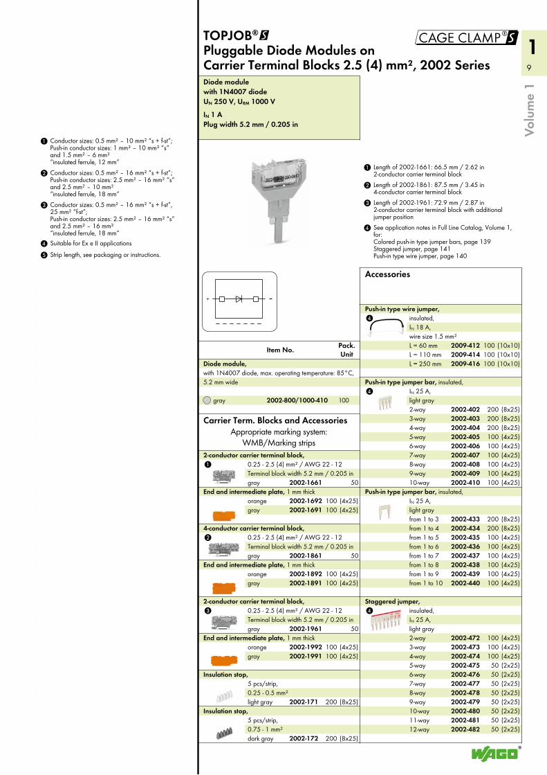
Plug width 5.2 mm / 0.205 inIN 1 A
UN 250 V, URM 1000 Vwith 1N4007 diodeDiode module
gray
Pack. UnitItem No.
Diode module, with 1N4007 diode, max. operating temperature: 85°C, 5.2 mm wide
TOPJOB®@ Pluggable Diode Modules on Carrier Terminal Blocks 2.5 (4) mm², 2002 Series
4 See application notes in Full Line Catalog, Volume 1, for: Colored push-in type jumper bars, page 139 Staggered jumper, page 141 Push-in type wire jumper, page 140
3 Length of 2002-1961: 72.9 mm / 2.87 in 2-conductor carrier terminal block with additional jumper position
2 Length of 2002-1861: 87.5 mm / 3.45 in 4-conductor carrier terminal block
1 Length of 2002-1661: 66.5 mm / 2.62 in 2-conductor carrier terminal block
Accessories
2002-4822002-4812002-4802002-4792002-4782002-4772002-4762002-4752002-4742002-4732002-472
2002-4402002-4392002-4382002-4372002-4362002-4352002-4342002-433
2002-4102002-4092002-4082002-4072002-4062002-4052002-4042002-4032002-402
2002-172
2002-171
2002-19912002-1992
2002-1961
2002-18912002-1892
2002-1861
2002-16912002-1692
2009-4162009-4142009-412
2002-1661
2002-800/1000-410 100
50
(4x25)100(4x25)100
(4x25)100(4x25)100
50
(4x25)100(4x25)100
(8x25)200
(8x25)200
(10x10)100(10x10)100(10x10)100
(4x25)100(4x25)100(4x25)100(4x25)100(4x25)100(4x25)100(8x25)200(8x25)200(8x25)200
(4x25)100(4x25)100(4x25)100(4x25)100(4x25)100(4x25)100(8x25)200(8x25)200
(2x25)50(2x25)50(2x25)50(2x25)50(2x25)50(2x25)50(2x25)50(2x25)50(4x25)100(4x25)100(4x25)100
10
1
110 mm/4.33 in56,7 mm/2.32 in
44,3
mm
/1.7
4 in
110 mm/4.33 in56,7 mm/2.32 in
44,3
mm
/1.7
4 in
110 mm/4.33 in56,7 mm/2.32 in
44,3
mm
/1.7
4 in
110 mm/4.33 in56,7 mm/2.32 in
56,7
mm
/2.3
2 in
44,3
mm
/1.7
4 in
110 mm/4.33 in56,7 mm/2.32 in
44,3
mm
/1.7
4 in
Volu
me
1
orange
grayEnd and intermediate plate,
only for use with fuse plugs, 1 mm thick
L 10 - 12 mm / 0.43 inTerminal block width 5.2 mm / 0.205 in
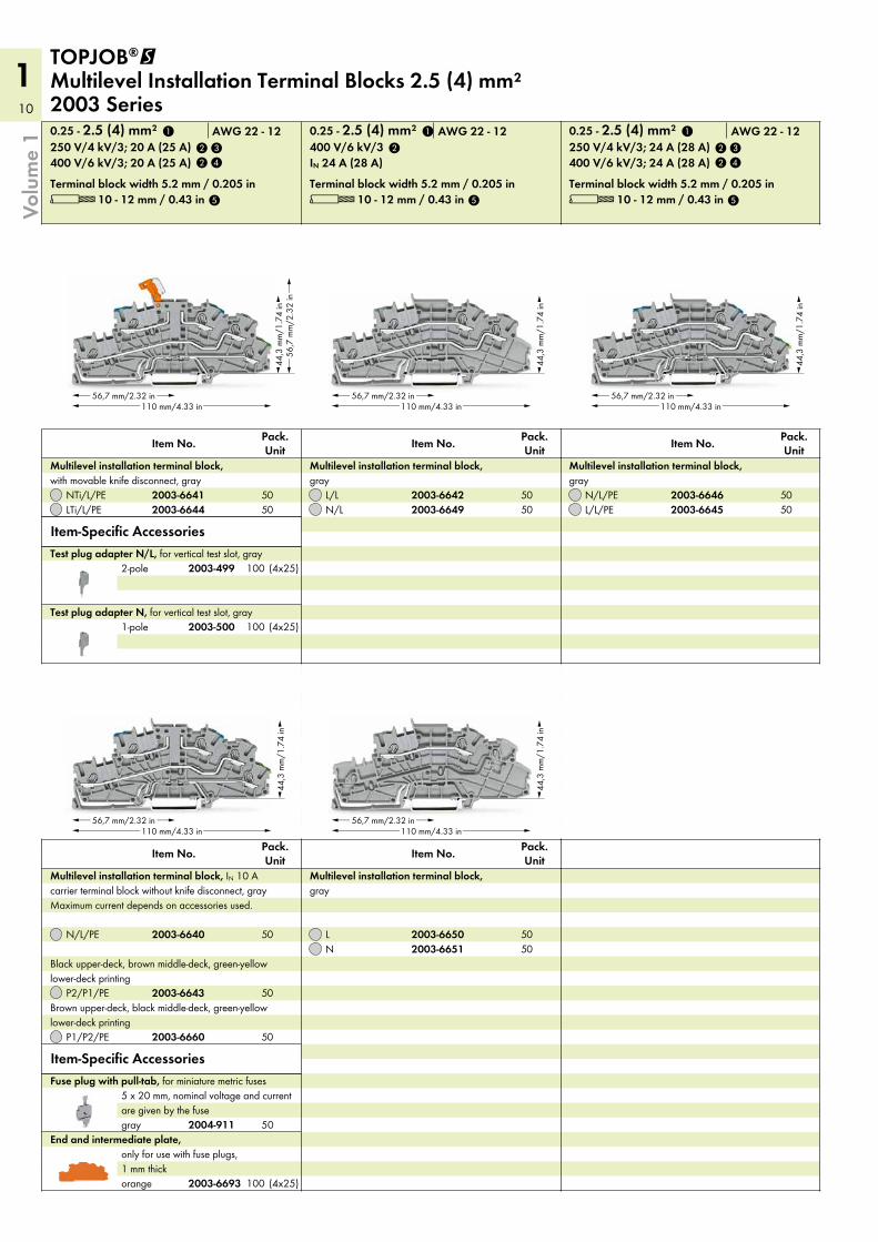
400 V/6 kV/3; 24 A (28 A)250 V/4 kV/3; 24 A (28 A)0.25 - 2.5 (4) mm² AWG 22 - 12
L/L/PEN/L/PE
Pack. UnitItem No.
Multilevel installation terminal block, gray
L 10 - 12 mm / 0.43 inTerminal block width 5.2 mm / 0.205 in
IN 24 A (28 A)400 V/6 kV/30.25 - 2.5 (4) mm² AWG 22 - 12
N/LL/L
Pack. UnitItem No.
Multilevel installation terminal block, gray
NL
Pack. UnitItem No.
Multilevel installation terminal block, gray
Fuse plug with pull-tab, for miniature metric fuses 5 x 20 mm, nominal voltage and current are given by the fuse
L 10 - 12 mm / 0.43 inTerminal block width 5.2 mm / 0.205 in
400 V/6 kV/3; 20 A (25 A)250 V/4 kV/3; 20 A (25 A)0.25 - 2.5 (4) mm² AWG 22 - 12
1-poleTest plug adapter N, for vertical test slot, gray
2-poleTest plug adapter N/L, for vertical test slot, gray
Item-Specific Accessories
NTi/L/PELTi/L/PE
Pack. UnitItem No.
Multilevel installation terminal block, with movable knife disconnect, gray
Item-Specific Accessories
P2/P1/PE
P1/P2/PE
Black upper-deck, brown middle-deck, green-yellow lower-deck printing
Brown upper-deck, black middle-deck, green-yellow lower-deck printing
N/L/PE
Pack. UnitItem No.
Multilevel installation terminal block, IN 10 A carrier terminal block without knife disconnect, gray Maximum current depends on accessories used.
TOPJOB®@ Multilevel Installation Terminal Blocks 2.5 (4) mm² 2003 Series
2003-6693
2003-66452003-6646
2003-66492003-6642
2003-66512003-6650
2003-500
2003-499
2003-66412003-6644
2003-6643
2003-6660
2003-6640
2
5
4
3
2
1
2
5
1
2
5
4
3
2
1
2004-911
5050
(4x25)100
(4x25)100
5050
5050
50
50
50
50
(4x25)100
5050
11
1
R R
N
PEL
max.500 V
!
Volu
me
1
2-way
Adjacent jumper for continuous commoning, insulated, I N 25 A, light gray
L = 250 mmL = 110 mmL = 60 mm
Push-in type wire jumper, insulated, IN 18 A, wire size 1.5 mm²
12-way11-way10-way9-way8-way7-way6-way5-way4-way3-way2-way
Staggered jumper, insulated, IN 25 A, light gray
from 1 to 10from 1 to 9from 1 to 8from 1 to 7from 1 to 6from 1 to 5from 1 to 4from 1 to 3
Push-in type jumper bar, insulated, IN 25 A, light gray
10-way9-way8-way7-way6-way5-way4-way3-way2-way
Push-in type jumper bar, insulated, IN 25 A, light gray
white
Marking strip, plain, 11 mm wide, 50 m roll
white
WMB Inline, plain, stretchable 5 - 5.2 mm, 1,500 WMB markers, 5 mm, on roll
plain
WMB Multi marking system, 10 strips with 10 markers per card, stretchable 5 - 5.2 mm
Operating tool, 3.5 mm and 5.5 mm blade, for TOPJOB®S installation terminal blocks
Operating tool, 3.5 mm and 2.5 mm blade, for TOPJOB®S installation terminal blocks
dark gray
Insulation stop, 5 pcs/strip, 0.75 - 1 mm²
light gray
Insulation stop, 5 pcs/strip, 0.25 - 0.5 mm²
blue
Busbar carrier, can replace end bracket, with detachable separator plate, for DIN 35 rail, 7.5 mm thick
blue
Busbar carrier, not suitable as end stop, for DIN 35 rail, 1.5 mm thick
orange
End and intermediate plate, for use without fuse plug, 0.8 mm thick
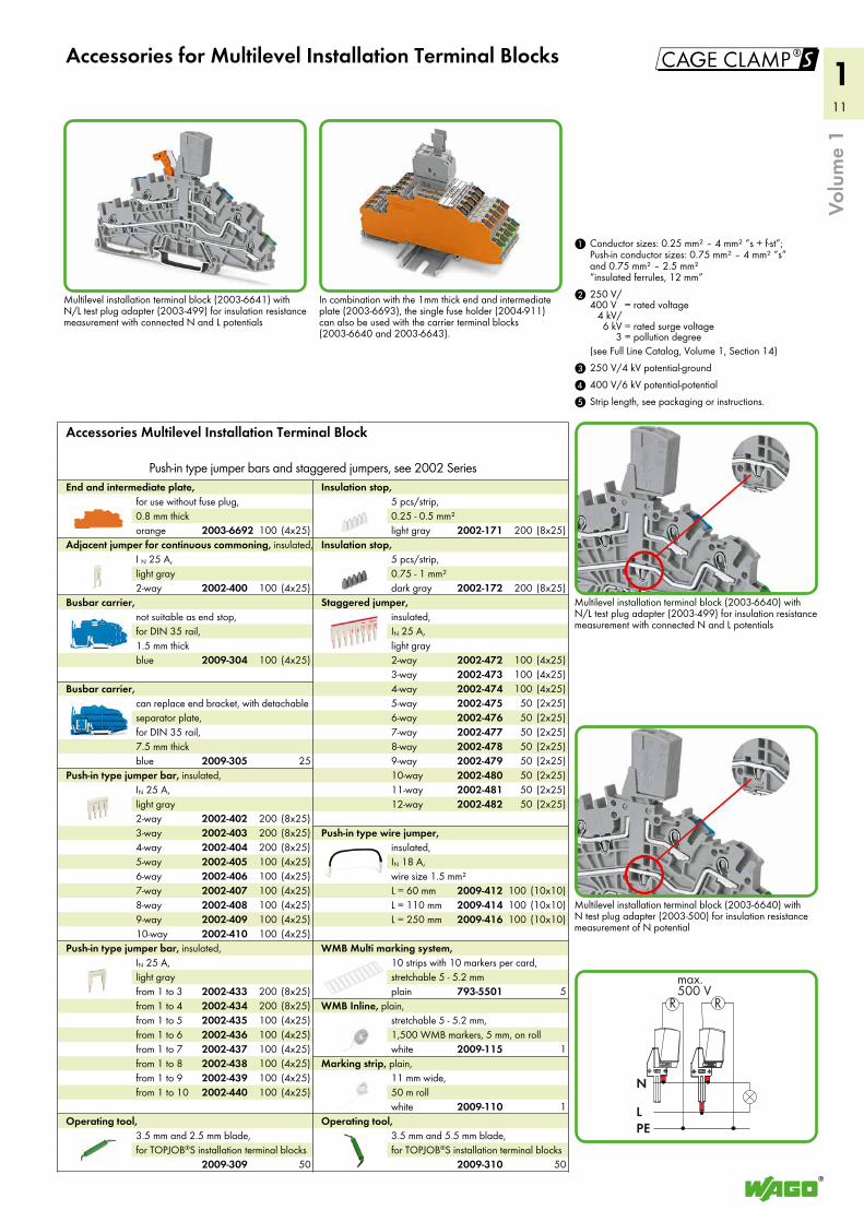
Accessories for Multilevel Installation Terminal Blocks
5 Strip length, see packaging or instructions.4 400 V/6 kV potential-potential3 250 V/4 kV potential-ground
2 250 V/400 V = rated voltage
4 kV/6 kV = rated surge voltage
3 = pollution degree(see Full Line Catalog, Volume 1, Section 14)
1 Conductor sizes: 0.25 mm² – 4 mm² “s + f-st”; Push-in conductor sizes: 0.75 mm² – 4 mm² “s” and 0.75 mm² – 2.5 mm² “insulated ferrules, 12 mm”
Accessories Multilevel Installation Terminal Block
Push-in type jumper bars and staggered jumpers, see 2002 Series
Multilevel installation terminal block (2003-6640) with N test plug adapter (2003-500) for insulation resistance measurement of N potential
Multilevel installation terminal block (2003-6640) with N/L test plug adapter (2003-499) for insulation resistance measurement with connected N and L potentials
Multilevel installation terminal block (2003-6641) with N/L test plug adapter (2003-499) for insulation resistance measurement with connected N and L potentials
In combination with the 1mm thick end and intermediate plate (2003-6693), the single fuse holder (2004-911) can also be used with the carrier terminal blocks (2003-6640 and 2003-6643).
2009-4162009-4142009-412
2002-4822002-4812002-4802002-4792002-4782002-4772002-4762002-4752002-4742002-4732002-472
2002-4402002-4392002-4382002-4372002-4362002-4352002-4342002-433
2002-4102002-4092002-4082002-4072002-4062002-4052002-4042002-4032002-402
2009-110
2009-115
793-5501
2009-3102009-309
2002-172
2002-171
2009-305
2009-304
2003-6692
2002-400
(4x25)100
100 (4x25)
(4x25)100
25
(4x25)100(4x25)100(4x25)100(4x25)100(4x25)100(4x25)100(8x25)200(8x25)200(8x25)200
(4x25)100(4x25)100(4x25)100(4x25)100(4x25)100(4x25)100(8x25)200(8x25)200
50
(8x25)200
(8x25)200
(2x25)50(2x25)50(2x25)50(2x25)50(2x25)50(2x25)50(2x25)50(2x25)50(4x25)100(4x25)100(4x25)100
(10x10)100(10x10)100(10x10)100
5
1
1
50
12
1
1
2
3
(4x25)100gray(4x25)100orange
End and intermediate plate, 1 mm thick50L/N
Double-deck carrier terminal block, 0.25 - 2.5 (4) mm² / AWG 22 - 12 Terminal block width 5.2 mm / 0.205 in
50L/L
Double-deck carrier terminal block, 0.25 - 2.5 (4) mm² / AWG 22 - 12 Terminal block width 5.2 mm / 0.205 in
(4x25)100gray(4x25)100orange
End and intermediate plate, 1 mm thick50gray
2-conductor carrier terminal block, 0.25 - 2.5 (4) mm² / AWG 22 - 12 Terminal block width 5.2 mm / 0.205 in
(4x25)100gray(4x25)100orange
End plate for fuse terminal blocks, 2 mm thick
(10x25)250IN 6.3 A
Shorting link, 5 x 20 mm, if the fuse plug is used as disconnect plug
5violetgreenlight greenorangegrayblueredyellow
WMB Multi marking system, plain, 10 strips with 10 markers per card, stretchable 5 - 5.2 mm
5plain
WMB Multi marking system, 10 strips with 10 markers per card, stretchable 5 - 5.2 mm
(4x25)100gray(4x25)100orange
End and intermediate plate, 1 mm thick50gray
4-conductor carrier terminal block, 0.25 - 2.5 (4) mm² / AWG 22 - 12 Terminal block width 5.2 mm / 0.205 in
50gray
2-conductor carrier terminal block, 0.25 - 2.5 (4) mm² / AWG 22 - 12 Terminal block width 5.2 mm / 0.205 in
(4x25)100gray(4x25)100orange
End and intermediate plate, 1 mm thick
AccessoriesAppropriate marking systems: WMB/Marking strips
(see Full Line Catalog, Volume 1, Section 13)
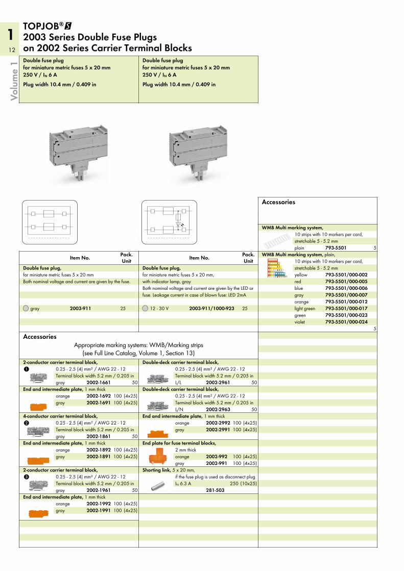
Plug width 10.4 mm / 0.409 in
250 V / IN 6 Afor miniature metric fuses 5 x 20 mmDouble fuse plug
12 - 30 V 25
Pack. UnitItem No.
Double fuse plug, for miniature metric fuses 5 x 20 mm, with indicator lamp, gray Both nominal voltage and current are given by the LED or fuse. Leakage current in case of blown fuse: LED 2mA
Plug width 10.4 mm / 0.409 in
250 V / IN 6 Afor miniature metric fuses 5 x 20 mmDouble fuse plug
gray 25
Pack. UnitItem No.
Double fuse plug, for miniature metric fuses 5 x 20 mm Both nominal voltage and current are given by the fuse.
TOPJOB®@ 2003 Series Double Fuse Plugs on 2002 Series Carrier Terminal Blocks
Accessories
Volu
me
1
2002-29912002-2992
2002-2963
2002-2961
2002-19912002-1992
2002-1961
2002-9912002-992
281-503
793-5501/000-024793-5501/000-023793-5501/000-017793-5501/000-012793-5501/000-007793-5501/000-006793-5501/000-005793-5501/000-002
793-5501
2002-18912002-1892
2002-1861
2002-1661
2002-16912002-1692
2003-911/1000-9232003-911

13
1
Volu
me
1
14
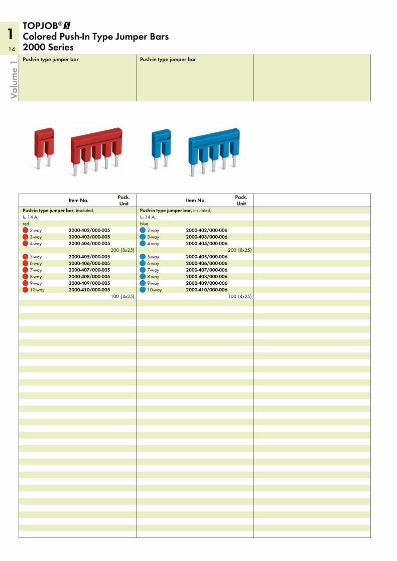
1Push-in type jumper bar
10-way9-way8-way7-way6-way5-way
4-way3-way2-way
Pack. UnitItem No.
Push-in type jumper bar, insulated, IN 14 A, blue
Push-in type jumper bar
10-way9-way8-way7-way6-way5-way
4-way3-way2-way
Pack. UnitItem No.
Push-in type jumper bar, insulated, IN 14 A, red
TOPJOB®@ Colored Push-In Type Jumper Bars 2000 Series
Volu
me
1
2000-410/000-0062000-409/000-0062000-408/000-0062000-407/000-0062000-406/000-0062000-405/000-006
2000-404/000-0062000-403/000-0062000-402/000-006
2000-410/000-0052000-409/000-0052000-408/000-0052000-407/000-0052000-406/000-0052000-405/000-005
2000-404/000-0052000-403/000-0052000-402/000-005
(4x25)100
(8x25)200
(4x25)100
(8x25)200
15
1
!
4
4
108 mm/4.25 in
42 m
m/1.
65 in
Volu
me
1
5plain
WMB Multi marking system, 10 strips with 10 markers per card, stretchable 5 - 5.2 mm
5violetgreenlight greenorangegrayblueredyellow
WMB Multi marking system, plain, 10 strips with 10 markers per card, stretchable 5 - 5.2 mm
4 See application notes in Full Line Catalog, Volume 1, for: Colored push-in type jumper bars, page 139 Push-in type wire jumper, page 140
3 Strip length, see packaging or instructions.
2 400 V = rated voltage6 kV = rated surge voltage
3 = pollution degree(see Full Line Catalog, Volume 1, Section 14)
1 Conductor sizes: 0.25 mm² – 4 mm² “s + f-st”; Push-in conductor sizes: 0.75 mm² – 4 mm² “s” and 0.75 mm² – 2.5 mm² “insulated ferrules, 12 mm”
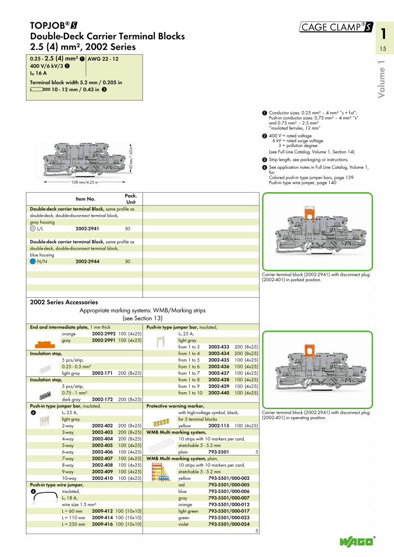
Carrier terminal block (2002-2941) with disconnect plug (2002-401) in parked position.
Carrier terminal block (2002-2941) with disconnect plug (2002-401) in operating position.
yellow
Protective warning marker, with high-voltage symbol, black, for 5 terminal blocks
from 1 to 10from 1 to 9from 1 to 8from 1 to 7from 1 to 6from 1 to 5from 1 to 4from 1 to 3
Push-in type jumper bar, insulated, IN 25 A, light gray
L = 250 mmL = 110 mmL = 60 mm
Push-in type wire jumper, insulated, IN 18 A, wire size 1.5 mm²
10-way9-way8-way7-way6-way5-way4-way3-way2-way
Push-in type jumper bar, insulated, IN 25 A, light gray
dark gray
Insulation stop, 5 pcs/strip, 0.75 - 1 mm²
light gray
Insulation stop, 5 pcs/strip, 0.25 - 0.5 mm²
grayorange
End and intermediate plate, 1 mm thick
2002 Series AccessoriesAppropriate marking systems: WMB/Marking strips
(see Section 13)
L 10 - 12 mm / 0.43 inTerminal block width 5.2 mm / 0.205 in
IN 16 A400 V/6 kV/30.25 - 2.5 (4) mm² AWG 22 - 12
N/N
L/L
Pack. UnitItem No.
Double-deck carrier terminal Block, same profile as double-deck, double-disconnect terminal block, gray housing
Double-deck carrier terminal Block, same profile as double-deck, double-disconnect terminal block, blue housing
TOPJOB®@ Double-Deck Carrier Terminal Blocks 2.5 (4) mm², 2002 Series
793-5501
793-5501/000-024793-5501/000-023793-5501/000-017793-5501/000-012793-5501/000-007793-5501/000-006793-5501/000-005793-5501/000-002
2002-115
2002-4402002-4392002-4382002-4372002-4362002-4352002-4342002-433
2009-4162009-4142009-412
2002-4102002-4092002-4082002-4072002-4062002-4052002-4042002-4032002-402
2002-172
2002-171
2002-29912002-2992
2002-2944
2002-2941
1
2
3
(4x25)100
(4x25)100(4x25)100(4x25)100(4x25)100(4x25)100(4x25)100(8x25)200(8x25)200
(10x10)100(10x10)100(10x10)100
(4x25)100(4x25)100(4x25)100(4x25)100(4x25)100(4x25)100(8x25)200(8x25)200(8x25)200
(8x25)200
(8x25)200
(4x25)100(4x25)100
50
50
16
1
51,7
mm
/2.0
4 in
93 mm/3.66 in
51,7
mm
/2.0
4 in
93 mm/3.66 in
51,7
mm
/2.0
4 in
93 mm/3.66 in
51,7
mm
/2.0
4 in
93 mm/3.66 in
51,7
mm
/2.0
4 in
93 mm/3.66 in
51,7
mm
/2.0
4 in
93 mm/3.66 in
Volu
me
1
L 10 - 12 mm / 0.43 inTerminal block width 5.2 mm / 0.205 in
IN 24 A (28 A)500 V/6 kV/30.25 - 2.5 (4) mm² AWG 22 - 12
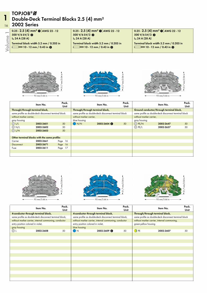
PE/LPE/N
Pack. UnitItem No.
Ground conductor/through terminal block, same profile as double-deck disconnect terminal block without marker carrier, gray housing
PE
Pack. UnitItem No.
Through/through terminal block, same profile as double-deck disconnect terminal block without marker carrier, internal commoning, green-yellow housing
L 10 - 12 mm / 0.43 inTerminal block width 5.2 mm / 0.205 in
IN 24 A (28 A)500 V/6 kV/30.25 - 2.5 (4) mm² AWG 22 - 12
N/N
Pack. UnitItem No.
Through/through terminal block, same profile as double-deck disconnect terminal block without marker carrier, blue housing
N
Pack. UnitItem No.
4-conductor through terminal block, same profile as double-deck disconnect terminal block, without marker carrier, internal commoning, conductor entry position colored in violet, blue housing
L 10 - 12 mm / 0.43 inTerminal block width 5.2 mm / 0.205 in
IN 24 A (28 A)500 V/6 kV/30.25 - 2.5 (4) mm² AWG 22 - 12
DisconnectCarrierOther terminal blocks with the same profile:
L/NN/LL/L
Pack. UnitItem No.
Through/through terminal block, same profile as double-deck disconnect terminal block without marker carrier, gray housing
L
Pack. UnitItem No.
4-conductor through terminal block, same profile as double-deck disconnect terminal block, without marker carrier, internal commoning, conductor entry position colored in violet, gray housing
TOPJOB®@ Double-Deck Terminal Blocks 2.5 (4) mm² 2002 Series
PagePage
Fuse Page
2002-26572002-2647
2002-2607
2002-2604
2002-2609
2002-26712002-2661
2002-26032002-26022002-2601
2002-2608 4
2
3
1
2
3
1
2
4
3
1
2002-2611
161617
505050 50
5050
505050
17
1
!
5
5
a bc
Volu
me
1
light gray
Double-deck vertical jumper, insulated, IN 24 A
from 1 to 10from 1 to 9from 1 to 8from 1 to 7from 1 to 6from 1 to 5from 1 to 4from 1 to 3
Push-in type jumper bar, insulated, IN 25 A, light gray
10-way9-way8-way7-way6-way5-way4-way3-way2-way
Push-in type jumper bar, insulated, IN 25 A, light gray
dark gray
Insulation stop, 5 pcs/strip, 0.75 - 1 mm²
light gray
Insulation stop, 5 pcs/strip, 0.25 - 0.5 mm²
gray
Double-deck marker carrier, pivoting
grayorange
End and intermediate plate, 1 mm thick
5 See application notes in Full Line Catalog, Volume 1, for: Colored push-in type jumper bars, page 139 Vertical jumper, page 142
4 Suitable for Ex i applications3 Strip length, see packaging or instructions.
2 500 V = rated voltage6 kV = rated surge voltage
3 = pollution degree(see Full Line Catalog, Volume 1, Section 14)
1 Conductor sizes: 0.25 mm² – 4 mm² “s + f-st”; Push-in conductor sizes: 0.75 mm² – 4 mm² “s” and 0.75 mm² – 2.5 mm² “insulated ferrule, 12 mm”
2002 Series AccessoriesAppropriate marking systems: WMB/Marking
strips/WMB Inline
2-way
Adjacent jumper for continuous commoning, insulated, IN 25 A, light gray
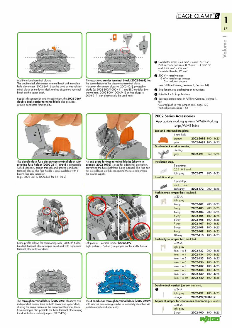
Multifunctional terminal blocks: The double-deck disconnect terminal block with movable knife disconnect (2002-2671) can be used as through ter-minal block on the lower deck and as disconnect terminal block on the upper deck. Besides disconnection and measurement, the 2002-2667 double-deck carrier terminal block also provides ground conductor functionality.
The double-deck fuse disconnect terminal block with pivoting fuse holder (2002-2611, gray) is compatible with disconnect, carrier, through and ground conductor terminal blocks. The fuse holder is also available with a blown fuse LED indicator. (e.g., 2002-2611/1000-541 for 12–30 V)
Same profile allows for commoning with TOPJOB® S dou-ble-deck terminal blocks (upper deck) and with triple-deck terminal blocks (lower deck).
The through terminal block (2002-2601) features two independent current bars on both lower and upper deck, sharing the same profile as the disconnect terminal block. Commoning is also possible for these terminal blocks using the double-deck vertical jumper (2002-492).
The associated carrier terminal block (2002-2661) has the same design as the disconnect terminal block. However, disconnect plugs (a: 2002-401), pluggable diode (b: 2002-800/1000-411 ) and LED modules (not shown here, 2002-800/1000-541) or fuse plugs (c: 2004-911) can alternatively be used here.
An end plate for fuse terminal blocks (shown in orange, 2002-1092) is used for additional protection, preventing the fuse shaft from being opened. The fuse can-not be replaced until disconnecting the fuse holder from the power supply.
Left picture – Vertical jumper (2002-492) Right picture – Push-in type jumper bar for 2002 Series
The 4-conductor through terminal block (2002-2609) with internal commoning can be immediately identified via violet-colored conductor entry.
orange2002-492
2002-4402002-4392002-4382002-4372002-4362002-4352002-4342002-433
2002-4102002-4092002-4082002-4072002-4062002-4052002-4042002-4032002-402
2002-172
2002-171
2002-121
2002-26912002-2692
2002-400
(4x25)(4x25)
100100
(2x25)50
(8x25)200
(8x25)200
(4x25)100(4x25)100(4x25)100(4x25)100(4x25)100(4x25)100(8x25)200(8x25)200(8x25)200
(4x25)100(4x25)100(4x25)100(4x25)100(4x25)100(4x25)100(8x25)200(8x25)200
(4x25)100
(4x25)100
2002-492/000-012
18
1
!
51,7
mm
/2.0
4 in
93 mm/3.66 in
56,4
mm
/2.2
2 in
51,7
mm
/2.0
4 in
93 mm/3.66 in
51,7
mm
/2.0
4 in
93 mm/3.66 in
4
4
Volu
me
1
light gray
Double-deck vertical jumper, insulated, IN 24 A
from 1 to 10from 1 to 9from 1 to 8from 1 to 7from 1 to 6from 1 to 5from 1 to 4from 1 to 3
Push-in type jumper bar, insulated, IN 25 A, light gray
10-way9-way8-way7-way6-way5-way4-way3-way2-way
Push-in type jumper bar, insulated, IN 25 A, light gray
dark gray
Insulation stop, 5 pcs/strip, 0.75 - 1 mm²
light gray
Insulation stop, 5 pcs/strip, 0.25 - 0.5 mm²
gray
Double-deck marker carrier, pivoting
grayorange
End and intermediate plate, 1 mm thick
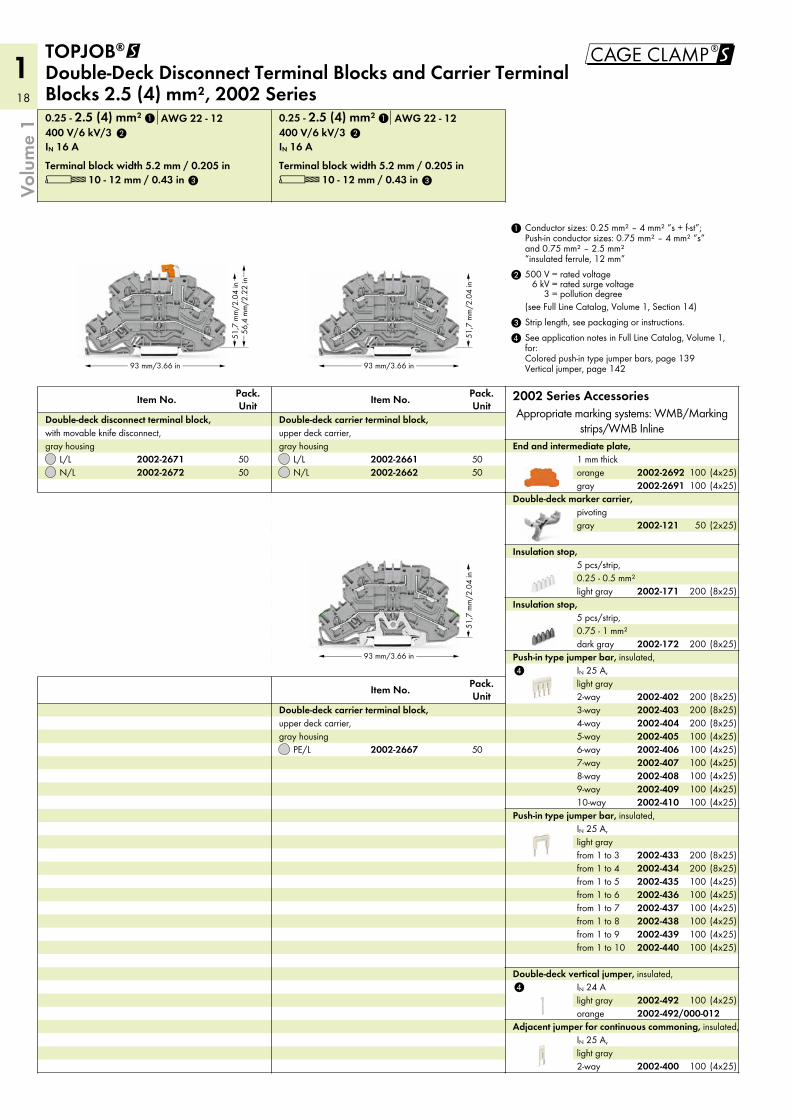
L 10 - 12 mm / 0.43 inTerminal block width 5.2 mm / 0.205 in
IN 16 A400 V/6 kV/30.25 - 2.5 (4) mm² AWG 22 - 12
N/LL/L
Pack. UnitItem No.
Double-deck carrier terminal block, upper deck carrier, gray housing
PE/L
Pack. UnitItem No.
Double-deck carrier terminal block, upper deck carrier, gray housing
L 10 - 12 mm / 0.43 inTerminal block width 5.2 mm / 0.205 in
IN 16 A400 V/6 kV/30.25 - 2.5 (4) mm² AWG 22 - 12
N/LL/L
Pack. UnitItem No.
Double-deck disconnect terminal block, with movable knife disconnect, gray housing
TOPJOB®@ Double-Deck Disconnect Terminal Blocks and Carrier Terminal Blocks 2.5 (4) mm², 2002 Series
4 See application notes in Full Line Catalog, Volume 1, for: Colored push-in type jumper bars, page 139 Vertical jumper, page 142
3 Strip length, see packaging or instructions.
2 500 V = rated voltage6 kV = rated surge voltage
3 = pollution degree(see Full Line Catalog, Volume 1, Section 14)
1 Conductor sizes: 0.25 mm² – 4 mm² “s + f-st”; Push-in conductor sizes: 0.75 mm² – 4 mm² “s” and 0.75 mm² – 2.5 mm² “insulated ferrule, 12 mm”
2002 Series AccessoriesAppropriate marking systems: WMB/Marking
strips/WMB Inline
2-way
Adjacent jumper for continuous commoning, insulated, IN 25 A, light gray
orange2002-492
2002-4352002-4362002-4372002-4382002-4392002-440
2002-4342002-433
2002-4102002-4092002-4082002-4072002-4062002-4052002-4042002-4032002-402
2002-172
2002-171
2002-121
2002-26912002-26922002-2662
2002-2661
2002-2667
2002-26722002-2671
2
3
1
2
3
1
2002-400
5050
5050
50
(4x25)(4x25)
100100
(2x25)50
(8x25)200
(8x25)200
(4x25)100(4x25)100(4x25)100(4x25)100(4x25)100(4x25)100(8x25)200(8x25)200(8x25)200
(4x25)(4x25)(4x25)(4x25)(4x25)(4x25)
100100100100100100
(8x25)200(8x25)200
(4x25)100
(4x25)100
2002-492/000-012
19
1
!
76,4
mm
/3.0
1 in
93 mm/3.66 in
76,4
mm
/3.0
1 in
93 mm/3.66 in
4
56
5
4
4
Volu
me
1
grayorange
End plate for fuse terminal blocks, 2 mm thick
white
Marking strip, plain, 11 mm wide, 50 m roll
yellow
Protective warning marker, with high-voltage symbol, black, for 5 terminal blocks
light gray
Double-deck vertical jumper, insulated, IN 24 A
from 1 to 10from 1 to 9from 1 to 8from 1 to 7from 1 to 6from 1 to 5from 1 to 4from 1 to 3
Push-in type jumper bar, insulated, IN 32 A, light gray
10-way9-way8-way7-way6-way5-way4-way3-way2-way
Push-in type jumper bar, insulated, IN 32 A, light gray
dark gray
Insulation stop, 5 pcs/strip, 0.75 - 1 mm²
light gray
Insulation stop, 5 pcs/strip, 0.25 - 0.5 mm²
grayorange
End and intermediate plate, 1 mm thick
Appropriate marking systems: WMB/Marking strips(see Full Line Catalog, Volume 1, Section 13)
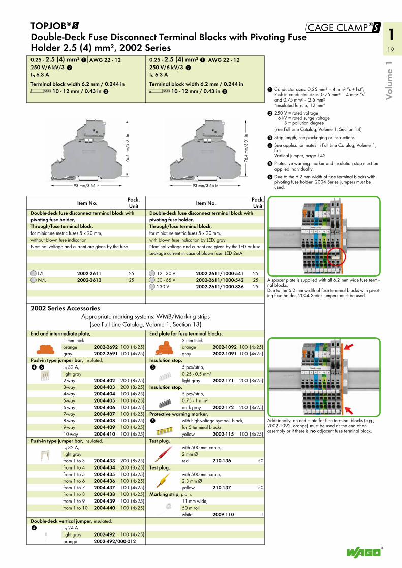
L 10 - 12 mm / 0.43 inTerminal block width 6.2 mm / 0.244 in
IN 6.3 A250 V/6 kV/30.25 - 2.5 (4) mm² AWG 22 - 12
230 V30 - 65 V12 - 30 V
Pack. UnitItem No.
Double-deck fuse disconnect terminal block with pivoting fuse holder, Through/fuse terminal block, for miniature metric fuses 5 x 20 mm, with blown fuse indication by LED, gray Nominal voltage and current are given by the LED or fuse. Leakage current in case of blown fuse: LED 2mA
L 10 - 12 mm / 0.43 inTerminal block width 6.2 mm / 0.244 in
IN 6.3 A250 V/6 kV/30.25 - 2.5 (4) mm² AWG 22 - 12
N/LL/L
Pack. UnitItem No.
Double-deck fuse disconnect terminal block with pivoting fuse holder, Through/fuse terminal block, for miniature metric fuses 5 x 20 mm, without blown fuse indication Nominal voltage and current are given by the fuse.
TOPJOB®@ Double-Deck Fuse Disconnect Terminal Blocks with Pivoting Fuse Holder 2.5 (4) mm², 2002 Series
2002 Series Accessories
Test plug, with 500 mm cable, 2 mm Øred
yellow
Test plug, with 500 mm cable, 2.3 mm Ø
A spacer plate is supplied with all 6.2 mm wide fuse termi-nal blocks. Due to the 6.2 mm width of fuse terminal blocks with pivot-ing fuse holder, 2004 Series jumpers must be used.
Additionally, an end plate for fuse terminal blocks (e.g., 2002-1092, orange) must be used at the end of an assembly or if there is no adjacent fuse terminal block.
6 Due to the 6.2 mm width of fuse terminal blocks with pivoting fuse holder, 2004 Series jumpers must be used.
5 Protective warning marker and insulation stop must be applied individually.
4 See application notes in Full Line Catalog, Volume 1, for: Vertical jumper, page 142
3 Strip length, see packaging or instructions.
2 250 V = rated voltage6 kV = rated surge voltage
3 = pollution degree(see Full Line Catalog, Volume 1, Section 14)
1 Conductor sizes: 0.25 mm² – 4 mm² “s + f-st”; Push-in conductor sizes: 0.75 mm² – 4 mm² “s” and 0.75 mm² – 2.5 mm² “insulated ferrule, 12 mm”
orange
210-137
2002-492
2004-4352004-4362004-4372004-4382004-4392004-440
2004-4342004-433
2004-4102004-4092004-4082004-4072004-4062004-4052004-4042004-4032004-402
2002-26912002-2692
2002-2611/1000-8362002-2611/1000-5422002-2611/1000-541
2002-26122002-2611
2002-10912002-1092
2009-110
2002-115
2002-172
2002-171
2
3
1
2
3
1
210-136
252525
2525
(4x25)100(4x25)100
(4x25)100(4x25)100(4x25)100(4x25)100(4x25)100(4x25)100(4x25)100(8x25)200(8x25)200
(4x25)(4x25)(4x25)(4x25)(4x25)(4x25)
100100100100100100
(8x25)200(8x25)200
(4x25)100
(4x25)100(4x25)100
(8x25)200
(8x25)200
(4x25)100
1
50
50
2002-492/000-012
20
1
4 4
4
4
4
44,7 mm/1.76 in
32,9
mm/
1.3
in
76,8 mm/3.02 in44,7 mm/1.76 in
32,9
mm/
1.3
in37
,6 m
m/1
.48
in
76,8 mm/3.02 in44,7 mm/1.76 in
32,9
mm/
1.3
in37
,6 m
m/1
.48
in
76,8 mm/3.02 in
Banana plug, for socket 4 mm Ø, color mixed
gray
Testing tap, for max. 2.5 mm²
gray
Test plug adapter, for 4 mm Ø test plug
gray
TOPJOB®S L-test plug module, can be snapped together
1-3-5-7-9-111-3-5-7-91-3-5-71-3-5
1-3
Customized staggered jumper, insulated, IN 25 A, light gray
grayorange
End and intermediate plate, 1 mm thick
2-way
Adjacent jumper for continuous commoning, insulated, IN 25 A, light grayL = 250 mm
L = 110 mmL = 60 mm
Push-in type wire jumper, insulated, IN 18 A, wire size 1.5 mm²
12-way11-way10-way9-way8-way7-way6-way5-way4-way3-way2-way
Staggered jumper, insulated, IN 25 A, light gray
from 1 to 10from 1 to 9from 1 to 8from 1 to 7from 1 to 6from 1 to 5from 1 to 4from 1 to 3
Push-in type jumper bar, insulated, IN 25 A, light gray
yellow
Protective warning marker, with high-voltage symbol, black, for 5 terminal blocks
10-way9-way8-way7-way6-way5-way4-way3-way2-way
Push-in type jumper bar, insulated, IN 25 A, light gray
dark gray
Insulation stop, 5 pcs/strip, 0.75 - 1 mm²
light gray
Insulation stop, 5 pcs/strip, 0.25 - 0.5 mm²
2002 Series AccessoriesAppropriate marking systems: WMB/Marking strips/WMB Inline
(see Full Line Catalog, Volume 1, Section 13)
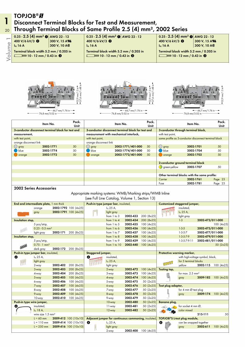
L 10 - 12 mm / 0.43 inTerminal block width 5.2 mm / 0.205 in
IN 16 A 300 V, 10 A2400 V/6 kV/3 300 V, 15 AU0.25 - 2.5 (4) mm² AWG 22 - 12
orangebluegray
Pack. UnitItem No.
3-conductor through terminal block, with test point, same profile as 3-conductor disconnect terminal block
L 10 - 12 mm / 0.43 inTerminal block width 5.2 mm / 0.205 in
IN 16 A400 V/6 kV/30.25 - 2.5 (4) mm² AWG 22 - 12
orangebluegray
Pack. UnitItem No.
3-conductor disconnect terminal block for test and measurement with mechanical interlock, with test point, orange disconnect link
L 10 - 12 mm / 0.43 inTerminal block width 5.2 mm / 0.205 in
IN 16 A 300 V, 10 A2400 V/6 kV/3 300 V, 15 AU0.25 - 2.5 (4) mm² AWG 22 - 12
orangebluegray
Pack. UnitItem No.
3-conductor disconnect terminal block for test and measurement, with test point, orange disconnect link
TOPJOB®@ Disconnect Terminal Blocks for Test and Measurement, Through Terminal Blocks of Same Profile 2.5 (4) mm², 2002 Series
Volu
me
1
PageFusePageCarrier
Other terminal blocks with the same profile:
green-yellow2-conductor ground terminal block
215-111
2009-182
2009-174
2002-611
2002-481/011-0002002-479/011-0002002-477/011-0002002-475/011-000
2002-473/011-000
2002-17912002-1792
2002-4002009-4162009-4142009-412
2002-4822002-4812002-4802002-4792002-4782002-4772002-4762002-4752002-4742002-4732002-472
2002-4402002-4392002-4382002-4372002-4362002-4352002-4342002-433
2002-115
2002-4102002-4092002-4082002-4072002-4062002-4052002-4042002-4032002-402
2002-172
2002-171
2002-17022002-17042002-1701
2002-1772/401-0002002-1774/401-0002002-1771/401-000
2002-17722002-17742002-1771
1
2
3
1 1
2 2
3 3
505050
505050
505050
(4x25)100(4x25)100
(8x25)200
(8x25)200
(4x25)100(4x25)100(4x25)100(4x25)100(4x25)100(4x25)100(8x25)200(8x25)200(8x25)200
(10x10)100(10x10)100(10x10)100
(4x25)100
(4x25)100
(4x25)100(4x25)100(4x25)100(4x25)100(4x25)100(4x25)100(8x25)200(8x25)200
(2x25)50(2x25)50(2x25)50(2x25)50(2x25)50(2x25)50(2x25)50(2x25)50(4x25)100(4x25)100(4x25)100
(4x25)100
(2x25)50
(4x25)100
50
(4x25)100
(4x25)100
2002-17812002-1761
2002-1707 50
2323
21
1
!
4
white
Marking strip, plain, 11 mm wide, 50 m roll
white
WMB Inline, plain, stretchable 5 - 5.2 mm, 1,500 WMB markers, 5 mm, on roll
plain
WMB Multi marking system, 10 strips with 10 markers per card, stretchable 5 - 5.2 mm
gray
Double-deck marker carrier, pivoting
4 See application notes in Full Line Catalog, Volume 1, for: Colored push-in type jumper bars, page 139 Staggered jumper, page 141 Adjacent jumper for continuous commoning, page 139 Push-in type wire jumper, page 140 TOPJOB®S connector, page 134 TOPJOB®S L-type test plug module, page 136
3 Strip length, see packaging or instructions.
2 400 V = rated voltage6 kV = rated surge voltage
3 = pollution degree(see Full Line Catalog, Volume 1, Section 14)
1 Conductor sizes: 0.25 mm² – 4 mm² “s + f-st”; Push-in conductor sizes: 0.75 mm² – 4 mm² “s” and 0.75 mm² – 2.5 mm² “insulated ferrules, 12 mm”
Accessories
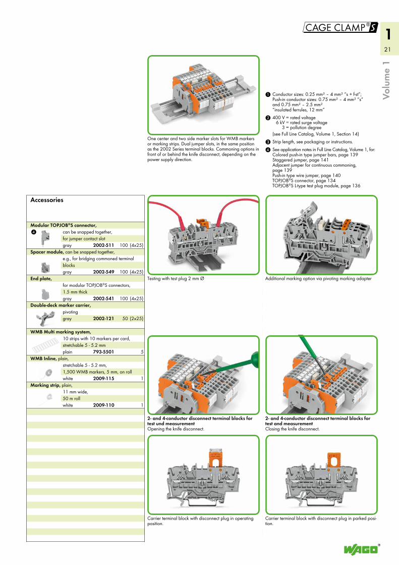
One center and two side marker slots for WMB markers or marking strips. Dual jumper slots, in the same position as the 2002 Series terminal blocks. Commoning options in front of or behind the knife disconnect, depending on the power supply direction.
Testing with test plug 2 mm Ø
2- and 4-conductor disconnect terminal blocks for test und measurement Opening the knife disconnect.
Carrier terminal block with disconnect plug in operating position.
Additional marking option via pivoting marking adapter
2- and 4-conductor disconnect terminal blocks for test and measurement Closing the knife disconnect.
Carrier terminal block with disconnect plug in parked posi-tion.
gray
End plate, for modular TOPJOB®S connectors, 1.5 mm thick
gray
Spacer module, can be snapped together, e.g., for bridging commoned terminal blocks
gray
Modular TOPJOB®S connector, can be snapped together, for jumper contact slot
Volu
me
1
2009-110
2009-115
793-5501
2002-121
2002-541
2002-549
2002-511 (4x25)100
(4x25)100
(4x25)100
1
1
5
(2x25)50
22
1
4
!
44,7 mm/1.76 in76,8 mm/3.02 in
57,6
mm
/2.2
7 in
44,7 mm/1.76 in76,8 mm/3.02 in
57,6
mm
/2.2
7 in
Volu
me
1
4 See application notes in Full Line Catalog, Volume 1, for: Push-in type wire jumper, page 140
3 Strip length, see packaging or instructions.
2 250 V = rated voltage6 kV = rated surge voltage
3 = pollution degree(see Full Line Catalog, Volume 1, Section 14)
1 Conductor sizes: 0.25 mm² – 4 mm² “s + f-st”; Push-in conductor sizes: 0.75 mm² – 4 mm² “s” and 0.75 mm² – 2.5 mm² “insulated ferrule, 12 mm”
(10x10)100L = 250 mm(10x10)100L = 110 mm(10x10)100L = 60 mm
Push-in type wire jumper, insulated, IN 16 A, wire size 1.5 mm²
(4x25)100from 1 to 10(4x25)100from 1 to 9(4x25)100from 1 to 8(4x25)100from 1 to 7(4x25)100from 1 to 6(4x25)100from 1 to 5(8x25)200from 1 to 4(8x25)200from 1 to 3
Push-in type jumper bar, insulated, IN 32 A, light gray
(4x25)10010-way(4x25)1009-way(4x25)1008-way(4x25)1007-way(4x25)1006-way(4x25)1005-way(4x25)1004-way(8x25)2003-way(8x25)2002-way
Push-in type jumper bar, insulated, IN 32 A, light gray
(4x25)100gray(4x25)100orange
End plate for fuse terminal blocks, 2 mm thick
(8x25)200dark gray
Insulation stop, 5 pcs/strip, 0.75 - 1 mm²
(8x25)200light gray
Insulation stop, 5 pcs/strip, 0.25 - 0.5 mm²
(4x25)100yellow
Protective warning marker, with high-voltage symbol, black, for 5 terminal blocks
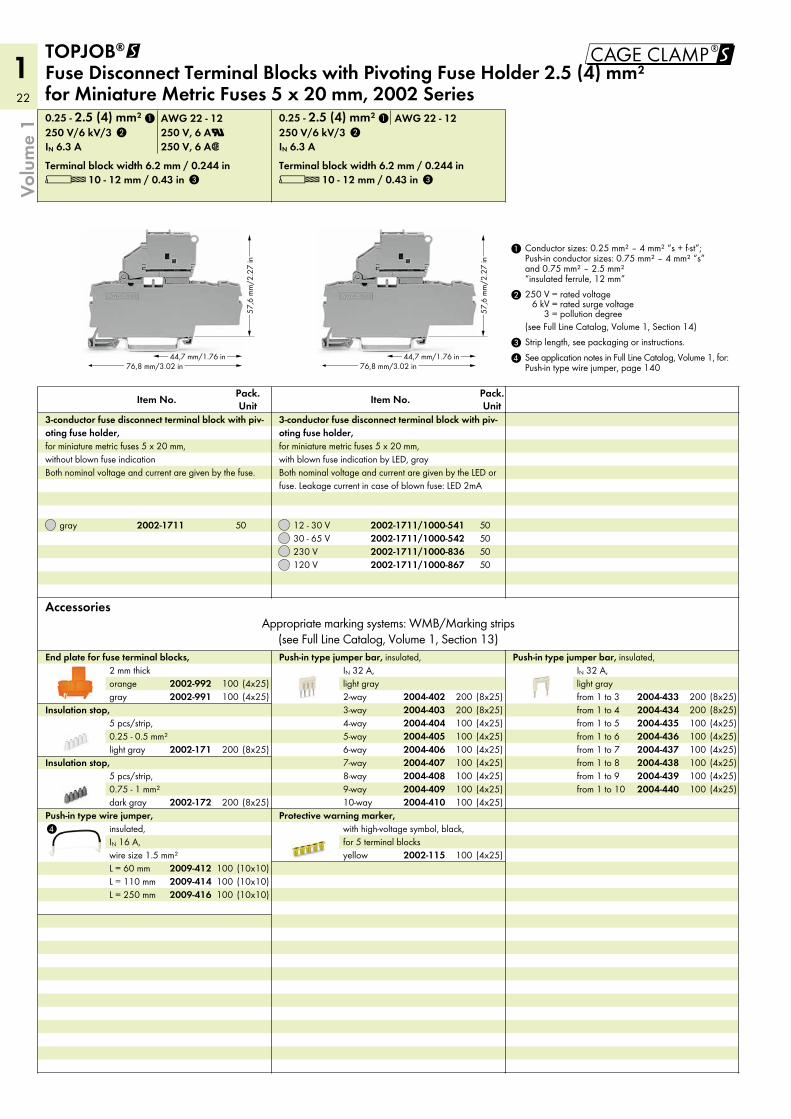
AccessoriesAppropriate marking systems: WMB/Marking strips
(see Full Line Catalog, Volume 1, Section 13)
L 10 - 12 mm / 0.43 inTerminal block width 6.2 mm / 0.244 in
IN 6.3 A250 V/6 kV/30.25 - 2.5 (4) mm² AWG 22 - 12
120 V 50230 V 5030 - 65 V 5012 - 30 V 50
Pack. UnitItem No.
3-conductor fuse disconnect terminal block with piv-oting fuse holder, for miniature metric fuses 5 x 20 mm, with blown fuse indication by LED, gray Both nominal voltage and current are given by the LED or fuse. Leakage current in case of blown fuse: LED 2mA
L 10 - 12 mm / 0.43 inTerminal block width 6.2 mm / 0.244 in
IN 6.3 A 250 V, 6 A2250 V/6 kV/3 250 V, 6 AU0.25 - 2.5 (4) mm² AWG 22 - 12
gray 50
Pack. UnitItem No.
3-conductor fuse disconnect terminal block with piv-oting fuse holder, for miniature metric fuses 5 x 20 mm, without blown fuse indication Both nominal voltage and current are given by the fuse.
TOPJOB®@ Fuse Disconnect Terminal Blocks with Pivoting Fuse Holder 2.5 (4) mm² for Miniature Metric Fuses 5 x 20 mm, 2002 Series
2009-4162009-4142009-412
2004-4402004-4392004-4382004-4372004-4362004-4352004-4342004-433
2004-4102004-4092004-4082004-4072004-4062004-4052004-4042004-4032004-4022002-991
2002-992
2002-172
2002-171
2002-115
2002-1711/1000-8672002-1711/1000-8362002-1711/1000-5422002-1711/1000-5412002-1711
1
2
3
1
2
3
23
1
5
5
5
5
5
5
!
44,7 mm/1.76 in
32,9
mm/
1.3
in38
mm
/1.5
in
76,8 mm/3.02 in44,7 mm/1.76 in
32,9
mm/
1.3
in
76,8 mm/3.02 in
Volu
me
1
50
Banana plug, for socket 4 mm Ø, color mixed
50red
Test plug, with 500 mm cable, 2 mm Ø
5plain
WMB Multi marking system, 10 strips with 10 markers per card, stretchable 5 - 5.2 mm
(2x25)50gray
Double-deck marker carrier, pivoting
(4x25)100gray
TOPJOB®S L-test plug module, can be snapped together
(4x25)100gray
Testing tap, for max. 2.5 mm²
(4x25)100gray
Test plug adapter, for 4 mm Ø test plug
(4x25)1002-way
Adjacent jumper for continuous commoning, insulated, IN 25 A, light gray
(4x25)100gray
End plate, for modular TOPJOB®S connectors, 1.5 mm thick
(4x25)100gray
Spacer module, can be snapped together, e.g., for bridging commoned terminal blocks
(4x25)100gray
Modular TOPJOB®S connector, can be snapped together, for jumper contact slot
(4x25)100yellow
Protective warning marker, with high-voltage symbol, black, for 5 terminal blocks
(10x10)100L = 250 mm(10x10)100L = 110 mm(10x10)100L = 60 mm
Push-in type wire jumper, insulated, IN 16 A, wire size 1.5 mm²
(2x25)5012-way(2x25)5011-way(2x25)5010-way(2x25)509-way(2x25)508-way(2x25)507-way(2x25)506-way(2x25)505-way(4x25)1004-way(4x25)1003-way(4x25)1002-way
Staggered jumper, insulated, IN 25 A, light gray
(4x25)100from 1 to 10(4x25)100from 1 to 9(4x25)100from 1 to 8(4x25)100from 1 to 7(4x25)100from 1 to 6(4x25)100from 1 to 5(8x25)200from 1 to 4(8x25)200from 1 to 3
Push-in type jumper bar, insulated, IN 25 A, light gray
(4x25)10010-way(4x25)1009-way(4x25)1008-way(4x25)1007-way(4x25)1006-way(4x25)1005-way(8x25)2004-way(8x25)2003-way(8x25)2002-way
Push-in type jumper bar, insulated, IN 25 A, light gray
(8x25)200dark gray
Insulation stop, 5 pcs/strip, 0.75 - 1 mm²
(8x25)200light gray
Insulation stop, 5 pcs/strip, 0.25 - 0.5 mm²
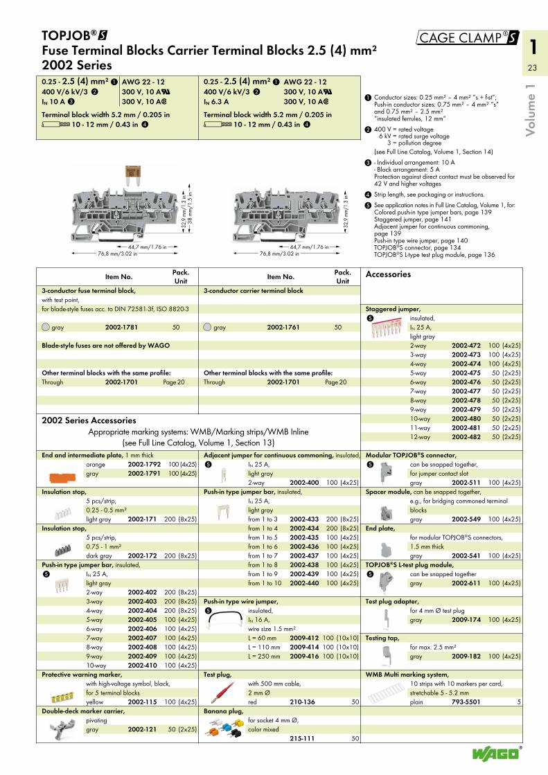
2002 Series AccessoriesAppropriate marking systems: WMB/Marking strips/WMB Inline
(see Full Line Catalog, Volume 1, Section 13)
L 10 - 12 mm / 0.43 inTerminal block width 5.2 mm / 0.205 in
IN 6.3 A 300 V, 10 A2400 V/6 kV/3 300 V, 10 AU0.25 - 2.5 (4) mm² AWG 22 - 12
PageThroughOther terminal blocks with the same profile:
gray 50
Pack. UnitItem No.
3-conductor carrier terminal block
(4x25)100gray(4x25)100orange
End and intermediate plate, 1 mm thick
L 10 - 12 mm / 0.43 inTerminal block width 5.2 mm / 0.205 in
IN 10 A 300 V, 10 A2400 V/6 kV/3 300 V, 10 AU0.25 - 2.5 (4) mm² AWG 22 - 12
PageThroughOther terminal blocks with the same profile:
Blade-style fuses are not offered by WAGO
gray 50
Pack. UnitItem No.
3-conductor fuse terminal block, with test point, for blade-style fuses acc. to DIN 72581-3f, ISO 8820-3
TOPJOB®@ Fuse Terminal Blocks Carrier Terminal Blocks 2.5 (4) mm² 2002 Series
Accessories
5 See application notes in Full Line Catalog, Volume 1, for: Colored push-in type jumper bars, page 139 Staggered jumper, page 141 Adjacent jumper for continuous commoning, page 139 Push-in type wire jumper, page 140 TOPJOB®S connector, page 134 TOPJOB®S L-type test plug module, page 136
4 Strip length, see packaging or instructions.
3 - Individual arrangement: 10 A - Block arrangement: 5 A Protection against direct contact must be observed for 42 V and higher voltages
2 400 V = rated voltage6 kV = rated surge voltage
3 = pollution degree(see Full Line Catalog, Volume 1, Section 14)
1 Conductor sizes: 0.25 mm² – 4 mm² “s + f-st”; Push-in conductor sizes: 0.75 mm² – 4 mm² “s” and 0.75 mm² – 2.5 mm² “insulated ferrules, 12 mm”
215-111
210-136 793-5501
2002-121
2002-611
2009-182
2009-174
2002-400
2002-541
2002-549
2002-511
2002-115
2009-4162009-4142009-412
2002-4822002-4812002-4802002-4792002-4782002-4772002-4762002-4752002-4742002-4732002-472
2002-4402002-4392002-4382002-4372002-4362002-4352002-4342002-433
2002-4102002-4092002-4082002-4072002-4062002-4052002-4042002-4032002-402
2002-172
2002-171
2002-1701
2002-1761
2002-17912002-1792
2002-1701
2002-1781
1 1
2 2
3
4 4
20 20
24
1Vo
lum
e 1
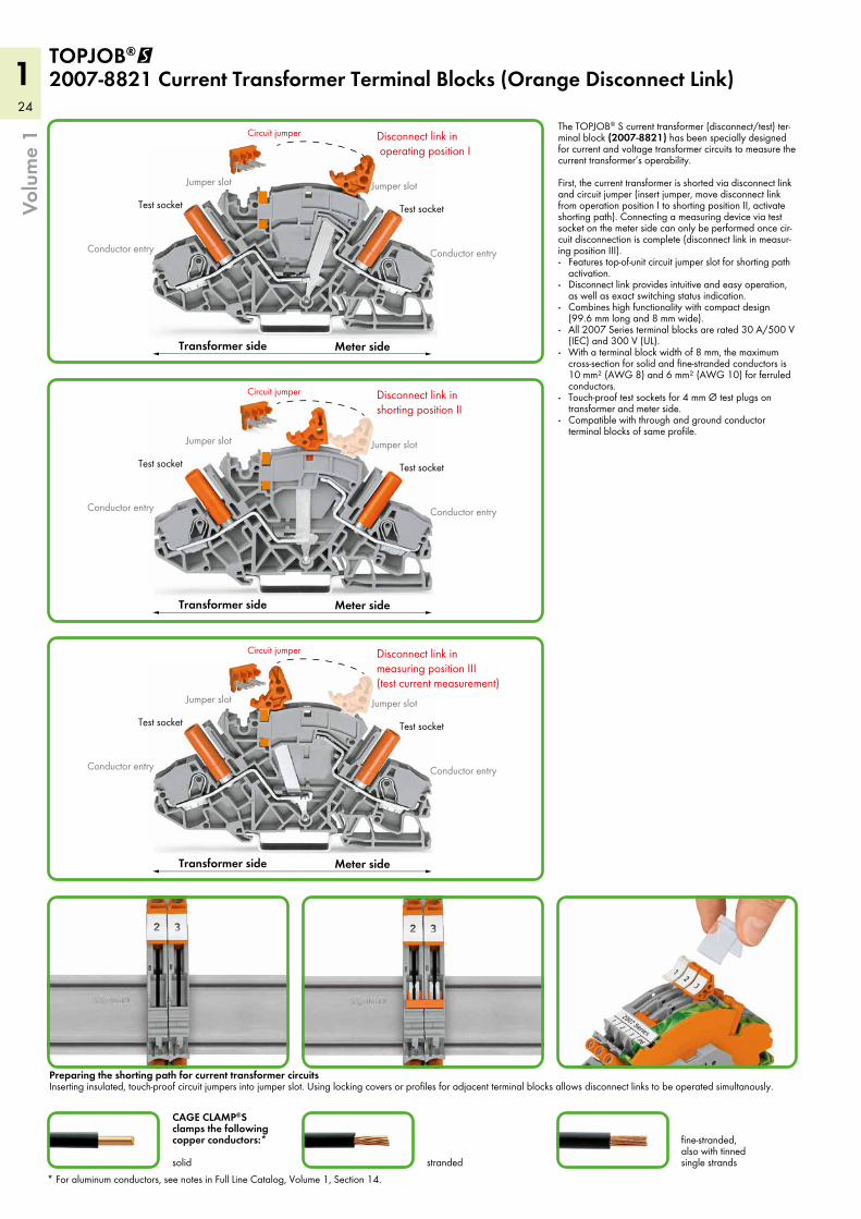
Jumper slot
Conductor entry
Test socketTest socket
Circuit jumper
Meter sideTransformer side
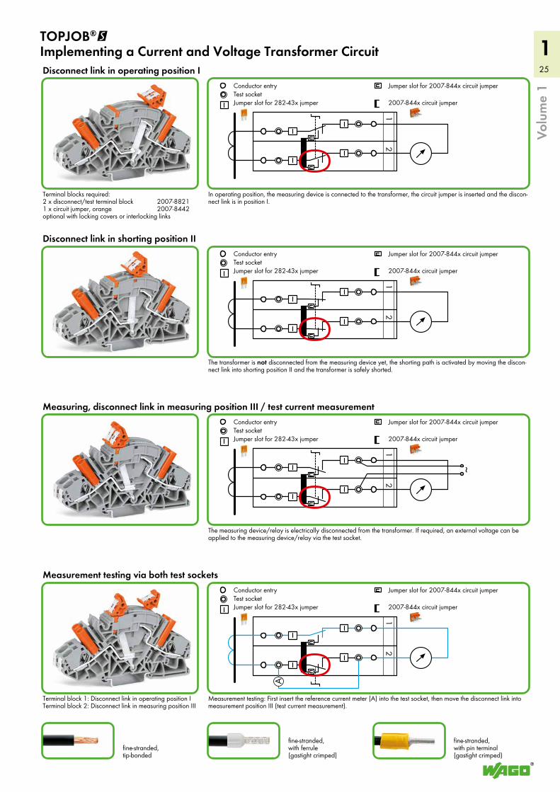
Disconnect link in operating position I
Jumper slot
Conductor entry
Jumper slot
Conductor entry
Test socketTest socket
Circuit jumper
Meter sideTransformer side
Disconnect link in measuring position III(test current measurement)
Jumper slot
Conductor entry
Jumper slot
Conductor entry
Test socketTest socket
Circuit jumper
Meter sideTransformer side
Disconnect link in shorting position II
Jumper slot
Conductor entry
CAGE CLAMP®S clamps the following copper conductors:* solid stranded
fine-stranded, also with tinned single strands
TOPJOB®@ 2007-8821 Current Transformer Terminal Blocks (Orange Disconnect Link)
The TOPJOB® S current transformer (disconnect/test) ter-minal block (2007-8821) has been specially designed for current and voltage transformer circuits to measure the current transformer’s operability. First, the current transformer is shorted via disconnect link and circuit jumper (insert jumper, move disconnect link from operation position I to shorting position II, activate shorting path). Connecting a measuring device via test socket on the meter side can only be performed once cir-cuit disconnection is complete (disconnect link in measur-ing position III).· Features top-of-unit circuit jumper slot for shorting path
activation.· Disconnect link provides intuitive and easy operation,
as well as exact switching status indication.· Combines high functionality with compact design
(99.6 mm long and 8 mm wide).· All 2007 Series terminal blocks are rated 30 A/500 V
(IEC) and 300 V (UL).· With a terminal block width of 8 mm, the maximum
cross-section for solid and fine-stranded conductors is 10 mm² (AWG 8) and 6 mm² (AWG 10) for ferruled conductors.
· Touch-proof test sockets for 4 mm Ø test plugs on transformer and meter side.
· Compatible with through and ground conductor terminal blocks of same profile.
Preparing the shorting path for current transformer circuits Inserting insulated, touch-proof circuit jumpers into jumper slot. Using locking covers or profiles for adjacent terminal blocks allows disconnect links to be operated simultanously.
* For aluminum conductors, see notes in Full Line Catalog, Volume 1, Section 14.
25
1
Volu
me
1
12
Conductor entryTest socketJumper slot for 282-43x jumper
Jumper slot for 2007-844x circuit jumper
2007-844x circuit jumper
12
~
Conductor entryTest socketJumper slot for 282-43x jumper
Jumper slot for 2007-844x circuit jumper
2007-844x circuit jumper
12
Conductor entryTest socketJumper slot for 282-43x jumper
Jumper slot for 2007-844x circuit jumper
2007-844x circuit jumper
12
A
Conductor entryTest socketJumper slot for 282-43x jumper
Jumper slot for 2007-844x circuit jumper
2007-844x circuit jumper
fine-stranded, tip-bonded
fine-stranded, with ferrule (gastight crimped)
fine-stranded, with pin terminal (gastight crimped)
TOPJOB®@ Implementing a Current and Voltage Transformer Circuit
Measurement testing: First insert the reference current meter (A) into the test socket, then move the disconnect link into measurement position III (test current measurement).
Terminal block 1: Disconnect link in operating position I Terminal block 2: Disconnect link in measuring position III
The transformer is not disconnected from the measuring device yet, the shorting path is activated by moving the discon-nect link into shorting position II and the transformer is safely shorted.
Disconnect link in shorting position II
Disconnect link in operating position I
The measuring device/relay is electrically disconnected from the transformer. If required, an external voltage can be applied to the measuring device/relay via the test socket.
Measuring, disconnect link in measuring position III / test current measurement
Measurement testing via both test sockets
In operating position, the measuring device is connected to the transformer, the circuit jumper is inserted and the discon-nect link is in position I.
Terminal blocks required: 2 x disconnect/test terminal block 2007-8821 1 x circuit jumper, orange 2007-8442 optional with locking covers or interlocking links
26
1Vo
lum
e 1
12
34
56
kl
kl
kl
Conductor entryTest socketJumper slot for 282-43x jumper
Jumper slot for 2007-844x circuit jumper
2007-844x circuit jumper
12
34
56
lk
lk
lk
Conductor entryTest socketJumper slot for 282-43x jumper
Jumper slot for 2007-844x circuit jumper
2007-844x circuit jumper
Examples for Current Transformer Circuits
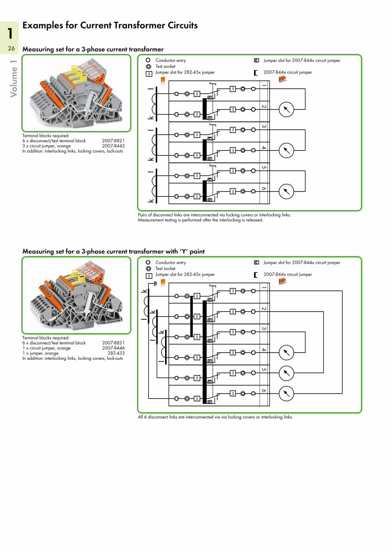
All 6 disconnect links are interconnected via via locking covers or interlocking links.
Measuring set for a 3-phase current transformer with ‘Y‘ point
Pairs of disconnect links are interconnected via locking covers or interlocking links. Measurement testing is performed after the interlocking is released.
Measuring set for a 3-phase current transformer
Terminal blocks required: 6 x disconnect/test terminal block 2007-8821 1 x circuit jumper, orange 2007-8446 1 x jumper, orange 282-433 In addition: interlocking links, locking covers, lock-outs
Terminal blocks required: 6 x disconnect/test terminal block 2007-8821 3 x circuit jumper, orange 2007-8442 In addition: interlocking links, locking covers, lock-outs
27
1
Volu
me
1
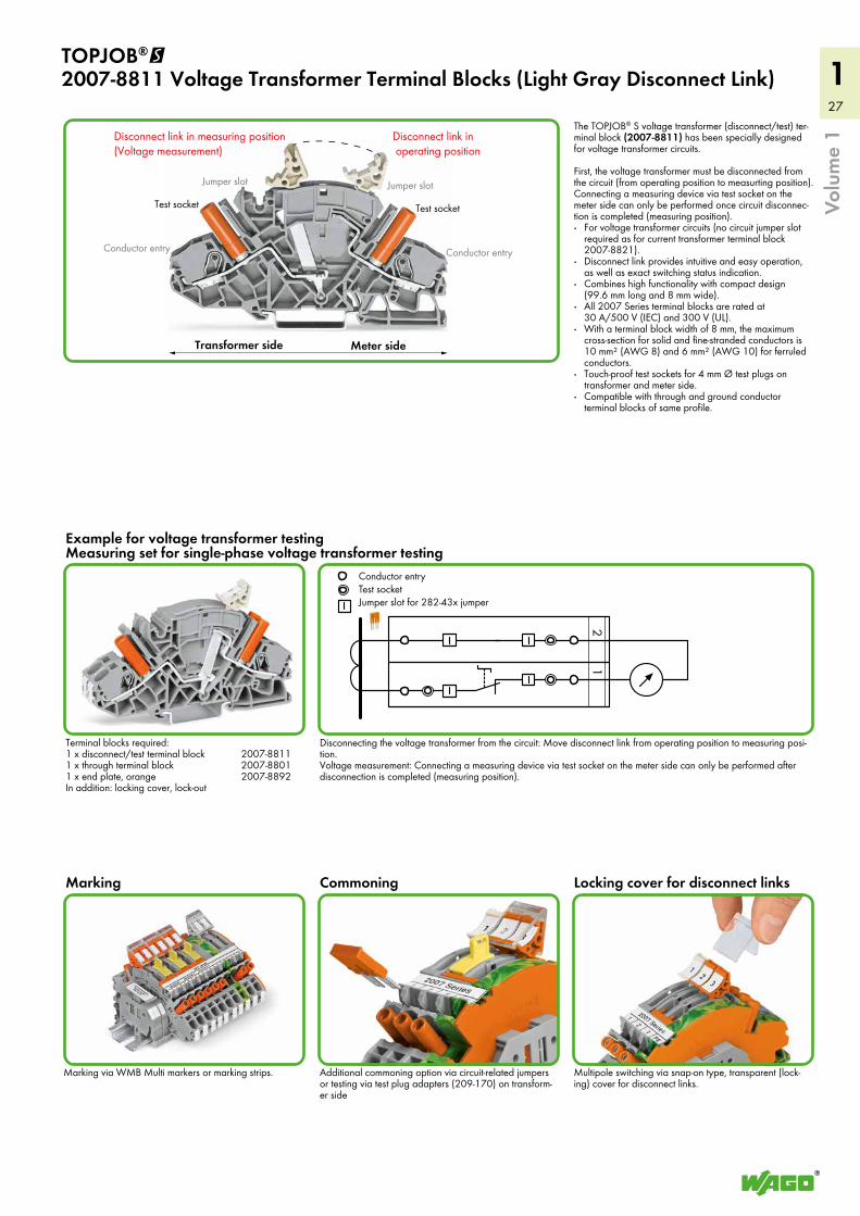
Marking via WMB Multi markers or marking strips.
Disconnect link in measuring position (Voltage measurement)
Disconnect link in operating position
Jumper slot
Conductor entry
Test socketTest socket
Meter sideTransformer side
Jumper slot
Conductor entry1
2
Conductor entryTest socketJumper slot for 282-43x jumper
TOPJOB®@ 2007-8811 Voltage Transformer Terminal Blocks (Light Gray Disconnect Link)
The TOPJOB® S voltage transformer (disconnect/test) ter-minal block (2007-8811) has been specially designed for voltage transformer circuits. First, the voltage transformer must be disconnected from the circuit (from operating position to measurting position). Connecting a measuring device via test socket on the meter side can only be performed once circuit disconnec-tion is completed (measuring position).· For voltage transformer circuits (no circuit jumper slot
required as for current transformer terminal block 2007-8821).
· Disconnect link provides intuitive and easy operation, as well as exact switching status indication.
· Combines high functionality with compact design (99.6 mm long and 8 mm wide).
· All 2007 Series terminal blocks are rated at 30 A/500 V (IEC) and 300 V (UL).
· With a terminal block width of 8 mm, the maximum cross-section for solid and fine-stranded conductors is 10 mm² (AWG 8) and 6 mm² (AWG 10) for ferruled conductors.
· Touch-proof test sockets for 4 mm Ø test plugs on transformer and meter side.
· Compatible with through and ground conductor terminal blocks of same profile.
Disconnecting the voltage transformer from the circuit: Move disconnect link from operating position to measuring posi-tion. Voltage measurement: Connecting a measuring device via test socket on the meter side can only be performed after disconnection is completed (measuring position).
Example for voltage transformer testing Measuring set for single-phase voltage transformer testing
Multipole switching via snap-on type, transparent (lock-ing) cover for disconnect links.
Additional commoning option via circuit-related jumpers or testing via test plug adapters (209-170) on transform-er side
Terminal blocks required: 1 x disconnect/test terminal block 2007-8811 1 x through terminal block 2007-8801 1 x end plate, orange 2007-8892 In addition: locking cover, lock-out
Locking cover for disconnect linksCommoningMarking
28
1
99,6 mm/3.93 in
46,8
mm
/1.8
5 in
99,6 mm/3.92 in
65,3
mm
/2.5
7 in
99,6 mm/3.92 in
65,3
mm
/2.5
7 in
Volu
me
1
Jumper, special design, IN 30 A, orange
4-way3-way2-way
Jumper with safety lid, insulated, IN 30 A, orange
10-way9-way8-way7-way6-way5-way4-way3-way2-way
Jumper, insulated, IN 30 A, orange
8-way7-way6-way5-way4-way3-way2-way
Adjacent jumper for switch lever, insulated, orange, IN 30 A
white
Marking strip, plain, 11 mm wide, 50 m roll
yellow
Protective warning marker, with high-voltage symbol, black, for 5 terminal blocks
plain
WMB Multi marking system, 10 strips with 10 markers per card, for terminal widths 5 - 17.5 mm
transparent
Interlocking link, mechanically locks multiple links, 1 m/3’3’’ long
8-pole7-pole6-pole5-pole4-pole3-pole2-pole1-pole
Locking cover, transparent, mechanically locks multiple links
yellow
Lock-out, for disconnect link
grayorange
End and separator plate, 1.5 mm thick, for use of lock-out seal
grayorange
End and separator plate, 1.5 mm thick, without use of lock-out seal
2006 Series AccessoriesAppropriate marking systems: WMB/Marking strips
(see Full Line Catalog, Volume 1, Section 13)
L 13 - 15 mm / 0.55 inTerminal block width 8 mm / 0.315 in
IN 30 A500 V/6 kV/30.5 - 6 (10) mm² AWG 20 - 8
gray
Pack. UnitItem No.
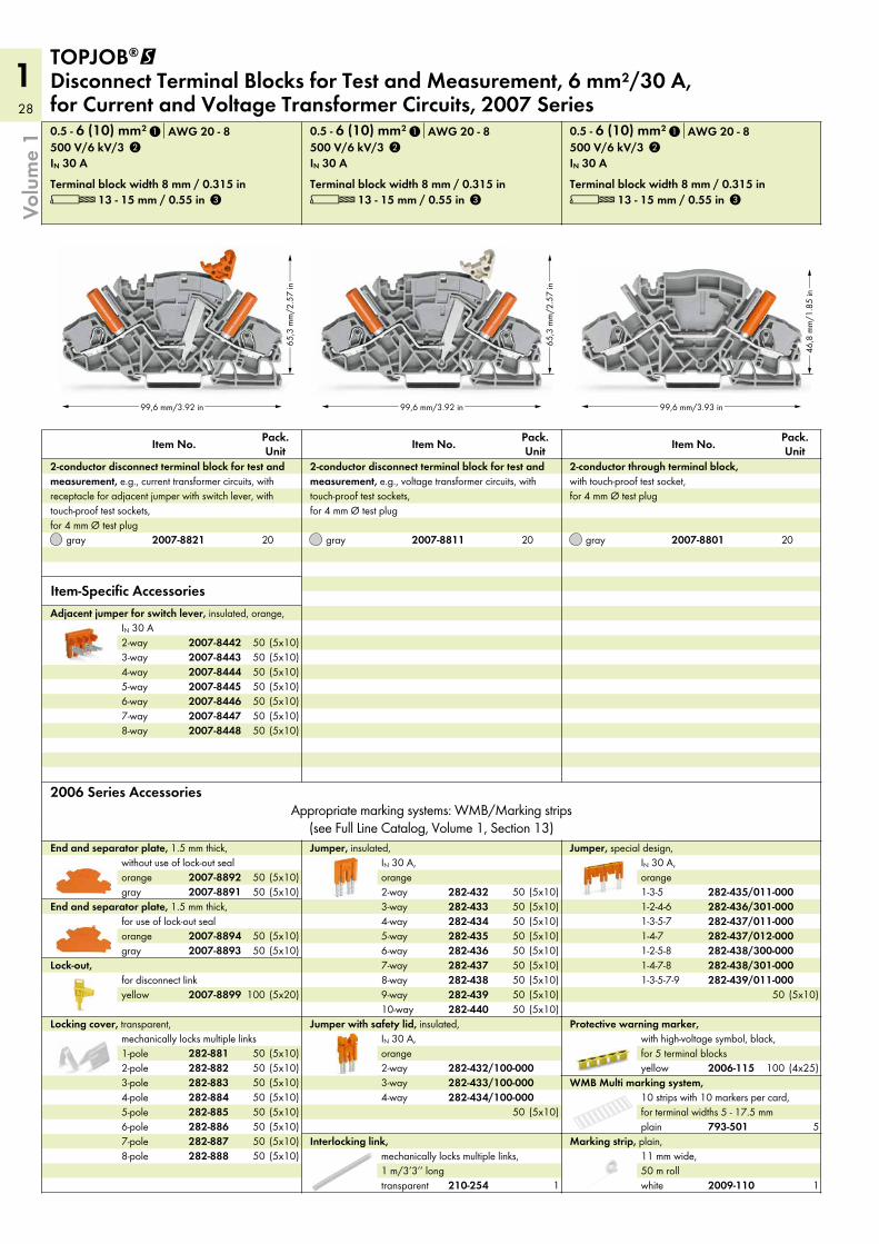
2-conductor through terminal block, with touch-proof test socket, for 4 mm Ø test plug
L 13 - 15 mm / 0.55 inTerminal block width 8 mm / 0.315 in
IN 30 A500 V/6 kV/30.5 - 6 (10) mm² AWG 20 - 8
gray
Pack. UnitItem No.
2-conductor disconnect terminal block for test and measurement, e.g., voltage transformer circuits, with touch-proof test sockets, for 4 mm Ø test plug
L 13 - 15 mm / 0.55 inTerminal block width 8 mm / 0.315 in
IN 30 A500 V/6 kV/30.5 - 6 (10) mm² AWG 20 - 8
gray
Pack. UnitItem No.
2-conductor disconnect terminal block for test and measurement, e.g., current transformer circuits, with receptacle for adjacent jumper with switch lever, with touch-proof test sockets, for 4 mm Ø test plug
TOPJOB®@ Disconnect Terminal Blocks for Test and Measurement, 6 mm²/30 A, for Current and Voltage Transformer Circuits, 2007 Series
Item-Specific Accessories
282-437/011-000282-437/012-000282-438/300-000282-438/301-000282-439/011-000
282-435/011-000282-436/301-000
282-434/100-000282-433/100-000282-432/100-000
282-440282-439282-438282-437282-436282-435282-434282-433282-432
2007-84482007-84472007-84462007-84452007-84442007-84432007-8442
2009-110
2006-115
793-501
210-254
282-888282-887282-886282-885282-884282-883282-882282-881
2007-8899
2007-88932007-8894
2007-88912007-8892
2007-88012007-88112007-8821
1
2
3
1
2
3
1
2
3
1-3-5-71-4-71-2-5-81-4-7-81-3-5-7-9
1-3-51-2-4-6
(5x10)50
202020
(5x10)(5x10)(5x10)(5x10)(5x10)(5x10)(5x10)
50505050505050
(5x10)50(5x10)50
(5x10)50(5x10)50
100 (5x20)
(5x10)50(5x10)50(5x10)50(5x10)50(5x10)50(5x10)50(5x10)50(5x10)50
(5x10)50(5x10)50(5x10)50(5x10)50(5x10)50(5x10)50(5x10)50(5x10)50(5x10)50
(5x10)50
1
(4x25)100
1
5
29
1
!
99,6 mm/3.93 in
46,8
mm
/1.8
5 in
Volu
me
1
L 13 - 15 mm / 0.55 inTerminal block width 8 mm / 0.315 in
0.5 - 6 (10) mm² AWG 20 - 8
green-yellow
Pack. UnitItem No.
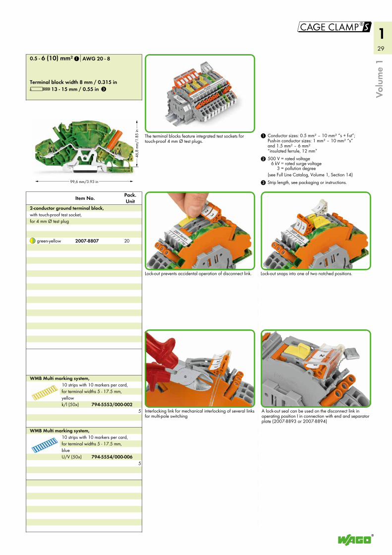
2-conductor ground terminal block, with touch-proof test socket, for 4 mm Ø test plug
3 Strip length, see packaging or instructions.
2 500 V = rated voltage6 kV = rated surge voltage
3 = pollution degree(see Full Line Catalog, Volume 1, Section 14)
1 Conductor sizes: 0.5 mm² – 10 mm² “s + f-st”; Push-in conductor sizes: 1 mm² – 10 mm² “s” and 1.5 mm² – 6 mm² “insulated ferrule, 12 mm”
The terminal blocks feature integrated test sockets for touch-proof 4 mm Ø test plugs.
Lock-out prevents accidental operation of disconnect link. Lock-out snaps into one of two notched positions.
U/V (50x)
WMB Multi marking system, 10 strips with 10 markers per card, for terminal widths 5 - 17.5 mm, blue
k/l (50x)
WMB Multi marking system, 10 strips with 10 markers per card, for terminal widths 5 - 17.5 mm, yellow
Interlocking link for mechanical interlocking of several links for multi-pole switching
A lock-out seal can be used on the disconnect link in operating position I in connection with end and separator plate (2007-8893 or 2007-8894)
2007-8807
794-5554/000-006
794-5553/000-002
1
3
20
5
5
30
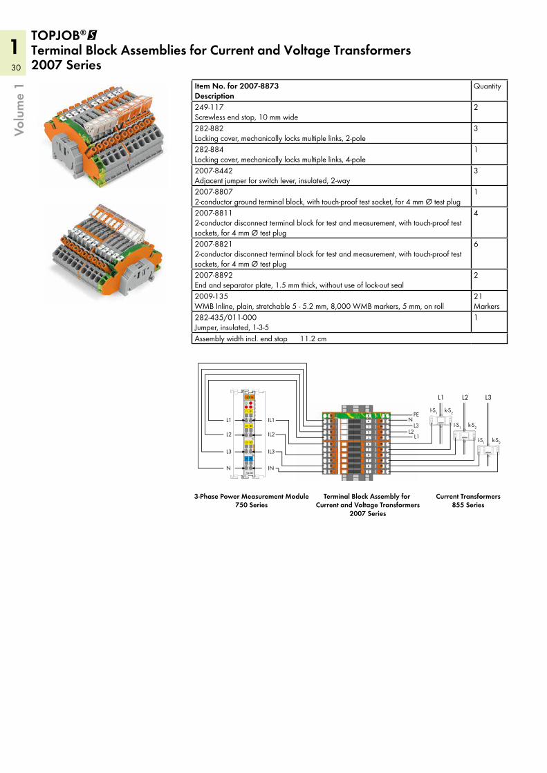
1 TOPJOB®@ Terminal Block Assemblies for Current and Voltage Transformers2007 Series
Volu
me
1 Item No. for 2007-8873Description
Quantity
249-117Screwless end stop, 10 mm wide
2
282-882Locking cover, mechanically locks multiple links, 2-pole
3
282-884Locking cover, mechanically locks multiple links, 4-pole
1
2007-8442Adjacent jumper for switch lever, insulated, 2-way
3
2007-88072-conductor ground terminal block, with touch-proof test socket, for 4 mm Ø test plug
1
2007-88112-conductor disconnect terminal block for test and measurement, with touch-proof test sockets, for 4 mm Ø test plug
4
2007-88212-conductor disconnect terminal block for test and measurement, with touch-proof test sockets, for 4 mm Ø test plug
6
2007-8892End and separator plate, 1.5 mm thick, without use of lock-out seal
2
2009-135WMB Inline, plain, stretchable 5 - 5.2 mm, 8,000 WMB markers, 5 mm, on roll
21Markers
282-435/011-000Jumper, insulated, 1-3-5
1
Assembly width incl. end stop 11.2 cm
13 14
CD
B
A
750-493
L1 IL1
L2 IL2
L3 IL3
N N
k-S2
L3L2L1
I-S1
k-S2I-S1
k-S2I-S1
L1
INN
IL3L3
IL2L2
IL1L1
L2L3
NPE
Terminal Block Assembly for Current and Voltage Transformers
2007 Series
Current Transformers855 Series
3-Phase Power Measurement Module750 Series
31
1!
Volu
me
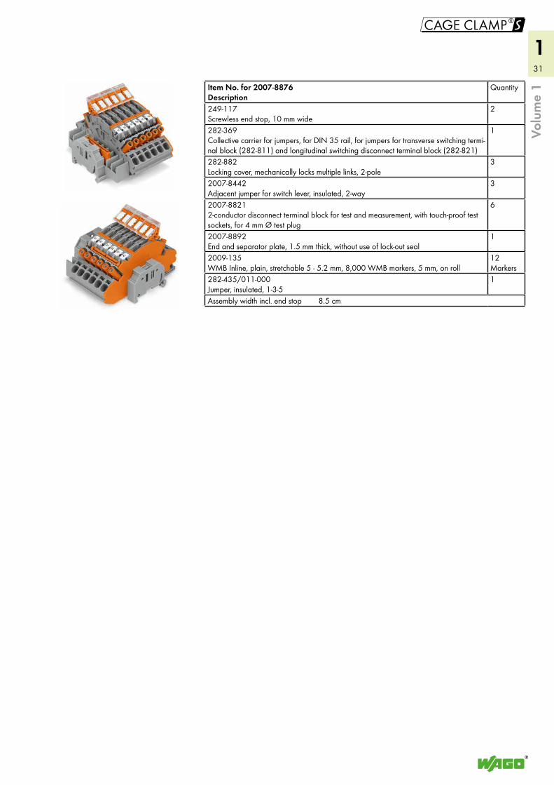
1Item No. for 2007-8876Description
Quantity
249-117Screwless end stop, 10 mm wide
2
282-369Collective carrier for jumpers, for DIN 35 rail, for jumpers for transverse switching termi-nal block (282-811) and longitudinal switching disconnect terminal block (282-821)
1
282-882Locking cover, mechanically locks multiple links, 2-pole
3
2007-8442Adjacent jumper for switch lever, insulated, 2-way
3
2007-88212-conductor disconnect terminal block for test and measurement, with touch-proof test sockets, for 4 mm Ø test plug
6
2007-8892End and separator plate, 1.5 mm thick, without use of lock-out seal
1
2009-135WMB Inline, plain, stretchable 5 - 5.2 mm, 8,000 WMB markers, 5 mm, on roll
12Markers
282-435/011-000Jumper, insulated, 1-3-5
1
Assembly width incl. end stop 8.5 cm
32
1
106,9 mm/4.21 in
33 m
m/1
.3 in
106,9 mm/4.21 in
33 m
m/1
.3 in
106,9 mm/4.21 in
59,2
mm
/2.3
3 in
4
Volu
me
1
white
WMB Inline, plain, stretchable 5 - 5.2 mm, 1,500 WMB markers, 5 mm, on roll
gray
Lockout cap, for conductor entry hole and operating slot
white
Marking strip, plain, 11 mm wide, 50 m roll
violetgreenlight greenorangegrayblueredyellow
WMB Multi marking system, plain, 10 strips with 10 markers per card, for terminal widths 5 - 17.5 mm
plain
WMB Multi marking system, 10 strips with 10 markers per card, for terminal widths 5 - 17.5 mm
from 1 to 5from 1 to 3
Push-in type jumper bar, insulated, IN 41 A, light gray
yellow
Protective warning marker, with high-voltage symbol, black, for 5 terminal blocks
grayorange
End and intermediate plate, 1 mm thick
2006 Series AccessoriesAppropriate marking systems: WMB/Marking strips
(see Full Line Catalog, Volume 1, Section 13)
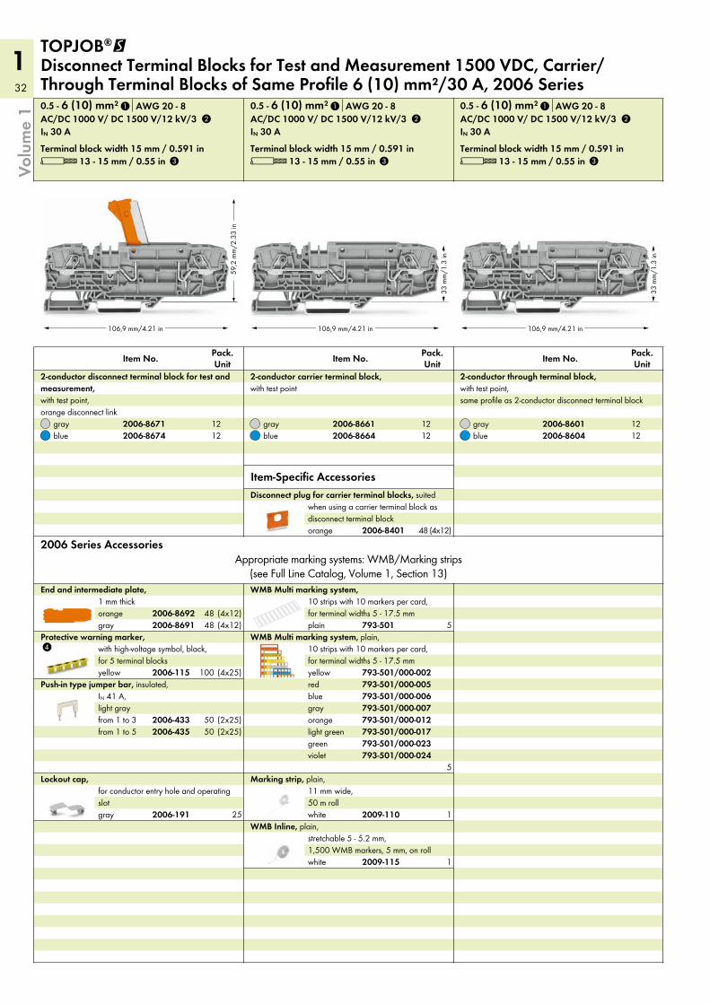
L 13 - 15 mm / 0.55 inTerminal block width 15 mm / 0.591 in
IN 30 AAC/DC 1000 V/ DC 1500 V/12 kV/30.5 - 6 (10) mm² AWG 20 - 8
bluegray
Pack. UnitItem No.
2-conductor through terminal block, with test point, same profile as 2-conductor disconnect terminal block
L 13 - 15 mm / 0.55 inTerminal block width 15 mm / 0.591 in
IN 30 AAC/DC 1000 V/ DC 1500 V/12 kV/30.5 - 6 (10) mm² AWG 20 - 8
bluegray
Pack. UnitItem No.
2-conductor carrier terminal block, with test point
L 13 - 15 mm / 0.55 inTerminal block width 15 mm / 0.591 in
IN 30 AAC/DC 1000 V/ DC 1500 V/12 kV/30.5 - 6 (10) mm² AWG 20 - 8
bluegray
Pack. UnitItem No.
2-conductor disconnect terminal block for test and measurement, with test point, orange disconnect link
TOPJOB®@ Disconnect Terminal Blocks for Test and Measurement 1500 VDC, Carrier/ Through Terminal Blocks of Same Profile 6 (10) mm²/30 A, 2006 Series
orange
Disconnect plug for carrier terminal blocks, suited when using a carrier terminal block as disconnect terminal block
Item-Specific Accessories
2009-115
2006-191 2009-110
793-501/000-024793-501/000-023793-501/000-017793-501/000-012793-501/000-007793-501/000-006793-501/000-005793-501/000-002
793-501
2006-4352006-433
2006-115
2006-86912006-8692
2006-86042006-8601
2006-86642006-8661
2006-86742006-8671
1
2
3
1
2
3
1
2
3
2006-8401
1212
1212
1212
(4x12)48
(4x12)(4x12)
4848
(4x25)100
(2x25)50(2x25)50
25
5
5
1
1
33
1!
Volu
me
1
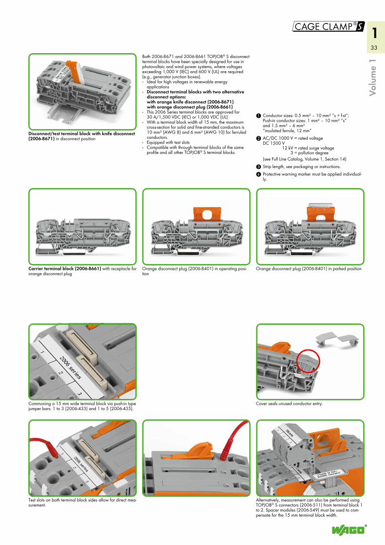
Disconnect/test terminal block with knife disconnect (2006-8671) in disconnect position
Carrier terminal block (2006-8661) with receptacle for orange disconnect plug
Commoning a 15 mm wide terminal block via push-in type jumper bars: 1 to 3 (2006-433) and 1 to 5 (2006-435).
Test slots on both terminal block sides allow for direct mea-surement.
Both 2006-8671 and 2006-8661 TOPJOB® S disconnect terminal blocks have been specially designed for use in photovoltaic and wind power systems, where voltages exceeding 1,000 V (IEC) and 600 V (UL) are required (e.g., generator junction boxes).· Ideal for high voltages in renewable energy
applications· Disconnect terminal blocks with two alternative
disconnect options: with orange knife disconnect (2006-8671) with orange disconnect plug (2006-8661)
· This 2006 Series terminal blocks are approved for 30 A/1,500 VDC (IEC) or 1,000 VDC (UL)
· With a terminal block width of 15 mm, the maximum cross-section for solid and fine-stranded conductors is 10 mm² (AWG 8) and 6 mm² (AWG 10) for ferruled conductors.
· Equipped with test slots· Compatible with through terminal blocks of the same
profile and all other TOPJOB® S terminal blocks
Orange disconnect plug (2006-8401) in operating posi-tion
Orange disconnect plug (2006-8401) in parked position
Cover seals unused conductor entry.
Alternatively, measurement can also be performed using TOPJOB® S connectors (2006-511) from terminal block 1 to 2. Spacer modules (2006-549) must be used to com-pensate for the 15 mm terminal block width.
4 Protective warning marker must be applied individual-ly.
3 Strip length, see packaging or instructions.
2
1 Conductor sizes: 0.5 mm² – 10 mm² “s + f-st”; Push-in conductor sizes: 1 mm² – 10 mm² “s” and 1.5 mm² – 6 mm² “insulated ferrule, 12 mm”AC/DC 1000 V DC 1500 V
= rated voltage
12 kV = rated surge voltage3 = pollution degree
(see Full Line Catalog, Volume 1, Section 14)
34
3
55 m
m/2
.16
in
105 mm/4.13 in
55 m
m/2
.16
in
105 mm/4.13 in
55 m
m/2
.16
in
105 mm/4.13 in
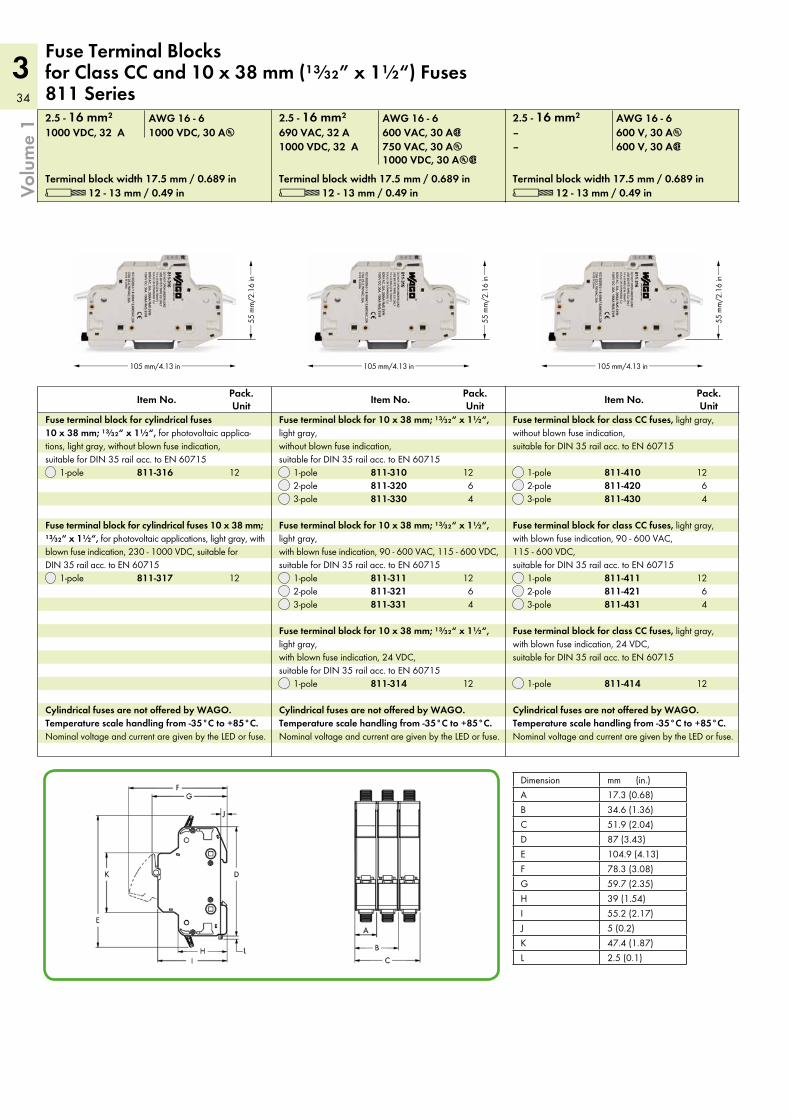
L 12 - 13 mm / 0.49 in L 12 - 13 mm / 0.49 in L 12 - 13 mm / 0.49 inTerminal block width 17.5 mm / 0.689 in Terminal block width 17.5 mm / 0.689 in Terminal block width 17.5 mm / 0.689 in
2.5 - 16 mm² 2.5 - 16 mm² 2.5 - 16 mm²AWG 16 - 6 AWG 16 - 6 AWG 16 - 6
Cylindrical fuses are not offered by WAGO. Temperature scale handling from -35°C to +85°C. Nominal voltage and current are given by the LED or fuse.
Cylindrical fuses are not offered by WAGO. Temperature scale handling from -35°C to +85°C. Nominal voltage and current are given by the LED or fuse.
Cylindrical fuses are not offered by WAGO. Temperature scale handling from -35°C to +85°C. Nominal voltage and current are given by the LED or fuse.
Dimension mm (in.)A 17.3 (0.68)B 34.6 (1.36)C 51.9 (2.04)D 87 (3.43)E 104.9 (4.13)F 78.3 (3.08)G 59.7 (2.35)H 39 (1.54)I 55.2 (2.17)J 5 (0.2)K 47.4 (1.87)L 2.5 (0.1)
1-pole2-pole3-pole
1-pole
Pack. Unit
Pack. Unit
Pack. UnitItem No. Item No. Item No.
Fuse terminal block for 10 x 38 mm; ¹³⁄₃₂“ x 1½“, light gray, without blown fuse indication, suitable for DIN 35 rail acc. to EN 60715
Fuse terminal block for cylindrical fuses 10 x 38 mm; ¹³⁄₃₂“ x 1½“, for photovoltaic applica-tions, light gray, without blown fuse indication, suitable for DIN 35 rail acc. to EN 60715
Fuse Terminal Blocks for Class CC and 10 x 38 mm (¹³⁄₃₂” x 1½“) Fuses 811 Series
1-pole2-pole3-pole
1-pole
1-pole
Fuse terminal block for 10 x 38 mm; ¹³⁄₃₂“ x 1½“, light gray, with blown fuse indication, 90 - 600 VAC, 115 - 600 VDC, suitable for DIN 35 rail acc. to EN 60715
Fuse terminal block for 10 x 38 mm; ¹³⁄₃₂“ x 1½“, light gray, with blown fuse indication, 24 VDC, suitable for DIN 35 rail acc. to EN 60715
Fuse terminal block for cylindrical fuses 10 x 38 mm; ¹³⁄₃₂“ x 1½“, for photovoltaic applications, light gray, with blown fuse indication, 230 - 1000 VDC, suitable for DIN 35 rail acc. to EN 60715
750 VAC, 30 Au600 VAC, 30 A2
1000 VDC, 30 Au2600 V, 30 A2600 V, 30 Au
–1000 VDC, 32 A–690 VAC, 32 A1000 VDC, 30 Au1000 VDC, 32 A
1-pole2-pole3-pole
Fuse terminal block for class CC fuses, light gray, without blown fuse indication, suitable for DIN 35 rail acc. to EN 60715
1-pole2-pole3-pole
1-pole
Fuse terminal block for class CC fuses, light gray, with blown fuse indication, 90 - 600 VAC, 115 - 600 VDC, suitable for DIN 35 rail acc. to EN 60715
Fuse terminal block for class CC fuses, light gray, with blown fuse indication, 24 VDC, suitable for DIN 35 rail acc. to EN 60715
Volu
me
1
811-310811-320811-330
811-316
811-311811-321811-331
811-314
811-317
811-410811-420811-430
811-411811-421811-431
811-414
1264
12
1264
12
12
1264
1264
12
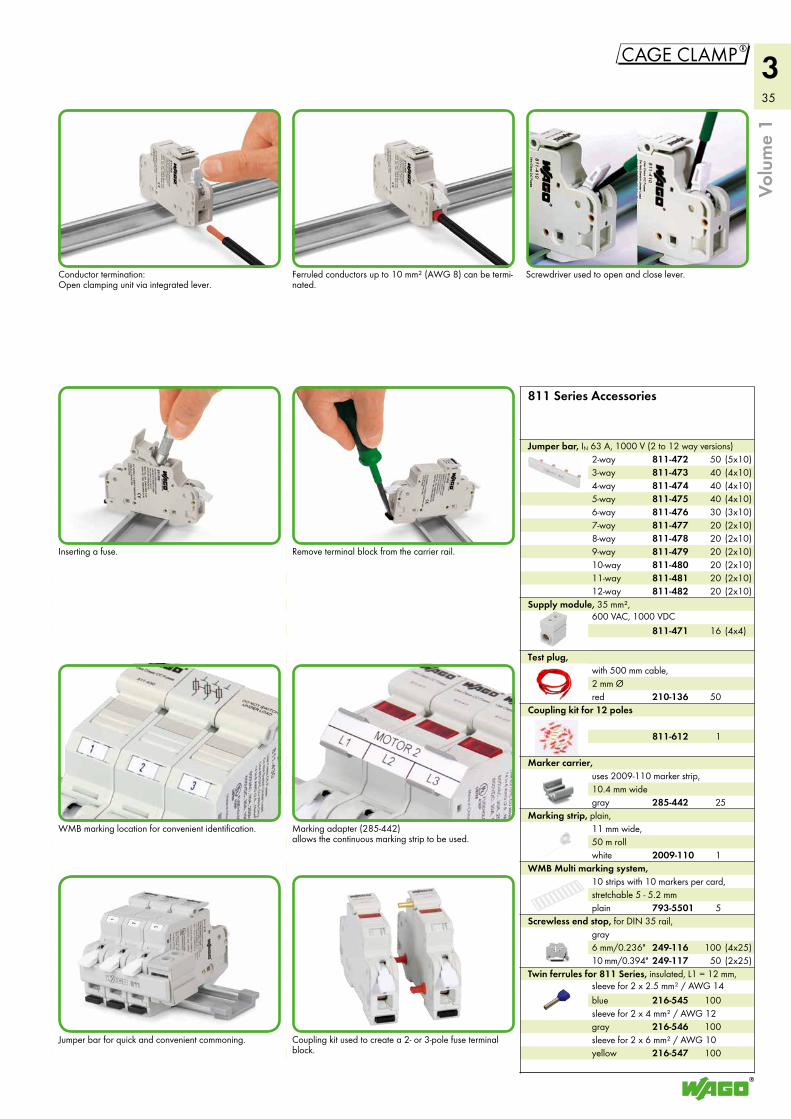
35
3
"
Ferruled conductors up to 10 mm² (AWG 8) can be termi-nated.
Coupling kit used to create a 2- or 3-pole fuse terminal block.
Conductor termination: Open clamping unit via integrated lever.
Screwdriver used to open and close lever.
Jumper bar for quick and convenient commoning.
Inserting a fuse.
WMB marking location for convenient identification.
Remove terminal block from the carrier rail.
Marking adapter (285-442) allows the continuous marking strip to be used.
12-way
2-way3-way4-way5-way6-way7-way8-way9-way10-way11-way
Jumper bar, IN 63 A, 1000 V (2 to 12 way versions)
6 mm/0.236"10 mm/0.394"
Screwless end stop, for DIN 35 rail, gray
white
Marking strip, plain, 11 mm wide, 50 m roll
plain
WMB Multi marking system, 10 strips with 10 markers per card, stretchable 5 - 5.2 mm
red
Test plug, with 500 mm cable, 2 mm Ø
811 Series Accessories
Coupling kit for 12 poles
gray
Marker carrier, uses 2009-110 marker strip, 10.4 mm wide
Supply module, 35 mm², 600 VAC, 1000 VDC
blue
gray
yellow
Twin ferrules for 811 Series, insulated, L1 = 12 mm, sleeve for 2 x 2.5 mm² / AWG 14
sleeve for 2 x 4 mm² / AWG 12
sleeve for 2 x 6 mm² / AWG 10
Volu
me
1811-612
811-472811-473811-474811-475811-476811-477811-478811-479811-480811-481811-482
249-116249-117
2009-110
793-5501
210-136
811-471
216-545
216-546
216-547
(5x10)(4x10)(4x10)(4x10)(3x10)(2x10)(2x10)(2x10)(2x10)(2x10)(2x10)
5040404030202020202020
(4x4)16
50
1
5
1
25
(4x25)(2x25)
10050
100
100
100
285-442
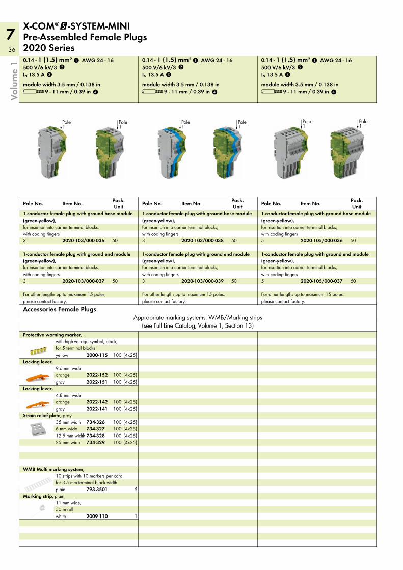
36
7Vo
lum
e 1
Accessories Female PlugsAppropriate marking systems: WMB/Marking strips
(see Full Line Catalog, Volume 1, Section 13)
L 9 - 11 mm / 0.39 inmodule width 3.5 mm / 0.138 in
IN 13.5 A500 V/6 kV/30.14 - 1 (1.5) mm² AWG 24 - 16
For other lengths up to maximum 15 poles, please contact factory.
5
1-conductor female plug with ground end module (green-yellow), for insertion into carrier terminal blocks, with coding fingers
5
Pole No. Pack. UnitItem No.
1-conductor female plug with ground base module (green-yellow), for insertion into carrier terminal blocks, with coding fingers
L 9 - 11 mm / 0.39 inmodule width 3.5 mm / 0.138 in
IN 13.5 A500 V/6 kV/30.14 - 1 (1.5) mm² AWG 24 - 16
For other lengths up to maximum 15 poles, please contact factory.
3
1-conductor female plug with ground end module (green-yellow), for insertion into carrier terminal blocks, with coding fingers
3
Pole No. Pack. UnitItem No.
1-conductor female plug with ground base module (green-yellow), for insertion into carrier terminal blocks, with coding fingers
X-COM®@-SYSTEM-MINI Pre-Assembled Female Plugs 2020 Series
white
Marking strip, plain, 11 mm wide, 50 m roll
plain
WMB Multi marking system, 10 strips with 10 markers per card, for 3.5 mm terminal block width
25 mm wide12.5 mm width6 mm wide35 mm width
Strain relief plate, graygrayorange
Locking lever, 4.8 mm wide
grayorange
Locking lever, 9.6 mm wide
yellow
Protective warning marker, with high-voltage symbol, black, for 5 terminal blocks
Pole1
Pole1
Pole1
Pole1
Pole1
Pole1
2020-105/000-037
2020-105/000-036
2020-103/000-039
2020-103/000-038
2020-103/000-037
2020-103/000-036
2009-110
793-3501
734-329734-328734-327734-326
2022-1412022-142
2022-1512022-152
2000-115
1
2
3
4
1
2
3
4
1
2
3
4
50
50
50
50
50
50
1
5
(4x25)100(4x25)100(4x25)100(4x25)100
(4x25)100(4x25)100
(4x25)100(4x25)100
(4x25)100
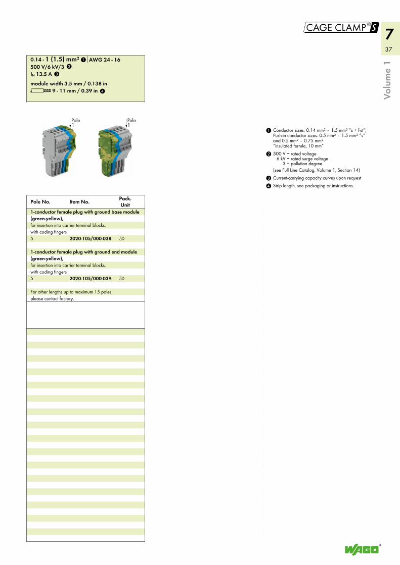
37
7
!
Volu
me
1
L 9 - 11 mm / 0.39 inmodule width 3.5 mm / 0.138 in
IN 13.5 A500 V/6 kV/30.14 - 1 (1.5) mm² AWG 24 - 16
For other lengths up to maximum 15 poles, please contact factory.
5
1-conductor female plug with ground end module (green-yellow), for insertion into carrier terminal blocks, with coding fingers
5
Pole No. Pack. UnitItem No.
1-conductor female plug with ground base module (green-yellow), for insertion into carrier terminal blocks, with coding fingers
4 Strip length, see packaging or instructions.3 Current-carrying capacity curves upon request
2 500 V = rated voltage6 kV = rated surge voltage
3 = pollution degree(see Full Line Catalog, Volume 1, Section 14)
1 Conductor sizes: 0.14 mm² – 1.5 mm² “s + f-st”; Push-in conductor sizes: 0.5 mm² – 1.5 mm² “s” and 0.5 mm² – 0.75 mm² “insulated ferrule, 10 mm”
Pole1
Pole1
2020-105/000-039
2020-105/000-038
1
2
3
4
50
50
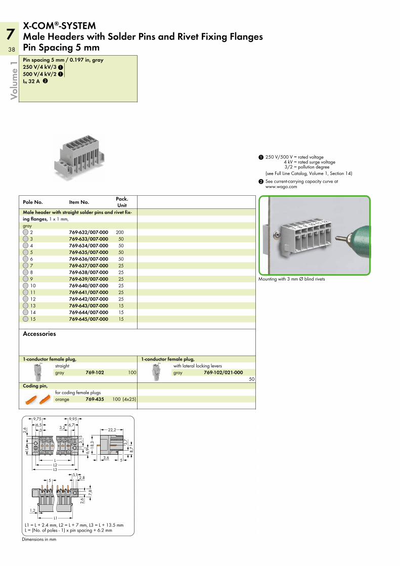
38
7
Volu
me
1
Pole1
Pole1
gray
1-conductor female plug, with lateral locking levers
orange
Coding pin, for coding female plugs
gray
1-conductor female plug, straight
Accessories
IN 32 A500 V/4 kV/2250 V/4 kV/3Pin spacing 5 mm / 0.197 in, gray
15141312111098765432
Pole No. Pack. UnitItem No.
Male header with straight solder pins and rivet fix-ing flanges, 1 x 1 mm, gray
Dimensions in mm
X-COM®-SYSTEM Male Headers with Solder Pins and Rivet Fixing Flanges Pin Spacing 5 mm
2 See current-carrying capacity curve at www.wago.com
1 250 V/500 V = rated voltage4 kV = rated surge voltage3/2 = pollution degree
(see Full Line Catalog, Volume 1, Section 14)
L1
L
22,2
L2L3
1,2
3,6 5
3,2
2,6
2,6
3,15
6,9
5
7,8
8,718
,3
5,1
6,76,53
9,959,75
2,8
3,7
11,4
L = (No. of poles - 1) x pin spacing + 6.2 mmL1 = L + 2.4 mm, L2 = L + 7 mm, L3 = L + 13.5 mm
Mounting with 3 mm Ø blind rivets
769-102/021-000
769-435
769-102
769-645/007-000769-644/007-000769-643/007-000769-642/007-000769-641/007-000769-640/007-000769-639/007-000769-638/007-000769-637/007-000769-636/007-000769-635/007-000769-634/007-000769-633/007-000769-632/007-000
1
2
1
15151525252525252550505050
200
50
(4x25)100
100
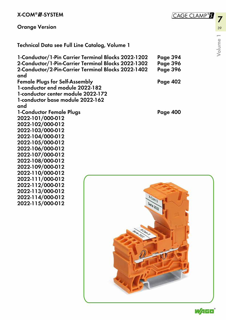
39
7!
Volu
me
1
X-COM®@-SYSTEM
Orange Version
Technical Data see Full Line Catalog, Volume 1
1-Conductor/1-Pin Carrier Terminal Blocks 2022-1202 Page 3942-Conductor/1-Pin-Carrier Terminal Blocks 2022-1302 Page 3962-Conductor/2-Pin-Carrier Terminal Blocks 2022-1402 Page 396andFemale Plugs for Self-Assembly Page 4021-conductor end module 2022-1821-conductor center module 2022-1721-conductor base module 2022-162and1-Conductor Female Plugs Page 4002022-101/000-0122022-102/000-0122022-103/000-0122022-104/000-0122022-105/000-0122022-106/000-0122022-107/000-0122022-108/000-0122022-109/000-0122022-110/000-0122022-111/000-0122022-112/000-0122022-113/000-0122022-114/000-0122022-115/000-012
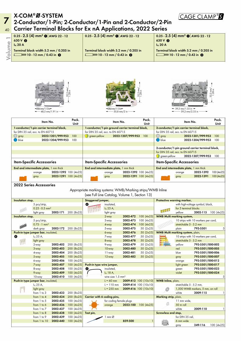
40
7 !
59,2 mm/2.33 in39,2 mm/1.55 in
32,5
mm
/1.
28 in
32,5
mm
/1.
28 in
28,6 mm/1.13 in50,8 mm/2 in
32,5
mm
/1.
28 in
28,6 mm/1.13 in48,5 mm/1.91 in
4
4
4
gray
Screwless end stop, for DIN 35 rail, 6 mm wide
white
Marking strip, plain, 11 mm wide, 50 m roll
white
WMB Inline, plain, stretchable 5 - 5.2 mm, 1,500 WMB markers, 5 mm, on roll
12-way11-way10-way9-way8-way7-way6-way5-way4-way3-way2-way
Staggered jumper, insulated, IN 25 A, light gray
violetgreenlight greenorangegrayblueredyellow
WMB Multi marking system, plain, 10 strips with 10 markers per card, stretchable 5 - 5.2 mm
plain
WMB Multi marking system, 10 strips with 10 markers per card, stretchable 5 - 5.2 mm
yellow
Protective warning marker, with high-voltage symbol, black, for 5 terminal blocks
Test pin, 1 mm Ø
orange
Carrier with 6 coding pins, for coding female plugs
L = 250 mmL = 110 mmL = 60 mm
Push-in type wire jumper, insulated, IN 18 A, wire size 1.5 mm²
from 1 to 10from 1 to 9from 1 to 8from 1 to 7from 1 to 6from 1 to 5from 1 to 4from 1 to 3
Push-in type jumper bar, insulated, IN 25 A, light gray
10-way9-way8-way7-way6-way5-way4-way3-way2-way
Push-in type jumper bar, insulated, IN 25 A, light gray
dark gray
Insulation stop, 5 pcs/strip, 0.75 - 1 mm²
light gray
Insulation stop, 5 pcs/strip, 0.25 - 0.5 mm²
2022 Series AccessoriesAppropriate marking systems: WMB/Marking strips/WMB Inline
(see Full Line Catalog, Volume 1, Section 13)
L 10 - 12 mm / 0.43 in L 10 - 12 mm / 0.43 inTerminal block width 5.2 mm / 0.205 in Terminal block width 5.2 mm / 0.205 in
0.25 - 2.5 (4) mm² 0.25 - 2.5 (4) mm²AWG 22 - 12 AWG 22 - 12
Item-Specific Accessories Item-Specific Accessories
Pack. Unit
Pack. UnitItem No. Item No.
grayorange
End and intermediate plate, 1 mm thick
L 10 - 12 mm / 0.43 inTerminal block width 5.2 mm / 0.205 in
0.25 - 2.5 (4) mm² AWG 22 - 12
Item-Specific Accessoriesgreen-yellow
2-conductor/1-pin ground carrier terminal block, for DIN 35 rail, acc. to EN 60715
bluegray
Pack. UnitItem No.
2-conductor/1-pin carrier terminal block, for DIN 35 rail, acc. to EN 60715
X-COM®@-SYSTEM 2-Conductor/1-Pin; 2-Conductor/1-Pin and 2-Conductor/2-Pin Carrier Terminal Blocks for Ex nA Applications, 2022 Series
green-yellow
1-conductor/1-pin ground carrier terminal block, for DIN 35 rail, acc. to EN 60715
bluegray
1-conductor/1-pin carrier terminal block, for DIN 35 rail, acc. to EN 60715
gray grayorange orange
End and intermediate plate, 1 mm thick End and intermediate plate, 1 mm thick
Volu
me
1
IN 20 A630 V
IN 20 A630 V
249-116
2009-110
2009-115
2002-4822002-4812002-4802002-4792002-4782002-4772002-4762002-4752002-4742002-4732002-472
793-5501/000-024793-5501/000-023793-5501/000-017793-5501/000-012793-5501/000-007793-5501/000-006793-5501/000-005793-5501/000-002
793-5501
2002-115
859-500
2022-100
2009-4162009-4142009-412
2002-4402002-4392002-4382002-4372002-4362002-4352002-4342002-433
2002-4102002-4092002-4082002-4072002-4062002-4052002-4042002-4032002-402
2002-172
2002-171
2022-13912022-1392
2022-1307/999-953
2022-1304/999-9532022-1301/999-953
1
2
3
2022-1207/999-9532022-1204/999-9532022-1201/999-953
2022-1291 2022-12912022-1292 2022-1292
1
2
3
1
100
100100100
100100
(4x25)100(4x25)100
(4x25) (4x25)100 100(4x25) (4x25)100 100
(8x25)200
(8x25)200
(4x25)100(4x25)100(4x25)100(4x25)100(4x25)100(4x25)100(8x25)200(8x25)200(8x25)200
(4x25)100(4x25)100(4x25)100(4x25)100(4x25)100(4x25)100(8x25)200(8x25)200
(2x25)50(2x25)50(2x25)50(2x25)50(2x25)50(2x25)50(2x25)50(2x25)50(4x25)100(4x25)100(4x25)100
(10x10)100(10x10)100(10x10)100
(4x25)100
1
1
1
5
5
(4x25)100
(4x25)100
3
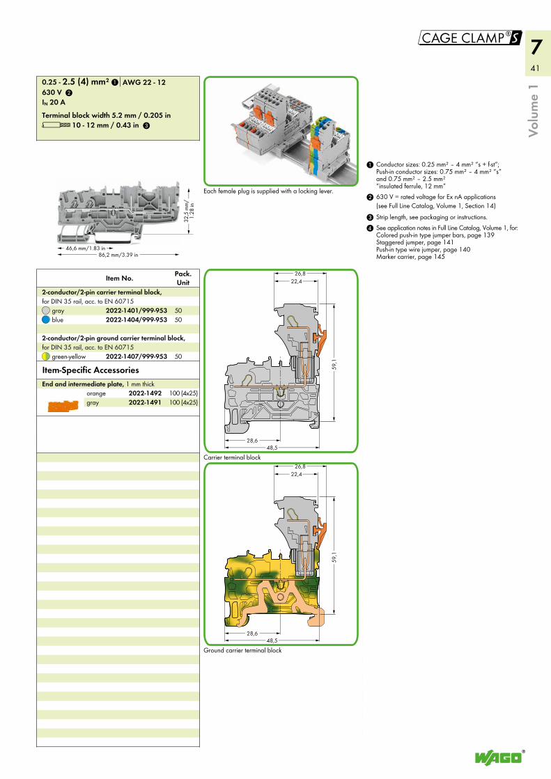
41
7
!
86,2 mm/3.39 in46,6 mm/1.83 in
32,5
mm
/1.
28 in
22,426,8
28,648,5
59,1
22,426,8
28,648,5
59,1
grayorange
End and intermediate plate, 1 mm thick
green-yellow
2-conductor/2-pin ground carrier terminal block, for DIN 35 rail, acc. to EN 60715
bluegray
2-conductor/2-pin carrier terminal block, for DIN 35 rail, acc. to EN 60715
See application notes in Full Line Catalog, Volume 1, for: Colored push-in type jumper bars, page 139 Staggered jumper, page 141 Push-in type wire jumper, page 140 Marker carrier, page 145
4
Strip length, see packaging or instructions.3
2 630 V = rated voltage for Ex nA applications(see Full Line Catalog, Volume 1, Section 14)
1 Conductor sizes: 0.25 mm² – 4 mm² “s + f-st”; Push-in conductor sizes: 0.75 mm² – 4 mm² “s” and 0.75 mm² – 2.5 mm² “insulated ferrule, 12 mm”
L 10 - 12 mm / 0.43 inTerminal block width 5.2 mm / 0.205 in
0.25 - 2.5 (4) mm² AWG 22 - 12
Pack. UnitItem No.
Item-Specific Accessories
Volu
me
1
IN 20 A630 V
Each female plug is supplied with a locking lever.
Carrier terminal block
Ground carrier terminal block
2022-14912022-1492
2022-1407/999-953
2022-1404/999-9532022-1401/999-953
1
2
3
(4x25)100(4x25)100
50
5050
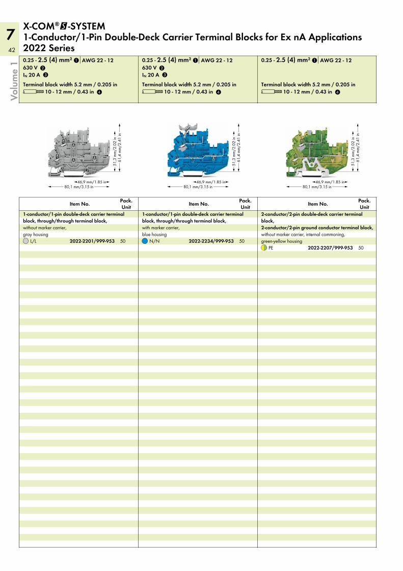
42
7
80,1 mm/3.15 in46,9 mm/1.85 in
51,3
mm
/2.0
2 in
61,4
mm
/2.4
1 in
80,1 mm/3.15 in46,9 mm/1.85 in
51,3
mm
/2.0
2 in
61,4
mm
/2.4
1 in
80,1 mm/3.15 in46,9 mm/1.85 in
51,3
mm
/2.0
2 in
61,4
mm
/2.4
1 in
L 10 - 12 mm / 0.43 inTerminal block width 5.2 mm / 0.205 in
0.25 - 2.5 (4) mm² AWG 22 - 12
Pack. UnitItem No.
PE
2-conductor/2-pin double-deck carrier terminal block, 2-conductor/2-pin ground conductor terminal block, without marker carrier, internal commoning, green-yellow housing
L 10 - 12 mm / 0.43 inTerminal block width 5.2 mm / 0.205 in
0.25 - 2.5 (4) mm² AWG 22 - 12
N/N
Pack. UnitItem No.
1-conductor/1-pin double-deck carrier terminal block, through/through terminal block, with marker carrier, blue housing
L 10 - 12 mm / 0.43 inTerminal block width 5.2 mm / 0.205 in
0.25 - 2.5 (4) mm² AWG 22 - 12
L/L
Pack. UnitItem No.
1-conductor/1-pin double-deck carrier terminal block, through/through terminal block, without marker carrier, gray housing
X-COM®@-SYSTEM 1-Conductor/1-Pin Double-Deck Carrier Terminal Blocks for Ex nA Applications 2022 Series
Volu
me
1
IN 20 A630 V
IN 20 A630 V
2022-2207/999-9532022-2234/999-9532022-2201/999-953
1
2
3
4
1
2
3
4
1
4
505050
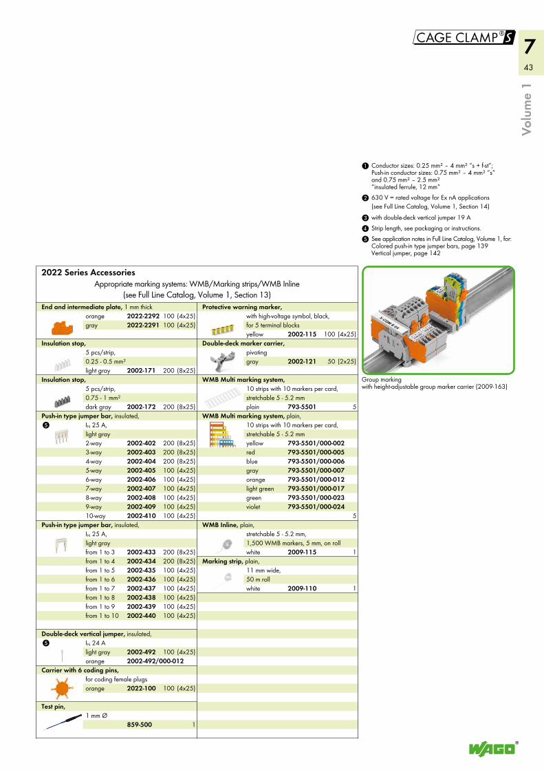
43
7
!
5
5
white
Marking strip, plain, 11 mm wide, 50 m roll
white
WMB Inline, plain, stretchable 5 - 5.2 mm, 1,500 WMB markers, 5 mm, on roll
plain
WMB Multi marking system, 10 strips with 10 markers per card, stretchable 5 - 5.2 mm
violetgreenlight greenorangegrayblueredyellow
WMB Multi marking system, plain, 10 strips with 10 markers per card, stretchable 5 - 5.2 mm
gray
Double-deck marker carrier, pivoting
yellow
Protective warning marker, with high-voltage symbol, black, for 5 terminal blocks
Test pin, 1 mm Ø
orange
Carrier with 6 coding pins, for coding female plugs
light gray
Double-deck vertical jumper, insulated, IN 24 A
from 1 to 10from 1 to 9from 1 to 8from 1 to 7from 1 to 6from 1 to 5from 1 to 4from 1 to 3
Push-in type jumper bar, insulated, IN 25 A, light gray
10-way9-way8-way7-way6-way5-way4-way3-way2-way
Push-in type jumper bar, insulated, IN 25 A, light gray
dark gray
Insulation stop, 5 pcs/strip, 0.75 - 1 mm²
light gray
Insulation stop, 5 pcs/strip, 0.25 - 0.5 mm²
grayorange
End and intermediate plate, 1 mm thick
5 See application notes in Full Line Catalog, Volume 1, for: Colored push-in type jumper bars, page 139 Vertical jumper, page 142
4 Strip length, see packaging or instructions.3 with double-deck vertical jumper 19 A
2 630 V = rated voltage for Ex nA applications(see Full Line Catalog, Volume 1, Section 14)
1 Conductor sizes: 0.25 mm² – 4 mm² “s + f-st”; Push-in conductor sizes: 0.75 mm² – 4 mm² “s” and 0.75 mm² – 2.5 mm² “insulated ferrule, 12 mm”
2022 Series AccessoriesAppropriate marking systems: WMB/Marking strips/WMB Inline
(see Full Line Catalog, Volume 1, Section 13)
Volu
me
1
Group marking with height-adjustable group marker carrier (2009-163)
orange
2009-110
2009-115
793-5501
793-5501/000-024793-5501/000-023793-5501/000-017793-5501/000-012793-5501/000-007793-5501/000-006793-5501/000-005793-5501/000-002
2002-121
2002-115
859-500
2022-100
2002-492
2002-4402002-4392002-4382002-4372002-4362002-4352002-4342002-433
2002-4102002-4092002-4082002-4072002-4062002-4052002-4042002-4032002-402
2002-172
2002-171
2022-22912022-2292
(4x25)100(4x25)100
(8x25)200
(8x25)200
(4x25)100(4x25)100(4x25)100(4x25)100(4x25)100(4x25)100(8x25)200(8x25)200(8x25)200
(4x25)100(4x25)100(4x25)100(4x25)100(4x25)100(4x25)100(8x25)200(8x25)200
(4x25)100
(4x25)100
1
1
1
5
5
(2x25)50
(4x25)100
2002-492/000-012
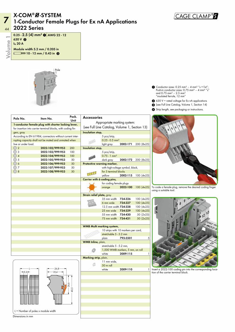
44
7
!
white
Marking strip, plain, 11 mm wide, 50 m roll
white
WMB Inline, plain, stretchable 5 - 5.2 mm, 1,500 WMB markers, 5 mm, on roll
plain
WMB Multi marking system, 10 strips with 10 markers per card, stretchable 5 - 5.2 mm
75 mm width55 mm width25 mm wide12.5 mm width6 mm wide35 mm width
Strain relief plate, gray
orange
Carrier with 6 coding pins, for coding female plugs
yellow
Protective warning marker, with high-voltage symbol, black, for 5 terminal blocks
dark gray
Insulation stop, 5 pcs/strip, 0.75 - 1 mm²
light gray
Insulation stop, 5 pcs/strip, 0.25 - 0.5 mm²
L 10 - 12 mm / 0.43 inModule width 5.2 mm / 0.205 in
0.25 - 2.5 (4) mm² AWG 22 - 12
8765432
Pole No. Pack. UnitItem No.
1-conductor female plug with shorter locking lever, for insertion into carrier terminal blocks, with coding fin-gers, gray According to EN 61984, connectors without current inter-rupting capacity shall not be mated and unmated when live or under load.
Dimensions in mm
X-COM®@-SYSTEM 1-Conductor Female Plugs for Ex nA Applications 2022 Series
4 Strip length, see packaging or instructions.3
2 630 V = rated voltage for Ex nA applications(see Full Line Catalog, Volume 1, Section 14)
1 Conductor sizes: 0.25 mm² – 4 mm² “s + f-st”; Push-in conductor sizes: 0.75 mm² – 4 mm² “s” and 0.75 mm² – 2.5 mm² “insulated ferrule, 12 mm”
AccessoriesAppropriate marking system:
(see Full Line Catalog, Volume 1, Section 13)
Volu
me
1
IN 20 A630 V
Pole1
<___ 22,4 ___><>5,2
<________
40,
5 ________>
<____
26,
6 ____>
L 26,8
L = Number of poles x module width
To code a female plug, remove the desired coding finger using a suitable tool.
Insert a 2022-100 coding pin into the corresponding loca-tion of the carrier terminal block.
2009-110
2009-115
793-5501
734-431734-430734-329734-328734-327734-326
2022-100
2002-115
2002-172
2002-171
2022-108/999-9532022-107/999-9532022-106/999-9532022-105/999-9532022-104/999-9532022-103/999-9532022-102/999-953
3
1
2
50505050
100100200
(8x25)200
1
1
5
(2x25)50(2x25)50(4x25)100(4x25)100(4x25)100(4x25)100
(4x25)100
(4x25)100
(8x25)200
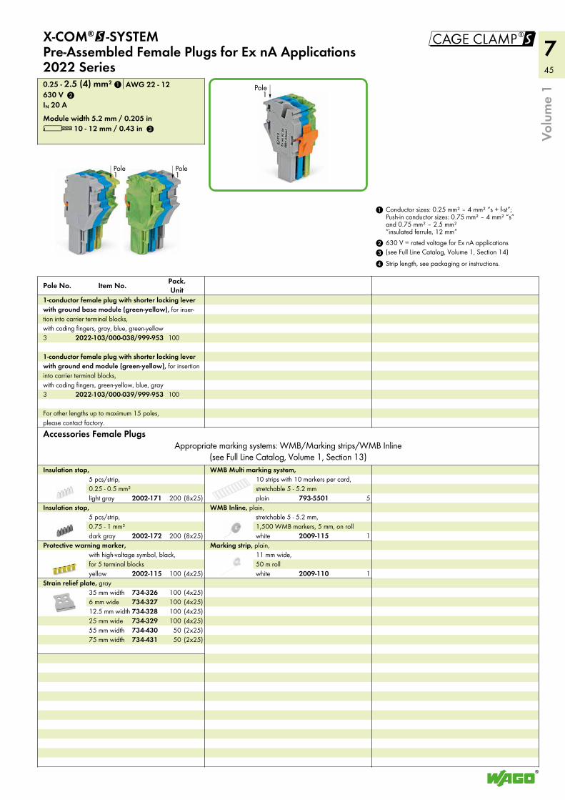
45
7!
white
Marking strip, plain, 11 mm wide, 50 m roll
white
WMB Inline, plain, stretchable 5 - 5.2 mm, 1,500 WMB markers, 5 mm, on roll
plain
WMB Multi marking system, 10 strips with 10 markers per card, stretchable 5 - 5.2 mm
75 mm width55 mm width25 mm wide12.5 mm width6 mm wide35 mm width
Strain relief plate, grayyellow
Protective warning marker, with high-voltage symbol, black, for 5 terminal blocks
dark gray
Insulation stop, 5 pcs/strip, 0.75 - 1 mm²
light gray
Insulation stop, 5 pcs/strip, 0.25 - 0.5 mm²
Accessories Female PlugsAppropriate marking systems: WMB/Marking strips/WMB Inline
(see Full Line Catalog, Volume 1, Section 13)
For other lengths up to maximum 15 poles, please contact factory.
3
1-conductor female plug with shorter locking lever with ground end module (green-yellow), for insertion into carrier terminal blocks, with coding fingers, green-yellow, blue, gray
3
1-conductor female plug with shorter locking lever with ground base module (green-yellow), for inser-tion into carrier terminal blocks, with coding fingers, gray, blue, green-yellow
L 10 - 12 mm / 0.43 inModule width 5.2 mm / 0.205 in
0.25 - 2.5 (4) mm² AWG 22 - 12
Pole No. Pack. UnitItem No.
X-COM®@-SYSTEM Pre-Assembled Female Plugs for Ex nA Applications 2022 Series
4 Strip length, see packaging or instructions.3
2 630 V = rated voltage for Ex nA applications(see Full Line Catalog, Volume 1, Section 14)
1 Conductor sizes: 0.25 mm² – 4 mm² “s + f-st”; Push-in conductor sizes: 0.75 mm² – 4 mm² “s” and 0.75 mm² – 2.5 mm² “insulated ferrule, 12 mm”
Volu
me
1
IN 20 A630 V
Pole1
Pole1
Pole1
2009-110
2009-115
793-5501
734-431734-430734-329734-328734-327734-326
2002-115
2002-172
2002-171
2022-103/000-039/999-953
2022-103/000-038/999-953
1
2
3
100
100
1
1
5
(2x25)50(2x25)50(4x25)100(4x25)100(4x25)100(4x25)100
(4x25)100
(8x25)200
(8x25)200
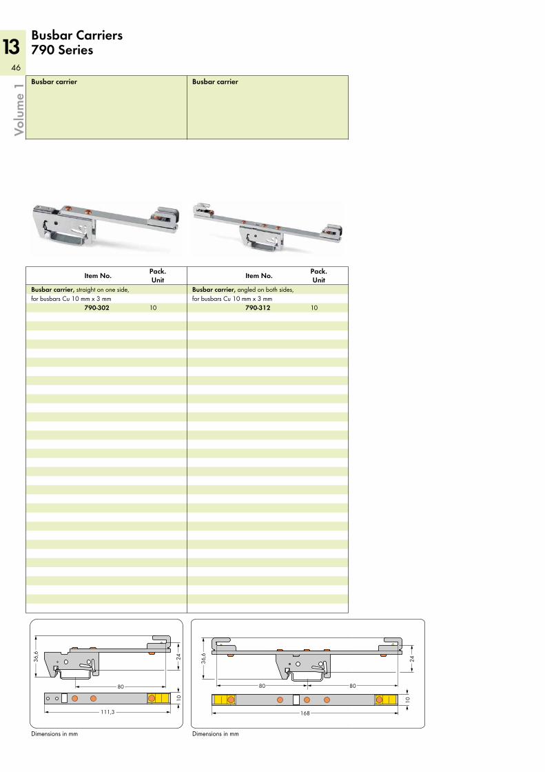
46
13
8080
168
2436,6
10
2436,6
10
80
111,3
Volu
me
1 Busbar carrier
Pack. UnitItem No.
Busbar carrier, angled on both sides, for busbars Cu 10 mm x 3 mm
Busbar carrier
Pack. UnitItem No.
Busbar carrier, straight on one side, for busbars Cu 10 mm x 3 mm
Dimensions in mmDimensions in mm
Busbar Carriers 790 Series
790-312790-302 1010
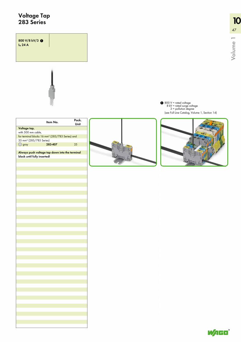
47
10
Volu
me
1
IN 24 A800 V/8 kV/3
gray
Pack. UnitItem No.
Voltage tap, with 500 mm cable, for terminal blocks 16 mm² (283/783 Series) and 35 mm² (285/785 Series)
Always push voltage tap down into the terminal block until fully inserted!
Voltage Tap 283 Series
800 V = rated voltage8 kV = rated surge voltage
3 = pollution degree(see Full Line Catalog, Volume 1, Section 14)
1
283-407
1
25
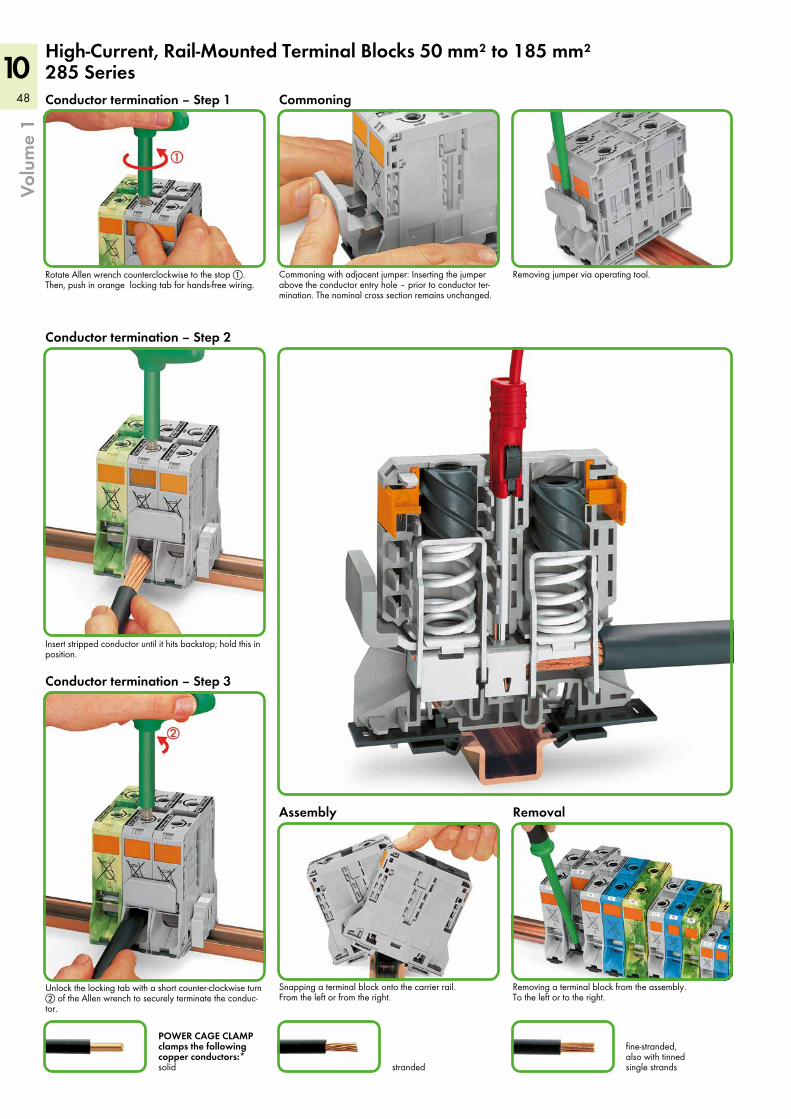
48
10
Insert stripped conductor until it hits backstop; hold this in position.
High-Current, Rail-Mounted Terminal Blocks 50 mm² to 185 mm² 285 Series
fine-stranded, also with tinned single strandsstranded
POWER CAGE CLAMP clamps the following copper conductors:* solid
Volu
me
1
Removing a terminal block from the assembly. To the left or to the right.
Snapping a terminal block onto the carrier rail. From the left or from the right.
RemovalAssembly
Commoning
Rotate Allen wrench counterclockwise to the stop !. Then, push in orange locking tab for hands-free wiring.
Commoning with adjacent jumper: Inserting the jumper above the conductor entry hole – prior to conductor ter-mination. The nominal cross section remains unchanged.
Removing jumper via operating tool.
Conductor termination – Step 2
Conductor termination – Step 1
Conductor termination – Step 3
Unlock the locking tab with a short counter-clockwise turn " of the Allen wrench to securely terminate the conduc-tor.
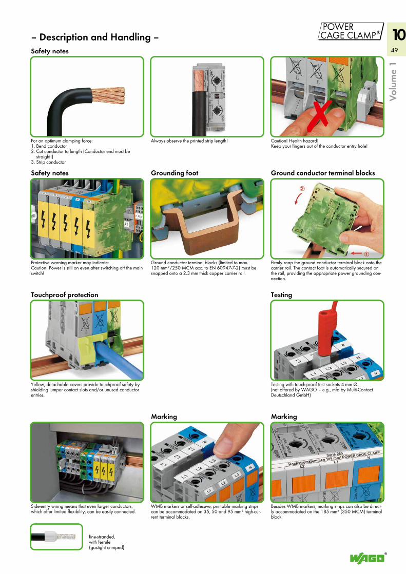
49
10'
Protective warning marker may indicate: Caution! Power is still on even after switching off the main switch!
Caution! Health hazard! Keep your fingers out of the conductor entry hole!
– Description and Handling –
fine-stranded, with ferrule (gastight crimped)
Touchproof protection
Grounding foot Ground conductor terminal blocks
Safety notes
Safety notes
Testing
Volu
me
1
MarkingMarking
Testing with touch-proof test sockets 4 mm Ø. (not offered by WAGO – e.g., mfd by Multi-Contact Deutschland GmbH)
Side-entry wiring means that even larger conductors, which offer limited flexibility, can be easily connected.
Always observe the printed strip length!For an optimum clamping force:1. Bend conductor2. Cut conductor to length (Conductor end must be
straight!)3. Strip conductor
Ground conductor terminal blocks (limited to max. 120 mm²/250 MCM acc. to EN 60947-7-2) must be snapped onto a 2.3 mm thick copper carrier rail.
Firmly snap the ground conductor terminal block onto the carrier rail. The contact foot is automatically secured on the rail, providing the appropriate power grounding con-nection.
Yellow, detachable covers provide touchproof safety by shielding jumper contact slots and/or unused conductor entries.
WMB markers or self-adhesive, printable marking strips can be accommodated on 35, 50 and 95 mm² high-cur-rent terminal blocks.
Besides WMB markers, marking strips can also be direct-ly accommodated on the 185 mm² (350 MCM) terminal block.
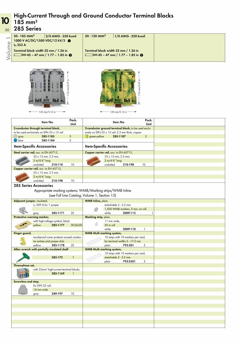
50
10
130 mm/5.12 in
116
mm
/4.5
7 in
130 mm/5.12 in
116
mm
/4.5
7 in
Platzhalter249-197EndklammerMaße fehlen noch
Terminal block width 32 mm / 1.26 in
Item-Specific Accessories
green-yellow
Pack. UnitItem No.
2-conductor ground terminal block, to be used exclu-sively on DIN 35 x 15 rail; 2.3 mm thick, copper
unslotted
unslotted
Copper carrier rail, acc. to EN 60715, 35 x 15 mm, 2.3 mm, 2 m/6’6” long
Copper carrier rail, acc. to EN 60715, 35 x 15 mm, 2.3 mm, 2 m/6’6” long
unslotted
Steel carrier rail, acc. to EN 60715, 35 x 15 mm, 2.3 mm, 2 m/6’6” long
plain
WMB Multi marking system, 10 strips with 10 markers per card, stretchable 5 - 5.2 mm
plain
WMB Multi marking system, 10 strips with 10 markers per card, for terminal widths 5 - 17.5 mm
Allen wrench with partially insulated shaftyellow
Finger guard, touchproof cover protects unused conduc-tor entries and jumper slots
yellow
Protective warning marker, with high-voltage symbol, black
gray
Adjacent jumper, insulated, IN 309 A for 1 jumper
Terminal block width 32 mm / 1.26 in
Item-Specific Accessoriesbluegray
Pack. UnitItem No.
2-conductor through terminal block, to be used exclusively on DIN 35 x 15 rail
High-Current Through and Ground Conductor Terminal Blocks 185 mm² 285 Series
Volu
me
1
L 45 – 47 mm / 1.77 – 1.85 in
IN 353 A
50 - 185 mm² 2/0 AWG - 350 kcmil 50 - 120 mm² 1/0 AWG - 250 kcmil
L 45 – 47 mm / 1.77 – 1.85 in
gray
Screwless end stop, for DIN 35 rail, 14 mm wide
white
Marking strip, plain, 11 mm wide, 50 m roll
Appropriate marking systems: WMB/Marking strips/WMB Inline(see Full Line Catalog, Volume 1, Section 13)
285 Series Accessories
white
WMB Inline, plain, stretchable 5 - 5.2 mm, 1,500 WMB markers, 5 mm, on roll
Three-phase set, with 35mm² high-current terminal blocks
1000 V AC/DC/1500 VDC/12 kV/3
285-1187
210-198
210-198
210-118
793-5501
793-501285-1178
285-1177
285-1171
285-1184285-1185
1
2 2
285-172
555
1
25
(2x25)50
25
10
10
10
5
5
2009-110
1
1
249-197
12009-115
1285-1169
10
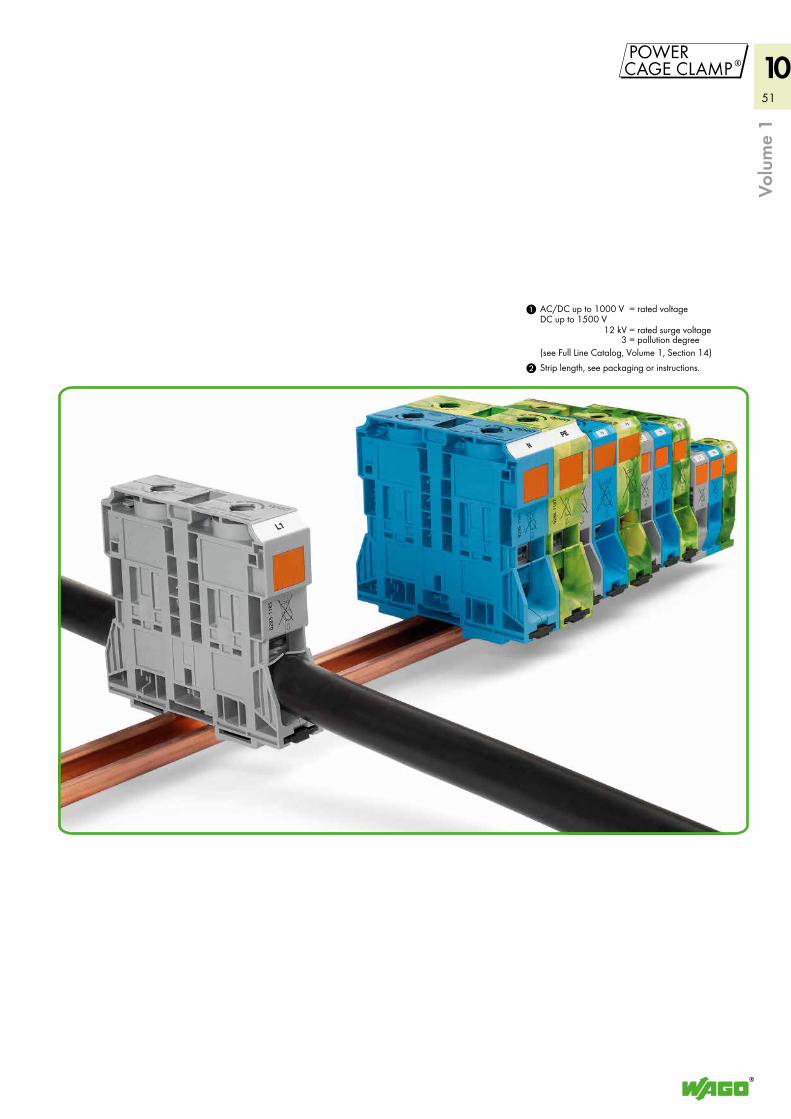
51
10'
Strip length, see packaging or instructions.2
1
Volu
me
1
AC/DC up to 1000 VDC up to 1500 V
= rated voltage
12 kV = rated surge voltage3 = pollution degree
(see Full Line Catalog, Volume 1, Section 14)
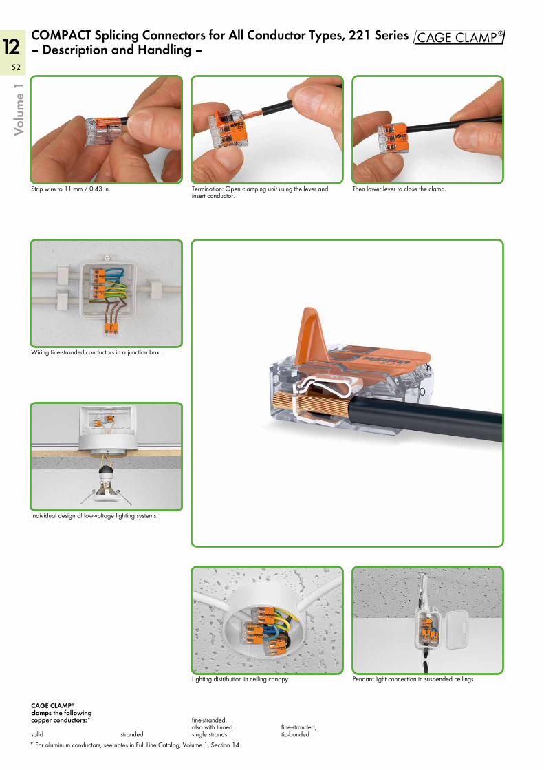
52
12 "Vo
lum
e 1
Lighting distribution in ceiling canopy
Then lower lever to close the clamp.Strip wire to 11 mm / 0.43 in.
COMPACT Splicing Connectors for All Conductor Types, 221 Series – Description and Handling –
* For aluminum conductors, see notes in Full Line Catalog, Volume 1, Section 14.
fine-stranded, tip-bondedstranded
fine-stranded, also with tinned single strands
CAGE CLAMP® clamps the following copper conductors:* solid
Pendant light connection in suspended ceilings
Wiring fine-stranded conductors in a junction box.
Individual design of low-voltage lighting systems.
Termination: Open clamping unit using the lever and insert conductor.
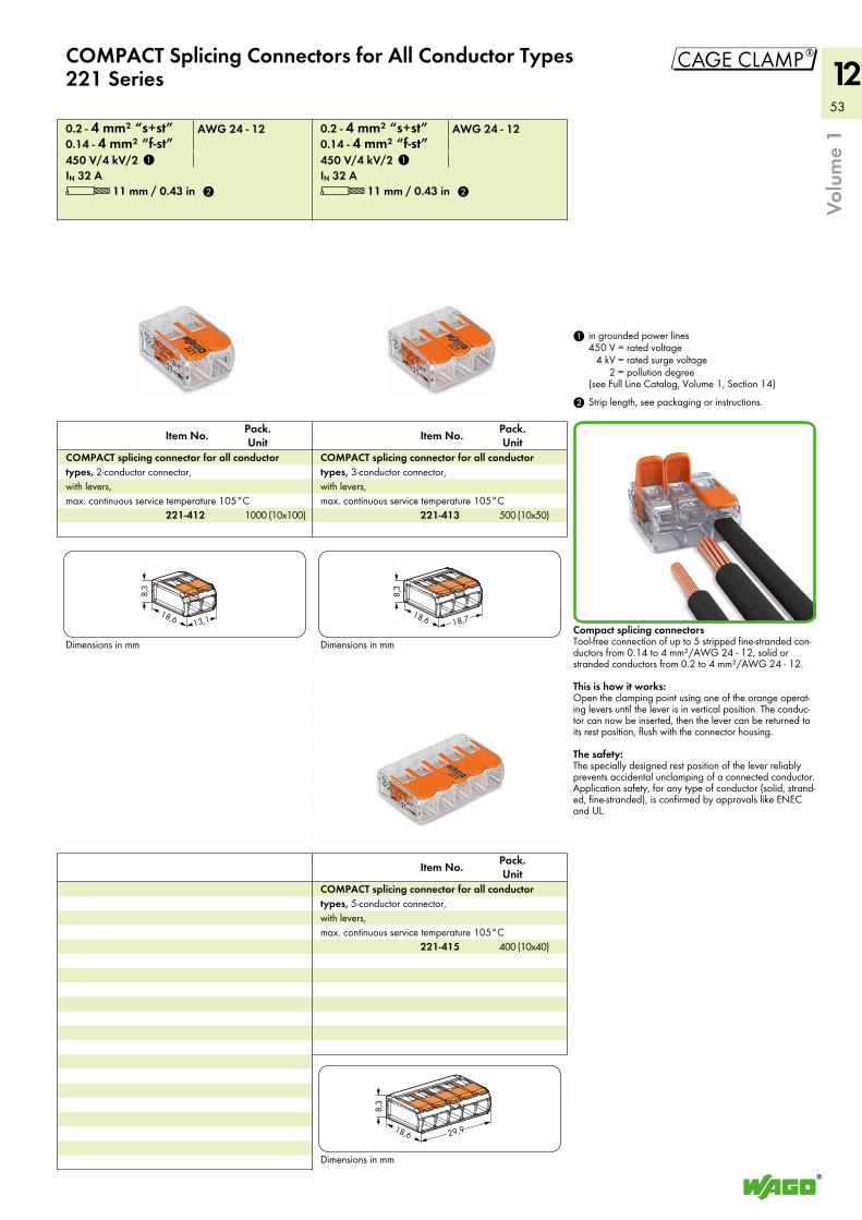
53
12
"
29,9
8,3
18,6
13,1
8,3
18,6 18,7
8,3
18,6
Volu
me
1
Dimensions in mm
IN 32 A450 V/4 kV/20.14 - 4 mm² “f-st”0.2 - 4 mm² “s+st”
Pack. UnitItem No.
COMPACT splicing connector for all conductor types, 3-conductor connector, with levers, max. continuous service temperature 105°C
Pack. UnitItem No.
COMPACT splicing connector for all conductor types, 5-conductor connector, with levers, max. continuous service temperature 105°C
Dimensions in mm
IN 32 A450 V/4 kV/20.14 - 4 mm² “f-st”0.2 - 4 mm² “s+st”
Pack. UnitItem No.
COMPACT splicing connector for all conductor types, 2-conductor connector, with levers, max. continuous service temperature 105°C
Dimensions in mm
COMPACT Splicing Connectors for All Conductor Types221 Series
2 Strip length, see packaging or instructions.
1 in grounded power lines450 V = rated voltage
4 kV = rated surge voltage2 = pollution degree
(see Full Line Catalog, Volume 1, Section 14)
Compact splicing connectors Tool-free connection of up to 5 stripped fine-stranded con-ductors from 0.14 to 4 mm²/AWG 24 - 12, solid or stranded conductors from 0.2 to 4 mm²/AWG 24 - 12.
This is how it works:Open the clamping point using one of the orange operat-ing levers until the lever is in vertical position. The conduc-tor can now be inserted, then the lever can be returned to its rest position, flush with the connector housing.
The safety:The specially designed rest position of the lever reliably prevents accidental unclamping of a connected conductor. Application safety, for any type of conductor (solid, strand-ed, fine-stranded), is confirmed by approvals like ENEC and UL.
AWG 24 - 12 AWG 24 - 12
L 11 mm / 0.43 inL 11 mm / 0.43 in
221-413
221-415
221-412
1
2
1
2
(10x50)500(10x100)1000
(10x40)400

54
12
Pack. UnitItem No.Pack.
UnitItem No.
Volu
me
1
Vario-T-BOXX, Variobox
High-quality Sortimo® cases contain a selection of WAGO connectors for all applications in electrical building instal-lations.
Vario-T-BOXX
High-quality Sortimo® plastic case containing a selection of WAGO installation connectors
Dimensions: 440 x 350 x 80 mm
Variobox
Indestructible Sortimo® metal case containing a selection of WAGO installation connectors
Dimensions: 440 x 330 x 66 mm
Vario-T-BOXX 887-910 1
Contains:
COMPACT PUSH WIRE® connectors for junction boxes2 x 0.5 - 2.5 mm2 2273-202 1003 x 0.5 - 2.5 mm2 2273-203 1005 x 0.5 - 2.5 mm2 2273-205 1008 x 0.5 - 2.5 mm2 2273-208 50
Compact splicing connectors3 x 0.08 - 4 mm2 222-413 505 x 0.08 - 4 mm2 222-415 40
Lighting connectors1 - 2.5 mm2 224-101 100
MICRO PUSH WIRE® connectors for junction boxesdark gray4 x 0.6 - 0.8 mm Ø 243-204 100
red4 x 0.6 - 0.8 mm Ø 243-804 100
dark gray8 x 0.6 - 0.8 mm Ø 243-208 50
Mounting carrierfor 6 connectors 243-113 10
Variobox 887-911 1
Contains:
COMPACT PUSH WIRE® connectors for junction boxes2 x 0.5 - 2.5 mm2 2273-202 1003 x 0.5 - 2.5 mm2 2273-203 1005 x 0.5 - 2.5 mm2 2273-205 1008 x 0.5 - 2.5 mm2 2273-208 50
Compact splicing connectors3 x 0.08 - 4 mm2 222-413 505 x 0.08 - 4 mm2 222-415 40
Lighting connectors1 - 2.5 mm2 224-101 100
MICRO PUSH WIRE® connectors for junction boxesdark gray4 x 0.6 - 0.8 mm Ø 243-204 100
red4 x 0.6 - 0.8 mm Ø 243-804 100
dark gray8 x 0.6 - 0.8 mm Ø 243-208 50
Mounting carrierfor 6 connectors 243-113 10
Vario-T-BOXX and Variobox
Description
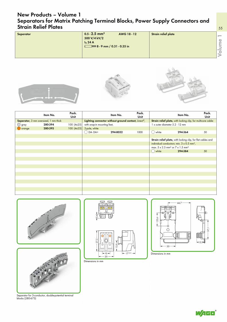
55
15,9
44,7
30
37,1
25,6
(_10 _) <_17 ±0,2 _><___ 20 ____>
<_____
27,3
_____>
<13
,9 >
> 5
,4 <
Volu
me
1
Separator for 3-conductor, double-potential terminal blocks (280-675)
Strain relief plateSeperator
white
orange
Strain relief plate, with locking clip, for flat cables and individual conductors: min. 3 x 0.5 mm², max. 5 x 2.5 mm² or 7 x 1.5 mm²
white
grayStrain relief plate, with locking clip, for multicore cable: 1 x outer diameter 5.2 - 12 mm
Seperator, 3 mm oversized, 1 mm thick
Dimensions in mm
Dimensions in mm
New Products – Volume 1Separators for Matrix Patching Terminal Blocks, Power Supply Connectors and Strain Relief Plates
Pack. Unit
Pack. Unit
Pack. Unit Item No. Item No.Item No.
DA- DA+
Lighting connector without ground contact, Linect®, with snap-in mounting feet, 2-pole, white
L 8 - 9 mm / 0.31 - 0.35 inIN 24 A500 V/4 kV/20.5 - 2.5 mm² AWG 18 - 12
294-384
280-395294-364294-8032
280-394
50
501000(4x25)100(4x25)100
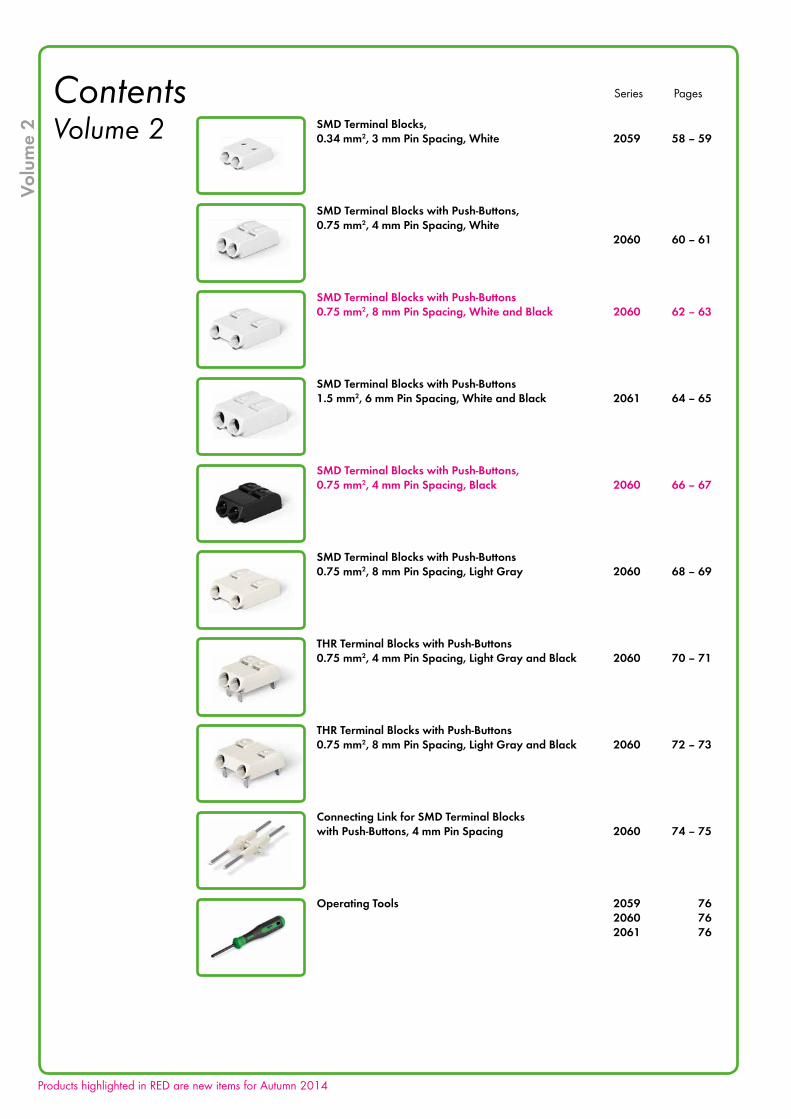
Volu
me
2
Contents Volume 2 SMD Terminal Blocks,
0.34 mm2, 3 mm Pin Spacing, White 2059 58 – 59
SMD Terminal Blocks with Push-Buttons, 0.75 mm2, 4 mm Pin Spacing, White 2060 60 – 61
SMD Terminal Blocks with Push-Buttons 0.75 mm2, 8 mm Pin Spacing, White and Black 2060 62 – 63
SMD Terminal Blocks with Push-Buttons 1.5 mm2, 6 mm Pin Spacing, White and Black 2061 64 – 65
SMD Terminal Blocks with Push-Buttons, 0.75 mm2, 4 mm Pin Spacing, Black 2060 66 – 67
SMD Terminal Blocks with Push-Buttons 0.75 mm2, 8 mm Pin Spacing, Light Gray 2060 68 – 69
THR Terminal Blocks with Push-Buttons 0.75 mm2, 4 mm Pin Spacing, Light Gray and Black 2060 70 – 71
THR Terminal Blocks with Push-Buttons 0.75 mm2, 8 mm Pin Spacing, Light Gray and Black 2060 72 – 73
Connecting Link for SMD Terminal Blocks with Push-Buttons, 4 mm Pin Spacing 2060 74 – 75
Operating Tools 2059 76 2060 76 2061 76
Series Pages
Products highlighted in RED are new items for Autumn 2014
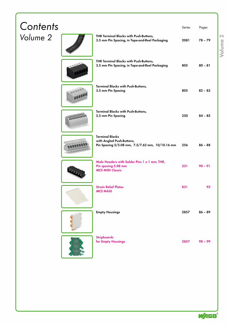
Volu
me
2
Contents Volume 2 THR Terminal Blocks with Push-Buttons,
3.5 mm Pin Spacing, in Tape-and-Reel Packaging 2081 78 – 79
THR Terminal Blocks with Push-Buttons, 3.5 mm Pin Spacing, in Tape-and-Reel Packaging 805 80 – 81
Terminal Blocks with Push-Buttons, 3.5 mm Pin Spacing 805 82 – 83
Terminal Blocks with Push-Buttons, 2.5 mm Pin Spacing 250 84 – 85
Terminal Blocks with Angled Push-Buttons, Pin Spacing 5/5.08 mm, 7.5/7.62 mm, 10/10.16 mm 256 86 – 88
Male Headers with Solder Pins 1 x 1 mm, THR,Pin spacing 5.08 mm 231 90 – 91MCS MIDI Classic
Strain Relief Plates 831 92MCS MAXI
Empty Housings 2857 86 – 89
Stripboardsfor Empty Housings 2857 98 – 99
Series Pages
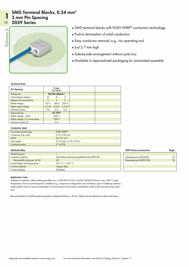
58
158
1Vo
lum
e 2
Approvals are available online at: www.wago.com For more technical information, see Full Line Catalog, Volume 2, Section 11
SMD Terminal Blocks, 0.34 mm2 3 mm Pin Spacing 2059 Series
Technical Data
Pin Spacing 3 mm 0.118 in
Ratings per IEC/EN 60664-1Overvoltage category III III IIDegree of contamination 3 2 2Rated voltage 63 V 160 V 320 VRated surge voltage 2.5 kV 2.5 kV 2.5 kVNominal current 3 A 3 A 3 AApprovals per UL 1977Rated voltage, 1-pole 600 VRated voltage, 2 or more poles 250 VNominal current UL 3 A
Material data:Material group IInsulation material Glass-fiber-reinforced polyphthalamide (PPA-GF)
Flammability rating per UL 94 V0Lower/Upper limit temperature -60 °C / +105 °CContact material Copper alloyContact plating Tin-plated
Conductor data:Connection technology PUSH WIRE®
Conductor size: solid 0.14–0.34 mm2
AWG 26–22 “sol.”Strip length 4–5.5 mm / 0.16–0.22 inConductor entry 0° to PCB
2059 Series accessories: Page:
Operating tool (206-859) 76Operating tool (2059-189) 76
SMD terminal blocks with PUSH WIRE® connection technology
Push-in termination of solid conductors
Easy conductor removal, e.g., via operating tool
Just 2.7 mm high
Side-by-side arrangement without pole loss
Available in tape-and-reel packaging for automated assembly
Application note:Suitable for lead-free, reflow-soldering profiles acc. to DIN EN 61760-1 and IEC 60068-2-58 up to max. 260°C peak temperature. Due to customer-specific variables (e.g., component configuration and orientation, type of soldering machine, solder paste), trial runs are recommended to ensure product and process compatibility under actual manufacturing condi-tions. Recommendation for SMD positioning pattern: Material thickness, 150 µm. Pattern layout identical to solder pad layout.
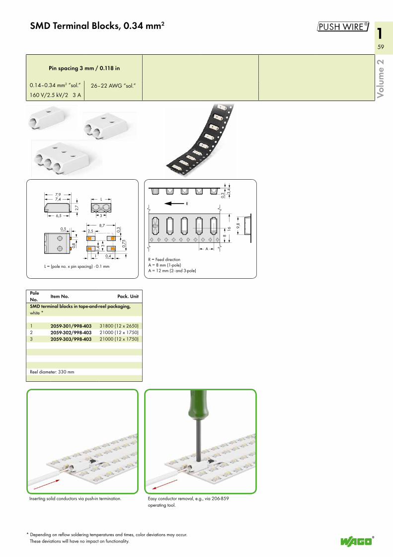
59
159
1
3( )
1<_>
2,5 <>8,7<____ ____>
0,4 <___>
0,5 <___>
0,8
(__>
0,3
<___
>0,
75<
___
>
<1,
4>
L<_ _>7,4<__ __>7,9<__ __>
6,5<_ _>
<2,
7>
3(
)
L = (pole no. x pin spacing) - 0.1 mm
< >A
<___>
0,3
<__
__>
16
R
3,4
><
8>
<
<>
9,8
R = Feed directionA = 8 mm (1-pole)A = 12 mm (2- and 3-pole)
$
Volu
me
2
SMD Terminal Blocks, 0.34 mm2
Pole No.
Item No. Pack. Unit
SMD terminal blocks in tape-and-reel packaging, white *
1 2059-301/998-403 31800 (12 x 2650)2 2059-302/998-403 21000 (12 x 1750)3 2059-303/998-403 21000 (12 x 1750)
Reel diameter: 330 mm
Pin spacing 3 mm / 0.118 in
0.14–0.34 mm2 “sol.” 26–22 AWG “sol.”160 V/2.5 kV/2 3 A
Inserting solid conductors via push-in termination. Easy conductor removal, e.g., via 206-859 operating tool.
* Depending on reflow soldering temperatures and times, color deviations may occur. These deviations will have no impact on functionality.
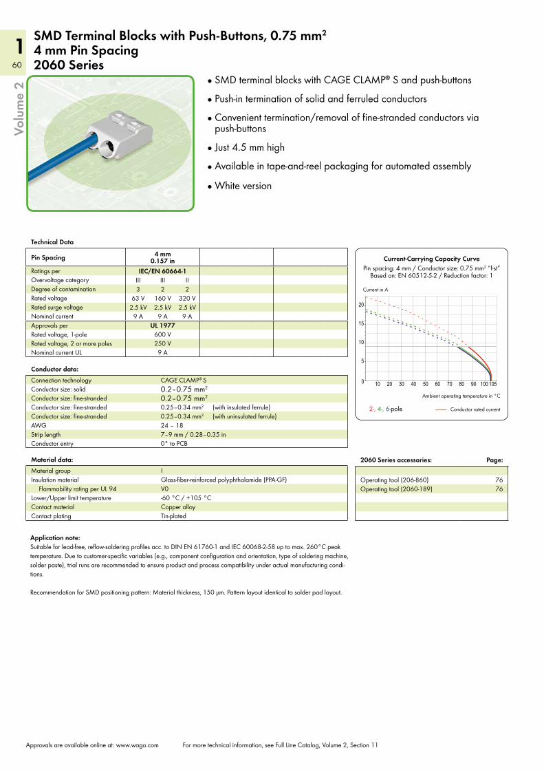
60
160
1
10 20 30 40 50 60 70 80 90 100 1050
5
10
15
20
Volu
me
2
Approvals are available online at: www.wago.com For more technical information, see Full Line Catalog, Volume 2, Section 11
SMD Terminal Blocks with Push-Buttons, 0.75 mm2
4 mm Pin Spacing 2060 Series
Technical Data
Pin Spacing 4 mm 0.157 in
Ratings per IEC/EN 60664-1Overvoltage category III III IIDegree of contamination 3 2 2Rated voltage 63 V 160 V 320 VRated surge voltage 2.5 kV 2.5 kV 2.5 kVNominal current 9 A 9 A 9 AApprovals per UL 1977Rated voltage, 1-pole 600 VRated voltage, 2 or more poles 250 VNominal current UL 9 A
Material data:Material group IInsulation material Glass-fiber-reinforced polyphthalamide (PPA-GF)
Flammability rating per UL 94 V0Lower/Upper limit temperature -60 °C / +105 °CContact material Copper alloyContact plating Tin-plated
Conductor data:Connection technology CAGE CLAMP® S
Conductor size: solid 0.2–0.75 mm2
Conductor size: fine-stranded 0.2–0.75 mm2
Conductor size: fine-stranded 0.25–0.34 mm2 (with insulated ferrule)Conductor size: fine-stranded 0.25–0.34 mm2 (with uninsulated ferrule)AWG 24 – 18Strip length 7–9 mm / 0.28–0.35 inConductor entry 0° to PCB
2060 Series accessories: Page:
Operating tool (206-860) 76Operating tool (2060-189) 76
Current-Carrying Capacity CurvePin spacing: 4 mm / Conductor size: 0.75 mm2 “f-st”
Based on: EN 60512-5-2 / Reduction factor: 1
Ambient operating temperature in °C
Conductor rated current 2-, 4-, 6-pole
Current in A
SMD terminal blocks with CAGE CLAMP® S and push-buttons
Push-in termination of solid and ferruled conductors
Convenient termination/removal of fine-stranded conductors via push-buttons
Just 4.5 mm high
Available in tape-and-reel packaging for automated assembly
White version
Application note:Suitable for lead-free, reflow-soldering profiles acc. to DIN EN 61760-1 and IEC 60068-2-58 up to max. 260°C peak temperature. Due to customer-specific variables (e.g., component configuration and orientation, type of soldering machine, solder paste), trial runs are recommended to ensure product and process compatibility under actual manufacturing condi-tions. Recommendation for SMD positioning pattern: Material thickness, 150 µm. Pattern layout identical to solder pad layout.
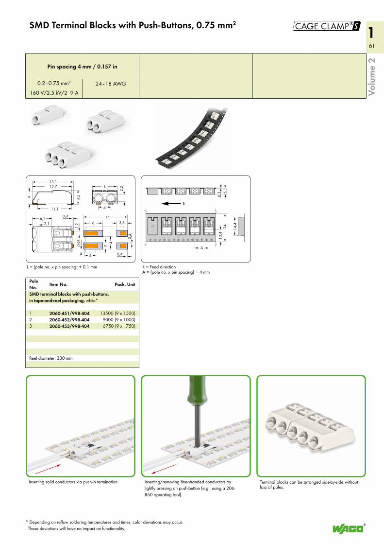
61
161
1
<2,1> 1,
2
2,2
<____
>
L<___ ___>
4< >
<_<6,1 _> 14<__________ _______>
6<_ _> 3,5 <>
4<2 <
>> 0,
4<
___
>
0,4 <___>>0,
95<
___
<__
)
4( )
<_______ _______>12,7<_____ ____>
11,1<____ ____>
4<
>
4,5
<>
13,1
0,4___>
< >A
<___>0,3
<__
__>
24
R
5,3
><
10,4
><
<>
14,4
!
Volu
me
2
SMD Terminal Blocks with Push-Buttons, 0.75 mm2
Pole No.
Item No. Pack. Unit
SMD terminal blocks with push-buttons, in tape-and-reel packaging, white*
1 2060-451/998-404 13500 (9 x 1500)2 2060-452/998-404 9000 (9 x 1000)3 2060-453/998-404 6750 (9 x 750)
Reel diameter: 330 mm
Pin spacing 4 mm / 0.157 in
0.2–0.75 mm2 24–18 AWG160 V/2.5 kV/2 9 A
Inserting solid conductors via push-in termination. Inserting/removing fine-stranded conductors by lightly pressing on push-button (e.g., using a 206-860 operating tool).
L = (pole no. x pin spacing) + 0.1 mm
Terminal blocks can be arranged side-by-side without loss of poles.
R = Feed directionA = (pole no. x pin spacing) + 4 mm
* Depending on reflow soldering temperatures and times, color deviations may occur. These deviations will have no impact on functionality.
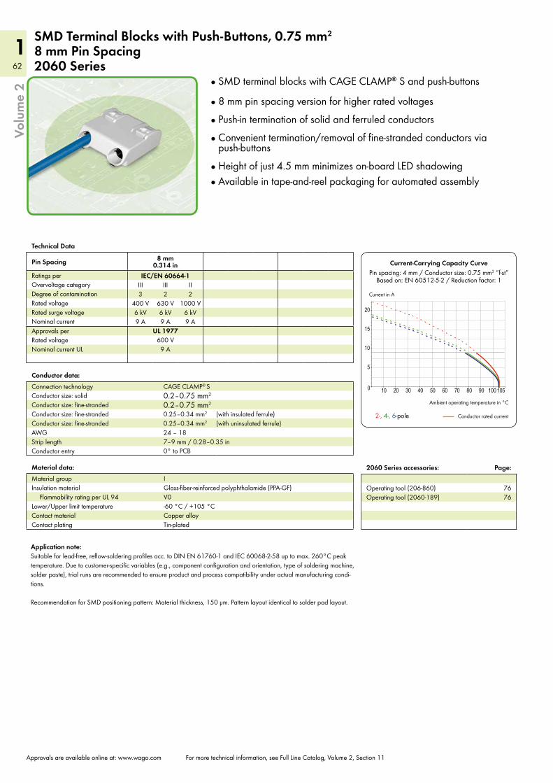
62
162
1
10 20 30 40 50 60 70 80 90 100 1050
5
10
15
20
Volu
me
2
Approvals are available online at: www.wago.com For more technical information, see Full Line Catalog, Volume 2, Section 11
SMD Terminal Blocks with Push-Buttons, 0.75 mm2
8 mm Pin Spacing2060 Series
Technical Data
Pin Spacing 8 mm 0.314 in
Ratings per IEC/EN 60664-1Overvoltage category III III IIDegree of contamination 3 2 2Rated voltage 400 V 630 V 1000 VRated surge voltage 6 kV 6 kV 6 kVNominal current 9 A 9 A 9 AApprovals per UL 1977Rated voltage 600 VNominal current UL 9 A
Material data:Material group IInsulation material Glass-fiber-reinforced polyphthalamide (PPA-GF)
Flammability rating per UL 94 V0Lower/Upper limit temperature -60 °C / +105 °CContact material Copper alloyContact plating Tin-plated
Conductor data:Connection technology CAGE CLAMP® S
Conductor size: solid 0.2–0.75 mm2
Conductor size: fine-stranded 0.2–0.75 mm2
Conductor size: fine-stranded 0.25–0.34 mm2 (with insulated ferrule)Conductor size: fine-stranded 0.25–0.34 mm2 (with uninsulated ferrule)AWG 24 – 18Strip length 7–9 mm / 0.28–0.35 inConductor entry 0° to PCB
Current-Carrying Capacity CurvePin spacing: 4 mm / Conductor size: 0.75 mm2 “f-st”
Based on: EN 60512-5-2 / Reduction factor: 1
Ambient operating temperature in °C
Conductor rated current 2-, 4-, 6-pole
Current in A
SMD terminal blocks with CAGE CLAMP® S and push-buttons
8 mm pin spacing version for higher rated voltages
Push-in termination of solid and ferruled conductors
Convenient termination/removal of fine-stranded conductors via push-buttons
Height of just 4.5 mm minimizes on-board LED shadowing Available in tape-and-reel packaging for automated assembly
Application note:Suitable for lead-free, reflow-soldering profiles acc. to DIN EN 61760-1 and IEC 60068-2-58 up to max. 260°C peak temperature. Due to customer-specific variables (e.g., component configuration and orientation, type of soldering machine, solder paste), trial runs are recommended to ensure product and process compatibility under actual manufacturing condi-tions. Recommendation for SMD positioning pattern: Material thickness, 150 µm. Pattern layout identical to solder pad layout.
2060 Series accessories: Page:
Operating tool (206-860) 76Operating tool (2060-189) 76
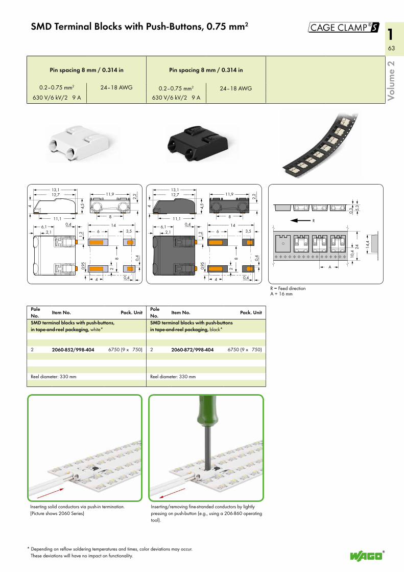
63
163
1
0,4 <___>2,1> 1,
2
<_<6,1 _> 14<__________ _______>
6<_ _> 3,5 <>
<2
>
0,4
<___
>
0,4 <___>>0,
95<
__
2,2
<____
>
11,9<______ ______>
8<___ ___>
4( )
<___
8<
___
___>
>
<_______ _______>12,7<_____ ____>
11,1<____ ____>
4<
>
4,5
<>
13,1
< >A
<___>0,3
<__
__>
24
R
5,3
><
10,4
><
<>
14,4
!
0,4 <___>2,1> 1,
2
<_<6,1 _> 14<__________ _______>
6<_ _> 3,5 <><
2>
0,4
<___
>
0,4 <___>>0,
95<
__
2,2
<____
>
11,9<______ ______>
8<___ ___>
4( )
<___
8<
___
___>
>
<_______ _______>12,7<_____ ____>
11,1<____ ____>
4<
>
4,5
<>
13,1
Volu
me
2
SMD Terminal Blocks with Push-Buttons, 0.75 mm2
Pin spacing 8 mm / 0.314 in Pin spacing 8 mm / 0.314 in
0.2–0.75 mm2 24–18 AWG 0.2–0.75 mm2 24–18 AWG630 V/6 kV/2 9 A 630 V/6 kV/2 9 A
Inserting solid conductors via push-in termination. (Picture shows 2060 Series)
R = Feed directionA + 16 mm
Inserting/removing fine-stranded conductors by lightly pressing on push-button (e.g., using a 206-860 operating tool).
* Depending on reflow soldering temperatures and times, color deviations may occur. These deviations will have no impact on functionality.
Pole No.
Item No. Pack. UnitPole No.
Item No. Pack. Unit
SMD terminal blocks with push-buttons, in tape-and-reel packaging, white*
SMD terminal blocks with push-buttons in tape-and-reel packaging, black*
2 2060-852/998-404 6750 (9 x 750) 2 2060-872/998-404 6750 (9 x 750)
Reel diameter: 330 mm Reel diameter: 330 mm
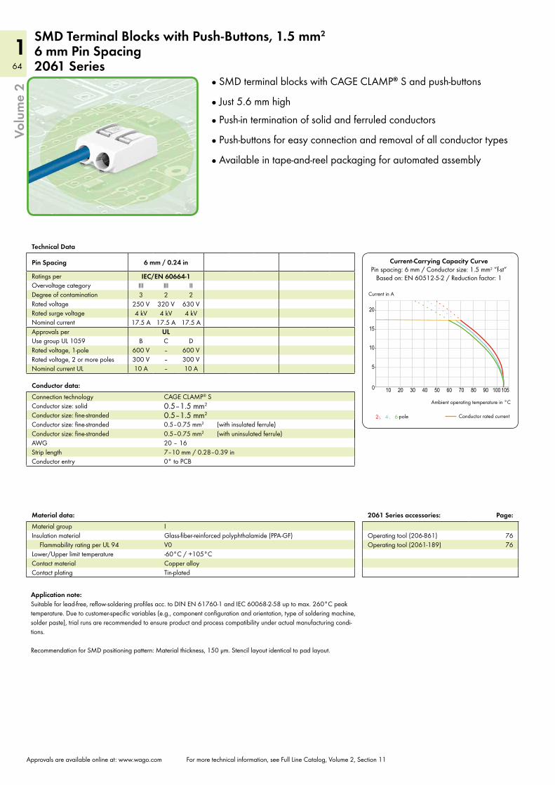
64
164
1
10 20 30 40 50 60 70 80 90 100 1050
5
10
15
20
2-, 4-, 6-
Current-Carrying Capacity CurvePin spacing: 6 mm / Conductor size: 1.5 mm2 “f-st”
Based on: EN 60512-5-2 / Reduction factor: 1
Current in A
Ambient operating temperature in °C
Conductor rated currentpole
Volu
me
2
Approvals are available online at: www.wago.com For more technical information, see Full Line Catalog, Volume 2, Section 11
SMD Terminal Blocks with Push-Buttons, 1.5 mm2
6 mm Pin Spacing2061 Series
Technical Data
Pin Spacing 6 mm / 0.24 in
Ratings per IEC/EN 60664-1Overvoltage category III III IIDegree of contamination 3 2 2Rated voltage 250 V 320 V 630 VRated surge voltage 4 kV 4 kV 4 kVNominal current 17.5 A 17.5 A 17.5 AApprovals per UL Use group UL 1059 B C DRated voltage, 1-pole 600 V – 600 VRated voltage, 2 or more poles 300 V – 300 VNominal current UL 10 A – 10 A
Material data:Material group IInsulation material Glass-fiber-reinforced polyphthalamide (PPA-GF)
Flammability rating per UL 94 V0Lower/Upper limit temperature -60°C / +105°CContact material Copper alloyContact plating Tin-plated
Conductor data:Connection technology CAGE CLAMP® S
Conductor size: solid 0.5–1.5 mm2
Conductor size: fine-stranded 0.5–1.5 mm2
Conductor size: fine-stranded 0.5–0.75 mm2 (with insulated ferrule)Conductor size: fine-stranded 0.5–0.75 mm2 (with uninsulated ferrule)AWG 20 – 16Strip length 7–10 mm / 0.28–0.39 inConductor entry 0° to PCB
SMD terminal blocks with CAGE CLAMP® S and push-buttons
Just 5.6 mm high
Push-in termination of solid and ferruled conductors
Push-buttons for easy connection and removal of all conductor types
Available in tape-and-reel packaging for automated assembly
Application note:Suitable for lead-free, reflow-soldering profiles acc. to DIN EN 61760-1 and IEC 60068-2-58 up to max. 260°C peak temperature. Due to customer-specific variables (e.g., component configuration and orientation, type of soldering machine, solder paste), trial runs are recommended to ensure product and process compatibility under actual manufacturing condi-tions. Recommendation for SMD positioning pattern: Material thickness, 150 µm. Stencil layout identical to pad layout.
2061 Series accessories: Page:
Operating tool (206-861) 76Operating tool (2061-189) 76
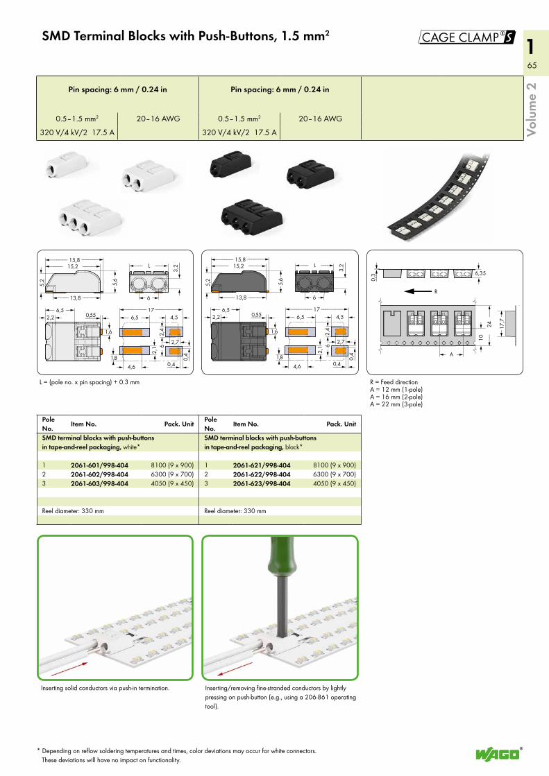
65
165
1
>
<_______ _______>15,2<_____ _____>
13,8<____ _____>
0,55 <____>2,2>
5,2
<>
5,6
<>
15,8
3,2
<____
>
L<___ ___>
6< >
<_<6,5 _> 17<_________ _________>
6,5<_ _> 4,5 <>
6<2,
1<
>
0,4
<___>
2,7 <>
)<
<
<2,
4
1,8
<> 4,6
>
1,6
0,4 <___>
>
<_______ _______>15,2<_____ _____>
13,8<____ _____>
0,55 <____>2,2>
5,2
<>
5,6
<>
15,8
3,2
<____
>
L<___ ___>
6< >
<_<6,5 _> 17<_________ _________>
6,5<_ _> 4,5 <>6<
2,1
<>
0,4
<___>
2,7 <>
)<
<
<2,
4
1,8
<> 4,6
>
1,6
0,4 <___>
< >A
<__>
0,3
<__
__>
24
R
6,35
><
10>
<
<>
17,7
!
Volu
me
2
SMD Terminal Blocks with Push-Buttons, 1.5 mm2
Pole No.
Item No. Pack. UnitPole No.
Item No. Pack. Unit
SMD terminal blocks with push-buttons in tape-and-reel packaging, white*
SMD terminal blocks with push-buttons in tape-and-reel packaging, black*
1 2061-601/998-404 8100 (9 x 900) 1 2061-621/998-404 8100 (9 x 900)2 2061-602/998-404 6300 (9 x 700) 2 2061-622/998-404 6300 (9 x 700)3 2061-603/998-404 4050 (9 x 450) 3 2061-623/998-404 4050 (9 x 450)
Reel diameter: 330 mm Reel diameter: 330 mm
Pin spacing: 6 mm / 0.24 in Pin spacing: 6 mm / 0.24 in
0.5–1.5 mm2 20–16 AWG 0.5–1.5 mm2 20–16 AWG
320 V/4 kV/2 17.5 A 320 V/4 kV/2 17.5 A
Inserting solid conductors via push-in termination.
R = Feed directionA = 12 mm (1-pole)A = 16 mm (2-pole)A = 22 mm (3-pole)
L = (pole no. x pin spacing) + 0.3 mm
* Depending on reflow soldering temperatures and times, color deviations may occur for white connectors. These deviations will have no impact on functionality.
Inserting/removing fine-stranded conductors by lightly pressing on push-button (e.g., using a 206-861 operating tool).
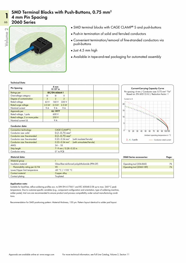
66
166
1
10 20 30 40 50 60 70 80 90 100 1050
5
10
15
20
Volu
me
2
Approvals are available online at: www.wago.com For more technical information, see Full Line Catalog, Volume 2, Section 11
SMD Terminal Blocks with Push-Buttons, 0.75 mm2
4 mm Pin Spacing2060 Series
Technical Data
Pin Spacing 4 mm 0.157 in
Ratings per IEC/EN 60664-1Overvoltage category III III IIDegree of contamination 3 2 2Rated voltage 63 V 160 V 320 VRated surge voltage 2.5 kV 2.5 kV 2.5 kVNominal current 9 A 9 A 9 AApprovals per UL 1977Rated voltage, 1-pole 600 VRated voltage, 2 or more poles 250 VNominal current UL 9 A
Material data:Material group IInsulation material Glass-fiber-reinforced polyphthalamide (PPA-GF)
Flammability rating per UL 94 V0Lower/Upper limit temperature -60 °C / +105 °CContact material Copper alloyContact plating Tin-plated
Conductor data:Connection technology CAGE CLAMP® S
Conductor size: solid 0.2–0.75 mm2
Conductor size: fine-stranded 0.2–0.75 mm2
Conductor size: fine-stranded 0.25–0.34 mm2 (with insulated ferrule)Conductor size: fine-stranded 0.25–0.34 mm2 (with uninsulated ferrule)AWG 24 – 18Strip length 7–9 mm / 0.28–0.35 inConductor entry 0° to PCB
2060 Series accessories: Page:
Operating tool (206-860) 76Operating tool (2060-189) 76
Current-Carrying Capacity CurvePin spacing: 4 mm / Conductor size: 0.75 mm2 “f-st”
Based on: EN 60512-5-2 / Reduction factor: 1
Ambient operating temperature in °C
Conductor rated current 2-, 4-, 6-pole
Current in A
SMD terminal blocks with CAGE CLAMP® S and push-buttons
Push-in termination of solid and ferruled conductors
Convenient termination/removal of fine-stranded conductors via push-buttons
Just 4.5 mm high
Available in tape-and-reel packaging for automated assembly
Application note:Suitable for lead-free, reflow-soldering profiles acc. to DIN EN 61760-1 and IEC 60068-2-58 up to max. 260°C peak temperature. Due to customer-specific variables (e.g., component configuration and orientation, type of soldering machine, solder paste), trial runs are recommended to ensure product and process compatibility under actual manufacturing condi-tions. Recommendation for SMD positioning pattern: Material thickness, 150 µm. Pattern layout identical to solder pad layout.
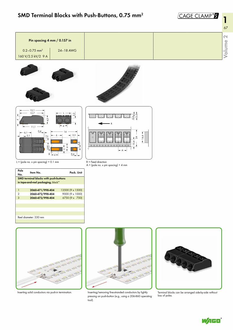
67
167
1!
< >A
<___>0,3
<__
__>
24
R
5,3
><
10,4
><
<>
14,4
<2,1> 1,
2
2,2
<____
>
L<___ ___>
4< >
<_<6,1 _> 14<__________ _______>
6<_ _> 3,5 <>
4<2 <
>> 0,
4<
___
>
0,4 <___>>0,
95<
___
<__
)
4( )
<_______ _______>12,7<_____ ____>
11,1<____ ____>
4<
>
4,5
<>
13,1
0,4___>
Volu
me
2
SMD Terminal Blocks with Push-Buttons, 0.75 mm2
Pole No.
Item No. Pack. Unit
SMD terminal blocks with push-buttons in tape-and-reel packaging, black*
1 2060-471/998-404 13500 (9 x 1500)2 2060-472/998-404 9000 (9 x 1000)3 2060-473/998-404 6750 (9 x 750)
Reel diameter: 330 mm
Pin spacing 4 mm / 0.157 in
0.2–0.75 mm2 24–18 AWG
160 V/2.5 kV/2 9 A
Inserting solid conductors via push-in termination. Inserting/removing fine-stranded conductors by lightly pressing on push-button (e.g., using a 206-860 operating tool).
L = (pole no. x pin spacing) + 0.1 mm
Terminal blocks can be arranged side-by-side without loss of poles.
R = Feed directionA = (pole no. x pin spacing) + 4 mm
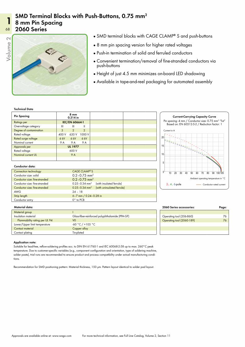
68
168
1
10 20 30 40 50 60 70 80 90 100 1050
5
10
15
20
Volu
me
2
Approvals are available online at: www.wago.com For more technical information, see Full Line Catalog, Volume 2, Section 11
SMD Terminal Blocks with Push-Buttons, 0.75 mm2
8 mm Pin Spacing2060 Series
Technical Data
Pin Spacing 8 mm 0.314 in
Ratings per IEC/EN 60664-1Overvoltage category III III IIDegree of contamination 3 2 2Rated voltage 400 V 630 V 1000 VRated surge voltage 6 kV 6 kV 6 kVNominal current 9 A 9 A 9 AApprovals per UL 1977Rated voltage 600 VNominal current UL 9 A
Material data:Material group IInsulation material Glass-fiber-reinforced polyphthalamide (PPA-GF)
Flammability rating per UL 94 V0Lower/Upper limit temperature -60 °C / +105 °CContact material Copper alloyContact plating Tin-plated
Conductor data:Connection technology CAGE CLAMP® S
Conductor size: solid 0.2–0.75 mm2
Conductor size: fine-stranded 0.2–0.75 mm2
Conductor size: fine-stranded 0.25–0.34 mm2 (with insulated ferrule)Conductor size: fine-stranded 0.25–0.34 mm2 (with uninsulated ferrule)AWG 24 – 18Strip length 6–7 mm / 0.24–0.28 inConductor entry 0° to PCB
Current-Carrying Capacity CurvePin spacing: 4 mm / Conductor size: 0.75 mm2 “f-st”
Based on: EN 60512-5-2 / Reduction factor: 1
Ambient operating temperature in °C
Conductor rated current 2-, 4-, 6-pole
Current in A
SMD terminal blocks with CAGE CLAMP® S and push-buttons
8 mm pin spacing version for higher rated voltages
Push-in termination of solid and ferruled conductors
Convenient termination/removal of fine-stranded conductors via push-buttons
Height of just 4.5 mm minimizes on-board LED shadowing
Available in tape-and-reel packaging for automated assembly
Application note:Suitable for lead-free, reflow-soldering profiles acc. to DIN EN 61760-1 and IEC 60068-2-58 up to max. 260°C peak temperature. Due to customer-specific variables (e.g., component configuration and orientation, type of soldering machine, solder paste), trial runs are recommended to ensure product and process compatibility under actual manufacturing condi-tions. Recommendation for SMD positioning pattern: Material thickness, 150 µm. Pattern layout identical to solder pad layout.
2060 Series accessories: Page:
Operating tool (206-860) 76Operating tool (2060-189) 76
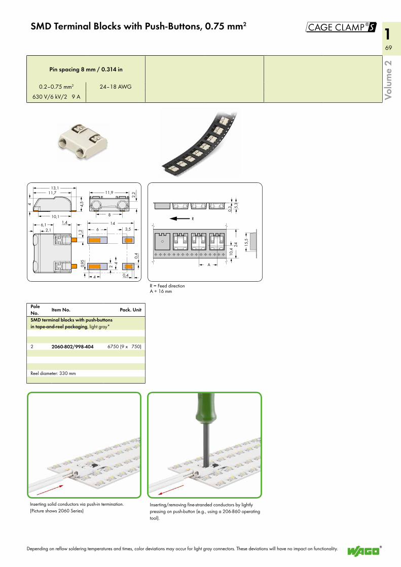
69
169
1
1,4 <___>2,1> 1,
2
<_<6,1 _> 14<__________ _______>
6<_ _> 3,5 <>
4<2 <
>> 0,
4<
___
>
0,4 <___>>0,
95<
___
<__
)
2,2
<____
>
11,9<______ ______>
8<___ ___>
<_______ _______>11,7<_____ ____>
10,1<____ ____>
4<
>
4,5
<>
13,1
4( )
< >A
<___>0,3
<__
__>
24
R
5,3
><
10,4
><
<>
15,5
!
Volu
me
2
SMD Terminal Blocks with Push-Buttons, 0.75 mm2
Pole No.
Item No. Pack. Unit
SMD terminal blocks with push-buttons in tape-and-reel packaging, light gray*
2 2060-802/998-404 6750 (9 x 750)
Reel diameter: 330 mm
Pin spacing 8 mm / 0.314 in
0.2–0.75 mm2 24–18 AWG
630 V/6 kV/2 9 A
Inserting solid conductors via push-in termination. (Picture shows 2060 Series)
Depending on reflow soldering temperatures and times, color deviations may occur for light gray connectors. These deviations will have no impact on functionality.
R = Feed directionA + 16 mm
Inserting/removing fine-stranded conductors by lightly pressing on push-button (e.g., using a 206-860 operating tool).
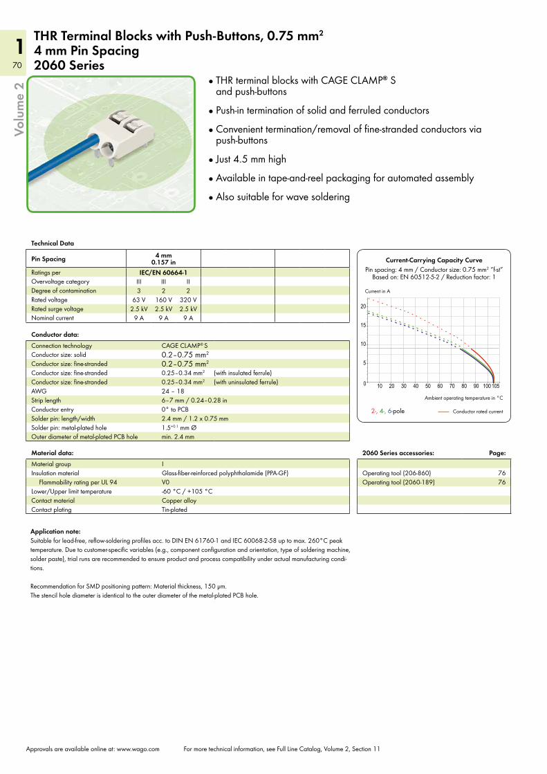
70
170
1
10 20 30 40 50 60 70 80 90 100 1050
5
10
15
20
Volu
me
2
Approvals are available online at: www.wago.com For more technical information, see Full Line Catalog, Volume 2, Section 11
THR Terminal Blocks with Push-Buttons, 0.75 mm2
4 mm Pin Spacing2060 Series
Technical Data
Pin Spacing 4 mm 0.157 in
Ratings per IEC/EN 60664-1Overvoltage category III III IIDegree of contamination 3 2 2Rated voltage 63 V 160 V 320 VRated surge voltage 2.5 kV 2.5 kV 2.5 kVNominal current 9 A 9 A 9 A
Material data:Material group IInsulation material Glass-fiber-reinforced polyphthalamide (PPA-GF)
Flammability rating per UL 94 V0Lower/Upper limit temperature -60 °C / +105 °CContact material Copper alloyContact plating Tin-plated
Conductor data:Connection technology CAGE CLAMP® S
Conductor size: solid 0.2–0.75 mm2
Conductor size: fine-stranded 0.2–0.75 mm2
Conductor size: fine-stranded 0.25–0.34 mm2 (with insulated ferrule)Conductor size: fine-stranded 0.25–0.34 mm2 (with uninsulated ferrule)AWG 24 – 18Strip length 6–7 mm / 0.24–0.28 inConductor entry 0° to PCBSolder pin: length/width 2.4 mm / 1.2 x 0.75 mmSolder pin: metal-plated hole 1.5+0.1 mm ØOuter diameter of metal-plated PCB hole min. 2.4 mm
Current-Carrying Capacity CurvePin spacing: 4 mm / Conductor size: 0.75 mm2 “f-st”
Based on: EN 60512-5-2 / Reduction factor: 1
Ambient operating temperature in °C
Conductor rated current 2-, 4-, 6-pole
Current in A
THR terminal blocks with CAGE CLAMP® S and push-buttons
Push-in termination of solid and ferruled conductors
Convenient termination/removal of fine-stranded conductors via push-buttons
Just 4.5 mm high
Available in tape-and-reel packaging for automated assembly
Also suitable for wave soldering
Application note:Suitable for lead-free, reflow-soldering profiles acc. to DIN EN 61760-1 and IEC 60068-2-58 up to max. 260°C peak temperature. Due to customer-specific variables (e.g., component configuration and orientation, type of soldering machine, solder paste), trial runs are recommended to ensure product and process compatibility under actual manufacturing condi-tions. Recommendation for SMD positioning pattern: Material thickness, 150 µm. The stencil hole diameter is identical to the outer diameter of the metal-plated PCB hole.
2060 Series accessories: Page:
Operating tool (206-860) 76Operating tool (2060-189) 76
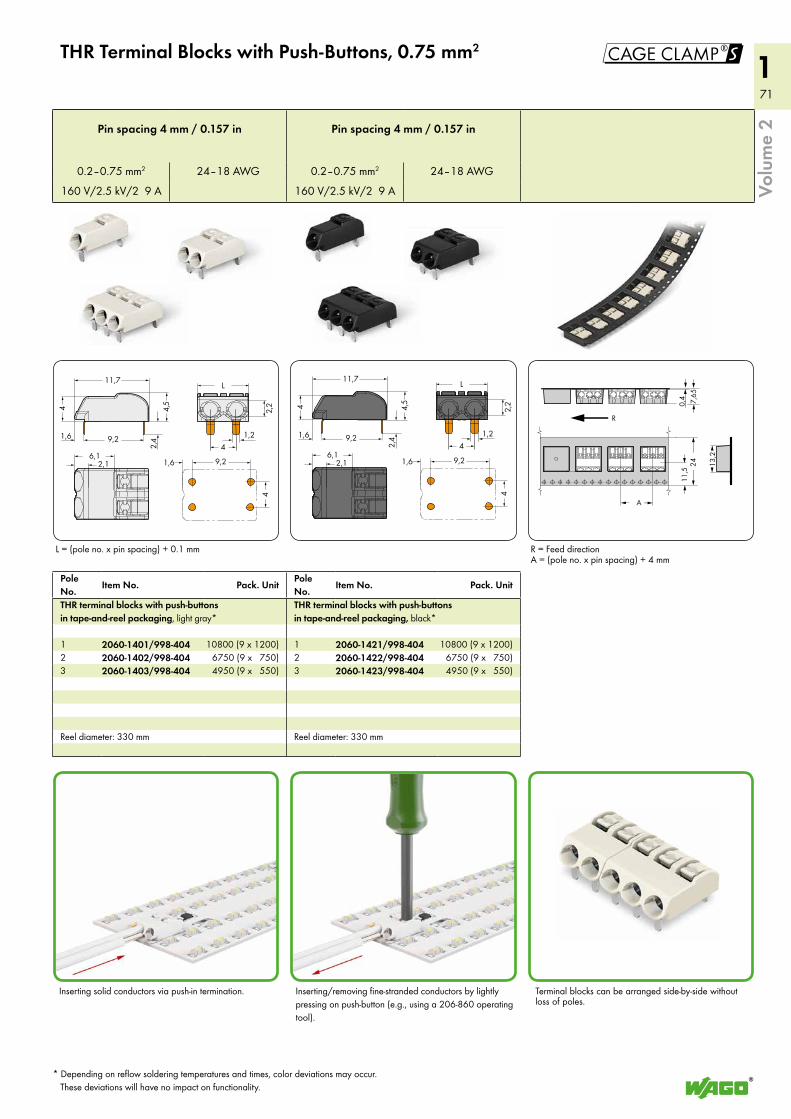
71
171
1
11,7
9,2
2,16,1
1,6
4,54
2,4
L
2,2
9,21,6
4
41,2
< >A
<___>
0,4
<__
__>
24
R
7,65
><
11,5
><
()
13,2
!
11,7
9,2
2,16,1
1,6
4,54
2,4
L
2,2
9,21,6
4
41,2
Volu
me
2
THR Terminal Blocks with Push-Buttons, 0.75 mm2
Pole No.
Item No. Pack. UnitPole No.
Item No. Pack. Unit
THR terminal blocks with push-buttons in tape-and-reel packaging, light gray*
THR terminal blocks with push-buttons in tape-and-reel packaging, black*
1 2060-1401/998-404 10800 (9 x 1200) 1 2060-1421/998-404 10800 (9 x 1200)2 2060-1402/998-404 6750 (9 x 750) 2 2060-1422/998-404 6750 (9 x 750)3 2060-1403/998-404 4950 (9 x 550) 3 2060-1423/998-404 4950 (9 x 550)
Reel diameter: 330 mm Reel diameter: 330 mm
Pin spacing 4 mm / 0.157 in Pin spacing 4 mm / 0.157 in
0.2–0.75 mm2 24–18 AWG 0.2–0.75 mm2 24–18 AWG
160 V/2.5 kV/2 9 A 160 V/2.5 kV/2 9 A
Inserting solid conductors via push-in termination.
L = (pole no. x pin spacing) + 0.1 mm
Terminal blocks can be arranged side-by-side without loss of poles.
R = Feed directionA = (pole no. x pin spacing) + 4 mm
Inserting/removing fine-stranded conductors by lightly pressing on push-button (e.g., using a 206-860 operating tool).
* Depending on reflow soldering temperatures and times, color deviations may occur. These deviations will have no impact on functionality.
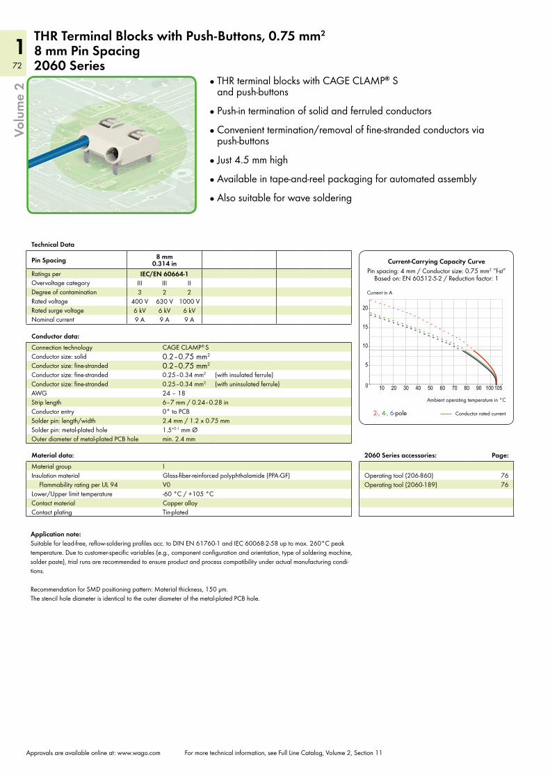
72
172
1
10 20 30 40 50 60 70 80 90 100 1050
5
10
15
20
Volu
me
2
Approvals are available online at: www.wago.com For more technical information, see Full Line Catalog, Volume 2, Section 11
THR Terminal Blocks with Push-Buttons, 0.75 mm2
8 mm Pin Spacing2060 Series
Technical Data
Pin Spacing 8 mm 0.314 in
Ratings per IEC/EN 60664-1Overvoltage category III III IIDegree of contamination 3 2 2Rated voltage 400 V 630 V 1000 VRated surge voltage 6 kV 6 kV 6 kVNominal current 9 A 9 A 9 A
Material data:Material group IInsulation material Glass-fiber-reinforced polyphthalamide (PPA-GF)
Flammability rating per UL 94 V0Lower/Upper limit temperature -60 °C / +105 °CContact material Copper alloyContact plating Tin-plated
Conductor data:Connection technology CAGE CLAMP® S
Conductor size: solid 0.2–0.75 mm2
Conductor size: fine-stranded 0.2–0.75 mm2
Conductor size: fine-stranded 0.25–0.34 mm2 (with insulated ferrule)Conductor size: fine-stranded 0.25–0.34 mm2 (with uninsulated ferrule)AWG 24 – 18Strip length 6–7 mm / 0.24–0.28 inConductor entry 0° to PCBSolder pin: length/width 2.4 mm / 1.2 x 0.75 mmSolder pin: metal-plated hole 1.5+0.1 mm ØOuter diameter of metal-plated PCB hole min. 2.4 mm
Current-Carrying Capacity CurvePin spacing: 4 mm / Conductor size: 0.75 mm2 “f-st”
Based on: EN 60512-5-2 / Reduction factor: 1
Ambient operating temperature in °C
Conductor rated current 2-, 4-, 6-pole
Current in A
THR terminal blocks with CAGE CLAMP® S and push-buttons
Push-in termination of solid and ferruled conductors
Convenient termination/removal of fine-stranded conductors via push-buttons
Just 4.5 mm high
Available in tape-and-reel packaging for automated assembly
Also suitable for wave soldering
Application note:Suitable for lead-free, reflow-soldering profiles acc. to DIN EN 61760-1 and IEC 60068-2-58 up to max. 260°C peak temperature. Due to customer-specific variables (e.g., component configuration and orientation, type of soldering machine, solder paste), trial runs are recommended to ensure product and process compatibility under actual manufacturing condi-tions. Recommendation for SMD positioning pattern: Material thickness, 150 µm. The stencil hole diameter is identical to the outer diameter of the metal-plated PCB hole.
2060 Series accessories: Page:
Operating tool (206-860) 76Operating tool (2060-189) 76
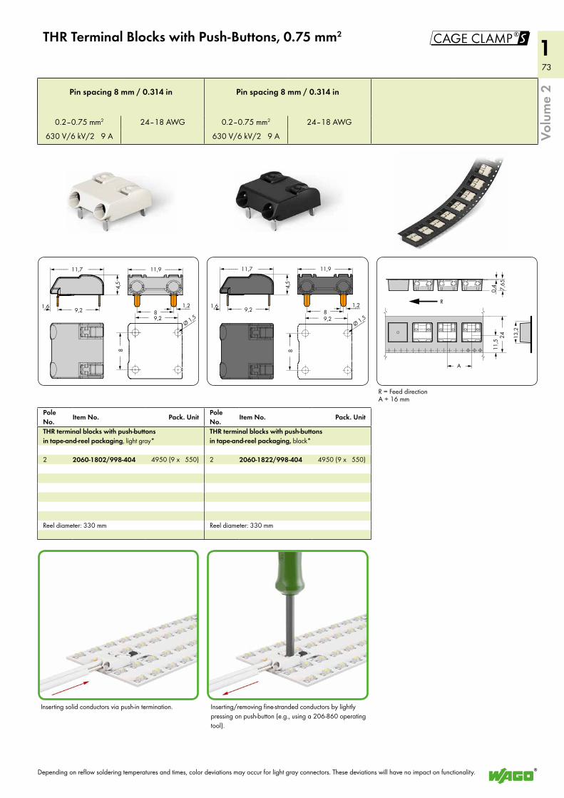
73
173
1
11,7<_____ ____>
9,21,6 <___ ___>>
4,5
<>
11,9<_____
<___ <___
<______Ø 1,5<___ 9,2 ___>
<___
8___>
_____>
8 ___>>1,2
11,7<_____ ____>
9,21,6 <___ ___>>
4,5
<>
11,9<_____
<___ <___
<______Ø 1,5<___ 9,2 ___>
<___
8___>
_____>
8 ___>>1,2
< >A
<___>0,4
<__
__>
24
R
7,65
><
11,5
><
()
13,2
!
Volu
me
2
THR Terminal Blocks with Push-Buttons, 0.75 mm2
Pole No.
Item No. Pack. UnitPole No.
Item No. Pack. Unit
THR terminal blocks with push-buttons in tape-and-reel packaging, light gray*
THR terminal blocks with push-buttons in tape-and-reel packaging, black*
2 2060-1802/998-404 4950 (9 x 550) 2 2060-1822/998-404 4950 (9 x 550)
Reel diameter: 330 mm Reel diameter: 330 mm
Pin spacing 8 mm / 0.314 in Pin spacing 8 mm / 0.314 in
0.2–0.75 mm2 24–18 AWG 0.2–0.75 mm2 24–18 AWG
630 V/6 kV/2 9 A 630 V/6 kV/2 9 A
Inserting solid conductors via push-in termination.
R = Feed directionA + 16 mm
Depending on reflow soldering temperatures and times, color deviations may occur for light gray connectors. These deviations will have no impact on functionality.
Inserting/removing fine-stranded conductors by lightly pressing on push-button (e.g., using a 206-860 operating tool).
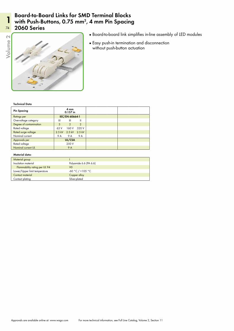
74
174
1Vo
lum
e 2
Approvals are available online at: www.wago.com For more technical information, see Full Line Catalog, Volume 2, Section 11
Board-to-Board Links for SMD Terminal Blocks with Push-Buttons, 0.75 mm2, 4 mm Pin Spacing2060 Series
Technical Data
Pin Spacing 4 mm 0.157 in
Ratings per IEC/EN 60664-1Overvoltage category III III IIDegree of contamination 3 2 2Rated voltage 63 V 160 V 320 VRated surge voltage 2.5 kV 2.5 kV 2.5 kVNominal current 9 A 9 A 9 AApprovals per UL/CSARated voltage 250 VNominal current UL 9 A
Board-to-board link simplifies in-line assembly of LED modules
Easy push-in termination and disconnection without push-button actuation
Material data:Material group IInsulation material Polyamide 6.6 (PA 6.6)
Flammability rating per UL 94 V0Lower/Upper limit temperature -60 °C / +105 °CContact material Copper alloyContact plating Silver-plated
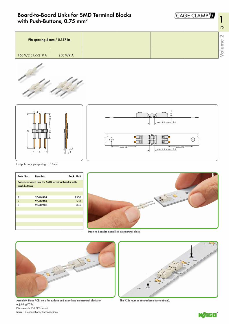
75
175
1
__><
2,6
26<
____________
____________>
L___> <___
><4
__><1
7,25<
<
11,5<
__
<__
max. 22<_____
<_____________________
______>max. 22<_____ ______>
4,5<
>
> min. 4,4 ‒ max. 5,4
<_____________________> min. 4,4 ‒ max. 5,4
!
Volu
me
2
Board-to-Board Links for SMD Terminal Blocks with Push-Buttons, 0.75 mm2
Pole No. Item No. Pack. Unit
Board-to-board link for SMD terminal blocks with push-buttons
1 2060-901 15002 2060-902 5003 2060-903 375
Pin spacing 4 mm / 0.157 in
160 V/2.5 kV/2 9 A 250 V/9 A
Inserting board-to-board link into terminal block.
Assembly: Place PCBs on a flat surface and insert links into terminal blocks on adjoining PCBs. Disassembly: Pull PCBs apart. (max. 10 connections/disconnections)
The PCBs must be secured (see figure above).
L = (pole no. x pin spacing) + 0.6 mm
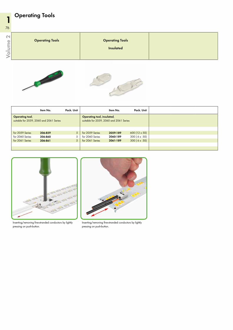
76
176
1Vo
lum
e 2
Operating Tools Operating Tools
Insulated
Item No. Pack. Unit Item No. Pack. Unit
Operating tool, suitable for 2059, 2060 and 2061 Series
Operating tool, insulated, suitable for 2059, 2060 and 2061 Series
for 2059 Series 206-859 5 for 2059 Series 2059-189 600 (12 x 50)for 2060 Series 206-860 5 for 2060 Series 2060-189 300 ( 6 x 50)for 2061 Series 206-861 5 for 2061 Series 2061-189 300 ( 6 x 50)
Operating Tools
Inserting/removing fine-stranded conductors by lightly pressing on push-button.
Inserting/removing fine-stranded conductors by lightly pressing on push-button.
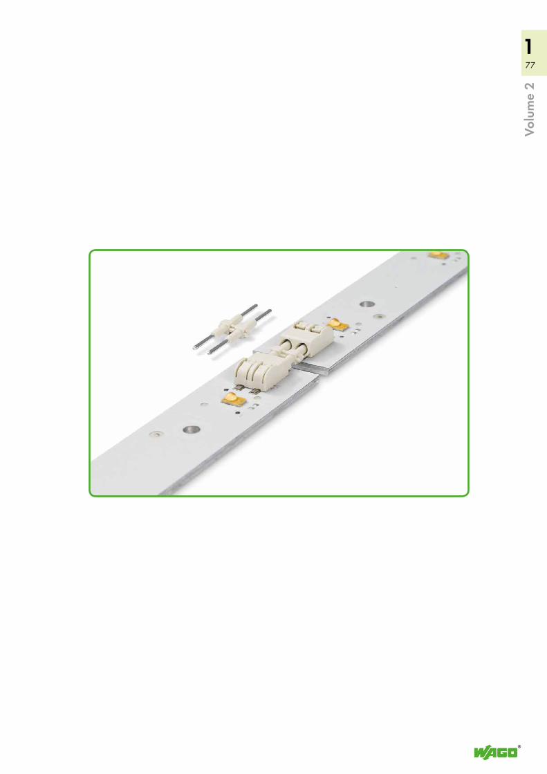
77
177
1
Volu
me
2
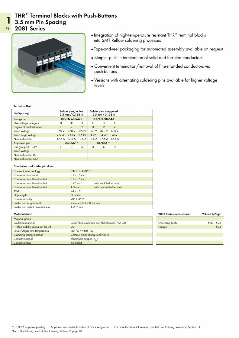
78
1
Material data:Material group IInsulation material Glass-fiber-reinforced polyphthalamide (PPA-GF)
Flammability rating per UL 94 V0Lower/Upper limit temperature -60 °C / +105 °CClamping spring material Chrome nickel spring steel (CrNi)Contact material Electrolytic copper (ECu)Contact plating Tin-plated
THR* Terminal Blocks with Push-Buttons 3.5 mm Pin Spacing2081 Series
Technical Data
Pin Spacing Solder pins, in line 3.5 mm / 0.138 in
Solder pins, staggered 3.5 mm / 0.138 in
Ratings per IEC/EN 60664-1 IEC/EN 60664-1Overvoltage category III III II III III IIDegree of contamination 3 2 2 3 2 2Rated voltage 160 V 160 V 320 V 250 V 320 V 630 VRated surge voltage 2.5 kV 2.5 kV 2.5 kV 4 kV 4 kV 4 kVNominal current 17.5 A 17.5 A 17.5 A 17.5 A 17.5 A 17.5 AApprovals per UL/CSA** UL/CSA**Use group UL 1059 B C D B C DRated voltageNominal current ULNominal current CSA
Conductor and solder pin data:Connection technology CAGE CLAMP® SConductor size: solid 0.2–1.5 mm2
Conductor size: fine-stranded 0.2–1.5 mm2
Conductor size: fine-stranded 0.75 mm2 (with insulated ferrule)Conductor size: fine-stranded 1.0 mm2 (with uninsulated ferrule)AWG 24 – 16Strip length 8–9 mmConductor entry 90° to PCBSolder pin: length/width 2.4 mm / 0.4 x 0.75 mmSolder pin: drilled hole diameter 1.0+0.1 mm
Integration of high-temperature resistant THR* terminal blocks into SMT Reflow soldering processes
Tape-and-reel packaging for automated assembly available on request
Simple, push-in termination of solid and ferruled conductors
Convenient termination/removal of fine-stranded conductors via push-buttons
Versions with alternating soldering pins available for higher voltage levels
2081 Series accessories: Volume 2/Page:
Operating Tools 526 – 528Test pin 538
**UL/CSA approval pending Approvals are available online at: www.wago.com For more technical information, see Full Line Catalog, Volume 2, Section 11 *For THR soldering, see Full Line Catalog, Volume 2, page 81
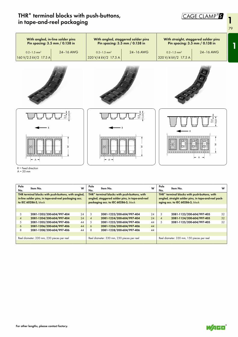
1
79
1!
<
<__>
0,5
<____
____>
W
R
<>
13,0
5
< >A< >A
<___>
0,6
<__
__>
W
R
<>
18,8
<
<__>
0,5
<____
____>
W
R
<>
13,0
5
< >A
THR* terminal blocks with push-buttons, in tape-and-reel packaging
For other lengths, please contact factory.
Pole No.
Item No. WPole No.
Item No. WPole No.
Item No. W
THR terminal blocks with push-buttons, with angled, in-line solder pins, in tape-and-reel packaging acc. to IEC 60286-3, black
THR* terminal blocks with push-buttons, with angled, staggered solder pins, in tape-and-reel packaging acc. to IEC 60286-3, black
THR* terminal blocks with push-buttons, with angled, straight solder pins, in tape-and-reel pack-aging acc. to IEC 60286-3, black
3 2081-1203/200-604/997-404 24 3 2081-1223/200-604/997-404 24 3 2081-1123/200-604/997-405 32 4 2081-1204/200-604/997-404 24 4 2081-1224/200-604/997-404 24 4 2081-1124/200-604/997-405 32 5 2081-1205/200-604/997-406 44 5 2081-1225/200-604/997-406 44 5 2081-1125/200-604/997-405 32 6 2081-1206/200-604/997-406 44 6 2081-1226/200-604/997-406 44 8 2081-1208/200-604/997-406 44 8 2081-1228/200-604/997-406 44
Reel diameter: 330 mm, 230 pieces per reel Reel diameter: 330 mm, 230 pieces per reel Reel diameter: 330 mm, 150 pieces per reel
With angled, in-line solder pinsPin spacing: 3.5 mm / 0.138 in
With angled, staggered solder pinsPin spacing: 3.5 mm / 0.138 in
With straight, staggered solder pinsPin spacing: 3.5 mm / 0.138 in
0.2–1.5 mm2 24–16 AWG 0.2–1.5 mm2 24–16 AWG 0.2–1.5 mm2 24–16 AWG160 V/2.5 kV/2 17.5 A 320 V/4 kV/2 17.5 A 320 V/4 kV/2 17.5 A
R = Feed directionA = 20 mm
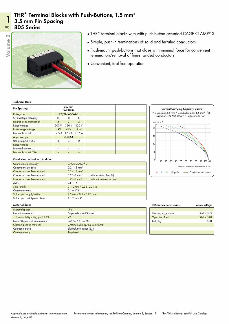
80
180
1
10 20 30 40 50 60 70 80 90 100 1050
5
10
15
20
Volu
me
2
Technical Data
Pin Spacing 3.5 mm 0.138 in
Ratings per IEC/EN 60664-1Overvoltage category III III IIDegree of contamination 3 2 2Rated voltage 200 V 320 V 320 VRated surge voltage 4 kV 4 kV 4 kVNominal current 17.5 A 17.5 A 17.5 AApprovals per UL/CSAUse group UL 1059 B C DRated voltage – – –Nominal current UL – – –Nominal current CSA – – –
Material data:Material group III aInsulation material Polyamide 4.6 (PA 4.6)
Flammability rating per UL 94 V2Lower/Upper limit temperature -60 °C / +105 °CClamping spring material Chrome nickel spring steel (CrNi)Contact material Electrolytic copper (ECu)Contact plating Tin-plated
Approvals are available online at: www.wago.com For more technical information, see Full Line Catalog, Volume 2, Section 11 *For THR soldering, see Full Line Catalog, Volume 2, page 81
805 Series accessories: Volume 2/Page:
Marking Accessories 540 – 543Operating Tools 526 – 528Test plug 538
THR* Terminal Blocks with Push-Buttons, 1,5 mm2
3.5 mm Pin Spacing 805 Series
Conductor and solder pin data:Connection technology CAGE CLAMP® SConductor size: solid 0.2–1.5 mm2
Conductor size: fine-stranded 0.2–1.5 mm2
Conductor size: fine-stranded 0.25–1 mm2 (with insulated ferrule)Conductor size: fine-stranded 0.25–1 mm2 (with uninsulated ferrule)AWG 24 – 16Strip length 9–10 mm / 0.35–0.39 inConductor entry 0° to PCBSolder pin: length/width 2.2 mm / 0.5 x 0.75 mmSolder pin: metal-plated hole 1.1+0.1 mm Ø
Current-Carrying Capacity CurvePin spacing: 3.5 mm / Conductor size: 1.5 mm2 “f-st”
Based on: EN 60512-5-2 / Reduction factor: 1
Ambient operating temperature in °C
Current in A
Conductor rated current 2-, 4-, 6-, 12-pole
THR* terminal blocks with with push-button actuated CAGE CLAMP® S
Simple, push-in terminations of solid and ferruled conductors
Flush-mount push-buttons that close with minimal force for convenient termination/removal of fine-stranded conductors
Convenient, tool-free operation
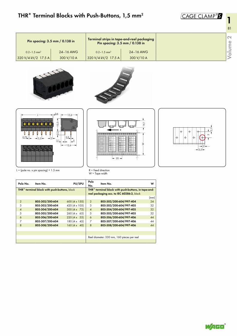
81
181
1!
<____13,6___><____________ L ___________> <__
<__> >3,1<__>0,5<< >> 3,5 2<___>0,75
0,6
<__
10,5_>
>2,
2
5<_<___12,6 ___>
< >20
<______
______>
W
R
14,1
><
<>
<>
<_ <__
< >
3,1
5
23,5
Volu
me
2
THR* Terminal Blocks with Push-Buttons, 1,5 mm2
L = (pole no. x pin spacing) + 1.5 mm
Pole No. Item No. PU/SPUPole No.
Item No. W
THR* terminal block with push-buttons, black THR* terminal block with push-buttons, in tape-and-reel packaging acc. to IEC 60286-3, black
(mm) 2 805-302/200-604 600 (4 x 150) 2 805-302/200-604/997-404 24 3 805-303/200-604 420 (4 x 10⁵) 3 805-303/200-604/997-405 32 4 805-304/200-604 300 (4 x 75) 4 805-304/200-604/997-405 32 5 805-305/200-604 260 (4 x 65) 5 805-305/200-604/997-405 32 6 805-306/200-604 220 (4 x 55) 6 805-306/200-604/997-406 44 7 805-307/200-604 180 (4 x 45) 7 805-307/200-604/997-406 44 8 805-308/200-604 160 (4 x 40) 8 805-308/200-604/997-406 44
Reel diameter: 330 mm, 160 pieces per reel
Pin spacing: 3.5 mm / 0.138 in Terminal strips in tape-and-reel packagingPin spacing: 3.5 mm / 0.138 in
0.2–1.5 mm2 24–16 AWG 0.2–1.5 mm2 24–16 AWG
320 V/4 kV/2 17.5 A 300 V/10 A 320 V/4 kV/2 17.5 A 300 V/10 A
R = Feed directionW = Tape width
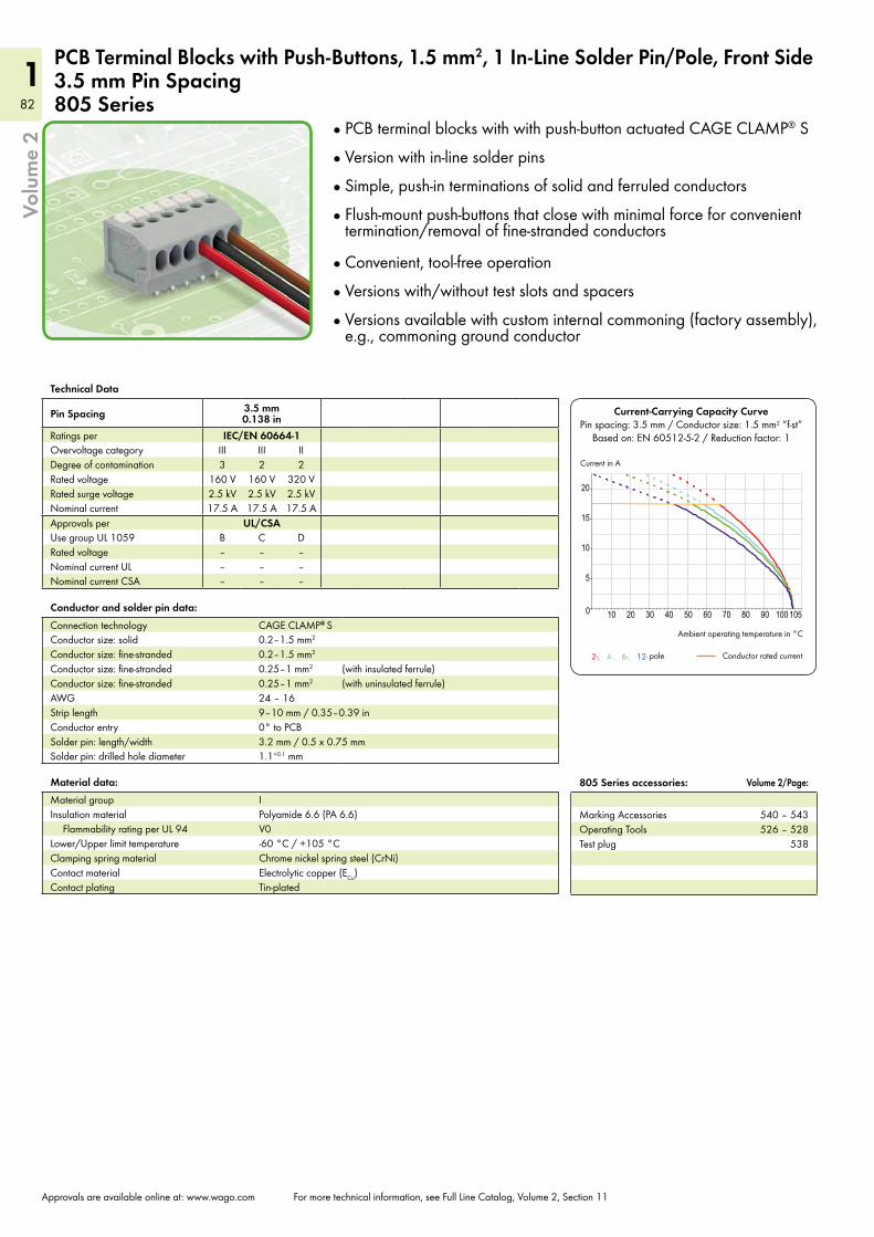
82
182
1
10 20 30 40 50 60 70 80 90 100 1050
5
10
15
20
2-, 4-, 6-, 12-
Current-Carrying Capacity CurvePin spacing: 3.5 mm / Conductor size: 1.5 mm2 “f-st”
Based on: EN 60512-5-2 / Reduction factor: 1
Current in A
Ambient operating temperature in °C
Conductor rated current pole
Volu
me
2
Technical Data
Pin Spacing 3.5 mm 0.138 in
Ratings per IEC/EN 60664-1Overvoltage category III III IIDegree of contamination 3 2 2Rated voltage 160 V 160 V 320 VRated surge voltage 2.5 kV 2.5 kV 2.5 kVNominal current 17.5 A 17.5 A 17.5 AApprovals per UL/CSAUse group UL 1059 B C DRated voltage – – –Nominal current UL – – –Nominal current CSA – – –
Material data:Material group IInsulation material Polyamide 6.6 (PA 6.6)
Flammability rating per UL 94 V0Lower/Upper limit temperature -60 °C / +105 °CClamping spring material Chrome nickel spring steel (CrNi)Contact material Electrolytic copper (ECu)Contact plating Tin-plated
Approvals are available online at: www.wago.com For more technical information, see Full Line Catalog, Volume 2, Section 11
805 Series accessories: Volume 2/Page:
Marking Accessories 540 – 543Operating Tools 526 – 528Test plug 538
PCB Terminal Blocks with Push-Buttons, 1.5 mm2, 1 In-Line Solder Pin/Pole, Front Side3.5 mm Pin Spacing805 Series
Conductor and solder pin data:Connection technology CAGE CLAMP® SConductor size: solid 0.2–1.5 mm2
Conductor size: fine-stranded 0.2–1.5 mm2
Conductor size: fine-stranded 0.25–1 mm2 (with insulated ferrule)Conductor size: fine-stranded 0.25–1 mm2 (with uninsulated ferrule)AWG 24 – 16Strip length 9–10 mm / 0.35–0.39 inConductor entry 0° to PCBSolder pin: length/width 3.2 mm / 0.5 x 0.75 mmSolder pin: drilled hole diameter 1.1+0.1 mm
PCB terminal blocks with with push-button actuated CAGE CLAMP® S
Version with in-line solder pins
Simple, push-in terminations of solid and ferruled conductors
Flush-mount push-buttons that close with minimal force for convenient termination/removal of fine-stranded conductors
Convenient, tool-free operation
Versions with/without test slots and spacers
Versions available with custom internal commoning (factory assembly), e.g., commoning ground conductor
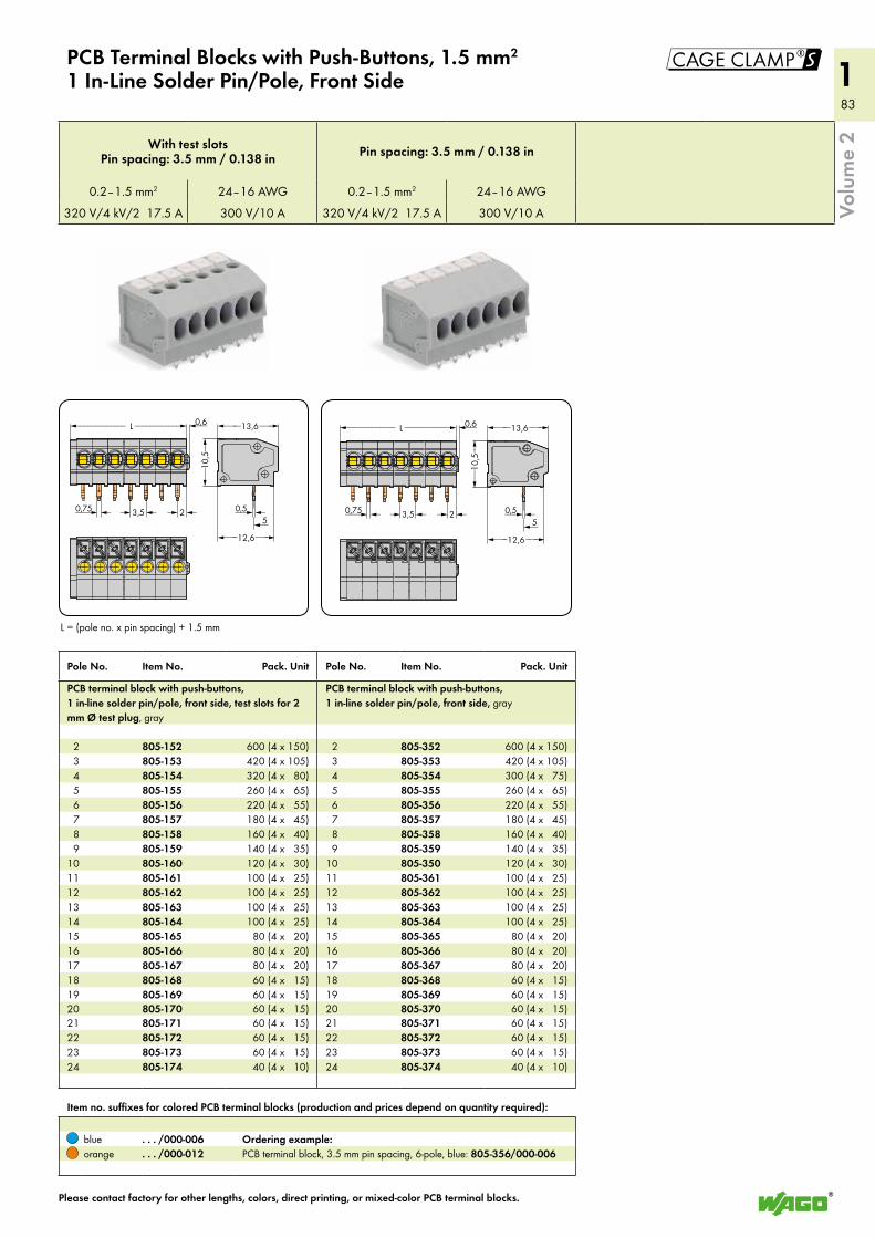
83
183
1!
<____13,6___>
<___12,6___>
<____________ L ___________> <__
<__>0,5<< >> 3,5 2<___>0,75
0,6
<__
10,5_>
5<_
<____13,6___><____________ L ___________> <__
<__>0,5<< >> 3,5 2<___>0,75
0,6
<__
10,5_>
5<_<___12,6 ___>
Volu
me
2
PCB Terminal Blocks with Push-Buttons, 1.5 mm2 1 In-Line Solder Pin/Pole, Front Side
L = (pole no. x pin spacing) + 1.5 mm
Pole No. Item No. Pack. Unit Pole No. Item No. Pack. Unit
PCB terminal block with push-buttons, 1 in-line solder pin/pole, front side, test slots for 2 mm Ø test plug, gray
PCB terminal block with push-buttons, 1 in-line solder pin/pole, front side, gray
2 805-152 600 (4 x 150) 2 805-352 600 (4 x 150) 3 805-153 420 (4 x 10⁵) 3 805-353 420 (4 x 10⁵) 4 805-154 320 (4 x 80) 4 805-354 300 (4 x 75) 5 805-155 260 (4 x 65) 5 805-355 260 (4 x 65) 6 805-156 220 (4 x 55) 6 805-356 220 (4 x 55) 7 805-157 180 (4 x 45) 7 805-357 180 (4 x 45) 8 805-158 160 (4 x 40) 8 805-358 160 (4 x 40) 9 805-159 140 (4 x 35) 9 805-359 140 (4 x 35)10 805-160 120 (4 x 30) 10 805-350 120 (4 x 30)11 805-161 100 (4 x 25) 11 805-361 100 (4 x 25)12 805-162 100 (4 x 25) 12 805-362 100 (4 x 25)13 805-163 100 (4 x 25) 13 805-363 100 (4 x 25)14 805-164 100 (4 x 25) 14 805-364 100 (4 x 25)15 805-165 80 (4 x 20) 15 805-365 80 (4 x 20)16 805-166 80 (4 x 20) 16 805-366 80 (4 x 20)17 805-167 80 (4 x 20) 17 805-367 80 (4 x 20)18 805-168 60 (4 x 15) 18 805-368 60 (4 x 15)19 805-169 60 (4 x 15) 19 805-369 60 (4 x 15)20 805-170 60 (4 x 15) 20 805-370 60 (4 x 15)21 805-171 60 (4 x 15) 21 805-371 60 (4 x 15)22 805-172 60 (4 x 15) 22 805-372 60 (4 x 15)23 805-173 60 (4 x 15) 23 805-373 60 (4 x 15)24 805-174 40 (4 x 10) 24 805-374 40 (4 x 10)
Item no. suffixes for colored PCB terminal blocks (production and prices depend on quantity required):
blue . . . /000-006 Ordering example:orange . . . /000-012 PCB terminal block, 3.5 mm pin spacing, 6-pole, blue: 805-356/000-006
Please contact factory for other lengths, colors, direct printing, or mixed-color PCB terminal blocks.
With test slots Pin spacing: 3.5 mm / 0.138 in Pin spacing: 3.5 mm / 0.138 in
0.2–1.5 mm2 24–16 AWG 0.2–1.5 mm2 24–16 AWG
320 V/4 kV/2 17.5 A 300 V/10 A 320 V/4 kV/2 17.5 A 300 V/10 A
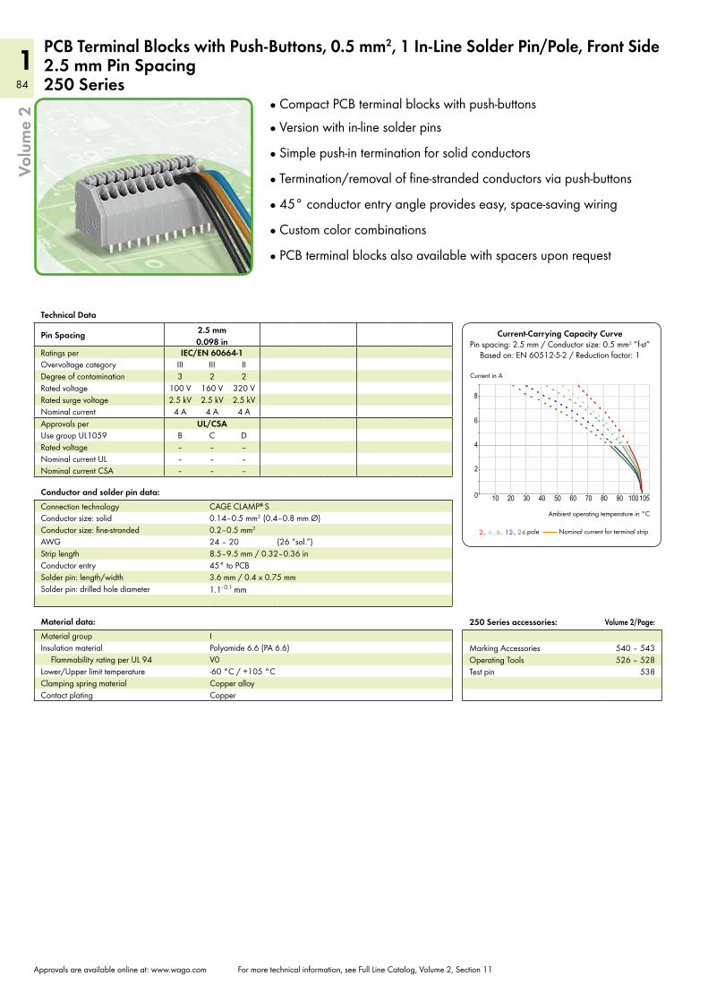
84
184
1
10 20 30 40 50 60 70 80 90 100 1050
4
2
6
8
2-, 4-, 6-, 12-, 24-
Current-Carrying Capacity CurvePin spacing: 2.5 mm / Conductor size: 0.5 mm2 “f-st”
Based on: EN 60512-5-2 / Reduction factor: 1
Current in A
Ambient operating temperature in °C
Nominal current for terminal strip pole
Volu
me
2
Technical Data
Pin Spacing 2.5 mm 0.098 in
Ratings per IEC/EN 60664-1Overvoltage category III III IIDegree of contamination 3 2 2Rated voltage 100 V 160 V 320 VRated surge voltage 2.5 kV 2.5 kV 2.5 kVNominal current 4 A 4 A 4 AApprovals per UL/CSAUse group UL1059 B C DRated voltage – – –Nominal current UL – – –Nominal current CSA – – –
Material data:Material group IInsulation material Polyamide 6.6 (PA 6.6)
Flammability rating per UL 94 V0Lower/Upper limit temperature -60 °C / +105 °CClamping spring material Copper alloyContact plating Copper
Approvals are available online at: www.wago.com For more technical information, see Full Line Catalog, Volume 2, Section 11
250 Series accessories: Volume 2/Page:
Marking Accessories 540 – 543Operating Tools 526 – 528Test pin 538
PCB Terminal Blocks with Push-Buttons, 0.5 mm2, 1 In-Line Solder Pin/Pole, Front Side2.5 mm Pin Spacing250 Series
Conductor and solder pin data:Connection technology CAGE CLAMP® SConductor size: solid 0.14–0.5 mm2 (0.4–0.8 mm Ø)Conductor size: fine-stranded 0.2–0.5 mm2
AWG 24 – 20 (26 “sol.”)Strip length 8.5–9.5 mm / 0.32–0.36 inConductor entry 45° to PCBSolder pin: length/width 3.6 mm / 0.4 x 0.75 mmSolder pin: drilled hole diameter 1.1- 0.1 mm
Compact PCB terminal blocks with push-buttons
Version with in-line solder pins
Simple push-in termination for solid conductors
Termination/removal of fine-stranded conductors via push-buttons
45° conductor entry angle provides easy, space-saving wiring
Custom color combinations
PCB terminal blocks also available with spacers upon request
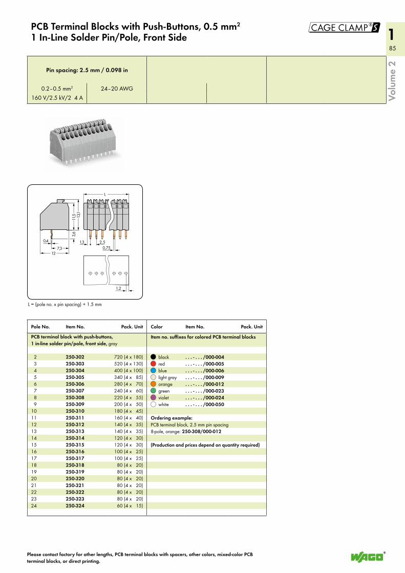
85
185
1
<____ 12 ____>
3,6
<__(___<__ 2,50,4__>>
<___1
1,5___>
<_____1
3,1_____>
<________ L _________>
< 7,31,3
___> <0,75
<___>1,2
_>
!
Volu
me
2
L = (pole no. x pin spacing) + 1.5 mm
PCB Terminal Blocks with Push-Buttons, 0.5 mm2 1 In-Line Solder Pin/Pole, Front Side
Please contact factory for other lengths, PCB terminal blocks with spacers, other colors, mixed-color PCB terminal blocks, or direct printing.
Pole No. Item No. Pack. Unit Color Item No. Pack. Unit
PCB terminal block with push-buttons, 1 in-line solder pin/pole, front side, gray
Item no. suffixes for colored PCB terminal blocks
2 250-302 720 (4 x 180) black . . . - . . . /000-004 3 250-303 520 (4 x 130) red . . . - . . . /000-005 4 250-304 400 (4 x 100) blue . . . - . . . /000-006 5 250-305 340 (4 x 85) light gray . . . - . . . /000-009 6 250-306 280 (4 x 70) orange . . . - . . . /000-012 7 250-307 240 (4 x 60) green . . . - . . . /000-023 8 250-308 220 (4 x 55) violet . . . - . . . /000-024 9 250-309 200 (4 x 50) white . . . - . . . /000-05010 250-310 180 (4 x 45)11 250-311 160 (4 x 40) Ordering example:12 250-312 140 (4 x 35) PCB terminal block, 2.5 mm pin spacing13 250-313 140 (4 x 35) 8-pole, orange: 250-308/000-01214 250-314 120 (4 x 30)15 250-315 120 (4 x 30) (Production and prices depend on quantity required)16 250-316 100 (4 x 25)17 250-317 100 (4 x 25)18 250-318 80 (4 x 20)19 250-319 80 (4 x 20)20 250-320 80 (4 x 20)21 250-321 80 (4 x 20)22 250-322 80 (4 x 20)23 250-323 80 (4 x 20)24 250-324 60 (4 x 15)
Pin spacing: 2.5 mm / 0.098 in
0.2–0.5 mm2 24–20 AWG160 V/2.5 kV/2 4 A
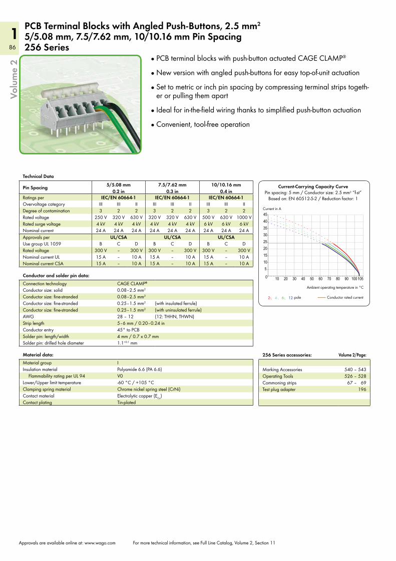
86
186
1
10 20 30 40 50 60 70 80 90 100 1050
51015202530354045
2-, 4-, 6-, 12-
Current-Carrying Capacity CurvePin spacing: 5 mm / Conductor size: 2.5 mm2 “f-st”
Based on: EN 60512-5-2 / Reduction factor: 1
Current in A
Ambient operating temperature in °C
Conductor rated currentpole
Volu
me
2
Approvals are available online at: www.wago.com For more technical information, see Full Line Catalog, Volume 2, Section 11
256 Series accessories: Volume 2/Page:
Marking Accessories 540 – 543Operating Tools 526 – 528Commoning strips 67 – 69Test plug adapter 196
PCB Terminal Blocks with Angled Push-Buttons, 2.5 mm2 5/5.08 mm, 7.5/7.62 mm, 10/10.16 mm Pin Spacing 256 Series
Technical Data
Pin Spacing 5/5.08 mm 0.2 in
7.5/7.62 mm 0.3 in
10/10.16 mm 0.4 in
Ratings per IEC/EN 60664-1 IEC/EN 60664-1 IEC/EN 60664-1Overvoltage category III III II III III II III III IIDegree of contamination 3 2 2 3 2 2 3 2 2Rated voltage 250 V 320 V 630 V 320 V 320 V 630 V 500 V 630 V 1000 VRated surge voltage 4 kV 4 kV 4 kV 4 kV 4 kV 4 kV 6 kV 6 kV 6 kVNominal current 24 A 24 A 24 A 24 A 24 A 24 A 24 A 24 A 24 AApprovals per UL/CSA UL/CSA UL/CSAUse group UL 1059 B C D B C D B C DRated voltage 300 V – 300 V 300 V – 300 V 300 V – 300 VNominal current UL 15 A – 10 A 15 A – 10 A 15 A – 10 ANominal current CSA 15 A – 10 A 15 A – 10 A 15 A – 10 A
Material data:Material group IInsulation material Polyamide 6.6 (PA 6.6)
Flammability rating per UL 94 V0Lower/Upper limit temperature -60 °C / +105 °CClamping spring material Chrome nickel spring steel (CrNi)Contact material Electrolytic copper (ECu)Contact plating Tin-plated
Conductor and solder pin data:Connection technology CAGE CLAMP®
Conductor size: solid 0.08–2.5 mm2
Conductor size: fine-stranded 0.08–2.5 mm2
Conductor size: fine-stranded 0.25–1.5 mm2 (with insulated ferrule)Conductor size: fine-stranded 0.25–1.5 mm2 (with uninsulated ferrule)AWG 28 – 12 (12: THHN, THWN)Strip length 5–6 mm / 0.20–0.24 inConductor entry 45° to PCBSolder pin: length/width 4 mm / 0.7 x 0.7 mmSolder pin: drilled hole diameter 1.1+0.1 mm
PCB terminal blocks with push-button actuated CAGE CLAMP®
New version with angled push-buttons for easy top-of-unit actuation
Set to metric or inch pin spacing by compressing terminal strips togeth-er or pulling them apart
Ideal for in-the-field wiring thanks to simplified push-button actuation
Convenient, tool-free operation
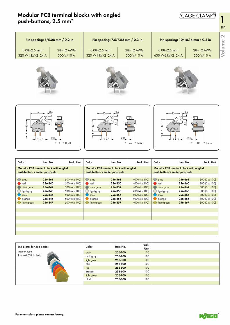
87
187
1"
> <5 (5,08)___>2,15
<___15___> <__2,5
3,1
<
<___
<__
13__>
>4
> <5 5> <7,5 (7,62)
<___>2,15
<___15___> <__2,53,
1<
<___
<__
13__>
>4
> <5 5> <10 (10,16)
<___>2,15
<___15___> <__2,5
3,1
<
<___
<__
13__>
>4
> <5 5
Volu
me
2
Color Item No. Pack. Unit Color Item No. Pack. Unit Color Item No. Pack. Unit
Modular PCB terminal block with angled push-button, 2 solder pins/pole
Modular PCB terminal block with angled push-button, 2 solder pins/pole
Modular PCB terminal block with angled push-button, 2 solder pins/pole
gray 256-461 600 (6 x 100) gray 256-561 400 (4 x 100) gray 256-661 300 (3 x 100)red 256-840 600 (6 x 100) red 256-850 400 (4 x 100) red 256-860 300 (3 x 100)dark gray 256-842 600 (6 x 100) dark gray 256-852 400 (4 x 100) dark gray 256-862 300 (3 x 100)light gray 256-843 600 (6 x 100) light gray 256-853 400 (4 x 100) light gray 256-863 300 (3 x 100)blue 256-844 600 (6 x 100) blue 256-854 400 (4 x 100) blue 256-864 300 (3 x 100)orange 256-846 600 (6 x 100) orange 256-856 400 (4 x 100) orange 256-866 300 (3 x 100)light green 256-847 600 (6 x 100) light green 256-857 400 (4 x 100) light green 256-867 300 (3 x 100)
End plates for 256 Series Color Item No.Pack.
Unitsnap-on type, 1 mm/0.039 in thick
gray 256-100 100dark gray 256-200 100light gray 256-300 100blue 256-400 100red 256-500 100orange 256-600 100light green 256-700 100black 256-800 100
For other colors, please contact factory.
Modular PCB terminal blocks with angled push-buttons, 2.5 mm2
Pin spacing: 5/5.08 mm / 0.2 in Pin spacing: 7.5/7.62 mm / 0.3 in Pin spacing: 10/10.16 mm / 0.4 in
0.08–2.5 mm2 28–12 AWG 0.08–2.5 mm2 28–12 AWG 0.08–2.5 mm2 28–12 AWG320 V/4 kV/2 24 A 300 V/10 A 320 V/4 kV/2 24 A 300 V/10 A 630 V/6 kV/2 24 A 300 V/10 A
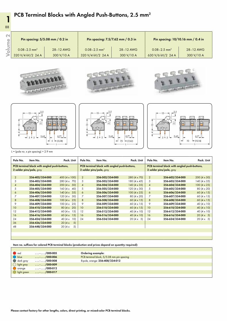
88
188
1
<_______ L _______>> <5 (5,08)
<___>3,65 <
<___15___> <__2,5
3,1
<
<___
<__
13__>
>4
> <5 5 ___>0,7
<_________ L _________>> <7,5 (7,62)
<___>3,65 <___>0,7
<___15___> <__2,53,
1<
<___
<__
13__>
>4
> <5 5
<___________ L___________>> <10 (10,16)
<___>3,65 <___>0,7
<___15___> <__2,5
3,1
<
<___
<__
13__>
>4
> <5 5
Volu
me
2
L = (pole no. x pin spacing) + 2.9 mm
Pole No. Item No. Pack. Unit Pole No. Item No. Pack. Unit Pole No. Item No. Pack. Unit
PCB terminal block with angled push-buttons, 2 solder pins/pole, gray
PCB terminal block with angled push-buttons, 2 solder pins/pole, gray
PCB terminal block with angled push-buttons, 2 solder pins/pole, gray
2 256-402/334-000 400 (4 x 100) 2 256-502/334-000 280 (4 x 70) 2 256-602/334-000 200 (4 x 50) 3 256-403/334-000 280 (4 x 70) 3 256-503/334-000 180 (4 x 45) 3 256-603/334-000 140 (4 x 35) 4 256-404/334-000 200 (4 x 50) 4 256-504/334-000 140 (4 x 35) 4 256-604/334-000 100 (4 x 25) 5 256-405/334-000 160 (4 x 40) 5 256-505/334-000 120 (4 x 30) 5 256-605/334-000 80 (4 x 20) 6 256-406/334-000 140 (4 x 35) 6 256-506/334-000 100 (4 x 25) 6 256-606/334-000 60 (4 x 15) 7 256-407/334-000 120 (4 x 30) 7 256-507/334-000 80 (4 x 20) 7 256-607/334-000 60 (4 x 15) 8 256-408/334-000 100 (4 x 25) 8 256-508/334-000 60 (4 x 15) 8 256-608/334-000 60 (4 x 15) 9 256-409/334-000 100 (4 x 25) 9 256-509/334-000 60 (4 x 15) 9 256-609/334-000 40 (4 x 10)10 256-410/334-000 80 (4 x 20) 10 256-510/334-000 60 (4 x 15) 10 256-610/334-000 40 (4 x 10)12 256-412/334-000 60 (4 x 15) 12 256-512/334-000 40 (4 x 10) 12 256-612/334-000 40 (4 x 10)16 256-416/334-000 60 (4 x 15) 16 256-516/334-000 40 (4 x 10) 16 256-616/334-000 20 (4 x 5)24 256-424/334-000 40 (4 x 10) 24 256-524/334-000 20 (4 x 5) 24 256-624/334-000 20 (4 x 5)36 256-436/334-000 20 (4 x 5)48 256-448/334-000 20 (4 x 5)
Item no. suffixes for colored PCB terminal blocks (production and prices depend on quantity required):
red . . . - . . . /000-005 Ordering example:blue . . . - . . . /000-006 PCB terminal block, 5/5.08 mm pin spacingdark gray . . . - . . . /000-008 8-pole, orange: 256-408/334-012light gray . . . - . . . /000-009orange . . . - . . . /000-012light green . . . - . . . /000-017
Please contact factory for other lengths, colors, direct printing, or mixed-color PCB terminal blocks.
PCB Terminal Blocks with Angled Push-Buttons, 2.5 mm2
Pin spacing: 5/5.08 mm / 0.2 in Pin spacing: 7.5/7.62 mm / 0.3 in Pin spacing: 10/10.16 mm / 0.4 in
0.08–2.5 mm2 28–12 AWG 0.08–2.5 mm2 28–12 AWG 0.08–2.5 mm2 28–12 AWG
320 V/4 kV/2 24 A 300 V/10 A 320 V/4 kV/2 24 A 300 V/10 A 630 V/6 kV/2 24 A 300 V/10 A

89
189
1
Volu
me
2
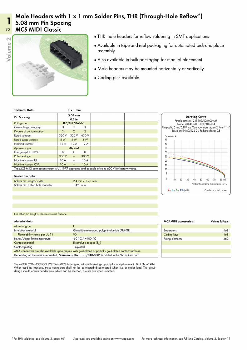
90
190
1
10 20 30 40 50 60 70 80 850
51015202530354045
Volu
me
2
*For THR soldering, see Volume 2, page 401 Approvals are available online at: www.wago.com For more technical information, see Full Line Catalog, Volume 2, Section 11
Material data:Material group IInsulation material Glass-fiber-reinforced polyphthalamide (PPA-GF)
Flammability rating per UL 94 V0Lower/Upper limit temperature -60 °C / +100 °CContact material Electrolytic copper (ECu)Contact plating Tin-platedMCS connectors are also available upon request with gold-plated or partially gold-plated contact surfaces.Depending on the version requested, “item no. suffix . . . /010-000” is added to the “basic item no.”
MCS MIDI accessories: Volume 2/Page:
Separators 468Coding keys 468Fixing elements 469
Male Headers with 1 x 1 mm Solder Pins, THR (Through-Hole Reflow*) 5.08 mm Pin SpacingMCS MIDI Classic
Technical Data 1 x 1 mm
Pin Spacing 5.08 mm 0.2 in
Ratings per IEC/EN 60664-1Overvoltage category III III IIDegree of contamination 3 2 2Rated voltage 320 V 320 V 630 VRated surge voltage 4 kV 4 kV 4 kVNominal current 12 A 12 A 12 AApprovals per UL/CSAUse group UL 1059 B C DRated voltage 300 V – 300 VNominal current UL 10 A – 10 ANominal current CSA 10 A – 10 AThe MCS-MIDI connection system is UL 1977 approved and capable of up to 600 V for factory wiring.
Solder pin data:Solder pin: length/width 2.4 mm / 1 x 1 mmSolder pin: drilled hole diameter 1.4+0.1 mm
For other pin lengths, please contact factory.
Derating Curve
Ambient operating temperature in °C
Current in A
Conductor rated current
Female connector 231-102/026-000 with header 231-432/001-000/105-604
Pin spacing 5 mm/0.197 in./ Conductor cross section 2.5 mm2 “f-st” Based on: EN 60512-5-2 / Reduction factor 0.8
2-, 4-, 6-, 12-pole
THR male headers for reflow soldering in SMT applications
Available in tape-and-reel packaging for automated pick-and-place assembly
Also available in bulk packaging for manual placement
Male headers may be mounted horizontally or vertically
Coding pins available
The MULTI CONNECTION SYSTEM (MCS) is designed without breaking capacity for compliance with DIN EN 61984. When used as intended, these connectors shall not be connected/disconnected when live or under load. The circuit design should ensure header pins, which can be touched, are not live when unmated.
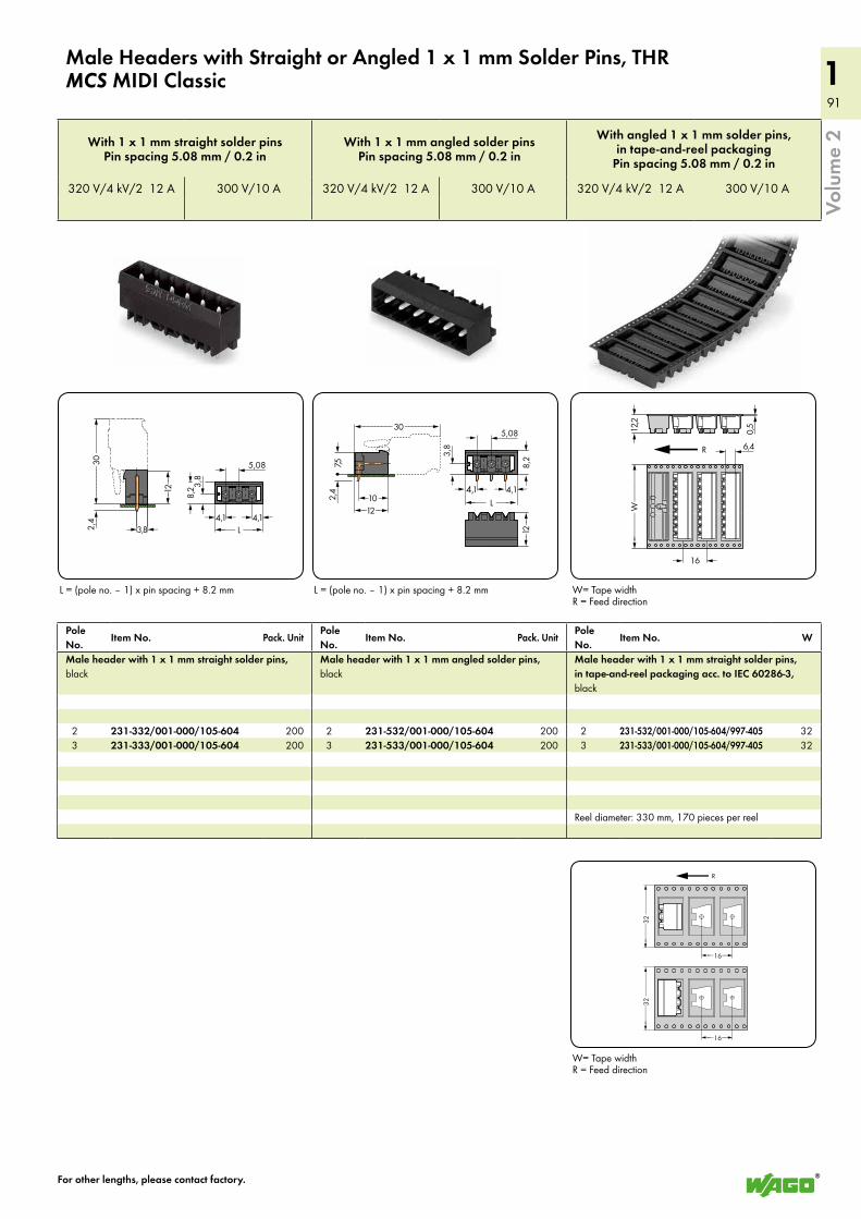
91
191
1
5,08
>
<____ L ___>
<____>
4,1<>
<8,
2>
<__3,8
3,8<>
<________
30______>
__>
<_12
_>
2,4 4,1<>
<________30_______>
<_12_><_1
2 _>
7,5<
___> (_10 _)2,4
5,08
>
<____ L ___>
<____>
4,1<>
<8,
2>
<__3,8
4,1<>
<_______
_______>
32
<___ _>16
R
<_______
_______>
32
<___ _>16
<________W
_______>
12,2
0,5
6,4
16
R
Volu
me
2
Male Headers with Straight or Angled 1 x 1 mm Solder Pins, THRMCS MIDI Classic
L = (pole no. – 1) x pin spacing + 8.2 mm L = (pole no. – 1) x pin spacing + 8.2 mm
W= Tape width R = Feed direction
With 1 x 1 mm straight solder pinsPin spacing 5.08 mm / 0.2 in
With 1 x 1 mm angled solder pins Pin spacing 5.08 mm / 0.2 in
With angled 1 x 1 mm solder pins, in tape-and-reel packaging
Pin spacing 5.08 mm / 0.2 in
320 V/4 kV/2 12 A 300 V/10 A 320 V/4 kV/2 12 A 300 V/10 A 320 V/4 kV/2 12 A 300 V/10 A
For other lengths, please contact factory.
Pole No.
Item No. Pack. UnitPole No.
Item No. Pack. UnitPole No.
Item No. W
Male header with 1 x 1 mm straight solder pins, black
Male header with 1 x 1 mm angled solder pins, black
Male header with 1 x 1 mm straight solder pins, in tape-and-reel packaging acc. to IEC 60286-3, black
2 231-332/001-000/105-604 200 2 231-532/001-000/105-604 200 2 231-532/001-000/105-604/997-405 32 3 231-333/001-000/105-604 200 3 231-533/001-000/105-604 200 3 231-533/001-000/105-604/997-405 32
Reel diameter: 330 mm, 170 pieces per reel
W= Tape width R = Feed direction
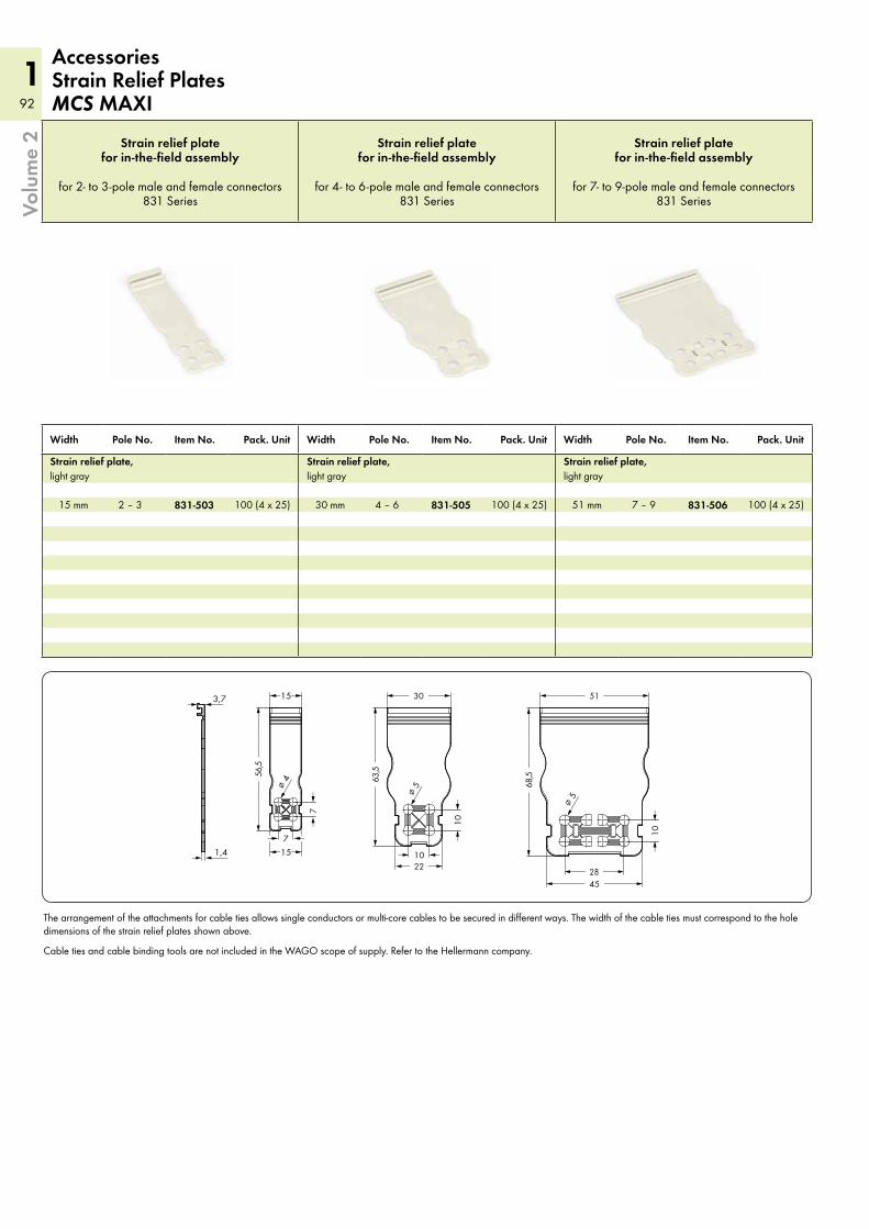
92
192
1
<___ 30 ___>
<_ 22 _> <___ 28 ___>
> 10 <
<____________ 6
3,5 ___________>
> 1
0 <
<15>
<15>
<__________ 5
6,5 __________>
> 7 <
> 7
<
> <___
<_________ 51 _________>
<_______ 45 _______>
<_____________
68,5 ____________>
> 1
0 <
1,4
> <__3,7
<___∅ 4
<___∅ 5
<___∅ 5
Volu
me
2 Strain relief plate for in-the-field assembly
for 2- to 3-pole male and female connectors 831 Series
Strain relief plate for in-the-field assembly
for 4- to 6-pole male and female connectors 831 Series
Strain relief plate for in-the-field assembly
for 7- to 9-pole male and female connectors 831 Series
AccessoriesStrain Relief PlatesMCS MAXI
Width Pole No. Item No. Pack. Unit Width Pole No. Item No. Pack. Unit Width Pole No. Item No. Pack. Unit
Strain relief plate, light gray
Strain relief plate, light gray
Strain relief plate, light gray
15 mm 2 – 3 831-503 100 (4 x 25) 30 mm 4 – 6 831-505 100 (4 x 25) 51 mm 7 – 9 831-506 100 (4 x 25)
The arrangement of the attachments for cable ties allows single conductors or multi-core cables to be secured in different ways. The width of the cable ties must correspond to the hole dimensions of the strain relief plates shown above.
Cable ties and cable binding tools are not included in the WAGO scope of supply. Refer to the Hellermann company.

93
193
1
Volu
me
2
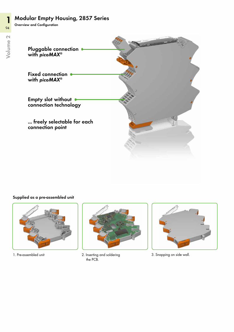
94
194
1Vo
lum
e 2
Modular Empty Housing, 2857 SeriesOverview and Configuration
Pluggable connection with picoMAX®
Fixed connection with picoMAX®
Empty slot without connection technology
... freely selectable for each connection point
Supplied as a pre-assembled unit
1. Pre-assembled unit 2. Inserting and soldering the PCB.
3. Snapping on side wall.
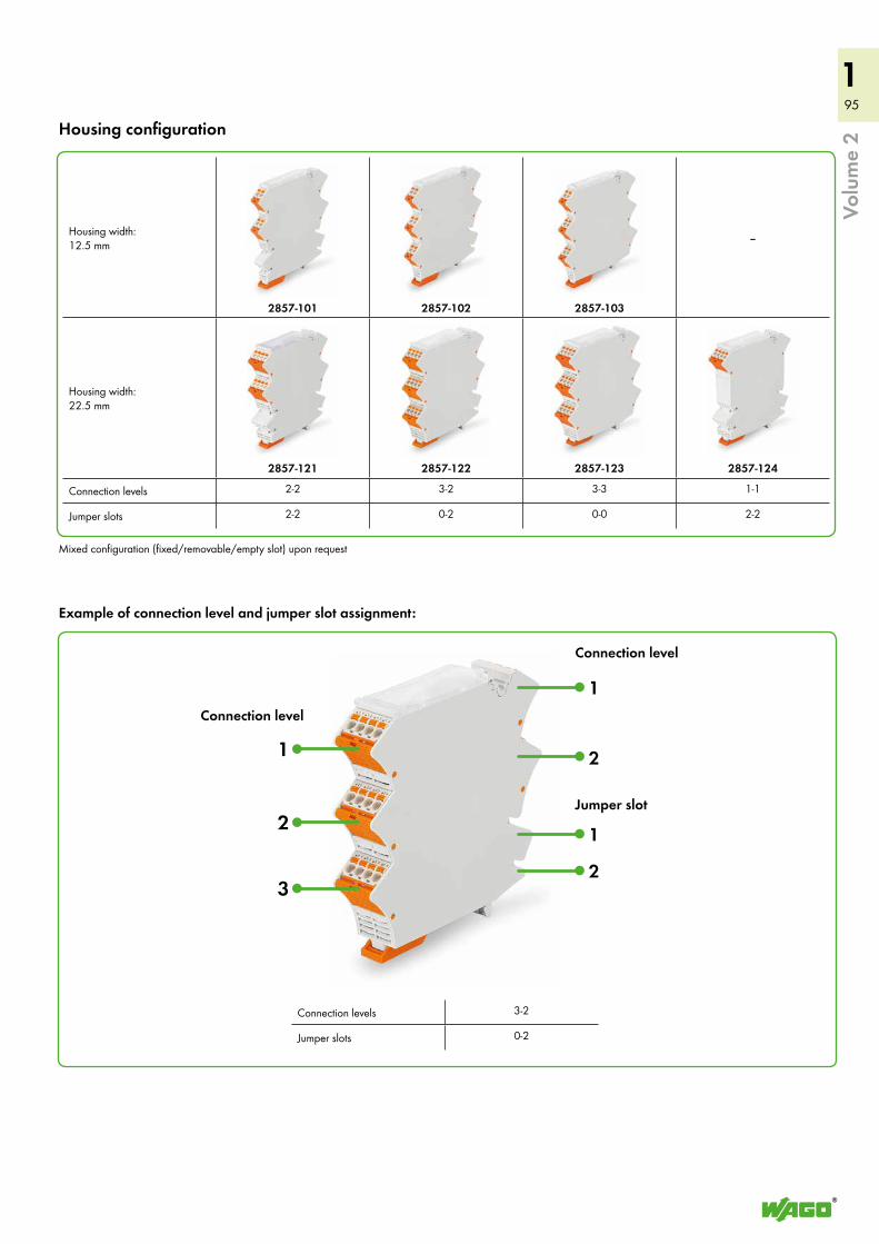
95
195
1
Housing width: 12.5 mm
2857-101 2857-102 2857-103
–
Housing width: 22.5 mm
2857-121 2857-122 2857-123 2857-124
Connection levels 2-2 3-2 3-3 1-1
Jumper slots 2-2 0-2 0-0 2-2
Volu
me
2Housing configuration
Mixed configuration (fixed/removable/empty slot) upon request
Connection level
Example of connection level and jumper slot assignment:
Connection levels 3-2
Jumper slots 0-2
Connection level
Jumper slot
1 2
1
2
1
2
3
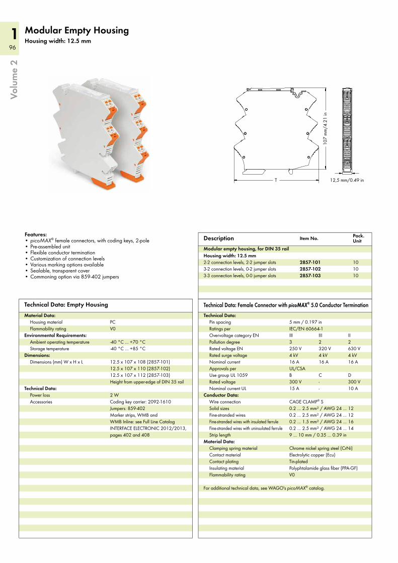
96
196
12857 SeriesModular Empty HousingHousing width: 12.5 mm
12,5 mm/0.49 in
107
mm
/4.2
1 in
T
Features:• picoMAX® female connectors, with coding keys, 2-pole• Pre-assembled unit• Flexible conductor termination• Customization of connection levels• Various marking options available• Sealable, transparent cover• Commoning option via 859-402 jumpers
Description Item No. Pack. Unit
2857-101 102857-102 10
Modular empty housing, for DIN 35 rail Housing width: 12.5 mm2-2 connection levels, 2-2 jumper slots3-2 connection levels, 0-2 jumper slots3-3 connection levels, 0-0 jumper slots 2857-103 10
Technical Data: Empty HousingMaterial Data:
Housing material PCFlammability rating V0
Environmental Requirements:Ambient operating temperature -40 °C … +70 °CStorage temperature -40 °C … +85 °C
Dimensions:Dimensions (mm) W x H x L 12.5 x 107 x 108 (2857-101)
12.5 x 107 x 110 (2857-102)12.5 x 107 x 112 (2857-103)Height from upper-edge of DIN 35 rail
Technical Data:Power loss 2 WAccessories Coding key carrier: 2092-1610
Jumpers: 859-402 Marker strips, WMB and WMB Inline: see Full Line Catalog INTERFACE ELECTRONIC 2012/2013, pages 402 and 408
Technical Data: Female Connector with picoMAX® 5.0 Conductor TerminationTechnical Data:
Pin spacing 5 mm / 0.197 inRatings per IEC/EN 60664-1Overvoltage category EN III III IIPollution degree 3 2 2Rated voltage EN 250 V 320 V 630 VRated surge voltage 4 kV 4 kV 4 kVNominal current 16 A 16 A 16 AApprovals per UL/CSAUse group UL 1059 B C DRated voltage 300 V - 300 VNominal current UL 15 A - 10 A
Conductor Data:Wire connection CAGE CLAMP® SSolid sizes 0.2 … 2.5 mm² / AWG 24 … 12Fine-stranded wires 0.2 … 2.5 mm² / AWG 24 … 12Fine-stranded wires with insulated ferrule 0.2 … 1.5 mm² / AWG 24 … 16Fine-stranded wires with uninsulated ferrule 0.2 … 2.5 mm² / AWG 24 … 14Strip length 9 … 10 mm / 0.35 … 0.39 in
Material Data:Clamping spring material Chrome nickel spring steel (CrNi)Contact material Electrolytic copper (Ecu)Contact plating Tin-platedInsulating material Polyphtalamide glass fiber (PPA-GF)Flammability rating V0
For additional technical data, see WAGO's picoMAX® catalog.
2857 SeriesModular Empty HousingHousing width: 22.5 mm
22,5 mm/0.89 in
107
mm
/4.2
1 in
T
Features:• picoMAX® female connectors, with coding keys, 4-pole• Pre-assembled unit• Flexible conductor termination• Customization of connection levels• Various marking options available• Sealable, transparent cover• Commoning option via 859-402 jumpers
Description Item No. Pack. Unit
Modular empty housing, for DIN 35 rail Housing width: 22.5 mm2-2 connection levels, 2-2 jumper slots 2857-121 53-2 connection levels, 0-2 jumper slots 2857-122 53-3 connection levels, 0-0 jumper slots 2857-123 51-1 connection levels, 2-2 jumper slots 2857-124 5
Technical Data: Empty HousingMaterial Data:
Housing material PCFlammability rating V0
Environmental Requirements:Ambient operating temperature -40 °C … +70 °CStorage temperature -40 °C … +85 °C
Dimensions:Dimensions (mm) W x H x L 22.5 x 107 x 108 (2857-121)
22.5 x 107 x 110 (2857-122)22.5 x 107 x 112 (2857-123)22.5 x 107 x 105 (2857-124)Height from upper-edge of DIN 35 rail
Technical Data:Power loss 3 WAccessories Coding key carrier: 2092-1610
Jumpers: 859-402 Marker strips, WMB and WMB Inline: see Full Line Catalog INTERFACE ELECTRONIC 2012/2013, pages 402 and 408
Technical Data: Female Connector with picoMAX® 5.0 Conductor TerminationTechnical Data:
Pin spacing 5 mm / 0.197 inRatings per IEC/EN 60664-1Overvoltage category EN III III IIPollution degree 3 2 2Rated voltage EN 250 V 320 630 VRated surge voltage 4 kV / 4 kV 4 kVNominal current 16 A 16 A 16 AApprovals per UL/CSAUse group UL 1059 B C DRated voltage 300 V - 300 VNominal current UL 15 A - 10 A
Conductor Data:Wire connection CAGE CLAMP® SSolid sizes 0.2 … 2.5 mm² / AWG 24 … 12Fine-stranded wires 0.2 … 2.5 mm² / AWG 24 … 12Fine-stranded wires with insulated ferrule 0.2 … 1.5 mm² / AWG 24 … 16Fine-stranded wires with uninsulated ferrule 0.2 … 2.5 mm² / AWG 24 … 14Strip length 9 … 10 mm / 0.35 … 0.39 in
Material Data:Clamping spring material Chrome nickel spring steel (CrNi)Contact material Electrolytic copper (Ecu)Contact plating Tin-platedInsulating material Polyphtalamide glass fiber (PPA-GF)Flammability rating V0
For additional technical data, see WAGO's picoMAX® catalog.
Volu
me
2
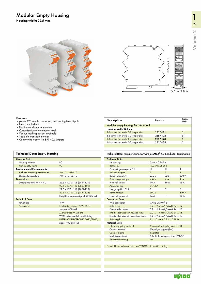
97
197
12857 SeriesModular Empty HousingHousing width: 12.5 mm
12,5 mm/0.49 in
107
mm
/4.2
1 in
T
Features:• picoMAX® female connectors, with coding keys, 2-pole• Pre-assembled unit• Flexible conductor termination• Customization of connection levels• Various marking options available• Sealable, transparent cover• Commoning option via 859-402 jumpers
Description Item No. Pack. Unit
2857-101 102857-102 10
Modular empty housing, for DIN 35 rail Housing width: 12.5 mm2-2 connection levels, 2-2 jumper slots3-2 connection levels, 0-2 jumper slots3-3 connection levels, 0-0 jumper slots 2857-103 10
Technical Data: Empty HousingMaterial Data:
Housing material PCFlammability rating V0
Environmental Requirements:Ambient operating temperature -40 °C … +70 °CStorage temperature -40 °C … +85 °C
Dimensions:Dimensions (mm) W x H x L 12.5 x 107 x 108 (2857-101)
12.5 x 107 x 110 (2857-102)12.5 x 107 x 112 (2857-103)Height from upper-edge of DIN 35 rail
Technical Data:Power loss 2 WAccessories Coding key carrier: 2092-1610
Jumpers: 859-402 Marker strips, WMB and WMB Inline: see Full Line Catalog INTERFACE ELECTRONIC 2012/2013, pages 402 and 408
Technical Data: Female Connector with picoMAX® 5.0 Conductor TerminationTechnical Data:
Pin spacing 5 mm / 0.197 inRatings per IEC/EN 60664-1Overvoltage category EN III III IIPollution degree 3 2 2Rated voltage EN 250 V 320 V 630 VRated surge voltage 4 kV 4 kV 4 kVNominal current 16 A 16 A 16 AApprovals per UL/CSAUse group UL 1059 B C DRated voltage 300 V - 300 VNominal current UL 15 A - 10 A
Conductor Data:Wire connection CAGE CLAMP® SSolid sizes 0.2 … 2.5 mm² / AWG 24 … 12Fine-stranded wires 0.2 … 2.5 mm² / AWG 24 … 12Fine-stranded wires with insulated ferrule 0.2 … 1.5 mm² / AWG 24 … 16Fine-stranded wires with uninsulated ferrule 0.2 … 2.5 mm² / AWG 24 … 14Strip length 9 … 10 mm / 0.35 … 0.39 in
Material Data:Clamping spring material Chrome nickel spring steel (CrNi)Contact material Electrolytic copper (Ecu)Contact plating Tin-platedInsulating material Polyphtalamide glass fiber (PPA-GF)Flammability rating V0
For additional technical data, see WAGO's picoMAX® catalog.
2857 SeriesModular Empty HousingHousing width: 22.5 mm
22,5 mm/0.89 in
107
mm
/4.2
1 in
T
Features:• picoMAX® female connectors, with coding keys, 4-pole• Pre-assembled unit• Flexible conductor termination• Customization of connection levels• Various marking options available• Sealable, transparent cover• Commoning option via 859-402 jumpers
Description Item No. Pack. Unit
Modular empty housing, for DIN 35 rail Housing width: 22.5 mm2-2 connection levels, 2-2 jumper slots 2857-121 53-2 connection levels, 0-2 jumper slots 2857-122 53-3 connection levels, 0-0 jumper slots 2857-123 51-1 connection levels, 2-2 jumper slots 2857-124 5
Technical Data: Empty HousingMaterial Data:
Housing material PCFlammability rating V0
Environmental Requirements:Ambient operating temperature -40 °C … +70 °CStorage temperature -40 °C … +85 °C
Dimensions:Dimensions (mm) W x H x L 22.5 x 107 x 108 (2857-121)
22.5 x 107 x 110 (2857-122)22.5 x 107 x 112 (2857-123)22.5 x 107 x 105 (2857-124)Height from upper-edge of DIN 35 rail
Technical Data:Power loss 3 WAccessories Coding key carrier: 2092-1610
Jumpers: 859-402 Marker strips, WMB and WMB Inline: see Full Line Catalog INTERFACE ELECTRONIC 2012/2013, pages 402 and 408
Technical Data: Female Connector with picoMAX® 5.0 Conductor TerminationTechnical Data:
Pin spacing 5 mm / 0.197 inRatings per IEC/EN 60664-1Overvoltage category EN III III IIPollution degree 3 2 2Rated voltage EN 250 V 320 630 VRated surge voltage 4 kV / 4 kV 4 kVNominal current 16 A 16 A 16 AApprovals per UL/CSAUse group UL 1059 B C DRated voltage 300 V - 300 VNominal current UL 15 A - 10 A
Conductor Data:Wire connection CAGE CLAMP® SSolid sizes 0.2 … 2.5 mm² / AWG 24 … 12Fine-stranded wires 0.2 … 2.5 mm² / AWG 24 … 12Fine-stranded wires with insulated ferrule 0.2 … 1.5 mm² / AWG 24 … 16Fine-stranded wires with uninsulated ferrule 0.2 … 2.5 mm² / AWG 24 … 14Strip length 9 … 10 mm / 0.35 … 0.39 in
Material Data:Clamping spring material Chrome nickel spring steel (CrNi)Contact material Electrolytic copper (Ecu)Contact plating Tin-platedInsulating material Polyphtalamide glass fiber (PPA-GF)Flammability rating V0
For additional technical data, see WAGO's picoMAX® catalog.
Volu
me
2
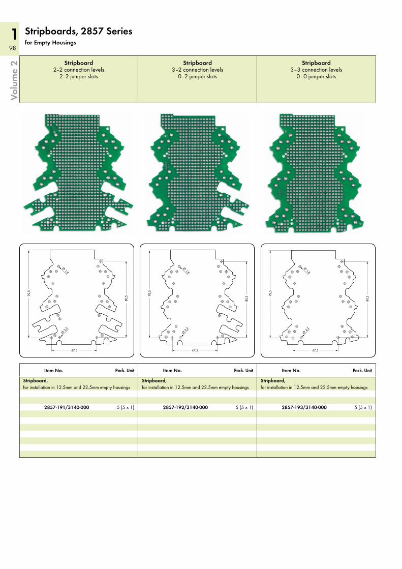
98
198
1
<__________ 47,5 __________>
<________________________ 9
2,5 _______________________>
<____________________ 8
0,5 ___________________><
_____
Ø 1,8
<_____
Ø 2,3
<__________ 47,5 __________>
<________________________ 9
2,5 _______________________>
<____________________ 8
0,5 ___________________><
_____
Ø 1,8
<_____
Ø 2,3
<__________ 47,5 __________>
<________________________ 9
2,5 _______________________>
<____________________ 8
0,5 ___________________><_____
Ø 1,8
<_____
Ø 2,3
Volu
me
2
Stripboards, 2857 Seriesfor Empty Housings
Stripboard 2–2 connection levels
2–2 jumper slots
Stripboard 3–2 connection levels
0–2 jumper slots
Stripboard 3–3 connection levels
0–0 jumper slots
Item No. Pack. Unit Item No. Pack. Unit Item No. Pack. Unit
Stripboard, for installation in 12.5mm and 22.5mm empty housings
Stripboard, for installation in 12.5mm and 22.5mm empty housings
Stripboard, for installation in 12.5mm and 22.5mm empty housings
2857-191/3140-000 5 (5 x 1) 2857-192/3140-000 5 (5 x 1) 2857-193/3140-000 5 (5 x 1)
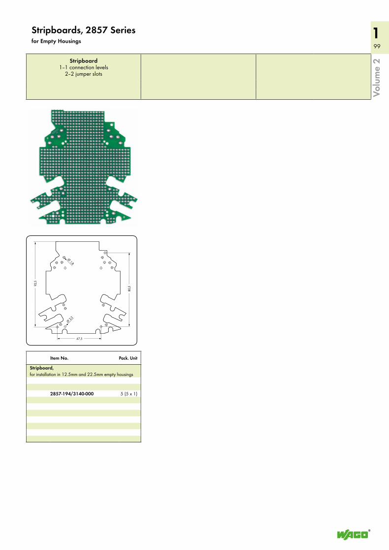
99
199
1
<__________ 47,5 __________>
<________________________ 9
2,5 _______________________>
<____________________ 8
0,5 ___________________><
_____
Ø 1,8
<_____
Ø 2,3
Volu
me
2Stripboard 1–1 connection levels
2–2 jumper slots
Item No. Pack. Unit
Stripboard, for installation in 12.5mm and 22.5mm empty housings
2857-194/3140-000 5 (5 x 1)
Stripboards, 2857 Seriesfor Empty Housings
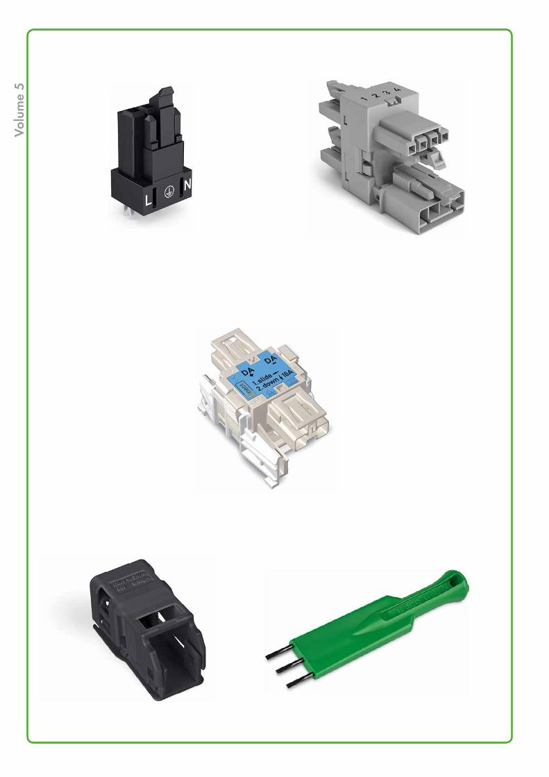
Volu
me
5
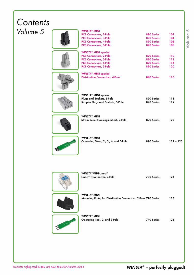
Contents Volume 5 WINSTA® MINI
PCB Connectors, 2-Pole 890 Series 102PCB Connectors, 3-Pole 890 Series 104PCB Connectors, 4-Pole 890 Series 106PCB Connectors, 5-Pole 890 Series 108
WINSTA® MINI specialPCB Connectors, 2-Pole 890 Series 110PCB Connectors, 3-Pole 890 Series 112PCB Connectors, 4-Pole 890 Series 114PCB Connectors, 5-Pole 890 Series 120
WINSTA® MINI specialDistribution Connectors, 4-Pole 890 Series 116
WINSTA® MINI specialPlugs and Sockets, 5-Pole 890 Series 118Snap-In Plugs and Sockets, 5-Pole 890 Series 119
WINSTA® MINI Strain Relief Housings, Short, 2-Pole 890 Series 122
WINSTA® MINI Operating Tools, 2-, 3-, 4- and 5-Pole 890 Series 122 – 123
WINSTA®MIDI-Linect®
Linect® T-Connector, 2-Pole 770 Series 124
WINSTA® MIDI Mounting Plate, for Distribution Connectors, 2-Pole 770 Series 125
WINSTA® MIDI Operating Tool, 2- and 3-Pole 770 Series 125
Products highlighted in RED are new items for Autumn 2014
Volu
me
5
WINSTA® – perfectly plugged!
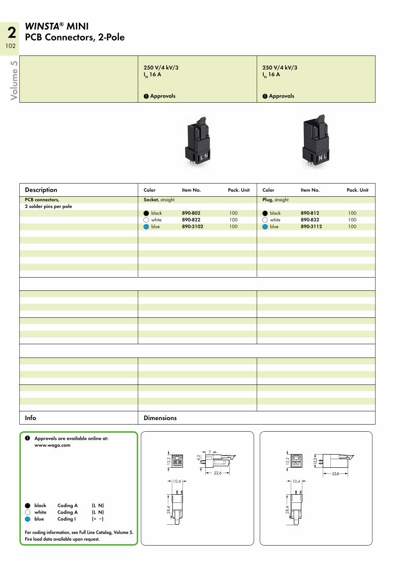
2102
4,2
<__
>
7 <>
12,2
<>
10,4 <>
28,4___>
___>
<_ 22,6 _>
12,2
<>
10,4> >
28,4___>
___>
<__ 22,6__>
(12,
2)
250 V/4 kV/3IN 16 A
1 Approvals
250 V/4 kV/3IN 16 A
1 Approvals
PCB connectors, 2 solder pins per pole
Socket, straight
black 890-802 100 white 890-822 100 blue 890-3102 100
Plug, straight
black 890-812 100 white 890-832 100 blue 890-3112 100
Description
1 Approvals are available online at: www.wago.com
black Coding A (L N) white Coding A (L N) blue Coding I (+ –)
For coding information, see Full Line Catalog, Volume 5. Fire load data available upon request.
WINSTA® MINI PCB Connectors, 2-Pole
Color Item No. Pack. Unit Color Item No. Pack. Unit
Info Dimensions
Volu
me
5
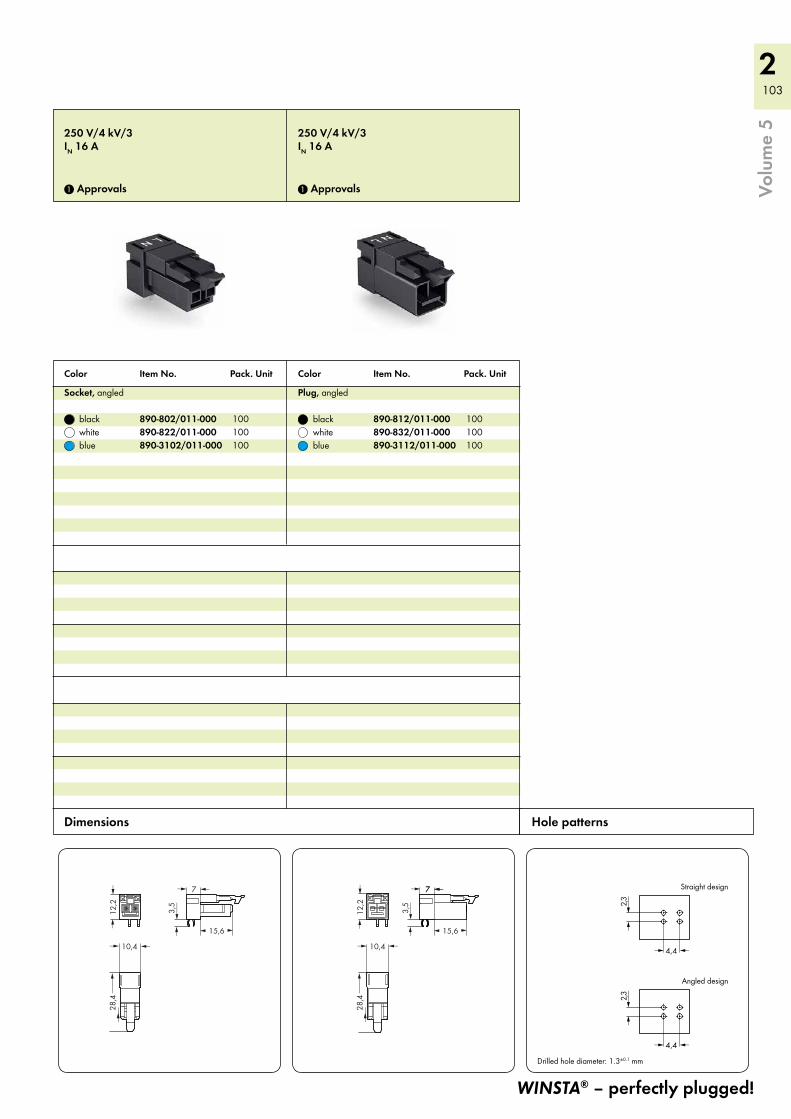
2 103
15,6( )
3,5
<__
>
7 <>
12,2
<>
10,4 <>
28,4___>
___>
12,2
<>
10,4> >
28,4___>
___>
7 <
15,6( )
7 <>
3,5
<__
>
2,3<
__>
4,4 <>
2,3<
__>
4,4 <>
Straight design
Angled design
Drilled hole diameter: 1.3±0.1 mm
250 V/4 kV/3IN 16 A
1 Approvals
250 V/4 kV/3IN 16 A
1 Approvals
Socket, angled
black 890-802/011-000 100 white 890-822/011-000 100 blue 890-3102/011-000 100
Plug, angled
black 890-812/011-000 100 white 890-832/011-000 100 blue 890-3112/011-000 100
WINSTA® – perfectly plugged!
Color Item No. Pack. Unit Color Item No. Pack. Unit
Hole patterns Dimensions
Volu
me
5
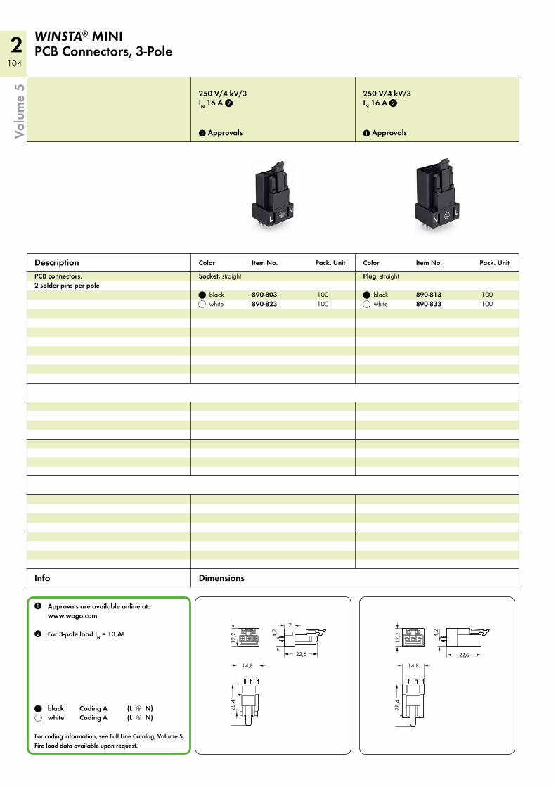
2104
4,2
<__
>
7 <>
12,2
<
<
14,8 <>
<_ 22,6 _>
28,4___>
___>
12,2
<>
14,8> >
28,4___>
___>
<__ 22,6__>
4,2
<__
>
250 V/4 kV/3IN 16 A 2
1 Approvals
250 V/4 kV/3IN 16 A 2
1 Approvals
PCB connectors, 2 solder pins per pole
Socket, straight
black 890-803 100 white 890-823 100
Plug, straight
black 890-813 100 white 890-833 100
Description
1 Approvals are available online at: www.wago.com
2 For 3-pole load IN = 13 A!
black Coding A (L 3 N) white Coding A (L 3 N)
For coding information, see Full Line Catalog, Volume 5. Fire load data available upon request.
WINSTA® MINI PCB Connectors, 3-Pole
Color Item No. Pack. Unit Color Item No. Pack. Unit
Info Dimensions
Volu
me
5
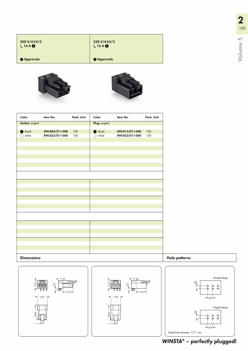
2 105
28,4___>
___>
15,6( )
7 <>
12,2
<>
14,8 <>
3,5
<__
>
12,2
<>
14,8> >
28,4___>
___>
7 <
15,6( )
7 <>
3,5
<__
>
2,3<
__>
4,4 <>
2,3<
__>
4,4 <>
Straight design
Angled design
Drilled hole diameter: 1.3±0.1 mm
250 V/4 kV/3IN 16 A 2
1 Approvals
250 V/4 kV/3IN 16 A 2
1 Approvals
Socket, angled
black 890-803/011-000 100 white 890-823/011-000 100
Plug, angled
black 890-813/011-000 100 white 890-833/011-000 100
WINSTA® – perfectly plugged!
Color Item No. Pack. Unit Color Item No. Pack. Unit
Hole patterns Dimensions
Volu
me
5
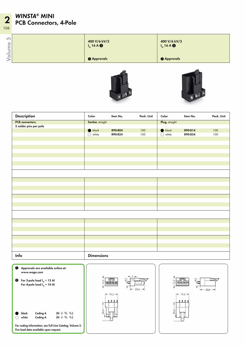
2106
12,2
<>
19,2 >>
28,4___>
___>
4,2
<__
>
7 <>
<_ 22,6 _>
12,2
<>
19,2 >>
28,4___>
___>
4,2
<__
>
<__ 22,6__>
400 V/6 kV/3IN 16 A 2
1 Approvals
400 V/6 kV/3IN 16 A 2
1 Approvals
PCB connectors, 2 solder pins per pole
Socket, straight
black 890-804 100 white 890-824 100
Plug, straight
black 890-814 100 white 890-834 100
Description
1 Approvals are available online at: www.wago.com
2 For 3-pole load IN = 13 A! For 4-pole load IN = 10 A!
black Coding A (N 3 2l L 1l L') white Coding A (N 3 2l L 1l L')
For coding information, see Full Line Catalog, Volume 5. Fire load data available upon request.
WINSTA® MINI PCB Connectors, 4-Pole
Color Item No. Pack. Unit Color Item No. Pack. Unit
Info Dimensions
Volu
me
5
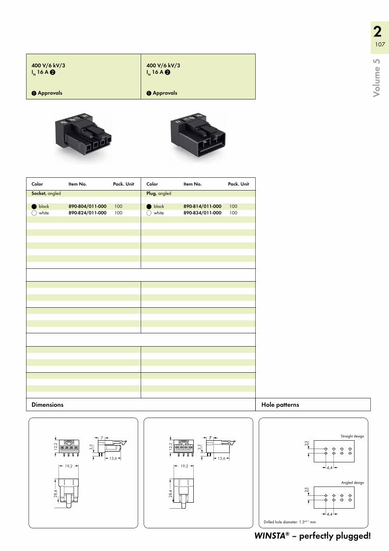
2 107
15,6( )
7 <>
12,2
<>
19,2 >>
28,4___>
___>
3,5
<__
>
12,2
<>
19,2 >>
28,4___>
___>
7 <
15,6( )
7 <>
3,5
<__
>
2,3<
__>
4,4 <>
2,3<
__>
4,4 <>
Straight design
Angled design
Drilled hole diameter: 1.3±0.1 mm
400 V/6 kV/3IN 16 A 2
1 Approvals
400 V/6 kV/3IN 16 A 2
1 Approvals
Socket, angled
black 890-804/011-000 100 white 890-824/011-000 100
Plug, angled
black 890-814/011-000 100 white 890-834/011-000 100
WINSTA® – perfectly plugged!
Color Item No. Pack. Unit Color Item No. Pack. Unit
Hole patterns Dimensions
Volu
me
5
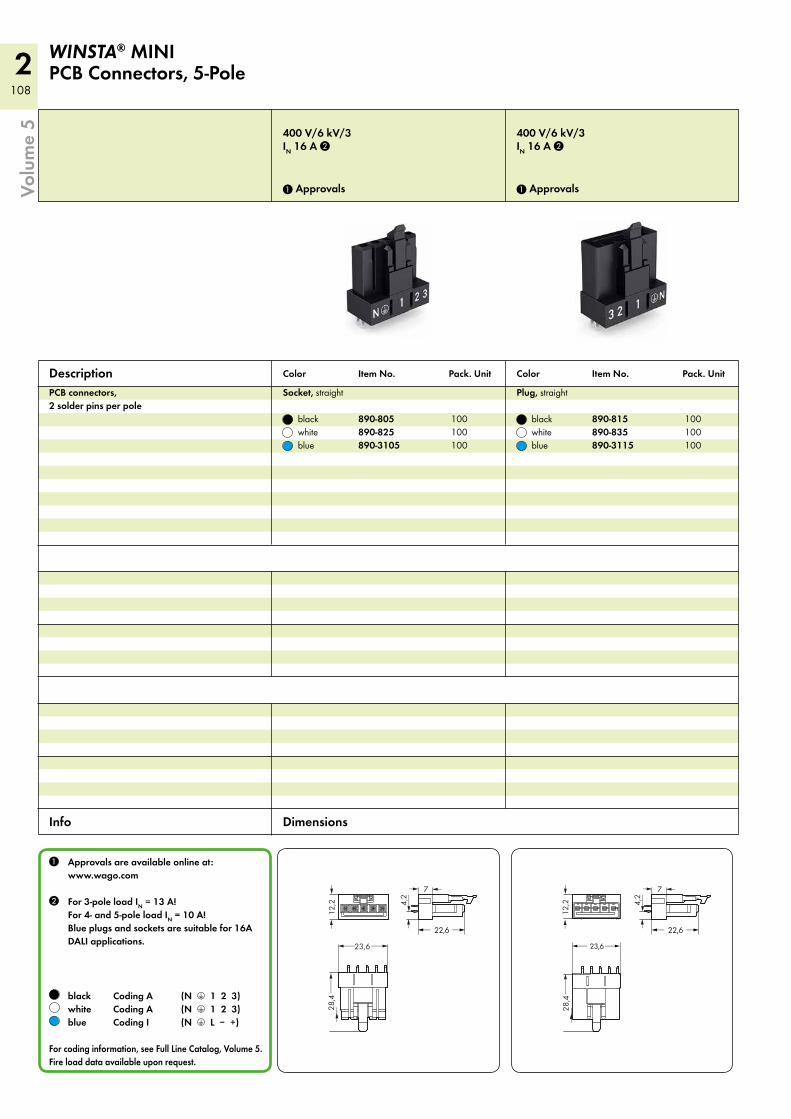
2108
12,2
<>
23,6 __>__>
28,4___>
___>
4,2
<__
>
7 <>
<_ 22,6 _>
<__ 23,6__>
12,2
<>
28,4___>
___>
<_ 22,6 _>
4,2
<__
>
7 <>
400 V/6 kV/3IN 16 A 2
1 Approvals
400 V/6 kV/3IN 16 A 2
1 Approvals
PCB connectors, 2 solder pins per pole
Socket, straight
black 890-805 100 white 890-825 100 blue 890-3105 100
Plug, straight
black 890-815 100 white 890-835 100 blue 890-3115 100
Description
1 Approvals are available online at: www.wago.com
2 For 3-pole load IN = 13 A! For 4- and 5-pole load IN = 10 A! Blue plugs and sockets are suitable for 16A DALI applications.
black Coding A (N 3 1 2 3) white Coding A (N 3 1 2 3) blue Coding I (N 3 L – +)
For coding information, see Full Line Catalog, Volume 5. Fire load data available upon request.
WINSTA® MINI PCB Connectors, 5-Pole
Color Item No. Pack. Unit Color Item No. Pack. Unit
Info Dimensions
Volu
me
5
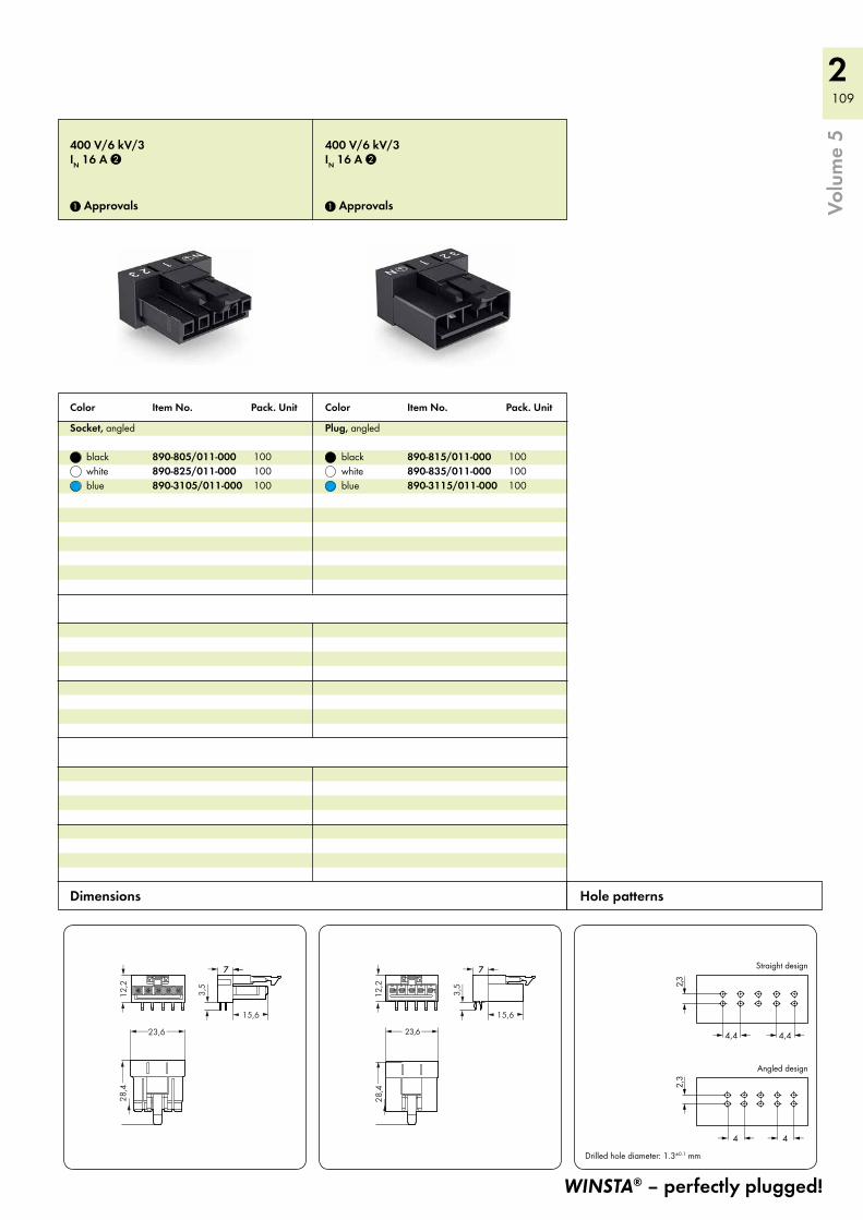
2 109
12,2
<>
23,6 __>__>
28,4___>
___>
7 <
15,6( )
7 <>
3,5
<__
>
<__ 23,6__>
12,2
<>
28,4___>
___>
7
15,6( )
7 <>
3,5
<__
>
4
2,3<
__>
2,3
<__
>
<>
4,4 <> 4,4 <>
4 <>
Straight design
Angled design
Drilled hole diameter: 1.3±0.1 mm
400 V/6 kV/3IN 16 A 2
1 Approvals
400 V/6 kV/3IN 16 A 2
1 Approvals
Socket, angled
black 890-805/011-000 100 white 890-825/011-000 100 blue 890-3105/011-000 100
Plug, angled
black 890-815/011-000 100 white 890-835/011-000 100 blue 890-3115/011-000 100
WINSTA® – perfectly plugged!
Color Item No. Pack. Unit Color Item No. Pack. Unit
Hole patterns Dimensions
Volu
me
5
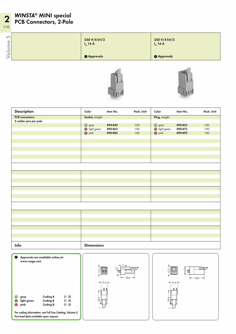
2110
4,2
<__
>
7 <>
12,2
<>
10,4 <>
28,4___>
___>
<_ 22,6 _>
12,2
<>
10,4> >
28,4___>
___>
<__ 22,6__>
(12,
2)
250 V/4 kV/3IN 16 A
1 Approvals
250 V/4 kV/3IN 16 A
1 Approvals
PCB connectors, 2 solder pins per pole
Socket, straight
gray 890-842 100 light green 890-862 100 pink 890-882 100
Plug, straight
gray 890-852 100 light green 890-872 100 pink 890-892 100
Description
1 Approvals are available online at: www.wago.com
gray Coding B (1 2) light green Coding B (1 2) pink Coding B (1 2)
For coding information, see Full Line Catalog, Volume 5. Fire load data available upon request.
WINSTA® MINI specialPCB Connectors, 2-Pole
Color Item No. Pack. Unit Color Item No. Pack. Unit
Info Dimensions
Volu
me
5
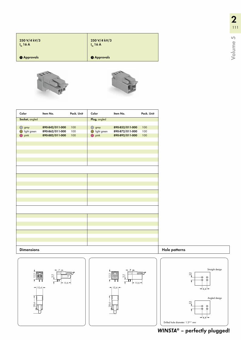
2 111
15,6( )
3,5
<__
>
7 <>
12,2
<>
10,4 <>
28,4___>
___>
12,2
<>
10,4> >
28,4___>
___>
7 <
15,6( )
7 <>
3,5
<__
>
2,3<
__>
4,4 <>
2,3<
__>
4,4 <>
Straight design
Angled design
Drilled hole diameter: 1.3±0.1 mm
250 V/4 kV/3IN 16 A
1 Approvals
250 V/4 kV/3IN 16 A
1 Approvals
Socket, angled
gray 890-842/011-000 100 light green 890-862/011-000 100 pink 890-882/011-000 100
Plug, angled
gray 890-852/011-000 100 light green 890-872/011-000 100 pink 890-892/011-000 100
WINSTA® – perfectly plugged!
Color Item No. Pack. Unit Color Item No. Pack. Unit
Hole patterns Dimensions
Volu
me
5
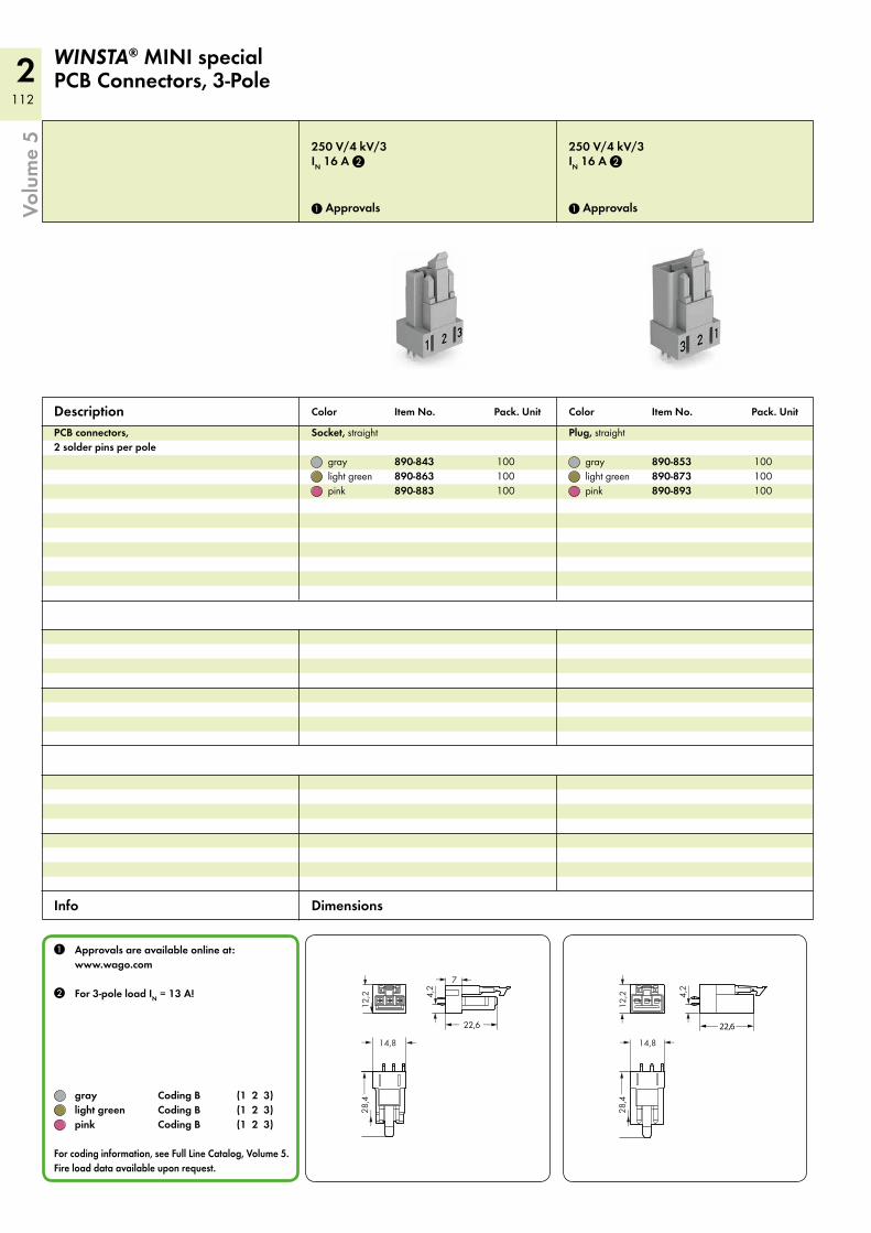
2112
4,2
<__
>
7 <>
12,2
<
<
14,8 <>
<_ 22,6 _>
28,4___>
___>
12,2
<>
14,8> >
28,4___>
___>
<__ 22,6__>
4,2
<__
>
250 V/4 kV/3IN 16 A 2
1 Approvals
250 V/4 kV/3IN 16 A 2
1 Approvals
PCB connectors, 2 solder pins per pole
Socket, straight
gray 890-843 100 light green 890-863 100 pink 890-883 100
Plug, straight
gray 890-853 100 light green 890-873 100 pink 890-893 100
Description
1 Approvals are available online at: www.wago.com
2 For 3-pole load IN = 13 A!
gray Coding B (1 2 3) light green Coding B (1 2 3) pink Coding B (1 2 3)
For coding information, see Full Line Catalog, Volume 5. Fire load data available upon request.
WINSTA® MINI specialPCB Connectors, 3-Pole
Color Item No. Pack. Unit Color Item No. Pack. Unit
Info Dimensions
Volu
me
5
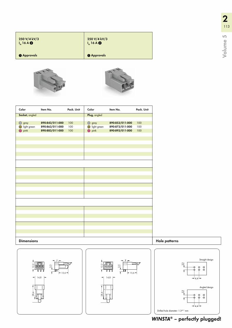
2 113
28,4___>
___>
15,6( )
7 <>
12,2
<>
14,8 <>
3,5
<__
>
12,2
<>
14,8> >
28,4___>
___>
7 <
15,6( )
7 <>
3,5
<__
>
2,3<
__>
4,4 <>
2,3<
__>
4,4 <>
Straight design
Angled design
Drilled hole diameter: 1.3±0.1 mm
250 V/4 kV/3IN 16 A 2
1 Approvals
250 V/4 kV/3IN 16 A 2
1 Approvals
Socket, angled
gray 890-843/011-000 100 light green 890-863/011-000 100 pink 890-883/011-000 100
Plug, angled
gray 890-853/011-000 100 light green 890-873/011-000 100 pink 890-893/011-000 100
WINSTA® – perfectly plugged!
Color Item No. Pack. Unit Color Item No. Pack. Unit
Hole patterns Dimensions
Volu
me
5
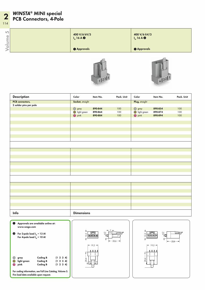
2114
12,2
<>
19,2 >>
28,4___>
___>
4,2
<__
>
7 <>
<_ 22,6 _>
12,2
<>
19,2 >>
28,4___>
___>
4,2
<__
>
<__ 22,6__>
400 V/6 kV/3IN 16 A 2
1 Approvals
400 V/6 kV/3IN 16 A 2
1 Approvals
PCB connectors, 2 solder pins per pole
Socket, straight
gray 890-844 100 light green 890-864 100 pink 890-884 100
Plug, straight
gray 890-854 100 light green 890-874 100 pink 890-894 100
Description
1 Approvals are available online at: www.wago.com
2 For 3-pole load IN = 13 A! For 4-pole load IN = 10 A!
gray Coding B (1 2 3 4) light green Coding B (1 2 3 4) pink Coding B (1 2 3 4)
For coding information, see Full Line Catalog, Volume 5. Fire load data available upon request.
WINSTA® MINI specialPCB Connectors, 4-Pole
Color Item No. Pack. Unit Color Item No. Pack. Unit
Info Dimensions
Volu
me
5
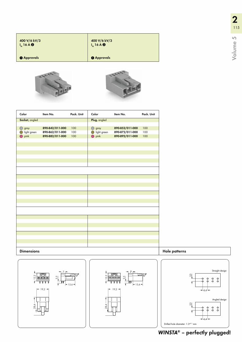
2 115
15,6( )
7 <>
12,2
<>
19,2 >>
28,4___>
___>
3,5
<__
>
12,2
<>
19,2 >>
28,4___>
___>
7 <
15,6( )
7 <>
3,5
<__
>
2,3<
__>
4,4 <>
2,3<
__>
4,4 <>
Straight design
Angled design
Drilled hole diameter: 1.3±0.1 mm
400 V/6 kV/3IN 16 A 2
1 Approvals
400 V/6 kV/3IN 16 A 2
1 Approvals
Socket, angled
gray 890-842/011-000 100 light green 890-862/011-000 100 pink 890-882/011-000 100
Plug, angled
gray 890-852/011-000 100 light green 890-872/011-000 100 pink 890-892/011-000 100
WINSTA® – perfectly plugged!
Color Item No. Pack. Unit Color Item No. Pack. Unit
Hole patterns Dimensions
Volu
me
5
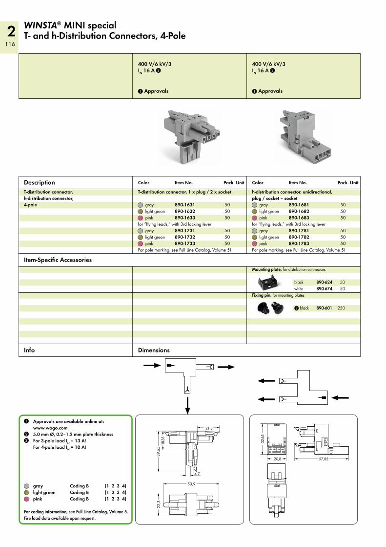
2116
<18
,35
<______ 3
9,65 ______>
21,3 _>
<___>
<_
4,7
>
<__________ 53,9 __________>
<_
22,3
_>
< 20,8> <___________ 57,85_________>
<___
32,6
5___>
400 V/6 kV/3IN 16 A 3
1 Approvals
400 V/6 kV/3IN 16 A 3
1 Approvals
T-distribution connector, h-distribution connector, 4-pole
Description
1 Approvals are available online at: www.wago.com
2 5.0 mm Ø, 0.2–1.2 mm plate thickness 3 For 3-pole load IN = 13 A!
For 4-pole load IN = 10 A!
gray Coding B (1 2 3 4) light green Coding B (1 2 3 4) pink Coding B (1 2 3 4) For coding information, see Full Line Catalog, Volume 5. Fire load data available upon request.
WINSTA® MINI specialT- and h-Distribution Connectors, 4-Pole
Color Item No. Pack. Unit Color Item No. Pack. Unit
Item-Specific Accessories
Dimensions Info
T-distribution connector, 1 x plug / 2 x socket
gray 890-1631 50 light green 890-1632 50 pink 890-1633 50for “flying leads,” with 3rd locking lever gray 890-1731 50 light green 890-1732 50 pink 890-1733 50For pole marking, see Full Line Catalog, Volume 5!
h-distribution connector, unidirectional, plug / socket – socket gray 890-1681 50 light green 890-1682 50 pink 890-1683 50for “flying leads,” with 3rd locking lever gray 890-1781 50 light green 890-1782 50 pink 890-1783 50For pole marking, see Full Line Catalog, Volume 5!
Mounting plate, for distribution connectors
black 890-624 50 white 890-674 50Fixing pin, for mounting plates
2 black 890-601 250
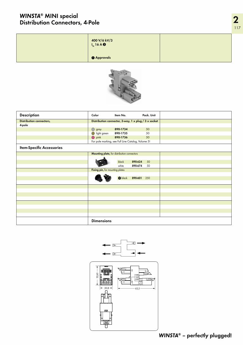
2 117
< 20,8> <_____________63,5 ___________>
<___
32,6
5___>
WINSTA® MINI specialDistribution Connectors, 4-Pole
WINSTA® – perfectly plugged!
400 V/6 kV/3IN 16 A 3
1 Approvals
Distribution connectors, 4-pole
Description Color Item No. Pack. Unit
Item-Specific Accessories
Dimensions
Distribution connector, 3-way, 1 x plug / 3 x socket
gray 890-1734 50 light green 890-1735 50 pink 890-1736 50For pole marking, see Full Line Catalog, Volume 5!
Mounting plate, for distribution connectors
black 890-624 50 white 890-674 50Fixing pin, for mounting plates
2 black 890-601 250
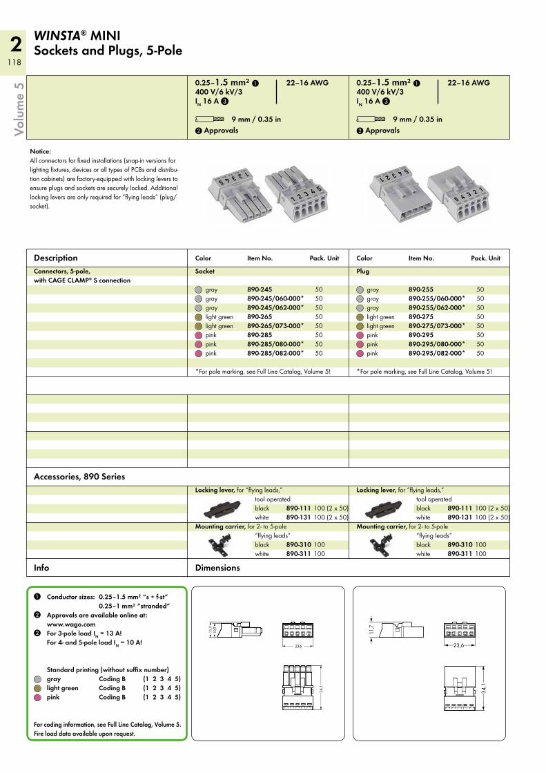
2118
<_______34
,1_________>
<____ 23,6 ___>
<11
,7>
<>
11,7
<____34
,1_____>
<_23,6__>
WINSTA® MINI Sockets and Plugs, 5-Pole
0.25–1.5 mm² 1 22–16 AWG 400 V/6 kV/3IN 16 A 3
L 9 mm / 0.35 in 2 Approvals
0.25–1.5 mm² 1 22–16 AWG 400 V/6 kV/3IN 16 A 3
L 9 mm / 0.35 in 2 Approvals
Description Connectors, 5-pole, with CAGE CLAMP® S connection
Socket
gray 890-245 50 gray 890-245/060-000* 50 gray 890-245/062-000* 50 light green 890-265 50 light green 890-265/073-000* 50 pink 890-285 50 pink 890-285/080-000* 50 pink 890-285/082-000* 50
*For pole marking, see Full Line Catalog, Volume 5!
Plug
gray 890-255 50 gray 890-255/060-000* 50 gray 890-255/062-000* 50 light green 890-275 50 light green 890-275/073-000* 50 pink 890-295 50 pink 890-295/080-000* 50 pink 890-295/082-000* 50
*For pole marking, see Full Line Catalog, Volume 5!
Color Item No. Pack. Unit
1 Conductor sizes: 0.25–1.5 mm² “s + f-st” 0.25–1 mm² “stranded” 2 Approvals are available online at:
www.wago.com2 For 3-pole load IN = 13 A!
For 4- and 5-pole load IN = 10 A!
Standard printing (without suffix number) gray Coding B (1 2 3 4 5) light green Coding B (1 2 3 4 5) pink Coding B (1 2 3 4 5)
For coding information, see Full Line Catalog, Volume 5. Fire load data available upon request.
Color Item No. Pack. Unit
Accessories, 890 Series
Info Dimensions
Locking lever, for “flying leads,” tool operated
black 890-111 100 (2 x 50) white 890-131 100 (2 x 50)Mounting carrier, for 2- to 5-pole
“flying leads” black 890-310 100 white 890-311 100
Locking lever, for “flying leads,” tool operated
black 890-111 100 (2 x 50) white 890-131 100 (2 x 50)Mounting carrier, for 2- to 5-pole
“flying leads” black 890-310 100 white 890-311 100
Notice: All connectors for fixed installations (snap-in versions for lighting fixtures, devices or all types of PCBs and distribu-tion cabinets) are factory-equipped with locking levers to ensure plugs and sockets are securely locked. Additional locking levers are only required for “flying leads” (plug/socket).
Volu
me
5
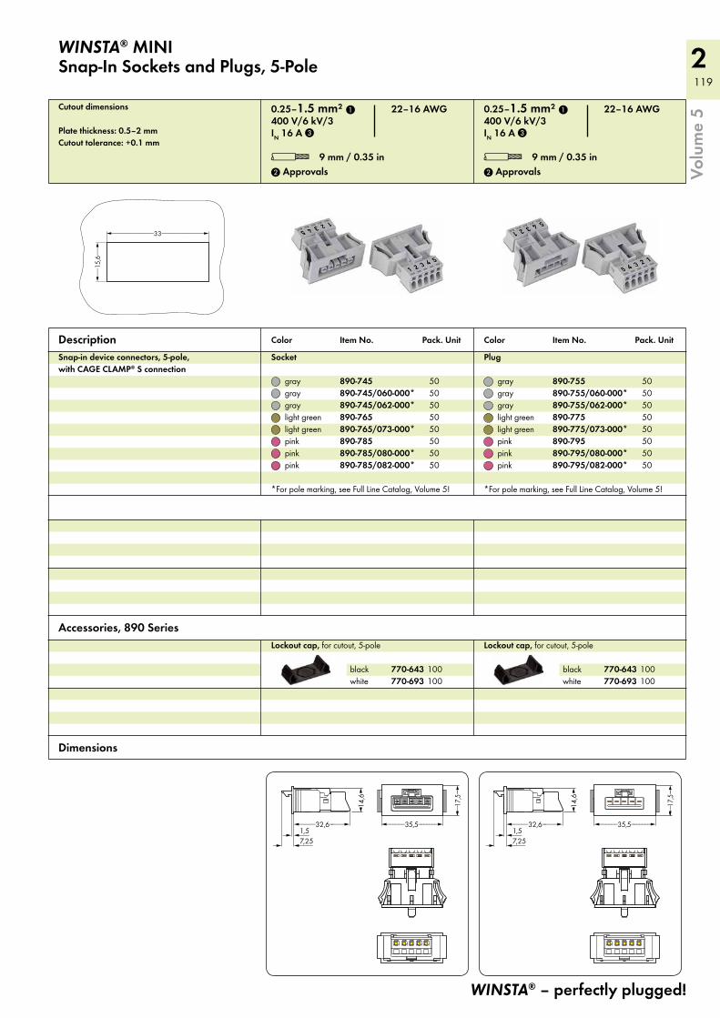
2 119
<_____________33_____________>
<__
15,6__>
<__1,5
>
<___7,25
>
<____32,6____> <_____35,5______><__
1,5>
<___7,25
>
<____32,6____> <_____35,5______>
WINSTA® MINI Snap-In Sockets and Plugs, 5-Pole
Description Snap-in device connectors, 5-pole, with CAGE CLAMP® S connection
WINSTA® – perfectly plugged!
Volu
me
50.25–1.5 mm² 1 22–16 AWG 400 V/6 kV/3IN 16 A 3
L 9 mm / 0.35 in 2 Approvals
0.25–1.5 mm² 1 22–16 AWG 400 V/6 kV/3IN 16 A 3
L 9 mm / 0.35 in 2 Approvals
Socket
gray 890-745 50 gray 890-745/060-000* 50 gray 890-745/062-000* 50 light green 890-765 50 light green 890-765/073-000* 50 pink 890-785 50 pink 890-785/080-000* 50 pink 890-785/082-000* 50
*For pole marking, see Full Line Catalog, Volume 5!
Plug
gray 890-755 50 gray 890-755/060-000* 50 gray 890-755/062-000* 50 light green 890-775 50 light green 890-775/073-000* 50 pink 890-795 50 pink 890-795/080-000* 50 pink 890-795/082-000* 50
*For pole marking, see Full Line Catalog, Volume 5!
Color Item No. Pack. Unit Color Item No. Pack. Unit
Dimensions
Lockout cap, for cutout, 5-pole
black 770-643 100 white 770-693 100
Lockout cap, for cutout, 5-pole
black 770-643 100 white 770-693 100
Accessories, 890 Series
Cutout dimensions
Plate thickness: 0.5–2 mmCutout tolerance: +0.1 mm
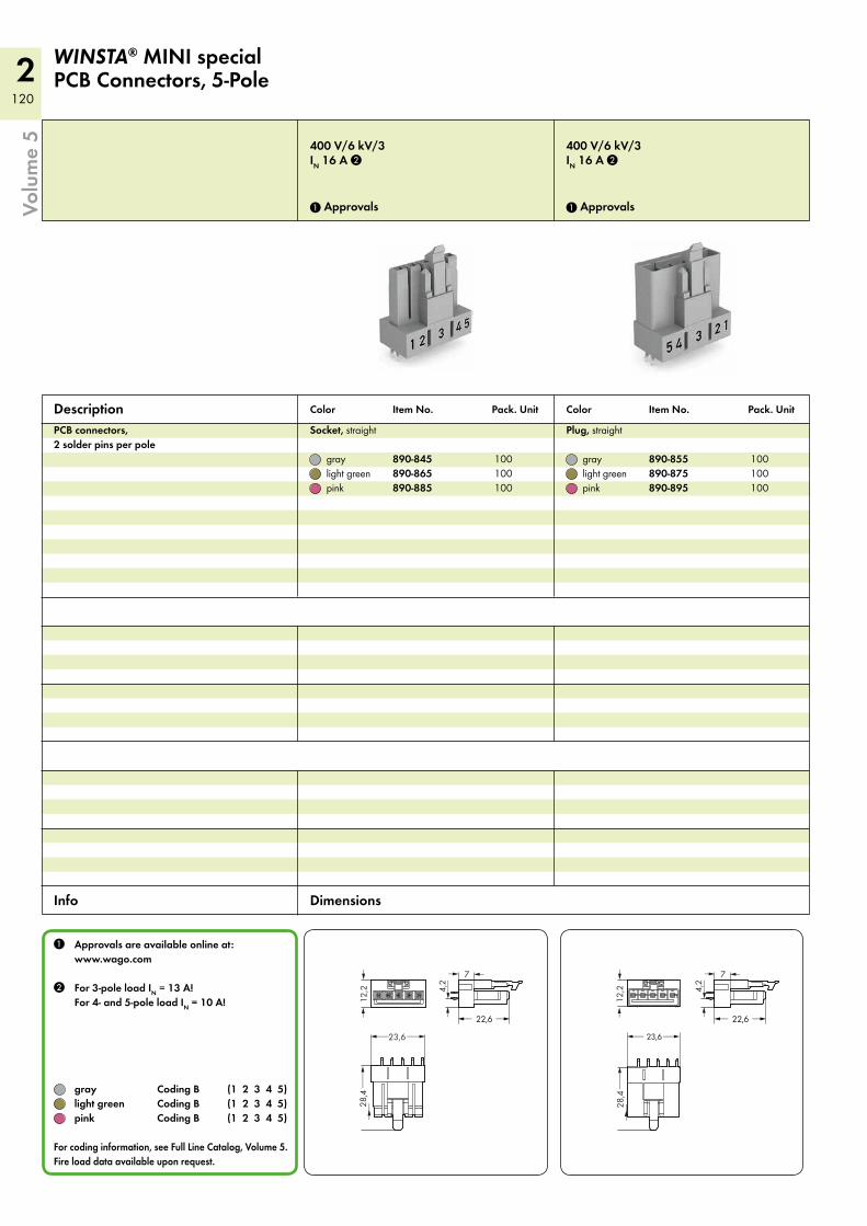
2120
12,2
<>
23,6 __>__>
28,4___>
___>
4,2
<__
>
7 <>
<_ 22,6 _>
<__ 23,6__>
12,2
<>
28,4___>
___>
<_ 22,6 _>
4,2
<__
>
7 <>
400 V/6 kV/3IN 16 A 2
1 Approvals
400 V/6 kV/3IN 16 A 2
1 Approvals
PCB connectors, 2 solder pins per pole
Socket, straight
gray 890-845 100 light green 890-865 100 pink 890-885 100
Plug, straight
gray 890-855 100 light green 890-875 100 pink 890-895 100
Description
1 Approvals are available online at: www.wago.com
2 For 3-pole load IN = 13 A! For 4- and 5-pole load IN = 10 A!
gray Coding B (1 2 3 4 5) light green Coding B (1 2 3 4 5) pink Coding B (1 2 3 4 5)
For coding information, see Full Line Catalog, Volume 5. Fire load data available upon request.
WINSTA® MINI specialPCB Connectors, 5-Pole
Color Item No. Pack. Unit Color Item No. Pack. Unit
Info Dimensions
Volu
me
5

2 121
12,2
<>
23,6 __>__>
28,4___>
___>
7 <
15,6( )
7 <>
3,5
<__
>
<__ 23,6__>
12,2
<>
28,4___>
___>
7
15,6( )
7 <>
3,5
<__
>
4
2,3<
__>
2,3
<__
>
<>
4,4 <> 4,4 <>
4 <>
Straight design
Angled design
Drilled hole diameter: 1.3±0.1 mm
400 V/6 kV/3IN 16 A 2
1 Approvals
400 V/6 kV/3IN 16 A 2
1 Approvals
Socket, angled
gray 890-845/011-000 100 light green 890-865/011-000 100 pink 890-885/011-000 100
Plug, angled
gray 890-855/011-000 100 light green 890-875/011-000 100 pink 890-895/011-000 100
WINSTA® – perfectly plugged!
Color Item No. Pack. Unit Color Item No. Pack. Unit
Hole patterns Dimensions
Volu
me
5
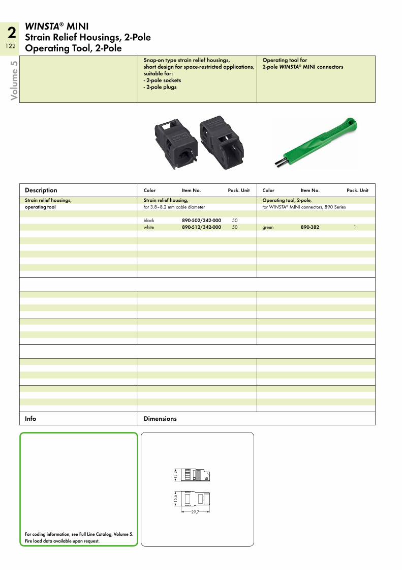
2122
<___29,7___>
(13,
2)(
15,6
)
WINSTA® MINI Strain Relief Housings, 2-Pole Operating Tool, 2-Pole
Snap-on type strain relief housings, short design for space-restricted applications, suitable for: - 2-pole sockets - 2-pole plugs
Operating tool for 2-pole WINSTA® MINI connectors
Strain relief housings, operating tool
Strain relief housing, for 3.8–8.2 mm cable diameter
black 890-502/342-000 50white 890-512/342-000 50
Operating tool, 2-pole, for WINSTA® MINI connectors, 890 Series
green 890-382 1
Description
For coding information, see Full Line Catalog, Volume 5. Fire load data available upon request.
Color Item No. Pack. Unit Color Item No. Pack. Unit
Info Dimensions
Volu
me
5
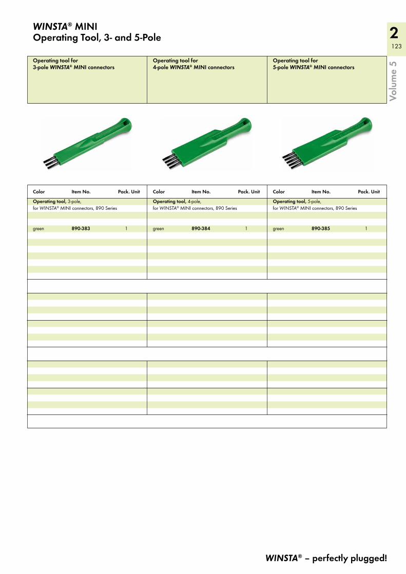
2 123
WINSTA® MINI Operating Tool, 3- and 5-Pole
WINSTA® – perfectly plugged!
Volu
me
5Operating tool for 3-pole WINSTA® MINI connectors
Operating tool for 4-pole WINSTA® MINI connectors
Operating tool for 5-pole WINSTA® MINI connectors
Operating tool, 3-pole, for WINSTA® MINI connectors, 890 Series
green 890-383 1
Operating tool, 4-pole, for WINSTA® MINI connectors, 890 Series
green 890-384 1
Operating tool, 5-pole, for WINSTA® MINI connectors, 890 Series
green 890-385 1
Color Item No. Pack. Unit Color Item No. Pack. Unit Color Item No. Pack. Unit
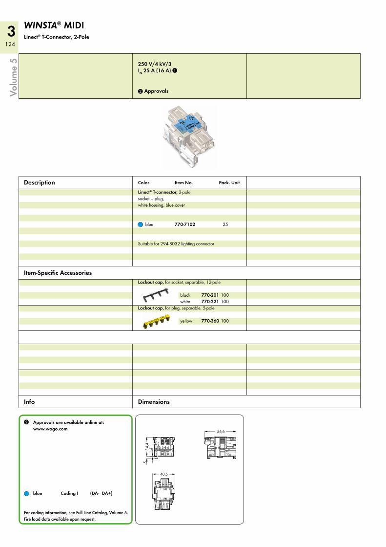
3124
40,5 <_ _>
56,6<___ ___>
34,4
<>
5_>
1,4
<__
_>
Volu
me
5WINSTA® MIDI Linect® T-Connector, 2-Pole
Color Item No. Pack. Unit
Item-Specific Accessories
Dimensions
2 Approvals are available online at: www.wago.com
blue Coding I (DA- DA+)
For coding information, see Full Line Catalog, Volume 5. Fire load data available upon request.
Info
Description Linect® T-connector, 2-pole, socket – plug, white housing, blue cover
blue 770-7102 25
Suitable for 294-8032 lighting connector
250 V/4 kV/3IN 25 A (16 A) 1
2 Approvals
Lockout cap, for socket, separable, 12-pole
black 770-201 100 white 770-221 100Lockout cap, for plug, separable, 5-pole
yellow 770-360 100
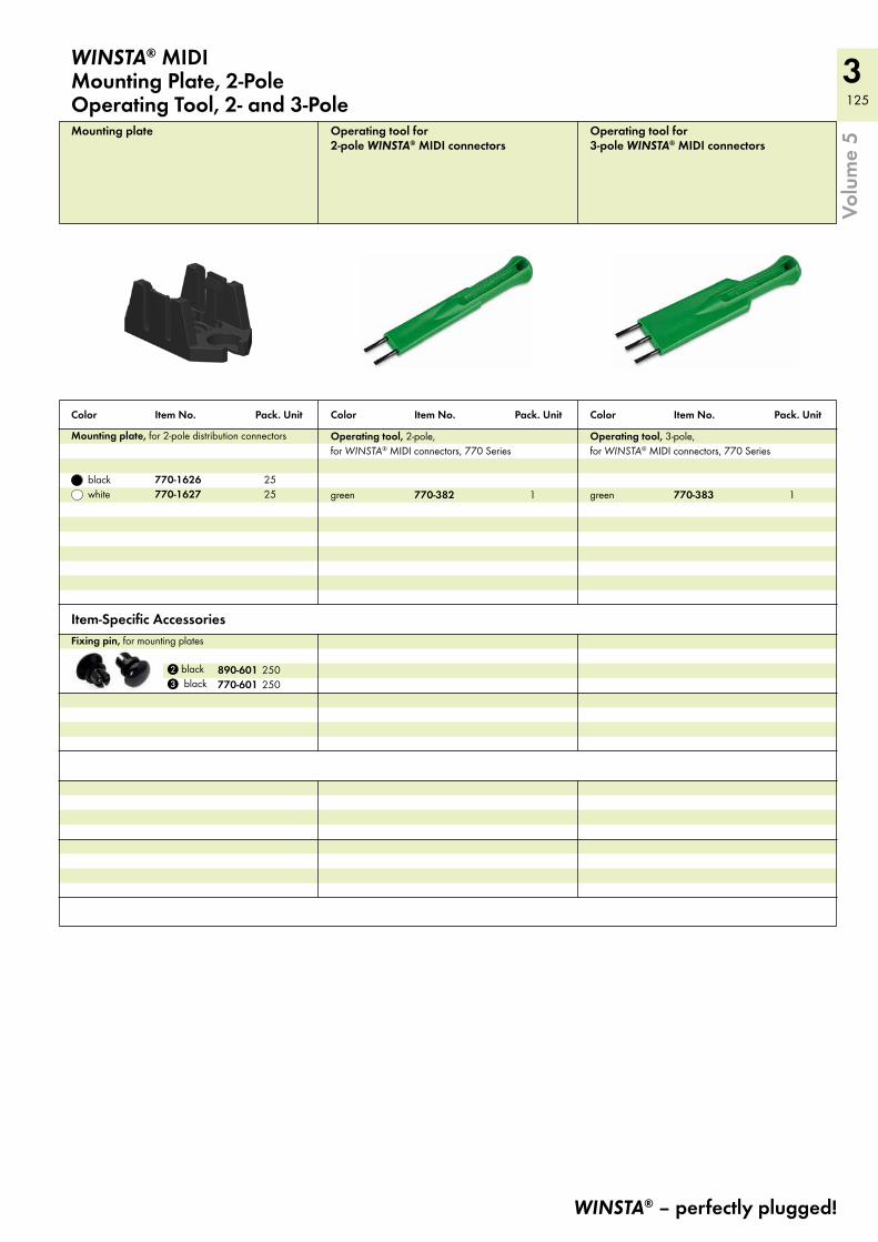
3 125
WINSTA® – perfectly plugged!
Volu
me
5
Color Item No. Pack. Unit Color Item No. Pack. Unit Color Item No. Pack. Unit
Item-Specific AccessoriesFixing pin, for mounting plates
2 black 890-601 250 3 black 770-601 250
WINSTA® MIDI Mounting Plate, 2-PoleOperating Tool, 2- and 3-Pole
Mounting plate, for 2-pole distribution connectors
black 770-1626 25 white 770-1627 25
Mounting plate Operating tool for 2-pole WINSTA® MIDI connectors
Operating tool for 3-pole WINSTA® MIDI connectors
Operating tool, 2-pole, for WINSTA® MIDI connectors, 770 Series
green 770-382 1
Operating tool, 3-pole, for WINSTA® MIDI connectors, 770 Series
green 770-383 1
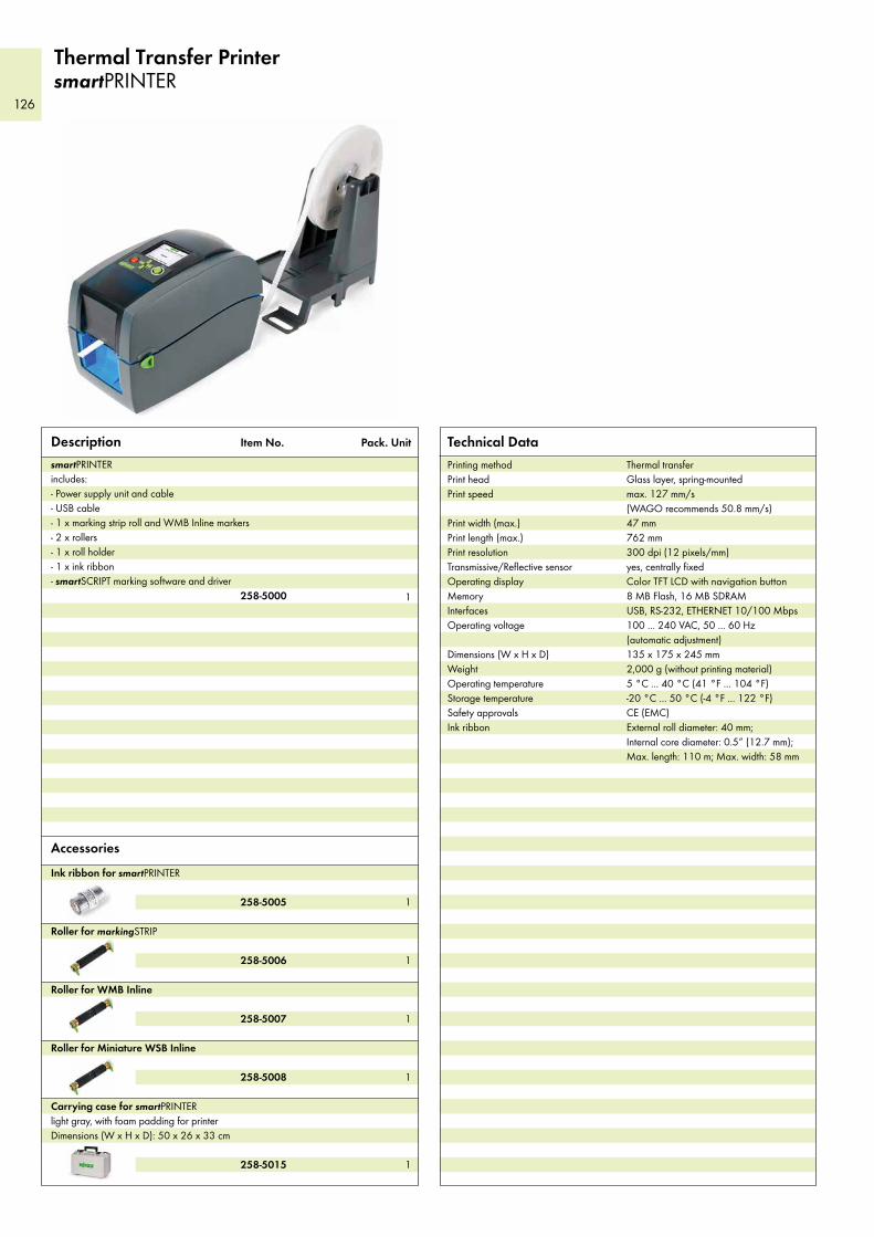
126
Thermal Transfer Printer smartPRINTER
Description Item No. Pack. Unit
smartPRINTERincludes: - Power supply unit and cable - USB cable - 1 x marking strip roll and WMB Inline markers- 2 x rollers - 1 x roll holder - 1 x ink ribbon - smartSCRIPT marking software and driver
258-5000 1
Accessories
Ink ribbon for smartPRINTER
258-5005 1
Roller for markingSTRIP
258-5006 1
Roller for WMB Inline
258-5007 1
Roller for Miniature WSB Inline
258-5008 1
Carrying case for smartPRINTERlight gray, with foam padding for printer Dimensions (W x H x D): 50 x 26 x 33 cm
258-5015 1
Technical DataPrinting method Thermal transfer Print head Glass layer, spring-mounted Print speed max. 127 mm/s
(WAGO recommends 50.8 mm/s) Print width (max.) 47 mm Print length (max.) 762 mm Print resolution 300 dpi (12 pixels/mm) Transmissive/Reflective sensor yes, centrally fixed Operating display Color TFT LCD with navigation button Memory 8 MB Flash, 16 MB SDRAM Interfaces USB, RS-232, ETHERNET 10/100 Mbps Operating voltage 100 ... 240 VAC, 50 ... 60 Hz
(automatic adjustment)Dimensions (W x H x D) 135 x 175 x 245 mm Weight 2,000 g (without printing material) Operating temperature 5 °C ... 40 °C (41 °F ... 104 °F) Storage temperature -20 °C ... 50 °C (-4 °F ... 122 °F) Safety approvals CE (EMC) Ink ribbon External roll diameter: 40 mm;
Internal core diameter: 0.5“ (12.7 mm); Max. length: 110 m; Max. width: 58 mm
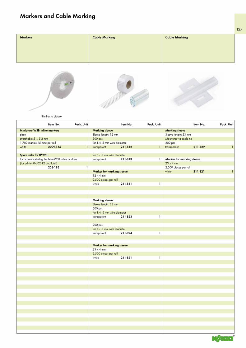
127
Item No. Pack. Unit Item No. Pack. Unit Item No. Pack. Unit
Marking sleeve Sleeve length: 12 mm500 pcsfor 1.4–5 mm wire diametertransparent 211-812 1
for 5–11 mm wire diametertransparent 211-813 1
Marker for marking sleeve12 x 4 mm2,500 pieces per rollwhite 211-811 1
Marking sleeve Sleeve length: 23 mm500 pcsfor 1.4–5 mm wire diametertransparent 211-823 1
200 pcsfor 5–11 mm wire diametertransparent 211-824 1
Marker for marking sleeve23 x 4 mm2,500 pieces per rollwhite 211-821 1
Cable MarkingCable MarkingMarkers
Marking sleeveSleeve length: 23 mmMounting via cable tie200 pcstransparent 211-829 1
Marker for marking sleeve23 x 4 mm2,500 pieces per rollwhite 211-821 1
Miniature WSB Inline markersplain stretchable 5 ... 5.2 mm1,700 markers (5 mm) per rollwhite 2009-145 1
Spare roller for TP 298+for accommodating the Mini-WSB Inline markers(for printer 04/2012 and later) 258-183 1
Markers and Cable Marking
Similiar to picture
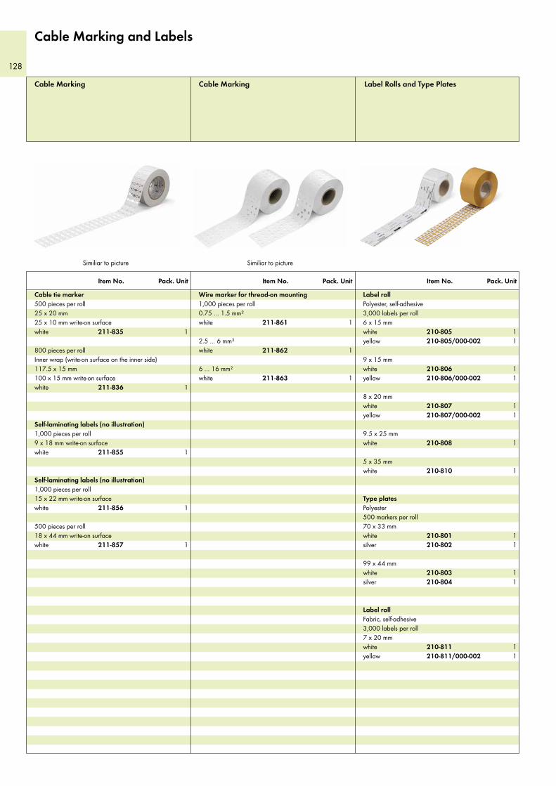
128
Item No. Pack. Unit Item No. Pack. Unit Item No. Pack. Unit
Label rollPolyester, self-adhesive 3,000 labels per roll6 x 15 mmwhite 210-805 1yellow 210-805/000-002 1
9 x 15 mmwhite 210-806 1yellow 210-806/000-002 1
8 x 20 mmwhite 210-807 1yellow 210-807/000-002 1
9.5 x 25 mmwhite 210-808 1
5 x 35 mmwhite 210-810 1
Type platesPolyester 500 markers per roll70 x 33 mm white 210-801 1silver 210-802 1
99 x 44 mm white 210-803 1silver 210-804 1
Label rollFabric, self-adhesive 3,000 labels per roll7 x 20 mmwhite 210-811 1yellow 210-811/000-002 1
Label Rolls and Type PlatesCable Marking Cable Marking
Cable tie marker500 pieces per roll25 x 20 mm25 x 10 mm write-on surfacewhite 211-835 1
800 pieces per roll Inner wrap (write-on surface on the inner side)117.5 x 15 mm100 x 15 mm write-on surfacewhite 211-836 1
Self-laminating labels (no illustration)1,000 pieces per roll9 x 18 mm write-on surfacewhite 211-855 1
Self-laminating labels (no illustration)1,000 pieces per roll15 x 22 mm write-on surfacewhite 211-856 1
500 pieces per roll18 x 44 mm write-on surfacewhite 211-857 1
Wire marker for thread-on mounting1,000 pieces per roll0.75 … 1.5 mm²white 211-861 1
2.5 … 6 mm²white 211-862 1
6 … 16 mm²white 211-863 1
Similiar to picture Similiar to picture
Cable Marking and Labels
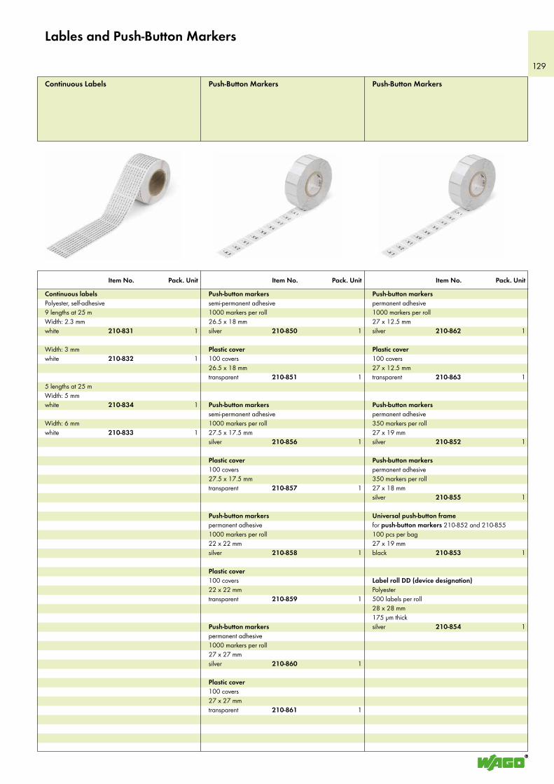
129
Item No. Pack. Unit Item No. Pack. Unit Item No. Pack. Unit
Push-button markerssemi-permanent adhesive1000 markers per roll26.5 x 18 mm silver 210-850 1
Plastic cover100 covers26.5 x 18 mm transparent 210-851 1
Push-button markerssemi-permanent adhesive1000 markers per roll27.5 x 17.5 mm silver 210-856 1
Plastic cover100 covers27.5 x 17.5 mm transparent 210-857 1
Push-button markerspermanent adhesive1000 markers per roll22 x 22 mm silver 210-858 1
Plastic cover100 covers22 x 22 mm transparent 210-859 1
Push-button markerspermanent adhesive1000 markers per roll27 x 27 mm silver 210-860 1
Plastic cover100 covers27 x 27 mm transparent 210-861 1
Push-Button Markers
Push-button markerspermanent adhesive1000 markers per roll27 x 12.5 mm silver 210-862 1
Plastic cover100 covers27 x 12.5 mm transparent 210-863 1
Push-button markerspermanent adhesive350 markers per roll27 x 19 mm silver 210-852 1
Push-button markerspermanent adhesive350 markers per roll27 x 18 mm silver 210-855 1
Universal push-button framefor push-button markers 210-852 and 210-855100 pcs per bag27 x 19 mm black 210-853 1
Label roll DD (device designation)Polyester 500 labels per roll28 x 28 mm175 µm thicksilver 210-854 1
Push-Button MarkersContinuous Labels
Continuous labelsPolyester, self-adhesive 9 lengths at 25 mWidth: 2.3 mmwhite 210-831 1
Width: 3 mmwhite 210-832 1
5 lengths at 25 mWidth: 5 mmwhite 210-834 1
Width: 6 mmwhite 210-833 1
Lables and Push-Button Markers
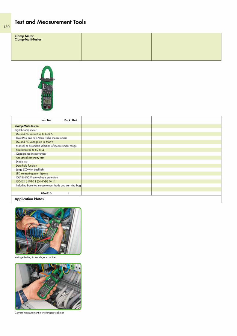
130Test and Measurement Tools
Application Notes
Item No. Pack. Unit
Clamp MeterClamp-Multi-Tester
Clamp-Multi-Tester, digital clamp meter- DC and AC current up to 600 A- True RMS and min./max. value measurement- DC and AC voltage up to 600 V- Manual or automatic selection of measurement range- Resistance up to 60 MΩ- Capacitance measurement- Acoustical continuity test- Diode test- Data hold function- Large LCD with backlight- LED measuring point lighting- CAT III 600 V overvoltage protection- IEC/EN 61010-1 (DIN VDE 0411)- Including batteries, measurement leads and carrying bag
206-816 1
Current measurement in switchgear cabinet
Voltage testing in switchgear cabinet

131
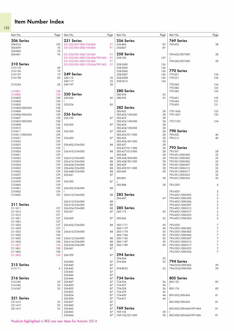
132
256 Series256-866 87256-867 87
258 Series258-183 127
258-5000 126258-5005 126258-5006 126258-5007 126258-5008 126258-5015 126
280 Series280-394 55280-395 55
282 Series282-432 28282-432/100-000 28282-433 28282-433/100-000 28282-434 28282-434/100-000 28282-435 28282-435/011-000 28282-436 28282-436/301-000 28282-437 28282-437/011-000 28282-437/012-000 28282-438 28282-438/300-000 28282-438/301-000 28282-439 28282-439/011-000 28282-440 28
282-881 28|282-888 28
283 Series283-407 47
285 Series285-172 50
285-442 35
285-1171 50285-1177 50285-1178 50285-1184 50285-1185 50285-1187 50285-1189 50
294 Series294-364 55294-384 55
294-8032 55
734 Series734-326 36734-327 36734-328 36734-329 36734-430 44734-431 44
769 Series769-102 38769-102/021-000 38
769 Series769-435 38
769-632/007-000 38|769-645/007-000 38
770 Series770-201 124770-221 124
770-360 124770-382 125770-383 125
770-601 125770-643 121770-693 121
770-1626 125770-1627 125
770-7102 124
790 Series790-302 46790-312 46
793 Series793-501 28793-501/000-002 32793-501/000-005 32793-501/000-006 32793-501/000-007 32793-501/000-012 32793-501/000-017 32793-501/000-023 32793-501/000-024 32
793-3501 4
793-4501 5793-4501/000-002 5793-4501/000-005 5793-4501/000-006 5793-4501/000-007 5793-4501/000-012 5793-4501/000-017 5793-4501/000-023 5793-4501/000-024 5
793-5501 7793-5501/000-002 7793-5501/000-005 7793-5501/000-006 7793-5501/000-007 7793-5501/000-012 7793-5501/000-017 7793-5501/000-023 7793-5501/000-024 7
794 Series794-5553/000-002 29794-5554/000-006 29
805 Series805-152 83l805-174 83
805-302/200-604 81l805-308/200-604 81
805-302/200-604/997-404 81l805-308/200-604/997-406 81
206 Series206-816 130206-859 76206-860 76206-861 76
210 Series210-118 50210-136 19210-137 19210-198 50
210-254 28
210-801 128210-802 128210-803 128210-804 128210-805 128210-805/000-002 128210-806 128210-806/000-002 128210-807 128210-807/000-002 128210-808 128210-810 128210-811 128210-811/000-002 128210-831 129210-832 129210-833 129210-834 129210-850 129210-851 129210-852 129210-853 129210-854 129210-855 129210-856 129210-857 129210-858 129210-859 129210-860 129210-861 129210-862 129210-863 129
211 Series211-811 127211-812 127211-813 127211-821 127211-823 127211-824 127211-829 127211-835 128211-836 128211-855 128211-856 128211-857 128211-861 128211-862 128211-863 128
215 Series215-111 4
216 Series216-545 35216-546 35216-547 35
221 Series221-412 53221-413 53221-415 53
231 Series231-332/001-000/105-604 91231-333/001-000/105-604 91
231-532/001-000/105-604 91231-532/001-000/105-604/997-405 91231-533/001-000/105-604 91231-533/001-000/105-604/997-405 91
249 Series249-116 35249-117 35249-197 50
250 Series250-302 85l250-324 85
256 Series256-100 87
256-200 87
256-300 87
256-400 87
256-402/334-000 88l256-410/334-000 88
256-412/334-000 88256-416/334-000 88256-424/334-000 88256-436/334-000 88256-448/334-000 88256-461 87
256-500 87
256-502/334-000 88l256-510/334-000 88
256-512/334-000 88256-516/334-000 88256-524/334-000 88256-561 87
256-600 87
256-602/334-000 88l256-610/334-000 88
256-612/334-000 88256-616/334-000 88256-624/334-000 88256-661 87
256-700 87
256-800 87256-840 87256-842 87256-843 87256-844 87256-846 87256-847 87256-850 87256-852 87256-853 87256-854 87256-856 87256-857 87256-860 87256-862 87256-863 87256-864 87
Item Number Index
Item No. Page Item No. PageItem No. Page Item No. Page
Products highlighted in RED are new items for Autumn 2014
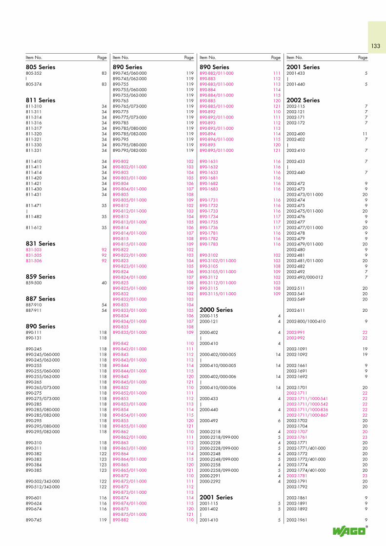
133
805 Series805-352 83l805-374 83
811 Series811-310 34811-311 34811-314 34811-316 34811-317 34811-320 34811-321 34811-330 34811-331 34
811-410 34811-411 34811-414 34811-420 34811-421 34811-430 34811-431 34
811-471 35|811-482 35
811-612 35
831 Series831-503 92831-505 92831-506 92
859 Series859-500 40
887 Series887-910 54887-911 54
890 Series890-111 118890-131 118
890-245 118890-245/060-000 118890-245/062-000 118890-255 118890-255/060-000 118890-255/062-000 118890-265 118890-265/073-000 118890-275 118890-275/073-000 118890-285 118890-285/080-000 118890-285/082-000 118890-295 118890-295/080-000 118890-295/082-000 118
890-310 118890-311 118890-382 122890-383 123890-384 123890-385 123
890-502/342-000 122890-512/342-000 122
890-601 116890-624 116890-674 116
890-745 119
890 Series890-882/011-000 111890-883 112890-883/011-000 113890-884 114890-884/011-000 115890-885 120890-885/011-000 121890-892 110890-892/011-000 111890-893 112890-893/011-000 113890-894 114890-894/011-000 115890-895 120890-895/011-000 121
890-1631 116890-1632 116890-1633 116890-1681 116890-1682 116890-1683 116
890-1731 116890-1732 116890-1733 116890-1734 117890-1735 117890-1736 117890-1781 116890-1782 116890-1783 116
890-3102 102890-3102/011-000 103890-3105 108890-3105/011-000 109890-3112 102890-3112/011-000 103890-3115 108890-3115/011-000 109
2000 Series2000-115 42000-121 4
2000-402 4|2000-410 4
2000-402/000-005 14|2000-410/000-005 14
2000-402/000-006 14|2000-410/000-006 14
2000-433 4|2000-440 4
2000-492 6
2000-2218 42000-2218/099-000 52000-2228 42000-2228/099-000 52000-2248 42000-2248/099-000 52000-2258 42000-2258/099-000 52000-2291 42000-2292 4
2001 Series2001-115 52001-402 5|2001-410 5
890 Series890-745/060-000 119890-745/062-000 119890-755 119890-755/060-000 119890-755/062-000 119890-765 119890-765/073-000 119890-775 119890-775/073-000 119890-785 119890-785/080-000 119890-785/082-000 119890-795 119890-795/080-000 119890-795/082-000 119
890-802 102890-802/011-000 103890-803 104890-803/011-000 105890-804 106890-804/011-000 107890-805 108890-805/011-000 109890-812 102890-812/011-000 103890-813 104890-813/011-000 105890-814 106890-814/011-000 107890-815 108890-815/011-000 109890-822 102890-822/011-000 103890-823 104890-823/011-000 105890-824 106890-824/011-000 107890-825 108890-825/011-000 109890-832 102890-832/011-000 103890-833 104890-833/011-000 105890-834 106890-834/011-000 107890-835 108890-835/011-000 109
890-842 110890-842/011-000 111890-843 112890-843/011-000 113890-844 114890-844/011-000 115890-845 120890-845/011-000 121890-852 110890-852/011-000 111890-853 112890-853/011-000 113890-854 114890-854/011-000 115890-855 120890-855/011-000 121890-862 110890-862/011-000 111890-863 112890-863/011-000 113890-864 114890-864/011-000 115890-865 120890-865/011-000 121890-872 110890-872/011-000 111890-873 112890-873/011-000 113890-874 114890-874/011-000 115890-875 120890-875/011-000 121890-882 110
2001 Series2001-433 5|2001-440 5
2002 Series2002-115 72002-121 72002-171 72002-172 7
2002-400 112002-402 7|2002-410 7
2002-433 7|2002-440 7
2002-472 92002-473 92002-473/011-000 202002-474 92002-475 92002-475/011-000 202002-476 92002-477 92002-477/011-000 202002-478 92002-479 92002-479/011-000 202002-480 92002-481 92002-481/011-000 202002-482 92002-492 72002-492/000-012 7
2002-511 202002-541 202002-549 20
2002-611 20
2002-800/1000-410 9
2002-991 222002-992 22
2002-1091 192002-1092 19
2002-1661 92002-1691 92002-1692 9
2002-1701 202002-1711 222002-1711/1000-541 222002-1711/1000-542 222002-1711/1000-836 222002-1711/1000-867 222002-1702 202002-1704 202002-1707 202002-1761 232002-1771 202002-1771/401-000 202002-1772 202002-1772/401-000 202002-1774 202002-1774/401-000 202002-1781 232002-1791 202002-1792 20
2002-1861 92002-1891 92002-1892 9
2002-1961 9
Item No. Page Item No. Page Item No. Page Item No. Page
134
2022 Series2022-103/000-038/999-953 452022-103/000-039/999-953 452022-141 362022-142 362022-151 362022-152 362022-162 352022-172 352022-182 35
2022-1201/999-953 402022-1202 352022-1204/999-953 402022-1207/999-953 402022-1291 402022-1292 40
2022-1301/999-953 402022-1302 352022-1304/999-953 402022-1307/999-953 402022-1391 402022-1392 40
2022-1401/999-953 402022-1402 352022-1404/999-953 402022-1407/999-953 402022-1491 412022-1492 41
2022-2201/999-953 422022-2207/999-953 422022-2234/999-953 422022-2291 432022-2292 43
2059 Series2059-189 76
2059-301/998-403 592059-302/998-403 592059-303/998-403 59
2060 Series2060-189 76
2060-451/998-404 612060-452/998-404 612060-453/998-404 61
2060-471/998-404 672060-472/998-404 672060-473/998-404 67
2060-802/998-404 69
2060-852/998-404 632060-872/998-404 63
2060-901 752060-902 752060-903 75
2060-1401/998-404 712060-1402/998-404 712060-1403/998-404 71
2060-1421/998-404 712060-1422/998-404 712060-1423/998-404 71
2060-1802/998-404 732060-1822/998-404 73
2061 Series2061-189 76
2061-601/998-404 65
2061 Series2061-602/998-404 652061-603/998-404 65
2061-621/998-404 652061-622/998-404 652061-623/998-404 65
2081 Series2081-1123/200-604/997-405 792081-1124/200-604/997-405 792081-1125/200-604/997-405 79
2081-1203/200-604/997-404 792081-1204/200-604/997-404 792081-1205/200-604/997-406 792081-1206/200-604/997-406 792081-1208/200-604/997-406 792081-1223/200-604/997-404 792081-1224/200-604/997-404 792081-1225/200-604/997-406 792081-1226/200-604/997-406 792081-1228/200-604/997-406 79
2857 Series2857-101 962857-102 962857-103 96
2857-121 972857-122 972857-123 972857-124 972857-191/314-000 982857-192/314-000 982857-193/314-000 982857-194/314-000 98
2002 Series2002-1991 92002-1992 9
2002-2418 72002-2428 72002-2448 72002-2458 72002-2491 72002-2492 7
2002-2601 162002-2602 162002-2603 162002-2604 162002-2607 162002-2608 162002-2609 162002-2611 192002-2611/1000-541 192002-2611/1000-542 192002-2611/1000-836 192002-2612 192002-2647 162002-2657 162002-2661 182002-2662 182002-2667 182002-2671 182002-2672 182002-2691 172002-2692 17
2002-2941 152002-2944 152002-2991 122002-2992 12
2003 Series2003-499 10
2003-500 10
2003-911 122003-911/1000-923 12
2003-6640 102003-6641 102003-6642 102003-6643 102003-6644 102003-6645 102003-6646 102003-6649 102003-6650 102003-6651 102003-6660 102003-6692 112003-6693 10
2004 Series2004-402 19|2004-410 19
2004-433 19|2004-440 19
2004-911 10
2006 Series2006-115 282006-191 32
2006-433 322006-435 32
2006-1208 8
2006 Series2006-8401 32
2006-8601 322006-8604 322006-8661 322006-8664 322006-8671 322006-8674 322006-8691 322006-8692 32
2007 Series2007-8442 28|2007-8448 28
2007-8801 282007-8807 292007-8811 282007-8821 282007-8873 302007-8876 312007-8891 282007-8892 282007-8893 282007-8894 282007-8899 28
2009 Series2009-110 42009-114 52009-115 72009-145 992009-174 42009-182 42009-191 7
2009-304 112009-305 112009-309 112009-310 11
2009-402 62009-404 62009-406 62009-412 92009-414 92009-416 9
2010 Series2010-1208 8
2016 Series2016-1208 8
2020 Series2020-103/000-036 362020-103/000-037 362020-103/000-038 362020-103/000-039 362020-105/000-036 362020-105/000-037 362020-105/000-038 372020-105/000-039 37
2022 Series2022-100 40
2022-101/000-012 35|2022-115/000-012 35
2022-102/999-953 44|2022-108/999-953 44
Item Number Index
Item No. Page Item No. PageItem No. Page Item No. Page
Products highlighted in RED are new items for Autumn 2014

135
Item No. Page Item No. Page Item No. Page Item No. Page
136Algeriaplease contact WAGO France
ArgentinaBruno Schillig S.A.Arenales 4030, B1604CFDFlorida, PBAPhone +54 11 4730 1100Fax +54 11 4761 [email protected]
AustraliaKontact GroupBuilding Automation & WINSTA SystemsOffice: 730 Springvale RdMulgrave Victoria 3170P.O. Box 3003, Wheelers Hill VIC 3150Tel. +61 03 95602757Fax +61 03 [email protected]
NHP ELECTRICAL ENGINEERINGPRODUCTS PTY LTD43-67 River StreetRichmond, Victoria, 3121, P.O. Box 199Phone +61 3 9429 2999Fax +61 3 9429 [email protected]
AustriaWAGO Kontakttechnik Ges.m.b.H.Laxenburger Straße 2441230 WienPhone +43 1 6150780Fax +43 1 [email protected]
AzerbaijanAZ Technics LTDZulfi V. AlizadeY.Safarov str.33 , AZ1025,BakuRepublic of AzerbaijanTel. +994 12 4968335Fax +994 12 [email protected]
BelarusOOO FEKpr-t Pushkina 29-B220015 MinskPhone +375 17 2102189Fax +375 17 [email protected]
UE ATAVAul. Denisovskaya, 47, office 1220006 MinskPhone +375 17 2054015Fax +375 17 2851759
BelgiumWAGO KontakttechnikExcelsiorlaan 111930 ZaventemPhone +32 2 7179090Fax +32 2 [email protected]
BoliviaKoln s.r.l.Barrio ConvifagC/Toborrochi #6, Zona NorteSanta CruzTel. +591 3 3120272Fax +591 3 3120272
Bosnia and Herzegovinaplease contact WAGO Bulgaria
BrazilWAGO Eletroeletrônicos LtdaRua Américo Simões 1470São Roque da ChaveItupeva SP Brasil 13295-000Phone +55 11 4591 0199Fax +55 11 4591 [email protected]
BulgariaWAGO Kontakttechnik GmbH & Co. KG/Representative Office SofiaBusiness Center Serdika2E Akad. Ivan Geshov Blvd. Building 1, Floor 4, Office 4171330 SofiaTel. +359 2 489 46 09Fax +359 2 928 28 [email protected]
Canadaplease contact WAGO USA
ChileDesimat ChileAv Puerto Vespucio 9670Pudahuel SantiagoPhone +56 2 7470152Fax +56 2 [email protected]
ChinaWAGO ELECTRONIC (TIANJIN) Co. LTDNo.5, Quan Hui Road, Wuqing Development AreaTianjin 301700Phone +86 22 59617688Fax +86 22 [email protected]
ColumbiaT.H.L. Ltda.Cra. 49 B # 91-33BogotáPhone +57 1 621 85 50Fax +57 1 621 60 [email protected]
CroatiaM.B.A. d.o.o. za trgovinu i zastupanjeFrana Supila 551211 Matulji HRPhone +385 51 275-736Fax +385 51 [email protected]
GENERA CTR d.o.o.- just for automation technology - Siget 18 b10020 ZagrebPhone +385 13647849Fax +385 [email protected]
Czech RepublicWAGO Elektro spol. sr. o.Rozvodova 1116/36143 00 Praha 4 - ModřanyPhone +420 261 090 143Fax +420 261 090 [email protected]
DenmarkWAGO DanmarkFilial of WAGO Kontakttechnik GmbH & Co. KGLejrvej 173500 VærløsePhone +45 44 357777Fax +45 44 [email protected]
EcuadorECUAINSETEC CIA LTDAEl Zurriago E9-32 y el VengadorQuitoTel. +593 2 2 26 91 48Fax +593 2 2 46 18 [email protected]
EgyptIBN Engineering Instrumentation & Control71 a El Shaheed Ahmed Hamdi St.King Faisal, GizaPhone +20 2 7214350Fax +20 2 [email protected]
EstoniaEltarko OÜLaki 14 - 50210621 TallinnPhone +372 651 7731Fax +372 651 [email protected]
FinlandWAGO Kontakttechnik GmbH & Co. KGFilial i FinlandVellamonkatu 30 B00550 HelsinkiPhone +358 9 7744 060Fax +358 9 7744 [email protected]
FranceWAGO CONTACT SASParis Nord 283 Rue des ChardonneretsB.P. 55065 - Tremblay en France95947 - ROISSY CDG CEDEXPhone +33 1 48172590Fax +33 1 [email protected]
GermanyWAGO Kontakttechnik GmbH & Co. KGPostfach 28 80, 32385 MindenHansastraße 2732423 MindenPhone +49 571 887-0Fax +49 571 [email protected]
WAGO Kontakttechnik GmbH & Co. KGWaldstraße 199706 SondershausenPhone +49 3632 659-0Fax +49 3632 [email protected]
Great BritianWAGO LimitedTriton Park, Swift Valley Industrial EstateRUGBYWarwickshire, CV21 1SGPhone +44 1788 568008Fax +44 1788 [email protected]
GreecePANAGIOTIS SP. DIMOULAS - BIOMATDIMOULAS AUTOMATIONSKritis Str. 2610439 AthenTel. +30 210 883 3337Fax +30 210 883 [email protected]
HondurasCILASAS S.A. de C.V.Barrio Los Andes7 Calle entre 14 y 15 Ave. N.O.P.O. Box. 1061San Pedro SulaTel. +504 25571146/7Fax +504 25571149
Hong KongNational Concord Eng., Ltd.Unit A-B, 5/F.Southeast Industrial Building611-619 Castle Peak RoadTsuen Wan, N.T.Phone +852 24292611Fax +852 [email protected]
HungaryWAGO Hungá¡ria KFTIpari Park, Gyár u. 22040 BudapestPhone +36 23 502-170Fax +36 23 [email protected]
IcelandS. Gudjonsson ehf.Audbrekku 9-11202 KopavogurPhone +354 520-4500Fax +354 [email protected]
IndiaWAGO LTD.C-27, Sector-58, Phase-IIINoida-201 301Gautam Budh Nagar (U.P)Tel. +91 120 2 580409 10Fax +91 120 2 [email protected]
Indonesiaplease contact WAGO Singapore
Iraqplease contact WAGO Middle East
IrelandDrives & ControlsUnit F4, Riverview Business ParkNangor RoadDublin 12Phone +353 1 4604474Fax +353 1 [email protected]
IsraelComtel Israel Electronic Solutions Ltd.Bet Hapaamon20 Hataas StreetP.O. Box 6644425 Kefar-SabaPhone +972 9 76 77 240Fax +972 9 76 77 [email protected]
ItalyWAGO ELETTRONICA SRL a Socio UnicoVia Parini 140033 Casalecchio di Reno (BO)Tel. +39 051 6132112Fax +39 051 [email protected]
JapanWAGO Co. of JAPAN Ltd.Nittetsu ND-Tower Building 4F5-7, Kameido 1-chomeKoto-KuTokyo 136-0071Tel. +81 3 5627 2050Fax +81 3 5627 [email protected]
Jordanplease contact WAGO Middle East
KazakhstanTOO INTANTul. Muratbaeva, d. 61050026 AlmatyTel. +7 727 2371492Fax +7 727 [email protected]
TOO Technik-Tradeul. i. A. Protosanova, 81070004 Ust-KamenogorskTel. +7 7232 254064Fax +7 7232 [email protected]
ITC Electronics: AlmatyProspekt Raiymbeka 221 ?/4050016 AlmatyKazakhstanTel. +7 727 2797117Fax +7 727 2339344
KoreaWAGO Korea Co., Ltd.#205 Anyang Mega ValleyDongan-gu, Anyang-siKyunggi-do, South KoreaPhone +82 3142 [email protected]
Kosovoplease contact WAGO Bulgaria
LatviaINSTABALT LATVIA SIAVestienas iela 6Rīga, LV-1035Phone +371 790 1188Fax +371 790 [email protected]
LebanonGemayel Trading & ContractingAntonins ProjectP.O. BOX 70-1096 Antelias, LebanonPhone +961 4 521 029Fax +961 4 521 [email protected]
LithuaniaINSTABALT LIT UABSavanorių 187Vilnius, 2053Phone +370 52 322 295Fax +370 52 322 [email protected]
WAGO Worldwide – Companies and Representatives –
137Luxembourgplease contact WAGO Belgium
Macedoniaplease contact WAGO Bulgaria
Kompjunet InzeneringVladimir Komarov 1A-3/91000 SkopjeRepublic of MacedoniaTel. +389 2 521 12 00Tel. +389 2 246 11 08
MalaysiaWAGO Representative Office MalaysiaNo 806, Block A4, Leisure Commerce Square,No 9, Jalan PJS 8/9, 46150 Petaling Jaya,Selangor Darul Ehsan, MalaysiaTel. +60 3 7877 1776Fax +60 3 7877 [email protected]
HPH Materials (M) Sdn BhdNo. 4, Jalan Nilam 1/6Suban Hi-Tech Industrial Park40000 Shah AlamSelangor, D.E. MalaysiaTel. +60 3 5638 2213Fax +60 3 5638 [email protected]
Setia Raya Teknik Sdn. Bhd.40 & 42 Jalan SS15/4Subang Jaya, 47500 P.J.Selangor D.E. MalaysiaTel. +60 3 5633 5511Tel. +60 3 5633 [email protected]
MexicoWAGO SA de CVAv. Del Marques 38 Bodega 3P. I. Bernardo Quintana76240 El Marques, QuerétaroPhone +52 442 221 5946Fax +52 442 221 5063Toll-Free: [email protected]
MoldovaElectroservice Slavinschi T.T.str. Bolgarskaia 9, office 62001 KishinevPhone +373 22 274427Fax +373 22 [email protected]
Moroccoplease contact WAGO France
NetherlandsWAGO NederlandLaan van de Ram 197234 BW APELDOORNTel. +31 55 36 83 500Fax +31 55 36 83 [email protected]
New ZealandNHP NZ7 Lockhart PlaceMt WellingtonNew ZealandPhone +64 9 2761967Fax +64 9 [email protected]
NigeriaGIL Automations Ltd.Daily Times Complex2 Lateef Jakande Rd., Agidingbi100271 Ikeja, Lagos StateTel. +234 [email protected]
NorwayWAGO Norge NUFJerikoveien 201067 OsloPhone +47 22 30 94 50Fax +47 22 30 94 [email protected]
Omanplease contact WAGO Middle East
PakistanFuziLogiX Automation & ControlSuit No. 14, 5th Floor, Shan ArcadeNew Garden Town, LahorePakistanPhone +92 42 594 1503 - 4Fax +92 42 585 [email protected]
PeruManufacturas Eléctricas S.A.Av O.R. Benavides 121515000 LimaTel. +511 6196200Fax +511 6196247
Philippinesplease contact WAGO Singapore
PolandWAGO ELWAG sp. z o. o.ul. Piękna 58 a50-506 WrocławPhone +48 71 3602970Fax +48 71 [email protected]
PortugalMORGADO & CA. LDA - SEDEEstrada Exterior daCircunvalação 3558/3560Apartado 10574435 Rio TintoPhone +351 22 9770600Fax +351 22 [email protected]
Quatarplease contact WAGO Middle East
RomaniaWAGO Kontakttechnik GmbH & Co. KG/Representative Office BukarestStr. Nicolae G. Caramfil Nr. 26Bl. 1D, Et. 3, Ap. 7, Sect. 1, OP 52014144-BucurestiTel. +40-(0)31 421 85 [email protected]
VDR & Servicii srlStr. Valeriu Branişte, nr. 60, ap.1, sector 3RomaniaTel. +40 21 3225074/76Fax +40 21 [email protected]
RussiaООО WAGO Kontakt RusDmitrovskoe shosse, 157, bldg. 12/5 127411 MoscowRussiaPhone +7 495 663-3305Fax +7 495 [email protected]
WAGO Branch officeEkaterinburgTel. +7 343 216 3426
WAGO Branch officeNovosibirskTel. +7 383 217 9244
WAGO Branch officeSt. PetersburgTel. +7 812 312 1918
Saudi ArabiaSaudi Electronic Trading Company (SETRA)P.O. Box 6071211555-RiyadhTel. +966 1 2062277Fax +966 1 [email protected]
Serbiaüber WAGO Bulgarien
Avalon Partners dooPatrijarha Dimitrija 2411000 BeogradTel. +381 11 2685311Fax +381 11 [email protected]
Sigma dooBalzakova 321000 Novi SadTel. +381 21 468431Fax +381 21 [email protected]
SingaporeWAGO Electronic Pte Ltd10 Upper Aljunied Link#04-04 Johnson Controls BuildingSingapore 367904Phone +65 62866776Fax +65 [email protected]
SlovakiaWAGO Elektrik spol. s r. oOdborárska 5283102 BratislavaTel. +421 2 [email protected]
Proelektro spol. s r.o.Na barine 22841 03 Bratislava - LamačTel. +421 2 4569 2503 [email protected]
SloveniaGENERA d.o.o.Prevale 101236 TrzinPhone +386 14393050Fax +386 [email protected]
IC elektronika d.o.o.Vodovodna cesta 1001000 LjubljanaPhone +386 15680110Fax +386 [email protected]
South AfricaShorrock Automation (Pty) LtdPostnet Suite # 219Private Bag X 8,Elardus Park0047 PRETORIATel. +27 12 4500300Fax +27 12 [email protected]
SpainDICOMAT S.L.Avda. de la Industria, 36Apartado Correos, 1.17828108 - Alcobendas (Madrid)Phone +34 91 6621362Fax +34 91 [email protected]
SwedenWAGO SverigeWAGO Kontakttechnik GmbHTyskland FilialBox 11127, 161 11 BROMMABesöksadress: Adolfsbergsv. 31Tel. +46 858410680Fax +46 [email protected]
SwitzerlandWAGO CONTACT SARte. de l’Industrie 19Case Postale 1681564 DomdidierPhone +41/26 676 75 86Fax +41/26 676 75 [email protected]
SyriaZahabi Co.8/5 Shouhadaa St., P.O. Box 8262AleppoPhone +963 21 21 22 235 / 6Fax +963 21 21 24 [email protected]
Taiwan R.O.C.WAGO Contact, Ltd.5F., No.168, Jiankang RdZhonghe CityTaipei County 23585, TaiwanPhone +886 2 22250123Fax +886 2 [email protected]
ThailandWAGO Representative Office Thailand4th Floor, KS Building213/6-8 Rachada-Phisek RoadDingdaeng, Bangkok 10320Tel. +66 2 6935611Fax +66 2 [email protected]
US Power Distribution Co., Ltd.4th Floor K.S. Building213/6-8 Rachada Phisek RoadDing Daeng, Bangkok 10400Tel. +66 2 2763040Fax +66 2 [email protected]
Tunisiaplease contact WAGO France
TurkeyWAGO Elektronik Sanayi ve Ticaret Ltd. Şti.Yukan Dudullu Mahallesi Bayraktar BulvanCad. Hattat Sok. No. 1034775 Ümraniye - IstanbulTurkeyTel. +90 216 472 1133Fax +90 216 472 [email protected]
UkraineNPP LogiconPredslavinskaya street, 39, office 30303150 KievTel. +380 44 5228019Fax +380 44 [email protected]
OOO Mikropriborul. Kotelnikova, 403115 KievTel. +380 44 5369386Fax +380 44 [email protected]
ITC Electronics: Kievpr. Vossoyedineniya 7aoffice 10702160 KievTel. +38 44 5596890Fax +38 44 [email protected]
United Arab Emirates (UAE)WAGO Middle East (FZC)SAIF Zone, Q4-282P.O. Box: 120665Sharjah, UAEPhone +971 6 5579920Fax +971 6 [email protected]
USAWAGO CorporationN120 W19129 Freistadt RoadGermantown, WI 53022Phone +1 262 255 6222Fax +1 262 255 3232Toll-Free: 1-800 DIN Rail (346-7245)[email protected]
VenezuelaPETROBORNAS, C.A.C.C. PLAZA AEROPUERTO - PISO 1 - LOCAL P1 - B - 03(8015) UNARE - PUERTO ORDAZ - ESTADO BOLÍVARREPÚBLICA BOLIVARIANA DE VENEZUELATel. +58 286 951 3382Fax +58 286 951 [email protected]
Vietnamplease contact WAGO Germany (Minden)
Version: 10/2014Current addresses at www.wago.com

138
Notes

139
Notes

140
Notes

141
Notes

142
Notes
143
Notes


WAGO Kontakttechnik GmbH & Co. KGPostfach 2880 · D - 32385 MindenHansastraße 27 · D - 32423 MindenGermanyPhone: +49 571 887 - 0Fax: +49 571 887 - 169E-Mail: [email protected]: www.wago.com
0888
-100
1/02
14-6
901
· Sup
pl. C
at. E
lect
rical
Inte
rcon
nect
ions
· U
S · 2
014/
2 - P
rinte
d in
Ger
man
y - S
ubje
ct to
des
ign
chan
ges