430 " 2 2. 508
TRANSCRIPT
USOO80666.29B2
(12) United States Patent (10) Patent No.: US 8,066,629 B2 Dlugos (45) Date of Patent: Nov. 29, 2011
(54) APPARATUS FOR ADJUSTMENT AND E. R. Sh t CS SENSING OF GASTRIC BAND PRESSURE RE3,322 E 3, 1869 Murch
(75) Inventor: Daniel F. Dlugos, Middletown, OH (US) 3. A }. Seiyan 400,401. A 3/1889 Gutzkow
(73) Assignee: Ethicon Endo-Surgery, Inc., Cincinnati, D23,637 S 9, 1894 Casadet al. OH (US) D24,900 S 11 1895 Clemecet
(Continued) (*) Notice: Subject to any disclaimer, the term of this
patent is extended or adjusted under 35 FOREIGN PATENT DOCUMENTS U.S.C. 154(b) by 1311 days. AU 729 467 2, 2001
(21) Appl. No.: 11/673,642 (Continued)
(22) Filed: Feb. 12, 2007 OTHER PUBLICATIONS U.S. Appl. No. 12/039,014, filed Feb. 28, 2008, Dlugos, Jr. et al.
(65) Prior Publication Data (Continued)
US 2007/0235083 A1 Oct. 11, 2007 O O Primary Examiner — John Lacyk
Related U.S. Application Data (74) Attorney, Agent, or Firm — Frost Brown Todd LLC (63) Continuation-in-part of application No. 1 1/369,389,
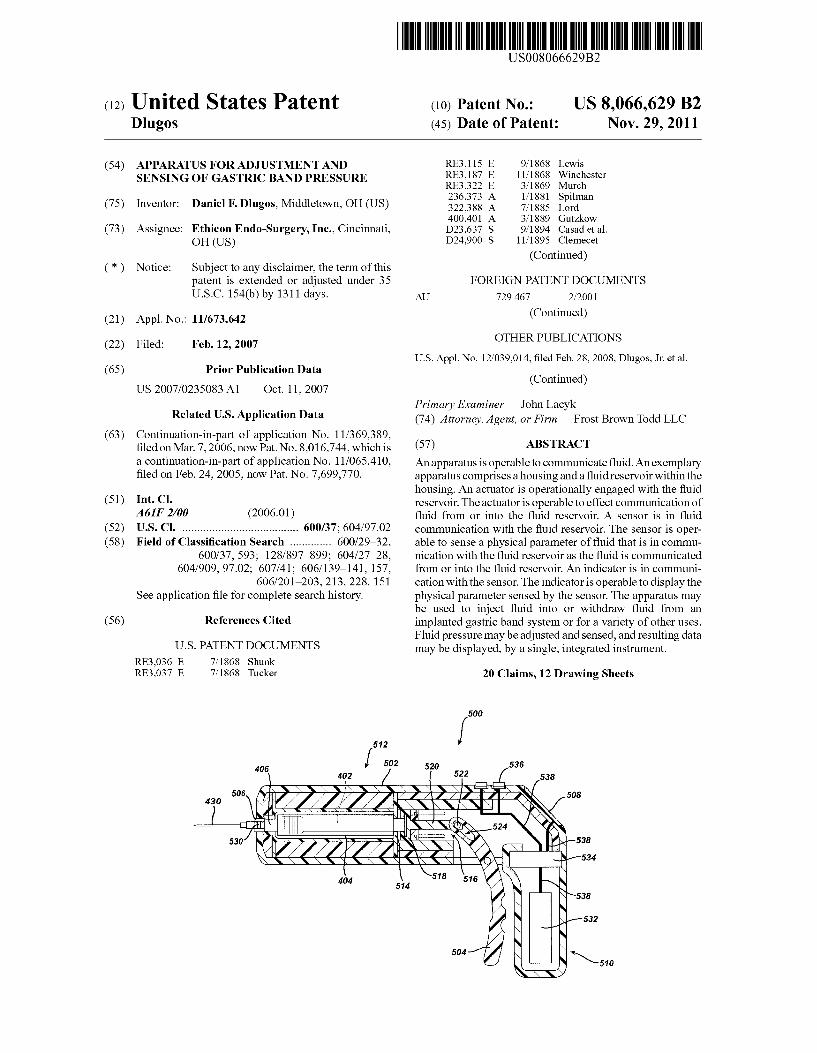
filed on Mar. 7, 2006, now Pat. No. 8,016,744, which is (57) ABSTRACT a continuation-in-part of application No. 11/065,410, Anapparatus is operable to communicate fluid. An exemplary filed on Feb. 24, 2005, now Pat. No. 7,699,770. apparatus comprises a housing and a fluid reservoir within the
housing. An actuator is operationally engaged with the fluid (51) Int. Cl. reservoir. The actuator is operable to effect communication of
A6F 2/00 (2006.01) fluid from or into the fluid reservoir. A sensor is in fluid (52) U.S. C. - - - - - - - - - - - - - - - - - - - - - - - - - - - - - - - - - - - - - - - 600/37; 604/97.02 communication with the fluid reservoir. The SSO is oper
(58) Field of Classification Search .............. 600/29-32, able to sense a physical parameter of fluid that is in commu 600/37, 593; 128/897–899; 604/27 28, nication with the fluid reservoir as the fluid is communicated
604/909, 97.02; 607/41; 606/139-141, 157, from or into the fluid reservoir. An indicator is in communi 606/201-203, 213, 228, 151 cation with the sensor. The indicator is operable to display the
See application file for complete search history. physical parameter sensed by the sensor. The apparatus may be used to inject fluid into or withdraw fluid from an
(56) References Cited implanted gastric band system or for a variety of other uses.
U.S. PATENT DOCUMENTS
RE3,036 E 7, 1868 Shunk RE3,037 E 7, 1868 Tucker
Fluid pressure may be adjusted and sensed, and resulting data may be displayed, by a single, integrated instrument.
20 Claims, 12 Drawing Sheets
500
512
502 536 406 520 402 522 538
430 " 2 2. 508 --- 524
530 538
53
518 516 404 514 538
532
504 N510
US 8,066,629 B2 Page 2
D25,318 D27,151 D29,715 D29,745 D29,885 D30,690 D30,966 D31,230 689,758 724,913 899,477 926, 197 953,875 991,192
1,087,988 1,210,701 1,219,296 1,224,355 1,263,914 1,310,290 1,384,873 1421,507 1551,525 1,560,973 1,620,633 1,623.403 1,689,085 1,764,071 1,780,704 1807,107 1,865,446 1,882.338 1924,781 2,027,875 2,063,430 2,099,160 2,105,127 2,106, 192 2,143,429 2,166,603 2,168,427 2,174,525 2,178.463 2,180,599 2,177.564 2,203,460 2,206,038 2,216,374 2,223,699 2,225,145 2,225,880 2,261,060 2,261,355 2,295,539 2,303,108 2,318,819 2,327.407 2,327,615 2,354,571 2,396,351 2,426,392 2,426,817 2.440,260 2,442,573 2.453,217 2,455,859 2.477,922 2.478,876 2,482,392 2.494,881 2,581479 2,509,210 2,509,673 2,511,765 2,520,056 2,521,976 2,533,924 2,538,259
U.S. PATENT DOCUMENTS
3, 1896 6, 1897
11, 1898 11, 1898 12, 1898 5, 1899 6, 1899 7, 1899
12, 1901 4, 1903 9, 1908 6, 1909 4, 1910 5, 1911 2, 1914 1, 1917 3, 1917 5, 1917 4, 1918 7, 1919 7, 1921 7, 1922 8, 1925
11, 1925 3, 1927 4, 1927
10, 1928 6, 1930
11, 1930 5, 1931 7, 1932
10, 1932 8, 1933 1, 1936
12, 1936 11, 1937
1, 1938 1, 1938 1, 1939 7, 1939 8, 1939
10, 1939 10, 1939 11, 1939 12, 1939 6, 1940 T. 1940
10, 1940 12, 1940 12, 1940 12, 1940 10, 1941 11, 1941 9, 1942
11, 1942 5, 1943 8, 1943 8, 1943 T. 1944 3, 1946 8, 1947 9, 1947 4, 1948 6, 1948
11, 1948 12, 1948 8, 1949 8, 1949 9, 1949 1, 1950 1, 1950 5, 1950 5, 1950 6, 1950 8, 1950 9, 1950
12, 1950 1, 1951
Perky Moulten Wheeler Bunker Gillespie et al. Schwedtmann Howe Hogan Shaw Montgomery Williams Kim Waring Battenfeld Sheldon Ryden Hahn Brown Martin Piechowicz Strickland Lindberg Hamer Cheron Colvin Friel Russell et al. Foulke Woodruffet al. Sternberch Sears Reed et al. Gaiser Odenhal Graser Charch Petrone Saville Auble Menzer McConkey Padernal Bahnson Menasco Havill Fieber Ford Martin Norgren Baumbach Montelius Giesler Flynn Beach Blackburn Verson Edyvean Ankarlo Blain Thompson Fennema Carlton et al. Gall Stafford Gregg et al. Foley Emery et al. Nelson Whitaker Kost Grashman Clark Church Bradbury PoSun Hays Foley Merriman
2,600,324 2,606,003 2,615.940 2,632.447 2,639,342 2,640,119 2,641,742 2,651,304 2,665,577 2,673.999 2,676,609 2,684,118 2,689,611 2,697.435 2,723,323 2,734,992 2,740,007 2,740,853 2,742,323 2,747,332 2,753,876 2,756,883 2,756,983 2,761,603 2,773,312 2,783,728 2,787,875 2,793,379 2,795,460 2,804,514 2,822,113 2,831,478 2,864,393 2,865,541 2,870,024 2,883,995 2,886,355 2,895,215 2,899,493 2.902,861 2.923,531 2.924,263 2.924,432 2.930, 170 2.938,592 2.941,338 2.943,682 2,958,781 2.96.1479 2,976,355 2,976,686 2,977,876 2.986,715 2.989,019 3,010,692 3,013,234 3,018,791 3,034,356 3,040,800 3,054,618 3,060,262 3,070,373 3,082,414 3,085,577 3,096.410 3,099,262 3,125,028 3,126,029 3,129,072 3,135,914 3,144,017 3,151,258 3,153,460 3,161,051 3,167,044 3,171,549 3,172,700 3,173,269 3,182,494
6, 1952 8, 1952
10, 1952 3, 1953 5, 1953 5, 1953 6, 1953 9, 1953 1, 1954 4, 1954 4, 1954 7, 1954 9, 1954
12, 1954 11, 1955 2, 1956 3, 1956 4, 1956 4, 1956 5, 1956 7, 1956 7, 1956 7, 1956 9, 1956
12, 1956 3, 1957 4, 1957 5, 1957 6, 1957 8, 1957 2, 1958 4, 1958
12, 1958 12, 1958 1, 1959 4, 1959 5, 1959 7, 1959 8, 1959 9, 1959 2, 1960 2, 1960 2, 1960 3, 1960 5, 1960 6, 1960 T. 1960
11, 1960 11, 1960 3, 1961 3, 1961 4, 1961 5, 1961 6, 1961
11, 1961 12, 1961
1, 1962 5, 1962 6, 1962 9, 1962
10, 1962 12, 1962 3, 1963 4, 1963 T. 1963 T. 1963 3, 1964 3, 1964 4, 1964 6, 1964 8, 1964 9, 1964
10, 1964 12, 1964 1, 1965 3, 1965 3, 1965 3, 1965 5, 1965
Rappaport McNeill Williams Dobes Cope Bradford, Jr. Wolfe Browner Sanowskis Shey Pfarrer Osmun Martinson Ray Niemi Elliot et al. Amelang Hatman, Jr. Shey Morehouse Kurt Schreck Furcini Fairchild Peck Hoffmann Johnson Moore Bletcher Peters Joiner, Jr. Uddenberg et al. Drake Hicks Martin Bialous et al. Wurzel Neher et al. Levine Frost et al. Bauer et al. Landis Arps et al. Holsman et al. Charske et al. Santschi Ingram, Jr. et al. Marchal et al. Bertling Levine Stelzer Meyers Church et al. Van Sciver, II Jentoft Bourns Knox Bieganski Hartley Abrams et al. Hoer Mathews et al. Papaminas Berman et al. Anderson Bigliano Rohde Englesson Cook et al. Callan et al. Muth Sonderegger et al. Raskin Perry, Jr. Henrickson Orloff Haas Imbertson Beatty et al.
US 8,066,629 B2 Page 3
3,187, 181 3,187,745 3,190,388 3,205,547 3,208,255 3,209,570 3,221,468 3,228,703 3,229,684 3,236,088 3,238,624 3,240,510 3.245,642 3,255,568 3,260,091 3,265,822 3,266,489 3,273.447 3,283,352 3,290.919 3,292.493 3,292,888 3.294.988 3,299,603 3,299,882 3,301,514 3,302.457 3,306,384 3,313,314 3,316,935 3,320,750 3,321,035 3,332,788 3,334,510 3,339,401 3,340,868 3,347,162 3,350.944 3,353,364 3,353,481 3,356,334 3,356,510 3,357,218 3,357,461 3,359,741 3,361,300 3,364,929 3,365,684 3,378.456 3,380.445 3,380,649 3,385,022 3,389,355 3,393,612 3,396,561 3,399,667 3,400,734 3,403,237 3,409,924 3,411,347 3,417,476 3.420,325 3.422,324 3,426,165 3,438,391 3,443,608 3,445,335 3,447.281 3.450,153 3,453,546 3,453,848 3.456,134 3.457,909 3,460,557 3,463,338 3,469,818 3,470,725 3,472,230 3,478,344
6, 1965 6, 1965 6, 1965 9, 1965 9, 1965
10, 1965 12, 1965
1, 1966 1, 1966 2, 1966 3, 1966 3, 1966 4, 1966 6, 1966 T. 1966 8, 1966 8, 1966 9, 1966
11, 1966 12, 1966 12, 1966 12, 1966 12, 1966 1, 1967 1, 1967 1, 1967 2, 1967 2, 1967 4, 1967 5, 1967 5, 1967 5, 1967 7, 1967 8, 1967 9, 1967 9, 1967
10, 1967 11, 1967 11, 1967 11, 1967 12, 1967 12, 1967 12, 1967 12, 1967 12, 1967
1, 1968 1, 1968 1, 1968 4, 1968 4, 1968 4, 1968 5, 1968 6, 1968 T. 1968 8, 1968 9, 1968 9, 1968 9, 1968
11, 1968 11, 1968 12, 1968 1, 1969 1, 1969 2, 1969 4, 1969 5, 1969 5, 1969 6, 1969 6, 1969 T. 1969 T. 1969 T. 1969 T. 1969 8, 1969 8, 1969 9, 1969
10, 1969 10, 1969 11, 1969
Keller Baum et al. Moser et al. Riekse Burk Hills Casey Wilson Nagumo et al. Moller McCabe Spouge Dicke Martin et al. Shaw, Jr. Moulten Watkins et al. Frank Hu Malinak et al. Franklin Fischer Packard Shaw Masino Sugaya Mayes Ross Burke et al. Kaiser et al. Haise et al. Tarpley Barnby Hallesy Peters Darling BraZnell De Michele Blanding et al. Antonucci Scaramucci Barnby Mitchell Friendship Nelson Kaplan Ide et al. Stemke Roberts Frasier Roberts Anderson Schroeder, Jr. Gorgens et al. Day Nishimoto et al. Rosenberg Wysong Slama Wirth et al. Martens McAlister et al. Webb Beaman Yocum Copping et al. Gluntz Bufford et al. Hildebrandt et al. Fryer Williamson Ko Laird Gallant Schneider Cowan Brown et al. Fogarty Schwitzgebel et al.
3,482.449 3,482,816 3.487,959 3,491,842 3,492.638 3,502,829 3,503,116 3,504,664 3,505,808 3,509,754 3,512,351 3,514,919 3,516,220 3,517,553 3,527,226 3,529,908 3,530,449 3,533,403 3,534,728 3,534,872 3,535,914 3,539,009 3,543,744 3,545,275 3,550,583 3,550,847 3,563,094 3,563,245 3,566,083 3,566,875 3,568,367 3,568,636 3,576,554 3,580,082 3,581.402 3,583,387 3,587,204 3,590,809 3,590,818 3,590,992 3,592, 183 3,594,519 3,602,885 3,610,016 3,610,851 3,611,811 3,614,926 3,614.955 3,619,742 3,623,371 3,624,854 3,630,242 3,631,847 3,633,881 3,635,061 3,635,074 3,638,496 3,644,883 3,648,687 3,651,289 3,651,405 3,653,671 3,659,615 3,677,685 3,686,958 3,688,568 3,701,392 3,702,677 3,703,099 3,712, 138 3,713,124 3,719,524 3,721.412 3,723,247 3,724,000 3,727.463 3,727,615 3,730,174 3,730,560
12, 1969 12, 1969 1, 1970 1, 1970 1, 1970 3, 1970 3, 1970 4, 1970 4, 1970 5, 1970 5, 1970 6, 1970 6, 1970 6, 1970 9, 1970 9, 1970 9, 1970
10, 1970 10, 1970 10, 1970 10, 1970 11, 1970 12, 1970 12, 1970 12, 1970 12, 1970 2, 1971 2, 1971 2, 1971 3, 1971 3, 1971 3, 1971 4, 1971 5, 1971 6, 1971 6, 1971 6, 1971 7, 1971 7, 1971 7, 1971 7, 1971 7, 1971 8, 1971
10, 1971 10, 1971 10, 1971 10, 1971 10, 1971 11, 1971 11, 1971 12, 1971 12, 1971 1/1972 1/1972 1/1972 1/1972 2, 1972 2, 1972 3, 1972 3, 1972 3, 1972 4, 1972 5, 1972 7, 1972 8, 1972 9, 1972
10, 1972 11, 1972 11, 1972 1, 1973 1, 1973 3, 1973 3, 1973 3, 1973 4, 1973 4, 1973 4, 1973 5, 1973 5, 1973
Werner Arnold Pearne et al. Delacour et al. Lane Reynolds Strack Haddad Eschle Massingill et al. Kadish et al. Ashton et al. Buford et al. Williams et al. Hakin et al. Smith Anderson Woodson Barrows Roth et al. Veith et al. Kudlaty LePar Harrison et al. Chiku Scott Rieschel McLean et al. McMillin Stoehr Myers Lockwood Temps, Jr. et al. Strack London et al. Garner et al. George London Lemole Soderstrom et al. Watkins et al. Schmidlin Grajeda Bultman Krupski Lissau Brechtel Mirowski et al. Rud, Jr. Jullien-Davin Strong Schieser et al. Hobbs, II Yurdin Rydell et al. Moos et al. King Borman et al. Ramsey, III Nagashima et al. Whitney et al. Shipes Enger Aoki et al. Porter et al. Karper et al. Wirth et al. Heffington Rouse et al. Alinariet al. Durland et al. Ripley et al. Kindorf Leine et al. Eakman Intraub Lenzkes Madison Abildgaard et al.
US 8,066,629 B2 Page 4
3,731,679 3,731,681 3,732,731 3,735,040 3,736,930 3,738,356 3,740,921 3,746,111 3,748,678 3,749,098 3,749,422 3,749,423 3,750,194 3,757,770 3,759,095 3,760,638 3,763,960 3,765,142 3,765,494 3,769,156 3,769,830 3,774,243 3,776,333 3,778,051 3,780,578 3,781,902 3,783,585 3,789,667 3,796,095 3,807,219 3,811,429 3,815,722 3,818,765 3,820.400 3,820,795 3,823,610 3,825,065 3,825,963 3,825,964 3,828,672 3,828,766 3,831,588 3,831,942 3,833,238 3,834,167 3,834,739 3,835,523 3,839,708 3,842,483 3,842,668 3,845,664 3,845,751 3,845,757 3,847,434 3,850,208 3,853,117 3,854,469 3,855,902 3,857,399 3,857,452 3,857,745 3,858,581 3,863,622 3,863,933 3,867,950 3,868,008 3,868,679 3,871,599 3,872.285 3,874,388 3,876.980 3,878,908 3,881.528 3,886,948 3,893,111 3,893,451 3,895,681 3,899,862 3,904,234
5, 1973 5, 1973 5, 1973 5, 1973 6, 1973 6, 1973 6, 1973 7, 1973 7, 1973 7, 1973 7, 1973 7, 1973 8, 1973 9, 1973 9, 1973 9, 1973
10, 1973 10, 1973 10, 1973 10, 1973 11, 1973 11, 1973 12, 1973 12, 1973 12, 1973 12, 1973 1, 1974 2, 1974 3, 1974 4, 1974 5, 1974 6, 1974 6, 1974 6, 1974 6, 1974 7, 1974 T. 1974 7, 1974 7, 1974 8, 1974 8, 1974 8, 1974 8, 1974 9, 1974 9, 1974 9, 1974 9, 1974
10, 1974 10, 1974 10, 1974 11, 1974 11, 1974 11, 1974 11, 1974 11, 1974 12, 1974 12, 1974 12, 1974 12, 1974 12, 1974 12, 1974 1/1975 2, 1975 2, 1975 2, 1975 2, 1975 2, 1975 3, 1975 3, 1975 4, 1975 4, 1975 4, 1975 5, 1975 6, 1975 7, 1975 7, 1975 7, 1975 8, 1975 9, 1975
Wilhelmson et al. Blackshear et al. Fussell, Jr. Punt et al. Georgi Workman Meyer et al. Berthiaume et al. Ballou De Bennetot et al. Abildgaard et al. Abildgaard et al. Summers Brayshaw etal. Short, Jr. et al. Lawson et al. John et al. Lindquist et al. Kielman, Jr. Brecy et al. Porter et al. Ny et al. Mathauser Allen et al. Sellman et al. Shim et al. Hoyland et al. Porter et al. Fussell, Jr. Wallskog Fletcher et al. Sessoms Eriksen et al. Russo Taylor Fussell, Jr. Lloyd et al. Abildgaard et al. Groswith, III et al. GaZZola et al. Krasnow Rindner Del Mar Liard et al. Tabor Abildgaard et al. Stansfield et al. Bredesen et al. Cramer Lippke et al. Perry, Jr. Runstetler Weyer Weman et al. Hamilton Murr Giori et al. Kirst et al. Zacouto et al. Hartman Grausch et al. Kamen Buuck Tredway Fischell Brumbaugh Arneson Takada et al. Shum et al. King et al. Haemmig et al. Andersson et al. Mackenzie Hakim et al. Cotter Durand et al. Griffin et al. Muys et al. Hill et al.
3,908,334 3,908461 3,908,721 3,910,087 3,912,168 3,912,304 3,918,286 3,918,291 3,920,965 3,921,682 3,922.951 3,923,060 3,924,635 3,928,980 3,929, 175 3,930,682 3,930,852 3,936,028 3,939,823 3,940,122 3,940,630 3,942,299 3,942.382 3,942,536 3,943,915 3,945,704 3,946,613 3,946,615 3,946,724 3,948,141 3,949,388 3,953,289 3,954,271 3,958,558 3,960,142 3,961425 3,961,646 3,962,895 3,962.921 3,963,019 3,964,485 3,964,770 3,967,737 3,968.473 3,968,594 3,972,320 3,973,753 3,973,858 3,974,655 3,974,865 3,976,278 3,977.391 3,980,871 3,982,571 3,983,948 3,985,133 3,987,860 3,989,005 3,991,749 3,992,948 3,993, 149 3.996,927 3.996,962 4,003,141 4,005,282 4,005,593 4,006,735 4,009,375 4,009,591 4,010,449 4,014,319 4,014,321 4,016,764 4,017,329 4,018, 134 4,022, 190 4,024,864 4,025,912 4,026,276
9, 1975 9, 1975 9, 1975
10, 1975 10, 1975 10, 1975 11, 1975 11, 1975 11, 1975 11, 1975 12, 1975 12, 1975 12, 1975 12, 1975 12, 1975 1, 1976 1, 1976 2, 1976 2, 1976 2, 1976 2, 1976 3, 1976 3, 1976 3, 1976 3, 1976 3, 1976 3, 1976 3, 1976 3, 1976 4, 1976 4, 1976 4, 1976 5, 1976 5, 1976 6, 1976 6, 1976 6, 1976 6, 1976 6, 1976 6, 1976 6, 1976 6, 1976 7, 1976 7, 1976 7, 1976 8, 1976 8, 1976 8, 1976 8, 1976 8, 1976 8, 1976 8, 1976 9, 1976 9, 1976
10, 1976 10, 1976 10, 1976 11, 1976 11, 1976 11, 1976 11, 1976 12, 1976 12, 1976 1/1977 1/1977 2, 1977 2, 1977 2, 1977 3, 1977 3, 1977 3, 1977 3, 1977 4, 1977 4, 1977 4, 1977 5, 1977 5, 1977 5, 1977 5, 1977
Rychiger et al. Turpen McGahey et al. Jones Mullins et al. Abildgaard et al. Whitehead Pauly et al. Sohrwardy et al. McGahey et al. Linsinger et al. Ellinwood, Jr. Hakim et al. Ganzinotti et al. Coone Booth Tanaka et al. Norton et al. Kaye et al. Janzen et al. Bergonz Bory et al. Hok et al. Mirowski et al. Severson Kraus et al. Silver Hluchan La Balme et al. Shinjo et al. Fuller Costes et al. Tredway, Sr. Dunphy et al. Elliott et al. Swanson et al. Schon et al. Rydell Lips Quandt Neumeier Abildgaard et al. Peralta et al. Patton et al. Kawakami Kalman Wheeler Poisson et al. Halpernet al. Fenton et al. Dye et al. Fleischmann Lindstrom et al. Fenton et al. Jeter Jenkins et al. Jabsen Bowler, Jr. et al. Zent D'Antonio et al. Harvey Frank Sutherland Le Roy Jennings Goldberg Hittman et al. White et al. Hester Faggin et al. Favre et al. March Rice Larson Linsinger et al. Meyer Davies et al. Rice Chubbuck
US 8,066,629 B2 Page 5
4,027,661 4,031,899 4,036,775 4,039,069 4,041.954 4,042.504 4,045.345 4,047,296 4,047,851 4,048,494 4,048,879 4,049,004 4,051.338 4,052,991 4,055,074 4,055, 175 4,056,854 4,058,007 4,062,351 4,062,354 4,062,360 4,063,439 4,064,882 4,070,239 4,072,047 4,073,292 4,075,099 4,075,602 4,077,072 4,077,394 4,077.405 4,077,882 4,078,620 4,080,653 4,084,752 4,086,488 4,087,568 4.088417 4,089,329 4,090,802 4,092,719 4,092,925 4,096,866 4,098.293 4,103,496 4,106,370 4,107,689 4,107,995 4,108,148 4,108,575 4,109,148 4,109,518 4,109,644 4,111,056 4,111,629 4,114,424 4,114,603 4,114,606 4,120,097 4,120,134 4,121,635 4,123,310 4,124,023 4,127,110 4,130,169 4,131,596 4,133,355 4,133,367 4,135,509 4,140,131 4,141,348 4,141,349 4,143,661 4,146,029 4,147,161 4,148,096 4,149,423 4,151,823 4,153,085
6, 1977 6, 1977 7, 1977 8, 1977 8, 1977 8, 1977 8, 1977 9, 1977 9, 1977 9, 1977 9, 1977 9, 1977 9, 1977
10, 1977 10, 1977 10, 1977 11, 1977 11, 1977 12, 1977 12, 1977 12, 1977 12, 1977 12, 1977 1, 1978 2, 1978 2, 1978 2, 1978 2, 1978 3, 1978 3, 1978 3, 1978 3, 1978 3, 1978 3, 1978 4, 1978 4, 1978 5, 1978 5, 1978 5, 1978 5, 1978 5, 1978 6, 1978 6, 1978 7, 1978 8, 1978 8, 1978 8, 1978 8, 1978 8, 1978 8, 1978 8, 1978 8, 1978 8, 1978 9, 1978 9, 1978 9, 1978 9, 1978 9, 1978
10, 1978 10, 1978 10, 1978 10, 1978 11, 1978 11, 1978 12, 1978 12, 1978
1, 1979 1, 1979 1, 1979 2, 1979 2, 1979 2, 1979 3, 1979 3, 1979 4, 1979 4, 1979 4, 1979 5, 1979 5, 1979
Lyon et al. Renirie et al. Trautvetter et al. Kwan et al. Ohara et al. Drori et al. Drori et al. Ishida et al. Bender Liesting et al. Cox Walters Harris, III Zacouto et al. Thimons et al. Clemens et al. Boretos et al. Exner et al. Hastwell et al. Taylor et al. Bentley Besson et al. Johnson et al. Bevilacqua Reismuller et al. Edelman Pelton et al. Clothier DeZura et al. McCurdy Haerten et al. Gangemi Westlake et al. Barnes, Jr. et al. Hagiwara et al. Hill Fayetal. Kosmowski Couvillon, Jr. et al. Bilz et al. Salmon et al. Fromson Fischell Kramer et al. Colamussi et al. Kraus et al. Jellinek Ligman et al. Cannon, III Schal et al. Jaulmes et al. Dooley et al. Kojima Mastromatteo Nussbaumer et al. Johnson Wilkinson Seylar Jeter Schole Hansel Varon et al. Fleischmann et al. Bullara Denison Allen Mayer Abell Shannon Dutcher et al. Hittman Ory et al. LaForge et al. Ellinwood, Jr. Ikebe et al. Haas et al. Frosch et al. Grosse et al. Adams
4,156,422 4,160,448 4, 160,971 4,166,469 4,167,304 4,167,952 4,168,567 4,170,280 4,171,218 4,173,228 4,183,124 4,183,247 4,185,641 4,186.287 4,186,749 4,186,751 4,190,057 4,191,004 4,191,187 4,192,192 4,193,397 4,204,547 4,206,755 4,206,761 4,206,762 4,207,903 4.212,074 4,217,221 4,217,588 4,220,189 4,221,219 4,221,523 4,223,837 4,226,124 4,226,229 4,227,533 4,231,376 4,232,682 4,237,900 4,241.247 4,241,870 4,245,593 4,246,877 4,247,850 4,248.238 4,248,241 4,256,094 4,256,118 4,262,343 4,262,632 4,265,241 4,265,252 4,271,018 4,273,070 4,274.444 4,275,600 4,275,913 4.278,540 4,280,036 4,280,775 4,281,666 4,281,667 4,284,073 4,285,770 4,291,699 4,295,963 4,297,927 4,303,075 4,305.402 4,312,374 4,314.480 4,316,693 4.325,387 4,327,804 4.328,654 4,332,254 4,332,255 4,339,831 4,342.218
5, 1979 7, 1979 7, 1979 9, 1979 9, 1979 9, 1979 9, 1979
10, 1979 10, 1979 11, 1979
1, 1980 1, 1980 1, 1980 1, 1980 2, 1980 2, 1980 2, 1980 3, 1980 3, 1980 3, 1980 3, 1980 5, 1980 6, 1980 6, 1980 6, 1980 6, 1980 T. 1980 8, 1980 8, 1980 9, 1980 9, 1980 9, 1980 9, 1980
10, 1980 10, 1980 10, 1980 11, 1980 11, 1980 12, 1980 12, 1980 12, 1980
1, 1981 1, 1981 1, 1981 2, 1981 2, 1981 3, 1981 3, 1981 4, 1981 4, 1981 5, 1981 5, 1981 6, 1981 6, 1981 6, 1981 6, 1981 6, 1981 T. 1981 T. 1981 T. 1981 8, 1981 8, 1981 8, 1981 8, 1981 9, 1981
10, 1981 11, 1981 12, 1981 12, 1981
1, 1982 2, 1982 2, 1982 4, 1982 5, 1982 5, 1982 6, 1982 6, 1982 7, 1982 8, 1982
Hildebrandt et al. Jackson Jones et al. Littleford Gelbke Reinicke Leguy et al. Schwarz Hoshino et al. Van Steenwyket al. Hoffman Allen et al. Minior et al. Scott Fryer Fleischmann Hill et al. Gmuer et al. Wright et al. Schnell Tucker et al. Allocca Klein et al. Cosman Cosman O'Neill Kuno et al. Masso Freeny, Jr. Marquez Tucker Eberle Gubbiotti et al. Kersten et al. Eckhart et al. Godfrey Lyon et al. Veth Schulman et al. Byrne et al. Marcus Stein Kennedy Marcus Joseph et al. Tacchi Kapp et al. Nagel et al. Claycomb Hanton et al. Portner et al. Chubbucket al. Drori et al. Hoefelmayr et al. Ruyak Turner et al. Marcus Drori et al. Fukatsu et al. Wood Cosman Cosman Krause et al. Chi et al. Geddes et al. Drori et al. Kuroda et al. Heilman et al. Katims Drori et al. Becker Baxter et al. Helfer Reed Van Ginkel et al. Lundquist Hakim et al. Johnson Fox
US 8,066,629 B2 Page 6
4,342.308 4,346,604 4,347,851 4,350,647 4,350,970 4,351,037 4,351,116 4,356,486 4,360,010 4,360,277 4,361,153 4,363,236 4,364,276 4,365.425 4,368,937 4,369,013 4,373,527 4,376,523 4,378,809 4,380.427 4.385,636 4,386,422 4,387,715 4,387,907 4,392,368 4,393,899 4,393.951 4,395.232 4,395,258 4,395,916 4,398.983 4,399,705 4,399,707 4,399,809 4,399,821 4,403,984 4.404.968 4.404,974 4.405,318 4,407,125 4,407,271 4,407.296 4,407,326 4.408,597 4.415,071 4,416.282 4.418,899 4.419,393 4.421,124 4.421.505 4.424,720 4,428,228 4,428,365 4,430,899 4,431,009 4,431.365 4,432,363 4,435,173 4,439, 186 4,441,491 4,441,501 4,444,194 4,444498 4,445,385 4,446,711 4,447.224 4449,493 4.450,811 4.450.946 4.451,033 4,453,537 4,453,578 4,460.835 4,464, 170 4,465,015 4,465,474 4.466.290 4,468,172 4,468,762
8, 1982 8, 1982 9, 1982 9, 1982 9, 1982 9, 1982 9, 1982
10, 1982 11, 1982 11, 1982 11, 1982 12, 1982 12, 1982 12, 1982
1, 1983 1, 1983 2, 1983 3, 1983 4, 1983 4, 1983 5, 1983 5, 1983 6, 1983 6, 1983 T. 1983 T. 1983 T. 1983 T. 1983 T. 1983 8, 1983 8, 1983 8, 1983 8, 1983 8, 1983 8, 1983 9, 1983 9, 1983 9, 1983 9, 1983
10, 1983 10, 1983 10, 1983 10, 1983 10, 1983 11, 1983 11, 1983 12, 1983 12, 1983 12, 1983 12, 1983
1, 1984 1, 1984 1, 1984 2, 1984 2, 1984 2, 1984 2, 1984 3, 1984 3, 1984 4, 1984 4, 1984 4, 1984 4, 1984 5, 1984 5, 1984 5, 1984 5, 1984 5, 1984 5, 1984 5, 1984 6, 1984 6, 1984 T. 1984 8, 1984 8, 1984 8, 1984 8, 1984 8, 1984 8, 1984
Trick Snook et al. Jundaniam de la Cruz von Tomkewitsch et al. Scherbatskoy Scott, Jr. Mount Finney Daniel et al. Slocum et al. Meyers Schimazoe et al. Gotchel Palombo et al. Abildgaard et al. Fischell Goyen Cosman Hehl et al. Cosman Mumby et al. Hakim et al. Hiestand et al. Folkesson et al. Tsuji et al. Horst-Rudolfetal. Koch Wang et al. Martin Suzuki et al. Weiger et al. Wamstad Baro et al. Bowers Ash et al. Evans, Sr. Titus Whitney et al. Parsons et al. Schiff Anderson Wilhelm Tenney, Jr. Butler et al. Saulson et al. Zimmermann et al. Hanson et al. Marshall Schwartz Bucchianeri Banzhafet al. Hakky et al. Wessel et al. Marino, Jr. et al. Sturtz, Jr. Kakegawa et al. Siposs et al. Kuhl et al. Evans, Sr. Parent Burcham Heinemann Endo Valente DeCant, Jr. et al. Kopec et al. Ichikawa et al. Olding et al. Nestegard Spitzer Wilder Masuoka et al. Clemens et al. Osta et al. Mardorf et al. Frick Dixon et al. Jurgens et al.
4,469,365 4,471,182 4,471,786 4473,067 4473,078 4476,721 4.478,213 4.478.538 4.483,196 4.484,135 4.485,813 4.489,916 4,492,632 4,494411 4,494.950 4497, 176 4497,201 4,499.394 4,499,691 4499,750 4,503,678 4,511,974 4.513,295 4,515,004 4,515,750 4,516,866 4,518,637 4,519,401 4,520,443 4,522,213 4,527,568 4,529,401 4,531.526 4,531,936 4,536,000 4,537,005 4,537,129 4,538,616 4,540.404 4,542.461 4,544,369 4,545,185 4,546,524 4,548,209 4,551,128 4.552,150 4,553,226 4,556,063 4,556,086 4,557,269 4,557,332 4,559,815 4,560,979 4,561442 4,562,751 4,563,175 4,565,116 4,566.456 4,569,623 4,570,351 4,571, 161 4,571,749 4,571,995 4,573,835 4,574,792 4,576, 181 4,576, 183 4,577,512 4,581,018 4,581,915 4,587,840 4,589,805 4,592,339 4,592,340 4,593,703 4.595,228 4.595,390 4,596,563 4,599,943
9, 1984 9, 1984 9, 1984 9, 1984 9, 1984
10, 1984 10, 1984 10, 1984 11, 1984 11, 1984 12, 1984 12, 1984 1, 1985 1, 1985 1, 1985 2, 1985 2, 1985 2, 1985 2, 1985 2, 1985 3, 1985 4, 1985 4, 1985 5, 1985 5, 1985 5, 1985 5, 1985 5, 1985 5, 1985 6, 1985 7, 1985 7, 1985 7, 1985 7, 1985 8, 1985 8, 1985 8, 1985 9, 1985 9, 1985 9, 1985
10, 1985 10, 1985 10, 1985 10, 1985 11, 1985 11, 1985 11, 1985 12, 1985 12, 1985 12, 1985 12, 1985 12, 1985 12, 1985 12, 1985
1, 1986 1, 1986 1, 1986 1, 1986 2, 1986 2, 1986 2, 1986 2, 1986 2, 1986 3, 1986 3, 1986 3, 1986 3, 1986 3, 1986 4, 1986 4, 1986 5, 1986 5, 1986 6, 1986 6, 1986 6, 1986 6, 1986 6, 1986 6, 1986 T. 1986
Marcus et al. Wielgos et al. Inagaki et al. Schiff Angel Hochreuther et al. Redding Kakino et al. Kurtz et al. Ishihara et al. Anderson et al. Stevens Mattson Koschke et al. Fischell Rubin et al. Allen et al. Koal Karazim et al. Gerber et al. Wimbush Nakane et al. Jones et al. Jaenson Pardini et al. Yamauchi et al. Takeda et al. Ko et al. Yuki et al. Wallroth et al. Rickards et al. Leslie et al. Genest Gordon Rohm et al. Hoyland et al. Heinemann et al. Rogoff Wolvek Eldridge et al. Skakoon et al. Chikatani et al. Kreft Wielders et al. Hakim et al. Zacouto et al. Scherbatskoy Thompson et al. Raines Reynolds et al. Denison et al. Needham et al. Rosskopf et al. Vollmann et al. Nason et al. LaFond Hehl et al. Koning et al. Goldmann Szanto et al. Leblanc et al. Fischell Timme Eckardt et al. Trick Wallace et al. Plicchi et al. Lowenheck et al. Jassawalla et al. Haulsee et al. Dobler et al. Duffner et al. Kuzmak et al. Boyles Cosman Chu Hakim et al. Pande Kobler et al.
US 8,066,629 B2 Page 7
4,600,855 4,602,541 4,604,089 4,605.354 4,606,419 4,606.478 4,610.256 4,614, 137 4,615,691 4,617,016 4,618,861 4,620,807 4,621,331 4,622,871 4,626,462 4,633,304 4,633,878 4,635, 182 4,637,736 4,638,665 4,644,246 4,646,553 4,648,363 4,648,406 4,658,358 4,658,760 4,660,568 4,665,511 4,665,896 4,669,484 4,672,974 4,674.457 4,674,546 4,678.408 4,681.559 4,683,850 4,685.463 4,685,469 4,685,903 4,686,987 4,687,530 4,691,694 4,691,710 4,693,253 4,695,237 4,696, 189 4,697,574 4,698,038 4,700.497 4,700,610 4,701, 143 4,703,756 4,705,507 4,706,948 4,711,249 4,712,562 4,718.425 4,722.348 4,724,806 4,724,830 4,725,826 4,727,887 4,728.479 4,729,517 4,730,188 4,730.420 4,730,619 4,731,058 4,735,205 4,738,267 4,738,268 4,741.345 4,741,732 4,743,129 4,745,541 4,746,830 4,750,495 4,752,115 4,752,658
T. 1986 T. 1986 8, 1986 8, 1986 8, 1986 8, 1986 9, 1986 9, 1986
10, 1986 10, 1986 10, 1986 11, 1986 11, 1986 11, 1986 12, 1986 12, 1986 1, 1987 1, 1987 1, 1987 1, 1987 2, 1987 3, 1987 3, 1987 3, 1987 4, 1987 4, 1987 4, 1987 5, 1987 5, 1987 6, 1987 6, 1987 6, 1987 6, 1987 7, 1987 7, 1987 8, 1987 8, 1987 8, 1987 8, 1987 8, 1987 8, 1987 9, 1987 9, 1987 9, 1987 9, 1987 9, 1987
10, 1987 10, 1987 10, 1987 10, 1987 10, 1987 11, 1987 11, 1987 11, 1987 12, 1987 12, 1987
1, 1988 2, 1988 2, 1988 2, 1988 2, 1988 3, 1988 3, 1988 3, 1988 3, 1988 3, 1988 3, 1988 3, 1988 4, 1988 4, 1988 4, 1988 5, 1988 5, 1988 5, 1988 5, 1988 5, 1988 6, 1988 6, 1988 6, 1988
Strachan et al. Benzinger et al. Santangelo et al. Daly Perini Hacket al. Wallace Jones Hakim et al. Blomberg et al. Gettens et al. Polit Iwata et al. Van Sickle et al. Kober et al. Nagasaki et al. Bombardieri et al. Hintz Andeen et al. Benson et al. Knapen et al. Tufte et al. Kronich Miller Leach et al. Zehuhr Cosman Rodney et al. LaForge et al. Masters Lee Berger et al. Fournier et al. Nason et al. Hooven Bauder et al. Williams Keller et al. Cable et al. Salo et al. Berscheid et al. Boyd et al. Dickens et al. Adams Inaba et al. Hochreuther et al. Karcher et al. Key et al. Sato et al. Bauer et al. Key et al. Gough et al. Boyles Kroecher et al. Brooks Ohayon et al. Tanaka et al. Ligtenberg et al. Hartwig et al. Fischell Hunter Haber Merkovsky Krokor et al. Milheiser Stratmann et al. Koning et al. Doan Chachcques et al. LaZorthes et al. Kipnis Matthews et al. Crankshaw et al. Keryhuel et al. Vaniglia et al. Holland Moore et al. Murray, Jr. etal. Mack
4,757.463 4,759,386 4,763,649 4,765,001 4,767.406 4,769,001 4,772,257 4,772,896 4,773,401 4,774,950 4,774,955 4,777,953 4,779,626 4,781,192 4,782,826 4,783, 106 4,785,822 4,788,847 4,791,318 4,794,803 4,796,641 4,798,211 4,798,227 4,799.491 4,799,625 4,802.488 4,803,987 4,804,368 4,807,321 4,808, 167 4,812,823 4,819,656 4,820,265 4,820.953 4,821, 167 4,821,723 4,823,779 4,830,006 4,832,034 4,833,384 4,834,731 4,838,857 4,840,068 4,840,350 4,844,002 4,846,153 4,846,191 4,846,664 4,854,328 4,863,470 4,865,587 4,867,160 4,867,498 4,867,618 4,869,252 4,870,258 4,871,351 4,872,483 4,872,869 4,873,677 4,875.483 4,880,004 4,882,678 4,886,392 4,893,630 4,895,151 4,896,594 4,898,158 4,898,578 4,899,751 4,899,752 4,902.277 4,903,701 4.905,698 4.909,678 4,913,147 4.919, 143 4.924,872 4,926,903
T. 1988 T. 1988 8, 1988 8, 1988 8, 1988 9, 1988 9, 1988 9, 1988 9, 1988
10, 1988 10, 1988 10, 1988 10, 1988 11, 1988 11, 1988 11, 1988 11, 1988 12, 1988 12, 1988 1, 1989 1, 1989 1, 1989 1, 1989 1, 1989 1, 1989 2, 1989 2, 1989 2, 1989 2, 1989 2, 1989 3, 1989 4, 1989 4, 1989 4, 1989 4, 1989 4, 1989 4, 1989 5, 1989 5, 1989 5, 1989 5, 1989 6, 1989 6, 1989 6, 1989 7, 1989 7, 1989 7, 1989 7, 1989 8, 1989 9, 1989 9, 1989 9, 1989 9, 1989 9, 1989 9, 1989 9, 1989
10, 1989 10, 1989 10, 1989 10, 1989 10, 1989 11, 1989 11, 1989 12, 1989 1, 1990 1, 1990 1, 1990 2, 1990 2, 1990 2, 1990 2, 1990 2, 1990 2, 1990 3, 1990 3, 1990 4, 1990 4, 1990 5, 1990 5, 1990
Ballou et al. Grouw, III Merrick Smith Wadham et al. Prince Hakim et al. Nakatsu et al. Citak et al. Cohen Jones Ash et al. Peel et al. Demer
Sterghos Lewis et al. Osterhout et al. Mills et al. Goor et al. Goodwin Eckerle Weaver, Jr. et al. Eckerle Calfee et al. Skakoon et al. Grasselli et al. Mann et al. Dickerson Spector DeSatnicket al. Saubolle et al. Wiebe Baker, Jr. et al. Daly et al. Halluska et al. Pizziconi et al. Munro et al. Nowak et al. Strowe et al. Mayhew, Jr. Cook et al. Yasue et al. Berci Brockway et al. Hehl et al. Pollack Carter Walling Schaldach et al. Delphia et al. Brohammer Gilli Mochizuki et al. Feingold et al. Shah Johns Sakamoto et al. Vollmann et al. Baker, Jr. et al. Hollis et al. Ilio et al. Bray, Jr. Grevis et al. Baur et al. Daly et al. Rubalcaba, Jr. Cohen Cohen Mathies et al. Moore et al. Strohl, Jr. et al. Kakimoto et al. Fahlstrom et al. Ayers Frank Kawai et al.
US 8,066,629 B2 Page 8
4,932,406 A 6, 1990 Berkovits 5,062,053 A 10, 1991 Shirai et al. 4,934,369 A 6, 1990 Maxwell 5,064,974 A 11/1991 Vigneau et al. 4,936,304. A 6, 1990 Kresh et al. 5,067,960 A 11/1991 Grandjean et al. 4,940,037 A 7, 1990 Eckert et al. 5,068,779 A 11/1991 Sullivan et al. 4.941,718 A 7/1990 Alexander, III et al. 5,069,680 A 12/1991 Grandjean et al. 4.942,004 A 7, 1990 Catanzaro 5,077,102 A 12/1991 Chong 4,944,050 A 7, 1990 Shames et al. 5,077,870 A 1/1992 Melbye et al. 4,944.298 A 7, 1990 Sholder 5,078,139 A 1/1992 Strand et al. 4,944,307 A 7, 1990 Hon et al. 5,082,006 A 1/1992 Jonasson et al. 4,945,761 A 8, 1990 Lessi et al. 5,083,563 A 1/1992 Collins et al. 4,949,724 A 8, 1990 Mahutte et al. 5,084,699 A 1/1992 DeMichele 4,952.205 A 8, 1990 Mauerer et al. 5,085,224 A 2f1992 Galen et al. 4,952,928 A 8, 1990 Carroll et al. 5,085,258 A 2/1992 Fink, Jr. et al. 4,953,563 A 9, 1990 Kaiser et al. 5,089,673 A 2f1992 Strzodka et al. 4.954,677 A 9, 1990 Alberter et al. 5,089,979 A 2f1992 McEachern et al. 4,958,630 A 9, 1990 Rosenbluth et al. 5,095,309 A 3/1992 Troyketal. 4,958,645 A 9, 1990 Cadell et al. 5,096,271 A 3, 1992 Portman 4,960,424 A 10, 1990 Grooters 5,097,831 A 3, 1992 Lekholm 4,960,966 A 10, 1990 Evans et al. 5,098,384 A 3, 1992 Abrams 4,967,585 A 11, 1990 Grimaldo 5,099,845. A 3, 1992 BeSZ. et al. 4,967,761 A 11, 1990 Nathanielsz 5,103,832 A 4, 1992 Jackson 4,970,823. A 11, 1990 Chen et al. 5,105,810 A 4, 1992 Collins et al. 4,971,251 A 11, 1990 Dobricket al. 5,107,850 A 4, 1992 Olive 4,977,896 A 12/1990 Robinson et al. 5,112,344 A 5/1992 Petros et al. 4,978.335 A 12/1990 Arthur, III 5,113,859 A 5/1992 Funke et al. 4,978.338 A 12/1990 Melsky et al. 5,113,869 A 5/1992 Nappholz et al. 4,979,730 A 12/1990 Holbrook et al. 5,115,676 A 5, 1992 Lee 4,980,671 A 12/1990 McCurdy 5,117,825 A 6/1992 Grevious 4,981,141 A 1/1991 Segalowitz 5, 120,313 A 6/1992 Elftman 4,981,173 A 1/1991 Perkins et al. 5,121,777 A 6/1992 Leininger et al. 4,981,426 A 1/1991 Aoki et al. 5,127,451 A 7/1992 Fink, Jr. et al. 4,987,897 A 1/1991 Funke et al. 5,129,394 A 7, 1992 Mehra 4,988,337 A 1/1991 Ito et al. 5,129,806 A 7, 1992 Hehl et al. 4,992,794. A 2f1991 Brouwers et al. 5,131,145 A 7, 1992 Badoureaux et al. 4,997.556 A 3, 1991 Yano et al. 5,131,388 A 7, 1992 Pless et al. 5,001,528 A 3, 1991 Bahraman 5,133,358 A 7, 1992 Gustafson et al. 5,003,807 A 4, 1991 Terrell et al. 5,135,488 A 8, 1992 Foote et al. 5,003,975 A 4/1991 Hafelfinger et al. 5,139,484 A 8, 1992 Hazon et al. 5,003,976 A 4, 1991 Alt et al. 5,144,949 A 9, 1992 Olson 5,004,472 A 4, 1991 Wallace 5,148,580 A 9/1992 Dyckow et al. 5,004,873. A 4, 1991 Schnut 5,148,695 A 9, 1992 Ellis 5,005,574 A 4, 1991 Fearnot et al. 5,152,770 A 10/1992 Bangmarket al. 5,005,586 A 4, 1991 Lahr 5,152,776 A 10, 1992 Pinchuk 5,006,884 A 4, 1991 Kazuhito et al. 5,154,170 A 10, 1992 Bennett et al. 5,006,997 A 4, 1991 Reich 5,154,171 A 10, 1992 Chirife et al. 5,007,401 A 4, 1991 Grohn et al. 5,154,693. A 10, 1992 East et al. 5,007,430 A 4, 1991 Dardik 5,156,972 A 10/1992 Issachar et al. 5,007,919 A 4, 1991 Silva et al. 5,158,078 A 10, 1992 Bennett et al. 5,009,662 A 4, 1991 Wallace et al. 5,163,429 A 11/1992 Cohen 5,010,893 A 4, 1991 Sholder 5,163,904 A 11/1992 Lampropoulos et al. 5,012,286 A 4, 1991 Kawano et al. 5,167,615 A 12/1992 East et al. 5,012,810 A 5, 1991 Strand et al. 5,168,757 A 12/1992 Rabenau et al. 5,013,292 A 5/1991 Lemay et al. 5,168.982 A 12/1992 Hakanen et al. 5,014,040 A 5, 1991 Weaver et al. 5,171,299 A 12/1992 Heitzmann et al. 5,019,032 A 5, 1991 Robertson 5,173,873 A 12, 1992 Wu et al. 5,019,041 A 5, 1991 Robinson et al. 5,174,286 A 12/1992 Chirige et al. 5,020,845. A 6, 1991 Falcoffet al. 5,174,291 A 12/1992 Schoonen et al. 5,021,046 A 6, 1991 Wallace 5,176,502 A 1/1993 Sanderson et al. 5,022,395 A 6, 1991 Russie 5,178,197 A 1/1993 Healy 5,024.965 A 6/1991 Chang et al. 5,181,423 A 1/1993 Phillips et al. 5,026, 180 A 6/1991 Tajima et al. 5,181,517 A 1/1993 Hickey 5,026,360 A 6, 1991 Johnsen et al. 5,184,132 A 2, 1993 Baird 5,028,918 A 7, 1991 Giles et al. 5,184,614 A 2f1993 Collins et al. 5,032,822 A 7, 1991 Sweet 5,184,619 A 2f1993 Austin 5,036,869 A 8, 1991 Inahara et al. 5,185.535 A 2f1993 Farb et al. 5,038,800 A 8, 1991 Oba et al. 5,186.224 A 2f1993 Schirmacher et al. 5,041,086 A 8/1991 Koenig et al. 5,188,106 A 2/1993 Nappholz et al. 5,041,826 A 8, 1991 Milheiser 5,188,604 A 2, 1993 Orth 5,042,503 A 8, 1991 Torok et al. 5, 192,314 A 3, 1993 Daskalakis 5,044,770 A 9/1991 Haghkar 5, 195,362 A 3, 1993 Eason 5,046,661 A 9, 1991 Kimura et al. 5,197,322 A 3, 1993 Indravudh 5,048,060 A 9, 1991 Arai et al. 5,199.427 A 4/1993 Strickland 5,050,922 A 9, 1991 Falcoff 5, 199,428 A 4/1993 Obel et al. 5,052,910 A 10, 1991 Hehl et al. 5,201,753 A 4/1993 Lampropoulos et al. 5,053,008 A 10/1991 Bajaj 5,204,670 A 4/1993 Stinton 5,057,078 A 10, 1991 Foote et al. 5,207,429 A 5/1993 Walmsley et al. 5,058,583 A 10, 1991 Geddes et al. 5,209,223. A 5/1993 McGorry et al. 5,061,239 A 10, 1991 Shiels 5,209,731 A * 5/1993 Sterman et al. ............ 604/97.02 5,062,052 A 10/1991 Sparer et al. 5,209,732 A 5/1993 Lampropoulos et al.
US 8,066,629 B2 Page 9
5,211,129 5,211,161 5,212,476 5,213,331 5,215,523 5,218,343 5,218,957 5,226,429 5,226,604 5,230,694 5,233,985 5,235,326 5,244,269 5,244,461 5,246,008 5,249,858 5,250,020 5,254,096 5,256,157 5,263,244 5,263.981 5,267,940 5,267.942 5,269,891 5,271,395 5,274,859 5,280,789 5,282,839 5,282,840 5,291,894 5,292,219 5,295,967 5,298,022 5,298.884 5,300,093 5,300,120 5,304,112 5,305,923 5,312.443 5,312,452 5,312,453 5,313,953 5,314.451 5,314.457 5,324,315 5,325,834 5,326,249 5,328,460 5.330,511 5,337,750 5,341,430 5,342.401 5,342.406 5,344,388 5,347,476 5,348,210 5,348,536 5,350,413 5,352,180 5,353,622 5,353,800 5,354.200 5,354.316 5,354,319 5,360.407 5,365,462 5,365,619 5,365,985 5,368,040 5,370.665 5,373,852 5,375,073 5,377,128 5,378,231 5,382,232 5,383,915 5,388,578 5,388,586 5,388,831
5, 1993 5, 1993 5, 1993 5, 1993 6, 1993 6, 1993 6, 1993 7, 1993 7, 1993 7, 1993 8, 1993 8, 1993 9, 1993 9, 1993 9, 1993
10, 1993 10, 1993 10, 1993 10, 1993 11, 1993 11, 1993 12, 1993 12, 1993 12, 1993 12, 1993 1, 1994 1, 1994 2, 1994 2, 1994 3, 1994 3, 1994 3, 1994 3, 1994 3, 1994 4, 1994 4, 1994 4, 1994 4, 1994 5, 1994 5, 1994 5, 1994 5, 1994 5, 1994 5, 1994 6, 1994 T. 1994 T. 1994 T. 1994 T. 1994 8, 1994 8, 1994 8, 1994 8, 1994 9, 1994 9, 1994 9, 1994 9, 1994 9, 1994
10, 1994 10, 1994 10, 1994 10, 1994 10, 1994 10, 1994 11, 1994 11, 1994 11, 1994 11, 1994 11, 1994 12, 1994 12, 1994 12, 1994 12, 1994 1, 1995 1, 1995 1, 1995 2, 1995 2, 1995 2, 1995
Taylor et al. Stefet al. Maloney Avanzini Williams et al. Stobbe et al. Strickland Kuzmak Seiffert et al. Rosenblum Hudrlik Beigel et al. Harriehausen et al. Derlien et al. Mueller et al. Nusser Bley Rondelet et al. Samiotes et al. Centa et al. Polyak et al. Moulder Saperston Colin et al. Wahlstrand et al. Redman et al. Potts Roline et al. Hudrlik Nagy et al. Merin et al. Rondelet et al. Bernardi et al. Gilmore et al. Koestner Knapp et al. Mirklas et al. Kirschner et al. Adams et al. Salo Shelton et al. Yomtov et al. Mullier Jeutter et al. Grevious Ballheimer et al. Weissfloch et al. Lord et al. Boute et al. Wallock Aulia et al. Spano et al. Thompson Maxwell et al. McBean, Sr. Linzell et al. Young et al. Miller et al. Candelon et al. Theener Pohndorf et al. Klein et al. Keimel Wyborny et al. Leonard et al. McBean, Sr. Solomon Todd et al. Carney Hudrlik Harrison et al. McBean McBean Johnson et al. Hague et al. Adams Yomtov et al. Lee et al. Quadri et al.
5,394,909 5,396,899 5,402.944 5,406,957 5,409,009 5,411,031 5,411,551 5,411,552 5,416,372 5,417,226 5,417,717 5.425,362 5.425,713 5.431,171 5.431,629 5.431,694 5.433,694 5.437,605 5,443,215 5.447,519 5.449,345 5.449,368 5,456,690 5,461,293 5,461,390 5,464.435 5,467,627 5,474.226 5,479,818 5,482,049 5.487,760 5.490,514 5,493.738 5,494,036 5,494, 193 5,504,474 5,505,916 5,507,412 5,507,737 5,507,785 5,509,888 5,509,891 5,513.945 5,514,103 5,518.504 5,520,606 5,523,740 5,534,018 5,535,752 5,538,005 5,540,731 5,541,857 5,545,140 5,545,151 5,545, 186 5,545,214 5,547470 5,551427 5,551,439 5,554,185 5,558,644 5,564,434 5,575,770 5,584.803 5,586,629 5,591,171 5,592,939 5,593,430 5,594,665 5,596,986 5,597,284 5,610,083 5,611,768 5,612,497 5,615,671 5,619,991 5,622,869 5,625,946 5,626,623
3, 1995 3, 1995 4, 1995 4, 1995 4, 1995 5, 1995 5, 1995 5, 1995 5, 1995 5, 1995 5, 1995 6, 1995 6, 1995 7, 1995 7, 1995 7, 1995 7, 1995 8, 1995 8, 1995 9, 1995 9, 1995 9, 1995
10, 1995 10, 1995 10, 1995 11, 1995 11, 1995 12, 1995 1, 1996 1, 1996 1, 1996 2, 1996 2, 1996 2, 1996 2, 1996 4, 1996 4, 1996 4, 1996 4, 1996 4, 1996 4, 1996 4, 1996 5, 1996 5, 1996 5, 1996 5, 1996 6, 1996 T/1996 T/1996 T/1996 T/1996 T/1996 8, 1996 8, 1996 8, 1996 8, 1996 8, 1996 9, 1996 9, 1996 9, 1996 9, 1996
10, 1996 11, 1996 12, 1996 12, 1996 1/1997 1/1997 1/1997 1/1997 1/1997 1/1997 3, 1997 3, 1997 3, 1997 4, 1997 4, 1997 4, 1997 5, 1997 5, 1997
Mitchell et al. Strittmatter Pape et al. Tansey Olson Yomtov Winston et al. Anderson et al. Ljungstroem et al. Juma Salo et al. Siker et al. Taylor et al. Harrison et al. Lampropoulos et al. Snaper et al. Lim Helmy et al. Fackler Peterson Taylor et al. Kuzmak Duong-Van Rozman et al. Hoshen Neumann Smith et al. Joseph Walter et al. Addiss et al. Villafana Rosenberg Sanderson et al. Uber, III et al. Kirschner et al. Libman et al. Berry, Jr. Ebert et al. Palmskog et al. Deno Miller DeRidder Hartmann et al. Srisathapat et al. Polyak Schoolman et al. Burgmann et al. Wahlstrand et al. Halperinet al. Harrison et al. Testerman Walter et al. Conero et al. O'Connor et al. Olson et al. Stevens Johnson et al. Altman Hickey Block et al. Boyd et al. Halperinet al. Melsky et al. Stevens et al. Shoberg et al. Brown Martinelli Renger Walter et al. Goldfarb Weltlich et al. Chan et al. Tutrone, Jr. Walter et al. Schoonen et al. Sloane Lewis et al. Wildeson et al. Kieval et al.
US 8,066,629 B2 Page 10
5,626,630 A 5, 1997 Markowitz et al. 5,957,861 A 9, 1999 Combs et al. 5,630,836 A 5, 1997 Prem et al. 5,967,986 A 10, 1999 Cimochowski et al. 5,634,255 A 6/1997 Bishop et al. 5,970,801 A 10, 1999 Ciobanu et al. 5,637,083. A 6, 1997 Bertrand et al. 5,971,934 A 10, 1999 Scherer et al. 5,643,207 A 7, 1997 Rise 5,974,873 A 11/1999 Nelson et al. 5,645,065. A 7/1997 Shapiro et al. 5,978,985 A 11/1999 Thurman 5,645,116 A 7, 1997 McDonald 5.991,664 A 1 1/1999 Seligman 5,650,766 A 7, 1997 Burgmann et al. 5,993,395 A 11, 1999 Shulze 5,673,585 A 10/1997 Bishop et al. 5,993,398 A 1 1/1999 Alperin 5,676,690 A 10, 1997 Noren et al. 5,995,874. A 11/1999 Borza et al. 5,681,285 A 10, 1997 Ford et al. 6,009,878 A 1/2000 Weijand et al. 5,686,831 A 11/1997 Vanderwalk et al. 6,010,482 A 1/2000 Kriesel et al. 5,687,734 A 1 1/1997 Dempsey et al. 6,015,386 A 1/2000 Kensey et al. 5,693,076 A 12/1997 Kaemmerer 6,015,387 A 1/2000 Schwartz et al. 5,702,368 A 12/1997 Stevens et al. 6,019,729 A 2/2000 Itoigawa et al. 5,702.427 A 12/1997 Ecker et al. 6,024,704 A 2/2000 Meador et al. 5,702.431 A 12/1997 Wang et al. 6,030,413 A 2/2000 Lazarus 5,704,352 A 1/1998 Tremblay et al. 6,035,461 A 3/2000 Nguyen 5,711,302 A 1/1998 Lampropoulos et al. 6,053,873. A 4/2000 Govariet al. 5,715,786 A 2f1998 Seiberth et al. 6,056,723 A 5, 2000 Donlon 5,715,837 A 2, 1998 Chen 6,058,330 A 5, 2000 Borza et al. 5,716,342 A 2, 1998 Dumbraveanu et al. 6,059,757 A 5, 2000 Macoviak et al. 5,720,436 A 2f1998 Buschor et al. 6,067.474. A 5, 2000 Schulman et al. 5,721,382 A 2f1998 Kriesel et al. 6,067,991 A 5, 2000 Forsell et al. 5,730, 101 A 3/1998 Aupperle et al. 6,071,267 A 6/2000 Zamierowski 5,732,710 A 3, 1998 Rabinovich et al. 6,076,016 A 6/2000 Feierbach 5,733,313 A 3/1998 Barreras, Sr. et al. 6,083,174 A 7/2000 Brehmeier-Flicket al. 5,738,652 A 4/1998 Boyd et al. 6,089,831 A 7/2000 Bruehmann et al. 5,742.233 A 4, 1998 Hoffman et al. 6,090,096 A 7/2000 St. Goar et al. 5,743,267 A 4, 1998 Nikolic et al. 6,102,678 A 8, 2000 Peciatet al. 5,749,369 A 5, 1998 Rabinovich et al. 6,102,856 A 8, 2000 Groffet al. 5,749,909 A 5/1998 Schroeppel et al. 6,102.922 A 8/2000 Jakobsson et al. 5,755,687 A 5, 1998 Donion 6,106,477 A 8, 2000 Miesel et al. 5,755,748 A 5, 1998 Borza et al. 6,106,551 A 8, 2000 Crossett et al. 5,765,568 A 6/1998 Sweezer, Jr. et al. 6,110,145 A 8, 2000 Macoviak 5,769,812 A 6, 1998 Stevens et al. 6,113,553 A 9, 2000 Chubbuck 5,771,903 A 6, 1998 Jakobsson 6,131,664 A 10, 2000 Sonnier 5,782,774 A 7, 1998 Shmulewitz 6,135,945 A 10/2000 Sultan 5,787,520 A 8, 1998 Dunbar 6,152,885 A 1 1/2000 Taepke 5,791,344 A 8, 1998 Schulman et al. 6,158,965 A 12/2000 Butterfield et al. 5,792,094. A 8, 1998 Stevens et al. 6,159,156 A 12/2000 Van Bockel et al. 5,792, 179 A 8, 1998 Sideris 6,162,180 A 12/2000 Miesel et al. 5,795.325 A 8/1998 Valley et al. 6,162,245 A 12/2000 Jayaraman et al. 5,796,827 A 8/1998 Coppersmith et al. 6,168,614 B1 1/2001 Andersen et al. 5,797.403 A 8, 1998 DiLorenzo 6,171,252 B1 1/2001 Roberts 5,800,375 A 9, 1998 Sweezer et al. 6,210,347 B1 4/2001 Forsell 5,803,917 A 9, 1998 Butter field et al. 6,216,028 B1 4/2001 Haynor et al. 5,807,265 A 9/1998 Itoigawa et al. 6,234,745 B1 5/2001 Pugh et al. 5,807.336 A 9, 1998 Russo et al. 6,240,316 B1 5, 2001 Richmond et al. 5,810,015 A 9/1998 Flaherty 6,240,318 B1 5/2001 Phillips 5,810,757 A 9/1998 Sweezer, Jr. et al. 6,245,102 B1 6/2001 Jayaraman 5,810,841 A 9/1998 McNeirney et al. 6,248,080 B1 6/2001 Miesel et al. 5,814,016 A 9/1998 Valley et al. 6,251,093 B1 6/2001 Valley et al. 5,817,093 A 10/1998 Williamson, IV et al. 6,269,819 B1 8, 2001 Oz et al. 5,833,603 A 11/1998 Kovacs et al. 6,270,482 B1* 8/2001 Rosoff et al. ................. 604/200 5,836,300 A 11, 1998 Mault 6,277,078 B1 8, 2001 Porat et al. 5,836,886 A 11/1998 Itoigawa et al. 6,285,897 B1 9/2001 Kilcoyne et al. 5,840,081 A 11, 1998 Anderson et al. 6,292,697 B1 9, 2001 Roberts 5,849,225 A 12/1998 Ebina et al. 6,305,381 B1 10/2001 Weijand et al. 5,855,597 A 1/1999 Jayaraman et al. 6,309,350 B1 10/2001 Van Tassel et al. 5,855,601 A 1/1999 Bessler et al. 6,315,769 B1 1 1/2001 Peer et al. 5,860,938 A 1/1999 LaFontaine et al. 6,319.208 B1 1 1/2001 Abita et al. 5,861,018 A 1/1999 Feierbach 6,328,699 B1 12/2001 Eigler et al. 5,863,366 A 1, 1999 Snow 6,338,735 B1 1/2002 Stevens 5,868,702 A 2f1999 Stevens et al. 6,357.438 B1 3/2002 Hansen 5,873,837 A 2f1999 Lieber et al. 6,360,122 B1 3/2002 Fischell et al. 5,875,953 A 3/1999 Shioya et al. 6,360,822 B1 3/2002 Robertson et al. 5,879,499 A 3, 1999 Corvi 6,366,799 B1 4/2002 Acker et al. 5,881,919 A 3, 1999 Womac et al. 6,366,817 B1 4/2002 Kung 5,885,238 A 3, 1999 Stevens et al. 6,379,308 B1 4/2002 Brockway et al. 5,887.475 A 3, 1999 Muldner 6,379,380 B1 4/2002 Satz 5,899,927 A 5, 1999 Ecker et al. 6,398,752 B1 6/2002 Sweezer, Jr. et al. 5,916,179 A 6, 1999 Sharrock 6,409,674 B1 6/2002 Brockway et al. 5,916,237 A 6, 1999 Schu 6,416.291 B1 7/2002 Butterfield et al. 5,928, 182 A 7, 1999 Kraus et al. 6,423,031 B1 7/2002 Donlon 5,935,078 A 8, 1999 Feierbach 6,430,444 B1 8, 2002 Borza et al. 5,935,083. A 8, 1999 Williams 6,431,175 B1 8, 2002 Penner et al. 5,938,669 A 8, 1999 Klaiber et al. 6.432,040 B1 8, 2002 Meah 5,951.487 A 9, 1999 Brehmeier-Flicket al. 6,443,887 B1 9, 2002 Derus et al.

US 8,066,629 B2 Page 11
6,443,893 B1 9/2002 Schnakenberg et al. 6,915, 165 B2 7/2005 Forsell et al. 6.450,173 B1 9, 2002 ForSell 6,926,246 B2 8/2005 Ginggen et al. 6.450,543 B1 9, 2002 Fukano et al. 6,929,653 B2 8, 2005 Strecter 6.450,946 B1 9, 2002 ForSell 6,932,792 B1 8, 2005 St. Goar et al. 6,453,907 B1 9, 2002 Forsell et al. 6,951,229 B2 10/2005 Garrison et al. 6,454,698 B1 9, 2002 Forsell et al. 6.951,571 B1 10/2005 Srivastava 6,454,699 B1 9, 2002 ForSell 6,953,429 B2 10/2005 Forsell et al. 6,454,700 B1 9, 2002 ForSell 6.961,619 B2 11/2005 Casey 6,454,701 B1 9, 2002 ForSell 6,970,742 B2 11/2005 Mann et al. 6,460,543 B1 10/2002 Forsell et al. 6,979,350 B2 12/2005 Moll et al. 6,461,292 B1 10/2002 Forsell et al. 6,985,078 B2 1/2006 Suzuki et al. 6,461,293 B1 10/2002 Forsell 6,989,027 B2 1/2006 Allen et al. 6,463,329 B1 10/2002 Goedeke 7,011,095 B2 3, 2006 Wolfetal. 6.463,935 B1 10/2002 Forsell 7,011,624 B2 3/2006 Forsell et al. 6,464,628 B1 10/2002 Forsell 7,017,583 B2 3/2006 Forsell et al. 6,470,212 B1 10/2002 Weijand et al. 7,018,406 B2 3/2006 Seguin et al. 6,470,213 B1 10/2002 Alley 7,021.402 B2 4/2006 Beato et al. 6,470,892 B1 10/2002 Forsell 7,025,727 B2 4/2006 Brockway et al. 6,471,635 B1 10/2002 Forsell 7,044,920 B2 5, 2006 Letort et al. 6,475,136 B1 1 1/2002 Forsell 7,060,080 B2 6/2006 Bachmann et al. 6,475,170 B1 1 1/2002 Doron et al. 7,081.683 B2 7/2006 Ariav et al. 6,481.292 B1 1 1/2002 Reich 7,109,933 B2 9, 2006 Ito et al. 6,482,145 B1 1 1/2002 Forsell 7,131.447 B2 11/2006 Sterman et al. 6,482,171 B1 1 1/2002 Corvi et al. 7,131,945 B2 11/2006 Finket al. 6,482,177 B1 1 1/2002 Leinders et al. 7,134,580 B2 11/2006 Garrison et al. 6,486,588 B2 11/2002 Doron et al. 7,143,462 B2 12/2006 Hohlbein 6,503,189 B1 1/2003 Forsell et al. 7,144,400 B2 12/2006 Byrum et al. 6,503,208 B1 1/2003 Skovlund et al. 7,147,640 B2 12/2006 Huebner et al. 6,504,286 B1 1/2003 Porat et al. 7,153,262 B2 12/2006 Stivoric et al. 6,505,062 B1 1/2003 Ritter et al. 7,187,978 B2 3/2007 Malek et al. 6,511490 B2 1/2003 Robert 7,225,032 B2 5/2007 Schmeling et al. 6,516,062 B1 2/2003 Yang et al. 7,257.438 B2 8, 2007 Kinast 6,516,212 B1 2/2003 Bladen et al. 7,285,090 B2 10/2007 Stivoric et al. 6,531,739 B2 3/2003 Cable et al. 2001 0011543 A1 8, 2001 Forsell 6,533,719 B2 3/2003 Kuyava et al. 2001/0041823 A1 1 1/2001 Snyder et al. 6,533,733 B1 3/2003 Ericson et al. 2002.0049394 A1 4/2002 Roy et al. 6,542,350 B1 4/2003 Rogers 2002O120200 A1 8/2002 Brockway et al. 6,543,907 B2 4/2003 Nishiyama et al. 2002/0138009 A1 9/2002 Brockway et al. 6,558.321 B1 5, 2003 Burdet al. 2002/0177782 A1 11, 2002 Penner 6,558,994 B2 5, 2003 Cha et al. 2003,0009201 A1 1/2003 Forsell 6,573,563 B2 6, 2003 Lee et al. 2003,1002313 1/2003 Tracey 6,582.462 B1 6/2003 Andersen et al. 2003, OO3O893 A1 2/2003 Cornelius et al. 6,587,709 B2 7, 2003 Solfetal. 2003/0032857 A1 2/2003 Forsell 6,589,189 B2 7/2003 Meyerson et al. 2003/OO37591 A1 2/2003 Ashton et al. 6,599,250 B2 7, 2003 Webb et al. 2003/0045775 A1 3/2003 Forsell 6,605,112 B1 8, 2003 Moll et al. 2003/0066536 A1 4/2003 Forsell 6,629,534 B1 10/2003 St. Goar et al. 2003, OO88148 A1 5, 2003 Forsell 6,640,137 B2 10/2003 MacDonald 2003/0092962 A1 5, 2003 Forsell 6,641,610 B2 11/2003 Wolfetal. 2003/00931, 17 A1 5/2003 Saadat 6,645,143 B2 11/2003 Van Tassel et al. 2003/0100929 A1 5, 2003 Forsell 6,654,629 B2 11/2003 Montegrande 2003/O105385 A1 6/2003 Forsell 6,673,109 B2 1/2004 Cox 2003.0109771 A1 6/2003 Forsell 6,678,561 B2 1/2004 Forsell et al. 2003.0114729 A1 6/2003 Forsell 6,682,480 B1 1/2004 Habib et al. 2003/O12O150 A1 6/2003 Govari 6,682,503 B1 1/2004 Fariss et al. 2003/O125605 A1 7, 2003 ForSell 6,682,559 B2 1/2004 Myers 2003/O125768 A1 7, 2003 Peter 6,689,046 B2 2/2004 Sayetet al. 2003. O135089 A1 7, 2003 ForSell 6,690,963 B2 2, 2004 Ben-Haim et al. 2003. O135090 A1 7, 2003 ForSell 6,695,866 B1 2/2004 Kuehn et al. 2003. O136417 A1 7/2003 Fonseca et al. 6,709,385 B2 3, 2004 Forsell et al. 2003. O144648 A1 7, 2003 ForSell 6,718,200 B2 4/2004 Marmaropoulos et al. 2003/O163079 A1 8, 2003 Burnett 6,719,787 B2 4/2004 Cox 2003/0216666 A1 11/2003 Ericson et al. 6,719,788 B2 4/2004 Cox 2003,0225371 A1 12/2003 Hadzic et al. 6,719,789 B2 4/2004 Cox 2004, OO1445.6 A1 1/2004 Vnnen 6,731,976 B2 5, 2004 Penn et al. 2004, OO16874 A1 1/2004 Rao et al. 6,733,525 B2 5, 2004 Pease et al. 2004/0039256 A1 2/2004 Kawatahara et al. 6,736,846 B2 5, 2004 COX 2004.0054351 A1 3/2004 Deniega et al. 6,752,813 B2 6, 2004 Goldfarb et al. 2004.0054352 A1 3/2004 Adams et al. 6,757,557 B1 6, 2004 Bladen et al. 2004/0055610 A1 3/2004 Forsell 6,779,851 B2 8, 2004 Bouchiere 2004, OO6403.0 A1 4/2004 Forsell 6,796,942 B1 9, 2004 Kreiner et al. 2004/0082867 A1 4/2004 Esch et al. 6,822,343 B2 11/2004 Estevez 2004/0082904 A1 4/2004 Houde et al. 6,851,628 B1 2/2005 Garrison et al. 2004/O113790 A1 6/2004 Hamel et al. 6,855,115 B2 2/2005 Fonseca et al. 2004/O133092 A1 7/2004 Kain 6,889,772 B2 5/2005 Buytaeft et al. 2004.0143212 A1 7/2004 Trombley et al. 6,890,300 B2 5/2005 Lloyd et al. 2004/0147969 A1 7/2004 Mann et al. 6,896,651 B2 5, 2005 Gross et al. 2004/0172087 A1 9, 2004 Forsell 6,896,690 B1 5, 2005 Lambrecht et al. 2004/O186396 A1 9/2004 Roy et al. 6,913,600 B2 7/2005 Valley et al. 2004/O193045 A1 9/2004 Scarborough et al.
US 8,066,629 B2 Page 12
2004/0215159 A1 10, 2004 ForSell 2006/0247721 A1 11/2006 Maschino et al. 2004/0243148 A1 12/2004 Wasielewski 2006/0247722 A1 11/2006 Maschino et al. 2004/0254537 A1 12/2004 Conlon et al. 2006/0247723 A1 11/2006 Gerber et al. 2005/0004516 A1 1/2005 Vanney 2006/02477 24 A1 11/2006 Geber et al. 2005/00 15014 A1 1/2005 Fonseca et al. 2006, O247725 A1 11, 2006 Gerber et al. 2005.0025979 A1 2/2005 Sandt et al. 2006/0252982 A1 11/2006 Hassler et al. 2005/0027175 A1 2/2005 Yang 2006, O293625 A1 12/2006 Hunt et al. 2005/0027998 A1 2/2005 Teglia et al. 2006/0293626 A1 12/2006 Byrum et al. 2005/0038328 A1 2/2005 Stoehrer et al. 2006/0293627 A1 12/2006 Byrum et al. 2005, OO61079 A1 3, 2005 Schulman 2007/0010790 A1 1/2007 Byrum et al. 2005, OO65450 A1 3, 2005 Stuebe et al. 2007/0027356 A1 2/2007 Ortiz 2005, 0102026 A1 5, 2005 Turner et al. 2007/0027493 A1 2/2007 Ben-Haim et al. 2005/0159789 A1 7/2005 Brockway et al. 2007/0067206 A1 3/2007 Haggerty et al. 2005. O165317 A1 7, 2005 Turner et al. 2007/0070906 A1 3, 2007 Thakur 2005/0182330 A1 8/2005 Brockway et al. 2007/0072452 A1 3/2007 Inagaki et al. 2005. O1874.82 A1 8, 2005 O'Brien et al. 2007/0081304 A1 4/2007 Takeguchi 2005/O187488 A1 8, 2005 Wolf 2007/O156O13 A1 T/2007 Birk 2005, 0192642 A1 9, 2005 ForSell 2007/0167672 A1 7/2007 Dlugos et al. 2005/0203360 A1 9, 2005 Brauker et al. 2007/0173881 A1 7, 2007 Birket al. 2005/024O144 A1 10, 2005 Wassermann et al. 2007/0179583 A1 8/2007 Goetzinger et al. 2005/024O155 A1 10, 2005 Conlon 2007/0208313 A1 9, 2007 Conlon et al. 2005/024.0156 A1 10, 2005 Conlon 2007/0225,781 A1 9, 2007 Saadat et al. 2005, O250979 A1 11, 2005 Coe 2008, OOO9680 A1 1/2008 Hassler 2005/0267406 A1 12, 2005 Hassler 2008/0172072 A1 7, 2008 Pool et al. 2005/0267,500 Al 12/2005 Hassler, Jr. et al. 2008/0250340 A1 10/2008 Dlugos et al. 2005/0272968 A1 12/2005 Byrum et al. 2008/0250341 A1 10/2008 Dlugos et al. 2005/0277960 A1 12, 2005 Hassler et al. 2009,0005703 A1 1/2009 Fasciano 2005/0277974 A1 12, 2005 Hassler et al. 2005/0288604 Al 12/2005 Eigler et al. FOREIGN PATENT DOCUMENTS 2005/0288720 A1 12, 2005 ROSS et al. 2005/0288721 A1 12/2005 Girouard et al. CA 1059035 7/1979 2005/0288739 A1 12, 2005 Hassler et al. CA 1119469 3, 1982 2005/028874.0 A1 12, 2005 Hassler CA 1275135 10, 1990 2005/0288741 A1 12/2005 Hassler et al. CA 1277885 12/1990 2005/0288742 A1 12/2005 Giordano et al. CA 1317,482 5, 1993 2006,0002035 A1 1/2006 Gao et al. CA 2O82O15 5, 1993 2006/0010090 A1 1/2006 Brockway et al. CA 1327,191 2, 1994 2006/0020224 A1 1/2006 Geiger CA 21.19101 9, 1994 2006/002O305 A1 1/2006 Desai et al. CA 2305998 4f1999 2006/0035446 A1 2/2006 Chang et al. CN 1119469 3, 1982 2006/0047205 A1 3/2006 Ludomirsky et al. CN 1059035 2, 1992 2006.0049714 A1 3, 2006 Liu et al. CN 1241003 1, 2000 2006/0058627 A1 3/2006 Flaherty et al. DE 9416395 12/1994 2006/0064134 A1 3f2006 Mazar et al. DE 10156494 6, 2003 2006/0085051 A1 4, 2006 Fritsch EA 4581 6, 2004 2006.0089571 A1 4, 2006 Gertner EP O417171 3, 1991 2006/00896.19 A1 4/2006 Ginggen EP 0508141 10, 1992 2006/0094966 A1 5/2006 Brockway et al. EP 0.568.730 11, 1993 2006/0100531 A1 5, 2006 Moser EP O6053O2 T 1994 2006/0113187 A1 6/2006 Deng et al. EP O 654 232 5, 1995 2006/01 18793 A1 6/2006 Yang et al. EP O660482 6, 1995 2006/0122285 A1 6/2006 Falloon et al. EP O714.017 5, 1996 2006/O122863 A1 6/2006 Gottesman et al. EP O769.340 4f1997 2006, O142635 A1 6, 2006 ForSell EP O846475 6, 1998 2006, O149124 A1 7, 2006 ForSell EP 0848780 6, 1998 2006, O1491.61 A1 7, 2006 Wilson et al. EP O876808 11, 1998 2006/0149324 A1 7/2006 Mann et al. EP O888079 1, 1999 2006/0149327 A1 7/2006 Hedberg et al. EP O914059 5, 1999 2006, O157701 A1 7, 2006 Bauer et al. EP O981293 3, 2000 2006/0161186 A1 7/2006 Hassler et al. EP O99768O 5, 2000 2006/01786 17 A1 8/2006 Adams et al. EP 1003021 5, 2000 2006/0178695 A1 8/2006 Decant et al. EP 1022983 8, 2000 2006, O183967 A1 8, 2006 Lechner EP 1050265 11, 2000 2006/0184206 A1 8/2006 Baker et al. EP 1115329 T 2001 2006/01898.87 A1 8/2006 Hassler et al. EP 11193.14 8, 2001 2006/0189888 A1 8/2006 Hassler et al. EP 1128871 9, 2001 2006, O1898.89 A1 8, 2006 Gertner EP 1202674 5, 2002 2006/0199997 A1 9/2006 Hassler, Jr. et al. EP 1213991 2: 2006/021 1912 A1 9/2006 Dlugos et al. EP 1253877 11 29: 2006/021 1913 A1 9/2006 Dlugos et al. E. 58 29: 2006/021 1914 A1 9, 2006 Hassler et al. EP 1253881 11, 2002 2006/0217668 A1 9, 2006 Schulze et al. EP 1253883 11, 2002 2006/0217673 A1 9, 2006 Schulze et al. EP 1253888 11, 2002 2006/023531.0 A1 10, 2006 O'Brien et al. EP 1255511 11, 2002 2006/0235439 A1 10, 2006 Molitor et al. EP 1255513 11, 2002 2006/0235448 A1 10, 2006 Roslin et al. EP 1255514 11, 2002 2006/0244914 A1 11/2006 Cech et al. EP 1263355 12/2002 2006/0247682 A1 11/2006 Gerber et al. EP 1263357 12/2002 2006/0247719 A1 11/2006 Maschino et al. EP 1284691 2, 2003
US 8,066,629 B2 Page 13
EP 1374758 1, 2004 WO WOO3,OO2.192 1, 2003 EP 1442715 8, 2004 WO WOO3,OO2 193 1, 2003 EP 1488735 12, 2004 WO WOO3,O2O182 3, 2003 EP 1500411 1, 2005 WO WO 03/043534 5, 2003 EP 1510306 3, 2005 WO WOO3,061467 T 2003 EP 1518514 3, 2005 WO WOO3,061504 T 2003 EP 1545303 6, 2005 WO WOO3,096889 11, 2003 EP 1547549 6, 2005 WO WO 2004/O14245 2, 2004 EP 1563814 8, 2005 WO WO 2004/O14456 2, 2004 EP 1568338 8, 2005 WO WO 2004/O19773 3, 2004 EP 15821.75 10/2005 WO WO 2004/030541 4/2004 EP 1582176 10/2005 WO WO 2004/058101 T 2004 EP 1584303 10/2005 WO WO 2004/066879 8, 2004 EP 1586.283 10/2005 WO WO 2004/110263 12, 2004 EP 1591086 11, 2005 WO WO 2005.000206 1, 2005 EP 1593359 11, 2005 WO WO 2005/OO7O75 1, 2005 EP 1598O30 11, 2005 WO WO 2005/027998 3, 2005 EP 1600 120 11, 2005 WO WO 2005/084544 9, 2005 EP 1609440 12/2005 WO WO 2005,107583 11, 2005 EP 16498.84 4/2006 WO WO 2006/OO1851 1, 2006 EP 1674033 6, 2006 WO WO 2006/O18927 2, 2006 EP 1676 527 T 2006 WO WO 2006/0354.46 4/2006 EP 1704833 9, 2006 WO WO 2006/1131.87 10, 2006 EP 1736 123 12/2006 WO WO 2006/122285 11, 2006 EP 1799.119 6, 2007 WO WO 2007/0672O6 6, 2007 GB 2355.937 5, 2001 WO WO 2007/070906 6, 2007 JP 2006/17519.1 T 2006 WO WO 2007/072452 6, 2007 WO WO 89,11244 11, 1989 WO WO 2007/081304 7/2007 WO WO 89.11.701 11, 1989 WO WO 2007/104356 9, 2007 WO WO90,04368 5, 1990 WO WO 2007 140430 12/2007 WO WO95/1105.7 4f1995 WO WO 2008.088949 T 2008 WO WO 97.15351 5, 1997 WO WO 97.335.13 9, 1997 OTHER PUBLICATIONS
W W 35. EP Search Report dated Jun. 13, 2007 for Application No. 07250931. WO WO99/01063 1, 1999 EP Search Report dated Jun. 18, 2007 for Application No. 07250932. WO WO99, 18850 4f1999 Kirchner, G., “Honeywell and Synopsys: Concept-to-Parts Solutions WO WOOO?O4945 2, 2000 for Next Generation Rad-Hard ASICs.” in online magazine Com WO WOOO,33738 6, 2000 piler, http://www.synopsys.com/news/pubs/compiler/artlead WO WOOOf72899 12/2000 redasic-apro5.html.(Apr. 2005), pp. 1-5. WO WOO1,04487 1, 2001 Neukomm, P.A. et al., “PassiveWireless Actuator Control and Sensor WO WOO1? 12075 2, 2001 Signal Transmission.” Sensors and Actuators, A21-A23 (1990) pp. WO WOO1? 12O76 2, 2001 258-262. WO WOO1? 1207 7 2, 2001 Lechner, W., “In Vivo Band Manometry: a New Access to Band WO WOO1? 12078 2, 2001 s WO WOO1/21066 3, 2001 Adjustment, Obesity Surgery, vol. 15 (2005) pp. 1432-1436. WO WOO1/36014 5, 2001 “Wireless in Healthcare.” The FocalPoint Group, www.thefpgroup. WO WOO1/45485 6, 2001 com (2004) pp. 1-85. WO WOO1/45486 6, 2001 EPO Search Report dated Jul 12, 2007, for EP Application No. WO WOO1? 47431 T 2001 O725.0931.8. WO WOO1? 47.432 T 2001 EPO Search Report dated Jul 23, 2007, for EP Application No. WO WOO1? 47433 T 2001 O7250932.6. WO WOO1? 47434 T 2001 European Search Report dated May 2, 2008 for Application No. EP WO WOO1? 47435 T 2001 O625O968. WO WOO1/47440 T 2001 European Examination Report dated Dec. 9, 2008 for Application WO WOO1/47575 T 2001 No EP 0625O968 O. WO WOO1? 48451 T 2001 WO WOO1/49245 T 2001 European Search Report dated Nov. 3, 2008 for Application No. EP WO WOO1, 50832 T 2001 08251508. WO WOO1, 50833 T 2001 European Examination Report dated Jul. 23, 2007 for Application WO WOO1,54626 8, 2001 No EP 06253286. WO WOO1,58388 8, 2001 European Search Report dated Sep. 28, 2006 for Application No. EP WO WOO1,583.90 8, 2001 O6253286. WO WOO1, 58.391 8, 2001 European Search Report dated Feb. 10, 2009 for Application No. EP WO WOO1,58393 8, 2001 O725O915. WO WOO1? 60453 8, 2001 Abstract for JP2006/175191, WO WOO1/81890 11, 2001 European Search Report dated Jun. 19, 2009 for Application No. WO WO O2/OO 118 1, 2002 O925O581.
W. W. E. 358, European Search Report dated Jul. 10, 2009 for Application No. WO WO O2/O53228 T 2002 O925O590. WO WO O2/O55126 T 2002 European Search Report dated Jul. 10, 2009 for Application No. WO WO O2/O58551 8, 2002 O925O600. WO WO O2/O65894 8, 2002 European Search Report dated Aug. 13, 2009 for Application No. WO WO O2/O76289 10, 2002 O825.1093. WO WO O2/082984 10, 2002 International Search Report and Written Opinion dated Sep. 22, 2008 WO WO O2/O89655 11, 2002 for Application No. PCT/US2008/053394. WO WO O2/O90894 11, 2002 WO WO O2/100.481 12/2002 * cited by examiner
U.S. Patent Nov. 29, 2011 Sheet 1 of 12 US 8,066,629 B2
FIG. 1
34
U.S. Patent Nov. 29, 2011 Sheet 2 of 12 US 8,066,629 B2
FIG. 2 32
U.S. Patent Nov. 29, 2011 Sheet 3 of 12 US 8,066,629 B2
420
F.G. 6
402
422
US 8,066,629 B2 Sheet 4 of 12 Nov. 29, 2011 U.S. Patent
U.S. Patent Nov. 29, 2011 Sheet 5 of 12 US 8,066,629 B2
Nov. 29, 2011 Sheet 6 of 12 US 8,066,629 B2
U.S. Patent Nov. 29, 2011 Sheet 7 of 12 US 8,066,629 B2
1400 1404
1406
1408
-II 430
1402 1404
U.S. Patent Nov. 29, 2011 Sheet 8 of 12 US 8,066,629 B2
U.S. Patent Nov. 29, 2011 Sheet 9 of 12 US 8,066,629 B2
F.G. 13
422
402
400
404
430
U.S. Patent Nov. 29, 2011 Sheet 10 of 12 US 8,066,629 B2
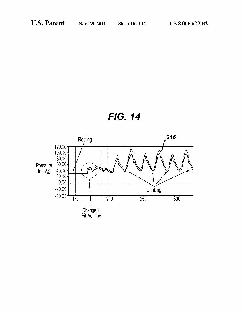
FIG. 14
120.00 100.00 80.00
Pressure 60.00 (mm/g) 40.00
20.00 OOO
-2000 Drinking 40.00" to 200 250 300
Change in Fill Volume
US 8,066,629 B2 Sheet 11 of 12 Nov. 29, 2011 U.S. Patent
U.S. Patent Nov. 29, 2011 Sheet 12 of 12 US 8,066,629 B2
7 6. NZ 628 fify/ NZ
7. ONE NWNW ZNNZ
N N N
US 8,066,629 B2 1.
APPARATUS FOR ADJUSTMENT AND SENSING OF GASTRIC BAND PRESSURE
PRIORITY
This application is a continuation-in-part of prior co-pend ing U.S. Non-Provisional application Ser. No. 1 1/369,389, filed Mar. 7, 2006,entitled “External Pressure-Based Gastric Band Adjustment System and Method, and published as U.S. Pub. No. 2006/021 1912, which is a continuation-in-part of prior co-pending U.S. Non-Provisional application Ser. No. 11/065,410, filed Feb. 24, 2005, entitled “Device for Non Invasive Measurement of Fluid Pressure in an Adjustable Restriction Device,” and published as U.S. Pub. No. 2006/ 0189888. The disclosure of each of those applications and publications is incorporated by reference herein.
BACKGROUND
Many devices and methods for treating obesity have been made and used, including but not limited to adjustable gastric bands. An example of Such an adjustable gastric band is disclosed in U.S. Pat. No. 6,067,991, entitled “Mechanical Food Intake Restriction Device,” which issued on May 30, 2000, and which is incorporated herein by reference. To the extent that an adjustable gastric band system is fluid based, those of ordinary skill in the art will appreciate that it may be advantageous to acquire data indicating the pressure of fluid in the band system. Similar advantages may be achieved with fluid-filled members implanted within the stomach cavity or elsewhere. Such pressure data may be obtained before, dur ing, and/or after pressure adjustment, and may be useful for adjustment, diagnostic, monitoring, or other purposes. The foregoing examples are merely illustrative and not exhaus tive. While a variety of techniques and devices have been used treat obesity, it is believed that no one prior to the inventors has previously made or used an invention as described in the appended claims.
BRIEF DESCRIPTION OF THE FIGURES
While the specification concludes with claims which par ticularly point out and distinctly claim the invention, it is believed the present invention will be better understood from the following description of certain examples taken in con junction with the accompanying drawings, in which like ref erence numerals identify the same elements and in which:
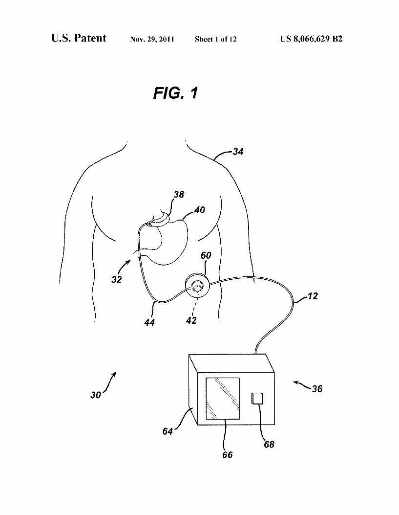
FIG. 1 is a schematic illustration of an exemplary food intake restriction system;
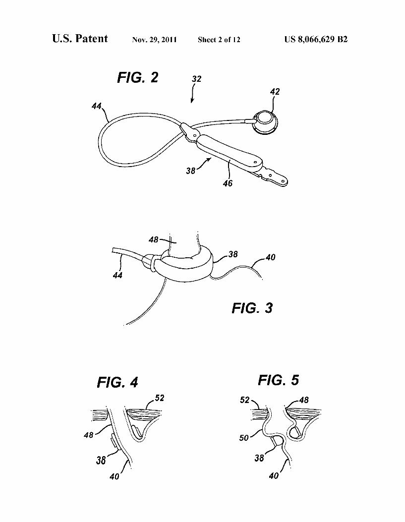
FIG. 2 is a more detailed perspective view of an exemplary implantable portion for the food intake restriction system of FIG. 1:
FIG. 3 is a perspective view of the adjustable gastric band of FIG. 2, showing the band positioned around the gastro esophageal junction of a patient in an exemplary use:
FIG. 4 is a cross-sectional view of the adjustable gastric band of FIG. 2, shown in an exemplary deflated configura tion;
FIG. 5 is a cross-sectional view of the adjustable gastric band of FIG. 2, shown in an exemplary inflated configuration to create a food intake restriction;
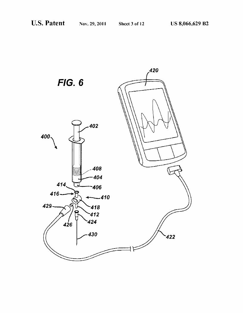
FIG. 6 is a perspective exploded view of an exemplary Syringe system with pressure sensor and display device;
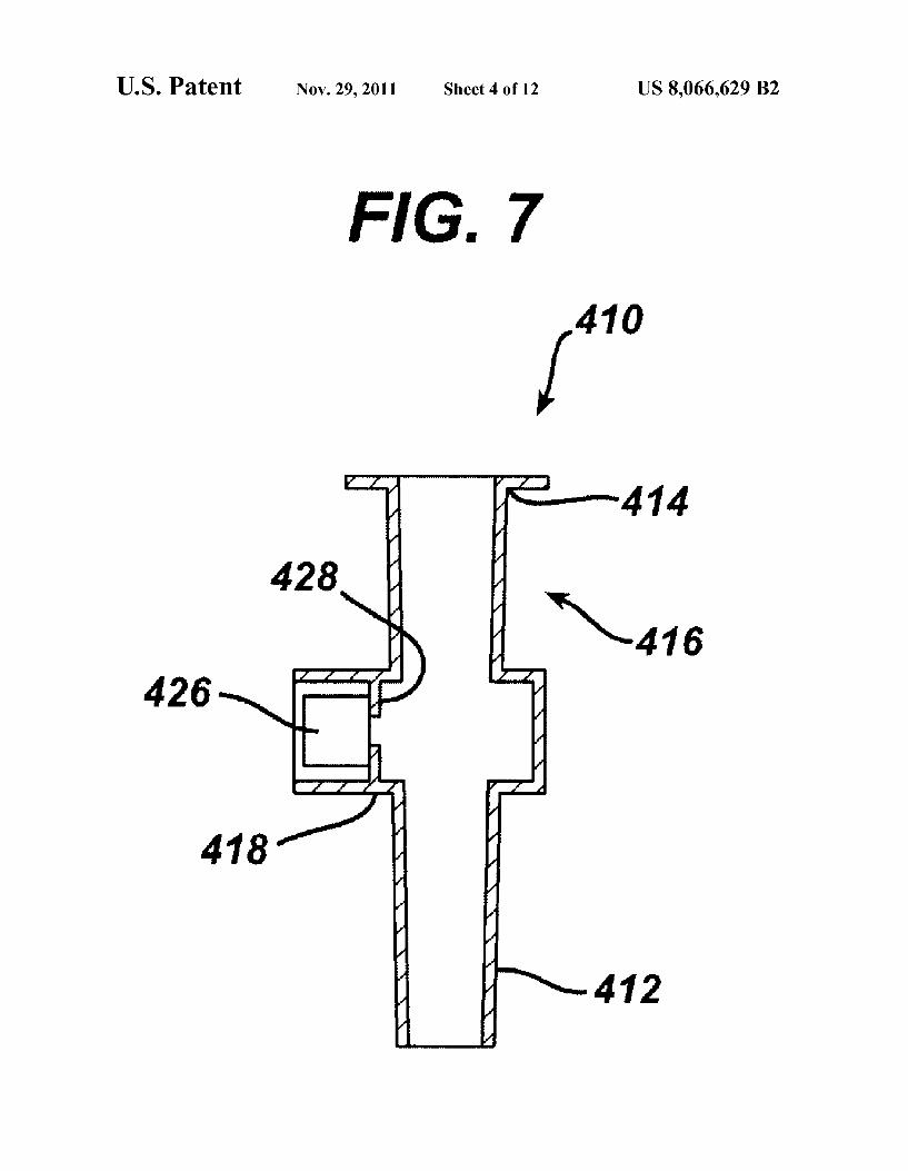
FIG. 7 is a cross-sectional view of a pressure sensing por tion of the syringe system of FIG. 6;
10
15
25
30
35
40
45
50
55
60
65
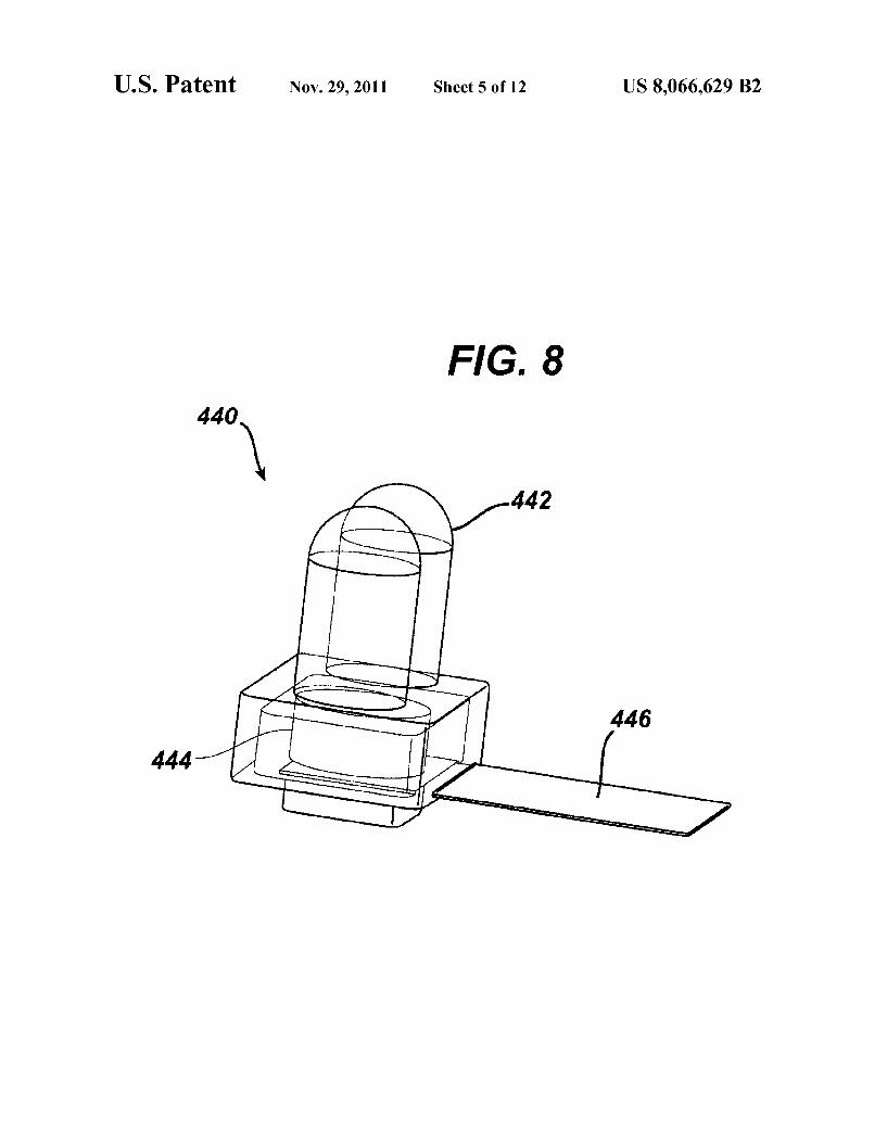
2 FIG. 8 is a perspective view of an exemplary infrared
communicator Suitable for use with the Syringe system of FIG. 6;
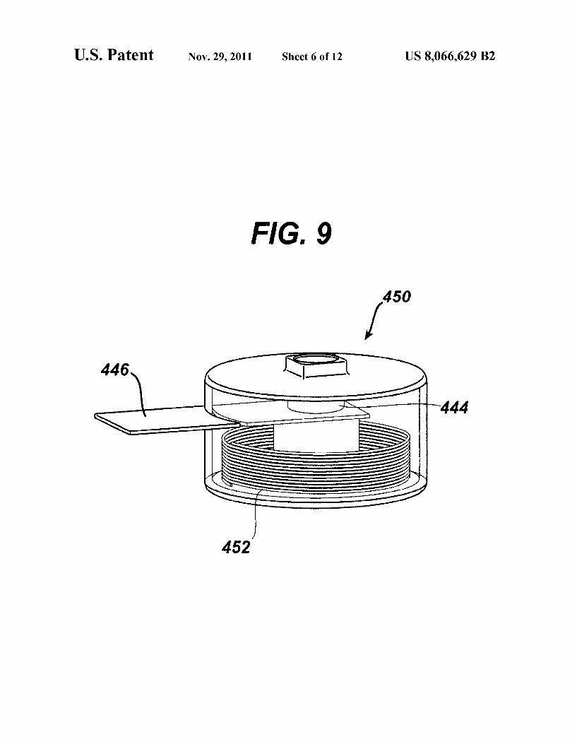
FIG. 9 is a perspective view of an exemplary RF commu nicator suitable for use with the syringe system of FIG. 6;
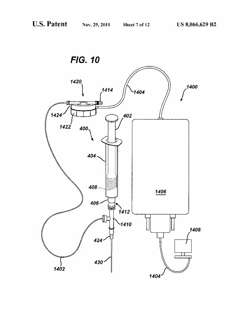
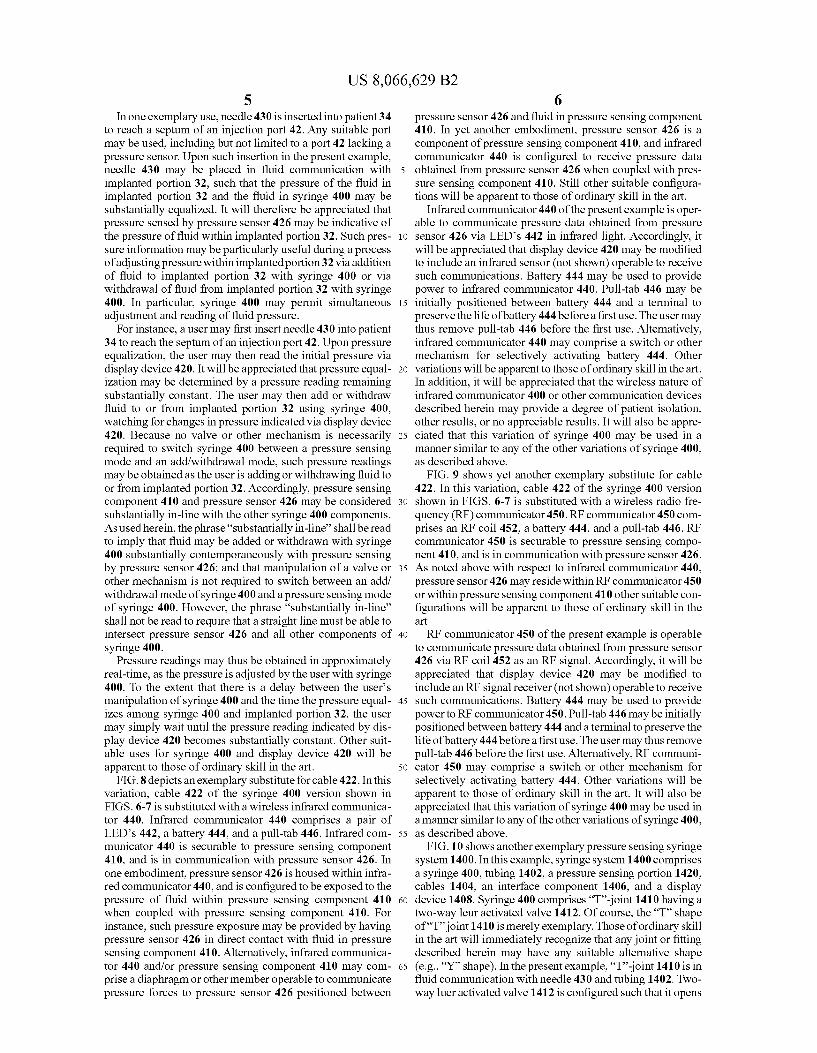
FIG. 10 is a schematic view of an alternative exemplary pressure sensing syringe system;
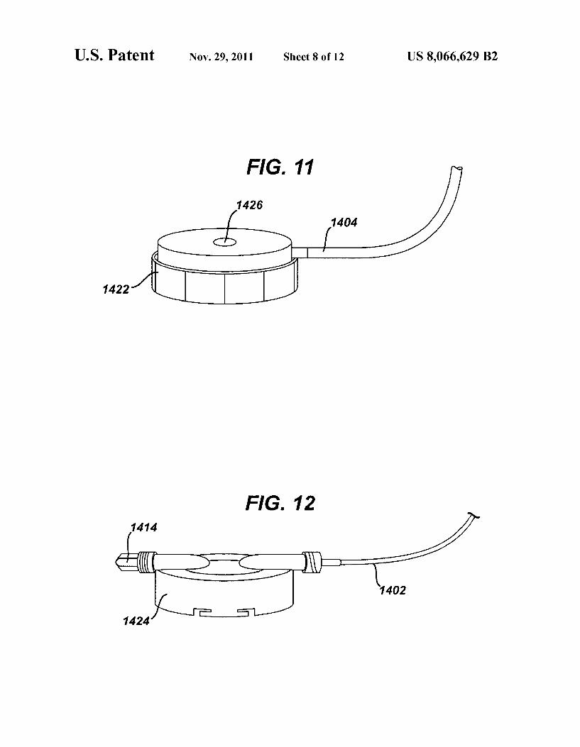
FIG.11 is a perspective view of a reusable sensorportion of the pressure sensing Syringe system of FIG. 10;
FIG. 12 is a partial perspective view of a disposable cap portion of the pressure sensing Syringe system of FIG. 10;
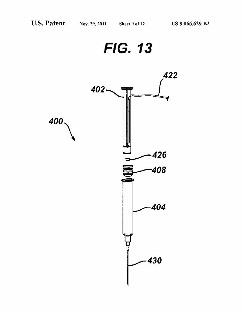
FIG. 13 is a perspective exploded view of an alternative Syringe with pressure sensor,
FIG. 14 is a graph indicating a pressure signal from a pressure sensing system, Such as may appear on an external monitor display during interrogation by a user;
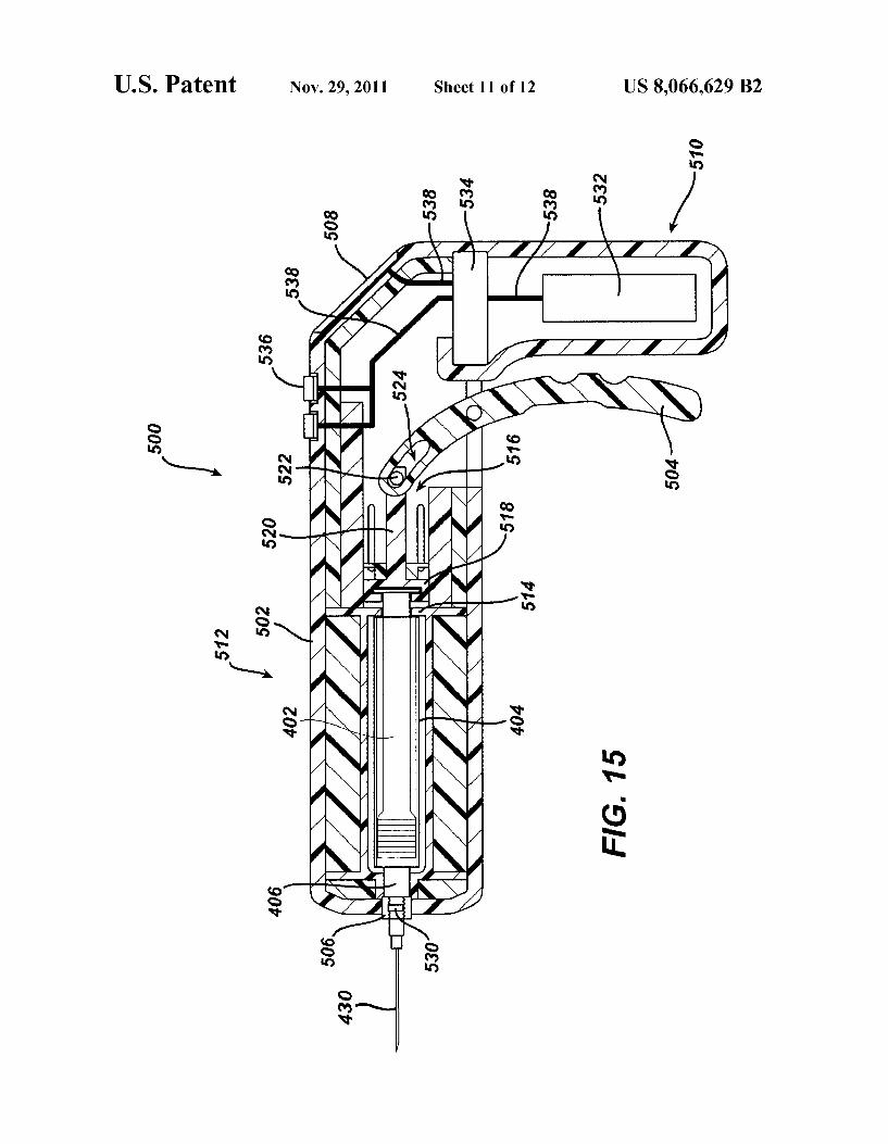
FIG. 15 is a cross-sectional side view of an alternative exemplary pressure adjustment and sensing device;
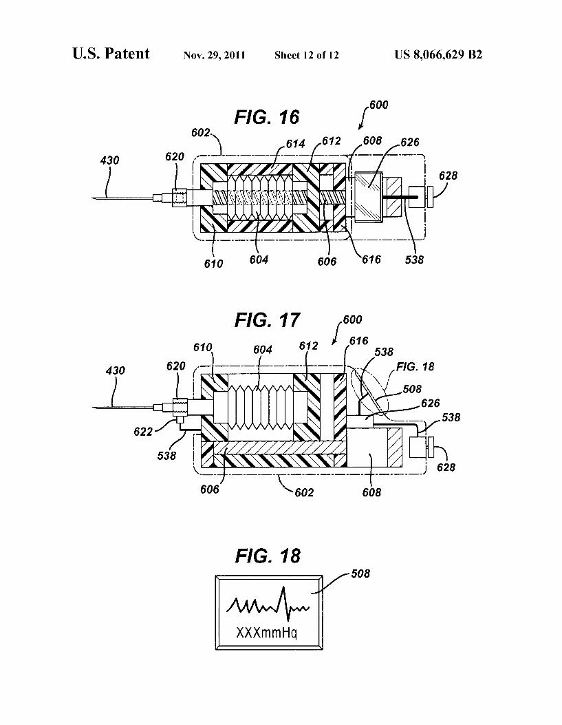
FIG.16 is a cross-sectional plan view of another alternative exemplary pressure adjustment and sensing device;
FIG. 17 is a cross-sectional side view of the device of FIG. 16; and
FIG. 18 is a plan view of an exemplary pressure data display.
DETAILED DESCRIPTION
The following description of certain examples of the inven tion should not be used to limit the scope of the present invention. Other examples, features, aspects, embodiments, and advantages of the invention will become apparent to those skilled in the art from the following description, which is by way of illustration, one of the best modes contemplated for carrying out the invention. As will be realized, the invention is capable of other different and obvious aspects, all without departing from the invention. Accordingly, the drawings and descriptions should be regarded as illustrative in nature and not restrictive.
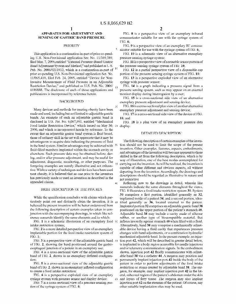
Referring now to the drawings in detail, wherein like numerals indicate the same elements throughout the views, FIG. 1 illustrates a food intake restriction system 30. System 30 comprises a first portion, identified generally as 32, implanted inside of a patient 34, and a second portion, iden tified generally as 36, located external to the patient. Implanted portion 32 comprises an adjustable gastric band 38 positioned on the upper portion of the patient’s stomach 40. Adjustable band 38 may include a cavity made of silicone rubber, or another type of biocompatible material, that inflates inwardly against stomach 40 when filled with a fluid. Alternatively, band 38 may comprise a mechanically adjust able device having a fluid cavity that experiences pressure changes with band adjustments, or a combination hydraulic/ mechanical adjustable band. In the present example, an injec tion port 42, which will be described in greater detail below, is implanted in a body region accessible for needle injections and/or telemetry communication signals. In the embodiment shown, injection port 42 fluidly communicates with adjust able band 38 via a catheter 44. A Surgeon may position and permanently implant injection port 42 inside the body of the patient in order to perform adjustments of the food intake restriction or stoma created by adjustable band 38. The sur geon, for example, may implant injection port 42 in the lat eral, Subcostal region of the patient’s abdomen under the skin and layers of fatty tissue. The Surgeon may also implant injection port 42 on the Sternum of the patient. Of course, any other Suitable implantation sites may be used.
US 8,066,629 B2 3
FIG. 2 illustrates an exemplary adjustable gastric band 38 in greater detail. In this embodiment, band 38 includes a variable Volume cavity 46 that expands or contracts against the outer wall of the stomach 40 to form an adjustable stoma for controllably restricting food intake into the stomach 40. A physician may decrease the size of the stoma opening by adding fluid to variable volume cavity 46 or, alternatively, may increase the stoma size by withdrawing fluid from the cavity 46. Fluid may be added or withdrawn by inserting a needle into injection port 42. Alternatively, fluid may be transferred in a non-invasive manner between band 38 and injection port 42 using telemetry command signals. The fluid may be, but is not restricted to, a 0.9 percent saline solution.
FIG. 3 shows the adjustable gastric band 38 of FIG. 2 applied about the gastro-esophageal junction of a patient in an exemplary use. As shown in FIG. 3, band 38 at least substan tially encloses the upper portion of stomach 40 near the junc tion with esophagus 48. FIG. 4 is a sectional view of band 38. showing the band 38 in a deflated configuration. In this view, band 38 contains little to no fluid, thereby maximizing the size of the stoma opening into stomach 40. FIG. 5 is a cross sectional view of band 38 and stomach 40, similar to FIG. 4, showing band 38 in an inflated, fluid-filled configuration. In this view, the pressure of band 38 against stomach 40 is increased due to the fluid within band 38, thereby decreasing the stoma opening to create a food intake restriction. FIG. 5 also schematically illustrates the dilation of esophagus 48 above band 38 to form an upper pouch 50 beneath the dia phragm muscle 52 of the patient.
Returning now to FIG. 1, external portion 36 of food restriction system 30 comprises a pressure-reading device 60 electrically connected (in this embodiment, via an electrical cable assembly 62) to a control box 64. Control box 64 includes a display 66, one or more control switches 68, and an external control module, which will be explained in further detail below. Control box 64 may be configured for use, for example, in a physicians office or examination room. Some ways to mount control box 64 include placement upon a desktop, attachment to an examination table, or hanging on a portable stand. Control box 64 may also be configured for carrying in the physician’s lab coat pocket, holding by hand, or placing upon the examination table or the reclining patient. Electrical cable assembly 62 may be detachably connected to control box 64 or pressure-reading device 60 to facilitate cleaning, maintenance, usage, and storage of external portion 36 of system 30.
Pressure-reading device 60 may non-invasively measure the pressure of the fluid within implanted portion 32 even when injection port 42 is implanted beneath thick (e.g., at least over 10 centimeters) subcutaneous fat tissue. For instance, implanted portion 32 may comprise one or more pressure sensors, and pressure-reading device 60 may be configured to obtain pressure data from implanted portion 32 via telemetry or other means. To the extent that implanted portion 32 requires power from an external Source, pressure reading device 60 or some other component, may be further configured to provide transcutaneous energy transfer (TET) to implanted portion. In the present example, a physician may hold pressure-reading device 60 against the patient’s skin near the location of injection port 42 in the patient and observe the pressure reading on display 66 of control box 64. Pressure-reading device 60 may also be removably attached to the patient 34. Such as during a prolonged examination, using straps, adhesives, and otherwell-known methods. Pres Sure-reading device 60 operates through conventional cloth or paper Surgical drapes, and may also include a disposal cover (not shown) that may be replaced for each patient.
10
15
25
30
35
40
45
50
55
60
65
4 While the above embodiments contemplate a pressure sen
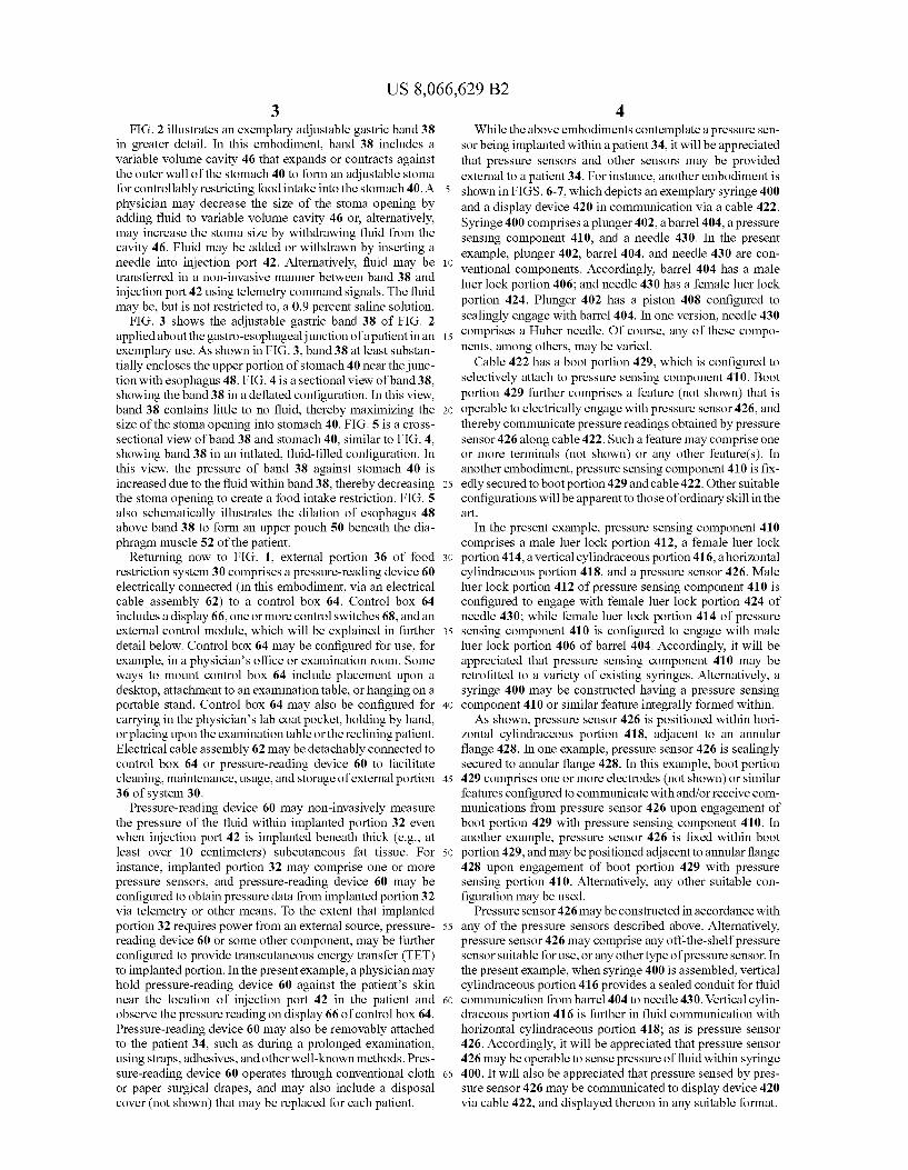
sor being implanted within a patient 34, it will be appreciated that pressure sensors and other sensors may be provided external to a patient 34. For instance, another embodiment is shown in FIGS. 6-7, which depicts an exemplary syringe 400 and a display device 420 in communication via a cable 422. Syringe 400 comprises a plunger 402, a barrel 404, a pressure sensing component 410, and a needle 430. In the present example, plunger 402, barrel 404, and needle 430 are con ventional components. Accordingly, barrel 404 has a male luer lock portion 406; and needle 430 has a female luer lock portion 424. Plunger 402 has a piston 408 configured to sealingly engage with barrel 404. In one version, needle 430 comprises a Huber needle. Of course, any of these compo nents, among others, may be varied.
Cable 422 has a boot portion 429, which is configured to selectively attach to pressure sensing component 410. Boot portion 429 further comprises a feature (not shown) that is operable to electrically engage with pressure sensor 426, and thereby communicate pressure readings obtained by pressure sensor 426 along cable 422. Such a feature may comprise one or more terminals (not shown) or any other feature(s). In another embodiment, pressure sensing component 410 is fix edly secured to boot portion 429 and cable 422. Other suitable configurations will be apparent to those of ordinary skill in the art.
In the present example, pressure sensing component 410 comprises a male luer lock portion 412, a female luer lock portion 414, a vertical cylindraceous portion 416, a horizontal cylindraceous portion 418, and a pressure sensor 426. Male luer lock portion 412 of pressure sensing component 410 is configured to engage with female luer lock portion 424 of needle 430; while female luer lock portion 414 of pressure sensing component 410 is configured to engage with male luer lock portion 406 of barrel 404. Accordingly, it will be appreciated that pressure sensing component 410 may be retrofitted to a variety of existing Syringes. Alternatively, a Syringe 400 may be constructed having a pressure sensing component 410 or similar feature integrally formed within. As shown, pressure sensor 426 is positioned within hori
Zontal cylindraceous portion 418, adjacent to an annular flange 428. In one example, pressure sensor 426 is sealingly secured to annular flange 428. In this example, boot portion 429 comprises one or more electrodes (not shown) or similar features configured to communicate with and/or receive com munications from pressure sensor 426 upon engagement of boot portion 429 with pressure sensing component 410. In another example, pressure sensor 426 is fixed within boot portion 429, and may be positioned adjacent to annular flange 428 upon engagement of boot portion 429 with pressure sensing portion 410. Alternatively, any other Suitable con figuration may be used.
Pressure sensor 426 may be constructed in accordance with any of the pressure sensors described above. Alternatively, pressure sensor 426 may comprise any off-the-shelf pressure sensor Suitable for use, or any other type of pressure sensor. In the present example, when syringe 400 is assembled, vertical cylindraceous portion 416 provides a sealed conduit for fluid communication from barrel 404 to needle 430. Vertical cylin draceous portion 416 is further in fluid communication with horizontal cylindraceous portion 418; as is pressure sensor 426. Accordingly, it will be appreciated that pressure sensor 426 may be operable to sense pressure of fluid within syringe 400. It will also be appreciated that pressure sensed by pres sure sensor 426 may be communicated to display device 420 via cable 422, and displayed thereon in any suitable format.
US 8,066,629 B2 5
In one exemplary use, needle 430 is inserted into patient 34 to reach a septum of an injection port 42. Any Suitable port may be used, including but not limited to a port 42 lacking a pressure sensor. Upon Such insertion in the present example, needle 430 may be placed in fluid communication with implanted portion 32, such that the pressure of the fluid in implanted portion 32 and the fluid in syringe 400 may be substantially equalized. It will therefore be appreciated that pressure sensed by pressure sensor 426 may be indicative of the pressure of fluid within implanted portion 32. Such pres Sure information may be particularly useful during a process of adjusting pressure within implanted portion32 via addition of fluid to implanted portion 32 with syringe 400 or via withdrawal of fluid from implanted portion 32 with syringe 400. In particular, syringe 400 may permit simultaneous adjustment and reading of fluid pressure.
For instance, a user may first insert needle 430 into patient 34 to reach the septum of an injection port 42. Upon pressure equalization, the user may then read the initial pressure via display device 420. It will be appreciated that pressure equal ization may be determined by a pressure reading remaining substantially constant. The user may then add or withdraw fluid to or from implanted portion 32 using syringe 400, watching for changes in pressure indicated via display device 420. Because no valve or other mechanism is necessarily required to Switch Syringe 400 between a pressure sensing mode and an add/withdrawal mode, Such pressure readings may be obtained as the user is adding or withdrawing fluid to or from implanted portion 32. Accordingly, pressure sensing component 410 and pressure sensor 426 may be considered substantially in-line with the other syringe 400 components. As used herein, the phrase “substantially in-line' shall be read to imply that fluid may be added or withdrawn with syringe 400 Substantially contemporaneously with pressure sensing by pressure sensor 426; and that manipulation of a valve or other mechanism is not required to Switch between an add/ withdrawal mode of syringe 400 and a pressure sensing mode of syringe 400. However, the phrase “substantially in-line' shall not be read to require that a straight line must be able to intersect pressure sensor 426 and all other components of syringe 400.
Pressure readings may thus be obtained in approximately real-time, as the pressure is adjusted by the user with Syringe 400. To the extent that there is a delay between the user's manipulation of Syringe 400 and the time the pressure equal izes among Syringe 400 and implanted portion 32, the user may simply wait until the pressure reading indicated by dis play device 420 becomes substantially constant. Other suit able uses for syringe 400 and display device 420 will be apparent to those of ordinary skill in the art.
FIG. 8 depicts an exemplary substitute for cable 422. In this variation, cable 422 of the syringe 400 version shown in FIGS. 6-7 is substituted with a wireless infrared communica tor 440. Infrared communicator 440 comprises a pair of LED's 442, a battery 444, and a pull-tab 446. Infrared com municator 440 is securable to pressure sensing component 410, and is in communication with pressure sensor 426. In one embodiment, pressure sensor 426 is housed within infra red communicator 440, and is configured to be exposed to the pressure of fluid within pressure sensing component 410 when coupled with pressure sensing component 410. For instance. Such pressure exposure may be provided by having pressure sensor 426 in direct contact with fluid in pressure sensing component 410. Alternatively, infrared communica tor 440 and/or pressure sensing component 410 may com prise a diaphragm or other member operable to communicate pressure forces to pressure sensor 426 positioned between
10
15
25
30
35
40
45
50
55
60
65
6 pressure sensor 426 and fluid in pressure sensing component 410. In yet another embodiment, pressure sensor 426 is a component of pressure sensing component 410, and infrared communicator 440 is configured to receive pressure data obtained from pressure sensor 426 when coupled with pres Sure sensing component 410. Still other Suitable configura tions will be apparent to those of ordinary skill in the art.
Infrared communicator 440 of the present example is oper able to communicate pressure data obtained from pressure sensor 426 via LED's 442 in infrared light. Accordingly, it will be appreciated that display device 420 may be modified to include an infrared sensor (not shown) operable to receive Such communications. Battery 444 may be used to provide power to infrared communicator 440. Pull-tab 446 may be initially positioned between battery 444 and a terminal to preserve the life of battery 444 before a first use. The user may thus remove pull-tab 446 before the first use. Alternatively, infrared communicator 440 may comprise a Switch or other mechanism for selectively activating battery 444. Other variations will be apparent to those of ordinary skill in the art. In addition, it will be appreciated that the wireless nature of infrared communicator 400 or other communication devices described herein may provide a degree of patient isolation, other results, or no appreciable results. It will also be appre ciated that this variation of syringe 400 may be used in a manner similar to any of the other variations of syringe 400, as described above.
FIG. 9 shows yet another exemplary substitute for cable 422. In this variation, cable 422 of the syringe 400 version shown in FIGS. 6-7 is substituted with a wireless radio fre quency (RF) communicator 450. RF communicator 450 com prises an RF coil 452, a battery 444, and a pull-tab 446. RF communicator 450 is securable to pressure sensing compo nent 410, and is in communication with pressure sensor 426. As noted above with respect to infrared communicator 440, pressure sensor 426 may reside within RF communicator 450 or within pressure sensing component 410 other Suitable con figurations will be apparent to those of ordinary skill in the art.
RF communicator 450 of the present example is operable to communicate pressure data obtained from pressure sensor 426 via RF coil 452 as an RF signal. Accordingly, it will be appreciated that display device 420 may be modified to include an RF signal receiver (not shown) operable to receive Such communications. Battery 444 may be used to provide power to RF communicator 450. Pull-tab 446 may be initially positioned between battery 444 and a terminal to preserve the life of battery 444 before a first use. The user may thus remove pull-tab 446 before the first use. Alternatively, RF communi cator 450 may comprise a switch or other mechanism for selectively activating battery 444. Other variations will be apparent to those of ordinary skill in the art. It will also be appreciated that this variation of syringe 400 may be used in a manner similar to any of the other variations of syringe 400, as described above.
FIG.10 shows another exemplary pressure sensing Syringe system 1400. In this example, syringe system 1400 comprises a syringe 400, tubing 1402, a pressure sensing portion 1420, cables 1404, an interface component 1406, and a display device 1408. Syringe 400 comprises “T'-joint 1410 having a two-way leur activated valve 1412. Of course, the “T” shape of “T” joint 1410 is merely exemplary. Those of ordinary skill in the art will immediately recognize that any joint or fitting described herein may have any suitable alternative shape (e.g., “Y” shape). In the present example, “T'-joint 1410 is in fluid communication with needle 430 and tubing 1402. Two way luer activated valve 1412 is configured such that it opens
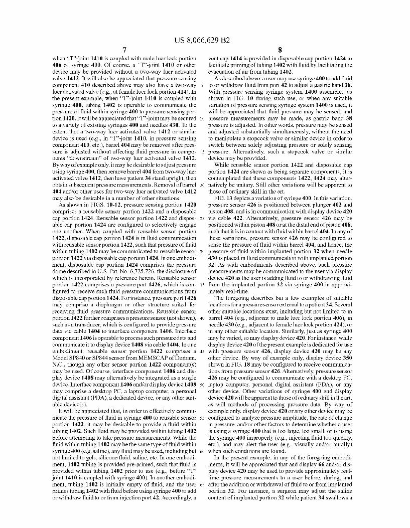
US 8,066,629 B2 7
when “T'-joint 1410 is coupled with male luer lock portion 406 of syringe 400. Of course, a “T'-joint 1410 or other device may be provided without a two-way luer activated valve 1412. It will also be appreciated that pressure sensing component 410 described above may also have a two-way luer activated valve (e.g., at female luer lock portion 414). In the present example, when “T'-joint 1410 is coupled with syringe 400, tubing 1402 is operable to communicate the pressure of fluid within Syringe 400 to pressure sensing por tion 1420. It will be appreciated that “T'-joint may be secured to a variety of existing syringes 400 and needles 430. To the extent that a two-way luer activated valve 1412 or similar device is used (e.g., in 'T'-joint 1410, in pressure sensing component 410, etc.), barrel 404 may be removed after pres Sure is adjusted without affecting fluid pressure in compo nents “downstream” of two-way luer activated valve 1412. By way of example only, it may be desirable to adjust pressure using syringe 400, then remove barrel 404 from two-way luer activated valve 1412, then have patient 34 stand upright, then obtain Subsequent pressure measurements. Removal of barrel 404 and/or other uses for two-way luer activated valve 1412 may also be desirable in a number of other situations. As shown in FIGS. 10-12, pressure sensing portion 1420
comprises a reusable sensor portion 1422 and a disposable cap portion 1424. Reusable sensor portion 1422 and dispos able cap portion 1424 are configured to selectively engage one another. When coupled with reusable sensor portion 1422, disposable cap portion 1424 is in fluid communication with reusable sensorportion 1422, such that pressure of fluid within tubing 1402 may be communicated to reusable sensor portion 1422 via disposable cap portion 1424. In one embodi ment, disposable cap portion 1424 comprises the pressure dome described in U.S. Pat. No. 6,725,726, the disclosure of which is incorporated by reference herein. Reusable sensor portion 1422 comprises a pressure port 1426, which is con figured to receive Such fluid pressure communications from disposable cap portion 1424. For instance, pressure port 1426 may comprise a diaphragm or other structure Suited for receiving fluid pressure communications. Reusable sensor portion 1422 further comprises a pressure sensor (not shown), Such as a transducer, which is configured to provide pressure data via cable 1404 to interface component 1406. Interface component 1406 is operable to process such pressure data and communicate it to display device 1408 via cable 1404. In one embodiment, reusable sensor portion 1422 comprises a Model SP840 or SP844 sensor from MEMSCAP of Durham, N.C., though any other sensor portion 1422 component(s) may be used. Of course, interface component 1406 and dis play device 1408 may alternatively be integrated as a single device. Interface component 1406 and/or display device 1408 may comprise a desktop PC, a laptop computer, a personal digital assistant (PDA), a dedicated device, or any other Suit able device(s).
It will be appreciated that, in order to effectively commu nicate the pressure of fluid in syringe 400 to reusable sensor portion 1422, it may be desirable to provide a fluid within tubing 1402. Such fluid may be provided within tubing 1402 before attempting to take pressure measurements. While the fluid within tubing 1402 may be the same type of fluid within Syringe 400 (e.g. saline), any fluid may be used, including but not limited to gels, silicone fluid, saline, etc. In one embodi ment, 1402 tubing is provided pre-primed, such that fluid is provided within tubing 1402 prior to use (e.g., before “T” joint 1410 is coupled with syringe 400). In another embodi ment, tubing 1402 is initially empty of fluid, and the user primes tubing 1402 with fluid before using syringe 400 to add or withdraw fluid to or from injection port 42. Accordingly, a
5
10
15
25
30
35
40
45
50
55
60
65
8 vent cap 1414 is provided in disposable cap portion 1424 to facilitate priming of tubing 1402 with fluid by facilitating the evacuation of air from tubing 1402. As described above, a user may use syringe 400 to add fluid
to or withdraw fluid from port 42 to adjust a gastric band 38. With pressure sensing syringe system 1400 assembled as shown in FIG. 10 during such use, or when any suitable variation of pressure sensing Syringe system 1400 is used, it will be appreciated that fluid pressure may be sensed, and pressure measurements may be made, as gastric band 38 pressure is adjusted. In other words, pressure may be sensed and adjusted Substantially simultaneously, without the need to manipulate a stopcock valve or similar device in order to Switch between solely adjusting pressure or solely sensing pressure. Alternatively, such a stopcock valve or similar device may be provided.
While reusable sensor portion 1422 and disposable cap portion 1424 are shown as being separate components, it is contemplated that these components 1422, 1424 may alter natively be unitary. Still other variations will be apparent to those of ordinary skill in the art.
FIG. 13 depicts a variation of syringe 400. In this variation, pressure sensor 426 is positioned between plunger 402 and piston 408, and is in communication with display device 420 via cable 422. Alternatively, pressure sensor 426 may be positioned within piston 408 or at the distal end of piston 408, such that it is in contact with fluid within barrel 404. In any of these variations, pressure sensor 426 may be configured to sense the pressure of fluid within barrel 404, and hence, the pressure of fluid within implanted portion 32 when needle 430 is placed in fluid communication with implanted portion 32. As with embodiments described above, such pressure measurements may be communicated to the user via display device 420 as the user is adding fluid to or withdrawing fluid from the implanted portion 32 via syringe 400 in approxi mately real-time. The foregoing describes but a few examples of suitable
locations for a pressure sensor external to a patient 34. Several other Suitable locations exist, including but not limited to in barrel 404 (e.g., adjacent to male luer lock portion 406), in needle 430 (e.g., adjacent to female luer lock portion 424), or in any other suitable location. Similarly, just as syringe 400 may be varied, so may display device 420. For instance, while display device 420 of the present example is dedicated for use with pressure sensor 426, display device 420 may be any other device. By way of example only, display device 350 shown in FIG. 18 may be configured to receive communica tions from pressure sensor 426. Alternatively, pressure sensor 426 may be configured to communicate with a desktop PC, laptop computer, personal digital assistant (PDA), or any other device. Other variations of syringe 400 and display device 420 will be apparent to those of ordinary skill in the art, as will methods of processing pressure data. By way of example only, display device 420 or any other device may be configured to analyze pressure amplitude, the rate of change in pressure, and/or other factors to determine whether a user is using a syringe 400 that is too large, too small, or is using the Syringe 400 improperly (e.g., injecting fluid too quickly, etc.), and may alert the user (e.g., visually and/or aurally) when such conditions are found.
In the present example, in any of the foregoing embodi ments, it will be appreciated that and display 66 and/or dis play device 420 may be used to provide approximately real time pressure measurements to a user before, during, and after the addition or withdrawal of fluid to or from implanted portion 32. For instance, a Surgeon may adjust the Saline content of implanted portion 32 while patient 34 swallows a
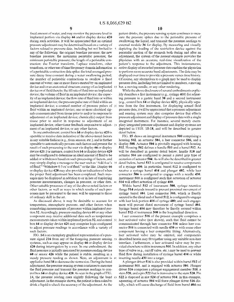
US 8,066,629 B2 9
fixed amount of water, and may monitor the pressure level in implanted portion via display 66 and/or display device 420 during such activities. It will be appreciated that an optimal pressure adjustment may be determined based on a variety of factors related to pressure data, including but not limited to any of the following: the original baseline pressure; the new baseline pressure; the maximum peristaltic pressure; the minimum peristaltic pressure; the length of a peristaltic con traction; the Fourier transform, Laplace transform, other transform, or other use of time/frequency domain information of a peristaltic contraction data spike; the total averaged pres Sure decay time constant during a water Swallowing period; the number of peristaltic contractions to swallow a fixed amount of water; one or more forces exerted by an implanted device and/oran anatomical structure; energy of an implanted device or of fluid therein; the fill rate offluid into an implanted device; the volume of fluid in an implanted device; the capac ity of an implanted device; the flow rate of fluid into or within an implanted device; the pressure pulse rate of fluid within an implanted device; a counted number of pressure pulses of fluid within an implanted device; one or more electrical sig nals communicated from tissue prior to and/or in response to adjustment of an implanted device; chemical(s) output from tissue prior to and/or in response to adjustment of an implanted device; other tissue feedback responsive to adjust ment of an implanted device; or any other factors.
In one embodiment, control box 64 or display device 420 is operable to receive data indicative of the above-noted factors in any Suitable fashion (e.g., from sensors, etc.), and is further operable to automatically process such factors and present the result of such processing to the user via display 66 or display device 420. For instance, control box 64 or display device 420 may be configured to determine an ideal amount of fluid to be added or withdrawn based on Such processing of factors, and may simply display a message to the user Such as "Add 4 cc’s of fluid,” “Withdraw 0.5 ccs of fluid,” or the like. Display 66 or display device 420 may also provide an indication of when the proper fluid adjustment has been completed. Such mes sages may be displayed in addition to or in lieu of displaying pressure measurements, changes in pressure, or other data. Other suitable processes of any of the above-noted factors or other factors, as well as ways in which results of Such pro cesses may be presented to the user, will be apparent to those of ordinary skill in the art. As discussed above, it may be desirable to account for
temperature, atmospheric pressure, and other factors when considering measurements of pressure within implanted por tion32. Accordingly, pressure-reading device 60 or any other component may receive additional data Such as temperature measurements taken within implanted portion32, and control box 64 or display device 420 may comprise logic configured to adjust pressure readings in accordance with a variety of Such factors.
FIG. 14 is an exemplary graphical representation of a pres Sure signal 216 from any of the foregoing pressure sensing systems, such as may appear on display 66 or display device 420 during interrogation by a user. In one embodiment, the fluid pressure is initially measured by pressure reading device 60 or sensor 426 while the patient is stable, resulting in a steady pressure reading as shown. Next, an adjustment is applied to band 38 to decrease the stoma size. During the band adjustment, the pressure sensing system continues to measure the fluid pressure and transmit the pressure readings to con trol box 64 or display device 420. As seen in the graph of FIG. 14, the pressure reading rises slightly following the band adjustment. In the example shown, the patient is then asked to drink a liquid to check the accuracy of the adjustment. As the
5
10
15
25
30
35
40
45
50
55
60
65
10 patient drinks, the pressure sensing system continues to mea Sure the pressure spikes due to the peristaltic pressure of Swallowing the liquid, and transmit the pressure readings to external module 36 for display. By measuring and visually depicting the loading of the restriction device against the peristaltic motion of the stomach both during and after an adjustment, the system of the present example provides the physician with an accurate, real-time visualization of the patient's response to the adjustment. This instantaneous, active display of recorded pressure data enables the physician to perform more accurate band adjustments. The data may be displayed over time to provide a pressure verses time history. Of course, any alternatives to a graph may be used to display pressure data, including but not limited to numbers, a moving bar, a moving needle, or any other rendering.
While the above disclosure of several embodiments explic itly describes a first instrument (e.g., Syringe 400) for adjust ing pressure in a gastric band 38 and a second instrument (e.g., control box 64 or display device 420), physically sepa rate from the first instrument, for displaying sensed fluid pressure data, it will be appreciated that a pressure adjustment and sensing system may also comprise device that effects pressure adjustment and display of pressure data with a single integrated instrument. For instance, several merely exem plary integrated pressure adjustment and display systems are depicted in FIGS. 15-18, and will be described in greater detail below.
FIG. 15 shows an integrated instrument 500 comprising a housing 502, an actuator 504, a luer connector 506, and a display 508. Actuator 504 is pivotally engaged with housing 502. Housing 502 defines a handle 510 and a barrel 512. As will be described in greater detail below, handle 510 and actuator 504 are configured to permit a pistol grip type of acutation of actuator 504. As will also be described in greater detail below, barrel 512 is configured to receive components of a syringe 400. In particular, barrel 512 is configured to receive a syringe barrel 404 and plunger 402, while luer connector 506 is configured to engage with a needle 430. Instrument 500 is configured such that actuation of actuator 504 will effect actuation of syringe 400.
Within barrel 512 of instrument 500, syringe retention flange 514 extends inward to prevent proximal movement of syringe barrel 404. Luer connector 506, which is fixedly secured in the distal end of barrel 512, is configured to engage with luer lock portion 406 of syringe 400; and such engage ment will prevent distal movement of syringe barrel 404. Syringe barrel 404 may therefore be fixedly secured within barrel 512 of instrument 500 in the longitudinal direction.
Luer connector 506 of the present example comprises a luer activated valve (not shown), such that fluid cannot be communicated through luer connector 506 unless luer con nector 506 is connected with needle 430 or with some other component having a luer compatible fitting. Alternatively, luer activated valve may be omitted, and components described herein may fit together using any Suitable non-luer interface. Furthermore, a luer activated valve may be pro vided elsewhere within instrument 500. In addition, any other type of Valve (e.g., on/off valve, etc.) may be used to prevent fluid flow during installation of syringe barrel 404 or while inserting needle 430 into a target. A plunger driver 516 is also provided within barrel 512 of
instrument 500, and is engaged with actuator 504. Plunger driver 516 comprises a plunger engagement member 518, a stem 520, and a pin 522 that is transverse to the stem 520. Pin 522 is disposed in slot 524 of actuator 504. In this example, squeezing of actuator 504 will force plunger driver 516 dis tally, which will cause discharge of fluid from barrel 404 out
US 8,066,629 B2 11
through needle 430. In addition, ifactuator 504 is forced away from handle 510, actuator 504 will pull plunger driver 516 proximally, which may effect withdrawal of fluid through needle 430 into barrel 404. Of course, as with any other components described herein, plunger driver 516 and actua tor 504 may be modified, substituted, or supplemented in any suitable way.
Instrument 500 of the present example further comprises a pressure sensor 530, a power source 532, a processor 534, and buttons 536. Each of these components, as well as display 508, are in communication via electrical wires 538, though any suitable alternative for wires 538 may be used. As shown, pressure sensor 530 is provided withinluer connector 506. Of course, pressure sensor 530 may be located elsewhere. In the present example, the configuration of pressure sensor 530 and luer connector 506 is such that fluid may be communicated through luer connector 506 (e.g., from barrel 404 of syringe 400 to needle 430); and pressure sensor 530 may sense pres sure of fluid withinluer connector 506 before, during, and/or after fluid is communicated through luer connector 506. For instance, as with any other pressure sensor described herein, pressure sensor 530 of this embodiment may be configured to sense static pressure and/or dynamic changes in pressure. Pressure sensor 530 and luer connector 506 are therefore similar to pressure sensor 426 and pressure sensing compo nent 410, respectively, described above with respect to the embodiment illustrated in FIGS. 6-7. Signals generated by pressure sensor 530 may be communicated to processor 534 via wire 538 or otherwise.
Power source 532 may comprise any suitable type of bat tery or cell. By way of example only, power source 532 may comprise a rechargeable lithium ion, nickel cadmium, alka line cell, or capacitor. Other Suitable power storage technolo gies may also be used. Alternatively, power source 532 may be located external to instrument 500, such as a wall outlet or power generator. In another embodiment, power source 532 comprises a user's hand. Instrument 500 of the present example is configured Such that power may be communicated from power source 532 to processor 534, display 508, and sensor 530 via wires 538. Processor 534 of this example is operable to process signals from sensor 530, and cause the rendering of pressure data on display 508. For instance, dis play 508 may render data in a manner similar to display 66 or display device 420 as described above, or in any other suitable manner. Display 508 may comprise any suitable type of dis play, including but not limited to LED, LCD, a graphic dis play, a numeric display, etc. Processor 534 is also operable to process signals from buttons 536, as will be described in greater detail below.
In the present example, instrument 500 comprises buttons 536 that are configured to be actuated by a user. For instance, buttons 536 may comprise a “+” button 536 and a "- button 536, and may be operable to set a desired pressure level. By actuating buttons 536, a user may increase or decrease a default pressure value until the desired pressure value is dis played on display 508. Then, as the user manipulates actuator 504 to change fluid pressure within a gastric band 38 via needle 430 inserted in injection port 42, processor 534 may compare pressure data obtained using pressure sensor 530 to the preset desired pressure value that has been input via buttons 536. Display 508 may provide a visual indication when the preset desired pressure value has been reached. In addition or in the alternative, instrument 500 may provide an audio indication when the preset desired pressure value has been reached. Any suitable alternative to buttons 536 may be used to indicate a desired pressure level, including but not limited to a knob, a dial, a slider, etc. In another embodiment,
10
15
25
30
35
40
45
50
55
60
65
12 processor 534 is preconfigured (e.g., “hardwired) with a desired pressure value, such that buttons 536 are omitted. It will be appreciated that display 508 may be replaced with an LED or other indicator to indicate when the preset or precon figured pressure value is reached. In another embodiment, pressure ranges may be input via buttons 536 or otherwise, or Such ranges may be preconfigured within processor 534 or a storage device. In yet another embodiment, no desired pres sure value or range is input via buttons 536 or otherwise, and processor 534 is not preconfigured with any particular pres Sure value or range. While not shown in the drawings, it will be appreciated that
instrument 500 may also have a storage device configured to store pressure data or other data. Instrument 500 may also be configured to communicate data or commands to a remote device, or receive data or commands from a remote device, via wire or wirelessly. It will also be appreciated that various other components may be added to instrument 500, and that various components described herein may be omitted, modi fied, Substituted, or Supplemented.
Housing 502 of instrument 500 may be at least partially openable by a user, such as to insert Syringe 400 components. For instance, barrel 512 may comprise a selectively remov able portion of housing 502. With such a portion removed, a user may insert a conventional Syringe barrel 404, with a conventional plunger 402, to fit within barrel 512 as shown in FIG. 15. Instrument 500 may thus be configured such that Syringe barrel 404 and plunger 402 may 'snap' into place, and such that syringe barrel 404 and plunger 402 may be replaced by a user. Alternatively, instrument 500 may be constructed such that syringe barrel 404 and plunger 402 cannot be easily accessed without destroying at least a portion of instrument 500. In another embodiment, a door (not shown) is engaged or engageable with housing 502. For instance, a door may snap onto or off of housing 502 to selectively cover or uncover Syringe barrel 404 and plunger 402. Alternatively, a door may be pivotally connected to hous ing 502. Such that it may be swung open or closed to selec tively cover or uncover syringe barrel 404 and plunger 402. A door may alternatively slide relative to housing 502 or have any other type of relationship with housing 502. Furthermore, a door may be at least partially transparent to provide a window for viewing at least a portion of syringe barrel 404 and/or plunger 402. For instance, a window may be provided to permit viewing of the amount of fluid within syringe barrel 404. A window may also be provided as an opening formed through a door. Still other ways in which at least a portion of syringe barrel 404 and/or plunger 402 may be covered or uncovered within housing 502 will be apparent to those of ordinary skill in the art.
Alternatively, housing 502 may provide an open recess configured to receive syringe barrel 404 and plunger 402. For instance, housing 502 may be configured Such that a syringe barrel 404 and plunger 402 may be selectively engaged and disengaged with housing 502 without requiring movement of a door or other member. In Such an embodiment, structures Such as inward protuberances may be used to secure Syringe barrel 404 and/or plunger 402 within housing 502 upon engagement of Syringe barrel 404 and/or plunger 402 with such protuberances. In other words, housing 502 may be configured such that syringe barrel 404 and/or plunger 402 can be 'snapped in or 'snapped out without requiring movement of a door or other member. Alternatively, any other Suitable structures, features, or relationships between Syringe barrel 404, plunger 402, and housing 502 may be employed.
Similarly, housing 502 may be constructed such that power Source 532 may be easily accessed. Such as for replacement or
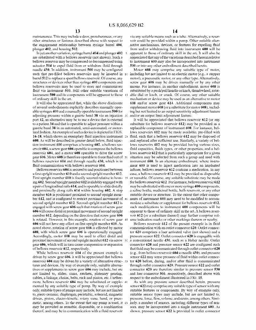
US 8,066,629 B2 13
maintenance. This may include a door, protuberances, or any other structures or features described above with respect to the engagement relationship between Syringe barrel 404. plunger 402, and housing 502.
In yet another variation, syringe barrel 404 and plunger 402 are substituted with a bellows reservoir (not shown). Such a bellows reservoir may be compressed or decompressed using actuator 504 to expel fluid from or withdraw fluid through needle 430. In addition, instrument 500 may be configured such that pre-filled bellows reservoirs may be inserted in barrel 512 to replace a spent bellows reservoir. Of course, any structures or devices other than Syringe 400 components and bellows reservoirs may be used to store and communicate fluid via instrument 500. Still other suitable variations of instrument 500 and its components will be apparent to those of ordinary skill in the art.
It will also be appreciated that, while the above disclosure of several embodiments explicitly describes manually oper able syringes 400 and a manually operable instrument 500 for adjusting pressure within a gastric band 38 via an injection port 42, an alternative may be to use a device that is external to a patient 34 and that is operable to adjust pressure within a gastric band 38 in an automated, semi-automated, or motor ized fashion. An example of such a device is depicted in FIGS. 16-18, which shows an exemplary fluid injection instrument 600. As will be described in greater detail below, fluid injec tion instrument 600 comprises a housing 602, a bellows res ervoir 604, a screw gear 606 operable to compress the bellows reservoir 604, and a motor 608 operable to drive the screw gear 606. Motor 608 is therefore operable to force fluid out of bellows reservior 604 and through needle 430, which is in fluid communication with bellows reservoir 604.
Bellows reservior 604 is secured to and positioned between a first upright member 610 and a second upright member 612. First upright member 610 is fixedly secured relative to hous ing 602. Second upright member 612 is slidably engaged with a pair of longitudinal rails 614, and is operable to slide distally and proximally along rails 614 within housing 602. A stop member 616 is positioned proximal to second upright mem ber 612, and is configured to restrict proximal movement of second upright member 612. Second upright member 612 is engaged with screw gear 606 Such that rotation of screw gear 606 will cause distal or proximal movement of second upright member 612, depending on the direction that screw gear 606 is rotated. However, in this example, rotation of Screw gear 606 will not have any effect on first upright member 610. As noted above, rotation of screw gear 606 is effected by motor 608, with which screw gear 606 is operationally engaged. Accordingly, motor 608 may be used to effect distal and proximal movement of second upright member 612 via screw gear 606, which will in turn cause compression or expansion of bellows reservoir 612, respectively.
While bellows reservoir 604 of the present example is driven by screw gear 606, it will be appreciated that bellows reservoir 604 may be driven by a variety of alternative struc tures and devices. By way of example only, Suitable alterna tives or Supplements to screw gear 606 may include, but are not limited to, slides, cams, ratchets, platenary gearing, cables, a linkage, chains, belts, rack and pinion, etc. Further more, bellows reservoir 604 may be substituted or supple mented by any suitable type of pump. By way of example only, Suitable types of pumps may include, but are not limited to, piezo ceramic, diaphragm, peristaltic, Solenoid, magnetic driven, piston, electro-kinetic, rotary vane, hand, or pneu matic, among others. To the extent that any pump is used, it may be provided as reusable, disposable, or a combination thereof, and may be in communication with a fluid reservoir
10
15
25
30
35
40
45
50
55
60
65
14 via any suitable means such as a tube. Alternatively, a reser voir could be provided within a pump. Other suitable alter native mechanisms, devices, or features for expelling fluid from and/or withdrawing fluid into instrument 600 will be apparent to those of ordinary skill in the art. It will also be appreciated that any of the variations described herein relative to instrument 600 may also be incorporated into instrument 500 or into any other embodiment described herein. Motor 608 may comprise any suitable type of motor,
including but not limited to an electric motor (e.g., a stepper motor), a pneumatic motor, or any other type. Alternatively, screw gear 606 may be driven manually or by any other means. For instance, in another embodiment, motor 608 is substituted by a push/pull handle or knob, thumbwheel, rotat able dial or knob, or crank. Of course, any other suitable mechanism or device may be used as an alternative to motor 608 and/or screw gear 614. Additional components may supplement motor 608 (or a substitute for motor 608), includ ing but not limited to an output sensitivity adjustment feature and/or an output limit adjustment feature.
It will be appreciated that bellows reservoir 612 (or any substitute for bellows reservoir 612) may be provided as a replacable component of instrument 600. For instance, bel lows reservoirs 612 may be made available, pre-filled with fluid, such that a bellows reservoir 612 may be disposed of and replaced after sufficient use. Similarly, a variety of bel lows reservoirs 612 may be provided having various sizes, fluid capacities, fluids types, or other properties; and a bel lows reservoir 612 that is particularly appropriate for a given situation may be selected from Such a group and used with instrument 600. In an alternate embodiment, where instru ment 600 is used to inject medication into an implanted infuser, bellows reservoir 612 contains a medication. In any case, a bellows reservoir 612 may be provided as disposable or reusable. Of course, any suitable substitute may be made for bellows reservoir 612. For instance, bellows reservoir 612 may be substituted with one or more syringe 400 components, a saline bottle, medicinal bottle, bulb reservoir, or any other suitable device or structure. To the extent that other compo nents of instrument 600 may need to be modified to accom modate a substitute or supplement for bellows reservoir 612. such modifications to instrument 600 components will be apparent to those of ordinary skill in the art. A bellows reser voir 612 (or a substitute thereof) may further comprise vol ume indication marks or other markings thereon or nearby.
Bellows reservoir 612 of the present example is in fluid communication with an outlet connector 620. Outlet connec tor 620 comprises a luer activated valve (not shown) and a pressure sensor 622. Outlet connector 620 is engagable with a conventional needle 430, such as a Huber needle. Outlet connector 620 and pressure sensor 622 are configured Such that fluid may be communicated through outlet connector 620 (e.g., from bellows reservoir 604 to needle 430), and pressure sensor 622 may sense pressure of fluid within outlet connec tor 620 before, during, and/or after fluid is communicated through outlet connector 620. Pressure sensor 622 and outlet connector 620 are therefore similar to pressure sensor 530 and luer connector 506, respectively, described above with respect to the embodiment illustrated in FIG. 15. As with any pressure sensor described herein, pressure
sensor 622 may comprise any Suitable type of sensor with any Suitable features or components. By way of example only, Suitable sensor types may include, but are not limited to, pressure, force, flow, Volume, and strain, among others. Simi larly, a number of sensors, including different types of sen sors, may be incorporated into a single instrument 600. As shown, pressure sensor 622 is provided in outlet connector
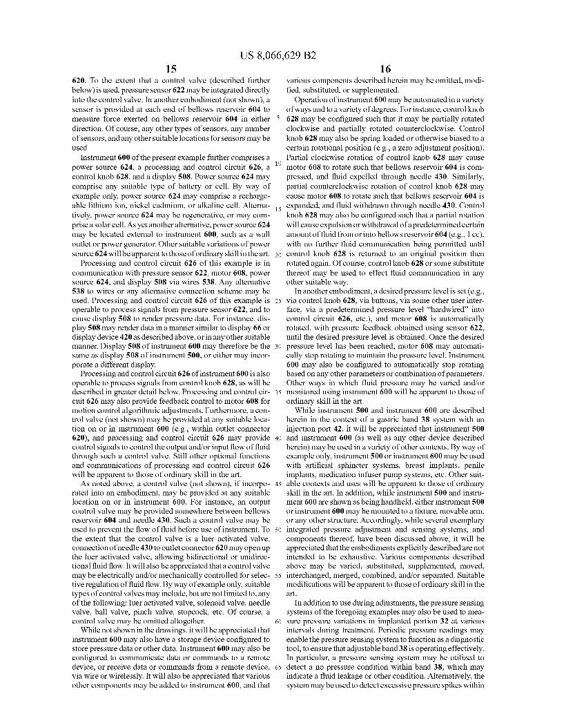
US 8,066,629 B2 15
620. To the extent that a control valve (described further below) is used, pressure sensor 622 may be integrated directly into the control valve. In another embodiment (not shown), a sensor is provided at each end of bellows reservoir 604 to measure force exerted on bellows reservoir 604 in either direction. Of course, any other types of sensors, any number of sensors, and any other Suitable locations for sensors may be used.
Instrument 600 of the present example further comprises a power source 624, a processing and control circuit 626, a control knob 628, and a display 508. Power source 624 may comprise any suitable type of battery or cell. By way of example only, power source 624 may comprise a recharge able lithium ion, nickel cadmium, or alkaline cell. Alterna tively, power source 624 may be regenerative, or may com prise a solar cell. As yet another alternative, power source 624 may be located external to instrument 600, such as a wall outlet or power generator. Other suitable variations of power source 624 will be apparent to those of ordinary skill in the art.
Processing and control circuit 626 of this example is in communication with pressure sensor 622, motor 608, power source 624, and display 508 via wires 538. Any alternative 538 to wires or any alternative connection scheme may be used. Processing and control circuit 626 of this example is operable to process signals from pressure sensor 622, and to cause display 508 to render pressure data. For instance, dis play 508 may render data in a manner similar to display 66 or display device 420 as described above, or in any other suitable manner. Display 508 of instrument 600 may therefore be the same as display 508 of instrument 500, or either may incor porate a different display.
Processing and control circuit 626 of instrument 600 is also operable to process signals from control knob 628, as will be described in greater detail below. Processing and control cir cuit 626 may also provide feedback control to motor 608 for motion control algorithmic adjustments. Furthermore, a con trol valve (not shown) may be provided at any suitable loca tion on or in instrument 600 (e.g., within outlet connector 620), and processing and control circuit 626 may provide control signals to control the output and/or input flow of fluid through such a control valve. Still other optional functions and communications of processing and control circuit 626 will be apparent to those of ordinary skill in the art. As noted above, a control valve (not shown), if incorpo
rated into an embodiment, may be provided at any Suitable location on or in instrument 600. For instance, an output control valve may be provided somewhere between bellows reservoir 604 and needle 430. Such a control valve may be used to prevent the flow of fluid before use of instrument. To the extent that the control valve is a luer activated valve, connection of needle 430 to outlet connector 620 may open up the luer activated valve, allowing bidirectional or unidirec tional fluid flow. It will also be appreciated that a control valve may be electrically and/or mechanically controlled for selec tive regulation of fluid flow. By way of example only, suitable types of control valves may include, but are not limited to, any of the following: luer activated valve, solenoid valve, needle valve, ball valve, pinch valve, Stopcock, etc. Of course, a control valve may be omitted altogether.
While not shown in the drawings, it will be appreciated that instrument 600 may also have a storage device configured to store pressure data or other data. Instrument 600 may also be configured to communicate data or commands to a remote device, or receive data or commands from a remote device, via wire or wirelessly. It will also be appreciated that various other components may be added to instrument 600, and that
10
15
25
30
35
40
45
50
55
60
65
16 various components described herein may be omitted, modi fied, Substituted, or Supplemented.
Operation of instrument 600 may be automated in a variety of ways and to a variety of degrees. For instance, control knob 628 may be configured such that it may be partially rotated clockwise and partially rotated counterclockwise. Control knob 628 may also be spring loaded or otherwise biased to a certain rotational position (e.g., a Zero adjustment position). Partial clockwise rotation of control knob 628 may cause motor 608 to rotate such that bellows reservoir 604 is com pressed, and fluid expelled through needle 430. Similarly, partial counterclockwise rotation of control knob 628 may cause motor 608 to rotate such that bellows reservoir 604 is expanded, and fluid withdrawn through needle 430. Control knob 628 may also be configured such that a partial rotation will cause expulsion or withdrawal of a predetermined certain amount of fluid from or into bellows reservoir 604 (e.g., 1 cc), with no further fluid communication being permitted until control knob 628 is returned to an original position then rotated again. Of course, control knob 628 or some substitute thereof may be used to effect fluid communication in any other suitable way.
In another embodiment, a desired pressure level is set (e.g., via control knob 628, via buttons, via some other user inter face, via a predetermined pressure level “hardwired into control circuit 626, etc.), and motor 608 is automatically rotated, with pressure feedback obtained using sensor 622, until the desired pressure level is obtained. Once the desired pressure level has been reached, motor 608 may automati cally stop rotating to maintain the pressure level. Instrument 600 may also be configured to automatically stop rotating based on any other parameters or combination of parameters. Other ways in which fluid pressure may be varied and/or monitored using instrument 600 will be apparent to those of ordinary skill in the art.
While instrument 500 and instrument 600 are described herein in the context of a gastric band 38 system with an injection port 42, it will be appreciated that instrument 500 and instrument 600 (as well as any other device described herein) may be used in a variety of other contexts. By way of example only, instrument 500 or instrument 600 may be used with artificial sphincter systems, breast implants, penile implants, medication infuser pump systems, etc. Other Suit able contexts and uses will be apparent to those of ordinary skill in the art. In addition, while instrument 500 and instru ment 600 are shown as being handheld, either instrument 500 or instrument 600 may be mounted to a fixture, movable arm, or any other structure. Accordingly, while several exemplary integrated pressure adjustment and sensing systems, and components thereof, have been discussed above, it will be appreciated that the embodiments explicitly described are not intended to be exhaustive. Various components described above may be varied, Substituted, Supplemented, moved, interchanged, merged, combined, and/or separated. Suitable modifications will be apparent to those of ordinary skill in the art.
In addition to use during adjustments, the pressure sensing systems of the foregoing examples may also be used to mea Sure pressure variations in implanted portion 32 at various intervals during treatment. Periodic pressure readings may enable the pressure sensing system to function as a diagnostic tool, to ensure that adjustable band 38 is operating effectively. In particular, a pressure sensing system may be utilized to detect a no pressure condition within band 38, which may indicate a fluid leakage or other condition. Alternatively, the system may be used to detect excessive pressure spikes within
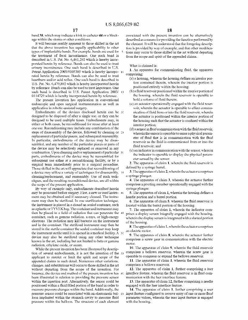
US 8,066,629 B2 17
band 38, which may indicate a kink in catheter 44 or a block age within the stoma or other conditions.
It will become readily apparent to those skilled in the art that the above invention has equally applicability to other types of implantable bands. For example, bands are used for the treatment of fecal incontinence. One such band is described in U.S. Pat. No. 6,461.292 which is hereby incor porated herein by reference. Bands can also be used to treat urinary incontinence. One such band is described in U.S. Patent Application 2003/0105385 which is hereby incorpo rated herein by reference. Bands can also be used to treat heartburn and/or acid reflux. One such band is described in U.S. Pat. No. 6,470,892 which is hereby incorporated herein by reference. Bands can also be used to treat impotence. One such band is described in U.S. Patent Application 2003/ 0114729 which is hereby incorporated herein by reference. The present invention has application in conventional
endoscopic and open Surgical instrumentation as well as application in robotic-assisted Surgery.
Embodiments of the devices disclosed herein can be designed to be disposed of after a single use, or they can be designed to be used multiple times. Embodiments may, in either or both cases, be reconditioned for reuse after at least one use. Reconditioning may include any combination of the steps of disassembly of the device, followed by cleaning or replacement of particular pieces, and Subsequent reassembly. In particular, embodiments of the device may be disas sembled, and any number of the particular pieces or parts of the device may be selectively replaced or removed in any combination. Upon cleaning and/or replacement of particular parts, embodiments of the device may be reassembled for subsequent use either at a reconditioning facility, or by a Surgical team immediately prior to a Surgical procedure. Those skilled in the art will appreciate that reconditioning of a device may utilize a variety of techniques for disassembly, cleaning/replacement, and reassembly. Use of Such tech niques, and the resulting reconditioned device, are all within the scope of the present application. By way of example only, embodiments described herein
may be processed before Surgery. First, a new or used instru ment may be obtained and if necessary cleaned. The instru ment may then be sterilized. In one sterilization technique, the instrument is placed in a closed an Sealed container, Such as a plastic or TYVEKbag. The container and instrument may then be placed in a field of radiation that can penetrate the container, such as gamma radiation, X-rays, or high-energy electrons. The radiation may kill bacteria on the instrument and in the container. The sterilized instrument may then be stored in the sterile container the sealed container may keep the instrument sterile until it is opened in a medical facility. A device may also be sterilized using any other technique known in the art, including but not limited to beta or gamma radiation, ethylene oxide, or steam.
While the present invention has been illustrated by descrip tion of several embodiments, it is not the intention of the applicant to restrict or limit the spirit and scope of the appended claims to Such detail. Numerous other variations, changes, and Substitutions will occur to those skilled in the art without departing from the scope of the invention. For instance, the device and method of the present invention has been illustrated in relation to providing the pressure sensor within the injection port. Alternatively, the sensor could be positioned within a fluid filled portion of the band in order to measure pressure changes within the band. Additionally, the pressure sensor could be associated with an elastomeric bal loon implanted within the stomach cavity to measure fluid pressure within the balloon. The structure of each element
10
15
25
30
35
40
45
50
55
60
65
18 associated with the present invention can be alternatively described as a means for providing the function performed by the element. It will be understood that the foregoing descrip tion is provided by way of example, and that other modifica tions may occur to those skilled in the art without departing from the scope and spirit of the appended claims.
What is claimed is: 1. An apparatus for communicating fluid, the apparatus
comprising: (a) a housing, wherein the housing defines an interior por
tion contained therein, wherein the interior portion is positioned entirely within the housing:
(b) a fluid reservoir positioned within the interiorportion of the housing, wherein the fluid reservoir is operable to hold a volume of fluid therein;
(c) an actuator operationally engaged with the fluid reser voir, wherein the actuator is operable to effect commu nication of fluid from or into the fluid reservoir, wherein the actuator is positioned within the interior portion of the housing Such that the actuator is confined within the interior portion;
(d) a sensor in fluid communication with the fluid reservoir, wherein the sensor is operable to sense a physical param eter of fluid that is in communication with the fluid reservoir as the fluid is communicated from or into the fluid reservoir; and
(e) an indicator in communication with the sensor, wherein the indicator is operable to display the physical param eter sensed by the sensor.
2. The apparatus of claim 1, wherein the fluid reservoir is defined by a syringe barrel.
3. The apparatus of claim 2, wherein the actuator comprises a Syringe plunger.
4. The apparatus of claim 3, wherein the actuator further comprises a pivoting member operationally engaged with the Syringe plunger.
5. The apparatus of claim 1, wherein the housing defines a handle portion and a barrel portion.
6. The apparatus of claim 5, wherein the fluid reservoir is located within the barrel portion of the housing.
7. The apparatus of claim 1, wherein the indicator com prises a display screen integrally engaged with the housing, wherein the display screen is integrated with a slanted portion of the housing.
8. The apparatus of claim 1, wherein the actuator comprises an electric motor.
9. The apparatus of claim 8, wherein the actuator further comprises a screw gear in communication with the electric motor.
10. The apparatus of claim 9, wherein the fluid reservoir comprises a bellows reservoir, wherein the screw gear is operable to compress or expand the bellows reservoir.
11. The apparatus of claim 1, wherein the fluid reservoir comprises a bellows reservoir.
12. The apparatus of claim 1, further comprising a luer interface feature, wherein the fluid reservoir is in fluid com munication with the luer interface feature.
13. The apparatus of claim 12, further comprising a needle engaged with the luer interface feature.
14. The apparatus of claim 1, further comprising a user input feature configured to receive entry of one or more fluid parameter values, wherein the user input feature is engaged with the housing.
US 8,066,629 B2 19
15. An apparatus for communicating fluid, the apparatus comprising:
(a) a housing defining a syringe receiving portion and a handle portion, wherein the Syringe receiving portion is configured to receive a syringe barrel and a syringe plunger,
(b) an actuator mechanism, wherein the actuator mecha nism comprises a stem feature, wherein the actuator mechanism is configured to engage with a syringe plunger received by the housing Such that the stem fea ture is coaxially aligned with the Syringe plunger, wherein the stem feature is movable from a first proxi mal position to a second distal position, wherein the stem feature of the actuator mechanism is operable to distally urge a Syringe plunger within a syringe barrel, when the Syringe barrel and Syringe plunger are received by the Syringe receiving portion, by moving the stem feature from the first proximal position to the second distal position, wherein the stem feature of the actuator mechanism is operable to proximally urge the Syringe plunger within the Syringe barrel, when the Syringe bar rel and Syringe plunger are received by the Syringe receiving portion, by moving the stem feature from the second distal position to the first proximal position;
(c) a sensor fixed relative to the housing, wherein the sensor is operable to sense a physical parameter associated with the communication of fluid from or into the Syringe barrel; and
(d) a display in communication with the sensor, wherein the display is operable to display data based on the physical parameter sensed by the sensor.
16. The apparatus of claim 15, wherein the sensor com prises a pressure sensor.
17. The apparatus of claim 15, wherein the display is inte grally engaged with the housing.
10
15
25
30
35
20 18. An apparatus for communicating fluid, the apparatus
comprising: (a) a housing: (b) a first member and an opposingly facing second mem
ber, wherein the first member and the second member are contained within the housing, wherein the second member is configured to axially advance toward the first member,
(c) a fluid reservoir within the housing, wherein the fluid reservoir has a variable volume, wherein the fluid reser Voir is held between a first plane and a second plane, wherein the first plane is defined by the first member and the second plane is defined by the second member, wherein the fluid reservoir is in communication with the first member, wherein the fluid reservoir is in further communication with the second member;
(d) a reservoir engagement mechanism engaged with the fluid reservoir, wherein the reservoir engagement mechanism is operable to selectively vary the volume of the fluid reservoir to expel fluid from or withdraw fluid into the fluid reservoir by compressing or expanding the fluid reservoir between the first member and the second member, respectively;
(e) a sensor operable to sense a physical parameter associ ated with the communication of fluid from or into the fluid reservoir; and
(f) a display in communication with the sensor, wherein the display is operable to render data associated with the physical parameter sensed by the sensor.
19. The apparatus of claim 18, wherein the reservoir engagement mechanism comprises a motor.
20. The apparatus of claim 18, further comprising a luer compatible feature in fluid communication with the fluid reservoir, wherein the sensor is engaged with the luer com patible feature.