4 speed electronic automatic transmission system
TRANSCRIPT
System Information Document____________________________________________________________________________________________________
[Revision: 2.3]
_____________________________________________________________________________________________________© Rover Group 1998 Page 1 of 52
ZF - 4HP22EH - 4.0l V8 vehicles4HP24 - 4.6l V8 vehicles
BOSCH - GS8.87.0 - 99MY Discovery Series IIGS8.87.1 - 99MY Range Rover
4 Speed ElectronicAutomatic Transmission
System
APPLICABILITY: 99MY Discovery Series II - 4.0 Petrol and 2.5 Turbo Diesel99MY Range Rover - 4.0l and 4.6l Petrol Vehicles99MY Range Rover Diesel transmissions are not covered by this document
DATE: 19th May 1998
System Information Document_____________________________________________________________________________________________________[ZF_4SPD\Project_Specs] [Revision: 2.3]
_____________________________________________________________________________________________________© Rover Group 1998 Page 2 of 52
INDEX1 INTRODUCTION.................................................................................................................................31.1 GENERAL....................................................................................................................................................................... 3
2 VEHICLE INTERFACE REQUIREMENTS ....................................................................................42.1 BLOCK DIAGRAM .......................................................................................................................................................... 42.2 INTERFACE SPECIFICATION ............................................................................................................................................ 5
2.2.1 Gear Shift Solenoids ................................................................................................................................................................ 52.2.2 Controller power supply .......................................................................................................................................................... 62.2.3 Serial information - inputs ....................................................................................................................................................... 72.2.4 Serial information – outputs .................................................................................................................................................... 72.2.5 Digital inputs ........................................................................................................................................................................... 72.2.6 Digital outputs ....................................................................................................................................................................... 132.2.7 Analogue inputs ..................................................................................................................................................................... 142.2.8 Diagnostic interface............................................................................................................................................................... 15
2.3 ECU CONNECTOR PIN-OUT......................................................................................................................................... 162.4 VEHICLE CONNECTOR PIN OUTS................................................................................................................................... 17
2.4.1 Diagnostic Connector ............................................................................................................................................................ 172.4.2 Harness to Position switch (mounted on Transmission)......................................................................................................... 172.4.3 Harness to Solenoid Valves (mounted on Transmission)........................................................................................................ 17
3 DESCRIPTION OF FUNCTIONALITY..........................................................................................183.1 SPECIAL FEATURES ...................................................................................................................................................... 18
3.1.1 Sport Mode. ........................................................................................................................................................................... 183.1.2 Manual Mode......................................................................................................................................................................... 183.1.3 Towing / Driving up steep gradients ...................................................................................................................................... 183.1.4 Compensation for reduced engine torque .............................................................................................................................. 183.1.5 Calibration Selection (99MY V8 Range Rover Only) ............................................................................................................. 18
4 FAULT FINDING...............................................................................................................................194.1 FIXING FAULTS ............................................................................................................................................................ 19
4.1.1 The transmission ECU is disconnected .................................................................................................................................. 194.1.2 The transmission has diagnosed a fault. ................................................................................................................................ 194.1.3 Power to the ECU has been lost or K line not connected....................................................................................................... 19
4.2 MIL LIGHT ILLUMINATION (N.A.S. VEHICLES ONLY) ................................................................................................... 20
5 FAULT CODES ..................................................................................................................................215.1 AMBIENT CONDITIONS STORED.................................................................................................................................... 215.2 FAULT CODES DESCRIPTIONS ....................................................................................................................................... 215.3 IMPACT ON THE SYSTEM OF EACH FAULT ..................................................................................................................... 30
6 GENERAL INFORMATION ............................................................................................................316.1 DIMENSIONS AND FIXING DETAILS ............................................................................................................................... 316.2 VOLTAGE REQUIREMENTS ........................................................................................................................................... 31
7 FAULT TREE ANALYSIS ................................................................................................................32
System Information Document_____________________________________________________________________________________________________[ZF_4SPD\Project_Specs] [Revision: 2.3]
_____________________________________________________________________________________________________© Rover Group 1998 Page 3 of 52
1 Introduction
1.1 General
This document is intended to be a guide to the BOSCH Transmission controllers for the ZF 4 Speed Automatic Transmissionunit incorporating the Torque Converter (4HP22). The information contained within gives the outline functionality,architecture and electrical specification. There should also be enough information to diagnose any system fault, which iscomplemented with a fault diagnosis tree.
System Information Document_____________________________________________________________________________________________________[ZF_4SPD\Project_Specs] [Revision: 2.3]
_____________________________________________________________________________________________________© Rover Group 1998 Page 4 of 52
2 Vehicle Interface requirements
2.1 Block Diagram
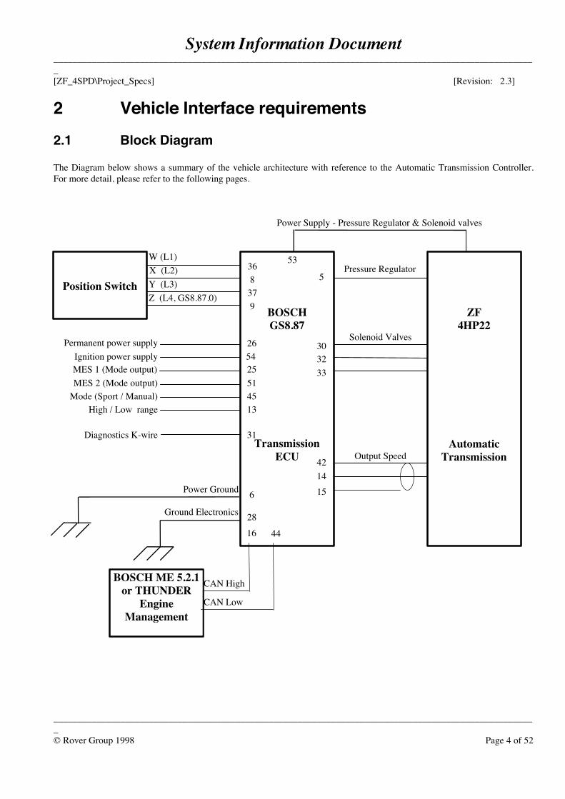
The Diagram below shows a summary of the vehicle architecture with reference to the Automatic Transmission Controller.For more detail, please refer to the following pages.
CAN Low
BOSCHGS8.87
TransmissionECU
ZF4HP22
AutomaticTransmission
Position Switch
BOSCH ME 5.2.1or THUNDER
EngineManagement
Pressure Regulator
Solenoid Valves
Output Speed
9Z (L4, GS8.87.0)
W (L1)
Y (L3)X (L2)
151442
5
333230
378
36
16 44
2654
Permanent power supplyIgnition power supply
High / Low range
MES 2 (Mode output)Mode (Sport / Manual)
514513
Power Supply - Pressure Regulator & Solenoid valves
53
28
6Power Ground
Ground Electronics
Diagnostics K-wire 31
CAN High
MES 1 (Mode output) 25

System Information Document_____________________________________________________________________________________________________[ZF_4SPD\Project_Specs] [Revision: 2.3]
_____________________________________________________________________________________________________© Rover Group 1998 Page 5 of 52
2.2 Interface specification
2.2.1 Gear Shift Solenoids2.2.1.1 Pin 5 - Pressure regulatorThe purpose of the Pressure regulator is to generate modulation pressure for the gearbox clutches. Thepressure regulator is mounted between the common output supply (pin 53) and pin 6. It is driven by apulse width modulated power signal that is generated and regulated in the CG202 ASIC.+The pulse width modulated signal frequency f0 is generated permanently; the free running duty cyclecorresponds to the minimal current and the maximal modulation pressure
- Component- Type 2/2-way relief jet with falling characteristic line; the control edge
is closed when the valve is without power supply.- Coil resistance R 5.5Ω +/- 6% @20°C- I_max 700mA mean value- I_min 150mA mean value- Chopper frequency 1000Hz +/- 50Hz @ +25°C
- Control Unit- Interface characteristic current regulated, chopped output stage, pulse width modulated.- Current range 145mA <= I_min <=175mA @ +25°C- Currrent range 680mA <=I_max <=720mA @ +25°C- Reference point Pin 6 (power ground- Recommended wire size: 1.0mm2
The ASIC status output is fed back to the processor for diagnostic purposes. See the diagnosticspecification for details.
2.2.1.2 Pin 30 (MV1), 32 (MV3, lockup), 33 (MV2) - Solenoid valves 1,2 and 3The purpose of solenoid valves 1 and 2 is to switch the hydraulic valves and thus control the hydrauliclogic for gear selection. Solenoid valve 3 is to lock the torque converter.
The solenoid valves are mounted between the common output plus supply (pin 53) and theircorresponding control pin. The solenoid valves are activated if the output control pins are drawn toground.
- Component- Type 3/2-way valves, inlet closed without power supply- Coil resistance R20 = 32.5Ω +/- 2Ω- Operating voltage range 9.5V <=U<=14V- Drop off current I<30mA @ P-o = 4.5 bar +/- 0.1 bar- Temperature range -30°C to +150°C under test conditions
System Information Document_____________________________________________________________________________________________________[ZF_4SPD\Project_Specs] [Revision: 2.3]
_____________________________________________________________________________________________________© Rover Group 1998 Page 6 of 52
- Control unit- Interface characteristic Power output- Output voltage low U_sat <=1V at I=1A- Reference point Pin 6 (power ground)- Recommended wire size: 1.0mm2
The output voltages of Pin30, Pin32 and Pin33 are fed back over a resistor network to the processor fordiagnostic purposes. During initialisation and operation the output signal is toggled periodically for ashort time in order to enhance the diagnosis of the outputs.
2.2.1.3 Pin 53 - Power supply to Pressure regulatorWhen an ignition supply is available at the controller, pin 53 is a permanent power supply to the pressureregulator and the solenoid valves. This power supply can be switched off with hardware and software inthe event of a failure in the transmission electrical system.
- Recommended wire size: 1.5mm2
2.2.2 Controller power supply2.2.2.1 Pin 6 - Power groundPermanent connection from the ECU to 0V. This is used for driving the Solenoid valves and the Pressureregulator.
- Recommended wire size: 1.5mm2
2.2.2.2 Pin 28 - Electronics groundPermanent connection from the ECU to 0V. This is used for driving the electronics within the controller.
- Recommended wire size: 1.5mm2
2.2.2.3 Pin 26 - Permanent ignition supplyPermanent connection to 12V required. This is essential in order to allow storage of data for adaptivepressure control.
- Recommended wire size: 0.5mm2
2.2.2.4 Pin 54 - Ignition supplyConnection to +12V when the igntion is switch on. This is the main feed to the controller, allowing thetransmission system to operate. It is essential that this supply is switch on at exactly the same time theengine management system receives an ignition supply. This is to ensure serial communications can beestablished between the two controllers.
System Information Document_____________________________________________________________________________________________________[ZF_4SPD\Project_Specs] [Revision: 2.3]
_____________________________________________________________________________________________________© Rover Group 1998 Page 7 of 52
If the battery supply is different from that expected, the following details the functionality of thetransmission controller:
Voltage System behaviour
16.0 - 26.0 Jump start; excess voltage without damage, limphome mode, output stanges forsolenoid valves and pressure regulator switched off (max 1min at 40°C).
9.0 - 16.0 Voltage range for normal operation of the EAT with CAN-Bus corresponding to thespecification.
6.5 - 9.0 Operation of the EAT with diagnostic functions and CAN-Bus enabled, limp homemode, output stages for solenoid valves and pressure regulator switched off.
3.0 - 6.5 Under voltage with data retention in SRAM, limp home mode, unreliablecommunication over the CAN bus.
0 - 3.0 Undervoltage without reliable function-14 - 0 Reversed polarity without damage (-14V max 1 min at 25°C)
- Recommended wire size: 1.5mm2
2.2.3 Serial information - inputs2.2.3.1 Pins 16 and 44 - CAN information from Engnine management systemBoth Discovery Series II and 99MY Range Rover vehicles use a CAN specification owned by ZF calledCAN 22H. This communication protocol operates at 500kBit/sec. Both the engine management systemand the transmission controller should be fitted with 120Ω terminating resistors. For more informationon the CAN bus, please refer to the CAN specification.
2.2.4 Serial information – outputs2.2.4.1 Pins 16 and 44 - CAN information sent to Engine Management systemSee section the relevant section - CAN information from the Engine management system.
2.2.5 Digital inputs2.2.5.1 Pins 8, 9, 36, 37 - Position switchThe position switch is the electrical input to the Transmission ECU regarding the drivers requested gear.It is not however, exactly the same as the gear which the Transmission may have selected. Thetransmission assumes a new selector position has been selected after it has recognised a stable input /code from the position switch lines for a filter time TPO_FILT.
System Information Document_____________________________________________________________________________________________________[ZF_4SPD\Project_Specs] [Revision: 2.3]
_____________________________________________________________________________________________________© Rover Group 1998 Page 8 of 52
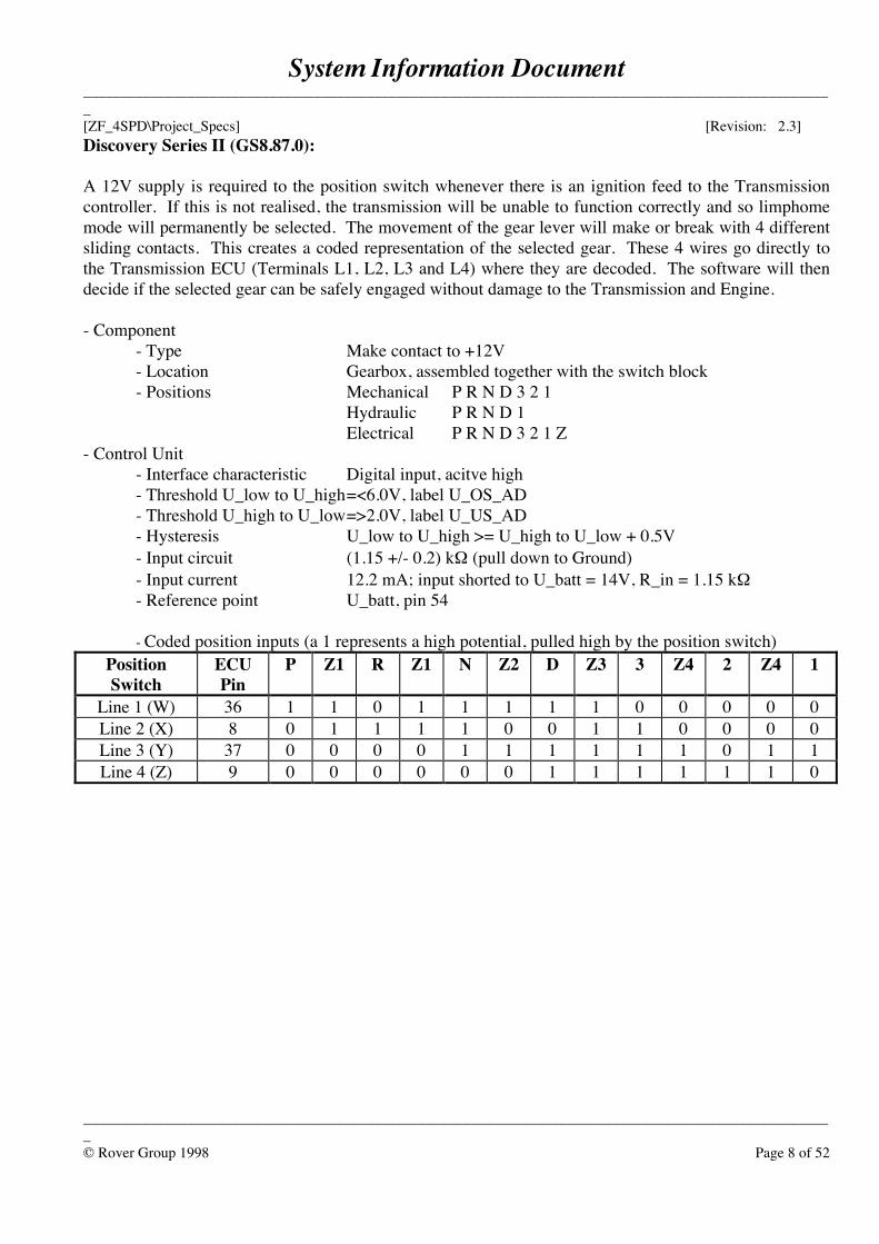
Discovery Series II (GS8.87.0):
A 12V supply is required to the position switch whenever there is an ignition feed to the Transmissioncontroller. If this is not realised, the transmission will be unable to function correctly and so limphomemode will permanently be selected. The movement of the gear lever will make or break with 4 differentsliding contacts. This creates a coded representation of the selected gear. These 4 wires go directly tothe Transmission ECU (Terminals L1, L2, L3 and L4) where they are decoded. The software will thendecide if the selected gear can be safely engaged without damage to the Transmission and Engine.
- Component- Type Make contact to +12V- Location Gearbox, assembled together with the switch block- Positions Mechanical P R N D 3 2 1
Hydraulic P R N D 1Electrical P R N D 3 2 1 Z
- Control Unit- Interface characteristic Digital input, acitve high- Threshold U_low to U_high=<6.0V, label U_OS_AD- Threshold U_high to U_low=>2.0V, label U_US_AD- Hysteresis U_low to U_high >= U_high to U_low + 0.5V- Input circuit (1.15 +/- 0.2) kΩ (pull down to Ground)- Input current 12.2 mA; input shorted to U_batt = 14V, R_in = 1.15 kΩ- Reference point U_batt, pin 54
- Coded position inputs (a 1 represents a high potential, pulled high by the position switch)PositionSwitch
ECUPin
P Z1 R Z1 N Z2 D Z3 3 Z4 2 Z4 1
Line 1 (W) 36 1 1 0 1 1 1 1 1 0 0 0 0 0Line 2 (X) 8 0 1 1 1 1 0 0 1 1 0 0 0 0Line 3 (Y) 37 0 0 0 0 1 1 1 1 1 1 0 1 1Line 4 (Z) 9 0 0 0 0 0 0 1 1 1 1 1 1 0
System Information Document_____________________________________________________________________________________________________[ZF_4SPD\Project_Specs] [Revision: 2.3]
_____________________________________________________________________________________________________© Rover Group 1998 Page 9 of 52
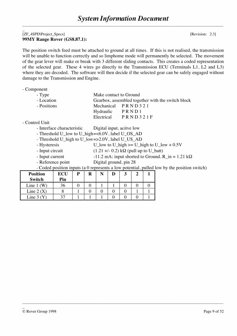
99MY Range Rover (GS8.87.1):
The position switch feed must be attached to ground at all times. If this is not realised, the transmissionwill be unable to function correctly and so limphome mode will permanently be selected. The movementof the gear lever will make or break with 3 different sliding contacts. This creates a coded representationof the selected gear. These 4 wires go directly to the Transmission ECU (Terminals L1, L2 and L3)where they are decoded. The software will then decide if the selected gear can be safely engaged withoutdamage to the Transmission and Engine.
- Component- Type Make contact to Ground- Location Gearbox, assembled together with the switch block- Positions Mechanical P R N D 3 2 1
Hydraulic P R N D 1Electrical P R N D 3 2 1 F
- Control Unit- Interface characteristic Digital input, acitve low- Threshold U_low to U_high=<6.0V, label U_OS_AD- Threshold U_high to U_low=>2.0V, label U_US_AD- Hysteresis U_low to U_high >= U_high to U_low + 0.5V- Input circuit (1.21 +/- 0.2) kΩ (pull up to U_batt)- Input current -11.2 mA; input shorted to Ground, R_in = 1.21 kΩ- Reference point Digital ground, pin 28- Coded position inputs (a 0 represents a low potential, pulled low by the position switch)
PositionSwitch
ECUPin
P R N D 3 2 1
Line 1 (W) 36 0 0 1 1 0 0 0Line 2 (X) 8 1 0 0 0 0 1 1Line 3 (Y) 37 1 1 1 0 0 0 1
System Information Document_____________________________________________________________________________________________________[ZF_4SPD\Project_Specs] [Revision: 2.3]
_____________________________________________________________________________________________________© Rover Group 1998 Page 10 of 52
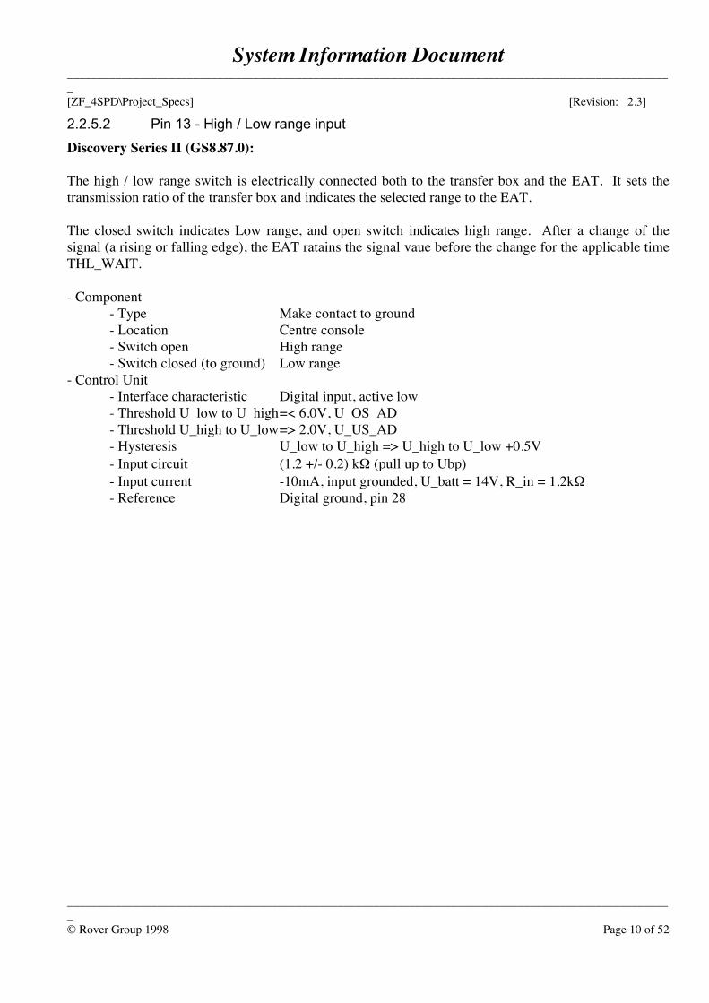
2.2.5.2 Pin 13 - High / Low range input
Discovery Series II (GS8.87.0):
The high / low range switch is electrically connected both to the transfer box and the EAT. It sets thetransmission ratio of the transfer box and indicates the selected range to the EAT.
The closed switch indicates Low range, and open switch indicates high range. After a change of thesignal (a rising or falling edge), the EAT ratains the signal vaue before the change for the applicable timeTHL_WAIT.
- Component- Type Make contact to ground- Location Centre console- Switch open High range- Switch closed (to ground) Low range
- Control Unit- Interface characteristic Digital input, active low- Threshold U_low to U_high=< 6.0V, U_OS_AD- Threshold U_high to U_low=> 2.0V, U_US_AD- Hysteresis U_low to U_high => U_high to U_low +0.5V- Input circuit (1.2 +/- 0.2) kΩ (pull up to Ubp)- Input current -10mA, input grounded, U_batt = 14V, R_in = 1.2kΩ- Reference Digital ground, pin 28
System Information Document_____________________________________________________________________________________________________[ZF_4SPD\Project_Specs] [Revision: 2.3]
_____________________________________________________________________________________________________© Rover Group 1998 Page 11 of 52
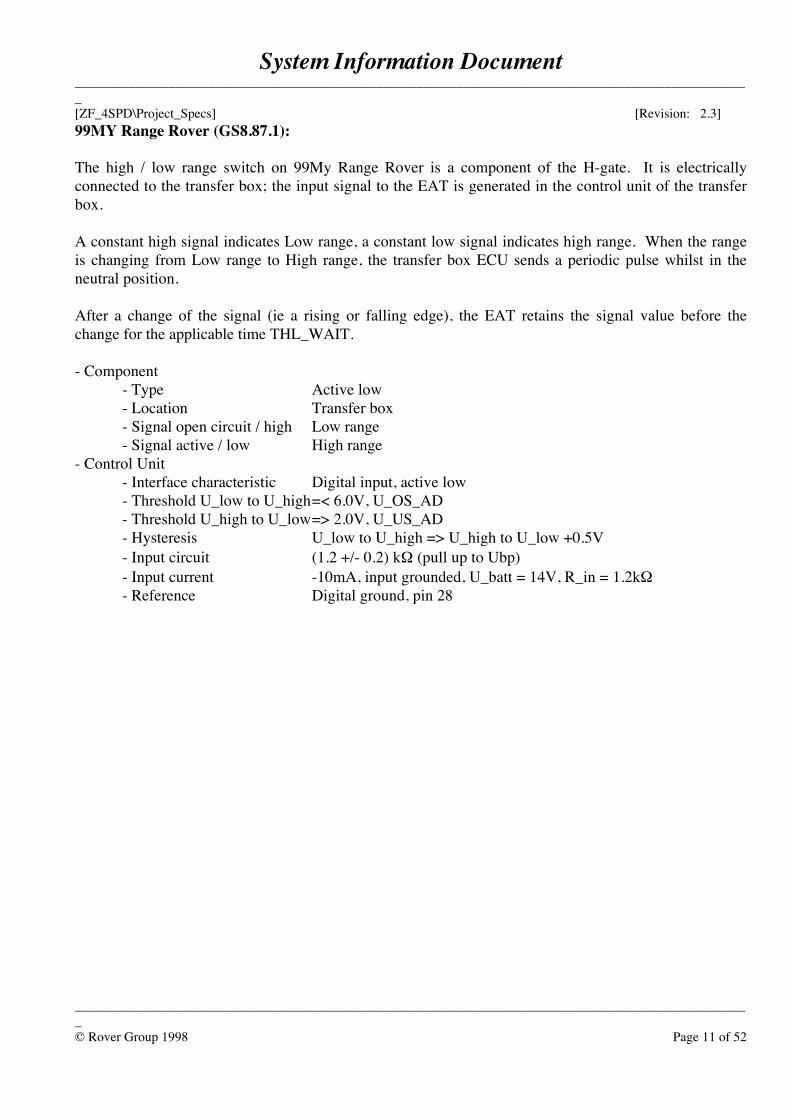
99MY Range Rover (GS8.87.1):
The high / low range switch on 99My Range Rover is a component of the H-gate. It is electricallyconnected to the transfer box; the input signal to the EAT is generated in the control unit of the transferbox.
A constant high signal indicates Low range, a constant low signal indicates high range. When the rangeis changing from Low range to High range, the transfer box ECU sends a periodic pulse whilst in theneutral position.
After a change of the signal (ie a rising or falling edge), the EAT retains the signal value before thechange for the applicable time THL_WAIT.
- Component- Type Active low- Location Transfer box- Signal open circuit / high Low range- Signal active / low High range
- Control Unit- Interface characteristic Digital input, active low- Threshold U_low to U_high=< 6.0V, U_OS_AD- Threshold U_high to U_low=> 2.0V, U_US_AD- Hysteresis U_low to U_high => U_high to U_low +0.5V- Input circuit (1.2 +/- 0.2) kΩ (pull up to Ubp)- Input current -10mA, input grounded, U_batt = 14V, R_in = 1.2kΩ- Reference Digital ground, pin 28
System Information Document_____________________________________________________________________________________________________[ZF_4SPD\Project_Specs] [Revision: 2.3]
_____________________________________________________________________________________________________© Rover Group 1998 Page 12 of 52
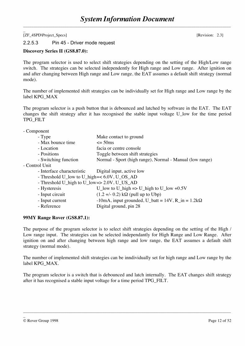
2.2.5.3 Pin 45 - Driver mode request
Discovery Series II (GS8.87.0):
The program selector is used to select shift strategies depending on the setting of the High/Low rangeswitch. The strategies can be selected independently for High range and Low range. After ignition onand after changing between High range and Low range, the EAT assumes a default shift strategy (normalmode).
The number of implemented shift strategies can be individually set for High range and Low range by thelabel KPG_MAX
The program selector is a push button that is debounced and latched by software in the EAT. The EATchanges the shift strategy after it has recognised the stable input voltage U_low for the time periodTPG_FILT
- Component- Type Make contact to ground- Max bounce time <= 50ms- Location facia or centre console- Positions Toggle between shift strategies- Switching function Normal - Sport (high range), Normal - Manual (low range)
- Control Unit- Interface characteristic Digital input, active low- Threshold U_low to U_high=< 6.0V, U_OS_AD- Threshold U_high to U_low=> 2.0V, U_US_AD- Hysteresis U_low to U_high => U_high to U_low +0.5V- Input circuit (1.2 +/- 0.2) kΩ (pull up to Ubp)- Input current -10mA, input grounded, U_batt = 14V, R_in = 1.2kΩ- Reference Digital ground, pin 28
99MY Range Rover (GS8.87.1):
The purpose of the program selector is to select shift strategies depending on the setting of the High /Low range input. The strategies can be selected independantly for High Range and Low Range. Afterignition on and after changing between high range and low range, the EAT assumes a default shiftstrategy (normal mode).
The number of implemented shift strategies can be inndividually set for high range and Low range by thelabel KPG_MAX.
The program selector is a switch that is debounced and latch internally. The EAT changes shift strategyafter it has recognised a stable input voltage for a time period TPG_FILT.
System Information Document_____________________________________________________________________________________________________[ZF_4SPD\Project_Specs] [Revision: 2.3]
_____________________________________________________________________________________________________© Rover Group 1998 Page 13 of 52
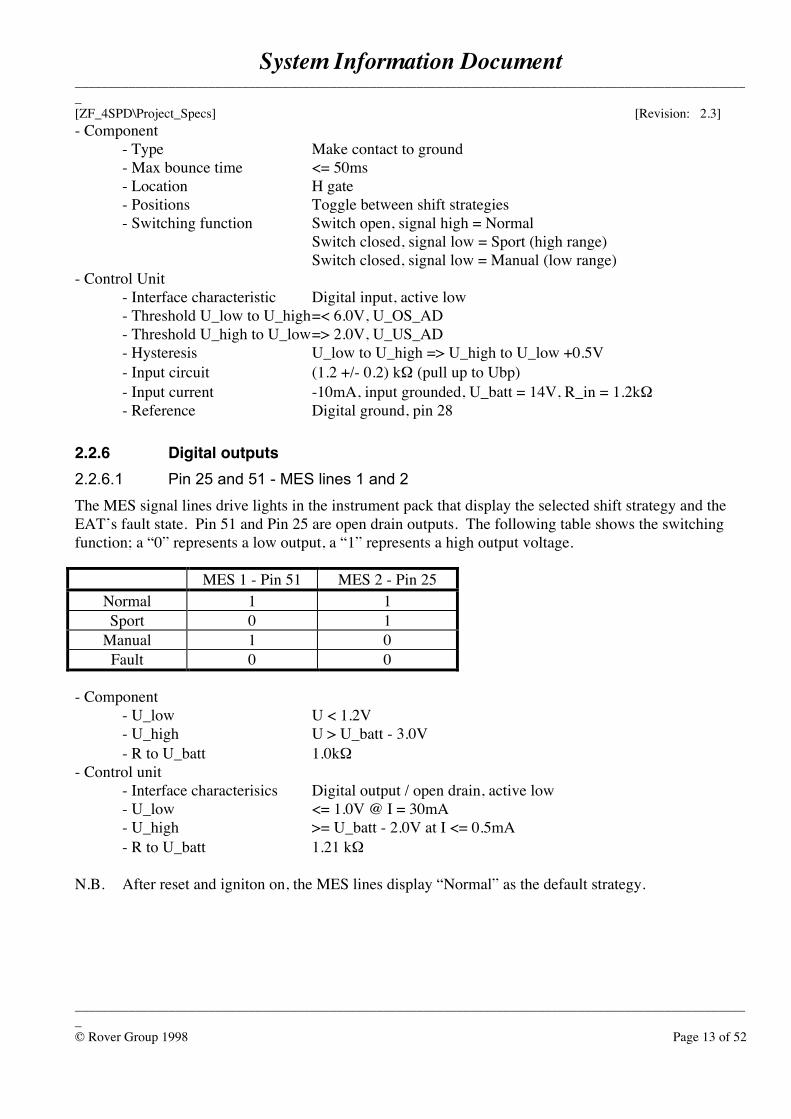
- Component- Type Make contact to ground- Max bounce time <= 50ms- Location H gate- Positions Toggle between shift strategies- Switching function Switch open, signal high = Normal
Switch closed, signal low = Sport (high range)Switch closed, signal low = Manual (low range)
- Control Unit- Interface characteristic Digital input, active low- Threshold U_low to U_high=< 6.0V, U_OS_AD- Threshold U_high to U_low=> 2.0V, U_US_AD- Hysteresis U_low to U_high => U_high to U_low +0.5V- Input circuit (1.2 +/- 0.2) kΩ (pull up to Ubp)- Input current -10mA, input grounded, U_batt = 14V, R_in = 1.2kΩ- Reference Digital ground, pin 28
2.2.6 Digital outputs2.2.6.1 Pin 25 and 51 - MES lines 1 and 2The MES signal lines drive lights in the instrument pack that display the selected shift strategy and theEAT’s fault state. Pin 51 and Pin 25 are open drain outputs. The following table shows the switchingfunction; a “0” represents a low output, a “1” represents a high output voltage.
MES 1 - Pin 51 MES 2 - Pin 25Normal 1 1Sport 0 1
Manual 1 0Fault 0 0
- Component- U_low U < 1.2V- U_high U > U_batt - 3.0V- R to U_batt 1.0kΩ
- Control unit- Interface characterisics Digital output / open drain, active low- U_low <= 1.0V @ I = 30mA- U_high >= U_batt - 2.0V at I <= 0.5mA- R to U_batt 1.21 kΩ
N.B. After reset and igniton on, the MES lines display “Normal” as the default strategy.
System Information Document_____________________________________________________________________________________________________[ZF_4SPD\Project_Specs] [Revision: 2.3]
_____________________________________________________________________________________________________© Rover Group 1998 Page 14 of 52
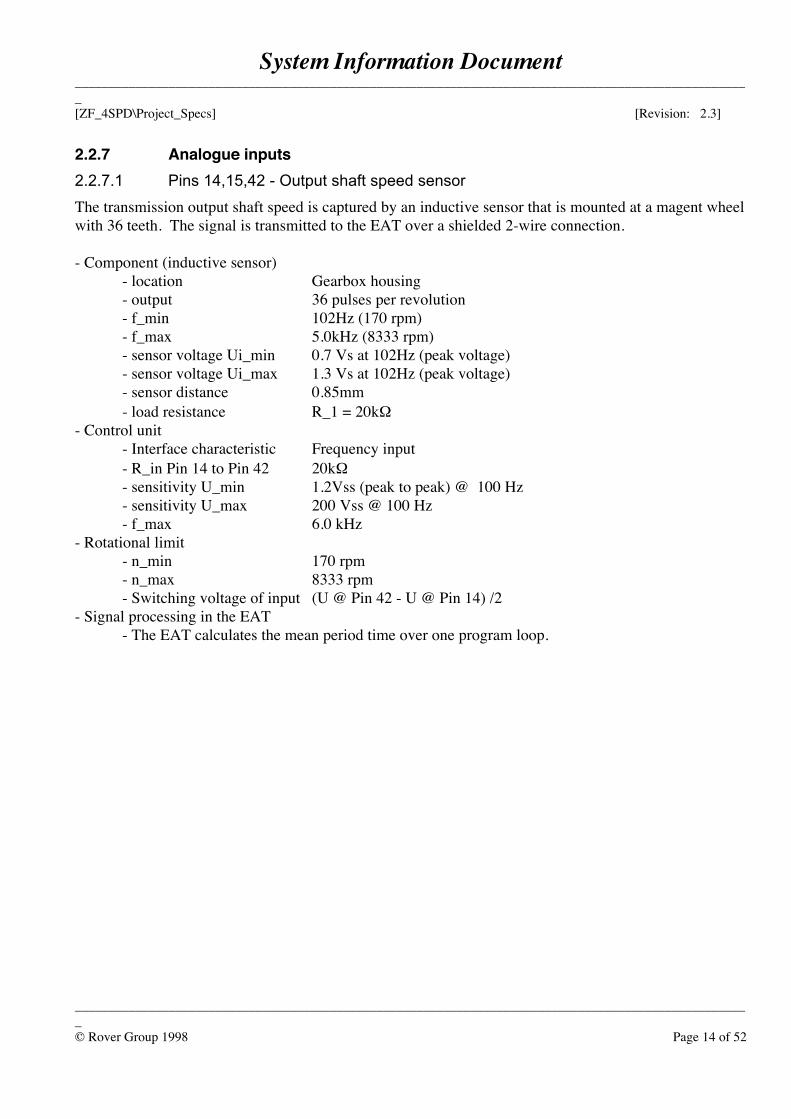
2.2.7 Analogue inputs2.2.7.1 Pins 14,15,42 - Output shaft speed sensorThe transmission output shaft speed is captured by an inductive sensor that is mounted at a magent wheelwith 36 teeth. The signal is transmitted to the EAT over a shielded 2-wire connection.
- Component (inductive sensor)- location Gearbox housing- output 36 pulses per revolution- f_min 102Hz (170 rpm)- f_max 5.0kHz (8333 rpm)- sensor voltage Ui_min 0.7 Vs at 102Hz (peak voltage)- sensor voltage Ui_max 1.3 Vs at 102Hz (peak voltage)- sensor distance 0.85mm- load resistance R_1 = 20kΩ
- Control unit- Interface characteristic Frequency input- R_in Pin 14 to Pin 42 20kΩ- sensitivity U_min 1.2Vss (peak to peak) @ 100 Hz- sensitivity U_max 200 Vss @ 100 Hz- f_max 6.0 kHz
- Rotational limit- n_min 170 rpm- n_max 8333 rpm- Switching voltage of input (U @ Pin 42 - U @ Pin 14) /2
- Signal processing in the EAT- The EAT calculates the mean period time over one program loop.
System Information Document_____________________________________________________________________________________________________[ZF_4SPD\Project_Specs] [Revision: 2.3]
_____________________________________________________________________________________________________© Rover Group 1998 Page 15 of 52
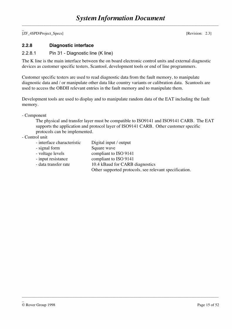
2.2.8 Diagnostic interface2.2.8.1 Pin 31 - Diagnostic line (K line)The K line is the main interface between the on board electronic control units and external diagnosticdevices as customer specific testers, Scantool, development tools or end of line programmers.
Customer specific testers are used to read diagnostic data from the fault memory, to manipulatediagnostic data and / or manipulate other data like country variants or calibration data. Scantools areused to access the OBDII relevant entries in the fault memory and to manipulate them.
Development tools are used to display and to manipulate random data of the EAT including the faultmemory.
- ComponentThe physical and transfer layer must be compatible to ISO9141 and ISO9141 CARB. The EAT supports the application and protocol layer of ISO9141 CARB. Other customer specific protocols can be implemented.
- Control unit- interface characteristic Digital input / output- signal form Square wave- voltage levels compliant to ISO 9141- input resistance compliant to ISO 9141- data transfer rate 10.4 kBaud for CARB diagnostics
Other supported protocols, see relevant specification.
System Information Document_____________________________________________________________________________________________________[ZF_4SPD\Project_Specs] [Revision: 2.3]
_____________________________________________________________________________________________________© Rover Group 1998 Page 16 of 52
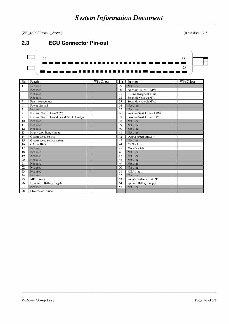
2.3 ECU Connector Pin-out
Pin Function Wire Colour Pin Function Wire Colour1 Not used 29 Not used2 Not used 30 Solenoid Valve 1; MV13 Not used 31 K Line (Diagnostic line)4 Not used 32 Solenoid valve 3; MV35 Pressure regulator 33 Solenoid valve 2; MV26 Power Ground 34 Not used7 Not used 35 Not used8 Position Switch Line 2 (X) 36 Position Switch Line 1 (W)9 Position Switch Line 4 (Z) (GS8.87.0 only) 37 Position Switch Line 3 (Y)10 Not used 38 Not used11 Not used 39 Not used12 Not used 40 Not used13 High / Low Range Input 41 Not used14 Output speed sensor - 42 Output speed sensor +15 Output speed sensor screen 43 Not used16 CAN – High 44 CAN – Low17 Not used 45 Mode Switch18 Not used 46 Not used19 Not used 47 Not used20 Not used 48 Not used21 Not used 49 Not used22 Not used 50 Not used23 Not used 51 MES Line 124 Not used 52 Not used25 MES Line 2 53 Supply, Solenoids & PR26 Permanent Battery Supply 54 Ignition Battery Supply27 Not used 55 Not used28 Electronic Ground
1 28
29 55
System Information Document_____________________________________________________________________________________________________[ZF_4SPD\Project_Specs] [Revision: 2.3]
_____________________________________________________________________________________________________© Rover Group 1998 Page 17 of 52
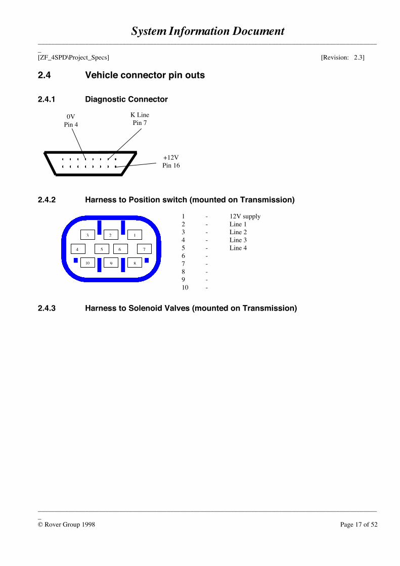
2.4 Vehicle connector pin outs
2.4.1 Diagnostic Connector
2.4.2 Harness to Position switch (mounted on Transmission)
1 - 12V supply2 - Line 13 - Line 24 - Line 35 - Line 46 -7 -8 -9 -10 -
2.4.3 Harness to Solenoid Valves (mounted on Transmission)
0VPin 4
+12VPin 16
K LinePin 7
5 6
123
10 8
4
9
7
System Information Document_____________________________________________________________________________________________________[ZF_4SPD\Project_Specs] [Revision: 2.3]
_____________________________________________________________________________________________________© Rover Group 1998 Page 18 of 52
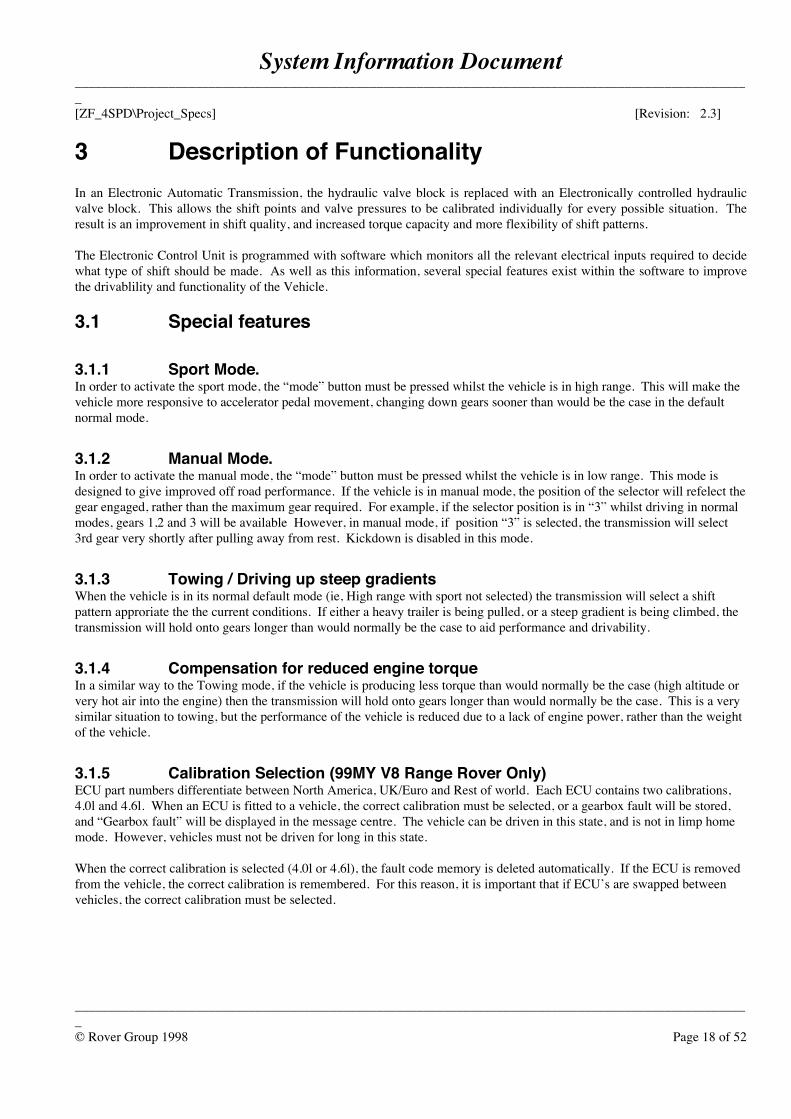
3 Description of FunctionalityIn an Electronic Automatic Transmission, the hydraulic valve block is replaced with an Electronically controlled hydraulicvalve block. This allows the shift points and valve pressures to be calibrated individually for every possible situation. Theresult is an improvement in shift quality, and increased torque capacity and more flexibility of shift patterns.
The Electronic Control Unit is programmed with software which monitors all the relevant electrical inputs required to decidewhat type of shift should be made. As well as this information, several special features exist within the software to improvethe drivablility and functionality of the Vehicle.
3.1 Special features
3.1.1 Sport Mode.In order to activate the sport mode, the “mode” button must be pressed whilst the vehicle is in high range. This will make thevehicle more responsive to accelerator pedal movement, changing down gears sooner than would be the case in the defaultnormal mode.
3.1.2 Manual Mode.In order to activate the manual mode, the “mode” button must be pressed whilst the vehicle is in low range. This mode isdesigned to give improved off road performance. If the vehicle is in manual mode, the position of the selector will refelect thegear engaged, rather than the maximum gear required. For example, if the selector position is in “3” whilst driving in normalmodes, gears 1,2 and 3 will be available However, in manual mode, if position “3” is selected, the transmission will select3rd gear very shortly after pulling away from rest. Kickdown is disabled in this mode.
3.1.3 Towing / Driving up steep gradientsWhen the vehicle is in its normal default mode (ie, High range with sport not selected) the transmission will select a shiftpattern approriate the the current conditions. If either a heavy trailer is being pulled, or a steep gradient is being climbed, thetransmission will hold onto gears longer than would normally be the case to aid performance and drivability.
3.1.4 Compensation for reduced engine torqueIn a similar way to the Towing mode, if the vehicle is producing less torque than would normally be the case (high altitude orvery hot air into the engine) then the transmission will hold onto gears longer than would normally be the case. This is a verysimilar situation to towing, but the performance of the vehicle is reduced due to a lack of engine power, rather than the weightof the vehicle.
3.1.5 Calibration Selection (99MY V8 Range Rover Only)ECU part numbers differentiate between North America, UK/Euro and Rest of world. Each ECU contains two calibrations,4.0l and 4.6l. When an ECU is fitted to a vehicle, the correct calibration must be selected, or a gearbox fault will be stored,and “Gearbox fault” will be displayed in the message centre. The vehicle can be driven in this state, and is not in limp homemode. However, vehicles must not be driven for long in this state.
When the correct calibration is selected (4.0l or 4.6l), the fault code memory is deleted automatically. If the ECU is removedfrom the vehicle, the correct calibration is remembered. For this reason, it is important that if ECU’s are swapped betweenvehicles, the correct calibration must be selected.
System Information Document_____________________________________________________________________________________________________[ZF_4SPD\Project_Specs] [Revision: 2.3]
_____________________________________________________________________________________________________© Rover Group 1998 Page 19 of 52
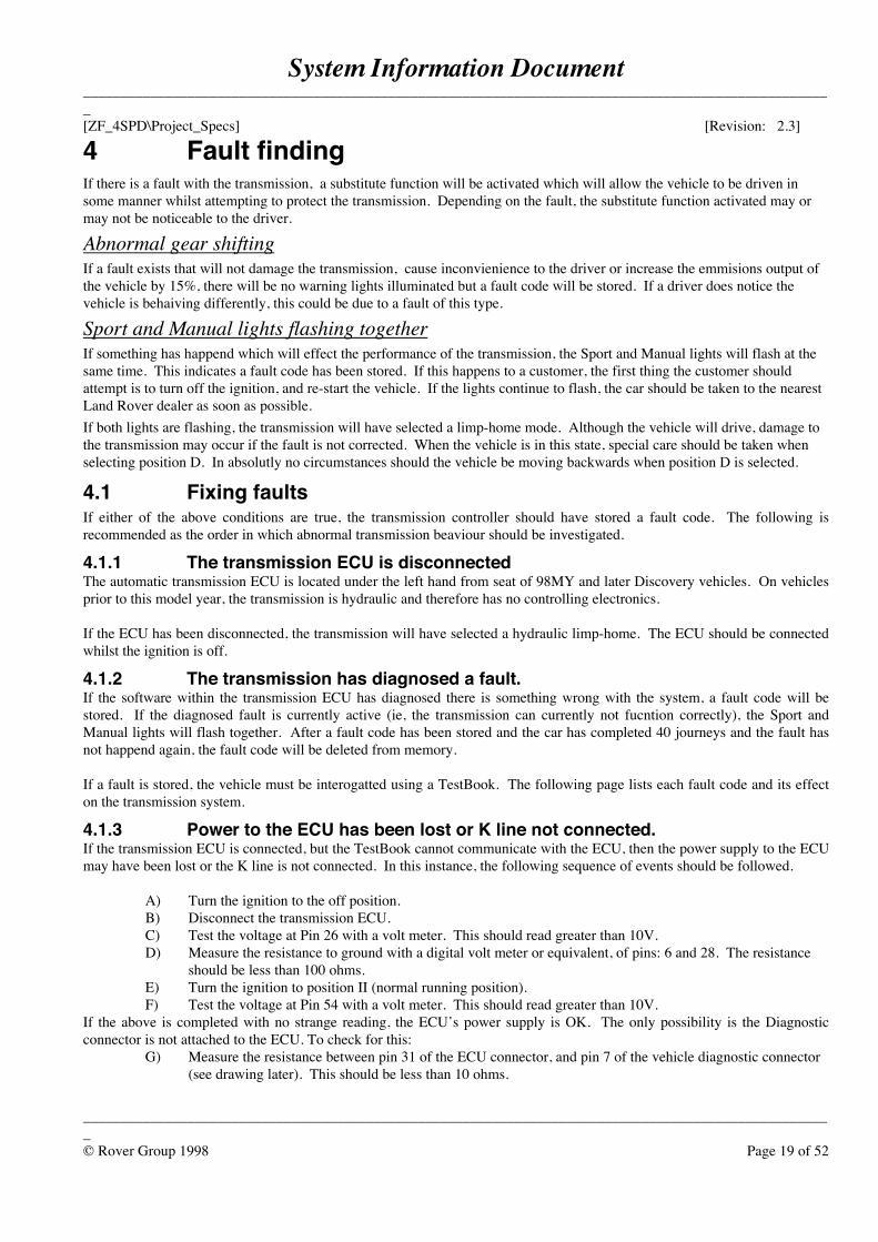
4 Fault findingIf there is a fault with the transmission, a substitute function will be activated which will allow the vehicle to be driven insome manner whilst attempting to protect the transmission. Depending on the fault, the substitute function activated may ormay not be noticeable to the driver.
Abnormal gear shiftingIf a fault exists that will not damage the transmission, cause inconvienience to the driver or increase the emmisions output ofthe vehicle by 15%, there will be no warning lights illuminated but a fault code will be stored. If a driver does notice thevehicle is behaiving differently, this could be due to a fault of this type.
Sport and Manual lights flashing togetherIf something has happend which will effect the performance of the transmission, the Sport and Manual lights will flash at thesame time. This indicates a fault code has been stored. If this happens to a customer, the first thing the customer shouldattempt is to turn off the ignition, and re-start the vehicle. If the lights continue to flash, the car should be taken to the nearestLand Rover dealer as soon as possible.If both lights are flashing, the transmission will have selected a limp-home mode. Although the vehicle will drive, damage tothe transmission may occur if the fault is not corrected. When the vehicle is in this state, special care should be taken whenselecting position D. In absolutly no circumstances should the vehicle be moving backwards when position D is selected.
4.1 Fixing faultsIf either of the above conditions are true, the transmission controller should have stored a fault code. The following isrecommended as the order in which abnormal transmission beaviour should be investigated.
4.1.1 The transmission ECU is disconnected The automatic transmission ECU is located under the left hand from seat of 98MY and later Discovery vehicles. On vehiclesprior to this model year, the transmission is hydraulic and therefore has no controlling electronics. If the ECU has been disconnected, the transmission will have selected a hydraulic limp-home. The ECU should be connectedwhilst the ignition is off.
4.1.2 The transmission has diagnosed a fault. If the software within the transmission ECU has diagnosed there is something wrong with the system, a fault code will bestored. If the diagnosed fault is currently active (ie, the transmission can currently not fucntion correctly), the Sport andManual lights will flash together. After a fault code has been stored and the car has completed 40 journeys and the fault hasnot happend again, the fault code will be deleted from memory. If a fault is stored, the vehicle must be interogatted using a TestBook. The following page lists each fault code and its effecton the transmission system.
4.1.3 Power to the ECU has been lost or K line not connected.If the transmission ECU is connected, but the TestBook cannot communicate with the ECU, then the power supply to the ECUmay have been lost or the K line is not connected. In this instance, the following sequence of events should be followed.
A) Turn the ignition to the off position.B) Disconnect the transmission ECU.C) Test the voltage at Pin 26 with a volt meter. This should read greater than 10V.D) Measure the resistance to ground with a digital volt meter or equivalent, of pins: 6 and 28. The resistance
should be less than 100 ohms.E) Turn the ignition to position II (normal running position).F) Test the voltage at Pin 54 with a volt meter. This should read greater than 10V.
If the above is completed with no strange reading, the ECU’s power supply is OK. The only possibility is the Diagnosticconnector is not attached to the ECU. To check for this:
G) Measure the resistance between pin 31 of the ECU connector, and pin 7 of the vehicle diagnostic connector (see drawing later). This should be less than 10 ohms.
System Information Document_____________________________________________________________________________________________________[ZF_4SPD\Project_Specs] [Revision: 2.3]
_____________________________________________________________________________________________________© Rover Group 1998 Page 20 of 52
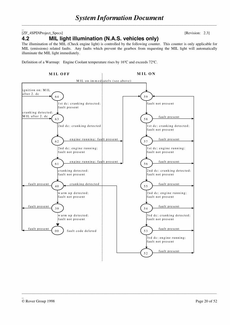
4.2 MIL light illumination (N.A.S. vehicles only)The illumination of the MIL (Check engine light) is controlled by the following counter. This counter is only applicable forMIL (emissions) related faults. Any faults which prevent the gearbox from requesting the MIL light will automaticallyilluminate the MIL light immediately.
Definition of a Warmup: Engine Coolant temperature rises by 16ºC and exceeds 72ºC.
1 s t d c ; c r a n k i n g d e t e c t e d ;f a u l t p r e s e n t
2 n d d c ; c r a n k i n g d e t e c t e d
2 n d d c ; en g i n e r u n n i n g ;f a u l t n o t p r e s e n t
c r a n k i n g d e t e c t e d ;f a u l t n o t p r e s e n t
6 4
6 3
6 1
6 2
4 0
3 9
0 0
5 9
5 8
5 7
5 6
5 5
5 4
5 3
5 2
w a r m u p d e t ec t ed ;f a u l t n o t p r e s e n t
w a r m u p d e t ec t ed ;f a u l t n o t p r e s e n t
e n g in e r u n n in g ; fau l t p r e s e n t
e n g in e r u n n in g ; fau l t p r e s e n t
f a u l t n o t p r e s e n t
1 s t d c ; c r a n k i n g d e t e c t e d ;f a u l t n o t p r e s e n t
1 s t d c ; e n g i n e r u n n i n g ;f a u l t n o t p r e s e n t
2 n d d c ; c r a n k i n g d e t ec t ed ;f a u l t n o t p r e s e n t
2 n d d c ; en g i n e r u n n i n g ;f a u l t n o t p r e s e n t
3 r d d c ; c r a n k i n g d e t ec t ed ;f a u l t n o t p r e s e n t
3 r d d c ; en g i n e r u n n i n g ;f a u l t n o t p r e s e n t
f a u l t p r e s e n t
f a u l t p r e s e n t
f a u l t p r e s e n t
f a u l t p r e s e n t
f a u l t p r e s e n t
f a u l t p r e s e n t
f a u l t p r e s e n t
f a u l t p r e s e n t
c r a n k i n g d e t e c t e d ;M I L a f t e r 2 . d c
i g n i t i o n o n ; M I La f t e r 2 . d c
M I L o n im m e d i a t e l y ( s e e a b o v e )
f a u l t p r e s e n t
f a u l t p r e s e n t
c r a n k i n g d e t e c t e d
M I L O F F M I L O N
f a u l t c o d e d e l e t e d
System Information Document_____________________________________________________________________________________________________[ZF_4SPD\Project_Specs] [Revision: 2.3]
_____________________________________________________________________________________________________© Rover Group 1998 Page 21 of 52
5 Fault codes
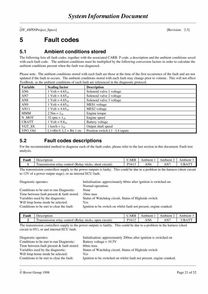
5.1 Ambient conditions storedThe following lists all fault codes, together with the associated CARB P code, a description and the ambient conditions savedwith each fault code. The ambient conditions must be multiplied by the following conversion factors in order to calculate theambient conditions present when the fault was diagnosed.
Please note. The ambient conditions stored with each fault are those at the time of the first occurrence of the fault and are notupdated if the fault re-occurs. The ambient conditions stored with each fault may change prior to volume. This will not effectTestBook, as the ambient conditions of each fault are referenced in the diagnostic protocol.
Variable Scaling factor DescriptionAN6 1 Volt = 4.6510 Solenoid valve 1 voltageAN7 1 Volt = 4.6510 Solenoid valve 2 voltageAN8 1 Volt = 4.6510 Solenoid valve 3 voltageAN9 1 Volt = 4.6510 MES1 voltageAN11 1 Volt = 4.6510 MES2 voltageMMM 2 Nm = 110 Engine torqueN_MOT 32 rpm = 110 Engine speedUBATT 1 Volt = 9.810 Battery voltageVGT_$X 1 km/h = 110 Output shaft speedYPO_Old L1=Bit 0, L2 = Bit 1 etc Position switch L1 - L4 inputs
5.2 Fault codes descriptionsFor the recommended method to diagnose each of the fault codes, please refer to the last section in this document, Fault treeanalysis.
Fault Description CARB Ambient 1 Ambient 2 Ambient 31 Transmission relay control (Relay sticks, short circuit) P1613 AN6 AN7 UBATT
The transmission controllers supply to the power outputs is faulty. This could be due to a problem in the harness (short circuitto 12V of a power output stage), or an internal ECU fault.
Diagnostic operates: Initialisation; approximately 60ms after ignition is switched on.Normal operation;
Conditions to be met to run Diagnostic: NoneTime between fault present & fault stored: 10ms maxVariables used by the diagnostic: Status of Watchdog circuit, Status of Highside switchWill limp home mode be selected: YesConditions to be met to clear the fault: Ignition to be switch on whilst fault not present, engine cranked.
Fault Description CARB Ambient 1 Ambient 2 Ambient 32 Transmission relay control (Relay sticks, open circuit) P1612 AN6 AN7 UBATT
The transmission controllers supply to the power outputs is faultly. This could be due to a problem in the harness (shortcircuit to 0V), or and internal ECU fault.
Diagnostic operates: Initialisation; approximately 200ms after ignition is switched onConditions to be met to run Diagnostic: Battery voltage > 10.5VTime between fault present & fault stored: 60ms max.Variables used by the diagnostic: Status of Watchdog circuit, Status of Highside switchWill limp home mode be selected: YesConditions to be met to clear the fault: Ignition to be switched on whilst fault not present, engine cranked.
System Information Document_____________________________________________________________________________________________________[ZF_4SPD\Project_Specs] [Revision: 2.3]
_____________________________________________________________________________________________________© Rover Group 1998 Page 22 of 52
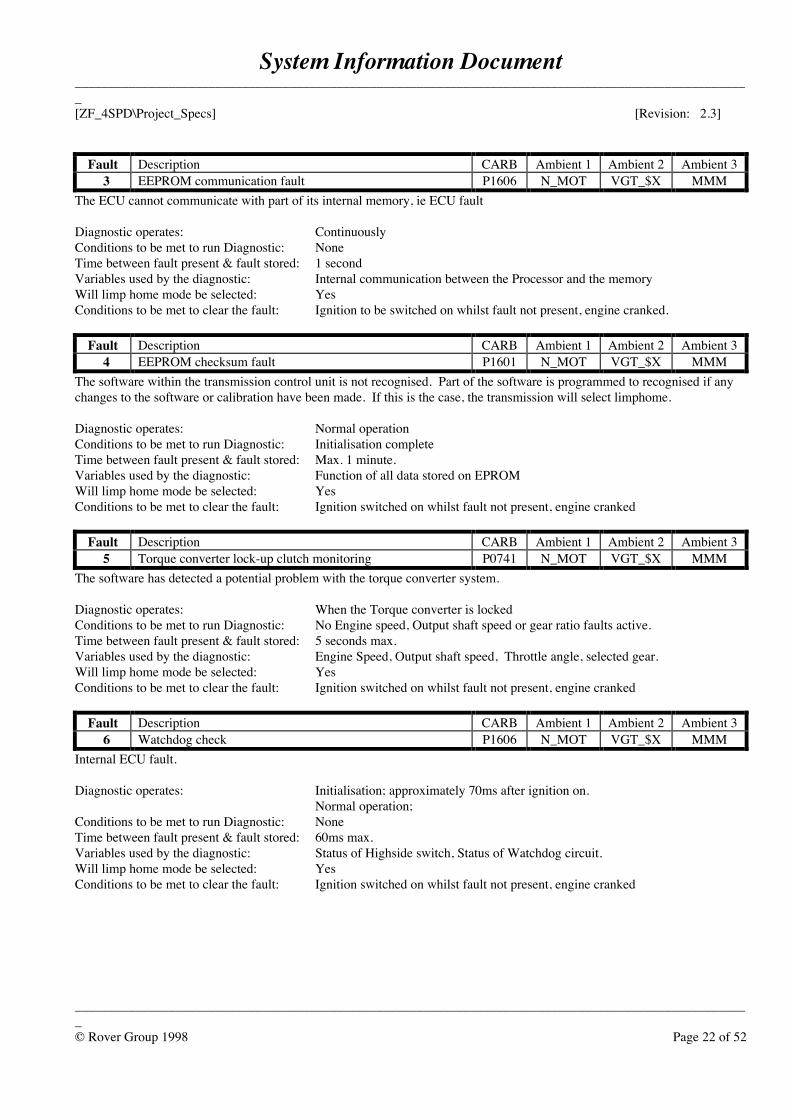
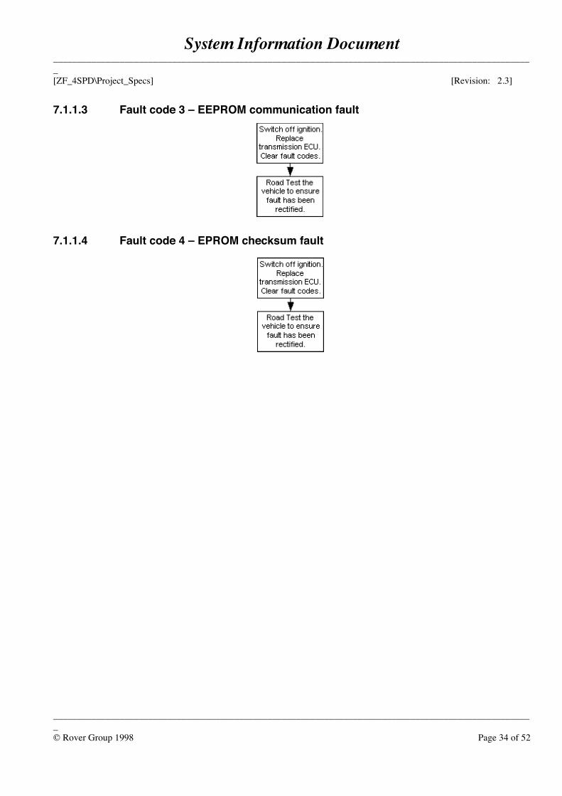
Fault Description CARB Ambient 1 Ambient 2 Ambient 33 EEPROM communication fault P1606 N_MOT VGT_$X MMM
The ECU cannot communicate with part of its internal memory, ie ECU fault
Diagnostic operates: ContinuouslyConditions to be met to run Diagnostic: NoneTime between fault present & fault stored: 1 secondVariables used by the diagnostic: Internal communication between the Processor and the memoryWill limp home mode be selected: YesConditions to be met to clear the fault: Ignition to be switched on whilst fault not present, engine cranked.
Fault Description CARB Ambient 1 Ambient 2 Ambient 34 EEPROM checksum fault P1601 N_MOT VGT_$X MMM
The software within the transmission control unit is not recognised. Part of the software is programmed to recognised if anychanges to the software or calibration have been made. If this is the case, the transmission will select limphome.
Diagnostic operates: Normal operationConditions to be met to run Diagnostic: Initialisation completeTime between fault present & fault stored: Max. 1 minute.Variables used by the diagnostic: Function of all data stored on EPROMWill limp home mode be selected: YesConditions to be met to clear the fault: Ignition switched on whilst fault not present, engine cranked
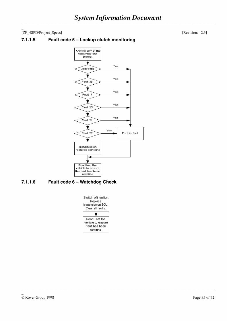
Fault Description CARB Ambient 1 Ambient 2 Ambient 35 Torque converter lock-up clutch monitoring P0741 N_MOT VGT_$X MMM
The software has detected a potential problem with the torque converter system.
Diagnostic operates: When the Torque converter is lockedConditions to be met to run Diagnostic: No Engine speed, Output shaft speed or gear ratio faults active.Time between fault present & fault stored: 5 seconds max.Variables used by the diagnostic: Engine Speed, Output shaft speed, Throttle angle, selected gear.Will limp home mode be selected: YesConditions to be met to clear the fault: Ignition switched on whilst fault not present, engine cranked
Fault Description CARB Ambient 1 Ambient 2 Ambient 36 Watchdog check P1606 N_MOT VGT_$X MMM
Internal ECU fault.
Diagnostic operates: Initialisation; approximately 70ms after ignition on.Normal operation;
Conditions to be met to run Diagnostic: NoneTime between fault present & fault stored: 60ms max.Variables used by the diagnostic: Status of Highside switch, Status of Watchdog circuit.Will limp home mode be selected: YesConditions to be met to clear the fault: Ignition switched on whilst fault not present, engine cranked
System Information Document_____________________________________________________________________________________________________[ZF_4SPD\Project_Specs] [Revision: 2.3]
_____________________________________________________________________________________________________© Rover Group 1998 Page 23 of 52
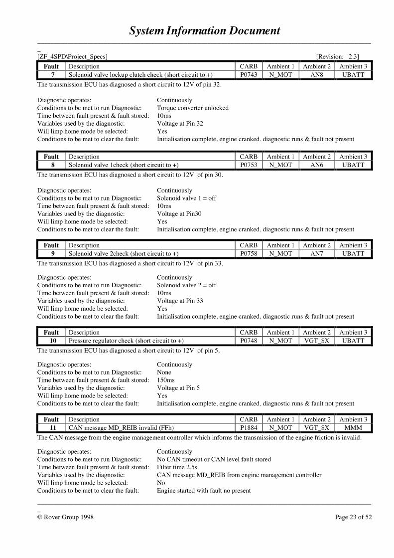
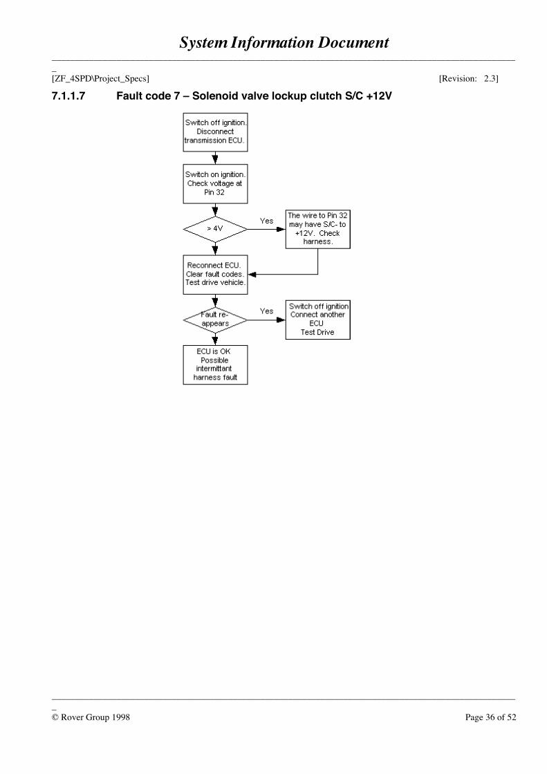
Fault Description CARB Ambient 1 Ambient 2 Ambient 37 Solenoid valve lockup clutch check (short circuit to +) P0743 N_MOT AN8 UBATT
The transmission ECU has diagnosed a short circuit to 12V of pin 32.
Diagnostic operates: ContinuouslyConditions to be met to run Diagnostic: Torque converter unlockedTime between fault present & fault stored: 10msVariables used by the diagnostic: Voltage at Pin 32Will limp home mode be selected: YesConditions to be met to clear the fault: Initialisation complete, engine cranked, diagnostic runs & fault not present
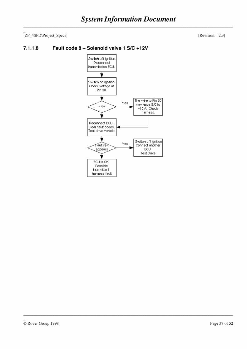
Fault Description CARB Ambient 1 Ambient 2 Ambient 38 Solenoid valve 1check (short circuit to +) P0753 N_MOT AN6 UBATT
The transmission ECU has diagnosed a short circuit to 12V of pin 30.
Diagnostic operates: ContinuouslyConditions to be met to run Diagnostic: Solenoid valve 1 = offTime between fault present & fault stored: 10msVariables used by the diagnostic: Voltage at Pin30Will limp home mode be selected: YesConditions to be met to clear the fault: Initialisation complete, engine cranked, diagnostic runs & fault not present
Fault Description CARB Ambient 1 Ambient 2 Ambient 39 Solenoid valve 2check (short circuit to +) P0758 N_MOT AN7 UBATT
The transmission ECU has diagnosed a short circuit to 12V of pin 33.
Diagnostic operates: ContinuouslyConditions to be met to run Diagnostic: Solenoid valve 2 = offTime between fault present & fault stored: 10msVariables used by the diagnostic: Voltage at Pin 33Will limp home mode be selected: YesConditions to be met to clear the fault: Initialisation complete, engine cranked, diagnostic runs & fault not present
Fault Description CARB Ambient 1 Ambient 2 Ambient 310 Pressure regulator check (short circuit to +) P0748 N_MOT VGT_$X UBATT
The transmission ECU has diagnosed a short circuit to 12V of pin 5.
Diagnostic operates: ContinuouslyConditions to be met to run Diagnostic: NoneTime between fault present & fault stored: 150msVariables used by the diagnostic: Voltage at Pin 5Will limp home mode be selected: YesConditions to be met to clear the fault: Initialisation complete, engine cranked, diagnostic runs & fault not present
Fault Description CARB Ambient 1 Ambient 2 Ambient 311 CAN message MD_REIB invalid (FFh) P1884 N_MOT VGT_$X MMM
The CAN message from the engine management controller which informs the transmission of the engine friction is invalid.
Diagnostic operates: ContinuouslyConditions to be met to run Diagnostic: No CAN timeout or CAN level fault storedTime between fault present & fault stored: Filter time 2.5sVariables used by the diagnostic: CAN message MD_REIB from engine management controllerWill limp home mode be selected: NoConditions to be met to clear the fault: Engine started with fault no present
System Information Document_____________________________________________________________________________________________________[ZF_4SPD\Project_Specs] [Revision: 2.3]
_____________________________________________________________________________________________________© Rover Group 1998 Page 24 of 52
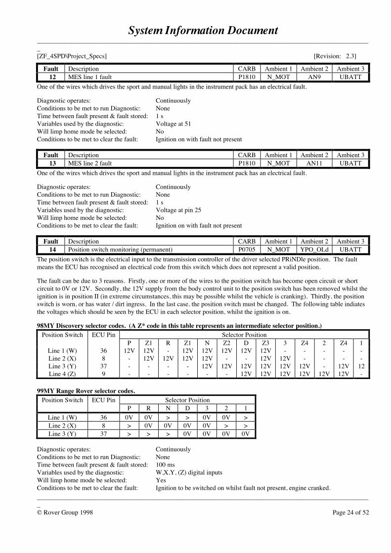
Fault Description CARB Ambient 1 Ambient 2 Ambient 312 MES line 1 fault P1810 N_MOT AN9 UBATT
One of the wires which drives the sport and manual lights in the instrument pack has an electrical fault.
Diagnostic operates: ContinuouslyConditions to be met to run Diagnostic: NoneTime between fault present & fault stored: 1 sVariables used by the diagnostic: Voltage at 51Will limp home mode be selected: NoConditions to be met to clear the fault: Ignition on with fault not present
Fault Description CARB Ambient 1 Ambient 2 Ambient 313 MES line 2 fault P1810 N_MOT AN11 UBATT
One of the wires which drives the sport and manual lights in the instrument pack has an electrical fault.
Diagnostic operates: ContinuouslyConditions to be met to run Diagnostic: NoneTime between fault present & fault stored: 1 sVariables used by the diagnostic: Voltage at pin 25Will limp home mode be selected: NoConditions to be met to clear the fault: Ignition on with fault not present
Fault Description CARB Ambient 1 Ambient 2 Ambient 314 Position switch monitoring (permanent) P0705 N_MOT YPO_OLd UBATT
The position switch is the electrical input to the transmission controller of the driver selected PRiNDle position. The faultmeans the ECU has recognised an electrical code from this switch which does not represent a valid position.
The fault can be due to 3 reasons. Firstly, one or more of the wires to the position switch has become open circuit or shortcircuit to 0V or 12V. Secondly, the 12V supply from the body control unit to the position switch has been removed whilst theignition is in position II (in extreme circumstances, this may be possible whilst the vehicle is cranking). Thirdly, the positionswitch is worn, or has water / dirt ingress. In the last case, the position switch must be changed. The following table indiatesthe voltages which should be seen by the ECU in each selector position, whilst the ignition is on.
98MY Discovery selector codes. (A Z* code in this table represents an intermediate selector position.)Position Switch ECU Pin Selector Position
P Z1 R Z1 N Z2 D Z3 3 Z4 2 Z4 1Line 1 (W) 36 12V 12V - 12V 12V 12V 12V 12V - - - - -Line 2 (X) 8 - 12V 12V 12V 12V - - 12V 12V - - - -Line 3 (Y) 37 - - - - 12V 12V 12V 12V 12V 12V - 12V 12Line 4 (Z) 9 - - - - - - 12V 12V 12V 12V 12V 12V -
99MY Range Rover selector codes.Position Switch ECU Pin Selector Position
P R N D 3 2 1Line 1 (W) 36 0V 0V > > 0V 0V >Line 2 (X) 8 > 0V 0V 0V 0V > >Line 3 (Y) 37 > > > 0V 0V 0V 0V
Diagnostic operates: ContinuouslyConditions to be met to run Diagnostic: NoneTime between fault present & fault stored: 100 msVariables used by the diagnostic: W,X,Y, (Z) digital inputsWill limp home mode be selected: YesConditions to be met to clear the fault: Ignition to be switched on whilst fault not present, engine cranked.
System Information Document_____________________________________________________________________________________________________[ZF_4SPD\Project_Specs] [Revision: 2.3]
_____________________________________________________________________________________________________© Rover Group 1998 Page 25 of 52
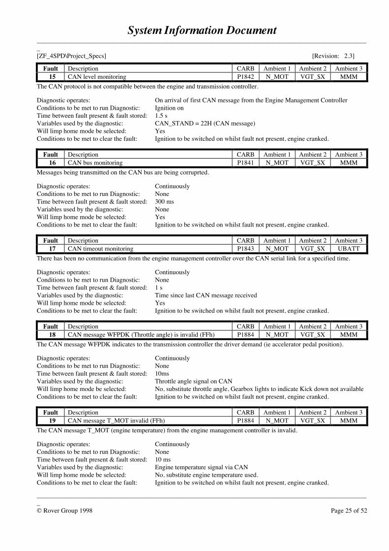
Fault Description CARB Ambient 1 Ambient 2 Ambient 315 CAN level monitoring P1842 N_MOT VGT_$X MMM
The CAN protocol is not compatible between the engine and transmission controller.
Diagnostic operates: On arrival of first CAN message from the Engine Management ControllerConditions to be met to run Diagnostic: Ignition onTime between fault present & fault stored: 1.5 sVariables used by the diagnostic: CAN_STAND = 22H (CAN message)Will limp home mode be selected: YesConditions to be met to clear the fault: Ignition to be switched on whilst fault not present, engine cranked.
Fault Description CARB Ambient 1 Ambient 2 Ambient 316 CAN bus monitoring P1841 N_MOT VGT_$X MMM
Messages being transmitted on the CAN bus are being corruprted.
Diagnostic operates: ContinuouslyConditions to be met to run Diagnostic: NoneTime between fault present & fault stored: 300 msVariables used by the diagnostic: NoneWill limp home mode be selected: YesConditions to be met to clear the fault: Ignition to be switched on whilst fault not present, engine cranked.
Fault Description CARB Ambient 1 Ambient 2 Ambient 317 CAN timeout monitoring P1843 N_MOT VGT_$X UBATT
There has been no communication from the engine management controller over the CAN serial link for a specified time.
Diagnostic operates: ContinuouslyConditions to be met to run Diagnostic: NoneTime between fault present & fault stored: 1 sVariables used by the diagnostic: Time since last CAN message receivedWill limp home mode be selected: YesConditions to be met to clear the fault: Ignition to be switched on whilst fault not present, engine cranked.
Fault Description CARB Ambient 1 Ambient 2 Ambient 318 CAN message WFPDK (Throttle angle) is invalid (FFh) P1884 N_MOT VGT_$X MMM
The CAN message WFPDK indicates to the transmission controller the driver demand (ie accelerator pedal position).
Diagnostic operates: ContinuouslyConditions to be met to run Diagnostic: NoneTime between fault present & fault stored: 10msVariables used by the diagnostic: Throttle angle signal on CANWill limp home mode be selected: No, substitute throttle angle, Gearbox lights to indicate Kick down not availableConditions to be met to clear the fault: Ignition to be switched on whilst fault not present, engine cranked.
Fault Description CARB Ambient 1 Ambient 2 Ambient 319 CAN message T_MOT invalid (FFh) P1884 N_MOT VGT_$X MMM
The CAN message T_MOT (engine temperature) from the engine management controller is invalid.
Diagnostic operates: ContinuouslyConditions to be met to run Diagnostic: NoneTime between fault present & fault stored: 10 msVariables used by the diagnostic: Engine temperature signal via CANWill limp home mode be selected: No, substitute engine temperature used.Conditions to be met to clear the fault: Ignition to be switched on whilst fault not present, engine cranked.
System Information Document_____________________________________________________________________________________________________[ZF_4SPD\Project_Specs] [Revision: 2.3]
_____________________________________________________________________________________________________© Rover Group 1998 Page 26 of 52
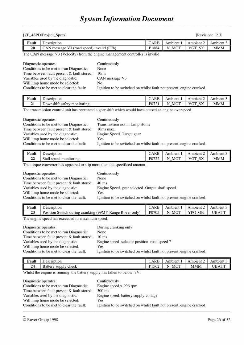
Fault Description CARB Ambient 1 Ambient 2 Ambient 320 CAN message V3 (road speed) invalid (FFh) P1884 N_MOT VGT_$X MMM
The CAN message V3 (Velocity) from the engine management controller is invalid.
Diagnostic operates: ContinuouslyConditions to be met to run Diagnostic: NoneTime between fault present & fault stored: 10msVariables used by the diagnostic: CAN message V3Will limp home mode be selected: NoConditions to be met to clear the fault: Ignition to be switched on whilst fault not present, engine cranked.
Fault Description CARB Ambient 1 Ambient 2 Ambient 321 Downshift safety monitoring P0721 N_MOT VGT_$X MMM
The transmission control unit has prevented a gear shift which would have caused an engine overspeed.
Diagnostic operates: ContinuouslyConditions to be met to run Diagnostic: Transmission not in Limp HomeTime between fault present & fault stored: 10ms max.Variables used by the diagnostic: Engine Speed, Target gearWill limp home mode be selected: YesConditions to be met to clear the fault: Ignition to be switched on whilst fault not present, engine cranked.
Fault Description CARB Ambient 1 Ambient 2 Ambient 322 Stall speed monitoring P0722 N_MOT VGT_$X MMM
The torque converter has appeared to slip more than the specificed amount.
Diagnostic operates: ContinuouslyConditions to be met to run Diagnostic: NoneTime between fault present & fault stored: 40 msVariables used by the diagnostic: Engine Speed, gear selected, Output shaft speed.Will limp home mode be selected: YesConditions to be met to clear the fault: Ignition to be switched on whilst fault not present, engine cranked.
Fault Description CARB Ambient 1 Ambient 2 Ambient 323 Position Switch during cranking (99MY Range Rover only) P0705 N_MOT YPO_Old UBATT
The engine speed has exceeded its maximum speed.
Diagnostic operates: During cranking onlyConditions to be met to run Diagnostic: NoneTime between fault present & fault stored: 10 msVariables used by the diagnostic: Engine speed, selector position, road speed ?Will limp home mode be selected: YesConditions to be met to clear the fault: Ignition to be switched on whilst fault not present, engine cranked.
Fault Description CARB Ambient 1 Ambient 2 Ambient 324 Battery supply check P1562 N_MOT MMM UBATT
Whilst the engine is running, the battery supply has fallen to below 9V.
Diagnostic operates: ContinuouslyConditions to be met to run Diagnostic: Engine speed > 996 rpmTime between fault present & fault stored: 300 msVariables used by the diagnostic: Engine speed, battery supply voltageWill limp home mode be selected: YesConditions to be met to clear the fault: Ignition to be switched on whilst fault not present, engine cranked.
System Information Document_____________________________________________________________________________________________________[ZF_4SPD\Project_Specs] [Revision: 2.3]
_____________________________________________________________________________________________________© Rover Group 1998 Page 27 of 52
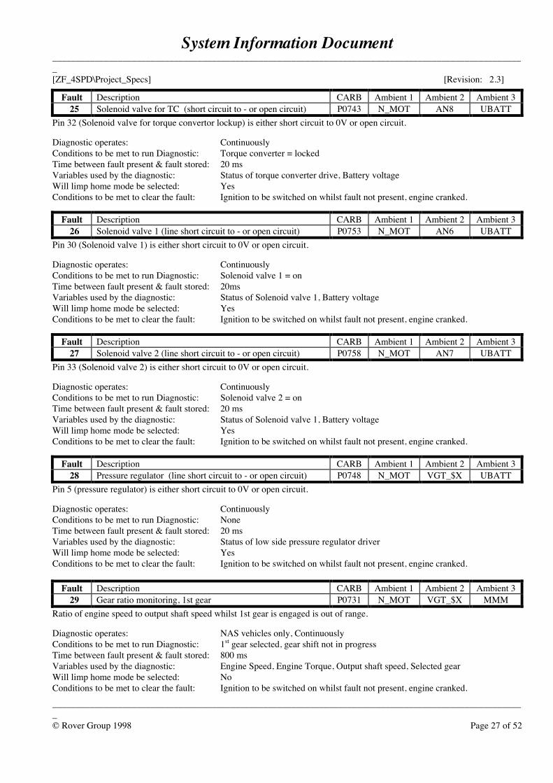
Fault Description CARB Ambient 1 Ambient 2 Ambient 325 Solenoid valve for TC (short circuit to - or open circuit) P0743 N_MOT AN8 UBATT
Pin 32 (Solenoid valve for torque convertor lockup) is either short circuit to 0V or open circuit.
Diagnostic operates: ContinuouslyConditions to be met to run Diagnostic: Torque converter = lockedTime between fault present & fault stored: 20 msVariables used by the diagnostic: Status of torque converter drive, Battery voltageWill limp home mode be selected: YesConditions to be met to clear the fault: Ignition to be switched on whilst fault not present, engine cranked.
Fault Description CARB Ambient 1 Ambient 2 Ambient 326 Solenoid valve 1 (line short circuit to - or open circuit) P0753 N_MOT AN6 UBATT
Pin 30 (Solenoid valve 1) is either short circuit to 0V or open circuit.
Diagnostic operates: ContinuouslyConditions to be met to run Diagnostic: Solenoid valve 1 = onTime between fault present & fault stored: 20msVariables used by the diagnostic: Status of Solenoid valve 1, Battery voltageWill limp home mode be selected: YesConditions to be met to clear the fault: Ignition to be switched on whilst fault not present, engine cranked.
Fault Description CARB Ambient 1 Ambient 2 Ambient 327 Solenoid valve 2 (line short circuit to - or open circuit) P0758 N_MOT AN7 UBATT
Pin 33 (Solenoid valve 2) is either short circuit to 0V or open circuit.
Diagnostic operates: ContinuouslyConditions to be met to run Diagnostic: Solenoid valve 2 = onTime between fault present & fault stored: 20 msVariables used by the diagnostic: Status of Solenoid valve 1, Battery voltageWill limp home mode be selected: YesConditions to be met to clear the fault: Ignition to be switched on whilst fault not present, engine cranked.
Fault Description CARB Ambient 1 Ambient 2 Ambient 328 Pressure regulator (line short circuit to - or open circuit) P0748 N_MOT VGT_$X UBATT
Pin 5 (pressure regulator) is either short circuit to 0V or open circuit.
Diagnostic operates: ContinuouslyConditions to be met to run Diagnostic: NoneTime between fault present & fault stored: 20 msVariables used by the diagnostic: Status of low side pressure regulator driverWill limp home mode be selected: YesConditions to be met to clear the fault: Ignition to be switched on whilst fault not present, engine cranked.
Fault Description CARB Ambient 1 Ambient 2 Ambient 329 Gear ratio monitoring, 1st gear P0731 N_MOT VGT_$X MMM
Ratio of engine speed to output shaft speed whilst 1st gear is engaged is out of range.
Diagnostic operates: NAS vehicles only, ContinuouslyConditions to be met to run Diagnostic: 1st gear selected, gear shift not in progressTime between fault present & fault stored: 800 msVariables used by the diagnostic: Engine Speed, Engine Torque, Output shaft speed, Selected gearWill limp home mode be selected: NoConditions to be met to clear the fault: Ignition to be switched on whilst fault not present, engine cranked.
System Information Document_____________________________________________________________________________________________________[ZF_4SPD\Project_Specs] [Revision: 2.3]
_____________________________________________________________________________________________________© Rover Group 1998 Page 28 of 52
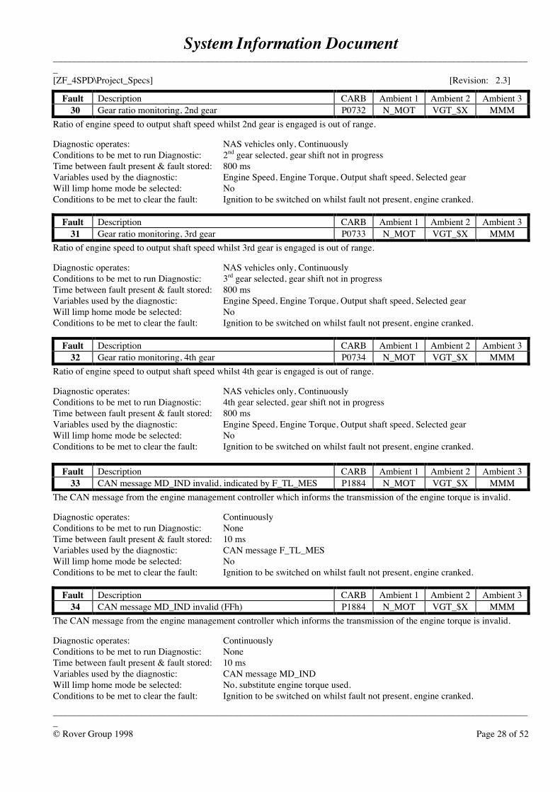
Fault Description CARB Ambient 1 Ambient 2 Ambient 330 Gear ratio monitoring, 2nd gear P0732 N_MOT VGT_$X MMM
Ratio of engine speed to output shaft speed whilst 2nd gear is engaged is out of range.
Diagnostic operates: NAS vehicles only, ContinuouslyConditions to be met to run Diagnostic: 2nd gear selected, gear shift not in progressTime between fault present & fault stored: 800 msVariables used by the diagnostic: Engine Speed, Engine Torque, Output shaft speed, Selected gearWill limp home mode be selected: NoConditions to be met to clear the fault: Ignition to be switched on whilst fault not present, engine cranked.
Fault Description CARB Ambient 1 Ambient 2 Ambient 331 Gear ratio monitoring, 3rd gear P0733 N_MOT VGT_$X MMM
Ratio of engine speed to output shaft speed whilst 3rd gear is engaged is out of range.
Diagnostic operates: NAS vehicles only, ContinuouslyConditions to be met to run Diagnostic: 3rd gear selected, gear shift not in progressTime between fault present & fault stored: 800 msVariables used by the diagnostic: Engine Speed, Engine Torque, Output shaft speed, Selected gearWill limp home mode be selected: NoConditions to be met to clear the fault: Ignition to be switched on whilst fault not present, engine cranked.
Fault Description CARB Ambient 1 Ambient 2 Ambient 332 Gear ratio monitoring, 4th gear P0734 N_MOT VGT_$X MMM
Ratio of engine speed to output shaft speed whilst 4th gear is engaged is out of range.
Diagnostic operates: NAS vehicles only, ContinuouslyConditions to be met to run Diagnostic: 4th gear selected, gear shift not in progressTime between fault present & fault stored: 800 msVariables used by the diagnostic: Engine Speed, Engine Torque, Output shaft speed, Selected gearWill limp home mode be selected: NoConditions to be met to clear the fault: Ignition to be switched on whilst fault not present, engine cranked.
Fault Description CARB Ambient 1 Ambient 2 Ambient 333 CAN message MD_IND invalid, indicated by F_TL_MES P1884 N_MOT VGT_$X MMM
The CAN message from the engine management controller which informs the transmission of the engine torque is invalid.
Diagnostic operates: ContinuouslyConditions to be met to run Diagnostic: NoneTime between fault present & fault stored: 10 msVariables used by the diagnostic: CAN message F_TL_MESWill limp home mode be selected: NoConditions to be met to clear the fault: Ignition to be switched on whilst fault not present, engine cranked.
Fault Description CARB Ambient 1 Ambient 2 Ambient 334 CAN message MD_IND invalid (FFh) P1884 N_MOT VGT_$X MMM
The CAN message from the engine management controller which informs the transmission of the engine torque is invalid.
Diagnostic operates: ContinuouslyConditions to be met to run Diagnostic: NoneTime between fault present & fault stored: 10 msVariables used by the diagnostic: CAN message MD_INDWill limp home mode be selected: No, substitute engine torque used.Conditions to be met to clear the fault: Ignition to be switched on whilst fault not present, engine cranked.
System Information Document_____________________________________________________________________________________________________[ZF_4SPD\Project_Specs] [Revision: 2.3]
_____________________________________________________________________________________________________© Rover Group 1998 Page 29 of 52
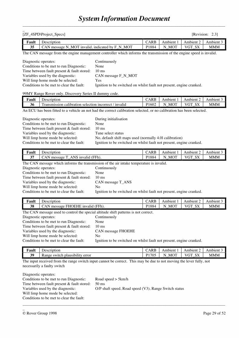
Fault Description CARB Ambient 1 Ambient 2 Ambient 335 CAN message N_MOT invalid, indicated by F_N_MOT P1884 N_MOT VGT_$X MMM
The CAN message from the engine management controller which informs the transmission of the engine speed is invalid.
Diagnostic operates: ContinuouslyConditions to be met to run Diagnostic: NoneTime between fault present & fault stored: 10 msVariables used by the diagnostic: CAN message F_N_MOTWill limp home mode be selected: YesConditions to be met to clear the fault: Ignition to be switched on whilst fault not present, engine cranked.
99MY Range Rover only, Discovery Series II dummy code.Fault Description CARB Ambient 1 Ambient 2 Ambient 3
36 Transmission calibration selection incorrect / invalid P1602 N_MOT VGT_$X MMMAn ECU has been fitted to a vehicle an not had the correct calibration selected, or no calibration has been selected.
Diagnostic operates: During initialisationConditions to be met to run Diagnostic: NoneTime between fault present & fault stored: 10 msVariables used by the diagnostic: Tune select statusWill limp home mode be selected: No, default shift maps used (normally 4.0l calibration)Conditions to be met to clear the fault: Ignition to be switched on whilst fault not present, engine cranked.
Fault Description CARB Ambient 1 Ambient 2 Ambient 337 CAN message T_ANS invalid (FFh). P1884 N_MOT VGT_$X MMM
The CAN message which informs the transmission of the air intake temperature is invalid.Diagnostic operates: ContinuouslyConditions to be met to run Diagnostic: NoneTime between fault present & fault stored: 10 msVariables used by the diagnostic: CAN message T_ANSWill limp home mode be selected: NoConditions to be met to clear the fault: Ignition to be switched on whilst fault not present, engine cranked.
Fault Description CARB Ambient 1 Ambient 2 Ambient 338 CAN message FHOEHE invalid (FFh). P1884 N_MOT VGT_$X MMM
The CAN message used to control the special altitude shift patterns is not correct.Diagnostic operates: ContinuouslyConditions to be met to run Diagnostic: NoneTime between fault present & fault stored: 10 msVariables used by the diagnostic: CAN message FHOEHEWill limp home mode be selected: NoConditions to be met to clear the fault: Ignition to be switched on whilst fault not present, engine cranked.
Fault Description CARB Ambient 1 Ambient 2 Ambient 339 Range switch plausibility error P1705 N_MOT VGT_$X MMM
The input received from the range switch input cannot be correct. This may be due to not moving the lever fully, notnecessarily a faulty switch
Diagnostic operates:Conditions to be met to run Diagnostic: Road speed > 5km/hTime between fault present & fault stored: 50 msVariables used by the diagnostic: O/P shaft speed, Road speed (V3), Range Switch statusWill limp home mode be selected:Conditions to be met to clear the fault:
System Information Document_____________________________________________________________________________________________________[ZF_4SPD\Project_Specs] [Revision: 2.3]
_____________________________________________________________________________________________________© Rover Group 1998 Page 30 of 52
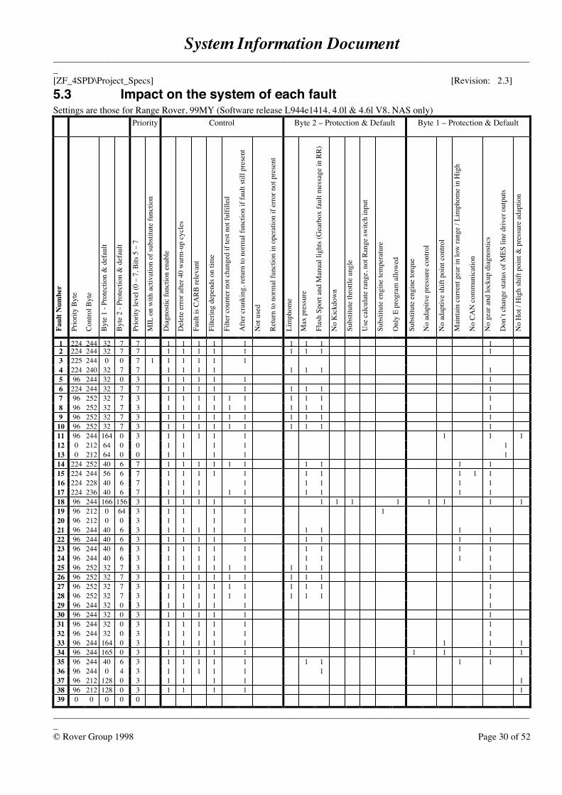
5.3 Impact on the system of each faultSettings are those for Range Rover, 99MY (Software release L944e1414, 4.0l & 4.6l V8, NAS only)
Priority Control Byte 2 – Protection & Default Byte 1 – Protection & Default
Faul
t Num
ber
Prio
rity
Byte
Cont
rol B
yte
Byte
1 -
Prot
ectio
n &
def
ault
Byte
2 -
Prot
ectio
n &
def
ault
Prio
rity
leve
l (0
– 7,
Bits
5 –
7
MIL
on
with
act
ivat
ion
of su
bstit
ute
func
tion
Dia
gnos
tic fu
nctio
n en
able
Del
ete
erro
r afte
r 40
war
m-u
p cy
cles
Faul
t is C
ARB
rele
vant
Filte
ring
depe
nds o
n tim
e
Filte
r cou
nter
not
cha
nged
if te
st no
t ful
fille
d
Afte
r cra
nkin
g, re
turn
to n
orm
al fu
nctio
n if
faul
t stil
l pre
sent
Not
use
d
Retu
rn to
nor
mal
func
tion
in o
pera
tion
if er
ror n
ot p
rese
nt
Lim
phom
e
Max
pre
ssur
e
Flas
h Sp
ort a
nd M
anua
l lig
hts (
Gea
rbox
faul
t mes
sage
in R
R)
No
Kic
kdow
n
Subs
titut
e th
rottl
e an
gle
Use
cal
cula
te ra
nge,
not
Ran
ge sw
itch
inpu
t
Subs
titut
e en
gine
tem
pera
ture
Onl
y E
prog
ram
allo
wed
Subs
titut
e en
gine
torq
ue
No
adap
itve
pres
sure
con
trol
No
adap
tive
shift
poi
nt c
ontro
l
Mai
ntai
n cu
rrent
gea
r in
low
rang
e / L
imph
ome
in H
igh
No
CAN
com
mun
icat
ion
No
gear
and
lock
up d
iagn
ostic
s
Don
’t ch
ange
stat
us o
f MES
line
driv
er o
utpu
ts
No
Hot
/ H
igh
shift
poi
nt &
pre
ssur
e ada
ptio
n
1 224 244 32 7 7 1 1 1 1 1 1 1 1 12 224 244 32 7 7 1 1 1 1 1 1 1 1 13 225 244 0 0 7 1 1 1 1 1 14 224 240 32 7 7 1 1 1 1 1 1 1 15 96 244 32 0 3 1 1 1 1 1 16 224 244 32 7 7 1 1 1 1 1 1 1 1 17 96 252 32 7 3 1 1 1 1 1 1 1 1 1 18 96 252 32 7 3 1 1 1 1 1 1 1 1 1 19 96 252 32 7 3 1 1 1 1 1 1 1 1 1 1
10 96 252 32 7 3 1 1 1 1 1 1 1 1 1 111 96 244 164 0 3 1 1 1 1 1 1 1 112 0 212 64 0 0 1 1 1 1 113 0 212 64 0 0 1 1 1 1 114 224 252 40 6 7 1 1 1 1 1 1 1 1 1 115 224 244 56 6 7 1 1 1 1 1 1 1 1 1 116 224 228 40 6 7 1 1 1 1 1 1 1 117 224 236 40 6 7 1 1 1 1 1 1 1 1 118 96 244 166 156 3 1 1 1 1 1 1 1 1 1 1 1 1 119 96 212 0 64 3 1 1 1 1 120 96 212 0 0 3 1 1 1 121 96 244 40 6 3 1 1 1 1 1 1 1 1 122 96 244 40 6 3 1 1 1 1 1 1 1 1 123 96 244 40 6 3 1 1 1 1 1 1 1 1 124 96 244 40 6 3 1 1 1 1 1 1 1 1 125 96 252 32 7 3 1 1 1 1 1 1 1 1 1 126 96 252 32 7 3 1 1 1 1 1 1 1 1 1 127 96 252 32 7 3 1 1 1 1 1 1 1 1 1 128 96 252 32 7 3 1 1 1 1 1 1 1 1 1 129 96 244 32 0 3 1 1 1 1 1 130 96 244 32 0 3 1 1 1 1 1 131 96 244 32 0 3 1 1 1 1 1 132 96 244 32 0 3 1 1 1 1 1 133 96 244 164 0 3 1 1 1 1 1 1 1 134 96 244 165 0 3 1 1 1 1 1 1 1 1 135 96 244 40 6 3 1 1 1 1 1 1 1 1 136 96 244 0 4 3 1 1 1 1 1 137 96 212 128 0 3 1 1 1 1 138 96 212 128 0 3 1 1 1 1 139 0 0 0 0 0
System Information Document_____________________________________________________________________________________________________[ZF_4SPD\Project_Specs] [Revision: 2.3]
_____________________________________________________________________________________________________© Rover Group 1998 Page 31 of 52
6 General information
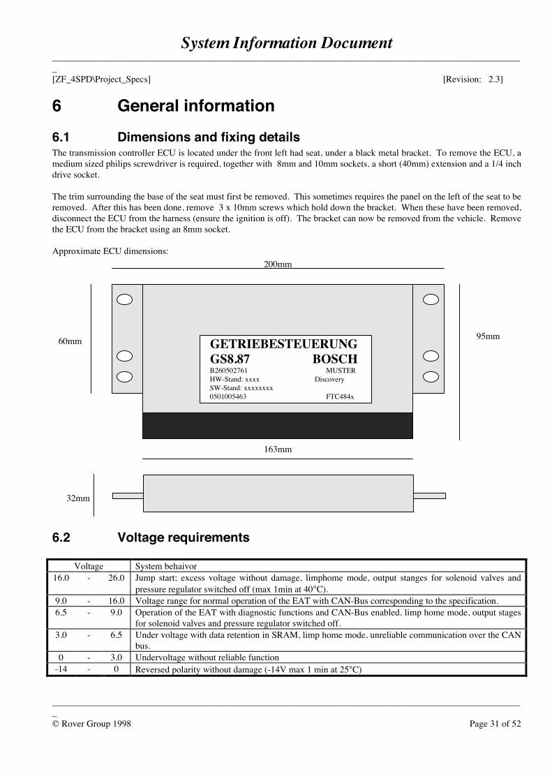
6.1 Dimensions and fixing detailsThe transmission controller ECU is located under the front left had seat, under a black metal bracket. To remove the ECU, amedium sized philips screwdriver is required, together with 8mm and 10mm sockets, a short (40mm) extension and a 1/4 inchdrive socket.
The trim surrounding the base of the seat must first be removed. This sometimes requires the panel on the left of the seat to beremoved. After this has been done, remove 3 x 10mm screws which hold down the bracket. When these have been removed,disconnect the ECU from the harness (ensure the ignition is off). The bracket can now be removed from the vehicle. Removethe ECU from the bracket using an 8mm socket.
Approximate ECU dimensions:
6.2 Voltage requirements
Voltage System behaivor16.0 - 26.0 Jump start; excess voltage without damage, limphome mode, output stanges for solenoid valves and
pressure regulator switched off (max 1min at 40°C).9.0 - 16.0 Voltage range for normal operation of the EAT with CAN-Bus corresponding to the specification.6.5 - 9.0 Operation of the EAT with diagnostic functions and CAN-Bus enabled, limp home mode, output stages
for solenoid valves and pressure regulator switched off.3.0 - 6.5 Under voltage with data retention in SRAM, limp home mode, unreliable communication over the CAN
bus.0 - 3.0 Undervoltage without reliable function
-14 - 0 Reversed polarity without damage (-14V max 1 min at 25°C)
GETRIEBESTEUERUNG GS8.87 BOSCH B260502761 MUSTER HW-Stand: xxxx Discovery SW-Stand: xxxxxxxx 0501005463 FTC484x
200mm
163mm
60mm 95mm
32mm
System Information Document_____________________________________________________________________________________________________[ZF_4SPD\Project_Specs] [Revision: 2.3]
_____________________________________________________________________________________________________© Rover Group 1998 Page 32 of 52
7 Fault tree analysisThe following pages are a guide to fixing faults with the electronic automatic transmission. In order to solve fault, the faulttrees indicate the most logical way a problem should be approached. If the fault tree indicates the transmission or controller isfaultly, the transmission electronics department should first be consulted.
In the instance, somebody will look at the car, and if nothing is deemed to be faulty with the electronics, the Transmissionsdepartment will check the condition of the gearbox. If both the transmission and the controller are deemed to be OK, thediagnosis will have to be further investigated by Transmission Electronics.
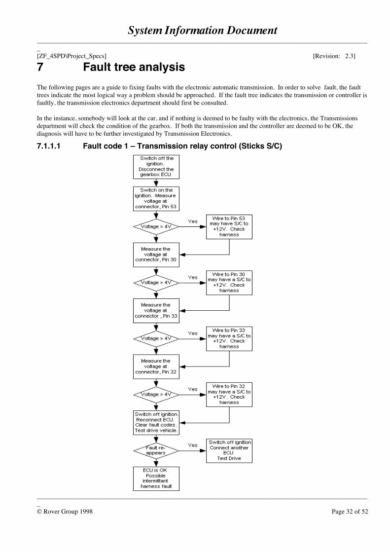
7.1.1.1 Fault code 1 – Transmission relay control (Sticks S/C)
System Information Document_____________________________________________________________________________________________________[ZF_4SPD\Project_Specs] [Revision: 2.3]
_____________________________________________________________________________________________________© Rover Group 1998 Page 33 of 52
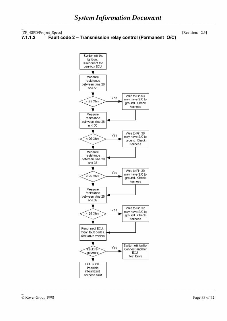
7.1.1.2 Fault code 2 – Transmission relay control (Permanent O/C)
System Information Document_____________________________________________________________________________________________________[ZF_4SPD\Project_Specs] [Revision: 2.3]
_____________________________________________________________________________________________________© Rover Group 1998 Page 34 of 52
7.1.1.3 Fault code 3 – EEPROM communication fault
7.1.1.4 Fault code 4 – EPROM checksum fault
System Information Document_____________________________________________________________________________________________________[ZF_4SPD\Project_Specs] [Revision: 2.3]
_____________________________________________________________________________________________________© Rover Group 1998 Page 35 of 52
7.1.1.5 Fault code 5 – Lockup clutch monitoring
7.1.1.6 Fault code 6 – Watchdog Check
System Information Document_____________________________________________________________________________________________________[ZF_4SPD\Project_Specs] [Revision: 2.3]
_____________________________________________________________________________________________________© Rover Group 1998 Page 36 of 52
7.1.1.7 Fault code 7 – Solenoid valve lockup clutch S/C +12V
System Information Document_____________________________________________________________________________________________________[ZF_4SPD\Project_Specs] [Revision: 2.3]
_____________________________________________________________________________________________________© Rover Group 1998 Page 37 of 52
7.1.1.8 Fault code 8 – Solenoid valve 1 S/C +12V
System Information Document_____________________________________________________________________________________________________[ZF_4SPD\Project_Specs] [Revision: 2.3]
_____________________________________________________________________________________________________© Rover Group 1998 Page 38 of 52
7.1.1.9 Fault code 9 – Solenoid valve 2 S/C +12V
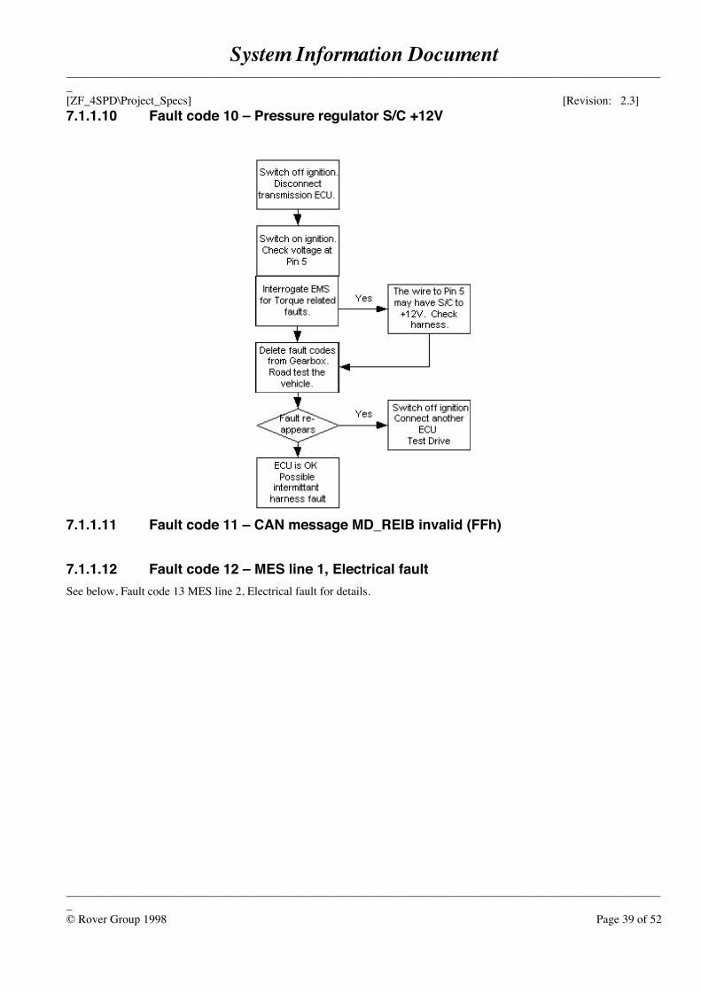
System Information Document_____________________________________________________________________________________________________[ZF_4SPD\Project_Specs] [Revision: 2.3]
_____________________________________________________________________________________________________© Rover Group 1998 Page 39 of 52
7.1.1.10 Fault code 10 – Pressure regulator S/C +12V
7.1.1.11 Fault code 11 – CAN message MD_REIB invalid (FFh)
7.1.1.12 Fault code 12 – MES line 1, Electrical faultSee below, Fault code 13 MES line 2, Electrical fault for details.
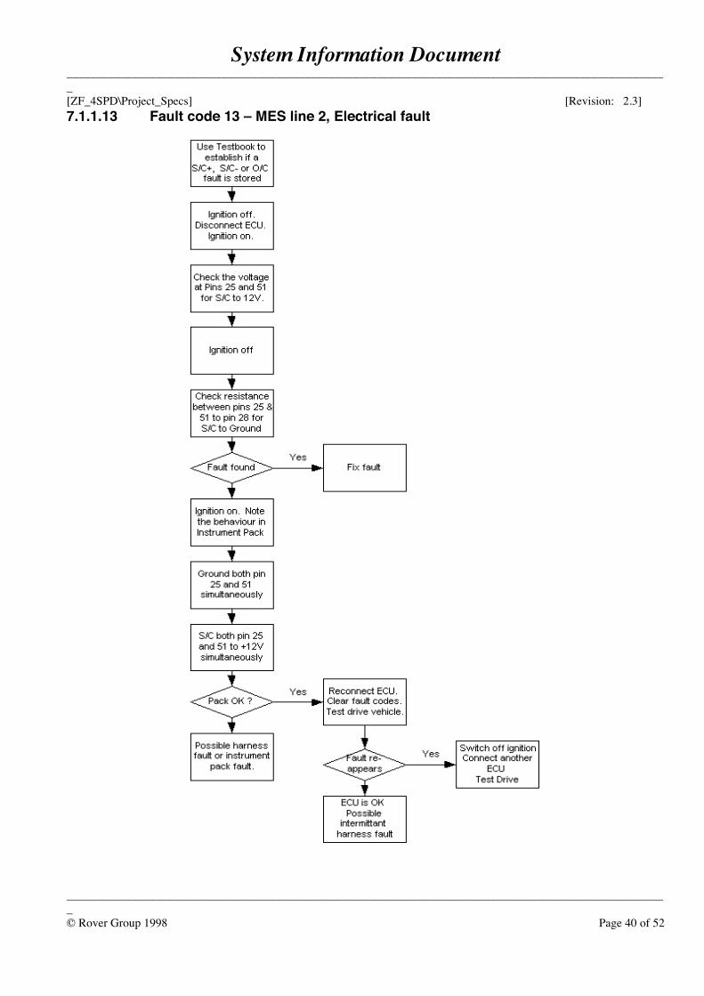
System Information Document_____________________________________________________________________________________________________[ZF_4SPD\Project_Specs] [Revision: 2.3]
_____________________________________________________________________________________________________© Rover Group 1998 Page 40 of 52
7.1.1.13 Fault code 13 – MES line 2, Electrical fault
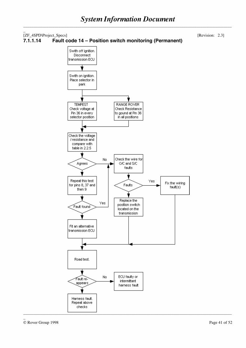
System Information Document_____________________________________________________________________________________________________[ZF_4SPD\Project_Specs] [Revision: 2.3]
_____________________________________________________________________________________________________© Rover Group 1998 Page 41 of 52
7.1.1.14 Fault code 14 – Position switch monitoring (Permanent)
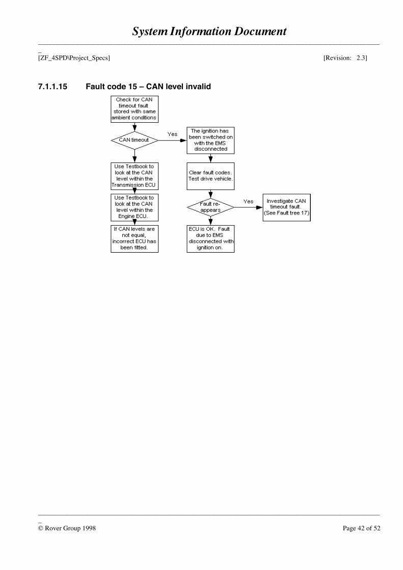
System Information Document_____________________________________________________________________________________________________[ZF_4SPD\Project_Specs] [Revision: 2.3]
_____________________________________________________________________________________________________© Rover Group 1998 Page 42 of 52
7.1.1.15 Fault code 15 – CAN level invalid
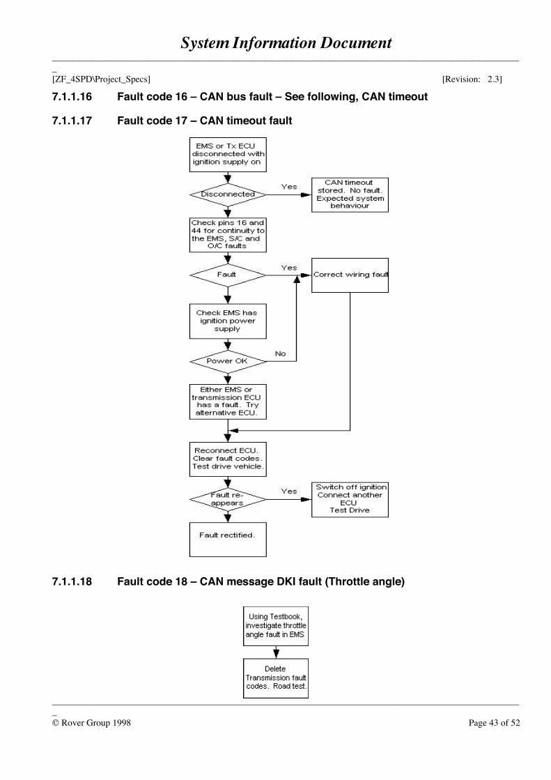
System Information Document_____________________________________________________________________________________________________[ZF_4SPD\Project_Specs] [Revision: 2.3]
_____________________________________________________________________________________________________© Rover Group 1998 Page 43 of 52
7.1.1.16 Fault code 16 – CAN bus fault – See following, CAN timeout
7.1.1.17 Fault code 17 – CAN timeout fault
7.1.1.18 Fault code 18 – CAN message DKI fault (Throttle angle)
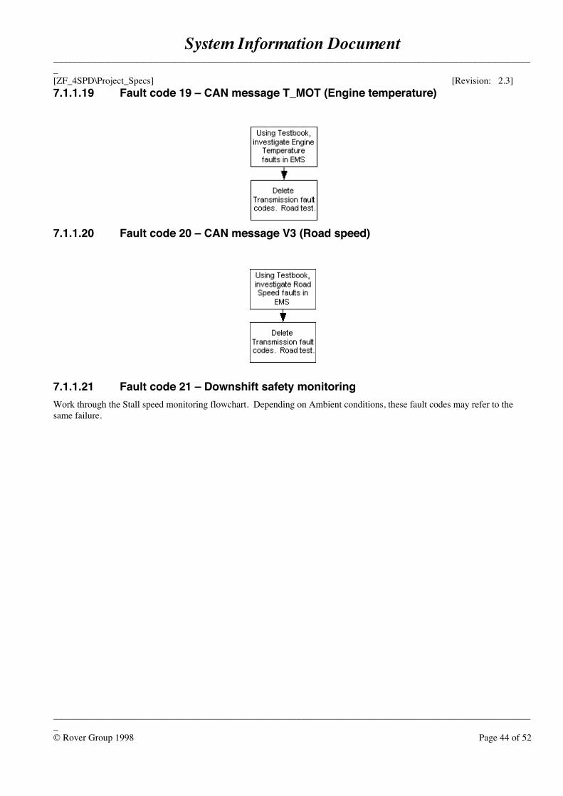
System Information Document_____________________________________________________________________________________________________[ZF_4SPD\Project_Specs] [Revision: 2.3]
_____________________________________________________________________________________________________© Rover Group 1998 Page 44 of 52
7.1.1.19 Fault code 19 – CAN message T_MOT (Engine temperature)
7.1.1.20 Fault code 20 – CAN message V3 (Road speed)
7.1.1.21 Fault code 21 – Downshift safety monitoringWork through the Stall speed monitoring flowchart. Depending on Ambient conditions, these fault codes may refer to thesame failure.
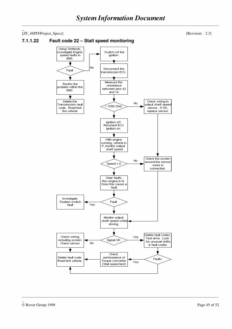
System Information Document_____________________________________________________________________________________________________[ZF_4SPD\Project_Specs] [Revision: 2.3]
_____________________________________________________________________________________________________© Rover Group 1998 Page 45 of 52
7.1.1.22 Fault code 22 – Stall speed monitoring
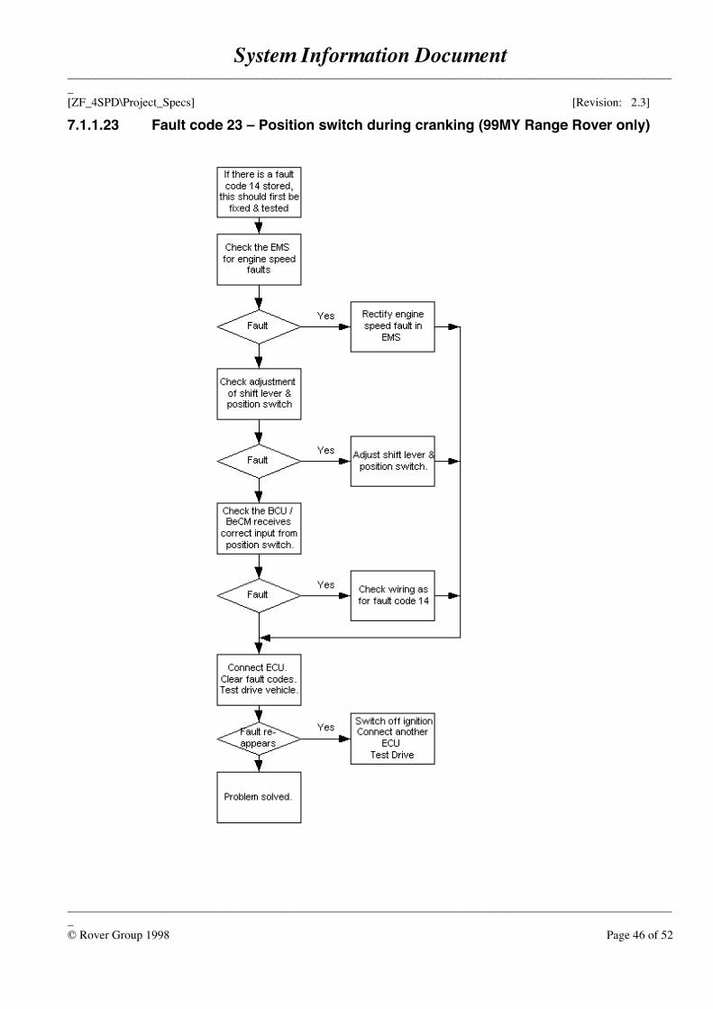
System Information Document_____________________________________________________________________________________________________[ZF_4SPD\Project_Specs] [Revision: 2.3]
_____________________________________________________________________________________________________© Rover Group 1998 Page 46 of 52
7.1.1.23 Fault code 23 – Position switch during cranking (99MY Range Rover only)
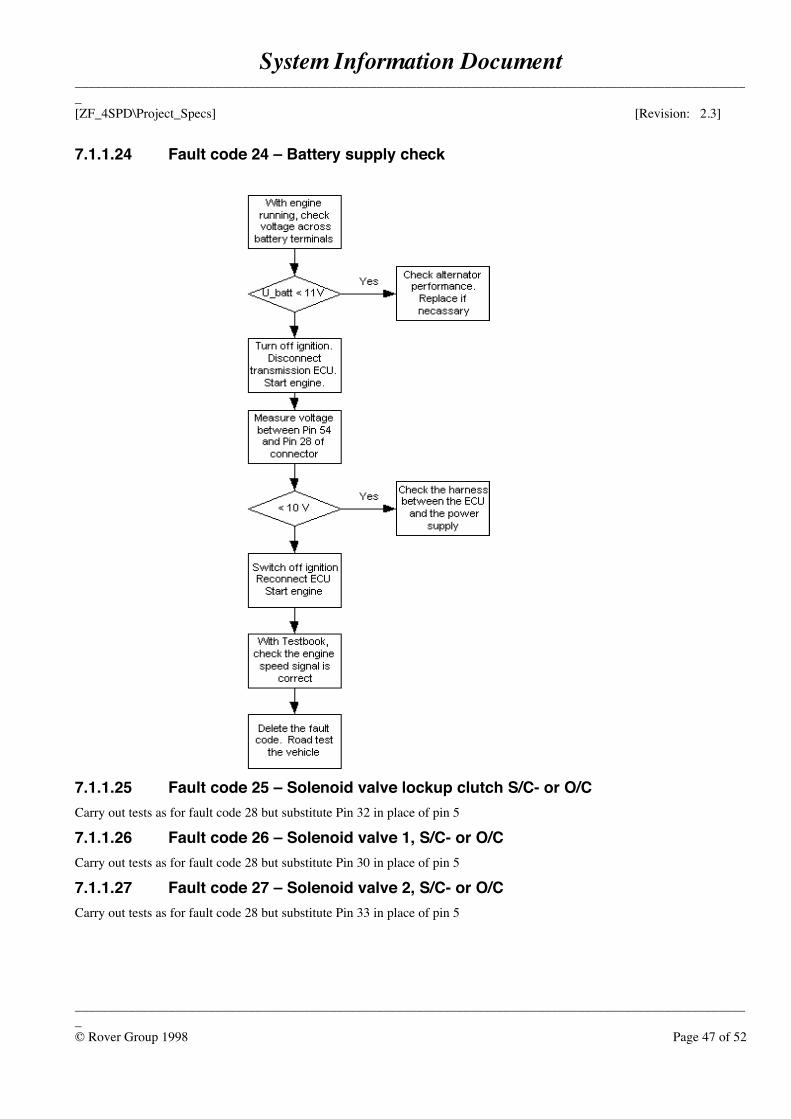
System Information Document_____________________________________________________________________________________________________[ZF_4SPD\Project_Specs] [Revision: 2.3]
_____________________________________________________________________________________________________© Rover Group 1998 Page 47 of 52
7.1.1.24 Fault code 24 – Battery supply check
7.1.1.25 Fault code 25 – Solenoid valve lockup clutch S/C- or O/CCarry out tests as for fault code 28 but substitute Pin 32 in place of pin 5
7.1.1.26 Fault code 26 – Solenoid valve 1, S/C- or O/CCarry out tests as for fault code 28 but substitute Pin 30 in place of pin 5
7.1.1.27 Fault code 27 – Solenoid valve 2, S/C- or O/CCarry out tests as for fault code 28 but substitute Pin 33 in place of pin 5
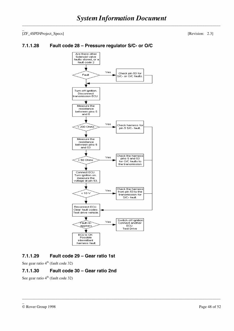
System Information Document_____________________________________________________________________________________________________[ZF_4SPD\Project_Specs] [Revision: 2.3]
_____________________________________________________________________________________________________© Rover Group 1998 Page 48 of 52
7.1.1.28 Fault code 28 – Pressure regulator S/C- or O/C
7.1.1.29 Fault code 29 – Gear ratio 1stSee gear ratio 4th (fault code 32)
7.1.1.30 Fault code 30 – Gear ratio 2ndSee gear ratio 4th (fault code 32)
System Information Document_____________________________________________________________________________________________________[ZF_4SPD\Project_Specs] [Revision: 2.3]
_____________________________________________________________________________________________________© Rover Group 1998 Page 49 of 52
7.1.1.31 Fault code 31 – Gear ratio 3rdSee gear ratio 4th (fault code 32)
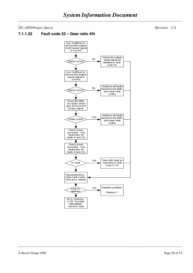
System Information Document_____________________________________________________________________________________________________[ZF_4SPD\Project_Specs] [Revision: 2.3]
_____________________________________________________________________________________________________© Rover Group 1998 Page 50 of 52
7.1.1.32 Fault code 32 – Gear ratio 4th
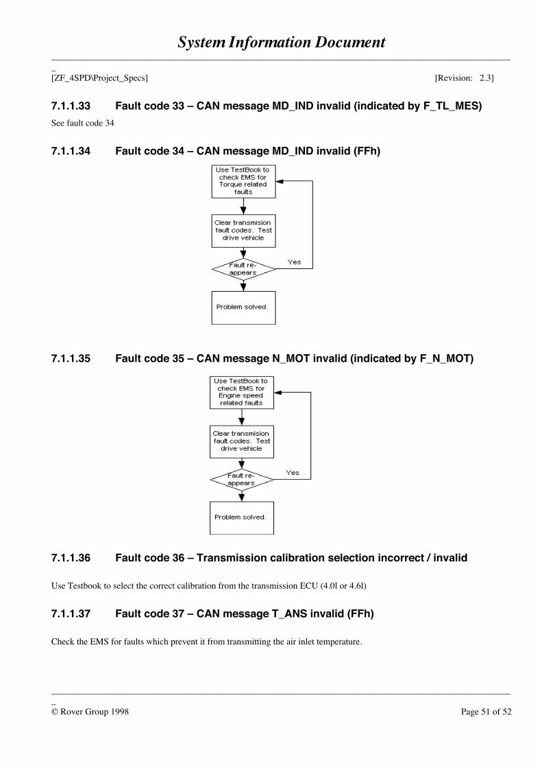
System Information Document_____________________________________________________________________________________________________[ZF_4SPD\Project_Specs] [Revision: 2.3]
_____________________________________________________________________________________________________© Rover Group 1998 Page 51 of 52
7.1.1.33 Fault code 33 – CAN message MD_IND invalid (indicated by F_TL_MES)See fault code 34
7.1.1.34 Fault code 34 – CAN message MD_IND invalid (FFh)
7.1.1.35 Fault code 35 – CAN message N_MOT invalid (indicated by F_N_MOT)
7.1.1.36 Fault code 36 – Transmission calibration selection incorrect / invalid
Use Testbook to select the correct calibration from the transmission ECU (4.0l or 4.6l)
7.1.1.37 Fault code 37 – CAN message T_ANS invalid (FFh)
Check the EMS for faults which prevent it from transmitting the air inlet temperature.
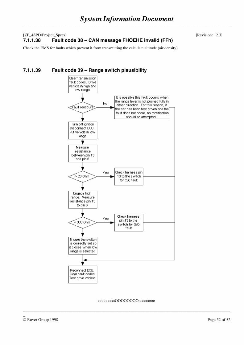
System Information Document_____________________________________________________________________________________________________[ZF_4SPD\Project_Specs] [Revision: 2.3]
_____________________________________________________________________________________________________© Rover Group 1998 Page 52 of 52
7.1.1.38 Fault code 38 – CAN message FHOEHE invalid (FFh)Check the EMS for faults which prevent it from transmitting the calculate altitude (air density).
7.1.1.39 Fault code 39 – Range switch plausibility
ooooooooOOOOOOOOoooooooo
No sealants or adhesives are used for automatic transmission assembly.
Gaskets are installed dry.
Lip seals should be dipped in ATF before installation. Clutch linings should be soaked in ATF for at least one-half hour before assembly.
Use petroleum jelly to retain torrington bearings in place during assembly. Do not use ordinary grease.
Never use rags or wiping cloths during transmission assembly. Lint from the rags can block tiny passages in the valve body. Use compressed air or lint free synthetic wipes.
Most Land Rover service literature specifies Dexron IID as the correct ATF type. Since IID is no longer commonly available, use Dexron III/Mercon.
Synthetic ATF is not recommended for Land Rover automatic transmissions.
SEALANTS, ADHESIVES AND LUBRICANTS