3900 series digital radio test set - mcs test equipment
TRANSCRIPT
3900 Series
Operation ManualDigital Radio Test Set
Issue-5
EXPORT CONTROL WARNING: This document contains controlled technical data under the jurisdiction of the Export Administration Regulations (EAR), 15 CFR 730-774. It cannot be transferred to any foreign third party without the specific prior approval of the U.S. Department of Commerce Bureau of Industry and Security (BIS). Violations of these regulations are punishable by fine, imprisonment, or both.
Subject to Export Control , see Cover Page for detai ls .
3900 Series
Digital Radio Test Set
Operation Manual
PUBLISHED BYAerof lex
COPYRIGHT © Aerof lex 2016
Al l r ights reserved. No part of th is publ icat ion may be reproduced, stored in a retr ieval system, or t ransmit ted in any form or by any means, elect ronic, mechanical , photocopying, recording or otherwise without the pr ior permission of the publ isher .
Re- Issued Jan 2014
Issue-2 Jul 2014
Issue-3 Oct 2014
Issue-4 Oct 2015
Issue-5 Jan 2016
10200 West York Street / Wich i ta, Kansas 67215 U.S.A./ (316) 522-4981/FAX (316) 524-2623
Subject to Export Control , see Cover Page for detai ls .
Preface
ABOUT THIS MANUAL
This manual explains how to use Test Sets found in the 3900 Digi tal Radio Test Set Ser ies. This Ser ies current ly includes the 3901, 3902 and 3920”x” Models. Unless otherwise indicated, informat ion in this manual appl ies to the 3901, 3902 and 3920”x” Dig i tal Radio Test Sets.
ELECTROMAGNETIC COMPATIBILITY
Double shielded and proper ly terminated externa l inter face cables must be used with this equipment when inter facing with the RS-232 and IEEE-488.
For cont inued EMC compl iance, al l externa l cables must be shielded and 3 meters or less in length.
NOMENCLATURE STATEMENT
The 3901, 3902, 3920 and 3920B Digi ta l Radio Test Set is the of f ic ia l nomenclature for the test sets current ly included in the 3900 Digi ta l Radio Test Set Ser ies. In this manual, 3900, uni t or Test Set, refers to the 3901, 3902, 3920 and 3920B Digi tal Radio Test Sets unless otherwise indicated.
INTENDED AUDIENCE
This manual is intended for personnel fami l iar wi th radio test systems and associa ted equipment.
Some screen shots may re ference f requencies above 1 GHz which are only appl icable to speci f ic 3900 models/opt ions. Refer to product speci f icat ions for model operat ional parameters.
NOTE
i

Preface
Subject to Export Control , see Cover Page for detai ls .
THIS PAGE INTENTIONALLY LEFT BLANK.
i i
Subject to Export Control , see Cover Page for detai ls .
Service Upon Receipt of Material
UNPACKING
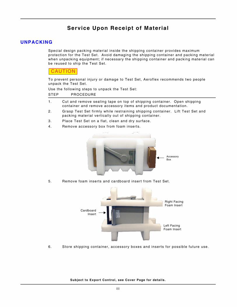
Special design packing mater ial inside the shipping conta iner provides maximum protect ion for the Test Set. Avoid damaging the shipping container and packing mater ia l when unpacking equipment; i f necessary the sh ipping container and packing mater ia l can be reused to sh ip the Test Set.
To prevent personal in jury or damage to Test Set, Aerof lex recommends two people unpack the Test Set.
Use the fol lowing steps to unpack the Test Set:
STEP PROCEDURE
1. Cut and remove seal ing tape on top of sh ipping container. Open shipping conta iner and remove accessory i tems and product documentat ion.
2. Grasp Test Set f i rmly whi le restraining shipping container . L i f t Test Set and packing mater ial ver t ical ly out of shipping conta iner.
3. Place Test Set on a f lat , c lean and dry sur face.
4. Remove accessory box f rom foam inserts.
5. Remove foam inser ts and cardboard inser t f rom Test Set.
6. Store shipping conta iner, accessory boxes and inserts for possible fu ture use.
CAUTION
AccessoryBox
CardboardInsert
Left FacingFoam Insert
Right FacingFoam Insert
i i i
Service Upon Receipt
Subject to Export Control , see Cover Page for detai ls .
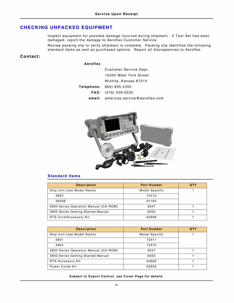
CHECKING UNPACKED EQUIPMENT
Inspect equipment for possible damage incurred dur ing shipment. I f Test Set had been damaged, report the damage to Aerof lex Customer Service.
Review packing sl ip to ver i fy shipment is complete. Packing sl ip ident i f ies the fol lowing standard i tems as wel l as purchased opt ions. Report al l d iscrepancies to Aerof lex.
Contact:
Standard Items
Aeroflex
Customer Service Dept.
10200 West York Street
Wichi ta, Kansas 67215
Telephone: 800) 835-2350
FAX: (316) 529-5330
email: americas.service@aerof lex.com
Descript ion Part Number QTY
Ship Uni t (see Model Name) Model Specif ic 1
3920 72412
3920B 91164
3900 Ser ies Operat ion Manual (CD-ROM) 6047 1
3900 Ser ies Gett ing Started Manual 6050 1
RTS Cord/Accessory Ki t 63938 1
Descript ion Part Number QTY
Ship Uni t (see Model Name) Model Specif ic 1
3901 72411
3902 72410
3900 Ser ies Operat ion Manual (CD-ROM) 6047 1
3900 Ser ies Gett ing Started Manual 6050 1
RTS Accessory Kit 63929 1
Power Cords Ki t 63933 1
iv
Subject to Export Control , see Cover Page for detai ls .
Precautions
SAFETY FIRST - TO ALL OPERATIONS PERSONNEL
GENERAL CONDITIONS OF USE
This product is designed and tested to comply with the requirements of IEC/EN61010-1 ‘Safety requi rements for electr ical equipment for measurement, control and laboratory use’ for Class I portable equipment and is for use in a pol lu t ion degree 2 environment. The equipment is designed to operate f rom instal la t ion supply Category I I .
Equipment should be protected f rom l iquids such as spi l ls , leaks, e tc. and precipi tat ion such as rain , snow, etc. When moving the equipment f rom a cold to hot environment , al low the temperature of the equipment to stabi l ize before i t is connected to the supply to avoid condensat ion forming. The equipment must only be operated wi thin the environmenta l condi t ions speci f ied in the performance data.
This product is not approved for use in hazardous atmospheres or medical appl icat ions. I f the equipment is to be used in a safety- re lated appl icat ion, such as avionics or mi l i tary appl icat ions, the sui tabi l i ty of the product must be assessed and approved for use by a competent person.
Refer al l servic ing of uni t to Qual i f ied Technica l Personnel. This uni t contains no operator serviceable parts.
CASE, COVER OR PANEL REMOVAL
Opening the Case Assembly exposes the operator to elect r ical hazards that may resul t in electr ical shock or equipment damage. Do not operate this Test Set wi th the Case Assembly open.
USING THIS EQUIPMENT IN A MANNER NOT SPECIFIED BY THE ACCOMPANYING DOCUMENTATION MAY IMPAIR THE SAFETY PROTECTION PROVIDED BY THE EQUIPMENT.
WARNING
v
Precaut ions
Subject to Export Control , see Cover Page for detai ls .
SAFETY FIRST - TO ALL OPERATIONS PERSONNEL (cont)
SAFETY IDENTIFICATION IN TECHNICAL MANUAL
This manual uses the fol lowing terms to draw attent ion to possible safety hazards that may exist when operat ing or servic ing this equipment .
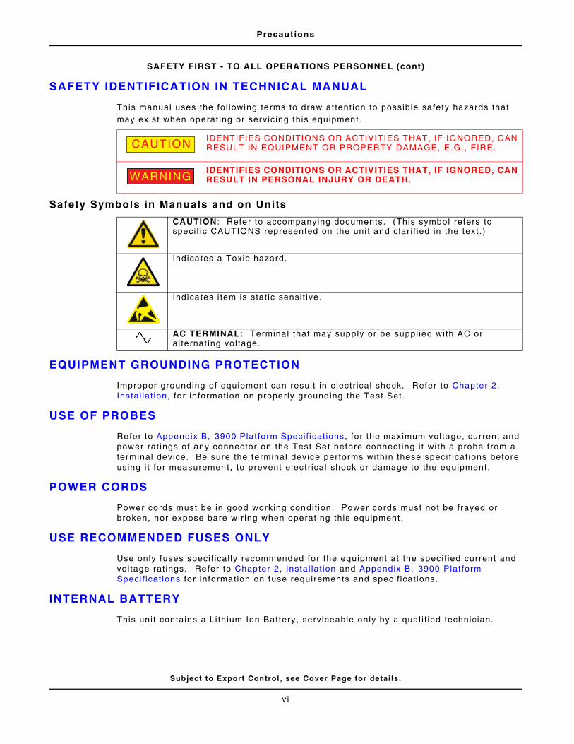
Safety Symbols in Manuals and on Units
EQUIPMENT GROUNDING PROTECTION
Improper grounding of equipment can resul t in electr ical shock. Refer to Chapter 2, Instal lat ion, for information on properly grounding the Test Set.
USE OF PROBES
Refer to Appendix B, 3900 Plat form Speci f icat ions, for the maximum vol tage, current and power rat ings of any connector on the Test Set before connect ing i t wi th a probe f rom a terminal device. Be sure the terminal device per forms within these speci f icat ions before using i t for measurement, to prevent elect r ical shock or damage to the equipment.
POWER CORDS
Power cords must be in good working condit ion. Power cords must not be frayed or broken, nor expose bare wir ing when operat ing this equipment .
USE RECOMMENDED FUSES ONLY
Use only fuses speci f ical ly recommended for the equipment at the speci f ied current and vol tage rat ings. Refer to Chapter 2, Instal lat ion and Appendix B, 3900 Plat form Speci f icat ions for information on fuse requirements and speci f icat ions.
INTERNAL BATTERY
This uni t contains a Li th ium Ion Battery, serviceable only by a qual i f ied technician.
IDENTIFIES CONDITIONS OR ACTIVITIES THAT, IF IGNORED, CAN RESULT IN EQUIPMENT OR PROPERTY DAMAGE, E.G. , FIRE.
IDENTIFIES CONDITIONS OR ACTIVITIES THAT, IF IGNORED, CAN RESULT IN PERSONAL INJURY OR DEATH.
CAUTION : Refer to accompanying documents. (This symbol refers to speci f ic CAUTIONS represented on the uni t and clar i f ied in the text .)
Indicates a Toxic hazard.
Indicates i tem is stat ic sensi t ive.
AC TERMINAL: Terminal that may supply or be suppl ied with AC or al ternat ing vol tage.
CAUTION
WARNING
vi
Precaut ions
Subject to Export Control , see Cover Page for detai ls .
SAFETY FIRST - TO ALL OPERATIONS PERSONNEL (cont)
EMI (ELECTROMAGNETIC INTERFERENCE
ELECTRICAL HAZARDS (AC SUPPLY VOLTAGE)
Refer al l servic ing to qual i f ied personnel. See the l ist o f Aerof lex of f ices on the back of the manual.
Fuses
Note that the internal supply fuse is in ser ies with the l ive conductor of the supply lead. I f connect ion is made to a 2-pin unpolar ized supply socket, i t is possible for the fuse to become transposed to the neutra l conductor , in which case, par ts of the equipment could remain at supply potent ia l even af ter the fuse has ruptured.
Definit ion of Instal lat ion Categories (ref IEC 664-1):
SIGNAL GENERATORS CAN BE A SOURCE OF ELECTROMAGNETIC INTERFERENCE (EMI) TO COMMUNICATION RECEIVERS. SOME TRANSMITTED SIGNALS CAN CAUSE DISRUPTION AND INTERFERENCE TO COMMUNICATION SERVICE OUT TO A DISTANCE OF SEVERAL MILES. USER OF THIS EQUIPMENT SHOULD SCRUTINIZE ANY OPERATION THAT RESULTS IN RADIATION OF A SIGNAL (DIRECTLY OR INDIRECTLY) AND SHOULD TAKE NECESSARY PRECAUTIONS TO AVOID POTENTIAL COMMUNICATION INTERFERENCE PROBLEMS.
THIS EQUIPMENT IS PROVIDED WITH A PROTECTIVE GROUNDING LEAD THAT CONFORMS WITH IEC SAFETY CLASS I . TO MAINTAIN THIS PROTECTION THE SUPPLY LEAD MUST ALWAYS BE CONNECTED TO THE SOURCE OF SUPPLY VIA A SOCKET WITH A GROUNDED CONTACT.BE AWARE THAT THE SUPPLY FILTER CONTAINS CAPACITORS THAT MAY REMAIN CHARGED AFTER THE EQUIPMENT IS DISCONNECTED FROM THE SUPPLY. ALTHOUGH THE STORED ENERGY IS WITHIN THE APPROVED SAFETY REQUIREMENTS, A SLIGHT SHOCK MAY BE FELT IF THE PLUG PINS ARE TOUCHED IMMEDIATELY AFTER REMOVAL.DO NOT REMOVE INSTRUMENT COVERS AS THIS MAY RESULT IN PERSONAL INJURY. THERE ARE NO USER-SERVICEABLE PARTS INSIDE.
CAT I Ci rcui ts that are protected by devices l imi t ing transient overvol tages to a low level , e.g. , e lectron ic c ircu i ts protected by f i l ters.
CAT I I Ci rcui ts that are supply c i rcui ts for domest ic or digi ta l devices that may include transient overvol tages with an average value, e.g. , power supply for household appl iances and portable tools.
CAT I I I Ci rcui ts that are supply c ircui ts for power equipment that may include large transient overvol tages, e .g. , power supply for indust r ia l machines or equipment.
CAT IV Circui ts that may include very high transient overvol tages, e .g. , supply distr ibut ion f rom power l ines.
CAUTION
WARNING
vi i
Precaut ions
Subject to Export Control , see Cover Page for detai ls .
SAFETY FIRST - TO ALL OPERATIONS PERSONNEL (cont)
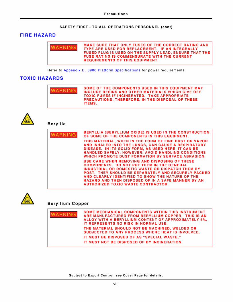
FIRE HAZARD
Refer to Appendix B, 3900 Plat form Speci f icat ions for power requirements.
TOXIC HAZARDS
Beryl l ia
Beryl l ium Copper
MAKE SURE THAT ONLY FUSES OF THE CORRECT RATING AND TYPE ARE USED FOR REPLACEMENT. IF AN INTEGRALLY FUSED PLUG IS USED ON THE SUPPLY LEAD, ENSURE THAT THE FUSE RATING IS COMMENSURATE WITH THE CURRENT REQUIREMENTS OF THIS EQUIPMENT.
SOME OF THE COMPONENTS USED IN THIS EQUIPMENT MAY INCLUDE RESINS AND OTHER MATERIALS WHICH GIVE OFF TOXIC FUMES IF INCINERATED. TAKE APPROPRIATE PRECAUTIONS, THEREFORE, IN THE DISPOSAL OF THESE ITEMS.
BERYLLIA (BERYLLIUM OXIDE) IS USED IN THE CONSTRUCTION OF SOME OF THE COMPONENTS IN THIS EQUIPMENT. THIS MATERIAL, WHEN IN THE FORM OF FINE DUST OR VAPOR AND INHALED INTO THE LUNGS, CAN CAUSE A RESPIRATORY DISEASE. IN ITS SOLID FORM, AS USED HERE, IT CAN BE HANDLED SAFELY, HOWEVER, AVOID HANDLING CONDITIONS WHICH PROMOTE DUST FORMATION BY SURFACE ABRASION.USE CARE WHEN REMOVING AND DISPOSING OF THESE COMPONENTS. DO NOT PUT THEM IN THE GENERAL INDUSTRIAL OR DOMESTIC WASTE OR DISPATCH THEM BY POST. THEY SHOULD BE SEPARATELY AND SECURELY PACKED AND CLEARLY IDENTIFIED TO SHOW THE NATURE OF THE HAZARD AND THEN DISPOSED OF IN A SAFE MANNER BY AN AUTHORIZED TOXIC WASTE CONTRACTOR.
SOME MECHANICAL COMPONENTS WITHIN THIS INSTRUMENT ARE MANUFACTURED FROM BERYLLIUM COPPER. THIS IS AN ALLOY WITH A BERYLLIUM CONTENT OF APPROXIMATELY 5%. IT REPRESENTS NO RISK IN NORMAL USE.THE MATERIAL SHOULD NOT BE MACHINED, WELDED OR SUBJECTED TO ANY PROCESS WHERE HEAT IS INVOLVED.IT MUST BE DISPOSED OF AS “SPECIAL WASTE.”IT MUST NOT BE DISPOSED OF BY INCINERATION.
WARNING
WARNING
WARNING
WARNING
vi i i
Precaut ions
Subject to Export Control , see Cover Page for detai ls .
SAFETY FIRST - TO ALL OPERATIONS PERSONNEL (cont)
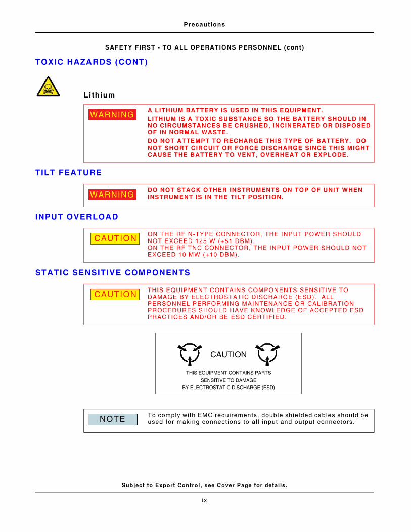
TOXIC HAZARDS (CONT)
Lithium
TILT FEATURE
INPUT OVERLOAD
STATIC SENSITIVE COMPONENTS
A LITHIUM BATTERY IS USED IN THIS EQUIPMENT.LITHIUM IS A TOXIC SUBSTANCE SO THE BATTERY SHOULD IN NO CIRCUMSTANCES BE CRUSHED, INCINERATED OR DISPOSED OF IN NORMAL WASTE. DO NOT ATTEMPT TO RECHARGE THIS TYPE OF BATTERY. DO NOT SHORT CIRCUIT OR FORCE DISCHARGE SINCE THIS MIGHT CAUSE THE BATTERY TO VENT, OVERHEAT OR EXPLODE.
DO NOT STACK OTHER INSTRUMENTS ON TOP OF UNIT WHEN INSTRUMENT IS IN THE TILT POSITION.
ON THE RF N-TYPE CONNECTOR, THE INPUT POWER SHOULD NOT EXCEED 125 W (+51 DBM). ON THE RF TNC CONNECTOR, THE INPUT POWER SHOULD NOT EXCEED 10 MW (+10 DBM).
THIS EQUIPMENT CONTAINS COMPONENTS SENSITIVE TO DAMAGE BY ELECTROSTATIC DISCHARGE (ESD). ALL PERSONNEL PERFORMING MAINTENANCE OR CALIBRATION PROCEDURES SHOULD HAVE KNOWLEDGE OF ACCEPTED ESD PRACTICES AND/OR BE ESD CERTIFIED.
To comply with EMC requirements, double shielded cables should be used for making connect ions to al l input and output connectors.
WARNING
WARNING
CAUTION
CAUTION
CAUTION
THIS EQUIPMENT CONTAINS PARTS
SENSITIVE TO DAMAGE
BY ELECTROSTATIC DISCHARGE (ESD)
NOTE
ix
Precaut ions
Subject to Export Control , see Cover Page for detai ls .
SAFETY FIRST - TO ALL OPERATIONS PERSONNEL (cont)
SUITABILITY FOR USE
THIS EQUIPMENT HAS BEEN DESIGNED AND MANUFACTURED BY AEROFLEX TO GENERATE, RECEIVE AND ANALYZE RF/AUDIO SIGNALS.
IF THE EQUIPMENT IS NOT USED IN A MANNER SPECIFIED BY AEROFLEX, THE PROTECTION PROVIDED BY THE EQUIPMENT MAY BE IMPAIRED.
AEROFLEX HAS NO CONTROL OVER THE USE OF THIS EQUIPMENT AND CANNOT BE HELD RESPONSIBLE FOR EVENTS ARISING FROM ITS USE OTHER THAN FOR ITS INTENDED PURPOSE.
CAUTION
x
Subject to Export Control , see Cover Page for detai ls .i
Table of Contents
General Information . . . . . . . . . . . . . . . . . . . . . . . . . . . 1 - 1
1.1 . . . Int roduct ion . . . . . . . . . . . . . . . . . . . . . . . . . . . . . . . . . . . . . . . . . . . . . . . . 1 - 11.2 . . . Test Set Features . . . . . . . . . . . . . . . . . . . . . . . . . . . . . . . . . . . . . . . . . . . . 1 - 11.3 . . . Test Set Usage . . . . . . . . . . . . . . . . . . . . . . . . . . . . . . . . . . . . . . . . . . . . . . 1 - 2
1.4 . . .Opt ional Test Systems and Funct ions . . . . . . . . . . . . . . . . . . . . . . . . . . . . . . 1 - 21.5 . . .Remote and Automatic Control . . . . . . . . . . . . . . . . . . . . . . . . . . . . . . . . . . . 1 - 2
Instal lat ion . . . . . . . . . . . . . . . . . . . . . . . . . . . . . . . . . . 2 - 1
2.1 . . . Int roduct ion . . . . . . . . . . . . . . . . . . . . . . . . . . . . . . . . . . . . . . . . . . . . . . . . 2 - 1
2.2 . . . In i t ia l V isual Inspect ion . . . . . . . . . . . . . . . . . . . . . . . . . . . . . . . . . . . . . . . . 2 - 12.3 . . . Instal lat ion Requirements . . . . . . . . . . . . . . . . . . . . . . . . . . . . . . . . . . . . . . 2 - 1
2.3.1 . . . . . . . Vent i lat ion . . . . . . . . . . . . . . . . . . . . . . . . . . . . . . . . . . . . . . . . . . . . 2 - 1
2.3.2 . . . . . . . Connect ing to AC Power Supply . . . . . . . . . . . . . . . . . . . . . . . . . . . . . 2 - 1
2.3.3 . . . . . . . Disconnect ing from AC Power Supply . . . . . . . . . . . . . . . . . . . . . . . . . 2 - 1
2.3.4 . . . . . . . AC Power Fuse . . . . . . . . . . . . . . . . . . . . . . . . . . . . . . . . . . . . . . . . 2 - 1
2.4 . . .Power Requirements . . . . . . . . . . . . . . . . . . . . . . . . . . . . . . . . . . . . . . . . . . 2 - 2
2.4.1 . . . . . . . Class I Power Cords (3-core) . . . . . . . . . . . . . . . . . . . . . . . . . . . . . . . 2 - 2
2.5 . . .Accessory Connectors . . . . . . . . . . . . . . . . . . . . . . . . . . . . . . . . . . . . . . . . . 2 - 6
2.5.1 . . . . . . . MIC/ACC Connector . . . . . . . . . . . . . . . . . . . . . . . . . . . . . . . . . . . . . 2 - 6
2.5.2 . . . . . . . GPIB Connector . . . . . . . . . . . . . . . . . . . . . . . . . . . . . . . . . . . . . . . . 2 - 7
2.5.3 . . . . . . . RS-232 Serial Connector . . . . . . . . . . . . . . . . . . . . . . . . . . . . . . . . . . 2 - 8
2.5.4 . . . . . . . Paral le l Connector . . . . . . . . . . . . . . . . . . . . . . . . . . . . . . . . . . . . . . 2 - 8
2.5.5 . . . . . . . Auxi l iary IF Input . . . . . . . . . . . . . . . . . . . . . . . . . . . . . . . . . . . . . . . 2 - 9
2.5.6 . . . . . . . VGA Monitor Output . . . . . . . . . . . . . . . . . . . . . . . . . . . . . . . . . . . . . 2 - 9
2.5.7 . . . . . . . Ethernet and USB Connectors . . . . . . . . . . . . . . . . . . . . . . . . . . . . . 2 - 10
2.5.8 . . . . . . . PS/2 Interface Connectors . . . . . . . . . . . . . . . . . . . . . . . . . . . . . . . 2 - 11
2.5.9 . . . . . . . Test Connector . . . . . . . . . . . . . . . . . . . . . . . . . . . . . . . . . . . . . . . 2 - 11
2.6 . . . Rout ine Safety Test ing and Inspect ion . . . . . . . . . . . . . . . . . . . . . . . . . . . . 2 - 12
2.6.1 . . . . . . . Ear th Bonding Tests . . . . . . . . . . . . . . . . . . . . . . . . . . . . . . . . . . . . 2 - 12
2.6.2 . . . . . . . Insula t ion Tests . . . . . . . . . . . . . . . . . . . . . . . . . . . . . . . . . . . . . . . 2 - 12
2.6.3 . . . . . . . Record Maintenance . . . . . . . . . . . . . . . . . . . . . . . . . . . . . . . . . . . . 2 - 12
2.6.4 . . . . . . . External Cleaning . . . . . . . . . . . . . . . . . . . . . . . . . . . . . . . . . . . . . . 2 - 13
2.6.5 . . . . . . . Visua l Inspect ion . . . . . . . . . . . . . . . . . . . . . . . . . . . . . . . . . . . . . . 2 - 13
2.6.6 . . . . . . . Carry Handle and Bench Support . . . . . . . . . . . . . . . . . . . . . . . . . . . 2 - 13
Table of Contents
Subject to Export Control , see Cover Page for detai ls .i i
Test Set Operat ion . . . . . . . . . . . . . . . . . . . . . . . . . . . . 3 - 1
3.1 . . . Int roduct ion . . . . . . . . . . . . . . . . . . . . . . . . . . . . . . . . . . . . . . . . . . . . . . . . 3 - 13.2 . . . Front Panel Contro ls and Connectors . . . . . . . . . . . . . . . . . . . . . . . . . . . . . . 3 - 1
3.2.1. . . . . . . Front Panel Connector Numerica l Reference Guide . . . . . . . . . . . . . . . 3 - 2
3.3 . . .Rear Panel Contro ls and Connectors . . . . . . . . . . . . . . . . . . . . . . . . . . . . . . . 3 - 7
3.3.1. . . . . . . Rear Panel Connector Numerical Reference Guide . . . . . . . . . . . . . . . . 3 - 7
3.4 . . . Turning Test Set On/Off . . . . . . . . . . . . . . . . . . . . . . . . . . . . . . . . . . . . . . . 3 - 11
3.4.1. . . . . . . Power ing Test Set On . . . . . . . . . . . . . . . . . . . . . . . . . . . . . . . . . . . 3 - 11
3.4.2. . . . . . . Power ing Test Set Down . . . . . . . . . . . . . . . . . . . . . . . . . . . . . . . . . 3 - 12
3.5 . . . Test Set Factory Default Set t ings . . . . . . . . . . . . . . . . . . . . . . . . . . . . . . . . 3 - 13
3.5.1. . . . . . . In i t ia l Star t-up in Factory Defau l t State . . . . . . . . . . . . . . . . . . . . . . . 3 - 13
3.5.2. . . . . . . Reboot in Factory Default State . . . . . . . . . . . . . . . . . . . . . . . . . . . . 3 - 14
3.5.3. . . . . . . Default Restore Options . . . . . . . . . . . . . . . . . . . . . . . . . . . . . . . . . 3 - 15
3.6 . . .Modes of Operat ion . . . . . . . . . . . . . . . . . . . . . . . . . . . . . . . . . . . . . . . . . . 3 - 16
3.6.1. . . . . . . TEST Mode . . . . . . . . . . . . . . . . . . . . . . . . . . . . . . . . . . . . . . . . . . 3 - 16
3.6.2. . . . . . . CONFIG (Conf igurat ion) Mode . . . . . . . . . . . . . . . . . . . . . . . . . . . . . 3 - 17
3.6.3. . . . . . . UTILS (Ut i l i t ies) Mode . . . . . . . . . . . . . . . . . . . . . . . . . . . . . . . . . . . 3 - 18
3.7 . . .Disp lay Layout . . . . . . . . . . . . . . . . . . . . . . . . . . . . . . . . . . . . . . . . . . . . . 3 - 19
3.7.1. . . . . . . Disp lay Ti le Status Bar . . . . . . . . . . . . . . . . . . . . . . . . . . . . . . . . . . 3 - 20
3.7.2. . . . . . . Maximized and Minimized Views . . . . . . . . . . . . . . . . . . . . . . . . . . . . 3 - 22
3.7.3. . . . . . . Navigat ing Display T i les . . . . . . . . . . . . . . . . . . . . . . . . . . . . . . . . . 3 - 23
3.7.4. . . . . . . Float ing Menus . . . . . . . . . . . . . . . . . . . . . . . . . . . . . . . . . . . . . . . . 3 - 23
3.8 . . .Disp lay Components . . . . . . . . . . . . . . . . . . . . . . . . . . . . . . . . . . . . . . . . . 3 - 24
3.8.1. . . . . . . Drop-down Menus . . . . . . . . . . . . . . . . . . . . . . . . . . . . . . . . . . . . . . 3 - 24
3.8.2. . . . . . . Data Entry Fields . . . . . . . . . . . . . . . . . . . . . . . . . . . . . . . . . . . . . . 3 - 24
3.8.3. . . . . . . Tick Boxes . . . . . . . . . . . . . . . . . . . . . . . . . . . . . . . . . . . . . . . . . . . 3 - 27
3.8.4. . . . . . . Opt ion But tons . . . . . . . . . . . . . . . . . . . . . . . . . . . . . . . . . . . . . . . . 3 - 27
3.8.5. . . . . . . Radio Buttons . . . . . . . . . . . . . . . . . . . . . . . . . . . . . . . . . . . . . . . . . 3 - 27
3.8.6. . . . . . . Sof t Keys . . . . . . . . . . . . . . . . . . . . . . . . . . . . . . . . . . . . . . . . . . . . 3 - 28
3.9 . . . L imits . . . . . . . . . . . . . . . . . . . . . . . . . . . . . . . . . . . . . . . . . . . . . . . . . . . . 3 - 30
3.9.1. . . . . . . Upper Limits . . . . . . . . . . . . . . . . . . . . . . . . . . . . . . . . . . . . . . . . . . 3 - 30
3.9.2. . . . . . . Lower Limit . . . . . . . . . . . . . . . . . . . . . . . . . . . . . . . . . . . . . . . . . . 3 - 31
3.10 . .Offsets . . . . . . . . . . . . . . . . . . . . . . . . . . . . . . . . . . . . . . . . . . . . . . . . . . . 3 - 313.11 . . Test Conf igurat ions and Setups . . . . . . . . . . . . . . . . . . . . . . . . . . . . . . . . . 3 - 32
3.11.1. . . . . . Digi tal Radio System . . . . . . . . . . . . . . . . . . . . . . . . . . . . . . . . . . . 3 - 32
3.11.2. . . . . . RF Input and Output Connectors . . . . . . . . . . . . . . . . . . . . . . . . . . . 3 - 33
3.11.3. . . . . . One Port Duplex . . . . . . . . . . . . . . . . . . . . . . . . . . . . . . . . . . . . . . . 3 - 33
3.11.4. . . . . . Two Port Duplex . . . . . . . . . . . . . . . . . . . . . . . . . . . . . . . . . . . . . . . 3 - 34
Table of Contents
Subject to Export Control , see Cover Page for detai ls .i i i
Test Set Uti l i ty Ti les . . . . . . . . . . . . . . . . . . . . . . . . . . . 4 - 1
4.1 . . . Int roduct ion . . . . . . . . . . . . . . . . . . . . . . . . . . . . . . . . . . . . . . . . . . . . . . . . 4 - 14.2 . . .Accessing Ut i l i ty Ti les . . . . . . . . . . . . . . . . . . . . . . . . . . . . . . . . . . . . . . . . . 4 - 14.3 . . .Database Status T i le . . . . . . . . . . . . . . . . . . . . . . . . . . . . . . . . . . . . . . . . . . 4 - 2
4.3.1 . . . . . . . Sof t Key Def in i t ions . . . . . . . . . . . . . . . . . . . . . . . . . . . . . . . . . . . . . 4 - 2
4.4 . . .Disp lay Hold T i le . . . . . . . . . . . . . . . . . . . . . . . . . . . . . . . . . . . . . . . . . . . . . 4 - 4
4.4.1 . . . . . . . Sof t Key Def in i t ions . . . . . . . . . . . . . . . . . . . . . . . . . . . . . . . . . . . . . 4 - 4
4.5 . . .Error List Ti le . . . . . . . . . . . . . . . . . . . . . . . . . . . . . . . . . . . . . . . . . . . . . . . 4 - 5
4.5.1 . . . . . . . Query Errors . . . . . . . . . . . . . . . . . . . . . . . . . . . . . . . . . . . . . . . . . . 4 - 5
4.5.2 . . . . . . . Command Errors . . . . . . . . . . . . . . . . . . . . . . . . . . . . . . . . . . . . . . . . 4 - 5
4.5.3 . . . . . . . Device Errors . . . . . . . . . . . . . . . . . . . . . . . . . . . . . . . . . . . . . . . . . . 4 - 5
4.5.4 . . . . . . . Execut ion Errors . . . . . . . . . . . . . . . . . . . . . . . . . . . . . . . . . . . . . . . . 4 - 5
4.5.5 . . . . . . . Warnings Soft Key Def ini t ion . . . . . . . . . . . . . . . . . . . . . . . . . . . . . . . 4 - 5
4.6 . . . Fi le Management Ti le . . . . . . . . . . . . . . . . . . . . . . . . . . . . . . . . . . . . . . . . . 4 - 6
4.6.1 . . . . . . . Fi le Management Types . . . . . . . . . . . . . . . . . . . . . . . . . . . . . . . . . . . 4 - 6
4.6.2 . . . . . . . Fi le Management Ti le Layout and Navigat ion . . . . . . . . . . . . . . . . . . . . 4 - 7
4.6.3 . . . . . . . Fi le Select ion . . . . . . . . . . . . . . . . . . . . . . . . . . . . . . . . . . . . . . . . . . 4 - 7
4.6.4 . . . . . . . Samples . . . . . . . . . . . . . . . . . . . . . . . . . . . . . . . . . . . . . . . . . . . . . 4 - 8
4.6.5 . . . . . . . Field /Soft Key Def ini t ions . . . . . . . . . . . . . . . . . . . . . . . . . . . . . . . . . 4 - 8
4.6.6 . . . . . . . Transferr ing Fi les . . . . . . . . . . . . . . . . . . . . . . . . . . . . . . . . . . . . . . . 4 - 9
4.7 . . . Frequency Reference Ti le . . . . . . . . . . . . . . . . . . . . . . . . . . . . . . . . . . . . . 4 - 134.8 . . .Help System . . . . . . . . . . . . . . . . . . . . . . . . . . . . . . . . . . . . . . . . . . . . . . . 4 - 14
4.8.1 . . . . . . . Sof t Key Def in i t ions . . . . . . . . . . . . . . . . . . . . . . . . . . . . . . . . . . . . 4 - 15
4.9 . . .Keyboard & Mouse Ti le . . . . . . . . . . . . . . . . . . . . . . . . . . . . . . . . . . . . . . . 4 - 16
4.9.1 . . . . . . . Field Def ini t ions . . . . . . . . . . . . . . . . . . . . . . . . . . . . . . . . . . . . . . . 4 - 16
4.10 . . Language Select . . . . . . . . . . . . . . . . . . . . . . . . . . . . . . . . . . . . . . . . . . . . 4 - 174.11 . . L icense Ti le . . . . . . . . . . . . . . . . . . . . . . . . . . . . . . . . . . . . . . . . . . . . . . . 4 - 18
4.11.1 . . . . . . Test Set Opt ions General Information . . . . . . . . . . . . . . . . . . . . . . . . 4 - 18
4.11.2 . . . . . . Opt ion Dist r ibut ion . . . . . . . . . . . . . . . . . . . . . . . . . . . . . . . . . . . . . 4 - 18
4.11.3 . . . . . . New Opt ion vs Opt ion Update . . . . . . . . . . . . . . . . . . . . . . . . . . . . . 4 - 18
4.11.4 . . . . . . How to Instal l a New Sof tware Option . . . . . . . . . . . . . . . . . . . . . . . . 4 - 19
4.12 . .Network T i le . . . . . . . . . . . . . . . . . . . . . . . . . . . . . . . . . . . . . . . . . . . . . . . 4 - 20
4.12.1 . . . . . . Field /Soft Key Def ini t ions . . . . . . . . . . . . . . . . . . . . . . . . . . . . . . . . 4 - 20
4.12.2 . . . . . . Conf igur ing Network Access . . . . . . . . . . . . . . . . . . . . . . . . . . . . . . 4 - 22
4.13 . .Operat ional Status T i le . . . . . . . . . . . . . . . . . . . . . . . . . . . . . . . . . . . . . . . 4 - 23
4.13.1 . . . . . . Field /Soft Key Def ini t ions . . . . . . . . . . . . . . . . . . . . . . . . . . . . . . . . 4 - 23
4.14 . .Pr inter Conf igurat ion T i le . . . . . . . . . . . . . . . . . . . . . . . . . . . . . . . . . . . . . . 4 - 24
4.14.1 . . . . . . Field /Soft Key Def ini t ions . . . . . . . . . . . . . . . . . . . . . . . . . . . . . . . . 4 - 24
4.14.2 . . . . . . How to Instal l USB or Para l le l Pr in ter Connect ion . . . . . . . . . . . . . . . 4 - 25
4.14.3 . . . . . . How to Instal l Network Printer . . . . . . . . . . . . . . . . . . . . . . . . . . . . . 4 - 26
Table of Contents
Subject to Export Control , see Cover Page for detai ls .iv
Test Set Uti l i ty Ti les (cont)
4.15 . .Remote T i le . . . . . . . . . . . . . . . . . . . . . . . . . . . . . . . . . . . . . . . . . . . . . . . 4 - 27
4.15.1 . . . . . . Field Def ini t ions . . . . . . . . . . . . . . . . . . . . . . . . . . . . . . . . . . . . . . . 4 - 27
4.15.2 . . . . . . Access Test Set v ia GPIB Connect ion (RCI Operat ion) . . . . . . . . . . . . 4 - 28
4.15.3 . . . . . . Access Test Set v ia Internet Browser (GUI Operat ion) . . . . . . . . . . . . 4 - 28
4.15.4 . . . . . . Access Test Set v ia VNC Connect ion (GUI Operat ion) . . . . . . . . . . . . 4 - 29
4.15.5 . . . . . . Access Test Set v ia Ethernet Connect ion (RCI Operat ion) . . . . . . . . . . 4 - 29
4.15.6 . . . . . . Access Test Set v ia WinSCP . . . . . . . . . . . . . . . . . . . . . . . . . . . . . . 4 - 30
4.16 . .Sof tware Upgrade Ti le . . . . . . . . . . . . . . . . . . . . . . . . . . . . . . . . . . . . . . . . 4 - 32
4.16.1 . . . . . . Test Set Software General In formation . . . . . . . . . . . . . . . . . . . . . . . 4 - 33
4.16.2 . . . . . . Sof t Key Def in i t ions . . . . . . . . . . . . . . . . . . . . . . . . . . . . . . . . . . . . 4 - 34
4.16.3 . . . . . . How to Upgrade Software . . . . . . . . . . . . . . . . . . . . . . . . . . . . . . . . 4 - 35
4.17 . .Startup Options Ti le . . . . . . . . . . . . . . . . . . . . . . . . . . . . . . . . . . . . . . . . . 4 - 38
4.17.1 . . . . . . State Def ini t ions . . . . . . . . . . . . . . . . . . . . . . . . . . . . . . . . . . . . . . . 4 - 38
4.18 . .Store/Recal l Ti le . . . . . . . . . . . . . . . . . . . . . . . . . . . . . . . . . . . . . . . . . . . . 4 - 39
4.18.1 . . . . . . Sof t Key Def in i t ions . . . . . . . . . . . . . . . . . . . . . . . . . . . . . . . . . . . . 4 - 40
4.18.2 . . . . . . Managing Fi les . . . . . . . . . . . . . . . . . . . . . . . . . . . . . . . . . . . . . . . . 4 - 41
4.18.3 . . . . . . Numeric Indexing . . . . . . . . . . . . . . . . . . . . . . . . . . . . . . . . . . . . . . 4 - 43
4.19 . . Time & Date Ti le . . . . . . . . . . . . . . . . . . . . . . . . . . . . . . . . . . . . . . . . . . . . 4 - 44
4.19.1 . . . . . . Field Def ini t ions . . . . . . . . . . . . . . . . . . . . . . . . . . . . . . . . . . . . . . . 4 - 44
4.20 . .User Cal ibrat ion Ti le . . . . . . . . . . . . . . . . . . . . . . . . . . . . . . . . . . . . . . . . . 4 - 45
4.20.1 . . . . . . Field /Soft Key Def ini t ions . . . . . . . . . . . . . . . . . . . . . . . . . . . . . . . . 4 - 45
4.20.2 . . . . . . Run User Cal ibrat ion Procedure . . . . . . . . . . . . . . . . . . . . . . . . . . . . 4 - 46
Table of Contents
Subject to Export Control , see Cover Page for detai ls .v
AutoTest I I System Operation . . . . . . . . . . . . . . . . . . . . 5 - 1
5.1 . . . Int roduct ion . . . . . . . . . . . . . . . . . . . . . . . . . . . . . . . . . . . . . . . . . . . . . . . . 5 - 15.2 . . .AutoTest I I Command Structure . . . . . . . . . . . . . . . . . . . . . . . . . . . . . . . . . . 5 - 1
5.2.1 . . . . . . . TCL Commands and Programming Structure . . . . . . . . . . . . . . . . . . . . 5 - 1
5.2.2 . . . . . . . 3900 Remote Commands . . . . . . . . . . . . . . . . . . . . . . . . . . . . . . . . . . 5 - 1
5.3 . . .Select ing AutoTest I I System . . . . . . . . . . . . . . . . . . . . . . . . . . . . . . . . . . . . 5 - 25.4 . . . Loading AutoTest I I Scr ipts . . . . . . . . . . . . . . . . . . . . . . . . . . . . . . . . . . . . . 5 - 2
5.5 . . .Exi t ing AutoTest I I . . . . . . . . . . . . . . . . . . . . . . . . . . . . . . . . . . . . . . . . . . . . 5 - 35.6 . . .AutoTest I I Fi le Name Format . . . . . . . . . . . . . . . . . . . . . . . . . . . . . . . . . . . . 5 - 35.7 . . .AutoTest I I Ti le Components . . . . . . . . . . . . . . . . . . . . . . . . . . . . . . . . . . . . 5 - 3
5.7.1 . . . . . . . Field /Soft Key Def ini t ions . . . . . . . . . . . . . . . . . . . . . . . . . . . . . . . . . 5 - 3
5.8 . . .AutoTest I I Conf igurat ion Ti le . . . . . . . . . . . . . . . . . . . . . . . . . . . . . . . . . . . . 5 - 5
5.8.1 . . . . . . . Field Def ini t ions . . . . . . . . . . . . . . . . . . . . . . . . . . . . . . . . . . . . . . . . 5 - 5
5.9 . . .Edi tor Mode . . . . . . . . . . . . . . . . . . . . . . . . . . . . . . . . . . . . . . . . . . . . . . . . 5 - 6
5.9.1 . . . . . . . Accessing Editor Mode . . . . . . . . . . . . . . . . . . . . . . . . . . . . . . . . . . . 5 - 6
5.10 . .AutoTest I I System Optional Test Scr ipts . . . . . . . . . . . . . . . . . . . . . . . . . . . . 5 - 8
5.10.1 . . . . . . Info Soft Key . . . . . . . . . . . . . . . . . . . . . . . . . . . . . . . . . . . . . . . . . . 5 - 8
5.10.2 . . . . . . Load System Sof t Key . . . . . . . . . . . . . . . . . . . . . . . . . . . . . . . . . . . . 5 - 9
5.10.3 . . . . . . Inst ruments Sof t Key . . . . . . . . . . . . . . . . . . . . . . . . . . . . . . . . . . . . . 5 - 9
5.10.4 . . . . . . Store Recal l Soft Key . . . . . . . . . . . . . . . . . . . . . . . . . . . . . . . . . . . . 5 - 9
5.10.5 . . . . . . Advanced Soft Key . . . . . . . . . . . . . . . . . . . . . . . . . . . . . . . . . . . . . . 5 - 9
5.10.6 . . . . . . Debug Soft Key . . . . . . . . . . . . . . . . . . . . . . . . . . . . . . . . . . . . . . . . 5 - 9
5.10.7 . . . . . . Return . . . . . . . . . . . . . . . . . . . . . . . . . . . . . . . . . . . . . . . . . . . . . . . 5 - 9
5.11 . .AutoTest I I Tutor ials . . . . . . . . . . . . . . . . . . . . . . . . . . . . . . . . . . . . . . . . . 5 - 10
5.11.1 . . . . . . tut1. tc l (Tutor ial 1) . . . . . . . . . . . . . . . . . . . . . . . . . . . . . . . . . . . . . 5 - 10
5.11.2 . . . . . . tut2. tc l (Tutor ial 2) . . . . . . . . . . . . . . . . . . . . . . . . . . . . . . . . . . . . . 5 - 10
5.11.3 . . . . . . tut3. tc l (Tutor ial 3) . . . . . . . . . . . . . . . . . . . . . . . . . . . . . . . . . . . . . 5 - 10
5.11.4 . . . . . . tut4. tc l (Tutor ial 4) . . . . . . . . . . . . . . . . . . . . . . . . . . . . . . . . . . . . . 5 - 10
5.11.5 . . . . . . tut5. tc l (Tutor ial 5) . . . . . . . . . . . . . . . . . . . . . . . . . . . . . . . . . . . . . 5 - 10
5.12 . .Managing Results . . . . . . . . . . . . . . . . . . . . . . . . . . . . . . . . . . . . . . . . . . . 5 - 10
5.12.1 . . . . . . Stor ing Results . . . . . . . . . . . . . . . . . . . . . . . . . . . . . . . . . . . . . . . . 5 - 10
5.12.2 . . . . . . Pr int ing Results . . . . . . . . . . . . . . . . . . . . . . . . . . . . . . . . . . . . . . . 5 - 10
Table of Contents
Subject to Export Control , see Cover Page for detai ls .vi
AutoTest I I System Operation (cont)
5.13 . .AutoTest I I Commands . . . . . . . . . . . . . . . . . . . . . . . . . . . . . . . . . . . . . . . . 5 - 11
5.13.1 . . . . . . AX . . . . . . . . . . . . . . . . . . . . . . . . . . . . . . . . . . . . . . . . . . . . . . . . . 5 - 11
5.13.2 . . . . . . delay “ t ime - in mi l l i seconds” “usrmsg - str ing” . . . . . . . . . . . . . . . . . . 5 - 11
5.13.3 . . . . . . pr int “str ing” . . . . . . . . . . . . . . . . . . . . . . . . . . . . . . . . . . . . . . . . . . 5 - 11
5.13.4 . . . . . . beep . . . . . . . . . . . . . . . . . . . . . . . . . . . . . . . . . . . . . . . . . . . . . . . 5 - 11
5.13.5 . . . . . . rc “str ing” . . . . . . . . . . . . . . . . . . . . . . . . . . . . . . . . . . . . . . . . . . . 5 - 12
5.13.6 . . . . . . c learresults . . . . . . . . . . . . . . . . . . . . . . . . . . . . . . . . . . . . . . . . . . 5 - 12
5.13.7 . . . . . . c learscreen . . . . . . . . . . . . . . . . . . . . . . . . . . . . . . . . . . . . . . . . . . 5 - 12
5.13.8 . . . . . . info1, in fo2, info3 . . . . . . . . . . . . . . . . . . . . . . . . . . . . . . . . . . . . . . 5 - 12
5.13.9 . . . . . . abor t . . . . . . . . . . . . . . . . . . . . . . . . . . . . . . . . . . . . . . . . . . . . . . . 5 - 12
5.13.10 . . . . . openprint f i le . . . . . . . . . . . . . . . . . . . . . . . . . . . . . . . . . . . . . . . . . . 5 - 12
5.13.11 . . . . . wr i teprint f i le . . . . . . . . . . . . . . . . . . . . . . . . . . . . . . . . . . . . . . . . . . 5 - 12
5.13.12 . . . . . c losepr int f i le . . . . . . . . . . . . . . . . . . . . . . . . . . . . . . . . . . . . . . . . . 5 - 12
5.13.13 . . . . . pr int f i le . . . . . . . . . . . . . . . . . . . . . . . . . . . . . . . . . . . . . . . . . . . . . 5 - 13
5.13.14 . . . . . reset tcpip . . . . . . . . . . . . . . . . . . . . . . . . . . . . . . . . . . . . . . . . . . . 5 - 13
5.13.15 . . . . . readch . . . . . . . . . . . . . . . . . . . . . . . . . . . . . . . . . . . . . . . . . . . . . . 5 - 13
5.13.16 . . . . . showmain . . . . . . . . . . . . . . . . . . . . . . . . . . . . . . . . . . . . . . . . . . . . 5 - 13
5.13.17 . . . . . showuser . . . . . . . . . . . . . . . . . . . . . . . . . . . . . . . . . . . . . . . . . . . . 5 - 13
5.13.18 . . . . . setcustom . . . . . . . . . . . . . . . . . . . . . . . . . . . . . . . . . . . . . . . . . . . 5 - 13
5.13.19 . . . . . showcustom . . . . . . . . . . . . . . . . . . . . . . . . . . . . . . . . . . . . . . . . . . 5 - 13
5.13.20 . . . . . c learcustom . . . . . . . . . . . . . . . . . . . . . . . . . . . . . . . . . . . . . . . . . . 5 - 13
5.13.21 . . . . . pause . . . . . . . . . . . . . . . . . . . . . . . . . . . . . . . . . . . . . . . . . . . . . . 5 - 13
5.13.22 . . . . . pauseFRA . . . . . . . . . . . . . . . . . . . . . . . . . . . . . . . . . . . . . . . . . . . 5 - 14
5.13.23 . . . . . pauseYN . . . . . . . . . . . . . . . . . . . . . . . . . . . . . . . . . . . . . . . . . . . . 5 - 14
5.13.24 . . . . . addusermsg “str ing” . . . . . . . . . . . . . . . . . . . . . . . . . . . . . . . . . . . . 5 - 14
5.13.25 . . . . . c learusermsg . . . . . . . . . . . . . . . . . . . . . . . . . . . . . . . . . . . . . . . . . 5 - 14
5.13.26 . . . . . d isplayusermsg . . . . . . . . . . . . . . . . . . . . . . . . . . . . . . . . . . . . . . . 5 - 14
5.13.27 . . . . . d isplayuserentry “str ing” . . . . . . . . . . . . . . . . . . . . . . . . . . . . . . . . . 5 - 15
5.13.28 . . . . . d isplayp icscreen “str ing” “ f i le name” . . . . . . . . . . . . . . . . . . . . . . . . . 5 - 15
5.13.29 . . . . . debugstep “mode” “st r ing” . . . . . . . . . . . . . . . . . . . . . . . . . . . . . . . . 5 - 15
5.13.30 . . . . . AutoTest to Tcl Command . . . . . . . . . . . . . . . . . . . . . . . . . . . . . . . . 5 - 15
5.14 . . Test Funct ions and Variables . . . . . . . . . . . . . . . . . . . . . . . . . . . . . . . . . . . 5 - 16
5.14.1 . . . . . . Using Funct ions . . . . . . . . . . . . . . . . . . . . . . . . . . . . . . . . . . . . . . . 5 - 16
5.14.2 . . . . . . Using Var iables . . . . . . . . . . . . . . . . . . . . . . . . . . . . . . . . . . . . . . . 5 - 19
5.15 . .AutoTest I I Command Conversion Chart . . . . . . . . . . . . . . . . . . . . . . . . . . . . 5 - 24
Table of Contents
Subject to Export Control , see Cover Page for detai ls .vi i
Radio Test Instruments . . . . . . . . . . . . . . . . . . . . . . . . . 6 - 1
6.1 . . . Int roduct ion . . . . . . . . . . . . . . . . . . . . . . . . . . . . . . . . . . . . . . . . . . . . . . . . 6 - 16.2 . . .Markers . . . . . . . . . . . . . . . . . . . . . . . . . . . . . . . . . . . . . . . . . . . . . . . . . . . 6 - 1
6.2.1 . . . . . . . Enabl ing Markers . . . . . . . . . . . . . . . . . . . . . . . . . . . . . . . . . . . . . . . 6 - 1
6.2.2 . . . . . . . Posi t ioning Markers . . . . . . . . . . . . . . . . . . . . . . . . . . . . . . . . . . . . . 6 - 1
6.2.3 . . . . . . . Marker Readings . . . . . . . . . . . . . . . . . . . . . . . . . . . . . . . . . . . . . . . 6 - 2
6.2.4 . . . . . . . Marker Field Def in i t ions . . . . . . . . . . . . . . . . . . . . . . . . . . . . . . . . . . 6 - 3
6.2.5 . . . . . . . Marker Soft Key Def ini t ions . . . . . . . . . . . . . . . . . . . . . . . . . . . . . . . . 6 - 5
6.2.6 . . . . . . . Marker Conf igurat ion T i les . . . . . . . . . . . . . . . . . . . . . . . . . . . . . . . . . 6 - 8
6.3 . . .Channel Analyzer . . . . . . . . . . . . . . . . . . . . . . . . . . . . . . . . . . . . . . . . . . . . 6 - 9
6.3.1 . . . . . . . Basic Set t ings . . . . . . . . . . . . . . . . . . . . . . . . . . . . . . . . . . . . . . . . . 6 - 9
6.3.2 . . . . . . . Field Def ini t ions . . . . . . . . . . . . . . . . . . . . . . . . . . . . . . . . . . . . . . . . 6 - 9
6.3.3 . . . . . . . Sof t Key Def in i t ions . . . . . . . . . . . . . . . . . . . . . . . . . . . . . . . . . . . . 6 - 13
6.4 . . .Spect rum Analyzer . . . . . . . . . . . . . . . . . . . . . . . . . . . . . . . . . . . . . . . . . . 6 - 20
6.4.1 . . . . . . . Basic Set t ings . . . . . . . . . . . . . . . . . . . . . . . . . . . . . . . . . . . . . . . . 6 - 20
6.4.2 . . . . . . . Accessing the Spectrum Analyzer . . . . . . . . . . . . . . . . . . . . . . . . . . . 6 - 20
6.4.3 . . . . . . . Spect rum Analyzer T i le Layout . . . . . . . . . . . . . . . . . . . . . . . . . . . . . 6 - 21
6.4.4 . . . . . . . Field Def ini t ions . . . . . . . . . . . . . . . . . . . . . . . . . . . . . . . . . . . . . . . 6 - 21
6.4.5 . . . . . . . Sof t Key Def in i t ions . . . . . . . . . . . . . . . . . . . . . . . . . . . . . . . . . . . . 6 - 24
6.5 . . .Osci l loscope . . . . . . . . . . . . . . . . . . . . . . . . . . . . . . . . . . . . . . . . . . . . . . . 6 - 31
6.5.1 . . . . . . . Basic Set t ings . . . . . . . . . . . . . . . . . . . . . . . . . . . . . . . . . . . . . . . . 6 - 31
6.5.2 . . . . . . . Accessing the Osci l loscope . . . . . . . . . . . . . . . . . . . . . . . . . . . . . . . 6 - 31
6.5.3 . . . . . . . Osci l loscope Ti le Layout . . . . . . . . . . . . . . . . . . . . . . . . . . . . . . . . . 6 - 32
6.5.4 . . . . . . . Field Def ini t ions . . . . . . . . . . . . . . . . . . . . . . . . . . . . . . . . . . . . . . . 6 - 32
6.5.5 . . . . . . . Sof t Key Def in i t ions . . . . . . . . . . . . . . . . . . . . . . . . . . . . . . . . . . . . 6 - 34
6.6 . . .Dig i tal Mult imeter . . . . . . . . . . . . . . . . . . . . . . . . . . . . . . . . . . . . . . . . . . . 6 - 38
6.6.1 . . . . . . . DMM Test T i le . . . . . . . . . . . . . . . . . . . . . . . . . . . . . . . . . . . . . . . . 6 - 38
6.6.2 . . . . . . . DMM Limits Conf igurat ion Ti le . . . . . . . . . . . . . . . . . . . . . . . . . . . . . 6 - 40
6.7 . . .Opt ional Inst rument Funct ions . . . . . . . . . . . . . . . . . . . . . . . . . . . . . . . . . . 6 - 41
6.7.1 . . . . . . . Audio Analyzer (390XOPT055) . . . . . . . . . . . . . . . . . . . . . . . . . . . . . 6 - 41
6.7.2 . . . . . . . Simulcast Analysis (390XOPT210) . . . . . . . . . . . . . . . . . . . . . . . . . . 6 - 48
6.7.3 . . . . . . . Analyzer OBW & Power Between Markers Opt ion (390XOPT064) . . . . . 6 - 50
6.7.4 . . . . . . . Spect rum Analyzer Tracking Generator Opt ion (390XOPT061) . . . . . . . 6 - 52
Table of Contents
Subject to Export Control , see Cover Page for detai ls .vi i i
Analog Duplex System . . . . . . . . . . . . . . . . . . . . . . . . . 7 - 1
7.1 . . . Int roduct ion . . . . . . . . . . . . . . . . . . . . . . . . . . . . . . . . . . . . . . . . . . . . . . . . 7 - 17.2 . . .Accessing Analog Duplex System . . . . . . . . . . . . . . . . . . . . . . . . . . . . . . . . . 7 - 27.3 . . .Analog Duplex Ti le Layout . . . . . . . . . . . . . . . . . . . . . . . . . . . . . . . . . . . . . . 7 - 3
7.4 . . .Conf igurat ion Ti les . . . . . . . . . . . . . . . . . . . . . . . . . . . . . . . . . . . . . . . . . . . 7 - 4
7.4.1 . . . . . . . AF Limits Conf igurat ion Ti le . . . . . . . . . . . . . . . . . . . . . . . . . . . . . . . . 7 - 4
7.4.2 . . . . . . . AF Measurements Conf igurat ion Ti le . . . . . . . . . . . . . . . . . . . . . . . . . . 7 - 5
7.4.3 . . . . . . . DMM Limits Conf igurat ion Ti le . . . . . . . . . . . . . . . . . . . . . . . . . . . . . . 7 - 7
7.4.4 . . . . . . . DTMF Conf igurat ion T i le . . . . . . . . . . . . . . . . . . . . . . . . . . . . . . . . . . 7 - 8
7.4.5 . . . . . . . Frequency L ist Setup Conf igurat ion Ti le . . . . . . . . . . . . . . . . . . . . . . . 7 - 9
7.4.6 . . . . . . . Harmonics and Spurious Conf igurat ion T i le . . . . . . . . . . . . . . . . . . . . 7 - 15
7.4.7 . . . . . . . Modulat ion Limits Conf igurat ion Ti le . . . . . . . . . . . . . . . . . . . . . . . . . 7 - 16
7.4.8 . . . . . . . Modulat ion Measurements Conf igurat ion T i le . . . . . . . . . . . . . . . . . . . 7 - 17
7.4.9 . . . . . . . Mod Noise Limits . . . . . . . . . . . . . . . . . . . . . . . . . . . . . . . . . . . . . . 7 - 19
7.4.10 . . . . . . Offsets Conf igurat ion Ti le . . . . . . . . . . . . . . . . . . . . . . . . . . . . . . . . 7 - 20
7.4.11 . . . . . . Offsets Cable Loss Measurements . . . . . . . . . . . . . . . . . . . . . . . . . . 7 - 22
7.4.12 . . . . . . Por ts Conf igurat ion Ti le . . . . . . . . . . . . . . . . . . . . . . . . . . . . . . . . . . 7 - 24
7.4.13 . . . . . . RF Generator Conf igurat ion Ti le . . . . . . . . . . . . . . . . . . . . . . . . . . . . 7 - 26
7.4.14 . . . . . . RF L imits Conf igurat ion Ti le . . . . . . . . . . . . . . . . . . . . . . . . . . . . . . 7 - 28
7.4.15 . . . . . . RF Measurements Conf igurat ion Ti le . . . . . . . . . . . . . . . . . . . . . . . . 7 - 29
7.4.16 . . . . . . RF Modulat ion Conf igurat ion Ti le . . . . . . . . . . . . . . . . . . . . . . . . . . . 7 - 31
7.4.17 . . . . . . Tone Sequent ia l Conf igurat ion T i le . . . . . . . . . . . . . . . . . . . . . . . . . . 7 - 32
7.5 . . . Test Ti les . . . . . . . . . . . . . . . . . . . . . . . . . . . . . . . . . . . . . . . . . . . . . . . . . 7 - 33
7.5.1 . . . . . . . Analyzers T i le . . . . . . . . . . . . . . . . . . . . . . . . . . . . . . . . . . . . . . . . 7 - 33
7.5.2 . . . . . . . Frequency L ist Test T i le . . . . . . . . . . . . . . . . . . . . . . . . . . . . . . . . . 7 - 42
7.5.3 . . . . . . . Generators Ti le . . . . . . . . . . . . . . . . . . . . . . . . . . . . . . . . . . . . . . . 7 - 43
7.5.4 . . . . . . . Harmonics and Spurious Measurements (390XOPT060) . . . . . . . . . . . 7 - 50
7.5.5 . . . . . . . IQ Gen Modulat ion (390XOPT054) . . . . . . . . . . . . . . . . . . . . . . . . . . 7 - 52
7.5.6 . . . . . . . Meters Ti le . . . . . . . . . . . . . . . . . . . . . . . . . . . . . . . . . . . . . . . . . . . 7 - 54
7.5.7 . . . . . . . Si te Monitor ing Appl icat ion Test Opt ion (390XOPT051) . . . . . . . . . . . . 7 - 60
7.5.8 . . . . . . . Tone Decoding Ti le . . . . . . . . . . . . . . . . . . . . . . . . . . . . . . . . . . . . . 7 - 66
7.5.9 . . . . . . . Tone Encoding T i le . . . . . . . . . . . . . . . . . . . . . . . . . . . . . . . . . . . . . 7 - 67
Table of Contents
Subject to Export Control , see Cover Page for detai ls .ix
3900 Optional Functions . . . . . . . . . . . . . . . . . . . . . . . . 8 - 1
8.1 . . . Int roduct ion . . . . . . . . . . . . . . . . . . . . . . . . . . . . . . . . . . . . . . . . . . . . . . . . 8 - 18.2 . . .Opt ional Inst rument Funct ions . . . . . . . . . . . . . . . . . . . . . . . . . . . . . . . . . . . 8 - 1
8.2.1. . . . . . . Audio Analyzer (390XOPT055) . . . . . . . . . . . . . . . . . . . . . . . . . . . . . . 8 - 1
8.2.2. . . . . . . Simulcast Analysis (390XOPT210) . . . . . . . . . . . . . . . . . . . . . . . . . . . 8 - 8
8.2.3. . . . . . . Spect rum Analyzer Tracking Generator Opt ion (390XOPT061) . . . . . . . 8 - 10
8.2.4. . . . . . . Analyzer OBW & Power Between Markers Opt ion (390XOPT064) . . . . . 8 - 11
8.3 . . .Opt ional Test and Measurement Funct ions . . . . . . . . . . . . . . . . . . . . . . . . . . 8 - 13
8.3.1. . . . . . . Harmonics and Spurious Measurements (390XOPT060) . . . . . . . . . . . 8 - 13
8.3.2. . . . . . . Harmonics and Spurious Conf igurat ion T i le . . . . . . . . . . . . . . . . . . . . 8 - 14
8.3.3. . . . . . . IQ Gen Modulat ion (390XOPT054) . . . . . . . . . . . . . . . . . . . . . . . . . . 8 - 16
8.3.4. . . . . . . Si te Monitor ing Appl icat ion Test Opt ion (390XOPT051) . . . . . . . . . . . . 8 - 18
8.3.5. . . . . . . POCSAG Test ing Opt ion (390XOPT067) - Encoding . . . . . . . . . . . . . . 8 - 23
8.3.6. . . . . . . POCSAG Test ing Opt ion (390XOPT067) - Decoding . . . . . . . . . . . . . . 8 - 27
8.3.7. . . . . . . Select iv i ty Generator Ti le . . . . . . . . . . . . . . . . . . . . . . . . . . . . . . . . 8 - 29
3900 Optional Test Scripts . . . . . . . . . . . . . . . . . . . . . . 9 - 1
9.1 . . . Int roduct ion . . . . . . . . . . . . . . . . . . . . . . . . . . . . . . . . . . . . . . . . . . . . . . . . 9 - 1
9.2 . . .Genera l Informat ion . . . . . . . . . . . . . . . . . . . . . . . . . . . . . . . . . . . . . . . . . . . 9 - 1
9.2.1 . . . . . . . Loading Scripts . . . . . . . . . . . . . . . . . . . . . . . . . . . . . . . . . . . . . . . . 9 - 1
9.2.2 . . . . . . . Enabl ing Tests . . . . . . . . . . . . . . . . . . . . . . . . . . . . . . . . . . . . . . . . . 9 - 1
9.2.3 . . . . . . . Main T i le Content . . . . . . . . . . . . . . . . . . . . . . . . . . . . . . . . . . . . . . . 9 - 2
9.2.4 . . . . . . . Common Scr ipt Funct ions . . . . . . . . . . . . . . . . . . . . . . . . . . . . . . . . . 9 - 2
9.2.5 . . . . . . . Common Soft Keys . . . . . . . . . . . . . . . . . . . . . . . . . . . . . . . . . . . . . . 9 - 2
9.2.6 . . . . . . . Common Fields . . . . . . . . . . . . . . . . . . . . . . . . . . . . . . . . . . . . . . . . . 9 - 8
9.3 . . .XTS™ 5000 Automatic Al ignment System (390XOPT600) . . . . . . . . . . . . . . . . 9 - 10
9.3.1 . . . . . . . Prel iminary Procedures . . . . . . . . . . . . . . . . . . . . . . . . . . . . . . . . . . 9 - 10
9.3.2 . . . . . . . Hardware Conf igurat ion . . . . . . . . . . . . . . . . . . . . . . . . . . . . . . . . . . 9 - 10
9.4 . . .XTS™ 3000 Automatic Al ignment System (390XOPT601) . . . . . . . . . . . . . . . . 9 - 12
9.4.1 . . . . . . . Prel iminary Procedures . . . . . . . . . . . . . . . . . . . . . . . . . . . . . . . . . . 9 - 12
9.4.2 . . . . . . . Hardware Conf igurat ion . . . . . . . . . . . . . . . . . . . . . . . . . . . . . . . . . . 9 - 12
9.5 . . .XTL Power Al ignment Opt ion (390XOPT602) . . . . . . . . . . . . . . . . . . . . . . . . 9 - 14
9.5.1 . . . . . . . Enable XTL Power Al ignment . . . . . . . . . . . . . . . . . . . . . . . . . . . . . . 9 - 14
9.5.2 . . . . . . . Prel iminary Procedures . . . . . . . . . . . . . . . . . . . . . . . . . . . . . . . . . . 9 - 14
9.5.3 . . . . . . . Hardware Conf igurat ion . . . . . . . . . . . . . . . . . . . . . . . . . . . . . . . . . . 9 - 14
9.6 . . . TIA-603 LMR AutoTest Appl icat ion (390XOPT603) . . . . . . . . . . . . . . . . . . . . 9 - 15
9.6.1 . . . . . . . How to Use TIA-603 LMR AutoTest Appl icat ion . . . . . . . . . . . . . . . . . 9 - 15
9.7 . . .Motorola APX7000 Radio Al ignment (390XOPT604) . . . . . . . . . . . . . . . . . . . 9 - 16
9.7.1 . . . . . . . Prel iminary Procedures . . . . . . . . . . . . . . . . . . . . . . . . . . . . . . . . . . 9 - 16
9.7.2 . . . . . . . Hardware Conf igurat ion . . . . . . . . . . . . . . . . . . . . . . . . . . . . . . . . . . 9 - 16
9.8 . . .EF Johnson 5100/5300 Radio Al ignment (390XOPT606) . . . . . . . . . . . . . . . . 9 - 17
9.8.1 . . . . . . . Prel iminary Procedures . . . . . . . . . . . . . . . . . . . . . . . . . . . . . . . . . . 9 - 17
9.8.2 . . . . . . . Hardware Conf igurat ion . . . . . . . . . . . . . . . . . . . . . . . . . . . . . . . . . . 9 - 17
Table of Contents
Subject to Export Control , see Cover Page for detai ls .x
3900 Optional Test Scripts (cont)
9.9 . . .BK DPHx Radio Al ignment (390XOPT607) . . . . . . . . . . . . . . . . . . . . . . . . . . 9 - 19
9.9.1 . . . . . . . Prel iminary Procedures . . . . . . . . . . . . . . . . . . . . . . . . . . . . . . . . . . 9 - 19
9.9.2 . . . . . . . Hardware Conf igurat ion . . . . . . . . . . . . . . . . . . . . . . . . . . . . . . . . . . 9 - 19
9.10 . .Kenwood P25 TK-5X10G Series Radio AutoTest/Al ignment (390XOPT608) . . . 9 - 20
9.10.1 . . . . . . Prel iminary Procedures . . . . . . . . . . . . . . . . . . . . . . . . . . . . . . . . . . 9 - 20
9.10.2 . . . . . . Hardware Conf igurat ion . . . . . . . . . . . . . . . . . . . . . . . . . . . . . . . . . . 9 - 20
9.11 . .MOTOTRBO Radio Series AutoTest /Al ignment (390XOPT610) . . . . . . . . . . . . 9 - 23
9.11.1 . . . . . . Prel iminary Procedures . . . . . . . . . . . . . . . . . . . . . . . . . . . . . . . . . . 9 - 23
9.11.2 . . . . . . Hardware Conf igurat ion . . . . . . . . . . . . . . . . . . . . . . . . . . . . . . . . . . 9 - 23
9.12 . . Technisonics Type 1 Radio AutoTest /Al ignment (390XOPT614) . . . . . . . . . . . 9 - 249.13 . . Technisonics Type 2 Radio AutoTest /Al ignment (390XOPT615) . . . . . . . . . . . 9 - 249.14 . .DMR Repeater AutoTest (390XOPT626) . . . . . . . . . . . . . . . . . . . . . . . . . . . 9 - 24
Shipping Test Set . . . . . . . . . . . . . . . . . . . . . . . . . . . . .A - 1
A.1 . . .Repacking for Shipping . . . . . . . . . . . . . . . . . . . . . . . . . . . . . . . . . . . . . . . . A - 1
A.1.1 . . . . . . Return Author izat ion . . . . . . . . . . . . . . . . . . . . . . . . . . . . . . . . . . . . . A - 1
A.2 . . . Tagging Test Sets . . . . . . . . . . . . . . . . . . . . . . . . . . . . . . . . . . . . . . . . . . . . A - 1
A.3 . . .Shipping Containers . . . . . . . . . . . . . . . . . . . . . . . . . . . . . . . . . . . . . . . . . . A - 1A.4 . . . Fre ight Costs . . . . . . . . . . . . . . . . . . . . . . . . . . . . . . . . . . . . . . . . . . . . . . . A - 1A.5 . . .Repacking Procedure . . . . . . . . . . . . . . . . . . . . . . . . . . . . . . . . . . . . . . . . . A - 2
3900 Platform Specif ications . . . . . . . . . . . . . . . . . . . .B - 1
B.1 . . .RF Signal Generator . . . . . . . . . . . . . . . . . . . . . . . . . . . . . . . . . . . . . . . . . . B - 1
B.1.1 . . . . . . Frequency . . . . . . . . . . . . . . . . . . . . . . . . . . . . . . . . . . . . . . . . . . . . B - 1
B.1.2 . . . . . . Output Level . . . . . . . . . . . . . . . . . . . . . . . . . . . . . . . . . . . . . . . . . . B - 1
B.1.3 . . . . . . Spect ral Pur i ty . . . . . . . . . . . . . . . . . . . . . . . . . . . . . . . . . . . . . . . . . B - 2
B.1.4 . . . . . . Modulat ion . . . . . . . . . . . . . . . . . . . . . . . . . . . . . . . . . . . . . . . . . . . B - 3
B.2 . . .RF Receiver . . . . . . . . . . . . . . . . . . . . . . . . . . . . . . . . . . . . . . . . . . . . . . . . B - 6
B.2.1 . . . . . . Demodulat ion Select ions . . . . . . . . . . . . . . . . . . . . . . . . . . . . . . . . . . B - 6
B.2.2 . . . . . . Frequency Range (Usable f rom 100 kHz) . . . . . . . . . . . . . . . . . . . . . . B - 6
B.2.3 . . . . . . Sensi t iv i ty . . . . . . . . . . . . . . . . . . . . . . . . . . . . . . . . . . . . . . . . . . . . B - 6
B.2.4 . . . . . . Select iv i ty . . . . . . . . . . . . . . . . . . . . . . . . . . . . . . . . . . . . . . . . . . . . B - 6
B.2.5 . . . . . . Demod Output Level . . . . . . . . . . . . . . . . . . . . . . . . . . . . . . . . . . . . . B - 6
B.3 . . .RF Receive Measurements . . . . . . . . . . . . . . . . . . . . . . . . . . . . . . . . . . . . . . B - 7
B.3.1 . . . . . . AM Meter . . . . . . . . . . . . . . . . . . . . . . . . . . . . . . . . . . . . . . . . . . . . . B - 7
B.3.2 . . . . . . FM Deviat ion Meter . . . . . . . . . . . . . . . . . . . . . . . . . . . . . . . . . . . . . B - 8
B.3.3 . . . . . . RF Counter . . . . . . . . . . . . . . . . . . . . . . . . . . . . . . . . . . . . . . . . . . . B - 8
B.3.4 . . . . . . RF Error Meter . . . . . . . . . . . . . . . . . . . . . . . . . . . . . . . . . . . . . . . . . B - 9
B.3.5 . . . . . . Demodulat ion . . . . . . . . . . . . . . . . . . . . . . . . . . . . . . . . . . . . . . . . . . B - 9
B.3.6 . . . . . . RF Power Meter (Broad band) . . . . . . . . . . . . . . . . . . . . . . . . . . . . . B - 10
B.3.7 . . . . . . RF Power Meter ( In Band) . . . . . . . . . . . . . . . . . . . . . . . . . . . . . . . . B - 10
Table of Contents
Subject to Export Control , see Cover Page for detai ls .xi
3900 Platform Specif ications (cont)
B.4 . . .Audio Funct ion Generator(s) . . . . . . . . . . . . . . . . . . . . . . . . . . . . . . . . . . . B - 11
B.4.1 . . . . . . Waveshape . . . . . . . . . . . . . . . . . . . . . . . . . . . . . . . . . . . . . . . . . . B - 11
B.4.2 . . . . . . Frequency . . . . . . . . . . . . . . . . . . . . . . . . . . . . . . . . . . . . . . . . . . . B - 11
B.4.3 . . . . . . Level (Sine) . . . . . . . . . . . . . . . . . . . . . . . . . . . . . . . . . . . . . . . . . . B - 11
B.4.4 . . . . . . Impedance . . . . . . . . . . . . . . . . . . . . . . . . . . . . . . . . . . . . . . . . . . . B - 11
B.4.5 . . . . . . Spect ral Pur i ty . . . . . . . . . . . . . . . . . . . . . . . . . . . . . . . . . . . . . . . . B - 11
B.5 . . .Audio & Modulat ion Measurements . . . . . . . . . . . . . . . . . . . . . . . . . . . . . . . B - 12
B.5.1 . . . . . . AF Counter . . . . . . . . . . . . . . . . . . . . . . . . . . . . . . . . . . . . . . . . . . B - 12
B.5.2 . . . . . . AF Level Meter . . . . . . . . . . . . . . . . . . . . . . . . . . . . . . . . . . . . . . . . B - 13
B.5.3 . . . . . . SINAD Meter . . . . . . . . . . . . . . . . . . . . . . . . . . . . . . . . . . . . . . . . . B - 14
B.5.4 . . . . . . Distort ion Meter . . . . . . . . . . . . . . . . . . . . . . . . . . . . . . . . . . . . . . . B - 15
B.5.5 . . . . . . Hum and Noise . . . . . . . . . . . . . . . . . . . . . . . . . . . . . . . . . . . . . . . . B - 16
B.5.6 . . . . . . Signal to Noise Rat io . . . . . . . . . . . . . . . . . . . . . . . . . . . . . . . . . . . B - 17
B.5.7 . . . . . . Audio Fi l ters (Character ist ic Response) . . . . . . . . . . . . . . . . . . . . . . B - 18
B.6 . . .Channel Analyzer . . . . . . . . . . . . . . . . . . . . . . . . . . . . . . . . . . . . . . . . . . . B - 19
B.6.1 . . . . . . Frequency . . . . . . . . . . . . . . . . . . . . . . . . . . . . . . . . . . . . . . . . . . . B - 19
B.6.2 . . . . . . Span . . . . . . . . . . . . . . . . . . . . . . . . . . . . . . . . . . . . . . . . . . . . . . . B - 19
B.6.3 . . . . . . Level . . . . . . . . . . . . . . . . . . . . . . . . . . . . . . . . . . . . . . . . . . . . . . . B - 19
B.6.4 . . . . . . Resolut ion Bandwidth . . . . . . . . . . . . . . . . . . . . . . . . . . . . . . . . . . . B - 19
B.6.5 . . . . . . Sweep . . . . . . . . . . . . . . . . . . . . . . . . . . . . . . . . . . . . . . . . . . . . . . B - 19
B.7 . . .RF Spectrum Analyzer . . . . . . . . . . . . . . . . . . . . . . . . . . . . . . . . . . . . . . . . B - 20
B.7.1 . . . . . . Frequency . . . . . . . . . . . . . . . . . . . . . . . . . . . . . . . . . . . . . . . . . . . B - 20
B.7.2 . . . . . . Span . . . . . . . . . . . . . . . . . . . . . . . . . . . . . . . . . . . . . . . . . . . . . . . B - 20
B.7.3 . . . . . . Disp lay Accuracy . . . . . . . . . . . . . . . . . . . . . . . . . . . . . . . . . . . . . . B - 20
B.7.4 . . . . . . Markers . . . . . . . . . . . . . . . . . . . . . . . . . . . . . . . . . . . . . . . . . . . . . B - 20
B.7.5 . . . . . . Level . . . . . . . . . . . . . . . . . . . . . . . . . . . . . . . . . . . . . . . . . . . . . . . B - 21
B.7.6 . . . . . . Resolut ion Bandwidth . . . . . . . . . . . . . . . . . . . . . . . . . . . . . . . . . . . B - 22
B.7.7 . . . . . . Video Bandwidth . . . . . . . . . . . . . . . . . . . . . . . . . . . . . . . . . . . . . . B - 22
B.7.8 . . . . . . Sweep . . . . . . . . . . . . . . . . . . . . . . . . . . . . . . . . . . . . . . . . . . . . . . B - 22
B.7.9 . . . . . . Funct ion/Feature . . . . . . . . . . . . . . . . . . . . . . . . . . . . . . . . . . . . . . B - 23
B.8 . . . Tracking Generator (Opt ion) . . . . . . . . . . . . . . . . . . . . . . . . . . . . . . . . . . . . B - 24
B.8.1 . . . . . . Tracking Generator Output . . . . . . . . . . . . . . . . . . . . . . . . . . . . . . . B - 24
B.8.2 . . . . . . Span and Sweep Time . . . . . . . . . . . . . . . . . . . . . . . . . . . . . . . . . . . B - 24
B.8.3 . . . . . . Tracking Generator Controls . . . . . . . . . . . . . . . . . . . . . . . . . . . . . . B - 24
B.9 . . .Osci l loscope . . . . . . . . . . . . . . . . . . . . . . . . . . . . . . . . . . . . . . . . . . . . . . . B - 25
B.9.1 . . . . . . Disp lay . . . . . . . . . . . . . . . . . . . . . . . . . . . . . . . . . . . . . . . . . . . . . B - 25
B.9.2 . . . . . . Ver t ical . . . . . . . . . . . . . . . . . . . . . . . . . . . . . . . . . . . . . . . . . . . . . B - 25
B.9.3 . . . . . . Horizontal . . . . . . . . . . . . . . . . . . . . . . . . . . . . . . . . . . . . . . . . . . . B - 26
B.9.4 . . . . . . Tr igger . . . . . . . . . . . . . . . . . . . . . . . . . . . . . . . . . . . . . . . . . . . . . B - 26
B.10 . . Frequency Standard I /O . . . . . . . . . . . . . . . . . . . . . . . . . . . . . . . . . . . . . . . B - 27
B.10.1 . . . . . . Internal Frequency Standard Output (OCXO) . . . . . . . . . . . . . . . . . . . B - 27
B.10.2 . . . . . . External Frequency Input . . . . . . . . . . . . . . . . . . . . . . . . . . . . . . . . B - 27
Table of Contents
Subject to Export Control , see Cover Page for detai ls .xi i
3900 Platform Specif ications (cont)
B.11 . .Audio Spectrum Analyzer (Opt ion) . . . . . . . . . . . . . . . . . . . . . . . . . . . . . . . . B - 28
B.11.1 . . . . . . Frequency Range . . . . . . . . . . . . . . . . . . . . . . . . . . . . . . . . . . . . . . B - 28
B.11.2 . . . . . . Resolut ion . . . . . . . . . . . . . . . . . . . . . . . . . . . . . . . . . . . . . . . . . . . B - 28
B.11.3 . . . . . . Accuracy . . . . . . . . . . . . . . . . . . . . . . . . . . . . . . . . . . . . . . . . . . . . B - 28
B.11.4 . . . . . . Span . . . . . . . . . . . . . . . . . . . . . . . . . . . . . . . . . . . . . . . . . . . . . . . B - 28
B.11.5 . . . . . . Level . . . . . . . . . . . . . . . . . . . . . . . . . . . . . . . . . . . . . . . . . . . . . . . B - 28
B.11.6 . . . . . . Markers . . . . . . . . . . . . . . . . . . . . . . . . . . . . . . . . . . . . . . . . . . . . . B - 28
B.12 . .Dig i tal Mult imeter (3920 Only) . . . . . . . . . . . . . . . . . . . . . . . . . . . . . . . . . . B - 29
B.12.1 . . . . . . AC/DC Voltmeter . . . . . . . . . . . . . . . . . . . . . . . . . . . . . . . . . . . . . . B - 29
B.12.2 . . . . . . AC/DC AM Meter . . . . . . . . . . . . . . . . . . . . . . . . . . . . . . . . . . . . . . B - 29
B.12.3 . . . . . . Ohm Meter . . . . . . . . . . . . . . . . . . . . . . . . . . . . . . . . . . . . . . . . . . . B - 29
B.12.4 . . . . . . External Shunt (Opt ional Accessory) . . . . . . . . . . . . . . . . . . . . . . . . . B - 30
B.13 . . Input/Output Connectors . . . . . . . . . . . . . . . . . . . . . . . . . . . . . . . . . . . . . . B - 31
B.13.1 . . . . . . ANT (RF Input) . . . . . . . . . . . . . . . . . . . . . . . . . . . . . . . . . . . . . . . . B - 31
B.13.2 . . . . . . T/R (RF Input/Output) . . . . . . . . . . . . . . . . . . . . . . . . . . . . . . . . . . . B - 31
B.13.3 . . . . . . GEN (RF Output) . . . . . . . . . . . . . . . . . . . . . . . . . . . . . . . . . . . . . . B - 32
B.13.4 . . . . . . GPIB . . . . . . . . . . . . . . . . . . . . . . . . . . . . . . . . . . . . . . . . . . . . . . . B - 32
B.13.5 . . . . . . Ethernet . . . . . . . . . . . . . . . . . . . . . . . . . . . . . . . . . . . . . . . . . . . . B - 32
B.13.6 . . . . . . RS-232 . . . . . . . . . . . . . . . . . . . . . . . . . . . . . . . . . . . . . . . . . . . . . B - 32
B.13.7 . . . . . . Video . . . . . . . . . . . . . . . . . . . . . . . . . . . . . . . . . . . . . . . . . . . . . . B - 33
B.13.8 . . . . . . IF Output . . . . . . . . . . . . . . . . . . . . . . . . . . . . . . . . . . . . . . . . . . . . B - 33
B.13.9 . . . . . . MIC/Accessory . . . . . . . . . . . . . . . . . . . . . . . . . . . . . . . . . . . . . . . . B - 33
B.13.10 . . . . . Paral le l Por t . . . . . . . . . . . . . . . . . . . . . . . . . . . . . . . . . . . . . . . . . B - 33
B.13.11 . . . . . USB . . . . . . . . . . . . . . . . . . . . . . . . . . . . . . . . . . . . . . . . . . . . . . . B - 33
B.13.12 . . . . . PS/2 Inter faces (3901/3902 only) . . . . . . . . . . . . . . . . . . . . . . . . . . B - 34
B.13.13 . . . . . Test Port . . . . . . . . . . . . . . . . . . . . . . . . . . . . . . . . . . . . . . . . . . . . B - 34
B.13.14 . . . . . Auxi l iary IF Input . . . . . . . . . . . . . . . . . . . . . . . . . . . . . . . . . . . . . . B - 34
B.14 . .Environmental . . . . . . . . . . . . . . . . . . . . . . . . . . . . . . . . . . . . . . . . . . . . . . B - 35
B.14.1 . . . . . . Operat ing Temperature . . . . . . . . . . . . . . . . . . . . . . . . . . . . . . . . . . B - 35
B.14.2 . . . . . . Warm-up Time . . . . . . . . . . . . . . . . . . . . . . . . . . . . . . . . . . . . . . . . B - 35
B.14.3 . . . . . . Storage Temperature . . . . . . . . . . . . . . . . . . . . . . . . . . . . . . . . . . . B - 35
B.14.4 . . . . . . Relat ive Humid i ty . . . . . . . . . . . . . . . . . . . . . . . . . . . . . . . . . . . . . . B - 35
B.14.5 . . . . . . Al t i tude . . . . . . . . . . . . . . . . . . . . . . . . . . . . . . . . . . . . . . . . . . . . . B - 35
B.14.6 . . . . . . Shock and Vibrat ions . . . . . . . . . . . . . . . . . . . . . . . . . . . . . . . . . . . B - 35
B.14.7 . . . . . . Use . . . . . . . . . . . . . . . . . . . . . . . . . . . . . . . . . . . . . . . . . . . . . . . . B - 35
B.14.8 . . . . . . EMC . . . . . . . . . . . . . . . . . . . . . . . . . . . . . . . . . . . . . . . . . . . . . . . B - 35
B.14.9 . . . . . . Rel iabi l i ty . . . . . . . . . . . . . . . . . . . . . . . . . . . . . . . . . . . . . . . . . . . B - 35
B.15 . .Safety Standards . . . . . . . . . . . . . . . . . . . . . . . . . . . . . . . . . . . . . . . . . . . B - 36B.16 . .Dimensions and Weight . . . . . . . . . . . . . . . . . . . . . . . . . . . . . . . . . . . . . . . B - 37
B.17 . .AC Power Requirements . . . . . . . . . . . . . . . . . . . . . . . . . . . . . . . . . . . . . . B - 38
B.17.1 . . . . . . Vol tage . . . . . . . . . . . . . . . . . . . . . . . . . . . . . . . . . . . . . . . . . . . . . B - 38
B.17.2 . . . . . . Power Consumption . . . . . . . . . . . . . . . . . . . . . . . . . . . . . . . . . . . . B - 38
B.17.3 . . . . . . Mains Supply Voltage F luctuat ions . . . . . . . . . . . . . . . . . . . . . . . . . . B - 38
B.17.4 . . . . . . Fuse Requirements . . . . . . . . . . . . . . . . . . . . . . . . . . . . . . . . . . . . . B - 38
Table of Contents
Subject to Export Control , see Cover Page for detai ls .xi i i
3900 Platform Specif ications (cont)
B.18 . .Genera l Features . . . . . . . . . . . . . . . . . . . . . . . . . . . . . . . . . . . . . . . . . . . B - 39
B.18.1 . . . . . . LCD Display . . . . . . . . . . . . . . . . . . . . . . . . . . . . . . . . . . . . . . . . . . B - 39
B.18.2 . . . . . . Disk Storage (3901/3902 only) . . . . . . . . . . . . . . . . . . . . . . . . . . . . . B - 39
B.19 . . . . . . . . . . . . . . . . . . . . . . . . . . . . . . . . . . . . . . . . . . . . . . . . . . . . . . . . . . B - 40
Fuse Replacement Instruct ions . . . . . . . . . . . . . . . . . . .C - 1
Abbreviations . . . . . . . . . . . . . . . . . . . . . . . . . . . . . . .D - 1
Common Features Quick Reference Guide . . . . . . . . . . . E - 1
Optional Test Systems and Functions . . . . . . . . . . . . . . F - 1
Error Messages . . . . . . . . . . . . . . . . . . . . . . . . . . . . . G - 1
G.1 . . .Command Errors . . . . . . . . . . . . . . . . . . . . . . . . . . . . . . . . . . . . . . . . . . . . . G - 1G.2 . . .Device Specif ic Errors . . . . . . . . . . . . . . . . . . . . . . . . . . . . . . . . . . . . . . . . . G - 3G.3 . . .Execut ion Errors . . . . . . . . . . . . . . . . . . . . . . . . . . . . . . . . . . . . . . . . . . . . . G - 6
G.4 . . .Query Errors . . . . . . . . . . . . . . . . . . . . . . . . . . . . . . . . . . . . . . . . . . . . . . . . G - 7
Tone Encoding/Decoding Frequency Mapping . . . . . . . .H - 1
Table of Contents
Subject to Export Control , see Cover Page for detai ls .xiv
THIS PAGE INTENTIONALLY LEFT BLANK.
Subject to Export Control , see Cover Page for detai ls .xv
List of Figures
FIGURE PAGE
Fig. 1-1 . . . . . 3920 Dig i tal Radio Test Set . . . . . . . . . . . . . . . . . . . . . . . . . . . . . . . . 1 - 1
Fig. 2-1 . . . . . Wire-Ended Class I Power Cord . . . . . . . . . . . . . . . . . . . . . . . . . . . . . 2 - 2
Fig. 2-2 . . . . . Br i t ish Class I Power Cord . . . . . . . . . . . . . . . . . . . . . . . . . . . . . . . . . 2 - 3
Fig. 2-3 . . . . . North Amer ican Class I Power Cord . . . . . . . . . . . . . . . . . . . . . . . . . . 2 - 3
Fig. 2-4 . . . . . Cont inental Europe Class I Power Cord . . . . . . . . . . . . . . . . . . . . . . . . 2 - 4
Fig. 2-5 . . . . . MIC/ACC Pin Locat ions . . . . . . . . . . . . . . . . . . . . . . . . . . . . . . . . . . . 2 - 6
Fig. 2-6 . . . . . GPIB Connector Pin Locat ions . . . . . . . . . . . . . . . . . . . . . . . . . . . . . . 2 - 7
Fig. 2-7 . . . . . Ser ial Connector Pin Locat ions . . . . . . . . . . . . . . . . . . . . . . . . . . . . . 2 - 8
Fig. 2-8 . . . . . Paral le l Connector Pin Locat ions . . . . . . . . . . . . . . . . . . . . . . . . . . . . 2 - 8
Fig. 2-9 . . . . . VGA Monitor Output Pin Locat ions . . . . . . . . . . . . . . . . . . . . . . . . . . . 2 - 9
Fig. 2-10 . . . . Ethernet and USB Connector Pin Locat ions . . . . . . . . . . . . . . . . . . . . 2 - 10
Fig. 2-11 . . . . PS/2 Connector Pin Locat ions . . . . . . . . . . . . . . . . . . . . . . . . . . . . . 2 - 11
Fig. 2-12 . . . . Test Connector Pin Locat ions . . . . . . . . . . . . . . . . . . . . . . . . . . . . . 2 - 11
Fig. 3-1 . . . . . 3901/3902 Front Panel Connectors . . . . . . . . . . . . . . . . . . . . . . . . . . . 3 - 1
Fig. 3-2 . . . . . 3920/3920B Front Panel Connectors . . . . . . . . . . . . . . . . . . . . . . . . . . 3 - 1
Fig. 3-3 . . . . . 3900 Ser ies Rear Panel Connectors . . . . . . . . . . . . . . . . . . . . . . . . . . 3 - 7
Fig. 3-4 . . . . . Factory Default T i le . . . . . . . . . . . . . . . . . . . . . . . . . . . . . . . . . . . . 3 - 11
Fig. 3-5 . . . . . System Shut-Down Prompt Dialog Box . . . . . . . . . . . . . . . . . . . . . . . 3 - 12
Fig. 3-6 . . . . . Factory Default Display Ti le . . . . . . . . . . . . . . . . . . . . . . . . . . . . . . . 3 - 13
Fig. 3-7 . . . . . Power On Blue Screen “X” . . . . . . . . . . . . . . . . . . . . . . . . . . . . . . . . 3 - 14
Fig. 3-8 . . . . . Restore Factory Defaul ts - Restore Select ions . . . . . . . . . . . . . . . . . . 3 - 15
Fig. 3-9 . . . . . System/Conf igurat ion Float ing Menu . . . . . . . . . . . . . . . . . . . . . . . . . 3 - 16
Fig. 3-10 . . . . Analog Duplex Conf igurat ion Float ing Menu . . . . . . . . . . . . . . . . . . . . 3 - 17
Fig. 3-11 . . . . UTILS Float ing Menu - Hardware Sett ings Selected . . . . . . . . . . . . . . 3 - 18
Fig. 3-12 . . . . Analog Duplex System Disp lay - Minimized View . . . . . . . . . . . . . . . . 3 - 19
Fig. 3-13 . . . . Status Bar Fields . . . . . . . . . . . . . . . . . . . . . . . . . . . . . . . . . . . . . . 3 - 20
Fig. 3-14 . . . . Status Bar Content Diagram . . . . . . . . . . . . . . . . . . . . . . . . . . . . . . . 3 - 20
Fig. 3-15 . . . . P25 Opt ional System - Channel Plan Field . . . . . . . . . . . . . . . . . . . . 3 - 21
Fig. 3-16 . . . . Minimized - Maximized Viewing Opt ions . . . . . . . . . . . . . . . . . . . . . . 3 - 22
Fig. 3-17 . . . . Channel Analyzer Maximized - TAB Float ing Menu of Act ive Ti les . . . . 3 - 23
Fig. 3-18 . . . . Numeric Entry - Selected Edit States . . . . . . . . . . . . . . . . . . . . . . . . 3 - 24
Fig. 3-19 . . . . Data F ield Background Colors . . . . . . . . . . . . . . . . . . . . . . . . . . . . . 3 - 25
Fig. 3-20 . . . . Pass/Fai l Indicators . . . . . . . . . . . . . . . . . . . . . . . . . . . . . . . . . . . . 3 - 25
Fig. 3-21 . . . . Numeric Output and Limi t Sett ings Readouts . . . . . . . . . . . . . . . . . . . 3 - 26
Fig. 3-22 . . . . Tick Buttons - Enable/Disable Mod Generators . . . . . . . . . . . . . . . . . 3 - 27
List of Figures
Subject to Export Control , see Cover Page for detai ls .xvi
FIGURE PAGE
Fig. 3-23 . . . . Opt ion (Toggle) Buttons . . . . . . . . . . . . . . . . . . . . . . . . . . . . . . . . . 3 - 27
Fig. 3-24 . . . . Radio Buttons - Measurement Results Select ion . . . . . . . . . . . . . . . . 3 - 27
Fig. 3-25 . . . . Analog Duplex - L imits Enabled . . . . . . . . . . . . . . . . . . . . . . . . . . . . 3 - 30
Fig. 3-26 . . . . Generator and Analyzer Offset Indicators . . . . . . . . . . . . . . . . . . . . . 3 - 31
Fig. 3-27 . . . . Basic Test Setup . . . . . . . . . . . . . . . . . . . . . . . . . . . . . . . . . . . . . . 3 - 32
Fig. 3-28 . . . . One Port Duplex Test Setup . . . . . . . . . . . . . . . . . . . . . . . . . . . . . . . 3 - 33
Fig. 3-29 . . . . GEN/ANT Two Port Duplex Test Setup . . . . . . . . . . . . . . . . . . . . . . . 3 - 34
Fig. 3-30 . . . . GEN/TR Two Port Duplex Test Setup . . . . . . . . . . . . . . . . . . . . . . . . 3 - 34
Fig. 3-31 . . . . TR/ANT Two Port Duplex Test Setup . . . . . . . . . . . . . . . . . . . . . . . . 3 - 34
Fig. 4-1 . . . . . Ut i l i ty Ti le Menu . . . . . . . . . . . . . . . . . . . . . . . . . . . . . . . . . . . . . . . . 4 - 1
Fig. 4-2 . . . . . Database Status T i le . . . . . . . . . . . . . . . . . . . . . . . . . . . . . . . . . . . . . 4 - 2
Fig. 4-3 . . . . . HOLD Display TI le . . . . . . . . . . . . . . . . . . . . . . . . . . . . . . . . . . . . . . 4 - 4
Fig. 4-4 . . . . . UTILS Error List Ti le . . . . . . . . . . . . . . . . . . . . . . . . . . . . . . . . . . . . . 4 - 5
Fig. 4-5 . . . . . Fi le Management Ti le . . . . . . . . . . . . . . . . . . . . . . . . . . . . . . . . . . . . 4 - 6
Fig. 4-6 . . . . . Fi le Management Ti le Layout . . . . . . . . . . . . . . . . . . . . . . . . . . . . . . . 4 - 7
Fig. 4-7 . . . . . Fi le Management - Mult ip le F i les Selected . . . . . . . . . . . . . . . . . . . . . 4 - 7
Fig. 4-8 . . . . . Fi le Management - Fi le Delete Conf irmat ion Prompt . . . . . . . . . . . . . . . 4 - 8
Fig. 4-9 . . . . . Fi le Management - Se lect ing Fi le . . . . . . . . . . . . . . . . . . . . . . . . . . . . 4 - 9
Fig. 4-10 . . . . Fi le Management Ti le - Fi le Selected to Copy . . . . . . . . . . . . . . . . . . 4 - 10
Fig. 4-11 . . . . Fi le Management Ti le - Copy Complete . . . . . . . . . . . . . . . . . . . . . . . 4 - 10
Fig. 4-12 . . . . Select Internal Drive . . . . . . . . . . . . . . . . . . . . . . . . . . . . . . . . . . . . 4 - 11
Fig. 4-13 . . . . Select External Drive . . . . . . . . . . . . . . . . . . . . . . . . . . . . . . . . . . . 4 - 11
Fig. 4-14 . . . . Fi le Management - Fi le Selected . . . . . . . . . . . . . . . . . . . . . . . . . . . 4 - 12
Fig. 4-15 . . . . UTILS Frequency Reference Ti le . . . . . . . . . . . . . . . . . . . . . . . . . . . 4 - 13
Fig. 4-16 . . . . Reference Unlocked Error Message . . . . . . . . . . . . . . . . . . . . . . . . . 4 - 13
Fig. 4-17 . . . . Main Help Ti le . . . . . . . . . . . . . . . . . . . . . . . . . . . . . . . . . . . . . . . . 4 - 14
Fig. 4-18 . . . . Example of Help Fi le Contents . . . . . . . . . . . . . . . . . . . . . . . . . . . . . 4 - 14
Fig. 4-19 . . . . UTILS Keyboard & Mouse Ti le . . . . . . . . . . . . . . . . . . . . . . . . . . . . . 4 - 16
Fig. 4-20 . . . . Language Select Ti le . . . . . . . . . . . . . . . . . . . . . . . . . . . . . . . . . . . 4 - 17
Fig. 4-21 . . . . Chinese Language Support . . . . . . . . . . . . . . . . . . . . . . . . . . . . . . . 4 - 17
Fig. 4-22 . . . . UTILS Sof tware License Ti le . . . . . . . . . . . . . . . . . . . . . . . . . . . . . . 4 - 18
Fig. 4-23 . . . . Di rectory Format for License Instal lat ion . . . . . . . . . . . . . . . . . . . . . . 4 - 19
Fig. 4-24 . . . . UTILS Network T i le . . . . . . . . . . . . . . . . . . . . . . . . . . . . . . . . . . . . . 4 - 20
Fig. 4-25 . . . . Operat ional Status T i le . . . . . . . . . . . . . . . . . . . . . . . . . . . . . . . . . . 4 - 23
Fig. 4-26 . . . . UTILS Pr inter Conf igurat ion Ti le - Main Ti le . . . . . . . . . . . . . . . . . . . 4 - 24
Fig. 4-27 . . . . USB Pr inter Instal lat ion Complete . . . . . . . . . . . . . . . . . . . . . . . . . . 4 - 25
Fig. 4-28 . . . . Network Printer Setup - Avai lable Pr inters . . . . . . . . . . . . . . . . . . . . . 4 - 26
Fig. 4-29 . . . . Network Printer Insta l lat ion Complete . . . . . . . . . . . . . . . . . . . . . . . . 4 - 26
Fig. 4-30 . . . . UTILS Remote T i le . . . . . . . . . . . . . . . . . . . . . . . . . . . . . . . . . . . . . 4 - 27
List of Figures
Subject to Export Control , see Cover Page for detai ls .xvi i
FIGURE PAGE
Fig. 4-31 . . . . GPIB Go To Local Soft Key . . . . . . . . . . . . . . . . . . . . . . . . . . . . . . . 4 - 28
Fig. 4-32 . . . . Command Window Example . . . . . . . . . . . . . . . . . . . . . . . . . . . . . . . 4 - 29
Fig. 4-33 . . . . WinSCP Login Window (Version 4.1 .8.415) . . . . . . . . . . . . . . . . . . . . 4 - 30
Fig. 4-34 . . . . WinSCP Window (Version 4.1 .8.415) . . . . . . . . . . . . . . . . . . . . . . . . 4 - 30
Fig. 4-35 . . . . WinSCP Transfer Preferences - Disable Timestamp . . . . . . . . . . . . . . 4 - 31
Fig. 4-36 . . . . Accessing Software Upgrade Funct ion . . . . . . . . . . . . . . . . . . . . . . . 4 - 32
Fig. 4-37 . . . . System Sof tware Information . . . . . . . . . . . . . . . . . . . . . . . . . . . . . . 4 - 33
Fig. 4-38 . . . . Check For Upgrades - Sub-menu Sof t Keys . . . . . . . . . . . . . . . . . . . . 4 - 34
Fig. 4-39 . . . . Defaults Ti le . . . . . . . . . . . . . . . . . . . . . . . . . . . . . . . . . . . . . . . . . 4 - 36
Fig. 4-40 . . . . Sof tware Upgrade - Conf irm Upgrade Process . . . . . . . . . . . . . . . . . . 4 - 37
Fig. 4-41 . . . . Startup Options Ti le . . . . . . . . . . . . . . . . . . . . . . . . . . . . . . . . . . . . 4 - 38
Fig. 4-42 . . . . Accessing Store/Recal l Ti le . . . . . . . . . . . . . . . . . . . . . . . . . . . . . . . 4 - 39
Fig. 4-43 . . . . Save/Recal l Ti le . . . . . . . . . . . . . . . . . . . . . . . . . . . . . . . . . . . . . . . 4 - 39
Fig. 4-44 . . . . Creat ing a Set t ings Fi le . . . . . . . . . . . . . . . . . . . . . . . . . . . . . . . . . . 4 - 41
Fig. 4-45 . . . . Store/Recal l Dialog Box . . . . . . . . . . . . . . . . . . . . . . . . . . . . . . . . . . 4 - 42
Fig. 4-46 . . . . Creat ing New Directory . . . . . . . . . . . . . . . . . . . . . . . . . . . . . . . . . . 4 - 43
Fig. 4-47 . . . . UTILS Time and Date Ti le . . . . . . . . . . . . . . . . . . . . . . . . . . . . . . . . 4 - 44
Fig. 4-48 . . . . UTILS User Cal ibrat ion Ti le . . . . . . . . . . . . . . . . . . . . . . . . . . . . . . . 4 - 45
Fig. 4-49 . . . . User Cal ibrat ion Ti le . . . . . . . . . . . . . . . . . . . . . . . . . . . . . . . . . . . . 4 - 46
Fig. 5-1 . . . . . Use of rc in AutoTest I I Scr ipt . . . . . . . . . . . . . . . . . . . . . . . . . . . . . . 5 - 1
Fig. 5-2 . . . . . AutoTest I I Main T i le . . . . . . . . . . . . . . . . . . . . . . . . . . . . . . . . . . . . 5 - 2
Fig. 5-3 . . . . . AutoTest I I Ti le Layout . . . . . . . . . . . . . . . . . . . . . . . . . . . . . . . . . . . 5 - 3
Fig. 5-4 . . . . . Remote Command Val idat ion . . . . . . . . . . . . . . . . . . . . . . . . . . . . . . . 5 - 4
Fig. 5-5 . . . . . AutoTest I I Conf igurat ion Ti le . . . . . . . . . . . . . . . . . . . . . . . . . . . . . . 5 - 5
Fig. 5-6 . . . . . Accessing AutoTest I I Ed i tor Tool . . . . . . . . . . . . . . . . . . . . . . . . . . . . 5 - 6
Fig. 5-7 . . . . . Scr ipt Fi le in Editor Mode . . . . . . . . . . . . . . . . . . . . . . . . . . . . . . . . . 5 - 7
Fig. 5-8 . . . . . AutoTest I I - Scr ipt Opt ion Buttons . . . . . . . . . . . . . . . . . . . . . . . . . . . 5 - 8
Fig. 5-9 . . . . . Informat ion T i le Example - Motorola ASTRO P25 Autotest . . . . . . . . . . . 5 - 8
Fig. 5-10 . . . . AutoTest I I System - Advanced Ti le . . . . . . . . . . . . . . . . . . . . . . . . . . 5 - 9
Fig. 6-1 . . . . . Marker Readings . . . . . . . . . . . . . . . . . . . . . . . . . . . . . . . . . . . . . . . 6 - 2
Fig. 6-2 . . . . . Channel Analyzer Marker Field/Toggle Buttons . . . . . . . . . . . . . . . . . . 6 - 3
Fig. 6-3 . . . . . Scope Marker F ield/Toggle But tons . . . . . . . . . . . . . . . . . . . . . . . . . . 6 - 3
Fig. 6-4 . . . . . Markers Soft Key Sub-menus . . . . . . . . . . . . . . . . . . . . . . . . . . . . . . . 6 - 5
Fig. 6-5 . . . . . Markers 1 and 2 - LOCKED State . . . . . . . . . . . . . . . . . . . . . . . . . . . . 6 - 5
Fig. 6-6 . . . . . LOCKED Markers - Reposi t ioned Whi le in LOCKED State . . . . . . . . . . . 6 - 6
Fig. 6-7 . . . . . Mkr 1 /Mkr 2 Soft Key Sub-menu . . . . . . . . . . . . . . . . . . . . . . . . . . . . . 6 - 6
Fig. 6-8 . . . . . Toggle Marker Soft Key . . . . . . . . . . . . . . . . . . . . . . . . . . . . . . . . . . . 6 - 7
Fig. 6-9 . . . . . Audio Analyzer Markers Conf igurat ion T i le . . . . . . . . . . . . . . . . . . . . . 6 - 8
Fig. 6-10 . . . . Spect rum Analyzer Markers Conf igurat ion Ti le . . . . . . . . . . . . . . . . . . . 6 - 8
List of Figures
Subject to Export Control , see Cover Page for detai ls .xvi i i
FIGURE PAGE
Fig. 6-11 . . . . Channel Analyzer Star t and Stop Frequency Sett ing . . . . . . . . . . . . . . 6 - 10
Fig. 6-12 . . . . Channel Analyzer Center Frequency and Span Sett ing . . . . . . . . . . . . 6 - 11
Fig. 6-13 . . . . Channel Analyzer Zero Span Example . . . . . . . . . . . . . . . . . . . . . . . . 6 - 11
Fig. 6-14 . . . . Channel Analyzer Absolute Sett ing . . . . . . . . . . . . . . . . . . . . . . . . . . 6 - 12
Fig. 6-15 . . . . Channel Analyzer Relat ive Sett ing . . . . . . . . . . . . . . . . . . . . . . . . . . 6 - 12
Fig. 6-16 . . . . Channel Analyzer - Ref Level and Scale Sett ings . . . . . . . . . . . . . . . . 6 - 13
Fig. 6-17 . . . . Channel Analyzer Star t and Stop Frequency Sett ing . . . . . . . . . . . . . . 6 - 14
Fig. 6-18 . . . . Channel Analyzer Coupl ing Soft Key Menu . . . . . . . . . . . . . . . . . . . . 6 - 15
Fig. 6-19 . . . . Channel Analyzer Sweep and Averaging Progress Bars . . . . . . . . . . . 6 - 16
Fig. 6-20 . . . . Channel Analyzer Trace Soft Key . . . . . . . . . . . . . . . . . . . . . . . . . . . 6 - 17
Fig. 6-21 . . . . Channel Analyzer with Tr igger Sof t Keys . . . . . . . . . . . . . . . . . . . . . . 6 - 19
Fig. 6-22 . . . . Accessing Spectrum Analyzer - TEST Float ing Menu . . . . . . . . . . . . . 6 - 20
Fig. 6-23 . . . . Spect rum Analyzer T i le . . . . . . . . . . . . . . . . . . . . . . . . . . . . . . . . . . 6 - 21
Fig. 6-24 . . . . Spect rum Analyzer Star t and Stop Frequency Sett ing . . . . . . . . . . . . . 6 - 22
Fig. 6-25 . . . . Spect rum Analyzer Center Frequency and Span Sett ing . . . . . . . . . . . 6 - 23
Fig. 6-26 . . . . Spect rum Analyzer Zero Span Example . . . . . . . . . . . . . . . . . . . . . . . 6 - 23
Fig. 6-27 . . . . Spect rum Analyzer Vert ical Sett ings T i le . . . . . . . . . . . . . . . . . . . . . . 6 - 24
Fig. 6-28 . . . . Spect rum Analyzer Horizontal Set t ings Ti le . . . . . . . . . . . . . . . . . . . . 6 - 25
Fig. 6-29 . . . . Spect rum Analyzer Coupl ing Soft Key Menu . . . . . . . . . . . . . . . . . . . 6 - 26
Fig. 6-30 . . . . Spect rum Analyzer - A l l Markers Enabled . . . . . . . . . . . . . . . . . . . . . 6 - 27
Fig. 6-31 . . . . Spect rum Analyzer with Live, Peak and Captured Traces . . . . . . . . . . 6 - 28
Fig. 6-32 . . . . Spect rum Analyzer with Live Trace . . . . . . . . . . . . . . . . . . . . . . . . . . 6 - 30
Fig. 6-33 . . . . Accessing the Osci l loscope . . . . . . . . . . . . . . . . . . . . . . . . . . . . . . . 6 - 31
Fig. 6-34 . . . . Osci l loscope Ti le - Maximized View . . . . . . . . . . . . . . . . . . . . . . . . . 6 - 32
Fig. 6-35 . . . . Osci l loscope Ti le - Vert ical Sett ings . . . . . . . . . . . . . . . . . . . . . . . . . 6 - 34
Fig. 6-36 . . . . Scope Expand/Contract Sof t Keys . . . . . . . . . . . . . . . . . . . . . . . . . . 6 - 34
Fig. 6-37 . . . . Osci l loscope Trace Soft Keys . . . . . . . . . . . . . . . . . . . . . . . . . . . . . . 6 - 35
Fig. 6-38 . . . . Osci l loscope Captured Traces . . . . . . . . . . . . . . . . . . . . . . . . . . . . . 6 - 36
Fig. 6-39 . . . . Osci l loscope Tr igger Sof t Keys . . . . . . . . . . . . . . . . . . . . . . . . . . . . 6 - 37
Fig. 6-40 . . . . DMM Ti le - Maximized View . . . . . . . . . . . . . . . . . . . . . . . . . . . . . . . 6 - 38
Fig. 6-41 . . . . DMM Shunt Instal lat ion Prompt Dialog Box . . . . . . . . . . . . . . . . . . . . 6 - 39
Fig. 6-42 . . . . Shunt Instal led . . . . . . . . . . . . . . . . . . . . . . . . . . . . . . . . . . . . . . . . 6 - 39
Fig. 6-43 . . . . DMM Limits Conf igurat ion Ti le . . . . . . . . . . . . . . . . . . . . . . . . . . . . . 6 - 40
Fig. 6-44 . . . . Accessing Audio Analyzer . . . . . . . . . . . . . . . . . . . . . . . . . . . . . . . . 6 - 41
Fig. 6-45 . . . . Audio Analyzer Ti le - Maximized View . . . . . . . . . . . . . . . . . . . . . . . . 6 - 42
Fig. 6-46 . . . . Log Scal ing Selected . . . . . . . . . . . . . . . . . . . . . . . . . . . . . . . . . . . 6 - 43
Fig. 6-47 . . . . Audio Analyzer - Ref Level and Scale Set t ings . . . . . . . . . . . . . . . . . . 6 - 44
Fig. 6-48 . . . . Audio Analyzer Start and Stop Frequency Set t ing . . . . . . . . . . . . . . . 6 - 44
Fig. 6-49 . . . . Audio Analyzer Trace Soft Keys . . . . . . . . . . . . . . . . . . . . . . . . . . . . 6 - 45
List of Figures
Subject to Export Control , see Cover Page for detai ls .xix
FIGURE PAGE
Fig. 6-50 . . . . Audio Analyzer - Trace Limits Enabled . . . . . . . . . . . . . . . . . . . . . . . 6 - 47
Fig. 6-51 . . . . Audio Analyzer - Rx Bandpass Sweep . . . . . . . . . . . . . . . . . . . . . . . . 6 - 48
Fig. 6-52 . . . . Audio Analyzer - Tx Bandpass Sweep . . . . . . . . . . . . . . . . . . . . . . . . 6 - 48
Fig. 6-53 . . . . Spect rum Analyzer - Power Between Markers Measurement . . . . . . . . 6 - 50
Fig. 6-54 . . . . Spect rum Analyzer - Occupied Bandwidth at 99% . . . . . . . . . . . . . . . . 6 - 50
Fig. 6-55 . . . . Spect rum Analyzer - Occupied Bandwidth at 75% . . . . . . . . . . . . . . . . 6 - 51
Fig. 6-56 . . . . Spect rum Analyzer T i le - Tracking Generator Parameters . . . . . . . . . . 6 - 52
Fig. 7-1 . . . . . Select ing Analog Duplex System . . . . . . . . . . . . . . . . . . . . . . . . . . . . 7 - 2
Fig. 7-2 . . . . . Analog Duplex System - TEST Mode - Minimized T i les . . . . . . . . . . . . . 7 - 3
Fig. 7-3 . . . . . AF Limits Conf igurat ion Ti le . . . . . . . . . . . . . . . . . . . . . . . . . . . . . . . 7 - 4
Fig. 7-4 . . . . . AF Measurements Conf igurat ion Ti le . . . . . . . . . . . . . . . . . . . . . . . . . 7 - 5
Fig. 7-5 . . . . . DMM Limits Conf igurat ion Ti le . . . . . . . . . . . . . . . . . . . . . . . . . . . . . . 7 - 7
Fig. 7-6 . . . . . DTMF Conf igurat ion T i le . . . . . . . . . . . . . . . . . . . . . . . . . . . . . . . . . . 7 - 8
Fig. 7-7 . . . . . Frequency L ist Setup Conf igurat ion Ti le . . . . . . . . . . . . . . . . . . . . . . . 7 - 9
Fig. 7-8 . . . . . Frequency L ist - Import /Expor t Soft Key Submenu . . . . . . . . . . . . . . . 7 - 10
Fig. 7-9 . . . . . Frequency L ist - Conf igure List . . . . . . . . . . . . . . . . . . . . . . . . . . . . 7 - 11
Fig. 7-10 . . . . Frequency L ist - Store Fi le Dialog Window . . . . . . . . . . . . . . . . . . . . 7 - 12
Fig. 7-11 . . . . Frequency L ist - Store Fi le Dialog Window . . . . . . . . . . . . . . . . . . . . 7 - 12
Fig. 7-12 . . . . Frequency L ist - Stored Fi le Avai lable . . . . . . . . . . . . . . . . . . . . . . . . 7 - 13
Fig. 7-13 . . . . Frequency L ist - Format Example . . . . . . . . . . . . . . . . . . . . . . . . . . . 7 - 13
Fig. 7-14 . . . . Harm & Spur L imits Conf igurat ion Ti le . . . . . . . . . . . . . . . . . . . . . . . 7 - 15
Fig. 7-15 . . . . Analog Duplex - Mod Limits Conf igurat ion Ti le . . . . . . . . . . . . . . . . . . 7 - 16
Fig. 7-16 . . . . Analog Duplex - Modulat ions Measurements Conf igurat ion Ti le . . . . . . 7 - 17
Fig. 7-17 . . . . Mod Noise Limits Conf igurat ion Ti le . . . . . . . . . . . . . . . . . . . . . . . . . 7 - 19
Fig. 7-18 . . . . Offsets Conf igurat ion Ti le . . . . . . . . . . . . . . . . . . . . . . . . . . . . . . . . 7 - 20
Fig. 7-19 . . . . Cable Loss Parameters Enabled . . . . . . . . . . . . . . . . . . . . . . . . . . . . 7 - 22
Fig. 7-20 . . . . Cable Loss Tables . . . . . . . . . . . . . . . . . . . . . . . . . . . . . . . . . . . . . 7 - 23
Fig. 7-21 . . . . Por ts Conf igurat ion Ti le . . . . . . . . . . . . . . . . . . . . . . . . . . . . . . . . . 7 - 24
Fig. 7-22 . . . . RF Generator Conf igurat ion Ti le . . . . . . . . . . . . . . . . . . . . . . . . . . . 7 - 26
Fig. 7-23 . . . . RF Limits Conf igurat ion Ti le . . . . . . . . . . . . . . . . . . . . . . . . . . . . . . 7 - 28
Fig. 7-24 . . . . RF Measurements Conf igurat ion Ti le . . . . . . . . . . . . . . . . . . . . . . . . 7 - 29
Fig. 7-25 . . . . Modulat ion Generator Conf igurat ion Ti le . . . . . . . . . . . . . . . . . . . . . . 7 - 31
Fig. 7-26 . . . . Tone Sequent ia l Conf igurat ion T i le . . . . . . . . . . . . . . . . . . . . . . . . . . 7 - 32
Fig. 7-27 . . . . Analyzers T i le - RF Analyzer Fie lds . . . . . . . . . . . . . . . . . . . . . . . . . 7 - 33
Fig. 7-28 . . . . Analyzers T i le - Power Meter Fields . . . . . . . . . . . . . . . . . . . . . . . . . 7 - 35
Fig. 7-29 . . . . Analyzers T i le - Modulat ion Fields . . . . . . . . . . . . . . . . . . . . . . . . . . 7 - 36
Fig. 7-30 . . . . Analyzers T i le - Audio Analyzer Fields . . . . . . . . . . . . . . . . . . . . . . . 7 - 37
Fig. 7-31 . . . . Analyzers T i le - Noise Meters Sof t Key Sub-menu . . . . . . . . . . . . . . . 7 - 39
Fig. 7-32 . . . . Frequency L ist Test T i le . . . . . . . . . . . . . . . . . . . . . . . . . . . . . . . . . 7 - 42
List of Figures
Subject to Export Control , see Cover Page for detai ls .xx
FIGURE PAGE
Fig. 7-33 . . . . Generators Ti le - RF Generator Fields . . . . . . . . . . . . . . . . . . . . . . . 7 - 43
Fig. 7-34 . . . . EMF and PD Indicators . . . . . . . . . . . . . . . . . . . . . . . . . . . . . . . . . . 7 - 44
Fig. 7-35 . . . . Modulat ion Generator F ields . . . . . . . . . . . . . . . . . . . . . . . . . . . . . . 7 - 45
Fig. 7-36 . . . . DTMF Waveform Enabled F ields . . . . . . . . . . . . . . . . . . . . . . . . . . . . 7 - 46
Fig. 7-37 . . . . AF Generator Fields . . . . . . . . . . . . . . . . . . . . . . . . . . . . . . . . . . . . 7 - 47
Fig. 7-38 . . . . DTMF Keypad Entry Soft Key Sub-menus . . . . . . . . . . . . . . . . . . . . . 7 - 49
Fig. 7-39 . . . . Harmonics and Spurious Measurements Ti le . . . . . . . . . . . . . . . . . . . 7 - 50
Fig. 7-40 . . . . Harmonics and Spurious Results . . . . . . . . . . . . . . . . . . . . . . . . . . . 7 - 51
Fig. 7-41 . . . . IQ Gen Conf igurat ion Ti le - Fi le Data . . . . . . . . . . . . . . . . . . . . . . . . 7 - 52
Fig. 7-42 . . . . IQ Gen Select ion . . . . . . . . . . . . . . . . . . . . . . . . . . . . . . . . . . . . . . 7 - 53
Fig. 7-43 . . . . Meters Ti le - Maximized View . . . . . . . . . . . . . . . . . . . . . . . . . . . . . 7 - 54
Fig. 7-44 . . . . Analog Duplex Meters Ti le - SINAD Meters Selected . . . . . . . . . . . . . 7 - 57
Fig. 7-45 . . . . Analog Duplex Meters Ti le - Hum & Noise SNR Selected . . . . . . . . . . . 7 - 58
Fig. 7-46 . . . . Analog Duplex Meters Ti le - Zero ing Hum & Noise Meter . . . . . . . . . . 7 - 59
Fig. 7-47 . . . . Select ing Sensit iv i ty Search Ti le . . . . . . . . . . . . . . . . . . . . . . . . . . . 7 - 60
Fig. 7-48 . . . . Main Sensit iv i ty Search Ti le - Maximized View . . . . . . . . . . . . . . . . . 7 - 60
Fig. 7-49 . . . . Sensi t iv i ty Search T i le - Log Running . . . . . . . . . . . . . . . . . . . . . . . . 7 - 61
Fig. 7-50 . . . . View L ive Data Sof t Key Sub-menu . . . . . . . . . . . . . . . . . . . . . . . . . . 7 - 62
Fig. 7-51 . . . . Sensi t iv i ty Search - V iew/Post Data T i le . . . . . . . . . . . . . . . . . . . . . . 7 - 63
Fig. 7-52 . . . . Sensi t iv i ty Search - Fi le Manager T i le . . . . . . . . . . . . . . . . . . . . . . . . 7 - 63
Fig. 7-53 . . . . Logged Data F i le . . . . . . . . . . . . . . . . . . . . . . . . . . . . . . . . . . . . . . 7 - 64
Fig. 7-54 . . . . Logged Data - P lot Log Soft Key Sub-menu . . . . . . . . . . . . . . . . . . . . 7 - 64
Fig. 7-55 . . . . Tone Decoding Ti le . . . . . . . . . . . . . . . . . . . . . . . . . . . . . . . . . . . . . 7 - 66
Fig. 7-56 . . . . Tone Type and Generator Select ion . . . . . . . . . . . . . . . . . . . . . . . . . 7 - 67
Fig. 7-57 . . . . Tone Remote - Modulat ion . . . . . . . . . . . . . . . . . . . . . . . . . . . . . . . . 7 - 68
Fig. 7-58 . . . . Tone Remote - Audio . . . . . . . . . . . . . . . . . . . . . . . . . . . . . . . . . . . 7 - 69
Fig. 7-59 . . . . Tone Sequent ia l - Modulat ion . . . . . . . . . . . . . . . . . . . . . . . . . . . . . . 7 - 70
Fig. 7-60 . . . . Tone Sequent ia l - Audio . . . . . . . . . . . . . . . . . . . . . . . . . . . . . . . . . 7 - 71
Fig. 7-61 . . . . Two Tone Sequent ial - Modulat ion . . . . . . . . . . . . . . . . . . . . . . . . . . 7 - 72
Fig. 7-62 . . . . Two Tone Sequent ial - Audio . . . . . . . . . . . . . . . . . . . . . . . . . . . . . . 7 - 73
Fig. 8-1 . . . . . Accessing Audio Analyzer . . . . . . . . . . . . . . . . . . . . . . . . . . . . . . . . . 8 - 1
Fig. 8-2 . . . . . Audio Analyzer Ti le - Maximized View . . . . . . . . . . . . . . . . . . . . . . . . . 8 - 2
Fig. 8-3 . . . . . Log Scal ing Selected . . . . . . . . . . . . . . . . . . . . . . . . . . . . . . . . . . . . 8 - 3
Fig. 8-4 . . . . . Audio Analyzer - Ref Level and Scale Set t ings . . . . . . . . . . . . . . . . . . . 8 - 4
Fig. 8-5 . . . . . Audio Analyzer Start and Stop Frequency Set t ing . . . . . . . . . . . . . . . . 8 - 4
Fig. 8-6 . . . . . Audio Analyzer Trace Soft Keys . . . . . . . . . . . . . . . . . . . . . . . . . . . . . 8 - 5
Fig. 8-7 . . . . . Audio Analyzer - Trace Limits Enabled . . . . . . . . . . . . . . . . . . . . . . . . 8 - 7
Fig. 8-8 . . . . . Audio Analyzer - Rx Bandpass Sweep . . . . . . . . . . . . . . . . . . . . . . . . . 8 - 8
Fig. 8-9 . . . . . Audio Analyzer - Tx Bandpass Sweep . . . . . . . . . . . . . . . . . . . . . . . . . 8 - 8

List of Figures
Subject to Export Control , see Cover Page for detai ls .xxi
FIGURE PAGE
Fig. 8-10 . . . . Spect rum Analyzer T i le - Tracking Generator Parameters . . . . . . . . . . 8 - 10
Fig. 8-11 . . . . Spect rum Analyzer - Power Between Markers Measurement . . . . . . . . 8 - 11
Fig. 8-12 . . . . Spect rum Analyzer - Occupied Bandwidth at 99% . . . . . . . . . . . . . . . . 8 - 11
Fig. 8-13 . . . . Spect rum Analyzer - Occupied Bandwidth at 75% . . . . . . . . . . . . . . . . 8 - 12
Fig. 8-14 . . . . Harmonics and Spurious Measurements Ti le . . . . . . . . . . . . . . . . . . . 8 - 13
Fig. 8-15 . . . . Harmonics and Spurious Results . . . . . . . . . . . . . . . . . . . . . . . . . . . 8 - 14
Fig. 8-16 . . . . Harm & Spur L imits Conf igurat ion Ti le . . . . . . . . . . . . . . . . . . . . . . . 8 - 14
Fig. 8-17 . . . . IQ Gen Conf igurat ion Ti le - Fi le Data . . . . . . . . . . . . . . . . . . . . . . . . 8 - 16
Fig. 8-18 . . . . IQ Gen Select ion . . . . . . . . . . . . . . . . . . . . . . . . . . . . . . . . . . . . . . 8 - 17
Fig. 8-19 . . . . Select ing Sensit iv i ty Search Ti le . . . . . . . . . . . . . . . . . . . . . . . . . . . 8 - 18
Fig. 8-20 . . . . Main Sensit iv i ty Search Ti le - Maximized View . . . . . . . . . . . . . . . . . 8 - 18
Fig. 8-21 . . . . Sensi t iv i ty Search T i le - Log Running . . . . . . . . . . . . . . . . . . . . . . . . 8 - 19
Fig. 8-22 . . . . View L ive Data Sof t Key Sub-menu . . . . . . . . . . . . . . . . . . . . . . . . . . 8 - 20
Fig. 8-23 . . . . Sensi t iv i ty Search - V iew/Post Data T i le . . . . . . . . . . . . . . . . . . . . . . 8 - 21
Fig. 8-24 . . . . Sensi t iv i ty Search - Fi le Manager T i le . . . . . . . . . . . . . . . . . . . . . . . . 8 - 21
Fig. 8-25 . . . . Logged Data F i le . . . . . . . . . . . . . . . . . . . . . . . . . . . . . . . . . . . . . . 8 - 22
Fig. 8-26 . . . . Logged Data - P lot Log Soft Key Sub-menu . . . . . . . . . . . . . . . . . . . . 8 - 22
Fig. 8-27 . . . . POCSAG Encoding Ti le . . . . . . . . . . . . . . . . . . . . . . . . . . . . . . . . . . 8 - 24
Fig. 8-28 . . . . POCSAG Message F ield States . . . . . . . . . . . . . . . . . . . . . . . . . . . . 8 - 25
Fig. 8-29 . . . . POCSAG Encoding - Sending Message . . . . . . . . . . . . . . . . . . . . . . . 8 - 26
Fig. 8-30 . . . . POCSAG Decoding T i le . . . . . . . . . . . . . . . . . . . . . . . . . . . . . . . . . . 8 - 27
Fig. 8-31 . . . . Select iv i ty Generator Ti le . . . . . . . . . . . . . . . . . . . . . . . . . . . . . . . . 8 - 29
Fig. 8-32 . . . . Select iv i ty Generator - I l lustrated Waveform . . . . . . . . . . . . . . . . . . . 8 - 30
Fig. 8-33 . . . . Select iv i ty Generator Test Setup Diagram . . . . . . . . . . . . . . . . . . . . . 8 - 31
Fig. 9-1 . . . . . Broadband Power, Reference Osci l lator , Deviat ion Balance Selected . . . 9 - 1
Fig. 9-2 . . . . . Main T i le - Test Status Indicators . . . . . . . . . . . . . . . . . . . . . . . . . . . . 9 - 2
Fig. 9-3 . . . . . Advanced Soft Key User In terface . . . . . . . . . . . . . . . . . . . . . . . . . . . 9 - 3
Fig. 9-4 . . . . . Cable Loss Tables Def ined . . . . . . . . . . . . . . . . . . . . . . . . . . . . . . . . 9 - 4
Fig. 9-5 . . . . . Speci f icat ions Ti le Example . . . . . . . . . . . . . . . . . . . . . . . . . . . . . . . . 9 - 5
Fig. 9-6 . . . . . Motorola ASTRO 25 Autotest In format ion . . . . . . . . . . . . . . . . . . . . . . 9 - 5
Fig. 9-7 . . . . . Speci f icat ion Save As Dialog Box . . . . . . . . . . . . . . . . . . . . . . . . . . . . 9 - 7
Fig. 9-8 . . . . . Results T i le - Ful l Test Sequence . . . . . . . . . . . . . . . . . . . . . . . . . . . . 9 - 8
Fig. 9-9 . . . . . Por table/Mobi le UUT <50 Watts Test Setup . . . . . . . . . . . . . . . . . . . . 9 - 10
Fig. 9-10 . . . . Mobi le >50 Watts Test Setup . . . . . . . . . . . . . . . . . . . . . . . . . . . . . . 9 - 11
Fig. 9-11 . . . . Por table UUT <50 Watts Test Setup . . . . . . . . . . . . . . . . . . . . . . . . . 9 - 12
Fig. 9-12 . . . . Mobi le >50 Watts Test Setup . . . . . . . . . . . . . . . . . . . . . . . . . . . . . . 9 - 13
Fig. 9-13 . . . . Power Al ignment Test (Opt 602) Test Setup . . . . . . . . . . . . . . . . . . . 9 - 14
Fig. 9-14 . . . . Motorola APX7000 AutoTest Test Setup . . . . . . . . . . . . . . . . . . . . . . 9 - 16
Fig. 9-15 . . . . EF Johnson Handheld Radio Al ignment Test Setup . . . . . . . . . . . . . . . 9 - 17
List of Figures
Subject to Export Control , see Cover Page for detai ls .xxi i
FIGURE PAGE
Fig. 9-16 . . . . EF Johnson Mobi le Radio Al ignment Test Setup . . . . . . . . . . . . . . . . . 9 - 18
Fig. 9-17 . . . . BK DPHx Handheld Radio Al ignment Test Setup . . . . . . . . . . . . . . . . 9 - 19
Fig. 9-18 . . . . Kenwood P25 TK-5X10G Handheld Series Radio Test/Al ignment Test Setup . . . . . . . . . . . . . . . . . . . . . . . . . . . . . . . . 9 - 20
Fig. 9-19 . . . . Kenwood P25 TK-5X10G Mobi le Series Low-Power Radio Test/Al ignment Test Setup . . . . . . . . . . . . . . . . . . . 9 - 21
Fig. 9-20 . . . . Kenwood P25 TK-5X10HG Mobi le Ser ies High-Power Radio Test/Al ignment Test Setup . . . . . . . . . . . . . . . . . . 9 - 22
Fig. 9-21 . . . . MOTOTRBO Ser ies Handheld Radio AutoTest /Al ignment Test Setup . . 9 - 23
Fig. 9-22 . . . . MOTOTRBO Ser ies Mobi le Radio AutoTest /Al ignment Test Setup . . . . 9 - 24
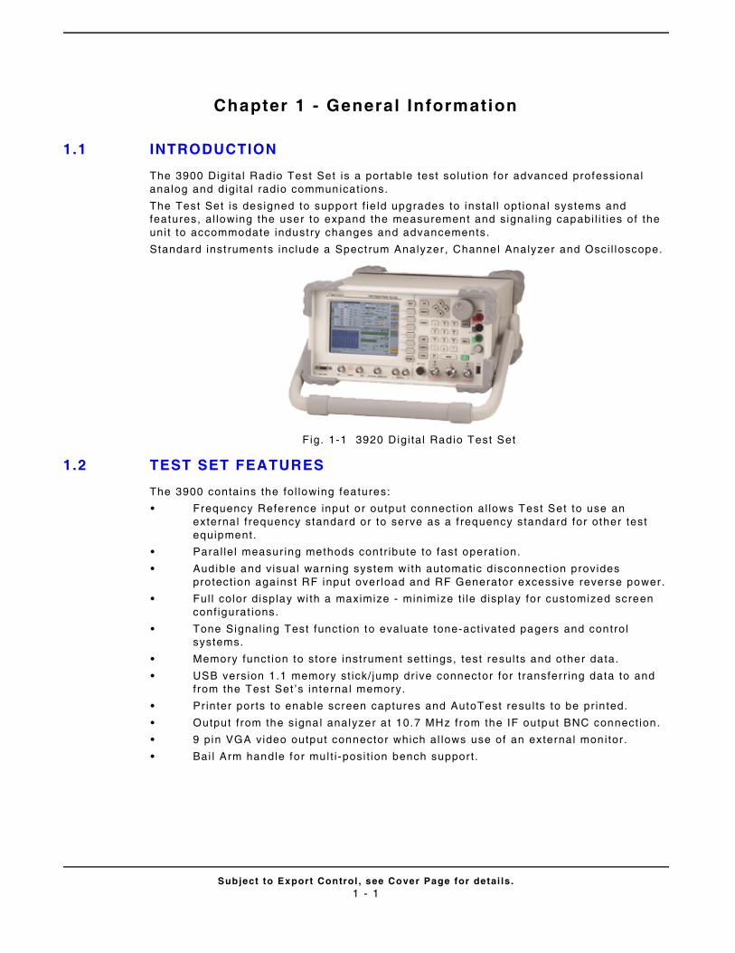
Subject to Export Control , see Cover Page for detai ls .1 - 1
Chapter 1 - General Information
1.1 INTRODUCTION
The 3900 Digi tal Radio Test Set is a por table test solut ion for advanced professional analog and digi ta l radio communicat ions.
The Test Set is designed to support f ie ld upgrades to instal l opt ional systems and features, al lowing the user to expand the measurement and signal ing capabi l i t ies of the uni t to accommodate indust ry changes and advancements.
Standard inst ruments include a Spectrum Analyzer , Channel Analyzer and Osci l loscope.
Fig. 1-1 3920 Digi tal Radio Test Set
1.2 TEST SET FEATURES
The 3900 contains the fol lowing features:
• Frequency Reference input or output connect ion al lows Test Set to use an external f requency standard or to serve as a f requency standard for other test equipment.
• Paral le l measur ing methods contr ibute to fast operat ion.
• Audible and visual warning system wi th automatic d isconnect ion provides protect ion against RF input over load and RF Generator excessive reverse power.
• Ful l color display wi th a maximize - minimize t i le display for customized screen conf igurat ions.
• Tone Signal ing Test funct ion to evaluate tone-act ivated pagers and control systems.
• Memory funct ion to store instrument set t ings, test resul ts and other data.
• USB version 1.1 memory st ick/ jump dr ive connector for t ransferr ing data to and from the Test Set ’s interna l memory.
• Printer por ts to enable screen captures and AutoTest resu l ts to be pr in ted.
• Output f rom the signal analyzer at 10.7 MHz from the IF output BNC connect ion.
• 9 pin VGA video output connector which al lows use of an external monitor .
• Bai l Arm handle for mult i -posi t ion bench suppor t .
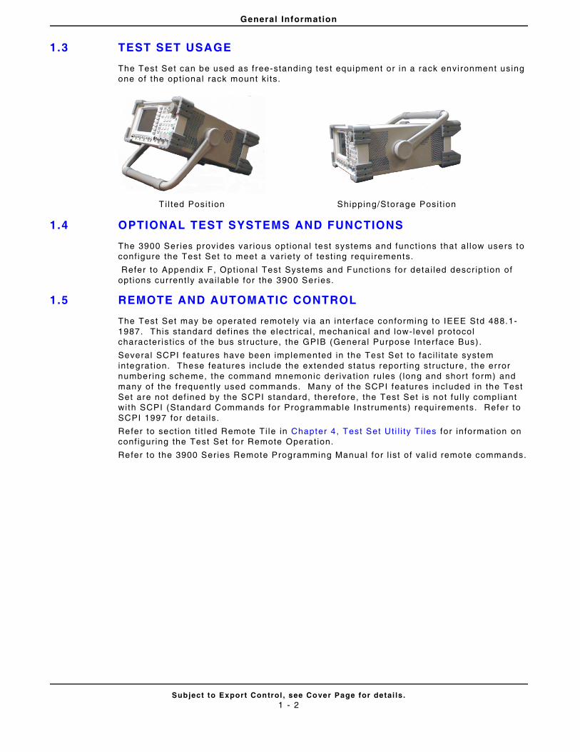
General Information
Subject to Export Control , see Cover Page for detai ls .1 - 2
1.3 TEST SET USAGE
The Test Set can be used as free-standing test equipment or in a rack envi ronment using one of the opt ional rack mount k i ts.
1.4 OPTIONAL TEST SYSTEMS AND FUNCTIONS
The 3900 Ser ies provides var ious opt ional test systems and funct ions that al low users to conf igure the Test Set to meet a var iety of test ing requi rements.
Refer to Appendix F, Opt ional Test Systems and Funct ions for detai led descr ip t ion of opt ions current ly avai lable for the 3900 Ser ies.
1.5 REMOTE AND AUTOMATIC CONTROL
The Test Set may be operated remotely v ia an inter face conforming to IEEE Std 488.1-1987. This standard def ines the elect r ical , mechanical and low-level protocol character ist ics of the bus st ructure, the GPIB (General Purpose Interface Bus) .
Several SCPI features have been implemented in the Test Set to faci l i ta te system integrat ion. These features include the extended status repor t ing structure, the error number ing scheme, the command mnemonic der ivat ion rules ( long and short form) and many of the frequent ly used commands. Many of the SCPI features included in the Test Set are not def ined by the SCPI standard, therefore, the Test Set is not fu l ly compl iant wi th SCPI (Standard Commands for Programmable Inst ruments) requirements. Refer to SCPI 1997 for detai ls.
Refer to sect ion t i t led Remote Ti le in Chapter 4 , Test Set Ut i l i ty T i les for information on conf igur ing the Test Set for Remote Operat ion.
Refer to the 3900 Series Remote Programming Manual for l is t of val id remote commands.
T i l ted Posi t ion Shipping/Storage Posi t ion
Subject to Export Control , see Cover Page for detai ls .2 - 1
Chapter 2 - Instal lat ion
2.1 INTRODUCTION
This chapter descr ibes the fol lowing:
• Prepar ing the 3900 for f i rst t ime use.
• Power requirements and rout ine safety tests and inspect ions.
• Interconnect ions to var ious control connectors, pr inter connectors and other input and output connectors.
2.2 INITIAL VISUAL INSPECTION
Visual inspect ions should be performed per iodical ly depending on operat ing envi ronment , maintenance and use.
2.3 INSTALLATION REQUIREMENTS
2.3.1 Venti lat ion
The 3900 is force air -coo led by three fans that draw air through vents in the sides of the case. Do not obstruct the air vents whi le the instrument is in use. Avoid standing the instrument on or c lose to other equipment that is hot.
2.3 .2 Connecting to AC Power Supply
The 3900 is a Safety Class 1 test instrument which must be grounded before use. The power cord suppl ied with the Test Set, or an appropr iate replacement , should be used to connect the Test Set to a grounded AC supply out let . Ensure that the power cord is properly connected to the AC Power Connector on the rear panel of the Test Set pr ior to connect ing un i t to an AC supply out let .
The 3900's PSU automat ical ly selects the appropr iate power supply range when the Test Set is connected to an AC power supply source which is wi thin the ranges speci f ied in Appendix B, 3900 Plat form Speci f icat ions.
2.3 .3 Disconnecting from AC Power Supply
The detachable AC power cord is the Test Set ’s disconnect ing device. I f the inst rument is integrated into a rack or test system, an externa l power switch or c i rcui t breaker may be required. The Test Set ’s AC Power Cord should be easi ly reached and accessible at al l t imes.
2.3 .4 AC Power Fuse
A 3 Amp, 250 V, Type F, 20 mm cartr idge fuse (F3AL250V) is included in the uni t ’s supply current path to the Power Supply Module. The AC Power Fuse is located in the fuse carr ier located on the rear of the Test Set . Replace fuse only with fuses of the speci f ied vol tage and current rat ings.
CAUTION
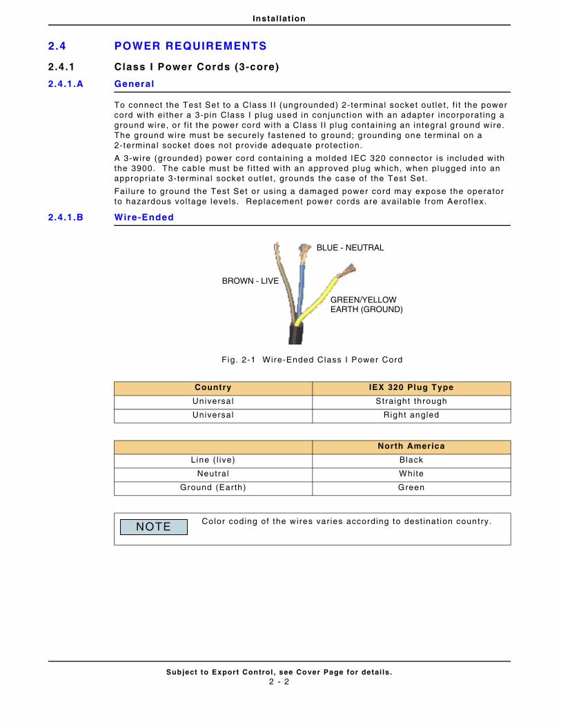
Instal lat ion
Subject to Export Control , see Cover Page for detai ls .2 - 2
2.4 POWER REQUIREMENTS
2.4.1 Class I Power Cords (3-core)
2.4.1.A General
To connect the Test Set to a Class I I (ungrounded) 2-terminal socket out le t , f i t the power cord with ei ther a 3-pin Class I p lug used in conjunct ion with an adapter incorporat ing a ground wire, or f i t the power cord with a Class I I p lug containing an integra l ground wire. The ground wire must be securely fastened to ground; grounding one terminal on a 2-termina l socket does not provide adequate protect ion.
A 3-wire (grounded) power cord containing a molded IEC 320 connector is included with the 3900. The cable must be f i t ted wi th an approved plug which, when plugged into an appropr iate 3-terminal socket out let , grounds the case of the Test Set .
Fai lure to ground the Test Set or using a damaged power cord may expose the operator to hazardous vol tage levels. Replacement power cords are avai lable f rom Aerof lex.
2.4.1.B Wire-Ended
Fig. 2-1 Wire-Ended Class I Power Cord
Country IEX 320 Plug Type
Universa l Straight through
Universa l Right angled
North America
Line ( l ive) Black
Neutral White
Ground (Earth) Green
Color coding of the wires var ies according to dest inat ion country.
BROWN - LIVE
BLUE - NEUTRAL
GREEN/YELLOWEARTH (GROUND)
NOTE
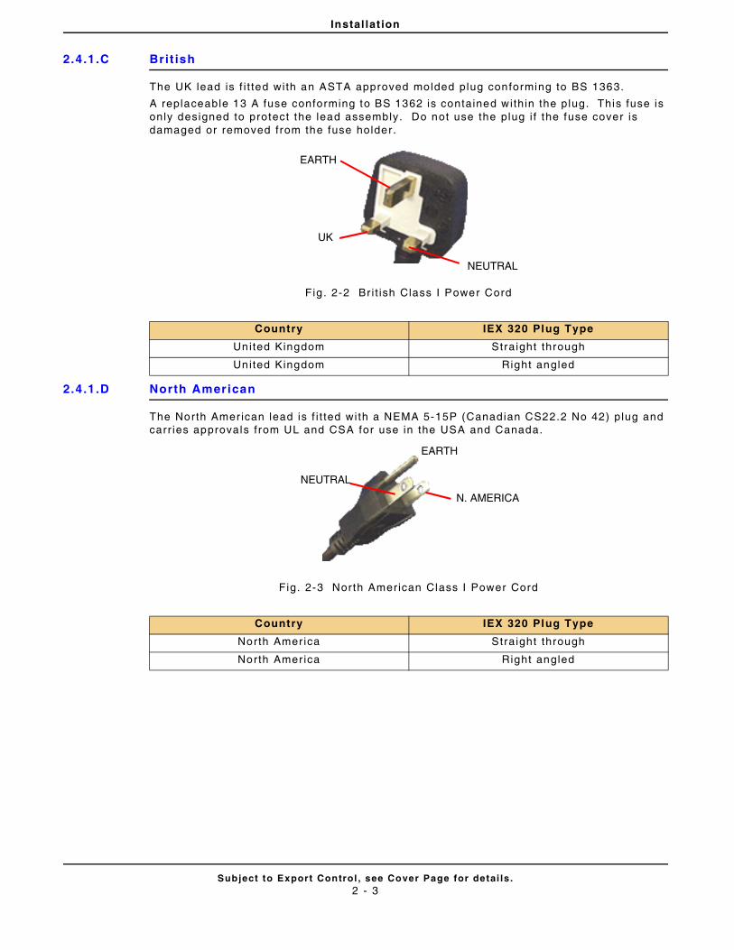
Instal lat ion
Subject to Export Control , see Cover Page for detai ls .2 - 3
2.4.1.C Brit ish
The UK lead is f i t ted with an ASTA approved molded plug conforming to BS 1363.
A replaceable 13 A fuse conforming to BS 1362 is contained within the plug. This fuse is only designed to protect the lead assembly. Do not use the plug i f the fuse cover is damaged or removed from the fuse holder.
Fig . 2-2 Br i t ish Class I Power Cord
2.4.1.D North American
The North Amer ican lead is f i t ted with a NEMA 5-15P (Canadian CS22.2 No 42) plug and carr ies approvals f rom UL and CSA for use in the USA and Canada.
Fig. 2-3 North American Class I Power Cord
Country IEX 320 Plug Type
United Kingdom Straight through
United Kingdom Right angled
Country IEX 320 Plug Type
North Amer ica Straight through
North Amer ica Right angled
EARTH
NEUTRAL
UK
NEUTRAL
EARTH
N. AMERICA
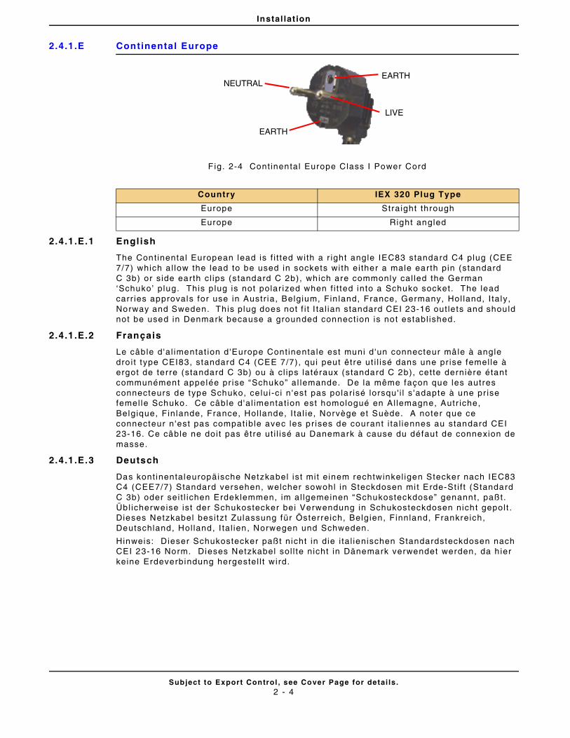
Instal lat ion
Subject to Export Control , see Cover Page for detai ls .2 - 4
2.4.1.E Continental Europe
Fig. 2-4 Cont inental Europe Class I Power Cord
2.4.1.E.1 Engl ish
The Cont inental European lead is f i t ted with a r ight angle IEC83 standard C4 plug (CEE 7/7) which a l low the lead to be used in sockets with ei ther a male earth pin (standard C 3b) or s ide earth cl ips (standard C 2b), which are commonly cal led the German ‘Schuko’ plug. This p lug is not polar ized when f i t ted into a Schuko socket. The lead carr ies approvals for use in Austr ia, Belgium, Fin land, France, Germany, Hol land, I ta ly, Norway and Sweden. Th is plug does not f i t I ta l ian standard CEI 23-16 out lets and should not be used in Denmark because a grounded connect ion is not establ ished.
2.4.1.E.2 Français
Le câble d 'al imentat ion d'Europe Cont inentale est muni d 'un connecteur mâle à angle dro i t type CEI83, standard C4 (CEE 7/7) , qui peut être ut i l isé dans une pr ise femel le à ergot de terre (standard C 3b) ou à cl ips latéraux (standard C 2b), cette dernière étant communément appelée pr ise “Schuko” al lemande. De la même façon que les autres connecteurs de type Schuko, ce lui-c i n 'est pas polar isé lorsqu ' i l s 'adapte à une pr ise femel le Schuko. Ce câble d 'al imentat ion est homologué en Al lemagne, Autr iche, Belgique, Finlande, France, Hol lande, I ta l ie, Norvège et Suède. A noter que ce connecteur n 'est pas compat ible avec les pr ises de courant i ta l iennes au standard CEI 23-16. Ce câble ne doi t pas être ut i l isé au Danemark à cause du défaut de connexion de masse.
2.4.1.E.3 Deutsch
Das kont inentaleuropäische Netzkabel ist mit e inem rechtwinkel igen Stecker nach IEC83 C4 (CEE7/7) Standard versehen, welcher sowohl in Steckdosen mi t Erde-St i f t (Standard C 3b) oder sei t l ichen Erdeklemmen, im al lgemeinen “Schukosteckdose” genannt, paßt. Übl icherweise ist der Schukostecker bei Verwendung in Schukosteckdosen nicht gepolt . Dieses Netzkabel besi tzt Zulassung für Österreich, Belg ien, Finnland, Frankreich, Deutschland, Hol land, I ta l ien, Norwegen und Schweden.
Hinweis: Dieser Schukostecker paßt nicht in die i ta l ienischen Standardsteckdosen nach CEI 23-16 Norm. Dieses Netzkabel sol l te nicht in Dänemark verwendet werden, da h ier keine Erdeverbindung hergestel l t wird.
Country IEX 320 Plug Type
Europe Straight through
Europe Right angled
NEUTRALEARTH
EARTH
LIVE
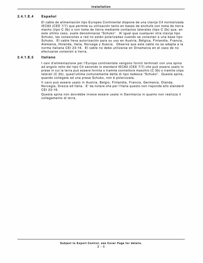
Instal lat ion
Subject to Export Control , see Cover Page for detai ls .2 - 5
2.4.1.E.4 Español
El cable de al imentación t ipo Europeo Cont inental d ispone de una clavi ja C4 normal izada IEC83 (CEE 7/7) que permite su ut i l ización tanto en bases de enchufe con toma de t ierra macho ( t ipo C 3b) o con toma de t ierra mediante contactos laterales ( t ipo C 2b) que, en este úl t imo caso, suele denominarse “Schuko” . Al igual que cualquier ot ra c lavi ja t ipo Schuko, las conexiones a red no están polar izadas cuando se conectan a una base t ipo Schuko. El cable l leva autor ización para su uso en Austr ia , Bélgica, Finlandia, Francia, Alemania, Holanda, I ta l ia, Noruega y Suecia. Observe que este cable no se adapta a la norma i ta l iana CEI 23-16. E l cable no debe ut i l izarse en Dinamarca en el caso de no efectuarse conexión a t ierra.
2.4.1.E.5 Ital iano
I cavi d 'a l imentazione per l 'Europa cont inentale vengono forni t i terminat i con una spina ad angolo ret to del t ipo C4 secondo lo standard IEC83 (CEE 7/7) che può essere usato in prese in cui la terra può essere forni ta o t ramite connettore maschio (C 3b) o t ramite c l ips lateral i (C 2b) , quest 'u l t ima comunemente detta di t ipo tedesca “Schuko” . Questa sp ina, quando col legata ad una presa Schuko, non è polar izzata.
I l cavo può essere usato in Austr ia, Belg io, Finlandia, Francia, Germania, Olanda, Norvegia, Svezia ed I ta l ia . E' da notare che per l ' I ta l ia questo non r isponde al lo standard CEI 23-16.
Questa spina non dovrebbe invece essere usata in Danimarca in quanto non rea l izza i l col legamento di terra .
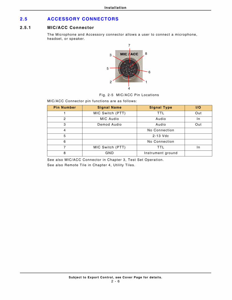
Instal lat ion
Subject to Export Control , see Cover Page for detai ls .2 - 6
2.5 ACCESSORY CONNECTORS
2.5.1 MIC/ACC Connector
The Microphone and Accessory connector al lows a user to connect a microphone, headset , or speaker.
Fig. 2-5 MIC/ACC Pin Locat ions
MIC/ACC Connector pin funct ions are as fol lows:
See also MIC/ACC Connector in Chapter 3, Test Set Operat ion.
See also Remote Ti le in Chapter 4, Ut i l i ty Ti les.
Pin Number Signal Name Signal Type I/O
1 MIC Switch (PTT) TTL Out
2 MIC Audio Audio In
3 Demod Audio Audio Out
4 No Connect ion
5 2-13 Vdc
6 No Connect ion
7 MIC Switch (PTT) TTL In
8 GND Instrument ground
8
6
1
4
2
5
3
7
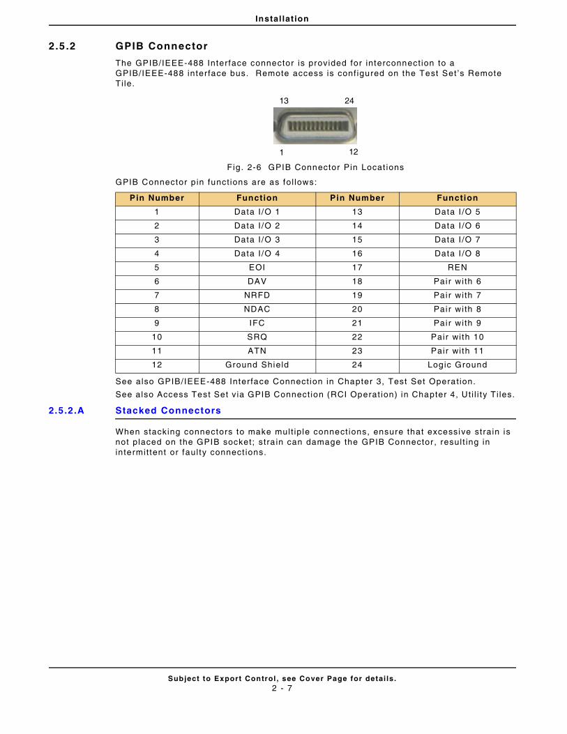
Instal lat ion
Subject to Export Control , see Cover Page for detai ls .2 - 7
2.5 .2 GPIB Connector
The GPIB/IEEE-488 Interface connector is provided for interconnect ion to a GPIB/IEEE-488 interface bus. Remote access is conf igured on the Test Set ’s Remote Ti le.
Fig. 2-6 GPIB Connector Pin Locat ions
GPIB Connector p in funct ions are as fol lows:
See also GPIB/IEEE-488 Interface Connect ion in Chapter 3, Test Set Operat ion.
See also Access Test Set v ia GPIB Connect ion (RCI Operat ion) in Chapter 4, Ut i l i ty Ti les.
2.5.2.A Stacked Connectors
When stacking connectors to make mult ip le connect ions, ensure that excessive strain is not placed on the GPIB socket; stra in can damage the GPIB Connector , resul t ing in intermit tent or faul ty connect ions.
Pin Number Function Pin Number Function
1 Data I /O 1 13 Data I /O 5
2 Data I /O 2 14 Data I /O 6
3 Data I /O 3 15 Data I /O 7
4 Data I /O 4 16 Data I /O 8
5 EOI 17 REN
6 DAV 18 Pai r wi th 6
7 NRFD 19 Pai r wi th 7
8 NDAC 20 Pai r wi th 8
9 IFC 21 Pai r wi th 9
10 SRQ 22 Pair wi th 10
11 ATN 23 Pair wi th 11
12 Ground Shield 24 Logic Ground
1 12
13 24
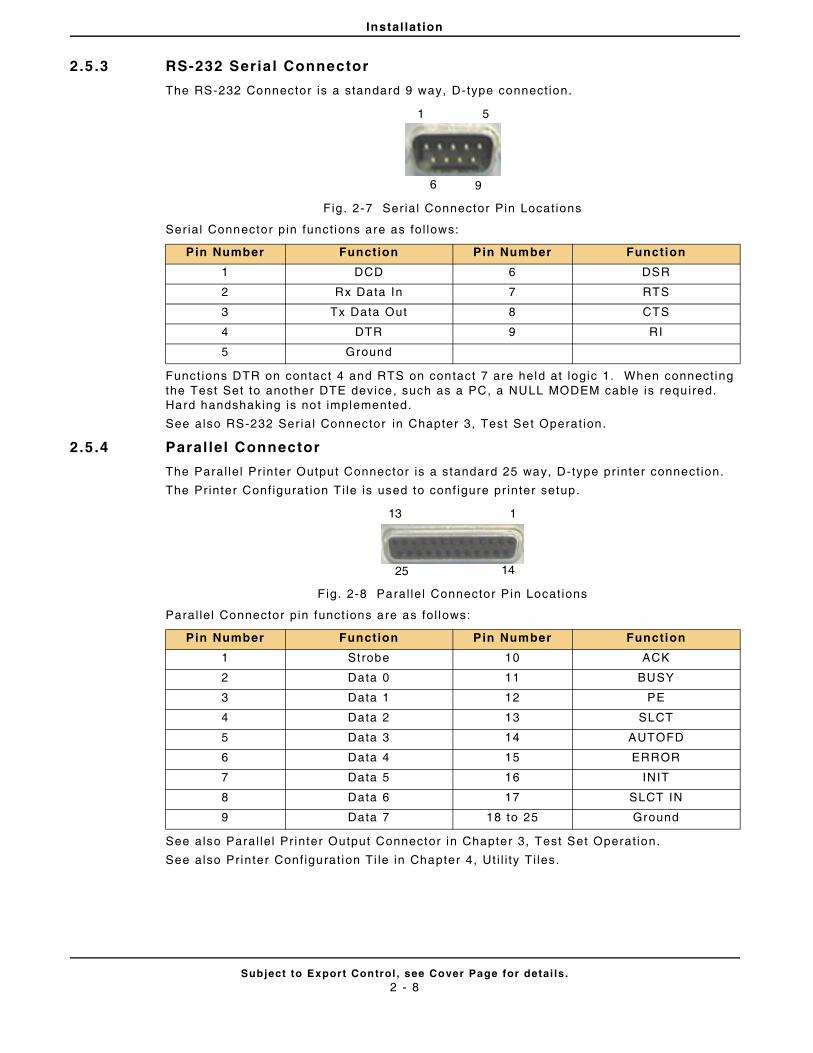
Instal lat ion
Subject to Export Control , see Cover Page for detai ls .2 - 8
2.5 .3 RS-232 Seria l Connector
The RS-232 Connector is a standard 9 way, D- type connect ion.
Fig . 2-7 Ser ial Connector Pin Locat ions
Ser ial Connector pin funct ions are as fol lows:
Funct ions DTR on contact 4 and RTS on contact 7 are held at logic 1. When connect ing the Test Set to another DTE device, such as a PC, a NULL MODEM cable is required. Hard handshaking is not implemented.
See also RS-232 Ser ial Connector in Chapter 3, Test Set Operat ion.
2.5 .4 Paral lel Connector
The Paral le l Pr inter Output Connector is a standard 25 way, D-type pr inter connect ion.
The Pr inter Conf igurat ion T i le is used to conf igure pr inter setup.
F ig. 2-8 Paral le l Connector Pin Locat ions
Paral le l Connector pin funct ions are as fol lows:
See also Paral le l Pr inter Output Connector in Chapter 3, Test Set Operat ion.
See also Pr inter Conf igurat ion Ti le in Chapter 4, Ut i l i ty Ti les.
Pin Number Function Pin Number Function
1 DCD 6 DSR
2 Rx Data In 7 RTS
3 Tx Data Out 8 CTS
4 DTR 9 RI
5 Ground
Pin Number Function Pin Number Function
1 Strobe 10 ACK
2 Data 0 11 BUSY
3 Data 1 12 PE
4 Data 2 13 SLCT
5 Data 3 14 AUTOFD
6 Data 4 15 ERROR
7 Data 5 16 INIT
8 Data 6 17 SLCT IN
9 Data 7 18 to 25 Ground
1 5
6 9
113
25 14
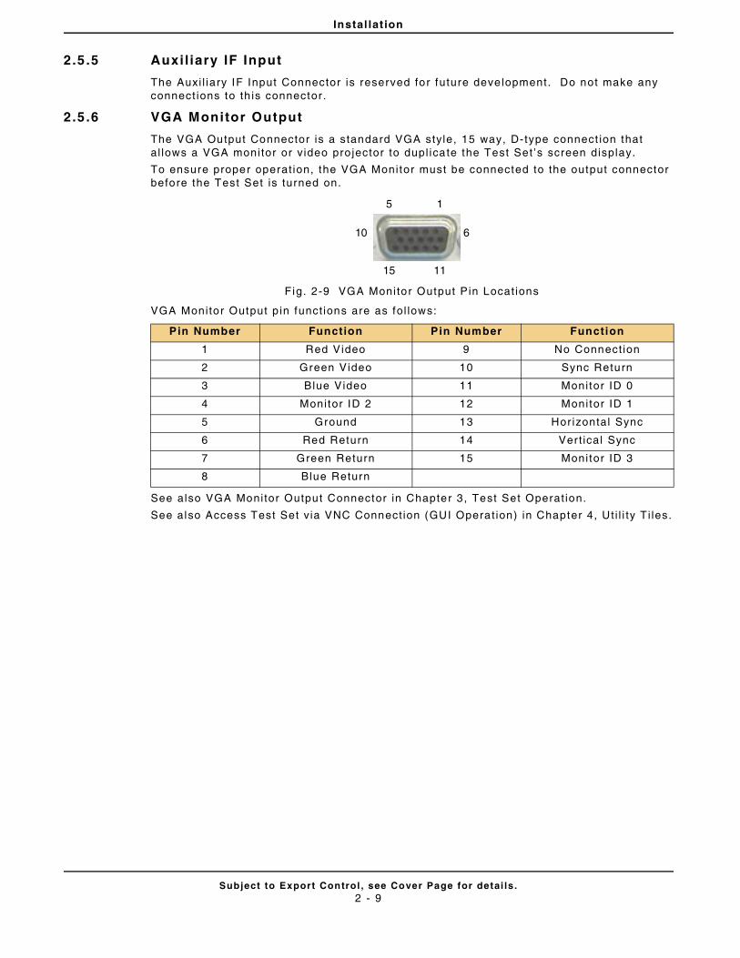
Instal lat ion
Subject to Export Control , see Cover Page for detai ls .2 - 9
2.5 .5 Auxi l iary IF Input
The Auxi l iary IF Input Connector is reserved for future development. Do not make any connect ions to th is connector.
2.5 .6 VGA Monitor Output
The VGA Output Connector is a standard VGA style, 15 way, D- type connect ion that al lows a VGA monitor or v ideo pro jector to dupl icate the Test Set ’s screen display.
To ensure proper operat ion, the VGA Monitor must be connected to the output connector before the Test Set is turned on.
Fig. 2-9 VGA Monitor Output Pin Locat ions
VGA Monitor Output p in funct ions are as fol lows:
See also VGA Monitor Output Connector in Chapter 3 , Test Set Operat ion.
See also Access Test Set v ia VNC Connect ion (GUI Operat ion) in Chapter 4, Ut i l i ty Ti les.
Pin Number Function Pin Number Function
1 Red Video 9 No Connect ion
2 Green Video 10 Sync Return
3 Blue Video 11 Monitor ID 0
4 Monitor ID 2 12 Monitor ID 1
5 Ground 13 Hor izontal Sync
6 Red Return 14 Vert ical Sync
7 Green Return 15 Monitor ID 3
8 Blue Return
15
610
15 11
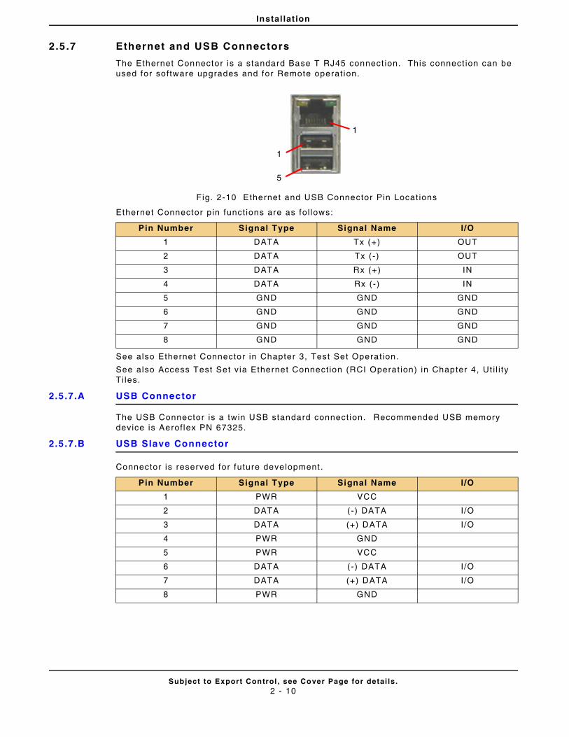
Instal lat ion
Subject to Export Control , see Cover Page for detai ls .2 - 10
2.5 .7 Ethernet and USB Connectors
The Ethernet Connector is a standard Base T RJ45 connect ion. This connect ion can be used for software upgrades and for Remote operat ion.
Fig. 2-10 Ethernet and USB Connector Pin Locat ions
Ethernet Connector pin funct ions are as fol lows:
See also Ethernet Connector in Chapter 3, Test Set Operat ion.
See also Access Test Set v ia Ethernet Connect ion (RCI Operat ion) in Chapter 4, Ut i l i ty Ti les.
2.5.7.A USB Connector
The USB Connector is a twin USB standard connect ion. Recommended USB memory device is Aerof lex PN 67325.
2.5.7.B USB Slave Connector
Connector is reserved for future development .
Pin Number Signal Type Signal Name I/O
1 DATA Tx (+) OUT
2 DATA Tx ( -) OUT
3 DATA Rx (+) IN
4 DATA Rx (- ) IN
5 GND GND GND
6 GND GND GND
7 GND GND GND
8 GND GND GND
Pin Number Signal Type Signal Name I/O
1 PWR VCC
2 DATA (-) DATA I/O
3 DATA (+) DATA I/O
4 PWR GND
5 PWR VCC
6 DATA (-) DATA I/O
7 DATA (+) DATA I/O
8 PWR GND
1
1
5
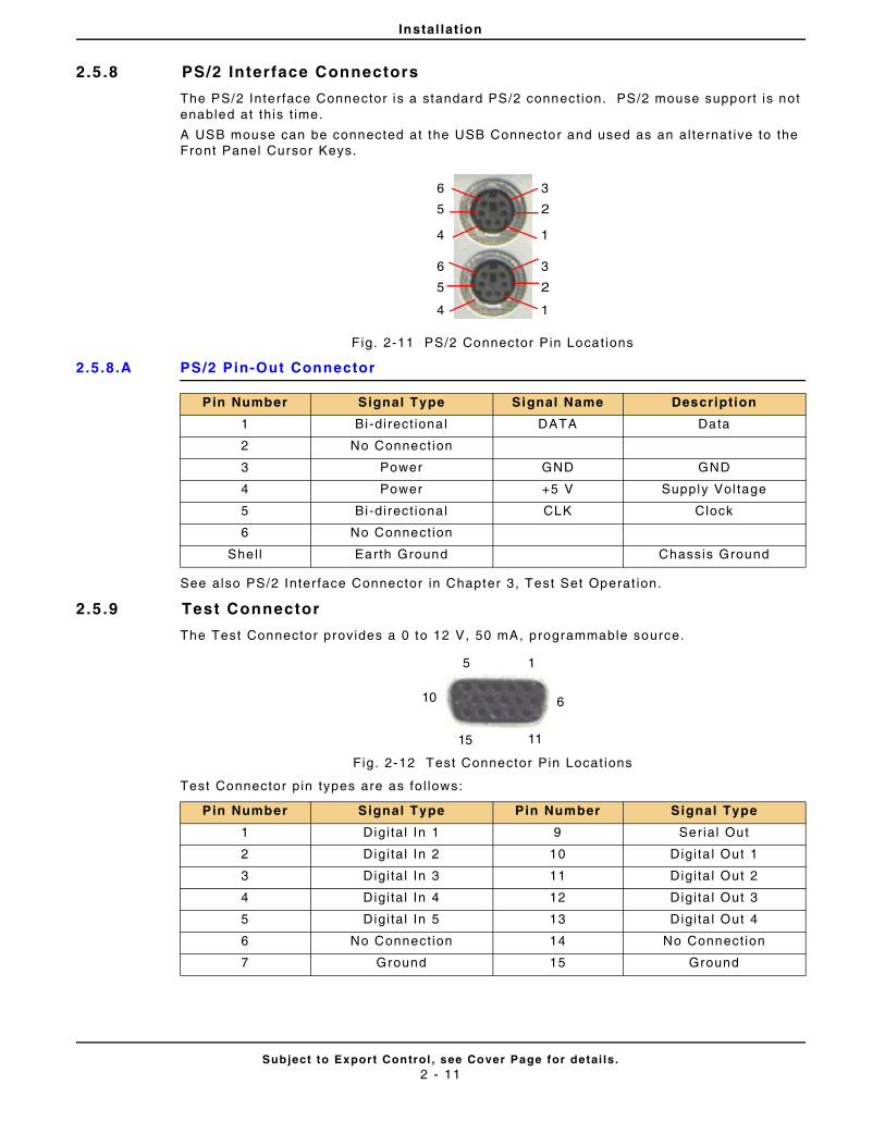
Instal lat ion
Subject to Export Control , see Cover Page for detai ls .2 - 11
2.5 .8 PS/2 Interface Connectors
The PS/2 Interface Connector is a standard PS/2 connect ion. PS/2 mouse support is not enabled at th is t ime.
A USB mouse can be connected at the USB Connector and used as an al ternat ive to the Front Panel Cursor Keys.
F ig. 2-11 PS/2 Connector Pin Locat ions
2.5.8.A PS/2 Pin-Out Connector
See also PS/2 Inter face Connector in Chapter 3, Test Set Operat ion.
2.5 .9 Test Connector
The Test Connector provides a 0 to 12 V, 50 mA, programmable source.
Fig. 2-12 Test Connector Pin Locat ions
Test Connector pin types are as fo l lows:
Pin Number Signal Type Signal Name Description
1 Bi-direct iona l DATA Data
2 No Connect ion
3 Power GND GND
4 Power +5 V Supply Vol tage
5 Bi-direct iona l CLK Clock
6 No Connect ion
Shel l Earth Ground Chassis Ground
Pin Number Signal Type Pin Number Signal Type
1 Digi tal In 1 9 Serial Out
2 Digi tal In 2 10 Digi ta l Out 1
3 Digi tal In 3 11 Digi ta l Out 2
4 Digi tal In 4 12 Digi ta l Out 3
5 Digi tal In 5 13 Digi ta l Out 4
6 No Connect ion 14 No Connect ion
7 Ground 15 Ground
1
2
3
4
5
6
1
2
3
4
5
6
15
610
1115
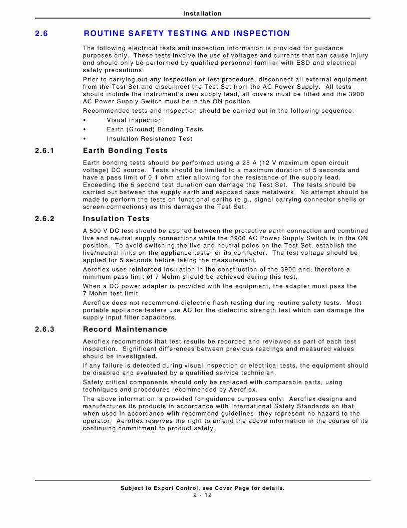
Instal lat ion
Subject to Export Control , see Cover Page for detai ls .2 - 12
2.6 ROUTINE SAFETY TESTING AND INSPECTION
The fol lowing elect r ical tests and inspect ion information is provided for gu idance purposes only. These tests involve the use of vol tages and currents that can cause in jury and should only be per formed by qual i f ied personnel fami l iar wi th ESD and e lectr ical safety precaut ions.
Pr ior to carrying out any inspect ion or test procedure, d isconnect al l external equipment f rom the Test Set and disconnect the Test Set f rom the AC Power Supply. Al l tests should include the instrument ’s own supply lead, al l covers must be f i t ted and the 3900 AC Power Supply Switch must be in the ON posi t ion.
Recommended tests and inspect ion should be carr ied out in the fol lowing sequence:
• Visual Inspect ion
• Earth (Ground) Bonding Tests
• Insula t ion Resistance Test
2.6 .1 Earth Bonding Tests
Earth bonding tests should be performed using a 25 A (12 V maximum open circui t vol tage) DC source. Tests should be l imi ted to a maximum durat ion of 5 seconds and have a pass l imit o f 0.1 ohm after al lowing for the resistance of the supply lead. Exceeding the 5 second test durat ion can damage the Test Set . The tests should be carr ied out between the supply earth and exposed case metalwork. No attempt should be made to perform the tests on funct ional earths (e .g. , s ignal carrying connector shel ls or screen connect ions) as this damages the Test Set .
2.6 .2 Insulat ion Tests
A 500 V DC test should be appl ied between the protect ive earth connect ion and combined l ive and neutral supply connect ions whi le the 3900 AC Power Supply Switch is in the ON posi t ion. To avoid switching the l ive and neutral po les on the Test Set , establ ish the l ive/neutral l inks on the appl iance tester or i ts connector. The test vol tage should be appl ied for 5 seconds before taking the measurement .
Aerof lex uses reinforced insulat ion in the construct ion of the 3900 and, therefore a minimum pass l imit of 7 Mohm should be achieved dur ing this test .
When a DC power adapter is provided with the equipment , the adapter must pass the 7 Mohm test l imit .
Aerof lex does not recommend dielect r ic f lash test ing dur ing rout ine safety tests. Most por table appl iance testers use AC for the dielect r ic st rength test which can damage the supply input f i l ter capaci tors.
2.6 .3 Record Maintenance
Aerof lex recommends that test resul ts be recorded and reviewed as part of each test inspect ion. Signi f icant di f ferences between previous readings and measured values should be invest igated.
I f any fai lure is detected dur ing visual inspect ion or electr ical tests, the equipment should be d isabled and eva luated by a qual i f ied service technician.
Safety cr i t ica l components should only be replaced with comparable par ts, using techniques and procedures recommended by Aerof lex.
The above informat ion is provided for guidance purposes only. Aerof lex designs and manufactures i ts products in accordance with Internat ional Safety Standards so that when used in accordance wi th recommend guidel ines, they represent no hazard to the operator . Aerof lex reserves the r ight to amend the above informat ion in the course of i ts cont inuing commitment to product safety.
Instal lat ion
Subject to Export Control , see Cover Page for detai ls .2 - 13
2.6 .4 External Cleaning
The fol lowing procedure conta ins rout ine instruct ions for c leaning the outside of the 3900.
• Clean f ront panel but tons and disp lay face with soft l int- f ree cloth. I f d i r t is di f f icul t to remove, dampen cloth with water and a mi ld l iqu id detergent.
• Remove grease, fungus and ground-in dir t f rom sur faces with soft l int - f ree cloth dampened (not soaked) with isopropyl alcohol.
• Remove dust and dir t f rom connectors with sof t-br ist led brush.
• Cover connectors, not in use, wi th sui table dust cover to prevent tarnishing of connector contacts.
• Clean cables with soft l int- f ree cloth.
• Paint exposed metal sur face to avo id corrosion.
2.6 .5 Visual Inspection
Visual inspect ions should be performed per iodical ly depending on operat ing envi ronment , maintenance and use.
• Ver i fy Test Set has been instal led in accordance wi th the inst ruct ions provided (e.g. , that vent i lat ion is adequate, supply isolators are accessible , supply wir ing is adequate and properly routed).
• Ensure that AC Power Cord and supply connector(s) are in good condit ion.
• Ver i fy the correct rat ing and type of supply fuses are used.
• Examine the stabi l i ty and condit ion of covers and handles.
• Check the presence and condi t ion of al l warning labels and markings and suppl ied safety informat ion.
• Check the wi r ing in re-wireable p lugs and appl iance connectors.
• Check the cleanl iness and condit ion of any vent i lat ion fan f i l ters.
• Ensure that the AC Power Supply Switch isolates the equipment f rom the AC Power Supply.
• Check the supply indicator funct ions ( i f f i t ted).
• Any noted defects should be corrected before proceeding with the fol lowing electr ical tests.
2.6 .6 Carry Handle and Bench Support
The Test Set is f i t ted with a Bai l Arm carry handle and bench support . The handle is at tached to the Test Set wi th hubs that al low ful l handle rota t ion with 12 locking posi t ions. To rotate the Bai l Arm, stand the Test Set on the rear feet and pul l both handle hubs outward, away f rom the case assembly. Rotate the handle and release hubs to lock handle posi t ion.
Instal lat ion
Subject to Export Control , see Cover Page for detai ls .2 - 14
THIS PAGE INTENTIONALLY LEFT BLANK.
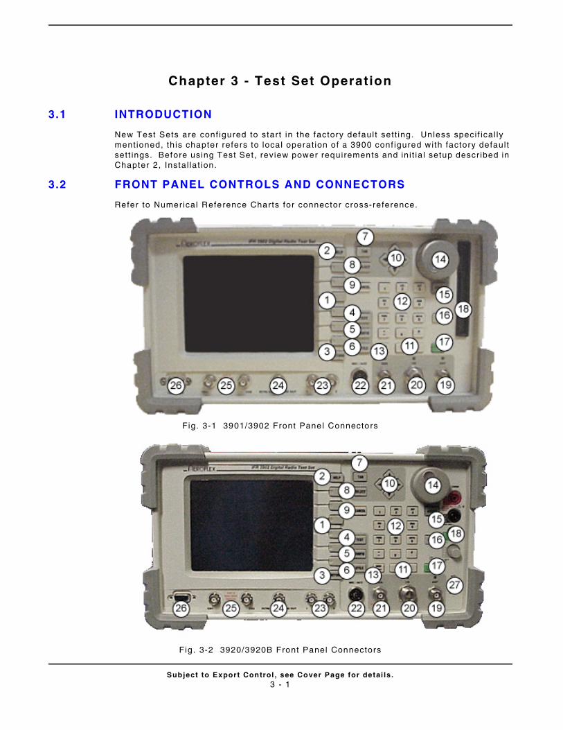
Subject to Export Control , see Cover Page for detai ls .3 - 1
Chapter 3 - Test Set Operation
3.1 INTRODUCTION
New Test Sets are conf igured to start in the factory defaul t set t ing. Unless speci f ical ly ment ioned, th is chapter refers to local operat ion of a 3900 conf igured with factory defaul t sett ings. Before using Test Set , review power requirements and ini t ia l setup descr ibed in Chapter 2, Instal lat ion.
3.2 FRONT PANEL CONTROLS AND CONNECTORS
Refer to Numer ical Reference Charts for connector cross-reference.
Fig. 3-1 3901/3902 Front Panel Connectors
Fig . 3-2 3920/3920B Front Panel Connectors
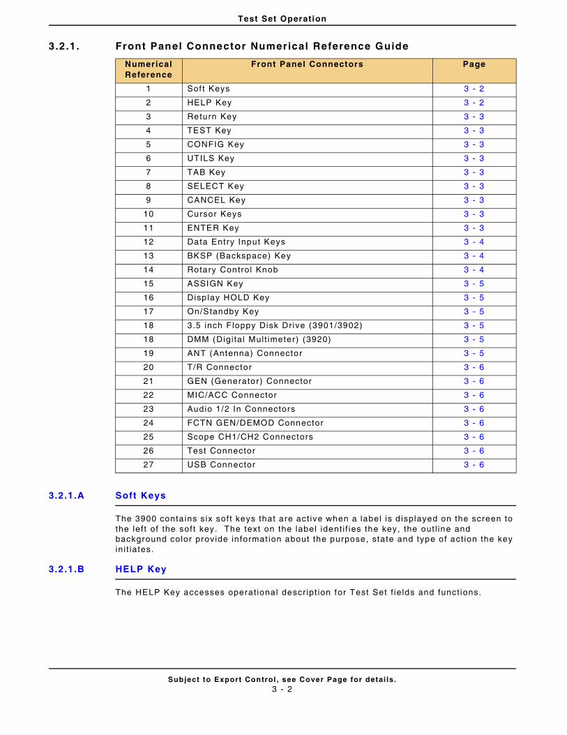
Test Set Operation
Subject to Export Control , see Cover Page for detai ls .3 - 2
3.2 .1. Front Panel Connector Numerical Reference Guide
3.2.1.A Soft Keys
The 3900 conta ins six soft keys that are act ive when a label is d isplayed on the screen to the lef t of the soft key. The text on the label ident i f ies the key, the out l ine and background color provide informat ion about the purpose, state and type of act ion the key in i t iates.
3.2.1.B HELP Key
The HELP Key accesses operat ional descr ipt ion for Test Set f ie lds and funct ions.
Numerical Reference
Front Panel Connectors Page
1 Sof t Keys 3 - 2
2 HELP Key 3 - 2
3 Return Key 3 - 3
4 TEST Key 3 - 3
5 CONFIG Key 3 - 3
6 UTILS Key 3 - 3
7 TAB Key 3 - 3
8 SELECT Key 3 - 3
9 CANCEL Key 3 - 3
10 Cursor Keys 3 - 3
11 ENTER Key 3 - 3
12 Data Entry Input Keys 3 - 4
13 BKSP (Backspace) Key 3 - 4
14 Rotary Control Knob 3 - 4
15 ASSIGN Key 3 - 5
16 Disp lay HOLD Key 3 - 5
17 On/Standby Key 3 - 5
18 3.5 inch F loppy Disk Drive (3901/3902) 3 - 5
18 DMM (Digi ta l Mult imeter) (3920) 3 - 5
19 ANT (Antenna) Connector 3 - 5
20 T/R Connector 3 - 6
21 GEN (Generator) Connector 3 - 6
22 MIC/ACC Connector 3 - 6
23 Audio 1/2 In Connectors 3 - 6
24 FCTN GEN/DEMOD Connector 3 - 6
25 Scope CH1/CH2 Connectors 3 - 6
26 Test Connector 3 - 6
27 USB Connector 3 - 6
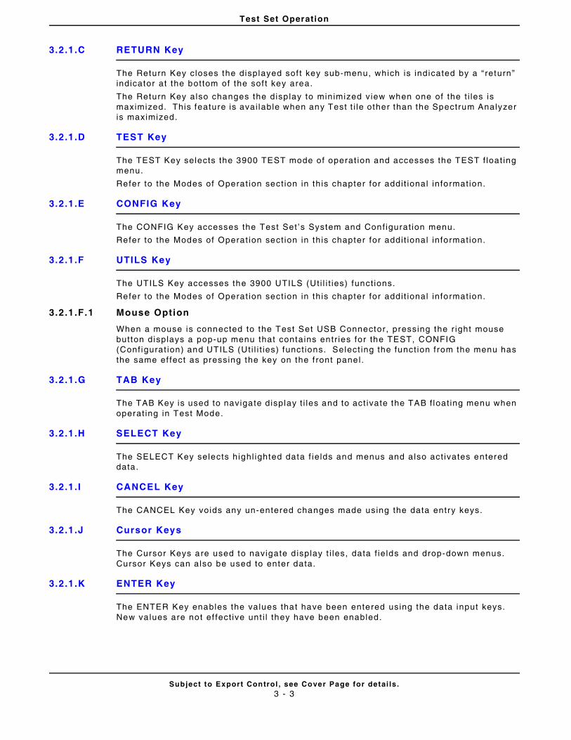
Test Set Operation
Subject to Export Control , see Cover Page for detai ls .3 - 3
3.2.1.C RETURN Key
The Return Key closes the displayed sof t key sub-menu, which is indicated by a “ return” indicator at the bottom of the sof t key area.
The Return Key also changes the disp lay to minimized view when one of the t i les is maximized. This feature is avai lable when any Test t i le other than the Spectrum Analyzer is maximized.
3.2.1.D TEST Key
The TEST Key selects the 3900 TEST mode of operat ion and accesses the TEST f loat ing menu.
Refer to the Modes of Operat ion sect ion in this chapter for addi t ional informat ion.
3.2.1.E CONFIG Key
The CONFIG Key accesses the Test Set ’s System and Conf igurat ion menu.
Refer to the Modes of Operat ion sect ion in this chapter for addi t ional informat ion.
3.2.1.F UTILS Key
The UTILS Key accesses the 3900 UTILS (Ut i l i t ies) funct ions.
Refer to the Modes of Operat ion sect ion in this chapter for addi t ional informat ion.
3.2.1.F.1 Mouse Option
When a mouse is connected to the Test Set USB Connector, pressing the r ight mouse button displays a pop-up menu that contains entr ies for the TEST, CONFIG (Conf igurat ion) and UTILS (Ut i l i t ies) funct ions. Select ing the funct ion from the menu has the same ef fect as pressing the key on the f ront panel.
3.2.1.G TAB Key
The TAB Key is used to navigate display t i les and to act ivate the TAB f loat ing menu when operat ing in Test Mode.
3.2.1.H SELECT Key
The SELECT Key selects highl ighted data f ie lds and menus and a lso act ivates entered data.
3.2.1.I CANCEL Key
The CANCEL Key voids any un-entered changes made using the data entry keys.
3.2.1.J Cursor Keys
The Cursor Keys are used to navigate d isplay t i les, data f ie lds and drop-down menus. Cursor Keys can also be used to enter data.
3.2.1.K ENTER Key
The ENTER Key enables the values that have been entered using the data input keys. New va lues are not ef fect ive unt i l they have been enabled.
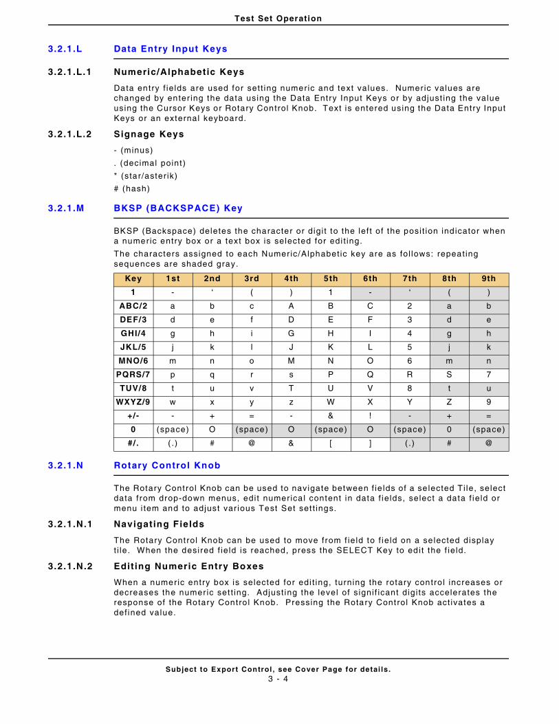
Test Set Operation
Subject to Export Control , see Cover Page for detai ls .3 - 4
3.2.1.L Data Entry Input Keys
3.2.1.L.1 Numeric/Alphabetic Keys
Data entry f ie lds are used for sett ing numeric and text values. Numer ic values are changed by enter ing the data using the Data Entry Input Keys or by adjust ing the value using the Cursor Keys or Rotary Control Knob. Text is entered using the Data Entry Input Keys or an external keyboard.
3.2.1.L.2 Signage Keys
- (minus)
. (decimal point )
* (star/aster ik)
# (hash)
3.2.1.M BKSP (BACKSPACE) Key
BKSP (Backspace) deletes the character or digi t to the lef t of the posi t ion ind icator when a numeric entry box or a text box is selected for edi t ing.
The characters assigned to each Numeric/Alphabet ic key are as fol lows: repeat ing sequences are shaded gray.
3.2.1.N Rotary Control Knob
The Rotary Control Knob can be used to navigate between f ie lds of a se lected Ti le, select data from drop-down menus, edi t numerica l content in data f ie lds, select a data f ie ld or menu i tem and to adjust var ious Test Set set t ings.
3.2.1.N.1 Navigating Fields
The Rotary Control Knob can be used to move from f ie ld to f ie ld on a se lected display t i le . When the desired f ie ld is reached, press the SELECT Key to ed i t the f ie ld.
3.2.1.N.2 Edit ing Numeric Entry Boxes
When a numeric entry box is selected for edi t ing, turning the rotary contro l increases or decreases the numer ic set t ing. Adjust ing the level of s igni f icant digi ts accelerates the response of the Rotary Contro l Knob. Pressing the Rotary Control Knob act ivates a def ined value.
Key 1st 2nd 3rd 4th 5th 6th 7th 8th 9th
1 - ‘ ( ) 1 - ‘ ( )
ABC/2 a b c A B C 2 a b
DEF/3 d e f D E F 3 d e
GHI/4 g h i G H I 4 g h
JKL/5 j k l J K L 5 j k
MNO/6 m n o M N O 6 m n
PQRS/7 p q r s P Q R S 7
TUV/8 t u v T U V 8 t u
WXYZ/9 w x y z W X Y Z 9
+/- - + = - & ! - + =
0 (space) O (space) O (space) O (space) 0 (space)
#/. ( . ) # @ & [ ] ( .) # @
Test Set Operation
Subject to Export Control , see Cover Page for detai ls .3 - 5
3.2.1.N.3 Menu I tem Select ion
When a f loat ing menu or a drop-down menu from a combinat ion set t ings box is d isplayed, turning the Rotary Control Knob scrol ls through the act ive l ist . Pressing the Rotary Contro l Knob act ivates a value and selects a menu i tem.
3.2.1.N.4 Assigned Functions
The Rotary Control Knob changes sett ings of funct ions that are enabled when the ASSIGN Key is pressed.
3.2.1.O ASSIGN Key
The ASSIGN Key al lows funct ions such as loudspeaker vo lume and audio rout ing, squelch level , and display br ightness to be adjusted using the Rotary Contro l Knob.
3.2.1.P Display HOLD Key
The HOLD Key f reezes the display to a l low the user to capture, pr int and save the current screen display.
3.2.1.Q On/Standby Key
The Power Supply On/Standby key is referred to as the On/Standby key. The Power Supply On/Standby Key is used to power the Test Set on and off .
• The On/Standby Key LED is not i l luminated when the AC Power Supply Switch is OFF.
• The On/Standby LED is ORANGE when the AC Power Supply Switch is in the ON posi t ion and the Test Set is in STANDBY mode.
• The On/Standby LED turns BLUE when the Test Set is boot ing up.
• The On/Standby LED is GREEN when the Test Set is ready for operat ion.
3.2.1.R 3.5 inch Floppy Disk Drive
The 3901/3902 3.5 inch Floppy Disk Drive provides an inter face for t ransferr ing data, sett ings and captured display f i les to and from the test set . Data transfers are managed through the UTILS, Fi le Management T i le.
3.2.1.R.1 Powering Up
Before power ing up the Test Set, check that the f loppy disk dr ive does not contain a disk. I f there is a disk in the dr ive at power up the Test Set may display i r relevant error messages. I f th is occurs, remove the disk and restar t the Test Set.
3.2.1.S Digital Mult imeter
The Dig i tal Mult imeter (DMM) Opt ion (390XOPT035) provides users with the abi l i ty to per form resistance measurements and AC and DC current and vol tage measurements.
3.2.1.T ANT (Antenna) Connector
The ANT Connector is a 50 ohm TNC input, providing maximum sensi t iv i ty input to the Test Set RF Analyzer .
THE RATED MAXIMUM INPUT LEVEL FOR THE ANT CONNECTOR IS +10 DBM.
REFER TO 3900 PLATFORM SPECIFICATIONS FOR ADDITIONAL INFORMATION.
Test Set Operation
Subject to Export Control , see Cover Page for detai ls .3 - 6
3.2.1.U T/R Connector
The T/R Connector is a 50 ohm N type, combined (Duplexed) connector that provides an RF Gen output connect ion and an RF analyzer input and broadband power meter connect ion.
3.2.1.V GEN (Generator) Connector
The RF Gen output is a 50 ohm TNC output, providing the maximum RF output level f rom the RF Gen.
The RF GEN Connector is reverse power protected to a level of +10 dBm.
3.2.1.W MIC/ACC Connector
The Microphone and Accessory connector al lows a user to connect a microphone, headset , or speaker.
See also MIC/ACC Connector Pin Out in Chapter 2.
3.2.1.X Audio 1 and 2 IN Connectors
AUDIO IN 1 and 2 are the pr imary AF input and external modulat ion input connectors. The Connectors can be conf igured as high impedance, unbalanced or 600 ohm balanced.
3.2.1.Y FCTN GEN/DEMOD Connector
(Funct ion Generator and Demodulated Signal Output)
The FCTN/GEN Demod Connector is the pr imary AF GEN output.
3.2.1.Z Scope CH1/CH2 Connectors
The Scope CH1 and CH2 connectors are the dedicated inputs to the dual- trace osci l loscope, providing a maximum input ra t ing of 100 Vpeak.
3.2.1.AA Test Connector
The Test Connector provides a 0 to 12 V, 50 mA, programmable source.
See also Test Connector Pin Out in Chapter 2.
3.2.1.AB USB Connector
The Front Panel USB Connector is a USB standard connect ion that al lows connect ion of USB 1.1 devices (e.g. a USB memory st ick or Network connectors) . Recommended USB memory device is Aerof lex PN 7110-1100-400. The Front Panel USB Connector is only found on the 3920 Test Set.
THE MAXIMUM RATED INPUT POWER LEVEL FOR THE T/R CONNECTOR IS 125 W.
REFER TO 3900 PLATFORM SPECIFICATIONS FOR ADDITIONAL INFORMATION.
DO NOT CONNECT A VGA MONITOR TO THIS CONNECTOR.
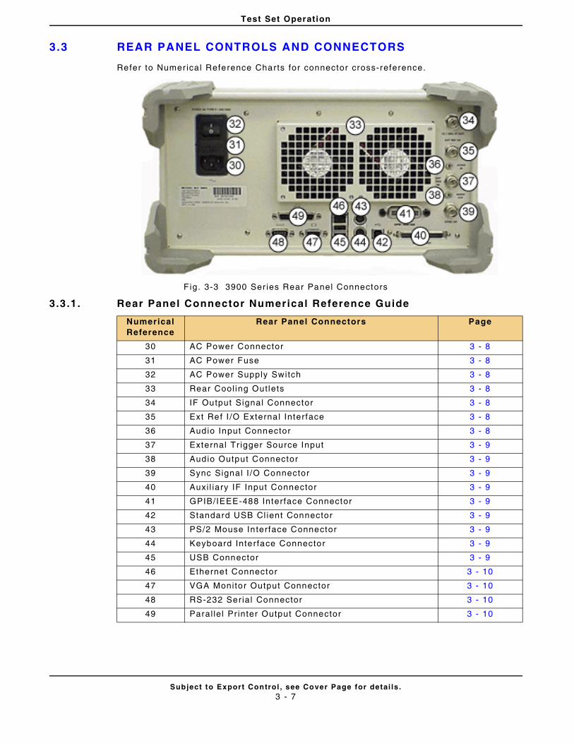
Test Set Operation
Subject to Export Control , see Cover Page for detai ls .3 - 7
3.3 REAR PANEL CONTROLS AND CONNECTORS
Refer to Numer ical Reference Charts for connector cross-reference.
F ig. 3-3 3900 Ser ies Rear Panel Connectors
3.3 .1. Rear Panel Connector Numerical Reference Guide
Numerical Reference
Rear Panel Connectors Page
30 AC Power Connector 3 - 8
31 AC Power Fuse 3 - 8
32 AC Power Supply Switch 3 - 8
33 Rear Cool ing Out lets 3 - 8
34 IF Output Signal Connector 3 - 8
35 Ext Ref I /O External Interface 3 - 8
36 Audio Input Connector 3 - 8
37 External Tr igger Source Input 3 - 9
38 Audio Output Connector 3 - 9
39 Sync Signal I /O Connector 3 - 9
40 Auxi l iary IF Input Connector 3 - 9
41 GPIB/IEEE-488 Interface Connector 3 - 9
42 Standard USB Cl ient Connector 3 - 9
43 PS/2 Mouse In terface Connector 3 - 9
44 Keyboard Interface Connector 3 - 9
45 USB Connector 3 - 9
46 Ethernet Connector 3 - 10
47 VGA Monitor Output Connector 3 - 10
48 RS-232 Serial Connector 3 - 10
49 Paral le l Pr inter Output Connector 3 - 10
Test Set Operation
Subject to Export Control , see Cover Page for detai ls .3 - 8
3.3.1.A AC Power Connector
The AC Power Connector accepts an IEC 320 connector . Refer to 3900 Plat form Speci f icat ions for the required supply vol tage, f requency and power consumpt ion speci f icat ions.
3.3.1.B AC Power Fuse
The AC Fuses are accessed from the rear panel by removing the fuse cover located above the AC Power.
Refer to Appendix C, Fuse Replacement Procedure for instruct ions on replacing AC Power Fuse.
3.3.1.C AC Power Supply Switch
The AC Power Supply Swi tch isolates the 3900 f rom the AC power supply.
The AC Power Supply Switch should not be used for powering down the Test Set because al l set t ings and test resul ts are lost .
The On/Standby Key should be used for rout ine power down of uni t because i t in i t iates a power-down procedure, saving al l current sett ings and test resu l ts.
Refer to sect ions t i t led Power ing Test Set On and Power ing Test Set Down in Chapter 3 for addi t ional informat ion.
3.3.1.D Rear Cooling Outlets
The Rear Fan Vents provide air c i rcu lat ion to the Test Set . Improper vent i lat ion may cause the Test Set to overheat and may damage interna l components.
3.3.1.E IF Output Signal Connector
The IF Output Signal is avai lable at th is BNC connector . The 10.7 MHz IF Output is the RF signal rece ived and down-converted by the Test Set RF Analyzer.
The output leve l is -10 dBm typical at 10.7 MHz (50 Ohm nominal) .
3.3.1.F Ext Ref I /O External Interface
The External Reference I /O Connector is a BNC connect ion used to connect the Test Set to an external f requency standard, or to output the internal f requency standard f rom the Test Set to other equipment .
Refer to sect ion t i t led Frequency Reference Ti le in Chapter 4 for information on proper Test Set conf igurat ion.
3.3.1.G Audio Input Connector
The Audio Input Connector is internal ly connected and ready for future development. Do not make any external connect ion to this connector.
The 10.7 MHz IF OUT signal is spectral ly inverted. An RF signal rece ived by the Test Set, down-converted to 10.7 MHz, then output on this socket has the proper ty that a f requency increase or a phase advance at RF is output as a frequency reduct ion or phase retardat ion at IF. Take this into account i f using this output for work wi th any type of FSK/PSK signal ing.
NOTE
Test Set Operation
Subject to Export Control , see Cover Page for detai ls .3 - 9
3.3.1.H External Trigger Signal Input Connector
The External Tr igger Signal Input is the external t r igger input for the Osci l loscope.
This BNC connect ion has an Input impedance 10 k ohm.
3.3.1.I Audio Output Connector
The Audio Output Connector is internal ly connected and ready for future development . Do not make any external connect ion to this connector.
3.3.1.J Synchronization Signal Input or Output Connector
The Synchronizat ion Signal Input /Output Connector is a BNC connect ion that is used with the TETRA Base Stat ion Test System for base stat ion receivers generat ing a sync output s ignal .
3.3.1.K Auxi l iary IF Input Connector
The Auxi l iary IF Input Connector is reserved for future development. Do not make any connect ions to th is connector.
Refer to Auxi l ia ry IF Input Pin Out in Chapter 2 for addit ional informat ion.
3.3.1.L GPIB/IEEE-488 Interface Connection
The GPIB/IEEE-488 Interface connector is provided for interconnect ion to a GPIB/IEEE-488 inter face bus. Remote access is conf igured on the Test Set ’s Remote Ti le.
Refer to sect ion t i t led Remote Ti le in Chapter 4 for informat ion on conf igur ing the Test Set for GPIB operat ion.
Refer to GPIB Connector Pin Out in Chapter 2 for addit ional informat ion.
3.3.1.M Standard USB Client Connector
The Standard USB connector is reserved for future development.
3.3.1.N PS/2 Interface Connector
The PS/2 Interface Connector is a standard PS/2 connect ion. PS/2 mouse support is not enabled at th is t ime.
A USB mouse can be connected at the USB Connector and used as an al ternat ive to the Front Panel Cursor Keys.
Refer to PS/2 Interface Connectors Pin Out in Chapter 2 for addit ional information.
3.3.1.O Keyboard Interface Connector
The Keyboard Inter face Connector is a standard PS/2 connect ion that supports use of a standard PS/2 keyboard. This connector is only on the 3901/3902 models.
Refer to sect ion t i t led Keyboard & Mouse T i le in Chapter 4 for keyboard conf igurat ion information.
3.3.1.P USB Connector
The Rear Panel USB connector is a double USB standard connect ion that a l lows connect ion of USB 1.1 devices (e.g . a USB memory st ick or USB Mouse or Keyboard).
Refer to Ethernet and USB Connectors Pin Out in Chapter 2 for addit ional in formation.
Test Set Operation
Subject to Export Control , see Cover Page for detai ls .3 - 10
3.3.1.Q Ethernet Connector
The Ethernet Connector is a standard Base T RJ45 connect ion. This connect ion can be used for software upgrades and for Remote operat ion.
Refer to sect ion t i t led Remote Ti le in Chapter 4 for informat ion on conf igur ing the Test Set for Ethernet operat ion.
Refer to Ethernet and USB Connectors Pin Out in Chapter 2 for addit ional in formation.
3.3.1.R VGA Monitor Output Connector
The VGA Output Connector is a standard VGA style, 15 way, D- type connect ion that al lows a VGA monitor or v ideo pro jector to dupl icate the Test Set ’s screen display.
To ensure proper operat ion, the VGA Monitor must be connected to the output connector before the Test Set is turned on.
Refer to VGA Monitor Output Pin Out in Chapter 2 for addit ional information.
3.3.1.S RS-232 Serial Connector
The RS-232 Connector is a standard 9 way, D- type connect ion. Refer to RS-232 Ser ial Connector Pin Out in Chapter 2 for addit ional information.
3.3.1.T Paral lel Printer Output Connector
The Paral le l Pr inter Output Connector is a standard 25 way, D-type pr inter connect ion.
The Pr inter Conf igurat ion T i le is used to conf igure pr inter setup.
Refer to sect ion t i t led Printer Conf igurat ion Ti le in Chapter 4 for addi t ional informat ion.
Refer to Paral le l Connector Pin Out in Chapter 2 for addit ional information.
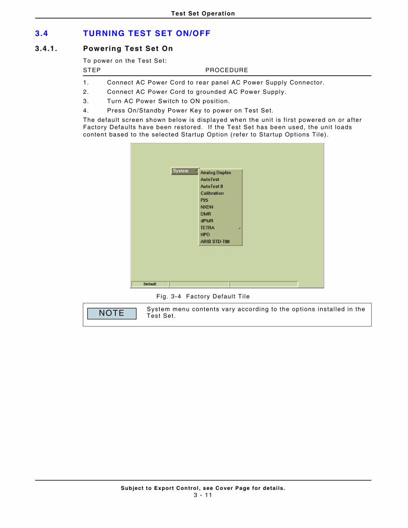
Test Set Operation
Subject to Export Control , see Cover Page for detai ls .3 - 11
3.4 TURNING TEST SET ON/OFF
3.4.1. Powering Test Set On
To power on the Test Set :
STEP PROCEDURE
1. Connect AC Power Cord to rear panel AC Power Supply Connector .
2. Connect AC Power Cord to grounded AC Power Supply.
3. Turn AC Power Switch to ON posi t ion.
4. Press On/Standby Power Key to power on Test Set.
The defau l t screen shown below is displayed when the uni t is f i rst powered on or a f ter Factory Defaul ts have been restored. I f the Test Set has been used, the uni t loads content based to the selected Startup Opt ion ( refer to Star tup Opt ions Ti le) .
Fig. 3-4 Factory Defaul t Ti le
System menu contents vary according to the opt ions instal led in the Test Set .NOTE
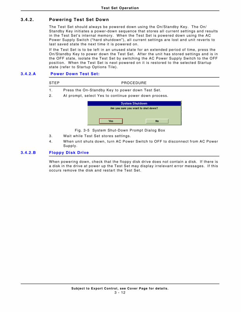
Test Set Operation
Subject to Export Control , see Cover Page for detai ls .3 - 12
3.4 .2. Powering Test Set Down
The Test Set should always be powered down using the On/Standby Key. The On/Standby Key in i t iates a power-down sequence that stores al l current sett ings and resul ts in the Test Set ’s internal memory. When the Test Set is powered down using the AC Power Supply Switch (“hard shutdown”) , al l current sett ings are lost and uni t reverts to last saved state the next t ime i t is powered on.
I f the Test Set is to be lef t in an unused sta te for an extended per iod of t ime, press the On/Standby Key to power down the Test Set. Af ter the uni t has stored set t ings and is in the OFF state, isolate the Test Set by switching the AC Power Supply Switch to the OFF posi t ion. When the Test Set is next powered on i t is restored to the selected Startup state (refer to Startup Opt ions Ti le).
3.4.2.A Power Down Test Set:
STEP PROCEDURE
1. Press the On-Standby Key to power down Test Set .
2. At prompt, select Yes to cont inue power down process.
Fig . 3-5 System Shut-Down Prompt Dialog Box
3. Wait whi le Test Set stores sett ings.
4. When uni t shuts down, turn AC Power Swi tch to OFF to disconnect f rom AC Power Supply.
3.4.2.B Floppy Disk Drive
When power ing down, check that the f loppy disk dr ive does not contain a disk. I f there is a disk in the dr ive at power up the Test Set may display i r relevant error messages. I f th is occurs remove the disk and restart the Test Set .
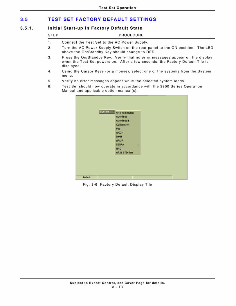
Test Set Operation
Subject to Export Control , see Cover Page for detai ls .3 - 13
3.5 TEST SET FACTORY DEFAULT SETTINGS
3.5.1. In it ial Start-up in Factory Default State
STEP PROCEDURE
1. Connect the Test Set to the AC Power Supply.
2. Turn the AC Power Supply Switch on the rear panel to the ON posi t ion. The LED above the On/Standby Key should change to RED.
3. Press the On/Standby Key. Ver i fy that no error messages appear on the display when the Test Set powers on. After a few seconds, the Factory Defaul t Ti le is displayed.
4. Using the Cursor Keys (or a mouse), select one of the systems from the System menu.
5. Ver i fy no error messages appear whi le the selected system loads.
6. Test Set should now operate in accordance with the 3900 Series Operat ion Manual and appl icable opt ion manual(s) .
Fig. 3-6 Factory Defaul t Display T i le
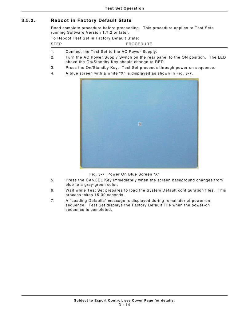
Test Set Operation
Subject to Export Control , see Cover Page for detai ls .3 - 14
3.5 .2. Reboot in Factory Default State
Read complete procedure before proceeding. This procedure appl ies to Test Sets running Software Version 1.7 .2 or la ter.
To Reboot Test Set in Factory Defaul t State:
STEP PROCEDURE
1. Connect the Test Set to the AC Power Supply.
2. Turn the AC Power Supply Switch on the rear panel to the ON posi t ion. The LED above the On/Standby Key should change to RED.
3. Press the On/Standby Key. Test Set proceeds through power on sequence.
4. A blue screen with a white “X” is disp layed as shown in Fig. 3-7.
F ig. 3-7 Power On Blue Screen “X”
5. Press the CANCEL Key immediately when the screen background changes f rom blue to a gray-green color.
6. Wait whi le Test Set prepares to load the System Defaul t conf igurat ion f i les. This process takes 15-30 seconds.
7. A “Loading Defaul ts” message is displayed dur ing remainder o f power-on sequence. Test Set displays the Factory Defaul t Ti le when the power-on sequence is completed.
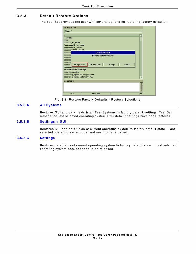
Test Set Operation
Subject to Export Control , see Cover Page for detai ls .3 - 15
3.5 .3. Default Restore Options
The Test Set provides the user with several opt ions for restor ing factory defaul ts.
Fig. 3-8 Restore Factory Defau l ts - Restore Select ions
3.5.3.A Al l Systems
Restores GUI and data f ie lds in al l Test Systems to factory defaul t set t ings. Test Set reloads the last selected operat ing system after defaul t set t ings have been restored.
3.5.3.B Sett ings + GUI
Restores GUI and data f ie lds of current operat ing system to factory defaul t state. Last selected operat ing system does not need to be reloaded.
3.5.3.C Sett ings
Restores data f ie lds of current operat ing system to factory defau l t state. Last selected operat ing system does not need to be reloaded.
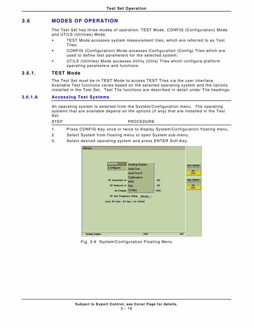
Test Set Operation
Subject to Export Control , see Cover Page for detai ls .3 - 16
3.6 MODES OF OPERATION
The Test Set has three modes of operat ion: TEST Mode, CONFIG (Conf igurat ion) Mode and UTILS (Ut i l i t ies) Mode.
• TEST Mode accesses system measurement t i les, which are referred to as Test Ti les;
• CONFIG (Conf igurat ion) Mode accesses Conf igurat ion (Conf ig) Ti les which are used to def ine test parameters for the selected system;
• UTILS (Ut i l i t ies) Mode accesses Ut i l i ty (Ut i ls) Ti les which conf igure plat form operat ing parameters and funct ions.
3.6 .1. TEST Mode
The Test Set must be in TEST Mode to access TEST Ti les via the user inter face. Avai lable Test funct ions var ies based on the se lected operat ing system and the opt ions instal led in the Test Set . Test Ti le funct ions are descr ibed in detai l under Ti le headings.
3.6.1.A Accessing Test Systems
An operat ing system is selected from the System/Conf igurat ion menu. The operat ing systems that are avai lable depend on the opt ions ( i f any) that are instal led in the Test Set .
STEP PROCEDURE
1. Press CONFIG Key once or twice to d isplay System/Conf igurat ion f loat ing menu.
2. Select System f rom f loat ing menu to open System sub-menu.
3. Select desired operat ing system and press ENTER Sof t Key.
F ig. 3-9 System/Conf igurat ion Float ing Menu
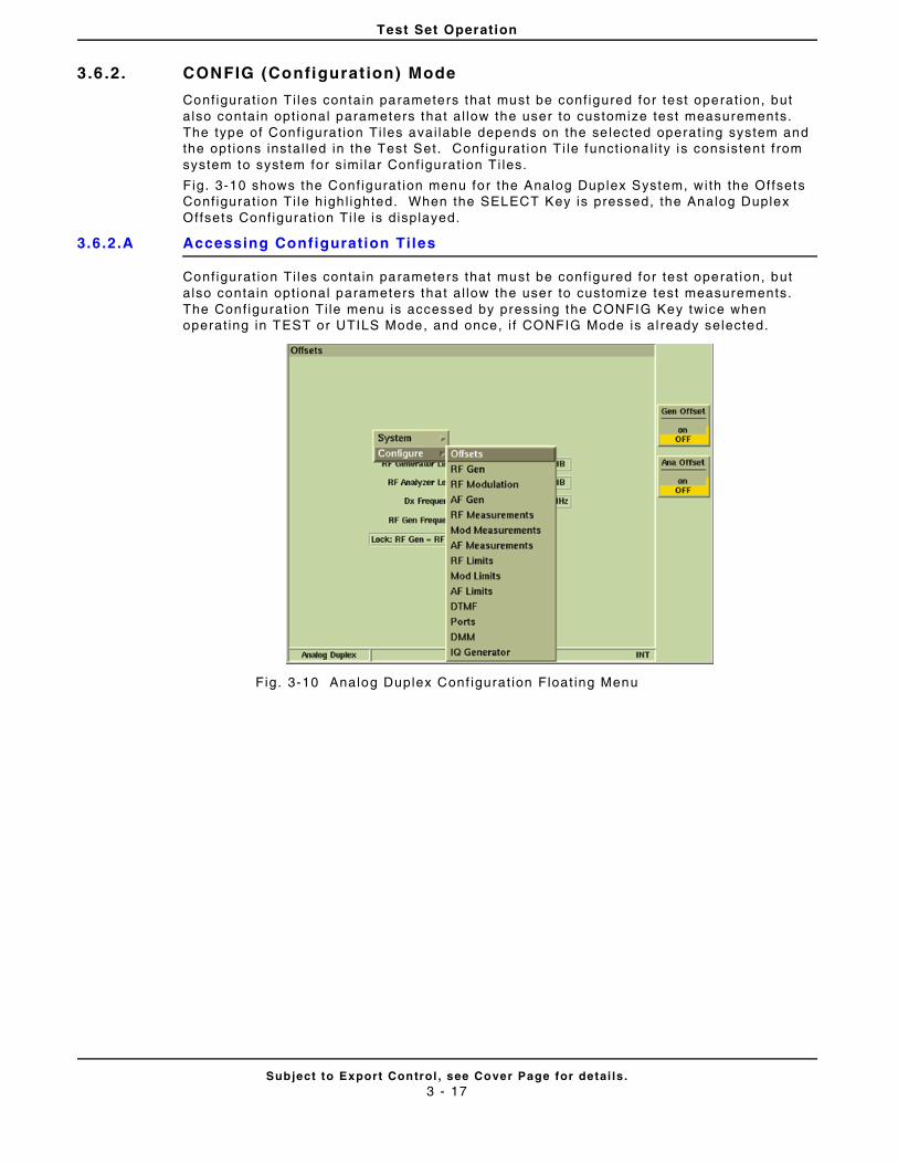
Test Set Operation
Subject to Export Control , see Cover Page for detai ls .3 - 17
3.6 .2. CONFIG (Configurat ion) Mode
Configurat ion Ti les contain parameters that must be conf igured for test operat ion, but also contain opt ional parameters that al low the user to customize test measurements. The type of Conf igurat ion Ti les avai lable depends on the se lected operat ing system and the opt ions instal led in the Test Set. Conf igurat ion Ti le funct ional i ty is consistent f rom system to system for s imi lar Conf igurat ion Ti les.
Fig. 3-10 shows the Conf igurat ion menu for the Analog Duplex System, with the Offsets Conf igurat ion Ti le high l ighted. When the SELECT Key is pressed, the Analog Duplex Offsets Conf igurat ion Ti le is displayed.
3.6.2.A Accessing Configuration Tiles
Configurat ion Ti les contain parameters that must be conf igured for test operat ion, but also contain opt ional parameters that al low the user to customize test measurements. The Conf igurat ion Ti le menu is accessed by pressing the CONFIG Key twice when operat ing in TEST or UTILS Mode, and once, i f CONFIG Mode is al ready selected.
Fig. 3-10 Analog Duplex Conf igurat ion Float ing Menu
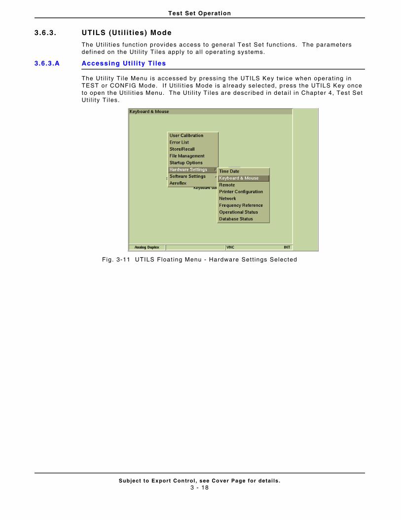
Test Set Operation
Subject to Export Control , see Cover Page for detai ls .3 - 18
3.6 .3. UTILS (Uti l i t ies) Mode
The Ut i l i t ies funct ion provides access to general Test Set funct ions. The parameters def ined on the Ut i l i ty Ti les apply to al l operat ing systems.
3.6.3.A Accessing Uti l i ty Ti les
The Ut i l i ty Ti le Menu is accessed by pressing the UTILS Key twice when operat ing in TEST or CONFIG Mode. I f Ut i l i t ies Mode is a lready selected, press the UTILS Key once to open the Ut i l i t ies Menu. The Uti l i ty T i les are descr ibed in detai l in Chapter 4, Test Set Ut i l i ty Ti les.
Fig. 3-11 UTILS Float ing Menu - Hardware Set t ings Selected
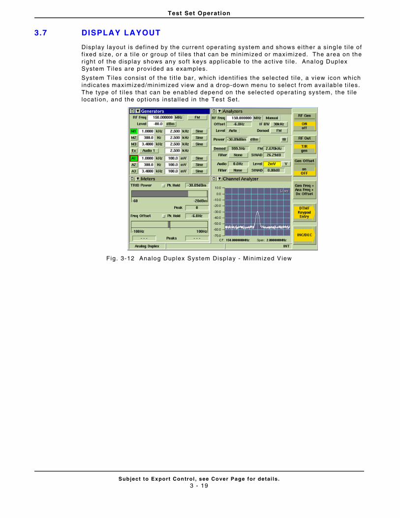
Test Set Operation
Subject to Export Control , see Cover Page for detai ls .3 - 19
3.7 DISPLAY LAYOUT
Disp lay layout is def ined by the current operat ing system and shows ei ther a s ing le t i le of f ixed size, or a t i le or group of t i les that can be minimized or maximized. The area on the r ight of the display shows any soft keys appl icable to the act ive t i le. Analog Duplex System Ti les are provided as examples.
System Ti les consist of the t i t le bar, which ident i f ies the selected t i le, a v iew icon which indicates maximized/minimized view and a drop-down menu to select f rom avai lab le t i les. The type of t i les that can be enabled depend on the selected operat ing system, the t i le locat ion, and the opt ions instal led in the Test Set.
Fig. 3-12 Analog Duplex System Display - Minimized View
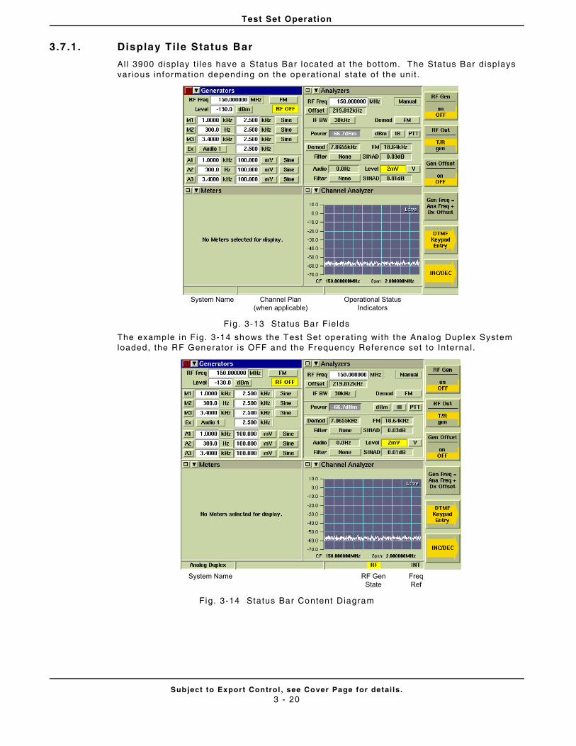
Test Set Operation
Subject to Export Control , see Cover Page for detai ls .3 - 20
3.7 .1. Display Ti le Status Bar
All 3900 display t i les have a Status Bar located at the bottom. The Status Bar displays var ious informat ion depending on the operat ional state of the uni t .
Fig. 3-13 Status Bar Fields
The example in Fig. 3-14 shows the Test Set operat ing wi th the Analog Duplex System loaded, the RF Generator is OFF and the Frequency Reference set to Internal .
Fig. 3-14 Status Bar Content Diagram
System Name Channel Plan(when applicable)
Operational StatusIndicators
System Name FreqRef
RF GenState
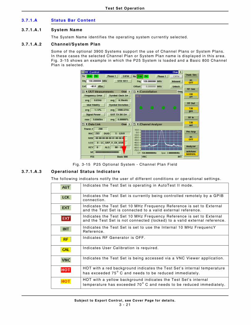
Test Set Operation
Subject to Export Control , see Cover Page for detai ls .3 - 21
3.7.1.A Status Bar Content
3.7.1.A.1 System Name
The System Name ident i f ies the operat ing system current ly selected.
3.7.1.A.2 Channel /System Plan
Some of the opt ional 3900 Systems support the use of Channel Plans or System Plans. In these cases the selected Channel Plan or System Plan name is displayed in th is area. Fig. 3-15 shows an example in which the P25 System is loaded and a Basic 800 Channel Plan is selected.
Fig. 3-15 P25 Opt ional System - Channel Plan F ield
3.7.1.A.3 Operational Status Indicators
The fol lowing indicators not i fy the user of di f ferent condi t ions or operat ional sett ings.
Indicates the Test Set is operat ing in AutoTest I I mode.
Indicates the Test Set is current ly being control led remotely by a GPIB connect ion.
Indicates the Test Set 10 MHz Frequency Reference is set to External and the Test Set is connected to a val id external reference.
Indicates the Test Set 10 MHz Frequency Reference is set to External and the Test Set is not connected ( locked) to a val id external reference.
Indicates the Test Set is set to use the Interna l 10 MHz FrequencY Reference.
Indicates RF Generator is OFF.
Indicates User Cal ibrat ion is required.
Indicates the Test Set is being accessed via a VNC Viewer appl icat ion.
HOT with a red background indicates the Test Set ’s internal temperature has exceeded 75° C and needs to be reduced immediately.
HOT with a yel low background indicates the Test Set ’s in ternal temperature has exceeded 70° C and needs to be reduced immediately.
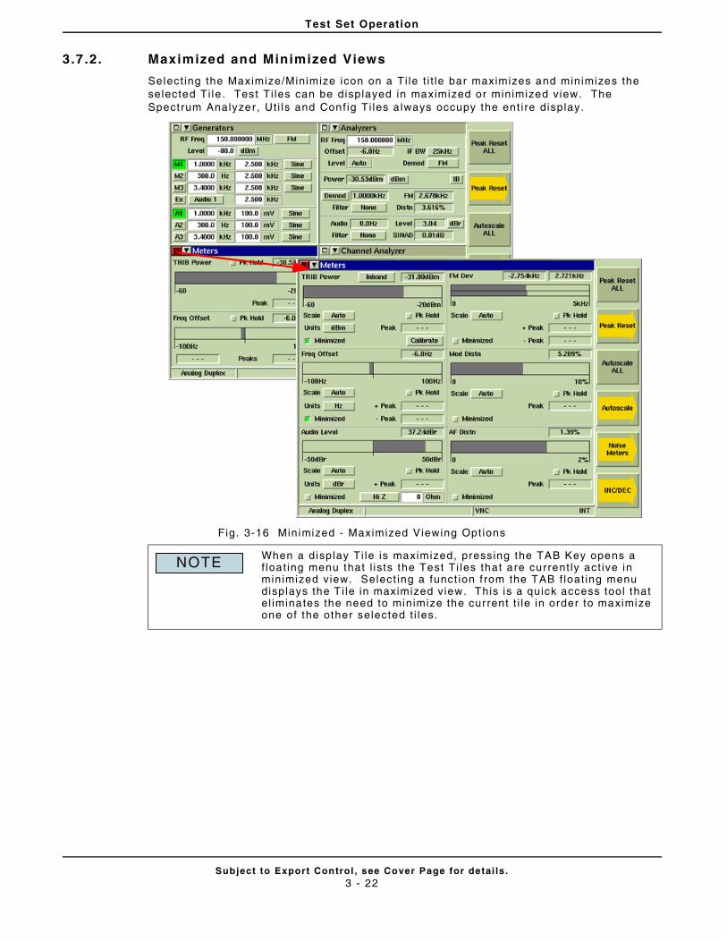
Test Set Operation
Subject to Export Control , see Cover Page for detai ls .3 - 22
3.7 .2. Maximized and Minimized Views
Select ing the Maximize/Minimize icon on a Ti le t i t le bar maximizes and minimizes the selected Ti le. Test Ti les can be displayed in maximized or minimized view. The Spectrum Analyzer, Ut i ls and Conf ig Ti les a lways occupy the ent i re display.
Fig. 3-16 Minimized - Maximized Viewing Opt ions
When a disp lay Ti le is maximized, pressing the TAB Key opens a f loat ing menu that l is ts the Test Ti les that are current ly act ive in minimized view. Select ing a funct ion f rom the TAB f loat ing menu displays the T i le in maximized view. This is a quick access tool that el iminates the need to minimize the current t i le in order to maximize one of the other selected t i les.
NOTE
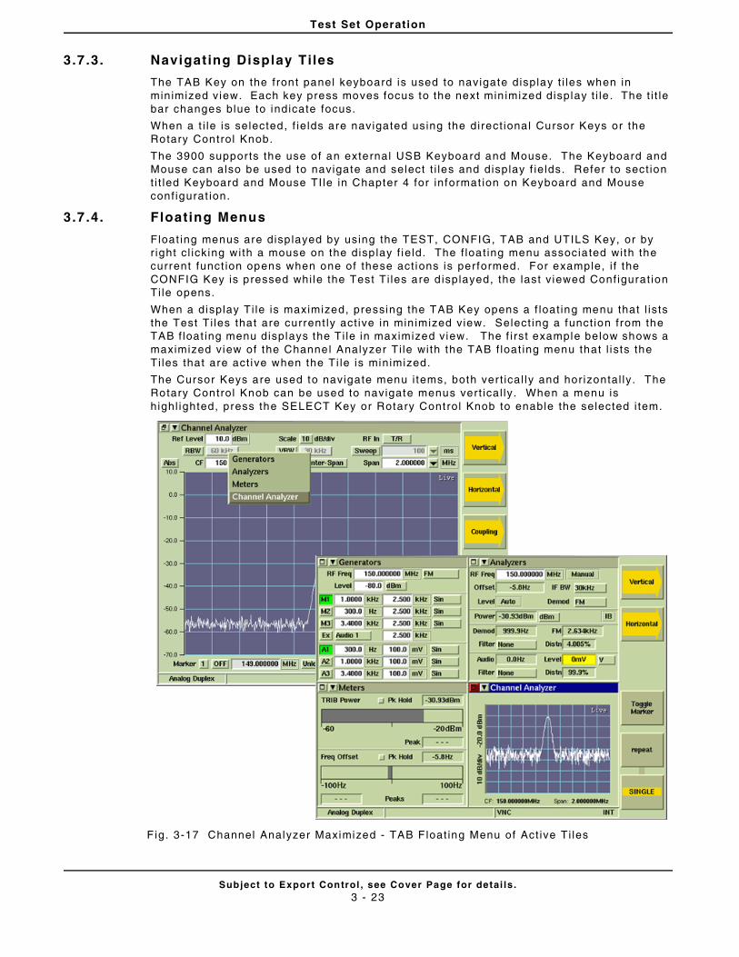
Test Set Operation
Subject to Export Control , see Cover Page for detai ls .3 - 23
3.7 .3. Navigating Display Tiles
The TAB Key on the front panel keyboard is used to navigate display t i les when in minimized view. Each key press moves focus to the next min imized display t i le . The t i t le bar changes blue to indicate focus.
When a t i le is selected, f ie lds are navigated using the direct ional Cursor Keys or the Rotary Control Knob.
The 3900 supports the use of an external USB Keyboard and Mouse. The Keyboard and Mouse can also be used to navigate and select t i les and display f ie lds. Refer to sect ion t i t led Keyboard and Mouse TI le in Chapter 4 for informat ion on Keyboard and Mouse conf igurat ion.
3.7 .4. Floating Menus
Float ing menus are disp layed by using the TEST, CONFIG, TAB and UTILS Key, or by r ight c l icking with a mouse on the disp lay f ie ld. The f loat ing menu associa ted with the current funct ion opens when one of these act ions is performed. For example, i f the CONFIG Key is pressed whi le the Test Ti les are d isplayed, the last v iewed Conf igurat ion Ti le opens.
When a display Ti le is maximized, pressing the TAB Key opens a f loat ing menu that l is ts the Test Ti les that are current ly act ive in min imized view. Select ing a funct ion from the TAB f loat ing menu displays the Ti le in maximized view. The f i rst example below shows a maximized view of the Channel Analyzer Ti le with the TAB f loat ing menu that l ists the Ti les that are act ive when the Ti le is minimized.
The Cursor Keys are used to navigate menu i tems, both ver t ical ly and hor izontal ly. The Rotary Control Knob can be used to navigate menus vert ical ly. When a menu is highl ighted, press the SELECT Key or Rotary Control Knob to enable the selected i tem.
Fig. 3-17 Channel Analyzer Maximized - TAB Float ing Menu of Act ive Ti les
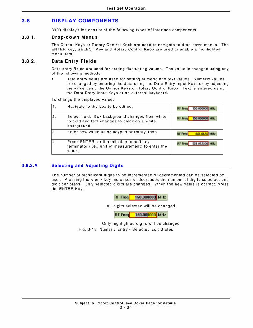
Test Set Operation
Subject to Export Control , see Cover Page for detai ls .3 - 24
3.8 DISPLAY COMPONENTS
3900 display t i les consist o f the fol lowing types of interface components:
3.8 .1. Drop-down Menus
The Cursor Keys or Rotary Control Knob are used to navigate to drop-down menus. The ENTER Key, SELECT Key and Rotary Contro l Knob are used to enable a h ighl ighted menu i tem.
3.8 .2. Data Entry Fields
Data ent ry f ie lds are used for sett ing f luctuat ing values. The value is changed using any of the fol lowing methods:
• Data entry f ie lds are used for sett ing numeric and text values. Numer ic values are changed by enter ing the data using the Data Entry Input Keys or by adjust ing the value using the Cursor Keys or Rotary Control Knob. Text is entered using the Data Entry Input Keys or an external keyboard.
To change the d isplayed value:
3.8.2.A Selecting and Adjusting Digits
The number of s igni f icant d igi ts to be incremented or decremented can be selected by user. Pressing the < or > key increases or decreases the number of digi ts selected, one digi t per press. Only selected digi ts are changed. When the new value is correct, press the ENTER Key.
Al l d igi ts selected wi l l be changed
Only highl ighted dig i ts wi l l be changed
Fig. 3-18 Numeric Entry - Se lected Edit States
1. Navigate to the box to be edi ted.
2. Select f ie ld. Box background changes f rom white to go ld and text changes to black on a white background.
3. Enter new va lue using keypad or rotary knob.
4. Press ENTER, or i f appl icable , a soft key terminator ( i .e. , uni t of measurement) to enter the va lue.
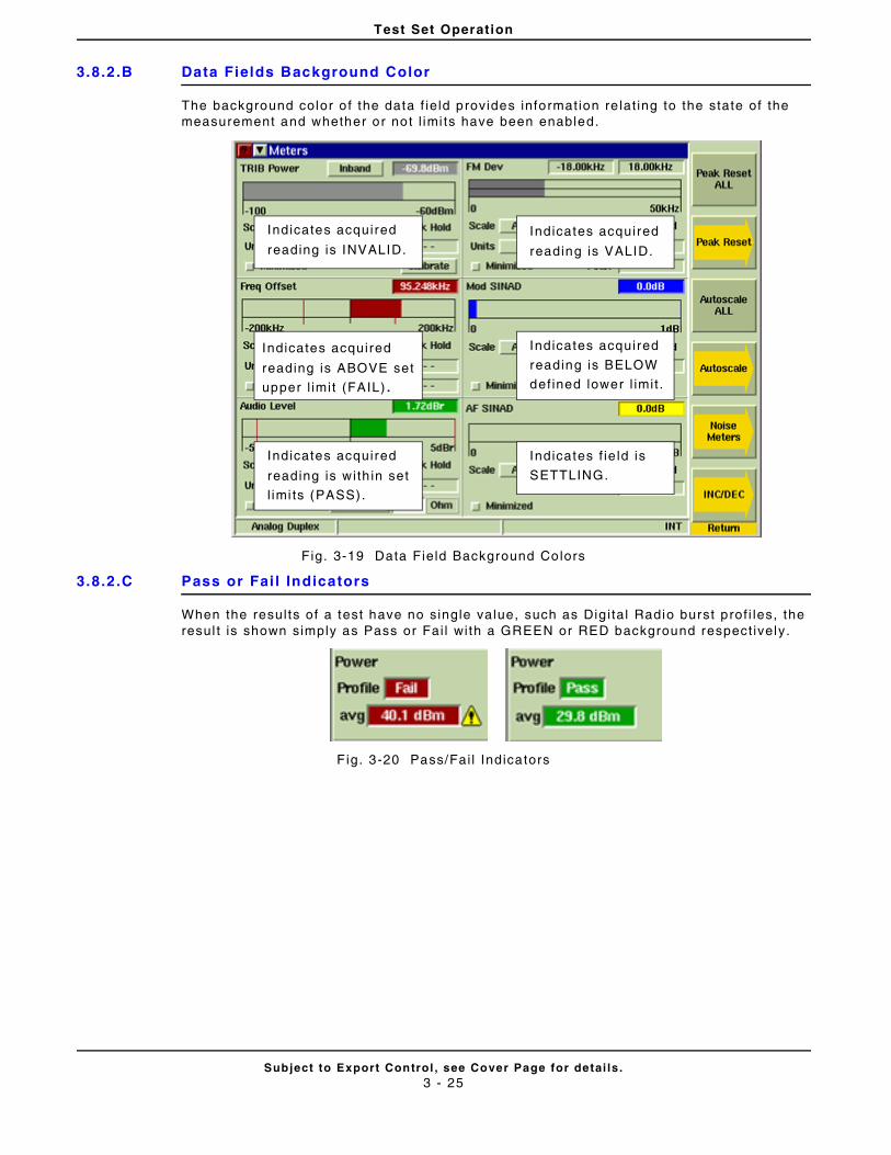
Test Set Operation
Subject to Export Control , see Cover Page for detai ls .3 - 25
3.8.2.B Data Fields Background Color
The background color o f the data f ie ld provides information re lat ing to the state of the measurement and whether or not l imi ts have been enabled.
Fig. 3-19 Data Field Background Colors
3.8.2.C Pass or Fai l Indicators
When the resul ts of a test have no single value, such as Dig i ta l Radio burst prof i les, the resul t is shown simply as Pass or Fai l wi th a GREEN or RED background respect ively.
F ig. 3-20 Pass/Fai l Indicators
Indicates acquired
reading is VALID.
Indicates acquired
reading is BELOW
defined lower l imit .
Indicates f ie ld is
SETTLING.
Indicates acquired
reading is INVALID.
Indicates acquired
reading is wi th in set
l imi ts (PASS).
Indicates acquired
reading is ABOVE set
upper l imit (FAIL).
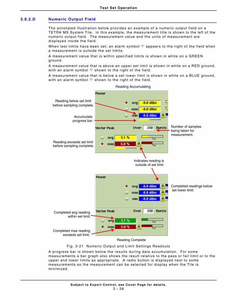
Test Set Operation
Subject to Export Control , see Cover Page for detai ls .3 - 26
3.8.2.D Numeric Output Field
The annotated i l lustrat ion below provides an example of a numeric output f ie ld on a TETRA MS System Ti le. In this example, the measurement t i t le is shown to the lef t of the numer ic output f ie ld. The measurement value and the uni ts o f measurement are displayed inside the f ie ld.
When test l imits have been set , an alarm symbol ‘ ! ’ appears to the r ight o f the f ie ld when a measurement is outside the set l imi ts.
A measurement value that is wi thin spec i f ied l imits is shown in white on a GREEN ground.
A measurement value that is above an upper set l imit is shown in white on a RED ground, wi th an alarm symbol ‘ ! ’ shown to the r ight of the f ie ld.
A measurement value that is below a set lower l imit is shown in white on a BLUE ground, wi th an alarm symbol ‘ ! ’ shown to the r ight of the f ie ld.
Fig. 3-21 Numeric Output and Limit Set t ings Readouts
A progress bar is shown below the resul ts dur ing data accumulat ion. For some measurements a bar graph also shows the resul t rela t ive to the pass or fa i l l imi t or to the upper and lower l imits as appropr iate. A radio button is disp layed next to some measurements so the measurement can be selected for display when the Ti le is minimized.
Number of samples being taken for measurement.
Completed readings below set lower limit.
Reading below set limit before sampling complete.
Accumulateprogress bar.
Reading exceeds set limitbefore sampling complete.
Indicates reading is outside of set limit.
Completed avg readingwithin set limit.
Completed max readingexceeds set limit.
Reading Accumulating
Reading Complete
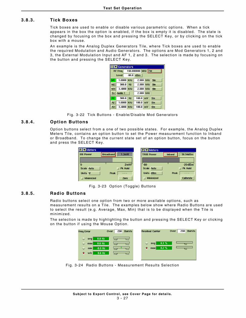
Test Set Operation
Subject to Export Control , see Cover Page for detai ls .3 - 27
3.8 .3. Tick Boxes
Tick boxes are used to enable or disable var ious parametr ic opt ions. When a t ick appears in the box the opt ion is enabled, i f the box is empty i t is disabled. The state is changed by focusing on the box and pressing the SELECT Key, or by cl icking on the t ick box with a mouse.
An example is the Analog Duplex Generators Ti le, where Tick boxes are used to enable the required Modulat ion and Audio Generators. The opt ions are Mod Generators 1, 2 and 3, the External Modulat ion Input and AF 1, 2 and 3. The se lect ion is made by focusing on the button and pressing the SELECT Key.
Fig. 3-22 Tick Buttons - Enable/Disable Mod Generators
3.8 .4. Option Buttons
Option buttons select f rom a one of two possible states. For example, the Analog Duplex Meters Ti le, contains an opt ion button to set the Power measurement funct ion to Inband or Broadband. To change the current sta te set of an opt ion button, focus on the but ton and press the SELECT Key.
Fig. 3-23 Opt ion (Toggle) Buttons
3.8 .5. Radio Buttons
Radio buttons select one opt ion from two or more avai lable opt ions, such as measurement resu l ts on a Ti le. The examples below show where Radio Buttons are used to select the resul t (e.g. Average, Max, Min) that is to be disp layed when the Ti le is minimized.
The select ion is made by highl ight ing the button and pressing the SELECT Key or c l icking on the button i f using the Mouse Opt ion.
Fig. 3-24 Radio Buttons - Measurement Results Select ion
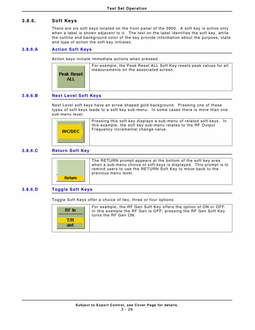
Test Set Operation
Subject to Export Control , see Cover Page for detai ls .3 - 28
3.8 .6. Soft Keys
There are six soft keys located on the front panel of the 3900. A soft key is act ive on ly when a label is shown adjacent to i t . The text on the label ident i f ies the sof t key, whi le the out l ine and background color o f the key provide informat ion about the purpose, sta te and type of act ion the sof t key in i t iates.
3.8.6.A Action Soft Keys
Act ion keys in i t ia te immediate act ions when pressed.
3.8.6.B Next Level Soft Keys
Next Level soft keys have an arrow shaped gold background. Pressing one of these types of sof t keys leads to a soft key sub-menu. In some cases there is more than one sub-menu level .
3.8.6.C Return Soft Key
3.8.6.D Toggle Soft Keys
Toggle Soft Keys of fer a choice of two, three or four opt ions.
For example, the Peak Reset ALL Soft Key resets peak values for al l measurements on the associated screen.
Pressing this sof t key displays a sub-menu of related soft keys. In th is example, the soft key sub-menu relates to the RF Output Frequency incremental change value.
The RETURN prompt appears at the bottom of the soft key area when a sub-menu choice of sof t keys is disp layed. This prompt is to remind users to use the RETURN Sof t Key to move back to the previous menu level .
For example, the RF Gen Sof t Key of fers the opt ion of ON or OFF. In this example the RF Gen is OFF; pressing the RF Gen Soft Key turns the RF Gen ON.
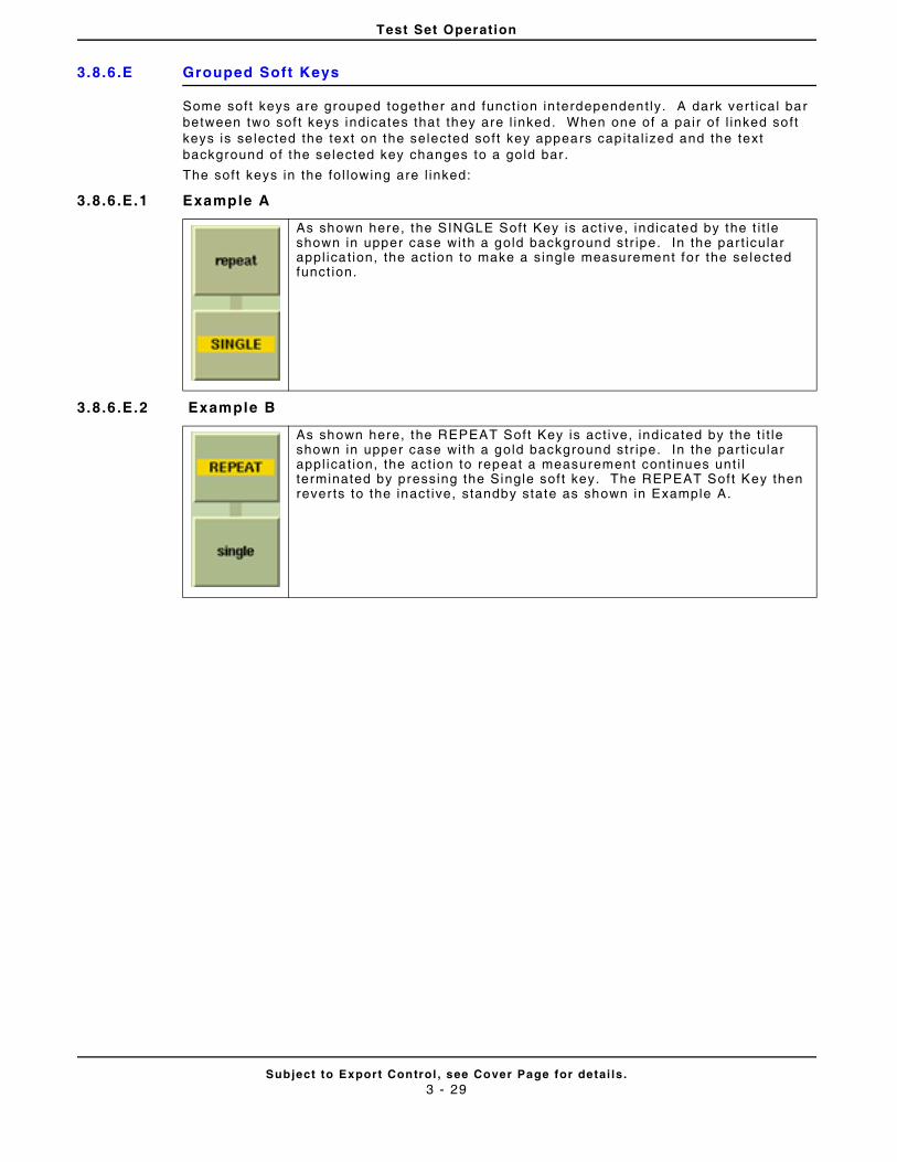
Test Set Operation
Subject to Export Control , see Cover Page for detai ls .3 - 29
3.8.6.E Grouped Soft Keys
Some soft keys are grouped together and funct ion in terdependent ly. A dark vert ical bar between two sof t keys indicates that they are l inked. When one of a pair of l inked soft keys is se lected the text on the selected soft key appears capi tal ized and the text background of the selected key changes to a gold bar .
The soft keys in the fol lowing are l inked:
3.8.6.E.1 Example A
3.8.6.E.2 Example B
As shown here, the SINGLE Soft Key is act ive, indicated by the t i t le shown in upper case with a gold background str ipe. In the par t icular appl icat ion, the act ion to make a single measurement for the se lected funct ion.
As shown here, the REPEAT Soft Key is act ive, indicated by the t i t le shown in upper case with a gold background str ipe. In the par t icular appl icat ion, the act ion to repeat a measurement cont inues unt i l terminated by pressing the Single soft key. The REPEAT Soft Key then rever ts to the inact ive, standby state as shown in Example A.
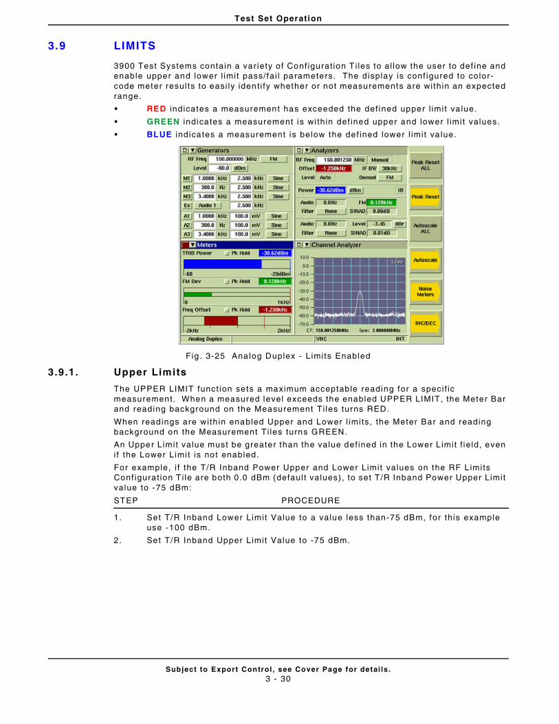
Test Set Operation
Subject to Export Control , see Cover Page for detai ls .3 - 30
3.9 LIMITS
3900 Test Systems contain a var iety of Conf igurat ion T i les to al low the user to def ine and enable upper and lower l imit pass/fai l parameters. The display is conf igured to color-code meter resul ts to easi ly ident i fy whether or not measurements are within an expected range.
• RED indicates a measurement has exceeded the def ined upper l imit va lue.
• GREEN indicates a measurement is wi thin def ined upper and lower l imit values.
• BLUE indicates a measurement is below the def ined lower l imit va lue.
Fig . 3-25 Analog Duplex - L imits Enabled
3.9 .1. Upper Limits
The UPPER LIMIT funct ion sets a maximum acceptable reading for a speci f ic measurement. When a measured level exceeds the enabled UPPER LIMIT, the Meter Bar and reading background on the Measurement Ti les turns RED.
When readings are with in enabled Upper and Lower l imits, the Meter Bar and reading background on the Measurement Ti les turns GREEN.
An Upper Limit value must be greater than the value def ined in the Lower L imit f ie ld, even i f the Lower Limi t is not enabled.
For example, i f the T/R Inband Power Upper and Lower Limit values on the RF L imits Conf igurat ion T i le are both 0.0 dBm (defaul t values) , to set T/R Inband Power Upper Limit value to -75 dBm:
STEP PROCEDURE
1. Set T/R Inband Lower Limit Value to a value less than-75 dBm, for th is example use -100 dBm.
2. Set T/R Inband Upper Limit Value to -75 dBm.
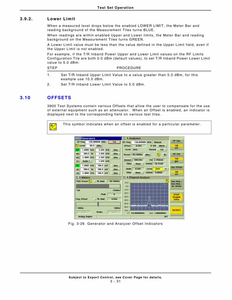
Test Set Operation
Subject to Export Control , see Cover Page for detai ls .3 - 31
3.9 .2. Lower Limit
When a measured level drops below the enabled LOWER LIMIT, the Meter Bar and reading background of the Measurement T i les turns BLUE.
When readings are with in enabled Upper and Lower l imits, the Meter Bar and reading background on the Measurement Ti les turns GREEN.
A Lower Limi t value must be less than the value def ined in the Upper L imit f ie ld, even i f the Upper L imit is not enabled.
For example, i f the T/R Inband Power Upper and Lower Limit values on the RF L imits Conf igurat ion T i le are both 0.0 dBm (defaul t values) , to set T/R Inband Power Lower Limit value to 5 .0 dBm:
STEP PROCEDURE
1. Set T/R Inband Upper Limit Value to a value greater than 5.0 dBm, for th is example use 10.0 dBm.
2. Set T/R Inband Lower Limit Value to 5.0 dBm.
3.10 OFFSETS
3900 Test Systems contain var ious Of fsets that al low the user to compensate for the use of external equipment such as an at tenuator . When an Offset is enabled, an indicator is displayed next to the corresponding f ie ld on var ious test t i les.
F ig. 3-26 Generator and Analyzer Of fset Indicators
This symbol ind icates when an of fset is enabled for a part icu lar parameter.
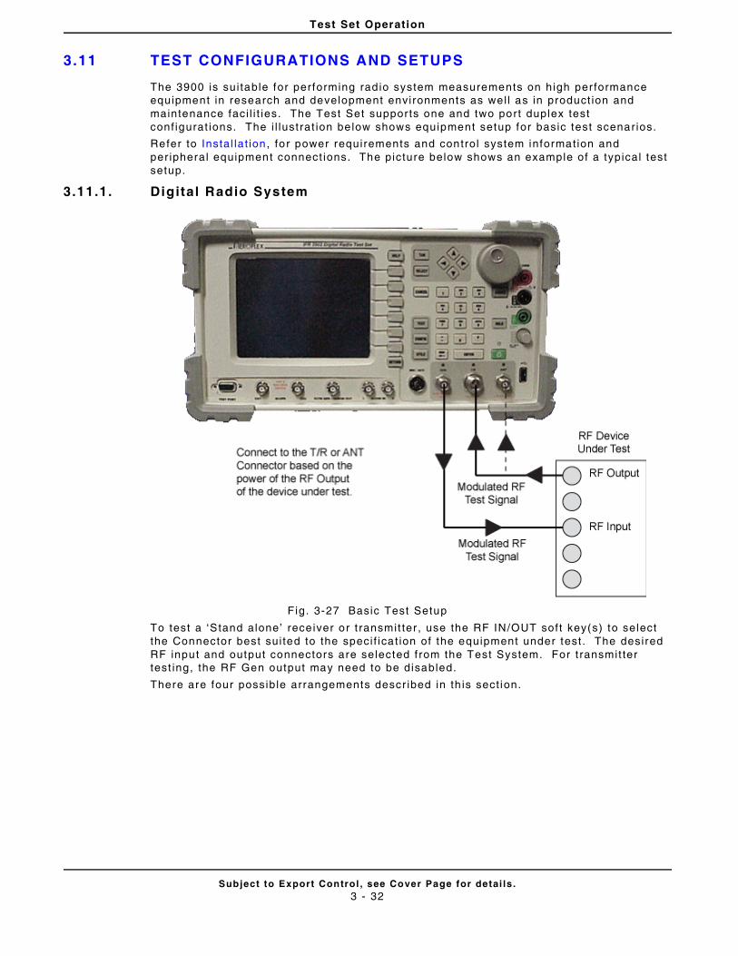
Test Set Operation
Subject to Export Control , see Cover Page for detai ls .3 - 32
3.11 TEST CONFIGURATIONS AND SETUPS
The 3900 is sui table for performing rad io system measurements on high per formance equipment in research and development environments as wel l as in product ion and maintenance faci l i t ies. The Test Set suppor ts one and two port duplex test conf igurat ions. The i l lust rat ion be low shows equipment setup for basic test scenarios.
Refer to Instal lat ion, for power requirements and control system information and per ipheral equipment connect ions. The picture below shows an example of a typical test setup.
3.11.1. Digital Radio System
Fig. 3-27 Basic Test Setup
To test a ‘Stand alone’ rece iver or t ransmit ter , use the RF IN/OUT soft key(s) to select the Connector best sui ted to the speci f icat ion of the equipment under test . The desired RF input and output connectors are selected f rom the Test System. For t ransmit ter test ing, the RF Gen output may need to be disabled.
There are four possible arrangements descr ibed in th is sect ion.
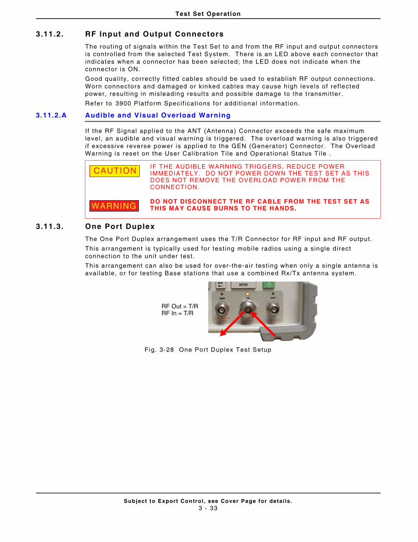
Test Set Operation
Subject to Export Control , see Cover Page for detai ls .3 - 33
3.11.2. RF Input and Output Connectors
The rout ing of s ignals within the Test Set to and from the RF input and output connectors is control led from the selected Test System. There is an LED above each connector that indicates when a connector has been selected; the LED does not indicate when the connector is ON.
Good qual i ty, correct ly f i t ted cables should be used to establ ish RF output connect ions. Worn connectors and damaged or k inked cables may cause high levels of ref lected power, resu l t ing in misleading resul ts and possible damage to the t ransmit ter .
Refer to 3900 Plat form Speci f icat ions for addi t iona l in format ion.
3.11.2.A Audible and Visual Overload Warning
I f the RF Signal appl ied to the ANT (Antenna) Connector exceeds the safe maximum level , an audible and visua l warning is t r iggered. The over load warning is also tr iggered i f excessive reverse power is appl ied to the GEN (Generator) Connector . The Overload Warning is reset on the User Cal ibrat ion Ti le and Operat ional Status T i le .
3.11.3. One Port Duplex
The One Port Duplex arrangement uses the T/R Connector for RF input and RF output.
This arrangement is typical ly used for test ing mobi le rad ios using a single d irect connect ion to the uni t under test .
This arrangement can also be used for over- the-air test ing when on ly a s ingle antenna is avai lab le, or for test ing Base sta t ions that use a combined Rx/Tx antenna system.
Fig. 3-28 One Port Duplex Test Setup
IF THE AUDIBLE WARNING TRIGGERS, REDUCE POWER IMMEDIATELY. DO NOT POWER DOWN THE TEST SET AS THIS DOES NOT REMOVE THE OVERLOAD POWER FROM THE CONNECTION.
DO NOT DISCONNECT THE RF CABLE FROM THE TEST SET AS THIS MAY CAUSE BURNS TO THE HANDS.
CAUTION
WARNING
RF Out = T/RRF In = T/R
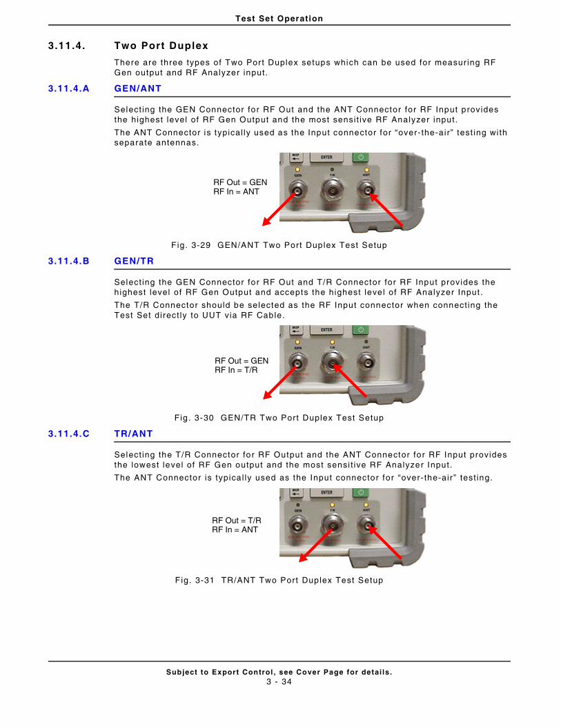
Test Set Operation
Subject to Export Control , see Cover Page for detai ls .3 - 34
3.11.4. Two Port Duplex
There are three types of Two Port Duplex setups which can be used for measur ing RF Gen output and RF Analyzer input.
3.11.4.A GEN/ANT
Select ing the GEN Connector for RF Out and the ANT Connector for RF Input provides the highest level of RF Gen Output and the most sensi t ive RF Analyzer input.
The ANT Connector is typical ly used as the Input connector for “over- the-air” test ing wi th separate antennas.
F ig. 3-29 GEN/ANT Two Port Duplex Test Setup
3.11.4.B GEN/TR
Select ing the GEN Connector for RF Out and T/R Connector for RF Input provides the highest level of RF Gen Output and accepts the highest leve l of RF Analyzer Input .
The T/R Connector should be selected as the RF Input connector when connect ing the Test Set direct ly to UUT via RF Cable.
Fig . 3-30 GEN/TR Two Port Duplex Test Setup
3.11.4.C TR/ANT
Select ing the T/R Connector for RF Output and the ANT Connector for RF Input provides the lowest level of RF Gen output and the most sensi t ive RF Analyzer Input.
The ANT Connector is typica l ly used as the Input connector for “over-the-air ” test ing.
F ig. 3-31 TR/ANT Two Port Duplex Test Setup
RF Out = GENRF In = ANT
RF Out = GENRF In = T/R
RF Out = T/RRF In = ANT
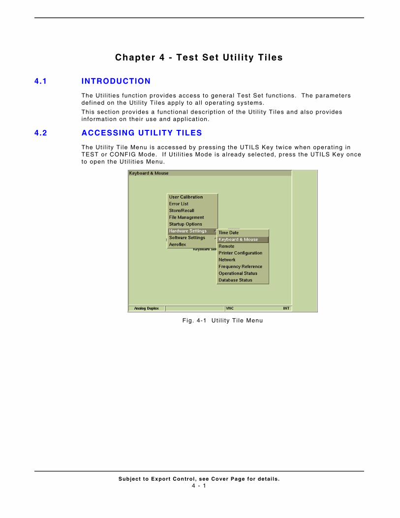
Subject to Export Control , see Cover Page for detai ls .4 - 1
Chapter 4 - Test Set Ut i l i ty Ti les
4.1 INTRODUCTION
The Ut i l i t ies funct ion provides access to general Test Set funct ions. The parameters def ined on the Ut i l i ty Ti les apply to al l operat ing systems.
This sect ion provides a funct ional descr ipt ion of the Ut i l i ty Ti les and also provides informat ion on their use and appl icat ion.
4.2 ACCESSING UTILITY TILES
The Ut i l i ty Ti le Menu is accessed by pressing the UTILS Key twice when operat ing in TEST or CONFIG Mode. I f Ut i l i t ies Mode is a lready selected, press the UTILS Key once to open the Ut i l i t ies Menu.
Fig. 4-1 Ut i l i ty Ti le Menu
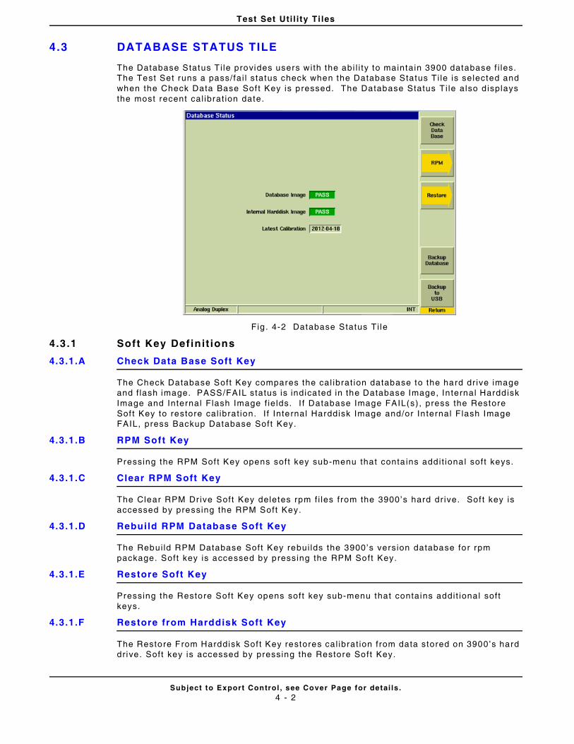
Test Set Uti l i ty Ti les
Subject to Export Control , see Cover Page for detai ls .4 - 2
4.3 DATABASE STATUS TILE
The Database Status Ti le provides users with the abi l i ty to maintain 3900 database f i les. The Test Set runs a pass/fai l status check when the Database Status Ti le is selected and when the Check Data Base Sof t Key is pressed. The Database Status Ti le also d isplays the most recent cal ibrat ion date.
Fig . 4-2 Database Status Ti le
4.3 .1 Soft Key Definit ions
4.3.1.A Check Data Base Soft Key
The Check Database Soft Key compares the cal ibrat ion database to the hard dr ive image and f lash image. PASS/FAIL status is indicated in the Database Image, In ternal Harddisk Image and Internal Flash Image f ie lds. I f Database Image FAIL(s), press the Restore Sof t Key to restore cal ibrat ion. I f Internal Harddisk Image and/or In ternal F lash Image FAIL, press Backup Database Soft Key.
4.3.1.B RPM Soft Key
Pressing the RPM Sof t Key opens soft key sub-menu that conta ins addi t iona l soft keys.
4.3.1.C Clear RPM Soft Key
The Clear RPM Dr ive Soft Key deletes rpm f i les f rom the 3900’s hard dr ive. Sof t key is accessed by pressing the RPM Soft Key.
4.3.1.D Rebui ld RPM Database Soft Key
The Rebui ld RPM Database Soft Key rebui lds the 3900’s version database for rpm package. Soft key is accessed by pressing the RPM Soft Key.
4.3.1.E Restore Soft Key
Pressing the Restore Soft Key opens soft key sub-menu that contains addi t ional soft keys.
4.3.1.F Restore from Harddisk Soft Key
The Restore From Harddisk Sof t Key restores cal ibrat ion from data stored on 3900’s hard dr ive. Soft key is accessed by pressing the Restore Soft Key.
Test Set Uti l i ty Ti les
Subject to Export Control , see Cover Page for detai ls .4 - 3
4.3.1.G Restore from USB Soft Key
The Restore From USB Soft Key restores cal ibrat ion from data on USB f lash dr ive. Soft key is accessed by pressing the Restore Soft Key.
4.3.1.H Backup Database Soft Key
Pressing the Backup Database Soft Key backs up 3900 database to the Test Set ’s internal hard dr ive.
4.3.1.I Backup to USB Soft Key
Pressing the Backup to USB Soft Key backs up the 3900 database to a USB device. The USB device must be at tached to USB connector before pressing soft key.
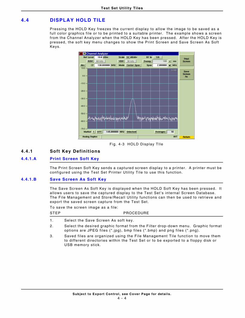
Test Set Uti l i ty Ti les
Subject to Export Control , see Cover Page for detai ls .4 - 4
4.4 DISPLAY HOLD TILE
Pressing the HOLD Key freezes the current display to al low the image to be saved as a ful l color graphics f i le or to be pr inted to a su i table pr inter . The example shows a screen from the Channel Analyzer when the HOLD Key has been pressed. After the HOLD Key is pressed, the sof t key menu changes to show the Print Screen and Save Screen As Sof t Keys.
Fig. 4-3 HOLD Disp lay TI le
4.4 .1 Soft Key Definit ions
4.4.1.A Print Screen Soft Key
The Prin t Screen Soft Key sends a captured screen display to a pr inter. A pr inter must be conf igured using the Test Set Pr inter Ut i l i ty Ti le to use this funct ion.
4.4.1.B Save Screen As Soft Key
The Save Screen As Sof t Key is displayed when the HOLD Soft Key has been pressed. I t a l lows users to save the captured display to the Test Set ’s internal Screen Database. The F i le Management and Store/Recal l Ut i l i ty funct ions can then be used to retr ieve and expor t the saved screen capture from the Test Set.
To save the screen image as a f i le:
STEP PROCEDURE
1. Select the Save Screen As soft key.
2. Select the desired graphic format f rom the F i l ter drop-down menu. Graphic format opt ions are JPEG f i les (*. jpg), bmp f i les (* .bmp) and png f i les (*.png) .
3. Saved f i les are organized using the F i le Management Ti le funct ion to move them to di f ferent director ies within the Test Set or to be exported to a f loppy disk or USB memory st ick.
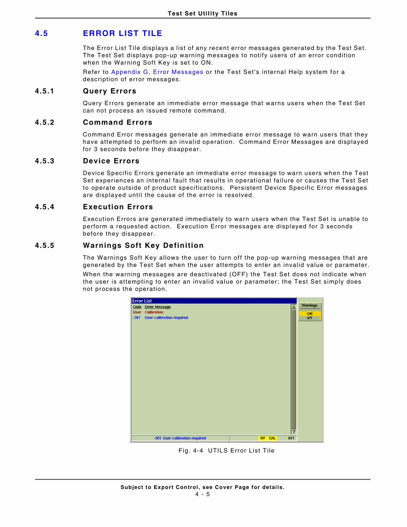
Test Set Uti l i ty Ti les
Subject to Export Control , see Cover Page for detai ls .4 - 5
4.5 ERROR LIST TILE
The Error List T i le displays a l ist of any recent error messages generated by the Test Set. The Test Set displays pop-up warn ing messages to not i fy users of an error condit ion when the Warning Sof t Key is set to ON.
Refer to Appendix G, Error Messages or the Test Set ’s internal Help system for a descr ipt ion of error messages.
4.5 .1 Query Errors
Query Errors generate an immediate error message that warns users when the Test Set can not process an issued remote command.
4.5 .2 Command Errors
Command Error messages generate an immediate error message to warn users that they have at tempted to perform an inval id operat ion. Command Error Messages are displayed for 3 seconds before they disappear.
4.5 .3 Device Errors
Device Speci f ic Errors generate an immediate error message to warn users when the Test Set experiences an interna l faul t that resul ts in operat ional fa i lure or causes the Test Set to operate outside of product speci f icat ions. Persistent Device Speci f ic Error messages are displayed unt i l the cause of the error is reso lved.
4.5 .4 Execution Errors
Execut ion Errors are generated immediately to warn users when the Test Set is unable to per form a requested act ion. Execut ion Error messages are d isplayed for 3 seconds before they disappear.
4.5 .5 Warnings Soft Key Definit ion
The Warn ings Soft Key al lows the user to turn of f the pop-up warning messages that are generated by the Test Set when the user at tempts to enter an inval id value or parameter.
When the warning messages are deact ivated (OFF) the Test Set does not indicate when the user is at tempting to enter an inval id value or parameter : the Test Set s imply does not process the operat ion.
Fig. 4-4 UTILS Error List T i le
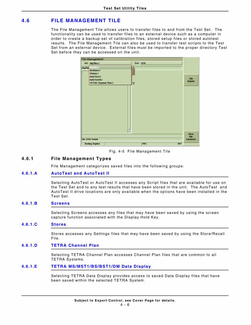
Test Set Uti l i ty Ti les
Subject to Export Control , see Cover Page for detai ls .4 - 6
4.6 FILE MANAGEMENT TILE
The Fi le Management Ti le al lows users to t ransfer f i les to and from the Test Set. The funct ional i ty can be used to t ransfer f i les to an externa l device such as a computer in order to create a backup set of ca l ibra t ion f i les, stored setup f i les or stored autotest resul ts. The Fi le Management Ti le can also be used to t ransfer test scr ipts to the Test Set f rom an external device. External f i les must be imported to the proper directory Test Set before they can be accessed on the uni t .
Fig. 4-5 Fi le Management Ti le
4.6 .1 Fi le Management Types
Fi le Management categor izes saved f i les into the fol lowing groups:
4.6.1.A AutoTest and AutoTest I I
Select ing AutoTest or AutoTest I I accesses any Scr ipt f i les that are avai lab le for use on the Test Set and to any test resul ts that have been stored in the un i t . The AutoTest and AutoTest I I dr ive locat ions are only avai lab le when the opt ions have been instal led in the Test Set .
4.6.1.B Screens
Select ing Screens accesses any f i les that may have been saved by using the screen capture funct ion associated with the Disp lay Hold Key.
4.6.1.C Stores
Stores accesses any Set t ings f i les that may have been saved by using the Store/Recal l Fi le.
4.6.1.D TETRA Channel Plan
Select ing TETRA Channel Plan accesses Channel Plan f i les that are common to al l TETRA Systems.
4.6.1.E TETRA MS/MST1/BS/BST1/DM Data Display
Select ing TETRA Data Display provides access to saved Data Display f i les that have been saved with in the selected TETRA System.
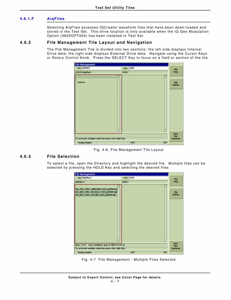
Test Set Uti l i ty Ti les
Subject to Export Control , see Cover Page for detai ls .4 - 7
4.6.1.F AiqFi les
Select ing AiqFi les accesses IQCreator waveform f i les that have been down- loaded and stored in the Test Set . This dr ive locat ion is only avai lable when the IQ Gen Modulat ion Opt ion (390XOPT054) has been instal led in Test Set.
4.6 .2 Fi le Management Tile Layout and Navigation
The Fi le Management Ti le is d iv ided into two sect ions: the le f t s ide disp lays Internal Dr ive data; the r ight s ide displays External Dr ive data. Navigate using the Cursor Keys or Rotary Control Knob. Press the SELECT Key to focus on a f ie ld or sect ion of the t i le.
F ig. 4-6 Fi le Management T i le Layout
4.6 .3 Fi le Selection
To se lect a f i le, open the Directory and highl ight the desired f i le. Mult ip le f i les can be selected by pressing the HOLD Key and select ing the desired f i les.
Fig. 4-7 Fi le Management - Mul t ip le Fi les Selected
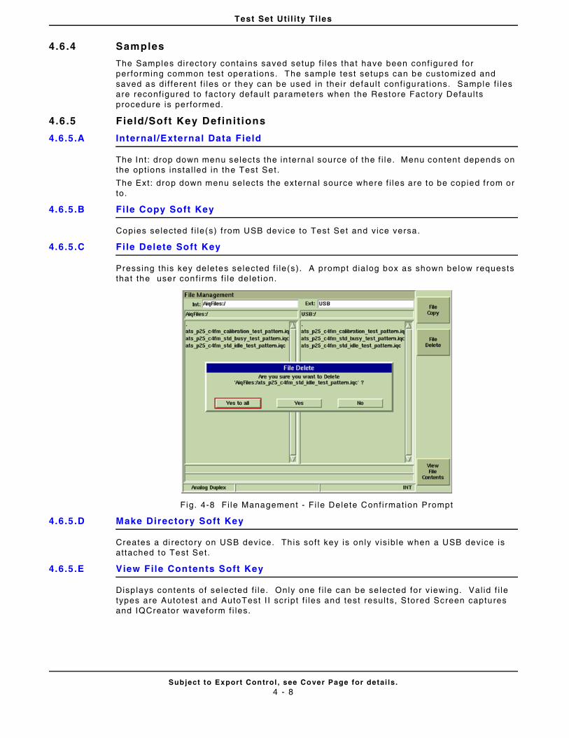
Test Set Uti l i ty Ti les
Subject to Export Control , see Cover Page for detai ls .4 - 8
4.6 .4 Samples
The Samples directory conta ins saved setup f i les that have been conf igured for per forming common test operat ions. The sample test setups can be customized and saved as di f ferent f i les or they can be used in their defaul t conf igurat ions. Sample f i les are reconf igured to factory defaul t parameters when the Restore Factory Defaul ts procedure is per formed.
4.6 .5 Field/Soft Key Definit ions
4.6.5.A Internal/External Data Field
The Int : drop down menu selects the in ternal source of the f i le. Menu content depends on the opt ions instal led in the Test Set.
The Ext: drop down menu selects the external source where f i les are to be copied from or to.
4.6.5.B Fi le Copy Soft Key
Copies selected f i le(s) f rom USB device to Test Set and vice versa.
4.6.5.C Fi le Delete Soft Key
Pressing this key deletes selected f i le(s). A prompt dialog box as shown below requests that the user conf i rms f i le delet ion.
Fig. 4-8 Fi le Management - Fi le Delete Conf i rmat ion Prompt
4.6.5.D Make Directory Soft Key
Creates a di rectory on USB device. Th is soft key is only v is ib le when a USB device is at tached to Test Set.
4.6.5.E View File Contents Soft Key
Disp lays contents of selected f i le. Only one f i le can be se lected for v iewing. Val id f i le types are Autotest and AutoTest I I scr ipt f i les and test resul ts, Stored Screen captures and IQCreator waveform f i les.
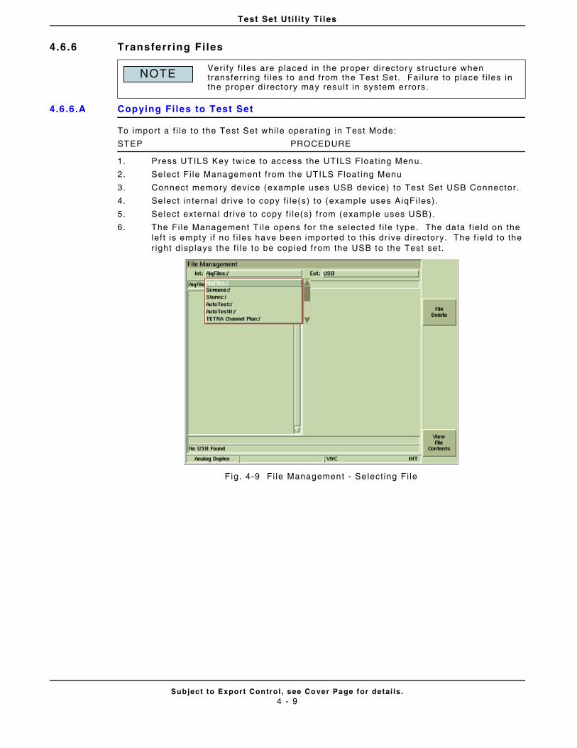
Test Set Uti l i ty Ti les
Subject to Export Control , see Cover Page for detai ls .4 - 9
4.6 .6 Transferr ing Files
4.6.6.A Copying Files to Test Set
To import a f i le to the Test Set whi le operat ing in Test Mode:
STEP PROCEDURE
1. Press UTILS Key twice to access the UTILS Float ing Menu.
2. Select F i le Management f rom the UTILS Float ing Menu
3. Connect memory device (example uses USB device) to Test Set USB Connector .
4. Select in ternal dr ive to copy f i le(s) to (example uses AiqFi les) .
5. Select externa l dr ive to copy f i le(s) f rom (example uses USB).
6. The Fi le Management Ti le opens for the selected f i le type. The data f ie ld on the lef t is empty i f no f i les have been imported to this dr ive directory. The f ie ld to the r ight displays the f i le to be copied f rom the USB to the Test set.
F ig. 4-9 Fi le Management - Se lect ing Fi le
Ver i fy f i les are placed in the proper directory structure when transferr ing f i les to and f rom the Test Set. Fai lure to place f i les in the proper directory may resul t in system errors.
NOTE
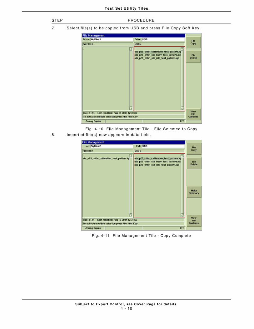
Test Set Uti l i ty Ti les
Subject to Export Control , see Cover Page for detai ls .4 - 10
STEP PROCEDURE
7. Select f i le(s) to be copied f rom USB and press Fi le Copy Soft Key.
Fig. 4-10 F i le Management Ti le - Fi le Selected to Copy
8. Imported f i le(s) now appears in data f ie ld.
Fig. 4-11 F i le Management Ti le - Copy Complete
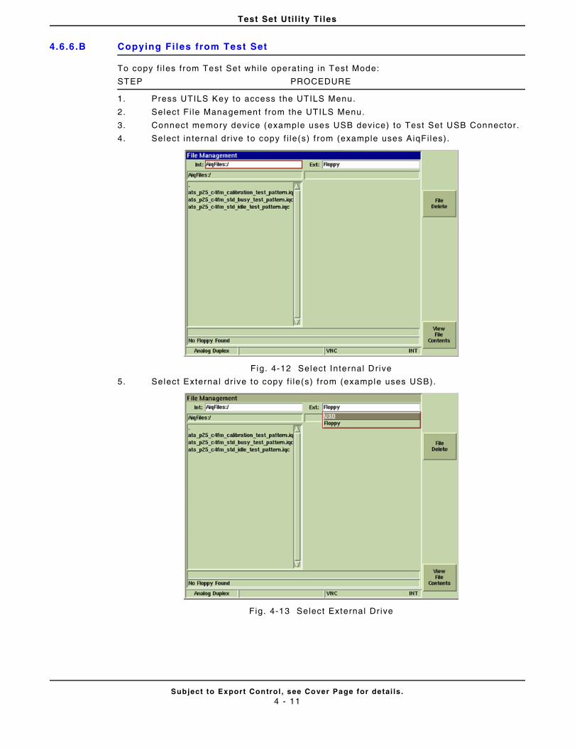
Test Set Uti l i ty Ti les
Subject to Export Control , see Cover Page for detai ls .4 - 11
4.6.6.B Copying Fi les from Test Set
To copy f i les f rom Test Set whi le operat ing in Test Mode:
STEP PROCEDURE
1. Press UTILS Key to access the UTILS Menu.
2. Select F i le Management f rom the UTILS Menu.
3. Connect memory device (example uses USB device) to Test Set USB Connector .
4. Select in ternal dr ive to copy f i le(s) f rom (example uses AiqFi les).
Fig. 4-12 Select Internal Drive
5. Select External dr ive to copy f i le(s) f rom (example uses USB).
Fig. 4-13 Select External Dr ive
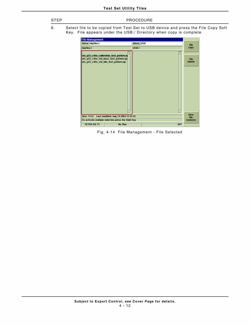
Test Set Uti l i ty Ti les
Subject to Export Control , see Cover Page for detai ls .4 - 12
STEP PROCEDURE
6. Select f i le to be copied from Test Set to USB device and press the Fi le Copy Sof t Key. F i le appears under the USB:/ Directory when copy is complete.
Fig. 4-14 F i le Management - Fi le Selected
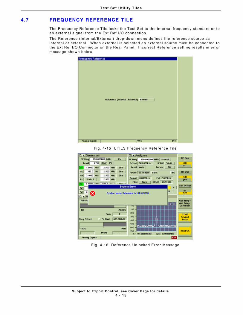
Test Set Uti l i ty Ti les
Subject to Export Control , see Cover Page for detai ls .4 - 13
4.7 FREQUENCY REFERENCE TILE
The Frequency Reference Ti le locks the Test Set to the internal f requency standard or to an external s ignal f rom the Ext Ref I /O connect ion.
The Reference ( Internal /External) drop-down menu def ines the reference source as internal or externa l . When external is selected an external source must be connected to the Ext Ref I /O Connector on the Rear Panel. Incorrect Reference set t ing resul ts in error message shown below.
Fig. 4-15 UTILS Frequency Reference Ti le
Fig. 4-16 Reference Unlocked Error Message
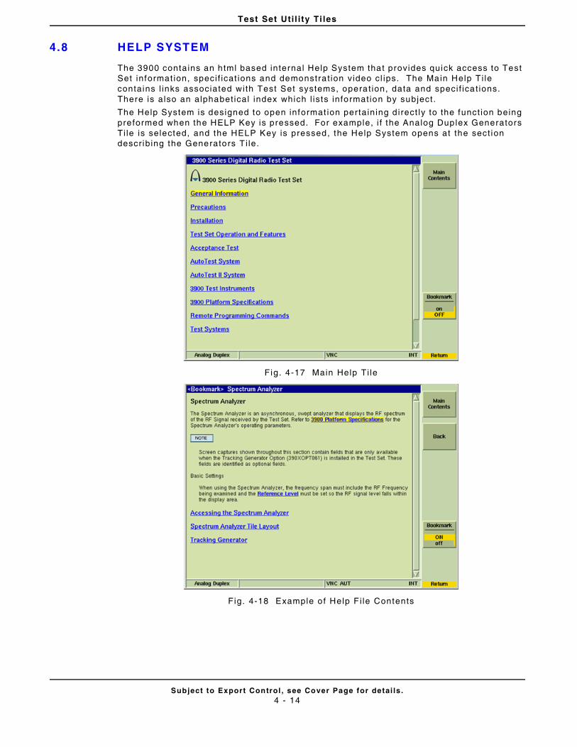
Test Set Uti l i ty Ti les
Subject to Export Control , see Cover Page for detai ls .4 - 14
4.8 HELP SYSTEM
The 3900 contains an html based internal Help System that provides quick access to Test Set informat ion, speci f icat ions and demonstra t ion video cl ips. The Main Help T i le contains l inks associated with Test Set systems, operat ion, data and speci f icat ions. There is also an alphabet ical index which l ists informat ion by subject.
The Help System is designed to open informat ion pertaining d irect ly to the funct ion being preformed when the HELP Key is pressed. For example, i f the Analog Duplex Generators Ti le is selected, and the HELP Key is pressed, the Help System opens at the sect ion descr ibing the Generators T i le.
Fig. 4-17 Main Help Ti le
Fig. 4-18 Example of Help F i le Contents
Test Set Uti l i ty Ti les
Subject to Export Control , see Cover Page for detai ls .4 - 15
4.8 .1 Soft Key Definit ions
4.8.1.A Main Contents Soft Key
Opens the main t i le in the Help System.
4.8.1.B Back Soft Key
Goes to previous Help Ti le.
4.8.1.C Bookmark Soft Key
This soft key sets a marker within the Help System that al lows the user to return to a speci f ic locat ion within Help the next t ime the HELP Key is pressed. When a Help ‘page’ is bookmarked, a <Bookmark> indicator appears in the Ti le t i t le bar. The user can then return to TEST mode, CONFIG mode or UTILS mode and cont inue with test ing. The next t ime the HELP Key is pressed, the Spectrum Analyzer Help Ti le opens.
4.8.1.D Return Soft Key
Exits Help System, returning to last used operat ing system ( i .e. , TEST Mode or CONFIG Mode). Can also press the TEST Key, CONFIG Key or UTILS Key to exi t Help System.
HELP cont inues to open to the Bookmarked T i le unt i l the Bookmark is turned OFF. Bookmarks are maintained when Operat ing System is changed.
NOTE
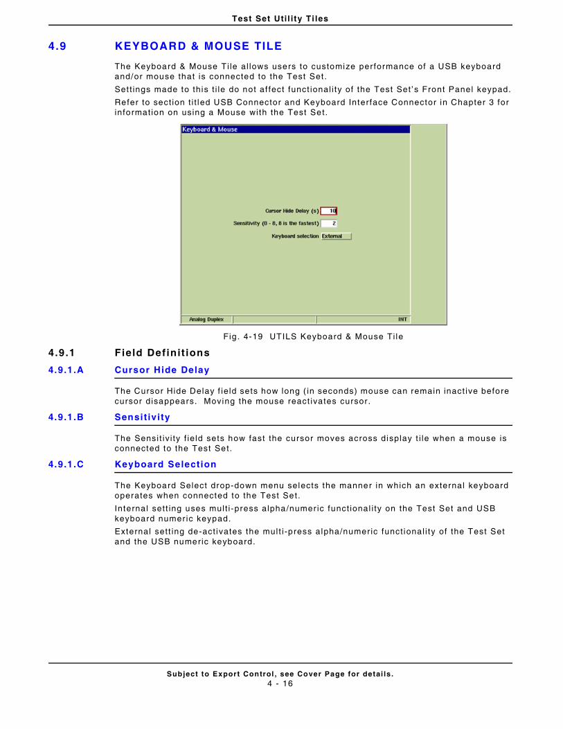
Test Set Uti l i ty Ti les
Subject to Export Control , see Cover Page for detai ls .4 - 16
4.9 KEYBOARD & MOUSE TILE
The Keyboard & Mouse Ti le al lows users to customize per formance of a USB keyboard and/or mouse that is connected to the Test Set .
Set t ings made to this t i le do not af fect funct ional i ty of the Test Set ’s Front Panel keypad.
Refer to sect ion t i t led USB Connector and Keyboard Interface Connector in Chapter 3 for informat ion on using a Mouse with the Test Set.
Fig . 4-19 UTILS Keyboard & Mouse Ti le
4.9 .1 Field Definit ions
4.9.1.A Cursor Hide Delay
The Cursor Hide Delay f ie ld sets how long ( in seconds) mouse can remain inact ive before cursor disappears. Moving the mouse react ivates cursor .
4.9.1.B Sensit ivity
The Sensi t iv i ty f ie ld sets how fast the cursor moves across display t i le when a mouse is connected to the Test Set.
4.9.1.C Keyboard Selection
The Keyboard Select drop-down menu selects the manner in which an external keyboard operates when connected to the Test Set.
Internal sett ing uses mult i -press alpha/numer ic funct ional i ty on the Test Set and USB keyboard numer ic keypad.
External sett ing de-act ivates the mult i -press alpha/numeric funct ional i ty of the Test Set and the USB numeric keyboard.
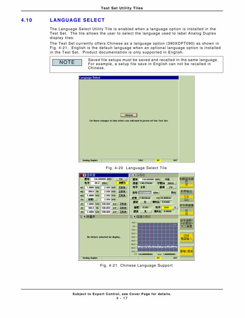
Test Set Uti l i ty Ti les
Subject to Export Control , see Cover Page for detai ls .4 - 17
4.10 LANGUAGE SELECT
The Language Select Ut i l i ty T i le is enabled when a language opt ion is instal led in the Test Set . The t i le al lows the user to select the language used to label Analog Duplex display t i les.
The Test Set current ly of fers Chinese as a language opt ion (390XOPT090) as shown in Fig. 4-21. Engl ish is the defaul t language when an opt ional language opt ion is instal led in the Test Set. Product documentat ion is only supported in Engl ish.
Fig. 4-20 Language Select Ti le
Fig. 4-21 Chinese Language Support
Saved f i le setups must be saved and recal led in the same language. For example, a setup f i le save in Engl ish can not be recal led in Chinese.
NOTE
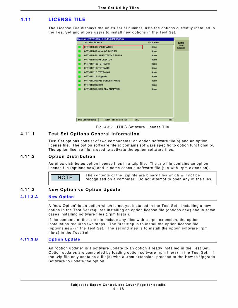
Test Set Uti l i ty Ti les
Subject to Export Control , see Cover Page for detai ls .4 - 18
4.11 LICENSE TILE
The License Ti le displays the un i t ’s ser ia l number, l ists the opt ions current ly instal led in the Test Set and al lows users to insta l l new opt ions in the Test Set.
F ig. 4-22 UTILS Software License Ti le
4.11.1 Test Set Options General Information
Test Set opt ions consist of two components: an opt ion software f i le(s) and an opt ion l icense f i le . The opt ion sof tware f i le(s) contains software speci f ic to opt ion funct ional i ty. The opt ion l icense f i le is used to act ivate the opt ion software f i les.
4.11.2 Option Distr ibution
Aerof lex distr ibutes opt ion l icense f i les in a .z ip f i le. The .z ip f i le contains an opt ion l icense f i le (opt ions.new) and in some cases a software f i le ( f i le wi th . rpm extension) .
4.11.3 New Option vs Option Update
4.11.3.A New Option
A “new Option” is an opt ion which is not yet instal led in the Test Set. Instal l ing a new opt ion in the Test Set requires instal l ing an opt ion l icense f i le (opt ions.new) and in some cases instal l ing software f i les ( .rpm f i le [s]) .
I f the contents of the .z ip f i le include any f i les with a . rpm extension, the opt ion instal lat ion requires two steps. The f i rst step is to instal l the opt ion l icense f i le (opt ions.new) in the Test Set . The second step is to instal l the opt ion software .rpm f i le (s) in the Test Set.
4.11.3.B Option Update
An “opt ion update” is a sof tware update to an opt ion already instal led in the Test Set. Opt ion updates are completed by loading opt ion software .rpm f i le(s) in the Test Set. I f the .z ip f i le only contains a f i le(s) wi th a . rpm extension, proceed to the How to Upgrade Sof tware to update the opt ion.
The contents of the .z ip f i le are binary f i les which wi l l not be recognized on a computer . Do not at tempt to open any of the f i les.NOTE
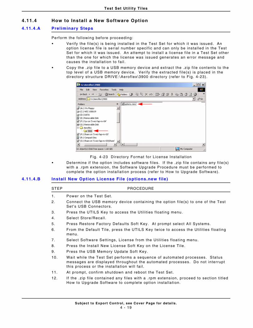
Test Set Uti l i ty Ti les
Subject to Export Control , see Cover Page for detai ls .4 - 19
4.11.4 How to Instal l a New Software Option
4.11.4.A Prel iminary Steps
Perform the fol lowing before proceeding:
• Ver i fy the f i le(s) is being instal led in the Test Set for which i t was issued. An opt ion l icense f i le is ser ia l number speci f ic and can on ly be instal led in the Test Set for which i t was issued. An at tempt to instal l a l icense f i le in a Test Set other than the one for which the l icense was issued generates an error message and causes the instal lat ion to fai l .
• Copy the .z ip f i le to a USB memory device and ext ract the .z ip f i le contents to the top level of a USB memory device. Ver i fy the extracted f i le(s) is placed in the directory structure DRIVE: \Aerof lex\3900 directory (refer to Fig. 4-23) .
F ig. 4-23 Directory Format for License Instal la t ion
• Determine i f the opt ion includes software f i les. I f the .z ip f i le contains any f i le(s) wi th a .rpm extension, the Software Upgrade Procedure must be per formed to complete the opt ion instal lat ion process ( refer to How to Upgrade Software) .
4.11.4.B Install New Option License Fi le (options.new fi le)
STEP PROCEDURE
1. Power on the Test Set.
2. Connect the USB memory device conta ining the opt ion f i le (s) to one of the Test Set ’s USB Connectors.
3. Press the UTILS Key to access the Ut i l i t ies f loat ing menu.
4. Select Store/Recal l .
5. Press Restore Factory Defaul ts Sof t Key. At prompt select A l l Systems.
6. From the Defaul t Ti le , press the UTILS Key twice to access the Ut i l i t ies f loat ing menu.
7. Select Software Sett ings, L icense f rom the Ut i l i t ies f loat ing menu.
8. Press the Instal l New License Soft Key on the License Ti le .
9. Press the USB Memory Update Soft Key.
10. Wait whi le the Test Set performs a sequence of automated processes. Status messages are d isplayed throughout the automated processes. Do not interrupt th is process or the instal la t ion wi l l fa i l .
11. At prompt, conf i rm shutdown and reboot the Test Set.
12. I f the .z ip f i le contained any f i les with a .rpm extension, proceed to sect ion t i t led How to Upgrade Software to complete opt ion instal la t ion.
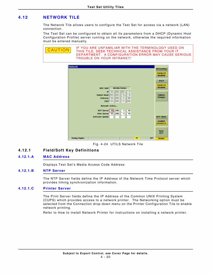
Test Set Uti l i ty Ti les
Subject to Export Control , see Cover Page for detai ls .4 - 20
4.12 NETWORK TILE
The Network Ti le al lows users to conf igure the Test Set for access via a network (LAN) connect ion.
The Test Set can be conf igured to obta in al l i ts parameters from a DHCP (Dynamic Host Conf igurat ion Prof i le) server running on the network, o therwise the required information must be entered manual ly.
Fig. 4-24 UTILS Network Ti le
4.12.1 Field/Soft Key Definit ions
4.12.1.A MAC Address
Disp lays Test Set ’s Media Access Code Address.
4.12.1.B NTP Server
The NTP Server f ie lds def ine the IP Address of the Network T ime Protocol server which provides t iming synchronizat ion in formation.
4.12.1.C Printer Server
The Pr int Server f ie lds def ine the IP Address of the Common UNIX Print ing System (CUPS) which provides access to a network pr inter. The Networking opt ion must be selected from the Connect ion drop-down menu on the Pr inter Conf igurat ion T i le to enable network pr int ing.
Refer to How to Instal l Network Pr inter for instruct ions on instal l ing a network pr inter.
IF YOU ARE UNFAMILIAR WITH THE TERMINOLOGY USED ON THIS TILE, SEEK TECHNICAL ASSISTANCE FROM YOUR IT DEPARTMENT. A CONFIGURATION ERROR MAY CAUSE SERIOUS TROUBLE ON YOUR INTRANET!
CAUTION
Test Set Uti l i ty Ti les
Subject to Export Control , see Cover Page for detai ls .4 - 21
4.12.1.D Software Update
The Sof tware Update f ie lds ident i fy the ht tp server f rom which software is downloaded when per forming a Network Software Upgrade. The Test Set can be conf igured to download software from the Aerof lex ht tp server or f rom a loca l server. As of software version 1.7 .5, the Aerof lex ht tp server IP address is 24.249.118.22.
I f using a local ht tp server , user should contact their IT depar tment for assistance. Enter the local ht tp server IP address in the Software Update f ie lds and press Val idate Changes to update Network connect ion.
Refer to sect ion t i t led Network Upgrade Procedure for addi t iona l informat ion.
4.12.1.E Networking Soft Key
Enables/Disables network access. When Enabled, the Test Set can be conf igured to be accessed f rom a remote locat ion.
4.12.1.F DHCP Soft Key
The DHCP Soft Key selects the manner in which network access is conf igured. Typica l conf igurat ion include Stat ic Conf igurat ion or Automat ic Conf igurat ion.
Refer to sect ion t i t led Conf igur ing Network Access.
4.12.1.G Val idate Changes Soft Key
The Val idate Sof t Key act ivates current network conf igurat ion and re-establ ishes (restar ts) network operat ion.
4.12.1.H NTP Cl ient Soft Key
Network T ime Protoco l Cl ient al lows the Test Set to be synchronized with an external t ime server .
4.12.1. I Sync NTP Soft Key
Synchronizes the Test Set wi th an external t ime server . NTP Cl ient Sof t Key must be Enabled before pressing this sof t key.
Test Set Uti l i ty Ti les
Subject to Export Control , see Cover Page for detai ls .4 - 22
4.12.2 Configuring Network Access
4.12.2.A Automatic Configuration (DHCP ON)
I f Automatic conf igurat ion is selected:
STEP PROCEDURE
1. Set Networking to ENABLED.
2. Set DHCP to ENABLED.
3. Select Val idate Conf igurat ion.
4. Wait whi le the Test Set quer ies on the network for a DHCP server and updates the IP, subnet mask, Gateway and DNS (Domain Name Server) f ie lds upon complet ion of the transact ion with the server.
4.12.2.B Static Configuration (DHCP OFF)
I f Stat ic conf igurat ion is selected:
STEP PROCEDURE
1. Set Networking to ENABLED.
2. Set DHCP to DISABLED.
3. Conf igure IP, subnet mask, Gateway and DNS va lues.
4. Select Val idate Conf igurat ion.
5. Wait whi le the Test Set quer ies for a val id network and enables network operat ion.
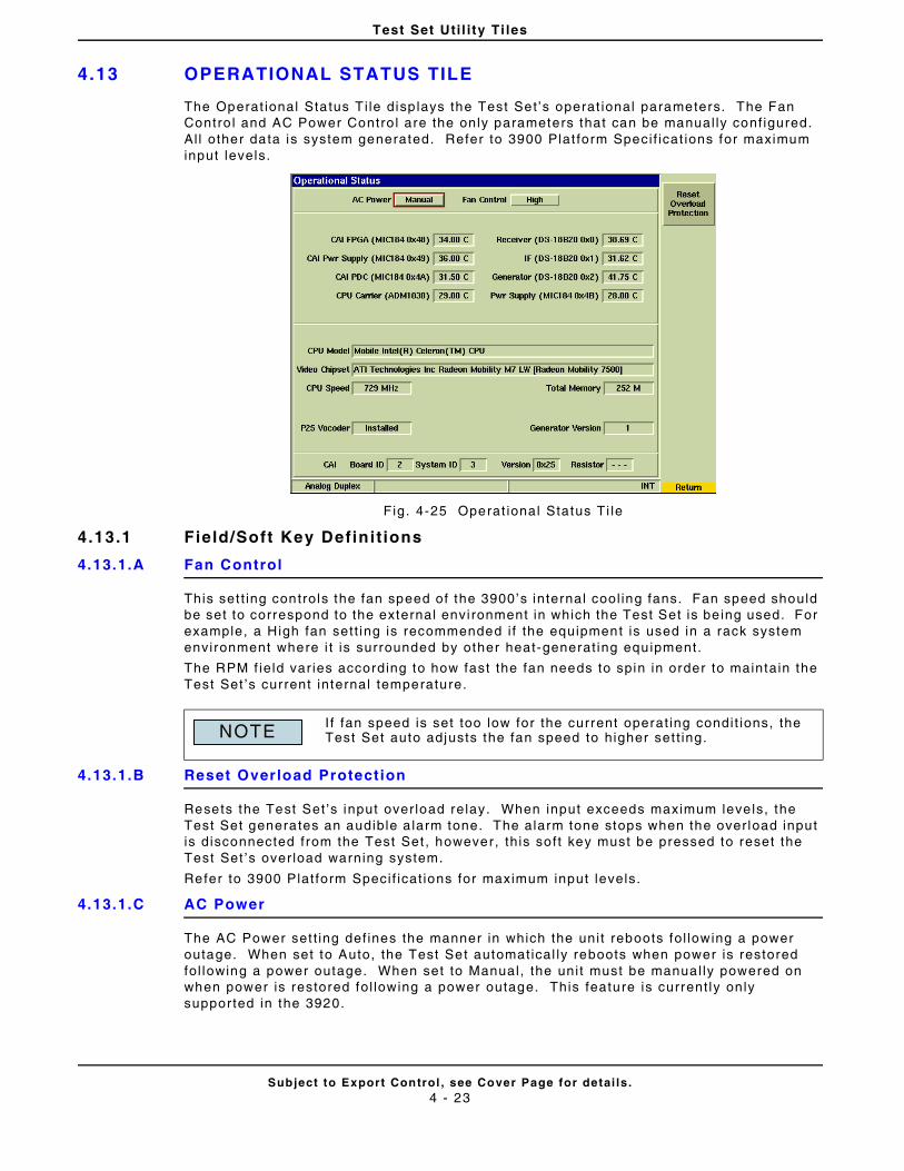
Test Set Uti l i ty Ti les
Subject to Export Control , see Cover Page for detai ls .4 - 23
4.13 OPERATIONAL STATUS TILE
The Operat ional Status T i le disp lays the Test Set ’s operat ional parameters. The Fan Contro l and AC Power Contro l are the only parameters that can be manual ly conf igured. Al l other data is system generated. Refer to 3900 Plat form Speci f icat ions for maximum input levels.
Fig. 4-25 Operat ional Status Ti le
4.13.1 Field/Soft Key Definit ions
4.13.1.A Fan Control
This set t ing controls the fan speed of the 3900’s internal cool ing fans. Fan speed should be set to correspond to the external envi ronment in which the Test Set is be ing used. For example, a High fan sett ing is recommended i f the equipment is used in a rack system environment where i t is surrounded by other heat-generat ing equipment.
The RPM f ie ld var ies according to how fast the fan needs to spin in order to maintain the Test Set ’s current internal temperature.
4.13.1.B Reset Overload Protection
Resets the Test Set ’s input over load relay. When input exceeds maximum leve ls, the Test Set generates an audible a larm tone. The alarm tone stops when the over load input is disconnected from the Test Set , however, th is soft key must be pressed to reset the Test Set ’s over load warning system.
Refer to 3900 Plat form Speci f icat ions for maximum input levels.
4.13.1.C AC Power
The AC Power set t ing def ines the manner in which the uni t reboots fol lowing a power outage. When set to Auto, the Test Set automatical ly reboots when power is restored fol lowing a power outage. When set to Manual, the uni t must be manual ly powered on when power is restored fol lowing a power outage. This feature is current ly only suppor ted in the 3920.
I f fan speed is set too low for the current operat ing condit ions, the Test Set auto adjusts the fan speed to higher set t ing.NOTE
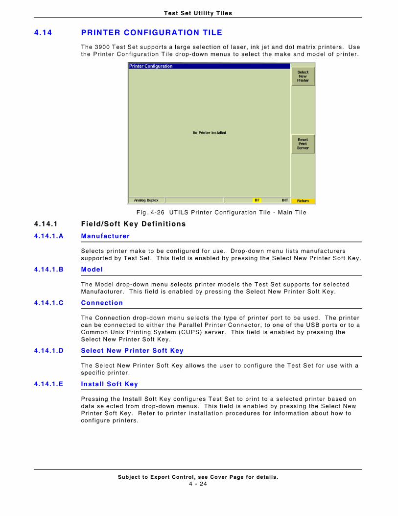
Test Set Uti l i ty Ti les
Subject to Export Control , see Cover Page for detai ls .4 - 24
4.14 PRINTER CONFIGURATION TILE
The 3900 Test Set supports a large se lect ion of laser, ink jet and dot matr ix pr inters. Use the Pr inter Conf igurat ion T i le drop-down menus to select the make and model of pr inter .
Fig. 4-26 UTILS Pr inter Conf igurat ion Ti le - Main Ti le
4.14.1 Field/Soft Key Definit ions
4.14.1.A Manufacturer
Selects pr inter make to be conf igured for use. Drop-down menu l ists manufacturers suppor ted by Test Set . This f ie ld is enabled by pressing the Select New Pr inter Soft Key.
4.14.1.B Model
The Model drop-down menu selects pr inter models the Test Set suppor ts for selected Manufacturer. This f ie ld is enabled by pressing the Select New Prin ter Sof t Key.
4.14.1.C Connection
The Connect ion drop-down menu selects the type of pr inter port to be used. The pr inter can be connected to ei ther the Paral le l Pr inter Connector, to one of the USB por ts or to a Common Unix Pr int ing System (CUPS) server . This f ie ld is enabled by pressing the Select New Pr inter Soft Key.
4.14.1.D Select New Printer Soft Key
The Select New Pr inter Soft Key al lows the user to conf igure the Test Set for use with a speci f ic pr inter .
4.14.1.E Install Soft Key
Pressing the Instal l Sof t Key conf igures Test Set to pr int to a selected pr inter based on data selected from drop-down menus. This f ie ld is enabled by pressing the Select New Pr inter Soft Key. Refer to pr inter instal lat ion procedures for information about how to conf igure pr in ters.
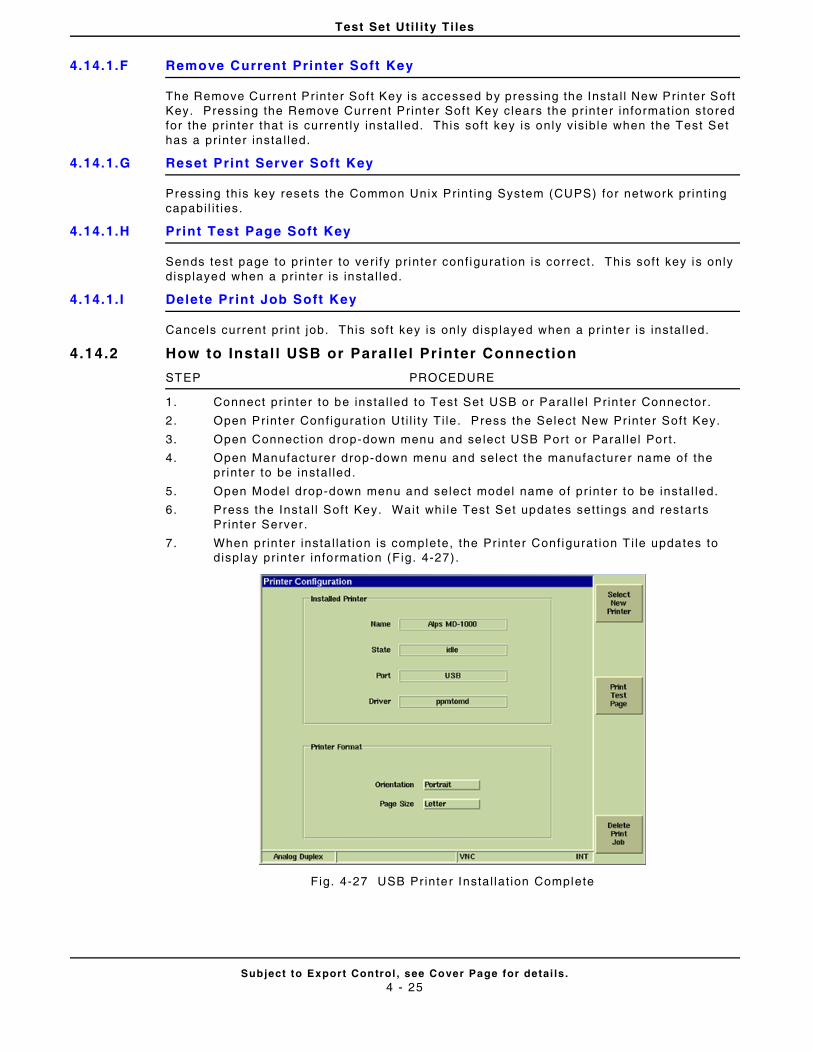
Test Set Uti l i ty Ti les
Subject to Export Control , see Cover Page for detai ls .4 - 25
4.14.1.F Remove Current Printer Soft Key
The Remove Current Printer Sof t Key is accessed by pressing the Instal l New Prin ter Soft Key. Pressing the Remove Current Printer Sof t Key clears the pr inter informat ion stored for the pr inter that is current ly instal led. This soft key is only v is ible when the Test Set has a pr inter insta l led.
4.14.1.G Reset Print Server Soft Key
Pressing this key resets the Common Unix Print ing System (CUPS) for network pr int ing capabi l i t ies.
4.14.1.H Print Test Page Soft Key
Sends test page to pr in ter to ver i fy pr inter conf igurat ion is correct. This soft key is only displayed when a pr in ter is instal led.
4.14.1. I Delete Print Job Soft Key
Cancels current pr int job. This soft key is only disp layed when a pr inter is instal led.
4.14.2 How to Instal l USB or Paral lel Printer Connection
STEP PROCEDURE
1. Connect pr inter to be instal led to Test Set USB or Paral le l Pr in ter Connector .
2. Open Printer Conf igurat ion Ut i l i ty Ti le. Press the Select New Pr inter Soft Key.
3. Open Connect ion drop-down menu and se lect USB Port or Paral le l Por t .
4. Open Manufacturer drop-down menu and select the manufacturer name of the pr inter to be instal led.
5. Open Model drop-down menu and select model name of pr inter to be instal led.
6. Press the Instal l Soft Key. Wait whi le Test Set updates sett ings and restarts Pr inter Server .
7. When pr in ter insta l lat ion is complete, the Pr inter Conf igurat ion T i le updates to display pr in ter information (F ig. 4-27).
Fig. 4-27 USB Pr inter Instal lat ion Complete
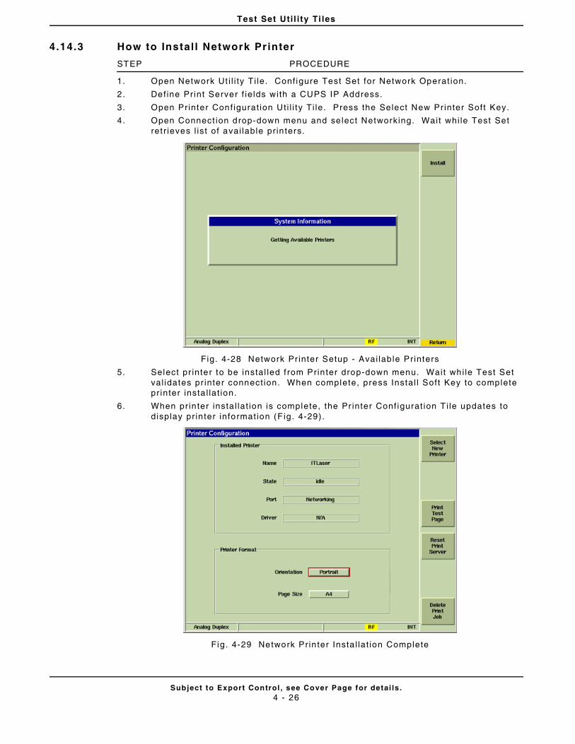
Test Set Uti l i ty Ti les
Subject to Export Control , see Cover Page for detai ls .4 - 26
4.14.3 How to Instal l Network Printer
STEP PROCEDURE
1. Open Network Ut i l i ty Ti le. Conf igure Test Set for Network Operat ion.
2. Def ine Print Server f ie lds with a CUPS IP Address.
3. Open Printer Conf igurat ion Ut i l i ty Ti le. Press the Select New Pr inter Soft Key.
4. Open Connect ion drop-down menu and se lect Networking. Wait whi le Test Set ret r ieves l ist of avai lable pr in ters.
Fig. 4-28 Network Pr inter Setup - Avai lab le Printers
5. Select pr inter to be instal led f rom Prin ter drop-down menu. Wait whi le Test Set val idates pr inter connect ion. When complete, press Instal l Soft Key to complete pr inter insta l lat ion.
6. When pr in ter insta l lat ion is complete, the Pr inter Conf igurat ion T i le updates to display pr in ter information (F ig. 4-29).
Fig. 4-29 Network Prin ter Insta l lat ion Complete
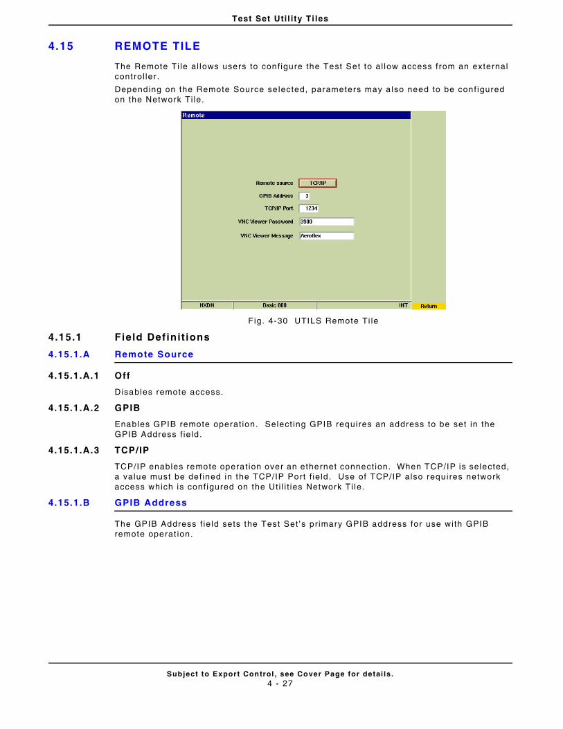
Test Set Uti l i ty Ti les
Subject to Export Control , see Cover Page for detai ls .4 - 27
4.15 REMOTE TILE
The Remote Ti le al lows users to conf igure the Test Set to al low access from an external control ler .
Depending on the Remote Source se lected, parameters may a lso need to be conf igured on the Network Ti le.
Fig. 4-30 UTILS Remote Ti le
4.15.1 Field Definit ions
4.15.1.A Remote Source
4.15.1.A.1 Off
Disables remote access.
4.15.1.A.2 GPIB
Enables GPIB remote operat ion. Select ing GPIB requires an address to be set in the GPIB Address f ie ld .
4.15.1.A.3 TCP/IP
TCP/IP enables remote operat ion over an ethernet connect ion. When TCP/IP is selected, a value must be def ined in the TCP/IP Port f ie ld . Use of TCP/IP also requires network access which is conf igured on the Ut i l i t ies Network Ti le.
4.15.1.B GPIB Address
The GPIB Address f ie ld sets the Test Set ’s pr imary GPIB address for use with GPIB remote operat ion.
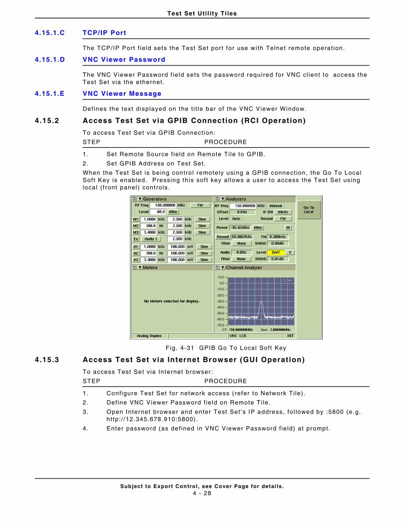
Test Set Uti l i ty Ti les
Subject to Export Control , see Cover Page for detai ls .4 - 28
4.15.1.C TCP/IP Port
The TCP/IP Port f ie ld sets the Test Set por t for use with Telnet remote operat ion.
4.15.1.D VNC Viewer Password
The VNC Viewer Password f ie ld sets the password required for VNC cl ient to access the Test Set v ia the ethernet.
4.15.1.E VNC Viewer Message
Defines the text displayed on the t i t le bar of the VNC Viewer Window.
4.15.2 Access Test Set via GPIB Connection (RCI Operation)
To access Test Set v ia GPIB Connect ion:
STEP PROCEDURE
1. Set Remote Source f ie ld on Remote Ti le to GPIB.
2. Set GPIB Address on Test Set.
When the Test Set is be ing control remotely using a GPIB connect ion, the Go To Local Sof t Key is enabled. Pressing this sof t key al lows a user to access the Test Set using local ( f ront panel) controls.
F ig. 4-31 GPIB Go To Local Soft Key
4.15.3 Access Test Set via Internet Browser (GUI Operation)
To access Test Set v ia Internet browser:
STEP PROCEDURE
1. Conf igure Test Set for network access ( refer to Network Ti le) .
2. Def ine VNC Viewer Password f ie ld on Remote Ti le.
3. Open Internet browser and enter Test Set ’s IP address, fo l lowed by :5800 (e.g. ht tp: / /12.345.678.910:5800) .
4. Enter password (as def ined in VNC Viewer Password f ie ld) at prompt.
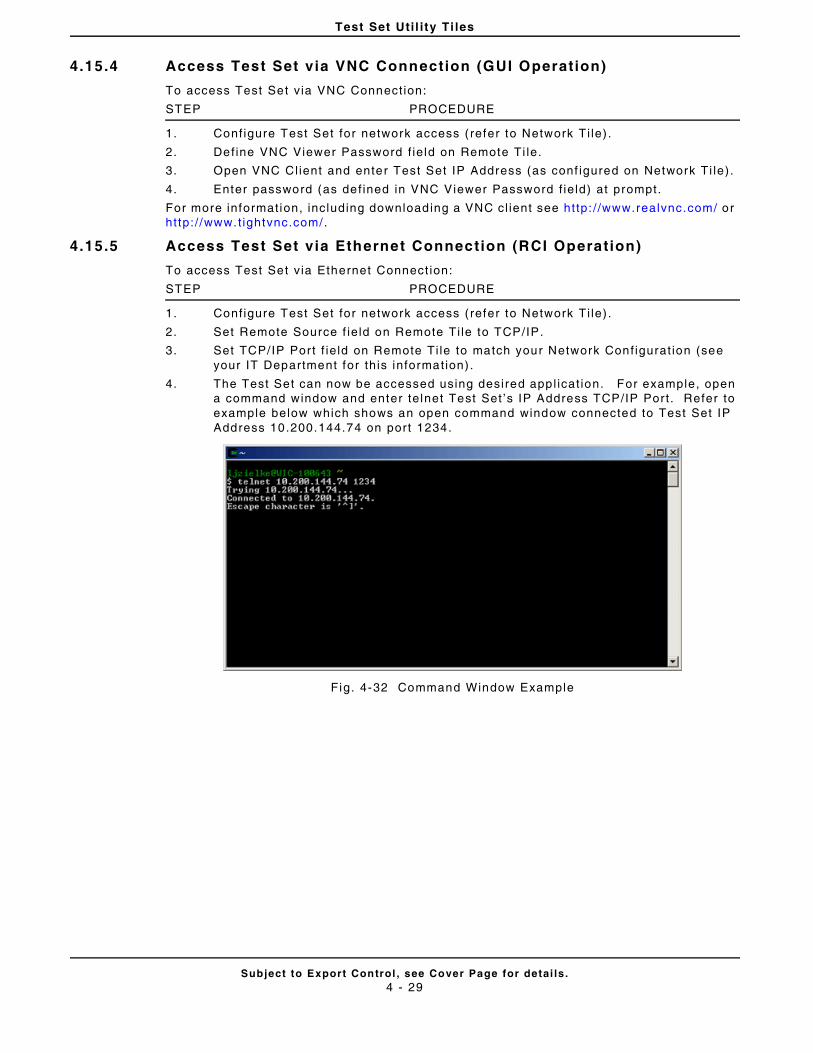
Test Set Uti l i ty Ti les
Subject to Export Control , see Cover Page for detai ls .4 - 29
4.15.4 Access Test Set via VNC Connection (GUI Operation)
To access Test Set v ia VNC Connect ion:
STEP PROCEDURE
1. Conf igure Test Set for network access ( refer to Network Ti le) .
2. Def ine VNC Viewer Password f ie ld on Remote Ti le.
3. Open VNC Cl ient and enter Test Set IP Address (as conf igured on Network Ti le).
4. Enter password (as def ined in VNC Viewer Password f ie ld) at prompt.
For more informat ion, including downloading a VNC cl ient see http: / /www.realvnc.com/ or ht tp: / /www.t ightvnc.com/.
4.15.5 Access Test Set via Ethernet Connection (RCI Operation)
To access Test Set v ia Ethernet Connect ion:
STEP PROCEDURE
1. Conf igure Test Set for network access ( refer to Network Ti le) .
2. Set Remote Source f ie ld on Remote Ti le to TCP/IP.
3. Set TCP/IP Por t f ie ld on Remote Ti le to match your Network Conf igurat ion (see your IT Department for this information) .
4. The Test Set can now be accessed using desired appl icat ion. For example, open a command window and enter telnet Test Set ’s IP Address TCP/IP Por t . Refer to example below which shows an open command window connected to Test Set IP Address 10.200.144.74 on port 1234.
Fig. 4-32 Command Window Example
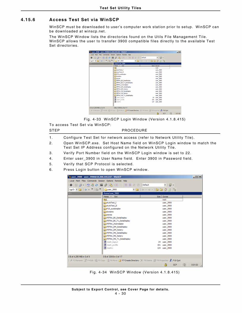
Test Set Uti l i ty Ti les
Subject to Export Control , see Cover Page for detai ls .4 - 30
4.15.6 Access Test Set via WinSCP
WinSCP must be downloaded to user’s computer work stat ion pr ior to setup. WinSCP can be downloaded at winscp.net.
The WinSCP Window l ists the di rector ies found on the Ut i ls Fi le Management Ti le. WinSCP al lows the user to t ransfer 3900 compatible f i les direct ly to the avai lable Test Set director ies.
Fig. 4-33 WinSCP Login Window (Version 4.1.8.415)
To access Test Set v ia WinSCP:
STEP PROCEDURE
1. Conf igure Test Set for network access ( refer to Network Ut i l i ty Ti le) .
2. Open WinSCP.exe. Set Host Name f ie ld on WinSCP Login window to match the Test Set IP Address conf igured on the Network Ut i l i ty Ti le.
3. Ver i fy Por t Number f ie ld on the WinSCP Login window is set to 22.
4. Enter user_3900 in User Name f ie ld. Enter 3900 in Password f ie ld .
5. Ver i fy that SCP Protocol is selected.
6. Press Login but ton to open WinSCP window.
Fig. 4-34 WinSCP Window (Version 4.1.8.415)
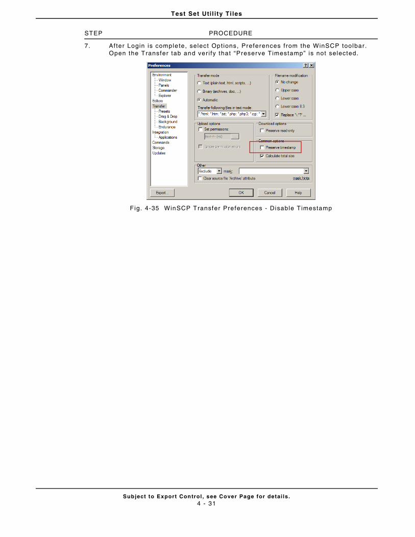
Test Set Uti l i ty Ti les
Subject to Export Control , see Cover Page for detai ls .4 - 31
STEP PROCEDURE
7. Af ter Login is complete, select Opt ions, Preferences from the WinSCP toolbar. Open the Transfer tab and ver i fy that “Preserve Timestamp” is not selected.
F ig. 4-35 WinSCP Transfer Preferences - Disable T imestamp
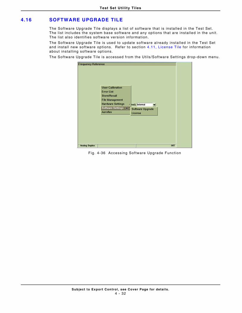
Test Set Uti l i ty Ti les
Subject to Export Control , see Cover Page for detai ls .4 - 32
4.16 SOFTWARE UPGRADE TILE
The Sof tware Upgrade Ti le displays a l ist of software that is instal led in the Test Set. The l ist includes the system base software and any opt ions that are instal led in the uni t . The l ist a lso ident i f ies software version informat ion.
The Sof tware Upgrade Ti le is used to update software already instal led in the Test Set and instal l new software opt ions. Refer to sect ion 4.11, L icense T i le for information about instal l ing software opt ions.
The Sof tware Upgrade Ti le is accessed from the Ut i ls/Software Sett ings drop-down menu.
Fig. 4-36 Accessing Sof tware Upgrade Funct ion
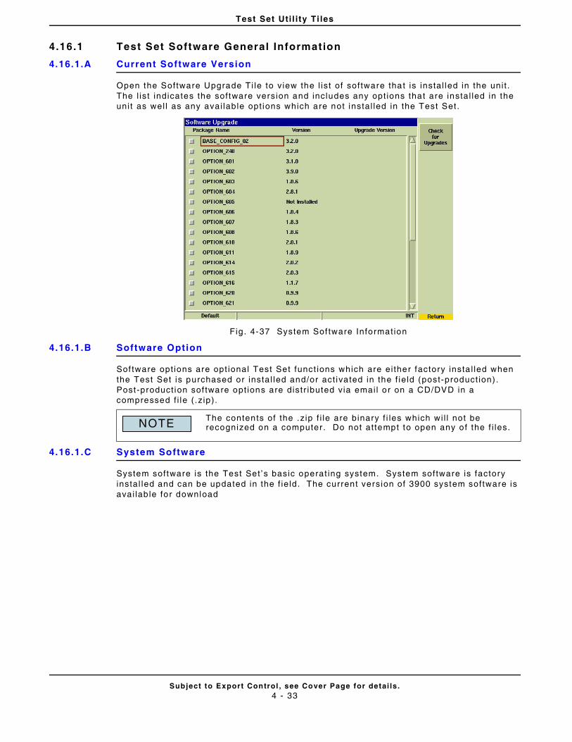
Test Set Uti l i ty Ti les
Subject to Export Control , see Cover Page for detai ls .4 - 33
4.16.1 Test Set Software General Information
4.16.1.A Current Software Version
Open the Software Upgrade Ti le to v iew the l ist of software that is instal led in the uni t . The l ist indicates the software version and includes any opt ions that are instal led in the uni t as wel l as any avai lable opt ions which are not instal led in the Test Set.
Fig . 4-37 System Sof tware Information
4.16.1.B Software Option
Sof tware opt ions are opt ional Test Set funct ions which are ei ther factory insta l led when the Test Set is purchased or instal led and/or act ivated in the f ie ld (post-product ion) . Post -product ion sof tware opt ions are distr ibuted via emai l or on a CD/DVD in a compressed f i le ( .z ip).
4.16.1.C System Software
System software is the Test Set ’s basic operat ing system. System software is factory instal led and can be updated in the f ie ld. The current version of 3900 system software is avai lab le for download
The contents of the .z ip f i le are binary f i les which wi l l not be recognized on a computer . Do not at tempt to open any of the f i les.NOTE
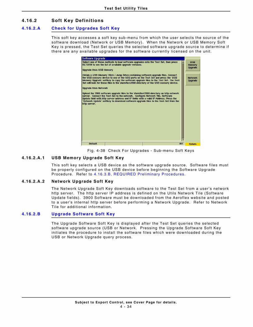
Test Set Uti l i ty Ti les
Subject to Export Control , see Cover Page for detai ls .4 - 34
4.16.2 Soft Key Definit ions
4.16.2.A Check for Upgrades Soft Key
This soft key accesses a sof t key sub-menu from which the user selects the source of the software download (Network or USB Memory) . When the Network or USB Memory Soft Key is pressed, the Test Set quer ies the selected software upgrade source to determine i f there are any avai lable upgrades for the software current ly l icensed on the uni t .
Fig. 4-38 Check For Upgrades - Sub-menu Soft Keys
4.16.2.A.1 USB Memory Upgrade Soft Key
This soft key selects a USB device as the sof tware upgrade source. Software f i les must be proper ly conf igured on the USB device before beginning the Software Upgrade Procedure. Refer to 4 .16.3.B, REQUIRED Prel iminary Procedures.
4.16.2.A.2 Network Upgrade Soft Key
The Network Upgrade Soft Key downloads software to the Test Set f rom a user ’s network ht tp server. The http server IP address is def ined on the Ut i ls Network Ti le (Sof tware Update f ie lds). 3900 Software must be downloaded from the Aerof lex websi te and posted to a user ’s interna l ht tp server before performing a Network Upgrade. Refer to Network Ti le for addi t ional informat ion.
4.16.2.B Upgrade Software Soft Key
The Upgrade Sof tware Sof t Key is d isplayed after the Test Set quer ies the selected software upgrade source (USB or Network. Pressing the Upgrade Sof tware Sof t Key in i t iates the procedure to instal l the software f i les which were downloaded dur ing the USB or Network Upgrade query process.
Test Set Uti l i ty Ti les
Subject to Export Control , see Cover Page for detai ls .4 - 35
4.16.3 How to Upgrade Software
Sof tware upgrade procedures may vary f rom one version of sof tware to another . Informat ion in this sect ion appl ies to Test Sets which have been upgraded to sof tware version 3.4 .0 and later. I f your Test Set contains software pr ior to version 3.4.0 contact Aerof lex Customer Service for the appropr iate sof tware upgrade procedure.
4.16.3.A Recommended Prel iminary Procedures
Aerof lex recommends that customers create a backup of the Test Set ’s internal f i les ( i .e. , test scr ipts, cal ibrat ion data, stored setup f i les) pr ior to performing the Software Upgrade Procedure. Refer to the F i le Management Ti le or contact Aerof lex Customer Service for informat ion.
4.16.3.B REQUIRED Preliminary Procedures
• Instal l any new License (Opt ion) f i les before beginning the Software Upgrade procedure. Refer to Instal l New Option License Fi le Procedure for in formation.
• Restore Factory Defaul ts before beginning Software Upgrade Procedure. Refer to Restore Factory Defaul t Sett ings Procedure for informat ion.
4.16.3.B.1 USB Device Upgrade Procedure (CD/DVD source)
• Extract the 3900 Sof tware zip f i le f rom CD/DVD to a USB device. Ver i fy ext racted f i les have been placed in root directory named Aerof lex, subdirectory named 3900 (Aerof lex\3900). Do not place the Aerof lex directory in a subdi rectory or the software upgrade wi l l fa i l .
• Proceed to Step 1 of Upgrade Procedure.
4.16.3.B.2 USB Device Upgrade Procedure (website download)
• Go to www.aerof lex.com to download current software version.
• Select the "Download Software Version.. ." l ink to access current software version.
• Cl ick on the desired f i le to download f i le to a USB device.
• Extract the 3900 Software zip f i le to a USB device. Ver i fy ext racted f i les have been placed in root directory named Aerof lex, subdirectory named 3900 (Aerof lex\3900). Do not place the Aerof lex directory in a subdi rectory or the software upgrade wi l l fa i l .
• Proceed to Step 1 of Upgrade Procedure.
4.16.3.B.3 Network Upgrade Procedure
The 3900 Network Upgrade feature al lows a user to upgrade the Test Set f rom a local ht tp server. To upgrade f rom a local ht tp server, 3900 Sof tware must be downloaded from the Aerof lex websi te, then uploaded to the loca l ht tp server before performing the software upgrade.
• Go to www.aerof lex.com to download current software version.
• Select the "Download Software Version.. ." l ink to access current software version.
• Cl ick on the sof tware f i le to download the f i le to desi red storage locat ion ( i .e. , a USB device or local directory).
• Extract the 3900 Software zip f i le to desired storage locat ion. Ver i fy extracted f i les have been placed in root directory named Aerof lex, subdirectory named 3900 (Aerof lex\3900). Do not place the Aerof lex directory in a subdi rectory or the software upgrade wi l l fa i l .
• Create an Aerof lex\3900 d irectory on the local ht tp server. Upload al l f i les located in the extracted Aerof lex\3900 software directory to the corresponding directory on the local ht tp server.
• Configure the Test Set for downloading software f rom a Network server to Test Set according to instruct ions in the sect ion t i t led Network Ti le, Software Update.
• Proceed to Step 1 of Upgrade Procedure.
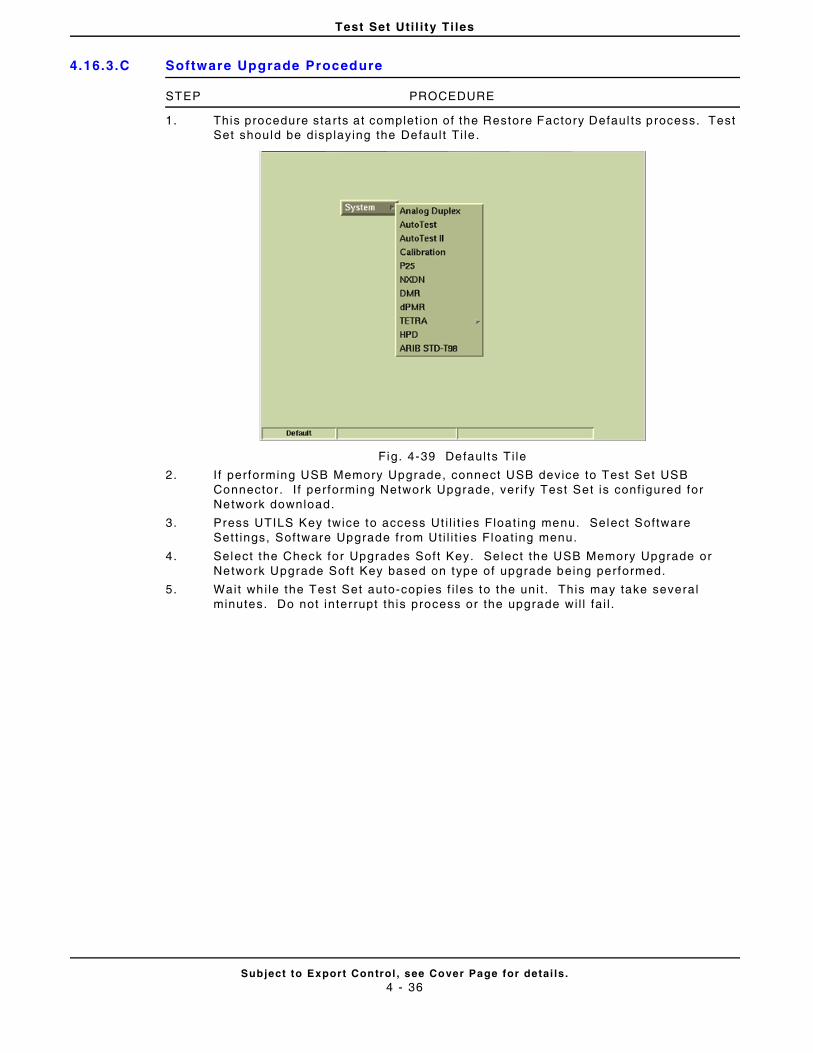
Test Set Uti l i ty Ti les
Subject to Export Control , see Cover Page for detai ls .4 - 36
4.16.3.C Software Upgrade Procedure
STEP PROCEDURE
1. This procedure starts at complet ion of the Restore Factory Defaul ts process. Test Set should be displaying the Defaul t Ti le .
Fig. 4-39 Defaul ts Ti le
2. I f performing USB Memory Upgrade, connect USB device to Test Set USB Connector . I f performing Network Upgrade, ver i fy Test Set is conf igured for Network download.
3. Press UTILS Key twice to access Ut i l i t ies Float ing menu. Select Software Set t ings, Software Upgrade from Uti l i t ies Float ing menu.
4. Select the Check for Upgrades Soft Key. Select the USB Memory Upgrade or Network Upgrade Soft Key based on type of upgrade being performed.
5. Wait whi le the Test Set auto-copies f i les to the uni t . This may take several minutes. Do not interrupt th is process or the upgrade wi l l fa i l .
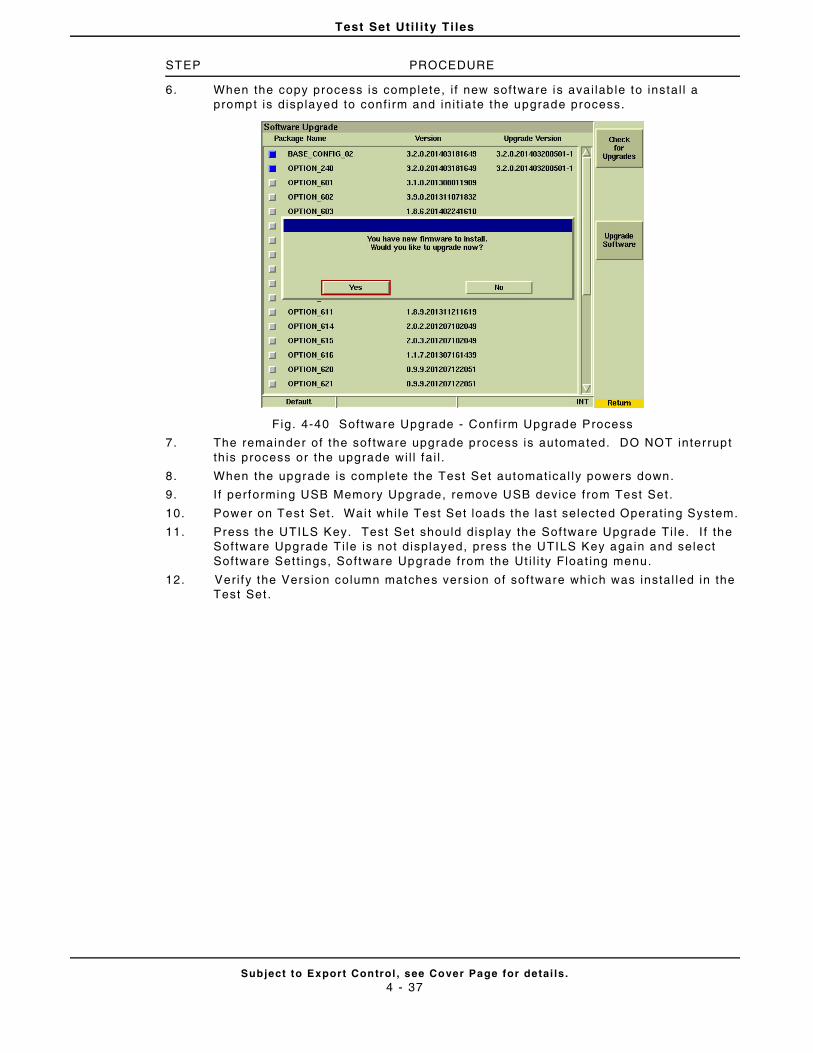
Test Set Uti l i ty Ti les
Subject to Export Control , see Cover Page for detai ls .4 - 37
STEP PROCEDURE
6. When the copy process is complete, i f new software is avai lab le to instal l a prompt is displayed to conf i rm and in i t iate the upgrade process.
Fig. 4-40 Software Upgrade - Conf i rm Upgrade Process
7. The remainder of the sof tware upgrade process is automated. DO NOT interrupt th is process or the upgrade wi l l fa i l .
8. When the upgrade is complete the Test Set automatical ly powers down.
9. I f performing USB Memory Upgrade, remove USB device from Test Set .
10. Power on Test Set. Wai t whi le Test Set loads the last selected Operat ing System.
11. Press the UTILS Key. Test Set should display the Sof tware Upgrade Ti le. I f the Sof tware Upgrade Ti le is not displayed, press the UTILS Key again and select Sof tware Set t ings, Software Upgrade from the Ut i l i ty Float ing menu.
12. Veri fy the Version column matches version of software which was instal led in the Test Set .
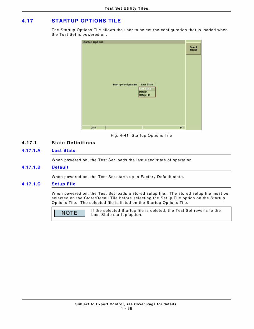
Test Set Uti l i ty Ti les
Subject to Export Control , see Cover Page for detai ls .4 - 38
4.17 STARTUP OPTIONS TILE
The Startup Opt ions Ti le al lows the user to select the conf igurat ion that is loaded when the Test Set is powered on.
Fig . 4-41 Startup Opt ions Ti le
4.17.1 State Definit ions
4.17.1.A Last State
When powered on, the Test Set loads the last used sta te o f operat ion.
4.17.1.B Default
When powered on, the Test Set star ts up in Factory Defaul t sta te.
4.17.1.C Setup File
When powered on, the Test Set loads a stored setup f i le. The stored setup f i le must be selected on the Store/Recal l Ti le before se lect ing the Setup F i le opt ion on the Startup Opt ions Ti le. The selected f i le is l is ted on the Star tup Opt ions Ti le.
I f the selected Startup f i le is deleted, the Test Set rever ts to the Last State startup opt ion.NOTE
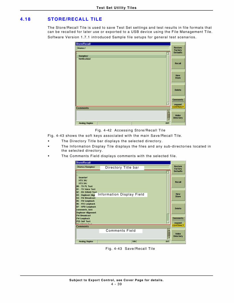
Test Set Uti l i ty Ti les
Subject to Export Control , see Cover Page for detai ls .4 - 39
4.18 STORE/RECALL TILE
The Store/Recal l T i le is used to save Test Set set t ings and test resul ts in f i le formats that can be recal led for later use or expor ted to a USB device using the F i le Management T i le.
Sof tware Version 1.7.1 introduced Sample f i le setups for general test scenar ios.
Fig . 4-42 Accessing Store/Recal l Ti le
Fig. 4-43 shows the sof t keys associated wi th the main Save/Recal l T i le.
• The Directory Ti t le bar d isplays the selected d irectory.
• The Informat ion Display T i le d isplays the f i les and any sub-director ies located in the selected directory.
• The Comments Fie ld disp lays comments with the selected f i le.
F ig. 4-43 Save/Recal l Ti le
Directory Ti t le bar
In format ion Display Field
Comments Field
Test Set Uti l i ty Ti les
Subject to Export Control , see Cover Page for detai ls .4 - 40
4.18.1 Soft Key Definit ions
4.18.1.A Restore Factory Defaults Soft Key
The Restore Factory Defau l ts Soft Key recal ls the factory defaul ts for the Test Set.
4.18.1.B Recal l Soft Key
The Recal l Soft Key retr ieves sett ings for the selected f i le. A f i le may also be recal led by double-cl icking on a f i le name when using a USB mouse.
4.18.1.C New Store Soft Key
The New Store Sof t Key opens the Store/Recal l - New Store T i le which al lows the user to save the exist ing Test Set conf igurat ion as a new f i le.
4.18.1.D Delete Soft Key
The Delete Soft Key erases the selected f i le f rom Test Set ’s in ternal memory. The act ion is protected by a second level of soft keys asking user to Conf i rm or Cancel the act ion.
4.18.1.E Make Directory Soft Key
The Make Directory Soft Key al lows the user to create a new directory (sub-di rectory) in which to store f i les.
4.18.1.F Accept Soft Key
The Accept Soft Key is displayed when creat ing a new sett ings f i le. Pressing this key accepts the def ined f i le parameters when creat ing a new f i le.
4.18.1.G Clear Comment Soft Key
The Clear Comment Soft Key clears any text present in the Comments f ie ld when the f ie ld is selected.
4.18.1.H Cancel Soft Key
The Cancel Sof t Key terminates the current act ion. This soft key is accessed by pressing the New Store Soft Key, Make Directory and Delete Soft Key.
4.18.1. I Store Soft Key
The Store Soft Key saves a new f i le to Test Set ’s interna l memory. This sof t key is accessed by pressing the New Store Sof t Key.
4.18.1.J Overwrite Soft Key
The Overwri te Sof t Key serves as a protect ive step when saving a sett ings f i le. When a f i le is being saved that has the same name as an exist ing f i le, pressing the Overwr i te Soft Key replaces the exist ing f i le wi th the new sett ings: exist ing f i le is overwr i t ten and can not be retr ieved.
4.18.1.K Comments Soft Key
The Comment Soft Key expands and contracts the Comments f ie ld. When the f ie ld is expanded fourteen l ines of text are vis ible. When the f ie ld is contracted four l ines of text are vis ible. The scrol l bar on the Comments f ie ld is only accessible using a mouse.
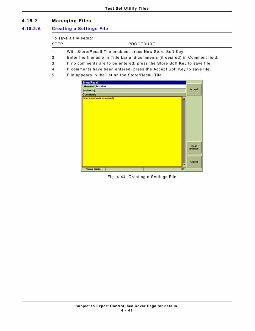
Test Set Uti l i ty Ti les
Subject to Export Control , see Cover Page for detai ls .4 - 41
4.18.2 Managing Fi les
4.18.2.A Creating a Sett ings File
To save a f i le setup:
STEP PROCEDURE
1. With Store/Recal l Ti le enabled, press New Store Soft Key.
2. Enter the f i lename in Ti t le bar and comments ( i f desired) in Comment f ie ld.
3. I f no comments are to be entered, press the Store Soft Key to save f i le.
4. I f comments have been entered, press the Accept Soft Key to save f i le.
5. Fi le appears in the l ist on the Store/Recal l T i le.
Fig. 4-44 Creat ing a Sett ings F i le
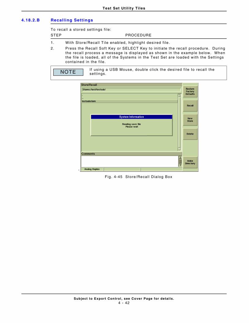
Test Set Uti l i ty Ti les
Subject to Export Control , see Cover Page for detai ls .4 - 42
4.18.2.B Recal l ing Sett ings
To recal l a stored sett ings f i le:
STEP PROCEDURE
1. With Store/Recal l Ti le enabled, highl ight desired f i le .
2. Press the Recal l Soft Key or SELECT Key to in i t iate the recal l procedure. Dur ing the recal l process a message is displayed as shown in the example below. When the f i le is loaded, al l o f the Systems in the Test Set are loaded with the Sett ings conta ined in the f i le .
‘
F ig. 4-45 Store/Recal l Dialog Box
If using a USB Mouse, double cl ick the desired f i le to recal l the sett ings.NOTE
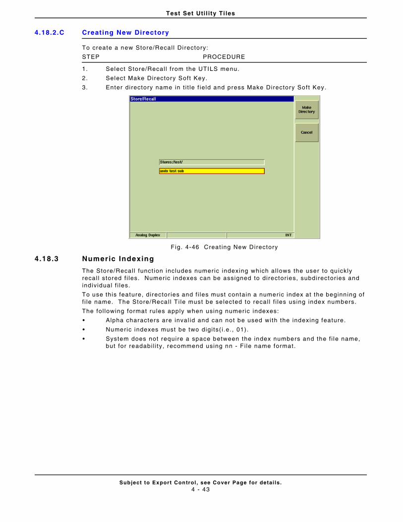
Test Set Uti l i ty Ti les
Subject to Export Control , see Cover Page for detai ls .4 - 43
4.18.2.C Creating New Directory
To create a new Store/Recal l Di rectory:
STEP PROCEDURE
1. Select Store/Recal l f rom the UTILS menu.
2. Select Make Directory Soft Key.
3. Enter directory name in t i t le f ie ld and press Make Directory Soft Key.
F ig. 4-46 Creat ing New Directory
4.18.3 Numeric Indexing
The Store/Recal l funct ion includes numeric indexing which al lows the user to qu ickly recal l stored f i les. Numeric indexes can be assigned to director ies, subdirector ies and indiv idual f i les.
To use this feature, director ies and f i les must contain a numeric index at the beginn ing of f i le name. The Store/Recal l Ti le must be se lected to recal l f i les using index numbers.
The fol lowing format rules apply when using numeric indexes:
• Alpha characters are inval id and can not be used with the indexing feature.
• Numeric indexes must be two digi ts( i .e. , 01).
• System does not require a space between the index numbers and the f i le name, but for readabi l i ty, recommend using nn - Fi le name format .
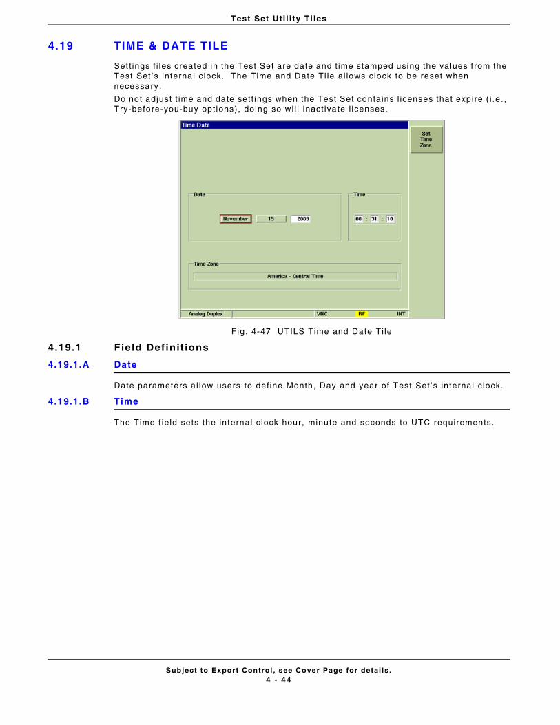
Test Set Uti l i ty Ti les
Subject to Export Control , see Cover Page for detai ls .4 - 44
4.19 TIME & DATE TILE
Set t ings f i les created in the Test Set are date and t ime stamped using the values f rom the Test Set ’s interna l c lock. The Time and Date Ti le al lows clock to be reset when necessary.
Do not adjust t ime and date sett ings when the Test Set contains l icenses that expire ( i .e . , Try-before-you-buy opt ions), doing so wi l l inact ivate l icenses.
Fig. 4-47 UTILS Time and Date Ti le
4.19.1 Field Definit ions
4.19.1.A Date
Date parameters a l low users to def ine Month, Day and year of Test Set ’s internal c lock.
4.19.1.B Time
The Time f ie ld sets the internal c lock hour, minute and seconds to UTC requirements.
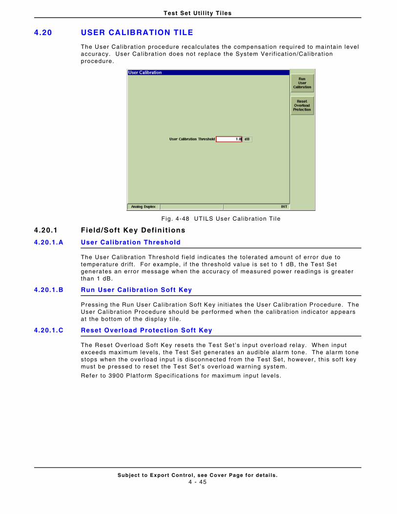
Test Set Uti l i ty Ti les
Subject to Export Control , see Cover Page for detai ls .4 - 45
4.20 USER CALIBRATION TILE
The User Cal ibrat ion procedure recalculates the compensat ion requi red to maintain level accuracy. User Cal ibrat ion does not replace the System Ver i f icat ion/Cal ibrat ion procedure.
Fig . 4-48 UTILS User Cal ibrat ion Ti le
4.20.1 Field/Soft Key Definit ions
4.20.1.A User Calibrat ion Threshold
The User Cal ibrat ion Threshold f ie ld indicates the to lerated amount o f er ror due to temperature dr i f t . For example, i f the threshold value is set to 1 dB, the Test Set generates an error message when the accuracy of measured power readings is greater than 1 dB.
4.20.1.B Run User Cal ibration Soft Key
Pressing the Run User Cal ibrat ion Soft Key ini t iates the User Cal ibrat ion Procedure. The User Cal ibrat ion Procedure should be per formed when the cal ibrat ion indicator appears at the bottom of the display t i le.
4.20.1.C Reset Overload Protection Soft Key
The Reset Overload Soft Key resets the Test Set ’s input over load re lay. When input exceeds maximum levels, the Test Set generates an audible alarm tone. The alarm tone stops when the over load input is disconnected from the Test Set , however , th is sof t key must be pressed to reset the Test Set ’s overload warning system.
Refer to 3900 Plat form Speci f icat ions for maximum input levels.
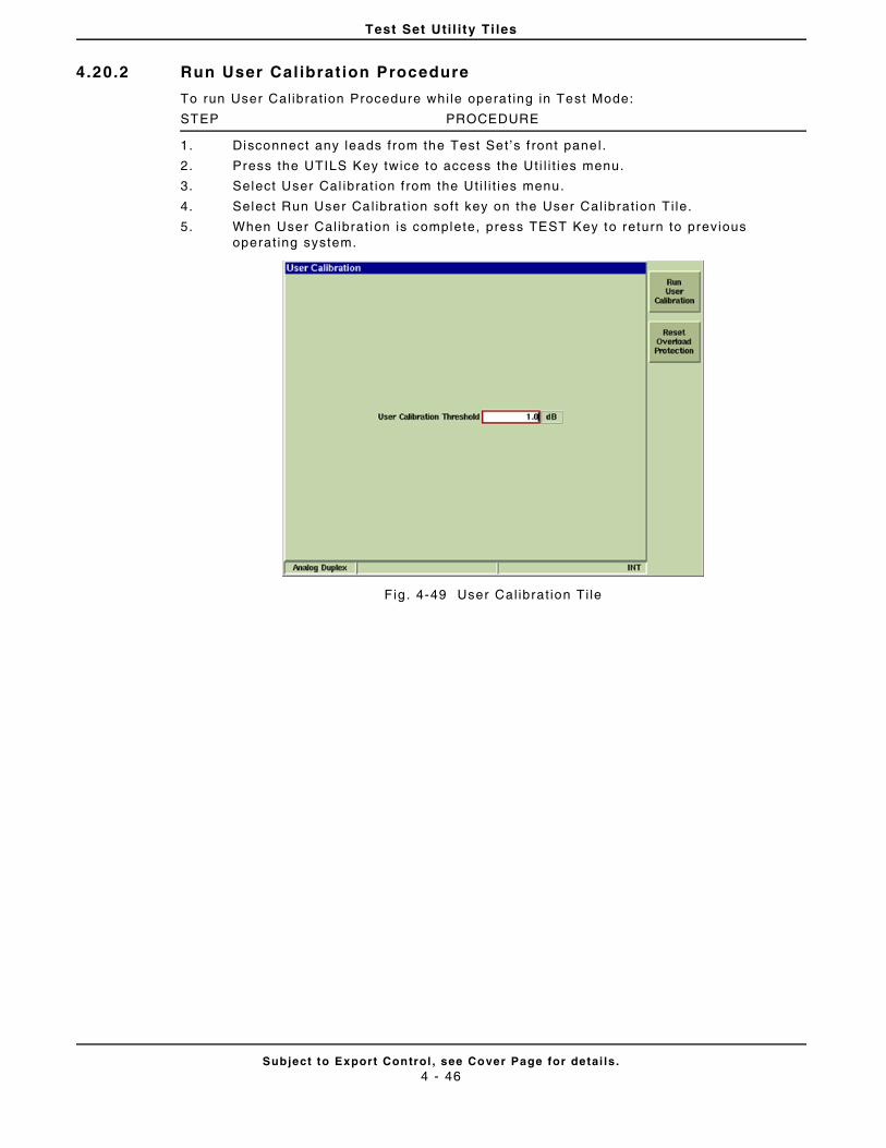
Test Set Uti l i ty Ti les
Subject to Export Control , see Cover Page for detai ls .4 - 46
4.20.2 Run User Cal ibrat ion Procedure
To run User Cal ibrat ion Procedure whi le operat ing in Test Mode:
STEP PROCEDURE
1. Disconnect any leads from the Test Set ’s f ront panel.
2. Press the UTILS Key twice to access the Ut i l i t ies menu.
3. Select User Cal ibrat ion f rom the Ut i l i t ies menu.
4. Select Run User Cal ibrat ion soft key on the User Cal ibrat ion Ti le.
5. When User Cal ibrat ion is complete, press TEST Key to return to previous operat ing system.
Fig . 4-49 User Cal ibrat ion Ti le
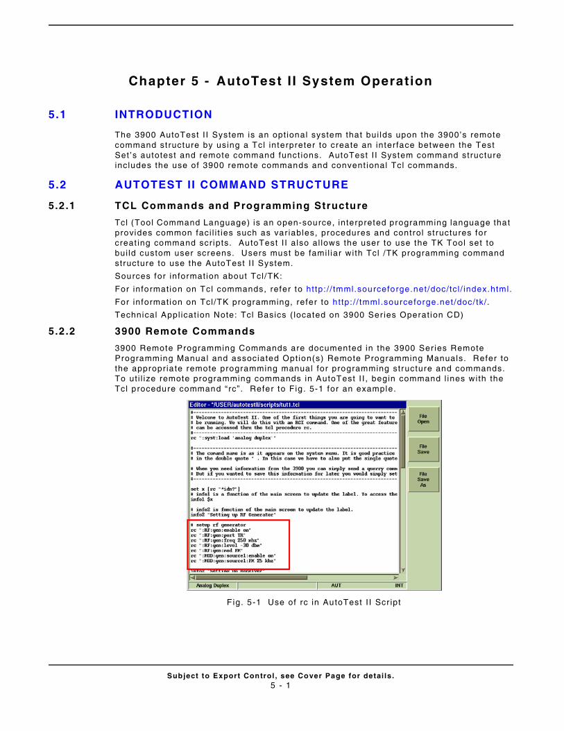
Subject to Export Control , see Cover Page for detai ls .5 - 1
Chapter 5 - AutoTest I I System Operation
5.1 INTRODUCTION
The 3900 AutoTest I I System is an opt ional system that bui lds upon the 3900’s remote command st ructure by using a Tcl interpreter to create an interface between the Test Set ’s autotest and remote command funct ions. AutoTest I I System command structure includes the use of 3900 remote commands and convent ional Tcl commands.
5.2 AUTOTEST I I COMMAND STRUCTURE
5.2.1 TCL Commands and Programming Structure
Tcl (Tool Command Language) is an open-source, interpreted programming language that provides common faci l i t ies such as var iables, procedures and control st ructures for creat ing command scr ipts. AutoTest I I a lso al lows the user to use the TK Tool set to bui ld custom user screens. Users must be fami l iar wi th Tcl /TK programming command structure to use the AutoTest I I System.
Sources for informat ion about Tcl /TK:
For informat ion on Tcl commands, refer to ht tp: / / tmml.sourceforge.net/doc/tc l / index.html.
For informat ion on Tcl /TK programming, refer to h t tp: / / tmml .sourceforge.net /doc/ tk/.
Technical Appl icat ion Note: Tcl Basics ( located on 3900 Ser ies Operat ion CD)
5.2 .2 3900 Remote Commands
3900 Remote Programming Commands are documented in the 3900 Ser ies Remote Programming Manual and associated Opt ion(s) Remote Programming Manuals. Refer to the appropr ia te remote programming manual for programming structure and commands. To ut i l ize remote programming commands in AutoTest I I , begin command l ines with the Tcl procedure command “ rc”. Refer to Fig . 5-1 for an example.
F ig. 5-1 Use of rc in AutoTest I I Scr ipt
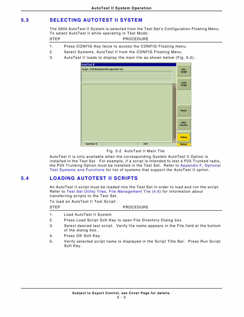
AutoTest I I System Operation
Subject to Export Control , see Cover Page for detai ls .5 - 2
5.3 SELECTING AUTOTEST I I SYSTEM
The 3900 AutoTest I I System is selected from the Test Set ’s Conf igurat ion Float ing Menu. To se lect AutoTest I I whi le operat ing in Test Mode:
STEP PROCEDURE
1. Press CONFIG Key twice to access the CONFIG Float ing menu.
2. Select Systems, AutoTest I I f rom the CONFIG Float ing Menu.
3. AutoTest I I loads to d isplay the main t i le as shown below (Fig. 5-2).
Fig. 5-2 AutoTest I I Main Ti le
AutoTest I I is on ly avai lable when the corresponding System AutoTest I I Opt ion is instal led in the Test Set . For example, i f a scr ipt is intended to test a P25 Trunked radio, the P25 Trunking Opt ion must be instal led in the Test Set. Refer to Appendix F, Opt ional Test Systems and Funct ions for l is t of systems that support the AutoTest I I opt ion.
5.4 LOADING AUTOTEST I I SCRIPTS
An AutoTest I I scr ipt must be loaded into the Test Set in order to load and run the scr ipt . Refer to Test Set Ut i l i ty Ti les, Fi le Management T i le (4.6) for in formation about t ransferr ing scr ipts to the Test Set .
To load an AutoTest I I Test Scr ipt :
STEP PROCEDURE
1. Load AutoTest I I System.
2. Press Load Scr ipt Sof t Key to open Fi le Di rectory Dialog box.
3. Select desired test scr ipt . Ver i fy f i le name appears in the Fi le f ie ld a t the bottom of the dialog box.
4. Press OK Sof t Key.
5. Ver i fy se lected scr ipt name is d isplayed in the Scr ipt T i t le Bar. Press Run Scr ipt Sof t Key.
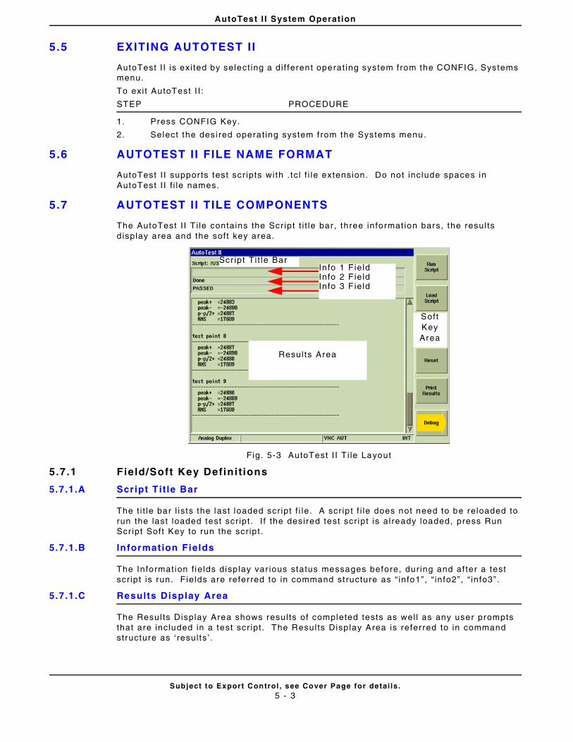
AutoTest I I System Operation
Subject to Export Control , see Cover Page for detai ls .5 - 3
5.5 EXITING AUTOTEST I I
AutoTest I I is exi ted by select ing a di f ferent operat ing system f rom the CONFIG, Systems menu.
To exi t AutoTest I I :
STEP PROCEDURE
1. Press CONFIG Key.
2. Select the desi red operat ing system f rom the Systems menu.
5.6 AUTOTEST I I FILE NAME FORMAT
AutoTest I I suppor ts test scr ipts with . tc l f i le extension. Do not include spaces in AutoTest I I f i le names.
5.7 AUTOTEST I I TILE COMPONENTS
The AutoTest I I Ti le contains the Scr ipt t i t le bar , three information bars, the resul ts display area and the soft key area.
Fig. 5-3 AutoTest I I T i le Layout
5.7 .1 Field/Soft Key Definit ions
5.7.1.A Script T it le Bar
The t i t le bar l ists the last loaded scr ipt f i le. A scr ip t f i le does not need to be reloaded to run the last loaded test scr ipt . I f the desired test scr ipt is already loaded, press Run Scr ipt Soft Key to run the scr ipt .
5.7.1.B Information Fields
The Informat ion f ie lds disp lay var ious status messages before, dur ing and af ter a test scr ipt is run. Fields are referred to in command structure as “ info1”, “ info2” , “ info3” .
5.7.1.C Results Display Area
The Resul ts Display Area shows resul ts of completed tests as wel l as any user prompts that are included in a test scr ipt . The Results Disp lay Area is re ferred to in command structure as ‘ resul ts ’ .
Resul ts Area
Info 1 F ieldInfo 2 F ieldInfo 3 F ield
Scr ipt Ti t le Bar
SoftKeyArea
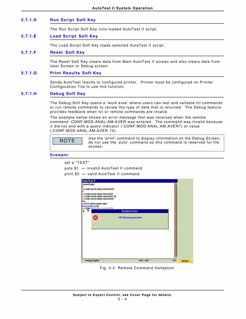
AutoTest I I System Operation
Subject to Export Control , see Cover Page for detai ls .5 - 4
5.7.1.D Run Script Soft Key
The Run Scr ipt Sof t Key runs loaded AutoTest I I scr ipt .
5.7.1.E Load Script Soft Key
The Load Scr ipt Soft Key loads selected AutoTest I I scr ipt .
5.7.1.F Reset Soft Key
The Reset Soft Key clears data from Main AutoTest I I screen and also clears data from User Screen or Debug screen.
5.7.1.G Print Results Soft Key
Sends AutoTest resul ts to conf igured pr inter. Pr inter must be conf igured on Printer Conf igurat ion Ti le to use this funct ion.
5.7.1.H Debug Soft Key
The Debug Soft Key opens a ‘work area’ where users can test and val idate tc l commands or run remote commands to review the type of data that is returned. The Debug feature provides feedback when tc l or remote commands are inval id.
The example below shows an error message that was received when the remote command :CONF:MOD:ANAL:AM:AVER was entered. The command was inva l id because i t d id not end with a query indicator ( :CONF:MOD:ANAL:AM:AVER?) or value (:CONF:MOD:ANAL:AM:AVER 10).
Example:
set a “TEST”
puts $1 <- inval id AutoTest I I command
print $2 <- val id AutoTest I I command
Fig. 5-4 Remote Command Val idat ion
Use the ‘pr in t ’ command to d isplay informat ion on the Debug Screen; do not use the ‘puts’ command as this command is reserved for f i le access.
NOTE
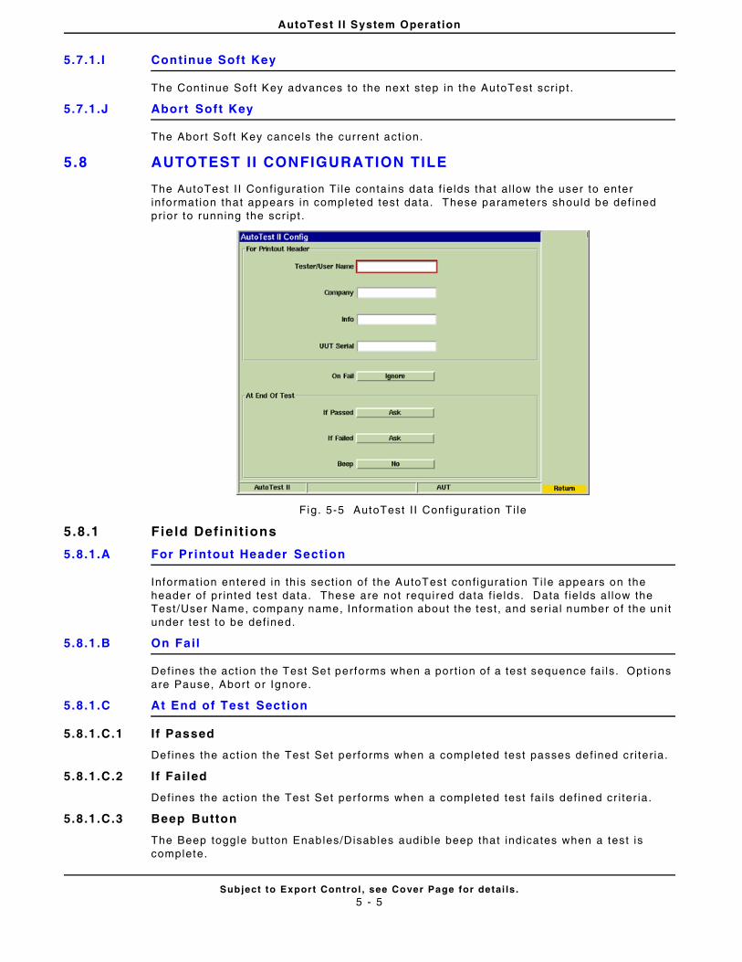
AutoTest I I System Operation
Subject to Export Control , see Cover Page for detai ls .5 - 5
5.7.1.I Continue Soft Key
The Cont inue Sof t Key advances to the next step in the AutoTest scr ipt .
5.7.1.J Abort Soft Key
The Abort Soft Key cancels the current act ion.
5.8 AUTOTEST I I CONFIGURATION TILE
The AutoTest I I Conf igurat ion Ti le conta ins data f ie lds that al low the user to enter informat ion that appears in completed test data. These parameters should be def ined pr ior to running the scr ipt .
Fig. 5-5 AutoTest I I Conf igurat ion Ti le
5.8 .1 Field Definit ions
5.8.1.A For Printout Header Section
Informat ion entered in this sect ion of the AutoTest conf igurat ion Ti le appears on the header of pr inted test data. These are not requi red data f ie lds. Data f ie lds al low the Test/User Name, company name, Informat ion about the test , and ser ial number of the un i t under test to be def ined.
5.8.1.B On Fail
Defines the act ion the Test Set performs when a por t ion of a test sequence fai ls. Opt ions are Pause, Abor t or Ignore.
5.8.1.C At End of Test Section
5.8.1.C.1 If Passed
Defines the act ion the Test Set performs when a completed test passes def ined cr i ter ia.
5.8.1.C.2 If Failed
Defines the act ion the Test Set performs when a completed test fa i ls def ined cr i ter ia.
5.8.1.C.3 Beep Button
The Beep toggle but ton Enables/Disables audible beep that ind icates when a test is complete.
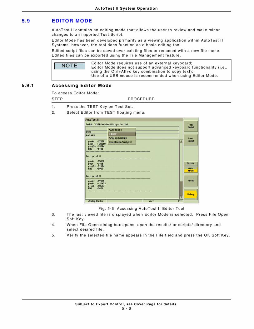
AutoTest I I System Operation
Subject to Export Control , see Cover Page for detai ls .5 - 6
5.9 EDITOR MODE
AutoTest I I conta ins an edi t ing mode that al lows the user to review and make minor changes to an imported Test Scr ipt .
Edi tor Mode has been developed pr imari ly as a viewing appl icat ion within AutoTest I I Systems, however , the tool does funct ion as a basic edi t ing tool .
Edi ted scr ipt f i les can be saved over exist ing f i les or renamed with a new f i le name. Edi ted f i les can be exported using the Fi le Management feature.
5.9 .1 Accessing Editor Mode
To access Editor Mode:
STEP PROCEDURE
1. Press the TEST Key on Test Set.
2. Select Edi tor f rom TEST f loat ing menu.
Fig. 5-6 Accessing AutoTest I I Ed i tor Tool
3. The last viewed f i le is d isplayed when Edi tor Mode is selected. Press Fi le Open Sof t Key.
4. When Fi le Open dialog box opens, open the resu l ts/ or scr ipts/ directory and select desired f i le.
5. Ver i fy the se lected f i le name appears in the F i le f ie ld and press the OK Sof t Key.
Edi tor Mode requires use of an externa l keyboard;Edi tor Mode does not support advanced keyboard funct ional i ty ( i .e. , using the Ctr l+Alt+c key combinat ion to copy text ) ;Use of a USB mouse is recommended when using Editor Mode.
NOTE
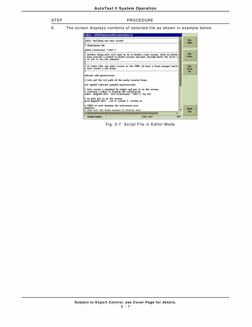
AutoTest I I System Operation
Subject to Export Control , see Cover Page for detai ls .5 - 7
STEP PROCEDURE
6. The screen displays contents of selected f i le as shown in example be low.
Fig. 5-7 Scr ipt Fi le in Editor Mode
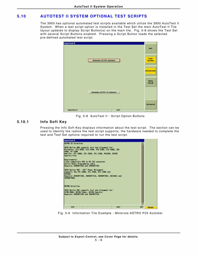
AutoTest I I System Operation
Subject to Export Control , see Cover Page for detai ls .5 - 8
5.10 AUTOTEST I I SYSTEM OPTIONAL TEST SCRIPTS
The 3900 has opt ional automated test scr ipts avai lable which ut i l ize the 3900 AutoTest I I System. When a test scr ip t opt ion is insta l led in the Test Set the main AutoTest I I Ti le layout updates to display Scr ipt But ton(s) on the main t i le. Fig. 5-8 shows the Test Set wi th several Scr ip t Buttons enabled. Pressing a Scr ipt Button loads the se lected pre-def ined automated test scr ipt .
Fig . 5-8 AutoTest I I - Scr ip t Opt ion Buttons
5.10.1 Info Soft Key
Pressing the Info Sof t Key d isplays informat ion about the test scr ip t . The sect ion can be used to ident i fy the radios the test scr ipt supports, the hardware needed to complete the test and Test Set opt ions required to run the test scr ip t .
Fig. 5-9 Informat ion Ti le Example - Motorola ASTRO P25 Autotest
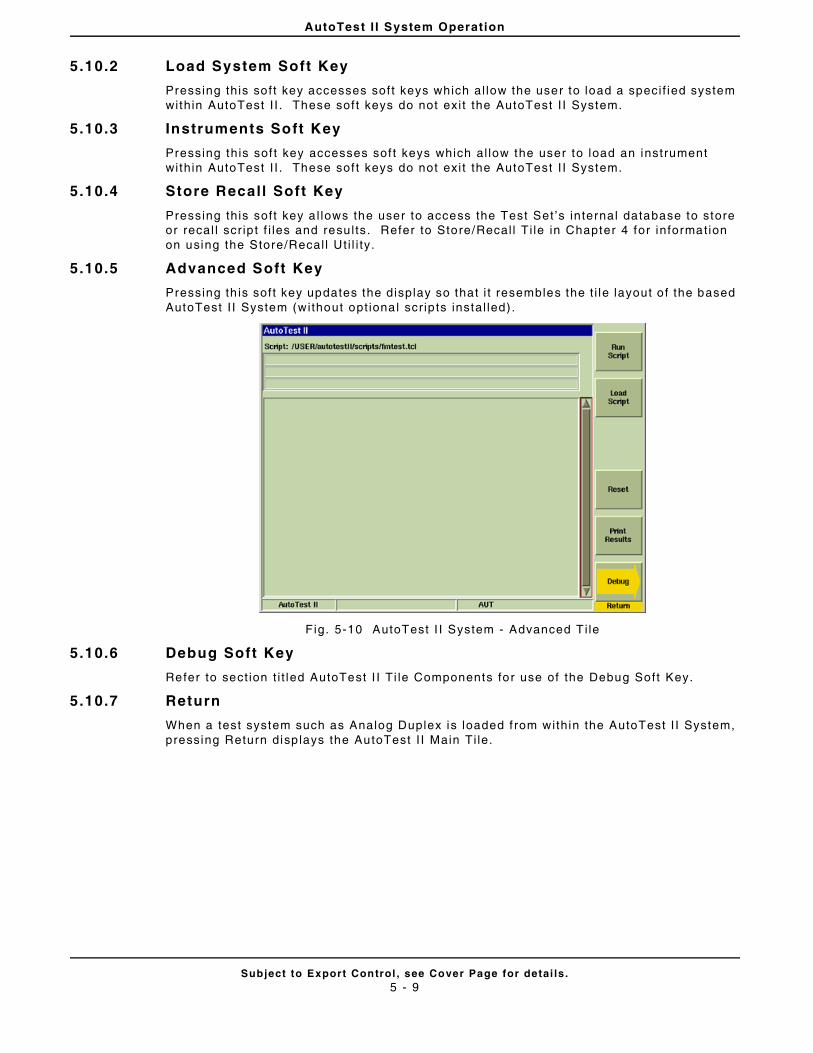
AutoTest I I System Operation
Subject to Export Control , see Cover Page for detai ls .5 - 9
5.10.2 Load System Soft Key
Pressing this sof t key accesses soft keys which al low the user to load a speci f ied system within AutoTest I I . These sof t keys do not exi t the AutoTest I I System.
5.10.3 Instruments Soft Key
Pressing this sof t key accesses sof t keys which al low the user to load an instrument within AutoTest I I . These sof t keys do not exi t the AutoTest I I System.
5.10.4 Store Recall Soft Key
Pressing this soft key a l lows the user to access the Test Set ’s internal database to store or recal l scr ip t f i les and resu l ts. Refer to Store/Recal l Ti le in Chapter 4 for information on using the Store/Recal l Ut i l i ty.
5.10.5 Advanced Soft Key
Pressing th is soft key updates the display so that i t resembles the t i le layout o f the based AutoTest I I System (without opt ional scr ip ts instal led) .
Fig. 5-10 AutoTest I I System - Advanced T i le
5.10.6 Debug Soft Key
Refer to sect ion t i t led AutoTest I I Ti le Components for use of the Debug Soft Key.
5.10.7 Return
When a test system such as Analog Duplex is loaded f rom within the AutoTest I I System, pressing Return disp lays the AutoTest I I Main Ti le.
AutoTest I I System Operation
Subject to Export Control , see Cover Page for detai ls .5 - 10
5.11 AUTOTEST I I TUTORIALS
AutoTest I I conta ins several tutor ia l test scr ipts that provide gu idel ines on creat ing test scr ipts. Tutor ia l scr ipts are accessed using Editor Mode.
5.11.1 tut1.tcl (Tutorial 1)
Includes examples of the fol lowing:
• Loading a 3900 system
• Set t ing up RF Generator
• Set t ing up Receiver
• Saving resul ts to a f i le
5.11.2 tut2.tcl (Tutorial 2)
Using displayuserentry and d isplaypicscreen.
5.11.3 tut3.tcl (Tutorial 3)
Using Funct ion Keys and User Message Screen.
5.11.4 tut4.tcl (Tutorial 4)
Using test_audio_level , test_audio_distor t ion and associated var iables.
5.11.5 tut5.tcl (Tutorial 5)
Using test_demod_fm, test_demod_distort ion and associated var iables.
5.12 MANAGING RESULTS
5.12.1 Storing Results
AutoTest I I stores resu l ts direct ly to the Test Set ’s internal hard dr ive. Saved test resul ts can then be expor ted from the Test Set to a USB device using the Fi le Management feature.
5.12.2 Printing Results
AutoTest I I test resu l ts and test scr ipts can be pr inted by pressing the Pr int Resul ts or Pr int Fi le Sof t Key.
AutoTest I I System Operation
Subject to Export Control , see Cover Page for detai ls .5 - 11
5.13 AUTOTEST I I COMMANDS
The fol lowing are AutoTest I I commands developed to be used with the 3900:
5.13.1 AX
AX is a global var iable that al lows the user to include var ious funct ions in a test scr ip t
5.13.1.A ::AX(scriptpath)
Holds the scr ip t path /USER/autotestI I /scr ipts
5.13.1.B ::AX(functionkey)
Holds the funct ion key that was pressed (1 - 6). Tutor ial 3 ( tut3. tc l ) provides informat ion on using funct ion keys.
5.13.1.C ::AX(abortproc)
Holds the name of the user abort procedure; the command is executed when Abort Soft Key is pressed dur ing scr ipt execut ion.
5.13.1.D ::AX(debug)
1 or 0; i f set to ‘0 ’ , debugstep statements are act ivated
5.13.2 delay “t ime - in mil l iseconds” “usrmsg - str ing”
Pauses execut ion of scr ipt for 1 seconds and d isplays user message in t i t le bar Informat ion area.
Limited to 24 characters in length.
Example:
delay 1000 “wait ing for reading”
5.13.3 print “str ing”
Prints “The Test has Passed” in the Results area when test is complete and has passed requirements.
Example:
pr int “The Test has Passed”
5.13.4 beep
Makes Test Set generate a shor t audio tone. Command usage would be to indicate the end of a test scr ipt or to indicate when user act ion is required.
AutoTest I I System Operation
Subject to Export Control , see Cover Page for detai ls .5 - 12
5.13.5 rc “str ing”
Remote command access: must be included in f ront o f RCI command when remote commands are used in test scr ipt .
Example:
rc “* idn?”
Reads Test Set in formation: Manufacturer, model, ser ial number, software issue number
AEROFLEX,3901,297001018,1.6.0
Example:
pr int [ rc “CONF:MOD:ANA:FREQ:AVER?”]
Pr ints value returned from the :CONF:MOD:ANA:FREQ:AVER? command in the resul ts area.
Example:
set reply [ rc “* idn?” ]
Includes value returned from the * idn? command in the var iable reply.
5.13.6 clearresults
Clears Results Area on display t i le.
5.13.7 clearscreen
Clears a l l data on display t i le , including data in the In fo 1 , 2 and 3 f ie lds as wel l as the Results Area.
5.13.8 info1, info2, info3
Commands inser t text into the corresponding data f ie ld on the display t i le.
Example:
info1 “Sett ing up RF Generator”
info2 “ “
info3 “ “
5.13.9 abort
Stops execut ion of the scr ipt and returns to the main test screen.
5.13.10 openprintf i le
Opens designated f i le in the resul ts directory for edi t ing purposes.
Example:
openprint f i le “ tut1resul ts.r ts”
5.13.11 writeprintfi le
Wri tes data to the f i le and pr ints i t to the resul ts area.
Example:
wr i teprint f i le “- --- -- -- --- -- -- -- --- -- -- -- --- -- -- --- -- -- -- --- -- -- -- --- -- -- -”
wr i tepr int f i le “ peak+ = [ l index $templ ist 4] ”
wr i tepr int f i le “ peak- = [ l index $templ ist 5 ]”
wr i tepr int f i le “ p-p/2+ = [ l index $templ ist 3] ”
wr i tepr int f i le “ RMS =[ l index $templ ist 6] ”
wr i teprint f i le “- --- -- -- --- -- -- -- --- -- -- -- --- -- -- --- -- -- -- --- -- -- -- --- -- -- -”
wr i tepr int f i le “ “
5.13.12 closeprintf i le
Closes previously opened f i le.
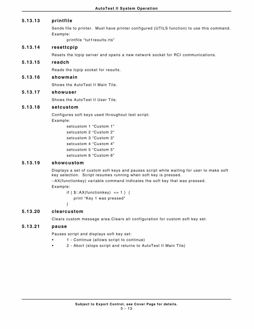
AutoTest I I System Operation
Subject to Export Control , see Cover Page for detai ls .5 - 13
5.13.13 printf i le
Sends f i le to pr in ter. Must have pr inter conf igured (UTILS funct ion) to use this command.
Example:
pr int f i le “ tut1results. r ts”
5.13.14 resettcpip
Resets the tcp ip server and opens a new network socket for RCI communicat ions.
5.13.15 readch
Reads the tcpip socket for resul ts.
5.13.16 showmain
Shows the AutoTest I I Main Ti le .
5.13.17 showuser
Shows the AutoTest I I User Ti le.
5.13.18 setcustom
Configures sof t keys used throughout test scr ipt .
Example:
setcustom 1 “Custom 1”
setcustom 2 “Custom 2”
setcustom 3 “Custom 3”
setcustom 4 “Custom 4”
setcustom 5 “Custom 5”
setcustom 6 “Custom 6”
5.13.19 showcustom
Disp lays a set of custom soft keys and pauses scr ipt whi le wait ing for user to make soft key select ion. Script resumes running when soft key is pressed.
: :AX(funct ionkey) var iable command indicates the sof t key that was pressed.
Example:
i f { $ : :AX(funct ionkey) == 1 } {
pr int “Key 1 was pressed”
}
5.13.20 clearcustom
Clears custom message area.Clears al l conf igurat ion for custom soft key set.
5.13.21 pause
Pauses scr ip t and displays soft key set :
• 1 - Cont inue (al lows scr ip t to cont inue)
• 2 - Abort (stops scr ipt and returns to AutoTest I I Main T i le)
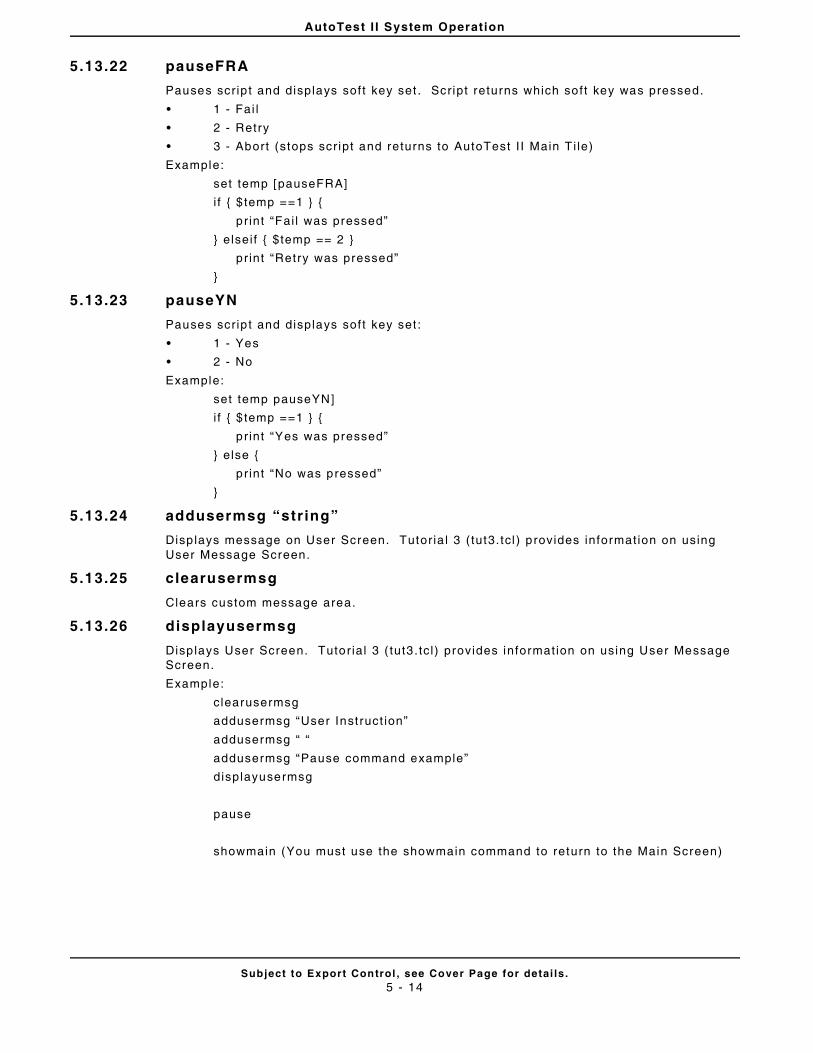
AutoTest I I System Operation
Subject to Export Control , see Cover Page for detai ls .5 - 14
5.13.22 pauseFRA
Pauses scr ip t and displays soft key set . Script returns which soft key was pressed.
• 1 - Fai l
• 2 - Retry
• 3 - Abort (stops scr ipt and returns to AutoTest I I Main T i le)
Example:
set temp [pauseFRA]
i f { $ temp ==1 } {
pr int “Fai l was pressed”
} elsei f { $temp == 2 }
pr int “Retry was pressed”
}
5.13.23 pauseYN
Pauses scr ip t and displays soft key set :
• 1 - Yes
• 2 - No
Example:
set temp pauseYN]
i f { $ temp ==1 } {
pr int “Yes was pressed”
} else {
pr int “No was pressed”
}
5.13.24 addusermsg “str ing”
Disp lays message on User Screen. Tutor ia l 3 ( tut3. tcl ) provides informat ion on using User Message Screen.
5.13.25 clearusermsg
Clears custom message area.
5.13.26 displayusermsg
Disp lays User Screen. Tutor ial 3 ( tut3 . tc l ) provides informat ion on using User Message Screen.
Example:
clearusermsg
addusermsg “User Inst ruct ion”
addusermsg “ “
addusermsg “Pause command example”
displayusermsg
pause
showmain (You must use the showmain command to return to the Main Screen)
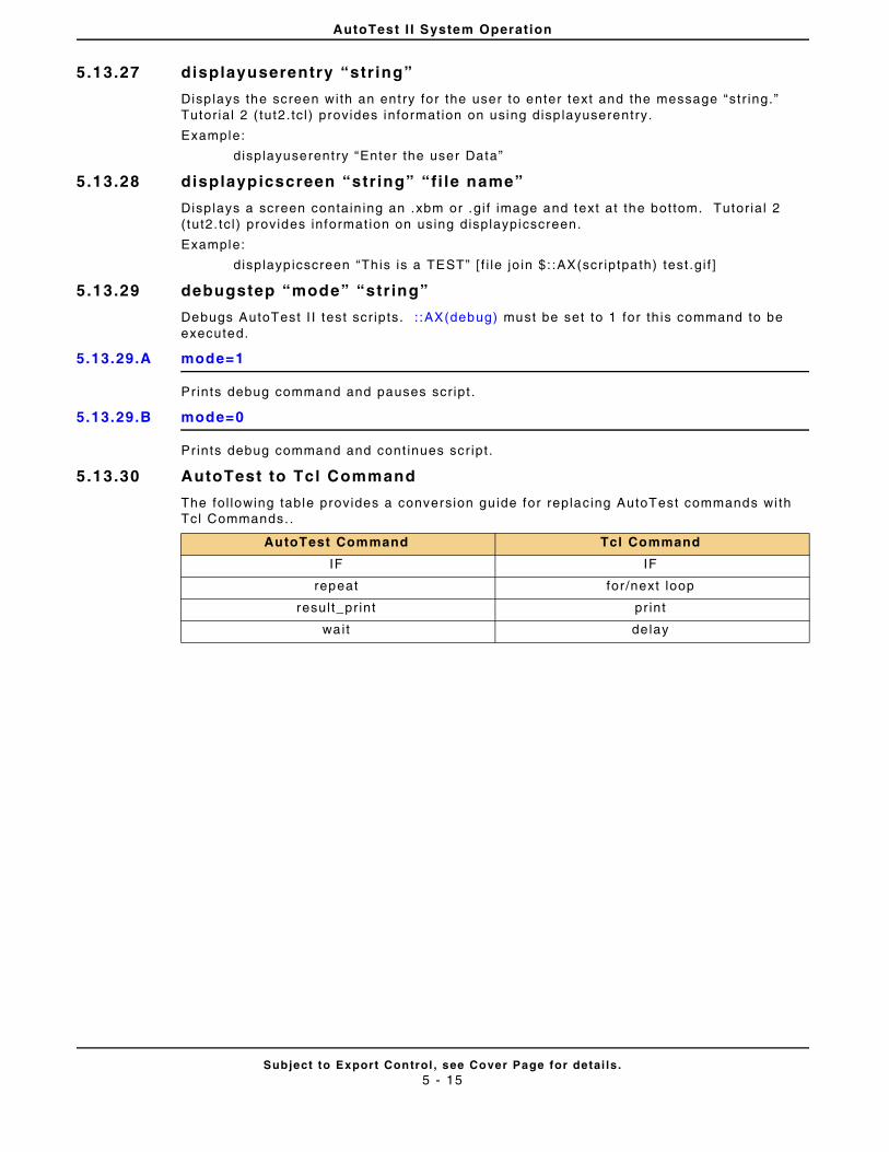
AutoTest I I System Operation
Subject to Export Control , see Cover Page for detai ls .5 - 15
5.13.27 displayuserentry “str ing”
Disp lays the screen with an ent ry for the user to enter text and the message “str ing.” Tutor ial 2 ( tut2. tc l ) provides informat ion on using disp layuserentry.
Example:
displayuserentry “Enter the user Data”
5.13.28 displaypicscreen “str ing” “fi le name”
Disp lays a screen contain ing an .xbm or .g i f image and text at the bot tom. Tutor ia l 2 ( tut2. tc l ) provides informat ion on using displaypicscreen.
Example:
displayp icscreen “Th is is a TEST” [ f i le jo in $: :AX(scr iptpath) test .gi f ]
5.13.29 debugstep “mode” “str ing”
Debugs AutoTest I I test scr ipts. : :AX(debug) must be set to 1 for th is command to be executed.
5.13.29.A mode=1
Prints debug command and pauses scr ipt .
5.13.29.B mode=0
Prints debug command and cont inues scr ipt .
5.13.30 AutoTest to Tcl Command
The fol lowing table provides a conversion gu ide for replacing AutoTest commands wi th Tcl Commands. .
AutoTest Command Tcl Command
IF IF
repeat for /next loop
resul t_pr int pr int
wait de lay
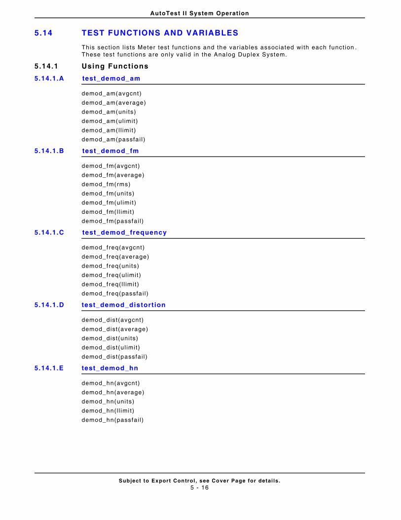
AutoTest I I System Operation
Subject to Export Control , see Cover Page for detai ls .5 - 16
5.14 TEST FUNCTIONS AND VARIABLES
This sect ion l ists Meter test funct ions and the var iables associated wi th each funct ion . These test funct ions are only val id in the Analog Duplex System.
5.14.1 Using Functions
5.14.1.A test_demod_am
demod_am(avgcnt)
demod_am(average)
demod_am(units)
demod_am(ul imit )
demod_am(l l imit )
demod_am(passfa i l )
5.14.1.B test_demod_fm
demod_fm(avgcnt)
demod_fm(average)
demod_fm(rms)
demod_fm(uni ts)
demod_fm(ul imit )
demod_fm(l l imit )
demod_fm(passfai l )
5.14.1.C test_demod_frequency
demod_freq(avgcnt)
demod_freq(average)
demod_freq(uni ts)
demod_freq(ul imit )
demod_freq( l l imit )
demod_freq(passfa i l )
5.14.1.D test_demod_distort ion
demod_dist(avgcnt)
demod_dist(average)
demod_dist(uni ts)
demod_dist(u l imit)
demod_dist(passfai l )
5.14.1.E test_demod_hn
demod_hn(avgcnt)
demod_hn(average)
demod_hn(uni ts)
demod_hn(l l imi t)
demod_hn(passfai l )
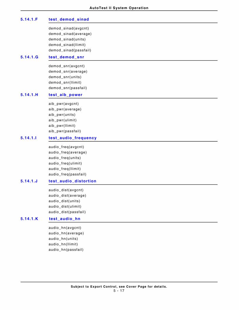
AutoTest I I System Operation
Subject to Export Control , see Cover Page for detai ls .5 - 17
5.14.1.F test_demod_sinad
demod_sinad(avgcnt)
demod_sinad(average)
demod_sinad(uni ts)
demod_sinad( l l imit)
demod_sinad(passfai l )
5.14.1.G test_demod_snr
demod_snr(avgcnt)
demod_snr(average)
demod_snr(uni ts)
demod_snr( l l imi t)
demod_snr(passfai l )
5.14.1.H test_aib_power
aib_pwr(avgcnt)
aib_pwr(average)
aib_pwr(uni ts)
aib_pwr(ul imit )
aib_pwr( l l imi t )
aib_pwr(passfa i l )
5.14.1. I test_audio_frequency
audio_freq(avgcnt)
audio_freq(average)
audio_freq(uni ts)
audio_freq(ul imi t)
audio_freq( l l imi t)
audio_freq(passfai l )
5.14.1.J test_audio_distort ion
audio_dist(avgcnt)
audio_dist(average)
audio_dist(uni ts)
audio_dist(ul imit)
audio_dist(passfai l )
5.14.1.K test_audio_hn
audio_hn(avgcnt)
audio_hn(average)
audio_hn(uni ts)
audio_hn(l l imit)
audio_hn(passfai l )
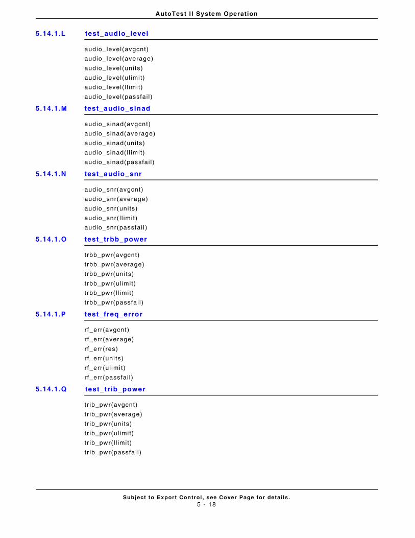
AutoTest I I System Operation
Subject to Export Control , see Cover Page for detai ls .5 - 18
5.14.1.L test_audio_level
audio_ level(avgcnt)
audio_ level(average)
audio_ level(uni ts)
audio_ level(ul imit)
audio_ level( l l imi t)
audio_ level(passfai l )
5.14.1.M test_audio_sinad
audio_sinad(avgcnt)
audio_sinad(average)
audio_sinad(uni ts)
audio_sinad( l l imit)
audio_sinad(passfai l )
5.14.1.N test_audio_snr
audio_snr(avgcnt)
audio_snr(average)
audio_snr(uni ts)
audio_snr( l l imit)
audio_snr(passfai l )
5.14.1.O test_trbb_power
t rbb_pwr(avgcnt)
trbb_pwr(average)
trbb_pwr(uni ts)
trbb_pwr(ul imit)
t rbb_pwr( l l imit)
t rbb_pwr(passfai l )
5.14.1.P test_freq_error
r f_err (avgcnt)
r f_err (average)
rf_err (res)
r f_err (uni ts)
r f_err (ul imi t)
r f_err (passfai l )
5.14.1.Q test_tr ib_power
t r ib_pwr(avgcnt)
tr ib_pwr(average)
tr ib_pwr(uni ts)
tr ib_pwr(ul imit)
t r ib_pwr( l l imit)
t r ib_pwr(passfai l )
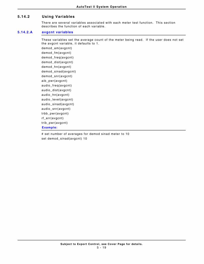
AutoTest I I System Operation
Subject to Export Control , see Cover Page for detai ls .5 - 19
5.14.2 Using Variables
There are several var iables associated with each meter test funct ion. This sect ion descr ibes the funct ion of each var iable.
5.14.2.A avgcnt variables
These var iables set the average count of the meter be ing read. I f the user does not set the avgcnt var iab le, i t defaul ts to 1.
demod_am(avgcnt)
demod_fm(avgcnt)
demod_freq(avgcnt)
demod_dist(avgcnt)
demod_hn(avgcnt)
demod_sinad(avgcnt)
demod_snr(avgcnt)
aib_pwr(avgcnt)
audio_freq(avgcnt)
audio_dist(avgcnt)
audio_hn(avgcnt)
audio_ level(avgcnt)
audio_sinad(avgcnt)
audio_snr(avgcnt)
trbb_pwr(avgcnt)
r f_err (avgcnt)
tr ib_pwr(avgcnt)
Example:
# set number of averages for demod sinad meter to 10
set demod_sinad(avgcnt) 10
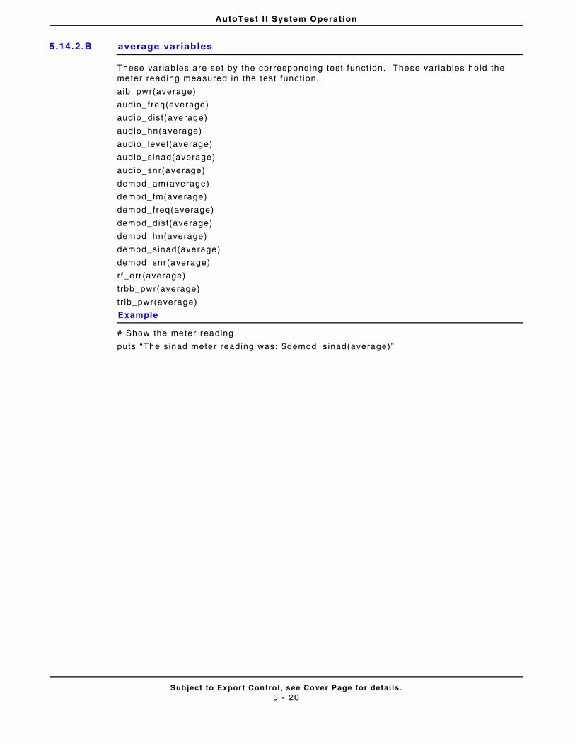
AutoTest I I System Operation
Subject to Export Control , see Cover Page for detai ls .5 - 20
5.14.2.B average variables
These var iables are set by the corresponding test funct ion. These var iables hold the meter reading measured in the test funct ion.
aib_pwr(average)
audio_freq(average)
audio_dist(average)
audio_hn(average)
audio_ level(average)
audio_sinad(average)
audio_snr(average)
demod_am(average)
demod_fm(average)
demod_freq(average)
demod_dist(average)
demod_hn(average)
demod_sinad(average)
demod_snr(average)
rf_err (average)
trbb_pwr(average)
tr ib_pwr(average)
Example
# Show the meter reading
puts “The sinad meter reading was: $demod_sinad(average)”
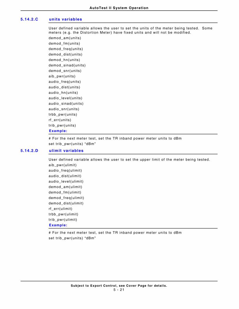
AutoTest I I System Operation
Subject to Export Control , see Cover Page for detai ls .5 - 21
5.14.2.C units variables
User def ined var iable al lows the user to set the uni ts of the meter being tested. Some meters (e .g. the Distort ion Meter) have f ixed uni ts and wi l l not be modi f ied.
demod_am(units)
demod_fm(uni ts)
demod_freq(uni ts)
demod_dist(uni ts)
demod_hn(uni ts)
demod_sinad(uni ts)
demod_snr(uni ts)
aib_pwr(uni ts)
audio_freq(uni ts)
audio_dist(uni ts)
audio_hn(uni ts)
audio_ level(uni ts)
audio_sinad(uni ts)
audio_snr(uni ts)
trbb_pwr(uni ts)
r f_err (uni ts)
tr ib_pwr(uni ts)
Example:
# For the next meter test , set the TR inband power meter uni ts to dBm
set t r ib_pwr(un i ts) “dBm”
5.14.2.D ul imit variables
User def ined var iable al lows the user to set the upper l imi t of the meter be ing tested.
aib_pwr(ul imit )
audio_freq(ul imi t)
audio_dist(ul imit)
audio_ level(ul imit)
demod_am(ul imit )
demod_fm(ul imit )
demod_freq(ul imit )
demod_dist(u l imit)
r f_err (ul imi t)
t rbb_pwr(ul imit)
t r ib_pwr(ul imit)
Example:
# For the next meter test , set the TR inband power meter uni ts to dBm
set t r ib_pwr(un i ts) “dBm”
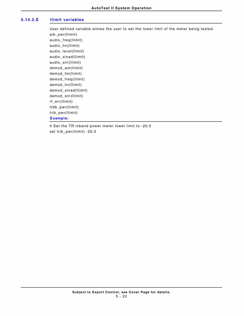
AutoTest I I System Operation
Subject to Export Control , see Cover Page for detai ls .5 - 22
5.14.2.E l l imit variables
User def ined var iable al lows the user to set the lower l imit of the meter being tested.
aib_pwr( l l imi t )
audio_freq( l l imi t)
audio_hn(l l imit)
audio_ level( l l imi t)
audio_sinad( l l imit)
audio_snr( l l imit)
demod_am(l l imit )
demod_fm(l l imit )
demod_freq( l l imit )
demod_hn(l l imi t)
demod_sinad( l l imit)
demod_snr( l l imi t)
r f_err ( l l imi t)
t rbb_pwr( l l imit)
t r ib_pwr( l l imit)
Example:
# Set the TR inband power meter lower l imit to -20.0
set t r ib_pwr( l l imit) -20.0
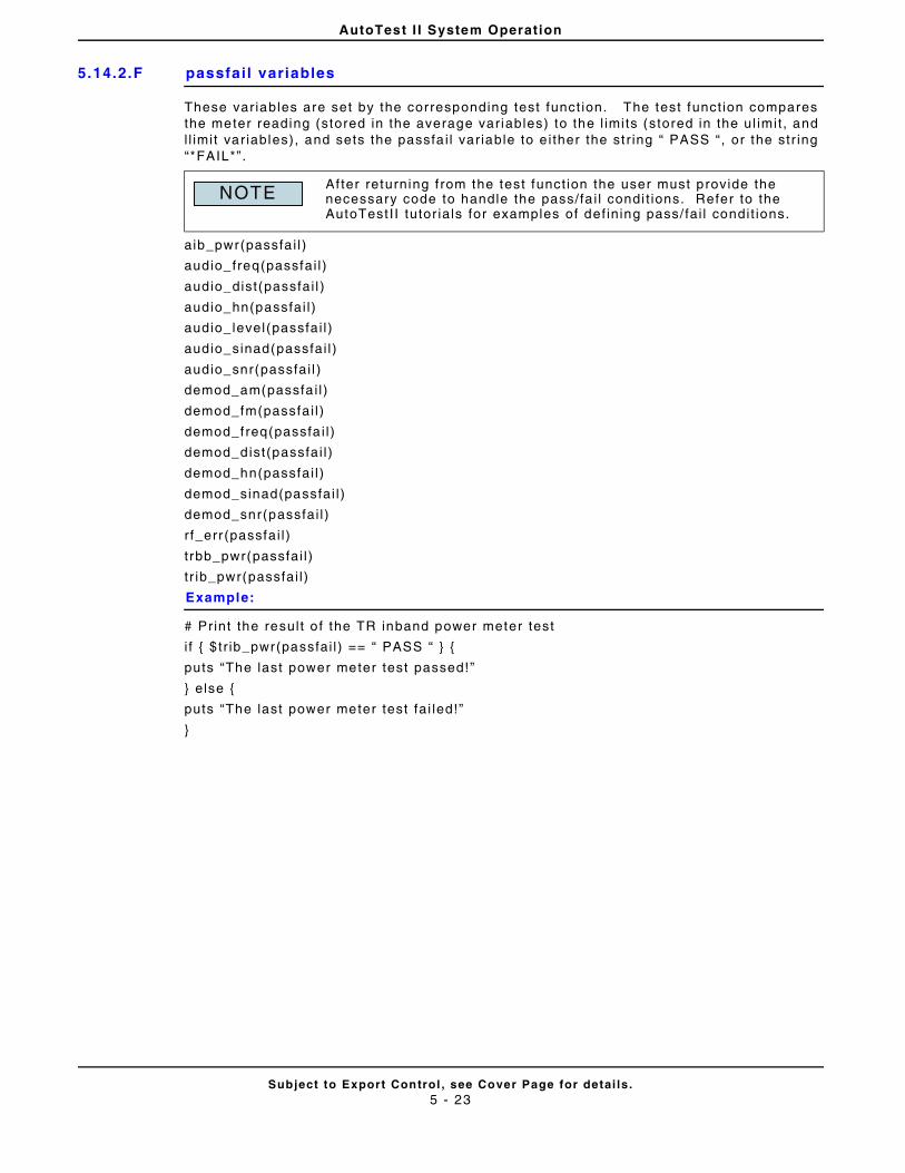
AutoTest I I System Operation
Subject to Export Control , see Cover Page for detai ls .5 - 23
5.14.2.F passfail variables
These var iables are set by the corresponding test funct ion. The test funct ion compares the meter reading (stored in the average var iables) to the l imits (stored in the ul imit , and l l imit var iables), and sets the passfa i l var iable to e i ther the st r ing “ PASS “, or the str ing “*FAIL*”.
aib_pwr(passfa i l )
audio_freq(passfai l )
audio_dist(passfai l )
audio_hn(passfai l )
audio_ level(passfai l )
audio_sinad(passfai l )
audio_snr(passfai l )
demod_am(passfa i l )
demod_fm(passfai l )
demod_freq(passfa i l )
demod_dist(passfai l )
demod_hn(passfai l )
demod_sinad(passfai l )
demod_snr(passfai l )
r f_err (passfai l )
t rbb_pwr(passfai l )
t r ib_pwr(passfai l )
Example:
# Print the resul t o f the TR inband power meter test
i f { $ tr ib_pwr(passfai l ) == “ PASS “ } {
puts “The last power meter test passed!”
} else {
puts “The last power meter test fa i led!”
}
Af ter returning f rom the test funct ion the user must provide the necessary code to handle the pass/fa i l condi t ions. Refer to the AutoTest I I tutor ia ls for examples of def in ing pass/ fai l condit ions.
NOTE
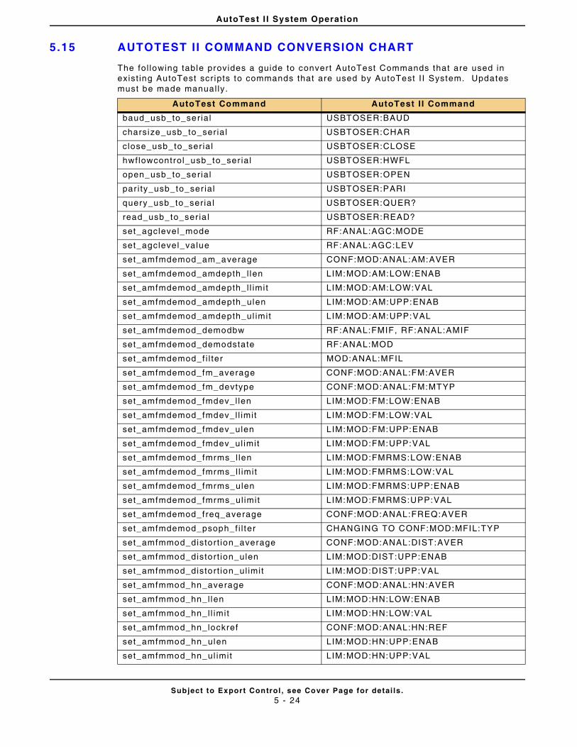
AutoTest I I System Operation
Subject to Export Control , see Cover Page for detai ls .5 - 24
5.15 AUTOTEST I I COMMAND CONVERSION CHART
The fol lowing table provides a guide to convert AutoTest Commands that are used in exist ing AutoTest scr ipts to commands that are used by AutoTest I I System. Updates must be made manual ly.
AutoTest Command AutoTest I I Command
baud_usb_to_serial USBTOSER:BAUD
charsize_usb_to_seria l USBTOSER:CHAR
close_usb_to_ser ial USBTOSER:CLOSE
hwflowcontrol_usb_to_ser ial USBTOSER:HWFL
open_usb_to_serial USBTOSER:OPEN
par i ty_usb_to_ser ial USBTOSER:PARI
query_usb_to_seria l USBTOSER:QUER?
read_usb_to_ser ia l USBTOSER:READ?
set_agclevel_mode RF:ANAL:AGC:MODE
set_agclevel_value RF:ANAL:AGC:LEV
set_amfmdemod_am_average CONF:MOD:ANAL:AM:AVER
set_amfmdemod_amdepth_l len LIM:MOD:AM:LOW:ENAB
set_amfmdemod_amdepth_l l imit LIM:MOD:AM:LOW:VAL
set_amfmdemod_amdepth_ulen LIM:MOD:AM:UPP:ENAB
set_amfmdemod_amdepth_ul imit LIM:MOD:AM:UPP:VAL
set_amfmdemod_demodbw RF:ANAL:FMIF, RF:ANAL:AMIF
set_amfmdemod_demodstate RF:ANAL:MOD
set_amfmdemod_f i l ter MOD:ANAL:MFIL
set_amfmdemod_fm_average CONF:MOD:ANAL:FM:AVER
set_amfmdemod_fm_devtype CONF:MOD:ANAL:FM:MTYP
set_amfmdemod_fmdev_l len LIM:MOD:FM:LOW:ENAB
set_amfmdemod_fmdev_l l imit LIM:MOD:FM:LOW:VAL
set_amfmdemod_fmdev_ulen LIM:MOD:FM:UPP:ENAB
set_amfmdemod_fmdev_ul imit LIM:MOD:FM:UPP:VAL
set_amfmdemod_fmrms_l len LIM:MOD:FMRMS:LOW:ENAB
set_amfmdemod_fmrms_l l imit LIM:MOD:FMRMS:LOW:VAL
set_amfmdemod_fmrms_ulen LIM:MOD:FMRMS:UPP:ENAB
set_amfmdemod_fmrms_ul imit LIM:MOD:FMRMS:UPP:VAL
set_amfmdemod_freq_average CONF:MOD:ANAL:FREQ:AVER
set_amfmdemod_psoph_f i l ter CHANGING TO CONF:MOD:MFIL:TYP
set_amfmmod_distort ion_average CONF:MOD:ANAL:DIST:AVER
set_amfmmod_distort ion_ulen LIM:MOD:DIST:UPP:ENAB
set_amfmmod_distort ion_ul imit LIM:MOD:DIST:UPP:VAL
set_amfmmod_hn_average CONF:MOD:ANAL:HN:AVER
set_amfmmod_hn_l len LIM:MOD:HN:LOW:ENAB
set_amfmmod_hn_l l imit LIM:MOD:HN:LOW:VAL
set_amfmmod_hn_lockref CONF:MOD:ANAL:HN:REF
set_amfmmod_hn_ulen LIM:MOD:HN:UPP:ENAB
set_amfmmod_hn_ul imit LIM:MOD:HN:UPP:VAL
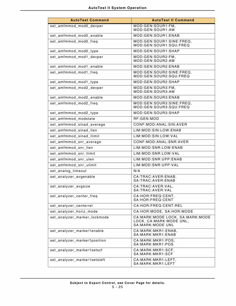
AutoTest I I System Operation
Subject to Export Control , see Cover Page for detai ls .5 - 25
set_amfmmod_mod0_devper MOD:GEN:SOUR1:FM, MOD:GEN:SOUR1:AM
set_amfmmod_mod0_enable MOD:GEN:SOUR1:ENAB
set_amfmmod_mod0_freq MOD:GEN:SOUR1:SINE:FREQ, MOD:GEN:SOUR1:SQU:FREQ
set_amfmmod_mod0_type MOD:GEN:SOUR1:SHAP
set_amfmmod_mod1_devper MOD:GEN:SOUR2:FM, MOD:GEN:SOUR2:AM
set_amfmmod_mod1_enable MOD:GEN:SOUR2:ENAB
set_amfmmod_mod1_freq MOD:GEN:SOUR2:SINE:FREQ, MOD:GEN:SOUR2:SQU:FREQ
set_amfmmod_mod1_type MOD:GEN:SOUR2:SHAP
set_amfmmod_mod2_devper MOD:GEN:SOUR3:FM, MOD:GEN:SOUR3:AM
set_amfmmod_mod2_enable MOD:GEN:SOUR3:ENAB
set_amfmmod_mod2_freq MOD:GEN:SOUR3:SINE:FREQ, MOD:GEN:SOUR3:SQU:FREQ
set_amfmmod_mod2_type MOD:GEN:SOUR3:SHAP
set_amfmmod_modstate RF:GEN:MOD
set_amfmmod_sinad_average CONF:MOD:ANAL:SIN:AVER
set_amfmmod_sinad_l len LIM:MOD:SIN:LOW:ENAB
set_amfmmod_sinad_l l imit LIM:MOD:SIN:LOW:VAL
set_amfmmod_snr_average CONF:MOD:ANAL:SNR:AVER
set_amfmmod_snr_ l len LIM:MOD:SNR:LOW:ENAB
set_amfmmod_snr_ l l imit LIM:MOD:SNR:LOW:VAL
set_amfmmod_snr_ulen LIM:MOD:SNR:UPP:ENAB
set_amfmmod_snr_ul imit LIM:MOD:SNR:UPP:VAL
set_analog_t imeout N/A
set_analyzer_avgenable CA:TRAC:AVER:ENAB, SA:TRAC:AVER:ENAB
set_analyzer_avgsize CA:TRAC:AVER:VAL, SA:TRAC:AVER:VAL
set_analyzer_center_freq CA:HOR:FREQ:CENT, SA:HOR:FREQ:CENT
set_analyzer_centerrel CA:HOR:FREQ:CENT:REL
set_analyzer_horiz_mode CA:HOR:MODE, SA:HOR:MODE
set_analyzer_marker_lockmode CA:MARK:MODE LOCK, SA:MARK:MODE LOCK, CA:MARK:MODE UNL, SA:MARK:MODE UNL
set_analyzer_marker1enable CA:MARK:MKR1:ENAB, SA:MARK:MKR1:ENAB
set_analyzer_marker1posi t ion CA:MARK:MKR1:POS, SA:MARK:MKR1:POS
set_analyzer_marker1setscf CA:MARK:MKR1:SCF, SA:MARK:MKR1:SCF
set_analyzer_marker1setslef t CA:MARK:MKR1:LEFT, SA:MARK:MKR1:LEFT
AutoTest Command AutoTest I I Command
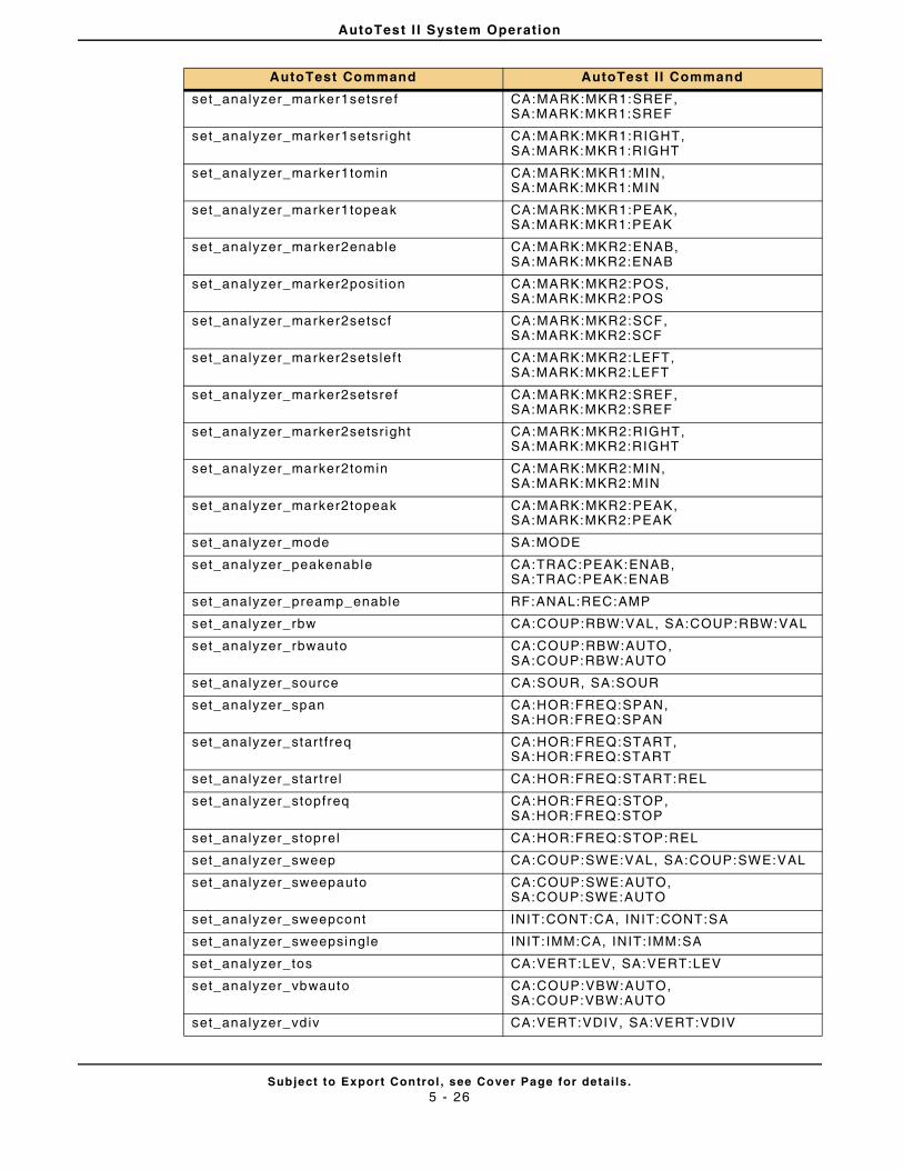
AutoTest I I System Operation
Subject to Export Control , see Cover Page for detai ls .5 - 26
set_analyzer_marker1setsref CA:MARK:MKR1:SREF, SA:MARK:MKR1:SREF
set_analyzer_marker1setsr ight CA:MARK:MKR1:RIGHT, SA:MARK:MKR1:RIGHT
set_analyzer_marker1tomin CA:MARK:MKR1:MIN, SA:MARK:MKR1:MIN
set_analyzer_marker1topeak CA:MARK:MKR1:PEAK, SA:MARK:MKR1:PEAK
set_analyzer_marker2enable CA:MARK:MKR2:ENAB, SA:MARK:MKR2:ENAB
set_analyzer_marker2posi t ion CA:MARK:MKR2:POS, SA:MARK:MKR2:POS
set_analyzer_marker2setscf CA:MARK:MKR2:SCF, SA:MARK:MKR2:SCF
set_analyzer_marker2setslef t CA:MARK:MKR2:LEFT, SA:MARK:MKR2:LEFT
set_analyzer_marker2setsref CA:MARK:MKR2:SREF, SA:MARK:MKR2:SREF
set_analyzer_marker2setsr ight CA:MARK:MKR2:RIGHT, SA:MARK:MKR2:RIGHT
set_analyzer_marker2tomin CA:MARK:MKR2:MIN, SA:MARK:MKR2:MIN
set_analyzer_marker2topeak CA:MARK:MKR2:PEAK, SA:MARK:MKR2:PEAK
set_analyzer_mode SA:MODE
set_analyzer_peakenable CA:TRAC:PEAK:ENAB, SA:TRAC:PEAK:ENAB
set_analyzer_preamp_enable RF:ANAL:REC:AMP
set_analyzer_rbw CA:COUP:RBW:VAL, SA:COUP:RBW:VAL
set_analyzer_rbwauto CA:COUP:RBW:AUTO, SA:COUP:RBW:AUTO
set_analyzer_source CA:SOUR, SA:SOUR
set_analyzer_span CA:HOR:FREQ:SPAN, SA:HOR:FREQ:SPAN
set_analyzer_start freq CA:HOR:FREQ:START, SA:HOR:FREQ:START
set_analyzer_start rel CA:HOR:FREQ:START:REL
set_analyzer_stopfreq CA:HOR:FREQ:STOP, SA:HOR:FREQ:STOP
set_analyzer_stoprel CA:HOR:FREQ:STOP:REL
set_analyzer_sweep CA:COUP:SWE:VAL, SA:COUP:SWE:VAL
set_analyzer_sweepauto CA:COUP:SWE:AUTO, SA:COUP:SWE:AUTO
set_analyzer_sweepcont INIT:CONT:CA, INIT:CONT:SA
set_analyzer_sweepsingle INIT: IMM:CA, INIT: IMM:SA
set_analyzer_tos CA:VERT:LEV, SA:VERT:LEV
set_analyzer_vbwauto CA:COUP:VBW:AUTO, SA:COUP:VBW:AUTO
set_analyzer_vdiv CA:VERT:VDIV, SA:VERT:VDIV
AutoTest Command AutoTest I I Command
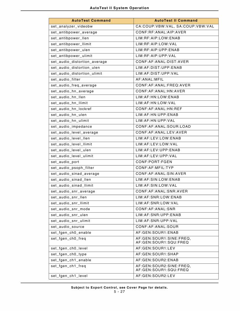
AutoTest I I System Operation
Subject to Export Control , see Cover Page for detai ls .5 - 27
set_analyzer_videobw CA:COUP:VBW:VAL, SA:COUP:VBW:VAL
set_ant ibpower_average CONF:RF:ANAL:AIP:AVER
set_ant ibpower_l len LIM:RF:AIP:LOW:ENAB
set_ant ibpower_l l imit LIM:RF:AIP:LOW:VAL
set_ant ibpower_ulen LIM:RF:AIP:UPP:ENAB
set_ant ibpower_ul imit LIM:RF:AIP:UPP:VAL
set_audio_distort ion_average CONF:AF:ANAL:DIST:AVER
set_audio_distort ion_ulen LIM:AF:DIST:UPP:ENAB
set_audio_distort ion_ul imi t LIM:AF:DIST:UPP:VAL
set_audio_f i l ter AF:ANAL:MFIL
set_audio_f req_average CONF:AF:ANAL:FREQ:AVER
set_audio_hn_average CONF:AF:ANAL:HN:AVER
set_audio_hn_l len LIM:AF:HN:LOW:ENAB
set_audio_hn_l l imit LIM:AF:HN:LOW:VAL
set_audio_hn_lockref CONF:AF:ANAL:HN:REF
set_audio_hn_ulen LIM:AF:HN:UPP:ENAB
set_audio_hn_ul imit LIM:AF:HN:UPP:VAL
set_audio_impedance CONF:AF:ANAL:SOUR:LOAD
set_audio_leve l_average CONF:AF:ANAL:LEV:AVER
set_audio_leve l_l len LIM:AF:LEV:LOW:ENAB
set_audio_leve l_l l imit LIM:AF:LEV:LOW:VAL
set_audio_leve l_ulen LIM:AF:LEV:UPP:ENAB
set_audio_leve l_ul imit LIM:AF:LEV:UPP:VAL
set_audio_por t CONF:PORT:FGEN
set_audio_psoph_f i l ter CONF:AF:MFIL:TYP
set_audio_sinad_average CONF:AF:ANAL:SIN:AVER
set_audio_sinad_l len LIM:AF:SIN:LOW:ENAB
set_audio_sinad_l l imit LIM:AF:SIN:LOW:VAL
set_audio_snr_average CONF:AF:ANAL:SNR:AVER
set_audio_snr_l len LIM:AF:SNR:LOW:ENAB
set_audio_snr_l l imit LIM:AF:SNR:LOW:VAL
set_audio_snr_mode CONF:AF:ANAL:SNR
set_audio_snr_ulen LIM:AF:SNR:UPP:ENAB
set_audio_snr_ul imit LIM:AF:SNR:UPP:VAL
set_audio_source CONF:AF:ANAL:SOUR
set_fgen_ch0_enable AF:GEN:SOUR1:ENAB
set_fgen_ch0_freq AF:GEN:SOUR1:SINE:FREQ, AF:GEN:SOUR1:SQU:FREQ
set_fgen_ch0_level AF:GEN:SOUR1:LEV
set_fgen_ch0_type AF:GEN:SOUR1:SHAP
set_fgen_ch1_enable AF:GEN:SOUR2:ENAB
set_fgen_ch1_freq AF:GEN:SOUR2:SINE:FREQ, AF:GEN:SOUR1:SQU:FREQ
set_fgen_ch1_level AF:GEN:SOUR2:LEV
AutoTest Command AutoTest I I Command
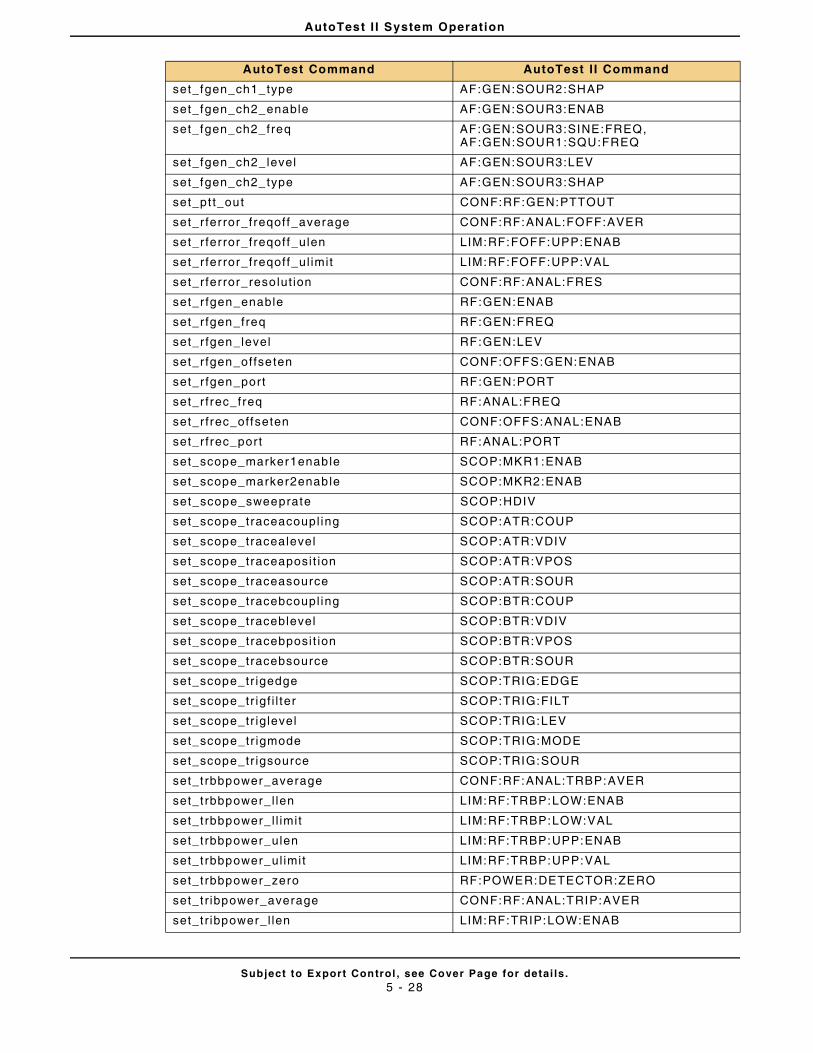
AutoTest I I System Operation
Subject to Export Control , see Cover Page for detai ls .5 - 28
set_fgen_ch1_type AF:GEN:SOUR2:SHAP
set_fgen_ch2_enable AF:GEN:SOUR3:ENAB
set_fgen_ch2_freq AF:GEN:SOUR3:SINE:FREQ, AF:GEN:SOUR1:SQU:FREQ
set_fgen_ch2_level AF:GEN:SOUR3:LEV
set_fgen_ch2_type AF:GEN:SOUR3:SHAP
set_pt t_out CONF:RF:GEN:PTTOUT
set_r ferror_freqoff_average CONF:RF:ANAL:FOFF:AVER
set_r ferror_freqoff_ulen LIM:RF:FOFF:UPP:ENAB
set_r ferror_freqoff_ul imit LIM:RF:FOFF:UPP:VAL
set_r ferror_reso lut ion CONF:RF:ANAL:FRES
set_r fgen_enable RF:GEN:ENAB
set_r fgen_freq RF:GEN:FREQ
set_r fgen_level RF:GEN:LEV
set_r fgen_offseten CONF:OFFS:GEN:ENAB
set_r fgen_port RF:GEN:PORT
set_r frec_freq RF:ANAL:FREQ
set_r frec_offseten CONF:OFFS:ANAL:ENAB
set_r frec_por t RF:ANAL:PORT
set_scope_marker1enable SCOP:MKR1:ENAB
set_scope_marker2enable SCOP:MKR2:ENAB
set_scope_sweeprate SCOP:HDIV
set_scope_traceacoupl ing SCOP:ATR:COUP
set_scope_tracealevel SCOP:ATR:VDIV
set_scope_traceaposi t ion SCOP:ATR:VPOS
set_scope_traceasource SCOP:ATR:SOUR
set_scope_tracebcoupl ing SCOP:BTR:COUP
set_scope_traceblevel SCOP:BTR:VDIV
set_scope_tracebposi t ion SCOP:BTR:VPOS
set_scope_tracebsource SCOP:BTR:SOUR
set_scope_tr igedge SCOP:TRIG:EDGE
set_scope_tr igf i l ter SCOP:TRIG:FILT
set_scope_tr ig level SCOP:TRIG:LEV
set_scope_tr igmode SCOP:TRIG:MODE
set_scope_tr igsource SCOP:TRIG:SOUR
set_t rbbpower_average CONF:RF:ANAL:TRBP:AVER
set_t rbbpower_l len LIM:RF:TRBP:LOW:ENAB
set_t rbbpower_l l imit LIM:RF:TRBP:LOW:VAL
set_t rbbpower_ulen LIM:RF:TRBP:UPP:ENAB
set_t rbbpower_ul imit LIM:RF:TRBP:UPP:VAL
set_t rbbpower_zero RF:POWER:DETECTOR:ZERO
set_t r ibpower_average CONF:RF:ANAL:TRIP:AVER
set_t r ibpower_l len LIM:RF:TRIP:LOW:ENAB
AutoTest Command AutoTest I I Command
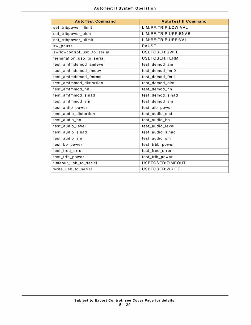
AutoTest I I System Operation
Subject to Export Control , see Cover Page for detai ls .5 - 29
set_t r ibpower_l l imit LIM:RF:TRIP:LOW:VAL
set_t r ibpower_ulen LIM:RF:TRIP:UPP:ENAB
set_t r ibpower_ul imit LIM:RF:TRIP:UPP:VAL
sw_pause PAUSE
swf lowcontro l_usb_to_ser ial USBTOSER:SWFL
terminat ion_usb_to_ser ial USBTOSER:TERM
test_amfmdemod_amlevel test_demod_am
test_amfmdemod_fmdev test_demod_fm 0
test_amfmdemod_fmrms test_demod_fm 1
test_amfmmod_distort ion test_demod_dist
test_amfmmod_hn test_demod_hn
test_amfmmod_sinad test_demod_sinad
test_amfmmod_snr test_demod_snr
test_ant ib_power test_aib_power
test_audio_distor t ion test_audio_dist
test_audio_hn test_audio_hn
test_audio_ level test_audio_ level
test_audio_sinad test_audio_sinad
test_audio_snr test_audio_snr
test_bb_power test_trbb_power
test_freq_error test_freq_error
test_tr ib_power test_tr ib_power
t imeout_usb_to_ser ial USBTOSER:TIMEOUT
wri te_usb_to_serial USBTOSER:WRITE
AutoTest Command AutoTest I I Command
AutoTest I I System Operation
Subject to Export Control , see Cover Page for detai ls .5 - 30
THIS PAGE INTENTIONALLY LEFT BLANK.
Subject to Export Control , see Cover Page for detai ls .6 - 1
Chapter 6 - Radio Test Instruments
6.1 INTRODUCTION
This chapter explains the use of the 3900 Spectrum Analyzer, Channel Analyzer, and Osci l loscope Instruments. This chapter is intended for users fami l iar wi th the general pr inciples and use of these instruments.
6.2 MARKERS
3900 Instruments include marker funct ions which al low users to obtain measurements at speci f ied poin ts on a signal . Implementat ion of marker funct ions var ies according to the instrument. This sect ion uses the Channel Analyzer Marker funct ions as examples.
6.2 .1 Enabling Markers
Markers are enabled using the fol lowing methods:
• Set t ing Marker 1/Marker 2 Soft Key to ENABLE;
• Select ing Marker f rom drop-down menu, then sett ing Marker Enable toggle but ton to ON ( this appl ies to Spectrum Analyzer and Channel Analyzer);
• Set t ing marker toggle button(s) to Enabled sta te.
6.2 .2 Positioning Markers
Marker posi t ion is adjusted by the fol lowing methods:
• By focusing on the Marker Posi t ion f ie ld and enter ing a value in the data f ie ld;
• By focusing on the Marker Posi t ion f ie ld and using the Rotary Control Knob to move the selected marker to a new reference point .
• (Mouse opt ion) By focusing on the Marker Posi t ion f ie ld and using a mouse to c l ick and drag the selected marker to the desired locat ion on the display f ie ld .
• The Mkr 1/Mkr 2 Sof t Keys access addi t ional soft keys that also adjust marker posi t ion on the display f ie ld .
Inst rument Markers are designed to maintain focus on the last selected marker. Se lect ing a non-marker funct ion or parameter does not cause the Test Set to lose marker focus. When using a mouse cl icking on the graph f ie ld reposi t ions the last selected marker to that posi t ion.
NOTE
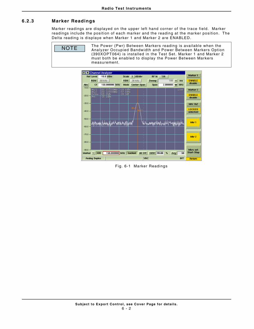
Radio Test Instruments
Subject to Export Control , see Cover Page for detai ls .6 - 2
6.2 .3 Marker Readings
Marker readings are displayed on the upper lef t hand corner o f the t race f ie ld. Marker readings include the posi t ion of each marker and the reading at the marker posi t ion. The Delta reading is d isplaye when Marker 1 and Marker 2 are ENABLED.
Fig. 6-1 Marker Readings
The Power (Pwr) Between Markers reading is avai lable when the Analyzer Occupied Bandwidth and Power Between Markers Opt ion (390XOPT064) is instal led in the Test Set. Marker 1 and Marker 2 must both be enabled to disp lay the Power Between Markers measurement.
NOTE
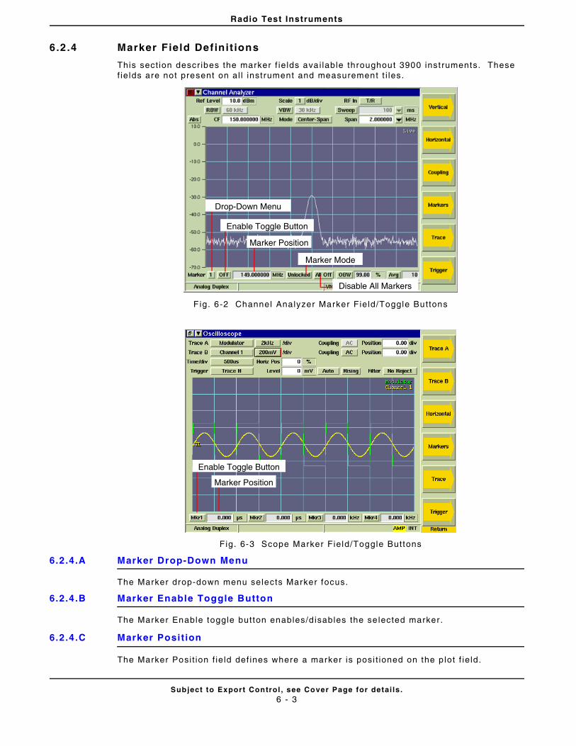
Radio Test Instruments
Subject to Export Control , see Cover Page for detai ls .6 - 3
6.2 .4 Marker Field Definit ions
This sect ion descr ibes the marker f ie lds ava i lable throughout 3900 inst ruments. These f ie lds are not present on al l instrument and measurement t i les.
F ig. 6-2 Channel Analyzer Marker Field/Toggle Buttons
Fig. 6-3 Scope Marker Field/Toggle Buttons
6.2.4.A Marker Drop-Down Menu
The Marker drop-down menu selects Marker focus.
6.2.4.B Marker Enable Toggle Button
The Marker Enable toggle button enables/d isables the se lected marker .
6.2.4.C Marker Posit ion
The Marker Posi t ion f ie ld def ines where a marker is posi t ioned on the p lot f ie ld.
Marker Mode
Marker Position
Enable Toggle Button
Drop-Down Menu
Disable All Markers
Marker Position
Enable Toggle Button
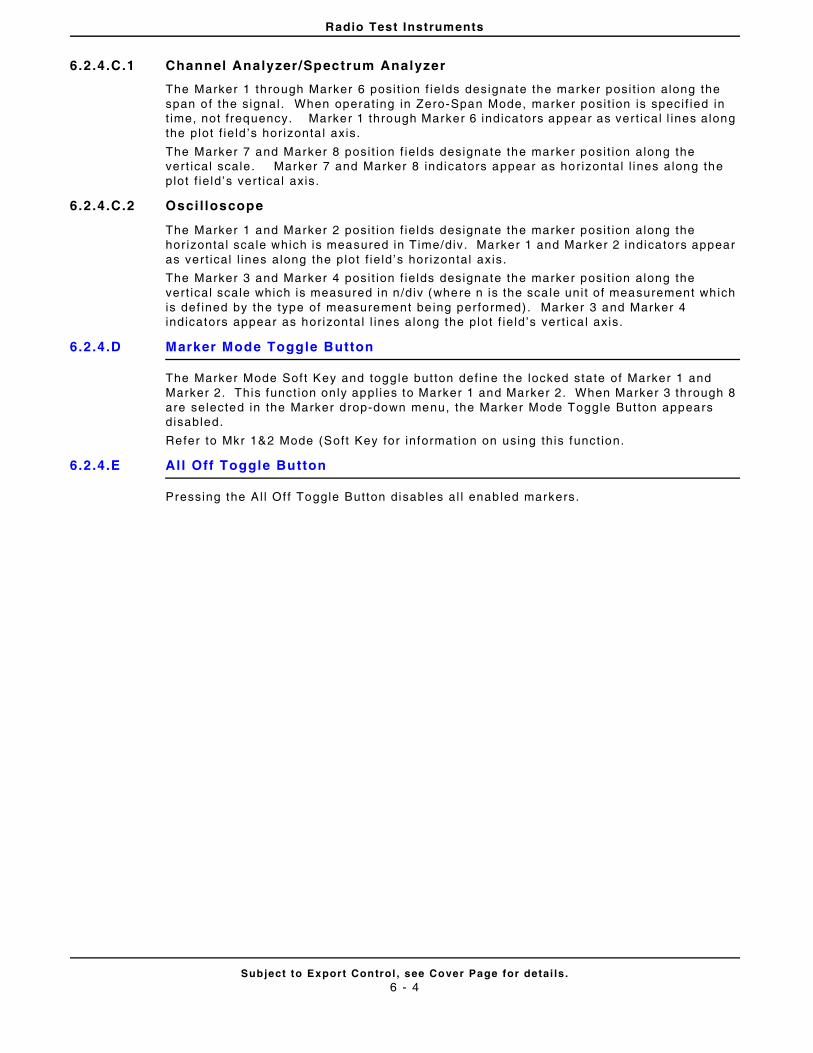
Radio Test Instruments
Subject to Export Control , see Cover Page for detai ls .6 - 4
6.2.4.C.1 Channel Analyzer/Spectrum Analyzer
The Marker 1 through Marker 6 posi t ion f ie lds designate the marker posi t ion along the span of the signal . When operat ing in Zero-Span Mode, marker posi t ion is speci f ied in t ime, not f requency. Marker 1 through Marker 6 indicators appear as ver t ical l ines along the plot f ie ld ’s hor izonta l axis.
The Marker 7 and Marker 8 posi t ion f ie lds designate the marker posi t ion along the vert ical scale . Marker 7 and Marker 8 indicators appear as hor izontal l ines along the plot f ie ld ’s ver t ical axis.
6.2.4.C.2 Osci l loscope
The Marker 1 and Marker 2 posi t ion f ie lds designate the marker posi t ion along the hor izontal scale which is measured in Time/div. Marker 1 and Marker 2 indicators appear as ver t ical l ines along the p lot f ie ld ’s hor izontal axis.
The Marker 3 and Marker 4 posi t ion f ie lds designate the marker posi t ion along the vert ical scale which is measured in n /div (where n is the sca le uni t of measurement which is def ined by the type of measurement be ing performed). Marker 3 and Marker 4 indicators appear as hor izontal l ines along the plot f ie ld’s vert ica l axis.
6.2.4.D Marker Mode Toggle Button
The Marker Mode Sof t Key and toggle but ton def ine the locked state of Marker 1 and Marker 2. This funct ion only appl ies to Marker 1 and Marker 2. When Marker 3 through 8 are selected in the Marker drop-down menu, the Marker Mode Toggle But ton appears disabled.
Refer to Mkr 1&2 Mode (Soft Key for informat ion on using this funct ion.
6.2.4.E Al l Off Toggle Button
Pressing the Al l Of f Toggle Button disables al l enabled markers.
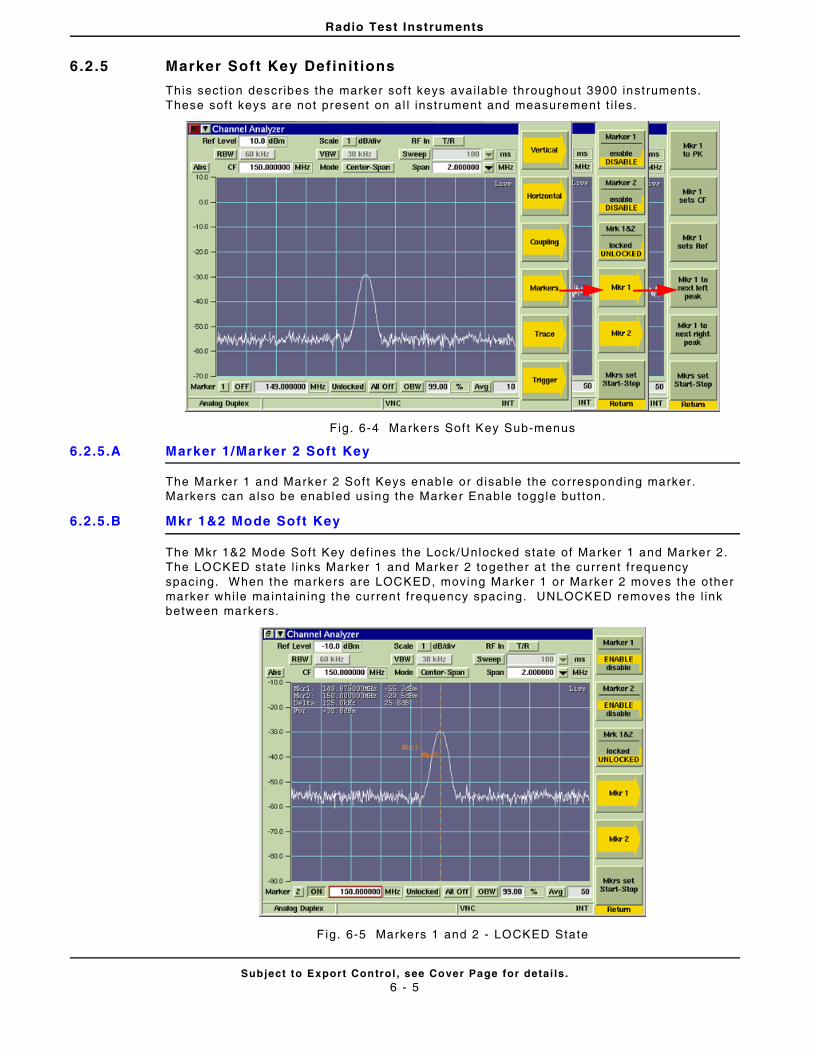
Radio Test Instruments
Subject to Export Control , see Cover Page for detai ls .6 - 5
6.2 .5 Marker Soft Key Definit ions
This sect ion descr ibes the marker sof t keys avai lable throughout 3900 instruments. These soft keys are not present on al l inst rument and measurement t i les.
Fig . 6-4 Markers Sof t Key Sub-menus
6.2.5.A Marker 1/Marker 2 Soft Key
The Marker 1 and Marker 2 Soft Keys enable or d isable the corresponding marker . Markers can also be enabled using the Marker Enable toggle but ton.
6.2.5.B Mkr 1&2 Mode Soft Key
The Mkr 1&2 Mode Soft Key def ines the Lock/Unlocked state of Marker 1 and Marker 2 . The LOCKED state l inks Marker 1 and Marker 2 together at the current f requency spacing. When the markers are LOCKED, moving Marker 1 or Marker 2 moves the other marker whi le maintain ing the current f requency spacing. UNLOCKED removes the l ink between markers.
F ig. 6-5 Markers 1 and 2 - LOCKED State
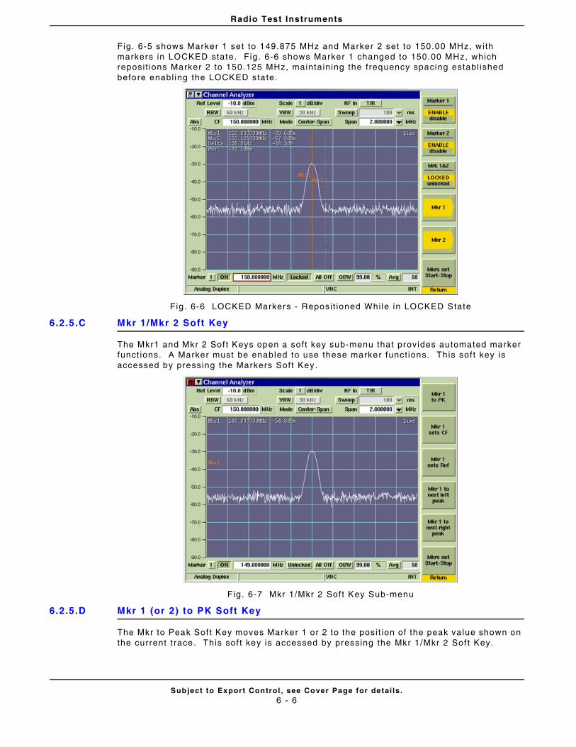
Radio Test Instruments
Subject to Export Control , see Cover Page for detai ls .6 - 6
Fig. 6-5 shows Marker 1 set to 149.875 MHz and Marker 2 set to 150.00 MHz, with markers in LOCKED state. Fig. 6-6 shows Marker 1 changed to 150.00 MHz, which reposi t ions Marker 2 to 150.125 MHz, maintaining the frequency spacing establ ished before enabl ing the LOCKED state.
Fig . 6-6 LOCKED Markers - Reposi t ioned Whi le in LOCKED State
6.2.5.C Mkr 1/Mkr 2 Soft Key
The Mkr1 and Mkr 2 Sof t Keys open a soft key sub-menu that provides automated marker funct ions. A Marker must be enabled to use these marker funct ions. This sof t key is accessed by pressing the Markers Soft Key.
Fig . 6-7 Mkr 1/Mkr 2 Sof t Key Sub-menu
6.2.5.D Mkr 1 (or 2) to PK Soft Key
The Mkr to Peak Sof t Key moves Marker 1 or 2 to the posi t ion of the peak va lue shown on the current t race. This sof t key is accessed by pressing the Mkr 1/Mkr 2 Sof t Key.
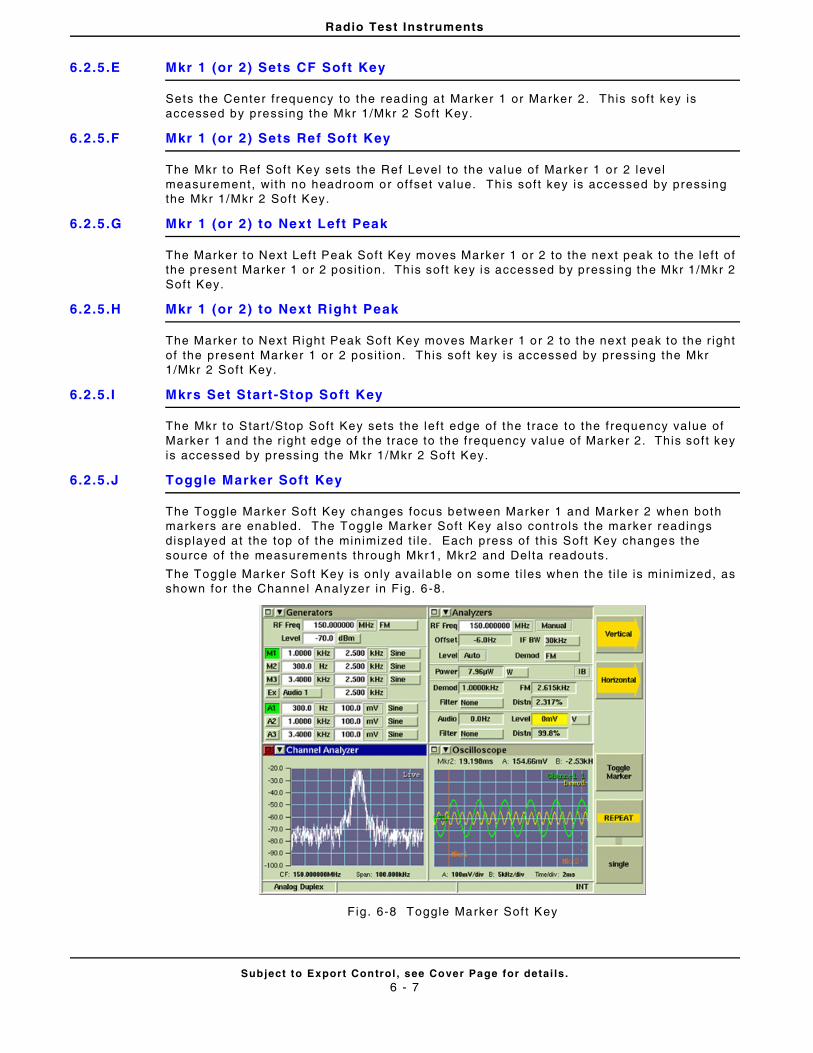
Radio Test Instruments
Subject to Export Control , see Cover Page for detai ls .6 - 7
6.2.5.E Mkr 1 (or 2) Sets CF Soft Key
Sets the Center f requency to the reading at Marker 1 or Marker 2. This soft key is accessed by pressing the Mkr 1/Mkr 2 Soft Key.
6.2.5.F Mkr 1 (or 2) Sets Ref Soft Key
The Mkr to Ref Soft Key sets the Ref Level to the value of Marker 1 or 2 level measurement, wi th no headroom or of fset value. This sof t key is accessed by pressing the Mkr 1/Mkr 2 Sof t Key.
6.2.5.G Mkr 1 (or 2) to Next Left Peak
The Marker to Next Left Peak Sof t Key moves Marker 1 or 2 to the next peak to the lef t of the present Marker 1 or 2 posi t ion. Th is soft key is accessed by pressing the Mkr 1/Mkr 2 Sof t Key.
6.2.5.H Mkr 1 (or 2) to Next Right Peak
The Marker to Next Right Peak Sof t Key moves Marker 1 or 2 to the next peak to the r ight of the present Marker 1 or 2 posi t ion. This sof t key is accessed by pressing the Mkr 1/Mkr 2 Soft Key.
6.2.5.I Mkrs Set Start -Stop Soft Key
The Mkr to Start /Stop Soft Key sets the lef t edge of the t race to the f requency value of Marker 1 and the r ight edge of the trace to the frequency value of Marker 2. This sof t key is accessed by pressing the Mkr 1/Mkr 2 Sof t Key.
6.2.5.J Toggle Marker Soft Key
The Toggle Marker Soft Key changes focus between Marker 1 and Marker 2 when both markers are enabled. The Toggle Marker Soft Key also controls the marker readings displayed at the top of the minimized t i le. Each press of th is Soft Key changes the source of the measurements through Mkr1, Mkr2 and Delta readouts.
The Toggle Marker Soft Key is only avai lable on some t i les when the t i le is minimized, as shown for the Channel Analyzer in Fig. 6-8.
Fig. 6-8 Toggle Marker Sof t Key
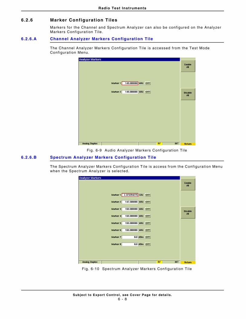
Radio Test Instruments
Subject to Export Control , see Cover Page for detai ls .6 - 8
6.2 .6 Marker Configurat ion Tiles
Markers for the Channel and Spectrum Analyzer can also be conf igured on the Analyzer Markers Conf igurat ion T i le.
6.2.6.A Channel Analyzer Markers Configuration Tile
The Channel Analyzer Markers Conf igurat ion Ti le is accessed from the Test Mode Conf igurat ion Menu.
Fig. 6-9 Audio Analyzer Markers Conf igurat ion Ti le
6.2.6.B Spectrum Analyzer Markers Configuration Tile
The Spectrum Analyzer Markers Conf igurat ion T i le is access from the Conf igurat ion Menu when the Spectrum Analyzer is selected.
Fig. 6-10 Spectrum Analyzer Markers Conf igurat ion Ti le
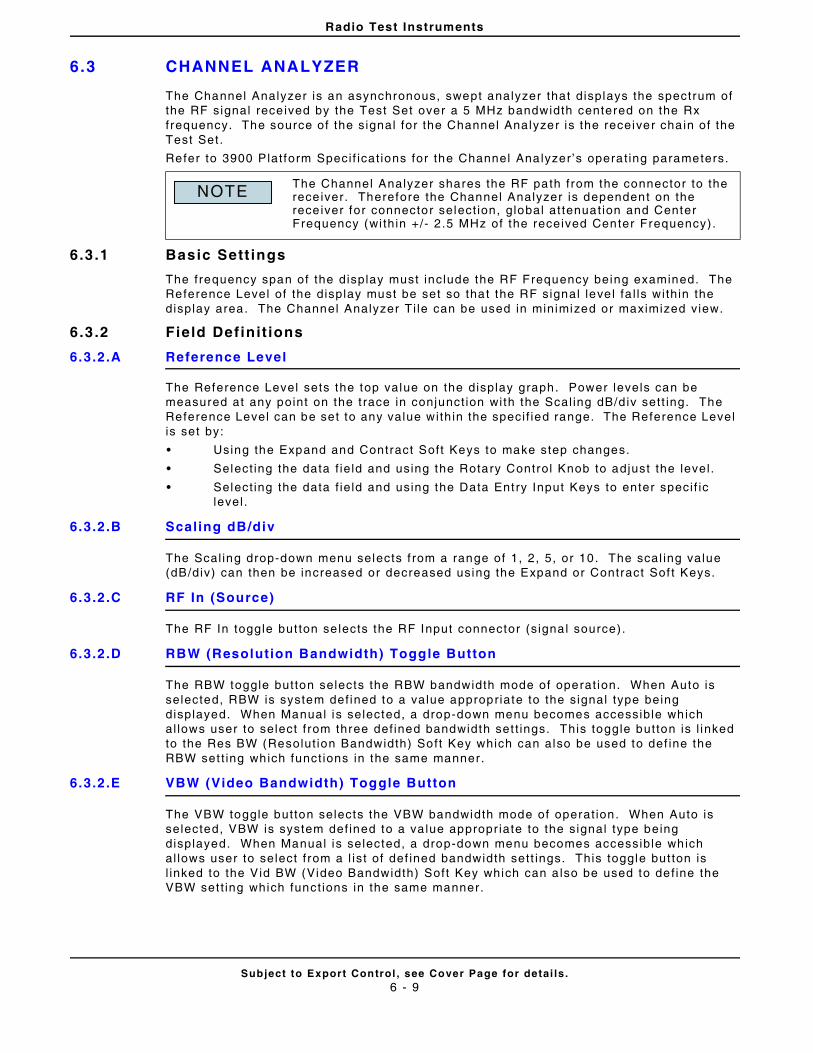
Radio Test Instruments
Subject to Export Control , see Cover Page for detai ls .6 - 9
6.3 CHANNEL ANALYZER
The Channel Analyzer is an asynchronous, swept analyzer that displays the spectrum of the RF signal rece ived by the Test Set over a 5 MHz bandwidth centered on the Rx frequency. The source of the signal for the Channel Analyzer is the receiver cha in of the Test Set .
Refer to 3900 Plat form Speci f icat ions for the Channel Analyzer ’s operat ing parameters.
6.3 .1 Basic Sett ings
The frequency span of the display must include the RF Frequency being examined. The Reference Level of the display must be set so that the RF signal leve l fa l ls wi thin the display area. The Channel Analyzer Ti le can be used in minimized or maximized view.
6.3 .2 Field Definit ions
6.3.2.A Reference Level
The Reference Level sets the top value on the display graph. Power levels can be measured at any point on the t race in conjunct ion with the Scal ing dB/d iv sett ing. The Reference Level can be set to any value with in the speci f ied range. The Reference Level is set by:
• Using the Expand and Contract Soft Keys to make step changes.
• Select ing the data f ie ld and using the Rotary Control Knob to adjust the level .
• Select ing the data f ie ld and using the Data Entry Input Keys to enter speci f ic level .
6.3.2.B Scaling dB/div
The Scal ing drop-down menu selects f rom a range of 1, 2, 5, or 10. The scal ing value (dB/div) can then be increased or decreased using the Expand or Contract Sof t Keys.
6.3.2.C RF In (Source)
The RF In toggle but ton se lects the RF Input connector (s ignal source).
6.3.2.D RBW (Resolution Bandwidth) Toggle Button
The RBW toggle button selects the RBW bandwidth mode of operat ion. When Auto is selected, RBW is system def ined to a value appropriate to the signal type being displayed. When Manual is selected, a drop-down menu becomes accessible which al lows user to select f rom three def ined bandwidth set t ings. This toggle button is l inked to the Res BW (Resolut ion Bandwidth) Soft Key which can also be used to def ine the RBW set t ing which funct ions in the same manner.
6.3.2.E VBW (Video Bandwidth) Toggle Button
The VBW toggle button selects the VBW bandwidth mode of operat ion. When Auto is selected, VBW is system def ined to a va lue appropr iate to the signal type being displayed. When Manual is selected, a drop-down menu becomes accessible which al lows user to select f rom a l ist of def ined bandwidth sett ings. This toggle but ton is l inked to the Vid BW (Video Bandwidth) Soft Key which can a lso be used to def ine the VBW set t ing which funct ions in the same manner.
The Channel Analyzer shares the RF path from the connector to the rece iver. Therefore the Channel Analyzer is dependent on the rece iver for connector select ion, global at tenuat ion and Center Frequency (wi thin +/- 2.5 MHz of the received Center Frequency) .
NOTE
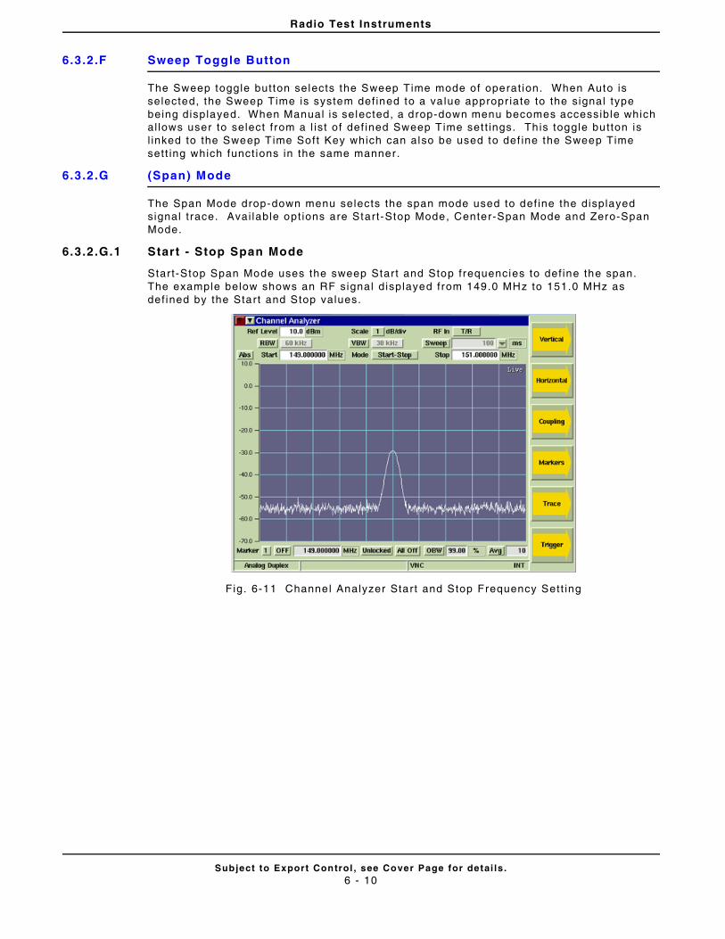
Radio Test Instruments
Subject to Export Control , see Cover Page for detai ls .6 - 10
6.3.2.F Sweep Toggle Button
The Sweep toggle button selects the Sweep Time mode of operat ion. When Auto is selected, the Sweep Time is system def ined to a va lue appropr iate to the signal type being displayed. When Manual is selected, a drop-down menu becomes accessible which al lows user to select f rom a l ist of def ined Sweep Time set t ings. Th is toggle button is l inked to the Sweep Time Soft Key which can also be used to def ine the Sweep Time sett ing which funct ions in the same manner.
6.3.2.G (Span) Mode
The Span Mode drop-down menu selects the span mode used to def ine the displayed signal t race. Avai lable opt ions are Start-Stop Mode, Center-Span Mode and Zero-Span Mode.
6.3.2.G.1 Start - Stop Span Mode
Start-Stop Span Mode uses the sweep Start and Stop frequencies to def ine the span. The example below shows an RF signal displayed from 149.0 MHz to 151.0 MHz as def ined by the Start and Stop values.
Fig. 6-11 Channel Analyzer Start and Stop Frequency Sett ing
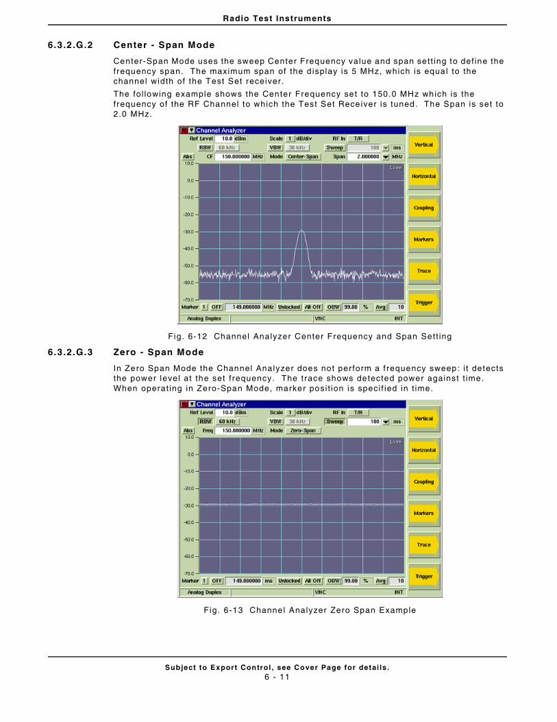
Radio Test Instruments
Subject to Export Control , see Cover Page for detai ls .6 - 11
6.3.2.G.2 Center - Span Mode
Center-Span Mode uses the sweep Center Frequency value and span sett ing to def ine the frequency span. The maximum span of the d isplay is 5 MHz, which is equal to the channel width of the Test Set receiver .
The fol lowing example shows the Center Frequency set to 150.0 MHz which is the frequency of the RF Channel to which the Test Set Receiver is tuned. The Span is set to 2.0 MHz.
Fig. 6-12 Channel Analyzer Center Frequency and Span Sett ing
6.3.2.G.3 Zero - Span Mode
In Zero Span Mode the Channel Analyzer does not per form a f requency sweep: i t detects the power level at the set f requency. The trace shows detected power against t ime. When operat ing in Zero-Span Mode, marker posi t ion is speci f ied in t ime.
Fig. 6-13 Channel Analyzer Zero Span Example
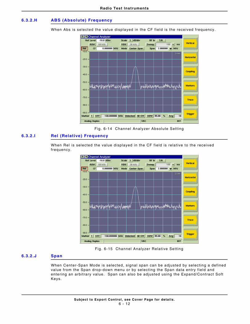
Radio Test Instruments
Subject to Export Control , see Cover Page for detai ls .6 - 12
6.3.2.H ABS (Absolute) Frequency
When Abs is selected the value displayed in the CF f ie ld is the received frequency.
Fig. 6-14 Channel Analyzer Absolute Sett ing
6.3.2.I Rel (Relative) Frequency
When Rel is selected the va lue displayed in the CF f ie ld is rela t ive to the received frequency.
Fig . 6-15 Channel Analyzer Relat ive Sett ing
6.3.2.J Span
When Center-Span Mode is selected, s ignal span can be adjusted by select ing a def ined value from the Span drop-down menu or by se lect ing the Span data ent ry f ie ld and enter ing an arbi t rary value. Span can also be ad justed using the Expand/Contract Soft Keys.
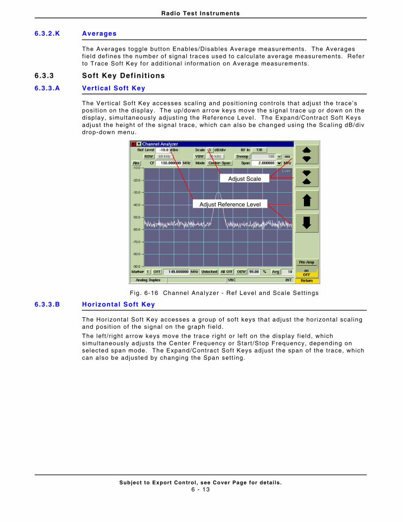
Radio Test Instruments
Subject to Export Control , see Cover Page for detai ls .6 - 13
6.3.2.K Averages
The Averages toggle button Enables/Disables Average measurements. The Averages f ie ld def ines the number of s ignal t races used to calculate average measurements. Refer to Trace Sof t Key for addi t ional information on Average measurements.
6.3 .3 Soft Key Definit ions
6.3.3.A Vertical Soft Key
The Vert ical Sof t Key accesses scal ing and posi t ioning controls that adjust the trace’s posi t ion on the display. The up/down arrow keys move the signal t race up or down on the display, s imultaneously adjust ing the Reference Level . The Expand/Contract Soft Keys adjust the height of the signal t race, which can also be changed using the Scal ing dB/div drop-down menu.
Fig . 6-16 Channel Analyzer - Ref Level and Scale Sett ings
6.3.3.B Horizontal Soft Key
The Hor izontal Soft Key accesses a group of soft keys that ad just the hor izontal scal ing and posi t ion of the signal on the graph f ie ld.
The lef t / r ight arrow keys move the trace r ight or lef t on the display f ie ld, which simultaneously adjusts the Center Frequency or Start /Stop Frequency, depending on selected span mode. The Expand/Contract Sof t Keys ad just the span of the trace, which can also be adjusted by changing the Span sett ing.
Adjust Reference Level
Adjust Scale
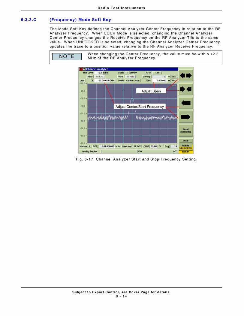
Radio Test Instruments
Subject to Export Control , see Cover Page for detai ls .6 - 14
6.3.3.C (Frequency) Mode Soft Key
The Mode Soft Key def ines the Channel Analyzer Center Frequency in relat ion to the RF Analyzer Frequency. When LOCK Mode is selected, changing the Channel Analyzer Center Frequency changes the Receive Frequency on the RF Analyzer Ti le to the same value. When UNLOCKED is selected, changing the Channel Analyzer Center Frequency updates the trace to a posi t ion value relat ive to the RF Analyzer Receive Frequency.
Fig. 6-17 Channel Analyzer Start and Stop Frequency Sett ing
When changing the Center Frequency, the value must be within ±2.5 MHz of the RF Analyzer Frequency.NOTE
Adjust Center/Start Frequency
Adjust Span
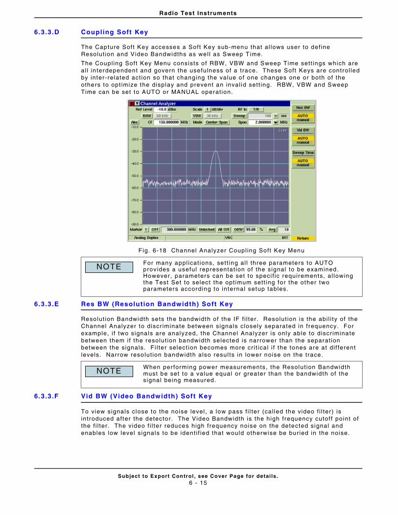
Radio Test Instruments
Subject to Export Control , see Cover Page for detai ls .6 - 15
6.3.3.D Coupling Soft Key
The Capture Sof t Key accesses a Soft Key sub-menu that al lows user to def ine Resolut ion and Video Bandwidths as wel l as Sweep Time.
The Coupl ing Soft Key Menu consists o f RBW, VBW and Sweep Time sett ings which are al l in terdependent and govern the usefulness of a t race. These Soft Keys are control led by inter- related act ion so that changing the value of one changes one or both of the others to opt imize the display and prevent an inval id sett ing. RBW, VBW and Sweep Time can be set to AUTO or MANUAL operat ion.
Fig . 6-18 Channel Analyzer Coupl ing Soft Key Menu
6.3.3.E Res BW (Resolution Bandwidth) Soft Key
Resolut ion Bandwidth sets the bandwidth of the IF f i l ter . Resolut ion is the abi l i ty of the Channel Analyzer to discr iminate between signals c losely separated in f requency. For example, i f two signals are analyzed, the Channel Analyzer is only able to discr iminate between them i f the resolut ion bandwidth se lected is narrower than the separat ion between the signals. Fi l ter select ion becomes more cr i t ical i f the tones are at di f ferent levels. Narrow reso lut ion bandwidth also resul ts in lower noise on the trace.
6.3.3.F Vid BW (Video Bandwidth) Soft Key
To view signals close to the noise level , a low pass f i l ter (cal led the video f i l ter) is introduced after the detector. The Video Bandwidth is the high frequency cutoff point of the f i l ter . The video f i l ter reduces high frequency noise on the detected signal and enables low level s ignals to be ident i f ied that would otherwise be bur ied in the noise.
For many appl icat ions, sett ing al l three parameters to AUTO provides a useful representat ion of the signal to be examined. However, parameters can be set to speci f ic requirements, al lowing the Test Set to select the opt imum sett ing for the other two parameters according to internal setup tables.
When per forming power measurements, the Resolut ion Bandwidth must be set to a value equal or greater than the bandwidth of the signal being measured.
NOTE
NOTE
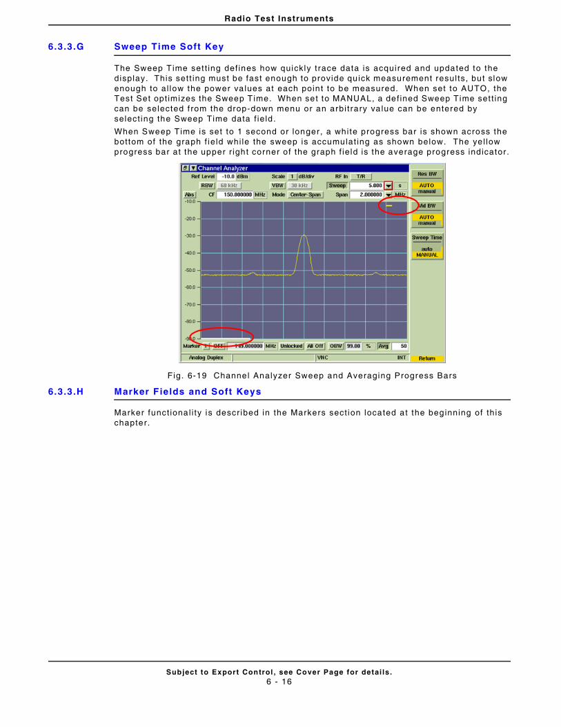
Radio Test Instruments
Subject to Export Control , see Cover Page for detai ls .6 - 16
6.3.3.G Sweep Time Soft Key
The Sweep Time set t ing def ines how quickly t race data is acquired and updated to the display. This sett ing must be fast enough to provide qu ick measurement resul ts, but slow enough to al low the power va lues at each poin t to be measured. When set to AUTO, the Test Set opt imizes the Sweep Time. When set to MANUAL, a def ined Sweep Time set t ing can be selected f rom the drop-down menu or an arbi t rary va lue can be entered by select ing the Sweep Time data f ie ld .
When Sweep Time is set to 1 second or longer, a white progress bar is shown across the bottom of the graph f ie ld whi le the sweep is accumulat ing as shown below. The ye l low progress bar at the upper r ight corner of the graph f ie ld is the average progress indicator.
Fig. 6-19 Channel Analyzer Sweep and Averaging Progress Bars
6.3.3.H Marker Fields and Soft Keys
Marker funct ional i ty is descr ibed in the Markers sect ion located at the beginning of th is chapter.
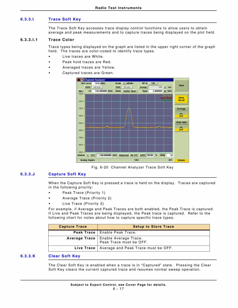
Radio Test Instruments
Subject to Export Control , see Cover Page for detai ls .6 - 17
6.3.3.I Trace Soft Key
The Trace Soft Key accesses trace disp lay control funct ions to al low users to obtain average and peak measurements and to capture t races being displayed on the p lot f ie ld.
6.3.3.I .1 Trace Color
Trace types being disp layed on the graph are l isted in the upper r ight corner of the graph f ie ld. The t races are color-coded to ident i fy t race types.
• Live t races are White.
• Peak hold traces are Red.
• Averaged traces are Yel low.
• Captured t races are Green.
Fig. 6-20 Channel Analyzer Trace Soft Key
6.3.3.J Capture Soft Key
When the Capture Sof t Key is pressed a t race is held on the d isplay. Traces are captured in the fol lowing pr ior i ty:
• Peak Trace (Pr ior i ty 1)
• Average Trace (Pr ior i ty 2)
• Live Trace (Pr ior i ty 3)
For example, i f Average and Peak Traces are both enabled, the Peak Trace is captured. I f L ive and Peak Traces are being d isplayed, the Peak trace is captured. Refer to the fol lowing char t for notes about how to capture speci f ic t race types.
6.3.3.K Clear Soft Key
The Clear Soft Key is enabled when a t race is in “Captured” state. Pressing the Clear Sof t Key clears the current captured trace and resumes normal sweep operat ion.
Capture Trace Setup to Store Trace
Peak Trace Enable Peak Trace.
Average Trace Enable Average Trace.Peak Trace must be OFF.
Live Trace Average and Peak Trace must be OFF.
Radio Test Instruments
Subject to Export Control , see Cover Page for detai ls .6 - 18
6.3.3.L Store Trace Soft Key
The Store Trace Sof t Keys al lows a user to store a signal t race. I f more than one type of t race is enabled the traces are stored in the fo l lowing pr ior i ty:
• Captured Trace (Pr ior i ty 1)
• Peak Trace (Pr ior i ty 2)
• Average Trace (Pr ior i ty 3)
• Live Trace (Pr ior i ty 4)
For example, i f Average and Peak Traces are both enabled and a t race has been captured, the Captured Trace is stored. I f Average and Peak Traces are being displayed, the Peak trace is stored. Refer to the fol lowing chart for notes about how to store speci f ic t race types.
6.3.3.M Recal l Trace Soft Key
The Recal l Trace Soft Key opens a dialog box that al lows the user to load stored t race data.
6.3.3.N Peak Hold Soft Key
When Peak Hold ON is se lected, the maximum value at each frequency point is disp layed to produce the RED Max Hold t race. This t race is c leared by select ing Peak Hold OFF. Peak Hold must be reset ( toggled ON/OFF) when Average readings are Enabled/Disabled. The white Live trace is also displayed and can be averaged depending on the current sett ing. This soft key is accessed by pressing the Trace Soft Key.
6.3.3.O Average Soft Key
When the Average Soft Key is ON, the trace is calculated by averaging the number of measurements def ined in the Averages f ie ld. The calculated va lue is a rol l ing average or a one-shot average as def ined on the Tr igger Ti le using the Repeat Soft Key and Single Sof t Key. A yel low progress indicator is displayed in the upper r ight corner of the graph f ie ld whi le the average reading is accumulat ing. This soft key is accessed by pressing the Trace Soft Key.
Store Trace Setup to Store Trace
Captured Trace Capture Trace must be engaged.
Peak Trace Enable Peak Trace.Clear any Captured Trace.
Average Trace Enable Average Trace.Peak Trace must be OFF.Clear any Captured Trace.
Live Trace Average and Peak Trace must be OFF.Clear any Captured Trace.
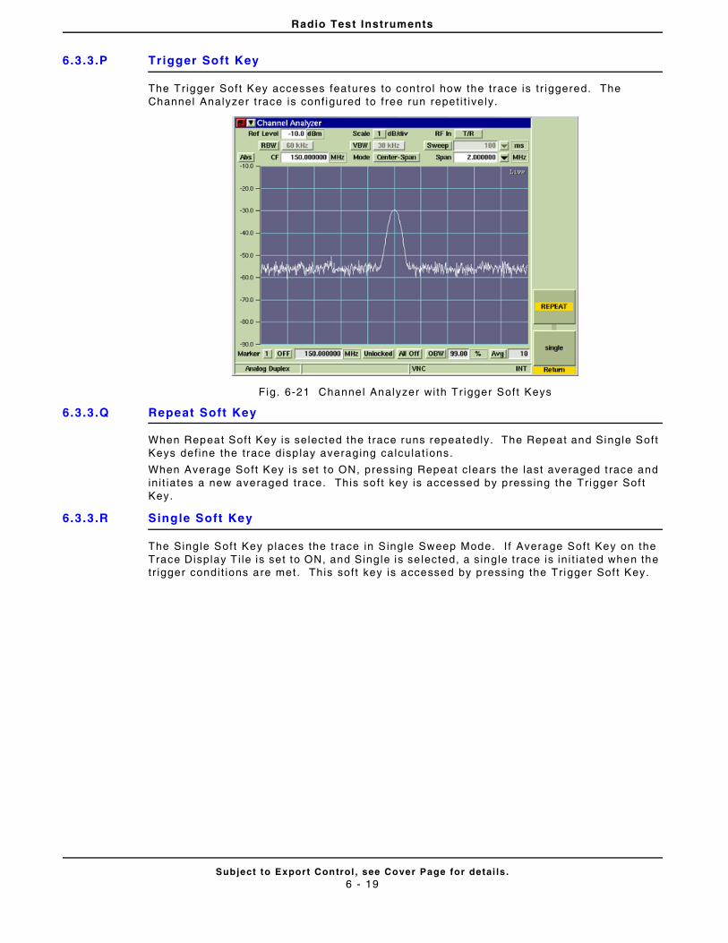
Radio Test Instruments
Subject to Export Control , see Cover Page for detai ls .6 - 19
6.3.3.P Trigger Soft Key
The Tr igger Sof t Key accesses features to control how the trace is t r iggered. The Channel Analyzer t race is conf igured to f ree run repet i t ively.
Fig. 6-21 Channel Analyzer with Tr igger Soft Keys
6.3.3.Q Repeat Soft Key
When Repeat Soft Key is selected the trace runs repeatedly. The Repeat and Single Soft Keys def ine the trace disp lay averaging calculat ions.
When Average Soft Key is set to ON, pressing Repeat c lears the last averaged t race and in i t iates a new averaged trace. This soft key is accessed by pressing the Tr igger Sof t Key.
6.3.3.R Single Soft Key
The Sing le Soft Key places the t race in Single Sweep Mode. I f Average Soft Key on the Trace Display T i le is set to ON, and Sing le is se lected, a s ingle t race is in i t iated when the tr igger condit ions are met . This soft key is accessed by pressing the Tr igger Sof t Key.
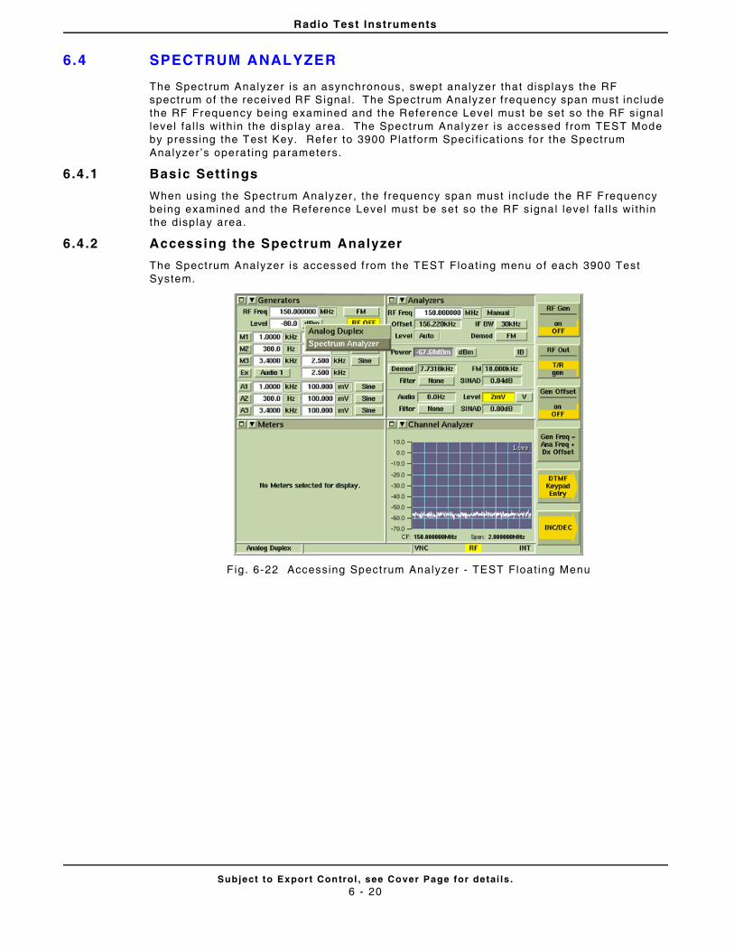
Radio Test Instruments
Subject to Export Control , see Cover Page for detai ls .6 - 20
6.4 SPECTRUM ANALYZER
The Spectrum Analyzer is an asynchronous, swept analyzer that displays the RF spectrum of the received RF Signal . The Spectrum Analyzer f requency span must include the RF Frequency being examined and the Reference Level must be set so the RF signal level fa l ls wi thin the disp lay area. The Spectrum Analyzer is accessed f rom TEST Mode by pressing the Test Key. Refer to 3900 Plat form Speci f icat ions for the Spectrum Analyzer ’s operat ing parameters.
6.4 .1 Basic Sett ings
When using the Spectrum Analyzer , the f requency span must include the RF Frequency being examined and the Reference Level must be set so the RF signal level fa l ls wi thin the display area.
6.4 .2 Accessing the Spectrum Analyzer
The Spectrum Analyzer is accessed f rom the TEST Float ing menu of each 3900 Test System.
Fig. 6-22 Accessing Spectrum Analyzer - TEST Float ing Menu
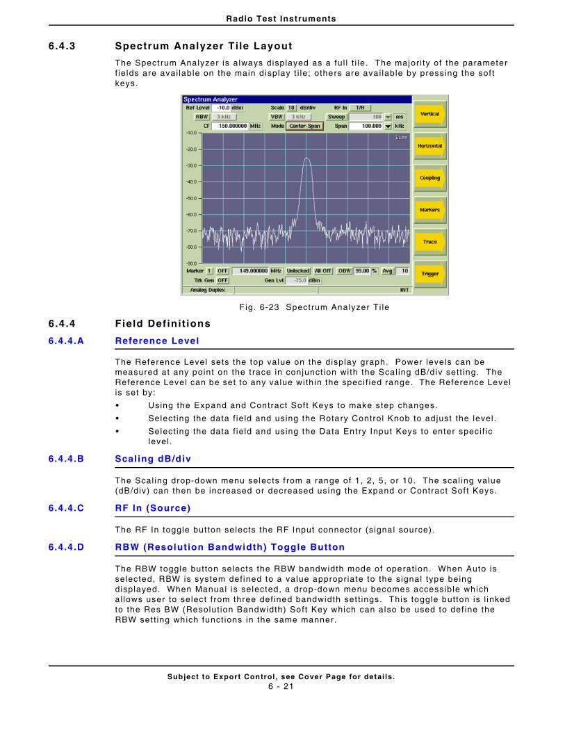
Radio Test Instruments
Subject to Export Control , see Cover Page for detai ls .6 - 21
6.4 .3 Spectrum Analyzer Tile Layout
The Spectrum Analyzer is always displayed as a ful l t i le . The major i ty of the parameter f ie lds are avai lable on the main d isplay t i le; others are ava i lable by pressing the sof t keys.
F ig. 6-23 Spectrum Analyzer Ti le
6.4 .4 Field Definit ions
6.4.4.A Reference Level
The Reference Level sets the top value on the display graph. Power levels can be measured at any point on the t race in conjunct ion with the Scal ing dB/d iv sett ing. The Reference Level can be set to any value with in the speci f ied range. The Reference Level is set by:
• Using the Expand and Contract Soft Keys to make step changes.
• Select ing the data f ie ld and using the Rotary Control Knob to adjust the level .
• Select ing the data f ie ld and using the Data Entry Input Keys to enter speci f ic level .
6.4.4.B Scaling dB/div
The Scal ing drop-down menu selects f rom a range of 1, 2, 5, or 10. The scal ing value (dB/div) can then be increased or decreased using the Expand or Contract Sof t Keys.
6.4.4.C RF In (Source)
The RF In toggle but ton se lects the RF Input connector (s ignal source).
6.4.4.D RBW (Resolution Bandwidth) Toggle Button
The RBW toggle button selects the RBW bandwidth mode of operat ion. When Auto is selected, RBW is system def ined to a value appropriate to the signal type being displayed. When Manual is selected, a drop-down menu becomes accessible which al lows user to select f rom three def ined bandwidth set t ings. This toggle button is l inked to the Res BW (Resolut ion Bandwidth) Soft Key which can also be used to def ine the RBW set t ing which funct ions in the same manner.
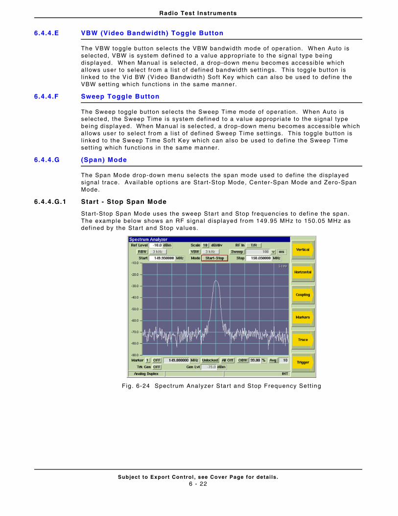
Radio Test Instruments
Subject to Export Control , see Cover Page for detai ls .6 - 22
6.4.4.E VBW (Video Bandwidth) Toggle Button
The VBW toggle button selects the VBW bandwidth mode of operat ion. When Auto is selected, VBW is system def ined to a va lue appropr iate to the signal type being displayed. When Manual is selected, a drop-down menu becomes accessible which al lows user to select f rom a l ist of def ined bandwidth sett ings. This toggle but ton is l inked to the Vid BW (Video Bandwidth) Soft Key which can a lso be used to def ine the VBW set t ing which funct ions in the same manner.
6.4.4.F Sweep Toggle Button
The Sweep toggle button selects the Sweep Time mode of operat ion. When Auto is selected, the Sweep Time is system def ined to a va lue appropr iate to the signal type being displayed. When Manual is selected, a drop-down menu becomes accessible which al lows user to select f rom a l ist of def ined Sweep Time set t ings. Th is toggle button is l inked to the Sweep Time Soft Key which can also be used to def ine the Sweep Time sett ing which funct ions in the same manner.
6.4.4.G (Span) Mode
The Span Mode drop-down menu selects the span mode used to def ine the displayed signal t race. Avai lable opt ions are Start-Stop Mode, Center-Span Mode and Zero-Span Mode.
6.4.4.G.1 Start - Stop Span Mode
Start-Stop Span Mode uses the sweep Start and Stop frequencies to def ine the span. The example below shows an RF signal displayed from 149.95 MHz to 150.05 MHz as def ined by the Start and Stop values.
Fig . 6-24 Spectrum Analyzer Star t and Stop Frequency Sett ing
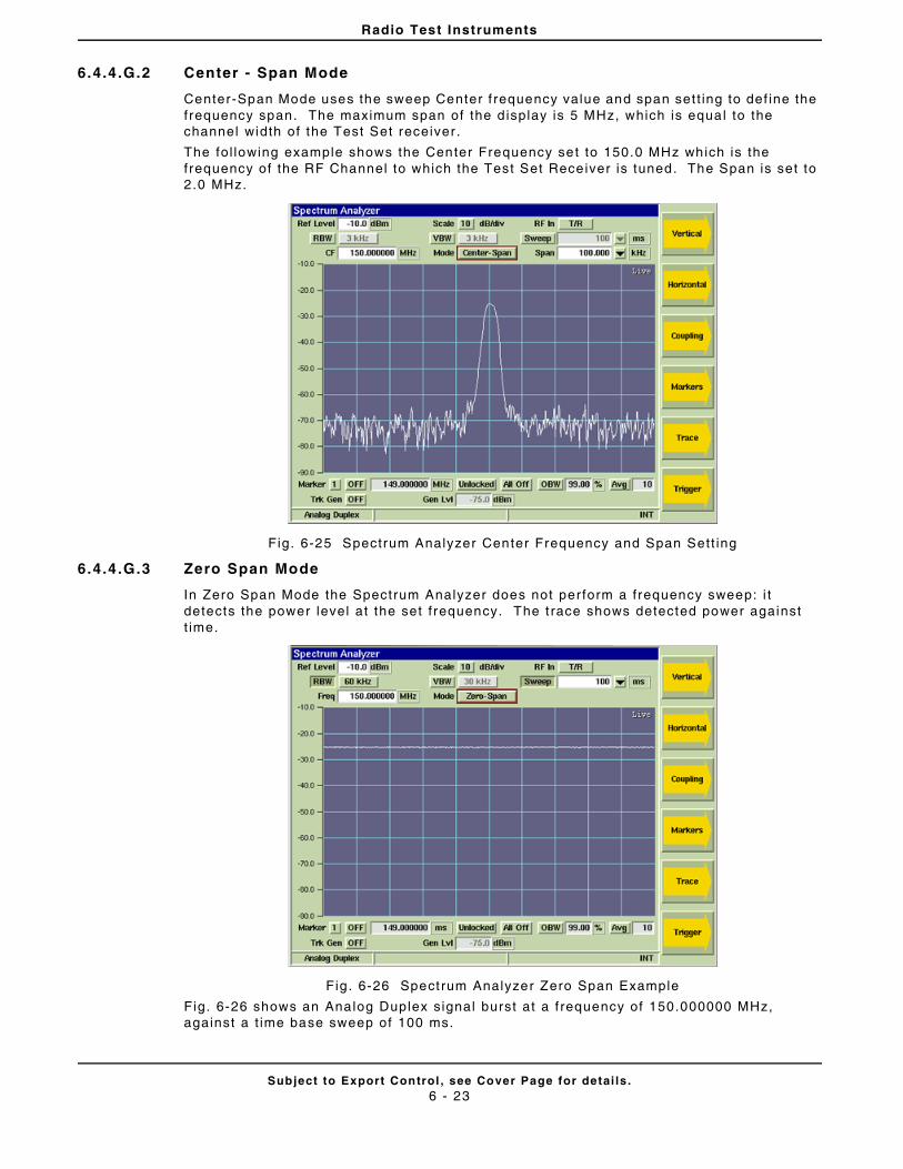
Radio Test Instruments
Subject to Export Control , see Cover Page for detai ls .6 - 23
6.4.4.G.2 Center - Span Mode
Center-Span Mode uses the sweep Center f requency value and span set t ing to def ine the frequency span. The maximum span of the d isplay is 5 MHz, which is equal to the channel width of the Test Set receiver .
The fol lowing example shows the Center Frequency set to 150.0 MHz which is the frequency of the RF Channel to which the Test Set Receiver is tuned. The Span is set to 2.0 MHz.
Fig. 6-25 Spectrum Analyzer Center Frequency and Span Sett ing
6.4.4.G.3 Zero Span Mode
In Zero Span Mode the Spectrum Analyzer does not per form a frequency sweep: i t detects the power level at the set f requency. The t race shows detected power against t ime.
Fig . 6-26 Spectrum Analyzer Zero Span Example
Fig. 6-26 shows an Analog Duplex signal burst at a f requency of 150.000000 MHz, against a t ime base sweep of 100 ms.
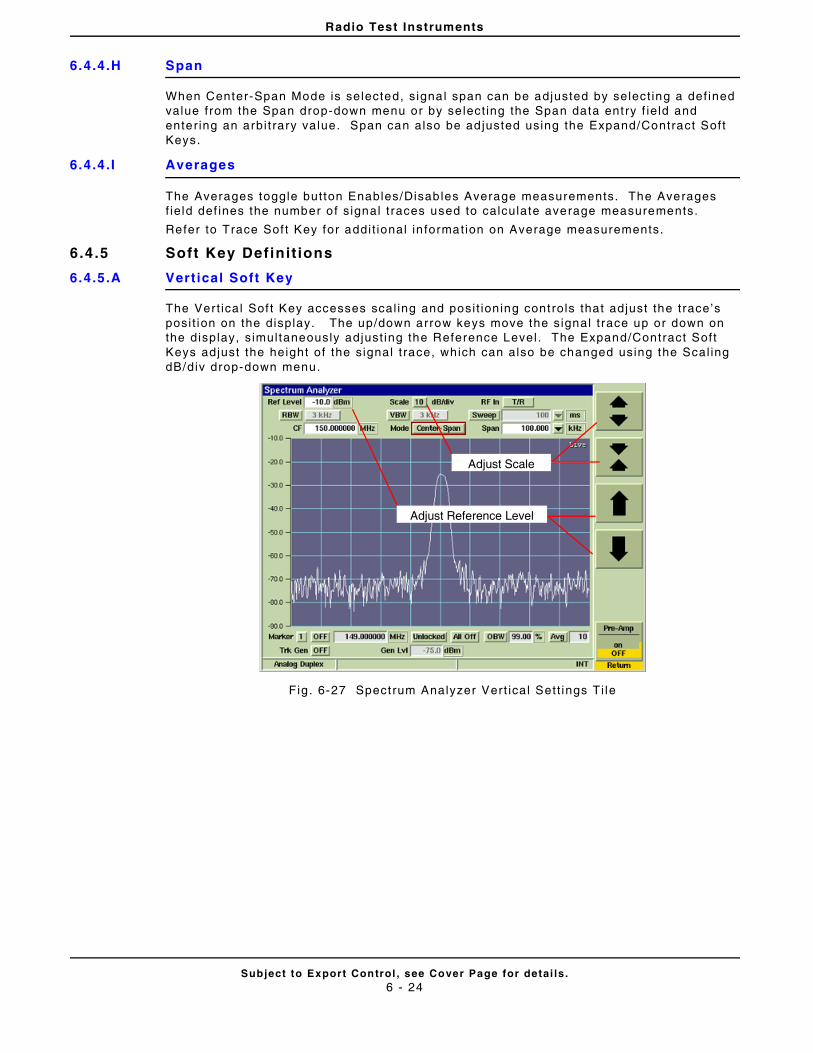
Radio Test Instruments
Subject to Export Control , see Cover Page for detai ls .6 - 24
6.4.4.H Span
When Center-Span Mode is selected, s ignal span can be adjusted by select ing a def ined value from the Span drop-down menu or by se lect ing the Span data ent ry f ie ld and enter ing an arbi t rary value. Span can also be ad justed using the Expand/Contract Soft Keys.
6.4.4.I Averages
The Averages toggle button Enables/Disables Average measurements. The Averages f ie ld def ines the number o f s ignal t races used to calculate average measurements.
Refer to Trace Sof t Key for addi t ional in formation on Average measurements.
6.4 .5 Soft Key Definit ions
6.4.5.A Vertical Soft Key
The Vert ical Sof t Key accesses scal ing and posi t ioning controls that adjust the trace’s posi t ion on the display. The up/down arrow keys move the signal t race up or down on the display, s imultaneously adjust ing the Reference Level . The Expand/Contract Soft Keys adjust the height of the signal t race, which can also be changed using the Scal ing dB/div drop-down menu.
Fig . 6-27 Spectrum Analyzer Vert ical Sett ings Ti le
Adjust Reference Level
Adjust Scale
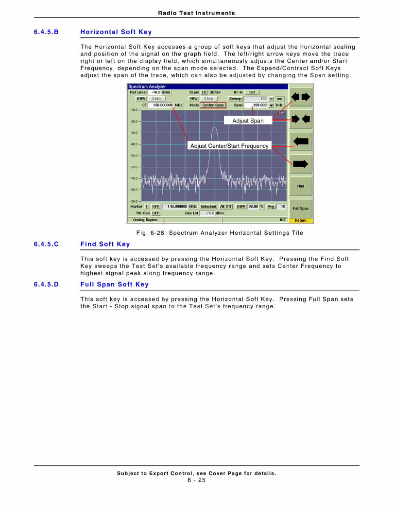
Radio Test Instruments
Subject to Export Control , see Cover Page for detai ls .6 - 25
6.4.5.B Horizontal Soft Key
The Hor izontal Soft Key accesses a group of soft keys that ad just the hor izontal scal ing and posi t ion of the signal on the graph f ie ld. The lef t / r ight arrow keys move the trace r ight or lef t on the display f ie ld, which simultaneously ad justs the Center and/or Start Frequency, depending on the span mode selected. The Expand/Contract Sof t Keys adjust the span of the t race, which can also be adjusted by changing the Span set t ing.
Fig. 6-28 Spectrum Analyzer Horizontal Sett ings T i le
6.4.5.C Find Soft Key
This soft key is accessed by pressing the Horizontal Soft Key. Pressing the Find Soft Key sweeps the Test Set ’s avai lable f requency range and sets Center Frequency to highest s ignal peak along frequency range.
6.4.5.D Ful l Span Soft Key
This soft key is accessed by pressing the Horizontal Soft Key. Pressing Ful l Span sets the Start - Stop signal span to the Test Set ’s f requency range.
Adjust Center/Start Frequency
Adjust Span
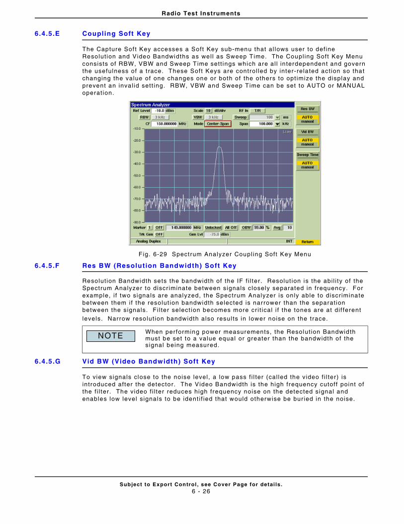
Radio Test Instruments
Subject to Export Control , see Cover Page for detai ls .6 - 26
6.4.5.E Coupling Soft Key
The Capture Sof t Key accesses a Soft Key sub-menu that al lows user to def ine Resolut ion and Video Bandwidths as wel l as Sweep Time. The Coupl ing Soft Key Menu consists of RBW, VBW and Sweep Time sett ings which are al l in terdependent and govern the usefulness of a t race. These Soft Keys are control led by inter- rela ted act ion so that changing the value of one changes one or both of the others to opt imize the display and prevent an inval id sett ing. RBW, VBW and Sweep Time can be set to AUTO or MANUAL operat ion.
F ig. 6-29 Spectrum Analyzer Coupl ing Soft Key Menu
6.4.5.F Res BW (Resolution Bandwidth) Soft Key
Resolut ion Bandwidth sets the bandwidth of the IF f i l ter . Resolut ion is the abi l i ty of the Spectrum Analyzer to discr iminate between signals c losely separated in f requency. For example, i f two signals are analyzed, the Spectrum Analyzer is on ly able to discr iminate between them i f the resolut ion bandwidth se lected is narrower than the separat ion between the signals. Fi l ter select ion becomes more cr i t ical i f the tones are at di f ferent
levels. Narrow reso lut ion bandwidth also resul ts in lower noise on the trace.
6.4.5.G Vid BW (Video Bandwidth) Soft Key
To view signals close to the noise level , a low pass f i l ter (cal led the video f i l ter) is introduced after the detector. The Video Bandwidth is the high frequency cutoff point of the f i l ter . The video f i l ter reduces high frequency noise on the detected signal and enables low level s ignals to be ident i f ied that would otherwise be bur ied in the noise.
When per forming power measurements, the Resolut ion Bandwidth must be set to a value equal or greater than the bandwidth of the signal being measured.
NOTE
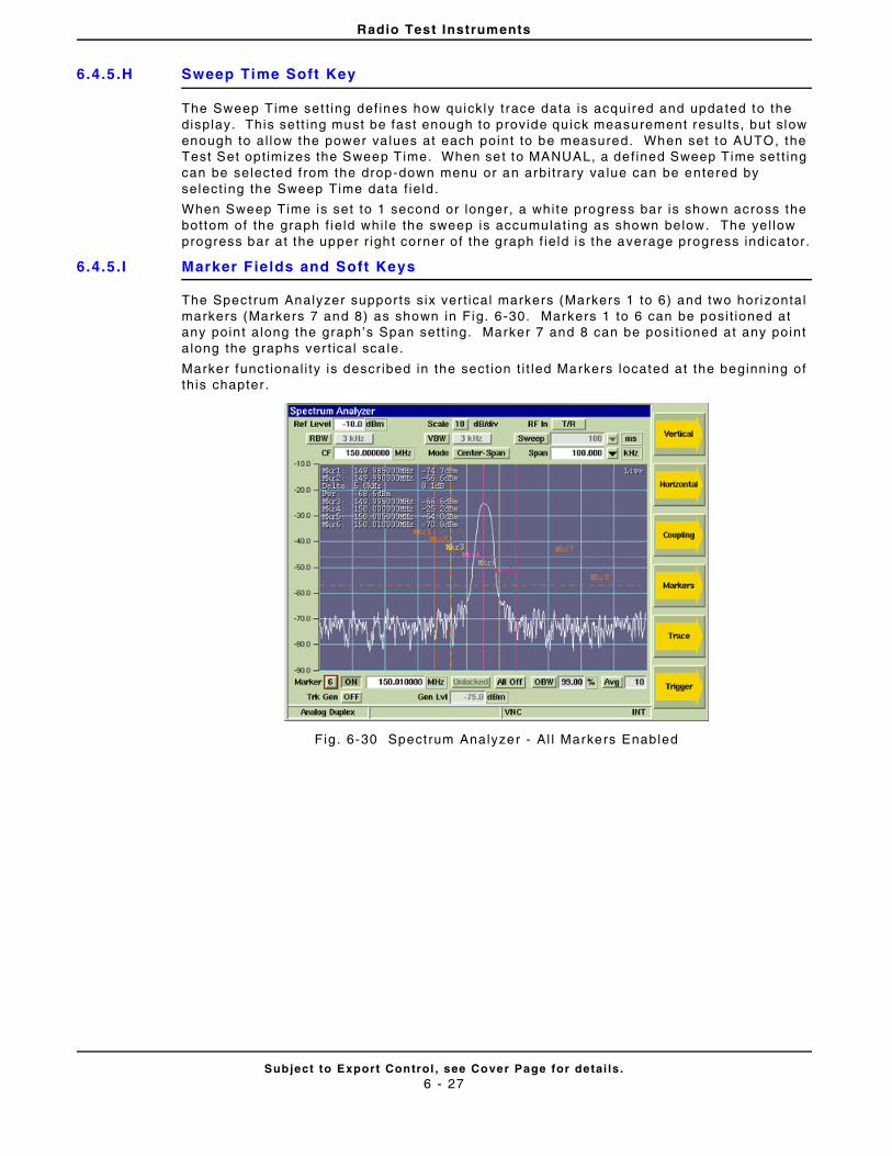
Radio Test Instruments
Subject to Export Control , see Cover Page for detai ls .6 - 27
6.4.5.H Sweep Time Soft Key
The Sweep Time set t ing def ines how quickly t race data is acquired and updated to the display. This sett ing must be fast enough to provide qu ick measurement resul ts, but slow enough to al low the power va lues at each poin t to be measured. When set to AUTO, the Test Set opt imizes the Sweep Time. When set to MANUAL, a def ined Sweep Time set t ing can be selected f rom the drop-down menu or an arbi t rary va lue can be entered by select ing the Sweep Time data f ie ld .
When Sweep Time is set to 1 second or longer, a white progress bar is shown across the bottom of the graph f ie ld whi le the sweep is accumulat ing as shown below. The ye l low progress bar at the upper r ight corner of the graph f ie ld is the average progress indicator.
6.4.5.I Marker Fields and Soft Keys
The Spectrum Analyzer suppor ts s ix ver t ical markers (Markers 1 to 6) and two hor izontal markers (Markers 7 and 8) as shown in Fig. 6-30. Markers 1 to 6 can be posi t ioned at any poin t along the graph’s Span sett ing. Marker 7 and 8 can be posi t ioned at any point along the graphs ver t ical sca le.
Marker funct ional i ty is descr ibed in the sect ion t i t led Markers located at the beginning of th is chapter .
Fig . 6-30 Spectrum Analyzer - Al l Markers Enabled
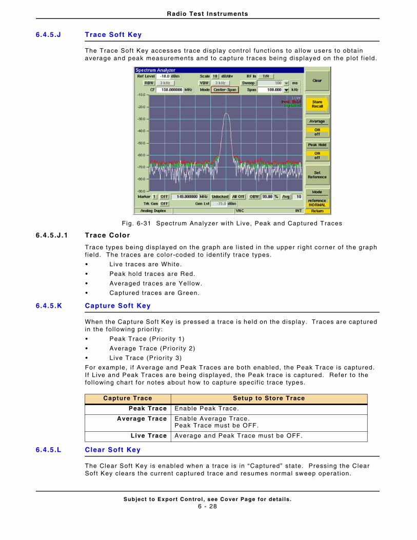
Radio Test Instruments
Subject to Export Control , see Cover Page for detai ls .6 - 28
6.4.5.J Trace Soft Key
The Trace Soft Key accesses trace disp lay control funct ions to al low users to obtain average and peak measurements and to capture t races being displayed on the p lot f ie ld.
Fig. 6-31 Spectrum Analyzer with Live, Peak and Captured Traces
6.4.5.J.1 Trace Color
Trace types being disp layed on the graph are l isted in the upper r ight corner of the graph f ie ld. The t races are color-coded to ident i fy t race types.
• Live t races are White.
• Peak hold traces are Red.
• Averaged traces are Yel low.
• Captured t races are Green.
6.4.5.K Capture Soft Key
When the Capture Sof t Key is pressed a t race is held on the d isplay. Traces are captured in the fol lowing pr ior i ty:
• Peak Trace (Pr ior i ty 1)
• Average Trace (Pr ior i ty 2)
• Live Trace (Pr ior i ty 3)
For example, i f Average and Peak Traces are both enabled, the Peak Trace is captured. I f L ive and Peak Traces are being d isplayed, the Peak trace is captured. Refer to the fol lowing char t for notes about how to capture speci f ic t race types.
6.4.5.L Clear Soft Key
The Clear Soft Key is enabled when a t race is in “Captured” state. Pressing the Clear Sof t Key clears the current captured trace and resumes normal sweep operat ion.
Capture Trace Setup to Store Trace
Peak Trace Enable Peak Trace.
Average Trace Enable Average Trace.Peak Trace must be OFF.
Live Trace Average and Peak Trace must be OFF.
Radio Test Instruments
Subject to Export Control , see Cover Page for detai ls .6 - 29
6.4.5.M Store Trace Soft Key
The Store Trace Sof t Keys al lows a user to store a signal t race. I f more than one type of t race is enabled the traces are stored in the fo l lowing pr ior i ty:
• Captured Trace (Pr ior i ty 1)
• Peak Trace (Pr ior i ty 2)
• Average Trace (Pr ior i ty 3)
• Live Trace (Pr ior i ty 4)
For example, i f Average and Peak Traces are both enabled and a t race has been captured, the Captured Trace is stored. I f Average and Peak Traces are being displayed, the Peak trace is stored. Refer to the fol lowing chart for notes about how to store speci f ic t race types.
6.4.5.N Recal l Trace Soft Key
The Recal l Trace Soft Key opens a dialog box that al lows the user to load stored signal t race.
6.4.5.O Peak Hold Soft Key
When Peak Hold ON is se lected, the maximum value at each frequency point is disp layed to produce the RED Max Hold t race. This t race is c leared by select ing Peak Hold OFF. Peak Hold must be reset ( toggled ON/OFF) when Average readings are Enabled/Disabled. The white Live trace is also displayed and can be averaged depending on the current sett ing. This soft key is accessed by pressing the Trace Soft Key.
6.4.5.P Set Reference Soft Key
When the Set Reference Soft Key is pressed, the Test Set stores current t race data which is used to establ ish a reference t race when Reference Mode is selected. This soft key is accessed by pressing the Trace Soft Key.
6.4.5.Q Trace Mode Soft Key
Selects Normal or Reference trace mode of operat ion for the analyzer t race. When Reference Mode is selected, the Test Set uses the last stored trace re ference ( refer to Set Reference Soft Key) to establ ish a frequency response of the character ist ics of the cabl ing and test setup. This response is used as a reference for the act ive trace being displayed on the Spectrum Analyzer Ti le. This soft key is accessed by pressing the Trace Soft Key.
Trace Type Setup to Store Trace
Captured Trace Capture Trace must be engaged.
Peak Trace Enable Peak Trace.Clear any Captured Trace.
Average Trace Enable Average Trace.Peak Trace must be OFF.Clear any Captured Trace.
Live Trace Average and Peak Trace must be OFF.Clear any Captured Trace.
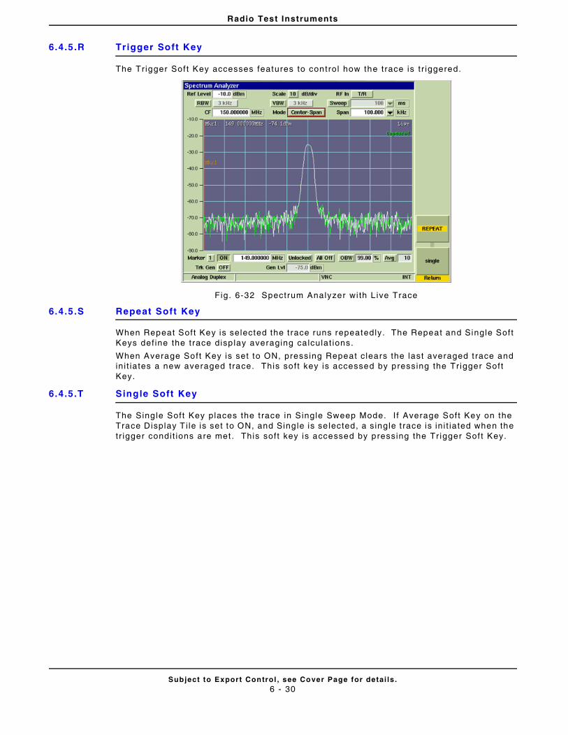
Radio Test Instruments
Subject to Export Control , see Cover Page for detai ls .6 - 30
6.4.5.R Trigger Soft Key
The Tr igger Sof t Key accesses features to control how the trace is t r iggered.
Fig. 6-32 Spectrum Analyzer wi th L ive Trace
6.4.5.S Repeat Soft Key
When Repeat Soft Key is selected the trace runs repeatedly. The Repeat and Single Soft Keys def ine the trace disp lay averaging calculat ions.
When Average Soft Key is set to ON, pressing Repeat c lears the last averaged t race and in i t iates a new averaged trace. This soft key is accessed by pressing the Tr igger Sof t Key.
6.4.5.T Single Soft Key
The Sing le Soft Key places the t race in Single Sweep Mode. I f Average Soft Key on the Trace Display T i le is set to ON, and Sing le is se lected, a s ingle t race is in i t iated when the tr igger condit ions are met . This soft key is accessed by pressing the Tr igger Sof t Key.
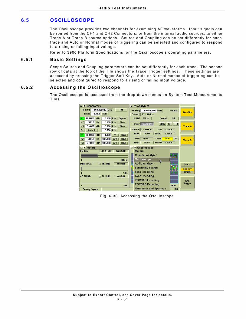
Radio Test Instruments
Subject to Export Control , see Cover Page for detai ls .6 - 31
6.5 OSCILLOSCOPE
The Osci l loscope provides two channels for examining AF waveforms. Input s ignals can be routed from the CH1 and CH2 Connectors, or f rom the interna l audio sources, to ei ther Trace A or Trace B source opt ions. Source and Coupl ing can be set di f ferent ly for each trace and Auto or Normal modes of t r igger ing can be se lected and conf igured to respond to a r is ing or fa l l ing input vol tage.
Refer to 3900 Plat form Speci f icat ions for the Osci l loscope’s operat ing parameters.
6.5 .1 Basic Sett ings
Scope Source and Coupl ing parameters can be set di f ferent ly for each trace. The second row of data at the top of the T i le shows the Trace Tr igger sett ings. These sett ings are accessed by pressing the Tr igger Soft Key. Auto or Normal modes of t r igger ing can be selected and conf igured to respond to a r is ing or fa l l ing input vol tage.
6.5 .2 Accessing the Oscil loscope
The Osci l loscope is accessed from the drop-down menus on System Test Measurements Ti les.
Fig. 6-33 Accessing the Osci l loscope
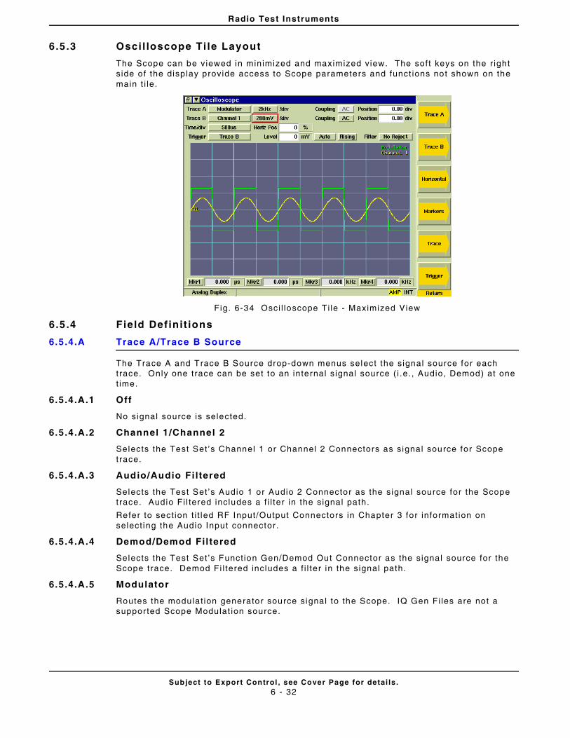
Radio Test Instruments
Subject to Export Control , see Cover Page for detai ls .6 - 32
6.5 .3 Osci l loscope Ti le Layout
The Scope can be viewed in minimized and maximized view. The soft keys on the r ight s ide of the disp lay provide access to Scope parameters and funct ions not shown on the main t i le.
Fig. 6-34 Osci l loscope T i le - Maximized View
6.5 .4 Field Definit ions
6.5.4.A Trace A/Trace B Source
The Trace A and Trace B Source drop-down menus select the signal source for each trace. Only one trace can be set to an internal s ignal source ( i .e. , Audio, Demod) at one t ime.
6.5.4.A.1 Off
No signal source is selected.
6.5.4.A.2 Channel 1/Channel 2
Selects the Test Set ’s Channel 1 or Channel 2 Connectors as signal source for Scope trace.
6.5.4.A.3 Audio/Audio Fi ltered
Selects the Test Set ’s Audio 1 or Audio 2 Connector as the signal source for the Scope trace. Audio Fi l tered includes a f i l ter in the signal path.
Refer to sect ion t i t led RF Input/Output Connectors in Chapter 3 for information on select ing the Audio Input connector.
6.5.4.A.4 Demod/Demod Fil tered
Selects the Test Set ’s Funct ion Gen/Demod Out Connector as the signal source for the Scope trace. Demod Fi l tered includes a f i l ter in the signal path.
6.5.4.A.5 Modulator
Routes the modulat ion generator source signal to the Scope. IQ Gen Fi les are not a suppor ted Scope Modulat ion source.
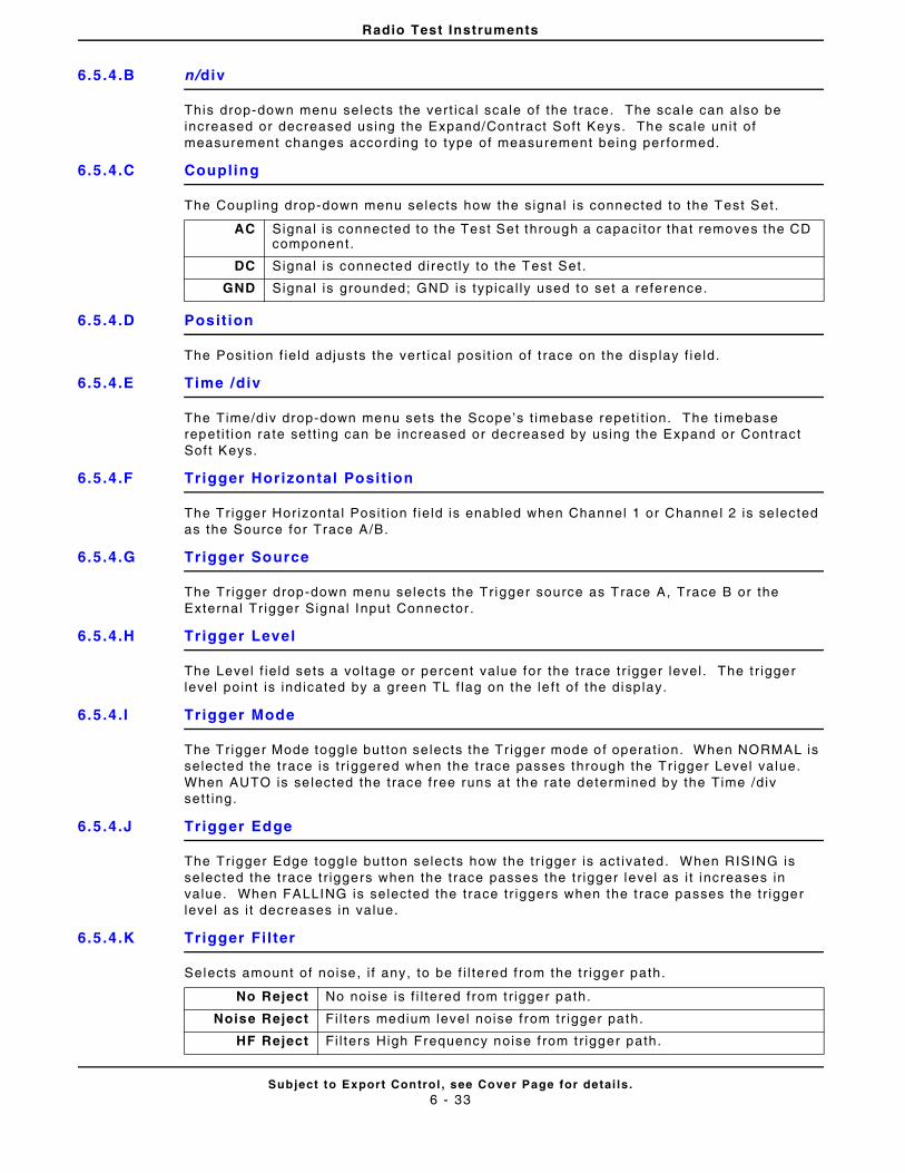
Radio Test Instruments
Subject to Export Control , see Cover Page for detai ls .6 - 33
6.5.4.B n/div
This drop-down menu selects the vert ical scale of the trace. The scale can also be increased or decreased using the Expand/Contract Soft Keys. The scale uni t of measurement changes according to type of measurement being per formed.
6.5.4.C Coupling
The Coupl ing drop-down menu selects how the signal is connected to the Test Set.
6.5.4.D Posit ion
The Posi t ion f ie ld adjusts the vert ical posi t ion of t race on the disp lay f ie ld.
6.5.4.E Time /div
The Time/d iv drop-down menu sets the Scope’s t imebase repet i t ion. The t imebase repet i t ion rate sett ing can be increased or decreased by using the Expand or Contract Sof t Keys.
6.5.4.F Trigger Horizontal Posit ion
The Tr igger Horizontal Posi t ion f ie ld is enabled when Channel 1 or Channel 2 is se lected as the Source for Trace A/B.
6.5.4.G Trigger Source
The Tr igger drop-down menu selects the Tr igger source as Trace A, Trace B or the External Tr igger Signal Input Connector .
6.5.4.H Trigger Level
The Level f ie ld sets a vol tage or percent value for the trace tr igger level . The t r igger level point is ind icated by a green TL f lag on the le f t of the disp lay.
6.5.4.I Tr igger Mode
The Trigger Mode toggle button se lects the Tr igger mode of operat ion. When NORMAL is selected the trace is t r iggered when the t race passes through the Tr igger Level value. When AUTO is se lected the trace free runs at the rate determined by the Time /div sett ing.
6.5.4.J Trigger Edge
The Tr igger Edge toggle button selects how the tr igger is act ivated. When RISING is selected the trace t r iggers when the trace passes the t r igger level as i t increases in value. When FALLING is selected the trace tr iggers when the t race passes the t r igger level as i t decreases in value.
6.5.4.K Trigger Fil ter
Selects amount of noise, i f any, to be f i l tered f rom the t r igger path.
AC Signal is connected to the Test Set through a capaci tor that removes the CD component.
DC Signal is connected direct ly to the Test Set.
GND Signal is grounded; GND is typical ly used to set a reference.
No Reject No noise is f i l tered from t r igger path.
Noise Reject Fi l ters medium leve l noise from tr igger path.
HF Reject Fi l ters High Frequency noise f rom t r igger path.
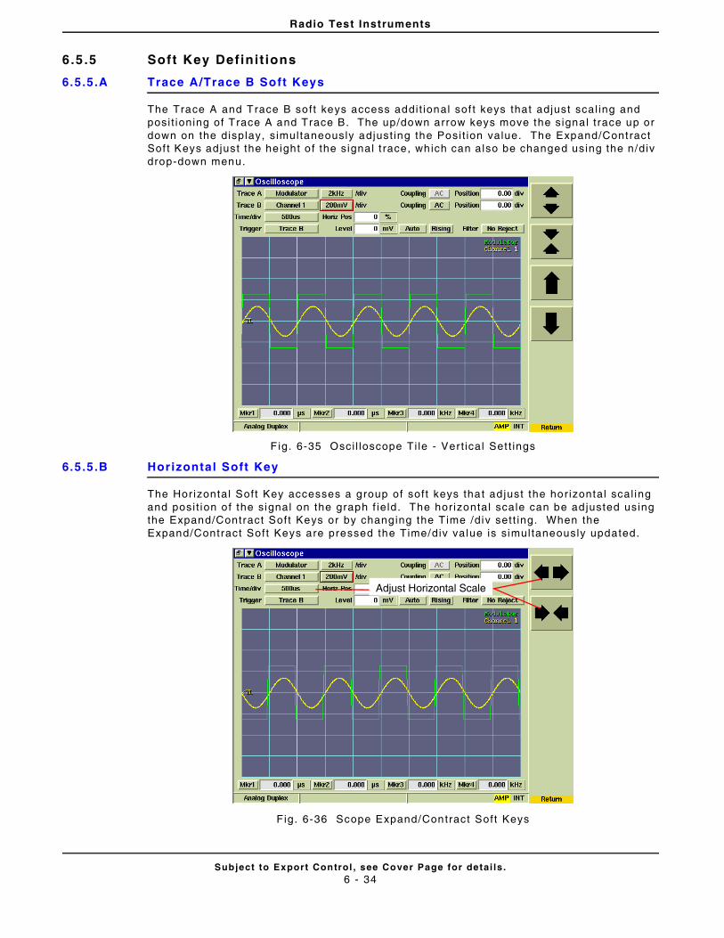
Radio Test Instruments
Subject to Export Control , see Cover Page for detai ls .6 - 34
6.5 .5 Soft Key Definit ions
6.5.5.A Trace A/Trace B Soft Keys
The Trace A and Trace B soft keys access addi t ional sof t keys that adjust scal ing and posi t ioning of Trace A and Trace B. The up/down arrow keys move the signal t race up or down on the display, s imultaneously adjust ing the Posi t ion value. The Expand/Contract Sof t Keys adjust the he ight o f the signal t race, which can also be changed using the n/div drop-down menu.
Fig. 6-35 Osci l loscope Ti le - Ver t ical Set t ings
6.5.5.B Horizontal Soft Key
The Hor izontal Soft Key accesses a group of soft keys that ad just the hor izontal scal ing and posi t ion of the signal on the graph f ie ld. The hor izontal scale can be ad justed using the Expand/Contract Soft Keys or by changing the T ime /div sett ing. When the Expand/Contract Soft Keys are pressed the Time/div value is simultaneously updated.
Fig. 6-36 Scope Expand/Contract Soft Keys
Adjust Horizontal Scale
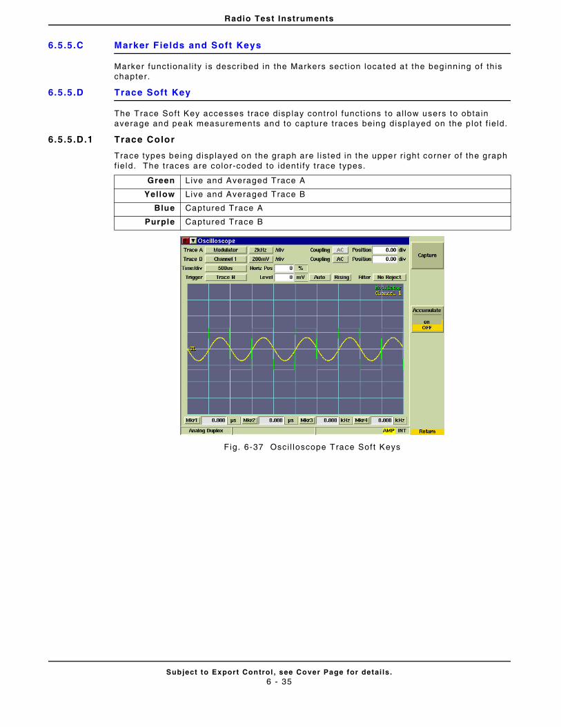
Radio Test Instruments
Subject to Export Control , see Cover Page for detai ls .6 - 35
6.5.5.C Marker Fields and Soft Keys
Marker funct ional i ty is descr ibed in the Markers sect ion located at the beginning of th is chapter.
6.5.5.D Trace Soft Key
The Trace Soft Key accesses trace disp lay control funct ions to al low users to obtain average and peak measurements and to capture t races being displayed on the p lot f ie ld.
6.5.5.D.1 Trace Color
Trace types being disp layed on the graph are l isted in the upper r ight corner of the graph f ie ld. The t races are color-coded to ident i fy t race types.
Fig. 6-37 Osci l loscope Trace Sof t Keys
Green Live and Averaged Trace A
Yellow Live and Averaged Trace B
Blue Captured Trace A
Purple Captured Trace B
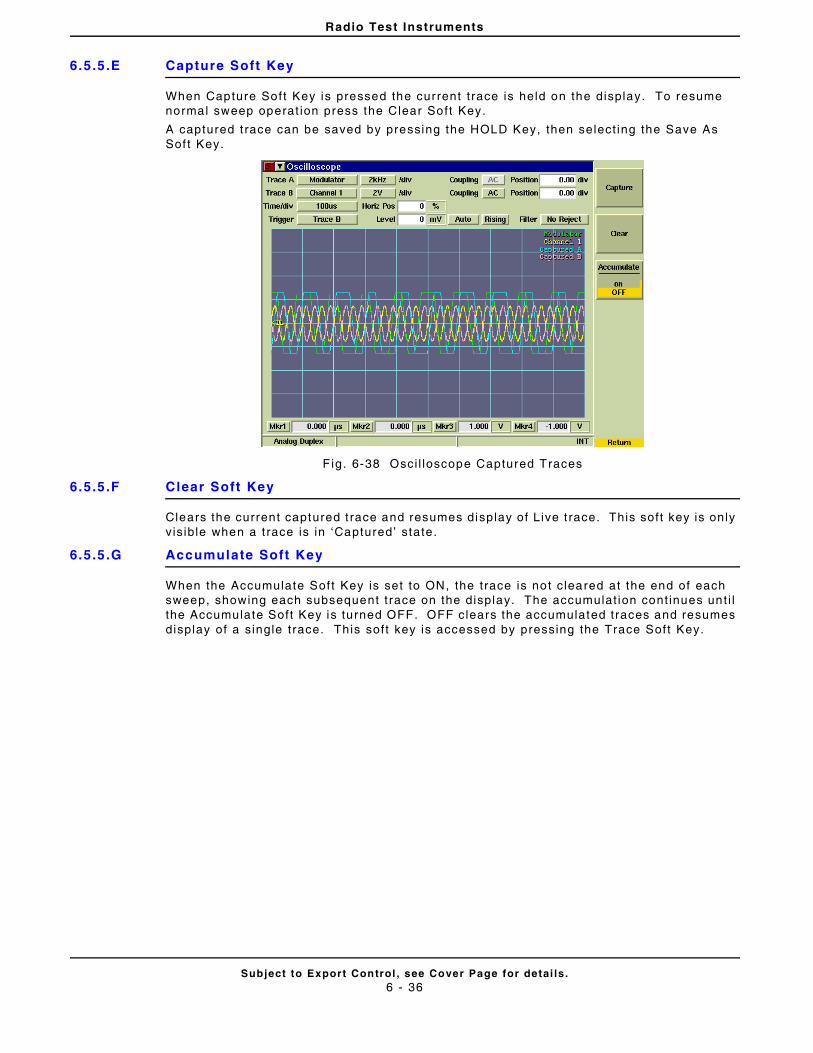
Radio Test Instruments
Subject to Export Control , see Cover Page for detai ls .6 - 36
6.5.5.E Capture Soft Key
When Capture Soft Key is pressed the current t race is held on the display. To resume normal sweep operat ion press the Clear Soft Key.
A captured t race can be saved by pressing the HOLD Key, then select ing the Save As Sof t Key.
F ig. 6-38 Osci l loscope Captured Traces
6.5.5.F Clear Soft Key
Clears the current captured t race and resumes display of Live t race. This soft key is only v is ible when a t race is in ‘Captured’ state.
6.5.5.G Accumulate Soft Key
When the Accumulate Soft Key is set to ON, the trace is not c leared at the end of each sweep, showing each subsequent t race on the display. The accumulat ion cont inues unt i l the Accumulate Soft Key is turned OFF. OFF clears the accumulated traces and resumes display of a s ingle t race. This soft key is accessed by pressing the Trace Soft Key.
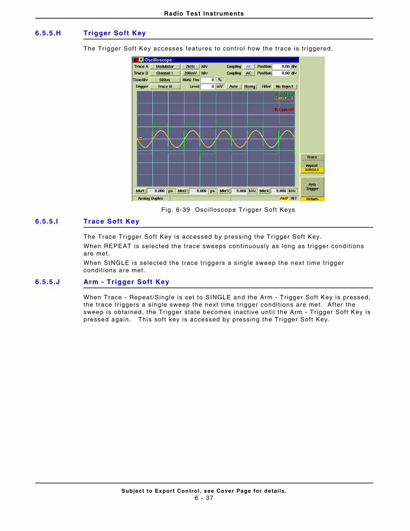
Radio Test Instruments
Subject to Export Control , see Cover Page for detai ls .6 - 37
6.5.5.H Trigger Soft Key
The Tr igger Sof t Key accesses features to control how the trace is t r iggered.
Fig. 6-39 Osci l loscope Tr igger Soft Keys
6.5.5.I Trace Soft Key
The Trace Tr igger Soft Key is accessed by pressing the Tr igger Soft Key.
When REPEAT is selected the t race sweeps cont inuously as long as tr igger condit ions are met.
When SINGLE is selected the t race tr iggers a sing le sweep the next t ime tr igger condi t ions are met .
6.5.5.J Arm - Trigger Soft Key
When Trace - Repeat/Single is set to SINGLE and the Arm - Tr igger Soft Key is pressed, the trace tr iggers a single sweep the next t ime t r igger condit ions are met. After the sweep is obta ined, the Tr igger state becomes inact ive unt i l the Arm - Tr igger Soft Key is pressed again. This soft key is accessed by pressing the Tr igger Soft Key.
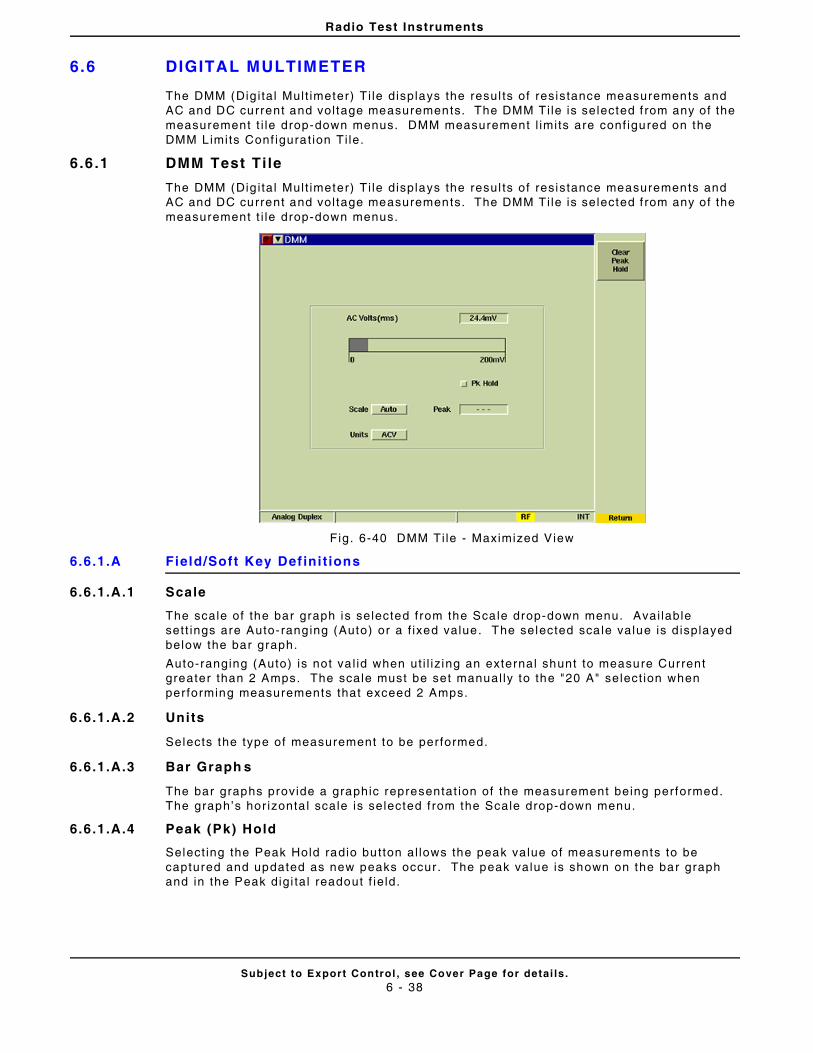
Radio Test Instruments
Subject to Export Control , see Cover Page for detai ls .6 - 38
6.6 DIGITAL MULTIMETER
The DMM (Dig i ta l Mult imeter) Ti le displays the resul ts of resistance measurements and AC and DC current and vol tage measurements. The DMM Ti le is selected f rom any of the measurement t i le drop-down menus. DMM measurement l imits are conf igured on the DMM Limits Conf igurat ion Ti le.
6.6 .1 DMM Test Ti le
The DMM (Dig i ta l Mult imeter) Ti le displays the resul ts of resistance measurements and AC and DC current and vol tage measurements. The DMM Ti le is selected f rom any of the measurement t i le drop-down menus.
Fig. 6-40 DMM Ti le - Maximized View
6.6.1.A Field/Soft Key Def ini t ions
6.6.1.A.1 Scale
The scale of the bar graph is selected from the Scale drop-down menu. Avai lable sett ings are Auto-ranging (Auto) or a f ixed value. The selected sca le value is d isplayed below the bar graph.
Auto-ranging (Auto) is not va l id when ut i l iz ing an external shunt to measure Current greater than 2 Amps. The scale must be set manual ly to the "20 A" select ion when per forming measurements that exceed 2 Amps.
6.6.1.A.2 Units
Selects the type of measurement to be per formed.
6.6.1.A.3 Bar Graph s
The bar graphs provide a graphic representat ion of the measurement being performed. The graph’s hor izonta l scale is selected f rom the Scale drop-down menu.
6.6.1.A.4 Peak (Pk) Hold
Select ing the Peak Hold radio button al lows the peak value of measurements to be captured and updated as new peaks occur . The peak value is shown on the bar graph and in the Peak digi ta l readout f ie ld.
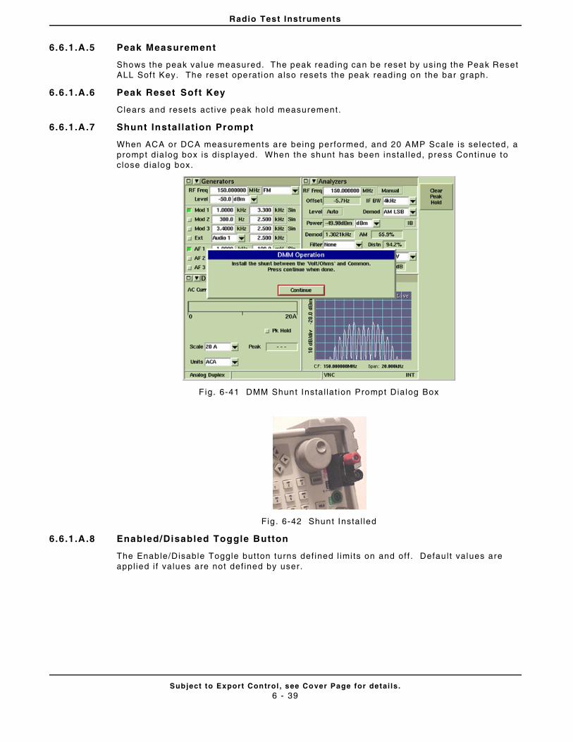
Radio Test Instruments
Subject to Export Control , see Cover Page for detai ls .6 - 39
6.6.1.A.5 Peak Measurement
Shows the peak value measured. The peak reading can be reset by using the Peak Reset ALL Sof t Key. The reset operat ion also resets the peak reading on the bar graph.
6.6.1.A.6 Peak Reset Soft Key
Clears and resets act ive peak hold measurement.
6.6.1.A.7 Shunt Installat ion Prompt
When ACA or DCA measurements are being performed, and 20 AMP Scale is selected, a prompt dia log box is displayed. When the shunt has been instal led, press Cont inue to c lose d ialog box.
F ig. 6-41 DMM Shunt Instal lat ion Prompt Dialog Box
Fig. 6-42 Shunt Instal led
6.6.1.A.8 Enabled/Disabled Toggle Button
The Enable/Disable Toggle but ton turns def ined l imi ts on and off . Defau l t values are appl ied i f values are not def ined by user.
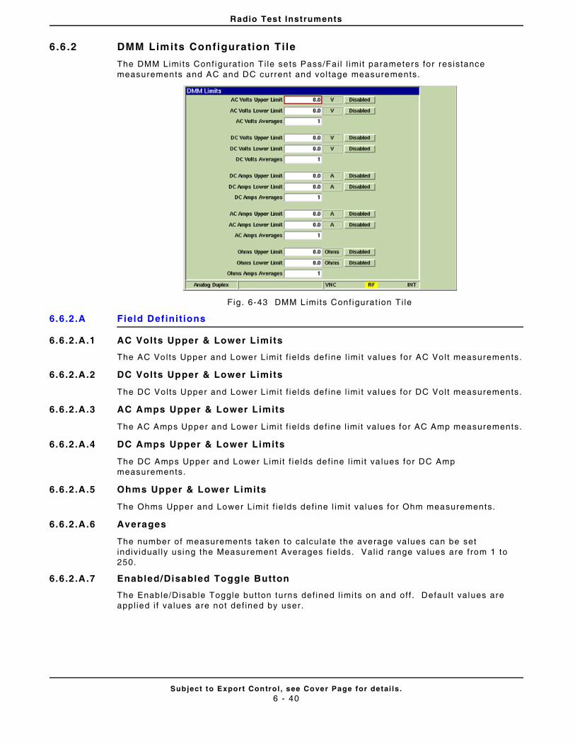
Radio Test Instruments
Subject to Export Control , see Cover Page for detai ls .6 - 40
6.6 .2 DMM Limits Configuration Tile
The DMM Limi ts Conf igurat ion T i le sets Pass/Fai l l imi t parameters for resistance measurements and AC and DC current and vol tage measurements.
Fig . 6-43 DMM Limits Conf igurat ion Ti le
6.6.2.A Field Def ini t ions
6.6.2.A.1 AC Volts Upper & Lower Limits
The AC Volts Upper and Lower Limit f ie lds def ine l imit values for AC Volt measurements.
6.6.2.A.2 DC Volts Upper & Lower Limits
The DC Volts Upper and Lower Limi t f ie lds def ine l imit values for DC Volt measurements.
6.6.2.A.3 AC Amps Upper & Lower Limits
The AC Amps Upper and Lower Limit f ie lds de f ine l imit values for AC Amp measurements.
6.6.2.A.4 DC Amps Upper & Lower Limits
The DC Amps Upper and Lower Limit f ie lds def ine l imit va lues for DC Amp measurements.
6.6.2.A.5 Ohms Upper & Lower Limits
The Ohms Upper and Lower Limit f ie lds def ine l imit values for Ohm measurements.
6.6.2.A.6 Averages
The number of measurements taken to calculate the average values can be set indiv idual ly using the Measurement Averages f ie lds. Val id range values are from 1 to 250.
6.6.2.A.7 Enabled/Disabled Toggle Button
The Enable/Disable Toggle but ton turns def ined l imi ts on and off . Defau l t values are appl ied i f values are not def ined by user.
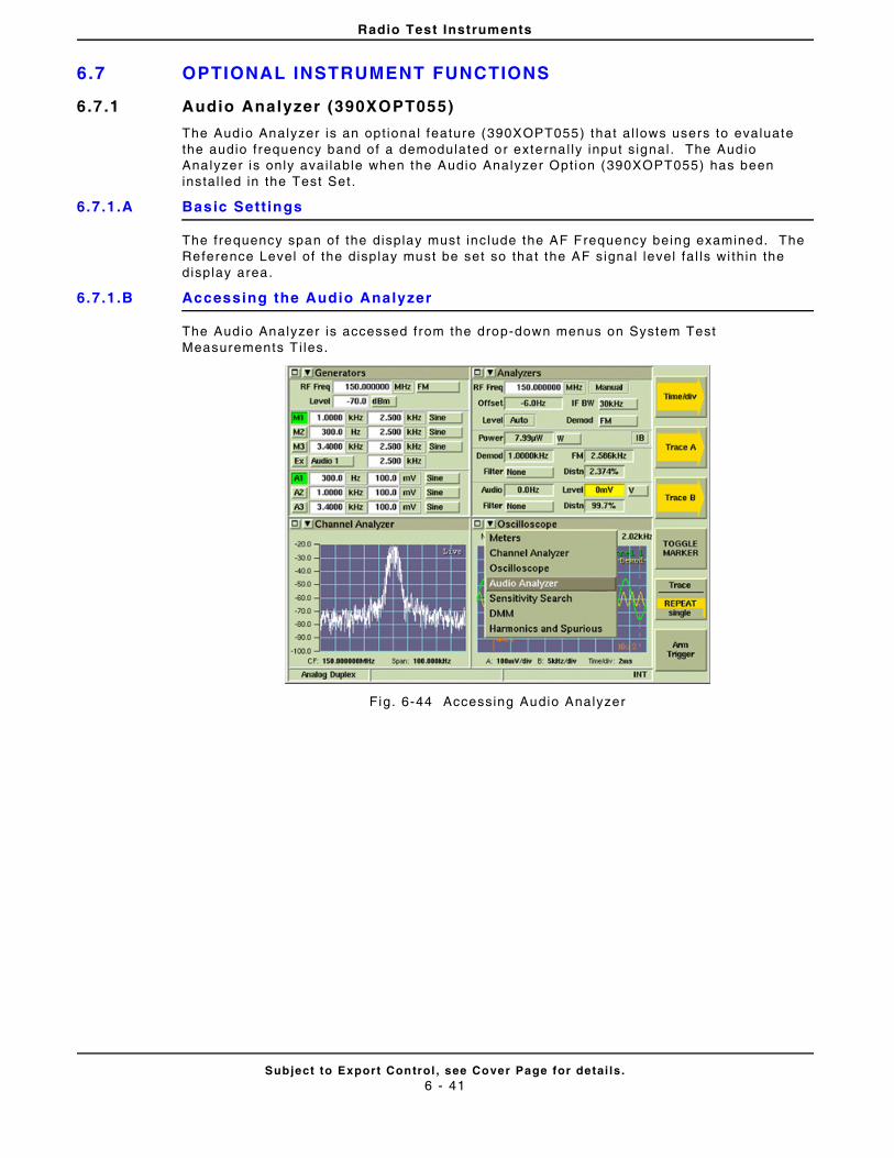
Radio Test Instruments
Subject to Export Control , see Cover Page for detai ls .6 - 41
6.7 OPTIONAL INSTRUMENT FUNCTIONS
6.7.1 Audio Analyzer (390XOPT055)
The Audio Analyzer is an opt ional feature (390XOPT055) that al lows users to evaluate the audio frequency band of a demodulated or externa l ly input s ignal . The Audio Analyzer is only avai lable when the Audio Analyzer Opt ion (390XOPT055) has been instal led in the Test Set .
6.7.1.A Basic Sett ings
The frequency span of the display must include the AF Frequency being examined. The Reference Level of the display must be set so that the AF signal level fa l ls wi thin the display area.
6.7.1.B Accessing the Audio Analyzer
The Audio Analyzer is accessed from the drop-down menus on System Test Measurements T i les.
Fig. 6-44 Accessing Audio Analyzer
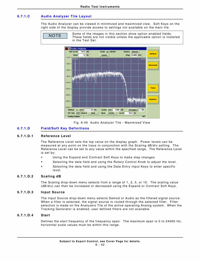
Radio Test Instruments
Subject to Export Control , see Cover Page for detai ls .6 - 42
6.7.1.C Audio Analyzer Ti le Layout
The Audio Analyzer can be viewed in minimized and maximized view. Sof t Keys on the r ight s ide of the display provide access to set t ings not avai lable on the main t i le.
Fig. 6-45 Audio Analyzer T i le - Maximized View
6.7.1.D Field/Soft Key Def ini t ions
6.7.1.D.1 Reference Level
The Reference Level sets the top value on the display graph. Power levels can be measured at any point on the t race in conjunct ion with the Scal ing dB/d iv sett ing. The Reference Level can be set to any value with in the speci f ied range. The Reference Level is set by:
• Using the Expand and Contract Soft Keys to make step changes.
• Select ing the data f ie ld and using the Rotary Control Knob to adjust the level .
• Select ing the data f ie ld and using the Data Entry Input Keys to enter speci f ic level .
6.7.1.D.2 Scaling dB
The Scal ing drop-down menu selects f rom a range of 1, 2, 5, or 10. The scal ing value (dB/div) can then be increased or decreased using the Expand or Contract Sof t Keys.
6.7.1.D.3 Input Source
The Input Source drop-down menu selects Demod or Audio as the f i l tered signal source. When a f i l ter is se lected, the signal source is routed through the selected f i l ter . F i l ter select ion is made on the Analyzers T i le of the act ive operat ing Analog system. When the Tracking Generator is enabled, user def ined f i l ters are not avai lable .
6.7.1.D.4 Start
Defines the star t f requency of the frequency span. The maximum span is 0 to 24000 Hz; hor izontal scale va lues must be with in this range.
Some of the images in this sect ion show opt ion enabled f ie lds. These f ie lds are not v is ib le unless the appl icable opt ion is instal led in the Test Set.
NOTE
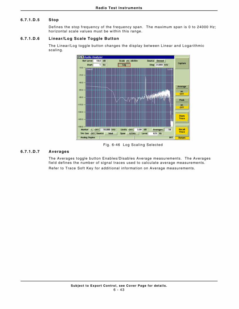
Radio Test Instruments
Subject to Export Control , see Cover Page for detai ls .6 - 43
6.7.1.D.5 Stop
Defines the stop f requency of the frequency span. The maximum span is 0 to 24000 Hz; hor izontal scale va lues must be with in this range.
6.7.1.D.6 Linear/Log Scale Toggle Button
The Linear /Log toggle button changes the display between L inear and Logar i thmic scal ing.
Fig. 6-46 Log Scal ing Selected
6.7.1.D.7 Averages
The Averages toggle button Enables/Disables Average measurements. The Averages f ie ld def ines the number o f s ignal t races used to calculate average measurements.
Refer to Trace Sof t Key for addi t ional in formation on Average measurements.
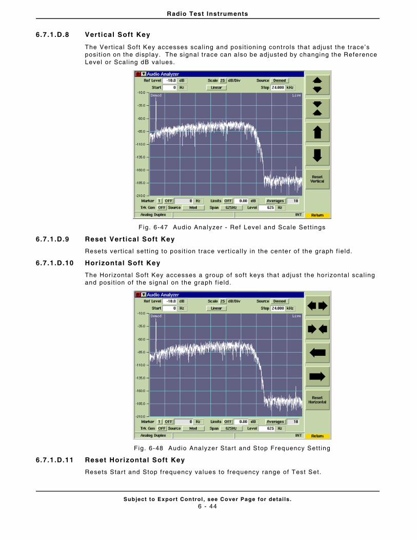
Radio Test Instruments
Subject to Export Control , see Cover Page for detai ls .6 - 44
6.7.1.D.8 Vert ical Soft Key
The Vert ical Sof t Key accesses scal ing and posi t ioning controls that adjust the trace’s posi t ion on the display. The signal t race can also be adjusted by changing the Reference Level or Scal ing dB values.
F ig. 6-47 Audio Analyzer - Ref Level and Scale Set t ings
6.7.1.D.9 Reset Vert ical Soft Key
Resets ver t ical set t ing to posi t ion t race vert ical ly in the center of the graph f ie ld.
6.7.1.D.10 Horizontal Soft Key
The Hor izontal Soft Key accesses a group of soft keys that ad just the hor izontal scal ing and posi t ion of the signal on the graph f ie ld.
Fig. 6-48 Audio Analyzer Star t and Stop Frequency Sett ing
6.7.1.D.11 Reset Horizontal Soft Key
Resets Star t and Stop f requency values to f requency range of Test Set.
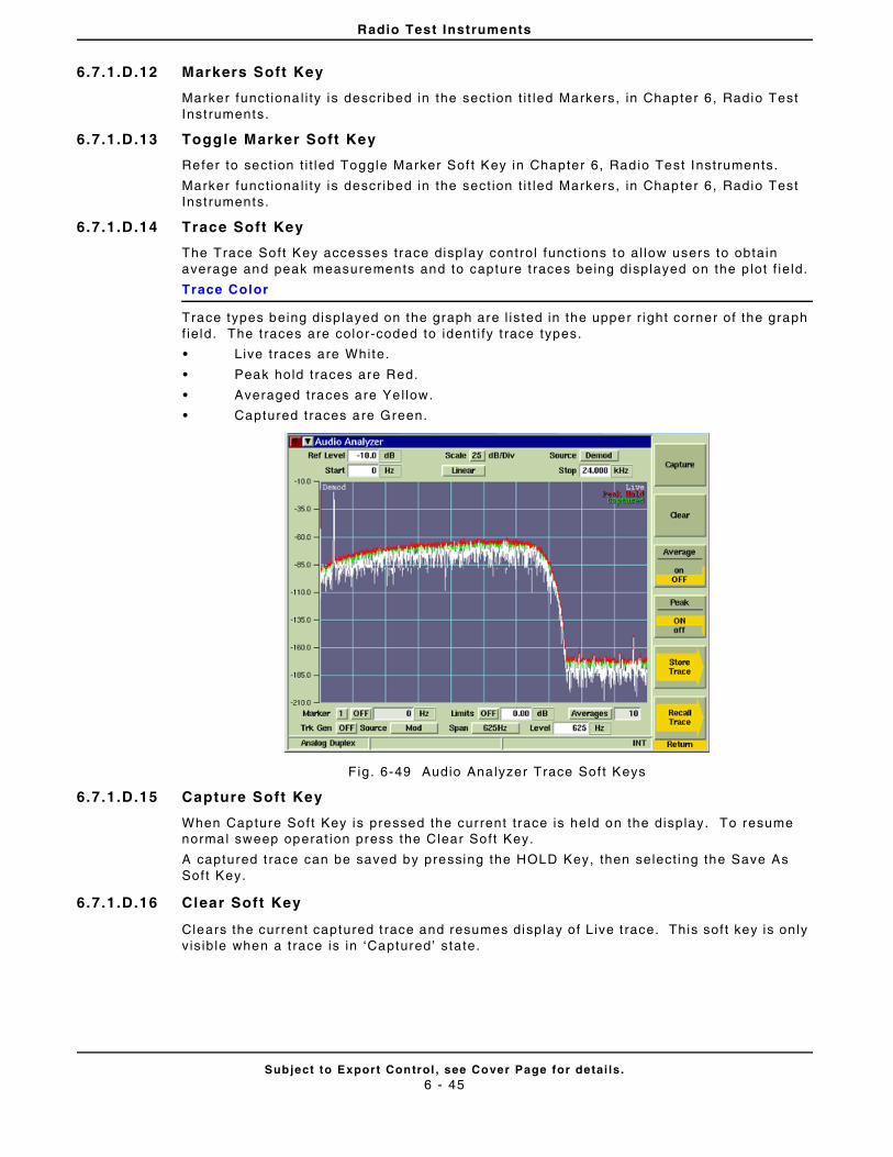
Radio Test Instruments
Subject to Export Control , see Cover Page for detai ls .6 - 45
6.7.1.D.12 Markers Soft Key
Marker funct ional i ty is descr ibed in the sect ion t i t led Markers, in Chapter 6, Radio Test Inst ruments.
6.7.1.D.13 Toggle Marker Soft Key
Refer to sect ion t i t led Toggle Marker Sof t Key in Chapter 6, Radio Test Instruments.
Marker funct ional i ty is descr ibed in the sect ion t i t led Markers, in Chapter 6, Radio Test Inst ruments.
6.7.1.D.14 Trace Soft Key
The Trace Soft Key accesses trace disp lay control funct ions to al low users to obtain average and peak measurements and to capture t races being displayed on the p lot f ie ld.
Trace Color
Trace types being disp layed on the graph are l isted in the upper r ight corner of the graph f ie ld. The t races are color-coded to ident i fy t race types.
• Live t races are White.
• Peak hold traces are Red.
• Averaged traces are Yel low.
• Captured t races are Green.
Fig. 6-49 Audio Analyzer Trace Sof t Keys
6.7.1.D.15 Capture Soft Key
When Capture Soft Key is pressed the current t race is held on the display. To resume normal sweep operat ion press the Clear Soft Key.
A captured t race can be saved by pressing the HOLD Key, then select ing the Save As Sof t Key.
6.7.1.D.16 Clear Soft Key
Clears the current captured t race and resumes display of Live t race. This soft key is only v is ible when a t race is in ‘Captured’ state.
Radio Test Instruments
Subject to Export Control , see Cover Page for detai ls .6 - 46
6.7.1.D.17 Peak Hold Soft Key
When Peak Hold ON is se lected, the maximum value at each frequency point is disp layed to produce the RED Max Hold t race. This t race is c leared by select ing Peak Hold OFF. Peak Hold must be reset ( toggled ON/OFF) when Average readings are Enabled/Disabled. The white Live trace is also displayed and can be averaged depending on the current sett ing. This soft key is accessed by pressing the Trace Soft Key.
6.7.1.D.18 Average Soft Key
When the Average Soft Key is ON, the trace is calculated by averaging the number of measurements def ined in the Averages f ie ld. The calculated va lue is a rol l ing average or a one-shot average as def ined on the Tr igger Ti le using the Repeat Soft Key and Single Sof t Key. A yel low progress indicator is displayed in the upper r ight corner of the graph f ie ld whi le the average reading is accumulat ing. This soft key is accessed by pressing the Trace Soft Key.
6.7.1.D.19 Store Trace Soft Key
The Store Trace Sof t Keys opens a d ialog box that a l lows a user to save a captured signal t race. The signal must be in “Captured” state before i t can be saved using the Store Trace funct ion. Refer to the Capture Soft Key for in formation on captur ing a signal t race.
6.7.1.D.20 Recal l Trace Soft Key
The Recal l Trace Soft Key opens a dialog box that al lows the user to load stored t race data.

Radio Test Instruments
Subject to Export Control , see Cover Page for detai ls .6 - 47
6.7.1.E Audio Analyzer Trace Limits
Audio Analyzer Trace l imits al lows users to set v isual l imits above and below the desired target level . This funct ion al lows the user to quickly determine i f the signal received from the UUT fal ls wi th in a desired target level range.
6.7.1.E.1 Limits On/Off Toggle Button
The Limits On/Off Toggle But ton enables the Audio Analyzer upper and lower s ignal t race l imits.
6.7.1.E.2 Limits Value
Limit t race posi t ion is def ined by enter ing a value in the L imits Value f ie ld . Upper and lower l imi t t races are of fset f rom the signal by the va lue def ined in the Limits Value f ie ld . For example, i f the Limit Value is set to 5.0 dB, the Upper Trace is posi t ioned 5.0 dB above the signal and the Lower Trace is posi t ioned 5.0 dB below the signal .
F ig. 6-50 Audio Analyzer - Trace Limits Enabled
6.7.1.E.3 Using Stored Trace with Trace Limits
The Store Trace funct ion can be used in combinat ion with Trace Limits to evaluate mult ip le radios that operate within the same speci f icat ions. To conf igure the Test Set for Audio Limits Analysis:
STEP PROCEDURE
1. Capture and Store a basel ine signal t race.
2. Def ine the Limits Value and set L imits to ON to establ ish a target upper and lower l imit .
3. Press the Clear Sof t Key to remove the stored signal t race (upper and lower Limits remain).
4. Transmit s ignal f rom UUT to Test Set. Adjust UUT unt i l s ignal is wi thin def ined trace l imits of basel ine signal t race.

Radio Test Instruments
Subject to Export Control , see Cover Page for detai ls .6 - 48
6.7 .2 Simulcast Analysis (390XOPT210)
The Simulcast Analysis Opt ion (390XOPT210) enables Tracking Generator funct ional i ty on the Audio Analyzer. The Audio Tracking Generator plots the frequency response of the external audio or demod audio path. The Simulcast Analysis Opt ion can be used to evaluate pre-emphasis and de-emphasis curves of the transmit and receive audio paths.
The examples below show the Simulcast Analysis Opt ion being used to test a radio ’s receive frequency response (de-emphasis curve) and t ransmit f requency response (pre-emphasis curve). Both examples show Markers 1 and 2 enabled and posi t ioned at 1000 Hz and 2000 Hz in order to evaluate signal st rength at these points on the signal . Both examples show an approximate 6 dB var iance in s ignal strength between 1000 Hz and 2000 Hz.
Fig. 6-51 Audio Analyzer - Rx Bandpass Sweep
Fig. 6-52 Audio Analyzer - Tx Bandpass Sweep
Radio Test Instruments
Subject to Export Control , see Cover Page for detai ls .6 - 49
6.7.2.A Trk Gen Toggle Button
The Trk Gen Toggle But ton turns the Tracking Generator On and Of f . When the Tracking Generator is ON, ei ther the M1 or A1 Generator is used to produce the Tracking Generator Output s ignal . When the Tracking Generator Output Source is set to Mod, M1 is used to generate the Tracking Generator Output s ignal . When the Tracking Generator Output Source is set to AF, A1 is used to generate the Tracking Generator Output s ignal . I f A1 or M1 is al ready enabled, the Tracking Generator s ignal overr ides the signal current ly conf igured on these generators.
6.7.2.B Span Drop-Down Menu
The Span drop-down menu is enabled when the Simulcast Analysis Opt ion (390XOPT210) is instal led in the Test Set. Span selects the hor izontal scal ing of the plot ted signal . Once Span is selected, the Stop Frequency Field can be used to focus on a speci f ic sect ion of the signal . For example, Span can be set to 9 .6 kHz, then the Stop Frequency can be adjusted to 100.0 Hz. The maximum Stop Frequency is def ined by the Span value.
6.7.2.C Tracking Generator Source
The Tracking Generator Source drop-down menu selects the output source of the Tracking Generator s ignal .
When AF is selected, the Tracking Generator Output s ignal is routed to the Test Set ’s Fctn GEN/Demod Out Connector .
When MOD is selected, the Tracking Generator Output s ignal is routed through the modulator to the selected RF Out Connector (GEN or T/R).
6.7.2.D Tracking Generator Level
The Tracking Generator Level def ines the Tracking Generator Output s ignal level .
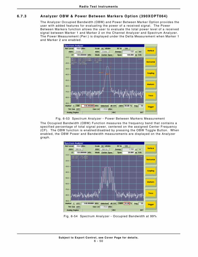
Radio Test Instruments
Subject to Export Control , see Cover Page for detai ls .6 - 50
6.7 .3 Analyzer OBW & Power Between Markers Option (390XOPT064)
The Analyzer Occupied Bandwidth (OBW) and Power Between Marker Opt ion provides the user with added features for evaluat ing the power of a received signal . The Power Between Markers funct ion al lows the user to evaluate the total power level of a received signal between Marker 1 and Marker 2 on the Channel Analyzer and Spectrum Analyzer . The Power Measurement (Pwr: ) is disp layed under the Del ta Measurement when Marker 1 and Marker 2 are enabled.
F ig. 6-53 Spectrum Analyzer - Power Between Markers Measurement
The Occupied Bandwidth (OBW) Funct ion measures the frequency band that contains a speci f ied percentage of total s ignal power, centered on the assigned Center Frequency (CF). The OBW funct ion is enabled/disabled by pressing the OBW Toggle Button. When enabled, the OBW Power and Bandwidth measurements are displayed on the Analyzer graph.
Fig. 6-54 Spectrum Analyzer - Occupied Bandwidth at 99%

Radio Test Instruments
Subject to Export Control , see Cover Page for detai ls .6 - 51
6.7.3.A Field Def ini t ions
6.7.3.A.1 OBW Field
The OBW f ield def ines the percentage of a s ignal ’s power over which Occupied Bandwidth measurements are per formed.
6.7.3.A.2 OBW Pwr
The OBW Power measurement ind icates the power leve l of the signal across the Occupied Bandwidth.
6.7.3.A.3 OBW BW
The OBW Bandwidth measurement indicates the amount of Bandwidth occupied by the percentage of s ignal power as def ined by the OBW f ield.
Fig. 6-55 Spectrum Analyzer - Occupied Bandwidth at 75%
% of Signal Power
OBW Bandwidth
OBW Power
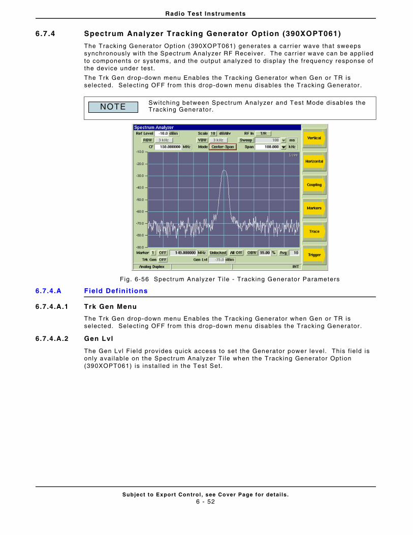
Radio Test Instruments
Subject to Export Control , see Cover Page for detai ls .6 - 52
6.7 .4 Spectrum Analyzer Tracking Generator Option (390XOPT061)
The Tracking Generator Opt ion (390XOPT061) generates a carr ier wave that sweeps synchronously with the Spectrum Analyzer RF Receiver . The carr ier wave can be appl ied to components or systems, and the output analyzed to display the frequency response of the device under test .
The Trk Gen drop-down menu Enables the Tracking Generator when Gen or TR is selected. Select ing OFF from this drop-down menu d isables the Tracking Generator .
Fig. 6-56 Spectrum Analyzer Ti le - Tracking Generator Parameters
6.7.4.A Field Def ini t ions
6.7.4.A.1 Trk Gen Menu
The Trk Gen drop-down menu Enables the Tracking Generator when Gen or TR is selected. Select ing OFF from this drop-down menu d isables the Tracking Generator .
6.7.4.A.2 Gen Lvl
The Gen Lvl Field provides quick access to set the Generator power level . This f ie ld is only avai lable on the Spectrum Analyzer Ti le when the Tracking Generator Opt ion (390XOPT061) is instal led in the Test Set.
Switching between Spectrum Analyzer and Test Mode disables the Tracking Generator.NOTE
Subject to Export Control , see Cover Page for detai ls .7 - 1
Chapter 7 - Analog Duplex System
7.1 INTRODUCTION
The 3900 Analog Duplex System tests mobi le radio t ransmit ters, receivers and transceivers. The tests can be simple funct ional i ty tests or more detai led tests such as test ing t ransmit ter power output , broad band and narrow band; rece iver sensi t iv i ty; AM and FM modulat ion and demodulat ion performance; distort ion level and SINAD.
The Analog Duplex System includes the fol lowing test funct ions:
• AM and FM Signal Generator
• RF Signal Analyzer
• Mult ip le AF Signal Generators
• Mult ip le AF Modulators
• AF Measurement
• Modulat ion Measurement
• Osci l loscope for examining external and internal s ignals
• Ful l Duplex operat ion
• Spectrum Analyzer and Channel Analyzer
This chapter explains how to use the Analog Duplex System. Refer to Chapter 3, Test Set Operat ion, for general operat ion of the Test Set. This chapter includes the fol lowing:
• Descr ipt ion of the Analog Duplex System and a diagram of a common test setup.
• Descr ibes how to access the Analog Duplex System.
• Descr ibes how to navigate Analog Duplex System Ti les.
• Descr ibes the layout and in formation provided on Analog Duplex Ti les.
• Expla ins the TEST Ti les.
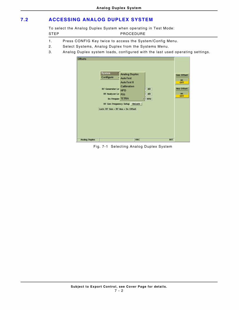
Analog Duplex System
Subject to Export Control , see Cover Page for detai ls .7 - 2
7.2 ACCESSING ANALOG DUPLEX SYSTEM
To se lect the Analog Duplex System when operat ing in Test Mode:
STEP PROCEDURE
1. Press CONFIG Key twice to access the System/Conf ig Menu.
2. Select Systems, Analog Duplex f rom the Systems Menu.
3. Analog Duplex system loads, conf igured with the last used operat ing sett ings.
Fig. 7-1 Select ing Analog Duplex System
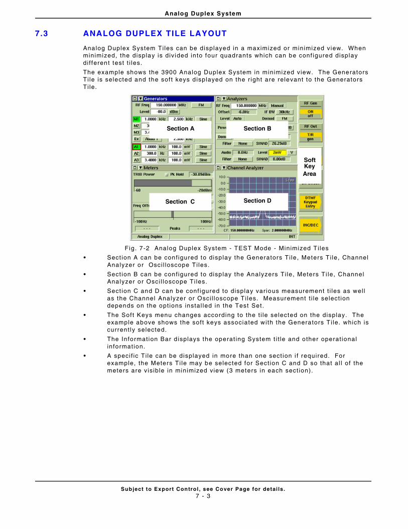
Analog Duplex System
Subject to Export Control , see Cover Page for detai ls .7 - 3
7.3 ANALOG DUPLEX TILE LAYOUT
Analog Duplex System Ti les can be displayed in a maximized or minimized view. When minimized, the display is div ided in to four quadrants which can be conf igured display di f ferent test t i les.
The example shows the 3900 Analog Duplex System in minimized view. The Generators Ti le is selected and the sof t keys d isplayed on the r ight are relevant to the Generators Ti le.
Fig. 7-2 Analog Duplex System - TEST Mode - Minimized T i les
• Sect ion A can be conf igured to disp lay the Generators Ti le , Meters T i le, Channel Analyzer or Osci l loscope Ti les.
• Sect ion B can be conf igured to disp lay the Analyzers Ti le, Meters Ti le, Channel Analyzer or Osci l loscope Ti les.
• Sect ion C and D can be conf igured to display var ious measurement t i les as wel l as the Channel Analyzer or Osci l loscope T i les. Measurement t i le select ion depends on the opt ions instal led in the Test Set .
• The Sof t Keys menu changes according to the t i le selected on the display. The example above shows the soft keys associated with the Generators T i le. which is current ly selected.
• The Informat ion Bar d isplays the operat ing System t i t le and other operat ional informat ion.
• A speci f ic Ti le can be displayed in more than one sect ion i f required. For example, the Meters Ti le may be selected for Sect ion C and D so that al l of the meters are vis ible in minimized view (3 meters in each sect ion).
Section A
Section C
Section B
Section D
SoftKeyArea
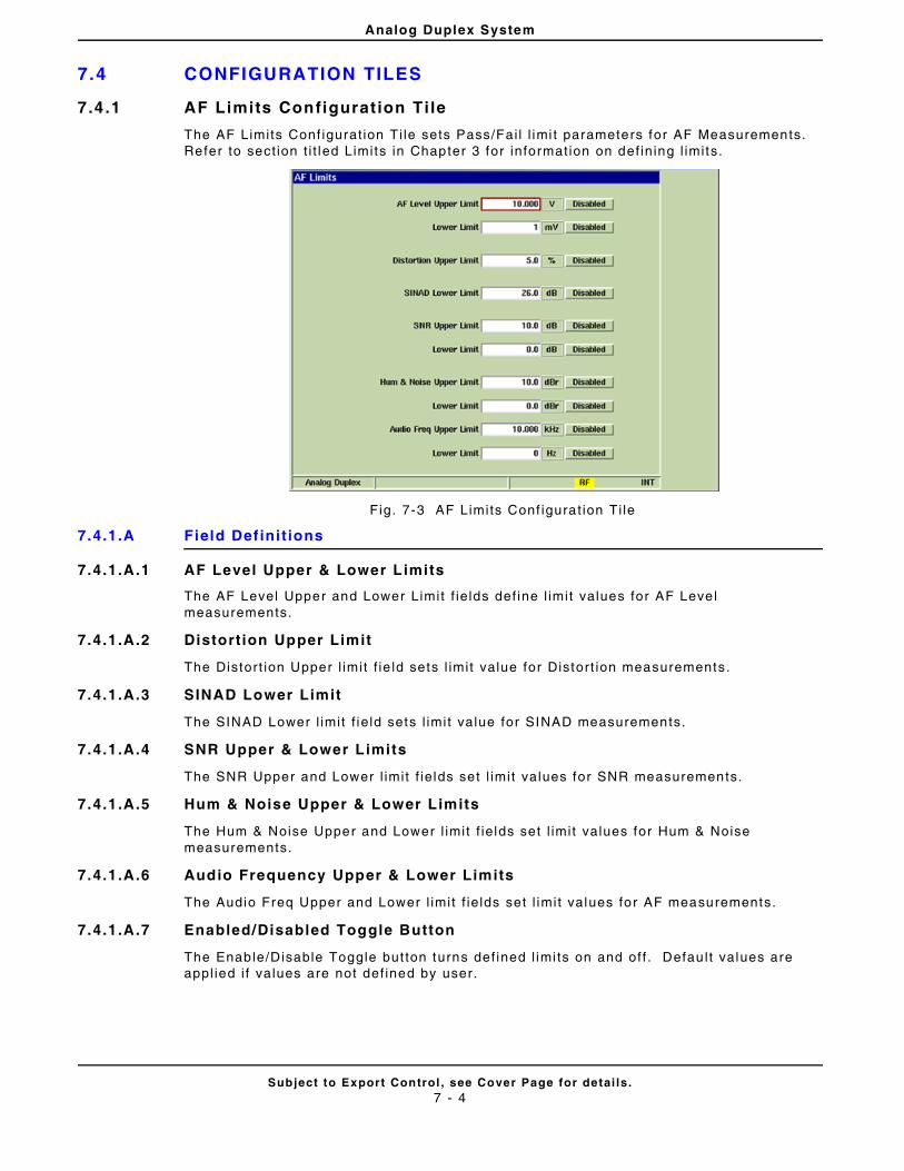
Analog Duplex System
Subject to Export Control , see Cover Page for detai ls .7 - 4
7.4 CONFIGURATION TILES
7.4.1 AF Limits Configurat ion Ti le
The AF Limits Conf igurat ion Ti le sets Pass/Fai l l imi t parameters for AF Measurements. Refer to sect ion t i t led Limits in Chapter 3 for informat ion on def ining l imits.
Fig. 7-3 AF Limits Conf igurat ion Ti le
7.4.1.A Field Def ini t ions
7.4.1.A.1 AF Level Upper & Lower Limits
The AF Level Upper and Lower Limit f ie lds def ine l imit values for AF Level measurements.
7.4.1.A.2 Distort ion Upper Limit
The Distort ion Upper l imit f ie ld sets l imit value for Distort ion measurements.
7.4.1.A.3 SINAD Lower Limit
The SINAD Lower l imit f ie ld sets l imit value for SINAD measurements.
7.4.1.A.4 SNR Upper & Lower Limits
The SNR Upper and Lower l imit f ie lds set l imit values for SNR measurements.
7.4.1.A.5 Hum & Noise Upper & Lower Limits
The Hum & Noise Upper and Lower l imit f ie lds set l imit values for Hum & Noise measurements.
7.4.1.A.6 Audio Frequency Upper & Lower Limits
The Audio Freq Upper and Lower l imit f ie lds set l imit values for AF measurements.
7.4.1.A.7 Enabled/Disabled Toggle Button
The Enable/Disable Toggle but ton turns def ined l imi ts on and off . Defau l t values are appl ied i f values are not def ined by user.
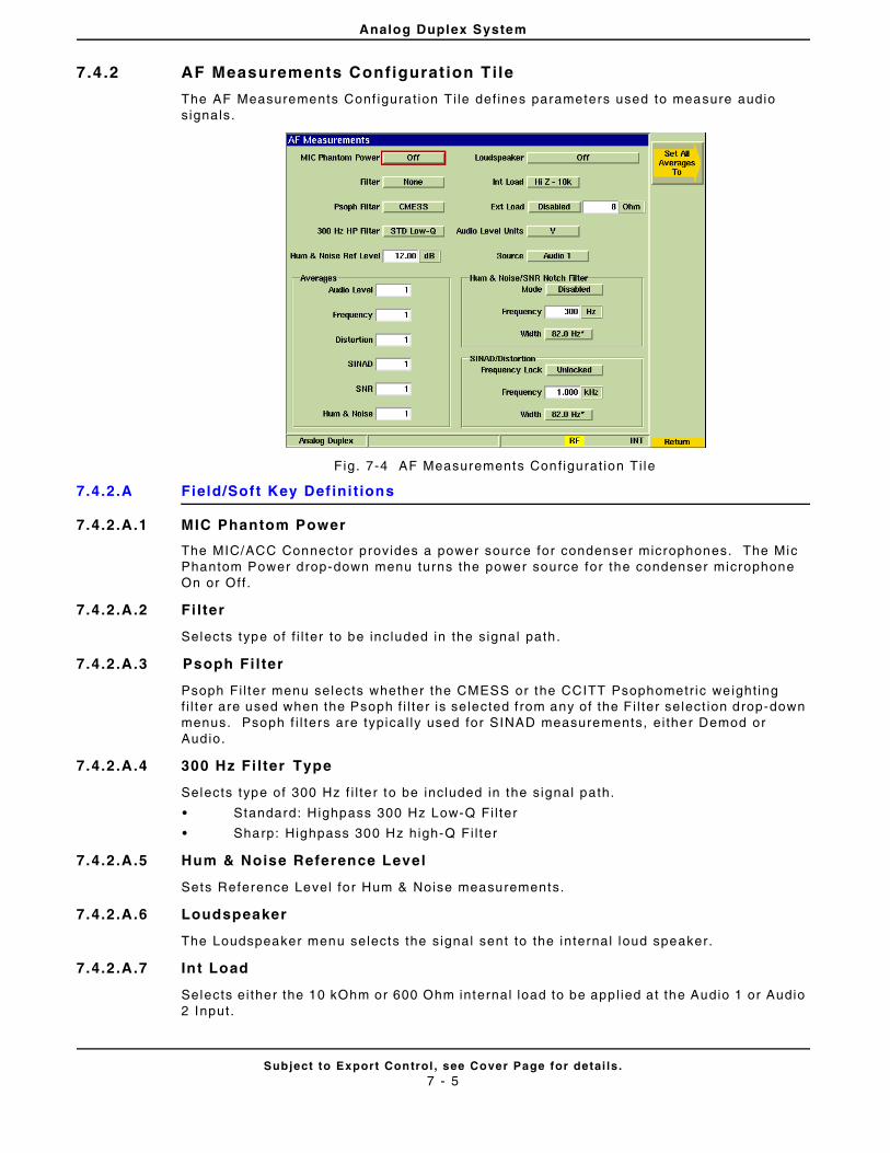
Analog Duplex System
Subject to Export Control , see Cover Page for detai ls .7 - 5
7.4 .2 AF Measurements Configurat ion Tile
The AF Measurements Conf igurat ion Ti le def ines parameters used to measure audio s ignals.
Fig. 7-4 AF Measurements Conf igurat ion Ti le
7.4.2.A Field/Soft Key Def ini t ions
7.4.2.A.1 MIC Phantom Power
The MIC/ACC Connector provides a power source for condenser microphones. The Mic Phantom Power drop-down menu turns the power source for the condenser microphone On or Off .
7.4.2.A.2 Fi lter
Selects type of f i l ter to be included in the signal path.
7.4.2.A.3 Psoph Fi l ter
Psoph Fi l ter menu selects whether the CMESS or the CCITT Psophometr ic weight ing f i l ter are used when the Psoph f i l ter is selected f rom any of the F i l ter select ion drop-down menus. Psoph f i l ters are typica l ly used for SINAD measurements, ei ther Demod or Audio.
7.4.2.A.4 300 Hz Fi lter Type
Selects type of 300 Hz f i l te r to be included in the signal path.
• Standard: Highpass 300 Hz Low-Q Fi l ter
• Sharp: Highpass 300 Hz high-Q Fi l ter
7.4.2.A.5 Hum & Noise Reference Level
Sets Reference Level for Hum & Noise measurements.
7.4.2.A.6 Loudspeaker
The Loudspeaker menu selects the signal sent to the internal loud speaker.
7.4.2.A.7 Int Load
Selects ei ther the 10 kOhm or 600 Ohm internal load to be appl ied at the Audio 1 or Audio 2 Input.
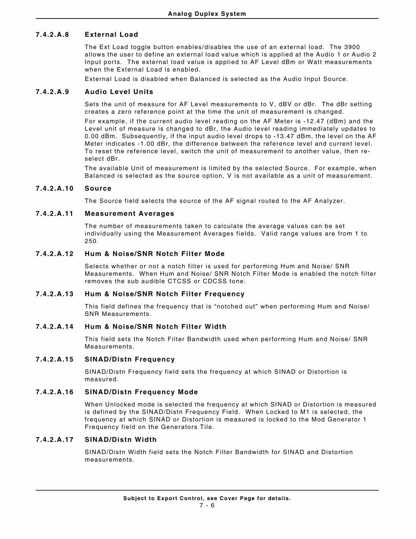
Analog Duplex System
Subject to Export Control , see Cover Page for detai ls .7 - 6
7.4.2.A.8 External Load
The Ext Load toggle but ton enables/disables the use of an external load. The 3900 al lows the user to def ine an external load value which is appl ied at the Audio 1 or Audio 2 Input por ts. The external load value is appl ied to AF Level dBm or Watt measurements when the External Load is enabled.
External Load is disab led when Balanced is selected as the Audio Input Source.
7.4.2.A.9 Audio Level Units
Sets the uni t of measure for AF Level measurements to V, dBV or dBr. The dBr sett ing creates a zero reference point at the t ime the uni t of measurement is changed.
For example, i f the current audio level reading on the AF Meter is -12.47 (dBm) and the Level uni t of measure is changed to dBr, the Audio level reading immediately updates to 0.00 dBm. Subsequent ly, i f the input audio level drops to -13.47 dBm, the level on the AF Meter indicates -1.00 dBr, the di f ference between the reference level and current leve l . To reset the reference level , switch the uni t o f measurement to another va lue, then re-select dBr.
The avai lable Unit of measurement is l imited by the selected Source. For example, when Balanced is selected as the source opt ion, V is not avai lable as a uni t o f measurement .
7.4.2.A.10 Source
The Source f ie ld se lects the source of the AF signal routed to the AF Analyzer .
7.4.2.A.11 Measurement Averages
The number of measurements taken to calculate the average values can be set indiv idual ly using the Measurement Averages f ie lds. Val id range values are from 1 to 250.
7.4.2.A.12 Hum & Noise/SNR Notch Fil ter Mode
Selects whether or not a notch f i l ter is used for per forming Hum and Noise/ SNR Measurements. When Hum and Noise/ SNR Notch F i l ter Mode is enabled the notch f i l ter removes the sub audible CTCSS or CDCSS tone.
7.4.2.A.13 Hum & Noise/SNR Notch Fil ter Frequency
This f ie ld def ines the frequency that is “notched out” when per forming Hum and Noise/ SNR Measurements.
7.4.2.A.14 Hum & Noise/SNR Notch Fil ter Width
This f ie ld sets the Notch Fi l ter Bandwidth used when per forming Hum and Noise/ SNR Measurements.
7.4.2.A.15 SINAD/Distn Frequency
SINAD/Distn Frequency f ie ld sets the f requency at which SINAD or Distort ion is measured.
7.4.2.A.16 SINAD/Distn Frequency Mode
When Unlocked mode is selected the frequency at which SINAD or Distor t ion is measured is def ined by the SINAD/Distn Frequency Field . When Locked to M1 is selected, the frequency at which SINAD or Distor t ion is measured is locked to the Mod Generator 1 Frequency f ie ld on the Generators Ti le.
7.4.2.A.17 SINAD/Distn Width
SINAD/Distn Width f ie ld sets the Notch F i l ter Bandwidth for SINAD and Distort ion measurements.
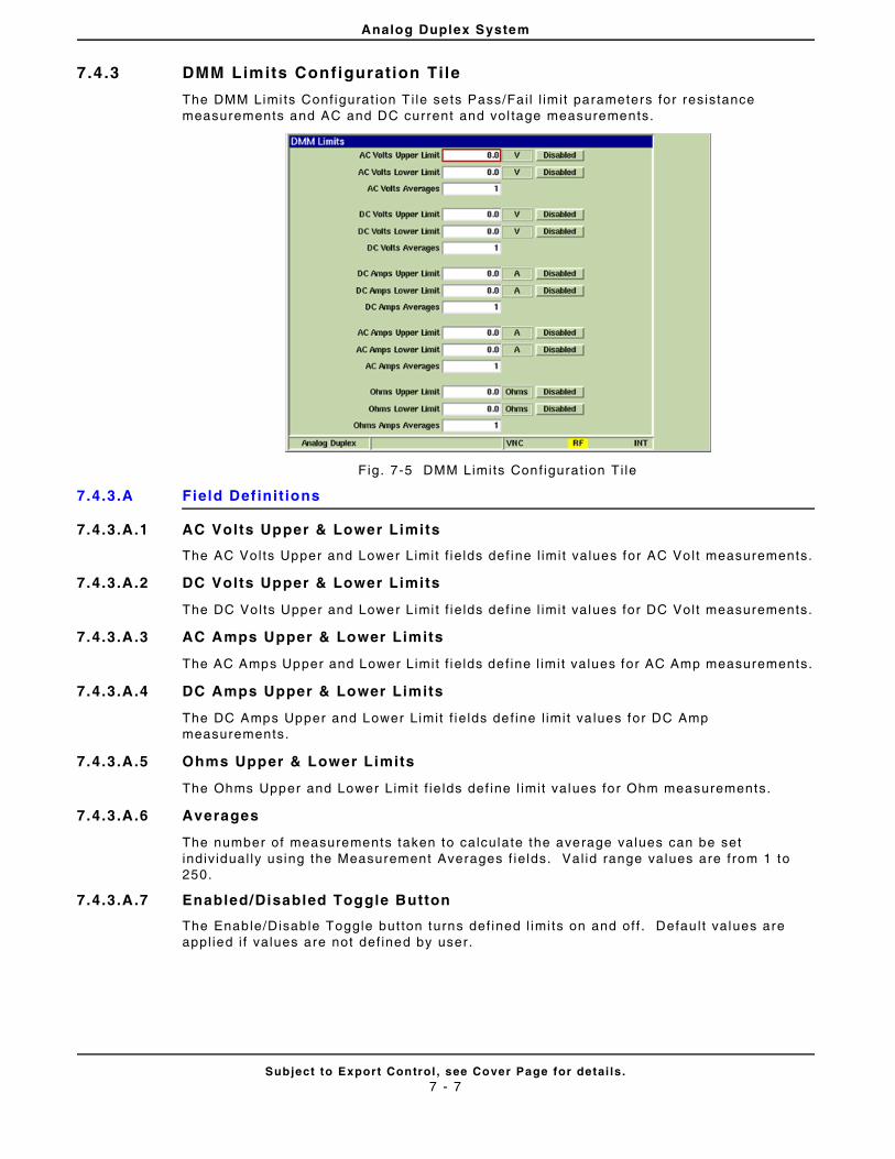
Analog Duplex System
Subject to Export Control , see Cover Page for detai ls .7 - 7
7.4 .3 DMM Limits Configuration Tile
The DMM Limi ts Conf igurat ion T i le sets Pass/Fai l l imi t parameters for resistance measurements and AC and DC current and vol tage measurements.
Fig. 7-5 DMM Limits Conf igurat ion Ti le
7.4.3.A Field Def ini t ions
7.4.3.A.1 AC Volts Upper & Lower Limits
The AC Volts Upper and Lower Limit f ie lds def ine l imit values for AC Volt measurements.
7.4.3.A.2 DC Volts Upper & Lower Limits
The DC Volts Upper and Lower Limi t f ie lds def ine l imit values for DC Volt measurements.
7.4.3.A.3 AC Amps Upper & Lower Limits
The AC Amps Upper and Lower Limit f ie lds de f ine l imit values for AC Amp measurements.
7.4.3.A.4 DC Amps Upper & Lower Limits
The DC Amps Upper and Lower Limit f ie lds def ine l imit va lues for DC Amp measurements.
7.4.3.A.5 Ohms Upper & Lower Limits
The Ohms Upper and Lower Limit f ie lds def ine l imit values for Ohm measurements.
7.4.3.A.6 Averages
The number of measurements taken to calculate the average values can be set indiv idual ly using the Measurement Averages f ie lds. Val id range values are from 1 to 250.
7.4.3.A.7 Enabled/Disabled Toggle Button
The Enable/Disable Toggle but ton turns def ined l imi ts on and off . Defau l t values are appl ied i f values are not def ined by user.
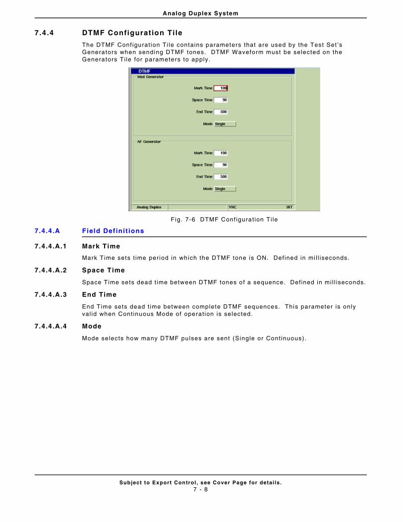
Analog Duplex System
Subject to Export Control , see Cover Page for detai ls .7 - 8
7.4 .4 DTMF Configurat ion Ti le
The DTMF Conf igurat ion Ti le contains parameters that are used by the Test Set ’s Generators when sending DTMF tones. DTMF Waveform must be selected on the Generators Ti le for parameters to apply.
F ig. 7-6 DTMF Conf igurat ion Ti le
7.4.4.A Field Def ini t ions
7.4.4.A.1 Mark Time
Mark Time sets t ime per iod in which the DTMF tone is ON. Def ined in mi l l iseconds.
7.4.4.A.2 Space Time
Space Time sets dead t ime between DTMF tones of a sequence. Def ined in mi l l iseconds.
7.4.4.A.3 End Time
End Time sets dead t ime between complete DTMF sequences. This parameter is only val id when Cont inuous Mode of operat ion is selected.
7.4.4.A.4 Mode
Mode se lects how many DTMF pulses are sent (Single or Cont inuous).
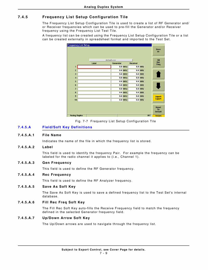
Analog Duplex System
Subject to Export Control , see Cover Page for detai ls .7 - 9
7.4 .5 Frequency List Setup Configuration Tile
The Frequency L ist Setup Conf igurat ion Ti le is used to create a l ist o f RF Generator and/or Receiver f requencies which can be used to pre- f i l l the Generator and/or Receiver f requency using the Frequency List Test Ti le.
A frequency l ist can be created using the Frequency List Setup Conf igurat ion T i le or a l is t can be created external ly in spreadsheet format and imported to the Test Set .
Fig. 7-7 Frequency List Setup Conf igurat ion Ti le
7.4.5.A Field/Soft Key Def ini t ions
7.4.5.A.1 Fi le Name
Indicates the name of the f i le in which the f requency l ist is stored.
7.4.5.A.2 Label
This f ie ld is used to ident i fy the f requency Pai r. For example the frequency can be labeled for the radio channel i t appl ies to ( i .e. , Channel 1) .
7.4.5.A.3 Gen Frequency
This f ie ld is used to def ine the RF Generator f requency.
7.4.5.A.4 Rec Frequency
This f ie ld is used to def ine the RF Analyzer f requency.
7.4.5.A.5 Save As Soft Key
The Save As Soft Key is used to save a def ined frequency l ist to the Test Set ’s internal database.
7.4.5.A.6 Fi l l Rec Freq Soft Key
The Fi l l Rec Sof t Key auto-f i l ls the Receive Frequency f ie ld to match the frequency def ined in the selected Generator f requency f ie ld .
7.4.5.A.7 Up/Down Arrow Soft Key
The Up/Down arrows are used to navigate through the frequency l ist .
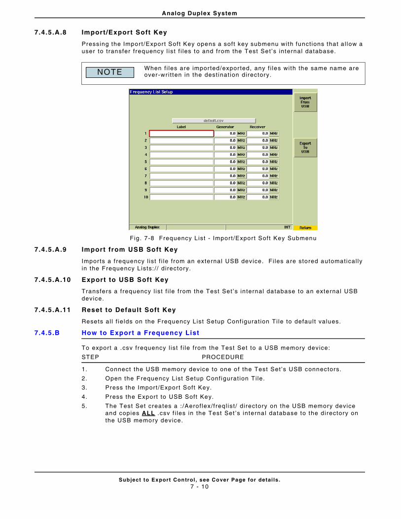
Analog Duplex System
Subject to Export Control , see Cover Page for detai ls .7 - 10
7.4.5.A.8 Import/Export Soft Key
Pressing the Import /Expor t Soft Key opens a soft key submenu with funct ions that a l low a user to t ransfer f requency l ist f i les to and from the Test Set ’s internal database.
Fig . 7-8 Frequency List - Import /Expor t Soft Key Submenu
7.4.5.A.9 Import from USB Soft Key
Imports a f requency l ist f i le f rom an external USB device. Fi les are stored automatical ly in the Frequency Lists: / / d i rectory.
7.4.5.A.10 Export to USB Soft Key
Transfers a f requency l ist f i le f rom the Test Set ’s in ternal database to an external USB device.
7.4.5.A.11 Reset to Default Soft Key
Resets al l f ie lds on the Frequency List Setup Conf igurat ion Ti le to defau l t values.
7.4.5.B How to Export a Frequency List
To export a .csv frequency l ist f i le f rom the Test Set to a USB memory device:
STEP PROCEDURE
1. Connect the USB memory device to one of the Test Set ’s USB connectors.
2. Open the Frequency List Setup Conf igurat ion Ti le.
3. Press the Import /Expor t Soft Key.
4. Press the Export to USB Soft Key.
5. The Test Set creates a : /Aerof lex/ f req l ist / d irectory on the USB memory device and copies ALL .csv f i les in the Test Set ’s interna l database to the directory on the USB memory device.
When f i les are imported/expor ted, any f i les with the same name are over-wri t ten in the dest inat ion directory.NOTE
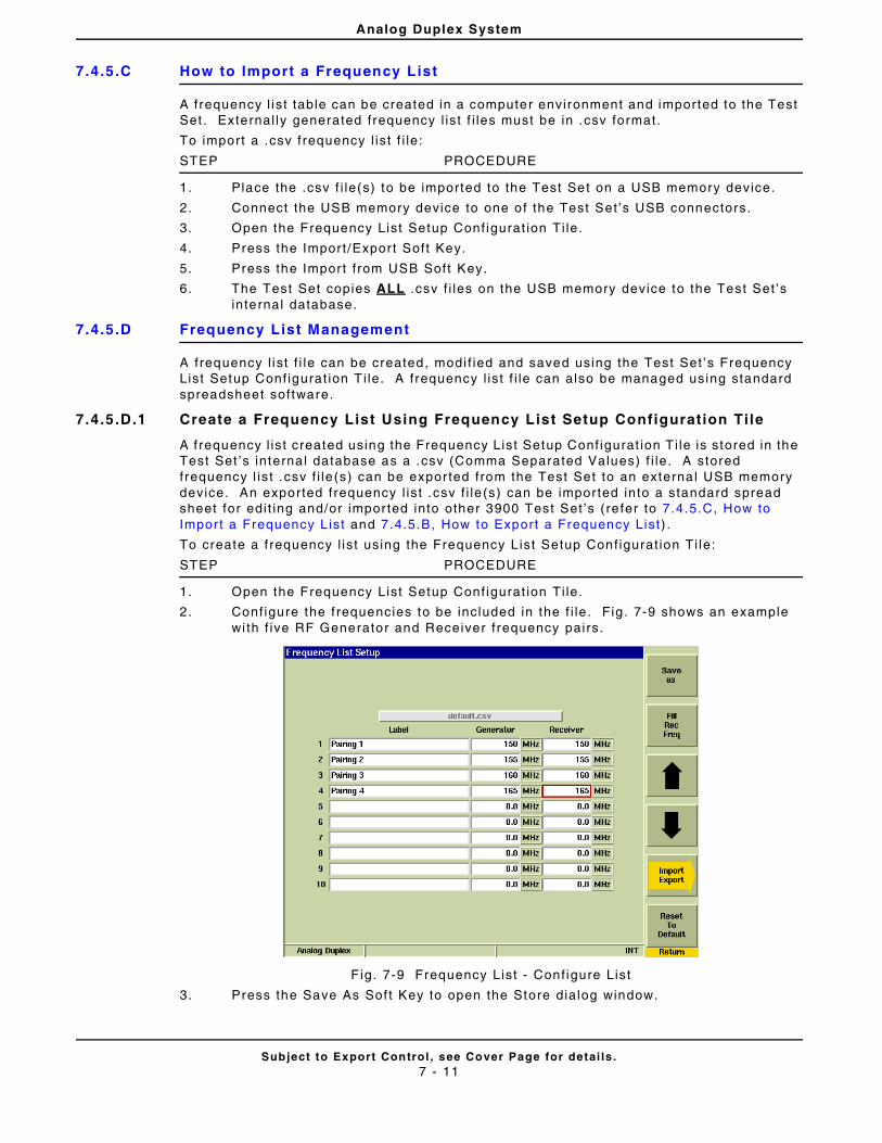
Analog Duplex System
Subject to Export Control , see Cover Page for detai ls .7 - 11
7.4.5.C How to Import a Frequency List
A frequency l ist table can be created in a computer environment and imported to the Test Set . External ly generated frequency l ist f i les must be in .csv format.
To import a .csv frequency l is t f i le:
STEP PROCEDURE
1. Place the .csv f i le(s) to be imported to the Test Set on a USB memory device.
2. Connect the USB memory device to one of the Test Set ’s USB connectors.
3. Open the Frequency List Setup Conf igurat ion Ti le.
4. Press the Import /Expor t Soft Key.
5. Press the Import f rom USB Soft Key.
6. The Test Set copies ALL .csv f i les on the USB memory device to the Test Set ’s internal database.
7.4.5.D Frequency List Management
A frequency l ist f i le can be created, modi f ied and saved using the Test Set ’s Frequency List Setup Conf igurat ion T i le. A frequency l ist f i le can also be managed using standard spreadsheet software.
7.4.5.D.1 Create a Frequency List Using Frequency List Setup Configuration Ti le
A f requency l ist created using the Frequency List Setup Conf igurat ion T i le is stored in the Test Set ’s interna l database as a .csv (Comma Separated Values) f i le. A stored frequency l ist .csv f i le (s) can be expor ted from the Test Set to an externa l USB memory device. An exported frequency l ist .csv f i le (s) can be imported into a standard spread sheet for edi t ing and/or imported into other 3900 Test Set ’s (re fer to 7.4.5.C, How to Import a Frequency L ist and 7.4.5.B, How to Export a Frequency List ) .
To create a f requency l ist using the Frequency L ist Setup Conf igurat ion Ti le:
STEP PROCEDURE
1. Open the Frequency List Setup Conf igurat ion Ti le.
2. Conf igure the f requencies to be included in the f i le. Fig . 7-9 shows an example wi th f ive RF Generator and Receiver f requency pairs.
F ig. 7-9 Frequency List - Conf igure List
3. Press the Save As Sof t Key to open the Store dialog window.
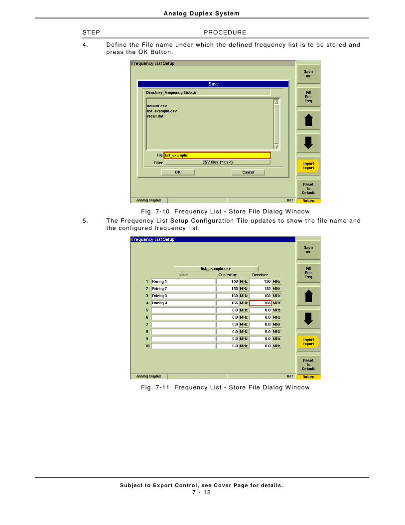
Analog Duplex System
Subject to Export Control , see Cover Page for detai ls .7 - 12
STEP PROCEDURE
4. Def ine the Fi le name under which the def ined frequency l ist is to be stored and press the OK Button.
Fig . 7-10 Frequency List - Store Fi le Dia log Window
5. The Frequency List Setup Conf igurat ion Ti le updates to show the f i le name and the conf igured frequency l ist .
Fig . 7-11 Frequency List - Store Fi le Dia log Window
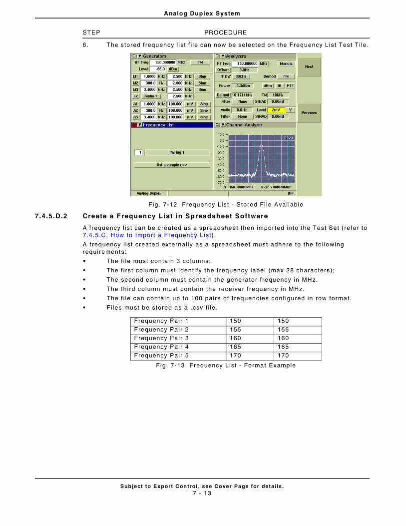
Analog Duplex System
Subject to Export Control , see Cover Page for detai ls .7 - 13
STEP PROCEDURE
6. The stored f requency l ist f i le can now be selected on the Frequency List Test T i le.
Fig. 7-12 Frequency List - Stored Fi le Avai lable
7.4.5.D.2 Create a Frequency List in Spreadsheet Software
A f requency l ist can be created as a spreadsheet then imported into the Test Set ( refer to 7.4.5.C, How to Import a Frequency L ist) .
A frequency l ist created external ly as a spreadsheet must adhere to the fol lowing requirements:
• The f i le must contain 3 columns;
• The f i rst column must ident i fy the frequency label (max 28 characters);
• The second co lumn must conta in the generator f requency in MHz.
• The third column must contain the receiver f requency in MHz.
• The f i le can contain up to 100 pairs of f requencies conf igured in row format.
• Fi les must be stored as a .csv f i le .
Fig. 7-13 Frequency List - Format Example
Frequency Pair 1 150 150
Frequency Pair 2 155 155Frequency Pair 3 160 160Frequency Pair 4 165 165
Frequency Pair 5 170 170
Analog Duplex System
Subject to Export Control , see Cover Page for detai ls .7 - 14
7.4.5.D.3 Modify a Frequency List Using Frequency List Setup Configuration Ti le
To modify a f requency l ist .csv f i le using the Test Set ’s Frequency List Setup Conf igurat ion Ti le:
STEP PROCEDURE
1. Open the Frequency List Setup Conf igurat ion Ti le.
2. Select the f i le to be edi ted from the f i le drop-down menu.
3. Make the desi red changes to the f requency l ist f i le.
4. Press the Save As Sof t Key to open the Store dialog window.
5. Enter the frequency l ist f i le name (keeping same name over-wr i tes current f i le) .
6. Press the OK Button to save the f i le.
7.4.5.D.4 Modify a Frequency List Using Spreadsheet Software
To modify a f requency l ist .csv f i le in spreadsheet format :
STEP PROCEDURE
1. Open f requency l is t .csv f i le using spreadsheet sof tware.
2. Make the desi red changes to the f requency l ist f i le.
3. Save the f i le as a .csv f i le.
4. Import the modi f ied frequency l ist .csv f i le into the Test Set (refer to 7.4 .5.B, How to Expor t a Frequency L ist) .
I f the f requency l ist f i le was created using the Test Set ’s Frequency List Setup Conf igurat ion T i le, expor t the f i le f rom the Test Set to a USB memory device ( refer to 7.4.5.B, How to Export a Frequency List ) .
NOTE
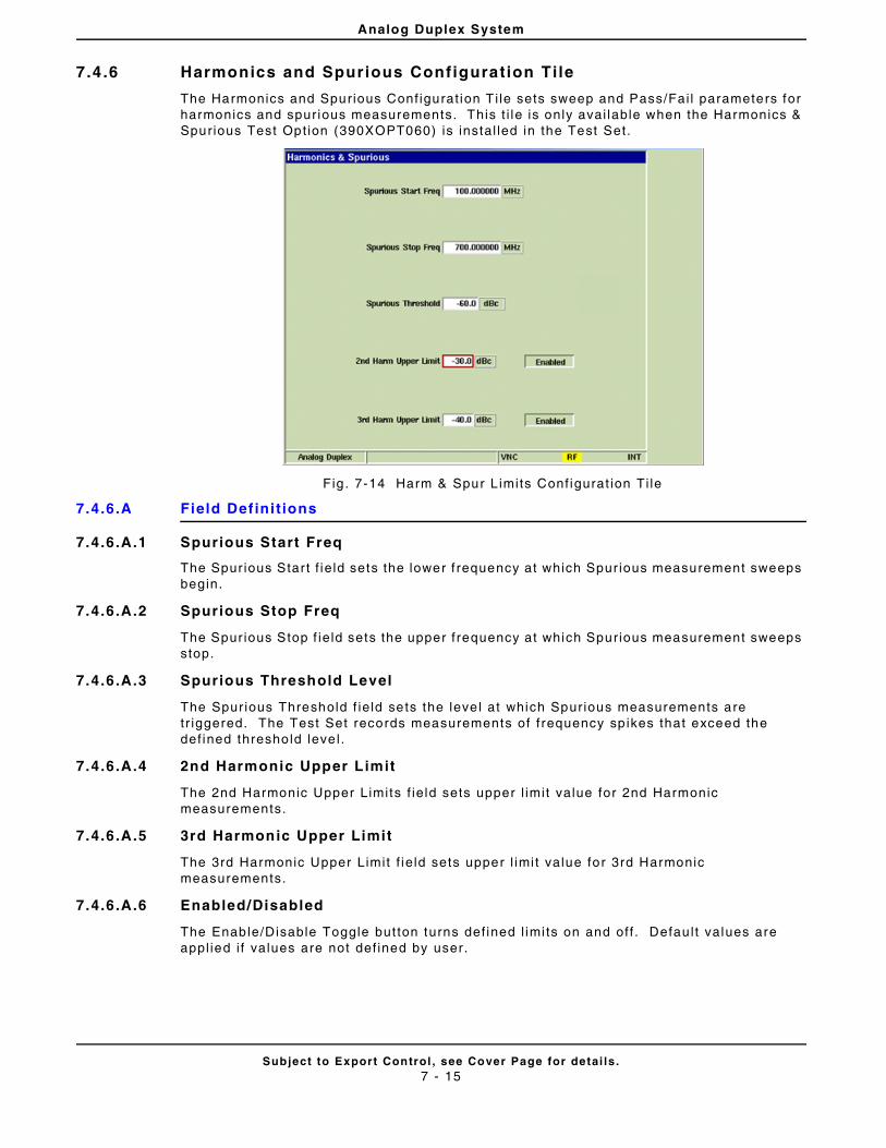
Analog Duplex System
Subject to Export Control , see Cover Page for detai ls .7 - 15
7.4 .6 Harmonics and Spurious Configuration Tile
The Harmonics and Spurious Conf igurat ion T i le sets sweep and Pass/Fai l parameters for harmonics and spur ious measurements. This t i le is only avai lable when the Harmonics & Spurious Test Opt ion (390XOPT060) is instal led in the Test Set.
Fig . 7-14 Harm & Spur L imits Conf igurat ion Ti le
7.4.6.A Field Def ini t ions
7.4.6.A.1 Spurious Start Freq
The Spur ious Star t f ie ld sets the lower f requency at which Spur ious measurement sweeps begin.
7.4.6.A.2 Spurious Stop Freq
The Spur ious Stop f ie ld sets the upper f requency at which Spurious measurement sweeps stop.
7.4.6.A.3 Spurious Threshold Level
The Spur ious Threshold f ie ld sets the leve l at which Spurious measurements are tr iggered. The Test Set records measurements of f requency sp ikes that exceed the def ined threshold leve l .
7.4.6.A.4 2nd Harmonic Upper Limit
The 2nd Harmonic Upper Limits f ie ld sets upper l imit value for 2nd Harmonic measurements.
7.4.6.A.5 3rd Harmonic Upper Limit
The 3rd Harmonic Upper Limit f ie ld sets upper l imi t value for 3rd Harmonic measurements.
7.4.6.A.6 Enabled/Disabled
The Enable/Disable Toggle but ton turns def ined l imi ts on and off . Defau l t values are appl ied i f values are not def ined by user.
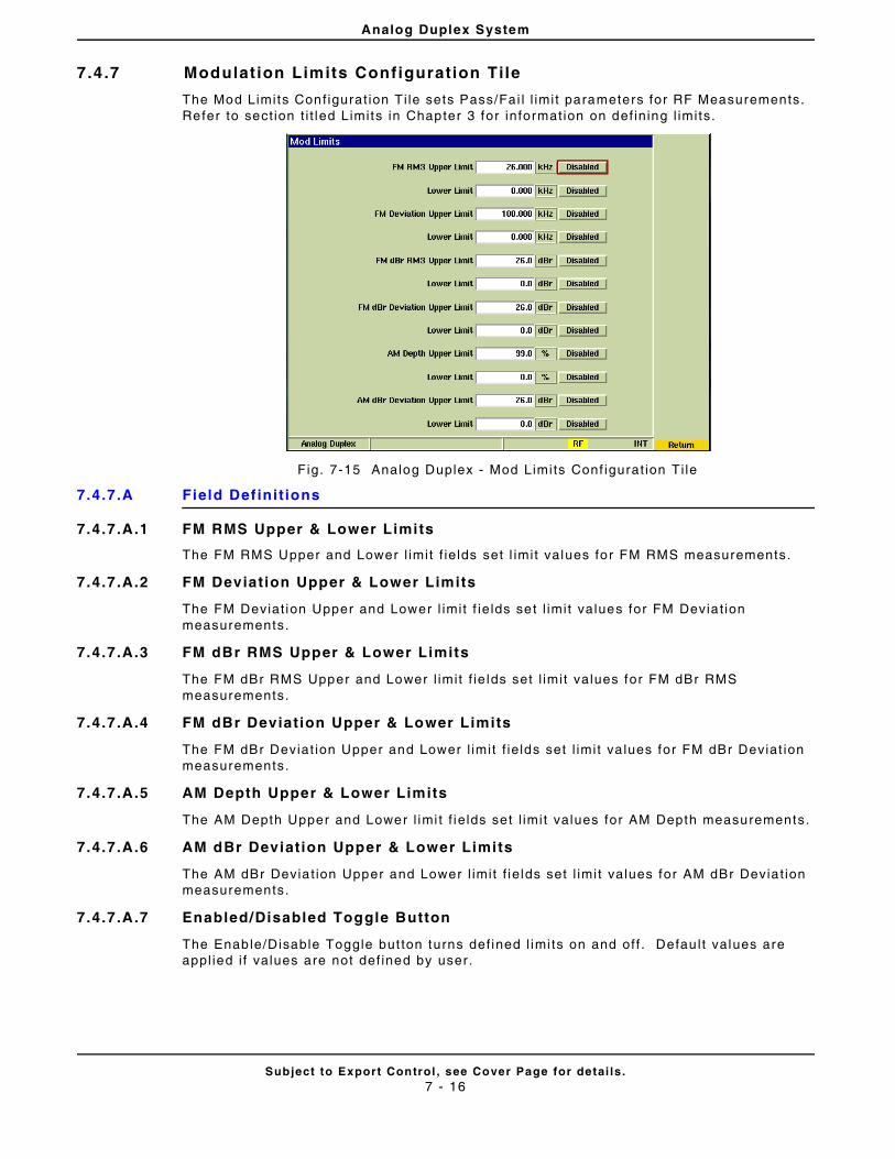
Analog Duplex System
Subject to Export Control , see Cover Page for detai ls .7 - 16
7.4 .7 Modulat ion Limits Configuration Tile
The Mod Limits Conf igurat ion Ti le sets Pass/Fai l l imi t parameters for RF Measurements. Refer to sect ion t i t led Limits in Chapter 3 for informat ion on def ining l imits.
Fig. 7-15 Analog Duplex - Mod Limits Conf igurat ion Ti le
7.4.7.A Field Def ini t ions
7.4.7.A.1 FM RMS Upper & Lower Limits
The FM RMS Upper and Lower l imit f ie lds set l imit values for FM RMS measurements.
7.4.7.A.2 FM Deviation Upper & Lower Limits
The FM Deviat ion Upper and Lower l imit f ie lds set l imit values for FM Devia t ion measurements.
7.4.7.A.3 FM dBr RMS Upper & Lower Limits
The FM dBr RMS Upper and Lower l imit f ie lds set l imit values for FM dBr RMS measurements.
7.4.7.A.4 FM dBr Deviation Upper & Lower Limits
The FM dBr Deviat ion Upper and Lower l imit f ie lds set l imit va lues for FM dBr Deviat ion measurements.
7.4.7.A.5 AM Depth Upper & Lower Limits
The AM Depth Upper and Lower l imi t f ie lds set l imi t values for AM Depth measurements.
7.4.7.A.6 AM dBr Deviation Upper & Lower Limits
The AM dBr Devia t ion Upper and Lower l imit f ie lds set l imit values for AM dBr Devia t ion measurements.
7.4.7.A.7 Enabled/Disabled Toggle Button
The Enable/Disable Toggle but ton turns def ined l imi ts on and off . Defau l t values are appl ied i f values are not def ined by user.
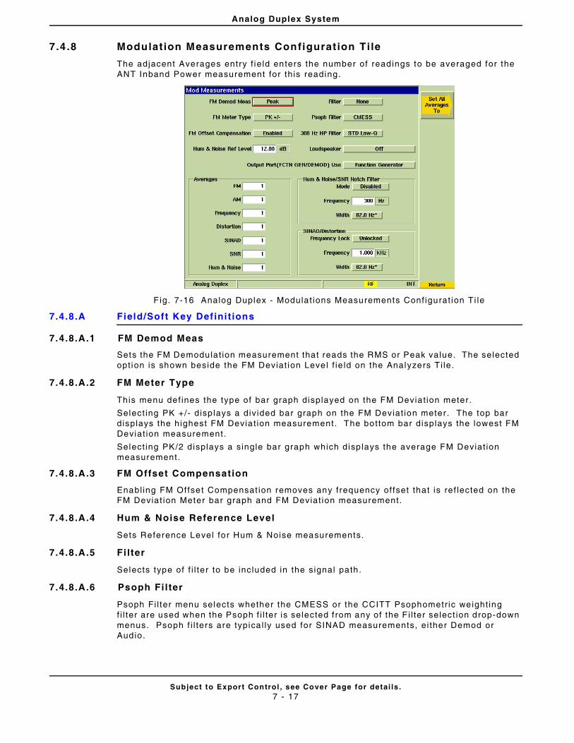
Analog Duplex System
Subject to Export Control , see Cover Page for detai ls .7 - 17
7.4 .8 Modulat ion Measurements Configurat ion Ti le
The adjacent Averages entry f ie ld enters the number of readings to be averaged for the ANT Inband Power measurement for th is reading.
F ig. 7-16 Analog Duplex - Modulat ions Measurements Conf igurat ion Ti le
7.4.8.A Field/Soft Key Def ini t ions
7.4.8.A.1 FM Demod Meas
Sets the FM Demodulat ion measurement that reads the RMS or Peak value. The selected opt ion is shown beside the FM Deviat ion Level f ie ld on the Analyzers T i le.
7.4.8.A.2 FM Meter Type
This menu def ines the type of bar graph displayed on the FM Deviat ion meter .
Select ing PK +/- disp lays a div ided bar graph on the FM Deviat ion meter. The top bar displays the highest FM Devia t ion measurement. The bottom bar displays the lowest FM Deviat ion measurement.
Select ing PK/2 d isplays a single bar graph which disp lays the average FM Deviat ion measurement.
7.4.8.A.3 FM Offset Compensation
Enabl ing FM Offset Compensat ion removes any frequency of fset that is ref lected on the FM Deviat ion Meter bar graph and FM Deviat ion measurement.
7.4.8.A.4 Hum & Noise Reference Level
Sets Reference Level for Hum & Noise measurements.
7.4.8.A.5 Fi lter
Selects type of f i l ter to be included in the signal path.
7.4.8.A.6 Psoph Fi l ter
Psoph Fi l ter menu selects whether the CMESS or the CCITT Psophometr ic weight ing f i l ter are used when the Psoph f i l ter is selected f rom any of the F i l ter select ion drop-down menus. Psoph f i l ters are typica l ly used for SINAD measurements, ei ther Demod or Audio.
Analog Duplex System
Subject to Export Control , see Cover Page for detai ls .7 - 18
7.4.8.A.7 300 Hz Fi lter Type
Selects type of 300 Hz f i l te r to be included in the signal path.
• Standard: Highpass 300 Hz Low-Q Fi l ter
• Sharp: Highpass 300 Hz high-Q Fi l ter
7.4.8.A.8 Loudspeaker
The Loudspeaker drop-down menu se lects the source and rout ing of the signal appl ied to the loudspeaker within the Test Set.
7.4.8.A.9 Output Port (FCTN GEN/DEMOD) Use
Selects the output connector on the front panel. Demod opt ions select the FCTN GEN/DEMOD Connector as the Demodulat ion Output. When a f i l tered output opt ion is selected, the f i l ter type is selected from the Psoph f i l ter drop-down menu.
7.4.8.A.10 Measurement Averages
The number of measurements taken to calculate the average values can be set indiv idual ly using the Measurement Averages f ie lds. Val id range values are from 1 to 250.
7.4.8.A.11 Hum & Noise/SNR Notch Fil ter Mode
Selects whether or not a notch f i l ter is used for per forming Hum and Noise/ SNR Measurements. When Hum and Noise/ SNR Notch F i l ter Mode is enabled the notch f i l ter removes the sub audible CTCSS or CDCSS tone.
7.4.8.A.12 Hum & Noise/SNR Notch Fil ter Frequency
This f ie ld def ines the frequency that is “notched out” when per forming Hum and Noise/ SNR Measurements.
7.4.8.A.13 Hum & Noise/SNR Notch Fil ter Width
This f ie ld sets the Notch Fi l ter Bandwidth used when per forming Hum and Noise/ SNR Measurements.
7.4.8.A.14 SINAD/Distn Frequency
Sets frequency at which SINAD or Distor t ion is measured.
7.4.8.A.15 SINAD/Distn Width
Sets Bandwidth for SINAD and Distor t ion measurements.
7.4.8.A.16 SINAD/Distn Frequency Mode
When Unlocked mode is selected the frequency at which SINAD or Distor t ion is measured is def ined by the SINAD/Distn Frequency Field . When Locked to A1 is se lected, the frequency at which SINAD or Distor t ion is measured is locked to the AF Generator 1 Frequency f ie ld on the Generators Ti le.
7.4.8.A.17 Set Al l Averages To Soft Key
Opens a soft key sub-menu that selects the number used to calculate al l RF Measurement averages.
Changing conf igurat ion to Demod Out whi le st i l l connected to the MIC/AF input of a radio under test may create a feedback loop.NOTE
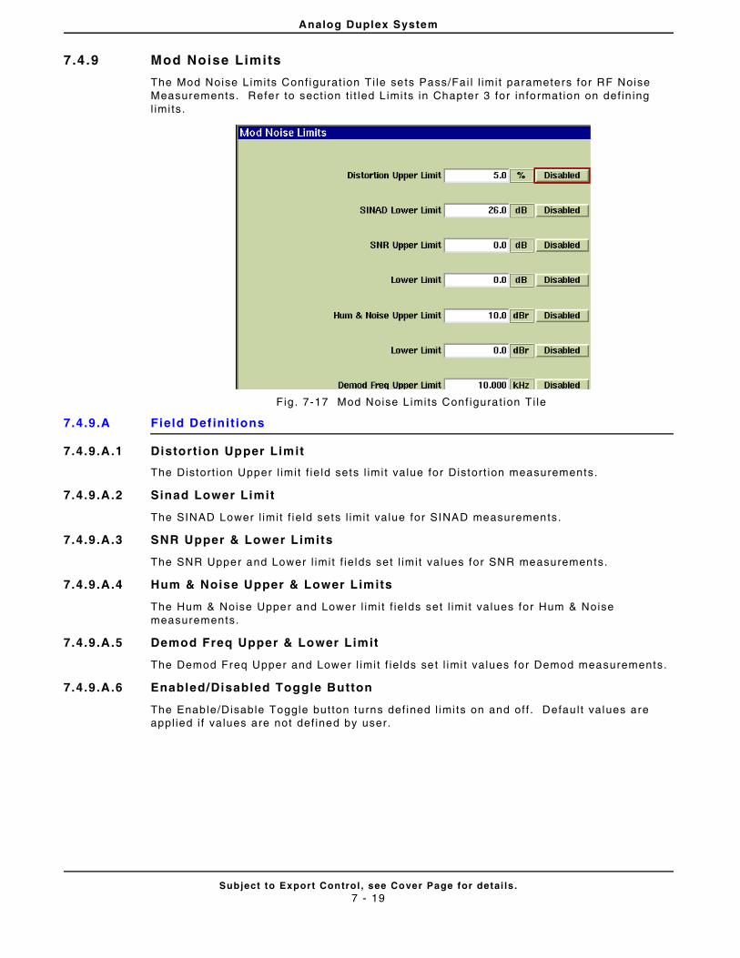
Analog Duplex System
Subject to Export Control , see Cover Page for detai ls .7 - 19
7.4 .9 Mod Noise Limits
The Mod Noise L imits Conf igurat ion Ti le sets Pass/Fai l l imi t parameters for RF Noise Measurements. Refer to sect ion t i t led L imits in Chapter 3 for information on def in ing l imi ts.
Fig . 7-17 Mod Noise L imits Conf igurat ion Ti le
7.4.9.A Field Def ini t ions
7.4.9.A.1 Distort ion Upper Limit
The Distort ion Upper l imit f ie ld sets l imit value for Distort ion measurements.
7.4.9.A.2 Sinad Lower Limit
The SINAD Lower l imit f ie ld sets l imit value for SINAD measurements.
7.4.9.A.3 SNR Upper & Lower Limits
The SNR Upper and Lower l imit f ie lds set l imit values for SNR measurements.
7.4.9.A.4 Hum & Noise Upper & Lower Limits
The Hum & Noise Upper and Lower l imit f ie lds set l imit values for Hum & Noise measurements.
7.4.9.A.5 Demod Freq Upper & Lower Limit
The Demod Freq Upper and Lower l imit f ie lds set l imi t values for Demod measurements.
7.4.9.A.6 Enabled/Disabled Toggle Button
The Enable/Disable Toggle but ton turns def ined l imi ts on and off . Defau l t values are appl ied i f values are not def ined by user.
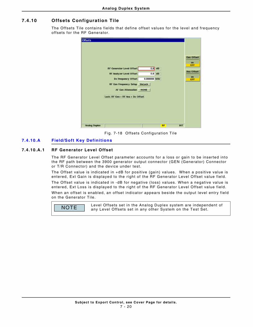
Analog Duplex System
Subject to Export Control , see Cover Page for detai ls .7 - 20
7.4 .10 Offsets Configuration Ti le
The Of fsets Ti le contains f ie lds that def ine of fset values for the leve l and frequency offsets for the RF Generator.
F ig. 7-18 Offsets Conf igurat ion T i le
7.4.10.A Field/Soft Key Def ini t ions
7.4.10.A.1 RF Generator Level Offset
The RF Generator Level Of fset parameter accounts for a loss or gain to be inserted into the RF path between the 3900 generator output connector (GEN (Generator) Connector or T/R Connector) and the device under test .
The Of fset value is indicated in +dB for posi t ive (ga in) values. When a posi t ive value is entered, Ext Gain is displayed to the r ight of the RF Generator Level Offset value f ie ld.
The Of fset value is indicated in -dB for negat ive ( loss) values. When a negat ive va lue is entered, Ext Loss is displayed to the r ight of the RF Generator Level Offset value f ie ld.
When an of fset is enabled, an of fset indicator appears beside the output level entry f ie ld on the Generator T i le.
Level Of fsets set in the Analog Duplex system are independent of any Level Offsets set in any other System on the Test Set.NOTE
Analog Duplex System
Subject to Export Control , see Cover Page for detai ls .7 - 21
7.4.10.A.2 RF Analyzers Level Offset
The RF Analyzer Level Offset accounts for a loss or gain to be inser ted into the RF path between the 3900 receiver input Connector (ANT (Antenna) Connector or T/R Connector.
The Of fset value is indicated in +dB for posi t ive (ga in) values. When a posi t ive value is entered, Ext Gain is displayed to the r ight of the RF Analyzers Level Of fset value f ie ld.
The Of fset value is indicated in -dB for negat ive ( loss) values. When a negat ive va lue is entered, Ext Loss is displayed to the r ight of the RF Analyzers Level Of fset value f ie ld.
7.4.10.A.3 Dx Frequency Offset
Dx Frequency Of fset al lows the f requency spacing between the RF Generator and the RF Analyzer to be set. A posi t ive value sets the RF Generator to a higher f requency than the RF Analyzer sett ing. Value speci f ied in MHz, kHz or Hz as def ined by user .
7.4.10.A.4 RF Gen Offset Mode
RF Gen Offset Mode Locks or Unlocks the frequency spacing between the RF Generator sett ing and the RF Analyzer sett ing. With the sett ing set to Lock the RF Generator f requency fol lows any change to the RF Analyzer set t ing with a spacing equal to the Dx Frequency Of fset value.
7.4.10.A.5 AF Generator Attenuation
The AF Generator Attenuat ion drop-down menu al lows the user to apply an of fset that compensates for a user suppl ied external at tenuat ion connected to the FCTN/GEN Demod Out Connector .
7.4.10.A.6 Gen Offset Soft Key
The Gen Offset Soft Key controls the use of the RF Generator Level Offset va lue.
ON inser ts the def ined RF Generator Level Of fset into the RF Path between the selected 3900 generator output connector and the device under test .
OFF removes the def ined RF Generator Level Offset f rom the RF Path between the selected 3900 generator output connector and the device under test .
7.4.10.A.7 Ana Offset Soft Key
The Ana Of fset Sof t Key controls the use of the RF Analyzers Level Of fset value.
ON inserts the def ined RF Analyzers Level Offset into the RF Path between the se lected 3900 receiver input connector and the device under test .
OFF removes the def ined RF Analyzers Level Of fset f rom the RF Path between the selected 3900 rece iver input connector and the device under test .
When an offset is enabled, an of fset indicator appears beside the power f ie ld on the Analyzers Ti le and in the upper lef t hand corner of the Channel Analyzer Ti le.
When an offset is enabled, an of fset indicator appears beside the output level ent ry f ie ld on the Generators Ti le.
NOTE
NOTE
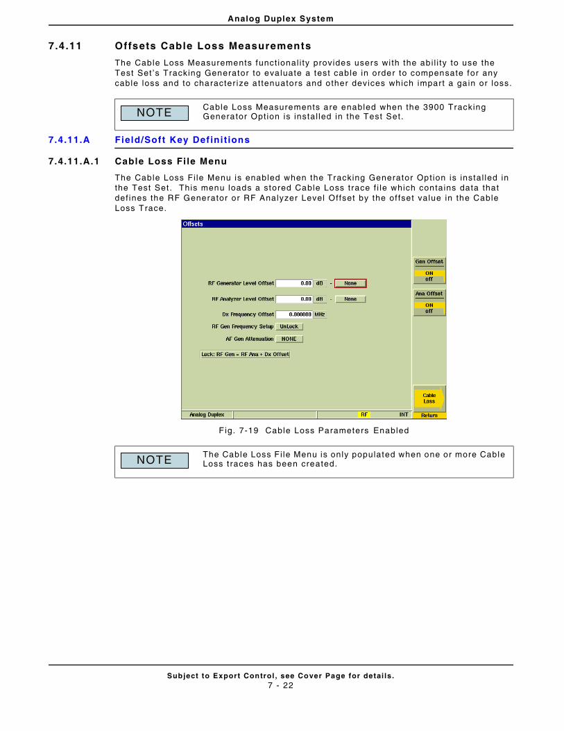
Analog Duplex System
Subject to Export Control , see Cover Page for detai ls .7 - 22
7.4 .11 Offsets Cable Loss Measurements
The Cable Loss Measurements funct ional i ty provides users wi th the ab i l i ty to use the Test Set ’s Tracking Generator to eva luate a test cab le in order to compensate for any cable loss and to character ize a t tenuators and other devices which impart a ga in or loss.
7.4.11.A Field/Soft Key Def ini t ions
7.4.11.A.1 Cable Loss Fi le Menu
The Cable Loss Fi le Menu is enabled when the Tracking Generator Opt ion is instal led in the Test Set . This menu loads a stored Cable Loss trace f i le which contains data that def ines the RF Generator or RF Analyzer Level Offset by the of fset value in the Cable Loss Trace.
F ig. 7-19 Cable Loss Parameters Enabled
Cable Loss Measurements are enabled when the 3900 Tracking Generator Opt ion is instal led in the Test Set.
The Cable Loss F i le Menu is only populated when one or more Cable Loss t races has been created.
NOTE
NOTE
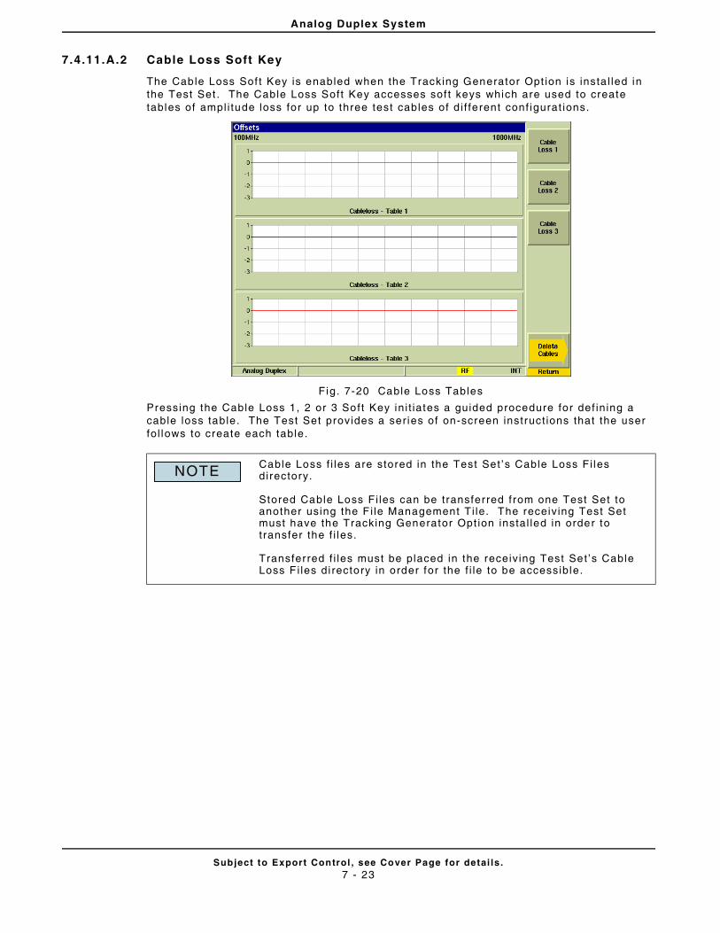
Analog Duplex System
Subject to Export Control , see Cover Page for detai ls .7 - 23
7.4.11.A.2 Cable Loss Soft Key
The Cable Loss Sof t Key is enabled when the Tracking Generator Opt ion is insta l led in the Test Set . The Cable Loss Soft Key accesses sof t keys which are used to create tables of ampl i tude loss for up to three test cables of d i f ferent conf igurat ions.
Fig. 7-20 Cable Loss Tables
Pressing the Cable Loss 1, 2 or 3 Soft Key in i t iates a guided procedure for def in ing a cable loss table. The Test Set provides a ser ies of on-screen instruct ions that the user fo l lows to create each table.
Cable Loss f i les are stored in the Test Set ’s Cable Loss Fi les directory.
Stored Cable Loss Fi les can be transferred from one Test Set to another using the F i le Management Ti le. The receiv ing Test Set must have the Tracking Generator Opt ion instal led in order to t ransfer the f i les.
Transferred f i les must be placed in the receiv ing Test Set ’s Cable Loss F i les di rectory in order for the f i le to be accessible.
NOTE
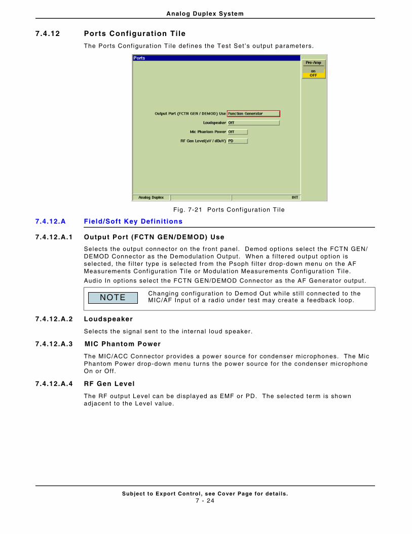
Analog Duplex System
Subject to Export Control , see Cover Page for detai ls .7 - 24
7.4 .12 Ports Configurat ion Ti le
The Ports Conf igurat ion Ti le def ines the Test Set ’s output parameters.
Fig . 7-21 Por ts Conf igurat ion Ti le
7.4.12.A Field/Soft Key Def ini t ions
7.4.12.A.1 Output Port (FCTN GEN/DEMOD) Use
Selects the output connector on the front panel. Demod opt ions select the FCTN GEN/DEMOD Connector as the Demodulat ion Output. When a f i l tered output opt ion is selected, the f i l ter type is selected from the Psoph f i l ter drop-down menu on the AF Measurements Conf igurat ion Ti le or Modulat ion Measurements Conf igurat ion Ti le.
Audio In opt ions select the FCTN GEN/DEMOD Connector as the AF Generator output .
7.4.12.A.2 Loudspeaker
Selects the signal sent to the internal loud speaker.
7.4.12.A.3 MIC Phantom Power
The MIC/ACC Connector provides a power source for condenser microphones. The Mic Phantom Power drop-down menu turns the power source for the condenser microphone On or Off .
7.4.12.A.4 RF Gen Level
The RF output Level can be displayed as EMF or PD. The selected term is shown adjacent to the Level value.
Changing conf igurat ion to Demod Out whi le st i l l connected to the MIC/AF Input o f a radio under test may create a feedback loop.NOTE
Analog Duplex System
Subject to Export Control , see Cover Page for detai ls .7 - 25
7.4.12.A.5 Pre-Amp Soft Key
The 3900 is equipped with an internal 15 dB broadband ampl i f ier that af fects the T/R and ANT Input Por ts. When Pre-Amp is ON, the 3900 has a typical noise f igure of -9 dB, resul t ing in a noise f loor level around -140 dBm in the spect rum analyzer (RBW = 300 Hz) and around -126 dBm for the Inband power meter ( IF = 6 .25 kHz). Use of the Pre-Amp feature dramatical ly increases the sensi t iv i ty of the 3900.
When Pre-Amp is used, special a t tent ion is required; i t is a broadband ampl i f ier and could lead to saturat ion or compression problems in the receiver cha in i f the signal of interest is very low, but a strong out of band signal is present.
NOTE
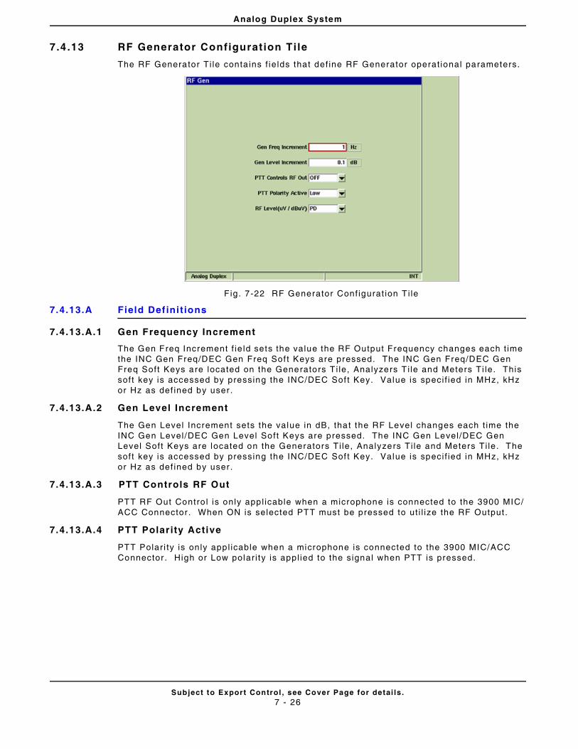
Analog Duplex System
Subject to Export Control , see Cover Page for detai ls .7 - 26
7.4 .13 RF Generator Configurat ion Ti le
The RF Generator Ti le conta ins f ie lds that def ine RF Generator operat ional parameters.
F ig. 7-22 RF Generator Conf igurat ion T i le
7.4.13.A Field Def ini t ions
7.4.13.A.1 Gen Frequency Increment
The Gen Freq Increment f ie ld sets the value the RF Output Frequency changes each t ime the INC Gen Freq/DEC Gen Freq Sof t Keys are pressed. The INC Gen Freq/DEC Gen Freq Soft Keys are located on the Generators T i le, Analyzers T i le and Meters Ti le. This soft key is accessed by pressing the INC/DEC Sof t Key. Value is speci f ied in MHz, kHz or Hz as def ined by user .
7.4.13.A.2 Gen Level Increment
The Gen Level Increment sets the value in dB, that the RF Level changes each t ime the INC Gen Level /DEC Gen Level Soft Keys are pressed. The INC Gen Level /DEC Gen Level Soft Keys are located on the Generators Ti le, Analyzers Ti le and Meters Ti le. The soft key is accessed by pressing the INC/DEC Sof t Key. Value is speci f ied in MHz, kHz or Hz as def ined by user .
7.4.13.A.3 PTT Controls RF Out
PTT RF Out Contro l is only appl icable when a microphone is connected to the 3900 MIC/ACC Connector . When ON is selected PTT must be pressed to ut i l ize the RF Output .
7.4.13.A.4 PTT Polarity Active
PTT Polar i ty is only appl icable when a microphone is connected to the 3900 MIC/ACC Connector . High or Low polar i ty is appl ied to the signal when PTT is pressed.
Analog Duplex System
Subject to Export Control , see Cover Page for detai ls .7 - 27
7.4.13.A.5 RF Level
The RF Level f ie ld selects whether the RF Generator Output Level , when given in mV (micro Vol t) is expressed in a PD or EMF reference system.
μV (PD) = micro Volts Potential Dif ference
Circui t is c losed onto a matching load that is equal to the output impedance of the source. The PD reference system includes a vol tage 1:2 div ider at the load.
μV (EMF) = micro Volts Electromotive Force
Circui t is open, or c losed onto an inf in i te load. The EMF reference system does not contain a vo l tage div ider at the load, resul t ing in values two t imes larger than those in the PD reference system. For example, -120 dBm is equal to 0.225 mV (PD) or 0.45 mV (EMF).
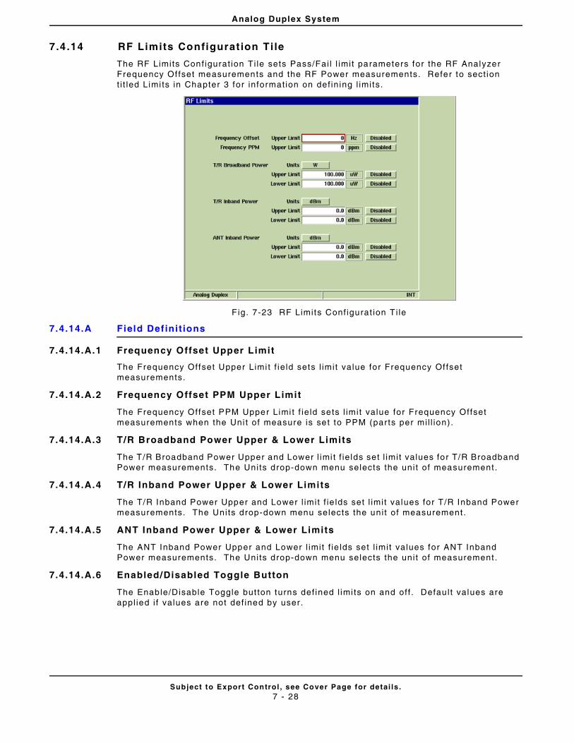
Analog Duplex System
Subject to Export Control , see Cover Page for detai ls .7 - 28
7.4 .14 RF Limits Configurat ion Ti le
The RF Limits Conf igurat ion Ti le sets Pass/Fai l l imit parameters for the RF Analyzer Frequency Of fset measurements and the RF Power measurements. Refer to sect ion t i t led Limi ts in Chapter 3 for informat ion on def in ing l imits.
F ig. 7-23 RF Limits Conf igurat ion T i le
7.4.14.A Field Def ini t ions
7.4.14.A.1 Frequency Offset Upper Limit
The Frequency Offset Upper Limi t f ie ld sets l imit value for Frequency Of fset measurements.
7.4.14.A.2 Frequency Offset PPM Upper Limit
The Frequency Offset PPM Upper Limi t f ie ld sets l imit value for Frequency Offset measurements when the Uni t of measure is set to PPM (parts per mi l l ion).
7.4.14.A.3 T/R Broadband Power Upper & Lower Limits
The T/R Broadband Power Upper and Lower l imi t f ie lds set l imit values for T/R Broadband Power measurements. The Units drop-down menu selects the uni t of measurement .
7.4.14.A.4 T/R Inband Power Upper & Lower Limits
The T/R Inband Power Upper and Lower l imit f ie lds set l imit values for T/R Inband Power measurements. The Units drop-down menu selects the uni t of measurement .
7.4.14.A.5 ANT Inband Power Upper & Lower Limits
The ANT Inband Power Upper and Lower l imit f ie lds set l imit values for ANT Inband Power measurements. The Units drop-down menu selects the uni t of measurement .
7.4.14.A.6 Enabled/Disabled Toggle Button
The Enable/Disable Toggle but ton turns def ined l imi ts on and off . Defau l t values are appl ied i f values are not def ined by user.
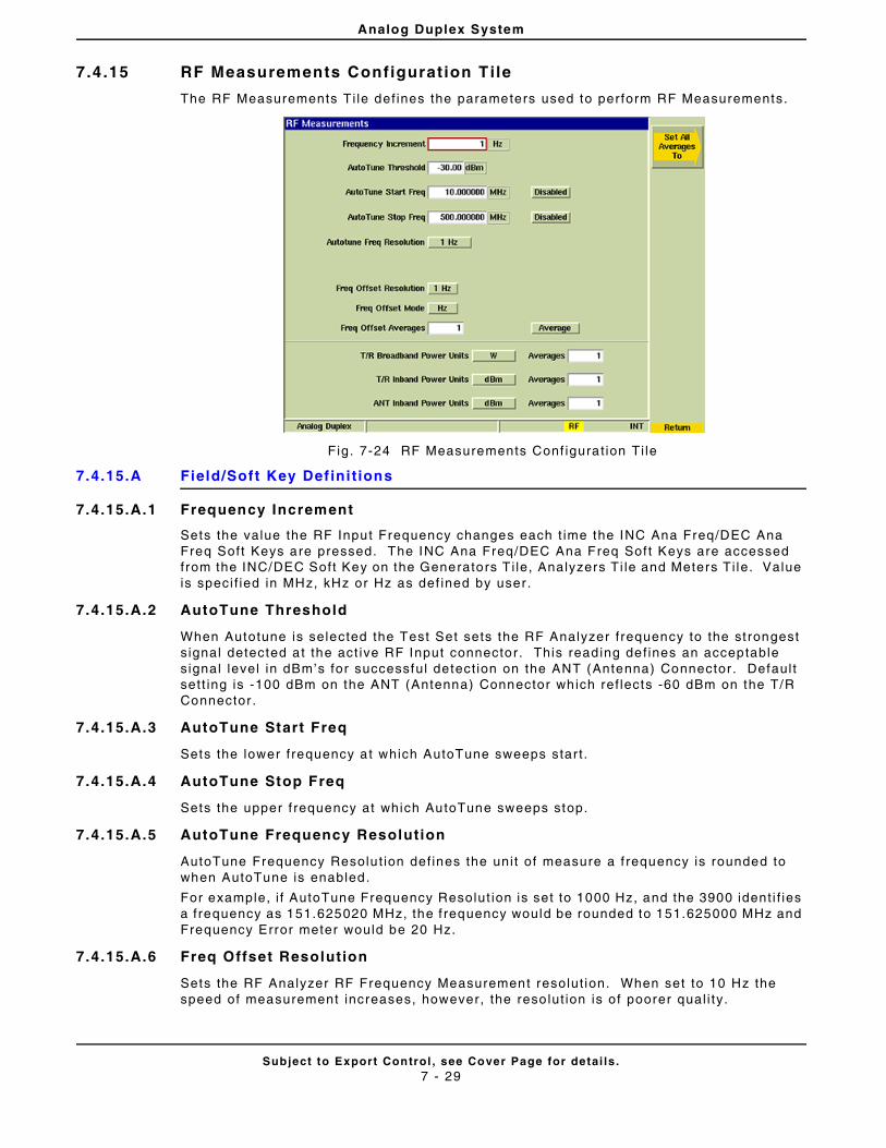
Analog Duplex System
Subject to Export Control , see Cover Page for detai ls .7 - 29
7.4 .15 RF Measurements Configurat ion Tile
The RF Measurements T i le def ines the parameters used to per form RF Measurements.
Fig. 7-24 RF Measurements Conf igurat ion Ti le
7.4.15.A Field/Soft Key Def ini t ions
7.4.15.A.1 Frequency Increment
Sets the value the RF Input Frequency changes each t ime the INC Ana Freq/DEC Ana Freq Soft Keys are pressed. The INC Ana Freq/DEC Ana Freq Sof t Keys are accessed from the INC/DEC Soft Key on the Generators T i le, Analyzers Ti le and Meters Ti le. Value is speci f ied in MHz, kHz or Hz as def ined by user .
7.4.15.A.2 AutoTune Threshold
When Autotune is selected the Test Set sets the RF Analyzer f requency to the st rongest s ignal detected at the act ive RF Input connector. This reading def ines an acceptable s ignal level in dBm’s for successful detect ion on the ANT (Antenna) Connector . Defaul t sett ing is -100 dBm on the ANT (Antenna) Connector which ref lects -60 dBm on the T/R Connector .
7.4.15.A.3 AutoTune Start Freq
Sets the lower f requency at which AutoTune sweeps star t .
7.4.15.A.4 AutoTune Stop Freq
Sets the upper f requency at which AutoTune sweeps stop.
7.4.15.A.5 AutoTune Frequency Resolution
AutoTune Frequency Resolut ion def ines the uni t of measure a f requency is rounded to when AutoTune is enabled.
For example, i f AutoTune Frequency Resolut ion is set to 1000 Hz, and the 3900 ident i f ies a f requency as 151.625020 MHz, the f requency would be rounded to 151.625000 MHz and Frequency Error meter would be 20 Hz.
7.4.15.A.6 Freq Offset Resolution
Sets the RF Analyzer RF Frequency Measurement resolut ion. When set to 10 Hz the speed of measurement increases, however, the reso lut ion is of poorer qual i ty.
Analog Duplex System
Subject to Export Control , see Cover Page for detai ls .7 - 30
7.4.15.A.7 Freq Offset Averages
The Freq Offset Averages drop-down menu al lows the select ion of Averages or Worst Case readings.
When Average is selected, the range value f ie ld sets the number of readings averaged for the RF Offset Measurement. This f ie ld is not appl icab le when Worst Case is selected.
When Worst Case is selected from the drop-down menu, the RF Of fset Measurement on the Analyzers Ti le ref lects the reading which most great ly exceeds the def ined parameters.
7.4.15.A.8 T/R Broadband Power Units
The T/R Broadband Power Units f ie ld selects the uni t of measurement for the T/R Broadband Power reading.
The adjacent Averages entry f ie ld enters the number of readings to be averaged for the T/R Broadband Power measurement.
7.4.15.A.9 T/R Inband Power Units
The T/R Inband Power Units f ie ld selects the uni t of measurement for the T/R Inband Power reading.
The adjacent Averages entry f ie ld enters the number of readings to be averaged for the T/R Inband Power measurement for this reading.
7.4.15.A.10 ANT Inband Power Units
The Antenna Inband Power Units f ie ld se lects the uni t o f measurement for the ANT Inband Power reading.
The adjacent Averages entry f ie ld enters the number of readings to be averaged for the ANT Inband Power measurement for th is reading.
7.4.15.A.11 Set Al l Averages To Soft Key
Opens a soft key sub-menu that selects the number used to calculate al l RF Measurement averages.
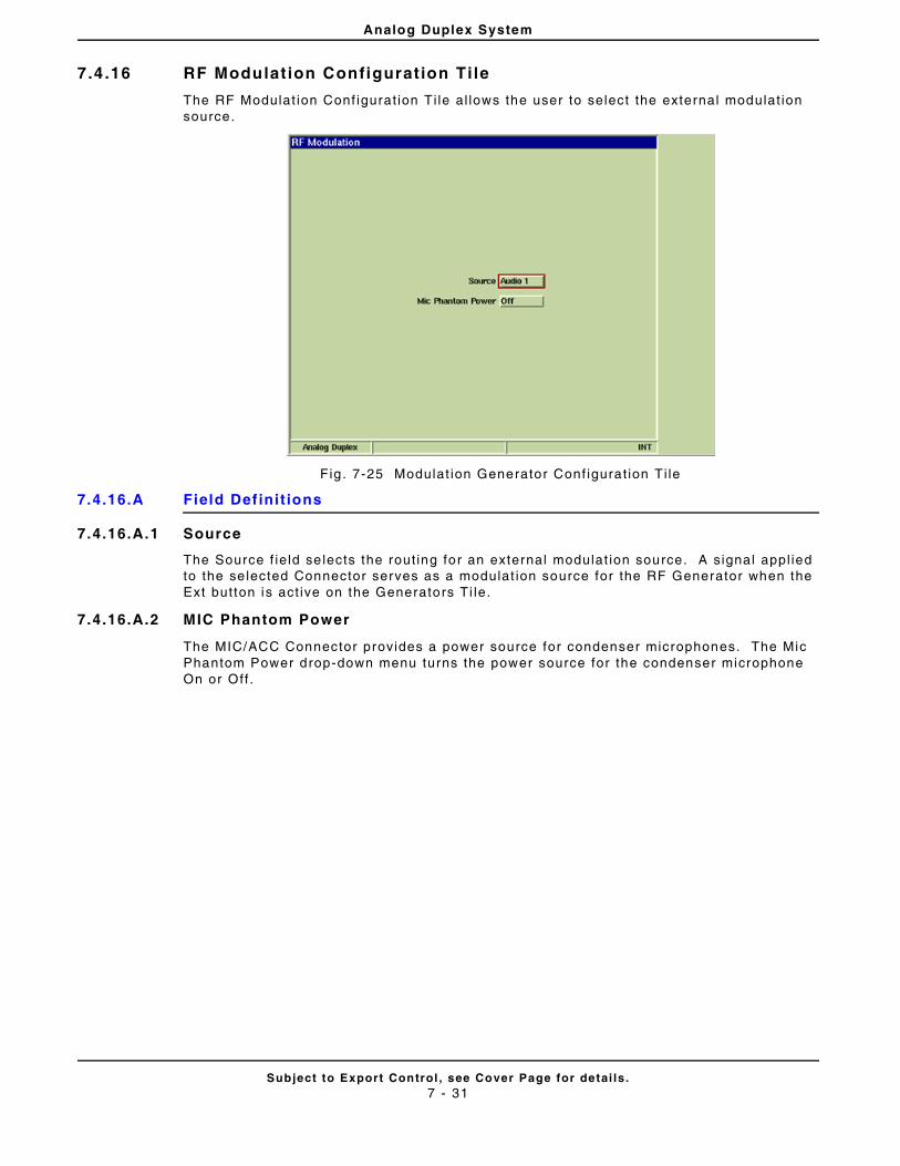
Analog Duplex System
Subject to Export Control , see Cover Page for detai ls .7 - 31
7.4 .16 RF Modulat ion Configurat ion Ti le
The RF Modulat ion Conf igurat ion Ti le al lows the user to select the external modulat ion source.
Fig . 7-25 Modulat ion Generator Conf igurat ion Ti le
7.4.16.A Field Def ini t ions
7.4.16.A.1 Source
The Source f ie ld se lects the rout ing for an external modulat ion source. A signal appl ied to the se lected Connector serves as a modulat ion source for the RF Generator when the Ext button is act ive on the Generators Ti le.
7.4.16.A.2 MIC Phantom Power
The MIC/ACC Connector provides a power source for condenser microphones. The Mic Phantom Power drop-down menu turns the power source for the condenser microphone On or Off .
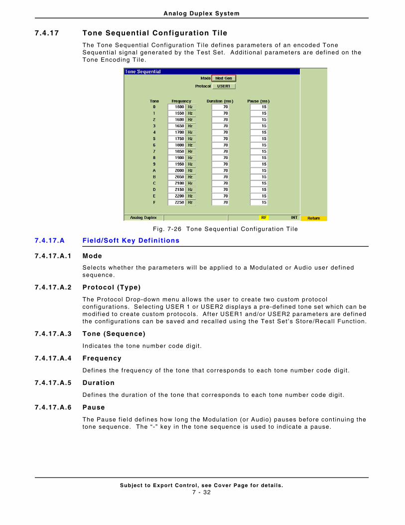
Analog Duplex System
Subject to Export Control , see Cover Page for detai ls .7 - 32
7.4 .17 Tone Sequential Configurat ion Ti le
The Tone Sequent ial Conf igurat ion Ti le def ines parameters o f an encoded Tone Sequent ia l s ignal generated by the Test Set. Addit ional parameters are def ined on the Tone Encoding T i le.
Fig. 7-26 Tone Sequent ial Conf igurat ion Ti le
7.4.17.A Field/Soft Key Def ini t ions
7.4.17.A.1 Mode
Selects whether the parameters wi l l be appl ied to a Modulated or Audio user def ined sequence.
7.4.17.A.2 Protocol (Type)
The Protocol Drop-down menu a l lows the user to create two custom protocol conf igurat ions. Select ing USER 1 or USER2 displays a pre-def ined tone set which can be modif ied to create custom protocols. Af ter USER1 and/or USER2 parameters are def ined the conf igurat ions can be saved and reca l led using the Test Set ’s Store/Recal l Funct ion.
7.4.17.A.3 Tone (Sequence)
Indicates the tone number code digi t .
7.4.17.A.4 Frequency
Defines the f requency of the tone that corresponds to each tone number code digi t .
7.4.17.A.5 Duration
Defines the durat ion of the tone that corresponds to each tone number code digi t .
7.4.17.A.6 Pause
The Pause f ie ld def ines how long the Modulat ion (or Audio) pauses before cont inuing the tone sequence. The “ -” key in the tone sequence is used to indicate a pause.
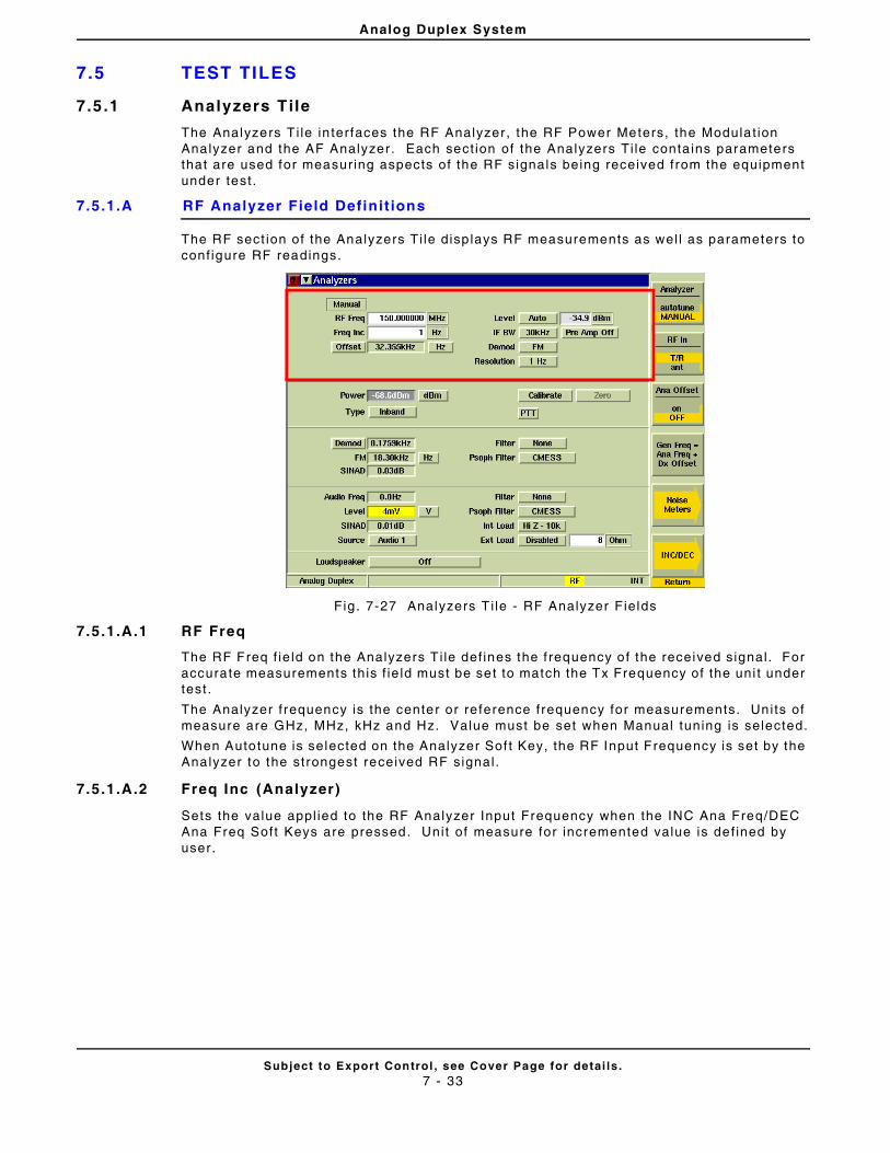
Analog Duplex System
Subject to Export Control , see Cover Page for detai ls .7 - 33
7.5 TEST TILES
7.5.1 Analyzers Tile
The Analyzers T i le in terfaces the RF Analyzer , the RF Power Meters, the Modulat ion Analyzer and the AF Analyzer . Each sect ion of the Analyzers Ti le conta ins parameters that are used for measuring aspects of the RF signals being received from the equipment under test .
7.5.1.A RF Analyzer Field Defini t ions
The RF sect ion of the Analyzers Ti le disp lays RF measurements as wel l as parameters to conf igure RF readings.
Fig . 7-27 Analyzers T i le - RF Analyzer Fields
7.5.1.A.1 RF Freq
The RF Freq f ie ld on the Analyzers T i le def ines the f requency of the received signal . For accurate measurements this f ie ld must be set to match the Tx Frequency of the uni t under test .
The Analyzer f requency is the center or re ference frequency for measurements. Uni ts of measure are GHz, MHz, kHz and Hz. Value must be set when Manual tuning is selected.
When Autotune is selected on the Analyzer Sof t Key, the RF Input Frequency is set by the Analyzer to the strongest received RF signal .
7.5.1.A.2 Freq Inc (Analyzer)
Sets the value appl ied to the RF Analyzer Input Frequency when the INC Ana Freq/DEC Ana Freq Soft Keys are pressed. Unit of measure for incremented value is def ined by user.
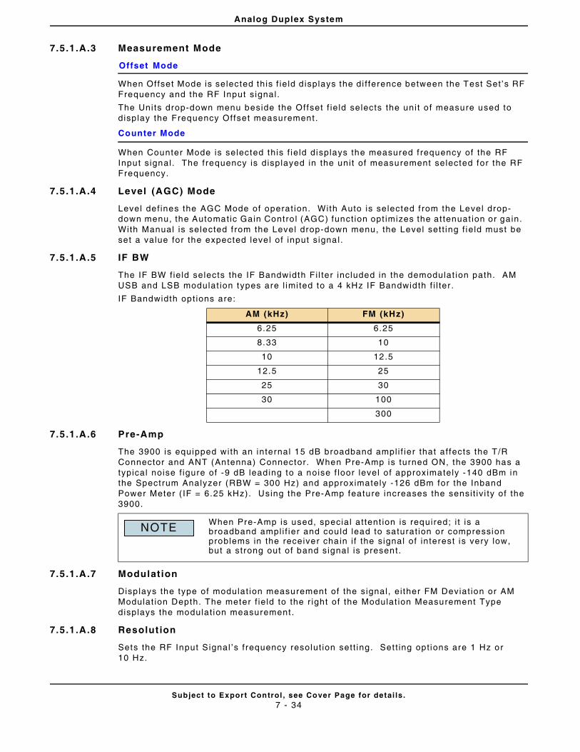
Analog Duplex System
Subject to Export Control , see Cover Page for detai ls .7 - 34
7.5.1.A.3 Measurement Mode
Offset Mode
When Offset Mode is selected this f ie ld d isplays the di f ference between the Test Set ’s RF Frequency and the RF Input s ignal .
The Uni ts drop-down menu beside the Offset f ie ld selects the uni t o f measure used to display the Frequency Offset measurement .
Counter Mode
When Counter Mode is selected this f ie ld displays the measured f requency of the RF Input s ignal . The frequency is displayed in the uni t of measurement selected for the RF Frequency.
7.5.1.A.4 Level (AGC) Mode
Level def ines the AGC Mode of operat ion. With Auto is selected f rom the Level drop-down menu, the Automatic Gain Contro l (AGC) funct ion opt imizes the at tenuat ion or gain. With Manual is selected f rom the Level drop-down menu, the Level sett ing f ie ld must be set a value for the expected leve l of input s ignal .
7.5.1.A.5 IF BW
The IF BW f ie ld selects the IF Bandwidth Fi l ter included in the demodulat ion path. AM USB and LSB modulat ion types are l imi ted to a 4 kHz IF Bandwidth f i l ter .
IF Bandwidth opt ions are:
7.5.1.A.6 Pre-Amp
The 3900 is equipped with an internal 15 dB broadband ampl i f ier that af fects the T/R Connector and ANT (Antenna) Connector. When Pre-Amp is turned ON, the 3900 has a typical noise f igure of -9 dB leading to a noise f loor level of approximately -140 dBm in the Spectrum Analyzer (RBW = 300 Hz) and approximately -126 dBm for the Inband Power Meter ( IF = 6.25 kHz). Using the Pre-Amp feature increases the sensi t iv i ty of the 3900.
7.5.1.A.7 Modulation
Disp lays the type of modulat ion measurement of the signal , e i ther FM Deviat ion or AM Modulat ion Depth. The meter f ie ld to the r ight of the Modulat ion Measurement Type displays the modulat ion measurement .
7.5.1.A.8 Resolut ion
Sets the RF Input Signal ’s f requency resolut ion sett ing. Set t ing opt ions are 1 Hz or 10 Hz.
AM (kHz) FM (kHz)
6.25 6.25
8.33 10
10 12.5
12.5 25
25 30
30 100
300
When Pre-Amp is used, special a t tent ion is required; i t is a broadband ampl i f ier and could lead to saturat ion or compression problems in the receiver cha in i f the signal of interest is very low, but a strong out of band signal is present.
NOTE
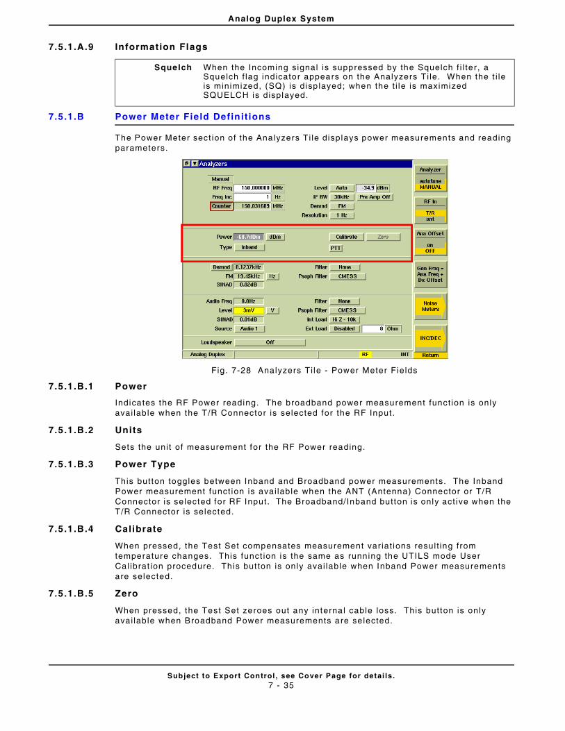
Analog Duplex System
Subject to Export Control , see Cover Page for detai ls .7 - 35
7.5.1.A.9 Information Flags
7.5.1.B Power Meter Field Definit ions
The Power Meter sect ion of the Analyzers Ti le displays power measurements and reading parameters.
Fig. 7-28 Analyzers Ti le - Power Meter Fields
7.5.1.B.1 Power
Indicates the RF Power reading. The broadband power measurement funct ion is only avai lab le when the T/R Connector is selected for the RF Input.
7.5.1.B.2 Units
Sets the uni t of measurement for the RF Power reading.
7.5.1.B.3 Power Type
This button toggles between Inband and Broadband power measurements. The Inband Power measurement funct ion is avai lable when the ANT (Antenna) Connector or T/R Connector is selected for RF Input. The Broadband/Inband button is only act ive when the T/R Connector is selected.
7.5.1.B.4 Calibrate
When pressed, the Test Set compensates measurement var iat ions resul t ing from temperature changes. This funct ion is the same as running the UTILS mode User Cal ibrat ion procedure. Th is but ton is only avai lable when Inband Power measurements are selected.
7.5.1.B.5 Zero
When pressed, the Test Set zeroes out any interna l cable loss. This button is only avai lab le when Broadband Power measurements are se lected.
Squelch When the Incoming signal is suppressed by the Squelch f i l te r, a Squelch f lag indicator appears on the Analyzers Ti le. When the t i le is minimized, (SQ) is disp layed; when the t i le is maximized SQUELCH is displayed.
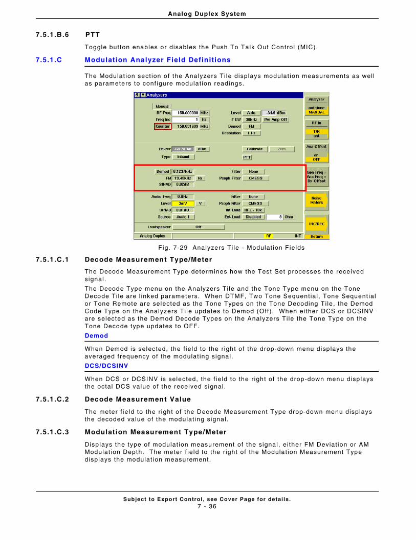
Analog Duplex System
Subject to Export Control , see Cover Page for detai ls .7 - 36
7.5.1.B.6 PTT
Toggle but ton enables or disables the Push To Talk Out Control (MIC).
7.5.1.C Modulation Analyzer Field Definit ions
The Modulat ion sect ion of the Analyzers Ti le displays modulat ion measurements as wel l as parameters to conf igure modulat ion readings.
Fig. 7-29 Analyzers Ti le - Modulat ion F ields
7.5.1.C.1 Decode Measurement Type/Meter
The Decode Measurement Type determines how the Test Set processes the received signal .
The Decode Type menu on the Analyzers Ti le and the Tone Type menu on the Tone Decode Ti le are l inked parameters. When DTMF, Two Tone Sequent ial , Tone Sequent ial or Tone Remote are selected as the Tone Types on the Tone Decoding Ti le , the Demod Code Type on the Analyzers Ti le updates to Demod (Off) . When ei ther DCS or DCSINV are selected as the Demod Decode Types on the Analyzers Ti le the Tone Type on the Tone Decode type updates to OFF.
Demod
When Demod is selected, the f ie ld to the r ight of the drop-down menu disp lays the averaged f requency of the modulat ing signal .
DCS/DCSINV
When DCS or DCSINV is selected, the f ie ld to the r ight of the drop-down menu disp lays the octal DCS value of the received signal .
7.5.1.C.2 Decode Measurement Value
The meter f ie ld to the r ight of the Decode Measurement Type drop-down menu disp lays the decoded value of the modulat ing signal .
7.5.1.C.3 Modulation Measurement Type/Meter
Disp lays the type of modulat ion measurement of the signal , e i ther FM Deviat ion or AM Modulat ion Depth. The meter f ie ld to the r ight of the Modulat ion Measurement Type displays the modulat ion measurement .
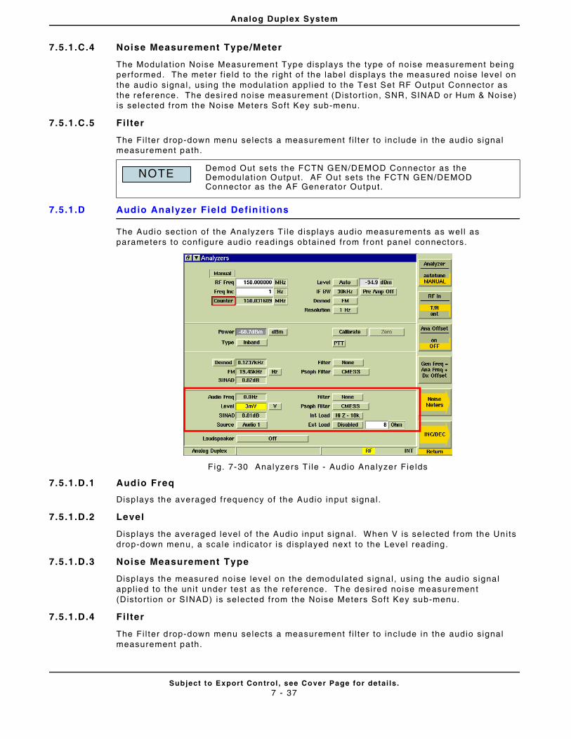
Analog Duplex System
Subject to Export Control , see Cover Page for detai ls .7 - 37
7.5.1.C.4 Noise Measurement Type/Meter
The Modulat ion Noise Measurement Type displays the type of noise measurement being per formed. The meter f ie ld to the r ight of the label displays the measured noise level on the audio signal , using the modulat ion appl ied to the Test Set RF Output Connector as the reference. The desired noise measurement (Distort ion, SNR, SINAD or Hum & Noise) is selected f rom the Noise Meters Soft Key sub-menu.
7.5.1.C.5 Fi lter
The Fi l ter drop-down menu selects a measurement f i l ter to include in the audio signal measurement path.
7.5.1.D Audio Analyzer Field Definit ions
The Audio sect ion of the Analyzers T i le d isplays audio measurements as wel l as parameters to conf igure audio readings obtained from front panel connectors.
Fig. 7-30 Analyzers T i le - Audio Analyzer Fie lds
7.5.1.D.1 Audio Freq
Disp lays the averaged frequency of the Audio input signal .
7.5.1.D.2 Level
Disp lays the averaged level of the Audio input s ignal . When V is se lected f rom the Units drop-down menu, a scale indicator is displayed next to the Level reading.
7.5.1.D.3 Noise Measurement Type
Disp lays the measured no ise leve l on the demodulated signal , using the audio s ignal appl ied to the uni t under test as the reference. The desired noise measurement (Distor t ion or SINAD) is selected from the Noise Meters Soft Key sub-menu.
7.5.1.D.4 Fi lter
The Fi l ter drop-down menu selects a measurement f i l ter to include in the audio signal measurement path.
Demod Out sets the FCTN GEN/DEMOD Connector as the Demodulat ion Output. AF Out sets the FCTN GEN/DEMOD Connector as the AF Generator Output.
NOTE
Analog Duplex System
Subject to Export Control , see Cover Page for detai ls .7 - 38
7.5.1.D.5 Units
Selects the uni t of measure for the Level reading. Avai lable value is l imi ted by selected audio input Source. For example, the Balanced audio input Source can be set to ei ther dBm or dBr: V is not avai lable as an opt ion. When V is selected, a sca l ing value indicator (mV) is displayed beside the Level reading f ie ld on the Generators Ti le .
7.5.1.D.6 Source
Selects the Audio input source for base band receive measurements and Tone Decoding.
7.5.1.D.7 Int Load
Selects ei ther the 10 kOhm or 600 Ohm in ternal load to be appl ied at the Audio 1 or Audio 2 Input . Remote Commands
7.5.1.D.8 External Load
The Ext Load toggle but ton enables/disables the use of an external load. The 3900 al lows the user to def ine an external load va lue which is appl ied at the Audio 1 or Audio 2 Input por ts. The external load value is appl ied to AF Level dBm or Watt measurements when the External Load is enabled.
External Load is disab led when Balanced is selected as the Audio Input Source.
7.5.1.D.9 Loudspeaker
The Loudspeaker drop-down menu selects the source and rout ing of the demod/audio signal appl ied to the loudspeaker within the Test Set.
7.5.1.E Soft Key Definit ions
7.5.1.E.1 Analyzer Soft Key
The Analyzer Sof t Key selects the method of set t ing the RF input f requency (Autotune or Manual) . When Autotune is selected the Test Set locks on to the strongest s ignal . Once the Test Set locks on to a f requency, i t monitors the Inband/Broadband Power Meter depending on the selected RF Input connector.
T/R Connector
When the T/R Connector is selected Autotune monitors the Inband and Broadband Power Meter . I f Inband Power drops be low the dB threshold def ined on the RF Measurements Conf igurat ion Ti le, and BroadBand Power exceeds 3 dBm, a search is t r iggered and the Test Set again searches for the st rongest s ignal wi th a power level above the def ined threshold.
ANT Connector
When the ANT Connector is selected Autotune monitors the Inband Power Meter. I f Inband Power drops below the dB threshold def ined on the RF Measurements Conf igurat ion Ti le , a search is t iggered and the Test Set again searches for the strongest s ignal wi th a power level above the def ined threshold.
7.5.1.E.2 RF In Soft Key
The RF In Soft Key controls the RF Input s ignal rout ing. Select ei ther the T/R Connector or ANT (Antenna) Connector as the RF Input port .
7.5.1.E.3 Ana Offset Soft Key
Appl ies or removes a level o f fset value to the analyzer input . With the Of fset value ON the input power leve l readings are ad justed to include the of fset value. Th is va lue is set on the Offsets Conf igurat ion Ti le and Analyzers Ti le.
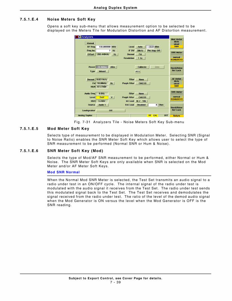
Analog Duplex System
Subject to Export Control , see Cover Page for detai ls .7 - 39
7.5.1.E.4 Noise Meters Soft Key
Opens a soft key sub-menu that al lows measurement opt ion to be se lected to be displayed on the Meters Ti le for Modulat ion Distort ion and AF Distor t ion measurement.
Fig. 7-31 Analyzers Ti le - Noise Meters Soft Key Sub-menu
7.5.1.E.5 Mod Meter Soft Key
Selects type of measurement to be d isplayed in Modulat ion Meter . Select ing SNR (Signal to Noise Rat io) enables the SNR Meter Soft Key which al lows user to select the type of SNR measurement to be per formed (Normal SNR or Hum & Noise) .
7.5.1.E.6 SNR Meter Soft Key (Mod)
Selects the type of Mod/AF SNR measurement to be performed, ei ther Normal or Hum & Noise. The SNR Meter Sof t Keys are only avai lable when SNR is selected on the Mod Meter and/or AF Meter Soft Keys.
Mod SNR Normal
When the Normal Mod SNR Meter is selected, the Test Set t ransmi ts an audio signal to a rad io under test in an ON/OFF cycle. The internal s ignal of the radio under test is modulated wi th the audio signal i t receives f rom the Test Set. The radio under test sends this modulated signal back to the Test Set. The Test Set receives and demodulates the signal received from the radio under test . The rat io of the level of the demod audio signal when the Mod Generator is ON versus the level when the Mod Generator is OFF is the SNR reading.
Analog Duplex System
Subject to Export Control , see Cover Page for detai ls .7 - 40
Mod SNR Hum & Noise
The Mod SNR Hum & Noise reading measures the transmit ter of the radio under test. SNR Hum & Noise is a measurement of the level of the audio signal that is demodulated by the Test Set when the radio sends a modulated signal versus when the signal is not modulated.
To use the Mod SNR Meter to obta in Mod Hum & Noise measurements:
STEP PROCEDURE
1. Connect the t ransmit ter of the radio under test to the Test Set.
2. Add modulat ion at the desi red level to the radio under test .
3. Press the Hum & Noise Ref Lock Sof t Key to obtain a reference lock of the demodulated signal received by the Test Set.
4. Remove the modulat ion from the radio under test .
5. The Test Set displays the Mod SNR Hum & Noise measurement rela t ive to the level of the demodulated received signal when the radio under test was being modulated.
7.5.1.E.7 AF Meter Soft Key
Selects the type of AF SNR measurement to be performed, ei ther Normal or Hum & Noise. This soft key is only avai lable when SNR is selected on the AF Meter Soft Key.
7.5.1.E.8 AF SNR Meter Mode Soft Key
Selects the type of AF SNR measurement to be performed, ei ther Normal or Hum & Noise. This soft key is only avai lable when SNR is selected on the AF Meter Soft Key.
AF SNR Normal
When the Normal AF SNR Meter is selected the Test Set t ransmits a user def ined, modulated RF signal to a radio under test . The Test Set t ransmits the signal , cycl ing the modulat ion ON and OFF whi le the signal is being t ransmit ted. The desired modulated signal must be enabled before the SNR Meter Sof t Key is se lected. The radio under test demodulates the signal i t receives f rom the Test Set and sends an audio signal back to the Test Set (v ia the Audio In connectors) . The rat io of the level of the audio in the modulated signal versus the leve l of audio in the demodulated signal is the SNR reading.
AF SNR Hum & Noise
The AF SNR Hum & Noise reading measures the receiver o f the radio under test . AF SNR Hum & Noise is a measurement of the level of the audio signal that is demodulated by the rad io when the Test Set sends a modulated signal versus when the signal is not modulated.
To use the AF SNR Meter to obtain Hum & Noise measurements:
STEP PROCEDURE
1. Connect the t ransmit ter of the Test Set to the radio under test .
2. Connect the demodulated audio of the radio under test to on of the Test Set ’s Audio In Connectors.
3. Add modulat ion at the desi red level to the Test Set.
4. Press the Hum & Noise Ref Lock Sof t Key to obtain a reference lock of the audio in the signal received by the Test Set.
5. Remove the modulat ion from the Test Set ’s t ransmit ted signal .
6. The Test Set displays the AF SNR Hum & Noise measurement relat ive to the level of the audio in the signal when the Test Set was being modulated.
Analog Duplex System
Subject to Export Control , see Cover Page for detai ls .7 - 41
7.5.1.E.9 Hum & Noise Ref Lock Soft Key
Sets a reference lock to the current Hum & Noise Meter reading. Th is soft key is only avai lab le when Hum & Noise SNR is selected on the SNR Meter or AF Meter Soft Key.
7.5.1.E.10 Gen Freq = Ana Freq + Dx Offset Soft Key
The Gen Freq = Ana Freq + Dx Of fset Sof t Key sets the RF Generator f requency to a value spaced f rom the RF Analyzer f requency as set in the Dx Of fset f ie ld on the Generators Ti le.
7.5.1.E.11 INC/DEC Soft Key
Opens a soft key sub-menu that increments or decrement a speci f ic set t ing.
7.5.1.E.12 INC Gen Freq/DEC Gen Freq Soft Key
Each press of the soft key causes the RF Generator f requency to increment or decrement by the value set in the Freq Inc f ie ld on the Generators Ti le .
7.5.1.E.13 INC Gen Level /DEC Gen Level Soft Key
Each press of the soft key causes the RF Generator level to increment or decrement by the value set in the Level Inc f ie ld on the Generators Ti le.
7.5.1.E.14 INC Ana Freq/DEC Ana Freq Soft Key
Each press of the soft key causes the RF Analyzer f requency to increment or decrement by the value set in the Freq Inc (Analyzer) f ie ld on the Analyzers Ti le.
7.5.1.E.15 Return Soft Key
Returns to the top level sof t key funct ions for the RF Generators Ti le.
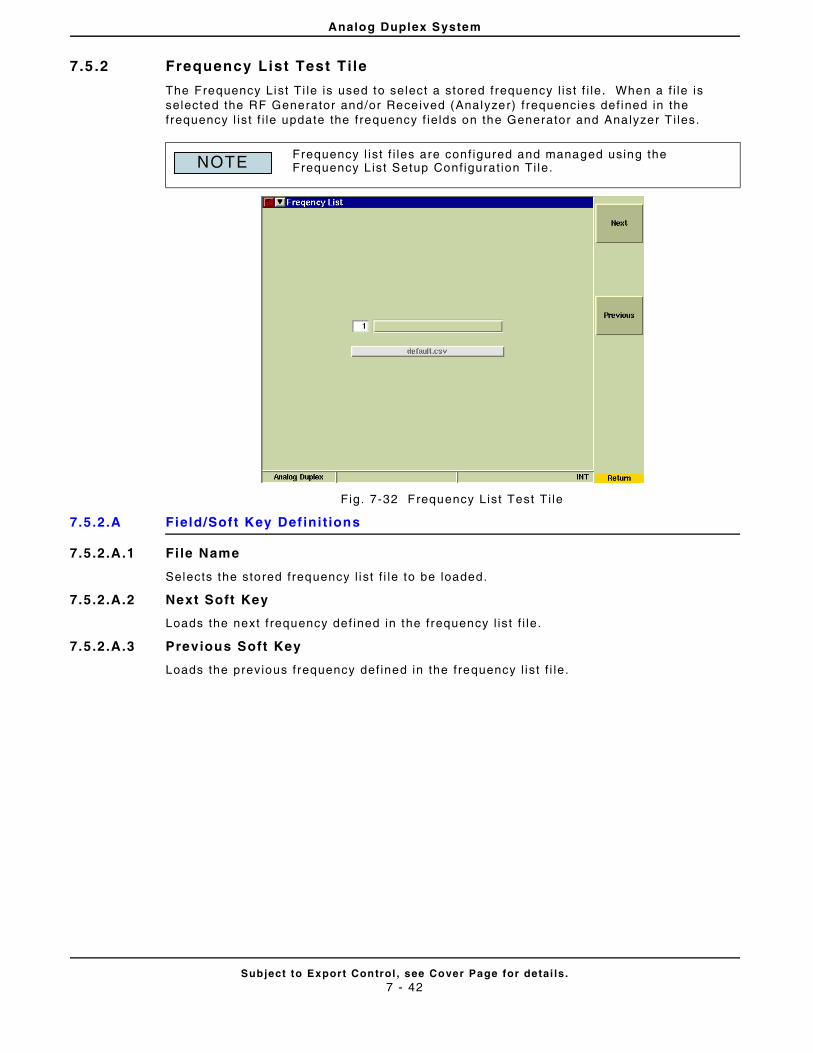
Analog Duplex System
Subject to Export Control , see Cover Page for detai ls .7 - 42
7.5 .2 Frequency List Test Tile
The Frequency List Ti le is used to select a stored frequency l ist f i le. When a f i le is selected the RF Generator and/or Received (Analyzer) f requencies def ined in the frequency l ist f i le update the frequency f ie lds on the Generator and Analyzer T i les.
Fig. 7-32 Frequency List Test Ti le
7.5.2.A Field/Soft Key Def ini t ions
7.5.2.A.1 Fi le Name
Selects the stored frequency l ist f i le to be loaded.
7.5.2.A.2 Next Soft Key
Loads the next f requency def ined in the frequency l ist f i le.
7.5.2.A.3 Previous Soft Key
Loads the previous frequency def ined in the frequency l ist f i le.
Frequency l ist f i les are conf igured and managed using the Frequency L ist Setup Conf igurat ion Ti le.NOTE
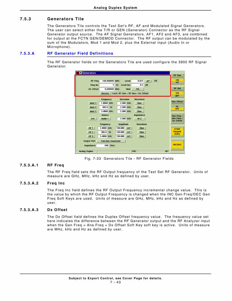
Analog Duplex System
Subject to Export Control , see Cover Page for detai ls .7 - 43
7.5 .3 Generators Tile
The Generators Ti le controls the Test Set ’s RF, AF and Modulated Signal Generators. The user can select ei ther the T/R or GEN (Generator) Connector as the RF Signal Generator output source. The AF Signal Generators, AF1, AF2 and AF3, are combined for output at the FCTN GEN/DEMOD Connector . The RF output can be modulated by the sum of the Modulators, Mod 1 and Mod 2, plus the External input (Audio In or Microphone).
7.5.3.A RF Generator Field Definit ions
The RF Generator f ie lds on the Generators T i le are used conf igure the 3900 RF Signal Generator.
Fig. 7-33 Generators T i le - RF Generator F ields
7.5.3.A.1 RF Freq
The RF Freq f ie ld sets the RF Output f requency of the Test Set RF Generator . Uni ts of measure are GHz, MHz, kHz and Hz as def ined by user.
7.5.3.A.2 Freq Inc
The Freq Inc f ie ld def ines the RF Output Frequency incrementa l change value. This is the va lue by which the RF Output Frequency is changed when the INC Gen Freq/DEC Gen Freq Soft Keys are used. Uni ts of measure are GHz, MHz, kHz and Hz as def ined by user.
7.5.3.A.3 Dx Offset
The Dx Of fset f ie ld def ines the Duplex Of fset f requency value. The frequency value set here indicates the di f ference between the RF Generator output and the RF Analyzer input when the Gen Freq = Ana Freq + Dx Offset Soft Key sof t key is act ive. Uni ts of measure are MHz, kHz and Hz as def ined by user.
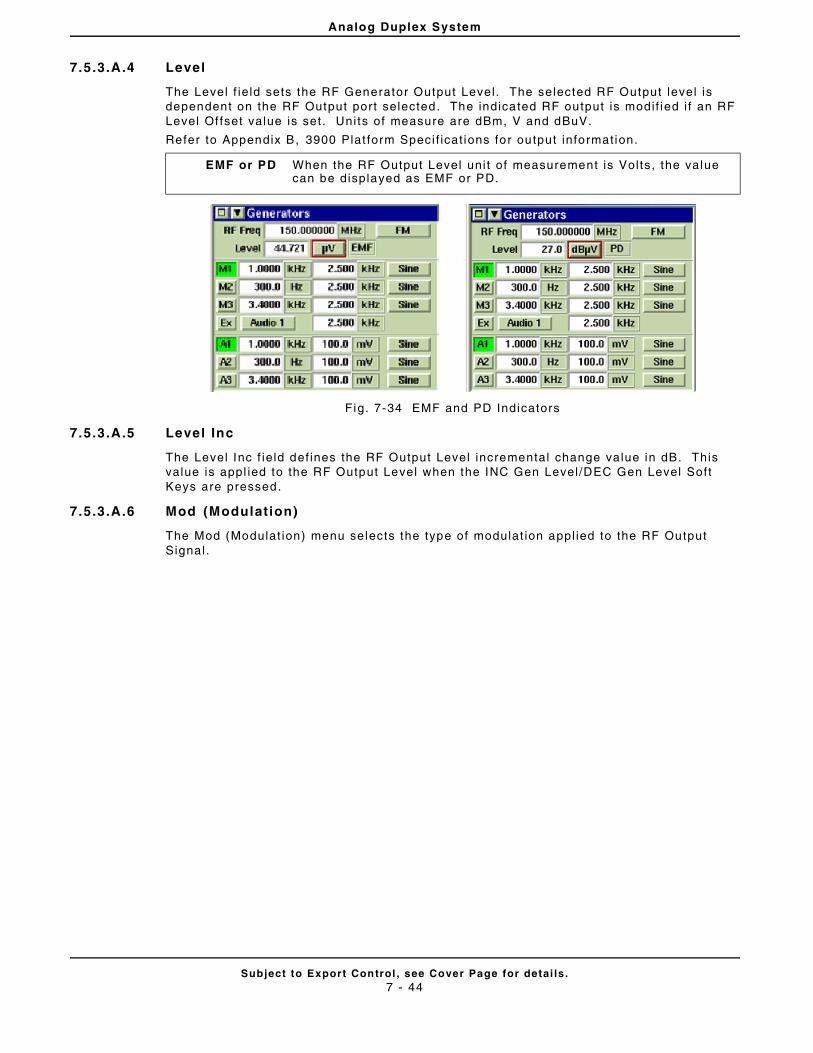
Analog Duplex System
Subject to Export Control , see Cover Page for detai ls .7 - 44
7.5.3.A.4 Level
The Level f ie ld sets the RF Generator Output Level . The selected RF Output level is dependent on the RF Output port selected. The indicated RF output is modif ied i f an RF Level Of fset value is set. Uni ts of measure are dBm, V and dBuV.
Refer to Appendix B, 3900 Plat form Speci f icat ions for output information.
Fig. 7-34 EMF and PD Indicators
7.5.3.A.5 Level Inc
The Level Inc f ie ld def ines the RF Output Level incremental change value in dB. This value is appl ied to the RF Output Level when the INC Gen Level/DEC Gen Level Soft Keys are pressed.
7.5.3.A.6 Mod (Modulation)
The Mod (Modulat ion) menu selects the type of modulat ion appl ied to the RF Output Signal.
EMF or PD When the RF Output Level uni t of measurement is Vol ts, the value can be displayed as EMF or PD.
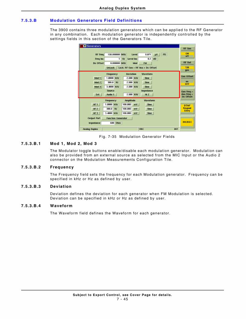
Analog Duplex System
Subject to Export Control , see Cover Page for detai ls .7 - 45
7.5.3.B Modulation Generators Field Defini t ions
The 3900 conta ins three modulat ion generators which can be appl ied to the RF Generator in any combinat ion. Each modulat ion generator is independent ly control led by the sett ings f ie lds in this sect ion of the Generators Ti le.
F ig. 7-35 Modulat ion Generator Fields
7.5.3.B.1 Mod 1, Mod 2, Mod 3
The Modulator toggle buttons enable/d isable each modulat ion generator . Modulat ion can also be provided from an external source as selected from the MIC Input or the Audio 2 connector on the Modulat ion Measurements Conf igurat ion Ti le.
7.5.3.B.2 Frequency
The Frequency f ie ld sets the frequency for each Modulat ion generator . Frequency can be speci f ied in kHz or Hz as def ined by user.
7.5.3.B.3 Deviation
Deviat ion def ines the devia t ion for each generator when FM Modulat ion is selected. Deviat ion can be speci f ied in kHz or Hz as def ined by user.
7.5.3.B.4 Waveform
The Waveform f ie ld def ines the Waveform for each generator.
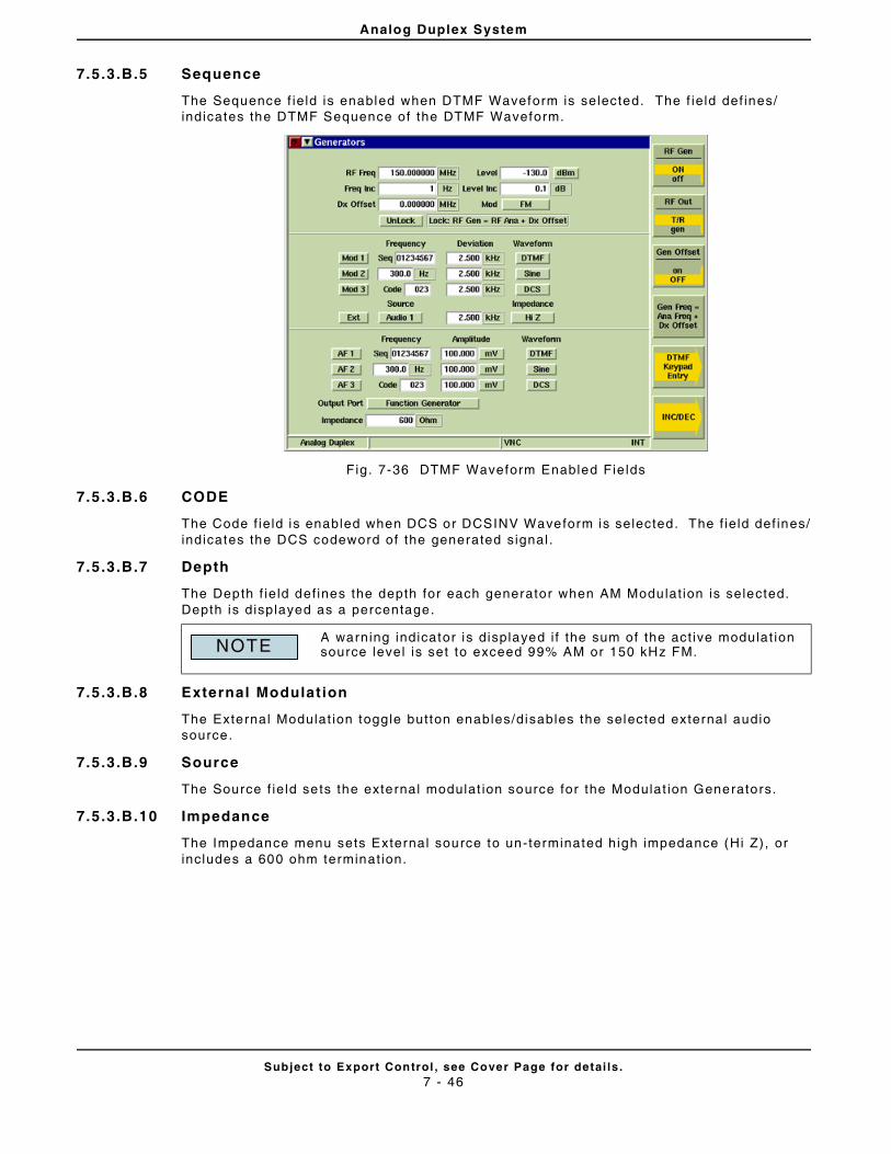
Analog Duplex System
Subject to Export Control , see Cover Page for detai ls .7 - 46
7.5.3.B.5 Sequence
The Sequence f ie ld is enabled when DTMF Waveform is selected. The f ie ld def ines/indicates the DTMF Sequence of the DTMF Waveform.
Fig. 7-36 DTMF Waveform Enabled Fie lds
7.5.3.B.6 CODE
The Code f ie ld is enabled when DCS or DCSINV Waveform is selected. The f ie ld def ines/indicates the DCS codeword of the generated signal .
7.5.3.B.7 Depth
The Depth f ie ld def ines the depth for each generator when AM Modulat ion is selected. Depth is displayed as a percentage.
7.5.3.B.8 External Modulation
The External Modulat ion toggle button enables/disables the selected external audio source.
7.5.3.B.9 Source
The Source f ie ld sets the external modulat ion source for the Modulat ion Generators.
7.5.3.B.10 Impedance
The Impedance menu sets External source to un-terminated high impedance (Hi Z), or includes a 600 ohm terminat ion.
A warning indicator is displayed i f the sum of the act ive modulat ion source level is set to exceed 99% AM or 150 kHz FM.NOTE
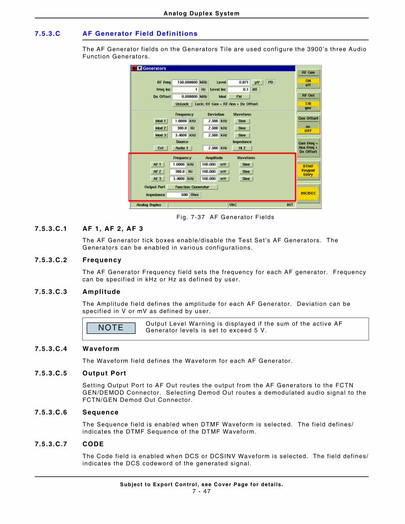
Analog Duplex System
Subject to Export Control , see Cover Page for detai ls .7 - 47
7.5.3.C AF Generator Field Definit ions
The AF Generator f ie lds on the Generators Ti le are used conf igure the 3900’s three Audio Funct ion Generators.
Fig. 7-37 AF Generator F ields
7.5.3.C.1 AF 1, AF 2, AF 3
The AF Generator t ick boxes enable/disable the Test Set ’s AF Generators. The Generators can be enabled in var ious conf igurat ions.
7.5.3.C.2 Frequency
The AF Generator Frequency f ie ld sets the frequency for each AF generator. Frequency can be speci f ied in kHz or Hz as def ined by user.
7.5.3.C.3 Ampli tude
The Ampl i tude f ie ld def ines the ampl i tude for each AF Generator. Deviat ion can be speci f ied in V or mV as def ined by user.
7.5.3.C.4 Waveform
The Waveform f ie ld def ines the Waveform for each AF Generator .
7.5.3.C.5 Output Port
Set t ing Output Port to AF Out routes the output f rom the AF Generators to the FCTN GEN/DEMOD Connector. Se lect ing Demod Out routes a demodulated audio signal to the FCTN/GEN Demod Out Connector .
7.5.3.C.6 Sequence
The Sequence f ie ld is enabled when DTMF Waveform is selected. The f ie ld def ines/indicates the DTMF Sequence of the DTMF Waveform.
7.5.3.C.7 CODE
The Code f ie ld is enabled when DCS or DCSINV Waveform is selected. The f ie ld def ines/indicates the DCS codeword of the generated signal .
Output Level Warning is displayed i f the sum of the act ive AF Generator levels is set to exceed 5 V.NOTE
Analog Duplex System
Subject to Export Control , see Cover Page for detai ls .7 - 48
7.5.3.C.8 Impedance
The AF Impedance f ie ld def ines the external terminat ion va lue used to calculate the AF Generator power level .
7.5.3.D Soft Key Definit ions
7.5.3.D.1 RF Gen Soft Key
Selects and indicates the On/Of f sta te o f the RF Generator output f rom the Test Set . When the generator is d isabled, an RF OFF indicator is shown on the T i le.
7.5.3.D.2 RF Out Soft Key
The RF Out Soft Key controls the RF Output s ignal rout ing. Se lects e i ther the GEN (Generator) Connector or T/R Connector as RF Output port .
7.5.3.D.3 RF Offset Soft Key
Opens a soft key sub-menu that selects to Include or Exclude any set Analyzer or Generator Offset .
7.5.3.D.4 Gen Freq = Ana Freq + Dx Offset Soft Key
The Gen Freq = Ana Freq + Dx Of fset Sof t Key sets the RF Generator f requency to a value spaced f rom the RF Analyzer f requency as set in the Dx Of fset f ie ld on the Generators Ti le.
7.5.3.D.5 INC/DEC Soft Key
Opens a soft key sub-menu that increments or decrement a speci f ic set t ing.
7.5.3.D.6 INC Gen Freq/DEC Gen Freq Soft Key
Each press of the soft key causes the RF Generator f requency to increment or decrement by the value set in the Freq Inc f ie ld on the Generators Ti le .
7.5.3.D.7 INC Gen Level /DEC Gen Level Soft Key
Each press of the soft key causes the RF Generator level to increment or decrement by the value set in the Level Inc f ie ld on the Generators Ti le.
7.5.3.D.8 INC Ana Freq/DEC Ana Freq Soft Key
Each press of the soft key causes the RF Analyzer f requency to increment or decrement by the value set in the Freq Inc (Analyzer) f ie ld on the Analyzers Ti le.
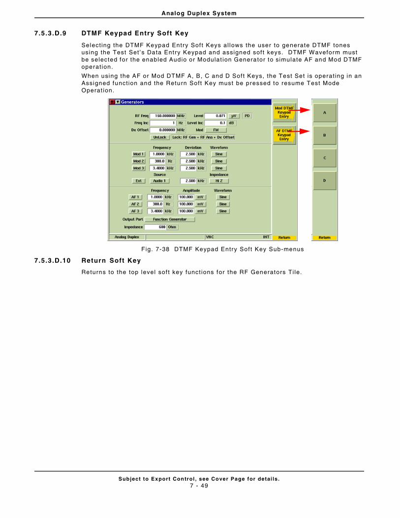
Analog Duplex System
Subject to Export Control , see Cover Page for detai ls .7 - 49
7.5.3.D.9 DTMF Keypad Entry Soft Key
Select ing the DTMF Keypad Entry Sof t Keys al lows the user to generate DTMF tones using the Test Set ’s Data Entry Keypad and assigned sof t keys. DTMF Waveform must be selected for the enabled Audio or Modulat ion Generator to s imulate AF and Mod DTMF operat ion.
When using the AF or Mod DTMF A, B, C and D Sof t Keys, the Test Set is operat ing in an Assigned funct ion and the Return Soft Key must be pressed to resume Test Mode Operat ion.
Fig. 7-38 DTMF Keypad Entry Sof t Key Sub-menus
7.5.3.D.10 Return Soft Key
Returns to the top level sof t key funct ions for the RF Generators Ti le.
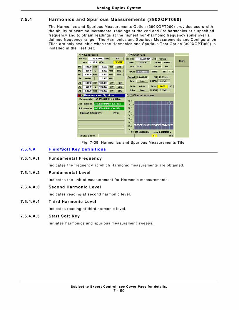
Analog Duplex System
Subject to Export Control , see Cover Page for detai ls .7 - 50
7.5 .4 Harmonics and Spurious Measurements (390XOPT060)
The Harmonics and Spurious Measurements Opt ion (390XOPT060) provides users wi th the abi l i ty to examine incremental readings at the 2nd and 3rd harmonics at a speci f ied frequency and to obtain readings at the highest non-harmonic f requency spike over a def ined frequency range. The Harmonics and Spurious Measurements and Conf igurat ion Ti les are only avai lable when the Harmonics and Spur ious Test Opt ion (390XOPT060) is instal led in the Test Set .
F ig. 7-39 Harmonics and Spur ious Measurements Ti le
7.5.4.A Field/Soft Key Def ini t ions
7.5.4.A.1 Fundamental Frequency
Indicates the f requency at which Harmonic measurements are obtained.
7.5.4.A.2 Fundamental Level
Indicates the un i t of measurement for Harmonic measurements.
7.5.4.A.3 Second Harmonic Level
Indicates reading at second harmonic level .
7.5.4.A.4 Third Harmonic Level
Indicates reading at th ird harmonic level .
7.5.4.A.5 Start Soft Key
In i t iates harmonics and spur ious measurement sweeps.
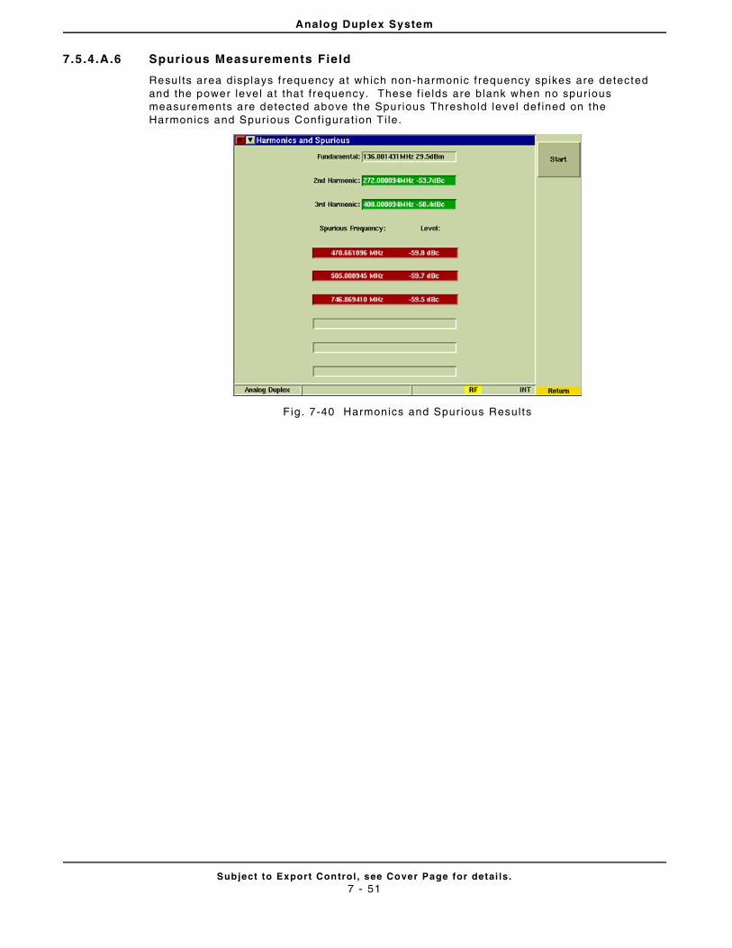
Analog Duplex System
Subject to Export Control , see Cover Page for detai ls .7 - 51
7.5.4.A.6 Spurious Measurements Field
Results area displays f requency at which non-harmonic f requency spikes are detected and the power leve l at that f requency. These f ie lds are blank when no spurious measurements are detected above the Spurious Threshold level def ined on the Harmonics and Spurious Conf igurat ion T i le.
F ig. 7-40 Harmonics and Spur ious Results

Analog Duplex System
Subject to Export Control , see Cover Page for detai ls .7 - 52
7.5 .5 IQ Gen Modulat ion (390XOPT054)
IQ Gen (Generator) Modulat ion is an opt ional feature for the 3900 Ser ies (390XOPT054) that al lows users to download IQCreator waveform f i les to the 3900. This opt ion only suppor ts waveform f i les that have been created using IQCreator sof tware. Refer to the IQCreator Get t ing Started Guide which is included on th is CD for informat ion on using IQCreator.
7.5.5.A Prel iminary Procedures
IQCreator waveform f i les must be imported to the Test Set v ia the Fi le Management Ut i l i ty funct ion pr ior to using the IQ Gen opt ion.
7.5.5.B Accessing IQ Gen
The Analog Duplex System must be operat ing on the 3900 to ut i l ize the IQ Gen. To select IQ Gen Modulat ion f i le:
STEP PROCEDURE
1. Press the CONFIG Key twice to open the CONFIG Menu.
2. Select IQ Gen from the CONFIG f loat ing menu.
3. Select the desi red IQ Fi le f rom the IQ F i le drop-down menu. After the f i le is selected, data f ie lds on the IQ Gen Conf igurat ion Ti le are f i l led with IQ F i le data informat ion ( refer to second example screen below).
Fig. 7-41 IQ Gen Conf igurat ion T i le - Fi le Data
4. Press TEST Key to return to the Analog Duplex Test Ti les.
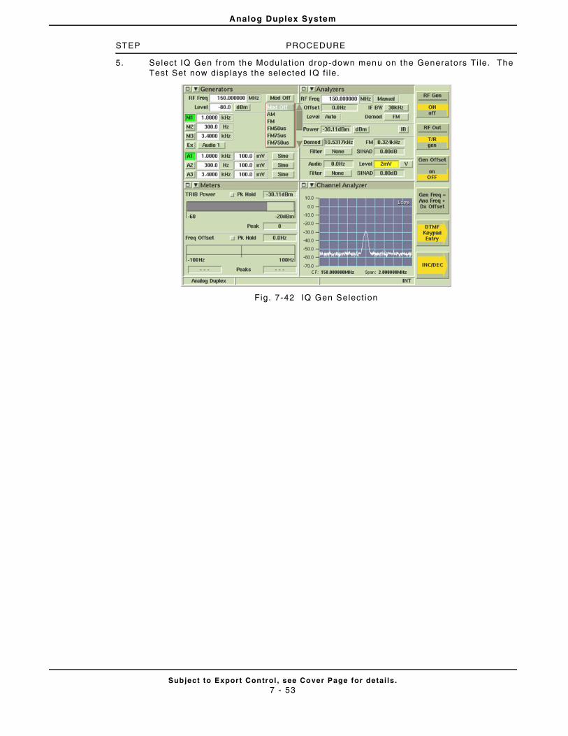
Analog Duplex System
Subject to Export Control , see Cover Page for detai ls .7 - 53
STEP PROCEDURE
5. Select IQ Gen from the Modulat ion drop-down menu on the Generators Ti le. The Test Set now disp lays the selected IQ f i le.
Fig. 7-42 IQ Gen Select ion
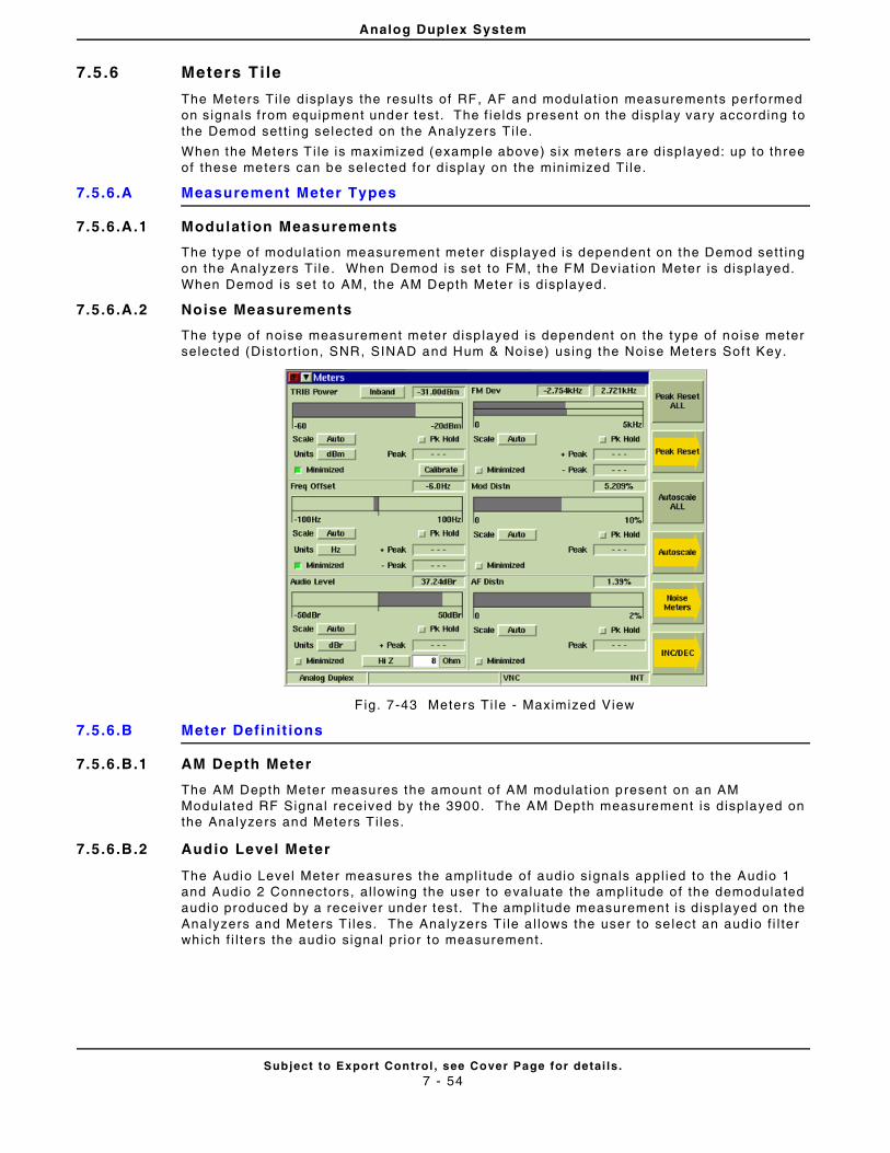
Analog Duplex System
Subject to Export Control , see Cover Page for detai ls .7 - 54
7.5 .6 Meters Tile
The Meters Ti le displays the resul ts of RF, AF and modulat ion measurements performed on signals f rom equipment under test . The f ie lds present on the display vary according to the Demod sett ing selected on the Analyzers Ti le.
When the Meters T i le is maximized (example above) s ix meters are displayed: up to three of these meters can be selected for d isplay on the minimized Ti le.
7.5.6.A Measurement Meter Types
7.5.6.A.1 Modulation Measurements
The type of modulat ion measurement meter displayed is dependent on the Demod sett ing on the Analyzers Ti le . When Demod is set to FM, the FM Deviat ion Meter is displayed. When Demod is set to AM, the AM Depth Meter is displayed.
7.5.6.A.2 Noise Measurements
The type of noise measurement meter disp layed is dependent on the type of noise meter selected (Distort ion, SNR, SINAD and Hum & Noise) using the Noise Meters Sof t Key.
F ig. 7-43 Meters Ti le - Maximized View
7.5.6.B Meter Definit ions
7.5.6.B.1 AM Depth Meter
The AM Depth Meter measures the amount o f AM modulat ion present on an AM Modulated RF Signal received by the 3900. The AM Depth measurement is displayed on the Analyzers and Meters T i les.
7.5.6.B.2 Audio Level Meter
The Audio Level Meter measures the ampl i tude of audio s ignals appl ied to the Audio 1 and Audio 2 Connectors, al lowing the user to evaluate the ampl i tude of the demodulated audio produced by a receiver under test . The ampl i tude measurement is displayed on the Analyzers and Meters T i les. The Analyzers T i le a l lows the user to se lect an audio f i l ter which f i l ters the audio signal pr ior to measurement.
Analog Duplex System
Subject to Export Control , see Cover Page for detai ls .7 - 55
7.5.6.B.3 Distort ion Meter
The AF Distort ion Meter measures the amount of audio distor t ion a radio receiver may add to an audio signal dur ing the demodulat ion process. The Modulat ion Distor t ion Meter measures the amount of audio distor t ion created by a radio transmit ter when an audio signal is modulated. These meters are enabled using the Noise Meters Soft Key on the Analyzers or Meters Ti les.
7.5.6.B.4 FM Deviation Meter
The FM Deviat ion Meter measures the amount of deviat ion present on an FM Modulated RF Signal received by the 3900. The FM Deviat ion measurement is displayed on the Analyzers and Meters T i les.
FM RMS Meter
The FM RMS Meter is selected f rom the FM Demod Measurement menu on the Mod Measurements Conf igurat ion Ti le.
FM Pk-PK/2 Meter
The FM PK-PK/2 Meter is selected from the FM Demod Measurement menu on the Mod Measurements Conf igurat ion Ti le.
7.5.6.B.5 Hum & Noise Meter
The AF Hum & Noise Meter measures the amount of hum and noise a radio receiver may add to the audio signal dur ing the demodulat ion process. The Modulat ion Hum & Noise Meter measures the level of hum and noise created by a rad io t ransmit ter when an audio signal is modulated. The AF and Modulat ion Hum & Noise Meters are enabled using the Noise Meters Soft Key on the Analyzers or Meters Ti les.
7.5.6.B.6 Power Meter
The Power Meter measures the ampl i tude of an RF Signal received at the T/R or ANT Connector . When the ANT Connector is selected as the RF Input , the Power Meter displays the Inband power of the rece ived RF Signal. The Inband Power Meter measures the strength of any signal present wi thin the range of the selected IF Bandwidth Fi l ter . When the T/R Connector is selected as the RF Input , the Power Meter can be conf igured to display Broadband or Inband Power measurements.
Inband/BroadBand Toggle Button
This button toggles between Inband and Broadband Power measurements. The Inband Power measurement funct ion is avai lable when ei ther the ANT (Antenna) Connector or T/R Connector is se lected for RF Input. The Inband/Broadband Toggle Button is only act ive when the T/R Connector is selected as the RF Input source.
7.5.6.B.7 RF Frequency Offset (when not Autotuned)
When the Manual method of sett ing the RF input leve l is se lected on the Analyzers Ti le, th is f ie ld indicates the di f ference between the RF input signal and the def ined tuned analyzer f requency.
The Frequency Offset bar graph has a center zero for posi t ive or negat ive readings. The Scale drop-down menu selects set t ing.
The Units drop-down menu selects the uni t of measure used to display Frequency Offset measurements.
7.5.6.B.8 Sinad Meter
The AF Sinad Meter measures the receive qual i ty of a radio receiver . The Modulat ion Sinad Meter measures the sinad of a t ransmi t ter . The AF and Modulat ion Sinad Meters are enabled using the Noise Meters Soft Key on the Analyzers or Meters Ti les.
Analog Duplex System
Subject to Export Control , see Cover Page for detai ls .7 - 56
7.5.6.B.9 SNR Meter
The AF SNR Meter measures the signal to noise rat io of an audio source. The Modulat ion SNR Meter measures the signal to noise rat io of a radio t ransmit ter . The AF and Modulat ion SNR Metes are enabled using the Noise Meters Sof t Key on the Analyzers or Meters Ti le .
7.5.6.C Meter Components
7.5.6.C.1 Measurement Readout
The measurement resul ts are displayed as a digi ta l readout at the top r ight of the meter panel. For some measurements such as AM Depth, the posi t ive and negat ive values of the measurements are g iven.
7.5.6.C.2 Bar Graph s
The Bar Graph is a s ingle, l inear indicator that provides a visual measurement reading based on a user def ined scale. Upper and lower l imit indicators are set on system Conf igurat ion Ti les.
7.5.6.C.3 Scale
The scale of the bar graph is selected from the Scale drop-down menu. Avai lable sett ings are Auto-ranging (Auto) or a f ixed value. The selected sca le value is d isplayed below the bar graph.
7.5.6.C.4 Peak (Pk) Hold
Select ing the Peak Hold but ton a l lows the peak va lue of measurements to be captured and updated as new peaks occur . The peak va lue is shown on the bar graph and in the Peak digi ta l readout f ie ld.
7.5.6.C.5 Peak Measurement
Shows the peak value from the bursts measured. The peak reading can be reset by using ei ther the Peak Reset ALL Soft Key, which resets al l measurements or by using the Peak Reset Sof t Key to reset an ind iv idual measurement selected from the soft key menu. The reset operat ion also resets the peak reading on the bar graph.
7.5.6.C.6 Minimize Button
This button selects the meter for d isplay on the minimized Ti le. Up to 3 meters can be displayed on the minimized display: a warning appearing i f more than three are selected. The informat ion shown on the minimized display for each measurement is reduced when mult ip le measurements are selected.
7.5.6.C.7 Peak Reset ALL Soft Key
Resets al l act ive peak hold levels to zero.
7.5.6.C.8 Peak Reset Soft Key
Disp lays a soft key sub-menu that resets the peak hold on a speci f ic meter or meters.
7.5.6.C.9 Autoscale ALL Soft Key
Sets al l meter bar graphs to Auto-ranging.
7.5.6.C.10 Autoscale Soft Key
Disp lays a soft key sub-menu containing soft keys that set the bar graph on a speci f ic meter or meters to Auto-ranging.
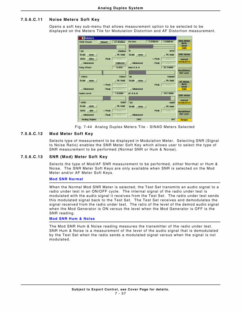
Analog Duplex System
Subject to Export Control , see Cover Page for detai ls .7 - 57
7.5.6.C.11 Noise Meters Soft Key
Opens a soft key sub-menu that al lows measurement opt ion to be se lected to be displayed on the Meters Ti le for Modulat ion Distort ion and AF Distor t ion measurement.
F ig. 7-44 Analog Duplex Meters Ti le - SINAD Meters Selected
7.5.6.C.12 Mod Meter Soft Key
Selects type of measurement to be d isplayed in Modulat ion Meter . Select ing SNR (Signal to Noise Rat io) enables the SNR Meter Soft Key which al lows user to select the type of SNR measurement to be per formed (Normal SNR or Hum & Noise) .
7.5.6.C.13 SNR (Mod) Meter Soft Key
Selects the type of Mod/AF SNR measurement to be performed, ei ther Normal or Hum & Noise. The SNR Meter Sof t Keys are only avai lable when SNR is selected on the Mod Meter and/or AF Meter Soft Keys.
Mod SNR Normal
When the Normal Mod SNR Meter is selected, the Test Set t ransmi ts an audio signal to a rad io under test in an ON/OFF cycle. The internal s ignal of the radio under test is modulated wi th the audio signal i t receives f rom the Test Set. The radio under test sends this modulated signal back to the Test Set. The Test Set receives and demodulates the signal received from the radio under test . The rat io of the level of the demod audio signal when the Mod Generator is ON versus the level when the Mod Generator is OFF is the SNR reading.
Mod SNR Hum & Noise
The Mod SNR Hum & Noise reading measures the transmit ter of the radio under test. SNR Hum & Noise is a measurement of the level of the audio signal that is demodulated by the Test Set when the radio sends a modulated signal versus when the signal is not modulated.
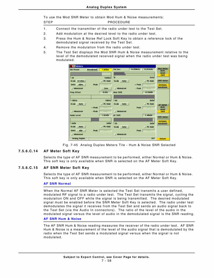
Analog Duplex System
Subject to Export Control , see Cover Page for detai ls .7 - 58
To use the Mod SNR Meter to obta in Mod Hum & Noise measurements:
STEP PROCEDURE
1. Connect the t ransmit ter of the radio under test to the Test Set.
2. Add modulat ion at the desi red level to the radio under test .
3. Press the Hum & Noise Ref Lock Sof t Key to obtain a reference lock of the demodulated signal received by the Test Set.
4. Remove the modulat ion from the radio under test .
5. The Test Set displays the Mod SNR Hum & Noise measurement rela t ive to the level of the demodulated received signal when the radio under test was being modulated.
F ig. 7-45 Analog Duplex Meters Ti le - Hum & Noise SNR Selected
7.5.6.C.14 AF Meter Soft Key
Selects the type of AF SNR measurement to be performed, ei ther Normal or Hum & Noise. This soft key is only avai lable when SNR is selected on the AF Meter Soft Key.
7.5.6.C.15 AF SNR Meter Soft Key
Selects the type of AF SNR measurement to be performed, ei ther Normal or Hum & Noise. This soft key is only avai lable when SNR is selected on the AF Meter Soft Key.
AF SNR Normal
When the Normal AF SNR Meter is selected the Test Set t ransmits a user def ined, modulated RF signal to a radio under test . The Test Set t ransmits the signal , cycl ing the modulat ion ON and OFF whi le the signal is being t ransmit ted. The desired modulated signal must be enabled before the SNR Meter Sof t Key is se lected. The radio under test demodulates the signal i t receives f rom the Test Set and sends an audio signal back to the Test Set (v ia the Audio In connectors) . The rat io of the level of the audio in the modulated signal versus the leve l of audio in the demodulated signal is the SNR reading.
AF SNR Hum & Noise
The AF SNR Hum & Noise reading measures the receiver o f the radio under test . AF SNR Hum & Noise is a measurement of the level of the audio signal that is demodulated by the rad io when the Test Set sends a modulated signal versus when the signal is not modulated.
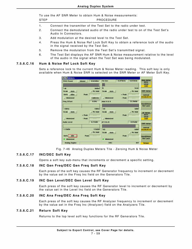
Analog Duplex System
Subject to Export Control , see Cover Page for detai ls .7 - 59
To use the AF SNR Meter to obtain Hum & Noise measurements:
STEP PROCEDURE
1. Connect the t ransmit ter of the Test Set to the radio under test .
2. Connect the demodulated audio of the radio under test to on of the Test Set ’s Audio In Connectors.
3. Add modulat ion at the desi red level to the Test Set.
4. Press the Hum & Noise Ref Lock Sof t Key to obtain a reference lock of the audio in the signal received by the Test Set.
5. Remove the modulat ion from the Test Set ’s t ransmit ted signal .
6. The Test Set displays the AF SNR Hum & Noise measurement relat ive to the level of the audio in the signal when the Test Set was being modulated.
7.5.6.C.16 Hum & Noise Ref Lock Soft Key
Sets a reference lock to the current Hum & Noise Meter reading. Th is soft key is only avai lab le when Hum & Noise SNR is selected on the SNR Meter or AF Meter Soft Key.
Fig. 7-46 Analog Duplex Meters Ti le - Zeroing Hum & Noise Meter
7.5.6.C.17 INC/DEC Soft Key
Opens a soft key sub-menu that increments or decrement a speci f ic set t ing.
7.5.6.C.18 INC Gen Freq/DEC Gen Freq Soft Key
Each press of the soft key causes the RF Generator f requency to increment or decrement by the value set in the Freq Inc f ie ld on the Generators Ti le .
7.5.6.C.19 INC Gen Level /DEC Gen Level Soft Key
Each press of the soft key causes the RF Generator level to increment or decrement by the value set in the Level Inc f ie ld on the Generators Ti le.
7.5.6.C.20 INC Ana Freq/DEC Ana Freq Soft Key
Each press of the soft key causes the RF Analyzer f requency to increment or decrement by the value set in the Freq Inc (Analyzer) f ie ld on the Analyzers Ti le.
7.5.6.C.21 Return Soft Key
Returns to the top level sof t key funct ions for the RF Generators Ti le.

Analog Duplex System
Subject to Export Control , see Cover Page for detai ls .7 - 60
7.5 .7 Site Monitoring Applicat ion Test Option (390XOPT051)
The Sensi t iv i ty Search Ti le is enabled when the Si te Monitor ing Appl icat ion Test Opt ion (390XOPT051) is instal led in the Test Set. The Sensi t iv i ty Search T i le is used to log the Sinad measurement of an in jected signal over t ime. Sensi t iv i ty Search is also used to log the spectrum trace of the RF signal . Sensi t iv i ty Search data f i les are referred to throughout th is sect ion as Data Log Fi les.
Refer to Appl icat ion Note 46891/951, Using the Aerof lex 3900 Series for Remote Site Monitor ing, for addit ional informat ion on use of th is opt ion. A copy of th is Appl icat ion Note is included on the 3900 Operat ion CD or can be at www.aerof lex.com.
7.5.7.A Accessing Site Monitoring
The Sensi t iv i ty Search T i le is selected f rom the Measurement drop-down menu on any of the Analog Duplex Test Ti les. Th is Ti le is on ly avai lable when the Si te Monitor ing Appl icat ion is instal led in the Test Set.
F ig. 7-47 Select ing Sensi t iv i ty Search Ti le
Fig. 7-48 Main Sensi t iv i ty Search Ti le - Maximized View
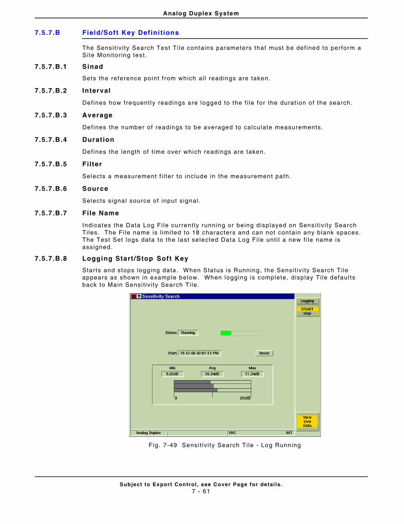
Analog Duplex System
Subject to Export Control , see Cover Page for detai ls .7 - 61
7.5.7.B Field/Soft Key Def ini t ions
The Sensi t iv i ty Search Test Ti le contains parameters that must be def ined to perform a Si te Monitor ing test.
7.5.7.B.1 Sinad
Sets the reference point f rom which al l readings are taken.
7.5.7.B.2 Interval
Defines how frequent ly readings are logged to the f i le for the durat ion of the search.
7.5.7.B.3 Average
Defines the number of readings to be averaged to calculate measurements.
7.5.7.B.4 Duration
Defines the length of t ime over which readings are taken.
7.5.7.B.5 Fi lter
Selects a measurement f i l ter to include in the measurement path.
7.5.7.B.6 Source
Selects s ignal source of input s ignal .
7.5.7.B.7 Fi le Name
Indicates the Data Log Fi le current ly running or being displayed on Sensi t iv i ty Search Ti les. The Fi le name is l imi ted to 18 characters and can not contain any blank spaces. The Test Set logs data to the last selected Data Log Fi le unt i l a new f i le name is assigned.
7.5.7.B.8 Logging Start /Stop Soft Key
Starts and stops logging data. When Status is Running, the Sensi t iv i ty Search Ti le appears as shown in example below. When logging is complete, display Ti le defaul ts back to Main Sensi t iv i ty Search T i le.
F ig. 7-49 Sensi t iv i ty Search Ti le - Log Running
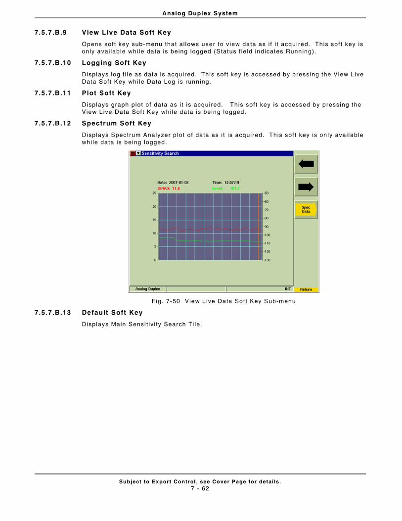
Analog Duplex System
Subject to Export Control , see Cover Page for detai ls .7 - 62
7.5.7.B.9 View Live Data Soft Key
Opens sof t key sub-menu that al lows user to v iew data as i f i t acquired. This sof t key is only avai lable whi le data is being logged (Status f ie ld ind icates Running).
7.5.7.B.10 Logging Soft Key
Disp lays log f i le as data is acquired. This soft key is accessed by pressing the View Live Data Soft Key whi le Data Log is running.
7.5.7.B.11 Plot Soft Key
Disp lays graph p lot o f data as i t is acquired. This sof t key is accessed by pressing the View L ive Data Sof t Key whi le data is being logged.
7.5.7.B.12 Spectrum Soft Key
Disp lays Spectrum Analyzer p lot of data as i t is acquired. This soft key is on ly ava i lable whi le data is being logged.
Fig. 7-50 View L ive Data Sof t Key Sub-menu
7.5.7.B.13 Default Soft Key
Disp lays Main Sensi t iv i ty Search Ti le.
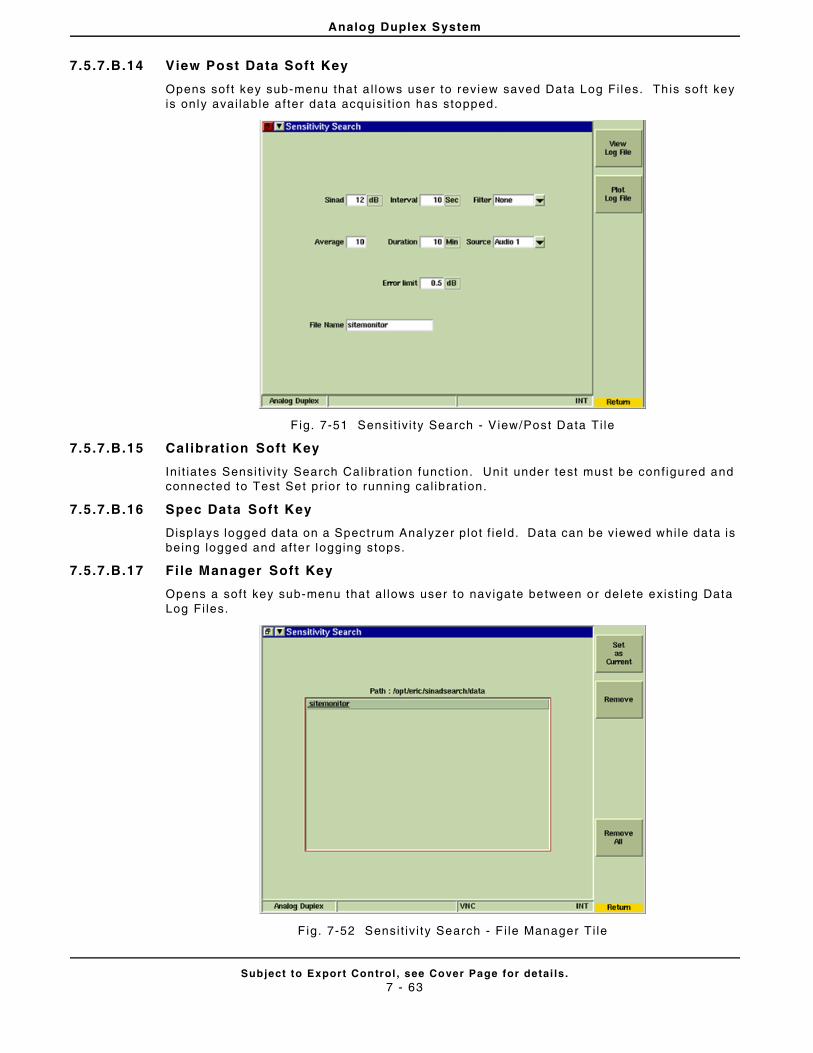
Analog Duplex System
Subject to Export Control , see Cover Page for detai ls .7 - 63
7.5.7.B.14 View Post Data Soft Key
Opens sof t key sub-menu that a l lows user to review saved Data Log Fi les. Th is soft key is only avai lable af ter data acquisi t ion has stopped.
F ig. 7-51 Sensi t iv i ty Search - V iew/Post Data Ti le
7.5.7.B.15 Calibrat ion Soft Key
In i t iates Sensi t iv i ty Search Cal ibrat ion funct ion. Unit under test must be conf igured and connected to Test Set pr ior to running cal ibrat ion.
7.5.7.B.16 Spec Data Soft Key
Disp lays logged data on a Spectrum Analyzer plot f ie ld. Data can be viewed whi le data is being logged and after logging stops.
7.5.7.B.17 Fi le Manager Soft Key
Opens a soft key sub-menu that al lows user to navigate between or delete exist ing Data Log Fi les.
F ig. 7-52 Sensi t iv i ty Search - F i le Manager Ti le
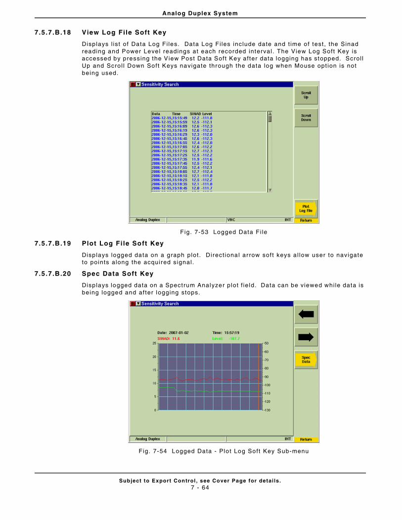
Analog Duplex System
Subject to Export Control , see Cover Page for detai ls .7 - 64
7.5.7.B.18 View Log File Soft Key
Disp lays l ist of Data Log Fi les. Data Log Fi les include date and t ime of test , the Sinad reading and Power Level readings at each recorded interval . The View Log Soft Key is accessed by pressing the View Post Data Soft Key af ter data logging has stopped. Scrol l Up and Scro l l Down Soft Keys navigate through the data log when Mouse opt ion is not being used.
Fig. 7-53 Logged Data Fi le
7.5.7.B.19 Plot Log Fi le Soft Key
Disp lays logged data on a graph plot . Direct iona l arrow soft keys a l low user to navigate to points along the acquired signal .
7.5.7.B.20 Spec Data Soft Key
Disp lays logged data on a Spectrum Analyzer plot f ie ld. Data can be viewed whi le data is being logged and after logging stops.
Fig. 7-54 Logged Data - Plo t Log Soft Key Sub-menu
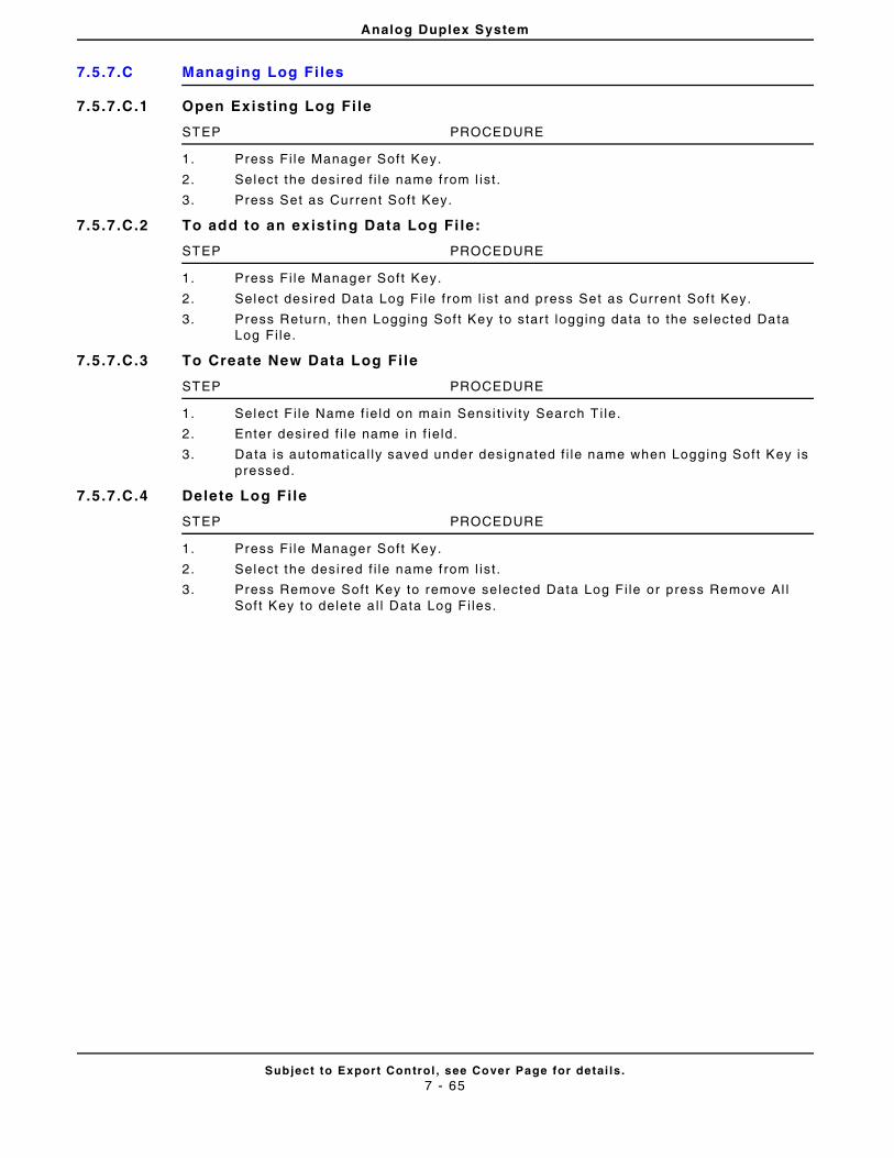
Analog Duplex System
Subject to Export Control , see Cover Page for detai ls .7 - 65
7.5.7.C Managing Log Fi les
7.5.7.C.1 Open Existing Log Fi le
STEP PROCEDURE
1. Press Fi le Manager Soft Key.
2. Select the desi red f i le name f rom l ist .
3. Press Set as Current Soft Key.
7.5.7.C.2 To add to an existing Data Log Fi le:
STEP PROCEDURE
1. Press Fi le Manager Soft Key.
2. Select desired Data Log Fi le f rom l ist and press Set as Current Sof t Key.
3. Press Return, then Logging Sof t Key to star t logging data to the selected Data Log Fi le.
7.5.7.C.3 To Create New Data Log File
STEP PROCEDURE
1. Select F i le Name f ie ld on main Sensi t iv i ty Search T i le.
2. Enter desired f i le name in f ie ld.
3. Data is automatica l ly saved under designated f i le name when Logging Soft Key is pressed.
7.5.7.C.4 Delete Log File
STEP PROCEDURE
1. Press Fi le Manager Soft Key.
2. Select the desi red f i le name f rom l ist .
3. Press Remove Soft Key to remove se lected Data Log Fi le or press Remove Al l Sof t Key to dele te a l l Data Log F i les.
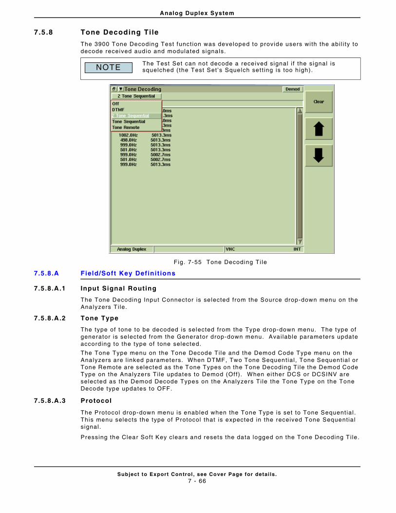
Analog Duplex System
Subject to Export Control , see Cover Page for detai ls .7 - 66
7.5 .8 Tone Decoding Ti le
The 3900 Tone Decoding Test funct ion was developed to provide users wi th the abi l i ty to decode received audio and modulated signals.
Fig. 7-55 Tone Decoding Ti le
7.5.8.A Field/Soft Key Def ini t ions
7.5.8.A.1 Input Signal Routing
The Tone Decoding Input Connector is se lected from the Source drop-down menu on the Analyzers T i le.
7.5.8.A.2 Tone Type
The type of tone to be decoded is selected from the Type drop-down menu. The type of generator is se lected from the Generator drop-down menu. Avai lable parameters update accord ing to the type of tone selected.
The Tone Type menu on the Tone Decode Ti le and the Demod Code Type menu on the Analyzers are l inked parameters. When DTMF, Two Tone Sequent ial , Tone Sequent ial or Tone Remote are selected as the Tone Types on the Tone Decoding Ti le the Demod Code Type on the Analyzers Ti le updates to Demod (Of f) . When ei ther DCS or DCSINV are selected as the Demod Decode Types on the Analyzers Ti le the Tone Type on the Tone Decode type updates to OFF.
7.5.8.A.3 Protocol
The Protocol drop-down menu is enabled when the Tone Type is set to Tone Sequent ial . This menu selects the type of Protocol that is expected in the received Tone Sequent ial s ignal .
Pressing the Clear Soft Key clears and resets the data logged on the Tone Decoding T i le.
The Test Set can not decode a rece ived signal i f the signal is squelched ( the Test Set ’s Squelch set t ing is too high) .NOTE
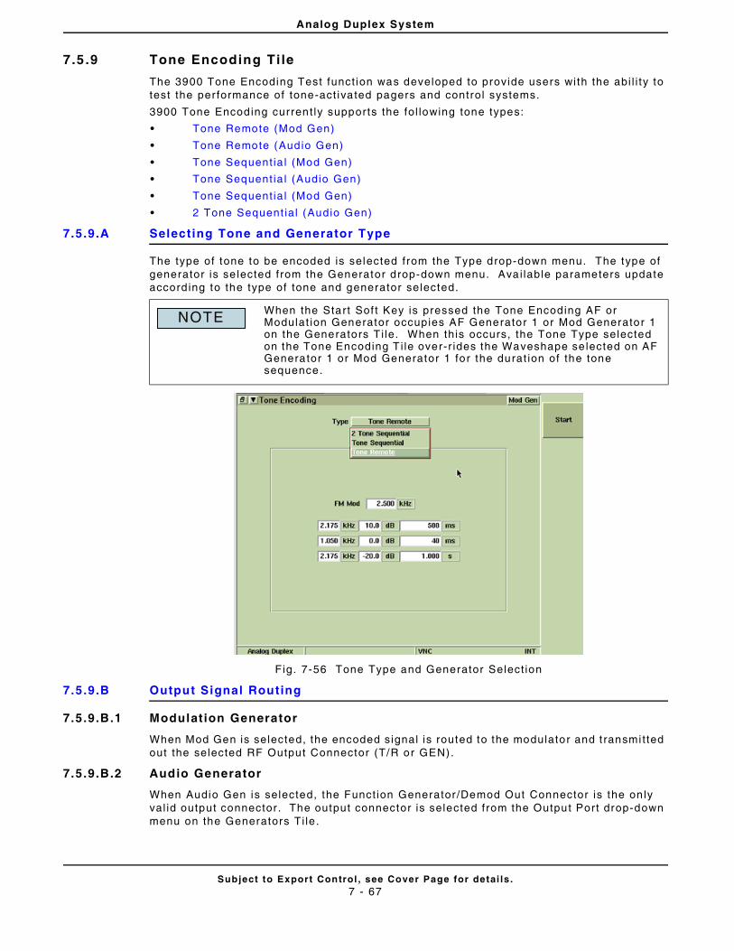
Analog Duplex System
Subject to Export Control , see Cover Page for detai ls .7 - 67
7.5 .9 Tone Encoding Ti le
The 3900 Tone Encoding Test funct ion was developed to provide users with the abi l i ty to test the per formance of tone-act ivated pagers and control systems.
3900 Tone Encoding current ly supports the fol lowing tone types:
• Tone Remote (Mod Gen)
• Tone Remote (Audio Gen)
• Tone Sequent ia l (Mod Gen)
• Tone Sequent ia l (Audio Gen)
• Tone Sequent ia l (Mod Gen)
• 2 Tone Sequent ial (Audio Gen)
7.5.9.A Selecting Tone and Generator Type
The type of tone to be encoded is selected from the Type drop-down menu. The type of generator is se lected from the Generator drop-down menu. Avai lable parameters update accord ing to the type of tone and generator selected.
Fig. 7-56 Tone Type and Generator Select ion
7.5.9.B Output Signal Routing
7.5.9.B.1 Modulation Generator
When Mod Gen is selected, the encoded signal is routed to the modulator and t ransmi t ted out the selected RF Output Connector (T/R or GEN).
7.5.9.B.2 Audio Generator
When Audio Gen is selected, the Funct ion Generator /Demod Out Connector is the on ly val id output connector . The output connector is selected from the Output Port drop-down menu on the Generators Ti le .
When the Start Sof t Key is pressed the Tone Encoding AF or Modulat ion Generator occupies AF Generator 1 or Mod Generator 1 on the Generators T i le. When this occurs, the Tone Type selected on the Tone Encoding T i le over-r ides the Waveshape se lected on AF Generator 1 or Mod Generator 1 for the durat ion of the tone sequence.
NOTE
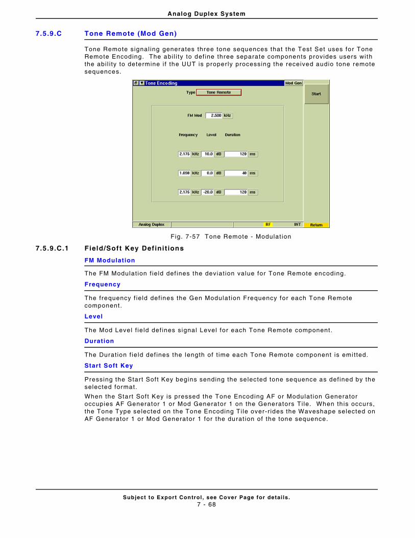
Analog Duplex System
Subject to Export Control , see Cover Page for detai ls .7 - 68
7.5.9.C Tone Remote (Mod Gen)
Tone Remote signal ing generates three tone sequences that the Test Set uses for Tone Remote Encoding. The abi l i ty to def ine three separate components provides users with the abi l i ty to determine i f the UUT is proper ly processing the received audio tone remote sequences.
Fig. 7-57 Tone Remote - Modulat ion
7.5.9.C.1 Field/Soft Key Def ini t ions
FM Modulat ion
The FM Modulat ion f ie ld def ines the deviat ion value for Tone Remote encoding.
Frequency
The frequency f ie ld def ines the Gen Modulat ion Frequency for each Tone Remote component .
Level
The Mod Level f ie ld def ines signal Level for each Tone Remote component .
Durat ion
The Durat ion f ie ld def ines the length of t ime each Tone Remote component is emi t ted.
Start Soft Key
Pressing the Start Sof t Key begins sending the se lected tone sequence as def ined by the selected format.
When the Start Sof t Key is pressed the Tone Encoding AF or Modulat ion Generator occupies AF Generator 1 or Mod Generator 1 on the Generators Ti le. When th is occurs, the Tone Type se lected on the Tone Encoding Ti le over- r ides the Waveshape selected on AF Generator 1 or Mod Generator 1 for the durat ion of the tone sequence.
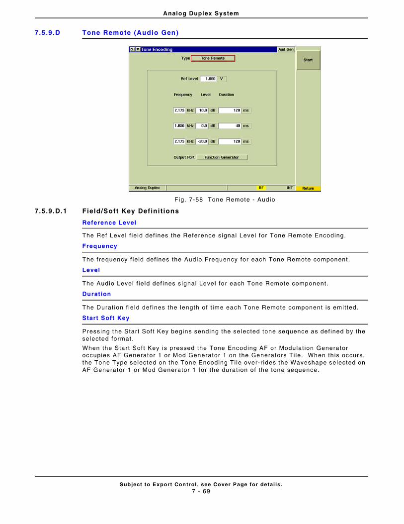
Analog Duplex System
Subject to Export Control , see Cover Page for detai ls .7 - 69
7.5.9.D Tone Remote (Audio Gen)
Fig. 7-58 Tone Remote - Audio
7.5.9.D.1 Field/Soft Key Def ini t ions
Reference Level
The Ref Level f ie ld def ines the Reference signal Level for Tone Remote Encoding.
Frequency
The frequency f ie ld def ines the Audio Frequency for each Tone Remote component.
Level
The Audio Level f ie ld def ines signal Level for each Tone Remote component .
Durat ion
The Durat ion f ie ld def ines the length of t ime each Tone Remote component is emi t ted.
Start Soft Key
Pressing the Start Sof t Key begins sending the se lected tone sequence as def ined by the selected format.
When the Start Sof t Key is pressed the Tone Encoding AF or Modulat ion Generator occupies AF Generator 1 or Mod Generator 1 on the Generators Ti le. When th is occurs, the Tone Type se lected on the Tone Encoding Ti le over- r ides the Waveshape selected on AF Generator 1 or Mod Generator 1 for the durat ion of the tone sequence.
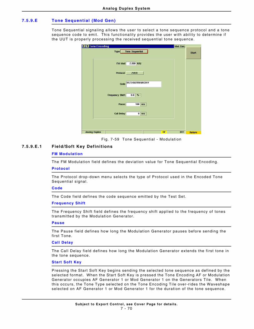
Analog Duplex System
Subject to Export Control , see Cover Page for detai ls .7 - 70
7.5.9.E Tone Sequent ial (Mod Gen)
Tone Sequent ia l s ignal ing a l lows the user to se lect a tone sequence protocol and a tone sequence code to emi t . This funct ional i ty provides the user with abi l i ty to determine i f the UUT is proper ly processing the received sequent ial tone sequence.
Fig. 7-59 Tone Sequent ial - Modulat ion
7.5.9.E.1 Field/Soft Key Def ini t ions
FM Modulat ion
The FM Modulat ion f ie ld def ines the deviat ion value for Tone Sequent ia l Encoding.
Protocol
The Protocol drop-down menu selects the type of Protocol used in the Encoded Tone Sequent ia l s ignal .
Code
The Code f ie ld def ines the code sequence emit ted by the Test Set.
Frequency Shif t
The Frequency Shif t f ie ld def ines the f requency shi f t appl ied to the f requency of tones transmit ted by the Modulat ion Generator .
Pause
The Pause f ie ld def ines how long the Modulat ion Generator pauses before sending the f i rst Tone.
Call Delay
The Cal l Delay f ie ld def ines how long the Modulat ion Generator extends the f i rst tone in the tone sequence.
Start Soft Key
Pressing the Start Sof t Key begins sending the se lected tone sequence as def ined by the selected format. When the Start Soft Key is pressed the Tone Encoding AF or Modulat ion Generator occupies AF Generator 1 or Mod Generator 1 on the Generators Ti le. When this occurs, the Tone Type selected on the Tone Encoding T i le over-r ides the Waveshape selected on AF Generator 1 or Mod Generator 1 for the durat ion of the tone sequence.
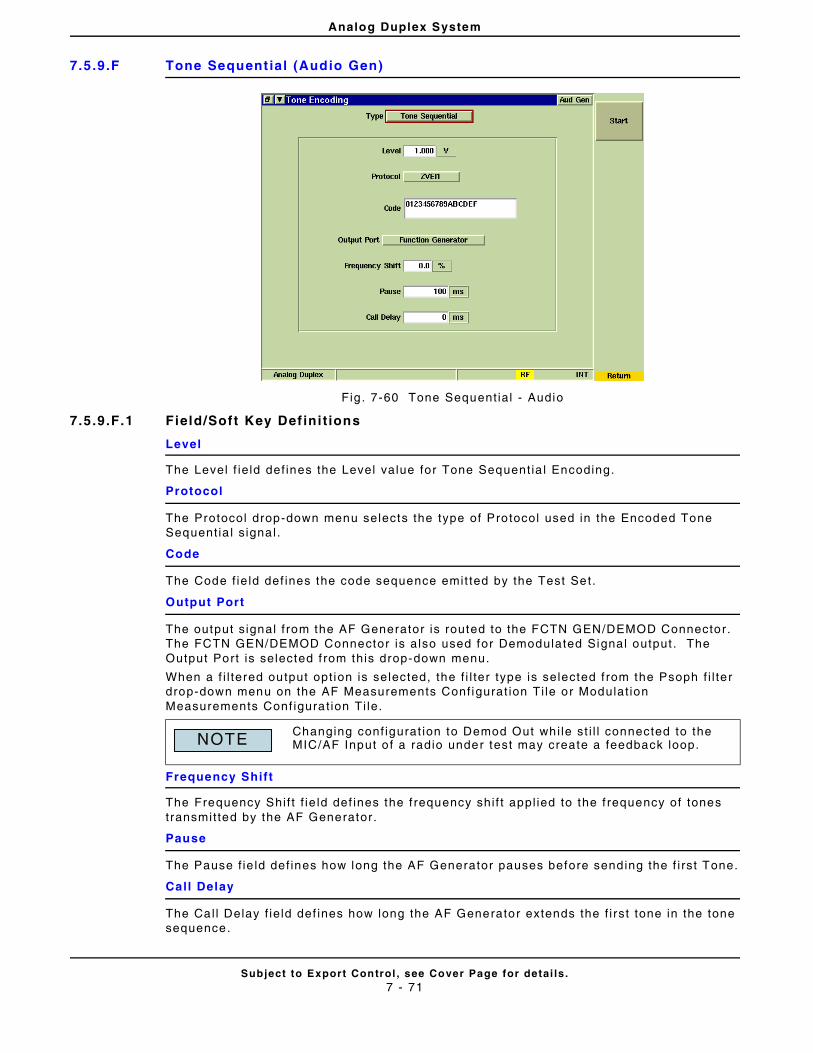
Analog Duplex System
Subject to Export Control , see Cover Page for detai ls .7 - 71
7.5.9.F Tone Sequent ial (Audio Gen)
Fig. 7-60 Tone Sequent ial - Audio
7.5.9.F.1 Field/Soft Key Def ini t ions
Level
The Level f ie ld def ines the Level value for Tone Sequent ia l Encoding.
Protocol
The Protocol drop-down menu selects the type of Protocol used in the Encoded Tone Sequent ia l s ignal .
Code
The Code f ie ld def ines the code sequence emit ted by the Test Set.
Output Port
The output s ignal f rom the AF Generator is routed to the FCTN GEN/DEMOD Connector. The FCTN GEN/DEMOD Connector is also used for Demodulated Signal output . The Output Port is selected f rom this drop-down menu.
When a f i l tered output opt ion is selected, the f i l ter type is selected f rom the Psoph f i l te r drop-down menu on the AF Measurements Conf igurat ion Ti le or Modulat ion Measurements Conf igurat ion Ti le.
Frequency Shif t
The Frequency Shif t f ie ld def ines the f requency shi f t appl ied to the f requency of tones transmit ted by the AF Generator.
Pause
The Pause f ie ld def ines how long the AF Generator pauses before sending the f i rst Tone.
Call Delay
The Cal l Delay f ie ld def ines how long the AF Generator extends the f i rst tone in the tone sequence.
Changing conf igurat ion to Demod Out whi le st i l l connected to the MIC/AF Input o f a radio under test may create a feedback loop.NOTE
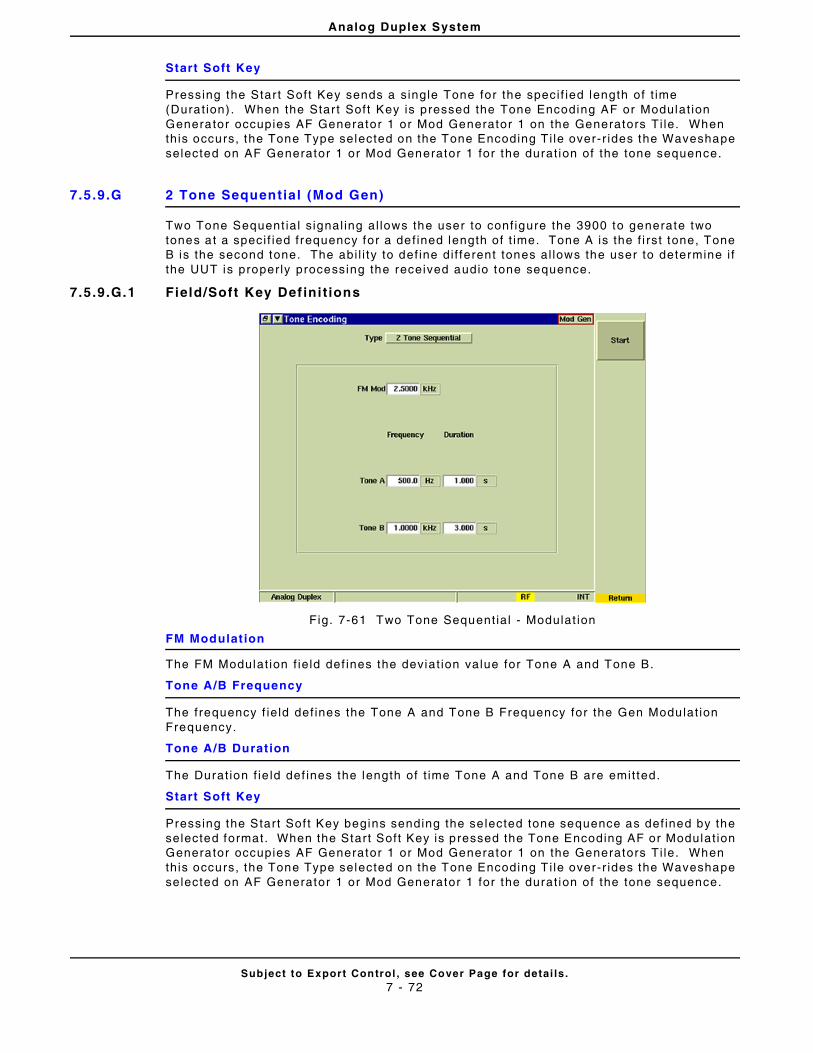
Analog Duplex System
Subject to Export Control , see Cover Page for detai ls .7 - 72
Start Soft Key
Pressing the Star t Soft Key sends a single Tone for the speci f ied length of t ime (Durat ion) . When the Star t Soft Key is pressed the Tone Encoding AF or Modulat ion Generator occupies AF Generator 1 or Mod Generator 1 on the Generators Ti le. When this occurs, the Tone Type selected on the Tone Encoding T i le over-r ides the Waveshape selected on AF Generator 1 or Mod Generator 1 for the durat ion of the tone sequence.
7.5.9.G 2 Tone Sequential (Mod Gen)
Two Tone Sequent ial s ignal ing al lows the user to conf igure the 3900 to generate two tones at a speci f ied frequency for a def ined length of t ime. Tone A is the f i rst tone, Tone B is the second tone. The abi l i ty to def ine di f ferent tones al lows the user to determine i f the UUT is proper ly processing the received audio tone sequence.
7.5.9.G.1 Field/Soft Key Def ini t ions
Fig. 7-61 Two Tone Sequent ial - Modulat ion
FM Modulat ion
The FM Modulat ion f ie ld def ines the deviat ion value for Tone A and Tone B.
Tone A/B Frequency
The frequency f ie ld def ines the Tone A and Tone B Frequency for the Gen Modulat ion Frequency.
Tone A/B Durat ion
The Durat ion f ie ld def ines the length of t ime Tone A and Tone B are emit ted.
Start Soft Key
Pressing the Start Sof t Key begins sending the se lected tone sequence as def ined by the selected format. When the Start Soft Key is pressed the Tone Encoding AF or Modulat ion Generator occupies AF Generator 1 or Mod Generator 1 on the Generators Ti le. When this occurs, the Tone Type selected on the Tone Encoding T i le over-r ides the Waveshape selected on AF Generator 1 or Mod Generator 1 for the durat ion of the tone sequence.
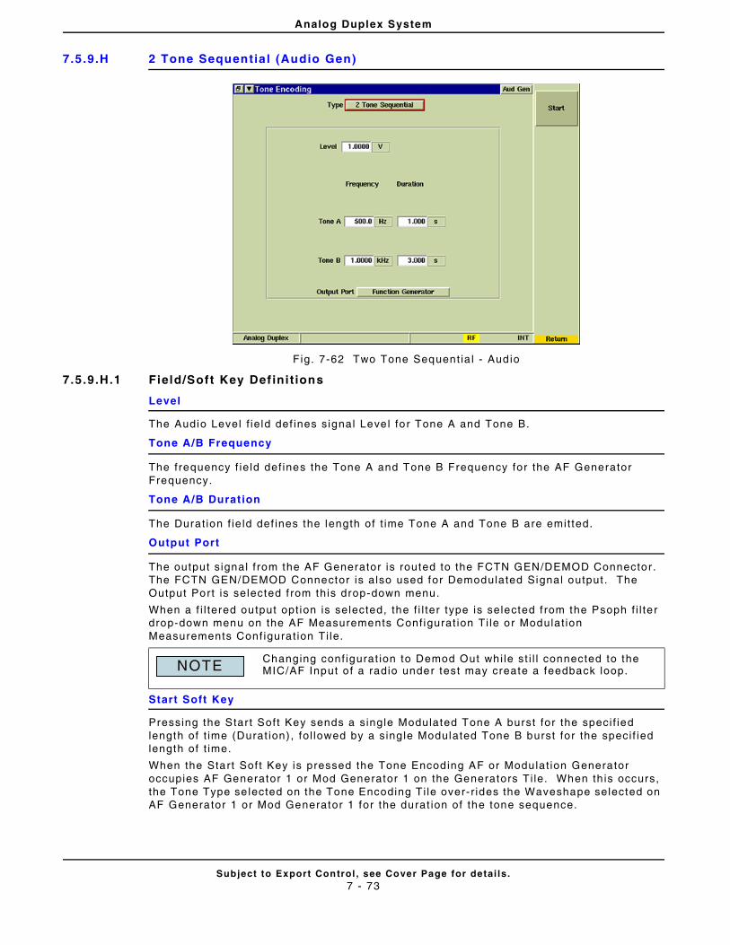
Analog Duplex System
Subject to Export Control , see Cover Page for detai ls .7 - 73
7.5.9.H 2 Tone Sequential (Audio Gen)
Fig. 7-62 Two Tone Sequent ia l - Audio
7.5.9.H.1 Field/Soft Key Def ini t ions
Level
The Audio Level f ie ld def ines signal Level for Tone A and Tone B.
Tone A/B Frequency
The frequency f ie ld def ines the Tone A and Tone B Frequency for the AF Generator Frequency.
Tone A/B Durat ion
The Durat ion f ie ld def ines the length of t ime Tone A and Tone B are emit ted.
Output Port
The output s ignal f rom the AF Generator is routed to the FCTN GEN/DEMOD Connector. The FCTN GEN/DEMOD Connector is also used for Demodulated Signal output . The Output Port is selected f rom this drop-down menu.
When a f i l tered output opt ion is selected, the f i l ter type is selected f rom the Psoph f i l te r drop-down menu on the AF Measurements Conf igurat ion Ti le or Modulat ion Measurements Conf igurat ion Ti le.
Start Soft Key
Pressing the Star t Soft Key sends a single Modulated Tone A burst for the speci f ied length of t ime (Durat ion) , fo l lowed by a sing le Modulated Tone B burst for the speci f ied length of t ime.
When the Start Sof t Key is pressed the Tone Encoding AF or Modulat ion Generator occupies AF Generator 1 or Mod Generator 1 on the Generators Ti le. When th is occurs, the Tone Type se lected on the Tone Encoding Ti le over- r ides the Waveshape selected on AF Generator 1 or Mod Generator 1 for the durat ion of the tone sequence.
Changing conf igurat ion to Demod Out whi le st i l l connected to the MIC/AF Input o f a radio under test may create a feedback loop.NOTE
Analog Duplex System
Subject to Export Control , see Cover Page for detai ls .7 - 74
THIS PAGE INTENTIONALLY LEFT BLANK.
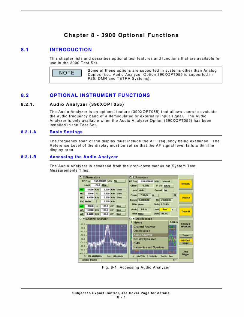
Subject to Export Control , see Cover Page for detai ls .8 - 1
Chapter 8 - 3900 Optional Functions
8.1 INTRODUCTION
This chapter l is ts and descr ibes opt ional test features and funct ions that are ava i lable for use in the 3900 Test Set .
8.2 OPTIONAL INSTRUMENT FUNCTIONS
8.2.1. Audio Analyzer (390XOPT055)
The Audio Analyzer is an opt ional feature (390XOPT055) that al lows users to evaluate the audio frequency band of a demodulated or externa l ly input s ignal . The Audio Analyzer is only avai lable when the Audio Analyzer Opt ion (390XOPT055) has been instal led in the Test Set .
8.2.1.A Basic Sett ings
The frequency span of the display must include the AF Frequency being examined. The Reference Level of the display must be set so that the AF signal level fa l ls wi thin the display area.
8.2.1.B Accessing the Audio Analyzer
The Audio Analyzer is accessed from the drop-down menus on System Test Measurements T i les.
Fig. 8-1 Accessing Audio Analyzer
Some of these opt ions are suppor ted in systems other than Analog Duplex ( i .e. , Audio Analyzer Opt ion 390XOPT055 is suppor ted in P25, DMR and TETRA Systems).
NOTE

3900 Optional Functions
Subject to Export Control , see Cover Page for detai ls .8 - 2
8.2.1.C Audio Analyzer Ti le Layout
The Audio Analyzer can be viewed in minimized and maximized view. Sof t Keys on the r ight s ide of the display provide access to set t ings not avai lable on the main t i le.
Fig. 8-2 Audio Analyzer Ti le - Maximized View
8.2.1.D Field/Soft Key Def ini t ions
8.2.1.D.1 Reference Level
The Reference Level sets the top value on the display graph. Power levels can be measured at any point on the t race in conjunct ion with the Scal ing dB/d iv sett ing. The Reference Level can be set to any value with in the speci f ied range. The Reference Level is set by:
• Using the Expand and Contract Soft Keys to make step changes.
• Select ing the data f ie ld and using the Rotary Control Knob to adjust the level .
• Select ing the data f ie ld and using the Data Entry Input Keys to enter speci f ic level .
8.2.1.D.2 Scaling dB
The Scal ing drop-down menu selects f rom a range of 1, 2, 5, or 10. The scal ing value (dB/div) can then be increased or decreased using the Expand or Contract Sof t Keys.
8.2.1.D.3 Input Source
The Input Source drop-down menu selects Demod or Audio as the f i l tered signal source. When a f i l ter is se lected, the signal source is routed through the selected f i l ter . F i l ter select ion is made on the Analyzers T i le of the act ive operat ing Analog system. When the Tracking Generator is enabled, user def ined f i l ters are not avai lable .
8.2.1.D.4 Start
Defines the star t f requency of the frequency span. The maximum span is 0 to 24000 Hz; hor izontal scale va lues must be with in this range.
Some of the images in this sect ion show opt ion enabled f ie lds. These f ie lds are not v is ib le unless the appl icable opt ion is instal led in the Test Set.
NOTE
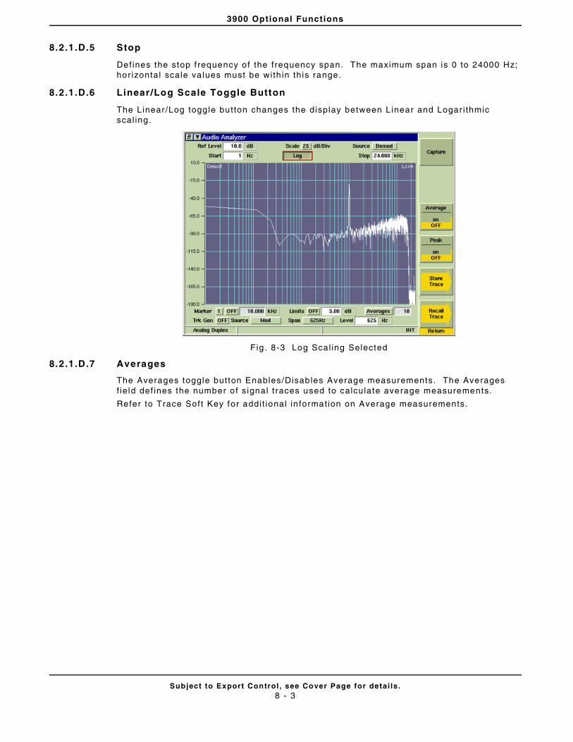
3900 Optional Functions
Subject to Export Control , see Cover Page for detai ls .8 - 3
8.2.1.D.5 Stop
Defines the stop f requency of the frequency span. The maximum span is 0 to 24000 Hz; hor izontal scale va lues must be with in this range.
8.2.1.D.6 Linear/Log Scale Toggle Button
The Linear /Log toggle button changes the display between L inear and Logar i thmic scal ing.
Fig. 8-3 Log Scal ing Selected
8.2.1.D.7 Averages
The Averages toggle button Enables/Disables Average measurements. The Averages f ie ld def ines the number o f s ignal t races used to calculate average measurements.
Refer to Trace Sof t Key for addi t ional in formation on Average measurements.

3900 Optional Functions
Subject to Export Control , see Cover Page for detai ls .8 - 4
8.2.1.D.8 Vert ical Soft Key
The Vert ical Sof t Key accesses scal ing and posi t ioning controls that adjust the trace’s posi t ion on the display. The signal t race can also be adjusted by changing the Reference Level or Scal ing dB values.
Fig. 8-4 Audio Analyzer - Ref Level and Scale Sett ings
8.2.1.D.9 Reset Vert ical Soft Key
Resets ver t ical set t ing to posi t ion t race vert ical ly in the center of the graph f ie ld.
8.2.1.D.10 Horizontal Soft Key
The Hor izontal Soft Key accesses a group of soft keys that ad just the hor izontal scal ing and posi t ion of the signal on the graph f ie ld.
F ig. 8-5 Audio Analyzer Start and Stop Frequency Set t ing
8.2.1.D.11 Reset Horizontal Soft Key
Resets Star t and Stop f requency values to f requency range of Test Set.

3900 Optional Functions
Subject to Export Control , see Cover Page for detai ls .8 - 5
8.2.1.D.12 Markers Soft Key
Marker funct ional i ty is descr ibed in the sect ion t i t led Markers, in Chapter 6, Radio Test Inst ruments.
8.2.1.D.13 Toggle Marker Soft Key
Refer to sect ion t i t led Toggle Marker Sof t Key in Chapter 6, Radio Test Instruments.
Marker funct ional i ty is descr ibed in the sect ion t i t led Markers, in Chapter 6, Radio Test Inst ruments.
8.2.1.D.14 Trace Soft Key
The Trace Soft Key accesses trace disp lay control funct ions to al low users to obtain average and peak measurements and to capture t races being displayed on the p lot f ie ld.
Trace Color
Trace types being disp layed on the graph are l isted in the upper r ight corner of the graph f ie ld. The t races are color-coded to ident i fy t race types.
• Live t races are White.
• Peak hold traces are Red.
• Averaged traces are Yel low.
• Captured t races are Green.
F ig. 8-6 Audio Analyzer Trace Soft Keys
8.2.1.D.15 Capture Soft Key
When Capture Soft Key is pressed the current t race is held on the display. To resume normal sweep operat ion press the Clear Soft Key.
A captured t race can be saved by pressing the HOLD Key, then select ing the Save As Sof t Key.
8.2.1.D.16 Clear Soft Key
Clears the current captured t race and resumes display of Live t race. This soft key is only v is ible when a t race is in ‘Captured’ state.
3900 Optional Functions
Subject to Export Control , see Cover Page for detai ls .8 - 6
8.2.1.D.17 Peak Hold Soft Key
When Peak Hold ON is se lected, the maximum value at each frequency point is disp layed to produce the RED Max Hold t race. This t race is c leared by select ing Peak Hold OFF. Peak Hold must be reset ( toggled ON/OFF) when Average readings are Enabled/Disabled. The white Live t race is also displayed and can be averaged depending on the current sett ing. This soft key is accessed by pressing the Trace Soft Key.
8.2.1.D.18 Average Soft Key
When the Average Soft Key is ON, the trace is calculated by averaging the number of measurements def ined in the Averages f ie ld. The calculated va lue is a rol l ing average or a one-shot average as def ined on the Tr igger Ti le using the Repeat Soft Key and Single Sof t Key. A yel low progress indicator is displayed in the upper r ight corner of the graph f ie ld whi le the average reading is accumulat ing. This soft key is accessed by pressing the Trace Soft Key.
8.2.1.D.19 Store Trace Soft Key
The Store Trace Sof t Keys opens a d ialog box that a l lows a user to save a captured signal t race. The signal must be in “Captured” state before i t can be saved using the Store Trace funct ion. Refer to the Capture Soft Key for in formation on captur ing a signal t race.
8.2.1.D.20 Recal l Trace Soft Key
The Recal l Trace Soft Key opens a dialog box that al lows the user to load stored t race data.
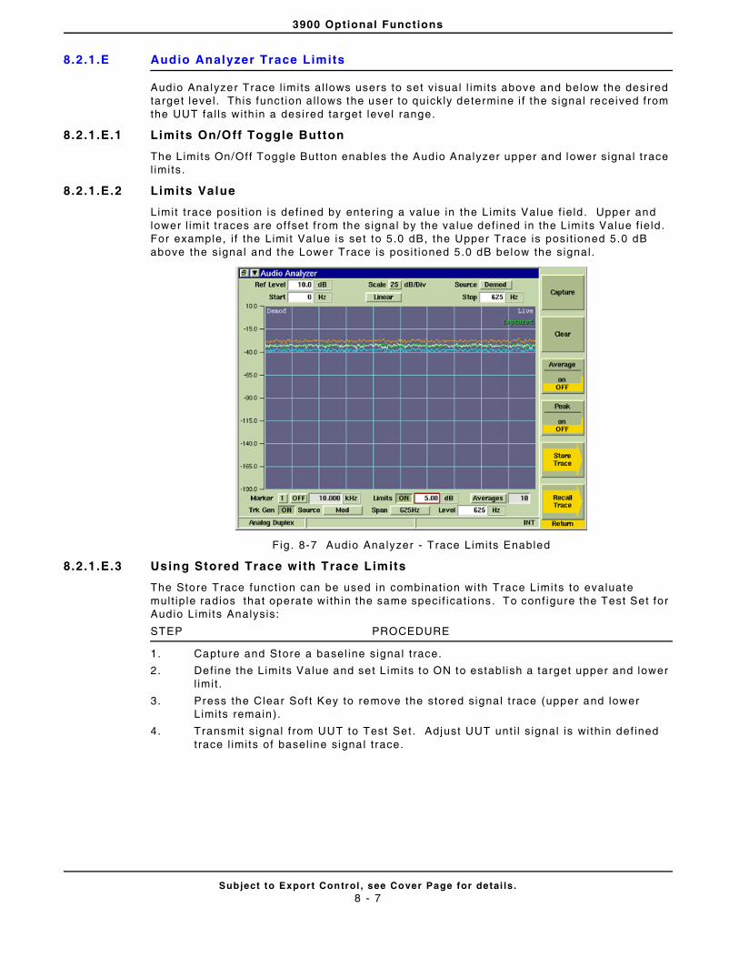
3900 Optional Functions
Subject to Export Control , see Cover Page for detai ls .8 - 7
8.2.1.E Audio Analyzer Trace Limits
Audio Analyzer Trace l imits al lows users to set v isual l imits above and below the desired target level . This funct ion al lows the user to quickly determine i f the signal received from the UUT fal ls wi th in a desired target level range.
8.2.1.E.1 Limits On/Off Toggle Button
The Limits On/Off Toggle But ton enables the Audio Analyzer upper and lower s ignal t race l imits.
8.2.1.E.2 Limits Value
Limit t race posi t ion is def ined by enter ing a value in the L imits Value f ie ld . Upper and lower l imi t t races are of fset f rom the signal by the va lue def ined in the Limits Value f ie ld . For example, i f the Limit Value is set to 5.0 dB, the Upper Trace is posi t ioned 5.0 dB above the signal and the Lower Trace is posi t ioned 5.0 dB below the signal .
Fig . 8-7 Audio Analyzer - Trace Limits Enabled
8.2.1.E.3 Using Stored Trace with Trace Limits
The Store Trace funct ion can be used in combinat ion with Trace Limits to evaluate mult ip le radios that operate within the same speci f icat ions. To conf igure the Test Set for Audio Limits Analysis:
STEP PROCEDURE
1. Capture and Store a basel ine signal t race.
2. Def ine the Limits Value and set L imits to ON to establ ish a target upper and lower l imit .
3. Press the Clear Sof t Key to remove the stored signal t race (upper and lower Limits remain).
4. Transmit s ignal f rom UUT to Test Set. Adjust UUT unt i l s ignal is wi thin def ined trace l imits of basel ine signal t race.
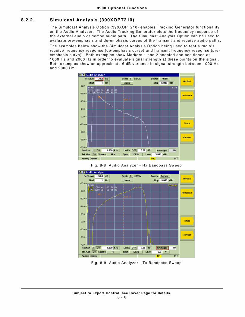
3900 Optional Functions
Subject to Export Control , see Cover Page for detai ls .8 - 8
8.2 .2. Simulcast Analysis (390XOPT210)
The Simulcast Analysis Opt ion (390XOPT210) enables Tracking Generator funct ional i ty on the Audio Analyzer. The Audio Tracking Generator plots the frequency response of the external audio or demod audio path. The Simulcast Analysis Opt ion can be used to evaluate pre-emphasis and de-emphasis curves of the transmit and receive audio paths.
The examples below show the Simulcast Analysis Opt ion being used to test a radio ’s receive frequency response (de-emphasis curve) and t ransmit f requency response (pre-emphasis curve) . Both examples show Markers 1 and 2 enabled and posi t ioned at 1000 Hz and 2000 Hz in order to evaluate signal st rength at these points on the signal . Both examples show an approximate 6 dB var iance in s ignal strength between 1000 Hz and 2000 Hz.
Fig. 8-8 Audio Analyzer - Rx Bandpass Sweep
Fig. 8-9 Audio Analyzer - Tx Bandpass Sweep

3900 Optional Functions
Subject to Export Control , see Cover Page for detai ls .8 - 9
8.2.2.A Trk Gen Toggle Button
The Trk Gen Toggle But ton turns the Tracking Generator On and Of f . When the Tracking Generator is ON, ei ther the M1 or A1 Generator is used to produce the Tracking Generator Output s ignal . When the Tracking Generator Output Source is set to Mod, M1 is used to generate the Tracking Generator Output s ignal . When the Tracking Generator Output Source is set to AF, A1 is used to generate the Tracking Generator Output s ignal . I f A1 or M1 is al ready enabled, the Tracking Generator s ignal overr ides the signal current ly conf igured on these generators.
8.2.2.B Span Drop-Down Menu
The Span drop-down menu is enabled when the Simulcast Analysis Opt ion (390XOPT210) is instal led in the Test Set. Span selects the hor izontal scal ing of the plot ted signal . Once Span is selected, the Stop Frequency Field can be used to focus on a speci f ic sect ion of the signal . For example, Span can be set to 9 .6 kHz, then the Stop Frequency can be adjusted to 100.0 Hz. The maximum Stop Frequency is def ined by the Span value.
8.2.2.C Tracking Generator Source
The Tracking Generator Source drop-down menu selects the output source of the Tracking Generator s ignal .
When AF is selected, the Tracking Generator Output s ignal is routed to the Test Set ’s Fctn GEN/Demod Out Connector .
When MOD is selected, the Tracking Generator Output s ignal is routed through the modulator to the selected RF Out Connector (GEN or T/R).
8.2.2.D Tracking Generator Level
The Tracking Generator Level def ines the Tracking Generator Output s ignal level .

3900 Optional Functions
Subject to Export Control , see Cover Page for detai ls .8 - 10
8.2 .3. Spectrum Analyzer Tracking Generator Option (390XOPT061)
The Tracking Generator Opt ion (390XOPT061) generates a carr ier wave that sweeps synchronously with the Spectrum Analyzer RF Receiver . The carr ier wave can be appl ied to components or systems, and the output analyzed to display the frequency response of the device under test .
The Trk Gen drop-down menu Enables the Tracking Generator when Gen or TR is selected. Select ing OFF from this drop-down menu d isables the Tracking Generator .
Fig. 8-10 Spectrum Analyzer Ti le - Tracking Generator Parameters
8.2.3.A Field Def ini t ions
8.2.3.A.1 Trk Gen Menu
The Trk Gen drop-down menu Enables the Tracking Generator when Gen or TR is selected. Select ing OFF from this drop-down menu d isables the Tracking Generator .
8.2.3.A.2 Gen Lvl
The Gen Lvl Field provides quick access to set the Generator power level . This f ie ld is only avai lable on the Spectrum Analyzer Ti le when the Tracking Generator Opt ion (390XOPT061) is instal led in the Test Set.
Switching between Spectrum Analyzer and Test Mode disables the Tracking Generator.NOTE

3900 Optional Functions
Subject to Export Control , see Cover Page for detai ls .8 - 11
8.2 .4. Analyzer OBW & Power Between Markers Option (390XOPT064)
The Analyzer Occupied Bandwidth (OBW) and Power Between Marker Opt ion provides the user with added features for evaluat ing the power of a received signal . The Power Between Markers funct ion al lows the user to evaluate the total power level of a received signal between Marker 1 and Marker 2 on the Channel Analyzer and Spectrum Analyzer . The Power Measurement (Pwr: ) is disp layed under the Del ta Measurement when Marker 1 and Marker 2 are enabled.
F ig. 8-11 Spectrum Analyzer - Power Between Markers Measurement
The Occupied Bandwidth (OBW) Funct ion measures the frequency band that contains a speci f ied percentage of total s ignal power, centered on the assigned Center Frequency (CF). The OBW funct ion is enabled/disabled by pressing the OBW Toggle Button. When enabled, the OBW Power and Bandwidth measurements are displayed on the Analyzer graph.
Fig. 8-12 Spectrum Analyzer - Occupied Bandwidth at 99%
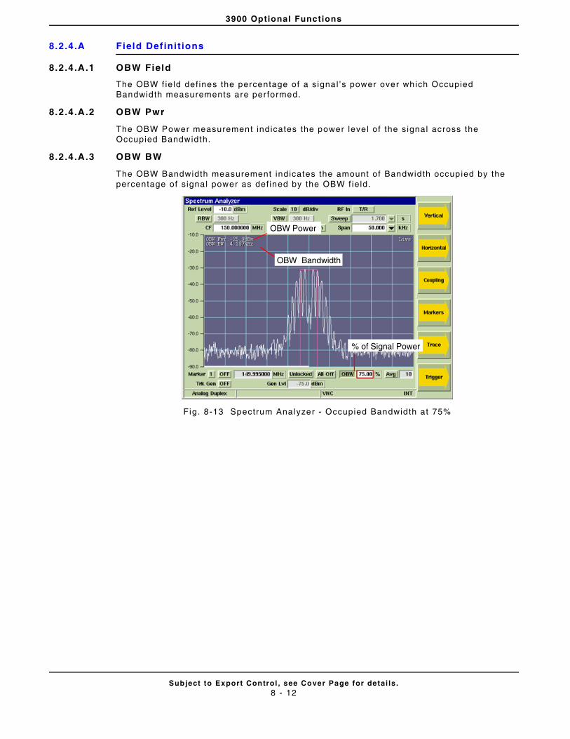
3900 Optional Functions
Subject to Export Control , see Cover Page for detai ls .8 - 12
8.2.4.A Field Def ini t ions
8.2.4.A.1 OBW Field
The OBW f ield def ines the percentage of a s ignal ’s power over which Occupied Bandwidth measurements are per formed.
8.2.4.A.2 OBW Pwr
The OBW Power measurement ind icates the power leve l of the signal across the Occupied Bandwidth.
8.2.4.A.3 OBW BW
The OBW Bandwidth measurement indicates the amount of Bandwidth occupied by the percentage of s ignal power as def ined by the OBW f ield.
Fig. 8-13 Spectrum Analyzer - Occupied Bandwidth at 75%
% of Signal Power
OBW Bandwidth
OBW Power
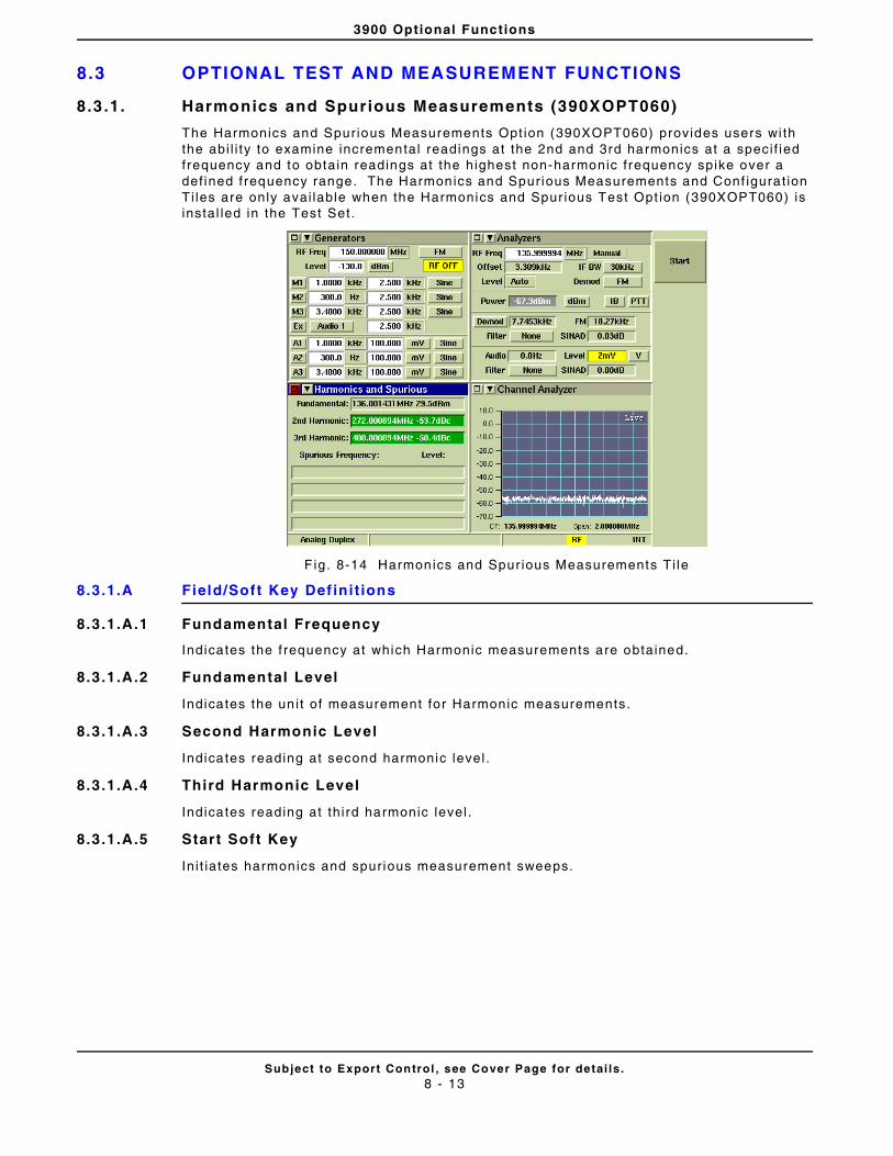
3900 Optional Functions
Subject to Export Control , see Cover Page for detai ls .8 - 13
8.3 OPTIONAL TEST AND MEASUREMENT FUNCTIONS
8.3.1. Harmonics and Spurious Measurements (390XOPT060)
The Harmonics and Spurious Measurements Opt ion (390XOPT060) provides users wi th the abi l i ty to examine incremental readings at the 2nd and 3rd harmonics at a speci f ied frequency and to obtain readings at the highest non-harmonic f requency spike over a def ined frequency range. The Harmonics and Spurious Measurements and Conf igurat ion Ti les are only avai lable when the Harmonics and Spur ious Test Opt ion (390XOPT060) is instal led in the Test Set .
F ig. 8-14 Harmonics and Spur ious Measurements Ti le
8.3.1.A Field/Soft Key Def ini t ions
8.3.1.A.1 Fundamental Frequency
Indicates the f requency at which Harmonic measurements are obtained.
8.3.1.A.2 Fundamental Level
Indicates the un i t of measurement for Harmonic measurements.
8.3.1.A.3 Second Harmonic Level
Indicates reading at second harmonic level .
8.3.1.A.4 Third Harmonic Level
Indicates reading at th ird harmonic level .
8.3.1.A.5 Start Soft Key
In i t iates harmonics and spur ious measurement sweeps.
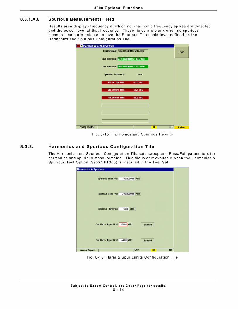
3900 Optional Functions
Subject to Export Control , see Cover Page for detai ls .8 - 14
8.3.1.A.6 Spurious Measurements Field
Results area displays f requency at which non-harmonic f requency spikes are detected and the power leve l at that f requency. These f ie lds are blank when no spurious measurements are detected above the Spurious Threshold level def ined on the Harmonics and Spurious Conf igurat ion T i le.
F ig. 8-15 Harmonics and Spur ious Results
8.3 .2. Harmonics and Spurious Configuration Tile
The Harmonics and Spurious Conf igurat ion T i le sets sweep and Pass/Fai l parameters for harmonics and spur ious measurements. This t i le is only avai lable when the Harmonics & Spurious Test Opt ion (390XOPT060) is instal led in the Test Set.
Fig . 8-16 Harm & Spur L imits Conf igurat ion Ti le
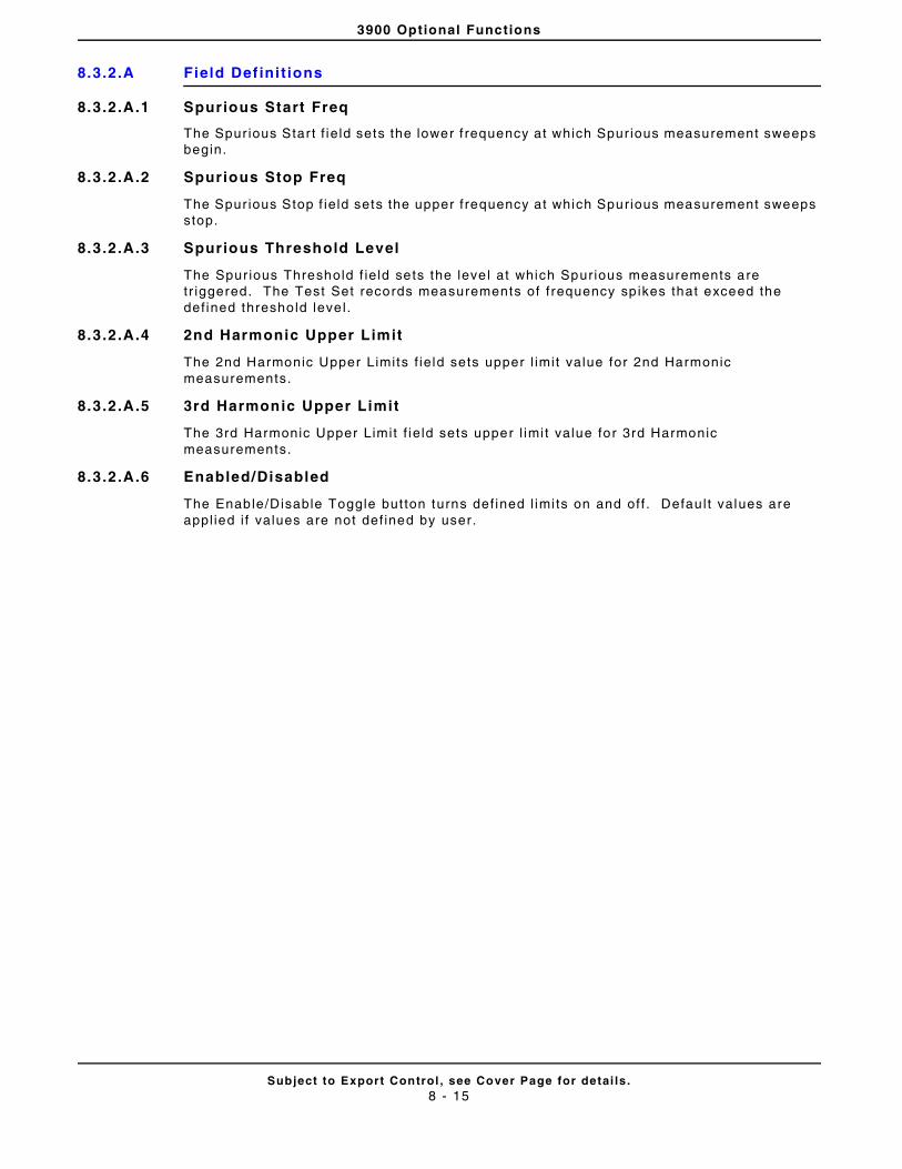
3900 Optional Functions
Subject to Export Control , see Cover Page for detai ls .8 - 15
8.3.2.A Field Def ini t ions
8.3.2.A.1 Spurious Start Freq
The Spur ious Star t f ie ld sets the lower f requency at which Spur ious measurement sweeps begin.
8.3.2.A.2 Spurious Stop Freq
The Spur ious Stop f ie ld sets the upper f requency at which Spurious measurement sweeps stop.
8.3.2.A.3 Spurious Threshold Level
The Spur ious Threshold f ie ld sets the leve l at which Spurious measurements are tr iggered. The Test Set records measurements of f requency sp ikes that exceed the def ined threshold leve l .
8.3.2.A.4 2nd Harmonic Upper Limit
The 2nd Harmonic Upper Limits f ie ld sets upper l imit value for 2nd Harmonic measurements.
8.3.2.A.5 3rd Harmonic Upper Limit
The 3rd Harmonic Upper Limit f ie ld sets upper l imi t value for 3rd Harmonic measurements.
8.3.2.A.6 Enabled/Disabled
The Enable/Disable Toggle but ton turns def ined l imi ts on and off . Defau l t values are appl ied i f values are not def ined by user.
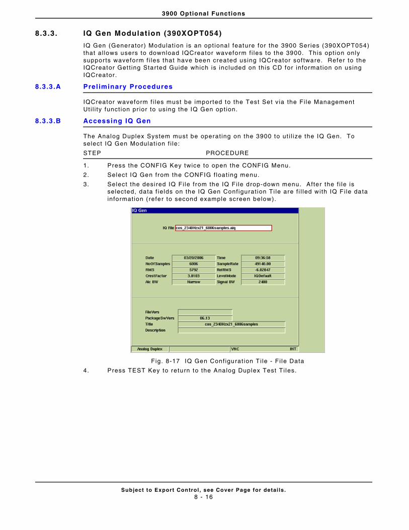
3900 Optional Functions
Subject to Export Control , see Cover Page for detai ls .8 - 16
8.3 .3. IQ Gen Modulat ion (390XOPT054)
IQ Gen (Generator) Modulat ion is an opt ional feature for the 3900 Ser ies (390XOPT054) that al lows users to download IQCreator waveform f i les to the 3900. This opt ion only suppor ts waveform f i les that have been created using IQCreator sof tware. Refer to the IQCreator Get t ing Started Guide which is included on th is CD for informat ion on using IQCreator.
8.3.3.A Prel iminary Procedures
IQCreator waveform f i les must be imported to the Test Set v ia the Fi le Management Ut i l i ty funct ion pr ior to using the IQ Gen opt ion.
8.3.3.B Accessing IQ Gen
The Analog Duplex System must be operat ing on the 3900 to ut i l ize the IQ Gen. To select IQ Gen Modulat ion f i le:
STEP PROCEDURE
1. Press the CONFIG Key twice to open the CONFIG Menu.
2. Select IQ Gen from the CONFIG f loat ing menu.
3. Select the desi red IQ Fi le f rom the IQ F i le drop-down menu. After the f i le is selected, data f ie lds on the IQ Gen Conf igurat ion Ti le are f i l led with IQ F i le data informat ion ( refer to second example screen below).
Fig. 8-17 IQ Gen Conf igurat ion T i le - Fi le Data
4. Press TEST Key to return to the Analog Duplex Test Ti les.

3900 Optional Functions
Subject to Export Control , see Cover Page for detai ls .8 - 17
STEP PROCEDURE
5. Select IQ Gen from the Modulat ion drop-down menu on the Generators Ti le. The Test Set now disp lays the selected IQ f i le.
Fig. 8-18 IQ Gen Select ion
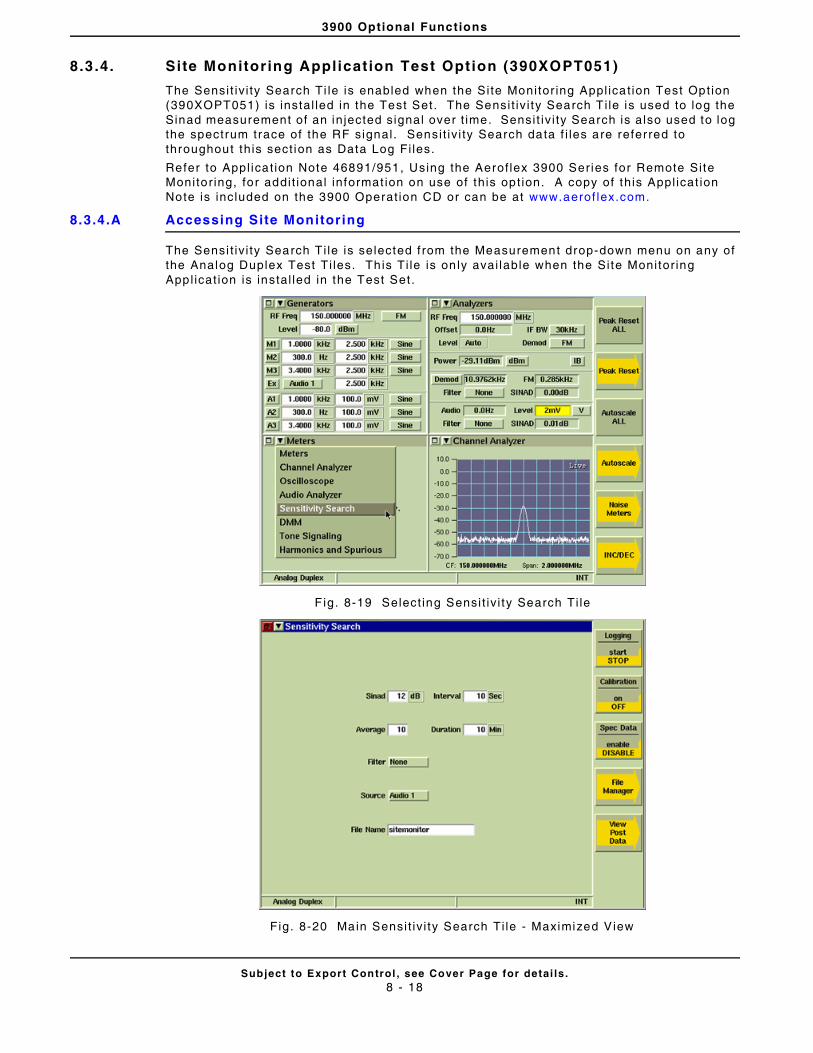
3900 Optional Functions
Subject to Export Control , see Cover Page for detai ls .8 - 18
8.3 .4. Site Monitoring Applicat ion Test Option (390XOPT051)
The Sensi t iv i ty Search Ti le is enabled when the Si te Monitor ing Appl icat ion Test Opt ion (390XOPT051) is instal led in the Test Set. The Sensi t iv i ty Search T i le is used to log the Sinad measurement of an in jected signal over t ime. Sensi t iv i ty Search is also used to log the spectrum trace of the RF signal . Sensi t iv i ty Search data f i les are referred to throughout th is sect ion as Data Log Fi les.
Refer to Appl icat ion Note 46891/951, Using the Aerof lex 3900 Series for Remote Site Monitor ing, for addit ional informat ion on use of th is opt ion. A copy of th is Appl icat ion Note is included on the 3900 Operat ion CD or can be at www.aerof lex.com.
8.3.4.A Accessing Site Monitoring
The Sensi t iv i ty Search T i le is selected f rom the Measurement drop-down menu on any of the Analog Duplex Test Ti les. Th is Ti le is on ly avai lable when the Si te Monitor ing Appl icat ion is instal led in the Test Set.
F ig. 8-19 Select ing Sensi t iv i ty Search Ti le
Fig. 8-20 Main Sensi t iv i ty Search Ti le - Maximized View

3900 Optional Functions
Subject to Export Control , see Cover Page for detai ls .8 - 19
8.3.4.B Field/Soft Key Def ini t ions
The Sensi t iv i ty Search Test Ti le contains parameters that must be def ined to perform a Si te Monitor ing test.
8.3.4.B.1 Sinad
Sets the reference point f rom which al l readings are taken.
8.3.4.B.2 Interval
Defines how frequent ly readings are logged to the f i le for the durat ion of the search.
8.3.4.B.3 Average
Defines the number of readings to be averaged to calculate measurements.
8.3.4.B.4 Duration
Defines the length of t ime over which readings are taken.
8.3.4.B.5 Fi lter
Selects a measurement f i l ter to include in the measurement path.
8.3.4.B.6 Source
Selects s ignal source of input s ignal .
8.3.4.B.7 Fi le Name
Indicates the Data Log Fi le current ly running or being displayed on Sensi t iv i ty Search Ti les. The Fi le name is l imi ted to 18 characters and can not contain any blank spaces. The Test Set logs data to the last selected Data Log Fi le unt i l a new f i le name is assigned.
8.3.4.B.8 Logging Start /Stop Soft Key
Starts and stops logging data. When Status is Running, the Sensi t iv i ty Search Ti le appears as shown in example below. When logging is complete, display Ti le defaul ts back to Main Sensi t iv i ty Search T i le.
F ig. 8-21 Sensi t iv i ty Search Ti le - Log Running

3900 Optional Functions
Subject to Export Control , see Cover Page for detai ls .8 - 20
8.3.4.B.9 View Live Data Soft Key
Opens sof t key sub-menu that al lows user to v iew data as i f i t acquired. This sof t key is only avai lable whi le data is being logged (Status f ie ld ind icates Running).
8.3.4.B.10 Logging Soft Key
Disp lays log f i le as data is acquired. This soft key is accessed by pressing the View Live Data Soft Key whi le Data Log is running.
8.3.4.B.11 Plot Soft Key
Disp lays graph p lot o f data as i t is acquired. This sof t key is accessed by pressing the View L ive Data Sof t Key whi le data is being logged.
8.3.4.B.12 Spectrum Soft Key
Disp lays Spectrum Analyzer p lot of data as i t is acquired. This soft key is on ly ava i lable whi le data is being logged.
Fig. 8-22 View L ive Data Sof t Key Sub-menu
8.3.4.B.13 Default Soft Key
Disp lays Main Sensi t iv i ty Search Ti le.

3900 Optional Functions
Subject to Export Control , see Cover Page for detai ls .8 - 21
8.3.4.B.14 View Post Data Soft Key
Opens sof t key sub-menu that a l lows user to review saved Data Log Fi les. Th is soft key is only avai lable af ter data acquisi t ion has stopped.
F ig. 8-23 Sensi t iv i ty Search - V iew/Post Data Ti le
8.3.4.B.15 Calibrat ion Soft Key
In i t iates Sensi t iv i ty Search Cal ibrat ion funct ion. Unit under test must be conf igured and connected to Test Set pr ior to running cal ibrat ion.
8.3.4.B.16 Spec Data Soft Key
Disp lays logged data on a Spectrum Analyzer plot f ie ld. Data can be viewed whi le data is being logged and after logging stops.
8.3.4.B.17 Fi le Manager Soft Key
Opens a soft key sub-menu that al lows user to navigate between or delete exist ing Data Log Fi les.
F ig. 8-24 Sensi t iv i ty Search - F i le Manager Ti le

3900 Optional Functions
Subject to Export Control , see Cover Page for detai ls .8 - 22
8.3.4.B.18 View Log File Soft Key
Disp lays l ist of Data Log Fi les. Data Log Fi les include date and t ime of test , the Sinad reading and Power Level readings at each recorded interval . The View Log Soft Key is accessed by pressing the View Post Data Soft Key af ter data logging has stopped. Scrol l Up and Scro l l Down Soft Keys navigate through the data log when Mouse opt ion is not being used.
Fig. 8-25 Logged Data Fi le
8.3.4.B.19 Plot Log Fi le Soft Key
Disp lays logged data on a graph plot . Direct iona l arrow soft keys a l low user to navigate to points along the acquired signal .
8.3.4.B.20 Spec Data Soft Key
Disp lays logged data on a Spectrum Analyzer plot f ie ld. Data can be viewed whi le data is being logged and after logging stops.
Fig. 8-26 Logged Data - Plo t Log Soft Key Sub-menu
3900 Optional Functions
Subject to Export Control , see Cover Page for detai ls .8 - 23
8.3.4.C Managing Log Fi les
8.3.4.C.1 Open Existing Log Fi le
STEP PROCEDURE
1. Press Fi le Manager Soft Key.
2. Select the desi red f i le name f rom l ist .
3. Press Set as Current Soft Key.
8.3.4.C.2 To add to an existing Data Log Fi le:
STEP PROCEDURE
1. Press Fi le Manager Soft Key.
2. Select desired Data Log Fi le f rom l ist and press Set as Current Sof t Key.
3. Press Return, then Logging Sof t Key to star t logging data to the selected Data Log Fi le.
8.3.4.C.3 To Create New Data Log File
STEP PROCEDURE
1. Select F i le Name f ie ld on main Sensi t iv i ty Search T i le.
2. Enter desired f i le name in f ie ld.
3. Data is automatica l ly saved under designated f i le name when Logging Soft Key is pressed.
8.3.4.C.4 Delete Log File
STEP PROCEDURE
1. Press Fi le Manager Soft Key.
2. Select the desi red f i le name f rom l ist .
3. Press Remove Soft Key to remove se lected Data Log Fi le or press Remove Al l Sof t Key to dele te a l l Data Log F i les.
8.3 .5. POCSAG Testing Option (390XOPT067) - Encoding
The POCSAG Test ing Opt ion (390XOPT067) provides users with the abi l i ty to test a pager ’s t ransmit and receive operat ion.
The POCSAG Encoding T i le is used to test a pager’s receive per formance. The POCSAG Encoding Ti le is used to def ine the parameters of the encoded message being sent to the pager . Message parameters should be def ined according to the pager ’s operat ional capabi l i t ies. The POCSAG Decoding Ti le is used to display the decoded POCSAG signal received from the pager.
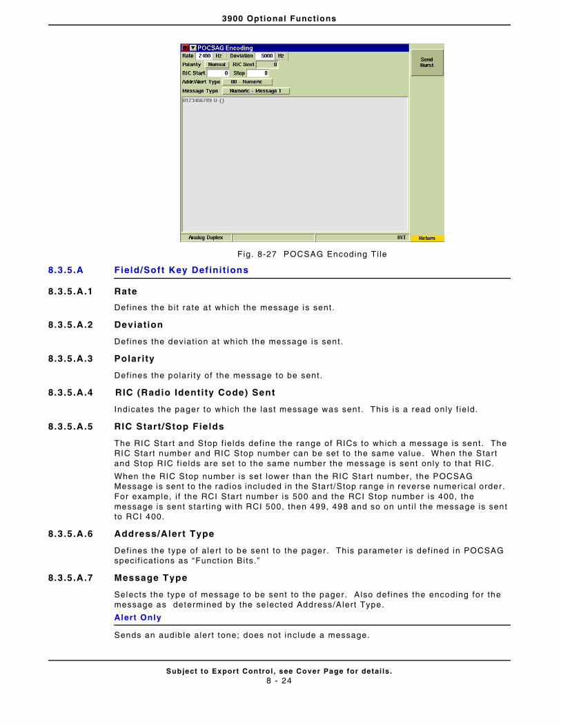
3900 Optional Functions
Subject to Export Control , see Cover Page for detai ls .8 - 24
Fig. 8-27 POCSAG Encoding Ti le
8.3.5.A Field/Soft Key Def ini t ions
8.3.5.A.1 Rate
Defines the b i t rate at which the message is sent.
8.3.5.A.2 Deviation
Defines the deviat ion at which the message is sent .
8.3.5.A.3 Polar ity
Defines the polar i ty of the message to be sent .
8.3.5.A.4 RIC (Radio Identi ty Code) Sent
Indicates the pager to which the last message was sent . This is a read only f ie ld.
8.3.5.A.5 RIC Start /Stop Fields
The RIC Star t and Stop f ie lds def ine the range of RICs to which a message is sent. The RIC Start number and RIC Stop number can be set to the same value. When the Star t and Stop RIC f ie lds are set to the same number the message is sent only to that RIC.
When the RIC Stop number is set lower than the RIC Start number, the POCSAG Message is sent to the radios included in the Star t /Stop range in reverse numerica l order . For example, i f the RCI Start number is 500 and the RCI Stop number is 400, the message is sent start ing wi th RCI 500, then 499, 498 and so on unt i l the message is sent to RCI 400.
8.3.5.A.6 Address/Alert Type
Defines the type of alert to be sent to the pager . This parameter is def ined in POCSAG speci f icat ions as “Funct ion Bi ts.”
8.3.5.A.7 Message Type
Selects the type of message to be sent to the pager. A lso def ines the encoding for the message as determined by the se lected Address/Alert Type.
Alert Only
Sends an audible aler t tone; does not include a message.
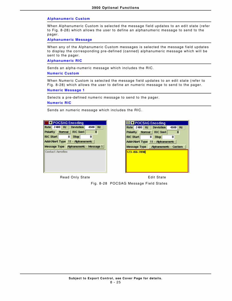
3900 Optional Functions
Subject to Export Control , see Cover Page for detai ls .8 - 25
Alphanumeric Custom
When Alphanumeric Custom is selected the message f ie ld updates to an edi t state ( refer to Fig. 8-28) which al lows the user to def ine an alphanumeric message to send to the pager .
Alphanumeric Message
When any of the Alphanumer ic Custom messages is selected the message f ie ld updates to display the corresponding pre-def ined (canned) alphanumer ic message which wi l l be sent to the pager.
Alphanumeric RIC
Sends an alpha-numeric message which includes the RIC.
Numeric Custom
When Numer ic Custom is selected the message f ie ld updates to an edi t state ( refer to Fig. 8-28) which al lows the user to def ine an numer ic message to send to the pager.
Numeric Message 1
Selects a pre-def ined numeric message to send to the pager.
Numeric RIC
Sends an numeric message which includes the RIC.
Fig . 8-28 POCSAG Message Field States
Read Only State Edit State
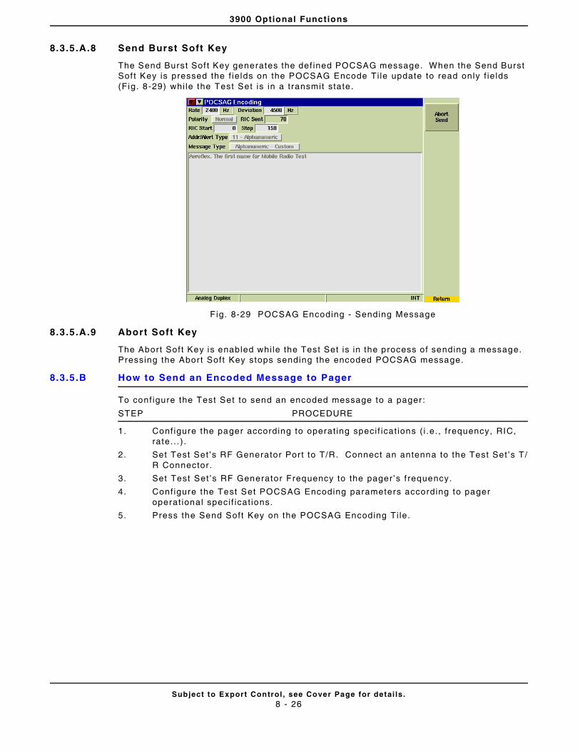
3900 Optional Functions
Subject to Export Control , see Cover Page for detai ls .8 - 26
8.3.5.A.8 Send Burst Soft Key
The Send Burst Sof t Key generates the def ined POCSAG message. When the Send Burst Sof t Key is pressed the f ie lds on the POCSAG Encode Ti le update to read only f ie lds (Fig. 8-29) whi le the Test Set is in a transmit state .
F ig. 8-29 POCSAG Encoding - Sending Message
8.3.5.A.9 Abort Soft Key
The Abort Sof t Key is enabled whi le the Test Set is in the process of sending a message. Pressing the Abor t Soft Key stops sending the encoded POCSAG message.
8.3.5.B How to Send an Encoded Message to Pager
To conf igure the Test Set to send an encoded message to a pager :
STEP PROCEDURE
1. Conf igure the pager according to operat ing speci f icat ions ( i .e. , f requency, RIC, rate.. . ) .
2. Set Test Set ’s RF Generator Por t to T/R. Connect an antenna to the Test Set ’s T/R Connector .
3. Set Test Set ’s RF Generator Frequency to the pager ’s f requency.
4. Conf igure the Test Set POCSAG Encoding parameters according to pager operat ional speci f icat ions.
5. Press the Send Soft Key on the POCSAG Encoding Ti le.
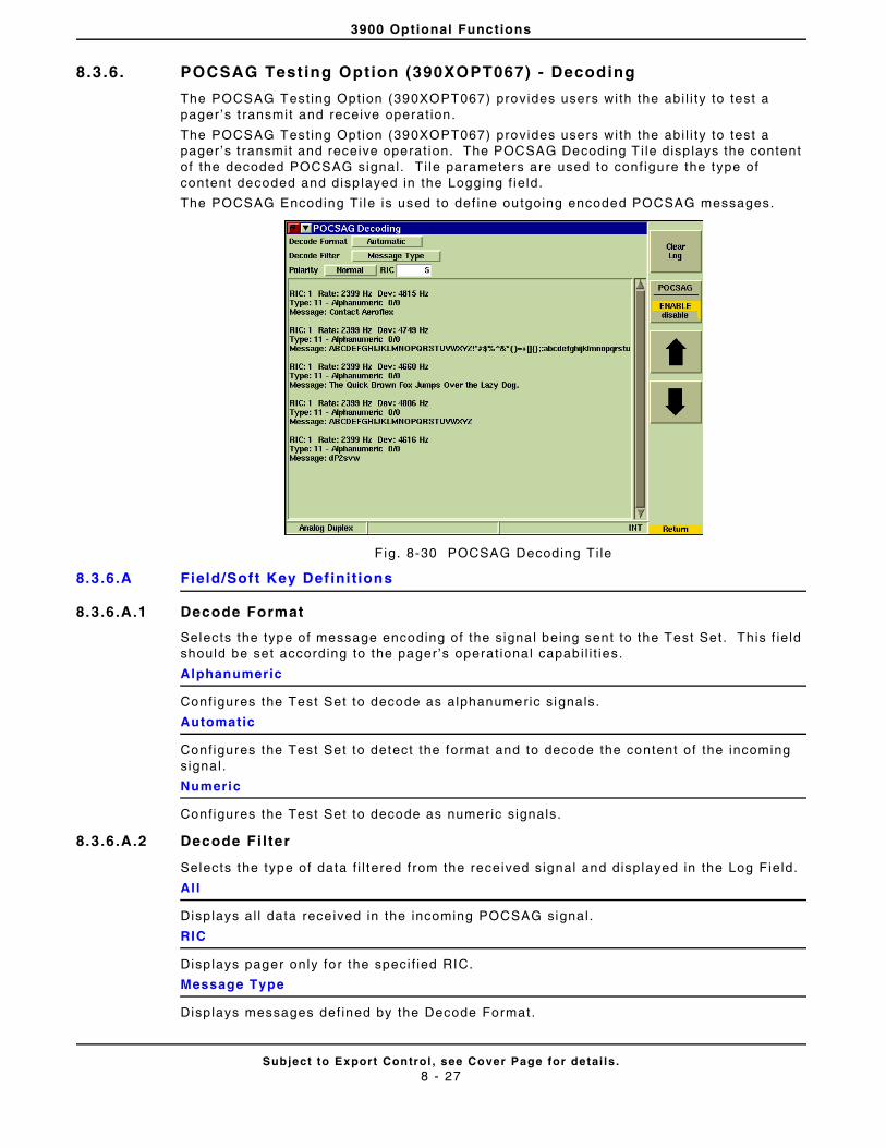
3900 Optional Functions
Subject to Export Control , see Cover Page for detai ls .8 - 27
8.3 .6. POCSAG Testing Option (390XOPT067) - Decoding
The POCSAG Test ing Opt ion (390XOPT067) provides users with the abi l i ty to test a pager ’s t ransmit and receive operat ion.
The POCSAG Test ing Opt ion (390XOPT067) provides users with the abi l i ty to test a pager ’s t ransmit and receive operat ion. The POCSAG Decoding T i le disp lays the content of the decoded POCSAG signal . Ti le parameters are used to conf igure the type of content decoded and disp layed in the Logging f ie ld.
The POCSAG Encoding Ti le is used to def ine outgoing encoded POCSAG messages.
F ig. 8-30 POCSAG Decoding Ti le
8.3.6.A Field/Soft Key Def ini t ions
8.3.6.A.1 Decode Format
Selects the type of message encoding of the signal being sent to the Test Set . This f ie ld should be set according to the pager’s operat ional capabi l i t ies.
Alphanumeric
Configures the Test Set to decode as alphanumeric s ignals.
Automatic
Configures the Test Set to detect the format and to decode the content of the incoming signal .
Numeric
Configures the Test Set to decode as numeric s ignals.
8.3.6.A.2 Decode Fi lter
Selects the type of data f i l tered from the received signal and displayed in the Log Field.
All
Disp lays al l data rece ived in the incoming POCSAG signal .
RIC
Disp lays pager only for the speci f ied RIC.
Message Type
Disp lays messages def ined by the Decode Format.
3900 Optional Functions
Subject to Export Control , see Cover Page for detai ls .8 - 28
8.3.6.A.3 Polar ity
Selects how the POCSAG signal is decoded (normal or inverted).
8.3.6.A.4 RIC
Decodes data f rom the incoming signal for the pager with the speci f ied RIC when the Decode Fi l ter is set to RIC.
8.3.6.A.5 Clear Log
Clears the Data Log f ie ld or al l logged data.
8.3.6.A.6 POCSAG State
Enables the Test Set ’s to decode a POCSAG signal.
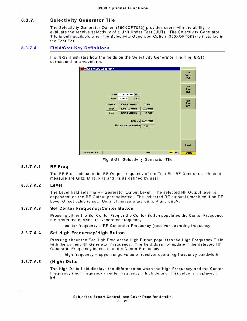
3900 Optional Functions
Subject to Export Control , see Cover Page for detai ls .8 - 29
8.3 .7. Select ivi ty Generator Ti le
The Select iv i ty Generator Opt ion (390XOPT083) provides users wi th the ab i l i ty to evaluate the receive select iv i ty of a Unit Under Test (UUT). The Select iv i ty Generator Ti le is only avai lab le when the Select iv i ty Generator Opt ion (390XOPT083) is instal led in the Test Set .
8.3.7.A Field/Soft Key Def ini t ions
Fig. 8-32 i l lustra tes how the f ie lds on the Select iv i ty Generator Ti le (F ig. 8-31) correspond to a waveform.
Fig. 8-31 Select iv i ty Generator Ti le
8.3.7.A.1 RF Freq
The RF Freq f ie ld sets the RF Output f requency of the Test Set RF Generator . Uni ts of measure are GHz, MHz, kHz and Hz as def ined by user.
8.3.7.A.2 Level
The Level f ie ld sets the RF Generator Output Level . The selected RF Output level is dependent on the RF Output port selected. The indicated RF output is modif ied i f an RF Level Of fset value is set. Uni ts of measure are dBm, V and dBuV.
8.3.7.A.3 Set Center Frequency/Center Button
Pressing ei ther the Set Center Freq or the Center But ton populates the Center Frequency Field wi th the current RF Generator Frequency.
center f requency = RF Generator Frequency ( receiver operat ing f requency)
8.3.7.A.4 Set High Frequency/ High Button
Pressing e i ther the Set High Freq or the High But ton populates the High Frequency Field with the current RF Generator Frequency. The f ie ld does not update i f the detected RF Generator Frequency is less than the Center Frequency.
high frequency = upper range value of receiver operat ing frequency bandwidth
8.3.7.A.5 (High) Delta
The High Delta f ie ld displays the di f ference between the High Frequency and the Center Frequency (high frequency - center f requency = high del ta). This value is displayed in kHz.
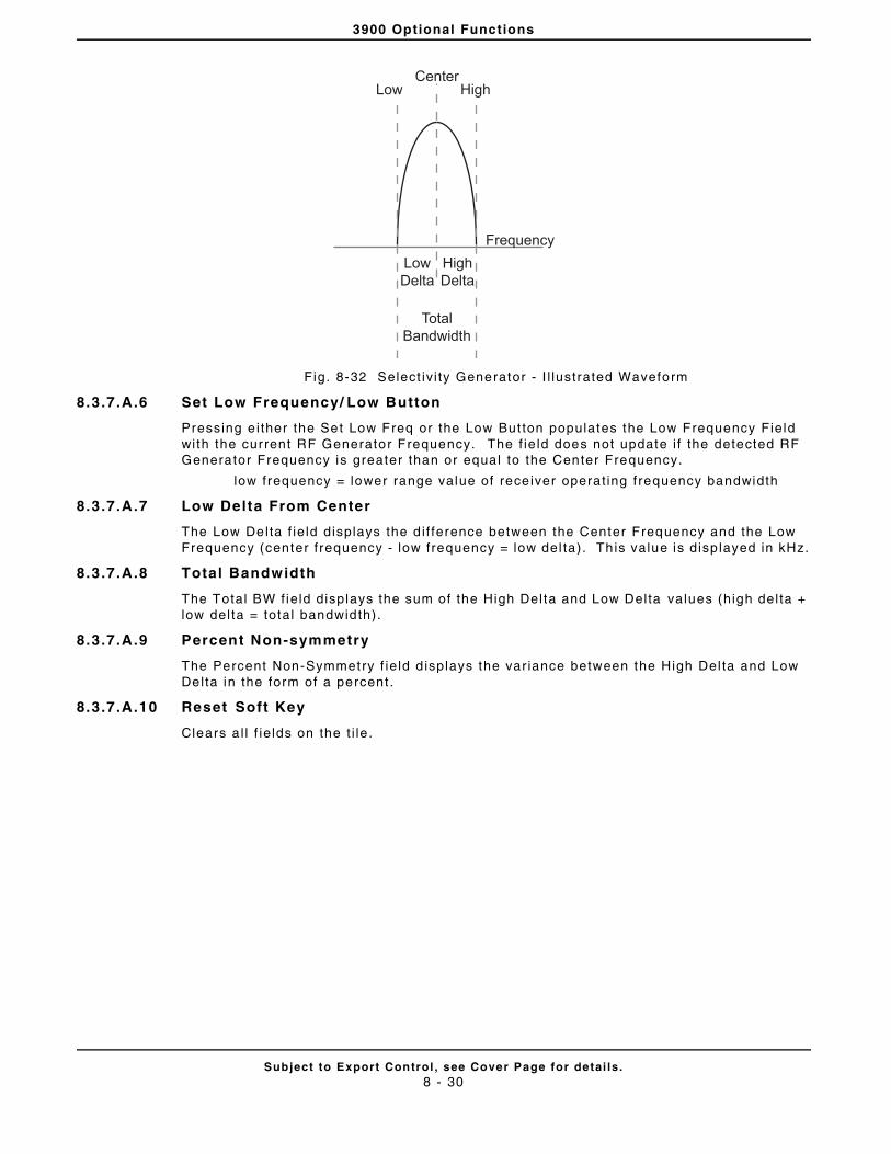
3900 Optional Functions
Subject to Export Control , see Cover Page for detai ls .8 - 30
Fig. 8-32 Select iv i ty Generator - I l lustrated Waveform
8.3.7.A.6 Set Low Frequency/ Low Button
Pressing e i ther the Set Low Freq or the Low But ton populates the Low Frequency Field with the current RF Generator Frequency. The f ie ld does not update i f the detected RF Generator Frequency is greater than or equal to the Center Frequency.
low frequency = lower range value of rece iver operat ing frequency bandwidth
8.3.7.A.7 Low Delta From Center
The Low Delta f ie ld displays the d i f ference between the Center Frequency and the Low Frequency (center f requency - low frequency = low del ta). Th is value is disp layed in kHz.
8.3.7.A.8 Total Bandwidth
The Total BW f ie ld displays the sum of the High Delta and Low Delta values (high del ta + low del ta = total bandwidth).
8.3.7.A.9 Percent Non-symmetry
The Percent Non-Symmetry f ie ld d isplays the var iance between the High Del ta and Low Delta in the form of a percent .
8.3.7.A.10 Reset Soft Key
Clears a l l f ie lds on the t i le .
CenterHighLow
HighDelta
LowDelta
TotalBandwidth
Frequency
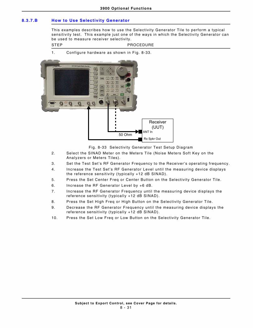
3900 Optional Functions
Subject to Export Control , see Cover Page for detai ls .8 - 31
8.3.7.B How to Use Select ivity Generator
This examples descr ibes how to use the Select iv i ty Generator Ti le to per form a typ ical sensi t iv i ty test . Th is example just one of the ways in which the Select iv i ty Generator can be used to measure receiver select iv i ty.
STEP PROCEDURE
1. Conf igure hardware as shown in Fig . 8-33.
Fig . 8-33 Select iv i ty Generator Test Setup Diagram
2. Select the SINAD Meter on the Meters Ti le (Noise Meters Sof t Key on the Analyzers or Meters Ti les) .
3. Set the Test Set ’s RF Generator Frequency to the Receiver ’s operat ing frequency.
4. Increase the Test Set ’s RF Generator Level unt i l the measuring device displays the reference sensi t iv i ty ( typical ly +12 dB SINAD).
5. Press the Set Center Freq or Center But ton on the Select iv i ty Generator Ti le .
6. Increase the RF Generator Level by +6 dB.
7. Increase the RF Generator Frequency unt i l the measur ing device d isplays the reference sensi t iv i ty ( typical ly +12 dB SINAD).
8. Press the Set High Freq or High Button on the Select iv i ty Generator T i le.
9. Decrease the RF Generator Frequency unt i l the measuring device displays the reference sensi t iv i ty ( typical ly +12 dB SINAD).
10. Press the Set Low Freq or Low But ton on the Select iv i ty Generator Ti le.
50 OhmANT In
Receiver(UUT)
Rx Spkr Out
3900 Optional Functions
Subject to Export Control , see Cover Page for detai ls .8 - 32
THIS PAGE INTENTIONALLY LEFT BLANK.
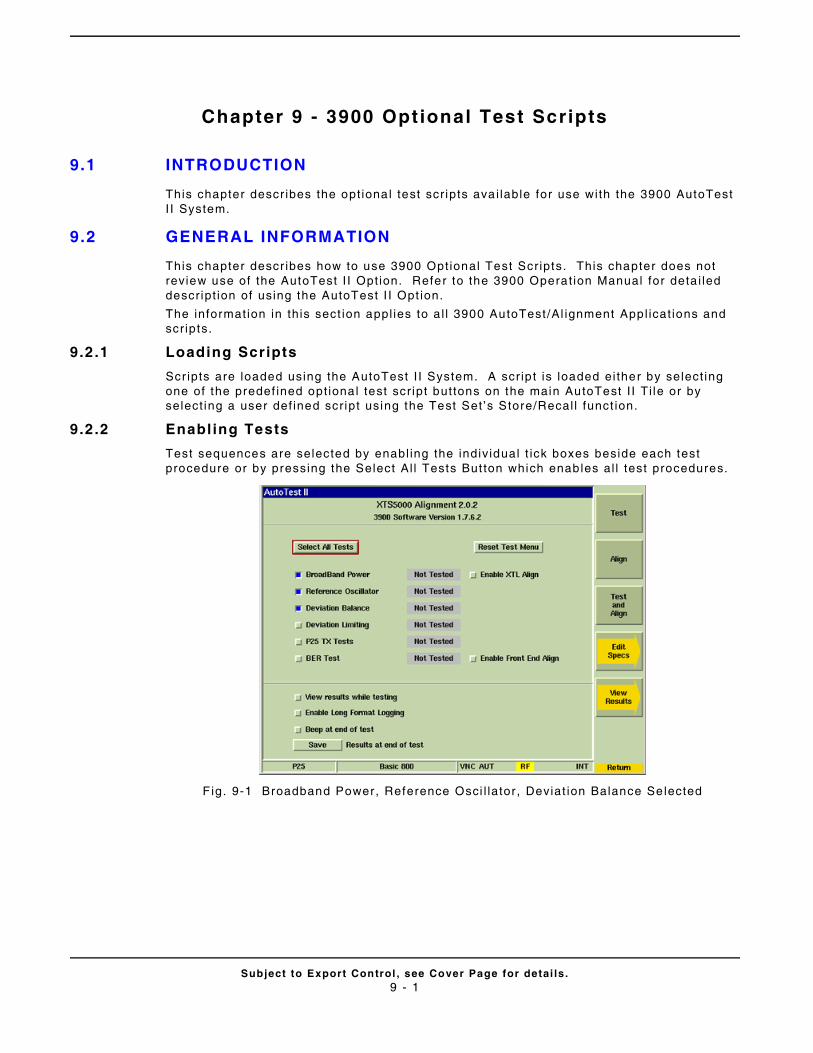
Subject to Export Control , see Cover Page for detai ls .9 - 1
Chapter 9 - 3900 Optional Test Scripts
9.1 INTRODUCTION
This chapter descr ibes the opt ional test scr ipts ava i lable for use with the 3900 AutoTest I I System.
9.2 GENERAL INFORMATION
This chapter descr ibes how to use 3900 Opt ional Test Scr ipts. This chapter does not review use of the AutoTest I I Opt ion. Refer to the 3900 Operat ion Manual for deta i led descr ipt ion of using the AutoTest I I Opt ion.
The informat ion in this sect ion appl ies to a l l 3900 AutoTest /Al ignment Appl icat ions and scr ipts.
9.2 .1 Loading Scripts
Scr ipts are loaded using the AutoTest I I System. A scr ip t is loaded ei ther by select ing one of the predef ined opt ional test scr ipt buttons on the main AutoTest I I Ti le or by select ing a user def ined scr ipt using the Test Set ’s Store/Recal l funct ion.
9.2 .2 Enabling Tests
Test sequences are selected by enabl ing the indiv idual t ick boxes beside each test procedure or by pressing the Select Al l Tests But ton which enables al l test procedures.
F ig. 9-1 Broadband Power, Reference Osci l lator , Deviat ion Balance Selected
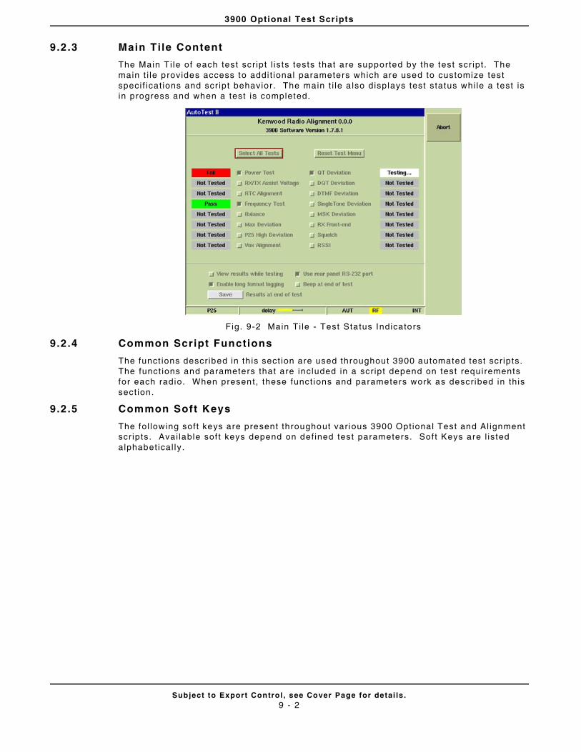
3900 Optional Test Scripts
Subject to Export Control , see Cover Page for detai ls .9 - 2
9.2 .3 Main Tile Content
The Main T i le of each test scr ipt l is ts tests that are supported by the test scr ipt . The main t i le provides access to addi t ional parameters which are used to customize test speci f icat ions and scr ipt behavior . The main t i le a lso displays test status whi le a test is in progress and when a test is completed.
Fig. 9-2 Main Ti le - Test Status Indicators
9.2 .4 Common Script Functions
The funct ions descr ibed in th is sect ion are used throughout 3900 automated test scr ipts. The funct ions and parameters that are included in a scr ipt depend on test requirements for each radio. When present, these funct ions and parameters work as descr ibed in this sect ion.
9.2 .5 Common Soft Keys
The fol lowing soft keys are present throughout var ious 3900 Opt ional Test and Al ignment scr ipts. Avai lable sof t keys depend on def ined test parameters. Sof t Keys are l isted alphabet ical ly .
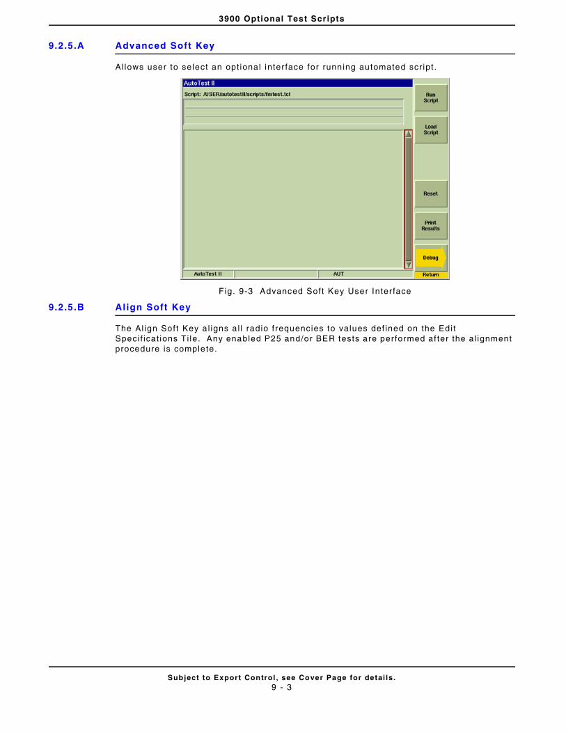
3900 Optional Test Scripts
Subject to Export Control , see Cover Page for detai ls .9 - 3
9.2.5.A Advanced Soft Key
Allows user to select an opt ional inter face for running automated scr ipt .
Fig. 9-3 Advanced Soft Key User Inter face
9.2.5.B Al ign Soft Key
The Al ign Soft Key a l igns a l l radio f requencies to values def ined on the Edit Speci f icat ions Ti le. Any enabled P25 and/or BER tests are per formed af ter the al ignment procedure is complete.
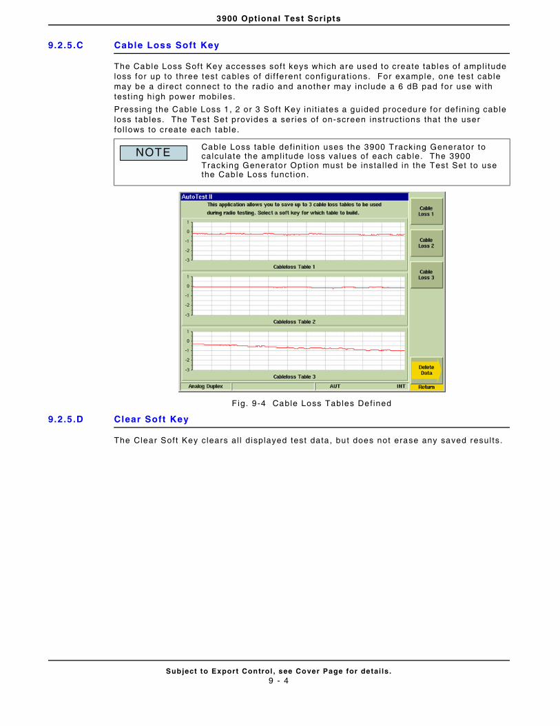
3900 Optional Test Scripts
Subject to Export Control , see Cover Page for detai ls .9 - 4
9.2.5.C Cable Loss Soft Key
The Cable Loss Soft Key accesses soft keys which are used to create tables of ampl i tude loss for up to three test cables of di f ferent conf igurat ions. For example, one test cable may be a direct connect to the radio and another may include a 6 dB pad for use with test ing high power mobi les.
Pressing the Cable Loss 1, 2 or 3 Soft Key in i t iates a guided procedure for def in ing cable loss tables. The Test Set provides a ser ies of on-screen instruct ions that the user fo l lows to create each table.
F ig. 9-4 Cable Loss Tables Def ined
9.2.5.D Clear Soft Key
The Clear Soft Key clears al l d isplayed test data, but does not erase any saved resul ts.
Cable Loss table def in i t ion uses the 3900 Tracking Generator to calculate the ampl i tude loss values of each cable. The 3900 Tracking Generator Opt ion must be instal led in the Test Set to use the Cable Loss funct ion.
NOTE
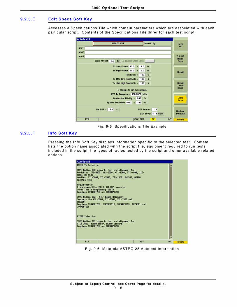
3900 Optional Test Scripts
Subject to Export Control , see Cover Page for detai ls .9 - 5
9.2.5.E Edit Specs Soft Key
Accesses a Speci f icat ions T i le which contain parameters which are associated with each par t icular scr ipt . Contents of the Speci f icat ions Ti le di f fer for each test scr ip t .
F ig. 9-5 Speci f icat ions T i le Example
9.2.5.F Info Soft Key
Pressing the Info Sof t Key displays informat ion speci f ic to the selected test . Content l is ts the opt ion name associated wi th the scr ipt f i le, equipment required to run tests included in the scr ipt , the types of radios tested by the scr ipt and other avai lable related opt ions.
F ig. 9-6 Motorola ASTRO 25 Autotest Information
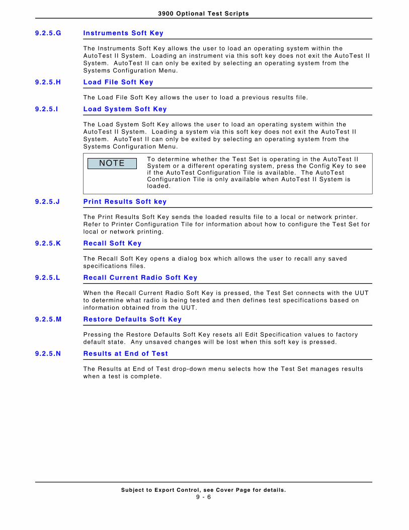
3900 Optional Test Scripts
Subject to Export Control , see Cover Page for detai ls .9 - 6
9.2.5.G Instruments Soft Key
The Instruments Sof t Key al lows the user to load an operat ing system with in the AutoTest I I System. Loading an instrument v ia this soft key does not exi t the AutoTest I I System. AutoTest I I can only be exi ted by select ing an operat ing system f rom the Systems Conf igurat ion Menu.
9.2.5.H Load File Soft Key
The Load Fi le Soft Key al lows the user to load a previous resul ts f i le.
9.2.5.I Load System Soft Key
The Load System Sof t Key al lows the user to load an operat ing system within the AutoTest I I System. Loading a system via this sof t key does not exi t the AutoTest I I System. AutoTest I I can only be exi ted by select ing an operat ing system f rom the Systems Conf igurat ion Menu.
9.2.5.J Print Results Soft key
The Pr int Results Soft Key sends the loaded resul ts f i le to a local or network pr inter. Refer to Pr inter Conf igurat ion T i le for information about how to conf igure the Test Set for local or network pr int ing.
9.2.5.K Recal l Soft Key
The Recal l Soft Key opens a dialog box which al lows the user to reca l l any saved speci f icat ions f i les.
9.2.5.L Recal l Current Radio Soft Key
When the Recal l Current Radio Soft Key is pressed, the Test Set connects with the UUT to determine what rad io is being tested and then def ines test speci f icat ions based on information obtained from the UUT.
9.2.5.M Restore Defaults Soft Key
Pressing the Restore Defaul ts Soft Key resets al l Edi t Speci f icat ion values to factory defaul t state. Any unsaved changes wi l l be lost when th is soft key is pressed.
9.2.5.N Results at End of Test
The Resul ts at End of Test drop-down menu selects how the Test Set manages resul ts when a test is complete.
To determine whether the Test Set is operat ing in the AutoTest I I System or a di f ferent operat ing system, press the Conf ig Key to see i f the AutoTest Conf igurat ion Ti le is avai lable. The AutoTest Conf igurat ion Ti le is only avai lable when AutoTest I I System is loaded.
NOTE
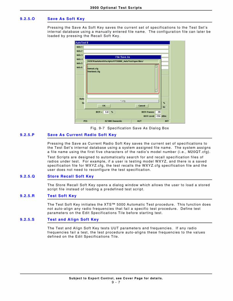
3900 Optional Test Scripts
Subject to Export Control , see Cover Page for detai ls .9 - 7
9.2.5.O Save As Soft Key
Pressing the Save As Soft Key saves the current set of speci f icat ions to the Test Set ’s internal database using a manual ly entered f i le name. The conf igurat ion f i le can later be loaded by pressing the Recal l Soft Key.
Fig. 9-7 Speci f icat ion Save As Dialog Box
9.2.5.P Save As Current Radio Soft Key
Pressing the Save as Current Radio Sof t Key saves the current set of speci f icat ions to the Test Set ’s in ternal database using a system assigned f i le name. The system assigns a f i le name using the f i rst f ive characters of the radio’s model number ( i .e. , M20QT.cfg).
Test Scr ipts are designed to automat ical ly search for and recal l speci f icat ion f i les of rad ios under test . For example, i f a user is test ing model WXYZ, and there is a saved speci f icat ion f i le for WXYZ.cfg, the test recal ls the WXYZ.cfg speci f icat ion f i le and the user does not need to reconf igure the test speci f icat ion.
9.2.5.Q Store Recal l Soft Key
The Store Recal l Sof t Key opens a dialog window which al lows the user to load a stored scr ipt f i le instead of loading a predef ined test scr ipt .
9.2.5.R Test Soft Key
The Test Soft Key in i t iates the XTS™ 5000 Automatic Test procedure. This funct ion does not auto-al ign any radio frequencies that fa i l a speci f ic test procedure. Def ine test parameters on the Edit Speci f icat ions Ti le before star t ing test .
9.2.5.S Test and Align Soft Key
The Test and Al ign Sof t Key tests UUT parameters and frequencies. I f any rad io f requencies fai l a test , the test procedure auto-al igns these frequencies to the va lues def ined on the Edi t Speci f icat ions Ti le.
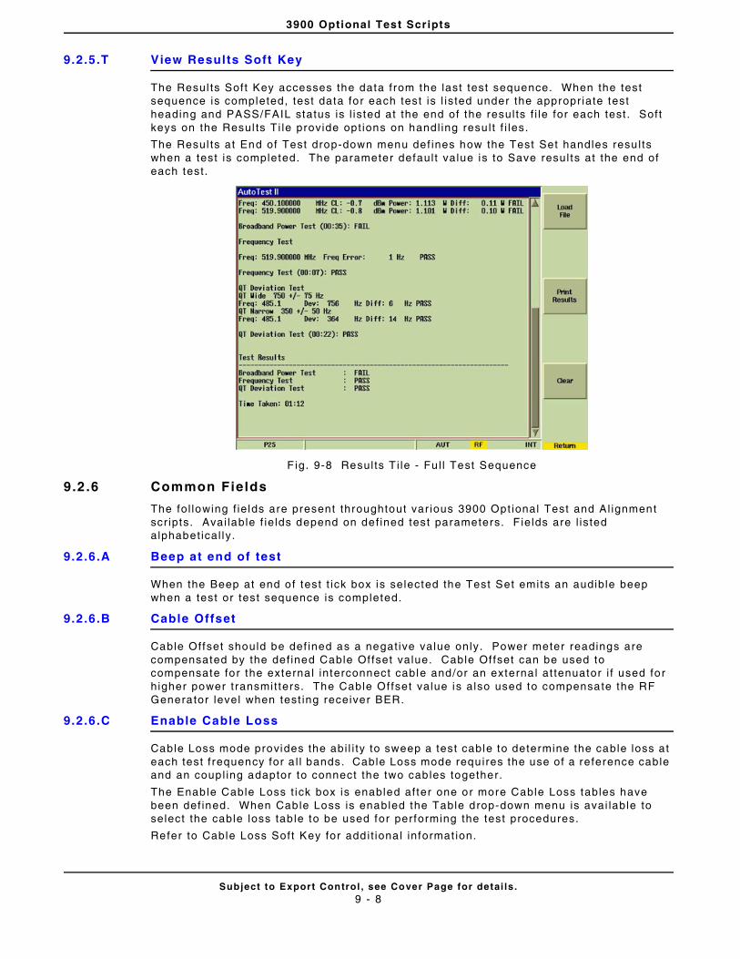
3900 Optional Test Scripts
Subject to Export Control , see Cover Page for detai ls .9 - 8
9.2.5.T View Results Soft Key
The Resul ts Soft Key accesses the data from the last test sequence. When the test sequence is completed, test data for each test is l is ted under the appropr iate test heading and PASS/FAIL status is l is ted at the end of the resul ts f i le for each test. Soft keys on the Resul ts Ti le provide opt ions on handl ing resu l t f i les.
The Resul ts at End of Test drop-down menu def ines how the Test Set handles resu l ts when a test is completed. The parameter defaul t value is to Save resul ts at the end of each test .
F ig. 9-8 Results T i le - Fu l l Test Sequence
9.2 .6 Common Fields
The fol lowing f ie lds are present throughtout var ious 3900 Opt ional Test and Al ignment scr ipts. Avai lable f ie lds depend on def ined test parameters. F ields are l isted alphabet ical ly .
9.2.6.A Beep at end of test
When the Beep at end of test t ick box is selected the Test Set emits an audible beep when a test or test sequence is completed.
9.2.6.B Cable Offset
Cable Offset should be def ined as a negat ive value only. Power meter readings are compensated by the def ined Cable Of fset value. Cable Of fset can be used to compensate for the externa l interconnect cable and/or an externa l at tenuator i f used for higher power t ransmit ters. The Cable Of fset value is also used to compensate the RF Generator level when test ing receiver BER.
9.2.6.C Enable Cable Loss
Cable Loss mode provides the abi l i ty to sweep a test cable to determine the cable loss at each test f requency for a l l bands. Cable Loss mode requires the use of a reference cable and an coupl ing adaptor to connect the two cables together.
The Enable Cable Loss t ick box is enabled af ter one or more Cable Loss tables have been def ined. When Cable Loss is enabled the Table drop-down menu is avai lable to select the cable loss tab le to be used for performing the test procedures.
Refer to Cable Loss Soft Key for addi t iona l informat ion.
3900 Optional Test Scripts
Subject to Export Control , see Cover Page for detai ls .9 - 9
9.2.6.D Enable Long Format Logging
The defaul t format for logging test data reports the beginning and ending soft pot values of the al ignment . When Long Format Logging is enabled, the test data includes each adjustment preformed when al ign ing a frequency.
9.2.6.E Results at end of test
The End of Test drop-down menu def ines how the Test Set handles test resul ts at the end of a test or test sequence.
• Save: Resul ts are saved automat ical ly.
• Ask: User is prompted to save f i les.
• Print : Results are automat ical ly pr inted.
• Save & Print : Results are automatica l ly saved and pr inted.
• Skip: Ignores test resul ts
When the Test Set saves resul ts, f i lenames are generated and stored in the fol lowing format:
Model_Number-Serial_number-month_day_year-hour_min.txt
9.2.6.F Reset Test Menu
Pressing the Reset Test Menu resets al l test procedure t ick boxes to Disabled. Pressing the Reset Test Menu button does not af fect any other parameters on the Main User Ti le. For example, the Enable XTL Al ign and Beep at end of test t ick boxes are selected, pressing the Reset Test Menu but ton does not deselect these parameters.
9.2.6.G Select Al l Tests
Pressing the Select Al l Tests button enables a l l tests l is ted on the main test t i le.
9.2.6.H Use Rear Panel RS-232 Port
Selects the Test Set ’s RS-232 Connector as the UUT interface for test setup.
9.2.6.I View results while testing
Enabl ing this funct ion displays the automated test procedure whi le i t is running. User can not return to the Main User Ti le dur ing a test when this funct ion is selected.
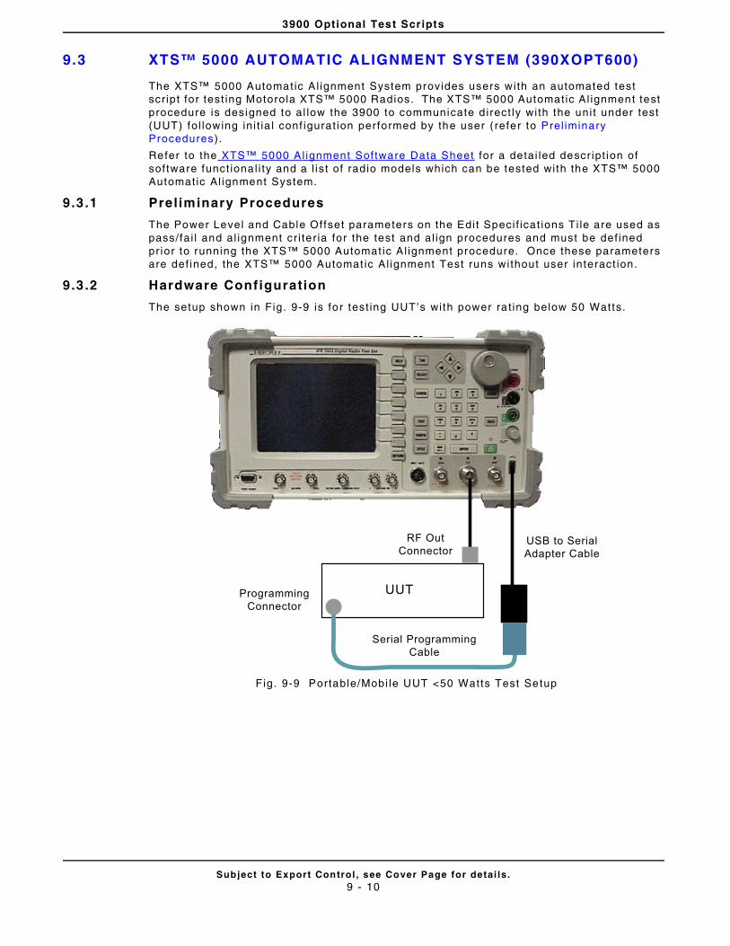
3900 Optional Test Scripts
Subject to Export Control , see Cover Page for detai ls .9 - 10
9.3 XTS™ 5000 AUTOMATIC ALIGNMENT SYSTEM (390XOPT600)
The XTS™ 5000 Automatic Al ignment System provides users with an automated test scr ipt for test ing Motorola XTS™ 5000 Radios. The XTS™ 5000 Automatic Al ignment test procedure is designed to al low the 3900 to communicate d irect ly wi th the uni t under test (UUT) fol lowing ini t ia l conf igurat ion performed by the user ( refer to Prel iminary Procedures).
Refer to the XTS™ 5000 Al ignment Software Data Sheet for a detai led descr ipt ion of software funct ional i ty and a l ist of radio models which can be tested with the XTS™ 5000 Automatic Al ignment System.
9.3 .1 Preliminary Procedures
The Power Level and Cable Offset parameters on the Edit Speci f icat ions Ti le are used as pass/fai l and al ignment cr i ter ia for the test and al ign procedures and must be def ined pr ior to running the XTS™ 5000 Automat ic Al ignment procedure. Once these parameters are def ined, the XTS™ 5000 Automat ic Al ignment Test runs without user interact ion.
9.3 .2 Hardware Configuration
The setup shown in Fig. 9-9 is for test ing UUT’s with power ra t ing below 50 Watts.
Fig. 9-9 Portable/Mobi le UUT <50 Watts Test Setup
UUT
RF OutConnector
ProgrammingConnector
USB to SerialAdapter Cable
Serial ProgrammingCable

3900 Optional Test Scripts
Subject to Export Control , see Cover Page for detai ls .9 - 11
The setup shown in Fig. 9-10 is for test ing UUT’s with power rat ing higher than 50 Watts.
Fig. 9-10 Mobi le >50 Watts Test Setup
High Power Cable
6dB/150 WAttenuator
RF Out Connector
UUTProgrammingConnector
USB to SerialAdapter Cable
Serial ProgrammingCable
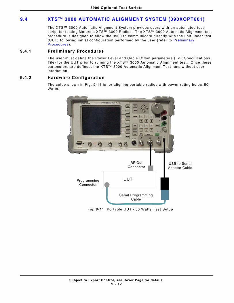
3900 Optional Test Scripts
Subject to Export Control , see Cover Page for detai ls .9 - 12
9.4 XTS™ 3000 AUTOMATIC ALIGNMENT SYSTEM (390XOPT601)
The XTS™ 3000 Automatic Al ignment System provides users with an automated test scr ipt for test ing Motorola XTS™ 3000 Radios. The XTS™ 3000 Automatic Al ignment test procedure is designed to al low the 3900 to communicate d irect ly wi th the uni t under test (UUT) fol lowing ini t ia l conf igurat ion performed by the user ( refer to Prel iminary Procedures).
9.4 .1 Preliminary Procedures
The user must def ine the Power Level and Cable Of fset parameters (Edi t Speci f icat ions Ti le) for the UUT pr ior to running the XTS™ 3000 Automatic Al ignment test . Once these parameters are def ined, the XTS™ 3000 Automatic Al ignment Test runs without user interact ion.
9.4 .2 Hardware Configuration
The setup shown in Fig. 9-11 is for al igning por table rad ios with power rat ing below 50 Watts.
Fig. 9-11 Por table UUT <50 Watts Test Setup
UUT
RF OutConnector
ProgrammingConnector
USB to SerialAdapter Cable
Serial ProgrammingCable
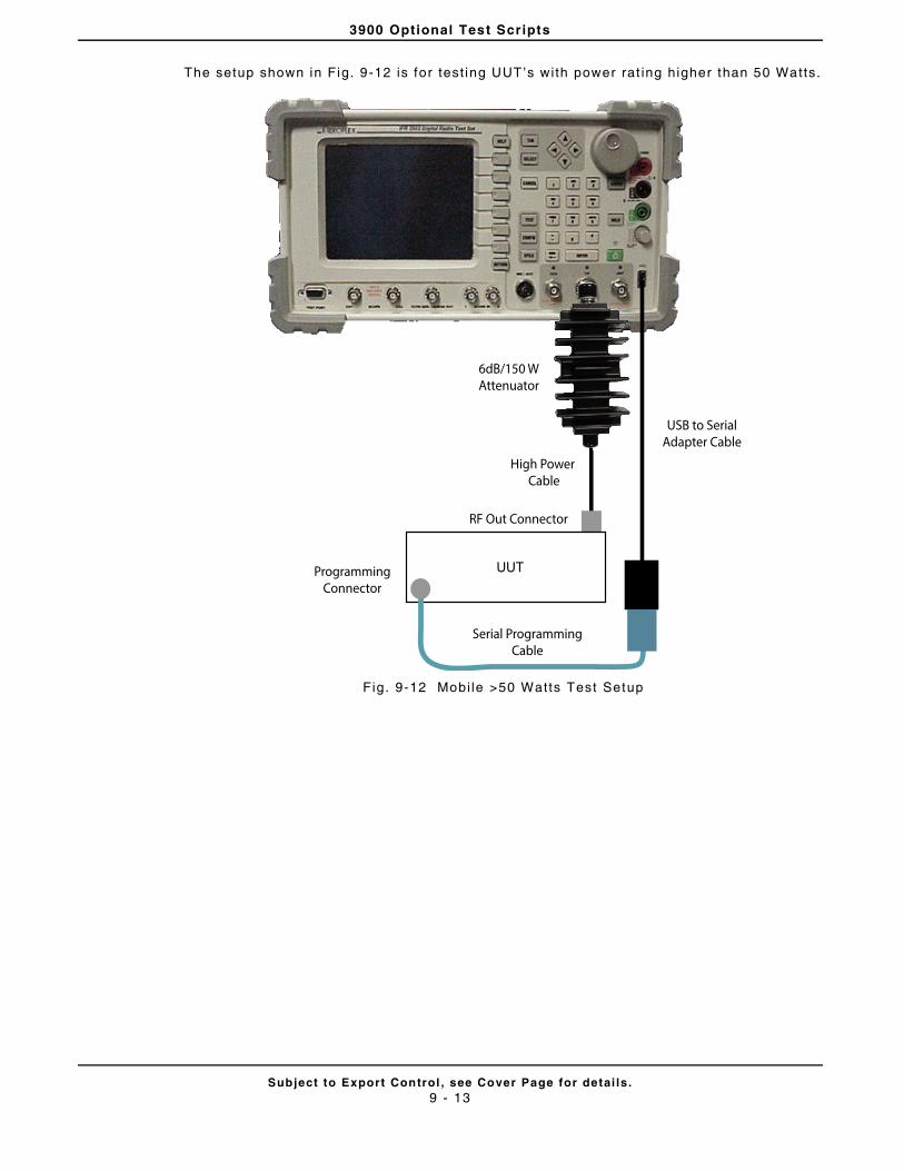
3900 Optional Test Scripts
Subject to Export Control , see Cover Page for detai ls .9 - 13
The setup shown in Fig. 9-12 is for test ing UUT’s with power rat ing higher than 50 Watts.
Fig. 9-12 Mobi le >50 Watts Test Setup
High Power Cable
6dB/150 WAttenuator
RF Out Connector
UUTProgrammingConnector
USB to SerialAdapter Cable
Serial ProgrammingCable
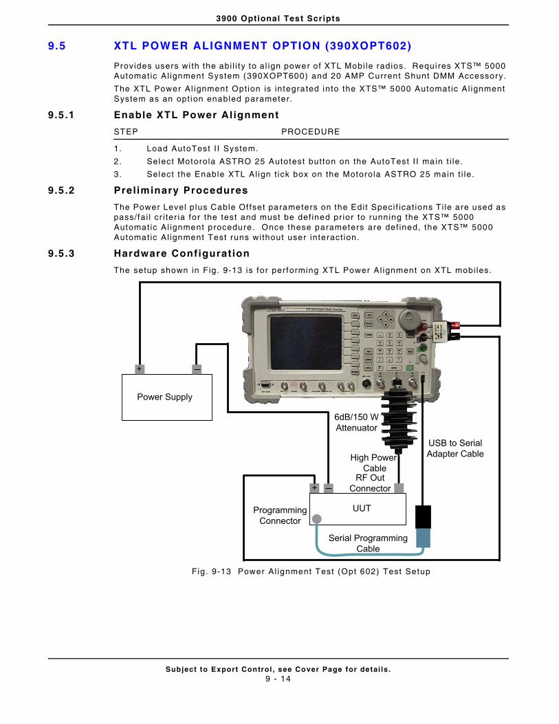
3900 Optional Test Scripts
Subject to Export Control , see Cover Page for detai ls .9 - 14
9.5 XTL POWER ALIGNMENT OPTION (390XOPT602)
Provides users wi th the abi l i ty to al ign power of XTL Mobi le radios. Requi res XTS™ 5000 Automatic Al ignment System (390XOPT600) and 20 AMP Current Shunt DMM Accessory.
The XTL Power Al ignment Opt ion is integrated into the XTS™ 5000 Automat ic Al ignment System as an opt ion enabled parameter.
9.5 .1 Enable XTL Power Al ignment
STEP PROCEDURE
1. Load AutoTest I I System.
2. Select Motorola ASTRO 25 Autotest button on the AutoTest I I main t i le.
3. Select the Enable XTL Al ign t ick box on the Motorola ASTRO 25 main t i le.
9.5 .2 Preliminary Procedures
The Power Level p lus Cable Of fset parameters on the Edit Speci f icat ions Ti le are used as pass/fai l cr i ter ia for the test and must be def ined pr ior to running the XTS™ 5000 Automatic Al ignment procedure. Once these parameters are def ined, the XTS™ 5000 Automatic Al ignment Test runs without user interact ion.
9.5 .3 Hardware Configuration
The setup shown in Fig. 9-13 is for performing XTL Power Al ignment on XTL mobi les.
Fig. 9-13 Power Al ignment Test (Opt 602) Test Setup
+
Power Supply
+
High Power Cable
6dB/150 WAttenuator
RF OutConnector
UUTProgrammingConnector
USB to SerialAdapter Cable
Serial ProgrammingCable
3900 Optional Test Scripts
Subject to Export Control , see Cover Page for detai ls .9 - 15
9.6 TIA-603 LMR AUTOTEST APPLICATION (390XOPT603)
The TIA-603 LMR AutoTest Appl icat ion provides users with an automated test scr ipt for test ing Land Mobi le Radios.
9.6 .1 How to Use TIA-603 LMR AutoTest Applicat ion
The TIA-603 LMR AutoTest Appl icat ion has been designed as a template from which customized LMR rad io test scr ipts can be developed. This appl icat ion was developed for users fami l iar wi th using the 3900 and the 3900 AutoTest I I opt ion.
When the TIA-603 LMR AutoTest Appl icat ion is loaded, the system a lways loads the defaul t .cfg setup f i le. The TIA-603 LMR AutoTest Appl icat ion has been designed so that users can ed i t and save over the defaul t .cfg setup f i le. This funct ional i ty has been included so that the Test Set is ready to test a speci f ic radio af ter the appl icat ion is loaded.
Before a radio can be tested, Test Set and UUT parameters must be def ined on the var ious t i les found in the TIA-603 LMR AutoTest Appl icat ion. Test parameters should be def ined according to UUT funct ional i ty and product speci f icat ions. For example, i f the rad io under test does not have squelch control , do not enable Squelch Control parameter on the Rx Conf igurat ion T i le.
A test setup f i le consists of the ent i re test sequence which is comprised of separate Channel test sequences. For example, a test setup f i le can consist of up to 30 Channel test sequences. Each Channel test sequence can consist of di f ferent tests to be per formed for each channel.
9.6.1.A Steps to Creating a New Test Setup:
9.6.1.A.1 Channel Configurat ion
STEP PROCEDURE
1. Load the Land Mobi le Radio Test Appl icat ion. After the appl icat ion loads press the Cont inue Sof t Key.
2. Press the Conf igure Channels Soft Key.
3. Select the Enable t ick box to include the setup data in the test sequence.
4. Enter the radio ’s Channel to be tested in the Label f ie ld.
5. Def ine the Rx and Tx Frequencies, Tx Power, Squelch Type and Squelch Code accord ing to UUT speci f icat ions and test requirements.
6. Select the tests to be performed for the Channel test sequence.
7. Press Next Channel Soft Key to conf igure addi t iona l channels to be included in the test .
8. When al l the Channels are conf igured, press the Save Conf igurat ion Sof t Key to save the test setup f i le.
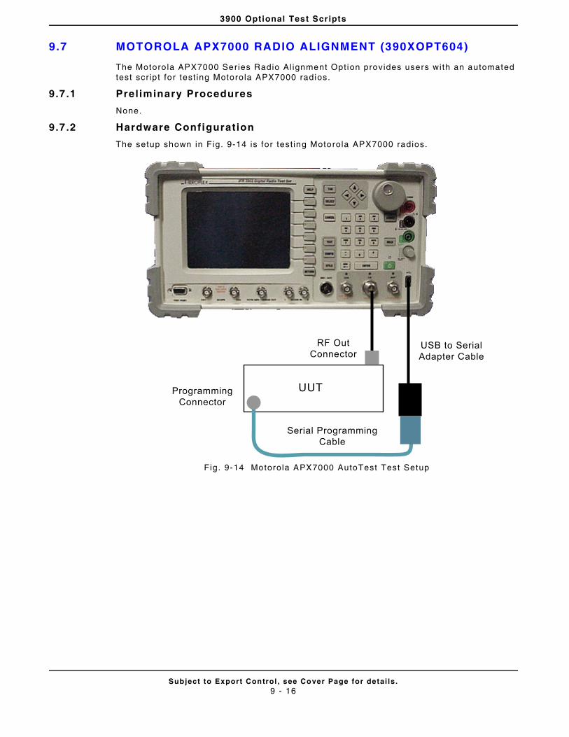
3900 Optional Test Scripts
Subject to Export Control , see Cover Page for detai ls .9 - 16
9.7 MOTOROLA APX7000 RADIO ALIGNMENT (390XOPT604)
The Motoro la APX7000 Series Radio Al ignment Opt ion provides users with an automated test scr ipt for test ing Motorola APX7000 radios.
9.7 .1 Preliminary Procedures
None.
9.7 .2 Hardware Configuration
The setup shown in Fig. 9-14 is for test ing Motorola APX7000 radios.
Fig. 9-14 Motorola APX7000 AutoTest Test Setup
UUT
RF OutConnector
ProgrammingConnector
USB to SerialAdapter Cable
Serial ProgrammingCable
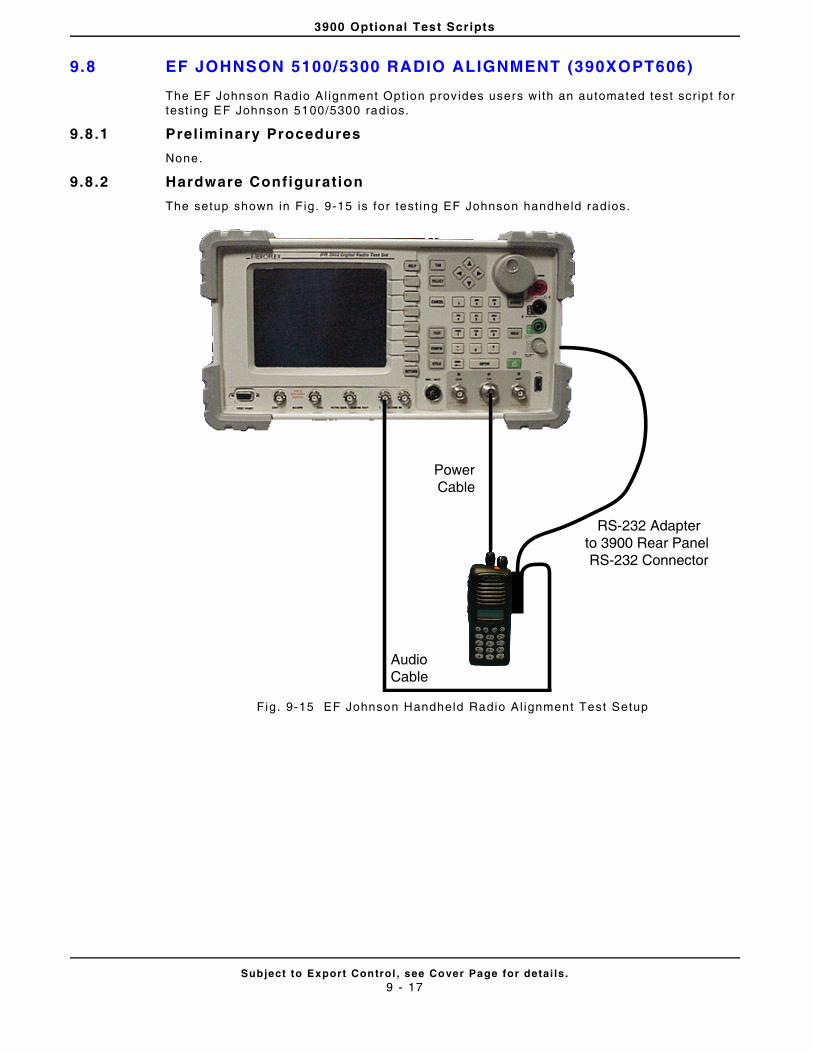
3900 Optional Test Scripts
Subject to Export Control , see Cover Page for detai ls .9 - 17
9.8 EF JOHNSON 5100/5300 RADIO ALIGNMENT (390XOPT606)
The EF Johnson Radio Al ignment Opt ion provides users with an automated test scr ip t for test ing EF Johnson 5100/5300 radios.
9.8 .1 Preliminary Procedures
None.
9.8 .2 Hardware Configuration
The setup shown in Fig. 9-15 is for test ing EF Johnson handheld radios.
F ig. 9-15 EF Johnson Handheld Radio Al ignment Test Setup
Power Cable
RS-232 Adapterto 3900 Rear Panel RS-232 Connector
Audio Cable
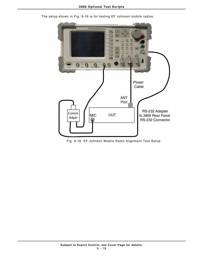
3900 Optional Test Scripts
Subject to Export Control , see Cover Page for detai ls .9 - 18
The setup shown in Fig. 9-16 is for test ing EF Johnson mobi le rad ios.
Fig. 9-16 EF Johnson Mobi le Radio Al ignment Test Setup
Power Cable
RS-232 Adapterto 3900 Rear Panel RS-232 Connector
UUTCommAdptr
MIC
ANTPort
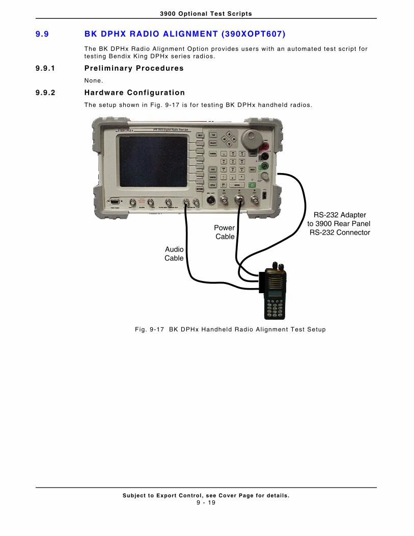
3900 Optional Test Scripts
Subject to Export Control , see Cover Page for detai ls .9 - 19
9.9 BK DPHX RADIO ALIGNMENT (390XOPT607)
The BK DPHx Radio Al ignment Opt ion provides users with an automated test scr ipt for test ing Bendix King DPHx ser ies radios.
9.9 .1 Preliminary Procedures
None.
9.9 .2 Hardware Configuration
The setup shown in Fig. 9-17 is for test ing BK DPHx handheld radios.
F ig. 9-17 BK DPHx Handheld Radio Al ignment Test Setup
PowerCable
AudioCable
RS-232 Adapterto 3900 Rear Panel RS-232 Connector
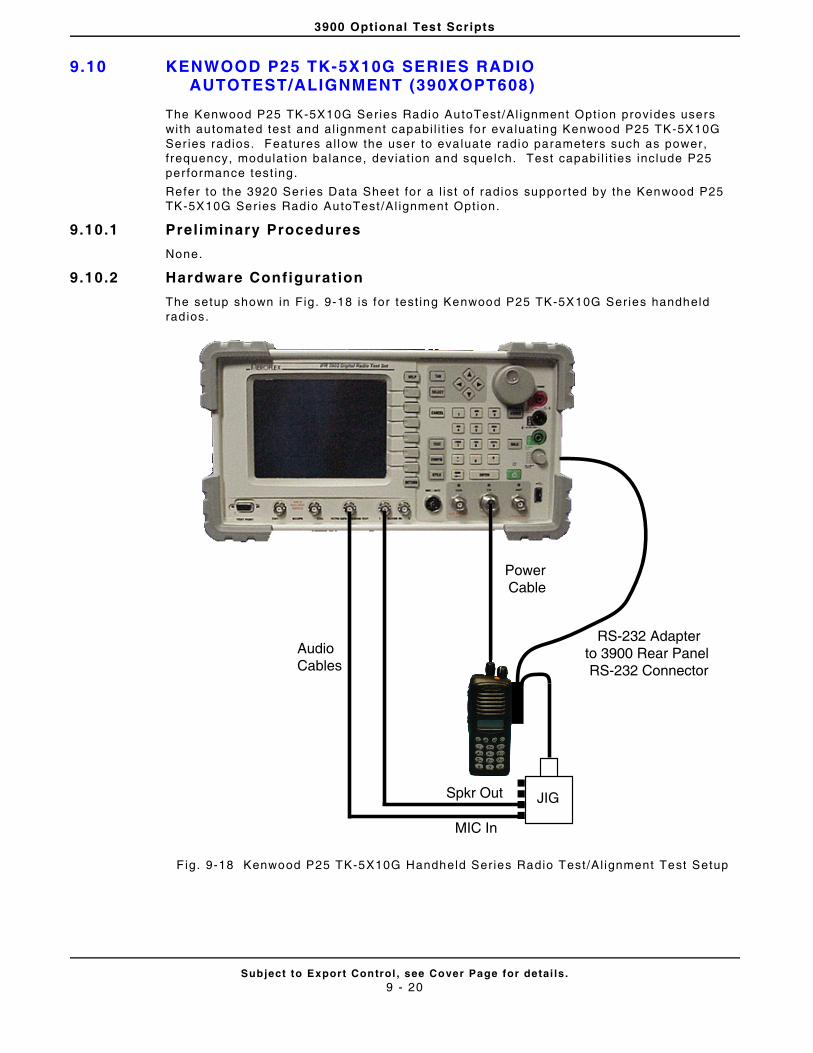
3900 Optional Test Scripts
Subject to Export Control , see Cover Page for detai ls .9 - 20
9.10 KENWOOD P25 TK-5X10G SERIES RADIO AUTOTEST/ALIGNMENT (390XOPT608)
The Kenwood P25 TK-5X10G Series Radio AutoTest /Al ignment Opt ion provides users with automated test and al ignment capabi l i t ies for eva luat ing Kenwood P25 TK-5X10G Ser ies radios. Features al low the user to eva luate radio parameters such as power, f requency, modulat ion balance, deviat ion and squelch. Test capabi l i t ies include P25 per formance test ing.
Refer to the 3920 Series Data Sheet for a l ist o f radios suppor ted by the Kenwood P25 TK-5X10G Series Radio AutoTest /Al ignment Opt ion.
9.10.1 Preliminary Procedures
None.
9.10.2 Hardware Configuration
The setup shown in Fig. 9-18 is for test ing Kenwood P25 TK-5X10G Series handheld rad ios.
F ig. 9-18 Kenwood P25 TK-5X10G Handheld Series Radio Test/Al ignment Test Setup
Power Cable
RS-232 Adapterto 3900 Rear Panel RS-232 Connector
Audio Cables
JIGSpkr Out
MIC In
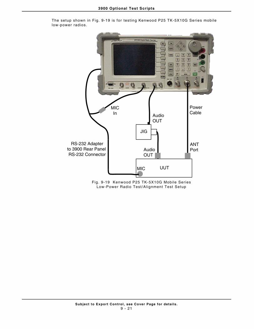
3900 Optional Test Scripts
Subject to Export Control , see Cover Page for detai ls .9 - 21
The setup shown in Fig. 9-19 is for test ing Kenwood P25 TK-5X10G Series mobi le low-power rad ios.
Fig. 9-19 Kenwood P25 TK-5X10G Mobi le Ser ies Low-Power Radio Test/Al ignment Test Setup
Power Cable
RS-232 Adapterto 3900 Rear Panel RS-232 Connector
UUT
ANTPort
MIC
JIG
AudioOUT
AudioOUT
MICIn
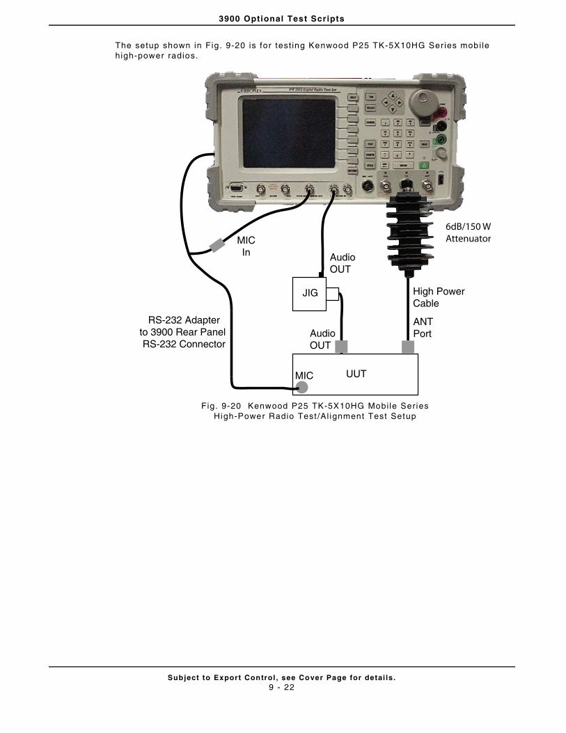
3900 Optional Test Scripts
Subject to Export Control , see Cover Page for detai ls .9 - 22
The setup shown in Fig. 9-20 is for test ing Kenwood P25 TK-5X10HG Ser ies mobi le high-power radios.
Fig . 9-20 Kenwood P25 TK-5X10HG Mobi le Series High-Power Radio Test /Al ignment Test Setup
High Power Cable
RS-232 Adapterto 3900 Rear Panel RS-232 Connector
UUT
ANTPort
MIC
JIG
AudioOUT
AudioOUT
MICIn
6dB/150 WAttenuator
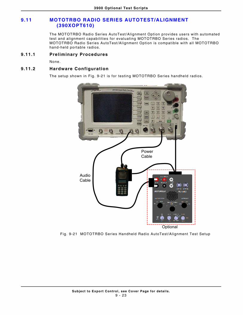
3900 Optional Test Scripts
Subject to Export Control , see Cover Page for detai ls .9 - 23
9.11 MOTOTRBO RADIO SERIES AUTOTEST/ALIGNMENT (390XOPT610)
The MOTOTRBO Radio Series AutoTest/Al ignment Opt ion provides users with automated test and al ignment capabi l i t ies for evaluat ing MOTOTRBO Ser ies radios. The MOTOTRBO Radio Series AutoTest /Al ignment Opt ion is compat ible with al l MOTOTRBO hand-held portable radios.
9.11.1 Preliminary Procedures
None.
9.11.2 Hardware Configuration
The setup shown in Fig. 9-21 is for test ing MOTOTRBO Series handheld radios.
F ig. 9-21 MOTOTRBO Series Handheld Radio AutoTest/Al ignment Test Setup
Audio Cable
Power Cable
Optional
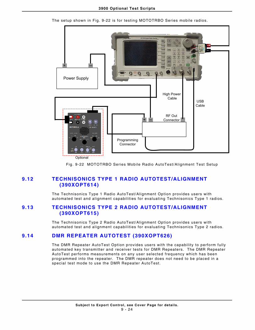
3900 Optional Test Scripts
Subject to Export Control , see Cover Page for detai ls .9 - 24
The setup shown in Fig. 9-22 is for test ing MOTOTRBO Series mobi le radios.
Fig . 9-22 MOTOTRBO Ser ies Mobi le Radio AutoTest/Al ignment Test Setup
9.12 TECHNISONICS TYPE 1 RADIO AUTOTEST/ALIGNMENT (390XOPT614)
The Technisonics Type 1 Radio AutoTest/Al ignment Opt ion provides users wi th automated test and al ignment capabi l i t ies for evaluat ing Technisonics Type 1 radios.
9.13 TECHNISONICS TYPE 2 RADIO AUTOTEST/ALIGNMENT (390XOPT615)
The Technisonics Type 2 Radio AutoTest/Al ignment Opt ion provides users wi th automated test and al ignment capabi l i t ies for evaluat ing Technisonics Type 2 radios.
9.14 DMR REPEATER AUTOTEST (390XOPT626)
The DMR Repeater AutoTest Opt ion provides users with the capabi l i ty to perform ful ly automated key transmit ter and receiver tests for DMR Repeaters. The DMR Repeater AutoTest per forms measurements on any user se lected frequency which has been programmed into the repeater . The DMR repeater does not need to be placed in a special test mode to use the DMR Repeater AutoTest.
+
Power Supply
+
High Power Cable
RF OutConnector
UUT
ProgrammingConnector
USBCable
Optional
Subject to Export Control , see Cover Page for detai ls .A - 1
Appendix A - Shipping Test Set
A.1 REPACKING FOR SHIPPING
Aerof lex Test Sets re turned to factory for cal ibrat ion, service or repair must be repackaged and shipped subject to the fo l lowing condit ions:
A.1.1 Return Authorizat ion
Do not return any products to factory without author izat ion from Aerof lex Customer Service Department .
A.1.1.A CONTACT:
A.2 TAGGING TEST SETS
All test sets must be tagged with:
• Owner ’s ident i f icat ion and address.
• Nature of service or repai r required.
• Model No. and Ser ial No.
A.3 SHIPPING CONTAINERS
Test Sets must be repackaged in or ig inal shipping containers using Aerof lex packing mater ials. I f or ig inal shipping containers and mater ials are not avai lable, contact Aerof lex Customer Service Department for shipp ing instruct ions.
A.4 FREIGHT COSTS
All f re ight costs on non-warranty shipments are assumed by the customer.
FAILURE TO PROPERLY PACKAGE THE TEST SET FOR SHIPMENT MAY RESULT IN DAMAGE DURING SHIPMENT. PRODUCT WARRANTY AND FREIGHT INSURANCE (IF PURCHASED) DO NOT COVER SHIPPING DAMAGES RESULTING FROM IMPROPER PACKAGING.
Aeroflex
Customer Service Dept.
10200 West York Street
Wichi ta, Kansas 67215
Telephone: 800) 835-2350
FAX: (316) 529-5330
email: americas.service@aerof lex.com
CAUTION

Shipping Test Set
Subject to Export Control , see Cover Page for detai ls .A - 2
A.5 REPACKING PROCEDURE
STEP PROCEDURE
1. Place Test Set in storage posi t ion as shown with handle adjusted and locked against Test Set.
2. Place one foam insert on a sol id f lat sur face. Fo ld cardboard inser t and place in foam insert as shown.
3. Place Test Set in foam insert . Cardboard insert should be against rear bumper guards.
DO NOT SHIP THE TEST SET WITH HANDLE EXTENDED. FAILURE TO PLACE HANDLE AGAINST TEST SET AS SHOWN MAY RESULT IN DAMAGE TO THE UNIT.
CAUTION
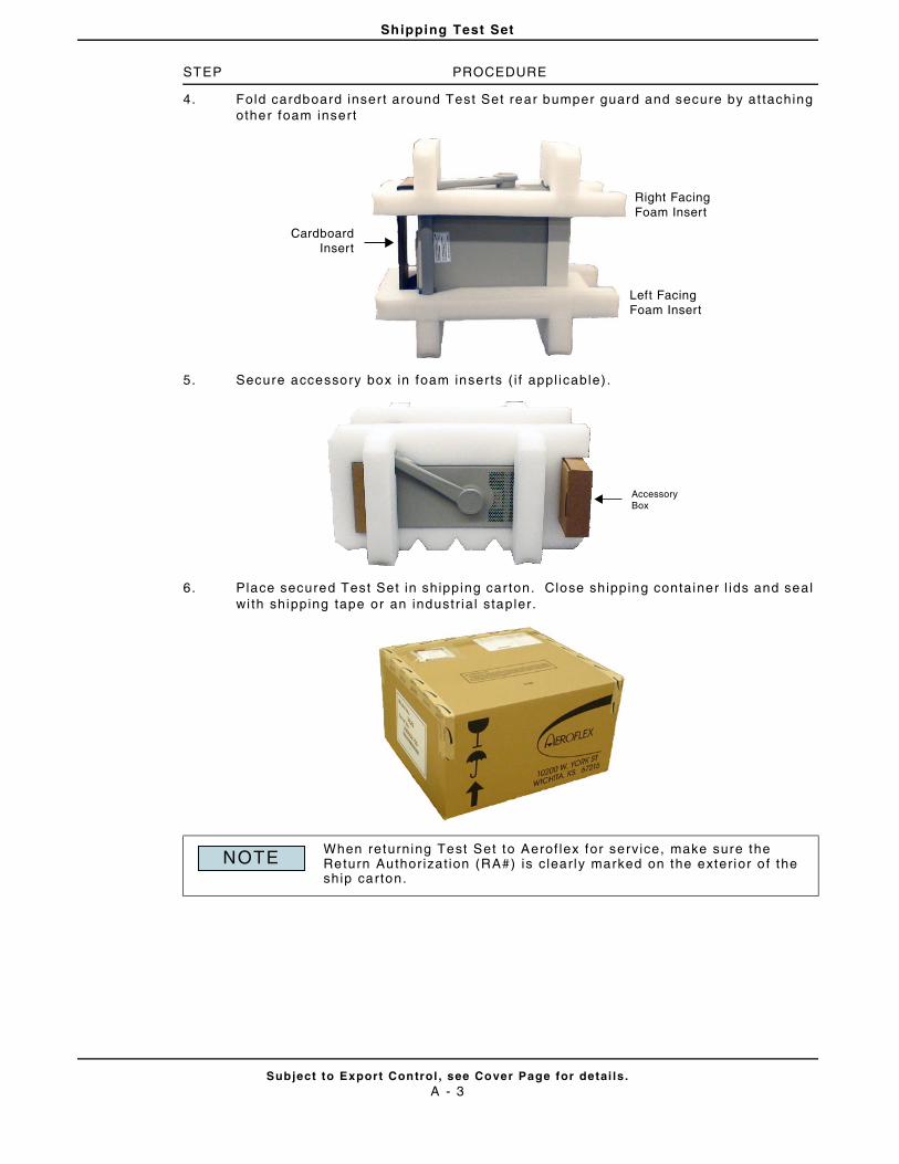
Shipping Test Set
Subject to Export Control , see Cover Page for detai ls .A - 3
STEP PROCEDURE
4. Fold cardboard inser t around Test Set rear bumper guard and secure by at taching other foam inser t
5. Secure accessory box in foam inserts ( i f appl icable) .
6. Place secured Test Set in shipping car ton. Close shipping container l ids and seal wi th shipping tape or an industr ia l stapler.
When returning Test Set to Aerof lex for service, make sure the Return Author izat ion (RA#) is c lear ly marked on the exter ior o f the ship carton.
CardboardInsert
Left FacingFoam Insert
Right FacingFoam Insert
AccessoryBox
NOTE
Shipping Test Set
Subject to Export Control , see Cover Page for detai ls .A - 4
THIS PAGE INTENTIONALLY LEFT BLANK.
Subject to Export Control , see Cover Page for detai ls .B - 1
Appendix B - 3900 Platform Specif ications
3900 Plat form Speci f icat ions apply to the 3901, 3902, 3920 and 3920B Test Sets except when otherwise indicated.
B.1 RF SIGNAL GENERATOR
B.1.1 Frequency
B.1.1.A Range (Usable from 100 kHz)
10 MHz to 1.05 GHz (3901, 3920, 3920B Standard)
*3920B refer to Phase Noise Speci f icat ions for f req >1.0 GHz
10 MHz to 2.7 GHz (3902, 3920, 3920B Freq Extension Opt ion [390XOPT058])
B.1.1.B Resolut ion
1 Hz
B.1.1.C Accuracy
Frequency Standard ±1 count
B.1.2 Output Level
B.1.2.A Range
T/R: -130.0 to -30.0 dBm
GEN: -130.0 to +10.0 dBm (+10 dBm max for CW or FM; 0 dBm max for complex modulat ion)
B.1.2.B Resolut ion
0.1 dB
B.1.2.C Accuracy (for level >-110 dBm)
T/R: ±1.0 dB (Typical better than ±0.6 dB) , ±2.0 dB (≥1800 MHz)
GEN: ±1.0 dB (Typical better than ±0.6 dB) , ±2.0 dB (≥1800 MHz)
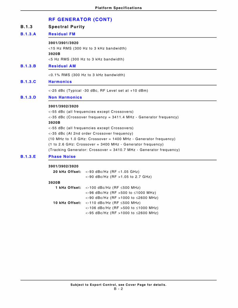
Platform Specifications
RF GENERATOR (CONT)
Subject to Export Control , see Cover Page for detai ls .B - 2
B.1.3 Spectral Purity
B.1.3.A Residual FM
3901/3901/3920
<15 Hz RMS (300 Hz to 3 kHz bandwidth)
3920B
<5 Hz RMS (300 Hz to 3 kHz bandwidth)
B.1.3.B Residual AM
<0.1% RMS (300 Hz to 3 kHz bandwidth)
B.1.3.C Harmonics
< -25 dBc (Typical -30 dBc, RF Level set at +10 dBm)
B.1.3.D Non Harmonics
3901/3902/3920
< -55 dBc (al l f requencies except Crossovers)
< -35 dBc (Crossover f requency = 3411.4 MHz - Generator f requency)
3920B
< -55 dBc (al l f requencies except Crossovers)
< -35 dBc (At 2nd order Crossover f requency)
(10 MHz to 1 .0 GHz: Crossover = 1400 MHz - Generator f requency)
(1 to 2 .6 GHz: Crossover = 3400 MHz - Generator f requency)
(Tracking Generator: Crossover = 3410.7 MHz - Generator f requency)
B.1.3.E Phase Noise
3901/3902/3920
3920B
20 kHz Offset: < -93 dBc/Hz (RF <1.05 GHz)< -90 dBc/Hz (RF >1.05 to 2.7 GHz)
1 kHz Offset: < -100 dBc/Hz (RF ≤500 MHz)
< -96 dBc/Hz (RF >500 to ≤1000 MHz)< -90 dBc/Hz (RF >1000 to ≤2600 MHz)
10 kHz Offset: < -110 dBc/Hz (RF ≤500 MHz)
< -106 dBc/Hz (RF >500 to ≤1000 MHz)< -95 dBc/Hz (RF >1000 to ≤2600 MHz)
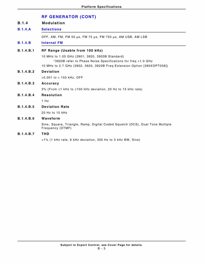
Platform Specifications
RF GENERATOR (CONT)
Subject to Export Control , see Cover Page for detai ls .B - 3
B.1.4 Modulat ion
B.1.4.A Selections
OFF, AM, FM, FM 50 μs, FM 75 μs, FM 750 μs, AM USB, AM LSB
B.1.4.B Internal FM
B.1.4.B.1 RF Range (Usable from 100 kHz)
10 MHz to 1.05 GHz (3901, 3920, 3920B Standard)
*3920B refer to Phase Noise Speci f icat ions for f req >1.0 GHz
10 MHz to 2.7 GHz (3902, 3920, 3920B Freq Extension Opt ion [390XOPT058])
B.1.4.B.2 Deviation
±0.001 to ± 150 kHz, OFF
B.1.4.B.3 Accuracy
3% (From ±1 kHz to ±100 kHz deviat ion, 20 Hz to 15 kHz rate)
B.1.4.B.4 Resolut ion
1 Hz
B.1.4.B.5 Deviation Rate
20 Hz to 15 kHz
B.1.4.B.6 Waveform
Sine , Square, Tr iangle, Ramp, Digi ta l Coded Squelch (DCS), Dual Tone Mult ip le Frequency (DTMF)
B.1.4.B.7 THD
<1% (1 kHz rate, 6 kHz deviat ion, 300 Hz to 3 kHz BW, Sine)
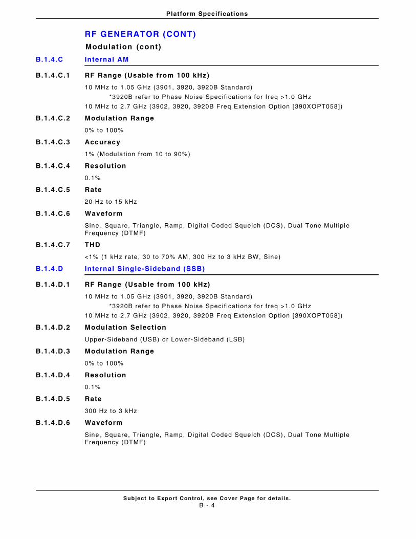
Platform Specifications
RF GENERATOR (CONT)
Subject to Export Control , see Cover Page for detai ls .B - 4
Modulat ion (cont)
B.1.4.C Internal AM
B.1.4.C.1 RF Range (Usable from 100 kHz)
10 MHz to 1.05 GHz (3901, 3920, 3920B Standard)
*3920B refer to Phase Noise Speci f icat ions for f req >1.0 GHz
10 MHz to 2.7 GHz (3902, 3920, 3920B Freq Extension Opt ion [390XOPT058])
B.1.4.C.2 Modulation Range
0% to 100%
B.1.4.C.3 Accuracy
1% (Modulat ion f rom 10 to 90%)
B.1.4.C.4 Resolut ion
0.1%
B.1.4.C.5 Rate
20 Hz to 15 kHz
B.1.4.C.6 Waveform
Sine , Square, Tr iangle, Ramp, Digi ta l Coded Squelch (DCS), Dual Tone Mult ip le Frequency (DTMF)
B.1.4.C.7 THD
<1% (1 kHz rate, 30 to 70% AM, 300 Hz to 3 kHz BW, Sine)
B.1.4.D Internal Single-Sideband (SSB)
B.1.4.D.1 RF Range (Usable from 100 kHz)
10 MHz to 1.05 GHz (3901, 3920, 3920B Standard)
*3920B refer to Phase Noise Speci f icat ions for f req >1.0 GHz
10 MHz to 2.7 GHz (3902, 3920, 3920B Freq Extension Opt ion [390XOPT058])
B.1.4.D.2 Modulation Selection
Upper-Sideband (USB) or Lower-Sideband (LSB)
B.1.4.D.3 Modulation Range
0% to 100%
B.1.4.D.4 Resolut ion
0.1%
B.1.4.D.5 Rate
300 Hz to 3 kHz
B.1.4.D.6 Waveform
Sine , Square, Tr iangle, Ramp, Digi ta l Coded Squelch (DCS), Dual Tone Mult ip le Frequency (DTMF)
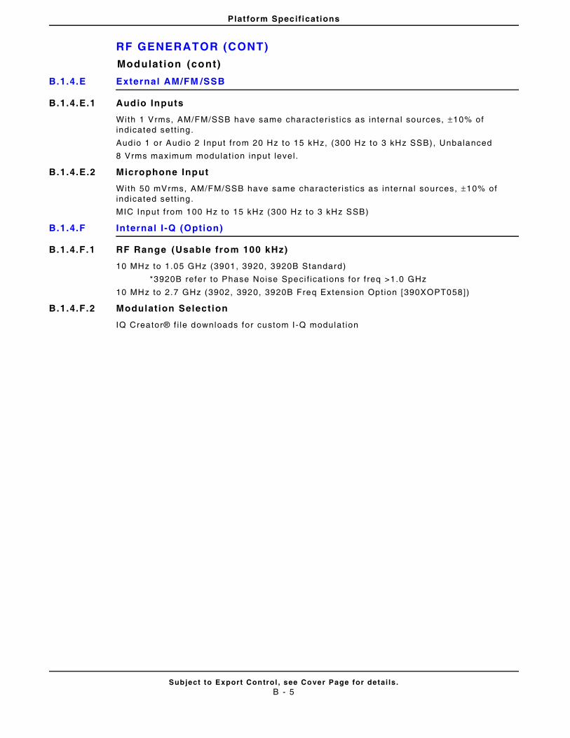
Platform Specifications
RF GENERATOR (CONT)
Subject to Export Control , see Cover Page for detai ls .B - 5
Modulat ion (cont)
B.1.4.E External AM/FM /SSB
B.1.4.E.1 Audio Inputs
With 1 Vrms, AM/FM/SSB have same character ist ics as internal sources, ±10% of indicated set t ing.
Audio 1 or Audio 2 Input f rom 20 Hz to 15 kHz, (300 Hz to 3 kHz SSB), Unbalanced
8 Vrms maximum modulat ion input level .
B.1.4.E.2 Microphone Input
With 50 mVrms, AM/FM/SSB have same character ist ics as internal sources, ±10% of indicated set t ing.
MIC Input f rom 100 Hz to 15 kHz (300 Hz to 3 kHz SSB)
B.1.4.F Internal I -Q (Option)
B.1.4.F.1 RF Range (Usable from 100 kHz)
10 MHz to 1.05 GHz (3901, 3920, 3920B Standard)
*3920B refer to Phase Noise Speci f icat ions for f req >1.0 GHz
10 MHz to 2.7 GHz (3902, 3920, 3920B Freq Extension Opt ion [390XOPT058])
B.1.4.F.2 Modulation Selection
IQ Creator® f i le downloads for custom I -Q modulat ion
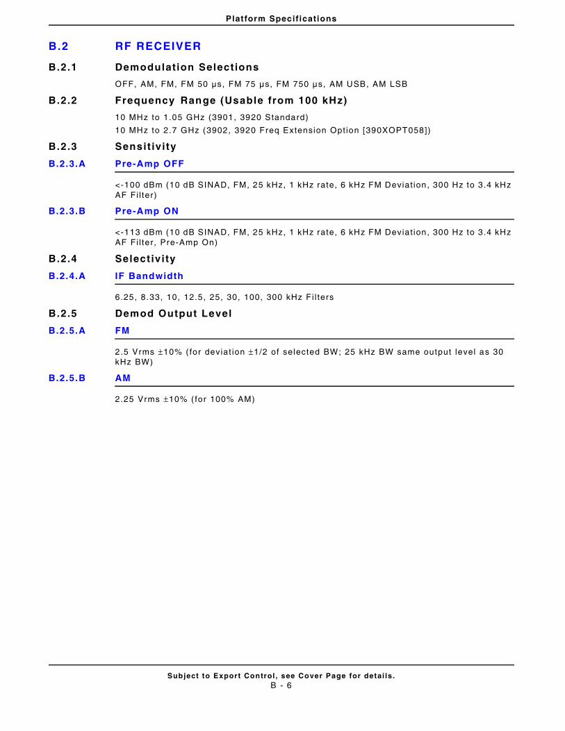
Platform Specifications
B.2 RF RECEIVER
Subject to Export Control , see Cover Page for detai ls .B - 6
B.2.1 Demodulation Selections
OFF, AM, FM, FM 50 μs, FM 75 μs, FM 750 μs, AM USB, AM LSB
B.2.2 Frequency Range (Usable from 100 kHz)
10 MHz to 1.05 GHz (3901, 3920 Standard)
10 MHz to 2.7 GHz (3902, 3920 Freq Extension Opt ion [390XOPT058])
B.2.3 Sensit ivi ty
B.2.3.A Pre-Amp OFF
<-100 dBm (10 dB SINAD, FM, 25 kHz, 1 kHz rate, 6 kHz FM Deviat ion, 300 Hz to 3.4 kHz AF Fi l ter)
B.2.3.B Pre-Amp ON
<-113 dBm (10 dB SINAD, FM, 25 kHz, 1 kHz rate, 6 kHz FM Deviat ion, 300 Hz to 3.4 kHz AF Fi l ter, Pre-Amp On)
B.2.4 Selectivi ty
B.2.4.A IF Bandwidth
6.25, 8.33, 10, 12.5, 25, 30, 100, 300 kHz F i l ters
B.2.5 Demod Output Level
B.2.5.A FM
2.5 Vrms ±10% ( for deviat ion ±1/2 of selected BW; 25 kHz BW same output level as 30 kHz BW)
B.2.5.B AM
2.25 Vrms ±10% ( for 100% AM)
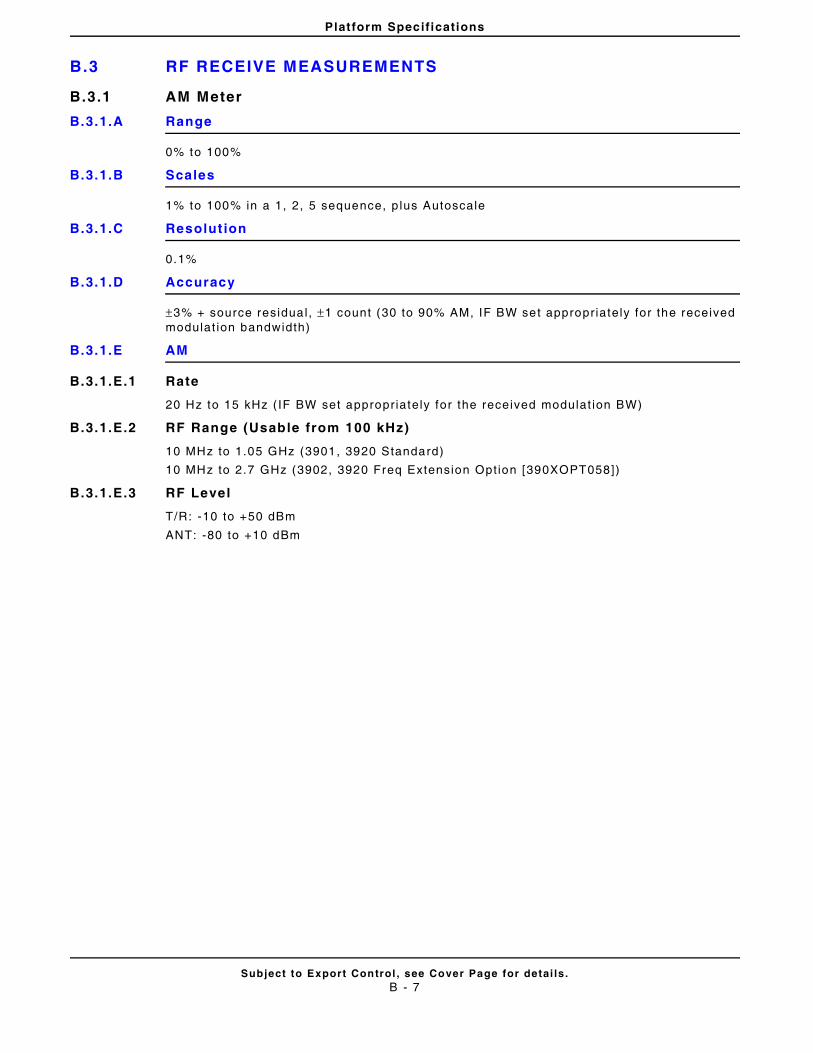
Platform Specifications
B.3 RF RECEIVE MEASUREMENTS
Subject to Export Control , see Cover Page for detai ls .B - 7
B.3.1 AM Meter
B.3.1.A Range
0% to 100%
B.3.1.B Scales
1% to 100% in a 1, 2, 5 sequence, p lus Autoscale
B.3.1.C Resolut ion
0.1%
B.3.1.D Accuracy
±3% + source residual , ±1 count (30 to 90% AM, IF BW set appropr iately for the received modulat ion bandwidth)
B.3.1.E AM
B.3.1.E.1 Rate
20 Hz to 15 kHz ( IF BW set appropr iately for the received modulat ion BW)
B.3.1.E.2 RF Range (Usable from 100 kHz)
10 MHz to 1.05 GHz (3901, 3920 Standard)
10 MHz to 2.7 GHz (3902, 3920 Freq Extension Opt ion [390XOPT058])
B.3.1.E.3 RF Level
T/R: -10 to +50 dBm
ANT: -80 to +10 dBm
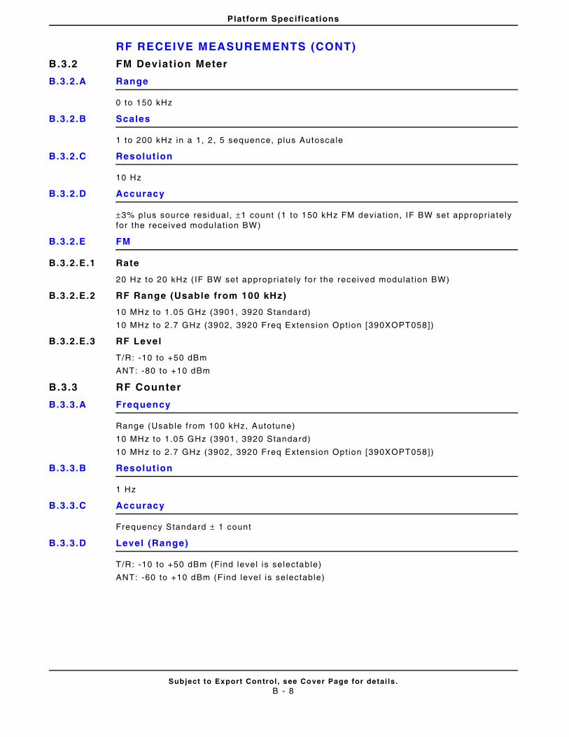
Platform Specifications
RF RECEIVE MEASUREMENTS (CONT)
Subject to Export Control , see Cover Page for detai ls .B - 8
B.3.2 FM Deviat ion Meter
B.3.2.A Range
0 to 150 kHz
B.3.2.B Scales
1 to 200 kHz in a 1, 2 , 5 sequence, plus Autoscale
B.3.2.C Resolut ion
10 Hz
B.3.2.D Accuracy
±3% plus source residual , ±1 count (1 to 150 kHz FM deviat ion, IF BW set appropr iately for the rece ived modulat ion BW)
B.3.2.E FM
B.3.2.E.1 Rate
20 Hz to 20 kHz ( IF BW set appropr iately for the received modulat ion BW)
B.3.2.E.2 RF Range (Usable from 100 kHz)
10 MHz to 1.05 GHz (3901, 3920 Standard)
10 MHz to 2.7 GHz (3902, 3920 Freq Extension Opt ion [390XOPT058])
B.3.2.E.3 RF Level
T/R: -10 to +50 dBm
ANT: -80 to +10 dBm
B.3.3 RF Counter
B.3.3.A Frequency
Range (Usable from 100 kHz, Autotune)
10 MHz to 1.05 GHz (3901, 3920 Standard)
10 MHz to 2.7 GHz (3902, 3920 Freq Extension Opt ion [390XOPT058])
B.3.3.B Resolut ion
1 Hz
B.3.3.C Accuracy
Frequency Standard ± 1 count
B.3.3.D Level (Range)
T/R: -10 to +50 dBm (Find level is selectable)
ANT: -60 to +10 dBm (Find level is selectable)
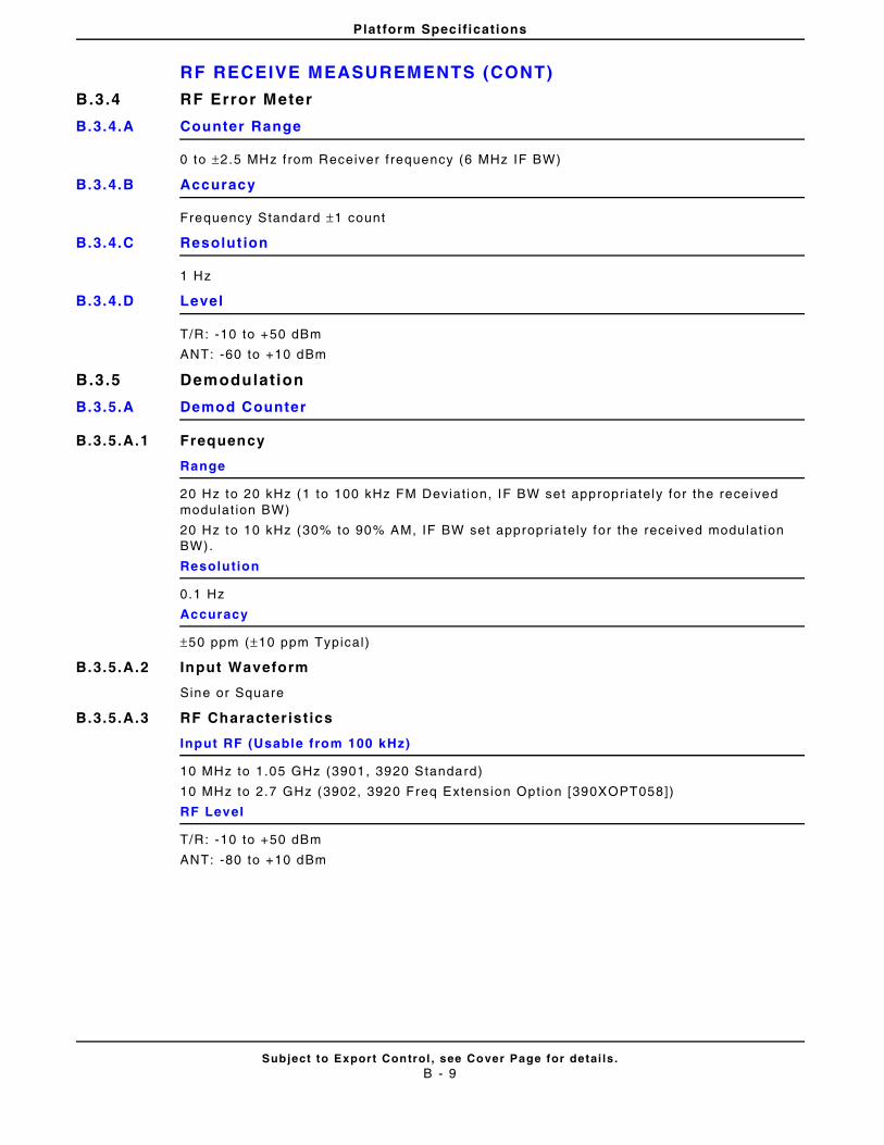
Platform Specifications
RF RECEIVE MEASUREMENTS (CONT)
Subject to Export Control , see Cover Page for detai ls .B - 9
B.3.4 RF Error Meter
B.3.4.A Counter Range
0 to ±2.5 MHz f rom Receiver f requency (6 MHz IF BW)
B.3.4.B Accuracy
Frequency Standard ±1 count
B.3.4.C Resolut ion
1 Hz
B.3.4.D Level
T/R: -10 to +50 dBm
ANT: -60 to +10 dBm
B.3.5 Demodulation
B.3.5.A Demod Counter
B.3.5.A.1 Frequency
Range
20 Hz to 20 kHz (1 to 100 kHz FM Deviat ion, IF BW set appropr iately for the rece ived modulat ion BW)
20 Hz to 10 kHz (30% to 90% AM, IF BW set appropr ia tely for the received modulat ion BW).
Resolution
0.1 Hz
Accuracy
±50 ppm (±10 ppm Typical)
B.3.5.A.2 Input Waveform
Sine or Square
B.3.5.A.3 RF Characterist ics
Input RF (Usable from 100 kHz)
10 MHz to 1.05 GHz (3901, 3920 Standard)
10 MHz to 2.7 GHz (3902, 3920 Freq Extension Opt ion [390XOPT058])
RF Level
T/R: -10 to +50 dBm
ANT: -80 to +10 dBm
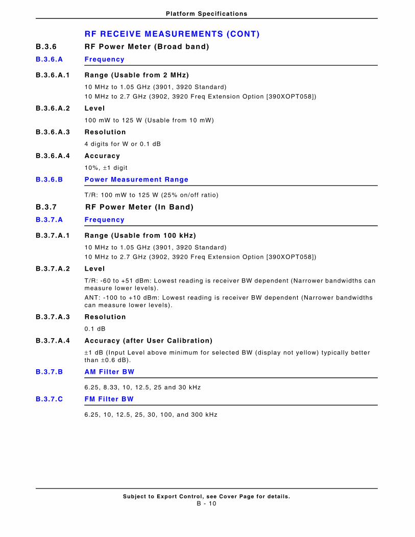
Platform Specifications
RF RECEIVE MEASUREMENTS (CONT)
Subject to Export Control , see Cover Page for detai ls .B - 10
B.3.6 RF Power Meter (Broad band)
B.3.6.A Frequency
B.3.6.A.1 Range (Usable from 2 MHz)
10 MHz to 1.05 GHz (3901, 3920 Standard)
10 MHz to 2.7 GHz (3902, 3920 Freq Extension Opt ion [390XOPT058])
B.3.6.A.2 Level
100 mW to 125 W (Usable from 10 mW)
B.3.6.A.3 Resolut ion
4 digi ts for W or 0.1 dB
B.3.6.A.4 Accuracy
10%, ±1 digi t
B.3.6.B Power Measurement Range
T/R: 100 mW to 125 W (25% on/off rat io)
B.3.7 RF Power Meter ( In Band)
B.3.7.A Frequency
B.3.7.A.1 Range (Usable from 100 kHz)
10 MHz to 1.05 GHz (3901, 3920 Standard)
10 MHz to 2.7 GHz (3902, 3920 Freq Extension Opt ion [390XOPT058])
B.3.7.A.2 Level
T/R: -60 to +51 dBm: Lowest reading is rece iver BW dependent (Narrower bandwidths can measure lower levels) .
ANT: -100 to +10 dBm: Lowest reading is receiver BW dependent (Narrower bandwidths can measure lower leve ls).
B.3.7.A.3 Resolut ion
0.1 dB
B.3.7.A.4 Accuracy (after User Calibration)
±1 dB (Input Level above minimum for selected BW (display not ye l low) typical ly better than ±0.6 dB).
B.3.7.B AM Fil ter BW
6.25, 8.33, 10, 12.5, 25 and 30 kHz
B.3.7.C FM Fi lter BW
6.25, 10, 12.5, 25, 30, 100, and 300 kHz
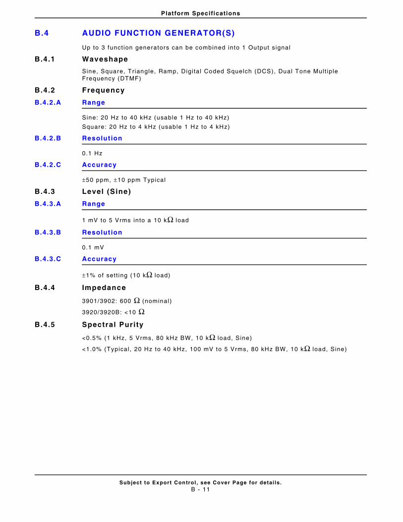
Platform Specifications
B.4 AUDIO FUNCTION GENERATOR(S)
Subject to Export Control , see Cover Page for detai ls .B - 11
Up to 3 funct ion generators can be combined into 1 Output s ignal
B.4.1 Waveshape
Sine, Square, Tr iangle, Ramp, Digi tal Coded Squelch (DCS), Dual Tone Mult ip le Frequency (DTMF)
B.4.2 Frequency
B.4.2.A Range
Sine: 20 Hz to 40 kHz (usable 1 Hz to 40 kHz)
Square: 20 Hz to 4 kHz (usable 1 Hz to 4 kHz)
B.4.2.B Resolut ion
0.1 Hz
B.4.2.C Accuracy
±50 ppm, ±10 ppm Typical
B.4.3 Level (Sine)
B.4.3.A Range
1 mV to 5 Vrms in to a 10 kΩ load
B.4.3.B Resolut ion
0.1 mV
B.4.3.C Accuracy
±1% of sett ing (10 kΩ load)
B.4.4 Impedance
3901/3902: 600 Ω (nominal)
3920/3920B: <10 ΩB.4.5 Spectral Purity
<0.5% (1 kHz, 5 Vrms, 80 kHz BW, 10 kΩ load, Sine)
<1.0% (Typical , 20 Hz to 40 kHz, 100 mV to 5 Vrms, 80 kHz BW, 10 kΩ load, Sine)
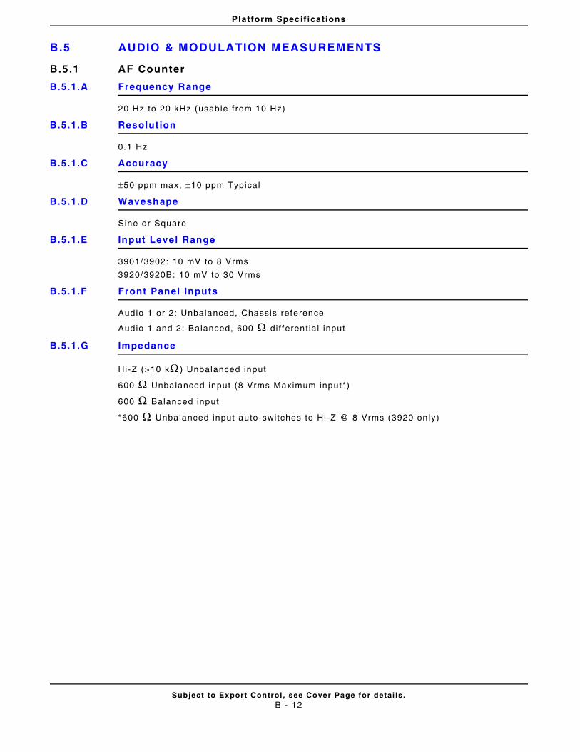
Platform Specifications
B.5 AUDIO & MODULATION MEASUREMENTS
Subject to Export Control , see Cover Page for detai ls .B - 12
B.5.1 AF Counter
B.5.1.A Frequency Range
20 Hz to 20 kHz (usable f rom 10 Hz)
B.5.1.B Resolut ion
0.1 Hz
B.5.1.C Accuracy
±50 ppm max, ±10 ppm Typical
B.5.1.D Waveshape
Sine or Square
B.5.1.E Input Level Range
3901/3902: 10 mV to 8 Vrms
3920/3920B: 10 mV to 30 Vrms
B.5.1.F Front Panel Inputs
Audio 1 or 2 : Unbalanced, Chassis reference
Audio 1 and 2: Balanced, 600 Ω d i f ferent ial input
B.5.1.G Impedance
Hi-Z (>10 kΩ ) Unbalanced input
600 Ω Unbalanced input (8 Vrms Maximum input*)
600 Ω Balanced input
*600 Ω Unbalanced input auto-switches to Hi -Z @ 8 Vrms (3920 on ly)
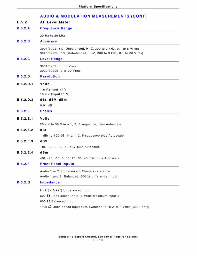
Platform Specifications
AUDIO & MODULATION MEASUREMENTS (CONT)
Subject to Export Control , see Cover Page for detai ls .B - 13
B.5.2 AF Level Meter
B.5.2.A Frequency Range
20 Hz to 20 kHz
B.5.2.B Accuracy
3901/3902: 5% (Unbalanced, Hi-Z, 300 to 3 kHz, 0.1 to 8 Vrms)
3920/3920B: 5% (Unbalanced, Hi-Z, 300 to 3 kHz, 0.1 to 30 Vrms)
B.5.2.C Level Range
3901/3902: 0 to 8 Vrms
3920/3920B: 0 to 30 Vrms
B.5.2.D Resolut ion
B.5.2.D.1 Volts
1 mV (Input <1 V)
10 mV ( Input ≥1 V)
B.5.2.D.2 dBr, dBV, dBm
0.01 dB
B.5.2.E Scales
B.5.2.E.1 Volts
20 mV to 50 V in a 1, 2, 5 sequence, plus Autoscale
B.5.2.E.2 dBr
1 dBr to 100 dBr in a 1, 2 , 5 sequence plus Autoscale
B.5.2.E.3 dBV
-40, -20, 0, 20, 40 dBV plus Autoscale
B.5.2.E.4 dBm
-30, -20, -10, 0, 10, 20, 30, 40 dBm plus Autoscale
B.5.2.F Front Panel Inputs
Audio 1 or 2 : Unbalanced, Chassis reference
Audio 1 and 2: Balanced, 600 Ω d i f ferent ial input
B.5.2.G Impedance
Hi-Z (>10 kΩ ) Unbalanced input
600 Ω Unbalanced input (8 Vrms Maximum input*)
600 Ω Balanced input
*600 Ω Unbalanced input auto-switches to Hi -Z @ 8 Vrms (3920 on ly)
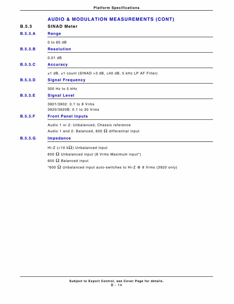
Platform Specifications
AUDIO & MODULATION MEASUREMENTS (CONT)
Subject to Export Control , see Cover Page for detai ls .B - 14
B.5.3 SINAD Meter
B.5.3.A Range
0 to 60 dB
B.5.3.B Resolut ion
0.01 dB
B.5.3.C Accuracy
±1 dB, ±1 count (SINAD >3 dB, ≤40 dB, 5 kHz LP AF Fi l ter)
B.5.3.D Signal Frequency
300 Hz to 5 kHz
B.5.3.E Signal Level
3901/3902: 0.1 to 8 Vrms
3920/3920B: 0 .1 to 30 Vrms
B.5.3.F Front Panel Inputs
Audio 1 or 2 : Unbalanced, Chassis reference
Audio 1 and 2: Balanced, 600 Ω d i f ferent ial input
B.5.3.G Impedance
Hi-Z (>10 kΩ ) Unbalanced input
600 Ω Unbalanced input (8 Vrms Maximum input*)
600 Ω Balanced input
*600 Ω Unbalanced input auto-switches to Hi -Z @ 8 Vrms (3920 on ly)
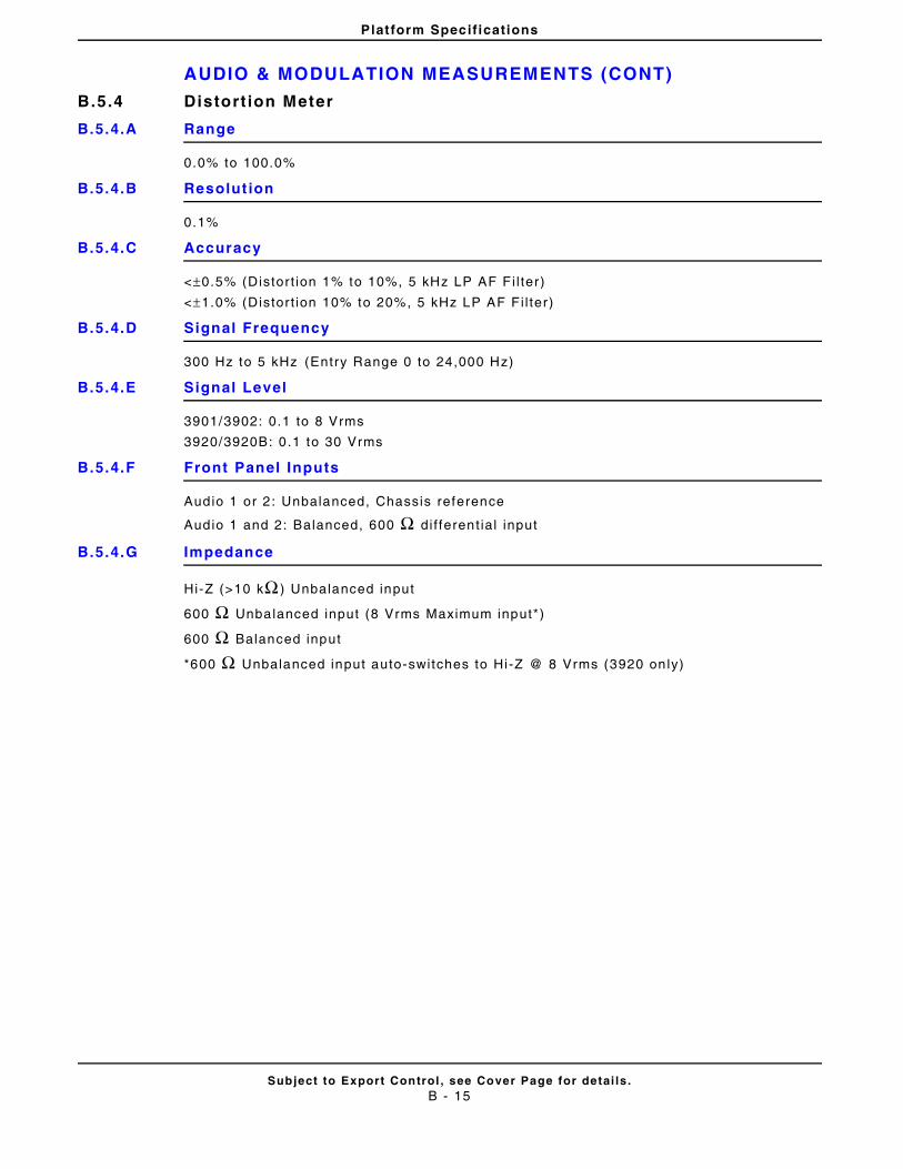
Platform Specifications
AUDIO & MODULATION MEASUREMENTS (CONT)
Subject to Export Control , see Cover Page for detai ls .B - 15
B.5.4 Distort ion Meter
B.5.4.A Range
0.0% to 100.0%
B.5.4.B Resolut ion
0.1%
B.5.4.C Accuracy
<±0.5% (Distor t ion 1% to 10%, 5 kHz LP AF Fi l ter )
<±1.0% (Distor t ion 10% to 20%, 5 kHz LP AF Fi l ter )
B.5.4.D Signal Frequency
300 Hz to 5 kHz (Entry Range 0 to 24,000 Hz)
B.5.4.E Signal Level
3901/3902: 0.1 to 8 Vrms
3920/3920B: 0 .1 to 30 Vrms
B.5.4.F Front Panel Inputs
Audio 1 or 2 : Unbalanced, Chassis reference
Audio 1 and 2: Balanced, 600 Ω d i f ferent ial input
B.5.4.G Impedance
Hi-Z (>10 kΩ ) Unbalanced input
600 Ω Unbalanced input (8 Vrms Maximum input*)
600 Ω Balanced input
*600 Ω Unbalanced input auto-switches to Hi -Z @ 8 Vrms (3920 on ly)
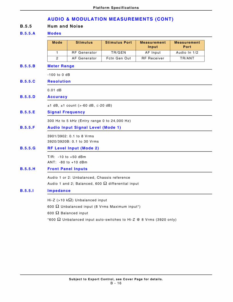
Platform Specifications
AUDIO & MODULATION MEASUREMENTS (CONT)
Subject to Export Control , see Cover Page for detai ls .B - 16
B.5.5 Hum and Noise
B.5.5.A Modes
B.5.5.B Meter Range
-100 to 0 dB
B.5.5.C Resolut ion
0.01 dB
B.5.5.D Accuracy
±1 dB, ±1 count (>-60 dB, ≤ -20 dB)
B.5.5.E Signal Frequency
300 Hz to 5 kHz (Entry range 0 to 24,000 Hz)
B.5.5.F Audio Input Signal Level (Mode 1)
3901/3902: 0.1 to 8 Vrms
3920/3920B: 0 .1 to 30 Vrms
B.5.5.G RF Level Input (Mode 2)
T/R: -10 to +50 dBm
ANT: -80 to +10 dBm
B.5.5.H Front Panel Inputs
Audio 1 or 2 : Unbalanced, Chassis reference
Audio 1 and 2; Balanced, 600 Ω d i f ferent ial input
B.5.5. I Impedance
Hi-Z (>10 kΩ ) Unbalanced input
600 Ω Unbalanced input (8 Vrms Maximum input*)
600 Ω Balanced input
*600 Ω Unbalanced input auto-switches to Hi -Z @ 8 Vrms (3920 on ly)
Mode Stimulus Stimulus Port Measurement Input
Measurement Port
1 RF Generator TR/GEN AF Input Audio In 1 /2
2 AF Generator Fctn Gen Out RF Receiver TR/ANT
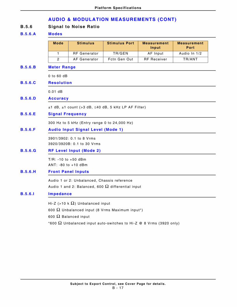
Platform Specifications
AUDIO & MODULATION MEASUREMENTS (CONT)
Subject to Export Control , see Cover Page for detai ls .B - 17
B.5.6 Signal to Noise Ratio
B.5.6.A Modes
B.5.6.B Meter Range
0 to 60 dB
B.5.6.C Resolut ion
0.01 dB
B.5.6.D Accuracy
±1 dB, ±1 count (>3 dB, ≤40 dB, 5 kHz LP AF Fi l ter )
B.5.6.E Signal Frequency
300 Hz to 5 kHz (Entry range 0 to 24,000 Hz)
B.5.6.F Audio Input Signal Level (Mode 1)
3901/3902: 0.1 to 8 Vrms
3920/3920B: 0 .1 to 30 Vrms
B.5.6.G RF Level Input (Mode 2)
T/R: -10 to +50 dBm
ANT: -80 to +10 dBm
B.5.6.H Front Panel Inputs
Audio 1 or 2 : Unbalanced, Chassis reference
Audio 1 and 2: Balanced, 600 Ω d i f ferent ial input
B.5.6. I Impedance
Hi-Z (>10 k Ω ) Unbalanced input
600 Ω Unbalanced input (8 Vrms Maximum input*)
600 Ω Balanced input
*600 Ω Unbalanced input auto-switches to Hi -Z @ 8 Vrms (3920 on ly)
Mode Stimulus Stimulus Port Measurement Input
Measurement Port
1 RF Generator TR/GEN AF Input Audio In 1 /2
2 AF Generator Fctn Gen Out RF Receiver TR/ANT
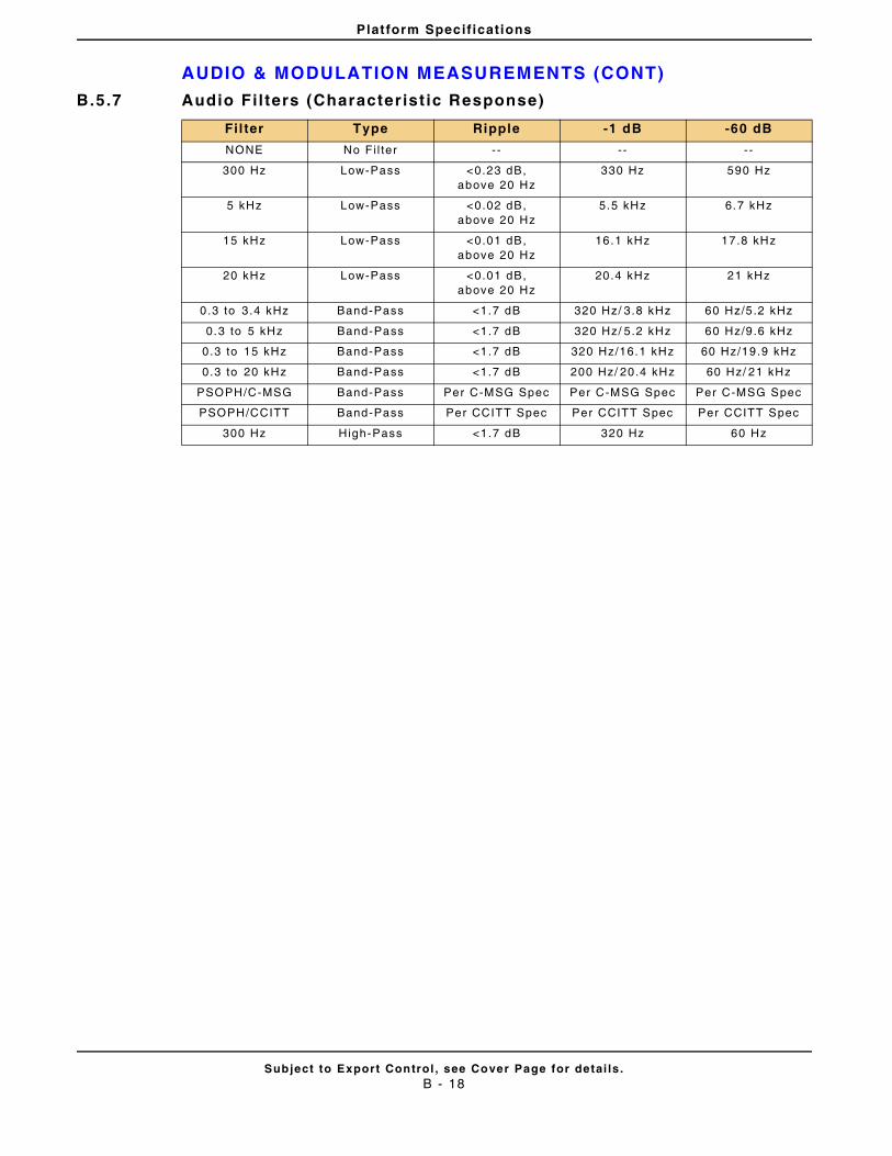
Platform Specifications
AUDIO & MODULATION MEASUREMENTS (CONT)
Subject to Export Control , see Cover Page for detai ls .B - 18
B.5.7 Audio Fil ters (Characterist ic Response)
Fil ter Type Ripple -1 dB -60 dB
NONE No Fi l ter - - - - - -
300 Hz Low-Pass <0.23 dB, above 20 Hz
330 Hz 590 Hz
5 kHz Low-Pass <0.02 dB, above 20 Hz
5.5 kHz 6.7 kHz
15 kHz Low-Pass <0.01 dB, above 20 Hz
16.1 kHz 17.8 kHz
20 kHz Low-Pass <0.01 dB, above 20 Hz
20.4 kHz 21 kHz
0.3 to 3 .4 kHz Band-Pass <1.7 dB 320 Hz/ 3.8 kHz 60 Hz/5.2 kHz
0.3 to 5 kHz Band-Pass <1.7 dB 320 Hz/ 5.2 kHz 60 Hz/9.6 kHz
0.3 to 15 kHz Band-Pass <1.7 dB 320 Hz/16.1 kHz 60 Hz/19.9 kHz
0.3 to 20 kHz Band-Pass <1.7 dB 200 Hz/ 20.4 kHz 60 Hz/ 21 kHz
PSOPH/C-MSG Band-Pass Per C-MSG Spec Per C-MSG Spec Per C-MSG Spec
PSOPH/CCITT Band-Pass Per CCITT Spec Per CCITT Spec Per CCITT Spec
300 Hz High-Pass <1.7 dB 320 Hz 60 Hz
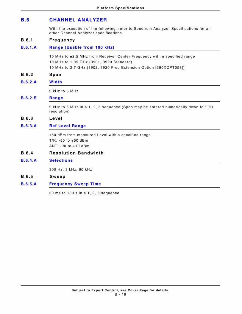
Platform Specifications
B.6 CHANNEL ANALYZER
Subject to Export Control , see Cover Page for detai ls .B - 19
With the except ion of the fol lowing, refer to Spectrum Analyzer Speci f icat ions for al l other Channel Analyzer speci f icat ions.
B.6.1 Frequency
B.6.1.A Range (Usable from 100 kHz)
10 MHz to ±2.5 MHz f rom Receiver Center Frequency wi thin speci f ied range
10 MHz to 1.05 GHz (3901, 3920 Standard)
10 MHz to 2.7 GHz (3902, 3920 Freq Extension Opt ion [390XOPT058])
B.6.2 Span
B.6.2.A Width
2 kHz to 5 MHz
B.6.2.B Range
2 kHz to 5 MHz in a 1, 2, 5 sequence (Span may be entered numerica l ly down to 1 Hz resolut ion)
B.6.3 Level
B.6.3.A Ref Level Range
±60 dBm from measured Level wi thin speci f ied range
T/R: -50 to +50 dBm
ANT: -90 to +10 dBm
B.6.4 Resolution Bandwidth
B.6.4.A Selections
300 Hz, 3 kHz, 60 kHz
B.6.5 Sweep
B.6.5.A Frequency Sweep Time
50 ms to 100 s in a 1 , 2, 5 sequence
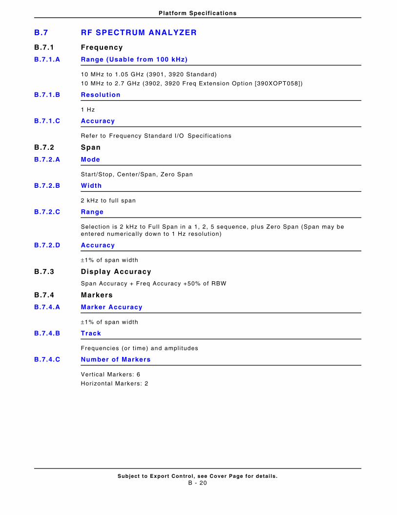
Platform Specifications
B.7 RF SPECTRUM ANALYZER
Subject to Export Control , see Cover Page for detai ls .B - 20
B.7.1 Frequency
B.7.1.A Range (Usable from 100 kHz)
10 MHz to 1.05 GHz (3901, 3920 Standard)
10 MHz to 2.7 GHz (3902, 3920 Freq Extension Opt ion [390XOPT058])
B.7.1.B Resolut ion
1 Hz
B.7.1.C Accuracy
Refer to Frequency Standard I /O Speci f icat ions
B.7.2 Span
B.7.2.A Mode
Start /Stop, Center/Span, Zero Span
B.7.2.B Width
2 kHz to ful l span
B.7.2.C Range
Select ion is 2 kHz to Fu l l Span in a 1, 2, 5 sequence, plus Zero Span (Span may be entered numerica l ly down to 1 Hz resolut ion)
B.7.2.D Accuracy
±1% of span width
B.7.3 Display Accuracy
Span Accuracy + Freq Accuracy +50% of RBW
B.7.4 Markers
B.7.4.A Marker Accuracy
±1% of span width
B.7.4.B Track
Frequencies (or t ime) and ampl i tudes
B.7.4.C Number of Markers
Vert ical Markers: 6
Horizontal Markers: 2
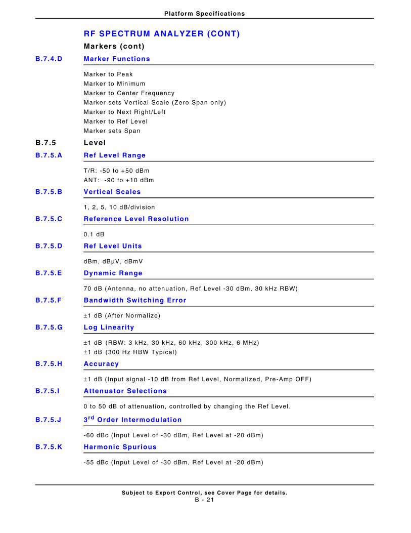
Platform Specifications
RF SPECTRUM ANALYZER (CONT)
Subject to Export Control , see Cover Page for detai ls .B - 21
Markers (cont)
B.7.4.D Marker Functions
Marker to Peak
Marker to Minimum
Marker to Center Frequency
Marker sets Ver t ical Scale (Zero Span only)
Marker to Next Right /Left
Marker to Ref Level
Marker sets Span
B.7.5 Level
B.7.5.A Ref Level Range
T/R: -50 to +50 dBm
ANT: -90 to +10 dBm
B.7.5.B Vertical Scales
1, 2, 5 , 10 dB/div is ion
B.7.5.C Reference Level Resolution
0.1 dB
B.7.5.D Ref Level Units
dBm, dBμV, dBmV
B.7.5.E Dynamic Range
70 dB (Antenna, no at tenuat ion, Ref Level -30 dBm, 30 kHz RBW)
B.7.5.F Bandwidth Switching Error
±1 dB (After Normal ize)
B.7.5.G Log Linearity
±1 dB (RBW: 3 kHz, 30 kHz, 60 kHz, 300 kHz, 6 MHz)
±1 dB (300 Hz RBW Typical )
B.7.5.H Accuracy
±1 dB (Input s ignal -10 dB from Ref Level , Normal ized, Pre-Amp OFF)
B.7.5. I Attenuator Selections
0 to 50 dB of a t tenuat ion, control led by changing the Ref Level .
B.7.5.J 3rd Order Intermodulation
-60 dBc ( Input Level o f -30 dBm, Ref Level at -20 dBm)
B.7.5.K Harmonic Spurious
-55 dBc ( Input Level o f -30 dBm, Ref Level at -20 dBm)
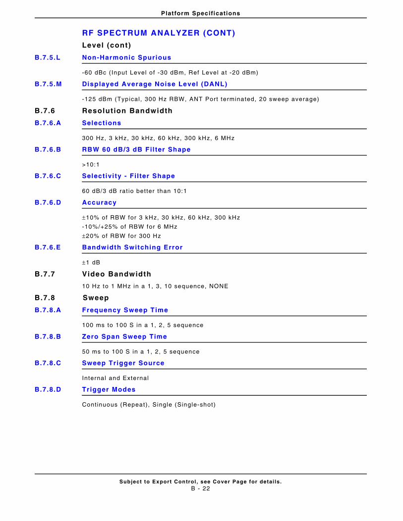
Platform Specifications
RF SPECTRUM ANALYZER (CONT)
Subject to Export Control , see Cover Page for detai ls .B - 22
Level (cont)
B.7.5.L Non-Harmonic Spurious
-60 dBc ( Input Level o f -30 dBm, Ref Level at -20 dBm)
B.7.5.M Displayed Average Noise Level (DANL)
-125 dBm (Typical , 300 Hz RBW, ANT Port terminated, 20 sweep average)
B.7.6 Resolution Bandwidth
B.7.6.A Selections
300 Hz, 3 kHz, 30 kHz, 60 kHz, 300 kHz, 6 MHz
B.7.6.B RBW 60 dB/3 dB Fil ter Shape
>10:1
B.7.6.C Selectivi ty - Fil ter Shape
60 dB/3 dB rat io bet ter than 10:1
B.7.6.D Accuracy
±10% of RBW for 3 kHz, 30 kHz, 60 kHz, 300 kHz
-10%/+25% of RBW for 6 MHz
±20% of RBW for 300 Hz
B.7.6.E Bandwidth Switching Error
±1 dB
B.7.7 Video Bandwidth
10 Hz to 1 MHz in a 1, 3, 10 sequence, NONE
B.7.8 Sweep
B.7.8.A Frequency Sweep Time
100 ms to 100 S in a 1, 2, 5 sequence
B.7.8.B Zero Span Sweep Time
50 ms to 100 S in a 1, 2, 5 sequence
B.7.8.C Sweep Trigger Source
Internal and External
B.7.8.D Trigger Modes
Continuous (Repeat), Single (Single-shot)
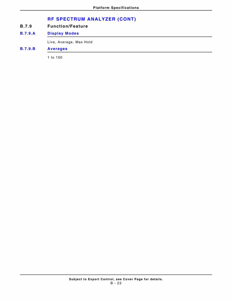
Platform Specifications
RF SPECTRUM ANALYZER (CONT)
Subject to Export Control , see Cover Page for detai ls .B - 23
B.7.9 Function/Feature
B.7.9.A Display Modes
Live, Average, Max Hold
B.7.9.B Averages
1 to 100
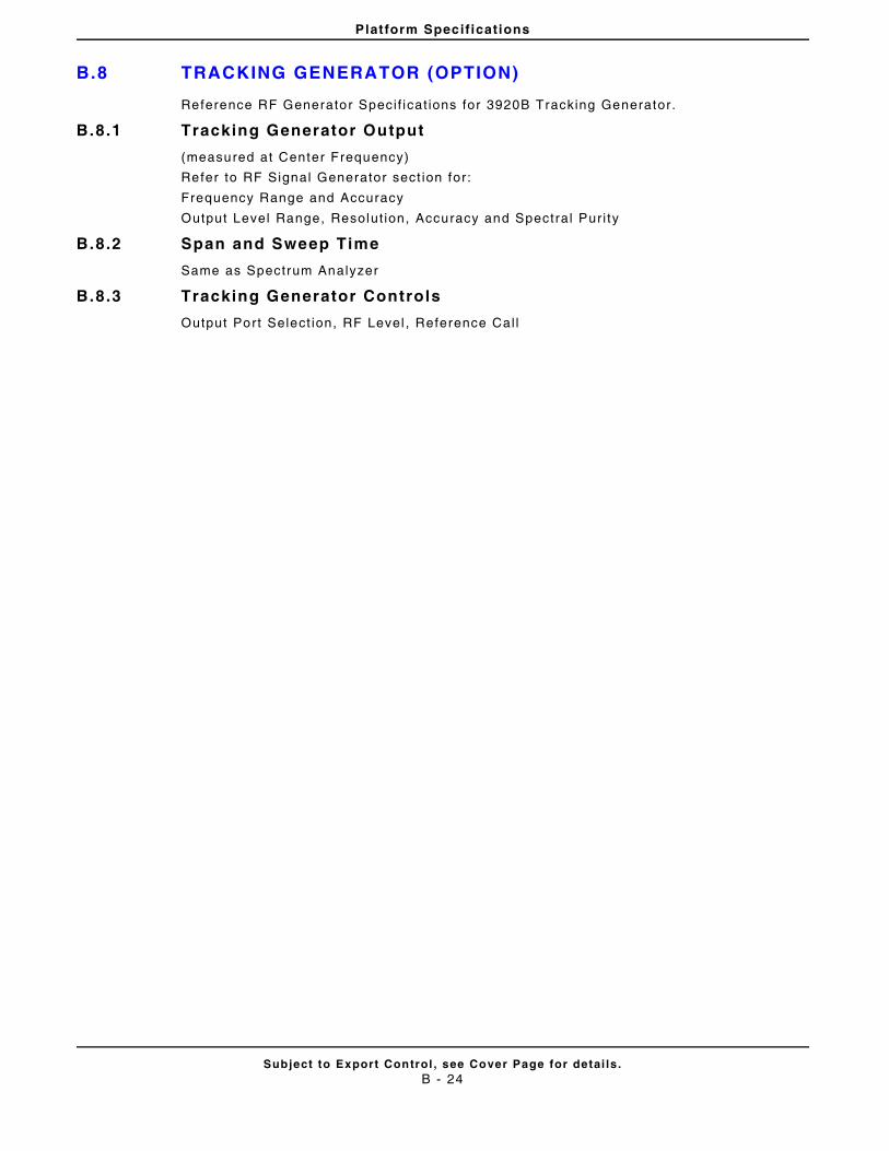
Platform Specifications
B.8 TRACKING GENERATOR (OPTION)
Subject to Export Control , see Cover Page for detai ls .B - 24
Reference RF Generator Speci f icat ions for 3920B Tracking Generator.
B.8.1 Tracking Generator Output
(measured at Center Frequency)
Refer to RF Signal Generator sect ion for:
Frequency Range and Accuracy
Output Level Range, Resolut ion, Accuracy and Spectral Pur i ty
B.8.2 Span and Sweep Time
Same as Spectrum Analyzer
B.8.3 Tracking Generator Controls
Output Port Select ion, RF Level , Reference Cal l
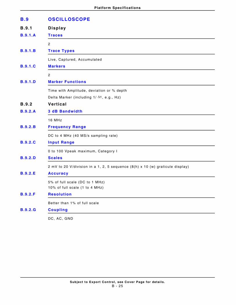
Platform Specifications
B.9 OSCILLOSCOPE
Subject to Export Control , see Cover Page for detai ls .B - 25
B.9.1 Display
B.9.1.A Traces
2
B.9.1.B Trace Types
Live, Captured, Accumulated
B.9.1.C Markers
2
B.9.1.D Marker Functions
Time with Ampl i tude, deviat ion or % depth
Delta Marker ( including 1/ , e .g. , Hz)
B.9.2 Vert ical
B.9.2.A 3 dB Bandwidth
16 MHz
B.9.2.B Frequency Range
DC to 4 MHz (40 MS/s sampl ing rate)
B.9.2.C Input Range
0 to 100 Vpeak maximum, Category I
B.9.2.D Scales
2 mV to 20 V/div is ion in a 1, 2, 5 sequence (8(h) x 10 (w) grat icule display)
B.9.2.E Accuracy
5% of fu l l scale (DC to 1 MHz)
10% of fu l l scale (1 to 4 MHz)
B.9.2.F Resolut ion
Bet ter than 1% of fu l l scale
B.9.2.G Coupling
DC, AC, GND
Δτ
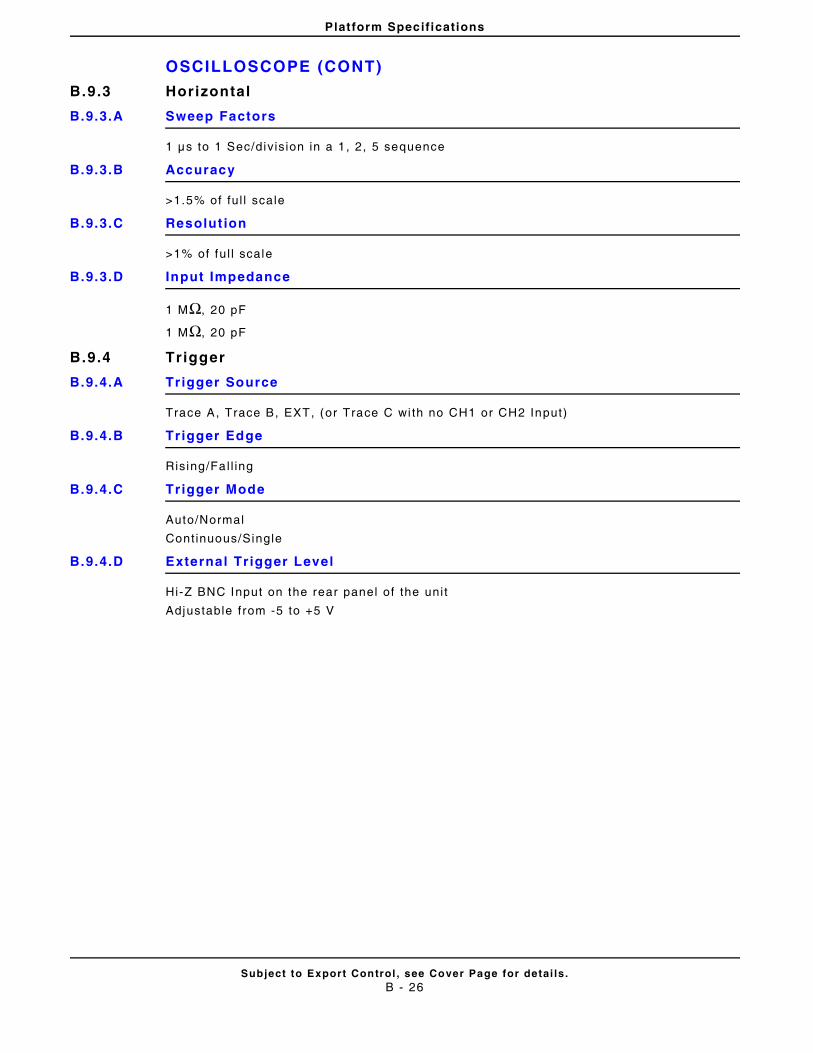
Platform Specifications
OSCILLOSCOPE (CONT)
Subject to Export Control , see Cover Page for detai ls .B - 26
B.9.3 Horizontal
B.9.3.A Sweep Factors
1 μs to 1 Sec/div is ion in a 1 , 2, 5 sequence
B.9.3.B Accuracy
>1.5% of fu l l scale
B.9.3.C Resolut ion
>1% of fu l l scale
B.9.3.D Input Impedance
1 MΩ, 20 pF
1 MΩ, 20 pF
B.9.4 Trigger
B.9.4.A Trigger Source
Trace A, Trace B, EXT, (or Trace C wi th no CH1 or CH2 Input)
B.9.4.B Trigger Edge
Rising/Fal l ing
B.9.4.C Trigger Mode
Auto/Normal
Cont inuous/Single
B.9.4.D External Trigger Level
Hi-Z BNC Input on the rear panel of the uni t
Adjustable from -5 to +5 V
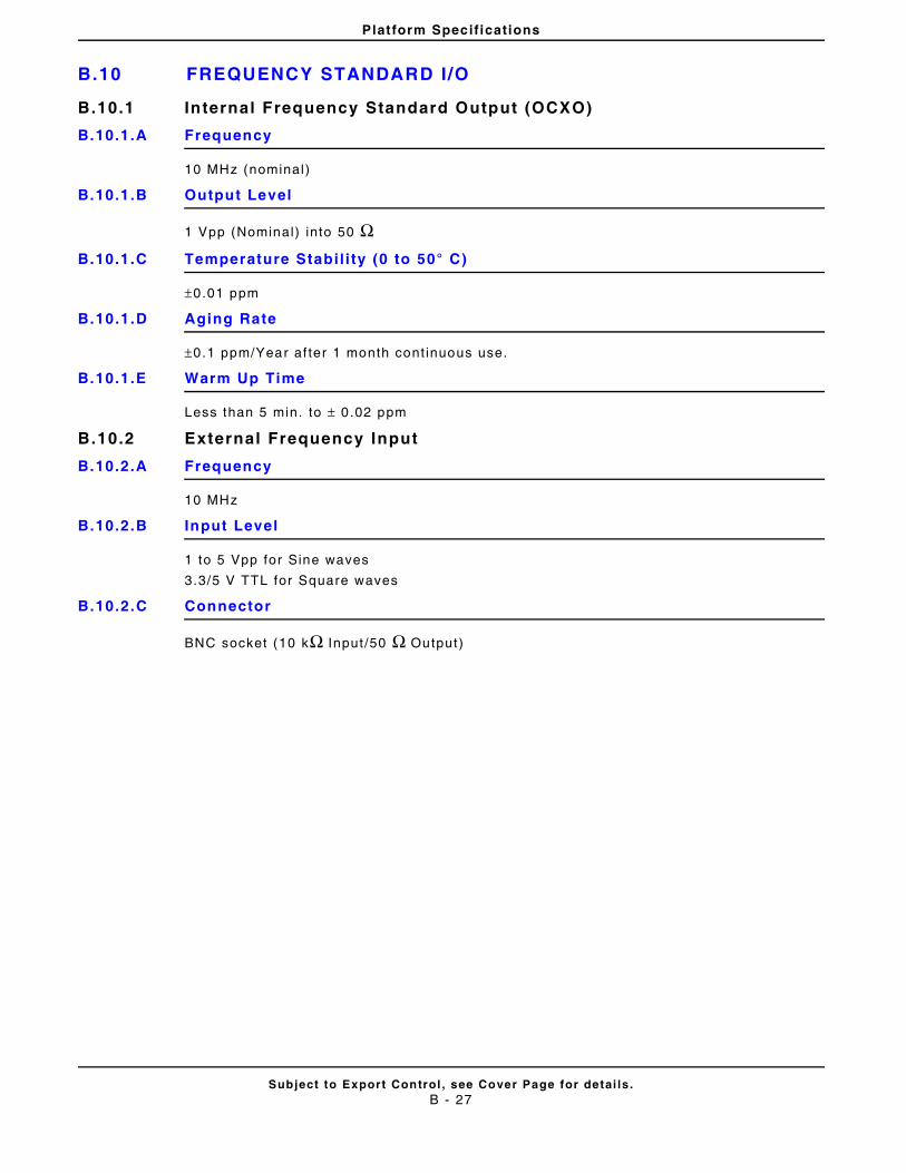
Platform Specifications
B.10 FREQUENCY STANDARD I/O
Subject to Export Control , see Cover Page for detai ls .B - 27
B.10.1 Internal Frequency Standard Output (OCXO)
B.10.1.A Frequency
10 MHz (nominal)
B.10.1.B Output Level
1 Vpp (Nominal) into 50 ΩB.10.1.C Temperature Stabi l i ty (0 to 50° C)
±0.01 ppm
B.10.1.D Aging Rate
±0.1 ppm/Year af ter 1 month cont inuous use.
B.10.1.E Warm Up Time
Less than 5 min. to ± 0 .02 ppm
B.10.2 External Frequency Input
B.10.2.A Frequency
10 MHz
B.10.2.B Input Level
1 to 5 Vpp for Sine waves
3.3/5 V TTL for Square waves
B.10.2.C Connector
BNC socket (10 kΩ Input /50 Ω Output)
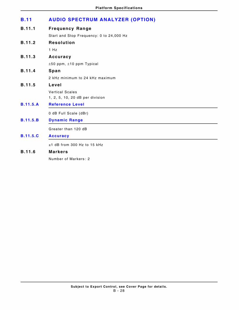
Platform Specifications
B.11 AUDIO SPECTRUM ANALYZER (OPTION)
Subject to Export Control , see Cover Page for detai ls .B - 28
B.11.1 Frequency Range
Start and Stop Frequency: 0 to 24,000 Hz
B.11.2 Resolution
1 Hz
B.11.3 Accuracy
±50 ppm, ±10 ppm Typical
B.11.4 Span
2 kHz minimum to 24 kHz maximum
B.11.5 Level
Vert ical Scales
1, 2, 5 , 10, 20 dB per div is ion
B.11.5.A Reference Level
0 dB Ful l Scale (dBr)
B.11.5.B Dynamic Range
Greater than 120 dB
B.11.5.C Accuracy
±1 dB from 300 Hz to 15 kHz
B.11.6 Markers
Number o f Markers : 2
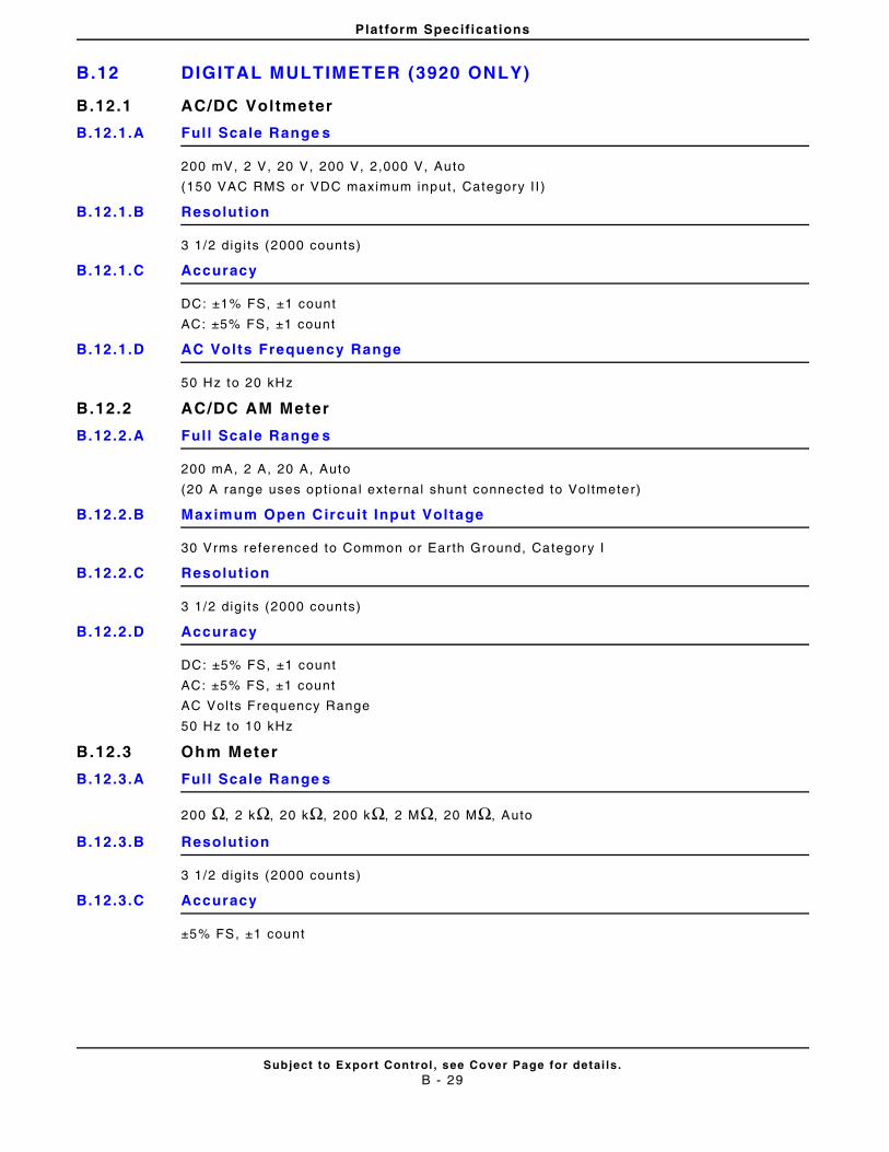
Platform Specifications
B.12 DIGITAL MULTIMETER (3920 ONLY)
Subject to Export Control , see Cover Page for detai ls .B - 29
B.12.1 AC/DC Voltmeter
B.12.1.A Ful l Scale Range s
200 mV, 2 V, 20 V, 200 V, 2,000 V, Auto
(150 VAC RMS or VDC maximum input, Category I I )
B.12.1.B Resolut ion
3 1/2 dig i ts (2000 counts)
B.12.1.C Accuracy
DC: ±1% FS, ±1 count
AC: ±5% FS, ±1 count
B.12.1.D AC Volts Frequency Range
50 Hz to 20 kHz
B.12.2 AC/DC AM Meter
B.12.2.A Ful l Scale Range s
200 mA, 2 A, 20 A, Auto
(20 A range uses opt ional external shunt connected to Voltmeter)
B.12.2.B Maximum Open Circuit Input Voltage
30 Vrms referenced to Common or Ear th Ground, Category I
B.12.2.C Resolut ion
3 1/2 dig i ts (2000 counts)
B.12.2.D Accuracy
DC: ±5% FS, ±1 count
AC: ±5% FS, ±1 count
AC Volts Frequency Range
50 Hz to 10 kHz
B.12.3 Ohm Meter
B.12.3.A Ful l Scale Range s
200 Ω, 2 kΩ, 20 kΩ, 200 kΩ, 2 MΩ, 20 MΩ, Auto
B.12.3.B Resolut ion
3 1/2 dig i ts (2000 counts)
B.12.3.C Accuracy
±5% FS, ±1 count
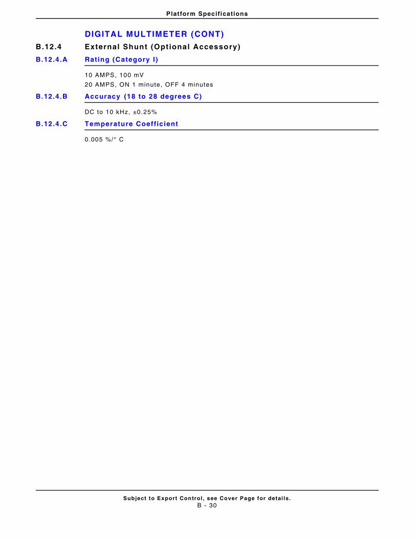
Platform Specifications
DIGITAL MULTIMETER (CONT)
Subject to Export Control , see Cover Page for detai ls .B - 30
B.12.4 External Shunt (Optional Accessory)
B.12.4.A Rating (Category I)
10 AMPS, 100 mV
20 AMPS, ON 1 minute, OFF 4 minutes
B.12.4.B Accuracy (18 to 28 degrees C)
DC to 10 kHz, ±0.25%
B.12.4.C Temperature Coeff icient
0.005 %/° C
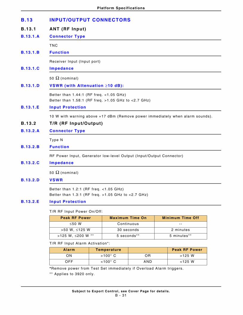
Platform Specifications
B.13 INPUT/OUTPUT CONNECTORS
Subject to Export Control , see Cover Page for detai ls .B - 31
B.13.1 ANT (RF Input)
B.13.1.A Connector Type
TNC
B.13.1.B Function
Receiver Input ( Input por t)
B.13.1.C Impedance
50 Ω (nominal)
B.13.1.D VSWR (with Attenuation ≥10 dB):
Bet ter than 1.44:1 (RF freq. <1.05 GHz)
Bet ter than 1.58:1 (RF freq. >1.05 GHz to <2.7 GHz)
B.13.1.E Input Protection
10 W with warning above +17 dBm (Remove power immediately when alarm sounds).
B.13.2 T/R (RF Input/Output)
B.13.2.A Connector Type
Type N
B.13.2.B Function
RF Power Input, Generator low-level Output ( Input /Output Connector)
B.13.2.C Impedance
50 Ω (nominal)
B.13.2.D VSWR
Bet ter than 1.2 :1 (RF freq. <1.05 GHz)
Bet ter than 1.3 :1 (RF freq. >1.05 GHz to <2.7 GHz)
B.13.2.E Input Protection
T/R RF Input Power On/Off :
T/R RF Input Alarm Act ivat ion*:
*Remove power f rom Test Set immediately i f Over load Alarm t r iggers.
** Appl ies to 3920 only.
Peak RF Power Maximum Time On Minimum Time Off
≤50 W Continuous --
>50 W, ≤125 W 30 seconds 2 minutes
>125 W, ≤200 W ** 5 seconds** 5 minutes**
Alarm Temperature Peak RF Power
ON >100° C OR >125 W
OFF <100° C AND <125 W
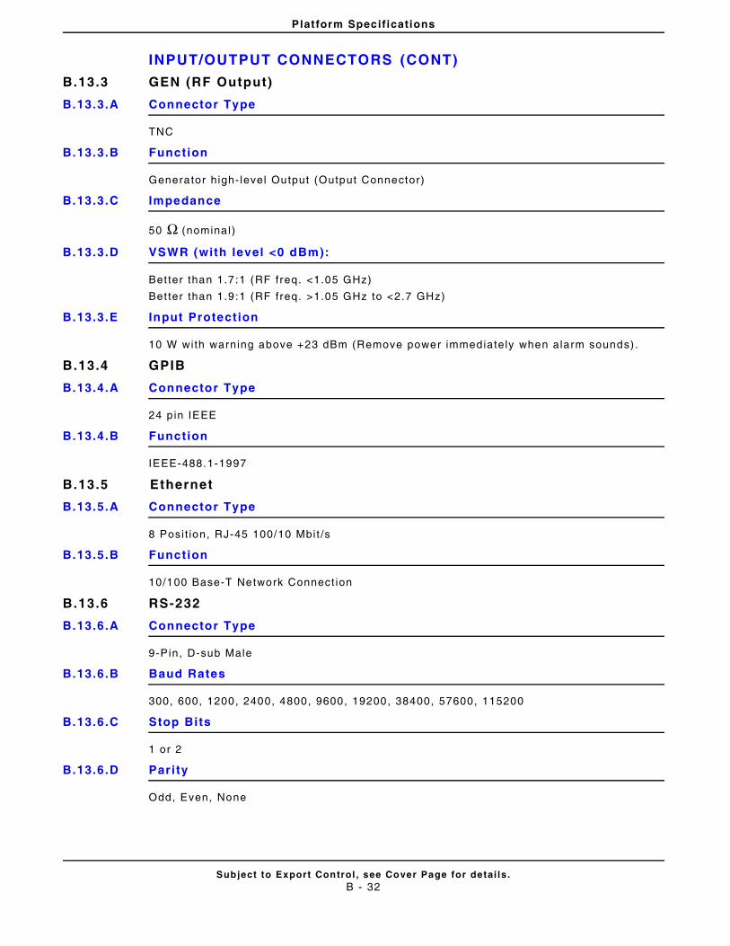
Platform Specifications
INPUT/OUTPUT CONNECTORS (CONT)
Subject to Export Control , see Cover Page for detai ls .B - 32
B.13.3 GEN (RF Output)
B.13.3.A Connector Type
TNC
B.13.3.B Function
Generator high- level Output (Output Connector)
B.13.3.C Impedance
50 Ω (nominal)
B.13.3.D VSWR (with level <0 dBm):
Bet ter than 1.7 :1 (RF freq. <1.05 GHz)
Bet ter than 1.9 :1 (RF freq. >1.05 GHz to <2.7 GHz)
B.13.3.E Input Protection
10 W with warning above +23 dBm (Remove power immediately when alarm sounds).
B.13.4 GPIB
B.13.4.A Connector Type
24 p in IEEE
B.13.4.B Function
IEEE-488.1-1997
B.13.5 Ethernet
B.13.5.A Connector Type
8 Posi t ion, RJ-45 100/10 Mbit /s
B.13.5.B Function
10/100 Base-T Network Connect ion
B.13.6 RS-232
B.13.6.A Connector Type
9-Pin, D-sub Male
B.13.6.B Baud Rates
300, 600, 1200, 2400, 4800, 9600, 19200, 38400, 57600, 115200
B.13.6.C Stop Bits
1 or 2
B.13.6.D Pari ty
Odd, Even, None
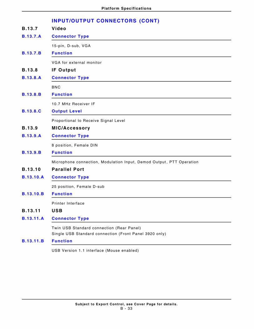
Platform Specifications
INPUT/OUTPUT CONNECTORS (CONT)
Subject to Export Control , see Cover Page for detai ls .B - 33
B.13.7 Video
B.13.7.A Connector Type
15-pin, D-sub, VGA
B.13.7.B Function
VGA for external monitor
B.13.8 IF Output
B.13.8.A Connector Type
BNC
B.13.8.B Function
10.7 MHz Receiver IF
B.13.8.C Output Level
Propor t ional to Receive Signal Level
B.13.9 MIC/Accessory
B.13.9.A Connector Type
8 posi t ion, Female DIN
B.13.9.B Function
Microphone connect ion, Modulat ion Input, Demod Output , PTT Operat ion
B.13.10 Paral lel Port
B.13.10.A Connector Type
25 posi t ion, Female D-sub
B.13.10.B Function
Printer Inter face
B.13.11 USB
B.13.11.A Connector Type
Twin USB Standard connect ion (Rear Panel)
Single USB Standard connect ion (Front Panel 3920 only)
B.13.11.B Function
USB Version 1.1 in terface (Mouse enabled)
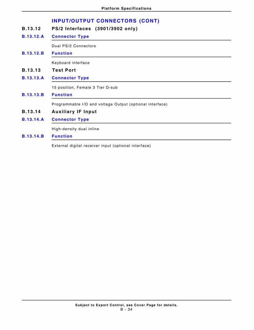
Platform Specifications
INPUT/OUTPUT CONNECTORS (CONT)
Subject to Export Control , see Cover Page for detai ls .B - 34
B.13.12 PS/2 Interfaces (3901/3902 only)
B.13.12.A Connector Type
Dual PS/2 Connectors
B.13.12.B Function
Keyboard inter face
B.13.13 Test Port
B.13.13.A Connector Type
15 posi t ion, Female 3 Tier D-sub
B.13.13.B Function
Programmable I /O and vol tage Output (opt ional interface)
B.13.14 Auxil iary IF Input
B.13.14.A Connector Type
High-densi ty dual in l ine
B.13.14.B Function
External digi ta l receiver input (opt ional interface)
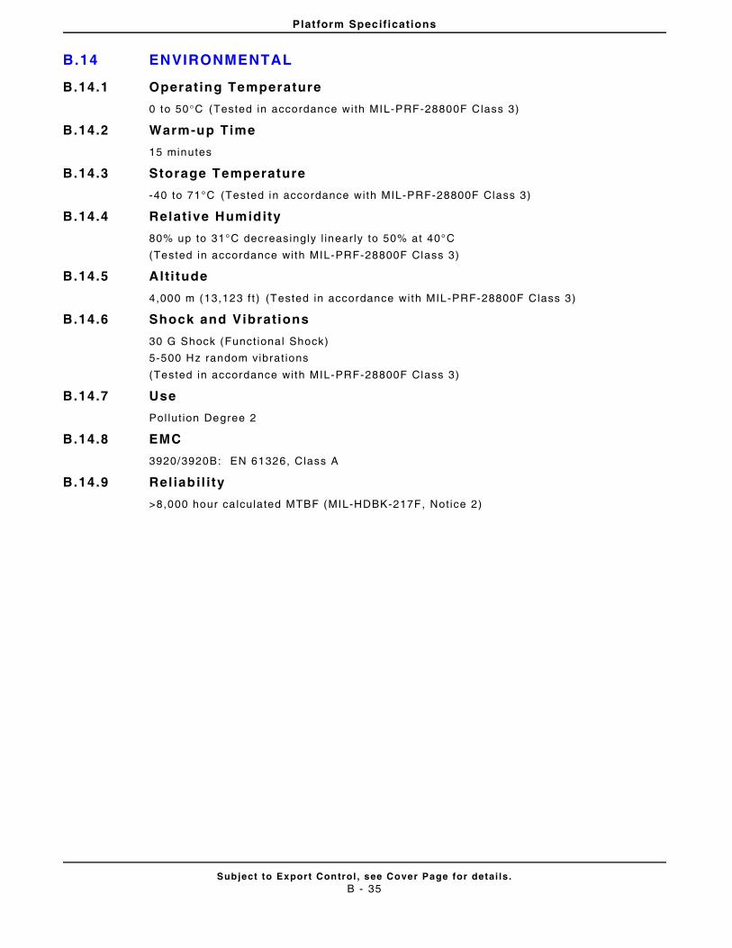
Platform Specifications
B.14 ENVIRONMENTAL
Subject to Export Control , see Cover Page for detai ls .B - 35
B.14.1 Operating Temperature
0 to 50°C (Tested in accordance with MIL-PRF-28800F Class 3)
B.14.2 Warm-up Time
15 minutes
B.14.3 Storage Temperature
-40 to 71°C (Tested in accordance with MIL-PRF-28800F Class 3)
B.14.4 Relative Humidity
80% up to 31°C decreasingly l inear ly to 50% at 40°C
(Tested in accordance with MIL-PRF-28800F Class 3)
B.14.5 Alti tude
4,000 m (13,123 f t ) (Tested in accordance with MIL-PRF-28800F Class 3)
B.14.6 Shock and Vibrations
30 G Shock (Funct ional Shock)
5-500 Hz random vibrat ions
(Tested in accordance with MIL-PRF-28800F Class 3)
B.14.7 Use
Pol lut ion Degree 2
B.14.8 EMC
3920/3920B: EN 61326, Class A
B.14.9 Rel iabil i ty
>8,000 hour ca lculated MTBF (MIL-HDBK-217F, Not ice 2)
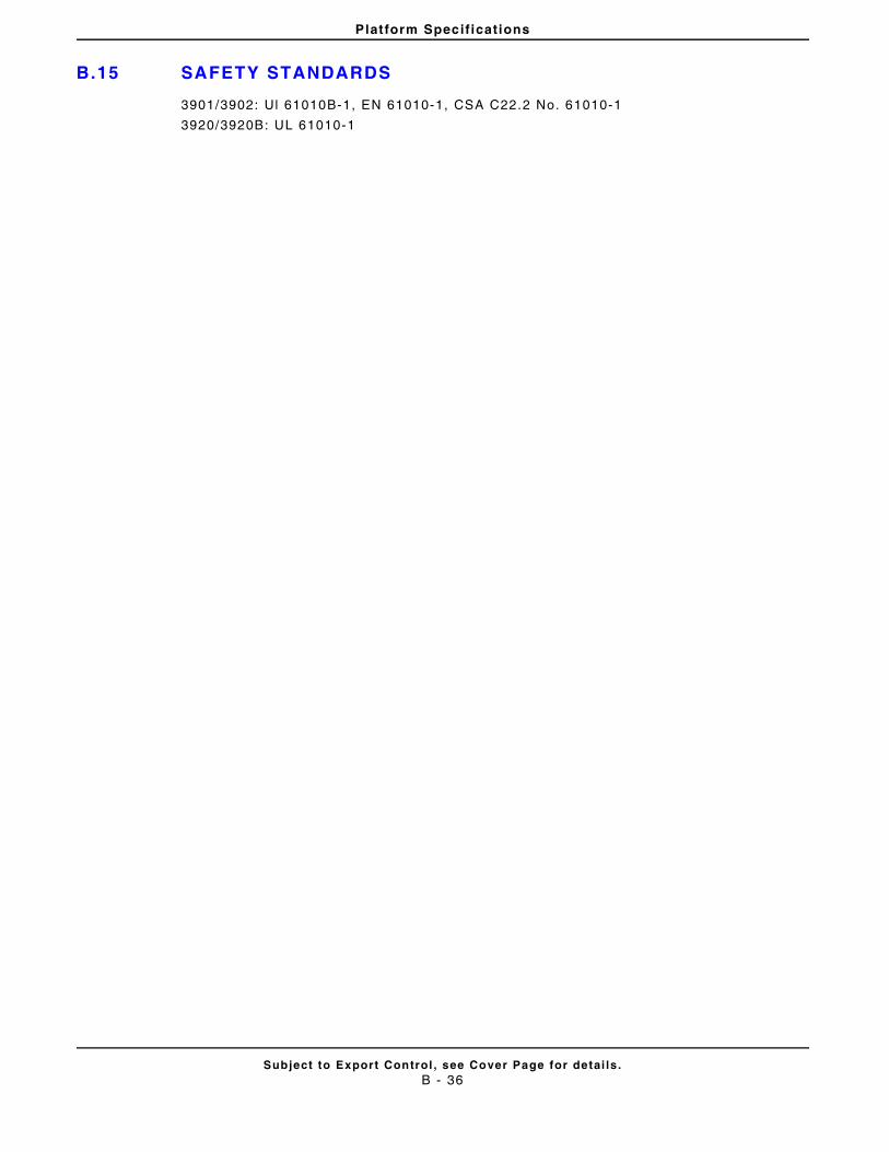
Platform Specifications
B.15 SAFETY STANDARDS
Subject to Export Control , see Cover Page for detai ls .B - 36
3901/3902: Ul 61010B-1, EN 61010-1, CSA C22.2 No. 61010-1
3920/3920B: UL 61010-1
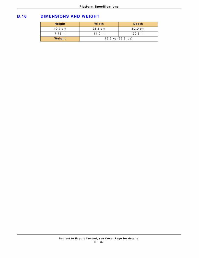
Platform Specifications
B.16 DIMENSIONS AND WEIGHT
Subject to Export Control , see Cover Page for detai ls .B - 37
Height Width Depth
19.7 cm 35.6 cm 52.0 cm
7.75 in 14.0 in 20.5 in
Weight 16.5 kg (36.8 lbs)
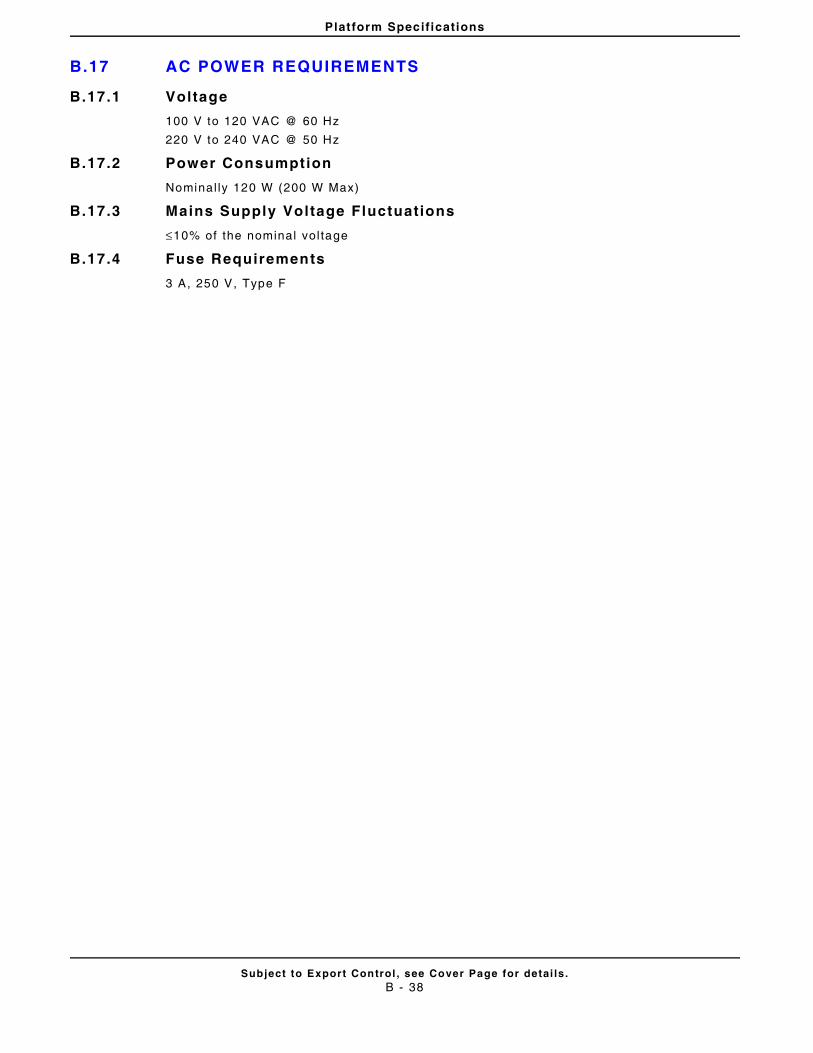
Platform Specifications
B.17 AC POWER REQUIREMENTS
Subject to Export Control , see Cover Page for detai ls .B - 38
B.17.1 Voltage
100 V to 120 VAC @ 60 Hz
220 V to 240 VAC @ 50 Hz
B.17.2 Power Consumption
Nominal ly 120 W (200 W Max)
B.17.3 Mains Supply Voltage Fluctuations
≤10% of the nominal vol tage
B.17.4 Fuse Requirements
3 A, 250 V, Type F
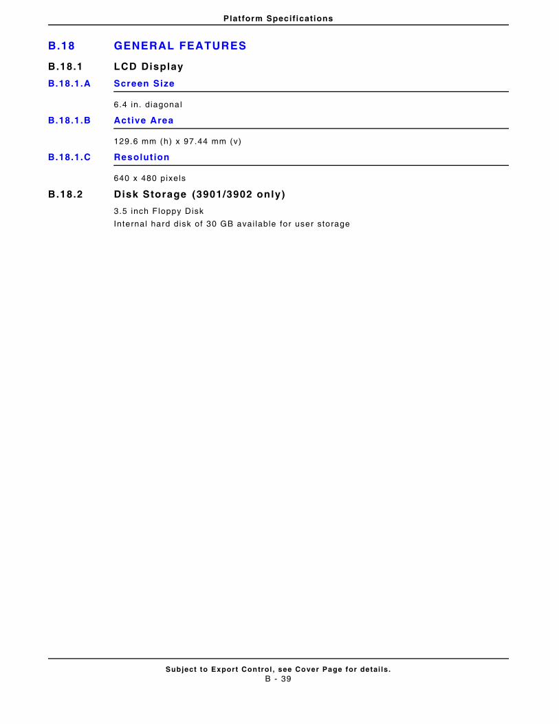
Platform Specifications
B.18 GENERAL FEATURES
Subject to Export Control , see Cover Page for detai ls .B - 39
B.18.1 LCD Display
B.18.1.A Screen Size
6.4 in. diagonal
B.18.1.B Active Area
129.6 mm (h) x 97.44 mm (v)
B.18.1.C Resolut ion
640 x 480 pixels
B.18.2 Disk Storage (3901/3902 only)
3.5 inch F loppy Disk
Internal hard disk of 30 GB avai lable for user storage

Platform Specifications
B.19
Subject to Export Control , see Cover Page for detai ls .B - 40
THIS PAGE INTENTIONALLY LEFT BLANK.
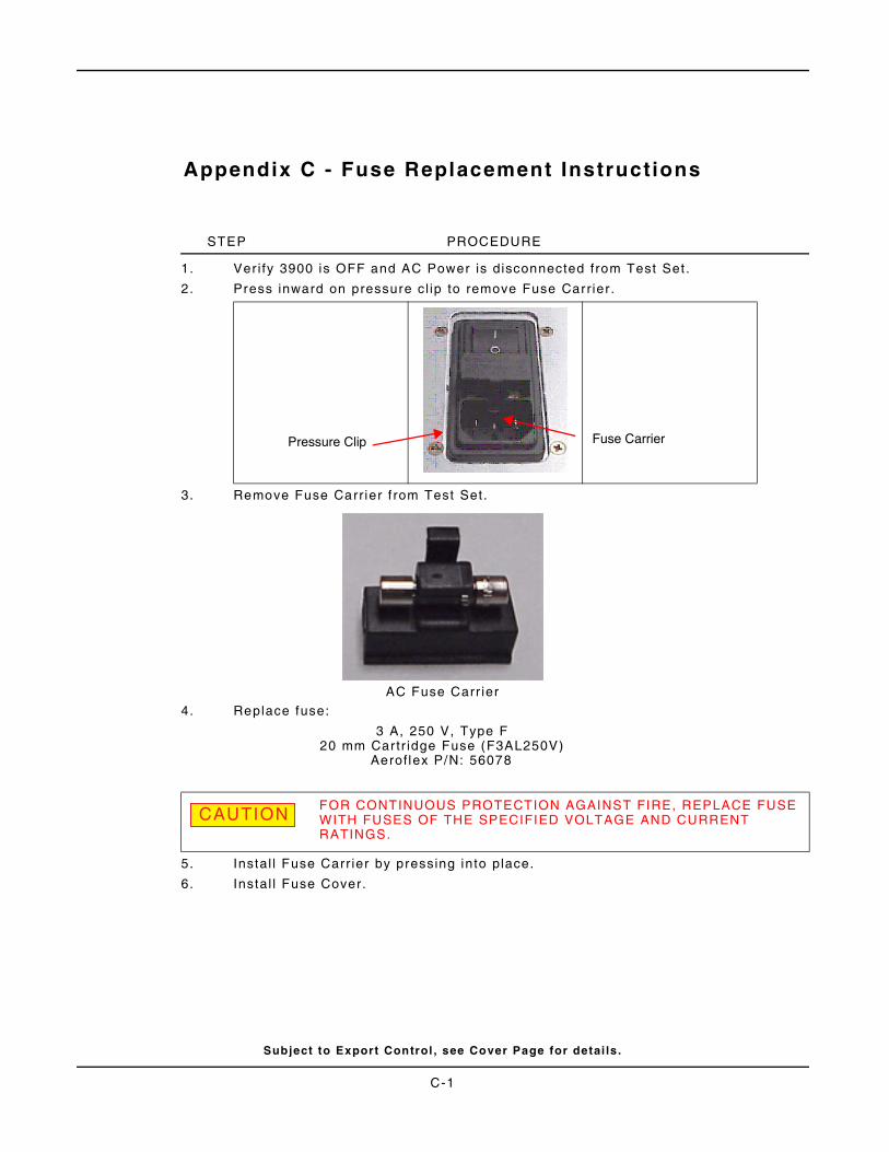
Appendix C - Fuse Replacement Instructions
STEP PROCEDURE
1. Ver i fy 3900 is OFF and AC Power is disconnected from Test Set .
2. Press inward on pressure cl ip to remove Fuse Carr ier .
3. Remove Fuse Carr ier f rom Test Set.
AC Fuse Carr ier
4. Replace fuse:
3 A, 250 V, Type F20 mm Cartr idge Fuse (F3AL250V)
Aerof lex P/N: 56078
5. Instal l Fuse Carr ier by pressing into place.
6. Instal l Fuse Cover.
FOR CONTINUOUS PROTECTION AGAINST FIRE, REPLACE FUSE WITH FUSES OF THE SPECIFIED VOLTAGE AND CURRENT RATINGS.
CAUTION
Fuse CarrierPressure Clip
Subject to Export Control , see Cover Page for detai ls .
C-1
Fuse Replacement Instructions
THIS PAGE INTENTIONALLY LEFT BLANK.
Subject to Export Control , see Cover Page for detai ls .
C-2
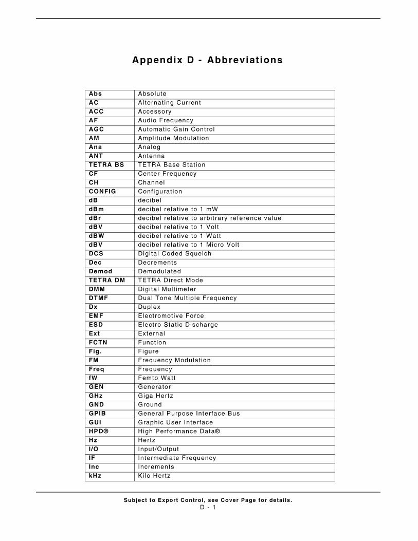
Subject to Export Control , see Cover Page for detai ls .D - 1
Appendix D - Abbreviat ions
Abs Absolute
AC Alternat ing CurrentACC AccessoryAF Audio Frequency
AGC Automatic Gain ControlAM Ampli tude Modulat ionAna Analog
ANT AntennaTETRA BS TETRA Base Stat ionCF Center Frequency
CH ChannelCONFIG Configurat iondB decibel
dBm decibel relat ive to 1 mWdBr decibel relat ive to arbi t rary reference valuedBV decibel relat ive to 1 Vol t
dBW decibel relat ive to 1 Wat tdBV decibel relat ive to 1 Micro Volt DCS Digi tal Coded Squelch
Dec DecrementsDemod DemodulatedTETRA DM TETRA Direct Mode
DMM Digi tal Mult imeterDTMF Dual Tone Mult ip le FrequencyDx Duplex
EMF Elect romot ive ForceESD Elect ro Stat ic DischargeExt External
FCTN Funct ionFig. FigureFM Frequency Modulat ion
Freq FrequencyfW Femto Wat tGEN Generator
GHz Giga HertzGND GroundGPIB Genera l Purpose Interface Bus
GUI Graphic User Inter faceHPD® High Performance Data®Hz Hertz
I /O Input/OutputIF Intermediate FrequencyInc Increments
kHz Kilo Hertz
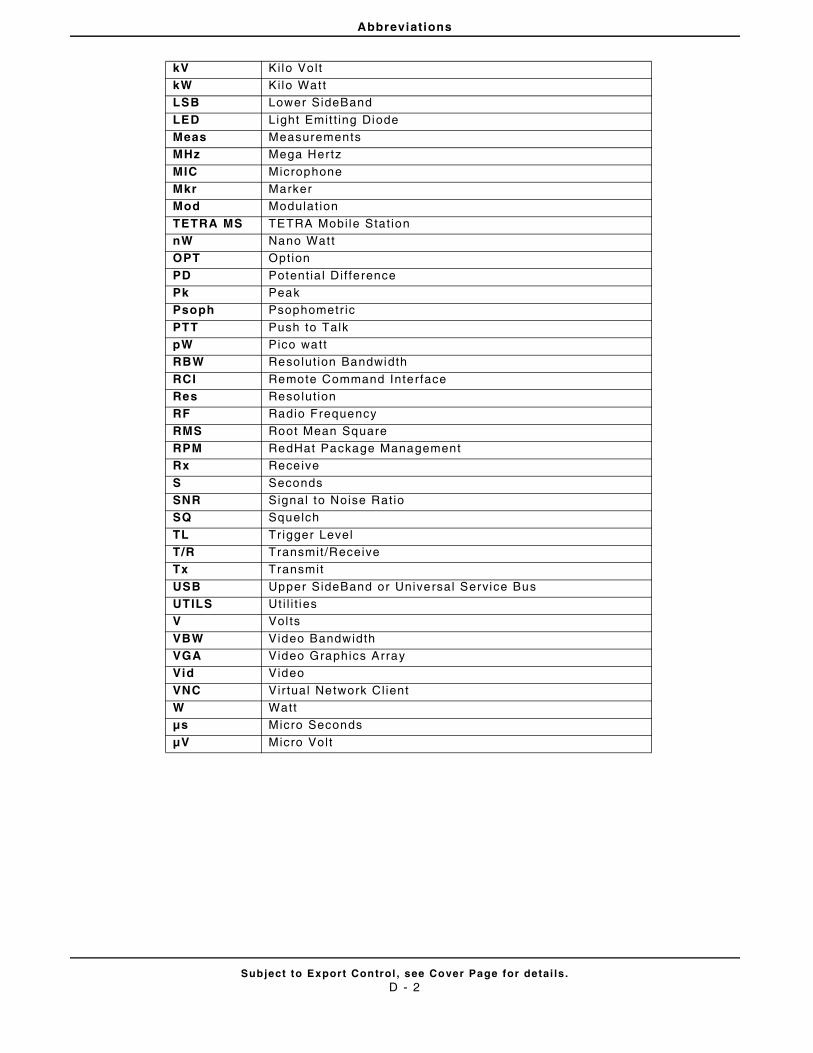
Abbreviations
Subject to Export Control , see Cover Page for detai ls .D - 2
kV Kilo VoltkW Kilo Wat tLSB Lower SideBand
LED Light Emit t ing DiodeMeas MeasurementsMHz Mega Hertz
MIC MicrophoneMkr MarkerMod Modulat ion
TETRA MS TETRA Mobi le Stat ionnW Nano Wat tOPT Option
PD Potent ia l Di f ferencePk PeakPsoph Psophometr ic
PTT Push to TalkpW Pico wattRBW Resolut ion Bandwidth
RCI Remote Command InterfaceRes Resolut ionRF Radio Frequency
RMS Root Mean SquareRPM RedHat Package ManagementRx Receive
S SecondsSNR Signal to Noise Rat ioSQ Squelch
TL Tr igger LevelT/R Transmit /ReceiveTx Transmit
USB Upper SideBand or Universal Service BusUTILS Ut i l i t iesV Vol ts
VBW Video BandwidthVGA Video Graphics ArrayVid Video
VNC Vir tual Network Cl ientW Wattμs Micro Seconds
μV Micro Vol t
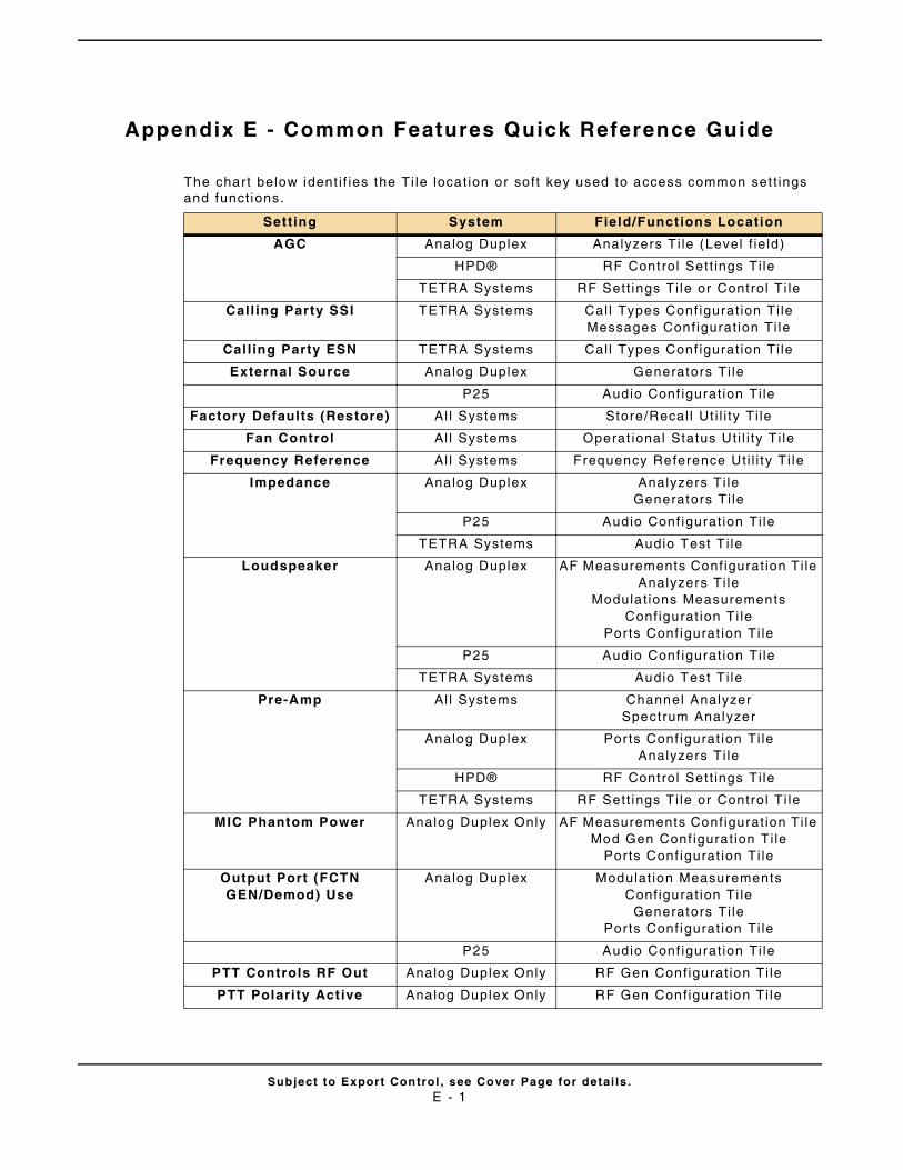
Subject to Export Control , see Cover Page for detai ls .E - 1
Appendix E - Common Features Quick Reference Guide
The chart below ident i f ies the Ti le locat ion or soft key used to access common set t ings and funct ions.
Setting System Field/Functions Location
AGC Analog Duplex Analyzers T i le (Level f ie ld)
HPD® RF Control Set t ings Ti le
TETRA Systems RF Sett ings Ti le or Control Ti le
Call ing Party SSI TETRA Systems Cal l Types Conf igurat ion Ti leMessages Conf igurat ion Ti le
Calling Party ESN TETRA Systems Cal l Types Conf igurat ion Ti le
External Source Analog Duplex Generators Ti le
P25 Audio Conf igurat ion Ti le
Factory Defaults (Restore) Al l Systems Store/Recal l Ut i l i ty Ti le
Fan Control Al l Systems Operat ional Status Ut i l i ty T i le
Frequency Reference Al l Systems Frequency Reference Uti l i ty Ti le
Impedance Analog Duplex Analyzers Ti leGenerators Ti le
P25 Audio Conf igurat ion Ti le
TETRA Systems Audio Test T i le
Loudspeaker Analog Duplex AF Measurements Conf igurat ion Ti leAnalyzers Ti le
Modulat ions Measurements Conf igurat ion Ti le
Ports Conf igurat ion Ti le
P25 Audio Conf igurat ion Ti le
TETRA Systems Audio Test T i le
Pre-Amp Al l Systems Channel AnalyzerSpectrum Analyzer
Analog Duplex Ports Conf igurat ion Ti leAnalyzers Ti le
HPD® RF Control Set t ings Ti le
TETRA Systems RF Sett ings Ti le or Control Ti le
MIC Phantom Power Analog Duplex Only AF Measurements Conf igurat ion Ti leMod Gen Conf igurat ion Ti le
Ports Conf igurat ion Ti le
Output Port (FCTN GEN/Demod) Use
Analog Duplex Modulat ion Measurements Conf igurat ion Ti le
Generators Ti lePorts Conf igurat ion Ti le
P25 Audio Conf igurat ion Ti le
PTT Controls RF Out Analog Duplex Only RF Gen Conf igurat ion Ti le
PTT Polari ty Act ive Analog Duplex Only RF Gen Conf igurat ion Ti le
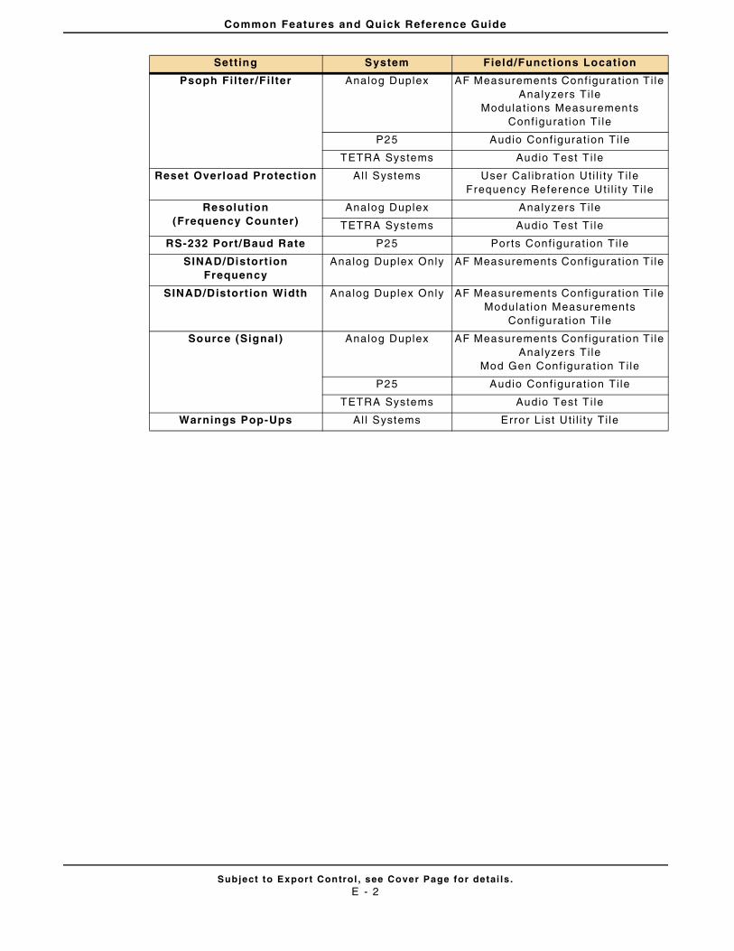
Common Features and Quick Reference Guide
Subject to Export Control , see Cover Page for detai ls .E - 2
Psoph Fil ter /Filter Analog Duplex AF Measurements Conf igurat ion Ti leAnalyzers Ti le
Modulat ions Measurements Conf igurat ion Ti le
P25 Audio Conf igurat ion Ti le
TETRA Systems Audio Test T i le
Reset Overload Protection Al l Systems User Cal ibrat ion Ut i l i ty Ti leFrequency Reference Uti l i ty Ti le
Resolution(Frequency Counter)
Analog Duplex Analyzers Ti le
TETRA Systems Audio Test T i le
RS-232 Port/Baud Rate P25 Ports Conf igurat ion Ti le
SINAD/Distort ion Frequency
Analog Duplex Only AF Measurements Conf igurat ion Ti le
SINAD/Distort ion Width Analog Duplex Only AF Measurements Conf igurat ion Ti leModulat ion Measurements
Conf igurat ion Ti le
Source (Signal) Analog Duplex AF Measurements Conf igurat ion Ti leAnalyzers Ti le
Mod Gen Conf igurat ion Ti le
P25 Audio Conf igurat ion Ti le
TETRA Systems Audio Test T i le
Warnings Pop-Ups Al l Systems Error List Ut i l i ty Ti le
Setting System Field/Functions Location
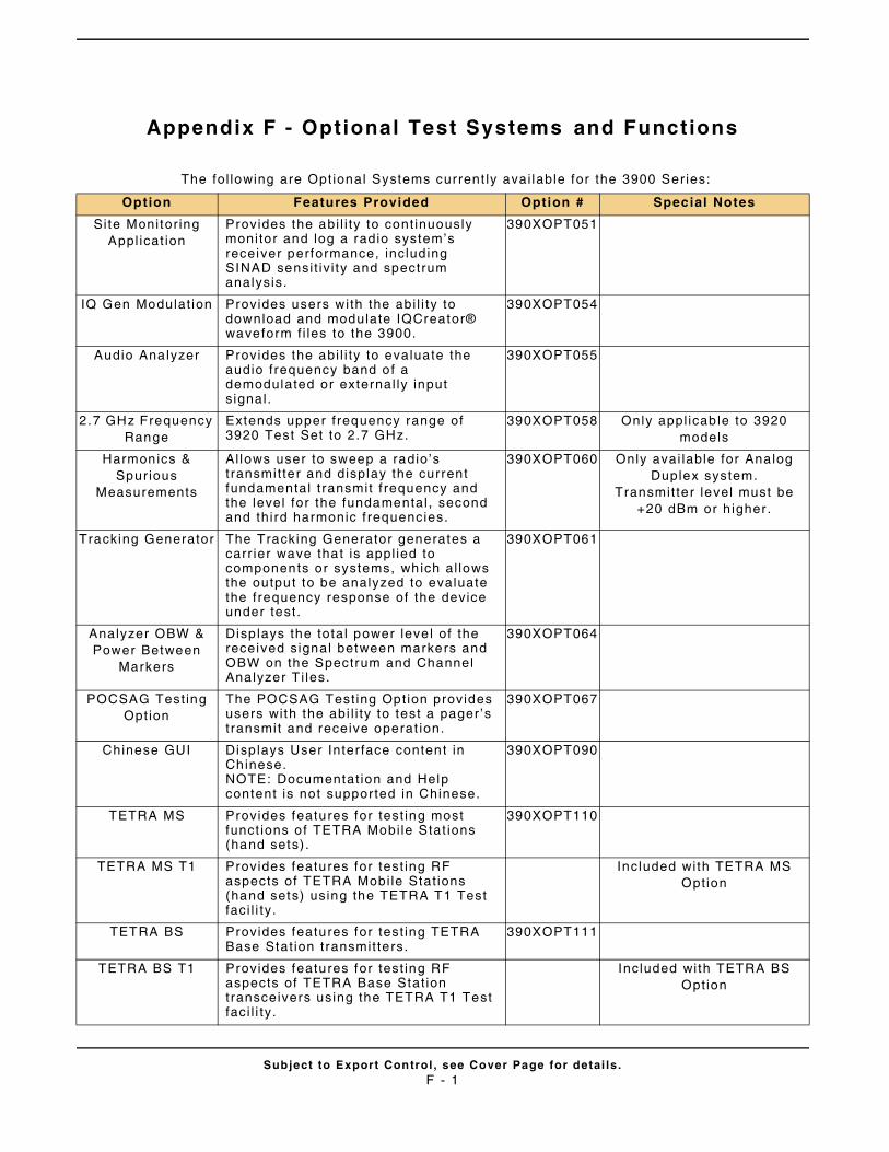
Subject to Export Control , see Cover Page for detai ls .F - 1
Appendix F - Optional Test Systems and Functions
The fol lowing are Opt ional Systems current ly avai lable for the 3900 Ser ies:
Option Features Provided Option # Special Notes
Site Monitor ing Appl icat ion
Provides the abi l i ty to cont inuously monitor and log a radio system’s receiver performance, includ ing SINAD sensi t iv i ty and spectrum analysis.
390XOPT051
IQ Gen Modulat ion Provides users with the abi l i ty to download and modulate IQCreator® waveform f i les to the 3900.
390XOPT054
Audio Analyzer Provides the abi l i ty to evaluate the audio frequency band of a demodulated or external ly input s ignal .
390XOPT055
2.7 GHz Frequency Range
Extends upper f requency range of 3920 Test Set to 2.7 GHz.
390XOPT058 Only appl icab le to 3920 models
Harmonics & Spurious
Measurements
Al lows user to sweep a radio’s t ransmit ter and display the current fundamental t ransmit f requency and the level for the fundamental , second and third harmonic f requencies.
390XOPT060 Only avai lable for Analog Duplex system.
Transmit ter level must be +20 dBm or h igher .
Tracking Generator The Tracking Generator generates a carr ier wave that is appl ied to components or systems, which al lows the output to be analyzed to evaluate the frequency response of the device under test .
390XOPT061
Analyzer OBW & Power Between
Markers
Disp lays the total power leve l of the received signal between markers and OBW on the Spectrum and Channel Analyzer T i les.
390XOPT064
POCSAG Test ing Option
The POCSAG Test ing Opt ion provides users with the abi l i ty to test a pager ’s t ransmit and receive operat ion.
390XOPT067
Chinese GUI Disp lays User Inter face content in Chinese.NOTE: Documentat ion and Help content is not suppor ted in Chinese.
390XOPT090
TETRA MS Provides features for test ing most funct ions of TETRA Mobi le Stat ions (hand sets) .
390XOPT110
TETRA MS T1 Provides features for test ing RF aspects of TETRA Mobi le Stat ions (hand sets) using the TETRA T1 Test faci l i ty.
Included with TETRA MS Option
TETRA BS Provides features for test ing TETRA Base Stat ion transmit ters.
390XOPT111
TETRA BS T1 Provides features for test ing RF aspects of TETRA Base Stat ion transceivers using the TETRA T1 Test faci l i ty.
Included with TETRA BS Option
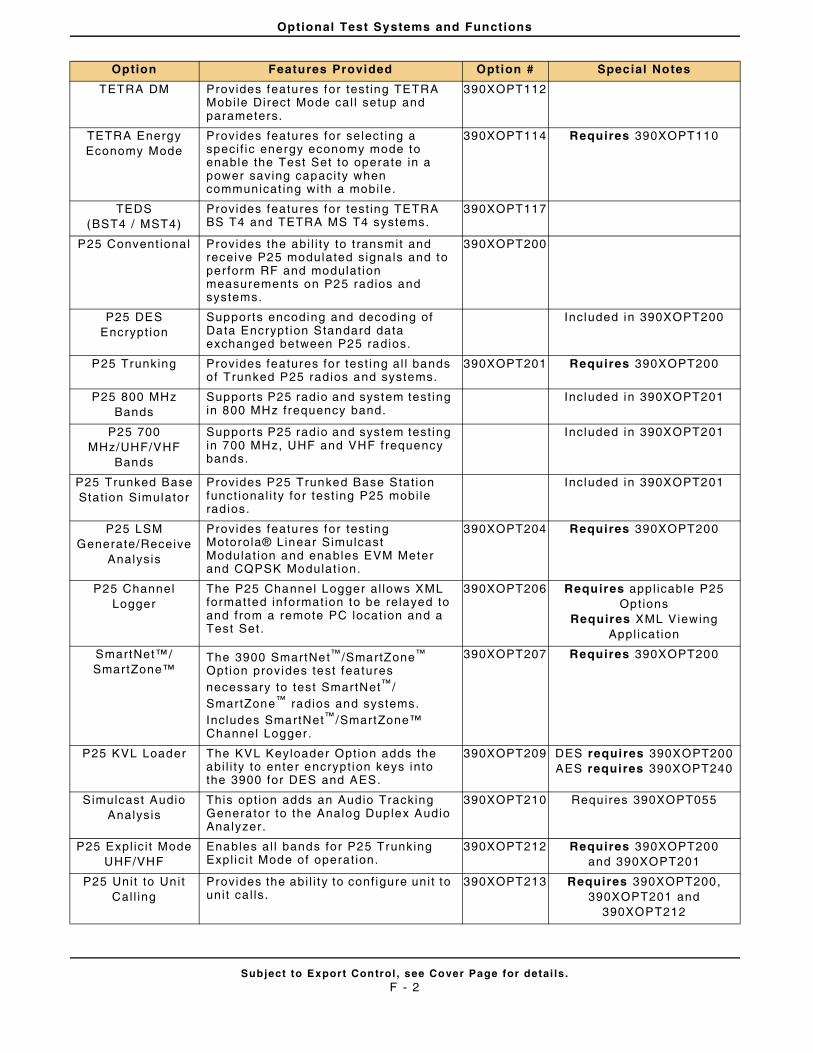
Optional Test Systems and Functions
Subject to Export Control , see Cover Page for detai ls .F - 2
TETRA DM Provides features for test ing TETRA Mobi le Direct Mode cal l setup and parameters.
390XOPT112
TETRA Energy Economy Mode
Provides features for select ing a speci f ic energy economy mode to enable the Test Set to operate in a power saving capaci ty when communicat ing with a mobi le.
390XOPT114 Requires 390XOPT110
TEDS(BST4 / MST4)
Provides features for test ing TETRA BS T4 and TETRA MS T4 systems.
390XOPT117
P25 Convent ional Provides the abi l i ty to t ransmit and receive P25 modulated signals and to per form RF and modulat ion measurements on P25 radios and systems.
390XOPT200
P25 DES Encrypt ion
Supports encoding and decoding of Data Encrypt ion Standard data exchanged between P25 radios.
Included in 390XOPT200
P25 Trunking Provides features for test ing al l bands of Trunked P25 radios and systems.
390XOPT201 Requires 390XOPT200
P25 800 MHz Bands
Supports P25 radio and system test ing in 800 MHz frequency band.
Included in 390XOPT201
P25 700 MHz/UHF/VHF
Bands
Supports P25 radio and system test ing in 700 MHz, UHF and VHF f requency bands.
Included in 390XOPT201
P25 Trunked Base Stat ion Simulator
Provides P25 Trunked Base Stat ion funct ional i ty for test ing P25 mobi le rad ios.
Included in 390XOPT201
P25 LSM Generate/Receive
Analysis
Provides features for test ing Motorola® Linear Simulcast Modulat ion and enables EVM Meter and CQPSK Modulat ion.
390XOPT204 Requires 390XOPT200
P25 Channel Logger
The P25 Channel Logger al lows XML formatted informat ion to be relayed to and from a remote PC locat ion and a Test Set .
390XOPT206 Requires app l icable P25 Opt ions
Requires XML Viewing Appl icat ion
SmartNet™/SmartZone™
The 3900 SmartNet™/SmartZone™ Option provides test features necessary to test SmartNet™/ SmartZone™ radios and systems. Includes SmartNet™/SmartZone™ Channel Logger .
390XOPT207 Requires 390XOPT200
P25 KVL Loader The KVL Keyloader Opt ion adds the abi l i ty to enter encrypt ion keys into the 3900 for DES and AES.
390XOPT209 DES requires 390XOPT200AES requires 390XOPT240
Simulcast Audio Analysis
This opt ion adds an Audio Tracking Generator to the Analog Duplex Audio Analyzer.
390XOPT210 Requires 390XOPT055
P25 Expl ic i t Mode UHF/VHF
Enables al l bands for P25 Trunking Expl ic i t Mode of operat ion.
390XOPT212 Requires 390XOPT200and 390XOPT201
P25 Unit to Unit Cal l ing
Provides the abi l i ty to conf igure uni t to uni t cal ls.
390XOPT213 Requires 390XOPT200, 390XOPT201 and
390XOPT212
Option Features Provided Option # Special Notes
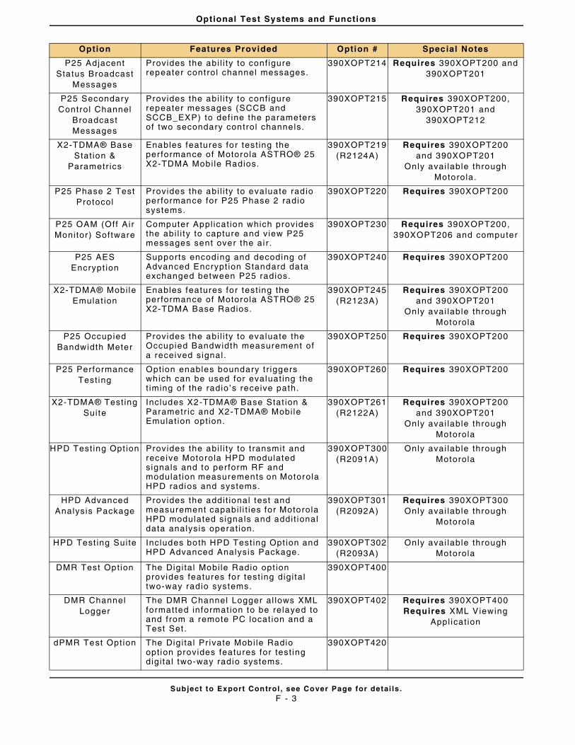
Optional Test Systems and Functions
Subject to Export Control , see Cover Page for detai ls .F - 3
P25 Adjacent Status Broadcast
Messages
Provides the abi l i ty to conf igure repeater control channel messages.
390XOPT214 Requires 390XOPT200 and 390XOPT201
P25 Secondary Control Channel
Broadcast Messages
Provides the abi l i ty to conf igure repeater messages (SCCB and SCCB_EXP) to def ine the parameters of two secondary control channels.
390XOPT215 Requires 390XOPT200, 390XOPT201 and
390XOPT212
X2-TDMA® Base Stat ion &
Parametr ics
Enables features for test ing the per formance of Motorola ASTRO® 25 X2-TDMA Mobi le Radios.
390XOPT219(R2124A)
Requires 390XOPT200and 390XOPT201
Only avai lable through Motorola.
P25 Phase 2 Test Protocol
Provides the abi l i ty to evaluate rad io per formance for P25 Phase 2 radio systems.
390XOPT220 Requires 390XOPT200
P25 OAM (Off A ir Monitor) Software
Computer Appl icat ion which provides the abi l i ty to capture and view P25 messages sent over the ai r .
390XOPT230 Requires 390XOPT200, 390XOPT206 and computer
P25 AES Encrypt ion
Supports encoding and decoding of Advanced Encrypt ion Standard data exchanged between P25 radios.
390XOPT240 Requires 390XOPT200
X2-TDMA® Mobi le Emulat ion
Enables features for test ing the per formance of Motorola ASTRO® 25 X2-TDMA Base Radios.
390XOPT245(R2123A)
Requires 390XOPT200and 390XOPT201
Only avai lable through Motorola
P25 Occupied Bandwidth Meter
Provides the abi l i ty to evaluate the Occupied Bandwidth measurement of a received signal .
390XOPT250 Requires 390XOPT200
P25 Performance Test ing
Option enables boundary t r iggers which can be used for evaluat ing the t iming of the radio ’s receive path.
390XOPT260 Requires 390XOPT200
X2-TDMA® Test ing Suite
Includes X2-TDMA® Base Stat ion & Parametr ic and X2-TDMA® Mobi le Emulat ion opt ion.
390XOPT261(R2122A)
Requires 390XOPT200and 390XOPT201
Only avai lable through Motorola
HPD Test ing Opt ion Provides the abi l i ty to t ransmit and receive Motorola HPD modulated signals and to perform RF and modulat ion measurements on Motorola HPD radios and systems.
390XOPT300 (R2091A)
Only avai lable through Motorola
HPD Advanced Analysis Package
Provides the addit ional test and measurement capabi l i t ies for Motorola HPD modulated signals and addi t ional data analysis operat ion.
390XOPT301(R2092A)
Requires 390XOPT300Only avai lable through
Motorola
HPD Test ing Suite Includes both HPD Test ing Opt ion and HPD Advanced Analysis Package.
390XOPT302(R2093A)
Only avai lable through Motorola
DMR Test Opt ion The Dig i tal Mobi le Radio opt ion provides features for test ing digi ta l two-way radio systems.
390XOPT400
DMR Channel Logger
The DMR Channel Logger al lows XML formatted informat ion to be relayed to and from a remote PC locat ion and a Test Set .
390XOPT402 Requires 390XOPT400Requires XML Viewing
Appl icat ion
dPMR Test Opt ion The Dig i tal Pr ivate Mobi le Radio opt ion provides features for test ing digi ta l two-way radio systems.
390XOPT420
Option Features Provided Option # Special Notes
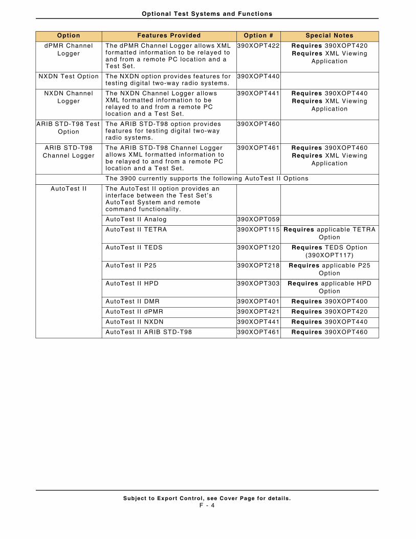
Optional Test Systems and Functions
Subject to Export Control , see Cover Page for detai ls .F - 4
dPMR Channel Logger
The dPMR Channel Logger al lows XML formatted informat ion to be relayed to and from a remote PC locat ion and a Test Set .
390XOPT422 Requires 390XOPT420Requires XML Viewing
Appl icat ion
NXDN Test Opt ion The NXDN opt ion provides features for test ing digi ta l two-way radio systems.
390XOPT440
NXDN Channel Logger
The NXDN Channel Logger a l lows XML formatted information to be relayed to and from a remote PC locat ion and a Test Set.
390XOPT441 Requires 390XOPT440Requires XML Viewing
Appl icat ion
ARIB STD-T98 Test Opt ion
The ARIB STD-T98 opt ion provides features for test ing d igi ta l two-way rad io systems.
390XOPT460
ARIB STD-T98 Channel Logger
The ARIB STD-T98 Channel Logger al lows XML formatted informat ion to be relayed to and f rom a remote PC locat ion and a Test Set.
390XOPT461 Requires 390XOPT460Requires XML Viewing
Appl icat ion
The 3900 current ly supports the fol lowing AutoTest I I Opt ions
AutoTest I I The AutoTest I I opt ion provides an interface between the Test Set ’s AutoTest System and remote command funct ional i ty.
AutoTest I I Analog 390XOPT059
AutoTest I I TETRA 390XOPT115 Requires appl icable TETRA Option
AutoTest I I TEDS 390XOPT120 Requires TEDS Opt ion (390XOPT117)
AutoTest I I P25 390XOPT218 Requires app l icable P25 Option
AutoTest I I HPD 390XOPT303 Requires appl icable HPD Option
AutoTest I I DMR 390XOPT401 Requires 390XOPT400
AutoTest I I dPMR 390XOPT421 Requires 390XOPT420
AutoTest I I NXDN 390XOPT441 Requires 390XOPT440
AutoTest I I ARIB STD-T98 390XOPT461 Requires 390XOPT460
Option Features Provided Option # Special Notes
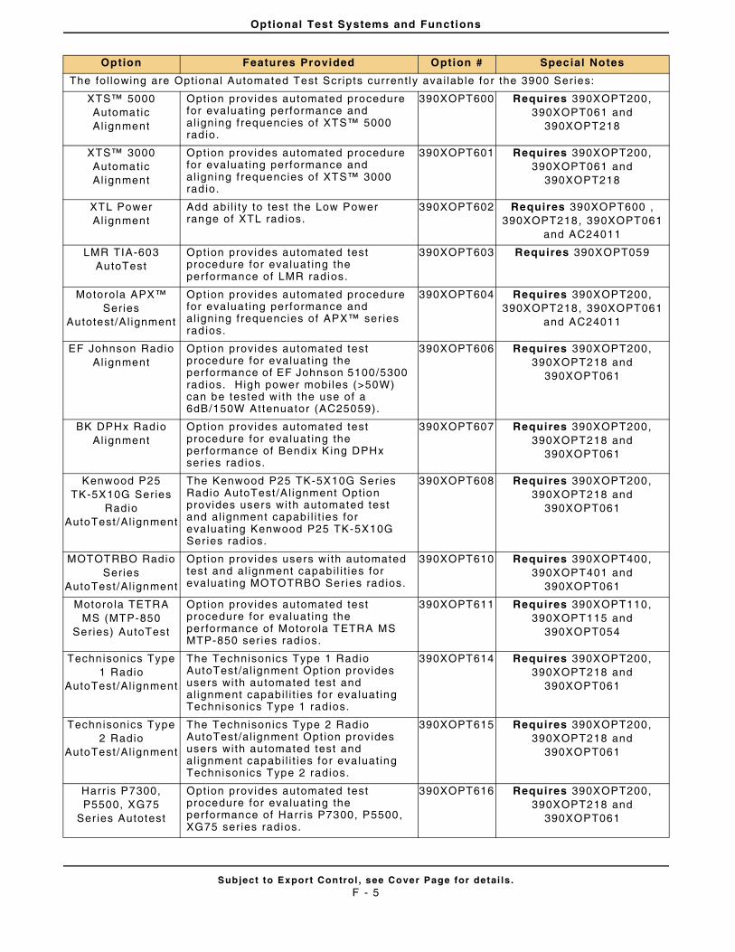
Optional Test Systems and Functions
Subject to Export Control , see Cover Page for detai ls .F - 5
The fol lowing are Opt ional Automated Test Scr ipts current ly avai lab le for the 3900 Series:
XTS™ 5000 Automatic Al ignment
Opt ion provides automated procedure for evaluat ing performance and al igning f requencies of XTS™ 5000 rad io.
390XOPT600 Requires 390XOPT200, 390XOPT061 and
390XOPT218
XTS™ 3000 Automatic Al ignment
Opt ion provides automated procedure for evaluat ing performance and al igning f requencies of XTS™ 3000 rad io.
390XOPT601 Requires 390XOPT200, 390XOPT061 and
390XOPT218
XTL Power Al ignment
Add abi l i ty to test the Low Power range of XTL radios.
390XOPT602 Requires 390XOPT600 , 390XOPT218, 390XOPT061
and AC24011
LMR TIA-603 AutoTest
Opt ion provides automated test procedure for evaluat ing the per formance of LMR radios.
390XOPT603 Requires 390XOPT059
Motorola APX™ Series
Autotest /Al ignment
Opt ion provides automated procedure for evaluat ing performance and al igning f requencies of APX™ ser ies rad ios.
390XOPT604 Requires 390XOPT200, 390XOPT218, 390XOPT061
and AC24011
EF Johnson Radio Al ignment
Opt ion provides automated test procedure for evaluat ing the per formance of EF Johnson 5100/5300 rad ios. High power mobi les (>50W) can be tested with the use of a 6dB/150W At tenuator (AC25059).
390XOPT606 Requires 390XOPT200, 390XOPT218 and
390XOPT061
BK DPHx Radio Al ignment
Opt ion provides automated test procedure for evaluat ing the per formance of Bendix King DPHx ser ies rad ios.
390XOPT607 Requires 390XOPT200, 390XOPT218 and
390XOPT061
Kenwood P25 TK-5X10G Series
Radio AutoTest/Al ignment
The Kenwood P25 TK-5X10G Series Radio AutoTest/Al ignment Opt ion provides users with automated test and al ignment capabi l i t ies for evaluat ing Kenwood P25 TK-5X10G Ser ies radios.
390XOPT608 Requires 390XOPT200, 390XOPT218 and
390XOPT061
MOTOTRBO Radio Series
AutoTest/Al ignment
Opt ion provides users with automated test and al ignment capabi l i t ies for evaluat ing MOTOTRBO Series rad ios.
390XOPT610 Requires 390XOPT400, 390XOPT401 and
390XOPT061
Motoro la TETRA MS (MTP-850
Series) AutoTest
Opt ion provides automated test procedure for evaluat ing the per formance of Motorola TETRA MS MTP-850 ser ies radios.
390XOPT611 Requires 390XOPT110, 390XOPT115 and
390XOPT054
Technisonics Type 1 Radio
AutoTest/Al ignment
The Technisonics Type 1 Radio AutoTest /al ignment Opt ion provides users with automated test and al ignment capabi l i t ies for eva luat ing Technisonics Type 1 radios.
390XOPT614 Requires 390XOPT200, 390XOPT218 and
390XOPT061
Technisonics Type 2 Radio
AutoTest/Al ignment
The Technisonics Type 2 Radio AutoTest /al ignment Opt ion provides users with automated test and al ignment capabi l i t ies for eva luat ing Technisonics Type 2 radios.
390XOPT615 Requires 390XOPT200, 390XOPT218 and
390XOPT061
Harr is P7300, P5500, XG75
Ser ies Autotest
Opt ion provides automated test procedure for evaluat ing the per formance of Harr is P7300, P5500, XG75 ser ies radios.
390XOPT616 Requires 390XOPT200, 390XOPT218 and
390XOPT061
Option Features Provided Option # Special Notes
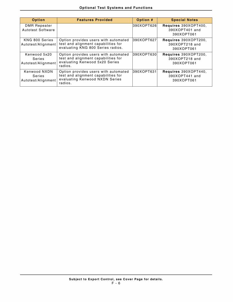
Optional Test Systems and Functions
Subject to Export Control , see Cover Page for detai ls .F - 6
DMR Repeater Autotest Software
390XOPT626 Requires 390XOPT400, 390XOPT401 and
390XOPT061
KNG 800 Ser ies Autotest /Al ignment
Opt ion provides users with automated test and al ignment capabi l i t ies for evaluat ing KNG 800 Series radios.
390XOPT627 Requires 390XOPT200, 390XOPT218 and
390XOPT061
Kenwood 5x20 Series
Autotest /Al ignment
Opt ion provides users with automated test and al ignment capabi l i t ies for evaluat ing Kenwood 5x20 Series rad ios.
390XOPT630 Requires 390XOPT200, 390XOPT218 and
390XOPT061
Kenwood NXDN Series
Autotest /Al ignment
Opt ion provides users with automated test and al ignment capabi l i t ies for evaluat ing Kenwood NXDN Series rad ios.
390XOPT631 Requires 390XOPT440, 390XOPT441 and
390XOPT061
Option Features Provided Option # Special Notes
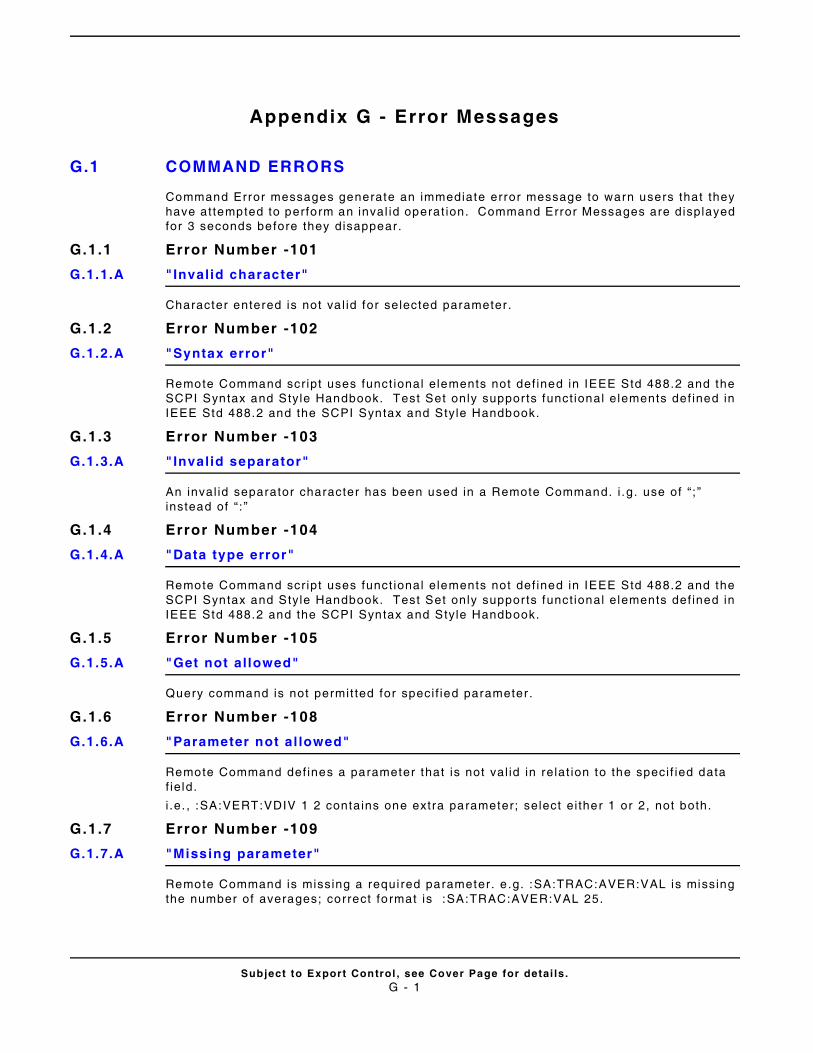
Subject to Export Control , see Cover Page for detai ls .G - 1
Appendix G - Error Messages
G.1 COMMAND ERRORS
Command Error messages generate an immediate error message to warn users that they have at tempted to perform an inval id operat ion. Command Error Messages are displayed for 3 seconds before they disappear.
G.1.1 Error Number -101
G.1.1.A "Invalid character"
Character entered is not va l id for selected parameter .
G.1.2 Error Number -102
G.1.2.A "Syntax error"
Remote Command scr ipt uses funct ional elements not def ined in IEEE Std 488.2 and the SCPI Syntax and Style Handbook. Test Set only suppor ts funct ional elements def ined in IEEE Std 488.2 and the SCPI Syntax and Style Handbook.
G.1.3 Error Number -103
G.1.3.A "Invalid separator"
An inval id separator character has been used in a Remote Command. i .g. use of “ ; ” instead of “ : ”
G.1.4 Error Number -104
G.1.4.A "Data type error"
Remote Command scr ipt uses funct ional elements not def ined in IEEE Std 488.2 and the SCPI Syntax and Style Handbook. Test Set only suppor ts funct ional elements def ined in IEEE Std 488.2 and the SCPI Syntax and Style Handbook.
G.1.5 Error Number -105
G.1.5.A "Get not allowed"
Query command is not permit ted for speci f ied parameter .
G.1.6 Error Number -108
G.1.6.A "Parameter not al lowed"
Remote Command def ines a parameter that is not val id in relat ion to the speci f ied data f ie ld.
i .e. , :SA:VERT:VDIV 1 2 contains one extra parameter; select ei ther 1 or 2, not both.
G.1.7 Error Number -109
G.1.7.A "Missing parameter"
Remote Command is missing a requi red parameter. e .g. :SA:TRAC:AVER:VAL is missing the number of averages; correct fo rmat is :SA:TRAC:AVER:VAL 25.
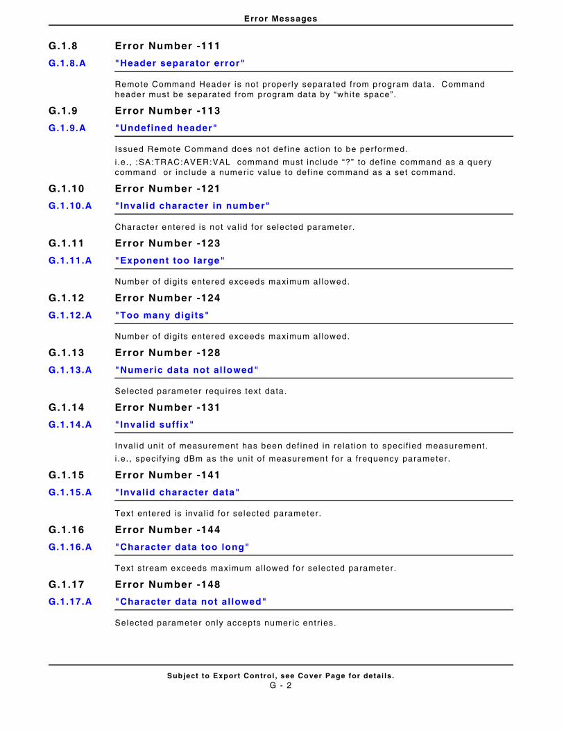
Error Messages
Subject to Export Control , see Cover Page for detai ls .G - 2
G.1.8 Error Number -111
G.1.8.A "Header separator error"
Remote Command Header is not properly separated from program data. Command header must be separated f rom program data by “white space”.
G.1.9 Error Number -113
G.1.9.A "Undefined header"
Issued Remote Command does not def ine act ion to be per formed.
i .e. , :SA:TRAC:AVER:VAL command must include “?” to def ine command as a query command or include a numeric value to def ine command as a set command.
G.1.10 Error Number -121
G.1.10.A "Invalid character in number"
Character entered is not va l id for selected parameter .
G.1.11 Error Number -123
G.1.11.A "Exponent too large"
Number o f digi ts entered exceeds maximum al lowed.
G.1.12 Error Number -124
G.1.12.A "Too many digits"
Number o f digi ts entered exceeds maximum al lowed.
G.1.13 Error Number -128
G.1.13.A "Numeric data not al lowed"
Selected parameter requires text data.
G.1.14 Error Number -131
G.1.14.A "Invalid suff ix"
Inval id uni t of measurement has been def ined in relat ion to speci f ied measurement .
i .e. , speci fy ing dBm as the uni t of measurement for a f requency parameter .
G.1.15 Error Number -141
G.1.15.A "Invalid character data"
Text entered is inval id for selected parameter.
G.1.16 Error Number -144
G.1.16.A "Character data too long"
Text stream exceeds maximum al lowed for selected parameter.
G.1.17 Error Number -148
G.1.17.A "Character data not allowed"
Selected parameter only accepts numeric entr ies.
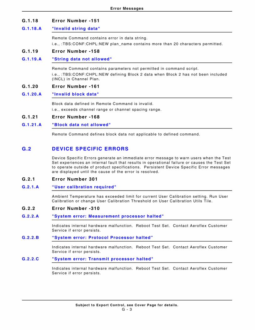
Error Messages
Subject to Export Control , see Cover Page for detai ls .G - 3
G.1.18 Error Number -151
G.1.18.A "Invalid str ing data"
Remote Command contains error in data st r ing.
i .e. , :TBS:CONF:CHPL:NEW plan_name contains more than 20 characters permit ted.
G.1.19 Error Number -158
G.1.19.A "String data not al lowed"
Remote Command contains parameters not permi t ted in command scr ip t .
i .e. , :TBS:CONF:CHPL:NEW def ining Block 2 data when Block 2 has not been included ( INCL) in Channel Plan.
G.1.20 Error Number -161
G.1.20.A "Invalid block data"
Block data def ined in Remote Command is inval id.
i .e. , exceeds channel range or channel spacing range.
G.1.21 Error Number -168
G.1.21.A "Block data not al lowed"
Remote Command def ines block data not appl icable to def ined command.
G.2 DEVICE SPECIFIC ERRORS
Device Speci f ic Errors generate an immediate error message to warn users when the Test Set experiences an interna l faul t that resul ts in operat ional fa i lure or causes the Test Set to operate outside of product speci f icat ions. Persistent Device Speci f ic Error messages are displayed unt i l the cause of the error is reso lved.
G.2.1 Error Number 301
G.2.1.A “User cal ibration required"
Ambient Temperature has exceeded l imit for current User Cal ibrat ion sett ing. Run User Cal ibrat ion or change User Cal ibrat ion Threshold on User Cal ibrat ion Ut i ls Ti le.
G.2.2 Error Number -310
G.2.2.A "System error: Measurement processor halted"
Indicates in ternal hardware malfunct ion. Reboot Test Set. Contact Aerof lex Customer Service i f er ror persists.
G.2.2.B “System error: Protocol Processor halted”
Indicates in ternal hardware malfunct ion. Reboot Test Set. Contact Aerof lex Customer Service i f er ror persists.
G.2.2.C "System error: Transmit processor halted"
Indicates in ternal hardware malfunct ion. Reboot Test Set. Contact Aerof lex Customer Service i f er ror persists.
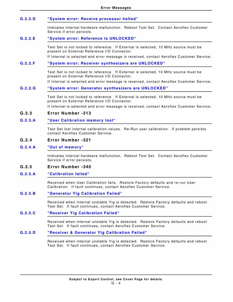
Error Messages
Subject to Export Control , see Cover Page for detai ls .G - 4
G.2.2.D "System error: Receive processor halted"
Indicates in ternal hardware malfunct ion. Reboot Test Set. Contact Aerof lex Customer Service i f er ror persists.
G.2.2.E "System error: Reference is UNLOCKED"
Test Set is not locked to re ference. I f External is selected, 10 MHz source must be present on Externa l Reference I /O Connector.
I f Internal is selected and error message is received, contact Aerof lex Customer Service.
G.2.2.F "System error: Receiver synthesizers are UNLOCKED"
Test Set is not locked to re ference. I f External is selected, 10 MHz source must be present on Externa l Reference I /O Connector.
I f Internal is selected and error message is received, contact Aerof lex Customer Service.
G.2.2.G “System error: Generator synthesizers are UNLOCKED”
Test Set is not locked to re ference. I f External is selected, 10 MHz source must be present on Externa l Reference I /O Connector.
I f Internal is selected and error message is received, contact Aerof lex Customer Service.
G.2.3 Error Number -313
G.2.3.A "User Calibration memory lost"
Test Set lost internal cal ibrat ion values. Re-Run user cal ibrat ion. I f problem persists contact Aerof lex Customer Service.
G.2.4 Error Number -321
G.2.4.A "Out of memory"
Indicates in ternal hardware malfunct ion. Reboot Test Set. Contact Aerof lex Customer Service i f er ror persists.
G.2.5 Error Number -340
G.2.5.A "Calibration fai led"
Received when User Cal ibrat ion fai ls. Restore Factory defaul ts and re-run User Cal ibrat ion. I f faul t cont inues, contact Aerof lex Customer Service.
G.2.5.B "Generator Yig Cal ibration Fai led"
Received when internal unstable Yig is detected. Restore Factory defaul ts and reboot Test Set . I f faul t cont inues, contact Aerof lex Customer Service.
G.2.5.C "Receiver Yig Cal ibration Fai led"
Received when internal unstable Yig is detected. Restore Factory defaul ts and reboot Test Set . I f faul t cont inues, contact Aerof lex Customer Service.
G.2.5.D "Receiver & Generator Yig Calibration Failed"
Received when internal unstable Yig is detected. Restore Factory defaul ts and reboot Test Set . I f faul t cont inues, contact Aerof lex Customer Service.
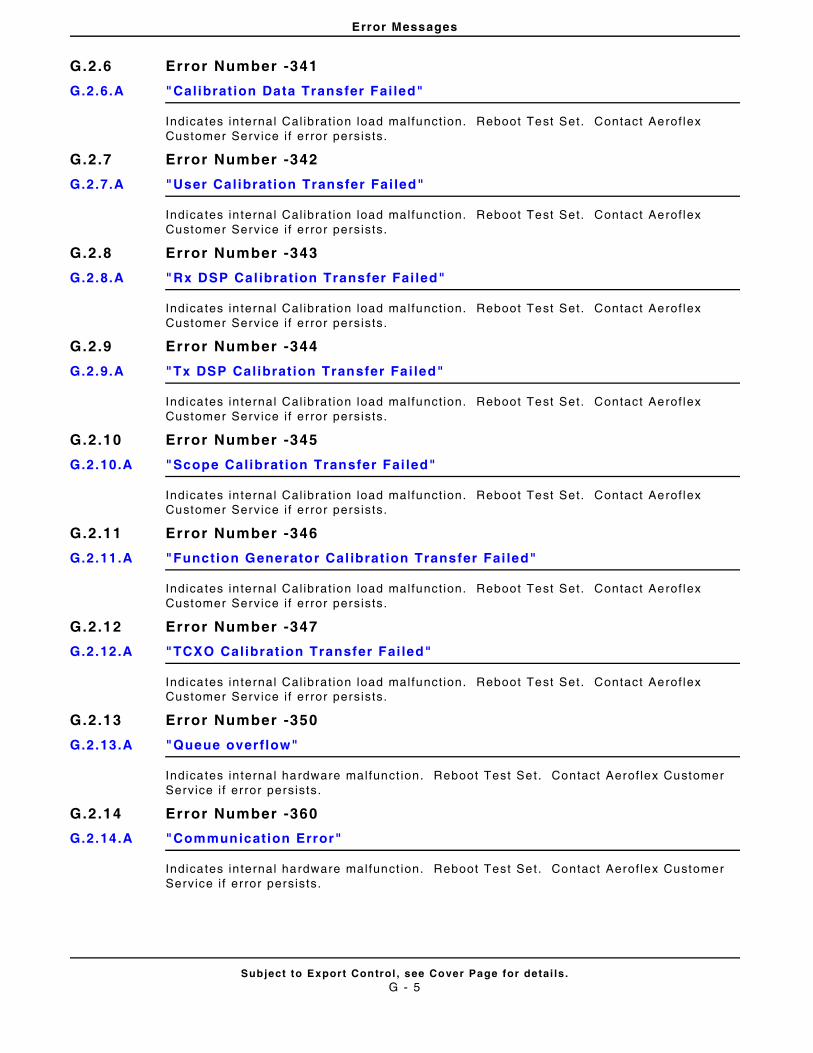
Error Messages
Subject to Export Control , see Cover Page for detai ls .G - 5
G.2.6 Error Number -341
G.2.6.A "Calibration Data Transfer Fai led"
Indicates in ternal Cal ibrat ion load malfunct ion. Reboot Test Set. Contact Aerof lex Customer Service i f er ror persists.
G.2.7 Error Number -342
G.2.7.A "User Calibration Transfer Fai led"
Indicates in ternal Cal ibrat ion load malfunct ion. Reboot Test Set. Contact Aerof lex Customer Service i f er ror persists.
G.2.8 Error Number -343
G.2.8.A "Rx DSP Cal ibration Transfer Fai led"
Indicates in ternal Cal ibrat ion load malfunct ion. Reboot Test Set. Contact Aerof lex Customer Service i f er ror persists.
G.2.9 Error Number -344
G.2.9.A "Tx DSP Calibration Transfer Fai led"
Indicates in ternal Cal ibrat ion load malfunct ion. Reboot Test Set. Contact Aerof lex Customer Service i f er ror persists.
G.2.10 Error Number -345
G.2.10.A "Scope Calibration Transfer Fai led"
Indicates in ternal Cal ibrat ion load malfunct ion. Reboot Test Set. Contact Aerof lex Customer Service i f er ror persists.
G.2.11 Error Number -346
G.2.11.A "Function Generator Cal ibration Transfer Fai led"
Indicates in ternal Cal ibrat ion load malfunct ion. Reboot Test Set. Contact Aerof lex Customer Service i f er ror persists.
G.2.12 Error Number -347
G.2.12.A "TCXO Calibrat ion Transfer Fai led"
Indicates in ternal Cal ibrat ion load malfunct ion. Reboot Test Set. Contact Aerof lex Customer Service i f er ror persists.
G.2.13 Error Number -350
G.2.13.A "Queue overflow"
Indicates in ternal hardware malfunct ion. Reboot Test Set. Contact Aerof lex Customer Service i f er ror persists.
G.2.14 Error Number -360
G.2.14.A "Communication Error"
Indicates in ternal hardware malfunct ion. Reboot Test Set. Contact Aerof lex Customer Service i f er ror persists.
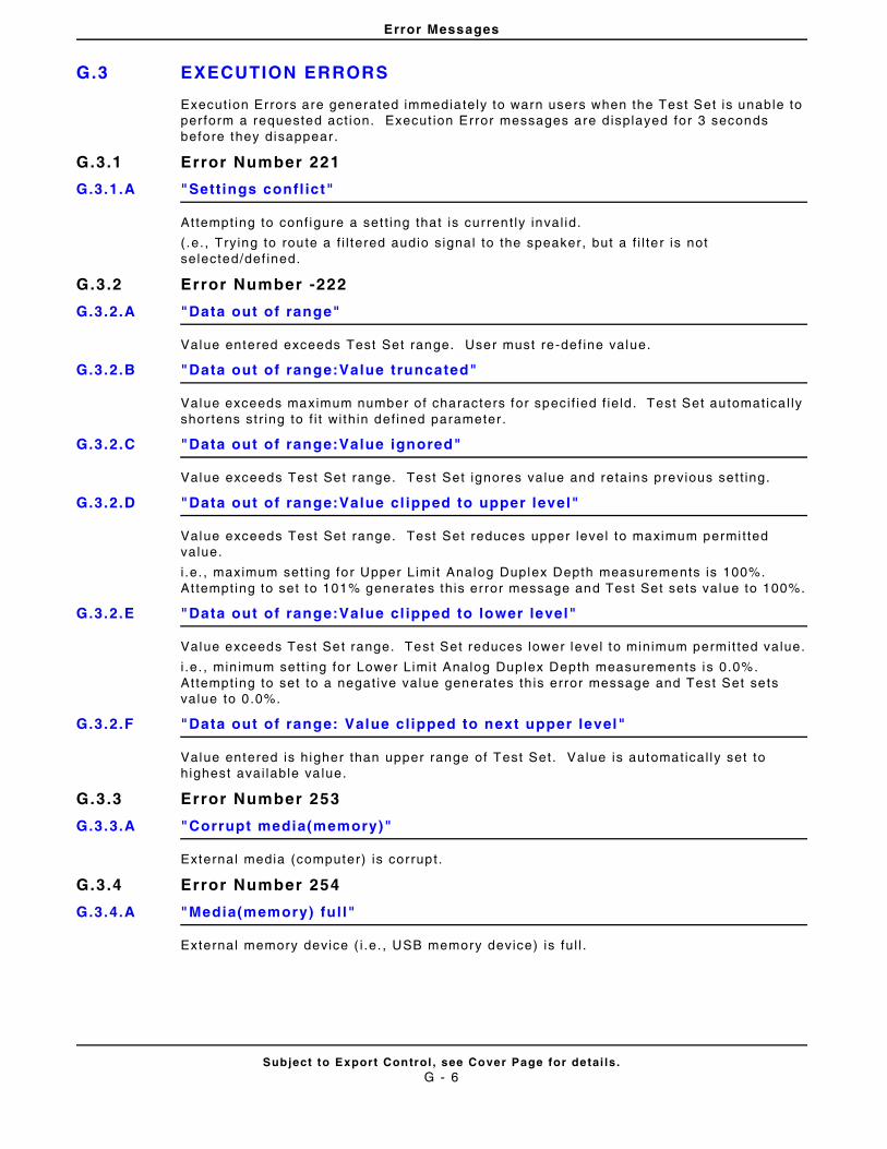
Error Messages
Subject to Export Control , see Cover Page for detai ls .G - 6
G.3 EXECUTION ERRORS
Execut ion Errors are generated immediately to warn users when the Test Set is unable to per form a requested act ion. Execut ion Error messages are d isplayed for 3 seconds before they disappear.
G.3.1 Error Number 221
G.3.1.A "Sett ings confl ict"
Attempting to conf igure a set t ing that is current ly inval id.
( .e. , Trying to route a f i l tered audio signal to the speaker, but a f i l te r is not selected/def ined.
G.3.2 Error Number -222
G.3.2.A "Data out of range"
Value entered exceeds Test Set range. User must re-def ine value.
G.3.2.B "Data out of range:Value truncated"
Value exceeds maximum number of characters for speci f ied f ie ld . Test Set automatica l ly shortens st r ing to f i t wi thin def ined parameter .
G.3.2.C "Data out of range:Value ignored"
Value exceeds Test Set range. Test Set ignores value and retains previous set t ing.
G.3.2.D "Data out of range:Value cl ipped to upper level"
Value exceeds Test Set range. Test Set reduces upper level to maximum permi t ted value.
i .e. , maximum sett ing for Upper Limit Analog Duplex Depth measurements is 100%. At tempting to set to 101% generates this error message and Test Set sets value to 100%.
G.3.2.E "Data out of range:Value cl ipped to lower level"
Value exceeds Test Set range. Test Set reduces lower level to minimum permit ted value.
i .e. , min imum sett ing for Lower Limit Analog Duplex Depth measurements is 0.0%. At tempting to set to a negat ive value generates th is error message and Test Set sets value to 0 .0%.
G.3.2.F "Data out of range: Value clipped to next upper level"
Value entered is higher than upper range of Test Set. Value is automatical ly set to highest avai lable va lue.
G.3.3 Error Number 253
G.3.3.A "Corrupt media(memory)"
External media (computer) is corrupt.
G.3.4 Error Number 254
G.3.4.A "Media(memory) ful l"
External memory device ( i .e. , USB memory device) is fu l l .
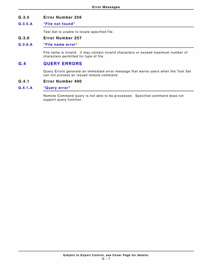
Error Messages
Subject to Export Control , see Cover Page for detai ls .G - 7
G.3.5 Error Number 256
G.3.5.A "File not found"
Test Set is unable to locate speci f ied f i le .
G.3.6 Error Number 257
G.3.6.A "File name error"
Fi le name is inval id . I t may conta in inval id characters or exceed maximum number o f characters permit ted for type of f i le.
G.4 QUERY ERRORS
Query Errors generate an immediate error message that warns users when the Test Set can not process an issued remote command.
G.4.1 Error Number 400
G.4.1.A "Query error"
Remote Command query is not able to be processed. Speci f ied command does not suppor t query funct ion.
Error Messages
Subject to Export Control , see Cover Page for detai ls .G - 8
THIS PAGE INTENTIONALLY LEFT BLANK.
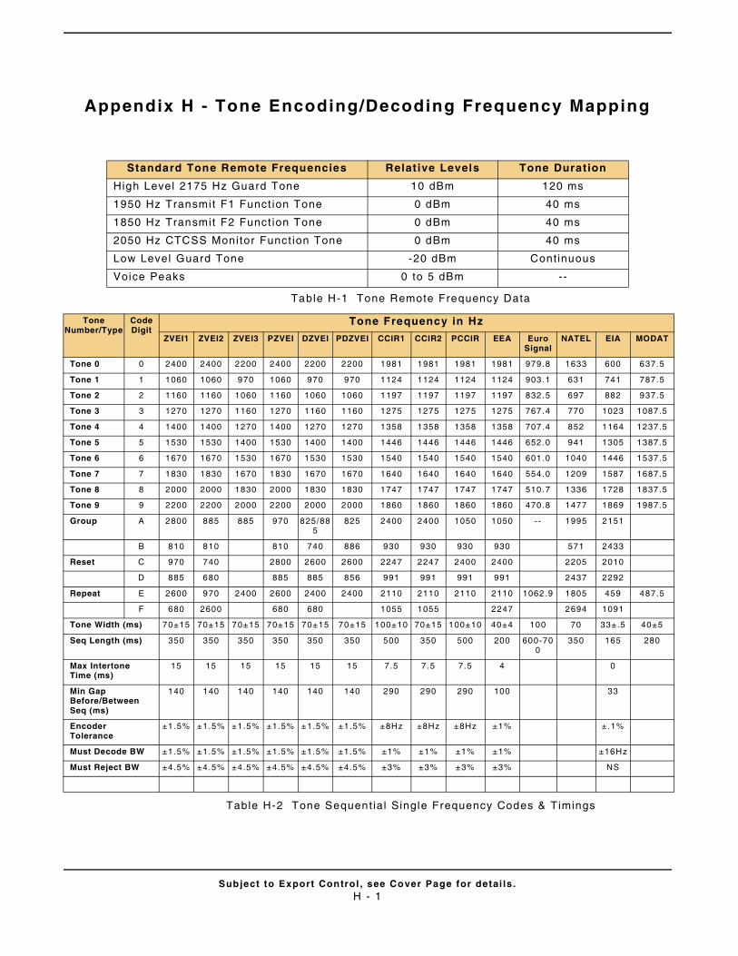
Subject to Export Control , see Cover Page for detai ls .H - 1
Appendix H - Tone Encoding/Decoding Frequency Mapping
Table H-1 Tone Remote Frequency Data
Table H-2 Tone Sequent ial Single Frequency Codes & Timings
Standard Tone Remote Frequencies Relat ive Levels Tone Durat ion
High Level 2175 Hz Guard Tone 10 dBm 120 ms
1950 Hz Transmit F1 Funct ion Tone 0 dBm 40 ms
1850 Hz Transmit F2 Funct ion Tone 0 dBm 40 ms
2050 Hz CTCSS Monitor Funct ion Tone 0 dBm 40 ms
Low Level Guard Tone -20 dBm Continuous
Voice Peaks 0 to 5 dBm --
Tone Number/Type
Code Digit
Tone Frequency in Hz
ZVEI1 ZVEI2 ZVEI3 PZVEI DZVEI PDZVEI CCIR1 CCIR2 PCCIR EEA Euro Signal
NATEL EIA MODAT
Tone 0 0 2400 2400 2200 2400 2200 2200 1981 1981 1981 1981 979.8 1633 600 637.5
Tone 1 1 1060 1060 970 1060 970 970 1124 1124 1124 1124 903.1 631 741 787.5
Tone 2 2 1160 1160 1060 1160 1060 1060 1197 1197 1197 1197 832.5 697 882 937.5
Tone 3 3 1270 1270 1160 1270 1160 1160 1275 1275 1275 1275 767.4 770 1023 1087.5
Tone 4 4 1400 1400 1270 1400 1270 1270 1358 1358 1358 1358 707.4 852 1164 1237.5
Tone 5 5 1530 1530 1400 1530 1400 1400 1446 1446 1446 1446 652.0 941 1305 1387.5
Tone 6 6 1670 1670 1530 1670 1530 1530 1540 1540 1540 1540 601.0 1040 1446 1537.5
Tone 7 7 1830 1830 1670 1830 1670 1670 1640 1640 1640 1640 554.0 1209 1587 1687.5
Tone 8 8 2000 2000 1830 2000 1830 1830 1747 1747 1747 1747 510.7 1336 1728 1837.5
Tone 9 9 2200 2200 2000 2200 2000 2000 1860 1860 1860 1860 470.8 1477 1869 1987.5
Group A 2800 885 885 970 825/885
825 2400 2400 1050 1050 -- 1995 2151
B 810 810 810 740 886 930 930 930 930 571 2433
Reset C 970 740 2800 2600 2600 2247 2247 2400 2400 2205 2010
D 885 680 885 885 856 991 991 991 991 2437 2292
Repeat E 2600 970 2400 2600 2400 2400 2110 2110 2110 2110 1062.9 1805 459 487.5
F 680 2600 680 680 1055 1055 2247 2694 1091
Tone Width (ms) 70±15 70±15 70±15 70±15 70±15 70±15 100±10 70±15 100±10 40±4 100 70 33±.5 40±5
Seq Length (ms) 350 350 350 350 350 350 500 350 500 200 600-700
350 165 280
Max Intertone Time (ms)
15 15 15 15 15 15 7.5 7.5 7.5 4 0
Min Gap Before/Between Seq (ms)
140 140 140 140 140 140 290 290 290 100 33
Encoder Tolerance
±1.5% ±1.5% ±1.5% ±1.5% ±1.5% ±1.5% ±8Hz ±8Hz ±8Hz ±1% ±.1%
Must Decode BW ±1.5% ±1.5% ±1.5% ±1.5% ±1.5% ±1.5% ±1% ±1% ±1% ±1% ±16Hz
Must Reject BW ±4.5% ±4.5% ±4.5% ±4.5% ±4.5% ±4.5% ±3% ±3% ±3% ±3% NS
Tone Encoding/Decoding Frequency Mapping
Subject to Export Control , see Cover Page for detai ls .H - 2
THIS PAGE INTENTIONALLY LEFT BLANK.

Our passion for performance is defined by threeattributes represented by these three icons:
solution-minded, performance-driven, customer-focused.
As we are always seeking to improve our products, the information in
this document gives only a general indication of the product capacity,
performance and suitability, none of which shall form part of any
contract. We reserve the right to make design changes without notice.
EXPORT CONTROL WARNING: This document contains controlled technical data under the jurisdiction of the Export Administration Regulations (EAR), 15 CFR 730-774. It cannot be transferred to any foreign third party without the specific prior approval of the U.S. Department of Commerce Bureau of Industry and Security (BIS). Violations of these regulations are punishable by fine, imprisonment, or both.
Go to http://ats.aeroflex.com/contact/sales-distribution for Sales and Service contact information.