30rbm/rbp (160-520) 30rqm/rqp (160-520) - ahi carrier
TRANSCRIPT
C O N T R O L S M A N U A L
Pro Dialog+ Control Touch Pilot Control
30RBM/RBP (160-520)30RQM/RQP (160-520)
Original document
Pro Dialog+ Control Standard control
Touch Pilot ControlAdvanced control features Web access

2
CONTENTS
1 - SAFETY CONSIDERATIONS ............................................................................................................................................... 51.1 - Safety guidelines ...................................................................................................................................................................... .51.2 - Safety precautions ................................................................................................................................................................... .5
2 - CONTROL OVERVIEW .......................................................................................................................................................... 52.1 - Control system ......................................................................................................................................................................... .52.2 - System functionalities ............................................................................................................................................................. .52.3 - Operating modes ..................................................................................................................................................................... .52.4 - Pro Dialog+ control ................................................................................................................................................................ .62.5 - Touch Pilot control .................................................................................................................................................................. .6
3 - CONTROL COMPONENTS ................................................................................................................................................... 73.1 - Chiller ....................................................................................................................................................................................... .73.2 - Features overview ................................................................................................................................................................... .7
4 - HARDWARE ............................................................................................................................................................................. 84.1 - Control boards ......................................................................................................................................................................... .84.2 - Electrical box ........................................................................................................................................................................... .84.3 - Power supply to boards ........................................................................................................................................................... .84.4 - Light emitting diodes on boards ............................................................................................................................................ .84.5 - Pressure transducers ............................................................................................................................................................... .84.6 - Temperature sensors ............................................................................................................................................................... .94.7 - Actuators .................................................................................................................................................................................. .94.8 - Terminal block connections .................................................................................................................................................. .10
5 - SETTING UP PRO DIALOG+ CONTROL ....................................................................................................................... 11
6 - HOW TO USE PRO DIALOG+ USER INTERFACE ...................................................................................................... 126.1 - Pro Dialog+ overview ........................................................................................................................................................... .126.2 - Default screen characteristics .............................................................................................................................................. .126.3 - Pro Dialog+ menu structure ................................................................................................................................................ .136.4 - Start the unit and set the mode ............................................................................................................................................ .146.5 - Stop the unit ........................................................................................................................................................................... .146.6 - Navigate across menus .......................................................................................................................................................... .146.7 - Monitor unit parameters ...................................................................................................................................................... .146.8 - Manage security settings ....................................................................................................................................................... .146.9 - Change a display language ................................................................................................................................................... .156.10 - Modify unit parameters ...................................................................................................................................................... .15
7 - SETTING UP TOUCH PILOT CONTROL ........................................................................................................................ 16
8 - HOW TO USE TOUCH PILOT USER INTERFACE ....................................................................................................... 178.1 - Touch Pilot overview ............................................................................................................................................................. .178.2 - Touch Pilot menu structure .................................................................................................................................................. .188.3 - Read the welcome screen ..................................................................................................................................................... .198.4 - Explore the synoptic screen ................................................................................................................................................. .198.5 - Start the unit .......................................................................................................................................................................... .198.6 - Stop the unit ........................................................................................................................................................................... .198.7 - Set the schedule ..................................................................................................................................................................... .208.8 - Manage display settings ........................................................................................................................................................ .208.9 - Monitor unit parameters ...................................................................................................................................................... .228.10 - Modify unit parameters ...................................................................................................................................................... .228.11 - Override system configuration........................................................................................................................................... .228.12 - Analyse history trends ........................................................................................................................................................ .23
9 - WEB CONNECTION .............................................................................................................................................................. 249.1 - Web interface ......................................................................................................................................................................... .249.2 - Open the web interface ........................................................................................................................................................ .249.3 - Manage web browser settings .............................................................................................................................................. .249.4 - Access technical documentation .......................................................................................................................................... .24
10 - PARAMETERS ..................................................................................................................................................................... 2510.1 - Main menu ........................................................................................................................................................................... .2510.2 - Configuration menu ............................................................................................................................................................ .3310.3 - Alarms menu ....................................................................................................................................................................... .37
The cover photos are solely for illustration and forms no part of any offer for sale or any sale contract. The manufacturer reserves the right to change the design at any time without notice.
11 - STANDARD CONTROL OPERATIONS AND OPTIONS .......................................................................................... 3811.1 - Unit start/stop control ........................................................................................................................................................ .3811.2 - Heating/Cooling/Standby ................................................................................................................................................... .3911.3 - Heating/Cooling selection .................................................................................................................................................. .3911.4 - Supplementary heating ....................................................................................................................................................... .4011.5 - Pumps control ...................................................................................................................................................................... .4011.6 - Hydronic kit option ............................................................................................................................................................. .4211.7 - Control point........................................................................................................................................................................ .4211.8 - Capacity limitation .............................................................................................................................................................. .4311.9 - Capacity control .................................................................................................................................................................. .4311.10 - Night mode ......................................................................................................................................................................... .4411.11 - Coil pressure control ......................................................................................................................................................... .4411.12 - Holidays .............................................................................................................................................................................. .4411.13 - Energy management module ........................................................................................................................................... .4511.14 - Free cooling option ........................................................................................................................................................... .4511.15 - Free Cooling Dry Cooler (FCDC) ................................................................................................................................. .4611.16 - Heat reclaim option .......................................................................................................................................................... .4611.17 - Desuperheater option ....................................................................................................................................................... .4611.18 - Defrost cycle for heat pumps ........................................................................................................................................... .4711.19 - Master/slave assembly ...................................................................................................................................................... .4711.20 - BACnet option ................................................................................................................................................................... .47
12 - DIAGNOSTICS ...................................................................................................................................................................... 4812.1 - Pro Dialog+ control diagnostics ........................................................................................................................................ .4812.2 - Touch Pilot control diagnostics .......................................................................................................................................... .4812.3 - Alarm description ................................................................................................................................................................ .50
13 - MAINTENANCE ................................................................................................................................................................... 55
4
PREFACE
The goal of this document is to give a broad overview of the main functions of the control system used to control 3 0 R B M / 3 0 R B P a i r- c o o l e d l i q u i d c h i l l e r s a n d 30RQM/RQP heat pumps with 160 to 520 kW cooling/heating capacity.
Instructions in this manual are given as a guide to good practice in the installation, start-up and operation of the control system. This document does not contain full service procedures for the correct operation of the equipment.
The support of a qualified Carrier Service Engineer is strongly recommended to ensure optimal operation of the equipment as well as the optimization of all available functionalities.
CAUTION
Heating option! Heating option applies to cooling-only units fitted with a boiler and heat pumps.
Note that this document may refer to optional components and certain functions, options or accessories may not be available for the specific unit. The cover images are solely for illustration and form no part of any offer for sale or any sale contract.
IMPORTANT: All screenshots of the user interface provided in this manual include text in English. After changing the language of the system, all labels will be in the language selected by the user.
Please read all instructions prior to proceeding with any work. Pay attention to all safety warnings.
The information provided herein is solely for the purpose of allowing customers to operate and service Carrier manufactured equipment and it is not to be reproduced, modified or used for any other purpose without the prior consent of Carrier Corporation.
Acronyms/abbreviationsIn this manual, the refrigeration circuits are called circuit A and circuit B. Compressors in circuit A are labelled A1, A2, A3, A4, whereas compressors in circuit B are labelled B1, B2, B3, B4.
BMS Building Management SystemCCN Carrier Comfort NetworkDGT Discharge Gas TemperatureEMM Energy Management ModuleEXV Electronic Expansion ValveEHS Electric Heater StageFC Free CoolingFCDC Free Cooling Dry CoolerOAT Outdoor Air Temperature LED Light Emitting DiodeLEN Sensor Bus (internal communication bus linking the basic
board to slave boards)SCT Saturated Condensing TemperatureSST Saturated Suction TemperatureVFD Variable Frequency DriveNetwork mode/Net Operating type: NetworkLocal-Off/LOFF Operating type: Local OffLocal-On/L-C Operating type: Local On modeLocal-Schedule/L-SC Operating type: Local On following a time scheduleMaster mode/Mast Operating type: Master unit (master/slave assembly)Remote mode/Rem Operating type: Remote contactsHSM Hydronic System Manager
5
1 - SAFETY CONSIDERATIONS
1.1 - Safety guidelines
Installation, start-up and servicing of equipment can be hazardous if certain factors particular to the installation are not considered: operating pressures, electrical components, voltages, and the installation site (elevated plinths and built-up structures).
Only qualified installation engineers and fully trained technicians are authorised to install and start the equipment.
All instructions and recommendations provided in the service guide, installation and operation manuals, as well as on tags and labels fixed to the equipment, components and other accompanying parts supplied separately must be read, understood and followed.
Failure to comply with the instructions provided by the manufacturer may result in injury or product damage.
• Apply all safety standards and practices.• Wear safety glasses and gloves.• Use the proper tools to move heavy objects. • Move units carefully and set them down gently.
CAUTION
Only qualified service technicians should be allowed to install and service the equipment.
1.2 - Safety precautions
Only personnel qualified in accordance with IEC ( I n t e r n a t i o n a l E l e c t r o t e c h n i c a l C o m m i s s i o n ) recommendations may be permitted access to electrical components.
It is particularly recommended that all sources of electricity to the unit should be shut off before any work is begun. Shut off the main power supply at the main circuit breaker or isolator.
IMPORTANT: The equipment uses and emits electromagnetic signals. Tests have shown that the equipment conforms to all applicable codes with respect to electromagnetic compatibility.
CAUTIONRISK OF ELECTROCUTION! Even when the main circuit breaker or isolator is switched off, specific circuits may still be energised as they may be connected to a separate power source.
CAUTIONRISK OF BURNS! Electrical currents may cause components to get hot. Handle the power cable, electrical cables and conduits, terminal box covers and motor frames with great care.
2 - CONTROL OVERVIEW
2.1 - Control system
30RBM/RBP chillers are equipped with two types of controls that serve as the user interface and configuration tools for Carrier communicating devices. Chillers are fitted with standard Pro Dialog+ Control or the advanced Touch Pilot Control with web connectivity.
30RQM/RQP heat pumps are equipped with one type of control that serves as the user interface and configuration tool for Carrier communicating devices. Heat pumps are fitted with the advanced Touch Pilot Control with web connectivity.
30RBM/RQM units typically use fixed speed fans and 30RBP/RQP units use variable speed fans. Variable speed fans reduce the unit energy use during occupied and unoccupied periods, provide condensing or evaporating pressure control and smooth fan start.
For both 30RBM/RBP chillers and 30RQM/RQP heat pumps, the system may control fixed speed pumps or variable speed pumps with a hydronic module.
IMPORTANT: This document may refer to optional components and certain functions, options or accessories may not be available for the specific unit.
2.2 - System functionalities
The system controls the start-up of the compressors needed to maintain the desired heat exchanger entering and leaving water temperature. It constantly manages the operation of the fans in order to maintain the correct refrigerant pressure in each circuit and monitors safety devices that protect the unit against failure and guarantee its optimal functioning.
2.3 - Operating modes
The control can operate in three independent modes:• Local mode: The unit is controlled by commands from
the user interface.• Remote mode: The unit is controlled by dry contacts.• Network mode: The unit is controlled by network
commands (CCN or BACnet). Data communication cable is used to connect the unit to the CCN communication bus.
When the control operates autonomously (Local or Remote), it retains all of its control capabilities but does not offer any of the features of the Network.
CAUTION
Emergency stop! The Network emergency stop command stops the unit regardless of its active operating type.
6
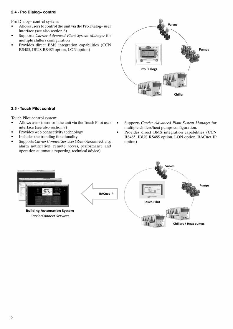
2.4 - Pro Dialog+ control
Pro Dialog+ control system:• Allows users to control the unit via the Pro Dialog+ user
interface (see also section 6)• Supports Carrier Advanced Plant System Manager for
multiple chillers configuration• Provides direct BMS integration capabilities (CCN
RS485, JBUS RS485 option, LON option)
2.5 - Touch Pilot control
Touch Pilot control system:• Allows users to control the unit via the Touch Pilot user
interface (see also section 8)• Provides web connectivity technology• Includes the trending functionality• Supports Carrier Connect Services (Remote connectivity,
alarm notification, remote access, performance and operation automatic reporting, technical advice)
Building Automation SystemCarrierConnect Services
Valves
Pumps
Chillers / Heat pumps
Touch Pilot
BACnet IP
• Supports Carrier Advanced Plant System Manager for multiple chillers/heat pumps configuration.
• Provides direct BMS integration capabilities (CCN RS485, JBUS RS485 option, LON option, BACnet IP option)
7
3 - CONTROL COMPONENTS
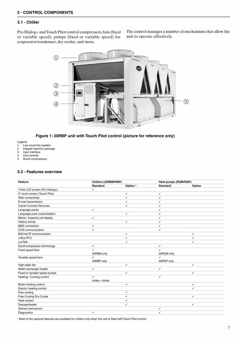
3.1 - Chiller
Pro Dialog+ and Touch Pilot control compressors, fans (fixed or variable speed), pumps (fixed or variable speed) for evaporator/condenser, dry cooler, and more.
The control manages a number of mechanisms that allow the unit to operate effectively.
Legend:1 Low sound fan system2 Integral hydronic package3 User interface4 Unit controls5 Scroll compressors
3.2 - Features overview
Feature Chillers (30RBM/RBP) Heat pumps (RQM/RQP)Standard Option * Standard Option
7-line LCD screen (Pro Dialog+) 5'' touch screen (Touch Pilot) Web connectivity E-mail transmission Carrier Connect Services Language packs Language pack customization Metric / Imperial unit display History trends BMS connection CCN communication BACnet IP communication J-Bus RTU LonTalk Scroll compressor technology Fixed speed fans
30RBM only 30RQM only
Variable speed fans 30RBP only
30RQP only
High static fan Water exchanger heater Fixed or variable speed pumps Heating / Cooling control
chiller + boiler
Boiler heating control Electric heating control Free cooling Free Cooling Dry Cooler Heat reclaim Desuperheater Defrost mechanism Diagnostics
* Most of the optional features are available for chillers only when the unit is fitted with Touch Pilot control.
Figure 1: 30RBP unit with Touch Pilot control (picture for reference only)
8
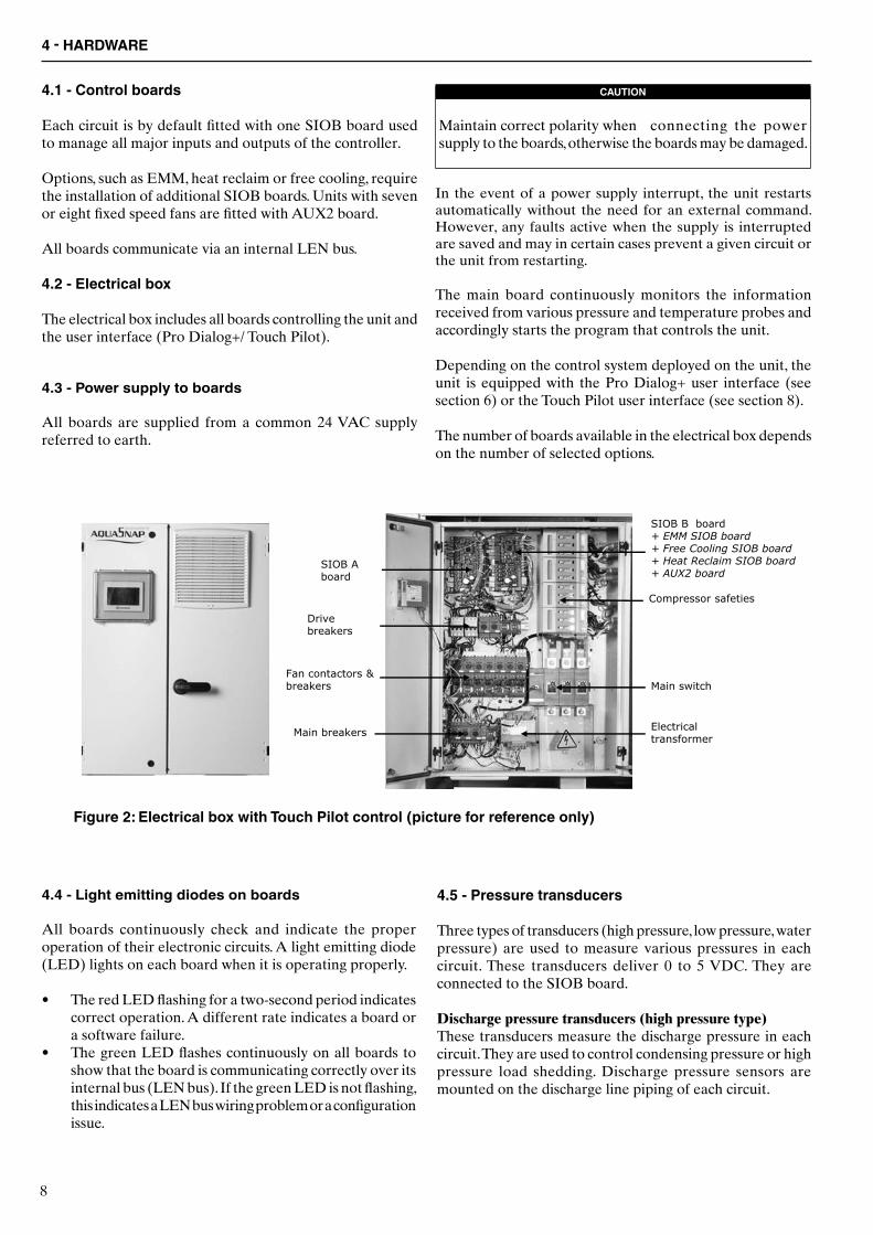
4.1 - Control boards
Each circuit is by default fitted with one SIOB board used to manage all major inputs and outputs of the controller.
Options, such as EMM, heat reclaim or free cooling, require the installation of additional SIOB boards. Units with seven or eight fixed speed fans are fitted with AUX2 board.
All boards communicate via an internal LEN bus.
4.2 - Electrical box
The electrical box includes all boards controlling the unit and the user interface (Pro Dialog+/ Touch Pilot).
4.3 - Power supply to boards
All boards are supplied from a common 24 VAC supply referred to earth.
CAUTION
Maintain correct polarity when connecting the power supply to the boards, otherwise the boards may be damaged.
In the event of a power supply interrupt, the unit restarts automatically without the need for an external command. However, any faults active when the supply is interrupted are saved and may in certain cases prevent a given circuit or the unit from restarting.
The main board continuously monitors the information received from various pressure and temperature probes and accordingly starts the program that controls the unit.
Depending on the control system deployed on the unit, the unit is equipped with the Pro Dialog+ user interface (see section 6) or the Touch Pilot user interface (see section 8).
The number of boards available in the electrical box depends on the number of selected options.
4.4 - Light emitting diodes on boards
All boards continuously check and indicate the proper operation of their electronic circuits. A light emitting diode (LED) lights on each board when it is operating properly.
• The red LED flashing for a two-second period indicates correct operation. A different rate indicates a board or a software failure.
• The green LED flashes continuously on all boards to show that the board is communicating correctly over its internal bus (LEN bus). If the green LED is not flashing, this indicates a LEN bus wiring problem or a configuration issue.
4.5 - Pressure transducers
Three types of transducers (high pressure, low pressure, water pressure) are used to measure various pressures in each circuit. These transducers deliver 0 to 5 VDC. They are connected to the SIOB board.
Discharge pressure transducers (high pressure type)These transducers measure the discharge pressure in each circuit. They are used to control condensing pressure or high pressure load shedding. Discharge pressure sensors are mounted on the discharge line piping of each circuit.
Figure 2: Electrical box with Touch Pilot control (picture for reference only)
4 - HARDWARE
9
Suction pressure transducers (low pressure type)These transducers measure the suction pressure in each circuit. They are used to control EXV, evaporating pressure (in heating mode) and monitor suction pressure safeties related to the compressor operating envelope. Suction pressure sensors are located on the common suction piping of each circuit.
Pump inlet/outlet water pressure transducers (water pressure type, hydronic kit option)These transducers measure the hydronic kit pump water inlet/outlet water pressure and monitor the water flow. Pump inlet/outlet water pressure sensors are mounted on the optional hydronic kit.
Heat reclaim pump-down pressure transducers (Heat Reclaim option)These transducers measure the pressure in the heat reclaim exchanger (water-cooled condenser) during the pump-down process. They are used to determine whether the refrigerant was successfully purged or not.
Pump inlet/outlet pressure transducers (Free Cooling option)These transducers measure the free cooling refrigerant pump inlet and outlet pressure. They are used to control pump start-up and monitor pump pressure during the free cooling cycle.
4.6 - Temperature sensors
Temperature sensors constantly measure the temperature of various components of the unit, ensuring the correct operation of the system.
Water heat exchanger entering and leaving water temperature sensorsThe water heat exchanger entering and leaving water temperature sensors are used for capacity control and safety purposes.
Outdoor air temperature sensorThis sensor measuring the outdoor air temperature is used for start-up, setpoint temperature reset and frost control.
Suction gas temperature sensorsThese sensors measure the suction gas temperature. They are used for the EXV control. Suction gas temperature sensors are located at the suction side of each circuit.
Master/slave water sensor (optional)This sensor measures the common water temperature in the master/slave system capacity control. It is installed only in the case of master/slave units.
Defrost temperature sensors (heat pumps)These sensors are used to determine the end of the defrost cycle for a given circuit.
Condenser entering and leaving fluid temperature sensors (Heat Reclaim option)These condenser entering and leaving fluid temperature sensors are used to control the condenser fluid temperature during the heat reclaim process.
Condenser sub-cooling temperature sensors (Heat Reclaim option)These sensors monitor the subcooling temperature necessary to enable the heat reclaim process.
Temperature setpoint reset sensor (EMM option)This sensor measures the space (room) temperature for the purpose of setpoint reset.
4.7 - Actuators
Electronic expansion valveThe electronic expansion valve (EXV) is used to adjust the refrigerant flow to changes in the operating conditions of the machine. The high degree of accuracy with which the piston is positioned provides precise control of the refrigerant flow and suction superheat.
Water flow switchFor units without internal pumps, the water flow switch configuration allows for the automatic control of the minimum water flow setpoint of the water flow switch. The configuration depends on the unit size and is made automatically at the start-up. If the flow switch fails, the alarm condition shuts off the unit.
Water heat exchanger pumps (optional)The controller can regulate one or two fixed speed or variable speed water heat exchanger pumps and takes care of the automatic changeover between these pumps (see also section 11.5).
Heat reclaim pump (optional)The controller regulates the water heat reclaim pump that comes with units fitted with the heat reclaim option. The pump is started when the heat reclaim cycle is active (see also section 11.16).
Free cooling refrigerant pumpFree cooling refrigerant pumps ensure the correct operation of the free cooling cycle.
Four-way valve (heat pumps)The control actuates the four-way valve for cooling / heating mode and defrosts session.
Free cooling three-way valveThe control actuates the three-way valve in order to isolatecompressors when the refrigerant pump is running (therefrigerant is cooled by the air exchanger).
10
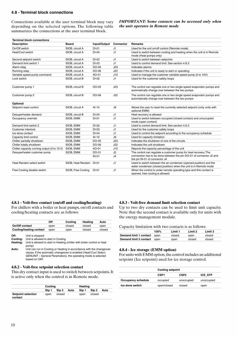
4.8.1 - Volt-free contact (on/off and cooling/heating)For chillers with a boiler or heat pumps, on/off contacts and cooling/heating contacts are as follows:
Off Cooling Heating Auto On/Off contact open closed closed openCooling/heating contact open open closed closed
Off: Unit is stoppedCooling: Unit is allowed to start in CoolingHeating: Unit is allowed to start in Heating (chiller with boiler control or heat
pump)Auto: Unit can run in Cooling or Heating in accordance with the changeover
values. If the automatic changeover is enabled (Heat/Cool Select, GENUNIT – General Parameters), the operating mode is selected based on OAT.
4.8.2 - Volt-free setpoint selection contactThis dry contact input is used to switch between setpoints. It is active only when the control is in Remote mode.
Cooling HeatingStp 1 Stp 2 Auto Stp 1 Stp 2 Auto
Setpoint selection contact
open closed - open closed -
4.8.3 - Volt-free demand limit selection contactUp to two dry contacts can be used to limit unit capacity. Note that the second contact is available only for units with the energy management module.
Capacity limitation with two contacts is as follows:100% Limit 1 Limit 2 Limit 3
Demand limit 1 contact open closed open closedDemand limit 2 contact open open closed closed
4.8.4 - Ice storage (EMM option)For units with EMM option, the control includes an additional setpoint (Ice setpoint) used for ice storage control.
Cooling setpoint
CSP1 CSP2 ICE_STP
Occupancy schedule occupied unoccupied unoccupied
Ice done switch open/closed closed open
Terminal block connectionsDescription Board Input/Output Connector RemarksOn/Off switch SIOB, circuit A DI-01 J1 Used for the unit on/off control (Remote mode)Heat/Cool switch SIOB, circuit A DI-04 J1 Used to switch between cooling and heating when the unit is in Remote
mode (Heat pumps only)Second setpoint switch SIOB, circuit A DI-02 J1 Used to switch between setpointsDemand limit switch 1 SIOB, circuit A DI-03 J1 Used to control demand limit. See section 4.8.3Alarm relay SIOB, circuit A DO-05 J23 Indicates alarmsRunning relay SIOB, circuit A DO-06 J22 Indicates if the unit is ready to start or operatingVariable speed pump command SIOB, circuit A AO-01 J10 Used to manage the customer variable speed pump (0 to 10V)Lock switch SIOB, circuit B DI-02 J1 Used for the customer safety loops
Customer pump 1 SIOB, circuit B DO-05 J23 The control can regulate one or two single speed evaporator pumps and automatically change over between the two pumps
Customer pump 2 SIOB, circuit B DO-06 J22 The control can regulate one or two single speed evaporator pumps and automatically change over between the two pumps
OptionalSetpoint reset control SIOB, circuit A AI-10 J9 Allows the user to reset the currently selected setpoint (only units with
optional EMM)Desuperheater demand SIOB, circuit B DI-04 J1 Heat recovery is allowedOccupancy override SIOB, EMM DI-01 J1 Used to switch between occupied (closed contact) and unoccupied
mode (open contact)Demand limit switch 2 SIOB, EMM DI-02 J1 Used to control demand limit. See section 4.8.3Customer interlock SIOB, EMM DI-03 J1 Used for the customer safety loopsIce done contact SIOB, EMM DI-04 J1 Used to control the setpoint according to the occupancy scheduleCapacity limit control SIOB, EMM AI-10 J9 Used for capacity limitationChiller partially shutdown SIOB, EMM DO-05 J23 Indicates the shutdown of one of the circuitsChiller totally shutdown SIOB, EMM DO-06 J22 Indicates the unit shutdownChiller capacity running output (0 to 10 V) SIOB, EMM AO-01 J10 Reports the capacity percentage of the unitDesuperheater customer pump SIOB, EMM DO-01 J2 The control can regulate a customer pump for heat recovery. The
connection has to be done between the pin DO-01 of connector J2 and the pin IN-01 of connector J4
IN-01 J4
Heat Reclaim select switch SIOB, Heat Reclaim DI-01 J1 Used to switch between the air condenser (opened position) and the water condenser (closed position) when the unit is in Remote mode
Free Cooling disable switch SIOB, Free Cooling DI-01 J1 When the control is under remote operating type and this contact is opened, free cooling is allowed
4.8 - Terminal block connections
Connections available at the user terminal block may vary depending on the selected options. The following table summarizes the connections at the user terminal block.
IMPORTANT: Some contacts can be accessed only when the unit operates in Remote mode.
11
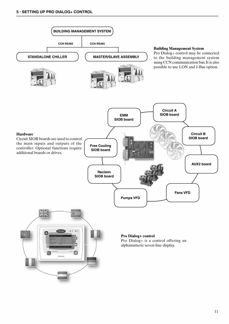
5 - SETTING UP PRO DIALOG+ CONTROL
Building Management SystemPro Dialog+ control may be connected to the building management system using CCN communication bus. It is also possible to use LON and J-Bus option.
HardwareCircuit SIOB boards are used to control the main inputs and outputs of the controller. Optional functions require additional boards or drives.
Pro Dialog+ controlPro Dialog+ is a control offering an alphanumeric seven-line display.
BUILDING MANAGEMENT SYSTEM
STANDALONE CHILLER MASTER/SLAVE ASSEMBLY
CCN RS485 CCN RS485
Circuit A SIOB board
Circuit B SIOB board
AUX2 board
Fans VFDPumps VFD
Reclaim SIOB board
Free Cooling SIOB board
EMM SIOB board
12
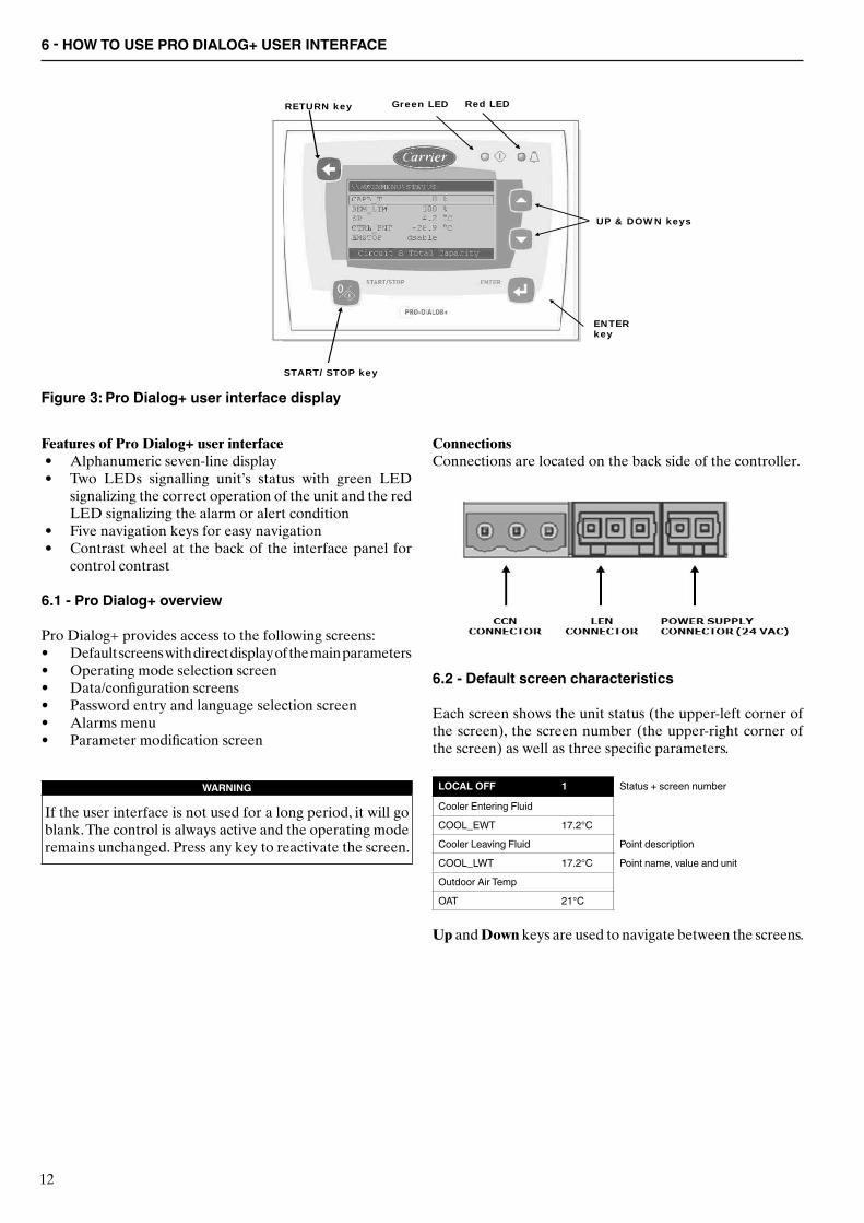
Features of Pro Dialog+ user interface• Alphanumeric seven-line display• Two LEDs signalling unit’s status with green LED
signalizing the correct operation of the unit and the red LED signalizing the alarm or alert condition
• Five navigation keys for easy navigation• Contrast wheel at the back of the interface panel for
control contrast
6.1 - Pro Dialog+ overview
Pro Dialog+ provides access to the following screens:• Default screens with direct display of the main parameters• Operating mode selection screen• Data/configuration screens• Password entry and language selection screen• Alarms menu• Parameter modification screen
WARNING
If the user interface is not used for a long period, it will go blank. The control is always active and the operating mode remains unchanged. Press any key to reactivate the screen.
UP & DOWN keys
ENTERkey
Green LED Red LEDRETURN key
START/STOP key
ConnectionsConnections are located on the back side of the controller.
6 - HOW TO USE PRO DIALOG+ USER INTERFACE
Figure 3: Pro Dialog+ user interface display
6.2 - Default screen characteristics
Each screen shows the unit status (the upper-left corner of the screen), the screen number (the upper-right corner of the screen) as well as three specific parameters.
LOCAL OFF 1 Status + screen number
Cooler Entering Fluid
COOL_EWT 17.2°C
Cooler Leaving Fluid Point description
COOL_LWT 17.2°C Point name, value and unit
Outdoor Air Temp
OAT 21°C
Up and Down keys are used to navigate between the screens.

13
6.3 - Pro Dialog+ menu structure
14
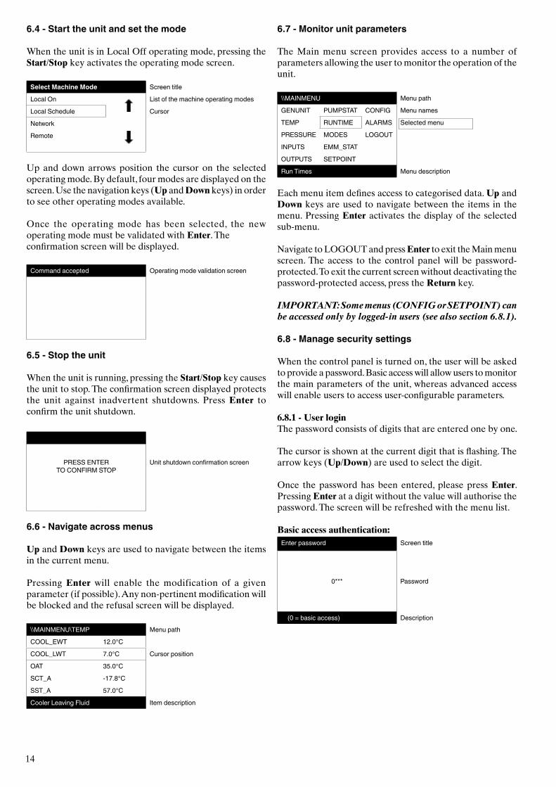
6.4 - Start the unit and set the mode
When the unit is in Local Off operating mode, pressing the Start/Stop key activates the operating mode screen.
Select Machine Mode Screen title
Local On List of the machine operating modes
Local Schedule Cursor
Network
Remote
Up and down arrows position the cursor on the selected operating mode. By default, four modes are displayed on the screen. Use the navigation keys (Up and Down keys) in order to see other operating modes available.
Once the operating mode has been selected, the new operating mode must be validated with Enter. The confirmation screen will be displayed.
Command accepted Operating mode validation screen
6.5 - Stop the unit
When the unit is running, pressing the Start/Stop key causes the unit to stop. The confirmation screen displayed protects the unit against inadvertent shutdowns. Press Enter to confirm the unit shutdown.
PRESS ENTER TO CONFIRM STOP
Unit shutdown confirmation screen
6.6 - Navigate across menus
Up and Down keys are used to navigate between the items in the current menu.
Pressing Enter will enable the modification of a given parameter (if possible). Any non-pertinent modification will be blocked and the refusal screen will be displayed.
\\MAINMENU\TEMP Menu path
COOL_EWT 12.0°C
COOL_LWT 7.0°C Cursor position
OAT 35.0°C
SCT_A -17.8°C
SST_A 57.0°C
Cooler Leaving Fluid Item description
6.7 - Monitor unit parameters
The Main menu screen provides access to a number of parameters allowing the user to monitor the operation of the unit.
\\MAINMENU Menu path
GENUNIT PUMPSTAT CONFIG Menu names
TEMP RUNTIME ALARMS Selected menu
PRESSURE MODES LOGOUT
INPUTS EMM_STAT
OUTPUTS SETPOINT
Run Times Menu description
Each menu item defines access to categorised data. Up and Down keys are used to navigate between the items in the menu. Pressing Enter activates the display of the selected sub-menu.
Navigate to LOGOUT and press Enter to exit the Main menu screen. The access to the control panel will be password-protected. To exit the current screen without deactivating the password-protected access, press the Return key.
IMPORTANT: Some menus (CONFIG or SETPOINT) can be accessed only by logged-in users (see also section 6.8.1).
6.8 - Manage security settings
When the control panel is turned on, the user will be asked to provide a password. Basic access will allow users to monitor the main parameters of the unit, whereas advanced access will enable users to access user-configurable parameters.
6.8.1 - User loginThe password consists of digits that are entered one by one.
The cursor is shown at the current digit that is flashing. The arrow keys (Up/Down) are used to select the digit.
Once the password has been entered, please press Enter. Pressing Enter at a digit without the value will authorise the password. The screen will be refreshed with the menu list.
Basic access authentication:Enter password Screen title
0*** Password
(0 = basic access) Description
15
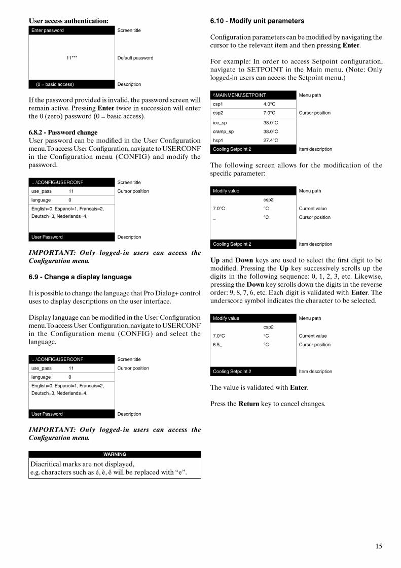
User access authentication:Enter password Screen title
11*** Default password
(0 = basic access) Description
If the password provided is invalid, the password screen will remain active. Pressing Enter twice in succession will enter the 0 (zero) password (0 = basic access).
6.8.2 - Password changeUser password can be modified in the User Configuration menu. To access User Configuration, navigate to USERCONF in the Configuration menu (CONFIG) and modify the password.
…\CONFIG\USERCONF Screen title
use_pass 11 Cursor position
language 0
English=0, Espanol=1, Francais=2, Deutsch=3, Nederlands=4,
User Password Description
IMPORTANT: Only logged-in users can access the Configuration menu.
6.9 - Change a display language
It is possible to change the language that Pro Dialog+ control uses to display descriptions on the user interface.
Display language can be modified in the User Configuration menu. To access User Configuration, navigate to USERCONF in the Configuration menu (CONFIG) and select the language.
…\CONFIG\USERCONF Screen title
use_pass 11 Cursor position
language 0
English=0, Espanol=1, Francais=2, Deutsch=3, Nederlands=4,
User Password Description
IMPORTANT: Only logged-in users can access the Configuration menu.
WARNING
Diacritical marks are not displayed,e.g. characters such as é, è, ê will be replaced with “e”.
6.10 - Modify unit parameters
Configuration parameters can be modified by navigating the cursor to the relevant item and then pressing Enter.
For example: In order to access Setpoint configuration, navigate to SETPOINT in the Main menu. (Note: Only logged-in users can access the Setpoint menu.)
\\MAINMENU\SETPOINT Menu path
csp1 4.0°C
csp2 7.0°C Cursor position
ice_sp 38.0°C
cramp_sp 38.0°C
hsp1 27.4°C
Cooling Setpoint 2 Item description
The following screen allows for the modification of the specific parameter:
Modify value Menu path
csp2
7.0°C °C Current value
_ °C Cursor position
Cooling Setpoint 2 Item description
Up and Down keys are used to select the first digit to be modified. Pressing the Up key successively scrolls up the digits in the following sequence: 0, 1, 2, 3, etc. Likewise, pressing the Down key scrolls down the digits in the reverse order: 9, 8, 7, 6, etc. Each digit is validated with Enter. The underscore symbol indicates the character to be selected.
Modify value Menu path
csp2
7.0°C °C Current value
6.5_ °C Cursor position
Cooling Setpoint 2 Item description
The value is validated with Enter.
Press the Return key to cancel changes.
16
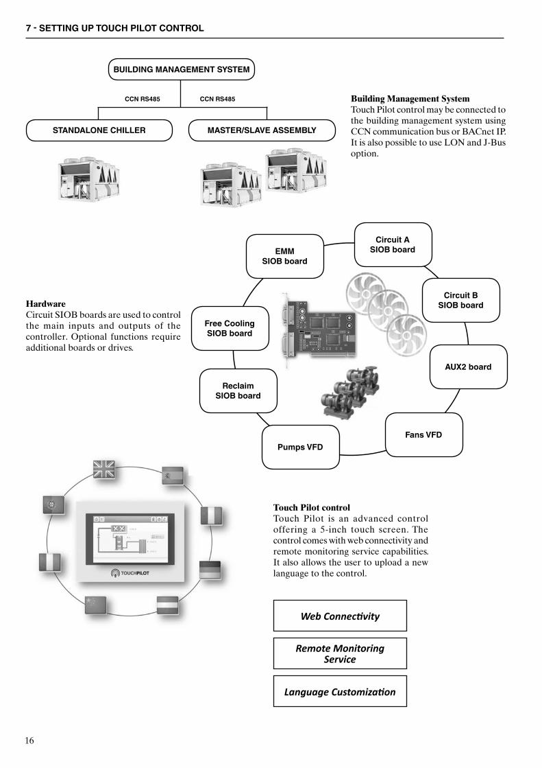
7 - SETTING UP TOUCH PILOT CONTROL
Building Management SystemTouch Pilot control may be connected to the building management system using CCN communication bus or BACnet IP. It is also possible to use LON and J-Bus option.
HardwareCircuit SIOB boards are used to control the main inputs and outputs of the controller. Optional functions require additional boards or drives.
Touch Pilot controlTouch Pilot is an advanced control offering a 5-inch touch screen. The control comes with web connectivity and remote monitoring service capabilities. It also allows the user to upload a new language to the control.
BUILDING MANAGEMENT SYSTEM
STANDALONE CHILLER MASTER/SLAVE ASSEMBLY
CCN RS485 CCN RS485
Circuit A SIOB board
Circuit B SIOB board
AUX2 board
Fans VFDPumps VFD
Reclaim SIOB board
Free Cooling SIOB board
EMM SIOB board
Web Connectivity
Remote MonitoringService
Language Customization
17
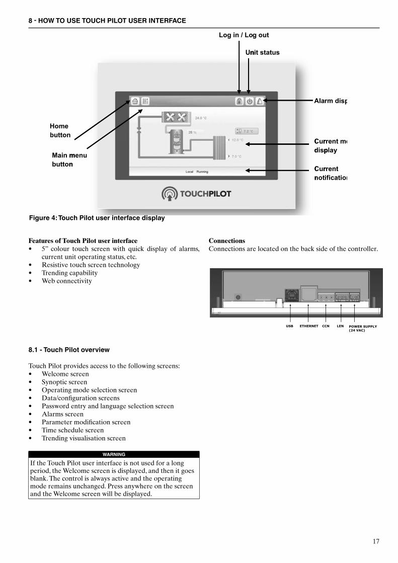
8 - HOW TO USE TOUCH PILOT USER INTERFACE
ConnectionsConnections are located on the back side of the controller.
Figure 4: Touch Pilot user interface display
Features of Touch Pilot user interface• 5” colour touch screen with quick display of alarms,
current unit operating status, etc. • Resistive touch screen technology• Trending capability• Web connectivity
8.1 - Touch Pilot overview
Touch Pilot provides access to the following screens:• Welcome screen• Synoptic screen • Operating mode selection screen• Data/configuration screens • Password entry and language selection screen• Alarms screen• Parameter modification screen• Time schedule screen• Trending visualisation screen
WARNING
If the Touch Pilot user interface is not used for a long period, the Welcome screen is displayed, and then it goes blank. The control is always active and the operating mode remains unchanged. Press anywhere on the screen and the Welcome screen will be displayed.
18
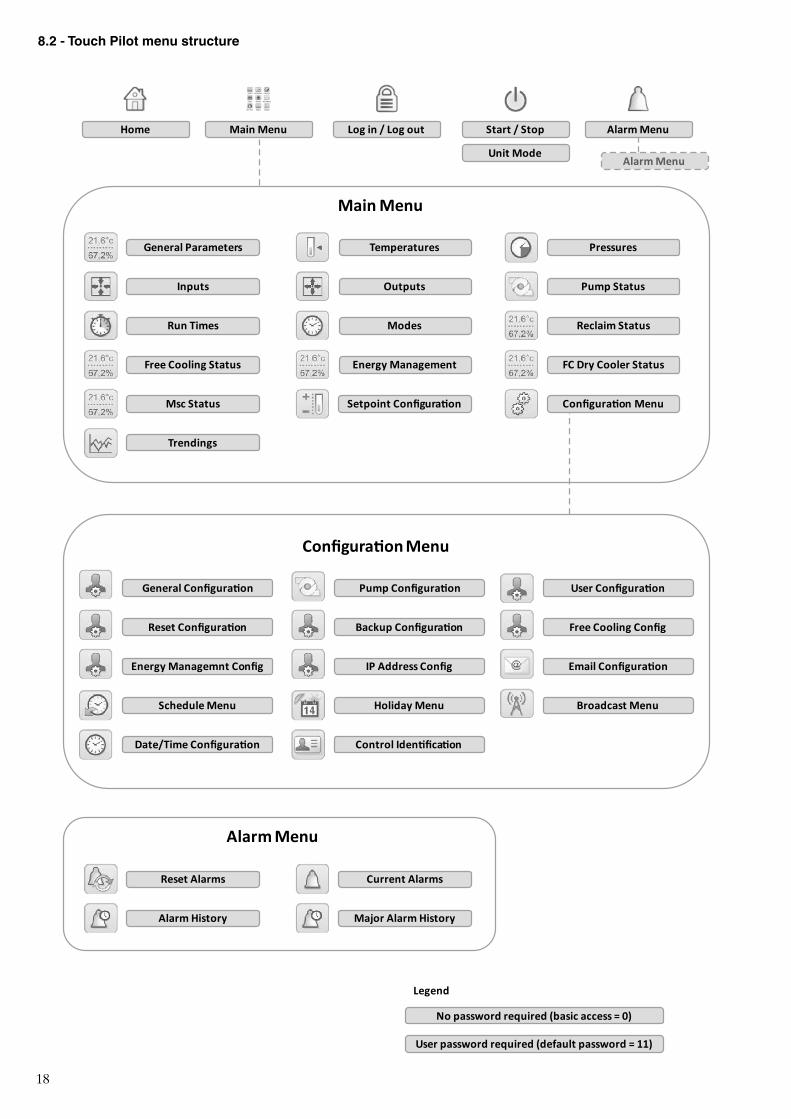
Home Main Menu Log in / Log out Start / Stop
Unit Mode
Alarm Menu
General Parameters Temperatures Pressures
Inputs Outputs Pump Status
Run Times Modes Reclaim Status
Free Cooling Status Energy Management FC Dry Cooler Status
Msc Status Setpoint Configuration Configuration Menu
Trendings
Main Menu
Alarm Menu
General Configuration Pump Configuration User Configuration
Reset Configuration Backup Configuration Free Cooling Config
Energy Managemnt Config IP Address Config Email Configuration
Schedule Menu Holiday Menu Broadcast Menu
Date/Time Configuration Control Identification
Configuration Menu
Reset Alarms Current Alarms
Alarm History Major Alarm History
Alarm Menu
No password required (basic access = 0)
User password required (default password = 11)
Legend
8.2 - Touch Pilot menu structure
19
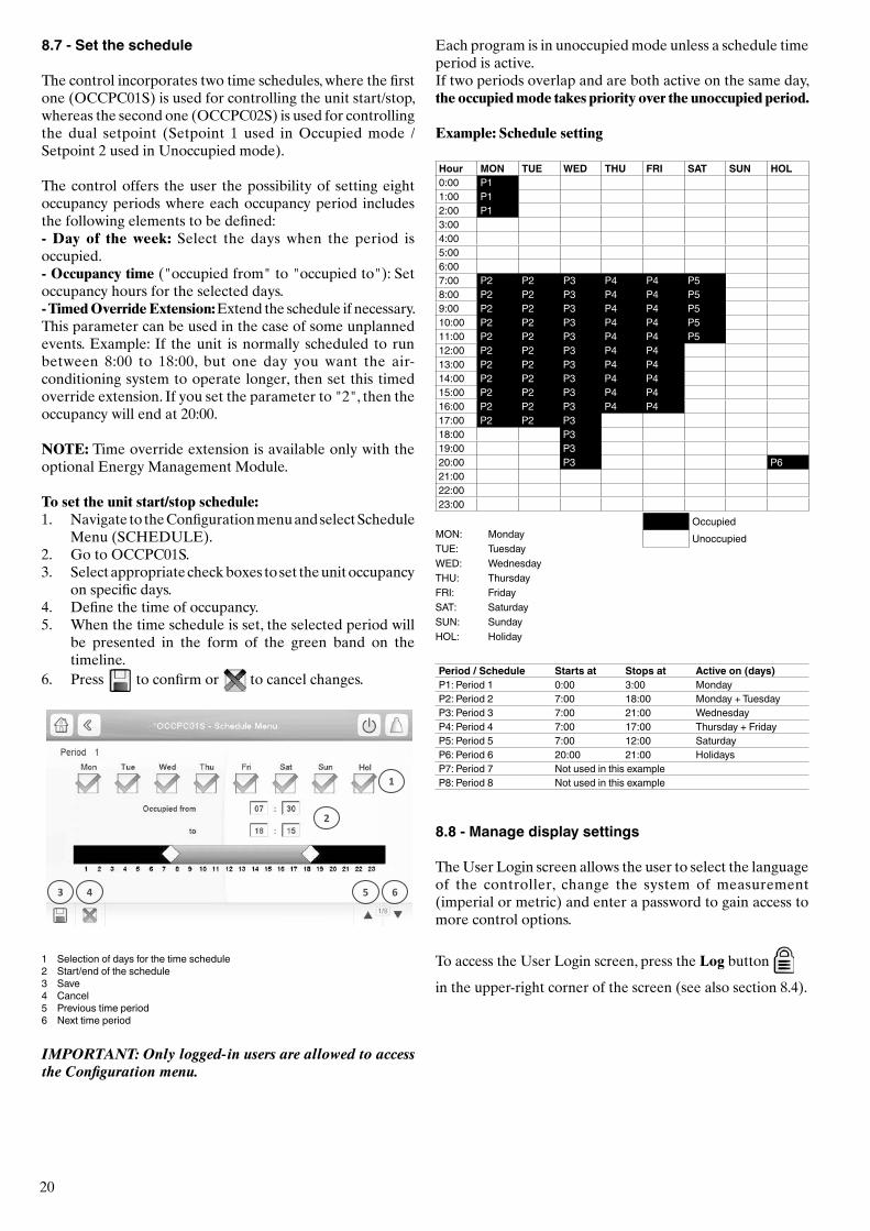
The bell located in the upper-right part of the screen lights when any fault is detected. By default, the parameters are presented in metric units. For more information on how to change the system of measurement, see section 8.8.3.
8.5 - Start the unit
With the unit in the Local off mode, press the Start/Stop
button to display the list of operating modes and select
the required mode.
Local On Local On: The unit is in the local control mode and allowed to start.
Local Schedule
Local Schedule: The unit is in the local control mode and allowed to start if the period is occupied.
Network Network: The unit is controlled by network commands and allowed to start if the period is occupied.
Remote Remote: The unit is controlled by external commands and allowed to start if the period is occupied.
Master Master: The unit operates as the master in the master/slave assembly and allowed to start if the period is occupied.
IMPORTANT: When entering the menu, please note that the currently selected item corresponds to the last running operating mode.
8.6 - Stop the unit
To stop the unit, press the Start/Stop button
Confirm the unit shutdown by pressing Confirm Stop or cancel the unit shut-down by pressing the
Back button
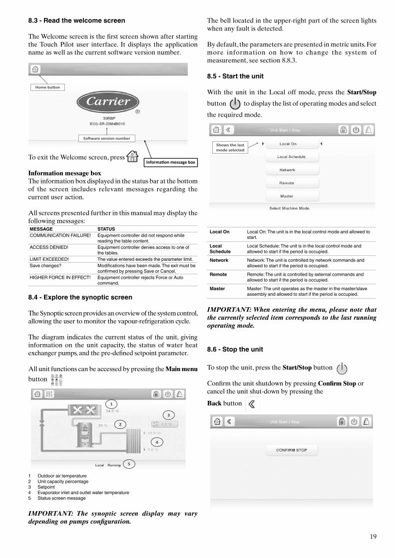
8.3 - Read the welcome screen
The Welcome screen is the first screen shown after starting the Touch Pilot user interface. It displays the application name as well as the current software version number.
To exit the Welcome screen, press
Information message boxThe information box displayed in the status bar at the bottom of the screen includes relevant messages regarding the current user action.
All screens presented further in this manual may display the following messages:MESSAGE STATUSCOMMUNICATION FAILURE! Equipment controller did not respond while
reading the table content.ACCESS DENIED! Equipment controller denies access to one of
the tables.LIMIT EXCEEDED! The value entered exceeds the parameter limit.Save changes? Modifications have been made. The exit must be
confirmed by pressing Save or Cancel.HIGHER FORCE IN EFFECT! Equipment controller rejects Force or Auto
command.
8.4 - Explore the synoptic screen
The Synoptic screen provides an overview of the system control, allowing the user to monitor the vapour-refrigeration cycle.
The diagram indicates the current status of the unit, giving information on the unit capacity, the status of water heat exchanger pumps, and the pre-defined setpoint parameter.
All unit functions can be accessed by pressing the Main menu
button
1 Outdoor air temperature2 Unit capacity percentage3 Setpoint4 Evaporator inlet and outlet water temperature5 Status screen message
IMPORTANT: The synoptic screen display may vary depending on pumps configuration.
Information message box
20
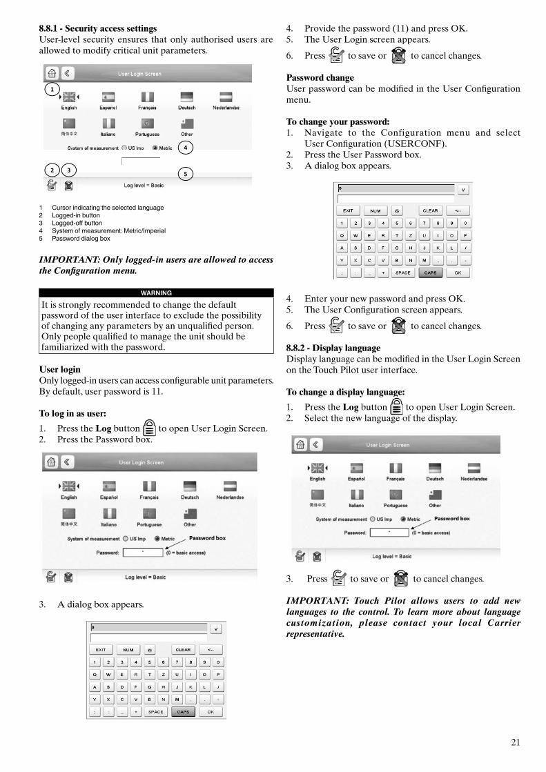
8.7 - Set the schedule
The control incorporates two time schedules, where the first one (OCCPC01S) is used for controlling the unit start/stop, whereas the second one (OCCPC02S) is used for controlling the dual setpoint (Setpoint 1 used in Occupied mode / Setpoint 2 used in Unoccupied mode).
The control offers the user the possibility of setting eight occupancy periods where each occupancy period includes the following elements to be defined: - Day of the week: Select the days when the period is occupied. - Occupancy time ("occupied from" to "occupied to"): Set occupancy hours for the selected days. - Timed Override Extension: Extend the schedule if necessary. This parameter can be used in the case of some unplanned events. Example: If the unit is normally scheduled to run between 8:00 to 18:00, but one day you want the air-conditioning system to operate longer, then set this timed override extension. If you set the parameter to "2", then the occupancy will end at 20:00.
NOTE: Time override extension is available only with the optional Energy Management Module.
To set the unit start/stop schedule:1. Navigate to the Configuration menu and select Schedule
Menu (SCHEDULE).2. Go to OCCPC01S. 3. Select appropriate check boxes to set the unit occupancy
on specific days.4. Define the time of occupancy.5. When the time schedule is set, the selected period will
be presented in the form of the green band on the timeline.
6. Press to confirm or to cancel changes.
1 Selection of days for the time schedule2 Start/end of the schedule3 Save4 Cancel5 Previous time period6 Next time period
IMPORTANT: Only logged-in users are allowed to access the Configuration menu.
Each program is in unoccupied mode unless a schedule time period is active. If two periods overlap and are both active on the same day, the occupied mode takes priority over the unoccupied period.
Example: Schedule setting
Hour MON TUE WED THU FRI SAT SUN HOL0:00 P11:00 P12:00 P13:004:005:006:007:00 P2 P2 P3 P4 P4 P58:00 P2 P2 P3 P4 P4 P59:00 P2 P2 P3 P4 P4 P510:00 P2 P2 P3 P4 P4 P511:00 P2 P2 P3 P4 P4 P512:00 P2 P2 P3 P4 P413:00 P2 P2 P3 P4 P414:00 P2 P2 P3 P4 P415:00 P2 P2 P3 P4 P416:00 P2 P2 P3 P4 P417:00 P2 P2 P318:00 P319:00 P320:00 P3 P621:0022:0023:00
MON: MondayTUE: TuesdayWED: WednesdayTHU: ThursdayFRI: FridaySAT: SaturdaySUN: SundayHOL: Holiday
Period / Schedule Starts at Stops at Active on (days)P1: Period 1 0:00 3:00 MondayP2: Period 2 7:00 18:00 Monday + TuesdayP3: Period 3 7:00 21:00 WednesdayP4: Period 4 7:00 17:00 Thursday + FridayP5: Period 5 7:00 12:00 SaturdayP6: Period 6 20:00 21:00 HolidaysP7: Period 7 Not used in this exampleP8: Period 8 Not used in this example
8.8 - Manage display settings
The User Login screen allows the user to select the language of the controller, change the system of measurement (imperial or metric) and enter a password to gain access to more control options.
To access the User Login screen, press the Log button
in the upper-right corner of the screen (see also section 8.4).
Occupied Unoccupied
21
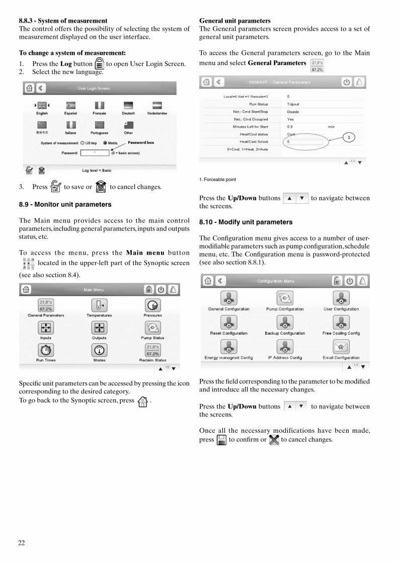
8.8.1 - Security access settingsUser-level security ensures that only authorised users are allowed to modify critical unit parameters.
1 Cursor indicating the selected language2 Logged-in button3 Logged-off button4 System of measurement: Metric/Imperial5 Password dialog box
IMPORTANT: Only logged-in users are allowed to access the Configuration menu.
WARNING
It is strongly recommended to change the default password of the user interface to exclude the possibility of changing any parameters by an unqualified person.Only people qualified to manage the unit should be familiarized with the password.
User loginOnly logged-in users can access configurable unit parameters. By default, user password is 11.
To log in as user:
1. Press the Log button to open User Login Screen. 2. Press the Password box.
3. A dialog box appears.
4. Provide the password (11) and press OK. 5. The User Login screen appears.
6. Press to save or to cancel changes.
Password changeUser password can be modified in the User Configuration menu.
To change your password:1. Navigate to the Configuration menu and select
User Configuration (USERCONF).2. Press the User Password box.3. A dialog box appears.
4. Enter your new password and press OK.5. The User Configuration screen appears.
6. Press to save or to cancel changes.
8.8.2 - Display languageDisplay language can be modified in the User Login Screen on the Touch Pilot user interface.
To change a display language:
1. Press the Log button to open User Login Screen.2. Select the new language of the display.
3. Press to save or to cancel changes.
IMPORTANT: Touch Pilot allows users to add new languages to the control. To learn more about language customization, please contact your local Carrier representative.
22
8.8.3 - System of measurementThe control offers the possibility of selecting the system of measurement displayed on the user interface.
To change a system of measurement:
1. Press the Log button to open User Login Screen.2. Select the new language.
3. Press to save or to cancel changes.
8.9 - Monitor unit parameters
The Main menu provides access to the main control parameters, including general parameters, inputs and outputs status, etc. To access the menu, press the Main menu button
located in the upper-left part of the Synoptic screen
(see also section 8.4).
Specific unit parameters can be accessed by pressing the icon corresponding to the desired category. To go back to the Synoptic screen, press .
General unit parametersThe General parameters screen provides access to a set of general unit parameters.
To access the General parameters screen, go to the Main
menu and select General Parameters
1. Forceable point
Press the Up/Down buttons to navigate between the screens.
8.10 - Modify unit parameters
The Configuration menu gives access to a number of user-modifiable parameters such as pump configuration, schedule menu, etc. The Configuration menu is password-protected (see also section 8.8.1).
Press the field corresponding to the parameter to be modified and introduce all the necessary changes.
Press the Up/Down buttons to navigate between the screens.
Once all the necessary modifications have been made, press to confirm or to cancel changes.
23
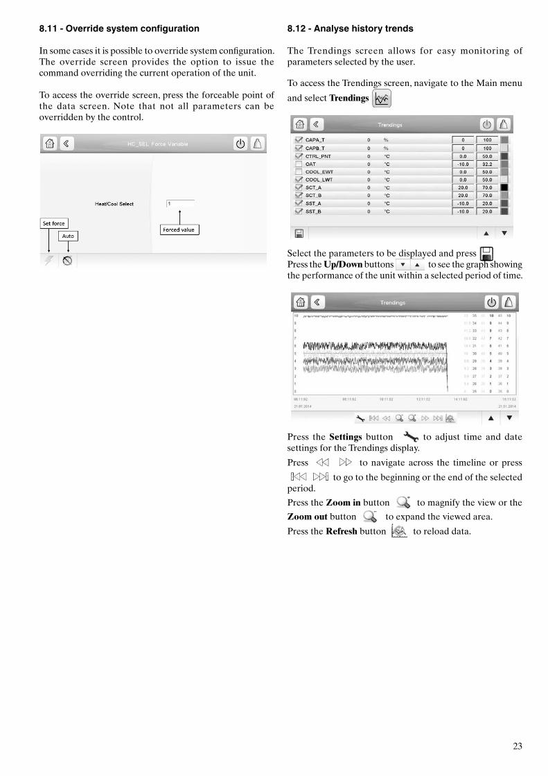
8.11 - Override system configuration
In some cases it is possible to override system configuration. The override screen provides the option to issue the command overriding the current operation of the unit.
To access the override screen, press the forceable point of the data screen. Note that not all parameters can be overridden by the control.
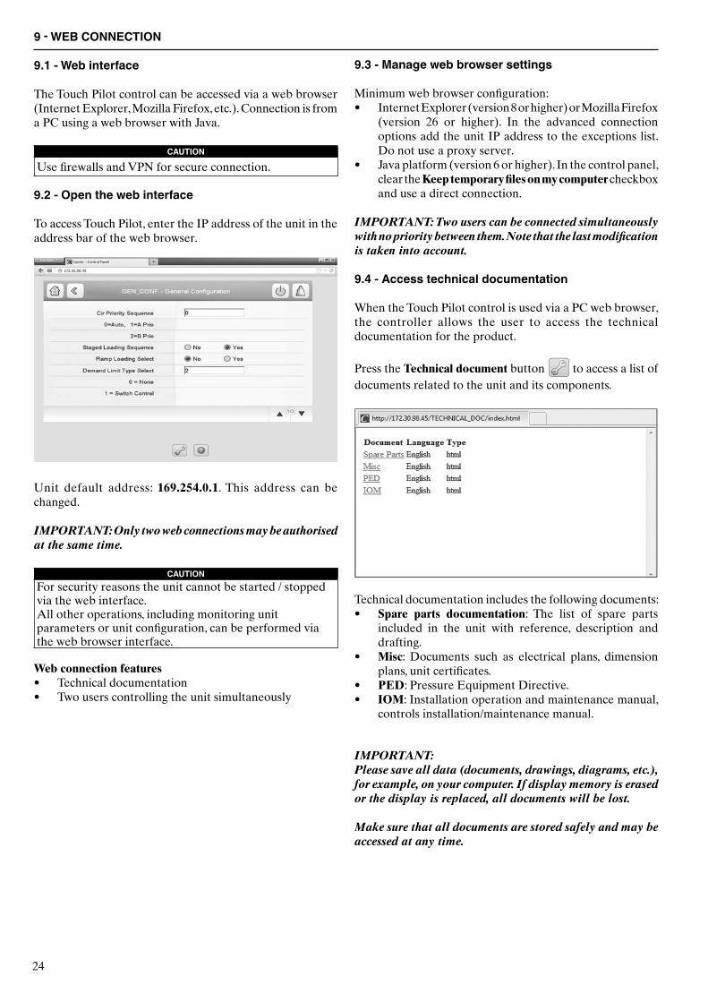
8.12 - Analyse history trends
The Trendings screen allows for easy monitoring of parameters selected by the user.
To access the Trendings screen, navigate to the Main menu
and select Trendings
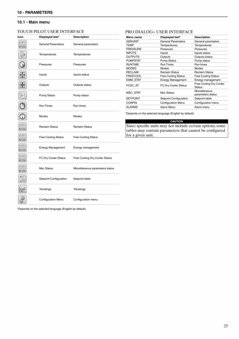
Select the parameters to be displayed and press Press the Up/Down buttons to see the graph showing the performance of the unit within a selected period of time.
Press the Settings button to adjust time and date settings for the Trendings display.
Press to navigate across the timeline or press
to go to the beginning or the end of the selected period.
Press the Zoom in button to magnify the view or the
Zoom out button to expand the viewed area.
Press the Refresh button to reload data.
24
9.3 - Manage web browser settings
Minimum web browser configuration:• Internet Explorer (version 8 or higher) or Mozilla Firefox
(version 26 or higher). In the advanced connection options add the unit IP address to the exceptions list. Do not use a proxy server.
• Java platform (version 6 or higher). In the control panel, clear the Keep temporary files on my computer checkbox and use a direct connection.
IMPORTANT: Two users can be connected simultaneously with no priority between them. Note that the last modification is taken into account.
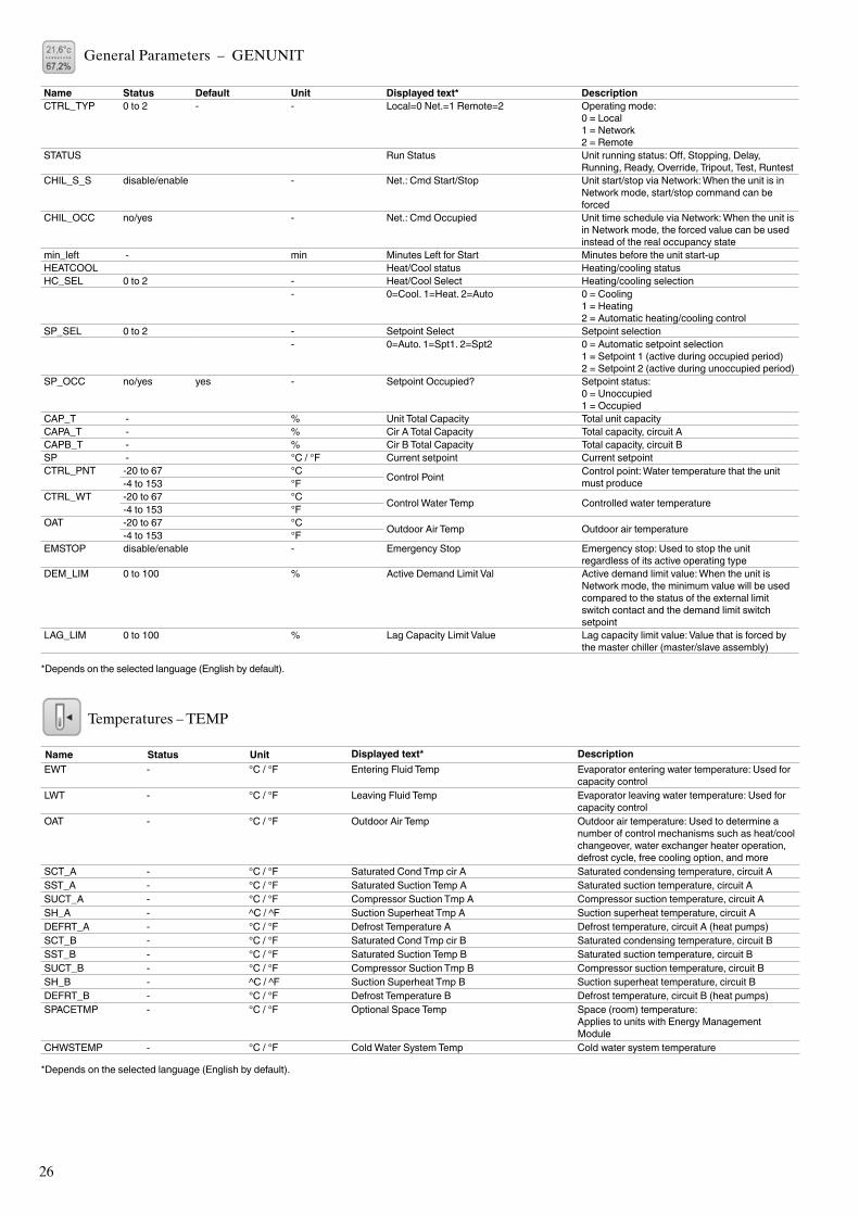
9.4 - Access technical documentation
When the Touch Pilot control is used via a PC web browser, the controller allows the user to access the technical documentation for the product.
Press the Technical document button to access a list of documents related to the unit and its components.
Technical documentation includes the following documents:• Spare parts documentation: The list of spare parts
included in the unit with reference, description and drafting.
• Misc: Documents such as electrical plans, dimension plans, unit certificates.
• PED: Pressure Equipment Directive.• IOM: Installation operation and maintenance manual,
controls installation/maintenance manual.
IMPORTANT: Please save all data (documents, drawings, diagrams, etc.), for example, on your computer. If display memory is erased or the display is replaced, all documents will be lost.
Make sure that all documents are stored safely and may be accessed at any time.
9 - WEB CONNECTION
9.1 - Web interface
The Touch Pilot control can be accessed via a web browser (Internet Explorer, Mozilla Firefox, etc.). Connection is from a PC using a web browser with Java.
CAUTION
Use firewalls and VPN for secure connection.
9.2 - Open the web interface
To access Touch Pilot, enter the IP address of the unit in the address bar of the web browser.
Unit default address: 169.254.0.1. This address can be changed.
IMPORTANT: Only two web connections may be authorised at the same time.
CAUTIONFor security reasons the unit cannot be started / stopped via the web interface.All other operations, including monitoring unit parameters or unit configuration, can be performed via the web browser interface.
Web connection features• Technical documentation• Two users controlling the unit simultaneously
25
TOUCH PILOT USER INTERFACEIcon Displayed text* Description
General Parameters General parameters
Temperatures Temperatures
Pressures Pressures
Inputs Inputs status
Outputs Outputs status
Pump Status Pump status
Run Times Run times
Modes Modes
Reclaim Status Reclaim Status
Free Cooling Status Free Cooling Status
Energy Management Energy management
FC Dry Cooler Status Free Cooling Dry Cooler Status
Msc Status Miscellaneous parameters status
Setpoint Configuration Setpoint table
Trendings Trendings
Configuration Menu Configuration menu
*Depends on the selected language (English by default).
10 - PARAMETERS
10.1 - Main menu
PRO DIALOG+ USER INTERFACEMenu name Displayed text* DescriptionGENUNIT General Parameters General parametersTEMP Temperatures TemperaturesPRESSURE Pressures PressuresINPUTS Inputs Inputs statusOUTPUTS Outputs Outputs statusPUMPSTAT Pump Status Pump statusRUNTIME Run Times Run timesMODES Modes ModesRECLAIM Reclaim Status Reclaim StatusFREECOOL Free Cooling Status Free Cooling StatusEMM_STAT Energy Management Energy management
FCDC_ST FC Dry Cooler Status Free Cooling Dry Cooler Status
MSC_STAT Msc Status Miscellaneous parameters status
SETPOINT Setpoint Configuration Setpoint tableCONFIG Configuration Menu Configuration menuALARMS Alarm Menu Alarm menu
*Depends on the selected language (English by default).
CAUTIONSince specific units may not include certain options, some tables may contain parameters that cannot be configured for a given unit.
26
General Parameters – GENUNIT
Name Status Default Unit Displayed text* DescriptionCTRL_TYP 0 to 2 - - Local=0 Net.=1 Remote=2 Operating mode:
0 = Local1 = Network2 = Remote
STATUS Run Status Unit running status: Off, Stopping, Delay, Running, Ready, Override, Tripout, Test, Runtest
CHIL_S_S disable/enable - Net.: Cmd Start/Stop Unit start/stop via Network: When the unit is in Network mode, start/stop command can be forced
CHIL_OCC no/yes - Net.: Cmd Occupied Unit time schedule via Network: When the unit is in Network mode, the forced value can be used instead of the real occupancy state
min_left - min Minutes Left for Start Minutes before the unit start-upHEATCOOL Heat/Cool status Heating/cooling statusHC_SEL 0 to 2 - Heat/Cool Select Heating/cooling selection
- 0=Cool. 1=Heat. 2=Auto 0 = Cooling 1 = Heating2 = Automatic heating/cooling control
SP_SEL 0 to 2 - Setpoint Select Setpoint selection- 0=Auto. 1=Spt1. 2=Spt2 0 = Automatic setpoint selection
1 = Setpoint 1 (active during occupied period)2 = Setpoint 2 (active during unoccupied period)
SP_OCC no/yes yes - Setpoint Occupied? Setpoint status:0 = Unoccupied1 = Occupied
CAP_T - % Unit Total Capacity Total unit capacityCAPA_T - % Cir A Total Capacity Total capacity, circuit ACAPB_T - % Cir B Total Capacity Total capacity, circuit BSP - °C / °F Current setpoint Current setpoint CTRL_PNT -20 to 67 °C Control Point Control point: Water temperature that the unit
must produce-4 to 153 °FCTRL_WT
-20 to 67 °C Control Water Temp Controlled water temperature-4 to 153 °FOAT
-20 to 67 °C Outdoor Air Temp Outdoor air temperature-4 to 153 °FEMSTOP disable/enable - Emergency Stop Emergency stop: Used to stop the unit
regardless of its active operating typeDEM_LIM 0 to 100 % Active Demand Limit Val Active demand limit value: When the unit is
Network mode, the minimum value will be used compared to the status of the external limit switch contact and the demand limit switch setpoint
LAG_LIM 0 to 100 % Lag Capacity Limit Value Lag capacity limit value: Value that is forced by the master chiller (master/slave assembly)
*Depends on the selected language (English by default).
Temperatures – TEMP
Name Status Unit Displayed text* DescriptionEWT - °C / °F Entering Fluid Temp Evaporator entering water temperature: Used for
capacity control LWT - °C / °F Leaving Fluid Temp Evaporator leaving water temperature: Used for
capacity control OAT - °C / °F Outdoor Air Temp Outdoor air temperature: Used to determine a
number of control mechanisms such as heat/cool changeover, water exchanger heater operation, defrost cycle, free cooling option, and more
SCT_A - °C / °F Saturated Cond Tmp cir A Saturated condensing temperature, circuit ASST_A - °C / °F Saturated Suction Temp A Saturated suction temperature, circuit ASUCT_A - °C / °F Compressor Suction Tmp A Compressor suction temperature, circuit ASH_A - ^C / ^F Suction Superheat Tmp A Suction superheat temperature, circuit ADEFRT_A - °C / °F Defrost Temperature A Defrost temperature, circuit A (heat pumps)SCT_B - °C / °F Saturated Cond Tmp cir B Saturated condensing temperature, circuit BSST_B - °C / °F Saturated Suction Temp B Saturated suction temperature, circuit BSUCT_B - °C / °F Compressor Suction Tmp B Compressor suction temperature, circuit BSH_B - ^C / ^F Suction Superheat Tmp B Suction superheat temperature, circuit BDEFRT_B - °C / °F Defrost Temperature B Defrost temperature, circuit B (heat pumps)SPACETMP - °C / °F Optional Space Temp Space (room) temperature:
Applies to units with Energy Management Module
CHWSTEMP - °C / °F Cold Water System Temp Cold water system temperature
*Depends on the selected language (English by default).
27
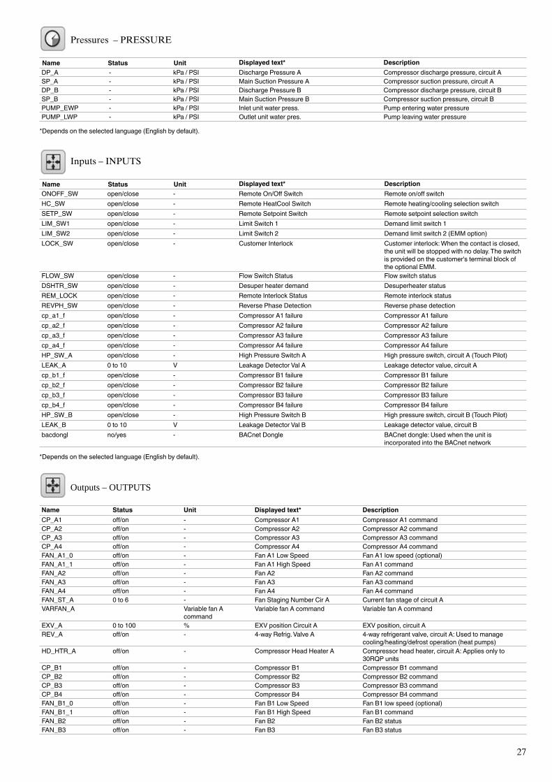
Pressures – PRESSURE
Name Status Unit Displayed text* DescriptionDP_A - kPa / PSI Discharge Pressure A Compressor discharge pressure, circuit A SP_A - kPa / PSI Main Suction Pressure A Compressor suction pressure, circuit ADP_B - kPa / PSI Discharge Pressure B Compressor discharge pressure, circuit BSP_B - kPa / PSI Main Suction Pressure B Compressor suction pressure, circuit BPUMP_EWP - kPa / PSI Inlet unit water press. Pump entering water pressurePUMP_LWP - kPa / PSI Outlet unit water pres. Pump leaving water pressure
*Depends on the selected language (English by default).
Inputs – INPUTS
Name Status Unit Displayed text* DescriptionONOFF_SW open/close - Remote On/Off Switch Remote on/off switch HC_SW open/close - Remote HeatCool Switch Remote heating/cooling selection switch SETP_SW open/close - Remote Setpoint Switch Remote setpoint selection switch LIM_SW1 open/close - Limit Switch 1 Demand limit switch 1 LIM_SW2 open/close - Limit Switch 2 Demand limit switch 2 (EMM option)LOCK_SW open/close - Customer Interlock Customer interlock: When the contact is closed,
the unit will be stopped with no delay. The switch is provided on the customer's terminal block of the optional EMM.
FLOW_SW open/close - Flow Switch Status Flow switch statusDSHTR_SW open/close - Desuper heater demand Desuperheater statusREM_LOCK open/close - Remote Interlock Status Remote interlock statusREVPH_SW open/close - Reverse Phase Detection Reverse phase detectioncp_a1_f open/close - Compressor A1 failure Compressor A1 failurecp_a2_f open/close - Compressor A2 failure Compressor A2 failurecp_a3_f open/close - Compressor A3 failure Compressor A3 failurecp_a4_f open/close - Compressor A4 failure Compressor A4 failureHP_SW_A open/close - High Pressure Switch A High pressure switch, circuit A (Touch Pilot)LEAK_A 0 to 10 V Leakage Detector Val A Leakage detector value, circuit Acp_b1_f open/close - Compressor B1 failure Compressor B1 failurecp_b2_f open/close - Compressor B2 failure Compressor B2 failurecp_b3_f open/close - Compressor B3 failure Compressor B3 failurecp_b4_f open/close - Compressor B4 failure Compressor B4 failureHP_SW_B open/close - High Pressure Switch B High pressure switch, circuit B (Touch Pilot)LEAK_B 0 to 10 V Leakage Detector Val B Leakage detector value, circuit Bbacdongl no/yes - BACnet Dongle BACnet dongle: Used when the unit is
incorporated into the BACnet network
*Depends on the selected language (English by default).
Outputs – OUTPUTS
Name Status Unit Displayed text* DescriptionCP_A1 off/on - Compressor A1 Compressor A1 commandCP_A2 off/on - Compressor A2 Compressor A2 commandCP_A3 off/on - Compressor A3 Compressor A3 commandCP_A4 off/on - Compressor A4 Compressor A4 commandFAN_A1_0 off/on - Fan A1 Low Speed Fan A1 low speed (optional)FAN_A1_1 off/on - Fan A1 High Speed Fan A1 commandFAN_A2 off/on - Fan A2 Fan A2 commandFAN_A3 off/on - Fan A3 Fan A3 commandFAN_A4 off/on - Fan A4 Fan A4 commandFAN_ST_A 0 to 6 - Fan Staging Number Cir A Current fan stage of circuit AVARFAN_A Variable fan A
commandVariable fan A command Variable fan A command
EXV_A 0 to 100 % EXV position Circuit A EXV position, circuit AREV_A off/on - 4-way Refrig. Valve A 4-way refrigerant valve, circuit A: Used to manage
cooling/heating/defrost operation (heat pumps)HD_HTR_A off/on - Compressor Head Heater A Compressor head heater, circuit A: Applies only to
30RQP unitsCP_B1 off/on - Compressor B1 Compressor B1 commandCP_B2 off/on - Compressor B2 Compressor B2 command CP_B3 off/on - Compressor B3 Compressor B3 commandCP_B4 off/on - Compressor B4 Compressor B4 commandFAN_B1_0 off/on - Fan B1 Low Speed Fan B1 low speed (optional)FAN_B1_1 off/on - Fan B1 High Speed Fan B1 commandFAN_B2 off/on - Fan B2 Fan B2 statusFAN_B3 off/on - Fan B3 Fan B3 status
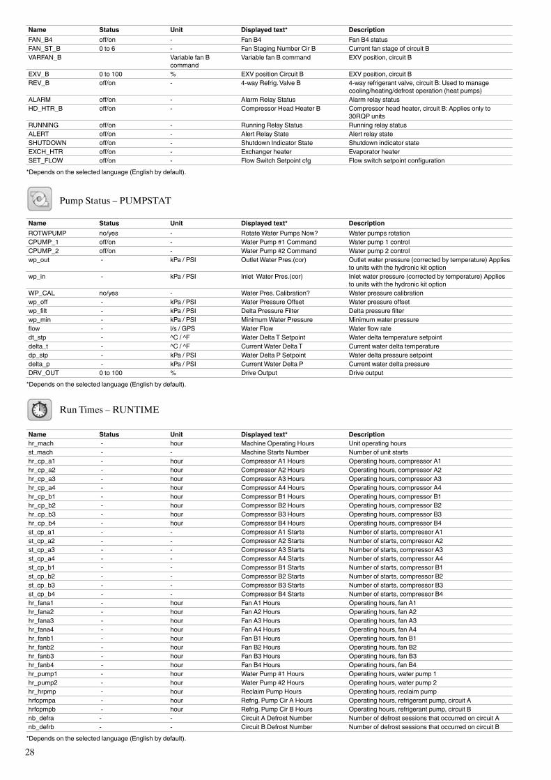
28
Name Status Unit Displayed text* DescriptionFAN_B4 off/on - Fan B4 Fan B4 statusFAN_ST_B 0 to 6 - Fan Staging Number Cir B Current fan stage of circuit BVARFAN_B Variable fan B
commandVariable fan B command EXV position, circuit B
EXV_B 0 to 100 % EXV position Circuit B EXV position, circuit BREV_B off/on - 4-way Refrig. Valve B 4-way refrigerant valve, circuit B: Used to manage
cooling/heating/defrost operation (heat pumps)ALARM off/on - Alarm Relay Status Alarm relay statusHD_HTR_B off/on - Compressor Head Heater B Compressor head heater, circuit B: Applies only to
30RQP units RUNNING off/on - Running Relay Status Running relay statusALERT off/on - Alert Relay State Alert relay stateSHUTDOWN off/on - Shutdown Indicator State Shutdown indicator stateEXCH_HTR off/on - Exchanger heater Evaporator heater SET_FLOW off/on - Flow Switch Setpoint cfg Flow switch setpoint configuration
*Depends on the selected language (English by default).
Pump Status – PUMPSTAT
Name Status Unit Displayed text* DescriptionROTWPUMP no/yes - Rotate Water Pumps Now? Water pumps rotationCPUMP_1 off/on - Water Pump #1 Command Water pump 1 controlCPUMP_2 off/on - Water Pump #2 Command Water pump 2 controlwp_out - kPa / PSI Outlet Water Pres.(cor) Outlet water pressure (corrected by temperature) Applies
to units with the hydronic kit optionwp_in - kPa / PSI Inlet Water Pres.(cor) Inlet water pressure (corrected by temperature) Applies
to units with the hydronic kit optionWP_CAL no/yes - Water Pres. Calibration? Water pressure calibrationwp_off - kPa / PSI Water Pressure Offset Water pressure offsetwp_filt - kPa / PSI Delta Pressure Filter Delta pressure filterwp_min - kPa / PSI Minimum Water Pressure Minimum water pressureflow - l/s / GPS Water Flow Water flow ratedt_stp - ^C / ^F Water Delta T Setpoint Water delta temperature setpointdelta_t - ^C / ^F Current Water Delta T Current water delta temperaturedp_stp - kPa / PSI Water Delta P Setpoint Water delta pressure setpointdelta_p - kPa / PSI Current Water Delta P Current water delta pressureDRV_OUT 0 to 100 % Drive Output Drive output
*Depends on the selected language (English by default).
Run Times – RUNTIME
Name Status Unit Displayed text* Descriptionhr_mach - hour Machine Operating Hours Unit operating hoursst_mach - - Machine Starts Number Number of unit startshr_cp_a1 - hour Compressor A1 Hours Operating hours, compressor A1hr_cp_a2 - hour Compressor A2 Hours Operating hours, compressor A2hr_cp_a3 - hour Compressor A3 Hours Operating hours, compressor A3hr_cp_a4 - hour Compressor A4 Hours Operating hours, compressor A4hr_cp_b1 - hour Compressor B1 Hours Operating hours, compressor B1hr_cp_b2 - hour Compressor B2 Hours Operating hours, compressor B2hr_cp_b3 - hour Compressor B3 Hours Operating hours, compressor B3hr_cp_b4 - hour Compressor B4 Hours Operating hours, compressor B4st_cp_a1 - - Compressor A1 Starts Number of starts, compressor A1st_cp_a2 - - Compressor A2 Starts Number of starts, compressor A2st_cp_a3 - - Compressor A3 Starts Number of starts, compressor A3st_cp_a4 - - Compressor A4 Starts Number of starts, compressor A4st_cp_b1 - - Compressor B1 Starts Number of starts, compressor B1st_cp_b2 - - Compressor B2 Starts Number of starts, compressor B2st_cp_b3 - - Compressor B3 Starts Number of starts, compressor B3st_cp_b4 - - Compressor B4 Starts Number of starts, compressor B4hr_fana1 - hour Fan A1 Hours Operating hours, fan A1hr_fana2 - hour Fan A2 Hours Operating hours, fan A2hr_fana3 - hour Fan A3 Hours Operating hours, fan A3hr_fana4 - hour Fan A4 Hours Operating hours, fan A4hr_fanb1 - hour Fan B1 Hours Operating hours, fan B1hr_fanb2 - hour Fan B2 Hours Operating hours, fan B2hr_fanb3 - hour Fan B3 Hours Operating hours, fan B3hr_fanb4 - hour Fan B4 Hours Operating hours, fan B4hr_pump1 - hour Water Pump #1 Hours Operating hours, water pump 1hr_pump2 - hour Water Pump #2 Hours Operating hours, water pump 2hr_hrpmp - hour Reclaim Pump Hours Operating hours, reclaim pumphrfcpmpa - hour Refrig. Pump Cir A Hours Operating hours, refrigerant pump, circuit Ahrfcpmpb - hour Refrig. Pump Cir B Hours Operating hours, refrigerant pump, circuit Bnb_defra - - Circuit A Defrost Number Number of defrost sessions that occurred on circuit Anb_defrb - - Circuit B Defrost Number Number of defrost sessions that occurred on circuit B
*Depends on the selected language (English by default).
29
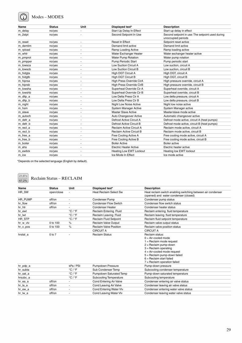
Modes – MODES
Name Status Unit Displayed text* Descriptionm_delay no/yes - Start Up Delay In Effect Start-up delay in effectm_2stpt no/yes - Second Setpoint In Use Second setpoint in use: The setpoint used during
unoccupied periodsm_reset no/yes - Reset In Effect Setpoint reset activem_demlim no/yes - Demand limit active Demand limit activem_rpload no/yes - Ramp Loading Active Ramp loading activem_whtr no/yes - Water Exchanger Heater Water exchanger heater activem_pmprot no/yes - Water Pump Rotation Water pump rotationm_pmpper no/yes - Pump Periodic Start Pump periodic start m_lowsca no/yes - Low Suction Circuit A Low suction, circuit Am_lowscb no/yes - Low Suction Circuit B Low suction, circuit Bm_hidgta no/yes - High DGT Circuit A High DGT, circuit Am_hidgtb no/yes - High DGT Circuit B High DGT, circuit Bm_hiprsa no/yes - High Press Override CirA High pressure override, circuit Am_hiprsb no/yes - High Press Override CirB High pressure override, circuit Bm_lowsha no/yes - Superheat Override Cir A Superheat override, circuit Am_lowshb no/yes - Superheat Override Cir B Superheat override, circuit Bm_dltp_a no/yes - Low Delta Press Cir A Low delta pressure, circuit Am_dltp_b no/yes - Low Delta Press Cir B Low delta pressure, circuit Bm_night no/yes - Night Low Noise Active Night low noise activem_hsm no/yes - System Manager Active System Manager activem_slave no/yes - Master Slave Active Master/slave mode activem_autoch no/yes - Auto Changeover Active Automatic changeover activem_defr_a no/yes - Defrost Active Circuit A Defrost mode active, circuit A (heat pumps)m_defr_b no/yes - Defrost Active Circuit B Defrost mode active, circuit B (heat pumps)m_recl_a no/yes - Reclaim Active Circuit A Reclaim mode active, circuit Am_recl_b no/yes - Reclaim Active Circuit B Reclaim mode active, circuit Bm_free_a no/yes - Free Cooling Active A Free cooling mode active, circuit Am_free_b no/yes - Free Cooling Active B Free cooling mode active, circuit Bm_boiler no/yes - Boiler Active Boiler activem_ehs no/yes - Electric Heater Active Electric heater activem_ewtlck no/yes - Heating Low EWT Lockout Heating low EWT lockoutm_ice no/yes - Ice Mode In Effect Ice mode active
*Depends on the selected language (English by default).
Reclaim Status – RECLAIM
Name Status Unit Displayed text* DescriptionHR_SW open/close - Heat Reclaim Select Sw Heat reclaim switch enabling switching between air condenser
(opened) and water condenser (closed)HR_PUMP off/on - Condenser Pump Condenser pump statushr_flow off/on - Condenser Flow Switch Condenser flow switch statushr_htr off/on - Condenser Heater Condenser heater statushr_ewt °C / °F Reclaim Entering Fluid Reclaim entering fluid temperaturehr_lwt °C / °F Reclaim Leaving Fluid Reclaim leaving fluid temperatureHR_STP °C / °F Reclaim Fluid Setpoint Reclaim fluid setpoint temperaturehr_w_vlv 0 to 100 % Reclaim Valve Output Reclaim valve output statushr_v_pos 0 to 100 % Reclaim Valve Position Reclaim valve position status CIRCUIT A CIRCUIT Ahrstat_a 0 to 7 - Reclaim Status Reclaim status:
0 = Air-cooled mode1 = Reclaim mode request2 = Reclaim pump-down3 = Reclaim operating4 = Air-cooled mode request5 = Reclaim pump-down failed6 = Reclaim start failed7 = Reclaim operation failed
hr_pdp_a kPa / PSI Pumpdown Pressure Pump-down pressurehr_subta °C / °F Sub Condenser Temp Subcooling condenser temperaturehr_sat_a °C / °F Pumpdown Saturated Temp Pump-down saturated temperaturehrsubc_a °C / °F Subcooling Temperature Subcooling temperaturehr_ea_a off/on - Cond Entering Air Valve Condenser entering air valve statushr_la_a off/on - Cond Leaving Air Valve Condenser leaving air valve statushr_ew_a off/on - Cond Entering Water Vlv Condenser entering water valve statushr_lw_a off/on - Cond Leaving Water Vlv Condenser leaving water valve status
30
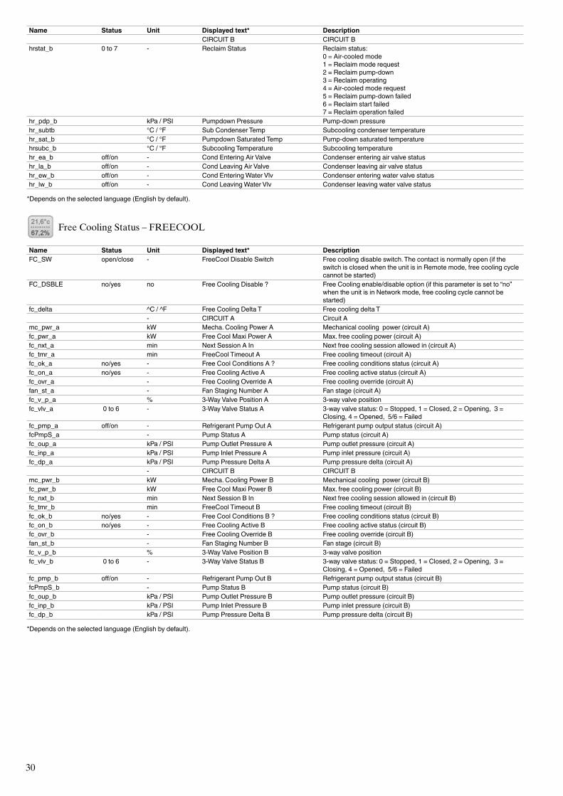
Name Status Unit Displayed text* Description CIRCUIT B CIRCUIT Bhrstat_b 0 to 7 - Reclaim Status Reclaim status:
0 = Air-cooled mode1 = Reclaim mode request2 = Reclaim pump-down3 = Reclaim operating4 = Air-cooled mode request5 = Reclaim pump-down failed6 = Reclaim start failed7 = Reclaim operation failed
hr_pdp_b kPa / PSI Pumpdown Pressure Pump-down pressurehr_subtb °C / °F Sub Condenser Temp Subcooling condenser temperaturehr_sat_b °C / °F Pumpdown Saturated Temp Pump-down saturated temperaturehrsubc_b °C / °F Subcooling Temperature Subcooling temperaturehr_ea_b off/on - Cond Entering Air Valve Condenser entering air valve statushr_la_b off/on - Cond Leaving Air Valve Condenser leaving air valve statushr_ew_b off/on - Cond Entering Water Vlv Condenser entering water valve statushr_lw_b off/on - Cond Leaving Water Vlv Condenser leaving water valve status
*Depends on the selected language (English by default).
Free Cooling Status – FREECOOL
Name Status Unit Displayed text* DescriptionFC_SW open/close - FreeCool Disable Switch Free cooling disable switch. The contact is normally open (if the
switch is closed when the unit is in Remote mode, free cooling cycle cannot be started)
FC_DSBLE no/yes no Free Cooling Disable ? Free Cooling enable/disable option (if this parameter is set to “no” when the unit is in Network mode, free cooling cycle cannot be started)
fc_delta ^C / ^F Free Cooling Delta T Free cooling delta T - CIRCUIT A Circuit Amc_pwr_a kW Mecha. Cooling Power A Mechanical cooling power (circuit A)fc_pwr_a kW Free Cool Maxi Power A Max. free cooling power (circuit A)fc_nxt_a min Next Session A In Next free cooling session allowed in (circuit A)fc_tmr_a min FreeCool Timeout A Free cooling timeout (circuit A)fc_ok_a no/yes - Free Cool Conditions A ? Free cooling conditions status (circuit A)fc_on_a no/yes - Free Cooling Active A Free cooling active status (circuit A)fc_ovr_a - Free Cooling Override A Free cooling override (circuit A)fan_st_a - Fan Staging Number A Fan stage (circuit A)fc_v_p_a % 3-Way Valve Position A 3-way valve positionfc_vlv_a 0 to 6 - 3-Way Valve Status A 3-way valve status: 0 = Stopped, 1 = Closed, 2 = Opening, 3 =
Closing, 4 = Opened, 5/6 = Failedfc_pmp_a off/on - Refrigerant Pump Out A Refrigerant pump output status (circuit A)fcPmpS_a - Pump Status A Pump status (circuit A)fc_oup_a kPa / PSI Pump Outlet Pressure A Pump outlet pressure (circuit A)fc_inp_a kPa / PSI Pump Inlet Pressure A Pump inlet pressure (circuit A)fc_dp_a kPa / PSI Pump Pressure Delta A Pump pressure delta (circuit A) - CIRCUIT B CIRCUIT Bmc_pwr_b kW Mecha. Cooling Power B Mechanical cooling power (circuit B)fc_pwr_b kW Free Cool Maxi Power B Max. free cooling power (circuit B)fc_nxt_b min Next Session B In Next free cooling session allowed in (circuit B)fc_tmr_b min FreeCool Timeout B Free cooling timeout (circuit B)fc_ok_b no/yes - Free Cool Conditions B ? Free cooling conditions status (circuit B)fc_on_b no/yes - Free Cooling Active B Free cooling active status (circuit B)fc_ovr_b - Free Cooling Override B Free cooling override (circuit B)fan_st_b - Fan Staging Number B Fan stage (circuit B)fc_v_p_b % 3-Way Valve Position B 3-way valve positionfc_vlv_b 0 to 6 - 3-Way Valve Status B 3-way valve status: 0 = Stopped, 1 = Closed, 2 = Opening, 3 =
Closing, 4 = Opened, 5/6 = Failedfc_pmp_b off/on - Refrigerant Pump Out B Refrigerant pump output status (circuit B)fcPmpS_b - Pump Status B Pump status (circuit B)fc_oup_b kPa / PSI Pump Outlet Pressure B Pump outlet pressure (circuit B)fc_inp_b kPa / PSI Pump Inlet Pressure B Pump inlet pressure (circuit B)fc_dp_b kPa / PSI Pump Pressure Delta B Pump pressure delta (circuit B)
*Depends on the selected language (English by default).
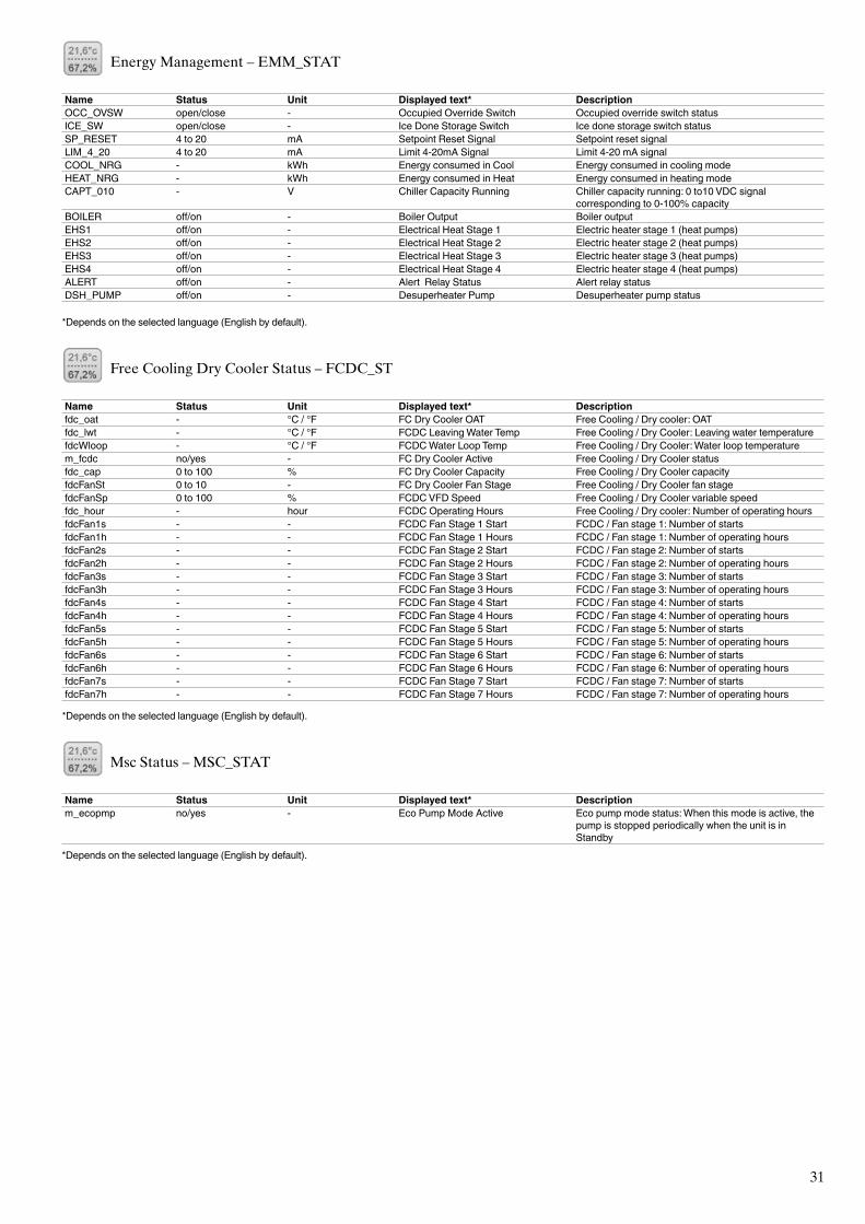
31
Energy Management – EMM_STAT
Name Status Unit Displayed text* DescriptionOCC_OVSW open/close - Occupied Override Switch Occupied override switch statusICE_SW open/close - Ice Done Storage Switch Ice done storage switch statusSP_RESET 4 to 20 mA Setpoint Reset Signal Setpoint reset signalLIM_4_20 4 to 20 mA Limit 4-20mA Signal Limit 4-20 mA signalCOOL_NRG - kWh Energy consumed in Cool Energy consumed in cooling modeHEAT_NRG - kWh Energy consumed in Heat Energy consumed in heating modeCAPT_010 - V Chiller Capacity Running Chiller capacity running: 0 to10 VDC signal
corresponding to 0-100% capacityBOILER off/on - Boiler Output Boiler outputEHS1 off/on - Electrical Heat Stage 1 Electric heater stage 1 (heat pumps)EHS2 off/on - Electrical Heat Stage 2 Electric heater stage 2 (heat pumps)EHS3 off/on - Electrical Heat Stage 3 Electric heater stage 3 (heat pumps)EHS4 off/on - Electrical Heat Stage 4 Electric heater stage 4 (heat pumps)ALERT off/on - Alert Relay Status Alert relay statusDSH_PUMP off/on - Desuperheater Pump Desuperheater pump status
*Depends on the selected language (English by default).
Free Cooling Dry Cooler Status – FCDC_ST
Name Status Unit Displayed text* Descriptionfdc_oat - °C / °F FC Dry Cooler OAT Free Cooling / Dry cooler: OATfdc_lwt - °C / °F FCDC Leaving Water Temp Free Cooling / Dry Cooler: Leaving water temperaturefdcWloop - °C / °F FCDC Water Loop Temp Free Cooling / Dry Cooler: Water loop temperaturem_fcdc no/yes - FC Dry Cooler Active Free Cooling / Dry Cooler statusfdc_cap 0 to 100 % FC Dry Cooler Capacity Free Cooling / Dry Cooler capacityfdcFanSt 0 to 10 - FC Dry Cooler Fan Stage Free Cooling / Dry Cooler fan stagefdcFanSp 0 to 100 % FCDC VFD Speed Free Cooling / Dry Cooler variable speedfdc_hour - hour FCDC Operating Hours Free Cooling / Dry cooler: Number of operating hoursfdcFan1s - - FCDC Fan Stage 1 Start FCDC / Fan stage 1: Number of startsfdcFan1h - - FCDC Fan Stage 1 Hours FCDC / Fan stage 1: Number of operating hoursfdcFan2s - - FCDC Fan Stage 2 Start FCDC / Fan stage 2: Number of startsfdcFan2h - - FCDC Fan Stage 2 Hours FCDC / Fan stage 2: Number of operating hoursfdcFan3s - - FCDC Fan Stage 3 Start FCDC / Fan stage 3: Number of startsfdcFan3h - - FCDC Fan Stage 3 Hours FCDC / Fan stage 3: Number of operating hoursfdcFan4s - - FCDC Fan Stage 4 Start FCDC / Fan stage 4: Number of startsfdcFan4h - - FCDC Fan Stage 4 Hours FCDC / Fan stage 4: Number of operating hoursfdcFan5s - - FCDC Fan Stage 5 Start FCDC / Fan stage 5: Number of startsfdcFan5h - - FCDC Fan Stage 5 Hours FCDC / Fan stage 5: Number of operating hoursfdcFan6s - - FCDC Fan Stage 6 Start FCDC / Fan stage 6: Number of startsfdcFan6h - - FCDC Fan Stage 6 Hours FCDC / Fan stage 6: Number of operating hoursfdcFan7s - - FCDC Fan Stage 7 Start FCDC / Fan stage 7: Number of startsfdcFan7h - - FCDC Fan Stage 7 Hours FCDC / Fan stage 7: Number of operating hours
*Depends on the selected language (English by default).
Msc Status – MSC_STAT
Name Status Unit Displayed text* Descriptionm_ecopmp no/yes - Eco Pump Mode Active Eco pump mode status: When this mode is active, the
pump is stopped periodically when the unit is in Standby
*Depends on the selected language (English by default).
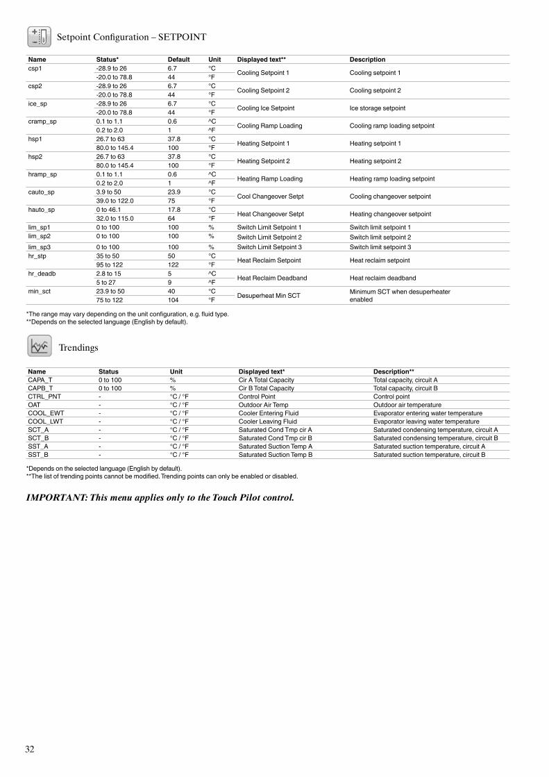
32
Setpoint Configuration – SETPOINT
Name Status* Default Unit Displayed text** Descriptioncsp1
-28.9 to 26 6.7 °C Cooling Setpoint 1 Cooling setpoint 1 -20.0 to 78.8 44 °Fcsp2
-28.9 to 26 6.7 °C Cooling Setpoint 2 Cooling setpoint 2 -20.0 to 78.8 44 °Fice_sp
-28.9 to 26 6.7 °C Cooling Ice Setpoint Ice storage setpoint -20.0 to 78.8 44 °Fcramp_sp
0.1 to 1.1 0.6 ^C Cooling Ramp Loading Cooling ramp loading setpoint 0.2 to 2.0 1 ^Fhsp1
26.7 to 63 37.8 °C Heating Setpoint 1 Heating setpoint 1 80.0 to 145.4 100 °Fhsp2
26.7 to 63 37.8 °C Heating Setpoint 2 Heating setpoint 2 80.0 to 145.4 100 °Fhramp_sp
0.1 to 1.1 0.6 ^C Heating Ramp Loading Heating ramp loading setpoint 0.2 to 2.0 1 ^Fcauto_sp
3.9 to 50 23.9 °C Cool Changeover Setpt Cooling changeover setpoint 39.0 to 122.0 75 °Fhauto_sp
0 to 46.1 17.8 °C Heat Changeover Setpt Heating changeover setpoint 32.0 to 115.0 64 °Flim_sp1 0 to 100 100 % Switch Limit Setpoint 1 Switch limit setpoint 1lim_sp2 0 to 100 100 % Switch Limit Setpoint 2 Switch limit setpoint 2lim_sp3 0 to 100 100 % Switch Limit Setpoint 3 Switch limit setpoint 3hr_stp
35 to 50 50 °C Heat Reclaim Setpoint Heat reclaim setpoint 95 to 122 122 °Fhr_deadb
2.8 to 15 5 ^C Heat Reclaim Deadband Heat reclaim deadband 5 to 27 9 ^Fmin_sct
23.9 to 50 40 °C Desuperheat Min SCT Minimum SCT when desuperheaterenabled75 to 122 104 °F
*The range may vary depending on the unit configuration, e.g. fluid type.**Depends on the selected language (English by default).
Trendings
Name Status Unit Displayed text* Description**CAPA_T 0 to 100 % Cir A Total Capacity Total capacity, circuit ACAPB_T 0 to 100 % Cir B Total Capacity Total capacity, circuit BCTRL_PNT - °C / °F Control Point Control point OAT - °C / °F Outdoor Air Temp Outdoor air temperatureCOOL_EWT - °C / °F Cooler Entering Fluid Evaporator entering water temperatureCOOL_LWT - °C / °F Cooler Leaving Fluid Evaporator leaving water temperatureSCT_A - °C / °F Saturated Cond Tmp cir A Saturated condensing temperature, circuit ASCT_B - °C / °F Saturated Cond Tmp cir B Saturated condensing temperature, circuit BSST_A - °C / °F Saturated Suction Temp A Saturated suction temperature, circuit A SST_B - °C / °F Saturated Suction Temp B Saturated suction temperature, circuit B
*Depends on the selected language (English by default).**The list of trending points cannot be modified. Trending points can only be enabled or disabled.
IMPORTANT: This menu applies only to the Touch Pilot control.
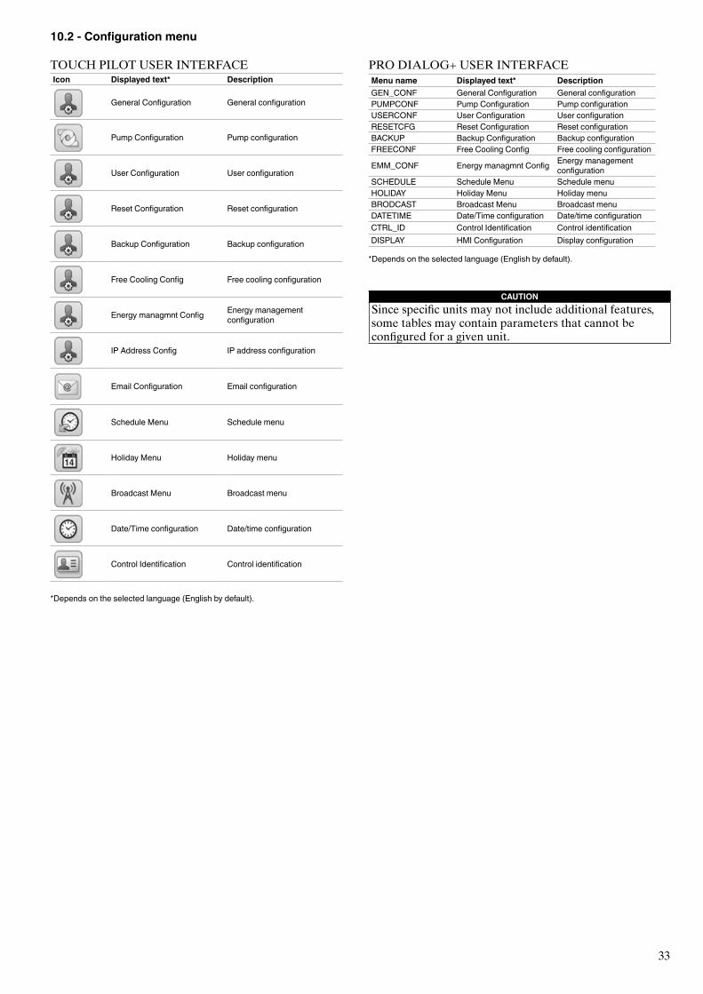
33
PRO DIALOG+ USER INTERFACEMenu name Displayed text* DescriptionGEN_CONF General Configuration General configurationPUMPCONF Pump Configuration Pump configurationUSERCONF User Configuration User configurationRESETCFG Reset Configuration Reset configurationBACKUP Backup Configuration Backup configurationFREECONF Free Cooling Config Free cooling configuration
EMM_CONF Energy managmnt Config Energy management configuration
SCHEDULE Schedule Menu Schedule menuHOLIDAY Holiday Menu Holiday menuBRODCAST Broadcast Menu Broadcast menuDATETIME Date/Time configuration Date/time configurationCTRL_ID Control Identification Control identificationDISPLAY HMI Configuration Display configuration
*Depends on the selected language (English by default).
CAUTIONSince specific units may not include additional features, some tables may contain parameters that cannot be configured for a given unit.
10.2 - Configuration menu
TOUCH PILOT USER INTERFACEIcon Displayed text* Description
General Configuration General configuration
Pump Configuration Pump configuration
User Configuration User configuration
Reset Configuration Reset configuration
Backup Configuration Backup configuration
Free Cooling Config Free cooling configuration
Energy managmnt Config Energy management configuration
IP Address Config IP address configuration
Email Configuration Email configuration
Schedule Menu Schedule menu
Holiday Menu Holiday menu
Broadcast Menu Broadcast menu
Date/Time configuration Date/time configuration
Control Identification Control identification
*Depends on the selected language (English by default).
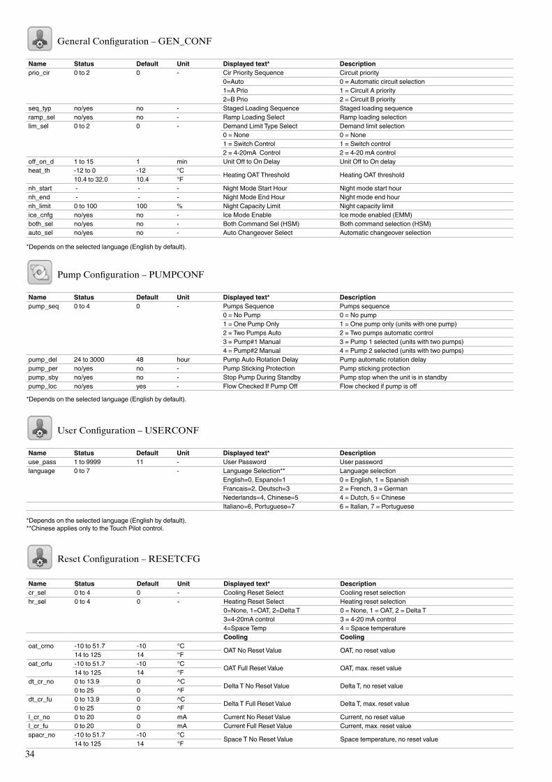
34
General Configuration – GEN_CONF
Name Status Default Unit Displayed text* Descriptionprio_cir
0 to 2
0 - Cir Priority Sequence Circuit priority0=Auto 0 = Automatic circuit selection1=A Prio 1 = Circuit A priority2=B Prio 2 = Circuit B priority
seq_typ no/yes no - Staged Loading Sequence Staged loading sequenceramp_sel no/yes no - Ramp Loading Select Ramp loading selectionlim_sel
0 to 2
0 - Demand Limit Type Select Demand limit selection0 = None 0 = None 1 = Switch Control 1 = Switch control 2 = 4-20mA Control 2 = 4-20 mA control
off_on_d 1 to 15 1 min Unit Off to On Delay Unit Off to On delayheat_th
-12 to 0 -12 °C Heating OAT Threshold Heating OAT threshold10.4 to 32.0 10.4 °Fnh_start - - - Night Mode Start Hour Night mode start hournh_end - - - Night Mode End Hour Night mode end hournh_limit 0 to 100 100 % Night Capacity Limit Night capacity limitice_cnfg no/yes no - Ice Mode Enable Ice mode enabled (EMM)both_sel no/yes no - Both Command Sel (HSM) Both command selection (HSM)auto_sel no/yes no - Auto Changeover Select Automatic changeover selection
*Depends on the selected language (English by default).
Pump Configuration – PUMPCONF
Name Status Default Unit Displayed text* Descriptionpump_seq
0 to 4
0 - Pumps Sequence Pumps sequence 0 = No Pump 0 = No pump1 = One Pump Only 1 = One pump only (units with one pump)2 = Two Pumps Auto 2 = Two pumps automatic control3 = Pump#1 Manual 3 = Pump 1 selected (units with two pumps)4 = Pump#2 Manual 4 = Pump 2 selected (units with two pumps)
pump_del 24 to 3000 48 hour Pump Auto Rotation Delay Pump automatic rotation delaypump_per no/yes no - Pump Sticking Protection Pump sticking protectionpump_sby no/yes no - Stop Pump During Standby Pump stop when the unit is in standbypump_loc no/yes yes - Flow Checked If Pump Off Flow checked if pump is off
*Depends on the selected language (English by default).
User Configuration – USERCONF
Name Status Default Unit Displayed text* Descriptionuse_pass 1 to 9999 11 - User Password User password language
0 to 7
- Language Selection** Language selection English=0, Espanol=1 0 = English, 1 = SpanishFrancais=2, Deutsch=3 2 = French, 3 = GermanNederlands=4, Chinese=5 4 = Dutch, 5 = Chinese
Italiano=6, Portuguese=7 6 = Italian, 7 = Portuguese
*Depends on the selected language (English by default).**Chinese applies only to the Touch Pilot control.
Reset Configuration – RESETCFG
Name Status Default Unit Displayed text* Descriptioncr_sel 0 to 4 0 - Cooling Reset Select Cooling reset selectionhr_sel
0 to 4
0 - Heating Reset Select Heating reset selection0=None, 1=OAT, 2=Delta T 0 = None, 1 = OAT, 2 = Delta T3=4-20mA control 3 = 4-20 mA control4=Space Temp 4 = Space temperature
Cooling Coolingoat_crno -10 to 51.7 -10 °C OAT No Reset Value OAT, no reset value14 to 125 14 °Foat_crfu -10 to 51.7 -10 °C OAT Full Reset Value OAT, max. reset value14 to 125 14 °Fdt_cr_no 0 to 13.9 0 ^C Delta T No Reset Value Delta T, no reset value0 to 25 0 ^Fdt_cr_fu 0 to 13.9 0 ^C Delta T Full Reset Value Delta T, max. reset value0 to 25 0 ^FI_cr_no 0 to 20 0 mA Current No Reset Value Current, no reset valueI_cr_fu 0 to 20 0 mA Current Full Reset Value Current, max. reset valuespacr_no -10 to 51.7 -10 °C Space T No Reset Value Space temperature, no reset value14 to 125 14 °F
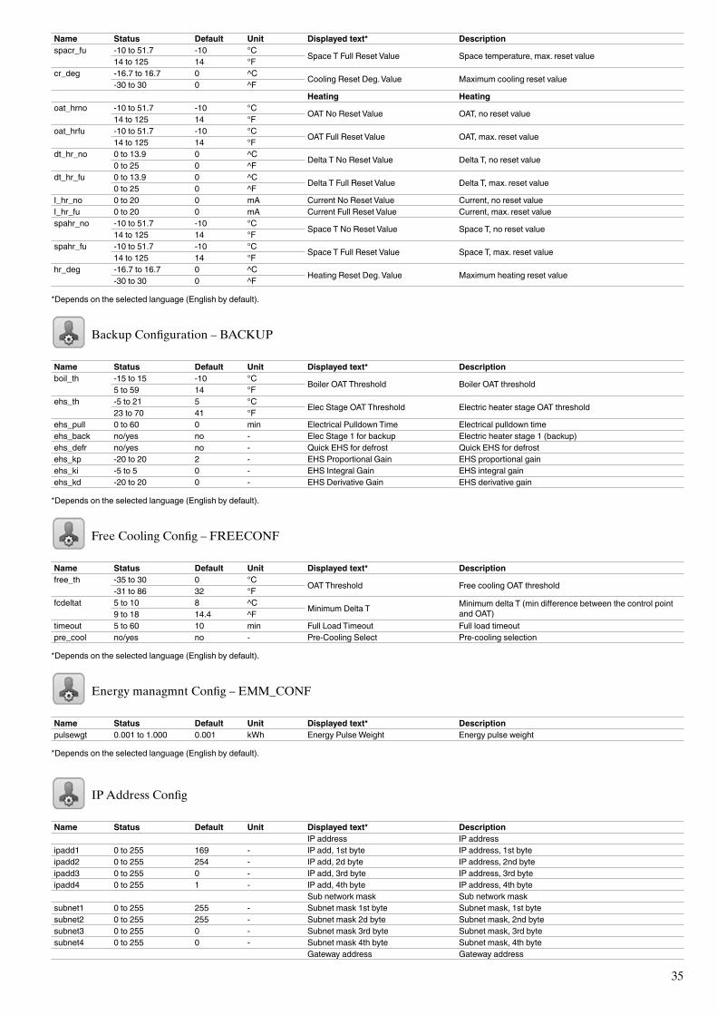
35
Name Status Default Unit Displayed text* Descriptionspacr_fu -10 to 51.7 -10 °C Space T Full Reset Value Space temperature, max. reset value14 to 125 14 °Fcr_deg -16.7 to 16.7 0 ^C Cooling Reset Deg. Value Maximum cooling reset value-30 to 30 0 ^F Heating Heatingoat_hrno -10 to 51.7 -10 °C OAT No Reset Value OAT, no reset value 14 to 125 14 °Foat_hrfu -10 to 51.7 -10 °C OAT Full Reset Value OAT, max. reset value 14 to 125 14 °Fdt_hr_no 0 to 13.9 0 ^C Delta T No Reset Value Delta T, no reset value 0 to 25 0 ^Fdt_hr_fu 0 to 13.9 0 ^C Delta T Full Reset Value Delta T, max. reset value 0 to 25 0 ^FI_hr_no 0 to 20 0 mA Current No Reset Value Current, no reset valueI_hr_fu 0 to 20 0 mA Current Full Reset Value Current, max. reset valuespahr_no -10 to 51.7 -10 °C Space T No Reset Value Space T, no reset value 14 to 125 14 °Fspahr_fu -10 to 51.7 -10 °C Space T Full Reset Value Space T, max. reset value 14 to 125 14 °Fhr_deg -16.7 to 16.7 0 ^C Heating Reset Deg. Value Maximum heating reset value -30 to 30 0 ^F
*Depends on the selected language (English by default).
Backup Configuration – BACKUP
Name Status Default Unit Displayed text* Descriptionboil_th
-15 to 15 -10 °C Boiler OAT Threshold Boiler OAT threshold 5 to 59 14 °Fehs_th
-5 to 21 5 °C Elec Stage OAT Threshold Electric heater stage OAT threshold 23 to 70 41 °Fehs_pull 0 to 60 0 min Electrical Pulldown Time Electrical pulldown timeehs_back no/yes no - Elec Stage 1 for backup Electric heater stage 1 (backup)ehs_defr no/yes no - Quick EHS for defrost Quick EHS for defrostehs_kp -20 to 20 2 - EHS Proportional Gain EHS proportional gainehs_ki -5 to 5 0 - EHS Integral Gain EHS integral gainehs_kd -20 to 20 0 - EHS Derivative Gain EHS derivative gain
*Depends on the selected language (English by default).
Free Cooling Config – FREECONF
Name Status Default Unit Displayed text* Descriptionfree_th -35 to 30 0 °C OAT Threshold Free cooling OAT threshold-31 to 86 32 °Ffcdeltat 5 to 10 8 ^C Minimum Delta T Minimum delta T (min difference between the control point
and OAT)9 to 18 14.4 ^Ftimeout 5 to 60 10 min Full Load Timeout Full load timeoutpre_cool no/yes no - Pre-Cooling Select Pre-cooling selection
*Depends on the selected language (English by default).
Energy managmnt Config – EMM_CONF
Name Status Default Unit Displayed text* Descriptionpulsewgt 0.001 to 1.000 0.001 kWh Energy Pulse Weight Energy pulse weight
*Depends on the selected language (English by default).
IP Address Config
Name Status Default Unit Displayed text* Description IP address IP addressipadd1 0 to 255 169 - IP add, 1st byte IP address, 1st byteipadd2 0 to 255 254 - IP add, 2d byte IP address, 2nd byteipadd3 0 to 255 0 - IP add, 3rd byte IP address, 3rd byteipadd4 0 to 255 1 - IP add, 4th byte IP address, 4th byte Sub network mask Sub network masksubnet1 0 to 255 255 - Subnet mask 1st byte Subnet mask, 1st bytesubnet2 0 to 255 255 - Subnet mask 2d byte Subnet mask, 2nd bytesubnet3 0 to 255 0 - Subnet mask 3rd byte Subnet mask, 3rd bytesubnet4 0 to 255 0 - Subnet mask 4th byte Subnet mask, 4th byte Gateway address Gateway address
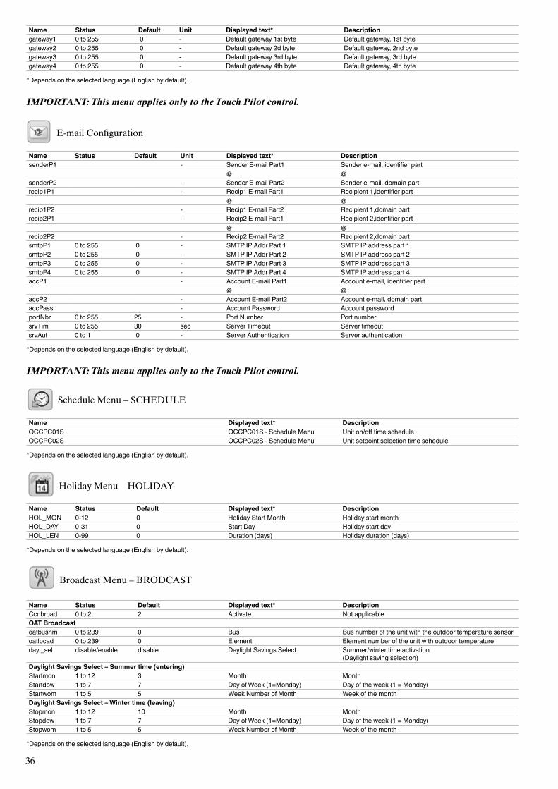
36
Name Status Default Unit Displayed text* Descriptiongateway1 0 to 255 0 - Default gateway 1st byte Default gateway, 1st bytegateway2 0 to 255 0 - Default gateway 2d byte Default gateway, 2nd bytegateway3 0 to 255 0 - Default gateway 3rd byte Default gateway, 3rd bytegateway4 0 to 255 0 - Default gateway 4th byte Default gateway, 4th byte
*Depends on the selected language (English by default).
IMPORTANT: This menu applies only to the Touch Pilot control.
E-mail Configuration
Name Status Default Unit Displayed text* DescriptionsenderP1 - Sender E-mail Part1 Sender e-mail, identifier part @ @senderP2 - Sender E-mail Part2 Sender e-mail, domain partrecip1P1 - Recip1 E-mail Part1 Recipient 1,identifier part @ @recip1P2 - Recip1 E-mail Part2 Recipient 1,domain partrecip2P1 - Recip2 E-mail Part1 Recipient 2,identifier part @ @recip2P2 - Recip2 E-mail Part2 Recipient 2,domain partsmtpP1 0 to 255 0 - SMTP IP Addr Part 1 SMTP IP address part 1smtpP2 0 to 255 0 - SMTP IP Addr Part 2 SMTP IP address part 2smtpP3 0 to 255 0 - SMTP IP Addr Part 3 SMTP IP address part 3smtpP4 0 to 255 0 - SMTP IP Addr Part 4 SMTP IP address part 4accP1 - Account E-mail Part1 Account e-mail, identifier part @ @accP2 - Account E-mail Part2 Account e-mail, domain partaccPass - Account Password Account passwordportNbr 0 to 255 25 - Port Number Port numbersrvTim 0 to 255 30 sec Server Timeout Server timeoutsrvAut 0 to 1 0 - Server Authentication Server authentication
*Depends on the selected language (English by default).
IMPORTANT: This menu applies only to the Touch Pilot control.
Schedule Menu – SCHEDULE
Name Displayed text* DescriptionOCCPC01S OCCPC01S - Schedule Menu Unit on/off time scheduleOCCPC02S OCCPC02S - Schedule Menu Unit setpoint selection time schedule
*Depends on the selected language (English by default).
Holiday Menu – HOLIDAY
Name Status Default Displayed text* DescriptionHOL_MON 0-12 0 Holiday Start Month Holiday start monthHOL_DAY 0-31 0 Start Day Holiday start dayHOL_LEN 0-99 0 Duration (days) Holiday duration (days)
*Depends on the selected language (English by default).
Broadcast Menu – BRODCAST
Name Status Default Displayed text* DescriptionCcnbroad 0 to 2 2 Activate Not applicableOAT Broadcastoatbusnm 0 to 239 0 Bus Bus number of the unit with the outdoor temperature sensoroatlocad 0 to 239 0 Element Element number of the unit with outdoor temperaturedayl_sel disable/enable disable Daylight Savings Select Summer/winter time activation
(Daylight saving selection)Daylight Savings Select – Summer time (entering)Startmon 1 to 12 3 Month MonthStartdow 1 to 7 7 Day of Week (1=Monday) Day of the week (1 = Monday)Startwom 1 to 5 5 Week Number of Month Week of the monthDaylight Savings Select – Winter time (leaving)Stopmon 1 to 12 10 Month MonthStopdow 1 to 7 7 Day of Week (1=Monday) Day of the week (1 = Monday)Stopwom 1 to 5 5 Week Number of Month Week of the month
*Depends on the selected language (English by default).
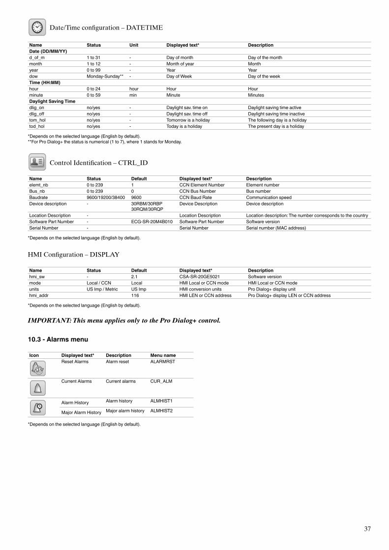
37
10.3 - Alarms menu
Icon Displayed text* Description Menu nameReset Alarms Alarm reset ALARMRST
Current Alarms Current alarms CUR_ALM
Alarm History Alarm history ALMHIST1
Major Alarm History Major alarm history ALMHIST2
*Depends on the selected language (English by default).
Date/Time configuration – DATETIME
Name Status Unit Displayed text* DescriptionDate (DD/MM/YY)d_of_m 1 to 31 - Day of month Day of the monthmonth 1 to 12 - Month of year Monthyear 0 to 99 - Year Yeardow Monday-Sunday** - Day of Week Day of the weekTime (HH:MM)hour 0 to 24 hour Hour Hourminute 0 to 59 min Minute MinutesDaylight Saving Timedlig_on no/yes - Daylight sav. time on Daylight saving time activedlig_off no/yes - Daylight sav. time off Daylight saving time inactivetom_hol no/yes - Tomorrow is a holiday The following day is a holidaytod_hol no/yes - Today is a holiday The present day is a holiday
*Depends on the selected language (English by default).**For Pro Dialog+ the status is numerical (1 to 7), where 1 stands for Monday.
Control Identification – CTRL_ID
Name Status Default Displayed text* Descriptionelemt_nb 0 to 239 1 CCN Element Number Element numberBus_nb 0 to 239 0 CCN Bus Number Bus numberBaudrate 9600/19200/38400 9600 CCN Baud Rate Communication speedDevice description - 30RBM/30RBP
30RQM/30RQPDevice Description Device description
Location Description - Location Description Location description: The number corresponds to the countrySoftware Part Number - ECG-SR-20M4B010 Software Part Number Software versionSerial Number - Serial Number Serial number (MAC address)
*Depends on the selected language (English by default).
HMI Configuration – DISPLAY
Name Status Default Displayed text* Descriptionhmi_sw - 2.1 CSA-SR-20GE5021 Software versionmode Local / CCN Local HMI Local or CCN mode HMI Local or CCN modeunits US Imp / Metric US Imp HMI conversion units Pro Dialog+ display unithmi_addr 116 HMI LEN or CCN address Pro Dialog+ display LEN or CCN address
*Depends on the selected language (English by default).
IMPORTANT: This menu applies only to the Pro Dialog+ control.
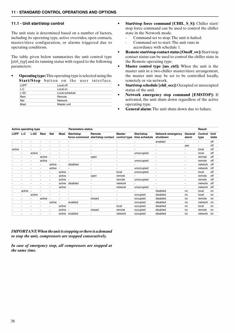
38
11.1 - Unit start/stop control
The unit state is determined based on a number of factors, including its operating type, active overrides, open contacts, master/slave configuration, or alarms triggered due to operating conditions.
The table given below summarises the unit control type [ctrl_typ] and its running status with regard to the following parameters:
• Operating type: This operating type is selected using the Start /Stop but ton on the user interface.LOFF Local offL-C Local onL-SC Local scheduleRem RemoteNet NetworkMast Master unit
• Start/stop force command [CHIL_S_S]: Chiller start/stop force command can be used to control the chiller state in the Network mode.
- Command set to stop: The unit is halted. - Command set to start: The unit runs in
accordance with schedule 1.• Remote start/stop contact status [Onoff_sw]: Start/stop
contact status can be used to control the chiller state in the Remote operating type.
• Master control type [ms_ctrl]: When the unit is the master unit in a two-chiller master/slave arrangement, the master unit may be set to be controlled locally, remotely or via network.
• Start/stop schedule [chil_occ]: Occupied or unoccupied status of the unit.
• Network emergency stop command [EMSTOP]: If activated, the unit shuts down regardless of the active operating type.
• General alarm: The unit shuts down due to failure.
Active operating type Parameters status ResultLOFF L-C L-SC Rem Net Mast Start/stop
force commandRemotestart/stop contact
Master control type
Start/stop time schedule
Network emergency shutdown
General alarm
Control type
Unit state
- - - - - - - - - - enabled - - off- - - - - - - - - - - yes - offactive - - - - - - - - - - - local off- - active - - - - - - unoccupied - - local off- - - active - - - open - - - - remote off- - - active - - - - - unoccupied - - remote off- - - - active - disabled - - - - - network off- - - - active - - - - unoccupied - - network off- - - - - active - - local unoccupied - - local off- - - - - active - open remote - - - remote off- - - - - active - - remote unoccupied - - remote off- - - - - active disabled - network - - - network off- - - - - active - - network unoccupied - - network off- active - - - - - - - - disabled no local on- - active - - - - - - occupied disabled no local on- - - active - - - closed - occupied disabled no remote on- - - - active - enabled - - occupied disabled no network on- - - - - active - - local occupied disabled no local on- - - - - active - closed remote occupied disabled no remote on- - - - - active enabled - network occupied disabled no network on
IMPORTANT: When the unit is stopping or there is a demand to stop the unit, compressors are stopped consecutively.
In case of emergency stop, all compressors are stopped at the same time.
11 - STANDARD CONTROL OPERATIONS AND OPTIONS
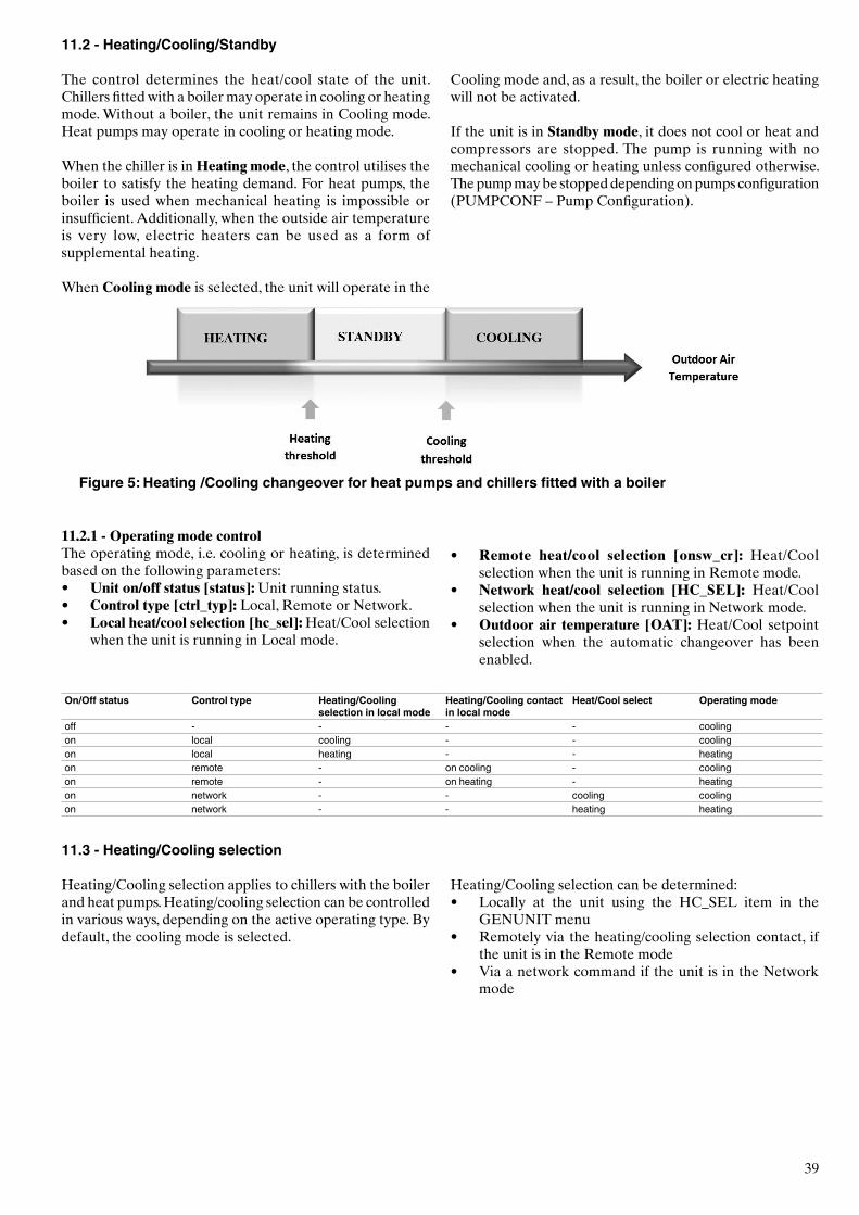
39
11.2 - Heating/Cooling/Standby
The control determines the heat/cool state of the unit. Chillers fitted with a boiler may operate in cooling or heating mode. Without a boiler, the unit remains in Cooling mode. Heat pumps may operate in cooling or heating mode.
When the chiller is in Heating mode, the control utilises the boiler to satisfy the heating demand. For heat pumps, the boiler is used when mechanical heating is impossible or insufficient. Additionally, when the outside air temperature is very low, electric heaters can be used as a form of supplemental heating. When Cooling mode is selected, the unit will operate in the
Cooling mode and, as a result, the boiler or electric heating will not be activated.
If the unit is in Standby mode, it does not cool or heat and compressors are stopped. The pump is running with no mechanical cooling or heating unless configured otherwise. The pump may be stopped depending on pumps configuration (PUMPCONF – Pump Configuration).
Figure 5: Heating /Cooling changeover for heat pumps and chillers fitted with a boiler
11.2.1 - Operating mode controlThe operating mode, i.e. cooling or heating, is determined based on the following parameters:• Unit on/off status [status]: Unit running status.• Control type [ctrl_typ]: Local, Remote or Network.• Local heat/cool selection [hc_sel]: Heat/Cool selection
when the unit is running in Local mode.
11.3 - Heating/Cooling selection
Heating/Cooling selection applies to chillers with the boiler and heat pumps. Heating/cooling selection can be controlled in various ways, depending on the active operating type. By default, the cooling mode is selected.
On/Off status Control type Heating/Cooling selection in local mode
Heating/Cooling contact in local mode
Heat/Cool select Operating mode
off - - - - coolingon local cooling - - coolingon local heating - - heatingon remote - on cooling - coolingon remote - on heating - heatingon network - - cooling coolingon network - - heating heating
• Remote heat/cool selection [onsw_cr]: Heat/Cool selection when the unit is running in Remote mode.
• Network heat/cool selection [HC_SEL]: Heat/Cool selection when the unit is running in Network mode.
• Outdoor air temperature [OAT]: Heat/Cool setpoint selection when the automatic changeover has been enabled.
Heating/Cooling selection can be determined:• Locally at the unit using the HC_SEL item in the
GENUNIT menu• Remotely via the heating/cooling selection contact, if
the unit is in the Remote mode• Via a network command if the unit is in the Network
mode
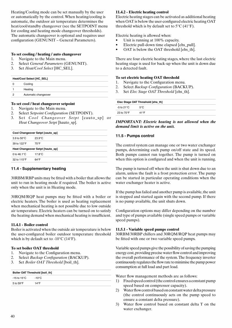
40
Heating/Cooling mode can be set manually by the user or automatically by the control. When heating/cooling is automatic, the outdoor air temperature determines the heat/cool/standby changeover (see the SETPOINT menu for cooling and heating mode changeover thresholds). The automatic changeover is optional and requires user configuration (GENUNIT – General Parameters).
To set cooling / heating / auto changeover1. Navigate to the Main menu.2. Select General Parameters (GENUNIT).3. Set Heat/Cool Select [HC_SEL].
Heat/Cool Select [HC_SEL]
0 Cooling
1 Heating
2 Automatic changeover
To set cool / heat changeover setpoint1. Navigate to the Main menu.2. Select Setpoint Configuration (SETPOINT).3. Set Cool Changeover Setpt [cauto_sp] or
Heat Changeover Setpt [hauto_sp].
Cool Changeover Setpt [cauto_sp]
3.9 to 50°C 23.9°C
39 to 122°F 75°F
Heat Changeover Setpt [hauto_sp]
0 to 46.1°C 17.8°C
32 to 115°F 64°F
11.4 - Supplementary heating
30RBM/RBP units may be fitted with a boiler that allows the unit to run in heating mode if required. The boiler is active only when the unit is in Heating mode.
30RQM/RQP heat pumps may be fitted with a boiler or electric heaters. The boiler is used as heating replacement when mechanical heating is not possible due to low outside air temperature. Electric heaters can be turned on to satisfy the heating demand when mechanical heating is insufficient.
11.4.1 - Boiler controlBoiler is activated when the outside air temperature is below the user-configured boiler outdoor temperature threshold which is by default set to -10°C (14°F).
To set boiler OAT threshold1. Navigate to the Configuration menu.2. Select Backup Configuration (BACKUP).3. Set Boiler OAT Threshold [boil_th].
Boiler OAT Threshold [boil_th]
-15 to 15°C -10°C
5 to 59°F 14°F
11.4.2 - Electric heating controlElectric heating stages can be activated as additional heating when OAT is below the user-configured electric heating OAT threshold which is by default set to 5°C (41°F).
Electric heating is allowed when:• Unit is running at 100% capacity.• Electric pull-down time elapsed [ehs_pull].• OAT is below the OAT threshold [ehs_th].
There are four electric heating stages, where the last electric heating stage is used for back-up when the unit is down due to a detected fault.
To set electric heating OAT threshold1. Navigate to the Configuration menu.2. Select Backup Configuration (BACKUP).3. Set Elec Stage OAT Threshold [ehs_th].
Elec Stage OAT Threshold [ehs_th]
-5 to 21°C 5°C
23 to 70°F 41°F
IMPORTANT: Electric heating is not allowed when the demand limit is active on the unit.
11.5 - Pumps control
The control system can manage one or two water exchanger pumps, determining each pump on/off state and its speed. Both pumps cannot run together. The pump is turned on when this option is configured and when the unit is running.
The pump is turned off when the unit is shut down due to an alarm, unless the fault is a frost protection error. The pump can be started in particular operating conditions when the water exchanger heater is active.
If the pump has failed and another pump is available, the unit is stopped and started again with the second pump. If there is no pump available, the unit shuts down.
Configuration options may differ depending on the number and type of pumps available (single speed pumps or variable speed pumps).
11.5.1 - Variable speed pumps control30RBM/30RBP chillers and 30RQM/RQP heat pumps may be fitted with one or two variable speed pumps.
Variable speed pumps give the possibility of saving the pumping energy cost, providing precise water flow control and improving the overall performance of the system. The frequency inverter continuously regulates the flow rate to minimise the pump power consumption at full load and part load.
Water flow management methods are as follows:1) Fixed speed control (the control ensures a constant pump
speed based on compressor capacity). 2) Water flow control based on constant water delta pressure
(the control continuously acts on the pump speed to ensure a constant delta pressure).
3) Water flow control based on constant delta T on the water exchanger.
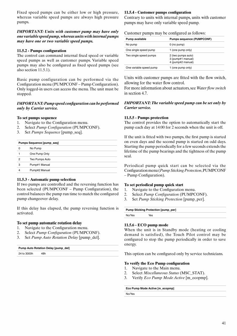
41
Fixed speed pumps can be either low or high pressure, whereas variable speed pumps are always high pressure pumps.
IMPORTANT: Units with customer pump may have only one variable speed pump, whereas units with internal pumps may have one or two variable speed pumps.
11.5.2 - Pumps configurationThe control can command internal fixed speed or variable speed pumps as well as customer pumps. Variable speed pumps may also be configured as fixed speed pumps (see also section 11.5.1).
Basic pump configuration can be performed via the Configuration menu (PUMPCONF – Pump Configuration). Only logged-in users can access the menu. The unit must be stopped.
IMPORTANT: Pump speed configuration can be performed only by Carrier service.
To set pumps sequence1. Navigate to the Configuration menu.2. Select Pump Configuration (PUMPCONF).3. Set Pumps Sequence [pump_seq].
Pumps Sequence [pump_seq]
0 No Pump
1 One Pump Only
2 Two Pumps Auto
3 Pump#1 Manual
4 Pump#2 Manual
11.5.3 - Automatic pump selectionIf two pumps are controlled and the reversing function has been selected (PUMPCONF – Pump Configuration), the control balances the pump run time to match the configured pump changeover delay.
If this delay has elapsed, the pump reversing function is activated.
To set pump automatic rotation delay1. Navigate to the Configuration menu.2. Select Pump Configuration (PUMPCONF).3. Set Pump Auto Rotation Delay [pump_del].
Pump Auto Rotation Delay [pump_del]
24 to 3000h 48h
11.5.4 - Customer pumps configurationContrary to units with internal pumps, units with customer pumps may have only variable speed pump.
Customer pumps may be configured as follows:Pump available Pumps sequence (PUMPCONF)
No pump 0 (no pump)
One single speed pump 1 (one pump only)
Two single speed pumps 2 (two pumps auto) 3 (pump#1 manual)4 (pump#2 manual)
One variable speed pump 1 (one pump only)
Units with customer pumps are fitted with the flow switch, allowing for the water flow control. For more information about actuators, see Water flow switch in section 4.7.
IMPORTANT: The variable speed pump can be set only by Carrier service.
11.5.5 - Pumps protectionThe control provides the option to automatically start the pump each day at 14:00 for 2 seconds when the unit is off.
If the unit is fitted with two pumps, the first pump is started on even days and the second pump is started on odd days. Starting the pump periodically for a few seconds extends the lifetime of the pump bearings and the tightness of the pump seal. Periodical pump quick start can be selected via the Configuration menu (Pump Sticking Protection, PUMPCONF – Pump Configuration).
To set periodical pump quick start1. Navigate to the Configuration menu.2. Select Pump Configuration (PUMPCONF).3. Set Pump Sticking Protection [pump_per].
Pump Sticking Protection [pump_per]
No/Yes Yes
11.5.6 - ECO pump modeWhen the unit is in Standby mode (heating or cooling demand is satisfied), the Touch Pilot control may be configured to stop the pump periodically in order to save energy.
This option can be configured only by service technicians.
To verify the Eco Pump configuration1. Navigate to the Main menu.2. Select Miscellaneous Status (MSC_STAT).3. Verify Eco Pump Mode Active [m_ecopmp].
Eco Pump Mode Active [m_ecopmp]
No/Yes
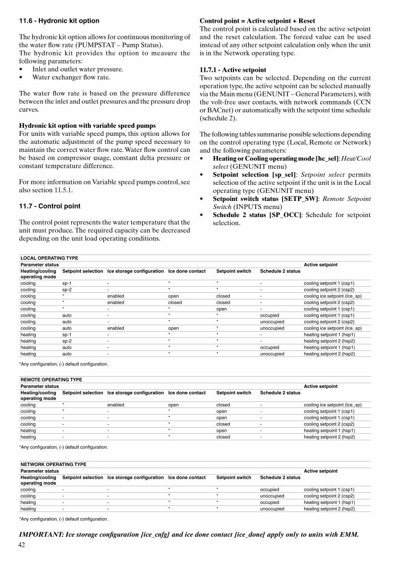
42
LOCAL OPERATING TYPEParameter status Active setpointHeating/cooling operating mode
Setpoint selection Ice storage configuration Ice done contact Setpoint switch Schedule 2 status
cooling sp-1 - * * - cooling setpoint 1 (csp1)cooling sp-2 - * * - cooling setpoint 2 (csp2)cooling * enabled open closed - cooling ice setpoint (Ice_sp)cooling * enabled closed closed - cooling setpoint 2 (csp2)cooling * - * open - cooling setpoint 1 (csp1)cooling auto - * * occupied cooling setpoint 1 (csp1)cooling auto - * * unoccupied cooling setpoint 2 (csp2)cooling auto enabled open * unoccupied cooling ice setpoint (Ice_sp)heating sp-1 - * * - heating setpoint 1 (hsp1)heating sp-2 - * * - heating setpoint 2 (hsp2)heating auto - * * occupied heating setpoint 1 (hsp1)heating auto - * * unoccupied heating setpoint 2 (hsp2)
*Any configuration, (-) default configuration.
REMOTE OPERATING TYPEParameter status Active setpointHeating/cooling operating mode
Setpoint selection Ice storage configuration Ice done contact Setpoint switch Schedule 2 status
cooling * enabled open closed - cooling ice setpoint (Ice_sp)cooling * - * open - cooling setpoint 1 (csp1)cooling - - * open - cooling setpoint 1 (csp1)cooling - - * closed - cooling setpoint 2 (csp2)heating - - * open - heating setpoint 1 (hsp1)heating - - * closed - heating setpoint 2 (hsp2)
*Any configuration, (-) default configuration.
NETWORK OPERATING TYPEParameter status Active setpointHeating/cooling operating mode
Setpoint selection Ice storage configuration Ice done contact Setpoint switch Schedule 2 status
cooling - - * * occupied cooling setpoint 1 (csp1)cooling - - * * unoccupied cooling setpoint 2 (csp2)heating - - * * occupied heating setpoint 1 (hsp1)heating - - * * unoccupied heating setpoint 2 (hsp2)
*Any configuration, (-) default configuration.
IMPORTANT: Ice storage configuration [ice_cnfg] and ice done contact [ice_done] apply only to units with EMM.
11.6 - Hydronic kit option
The hydronic kit option allows for continuous monitoring of the water flow rate (PUMPSTAT – Pump Status). The hydronic kit provides the option to measure the following parameters:• Inlet and outlet water pressure. • Water exchanger flow rate.
The water flow rate is based on the pressure difference between the inlet and outlet pressures and the pressure drop curves.
Hydronic kit option with variable speed pumpsFor units with variable speed pumps, this option allows for the automatic adjustment of the pump speed necessary to maintain the correct water flow rate. Water flow control can be based on compressor usage, constant delta pressure or constant temperature difference.
For more information on Variable speed pumps control, see also section 11.5.1.
11.7 - Control point
The control point represents the water temperature that the unit must produce. The required capacity can be decreased depending on the unit load operating conditions.
Control point = Active setpoint + ResetThe control point is calculated based on the active setpoint and the reset calculation. The forced value can be used instead of any other setpoint calculation only when the unit is in the Network operating type.
11.7.1 - Active setpointTwo setpoints can be selected. Depending on the current operation type, the active setpoint can be selected manually via the Main menu (GENUNIT – General Parameters), with the volt-free user contacts, with network commands (CCN or BACnet) or automatically with the setpoint time schedule (schedule 2). The following tables summarise possible selections depending on the control operating type (Local, Remote or Network) and the following parameters:• Heating or Cooling operating mode [hc_sel]: Heat/Cool
select (GENUNIT menu)• Setpoint selection [sp_sel]: Setpoint select permits
selection of the active setpoint if the unit is in the Local operating type (GENUNIT menu)
• Setpoint switch status [SETP_SW]: Remote Setpoint Switch (INPUTS menu)
• Schedule 2 status [SP_OCC]: Schedule for setpoint selection.
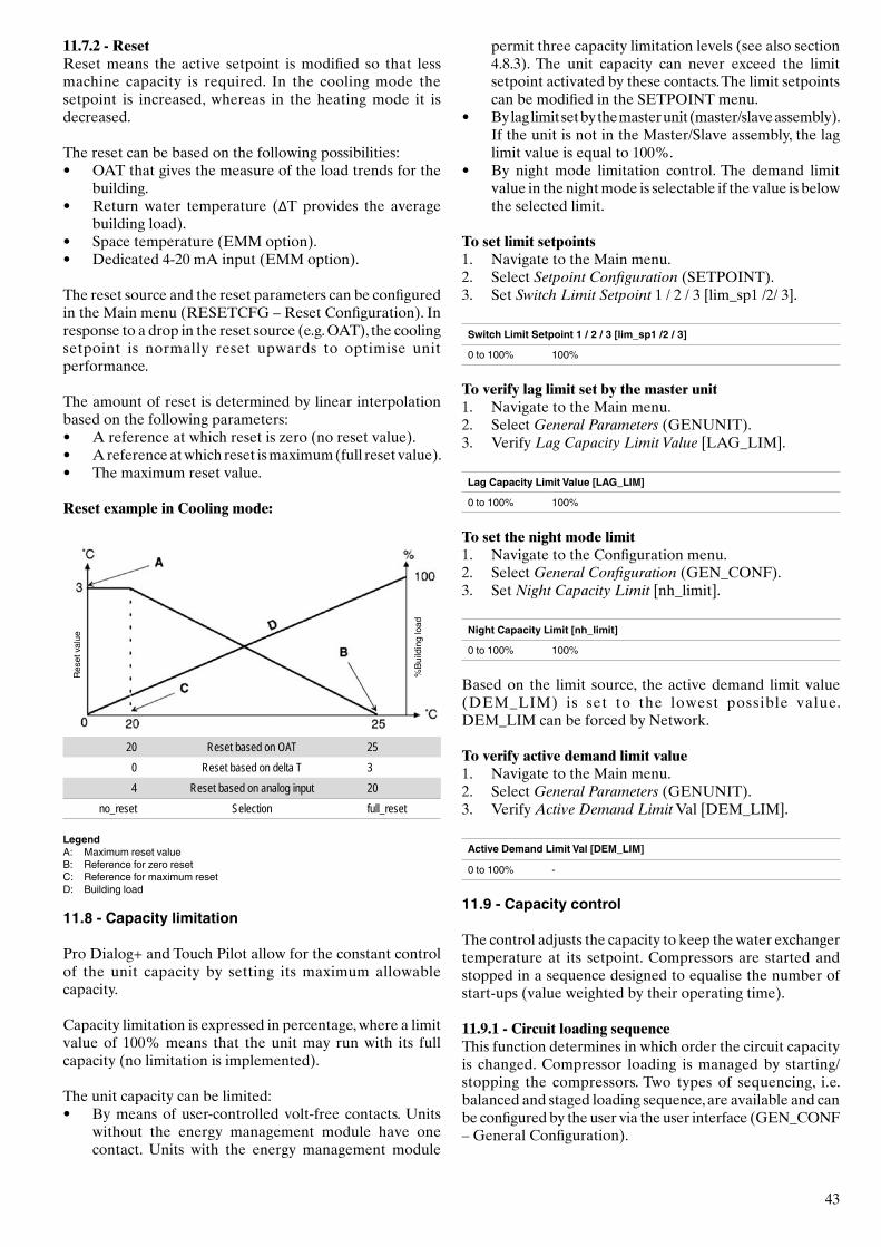
43
11.7.2 - ResetReset means the active setpoint is modified so that less machine capacity is required. In the cooling mode the setpoint is increased, whereas in the heating mode it is decreased. The reset can be based on the following possibilities:• OAT that gives the measure of the load trends for the
building.• Return water temperature (ΔT provides the average
building load).• Space temperature (EMM option).• Dedicated 4-20 mA input (EMM option). The reset source and the reset parameters can be configured in the Main menu (RESETCFG – Reset Configuration). In response to a drop in the reset source (e.g. OAT), the cooling setpoint is normally reset upwards to optimise unit performance.
The amount of reset is determined by linear interpolation based on the following parameters:• A reference at which reset is zero (no reset value).• A reference at which reset is maximum (full reset value).• The maximum reset value.
Reset example in Cooling mode:
%Bu
ildin
g lo
ad
Rese
t val
ue
20 Reset based on OAT 250 Reset based on delta T 34 Reset based on analog input 20
no_reset Selection full_reset
LegendA: Maximum reset valueB: Reference for zero resetC: Reference for maximum resetD: Building load
11.8 - Capacity limitation
Pro Dialog+ and Touch Pilot allow for the constant control of the unit capacity by setting its maximum allowable capacity.
Capacity limitation is expressed in percentage, where a limit value of 100% means that the unit may run with its full capacity (no limitation is implemented).
The unit capacity can be limited:• By means of user-controlled volt-free contacts. Units
without the energy management module have one contact. Units with the energy management module
permit three capacity limitation levels (see also section 4.8.3). The unit capacity can never exceed the limit setpoint activated by these contacts. The limit setpoints can be modified in the SETPOINT menu.
• By lag limit set by the master unit (master/slave assembly). If the unit is not in the Master/Slave assembly, the lag
limit value is equal to 100%.• By night mode limitation control. The demand limit
value in the night mode is selectable if the value is below the selected limit.
To set limit setpoints1. Navigate to the Main menu.2. Select Setpoint Configuration (SETPOINT).3. Set Switch Limit Setpoint 1 / 2 / 3 [lim_sp1 /2/ 3].
Switch Limit Setpoint 1 / 2 / 3 [lim_sp1 /2 / 3]
0 to 100% 100%
To verify lag limit set by the master unit1. Navigate to the Main menu.2. Select General Parameters (GENUNIT).3. Verify Lag Capacity Limit Value [LAG_LIM].
Lag Capacity Limit Value [LAG_LIM]
0 to 100% 100%
To set the night mode limit1. Navigate to the Configuration menu.2. Select General Configuration (GEN_CONF).3. Set Night Capacity Limit [nh_limit].
Night Capacity Limit [nh_limit]
0 to 100% 100%
Based on the limit source, the active demand limit value (DEM_LIM) is set to the lowest possible value. DEM_LIM can be forced by Network.
To verify active demand limit value1. Navigate to the Main menu.2. Select General Parameters (GENUNIT).3. Verify Active Demand Limit Val [DEM_LIM].
Active Demand Limit Val [DEM_LIM]
0 to 100% -
11.9 - Capacity control
The control adjusts the capacity to keep the water exchanger temperature at its setpoint. Compressors are started and stopped in a sequence designed to equalise the number of start-ups (value weighted by their operating time).
11.9.1 - Circuit loading sequenceThis function determines in which order the circuit capacity is changed. Compressor loading is managed by starting/stopping the compressors. Two types of sequencing, i.e. balanced and staged loading sequence, are available and can be configured by the user via the user interface (GEN_CONF – General Configuration).
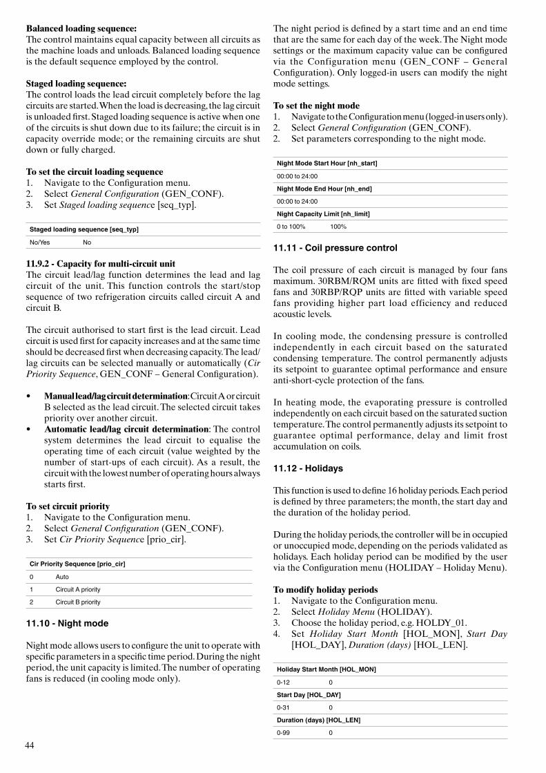
44
Balanced loading sequence: The control maintains equal capacity between all circuits as the machine loads and unloads. Balanced loading sequence is the default sequence employed by the control.
Staged loading sequence: The control loads the lead circuit completely before the lag circuits are started. When the load is decreasing, the lag circuit is unloaded first. Staged loading sequence is active when one of the circuits is shut down due to its failure; the circuit is in capacity override mode; or the remaining circuits are shut down or fully charged.
To set the circuit loading sequence1. Navigate to the Configuration menu.2. Select General Configuration (GEN_CONF).3. Set Staged loading sequence [seq_typ].
Staged loading sequence [seq_typ]
No/Yes No
11.9.2 - Capacity for multi-circuit unitThe circuit lead/lag function determines the lead and lag circuit of the unit. This function controls the start/stop sequence of two refrigeration circuits called circuit A and circuit B.
The circuit authorised to start first is the lead circuit. Lead circuit is used first for capacity increases and at the same time should be decreased first when decreasing capacity. The lead/lag circuits can be selected manually or automatically (Cir Priority Sequence, GEN_CONF – General Configuration).
• Manual lead/lag circuit determination: Circuit A or circuit B selected as the lead circuit. The selected circuit takes priority over another circuit.
• Automatic lead/lag circuit determination: The control system determines the lead circuit to equalise the operating time of each circuit (value weighted by the number of start-ups of each circuit). As a result, the circuit with the lowest number of operating hours always starts first.
To set circuit priority1. Navigate to the Configuration menu.2. Select General Configuration (GEN_CONF).3. Set Cir Priority Sequence [prio_cir].
Cir Priority Sequence [prio_cir]
0 Auto
1 Circuit A priority
2 Circuit B priority
11.10 - Night mode
Night mode allows users to configure the unit to operate with specific parameters in a specific time period. During the night period, the unit capacity is limited. The number of operating fans is reduced (in cooling mode only).
The night period is defined by a start time and an end time that are the same for each day of the week. The Night mode settings or the maximum capacity value can be configured via the Configuration menu (GEN_CONF – General Configuration). Only logged-in users can modify the night mode settings.
To set the night mode1. Navigate to the Configuration menu (logged-in users only). 2. Select General Configuration (GEN_CONF). 2. Set parameters corresponding to the night mode.
Night Mode Start Hour [nh_start]
00:00 to 24:00
Night Mode End Hour [nh_end]
00:00 to 24:00
Night Capacity Limit [nh_limit]
0 to 100% 100%
11.11 - Coil pressure control
The coil pressure of each circuit is managed by four fans maximum. 30RBM/RQM units are fitted with fixed speed fans and 30RBP/RQP units are fitted with variable speed fans providing higher part load efficiency and reduced acoustic levels.
In cooling mode, the condensing pressure is controlled independently in each circuit based on the saturated condensing temperature. The control permanently adjusts its setpoint to guarantee optimal performance and ensure anti-short-cycle protection of the fans.
In heating mode, the evaporating pressure is controlled independently on each circuit based on the saturated suction temperature. The control permanently adjusts its setpoint to guarantee optimal performance, delay and limit frost accumulation on coils.
11.12 - Holidays
This function is used to define 16 holiday periods. Each period is defined by three parameters; the month, the start day and the duration of the holiday period.
During the holiday periods, the controller will be in occupied or unoccupied mode, depending on the periods validated as holidays. Each holiday period can be modified by the user via the Configuration menu (HOLIDAY – Holiday Menu).
To modify holiday periods1. Navigate to the Configuration menu.2. Select Holiday Menu (HOLIDAY).3. Choose the holiday period, e.g. HOLDY_01.4. Set Holiday Start Month [HOL_MON], Start Day
[HOL_DAY], Duration (days) [HOL_LEN].
Holiday Start Month [HOL_MON]
0-12 0
Start Day [HOL_DAY]
0-31 0
Duration (days) [HOL_LEN]
0-99 0
45
11.13 - Energy management module
The optional Energy Management Module is used to control the level of energy consumption, providing users with information such as current unit status, compressors operating status, etc.
For more information about connections associated with the energy management module, see Terminal block connections in section 4.8.
11.14 - Free cooling option
Free cooling is a method of using low outside air temperature as an aid to chilling water that is later used in the air-conditioning system. Thanks to this option, the energy consumed by the unit can be reduced depending on the external air temperature, with the system being most effective when the outdoor air temperature is below 0°C (32°F).
The outdoor air temperature threshold that triggers the free cooling cycle can be set by the user in the Configuration menu (FREECONF – Free Cooling).
The free cooling option requires an additional SIOB board to be installed.
Free Cooling can be disabled using one of the following methods:• By forcing the Free Cooling Disable ? parameter to "yes"
via the user interface (FC_DSBLE in FREECOOL menu).
• By forcing the parameter FREECOOL.FC_DSBLE to "yes" through the Network in Network mode.
• By switching to "close" the FC_SW input on the FC SIOB board in Remote mode.
11.14.1 - Free cooling cycle (30RBM/30RQM only)When operating conditions allow for free cooling, the compressors are stopped and the 3-way valve is used to prevent the fluid from entering the compressor when the refrigerant pump is running. The cooling capacity is controlled by opening the electronic expansion valve (EXV).
The changeover from mechanical cooling to free cooling is controlled automatically by the control.
The free cooling session may be performed independently on two circuits at the same time. In case of 30RBP units (only units without common V-coil for both circuits), it is also possible for one circuit to operate in mechanical cooling, whereas another one may be in the free cooling mode. Such a solution helps to optimize the free cooling operation and ensures that the cooling demand is satisfied at any time.
CAUTION
If the unit is in the Free Cooling alarm, the control will switch back to compressor cooling (mechanical cooling) and another free cooling session will not be allowed within the next hour.
11.14.2 - Free cooling modeThe free cooling mode depends on the OAT threshold and Delta T (minimum difference between the control point and OAT). Higher Delta T implies higher Energy Efficiency Ratio (EER).
EER: Energy Efficiency RatioDelta T: Minimum difference between the control point and OAT
To set free cooling OAT threshold1. Navigate to the Configuration menu.2. Select Free Cooling Config (FREECONF).3. Set OAT Threshold [free_th].
OAT Threshold [free_th]
-35 to 30°C 0°C
-31 to 86°F 32°F
To set minimum Delta T1. Navigate to the Configuration menu.2. Select Free Cooling Config (FREECONF).3. Set Minimum Delta T [fcdeltat].
Minimum Delta T [fcdeltat]
5 to 10^C 8^C
9 to 18^F 14.4^F
Additionally, the control allows for pre-cooling which means that free cooling is allowed only when the difference between OAT and LWT is greater than the minimum Delta T.
To set pre-cooling 1. Navigate to the Configuration menu.2. Select Free Cooling Config (FREECONF).3. Set Pre-Cooling Select [pre_cool].
Pre-Cooling Select [pre_cool]
No/Yes Yes
46
11.15 - Free Cooling Dry Cooler (FCDC)
30RBM/RBP chillers and 30RQMP/RQP heat pumps may be fitted with a dry cooler that enables power consumption reduction which amounts to energy and cost savings. The installation of a dry cooler allows for "free cooling" – a method of using low outdoor air temperature as an aid to chilling water that is later used in the air-conditioning system. The system is the most effective when the outdoor air temperature is below 0°C (32°F).
Starting free cooling
The free cooling mode is ENABLED when the free cooling / dry cooler OAT [fdc_oat] is below the water loop temperature and the start threshold:
fdc_oat < fdcWloop - fdc_start
fdc_oat: Free Cooling Dry Cooler OATfdcWloop: Free Cooling Dry Cooler Water Temperaturefdc_start: Free Cooling Dry Cooler Start Valve Threshold (service access only)
Note: [fdcWloop] and [fdc_oat] temperatures measured by the control are read-only values that can be verified in the FC Dry Cooler Status menu (FCDC_ST).
To verify Dry Cooler water loop temp.1. Navigate to the Main menu.2. Select FC Dry Cooler Status (FCDC_ST).3. Verify FCDC Water Loop Temp [fdcWloop].
FCDC Water Loop Temp [fdcWloop]
°C / °F
To verify Free Cooling OAT1. Navigate to the Main menu.2. Select FC Dry Cooler Status (FCDC_ST).3. Verify FC Dry Cooler OAT [fdc_oat].
FC Dry Cooler OAT [fdc_oat]
°C / °F
Stopping free cooling
If it turns out that the cooling power of the dry cooler is not enough in order to reach the cooling setpoint, then the mechanical cooling will be started.
Free Cooling is normally stopped when the free cooling / dry cooler OAT [fdc_oat] is above the water loop temperature and the start/stop threshold:
fdc_oat > fdcWloop - fdc_start + fdc_stop
fdc_oat: Free Cooling Dry Cooler OATfdcWloop: Free Cooling Dry Cooler Water Temperaturefdc_start: Free Cooling Dry Cooler Start Valve Threshold (service access only)fdc_stop: Free Cooling Dry Cooler Stop Valve Threshold (service access only)
When FC capacity is at 100%, then mechanical cooling can be started.
11.16 - Heat reclaim option
Heat reclaim is a method of using energy that normally leaves the system in the form of the waste heat at the condenser site. Heat reclaim chiller generates high pressure refrigerant within the condenser that can be used to produce higher temperature condenser water.
11.16.1 - Heat reclaim processUnits with the heat reclaim option are fitted with two condensers (air-cooled condenser which is set as standard and water-cooled condenser which is used for heat reclaim). Adding the heat reclaim condenser to the unit may significantly reduce unit energy consumption and lead to lower greenhouse generation with maximized chiller plant efficiency.
11.16.2 - Heat reclaim modeThe reclaim mode is active when the reclaim entering water temperature is below the Reclaim setpoint (SETPOINT – Setpoint Configuration). Depending on the difference between the reclaim entering water temperature and the reclaim setpoint, the control decides how many circuits must be started to provide heat reclaim operation (one or two circuits). The number of circuits with the heat reclaim option is factory-configured.
To set reclaim setpoint1. Navigate to the Main menu.2. Select Setpoint Configuration (SETPOINT).3. Set Heat Reclaim Setpoint [hr_stp].
Heat Reclaim Setpoint [hr_stp]
35 to 50°C 50°C
95 to 122°F 122°F 11.17 - Desuperheater option
30RBM/RQM/RBP/RQP units may be fitted with a desuperheater that allows for better energy management. The desuperheater is used to extract the high pressure, high temperature heat from the refrigerant to “desuperheat” it to a lower pressure refrigerant. The vapour that goes into the desuperheater is not fully condensed; therefore, the refrigerant vapour must be channelled to a separate heat exchanger where the condensing process occurs.
Note that the desuperheater is enabled when the Desuperheater demand contact is closed. For units with EMM option, there is also an output used to command a desuperheater pump.
To set minimal condensing setpoint1. Navigate to the Main menu.2. Select Setpoint Configuration (SETPOINT).3. Set Desuperheat Min SCT [min_sct].
Desuperheat Min SCT [min_sct]
24 to 50°C 40°C
75 to 122°F 104°F
47
11.18 - Defrost cycle for heat pumps
When the outside air temperature is low and the ambient humidity is high, the probability of frost forming on the surface of the outdoor coil increases. The frost covering the outdoor coil may decrease the air flow across the coil and lead to lower performance of the unit. To remove the frost from the coil, the control initiates the defrost cycle when necessary.
During the defrost cycle, the circuit is forced into the cooling mode. To prevent the water loop from cooling down, optional electric heating may be started. The defrost cycle lasts until the end of defrost temperature is achieved.
11.19 - Master/slave assembly
The control system allows for master/slave control of two units linked by the CCN network. The master unit can be controlled locally, remotely or by network commands (CCN), while the slave unit remains in Network mode. All control commands to the master/slave assembly (start/stop, setpoint selection, heating/cooling operation, load shedding, etc.) are handled by the unit which is configured as the master. The commands are transmitted automatically to the slave unit.
If the master chiller is turned off, while the master/slave function is active, then the slave chiller will be stopped.Under certain circumstances, the slave unit may be started first to ensure that the run times of the two units are equalised.
In the event of a communication failure between the two units, each unit will return to an autonomous operating mode until the fault is cleared. If the master unit is stopped due to an alarm, the slave unit is authorised to start.
IMPORTANT: Master/slave assembly can be configured only by Carrier service.
11.20 - BACnet option
The BACnet/IP communication protocol is used by BMS or the programmable controllers to communicate with the control.
IMPORTANT: BACnet option can be installed only by Carrier service.
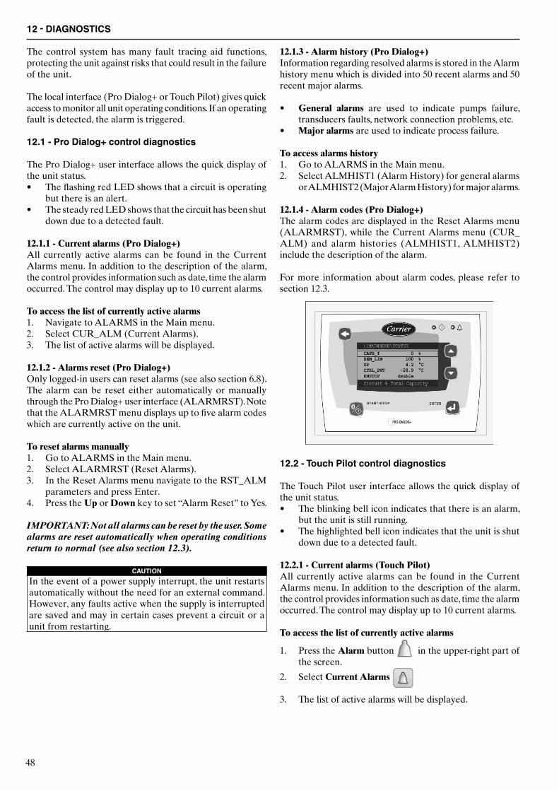
48
12 - DIAGNOSTICS
The control system has many fault tracing aid functions, protecting the unit against risks that could result in the failure of the unit.
The local interface (Pro Dialog+ or Touch Pilot) gives quick access to monitor all unit operating conditions. If an operating fault is detected, the alarm is triggered.
12.1 - Pro Dialog+ control diagnostics
The Pro Dialog+ user interface allows the quick display of the unit status.• The flashing red LED shows that a circuit is operating
but there is an alert.• The steady red LED shows that the circuit has been shut
down due to a detected fault.
12.1.1 - Current alarms (Pro Dialog+)All currently active alarms can be found in the Current Alarms menu. In addition to the description of the alarm, the control provides information such as date, time the alarm occurred. The control may display up to 10 current alarms.
To access the list of currently active alarms1. Navigate to ALARMS in the Main menu.2. Select CUR_ALM (Current Alarms).3. The list of active alarms will be displayed.
12.1.2 - Alarms reset (Pro Dialog+)Only logged-in users can reset alarms (see also section 6.8). The alarm can be reset either automatically or manually through the Pro Dialog+ user interface (ALARMRST). Note that the ALARMRST menu displays up to five alarm codes which are currently active on the unit.
To reset alarms manually1. Go to ALARMS in the Main menu.2. Select ALARMRST (Reset Alarms).3. In the Reset Alarms menu navigate to the RST_ALM
parameters and press Enter.4. Press the Up or Down key to set “Alarm Reset” to Yes.
IMPORTANT: Not all alarms can be reset by the user. Some alarms are reset automatically when operating conditions return to normal (see also section 12.3).
CAUTIONIn the event of a power supply interrupt, the unit restarts automatically without the need for an external command. However, any faults active when the supply is interrupted are saved and may in certain cases prevent a circuit or a unit from restarting.
12.1.3 - Alarm history (Pro Dialog+)Information regarding resolved alarms is stored in the Alarm history menu which is divided into 50 recent alarms and 50 recent major alarms.
• General alarms are used to indicate pumps failure, transducers faults, network connection problems, etc.
• Major alarms are used to indicate process failure.
To access alarms history1. Go to ALARMS in the Main menu.2. Select ALMHIST1 (Alarm History) for general alarms
or ALMHIST2 (Major Alarm History) for major alarms.
12.1.4 - Alarm codes (Pro Dialog+)The alarm codes are displayed in the Reset Alarms menu (ALARMRST), while the Current Alarms menu (CUR_ALM) and alarm histories (ALMHIST1, ALMHIST2) include the description of the alarm.
For more information about alarm codes, please refer to section 12.3.
12.2 - Touch Pilot control diagnostics
The Touch Pilot user interface allows the quick display of the unit status.• The blinking bell icon indicates that there is an alarm,
but the unit is still running.• The highlighted bell icon indicates that the unit is shut
down due to a detected fault.
12.2.1 - Current alarms (Touch Pilot)All currently active alarms can be found in the Current Alarms menu. In addition to the description of the alarm, the control provides information such as date, time the alarm occurred. The control may display up to 10 current alarms.
To access the list of currently active alarms
1. Press the Alarm button in the upper-right part of the screen.
2. Select Current Alarms
3. The list of active alarms will be displayed.

49
12.2.2 - Alarms reset (Touch Pilot)Alarm can be reset without stopping the machine. Only logged-in users can reset alarms (see also section 8.8.1). The alarm can be reset either automatically or manually through the Touch Pilot user interface or the web interface (Reset Alarms menu). Note that the Reset Alarms menu displays up to five alarm codes which are currently active on the unit.
To reset alarms manually
1. Press the Alarm button in the upper-right part of the screen.
2. Select Reset Alarms
3. Set “Alarm Reset” to Yes.
IMPORTANT: Not all alarms can be reset by the user. Some alarms are reset automatically when operating conditions return to normal (see also section 12.3).
CAUTIONIn the event of a power supply interrupt, the unit restarts automatically without the need for an external command. However, any faults active when the supply is interrupted are saved and may in certain cases prevent a circuit or a unit from restarting.
12.2.3 - Alarm history (Touch Pilot)Information regarding resolved alarms is stored in the Alarm history menu which is divided into 50 recent alarms and 50 recent major alarms.
• General alarms are used to indicate pumps failure, transducers faults, network connection problems, etc.
• Major alarms are used to indicate process failure.
To access alarms history
1. Press the Alarm button in the upper-right part of the screen.
2. Select Alarm History or Major Alarm
History
12.2.4 - Alarm codesThe alarm codes are displayed in the Reset Alarms menu, while the Current Alarms menu as well as Alarm History and Major Alarm History include the description of the alarm.
12.2.5 - E-mail notificationsThe control provides the option to define one or two recipients who receive e-mail notifications each time the new alarm occurs or all existing alarms have been reset. Only logged-in users can set and modify e-mail notifications (see also section 8.8.1).
To define recipients 1. Navigate to the Configuration menu.
2. Select Email Configuration 3. Define user e-mails.
4. Press to save changes.
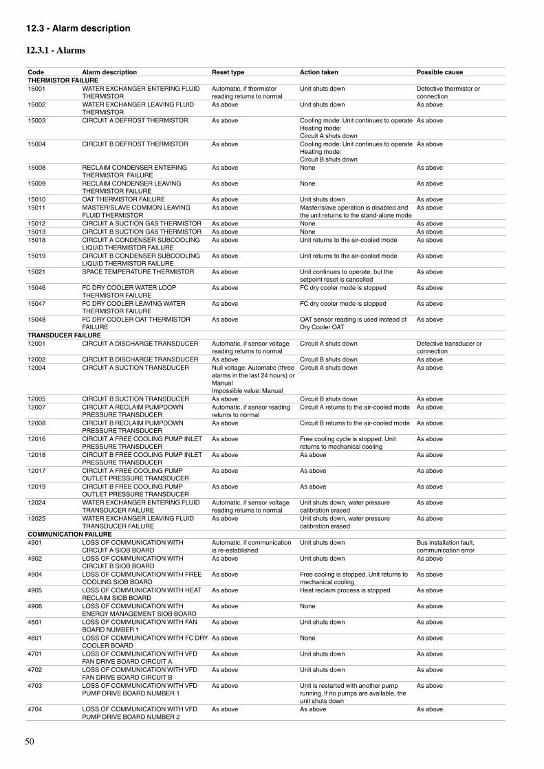
50
12.3 - Alarm description
12.3.1 - Alarms
Code Alarm description Reset type Action taken Possible causeTHERMISTOR FAILURE15001 WATER EXCHANGER ENTERING FLUID
THERMISTORAutomatic, if thermistor reading returns to normal
Unit shuts down Defective thermistor or connection
15002 WATER EXCHANGER LEAVING FLUID THERMISTOR
As above Unit shuts down As above
15003 CIRCUIT A DEFROST THERMISTOR As above Cooling mode: Unit continues to operateHeating mode:Circuit A shuts down
As above
15004 CIRCUIT B DEFROST THERMISTOR As above Cooling mode: Unit continues to operateHeating mode:Circuit B shuts down
As above
15008 RECLAIM CONDENSER ENTERING THERMISTOR FAILURE
As above None As above
15009 RECLAIM CONDENSER LEAVING THERMISTOR FAILURE
As above None As above
15010 OAT THERMISTOR FAILURE As above Unit shuts down As above15011 MASTER/SLAVE COMMON LEAVING
FLUID THERMISTORAs above Master/slave operation is disabled and
the unit returns to the stand-alone modeAs above
15012 CIRCUIT A SUCTION GAS THERMISTOR As above None As above15013 CIRCUIT B SUCTION GAS THERMISTOR As above None As above15018 CIRCUIT A CONDENSER SUBCOOLING
LIQUID THERMISTOR FAILURE As above Unit returns to the air-cooled mode As above
15019 CIRCUIT B CONDENSER SUBCOOLING LIQUID THERMISTOR FAILURE
As above Unit returns to the air-cooled mode As above
15021 SPACE TEMPERATURE THERMISTOR As above Unit continues to operate, but the setpoint reset is cancelled
As above
15046 FC DRY COOLER WATER LOOP THERMISTOR FAILURE
As above FC dry cooler mode is stopped As above
15047 FC DRY COOLER LEAVING WATER THERMISTOR FAILURE
As above FC dry cooler mode is stopped As above
15048 FC DRY COOLER OAT THERMISTOR FAILURE
As above OAT sensor reading is used instead of Dry Cooler OAT
As above
TRANSDUCER FAILURE12001 CIRCUIT A DISCHARGE TRANSDUCER Automatic, if sensor voltage
reading returns to normalCircuit A shuts down Defective transducer or
connection12002 CIRCUIT B DISCHARGE TRANSDUCER As above Circuit B shuts down As above12004 CIRCUIT A SUCTION TRANSDUCER Null voltage: Automatic (three
alarms in the last 24 hours) or ManualImpossible value: Manual
Circuit A shuts down As above
12005 CIRCUIT B SUCTION TRANSDUCER As above Circuit B shuts down As above12007 CIRCUIT A RECLAIM PUMPDOWN
PRESSURE TRANSDUCERAutomatic, if sensor reading returns to normal
Circuit A returns to the air-cooled mode As above
12008 CIRCUIT B RECLAIM PUMPDOWN PRESSURE TRANSDUCER
As above Circuit B returns to the air-cooled mode As above
12016 CIRCUIT A FREE COOLING PUMP INLET PRESSURE TRANSDUCER
As above Free cooling cycle is stopped. Unit returns to mechanical cooling
As above
12018 CIRCUIT B FREE COOLING PUMP INLET PRESSURE TRANSDUCER
As above As above As above
12017 CIRCUIT A FREE COOLING PUMP OUTLET PRESSURE TRANSDUCER
As above As above As above
12019 CIRCUIT B FREE COOLING PUMP OUTLET PRESSURE TRANSDUCER
As above As above As above
12024 WATER EXCHANGER ENTERING FLUID TRANSDUCER FAILURE
Automatic, if sensor voltage reading returns to normal
Unit shuts down, water pressure calibration erased
As above
12025 WATER EXCHANGER LEAVING FLUID TRANSDUCER FAILURE
As above Unit shuts down, water pressure calibration erased
As above
COMMUNICATION FAILURE4901 LOSS OF COMMUNICATION WITH
CIRCUIT A SIOB BOARDAutomatic, if communication is re-established
Unit shuts down Bus installation fault, communication error
4902 LOSS OF COMMUNICATION WITH CIRCUIT B SIOB BOARD
As above Unit shuts down As above
4904 LOSS OF COMMUNICATION WITH FREE COOLING SIOB BOARD
As above Free cooling is stopped. Unit returns to mechanical cooling
As above
4905 LOSS OF COMMUNICATION WITH HEAT RECLAIM SIOB BOARD
As above Heat reclaim process is stopped As above
4906 LOSS OF COMMUNICATION WITH ENERGY MANAGEMENT SIOB BOARD
As above None As above
4501 LOSS OF COMMUNICATION WITH FAN BOARD NUMBER 1
As above Unit shuts down As above
4601 LOSS OF COMMUNICATION WITH FC DRY COOLER BOARD
As above None As above
4701 LOSS OF COMMUNICATION WITH VFD FAN DRIVE BOARD CIRCUIT A
As above Unit shuts down As above
4702 LOSS OF COMMUNICATION WITH VFD FAN DRIVE BOARD CIRCUIT B
As above Unit shuts down As above
4703 LOSS OF COMMUNICATION WITH VFD PUMP DRIVE BOARD NUMBER 1
As above Unit is restarted with another pump running. If no pumps are available, the unit shuts down
As above
4704 LOSS OF COMMUNICATION WITH VFD PUMP DRIVE BOARD NUMBER 2
As above As above As above
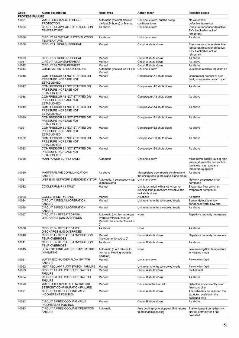
51
Code Alarm description Reset type Action taken Possible causePROCESS FAILURE10001 WATER EXCHANGER FREEZE
PROTECTIONAutomatic (the first alarm in the last 24 hours) or Manual
Unit shuts down, but the pump continues to run
No water flow,defective thermistor
10005 CIRCUIT A LOW SATURATED SUCTION TEMPERATURE
As above Unit shuts down Pressure transducer defective, EXV blocked or lack of refrigerant
10006 CIRCUIT B LOW SATURATED SUCTION TEMPERATURE
As above Unit shuts down As above
10008 CIRCUIT A HIGH SUPERHEAT Manual Circuit A shuts down Pressure transducer defective, temperature sensor defective, EXV blocked or lack of refrigerant
10009 CIRCUIT B HIGH SUPERHEAT Manual Circuit B shuts down As above10011 CIRCUIT A LOW SUPERHEAT Manual Circuit A shuts down As above10012 CIRCUIT B LOW SUPERHEAT Manual Circuit B shuts down As above10014 CUSTOMER INTERLOCK FAILURE Automatic (the unit is OFF) or
ManualUnit shuts down Customer interlock input set on
10016 COMPRESSOR A1 NOT STARTED OR PRESSURE INCREASE NOT ESTABLISHED
Manual Compressor A1 shuts down Compressor breaker or fuse fault, compressor switch open
10017 COMPRESSOR A2 NOT STARTED OR PRESSURE INCREASE NOT ESTABLISHED
Manual Compressor A2 shuts down As above
10018 COMPRESSOR A3 NOT STARTED OR PRESSURE INCREASE NOT ESTABLISHED
Manual Compressor A3 shuts down As above
10019 COMPRESSOR A4 NOT STARTED OR PRESSURE INCREASE NOT ESTABLISHED
Manual Compressor A4 shuts down As above
10020 COMPRESSOR B1 NOT STARTED OR PRESSURE INCREASE NOT ESTABLISHED
Manual Compressor B1 shuts down As above
10021 COMPRESSOR B2 NOT STARTED OR PRESSURE INCREASE NOT ESTABLISHED
Manual Compressor B2 shuts down As above
10022 COMPRESSOR B3 NOT STARTED OR PRESSURE INCREASE NOT ESTABLISHED
Manual Compressor B3 shuts down As above
10023 COMPRESSOR B4 NOT STARTED OR PRESSURE INCREASE NOT ESTABLISHED
Manual Compressor B4 shuts down As above
10028 MAIN POWER SUPPLY FAULT Automatic Unit shuts down Main power supply fault or high temperature in the control box (units with high ambient temperature option)
10030 MASTER/SLAVE COMMUNICATION FAILURE
As above Master/slave operation is disabled and the unit returns to the stand-alone mode
As above
10031 UNIT IS IN NETWORK EMERGENCY STOP Automatic, if emergency stop is deactivated
Unit shuts down Network emergency stop command
10032 COOLER PUMP #1 FAULT Manual Unit is restarted with another pump running. If no pumps are available, the unit shuts down
Evaporator flow switch or evaporator pump fault
10033 COOLER PUMP #2 FAULT Manual As above As above10034 CIRCUIT A RECLAIM OPERATION
FAILURE Manual Unit returns to the air-cooled mode Sensor defective or low
condenser water flow rate10035 CIRCUIT B RECLAIM OPERATION
FAILURE Manual Unit returns to the air-cooled mode As above
10037 CIRCUIT A - REPEATED HIGH DISCHARGE GAS OVERRIDES
Automatic (no discharge gas override within 30 min) or Manual (the counter forced to 0)
None Repetitive capacity decreases
10038 CIRCUIT B - REPEATED HIGH DISCHARGE GAS OVERRIDES
As above None As above
10040 CIRCUIT A - REPEATED LOW SUCTION TEMP OVERRIDES
Manual (the counter forced to 0)
Circuit A shuts down Repetitive capacity decreases
10041 CIRCUIT B - REPEATED LOW SUCTION TEMP OVERRIDES
As above Circuit B shuts down As above
10043 LOW ENTERING WATER TEMPERATURE IN HEATING
Automatic (EWT returns to normal or Heating mode is disabled)
None Low entering fluid temperature in Heating mode
10051 WATER EXCHANGER FLOW SWITCH FAILURE
Manual Unit shuts down Flow switch fault
10052 HEAT RECLAIM FLOW SWITCH FAILURE Manual Unit returns to the air-cooled mode Flow switch fault10063 CIRCUIT A HIGH PRESSURE SWITCH
FAILURE Manual Circuit A shuts down Switch fault
10064 CIRCUIT B HIGH PRESSURE SWITCH FAILURE
Manual Circuit B shuts down As above
10090 WATER EXCHANGER FLOW SWITCH SETPOINT CONFIGURATION FAILURE
Manual Unit cannot be started Defective or incorrectly wired flow controller
10091 CIRCUIT A FREE COOLING VALVE INCOHERENT POSITION
Manual Circuit A shuts down The valve has not reached the expected position in the assigned time
10092 CIRCUIT B FREE COOLING VALVE INCOHERENT POSITION
Manual Circuit B shuts down As above
10093 CIRCUIT A FREE COOLING OPERATION FAILURE
Automatic Free cooling cycle stopped. Unit returns to mechanical cooling
The refrigerant pump has not started correctly or it has cavitated
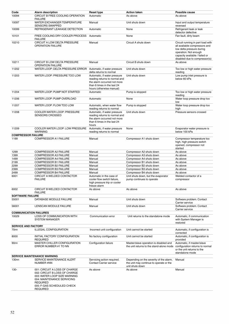
52
Code Alarm description Reset type Action taken Possible cause10094 CIRCUIT B FREE COOLING OPERATION
FAILURE Automatic As above As above
10097 WATER EXCHANGER TEMPERATURE SENSORS SWAPPED
Manual Unit shuts down Input and output temperature reversed
10099 REFRIGERANT LEAKAGE DETECTION Automatic None Refrigerant leak or leak detector defective
10101 FREE COOLING DRY COOLER PROCESS FAILURE
Automatic None Fan fault, dirty beam
10210 CIRCUIT A LOW DELTA PRESSURE OPERATION FAILURE
Manual Circuit A shuts down Circuit running in part load with all available compressors and low delta pressure during operation. Not enough capacity available / failed or disabled due to compressor(s)
10211 CIRCUIT B LOW DELTA PRESSURE OPERATION FAILURE
Manual Circuit B shuts down As above
11202 WATER LOOP: DELTA PRESSURE ERROR Automatic, if water pressure delta returns to normal
Unit shuts down Too low or high water pressure reading
11203 WATER LOOP: PRESSURE TOO LOW Automatic, if water pressure reading returns to normal and the alarm occurred not more than 6 times in the last 24 hours (otherwise manual)
Unit shuts down Low pump inlet pressure is below 60 kPa
11204 WATER LOOP: PUMP NOT STARTED Automatic Pump is stopped Too low or high water pressure reading
11206 WATER LOOP: PUMP OVERLOAD Automatic None Water loop pressure drop too low
11207 WATER LOOP: FLOW TOO LOW Automatic, when water flow reading returns to normal
Pump is stopped Water loop pressure drop too high
11208 COOLER WATER LOOP: PRESSURE SENSORS CROSSED
Automatic, if water pressure reading returns to normal and the alarm occurred not more than 6 times in the last 24 hours
Unit shuts down Pressure sensors crossed
11209 COOLER WATER LOOP: LOW PRESSURE WARNING
Automatic, if water pressure reading returns to normal
None Evaporator water pressure is below 100 kPa
COMPRESSOR FAILURE1199 COMPRESSOR A1 FAILURE Manual Compressor A1 shuts down Compressor temperature too
high, high pressure switch opened, compressor not started
1299 COMPRESSOR A2 FAILURE Manual Compressor A2 shuts down As above1399 COMPRESSOR A3 FAILURE Manual Compressor A3 shuts down As above1499 COMPRESSOR A4 FAILURE Manual Compressor A4 shuts down As above2199 COMPRESSOR B1 FAILURE Manual Compressor B1 shuts down As above2299 COMPRESSOR B2 FAILURE Manual Compressor B2 shuts down As above2399 COMPRESSOR B3 FAILURE Manual Compressor B3 shuts down As above2499 COMPRESSOR B4 FAILURE Manual Compressor B4 shuts down As above6001 CIRCUIT A WELDED CONTACTOR
FAILURE Automatic in the case of cooler flow switch failure, high pressure trip or cooler freeze alarm
Unit shuts down, but the evaporator pump continues to operate
Welded contactor of a compressor
6002 CIRCUIT B WELDED CONTACTOR FAILURE
As above As above As above
SOFTWARE FAILURE55001 DATABASE MODULE FAILURE Manual Unit shuts down Software problem. Contact
Carrier service56001 LENSCAN MODULE FAILURE Manual Unit shuts down Software problem. Contact
Carrier serviceCOMMUNICATION FAILURES10029 LOSS OF COMMUNICATION WITH
SYSTEM MANAGER Communication error Unit returns to the standalone mode Automatic, if communication
with System Manager is restored
SERVICE AND FACTORY70nn ILLEGAL CONFIGURATION Incorrect unit configuration Unit cannot be started Automatic, if configuration is
corrected8000 INITIAL FACTORY CONFIGURATION
REQUIREDNo factory configuration Unit cannot be started Automatic, if configuration is
provided90nn MASTER CHILLER CONFIGURATION
ERROR NUMBER #1 TO NNConfiguration failure Master/slave operation is disabled and
the unit returns to the stand-alone modeAutomatic, if master/slave configuration returns to normal or the unit returns to the standalone mode
SERVICE MAINTENANCE WARNING130nn SERVICE MAINTENANCE ALERT
NUMBER #NNServicing action required. Contact Carrier service
Depending on the severity of the alarm, the unit may continue to operate or the unit shuts down
Manual
130- 001: CIRCUIT A LOSS OF CHARGE002: CIRCUIT B LOSS OF CHARGE003: WATER LOOP SIZE WARNING004: MAINTENANCE SERVICING REQUIRED005: F-GAS SCHEDULED CHECK REQUIRED
As above As above Manual
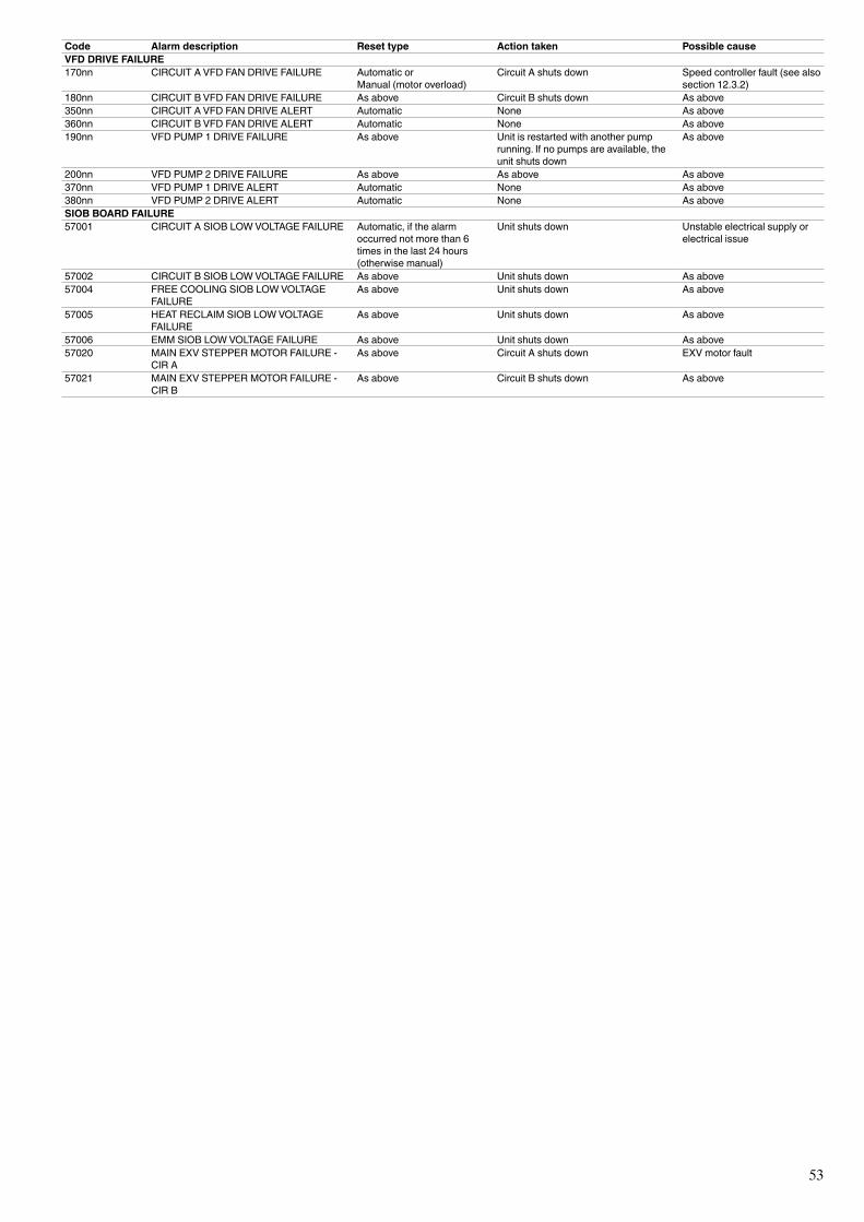
53
Code Alarm description Reset type Action taken Possible causeVFD DRIVE FAILURE170nn CIRCUIT A VFD FAN DRIVE FAILURE Automatic or
Manual (motor overload)Circuit A shuts down Speed controller fault (see also
section 12.3.2)180nn CIRCUIT B VFD FAN DRIVE FAILURE As above Circuit B shuts down As above350nn CIRCUIT A VFD FAN DRIVE ALERT Automatic None As above360nn CIRCUIT B VFD FAN DRIVE ALERT Automatic None As above190nn VFD PUMP 1 DRIVE FAILURE As above Unit is restarted with another pump
running. If no pumps are available, the unit shuts down
As above
200nn VFD PUMP 2 DRIVE FAILURE As above As above As above370nn VFD PUMP 1 DRIVE ALERT Automatic None As above380nn VFD PUMP 2 DRIVE ALERT Automatic None As aboveSIOB BOARD FAILURE57001 CIRCUIT A SIOB LOW VOLTAGE FAILURE Automatic, if the alarm
occurred not more than 6 times in the last 24 hours (otherwise manual)
Unit shuts down Unstable electrical supply or electrical issue
57002 CIRCUIT B SIOB LOW VOLTAGE FAILURE As above Unit shuts down As above57004 FREE COOLING SIOB LOW VOLTAGE
FAILUREAs above Unit shuts down As above
57005 HEAT RECLAIM SIOB LOW VOLTAGE FAILURE
As above Unit shuts down As above
57006 EMM SIOB LOW VOLTAGE FAILURE As above Unit shuts down As above57020 MAIN EXV STEPPER MOTOR FAILURE -
CIR AAs above Circuit A shuts down EXV motor fault
57021 MAIN EXV STEPPER MOTOR FAILURE - CIR B
As above Circuit B shuts down As above
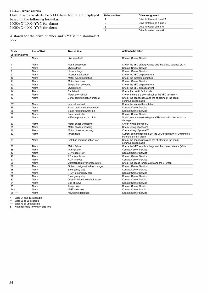
54
12.3.2 - Drive alarmsDrive alarms or alerts for VFD drive failure are displayed based on the following formulas: 16000+X*1000+YYY for alarms 34000+X*1000+YYY for alerts
X stands for the drive number and YYY is the alarm/alert code.
Drive number Drive assignment 1 Drive for fan(s) of circuit A 2 Drive for fan(s) of circuit B 3 Drive for water pump #1 4 Drive for water pump #2
Code Alarm/Alert Description Action to be takenVariator alarms2 Alarm Live zero fault Contact Carrier Service
4 Alarm Mains phase loss Check the VFD supply voltage and the phase balance (±3%)7 Alarm Overvoltage Contact Carrier Service8 Alarm Undervoltage Contact Carrier Service9 Alarm Inverter overloaded Check the VFD output current10 Alarm Motor overtemperature Check the motor temperature11 Alarm Motor thermistor Contact Carrier Service12 Alarm Torque limit exceeded Check the VFD output current13 Alarm Overcurrent Check the VFD output current14 Alarm Earth fault Check if an earth fault exists16 Alarm Motor short-circuit Check if there is a short-circuit at the VFD terminals17 Alarm Serial communication timeout Check the connections and the shielding of the serial
communication cable23* Alarm Internal fan fault Check the internal fan rotation25 Alarm Brake resistor short-circuited Contact Carrier Service26 Alarm Brake resistor power limit Contact Carrier Service28 Alarm Brake verification Contact Carrier Service29 Alarm VFD temperature too high Space temperature too high or VFD ventilation obstructed or
damaged30 Alarm Motor phase U missing Check wiring of phase U31 Alarm Motor phase V missing Check wiring of phase V32 Alarm Motor phase W missing Check wiring of phase W33 Alarm Inrush fault Current demand too high: Let the VFD cool down for 20 minutes
before starting it again34 Alarm Fieldbus communication fault Check the connections and the shielding of the serial
communication cable36 Alarm Mains failure Check the VFD supply voltage and the phase balance (±3%)38 Alarm Internal fault Contact Carrier Service47 Alarm 24 V supply low Contact Carrier Service48 Alarm 1.8 V supply low Contact Carrier Service57** Alarm AMA timeout Contact Carrier Service65 Alarm Control board overtemperature Check the space temperature and the VFD fan67 Alarm Option configuration has changed Contact Carrier Service68 Alarm Emergency stop Contact Carrier Service71 Alarm PTC 1 emergency stop Contact Carrier Service72 Alarm Emergency stop Contact Carrier Service80 Alarm Drive initialized to default value Contact Carrier Service94 Alarm End of curve Contact Carrier Service95 Alarm Torque loss Contact Carrier Service243 Alarm IGBT defective Contact Carrier Service251*** Alarm New parts detached Contact Carrier Service
* Error 24 and 104 possible** Error 50 to 58 possible*** Error 70 or 250 possible† Not applicable to variator size 102
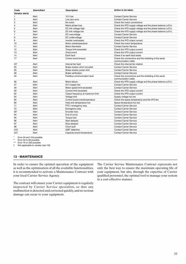
55
Code Alarm/Alert Description Action to be takenVariator alerts1 Alert 10 V low Contact Carrier Service2 Alert Live zero error Contact Carrier Service3 Alert No motor Check the motor connections4 Alert Mains phase loss Check the VFD supply voltage and the phase balance (±3%)5 Alert DC link voltage high Check the VFD supply voltage and the phase balance (±3%)6 Alert DC link voltage low Check the VFD supply voltage and the phase balance (±3%)7 Alert DC overvoltage Contact Carrier Service8 Alert DC undervoltage Contact Carrier Service9 Alert Inverter overloaded Check the VFD output current10 Alert Motor overtemperature Check the motor temperature11 Alert Motor thermistor Contact Carrier Service12 Alert Torque limit exceeded Check the VFD output current13 Alert Overcurrent Check the VFD output current14 Alert Earth fault Check if an earth fault exists17 Alert Control word timeout Check the connections and the shielding of the serial
communication cable23* Alert Internal fan fault Check the internal fan rotation25 Alert Brake resistor short-circuited Contact Carrier Service26 Alert Brake resistor power limit Contact Carrier Service28 Alert Brake verification Contact Carrier Service34 Alert Fieldbus communication fault Check the connections and the shielding of the serial
communication cable36 Alert Mains failure Check the VFD supply voltage and the phase balance (±3%)47 Alert 24 V supply low Contact Carrier Service49 Alert Motor speed limit exceeded Contact Carrier Service59 Alert Current limit exceeded Check the VFD output current62 Alert Output frequency at maximum limit Check the VFD output current64 Alert Voltage limit Supply voltage too low65 Alert Control board overtemperature Check the space temperature and the VFD fan66 Alert Heat sink temperature low Space temperature too low71 Alert PTC1 emergency stop Contact Carrier Service72 Alert Emergency stop Contact Carrier Service90† Alert Encoder loss Contact Carrier Service94 Alert End of curve Contact Carrier Service95 Alert Torque loss Contact Carrier Service96 Alert Start delayed Contact Carrier Service97 Alert Stop delayed Contact Carrier Service98 Alert Clock fault Contact Carrier Service243 Alert IGBT defective Contact Carrier Service247 Alert Capacity board temperature Contact Carrier Service
* Error 24 and 104 possible** Error 50 to 58 possible*** Error 70 or 250 possible† Not applicable to variator size 102
13 - MAINTENANCE
In order to ensure the optimal operation of the equipment as well as the optimisation of all the available functionalities, it is recommended to activate a Maintenance Contract with your local Carrier Service Agency.
The contract will ensure your Carrier equipment is regularly inspected by Carrier Service specialists, so that any malfunction is detected and corrected quickly, and no serious damage can occur to your equipment.
The Carrier Service Maintenance Contract represents not only the best way to ensure the maximum operating life of your equipment, but also, through the expertise of Carrier qualified personnel, the optimal tool to manage your system in a cost-effective manner.

Order No. 13540, 06.2016. Supersedes order No.: 13540, 03.2015. Manufacturer: Carrier SCS, Montluel, France.Manufacturer reserves the right to change any product specifications without notice. Printed in the European Union.