ag-160-02-02pp001.pdf - nato sto
TRANSCRIPT

Irite Trenkle and Manfred Reinhard= Deutsche Porschungs - und “ersucbsansealt fiir luft - und Raumfahrt E.“.
Inseftut fiir Physit de= Atmosphire Oberpfaffenbofe”
Germany
This publication is intended to give practical assistance to all instrumentation and rest
engineera working in the field of temperature measurements in aircraft at Mach numbers up to 2.3 and
altitudes up to 80,000 feet.
After a generel discussion of the requirements of aircraft temperature re(lsu=e%enfs, and the
available temperature sensing technology, the detailed techniques of using resistance probes and
rhermocouples, as well as =he associated electrical leads, circuits, rind indicators. a=e explained. A
discussion of heat transfer processes, primarily between moving fluids and solids, includes terminology,
the systematics of temperature measu=emenfs , and the concept of total temperature as the main operational
parameter. A,, extensive section deals with e==o=s in temperature measuremente, as functions of various
parameters, in gases, liquids and solids. Typical leborarory end in-flight calibration techniques for
thermometers a=e described, followed by discussions of data handling, error analysis. and the limits of
present methods.
1. wmoD”m‘IoN
Temperatures to be measured in and on aircraft presently range between approximately 200 and
l,SOO%, and in ext=eme cases, the limits extend to 20% and 2,000°K. Exrremely different requirements
are made on the meaau=eme,,t devices depending on the type of measurement (outside air, exhaust, fuel,
etc.). The large mmber of temperature me~suremenre normally made in a mDdern production aircraft is
further increased fo= flight test programs, and there a=e increased requirements for meas”=ement accuracy,
as well es additional demands, e.g. for matching withrecorders, indicators, and signal conditioners.
The inform&ion required to make more precise measu=e,zents in ai=c=aft is usually not found in the
regular textbooks on temperature meas”=ement, but have to be @aned from different individual publications,
and are. therefore, not readily at the disposal of the engineer who suddenly finds himself faced with a
new meesurerent problem. In the m~=e popular handbooks for flight testin& the measurement of the
tempe=at”=e of the outside sir ia briefly discussed. This discussion is. however, often based on the
level of technology in 1945 and the flight regime of the typical piston en&e aircraft of the day.
The possibilities opened up by the development of modern equipment a=e not often explored. Special
pmblems a=e usually imored, for example. the case of extremely slavflying aircraft (VIOL) o= very fast,
high-altitude aircraft, and the meas”rement of the tsmpsrature of the air as it enters a jet engine.
The following survey should ee=“e the test en&tee= as “ell as the instrumentation engineer 88
a practical handbook which cat, be used to choose the correct probes, indicators and signal conditioners,
es~er‘tein their optimum installation, determine their accuracy and correctly interpret the measurements
obtained. Special importance is attached to directly applicable graphic representations in order to
reduce computational work. The examples also show the extent to which data, that are considered
generally valid in normal measurement techniques, ce” change “hen meaa”=erenta a=e made in air o= in
other gases. In the discussion of the processes of heat transfer and the effec= of the individual
parameters, the number of problems involved often necessitated an extremely simplified representation,
appropriate for the given measurement purposes, to meint~in clarity and because of the limited scope of
this paper. Thus, this paper is intended to be a supplement to the references and manuals which are no”
available to the technician. Additional information can be found in the bibliographic list of primary
BO”rCeB.
For measuring the outside air temperature, the authors have limited themselves to the range of
altitudes and speede of modeln production ai=c=aft. These limits were set at an altitude of 80,000 feet
and a speed of approximately Mach 2.3. The =.sults of measu=erents made on exparimental and Lest

aircraft which exceeded these limits, insofar as the results ha”e been p”bl*shed. do not enable any
generally valid conclusio”s co be made. But e”en in the flight regi*e *elected, there are still zones
for which there are “0 valid measurement results. This is especially true at relatively low speeds at
high altitudes, in the near-sonic airspeed range at low altitudes with high atmospheric temperatures
combined with high humidity, and for flights in clouds end heavy rain.
1.2 Temperature Measurements in Aircraft
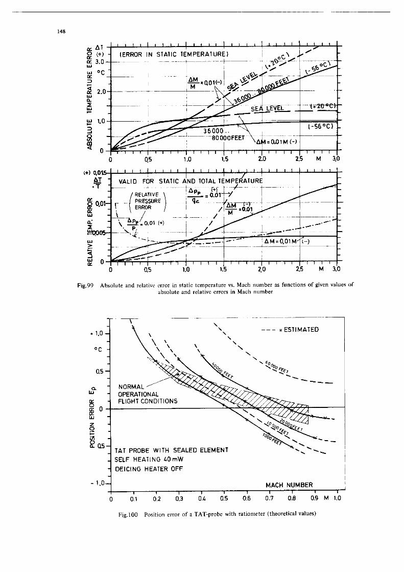
One of the most important values is the undisturbed auteide or static air temperature (SAT).
For reasons of meas”rement accuracy, the increased total air temperature (TAT), which depends on the corresponding Mach number, is almost always determined instead of the =t=tic sir temperature erchpt ox,
very slorrflying types of aircraft. If Mach number is deCermined,TAT is readily converted to static sir
temperature. In many aircraft, the conversion is done automaticelly in = central afr data computer, which
uses the temperature value and the Mach number to yield the true airspeed (US) and other additional
values, e.g. air density. whictx are necessary for the =utom=tic pilot and the weapons syetem.
Other important temperature measurem=nfs are made in engines to insure that limiting tem~~atures
are not exceeded. For piston engines it is necessary to measure and observe the oil f=q=r=tur=, the
cylinder head Cem~erature, the coolant remwr=ture,and if needed, rhe carburetor tem~rature or the &
inlet temperature far injection engines. For ,et engines the compressor inlet temperature determines
im~ortmt operating parameters* so that it must be indicated directly as well as fed to the =utom=fic
fuel control system. Accurate total temperature measuremenfe of the exhaust BBS temperature =r= also
required. There is a logarithmic relation between this temperature and the life of the engine. The
optimum engine o”t~“t can, however, only be reached at or neer the prescribed fempereture, so that the exhaust temperature must also be measured and indicated continuously. on supersonic aircraft it is also
fed into =,I automatic nozzle are= control system.
Additionally, the measurement and indication of the fuel terw=r=ture is often necessary if, for
example, aerodynamic heating of the aircraft skin influences the fuel temperature.
1” the s=me way, several surface temperatures m~8t be measured on the bra*==, and an various
structural cam~onents that are exposed to the thermal radietion of the engine or the exhaust stream, as
well as aerodynamic heating, at different point= on the aircraft skin and interior =tr”ctur=. The
fuselage of the aircraft runs through a temperature cycle in every flight, where certain com&~ne”ts heat up and the” cool faster than adjacent components. so that there are differences in expansion and
corresponding material stresses.
‘kmperature mssurements in aircraft are made =t widely different locations (outside air. fuel.
etc.); they encompass very different ranges and =I’= =ub,ect to very different accuracy requirements.
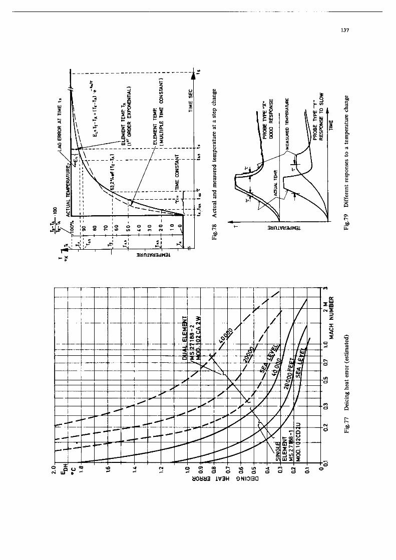
figures 2 and 3 show examples of typical temperature curve= for a supersonic aircraft =s = function of
altitude and flight time.
1.3 Thermometers Used in Aircraft
The temperatures mentioned I” the ~r=“Ious section BT= measured using, to = certain =xt=“t,
various measuring devices, which far the eak of simplicity will be called Chermomecers in the r==C of
this volume. since the points at which the m===ur=ment= and readings are taken BT= videly eewrated
in aircraft, a typical thermometer usually consists of a tempereture probe setached at = measuring point,
* E.g. far supersonic aircraft, the value of the maximum permissible speed.
3
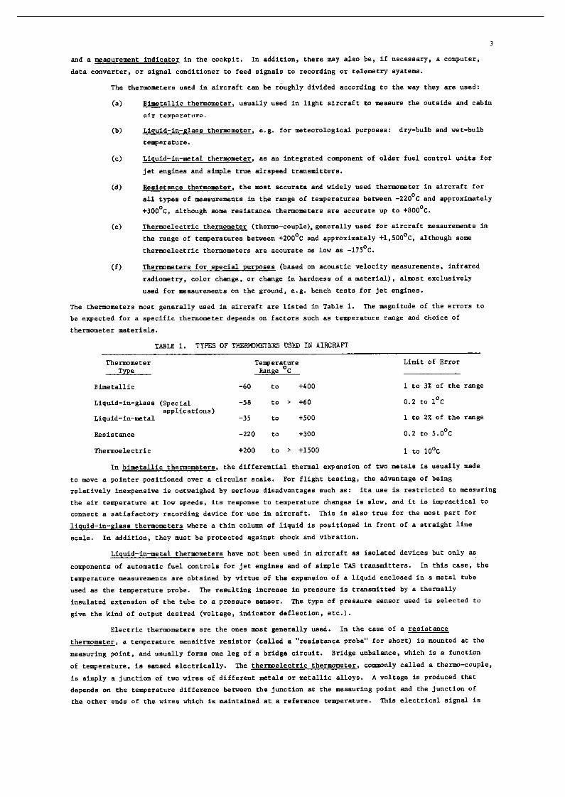
and a measurement indicator in the cockpit. I” addition, there my also be, if necessary, a computer.
Cc) Li.a”id-i”-meeal thermometer, a* a” inregrate* cmponene of older fuel control units for
,ee e”gi”es and simple -a”* airspeed trensmicters.
TABLE 1. TYPES OF THERWBTERS USED IN AIRCRAFT
Th*I”PXlld*r T*mp*r*t”l-* Limit Of Error Type Range %
Bimetallic -60 to +400 1 to 3x Of the range
0.2 to 1°C
1 to 2x of the range

4
Lhe” co”“erted.usi”g a (ie”siti”e ammeter, or by using * reference voltage and a compensator, inro the corresponding temperature value. since both types Of electric thermometers CM be used for practically all possible problems of tempereture me==“r=me”t in aircraft with = great degree of accuracy, flexibility.
and reliability, end since the output can be easily prepared for recording and/or telemetry,th=y are
used almost exclusively in flight test=. Par these reasons, only these tie types will be discussed in
greater detail in the following sections.
The special-,aur~o== thermometers include the temperature sensitive materials whose color depends
upon the hi@est temperacure to which it has been exposed. There are even certain types which go through 8 m,dtiple color change and can indicate up to four different temperature levels (cf. Section 6.1.4).
Mechanics1 eempereture indicaCar= are eleo used on occesion in engine test=. In this EBB=. the change in
hardness of = material is = measure of the maximum temperature reached. Optical temperature measurements
are often made, in research and development tat=, of the hot gases in combustion chambers end exhaust
*tJ*-. They have ebe advantages that no probes BT= zrounted in the gas =fr=am and hence gas flow and
temperature distributions are not diseurbed, the possibility of theroometer damage and parts entering an
engine is minimIz=d,and almost in=rcial=s= recordings =I-= feasible. some of the instruments c=” be used
to obtain a measurement of the temperaewe distribution in the gas =tr=am. However. this technique has
not yet been extended to in-flight applications.
There is 8 close relationship between thermometers and haevire anerwmeters which, in edditto”
to measuring the speed of the gas stream, con aleo be used at rimes fo me==ur= the temperature. This
measurement principle is based on the con”=cti”= heat loss of an electricelly heated wire rwunted in a gas
stream. There are, however, many problems when using them == thermometers. Acoustic thermometer= mu=c
also be mentioned. These thermometers measure =ound “elociey == a function of the temperefure. There
is little information on their u== in aircraft.
Novel ferwerafure probes such aa specially-cut quarfz crystals, t=mperaf”re Bensiti”= condensore.
etc. are often used in temperature mea=“r=m=nt=. Until now, however. no model= of these device= have
been produced that are suitable for the me==“remenf condition= in aircraft. The successful tri=ls of a
Fluidic-TAT-probe up t., Mach 6.7 in an X-15 aircraft =r= rsportad. It c=n b= esaumsd that in the next
few years, “digital probes” of thie =ort. which do not produce a genuine digital signal, but rather a
variable frequency which c=n easily be converted to digital form, will come into u==.
Almosr all temperature measurezents in aircraft are relative meeeuremence, i.e. the indicetors
give the temperature of an object relative to the melting point of ice measured in ‘C, and seldom rhe
absolute eempera~ure in OK. IX, special flight tests two temperature probes of the =a fy~e =r= mDunt=d
=t different measuring points and connected differentially to the ==me measuring instrument, thereby
giving the difference between two ~=w=ret”r== AT in *C. Ihe rate of chanae of temperature
may also be measured, in which CBS=, tw tempererure probes wit,, different time constimts BT= connected
differentially =t the same measuring paint and to rbe same measuring inetrumenr to indicate the rate
chat the temperature is increasing or decreasing (AT/At in + %/rain).
Metals, i.e. electrical conductors, =r= cryetal =tructur== that are composed of the corres~nding
metal ions, i.e. of =tom= whose valence electrons* ha”= been freed by Brownian movement. When = “clta~e
is applied, a direcriolld flow of free elactrons i= superimposed on this random morion. The electron=
collide with esch other and with ions of the crystal lertice (which oscillate about an equilibrium position)
=,,d thereby impede the flow, i.e. generate electrical resistance. As the conductor heats UP, the
oscillations of ebe electrons Bnd ions increase, i.e. reaisrtmce increases Wifb fempersture. The increase
in resistance in ferroelactric ceramics and the =o-called “cold conductors” is much greater than in
meeals.
* Valence electron - the electron in rhe outermrsr electron shell, which is bound only very loosely
to the =tom.

5
In some type. of the so-called “semiconductor.“, the vnlence electrons .re bound more strongly
to the stoma and .I-.. freed only at higher temperature. 80 that the flow incraase. with the temperature
(“hen voltage is applied), since more electron. c.” jai. the flow of the current. In other word., the
resistance deer=.... as the temperature increase.. These semiconductors which .I. used . . temperature
sensitive resistors .re. therefore, .I.= called “hot conductors”.
In general, both phenomena mentioned above (increase or decrease in resistance with
increase in temperature) t&e place eimultaneously, but generally on. of the process.. is predominant.
However, certain ut.1 alloys, the so-called “constant resistance alloy.“, c.n be produced which exhibit
no appreciable change of r=.i.t.nc= with t=mp=r.tur. over . rather “id. temperature range.
The useful temperature rang. of . r.si.r.nce probe is determined by the magnitude of the
tempereture .en.iti”ity,.ch.mic.l reaction. (heavy oxidetion or reduction), permanent change. in the
crystal structure, etc. At very high temperature., it i. important to note thst all i”.ul.cors (e.g. gl..=
above 550%) became electric conductors (due to the release of all the valence electrons), and all
materials lose their impermeability to g.. (important for shield tube.).
The slope of the R/T cur”. (resietance over temperature) can be expressed . . change in
resistimce AR per change in temperature AT of 1%. or for purpo... of comp.ri=on 8. the temp=r.t”r.
coefficient a, i.e. 8. the relative change in resistance AR/R. per ‘C, according to the equations:
AK - It, * a * AT and (1)
CL - AK/(R, * AT) (2)
Ill practice, a (multiplied by 100) is usually sxpresaed in %I%, and a is positive if
resistance increase. with temperature, but negative if r..ist.nc. decrease. with temperature. Although
a is u.u.lly tr..r.d . . constant, in reality it beer. . non-linear relation to temperature, and a
given value of a is exact .t only on. value of \.
If ie ch.r.ct.ri.tic of temperature sensiri”. r..i.tor. that they are passive element.. and
that . current must be .~t through them (e.g. in . bridge circuit) which c.. perceptibly beat up the
reeiefor through th. “Joul. effect” , ceusfng e self-heating error. ‘fhe definition of the “..“=iti”ity”
of . e=mp.r.rur= prob. . the relationship between the variation in the output voltage [IF for .
veriation in t.mp.r.tur. AT of 1% for purposes of comparison with active temperature prob..
(therm.-couples, which generate “o1r.g. of themselves) is very mi.1e.di.g. This applies especially
when zaasuring in medie with . poor therm.1 conductivity (air or other gas.., etc.), and “hen not all
the condition. are n.med, such a. p.rmi=.ibl= self-heating error, magnitude of the probe resistance,
circuit design. typ. and velocity of the medium, etc.
In the following. \ generally =xpr=..=. the resistanca “clue of an elemant at .ny temperature
TX. an.3 Kd ie the value .t a temperature T1, Rx2 at T2, but R. i= the “al”. at O°C, R25 the
valve at +25%, etc.
2.1.1 El.mer,r. vich Positive Temperetur. Coefficient.
Temperature probes of pure platinum wire w.r. selected . the inter..tio”.l standard for
temperature ,w..ur.m.nt. between th. boiling point of liquid oxygen (-182.97%) and the melting point
of wtimony (+630.5%),since the raeiacance-ro-t.~=r.~“=. r.tio of pure platinum wire in .” annealed and
.tr.in-free seat= is especially stable and reproducible. I%. temperature coefficient increase. repidly
from ..ro .t approximately 10% (-263%). reach.. . m.ximum (0.42%l°C) .t approximerely 30% (-243%)
and then gradually d=cr=..=. 8. the temperature is increased (Figure. 4 and 5). The upper t.mp=r.t”r.
limit for conrinwu. operation is .ppraxim.t.ly 800% (for shore-term applications, 1.100%). Tabular
data for the resist.“=. values of coiled platinum wire element. a. 8 fvnctio” of temperature BT. found,
e.g. for elamene. where R, - 100 ohm., in DIN 43760 (R.f=r.nc= 70). For element. where go - 500 ohms,
the “.lue. for R. - 100 ohms should be multiplied by 5; where R, - 50 ohm, the values should be halved,
etc. Pl.tin,,m with only . reletively high degree of pvriey is often used in “ario=. .=ron.“tic.l devices,
and especially in rot.1 tempereture probes, in ordsr to obtain minor variation. in R/T “alua.;
the.. are ..t forth in MIL-P-25726 g ASG and MIL-P-27723& Platinum prob.. for .ircr.ft .r. u.u.lly
manufactured with . r.si.r.n~= R= of 50 or 500 ohms in the U.S.A. However, other value. are .I.= used,

6

7 2.1.3 Elenk%“ts with Negative Temperature Coefficients
Semiconductors with negative eemperarure coefficients, the so-celled thermistors (also called ~ewi, “rdox, Thernetid or NTC resistors) are made of sintered ceramics, usually of mixtures of metal oxides,
e.g. iron, manganese, nickel, cobalt, copper, titanium or uranium oxide, preferably with values for I$<
between 100 ohms and 100 kilobms. As is the cme with most semiconductor probes, the same types do not
have identical temperature coefficients, BO that a recalibration of the thermometer arrangement is usually
necessary when the probe is changed. mwever, there are selected models with very close tolerances and
probe assemblies that are directly interchangeable. I” the letter case. a resistance (e.g. 3 km is
applied in series with the probe and a resistance (e.g. 30 k02) in parallel tith this series arrwgement
80 that the resultant RIT curve exhibits a somewhat lower temperature coefficient than the element
itself. The range of applicability of thermieeora usually lies between the limits Of approximately -1ooOc
and +300’%, but an individual type rarely has a temperature range greater than 100 to 250%. ‘Urger
measureme”~ ranges often require a change of the bridge or different types of probes. Special types of thermistors are available where the lower limit et the present time is epproximstely 10% (approximetely
-263%). and the upper limit is approximately +4’S, to f450’C.
Because of their small size. thermistors are especially suitable for point measurements or for
deternrining the temperature gradients between closely spaced points.
The resistance curve of themtstora with respect LO temperature is approximately exponential
(Figure 7) and cm be expressed by the equation
where “a” (in ohms) is a constant determined by the form and material a”d ‘lb” (in OK) ie a conetmt
determined primarily by the material. The temperature coefficient cm be described by the equation
u - AR/(R25 * AT) - -b/T’ (38)
md is typically -3 to -5X/% (depending on temperature T). In specifications, the resistance R25 is
usually given (i.e. R at 25’C or 298%), as well BB the b-value or the resistance ratio Rxl/Rx2 at
given temperature values T1 and T2 (in “0. The connection beWee” both definitions is expressed by
the equation
R x2 - Rx1 * c b(llT1 - 1/T2) (3b)
This equation enables us to calculate the re~i8ta”ce value R2 for any value of T2 (Reference 78).
The advantage of the large temperature coefficient, which is approximately 10 times greater
than those of Pt aad Ni re~isf~ce~,cm only be completely exploited when measurements are made in
good therm1 conductors. The self-heating I” air is very great so that very small meesuring c~rrenta
mmt be used in the probe. AB a result of the differences in conetmctio” of beads or rods in contrast
to wire-wound resistors, the fact that the current flow in the material is not uniform tie” there is a
change in temperature or when there are large currents must be considered for all typem of semiconductors, since heat ca” only be absorbed or released at the surfaces*. Par voltages of less than 1 volt at the
probe, the contact resistance at the pigtails met alao be considered, since there is a relationship
between the voltage and the contact reeisfmce (Reference 78). Probes supplied with inexpensive connectors
often cannot be used to measure air teqerature~ for exactly this reaso”.
I” order to n,eas,,re extremely low ~emprratures (Figure 8). elerents of doped germanium ca” be
used (in addition to the special low-temperature thermistors mentioned previously) in the range from
approximately 1 to 40% (approximately -272 to -233%. Also carbon resistors can be used in the range
from approximately 0.1 to 15 or 20%. Above approximately 23% (-250% these materials are not as good
as platinum, both with respect to the value of their temperature coefficients and their stability, 80
Wt could be that “recovery factors > 1.0” found in air with thermistors are based on this effect
(cf. section 4.3.3.2).

8
they Will not be diecussed further in detail.
2.1.4 Cmstr”cticm Of Resistance Elemenee
Because Of the different requirements (time CO*stMte. ability to withstand vibration or
chemical corrosion, etc.),or their relative importance in any individual application, construction
techniques vary considerably. Figure 9a chows a .o-called openlrire elcnnt,in which * p1aeinum vire
ie wound on a perforated CD11 form. Therefore. the tire ie in direct contact with the gas or
liquid “hose temperature ie to he measured. This element generally has a” excellent response time, a
small condueeion error. and e amall self-heating error. The g.ees or liquids rmsr not be corrosive or
conductive. nor leave sediments behind. In the came of tubular elements (Figures 9b and SC) the
resistance wire is protected and withstands hi& pressures, fluid speeds and vibrations. and is less
easily damaged by small foreign bodies. In the more expenst”e model. Figure 9b, the wire is hermetically
sealed bebeen two platinum tubes, whereas in the rode1 shown in Figure 9c, the wire bee a” or@“ic coating
and is embedded in ceramic. Since both the inside and outside of the tuba is exposed to the medium, both
a good rime constant and good protection of the resistance wire 1s obtained. Figure 9d shows a ceramic
coated miniature element which musf be protected against mechanical damage by a wire net or cylinder,
but has a relatively small time constant as a result of ite emall sire. Too high bridge currents can
overheat this type of element. The well-type elements, Pigvres 9e, f and g, protect best ar&nst fast
flavi”~. electrically conductive or corrosive liquids, even when there are heavy oscillations, by
enclosing the reeiarmce wire inside of a atainlesa steel or platinwn tube vhicb is sealed at both ends.
These tyres are @marily used as tap-sensitive elementa far meas”renents in solid bodies and stem-
eeneitive elements for ,r.?aeureme”te in liquids and gaees. The well-type elements that require a solid core
inherently have very high time constants. In stem-eensitive models without a core (Figure 98). the time
constants are sharply reduced. In the case of flat elemente (Figures 9h and i, showing elements of
quadrileteral form*) the resistance wire is embedded in insularin~ material and housed in a thin metal
chamber (stainless steel. eluminum, platinum etc.). 1” some models, B metallic layer ta vaparized on the
insulerim material. which,howe”er. is quite subject LO mechanical damage. Flat elements are mainly used
to meaeure surface temperatures. For thim purpose, there are special models in which the resistance
wire la sandwiched between two flexible pieces of resin-impregnated glass paper so that if can be wound
around small tubes.
The widely different types of element construction result,anong other things, from the fact that
the thermal expansion of the resistance wire, insulation, coil forms and chambers rm,st be as equal 88
possible in order to prevent chenges in the resistance by elongation (mechanical stress) of the resistance
tire (siroiler to the effect of a wire strain gauge). Otherwise, the calibration of a probe element would
be almost or completely non-reproducible. The required vibration resistance and the resistance value,
i.e. the required wire length, aleo are important considerationa. Semi-conductor elements are ma”“-
factured in very different forms, e.g. 88 epheres (Figure 9k) or disks, spheres embedded in a glass bead,
layered glass laminates. 01 e”en in special mou”tinW (FiWre lo), and are characterized by their small
aiee. special models for use in aircraft have not yet been developed.
2.1.5 ~onseruction of Resistance Probes
“he,, a resistance element. which is usually manufactured without a mountins and with loose lead
“ires. is protided with a socket, a protecti”e shield or a housing, and P radiation shield. if is known aa
a temperature probe.
The well-type probe is one of the most co-n types of construction. The types that are intended
far temperature measurements in liquids and ~.aes are made up of a long tube,a threaded base and B socket
for the electric connection. The resistance element ir, housed in the rod-shaped protective tube and is
so constructed that the temperature changes on the surface of the cylinder have more effect than those
at the upper end (stem-sensitive type). examples are shown in Figures 12a and b. There are models in
which a second concentric protective tube GUI be attached (as can be see” on the bimetallic thermometer
in Figure 11). This aervee to reduce the radiation error. to channel the flow between the protective
tube an.3 the element 80 that the recovery factor becomes larger, and to decrease the time cOnSta”t with
*Cf. PlSO Pigvre 94.

- -..
9
reapect to the temparat”re changes of the liquid or gas (see Section 4.3). POT the *am* reason,
cert.&l tyQ.a are given a right-angle bend (Figures UC end d) 80 thof the air current flmm parallel to
the tamperat”r. *e”s*ti”e part of the surface. They are aleo mnufaetured with a” additional radiation
shield. Another type of conatructio”, which is only used when maaa”ri”g air temperPt”res, ia the
knife-edge-probe that ia rmunted perpe*dic"lar to the surface of the aircraft, but parallel to the air
flow (Figure 13b). Figure 13a *ham a type, which wee earlier qvite co-*, that is equipped "ith a
protective housing that al.0 B.N.. to a certain extent 8. . radietio" shield. A similsr stru~tur. i.
the fluah-bulb (Figure 14). It is mounted flush with the airplane ski", but thermally insulated from it.
The air flows parall.1 to it. surf.... Itie prob. prwid.. a relatively inexpensive method of measuring
the air temperature, but the m....r.m."t .ccur.cy deer..... quickly . . the speed is increaeed, .M" when
the mounting location is carefully chose", since the temperature is meeaured in the boundary layer of the
aircraft (cf. Section. 4.3 and 6.4.2).
All modern probe. for m...uri"g the outside air tenqeratur. on aircraft .r. tot.1 tan..r.t"r.
e (TAT) with . tub. shaped housing, which is mounted parallel to the free-flowing air outside the
boundary layer of the aircraft, and in which th. r..i.tanc. element is .rr."ged conc."tric.lly (Figure.
15, 16 and 17). In order Co minidze dissipation of heat. the element is mmnced on su~~or‘cs vhich he".
a low thermal condwtivity and it i. surrovnded by on. or mar. concentric heat shield. (cylinder.) t"
prevent heat lo.. by radiation. The lead wire. to the element .r. also c"".truct.d in such a way that
they conduct and di..ipat. a. little h..t as possible. The air which enter. through the op." front of
th. chamber is almost completely decelerated ."d the air is compressed "early sdiebatically. The
resistance element m...ur.. the ..m of the static air temperature ."d the temperatvr. ri.e by
comprassio". i.e. th. tot.1 sir temperature, with ~"ly . small error. In order to minimise
the time lag with r..p.ct t" the rat. of tsmperatur. change, and the lo.... reeulting from dissipation
and r.di.tio", openi"~?. "ear the resr or d"w.tr..m end of the chamber pmvid. . controlled air flow.
This flow rat. reech.. it. m.ximum value (typically 0.3 Mach) .t an .ircr.ft apeed of 0.7 t" 0.9 M.ch
and remain. co".t."t at higher speed..
I" addition to the earlier type of TAT Prob. deecribed ebov. (Figure 17 left side), model. with
intern.1 air flow d.fl.ctio" ahead of the element (Figure 18) are wed. In rhi. case, th. element is
arranged with it. radiation shield perpendicular to the direction of flow, and the air is deflected 90'
before it pa.... throvgh the me...r.,.."t element. Particle. of w.t.r and d,,.t c." leave the prob. housing
directly without coming in contect with the . . . . ..ur.ment .l.~,."t. This provide. greater stability in
relation to external influence. and also yield. a significantly 1ow.r error of m...urem."t when flying
ill a rain *tc.nn. "oat mrrd.1. can be m."uf.ctur.d with . heater winding "ear th. air intake to prevent
icing. laterally arranged sm.11 openings allow the h..t.d intern.1 boundary layer in the prob. housing
to be removed (boundary layer control) , 80 thet .rror. 1" the measured terqeratur. caused by the deicing
he.t.rek.pt within tclerabl. limit. 8. long . the tich "umber do.. not 8" below 0.3 M.ch (for housing.
with one element).
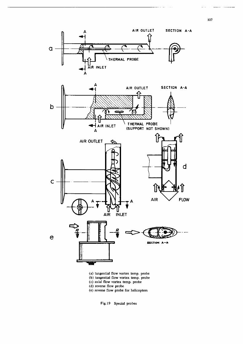
Two othar type. of pr"b.. for ,....uri.g t.q.r.tur.. outaid. the boundary layer of nircraft
are of historical i"t.r..t. It seemed logic.1 to count.r.ct th. temperatvr. ri.. of the air by
appropriately loweri"~ the temperatur. .t the t.mp.r.t"r. prob. element. "sing an effect discovered by
Ranqua a. early 8. 1933, which .hov.d that the. i. . deer.... in t.mp.r.tur. at the cent.= of a rotating
stream of sir (vort..), prob.. w.r. built with tanp"ti.1 and ai. flow. (Figure. 19a, b aid c). i.e.
the .o-called vortex prob... The.. prob.. wer. u..d to directly .,....I. th. static air t.mp.r.tur..
However, the incr.... in temperatur. caused by . v.rying pIxt.r. of friction and compression was
compe"..t.d by me.". of . t.mp.r.tur. rsduetio" . . . ..A by adiabatic .xp.".io", and h."c. the desired
effect co.ld mly be realized axactly for a". flight altitud. and up to . c.rt.in speed. Thi. v.. deter-
mined by the .ircr.ft speed at which the .cc.l.r.r.d intern.1 flow reached the speed of sound. Thi.
critical velocity Y.. bet".." 0.45 Mach or 300sk"ot..t se. l.v.1 and .pproxim.tely 0.8 Mach or 350
knot. indicated .ir.p..d .t 30,000 f..r. Exe" *t lov .*.&I there war* po*itiv. or nagativ. ..rx.r. of
up to 2% depending on altitude a-ad o" the prob. d..ign. with distribution. of up to double chat error.
Theroforr, this fyp. of temperature sensor is ..ldom u..d bacau.. , among 0th.r thing., there is no
possibility af deicing the prob. (Reference. 27 through 30).


II
i.e. an absolutely linear calibration can only be obr*ined under certain conditions.
I” the case Of the balanced bridge cir‘cult, one Of the two resistances Rl o= q that ==e
adjacent ta k, is either manually or automatically adjusted during each measurement so that the
diagonal current becomes zero. The resistance Of Rx, or temperature, is read on a scale for the
variable resistance R1 or R4. In the case of manually balanced bridge circuits, the load along the
diagonal Rd is usually a null indicating galvanometer. In the case of self-balancing bridge circuits
(servo indicators) on the other hand, Rd is the input impedance of an amplifier. The amplifier
supplies power, proportional to the unbalance voltage, to a mtor that adjusts the ~tentiometer. F$ or
R4s in the correct direction, so chat the current or voltage along the diagonal becomes zero.
The step balanced bridge circuit has characteristics between unbalanced and balanced bridge
circuits. A temperature indicator having a relatively narrow range is used, and rhe variable resistance
% or R4, is switched as needed to keep the indicator on male. nws the accuracy of the reading is
increased. “awever, a” increase in the bridge supply voltage is generally needed, resulting in a
considerable increase in self-heating of the temperature probe.
The resistance bridge can be supplied with either DC or AC power (usually 400 Hz). The latter
type of supply necessitates certain safety procedures to guard against pick-up from external sourcee.
A totally different type of arrangement ia constant current excitation shown in Figure 24~.
This type will be discussed in greeter detail below.
2.2.2 Compensation of Lead Resistances
The probe resistance Rx is usually mounted some distance from the bridge so that the lead
resistances must be taken into account if the minimum value of the probe resistance is not at least 100
times larger than the sum of the lead resistances. In practice, this usually means that the lead
resistances must be considered whenever the minimum reeistmce value of the probe is less than 300 ohma
or whenever especially long probe leads are unavoidable.
The lead resistances can be largely compensated by the use of a threevire connection es show”
in Figure 2%. whenever the lead resistances RI.1 and RL3 have the 8ame magnitude (and always vary in
the same direction by the same mount). This technique is used in full and half bridges in which the
resistance R1 is approximately the same aa the average value of Rx. The lead resistance RL1
increases resietance R1, and the lead resistance P.l.3 increases resistance % by the same amount.
The lead resistance P.L2 is in series with the loed Rd and has practically no effect on the current
flowing through the diagonal if the resistance of Rd is relatively high.
The circuit in Figure 25b is used whenever R4 is the same as the average value of Rx or R4
la adjusted to the appropriate value of Rx by a manual or servo arrangement. In this case FL1 increases
the value of g4 and RL3 increases the value of \ by the same arvxnt: N.2 is in series “ith the
bridge supply voltage. If there are very good grounding possibilities at point M directly at the probe
and at ,mint E, then the third lead (RL.2) can be eliminated; point N. however, must be insulated from
ground. In Chis way, a compensating effect cm be obtained with a two-tire connection. In the circ”it
shown in Figure 2%. this technique (grounding point M) is not possible.
T,,.s compensared Wheatstone bridge ehovn in Pig”re 25~ is seldom used. It requires (L four-wire
~onneceion between the bridge end the probe location, but only two of the leads are actually connected to
the probe. A four-wire co,,,,ecrion ie used much more often with a Kelvin dDvble bridge, show” in Figure 25d.
Thi- yields the best cm,~en8r,tion of all the circuits shown, but its sensitivity is less than tbef Of e
simple bridge. For this reason it is most often used with en amplifier circuit. Its method of operation
is baaed on the fact that the lead resistances RLl, RL2 and RL3 8r.s in series with relatively large
resistance8 so that small fluctuations in the lead rc.l.tence~ are of little immportance. The bridge in
also leid m,t in such a way that in ire normal state, there is no curre”t flowing through RL4. However,
if there are appreciable chengee in the lead resist.ncee. then a current flowing through RL4 adjusts
the potential conditions of the lower half of the bridge so that there is compensation of the effect Of
the changes in the leads.
In using the three-wire compensetion techniques (Figures 25a and b) there is fr”e compensation
only when the lead resistances are absolutely equal (and change by the same amo”nt in the same direction),
and when the bridge is balanced. In the ease of unbalanced bridge circuits, the lead resistances m”st

I2
he taken into account whea calibrating the thermometer. Thu. for example. .n incr.... in eh. r..i.t.nc.
of on. lead by 41 (in this c... - 0.02 ohm.) in . bridge whher. the prob. r..i.t.nc. is 50 ohm. .,,d th.
1e.d resisrmc.. F&l rind PA3 are ..ch 0.5 ohm.. renult. in a m...“r~.z,t .rror of .pproxim.t.ly 0.1%.
For .p.eirl e.... “her. high 1a.d r..i.t.nc.. (in comp.ri.on with Rx’ .r. “n.void.bl., B
bridge circuit.. (e.g. the triple bridge. R.f.r.nc. 17) m.y b. u..d to s1imin.e. the effsct .,f gr..ely
verying 1e.d r..i.t.nc... It must be noted that in all complex bridges the sensitivity always drops
to le.. than half th.t of . simple bridge. This m..n. that amplifier. PT. u.u.lly n.e....ry for sansitiv.
m...“r.m.“t., especially when the self-h..ting of the prob. m”.t be kept low. The.. amplifier. rrm.t b.
carefully compensnted with respect to tmp.r.t”r. in the c... of unbalanced bridg. circuit..
Figure 24~ show. . .p.ci.l h.lf-bridge circ”ir which u... constxnt c”rr.nt .xcit.tion inatud of
con.t.nt vo1r.g. .xcit.tic.“. A self-r.gul.ting power “nit nupplies . con.C.nt current in th. ..ri.. cir-
cult th.t con.i.t. of . ranp.r.t”r. prob. Rx, the 1e.d r..i.t.nc.. RL1 .,,d RL2 .,,d th. c.libnti.,r,
r..i.t.nc. Be. Since the current 1. .Iv.y. k.pt con.t.“t, .v.n wb.n the r..i.t.nc.. ehang., th. vo2r.g.
drop .cro.. the prob. reaieranc. Rx f. . direct m...“r. of it. r..i.t.nc. v.l”., or it. t.mp.r.t”r..
Change. in the lead resistance. have no effect, and the lin..rity of this circvir is b.tt.r than th.t of
the other. if the voltage .t I& is m...“r.d with separate lead. (four-wir. co.,,.crion of the t.mp.r.e”r.
prob.) .nd with a high-resistance indicator (Reference 37). Th. c.libr.tion r..i.t.nc. ..rv.. to .d,“.t
and monit,x the desired c”rr.nt value. The stability of the current .o”rf. m”.t, howwar, be b.rr.r th.n
0.01% and good hum filtering should be provided, since the r.01.. .cro.. th. o”tp”r in this c... .q”.l.
the bum voltage. The circuit requires . power supply unit for ..ch hslf bridg.. A v.ri.tion with.
.uppr....d z.ro is possible (Reference 84) but require. . second power .upply “nit with .n axrr.m.1~ high
.t.bility, better than 0.001%.
2.2.3 Design of Bridge Circuits
when designing bridge circ”It., there .r. alway. a series of specific condition. to be met,
which lead to very different method. of aolurion depending upon the given condition. and the purpose for
which the circuit is to be used. this fact explain. the extremely large number of circuit. in u... and
also explains fb. apparent contradiction of design rule. found in the pertinent literature. For
m...“rem.nt. in aircraft, there is .n addition.1 series of condition., which .r. .f most merely hinted
at in the general llceratur. and which msy lead to incorrect meaeurement. if they are ignored. Beside.
the rougher .nvironmenr.l conditions svch a. terqeratur. rang.. vibration. long lead., variation. in the
aircraft voltage supply, etc., there is also the ,,roblem of the meximum permissible self-beating of the
prob. by the measuring c”r~.nt, which m”.t be taken into account.
In addition to cb. indicator, a recording or telemetry o”tp”f is eleo neceseary for the
thermometer.
When designing . bridge circuit, the folloving factor. m”.t be taken into consideration:
(4 The power dissipated in the prob. resistance Rx , end therefore the self-heating error,
is always greatest for. give” bridge supply voltage when the instentaneo”. value of
Rx f. the game as th. “.I”. of Rl (at . given temperetur.).
(b) The self-heating error and the lead r..i.t.nc. errors .I-. inversely proporti0n.l to
the resietanc. value of \ for a given supply voltage and P given ratio %/s. Probes with higher rasistanc. values for e given type yield smaller aelf-heating and
lead error..
Cc) FOT (L given type, wire wound prob.. with high r..i.t.nc. value. WOO ohm. at 0%
usually exhibit a great.= r..pon.. time with respect to t.q.r.t”r. change. than those
with low resis~anc. value.. Prob.. with extremely high resistance “al”.., e.g. .om.
type. of fhermiator., increase the susceptibility of rh. circuit to insulation failure.
(..g. from corrosion) and pick-up from extarnal .o”rc.. (hum voltage). Since the
in.mlatfon resistance of all insulation materiels is redvced at very high r.m~.r.t”r...
only prob.. with relatively smrll r.si.t.“c.. may be used for m...“r.m.nt. at high
temperatures. If low raeistence probes ere used, to&her with r.LPtiv.l.. hiah
resistance leads, th..v should be used with thrsa- or four-wir. conn.ction..

Cd) Since all bridge circuits =r= nonlin==r. the bridge output “oltege is alwsys a
*0”1***ar function of the probe resistance. The 1arter. howe”ar, is ale0 a no”li”ear
f”nCtio” of the temperature. Nevertheless, when the bridge is designed appropriately,
a nearly linear indicator =cal= cm be obtpined, a= long BB the indicator rang= is not
extremely large.
(=) Bridges with recording or talemetry outwte should be designed so that the connected
eqti~mene has == little effect 88 possible on tha calibr=tion of the circuit.
w Changes in the en”iromre”t=l t=mp=r=tur= of the bridge should “of have my effect.
This can be echieved by using bridge resistors of manmt~i” tire and all the connecting
leads of copper tire. In certain cases. the bridge r==i=tmc=e c8n be made using =
copper wire section md a mansan& wire ==ction. The u== of constanten and other
metals, which in combination with copper generate =I, appreciable themelectric
voltage, mtme be avoided in all cases. Even the temperature ==n=iti”ify of the leads
connected to the bridw, including th=t of the instruments. emplifiers. etc., mast be srudied and if necessary co~=nsat=d for.
c3) The bridge supply voltage should be ra@lated to better than 0.1X, since voltage changes
yield corresponding read-out errors. Exceptions are bridges with ratio meters, and
eervo bridges.
When designing = circuit, it ia therefor= always necessary to compromise between requirements
that are to = certain extent contradictory.
2.2.3.1 Waif Bridge Circuits
This circuit. which is usually used only far recording or telemetry purposes, co”=i=t=
primarily of the probe resistance Rx and = serias resistance % (Figure 24a). Ihe us= of a three-wire
connection is possible, if Fi is approximately equal CO the mea, value of Rx. For r===m= mentioned
below, relatively high r=si=t=nc= probes =r= sel=ct=d =o char the sffect of the leads is very small; in this ease, tha magnitude of I$ c=” be any eelecred value. If the load Rd, which should be 88 high in
resistance as possible, ia connacted in parallel “itb Rl, the relaeionahips are rmre easily seen 88
the magnitude of \ varies. It muet be taksn into =ccount th.t the polarity of the output voltage
depends on whether Rd is applied in p=rall=l with F$ or Rx, and also depends on whether the probe
temperature coefficient is positive or negative.
In Figure 26a the ratio of the out@ “olt=ga UA (.cross RI) to th= supply voltage UB is
given as a function of the temperature, “hen nictel probes BT= used (the cur”== would be similar for platinum probes). The useful change in the output voltage is r=leti”ely amall for Case I but is
increased by selecting higher probe resistances and lower values for El/R0 (Case II). In Case II, =
relatively high bridge supply voltage UB was also eelacted. I,, order fo prevent excessive self-heatin
of the probe by the mea=urPng current, the maximum bridge “oltege is determined by the maximum permissible
power generated in the probe.
Example (refer to EIgvre xa):
Range of raasurement - 0 to 1ooOc
Probe r=si=tmce af 0’~ R.; (nick=1 elem=nr) - 100 ohms
Dissipetio” consrent in flowing weter - 112 mwPc
P=m,,issibl= self-heating error - o.zOc
P=rmissible power at the probe P - (112 . 0.2) I 22.4 mw - 0.0224 W
**en No - 100 ohms, the lead resistances will h=“= a significant effecf.

4 3 10 10 0.2 2 4.0 0.46-3.76 3.28
4 3 1 1 0.2 0.2 1.6 0.16-1.25 1.09
15 11 1 1 0.2 0.2 3.0 0.30-2.40 2.10
100 75 1 1 0.2 0.2 7.6 0.76-6.08 5.32
(*I 0.1 1.1 112 6 0.2 22.4 14.65 13.61-12.97 0.64
(*I 1.2 4 112 6 0.2 22.4 16.7 15.3 -12.55 2.75
(.) Probe with nickel elmsent; resistance at 0%.

15
A comp=ri=on of the values shown in Table 2 for thermierms shows th=t larger useful ch=ng=s
in the o”rpur volt=@= A UA can be obtained. either by using probes with high=r* deeignad ra=ist=nces
(Rz5) or types with higher dissipation con=t=“t= =nd thus, larger time con=t=nt=, In Table 2 the outpput voltages of nickel probes =r= not directly comparable with those of the thermistors as the
dimensions of the nickel probes are larger than those of the thermistors, as appears from the large dissipation-constant. Same dimensions would have resulted in a much larger “* for thermistors
due to the greater slope of the R/T curve. The use of thermistors instead of platinum or nickel elements is often recommended when the measuremene ranges BT= not too great and relatively high useful voltages
are required for small bridge supply voltages (e.g. 1.5 or 3.0 V), 8s in the case with portable
measurement devices. However, thermistors are not generally reconnnended for aircraft m=asurem=nts.
2.2.3.2 Full Bridge Circuit=
For full bridge circuits with an indicator (Figure 24b). and for = given bridge =upply voltage,
thr output power available In rhe diegone branch of the bridge. end, therefore, the indication of a
connected instrument, 18 greatest when the four bridse resis~ancee Rx, RI, R2 and R4 and rhe instru-
ment reeieearLC* Rd in the diagonal branch are of approximately the ==me ma@tude. However, when it
is necessary to avoid =xc=sai”= self-hearing =rror=s the maxirmm output power occurs when there is a
certain meximum allownrable power dissipation in the probe realstance Rx, and very different design rules
must be need. When there is consesnt power di=sipac=d in Rx, the output paver i,,cr=as== with the ratio
%/Rx, “he,, there is = corresponding increaee in the bridge supply voltage. Thus, if the ratio q/R,
ie increaeed from l/l to 1011, the o”tput power in the diagonal brencb i= approximately doubled. When
the ratio is further increased, the output power increases only elightly.
In the c=== of simple indicator= such 88 &al”=nom=t=rs, the instrument resistance Rd is
approximately equal to or leas than R./ In this caee, an additional power increaee of 50% can be obtair
in the diagonal branch if the resistances R4 and R2 in the right half of the bridge BT= reduced by
a factor af one-half to one-fifth. Purt.h=rd=cr=ases yield no substantial power increase, and require
uneconomicslly high supply power from the =o”rc=. By combining both techniques, a power increase of
=pproximately 200% can be obtained in contrast to a design with equal resistances, for constant
power dis=ipation in Rx. ‘i-h= followin& BT= the =pprc.xim=t= values for the optimum values of Ed/Rx:
when R1/Rx - l/l and R4/Rx - l/l, then Rd/Rx should be =ppmximately l/l.
when Rl/\ = 5/l and R4/R,- I/l, then Rd’R, should be approximately 1.8/l.
when El/Rx = 5/l and R,,/R, = 0.211 then Rd/Rx should be approximately l/l.
Eve” larger values of 51% or even amaner values of R4/Rx have no si&ficant effect on Rd’Rx.
DeYiafiDne Of Rd/RX by = factor of 2 from the given ratios =r= not critical and have more effect
on the output linearity than on the ==n=iti”ity of the indicator.
In the c=== of balanced bridge circuits “here negligible power ia required in the diagonsl branch, the ratio= R1,Rx (and R2/R4’ BT-= often 150/l or more, permirring a small -“nt of self-heating
and = simple circuit for the power supply unit, since in this case the curr~t requirement of the bridge
circuit remain* “early co”eta”t. A high input resistance for the amplifier in the diagonal branch also
minimizes the nonlineariry of the bridge circuit and thereby makes lineerizstion of the indicator
easier. (Cf. ale.3 s=ction 2.2.5).
When e rhermisror is used, the bridge ma=L be balanced =t the lower end of the Cem~erature
range. According to Figure 2&&h= best linesrity is obtained for the measurement range of 0 to +50°C
when = probe with 8 nominal resistance R25 of 4,000 ohms ie s=I=cted and used with a resistance 5
which also equal= 4,000 ohms. The resistance R2 i= assumed to be 4,000 ohms 80 that R4 m”st be the
came as the value of Rx et O’C, or 11,400 ohme. With a bridge eupply volt=&= of 1.5 Y. the maximum
probe power is approximarely 0.2 mW, i.e. the =mo”“t of self-heating remeina small. When = 50 PA
indicator i= used, it m”=t be connected in series “ith = resisfance of 10,000 ohms. The exact process of
calculerion for thie type of inefrwenr. which exhibit= excellenr linearify, is deecribed in Aeference
*When “=iW probes where R25 - 100 U-L difficulties c=n ba =rp=ct=d with the ins,,lation r=si=t=nc=.

Linearization of the indicator is often unnecessary in bridge circuits when nickel p=obes a=e
used. since the nonlineariries of the nickel probes and those of the bridge circuits tend to counteract
each other. Increased lineariration can be achie”ed by applying B reeisrance Rp in parallel with Rx
(Figure 27s), the value of which depends on the design of the bridge branches and the diasonal branch.
Since this changes the balance of the bridge. either a relatively small resistance Re must be applied
in eerie8 with ehe parallel combination of Rx and Ep, o= one of the =YO bridge resistances 5 o= R,,
rust be appropriately reduced. Since the reaiscmces necessary for lineerieation tend fo counteract the
lead resisrmce compensation effect of a three-wire connecrion, it is advisable eo “se high resistance
probes, e.g. 1,200 ohms.
When platinum mobes a=e used. the nonlineari=y of the characteristic probe curve and that of
the bridge circuit are added. Far rhia reason, one can only try to keep the non-linearity .af the bridge
circuit, and by rhe same token, the amount of self-heating, aa small as possible, by using a probe in which the reeistmce is as high as practical. If a probe with a desiped resietance of 500 ohms at O’C
is selected, R4 should be approximately equal =o the value of R x at the geometric cenrer* of the
meae”rement range. The value of % rrmst be at leaet 2,000 ohms, and =be instlument reeisfmce Rd
should lie between approximately 1,500 and 2,000 alms. Since in the case of unbalanced bridge circuit8
with platinum and nickel probes (01. probes with similar characteristic curves), the point of balance**
must lie at the geometric center of rbe me~su=emnt range if good lineariey of the output vol=age is to
be obtained. galvanometers with null at the center of the scale must be selected.
I,, order to measure temperature difference (Figure 27b), it must be noted char calibration of
rhe i,,strument scale inde~endenr of the given temwrafure level is only possible when the characteristic
curves of eemperature probes that a=e connected differentially are exactly linearfzed. Since the use of
a three-wire connection would be of little value in reducing the effect of lead resistances that very in
magnitude, and the complete circuit would only be made unneceesarily corn&x, if is advisable to “se high
resistance probes in this case also. Resistances of approximately 4,100 ohms applied in parallel with
12OPdm nickel probes ensure the applicability of the bridge to the temperstore range between -70 and
+50%. When the mean temperature is at a higher level, the parallel resistances must also have higher
values corresponding to the higher probe reeisrancea. For differential meaeuremenls. both probes must
have the same characteristics and especially the same time consts”te.
For temperature-rate meae”reme”t*, i.e. measurements of the direcrion and rate of the
temperature changes. the cI=cuIt in Figure 27b is also used. In this case. the measurement is talcen with
the probes mounted at the satme point. he probee should aleo be as similar ae possible, except they
must have time constants chat are as different as possible. since very small time ConstantB can only
be obtained with open-wire elements. which are only manufactured in low resistance models (nominal
resistance of 100 ohm is maximum), this ie a case where a low resistance probe must be used in a two-
wire connection. This is not es critical in rate measurements if both probes have approximately the
same lead =esis=mces. In certain cases a lead-balancing reslsrance muse be applied.
Excitation of bridge circuits in aircraft inatrumente direcfly from the ai=c=aft power supply
(28~ DC) through simple regulation circuits (e.g.ase=ies resistance and a zener diode) is mzst convenient
a8 a eO”rCe of constant voltage. 1” the case of constant cu==ent excitation (e.8. through a variable
resistance whose value depends on the current) there is a greerer influence of the ambient temperature.
since more cirwit elements are usually required. When connecting bridges with telemetry circuits. the
stabilized voltage supply far the amplifier should be used as rhe bridge source in order CO avoid
*E.g., fma mee~uremenr range of -70 to +50% or 203 to 323%. the geometric mean temperacvre
.rM - J203. - 257% = -16OC.
**I.e. the point at which the bridge cu==ent is zem.
*see section 5.2.2.


when the outside air temperature is low, the difference between TAT and SAT at B constant
Mach number is smaller than at higher outside air rempereturee. This means that “ball bridge circuits
are suited for the installation of a computing or function potentiometer. Figure 30a shows on the left
side a typical AC bridge circuit with Mach correction far indicating the static air temperature (SAT).
The ser”omotor that drives the linear follar-up potentiometer P/, also drives another linear potentio-
meter P12, which together “ith a linear balancing potentiometer PI,,. a second Mach function potentio-
meter P13 and a fixed resistance ~1~. make up the bridge (on the right side of Figure 30a) of an
indicator for true airspeed (TM).
Figure 30b shows B newer type of DC bridge circuit to indicate SAT in which only a Cworire
connection of the probe ie possible (i.e. no compensation for the lead resistances and hence, only a
probe with a nominal resistance of 500 ohms or higher should be used). The resistances in the left
branch of the SAT bridge. Rl, RS, R P
and Rx, are chosen so that the voltage at point A is not a
linear function Of mmperature TT’ bUC is proportiona.1 to the equere root of T. This voltage is
applied to tw., non-linear, voltage-dividing potentiometers(~~ for SAT and P13 for US). both of
which are displaced in proportion to the Mach number. The following vOltage appears at the pick-off
of the potentiometer P1
5 - u.41 l+O.ZM 7 (Salb)
and must be equalled by the voltage of the non-linear follow-up pocenriomecer P4
so thee the unbalance voltage in the diagonal branch of the bridge becomes zero. (For simplicity. the
mnaeant factors in the above equations have been omitted). This circuit has the advantage that the
T&i indicator is independent of the SAT indicator.
Examples of the types of instruments discussed above will be given af the end of the
following section.
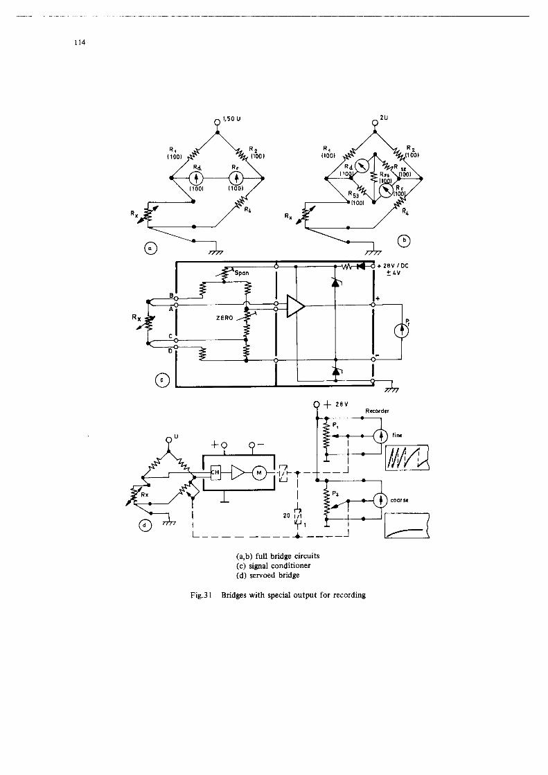
2.2.6 Bridges with Special Output for Recording
In this section, the concept of “output for recording” ia always understood Co mean an
outp”t in the form of a” analog voltage which La used BB an input to a galvanometer in a” optical
type recorder, a subcarrier oscillator in a telemetry system or an A/D converter in a digital rape
recorder. In servoed bridges an electrically ieol.ted output for recorders CM readily be obtained by
coupling transmitters such as ~.Xentimters, symchros or shaft position encoders to the se~omotor.
1” all nonservoed types of bridge circuits, with few exceptions, the two output leads have a specific
potential with respect to the aircraft ground, so that ground conditions must be carefully considered
to avoid short circuits or cxoee coupling, when connecting recording or telemetry devices.

20
to probe leads mi@t be permtseible (but not advisable) if extremely high resistance loads ere used.
“he” connections can be made in the bridge circuit , a” output for recording is readily obtained in the
case of bridges for galvenometer type indicators as ia shown in Figures 31a end b. I,, each of cheae
examples, the indicator bridge has a resistance of approximately 100 ohms in each branch. i?.,r 500 ohm
bridges, all values vould have to be multiplied by 5. In the diegrams, R, includes the input reeie-
tan== Of the recording device (e.g. recording galvenometer. subcarrier oscillator, etc.) since it rrmet
be conditioned to the bridge. The simplest circuit is the series arrangement of Rd end R, shown in Figure 31a; in this caee. however, the bridge seneitivity end hence the indicator calibration is changed. In order CO obtain the same calibration es before. the bridge supply voltage must be increased approxi- mately 1.5 Limes, in which case the self-heating error for the probe Rx increases to 2202: of ice
pre”io”s value. When the indicator is moved by acceleration forces, its gal”a”meter act.* like a
generator, md pulse-like error voltages are generated that ten invalidate the recording. A direct
parallel arrangement of Rd and Rr instead of a series rrrengement is usually woree unless the
resistance of R, is high in comparison with Rd.
Figure 31b shows e circ”it in which Rd and Rr ere differentially uncoupled by additional bridge elements (R52. R53 end R55), i.e. feedback from Rd to R= and vice verse is impoeeible when they are properly connected. Hwever, the bridge supply voltage most be increased to ZOOX of its original value. in which ceee the self-beating error for the probe increases to 400X of its preyi,,“e
“al”*.
Figure Xc shows the circuit of a commercial sianal conditioner with a four-wire cnrnection
of the probe, e Kelvin double bridge and a DC amplifier. It provides an output voltage of 0 co 1.4 MC
or 0 to 5.0 voc that increases lineerly with the temperacure. This circuit is not affected by changes in the length of the probe leade (up co 30 meters), but should be operated at ambient temperatures
between +lO and +40% if the errors are not to exceed LO.4’ when measuring temperatures between -50% and +lOO’ C(References 17, 18 end 19). Similer bridge circuits are alao available WithoUt Bmplifiers. They
deliver a maximum o”tp”t voltage of only approximetely 50 m” and require e highly srabilized supply
voltage. In the cese of recording or telemetry systems with multiplexing. self-manufactured half bridge
circuits or the previously mentioned bridge units without amplifiers ce” be connected through the
multiplexer Co en AC amplifier with e chopper and a demodulator. Another possibility is to “se the bridge
unite with built-in emplifiers and connect their o”tp”ts to the multiplexer without subsequent
ecqlificetio”. his last technique is quite expeneive, but gives the greatest accuracy and is lease effected by external disturbances, since the signal level at the multiplexer is ueually much higher than
thet of stray voltages. The most inexpensive, but mst unreliable and inacc”rete solution is the former.
“here it is extremely difficult to avoid co-n mode problems.
In the caee of servoed bridges (Figure 31d) one or several output shafts are usually available
ta which e potentiometer P2 (or even a shaft position encoder) can be covpled in order to obtain a
voltage for recording purposes chat is electrically isolated from the actusl thermometer circuit. The
resolution end accuracy of this type of recording o”tp”t is not very high when a single-cur,, potenfio-
meter with ~~~roximetely 1X linearity is used. Better reeolution is obtained with a second (fine)
potentiometer Pl (also single-turn) coupled so that it rotates faster, e.g. 20 rimes faster than P2,
the one used for coerse meas”re~nte. If PI rotates through 360° 20 rimes over the total temperature
renge of -7O’C to +50°C, there is e fine recording with 20 intervals, each being 120°C/ 20 or 6’~. 1t
should be noted that potentiometers generally have e deedbend of ebout l/lOOth of a turn or about 3.6’.
Since thie would emo~nt to only 0.06%. end the coerse recording is also available, this is considered to
be tolerable.
Figure 32 illustrates severe1 common temper.t”re indicators with zqlvenometere (C) ratiometers
(R) end servocircuits (S). of which rbe letter can be manufactured with an output potentiometer for
recording purposes. Figure 33 shows servoed brid@es with digital indication for 100 ohm platinum probes.
They can be equipped “ith both coerse and fine recording potentiometers. The measurene”t range ta -100
to +100% with (111 accuracy of +0.2%. The instrument on the right in Figure 33 can eleo be switched for
SAT indi~arion (when wnneeted to a Mach function potentiometer). operating in tbie cese as a computing
bridge. Figure 34 shows other computing servoed indicators for single and combined indication of SAT,
TAT end ‘MS. They ce” all be manufactured with outputs for recording (potentiometer, synchro, etc.) end
be connected to a so”rce of the Mach function. e.g. an air data computer.

21
3. THERMOELECTRIC T!mPERATLw mAsUP.EmTS
3.1 TberTmcouple Probes
3.1.1 Thermocouples
A therrmcouple is formed by joining (twisting or welding) two electrical leads made of different
~tx.18 or metallic alloya. 1” each lead, the valence electrons. which are free to nave between the
cryetal lattices. are under a “pre.~sure~’ that is proportional to the temperature and the electron coneen-
rrafion of the lead in question. At the point of contact of the leads, the electrons diffuse tbrou6b the
boundary layer between the MO leads ~8 a result of the “pressure differential”. Therefore. the one lead
loses electrons, i.e. becomea positive, and the other gains mare electrons, i.e. becomes negative, and w electromotive force (“contact e.m.f.“) is produced. If the other ends of the leads are connected in
the same way, a” e.m.f. is also produced at that end in the opposite direction from the first one. The
e.m.f. is highest at the point of contact where the temperature is highest. The difference between the
contact e.m.f.‘e, is proportional to the temperature difference, and causes a tberm~current to flow. This
phenomenon is called the “Seebeck effect”. In addition, a “umber of other effects occur (Reference 42)
but they are usually negligibly small in temperature n.za~ureme”ts*.
When a millivoltmeter ia inserted at any point in the above-mentioned arrangement of two leads,
the Seebeck effect enables measurement of the temperature difference between the two points of contact.
If however, one contact is kept at a constant (reference) temperature, the instrument scale ca” be
calibrated to directly indicate the temperature at the other contact (thermocouple). The contact where
the temperature remains constant is called the “cold junction”, the other the “hot junction”.
The Seebeck coefficient or m S of a thermocouple is S - AE/AT and is measured in
microvolts PC. Table 3 gives nominal sensitivities “ear O’c for various materials compared with
platinum. The output valta6e of two give” material- compared with each other is obtained from the
difference of the S valuee, e.g. chromel vs.alumel - (+25) - (-15) - 40 WI%.
TABLE 3. SmSITIVITY OP *EP.MELEmRIC MATERIALS vms”S PLATINOM
(a) Blslluth -72 Micro”olrl°C
consranta” -35
Al,,,& (and Nickel) -15
Platinum 0
Alumi”“m +3.5
Rhodium +6
Copper +6.5
IrOn +u.5
Chrome1 f25
(a) POT pvrposes (a) Selenium +900
Of comparison
Table 4 ie a list of the most important thermocouples and their characteristics, including
information on the limiti”8 temperatures. wbicb when exceeded cause oxidation or reduction. At these
limiting temperatures, unprotected cberm~cou~les cannot be used. when the curie point for nickel is
exceeded, there is no effect on the resulting thermoelectric voltage 88 contrasted to the effect on
resistarse change with temperature, since the former depends on the electron concentration. Figure 35
gives representative values for the thermoelectric voltage as a function of temperature difference for the
msf often used thermocouples over the range “here they are primarily used. The actual values for
thermocouplea from different companies vary somewhat, depending on the material used and the way it is
treated.
3.1.2 Co”str”Ctio” of Tbennoco”plea
Jut as in the case of the resistance probes, different requiremente (time constant. vibration
resLsta”ce, corrosion resistance, etc.), or their relative importance in a give” application. necessitate
different construction techniquee for thermocouplerr.
*Exceptiona are discussed in Section 3.2.

Type E (ISA Std.)
wee K (ISA Std.)
WWF-e J (ISA Std.)
Type R (ISA Std.)
Type s (ISA Std.)
Type T (ISA. Std.)
lkSi*atiO”
Chrome1 (+)/ CcmStantan (-)
Chrmel (+) I Alumel C-1
IrOn (+) I constantan C-1
Platinum (-)I Plati*u!n-EIodium (t)
composition
90% Ni 10% cri 57% C" 43% Ni
90% Ni 10% Cd 94% Ni 3% l4l 2% Al 1% si
Fe I 57% cu 43% Ni
Pt I 87% PC 13% Kb
Platinum (-)I et I Platinuu-Rhcdium CC) 90% et lo* P.h
copper (t) / cu / constantaIL (-) 57% cu 43% N1
RangelAceuracy
-1s to +3150 c/ + l.PC +315 to +*700 c/z 0.5%
-18 to +27b°Cl + 2.2'C +276to+760°C/ 3.5%
-18 to +276W +Z.Z'C +276to+760°CI x0.5%
0t0+1,000%/ 5.25%
+450to+1,500°CI 5.25%
-200to+93°Cl +o.fc
e.m.f., small themo e.m.f., heavy absorption above 1,000~
Especially suited for negative temperatures. copper oridizes above 35ooc
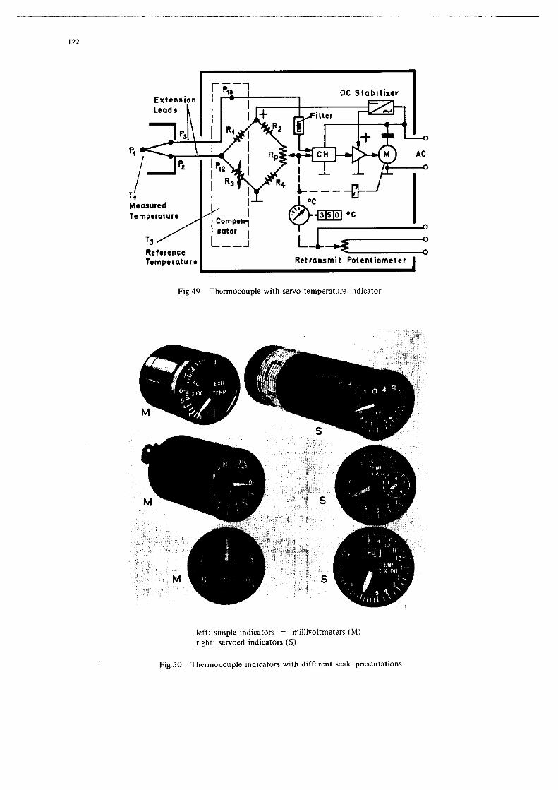
For further information see: Instrument Society of America ISA Recommended Practice Rp 1.1-l.); WE,MI-3511; DIN 43710; etc.

23
Figures 36a through d show “open” eleme*ts (exposed hot junctions). The first one (Figure 36a)
is made Of LL single lead thermOcoaxial cable; the center conductor is CDnstantan wire and the outer
co”ductor is copper tubing. More typically two insulated wire. are used, and they are joined at the
hot junction by twisting or better yet, by welding or silver soldering. When measurements must be made
in a medium that is moving at high speeds, or if the element rrmst be mechanically protected, a” e
element with a protective shield (Figure 3.58) is used. In all the previously mentioned types, the lDedium
to be measured is in direct contact with the thermocouple so that as a result of the small mass, very
small time co”stants are obtained.
For uee in media at high pressures. or if the medium is corrosive or an electrical conductor,
the thermocouples must be housed in sealed tubes (Figures 36e and f). I” these well-type elements,
the wires are often welded to the tube and hence grounded at the contact paint (Figure 36~). This
nam,ally excludes a”y arrangement of several elements in parallel (for indication of mea” temperature
with a single instrument), but yields smaller time constants than the well-type elements with a”
ungrounded junction shhown in Figure Hf. Examples of another type of open element, the so-called foil
themcouples thee are used for surface temperature measureme”ts, are shown in Figure 37. They are made
of flat ribbons, end are provided with temporary carriers of polyamide film. These elements are directly
attached to the surface with a ceramic cement and are sometimes sprayed with a protective ceramic
coating.
3.1.3 Co”struCt*o” of Probes with Tbentocmp1es
If a tberm~element is equipped with a threaded or bayonet fitting, some other type of fitting,
or even a housing, the arrangement is usually called a thermocouple probe. I” contrast to the
resistance probes which are usually provided with a” electrical connector, the thermocouple probes have
lead “ires without terminals, eyes or eve” co”“ectors with pins made of the same material as the element.
Depending on the purpose for which they .ere used, there are numerous types of probe
construction. 80 that only examples Of the most important types can be given here. Probes for measurements
in liquids and gases are usually cylindrical in shape (Figure 38a). ad the threaded fitting is often
manufactured with a clamp so that the immersion depth of the element ca” be adjusted (Figure 38b). The
element itself may be open, equipped with a shield (Figure 38a) or closed (Figure 38~). Figure 38d
shows an open model with two separate thermocouples, one of which can be used for individual measurements.
and the other for obtaining average temperatuee values when connected with other elements.
For measureents in a rapidly rmwing gas stream. the gas temperature probes (TAT or stagnation
probes) abow” in Figures 39 and 40 are used. They are always open elements and the housing usually has
large intake openings, but small exhaust openings, 80 that the entering gas streem is adiabatically
compressed. Figures 3% and 39b show simple wdels; Figure 39c, however, shows B model that is better
suited for messureme”ts I” high speed gases, e.g. exhaust gas temperatures. I” order to measure the
outside air temperature in supersonic aircraft, where stagnation temperatutes can be +150°C or higher,
special types met be used. Figure 40 shows a model with two concentric radiation shields in the housing
which significantly reduces the otherwise relatively large r+diation error.
Finally. Figure 41 shows various probes for measuring temperature in solid bodies and on s”rfaces.
The one in Figure 4la’is a special spring-loaded model for measuring the temperature of the cylinder bead
of a* aircraft engine. The spring presses the enclosed probe element against the bottom of a bored hole in the cylinder head. Figure 41b shows a semi-ape” probe with a threaded fitting designed to measure the
temperature of brake drums. Figure 41f shows a clamp type probe which can be mounted on a pipeline. The
gasket probes shown in Figure 41~ and d are mounted like gaskets under spark plu’ds or screws. Figure 41e
gives B front and side view of a probe that is riveted into B bole in the surface whose temperature
is to be measured.
At this point. it muat be mentioned that there are a “umber of other special types of probes.
e.g. those that ate r,.,re applicable for directly measuring the beat flux from and to surfaces, rather
than for terqerature measurements (see References 91 through 94).

.-~ --..-
24
In Figure 42.. two leads x and y made of different maarials are shown, which are connected
to each other .t pointe P1 and Pq by welding, twiecing, etc. When PI and P2 are at different
temperar”ree a1 end T2). a current is generet** ther is proportion.1 to the rem*erarure difference.
The diraction of the current depends on whether T1 ia greater or less th.” T*. A temperature difference,
therefore, produces .n electromotive force (thermal e.m.f.), if this temperature difference occur8 be-
tween two points of cxntsct of different metale. Temperature gradients anyvhere within lead x or lead
y will have no effect if each is made of a homogeneous material*.
I” thermocouple c*rc”ite, symerrics1 con”ection points (or even lines) of a different
mater**1 can be arranged differentially YiCho”t co”eeq”ence as long 88 these points (or the connection
points Of the lines) *I* *t the **me temperature (i.e., 88 km* as the “olt*gee that are generate* *t
the point8 where the two different materials are connecred are cancelled). Hence, if one of the
conductors shorn in Figure 42s is broken and a milli”olrmerer inserted (Figure 42b) with leads made of
materiel z (e.g., copper) and both points of contsct (P, and P4) of the broken lead are kept at the
same temperature, there ia no effect on the thermal e.m.f.. although two new - but differentially
erranged - thermocouples P3 end P4 have been farmed. Their common temperature T3 can be different
from T1 end T2 and even from the temperature at the instrument, since in the latter case the tempera-
ture gradients appear in 8b.il.r leads (both of material z). If however, points P3 and P4 were at
different temperatures, their thermoelectric voltages would no longer cancel out end the resulting
thermoelectric voltage of the circuit would be eqval to the algebraic sum of all the individual voltages.
This is equally true for a point P5, which per se muet have a single temperature, and it can also be
considered a differential connection, Y’IP, to P5/Y. This cIrcuIt (Figure 42b) is useful for measuring
temperature differences or rete of temperature changea** (cf. sect. 2.2.3.2).
“*“ally, it is desirable to directly meee”re the temperature T1 et point P1’ in which ceee
the ~ircuif shown in Figure 42~ is better for several reaso”s. Instead of opening one lead an* using
two themoCO”plee. point P* is open** end the instrument is connected to paint. P2 en* P,. **sin, two new differentially ercenged thermocouples have been formed. and their temperature must be equal. If
this temperature T2 is kept at O’C 88 B reference temperature, using for example a container with
melting ice. then the temperature difference AT between T1 and T2 would equal T1 in ‘C. If
on the other hand. a thermostat is ueed to keep T2 at +40%. then AT - Tl - 40’. The indicator
scale must then be shifted by +40°C so that instead of the temperature difference. the remperature
5 - AT + 40% ia directly indicated. In aircraft, another type of reference point formation is often
ueed (see below).
*Cf. helov the affect of heterogeneous leads.
**Non-1ine.r thermocouple .,utput voltages must be taken into BCCOYTI~.

25
Pigures 43~ and d illusrrsre rather drastically the effecte of tempereture gradiente in the
extension lead connections. The connection points P2 and P;, as well ee P, and P;, =r= assured
to be terminals that are connected with lead material W. ln the extreme CBS= of Figure UC, the
entire rhemacauple x-y is =t the =pm= temperature and, hence, there i= no thermoelectric voltaS=
between P2 and Pg. There is also no “olrege between P2 and ‘;. or between P, and P;, despite the l=rS= temperature difference (becsuse of the two similar l==d= “1, =lthouSh there are voltaS==
between P; and Pl2 ee well as between P; ad P13. Figure 43d gives =n extreme example of the
reversal of c”rre,,t rhst C=II occur when the m=asurinS point is cooler than points closer to the in=tr”-
menr (Reference 43).
When leads must be quite long, Chrcmel-Almel rhermacauples BT= often leqthened with copper-
constanten leads to reduce circuit r==ist=nc=, if the temperature of points P2 and P3 in FiSure 4%
ie not more than approximately +&C. This e=n result in = considerable reduction in wright where =
larae number of thermocouples =r= used, but at the expense of m==eur=m=“t accuracy. 1.x the c=== of pletinum snd platinur-rhodium rh=mcoupl=s, extension leads of copper or copper-nickel elloy are
usually used for economic r===on=. The thermoelectric voltaS= of these extension leads with respect
to ehi= themocouple remains small within = limited temperature raw=.
Thermocoup2e circuits (in contr==r to the== utilieing resistance element=) are characterired by
measurement errors that easily occur == = rasule ofparasitic”oltaS=s or currents, which often ~=nnof
be detected by the indicator or BT= difficvlt to explain in the c=== of faulty indication “al”==.
Special attention muse be paid to the correct polarity of the extension leads when the thermocouple circuit
is wired. Parasitic currents are particularly troublesome when ==“=r=l th=rmDco”pl== =I= connected to a eiu,,le indicetor through a selector witch. if the latter is not bipolar. The insulation resistance of
thermocouples to ground is lo” =t very high tempereeures, and well-type elements with a grounded
junction yield undefined conditions in the c=== of single-pole commut=tion.
Since the current in thermocouple circuits also depends on the resistance of all the lead=
(x, X’, Y, Y’, =, v, etc.) the calibration of a p=rtic”lar indic=tor (such == a millivolt-meter) is
only execr for = certain tot=1 r=si=t=nc= “clue. to which the circuit can be adjusted by m==n= of a
trim resiaran~e. This ad,uatment, however, only holds for the lead temperature existinS at the time
“hen the circ”it w== adjusted. The effect of the lead r==i=r=nc= i= n=SliSibl= in the c==e of
currentlese m==s”remcnt= taken with a servoed instrument (see below).
In thermocouple circuit=, there are = number of other effects besides the Seebeck effect;
e.g.. the Peltier effect, the Thomson effect and the Joule effect (cf. Reference 42) BT= n=SliSibl=
when curr=nt= =r= relatively small. On the other hand, the Secquerel effect can be very large. Local
material dissimilarities in the extension leads c=n generate =iSnific=nt p=r==itic e.m.f.8 in the circuit
when there is = temperature gradient (Reference 42) even when .=r”o=d insrruments =I’= used. For this
reason. complete accurscy of the thermocouple circuit c=” only be achieved when the temperature di=tri- bution at the time of the calibr=tion c=n be exactly reproduced in all the leads. This i= almost
impossible in aircrsft. Errors ten reach +Z’C, especially when leads are made of iron or con=t=nt=n.
For this reason iron-constanten th=mocoupl=s ore rarely used any more in aircraft. Local defo&x&&as
of thermocouples and leads c=n alec produce h=t=roS=n=ousn=ss and m”=t be avoided. Welding of them-
cm,ple contecte is therefore better th=” twisting. When the depth of immersion of the element is
changed, h=t=raS=n=ousn==s c=us=d by temperature can h=“= a strong influence and for this r==son the
depth of inmersion should not be chanS=d at l=t=r stag==.
Vibration effects can produce noise “olt=S== of up to 100 microvolt= in thermocouple-
circuits with fr=ausnci== from 10 Hz to 5 KHz, dspsndsnt on ths rat= of rotation of ths snezines.
These noise voltage= =r= therefore equsl to or greater than the useful signal at lo” rem~=r=cur=s
(e.g. et the engine .ir inralre point). Servoed indic=rors are “sually equipped with =n input filter,
which filters atf thsse voltaS== (=nd 400 HE =tr=y volt=Ses). However, servoed insrr~menfs utilizinS
resistance probe= a= usually mot’= =ccurax= at temperatures below 200% and co=t the =~me (Section 5.3).
In the c=== of home-made themoecuples. the =ginS effect which changes the calibration after a specific period of operecion muse ale., bs &iv=,, consideration; rhemcou~les in commercial
probes =r= usually pre-aged. In the f=== of open thermocouples, special attention must be given to

26
chemical and phvsical effects “hiCh limit the life of the thermocouple at high temperatures by
absorption of gases, reduction or oxidation, md other processes, depending on the material of the
elements (cf. man”fact”rer’* specifications).
3.3 Indicators for Thermocouples
3.3.1 Direct Indicatars
In the case of all thermacouple indicators, the accuracy is directly dependent on the arrange-
ment of the temperature reference paint. In simple an-board aircraft instruments (Figure 44). the refer-
ence point is located at the compensated indicator (a moving coil millivoltmeter) 80 that the therm+
couple extension leads run directly to the instrument housing. The positive cannection is made of
bronze for copper-constantan and chromel-alumel thermocouples. and of iron for iron-constanten thermo-
couples. The negative connection is always made of constanta,,. The wiring in the instrument “tilizes
iron or copper wire, and constanfan wire. Since the temperature of the instnment. and thus the refer-
ence point, depends on the cabin temperature, the thermoelectric voltage will also change wit,, cabin
t-llp~K*t”K~. A bimetallic sprin&; knouneed on the moving coil device, and a resistance with a negative temperature coefficient in eerie8 with the copper coil, provide compensation for changes in the cabin
temperature. since tile millivoltmeter requires a CerCain current, different lengths of extension leads would yield different scale calibrations. A trim resistance of constanta” wire is connected in series
with the negative extension lead, and is adjusted so that the total external resistance is that for
which the instrument was calibrated (e.p., 8 f 0.05 ohms). A measuring device of this type has, in it-
self, a permissible tolerance of flO% for a measurement range of 0 f” l,OOO%.
The measurement accuracy of the above arrangement cannot, of co”rse, be very high. separating
the temperature reference point from the instrument can result in considerable simplification af the
design (since no special plugs are needed for the extension leads, etc.) end a considerable reduction in
cable weight in large aircraft (since copper leads between the reference point and the indicator can be significantly smaller in diameter with the same resistance than, for example. chromel-alumel leads).
Instead of a thermostatically controlled reference p”int (Figure 45), the “se of a cold junction
compensator (Figure 46) is preferred in aircraft. The latter utilizes a bridge circuit that is supplied
with a regulated voltage eource and consiste of three normal resistors and a temperature sensitive, semi-
conductor resistor. The bridge o”tp”t terminals are connected in series with the thermocouple and its
extension leads. copper leads and indicator. The bridge output voltage is proportional t” the reference
point temperature and is used to compensate for the undesirable change in the thermoelectric voltage.
Even in this thermometer circuit, the lead resistance must be adjusted to the value for which the
indicarar was calibrated.
Figure 47a shows a thermometer arrangement with several measuring p”i”ts and a common cold
junction compensator. The latter m”st be at the fame temperature BB the terminale of the thermocouples
(OK the terminals of the extension leads). This “sually requires B considerable amount of copper
wire between this point and the commutator. In this case especially, a separate trim resistance is
needed for each thermocouple if exact measurements are to be obtained.
Figure 47b shows 4 thermocouples in parallel to measure an average temperature (e.8.. turbine
exhaust temperature). In this case also. separate trim resistances rather than a single resistance
should be used for each thermocouple for maximum accuracy, since the internal resistances of the thermo-
couples can be different.
All methods that measure a current generated by the thermocouple. rather than the ““loaded
thermaelecrric voltage, have the disadvantage that resistance changes in the leads (as a result of lead
temperature changes during flight) can produce large meas”reme,,~ errors. The magnitude of the err”rs
depends on the rati” of the trim and lead resistances t.Lheother resistances of the circuit.
3.3.2 Servoed Indicators The effect of lead resiqtnnces can be eliminated if measuremene~ are made when no currene is
flowing, as in the “potentiometer” circuit shown in Figure 48. In thin type of balanced bridae circuit,

27
the thermoel.crrie voltage is balanced with B variebl. voltage acro*s the dia*oasl branch of the bridge,
the magnitude of which is mamla1ly adjusted by the porentiamerer BP. A temperaevre i”diCBb3. is
coupled to the viper of the pofentiameter. Since the ch.r.cf.ri.tic curve of the thermocouple, i.e.,
the thermoelectric voltage . . a function of the t.mp.r.tur., is “on-linear over . large segment of the
rang., a “on-linear 9ot.nriom.e.r is usually used. and give” segment. of the temperature rang. c.” be
expanded by changing bridge element.. The thermoelectric volcag. and the voltage .cro.. the diagonal
branch of the bridge .r. equal when the sensitive, series-connected meter is zeroed. Temperature
meesurementrr. however, are only correct if point. PI2 .“d P13 are at the reference temperature. The circuit shown in Figure 48 can be combined with the circuit show” in Figure 46 by replacing the resist-
ance Rj in the former circuit with a temperature sensitive resistenc. 80 that veriations of the bridge
temperature, which is aleo the reference t.mp.r.tur. I” this c.... .r. .urom.tic.lly compensated. Since
the type of temperature indicator ,u.c described require. a manual setting for each measurement, it is
used almost exclusiv.ly a. . rest device. Accuracy is typically fO.lX of the rem9eratur. m...urem.nt
rang..
I” the ca.. of a ..rvo indicstor, 8. described in ..ction 2.2.5. the zero indicator in Figure
48 is replaced by a 8.~0 circuit (Figure 49). The filtered DC error voltage is converted into .n AC
voltage by me.“. of . chopper and is the” amplified end fed to a” AC motor. The motor, through gearing, turns the wiper of the por.nt1om.f.r Rp until the difference bet”..” the thermoelectric voltage and
the bridge voltage become. zero. At this point, no current flow. in the thermocouple circuit, and hence,
the lead resistance. have no effect o” the point of balance. The angular position of the bridge pot.“-
ticmeter (which is wound non-linearly to match the “on-linear characteristic cur.,. of the thermocou91.)
indicate. the t.m,,.r.tur. at the rbermocovpl. on . scale. In this type of temperature indicator. the
temperature reference point is usuelly in the indicator housing for pr.cric.1 purpose., end fh”., the
extension lead. run to the insrrllmenr. Only newer models with .” input filter should be used in order
to eliminate 400 Hz pickup and “de. volreges caused by vibrations. Servo instruments usully have a”
accuracy of fl% between 500 and l,OOO%.
Figure 50 show. several cams,” type. of indicator. for thermocouple.. The series on the left
utiliz. simple millivoltmeter. and the seri.. on the right are 8.~~0 instrument.. The latter are m.“u-
factured with expanded partial rang.., with two painter8 or with .” additional counter wheel indicator
to improve scale resolution.
4. “EAT TRANSFER AND TEMPERATURE RECO”ER*
,x..ry type of temperattire m..surem.“t i. b...d o” the h..t .rcb.“g. proc..... b.tw..” the
tempersturo prob. .r,d the medium which is being measured. In .ddirio”, there i. .I.. the undesired h..t
exchange with other media which must be eliminated . . much (I. pos.ibl.. On. ch.r.ct.ri.tic of every
type of beer transfer is the heat tr.n.f.1 coefficient. when t.ki”g m.a.ur.m.“t. in rapidly moving
media, there i. also a temperarur. rise caused by the transformation of kinetic energy intO therm.1
mergy, the r.l.tiv. m.g”lrud. of which is d..erib.d by the .o-called r.c.“.ry factor. Since the.. f.ctor. .r. function. of a large nvmber of p.r.n.t.r., k”owl.dg. Of the m0.t importmr proc..... in
hea tr.“.fer f.cilit.te. selection of th. correct m...uri”g points .“d the .ptimm type of me..ureme”t
prob., .“d al.0 help. in .v.lu.ti”g .“d interpreting the m...ur.m.“t r..ult.. The following brief
di.cu..io”. .r. intended only to introduce .om. of th... f.ctOr.. MOT‘. d.r.il.d tr..tm.nt of the..
abject. c.” be found in the following reference.: 1 through 13. 22 through 24, 44. 46, 40,99A md 998.
4.1 Mod.. of “..t Tr.n.f.r
me following consideration. hold, on the on. hlmd, for the h..r tr.“.f.r between tb.
ramperatur. prob. . . . solid body md the medium which in being measurad, be it a g... liquid 0.. nolid.
o,, the ,,th.r h.“d, they .l.o hold for the heat ,trsn.f.r betwe.” the medium .“d th. .tr”ct”r. Of the
.ircraft, in which c..., eh. e.mp.r.tur. of th. .ircr.ft .tructur. c.” influence the trmrperatur. Of the medium to be measured (e.g. the outer skin can affect out&de sir temperature and piping can affect oil temperature.)
“.a tr.n.f.r within. medium, or bstwe.” two different m.dia, CL” t.k. place i” the
following way. (Reference 998):

28
(B) Through heat con*uctio*: Thi. in a tr.“.fer of kinetic snergy from high energy molecul..
to low energy mol~cul.~ within . medium or bceween two medie in dfract phy.ic.1 cont.ct.
Th.r. ia .leo . m.reri.1 .xch.“g. by mol.cul.r diffusion b.tw..” two ~,BBB or liquid.
which corr..po”ds to Browni.” movement.
(b) Through co”v.cfio”: Tbia i. . fypa of b..t tr.“.porr by r.loc.rio” of microscopic
p.rtic1.a .“d is b.e.d, in the c... of m co”v.ctio”. on . diffarenc. in d.“.ity
resulting from temperature difference.. In the c... of forced convection, however, the
flow is the result of m.ch.“ical influence..
(c) Thrwgh r.di.rio”: This i. . heat tr.“.f.r procass without . m.t.ri.l c.rri.r, but by
m..ne of ‘a.“. .ner$y, primarily through infrared rsdi.tion. 1t c.” p.s. through
tre”spsr.nr media, but GUI al.0 be reflected .t the boundsry .urf.c.., or b. absorbed by
the medie and tb”~ be r.co”v.rr.d into belt energy.
All three type. of b..r tr.“sf.r c.” occur either individually or cornbind.
T.bl. 5 .how. tha co”“.ctio” betve.” the mo.r important term. in therm.1 r.ch”olo-dy which CL”
b. inserted into th. formvla. with the ““it. refarred to the qu.“tity of h..r or work (30~1.~) or
referred LO the electric power (watt.). In order to convart from the therm.1 sy.it.m of unit. (ealori.~)
to Lh. electric.1 .y.r.m .“d vice VW.., eh. them1 .quival.“t 1 cal - 4.185 “..c - 4.185 J c.” be
used. 1” the CBBB of bsat transfer, . .p.cific therm.1 power P equale the h..t qu.“tiey 9 per
unit fh. t ehet ie transported within . .“b.t.“c. or from one ~ubscenc. to another. Tb. rr.“.f.rr.d
heat qu.“tity incr..... when the thermal conductance G i. increased or the them.1 r~eietanc. R
(.qu.l to UC) ia d.er..eed, for . .p.cific esmperarur. differanc. AT.
The magnitude of the conductance value in this c... is “or only conditionad by geometric.1
dfm.“sio”s (length, .r.., etc.) and th. material propertiee (therm.1 conductivity, specific heat, etc.)
but primarily by the type of best trsnsfer and energy incr.... (energy of motion, h..ti”g power, etc).
T.bl. 6 giv.. th. general equations for the heat transfer processes.
4.2 “eet Trensfcr between Immobile M.teri.1.
4.2.1 Hart Transfer between Solids
The beat transfer bet”..” two solids, which BT. directly adjacent to ..ch othar and .r.
aurrcunded by a single extremely good layer of therm.1 insulation occur. only throwah co”duCCio” .nd is
dependent on:
(e) the tampersrure diff.r.“ti.l AT of both bodi...
(b) th. geometric dimenaio”. (length I. and di.m.t.r d. etc.).
(c) the specific thermal conductivity t of both .d,.c.“t surfa...
“eat tr.“~~c.rt within a m.t.ri.1 (e.8. slang . met.1 rod) with a czo.. .=.a A i. described
by the equetio”:
q-t.A.t * AT (6)
The h..t t.r.“.f.r between two solids (1) .“d (2) on the other hand, must pass through the
eerie. .rrang.m.nt of the thermal re.i.e.“ce of the mar.ri.1 (I). the contactins .urf.c. (.b) .nd the
mete.i.1 (2). Thue, we obrein the following .q”.tio”:
1 Q- . .tb . t * AT (7)
!L+t!L+5 % ‘b k2
The them.1 re~ietmce is heavily influenced by the degree of eontsct betw..” both nolid. (e.g.
.d,.c.“r position, welding, soldering or cementing, possibly with metallic .dditiv. to the caant) end
.leo by the prc..“ce of .me .ort of interference, ..g, air. oxide or 0th.r f”t.m.di.t. 1.y.r.. Wt.”
there is no co,,,r,on in~ulntian around both .&id., a heat exchange of each nolid with the .tmo.phcr.
occure tbmush conduction, co”vectio” and radktion, (se. below). Calc”lBCio” Of the proc..e.a in all
the.. case. I. circumst.nti.1 and I”=x.ct.

29
TABLE 5. TABLE OF MEASUREMENT UNITS
TABLE 6. GENERAL EQUATIONS OF HEAT TRANSFER
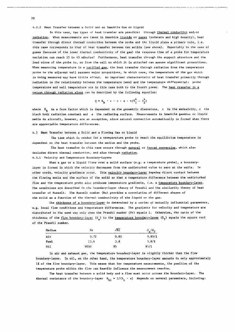
4.3 Heat Transfer beeween e Solid and a Flawing Gas or Liquid
'rhe the which is needed for a temperature probe to reach the equilibrium temperature is
dependent on the hear transfer between the medium and the probe.
The heat transfer in this case occurs through naCural or forced co""eccion. which also
includes direct thermal cond"ct*o", and also through radiation.
4.3.1 Velocity and Temperature Boundary-Layers
when a gas or a liquid flows over a solid surface (e.g. 8 temperature probe), B boundary-
layer is formed in which the velocity decreases from the undisturbed value to zero at the walls. In
other words, velocity gradients DCC"~. This velocity baundarv-1aver impedes direct contact between
the flowing media and the surface of the solid 80 that B temperature difference between the undisturbed
flow and the temperature probe also produces femperature gradients, i.e. B temperature boundary-layer.
The conditions are described in the boundary-layer theory of Prandtl and the similarity theory of heat
transfer of Nueselt. The Nusselt number (Nu) provides a correlation of different shapes of
the solid as e function of the thermal conductivity of the liquid or the gas.
The thickness of a boundarv-layer is determined by a series of mutually influential parameters.
e.g. local flow conditione and temperature differences. The gradients for velocity and temperaCure are
distributed in the same way only when the Prandtl nrrmber (Pr) equals 1. Ofhenriee, the ratio of the
thickness of the flow boundar.,-la,.er (OS) to the temperature boundary-layer (DT) equals the square root
of the Prandrl "umber.
Air 0.72 0.85 0.85/l
F”d 13.6 3.8 1.811
Oil 9000 95 95/l
In air and exhawt gas, the temperature boundary-layer is slightly thicker than the flow
boundery-layer. In oil, on the other hand, the temperature boundary-layer amo"nt(r co only approximately
1X of the flow boundary-layer. This means that for temperature measurements, the pwition of the
~emperarure probe within the flow can heavily influence the measurement results.
The heat transfer between a solid body and a flow m"st "cc"r acroee the boundary-layer. The
thermal resistance of the boundary-layer Q - l/(hc . s) depends on several parameters, including:

31
(a) the geometric di!n*“sfons of the body in the flow,
(b) the thermal COnd”LCti”ity of the flowing media,
(c) the Reynolds number or the type of flow (laminar or turbulent),
(d) “he Prandcl number,
(e) the temperatures of the body and the flawing media,
(f) the type of convection (natural or forced),
(8) presllure (in the case of a gas),
(h) Mach number
4.3.2 Heat Transfer by Natural Convection
h, - K, . (AT) l/4 (9)

32
hc = "f/de kf . N” - a a Rem . PT 0.31 (11)
8
I" addition to the previously discussed ideal flow condftions, tiler* ie also an eddy flow
aft a flow separation, which occurs for example in the wake of a cylinder hit by a croe* flow, or
behind eolids which pro,ect from a plane surface in a parallel flow. Often, small modification*, e.g.
changing clle angle Of sideslip, are enough to significantly alter the type Of eddy formation. "eat
transfer in theas zones is in my CBS* variable; one can obtain a statistic distribution of the
mee*"Teme"t values which are often "on-reproducible e"e" with respect to their mean value. These
conditions are often encountered on the *kin Of the aircraft aId in the engines including intakes and
,et pipes.
4.3.3.2 TemperaLures of a High-Velocity Flow
me following considerations are valid for liquids* as well Be for gases, which in contrast
to liquid* also have the property of compressibility. For this reason, in the CBS* Of gases. the true
airspeed Vt r,"et be used a6 a meaeure for the velocity, which, however, deviates from the value shown
by the airspeed indicator depending 0" flight altitude and temperature, especially at high speeds.
For example. when a flat plate (or even a smooth cylinder) is inserted in a flow parallel to
tile direction of the flow, there Is a temperature rise due to friction Tkf in the boundary layer. In
a laminar flow (i.e. when the Reynolds number is small), this rise can be described by the following
equation :
p,lfZ . "2 t
%fl = 2g . J . cp (12a)

33
and in a turbulent flow (i.e. when the Reynolds number is large) by:
p,1/3 . v= t
%it - 2g . J . c P
(12b)
where g - the gravitation of the earth. .I -mechanical equivalent of heat. and cp - the specific heat of the liquid.
Usually. however, the conditions of flow are not so well defined BD that the reeulting
temperature rise ia usually caused by a combination of different processes (friction, compression, etc.).
It in usually called the recovered temperature rise and cm be defined by the following equations:
r * v: - 2g . .I . cp
In other words, in the majority of cakes, in ccmtrast to the previously given equations for the
frictional heating. the Prmdtl number 88 a function of the probe design and the conditions of flaw must
be multiplied by a factor b, in which case. we,, the exponent my change (References 12 and 24). The
term (b . P:, in the numerator of equation 13a is usually designated the recover” factor r, since.
in addition to the velocity. it usually determines the value of the resulting temperature rise in a
specific medium.
ml, - v: 2g . J * cp (14)
By conversion (Reference 101) the adiabatic temperature rise can be obtained as a function of the Mach
number:
This Cem~erature rise reaches approximately 1.3’C et a speed (Vt) of 100 knots, and approximately IZ’C
at 300 knot*. At 1,000 *not* it ie approximately 13ov.
According to equations (13a) end(l3b). the recovery factor is a function of the Prandtl
number which itself is not a function of the temperature and the pressure. The factor b and the
exponent n, however, depend on the flow conditiona in question. The following equation is valid:
= - f(Vt. Pr, Re, k. K . . . .>
Therefore, for the mo8t part. we have the same parameters as i,, equatim (11) for the heat
transfer coefficient for forced convection. The factor K take into account the structural properties of the probe and the place where it is mounted. Clomcr in”estif,atic.” shwa that correlation of the
recovery factor and the Reynolde number is only possible for very simple probes. Figure 53 shows this
for a flat plate (Reference 6) and a cylindricaE temperature probe (References 5, 10, and 12) where
there is a parallel flow which is a function of the Beymolds number with respect to the “characteristic
length” X, It can be seen that in these cases, the recovery factor in a laminsr flow (low Reynolds
number - low speed) is approximately equal to Pr II2 . In a turbulent flow, however, r approximates EG3 and ie almost independent of the pressure and the apeed. In the trensitfonal zone, there are
significant deviations (shaded areas), see also Rsferance 113. For probes in a cross flaw, the recovery factor is much lower and can drop to 0.5, in which case, the minimum values are reached as the
local speed of sound is approached (for cylinders in a CT‘OBB flow, this corresponds to a “ach number

- T + v:/(zg * J . c,) (17)

35
r = ATkrIATk (19)
Sin=. th. r.cov.ry f.ctor i. th.t p.rc.nr.g. of tb. v.1”. of th. full .di.b.tic t.mp.r.t”r.
rise ATk which th. prob. e.. r..ch, md .iac.. rscovery f.ctor of 1.0 i. th. full v.1”. of ATk, it.
v.1”. i. .lw.y. .m.ll.r th.” or .pproxim.t.ly equ.1 to 1 in .ir .nd .xb,“.t g.. whsr. th. Pr..dtl
mmbsr is .pproxim.t.ly 0.7 .nd csnoot ucced tbi. vrl”..
Th. rscovsry f.ctor, for thi. r...on, lie. b.tw..n .pproxi~~t.ly r = 0.5 .nd r = 0.9 for
simpl. t.mp.r.t”r. prob.. mounted in th. bo”nd.ry 1.y.r of the .ircr.fr md “.“.lly bstmen r = 0.95
and r = 0.99 for TAT probes for measuring the outside air temperature. This latter value is reached
by the fnCeractio” of the almost full adiabatic compression with the individual recovery factors of the .l.m.nt .nd .hi.ld md th. .xXtr.m.Iy sm.11 hesr lo.... which r..“It from r.di.rion .nd di..ip.tion
(R.f.r.nc. 44).
Using ths recovery f.ctor, on ths other had, . .o-c.1l.d r.ccw.ry r.mp.r.t”rr Tr esn ba
d.fin.d ‘. Ch. .“m of the .C.tic t.mp.r.c”r. T .nd ch. r.cov.r.d c.mp.r‘t”r. ri.. ATkr mxoding
to th. following .q”.tion:
T= = T + ATkr = T + = * ATk (20)
-T+r.Y~/(Zg.J.cp) (21)
IT (l+rqdMZ) (22)
Th. r.cov.ry tsmp.r.t~r. w.. formerly. v.ry import.nt f.ctor .inc. th. low recovary fsctor
of old.1 typ.. of prob.. w.. th. .o”re. of the gr..t..t .rror in m...urln~ th.our.id. sir esmp.r.tur.
so thst th. orhsr .o”rc.. of srror . ..m.d minor. On th. other h.nd, when TAT prob.. .r. used, rh.
r.Co”.I‘y t.mp.r.tur. i. only on. of s.v.r.1 .od.r.e. *o”rc.. Of .rror.
4.3.3.3 Temperature M..sur.m.nt in a Supersonic Flow
Ths 1.~ of mation of s eompressibla 8.. in s subsonic flow .r. very diver.. in comp.ri.0”
with Chos. which .pply Co th. .up.r.oaic rag.. Whsn the loc.1 sp..d of round ia exceeded, . .hock Y.V.
form. in front of rh. tip of th. body in eh. flow (no.., TAT prob., forrnrd wing .dg., LIT intak. &a.
etc.). The .t.tic pr...ur., the .I= d.,,,ity .nd th. ststic .ir e.mp.r.r”r. incr.... behind the shock
w.v.; th. tot.I pr...“r., the M.ch wmber .nd the .ir.p..d, hov.v.r, .r. la.. behind th. shock w.“.
then in front of it. Th. tot.1 r.mp.r.r”r.. how”.=, do.. not chmg.. Thus, th. cqustion for the tot.l
.ir tanparatur. -in. completely v.lid for th. .“p.r..nic r.r@:
The di.t.nc. b.tw.m th. whack wsv. acad the body in the flow diminish.. . . the .p..d ie
incr4a4.d. The rotsl sir r.mp.r.r”r. inner......r th. ,olid top .urf.c. of the body . . . r..“lt of
compr...ion, .ndrh.a daers~c. .long th. body in tb. bowJ.ry 1.y.r. Th. v.l”.. obt.in.d in pr.cric.,
however. .r. only 85 to 92X of the c.lc”1.r.d ~1.~8 ,i.c. . th. sltitud. .nd tot.1 .fr t.mp.r.t”r.
.r. incr....d, h..r tr.n.f.r .(I . r..ult of r.di.tion .l.o in==...... Th. thickr.... of th. bo”nd.ry
l.ysr .loog tbs l.tsr.1 surfsc.. of tb. body in th. flow incrs.ms .lmo.t proporrionllly with ths speed,
which i. prinurily the r..“lt of th. incr.... in vol”m. c.“..d by hutins (Baferenc. 9920.
In th. c... of .imply constructsd prob.. with wry sm.11 m...urira .l.m.nt. (e.&op.n
th.rmeo”ple. or op.. th.mistor.), it i. po..ibl. thst in .up.r.onic flow, th. mu.“rins slamat m.y
p.n.tr.r. th. ahock VW., which form. .ro”nd it. .om.wh.t thick.= howing. In .II .n.l080”. -.r,
th. ahock W.V. CM .I.o .nt.r the opening of . TA’f prob. ho”.ing st .ngl.. of scrsck of nor. th.n
spproxi.ut.1y 3o”. so tb.t .om.tim.. th. r.di.tion shield p.n.tr.t.. th. shock “.“a. A mb.rp drop i.
eh. r.cov.ry fsccor i. ob,.nr.d in both c.... (cf. 8..xio,, 5.2.2. Fi@r. 67 .md Rafersnc. 41).
Duriq .“p.r.onic flight, th. .ir enrsr. . TAT mob., through th. sffact of the 1ins.r .hock
x.“., st . .“b.onic .p..d, but st LII incr....d tmp.r.t”r. (R.f.r.nc. 3). Th. ov.r.11 r.~o”.ry f.ctor
which r..“lt. from th. combinsd .ff.ct of th. r.cov.ry f.etor of th. .bnck W.V. (I = 1.0) .nd the
co+rs.pomding sub.onic r.cov.ry f.ctor of ths prob., ..ymptoric.lly sppromhs. th. v.lu. 1.0 . . ths

36
.p..d i. incre...d. Thi.. however, only hold. trua wh.n the prob. is not mounted in. poor loc.tion,
La., ,hr. th. thicka... of ths bemd.ry 1.y.r which incr..... with th. .p..d. remha. or sxccsd. the
h.iSht of rha TAT prob.. D.pcndinp on th. .ircr.fr d.eipn .nd th. p1.c. wh.r. it i. mwmd, tha ohock
XIV.. fwm.d .e th. no.. .nd .t rhc prob. m.y ine.rf.r. with ..ch 0th.r .e . ‘pacific ‘peed. In.ccur.cy
of me.auremant cm also r..ulr in thi. c....
‘I%. rffcce of v.ri.blc properties of th. S... ..p.ei.lly rho.. of (v.porir.dd) .tm..hcric
moi.tur. on th. tot.1 .ir eemp.rature, . . ~11 . . th. ch.nS.. in rba r.covcry f.ctor camed by (liquid)
- (in droplet.).nd &.re di.cu...d in Section 5.2.
5. si3FmENCE “AWES, ERRORS AND DSPINITIONS OF TmEsAToRE KEAsm
5.1 R.f.r.*c* “.lU.. Of T.mper.eure M.*.“r.m.nt
5.1.1 sr.ric Tamp*r*tur~
when VC .p..k of tba “r.mp.r.ture” of . Siv.n m.L.ri.1, norm.lly w. m..n eh. .o-c.1l.d u
mmPerature. Sr.tic t.mp.r.turs i. definei . . th.t t.mpar.tur. which rh. m.t.ri.1 h.. in. .t.te of
r..t, i.e.. without di.turbinS it. r.mpar.tur. aquilibrium by . probe which cm .ith.r add or t.k. .w.y
h..t . It met, hm..,.r, be mead th.t in mat c.... Lh. .t.tic t.mper.tura of . m.tsri.1 is not the
..me in sll pl.c.., .inc. th. t.mpersrure urchmg. with the enviromi.nr fluetut.. Sra.tly from p1.c. to
pl*.2. .
In mury c...., diffrrmce. in the b..t .xch.nS. of thin type .=a int.ntion.1, a.S. in th.
coolinS .y.t.m. of .r, anSine, wh.re h..r i‘ .ppli.d in c.rt.in pl.c.., md r.mov.d to 1‘ Sr..t .r. .xt.nt
a. po..ibl. in oth.r.. If m...ur.m.nr. .r. t.ken in liquid. in . so-c.1l.d “dad” cornar ti.re them
i. pr.etiully no flow, on. c.n not. Lmp.r.ture 1.y.r. by v.rying the depth of imm.r.ion of th. prob..
‘I,,. individu.1 v.luc. for rh... 1.y.r.. how.v.r, .r. Lx.1 tmpcr.t”r.. .d u‘u.lly of no importance.
wh.t i. requir.d i. . m..,, f.m.r.tur., .nd for thi. r...on, a point mu.t be .ouSht wh.r. there i.
,,pthm mixinS of th. liquid. and wh.re I m...ur.m.nt will bs of p.rticu1.r ‘ipnifiC.ric.. Ar..loSou‘
con.idsr.tion. .r..l.o v.lid for tanp.r.turc n...ur.m.nt. in ‘olid. .nd on surface‘.
or T-Tr/(l+r *J$n’, (24.1
Norm.lly y - E /c p v csr, be rmda equ.1 to 1.40 .O th.t th. followinS r.duc.d .rpr.‘.ion i. obt.ined:
T - TT/(l + 0.2 Hz) (24b)
or T.TJ(l+r * 0.2 2,
I,, 1.~8. .ircraft, th. c.lcu1atic.n i. usually don. .ur‘m.tic.lly by .ir d.t. computer‘. If tb.r. i‘ .ZI
.ir lop which dimcrly give. th. true .ir speed. comr.r.ion c.n be done .ccordfnS LO th. followinS
‘qu‘tdon:
T-TT-V:/(2S+cp)
>
(2%
T-Tr-r.V~/(2p.J.cp)
Vt in m/m
or
Normally, w.n in thi. cm., fp e.r, bc con.id.rcd . co‘,.t.t,t ‘0 th.t r. obt.ia th. follovinS .xpr.“ion:

37
T - TT - $17592 (26) Yt in knot.
T - Tr - r - $7592 (26~)
The given equation. .r. in general Y.. end er. mfficiantly .c.ur.r. . . long I. Lh. .ir c.n
be treeted e. .n id..l S.., i.e. when the limit. giv.r, in Section 5.3.1 .r. rmr uc..d.d.
5.1.2 Tmperatur. Definition. Be1at.d to Static Tmaparature
Any .~m,r.t. ,,,...ur.m.,,t require. rh. qu.lit.tiv. md quantit.tiv. cov.r.S. of .ll error..
Only th.,, till it be possibl. to .d,u.r the m...ur.d v.lu. by eb. correction. (the.. .r. the error
velu.. with inv.rr.d .iSn). Th.r.for.. in ord.r to .chi.v. diract cem~.r.bility of different mm.“=.-
rem., a pr..crib.d sequence of cmp,,tinS and c.,rr.ctinS step. .nd .n ..r.blf.h.d d..ipn.tion of infar-
mediate vslu.. must be used, m..ninp . certain .y.t.m.tic order and .n ..t.bli.h.d trrminology. For .ll m...ur.m.nt. with the .xc.ption of f..t .ir and enSir.. .xh.u.t 8.. flow, t.mp.r.tur. definition.
a. rsfcrred to th. unperturbad tmp.r.tur., th.t i.. th. .t.tic t.mp.r.tur. T.
The indic.t.d t.mp.ratur. Ti 1. th. i,,dic.tion of a th.rmm.t.r th.t .till includ.. .I1
th. .rror. (8.. Section 5.2):
Ti - T + Ep + % + EI
“her.
E - poeirion error: P
% - t.rap.rarur. 1.8 srror;
EI - irletrument error.
Th. b..ic temperatur. Tic i. th. indication of . ehermmtar, corr.ce.d for i”.trum.rat arror:
T ic - Ti + PTic (28)
-T+EP+EL
whcr.
ATic i. rh. in.trtm.nt error corr.ction.
The corr.ct.d t.mp.r.t”r. Tic1 i. the indic.tion, cerr.ct.d for in.trum.nt arror md
tcmperatur. 1.p error:
=ic1 - Ti + AL + ATicl (29)
-T+E P
where ATic i. the temperatur. 1.~ c.rr.ction.
Th. c.1ibr.t.d t.mwr.t”r. Tc ie the irdicetion of th. rh.r!mmt.r, corrected for
in.trum.rd .rror, t.mp.r.tur. lag .rror, and position .rror, and hsnc. is equivalcat to th. .t.tic
t.mp.r.tura:
TV - TV + ATic + ATic + AT PC
(30) -T
where
AT pc i. th. position .rror corr.ctton.
Sine. th. tempentur. 1.S .rror i. oft.,, .o m.ll th.t it c.” be di.r.p.rd.d, the followinS
form em be found also:

38
.rC - T - Ti + ATic + AT PC - =ic + ATpc (31)
The maul r.m.r.t”r. Ta** i. the mc.n valve for . m...“r.d obJ.ct, found tbro”# reading.
taken .t diff.r.rit point., where the obfrct i. .“b,.ct to . pr.dominmt .ddition of h..t .t 0”. point
.,,d LO . predomizmt lo.. of beat .t moth.r point.
I%. 1oc.l tm.r.t”r. TV”= i. th. t.mp.r.t”r. of I m...ur.d obj.ct th.t pr.“.ilm .t .
c.rr.in point of th. obj.ct.
“‘ha prob. t.m”.r.t”r. T P
I. the ramp.r.tur. . ..“m.d by th. m...“rinp .l.m.nt “f the pr”b.
u,,d.r given condition. .nd/or .rror .““Tc...
The m..rur.d t.mp.r.t”r. Tm i. th. .l.ctric.l output .igrul of . prob., corr..ponding to th.
prob. t.mp.r.t”r.. tb.t etill wntain. .I1 the error. with the .xc.pti”” of the,. colpmmt. of in.tr”m.nt
error which occm only in the conn.ct.d indic.tor in.tr”mnt (or telemetry module or racording in.tr”r..nt).
5.1.3 Tot.1 T.lQp.r.tur.
A. h.. .lr..dy b..n disc”...d in Saction 4. when m...“ring t.mp.r.t”r. in f..t-movin~ .ir .nd g..
flea, La., when m...“ring the o”t.id. .ir t.,w.r.t”r. (OAT), th. c~mpr.,.or ia1.t t.m.r.t”r. @IT), md
the .xh.“.t 8.. t.m,p.r.t”r. (EGT). .“ffici.nt .cc”r.cy c.n only b. cbt.in.d if th. tot.1 t.mp.r.tur. i. calculated “sing .“it.bl. temperatvr. prob., with intern.1 .di.b.eic compr...ion. Only th. TAT @a. .
,n.a.ur. cf th. total cnargy I.v.1 of th. gas.
The .di.b.tic t.mp.r.t”r. ri.. ATk “f th. air or th. g..* prod”c.d by total conversion of
energy .,f motion into th.rmal energy .(I . function of th. “.ch number M, or the tr”. .ir speed VC
I. 0bt.in.d frm the folkwin equation.:
ATt - T . p - M2 (‘7 6 AT,‘ in ‘K) (32)
- T * 0.2 * M2 (for y - CP/C” - 1.4) (32.)
- vf/7592 (for vt in knot.) (33)
- ‘I:/26040 (for “t in km/h) (33a)
The v.1”. of the 1ctu.1 r.eov.r.d t.,w.r.t”r. ri.. Tkr, which i. dependent .mng other thing.
“n th. .tmct”r. “f th. prob., i. th. product of th. .di.batic tempcratur. ri.. .nd th. m-called
r.cov.ry f.ctor r .ccording t” tb. .q”.tio”:
AT*r - r - AT
t
-T.--T* 9 n2 .tc.* (34)
The tot.1 t.mp.r.t”~. TT, which i. the .“m of th. .t.tic t.mp.r.t”r. T .nd tb. .di.batic
t.mp.r.t”r. rim, aqu.1.:
TT - T + ATk
- T(l + 9 W2) (T, TT 6 ATk in OK) (35)
- T * (1 + 0.2 n2, (for y - 1.4) (35.)
- T + $7592 (for Vt in knots) (3%)
- T + V:/26040 (for Yt in Wh) (35C)
since in pr.ctic. th. recovery f.ctor i. .Iw.y. .m.ll.r th.n 1.0, th. follwiw .qu.tion. .=. v.lid
for the r.cov.w t..m.r.t”r. Tr of th. pmb. in th. .b..nc., or .ft.r corr.ction, of 111 other .rro=.:
TV - T + A’& - T + r * ATk (T, Tr, ATkr in%) (36)
-T’ (1 + T * 0.z M2) (for y - 1.4) (36.)
IT+?2 * V:/!5¶2 (for Vt in knot.) Mb)
The giver, .q”..tion. ahow th.t the .di.b.tic r.mp.r.t”e. rise .nd th. r.cw.r.d t.w.=.t”=. Ii..
cm only b. directly .xpr....d in OK (or ‘C) when thsy .r. con,id.r.d L. function. of th. true air .p..d
“t (Pigur.. 56.. 57 and 58). sine. th. 1att.r i, alr..dy . function of th. .tatic air t.V.mt”=.. If tb.
* 3%. m,t.rial V&N., e.g. Pr.ndtl nmb.r .nd R.y”“ld, numb.r. of .ir ad .&II. .xh.“.t g.... with th. a.m. t.mp.r.t”r. .nd prassur. cm, be considerad to b. .pproxim.t.ly equl. .” th.t th. @“.a .q”.tion. LT. v.lid for both nedi..

39
temperature rise 10 plotted se . function of tha M.ch "umber H, a a.p.r.t. value is obtained for each static tsmpsr.turs (Figures 56b and 57). I,, thi, ~..a, th. t.mp.r.t"r. r.tio TT/T (or TrIT) ia beat melacted am the ordinate for precimly this r..,a (Figursa 56b, ripht male, and 59).
Figure 60 sham the total temper.t"re .S . f""ction of the flipht altitude and the Mach r,umbsr under stmd.rd atm‘mpheric condirioan. I,, thi, di.pr.m, the zone, "hare rain ia normally en- countered or Idlers icmg co* occ"r. .re elm irLdic*t*d. When csrtsm (.lriruds depmdaat) spacd v.1u.m srs exceeded. the temperature of the aircraft .ppr"achrs the t"tal t.mpar.t"ra. a" thst "" more icir.8 em occur, .nd tha ic. which hea .lre.dy f"rmd. malts. Since tba static .ir t.mper.t"rc in th..tmo.ph.ra c.n deviate c"n.iderably from the valuea for ntandard atmo,ph.ric conditionm, Fipre 61 pi".. the powibla rmximm and minimum values for the total tampar.t"ra IS . f"netio" "f M.ch n"mbar and altitude.
When tempar.t"re maa~ursment~ .re made in rapidly moving .ir md 8.11 fl"vm. tha total t-per*- turs must ba used 8~) the raference temper.t"ra for 111 corractiona. ainca only ma.~"reme"t. made with atagn.tion pr"bes yi.ld the req"ird accuracy, .nd th. tot.1 t.m9ae.t"rm which "CC"= on the surface of fmter .ircr.ft or in their an@,.l, .ee decisive for c"",idsr.tion. of aerodynamics. mximrrm oparatir.8 tsmpcratura, sir dan.ity. m.m wlocity md other parametmo. The r.covsry tsepar.t"rc in cmp.rison is only "ne of the resulting intrmmdi.te ".l"e~ in tha correctim of the diff.ra"t arr"r~.
5.1.4 T.mp.ratura Oefinition~ Re1ate.d to Total Tampmature
The i,,dicat.d air tempenture IAT, or indicated total air tammrature TTi is the indication of a thermomstsr that ail1 contains a11 the err"=.:
TTi - TT + Ep + s + !dI (37)
wham E - position error;
P
p. - temperatur. lag error;
EI - irAstr"ms"t error.
The b.aic .ir tem"ar.t"re BAT or basic total air t.Wer.L"ra TTic is the indication of . th.TPOmeter, corrected for the instr"ment error E,:
TTic - TTi + A Tic * (38)
TTicl - TTic + A Ticl *
-TT+E P
(39)
where
A Ticl is the temperetura lag eorractio".
Tb. c.libratcd .ir tempsr.turs or c.1ibr.t.d t"t.1 .ir t.mD.r.t"ra TTc in identical to the tot.1 tcmparsture TT (rots1 .ir tamp.r.t"ra, TAT or .t.gn.ti"n .ir tmparature), .nd res"ltS from the total temperature TTiel aft.= correcting for the po,iti"" .rror:
TT - TTicl + "PC * (40)
* Correctly, the corractiom ATic, ATic and AT pc should be written ATOMS, ATTicI and ATTpc, but this i. not yet cm" practic..

40
TT - TTic + ATpc (41)
The tot*1 cir tcmparat”rc T* i. .quivclent to the *urn of seaeic .ir rempereture (cf. bslow)
=,,d the full *di.b=tic Wraperatura ri*e of the *Ir Tk:
TT - T + ATk (42)
The full .di*b.tic rcmperature ri.. ATk is the remperaeure ri*e of * S.. flow ** * re*ult
of the emplere conversion of kinetic a=rSy into therrml energy, provided th*t thin proca.. take. pleca
without edding or rmovinp beer, thet i., in the form of .di=b*tic compression.
The seeeic sir trmper.,ture T (SAT)* is defined e. rhe cemperaeure of ehe unperturbed eir et
flyinS elrimide. Since (unlike ctstic aemspheric praseure) it cm be m*.*ured directly only at very
low cir aped., it i. normally determined from the toe.1 temp=r*~ur= TT cftcr d&q rhe compreseion
correction ATke Mere the latter i. equivslent in magnirude to the adisbetie tempareture rise ATk
but h.. the opposite .iSn):
T - TT + ATkc (43)
- TT - ATk (43a)
The true .ir tm~eratrrre TAT is = synonym for static .ir remperature used only by the “. S.
Air Porcc (ccutim, normlly the *bbr=vi.eion TAT denor.. tot.1 air L.mp.r.ture:).
The true rot.1 sir mmpereture TTt is .omctimes used to de.iSn.te the correct vslue of the
tot.1 tempereture *r flight condieion., where the *ctu=l y deviate. from 1.40 end y=ff mu*r be
used in =qu*tion (35), cf. Section 5.2.1.
Th. local .ir t.mp.r.tur. Tloc is defined (I. the .ir remperarure *t * cert*in point of the
sircraft. “ovevar, depending on loc.1 flow condition. it csn **=um= my value b=We=n .r*tic snd
tote1 eemp.r.e”r*.
The meseured tot.1 eir t=m.=r=tur= TTm is the =1=c~ri~.1 output dgn.1 of . r.mpsr.turs
probe. It still cont.fn. prcctically sll the error‘. with the exception of tho*e component. of i~*Fr”-
me,,r error th.t occur only in rhe user or indicator insrrumerrt (scale error snd the like).
The com,utcd .t.tic sir temperature is th. slectric.l output sign.1 Of .” .ir dse. computar.
It results from correctinS the computed tot.1 sir tempersture for the .di*b*tie t.mper*t”r= rise, *nd
conssquclrrly, is .quiv.lcnne to the ststic sir Famp=r*rure T (within the limits of cwpvter .ccur.cy).
Additioncl rcmpcra~ure definition. can b. found in the lirereture thst .I’= used only 118
inrcrmcdicte value. when compurin.q rhe correcrion. for the position error‘, or hsve become obsolete
antirely. It *hould be kept in mind th.t, in the p..t, it w.. felt th*t the only imporemt *o”lc= Of
error in mu.uring .ir rcmpcretures WI. the rcl=tively low recovary f*ctor r (cf. below) of the
eemprreture probe.** uasd st that time. All other cmponcnt. were m*tly n=Sl=ct=d (.nd unju*tifi*bly
co), such *II tempereture l=S error end i~.Wwmn.t error. This conc.pt w.. retafnad for ye*=* sfter
introduction of tot.1 re.mpcrarurr prob.., .lthouSh in th.t a%*=, the individu.1 =rror components must
be ***iSned different weight..
~,,a recovery t.mpcrat.urc T= is thet eemp.r=ture of . probe eler~ent which, in the *bs=nc= of
(or *ft=,r correcrion for) *I1 0th.r pormti.1 error., is d=t=min=d exclu.ively by the prev*iliaS mani-
rude of th. velocity error Ev *** .nd th= tot.1 t.mp.r*ture TT:
* Al.0 c.U=d free *ix t.mp.r.rurr, .mbient sir temp.r*ture, or rctu.1 outside .ir t.mp.r.t”r.. OAT.
** These probes ware gener.Uy installed in the boundary-layer of the *ircr*h.
l ** This i. the error oriSin*tsd due to * recovery fsctor not cqu.1 to 1.0 (Se. S.CtiOn 5.2.).

Tr - TT - 5
41
(44)
Consequently. it is also ‘qua1 to the sum of ststic .ir tempsr.turs T and tha rscovared
tqersture riss ATkr (which is the original ty,m of dsfinition)
T, - T + ATh
The rscovsrsd tenmerature rise ATkr is ths tm‘mr.t”re rise which takss place ‘t s t.mPr.-
ture proba upon Incomplete stapmtion of s a.. flow .s . result of friction and/or compression (md is
slw.ys smeller then the full adiabetic tanpar.tura rise ATk):
ATkr - r * ATk - AT
k-5 (45)
Th. f.etor r is callad the recovery fsetor. In sccordsncs with ths stipulrtion msds sbovs
(.bsmea of .ny oeh.r error type.), rhsss aqution‘ in th. c.se of older eaparsturc prob.‘* apply only
for wind tunnel mmsuramer.ts. unless ths so-called “flight tast recovery fsctor” v.. used in placa of
r which *Ilowed for additiorml errorm end w‘s datsminad through m.s~urem.r.ts on the aIrcr.fL. In these c.ses, the tsrn recovery tmperature v.. frsquently used for th. definition of bssic tmp.rst”rs
TTie, or indicated tempsraturs TTi (cf. sbovs).
The tsrm rm air tempe.r.turs RAT is usad with different dsfinitions in the lit‘rsture. It
csn dssipnate. for us&a, the recovery tenqmr.t”ra Tr (for instsnes, ARINC) ths indicated
tqsr.ture Ti, the tor‘l tempsr.tura TT, or ever, the .di.bstic tmper.turc ris‘ AT*.
The observsd outsida tamwraturs formarly w.s .nothar term usd fo? bssic t=~.r.tura, TTic.
The indic.ted tot.1 absolute tswaratura TTi is dsfinsd in the ARINC spacific.tion‘** se
“indication of s total temper.tura indicator. correctad for sll .rrors (including velocity error). but
with the sxcaption of instrument error and read-out error”. “cwwer‘, ths .ssociseed equation till
yield the recovsry tmparstur. Tr of . widely used total temp‘r‘ture prob. which, consequently,
includss nothing but the velocity srror.
5.2 Errors of Temperature “.easurements***
Taapcrature m.ssurin6 errors .lx.ys rssult in tha following c.‘es:
(.) vhen tba idcsl h.at uchurge bstwaen th. me.surad object md the mu‘uri~~ ‘l-W&t ia
disturbed .(I . result of h..t tnnsf‘r to foraipn ob,acts or he.t trur‘fer from them;
(b) when . cert.in period of time is required to restore the tempar.turs equilibrium after
tampsraturs chmgss of the measured object;
(c) when the materiel c‘m‘tmts of the msmxsd object show deviations from the cu‘t-ry
st.ndsrds as . result of extreme environmsr~tal conditions or .dmixture of other
substsnces (such ss rstar v.por md rain drops in air);
(d) wbsn instrummt.tlon conditions (such .s improper alibration) c.“ae f.lse thermometer
indicstion‘.
1t is tr,,. th.t the ~.xditior,‘ nsmd under itsmm , .nd b are determined in both c.ses by the
type .d msgnituds of hs.t tr.nsfer, depending or, locstion mid design of ths tsmParature ‘en‘o~.
Bwsv.r, a ssp.rstion is m,de for procedur.1 rmson. between the group of the ,m‘itim errors ad the
tempersturr 1.~ srror which is s,,co,,ntsrd when the tempsr.ture of the ms.surd object chsn@s. Chase‘
in matcri.1 coastants .re usually significant only ir, sir t.mpcr.turs me.mmments under axtreme
conditions (high total temperaturss), in ststs‘ ne.r the ssturetion point of sir with w.tar vapor,
or during intmsivs rainfsll, end .r. then csl1.d msteorolcaic.1 errors. The errors th.t .re
axxelusivvrly due to instrm.,,ts srs celled instrume.nt srrors, md this term is not confined ~clusiv‘ly
to ths indicator but includes ths proba end the l‘ad‘.
*These probes ~‘?a generally installed in the boundary-layer of the aircraft.
** APJNC chsractsristics 545, 565, 575, and 576.
**I Thin section is LII expanded vsrsion of ths correapondin~ chspter in Nefsr‘ncs 100.

42
T.bl. 7 provide. .n over.11 li.ting of th. mo.t imporr.ne t.mper.tur. m...uuring error. in .n .ircraft with .n ~rg.rd..tim by .rror e.t.&xi.., but n.tni”~ only the mo.t im+,re.nt indi”idu.1 .rror.,
Of tour.., their rrmgnirud. depends on Lh. typ. of r.mprr.t”r. m...ur.m.nt and th. prevailing ccmditim.,
For instance, the errora d..ign.t.d by UL ..t.rl.k m.t be t.k.n into con.id.r.tion only whcr. r..dinla
.re t.kan in f..t .ir or g.. flow. M.“y of the .rror. n.md in thi. table .r. .“oid.bl. error. if .
certni” urpen.. cm be incurred in s.l.ctin& the equipmant, .nd only . fsw of thm LT. truly un.“oid.bl.
errors. Incident.lly, m...uring error. c.n be con.id.r.d to be indcpandenr of ..ch other only “her.
..ch error rermin. maI1 in iteclf .o th.t it do.. not .ppr.ci.bly affect the other. (Paferenca 44).
Exceptiom to thi, ml. will be p0int.d out in Lb. r.xt below.
Dapanding on the c.u... for their drvelopmcnt, m...uring error. .r. .ith.r .y.L.m.tic error.
(with fixad ,ign +I-) “b.r., howover. . c.rt.2. .ddition.l u”cerF.inty or di.p.r.ion r.ng. with ch.n&g
.ign im pr...nt in m0.t cl..., or th.y ar. rmdom .rror. “Mr. the sign CM chmgc from on. to another
(cf. the Sacrion on ‘*error .n.lysia”) . Th. correction. n..d.d to corr.ct tb. in.rr,,m.nr r..ding. are
ex.ctly equiv.lent to the v.1u.s of th. corr..ponding .rror. (or error cotsgori..) but ha”. Lh. opposite
lign.
The errors th.t (LT. .ncount.r.d during tempsrarur. m...ur.m.nt. in .ircr.fr will be di.cu...d
in .m.wh.r grater d.t.0 because littl. specific litcratur. has become knm o,, thi. .ubJ.cr. Yet,
eon.ider.bbl. .implific.tions h.“. to be .e.d. in the presentation b.c.u.e the.. .rror. .r. 11w.y. .
function of . gr..t nunbar of (mutu.lly d.p.nd.nt) p.r.m.r.rs. “.th.ri.tic.l d.r.min.tion of the..
.rror. i. quit. difficult. since in moat c.... the compo.ieicn of prob. m.t.ri.1. .nd tb. prob. d..i$”
.re 1nvolv.d. ‘Lb.r.for., only ~en.r.1 function.1 eqution. .r. listed in m.ny in.L.nc... Thi.
.pplie. p.rticul.rly to .ir and g.. rcmp.r.tur. m...ur.m.nt. especidly whher. the m...ur.m.nt. obtainad
from .impl. prob.. in tb. boundary 1.y.r .r. .ubj.cr to flow phenomena th.r .r. difficult to .cquir..
‘dowever, di.gr.m. .r. provid.d for mm. widely used probes* th.t c.” be wad to achi.“. . f.ir ..tim.t.
of the arror. eh.t c.” be l xpscred for eh. prev.ilir.8 flight p.r.m.tcr..
I,, th. tat below it W.B found b..t to dim”.. the error. on the b..i. of m our.id. .ir
temper.ture meas”ramnt (“ha. the .nngin. inlet t.mp.r.tur. .%I engine .xh.“.t t.mp.r.tur. re.dins.
repmscnt v.r*.nt. only). In the.. a..., 111 error. .r. r.f.rr.d to the tot.]. t.m~rr.tur. UT).
Mm.o”.r, .ppropri.t. informarion till be provided on rh. other WP.. of temperature m...“rem.nt., but
rh... must be referred to the .t.tic t.m~.r.t”r. (0.
Probe C.1ibr.ti.n Error ECAL
Electric Lead Error G
* B...d on m”uf.cturera’ informatim .nd m...ur.d d.t..

43
5.2.1 M.t.0r010gic.l Error.
M.r.orologic.l effect. will b. d.fill.d hare . . chmg.. in th. .ctu.1 ml”.. of *ir or * g..,
comp.r.d to the ch.r.ct.ri.rics th.t .pply for dry .ir or g.. which .r. normally considered to b.
conetant . Ilowever, wher. high tot.1 t.mp.r.tur.. .r. r..ch.d thi. i. not always v.lid. Thi. .ppli..
..p.ci.lly where th. humidity of tb. .ir .t flying .ltitud. i. high. Thi. .rror* cmmidering it. C.“..., till not be .ncount.r.d in r..ding. t.k.n in liquid., .t .urf.c... .nd in .olid..
D.vi.tion. from th. id..l g.. atat.* (tb.m.l imperfection.) c.. b. di.r.g.rd.d her., .inc.
they only occur at .Ititud.. .nd .ir .p..d. tb.t can be rercbad only by .p.c. glider. .nd hyp.r.onic
r....rch .ircr.ft.
On the other had, d.vi.rion. of th. c /c P v
- y m from th. .t.nd.rd v.1”. (e.loric
imperfaction.) m.y .ff.ct computation. of th. .t.tic .ir t.r,p.r.tur. T or th. true .ir .p..d Vt
from the mcb numb.r H .nd tot.1 tamparatur. TT. Figure 62 show. th.t th. v&u. of y depend. or,
total t.mp.r.tur. . . wall . . tot.1 pressur. .nd r.l.tiv. humidity. However, a. v. .lr..dy indic.r.d
in th. pr.c.ding ch.pt.r., th. .ctu.l v.lu. of y .t . pr...ur. of 1 .tmo.ph.r. .nd . t.mp.r.t”r. of
+20°C till be high.= th.” tb. .t.nd.rd ~1”. of 1.40 in dry air, .d low.= in ..tur.t.d .ir (.t the
.m. pr...ur. .nd tmperarur.). Thrrefor., this v.lu. r.pr...nt. . good colppromi.. for nom.1
condition. n..r th. ground. Thi. .ppli.. .v.n for high .ltitud.., i.e., et lovmr pr...ur.*, .I... only
1ov.r tempsratur.. .r. encountered th.r. (md only wry low humidity v.lu.8).
Since t.q.r.tur. prob.. for .mbi.nt t.mp.r.tur. m...“r.m.nt. (unlike pr...“r. ..n.or.**
for .ir speed or altitude m...ur.m.nt.) BT‘. 1oc.t.d dir.ctly in .n .ir compr...ion zone, w rust trk.
into cormidaration that th. v.1”. of y in th. .v.nt of pr...ur. chmg.. i. .lso I function of the
compr...ion or .xp.n.ion r.t.. .inc. the .ir molecul.. requir.. c.rt.in .mur.t of tim. (r.l.x.tion
rim.) in order to eohiev. temperatur. .quilibrium. Th.r.for., fh. nom.1 v.lu. of y must be replaced
by .n affective ~1”. y.ff who.. profile ba. much le.. .lop. th.” the profil. of the .t.tic v.L...
A. a result, w c.n us. th. .t.nd.rd v.lu. of 1.40 for pr.ctfc.1 c.lcul.tion.. . . long . . the total
trmparatur. do.. not sxcead c.rt.i” boundmy v.lu... The.. .r. .bout +160°C in dry .ir (eorrasponding
to “.eh 2.2 .t high .ltitud.), md only .bout +75’C in .ir with . relative humidity above 80%
(corr..ponding t. M.cb 0.85 n..r the ground on I hot .nd humid .u-r day). At the.. boundary value.
the error. will .mou,,t to only .bout 2 p.rt. par thouslnd of the prevailing tot.1 t.mp.r.t”r..
(n...ur.d .I) absolvt. tampsratvr.. in OK), but will rise .h.rply . . tb. boundary “.I”.. .r. .xc..d.d.
In order to compute th. .ff.ct of ~r...ur. md t.mp.r.tur. on th. .ff.cti”. v.lu. of y.
we must scquir. . m..n spscific heat on the b..i. of g.. .neh.lpy (i - cp * T) for the bound.ry v.1u.s
of T .nd TT. Thr.. c.... (for dry .ir) .r. .r.t.d in Reference 2:
“.ch No. Yeff T. 4 T.4
0 1.2 1.4011 + 0.23OC -0.00035 -0.14oc
50,000 2.3 1.3977 - 1.36OC +0.00145 +0.51°C
100,000 3.0 1.3696 -10.68’C +0.00815 +3.00°c
1n thi. table the mbscript 1.4 indicat.. th.t th... t..mp.r.t”r.. and Mach number were
d.t.rmin.d for y - 1.40. Thi. m..r.. the, for . M.ch number of 3.0 .t 100,000 ft., tb. .ctu.l
tot.1 t.mp.r.tur. i. 10.66’C lower rh.n th. t.mp.r.tur. eompur.d using th. .t.nd.rd v&z. of y - 1.4.
Con..qu.ntly, tha toed t.mp.ratur. ms..ur.d md.r th... circumeam. i. . true v.lua th.t I. du. to
v.ri.bl. g.. ch.r.ct.ri.tic.. Error. er. .ncount.r.d only whar. the .t.tic .ir t.mp.r.tur. is computed
from th. .ctu.lly m...ur.d tot.1 taaperatur. with the .id of th. .t.nd.rd v.lu. of y - 1.4, or the
.bbr.vi.t.d equation
T1 4 - T&(1 + 0.2 M*) (46)
* Ida.1 9.. daf1n.d . . p - p * B * T
** Di.phr.gm ..p.ul.., etc.

-.
44
In rhea. c...s the pr.veiling effective v.lu. y.ff must b. substituted for y in the eompr.h.n.iv.
.qu.tion *or the true tot.1 temperature
T - TT/(l + (+ $1
In O”T exempl.. “Sing y - 1.4 would yield . ststie tq.r.tur. tbet would b. to,, low by 3%. The
profil. of th. ye,, velu.~ is plottd in Pigur. 62. for tro sltitud.. (n..r th. ground end in ‘be L,,,.r
.tr.to.ph.r.) end for c.rt.in Mach n”mb.rs in .ccordenc. with tb. pr.v.iling totsl t.mp.r.tur.. (und.t
the conditions of the .t.r.d.rd atmosphcr.).
“cry little ~l.rific.tio. b.s b..n 0bt.in.d on the .ff.ct of r.l.tiv. humiditr or, the r.tio
af specific halts c /c P v
for the c.s. of tsmp.r.tur. m..sutant. .t high .i.r .p..d.. Wind tunn.1
inv.stig.tions .ts fsirly difficult since ov.rs.t”r.tion end hence conden..tion occurs .v.n in un-
p.rturb.d flow. st sll I&h numbers .xc..ding . csrtain velu. tbet depends on initisl humidity. This
value f. 1oc.t.d n..r ” - 0.8.
Tbs 7 v.1u.s for st.gn.nt, s.tur.t.d sir (100% 1.1. hum.) et. plotted in Figure 62s.s
function. of st.tic sir t.r.p.r.tur. end pr.ssur.. Ag.in, ysff v.1u.s ehould b. ussd h.r. b.c.us. th.
t.mpsr.t”r. is incr....d upon air compression, but tb. rcl.tiv+ humidity is d.cr..s.d in pr,,portioa;
their profile would be”. . much smeller slop.. “‘WC”.=, this 1. not confi-d in th. only r.f.r.nc. (39)
eccessibl. to th. suthors in which this problem is eddressed dirwtly.
Although the ectu.1 magnitude of the chsnga in the ,‘.ff vslu. is still s mater of dispute
in the event of . coinciderae of high stetic eir t.mp.r.turcs end very high r.lstiv. humidity, it ten
be consid.r.d ..tsblish.d thct, under eubtropicsl conditions, consid.rsbl. vsrietion. of y will oec,,r
.v.n in the high subsonic air .p..d rsng.. It i. WY. thst this typ. of w..tb.r .It,,.tion is reletivsly
rsr. in the modaret. 1.tftud.s. and thet D(.T-.o”ic rir .ps.d. .t low .ltfcud., .r. raraly flow,, by
other then milft*ry .irCr.ft. Yet it should b. possibl. to .cquir. tb. y v.ri.tion. qu.lit.tively,
since othswi.. consideeebl. error. wuld b. incurred in th. precticel c.lcul.tion of st.tic .ir
t.lUp.r.t”l%. Hw.v.r, the.. .rrors will drop sh.rply es the t.mp.r.tura or humidity d.cre.s... Since,
in ~orm.1 flying operstfcn., high subsorzie or .“.‘I supsrsonic air sp..ds .r. flown only .t high.=
altitudes where static tanperature end especislly the humidity er. r.lstiv.ly low. ths effect of
humidity ten be neglected in most ceses.
“71. humidity content in tb. .ir. whst. tb. w.t.r occur. only in th. vepor ph..., should not
b. confusad with its lfwfd ~.t.r content (WC) in th. form of vlter droplet.. enow, ot ice
cryet.1.. It 1. true that drops of w.t.r fmp.ctfng on tb. t.mp.r.tur. sensor .lem.at will b. dsflacted
in the msjority of cs..s. Yet the mo,n.nt vi11 occ”t, d.p.nding on the int.mll d.sign of the prob.
housing, wh.r. large pat. or all of th. surfsea of the prob. e1.m.r.t er. covered by s thin 1.y.r of
v*t.r . While the eir flow continu.. to carry n.v wet.= drop. to the elemsnt. it will. on the oth.r bend,
f.vot e continvovs .v.poration. Most of th. thermel .n.rgy requirsd for this weporation will b.
r.mov.d from th. s.nsot tlement, establishing s t~perstur. .quilibrium that differs from condition.
prevailing in dry sir. This so-celled 5r.t bulb temparetur.” is less then th. tsmpsreturc vhich would
b. estsblishcd I,, the .bs.nc. of w.t.r but under oth.rwis. rqu.1 condition. (“dry bulb tanpsrrtur.“).
This m.gnitud. depend. or, en extr.ordin.rily l.rg. number of f.ctor. (such se raletiv. hunldity.
vmtiletion ret., t.mp.r.tur. level, diffcrenc. b.tw..n vet.= t.mp.ratur. end .t.tic .ir t.mp.r.tur.*,
thickn... end shsp. of the weret film on th. .l.m.nt, and othara). If the tamp.rstur. of the sir
entering the prob. housing drop. bslow tb. fraseing point, the t.mp.r.tur. of .,, e1am.r.t w.t, for
instmc., by wet snowflake., will also drop to . e.rt.in velu. th.t CL,, be con.id.r.bly balov 0%. If
subsequlmtly the still liquid (undercooled) wet.r film freezes for my r...on (such es shock, vibretion,
impsct of e” ice perticla. etc.), h..t will b. relessed so thet tb. ssnsor temperntur. “ill ri.. to
0% .nd will remain there until .I1 th. v.t.r he. fror.n. Only th.n will th. tempsratur. of the .l.mat
drop .g.in slowly (d.p.nding on the v.ntilation r.t.). If th. .ir flowing into th. houeing be. .“.t.r
vepor content thrt is locatad n.er s.tur.tion (sbov. wet.=) **, th. .xc.s. wet.r “apot will conden.. on
* Rain droplet. cennot a1w.y. essw~.., tepidly anough, the tempcretur. of the sir lsyers through which they drop.
** The “spot pressur. .bov. an ice 1.y.r is lsss th.n the wpor pressure above . rrster 1ey.t.

4
the ice layer ."d till incr.... it until the ..tur.tio" 1.~1 of .ir .bov. ice i. r..ch.d. Thi. conden-
..tiOn Of w.t.r ".pOr and fr..Zi"g 0" the element will release hea th.r misht cm,.. . prob. t.mQ.ratur.
which i. 1oc.t.d above th. drop t.mp.ratur. (Referonce. 97 ."d 98). Since 611 of rh... phenw.". t.k.
place in * compr.*.ion zon.*, ."d .i"c. all tr.".itory atat.. between liquid w.t.r and ice can occur‘,
it i. imporrsibl. to predict th. d.vi.tio" of t.m~.r.tur.a.".or. "et with w.t.r droplet. or wet
."o"flak.s from it. rated value.
The only establlahed fact. are that dry snowflakes unlike water droplets or wet s""wfl.k.s ha". only a small affect, and char the error magnitude. in th. case of a prob. design with ~"t.~~l air
d.fl.ction .r. only . fr.ctio" of the .rror ms8"itud.a mcouneered in prob.. where the measuri~
element i. .xpo.ed directly to the .ir flow. A. a r..ult of thin dependence on prob. CO"figUr.ti"" th.
effect of liquid w.t.r i. better treated . . part of the velocity error (cf. below).
3.2.2 Po.iti.* Error.
Th... .,~a'. .r. due to p.rturb."c.. in ideal h..t tr.".f.r betw.." th. m.a.,ur.d object .nd
the prob. element .nd .r., thcrefor., rainly function. of th. h..t tr.n.f.r coefficient. This me.".
th.t. in m..."r.m."t. in 9.. or .ir, they .r. function. of th. flow type ."d the m... f1.w.t. throu8h
the .""ironm."t of the prob.. The pr.".i11"8 v.1u.s Of the.. .rror., being dependent on flight
parameter., are p.".ra11y .t.t.d . . function. of pr...ur., altitude H .nd M.ch "umber " in the
text below, since this will yield the .impl..t .v.lu.tio" (at adaquat. accuracy).
(a) Probe loc.tion Error EpL
I" the CB.. Of m...ur.m.nt. in 8.. or air, thi. error i. a f""Cti0" Of the ."".lOpi"g flo"
.t the prob. location and will occur in the "cam.1 flight altitude (unlit. th. .ltitud. .rror which i.
di.cu...d below). Par .imQl. prob. type. 1oc.t.d in th. boundary layer it. magnitude will d.p.nd on
the 10~1 flow velocitewhich, . . we know, c.n differ gr..tly from the .ir speed. d.p.ndi"g on l0c.l
condition.. Thi. me."., of co"r.., that pr...ur. gr.di.,,t. will OCC"~. Consequently, the kinetic
t.mp.r.tur. i"cr..s. ATkr at the prob. is no lO"8.r directly dependent on .ir speed but a8.ocinr.d
with it throu8h .ff.ct. that .r. difficult to scquuire. On the other hand, dependi" on Lx.1 velocity
.t the prob., the ~e.v.ilina flow type (laminary, turbulent, or .cp.rar.d flow) will be eubjecr to
Ch."g., .hifti"8 suddenly from on. type to ."oth.r depending 0" th. 1oc.l Reynold. "umber. Ch."Q,. in
CO"[email protected]" Or ."81. Of .tt.Ck Or sideslip. Thi. will have . direct effect on the recovery f.ctor r
(Cf. pig"=. 53). The.. effect. .r. ."cou"t.r.d with .p.ci.l ..v.rity where, for i".t.nc.. . .urf.c.
prob. ie i"st.1l.d on a flat f"..l.g. belly in co",u"cti~" with P cl".. radiation .hi.ld. The.. f.ct.,
."d the c""dition. outlined in Section 6.3, .r. partly r..po".ibl. for th. f.ct th.t wind tunnel
m...ur.m.nt. of simple prob.. .r. not valid for prob.. in.tal1.d on aircraft, ."d that in thi. c... it
is h.rdly possible to i.01.t. th. prob. loc.tion error from the othar po.itio" error component..
In the c... ,,f total temprratur. prob.. th. prob. location error vi11 reach . .ifJ”ifiC.“t
m.8"it"d. only wbar. th. prob. i. in.t.1l.d in I highly unfavorabl. loc.tio", for i".t."c. in the
effective r."D. of . propeller or within . thick bou"d.ry leyer (cf. Piyr. 63). The 1oc.ti.n error
csn be acquired by c.mp.ri.o" with . prob. of the urn. type 1oc.t.d .t . point with id..1 flow condition.
(for i".t..nc. on . no.. boom).
SWpri.in@y, the ~1". of tot.1 t.mp.r.tur. i. ch."s.d only little if the prob. i. 1oc.t.d
in the .ir intake of a" ."pi?J.** llthou8h the r.l.tio".hip b&w.." the flight M.ch "mbar and the
local M.ch "umber i" the .ir intake i. "ot a .impl. on. (it i. d.p."d."t, for i".t."C., on ."@". rpm).
Y.t a thermwletee for comQr...or inl.t tmp.r.t.,r. (UT) .hould "ct b. u..d to compvt. th. .t.tic .ir
tenperetur., .i"c. the diff.r.nc.. .r. to. 8re.t for tb.t. Pisure 65 ‘how. the yr.du.1 reduction of
flo" velocity in a" .ir inlet during .up.r.o"ic flipht I. . r..ult of oblique and norm.1 mhcck w."..
.nd . . . r..ult of the i"cr...ing cr...-..ctio" .r.. of the inlet. Althovgh this i. .cc.mpa"i.d by
i"Cr...i"& .t.tic pr...ur., th. i"t.r".l M.ch number differ. quit. considerably from the flight M.ch
"umber. .O that it i. brtter to u.. the .ir flow-r.t. (m... velocity. for inltanc., m...ur.d in kg/m*..)
s. . unit of rn..."T.. Figur. 62~ .har. ." .~.mpl. for them... f1mrr.t. of ." .t,pi". . . . function
of the l4.ch number for 8iV.n v.lu.. of tot.1 pr..."r. .nd t.t.1 temperature.
* On which no .p.cific 1it.r.t~. i. know".
** The sm. totsl t~eratur. Qr.V.il. .t sny point of th. cross-..ctio" of . wind tunnel.

46
For rapidly moving gases, as in inlet*, not only YeloCfCy gradients *re found but twpereture
gradients 88 well. and their distribution will be dependent on * very large number of parameters (such
as inlet geometry, air inlet velocity. temperature difference between well snd air, Reynolde number,
Prandrl number and others). Consequently, even where * TAT probe (for * CIT reading) is inetalled on Bll
inlet wall, we must keep in mind that in the event of fact climbing or descending flight the CIT
indication my lag considerably behind 88 a result Of the temperature exchange berxee” the air and Lb
inlet wall (lag error) until the wall has adjusted to rile new temperature equilibrium. Therefore, in
order to acquire accurete readings during flight tests, especially in the sir inlet* of “TOL aircraft.
* number of temperature probes are distributed evenly over the Cr0**-8*CtiO” (cf. Figure 66).

r - ATJPTk - q - n/q - T) (51)
ATkr - r * ATk (52)
In air and in engine exhaust gases if is always smaller ehan l.D*, even though home instrument readings
appear to contradict this - probably because other effect. were not fully covered. In the case of
simple mubee installed in the boundarv Iaver of the aircraft. the recovery factor will be between the
limit values of approximately = = 0.5 and = - 0.9 (cf. Figure 55). where a measuring uncertainty
between fl.03 = and +0.1 = can occur if the airflow mo”es parallel to the probe surface. In the
caee of stem probes placed in a lateral flow, this instrument dispersion can be even considerably
greater. The recovery factor for simple probes in the boundary layer of a wind tunnel could be defined
by:
= - f(Vt. PT. Re. k, ‘k, SL . . .) (53)
As the local flow conditions in a wind tunnel and an the skin of an aircraft a=e quite different
(cf. Section 4.X3.2). the term “flight test recovery factor” was created:
vf local =flight test
- 1 - (1-r) v: ai=c=aft
(54)
Where this factor was acquired th=.ougb measurements on the aircraft, it automatically incorporates
other components of the position error (such as the probe location error) so that a family of cu=“ee
dependent on altitude or aircraft weight (a= angle of attack) resulted in place of a single cu=“e
dependent 0” velocity.
In the case of good total tem,e=atu=e probes the recovery factor is practically only a
function of cbe Mach number M and the design characteristics 5 of the probe:
= - fob ‘k’ (55)
It is true that this definition, too, incorporates certain componente of the heat conduction e==o= and
radiation error (cf. below). However. in the case of TAT probes all rema involved in the air speed
error or the recovery temperature can be treated as if all e==o=s were independent of each other. It
is Bee” from Figure 68 that the recovery factor of TAT probes for Outside air temperature readings in
the subsonic range (up to abo”t Mach 0.7) is located near a constant value between 0.96 end 0.99;
certain models with open wire elements have eve” better characteristics. The dispersion between
individual probes of the same type should amount to about +0.015 = in the air speed range below Mach
0.7 (cf. the dispersions of simple probes stated above). Sometimes, slightly lower values of I will
be encountered in the ca8e of TAT probes for engine air inlet temperature measurements. This is
primarily due to the requirements for low probe height, high vibration stability, and others**. In the
* In the case of other gases and liquide with higher Prandtl number. values above 1.0 a=e possible.
** One exfreme sample is the Type 153 AC probe with recovery factors between = - 0.7 and 0.8.

1 - r’ t1 - ” % CM2 - l)] * [l +
T- q.M4. [u.M2-yl (58)
where the supersonic fli@,t Mach “umber m”st be substituted for M (Cf. Figure 69). Thus assuming a constant subsonic recovery factor, a sharply defined maximum of the recovery error is obtained
(and hence of the velocity error) at Mach 1.0 which decreases at first rapidly and then more slowly
with increasing Mach number and will start to rise again slowly beymd Mach 2.5. However, assuming
that the recovery factor will rise at Mach numbers between 0.7 and 1.0 (at the probe inlet). this
stipulatian will have an effect in the supersonic range between Mach 1.0 and 1.4 also (where the
Mach number drops behind the shock wave from Mach 1.0 to about Mach 0.7). As a result, the maximum of the velocity error is considerably flattened so that the values of the theoretical consideration
differ only little from the valurs that stipulate a constant supersonic recovery error (relative
value I” percent of tata1 temperature).
“-1-R (60)
n - (1 - r) . 2 - (I-=) ,.q$
TT (61)
T+T .ti”2 2
* Therefore, come probe typee are supplied with &%ater probe height (greater diatmce between inlet and bane plate).

T+T*+H'
T .ti”’ 2
49
(62)
mob.. with eh.rm,coupl.. ta m...ur. the engine .xh.u.t g.. tamp.r.tur. (EGT) .r. included in thi.
iigur..
The velocity error E” (m.aaur.d in OC or ‘K) can be defined in different ways, using the term named above (r, n, R). In most instances only the Mach number (from altitude and indicated sir speed)
and the recovery temperature Tr (from the indicated temperature through correction for all ,,th.r error
types) are available far determining the velocity error. Where a flight log is available the Mach number can be replaced by the tr‘u. airspeed Vt, which ia then directly available. “enc. the following
eauarions are obtained:
s - f(I, M) (63)
- TT - T= - ATE - ATkr - ATk - r * ATk (64)
- (1 - r) ATt
v: - (I - =) 7592 (for v, in knots)
- (1 - r) * T * + M2 (for T In OK)
(65)
(66)
(67)
- (1 - r) * % 1+=.ti 2
.I.2 .“2 (68)
T 2 n 2
-2-T (1 - 11) r (69)
In eh. CL.. of TAT prob.. .qu.tion (69) c.n b. r.pl.c.d by the .ppr.xim.t.d fomvl.
Ev : 17 * Tr (70)
(Cf. gigur. 111). The error resulting frw thi. .pprcxim.tion will r-in bslov . 1.v.l of O.Ol’C . .
long . . n is m.1l.r th.n 0,005, .inc. under the.. condition. TT .d Tr will h.“. .pproxW.t.ly
the ..m. nagnitud.. ‘fh. changes in gas characteristics, i.e. changes in Y (cf. section 5.2.1), which take
plac. u,,d.r certain conditions, will a affect the magnitude of the quanritiee r, lip and R. unlike
the absolute values of total temperature TT and velocity error E”.
Cm th. .tb.r hmd, th. liquid w.t.r contmt (WC) in th. .ir (in droplet form) till .ff.ct th.
velocity error. depmding on d..ign ch.r.ct.ri.tic. (cf. S.ction 5.2.1). Prob. type. with intern.1
air deflection prior to reaching th. elmant (cf. Pigur. 18) b.v. . much lcssar depandenc. of th.
measured r.mp.r.rur. on th. liquid v.t.r contme in th. .<I thm other prob. co.figur.tion. (cf.
Figure 171, since practicelly only very few .nd .xtr.m.ly me.11 w.t.r p.reic1.s r..ch the prob. surfac.
.nd, thsrefore, c.n have .n .ff.ct only on r.l.tiv.ly sol11 pmt. of tb.t eurfaec. Figure 70 show. the
velocity .rr.r cmp~ri.nt. (in ‘C) for th. Typ. 101 (without .ir d.fl.ction) .d the Type 102 (with .ir dsflection). plotted . . . function .f th. 1.t.r co,,t.nt in the .ir (kg v.t.r psr kg eir). .nd
determine* by wind rum.1 m..*ur.rA.*t. .t M.Ch 0.4 .ad 0.5 (Ilefcrenc. 39). M...ur.m.nt. taken by
other euthor. during flight. with diff.r.nt w.t.r cont.nt in tb. .ir yi.1d.d th. following r.l.tion.hip.
b.twcm the t.mp.r.tur. incr.... ATlrd m...ur.d in dry .ir end the ramprratur. incr.... ATlor m...ur.d
in eir with w.t.r c.nt.nt, acquired for th. Typ. 102 prob. with enclosed .l.m.“t:
W - ATk/ATkd - 1.0 in dry .ir
1
(71)
- 0.96 in gre.nu1.r snowf.11 Ccm.t.“t from
- 0.93 in int.n.iv. r.inf.11 &.ch 0.5 to “.eh 0.95
- 0.91 in vary i*r.n.i”. r.inf.11

It i. n.rur.1 to d.~if,n.r. the retie AT,lATm the liquid w.t.r inf1”er.c. f.ctor W by
which the prevailing recovery fector r of the probe type in question mwt be m”lcip1i.d:
% - (1 - W * r) * ATk - (1 - W * r) (T * 9 * M’) (72)
00 the other hand, heat is released at the probe elemenr during ice fornation, and 1s indicated
as a temperatuee increase.
I” eh. LX.. of TAT probem for o”r.id. .ir t.mp.r.t”r. m..~“r.m.nt. th.t bw. .t least on.
r.di.ti.o” .hi.ld, rhi. error will b. .i@,ific.nr only .t hi‘& tot.1 t.mp.r.r”r.. (.bov. &out H - 3)
md .t vary high altitude. (above .bo”t 40,000 ft). As . rul., it b.8 . n.g.tiv. ,ipn. Figur. 71 shows
eh. r.di.eion error‘ for the Type 101 prob., plotted . . the r.l.tiv. ~1”. of tot.1 temperature “8. the
M.ch number. Th. d.p.nd.nc. on altitude i. indirectly included in rhi. plot, .inc. hiph M.ch number. (LT.
flown only at gr..t a1tit”d.s. Th. r.di.ticn .rrore for the Typ. 102 ssri.. rend to be slightly
smal1.r than the dat. show,, in this fig”=. (.x.ct n,...“r..m.nt. .r. atill 1.&itI8). TAT prob.. fOI .Win.
inlet t.mp.r.t”re m..~“r.m.nt., in most a.... .how . .1isht1y gr..t.r r.di.tion error that m.y ha”. the .ff.ct .,f L d.cra.ei”8 racovery factor r with i”Cr...ing .ir .pe.d (simi1.r to the cur”. for the Typ.
154 F in FigUr. 68).
In the case of simple probes without a radiation shield, considerably higher values for
the radiation error at medium air speeds and high altitudes must be expected. I,, this type of prob.
it is also possible to enco”nter radiation errors of several degrees centigrade with positive sign,
when if is exposed to direct su”li’&ht. or on Lb. ground, when the probe is exposed to solar radiation
reflected from the runway.
radiation errors can be described by:
ER - f(T; - Ti, ‘k, l/pT)
&.ill, T1, d.mt.. th. tempsrrrvre of eh. prob. hou.k.8, md rh. factor Z$ r.pr...“nr, fh. radi.rion
cb.r.ct.ri.tic. of th. element fh.t are due to it. d..ign, i.e., emimsiviry, the prob. a.., .nd
addition.1 ,a.r.m.t.rs; pT i. the tot.1 pr.s.“r..
In the c... of co~r...or inlet and tvrbin. .xh.“.t 9.. t.m.r.t”r. m...“r.m.nt., the
r.di.tion .rror duema. q.ci.1 .rc.ntion wh.n th. .&,i. i. operated “nd.r p.rri.1 load (with low .ir
flowrat.) ‘t biph .leit”d.s, and/or wt..,, the t.mp.r.e”r. of eh. engine c.sir.8 differ. ,3,‘..t1y from the
8.9s t.mp.rat”r. (for in.t.nc.. when . cold .Win. i. .t.rt.d). In eh... a... it f. difficult to
i.0l.t. the r.di.tion error from rh. h..t conduction .rror (r.f.r to yip”%.. 72).
Po, t.r+.mt”r. m...“r.m.nt. on mrf.c.., rh. ourwad .id. of the prob. should hw. th. a.m.
.a,isd,ity .e th. r.,,..ining .“rf.c. .o th.e both .r. .“b,.ce to th. ..m. r.di.tion lo.....
The r.di.tion error encounrsred during m...“r.m.nt. in m i. .lm.t .Iw.y. .o m.11 that
it c.n b. di.r.8.rd.d.
Thi. .rror i. d”. to h..t tr.n,f.r from th. elmnt “i. its olo”nti”g. .nd el.ctric.1 1e.d..
In th. c... of TAT prob.. for o”r.id. .ir .nd co~r.,,or inl.L t.nw.r.t”r. m...“r.m.nt., rh. prob.
ho”.ing and the .ircr.ft f”W1.g. .r. norrrmlly .t . .liphtly 1ow.r t.m.r.t”r. th.rn the .l.m...Lt.
“ow.v.~, the oppoeit. CLIL .lso t.k. p1.c.. for i11,t.n~. when th. prob. d.ic.r .y.t.m i. t”rn.d On.
or in repidly Climbin flight. In the 1.tt.r C.P. th. t.mp.ratur. of th. f”s.l.8. drops .t . sl0w.r
rat., h.c.u.. of it. 1.rp. halt c.p.city, th.n th. .ir t.mp.r.t”r.. Con..q”.ntly, rh. condvction .rror
een hw. .ith.r . n.@i”. or . positi”. .ip”. “w.v.r, it will h.v. . m..jor .ff.ce only if th.r. i.
littl. con”.ctiv. halt .XCh.W. with th. .ir. Thi. m..n. rh.t it till ri.. with itEr...ing .ltit”d.*
* At vary high .lrit”d.. the bound.ry 1.y.r. inaid. th. prob. (.t the .l.m.nt, .t th. r.di.tion .hi.ld, end et th. housing v.11.) bsc‘m. “cry thick so th.t th.y will .ff.ct ..ch oth.r tith the result that .xrr.pol.tions b...d on dat. .cquir.d .t low .ltit”d.. till become hiphl,’ inrec”r.t..

and decreasing gas pressure. In the case of modern probe typesz, it is 80 small that it c*” be dis-
regarded, and is difficult to isolate fmm other errors such as the radiation *rmr, eve” in extreme
c*ses. At low air speeds it can possibly have the effect of reducing the recovery factor r (which
ia otherwise constant in this air speed range) (cf. Figure 68, “cylinder probe”).
The conduction error c*” be defined by:
where
Tw is the temperature of the probe housing, and
KC is a factor to allow for design features. ,
The conduction error of eimple (well-type) resierance probes or thermocouples is * hyperbolic
function of immersion length in the *es flow. (Figure 73 shows Ch.3 resu1cing ratio Of temperature
differences (Tr - Tm),(TT - TM,, ** a function of the probe le”gfh/di*meter rsfio and the flowrate or
ma88 “elociry). The conduction error c*” **ware appreciable value* if the probe diameter ia relatively
large, compared to immersion depth, and al*” at small Cm velocities.
In the cane of tempererure me**ur*me”t* in m the beat transfer between the probe and
the measured object is considerably better than in gases, and in most instances the Lm~er*t”re
difference between the liquid and the container or tube wall info which the probe is ecrewed is
relatively Small. Consequently, appreciable error* cm develop only in extreme c**** (for instance,
where a probe of very short immersion length is u*ed)(cf. Section 6.1.3).
In the case of rem~erature measurement* on solid oblects (such 88 cylinder blocks, etc.) or
on surfaces rbe probe ia mounted directly on the object to be measured 80 that beat conduction could -8 cake place only via the electrical leads, if these are routed unfavmably (cf. Section 6.1.3), so
that they cannot assume the rm~erarure of the solid body *t their ends “ear the probe.
(f) Self-Heating error ES”
This error is encountered only in resistance rhemom*ters. IL is due to the face that *
current m”st flow thraueh the element in order to determine if* resistance which, in turn, is *
f”ncti0” of its temperature. During this process * heat energy P, (cf. Figure 74) is generated
that increases with the square of the meaeuring curr*“t. (I2 R). ‘fhis thermal energy La transferred
to the air flow via the thermal re*i*ta”ce %l of the probe element’. boundary layer. As altitvde
is increased, and/or airspeed is reduced, the element rempersture muet increase before equilibrium
ia reached. As a consequence, errors of several degrees or more c*” occur, if indicator* requirin&
large current* *IT used.
The self-hearing effect of resi*r*“ce ehenwmeters is one of the mo*f import*“f, and
frequentlv one of the larltest error*, unless modern *WV” indicators are “**d. It is a systematic
*rror, alwaye of ~osicive eign, and c*” be defined by:
%I - f(P, l/PT. l/M, TT’ KS”) (75)
meaning that this *rror is * function of electrical power, P, tot*1 pressure +, Mach “umber M,
rote1 temperature TT, and a factor KS” that is due to the probe design. Another form of
definition is:
%I - p . %l - P/(h, . S) (76)
In the case of simle mob** used to measure the outside air tem,xr*ture, wind tunnel
calibrations cannot be applied directly f” mnditions prevailing in the aircraft, since the boundary-
layer PC the element differs mnsiderably in both c****. Unfortunately, exact data on this problem
BT* not available, probably because it uaed t” be the prevailing opinion that the *elf-heating m-t-or
was 80 *mall compared to the velocity error that it could be disregarded.
The relationship* BT* much more clearly defined in the E*** of TAT mob** for outside eir and
compre*sor inlet temperature m***urem*nts. I” this case the self-heating error varies appraximacelY
inversely to the square of total pressure, meaning that it is dependent on slfitude and Mach “umber
(and on total temperature to a degree char can be disregarded in most instances). Therefore, in

52
accordance with the constant air flowrate above a range of about M - 0.7, the self-heatins
error will remain conllemt. too. *e a resvlt Of the effect Of derd*Il fe*turse, TAT prob.% with open
wire elements have almost twice the self-heatinS e==o= of enclosed elemenrm .t almost all air speeds.
Figure 74 represents the electrical pow= P (in mw) dissipated in the probe, as a function
of the measu=i”S voltage ” applied to the probe’8 temi”als, and the c,,==a”r I flowing rh=o,,Sh the
probe, plotted fo= the prevailing re~~iatancr value ‘k. PO? meae”reme”fe I” .I?, a value of 5 mw
should not be exceeded to avoid excessive self-he.ri”S. Figure 75 shows the relative self-heatinS S”
of the probe, in ‘C pa= mW. for different probe types with open-wire and eraled elements, aa . function
of altitude and Mach “umber. Using these dars the self-heming error ESH (absolute value in ‘C o= OK)
is obtained from:
E SH - S” . P [P in muI (77)
TM auxiliary scales for instruments with 4.5 mW and 40 nN probe load a=e show” on the right
margin of these figures so that the self-heating a==~= for tha majority of S.lvmomete=s and =atio
meters can be read directly. The value. plotted in Figure 75 fo= za=o at= apeed (‘kill air”) and
for measurementll I” q tagnent wafer (“still vater”) .=e approximate, for i”fo=mat.io” only, since they
cannot be me.su=sd exactly (cf. Section 4). Fi$ure 76 show. the self-heating of some CIT probee 1s a
function of the ai= flmats (mass velocity) of the e”Sina.
Again, it should be pointed out that modem sa=vo i”~trume”te subject the probe to a load of only about 0.04 mW, 80 that no measurable self-heating develops. However, this doea not apply to the
older typea. nor Co the maJo=iry of air data computers.
The self-beatinS e==o= =e.ches much smeller valuea during cemp.=.ru=e meawa=eme”ts in w.
Therefore, a simple coolinS Water thermometer, for instance, ca”“ot be used to measure cockpit ai=
temperature because rbe calibrations ale only valid for self-beating in water and for a ce=fai” flow
velocity.
The aelf-heating e==o= aes”mes eve” less nignificance in most Insta”ccs during temperature
me.eureme”ts on eu=faces o= in solid bodies, provided th.t the probe has a very good heat cootact to
these bodies, meming th.t it should be completely embedded in the body, if possible. The amount of
the temai”i”g self-heating error under these cfrcmnstances depends o” the cu==a”t rh=ouSh the probe,
on the heat transfer =esista”ce. and on the volume and rhsmal characteristics of the body,
ThermDclact=ic elements have practically no self-heating er=o=, beeavse the Senerrred meaau=inS
currente are f*= coo srmll.
Thie error can develop only during outaide air and cmpresaor inlet temperature measu=me”t.,
if probee with deicingsystems a=e used. As we indicated earlier, ice fomtio” on the aircraft and
hence on the temperature probe ie improbable aftC= the aircraft hae exceeded a” air speed of about
M.,ch 0.8 (cf. Figure 60). Howeve=, it is not acceptable to depend on this possibility since. on the
one hand, not all ai=c=.ft reach this ai= speed range and, on the other ha”d, a” unacceptably long
period of time ie required for “natural deicing” , if there was a” ice buil=-up a= lover speeds*. It
must be kept in mind that ice formation on rhe probe will considerably increase the response time to
temperature changea and the conduceion error, and that the ice temperarure will be measured instead of
the air temperature. The ice cemperarure depends, in part, on the temperature of the aircraft fuaelags
and the heat balance** du=i”S the process of frae.i”S o= thawing ice ,m=eicles. These mea~“=i”S e==o=s
cm exceed 10’ to ZO’C. Where en air data computer is used, this can result in false values being used
over exte”ded periods of time.
For these =amo”s, most of the TAT probe houain,,s a=e provided with deicing heaters (Cf. below). ““fortunnrely, despite bo”“da=y Iaye= control (cf. Section 2.1) thie will result in . certain temperature
* I,, the c.se of probes with open-“<=a elemente the wire cm break 88 a result of the vibration of ice p.rticles adhering to it.
** Cf. maeeo=ological errors, Section 5.2.1.
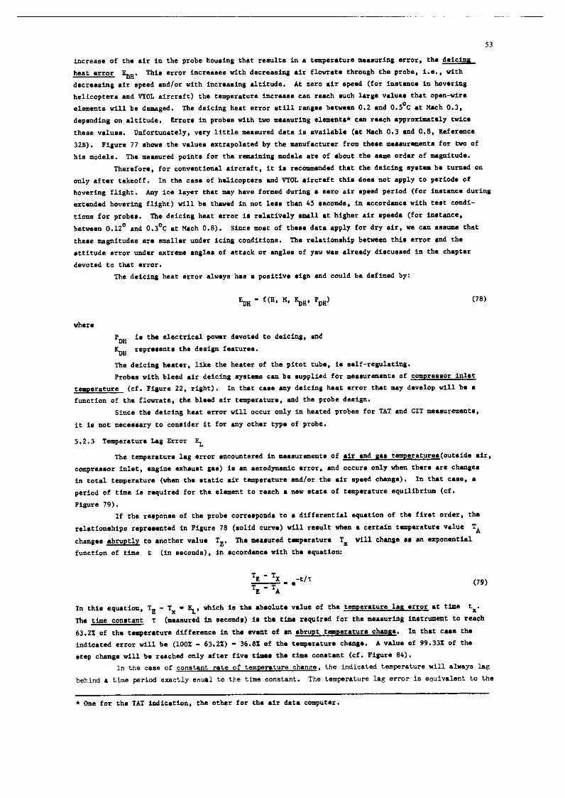
53
increase of the air in the prob. housing thet r..ult. in . temp.r.tur. m...urir.g error, th. deicim
h..r error S”. This error incr..... with d.cr...ing .ir f1ow.t. through th. prob., i..., with
d.cr...ing .ir speed and/or with incr...ing .ltitud.. At sero sir .p..d (for irmrmc. in hov.ring
balicopecr. .nd “TO,, .ircr.fr) th. temperature incr.... can r..ch .uch lag. “.l... th.t open-wir.
.l.m.r.t. sill b. d.m.g.d. Tb. dsicing beat error still rang.. b.tw..n 0.2 .nd 0.5’C .t M.ch 0.3,
depending on altitude. Error. in prob.. with two m...“ring .l.m.nt.* c.. r..ch .pproxlmat.ly wk.
th... v.1u.n. Unfortunrtely, very little m..sur.d d.t. is .v.il.bl. (.t M.cb 0.3 .nd 0.8. R.f.r.nc.
32B). Ptgur. 77 show. the “.l”.. sxtr.po1.t.d by rh. rmnuflcturer from rh... m...ur.m.nt. for two of
hi. model.. Th. m...ur.d point. for th. r.m.ining modal. .r. of .bout the ..a ordrr of m.gnirud..
Therefore, for convention.1 .ircr.ft, it i. r.cmm.nd.d th.t the d.ic1r.g .y.t.m b. turrmd on
only *ft.* takeoff. In th. c... of belicoptar. .nd “TOL .ircr.fr thi. do.. not .pply to period. of
hovering flight. Any ice 1.y.r th.t m.y h.“. formsd during I z.ro air .p..d period (for in.t.nc. during
sxrended howring flight) till b. tb.w.d in not le.. tb.n 45 second., in .ccord.nc. with t..t condi-
tion. for prob... The deicing h..e .rror i. r.l.tiv.ly mall .t higher .ir .p..d. (for ia.t.wx,
berw..” 0.12’ .nd 0.3’C .t M.ch 0.8). Since most of th... dar. apply for dry .ir, WI cm, . ..m that
th... magnirud.. .r. m.1l.r und.r icing condition.. The relaionship b.tw..n this error md the
.ttitud. .rror “ndar .xtr.m. angl.. of .rL.ck or angle. of ysv w.. .lr..dy discussed in th. chapter
devoted to th.t .rror.
The d.ici,,g h..t .rror a1v.y. h.. a positi”. sign .nd could be defined by:
where
PDB is th. .l.ctric.l power d.“ot.d to deicing, and
k$,” r.pr...nt. th. dsaign f..tur...
The deicing hut.=, lik. the heater of th. pitot tub., is ..lf-regulating.
Prob.. with blead .ir deicing .y.t.m. c.” b. .“ppli.d for m...“r.r..“t. of con~r...or inlet
t.mo.r.tur. (cf. Figure 22, right). In ther c... sny d.icins h..t error th.t m.y dnrslop till b. s
function of the flowrat., th. bl..d air t+mp.r.t”r.. and the prob. d..ign.
Since the deicing heat .rror till occur only in h..t.d prob.. for TAT .nd CIT m..“r.m.“t.,
it is not necessery to consider it for my other type of prob..
5.2.3 T.mp.r.t”r. Leg Error f
The remperetur. lsg error .ncount.r.d in m...“rem.nt. of sir mud n.. t.m.r.r”r..(out.id. .ir,
cmpreesor inlet, engine .xh.“.t g..) 2. .r. ..rody,,.nic .rror, md occur. only when them sr. chmg..
in tot.1 temperarur. (vhsn the static .ir t.ap.r.r”r. end/or fh. .ir .p..d chmg.). In th.t es.., .
period of tim. is r.quir.d for the .l.mmt to r..ch s ,I.” .t.t. of t.mp.r.t”r. .quilibrium (Cf.
Figure 79).
If the raspon.. of the prob. corraspond. to . diff.r.nri.1 .qu.tion of th. first order, eh.
r.l.tion.hip. r.pr...nt.d in Figure 78 (solid curve) will r..ult vh.n . c.rt.in temperatur. ml”. TA
chmg.. .bruptly to mother “.lu. TE, Th. m...ur.d t.mp.r.t”r. TX vi11 chmg. . . .n upon.ati.1
function of rim. t (in ..eond.), in .ccord..o. with th. rqution:
In rhi. .qu.tion, Tg - TX - EL, which i. th. .b.ol”t. “.I”. of th. t.rn.r.t”r. 1.. error .t time tX.
The time eOll.t.“L ‘I (m...“r.d io. recond.) is th. rim. requirsd for eh. m...uring in.trum.nDt to r..ch
63.2.X of rh. r.mp.r.rur. diff.r.nc. in th. .v.nt of .” .br”pt t.W.r.t”r. eh.ng.. In th.t C... th.
indiared error till b. (1OOZ - 63.2%) - 36.8X of th. t~.r.tur. ch.ng.. A “llu. of 99.332 of th.
.t.p change will b. r..ch.d only .ft.r fi”. ti,m. th. rim. con.t.nt (cf. Piplr. 84).
In the csse of constant rat.0 of temrersture chenm, the indicated tempreture will slrsys lag
behind 0 time period exactly *au*1 to the time comtent. The temperat”r. lag *rmr is eo”i”.l*“t to the
* On. for the TAT indic.tion, th. other for th. .ir dat. conput.r.
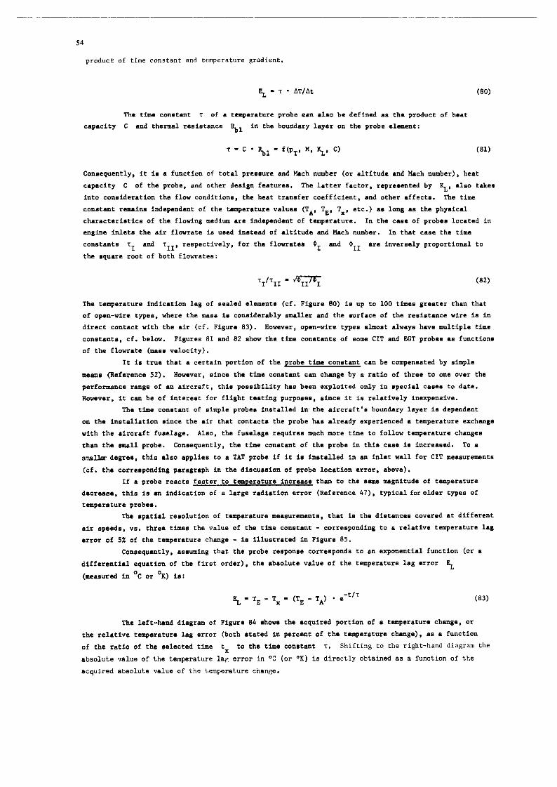
54
produce Of Cl”. cO”Sea”C and temperature gradient.
% - T * AT/At (80)
Tha time CO”.t.nt T Of . t.mp.r.tur. prob. lJ.* *ho b. dafinad a* the product of heat
enpecity c and t.h.rm.1 r..i.r.nc. 8.1 in the boundary 1.y.r on the prob. .l.m.“t:
Consequently, it i. . function of tot.1 pr...ur. and Mxh number (or slrirud. .nd MIch number). h..F
c.,mcity C of eh. prob., and other d..ign f..rur... The 1.tf.r f.ct.r, r.pr...nr.d by yt, .I.. r.k..
into consideration th. flow condition., the h..e transfer coefficient, .nd other affect.. The time
constant r.m.in. independent of the ump.r.tur. value. (TA, TE, TX, etc.) . . long . . the phy.ic.1
~h.r.ct.ri.ti~. of the flotin$ medium LT. independent of t.mp.r.ture. In the c... of prob.. 1oc.t.d in engine inlet. the .ir flowrare i. u..d i”.t..d .f .Itifud. .t,d M.ch “umber. In ch.t c... th. time
con.t.nt. ~~ and ‘I~~, reepectively, for th. f1owr.r.. ~5, md O,, *r. inversaly proportion.1 to
the .qu.r. root of both flowrace.:
The t.mp.r.tur. indic.rion 1.8 of se.1.d element. (cf. Figure 80) i. up to 100 rim.. 8ra.t.r eh.n rh.t .f op.“-,&. type., where the m... i. con.id.r.bly .m.ll.r and the .urf.c. of th. r..i.t.“c. wire i. in
dir.& contact with the air (cf. Figure 83). How.v.r, open-wire type. almet .lw.y. h.v. mulripl. rim.
consesnr., cf. below. Figure. 81 and 82 .how the time co”.t.nF. of .om. CIT and EGT prob.. . . function.
Of rho f1owr.t. (ma.. velocity).
It i. true th.t P certain portion of the prob. rO,m con.t.“t c.” be comp.n..t.d by simple
me.“. (Rafarenc. 52). However, since the time co”.t.nt CUL ch.“g. by a ratio of three to on. over the
perfonnanc. r.ng. Of .” aircraft, thi. po..ibility h.s b..” .x,,loit.d only in ~rci.1 c.... to date.
H.,wv.r, it c.n be of intereat for flight t..ri”g purpose., einc. it is relatively in.x~.“.i”..
The Mm. conwant of simple prob.. in.ral1.d in the .ircr.ft’. bou”d.ry 1.y.r i. dependcut
on the in.c.ll.eion ainc. the air that contact. the prob. ha. already experienced . t.mp.r.tur. exchange
with the .ircr.fr fus.1.g.. Also, th. fus.1.g. require. much more time to follow r.mp.r.eur. ch.na..
th.” th. small prob.. Coneequuently, rh. rim. c.“.t.“t of rh. prob. in thi. c... i. increased. TO P
.,x,,j,w degr.., this .l.o applies t. . TAT prob. if it is in.t.1l.d in .” inlet w.11 for CIT m...ur.me”t.
(cf. th. corresponding paragraph in the di.cu..ion of prob. loc.tIon error, abov.).
If . pr.b. r..ct. faster to tem~.r.t”r. incr.... th.” to th. 8.m. m.@tud. of tam~erafur.
dacr...., this i. .” indication of a large r.di.ri.n error (Reference 47). typic.1 for older Q’,a.. of
tempererur. prob...
Th. .p.ri.l resolution of t.mp.r.t”r. m...“r.m.“t., eh.t i. the distance. covered .t different
.ir speed., v.. thr.. time. the value .f eh. time constant - corresponding to a relative t.mp.r.t”r. 1.8
error of 5X of the e.mp.r.eur. change - i. il1u.rr.t.d in Pi@~t. 85.
Coneequently, . ..“ming that the pr,,b. response correspond. fo .n exponential function (or .
diff.r.nti.1 equation of th. first order), the .b.clur. value of the temperature 1.8 .rror E,,
(meaaursd in .C or OK) is:
er - TE - TX - (T8 - TA’ * .-t/T (83)
The lsft-h.“d di.gr.m of Figure 8k ahow. the .cqtzir.d portion of . tsmperatur. chmw, or
eh. relative eemp.r.eur. lag .rror (both .r.e.d in percant of th. trmp.r.tur. ch.“g.), P. . function
of the ratio of the a.1.cr.d time tx to the tim. con.t.“t T. Shifting to the right-hand diagram the
absolute value of th. temperature lag .rror in OC (or “K) is directly obtainad . . a function of the
.cquir.d sbsolut. value of the temperatur. change.

The =..Q0,!.. Of my ?..i.t~C. Qrob.. t0 .bNQt taQ.=.t"=. chmg.. no longer Co==..Q0IId. to
a sin$l. SXQOC.S~ti.1 c"r".; rathsr, it CM be subdividad into ..".r.l .x~.r,.r,ti.l Qortion. (.hovm .
dottsd CYN.8 in Figure 78). The first, r.Qidly reacting portion i. frsqu.ntly int.rQret.d . . the
bshsvior of the r..i.t.“c. wire, and the rddition.1 (“slowsr”) QOCtiO,l. L. tb. b.h.vior of the r.di.rion shield, the m..~~,rin~., .nd the prob. ho.&,*. I” these CBS.. several tim. COr~tant* “t”St be Used. O”e
.xs@. Of thi. tJp. ill .how” i. Fig”=. 83 for th. Typ. 102 E 2 AL prob. with 0Q.%L-"ir. .lam.~X. Th.
reaction b.h.vior of thi. prob. CM b. d..crib.d by two time consturt., whcr. th. following .qu.tion
SQQ1i.S for the .b.olut. V.lu. Of the t~Q.C.t"C. 1.g .==0= EL:
t - Tg - TX - (TK - T*’ - (0.8 - .-t”1 + 0.2 . s-~‘?) (84)
Tha time con.t..t c.mot be me..ur.d in .t.m.nt sir (rhi. hold. .l.o for self-hating) but
only in .I, exactly dsfined flow v.locity, sine. otherwi.. th. h..t rrlmafcr would b. d.Q.nd.nt on too
many Q.C#X..t.CS in too com~1.x . =.l.tion.hip, md th. r.."lting in.trum.nt r..dding. would show too
great an error spread. Th.r.for., the m..."=.m.nt mu.t be Q.=fO=Ed in .=a .i= flow Of c.ll.t.nt ~.lo~ity
but .brUQtly v.ri.bl. tSlC,Q.C.tUC.. At l...t four v.lu.. for the t.m~.r.tm. chmg. of the probe must
be measured (for imtmc., 202, 50X, 63.2% .nd 90%). in ordsr to be .bl. to QlOt . CUN. of sufficient
.CC"C.Cy. Only if the time. for 50% L.OlQ.C.t"C. ch.ng. sr. aqu.1 to 0.693 T .nd for 90% equ.1 to 2.303 T
(RSfSrenC. 13), will th. cur". =.Q=....t . .imQl. S~Q‘m.r.ti.1 function. This is the only condition for
which the tin. con.t.nt T i. in iteslf .ufficimt to dsesrmin. th. indiatim time 1.8.
ID . th.r,mm.t.r .,-my . tim. c...t..t is not only . ..oci.t.d with the t.mp.r.tur. prob. but
also with the comcctod unit (for instmc., th. indic.ting instrmsnt). This r..ult. in .
th.nxm.t.r rime constmt T’. definsd by the .qu.tion:
T’ - T + 2P/w* (85)
Her. ‘I is th. tim. conetult of the prob. (with .impl. tipl. con.t.nt), P i. th. d.mping ratio (in
most ca..~ between 0.7 ad 2). and wr, is th. ("nd.mQ.d) n.eur.1 fr.qu.nncy of the indic.ting (or
recording) .y.t.m (in r.di.n./..c). Since the nsrursl fr.qu.,xy of th... systrm. i. f.r greater th."
10 HZ in most c...., th. contribution of th. indicating in.trum.nt to the tin. lag of the indic.tion
or recording i. 80 an.11 in m0.t in.t.nc.. th.t it csn be di.r.g.=d.d (SXCSQtiOn: where the in.trmMt
is connected to 0Q.P"ir. prob..)(R.f.r.nc. 3).
Since t.mp.r.tur. ehmg.. LT. individu.1, short-rim. Qh.n'.XM. who.. .x.ct profile (.b=UQt,
.inu.oid.l, etc.) i. u.u.lly unknown, ths ob.srvsr will usully d.1.y hi. r..ding until ths indication
ha. 8t.biliz.d .ft.r . ceetsin Qsriod of tin. (Co==..Qonding to three to fi". time. rh. time constant).
Thi. me.". th.t th. t.nm.r.tu=. 1.8 .==o= (like the 1.g .==o= in the QitOt-.t.tiC systsm) i. norm.119
di.r.g.=d.d, For th. r..mn. named .bov., a tru. corrsction could b. rmd., .t beat, .t . I.e.= time to
th. recordad "al"... Hm.v.r, thi. Qr0bl.m i. usy to de.1 with only whsr. the t.mp.=.t"=. change. .=a
.t.Q ch.~.. from 0.. ~.xi.t..t tmQ.=.tU=. 1.~1 to .norh.r c0n.t.M “.lu., or “her. they LT. chm8.s
with con.t.nr r.mp.r.rur. grndisnt. (%/..c). All other chmg.. r.q,,ir. r1.bor.t. m.th.m.tic.1 t=..tm.nt
(R.f.r.nc. 3), Q.=tiCUl.=ly sin.=. prob.. with ..“.r.l tima c.On.t.nt. Mr. U..d.
The 8.t~ con.id.r.tion. SQQly to th. r..Ulti.8 tima con.tant when m...uriW t.W.r.tW..
in liquid.. In it. .xp.nd.d form th. aqustion T - C - B mad.:
“her.
‘P is th. .Q.CifiC h..t, 30
W..C/Cm K, of th. liquid;
” is th. volm. of the prob., cm3;
s is th. effective N=f.c. of th. Q=ob., cm*, mad
h i* rll. h..r tr...f.r co.ffici..t, WC2 OK .
Sine. th. best trsnsfsr co.ffici..t i. much gr..L.,r for liquid. eh.. for us.... th. tin.
con.t.nt. will b. much wailer 80 th.t th.y c.. b. disragsrdsd, in most ir..t..c.., CmQ.=.d to th.
r.t. of chmg. of rh. t~Q.C.tUC..

56
Where temperatures are measured on surfaces urd in solid bodies the time constant of the
me.a"rfng e1ment is pr*cticc.11y insignificant.
5.2.4 In~trumcnt Error EI
This category im composed of the errors involved in fbe indic.ting i,,atr,,ment, recording
iI1StrW.t, Or tel.-try myrrtom, LLI well a~ certah error. involved in the probe and in the electrical leads. The inforauticn provided below applfee for all types of temperature me.suremenr.. 'fbe instru- ment errore .re always a function of the measured tempenture, while the m.,oriry .,f the errors in air
or gas flo"8 that were discussed earliar are primarily a fu,ceion of air speed, which of coy,-se make@
correcrione much more complicated (cf.Chapeer 6).
(a) Probe Calibratiu, Error ECAI.
The calibration error of a resi#t.,nce measuri"g element depends on the type of material used
l ,,d on the quality of the instrument. The fo1laring Coler.3nce limits *re customary:
Pl.etinum elements standard - 5.25% + 0.X of the indicated temperature ('C);
epecid - +o.l%, for in.tmce from -50°c to +150%
Nickel elemu.rs standard - +1.2%, in the range from -50% to +150%
special - +o.l%, in patie rmges.
This calibration error can be encountered as B parallel displacement of the standard
calibration curve (resistance/temperature or volta~eftemperature), as deviations in the slope of the curve (but retaining the primery calibration point at WC), as an irregular, positi\e and/ar "egatiue deviation from certain 9art.s of the standard calibration, or as 8 combination of these. 'rbe elements
listed as "special quality" above are typss with closer tolerances (such a6 the so-ca?led RI elements*) and built-in atiiwy resist.ncea. These elements have two calibration points (cf Tigure 86) end are directly interchangeable without recalibration of the tbarmomeier. liowever, since their calibration c"rve has . little less slo9c than the cuve of stendard elements, they must be used in conjunction with specially calibrated indicating instruments (for instance bridge circuits, etc.).
The tolerance limits of the most im9orr.r.t re#isLance remperature probes are shown in
Pigures 87a and 87b. The aetue.1 calibrarion errors of these elements are located within these
boundaries.
1n the c.se of thermistors .r,d all other types of semiconductors the dispersion of the
calibration vrlue~ of individual inetr"ments is usually very large. However, come cmpmies market
types with narrower tolerances &at are directly interchmgeable. This ie .chieved through meries
.nd p.r.llel re,ist.ncel, built into the probe base, 80 th.t standard calibr.stion c"rves apply for
rhe.e types. The calibration accuracy in the desired eemperatuse range is typically about +o.l%.
The c.libration errors of tbarmocou9le~ .re within the tolerance limits of 0.5% to 0.75%
of the indicated temperature (cf. Figure BE), meaning that the voltage deviationa caused by tha
calibration error correepond to a msxtium temperature error of& to 57.5% at a probe temperature
of 1,000%.
A calibration change as a function of service life is mrntioncd in many performance
specificafio"s of resistance llmbeb. I,, most cases it IS so small that it can be ne&cced. However,
calibration churges c.n t.ke 9lace suddenly, for inl)tance when the recommended ~xim"m temperature
valuee .re exceeded, when "concamin.tion" occurs .s a result of chemical effects, or when the
element W.B mechw&ally damaged. Since effectm of this type frequently remain unnoticed, it in
.dvis.blc to verify the calibration curve from rime to time, es9ecially where the probes do not
r-in in place permanently - far in.t.nce, in flight te.ting prosrms. Specie.1 care in indicated i,, the c.se of rharmocouples ,cade in-house, eince theme are subject fo aging effects. Miss- prdduced th.-couple probes a,-e supplied in aged condirion and retain their ce.librated values Over
rel.tively long periods of time. This a99lie~ especklly eo ecaled probes with velded contact
points. n,e service life of ebe~~~~ouples depends on factors ouch as the type of material wed.
the t,,.r,d load l rpoaure, the design, my chemical effectn that may be encountered (oxidation.
reduction), ad mechenicel stress (es9ecially where the c0nt.H leads are twinted). Aleo, the
l PC1 - precisim calibration interchaueability.

57
so-called “restructuring .ff.ct” should be m.nt1on.d. It occurs when mechanical str.s8 on thermoelectric
conductor. result. in .,, “mplification” of th. inhomopeneiti.. of th. cry.t.llin. ,tructu~. of the
conductor m.t.ri.1 l d b.nc. in. ohm*. of c.libr.tion, for in.t.nc. wh.n th. imi.r.ion d.pth of .
th.rmocoupl. prob. i. cb.,,p.d. Th.r.for., th. calibration of themoeoupl.. should be .ubJ.et to
coneinuou. “.rific.tio” at not too infrsqumt int.rv.1..
(b) El.cLric L..d Error s
In the ea.. of r.ei.tmc. thermometer. the lead. betwmn probe and indic.ting in.trum.nt hav.
. certsin r..i.t.nc. (ca1l.d “line ra.1.t.m.“) which, for inntanc., mnour.t. to about 0.5 ohm in th.
case of . 16 m l.n@h of AN 20 - 0.6 arm2 cable @W&x. 89, 1ow.r diagrm). A. . result of th. .llow.d
production tolerant.. &55x), this r..i.t.ne. can v.ry by .bout +0.025 ohm b.tv..n two Ii,,.. usinp the
cable msntioned .bov.. Additional diffcrac.. r..ult from the int.rm.di.t. plug. .,,d t.rmi,,.l., .,,d
from th. different l.n$th. .nd different t.mp.r.tur.. of th. c.bl... Con..qu.zItly, in mo.t in.t.nc.. th. individu.1 prob. lead. h.v. diffsrent r..i.tmc. value. which, norcover, C.D. be .ub,.ct to ch.ng. in th. ..,m. dirrction or in th. opposite diraction.
Wbcr. . prob. i. connected a. .how in Pipure 89, circuit typ. (.), which i. . tvo-wir. circuit,
th. r..ulting lin. r..i.t.,,c. \ till cqu.1 th. mm of %A .r,d b. The resistance value of the
prob. i$ increases, resulting in a” err~necu~ tmperature indication. The m.&t.d.
of rh. r..ultin& l..d error pW (in ‘C) depend. on the mrgnirud. of the r..i.t.r.c. pX .nd on th. .lop.
of the R/T ch.r.ct.ri.tic. It is ..a, frw th. upp.r di.gr.m in Pigur. 89 th.t . ml”. of (0.5 + 0.5
+ 0.025) - 1.025 oh for Ru in th. c... of . SO-ohm Pt prob. would r..ult in . l..d .rror of .bout
+5.3’C. but only in an .rror of +0.53OC in th. c... of . 500-ohm Pt prob.*.
Cm th. other h.nd, wh.r. th. three-wire circuit of Figvr. 89 (b) is u..d, th. rssultin~
r..i.tuIc. s till b. .pproxim.t.ly .qu.l to th. difference b.tw..n Ql .nd s2. In th. uunpl.
mentiomd ..bov., thi. would correspond to . value of about 0.025 ohm, r..ultinp in .n .rror of only
about 0.13’C for . 50-ohm prob. (Pt), and in .n arror .o sm.11 th.t it c.n be di.r.8ard.d for .
500~ohm prob.*. Thmefor.. low r..i.tmc. prob.. should a1v.y. be op.r.t.d in . thras-wire circuit**.
A. I al.. th. 1e.d error h.. . poaitiv. .ign. Howvsr, indic.ting instrument. .xi.t who..
.c.l. i. .lr..dy c.1ibr.t.d for a c.rt.in mount of lead error. In that CL.. the .ctu.l lead error
mmt be .d,u.t.d to this r.t.d v.lu. through calibration r..i.t.nc... A b.tt.r 8y.t.m i. r.pr...at.d
by In.trum.nt. with built-in c.libr.tion r..i.t.nc.. for lead c.lfbrarion .t two point. of the .c.l..
The lead error cm be dafincd by:
where th. f.ctor 4 r.pr..ent. the typ. of circuitry (two-wire or threa-wir.) .r,d th. .lop. of
the prob. ch.r.ct.ri.tfc.
A. . r”l., supplying r..f.t.nc. prob.. with .lt.m.tins current (400 Hz) in.t..d of dir.ct currme will not in it..lf be . .ourc. of error. Unshielded leads can =.“a. indication errors
(periodfc fluctuation. .nd th. I&.) in the indic.ting i,,.trum.nt..
P.r..itic th.rm-vo1t.p.. in r..i.t.r,c. th.mom.t.r. c.n only occur . . . result of $ro..
infraction. of the twtomary able-laying ml.. (to t8.t: interchmg. th. l.ad. to th. prob.
and comp.r. the indication.).
Psrssitfc noise volt.8.. c.n drvelop .t location. with high vibration 1.v.l. (for in.t.nc..
et the mgin. inlet), if un.uit.ble prob. typ.. (or plug. with ox1dir.d contrct.) a=. uaed. Tb... SC. oft.,, caused by th. so-c.1l.d .tr.in .ff.ct, I..., by. r..i.t.nc. ch.w. in the wire . . . r..ult
of m.ch.nic.1 .tr.in (.s in .train pmg..).
* ‘Ph... v.lu.. .pply only for bridge circuit. whar. R urd circuit. in Pisur. 25.) h.v. .pproxim.t.ly equ.1 m&cud...
R4 (or Rx .nd 8.2 in tb. c... of th.
** Pour-wir. circuit. .I. wed for special r.quir.m.nt. in flisht t..ti,,g (R.f.r.nc.. 18 .nd 21) th.t .r. .“.n batter; how.v.r, th.y r.quir. sp.ci.1 bridge circuit., cf. PQur. Xc.

The error cause* by so-called intern.1 line r..i.c.nc. (i.e.. by the r..i.t.nc. Of the lead
.l.m.nt. between measuring element and the plug connection of eh. prob.) i. .c sm.11 in the typ..
cu.tcm.rily wed in aviation thet it can be di.r.g.rd.d, ein~. the .l.m.nts .r. tir.d in the.-wire or
even four-tire cfrcuitry inaid. the prob. howing.
S.v.r.1 type. of line error are encountered in eh. ccnn.cting 1e.d. b.w..n rhsrmcccupl.. .nd
i*dic*ting in.tru!n.nt*. On. of the.. i. due to the .hmic r..i.t.r.c. cf the ut.n.icn 1e.d. which i.
much gr..t.r eh.. th.t of copper lead. cf th. ..m. diam.t.r. Th.r.fcr., wh.r. .impl. i.dic.ting
in.tru,..nt. .r. used (millivcltm.t.r.). . c.1ibr.ti.x r..i.f.nc. m”.f b. prcvid.d which i. u..d tc
.d,u.r th. cvsrall r..i.r.nc. (of thermcccupl. plus leads md c.libr.ting r..i.t.nc.) to 8 cartain
r&ad v.1”. RI, (for instance 8.0 ohm.). R..i.eanc. ch.ng.. ARL in eh. conducror loop till .r.nt.r
intc 0,. indiceticn, depending on the int.m.1 resistance Ri of the in.trum.“t. In th.t cu., the
ohmic component of rh. lead errcr (in ‘C) till be
where Ti i. the indiceted t.mp.retur.* cf the in.trum.nt (“2). Self-balancing compensation bridge
circuit. do not ho”. any currenf flow .c rb.r this error ccmponanr i. e1imin.t.d.
Addition.1 ccmpcnmr. cf the electric 1a.d .rrcr.th.r occur in eh. 1a.d. cf thermcccupl.. . .
. reeult of the Se.b.ck and B.cqu.r.1 effect. (cf. Chapter3), er. the ,w..itie tharmcvclt.~.. which
~.mcL be comp.n..e.d. Pereeftic thermocouple. result, for in.t.nc.. in eh. .xt.n.ion lad. where they
.r. p....d thr.ugh other rasteriala, (ncrm.1 connecting plug. or r.rmin.1 bc.rd.), ..p.ci.lly wh.r. .
lerg. r.mp.r.tur. drop axist. .f rh. lad-in point. The cppcsing th.rr.cvc1t.g.. th.t .r. gcnerared .t
thee. points till c.nc.1 each other but cnly if rh... two ccnnacting pcint.hav. the same
t.LUp.~.tU~.. Th.r.fcr.. .p.ci.l-purpc.. plug. with pin. .nd socket. of the ..m. m.e.ri.l LB the
axtenefon lead. .r. supplied for the point. wbhere th... linas nu.t be pas..d rbrc~gh engine c.8Lr.g. .nd
bulk&ad ft..,.... “cvever, temperatur. gradient. nlcng th. balancing circuit. .r. unwcidebl..
Coneaquently, the calibration of . thermcelecrric eh.rmcm.t.r till b. .ccur.t. cnly if the eemp.r.tur. di.tributicn slang eh. .xt.n.icn leads i. r.pr0duc.d in the .x.ct p.tt.r” eh.t existed .t the time of
calibration. But rhi. c.n”ct be achieved in flying operation.. Thi. error can r..ch “al”.. of
..v.r.l degree. centigrade, but if 1. impcssibl. tc ccmpur. it.
The strain effect is primarily r..pan.ibl. for the d.v.lcpm.nt of p.r..itic nci.. vclt.g..**
in the presence cf vibration. These vcltag.. c.n amount ot more than 100 microvolts. IT, the case of
thermcccupl.. with no,,-w.1d.d cc”t.ct. (.,uch . . rwistcd wir..) th. .tr.in efface i. further “.mplifi.d”
by ch.ng.. in ccnt.ct pressure during vibration .nd temperature increase .c th.t element. with welded
ccntects will .l”.y. yisld mcr. .t.bl. date.
sleceric 1a.d error. in all type. of electric.1 eh.rmomet.r. c.n b. further g.n.r.t.d by
.xr.rn.ll~ induced vo1t.g.. in the lad. (prim.rily 400 Hz cf. Chapter 3). In thin CL.. the prob.
lea,. would hnr. to b. twisted wire. p1.c.d .t . di.r.nc. frcm all ether lin.., or shielded c.bl. which
will c.u.. ccn.id.r.bl. wsight (snd cc.t) incr......
Consequently, the electric l..d errcr i. greatly d.p.nd.nt on the sclecred thermometer type.
th. salected circ”it type, and edditia.1 parameter.. The rmgnirud. .nd sign cf thi. .y.t.m.tic arrcr
e.n differ greatly .v.n beeveen syst.ms cf . simi1.r .pp..r.nc..
(c) Inetrument Error of the Indicstor
The mc.r impcrt.,,t systematic error i. eh. c.libr,ticn errcr or .c.l. error which is caused
prhrily by in.ccur.ci.. (during rh. calibrating op.r.ticn),in uljusting and relding the in.trum.nt.,
.,,d .lec thrcugh g.cm.tric.1 inaccuraci.. cf the .c.l.. It i. d.t.rmin.d under l.bcr.tcry condiricn.
(SC that small lead errore. can bc disregarded) .,,d i. .t.t.d L. th. d.vi.ticn of th. t.mp.r.tur.
indic.t,.cn frcm th. r..i.t.~c./r.mp.r.tur+ CUN. or vclt.g./t.mp.r.tur. c”rv. of th. . ..oci.r.d prob.
. I,, th. c... of th.rmc.l.m.nt. vhc.. r.v.rs.1 point Tu of th. direction cf th. c”tp”t curr.nt I. llct 1cc.t.d .t OcC (bitt .t +2OcC, for sxampl.), th. .xpr...ion (Ti - Tu) mu.c be .ub.titut.d for Ti in th. tquaticn.
** The pc..ibility of nci.. vclrag. d.mcdul.tion .t non-lin..r circuit .l.m.nt. c.nnct b. excluded completely .c that not .v.n filter. till b. able tc ..p.r.t. it from th. useful vo1t.g.. This applies ev.,, for RP inj.cricr,.;fcr instance, on. indic.tcr a1v.y. indicrted tsmpcratur. ch.ng.. during VHF voice radio traffic:

59
element (cf. Pigur. 90, . .nd b). For tbi. purpose rh. .l.m,,t .nd it. 1r.d. .r. mp1.c.d by. “ari.bl.
standard r..i.e.nc. or semd.rd “o1t.g. .ourc.. lhis error can be incluenced by additional
error. q uch . . the .ging error ehet c.u... . gr.du.1 ch.ng. in th. c.libr.rion cur”. . . . r.sult of .
cblng. in tb. cb.r.ct.ri.tic. .,f .l.ctric.1 component. or . . . r.,ult of . comp.n..tfon of m.ch.r.ic.1
strain. in the at.1 of the in.trum.nt’. m.ch.aic.1 .l.m.nte.
The group of st.ti.tic.1 arror. includ.. both .l.stic errors mud .l.ctric.l error., .uch . .
drift .nd hyst.r..i. error.. In .ddition, m.chmic.1 .rror. .uch . . tr.n.mi.sion .nd friction error.
LT. fr.qu.ntly found. A more d.tai1.d di.cu..ior, of .ll the .rror. .ncounr.r.d in ir.dic.tor. i. rtot
n.c...ary her., .Inc. th..a problem. h.“. bean co”.r.d .xh.u.ri”.ly in rh. .ppropri.e. lit.r.tur..
Prequer~rly, the tam in.trm.nt clllibration .rror or in.trtm.nt .c.l. .rror i. und.r.tood
. . including tb. .“m of .I1 Lh. .rror. of rh. in.trtm.nt. It 1. rh.n .t.t.d . . . ay.t.m.tic .rror with
. stati.tic.1 compon.nt. for in.t.nc., in the form of . c.librrtion CUN. with addition.1 par.ll.1
boundari.. indic.tinp the m..suring uncertainty (cf. Figure 90.). The ov.r.11 .CCU~.CY of th. in.tr”m.nt
.t.t.. the eo1.r.m. limits wh.r. the indic.tion mu.t be located und.r the ,r.t.d .n”ironm.nr.l condition.,
mud include. 111 th. error. af the instrum.nt. It i. giv.n *itiI*r in percant Of full sc.1. or in
.baolut. valuas .t c.rt.in point. of th. .c.l.. Typic.1 wlu.. for out.id. .ir t.mp.r.tur. indic.tors
with r..i.t.nc. prob.. .r. .hc+m in Pig”=. 90, . .nd b, .nd for mgin. .xh.u.r g.. t.mp.r.tur.
indicetors with rh.rmocoupl.. in Pigur. 91.
Two .dditfm.l type. of error. mu.t be m.nt1on.d her.: th. ..a-e.ll.d .n”irom.nt.l error.
th.t c.” darelop . . . r..ult of ut.m.1 .ff.ct. on th. in.tr”mnt, .uch ., r.mp.r.tur., .ttirud.,
.cc.l.racion, “ibr.tion, or m.gn.tic field affect., but th.y .r. .ieh.r me pr...nr in th. norm.1
flying .t.t. or thay till occur only with improp.r in.trum.nr in.t.ll.tion. On th. other hmd, th.
r..d-out drror i. d.p.nd.nt on Lh. typ. of indic.tion, th.t i., on th. number of sale mart. or n..dl..
in th. c... of dill-type .c.l.., on the .ubdi”i.ion of th. last num.r.1 drum in the c... of digit.l drum
indic.ror., on the ,ie. of the numerals, on P.r.ll.X, md th. lilt.. Sine. the.. .r. .void.bl. .rror.
they require no d.t.il.d di.cus.ion b.r..
6. PPACTICAL TEMPEP.AToRE mAS”REmNTS
Thischapter .mm.rir.. .nd .uppl.r,,.nt. rh. r.l.tion.hips di.cu...d in th. pr.c.ding ..cticm.
that. .r. observed during m.a.ur.m.nta in air and other g...., in liquid., on .olid bodies, .nd on
surface., .nd .xpl.in. the different .ep.ct. that m.t b. r.k.n into consid.r.eion for the ..l.ction
of the suit.bl. tb.rmm.t.r type, prob. d..ipn, .nd indic.tor. Th. foll,,ting p.r.gr.ph. discuss the
c.1ibr.ri.m of the m.ae”ring .rr.y and the .yst.m.tic order and practic.1 ax.mp1.s for .rror corr.ct$on.
6.1 Diff.r.nt Typ.. of T.q.r.tur. M..sur.m.nts
6.1.1 M...ur.m.nt. in Cutaid. Air
Besically. two methods are di.cu...d her.:
(.) T.mp.r.tur. m.a.ur.m.nt. using .impl. prob.. in.t.1l.d in th. .ircr.ft’. bovnd.ry layer;
(b) T.m.p.r.tur. m...ur.m.nt. our.id. the .ircrrft’. bound.ry 1.y.r.
Sim~l. prob.. u..d to n,...ur. r.mp.r.tur. in th. bound.r” layer of Lh. .ircr.ft .r.
r.1.tiv.ly i”.xp.nsi”e. Sine. the d.p.nd.nc. of l.c.1 flw .nd tsmperatur. r.l.tion.hips .t the prob. on
the cbaractaristic. of the unperturbsd flow l round th. .ircraft i. highly C0V.Ql.X (cf.ChaPter 4, .bov.),
lag. m...“ring u”c.rt.inti.s eri.. th.r inCr.... r.Qidly with incr...ing .irsQ..d. ginf. in thin
=... the wind turn.1 m..surea.nt. c.mot be tr.n.f.rr.d to th. prob. in.t.ll.tion in rh. .ircr.fr, time
ccmsu,ning and costly m..sur.m.nt. m”.t be t&an in w.ry i.di”idu.1 in.t.nc.. nOr.o”.r. e0.t
affecriven... d.m.nd. th.e . ch..Q prob. be COUQ1.d only with inelrpenmi". ind1c.r.r in.trun.nt. (or
.pp~~priate .d.QL.r circuitry for recording or telwtry QUCQM..) th.t h.v. . la* .ccur.cy level
(.,uch . . 1 to 21 .,f the i".tr,m.nt rang.). Pinelly, th... irmerumant. r.guir. . l.rge meeeuring
current which c.u... . aelf-hasting error, th. mgnitud. of which incr..... with d.cr..sing airspeed.
Cor,..qu.r.tly, prob.. in.t.1l.d in th. bound.ry 1.y.r h.“. . ntmb.r of di..d”.nr.g.s:
(.) M...“rin$ “ncereeinty IILCC..... .h.rply with Mach n”mb.r; the “QQ.C limit of f...ibility
1. 1oc.r.d b.tw..n “ah 0.3 .nd 0.8, d.p.nding on dsnign. mere .impl. m..suring inlltru-
menta (or m...uring circuits) .r. u..d, th. low.r limit i. 1oc.c.d b.W..n about M.ch
0.13 md 0.2, b.c.us. of the ..lf-h..ting .rror.

60
(b) The selection of . prob. location i. about . . difficult (1. it is for .t.tic pr...ur.
..nsing, and must be governed by the .~me principle..
(c) An .ppr.ci.bl. time leg in the .“.nt of . t.mp.rstur. cb.“g. i. c.us.d by the
tmperatur. exchange between the air end the aircraft 8urf.c. forwad ,,f the probe 1oc.rion.
(d) The m.,ority of simple prob.. do not h.v. . r.di.tion .hi.ld .o th.t direct (or r.fl.ct.d)
solar r.di.tion c.” result in con.id.n.bl. mc.a,,ring .rror. (+4%, and m,,r.). Ho,,...,.~,
where radi.tion shields .r. used, they will somctim.. rff.ct tb. flow to such . dsgr..
th.t even sm.11 directional ch.r,g.s in th. .ir flow c.” c.u.. .brupt ch.“g.. in fl,,w
~.lo~ity at the prob. and, consequently, . lag. dispersion in the meesured d.t..
(e) This type of probe cannot be protect.d .g.inse icing.
(f) Tb. error. of simple temperature prob.. must be datermined through m...ur.m.z,ts on avary
individunl .ircr.ft ty~., *inc. wind tunnel m...~r.ments c.““ot be tr.nsf.rr.d.
Where this msasurement procedure ie us.d, prob. configurations .ho”ld be u..d exclusively
where the inflow is parallel Co the .ircr.ft surface (such LB the L-ehap.d rod prob.. i1lu.trat.d in
Figure 12~ or flush bulb. I. illustrated in Figure 14), since th... typ.. hw. smal1.r .ir.pr.d error.
and the errors .r. more evenly distributed over ths airspeed r.“ge than prob.. with l.ter.1 inflow.
The prob.. should be mated only to galv.“om.t.r indicating in.trum.nt. in order to k..p th. self-h..ting
effect small, howsver, the.. instruments should still b. calibrated individu.lly. Th. prob. loc.tio”
.hould be at .pproximat.ly the sari. point on the .irfr.m. forw.rd of th. cockpit whhara the st.tie pr...“ra ..“.or for the pilot .t.tic .yst.m is loc.t.d* (or might be located). If f..sibl., the prob.
nhould be .lightly di.placsd tow.rd the fvaelag. belly .o th.t in th. norm.1 flight attitude the
dir.ct .olar radi.tian exposure of the prob. is reduced . . much .s ,weibl., but nor too f.r in order
to avoid .n excessive effect of th. angle of stuck and of .ircr.ft configuration ch.,,g.s (due to
landing g..r, flaps. etc.).
Th. most .ccur.t. tecbniqu. currently used for rh. m...ur.m.“t of air t.mp.r.tur.. in flight
utili... tot.1 t.me.r.tur. prob.. (TAT prob.., et.~.tion prob..) 1oc.t.d out.id. the boundary 1.y.r
of th. .ircraft. Modern TAT prob.. with enclosed pl.ti”um .l.m.“te .r. .pplic.bl. over a wide rang. of velocity which ..t.nd. from zero airspeed to beyond Mach 3.5**, end up to *ltitud.* Of 100,000 ft.
For flight teering purposes the relatively low price incre... for element. with more .trir.g.nt
~elibreti~n tolerenc.. I. always worth-whil., since the.. element. simplify error correction
con.id.rably (cf. Section 6.2). For th. ..,a. r....“, only good ..rvo I”.tn,m.“t. should be us.d 8.
indicators which, moreover, efford a c.pability for th. in.t.ll.tion of indepandsnt recording output.
(cf. section 2.2.6). The special calibration curve of elements with close toler.“c.s must be taken
into con.id.r.tion for the aelection of the indicator inatrum.nt.
When the prob. i. s.1.ct.d. type. with i”t.rn.1 .ir d.fl.ctio” in front of th. .l.m.“t
.hould b. pr.f.rred, sines they ebow only. fr.ction ,,f the error c.us.d by the liquid w.t.r conf.“t
of the air during rain or e”owf.ll. DT flight through cloud., comron to all other typ.. of prob... In
the c... of .traight TAT prob.. with l.t.r.1 exit. when the air i. not daflected until it hr.
p.s..d the .lem.“t, . considerable incr.... of th. haa conduction error, remuleing from w.t.r accumula-
tion .bout the 1e.d.. c.” be expected.
In th. ~a.. of maa.ur.m.nt. wh.r. a short i”dic.tio” t,m. lag i. ..p.ci.lly importmt (for inet.,,~., m...ur.rm,t. during acceleratsd flight.), TAT prob.. with op.“-wir. .l.sa.nt. c.” b. usad
who.. tim. con.t.“t i. up to 20 timas w.1l.r tb.” th. time constrnt of’hsnnatically s.alcd s1.m.nt.a. Th...
elllment., ho”.v.r,.r. too fragile for g.n.r.1 flying op.r.tions. and a prob. deicing .y.t.m turned 0”
et ecro airspeed may overheat and dsm.g. the .l.m.“t. It I. true th.t .ny ice which may h.v. formed
during . period on th. ground will melt in flight. Hw.“.r, rhi. may r..ult in ic. bad fcrm.tion on
* At th... points whrr. the measured .t.tic pra.eure il .pproxim.t.ly equiwlant to the non-perturbed .tatic pr.s.ur., th. Lx.1 flow velocity will also be .pproxim.t.ly .quiv.l.nt to the true airsp..d or, in the ..m. .a.., the l.c.1 M.ch numbar will b. .pproxim.t.ly equivalent to the true M.ch number.
** At ev.” greater airspeeds, where the tot.1 t.mp.rature exceed. value. of 5OO.C, TAT prob.. with thermocoupl.. .hould b. consider.d (cf. Figure 40).

61
the wire. thct CC”.. vibr.tion in the .ir flow, which could 1e.d to wire br..k.. In f.ct, mch f.ilur..
have be.n uperi.nc.d using el.m.nt. with . nomin.1 r..i.tmc. of 100 ohm. (meening v.~ fin. wires)
in .up.r.onic flight, and were prob.bly due to .hock W.V. affect. mdlor r..onm~. .ff.ct..
Th. combin.tim of . TAT prob. with . good ccrvo in.trwm,e, .lrhough r.l.tiv.ly .xp.n.iv.,
he. pr.ctic.lly no ,.lf-heeting error .v.n .t th. .xtr.m.ly low .irsp..d. typically encountered during
h.ltcopt.r or “TO,, .ircr.ft flight., In .ddition. th. time con.t.nt of th... prob.. i. pr.etic.lly
in..n.iti”. (slight incr.....) to the extremely high engle. of .tt.ck .m.tim., experienced in rh...
.ircr.ft during v.rric.1 tel.-off or turninp mezteuver.. It .hould be noted eb.r th... ch.r.ct.ri.rics .r. only .pplic.bl. when the prob. deicing .y.t.m ,.. turned off. In helicopter.* end “TOL .ircr.ft
thin eystem should be rumed on only in crui.ing condition.. Orhewi.. the d.icing h..t error would
rile gr..tly et 10~ forwrd .p..d.. ..p.ci.lly wh.n combined with climbing or daecmding flight (where
th. prob. I. upo..d to . lug. .ugl. of .tt.ck). Simi1.r con.idar.tion. .pply also for convention.l
.ircraft. if prcei.. tmpar.t”ra m..ur.n!ent. .r. required during low eirlipcad condition. or during rha
t.k.off end lmdirsg ph.....
11, th. .up.r.onic rmge, TAT probe., unlik. the pitot tub.., .r. l.rgely in..n.iriv. to norm.1
.hock VI”.. ein.. tber. is no ch.ng. in tot.1 t.mp.r.eur. .cro., the shock. Another .dv.nt.g. i. the
ch.r.ct.ri.tic, inh.r.nt in the d..ign of v.riou. type., thet th. recovery fecror which remain. con.t.“t
in the .ub.onic reng. (up to .bout M.ch 0.7) rim. gradurlly in th. r.ng. from “ech 0.7 to 1.0, .nd then
repidly .ppro.ch.. . v.lue of 1.0 in the wpersonic req.. The r.eov.ry error (.t.ted in X of rot.1
temperature), arrd h.nce the m..auring .ecur.cy of . good TAT probe, remin. .pproximetely ccmrenr
.bov. about “ah 1.0**. Thi. . ..um.. th.t gro.. error. were not med. in the ..lection of th. probe
lOCatiOn. Wind tuoll.1 c.libr.tion. of TAT prob.. .re 11.0 dirsctly eppliceble . ..uming. ag.in,
correct prob. in.t.ll.tion on the .ircr.ft.
The ..l.ction of . prob. 1oc.ti.n for TAT probe. i. not very criric.1. Any location is
.ppropri.te th.t would b. .uit.bl. for a pirot tub. (tot.1 pr...“r.). Th. probe inlet epertur. .hould
point exactly in th. flow dir.ction when th. .ircr.ft in in it. nom.1 flight attitude, .nd .hould be
1oc.t.d out.id. the .ircr.ft’. boundary layer. TM. me.,,. thet .n ..peci.lly f.vor.ble .r.. i. the
.ircrdt no... in the zone where the flow i. ail1 .rr.ched. “orticity EO~.. .hould be woidad
(behind propeller, .nt.rm. boom .r,d the like),
T.ble S .har. . compil.tion of th. error type. thet cell occ”r during OAT end CIT
m...ur.m.nt., .nd the condition. under which the.. error. ar. .void.ble or mevoidable.
TASLE 8 ERRORS IN OAT AN0 CIT HEAS”P.S”SNTS
Error du. to
Error not .void.bl. for
Error .xc.*.i”. for
Prob. locrtion, Attitude sc1ccrion of loc.tion “o”.ring or
v.rtic.1 flight Hc.“.ring or vertic.1 flight
“ClOCfty TAT probe I , (Old prob. typ..) Trms- mud *up.r.onic epaed.
TAT prob. Mlch > 2.5 .t .ltitud.s ) 60 000 f..r
Low speed* .t high cltitud..
Self h..ting S.rvoed iadic.tor Patiometer-indic.tor Low-co.t ia.trum.nt. It very low 0p.d.
(.)Deicing h..t (b)Srritchir,g out of heeter .t low .p..d.
(.) If deicing hut.= provided
law apecds end/or high .ltitud..
low speed. .t high .ltitud..
(b) For helicopter., u.. of r.v.r..-flow prob..
* Par helicopter. Lbe u.. of n.v rever.. flow prob. .hould be eonaidarad, which i. f.irly in..n.itiv. to icing (Cf. s.ction 2.1.5).
** Cf. Section 5.2.

62
Error d”. to
L=g
Lad
Co”“cenmas”r..
Sal.ct*o” of .l.m.rAC (oQ.*-wire elmant)
Three-wire connection
Error “or .“oid.hl* for
Repid “ari.tio”. Of .p..d and/or .ltitud.
Lover r..i.tmc. .l.tW”t.
Error .xC...i”. f.lr
Fully iced prob. (Without deicing)
Low r..i.tmc. .l.m,.nt. with twoYi*. co”n.c- tion and long 1c.d.
“ibr*tio”
Prob. ealibraeio”
Seal.
Sel.cti.3” of prob. type md loc.tion
S.l.ctio” Of type
Servoed in.trum.“t
(Old prob. type.)
(Low-cost typ..)
(Low-cost type.)
some engine .C.CiO”~
(Low-COSC types)
(Low-coat type.)
6.1.2 T.m,mratur. I4...urem.“ts in Air .“d G.... of EnSin..
In th. ~a.. of r.cipr”c.ti”S .I,@,.. th. only t.mp.r.tur. m...ur.m.nt. which .r. u.u.lly of
concern ar. the c.rb”r.tor tmperetur. .“d possibly th. .ir i”1.t t.,np.r.tur.. W.ll-tn.. prob.. (cf. Pig”=. 12% b) .r. preferred far th... me..“r.r,.nt.. A. . rule, simpl. prob.. .r. wfficimt
in the.. .pplicatio”., since a sharp 10~1 incr.... of .ir vslccity and he”=. .” up.“sion and
dacr.... of .t.tic air t.mp.rat”r. i. fraquently .“count.r.d .t the m..surinS point. Co”d.“s.tio” .“d
icing affect. must be expected o” the prob. at low air tamperw~r.. combined with r.l.tiv.ly high humidity,
of th. typ. d..crib.d in Section 5.2.1. Thi. m..“. th.t th. d.t.rmi”.tio” of .x.ct t.m,a.r.tur.s em
becon. very difficult.
I” th. c... of ,.t enSi”.., the m0.t import.“t tamp.ratur.s .r. th. cmpreeeor inlst
t.mp.ratur. (CIT) md .xh.“.t S.s t.mp.r.tur. (WI). in .dditio” to “ther m...ur.m.“t. th.t “y b.
required in flight t.eti”S. These t.mp.ratur.. must be .cquir.d . . total t.mp.ratur.., sine. only
the.. “ill yield . tr”. measure of the tot.1 energy l.v.1 of the gas. TAT prob.. .hould b. u..d in
thi. .pplic.tion in order to obtain remonabl. ~a.“ram”t .cc”racy. D.C. 0bt.in.d with aimpl. prob..
require corractio”. b...d on the simvltaneo”. m..e”r.m.“t of the Lx.1 tich number. .nd/or th. .ir or
g.. flowrat. (mass flowst.) at the point .t which the tmperatur. is m..sur.d. I” most instmc..,
the.. data .I‘. not .v.ilabl..
6.1.2.1 Important Engine T.mp.ratur..
The compr...or inlet t.m.r.tur. (CIT) which dapsnds on .t.tic .ir t.mp.r.t”r.. i”1.t
gsmetry, .nd engine ‘ir flowrat., is .n important op.r.ti”S p.r.m.t.r md i. therefore, datermimd
sap.rat.ly (poe.ibly at multiple paint.) for high-perfornuncr .ircr.ft. I” the c... of superamic
aircraft, engine life “.?A.. directly with ths CIT (due to h..t atagnrtio” in the compr...or), .nd
this in turn d.t.rmi”.. th. msximm p.rmi..ibl. airspeed for the Siv.” situation. nOr.ov.t, in m.“y
engine type. th. CIT is needed 8. a” input to the fuel c~“trol syetem, the compr...or “.“a control
aystem or th. air inlet control syetsm. At the pr...nt rim. the maximum .cc.pt.bl. CIT value i.
about 100% , in ap.ci.1 .a... (SST) .t .bout 160’~. Addkim. measuring point. on the cmpr.s.or m.y .ei.. in flight t..ti”S, for i”.t.“c. .t
.pproximat.ly the middle of the compr.s.or (intemed1.t. compressor tenperatur.) and .t it. o”t1.t
(cmpr...or di.eh.rS. t.mp.r.t”re), where the tmp.r.tur.a .r. considerably high.1 but .till within th.
normal .pplic.tio” rang. of pl.ti”um prob.. fitted I” ap.ci.1 housiw..
Th. exhaust g.. t.m,,.ratur. (EGT) i. m..sur.d on . continuou, basis in ordar to achieve the
d..ir.d thrust within the ..f.ty limits of engine tlmp.r.tur.. In .t..dy-stat. flight the EGT
i,,mdi.e.ly behind the turbine i. usually about 800% (in .p.cial c.... more th.” lZOO%, md c.” be
.xc..ded only for short period. of time. In con,. Jet engine. the EGT is “eed . . .n input for the
.“tomtiC control of Jet nozzle cross-section .r.*. Wh.r. .” .ft.rbur”.r i. provid.d behind th.
engin., th. t.r,p.r.tur.s behind the afterburnsr (timen it i. in operation) till re.ch axtramcly high
“Ll”.. (up t” 1800%). The EGT magnitude .nd 10.~1 distribution, howwar, depend 0”. great “umber
of p.ram.t.rs (such . . S.. .“d air flowrat. of th. engine, distance of m..auring points from the

63
afterburner plan., SW.) snd CM b. .v.l”at.d only after t.ki”g 111 tbss. affect. into considerStim.
Therefore, t.nq.rat”r. m...urin* points behind sft.rburner. .r. n.,t customary in n.m.1 flyin* op.r.tion.
but may bacon. n.e....ry in engin. snd flight &sting.
6.1.2.2 Selection of Tsmp.r.t”r. Probes
‘“I. 8xpcct.d tmnpcr.ture rcn~cs. the high flow v.loeity. md tb. .v.il.bl. inst.1l.ti.n
possibilities mst b. t.k.n into considention when selectin* the t.mp.r.tur. probas for CIT ,,,..s”r.asnts.
It x.. form.rly the practice LO employ thsmocouplas ucluaivaly since, on th. on. hmd, lsss simifi-
ccncc we. sttr1b”t.d to .x.ct inlet temp.,r.t”r. m...“r.m.nts md, on th. oth.r h.nd. th.m,co”pl.s .r.
l.ss sensitive to vibntion b.c.u.a of their sm.ll sis. .nd mor.ov.r, .r. r.l.tiv.ly inexpsnsiv.. Mom
racsntly, howwar, sp.ci.l-purpos. rssistmc. prob.. hsv. been d.w.1op.d th.t .r. insensitive to
vibration snd ylsld s volt.*. char.*. of sboUt 4 mV/% .t . r..ist.nc. chsnga of shout 0.4 ohms p.r .C
t.mp.r.t”r. chm*. .nd s current of .bcut 10 mA. compsred t” abovt 0.011 to 0.045 mV/?Z for them-
couples. Of co”rs., this slmst 100 fold incr..s. in c.“rp”t Volta. provides bettar r..ol”tion
cud mc.suri”g l ccur*ey. However, I much nor. import.nt consid.r.tion fs the noi.. vo1t.g. producad in
thcrmcou~les due to inter... .,@,I. vibrations vhich c.n b. in th. ord.r of 100~1” o= more. lhis phenomenon will impede the execution Of measurementa where high accuracy
is Of paramount importance. ‘I,,. noise voltage is dependent on enSine rpm (but is
r,ot QroQOrtiOUl to it) end hss . frsqusncy SQ.ctr”m rsngin$ from . f.W Hertz to s.“.r.L MIS
(Bcfarence 54). Thsrsfor.. s SQCCiSl-QUrQOCC TAT prob. with r..i.t.nc. al.r,.nt should be “sad in .v.ry
instsnc. wh.r. the r.l.tiv.ly lox compr.ssor in1.t tsmp.r,t”r., CIT, m”.t be n..sur.d. Simpl. and
inas~ancive r.cistcr,ca prob.s d..ipn.d for mininum ..,,.itivity t. vibration .r. .v.il.bl. for thi.
purpose. As axsmpl.,, on. d.,ign “tilir.. sr. open-wir. nickel .l.m.nt (tqeratur.. r.n*. frm -7O’C
to +260% W&h 11 ClCim=d ‘==“raey of +o.l ohm, corresponding to +o.l% .t temperatures ,,a.= loo”c, cf. Pi*“=. 2Ob). ad another d.sipn.d with. ssslsd platinum .l.mnt (tsmp.r.t”r. r.n*. from -260 to
t600%, cf. ri*vr. 20s). Sp.ci.1 confi~“r.tions of the.. probes St. .sp.ci.lly suited for me.s”rma.nts
in the compressor (intem.di.t. compr.s,or t-QCrStUrC) sd behind th. comprsssor (comprassor disch.r*s
tWSQ.?Ct"rC) . sQCCi.l-QWPOCC typ.s .I‘. svsilsbl. for combined pitot-ststic Qr.s.“t. Snd iU1.t
t.mp.rst”r. m.ss”r.msnts wb.r. the prob. must b. .bl. t” s”st.in m.ch.nic.1 d.m.*s without sheddin*
psrts upon dsfom.ti.n*; sw. of th.s. GUI b. pe.t.ctsd .*sinst iciw with the sid of bleed sir. An
importsnt consid.r.ti”n for th. sslsction of s prob. is th. problsm of the time constmt, sine.
slactronic fu.1 control syst.ms require s much shorter prob. tim. constsnt th.n hydrm.chmic.1 fv.1
control syst.ms rlmr. .xc.ssiv.ly short tim. constmts vovld r..“lt in unpls.smt control oscillstior~.,
ssp.ci.lly in the vsrticsl lift snnpin.. of VTOL sircrsft.
On the otb.+ had, thswcouplss sr. th. only r.com.ndsd Qrob. type for axhmst PS.
temmrct,,rc ms..ur.m.nts, .i,,cs sIrmat .ll QISSSlltly w.il.bl. r.sist.nc. Qrob.. wwld suffer dsm.*a
et this loc.tio” during the short-tim. tsmperstur. ps.ks th.t d.“.loQ frequently st this point. TAT
Qrobss with .xQo..d .lem.nts srs shown in Pigur. 39. Tb. .rpos.d md ahialdad configurstions of simple
prob.. sh”,m in Pi@r. 38 me n”t ss dssirsbl. sine. th.ir r.cov.ry fsctor is flm-d.p.r.d.nt. Th.
cmputstion of corr.ctims for diff.r.nt stst.. of op.r.tion b.cm.s v.ry coqlicstsd. I%. imn.rsi.n
depth I of tb.rmco”p1.s into ths *ss flow should ba sbo”t 12 to 15 time. th. di.m.t.r of the
cylindrie.1 QST‘t of the prob., in ordsr to kssp ths rsdi.ti.n arror .t s 10” l.“.l. Us. rSf.r t.
Section 5.2.2 ..d Pi$“r. 73.
In the C.S. “f .xh.ust *.s t.qsr.t”r. m”s”r‘sm.nt. behind .ftsrburnsrs.w. mst tsk. into
consid.r.tion thct th. mxirm t.mp.r.t”rss axp.risacsd by th. Qrobs grs.tly .xc..d the tmp.r.t”r.
r.n*. for which th. c.1ibr.ti.m. of mast th.moe.upl.s is st.bl.. Thsr.for.. thsir life will be short,
c”cn in th. c... of cpccid-purpos. typ.., .nd ths prob. mzst be r.c.1ibr.t.d st th. muimm prtissibl.
temperature (to svoid d..tr”ction of th. .l.msnt) sftsr svery flisht or ssri.. .,f m.ss”r.msr,ts. It is
“nknmm wh.th.r pr.b.s of t”r.*stsn rhsniun sr‘s wsilsbl. for CQQliCStiOnS la sircrsft. This mst.ri.1,
which is usad in 0Q.C. t.cbnolo*y, psmits th. m..sursmsnt of t.mpsrst”r.s up LO 3100% with . m..s”ria*
“ncsrtainty of .bo”t +7’C.
* Dcq,cr of .ngin. da*..

64
6.1.2.3 Selection Of Probe locations
Th. Cr088-s.Ctiml8 Just ahead Of the compreamr **d Just b.hind the turbine have proved to b.
good prob. 1oEPtio”~ for CIT and SGT. It is much mar. difficvlr to determire ‘ch. amber llnd *rr*n~.m.,,r of prob.8 .t the s.1.ct.d *t*tion, R.di*l velocity and r.mp.r*r”re gradiane. occur in .ir or orb.r
g...* moved .t high valocity through . duct, dapending on th. typ.. of flow eh*t dewlop, but the,. do
not differ .xc..*iv.ly .inc. air and 0th.r g...* h*ve . Prandtl mmbsr cl”*. to 0.7. It i. q”iee
difficult to determine the t.mp.r*t”r. gradient* in th. flow through comp”t.tion, *inc. in1.t *nd axh.“*t
duct. deviate &~..tly from the “id.*l” cylinder with r..p.ct to their length .r,d g.om.try, .nd th.
in~turtancou. or affective values of too many p.ram.r.r. would h*v. to b. inc1ud.d. Moreover, the
en&.. .t.tions “her. t.mp.r.tur.. .r. u.u.lly maasursd .re 1oc.r.d .t th. tr.n.iti,,n point. b.tw..r, fh.
circ”1.r cross-section. of inlet and .xh*“.t duct. *nd eh. *r,n”l.r flow cross-..ction* of compressor
end turbine. Th. conditiona prwailing in the .ir inlet of . .“p.r*onic j.t wer. *lr..dy d.*crib.d in
Section 5.2.2 mud ill”str*t.d in Figure 65. Therefor., th. frequantly “*.A procedure i. to m..*“r.
the r*di*l velocity di.trib”tion first, (possibly *. . function of .r@l.) “sing pitot rub.. (or a
“comb *rr.y”), in order to obtsin an id.* of the temperature di*trib”tion to be cxpccted.
when it 18 fDvnd th*t there will be no .sym.tric*l pr.*s”r. or t.mp.r.t”r. diacribution.
over the entire op.r*tin$ rang. of the engine, it i* th.or.ric*lly .“ffici.nt to Y.. * single prob.
par croae-section wham th. t.m~.r*r”r. i* m...“r.d. If the pr...“re di.rrib”eim is *.ym.tric.l,.t l.*sr four to eight prob.* m”.t be provided in diffcrant ..cf”r., Th. conv.ncion.1, fix.d *rr.y i.
**a to fo”r r.*i*tmc. prob.. I” front of the compr...,or, and fo”r to v,,.lv. thermoco”p1.s behind th.
turbin.. Tb. latter .r. freqwntly d..ign.d ** dual prob.. (with two .l.r,.r,t*). Or,. *et of the..
.lem.nt* is switched p*rall.l for *n *ver*g. tamperatur. m..*“r.m.nt, while Lh. othar elements *r.
.*ch individ”*lly com.cr.d to a t..t plug in order to m.a.“r., for in*t.nc., tb. e.m,,.r*t”r. behind
.*ch individval comb”.tion chamber. For flight teetin* purposes, con.id.r*bly nor. prob.. *r. usually provid.d in front of ch. cmpr...or. in order to monitor the ~.n,~.r*tur. di.trib”tio,, mar
th. cr.,..-..ction.
The .x.ct location of the prob.. in th. em*.-*action to be m.*.“r.d must be *.l.cLad *o
ehne th. t.mp.r*t”r.-sensitive elemmr. .r. pl*c.d neithsr too n.*r the tvb. or engin. *id., nor
exnctly in the c.“f.r of the flow, aim. it i. rh. mea” al”. of tnp.r.t”r. eh*e i* d.*ir.d. A
“rul. of thumb” i. to place the prob. in the mtl. b.tw..n 25X ad 75X of th. r.di”. in th. ~8.. of
a circular cross-saction, or into the *on.* b.tw..n *bout 12% and 36% and/or 64% and 88% of the
ring width in the c*.e of *nn”l*r cross-sections. Sever.1 concentric ringa of prob.. tiith ..p.r*e.
.,utp,t~ nr. .l”.ys rsquired whsr. it i. inrmded to acqvir. not only the r.mp.r.rur. r.l.tion.hip.
during flighr but al.0 the condition* pr.v*iling during *t*rf-“p of . cold .n$in.. Thi. i* the only
po..ibl. method to acqvir. the di.trib”tion of th. r.mp.r*r”r.s th*t PT. entirely differant in thi*
.t.t. of op.r.tion (or to acquire the tampariltvr. diff.r.nti*ls between rub. wall .nd the gas). in
order to form concl”.ion. 8. to Lb. most advantageous prob. location for the .cquisirion of the me**
trmp.r.t”r*. Also, condition* in the *ir inlet of vertical lift .“&.a* in VTOL *ircr.ft .r.
..p.ci.lly critical. A,, inhomo~.n.c,,s *ir mixr”r. of continuously changing temperatures
and different temperature distribution over the cross-section *LT.* is encountered *t the.. inlets
d”. to .xh*“st gas r.fl.ction off the ground end r.circ”l*tion, eogechar with the colder sxtem.1 .ir.
A typic.1 prob. *rr*y in the inlet of vertical lift e”!&n*.. “sing the r..iat.“c. prob..
.h,,wn in Figure 21, Y** prrsented in Fig”=* 66, where the array parallel to th. flow (*) is the better
.01llti0r.. In order to determine the mean t.mp.r*t”r. directly. * possible array pl*ce. three prob..
in *.ri.s md thr.. svch groups in p.rall.1 .O tb*it th. r..“lt*nt tot.1 re.i.e*nc. will be equal EO
th. ra.i*r*nc. of * single prob.. AmChar possibility i. to place four probe. (each with I nomin*l
r.*i.t*ne. of 50 ohms) ia *.riee. and to plrc. two of the*. groups in p*rall.l 80 th*t I total
r.s*et*nc. Of 100 ohms will result. In th.t CL.. a ma..-produced imtrment (for lOO-ohm prob..)
eat, b. “lied.
6.1.3 ~.m,,.r*tur. H.*.“rem.nts in Liquid*
A. p rul., m.*.“ring the r.mp.r.C”r. of liqvids in containers do.. not involve *ny
diffic”ltis* since th. flow v.lociti.* arc low .nd th. t.mp.r.t”r. chmg.. “cry slowly. The prob.
must ,-at, be in*t*ll.d o,, the topside but on * aide w.11 or on the bottom of the cont.in.r. If it i.
in.t.1l.d on * *id. r*ll the location must be low enovgh .o that it will *Iway. be wetted by liquid
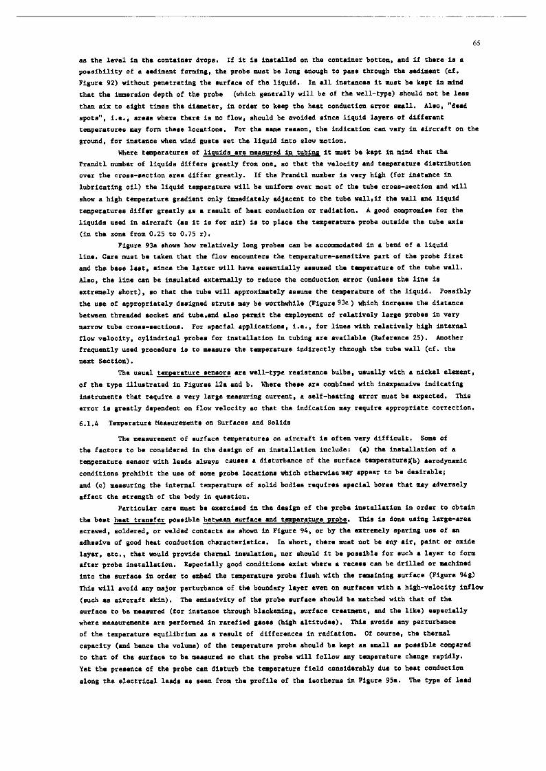
65
a. the level in the cont.in.r drops. If it is instelled on rh. cont.in.r bottom, end if ther. i. .
poesibilify of . ..dh.nt forminp. the prob. must be long enough to p.s. through the ssdimenr (cf.
Figure 92) without p.n.rrseing the surf.c. of th. liquid. In 111 i**r*nc.* it mist b. k.*t in mind
that the immersior, depth .,f the prob. (which generelly will be of th. well-type) should not be l.ss
then six to eight times the diemeter, in ord.r to keep the best conduction error ermll. Also, “d..d
epots”, i.e., erees where there is no flow, shwld be avoided since liquid layers of different
tempererur.. mey form tllcs. locetions. For th. ssne r...on, eb. indication ten vary in eircrefr on the
ground. for instene. when wind gust. set the liquid into slow motion.
Where tmp.r.tur.s of liquids er. mesursd in tubing it must be k.pr in mind thst the
Prendtl number of liquids differ. greetly from on., so ther the velocity .nd t.mp.r.tur. distrib”tio”
over th. cross-section .I.. differ greetly. If the Pr.ndel numbar is “.ry high (for inerenc. in
lubricatin$ oil) the liquid remp.r.tur. will be uniform o”.r most of the tube cross-section end will
show. high temp.r.tur. gredient only imm.diet.ly edjecent to the rub. w.ll,if th. well end liquid
tem9erat”r.s differ grsetly es s result of beet condnction or radietion. A good compromise for the
liquid. us.d in eircreft (.s it is for air) is to p1.c. the remp.r.tur. prob. oursid. the tub. ui.
(in the zone from 0.25 to 0.75 r).
Pipur. 9% .hows how reletivaly long probe. can b. .cconmod.t.d in e bend of . liquid
line. Cm. must b. taken th.t the flow .ncomt.r. the eempererure-sensiti”. p.rr of the prob. fir.t
and the be.. lest, .inc. th. latter will h.v. .ss.nrially e.sumed th. t.mp.r.turr of the tub. well.
Also, the line can be insulated extaruelly to reduce the conduction error (unless the line is
utrrrmely short), so that the rub. will .pproxIm.t.1y ..sum. the temperature of the liquid. Poseibly
the us. of .ppr,,priat.ly d..ign.d stats mey be worthwhile (Figure93c) which incr.... th. di.t.nc.
b.rw..n rhresded .ock.t end tub..e,,d .lso permit the employment of r.loti”.ly l.rpe prob.. in “.ry
t,.rrow tub. croes-section.. For specie1 .pp1icetions, i.e., for line. with relstively high intern.1
flow “.locity, cylindrical prob.. for in.t.llstion in rubin .r. aveilebl. (K.fer.nc. 25). Another
frequently used proeadur. is to meesur. the mmperatur. indirectly through the tube well (cf. the
nent Section).
The usuel t.m..retur. s.nsore sr. well-type resistera. bulb.. ususlly with e nick.1 element,
of the type illustrated in Figursa 1’2. and b. Where the.. er. combined with inexpensive indicating
instruments that require every lag. meeauring current, a self-he.ting error must be expected. This
error is greetly dspendent on flow velocity 80 thet the indic.tion my r.quire epproprist. correction.
6.x.4 Temperatur. Meeeuremente on Surf.c.s end Solid.
Th. m..sur.ment of surfec. temperetvr.. on eircreft is 0ft.n very difficult. Sm. of
th. f.ct.,r. to be considered in the desipn of .n insr.ll.tion includ.: (e) the instsllstion of e temperetur. sensor with lad. .Iw.y. c.“s.s e dieturbenc. of the surfec. temp.r.ture;(b) serodyrmic
conditions prohibit the us. of some prob. locetions which othewisemy eppsar to be desirebl.;
end (c) m..suring the internal tamperature of solid bodies requir.. .p.ci.l bores ehet mey edversely
.ff.ct the .tr.n$tb of the body in question.
Particul.r cer. must be ex.rci..d in th. d.sign of tb. prob. innstalletion in order to obtain
th. bsst h..r transfer po..ibl. bet~en .urf.c. snd t.mp.r.tur. prob.. This i. don. using l.rg.-a..
acrewed, eoldered, or welded contects I. showrn in Pigur. 94, or by the extremely sperinp “8. of sn
.dh..i”. cf good beet conduction chsrecteristics. In short, there must not ba .ny .ir. petit or orid.
leyer, etc., thet would provid. rherml insuletion, nor should it be possible for such s 1.y.r to form .ft.r prob. install.tion. Eepecielly good conditions exist where e recess cm be drilled or machined
into the eurfec. in order to embed the temp.r.tur. prob. flush with the raininp surfsc. (Pigur. 946)
This will e”,,id my m,or p.rturbmce of th. boundary layer a”.” on surfec.. vith s high-velocity inflow
(such . . .ircr.ft skin). The misaivity .,f the prob. surfsc. should b. m.tch.d with thet of the
.“rf.c. to be m...ur.d (for instance through bl.ck.ninp, surfnc. trutmmt, md th. lik.) ..p.ci.lly
where m..s”rem.nt. .r. performed in r.r.fi.d g.s.. (huh eltitud..). This evoids my perturbsnc.
of the t.r,p.r.tur. equilibrium .s e rasult of differences in redietion. Of co~r.., the therm1
eepecity (end henc. the volume) of th. temperature prob. should be kept .s sm.11 ss possible cowerad
to thet of the surface to be me.sur.d so thet the prob. will follow my temperature chew. rapidly.
Yet the presence of th. prob. cm disturb the tempereture field considerebly due to hset Conduction
.long the electric.1 lasds s. s..n from the profile of th. isotherms in Figure 95s. The type of lasd

66
configuration il1u.rr.a.d should .I.0 be amidad bscau.. of the dmger of . l..d br..ki”g .t th. .l.,n.nt.
R.th.r, eh. l..d. should be p1ac.d . . .hown in Pigur. 95b, if po..ibl. .lonp .n i.oth.m .nd with good
h..t cmduction to the surfac., and th. minimum length L .hould b. .bout 50 tim.. the l..d dilmctsr d.
For m...“r.m.nt, on th. out.id. of the .ircr.ft skin the 1..d. IT. b..t Q1.c.d p.r.ll.1 to tb. .ir flow
until they r..cb th. n..r..t frame, strin‘er, or vab, to r.duc. the Q.rturb.tim of th. flow; from tbar.
they .r. p....d imid. th. .ircr.ft, ml... it i. po..ibl. to m...ur. the temp.r.tur. indfrectly . .
d..crib.d balm,. Unfortunately, it is r.raly po..ibl. to pl..c. the lad. p.r.ll.1 to i.oth.m. on the
outside Of th. ‘kin, . . it i. . . ..I from the ax.mp1.s of .urf.c. trmp.r.tur.. .hom in Figure. 97 .d 98.
In the c... of direct .urf.c. t.mQ.r.tur.m...ur.m.nt. the actu.1 t.mp.r.tur. or, the outside
(for in‘t.nc.. of ‘n item of .quipmmt or a pip.) is mea‘urcd by pl.cinp . t.mp.r.tur. prob. on the
out.id.. Hmv.r, if the prob. md it. immd1.t. vicinity .r. coverad by .n in.ul.ting 1.y.r. a
t.mp.r.t”r. will be m...urbd th.t is very cl... to that of the opposie. .id. of . meal skin. Thi‘
will p.mit indimct .“rf.e. t.mQ.r.t”r. m...ur.m.nt., i..., . m...ur.ra.nt ,,f the ‘urf‘c. t.r,p.r.t”r.
of the .ircr.ft ‘kin in .n .ir flw by mean. of a prob. in.t.1l.d on fh. in.id. of the ‘kin (cf.
Figure 95e). The m.a.ur.d valu. would be too mall ““le.. .uffici.nt in.ul.ti.,n war. p1.c.d over the
prob. location. Ho%‘.v.~, if thin in‘ul.ting l.yar were to extend over too 1.r~. an LT.. th. redwed
lo.. of h..t would uc...iv.ly change the condition. c0mp.r.d to the normal .t.t., .nd th. m...ur.d
tempentur. muld be too high. Consequently, m.t of th. h..t conduction error c.u..d by th. 1a.d. of
the t.m~.r.tur. prob. can be compensatsd vi. th. IT‘.. md thickn... of rhi. in.ul.ting layer*.
A very popu1.r procedure is th. indirect t.m~.r.tur. m...~r.m.r.t of . liquid flowing through
. pip.. masuri~ from the outeid. of th. QiQ.. Figure‘ 96. throu&b 96~ .hov th. t.mp.r.tur.
r.l.tion.hip. in th. event of unfworabl. heat conduction by th. l..d., th. condition. wh.r. th. 1a.d.
clo.. t. the prob. .r. p1.c.d properly p.r.ll.1 to th. pip., .,,d the r.l.tion.hip. prw.ilinp srhan an
addition.l in.ul.tion is wrapped around pip. md prob.. It i. . ..n th.t in th. latter c... the
r.m~.r.tur.. of liquuid and out.id. tub. w‘ll (.nd th. prob.) LT. .Imo.t equ.1. “ower, this .ppli..
only where rh. l.ngth of the pip. is .f l...t 20 tim.. th. pip. dimetsr. .nd vh.r. the prob. is
1oc.t.d at .n .d.qu.t. di.t.nc. from th. end. of th. pip.. In other word., the pip. mu.t be ‘bl. to
. ..tm. rh. ~.ap.r.t”rr of the liquid. Short sad thick-w.1l.d tubing 1oc.t.d on l.rg. .ircr.ft .l.m.nt‘
vi11 t.,,d t. . ..~.a th. tempsratur. of th.t .l.m.“t (angin. .d th. lik.) .,,d .r., therefore, “n.uit.d
for thi. m...uring techniqu..
Simi1.r con.id.r.tion. .QQlY for t.T.Q.~‘tU~.md.‘“~.‘L.~t‘ in .olid.bodi..,wb.r. th.
m..‘~r.‘,.nt. must take Q1.C. with . mini- p.rturb.tion ta local t.mQ.r.t”r. r.l.tion.hiQ.. Wh.r. th.
g.m.try of the body QCrDJit‘, the bore for the tm~psratur. prob. ehould be .(I n.rrow .nd d..p . .
possible, .nd th. r.tio of bore depth to dimrter should be f~..t.r ehm fiv. to on. “her. the body
h.. @md h..e conductivity, and gr..t.r tb.,, about 15 to 1 where if ha. QOor h..r conductivity. If the
electric.1 lad. .,-a p1.c.d along .” i.oth.m on th. body and c.n be secured to th. body with good h..t
conductivity. th. haat removed from th. 1e.d. (h..t conduction error) will not be r.mov.d from th. prob.
location but from th. environment in which th. 1e.d. ..r. embcddcd.
Both r..i.t.nc. elrment. and th.mocoup1.s (for high.= t~Q.I.tUr.8) .r. u..d . . t.mp.r.t”r.
prob... Fipr. 94 .har. .m,. typic.1 r..i.t.,,c. prob.. for surface t.n,p.r.tur. mu.ur.m.nt.,.nd fh.
mounting technique. Figure 23 shows re‘i‘tanc. prob.. for r,...“r.r..nt. in mlid bodie.1 tip-‘en‘itiv.
well-type prob.. in Figure. 23. and b, and . 8Q.Ci.l d..i@,tiith . spring-1o.d.d .l.r..nt for cylinder
had t~Q‘r.tUr‘? m...ur.m.nt. in Pig”r. 23~ which can be .xch.np.d ‘t my time for th. th.rmoco”Ql. .hoWa
in PQur. 41. (pro”id.d th.t th. 1e.d‘ .nd the indic.ting in.trun.nt (LT. .witch.d. too). Figure 41
.l.o show. .ddirion.l prob.. with th.rmXOuQl.., including prob.. .cr.w.d to QiQ.‘, ‘CZ’.W.~ under .Q.rk
QlUg‘ or bolt h..d., .nd blind rivet prob... Pin.lly, Figure 95 ch‘w. . “‘ry sm.11 th.“WXWQl. th‘t c.ri
b. m.d. from th.lmocouQl. m.t.ri.1. (for i,,.t.nc. AN 30 wire. or fr0.J . th.moco.xi.1 line) .nd i‘
aconomic.1 .‘Q.Ci.llY when mad. in 1.r~. nunbar.. The twi.r.d and of th. 1r.d i. .Qot-W.ld.d to th.
.ircr.ft okin. “her. th. mrfsc.. or bodi.. h.v. poor h..t conductivity the th.mocont.ct i. w.1d.d to
. met.1 p1.t. which i. then .trach.d to the body with th. best ha.t conduct.nc. Qossibl.. Where the
t.m~.r.tur. of .olid bodi.. is m...ur.d, this .rr.y must b. .mb.dd.d into th. body. It m”.t b. kept in
mid th.t n.wly m.d. th.m.xo,,pl.. should be w.d QriOr to u.. by @“ins tb.m ‘w.r.1 time.. .iac.
l Thi. c.n be determined through COmQ‘d‘OZ, with . contact rh.mom.t.r, making .ur. rh.r the condition. .r. . similar se pcmibl. to normal m...uring condition..

67
othewi.. the c.libr.tion will eh.ng. too rapidly. The “II. of ..ri..cmn.ct.d th.rmocoup1.s
for ebt.fnin& m...ur~.nt. of maen tampcratur. i. not po..ibls, if the th.r”tocoup1.s .r. grounded.
Incideatllly, .peci.l resi.t.r.c. prob.. with extremely .m.ll remperature 1.g error. .r.
.v.il.bl. for m...uring t.mp.r.t”r.. on surfaces with r.pidly churgiag tcmp.r.ture. (for i”.r.ne.,
fun.1.g. #kin of VTOL .ircraft in thetake-off or lmding ph...). Thi. i. .chiev.d through . 8paci.l
.rr.y of different r..i.t.nc.. in the ..m. .l.m.at, wing . b.l.ncing circuit: “Compu-Th.rn” principle,
R.f.r.nc.. 86 UAd 87. Sp.ci.1 thermocouple typ.. cr. .vail.ble for m.a.urinp the h..t flux (the
.o-c.1l.d “hat flux” tr.n.duc.r., References 92 end 931, who.. d..cription would .xc..d the eeop. of
rhi. p.p.r.
Addition.1 inform.rion on .urf.c. r.mp.r.tur. prob.., rh. . ..oci.t.d .dh..iv.., .nd rh. like,
cc” b. obt.in.d from the .ppropriar. compa”y lit.r.tur..
Tsmp.ratur.-s.n.iriv. r&at. oh.11 be mentioned here rh.e a. .ppli.d to the uurfac. of th.
body in qusation and will nhow . color change when . c.rt.in t.mp.r.rur. i. excasded, permitting the
indication of tamp.r.t”r.s in rh. r.ng. between .boue 37’ and 67O’C. The.. .o-c.1l.d ‘~th.rmcolor.” ar.
rrupp1i.d in the fern of powder th.e i. .u.p.r.d.d in d.n.tur.d .lcohol .nd thinly epplied with brush
or *prey gun. ‘fh. drying time i. about 30 minut... The temperature. muct pr.v.il for . p.riod
of 30 minutes in order for rh. full color ch.ng. ro t.k. p1.c.. If rh. rim. i. only 5 ..conde. the
ir.dic.r.d ramperatur. will be .bo”t 10 to 40% 1c.w.r th.n the .cru.l tamp.r.tur.. The color eh.nge will
be r.r.in.d for a certain period of time if the .“rf.c. cool. alowly*. Th. original color will be
r..eor.d when th. curface 1. vet. The.. co1or.z cc,, be used several rim... Also. there .r. types with
multiple color ch.ng. (for in.t.nc., initi.1 color pink, changing to light blue .t 65% to yellow .f
145’C, to bl.ck .t 174%, and to olive dr.b .t 340%. A d~i1.r behwior i. ch.r.ct.ri.tic for
“Detectotcmp pcint.” .nd Th.rmochrom. crayon.“; howwcr, the former ~.nnot be used in the op.” air,
i.e. on the out.id. of M .irer.ft .kin (R.f.r.nc. 96). The Thermochrom. crayon musr be applied to .
hot body, ,,th.rwis. rh. color ch.ng. “ill r.k. p1.c. too ..rly. If the bcdy i. .bov. the temperarur.
for which the p.inr 1.. ..l.ct.d, eh. color ch.ng. will t.k. p1.c. immadiately. T.mp.r.tur. indicrrora
in the form of s.lf-.dh..iv. ribbon. .r. ..p.ci.lly well-,uie.d for monitoring purpo..., i...,far long
t.rm ob..rv.tion. to determine whether . certsin r.mp.r.tur. h.. been exceeded. Different type. of
the .o-c.1l.d “t.mp-pl.t..” (R.f.r.nc. 95) .r. .v.il.ble that provide from one to eight calibrated
color point. which . ..um. . bl.ck color permanently vh.n the ind1c.t.d tempararvr. i. exceeded.
Finally, there .r. mach.nic.1 r.mper.rur. indie.tors, for in.t.nc. the .o-csllad “ternplug.“.
Thea. r...mbl. grub .cr.w. (.bout 5 mm long, 2.5 mm d1.m.t.r) which .r. .cr.w.d into appropriar. bore.
in the obJ.et whhos. t.mp.r.r”r. i. to be m...ur.d (for in.t.nc., . rurbin. howing). The h.rdn..s of
eh... indic.tor. will ch.ng. . . . function of remperarur. .nd uposur. period. Th. t-plug is subjected
to . h.rdn.n. t..r in th. labor.tory .ft.r completion of rh. rest in qu..tion which permits .ub..qu.nt
t.mp.r.rur. d.t.rmin.tion with .n .ccur.cy of 25’ (R.f.r.nc. 13). Another eomp.rabl. technique ha.
r.c.,,tly been r.pore.d which utilir.. c.peul.. filled with di.mond pmd.r th.r hr. been .xpos.d to
radi.tion in . nuc1e.r r..cror. The ch.n&. in the d.r,.iry of rh. powd.r i. proportion.l to the t.m9.r.-
tur. r..ch.d, .nd ia .“b..qu.ntly determined through X-r.y photogr.phy with .n .ccur.cy alleged LO be
+PC (Reference 102).
6.2 gelaction of Th.rmom.t.rs
The .c+wct. which .r. imporr.nr in the ..l.ction of . th.rwm.t.r include:
Type of medium to b. m...ur.d: .mbi.nt .ir, .ngin. .xh.u.,r g.., fuel, .ircr.ft
okin, equipment, etc.
T.mp.r.tur. r.ng. to be cov.r.d.
M..auring purpos.: p.rm.n.nr i*.t.n.tim or t.*t rig.
Typ. Of .irer.ft: .irsp..d rmg.. spur .nd weight con.id.r.tion.. etc.
Typ. Of m...ur.m.nr: individuel, multiple, maul v.lu.. diff.r.nti.l, or r.my.rar”r. r.r.
m....Yr.m.nt; point or (Lr.. m...ur.m.nt.
Typ. of d.r. aequi.ftion: instrument reading, t.l.m.try. airborn. recording, or comblrt.tion.
of rh... technique..
* Exercise c.utim in th. tr..tm.nt of objects th.t .r. .xpos.d to .n air or gas flow:

1 ~u,,garen - Rhenium thermocouple up to +3100%.
the probe with the higheat po..ibl. r..i.tMC* muet b. meted to *n in.tr”m.r.t that will not C.“..
.xc...iv. aelf-hesting in the Prob., t+,r.ov.r, n,.n”f.ce”r.r’. inform.rion m”.r be critiully .x.min.d
to fully “nderseand it. .pPlic.bility to th. m...“r.m.nt r.q”ir.m.“t, for which the component h.. been
or will be procured. C.“urion i. ind1c.t.d in the CL.. of comP.ni.. th.t .r. very .p.ring with de. and
docvmentation or c.nnof .f.t. the test condition. “tier which . c.rt.in ch.r.ct.ri.tic (.uch . . self-
heating) w.. m...“r.d*. Thi. eyp. of .dv.rti.ing may be indicative of .a effort or. the p.rr of the
~ontr.~t.,r to .xP.nd into new ma.., such . . ..n.or., iw3ic.tir.g in.tr”m.nt,, and rh. lik..witbout
.p.ci.liz.d knowhow and euieabl. test .q”ipm.nt, nor even an in-ho”..d.v.lop,..r,r mtivity tb.t p.rforms
v,...“r.m.*t. in .frcreft itself. “Ch..p” prodwt. cm t”rn o”t to be very “.xp.n.iv.” wh.” the
m...ur.m.nr. are finslly obtained.
In this connection we m”.f also disc”.. the in-ho”.. f.brie.tio” of prob.., bridge circuit.,
rind the like. Thi. used to be P cormon practice since. .mng other r...on., .uit.bl. rrign.1 conditioner.
.nd indicsting in.trum.nr. with recording output. were not comm.rci.lly .v.il.bl.. The mo.t frequent
shortcoming. of thi. cl... of .q”ipm.nt PT.: “n.cc.pt.bly high self-h..ein$ of th. prob. I. . result of
impropsr dim.n.ioning of the brids. cIrc”it, th. t.tnp.r.t”r. depcndenc. of the dc mP1ifi.r. used,
in.d.quat.ly stabilired “upply volc.g.., and the lik. (cf. S.ction 2.2 .nd 3.3). It i. rscommended
tb.r.for. th.t modem servoed instrument. with independent m...“ring output. (potantiomter, encoder,
etc.) be employed in every in.r.nc. “hare .x.ct t.mp.r.t”r. m...“r.m.nt. in air md other ,q.... .r.
r.q”ir.d. I,,-ho”.. development of comp.r.bl. equipment require. ye.=. of .p.ci.liz.d rxperienc. and
is time-consuming .r,d, therefore, in most c.... mm. .xp.n.ive.
Prior to the acquisiricn of prob.., sign.1 conditioner., and the like, consideration should
be given to the cost .ff.cri”.n... of procuring expensive component.. with more .tring.nt .p.cific.tion..
in the interest of lowering the cost of other op.r.tim.. A. a” .x.mpl.,on. would expect that in .
better .y.t.m. the number and complexity of the corr.ction. required would be r.d”c.d, md this in t”rn
should lowsr the c0.f of po.t flight operation.. In Lddition. th. r..“lt. .ho”ld be more .cc”t.f. md
easier co .v.lu.t.. (cf. Section 6.4)
6.3 Calibration of Thermometer.
The ch.r.ct.ri.ric. of the rh.rmom.t.r and all the . ..oci.t.d recording and/or indic.ting
d.“ic.. must be ~ovm before any .cc”rat. temperature m...“r.m.nt. can be mad.. Thi. me.“. th.t all
error. m”.t be identified .nd defined for sll flying .t.t.. th.t .r. of int.r..t. M...“r.. required
for thi. pvrpo.. cm be subdivided into three atag..:
(a) Error determination on individusl compon.nt. in tb. l.bor.tory.
(b) Error determination of the entir. th.rmom.t.r .ft.r in.t.ll.tion in th. .ircr.ft.
(c) Error determination while .irborn..
A. P result of the interdependmc. of meny error. and th. influmc. of m.ny p.r.m.t.r. that
are difficvlf to .v.l”.t., all experiment. and m...“r.m.“t. must be p1.nn.d and uecuted .o th.t the
error. er. .cq”ir.d individually wherever possible. The m...“r.d data m.t be available in a form
that can be .v.l”.t.d directly. for instance. a. . function of Mach m”mb.r .nd .ltit”d.. 80 that
time-con.umin& con”.reion routine. will be a1imin.t.d.
Test f.ci1ifi.a .v.il.bl. to in.rrum.nF engineer. during flight program. .r. normelly rather
limited. Tharefor., tb. following di.c”..ion n.gl.ce. those m...“r.m.nt. th.r wovld require specie1
facilities euch 8. wind t”nn.l., etc. Ho.,.v.r, decade r..i.t.nc. box.., remperacur. calibration bath.
with precision th.rmom.r.r., digit.1 mltimtera, .nd a temperature test chamber with . rang. from,
for instance, -80° to +80°c (but .t lease from -20’ to +SO’C) m.t be .v.il.bl.. A thermcovpl.
eh.rmom.r.t teeter, . am.11 electric fumec. .nd . “J.tc.1 .n.lyz.r” with .I1 accassori.. should be
.v.il.bl. for t..ring thermocouple..
6.3.1 Calibration. in the L.bor.tory
A. a rule, only the following .eeiviry c.” take place in the typical leboretory or test shop:
* This appli.. rho to informtion euch . . “recovery factor - l.O”, “self-heating .o sm.11 that it CM b. disregarded”, etc.

70
(.) m.war.m.“t. Of R*818C.“c. Probell
Th. prob. calihratio” error EC& il *.t.rmi*.d for the temperetur. ran*. of intereet in .
c.libr*tio” b.th agiteted et c0nstant ret., by c0mp*ri** the acqvired rellietennc. “~1U.. to the .ppropri*r.
tehl. Of srendard values (for pl.ti*um, nickel, etc.) .“d to the liqvid t.mpar..tur. d.t.rmi”.d with .
precision thermometer. Although the ..lf-h..ting effect i. much am.1l.r in liquid. than in .i=. th.
prob. should b. operated .t the rrm.1le.t m...u=i”6 cu==.“t poseibl. (for in,t.“c., 1 mA for Ni .nd Pt
prob.., and nbout 0.1 mA for thermistor.), in order to be c.=t.i” th.t rh. ..lf-h..ti”g .==o= till
remein below . level of 0.1%.
Addition.1 m...u=.m.“t. c.” be performed in th. l.bo=.to=y o” =.,i.t.“c. prob.. used to m...“=.
t.mp.rat”r.a in w. The p=.=.qui.it. i. rh.e the ..m. liquid be used th.t will be m...urad by th.
prob. in.t.1l.d in th. .i=c=sft .“d th.t the liquid flow v.locity be the ..I.. . . prewili”6 .t th.
intmd.d prob. loc.tio”. The haet conduction error EC ten be detarminsd. for i”.t.“c., by completely
imer~ing the t.m‘a.=.tu=.-..“.iti”. part of the prob. in M agitated liquid b.th .t, for i”.t.“c.,
+lOO%, .“d packing the head of the prob. in ic.. Th. difference between th. m...ur.d t.mp.=.tu=. .nd
the temperature of the liquid will yiald th. h..t conduction .==o= fo= a t.mp.=.tu=. difference of
1OO’C between liquid and prob. h..d. Reparition of thi. t..t .t ..“.=.l lower t.mp.=.tu=.. (ouch . .
80%, 60%. 40%, 20% end 10%) is .d”i..hl. beceu.. rh. hut conduction error i. . “on-li”..=
function of the t.m,,.=.tu=. differential. D.tai1.d instruction. for determining th. h..t conduction
error .r. provided in R.f.=mc. 25.
Th. t.mp.=.tu=. 1.g .==o= EL fen be d.t.rmi”.d by =.pidly .lt.rn.ti”~ the prob. b.tw..” tvo
.git.t.d b.th. of diff.r.“t temperstur.., m...u=i”~ th. tin. raquired to i”dic.t. 20X, 50X, 63.2% .“d
90% of the tempsratur. differanc. (cf. Section 5.2.3).
Th. s&f-h..ting error ESH CM be determined fo= . giv.” typ. of liquid and liquid velocity
.t . d..i=.d temp.=.tu=. provided rh. r..i.t.nc. of th. prob. i. fi=.t m...u=.d with no .i@ific.“t
..lf-h..ti”g (u.in$, fo= .x.mpl. 1 mA for Ni end Pt prob.., .“d 0.1 ti fo= th.rmi.to=.). Th. cu==.“t
i. th.” i”c=....d to ten tima. the initi.1 v.3”. or nor.. A mi11iamm.e.r is p1.c.d in ..=i.. with
th. prob.. .nd an .l.ct=o”ic milli”oltm.t.= of vary high input =..ist.nc. i, pl.c.d in p.r.ll.1.
Aemming th. temperature increase Y.. 1.50% uld took p1.e. .t . cu==.“t of 10 mA .nd . voltage of 5.00 V,
i.e. .t . power of 50 mW, the self-h..ti”g effect will be 1.50%/50 TA’, o= 0.03%I.W. D.t. obtained
for . give” liquid .nd . give” liquid velocity .=. .lmo.t impossible to extr.po1.t. to oth.= liquid.
(or pa...) .t the ..m. or different velociti.., ainc. th.y .=. .l.o deprndent on the prob. d..ign .nd
will yield different f.ctor. for each prob. type.
A rough estimat. .pplic.bl. to certain well-typ. prob.. is th.t th. tin. co”.t.nt c.” be
.bo,,t 30 rim.. g=..t.= in .i=, .bout 2 time. in oil, and .bout 1.5 time. 8=..t.= in liquid orys.”
th.” in wt.=; u”d.= othewi.. equal condition. the ..lf-h..ti”g .ff.ct in %mW c.” b. .bout 100 time.
g=..t.= I” .i=, and about 2 tin.. 6ra.t.r in oil .“d in liquuid oxyg.” th.” in wt.=, prcvidsd .
liquid velocity of 5 ftl..c i. assumed in .v.=y i”.turc.. Th. actu.1 value. of other prob. type. c.”
d.“i.t. quit. co”.id.=.bly from these =.l.tio”.hip..
Th. c.lib=.eio” of prob.. for .urf.c. md solid body t.m~.=.tu=.. c.” b. acquired in liquid
b.th., to.,; however, m...u=.m.“t. of ..lf-hating, tsmp.=.tu=. lag, or he.= conduction a=. m..“i”gl...
if performed on individual p=“b.s before they .=. inntalled, .“d in most c....,difficult to obtain wh.”
th. prob.. .=. in.t.1l.d on tb. solid body.
I,, the c... of p=ob.. for .i= .“A a.. t.m~.=.tu=. m...u=.m.“t. little nor. th.=a the c.lib=.tio”
error ten be d.t.rmi”.d in the laboratory. All other error. mu.t be detarmined in the .i=c=.ft (~“1.8.
.uit.bl. wind tu”n.1. .=. .v.il.bl.), since they .=. d.p.“d.nt on flight condition. (cf. below).
(b) H...u=.m.“t. of Th.rmocoupl..
Thi, discusaio” of the m...u=.m.“t of th.rmocoupl. ch.=.ct.ri.tic. will b. co”f1n.d to th.
d.t.rmin.tio” of the prob. calibration .==o= ECAL. In usinnp furnnc.. 8p.ci.l a=. mu.t b. t.k.” to
.s.um. th.t th. Imm.=.io” depth is .d.qu.t. .“d th.t .tt.“tio” i. 6%“~” to .ny .ff.Ct. e.us.d by tb.
high t.mp.=.tu=. gradient in the re@o” wher. th. lad. .=. p....d through th. furnace wall (cf.
Section 3).
C.1ibr.rior.m wing the “J.tc.1 ~.lyr.r”, which i. di.cu...d below, m.y pro”. to be
considerably b.tt.=. A d.t.il.d description of th. c.lib=.tio” of tharmoeoupl.. I. found 1”
Reference. 13 .nd 42.

71
(c) Cslibrstion of In,trmsnts, sign.1 Conditiotmr,, stc,
Ths follovinp informtion on ths m..,“=.m.nt of in.trumant ell.r.ct.ri.tics .I.0 wp1i.s to
sipn.1 condition.=., t.lsm.try, md recording .pp.=stu.. It should b. mntionsd .t this point thsr
th... devices. unliks the ususl practics with prob... are not .lw.ys .uppli.d in .gsd condition.
Th.rafor., if ia .dvi..bl. to op.ratc new equUipm.nnt for sn urdntermpred p.riod of 24 hour., if
possibls st .n incrsssad smbiwt t.mp.rature, befor. proc..dding “ith it. cslibrstion*.
Lsborstory tests thst c.n b. psrfomsd on this .quipr,snt iaclud. the following:
(s) The instrumnr scale .==o= BSC, st room tsmpsr.tur. (spprox. +ZO%) .nd with th. specified
l‘sd r‘si‘tmce, csn b. d.tsrmfn.d by substitution of s prscision d.csd. =.‘ist..~c. box
for th. prob.**. A “mm-up period of st lust 30 minut.. must b. sl1ow.d b.for‘ this
m~.sursr.~nt is mada
(b) Simu1.t. . st‘p chsnrc in ths tmp.r.tur. st th. prob. by Witchins betwem t”o =.‘ist.n~.‘
thst wrrsspond to th. prob. rssistsncss st th. lover ad uppsr limit of th. ncssurinp
rsng., to detsrmias rhs aof ths in.trum.nt (or th. follow-up rims in Lh. csse of
‘er”o‘d in‘rrlm‘nr‘).
(c) Simrlste vary sm.11 tsmpcr.ture ehsn~.. st th. prob. by iatrodvcinp “.ry sm.11 ch.ne.‘ in
th. com‘ct.d rc.isrsnne‘ to dat‘mina ths rssolution of th. instrument. Rspa‘t this
rsse ,,hila lightly striking th. instr,,m.nt to d.tsrminr ths l ff.ct of friction in.id. the
in‘trume”t.
(d) Tvrn th. eq”ipm.nt off Lo= s p‘riod of not lass thm 30 minut.. (until th. instrumsnt h‘s
reeurnsd to room t.mpsr.turc), and m..s,urs tba tins rsquirrd to schi.“. s con‘t.nt
indic.tim for tbr.. differant inputs, perhsps 302, 70X, snd 100X of full ‘csla, to
dstcmine the wsrm-w time. Ist the instmmmt cool dam betwasn .ach of the rhr..
me*‘“rsme”t‘.
(.) P..p..t th. m...ur.msnt‘ d..c=fb.d “ad.= item (d), ‘bow, .t -20% sad th.n .t +bO%, aft.=
placi,,~ the in.tr,,mant in s raaparsrure-controlled chmb‘r***. Le.“. th. r.sistanc. box
oursids. Thsse t.st‘ cm bc used to d.t.rminr both th. maximum “srm-up tin,. thst must be
sllowsd bsfor. ,n..su=sm.nt. cm, b.pin, ad p.rticul.rly th. instrument t.m..=.t”=. error.
This srror is not mrmslly spscifisd, r.th.r, ths srrors srs dst.rmimd for . constsr~t
input .t the low.st, int.rm.di.t., .nd highest tempsrstur. for which th. instrument
is dssipn.d. The..e sre cmbinsd .x,d prssant.d .s . mcsn scsl. .rror .o thse this .==o=
sppurs ss s systmstic srror with . metsin di.psrsion raw (cf. Section 6.4.1).
(f) If 111 co!nponmts, i..., th‘ sctu.1 wiring, plug., circuit bresksrs, .tc. LT. sv.ilsbla
prior to inst.ll.tfon in th. sircnlft, it is .lso possibl. to d‘temin. the electric 1.~3
a s. This error is “.ri.bl.. d.p.nding on th. indic.t.d t.mper.t”=., “pe~1.11~
in ths essa of simpls instrummts. “or. dstsils sre provid.d in the following ch.ptrr.
6.3.2 PIi,,ht Lin. Cslibrstion.
Unliks th. indi”1du.l me.su=sm.nts in rhs I.borstory that wsrs discussed in th. prncsdias
..crion, th. th.rmmst.r systmx ss s “hhol. csn be tastsd “in situ” on ths flight line.
‘fb. fin.1 c.libr.tion of th. tot.1 th.rm,m.t.r syst.m c.r, be p.rfom.d by replacing th. probe
with s d.csds r..istmc. box. I,, this prowdur., th. following ~o.m.=.t. m.y pro”. halpful. Cl=. should
b. tsksn to us. ~mmsction. “hich sr. ss short . possibl. snd which .r.msd. using AN16 w”P vi=..
or 1.=p*r****. This pr.~.,,tio,i till hslp ‘void introducing sdditioml ‘Isctricsl lesd srrors. In
* It w.. found in th. e... of cs=t.i=, typs. of servoad .quipmant th.t this brs.k-in period rducsd th. wsrm-up rims from 40 minut.. to 8 minutss*
** 1~. losdi,q c.p.eity should b. gr..tcr tbsn 1 v.tt, if possibl., to ‘void ‘elf h..ting of th. =.‘i‘t.11~..
*** These “slus. d.pmd 00. the s,nbi.nt t.q..=.tu=s. tb. i~.t=,m,..t i. .xp.et.d to .xp.=i.ncc in th. aircrlft.
**** If th. prob.. h.“. “sry low r..i.tsne., ths r.‘i.tme. of th... lin.‘ m”st b. dducted from the v.1~. of th. dscsds r.s~.ts=nc..

..1eceing r.siSr.“c. box “.lu.s. if Lh. .ctual prob. c.libr.tion is used in lieu of . standard c.libra-
tion CUN., the” prob. r.plac.m.nt will require II re-c.libr.tio”.* Thi. procedure will,how.v.r, reduce
the correction. “eceasary when the raw data .r. processed. A. .” extmpl., ..,I,. i”dic.tors .r. equipped
with ext.rn.lly-.cc.ssibl. trim pot. which are wed for li”. comp.“a.tio” and/or .cal. .d,u.tm.“te.
When the.. are properly adjusted, the value. of i”dic.t.d empcrseur. LT. . . close to eh. corr..po”di”g
values of act”.1 t.mp.r.t”re 8. the prob. llnd i”dic.ror calibration .“o,..li.. will allow. Thi. combined
corraction mey not be .uit.bl. over eb. full rang. of fb. scale, because, for .x.mpl., of different
“on-1ine.riti.e in the calibration. of fh. prob. and indicator. In this event. a d.ci.ion m”.t be m.d. r.gardi”$ th. maximum allowable deviation. between 5”dic.t.d rind actual valu.. over the portion(.) of
the x.1. which .r. of prim. intereat. This procedure is illustrative of the .,t.ps Lh.t c.” b. t&e”
in ..tti”g up a syetem to facilitate the evaluation of the dst. acquired during teat run.. Ideally, in
this i”st.“c., for example, the only addition.1 error. that would h.v. to be accounted for would be rho..
dependmr on th. flow “elocity.
In th. case of tb.mom.t.r. u..d for mbi.“t temperature or compr...or inlet
temperature m..sur.m.“cs(OAT or CIT t..a.ur.m.“t.), addition.1 resting a” the fliBht
line i. badly poesibl.. .xc.pr for f”“ction.l test. in which cm. the prob. dricing heater mu.t be
turned off . On the ground, the indication till s1mo.t al”.,‘. deviate by .om. .mo”“t from th. .t.tic
.ir tamperarur., partly b.c.u.. the time co”.t.“t. in this .rat. LT. very long, p.rh.p. 15 minute. .“d
more. If the prob. hearing .y.t.m (deicer) wer. turned on, the t.mper.tw. indication would rie. to
nor. than lo&, and in prob.. with open-wir. .l.m.“t. it i. likely that the .l.m.“t would be d.m.g.d.
A function.1 test, in addition to the calibration d..crib.d above, c.” be performed 0”
th.rmom.e.r. for m...“r.m.“r. in w, on .urf.c..**, .“d in .olid bodi...** In a.m. ea..., the
engine. muet be running for this function.1 t..,t in order to simulate flight condition.. Al..,
cm,p.ri.o” . . ..uIwJAc”~. mi&t be rek.” in this .t.t. in order t” determine th. effects of self-bs.ti”s
or heat conduction error.. “any i”.xp.“.ivc th.mm.t.rs designed for m..surm.“ts in liquid. allow for
the s.lf-h..ti”g error of the prob. in the cslibrseio” of the instrument. I” eh.t c..., the scale
c.1ibrsti.n till apply only for the liquid in question and for a certain velocity of the liquid flow.
When th. engine. .r. turned off, the indication will fluctuars and become u”r.li.bl., .sp.ci.lly whs”
n.tur.1 co”vecrion ..‘a in, because the prob. i. subject to appreciable ..lf-h..ti”g. A “umber of good tb.rm.,m.r.r t..t.rs .r. .vail.bl., but the operating inetrucrions which .r. provided do “of almy.
.d.qu.t.ly discuss all potential .o”rc.. of .rror (..p.ci.lly 8.1%heaLi”&.
(b) I’b.mm.r.r. with Thermocouples
‘l-h. most important spplicatio” for rh.mom.r.rs of rhie type i. in tb. m.a.ur.m.“r of the engine
.xh*u*t gee temperseur. (Pm). I” this c..., it .bould he possible to .imul.t. most of the opereti”~
condition. axisring in flight by running the en@.. on the ground. “.,w.v.r, the determination of the
pctu.1 measuring aceuraey of tb.mmm.t.~ srraya in .” engine is very difficult under the.. conditim..
A good aid in this C.B. is th. m-called “Jetcal an.1yz.r” or comparabl. .pp.ratus. Tbi. .et
permits, .,a.,“~ othar procedures, a function.1 t..t of the .“tir. EGT .yst.m with “on-running engine.,
teeeing each th.rmo.l.m.“r end ch. whole array for continuity, short circuit., .tc. Gtnerally, ch. entire
EGT .y.f.m CL,, be rested with a” accuracy of about +4%. The different c.p.bi1iti.e of eh. ..f c.” be
B..” from th. operating manual supplied with if.
6.3.3 In-Flight Error Calibration
6.3.3.1 G.n.r.1
I” the majority Of r.mp.rat”r. m...“tml.nt., ..$., in liquids .“d solids, in-flight .rror
.v.lu.ricn i. co”fi”.d to . check .g.i”.t tb. reeulr. 0bt.in.d in the l.bor.fory and on the flight line, zg,d,or to the deteminetio” of that prob. loc.tion which till rssult in the minimum positio” .rrOt’.
opth,,m probe loc.tio”s c.” ““ly be detamined in-flight sine. the.. conditions c.““ot be .d.qu.t.ly
simulated on the wand. oh. procedur. generally u..d i”“ol”.e the i”.tall.tio” of tb.rmm.t.rs .t
different locations t” m...“r. the 8.m. P.r.m.t.r.. The output. BT. read out .ith.r individully or
* Thi. do.. “ot bold for prob.. with cl... to1.ra”c.s.
** Provided the .ir flow ebout the aircraft th.t exists in flight do.. not play any d.cI.iv. role.
73
connwt.t.d onto . sir&. ch.nr.al snd ra.d sequentislly. The prob. that show. rh. 1.s.t position .rror
is used in succasding flight..
The d.t.rmin.tion of the po.ition .rror of prob.. for OAT snd CIT m...ur.m.nt. using in-flight
t.chniqu.. is, .t time., ,u.tifi.bla bscsu.. th. rssulting flow, pr..,ura, .nd tsmp.r.tur. ralstionship.
.t the prob. or .t tb. m...uring e1.mrr.t c.n b. cr..t.d only in flight. Sinoa position .rror. .I. dependmt o,, .ltitud. .nd .ir.pa.d or Msch numbsr, th. .rror. in th. .ircr.ft’. pitot-.t.tic .y.t.m
must firat b. det.rmin.d in sp.ci.1 in.ti.,m.nt.tion flight.. Techniqu.. for obt.ining the.. c.libr.- tier.. .r. described in the conv.ntioa.1 flight t..t m.r.u.1.. Roav.r, if . r.far.ncc thcrmom. ter rh.t could bc usad . . . “.t.nd.rd” (cf. b.lov) is not .v.il.bl., thsn only those procadur.. whsrein the
.t.tic sir t.mper.t,,rs is d.t.rmined by . th.rmom.r.r on th. ground or by. r.dio sand. st flight
sltitude can be used. To perform thrrmom.ter cslibrsrion runs .t diffsrsnt sirspssd. snd th. ssma prsssure
sltitud., or corra1.t. c.libr.tion m...ursm.nt. obt.in.d in diff.rmt flight. snd in different flight
regime., it is vsry importmt that SCCY~..~. ra...“rsm.nt. of the .t.tio ~r...“r. position error . . .
function of air.pe.d sr. .v.il.bl.. In the pr...nca of unf.vor.bl. m.teorologic.1 .tr.tification in
the troposphar., .v.n .m.ll d.vi.tion. from squsl prsssur. .ltitud. e.n result in l.rg. ch.r.g.. of
.t*tie air temperetur.. The difference. b.t”..n the tr”. M.cb numb.r l d th. indiated “.ch numb.=
(which is .ub,.ct to pr...urc errors) . . s rule hsv. . minor affect on th. .ccur.cy of error detarmins-
tioll. Bos).v.r, th.y csnnot be disregsrded, ..psci.lly in the ,,..I-sonic s1r.ps.d rmg., since the
pressure error in this flight r.n&a c.n . ..uym. rs.p.ct.bl. m.gn1tud.s. Figure 99 show. the affect of
. relative error of AM/M - 1% on rh. datcrminstion of .t.tic t.mp.r.tur. s. s” .b.olut. m.gnirud. md
es I r.lati”. L*mp.r.t”r. error.
All c.libr.tion flight. to d.t.rmin. the pr...ur. md tsmp.r.tur. arror of ..n.or. on the
.ircr.ft should be c.rriad out tith du. sttantion to .uit.bla m.t.orolo~ic.l condition.. This will psy off in term. of 18.. di.per.ion of measuring error.. b,.rrumr,t.tion progrsm. of this type c.n be
accomplished quicker at test sit.. h.ving fworsbl. clim.tic condition..
The .v.lu.tion of wasthar situstion. is bsssd primarily on the vsrtical t.m,xr.tur.
stratificstion snd, .econd.rily, on the vertical structure of th. wind.. ‘fh. d.t. rsquirsd for this
.v.luarion ar. eupplied by the r.dio sonde .t.tion. of ths n.ticn.1 w..th.r ..rvic. 1oc.e.d in or .bout
th. test a..; the.. .r. acquired .t th. .tsnd.rdie.d world-wid. tin.. st 00.00 GMT snd 12.00 GMT.
Where this inform.tion turn. out to be inid.qu.re. specisl r.dio sond. or .ircr.ft mission. must be
sccomplished to detsrmin. the temp.r.ture s. s function of prassur. .ltitud..
In .ny .v.,,t it is bettsr to dctsrmin. th. m.t.orologic.1 strstifiestio” bafor.h.nd. sad
then c.rry out the in.trument.tion flight. in the .uit.bl. strst., r.th.r thm psrform the
in.trum.at.tion flight. .t prapl..rvred sltitud.. without m.taorologic.1 infornation. Th. risk
inherent in the l&tar .ppro.ch is hwing to discsrd ths dsr. b.c.uss of s%c.s.ivs mstsorologic.1
error. which. of tour.., c.r, render tha d.t. usal... for srror d.t.rm%n.tion.
Th. following type. of v.rtic.1 .tr.tific.rion ST‘. suitsbl. for th. dercrminstion of
pressure .nd rem~ersrur. m...uring error. ue3.r in-flieht comditio..:
(4 T.mp.r.tur. *rrYcrur.: Attampt. should be m..d. to 1oc.t. .r... vh.r. th. t.oth.rmic
vertical .tr.tific.tion, i.e., th. v.rtic.1 tsmperstur. gr.di.nt. is O°C/lOCm. or s. close . . possibl.
to this v.lu.. M...ur.m.nr. .hould n.v.r be performsd .t gr.di.nt. in CXO... of -loCIlOO m (dry .di.b.tic
rmprrstur. gr.di.nr) or +l°C/lOCm (inversion). In th. pr.s.ne. of strstificstion of this msgnituda,
.,, .ltitudc ch.nge of +=m (230 fr) till c.u.. s temperature ch.ng. of O.Z’C, which is in the order of
m...ur.bl. error.. It require. spaci.1 skill on th. part of th. pilot to m.int.in .ltitud. with sn
.ccur.cy of this order, ..peci.lly wherr .t..dy flight condition. must b. ..t.bli.h.d .t relstively
high .ir.p..d..
Th.rmocor,v.ctiv. ws.th.r situstion. sr. un.uit.bls. The.. sr. siruation. with v.rtic.1
i,,t.rch.,,gc caused sithsr by rsdistion vi. s h..t in.cr.... of th. ground (bound.ry or .xch.We 1.y.r.)
or by . mixture of sir M.... of diff.r.nt .n.rgy 1ev.l.. P.rrio-3. of minimum sxchsnac .r. fsvorsbl.
for m...ur.m.nts, sspecially .t low .ltitud.. The.. sr. tha psriod. vh.r. th. direction of rsdistion is
ch.nging, .I) wall . . all w..th.r situstion. with da.. cloud .tr.tific.tion snd no convection phmomea..
“or.ov.r, th.r. must not be my pr.cipit.tlon, uul... it is intnndad spacificslly to tsst
the effect of the liquid vstsr ph... on th. .ir.p..d srror.

74
Vlura e radio sondc i. wed . . . referene. for ev.lu.tin* the .tr.tific.tion, it must be kept
in mind the rh. wand. in mo.f c.... will ri.. .t . “ereic.1 “.locicy of *bout 6 ml. (17 felsec) and
that the prob.. in this .onde ba”. II rim. con.t.“t of . fn, .ccond.. l’h.r.forc, tb. r.mp.r.tur.
bound.ri.. will bs “b1urr.d” conaider.bly, which comp1ic.t.. ehc .v.lu.tion. Thi. .pplies especially
“her. r.dio sonda d.t. BT. used L. r.f.r.nc. “.lue. to c.1ibr.t. the .irer.fr in.trum.nt.. Undsr th...
co,,dition. it i, .d”i..ble to connult II m.teoro1ogi.t for .n .“.lu.rion of tb. true .tr.tific.tion.
The r.dic aonde itself m,,.t be comp.r.d to . pr.ci.ion thsnwmseer prior to taksoff. Thi.
thermDm.err should br exposed to a con.t.nt .ir flow of, for in.tmce. 6 m/.ac. which corr..ponds to
the climbing r.t. of tb. radio aande, by me.,,. of . built-in blcver. Al.0, the rime interv.l b.ewe.n
the radio .onde m...ur.m.nt .,-ad th. in-flight mc..“r.m.nt. ahovld not be exca..i”e (if po..ibl. l... th.n
30 minute.), and the l.unch .ttc of the radio .onde should b. 1oc.t.d within tha t..t .r.., if powibl.,
to minimire th. affect. of temporal and 1p.ti.1 “ari.Lion..
(b) Wind field .tructw.: The te.t.. .hould ba conductad in .tr.t. of con.t.nt wind speed .nd
wind direction. if poasibl.. A vertical wind profile c.n b. plotted from r.win .onde m...ur.m.nt.,
and rhie will show iarm.di.t.ly which .tr.t. ha”. accept.blr l h..r “11ue.. Pronounc.d vertical or
horizontal .h..r line. with .ssociat.d c”~.t”re of rhc wind profile will ra.ult in Y.“., cr..t, .nd
rotor form.tion. In the presence of these boundary ar.. phenomen., the isoebermic 1.y.r. .lsc h.“. (4~.
or credit structures, dspanding on remperatvre stra?.ific.tion .nd ah..= cb.r.ct.rf.tic. of ths “ind,
“ieh “it”. Icngth. ranging from shout 0.5 Irm to 40 km. The** atr”Ct”re~ vi11 sometimes occur even in 8
eloudlcs~ sky and . . high .I) the tropop.u.e, hove”.=, they cm ba detected from th. ch.racrcristic “.“a
~~tr”ct”~‘c of tb. tamperaeurc record.
Pisure 103 .hovs a .ch.m.tic di.gr.m of the .tr.t. thrt .r. .uit.ble for temper.Lur.
calibr.tion flight. i” the 1ow.r atmosph.ra,r.ferred to th. “erCic.l t.mp.r.ture .tr.tific.tion (A),
wind “clocity (B), .nd horizontal wind ditrction .(C). It in rcl.Fively rare to find good condition.
xirh ra.p.cr to .11 three effective component. in on. and tb. same .Ifitud. 2.y.r. .nd tbi. cm be
erpsctad only II..= the cmter of high preesure .re.s.
The different effects must be con.idered to determine if exi.tin* “ather conditions
.re accept.ble.
6.3.3.2 tipluratory Ex.mp1.s
In order to show tbc difficulti.. .ncounter.d, wa 1.11 first describe the “nimple” c... of
deteminins ehs position error of B TAT prob. “ithout deicing beater. combinad with .n indicator or sig,,.l co,,diei.,n.r that c.us..probe self-h..tin* pow.r to be 40 mW. The separ.tion of the
individual componant. of the position error will not be considered in this .x.mpla. It .h.ll be ..sumed
tb.t the m.xim,!a altitude is 40,000 ft. .nd (I pro”.‘% type of TAT probe is inntalled at . highly
f.“orable location (nose-boom). Then the only effective components of the position error should be
th. “.,.ociey error .,,d the self-beating error, which partially c.ncel c.ch other. In order to reduce
the number of me..urin* points end the dur.tion of the c.libraeion flight, data will bs t.k.n only
.t 3 differcnr pltitud.. with increment. in airspeed of .boue Mach 0.1. A radio eond. m”st be launched
conc”rre”rly vith the flight program. Its temperature re.din*. will provide the static .I= temperatur.
at th. .Ititud. “here the te.t. arc sccompli.bcd*. The position error i. obrrined, for ir..t.nc. .t
Mach 0.5 .nd an .lcieude of 20,000 ft.,.. .howr below:
st.tic temperature T (from th. radio .onde)
Total remperatvre TT - T(1 + 0.2 M2)
- 249 (1 + 0.2 . 0.5’)
Tempareture m..sured in the .ircr.ft TTic
(corr.cted for in.frum.nr error)
Pcmifion error Ep - TTiC - TT - 261.68 - 261.45
249.00° K
- 261.45’ K
261.68’ K
- + 0.23. K
l E?m.p1e: &ccordin* to the standard atmosphere, a pressvre .ltitude of 20,000 ft. correspond. to .n .tmospheric prcs.ure of 465 mb. Consaguenrly, rh.r temperature value nust b. used which w.. measured simultaneously with B pressure of 465 mb.

75
“‘be th.or.tic.lly .xpacted re.ult of such . ..ri.s of m...ur..w,,t. i. plotted in greph form in
Figure 100. ‘I%. pr.ctic.1 r..ult of . .ingl. ..rie. of in.trument r..ding. would not, . . shown in this
figure, yi.ld the .pproxim.t.ly p.r.llel curv.. but CYN.. tb.t .pp..r to be cro‘aing ..ch other .t r.n-
dam. There .r. a.v.r.1 r...or,. for thi.. Even in th. .b..nc. of .,...“r.m.nt ‘rrore lot.1 t.mpor.1
v.ri.tion. of .t.tic r.mperatur. ,c..y .mour,t to .bout +0.5%, e.p.ci.lly in eh. lovast .ltitud. .tr.t.
(R‘f‘r‘nc‘ 104). Thin me.“. th.r this ‘ffrct .lon., c.n b. s.v.r.1 time. gr..L.r th.n the diff‘r‘nc.
between the m...ur.d v.lu.. .t I c.rt.in H..ch number. Therefor., .ny .tt.mpt to ‘ccomp1i.h such
calibr.tion flight. under un.uit.bl. meteorologic.1 condition. would be na.aingl.8.. Although modern
radio .ond.. h.“. r.li.bl. tolermc.. . . ,,.rrow .‘ +0.5’C to +0.7%, ‘am. of th.m .r. abject to
con.ider.bl. ttmp.r.tur. 1.g ‘rror.. If the d.t. from .‘ver.l ca1ibr.ti.n flight. war. combined*,
e con.ider.bly bett‘r pictur. could be obtainad. “cw.v.r. it ‘hould b. k‘pt in mind th.t .uch c.libr.-
Lion flight. will t.ke .bout tw hour.. Rren if th. r‘dio ‘ood. war. 1.unch.d in the middlr of sreh
flight. .ppr.ci.bl. tamperatur. error. c.n occur due to chmg.. in ths .ir teolparature during th.
flight. With . wry 1imit.d number of m...,,ring point. in tb. .r.. of gr..t..t int.r..t for the
rslsvsnt .ircr.ft undsr norm.1 flight oper.tion. (.h.d.d .r.. in Figure loo), .x.ct t..t re.ult. ‘r‘
difficult to obt.in, P. .tmo.pheric t.mp.r.ture v.ri.tions excead the .rr‘or to b. m.uur.d.
Pigur. 101 .bcw. th. .caui.ition of th. d.icing h..t .rror . . .n individu.1 componmt of tha
pe.itio” error through .ix c.1ibrati.x flight. p‘rf0rm.d .t 10~ .ltitud.. The.. mwt b. repeated ‘t
different .ltitd. l‘val., of coura., b.c.u.. of tb‘ .ltitudr d.pand.nc. of thi. .rror. Sfmply
connecting the maeaured v.1u.s 0bt.in.d in . .ingl. flight (corr.ct.d for prob. c.libr.tion ‘rror)
would yield . f.irly 1rr.gul.r line. The seme would ‘till epply for . m..n of tvo flights .o th.t the
practicsl app1ic.ti.n of the.. cur”.. r‘quira. con.ider.bl. mmoothing.
Thi. u.mple w.. ..l.cted in order to d.mo,,.trrt. how on. individu.1 ‘rror C.IL b. 1.ol.t.d
from the other.. I,,. t..t c.r, be p.rf0nn.d by wing two TAT prob.. (A .nd B) of th. ..m. type end
conmeting thm .It.rn.t.ly vi. I commut.tor to the .a ..rvocd indic.tor. Probe A i. continuowly
operated with prob. d.icer on during the fir.t h.lf of the flight., whil. prob. S r.m.in‘ unh..t.d.
During the ..cond b.lf .,f th. c.1ibr.tit.n flight.. prob. S i. continut.“.ly hutad, while probe A
remmine unh..r.d. If both prob.. .r. .ubj.ct.d to the ..m. flow (for in.t.r.c. on th. underside of
th. no.. .t . l.t.r.1 di.t.nc. of 25 cm from ..ch 0th.r). .nd if th. 1e.d‘ batrren th. probe. .nd th.
commutetor h.v. be.,, .d,u,t.d to .x.ctly th. am. r..i.t.“e. v‘lu“, .I1 .rmr‘ will h.v. the ..m.
.ff.ct on th. m...ur.m.nt. taken with prob.. A ad S. I’,,... error. rh.n c.e.1 out wh.n th. diffarenc.
b.rw..n th. m...ur.d value. of A .nd B I. t&m. This differsace than i. th. deicing error. It
should b. noted th.t thi. do.. not .Ilow for th. indiviud.1 c.libr.tion ‘rr.1“ Of prob.. A .nd B.
The.. correction. !m~.t be .pplied before plotting th. m...ur.d d.t..
If only OIL. prob. were .v.il.bla, it would b. tl.c....ry .t ..eh incramat of .ltitude .nd
.ir.p.ed, .ft.r .t.bili.ing th. corr‘ctd .ir.p..d md ‘Ititudc indic.tion., to m.k. 60-‘.cond m...“r.-
mento with .nd without th. deicer, Suffici.,,t tin. ‘hould ba .llov.d for the prob. hou‘ing to cool off
complet‘ly bsfora ‘ttsmpting ru,. .t the n.xt .ir.p..d. Wh‘re thi. method i. u..d. eh.ng.. in the .ir
tsmpcretur. during ths c.libr.tion run appe.r dir‘ctly in the n...ur.d d.t.. Th... m...ur.m.nt. then
becoma memir~gl... if th. .tmo.pheric tmper.tur. chmp.. axeed the d.icing hat .rror. In these
c.... th. u.. of . r.dio .cnd. would not yield .ny .dv.nt.g...
The det.rm%n.rfon of the v.locity .rror sh.11 be di.cu.8.d . . moth.r .xanpla. In ..rli.r
the. thi. WI. don. by m...uring th. r.cov.ry f‘ctor r .nd plotting tha corr.ct.d tampanturaa
m...ur.d .t diff.r.,,t .ir.pe.d. . . . function of th, .q”.r‘ of th. M.ch number (Pig”r‘ 102.). Sine‘
th. recovary f.ctor is . rel.tiv. v.lu., . .ir&. flight .t differeat .ir.p..d. .nd eo”.t.nt .ltit”d‘.
vhcr‘ . unifam t‘mpcratur. ova the c.libr.tion run GUI b. .xpact.d, will be .uffici.nt. In m.nY
i,,.t.nce. this we. ‘cconp1i.h.d by incra..ing th. .ir.p..d .t .xn.t.st .cc.l.r.tion (such . . 1 g)
until the .ir.Cr.ft’. m.xLmum .ir.p.d w.. scteinsd, aid th.n d.er...irag th. .ir.p..d .t idling ‘egin‘
* Cf. Saction 6.4.

.p..d ““Cil the **it*.1 “.l”. (I.8 r..ch.d. since tha 1.p error EL in the .ec.l.rat.d .“d d.c.1.r.t.d p.rt. of the flight h.. oppo.it. mign., th. me.” of the two eerie. of m...ur.m.,,t. v.. u..d to deternina th. recovery factor. The .t.tic t.mp.r.t”r. w.. determined by .xtrapol.ti”g the m...ur.d da. to zero .i*.p..d . The” through this point . line “1. plotted eorreaponding to the tot.1 t.mp.r.rur. TT
in qu..rion ; this li”. *.**...*t. . recovery f.ctor cd 1.0*. The tctio of th. temperature incr.... for r - 1.0 to th. ~tu.1 t.mp.r.tur. i”cre.8.. .t the em. “.cb number till yield the recovery f.ceor of th. prob.. Sub..q”.“tly the velocityerror c.” b. computed in w.ry individu.l i”,t.“c. with th. rid of eqwtio” (64) (cf. Section 5.2).
Obviowly, in the mejority of c.... this method provides . me.“. of finding the velocity error which i. .t best, only mcdemtely .ccur.t.. “or. .ccur.t. da. would dspsnd upon ..tiafyi”g .I1 of the followi”g e0”dirion.r
1. Th. r.co”.ry f.ctor mmt b. co”.t.“t over the .irsp..d r.“g. w,d.r co”.id.r.tio”; 2. The nelf-heeting error m,,.t be .o sm.11 th.f it cm, b. di.r.g.rd.d,** or it must h.v. b..”
.equir.d . . . function of .leitud. .“d airep..d in the pr.“iou.ly deecribed c.1ibr.ri.n flight., .“d corre~tlo”. for such f.ctor. .(I tb. i”scrum.“r error mu.t b. .ppli.d before plotting the m...ur.d da.;
3. Where data from .cc.l.r.tion flight. .r. wed, the l c.1.r.ti.n .“d d.c.ler.eio” muet be aqu.1 .t the individual “.ch ““mber itlcr.m”t., which i. h.rdly poasibl.;
4. Th. d.p.“d.“c. of the .t.tic pressure QO.itiOn .==a= on the .irsp..d muer be rake,, into co”.id.r.tion with r..p.cc to m.intai”i”g ~o”.t.“r pr...ur. .ltitud.;
5. Th. .lritud. ehculd not excaed 40,000 feet bec.us. .,f th. po..ibls r.di.eio” .rror (e.p.ei.11~ .t eupermnic flight.).
Ap.rt from the f.ct that the first condition will “ever be obt.in.d for TAT prob.. .bov. . cartei” H.ch “umber (.uch . . 0.71, it i. not ..fi.fi.d by m.“y pmb. type. in the lower .ub.onic r.“g., either. Additiomlly. if only the valu.. .t two eirspaede, or for . “.rrow r.“g. of .ir.p..d. var.
wed, the ..lf-h..ti”g .“d th. deicing .rror. would not b. ~ropcrly accounted for. Figure 102. chow. the m..sur.d d.r. of . TAT prob. th.t has P co”.t.“t recovery f.ctor of
r - 0.97 b.lar M.ch 0.7, and the measured d.t. of . cylindrical Q=Ob. with r.cov.=y fator. betwcea 0.52 end 0.74, l.,c.tad in flow perpe”dicu1.r to Lt. ui.. If, in the ~a.. of tb. 1.tr.r prob., only the m...ur.d d.t. betx..” Hach 0.7 .“d 0.85 WC=. used. the r..ulti”g static temperature would be 246.5% increld of 253.0% .“d. at “.ch 0.8, th. resulting r.cov.ry f.ctor would be 0.90 i”.t..d of 0.72. Figure 102b .how. . phenomenon fowd in many c.libr.tion record. where th. m..sur.d d.t. ri... .bo”. the 11”. of r - 1.0 at .m.ll M.ch “r$b.rs. This infers that the recovery f.ctor c.” bacon. greeter th.” l,hmv.r, in this inst.“.%, the d&a b.v. not been corrected for aalf-heating error.. Fureh.r, in the r.“g. from H.cb 0.1 to 0.7 the prob. used to acquire the m...ur.d d.t. do.. h.v. . CO”.ta”t r.co”.ry f.ctot‘ Of 0.97. Consequently, if the plotted measured d.r. .r. not corrected for self-b..ri”g .rror, .“d if the line pl.cad through ch. m...ur.d dat. i. .xt.r.d.d, the .tatic rem~cratur. b.rw.m “.ch 0.2 .“d 0.5 will .bow . f.1.. “.I”. of 249% instead of the corr.cf “.l”. Of 248.0% in tbi. c.... If the Ii”. for r - I.0 i. plecad through thi. f.1.. “rlu. also, the uncorrected m..sur.d d.t. “ill yield .” .pp.r.“t “al,,. of r - 0.91 for rh. recovery f.ceor which 1. al.0 f.ls..
Con,.qu.ntly, this method to deternine the velocity error c.” be r.ccmn.“d.d only if .ll the pr.r.qui.it.. outlined .bw. are truly .pplic.bl..
I,, mother r&hod of .xp.rim.nt.lly determining th. vslocity error, t.mp.r.ture m...ur.m.“E. .r. mad. .t la.& five tin.. .t ..ch of three .irsp..ds. The.. mu.f be .ccmpli.h.d at the ..m. preseur. .ltirud.. The.. da. ‘r. compared with the rot.1 temp.ratur. calculated wing radio .o”d. m...“r.m.“t.. The proecdur., then, i. . . follow.:
Prom Pr...ur. Altitude .“d Cr1ibr.r.d Airspeed: M.ch Numbar M From ach Number and St.tic T~mparatvr. @adi. Sand.): Tot.1 T.mp.r.e”r. TT [%I TT [‘K] - M..n Value of M..sur.d*** Temperatui.. [%I - Velocity Error I$ mec” I%]
* Cf. Figure 110, for r - 1.0.
** Through u.i”g I modern ..rvo.d i”strum.“t. *** Corr.ct.d for self-h..ti”g .“d deicing effect..

17
The prerequisite. for th. application of this technique are the ..m. e. de.crib.d .bov. with
the supplementary condition, thet the flights be performed under id..1 w..th.r condirior,..
Con.ider.bly better eceuracy ~(UI be .chieved throuph wind tunnel meesurement.. In mo.t c..e.
if is worthwhile to ecquire . prob. which he. been crlibreted in the rind tunn.2 for Y.. e. e
reference prob. for in-flight celibration.. since the implementation .,,d ew,lu.ei.n of celibration
flishfs till c0.c rime end money. If W. recovery error and the velocity error* LT. .ccvrately known
(equations (56), (57), and (66) to (69)) .cquisition of the other error. will no longar p.,.. eny m.Jor
problem (cf. below), rrince the .ccur.t. value of .t.tic .ir L~pe~atur. ia not n.c..s.ry for their
.cq”i.ition*
6.3.3.3 Practical lmpl.m..nr.tio”
The following conclusion., .nwng other., c.,, be drawn from the .x.,npl.. diecussed ebov. for the
ecquisition of the position error ,,f OAT and CIT prob..:
(4 Where good TAT probes LT. used, the mrgnitud. of the position srror will hw. .pproxim.r.ly
the .m. ordrr of magnitude . . the m..surin~ unc.rt.inti.. . ..oci.t.d with the in.ccur.cy
in d.t.rmining th. Mech number (for the compuE.tlon of T from TT), by inhomogeneities
in the temp.r.tur. stratification of the .tmosph.r.. by difficulti.. in maintainins con.e.nt
altitude .t different airspeeds, by iluccuraci.. of the r.dio sonde u..d e. e referanc..
end by other au...**. Therefore. accurer. d.r.rmin.tion Of the poaicion error i. extremely difficult to obtein l xperimentelly.
(b) Some of the instruction. for flight c.libr.tion .,f .mbi.nr .ir rh.rmom.r.rs thet CM still
be found in flight te.t mnnwl., which .pp.ar to be f.irly aimplr, (LT. b..ed on the
stet. of the .rt I. it .xiat.d 25 ye.=. .ao, and in .ddition,
contain unacceptable .implific.eions (neglecrin~ the ..lf-butins error, deicing h..t
error, etc.).
Cc) 8imle.r..0u. date .cq”i.itit,n from. thermometer used . . . standard .nd the meeeuring
eystem to bc used in the .ircr.ft till permit the elimination. fo e l.ra. dear.., of mo.t
of the measuring uncerteinti.. mentioned in peraarlph (e) of rhi. ..ction (inhomogeneiti..
in the rtmospher., dispersion of radio sond.., and the like).
(d) Th. m0.t .ccur.te information posrrible on the magnitudes of the individu.1 components of
the po.ition error of the TAT prob. used . . . reference is required for flight t..ring
purpose., and in thi. r..p.ce the .cqui~iri.,n of the velocity error involves the ~reareet
difficulti.. under pracricsl circumatmc.. , since the .x.ct v.1”. of .t.tic r.mp.rarur.
is needed for every me..~~.m.nr here. For thi. purpose it i. u.u.lly wxthwhil. to
procure . prob. c.libr.f.d in the m.“uf.ctur.rs’*** wind tunnel. Swrcas for thi. type
of In.tr”ment c.” be only eho.. compeni.. th.t perform this type of celibrarion L. e
mstter of routine. publish their date, and can ~u.r.,,t.. the performenc. of their
product..
(e) Where it i. neceseary to depend on comply information, it must be kept in mind rher the
Hated da. were ecquired only in tb. wind tum.1. .v.il.bl. .t tb.t time. .,,d on norm.1
* In the c... of TAT prob.. (WO.005) th. a9proxirmt. formula 4 - ri . Tr .ppli.. and is presented
in graphic.1 form in Figure 111. In thin greph, the velocity error ten be determined directly from the recovery temperature Tr end the value of T,. which is . function of H.ch number.
** Where simple prob.. are used in the aircroft’s bound.ry l.y.r, the pcdtio,, error .t high eirspeeds is r.l.tively larg. end, therefore, .pp.r.ntly . ..y to .cquir. from the point of in.trum.nt.tion; however, this also m..n. that it. fluctuation =.,,a. i. very l.rgs, depending on the flow .b.bour the .ircr.ft, which i. in turn dependent on th. -1. of .rr.ck, yro.. weight. configwetio,,. elcitud., airspeed, end other p.r.m.t.r., Therefore, “sin* the.. prob.. 1. not meeninaful .t high .ir.p..ds. .i”c. .“it.hl. correction procedures .r. to,, comp1ic.t.d for practice2 Y.., in eddieion to being .xc...iv.ly inaccurera (cf. Figvr. 106).
*** Subsequant celibrerion of e prob. in . wind tunnel requires con.id.r.bl. experience end in turn d.m.nd. the .v.il.bility of . reference prob. to determine the true t.mp.r.tur. relationship. in the rest section.

78
.ircr.ft. Infom.tian on in-flight de. out.id. th. normal flQhr corridor, for in.r.nc.
.t M.ch 0.1 .nd 80,000 ft.. could .t b..t b. .cq,,tr.d through cmput.eion md must,
rh.r.for.,b. con.id.r.d with treat c.uution. 011 the oeh.r h.nd, informtim for th.
norm.1 flight corridor i. u.u.lly con..r”.tl”., since cmpli.nc. with the.. da. mu.t be
prowd to certain con.uner. in very arringanr t..t prccedur...
(f) For flight c..ting purpose. th. po.ition error .,f th. c.mp.r.rur. prob. is .,f int.r..t with
respect to all those combination. of .ltitud. .,,d .ir.p..d within the c.p.bility of
the tssr .ircr.f~. Hwever, in prsctical flight operation. m.ny drcraft in mo.t c....
r.m.in within . narrow rmg. .bour . nmin.1 flight profile (cf. the .h.d.d are. in
Figure 100) which makes it posaibl. to Y.. gr..tly eimp1ifi.d correction. for the
indic.t.d d.t..
A .uir.bl. referent. th.rmm.t.r, which b.. been m.ntion.d e.v.r.1 rim.. i. . TAT prob.,
Type MS 27 188 - 1 (nod.1 102 CD 2”), c.1ibr.t.d for th. r.co”.ry .rror*, with. h.m.tic.lly ~c.1.d
Pt element .,f 500 ohm. b.“ing close col.r.nc... md . 8.~0 in.t,vn.nt “Lth recordinp output. (such . .
BH 180 or BH 187 “Auto-Tcmp” by Howell 1n.m. Co ,, or rh. T.mp.r.c”r. S.N~ Indic.mr 25001 by B.tr.lt
Gab” Ku.nch.n,G.mnyy). They ha”. .n indic.tor accuracy of +0.2% .nd P self-heating effect .o sm.11
(le.. th.n 0.04 r&I) th.t it cm be di.r.g.rd.d**. Consequmtly, the in.trrrm.nt error (including prob.
c.libr.tion error) in *bout +0.23%, provided that the .y.t.m w.. carefully correctad for lead
r.simtanc.m .ft.r in.t.ll.tion into the .ircr.fr (cf. Sacrion 6.3.2). wh.n thi. eyp. Of prob. c.” b.
in.r.ll.d .t . f.“or.bl. location (such . . . no.. boom), .nd whhsn the prob. d.ic.r i. t”rn.d off.
mly rh. “.loc,.ry error is .ignific.nf .o th.t eh. indic.tioa correeponde dir.ctly to rh. r.co”.ry
t.mp.rat”r.. Tr. The . . ..ci.t.d absolut. v.1”. of the “slociry error F$ i. . ..ily dctermfnsd from
the v.1u.a of eh. recovsry error. and th. recovery t.mp.r.t”r., “bich .I-. dependant on the “ah number
‘E” - l? * Tr [%I, cf. Figure 111). Consequsntly, the Femperatur. value. r..d, or recorded, win,, thi.
themcmster, r.quIr. only . correction for the velocity error in order to acquir. the . ..oci.t.d tot.1
rmp.r.tur. . . . reference v.lu. for other thermometers th.t mu.t be calibreted.
Sub..q”.ntly, during calibration flight., direct comp.ri.on of the referme. th.m,,mt.r with
the th.mom.t.r to be c.1ibr.t.d will yisld the over.11 po.ttion error of th. 1.tt.r . . vmnll . . it.
individual component.. Th. tabuletion belowillustrate. . distinction bet.,..” two c.... of int.r..t.
I,, cm. (.) the .cipul.tion ia th.f the prob. to b. c.2ibr.e.d h.. the ..m. nomin.1 r..i.t.nc. (for
in~renc., 500 ohms) l d rh. 8.m. characteristic*** . . th. r.f.r.nc. prob.. In that c.... . . *how” in
Figure IO&., . com”t.tor should be used. In c... (b) it 1. . ..um.d th.r different prob. rasistanc..
or cb.r.ct.ri.cic. .xi.t 80 th.t it is nor posaibl. to comur.e.. In both c...., it i. .tipular.d th.t
th. m...ur.,,,.,,t. .r. performed .t con.t.nr airapaed .nd .ltirud. **** 80 th.t th. lag error c.n be
nsglecred. Pr.ctic.lly, ita magnitude could be determined with .d.qu.t. .cc”r.cy only in .n
appropriately rquippad wind 0mn.l
o”.r.ll position error***** (1.) *. in (lb). no comut.tim.
(lb) C0mp.ri.o. of the indic.tion of th. r.f.r.nc.
thamomeeer, corracrad for th. velocity error
(- t,,td eemp.r.tur.), with eh. indic.tion of
rh. rh.r,r,met.r to be c.1ibr.t.d. corrected
for instrumant error.
. ,a.. f.“or.bl. th.. wind rum.1 c.libr.rion i. in-flishr calibretim p.rfom.d with the .id of I r.dio acmd., . . described .bo”..
** T,,. ‘,.t..lt indfc.tor .I.0 h.. pro”i.ion. for witching to . Mach-function pot.nti0m.t.r for diract indiatim of St.ric Air T.mp.r.tur. (SAT) (cf. Figure 33).
*L** C.uri.,n: Normal pl.ri,,um prob.. md pl.ti‘m prob.. with n.rrov.d to1.rmc.s (PC1 .l.m.nL.) h.“. diff.r.nnt ch.r.cr.rieric.; th. ..ri. .ppli.., for instance, to 100 elm Pt probe. md 100 ohm Ni prob...
**** Th... .ltitud.. .I. ..l.ct.d .ft.r .“.lurion of the radio sand. mineion th.r 1. n..r..t with r..p.ct to tim. md loc.tion.
SC**** 0.ic.r tumd off on both prob...

self-he.ting error* **
Deicing heat error
Probe loc.rion error*
Recovery error * **
(from th. wlocity .rror. .t ona
and th. sama altitude)
(2a) Reference prob. .nd c.1ibr.t.d prob. conn.cr.d
.1t.rn.t.1y to th. r.f.r..c. indicaor. COP
pari.o* Of th. indic*tion of t.b. r.f.r.nc.
prob., c0rr.ct.d for v.locity .rror (- rot.2
temperature), with rh. u.corr.er.d indie.ti..
of the probe to be c.1ibr.r.d (- r.eov.ry
temparmna).
(2b) Comp.ri.on of Lh. indiatim of the r.f.r..c.
th.,xnom.t.r, c0rr.et.d for “.locity .rror, to
th. indic.tion of tb. th.rmom.t.r Lo be
c.libr.r.d, corr.ce.d for in,trum.nt .rror.
If rh. 1.tt.r c.u... .p,v.ci.bl. ..lf-he.ti.2,
tb. .um of velocity .nd ..lf-h..ring error will
b. obt.1n.d.
(3a) Through . combimtio. of mathod. (2.) ..d (Zb) :
the ..lf-h..ting .rror will b. th. difference
baew... the two m...ur.m.nt. on th. prob. to
b. c.1ibr.r.d.
(3b) Tb. ..lf-halting .rror of eh. prob. c.” b.
determined by it..lf with th. .id of . .p.ci.l
“test th. lmamLer”***. The values for eh.
th.rmom.L.r to be c.1ibr.t.d .t 111 .Itieud.. .nd
.irsp..d. .r. 0br.in.d from th. determined
..lf-bs.ti.2 (2”) in %lmW .,,d the prob. 1o.di.g
P (in mW) of the rhsrmmetar to be c.libr.r.d,
which .r. multiplied (SH * P).
(4a.b) Altermtin2 oy.r.tion of the prob. to b.
c.1ibr.e.d without ..d with d.ic.r. Tb.
difference b.tw..n the two iadic.cio.. directly
yield. the d..ir.d .rror for the .ltieud. .md
.ir.p.ed in qu..rion.
(5a) Referene. prob. ..d c.1ibr.r.d prob. corm.ct.d
alternately to th. r.f.r.nc. indicrtor. Th.
differmc. b.tw.m th. i”dic.rio. srirb reference
prob., corrcered for velocify .rror, .nd the
uncorrected indiatim with rh. prob. to b.
c.1ibr.t.d. yield. the mm of velocity error .nd
prob. loc.tion error (,m..ibly preceded by method
2.; emrio., differmt prob. lcation.:).
(5b) (perh.p. po..ible through . combin.tion of the
m.thod. previowly ..m.d).
* Deicer .vitch.d off on both prob...
** The prob. to b. c.1ibr.L.d mu.t b. in.L.1l.d .t .n id..1 loc.tion, too, in order to .void prob. loc.tion .rror..
l ** A e..r th.rmm.rer for aelf-he.ti.2 con.i.r. of . bridge circuit wher. . doubl.-pole comut.tor c.. be u..d to eonn.ct .ith.r . large ..ri.. r..i.t.nc. to the bridge .nd . high-r..i.t.nc. shunt p.r.ll.1 to th. in.trument, or . ma.11 ..ri.. r..i.t.nc. .nd . low-ra.i.e.nc. .hunt. These resistance~~ .r. SO selected th.e rh. .m. w.1. c.libr.tion ramlt. in both .witch ,m.ition. (teati. with m.ximm 1o.d t..t r..i.t.nc..:), but rh.t th. currant flowing Lhroupb eh. prob. will chsng. .t . r.tio of, for in.t..c.. 1 to 40 .nd h.nc. . self-h..ring .ff.ct of 1 to 1600 (Reference 3U) will d.v.lop. Diffarent i.dic.rion. will b. 0br.in.d wh.. . prob. i. connected, d.p.nding on the c-t.ting .“iLch position (without or with ..lf-hr.ri.2). For in.t.r.c.. .n increase of the indic.rio. by 2.0% for . given .itu.tion under . prob. load of 200 mW, will r.s”lt in . ..lf- h..ting effect of O.Ol%lmW in rhi. c....

80
If the procedure. described above .re used eo determine rhe velocity error .t high .ltitude.
or .t high supersonic airspeeds, the me..ured data will ~1.0 include the cmpo”.“r, of the c.3”ducri.n .“d
r.di.tio” error.. I” th.t c..e the latter c.““ot be .ep.r.ted from the velocity e,~.r. The re.ule. of
these me.c”rementc, th.t i. the position error or its individual componenr., are plotred in Figure 10,
for two differ.“r altitude. a. . function of ehe “.cb “umber.
New de”.lopme”t. of flight log. (Dorniel: AC, Gemmy) have recenrly become wailable for flight
tc.ti”8 ~“rpoccs that pmduce the true .ir.peed (US) direcely,wieh high .ccur.cy. Err.,r .cqui.itio”
on .mbie.“e .ir the rmomct.rc using the TAS se the airspeed psramarer i”.re.d of cb. Hsch “umber might
.fford ‘me .dv.“e.ge.. This subject we. omitted here for re...“. of space, among others, .“d only twa
di.Sr.m. were included. Figure 112 show. the interrelntionship between pressure altitude, i”dic.rad
.irspeed, “.cb “umber, .“d true airspeed ae .t.“d.rd .tm.pher‘ic condition.. Pigure 113 .hov. the
sbsoluea .“d rrl.tive error of tr”e .ir.peed 8. . function of prmcribed error. of the M.cb “umber,
cr.ric ~rc.sure, and .t.tic sir cemprnltur.. Thin d1.gr.m show.. .monS Other fe.ture., tb.t . 1X error in M.ch “umber or .” 0.X error in static tempersture (in OK) will result in. 1X err,,r when computing
the tr”c sirepeed.
6.4 Data Evaluation
6.4.1 Error H.“dling
The .cquired da. ere best proc...ed in ebe .y.teaveic order expl.i”ed in S.ctia” 5.3. using .
.pecific .rq,,e”cs of *reps .“d the stmdsrdized designation. for me..ured detq subject to cerf.i”
type, of error. or corrected for eert.i” type. of error.. This cystematic order i. reppesrad in Figure
105 for the c..e of .” .mbie”t temperature measurement. The left-b.“d column i”dic.t.. the build-up of
th. t~mp.r.ture i”dic.eio” . . . result .f the combined sctio” of the ui.,ci”S phy.ic.1 .itu.rio” (ac.tic
temper.ture .“d kinetic self-hesting) md the measuring error. (i”.trment error, ~mperature 1.8 error,
snd position error). The cenfer co1t.a” indicate. the correction routine. taking pl.ce in s” sir dst.
computer, snd, in the right-had column, the correction roueinee performed m.“u.lly with the .id of
able., disgrams, .nd th. like. The ..me paeeer” sppli.. to the correction of recorded data. This
figure .l.. indicet.. the i”terrel.ti.“nhip beeve.” true value., errors, end d.t. acquired through
me.cure,mcntc th.t .r. abject to error:
*rr0**0u* value - trlle value + error.
true “.l”C - erro”e0”. v.lue - error.
- erro”eo”c “Cl”0 + c0rr*ct10**.
Consequently, the correction value i. equivalent to the shsolute magnitude of the corresponding error
v.lue, but h.. the oppo.ite sign.
Other frequantly mad error magnitudes include ehe following term. .“d definition.:
(s) Accuracy ic defined 8. the degree of .Sraem.“~ betwren the mseeured v.lua sd the true
v*lu*. Hc,wever. in most c.e.c it 1, .t.ted . . “i”.ccur.cy”. thst i.. the difference
between me.sured vslue and true v.lua (or absolute value), or a. the perce”t.Sc reti. of
inaccuracy eo true v.lue or to the mximum vslue of the me..uri”S range (that is, .
r.?l.ri”e value).
(b) Rs.olutio” (or precision) is defined . . the m.&tude of the minimum chlnge eo which a
messuring device clearly re.ct. or the minimm ch.“ge of the scale i”dic.tio” (for
I”ct.“~e, bet”.=” two .c.l. art.) that c.” be r..d without i”t.rpo1.ti.n.
(c) Kc~.st.bilit~ de.iS”.te. the sbility of . me.suri”S device to produce the ..,.a .utpue
cign.1 if the ..me input aisn.1 i. .pplied repeatedly.
Nherc s .y.tcmstic order i. wad, the following mu.L be k.pt in mind at ell time.:
I,, ecrrsin CSCC., COM of the errors “mad above .re .o m.11 chat they c.” be disrewrded .“d,
con..quantly, their corrc.pc”di”S correction v.lues will be pr.ctic.lly .ero. Therefore, in the.8
case. the .cquired m.r,eric.l value, for two or three different correction ot.g.8 till be equ.1. Special
csre I. indicsted where . c,,rraccio” .tep (.uch . . correctlo. for indicsror time 1.8) PI.. n.t performed
for any rcscon, slthough the .ssoci.ted error has .” .ppreci.blc nmgnitudr. I” that c..e, the de.ipn.ric”.
for the .ub.aqu.“r intermdiate value. .f the c.lcul.rio” must be clearly di.tin.ui.hed from the norm.1
81
cm.2 (for inetence, .t.ting “rot.1 temperetur., lwt corrected f0T indic*tor time I.* error”). Only the - most important error categories (position .rror, tempeperarure lag error, .nd Inetrument error) .r. n.med
in the ayatm,e.tie order shown in thi. p.per. In camin boundery me.., the group of meteorologic.1
errors can be edded, which i. be.t ,mc....d in conjunction with the position error.. Since ..ch error
group co”aists of individual error., their over.11 valua muet be determined from the individu.I error
velue. in . ..cond.ry c.lcul.tion not included here, before these .re entered into the .y.t.m (cf. below).
Thi. i. the r..eon why th. term “recovery tamp.r.tur.” do.. not appe.r in Pigur. 103, .inc. it i. m.r.ly
an int.m.di.te value for the c.lcu1.ti.n of the po.ition error.
Since any computation routine is a tfm-conturning n”is.nce during the m...ur.m..t period, in
eddition to introducing n.w eources of error, .tt.mpt, must be mde beforehmd to reduce the number of
error twm md their mgnieudes e. much e. poseible. All avoideble error., such .(I re.d-out error.,
error. due to recording paper ahrinkeg., error. due to using instrument. with cxceesive self-h..ting
cheracterietics, probe location .rror., and the like*, met b. evoided ueinp .ppropri.te inetrumentarion
tcchniquce. Also, .very cam m”8t b. t.km to ..sur. th.t th. .b.olut. m.gniLude. of rhc r.m.ining
unevoidabl. arror. .re k.,,t e. me11 a. poseibl.. The re.dar ie rtferred to the .ppropri.r. diecuseion in th. preceding eb,pt.rs end to Teble 8 in Section 6.1.1.
The error. encountered in mcompliehing the different c.1ibr.ti.n. (.ccording to Sectim 6.3)
CL,, be ~merally q bdiv1d.d as follows:
Random errors, ‘l’hase ‘re errors with . .t.ti.tic‘l di.tribuCion of value. and indefinite
sign (po.itive or n.g.ri”e).
Exrmp1.: E - + 0.23%.
Systematic errors have I cert(~fn rmpnitude md definite sign for . given .et of circm.t.nc...
Ex.mpl.: E - + 0.46% (at male point + 25.0%).
Howawr. bsceu.. of the limited ma..uring eccuracy, they er. frequently encountered e. s~yatemetic error.
with “nc.~t.inty, th.t have . definite .ign but . mgnitude which i. v.ri.ble within eertein limits.
Exunp1.: E - + 0.52% + 0.26%.
Systmatic errore c.rx be corrected, .ince they .f. determined with rs.p.ct to sign end m.gnitude.
Sever.1 individu.1 .ystamatic error. ten b. combined through .d.dition into I .ingl. m.gnitude for .n
eeror group. Rlndom error., like the uncert.inti.. of .ystsoatic .rror., h.v. .ltrmrting .ign.
end therefore p.?ti.lly cencel e.ch other, .O thee they must be combined on . et.ti.tic.1 basis. A good
approximation for this ~ur~oee ie provided by the equer. root of the .qu.r.d .b.olute m.gnitude. of
r.ndom error. (RSS mxmation):
2e-2 E;+E;+E;+. . . (89)
*.ra E., I$,, etc am random error., sansralb s*rmsssd in standard deviations (cf. page 82).
Sy.t.m.tIc .r,mr. with unc.rt.fnty c.n d.v.lop, for in.t.nee, . . follow.: The error‘ B i.
norrmlly dafined P. the d.vi.tion of the m...ur.d “.lu. X, from the true valve Xc, Eva, with careful
urcution of . .eri.. of ma..“r~.nf. .p.cific.lly d..ign.d to determine, for inetmce. th. ac.1.
error QC, the meding. t.k.n .t . certein point on th. m.1. (.uch . . +25%) during twenty repetitions
of the n!ae.urem.nt will yield 20 different m...ur.d v.1u.e (X1, X2, . . . Xzo). which till ehw . c.rt.ti
.moune of di.,mr.ion in their v.lua.**.
Connequently, we obt.in for n m...ur.m.nt of . point n m...ur.d velue.: X1, X2, . . . X,.
The true v.lu. i. Xc.
The me.sur.d .,xor v.1u.e me:
* *.g* t.mp.ratur.-..n.iti”. DC-mplifier. or oscill.tor. in t.1.al.tcy .quipu.nt.
** Thi. i. due, .mng other CLUB... to the f.ct that both th. in.tr,,,r,.nt end the te.t equiprat connected to it h.va . finit. eccuraey. In .dditim. th.r. .r. anvironm.nt.1 effect.. reed-o”t error., etc.

82
El - x1 - xc
E2 - x2 - xc
I -(el+e*+...+En)/n
The meen arror spraad a is:
a - ICE1 - %lah, + (Ep - I),. + . . . + (En - &abslb
E - B +a (for example. E6C - + 1.97Oc + 0.045%).
Where if is intandsd to .dd this error to another systematic eerm with uncertainty (for instance,
5 - - 0.47% + 0.050%), the followin$ procedure in followed:
(90)
(91)
E o”er*ll - + 1.97% - 0.47Oc + 0.045 + 0.050 7
- + 1.50°C + o.067°c
l If ,,ceded ,m cm, .Iso obtain the form for 30 by multiplication (2 0.056 . 3): ESC - + 1.97’C + 0.168%; (30)

83
The cmblnrtion of meveral individu.1 .rr”r. i”to on. ov.rall error is .chieved, in the .umplerr “a.d
her., thr”ugh direct .ddition of the .y.tematic compon.“t. md forming the .q”.r. r”“t of the .“m of
the squarad .t.ti.tic.l error component. (RSS s”-tion of the uac.rt&,ti..), . follow.:
%“.*a11 - SC + Ew
- + 1.97% + o.90°c + 0.056 + 0.017 (12%
- + 2.87% + 0.0575%; (la)
It 1s eeen th.t, in th. combination of “nc.rt.inti.. or .t.nd.rd d.vi.rion., . . v.11 .
.t.fistlc.lly distributed error. (rmdm errm.), it i. .lw.ys the rmuimum v.1”. th.t govern. the
ov.r.ll WI”.. In m.t irmtmc.., .11 value. c.n be di.r.g.rd.d if they are mal1.r rhln on. fifth of the muimrn value. Hor.“v.r, it i. impr.ctic.1 to c.1c”l.t. with . 8re.tly different nvmber “f integer. behind the d.cim.1 point, since this will “ot incr.... the .cc”r.cy b”t merely the comp”t.ticn
effort. Th.r.f”r., numerical v.Iu.. with to” -9 decimrl. .ho”ld be rounded off.
In the c.lc”l.tion routine dencribed .bov., the over.11 error for . c.rt.in point of the
in.ztrumenL sc.1. (indication + 25%) w.. d.r.min.d. If this routin. i. repeated for . wmber N of .dditi”,,.l .c.l. point., . differant m..n for the 0v.r.U error will be obt.in.d for every point “IL
the .c.l., where the srmdsrd d.vi.rion e.” . ..“m. different v.lu.8. If, I. in the .x.,&e “f Figurn lOlb, the v.ri.ti”n of th. mm. is emall, an ov.r.U error with uncertainty cm be derived
from the mmb.,r N of the overall errors that are ..oh valid only for one single point. Her., the sum of th. mesns and the separate standard d.vi.tion. c.” be combinsd (I. follows:
- - %v.r.n - [ 1% + Err ’ . . +&)/N]& +O& . . . +O,?&N
Thus we obtain . .ingl. v.lu. that is valid for the entire rang. with .uffici.“t .cc”r.cy.
The s.s.. procedvr. mid be po..ibl. for .n error profil. “f the typ. .hmm in Figvr. IOl., for low
M.ch n”mb.r., b”t it Pxruld yield . f.1.. .t.t.mm.t on the ch.r.ct.ri.tic error profile over . 1.r~.
p.rt of the r.ng..
Pr.ctic.1 umpl.. for the .cq”i.ition of the over.11 error . . . fvllctio” of diff.r.“t
p.r.m.t.r. are provided below. However, it .ho”ld be noted her. th.t, I” .ddition t” th. 1i”r.r error
di.trib”ticm d1.cu.w.d above, whar. the uncertainty boundaries LT. located .yam.tric.lly to the me.”
vel”.. tb.r. are n1.o n”n1ine.r error di.tributi”n. “her. the unc.rt.inty b”und.ri.. a. 1oc.t.d
aeymmetricelly to the mem value. On. typic.1 .x.mpl. of this .it”.tion i. the velocity error. For
I,,.%~~.c., if the recovery f.ct”r fl”ct”.t.. by 2 0.1 in the .“b.onie r.ng., the velocity error will
b.v. .n ..,m.tric.l err‘or di.trib”tion. Figure 106* .hOw. . velocity error “f I$ - -2.3’C + I.451
-1.05% for M.ch 0.5. Co,,v.r~lon into e .ym.trie.l form (by forming I simple me.” of “nc.rt.inty).
!+ - -2.3% + 1.25%. i. not mrrect, but in thi. a.., is .cc.pt.bl. in p1.c. of c”mb.r.cm. compvtati””
routi”.., bet.“.. the l rmr “.I”. 8” obt.in.d i. 1oc.t.d “on the ..f. .id.” (con..wativ.). me.nin~ that
it I. more likely to” high thm to” 1”“. ‘fhi. form .f . .y,t.m.ric .rr”r with .ym.rric.l “nc.rt.inty
cm be combined .“b..q”.“tly with other error. “f .r,y type, by the procedure d..crib.d .bw..
In ““r di,e”..ion of the individual compomnt. of the ponition arror in Section 5.2, PT.
m.nti”r,.d only . f.w .y.te,n.tic .rror. tb.t .lw.y. h.v. L poeitiv. .ign (such . . the ..lf-hating error
E SH end the detcins h..t error E&, or .lv.y. . n.g.tiv. .ign (such L. th. v.lociE.9 error Eq and
the .ttit”d. error EJ . Other sy.t.m.tiC error. c.n have differeat .ign., d.p.ndi”g “n pr.v.ilfng
* The.. figure. will be di.c”...d .t gr..t.r length in the nection which follow..
84
condition. (heat eddition gresrer then heat .“btr*crion, end “if. “er..). for i*.t.“C., the h..t
conduction error EC .“d the r**i.tion *rror Eg. klm” ell Of the*. component. .r. combined into Ch.
position error, . .y.t.m..tic ov.r.11 error will ari.. that h.. a poaitiv. .ign balm . certain H.cb
“umber, p.s... through zero .t this M.ch “vmbar. md th.” h.. . negative .ig” (cf. Figure. 108 .nd 109)*.
The uncerteinty or stmdsrd d.vi.tion of th. position error will be very gr..t in the pr...nc. of . sslf-
h..ti”g .rror and/or . deicing b..t .rror .t utr.rmly low .ir.p..ds. b”t till d.cr.... very r.pidly
with i”cr...i”g .ir.p..d. and ri.. .g.in gr.du.lly abw. .bout “.ch 0.2. Wher. th... two .rror. .r.
.b..“t, the u”c.rt.i”ty of .rand.rd d.vi.tio” will be 1lm0.t equ.1 to rem at very .lov .ir.p..d., .“d
will ri.. elovly with incr...ing .ir.p..d, a. . function of the v.1ocity error (cf. FIgur.. 106 .nd lo,)*.
In most inatanc.., eh. t.mp.r.t”r. lag error can be dimegarded, .i”c. the m...“r.mm~t. .r.
normally performed in . steady-stat. flight (th.t i., .t co”.tant altitude .nd .ir.p..d). W,.r. th.
prob. h.. . simple tim. co”.t.“t, .nd in th. .v.nt th.t tmperatur. fump. or tmp.r.tur. ch.“g.. .t
co”.t.“t ramp.r.rur. gradient occur during the m...“r.m.“t, th... could be corrected L. described in
section 3.2.3. Since it is very difficult. in moot c...., to detemin. wh.th.r tcmpentur.. balong to
on. of eh... two type., or whether rhay h.“. a sinusoid.1 p.tt.rn, r.ch.r e1.bor.t. m.th.m.tic.1 tr..tm.“t
will ueually becom. necessary (cf. Rsfermc. 3). The.. .r. subject to gr..t uncertainty, ..p.ci.lly
in those c.... where m...ur.r..“ts mqu1r.d i” accalaratsd flight. .r. to be .v.lu.t.d**. M...ur.me”t.
u,i,,g prob.. th.t h.v. sever.1 time co”.t.“t. .r. normally eve” more difficult to c.,rr.ct. “o,,.v.r,
in the c... of the prob. show” in Figure 83, it c.” be .xp.ct.d th.t. at .ir.p..d. .bov. tich 0.2
(th.t is, where the time constant h.. value. of TV ‘ 0.4 ..c), th. error till be le.. th.” 1% of the
tecnperatur. chnng. within on. secorsd after it. occ”rr.“c.. 80 that if CL” be di.r.g.rd.d for practical
p”rpO....
Th. component. of the i”.trum.“t error EI (prob. c.libr.tio” error Ew and .c.l. error
E,,) .r. d.p.“d.“t on the temperature me..ur.d in every instant., .“d no r.gv1.r inr.rr.l.tio”.hip .xi.t. between arror magnitude .“d temperature. The... error‘8 .re due to random v.ri.tio”. in th.
producti.” proc.... The.. met be measured individully for every prob. and i”.trm.“t (cf. Figure.
106 .“d log)* , ml... unit. with clo.. tolerance. .“d ..rvo.d indicator., or sign.1 condition.r. with
extremely .m.ll error., .r. used (cf. Figure lO,)* . The electric lead .rro,r Q i. dependent on th.
indicated tenperstur. al.‘,. but it c.” be rmd. 80 m.11, through u.. of thraalrir. or four-wire lead.
if low-r..i.t.“c. elwent. .r. used, rh.t it c.” be d1.r.g.rd.d.
6.4.2 Da. Evaluation md Error Correction
Her., data .v.1u.tio” and error correction .r. di.c”...d using th. .mmpl. of Mbi..f
mmrer.t”r. m...“r.m?“r, end the value. illu.te.t.d in the form of table. .nd di.gr.m..
A. . rule we must distinguish bstvra two c....:
(.) If th. data .r. needed 0v.r the .“tir. flight .“v.lop.of th. .ircr.ft, the depandmc. of
all .rror. o” Mach number must be plotted for the different sltitud.. .t i”cr.m.“t. of
typically 10,000 ft. Thi. rather valuminou. effort will be required in most in.t.“c.. for
flight t..t. of civil as v.ll a. milit.ry aircraft.
(b) I” tb. c... of aircraft used for civil tr.“.port.tio” or 0ti.r “.., P
certain rang. .bo”t . .t.“d.rd flight profile till be exceadsd only under exception.1
circ”m.t**c... Possibly, two such flight profile. CM mffic., where .n .ircr.ft is
employed in both short-r.“g. .“d long-rang. flight..
In the fir.t c..., five diagram. may b. r.qufr.d. TM. could .v.n double in “umber where both
operation. with .“d without prob. deicer .r. to be coverad. ‘dow.v.r‘, in the ..ccnd CL.., th. prob. de-
icer .y.t.m will a1v.y. be turned on at t&.-off, 80 tb.t on. or two di.gr.m. will suffic.. ID. the
c... of “TOL aircraft or helicopters, relationships till possibly r.“g. bet”..” the.. t”o bou”d.ry f.....
* Th... figure. 81% discussed in~mor. d.t.il in th. section which follow..
** Th. time l.g error of the recorded pr...ur. valu.. must first be corrected also.

85
A. * rul., it will b. .“ffici.“t t. plot th. .ppropri.t. “.l”.. .f th. .t.nd*rd acmD.pber. . .
etetic r.m*.r.t”r.* for the differmt Lltitud... “.w.v.r, it .hould b. point.d out th.t. n..r the
ground, the .t.eic tmperatur. cm dev1.t. con.id.r.bly from the .r.nd.rd v.lu.. In those c.... wh.r.
th. irietrument .rror. th.t .r. d.p.nd.nt on the indic.t.d t.mp.r.rur. r..ch l.rg. value., it my prom
necenbary to prepar. tyo or three di.gram. for th. 1m.t altitude lm.1 (for in.tme., 1000 fr)*,
eiac. the indic.c.d temperature i. . function of .t l...t .t.tic t.,np.r.tur. .,,d “.cb number. Par
practical purpose. (m..ning th. c.rr.ction of the indicated v.lu.. in th. .ircr.fe), th. u.u.1 procedure
is to a.t.bl1.b . .m.ll correction t.bl. from the *mph pr...nt.eion.. po..ibly .t.tir.g th. .pplic.bl.
reng. of th. t.bl..
The first type of d.t. .v.lu.tion i. show” in Fif,ur. 106 for . 1200 ohm fl”.b-bulb prob.
with ratio mater at .n altitud. of 100 ft .,,d . .t.tic t.mp.r.tur. of + 16%. Th. ..m. pr...nt.tion,
would hav. to be pr.9.r.d for the Iltitud.. of 10,000 ft, 20,000 ft, .nd 30,000 ft (d.p.r,dinp on th.
ceiling of Lh. .ircr.ft), In th. upper part of Figure 106, tb. ..lf-h..ting .rror ESH, .d the .ir.p..d
error Ev with it. di.9.r.i.n r.ng., .r. plotted v.r.u. the M.ch numb.r. Sine. th. cmponmt. of the
in.trum.nt error dapmd or, th. t.mp.r.tur. of th. pmb. or .n th. pr.mi1f.g ir,dic.tion of th.
in.trum.nt, th. prob. c.1ibr.ti.n .rr.r ISCAL, th. .c.l. .rror ESC .nd their mm, th. in.rrvm.nr
error EI (each m...ur.d individu.lly in the l.bor.tory) .r. plotted in th. 1ow.r p.rt of thi. fi6ur. . .
. function of t.mp.r.tur.. The .l.ctric lad .rr.r F$ w.. con.id.r.d n.@igibl., .inc. the prob.
h.. very high r..i.t.nc. .nd i. operaed ia . thr..rir. configur.tion. Ir, 0rd.r to be .bl. to tr.n.f.r
th. in.trumant arror to th. upper part of the fipur. . . . function of M.ch number, we mast firer
d.t.rmin. the r.cov.ry temperature. Tr . ..oci.t.d with the individu.1 M.ch number., . ..w.ing . m..n
recovery i.cror of r - 0.85** for tb. .ltitud. in qu..tion mud for th. .t.tic t.mp.r.eur. prevailing
there, vein* Figure 110. The value. of th. in.tr,m.nt .rr.r th.t .r. . ..oci.t.d with the r.c.v.ry
e.mp.r.tur. value. found by thi. procdur. c.,, be plotted subsequsntly in th. “pp.= di.gr.m v.r.u. the
eorr..ponding Mach numb.r.. Addition of ..lf-hating error, in.tr,m.nt err-or, .nd “elocity .rror (me..,)
will yield the solid line of tb. overall error, by which th. m..n of th. ir,dic.eion dev1.t.. from the
tot.1 t.mp.r.tur.. The uncertainty of th.v.locity error would ,,.“a to b. diap1.c.d in .ccord.nc. with
the over.11 .rror of -2.8% with .n uncertainty of .bout + O.&Z*** .t Mach 0.4. TO b. quit. preci..,
.p.cific “ncsrtainti.. wuld h.v. to b. t.k.n into con.id.r.tion for th. other error v.1u.a .I) well,
but in the c... .hown her. th... .r. wry .a.11 .r,d c.n rh.r.for. b. di.r.g.rd.d. The unc.rt.inty would
incr.... rapidly with incr...inp .ir.p..d .,,d wuld ruch . v.lu. of .bout + 4% .t Mach 0.85. for
inetmc., meting th. m...urm.r.t us.1.s..
It i. . . . fr.m thi. .x.mpl. the. in tb. c... of .impl. temp.r.tur. prob.. 1oc.t.d in tb.
.ircr.ft’. bound.ry 1.y.r. th. .ir.p..d .rr.r, .nd di.p.r.ior, i. .O l.rg. .t int.rm.di.t. M.ch numb.r.
rh.t it ov.r.h.dow. 111 .rh.r .rr.r.. Further, it i. . ..n th.t th. .ffort involved in th. c.libr.tion
and in th. .umm.ti.r, of the iwtrumnt .rmr. th.t .r. d.p.r,d.nt or, th. indicated t.ap.r.tur., .nd th.
position error. that .r. d.p.nd.nt on th. Mlch numbar .r. .xtr.m.ly l.boriou. .nd time-con.utinp if
111 .cc.pt.bl. .ccur.cy i. to be 0bt.in.d.
The oppeeit. .x.r,pl. i. il1u.tr.t.d in Figur. 107. wh.r. the .rr.r compon.nt. for . tot.1
temperature prob. of 500 ohm. .nd . servoed indio.r.r .r. .h.wn. In thi. .y.r.m. tb. r.pl.c.m.nt of the
prob. or th. in.trw,.r.t r.q,,ir.. only th. .d,u.tm.r,t of th. lin. cmp.n..tion for tb. in.trum.nt .t hlo
me..uring point.. In th.t case, tb. in.trum.nt .rrm, like it. individual .rr.r.. i. dafined by
it. to1.r.nc. limit.:
(cf. rb. uppar p.rt .f the figure). Tbi. v.lu. i. not d.p.nd.nt or, th. ind1c.t.d t.mp.r.rur.. .inc. th.
* Thi. corr..pond. .pproximat.ly to minirmn .ltit”d.,.xe.pt for t&.-off .,,d l.,,ding.
** To simplify the pr...nt.tion, . very f.v.r.bl. prob. 1oc.ei.n v.. ..sumd; thi. my r..ult in .n .lmJ.t COn.t.nt recovery f.ctor.
*** In thin c..., di.9.r.i.” r.ng. .hould b. ..ym.tric.l: +0.9%, -0.7%; it CUL be rounded off with little arror to + O.PC, cf. .bov..

limit. for ESC .“d EC. apply for Ch. entir. t.m*.rat”r. r*ng.. Where probsm with norm.1 tol.r.“c..
LT. “..d (cf. the dotted curve.), thi. would not be the c.... How.Y.~, during norm.1 climbing and let-
dorm flight. the tempcratur. i” the sub.o”ic .irsp..d rang. would be di.pl.c.d to such. degree th.t the
prob. c.libr.tio” rrror should not .xc..d the limits of +0.3%. The r..ult would be .” i”.trum.“t error of +0.36% 0v.r th. .“tir. .ub.o”ic r.“g. tb.t muId includ. the .c.l. error limits. The ..“t.r disgram
shove the deicing h..t error sH of . prob. houaing with on. .l.m.r,t*, .nd th. velocity .rror ,I,,
with “ncartrinti.. up to .” altitude of .bout 1000 ft. The lover diagrlm shows the corresponding v.lue.
for th. .tr.tosph.r.. Thin type of . TAT prob. will .lso yield .” asymm.tric.1 m...ur.d value
di.tributio”, where the me.” till be located “..r.r to the .m.ll.r velur.. Co”..qu.“tly, if the
prob. deicer MT‘. turned off, only the velocity error s would h.“. .” affect, .nd it. “nc.rt.inty would h.“. to be .wm.d (.ft.r converafon to ~yam.trlc.1 valuer) with the unc.rr.i”ty of the i”.trum.“t
error (RSS suaml.¶tton). If the prob. dsicsr wcr. turned on, th. velocity error s would be comp.“..t.d
by the deicing heat error GH at .bout Mach 0.35 in . . . l.v.1 flight, .nd M.ch 0.55 .t .” .Ititud. of
40,000 ft. At gr..ter .irsp.ade, the vdocity crr’or would be predomimnt, .nd .t .lowr .ir.p..d.
th. deicing heat error pr.domir..te.. The r..ulting over.11 error** w.. not plotted in thi. figure, but
the .alf-h..ting .rror ggH wh.” using g.1v.nomet.r. uxd r.tio meter. ie show” for comp.riso” purpose..
This error ia h.rdly ,,otic..bl. in the c... of good servoed i”.tru,.“t..
Figure 108 show. an .x.mpl. for c... (b) id.ntifi.d .bov., whar. the r..ulting over.11 error
i. .hor.m for . flight profile vith Mach 0.2 .t . . . l.v.1, M.eh 0.85 .t 40.000 ft, .“d M.ch 2.0 .t
50.000 ft. wing 8.rvo.d instrumsnt. with e”c1oa.d .“d .xpo.ed .l.m.“t., ..ch ..t with md without
prob. deicer ~1y.t.m.
Pigure 109 .hows II combi”.tio” of . prob. h.vi”g .” enclosed 500 ohm pl.tinw element with .
g.1v.nom.t.r ad with P r.tio meter, for th. ..m. flight profil.. Th. me.“. .“d th. r..oci.t.d
une.rt.i”ti.. .r. repr...“t.d for the condition. with md without prob. d.ic.r. I” thi. c... the
t01.r.w. limit. of the in.trum.“t error and prob. ca1ibr.tL.a” error were entered into the c.lcul.tion of
th. uncertainty, .i”c. the atipuletion h.d be.” m.d. th.t th. prob.. .“d the indic.tor. should be
interch.“g..bl. without i”dividu.1 r.calibr.rio”. It i, ..en from tbi. figure th.t thi. r.quir.m.“t,
which i. m.d. by .om. .ircraff operators, result. in u”c.rt.i”tie. or tol.r.“ce limits r.“gi”g from
+ 1.5% to 2.5%, in .pit. of using TAT prob... Under these condition. the employment of probes h.vi”g
close to1.r.nc.s would herdly yield .” .dv.“t.g.. since the instrument tolerance. .r. th. govarning
factor. “ovever, vhrr. aimpl. prob.. .r. wed in the .ircr.ft’. bou”d.ry layer ***, the u”c.rt.i”ti..
would irare... very rapidly .t airspeeds in .xc... of about Mach 0.4. Th. case of . combi”.tion of .
TAT prob. (with “orm.l clllibration tolerpnc..) with a g.lv.“ometer ia shown for comp.ri.on purpose.,
both el.m.“ts being c.1ibr.t.d in th. l.bor.tory. Thi. r..ult. in a con.id.rably “.rrow.d u”c.rt.inty.
cf. th. sh.d.d SW”., of .b‘wt +oS%. Bovaver. the meen e.” hw. such .” unf.vor.bl. profile v.r.u.
the M.ch “umber th.t . .tr.“g. correctio” t.bl. would r..ult.
Th. following concluaio”. c.” be drw” from th... figure.:
(a) The cu.tom.ry cc.mbi”.tio” of TAT prob. with .nclo.ed .l.m.nt (norm.1 tol.r.“c.s) md
g.lv.nom.t.r or r.tio meter till permit only mod.r.t. .ccur.cy with . di.psrsio” of + 2.5%
in the E... of the g.lv.0met.r or + 1.5.C for the r.tio metar (.pplic.bla for m..euri”$
rang.s from -50% to +70°C). unl... corrretion t.bl.a .r. usad.
(b) If a” in.trument error correction (composed from i”dividu.1 c.libr.tione of i”.trum.nt
.“d probe), which ia depandant 0~. th. indicatad temperstur., i. .llov.d for the
equipment .rr.y named .bov., .uppl.m.“t.d by a” .dditio”.l correction for the poaitio”
error (vslocity error + deicing haat error), which is dependent on the mch “umber,
guit. r...o”.ble accur.ey_ will be rchi.v.d with .n uncsrtrinty of .bo”t + 0.5%.
However, the correct,,,,” tsbl.. mu.t list . large number of v.lu.. .nd become too
cumbersome to h.ndl. in pr.ctic.l .pplic.tion.
* ~.ieir,g h..t error i. co”.ider.bly gr..t.r in houeing. with two .l.m.“t. (by mar. th.n l°C .t slow .irsp..d.).
l * Cf. Figure 108. **SC As ia the c... in Figure 106.

87
(c) Th. b.,t .ccur.ce (0 to + 0.25’C with .n unc.rt.lnty of + 0.25’~) 1s provided by a prob.
with .n open-wir. .l.m.nt .nd close tol.r.nc.., combined with . s.tvo.d lndlc.tor. In
that c.s. th. corrrctlon table. my becom. .ntir.ly sup.rf1u.u.. Hornvsr, b.c.u.. of
their frsgil. rmtur., th.s. open-wlr. .l.m.nt. .r. h.rdly f...ibl. for su.t.1n.d US. in
.“p.r.onic s~rcrafr.
(d) Very good results (0 to -0.6’C + 0.32’C) .r. .chl.v.d with prob.. h.vlw se.1.d .l.m.nt.
.nd close tolerancas, combinad with a sarvod irdicmtor. In this cane. th. correction
t.bl.. could b. e1lmin.t.d for rmny typos of .pplic.tions. snd where it i. n..d.d. th.
tabl. till be much simpler thvl it is in th. c.s. of ltcm (b) .bov..
An .ddltlor,.l ln.ccur.cy of + 0.5’C will d.v.lop during th. comrsrslon of tot.1 t.mp.r.tur.
to stetic t.ap.ratur. (using t.bl.. or Pigur. 110, line r - l.OO), lncr...ing the ur,c.rt.lnty to .
m.xis.,m of +2.6’C or + 1.6’C, respectively. in case (., and to .bout + 0.6’C in c.s. (d).
In .,I .I= d.t. comwter. th. corr.cti.n. for th. .yst.m.tio .rror compon.mt of th. o”tput
sQn.1 (th.t is fed to oth.r systems snd indimtors) should b. do,,. .utom.tlc.lly. In th.t c.s.. th.
th.or.tlc.1 unc.rr.ir,ry for th. ststlc t.,np.r.eur. i,, s cmput.r for th. subsonic .ir.pe.d r.ng.
(..t . m..,, error of + 0.01 “.cb in tb. .cqul.ltlon of th. M.ch mmber) would h.v. .m.ximm of + O.B’C*.
Bonwer, the “gu.rsnte.d” v.lues .r. + 3.o.c from mch 0.3 upw.rd for th. o1d.r ~1yst.m (referred to the
Indication on the instrument), b.c.us. of the dlfficultl.. Involved In .cq”frlng th. M.ch number .t th.
low .irsp..d.. “ow.v.r, in this r.sp.et, the following should b. noted:
The “~.r.,,t..d” veluas of .lr d.t. computer. spply .lmst alwy. with th. .tipul.tion th.t
th. position .rror .t tb. input. for st.tie and total prassur. .r. pr.s.nt only .bw. “.ch 0.4, .nd
th.t th. position error t.bl. .cquir.d durin* th. fltht test program 1s “.lid for .I1 .irer.ft of th.
..m. type end pamit. 100% corr.ction. Aleo, it is u.r,slly stipu1.t.d th.t th. v.loclty .rror b. the
only .ppr.cl.bl. error of the t.mp.r.tur. prob. (which in th. cm. of TAT prob.. h.. been r.duc.d to the
magnltud. of the oth.r error.). Morsovsr, in the nmjority of cw.. the comput.r eanuf.ctur.rs pr..cribe
n.1th.r the s.l.ctlon of th. TAT prob. (for instant., typss with close to1.rurc.s md two almats),
nor th.t th. dclcer b. turn.d on (wbil. t.xiir@ .nd in flight). And in .r.y .v.nt, the t.mp.r.tur.
probes .r. in most c.s.s op.r.t.d st ~r..tly sxcassiv. volt.g.s, so th.t self-h..tlns till .ssum.
conslderabl. v.lu... Con..qu.,~tly. it is worthy of u.min.tlon wh.th.r th. “gu.r.nt..d t.mp.r.tur.
velure” are ma1nt.in.d only with . wbstitut. r.sist.nc. (th.t c.” b. 1o.d.d .s d.sir.d) or whcthar
they can b. maint.1n.d with . prob. uposed to .n .lr flow, t.kiw into cw.id.r.tion whether th.
prob. deicer 1. turn.d on or off.
~o,,..q~.,,tl~, th.r. ..r. the following unc.rt.inti.s as absolute .nd r.l.tiv. v.1u.s for the
determination of th. st.tic .ir t.mp.r.tur., th. r.l.tlv. v.1u.s r.f.rr.d to . static .I? t.mp.r.tur.
of 216.7’K - - 56.5’C in the .rrstosph.r.* (for sirspead. “p to about “ah 2.3 md .ltltud.s below .bouc
60,000 ft):
CorL”.rsiora from the TAT imiic.tion
Air d.t. COC%P”C.?
R.diosond.
Cal”.nom.t.r +2.6OC - +1.2X
II
ROti=-t.= $.6oC - TO.742 5.rvo.d in.truuw.t 9.6OC - 3.28% (wfth PC11
New +“C - 5.46%
C
(m.nuf.ctur.r’. d.t.) Old +3=c - +1.4x
(m.nuf.ctur.r’. data)
N.w (c.1ibr.t.d fi).7oc - +0.33x
{
prior to t.k.-off) a p.n.r.1, m.ximum +5’C - 22.3%
When th. co,,,pr.ssor in1.t t.mp.r.tur. ‘XT 1. m...ur.d. th. d.t. ar. rv.1u.t.d by the 8.m.
procedure, excspt th.t th.y m.y b. plotted versus the flowst. (mm. velocity) 1rmta.d of th. Mach
number. I. th. c.s. of th. OAT m..sur.mnt, it w.s ..fflci.nt to plot th. .lr.p..d ss . function of
l Provldsd th.t Mach nun,b.rs of grater value .r. flown only .t gr..t.r altitud.a.
** V.1u.s .r. slightly mar. f.vor.bl. .t low.= .ltitud.. .nd .irsp..ds. if no flishts In cloud., den.. fog. or 1ntens. r.1n sr. rind..

88

This *al*. is Al.0 ch.r.ct.ri*tic for the “.lidity 1lm1t. Of Ch. .impl*fi.d .q”*tfon* “*In* y - 1.40 .nd of th. diagrm. 1i.t.d in thi. book. Tb.t i., prov1d.d th. rir h.. . limited conrant of
w.t.r vapor and liquid “.t.r.
“cws”.~, the lint of [email protected] mentioned .bo”. nu.t h. ,uppl.m.nt.d by .t l...t on.
addition.1 r.ng.:
80,000 ft: .ppr.xim.t.ly “.ch 2.0 to 3.0.
At thin .ltitud. th. d.n.ity of th. sir i. “sry low .o th.t . shsrp ri.. of the otharwi.. negligibl. b..t conduction error mu.t b. .xp.ct.d if th. .ir .p..d i. c.n.id.r.bly below th. minimum
n.m.d .bo”.. On the other hmd, very high tot.1 t.mp.r.tur.. “ill develop in this .ir.p..d rang.
(.ccording to Pigur. 61, up to . r.xim”m of *bout +460%). Under the.. condition., the r.di.ti.n .rror
will reach .ppr.ci.bl. magnitude., sine. it d.p.nds on th. fourth pow.= of th. 8.. t.mp.r.tur.. insida
the prob. housing .nd of the housing wall. Figure 71 show. th.t it c.n .wxnt to b.tw..n 0.08% .nd
0.12% of .h.olut. tot.1 t.mp.r.tur., corr..pondinp to .n .h.olut. .rr.r b.tw..n -0.35% md -0.88%.
Among other .ff.ct., both of th... srror. .r. imf1u.nc.d by th. f.ct th.t, .t high .ltitud... the
bound.ry layer .bo”t the indi”idu.1 prob. .l.m.nt. (..n.er, r.di.ti.n .hi.ld, in”.= ~11 of howing)
become vary thick, dapendinp on th. R.y”old. r.umh.r, .nd .t.rt p.n.tr.ting ..ch other .o th.t m...ur.d
d.t..equir.d .t 10” .ltitud.. c..not be .imply .xtr.pol.t.d t. higher .Ititud.. (Refsranc.. 103 .nd 112).
In the c... of modern prob.., thin condition till not be .ncount.r.d, ..p.ci.lly .t higher .ir .p..d.,
II. long . . th. tot.1 pr...ur. behind the .hock v.“. do.. not drop below. “.lu. of *bout 300 mm Ilk?
(about 400 mb).* Al.0, w. .hould keep in mind tb.t th. given .qu.tion. md di.grltP. for surersonic
w .pply only b.bind norm.l .bock v.“.. but not b.bind obliqu. or int.r.sctir.8 shock VT.“...
“.w.“.r, with incr...ing M.ch numb.r and .ltitud. th. ‘hock w.“. form.d .t the 110.. till becom.
contlnuou.ly .h.rp.r 80 tb.t intersction b.tw..n th. no.. shock .nd th. .hock w.“. form.d .t ths prob.
1*1.t cerl take *l.c.. Condition. b.c.m. .“.,I mot. c.mp1ic.t.d wbcn th. boundary layer .t th. fu..l.g..
which baeom.. thick.r with incr...ing .ir.p..d . . a r..ult of th. ri.ing t.mp.r.t”r., immcr... the
prob. inlet. In .ddition, it mwt be kept in mind ha. tb.t, .t .Itit.d.. of 80,000 ft and .t high
tot.1 t.mp.r.tur.., v. lpproach the son. where th. .ir no 1ong.r b.h.“.. . . . continuou. fluid. In this ton. .ignific.nt ch.“p.. in the ..rodyn.mic .rid h..t trensfsr proc..... t.k. p1.e.. In th.t c... th. thsori.. on rarefiad 8.. dyna+z. mu.t b. used. Who,, th. r.tio of ma.” free mol.cu1.r p.th lanpth
to bound.ry layer thickn..., know, . . th. ffiudsm nunbar I(, r..ch.. . “.lu. .f .hout 0.01, the
~~ntlnut.~. flow till be rep1.c.d by . .o-c.1l.d slip flow. The 1.y.r of .ir which cor.t.ct. th. surf.=.
of .,, rerodynamic body directly till no lonwr stick to it but will .lid. .long the .urf.c., .“d .
corr..ponding t.mp.r.tur. ,ump till t.k. p1.c. (Reference 106). Th. pr.ctic.1 imp1ic.ti.n. of this
phenomenon .r. not by any MUL. completsly “nd.r.tood from the “iawpoint of in.trum.nt.tion
technology.
Mor.ov.r, it w.. .lr..dy 1ndic.t.d in Section 5.2 th.t th. value y - cplc” - 1.40 which I.
norm.lly used to ct.m+. th. kinetic t.mp.r.tur. ri.. is no longer “llid .t “cry high tapp.r.tur... ‘rho ch.ng. in the y “.I”.. i. du. to th. f.ct thst with incr..ain~ mtstic t.mp.r.t”r. mar. .nd nor.
de*=... of fr..dom of di.tomie molecul., .r. ucitad (cf. P..f.r.nc.. 107. etc.). Thu., th. “.lu. of y
drop. from 1.67 .t “.ry low t.mp.r.tur.. to .b..t 1.40 .t room t.mp.r.tur.. At .bout 350% vibration.1
degree. of freadom sr. .,&ted in .ddition to th. rot.tion.1 md trm.l.tion.1 degree. of freedom.
Th... achi.“. thair full “.lu. .t .b.ut 1.800’8, wh.r. y drop. dowa to 1.29. In .ddition, wh.n the
..n.or i. 1oc.t.d fnn.di.t.ly b.hind th. .b.ck x.“., it mr.t b. r.m.nb.rad th.t y is n.t only .
function of temperature .nd pr...ur. hut .lw of th. ret. of .xpm.ion or compr...ion, .inc. the
.ir molecule. requir. . c.rt.in period of tin. to .chi.“r temp.r.t.r. equilibrium. Under the..
condition.. th. .ff.cti”. “rlu.. of y d.cr.....t . much .lw.r ret. with r..p.ct to the tot.1
t.mp.r.~ur. th.,, th. y “.lu., for th. .t.tic t.mp.r.turs, (cf. Pipur. 62). Tbi. churp. of th. y
“.lu. from it. .t.nd.rd “.I”. of 1.40, .l.o c.1l.d caloric imp.rf.ction, i. not . .ourc. of .rr.r in
m...uring the tot.1 t.mp.r.tur. but. .t tot.1 t.mp.r.tur.. ebw. .bout +150%, th.t is, .t .ir .p..d.
l At hi& .up.r.onic .p..d. sxcssdinp N - 3, corr.ction. of th. TAT indic.tfon. indspendsnt of the tot.1 pr...ur. must be found. It must .l.o be k.pt in mind th.t .t high t.mp.r.t”r.. .ll in.ul.tor. con”.rt .lawly to conductor. and that .t .bout M - 6.7 th. TAT .ppro.ch.. th. melting tamp. of pl.tin”m- rhodium thermocouple. (cf. P..far.nc. 112).

90
Caloric imp.rf.ct*on. C.” pl*y . role *“an in Lh. .“b.onic eir .p..* ran=. Let “8 be reminded that, for imtance, in flights “aal: the ground .t rransonfc air speed. and . static temperature
of +30% .ccomp.ni.d by . relative humidity of more rh.n 80X, .rr‘orn of more tb.n 1Z m,st be expected
in the vslues supplied by M air data comp”t.r (true air speed, static air temp.r.t”r., .nd the like).
The.. incr.... very rapidly with increasing remperaevr. and hvmidify (Refermce 105). Another .r..
where the pr.ctic.1 implicationa BT. not understood .r. th. con..q”.nce. th.e result whan w.ter v.por
condense. in .x~.n.ion zone. .bout the .ircr.ft or in the anSin. inlet*, a pb.nw.non rh.r i. not
“““.“.l. Similar condition. prevail when eb. aircraft .nt.r. . cloud fomtian. “.r~ . different
cempereeur. .nd .ir density prevails tb.n in the adjacent cl..= air; however, it i. certain tb.t tb.
values read from rh. altimeter, sir speed indicator, and e.mp.r.t”re indicator .re .“b,ect to very large
error.. Thi. appli.. e.p.ci.lly to the t.nperat”re valven when the cloud contains undercooled water
droplets tb.e h.va subfreezing remper.t”r.s. All of the.. effects, in addition to the effects of .n
fneenaiv. r.inf.11, are not satiefacrorily “nd.rsLood at 111 (F2fer.nc.s 39, 49, 97, 98,and 105 to 110).
The.. affect. dcwrv. special attention not only for poor welther approach.. by civili.,, .ircr.ft. but
.“a” more 80 for military aircraft th.r mast operate at high .i+ epeeds .d low altitude in ord.r to
escape radar acquisition.
I” the c..e of a” OAT m.a.“rem.nt, it is r.l.tiv.ly simple to determine the .bsol”re v.l”e
of the velocity error 8. a function of r.cov.ry error and M.ch number. In the c..e of the CIT .nd EGT
m...“r.m”t., the velocity error is msre difficult to determine .inc. the flow rat. (maes velocity) in
the engine is depandenr. among other things, on th. flight Mach n”mb.r and .n@rt. rpm or engine output.
On the other hand, little experimental confimaeion exists for th. mathem.eic.l r.l.tion.hips bervecn
loc.1 Mach number in the engine and rm.e velocity LB . f”“ction of pre..“r. and tcmperatur. (cf. PiSure
624. D.t.il.d inveeti~ations are still needed on the ~.~f values to b. used in EGT m..s”rem.nt.
(static value about 1.316 n..,r 800%. normally “ad “sffectiv. value” - 1.33). Since ebi# is .n .r..
wher. ralatively primitive prob. typsa .re wed, and the ..r”ice life of the engine is . lo~.rithmiC
function of KT, the rem.i”i”g open qvestions ehovld be cl.rified axp.riment.lly, considerinS the
conr**“ou. i*cr..s.s in engine perfomnc..
As . rule, Lb. remaining types of meas”retn.nt~ .re r.l.tively straight fow.rd .nd do not
require d.t.il.d disc”mion here. On. exception could be th. maa.“r.tn.nt of the temperature of . surfac.
1c.c.t.d in a” inflow. Her. the problems outlined .bov. .r. coup1.d wfch th. uncertaintie. i”vo1v.d in
m..sur.mene. obtained in a bwndary layer, and sp.ci.1 .tt.ntion will h.v. to be devoted to th. radiation
error.
11, compilinS this volume the .“rhors enco”nrer.d a hishly v.ri.bl. “ommcl.ture in the
differant p”blic.tion. on the .“b,.ces di.cu...d her.. Therefore. .n .ttempt w.s mad. to 8chi.w .
certain uniformity of pr...nrerion, at the ..m. tima retaining c.re.in tarma md symbol. that hw. be-
come well estsblished in practical YB.. Especirlly 8rs.t divergence in th. rams .nd symbols “sad
exist. betwee” the purely scientific lit.rat”re (for insrsnce on wind rum.1 i”v.sLiWims) .nd the
flight testinS re.“lt. pub1i.h.d by Lh. practitioners. B”t a”.,, among the latter, it is r.r.ly po..ibl.
to .v.lu.t. and compare tb. r..“lrs directly, einc. important information i. l.ckinS in m0.t i”.t.“c.. (.“c,, .., wh.th.r darn “are obt.in.d in aready-star. or .cc.l.r.t.d flight, whether or not corrected
for instrument .rr.,r or s.lf-hearing error, r.aiet.nc. value of the element, instr”ment type and
h.m... type used, atatsment of probe lo.ding, and the like). It would be of Sr..t .dv.nnt.S. if the
symbols and t.rr,e “..d in science snd practical aeronavrics could b. etendardized.
* This appli.. ,“se a. well for condanaation #hocks behind ahock w.ve. in supersonic flight (Referent. 107).


92
1.
2.
3.
4.
5.
6.
7.
8.
9.
10.
11.
12.
13.
14.
15.
16.
17.
18.
19.
20.
21.
22.
23.
24.
25.
W.lZ, A., stro.Iaungs- u*d ~.m~.ratur-or.“.schichtan, (Current and Tempsrarur. Bou”d.ry Layer.), 0. Emu”-V.rl.S, Karlsruh., 1966.
De Leo. R. Y. .“d Werner. F. D.. T.mP.rat”r. s.“.i”* from Aircr.ft with Inmrrsion S.“..xI). 1*.+x. Society of American, Pr.princ Ny60-91, 1960.
Woodfield. A. A. .“d “.y”a., P. J., H.aeur.m.“t of Air T.mP.r.t”r. 0” an Aircraft Tr.“.l.li”n .t High Subsonic .“d Supersonic S,a..d., Min. of Aviation, *em” , Se.. Council, CP No. 809, 1965.
Walz, *., A Contribution to the Tbeor’y of “e.r Transfer for Lap. Tem~aratur. md Pr...ur. Gradient. i” tb. Direction of the Current for Plate md Rotation.lly S,mmetric.l Sound.ry L.y.r., Deurach. Luft- und Rmmfahrt, Report 65-21, 1965.
m*.rr, E. and Weis., W., M..~~r.m.nC~ of the Tem~.r.tur. Distribution on th. Surf.c. of U”h..t.d Bodi.. Hit by . Rapidly Moving Current, Porsch. Cebiat. Ingcnieurw., NO. 13. pp. 246-254, 1942.
Slack, ‘2. G., Exp.rime”t.1 Inv.sti~.tion of Heat Tr.“sf.r through L.z,i”.r and Turbulent Bou”d.re Layers on . Cooled Flat Plate .t . M.cb Numberof 2.4, NASA, TN 2686, 1952.
Eckert, E. .“d Weis., W., The Temwratur. of Dnhcaead Bodi.. in . “igh-“olocity G.. SFr..m, Por.ch. Gebier., Ingsnieuw. No. 12, pp. 40-50, 1941.
Schmidt, E. .“d W.““.r, K., H..E Lo.. on the Surface of P “eat Cylinder in a Current, Porncb. Gsbiet. InSenieurw., NO. 12, pp. 66-73. 1941.
!4imm.r, W., M..eur.m.“t of Sragnltio” Temparature, I”S. Arch.. “01, II. 11. 1, 1940.
Ackermmn, C., Plate Th.rmm.r.rs in a C”rr.nf with High “elociry and Turbulent Bou”d.ry L.v.r. Farsch. Cebiet. Ingcnieurw., NO. 13. pp. 226-235, 1942.
Eck.err. E. R. G., Heat .“d Ma.. Tr.“sfer, McGraw “ill Seriee in Mechanic.1 En&neering, 1963.
“c*d.ms, W. H.. “..r Trensmissio”, McGr.w Hill, New York, London, Toronto, 1954.
‘fechnilrch. T.mp.r.ru,-m.ssung, (Technical Temperature Measurements), ME/MI-Richtlinien, “WVDI 3511 MI-“srlag, Dueseeldorf, 1967.
Lion, K. S. and Herri... W. L., El.m.ncs of In.trum.ntation/II. T.,np.r.tur. Tr.“.duc.rs. Jun. 1955, Lab. of Applied Airphysics (MIT), US Dept. of Comerc. Office of Technical ServIc.., PB 121 296, 1955.
Schw.rz.r. H., “Electrical Temperature M.asursm.“t and M...ur.m.“t Equi~mment,” Archi” f. tech”. M.~s.n. AT” V 212-5. 1965.
!&lcb.r, Th., Crundl.~.” und *“we”du”SsSebiet. der e1.kcri.ch.n Wid.=.t.nd.-M...b~“.cke, (Ewes and Areee for U.c of Electric.1 R..i.t.“ce Bridge.), Conti-Electra Berichte, October-December, 1960.
Rosemount Lng. Co., Model 510 BF Signal Conditioninn Amplifier, IEC Bulletin 5102, Minneapolis, Minn..ot., 1967.
E 400 Series Pr.ciaion R.eIstan~. Bridge Swtem., Ros.mou”t Eng. Co., *Ll*nor Regis, Sussex. Bulletin E 126419, Rev. A., 1964.
gyp. 4056 Prob. .“d Sign.1 Conditioner System for Precision Temperarur. M...ureme”t, MF D.t. Sheet 36612, Arthur C. Ruge Ass. Inc., Hudson, New Hampshire.
Sromb.cher, W. G., M.tbod. of Me..uri”S Free Air ‘f.m~.r.tur. md Aircraft True Mr.p..d .“d Ground e, ~.tional Bureau of Standards Report 5740. (ASTM AD 56980). 1958.
plaei,,,m ~..ist.nc. ‘f.my).rat~r. Sensors, Q.cm.mmm~ Eng. Co., Bulletin 9612, RN. 8. 1963.
S.u”d.r., R. N., Methods of M...urI”S Temarature Sensor Time C.,“.t.“t and Self-“e.ti”&, Ro..m.““t mg. Co., Bulletin 7619 A*. 1961.
w.rn.r, P. D., Tim. Constant .“d s.lf-H..ti”g Effect for T.mp.r.tur. Prob.. in MovinS Fluid., ~ssmount Eng.Co., !,ull.ein 106017 A*, 1960.
Werner, F. D., a”d De Leo. R. V.. ~riceional Heaein~ of the T.mxr.tur. S.“.or for the C..e of Movi”& Liquids, Ro~emount Eng.Co ., Bulletin 8628*, 1962.
werner, F. D., Soyle, R. D. and Anderson. L. E., Stem Conduction Error for T.m~.r.tur. S.“.ors, ~B.m~unt Eng. Co., Bulletin ¶622*, 1962.
* All contained in Reference 21.

93
26. Lode. T., We.rner, F. D. .nd Mooera, H. T., Error. An.1 #is with Applic.tion. to Platinum Re.i.t.nce T.~~~er.t"ra Sensors. RD~em~unt Eng. Co., Bulletin 9628*, 1962.
27. Ad.1 Plcw Vortex Themmetar, Bendix-Frie. In.trume"t Div. D.t. Sheet, 81-001-12. 1958.
28. VonnaSut, B., Vortex Themmeter far "e..urinS True Air T.,mer.ture. .d True Air Speed. in PliSht. llm Ra”le” Of Scientific 1mtr.. “01. 21, Feb. 1950.
29. Robinmm. R. B., Yortex Free Air Thermometry System, Rep. No. 1, Final Rep., Project TSD, No-PTK-AE- 71115 Cornell Aeronautical Labonltory, NATC, P.tucet River, Maryland, 1960.
30. Pmhkin, R. E.. Schecter, R. M., DinSar, J. E., md Merril, 9.. D., Develo ent of the NKL Axi.l-Flow Vortex Thermometer, NRL Rap. NO. 4008, 1952. ,
31A. Pool, A., Ontwikkeling an beproe"fnS ".n an .twpunt.them,m.ter, (A De"*lopmmt .nd Telting of . Stngnarion Point Thermometer), N.tion.1 Lueht en Ku~tev..rsl.bor.tori~, NLK, Paport V, 1610, 1951.
318. Pool, A., Hatins YM de recovery fsetor v.11 de N.L.L. .tuwpunt.tbemmeter in een Windtumel, (%..auring the Recovery P.ctor of the N.L.L. St.Sn.tion Point Thermometer in . Wind Tunnel), NLR, R.p.xt V, 1622. 1951.
32A. Tot.1 Tamperature Probe.. Rosemount SnS. Co. Bulletin 126027, 1960.
32B. Tot.1 Tm19erat"rc Semx., Sn.erm"nt EnS. Co. Bulletin 7637, Rev. 8, 1963.
33. Werner. P. D., Keppel, R. E. md Bernard., M. A., De.inn .nd Perforrmnce Studie. for Imroved Multiple-Shi.lded Tot.1 T..mper..ture Probe., WADC Tech". Rsport 53-194, 1953.
34. Wemar, P. D. .nd Keppel, R. E., Davelo~mnt and Tut. of Tot.1 Te.nm.r.ture Probe., WADC Tachn. RIporr 56-613, A&i. Document NO. A0 110622. 1955.
35. Keppel, R. E., A. In"e.tiS.tion LO Datarminr the Optimum Intern.1 M.ch Number in a Multi-Shi..ld..d Stn~ation Temperatur. Probe, A 'Theei. I(lbmitt.d to University of Minaasota, 1956.
36. Werner, F. D., Keppal, R. E. and Huppert, 1. D., Ch.r.cteri.rics of Several Tot.1 Temer.twa Prob.. Suitable for Flight Sarvic.,, University of Mimw..ot.. Minneapolis. Ke.a.rch Report 139, 1957.
37. Hm.h.", D. H. .nd D.", D, P., Desi gn of Total Te,,,p.r.ture Probe., N.tion.1 Aeron. Est.bl. NAS. Culnd., LR-114, 1957.
38. s.mp1ir.g Pl." Tea Report for Trlnsmitter Tot.1 Temp. Model 102 AI&“-UK, Bosemount En& Co.. SEC Te.t Report 106727A, 1967.
39. me Lao, R. V., Humidity Effect. or. Tot.1 Temparature N..."rement., Ro..m.o"nt EnS. CO., "inne~.oli., K.port 66021, 1960.
40. Boism,, A., Synthese de Re."lt.t. ."I le. C.r.cteristiq"es de Sonde. de T.mr.ar.t"re d'Imv.ct, (Synthesi. of the Re."lts on the Ch.racteri.ric. of Impact Tmpeatur. Probe.), Centre d'E...is, Bretigny, Se.pt. 1966.
41. Stickmy, T. M., Recovery .nd Tim-Seepor,.. Ch.r.cteri.tic. of Six Themocoude Probes in Sub.onic .,,d Super..,nic Flow, NASA Technic.1 Note 3455, 1955.
42. Finch, D. I., 1. General Principle. of Thermoelectric Tbemmetr& in Refernnce 46. 1962.
43. tiffat, R. I., 2. The Gradient Approach to Themcoupl. Circuitry, in Ref~rencc 46, 1962.
44. Moff.t, R. I., 52. C.. Temperature Me.e"mment, in Refer.nca 46. 1962.
45. w.~ner, Stewart, A,, Explcration of the Thermoelectric Propertia. of Cert.in Cobrlt-Base Allws, in Rsf.rence 47, 1962.
46. "erzfsld, Ch. M.. Temparature. Its Ne.**urcment .nd Control in scienca *lid Indusrr~. Volume Three, P.rt. I and II, Reinhold Pub1i.hi.S Corp., N.w York, Ch.pmm 6 H.11, Ltd., London, 1962.
47. D.hl, A. I., and Piock, E. P., Ras 0n.e Ch.r.cte,ri.tic. of T emDsr*ture san.in* Eleuents for ".e in the Control of Jet-, Journ. of R... of th. NBS, Vol. 45, No. 4, Kewearch P.per 2136. October 1950.
48. Hawthorne., W. R., Aarodvnlmic. of Turbines .nd Compre.eors. HiSh Speed AerodUnmics md Jet Proouleioq Vol. X, Princeton University Press, 1964.
49. Thorann, Ii. .nd White, R. A., An Experimental Inva.tiS.tion of tha Influmce of Humidity 0. the Recovery Temperature .t M.ch Number 3, P1ySta~i.k. For.ok.n.t.lten Report 89, 1961.
50. Hunninger, W., Temwrature Ne.surmante with Tbarmocouplaa 1111. Archi” f. Tech.. H..aen, ATN (J 2402-2. 3). 1958.
l All Contain.d in Reference 21.
94
51. wiclre, N. W., T emwraturs mamLrement* with Philips Miniature Shell-Type Tb.mocoupl.. (Th.rm0co.x). Philip. Industri. Elektronik GmbH. &burg, 1969.
52. Shepard, Ch. E., W.r.h.w.ky, I., E1.crric.1 Techniqu.. for Ccm~.n..tion of Them.1 Tim. L.R of Th.rmocoupl.. .nd R.ai8t.nce Th.rmomat.r El.m.nt, NASA Technical Not. 2703, 1952.
53. De Lao, R. V.. Werner, F. D. .nd H.S.n, F. W., Me.eUElr,mt Of M..ll T.mp.ratur. in a Cuct, Roezacmnt En*. co., Bulletin 116017A, 1960 (I” Refsrence 21).
54. So&. B., Setwing of Air Ennine Inlet Tam~.r.t”r. in “TOL Aircraft, Rosemount En*. Co. Ltd. Technical Note E 56316, 1963.
55. ‘Ph. Dav.lopment of th. Concord. Engine, Aero-Revue, Nov.mb.r, 1967.
56. Koch, IX., The “8. of T.m~.r.tur. M...ur.m.nt Technique. in Flow Technology, Archiv f. tech,,. M....n, ATM VlM-13, 1964.
57. “m~mn, P., Pr..,,,. .d T.mp.r.tur. Me..urement in Ex.min.tlon. on Jet Engines, DPL-Mitt. NO, 8,
58. Ott, M., The Us. of Mechanic.1 Flow Anxz1ifi.r. in the Ragvlatory System of Jet Engin.., Luftf.hrtr.chnik-Raunfahrttechnik No. 12, 1966.
59. Shapiro. A. H., The Dyn.mic. snd Thermodynamic. of Compressible Fluid Plar. “01. 1. P.rt. I .nd II, Th. Ror..ld Pr... Company. Neu York, 1958.
60. Stickney, T., Accuracy of G.. T.mwr.tur. S.n.or. in 6.. Turbine Ensin. A~plic.tion., Ro..mount En& CO., WC Baport 56.910, 1968.
61. Plemning, W. .nd Se.., D., Temp.rature Prob1.m. in rh. Structure of VTOL J.t Tr.n.~ort.r., WGLRIDGRR-J.hrest.SunS, Karlsrube, Dornier GmbH., Priedrichshafen, October 1967.
62. Surfac. T.mp.r.tur. S.n.ors. Ro..mo”nt EnS. Co., Bull.tin llSl A, 1966.
63. Ma”rin, E.. “allat, P. snd Harp”=, N. F., The Structur. of the “Concord.” S”~.r.onic Aircr.ft, Luftflhrttcchnik-Ra~fabrttechnil, Vol. 12, No. 1. 1966.
64. Sch.rh.S, R., w.m.ck., G. and Wahry, W., M.t.oroloSic.l P.r.m.t.r. Affectins suLxr*onic Transport 0p.r.ti.n , First Interim Report to Workfng Group on SST N.vie.rion, 1n.r. f. M.t.oroloSi. U. Gaophysik d. f. Univarsitiit Berlin, 1965.
65. Wshry, W., Fe.qu.ncy of Unfavorable Temperature. 0v.r the North-Atl.ntic .t th. &win.-Level of SST AIrcr.ft, Inst. f. Mcteoralogi. und G.ophy.ik der Praisn Univ.r.it.t Berlin, 1967.
66. AGARD Report 507, 1965. Selected instmentetion application capers from the 26th mratlng of the AGARD Flight Mechanics Panel.
67. An Airborn. Dar.-Acqui.ition Sy.t.m for “se in Plight-T..tin,, the SB-70 Air~l.,,., 26th s.asion, AGAKD Plight Mech. P.n.1, 1965.
68. Reed, R. D. and Watt., I. D.. Skin end Strvetvrel Tamperature~ M...ur.d o,, th. X-15 Airplan. hlrina . Plight to M.ch Numb- NASA Technic.1 M.mor.ndum X-468, 1961.
69. Banner‘, R. Da .nd Kin8l.r. M. R., Society, Los Angel.., ARS NO. 1
70. Gmndwert. d.r “.Bwid.rst..nd. fuer Wid.r.t.nd.th.rmom.t.r (Pl.tin. Nickel), (B..ic “.1,x.. of th. Pr.cision Raeistanca for Resietsncc Thermometera), DIN 43760. Beuth-“.rtri.b. 1968.
71. Wabar, P. J., P1.tinum Fil.m.nf. for M...urinS th. H..t Flux in Wind Tunnel., DLR-Mitt. 67-15, ZLDI, “uenchsn, 196,.
72. Harris, H.. Comparing the Three Most Popular T.m~.r.tur. S.n,or., Electronic Design J.“, 1965.
73. 2.1 Structur.1 C~on.ntsIKesistanc.n (Cold Conductor.). El.ktronik, Arb.it.bl.tt. No. 13, 1968.
74. “Tmv-S.n.or.” Solid Stst. T.mp.r.tur. G.w..~ Micro System., Inc., P...d.n., California, 1962.
75. Kulit. Ssmiconductor Strain Gwg... ” T.mp.r.tur. S.n.or., Bulletin KSG-4, Kulit. S.mieonductor Product., Inc., Ridgefield, N.v Jersey, 1966.
76. “EC0 Plusistor Positiv. Te.!merat”re Co.ffici.nt Th.rmi.tor., “ECO, Victory Engineering Corp., Springfield, N. J., 1969.
77. Pool, A., T .mwr.tur. S.n.inS T.chniau.., AGARD Plight T..t M.nu.1, Volume I”, Put II A 4, 1962.
78. titer, H.,T.mwr.tur. Sansitiv. R..i.tor. I. II. III. I”. AT” Archiv fu.r T.chni.ch.. H....n Z 119-3, -4, -5. -6, 1955156.
79. Goodyear, R. S., Th.rmi.tor.. Descripticm. Ap,,lic.tion. 6 St.bllity D.t.. Th.rni.eor Technic.1 D.ea TD-3/W33, P.nwl Electronic., Inc. Pr.mir,Sb.m, I,...., 1965.
BOA. Capsul. Themimtor Cours.. L-3, Fen”.1 Electronic., Inc., Pr.mingh.m, M...,. 1965.

.-
95
808. Thsrmistor Housing Menu.1, L-5, Pews1 Electronics, Inc., Preminghem. Msss., 1967.
81. “Hot Cod”ctore’~, si.m.n., AG, “u+neh.n, 1968.
au. YSI Precision Th.rmi.tor., YST Cmpon.nr. Div., Yellow spring., Ohio, 1965.
am. YSI Th.rmoline*r Co~on.nmt., L1re.r CurpYt ThsmistOr Devic.., YSI conponsnt. Div., Yellow sprinp., Ohio. 1965.
83. oonmsech, D. O., et el.. Airspeed, Altitude snd Temperature “..surem.nt.. ACAao FliShr Test Menu.1, vol. I, chsptsr 7, 1962.
84. PoSsch, B., Trsnsducer Cmditioninp 1967. Instrument S~cisty ‘,f Americs, Preprint NO. 16.17 (a&F Instruments. Inc.), April 1966.
85. R..ise.nc. T.om.r.ture Defector. for Aircraft snd Missile., Cetal~a 260. The Lewis EnS. 0,. N.“p.r”ck, c.ann*. 1965.
86. “Cmmu-Therm.” Principle, Technical Note 2628, Arthur C. Xuae Ass.,Inc. 1962.
87. f@. w&.,x-Therm Stikon” Surf.c. Temwr.tur. Senems, Dp+.. Sheet 36223, Arthur C. Rua. A... Inc., 1965.
88. “Stikd R..i.t.nc. El.m.nt., Porm T-67, Arthur C. Ruge Ass. Inc., 1967.
89. Thermfoil., Bulletin TF. Mince PrOducts, Inc., Minneepoli., “inn., 1967.
90. Thermcouples sr,d Accessories for Industry. Muin.. Aircrsft, Bull. T-300, Th. Lewis En& Co., N.“g*r”ek, Corm.) 1965.
9L4. MP Foil Th.rmxoupl.., mt. Sheet 36510. Arthur C. mge ASS. Inc., 1969.
91a. RdF Micro Foil Rest Plow Sensors, oet. Sheer 36615, Arthur C. Ruse Ass,Inc., 1968.
92. Cerdon, a., Trmmducer for the M...ur.m.nt of Heet F’lw Ut., Journal of “eat Transfer, Series C of Transection of the ASMe. Nov. 1960.
93. Yersetile T,W 5250 Heat Flux Transducers, Data Sheet 36427, Atihur C. nuge ASS. Inc., 196%
94. Ruggedized “Lhit,ren Calorimeters, Technical Note, Ar%h”I c. nuge Ass. Inc., 1968.
95. “Temp-Plet.” 8est Ssnsor, est. Sheer. Willism Wshl Corp., Ssnt. “sri.. Cal., 1968.
96. “Th.Folochrom/D.t.ctot.m~~ Dsr. Sheet, N.“. Brady Bvrop. S. A, Sint Niklass, We.. BelSium, 1969.
97. aonS.rds, H., F.uehefSk.irsm.ssun~ (MesswinS Humidity), “er1.a Oldenbourg, Hoenchen b Berlin. 1926.
98. M,z.ll.r, H. o., “eber die BeeinflussunS A.ro1oSisch.r Themomerer durch Wolkeengrensen, (The Effect of . Cloud Leyer ox, A.ro1oaic.l Th.rmometsr.), aericht. d. Deutschen W.tt.rdi.,,.t.s in der “S-Zone, NO. 12, 1950.
99A. Dubs. F., Aerodynsmik der reinen “nt.r.chrll.troemng. (Aerodynsmic. of Pure Subsonic Plow.), Birkh..“..r-“srlag. B.s.1, sruetgerr, 1954.
99B. Dub., F., HochneschwindiSkeits-Aerodynemik, Birkhseuser-Verlag, Basel, StuttSsrt, 1961.
100. Trenkle, P., Ir,trc,d”ctio. to Air D.t. Systems, ZLDI, “uenchen. (in prepsration).
101. Bon., A. o., Aircraft Aerodylumic “eight s,,d Speed htenntities. their Chsrscterietics end Co-Reletion. Roy.1 Mrcrsft Establishment, Fmnborouah, Techn. Not. IAP 1085, 1958.
102. D.ni.1, P.. New Fisld for Dismmd. in Indu.tr& SeSineer, Vol. 229 No. 5923, 1969.
103. Stichey. T. N. end Outt, H., Therm.1 Becwery end the Accuracy of Air and Tot.1 T.m~).r.f”r. Sensor., Ro..mount Engineering CO., Mi.na.poli.. Psper presented et 16th N.tion.1 ISA A.m.p.c. In,trummt.tion Symposium, Seattle, Wsshington. Nay 11-13. 1970.
104 * Weber, F., The Temperature Structure in Pole= Front Seem Currents, oeuesch. Luft- und Reumfehrt. DLR PB 69-47, 1969.
105. “uston, W. B., A.x”r.cy of Airspeed Meesurements snd FliSht Calibretim Procedures, NASA Report No. 919,194b.
106. Sehesf, S. A., Telbot, L., Mechsnics of awefled 6ss.s. Section 16, Hendbook of SupersCmic Asmdynamics, NAVoRD Report 1488. Vol. 5, Sure.” of Ordnance PubliCetion , 1959.
107. ~01, J. F. F., Schi.d.1, J. H. end “erkhem, J. R.. Mach Nun,b.r “..s”rsmcnts in Hish Speed Wind Tumel., AG,SDoSr.ph 22, 1956.
108. Schwsrts, H., Preliminerv P..pcrt on Three Tem~.r.tur. Prob.. for MesswinS Ambient Air T.m.r.tUr@. in Cl..= Air end Clouds, Wright Air De”e1opme.L Center, T.&n. Wt. WCT 54-94, 1954.

96 96
109. 109. Pe.rey, 8. II,, Th. Effect of the Condenmtion of Atmospharic W.t.r Y.m,ur on Total He.t aad Other Pe.rey, 8. II,, Th. Effect of the Condenmtion of Atmospharic Watar Y.mur on Total Heat and Other Ma.,urcmm,t, in the N.P.L. High Spaad Tunmls,ARC Report# aad M.mrmda No. 2249, 1944. Ma.,urcmm,t, in the N.P.L. High Spaad Tunmls,ARC Report# aad M.mrmda No. 2249, 1944.
110. P.tit. K. C., Atms~haric W.t.r "a~cur and Icing Smsins Tschniaues, ACARD Plight Test Mmual, Vol. I", Pat II A 10, 1962.

ENGINE TEMP.
SURFAC, TEMP.
EOUIPM. TEMP.
Fig. I Ranges of temperature measurements in aircraft
I S?llC AIR
AGARD RER SO7 I1965 I
TEMPERATURE
Fig.2 Environmental temperatures of supersonic aircraft
"C
150
2 I L 50
P AGARO REP. 507
0 I1965 I
0 20 40 00 60 100 120 FLIGHT TIME-MINUTES
Fig.3 Temperatures vs time for supersonic flight

98
2.5--
2.0-p
1.5-p
1.0
-
/’ /
f
/’ 0.5
c
rhermis
Silicon Semico
h
I tor
1 nd \ 1,
I I
L-
/#
l-7 IOC
remperature OC -r
0 I”” ““l”r 3bo 401
/
1
D
Fig.4 Resistance-temperature relationship of some temperature elements

VALUES 0; 50R PROBE BY 10 -
I I IC?.
35
30 200 220 2LO ,
-100 -60 -60 -Lo
FigXa) Resistance-temperature relationship of platinum elements MIL-P-28726 range -100 to +6O”C
i PROBES WITH lUlPL” VALUES 0
T R< ‘P
I 75.
f L3
I 12
.12
It LOO L20 Ll.0
0 110 160 I 2$&-L
TEMPERATURE
F&.5(b) Cont., range +60 to +200°C (platinum, MIL-P-25726).

1,soa
R
F&6(a) Resistance-temperature relationship of nickel element MIL-B-7258 Fig.6(b) Resistance-temperature relationship of nickel element M~L-B-~WO