309738l - precisionflo lt standard, instructions, english
TRANSCRIPT

Instructions
PrecisionFlo LT™
Standard, Series B
Electronically controlled fluid dispensing packages. For professional useonly.
• Pneumatically operated fluid regulators
• EasyKey keypad interface
Not for use in explosive atmospheres.See page 2 for a list of models and maximum working pressures.See page 4 for Table of Contents.
Important Safety InstructionsRead all warnings and instructions in this manual.Save these instructions.
9902471Certified to CAN/CSA C22.2 No. 1010
Conforms toUL 3121-1
309738LENG

List of Models
2 309738L
List of ModelsControl ModulesPrecisionFlo LTControl ModuleNumber
Description Power Supply Voltage Power Requirement
234129, Series B Standard PrecisionFlo LT Control Unit 93 - 264 VAC, 50-60 HZ Full Load Amps - 1Fused Amps - 2
Fluid ModulesPrecision-Flo LT FluidModuleNumber
Description Maximum FluidInlet Pressure
Regulated FluidPressure
Maximum InboundAir Pressure
234168 Ambient cartridge style regulatorwith no flow meter
6000 psi(41 MPa, 414 bar)
100 - 4500 psi(0.7-31 MPa, 7-310 bar)
100 psi(0.7 MPa, 7 bar)
234165 Ambient cartridge style regulatorwith a G3000 flow meter
4000 psi(28 MPa, 276 bar)
100 - 4000 psi(0.7-28 MPa, 7-276 bar)
100 psi(0.7 MPa, 7 bar)
234166 Ambient cartridge style regulatorwith a G3000HR flow meter
4000 psi(28 MPa, 276 bar)
100 - 4000 psi(0.7-28 MPa, 7-276 bar)
100 psi(0.7 MPa, 7 bar)
234167 Ambient cartridge style regulatorwith a Graco helical flow meter
6000 psi(41 MPa, 414 bar)
100 - 4500 psi(0.7-31 MPa, 7-310 bar)
100 psi(0.7 MPa, 7 bar)
234195 Ambient cartridge style regulatorwith a Graco high resolution heli-cal flow meter
6000 psi(41 MPa, 414 bar)
100 - 4500 psi(0.7-31 MPa, 7-310 bar)
100 psi(0.7 MPa, 7 bar)
234170 Ambient mastic style regulatorwith no flow meter
5000 psi(34.4 MPa, 344 bar)
100 - 4500 psi(0.7-31 MPa, 7-310 bar)
100 psi(0.7 MPa, 7 bar)
234169 Ambient mastic style regulatorwith a Graco helical flow meter
5000 psi(34.4 MPa, 344 bar)
100 - 4500 psi(0.7-31 MPa, 7-310 bar)
100 psi(0.7 MPa, 7 bar)
234196 Ambient mastic style regulatorwith a Graco high resolution heli-cal flow meter
5000 psi(34.4 MPa, 344 bar)
100 - 4500 psi(0.7-31 MPa, 7-310 bar)
100 psi(0.7 MPa, 7 bar)
234193 Heated mastic style regulator withno flow meter
5000 psi(34.4 MPa, 344 bar)
100 - 3500 psi(0.7-24.1 MPa, 7-241 bar)
65 psi(0.45 MPa, 4.5 bar)
234194 Heated mastic style regulator witha heated Graco helical flow meter
5000 psi(34.4 MPa, 344 bar)
100 - 3500 psi(0.7-24.1 MPa, 7-241 bar)
65 psi(0.45 MPa, 4.5 bar)
Standard SystemsPrecisionFlo LTSystem Number
Description Configura-tor Code
ControlModule
FluidModule
Cables
234284 Advanced PFlo LT Control with Ambient Car-tridge Regulator and Helical Gear Meter
PFloLT-A-2-5-04-1
234190 234167 I/O-117752
234285 Advanced PFlo LT Control with a Heated Mas-tic Regulator and Heated Helical Flow Meter
PFloLT-A-2-5-10-1
234190 234194 Automation-117774

List of Models
309738L 3

Contents
4 309738L
ContentsManual Conventions . . . . . . . . . . . . . . . . . . . . . . . . 5Model Identification . . . . . . . . . . . . . . . . . . . . . . . . . 8
PrecisionFlo LT . . . . . . . . . . . . . . . . . . . . . . . . . . 8Model Number Identification . . . . . . . . . . . . . . . . 8
Overview . . . . . . . . . . . . . . . . . . . . . . . . . . . . . . . . . . 9PrecisionFlo LT Module Overview . . . . . . . . . . . . 10Typical PrecisionFlo LT Configurations . . . . . . . 11Typical PrecisionFlo LT Configurations . . . . . . . 12Typical PrecisionFlo LT Configurations . . . . . . . 13Fluid Metering Assembly Overview . . . . . . . . . . . 14Installation . . . . . . . . . . . . . . . . . . . . . . . . . . . . . . . 15
Overview . . . . . . . . . . . . . . . . . . . . . . . . . . . . . . 15Before Beginning Installation . . . . . . . . . . . . . . 15
Installing the Control Unit . . . . . . . . . . . . . . . . . . . 16Mounting the Control Unit . . . . . . . . . . . . . . . . . 16Electrical Connections . . . . . . . . . . . . . . . . . . . 17Grounding Control Unit . . . . . . . . . . . . . . . . . . . 17Connecting to Power Source . . . . . . . . . . . . . . 18
Installing Fluid Metering Assembly . . . . . . . . . . . 19Connecting Fluid and Air Lines . . . . . . . . . . . . . 20Grounding the Metering Assembly . . . . . . . . . . 20
Installing Cable Assemblies . . . . . . . . . . . . . . . . . 21Installing the Cable Assemblies . . . . . . . . . . . . . . 22
Checking Ground Continuity . . . . . . . . . . . . . . . 23PrecisionFlo LT Module Operation . . . . . . . . . . . 24PrecisionFlo LT User Interface . . . . . . . . . . . . . . . 26
Operation Modes . . . . . . . . . . . . . . . . . . . . . . . 26Control Modes . . . . . . . . . . . . . . . . . . . . . . . . . . 27Automation Modes . . . . . . . . . . . . . . . . . . . . . . 28
Operation . . . . . . . . . . . . . . . . . . . . . . . . . . . . . . . . 29Pressure Relief Procedure . . . . . . . . . . . . . . . . 29Safety Reminder . . . . . . . . . . . . . . . . . . . . . . . . 29Starting the System . . . . . . . . . . . . . . . . . . . . . . 30Loading Material . . . . . . . . . . . . . . . . . . . . . . . . 31
Configuring Software . . . . . . . . . . . . . . . . . . . . . . 32Setting Flow Meter K-Factors . . . . . . . . . . . . . . 33System Calibration . . . . . . . . . . . . . . . . . . . . . . 33Flow Rate Calibration . . . . . . . . . . . . . . . . . . . . 34Verifying Flow Meter Calibration . . . . . . . . . . . . 35Other Software Settings . . . . . . . . . . . . . . . . . . 35On/Off Delays . . . . . . . . . . . . . . . . . . . . . . . . . . 37Shutting Down the System . . . . . . . . . . . . . . . . 39
Communicating with PrecisionFlo LT . . . . . . . . . 40Maintenance . . . . . . . . . . . . . . . . . . . . . . . . . . . . . . 42
Mechanical . . . . . . . . . . . . . . . . . . . . . . . . . . . . 42Electrical . . . . . . . . . . . . . . . . . . . . . . . . . . . . . . 42
Troubleshooting . . . . . . . . . . . . . . . . . . . . . . . . . . . 43Fluid Modules . . . . . . . . . . . . . . . . . . . . . . . . . . 43Flow Meter . . . . . . . . . . . . . . . . . . . . . . . . . . . . . 44Regulator . . . . . . . . . . . . . . . . . . . . . . . . . . . . . . 44Dispense Valves . . . . . . . . . . . . . . . . . . . . . . . . 45Electrical Component Paths . . . . . . . . . . . . . . . 46
Troubleshooting and Fault Recovery . . . . . . . . . 47Control Assembly Service . . . . . . . . . . . . . . . . . . 51
Servicing the Panel Assembly . . . . . . . . . . . . . . 51Software Upgrade . . . . . . . . . . . . . . . . . . . . . . . . . 52
Display Board . . . . . . . . . . . . . . . . . . . . . . . . . . 52Control Board . . . . . . . . . . . . . . . . . . . . . . . . . . 53
Panel Assembly Service . . . . . . . . . . . . . . . . . . . . 54Fuse Removal . . . . . . . . . . . . . . . . . . . . . . . . . . 54Fuse Replacement . . . . . . . . . . . . . . . . . . . . . . 54Replacing the Backlighting . . . . . . . . . . . . . . . . 55
Fluid Module Service . . . . . . . . . . . . . . . . . . . . . . . 56Frequently Asked Questions . . . . . . . . . . . . . . . . 59Fault Reporting . . . . . . . . . . . . . . . . . . . . . . . . . . . 62Control Assembly Parts . . . . . . . . . . . . . . . . . . . . 63Control Assembly Parts (continued) . . . . . . . . . . 64Fluid Module Parts . . . . . . . . . . . . . . . . . . . . . . . . . 65Fluid Module Parts (continued) . . . . . . . . . . . . . . 66Accessory Parts . . . . . . . . . . . . . . . . . . . . . . . . . . . 67
Automation Interface Cable Assembly . . . . . . . 67Operations Cable Assembly . . . . . . . . . . . . . . . . . 68Electrical Schematics . . . . . . . . . . . . . . . . . . . . . . 69PrecisionFlo LT Control Box . . . . . . . . . . . . . . . . 69Technical Data . . . . . . . . . . . . . . . . . . . . . . . . . . . . 73Kits and Accessories . . . . . . . . . . . . . . . . . . . . . . . 75

Contents
309738L 5
Appendix A . . . . . . . . . . . . . . . . . . . . . . . . . . . . . . . 81Using the PrecisionFlo LT I/O . . . . . . . . . . . . . . 81
Appendix B . . . . . . . . . . . . . . . . . . . . . . . . . . . . . . . 84PrecisionFlo LT User Interface . . . . . . . . . . . . . 84
Appendix C . . . . . . . . . . . . . . . . . . . . . . . . . . . . . . . 95Theory of Operation . . . . . . . . . . . . . . . . . . . . . 95Operation Modes . . . . . . . . . . . . . . . . . . . . . . . . 96Jobs . . . . . . . . . . . . . . . . . . . . . . . . . . . . . . . . . . 97Typical Job Cycle . . . . . . . . . . . . . . . . . . . . . . . 98Typical Dispense Cycle . . . . . . . . . . . . . . . . . . . 99Bead Control / Vol. Monitor / Pressure Control . 99Typical Bead Control / Vol. Monitor / Pressure
Control . . . . . . . . . . . . . . . . . . . . . . . . . . . 100Typical Batch Dispense Cycle (I/O) . . . . . . . . . 101Typical Batch Dispense Cycle (Timer) . . . . . . 102Continuously Running Applications . . . . . . . . . 103Flow Rate Calculation . . . . . . . . . . . . . . . . . . . 104Flow Calibration . . . . . . . . . . . . . . . . . . . . . . . . 104Volume Compensation . . . . . . . . . . . . . . . . . . 105
Appendix D . . . . . . . . . . . . . . . . . . . . . . . . . . . . . . 106Ethernet Kit 118329 . . . . . . . . . . . . . . . . . . . . . 106
Graco Standard Warranty . . . . . . . . . . . . . . . . . 108Graco Information . . . . . . . . . . . . . . . . . . . . . . 108

Manual Conventions
6 309738L
Manual ConventionsWarning Caution
Note
WARNING
A warning alerts you to possible serious injury ordeath if you do not follow instructions.
Symbols, such as fire and explosion (shown), alert youto a specific hazard and direct you to read the indi-cated hazard warnings beginning on page 6.
CAUTIONA caution alerts you to possible equipment damage ordestruction if you do not follow instructions.
A note indicates additional helpful information.
WARNINGSEQUIPMENT MISUSE HAZARDEquipment misuse can cause the equipment to rupture or malfunction and result in serious injury.
• This equipment is for professional use only.
• Use the equipment only for its intended purpose. Call your Graco distributor for information.
• Read all instruction manuals, tags, and labels before operating equipment.
• Check equipment daily. Repair or replace worn or damaged parts immediately.
• Do not alter or modify this equipment. Use only Graco parts and accessories.
• Do not exceed the maximum working pressure of the lowest rated system component.
• Be sure that all spray/dispensing equipment and accessories are rated to withstand the maximumworking pressure of the pump. Do not exceed the maximum working pressure of any componentor accessory used in the system.
• Route hoses and cables away from traffic areas, sharp edges, moving parts, and hot surfaces.
• Do not exceed the maximum working temperature of the lowest rated system hose.
• Use fluids and solvents that are compatible with equipment wetted parts. See Configuring Soft-ware in all equipment manuals. Read fluid and solvent manufacturer’s warnings.
• Always wear protective eyewear, gloves, clothing, and respirator as recommended by the fluidand solvent manufacturer.
• Comply with all applicable local, state, and national fire, electrical, and safety regulations.

Warning
309738L 7
WARNINGFIRE, EXPLOSION, AND ELECTRIC SHOCK HAZARDImproper grounding, poor air ventilation, open flames, or sparks can cause a hazardous condition andresult in fire or explosion and serious injury.
• Ground the equipment and the object being dispensed.
• Do not use this equipment with flammable liquids.
• Keep the dispense area free of debris, including solvent, rags, and gasoline.
• If there is any static sparking or you feel an electric shock while using the equipment, stop dispens-ing immediately. Do not use the equipment until you have identified and corrected the problem.
• Be sure all electrical work is performed by a qualified electrician only.
• Have any checks, installation, or service to electrical equipment performed by a qualified electricianonly.
• Be sure all electrical equipment is installed and operated in compliance with applicable codes.
• Be sure power is disconnected when servicing and repairing equipment.
• Before operating the equipment, extinguish all open flames or pilot lights in the dispense area.
• Do not smoke in the dispensing area.
• Keep liquids away from the electrical components.
• Disconnect electrical power at the main switch before servicing the equipment.
TOXIC FLUID OR FUMES HAZARDHazardous fluids or toxic fumes can cause serious injury or death if splashed in the eyes or on the skin,swallowed, or inhaled.
• Provide fresh air ventilation to avoid the buildup of vapors from the fluid being dispensed.
• Know the specific hazards of the fluid you are using.
• Store hazardous fluid in an approved container. Dispose of hazardous fluid according to all local,state and national guidelines.
• Always wear protective eyewear, gloves, clothing and respirator as recommended by the fluid andsolvent manufacturer.
• Avoid exposure to heated material fumes.

Warning
8 309738L
SKIN INJECTION HAZARDSpray from the gun, leaks, or ruptured components can inject fluid into your body and cause extremelyserious injury, including the need for amputation. Fluid splashed in the eyes or on the skin can alsocause serious injury.
• Fluid injected into the skin might look like just a cut, but it is a serious injury. Get immediate surgicaltreatment.
• Do not stop or deflect fluid leaks with you hand, body, glove, or rag.
• Follow the Pressure Relief Procedure on page 30 and in your separate equipment manuals when-ever you are instructed to: relieve pressure, stop dispensing, clean, check, or service the equipment;or install or clean a nozzle.
• Tighten all the fluid connections before operating the equipment.
• Check the hoses, tubes, and couplings daily. Replace worn, damaged, or loose parts immediately.Permanently coupled hoses cannot be repaired; replace the entire hose.
• Always wear eye protection and protective clothing when installing, operating, or servicing this dis-pensing equipment.
• Never wipe off build-up around the nozzle or inlet cap until pressure is fully relieved.
MOVING PARTS HAZARDMoving parts can pinch fingers.
• Keep clear of any moving parts when starting or operating the equipment.
HEAVY EQUIPMENTUse adequate personnel and support devices when mounting, moving, or handling the control unit toprevent equipment damage or personal injury.
HOT SURFACE AND FLUID HAZARDHeated fluid can cause severe burns and can cause equipment surfaces to become very hot.
• Wear protective gloves and clothing when operating this equipment in a heated system.
• Do not touch the metal heat sink when the surface is hot.
• Allow the equipment to cool thoroughly before servicing.
• Some heated systems are designed to dispense Polyurethane (PUR) heated materials. PUR Sys-tems are supplied with ventilation hoods, and require proper ventilation and specifically designedsystem components.
WARNING

Model Identification
309738L 9
Model IdentificationPrecisionFlo LT
Graco’s PrecisionFlo LT is an electronically controlledfluid regulating package designed to meter and dis-pense adhesives and sealants. Your equipment waslikely ordered as a configured package to fit your appli-cator.
Model Number IdentificationOn your control unit, there is an ID plate with a modelnumber on it. Use the table on this page for explanationsof each code letter and to define what equipment wasordered as part of the configured package from Graco.
Typical Model NumberLT-A -___ - ___ - ___ - ___
Code A B C D
Example: LT-A-1-2-04-5
Code A: Control Unit Code B: Operations CableOptions 1-3 Options 1-N
1. Standard 1. High Flex 25’2. Advanced 2. High Flex 60’3. Automation Integrated 3. High Flex 125’
4. Standard Flex 25’
Code C: Fluid Regulator 5. Standard Flex 60’
Options 01-10 6. Standard Flex 125’01. Ambient Cartridge Regulator / No Flow Meter 7. Low Flex 25’02. Ambient Cartridge Regulator / G3000 Flow Meter 8. Low Flex 60’03. Ambient Cartridge Regulator / G3000 HR Flow Meter 9. Low Flex 125’04. Ambient Cartridge Regulator / Helical Flow Meter N. None05. Ambient Cartridge Regulator / HR Helical Flow Meter06. Ambient Mastic Regulator / No Flow Meter Code D: Language07. Ambient Mastic Regulator / Helical Flow Meter Options 1-808. Ambient Mastic Regulator / HR Helical Flow Meter 1. English09. Heated Mastic Regulator / No Flow Meter 2. French10. Heated Mastic Regulator / Helical Flow Meter 3. German
4. Italian5. Japanese6. Korean7. Portuguese8. Spanish

Overview
10 309738L
Overview
What This Manual Includes
This manual provides detailed information about thePrecisionFlo LT control unit and operation of the Preci-sionFlo LT system. Specific information on the fluidmodule for example is contained in other instructionforms supplied with each component as part of the Pre-cisionFlo LT system.
Instruction Manual Conventions
Reference numbers (10) and letters (A) in parenthesesin this manual refer to the numbers and letters in theillustrations.
Unless otherwise specified, the step-by-step proceduresin this manual must be performed in numerical order.Procedures that contain a list preceded by bullets canbe performed in any order.
Abbreviations and Acronyms
PrecisionFlo LT Definitions
Abbreviation: Stands For:
COM common
FM flow meter
GND ground
msec milliseconds
OP operations cable
psi pounds per square inch
PVC poly vinyl chloride
V volts
VAC volts AC
VDC volts DC
Component Description
Control Unit The PrecisionFlo LT control unit con-tains the electronics used to controlthe fluid module.
PrecisionFlo LTSystem
The control unit, fluid module, and allcables and sensors used to measureand control the fluid application.
AutomationController
An external electronic (automation)system having some control interac-tion via electronic signals with thePrecisionFlo LT system.
EasyKey EasyKey is the type of interface usedto set up, display, operate and monitorthe PrecisionFlo LT system.
Fluid Module The fluid module includes compo-nents that control and monitor fluiddispensing, such as a flow meter andregulator.

PrecisionFlo LT Module Overview
309738L 11
PrecisionFlo LT Module OverviewThe block diagram in FIG. 1 shows an example of thePrecisionFlo LT module, robot I/O signals, and wirenumbers.
The fluid metering assembly contains the componentsthat control and monitor fluid dispensing. It can beattached to an automation arm or mounted on a pedes-tal.
The control assembly sends continuous voltage signalsto the PrecisionFlo LT fluid assembly regulator to controlfluid pressure and the opening and closing of the dis-pense valve.
The control assembly receives input from the automa-tion controller. The control assembly uses these inputsto determine the signals it should send to the fluidmetering assembly.
The PrecisionFlo LT fluid regulator is electrically con-trolled by the PrecisionFlo LT module, and consistentmaterial flow is assured by a closed-loop pressure orclosed-loop flow control design. The module respondsto automation-supplied signals to provide an accurateand consistent output flow based on a comparison ofactual to desired flow rates. The pneumatic regulatoruses air pressure to control fluid pressure and to pro-vide fast response to electronic commands and ensurea precisely controlled, continuous flow of material.
FIG. 1
Automation Controller
Job Complete (3310)Dispense (3290)
Flow Command (3150)
Fault Present (2710)Dispenser Ready (2680)
Min Volume Dispensed (2770)
In Cycle (2740)
Flow Rate (3210)
Gun On
V/P
Flow Meter
Outlet Pressure
PrecisionFlo LTFluid Metering Assembly
PrecisionFlo LTControl Assembly
D

Typical PrecisionFlo LT Configurations
12 309738L
Typical PrecisionFlo LT ConfigurationsMajor components in a typical PrecisionFlo LT installation.
FIG. 2
5*
4
1*8
7
4
3
6*
9
10
2*
11*
Air SupplyDrop Site
Note: For proper operation of filter assembly, filter orientation must be such that the bowls are orientated so thebowls are always perpendicular to the ground (i.e. do not attach to robotic arms, as the filters may not remain in theproper orientation.)
No. Description1* PFlo Control Assembly2* PFlo Fluid Metering Assembly3 Applicator/Dispense Valve4 User Interface5* PFlo LT Automation Control Cable Interface6* PFlo LT Operations (OP) Cable7 Fluid Supply System8 Fluid Supply Header9 Filter Module10 Automation Controller11* Filter Assembly
* included

Typical PrecisionFlo LT Configurations
309738L 13
Typical PrecisionFlo LT ConfigurationsOptional Temperature Conditioned System
FIG. 3
5
3
2*
11
7*
1*
6*
9
4
13
12
13
8
14*
No. Description1* PFlo LT Control Assembly
2* PFlo LT Fluid Metering Assembly
3 Water Conditioned Applicator / Dis-pense Valve
4 Automation Controller
5 Sealer Automation
6* PFlo LT Automation Control CableInterface
7* PFlo LT Operations (OP) cable
8 Fluid Supply System
9 Water Jacketed Supply Hose
10 Water Jacketed Dispense Hose
11 Temperature Control Unit
12 RTD Cable
13 Water Hose
14* Filter Assembly
* included
Air SupplyDrop Site

Typical PrecisionFlo LT Configurations
14 309738L
Typical PrecisionFlo LT ConfigurationsMajor components in a typical heated PrecisionFlo LT installation.
FIG. 4
7
4
3
2*
9
6*
1*
4
5*
8
10
Air SupplyDrop Site
11*
No. Description
1* PFlo LT Control Assembly
2* PFlo LT Fluid Metering Assembly
3 Applicator/Dispense Valve
4 Sealer automation
5* PFlo LT Automation Control Cable Interface
6* PFlo LT Operations (OP) Cable
7 Heated Fluid Supply System
8 Fluid Supply Hose
9 2 - Zone Accessory Heat Control
10 Automation Controller
* included
Fluid Metering Assembly Overview
309738L 15
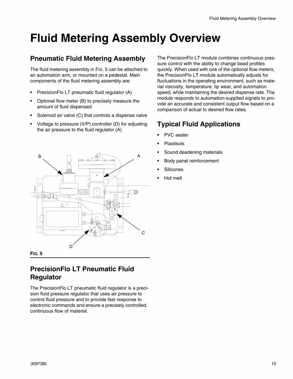
Fluid Metering Assembly Overview
Pneumatic Fluid Metering Assembly
The fluid metering assembly in FIG. 5 can be attached toan automation arm, or mounted on a pedestal. Maincomponents of the fluid metering assembly are:
• PrecisionFlo LT pneumatic fluid regulator (A)
• Optional flow meter (B) to precisely measure theamount of fluid dispensed
• Solenoid air valve (C) that controls a dispense valve
• Voltage to pressure (V/P) controller (D) for adjustingthe air pressure to the fluid regulator (A)
PrecisionFlo LT Pneumatic FluidRegulator
The PrecisionFlo LT pneumatic fluid regulator is a preci-sion fluid pressure regulator that uses air pressure tocontrol fluid pressure and to provide fast response toelectronic commands and ensure a precisely controlled,continuous flow of material.
The PrecisionFlo LT module combines continuous pres-sure control with the ability to change bead profilesquickly. When used with one of the optional flow meters,the PrecisionFlo LT module automatically adjusts forfluctuations in the operating environment, such as mate-rial viscosity, temperature, tip wear, and automationspeed, while maintaining the desired dispense rate. Themodule responds to automation-supplied signals to pro-vide an accurate and consistent output flow based on acomparison of actual to desired flow rates.
Typical Fluid Applications
• PVC sealer
• Plastisols
• Sound deadening materials
• Body panel reinforcement
• Silicones
• Hot melt
FIG. 5
B A
C
D

Installation
16 309738L
InstallationOverviewThe basic steps to install a Graco PrecisionFlo LT system are shown below. See the separate component manualsfor detailed information.
A number of different types of applicators can be used with the system. Refer to the manual for your applicator.
Before Beginning Installation• Have all system and component documentation
available during installation.
• See component manuals for specific data on compo-nent requirements. Data presented here applies tothe PrecisionFlo LT assemblies only.
• Electrical schematics are included in this manual.Refer to the schematics as required when connect-ing power and I/O signals.
• Be sure all accessories are adequately sized andpressure-rated to meet system requirements.
• Use the Graco PrecisionFlo LT control unit only withthe PrecisionFlo LT fluid module.
Installation Steps
1. Mount LT control unit
2. Ground LT control unit
3. Mount fluid plate
4. Connect cables between the LT control unit and:
a. Junction box of the fluid module (OP cable)
b. Automation or cell controller (automation I/O cable)
5. Check ground continuity
6. Connect air and fluid lines
a. Connect fluid lines between fluid module and applicator. Connect fluid supply line and air supply to module
b. Plumb filter assembly near air drop site that will be used for fluid metering assembly
c. Connect other fluid and air lines to additional system components as instructed in their manuals
7. Connect control unit to power source

Installing the Control Unit
309738L 17
Installing the Control UnitMounting the Control Unit
• Select a location for the PrecisionFlo LT control unitthat allows adequate space for installation, service,and use of the equipment. See FIG. 6.
• Mount the control unit so that the disconnect is read-ily accessible and located 54-67 in. (137-170 cm)above the floor.
• For best viewing, the control display should be 60-64in. (152-163 cm) from the floor.
• Ensure all fluid lines, cables, and hoses easily reachthe components to which they will be connected.
• Ensure there is sufficient clearance around the con-trol unit to run cables to other components.
• Ensure there is safe and easy access to an appropri-ate electrical power source. The National ElectricCode requires 3 ft. (0.91 m) of open space in front ofthe assembly enclosure.
• Ensure the mounting surface can support the weightof the control unit and the cables attached to it.
8. Secure the PrecisionFlo LT control unit with appro-priate size bolts through the 0.31 in. (8 mm) diame-ter holes in the mounting tabs.
WARNING
Read Warnings, page 6.
FIG. 6
14”356 mm
12.75”324 mm
13.5”343 mm
12”305 mm
12”305 mm
Control UnitBack View

Installing the Control Unit
18 309738L
Electrical ConnectionsFollow these precautions when grounding, connectingcables, connecting to a power source or making otherelectrical connections.
Grounding Control Unit
Connect a ground wire from the ground point in the Pre-cisionFlo LT control enclosure to a true earth ground.See FIG. 7. A 10 AWG, 25 ft. (7.6 m) long ground wirewith clamp, Part No. 222011, is supplied.
The PrecisionFlo LT fluid module is grounded to the
control unit, using cables provided with the module.
WARNING
To reduce the risk of fire, explosion or electric shock:
• The PrecisionFlo LT control unit must be electri-cally connected to a true earth ground; the groundin the electrical system may not be sufficient.
• All wires used for grounding must be 18 AWG mini-mum.
• A qualified electrician must complete all groundingand wiring connections.
• Refer to your local code for the requirements for a“true earth ground” in your area.
Read Warnings, page 6.
CAUTIONIf power and grounding connections are not done prop-erly, the equipment will be damaged and the warrantyvoided.
CAUTIONTo avoid control voltage differences, ensure that theautomation and PrecisionFlo LT equipment aregrounded to the same point.
FIG. 7
Ground Terminal L1
L2

Installing the Control Unit
309738L 19
Connecting to Power Source
Have a qualified electrician connect the PrecisionFlo LTcontrol assembly to a grounded electrical source thathas the required service ratings, as shown in the PowerRequirement table.
To connect the control unit to the power source:
1. Remove a hole plug to use one of the pre-cut enclo-sure holes or, if necessary for your installation, cre-ate an opening in the control assembly enclosure.Protect interior components from metal chips whencutting or drilling.
2. Using the appropriate gauge wire, connect electricalpower L1 and L2 to the top of the fuse terminalblocks, see FIG. 7, page 18.
3. Use NEMA 4 cord grip to seal the area where wiresenter the enclosure.
Power Requirements:
WARNING
To reduce the risk of fire, explosion, or electric shock,the resistance between the supply unit componentsand true earth ground must be less than 0.25 ohms.
Read Warnings, page 6.
VAC: 93 - 264Phase: 1Hz: 50/60Full Load Amps. 1Fused Amps 2

Installing Fluid Metering Assembly
20 309738L
Installing Fluid Metering AssemblyTo install the fluid metering assembly hardware:
• Install the PrecisionFlo LT fluid metering assembly.
• Connect the PrecisionFlo LT fluid metering assemblyto the control assembly.
• Connect fluid lines and cables.
Installing the Fluid Metering Assembly
Preparing to Install the Assembly
Before installing the fluid metering assembly:
• See component manuals for specific data on compo-nent requirements. Data presented here pertains tothe PrecisionFlo LT fluid metering assembly only.
• Have all system and subassembly documentationavailable during installation.
• Be sure all accessories are adequately sized andpressure-rated to meet the system's requirements.
• Use only the Graco PrecisionFlo LT fluid meteringassembly with the PrecisionFlo LT control assembly.
Installing the Assembly
1. Select a location for the PrecisionFlo LT fluid meter-ing assembly. Keep the following in mind:
• Allow sufficient space for installing the equipment.
• Make sure all fluid lines, cables and hoses easilyreach the components to which they will be con-nected.
• Make sure the fluid metering assembly allows theautomation unit to move freely along all axis.
• Make sure the fluid metering assembly provideseasy access for servicing its components.
2. Locate and secure the PrecisionFlo LT fluid meter-ing assembly to the automation unit (or other mount-ing surface) with appropriate size bolts through the0.42 in. (10.7 mm) diameter holes in the base plate.See the mounting dimensions in Table 1 - Measure-ment, inches (mm) and FIG. 8.
Table 1 - Measurement, inches (mm)
WARNING
Read Warnings, page 6.
WARNING
Read Warnings, page 6.
A 16.0 (407)
B 15.0 (381)
C 11.0 (280)
D 8.0 (204)
FIG. 8
AB
D
C

Installing Fluid Metering Assembly
309738L 21
Connecting Fluid and AirLines
Follow the instructions in your separate componentmanuals to connect air and fluid lines. General guidelines are provided below.
• The PrecisionFlo LT fluid module should be installedon the automation unit or in another appropriateplace, as close as practical to the dispense valve.
• Connect a fluid line between the fluid module outletand the dispense device. Smaller diameter andshorter fluid lines (hoses) will provide better fluid sys-tem response.
• Connect a fluid line to the flow meter fluid inlet or reg-ulator inlet if your system does not have a flow meter.
• Air must be clean and dry, between 60-120 psi (0.41MPa - 4.14 bar). Flush air line before plumbing in airfilter assembly (234967). Plumb in air filter assemblynear air drop site (upstream of fluid plate module).Adding an air regulator to this line will provide moreconsistent dispense valve response times.
• Connect an air supply line to the 1/4 npt inlet port onthe fluid module(s) air supply inlet.
• Connect 5/32 in. or 4 mm OD air lines from the appli-cator's solenoid valve to the applicator. Plug anyunused solenoid ports.
To maximize system performance keep the dis-
pense hose length and ID as small as the applicationwill allow.
Grounding the Metering AssemblyGrounding the Fluid Metering Assembly
Ground the fluid metering assembly as instructed hereand in the individual component manuals. Make sure thefluid metering assembly and its components areinstalled correctly to ensure proper grounding.
Air and Fluid Hoses
For static dissipation, use only electrically conductivehoses or ground the applicator / dispense valves.
Metering Module
The PrecisionFlo LT fluid metering assembly isgrounded to the control assembly through proper con-nection of the electrical cable provided with the meteringmodule.
Dispense Device
Follow the grounding instructions in the dispense devicedocumentation.
CAUTIONRoute all fluid and air lines carefully. Avoid pinchingand premature wear due to excessive flexing or rub-bing. Hose life is directly related to how well they aresupported.
WARNING
Read Warnings, page 6.
CAUTIONIf power and grounding connections are not doneproperly, the equipment will be damaged and the war-ranty voided.

Installing Cable Assemblies
22 309738L
Installing Cable Assemblies
Fluid Module Cables
Operations Cable (13) - This cable carries signalsbetween the fluid module and the control unit. Theapplicator solenoid, V/P valve, pressure transducer andflow meter signals are carried through this cable.
Automation I/O Cable (17) - This cable carries signalsbetween the automation controller and the PrecisionFloLT control unit.
Maximum recommended length of both the opera-tions and automation cable is 125 ft. (38.1 m).
Connecting the Operations Cable
Operation cables are offered in three lengths (25, 60,and 125 ft.) and three flexibilities (see page 6 for cableoptions.)
To connect the operation cable between the control unitand fluid module do the following:
1. Locate the receptacle on the top of the control unit.See Fig. 8.
2. Connect the operation cable to the control unit rev-ceptable.
3. Locate the receptacle on the fluid module junctionbox.
4. Route the operation cable and conform to the follow-ing cable routing requirements:
• Avoid small bend radii.• Avoid pinch points.• Avoid cable pulling or stretching.• Keep cables from rubbing against other compo-
nents or machinery.• If a lot of robot wrist motion is required, leave
sufficient cable length to allow for the motion,avoiding any cable droops that may interferewith the machinery or substrate.
• Cable ties should only be used to loosely bundlehoses together. Do not tighten cable ties to thepoint where cable movement is restricted.
5. Connect the operation cable to the fluid modulejunction box.
6. Check the connections to ensure the cable is con-nected correctly.
FIG. 9
BB
PrecisionFlo LTControl Unit
*Operations Cable Automation I/O
Automation I/OController
*Available in
25’, 60’, or 125’lengths of:
FIG. 10
CAUTIONAlways make connections to the control assembly withthe power off.
13 17
Control Unit - Top View

Installing the Cable Assemblies
309738L 23
Installing the Cable Assemblies
Connecting the Automation ControlCable
The PrecisionFlo LT control assembly is provided withan 18-pin receptacle for the automation I/O cable.
Any wiring from an external source such as anautomation controller, must follow the automation manu-facturer’s instructions and must comply with the appro-priate codes and standards.
The automation cable has terminated individualleads. The installer will need to configure the properconnector for the automation/cell controller being used.Refer to Appendix C Theory of Operation on page 95and Appendix A PrecisionFlo LT User Interface onpage 84.
To connect the automaton control cable between thecontrol assembly and the automation perform the follow-ing steps:
1. Locate the receptacle on the top of the controlassembly. See FIG. 10.
2. Connect the cable assembly to the automation I/Oreceptacle in FIG. 10.
3. Connect the opposite end of the cable assembly tothe applicable terminals or receptacle on the robotcontroller.
For information about specific control assembly circuitryand connections, read the chart on this page and seethe Wiring Diagrams beginning on page 69 and FIG. 10.
4. Check the connections to ensure the cable is con-nected correctly.
CAUTIONAlways make connections to the control assembly withthe power off.
Signal Wire No Description
Digital InputDispense Gun / 3290 This signal is used to control the opening of the dis-
pense valve.
Job Complete / 3310 This signal can be used to signal the end of a job.
Digital OutputDispenser Ready / 2680 This signal indicates to the automation controller that
the PrecisionFlo LT unit is ready to dispense.
Fault Present / 2710 This signal indicates to the automation control when afault is present.
In Cycle / 2740 This signal indicates to the automation control that thePrecisionFlo LT unit is currently in a job cycle.
Minimum Volume Dis-pensed / 2770
This signal indicates when the minimum amount ofmaterial is dispensed.
PFlo LT E-Stop / 2170 This signal indicates to the automation control whenthe emergency stop is depressed on the PrecisionFloLT unit.
Analog InputAnalog Flow Command /3150
This signal represents the flow or pressure requestsfrom the automation control.
Analog OutputActual Flow Rate Signal3210
Analog output signal of the current system flow rate.
24 VDC / 2120 24 VDC from the PrecisionFlo LT control box.
24 VDC Common / 2121 Digital reference point.
Analog Common / 3170 Analog reference point.
GND Shield connection.

Installing the Cable Assemblies
24 309738L
Checking Ground Continuity Have a qualified electrician check the resistancebetween:
• true earth ground and the panel ground lug
• the application device and the automation unit
• the fluid module and the automation unit
• the regulator and the automation unit
• each supply system component and true earthground
The resistance must be less than 0.25 ohms. If theresistance is greater than 0.25 ohms, a different groundsite may be required. Do not operate the system untilthe problem is corrected.
WARNING
To reduce the risk of fire, explosion, or electric shock,the resistance between the supply unit componentsand true earth grounding must be less than 0.25ohms.
Read Warnings, page 6.

PrecisionFlo LT Module Operation
309738L 25
PrecisionFlo LT Module OperationReading PrecisionFLo LT Control / Indicators
Table 2 - PrecisionFlo Buttons/Switches
Table 3 - PrecisionFlo LT Indicators
Table 4 - PrecisionFlo Indicator Lights
FIG. 11
7
64
3
1
2
Ref Button/Switch What it Does4 Sealer Stop Button • Disables all air solenoids and V/P regulators.
• Signals the external controller that a SEALER STOP condition is in effect.6 Run/Setup Mode Key
Switch• Turn key switch counter-clockwise to set control unit to Run Mode. When the
key is in Run Mode or removed, you can operate and monitor the system.
• Turn key switch clockwise to set control unit to Setup Mode (for software con-figuration). The key cannot be removed while turned to Setup Mode.
7 Main Electrical Power(Disconnect) Switch
• Turns on power to system.
• Lights Condition Light(s).
Ref Indicator Indicatorlight
Meaning
1 User Display On Display is on when power is applied to the control assembly.Off Display is off when power is removed from the control assembly or
the screen saver is active. Press any key to activate the screen.
Dispenser ReadyLight (Ref 2) Status
Fault Present Light(Ref 3) Status
Off Off No System Power or the system is in manual mode with no faultpresent.
On Off System is in auto mode with no fault present.On On System is in auto mode with a minor fault present.Off On System is in auto or manual mode with a major fault present or
the system is in manual mode with a minor fault present.

PrecisionFlo LT Module Operation
26 309738L

PrecisionFlo LT User Interface
309738L 27
PrecisionFlo LT User InterfaceThe EasyKey User Interface is available with the Preci-sionFlo LT control unit.
For screen-captures of the screens and your selectionoptions, see page 84 for the EasyKey interface.
Key Groups
There are three groups of keys on the PrecisionFlo LTuser interface.
• Action Keys – perform an action when they arepressed. Manual Dispense Gun, Fault Reset, BeadSize Increase, Bead Size Decrease, Help, and Auto/Manual. See Action Keys at right.
• Numeric Entry Keys – are used to enter variabledata into the controller.
• Navigation Keys – are used to navigate betweenand within the different user screens.
Action Keys
• Manual Dispense Gun – is used for functionsrelated to the regulator and dispense gun, includingmanual dispense, and calibration.
• Bead Size – is used to increase or decrease thebead size during unit operation. This feature isenabled / disabled in the setup screens.
• Help Key – is used to display the help screen.
• Fault Reset – is used to reset a fault generated onthe control once the fault has been corrected.
• Auto / Manual – is used to change the mode ofoperation between Automatic and Manual.
EasyKey User Interface Overview
FIG. 12
Bead Size Decrease
Bead Size Increase
Help Key
Manual
Fault Reset
Auto / Manual
Enter Key
Data Field
Dispense Gun
Navigation Keys
ScreenNavigation Keys

PrecisionFlo LT User Interface
28 309738L
Operation ModesThe PrecisionFlo LT system has two operating modes:
• Automatic dispense mode – enables the Precision-Flo LT module to begin dispensing when it receives acommand from the automation unit.
• Manual dispense mode – enables the Precision FloLT module to begin dispensing when you press Man-ual Dispense Gun on the EasyKey interface. Dis-pensing continues for as long as the ManualDispense Gun button is pressed. Manual mode isalso used for system tuning or calibration.
To select the Operation Mode and to operate in manualdispense mode, see the following specific instructions.
Refer to Appendix C, Theory of Operation, page 95for more information on Operation Modes.
Refer to Keypad Overview on page 27 for key
locations.
Setting Operation Mode
On the keypad, perform the following steps:
1. The dispense mode is indicated on the run screen,either Auto or Manual.
2. To change the mode, press the Auto/Manual key.
Manually Dispensing Fluid
On the keypad, perform the following steps:
1. Place the system in manual dispense mode. Referto Setting Operation Mode, above.
2. Press the Manual Dispense Gun key .
a. Press the key and verify that the dispensedevice opens.
b. Continue to press the key as long as needed toload material or dispense.
Control Modes
The PrecisionFlo LT module has four fluid dispensingcontrol modes:
• Bead Control – the control unit measures the flowrate of material being dispensed. The regulator outletpressure is varied to control the fluid flow rate to therequested value. Use Bead Control Mode when aconsistent bead size is required.
• Volume Monitor – regulator outlet pressure is con-trolled to the requested value. Use Volume MonitorMode when a constant pressure is required for aspray application.
• Batch Dispense – regulator outlet pressure is con-trolled to the requested value. Dispense valve isclosed when target volume is reached or the automa-tion provides a signal.
• Pressure Control – regulator outlet pressure is con-trolled to the requested value. Use pressure controlmode if the system does not include a flow meter.
Refer to Appendix C, Theory of Operation, page 95for more information on Control Modes.
Setting the Control Mode
1. Place the system in setup mode (key switch clock-wise).
2. The control mode is indicated on the dispensescreen.
3. To change the mode, press the down arrow keyuntil the cursor is over the mode cell.
4. Press Enter and use the up and down arrow keys, or to change values.
5. Press Enter.

PrecisionFlo LT User Interface
309738L 29
Automation Modes
The PrecisionFlo LT system has two automation com-mand modes:
• Fixed mode – enables the PrecisionFlo LT system todispense at preset rate in the control unit.
• Analog mode – enables the PrecisionFlo LT systemto dispense at a rate proportional to a 0-10 VDC ana-log input signal from the automation unit.
Refer to Appendix C, Theory of Operation, page 95for more information on Automation Command Modes.
Setting Automation Mode
On the keypad, perform the following steps:
1. With the system in setup mode (key switch clock
wise), press the right arrow key until the
OTHER screen appears. The command mode isindicated on this screen, either Fixed or Analog.
2. To change the mode, press the down arrow keyuntil the cursor is over the desired mode cell.
3. Press Enter and use the up and down arrow keys, or to change values.
4. Press Enter.

Operation
30 309738L
Operation
Pressure Relief Procedure
This procedure describes how to relieve pressure for thePrecisionFlo LT system.
1. Shut off the fluid supply to the fluid module.
2. Place a waste container beneath the fluid drainvalve, which is located at the filter. Place a wastecontainer beneath the dispense device.
3. Slowly open the drain valve, located at each filter, torelieve fluid pressure. Close valve when pressuregauge reads zero.
4. In manual dispense mode, touch and hold the Man-ual Dispense Gun key , which will open the reg-
ulator and the dispensing device, until the fluid stopsflowing from them.
5. If the dispense device cannot be actuated from thecontrol unit, refer to FIG. 13 and perform the follow-ing steps to open the dispense device and relievefluid pressure:
a. Manually actuate the plunger on the solenoid,that opens the dispense device, to relieve fluidpressure. Refer to FIG. 13.
b. Continue actuating the plunger until all pressureis purged from the system between the needleand the dispense device before proceeding tothe next step.
6. Shut off power and air to the fluid supply systems.
If you have followed the steps above and still suspectthat a valve, hose, or dispense nozzle is clogged orpressure has not been fully relieved, very slowly removethe dispense tip, clean the orifice, and continue relievingpressure.
If this does not remove the obstruction, very slowlyloosen the hose end coupling and relieve pressure grad-ually, then loosen the coupling completely. Clear thevalves or hose. Do not pressurize the system until theblockage is cleared.
Safety ReminderFollow the precautions below and the warnings thatbegin on page 6.
WARNING
Read Warnings, page 6.
FIG. 13
WARNING
Read Warnings, page 6.
ManualActuator
To Dis-penseValve
Dispense ValveAir Solenoid

Operation
309738L 31
Starting the SystemInitial Startup
1. Make sure you have installed and made all theproper connections to and from the PrecisionFlo LTcontrol assembly enclosure. Make sure fittings aretight.
2. Read and understand the Operation and SoftwareConfiguration sections of this manual.
3. Continue startup with step 2 in Standard Startup.
Be sure to set the max outlet pressure range
switch in the fluid module junction box to the appropriatevalue. See page 72. The pressure range (5 VDC sensorpressure) must match the junction box setting. See page92.
See Table 2 - PrecisionFlo Buttons/Switches
and PrecisionFlo LT User Interface, page 32 for infor-mation on the PrecisionFlo LT control unit buttons,switches, and indicator lights.
1. Carefully inspect the entire system for signs of leak-age or wear. Replace or repair any worn or leakingcomponents before operating the system.
2. Press the E-stop button (4). See FIG. 15.
3. Turn on air and electrical power to the system.
4. Turn on the main electrical disconnect (7) to supplypower to the PrecisionFlo LT module.
The user interface becomes active, showing first adiagnostic message and then the first screen. Thedispenser ready (2) and / or the fault present indica-tor light (3) turns on.
5. Check Interface Signals: If this is a new installa-tion, power each of the system inputs and verify thatthe input is being received.
6. Turn on material supply system.FIG. 14
Initial Startup
Read and understand Operationsection of this manual
Startup system
Check interfacesignals
Load Material
Verify flow meterK-factors
Configure software
End Initial Startup
FIG. 15
1
2 34 6
7

Operation
32 309738L
Loading MaterialBefore you can configure the software, you must loadmaterial into the supply system.
1. If this is a new installation, follow the Initial Start upprocedure. Otherwise, follow the Standard Startupprocedure. See page 31.
2. Turn on fluid supply pressure to the fluid module.
3. Place the dispense device(s) over a waste con-tainer.
4. Set the control unit to Manual mode. See OperationModes, below.
5. Select a control mode other than bead control. Dis-pensing in bead control mode is not possible until aflow calibration has been performed. See ControlModes on page 28.
6. Disengage the E-stop button (4). See FIG. 15.
7. Press and hold the Manual Dispense Gun key
. Manually dispense fluid until clean, air-free
fluid flows from the Dispense Gun.

Configuring Software
309738L 33
Configuring SoftwareAfter you have loaded material into the dispensing sys-tem, configure the PrecisionFlo LT software. FIG. 16shows the major configuration steps.
The PrecisionFlo LT system compensates for tem-
perature, flow, or pressure fluctuations. However, if youchange hardware on the dispensing system or changethe type of material being dispensed, you must reconfig-ure the PrecisionFlo LT software.
To configure the PrecisionFlo LT software, perform thefollowing procedure. When you have completed this pro-cedure, the module is ready for operation.
1. Select the desired control mode. See page 28.
2. Calibrate the system. See page 34.
3. Verify the flow meter K-Factor. See page 34.
4. Verify other controller preset values. See page 37for more information.
5. The PrecisionFlo LT User Interface section onpage 27 gives detailed operating instructions for thedisplay keypad and each screen.
For more information regarding applications that
run continuously see Appendix C, Theory of Opera-tion, page 95.
FIG. 16
Configure Software
Verify flowmeter K-factor
Calibratesystem
Set user andsystem variables
Set dispenseon/off delays
End SoftwareConfiguration
Select ControlMode. Ref Page 27
Calibratesystem

Configuring Software
34 309738L
Setting Flow Meter K-FactorsThe accuracy of the PrecisionFlo LT volume reportingdepends on precise adjustment of the K-factor(s). Thecontrol unit uses the K-factor(s) to calculate the volumedispensed. If the set value is not correct, the system stilldelivers accurate and repeatable flow rates; however,the reported value may not be correct. See page 36 foradditional K-factor information.
Table 4 - Flow Meter K-Factors
Set Flow Meter K-FactorOn the keypad, perform the following steps:
1. With the system in setup mode, press the screen nav-igation key until the OTHER screen appears.
2. Press the down data field navigation key until theflow meter K factor value is highlighted.
3. Key in the K-factor value and press Enter. See Table4 - Flow Meter K-Factors for values.
System CalibrationPressure Calibration
The PrecisionFlo LT system uses variables (Kp and Ki)in the software calculations to accurately and preciselycontrol the fluid pressure and flow rate. The control unitcalculates Kp and Ki automatically during pressure cali-bration. These values are different with every material.
The system must be loaded with material before
calibrating pressure. The nozzle or tip should beinstalled on the dispense device.
Before Calibrating
1. Verify that the system is in setup mode and manualdispense mode.
2. Verify that dispense device is placed over a materialwaste container.
3. Verify that the fluid module air supply is on.
4. Verify that the control mode is set to the desiredvalue.
Calibrate
On the keypad, perform the following steps:
1. Press the right screen navigation key until the
Calibrate screen appears.
2. Enter the desired 100% command Flow/Pressure.
3. Press the Manual Dispense Gun key . The sys-
tem will dispense material for 15-30 seconds andgather the required information.
Manually Adjusting Kp and Ki
If automatic pressure calibration does not result inproper system pressure control, you can change the Kpand Ki values manually:
• If the regulator outlet pressure does not closely fol-low the desired pressure increase Kp with the Kivalue set to zero. Continue to increase the Kp valueby 10% increments until the proper pressure controlis achieved.
• Decrease Kp if the regulator outlet pressure oscil-lates rapidly above and below the commanded pres-sure. Continue to decrease the Kp value by 10%increments until the outlet pressure is stable.
• Set Ki volume to 2 and continue to increase the Kivalue by 2 until the system oscillates.
• Decrease Ki until oscillation stops.
Part No. Description K-Factor
239716 G3000 Gear Meters 8400244292 G3000 HR Gear Meter 16400246190 Helical Gear Meter 3500246652 High Resolution Helical Gear
Meter7000
246340 Heated Helical Gear Meter 3500

Configuring Software
309738L 35
Flow Rate CalibrationThe system only calibrates flow rate if you are operatingin Bead Control Mode. Flow rate calibration takes placeimmediately after the pressure calibration in bead con-trol mode.
How Flow Rate Calibration Works
Each application may have different flow rate require-ments. Flow rate calibration verifies the maximum flowrate of the system and determines the regulator outletpressure required to achieve the required flow rate.
At the start of the flow rate calibration procedure, youneed to enter the maximum flow rate required by theapplication. When you actuate the dispensing deviceduring calibration, the control unit:
1. Measures the maximum system flow rate. If themaximum system flow rate is less than the requiredmaximum flow rate a fault is generated.
2. Determines the outlet pressure required to obtainthe flow rate value you entered.
3. Calculates a linear ratio of the automation analoginput voltage to the desired flow rate. Refer to FIG.17.
Flow Rate Guide
Use the values in Table 5 - Maximum Flow Rate Val-ues (cc/min) as a guide to determine the maximum flowrate to enter during flow rate calibration.
Table 5 - Maximum Flow Rate Values (cc/min)
Setting Inlet Pressure
The inlet pressure reading should be in the range of 300psi (2.1 MPa, 21 bar) to 500 psi (3.4 MPa, 34 bar) abovethe outlet pressure reading under your highest flow con-dition.
Excessive inlet pressure will cause accelerated wear onthe regulating valve and the pump feed system.
Feed System Pressure Drop
During material flow, the regulator inlet pressuredecreases. The amount the pressure decreases is theamount of pressure lost between the feed pump and theregulator inlet. With high viscosity fluids, long linelengths, or small diameter line sizes this pressuredecrease can be thousands of psi (hundreds of bar).This means that the static pump pressure is set muchhigher than the regulator needs at its inlet. To preventexcessive control regulator wear or surging, a masticfluid pressure regulator is recommended on the feed lineclose to the control regulator. The mastic regulator willsuppress the static feed pressure at the control regulatorinlet.
FIG. 17
Flow mode: Analog voltage to flow rate ratioMax.FlowRate
Flow Rate(cc/minute)
00 10Automation Flow Command
Volts (Vdc)
Round Equivalent Bead Diameter (mm)
Max. Automa-tion Speed(mm/sec)
2 3 5 7 9
50 10 21 59 115 191
100 19 42 118 231 382
200 38 85 236 462 763
300 57 127 353 693 1145
400 75 170 471 924 1527
500 94 212 589 1155 1909
600 113 254 707 1385 2290
700 132 297 825 1616 2672
800 151 340 943 1847 3054
900 170 382 160 2078 3435
1000 189 424 1178 2309 3817

Configuring Software
36 309738L
Verifying Flow MeterCalibrationMost sealant and adhesive materials are compressible.Since the flow meter is measuring the material underhigh pressure, the actual volume of material dispensedmay vary slightly from the measured volume, due to thiscompressibility. If the K-factor is not correct, the dis-played volume will not be accurate.
Follow this procedure to calibrate the flow meter duringinitial setup and on a routine basis to check for flowmeter wear.
Method 1. Using a gram scale
1. Obtain a beaker, 500 cc or larger, and measure themass of the empty beaker.
2. Manually dispense material into the beaker. Holdthe beaker so that the stream of material is sub-merged in the captured material. This is to minimizeair entrapment in the container.
3. Record the volume dispensed on the Run screenand the flow meter K-factor from the Setup Otherscreen.
4. Calculate the actual volume dispensed:
5. Calculate the new flow meter K-factor:
6. Enter new K-factor.
7. Repeat the procedure to verify the new K-factor.
Method 2. Without using a gram scale, visual mea-surement
1. Obtain a beaker, 500 cc or larger with measurementincrements.
2. Manually dispense material into the beaker. Holdthe beaker so that the stream of material is sub-merged in the captured material. This is to minimizeair entrapment in the container.
3. Record the volume dispensed on the Run screenand the flow meter K-factor from the Setup screen.
4. Settle the material into the beaker and view theactual volume dispensed.
5. Calculate the new flow meter K-factor:
6. Enter new K-factor.
7. Repeat the procedure to verify the new K-factor.
Other Software SettingsThere are various software settings that are preset atthe factory, based on the system configuration that wasordered. A quick check of these variables is recom-mended. See Table 5 - PrecisionFlo LT User Vari-ables and Presets and Table 6 - PrecisionFlo LTSystem Variables.
The PrecisionFlo LT User Interface screens are listedin Appendix B beginning on page 84 to guide youthrough the process.
fluid mass (g)density (g/cc) = measure volume (cc)
K-Factor (new) = displayed volume (cc) x K-Factor (old)
measured volume (cc)
K-Factor (new) = displayed volume (cc) x K-Factor (old)
dispensed volume (cc)

Configuring Software
309738L 37
Setting User Variables
The following variables and presets should be verified prior to calibration and path programming and/or operation inautomatic mode. All of the screens as well as additional screen information can be viewed in Appendix B, Preci-sionFlo LT User Interface, starting on page 84.
There are additional variables that should be set after the path programming is completed, they include; High/Lowpressure settings and Style (volume) information.
Table 5 - PrecisionFlo LT User Variables and PresetsValues in italics are factory defaults.
Other System Variables
After the calibration and automation path programming is complete and the desired bead profiles have beenachieved, verify that the following variables are set.
Table 6 - PrecisionFlo LT System Variables
Screen Variable / Preset Values CommentsDispense Control Mode Bead Control, Volume Monitor,
Batch Dispense, or pressurecontrol
Only bead control mode controls flow.
Other Command Mode Analog or Fixed
Job End Mode Timer or Digital I/O
Language Many Set the desired language.
Pressure Units psi or bar Set the desired pressure units.
Manual Gun FlowRate
0 - 100%, 50% Flow rate or pressure setting for ManualDispense.
Job End Delay 0 - 999 sec, 4 sec Delay time after dispensing for job com-plete if Job End Mode is set to Timer.
Year,Month,Day,Hour, Minute
Set the Time and Date.
Default / FixedCommand
0-100%, 50% Set value for fixed command mode. If thecommand signal falls below 1 VDC in ana-log mode, this value will be used as thecommand.
Screen Variable / Preset Values CommentsDispense Volume 0 - 9999 cc, 25 cc Set the volume set point for each of the styles being used.
Tolerance 0 - 99.9%, 10% Set the volume tolerance for each of the styles being used.
Other Set the User configurable faults to Alarms or Warnings. More information on the faults can be found inAppendix B, PrecisionFlo LT User Interface.An Alarm will cause the fault present signal to activate and the dispenser ready signal to drop out. Thisis something considered by the user to be a major fault, one which should cause the system to stopdispensing.A Warning will cause the fault present signal to activate and the dispense ready signal to stay on. Thisis something considered by the user to be a minor fault, one which will warn the user but will continuedispensing even if the bead profile is degraded.

Configuring Software
38 309738L
On/Off DelaysThe PrecisionFlo LT regulator can physically respondfaster than the dispense device and its solenoid. As aresult, the regulator can supply material to the dispensedevice before the device has time to open. Supplyingmaterial to a closed device can create trapped-pressure.
At the end of a cycle, the dispense device can shut offbefore the pressure has dissipated. This can cause adispense of an excess of material at the beginning of thenext cycle.
To eliminate these two problems, you can change thedelay time associated with the opening of the regula-tor/dispense and/or the closing of the dispense device,see Table 7 - On/Off Delay Variables.
In general, your outlet pressure on the screen during “noflow” should be slightly below the outlet pressure duringdispense. If your dispense hose to the gun is creatingtoo much pressure drop during flow, you may want theno flow reading to be lower. High trapped pressuresshorten the dispense device life.
Table 7 - On/Off Delay Variables
FIG. 18 and Table 8 - Delay On/Off Timing show delayON and OFF timing.
Table 8 - Delay On/Off Timing
Regulator Pre-ChargeAnother method which can be used to increase the dispense hose pressure while the dispense valve is closed is touse a regulator pre-charge. Setting this value to a range of 1.00 to 5.00 VDC causes the V/P to apply 0 to 100 psi (.60MPa, 68 bar) air pressure to the fluid regulator. Typical values entered would be about 1.2 VDC.
Variable: Sets the Amount of Time:
Gun ON Sets time from Dispense Gun High toGun Open command
Regulator ON Sets time from Dispense Gun High toRegulator ON
Gun OFF Sets time from Dispense Gun Low toGun Close command
RegulatorOFF
Sets time from Dispense Gun Low toRegulator OFF
FIG. 18
D
C
A
B
Dispense GunSignal
PrecisionFlo LTRegulator
Gun OpenCommand
Gun ActuallyOpen
E F
A Regulator ON delay The user sets the regulator ON delay timing.B Gun ON delay Usually set to zero. Can be used to change the starting point of a bead.C Gun OFF Delay Usually set to zero. Higher values will lower the trapped pressure.D Regulator OFF delay The user sets the regulator OFF delay timing. Zero or small values will lower the
trapped pressure.E Gun Open Reaction
TimeTime delay for gun to physically open. Delay varies based on pneumatic hose lengthand valve air volume.
F Gun Close ReactionTime
Time delay for gun to physically close. Delay varies based on pneumatic hose lengthand valve air volume.

Configuring Software
309738L 39
Shutting Down the System1. Shut off the material supply to the fluid module.
2. Follow the Pressure Relief Procedure on page 30.
3. Turn off the PrecisionFlo LT system's compressedair supply.
4. Press the sealer stop button (7). See FIG. 19.
5. Turn off the main electrical disconnect (2).
WARNING
Read Warnings, page 6.
FIG. 19
7
2

Communicating with PrecisionFlo LT
40 309738L
Communicating with PrecisionFlo LTCommunication with the PrecisionFlo LT is carried outthrough the Graco Shell program (included). This is atext based menu program that you can use to performthe following tasks:
• Upgrade software
• Display software versions
• Download job and alarm logs
• Backup and restore setup parameters
• Restore the factory defaults
You can access the Graco Shell program via the pro-gramming port on the side of the control box. Plug oneend of the programming cable into the RJ12 (phone jackstyle) on the control box and the other end of the cableinto the serial (COM port) of a computer.
For more information on the use of Ethernet and
Ethernet Kit 118329 see Appendix D, Ethernet Kit118329, page 106.
The laptop computer used to interface to the GracoShell must be running some type of terminal emulationsoftware. Some examples are Hyper Terminal or TeraTerm. Graco recommends using Tera Term which canbe downloaded from http://hp.vector.co.jp/authors/VA002416/teraterm.html. The following communica-tions parameters must be used (these are the defaultparameters in Tera Term).
Once the programming cable is connected and the com-munications software is running, the user can activatethe Graco Shell by pressing the Enter key on the key-board. The main menu will be displayed.
The main menu will look as follows:
****Welcome to the Graco Control Application Menu****Build date: Mar 05 2003 14:23:23a. Software Update and Version Informationb. Data Transferc. Restore settings to factory defaultsEnter Selection [a-c]:
Upgrading Control Board Software
To upgrade the controller software, you must first obtainthe latest version of Ltcontrol.rec. Contact your Gracodistributor for details.
Select option “a”. Make sure the key switch is turned toSetup mode. The following text will be displayed.
Are you sure? Enter yes to continue:
Type “yes”. The following text will be shown.
****Welcome to the Graco Control Boot Software.****Version: 1.01.001 Built: Mar 10 2003 14:39:33.Warning: you are about to erase your applica-tion software.Type ‘yes’ to continue upgrading software(reboot to cancel).
Type “yes”. The following text will be shown.
Sector 1 erased.Sector 2 erased.Sector 3 erased.
Hyperterminal: Go to (Menu Transfer XXX SendText File) and select *.rec file.Tera Term: Go to (File XXX Send File) andselect *.rec file.
Select Send File from the File menu in Tera Term. Thenselect the Ltcontrol.rec from the selection box window(you will need to browse to the appropriate directory).
The file will begin to download to the controller, whichwill take approximately one to two minutes. When thedownload is complete, a new menu will appear on thescreen. The software upgrade is now complete. Cyclingpower to the controller is recommended after a softwareupgrade.
Setting ValuePort COM 1 or COM 2Baud Rate 57600Data 8 BitParity NoneStop 1 bitFlow Control None

Communicating with PrecisionFlo LT
309738L 41
Upgrading Display Board Software
To upgrade the display software, you must first obtainthe latest version of Ltdisplay.rec. Contact your Gracodistributor for details.
To upgrade the Display Software the jumpers
between terminals 2540 and 2541and terminals 2550and 2551 should be moved to connect terminals 2541and 3720 and terminals 2551 and 3740.
Once the programming cable is connected and the com-munications software is running, the user can activatethe Graco Shell by pressing the Enter key on the key-board. The main menu will be displayed.
****Welcome to the Graco EasyKey Display****Build date: Mar 10 2003 14:23:23.a. Install Display Application Softwareb. Display Software VersionsEnter Selection (a-b)
Select option “a”. Make sure the key switch is turned toSetup mode. The following text will be displayed.
Are you sure? Enter yes to continue:
Type “yes”. The following text will be shown.
****Welcome to the Graco Control Boot Soft-ware.****Version: 1.01.001 Built: Mar 10 2003 14:39:33.Warning: you are about to erase your applica-tion software.Type ‘yes’ to continue upgrading software(reboot to cancel).
Type “yes”. The following text will be shown.
Sector 1 erased.Sector 2 erased.Sector 3 erased.
Hyperterminal: Go to (Menu Transfer XXX Send
Text File) and select *.rec file.Tera Term: Go to (File XXX Send File) andselect *.rec file.
Select Send File from the File menu in Tera Term. Thenselect the Ltdisplay.rec from the selection box window(you will need to browse to the appropriate directory).
The file will begin to download to the controller, whichwill take approximately one to two minutes. When thedownload is complete, a new menu will appear on thescreen. The software upgrade is now complete. Cyclingpower to the controller is recommended after a softwareupgrade.
Displaying Versions
Select option “b”. Text similar to this will be shown.
Boot Code version: 1.01.001, checksum=52c2f6,built:Mar 10 2003 14:47:49Application: 1.01.001, checksum=cc5bd,built:Mar 05 2003 14:47:49
Return to Main Menu
Select option “h”. The main menu will be shown.
Welcome to the Graco Control Application MenuBuild date: Jul 06 2001 15:45:38 (debug build)a. Software Update and Version Informationb. Data Transferc. Restore settings to factory defaultsEnter Selection [a-c]:
Restoring Defaults
Select option “c” and the following message will appear.
Are you sure? Enter yes to continue:
Type “yes”.
When the operation is complete, the main menu will

Maintenance
42 309738L
MaintenanceThe following is a list of recommended maintenance procedures and frequencies to operate your equipment safely.The maintenance is divided between mechanical and electrical tasks. Maintenance must be performed by trainedpersonnel per this schedule to assure safety and reliability of the equipment.
Mechanical
Electrical
* Check Component Manual for more detailed maintenance information.
Operator Maintenance Person
Task Daily Weekly Monthly 3-6months
or125,000cycles
6-12months
or250,000cycles
18-24months
or500,000cycles
36-48months
or1,000,000
cycles
Inspect system for leaks ✓
Depressurize fluid, after opera-tion
✓
Remove heat from system, afteroperation
✓
Inspect filter (234967) bowls
and drain
✓
Check hoses for wear ✓
Check/tighten fluid connections ✓
Check/tighten air connections ✓
Lubricate dispense valves* ✓
Rebuild regulator* ✓
Rebuild dispense valve* ✓
Replace air filter (234967)
assembly
✓
Replace Solenoid ✓
Replace V/P valve ✓
* Check component manual for more detailed maintenance information.
Task Daily Weekly Monthly 6 months 12 months
Calibrate flow meter** ✓
Check cables for wear ✓
Verify cable connections ✓
Verify resistance of electric heaters* ✓
Verify operation of “System Stop” button ✓
** Weekly calibration is recommended for applications using abrasive materials.

Troubleshooting
309738L 43
Troubleshooting
Check all possible solutions in the chart below
before you disassemble the regulator.
Troubleshooting for individual regulators and flowmeters is discussed in their separate manuals. Thesemanuals are called out in the parts lists later in this man-ual. Also refer to the section on Troubleshooting andFault Recovery for detailed information on how faultcodes are communicated.
Fluid Modules
WARNING
Read Warnings, page 6.
Problem Cause(s) Possible Solution(s)No outlet pressure Air pressure low Verify air pressure is above 60 psi
(0.4 MPa, 4 bar)No “Gun On” signal from automa-tion unit
Check input from automation unit
No output signal from system I/Oboard
Check signal from system I/Oboard, verify that a signal is beingsent (1-5 VDC)
No air signal to air diaphragm Check for loose/disconnected/wornoperations cable; tighten/replace asrequiredCheck for loose/disconnected DINconnector to V/P valve; tighten
False signal being sent to control Check outlet pressure sensor output; verify that it corresponds tozero pressure; replace sensorand/or amplifier
High outlet pressure Needle/seat is worn Rebuild regulator; replace needle/seat
Air leaks from fluid module Loose air connections Check air connections; tighten ifnecessary
Worn gaskets Check/replace gaskets on V/P andsolenoid valve
Fluid module heater does not heat Temperature controller turned off Verify Zone is properly adjusted.Loose electrical connections Verify connection between inlet
hose and fluid module connectorVerify connections between inlethose and main enclosure
Blown fuse Check/verify fuse in heater controlbox
Broken heater element Check/verify heater resistanceBroken sensor Check/verify sensor resistance

Troubleshooting
44 309738L
Flow Meter
Regulator
Problem Cause(s) Possible Solution(s)
No flow measurement Flow meter pick-up sensor loose Tighten flow meter pick-up sensorFlow too low Verify flow rate is above minimum
for the flow meter selectedLoose wiring Verify wiring connections from flow
meter to junction boxDamaged flow meter pick-up sensor Replace pick-up sensor
False measurement Flow meter not calibrated Calibrate flow meterFlow meter cable shield wire notconnected
Verify shielding to ground
System not grounded properly Verify system groundNoisy power source Verify clean power supply power to
main enclosure
Flow reported is not correct orinconsistent
Flow meter not calibrated Calibrate flow meter
Flow meter is worn Replace flow meter
Problem Cause(s) Possible Solution(s)No pressure regulation Damaged diaphragm Replace diaphragm
Leaking or dirty seat Replace cartridge, or clean seatNo fluid flow Damaged valve actuator Replace valve actuatorPressure creeps above setting Metal chip or contamination
between ball and seatReplace cartridge, or clean seatarea
Damaged diaphragm Replace diaphragm
Damaged o-ring or improper seal Replace the o-ring under the seat
Damaged or clogged air regulator or
line (air-operated regulator only)
Clear obstruction in line. Service
regulator if necessary
Leaking or dirty seat Replace cartridge, or clean seat
Large change in inlet pressure Stabilize regulator inlet pressurePressure drops below setting Empty/clogged supply line Fill/flush supply line
Damaged or clogged air regulator orline (air-operated regulator only)
Clear obstruction in line. Serviceregulator if necessary
Using valve beyond its rated flowcapacity
Install valve for each spray gun or
dispensing valve
Large change in inlet pressure Stabilize regulator inlet pressureFluid leaks from spring housing Loose fluid housing Tighten the four cap screws
Damaged diaphragm Replace diaphragmChatter Excessive pressure differential be
tween pump and gunReduce pump pressure to not morethan 2000 psi (14 MPa, 138 bar)greater than required gun pressure.
Excessive flow rate Reduce fluid flow through regulator.Connect only one spray gun or dis-pensing valve to each fluid regulator

Troubleshooting
309738L 45
Dispense ValvesProblem Cause(s) Possible Solution(s)Valve not opening Air not getting to open port Verify air pressure solenoid
No “Gun On” signal from automa-tion unit
Check input from automation unit
No output from system I/O board Check output from system I/Oboard; verify that it is on
Valve not shutting off Air not getting to close port (exceptAutoPlus valve)
Verify air pressure to solenoid
Verify solenoid operation
Verify air line routing and connec-tions
“Gun On” signal from automationunit is on
Check input from automation unit
Check output from system I/Oboard; verify that it is on
Sluggish open/close Air pressure low Verify air pressure is above 60 psi(0.4 MPa, 4 bar)
Needle/seat worn Rebuild valve; replace needle/seat
Pressurized material past the valveshut-off is escaping
Reduce running pressure
Reduce nozzle length
Increase nozzle orifice sizeMaterial leaks from back of valve Shaft seal is worn Rebuild valve; replace sealsAir leaks from dispense valve Loose air connections Check air connections; tighten if
necessary
Worn piston o-ring Rebuild valve; replace piston o-ringDispense valve does not heat Temperature controller turned off Verify zone #4 is on through the
user interface
Loose electrical connections Verify connection between outlethose and valve connectorVerify connection between outlethose and main enclosure throughextension cord
Blown fuse Check/verify fuse in Electric Heatbox
Broken heat cartridge Check/verify heater resistance
Broken sensor Check/verify sensor resistance

Troubleshooting
46 309738L
Electrical Component PathsUse the following table to troubleshoot wiring to the automation:
KEY
Component – External component wired into module'sjunction box.
Description – Type of signal.
Component ID – Where it originates from on the com-ponent.
J-Box Wire – Wire number or terminal location in themodule's junction box.
Cable/Pin – Pin number on the operations cable. Theoperations cable connects the module's junction box tothe main electrical enclosure.
Enclosure Wire – The wire number inside of the mainelectrical enclosure.
Board/Connector – Where the wire terminates inside ofthe main electrical enclosure.
Component Description Cable /
Pin
Enclosure
Wire
Board / Connector Wire Color
Dispense Gun +24 VDC Input 1 3290 J8-4 WHTJob Complete +24 VDC Input 2 3310 J8-5 BLU24 VDC From IFC +24 VDC Input 5 2120 +24 VDC RED24 VDC Common COM 6 2121 Common BLKAnalog Flow Command 0-10 VDC Input 7 3150 J7-3 GRN/BLK
Analog Common COM 8 3170 J7-4 GRNActual FLow Rate Signal 0-5 VDC Output 9 3210 J7-6 ORN/BLKDispenser Ready +24 VDC Output 10 2680 J5-5, Green Light BLU/BLK
Fault Present +24 VDC Output 11 2710 J5-7, Red Light BLK/WHT
In Cycle +24 VDC Output 12 2740 J5-9 RED/WHT
Minimum Volume Dis-pensed
+24 VDC Output 13 2770 J5-11 GRN/WHT
24 VDC Thru E-Stop +24 VDC Output 14 2170 E-Stop Switch ORN
GND Shield GND 15 Shield Chassis GND N/A

Troubleshooting and Fault Recovery
309738L 47
Troubleshooting and Fault RecoveryThe following table describes the valid fault codes usedby the PrecisionFlo LT module, possible causes, andsolutions. PrecisionFlo LT module displays warningsand alarms on the user interface and alarms via the con-trol unit fault light.
• Alarms set the dispenser ready signal LOW.
• Warnings do not set the dispenser ready signalLOW.
Resetting Control Unit After a Fault
If a fault has occurred, you should clear (reset) the faultbefore restarting the PrecisionFlo LT control unit. Press
the fault reset key to clear the fault, or press the ?
key for additional information.
Table 9 – Fault Priority Table
FaultPriority
Fault Name FaultDescription
Causes Solutions
The following faults are always Alarms
2 DispenserStop
There is no electricalpower
E-Stop has been pressed Turn E-Stop switch to release
Green and/or red light not lit, con-trol assembly is off
Apply power to PrecisionFlo LTmodule
5 Closed GunFlow
System reading flowmeter pulses from FlowMeter with Gun closed.These meter pulses cor-respond to a flow ratethat is greater than 1000cc/min
Dispense hose leak Check hose; replace if needed
Flow meter providing false pulses Replace flow meter sensor or cali-brate meter (corilis)
Dispense valve not operatingproperly
Repair dispense valve
Flow meter providing false pulses Replace flow meter sensor
The following faults are always Warnings
1 Communica-tion Error
Communication hasbeen lost between thecontrol board nd the dis-play board
The display board and the controlboard are no longer communicat-ing
Repair any loose or disconnectedwires in the connectors betweenthe two circuit boards
Replace one or both of the circuitboards if their “heartbeat” LEDsare no longer blinking
Replace the wiring harnessbetween the two circuit boards
3 Power Up Control box power up
4 CalibrationError
System was not able tocomplete a flow calibra-tion
Flow setpoint higher than the flowrate the system can deliver
Lower calibration flow setpoint
Increase dispense valve tip size ordispense hose diameter
Increase supply pressure
Regulator worn or not operatingproperly
Repair regulator
A dispense command in flowmode was received without avalid flow calibration being per-formed
Perform a flow calibration

Troubleshooting and Fault Recovery
48 309738L
Table 9 - Fault Priority Table (continued)
FaultPriority
Fault Name Fault Description Causes Solutions
The following faults are always Warnings (con't)
6 VolumeComp Limit
Peak value of flow com-pensation for regulatorhas reached the 25% or400% limit
Fluid supply too low to achievedesired flow rate
Increase fluid supply pressure orcheck for clogged filter
Regulator is not able to closecompletely
Repair regulator
Major change to fluid or fluid sys-tem downstream of the regulator
Check fluid viscosity
Check hoses and tips for problems
Perform a new calibration if neces-sary
Operating below the minimumregulator operating pressure
Increase fluid pressure above reg-ulator minimum
7 Low Analog Analog commanddropped below 1 VDCwhile dispensing
Bad or loose I/O cable connection Check cable and connection
Entered command mode incor-rectly
Enter correct command mode
Automation program error Verify correct automation programor set the default flow rate to 3500or disable this fault
15 Default Kp/Ki Default Values for Kp &Ki have been loaded
The autotune portion of the cali-bration has failed to find new Kpand Ki values. Default values forthese parameters are being used.
Decrease the volume of the dis-pense hose (length and / or diame-ter)
Choose a smaller tip size for thedispense valve
Increase the fluid supply pressure
Manually adjust Kp and Ki (seepage 34)
16 Setup Val-ues Changed
Setup change notifica-tion
When the Key Switch was turnedfrom Setup to Run mode, the con-trol detected a change from previ-ous setup data value(s)
No action necessary if changeswere desired
Remaining faults are selectable by the user as Alarms or Warnings (Setup Alarms/Warnings screen)
8 High OutletPressure
Output pressure to thePrecisionFlo LT regulatoris above the upper limitset for operation. If thisfault occurred whiledoing a pressure calibra-tion, pressure calibrationcould not determine opti-mum values and defaultvalues were used
Incorrect limit set Verify limit is set correctly
Dispense hose/device plugged Clean/replace hose/device
Failed transducer CHeck transducer, replace if failed
Regulator is not closing com-pletely.
Repair regulator
Incorrect pressure amplificationswitch setting
Verify switch is set correctly

Troubleshooting and Fault Recovery
309738L 49
Table 9 - Fault Priority Table (continued)
FaultPriority
Fault Name Fault Description Causes Solutions
9 Low OutletPressure
Output pressure of thePrecisionFlo LT regulatoris below the limit set foroperation. If this faultoccurred while doing apressure calibration, sys-tem pressure was toolow (<500 psi [3.4MPa,34 bar] at the regulatoroutlet) to complete thecalibration
Incorrect limit set Verify limit is set correctly
No or insufficient material flow Increase material flow rate
Dispense valve needle is stuckclosed
Dislodge and inspect needle
Dispense valve leaking Repair dispense valve
Regulator not operating properly Repair regulator
Pump wink passed through outlet Recalibrate PrecisionFlo LT orincrease pump pressure
Failed transducer Check transducer, replace if failed
Incorrect pressure amplificationswitch setting
Verify switch is set correctly
10 High Volume Material dispensed dur-ing the last dispensecycle was above theamount established byrequest and above theallowable (entered) toler-ance
Material viscosity is outside flowcompensation window
Verify material characteristics,recalibrate if necessary. IncreaseBead scale
PrecisionFlo LT regulator is notregulating properly
Check regulator, repair if neces-sary. Increase pressure to regula-tor above.
Incorrect volume or tolerancewhen using Volume Monitor orBatch Dispense
Enter correct values or minimumoperating pressure
11 Low Volume Material dispensed dur-ing the last dispensecycle was below theamount established byrequest and below theallowable (entered) toler-ance
Partially plugged tip or supplysystem. Error is outside flow com-pensation window
Clean tip and/or supply system.
Insufficient flow to PrecisionFlo LTregulator inlet. Error is outsideflow compensation window
Increase flow rate to PrecisionFloLT regulator inlet
Material viscosity is outside flowcompensation window
Verify material characteristics,recalibrate if necessary
Material viscosity increased Increase bead scale
PrecisionFlo LT regulator is notregulating properly
Enter correct values or set the tol-erance to 0% to disable this fault
12 Low FlowRate
Measured flow rate lessthan desired flow rateminus tolerance
Fluid supply too low to achievedesired flow rate
Increase fluid supply pressure orcheck for clogged filter
Tip plugged Clean/replace tip
No air pressure to solenoid valves Turn on air to solenoid valves
No flow meter signal Check cable and sensor
No material supply Replace drum or turn on pumps
Incorrect flow tolerance or flowfault time
Enter correct tolerance or flow faulttime

Troubleshooting and Fault Recovery
50 309738L
FaultPriority
Fault Name Fault Description Causes
13 High FlowRate
Measured Flow ratemore than desired flowrate plus tolerance
Operating below the minimumregulator operating pressure
Increase fluid pressure above reg-ulator minimum
Regulator worn or not operatingproperly
Repair regulator
Flow meter providing false pulses Replace flow meter sensor
Incorrect flow fault tolerance orflow fault time
Enter correct tolerance or flow faulttime
14 ComputedTarget
The requested volumediffers from the enteredprocess target by morethan the entered toler-ance for style requested
Entered process target incorrectly Enter correct process target
Entered tolerance incorrectly Enter correct tolerance
Requested volume incorrect Check automation program
Automation problem Verify automation is correct

Control Assembly Service
309738L 51
Control Assembly Service
Servicing the Panel AssemblyThis part of the manual provides information about thefollowing panel assembly component:
• Main Control Board
• Software Upgrade
• Fuse
• Display Backlight
Main Control Board Removal
Remove the control board as follows:
1. Shut off system power at the main circuit breaker.
2. At the control assembly, move the MAIN powerswitch to the OFF position.
3. Open the hinged cover of the control assembly.
4. Unplug the connectors from the control board.
5. Pry the plastic cups off the board with a screwdriverto release the board from the din rail.
Control Board Replacement
Replace the control board as follows:
1. Snap the main control board onto the din rail.
2. Plug the connectors into the control board.
3. Close and lock the hinged cover on the controlassembly.
4. Apply system power at the main circuit breaker.
5. Move the MAIN power switch to the ON position,applying power to the control assembly.
6. Verify that the control board operates correctly.
7. Restore the system parameters to return the controlassembly to normal operating condition.
FIG. 20
Door Side
Display Backlight Easy Key Interface Main Control Board
Fuses
Enclosure Side
WARNING
Read Warnings, page 6.

Software Upgrade
52 309738L
Software UpgradeThere are two ways to upgrade the software in the Preci-sionFlo LT system.
• Use the Graco Shell Serial menu System (see Com-municating with PrecisionFlo LT, page 40).
• Replace the flash memory in the two circuit boards.
The software upgrade kit (253614 Standard) can also beused to upgrade software. This kit contains flash mem-ory chips for the display board (see FIG. 21) and controlboard (see FIG. 22). The kit also includes a chip pullingtool.
To replace a flash memory chip on either the displayboard or the control board, perform the following steps.
1. Attach the grounding strap included with the kit toyour wrist and ground appropriately.
2. Turn off the power to the LT system.
3. Press the two feet of the chip extraction tool into theopen holes in the corners of the flash chip socket onthe circuit board. See Display Board FIG. 21 orControl Board FIG. 22.
4. Position the chip extraction tool so that the feet ofthe tool are underneath the flash chip. Squeeze thetool to grip the chip.
5. Continue squeezing the tool while pulling the chipout of the socket.
6. Orient the new flash chip such that the beveled cor-ner on the chip aligns with the beveled corner of thesocket.
7. Press the new chip into the open socket. Make surethat the pins are not bent or touching.
8. Repeat this procedure for both circuit boards.
9. Turn the power on the LT back on.
Display Board
FIG. 21
253612 Standardflash memory chip
BeveledEdge

Software Upgrade
309738L 53
Control Board
FIG. 22
253613 flashmemory chip
Bevelededge

Panel Assembly Service
54 309738L
Panel Assembly Service
Fuse RemovalRemove the fuse as follows:
1. Shut off system power at the main circuit breaker.
2. At the control assembly, move the MAIN powerswitch to the off position.
3. Unlock and open the hinged cover of the controlassembly.
4. Lift to unlock the top of the fuse holder, which ishinged at the bottom, from its clamp.
5. Open the fuse holder fully. Locate the failed fuseinside.
6. Carefully remove the fuse from the fuse holder.
Fuse ReplacementReplace the fuse as follows:
Check the new fuse to ensure that it matches the
amp rating of the failed fuse.
1. Press both ends of the new fuse evenly into place inthe fuse holder.
2. Close and lock the fuse holder into place.
3. Close and lock the hinged cover on the controlassembly.
4. Apply system power at the main circuit breaker.
5. Move the MAIN power switch to the ON positionapplying power to the control assembly.
6. Verify that the fuse operates correctly.
7. Return the control assembly to the normal operatingcondition.
WARNING
Read Warnings, page 6.
FIG. 23
Lift the top of thefuse holder to unlock
Fuse location(two places)

Panel Assembly Service
309738L 55
Replacing the Backlighting
A Backlighting Replacement Kit is available. Order partno. 118337.
Before replacing the backlighting, check the inverter (9)for proper voltage by unplugging the backlighting con-nector (1), turning on the PFlo LT and carefully measur-ing the AC voltage across the two pins of the inverter.Voltage should read approximately 700 VAC. If notreplace the inverter.
1. Shut off system power at the main circuit breaker.
2. At the control assembly, move the main powerswitch to the off position.
3. Unlock and open the hinged cover of the controlassembly.
4. Unplug the ribbon cable from the board (4) by slid-ing it out of the connector. Note the position of thecable in the connector. The arrow indicates pin #1,reconnect later with pin #1 engaged.
5. Unplug the remaining connectors on the board andnote their location. Unplug the connector (1) comingfrom the backlighting bulb.
6. Remove the four screws from the board.
7. Disconnect the ground wire.
8. Remove the two small screws holding the backlight-ing (3) to the display (2), and slide the backlightingout the side of the display.
9. Install the parts in reverse order of disassembly
10. Return the control assembly to normal operatingconditions.
WARNING
A qualified electrician must complete all groundingand wiring connections.
Read Warnings, page 6.
FIG. 24
2
3
19
4

Fluid Module Service
56 309738L
Fluid Module ServiceThis section describes how to remove and replace thesecomponents on the fluid metering assembly:
• flow meter (20) (FIG. 25)
• regulator (14) (FIG. 25)
The numbers in parentheses in the text refer to ref-
erence numbers in the parts drawings and parts lists.
Prepare the System for Service
Relieve the system pressure. Follow procedure onpage 30.
Servicing the Flow Meter
For complete flow meter service instructions refer to themaintenance and service sections of the following man-uals: 308778 for all G3000 meters, and 309834 for allGraco Helical flow meters.
Remove the Flow Meter from the Mounting Plate
1. Prepare the system for service as instructed above.
2. Disconnect the flow meter cable (J) from the flowmeter sensor. See FIG. 25.
3. Disconnect the material hose.
4. Disconnect the swivel fitting (18) from the regulator.
5. Loosen the four screws (12), and remove thebracket (22) and flow meter.
6. The flow meter (20) weighs approximately 15 lbs.(6.75 kg). Carefully lift it off the mounting plate (10).
WARNING
Read Warnings, page 6.
FIG. 25
22 12
18
10
20 J14

Fluid Module Service
309738L 57
Install the Flow Meter on the Mounting Plate
1. Rest the flow meter and bracket (20) on the fluidplate while threading the swivel fitting (18) onto theregulator material inlet. See FIG. 25.
2. Tighten the swivel fitting (18) to the regulator mate-rial inlet.
3. Tighten the four screws (12) to hold the bracket andflow meter in place.
4. Check that the flow meter (20) and regulator (14)are still aligned.
5. Connect the material hose.
6. Connect the flow meter cable (J).
Servicing the Fluid Regulator
For complete cartridge fluid regulator service refer
to instruction manual 308647. For Mastic Fluid Regula-tors refer to instruction manual 307517.
Replacing the Cartridge
See FIG. 26 and perform the following steps.
1. Relieve the pressure.
2. Remove the cartridge assembly by loosening thevalve housing (5) with a 6 mm hex wrench and pull-ing the cartridge assembly out of the base housing(4).
The retaining nut (3) often loosens when removing
the cartridge assembly from the base housing. Be sureto re-torque as described in step 4.
3. Inspect and clean the internal walls of the basehousing (4).
Be careful to not scrape or gouge the internal walls
of the base housing. They are a sealing surface.
4. Re-torque the retaining nut (3) to 140 to 160 in-lb(16 to 18 N•m).
You must re-torque the retaining nut before you
install it in the base housing in step 5.
5. Install the new cartridge assembly in the base hous-ing (4), and torque the valve housing (5) to 30 to 35ft-lb (41 to 48 N•m).
The valve seat is double sided and may be
reversed for extended life. The o-ring and ball must bereplaced. See instruction manual 308647.
Service Kits for Regulator 244734
For the Fluid Diaphragm Repair Kit, order Part No.238747.
For the Cartridge Repair Kit, order Part No. 238748.
CAUTIONHandle the hard carbide parts ball, valve actuator, andvalve seat, carefully to avoid damaging them.
WARNING
Read Warnings, page 6.

Fluid Module Service
58 309738L
FIG. 26
diaphragmand valveactuatorsubassembly
cartridgeassembly
Torque Sequence for RegulatorBase Housing Screws (9)
4
2 3
1
4
5
3

Frequently Asked Questions
309738L 59
Frequently Asked QuestionsQ: What is the difference between running in Volume Monitor versus Bead Control?
A: In Volume Monitor the control will maintain a specific pressure at the fluid regulator outlet. If the viscosity of thefluid changes or the nozzle becomes restricted, that pressure will result in a different flow rate. If you have a flowmeter installed it can still monitor the job volume for faults. Volume monitor is sometimes desirable for sprayapplications to maintain a specific spray pattern.
In Bead Control the fluid regulator is still reacting to the fluid pressure for quick adjustment, but the control alsomonitors the flow meter. If the flow rate does not agree with the flow command, the pressure target is adjusted.This method gives you the quick response of a pressure transducer, while maintaining the rate accuracy of aflow meter.
Q: How do I adjust the flow rate up or down without changing my automation commands?
A: There is an adjustment called Bead Scale which appears on the EasyKey Run screen or on the Dispense SetupScreen. This can be set from 50-150% of command flow. To change the Bead Scale turn the key switch to theright to enter Setup mode. The Setup mode screen allows you to change the Bead Scale percentage. To changeto the new setting press the Enter key on the EasyKey interface. The new value will be stored when you turn thekey switch back to Run mode. In Run mode the Bead Scale can be changed using the bead adjust keys.
Q: Why do I get a warning for “Volume Compensation Limit”?
A: Something has changed since you calibrated the regulator. The control has changed the regulator pressure setpoint too far away from the calibration point. This happens in Bead Control when the control is monitoring theflow meter and trying to maintain the proper flow rate. The cause is some factor that has changed the pressure,downstream of the regulator, at the desired flow rate. This might be a plugged nozzle or a fluid viscosity change.The viscosity difference could be caused by a change in temperature or a new batch of material. If the pressureneeds to increase to maintain the desired flow rate, but the fluid regulator is already fully open, the volume com-pensation continues to increase the desired pressure target until the limit is reached. The fluid feed pressure atthe regulator inlet needs to be increased. If the fluid and equipment are all right you need to recalibrate to yourflow target.
Q: How is a fluid control regulator calibration performed?
A: There are three steps: (1) determine system maximums (2) pressure calibration (3) flow calibration. These stepsare performed sequentially during the calibration process. If you are not using a flow meter and will run in pres-sure control mode, only the pressure calibration and system maximums will be performed. To calibrate pressureand flow, see page 104.
Q: How do I know if the fluid control regulator calibration was successful?
A: On the EasyKey display, calibration was successful if the calibrate setup screen indicates “Calibration Valid”.
Q: Why will my fluid control regulator not calibrate in the calibration screen?
A: You may not have enough fluid pressure downstream of the regulator. Raising the downstream pressurebecomes more important if the pressure is below 500 psi (3.5 MPa, 34.5 bar). Try a smaller nozzle on the dis-pense valve.

Frequently Asked Questions
60 309738L
Q: Why is my calibration failing after only a few seconds?
A: You may not have been able to reach the maximum flow rate or maximum pressure you entered. To reach ahigher flow rate or pressure, you can increase the feed pressure or increase the dispense valve nozzle size.
Q: Why will my dispense valve not operate?
A: The valve will not dispense in Bead Control Mode until a valid calibration has been performed. Try switching tovolume monitor or pressure control mode or calibrate again.
Q: Does Volume Monitor Mode use a flow meter?
A: Running in Volume Monitor Mode requires a flow meter to monitor the job volume limits or job log volumes. Ifyou do not have a flow meter set the system to the pressure control mode.
Q: How do I know my flow and volume measurements are accurate?
A: Calibrate the flow meter as instructed on page 104. This is strongly recommended as many sealants are com-pressible, and the flow meter measures the fluid while it is under pressure. Calibrating the meter makes it accu-rate for your fluid at ambient pressure. Periodic calibration is also important to monitor your meter for wear.
Q: I have flow, but how do I know if my fluid regulator is working?
A: If a fluid regulator fails it can no longer hold back fluid pressure. If the outlet pressure climbs up to equalize withthe inlet pressure when you stop dispensing, the regulator has lost the ability to shutoff or fully regulate flow. Ifyou have pressure limits set you will get a High Outlet Pressure alarm. If you have job volume limits set you willget a High Volume On Last Job alarm.
Q: Is there a way to put the fluid plate control regulator in a bypass mode to still operate the dis-pense valve when I have a problem?
A: With the air operated regulators you can move the air tube that feeds the V/P valve directly to the fluid regulatorair inlet. Turn off the air supply before moving tubes.
Q: How do I download job logs or alarm logs from the PrecisionFlo LT control?
A: There is an external phone-style connection on the right side of the control enclosure. You need a PC or laptopcomputer with terminal emulation software and part number 233657 accessory cable kit. See Communicatingwith PrecisionFlo LT, page 40.
Q: Will I lose any of my Setup parameters or logged information if power is lost?
A: No. All setup parameters, job logs, and alarm logs are saved to flash memory and do not need any power. Thisis non-volatile memory similar to the cards used with digital cameras. There also is no battery to replace. Thesetup parameters are stored to flash memory when the key switch is moved from the setup to the run position.
Q: Can I cause an error or system problem while looking at screens when production is running?
A: If the key switch is turned counter clockwise or removed, which means the system is in Run mode, you can viewthe run screen but you cannot change any parameters except Bead Scale when enabled. You can still selectManual or Automatic mode on the user interface which would stop the automation initiated dispensing.

Frequently Asked Questions
309738L 61
Q: Can I change my Setup values while the machine is running?
A: Yes. If you turn the key switch to Setup mode, you have complete control of the system. Changes to controlmodes, pressure values, time delays, alarms, etc. become effective when you press Enter and the changes aresaved to memory when the key switch is turned back to Run mode.
Q: How can I get out of Setup without saving the changes I have entered?
A: You can turn the power off before turning the key switch back to Run mode. When you turn the power back on,the changes will not be there.
Q: How do I set my pressures?
A: First, set the dispense pressure. A dispense valve hose and nozzle should be used, which will maintain at least500 psi (3.5 MPa, 34.5 bar) back pressure at the fluid control regulator outlet at your lowest flow rate setting.
Second, set the feed pressure. Once you are running, back down the feed pressure to a point where the regula-tor inlet pressure stays at least 500 psi (3.5 MPa, 34.5 bar) greater than the regulator outlet pressure, when dis-pensing at your maximum flow rate. If you will have multiple valves open at the same time, being fed by thesame feed pump, do this check with all of those valves open. Excessive feed pressure will cause excessivewear.

Fault Reporting
62 309738L
Fault Reporting
Fault code data is valid for a minimum of 1 msec beforeFAULT ON DATA goes HIGH. Fault code data remainsvalid, and the FAULT ON DATA remains HIGH, until aFAULT RESET is received from the automation control-ler, or the fault is cleared using the display.
Fault codes are reported using the FAULT ON DATA sig-nal and the data bus. Fault codes can be either:
• Alarms, which cause the PrecisionFlo LT DIS-PENSER READY signal to go LOW or,
• Warnings, which keep the PrecisionFlo LT DIS-PENSER READY signal HIGH.
Both volume and fault data are available on the I/O
interface. Volume and fault data share I/O points, Data 1- Data 32768. If the VOLUME ON DATA output is on, theoutputs contain volume data. If the FAULT ON DATA out-put is on, the outputs contain fault data.
The automation unit can read a fault code any time dur-ing the cycle, If several faults are present at the sametime, the highest priority fault code is sent to the databus. At the end of the dispense cycle the data bus isused for volume reporting, If requested by the automa-tion controller. Once volume reporting has been com-peted, the fault code is placed back on the data bus.
Each fault is recorded on the user interface. The faultdata is also available on the I/O interface until the fault iscleared.
Refer to the Troubleshooting and Fault Recover sectionfor fault code causes, descriptions, and solutions for thevarious faults.
FIG. 27
Fault On Data
Fault Code Data
>1 msec

Control Assembly Parts
309738L 63
Control Assembly PartsPart No. 234129, Series B, PrecisionFlo LT Standard Control Assembly
RefNo Part No Description Qty.1 ENCLOSURE 12 112546 SCREW, machine 83◆ 118334 LABEL, warning 14 PLUG, conduit 25 CONNECTOR 16 HARNESS, key switch wire 17 SWITCH, power rotary 18 PANEL, control assembly 19 116653 SWITCH, key 110 LABEL, identification switch 111 117689 SWITCH, emergency stop 112 C19208 WASHER, lock 813 117788 KIT, accessory 114 117762 LAMP, led red snap in 115 117763 LAMP, led green snap in 116 LABEL, identification control box 117 CONNECTOR 118 LATCH, quarter turn 120† 223547 WIRE, assy 25 ft. 121 NUT, hex 422 WASHER, lock 223 WIRE, grounding 1
24 TERMINAL 125 WASHER, lock 626 NUT, hex 627 CONNECTOR, RJ12 128 253620 BOARD, control circuit 129 117782 POWER supply 130 115216 FUSE, 1 amp 231 BLOCK, clamp end 132 WASHER, lock 133 TERMINAL, ground 134 TERMINAL, block 435 FUSE, holder 236 SCREW, machine 137 TERMINAL, block 538 117790 POWER, supply 5V inverter 139 118337 DISPLAY, backlight 1
† These parts are not shown on the parts drawing.
◆ Replacement Danger and Warning labels, tags andcards are available at no cost.
RefNo Part No Description Qty.
2, 5, 12 2,12,17 7
3
9
4
271114
15
1
18
13

Control Assembly Parts (continued)
64 309738L
Control Assembly Parts (continued)
25, 26
38
39
23
6
24
29 32, 33, 36
31
30, 35
8
28

Fluid Module Parts
309738L 65
Fluid Module PartsFor additional parts see page 66.
2837
3627
41
20
29
35
1 43,4419
18 17
23
8
11
26
38,39
233
8 38,39 33 12 2 26 30,34 12
40
328
13
35
16
7
3513
16
8
Fluid Outlet
21
431
22
Fluid Inlet
Air Inlet
To DispenseValve
16
RefNo Part No Description
Qty.
1 117669 PLATE, blank fluid 12 195942 REGULATOR, I/P 16 198179 FITTING, bulkhead 17 551348 VALVE, sol 4-W 18 C06061 MUFFLER, sinter 210 234967 FILTER, inline (not shown) 111 198175 FITTING, push 112 111119 SCREW, valve 413 117820 SCREW, cap skt 216 198177 FITTING, push 320 198269 BRACKET, flowmeter 123 107530 SCREW, cap skt 424 070269 SEALANT, anaero 125 070408 SEALANT, pipe s 1
26 054753 TUBE, nylon rd 2.329 110580 SCREW, cap sock 230 198315 BLANK, label 132 196108 PLUG, assy 100V 133 198683 WIRE, 3 cond 2 234 291487 ARTWORK, identification 135 198708 LABEL, rectangular 336 198268 BRACKET, flowmeter 138 107100 SCREW, cap skt 239 112906 WASHER, lock sp 242 804500 LABEL, warning 143 112513 FERRULE, wire, white 544 112515 FERRULE, wire, red 4
RefNo Part No Description
Qty.

Fluid Module Parts (continued)
66 309738L
Fluid Module Parts (continued)
Code C Option-01 Model No 234168 13 234171 Junction box 14 198082 Transducer, pressure 121 244734 Regulator, assembly 127 108328 Screw, cap, skt 240 C34045 Spacer
Code C Option-02 Model No 2341653 234171 Junction box 14 198082 Transducer, pressure 117 198327 Bracket, flowmeter 118 110501 Screw, cap, skt 421 244734 Regulator, assembly 122 162449 Fitting, nipple 127 108328 Screw, cap, skt 228 239716 Meter, gear, G3000 131 156684 Union, adapter 137 198578 Harness, cable 140 C34045 Spacer 2
Code C Option-03 Model No 2341663 234171 Junction box 14 198082 Transducer, pre 117 198327 Bracket, flowmeter 118 110501 Screw, cap, skt 421 244734 Regulator, assembly 122 162449 Fitting, nipple 127 108328 Screw, cap, skt 228 244292 Meter, gear, G3000 HR 131 156684 Union, adapter 137 198578 Harness, cable 140 C34045 Spacer 2
Code C Option-04 Model No 2341673 234171 Junction box 14 198082 Transducer, pressure 117 117670 Bracket, flowmeter 119 115226 Washer, lock sp 621 244734 Regulator, assembly 122 C20461 Fitting, nipple 127 108328 Screw, cap, skt 628 246190 Meter, helical gear 131 156684 Union, adapter 137 123409 Harness, cable 140 C34045 Spacer 244 C19197 Washer, plain 4
Code C Option-05 Model No 2341953 234171 Junction box 14 198082 Transducer, pressure 117 117670 Bracket, flowmeter 119 115226 Washer, lock sp 621 244734 Regulator, assembly 122 C20461 Fitting, nipple 127 108328 Screw, cap, skt 628 246652 Meter, helical gear, HR 131 156684 Union, adapter 137 123409 Harness, cable 140 C34045 Spacer 244 C19197 Washer, plain 4
Code C Option - 06 Model No 2341703 234171 Junction Box 14 198082 Transducer, Pressure 121 246642 Regulator, mastic 127 108328 Screw, cap skt 2
Code C Option-07 Model No 2341693 234171 Junction box 14 198082 Transducer, pressure 117 117670 Bracket, flowmeter 119 115226 Washer, lock, sp 621 246642 Regulator, mastic 122 C20487 Fitting, nipple 127 108328 Screw, cap, skt 628 246190 Meter, helical gear 131 157785 Union, swivel 137 123409 Harness, cable 144 C19197 Washer, plain 4
Code C Option-08 Model No 2341963 234171 Junction box 14 198082 Transducer, pressure 117 117670 Bracket, flow meter 119 115226 Washer, lock 621 246642 Regulator, mastic 122 C20487 Fitting, nipple 127 108328 Screw, cap, skt 628 246652 Meter, helical gear, HR 131 157785 Union, swivel 137 123409 Harness, cable 444 C19197 Washer, plain 4
Code C Option-09 Model No 2341933 234209 Junction box 14 234191 Cable, pressure 15 117764 Sensor, pressure 121 246643 Regulator, mastic 127 108328 Screw, cap, skt 241 118331 Label, warning 145 624545 Fitting, tee 3/4 x 1/4 1
Code C Option-10 Model No 2341943 234209 Junction, box 14 234191 Cable, pressure 15 117764 Sensor, pressure 117 117670 Bracket, flowmeter 119 115226 Washer, lock, sp 621 246643 Regulator, mastic 122 175013 Nipple, pipe 127 108328 Screw, cap, skt 628 246340 Meter, helical gear, HTD 131 157785 Union, swivel 137 123409 Harness, cable 141 118331 Label, warning 144 C19197 Washer, plain 445 624545 Fitting, tee, 3/4 x 1/4 1

Accessory Parts
309738L 67
Accessory PartsAutomation Interface Cable AssemblyThe cable length of automation interface cable assembly 117774 is 40 ft (12.2 m). This figure shows the cable andidentifies the cable interface signals.
Pin # Wire # Color Description
1 3290 Blk Dispense Gun
2 3310 Red Job Complete
3 3350 Wht Style Bit 1
4 3370 Grn Style Bit 2
5 2120 Orn 24 VDC from IFC
6 2121 Blu 24 VDC common
7 3150 Brn Analog flow command
8 3170 Yel Analog common
9 3210 Vlt Actual Flow rate signal
10 2680 Gry Dispenser ready
11 2710 Pnk Fault present
12 2740 Tan In cycle
13 2770 Red / Grn Minimum volume dispensed
14 2170 Red / Orn 24 VDC thru E-stop
15 Ground
16 3390 Red / Blk Style Bit 3
17 3410 Wht / Blk Style Bit 4
18 Spare Wht / Red N/C
N/A Spare Wht / Grn N/C
N/A Spare Wht / Yel N/C
N/A Spare Wht / Blu N/C
56
2 1
4 3
7891011
12131415
161718

Operations Cable Assembly
68 309738L
Operations Cable AssemblyThe operations cable is offered in these lengths (25 ft, 60 ft, and 125 ft.) and three different flexibilities. See page 9 forcable options.
A 1 A 24 VDC thru E-stop
B 2 B 24 VDC common
C 3 C Gun solenoid
D 4 D Ground
E 5 E V/P +
F 6 F V/P -
G - G
H - H
J 7 J Pressure Sensor +
K 8 K Pressure sensor -
L - L
M - M
N 9 N Flow meter signal
P 10 P Flow meter common
R 11 R
S 12 S
D
GH
FE
M
L
J
K
SR
B
NP
C
A

Electrical Schematics
309738L 69
Electrical SchematicsPrecisionFlo LT Control Box
FIG. 28
200
201
2 02
203
204
205
206
207
2 08
2 09
210
211
212
213
214
2 15
216
217
218
219
220
221
222
2 23
2 24
225
226
227
228
229
230
2 31
232
233
234
235
236
2 37
2 38
250
251
252
253
254
255
256
257
258
2 59
2 60
261
262
263
264
265
2 66
267
268
2 69
270
271
272
273
274
2 75
2 76
277
278
279
280
FU
2051
2 A
MP
FU
2052
2 A
MP
P
S21
0P
OW
ER
SU
PP
LY
+24
VC
OM
R
301
459
358
333
401
477
271
268
307
461
3 60
G
E-S
TOP
SW
I TC
H
PB
215
2 120
2 121
2060
2061
2170
2 121
2121
212 1
2121
2121
2 710
268 0
J2
3 80
3 78
1 2 3 4 5 6 7
2550
2540
2 570
258 0
DAT
A D
OW
NLO
AD
/P
RO
GR
AM
MIN
GP
OR
T
CO
NT
RO
L B
OA
RD
2541
2551
2 560
RS
-232
TO
DIS
PLA
Y B
OA
RD
220
403
405
222
469
2 21
473
471
1 2 3 4 5 6 7 8 9 10 1 1 1 2
4 75
J5
+24
IN21
70
265 0
2660
2680
2710
2740
2770
CO
MM
ON
DIS
PE
NS
E G
UN
DIS
PE
NS
ER
FE
AD
Y
F AU
LT P
RE
SE
NT
IN C
YC
L E
MIN
VO
L D
ISP
EN
SE
D
# 20
BLK
# 20
BL K
#20
BLK
#18
GR
N/Y
EL
#18
GR
N/Y
EL
#20
BLU
#20
BLU
/WH
T
13
13
10
10
13
11
9
SE
RIA
L (R
S-2
32)
TX
1
RX
1
#20
PU
R12
DIG
ITA
L O
UT
#20
BLU
/ WH
T11
93-2
64 V
AC
50/6
0 H
zV
CC
TX
2
RX
2
2 560
RJ1
2JA
CK
1 2 3R
ED
BLK
WH
T
15
264
L1 L22A
2
1A
1
5
6
1
2
WIR
ING
FO
R R
OC
KE
R S
WIT
CH
WIR
ING
FO
R R
OTA
RY
SW
ITC
H
G
2 121
2120
2541
2551
2560
Rx
Tx
+24
CO
M
Opt
iona
lEth
erne
tK
it11
8329
2680
2681
222
469
#20
pur
12
DIS
PE
NS
ER
RE
AD
Y

PrecisionFlo LT Control Box
70 309738L
PrecisionFlo LT Control Box
FIG. 29
300
301
302
303
304
305
306
307
308
309
310
311
312
313
314
315
316
317
318
319
320
321
322
323
324
325
326
327
328
329
330
331
332
334
335
336
337
338
350
351
352
353
354
355
356
357
358
359
360
361
362
363
364
365
366
367
368
369
370
371
372
373
374
375
376
377
378
379
380
381
382
425
427
453
455
222
1 2 3 4 5 6 7 8
451
J8
DIG
ITA
L IN
FLO
W M
ET
ER
467
417
463
409
1 2 3 4 5 6
411
VD
DA
IN IN A OU
T
OU
T
3130
3150
3170
3190
3210
J7
465
PR
ES
SU
RE
SE
NS
OR
(0-
5VD
C)
CO
MM
AN
D (
0-10
VD
C)
AN
ALO
G C
OM
MO
N
V/P
CO
MM
AN
D (
0-5V
DC
)
FLO
W R
ATE
(0-
5VD
C)
457
CO
MM
ON
DIS
PE
NS
E G
UN
JOB
CO
MP
LET
E
CO
NT
RO
L O
N
ST
YLE
BIT
1
ST
YLE
BIT
2
215
222
1 2 3
PO
WE
R +24V
2120
2121
CO
NT
RO
L B
OA
RD
J6
1 2 3
DIG
ITA
L IN
PU
TS
DIS
PLA
Y B
OA
RD
J1
KS
353
OP
EN
= R
UN
CLO
SE
D =
SE
TU
P
226
1 2 3 4 5 6
+24V
V5 +5 +5 B2
J5
215
INV
ER
TE
R
BA
CK
LIG
HT
WH
T
WH
T
3660
3680
+5 R
ED
CO
M G
RN
3620
2121
2120
PO
WE
R/B
AC
KLI
GH
T
3230
3250
3290
3310
2170
3350
3370
1 2 3 4 5 6
TX
1
RX
1
RX
2
J6
RS
-232
PR
OG
RA
MM
ING
PO
RT
RS
-232
TO
CO
NT
RO
L B
OA
RD
SE
RIA
L (R
S23
2)
3720
3740
2580
2570
+24V
AN
ALO
G
+24V
TX
2
417
6
G
Bla
ck
Red
Whi
te
Whi
te
Red Gre
en Bla
ck
258
257

PrecisionFlo LT Control Box
309738L 71
PrecisionFlo LT Control Box
FIG. 30
400
401
402
403
404
405
406
407
408
409
410
411
412
413
414
415
416
417
418
419
420
421
422
423
424
425
426
427
428
429
430
431
432
433
434
435
436
437
438
450
451
452
453
454
455
456
457
458
459
460
461
462
463
464
465
466
467
468
469
470
471
472
473
474
475
476
477
478
479
480
481
482
483
484
485
A
OP
ER
ATIO
NS
CO
NN
EC
TOR
224
B26
5
C26
6
D E31
9
F31
7
G H J31
3
K31
6
L M N32
3
P32
5
R S
2170
2650
2660
3190
3170
3130
3170
3230
3250
SPA
RE
SPA
RE
FLO
W M
ET
ER
CO
MM
ON
FLO
W M
ET
ER
SIG
NA
L
SPA
RE
SPA
RE
PR
ES
SU
RE
SE
NS
OR
-
PR
ES
SU
RE
SE
NS
OR
+
SPA
RE
SPA
RE
V/P
-
V/P
+
SH
I ELD
DIS
PE
NS
E G
UN
CO
MM
ON
24V
FR
OM
E-S
TOP
I/O C
ON
NE
CTO
R
329
331
335
215
224
321
268
277
226
1 2 3 4 5 6 7 8 9 10 11 12 13 14 15 16 17 18
337
315
272
274
3290
3310
3350
3370
2120
2121
3150
3170
3210
2680
2710
2740
2770
2170
SH
I ELD
SPA
RE
SPA
RE
SPA
RE
24V
FR
OM
E-S
TOP
MI N
VO
L D
I SP
EN
SE
D
I N C
YC
LE
FAU
LT P
RE
SE
NT
DI S
PE
NS
E R
EA
DY
FLO
W R
ATE
AN
ALO
G C
OM
MO
N
CO
MM
AN
D
24V
DC
CO
MM
ON
24V
DC
ST
YLE
BI T
2
ST
YLE
BIT
1
JOB
CO
MP
LET
E
DIS
PE
NS
E G
UN
#18
GR
N/Y
EL
10
#18
GR
N/ Y
EL
10
#24
16
#24
17
G
Spa
re
Spa
re

PrecisionFlo LT Control Box
72 309738L
Fluid Module Junction Box
FIG. 31
ABCDEFGHJKLMNPRS
-2170-2650-2660-GND-3190-3170
-3130-3170
-3230-3250
2170
2170
31703170
3130GND
26602650
3190
265032303250
GNDGND- -+ +
J2-AJ2-BJ2-C
J2-DJ2-EJ2-FJ2-G
J2-H
J1-HJ1-G
J1-FJ1-EJ1-DJ1-CJ1-BJ1-A
217031902650
GND
26602650
GND
GND
217032303250
GND
J1-DJ1-CJ1-BJ1-A
5GND
REDWHTBLK
REDWHTBLK
REDCLRBLK
BLKREDGRNWHT
1
23
1
2GND
24V
SIG 1
SOLRTNGND
24V
SIG 1COM
EXE -EXE +SIG +SIG -
COM
V/P
SOL. 1
FlowMeter
PressureSensor
ApproximateLED location
ABCDEFGHJKLMNPRS
-2170-2650-2660-GND-3190-3170
-3130-3170
-3230-3250
2170
2170
31703170
3130GND
26602650
3190
265032303250
GNDGND- -+ +
J2-AJ2-BJ2-C
J2-DJ2-EJ2-FJ2-G
J2-H
J1-HJ1-G
J1-FJ1-EJ1-DJ1-CJ1-BJ1-A
217031902650
GND
2660
2650GND
GND
217032303250
GND
J1-DJ1-CJ1-BJ1-A
5GND
REDWHTBLK
REDWHTBLK
REDCLRBLK
BLKREDGRNWHT
1
23
1
2GND
24V
SIG 1
SOLRTNGND
24V
SIG 1COM
EXE -EXE +SIG +SIG -
COM
V/P
SOL. 1
FlowMeter
ApproximateLED location
PressureSensor
Orange tabon housing
Connections for:Pressure sensorV/PGun SolenoidFlow Meter
Max outlet pressurerange switch:set appropriate fluidworking pressure(1500, 3500,
OP cableconnector
or 5000 psi) See page95 for software update

Technical Data
309738L 73
Technical Data
*Flow rates and viscosities are general estimates. Flow rates drop as viscosity increases. Fluids are expected toshear under pressure. New applications or fluids should always be tested to determine proper line sizes and equip-ment selections.
See your Graco Authorized distributor for other capabilities.
*Minimum Flow Rates 38 cc/minute with G3000HR meter75 cc/minute with G3000 meter50 cc/minute with High Resolution Helical flow meter100 cc/minute with Helical flow meter (ambient/heated)
*Maximum Flow Rates 1900 cc/minute with G3000HR meter3800 cc/minute with G3000 meter3750 cc/minute with High Resolution Helical flow meter7500 cc/minute with Helical flow meter (ambient/heated)
Maximum FluidWorking Pressure
See List of Models on page 2
Minimum FluidWorking Pressure
At Regulator Outlet ......... 500 psi (3.5 MPa, 34.5 bar)
Minimum BackPressure
Between Regulator Outlet and Dispense Nozzle ...... 500 psi (3.5 MPa, 34.5 bar)
Air Supply PressureRange
60-120 psi (.4 - .8 MPa, 4.1- 8.3 bar) - 10 Micron filtration recommended
Fluid FiltrationRequired
30 mesh (500 micron) minimum
*Viscosity Rangeof Fluids
50 to 50000 cps with G3000 meter10000 to 1000000 cps with Helical meter
*Minimum DispensedShot Size
3 cc with G3000HR meter6 cc with G3000 meter4 cc with High Resolution Helical meter7 cc with Helical meter
V/P Output 1 to 5 VDC provide 0 to 100 psi (.68 MPa, 6.8 bar)
Wetted Parts Meters and Fluid Panels ..... 303, 304, 321, 17- 4 stainless steel; tungsten carbide,PTFE, steel, Fluoroelastomer
Power Requirements Full Load Amps - 1, Fused Amps - 2
Power Supply VoltageRange
120 VAC nominal ..... 93 - 264 VAC, 50-60 Hz., single phase
Operating Tempera-ture Range
Controller ..... 40° - 122° F (4° - 50° C)Fluid Panel ..... see regulator rate technical data, page 74.
Operating HumidityRange
0 - 90% non-condensing

Technical Data
74 309738L
Regulator Plates
Mounting dimensions and parts breakdowns for the Air-Operated Regulator Fluid Plates are in the installation sectionof this manual.
*Maximum system pressure depends on dispense valve.
Cartridge Regulator Mastic Regulator
Regulator Manual 308647 307517
Weight - No Flow Meter 25.5 lbs (11.6 kg) 33 lbs (15 kg)
Weight - W/G3000 30 lbs (13.6 kg) N/A
Weight - Helical 40 lbs (18 kg) 48 lbs (22 kg)
Fluid Port Inlet G3000 1/4” NPT (f)Helical 3/4” NPT(f)
3/4” npt(f)
Fluid Port Outlet 1/2” npt(f) 3/4” npt(f)
Maximum Inlet Pressure See List of Models on page 2 5000 psi (34 MPa, 340 bar)
Maximum Working Pressure* 4500 psi (31 MPa, 310 bar) Ambient 4500 psi (31 MPa, 310 bar)Heated 3500 psi (24 MPa, 241 bar)
Air Supply 1/4” npt(f) 1/4” npt(f)
Maximum Air Pressure 100 psi (0.7 MPa, 7.0 bar) 100 psi (0.7 MPa, 7.0 bar)
Minimum Air Pressure 60 psi (0.4 MPa, 4.1 bar) 60 psi (0.4 MPa, 4.1 bar)
Range Operating Temperature Ambient 40° - 120°F (4° - 50°C)) Heated 40° - 400°F (4° - 204°C)Ambient 40° - 120°F (4° - 60°C)
Minimum Flow Rate - G3000 50 cc/min N/A
Minimum Flow Rate - Helical 100 cc/min 100 cc/min
Air outlets, open and close to dispense valve 5/32” or 4 mm tube fittingsElectric Power Requirements 24 VDC, from PrecisionFlo LT controlHeight 8” (203 mm) (varies with model)Fluid Specifications For use when dispensing fluids that meet at least one
of the following conditions for non-flammability:
• The fluid has a flash point above 140° F (60° C) anda maximum organic solvent concentration of 20%by weight, per ASTM Standard D93.
• The fluid does not sustain burning when tested perASTM Standard D4206 Sustained Burn Test.
Ambient Air Temperature Range 40° to 120° (5° to 50° C)Noise DataContinuous operator (full current)
70 dBA
Dispensing device exhaust (with muffler, peak-hold)
84 dBA

Kits and Accessories
309738L 75
Kits and AccessoriesPrecisionFlo LT Recommended Spare Parts
Part Number Description
234282 Advanced control manual set in binder
244283 Standard control manual set in binder
117782 Power Supply
246496 Board, Circuit Assy, HI-Temp Press Sensor
246517 Board, Circuit Assy, Ambient Press Sensor
115216 Fuse, 2 Amp
117764 Sensor, Pressure, Assembly, High Temp.
246786 Sensor, High Temp., Helical
198082 Sensor, Pressure, Ambient
118342 Kit, Accessory, Communications Cable
195942 V/P
234967 Filter
Control Parts and Accessories
253620 PFlo LT Control Board Assy
117788 Kit, Accessory, Interface & Board, Std
117790 Power Supply, 5V Inverter
117818 Key, Panel Access
116728 Key, Set-Up
118329 Ethernet Kit
118337 Kit, Backlight Repair
117762 LED, Red
117763 LED, Green
117689 E-Stop
116320 Power Switch Rocker
116653 Rotary Disconnect
253614 Chip Set, CNTRL & Display Std
Fluid Plates
234168 Fluid plate, Ambient Cartridge Regulator with no flow meter
234165 Fluid plate, Ambient Cartridge Regulator with G3000 flow meter
234166 Fluid plate, Ambient Cartridge Regulator with a G3000HR flow meter
234167 Fluid Plate, Ambient Cartridge with helical flow meter
234195 Fluid plate, Ambient Cartridge Regulator with high resolution helical flow meter
234170 Fluid plate, Ambient Mastic Regulator with no flow meter
234169 Fluid plate, Ambient Mastic Regulator with helical flow meter
234196 Fluid plate, Ambient Mastic Regulator with high resolution helical flow meter
234193 Fluid plate, Heated Mastic Regulator with no flow meter
234194 Fluid plate, Heated Mastic Regulator with helical flow meter

Kits and Accessories
76 309738L
Fluid Plate Parts and Accessories
246687 Mastic regulator, 3/4” air operated (no transducer ports)
246642 Mastic regulator, 3/4” air operated, with transducer ports for ambient fluid plates
246643 Mastic regulator, 3/4” air operated, for heated fluid plates
246688 Mastic regulator, 3/4” air operated for heated applications (no transducer ports)
244734 Cartridge regulator with transducer ports for fluid plates
238748 Repair kit, cartridge regulator
238747 Fluid diaphragm repair kit, cartridge regulator
233131 Fluid section repair kit, mastic fluid regulator
246190 Flow meter, ambient helical, w/sensor
234134 Flow meter, ambient helical, w/o sensor
246652 Flow meter, high resolution helical, w/sensor
246650 Flow meter, high resolution helical, w/o sensor
246340 Flow meter, heated helical, w/sensor
246191 Flow meter, heated helical, w/o sensor
246786 Kit, sensor and cable for HG6000 (all models)
239716 Flow meter assembly, G3000 spur gear, meter and sensor
239719 Flow meter, G3000 spur gear, does not include sensor
244292 Flow meter assembly, G3000 HR spur gear, meter and sensor
244291 Flow meter, G3000HR spur gear, does not include sensor
239717 Sensor, flow meter, G3000 & G3000HR
198082 Pressure sensor, outlet for ambient regulators
117764 Pressure sensor, outlet for heated regulators
198579 Kit, cable, for adding SRZ40 meter
198578 Kit, cable, for adding G3000 meter
244343 Mass flow meter kit, non-intrusive
246596 Kit, Helical gear set repair (standard and heated)
246949 Kit, Helical gear set repair (high resolution)
123409 Kit, cable for adding HG6000 (Helical) meter
Cables
118342 Cable kit, PrecisionFlo LT to personal computer
117774 Cable, automation analog, 40 ft. (12.9 m)
198731 Cable, High Flex Operation, 20 ft. (6.11 m)
198296 Cable, High Flex Operation, 60 ft. (18.29 m)
198732 Cable, High Flex Operation, 125 ft. (38.1 m)
117751 Cable, Standard Flex Operation 20 ft. (6.11 m)
117752 Cable, Standard Flex Operation 60 ft. (18.29 m)
117753 Cable, Standard Flex Operation 125 ft. (38.1 m)
117747 Cable, Low Flex Operation, 20 ft. (6.11 m)
117748 Cable, Low Flex Operation, 60 ft. (18.29 m)
117749 Cable, Low Flex Operation, 125 ft. (38.1 m)
234191 Cable, Heated Pressure Sensor

Kits and Accessories
309738L 77
Filters and Accessories
C59725 Dual filter bank with gauges, ball and drain valves, 30 mesh element, 5000 psi, (345 bar, 34.5MPa) 1-1/4” NPT Inlet 1” NPT Outlet
C59547 Single filter kit, gauges, ball and drain valves, 30 mesh element, 5000 psi, (345 bar, 34.5 MPa) 1”NPT
C58997 Fluid filter, polyethylene support, 30 mesh element, 5000 psi (345 bar, 34.5 MPa) 1” NPT
515222 Fluid filter, polyethylene support, no element from above kits
157630 Spring, filter
521477 Fluid shutoff valve, 1” NPT(F), 5000 psi (345 bar, 34.5 MPa) CS, Fluoroelastomer
210657 Ball valve, high pressure, 1/2” NPT(M), 5000 psi, (345 bar, 34.5 MPa) CS, Fluoroelastomer
210658 Ball valve, high pressure, 3/8” NPT(M), 5000 psi, (345 bar, 34.5 MPa) CS, Fluoroelastomer
210659 Ball valve, high pressure, 3/8” x 1/4” NPT(M), 5000 psi, (345 bar, 34.5 MPa) CS, Fluoroelasto-mer
Applicators and Repair Kits
918533 Dispense Valve, Extrusion, Ambient, Ball Seat
918535 Dispense Valve, Extrusion, Ambient, Snuff Back
918537 Dispense Valve, High Viscosity
918539 Dispense Valve, Extrusion, High Flow, High Viscosity
918623 Compact Dispense Valve, Extrusion
918625 Compact Dispense Valve, Spray
233670 AutoPlus SAE valve
244930 Manifold, Fluid Inlet, AutoPlus SAE valve
243482 1K Ultra-Lite valve 45° outlet for orbiter
244535 EnDure Valve replacement, no manifold
244910 EnDure Valve with ambient or temperature conditioning manifold
244961 EnDure Valve with 120 volt electric heat (200°F) (93.3°C)
244962 EnDure Valve with 230 volt electric heat (200°F) (93.3°C)
239807 Needle assembly, AutoPlus SAE valve
233671 Seat, AutoPlus SAE valve
189970 Gasket, AutoPlus SAE valve, seat
192443 Gasket, AutoPlus SAE valve, inlet
114134 Gasket, AutoPlus SAE valve, inlet air
570267 Fluid Section Seal kit, 1K Ultra-Lite valve
570268 Rebuild kit, 1K Ultra-Lite valve
15E012 Standard seal kit, EnDure valve
15E011 High temperature seal kit, EnDure valve
104661 Quick exhaust valve, 1/8” NPT(F)
244021 Cable kit, 8 pin connector and 10 ft. cable for 240 VAC valves
PrecisionSwirl
234029 PrecisionSwirl Module, Narrow Pattern
241658 PrecisionSwirl Module, Wide Pattern
243402 Swirl orbiter, narrow pattern
243403 Swirl orbiter, wide pattern
243437 Tube/bearing repair kit, narrow pattern

Kits and Accessories
78 309738L
918620 Tube/bearing repair kit, wide pattern
617870 Cable, PrecisionSwirl, 55’
617829 Cable, PrecisionSwirl, automation, 40’
233125 Extension cable, 6’
233124 Extension cable 9’
233123 Extension cable 15’
241479 Motor kit
196008 Bellows (12-pack)
241569 Bearing Repair Tool Kit
Tips, Nozzles and Adapters
918610 Swirl dispense tip 0.012”, (0.31 mm) carbide
918601 Swirl dispense tip 0.015”, (0.38 mm) carbide
918602 Swirl dispense tip 0.017”, (0.43 mm) carbide
918603 Swirl dispense tip 0.019”, (0.48 mm) carbide
918604 Swirl dispense tip 0.021”, (0.53 mm) carbide
918605 Swirl dispense tip 0.023”, (0.58 mm) carbide
918606 Swirl dispense tip 0.025”, (0.64 mm) carbide
918607 Swirl dispense tip 0.027”, (0.69 mm) carbide
918608 Swirl dispense tip 0.031”, (0.79 mm) carbide
918611 Swirl dispense tip 0.035”, (0.90 mm) carbide
918612 Swirl dispense tip 0.039”, (0.99 mm) carbide
918613 Swirl dispense tip 0.043”, (1.09 mm) carbide
918614 Swirl dispense tip 0.047”, (1.19 mm) carbide
241813 Swirl dispense tip 0.051”, (1.30 mm) carbide
241814 Swirl dispense tip 0.055”, (1.40 mm) carbide
241816 Swirl dispense tip 0.070”, (1.78 mm) carbide
198316 Nozzle nut, 1/8” NPT for AutoPlus SAE valve, extruding applications
198391 Tip nut, AutoPlus SAE valve, fan or stream
617585 Nozzle nut for streaming tips, EnDure valve
197504 Straight 3/4-16 JIC outlet for swirl, EnDure valve
197842 Nozzle, 45° nose piece, orbiter to EnDure valve
198323 Adapter, 45° orbiter to EnDure
198324 Fitting, 45° orbiter to EnDure
607665 Dispense nozzle, steel, 1/8” NPT(M), 0.125”, (3.18 mm), 2’ (0.6 m) long
161505 Dispense nozzle, steel, 1/8” NPT(M), 0.094”, (2.39 mm), 2’ (0.6 m) long
164799 Dispense nozzle, steel, 1/8” NPT(M), 0.055”, (1.4 mm), 2’ (0.6 m) long
C17009 Dispense nozzle, steel, 1/8” NPT(M), 0.125”, (3.18 mm), 1.22’ (0.36 m) long
C01025 Dispense nozzle, steel, 1/8” NPT(M), 0.9” x 0.37 (22.86 mm x 9.40 mm) ribbon hardened tip, 2.43”(61.72 mm) long
182XXX Airless 182xxx fan tips for AutoPlus SAE valve, ref. 308813 manual
270025 Streaming tip, 0.025 (0.64 mm) orifice
270027 Streaming tip, 0.027 (0.69 mm) orifice
270029 Streaming tip, 0.029 (0.74 mm) orifice

Kits and Accessories
309738L 79
270035 Streaming tip, 0.035 (0.89 mm) orifice
270037 Streaming tip, 0.037 (0.94 mm) orifice
270039 Streaming tip, 0.039 (0.99 mm) orifice
270041 Streaming tip, 0.041 (1.04 mm) orifice
270043 Streaming tip, 0.043 (1.09 mm) orifice
270059 Streaming tip, 0.059 (1.50 mm) orifice
C08224 Shower tip, 6 orifices, 0.021” (0.53 mm) orifice size
Hoses
116760 Dispense, 0.50” (1.27 mm) ID x 6’, (1.83 m), Neoprene core, 4000 psi, (276 bar, 27.6 MPa) highflex, abrasion resistant for automation units
116762 Dispense, 0.62” (1.57 mm) ID x 6’, (1.83 m), Neoprene core, 3625, (250 bar, 25.0 MPa) high flex,abrasion resistant for automation units
116761 Dispense 0.50” (1.27 mm) ID x 10’, (3.05 m), Neoprene core, 4000 psi, (276 bar, 27.6 MPa) highflex, abrasion resistant for automation units
116763 Dispense, 0.62” (1.57 mm) ID x 10’, (3.05 m) Neoprene core, 3625 psi, 250 bar, 25.0 MPa) highflex, abrasion resistant for automation units
C12383 Feed, 1.0” (25.4 mm) ID x 10’, (3.05 mm), Neoprene core 5000 psi (345 bar, 34.5 MPa)
C12218 Feed, 1.0” (25.4 mm) ID x 20’, (3.03 m), Neoprene core, 5000 psi (345 bar, 34.5 MPa)
116749 Co-axial feed, 1.0” (25.4 mm) ID x 10’ (3.05 mm), synthetic rubber, 5000 psi (345 bar 24.5 MPa)
116748 Co-axial feed, 1.0” (25.4 mm) ID x 20’ (3.03 m), synthetic rubber, 5000 psi (345 bar 24.5 MPa)
115875 Dispense, 240 volt electric heat, 0.5” (1.27 mm) x 6’, (1.83 m) PTFE core
115903 Dispense, 240 volt electric heat, 0.62” (15.75 mm) x 6’, (1.83 m) PTFE core
115876 Dispense, 240 volt electric heat, 0.5” (1.27 mm) x 10’, (3.05 m) PTFE core
115880 Dispense, 240 volt electric heat, 0.62” (15.75 mm) x 10’, (3.05 m) PTFE core
115885 Feed, 240 volt electric heat, 0.87” (22.10 mm) x 10’, (3.05 m) PTFE core
115887 Feed, 240 volt electric heat, 0.87” (22.10 mm) x 20’, (6.1 m) PTFE core
116770 Jacket, 6’ (1.83 m) dispense hose, temperature conditioning
116769 Jacket, 10’ (3.05 m) dispense hose, temperature conditioning
C50239 Hose swivel, 1/2” NPT(F), 5000 psi (345 bar, 34.5 MPa)
512028 PTFE hose, SS braid, 0.187 (4.75 mm) ID, 10’ (3.05 m) long, 3000 psi (207 bar, 20.7 MPa)
685612 PTFE hose, SS braid, 0.22 (5.59 mm) ID, 6’ (1.83 m) long, 4000 psi (276 bar, 27.6 MPa)
205099 PTFE hose, SS braid, 0.25 (6.35 mm) ID, 2.5’ (0.76 m) long, 3000 psi (207 bar, 20.7 MPa)
205058 PTFE hose, SS braid, 0.25 (6.35 m) ID, 6’ (1.83 m) long, 3000 psi (207 bar, 20.7 MPa)
205349 PTFE hose, SS braid, 0.25 (6.35 m) ID, 15’ (4.57 m) long, 3000 psi (207 bar, 20.7 MPa)
204938 PTFE hose, SS braid, 0.25 (6.35 mm) ID, 25’ (7.62 m) long, 3000 psi (207 bar, 20.7 MPa)
206024 PTFE hose, SS braid, 0.25 (6.35 mm) ID, 50’ (15.35 m) long, 3000 psi (207 bar, 20.7 MPa)
235905 PTFE hose, SS braid, 0.308 (7.82 mm) ID, 2.5’ (0.76 m) long, 4000 psi (276 bar, 27.6 MPa)
685602 PTFE hose, SS braid, 0.308 (7.82 mm) ID, 15’ (4.57 m) long, 4000 psi (276 bar, 27.6 MPa)
685603 PTFE hose, SS braid, 0.308 (7.82 mm) ID, 25’ (7.62 m) long, 4000 psi (276 bar, 27.6 MPa)
511381 PTFE hose, SS braid, 0.401 (10.19 mm) ID, 10’ (3.05 m) long, 4000 psi (276 bar, 27.6 MPa)
685605 PTFE hose, SS braid, 0.617 (15.67 mm) ID, 6’ (1.85 m) long, 4000 psi (276 bar, 27.6 MPa)
685606 PTFE hose, SS braid, 0.617 (15.67 mm) ID, 10’ (3.05 mm) long, 4000 psi (276 bar, 27.6 MPa)
685607 PTFE hose, SS braid, 0.617 (15.67 mm) ID, 15’ (4.57 m) long, 4000 psi (276 bar, 27.6 MPa)

Kits and Accessories
80 309738L
686608 PTFE hose, SS braid, 0.617 (15.67 mm) ID, 25’ (7.62 m) long, 4000 psi (276 bar, 27.6 MPa)
C12288 PTFE hose, SS braid, 0.51 (12.95 mm) ID, 10’ (3.05 m) long, 1500 psi (103 bar, 10.3 MPa)
514428 PTFE hose, SS braid, 0.25 (6.35 m) ID, 10’ (3.05 mm) long, 3000 psi (207 bar, 20.7 MPa)
511385 PTFE feed 3/4”, (19.05 mm) 10’ (3.05 m) long, SS braid, PTFE feed, 4000 psi (276 bar, 27.6 MPa)
511387 PTFE feed 3/4”, (19.05 mm) 25’ (7.62 m) long, SS braid, PTFE feed, 4000 psi (276 bar, 27.6 MPa)
511390 PTFE feed 1”, (25.4 mm) 10’ (3.05 m) long, SS braid, PTFE feed, 4000 psi (276 bar, 27.6 MPa)
109161 Hose Buna-N core and cover, 5000 psi, (345 bar, 34.5 MPa) 3/8” (9.52 mm) ID, 2’ (0.61 m) long
109162 Hose Buna-N core and cover, 5000 psi, (345 bar, 34.5 MPa) 3/8” (9.52 mm) ID, 4’ (1.22 m) long
109163 Hose Buna-N core and cover, 5000 psi, (345 bar, 34.5 MPa) 3/8” (9.52 mm) ID, 6’ (1.83 m) long
215441 Hose Buna-N core and cover, 5000 psi, (345 bar, 34.5 MPa) 3/8” (9.52 mm) ID, 10’ (3.05 m) long
215443 Hose Buna-N core and cover, 5000 psi, (345 bar, 34.5 MPa) 1/2” (12.7 mm) ID, 25’ (7.62 m) long
215444 Hose Buna-N core and cover, 5000 psi, (345 bar, 34.5 MPa) 1/2” (12.7 mm) ID, 50’ (15.24 m) long
215445 Hose Buna-N core and cover, 5000 psi, (345 bar, 34.5 MPa) 1/2” (12.7 mm) ID, 5’ (1.52 m) long
215241 Hose Neoprene core and cover, 5000 psi, (345 bar, 34.5 MPa) 3/4” (19.05 mm) ID, 6’ (1.83 m) long
215238 Hose Neoprene core and cover, 5000 psi, (345 bar, 34.5 MPa) 3/4” (19.05 mm) ID, 10’ (3.05 m) long
215239 Hose Neoprene core and cover, 5000 psi, (345 bar, 34.5 MPa) 3/4” (19.05 mm) ID, 15’ (4.57 m) long
215240 Hose Neoprene core and cover, 5000 psi, (345 bar, 34.5 MPa) 3/4” (19.05 mm) ID, 25’ (7.62 m) long
626721 Dried hose, Buna-N core and cover, 5000 psi, (345 bar, 34.5 MPa) 1/2” (12.7 mm) ID, 10’ (3.05 m)long, dried, capped with desiccant
626722 Dried hose, Buna-N core and cover, 5000 psi, (345 bar, 34.5 MPa) 1/2” (12.7 mm) ID, 25’ (7.62 mm)long, dried, capped with desiccant
626720 Dried hose, Buna-N core and cover, 5000 psi, (345 bar, 34.5 MPa) 1/2” (12.7 mm) ID, 5’ (1.52 m)long, dried, capped with desiccant
626723 Dried hose, Neoprene core and cover, 5000 psi, (345 bar, 34.5 MPa) 3/4” (19.05 mm) ID, 6’ (1.83m) long, dried, capped with desiccant
626724 Dried hose, Neoprene core and cover, 5000 psi, (345 bar, 34.5 MPa) 3/4” (19.05 mm) ID, 10’ (12.7m) long, dried, capped with desiccant
626725 Dried hose, Neoprene core and cover, 5000 psi, (345 bar, 34.5 MPa) 3/4” (19.05 mm) ID, 15’ (4.57m) long, dried, capped with desiccant
626726 Dried hose, Buna-N core and cover, 5000 psi, (345 bar, 34.5 MPa) 3/4” (19.05 mm) ID, 25’ (7.62 m)long, dried, capped with desiccant
Temperature Conditioning and Electric Heat
198457 RTD Sensor, 100 ohm, 3 pin picofast connector
198458 Sensor cable, 6 ft., (1.83 m) 198457 sensor to temperature conditioning unit
116824 Heat zone controller module, temperature conditioning (spare parts)
116503 Heat zone controller module, electric heat (spare parts)
116201 Control relay 12v coil, electric heat box (spare parts)
116204 Zone relay, qty. 4, electric heat box (spare parts)

Appendix A
309738L 81
Appendix AUsing the PrecisionFlo LT I/OThe PrecisionFlo LT uses several I/O signals to communicate with plant automation controllers. There are four digitalinputs, four digital outputs, one analog input, and one analog output. All of these signals are routed to the I/O connec-tor on the top of the controller.
Other pins on the I/O connector include 24 VDC power, 24 VDC common, analog common, and a signal which is 24VDC power only when the controller E-Stop switch is not latched in. None of the signals are isolated; all are refer-enced to the ground plane of the control board. The following paragraphs describe typical connection methods for theautomation controller signals.
Digital Inputs
The two digital inputs are Dispense Gun and Job Com-plete. These inputs require a 24 VDC current sourcingoutput from the automation controller. See FIG. 32.
If the automation controller uses relay contacts to acti-vate I/O signals, the 24 VDC available at the Precision-Flo LT I/O connector (pin 5) should be used to drive theinputs. If the automation controller uses high-sideswitching of 24 VDC, the automation outputs can bedirectly connected to the inputs as long as the 24 VDCcommon (pin 6) of the PrecisionFlo LT is able to be con-nected to the automation controller common. If the auto-mation controller outputs are low-side switching (opencollector) or a voltage other than 24 VDC, relays mustbe used as shown in FIG. 32.
FIG. 32
Pin 1 or 2

Appendix A
82 309738L
Digital Outputs
The four digital outputs are Dispenser Ready, FaultPresent, In Cycle, and Minimum Volume Dispensed.These outputs perform high-side switching of 24 VDCand require a 24 VDC current sinking input at the auto-mation controller. See FIG. 33. If the automation control-ler uses 24 VDC relay coils to receive I/O signals, thesignals should be connected as shown in FIG. 33.
If the automation controller uses optocouplers to receivedigital I/O signals, the inputs must be designed for 24VDC and the optocoupler emitter cathode must be con-nected to the PrecisionFlo LT 24 VDC common (pin 6).See FIG. 34.
If the automation controller inputs are current sourcingor use a voltage other than 24 VDC, relays with 24 VDCcoils must be used as shown in FIG. 33.
FIG. 33
FIG. 34

Appendix A
309738L 83
Analog Inputs
The PrecisionFlo LT receives a flow rate or pressureanalog command from the automation. The 0 to 10 VDCanalog input is referenced to analog common on thecontrol board. See FIG. 35. The reference for the auto-mation controller analog output must be connected tothe PrecisionFlo LT analog reference (pin 8) for this sig-nal to function properly. If this reference connection isnot possible an analog isolator must be used.
Analog Outputs
The PrecisionFlo LT provides a flow rate (tach) signal foruse in the automation. The 0 to 5 VDC analog output isreferenced to analog common on the control board. SeeFIG. 36. The reference for the automation controller ana-log output must be connected to the PrecisionFlo LTanalog reference (pin 8) for this signal to function prop-erly. If this reference connection is not possible an ana-log isolator must be used.
24 VDC From E-Stop
The PrecisionFlo LT provides a signal that can be usedby the automation controller to monitor the emergencystop switch position of the PrecisionFlo LT controller.See FIG. 37.
Relays
If the use of relays is required to condition the digital I/Osignals, these are some examples of part numbers thatcould be used.
For 24 VDC Coils:
• Relay: IDEC Part # RH1B-UDC24V
• Socket (DIN Rail): IDEC Part # SH1B-05
• Spring: IDEC Part # SY2S-02F1
For 120 VAC Coils:
• Relay: IDEC Part # RH1B-UAC120V
• Socket (DIN Rail): IDEC Part # SH1B-05
• Spring: IDEC Part # SY2S-02F1
FIG. 35
FIG. 36
FIG. 37

Appendix B
84 309738L
Appendix BPrecisionFlo LT User InterfaceScreen Overview - Run Screen (Bead Control Mode)The purpose of this screen is to display the required run parameters.
Notes:1. Reverse image indicates Run Mode Bead scale is enabled in the setup other screen.
2. Target Volume should change based on style.
3. Error values reflect the last completed job’s data.
Description Possible Values Default ValueHour 0-23 N/AMinute 0-59 N/ADay 1-31 N/AMonth 1-12 N/AYear 2000-2099 N/ADate Format mm/dd/yy-dd/mm/yy mm/dd/yyPressure 0-9999 N/APressure Units psi or bar psiActual Flow Rate 0-9999 cc/min N/ACommand 0-100% N/A
Bead Scale note 1 50-150% 100%
Dispense Mode Auto or Manual N/AControl Mode Bead Control, Volume Monitor, Batch
Dispense, or Pressure ControlBead Control
Style (not shown in low end) 1 to 4 1
Target Volumenote 2 0 to 9,999.9 cc 25.0 cc
Requested Volume 0 to 9,999,999.9 cc N/AActual Volume 0 to 9,999,999.9 cc N/A
Volume Errornote 3 -100.0 to 999.9% N/A
Active Fault Numerous text strings N/A
Output: 345 psi 213 cc/min
Command: 100% % Bead Scale
Mode: Auto Bead Control
VOLUME:
Target: 414 cc
Requested: + 0.2%
Measured: - 0.5%
No Active Faults 09/06/02 10:00
112
415
412

Appendix B
309738L 85
Run Screen (Volume Control Mode)
The purpose of this screen is to display the required run parameters.
Notes:1. Reverse image indicates Run Mode Bead Scale is enabled in the setup other screen.
2. Target Volume should change based on style.
3. Error Values reflect the completed last job's data.
Description Possible Values Default ValueHour 0-23 N/AMinute 0-59 N/ADay 1-31 N/AMonth 1-12 N/AYear 2000-2099 N/ADate Format mm/dd/yy-dd/mm/yy mm/dd/yyPressure 0-9999 N/APressure Units psi or bar psiActual Flow Rate 0-9999 cc/min N/ACommand 0-100% N/ABead Scale note 1 50-150% 100%
Dispense Mode Auto or Manual N/AControl Mode Bead Control, Volume Monitor,
Batch Dispense, or PressureControl
Bead Control
Style 1 to 4 1
Target Volume note 2 0 to 9999.9 cc 25.0 cc
Actual Volume 0 to 9,999,999.9 cc N/A
Volume Error note 3 -100.0 to 999.9% N/A
Active Fault Numerous text strings N/A
Output: 345 psi 213 cc/min
Command: 100% % Bead Scale
Mode: Auto Volume Monitor
VOLUME:
Target: 414 cc
Measured: - 0.5%
No Active Faults 02/25/03 10:00
112
412

Appendix B
86 309738L
Run Screen (Batch Dispense Mode)
The purpose of this screen is to display the required run parameters.
Notes:1. Reverse image indicates Run Mode Bead scale is enabled in the setup other screen.
2. Target volume should change based on style.
3. Error values reflect the last completed job’s data.
Description Possible Values Default ValueHour 0-23 N/AMinute 0-59 N/ADay 1-31 N/AMonth 1-12 N/AYear 2000-2099 N/ADate Format mm/dd/yy-dd/mm/yy mm/dd/yyPressure 0-9999 N/APressure Units psi or bar psiActual Flow Rate 0-9999 cc/min N/ACommand 0-100% N/ABead Scale note 1 50-150% 100%
Dispense Mode Auto or Manual N/AControl Mode Bead Control, Volume Monitor,
Batch Dispense, or PressureControl
Bead Control
Style 1 to 4 1
Target Volume note 2 0 to 9999.9 cc 25.0 cc
Actual Volume 0 to 9,999,999.9 cc N/A
Volume Error note 3 -100.0 to 999.9% N/A
Active Fault Numerous text strings N/A
Output: 345 psi 213 cc/min
Command: 100% % Bead Scale
Mode: Auto Batch Dispense
VOLUME:
Target: 414 cc
Measured - 0.5%
No Active Faults 09/06/02 10:00
112
412

Appendix B
309738L 87
Run Screen (Pressure Control Mode)
The purpose of this screen is to display the required run parameters.
Notes:1. Reverse image indicates Run Mode Bead scale is enabled in the setup other screen.
Description Possible Values Default ValueHour 0-23 N/AMinute 0-59 N/ADay 1-31 N/AMonth 1-12 N/AYear 2000-2099 N/ADate Format mm/dd/yy-dd/mm/yy mm/dd/yyPressure 0-9999 N/APressure Units psi or bar psiCommand 0-100% N/ABead Scale note 1 50-150% 100%
Dispense Mode Auto or Manual N/AControl Mode Bead Control, Volume Moni-
tor, Batch Dispense, or Pres-sure Control
Bead Control
Style 1 to 4 1Active Fault Numerous text strings N/A
Output: 345 psi
Command: 100% % Bead Scale
Mode: Auto Pressure Control
No Active Faults 09/06/02 10:00
112

Appendix B
88 309738L
Setup Screen 1 Dispense Screen
The purpose of this screen is to display the required run parameters.
Notes:1. Reverse image to indicate an input cell only if Run Mode Bead Adjust is enabled.
Notes:
Bead Scale cannot be changed with the membrane buttons in Setup mode, only with the number keys.
Bead Scale %
Control Mode
Target Volume cc +/- %
Dispense Calibrate Other
No Active Faults 02/24/06 09:34
100
Bead Control
25.0 10.0
Description Possible Values Default ValueHour 0-23 N/AMinute 0-59 N/ADay 1-31 N/AMonth 1-12 N/AYear 2000-2099 N/ADate Format mm/dd/yy-dd/mm/yy mm/dd/yyBead Scale 50-150% 100%Control Mode Bead Control, Volume Monitor,
Batch Dispense, or Pressure Con-trol
Bead Control
Target Volume 0 to 9999.9 N/AVolume Tolerance 1 to 4 0 to 99.9% 10.0%Active Fault Numerous text strings N/A

Appendix B
309738L 89
Setup Screen 2: Calibrate Screen (Bead Control Mode)
Notes:
The values for the pressure loop constants Kp and Ki can also be directly entered by the user in the OTHER setupscreen.
100% Command Flow cc/min
In Manual Mode, press to begin calibration
Calibration required (valid)
Press to see details
Output 345 psi 2134 cc/min
Desired Output 333 psi 2115 cc/minKp 105 Ki 4 346 psi
Max System Output 3405 cc/min 622 psiVolume Compensation -2% 112%
Dispense Calibrate Other
No Active Faults 09/06/02 10:00
2548
Description Possible Values Default ValueHour 0-23 N/AMinute 0-59 N/ADay 1-31 N/AMonth 1-12 N/AYear 2000-2099 N/ADate Format mm/dd/yy-dd/mm/yy mm/dd/yy100% commanded flow rate 50-150% 100%Pressure tuning status In process, complete N/AFlow calibration status In process, complete N/AFlow calibration result Required, Valid RequiredPressure 0-9999 N/APressure units psi or bar psiActual flow rate 0-9999cc/min N/ADesired outlet pressure 0-9999 N/ADesired flow rate 0-9999 N/A
Calculated optimal KP note 1 0 to 9999 100
Calculated optimal Ki note 1 0 to 9999 6
Pressure for 100% flow 0 to 9999 N/ASystem maximum flow with completely openreg
0 to 9999 N/A
Compensation zero offset -50 to 399% 0%Compensation peak 25 to 400 100%Active Fault Numerous text strings N/A

Appendix B
90 309738L
Setup Screen 2: Calibrate Screen (Batch Dispense and Volume Monitor Modes)
Notes:
1. The values for the pressure loop constants Kp and Ki can also be directly entered by the user in the OTHERsetup screen.
100% Command Flow psi
In Manual Mode, press to begin calibration
Calibration required (valid)
Press to see details
Output 1254 psi
Desired Output 1250 psiResult Kp 105 Ki 4
Max System Output 3250 psi 3405 cc/min
Dispense Calibrate Other
No Active Faults 09/06/02 10:00
2500
Description Possible Values Default ValueHour 0-23 N/AMinute 0-59 N/ADay 1-31 N/AMonth 1-12 N/AYear 2000-2099 N/ADate Format mm/dd/yy-dd/mm/yy mm/dd/yy100% commanded pressure 1 to 9999 1000Calibration status In process, complete N/APressure 0-9999 N/APressure Units psi or bar psiDesired Outlet Pressure 0 - 9999 N/A
Calculated optimal Kp note 1 0 to 9999 100
Calculated optimal Ki note 1 0 to 9999 6
System maximum pressure with completelyopen reg
0 to 9999 N/A
System maximum flow with completely openreg
0 to 9999 N/A
Active Fault Numerous text strings N/A

Appendix B
309738L 91
Setup Screen 2: Calibrate Screen (Pressure Control Mode)
Notes:
1. The values for the pressure loop constants Kp and Ki can also be directly entered by the user in the OTHERsetup screen.
100% Command Pressure psi
In Manual Mode, press to begin calibration
Calibration required (valid)
Press to see details
Output 1254 psiDesired Output 1250 psi
Result Kp 105 Ki 4Max System Output 3250 psi
Dispense Calibrate Other
No Active Faults 09/06/02 10:00
2500
Description Possible Values Default ValueHour 0-23 N/AMinute 0-59 N/ADay 1-31 N/AMonth 1-12 N/AYear 2000-2099 N/ADate Format mm/dd/yy-dd/mm/yy mm/dd/yy100% commanded pressure 1 to 9999 1000Calibration status In process, complete N/APressure 0-9999 N/APressure Units psi or bar psiDesired Outlet Pressure 0 - 9999 N/A
Calculated optimal Kp note 1 0 to 9999 100
Calculated optimal Ki note 1 0 to 9999 6
System maximum pressure with com-pletely open reg
0 to 9999 N/A
Active Fault Numerous text strings N/A

Appendix B
92 309738L
Setup Screen 3: Other Screens
LanguageControl ModeCommand ModePressure Loop Kp 1Pressure Loop Ki
Job End Mode
Job End Delay secondsRun Mode Bead Scale?Regulator Pre-Charge VDCGun On Delay msGun Off Delay ms 2
Reg On Delay msReg. Off Delay
Pulses per Flow Reading
Flow Comp Pivot %Flow Fault Time secondsScreen Saver Timeout minutesPressure Units 3Flow Meter K Factor pulses/LDefault/Fixed Command %Manual Command %Zero Pressure Signal VDC5 VDC Pressure psiMinimum Pressure psiMaximum Pressure psi 45 VDC Output Flow Rate cc/min
Date Format
Year 20MonthDay 5HourMinute
Bead ControlAnalog107
9
Timer4
.00
0
0
0
06
50
20psi
3500
50501.003500
050001000
mm/dd/yy03
090618
00
English
No

Appendix B
309738L 93
.
Low Volume AlarmHigh Volume WarningLow Flow Rate AlarmHigh Flow Rate Alarm 6Low Pressure WarningHigh Pressure WarningComputed Target Warning
Description Possible Values Default ValueLanguage English, Spanish,
French, German, Italian,Portuguese, Japanese,or Korean
English
Date Format dd/mm/yy or mm/dd/yy mm/dd/yyYear 00 to 99 (2000 to 2099) N/AMonth 1 to 12 N/ADay 1 to 31 N/AHour 0 to 23 N/AMinute 0 to 59 N/APressure Units PSI or BAR PSICommand Mode Fixed or Analog Analog
Default Command note 1 0 to 100% 50%
Manual Command 0 to 100% 50%Job End Mode Timer or Digital I/O Digital I/OJob End Delay 1 to 99 seconds 4 secFlow Meter K-Factor 1 to 99,999 pulses/L 3500Regulator Pre-Charge 0.00 to 5.00 VDC 0.00 VDCGun On Delay 0 to 999 msec 0 msecGun Off Delay 0 to 999 msec 0 msecReg On Delay 0 to 999 msec 0 msecReg Off Delay 0 to 999 msec 0 msecZero Pressure Sensor Signal 0.00 to 5.00 VDC 1.00 VDC5 VDC Sensor Pressure 0 to 5000 PSI 3500 PSIMinimum Outlet Pressure forFault
0 to 5000 PSI 0 PSI
Maximum Outlet Pressure forFault
0 to 5000 PSI 5000 PSI
Pressure Loop Kp note 2 0 to 9999 100
Pressure Loop Ki note 2 0 to 9999 6

Appendix B
94 309738L
Notes:
1. The default flow rate command would be used if there is no analog signal (fixed) or the analog signal is lost. Set-ting this value to zero disables the low analog fault.
2. The values for the pressure loop constant Kp and Ki are automatically calculated during the calibration processand can be manually changed here. See page 104.
3. The value for the number of pulses per flow reading is automatically calculated during the calibration process andcan be manually changed here. See page 34.
4. The Flow Comp Pivot is the command level that determines whether the zero offset or peak is adjusted duringvolume compensation. See page 104.
5. This variable sets the number of minutes without button press activity before the screen backlight will turn off.This function increases the life of the backlight. Setting this value to zero disables the screen saver function,keeping the light on continuously.
Pulses per Flow Readingnote 3
2 to 99 pulses 4 pulses
Flow Compensation Pivot
Point note 40 to 100% 50%
Flow Fault Time 1 to 99 seconds 2 secondsEnable Run Mode BeadAdjust?
Yes or No No
Screen Saver Timeout 0 to 99 minutesnote 5 0 minutes
5 VDC Output Flow Rate(scale analog “tach” out)
1 to 9999 cc/min 5000 cc/min
Low Volume Fault Alarm or Warning AlarmHigh Volume Fault Alarm or Warning WarningLow Flow Rate Fault Alarm or Warning AlarmHigh Flow Rate Fault Alarm or Warning WarningLow Pressure Fault Alarm or Warning WarningHigh Pressure Fault Alarm or Warning WarningComputed Target Fault Alarm or Warning WarningActive Fault Numerous text strings N/A

Appendix C
309738L 95
Appendix CTheory of OperationInput and Output Signals
Terminology
For the purpose of this document a digital signal is saidto be SET when voltage is present (or above the mini-mum threshold). A signal is said to be RESET when thesignal voltage is not present (below minimum threshold).Devices are referred to as SET when they are in theirenergized or active state.
Digital Inputs
Dispense Gun - This is the Dispense Signal. The Preci-sionFlo LT unit will attempt to dispense at either thecommanded flowrate or commanded pressure while thissignal is SET, dependent on mode.
Control On - This input is reset when the E-stop buttonis pressed.
Job Complete - This input can be used to signal a jobend.
The dispenser ready signal is an important signal
for the automation to monitor. When the dispenser readyoutput is not on, the LT may not be responding torequests form the automation. This could create the sit-uation where the automation is running production, butthe LT is not dispensing any material.
Gun Solenoid - This signal will be set to energize thegun solenoid at the beginning of a dispense cycle.
Minimum Volume Dispensed - This signal will be setwhen the minimum volume (target volume - tolerance)has been dispensed for the job.
Fault Present - This bit is RESET under the followingconditions:
1. No Faults (alarms or warnings) are active.
In Cycle - In Cycle signal is set at the beginning of a dis-pense cycle. It is reset at the end of the dispense cycle.The dispense cycle can end in two ways, depending onhow the Job End mode is set:
• If the Job End mode is set to automation I/O, dis-pense cycle ends when the job complete signal isreceived from the automation I/O.
• If the Job End mode is set to Timer, dispense cycleends when the Job End delay timer expires.
Analog Input
Flow Command - The flow command signal input rep-resents flow or pressure requests. The voltage must bebetween 0 and 10 volts DC. The 0-10 volt signal is inter-preted as a relative 0-100% flow or pressure commandsignal. The system must be in Analog Mode for thisinput to be used.
Outlet Pressure- The outlet pressure input representsthe fluid pressure at the regulator outlet. The defaultvoltage ranges from 1 to 5 VDC for 0 to 3500 psi (23.8MPa, 238 bar).
Analog Output
V/P Command - The V/P command output correspondsto an air pressure driving the regulator. The voltageranges from 1 - 5 VDC to adjust flow and/or pressure inthe fluid system.
Flow Rate - The flow rate output relates to the fluid flowthrough the meter. The voltage ranges from 0 - 5 VDCcorresponding to a 0 - 5000 cc/min.

Operation Modes
96 309738L
Operation ModesDispense Modes:
Manual ModeWhen in Manual mode, the PrecisionFlo LT controlreacts only to input from the user interface. The Preci-sionFlo LT control ignores automation controller signalswhen in Manual mode.
Automatic ModeWhen in Automatic mode, the PrecisionFlo LT controlremains in a ready state, indicated by the DISPENSERREADY signal, and reacts to inputs such as DISPENSEand VOLUME REQUEST signals from the automationunit.
When a fault is detected, the PrecisionFlo LT controlsets the FAULT present signal HIGH, and may set theDISPENSER READY signal LOW. Fault detection canalso occur during manual dispensing.
During dispensing, the PrecisionFlo LT control performsa variety of functions in the background. These func-tions include fault monitoring, real-time volume com-pensation, measuring volume (per job), and continuouscalculations to maintain the pressure and flow controlloops.
Control Modes:
Volume MonitorThe automation I/O or Manual dispense command andthe 100% pressure setting are used to set a pressuretarget. The regulator adjusts to maintain this pressure.In automatic mode the controller compares the dis-pensed volume to the target volume and sets volumefaults if needed.
Bead ControlThe automation I/O command for manual dispenseestablishes a Flow Rate target. A pressure setpoint isdetermined from the calibration results and the volumecompensation values. The regulator adjusts to maintainthe pressure setpoint, volume compensation will adjustthe pressure setpoint to achieve the desired flow rate.
Batch Dispense:The automation I/O command and the 100% pressuresettings are used to set the pressure target. The regula-tor adjusts to maintain this pressure. In automatic modethe dispense valve is closed when the target volume isreached, a job complete signal is received by the con-trol, or the job timer expires.
Pressure ControlThe automation I/O or manual dispense command andthe 100% pressure setting are used to set a pressuretarget. The regulator adjusts to maintain this pressure.
Automation I/O Modes:
Analog0-10 VDC signal from the automation unit is used todetermine the pressure or flow command. A 10 voltcommand will establish a pressure or flow rate com-mand equal to the 100% value entered during the cali-bration procedure. If an analog signal < 1vdc is giventhe pressure or flow command is determined by thevalue entered in the default/fixed command parameter.
FixedThe default/fixed value entered in the setup is used todetermine the pressure or flow command.

Jobs
309738L 97
JobsThe PrecisionFlo LT system operates using the conceptof jobs. A job is a specified amount of material that isdispensed by the system. The amount of material speci-fied for a job varies, depending on the application. Insome applications, a job may be the amount of materialdispensed on a part. Other applications may define ajob to be the amount of material dispensed on a numberof parts or dispensed over a period of time.
A job is initiated when the automation sends a “Dis-pense Gun” signal to the LT. Once the job is initiated, theLT will start tracking the amount of volume requested bythe automation and the amount of material that is actu-ally dispensed. These volumes will be tracked until thejob is completed. At the end of the job, fault calculationsare made and the volumes are stored to non-volatilememory on the LT system (Job Log).
The LT system watches two things to decide when a jobis complete. Either the “Job Complete” signal is sent bythe automation, or the job complete timer expires. Thetype of job end signal is configured in the “Other” screento be of type “Timer” or “Digital I/O”. If the timer methodis used, the timer begins counting every time the dis-pense gun is turned off. If the gun stays off for more thanthe preset timer value, then the job is considered com-plete.
Once the job is complete, the job information is stored tomemory. The most recent jobs can then be viewed onthe “Job” screen or by using the Graco Shell Menu Sys-tem. The information stored with each job is as follows.
Measured Volume - The amount of material measuredby the flow meter during a job.
Requested Volume - The amount of material that theautomation tries to dispense during a job. This volume iscalculated by measuring how long the dispense gun ison, taking in effect the command voltage from the auto-mation over time.
Target Volume - The theoretical amount of material thata job should have. This value is usually calculated orfound using trial and error when the application is firstset up.
In Bead Mode, all of these volumes are monitored. TheHigh Volume, Low Volume, and Computed Target faultsare evaluated at the end of the job. The volume alarmscompare the measured volume to the requested volumeand the computed target alarm compares the requestedvolume to the target volume.
In Volume Monitor Mode and Batch Mode, therequested volume is not measured. In these two modes,the automation command voltage corresponds to apressure instead of flow rate. For this reason therequested volume is not available (as well as the Com-puted Target fault). The high and low volume alarmscompare the measured volume to the target volume forVolume Monitor and Batch modes.
In Pressure Mode, there are no flow meters availableand the controls are all performed based on pressure.For this reason the LT does not monitor measured,requested, or target volume. The High Volume, Low Vol-ume, and Computed Target faults are all inactive whenusing Pressure mode.

Typical Job Cycle
98 309738L
Typical Job Cycle1. Automation system controller verifies that the DIS-
PENSER READY signal is HIGH.
2. Automation system goes into cycle.
3. PrecisionFlo LT control waits for DISPENSE gunsignal from the automation system to start dispens-ing.
4. Automation system controller requests material tobe dispensed by setting the DISPENSE gun signalHIGH.
In Batch Dispense Mode the dispense gun signalmust remain valid for a minimum of 20 msec.
5. Dispense gun opens after the GUN ON DELAY,immediately if the delay is set to zero.
6. PrecisionFlo LT control checks if a REGULATORON DELAY has been set by the user.
If the delay has been set, the PrecisionFlo LT controlwaits until the delay has expired, then begins regu-lating material to the gun.
If the delay has not been set, the PrecisionFlo LTcontrol immediately begins regulating material tothe gun.
7. PrecisionFlo LT control regulates output based onthe COMMAND input signal from the automationunit in analog mode or the set value in Default/Fixedmode.
8. PrecisionFlo LT control measures the volume dis-pensed continuously in all modes except pressurecontrol.
9. PrecisionFlo LT control continuously monitors theoutlet fluid pressure and the flow rate, as measured
by the flow meter, and makes adjustments forchanges in operating conditions.
10. PrecisionFlo LT control monitors operating parame-ters to detect and report any faults that may occur.
11. Automation unit sets the DISPENSE gun signalLOW, indicating that no material is required duringthis portion of the program. (automation unit cancycle the DISPENSE gun signal HIGH and LOWthroughout a cycle if required. Volume measure-ment will still occur.)
12. The regulator closes after the REGULATOR OFFDELAY expires.
13. The PrecisionFlo LT control checks if a GUN OFFDELAY has been set by the user.
If the delay has been set, the PrecisionFlo LT controlwaits until the delay has expired, then closes thedispense gun solenoid, which closes the gun.
If the delay has not been set, the PrecisionFlo LTcontrol immediately closes the dispense gun sole-noid, which closes the gun.
14. PrecisionFlo LT control stops measuring volumeafter the DISPENSE DONE DELAY timer expires orthe JOB COMPLETE automation I/O signal isreceived, depending on the job end mode selected.The job complete signal must remain valid for a min-imum of 20 msec.
15. PrecisionFlo LT control updates the Status screenand the Data table.
16. The PrecisionFlo LT waits for the next cycle tobegin.

Typical Dispense Cycle
309738L 99
Typical Dispense CycleThe In Cycle signal is set at the beginning of a dispense cycle, which starts with a Dispense Gun signal from theautomation unit.
Bead Control / Vol. Monitor / Pressure ControlUsing I/O for Job End
A = Regulator On Delay
B = Regulator Off Delay
C = Gun On Delay
D = Gun Off Delay
E = Minimum delay between regulator / valve closing is 10 msec
F = The minimum pulse width for the Job Complete signal is 20 msec
FIG. 38
Dispense GunInput Signal
RegulatorOn
A B
C D
F
ValveOn
Job CompleteInput Signal
In CycleOutput Signal
E

Typical Bead Control / Vol. Monitor / Pressure Control
100 309738L
Typical Bead Control / Vol. Monitor / Pressure ControlUsing Timer for Job End
A = Regulator On Delay
B = Regulator Off Delay
C = Gun On Delay
D = Gun Off Delay
E = Job end delay time, default value is 4 seconds
FIG. 39
Dispense GunInput Signal
A
C
B
D
E
RegulatorOn
ValveOn
In CycleOutput Signal

Typical Batch Dispense Cycle (I/O)
309738L 101
Typical Batch Dispense Cycle (I/O)Using I/O for Job End
A = The minimum pulse width for the Dispense Gun input signal is 20 msec.B = Regulator On DelayC = Regulator Off DelayD = Gun On DelayE = Gun Off DelayF = The minimum pulse width for the Job Complete signal is 20 msec
FIG. 40
ADispense GunInput Signal
B C
ED
F
RegulatorOn
ValveOn
Volume Not Reached, Job Aborted by I/O
Job CompleteInput Signal
In CycleOutput Signal
Min VolumeOutput Signal
Volume Reached, Job Ended AutomaticallyJob Complete
Input Signal
In CycleOutput Signal
Min VolumeOutput Signal

Typical Batch Dispense Cycle (I/O)
102 309738L
Typical Batch Dispense Cycle (Timer)Using Timer for Job End
(Minimum Volume = Target Volume - Volume Tolerance)A = The minimum pulse width for the Dispense Gun input signal is 20 msec.B = Regulator On DelayC = Regulator Off DelayD = Gun On DelayE = Gun Off DelayF = The Job End Delay time, default is 4 seconds.
FIG. 41
Dispense GunInput Signal
RegulatorOn
ValveOn
In CycleOutput Signal
Min VolumeOutput Signal
In CycleOutput Signal
Min. VolumeOutput Signal
Target Volume Reached
Minimum Volume Reached
F
D E
B C
A
Volume not reached, job aborted by timer
Volume reached, job ended automatically

Continuously Running Applications
309738L 103
Continuously Running ApplicationsIn some cases the target volume for a job is not known.An example of a case where the target volume isunknown is a continuously running system. This wouldbe a system that does not run jobs, but runs continu-ously over a day or a shift. In this case, the flow ratebecomes more important than the amount of volumedispensed in a job. The way to handle this situation is toset the target volume to a value of zero. This effectivelydisables the computed target fault. The controls will stillmaintain the desired flow rate and report faults corre-sponding to the tolerance set for the running style.
Another situation where it may be desirable to set thetarget volume to be zero is when there are too manystyles for the LT to keep track of. For the standard con-figuration, the LT only maintains one style and for theadvanced configuration there are four styles. If the tar-get volume is set to zero, then the LT will be able to han-dle running jobs with varied volumes with out generatingfaults. The flow rate faults will still be active and the highand low volume faults will also still be active. The com-puted target faults will not be active and the job logs willalways show a value of 0 in the Target Volume column.

Flow Rate Calculation
104 309738L
Flow Rate CalculationThe pulses per flow reading value is calculated by thesystem based on the K-factor and the flow rate enteredduring flow calibration.
The time is measured for the number of flow meterpulses in the flow average variable to occur and the flowrate is calculated.
Example: pulses per reading = 4 pulses
Flow Rate = 400 cc/min
K-factor = 3500 pulses/liter = 3.5 pulses/cc
This gives a pulse rate of 23.3 pulses/second or 43 milli-seconds/pulse. A new flow rate is measured approxi-mately every 171 milli-seconds.
If the time measured with the same parameters (3500pulses/liter, 4 pulses flow average) is 180 milliseconds,the flow rate calculation would be 380 cc/minute.
Flow CalibrationIn order to control the flow rate of a material, the system must determine the pressure required at the regulator outletto achieve a desired flow rate (Fig. 20).The flow calibration procedure provides the pressure required to obtain themaximum desired flow rate (10 VDC flow command.)
4 pulses
(pulses per reading)
FIG. 42
0
200
400
600
800
1000100%
80%
60%
40%
20%
0%
0 2 4 6 8 10-10%
The flow calibration proceduredetermines this point. This is theinitial pressure/flow peak setting(100%).
This is theinitial pressureflow offset setting(0%)
Flow Command (VDC)
10 VDC = flow rate entered on flow calibration screen for 100% flow command
Pressure (psi)
Default flow comp pivotpoint (50%). See ControlAssembly Parts on page

Flow Rate Calculation
309738L 105
Volume CompensationVolume compensation is used when the PrecisionFlo LTsystem is operated in bead control mode. The systemmeasures the actual flow rate and adjusts the pres-sure/flow relationship (as determined during flow cali-bration) to achieve the desired flow.
When flow calibration is completed, the resulting pres-sure value is divided by 100 to obtain a 1% value. Theinitial offset is set to 0%, the initial peak is set to 100%(see Flow Calibration on page 104).
Each time a new flow rate measurement has been com-pleted, the actual flow rate is compared to the requestedflow rate. The flow rate command from the automationunit (analog or fixed) is also compared to the flow ratedefined by the flow comp pivot point value. The pivotpoint should be set to the average value of the minimumand maximum automation commands when using Ana-log for automation mode.
The volume compensation routine moves the end pointsof a straight line which defines the pressure/flow rela-tionship of the system.
The end point of the pressure/flow line (offset or peak) ismoved the 1% value determined at the end of the flowcalibration routine. The magnitude of the flow rate errordoes not affect the size of the adjustment.
The maximum adjustment range of the peak point is25% to 400% of the original value from calibration. If the25% or 400% limits are reached, a Volume Comp Limitfault is generated.
EndpointAdjustment
Flow Command <Flow comp PivotPoint
FlowCommand>Flow comp PivotPoint
Flow rate <desiredflow rate
Increase offset Increase peak
Flow rate >desiredflow rate
Decrease offset Decrease peak

Appendix D
106 309738L
Appendix DEthernet Kit 118329The Ethernet kit for PrecisionFlo LT provides for a way tocommunicate with the LT via an industrial or office net-work. This kit converts the serial (RS232) informationprovided in the Graco Shell menu system into Ethernetpackets that can be accessed using TCP/IP networking.A DIN rail mounted module that has terminal screws forthe RS232 wires as well as a RJ45 port for Ethernet per-forms the conversion.
The kit comes from the factory pre-wired with the wiresneeded to connect to the LT system. The five wires arelabeled with wire numbers that indicate where theyshould be located inside of the LT control box. The wir-ing for the converter module is as follows.
The kit ships with a User’s Guide that provides detailedinstructions on how to configure the conversion module.The module can be configured using a graphical webbased configuration connection or by using a serial con-nection to the module. In general, the default settings ofthe unit may be used with the following exceptions.
• The Baud Rate needs to be changed to 57600• The “End Char” setting needs to be “0x0D”• The dip switches on the outside the box should
be set to “Terminal”. This would be switch #4 onand all of the other switches are off.
Once the conversion module has been configured, theGraco Shell menu system (see page 40) for the LT canbe accessed by any computer that exists on the samenetwork as the LT. The LT will be uniquely identified byits IP Address. This IP address could be an internal IPaddress assigned by your IS department or it could be apublic IP address that will make the system accessibleon the Internet. The module can also be configured toobtain its IP address automatically from the network thatit is attached to using DHCP. Due to the security implica-tions and the complexity of setting up a new IPaddresses, the IP address selection and configurationshould be done with the help of an IS professional.
It is important to note that Xmodem and Ymodem do notwork reliably through the Ethernet conversion module.These protocols are used when selecting the menuoptions that “Transfer” or “Restore” files to and from theLT. The alternative is to use the options that “Dump” thefile to the screen. The data can then be copied to theclipboard.
Wire function Wire Number
+24 V 2120
Common 2121
RS232 Transmit 2551
RS232 Receive 2541
RS232 Ground 2560
FIG. 43
2120
2121
2551
2560
2541

Appendix D
309738L 107

All written and visual data contained in this document reflects the latest product information available at the time of publication.Graco reserves the right to make changes at any time without notice.
This manual contains English. MM 309738
Graco Headquarters: MinneapolisInternational Offices: Belgium, China, Japan, Korea
GRACO INC. P.O. BOX 1441 MINNEAPOLIS, MN 55440-1441Copyright 2003, Graco Inc. is registered to ISO 9001
www.graco.comRevised 01/2010
Graco Standard WarrantyGraco warrants all equipment referenced in this document which is manufactured by Graco and bearing its name to be free from defects inmaterial and workmanship on the date of sale to the original purchaser for use. With the exception of any special, extended, or limited warrantypublished by Graco, Graco will, for a period of twelve months from the date of sale, repair or replace any part of the equipment determined byGraco to be defective. This warranty applies only when the equipment is installed, operated and maintained in accordance with Graco's writtenrecommendations.
This warranty does not cover, and Graco shall not be liable for general wear and tear, or any malfunction, damage or wear caused by faultyinstallation, misapplication, abrasion, corrosion, inadequate or improper maintenance, negligence, accident, tampering, or substitution ofnon-Graco component parts. Nor shall Graco be liable for malfunction, damage or wear caused by the incompatibility of Graco equipment withstructures, accessories, equipment or materials not supplied by Graco, or the improper design, manufacture, installation, operation ormaintenance of structures, accessories, equipment or materials not supplied by Graco.
This warranty is conditioned upon the prepaid return of the equipment claimed to be defective to an authorized Graco distributor for verification ofthe claimed defect. If the claimed defect is verified, Graco will repair or replace free of charge any defective parts. The equipment will be returnedto the original purchaser transportation prepaid. If inspection of the equipment does not disclose any defect in material or workmanship, repairswill be made at a reasonable charge, which charges may include the costs of parts, labor, and transportation.
THIS WARRANTY IS EXCLUSIVE, AND IS IN LIEU OF ANY OTHER WARRANTIES, EXPRESS OR IMPLIED, INCLUDING BUT NOT LIMITEDTO WARRANTY OF MERCHANTABILITY OR WARRANTY OF FITNESS FOR A PARTICULAR PURPOSE.
Graco's sole obligation and buyer's sole remedy for any breach of warranty shall be as set forth above. The buyer agrees that no other remedy(including, but not limited to, incidental or consequential damages for lost profits, lost sales, injury to person or property, or any other incidental orconsequential loss) shall be available. Any action for breach of warranty must be brought within two (2) years of the date of sale.
GRACO MAKES NO WARRANTY, AND DISCLAIMS ALL IMPLIED WARRANTIES OF MERCHANTABILITY AND FITNESS FOR APARTICULAR PURPOSE, IN CONNECTION WITH ACCESSORIES, EQUIPMENT, MATERIALS OR COMPONENTS SOLD BUT NOTMANUFACTURED BY GRACO. These items sold, but not manufactured by Graco (such as electric motors, switches, hose, etc.), are subject tothe warranty, if any, of their manufacturer. Graco will provide purchaser with reasonable assistance in making any claim for breach of thesewarranties.
In no event will Graco be liable for indirect, incidental, special or consequential damages resulting from Graco supplying equipment hereunder, orthe furnishing, performance, or use of any products or other goods sold hereto, whether due to a breach of contract, breach of warranty, thenegligence of Graco, or otherwise.
FOR GRACO CANADA CUSTOMERSThe parties acknowledge that they have required that the present document, as well as all documents, notices and legal proceedings entered into,given or instituted pursuant hereto or relating directly or indirectly hereto, be drawn up in English. Les parties reconnaissent avoir convenu que larédaction du présente document sera en Anglais, ainsi que tous documents, avis et procédures judiciaires exécutés, donnés ou intentés à la suitede ou en rapport, directement ou indirectement, avec les procedures concernées.
Graco InformationFor the latest information about Graco products, visit www.graco.com.
TO PLACE AN ORDER, contact your Graco distributor or call to identify the nearest distributor.Phone: 612-623-6921 or Toll Free: 1-800-328-0211 Fax: 612-378-3505