2017 since 1962 - prestige pumps
TRANSCRIPT

Catalogue
2017Pumps UK
Since 1962
www.espa.comwww.espa-pumps.co.uk
3
ESPA Pumps (UK) Ltd
ESPA Pumps UK are one of the UK’s leading pump manufacturers. We service domestic,
commercial and residential sectors.
ESPA Pumps UK operate from our 10,000 sq. ft. premises based in Manningtree, Essex.
We offer a comprehensive range of efficient and reliable pumps suitable for Industrial,
irrigation, rainwater harvesting, swimming pool, hydro massage, spa & wellness and many
other sectors.
We are at the forefront in the development and manufacturing of cold water booster sets.
WRAS approved components are incorporated for use in the Building Services sector. In
addition, we offer a comprehensive range of pressurisation units and firefighting equipment.
Service and commitment to the customer is paramount to ESPA. Our technically trained
internal and external sales team handle enquiries and offer technical advice in an efficient
and knowledgeable manner. We are a solutions based company with the knowledge
and product range to assist the customer in achieving maximum pumping efficiency at
competitive prices. Our aim is to build beneficial long term customer relationships.
ESPA has an ongoing policy of product development based on market demands. We
manufacture efficient, well-engineered and innovative products to meet the high standards
required by the customer.
ESPA Pumps (UK) Ltd is a subsidiary of the Spanish ESPA Group and has been serving the UK
market since 1989. ESPA operate on a worldwide basis with manufacturing bases located
in Banyoles (Spain), Chile, France and China. ESPA subsidiaries can be found in Argentina,
Brazil, Chile, China, France, Germany, Hong Kong, India, Italy, Middle East, Russia, Spain
and Turkey.
4
5
Fire-Fighting Booster SetsFire Sets
Rainwater HarvestingEco-System
Rainpres
Rainsub
Accessories/Control Panels & InvertersAccessories
Control Panels Q2P
Technical InformationTechnical Information
Typical applications
Pricing details etc
Carriage and packaging charges
Re-Stocking/Service Charges
Conditions of supply
t160
t164
165
166
t
168
169
t172
174
175
175
176
176
Pool & WellnessSilen I
Silen S
Silen S2
Silen Plus
Multipool N
Pool
Nadorself
Wiper
Wiper/Nadorself Accessories
Piscis
Filterkit Base
Filterkit Plus
Filterpak Base
Filterpak Plus
Tekbox
Tiper 0/2/15
Pressure Building ServicesPressdrivePressdrive 05Pressure Sets
Tecnopres
Tecnoplus 15
Tecnoplus 25
Acuapres
Acuaplus N
Aquabox
Sub-Tank 100/05
Sub-Tank 270/05
Sub-Tank 270.I
Sub-Tank 270.DI
Sub-Tank 500/750/1000
ES 1000
Wallpres Mini/Midi
Espres/Espres Delux
Espres Delux Twin System
Circulation Pumps
AFE/ACS/AFOSB/AFESB Series
Pressure Wave
Challenger
Other Vessels
Advanced Solutions in Automatic Booster SetsSpeedrive
CKE Multi VS
Booster Sets
t88
89
90
91
93
94
95
96
98
99
101
102
103
104
105
106
t110111112
113
115
116
117
118
119
121
122
123
124
125
128
129
130
131
132
134
136
137
138
t
142
146
157
Index
Water Evacuation Submersible & DrainageES4
XS 6/8/10/12”
A4F
A6F
A8F
Franklin Accessories
Acuaria 07N/17/27
Acuaria 37/57
DrainageVigila 100
Vigila 200/350/500
Vigilex
MXO
DMR
Viginox
Viginox V
TGR
Drainex 100
Drain 100
Drainex 200/300
Drainex 400/500/600
Accessories
Draincor
Drainbox 300/600
Drainbox 600/1000/1250/1500
Control Panels
Water Supply Surface Horizontal & Vertical Prisma 15/25
Prisma 35N/45N
Prisma ESD
Aspri 15/25 MB
Aspri 35N/45N
Aspri ESD B
Tecno/Tecnoself
Tecno ESD
Delta
Multi
Multi ESD
Multi VE
Multi VS
Multi VS ESD
t
8
17
18
19
20
21
22
24
t26
27
28
29
30
31
32
33
34
35
36
39
43
44
46
48
49
t
52
54
56
58
60
62
64
66
68
69
71
73
75
85 ESPAPremium Efficiency
NEW PRODUCT
2017
6
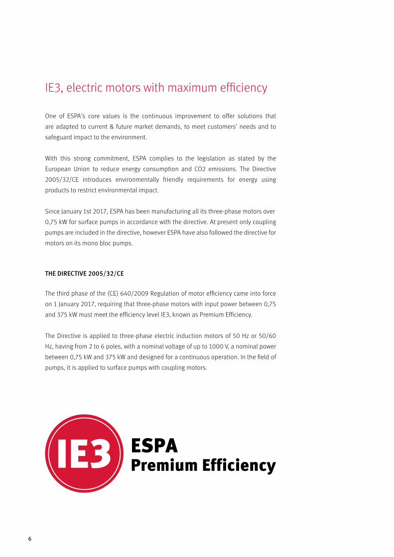
IE3, electric motors with maximum efficiency
One of ESPA’s core values is the continuous improvement to offer solutions that
are adapted to current & future market demands, to meet customers’ needs and to
safeguard impact to the environment.
With this strong commitment, ESPA complies to the legislation as stated by the
European Union to reduce energy consumption and CO2 emissions. The Directive
2005/32/CE introduces environmentally friendly requirements for energy using
products to restrict environmental impact.
Since January 1st 2017, ESPA has been manufacturing all its three-phase motors over
0,75 kW for surface pumps in accordance with the directive. At present only coupling
pumps are included in the directive, however ESPA have also followed the directive for
motors on its mono bloc pumps.
THE DIRECTIVE 2005/32/CE
The third phase of the (CE) 640/2009 Regulation of motor efficiency came into force
on 1 January 2017, requiring that three-phase motors with input power between 0,75
and 375 kW must meet the efficiency level IE3, known as Premium Efficiency.
The Directive is applied to three-phase electric induction motors of 50 Hz or 50/60
Hz, having from 2 to 6 poles, with a nominal voltage of up to 1000 V, a nominal power
between 0,75 kW and 375 kW and designed for a continuous operation. In the field of
pumps, it is applied to surface pumps with coupling motors.
ESPAPremium Efficiency

WATER EVACUATIONSUBMERSIBLE & DRAINAGE
8
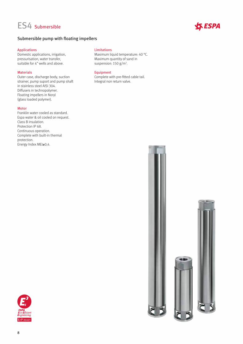
ES4 Submersible
Submersible pump with floating impellers
ApplicationsDomestic applications, irrigation,pressurisation, water transfer,suitable for 4” wells and above.
MaterialsOuter case, discharge body, suction strainer, pump suport and pump shaftin stainless steel AISI 304.Diffusers in technopolymer.Floating impellers in Noryl (glass loaded polymer).
MotorFranklin water cooled as standard.Espa water & oil cooled on request.Class B insulation.Protection IP 68.Continuous operation.Complete with built-in thermal protection.Energy Index MEI≥0,4.
LimitationsMaximum liquid temperature: 40 °C.Maximum quantity of sand in suspension: 150 g/m3.
EquipmentComplete with pre-fitted cable tail.Integral non return valve.
9
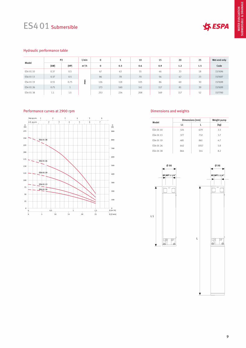
ES4 01 Submersible
Hydraulic performance table
RP/NPT 1 1/4” RP/NPT 1 1/4”
Performance curves at 2900 rpm
ES4 01 38
ES4 01 19
ES4 01 26
ES4 01 13
ES4 01 10
ModelP2 l/min 0 5 10 15 20 25 Wet-end only
[kW] [HP] m3/h 0 0.3 0.6 0.9 1.2 1.5 Code
ES4 01 10 0.37 0.5
mw
c
67 63 55 46 33 18 157696
ES4 01 13 0.37 0.5 86 78 70 56 42 23 157697
ES4 01 19 0.55 0.75 126 118 105 86 60 30 157698
ES4 01 26 0.75 1 173 160 141 117 81 39 157699
ES4 01 38 1.1 1.5 253 234 208 169 117 52 157700
Dimensions and weights
ModelDimensions [mm] Weight pump
L1 L [kg]
ES4 01 10 324 679 3.3
ES4 01 13 377 732 3.7
ES4 01 19 481 861 4.7
ES4 01 26 642 1057 5.8
ES4 01 38 864 314 8.2
WAT
ER E
VACU
ATIO
NSU
BMER
SIBL
E &
DRA
INAG
E
10
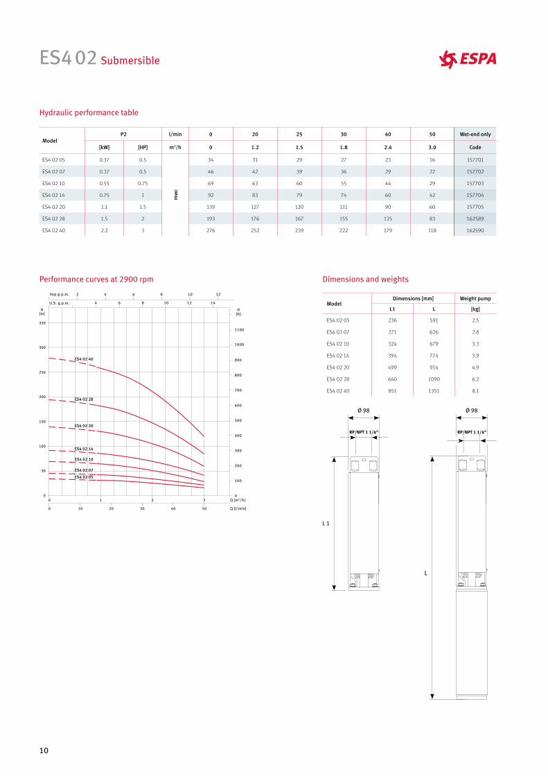
ES4 02 Submersible
RP/NPT 1 1/4” RP/NPT 1 1/4”
ES4 02 05
ES4 02 07
ES4 02 10
ES4 02 14
ES4 02 20
ES4 02 28
ES4 02 40
Dimensions and weights
Hydraulic performance table
Performance curves at 2900 rpm
ModelP2 l/min 0 20 25 30 40 50 Wet-end only
[kW] [HP] m3/h 0 1.2 1.5 1.8 2.4 3.0 Code
ES4 02 05 0.37 0.5
mw
c
34 31 29 27 23 16 157701
ES4 02 07 0.37 0.5 46 42 39 36 29 22 157702
ES4 02 10 0.55 0.75 69 63 60 55 44 29 157703
ES4 02 14 0.75 1 92 83 79 74 60 42 157704
ES4 02 20 1.1 1.5 139 127 120 111 90 60 157705
ES4 02 28 1.5 2 193 176 167 155 125 83 162589
ES4 02 40 2.2 3 276 252 239 222 179 118 162590
ModelDimensions [mm] Weight pump
L1 L [kg]
ES4 02 05 236 591 2.5
ES4 02 07 271 626 2.8
ES4 02 10 324 679 3.3
ES4 02 14 394 774 3.9
ES4 02 20 499 914 4.9
ES4 02 28 640 1090 6.2
ES4 02 40 851 1351 8.1
11
Dimensions and weights
Hydraulic performance table
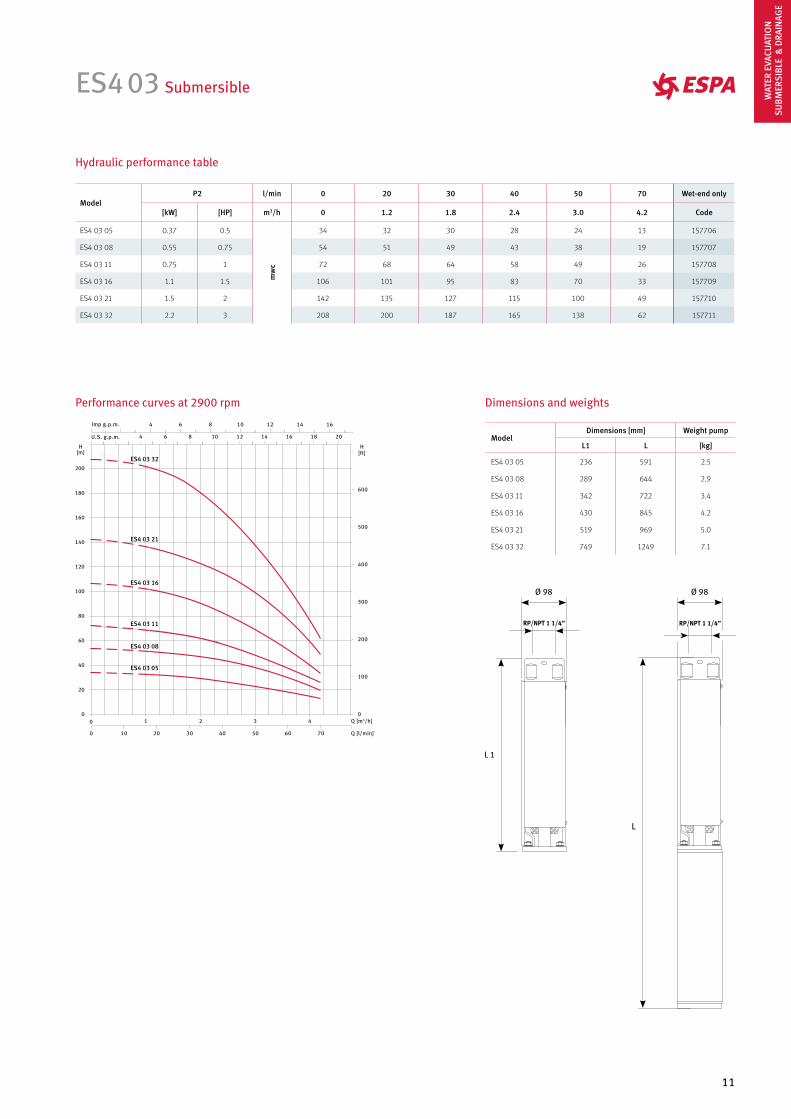
ES4 03 Submersible
RP/NPT 1 1/4” RP/NPT 1 1/4”
ES4 03 05
ES4 03 08
ES4 03 11
ES4 03 16
ES4 03 21
ES4 03 32
Performance curves at 2900 rpm
ModelP2 l/min 0 20 30 40 50 70 Wet-end only
[kW] [HP] m3/h 0 1.2 1.8 2.4 3.0 4.2 Code
ES4 03 05 0.37 0.5
mw
c
34 32 30 28 24 13 157706
ES4 03 08 0.55 0.75 54 51 49 43 38 19 157707
ES4 03 11 0.75 1 72 68 64 58 49 26 157708
ES4 03 16 1.1 1.5 106 101 95 83 70 33 157709
ES4 03 21 1.5 2 142 135 127 115 100 49 157710
ES4 03 32 2.2 3 208 200 187 165 138 62 157711
ModelDimensions [mm] Weight pump
L1 L [kg]
ES4 03 05 236 591 2.5
ES4 03 08 289 644 2.9
ES4 03 11 342 722 3.4
ES4 03 16 430 845 4.2
ES4 03 21 519 969 5.0
ES4 03 32 749 1249 7.1
WAT
ER E
VACU
ATIO
NSU
BMER
SIBL
E &
DRA
INAG
E
12
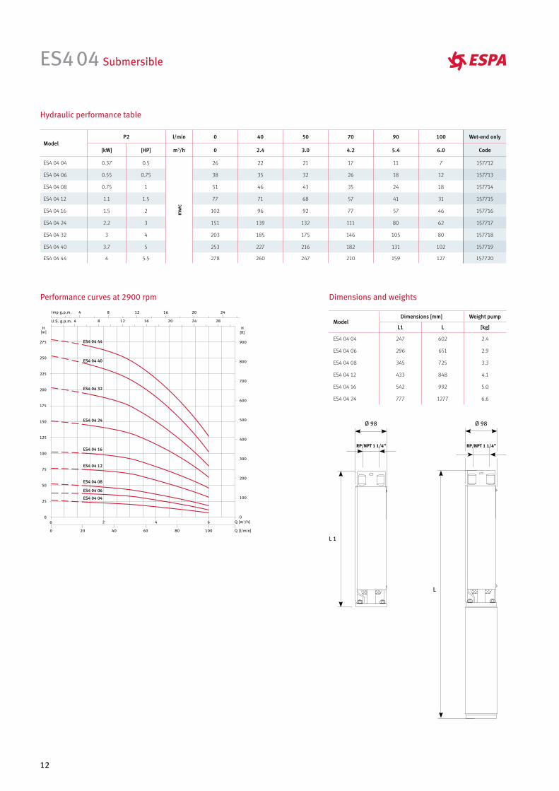
ES4 04 Submersible
ES4 04 04
ES4 04 08
ES4 04 06
ES4 04 12
ES4 04 16
ES4 04 24
ES4 04 32
ES4 04 40
ES4 04 44
Dimensions and weights
Hydraulic performance table
Performance curves at 2900 rpm
ModelP2 l/min 0 40 50 70 90 100 Wet-end only
[kW] [HP] m3/h 0 2.4 3.0 4.2 5.4 6.0 Code
ES4 04 04 0.37 0.5
mw
c
26 22 21 17 11 7 157712
ES4 04 06 0.55 0.75 38 35 32 26 18 12 157713
ES4 04 08 0.75 1 51 46 43 35 24 18 157714
ES4 04 12 1.1 1.5 77 71 68 57 41 31 157715
ES4 04 16 1.5 2 102 96 92 77 57 46 157716
ES4 04 24 2.2 3 151 139 132 111 80 62 157717
ES4 04 32 3 4 203 185 175 146 105 80 157718
ES4 04 40 3.7 5 253 227 216 182 131 102 157719
ES4 04 44 4 5.5 278 260 247 210 159 127 157720
ModelDimensions [mm] Weight pump
L1 L [kg]
ES4 04 04 247 602 2.4
ES4 04 06 296 651 2.9
ES4 04 08 345 725 3.3
ES4 04 12 433 848 4.1
ES4 04 16 542 992 5.0
ES4 04 24 777 1277 6.6
RP/NPT 1 1/4” RP/NPT 1 1/4”
13
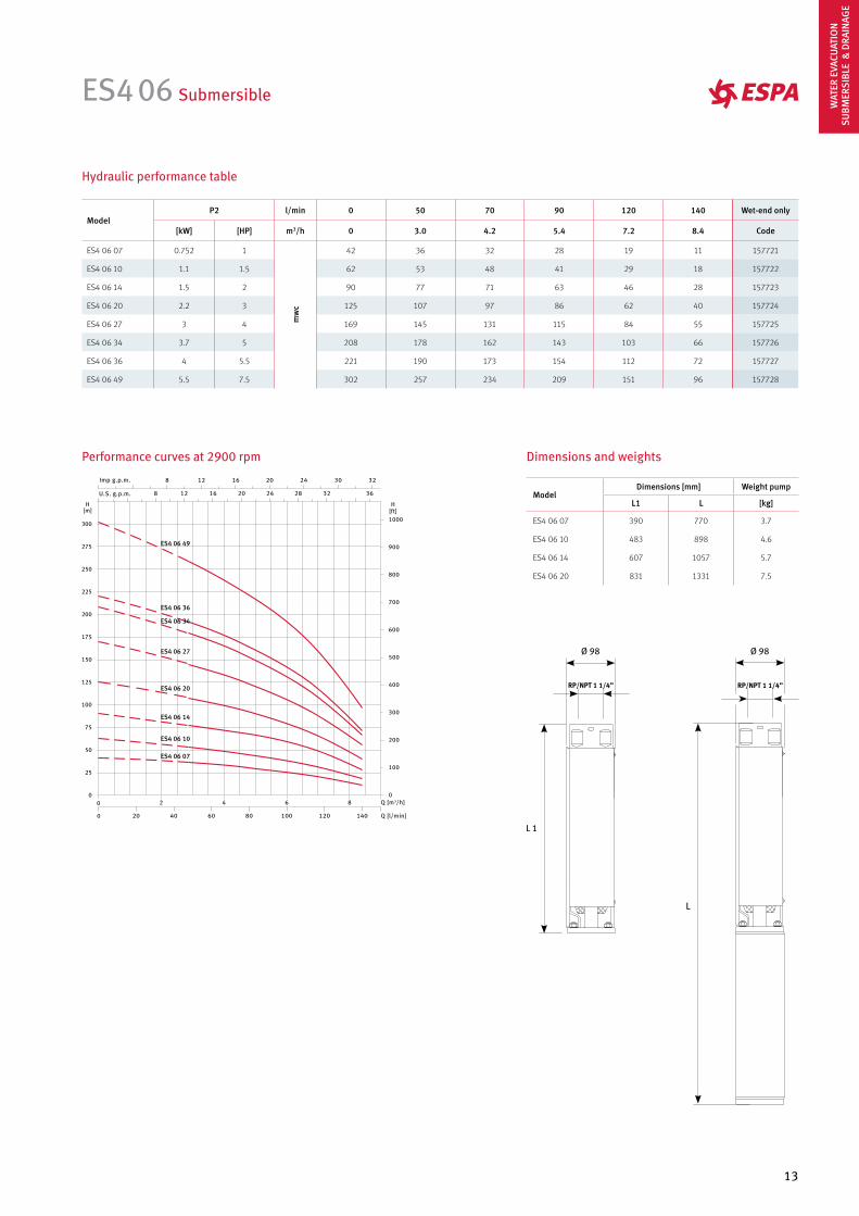
ES4 06 Submersible
RP/NPT 1 1/4” RP/NPT 1 1/4”
ES4 06 07
ES4 06 10
ES4 06 14
ES4 06 27
ES4 06 34
ES4 06 36
ES4 06 49
ES4 06 20
Performance curves at 2900 rpm Dimensions and weights
Hydraulic performance table
ModelP2 l/min 0 50 70 90 120 140 Wet-end only
[kW] [HP] m3/h 0 3.0 4.2 5.4 7.2 8.4 Code
ES4 06 07 0.752 1
mw
c
42 36 32 28 19 11 157721
ES4 06 10 1.1 1.5 62 53 48 41 29 18 157722
ES4 06 14 1.5 2 90 77 71 63 46 28 157723
ES4 06 20 2.2 3 125 107 97 86 62 40 157724
ES4 06 27 3 4 169 145 131 115 84 55 157725
ES4 06 34 3.7 5 208 178 162 143 103 66 157726
ES4 06 36 4 5.5 221 190 173 154 112 72 157727
ES4 06 49 5.5 7.5 302 257 234 209 151 96 157728
ModelDimensions [mm] Weight pump
L1 L [kg]
ES4 06 07 390 770 3.7
ES4 06 10 483 898 4.6
ES4 06 14 607 1057 5.7
ES4 06 20 831 1331 7.5
WAT
ER E
VACU
ATIO
NSU
BMER
SIBL
E &
DRA
INAG
E
14
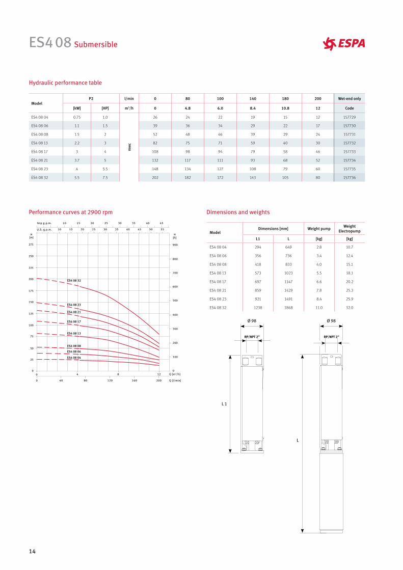
ES4 08 Submersible
RP/NPT 2” RP/NPT 2”
ES4 08 04
ES4 08 08
ES4 08 13
ES4 08 17
ES4 08 21
ES4 08 23
ES4 08 32
ES4 08 06
Performance curves at 2900 rpm Dimensions and weights
Hydraulic performance table
ModelP2 l/min 0 80 100 140 180 200 Wet-end only
[kW] [HP] m3/h 0 4.8 6.0 8.4 10.8 12 Code
ES4 08 04 0.75 1.0
mw
c
26 24 22 19 15 12 157729
ES4 08 06 1.1 1.5 39 36 34 29 22 17 157730
ES4 08 08 1.5 2 52 48 46 39 29 24 157731
ES4 08 13 2.2 3 82 75 71 59 40 30 157732
ES4 08 17 3 4 108 98 94 79 58 46 157733
ES4 08 21 3.7 5 132 117 111 93 68 52 157734
ES4 08 23 4 5.5 148 134 127 108 79 60 157735
ES4 08 32 5.5 7.5 202 182 172 143 105 80 157736
ModelDimensions [mm] Weight pump Weight
Electropump
L1 L [kg] [kg]
ES4 08 04 294 649 2.8 10.7
ES4 08 06 356 736 3.4 12.4
ES4 08 08 418 833 4.0 15.1
ES4 08 13 573 1023 5.5 18.1
ES4 08 17 697 1147 6.6 20.2
ES4 08 21 859 1429 7.8 25.3
ES4 08 23 921 1491 8.4 25.9
ES4 08 32 1238 1868 11.0 32.0
15
ES4 12 Submersible
RP/NPT 2” RP/NPT 2”
ES4 12 07
ES4 12 10
ES4 12 14
ES4 12 17
ES4 12 19
ES4 12 26
Performance curves at 2900 rpm Dimensions and weights
Hydraulic performance table
ModelP2 l/min 0 100 140 180 220 260 Wet-end only
[kW] [HP] m3/h 0 6.0 8.4 10.8 13.2 15.6 Code
ES4 12 07 1.5 2
mw
c
45 37 33 28 22 14 157737
ES4 12 10 2.2 3 64 54 48 41 32 20 157738
ES4 12 14 3 4 89 76 67 56 43 28 157739
ES4 12 17 3.7 5 107 90 80 67 51 32 157740
ES4 12 19 4 5.5 120 102 91 76 58 37 157741
ES4 12 26 5.5 7.5 163 136 120 100 75 48 157742
ModelDimensions [mm] Weight pump
L1 L [kg]
ES4 12 07 534 949 5.3
ES4 12 10 690 1140 6.7
ES4 12 14 989 1439 8.6
ES4 12 17 1092 1662 10.1
ES4 12 19 1195 1765 11.0
ES4 12 26 1559 2189 14.3
WAT
ER E
VACU
ATIO
NSU
BMER
SIBL
E &
DRA
INAG
E
16
ES4 16 Submersible
RP/NPT 2” RP/NPT 2”
ES4 16 08
ES4 16 11
ES4 16 13
ES4 16 15
ES4 16 20
Performance curves at 2900 rpm Dimensions and weights
Hydraulic performance table
ModelP2 l/min 0 140 200 260 320 400 Wet-end only
[kW] [HP] m3/h 0 8.4 12 15.6 19.2 24 Code
ES4 16 08 2.2 3
mw
c
51 41 35 29 22 12 157743
ES4 16 11 3 4 70 57 49 41 31 18 157744
ES4 16 13 3.7 5 81 67 58 48 38 22 157745
ES4 16 15 4 5.5 97 79 69 58 46 27 157746
ES4 16 20 5.5 7.5 125 102 89 74 60 37 157747
ModelDimensions [mm] Weight pump Weight
Electropump
L1 L [kg] [kg]
ES4 16 08 676 1126 6.3 18.9
ES4 16 11 880 1330 8.1 21.7
ES4 16 13 1013 1583 9.3 26.8
ES4 16 15 1149 1719 10.5 28.0
ES4 16 20 1489 2119 13.5 34.5
17
XS 6/8/10/12” Submersible
Espa Pumps UK can supply the following well pump range for larger applications. Price on Application
ApplicationsFor deep wells with minimum diameterof 158 mm, water supply, fountains,irrigation, pressure boosting, dewatering, mining & other civil/industrialapplications.
MaterialsSuction support in cast iron (EN-GJL-250).Shaft & coupling in Stainless Steel AISI 431.Impeller & diffuser in cast iron (EN-GJL-250).Options:Fully Stainless Steel AISI 316 (XSX6).Fully Bronze (XSB6).
MotorWater or oiled option, 2900 rpm.Class B insulation.IP 68 protection.Continuous & intermittent operation.Complete with built-in-thermal protection.Connected in accordance with NEMA standard:4’’ NEMA MG1–18.388 or6’’ NEMA MG1-18.401-18.413
Construction featuresSemi-axial impellers.3’’ outlet c/w non-return valve.Pump equipped with counter thrust ringin anti-wear resin.Diffuser c/w wear ring in anti-wear rubber.Driving bushings in anti-wear rubber with metallic shell.Components realised with particular materials which assure in high wear resistance.
LimitationsMaximum liquid temperature 30 °C.Maximum immersion depth 300 m under liquid level.Clean non-aggressive and non-explosive liquids, not containing solid particlesmore than 2 mm.
RangeXS6: Up to 90 m3/h or H-Max 390mtrsXS8: Up to 228 m3/h or H-max 338 mtrs.XS10: Up to 400 m3/h or H-max 2881 mtrs.XS12: Up to 575 m3/h or H max: 384 mtrs.
For all these ranges of pump P.O.A.
WAT
ER E
VACU
ATIO
NSU
BMER
SIBL
E &
DRA
INAG
E
18
ApplicationsDomestic applications for 4’’or larger water wells.
MotorWater cooled encapsulated PSC motors.Class B insulation.IP 68 protection.4’’ NEMA flange.Rotation: CCW facing shaft endon single phase the motor is connected to only one capacitorwhich works permanently as startand run capacitor.Voltage available: 1~ 230 V3~ 230 V3~ 400 V
BenefitsNon contamination, water filled design.Hermetically sealed stator.Anti track, self healing stator resinprevents motor burn out.
A4F Submersible
Franklin electric 4’’ motors (water cooled) and cable tails for ES4
LimitationsMaximum liquid temperature 30 °C.Maximum quantity of sand in suspension: Starts: 20 per hourFrost protection to – 15 °C.
AccesoriesCable tails to suit Franklin Motors1.5m long.2.5m long.2.5m long c/w stainless steel connector.Motor shrouds (Horizontal mounting)4’’ Cooling shroud.4’’ Support Feet.4’’ Filter.
Model I [A]P2 Cable section in [mm2]
Code[kW] [HP] 4x1.5 4x2.5 4x4 4x6 4x10
4" PC Franklin motor 230 V 1PH 3.2 0.37 0.5 120 200 320 480 810 2548156700L
4" PC Franklin motor 230 V 1PH 4.1 0.55 0.75 80 130 220 320 550 2548176700L
4" PC Franklin motor 230 V 1PH 5.4 0.75 1 60 100 170 250 430 2548186700L
4" PC Franklin motor 230 V 1PH 8.1 1.1 1.5 40 70 120 180 300 2548196700L
4" PC Franklin motor 230 V 1PH 10.2 1.5 2 30 60 90 130 230 2548206700L
4" PC Franklin motor 230 V 1PH 15.2 2.2 3 20 40 60 90 150 2548216700L
Model I [A]P2 Cable section in [mm2]
Code[kW] [HP] 4x1.5 4x2.5 4x4 4x6 4x10
4" PC Franklin motor 400 V 3PH 1.1 0.37 0.5 810 1350 2160 3240 5500 2347616700L
4" PC Franklin motor 400 V 3PH 1.6 0.55 0.75 550 920 1480 2230 3780 2347626700L
4" PC Franklin motor 400 V 3PH 2.1 0.75 1 410 680 1090 1640 2780 2347636700L
4" PC Franklin motor 400 V 3PH 3 1.1 1.5 300 500 810 1210 2060 2347246700L
4" PC Franklin motor 400 V 3PH 4 1.5 2 220 370 590 880 1500 2347256700L
4" PC Franklin motor 400 V 3PH 5.9 2.2 3 150 250 400 600 1030 2347266700L
4" PC Franklin motor 400 V 3PH 7.8 3 4 110 190 310 460 790 2347646700L
4" PC Franklin motor 400 V 3PH 9.1 3.7 5 80 140 230 340 590 234 727 3421L
4" PC Franklin motor 400 V 3PH 10 4 5.5 80 140 230 340 590 234 765 3421L
4" PC Franklin motor 400 V 3PH 13.7 5.5 7.5 60 110 170 260 440 234 728 3421L
4” 230 V Single phase water cooled c/w lead
4” 400 V Three phase water cooled c/w lead
19
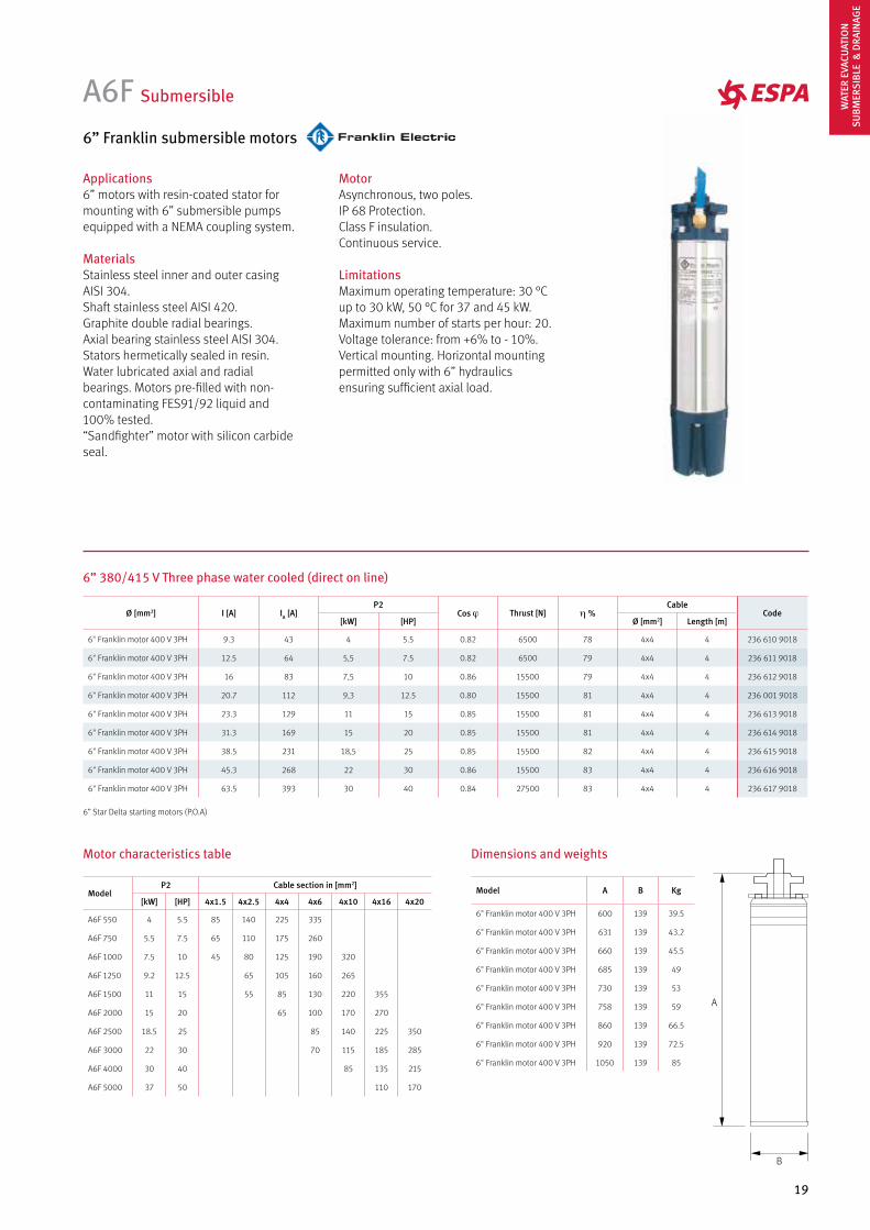
Applications6” motors with resin-coated stator for mounting with 6” submersible pumps equipped with a NEMA coupling system.
Materials Stainless steel inner and outer casingAISI 304.Shaft stainless steel AISI 420. Graphite double radial bearings.Axial bearing stainless steel AISI 304. Stators hermetically sealed in resin.Water lubricated axial and radial bearings. Motors pre-filled with non-contaminating FES91/92 liquid and 100% tested.“Sandfighter” motor with silicon carbide seal.
A6F Submersible
6” Franklin submersible motors
MotorAsynchronous, two poles.IP 68 Protection.Class F insulation.Continuous service.
LimitationsMaximum operating temperature: 30 °C up to 30 kW, 50 °C for 37 and 45 kW.Maximum number of starts per hour: 20. Voltage tolerance: from +6% to - 10%.Vertical mounting. Horizontal mounting permitted only with 6” hydraulics ensuring sufficient axial load.
6” 380/415 V Three phase water cooled (direct on line)
ModelP2 Cable section in [mm2]
[kW] [HP] 4x1.5 4x2.5 4x4 4x6 4x10 4x16 4x20
A6F 550 4 5.5 85 140 225 335
A6F 750 5.5 7.5 65 110 175 260
A6F 1000 7.5 10 45 80 125 190 320
A6F 1250 9.2 12.5 65 105 160 265
A6F 1500 11 15 55 85 130 220 355
A6F 2000 15 20 65 100 170 270
A6F 2500 18.5 25 85 140 225 350
A6F 3000 22 30 70 115 185 285
A6F 4000 30 40 85 135 215
A6F 5000 37 50 110 170
Motor characteristics table
A
B
Ø [mm2] I [A] IA [A]P2
Cos j Thrust [N] h %Cable
Code[kW] [HP] Ø [mm2] Length [m]
6" Franklin motor 400 V 3PH 9.3 43 4 5.5 0.82 6500 78 4x4 4 236 610 9018
6" Franklin motor 400 V 3PH 12.5 64 5,5 7.5 0.82 6500 79 4x4 4 236 611 9018
6" Franklin motor 400 V 3PH 16 83 7,5 10 0.86 15500 79 4x4 4 236 612 9018
6" Franklin motor 400 V 3PH 20.7 112 9,3 12.5 0.80 15500 81 4x4 4 236 001 9018
6" Franklin motor 400 V 3PH 23.3 129 11 15 0.85 15500 81 4x4 4 236 613 9018
6" Franklin motor 400 V 3PH 31.3 169 15 20 0.85 15500 81 4x4 4 236 614 9018
6" Franklin motor 400 V 3PH 38.5 231 18,5 25 0.85 15500 82 4x4 4 236 615 9018
6" Franklin motor 400 V 3PH 45.3 268 22 30 0.86 15500 83 4x4 4 236 616 9018
6" Franklin motor 400 V 3PH 63.5 393 30 40 0.84 27500 83 4x4 4 236 617 9018
6” Star Delta starting motors (P.O.A)
Dimensions and weights
Model A B Kg
6" Franklin motor 400 V 3PH 600 139 39.5
6" Franklin motor 400 V 3PH 631 139 43.2
6" Franklin motor 400 V 3PH 660 139 45.5
6" Franklin motor 400 V 3PH 685 139 49
6" Franklin motor 400 V 3PH 730 139 53
6" Franklin motor 400 V 3PH 758 139 59
6" Franklin motor 400 V 3PH 860 139 66.5
6" Franklin motor 400 V 3PH 920 139 72.5
6" Franklin motor 400 V 3PH 1050 139 85
WAT
ER E
VACU
ATIO
NSU
BMER
SIBL
E &
DRA
INAG
E
20
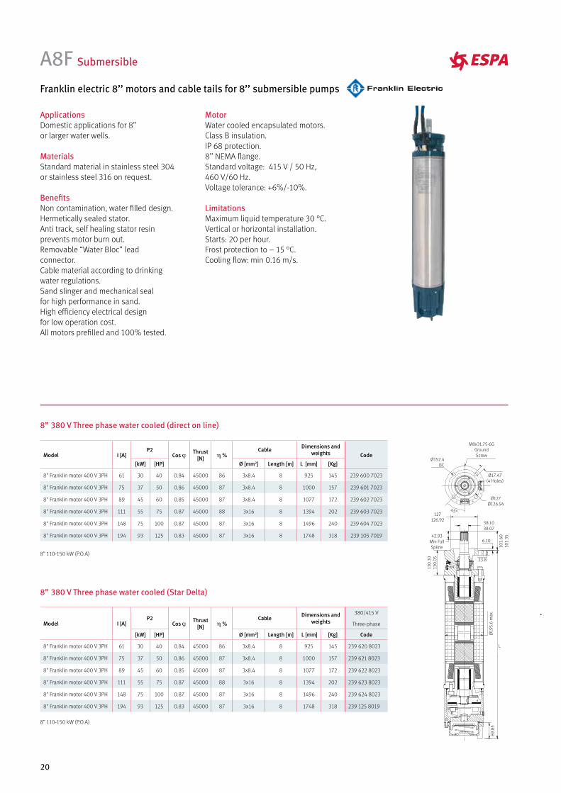
8” 110-150 kW (P.O.A)
8” 110-150 kW (P.O.A)
ApplicationsDomestic applications for 8’’or larger water wells.
MaterialsStandard material in stainless steel 304or stainless steel 316 on request.
BenefitsNon contamination, water filled design.Hermetically sealed stator.Anti track, self healing stator resinprevents motor burn out.Removable “Water Bloc” leadconnector.Cable material according to drinkingwater regulations.Sand slinger and mechanical sealfor high performance in sand.High efficiency electrical designfor low operation cost.All motors prefilled and 100% tested.
A8F Submersible
Franklin electric 8’’ motors and cable tails for 8’’ submersible pumps
MotorWater cooled encapsulated motors.Class B insulation.IP 68 protection.8’’ NEMA flange. Standard voltage: 415 V / 50 Hz,460 V/60 Hz.Voltage tolerance: +6%/-10%.
LimitationsMaximum liquid temperature 30 °C.Vertical or horizontal installation.Starts: 20 per hour.Frost protection to – 15 °C.Cooling flow: min 0.16 m/s.
8” 380 V Three phase water cooled (direct on line)
8” 380 V Three phase water cooled (Star Delta)
Model I [A]P2
Cos j Thrust[N] h %
Cable Dimensions and weights Code
[kW] [HP] Ø [mm2] Length [m] L [mm] [Kg]
8" Franklin motor 400 V 3PH 61 30 40 0.84 45000 86 3x8.4 8 925 145 239 600 7023
8" Franklin motor 400 V 3PH 75 37 50 0.86 45000 87 3x8.4 8 1000 157 239 601 7023
8" Franklin motor 400 V 3PH 89 45 60 0.85 45000 87 3x8.4 8 1077 172 239 602 7023
8" Franklin motor 400 V 3PH 111 55 75 0.87 45000 88 3x16 8 1394 202 239 603 7023
8" Franklin motor 400 V 3PH 148 75 100 0.87 45000 87 3x16 8 1496 240 239 604 7023
8" Franklin motor 400 V 3PH 194 93 125 0.83 45000 87 3x16 8 1748 318 239 105 7019
Model I [A]P2
Cos j Thrust [N] h %
Cable Dimensions and weights
380/415 V
Three-phase
[kW] [HP] Ø [mm2] Length [m] L [mm] [Kg] Code
8" Franklin motor 400 V 3PH 61 30 40 0.84 45000 86 3x8.4 8 925 145 239 620 8023
8" Franklin motor 400 V 3PH 75 37 50 0.86 45000 87 3x8.4 8 1000 157 239 621 8023
8" Franklin motor 400 V 3PH 89 45 60 0.85 45000 87 3x8.4 8 1077 172 239 622 8023
8" Franklin motor 400 V 3PH 111 55 75 0.87 45000 88 3x16 8 1394 202 239 623 8023
8" Franklin motor 400 V 3PH 148 75 100 0.87 45000 87 3x16 8 1496 240 239 624 8023
8" Franklin motor 400 V 3PH 194 93 125 0.83 45000 87 3x16 8 1748 318 239 125 8019
69,8
5
L
Ø19
5.6
max
.
130.
3013
0.05
101.
6010
1.35
127126.92
Ø127Ø126.94
Ø152.4BC
Ø17.47(4 Holes)
M8x31.75-6GGroundScrew
38.1038.07
42.93Min FullSpline
23.8
6.10
45°
21
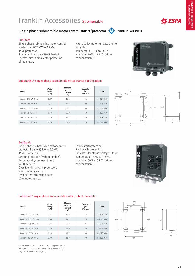
Single phase submersible motor control starter/protector
SubStartSingle phase submersible motor control starter from 0.25 kW to 2.2 kW.IP 54 protection.Illuminated integral ON/OFF switch.Thermal circuit breaker for protection of the motor.
High quality motor run capacitor for long life.Temperature: -5 °C to +40 °C. Humidity: 50% at 55 °C (without condensation).
Franklin Accessories Submersible
SubStartSC® single phase submersible motor starter specifications
ModelMotor rating[kW]
Maximalexpectedcurrent
[A]
Capacitor[µF]
450 V acCode
Substart 0.37 kW 230 V 0.37 12.6 16 284 624 3510
Substart 0.55 kW 230 V 0,55 17.7 20 284 625 3510
Substart 0.75 kW 230 V 0.75 22.7 35 284 626 3510
Substart 1.1 kW 230 V 1.10 33.9 40 284 627 3510
Substart 1.5 kW 230 V 1.50 41.7 50 284 628 3510
Substart 2.2 kW 230 V 2.20 61.8 70 284 629 3510
140168115
140
Ø5.2
193165
7 22
87
90
SubTronic® single phase submersible motor protector models
ModelMotor rating[kW]
Maximalexpectedcurrent
[A]
Capacitor[µF]
450 V acCode
Subtronic 0.37 kW 230 V 0.37 12.6 16 285 624 3510
Subtronic 0.55 kW 230 V 0,55 17.7 20 286 625 3510
Subtronic 0.75 kW 230 V 0.75 22.7 35 287 626 3510
Subtronic 1.1 kW 230 V 1.10 33.9 40 288 627 3510
Subtronic 1.5 kW 230 V 1.50 41.7 50 289 628 3510
Subtronic 2.2 kW 230 V 2.20 61.8 70 290 629 3510
Ø5.2
90
230230 180
180
195
140
245
SubTronicSingle phase submersible motor control protector from 0.25 kW to 2.2 kW.IP 54 protection.Dry-run protection (without probes).Automatic dry-run reset time 6 to 60 minutes.Over & under voltage protection,reset 3 minutes approx.Over current protection, reset 10 minutes approx.
Faulty start protection.Rapid cycle protection.Indicators for status, voltage & fault.Temperature: -5 °C to +40 °C. Humidity: 50% at 55 °C (without condensation).
Control panels for 6”, 8” , 10” & 12” Borehole pumps (P.O.A)
Dol-Star Delta-Impedence start-soft start & inverter options
Larger Resin Joints available (P.O.A)
WAT
ER E
VACU
ATIO
NSU
BMER
SIBL
E &
DRA
INAG
E
22
Hydraulic performance table
Model
I [A]
P1 [kW] P2 c l/min 10 20 30 40 50 60 65 3~400V T 1~230V M 1~230V MA
1~230 V
3~400 V
1~230 V
3~400 V [kW] [HP] [µF] m3/h 0.6 1.2 1.8 2.4 3.0 3.6 3.9 Code Code Code
Acuaria 07 3N 2.8 0.6 0.37 0.5 12
mw
c
33 29 26 21 15 8 4 157967 157968
Acuaria 07 4N 3.5 1.7 0.8 0.8 0.5 0.75 12 41 37 32 26 19 10 6 166210 157964 157965
Acuaria 07 5N 4.1 1.9 1 1 0.75 1 12 50 46 40 32 23 13 8 166211 157969 143389
Acuaria 07 6N 5 2 1.2 1.1 0.9 1.2 12 60 55 47 37 26 15 9 166212 157970 157971
Acuaria 07 7N 5.5 2.4 1.4 1.3 1.1 1.5 30 70 64 55 44 31 18 11 166213 157973 169292
Model
I [A]
P1 [kW] P2 c l/min 10 20 30 40 50 60 80 85 3~400V T 1~230V M 1~230V MA
1~230 V
3~400 V
1~230 V
3~400 V [kW] [HP] [µF] m3/h 0.6 1.2 1.8 2.4 3.0 3.6 4.8 5.1 Code Code Code
Acuaria 17 5 7.4 1.6 0.9 1.25 16
mw
c 67 65 62 55 48 39 18 12 96251 96265 96266
Acuaria 17 7 10.7 3.8 2.2 2.1 1.5 2.0 25 94 90 85 78 69 58 30 22 96275 96265 96283
Model
I [A]
P1 [kW] P2 c l/min 20 30 40 50 60 80 100 120 3~400V T 1~230V M 1~230V MA
1~230 V
3~400 V
1~230 V
3~400 V [kW] [HP] [µF] m3/h 1.2 1.8 2.4 3.0 3.6 4.8 6.0 7.2 Code Code Code
Acuaria 27 4 7 2.5 1.5 1.4 0.9 1.25 16
mw
c 43 42 41 39 38 31 23 14 96328 96342 96343
Acuaria 27 6 10.8 3.8 2.2 2.1 1.5 2.0 25 68 66 64 61 57 47 36 24 96352 96359 96360
ApplicationsIrrigation, decanting and hydropneumatic sets. Max. immersion level according to technical table on page 281.
MaterialsOuter casing, discharge body, impellers, filter and motor casing in stainless steel AISI 304.Pump shaft in stainless steel AISI 303.Diffusers in tecnopolimer.Double mechanical seal in ceramic/graphite/NBR. Foodgrade oil in seal chamber.
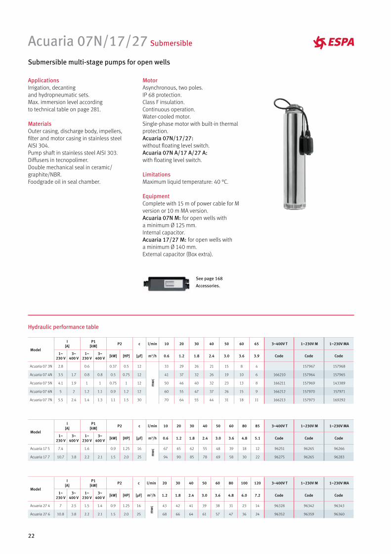
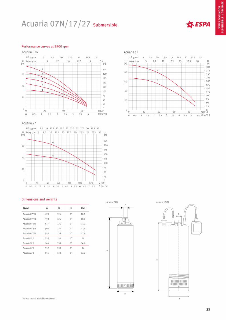
Acuaria 07N/17/27 Submersible
Submersible multi-stage pumps for open wells
MotorAsynchronous, two poles.IP 68 protection.Class F insulation.Continuous operation.Water-cooled motor.Single-phase motor with built-in thermal protection.Acuaria 07N/17/27: without floating level switch.Acuaria 07N A/17 A/27 A: with floating level switch.
LimitationsMaximum liquid temperature: 40 °C.
EquipmentComplete with 15 m of power cable for M version or 10 m MA version.Acuaria 07N M: for open wells with a minimum Ø 125 mm. Internal capacitor.Acuaria 17/27 M: for open wells with a minimum Ø 140 mm.External capacitor (Box extra).
See page 168
Accessories.
23
Acuaria 07N/17/27 Submersible
Performance curves at 2900 rpm
Acuaria 07N Acuaria 17
Acuaria 27
7
6
5
4
3
7
5
6
4
Dimensions and weights
A
B
CAcuaria 07N
A
B
C
Acuaria 17/27
Model A B C [Kg]
Acuaria 07 3N 470 126 1” 10.0
Acuaria 07 4N 493 126 1” 10.6
Acuaria 07 5N 517 126 1” 11.5
Acuaria 07 6N 560 126 1” 12.4
Acuaria 07 7N 583 126 1” 12.6
Acuaria 17 5 553 138 1” 14
Acuaria 17 7 646 138 1” 14.2
Acuaria 27 4 552 138 1” 17
Acuaria 27 6 655 138 1” 17.2
*Service kits are available on request
WAT
ER E
VACU
ATIO
NSU
BMER
SIBL
E &
DRA
INAG
E
24
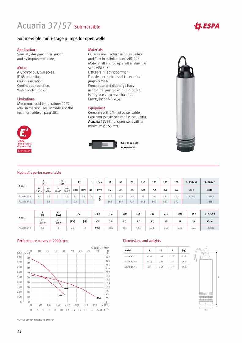
Acuaria 37/57 Submersible
Submersible multi-stage pumps for open wells
ApplicationsSpecially designed for irrigation and hydropneumatic sets.
MotorAsynchronous, two poles.IP 68 protection.Class F insulation.Continuous operation.Water-cooled motor.
LimitationsMaximum liquid temperature: 40 °C.Max. immersion level according to the technical table on page 281.
See page 168
Accessories.
MaterialsOuter casing, motor casing, impellersand filter in stainless steel AISI 304.Motor shaft and pump shaft in stainless steel AISI 303.Diffusers in technopolymer.Double mechanical seal in ceramic/graphite/NBR. Pump base and discharge body in cast iron painted with cataforesis.Foodgrade oil in seal chamber.Energy Index MEI≥0,4.
EquipmentComplete with 15 m of power cable.Capacitor (single-phase only, box extra).Acuaria 37/57: for open wells with a minimum Ø 155 mm.
A
B
C
Performance curves at 2900 rpm Dimensions and weights
37-6
37-457-4
Hydraulic performance table
Model
I [A]
P1 [kW] P2 c l/min 12 40 60 100 120 140 160 1~ 230V M 3~ 400V T
1~230 V
3~400 V
1~230 V
3~400 V [kW] [HP] [µF] m3/h 1.2 2.4 3.6 6.0 7.2 8.4 8.6 Code Code
Acuaria 37 4 9.2 3.3 2 1.9 1.1 1.5 30
mw
c 55.7 53.4 50.9 41 35.2 29.1 22.3 135380 135379
Acuaria 37 6 5.3 3 2.2 3 84.5 80.7 77.4 64.8 56.3 46.1 37.2 135381
Model
I [A]
P1 [kW] P2 l/min 50 100 150 200 250 300 350 3~ 400V T
3~400 V
3~400 V [kW] [HP] m3/h 3.0 6.0 9.0 12 15 18 21 Code
Acuaria 57 4 5.4 3 2.2 3 mwc 52.5 48.1 42.2 37.8 31.5 23.2 12.1 135382
Model A B C [Kg]
Acuaria 37 4 622.5 152 11/2” 27.6
Acuaria 37 6 671.5 152 11/2” 30.6
Acuaria 57 4 684 152 11/2” 30.6
*Service kits are available on request
DRAINAGE
26
Vigila 100 Drainage
Submersible pumps for the drainage of clear water
ApplicationsDrainage of clear water, decorative foun-tains, tanks, etc.
MaterialsPump body, impellers and suction filter in technopolymer.Motor shaft in stainless steel AISI 420. Double lip seal and o-rings in NBR.
MotorAsynchronous, two poles.IP 68 protection.Class F insulation.Forced cooling through the discharge water.
LimitationsMaximum solids handling: Ø 5 mm.
EquipmentSupplied with 10 m power cable.Vigila 100 M A: with float switch.
Model
I [A]
P1 [kW] P2 c l/min 10 20 30 40 50 60 80 95 1~
230 V
1~230 V
1~230 V [kW] [HP] [µF] m3/h 0.6 1.2 1.8 2.4 3.0 3.6 4.8 5.7 Code
Vigila 100 1.04 0.23 0.11 0.15 6 mwc 5 4.3 3.7 3.4 3.0 2.5 1.2 0.3 97806
A
B
D
C
Model A B C D Kg
Vigila 100 272 159 26.5 1”/25 3.8
Performance curves at 2900 rpm Dimensions and weights
Hydraulic performance table
*Service kits are available on request
27
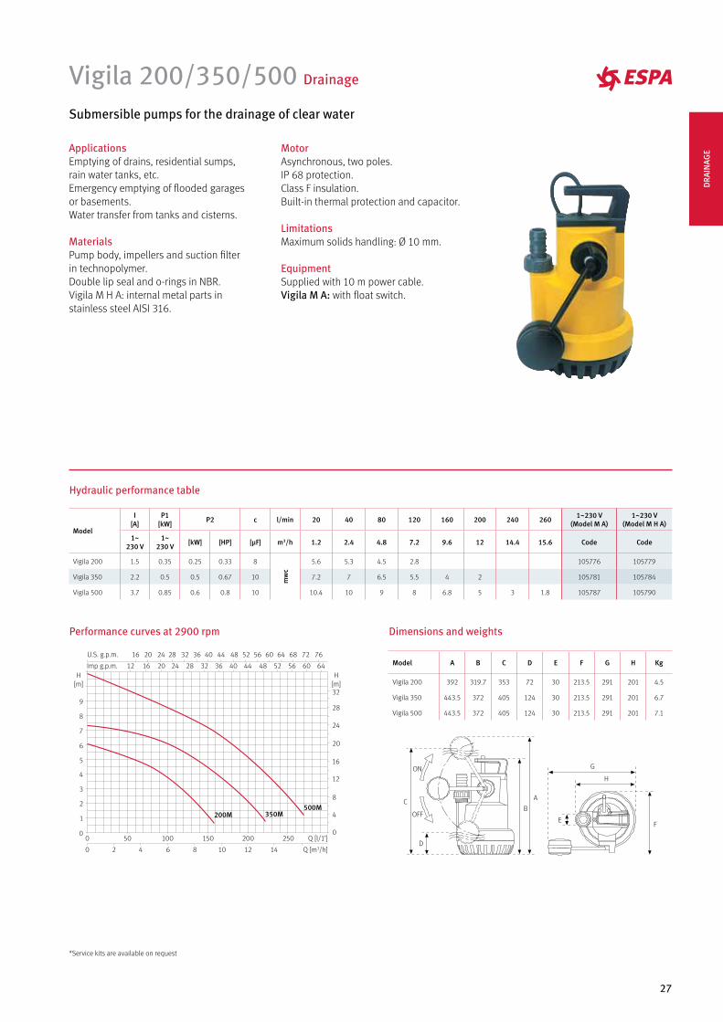
Vigila 200/350/500 Drainage
Submersible pumps for the drainage of clear water
ApplicationsEmptying of drains, residential sumps, rain water tanks, etc.Emergency emptying of flooded garages or basements. Water transfer from tanks and cisterns.
MaterialsPump body, impellers and suction filter in technopolymer.Double lip seal and o-rings in NBR.Vigila M H A: internal metal parts in stainless steel AISI 316.
MotorAsynchronous, two poles.IP 68 protection.Class F insulation.Built-in thermal protection and capacitor.
LimitationsMaximum solids handling: Ø 10 mm.
EquipmentSupplied with 10 m power cable.Vigila M A: with float switch.
Model
I [A]
P1 [kW] P2 c l/min 20 40 80 120 160 200 240 260 1~230 V
(Model M A)1~230 V
(Model M H A)
1~230 V
1~230 V [kW] [HP] [µF] m3/h 1.2 2.4 4.8 7.2 9.6 12 14.4 15.6 Code Code
Vigila 200 1.5 0.35 0.25 0.33 8
mw
c
5.6 5.3 4.5 2.8 105776 105779
Vigila 350 2.2 0.5 0.5 0.67 10 7.2 7 6.5 5.5 4 2 105781 105784
Vigila 500 3.7 0.85 0.6 0.8 10 10.4 10 9 8 6.8 5 3 1.8 105787 105790
Model A B C D E F G H Kg
Vigila 200 392 319.7 353 72 30 213.5 291 201 4.5
Vigila 350 443.5 372 405 124 30 213.5 291 201 6.7
Vigila 500 443.5 372 405 124 30 213.5 291 201 7.1
500M350M200M
Q [l/1’]
Q [m3/h]
0 50 100 150 200 250
2016U.S. g.p.m. 28 36 44 52 60 68 76
0 2 4 6 8 10 12 14
1612H
[m]H
[m]
0
1
2
3
4
5
6
7
8
9
0
4
8
12
16
20
24
28
32
Imp g.p.m. 20 24 28 32 36 40 44 48 52 56 60 64
24 32 40 48 56 64 72
H
G
FE
A
D
CB
ON
OFF
Performance curves at 2900 rpm Dimensions and weights
Hydraulic performance table
*Service kits are available on request
DRA
INAG
E
28
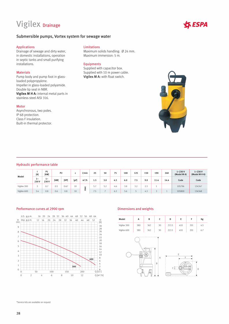
Vigilex Drainage
Submersible pumps, Vortex system for sewage water
ApplicationsDrainage of sewage and dirty water, in domestic installations, operation in septic tanks and small purifying installations.
MaterialsPump body and pump foot in glass-loaded polypropylene. Impeller in glass-loaded polyamide.Double lip seal in NBR.Vigilex M H A: internal metal parts in stainless steel AISI 316.
MotorAsynchronous, two poles.IP 68 protection.Class F insulation.Built-in thermal protector.
LimitationsMaximum solids handling: Ø 24 mm.Maximum immersion: 5 m.
EquipmentsSupplied with capacitor box.Supplied with 10 m power cable.Vigilex M A: with float switch.
300
600A F
E
DC
B
Model A B C D E F Kg
Vigilex 300 380 362 30 213.5 410 201 4.5
Vigilex 600 380 362 30 213.5 410 201 6.7
Performance curves at 2900 rpm Dimensions and weights
Hydraulic performance table
Model
I [A]
P1 [kW] P2 c l/min 25 50 75 100 125 150 190 240 1~230 V
(Model M A)1~230 V
(Model M H A)
1~230 V
1~230 V [kW] [HP] [µF] m3/h 1.5 3.0 4.5 6.0 7.5 9.0 11.4 14.4 Code Code
Vigilex 300 3 0.7 0.5 0.67 10
mw
c 5.7 5.2 4.6 3.8 3.2 2.3 1 105796 134347
Vigilex 600 3.4 0.8 0.6 0.8 10 7.5 7 6.3 5.6 5 4.3 3 1 105800 134348
*Service kits are available on request
29
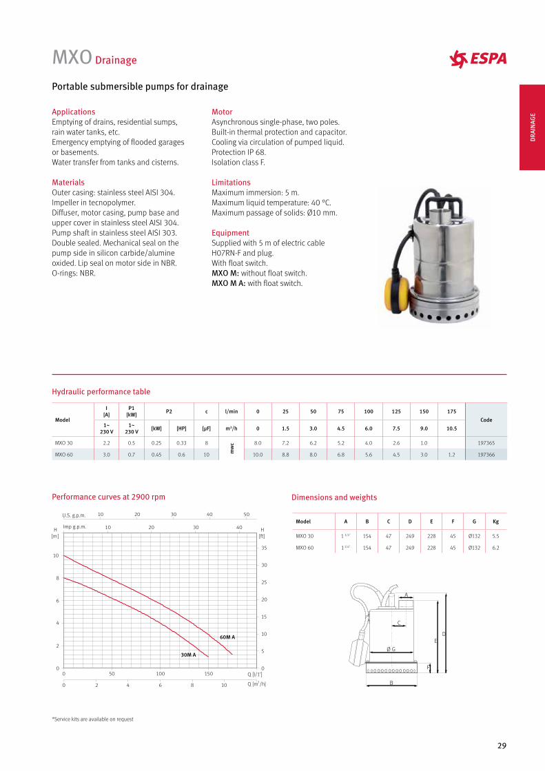
MXO Drainage
Portable submersible pumps for drainage
ApplicationsEmptying of drains, residential sumps,rain water tanks, etc.Emergency emptying of flooded garagesor basements.Water transfer from tanks and cisterns.
MaterialsOuter casing: stainless steel AISI 304.Impeller in tecnopolymer.Diffuser, motor casing, pump base andupper cover in stainless steel AISI 304.Pump shaft in stainless steel AISI 303.Double sealed. Mechanical seal on thepump side in silicon carbide/alumineoxided. Lip seal on motor side in NBR.O-rings: NBR.
MotorAsynchronous single-phase, two poles.Built-in thermal protection and capacitor.Cooling via circulation of pumped liquid.Protection IP 68.Isolation class F.
LimitationsMaximum immersion: 5 m.Maximum liquid temperature: 40 °C.Maximum passage of solids: Ø10 mm.
EquipmentSupplied with 5 m of electric cableH07RN-F and plug.With float switch.MXO M: without float switch.MXO M A: with float switch.
Dimensions and weights
Model A B C D E F G Kg
MXO 30 1 1/4" 154 47 249 228 45 Ø132 5.5
MXO 60 1 1/4" 154 47 249 228 45 Ø132 6.2
B
A
F
C
DE
Performance curves at 2900 rpm
Q [l/1’]
H[m]
0
2
4
4
6
6
8
8
10
10 Q [m3/h]
U.S. g.p.m.
Imp g.p.m.H
[ft]
0
5
10
15
20
25
30
35
10 20 30 40
10 20 30 40
50
0
0
50 100 150
2
30M A
60M A
Hydraulic performance table
Model
I [A]
P1 [kW] P2 c l/min 0 25 50 75 100 125 150 175
Code1~
230 V1~
230 V [kW] [HP] [µF] m3/h 0 1.5 3.0 4.5 6.0 7.5 9.0 10.5
MXO 30 2.2 0.5 0.25 0.33 8
mw
c 8.0 7.2 6.2 5.2 4.0 2.6 1.0 197365
MXO 60 3.0 0.7 0.45 0.6 10 10.0 8.8 8.0 6.8 5.6 4.5 3.0 1.2 197366
*Service kits are available on request
DRA
INAG
E
30
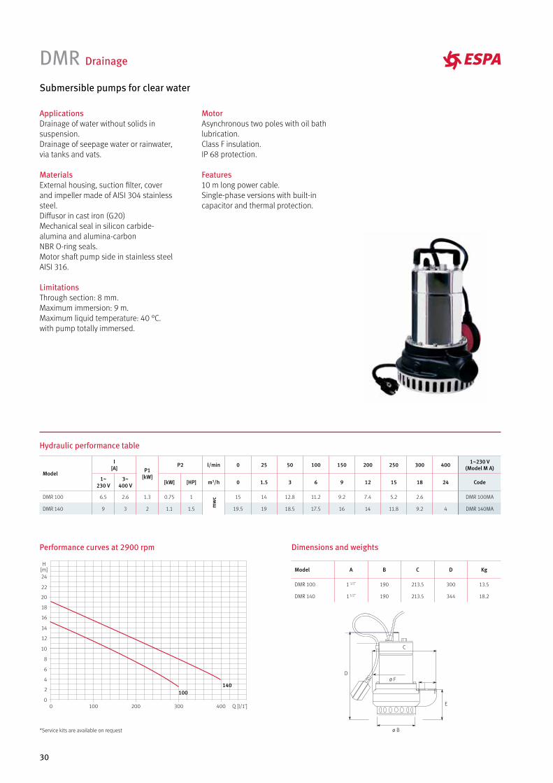
DMR Drainage
Submersible pumps for clear water
ApplicationsDrainage of water without solids in suspension.Drainage of seepage water or rainwater, via tanks and vats.
MaterialsExternal housing, suction filter, cover and impeller made of AISI 304 stainless steel.Diffusor in cast iron (G20)Mechanical seal in silicon carbide-alumina and alumina-carbon NBR O-ring seals.Motor shaft pump side in stainless steel AISI 316.
LimitationsThrough section: 8 mm.Maximum immersion: 9 m. Maximum liquid temperature: 40 °C. with pump totally immersed.
MotorAsynchronous two poles with oil bath lubrication. Class F insulation.IP 68 protection.
Features10 m long power cable.Single-phase versions with built-in capacitor and thermal protection.
Dimensions and weights
Model A B C D Kg
DMR 100 1 1/2" 190 213.5 300 13.5
DMR 140 1 1/2" 190 213.5 344 18.2
Hydraulic performance table
Model
I [A] P1
[kW]
P2 l/min 0 25 50 100 150 200 250 300 400 1~230 V (Model M A)
1~230 V
3~400 V [kW] [HP] m3/h 0 1.5 3 6 9 12 15 18 24 Code
DMR 100 6.5 2.6 1.3 0.75 1
mw
c 15 14 12.8 11.2 9.2 7.4 5.2 2.6 DMR 100MA
DMR 140 9 3 2 1.1 1.5 19.5 19 18.5 17.5 16 14 11.8 9.2 4 DMR 140MA
Performance curves at 2900 rpm
140
Q [l/1’]40030020010000
2
4
6
8
10
12
14
16
18
20
22
24
H[m]
100
*Service kits are available on request
31
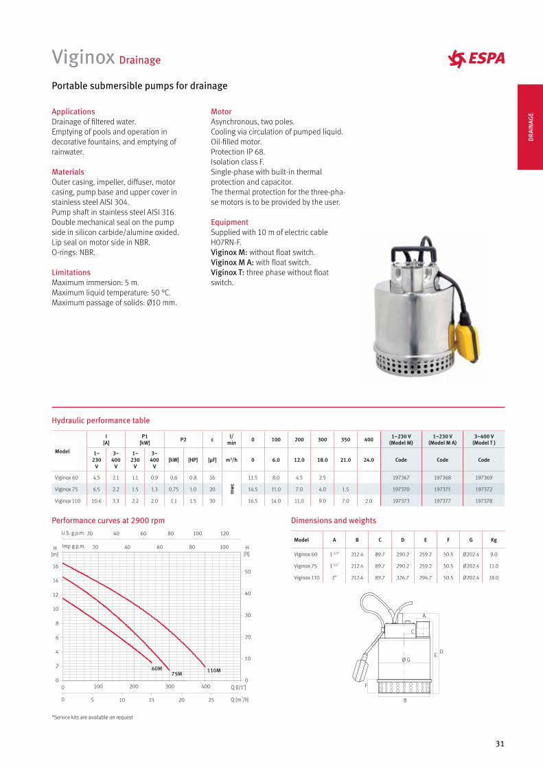
Viginox Drainage
Portable submersible pumps for drainage
ApplicationsDrainage of filtered water. Emptying of pools and operation in decorative fountains, and emptying of rainwater.
MaterialsOuter casing, impeller, diffuser, motorcasing, pump base and upper cover instainless steel AISI 304.Pump shaft in stainless steel AISI 316.Double mechanical seal on the pump side in silicon carbide/alumine oxided. Lip seal on motor side in NBR.O-rings: NBR.
LimitationsMaximum immersion: 5 m.Maximum liquid temperature: 50 °C.Maximum passage of solids: Ø10 mm.
MotorAsynchronous, two poles.Cooling via circulation of pumped liquid.Oil-filled motor.Protection IP 68.Isolation class F.Single-phase with built-in thermal protection and capacitor.The thermal protection for the three-pha-se motors is to be provided by the user.
EquipmentSupplied with 10 m of electric cableH07RN-F.Viginox M: without float switch.Viginox M A: with float switch.Viginox T: three phase without float switch.
Hydraulic performance table
Model
I [A]
P1 [kW] P2 c l/
min 0 100 200 300 350 400 1~230 V (Model M)
1~230 V (Model M A)
3~400 V (Model T )
1~230
V
3~400
V
1~230
V
3~400
V[kW] [HP] [µF] m3/h 0 6.0 12.0 18.0 21.0 24.0 Code Code Code
Viginox 60 4.5 2.1 1.1 0.9 0.6 0.8 16
mw
c
11.5 8.0 4.5 2.5 197367 197368 197369
Viginox 75 6.5 2.2 1.5 1.3 0.75 1.0 20 14.5 11.0 7.0 4.0 1.5 197370 197371 197372
Viginox 110 10.6 3.3 2.2 2.0 1.1 1.5 30 16.5 14.0 11.0 9.0 7.0 2.0 197373 197377 197378
Performance curves at 2900 rpm
Q [m3/h]
H[m]
0
2
4
6
8
10
12
14
16
Q [l/1’]0
U.S. g.p.m.
Imp g.p.m. H[ft]
0
10
20
30
40
50
60M75M
110M
20 40 60
100 200 300 400
15 20 25
80 100 120
20 40 60 80 100
0 105
Dimensions and weights
Model A B C D E F G Kg
Viginox 60 1 1/2" 212.4 89.7 290.2 259.2 50.5 Ø202.4 9.0
Viginox 75 1 1/2" 212.4 89.7 290.2 259.2 50.5 Ø202.4 11.0
Viginox 110 2” 212.4 89.7 326.7 294.7 50.5 Ø202.4 18.0
*Service kits are available on request
DRA
INAG
E
32
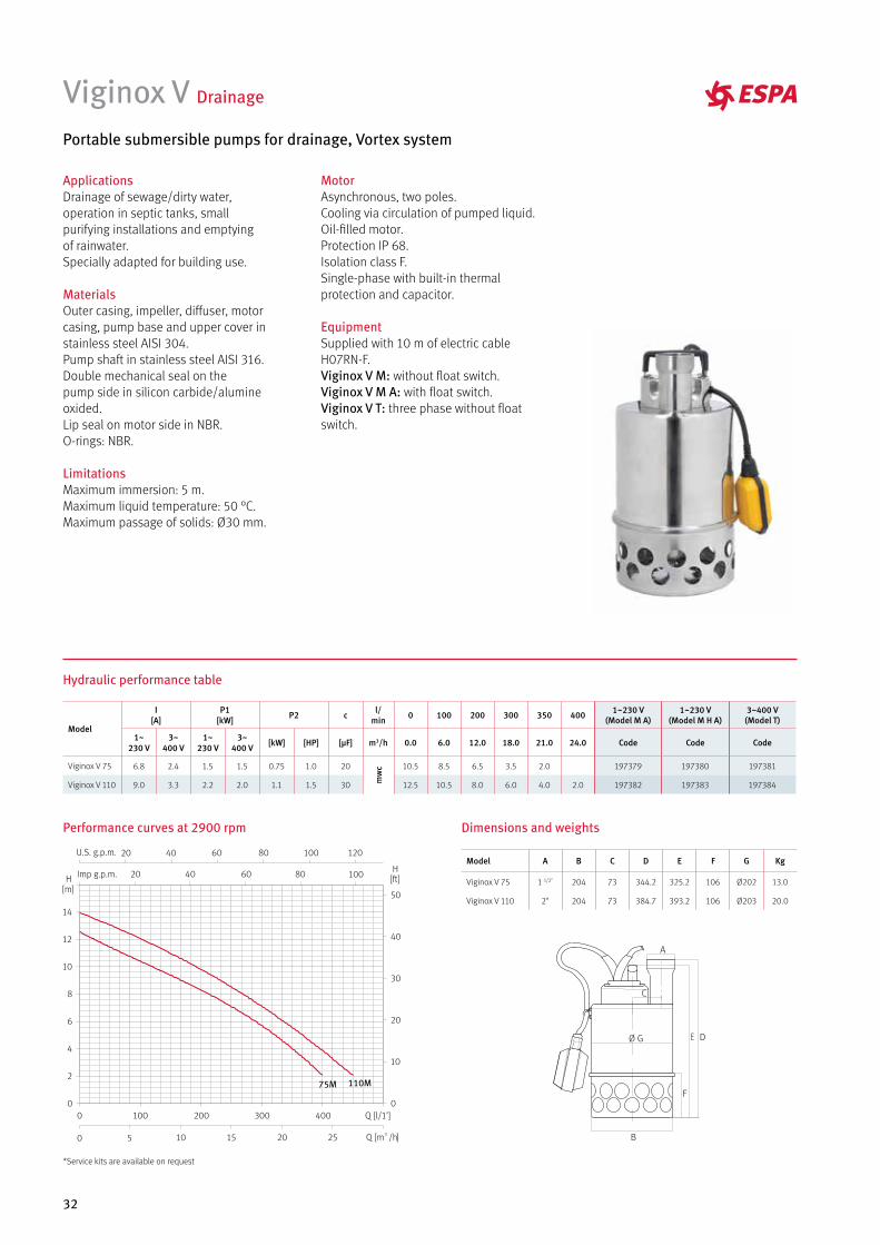
Viginox V Drainage
Portable submersible pumps for drainage, Vortex system
ApplicationsDrainage of sewage/dirty water, operation in septic tanks, small purifying installations and emptyingof rainwater. Specially adapted for building use.
MaterialsOuter casing, impeller, diffuser, motorcasing, pump base and upper cover instainless steel AISI 304.Pump shaft in stainless steel AISI 316.Double mechanical seal on thepump side in silicon carbide/alumineoxided. Lip seal on motor side in NBR.O-rings: NBR.
LimitationsMaximum immersion: 5 m.Maximum liquid temperature: 50 °C.Maximum passage of solids: Ø30 mm.
MotorAsynchronous, two poles.Cooling via circulation of pumped liquid.Oil-filled motor.Protection IP 68.Isolation class F.Single-phase with built-in thermal protection and capacitor.
EquipmentSupplied with 10 m of electric cableH07RN-F.Viginox V M: without float switch.Viginox V M A: with float switch.Viginox V T: three phase without float switch.
Performance curves at 2900 rpm
Q [m3 /h]20 25
H[m]
0
2
4
6
8
10
12
14
Q [l/1’]0 100 200 300 400
H[ft]
0
10
20
30
40
50
Imp g.p.m. 100
U.S. g.p.m. 20
20
40 60 80
40 60 80
100 120
10 150 5
75M 110M
Hydraulic performance table
Model
I [A]
P1 [kW] P2 c l/
min 0 100 200 300 350 400 1~230 V (Model M A)
1~230 V (Model M H A)
3~400 V (Model T)
1~230 V
3~400 V
1~230 V
3~400 V [kW] [HP] [µF] m3/h 0.0 6.0 12.0 18.0 21.0 24.0 Code Code Code
Viginox V 75 6.8 2.4 1.5 1.5 0.75 1.0 20
mw
c 10.5 8.5 6.5 3.5 2.0 197379 197380 197381
Viginox V 110 9.0 3.3 2.2 2.0 1.1 1.5 30 12.5 10.5 8.0 6.0 4.0 2.0 197382 197383 197384
Dimensions and weights
Model A B C D E F G Kg
Viginox V 75 1 1/2" 204 73 344.2 325.2 106 Ø202 13.0
Viginox V 110 2" 204 73 384.7 393.2 106 Ø203 20.0
*Service kits are available on request
33
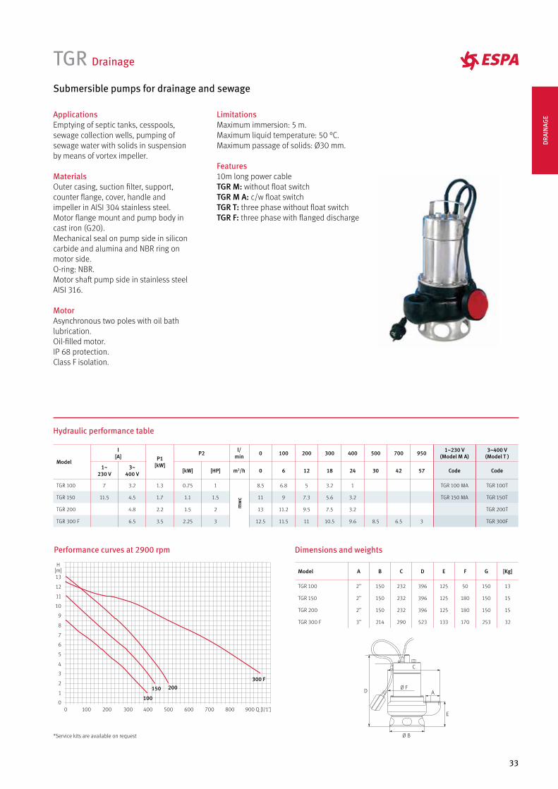
TGR Drainage
Submersible pumps for drainage and sewage
ApplicationsEmptying of septic tanks, cesspools, sewage collection wells, pumping of sewage water with solids in suspension by means of vortex impeller.
MaterialsOuter casing, suction filter, support, counter flange, cover, handle and impeller in AISI 304 stainless steel.Motor flange mount and pump body in cast iron (G20).Mechanical seal on pump side in silicon carbide and alumina and NBR ring on motor side.O-ring: NBR.Motor shaft pump side in stainless steel AISI 316.
MotorAsynchronous two poles with oil bath lubrication.Oil-filled motor.IP 68 protection.Class F isolation.
LimitationsMaximum immersion: 5 m.Maximum liquid temperature: 50 °C.Maximum passage of solids: Ø30 mm.
Features10m long power cableTGR M: without float switchTGR M A: c/w float switchTGR T: three phase without float switchTGR F: three phase with flanged discharge
Performance curves at 2900 rpm
Q [l/1’]800 9007006005004003002001000
100
150 200300 F
0
1
2
3
4
5
6
7
8
9
10
11
12
13
H[m]
Hydraulic performance table
Model
I [A] P1
[kW]
P2 l/min 0 100 200 300 400 500 700 950 1~230 V
(Model M A)3~400 V
(Model T )
1~230 V
3~400 V [kW] [HP] m3/h 0 6 12 18 24 30 42 57 Code Code
TGR 100 7 3.2 1.3 0.75 1
mw
c
8.5 6.8 5 3.2 1 TGR 100 MA TGR 100T
TGR 150 11.5 4.5 1.7 1.1 1.5 11 9 7.3 5.6 3.2 TGR 150 MA TGR 150T
TGR 200 4.8 2.2 1.5 2 13 11.2 9.5 7.5 3.2 TGR 200T
TGR 300 F 6.5 3.5 2.25 3 12.5 11.5 11 10.5 9.6 8.5 6.5 3 TGR 300F
Dimensions and weights
Model A B C D E F G [Kg]
TGR 100 2’’ 150 232 396 125 50 150 13
TGR 150 2’’ 150 232 396 125 180 150 15
TGR 200 2’’ 150 232 396 125 180 150 15
TGR 300 F 3’’ 214 290 523 133 170 253 32
*Service kits are available on request
DRA
INAG
E
34
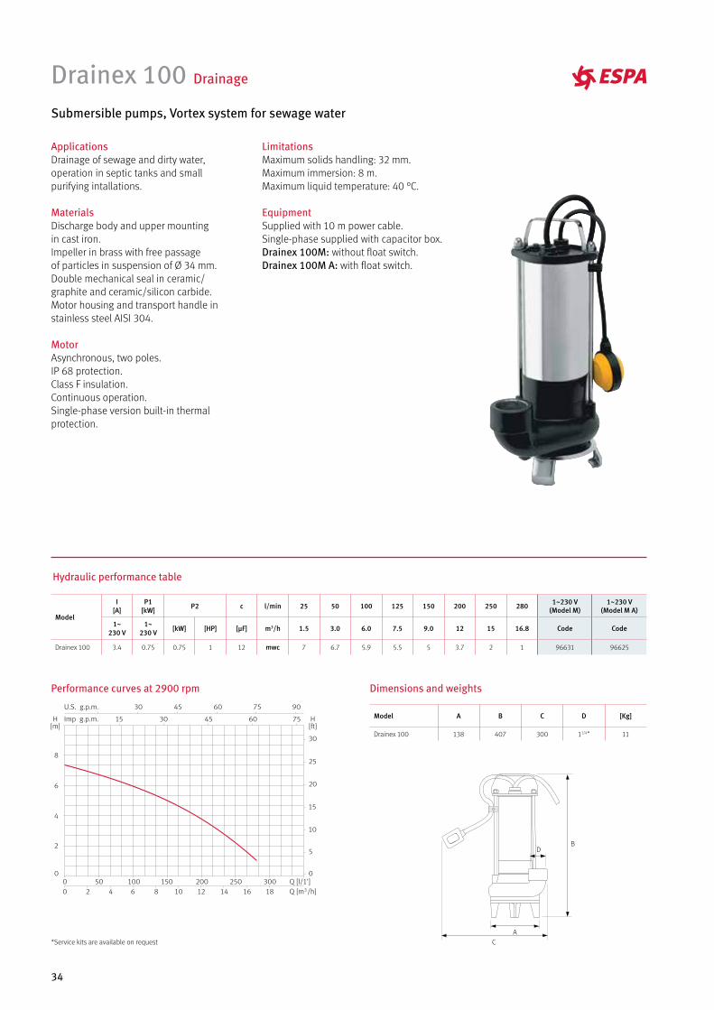
Drainex 100 Drainage
Submersible pumps, Vortex system for sewage water
ApplicationsDrainage of sewage and dirty water, operation in septic tanks and small purifying intallations.
MaterialsDischarge body and upper mounting in cast iron.Impeller in brass with free passage of particles in suspension of Ø 34 mm.Double mechanical seal in ceramic/graphite and ceramic/silicon carbide.Motor housing and transport handle in stainless steel AISI 304.
MotorAsynchronous, two poles.IP 68 protection.Class F insulation.Continuous operation.Single-phase version built-in thermal protection.
LimitationsMaximum solids handling: 32 mm.Maximum immersion: 8 m.Maximum liquid temperature: 40 °C.
EquipmentSupplied with 10 m power cable.Single-phase supplied with capacitor box.Drainex 100M: without float switch.Drainex 100M A: with float switch.
Performance curves at 2900 rpm
A
B
C
D
Dimensions and weights
Hydraulic performance table
Model
I [A]
P1 [kW] P2 c l/min 25 50 100 125 150 200 250 280 1~230 V
(Model M)1~230 V
(Model M A)
1~230 V
1~230 V [kW] [HP] [µF] m3/h 1.5 3.0 6.0 7.5 9.0 12 15 16.8 Code Code
Drainex 100 3.4 0.75 0.75 1 12 mwc 7 6.7 5.9 5.5 5 3.7 2 1 96631 96625
Model A B C D [Kg]
Drainex 100 138 407 300 11/4” 11
*Service kits are available on request
35
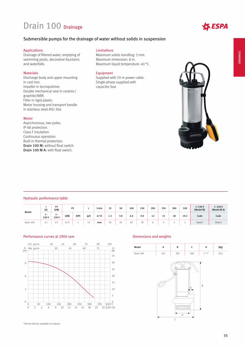
Model A B C D [Kg]
Drain 100 122 392 300 1 1/4” 10.5
Hydraulic performance table
Drain 100 Drainage
Submersible pumps for the drainage of water without solids in suspension
ApplicationsDrainage of filtered water, emptying of swimming pools, decorative fountains and waterfalls.
MaterialsDischarge body and upper mounting in cast iron.Impeller in tecnopolimer. Double mechanical seal in ceramic/graphite/NBR.Filter in rigid plastic.Motor housing and transport handle in stainless steel AISI 304.
MotorAsynchronous, two poles.IP 68 protection.Class F insulation.Continuous operation.Built-in thermal protection.Drain 100 M: without float switch.Drain 100 M A: with float switch.
LimitationsMaximum solids handling: 5 mm.Maximum immersion: 8 m.Maximum liquid temperature: 40 °C.
EquipmentSupplied with 10 m power cable.Single-phase supplied with capacitor box.
Performance curves at 2900 rpm
A
B
C
D
Dimensions and weights
Model
I [A]
P1 [kW] P2 c l/min 25 50 100 150 200 250 300 320 1~230 V
(Model M)1~230 V
(Model M A)
1~230 V
1~230 V [kW] [HP] [µF] m3/h 1.5 3.0 6.0 9.0 12 15 18 19.2 Code Code
Drain 100 3.1 0.7 0.75 1 12 mwc 92 91 87 78 6 4 2 1 96605 96603
*Service kits are available on request
DRA
INAG
E

36
Drainex 200/300 Drainage
Submersible monobloc pumps, Vortex system for sewage water
ApplicationsDrainage of sewage and dirty water, operation in septic tanks and small purifying installations.
MaterialsPump body, discharge body, suction body and impeller in cast iron.Mechanical seal in silicon carbide and ceramic.Pump base in stainless steel AISI 304, detachable for coupling of accessories.O-rings in NBR.Motor shaft in stainless steel AISI 420.
MotorAsynchronous, two poles, high torque.IP 68 protection.Class F insulation.Continuous operation.Water-cooled motor.Single-phase version built-in thermal protection and capacitor.
LimitationsMaximum solids handling:Drainex 200: 45 mm.Drainex 300: 60 mm.Maximum liquid temperature: 40 °C.
EquipmentSupplied with 10 m power cable.Drainex M: without float switch.Drainex M A: with float switch.Drainex T: three phase without float switch.Transportable versions include elbow and s/s feet.
Hydraulic performance table
Model
I [A]
P1 [kW] P2 c l/min 50 100 200 400 500 650 1~230V M 1~230V MA 3~400V
1~230 V
3~400 V
1~230 V
3~400 V [kW] [HP] [µF] m3/h 3.0 6.0 12 24 30 39 Code Code Code
Drainex 300 5.50 2.4 1.2 1.2 1.1 1.5 16
mw
c
7.1 6.6 5.4 2.9 1.8 96684 96686 96682
Drainex 301 6.80 2.7 1.5 1.5 1.1 1.5 12 9.2 8.5 7 4.1 2.8 96694 96696 96692
Drainex 302 7.20 3 1.8 1.8 1.1 1.5 12 11 10.5 9 5.8 4.2 1.8 96704 96706 96702
Model
I [A]
P1 [kW] P2 c l/min 50 100 200 300 400 500 1~230V M 1~230V MA 3~400V
1~230 V
3~400 V
1~230 V
3~400 V [kW] [HP] [µF] m3/h 3.0 6.0 12 18 24 30 Code Code Code
Drainex 200 5.4 2.3 1.1 1.1 1.1 1.5 16
mw
c
10.7 9.7 7.4 4.9 2.3 96652 96654 96648
Drainex 201 6.6 2.6 1.4 1.4 1.1 1.5 16 13.2 11.9 9.4 6.7 3.8 96664 96666 96662
Drainex 202 7.4 2.8 1.6 1.6 1.1 1.5 16 15.1 13.8 11.3 8.5 5.6 2.5 96674 96676 96672
Elbow flange set (P.O.A)
37
A
B
C
D
E F
G
H
I
E
FG
H I
A
B
C
D
J
Drainex 200/201/202 Drainex 300/301/302
Dimensions and weights
Drainex 200/300 Drainage
Interior condenser is in
a completely watertight
chamber to simplify the
pump installation process.
Optimal cooling of the motor thanks to the motor
body being designed as a single part.
The incorporation of a mechanical seal guarantees
complete watertightness between the hydraulic part
and the motor.
Large chamber between the impeller
and the aspiration cone which allows
suspended solid particles to pass
through. Drainex 200, 45 mm.
and Drainex 300, 60 mm.
Drainex 200
Performance curves at 2900 rpm
200 201 202
Drainex 300
300 301 302
Model A B C D E F G H I [Kg]
Drainex 200 415 239.5 383 118.7 2” 110 196 95 12 25
Drainex 201 415 239.5 383 118.7 2” 110 196 95 12 25
Drainex 202 415 239.5 383 118.7 2” 110 196 95 12 25
Model A B C D E F G H I J [Kg]
Drainex 300 429 271.5 408 118.7 222 110 150 110 144 2 1/2” 28
Drainex 301 429 271.5 408 118.7 222 110 150 110 144 2 1/2” 28
Drainex 302 429 271.5 408 118.7 222 110 150 110 144 2 1/2” 28
Impeller ext. Ø: Drainex 200: 105 mm. Drainex 201: 115 mm. Drainex 202: 124 mm. Impeller ext. Ø: Drainex 300: 105 mm. Drainex 301: 115 mm. Drainex 302: 124 mm.
DRA
INAG
E
38
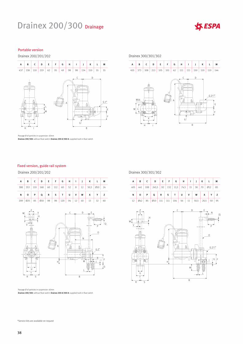
Portable version
Drainex 200/201/202 Drainex 300/301/302
H I
JK
L
M
F
G
A
B
C D
E
G 2”
F
G
A
B
C D
E
G 21/2”
H I
JK
LM
M16
Passage Ø of particles in suspension: 45mm
Drainex 200/300: without float switch. Drainex 200 A/300 A: supplied built-in float switch
Drainex 300/301/302
Fixed version, guide rail system
Drainex 200/201/202
R S
T
U
Z
V
WX
Y
F
G
HI
J
PQ
A
B
C D E
K
L
M
N
O
G 2”
R S
T
U
Z
V
W
X
Y
FGH
IJ
P
Q
A
B
C D E
K
L
M
N
O
G 21/2”
Passage Ø of particles in suspension: 60mm
Drainex 200/300: without float switch. Drainex 200 A/300 A: supplied built-in float switch
Drainex 200/300 Drainage
A B C D E F G H I J K L M
437 338 110 219 62 95 49 98 98 134 110 55 55
A B C D E F G H I J K L M
455 373 108 213 105 101 62 111 111 150 110 110 144
A B C D E F G H I J K L M
405 441 108 245,5 92 132 11,5 74,5 15 38 70 Ø12 85
A B C D E F G H I J K L M
388 353 110 168 60 112 60 52 8 12 50,5 Ø10 24
N O P Q R S T U V W X Y Z
209 Ø25 85 Ø10 98 98 120 94 12 40 13 32 60
N O P Q R S T U V W X Y Z
12 Ø42 85 Ø10 111 111 104 56 11 50,5 20,5 50 95
*Service kits are available on request
39
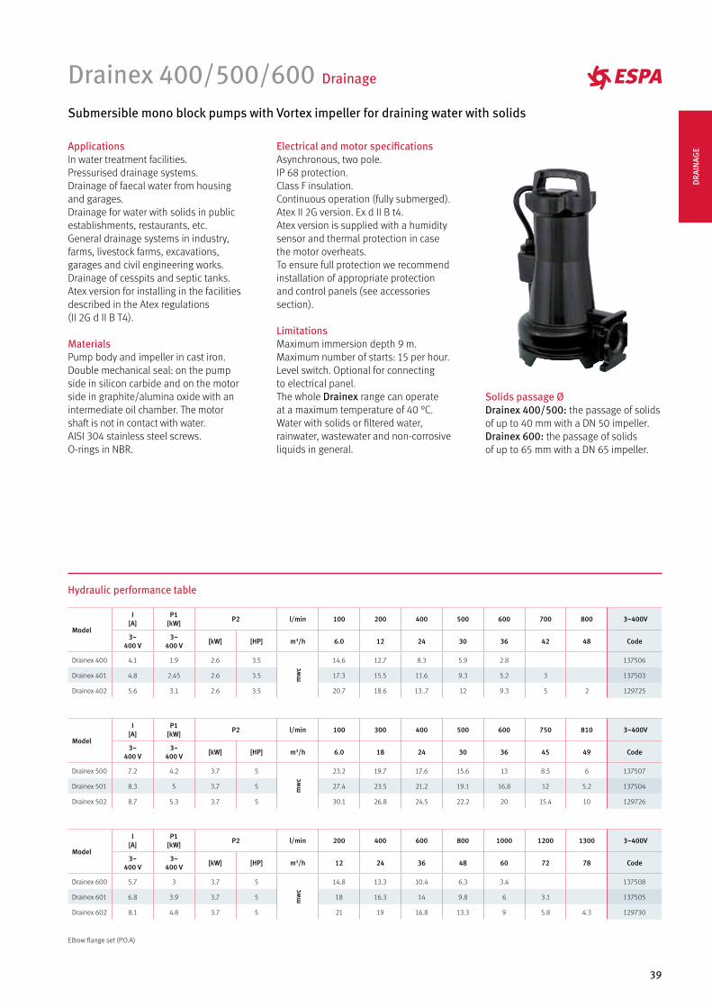
Drainex 400/500/600 Drainage
Submersible mono block pumps with Vortex impeller for draining water with solids
ApplicationsIn water treatment facilities. Pressurised drainage systems. Drainage of faecal water from housing and garages.Drainage for water with solids in public establishments, restaurants, etc.General drainage systems in industry, farms, livestock farms, excavations, garages and civil engineering works. Drainage of cesspits and septic tanks. Atex version for installing in the facilities described in the Atex regulations (II 2G d II B T4).
MaterialsPump body and impeller in cast iron.Double mechanical seal: on the pump side in silicon carbide and on the motor side in graphite/alumina oxide with an intermediate oil chamber. The motor shaft is not in contact with water. AISI 304 stainless steel screws.O-rings in NBR.
Electrical and motor specificationsAsynchronous, two pole.IP 68 protection. Class F insulation.Continuous operation (fully submerged).Atex II 2G version. Ex d II B t4.Atex version is supplied with a humidity sensor and thermal protection in case the motor overheats.To ensure full protection we recommend installation of appropriate protection and control panels (see accessories section).
LimitationsMaximum immersion depth 9 m.Maximum number of starts: 15 per hour.Level switch. Optional for connecting to electrical panel.The whole Drainex range can operate at a maximum temperature of 40 °C.Water with solids or filtered water, rainwater, wastewater and non-corrosive liquids in general.
Solids passage ØDrainex 400/500: the passage of solids of up to 40 mm with a DN 50 impeller.Drainex 600: the passage of solids of up to 65 mm with a DN 65 impeller.
Hydraulic performance table
Model
I [A]
P1 [kW] P2 l/min 100 200 400 500 600 700 800 3~400V
3~400 V
3~400 V [kW] [HP] m3/h 6.0 12 24 30 36 42 48 Code
Drainex 400 4.1 1.9 2.6 3.5
mw
c
14.6 12.7 8.3 5.9 2.8 137506
Drainex 401 4.8 2.45 2.6 3.5 17.3 15.5 11.6 9.3 5.2 3 137503
Drainex 402 5.6 3.1 2.6 3.5 20.7 18.6 13..7 12 9.3 5 2 129725
Model
I [A]
P1 [kW] P2 l/min 100 300 400 500 600 750 810 3~400V
3~400 V
3~400 V [kW] [HP] m3/h 6.0 18 24 30 36 45 49 Code
Drainex 500 7.2 4.2 3.7 5
mw
c
23.2 19.7 17.6 15.6 13 8.5 6 137507
Drainex 501 8.3 5 3.7 5 27.4 23.5 21.2 19.1 16.8 12 5.2 137504
Drainex 502 8.7 5.3 3.7 5 30.1 26.8 24.5 22.2 20 15.4 10 129726
Model
I [A]
P1 [kW] P2 l/min 200 400 600 800 1000 1200 1300 3~400V
3~400 V
3~400 V [kW] [HP] m3/h 12 24 36 48 60 72 78 Code
Drainex 600 5.7 3 3.7 5
mw
c
14.8 13.3 10.4 6.3 3.4 137508
Drainex 601 6.8 3.9 3.7 5 18 16.3 14 9.8 6 3.1 137505
Drainex 602 8.1 4.8 3.7 5 21 19 16.8 13.3 9 5.8 4.3 129730
Elbow flange set (P.O.A)
DRA
INAG
E
40
Drainex 400/500/600 Drainage
Portable version
Drainex 400/401/402 Drainex 500/501/502
Drainex 600/601/602
H
IJK
F
G
A
BCD
E
G 2”
H
IJK
F
G
A
B
CD
E
G 2”
H I
JKL
F
G
A
BCD
E
G 21/2”
Drainex 400/401/402
Impeller ext. Ø: Drainex 400: 115mm. Drainex 401: 125mm. Drainex 402: 136mm.
Drainex 500/501/502
Impeller ext. Ø: Drainex 500: 140mm. Drainex 501: 150mm. Drainex 502: 160mm.
Drainex 600/601/602
Impeller ext. Ø: Drainex 600: 125mm. Drainex 601: 135mm. Drainex 602: 145mm.
A
B
C
D
FGH
I
J
E
KLM
A
B
C
D
FGH
I
J
E
KLM
A
B
C
D
FG
H
I
J
E
K
Dimensions and weights
Model A B C D E F G H I J K L M Kg
Drainex 400 488 313 130 Ø50 251 134 110 86 75 19 Ø14 86 142 45
Drainex 401 488 313 130 Ø50 251 134 110 86 75 19 Ø14 86 142 45
Drainex 402 488 313 130 Ø50 251 134 110 86 75 19 Ø14 86 142 45
Model A B C D E F G H I J K L M Kg
Drainex 500 526 317 139 Ø50 256 134 110 85 80 18 Ø14 88 140 55
Drainex 501 526 317 139 Ø50 256 134 110 85 80 18 Ø14 88 140 55
Drainex 502 526 317 139 Ø50 256 134 110 85 80 18 Ø14 88 140 55
Model A B C D E F G H I J K Kg
Drainex 600 567 348 139 Ø65 254 154 110 87 18 110 170 60
Drainex 601 567 348 139 Ø65 254 154 110 87 18 110 170 60
Drainex 602 567 348 139 Ø65 254 154 110 87 18 110 170 60
A B C D E F G H I J K
575 412 234 139 129 64 70 110 256 134 110
A B C D E F G H I J K
537 408 238 130 124 64 70 110 251 134 110
A B C D E F G H I J K L
616 458 272 139 136 105 83 144 110 254 150 110
41
Drainex 400/500/600 Drainage
Drainex 500/501/502
Drainex 600/601/602
Fixed version, guide rail system
Drainex 400/401/402
S
T
U
V
W
F
G
H
I
J
A
B
C D E
X
K
L
PQ
R
Ñ
M
N
O
S
T
U
V
W
F
G
H
I
J
A
B
C D E
X
K
L
PQ
R
Ñ
M
N
O
P
Q
R
M
N
O
Ñ
F
G
H
I
J
A
B
C D E
K
L
Z
X
Y
Flange DN65
S
T
U
V
W
Flange DN80
A B C D E F G H I J K L
532 363 130 258 62 214 182.5 125 65 105 1” Ø50
A B C D E F G H I J K L
566 360 139 255 62 215 182.5 125 61 105 1” Ø50
M N Ñ O P Q R S T U V W X
251 116 93 88 40 13 12 251 125 100 120.5 19 561
M N Ñ O P Q R S T U V W X
256 116 93 88 40 13 12 256 131 100 120 19 566.8
A B C D E F G H I J K L M
630 419 319 285 62 260 231 165 97 134 1” Ø65 254
N Ñ O P Q R S T U V W X Y Z
125 102 88 40 13 12 254 127 Ø60 Ø133 Ø18 Ø140 Ø120 Ø21D
RAIN
AGE
42
Drainex 400/500/600 Drainage
Performance curves at 2900 rpm
Drainex 400 Drainex 500
Drainex 600
400 401 402
500
501
502
601600
602
Detachable connector with hermetic seal.
Wide aperture for solids passage:
40 mm for the 400/500 series
65 mm for the 600 series
Double mechanical seal
to guarantee that the motor is
completely watertight.
Oil chamber for optimal lubrication
of the mechanical seal.
Oversized bearings to support the radial
and axial stress of the hydraulic set.
*Service kits are available on request
43
AccessoriesDrainex 200/300/400/500/600
Transportable version for Drainex 400/500 modelsStationary version for Drainex 400/500 models
Support base with elbow
for automatic anchoring.
DN 50 (flange 50)
Upper anchoring on
double guide tube.
ANSI 150 2”
90 ° elbow at 2”. Stainless steel feet.
Stationary version for Drainex 300 modelsStationary version for Drainex 200 models
Support base for
automatic anchoring.
Upper anchoring
on guide.
Clamping flange. Support base for
automatic anchoring.
Upper anchoring
on guide tube.
Clamping flange.
Transportable version for Drainex 600 modelsStationary version for Drainex 600 models
Support base with elbow
for automatic anchoring.
DN 65 (flange 80)
Clamping flange.
DIN 2501 PN16
Upper anchoring on
double guide tube.
ANSI 150 21/2”
Support base with elbow
for automatic anchoring.
Upper anchoring on
double guide tube.
Clamping flange.
DN 65 (flange 65) DIN 2501 PN16 ANSI 150 21/2”
90 ° elbow at 21/2”. Stainless steel feet.
Kit Code
DR1 100527
Kit Code
DR3 132136
Kit Code
DR6 132139
Kit Code
DR5 132138
Kit Code
DR4 132137
Kit Code
DR7 132140
Kit Code
DR2 100528 DRA
INAG
E
44
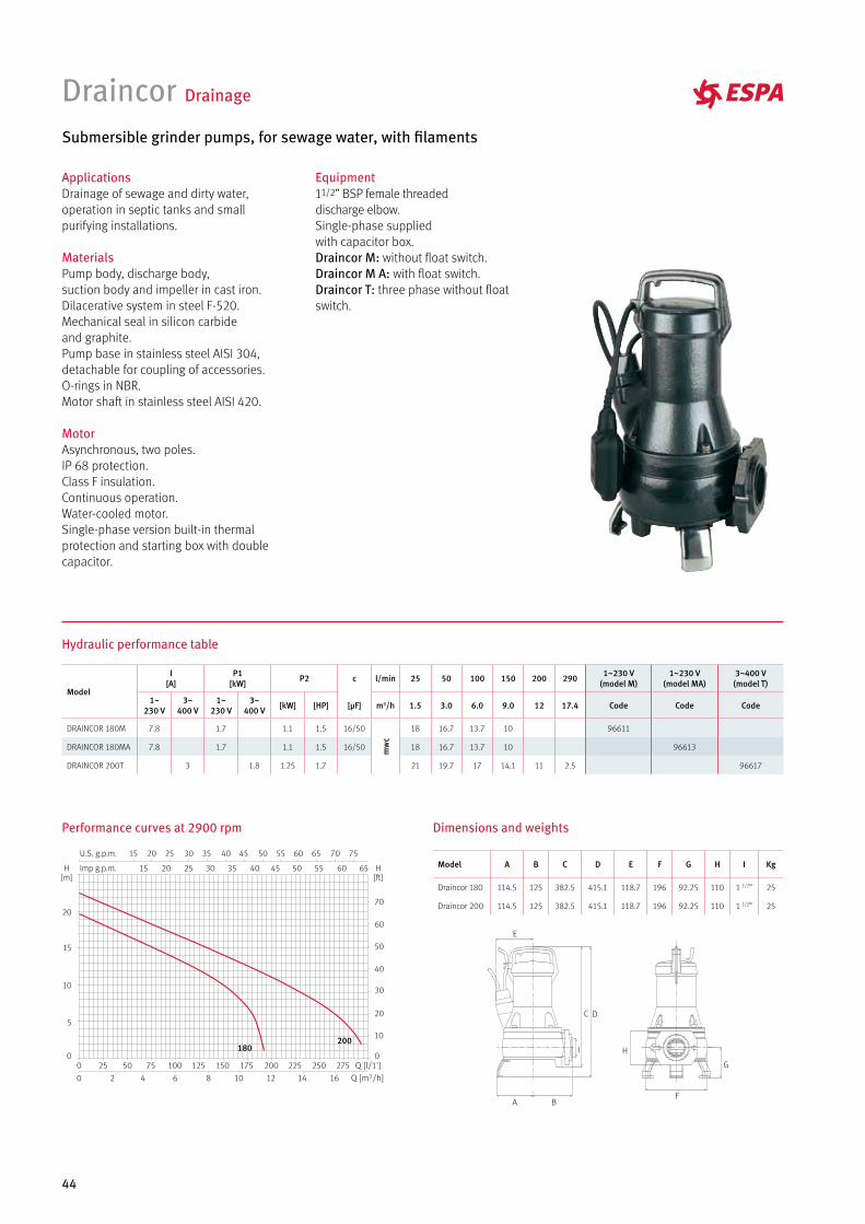
Draincor Drainage
Submersible grinder pumps, for sewage water, with filaments
ApplicationsDrainage of sewage and dirty water, operation in septic tanks and small purifying installations.
MaterialsPump body, discharge body, suction body and impeller in cast iron.Dilacerative system in steel F-520.Mechanical seal in silicon carbide and graphite.Pump base in stainless steel AISI 304, detachable for coupling of accessories.O-rings in NBR.Motor shaft in stainless steel AISI 420.
MotorAsynchronous, two poles.IP 68 protection.Class F insulation.Continuous operation.Water-cooled motor.Single-phase version built-in thermal protection and starting box with double capacitor.
Equipment11/2” BSP female threaded discharge elbow.Single-phase supplied with capacitor box.Draincor M: without float switch.Draincor M A: with float switch.Draincor T: three phase without float switch.
Performance curves at 2900 rpm
Hydraulic performance table
Dimensions and weights
F
G
H
A B
C D
E
I180200
Model
I [A]
P1 [kW] P2 c l/min 25 50 100 150 200 290 1~230 V
(model M)1~230 V
(model MA)3~400 V (model T)
1~230 V
3~400 V
1~230 V
3~400 V [kW] [HP] [µF] m3/h 1.5 3.0 6.0 9.0 12 17.4 Code Code Code
DRAINCOR 180M 7.8 1.7 1.1 1.5 16/50
mw
c
18 16.7 13.7 10 96611
DRAINCOR 180MA 7.8 1.7 1.1 1.5 16/50 18 16.7 13.7 10 96613
DRAINCOR 200T 3 1.8 1.25 1.7 21 19.7 17 14.1 11 2.5 96617
Model A B C D E F G H I Kg
Draincor 180 114.5 125 382.5 415.1 118.7 196 92.25 110 1 1/2” 25
Draincor 200 114.5 125 382.5 415.1 118.7 196 92.25 110 1 1/2” 25
45
Portable version
H I
JK
L
M
F
G
A
B
C D
E
G 2”
Draincor: without float switch. Draincor A: supplied built-in float switch
Fixed version, guide rail system
R S
T
U
Z
V
WX
Y
F
G
HI
J
PQ
A
B
C D E
K
L
M
N
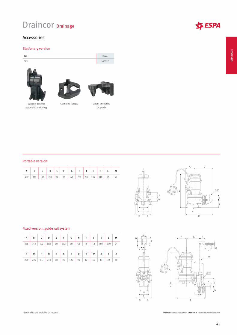
O
G 2”
Accessories
Draincor Drainage
Stationary version
Support base for
automatic anchoring.
Upper anchoring
on guide.
Clamping flange.
A B C D E F G H I J K L M
437 338 110 219 62 95 49 98 98 134 110 55 55
A B C D E F G H I J K L M
388 353 110 168 60 112 60 52 8 12 50.5 Ø10 24
N O P Q R S T U V W X Y Z
209 Ø25 85 Ø10 98 98 120 94 12 40 13 32 60
Kit Code
DR1 100527
*Service kits are available on request
DRA
INAG
E
46
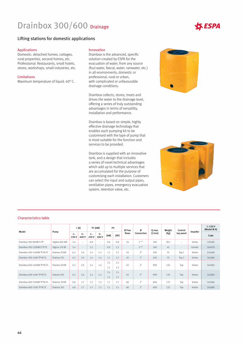
Drainbox 300/600 Drainage
Lifting stations for domestic applications
InnovationDrainbox is the advanced, specific solution created by ESPA for the evacuation of water, from any source (foul water, faecal, water, rainwater, etc.) in all environments; domestic or professional, rural or urban, with complicated or unfavourable drainage conditions.
Drainbox collects, stores, treats and drives the water to the drainage level, offering a series of truly outstanding advantages in terms of versatility, installation and performance.
Drainbox is based on simple, highly effective drainage technology that enables each pumping kit to be customised with the type of pump that is most suitable for the function and services to be provided.
Drainbox is supplied with an innovative tank, and a design that includes a series of novel technical advantages which add up to multiple services that are accumulated for the purpose of customising each installation. Customers can select the input and output pipes, ventilation pipes, emergency evacuation system, retention valve, etc.
ApplicationsDomestic: detached homes, cottages, rural properties, second homes, etc.Professional: Restaurants, small hotels, stores, workshops, small industries, etc.
LimitationsMaximum temperature of liquid: 40° C.
Characteristics table
Model Pump
I [A] P1 [kW] P2Ø Freeflows
Ø Connection
Q max.[l/min]
Weight[Kg]
Controltop panel Impeller
1~230 V (Model M A)
1~230 V
3~400 V
1~230 V
3~400 V [kW] [HP] Code
Drainbox 300 800M A TP Vigilex 600 MA 3.4 - 0.8 - 0.6 0.8 24 11/4” 240 28.1 - Vortex 125485
Drainbox 300 1200M D TP FL Vigicor 150 M 5.4 - 1.2 - 0.9 1.2 11/4” 140 41 - Grinder 142479
Drainbox 300 1400M TP KE FL Drainex 201M 6.2 2.6 1.4 1.4 1.1 1.5 45 2” 450 55 Top 1 Vortex 142480
Drainbox 300 1400 TP KE FL Drainex 201 6.2 2.6 1.4 1.4 1.1 1.5 45 2” 450 55 Top 2 Vortex 142481
Drainbox 600 1400M TP KE FL Drainex 201M 6.2 2.6 1.4 1.42 x
1.1
2 x
1.545 2” 900 110 Top Vortex 142482
Drainbox 600 1400 TP KE FL Drainex 201 6.2 2.6 1.4 1.42 x
1.1
2 x
1.545 2” 900 110 Top Vortex 142483
Drainbox 600 1500M TP KE FL Drainex 301M 6.8 2.7 1.5 1.5 1.1 1.5 60 2” 600 122 Top Vortex 142484
Drainbox 600 1500 TP KE FL Drainex 301 6.8 2.7 1.5 1.5 1.1 1.5 60 2” 600 122 Top Vortex 142485
47
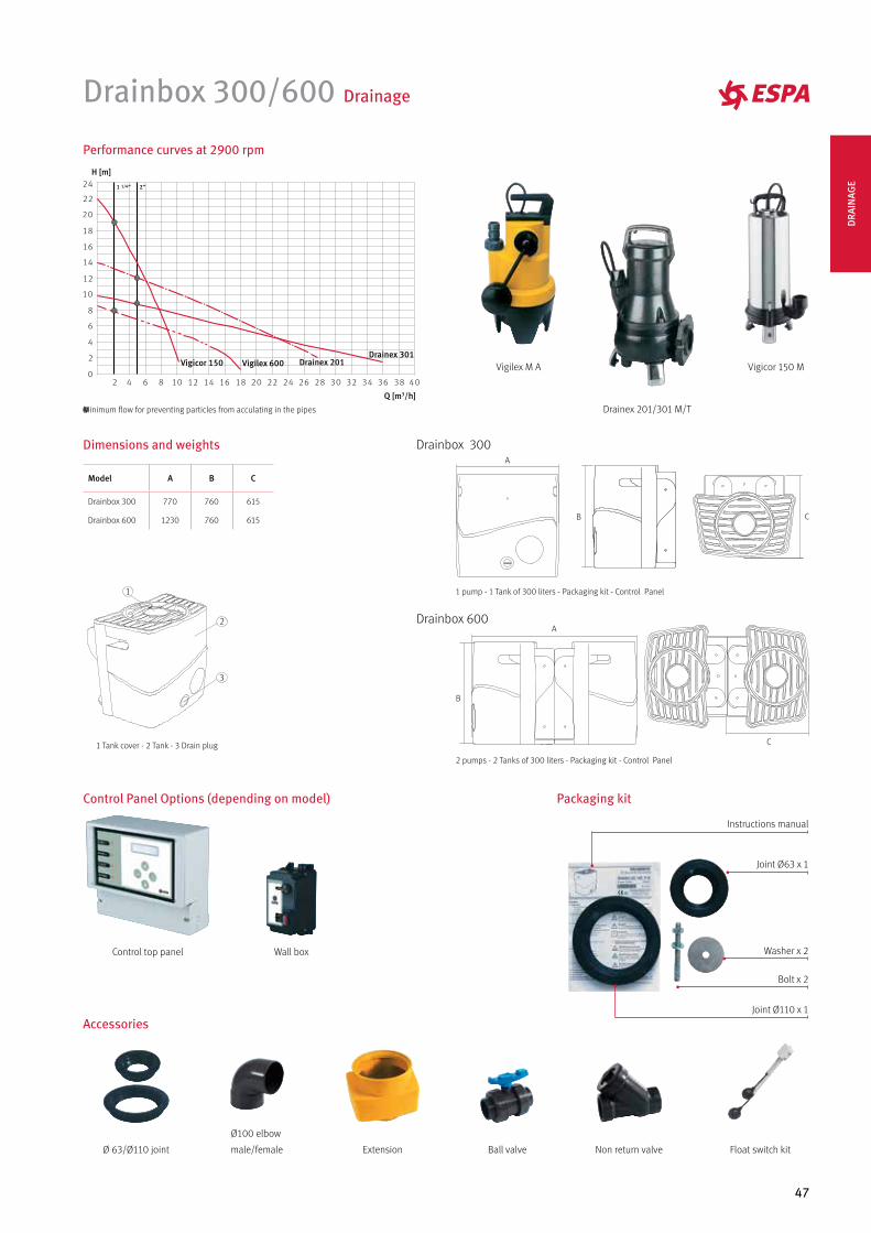
Drainbox 300/600 Drainage
Performance curves at 2900 rpm
Drainex 201/301 M/T
Vigicor 150 MVigilex M A
Accessories
Float switch kitNon return valveØ 63/Ø110 joint Extension
Ø100 elbow
male/female Ball valve
Packaging kitControl Panel Options (depending on model)
Wall boxControl top panel
Bolt x 2
Washer x 2
Joint Ø63 x 1
Instructions manual
Joint Ø110 x 1
Minimum flow for preventing particles from acculating in the pipes
H [m]
Q [m3/h]
Drainex 301Drainex 201Vigilex 600Vigicor 150
1 Tank cover - 2 Tank - 3 Drain plug
1
2
3
Drainbox 300A
B C
1 pump - 1 Tank of 300 liters - Packaging kit - Control Panel
Drainbox 600A
B
C
2 pumps - 2 Tanks of 300 liters - Packaging kit - Control Panel
Dimensions and weights
Model A B C
Drainbox 300 770 760 615
Drainbox 600 1230 760 615
DRA
INAG
E
48
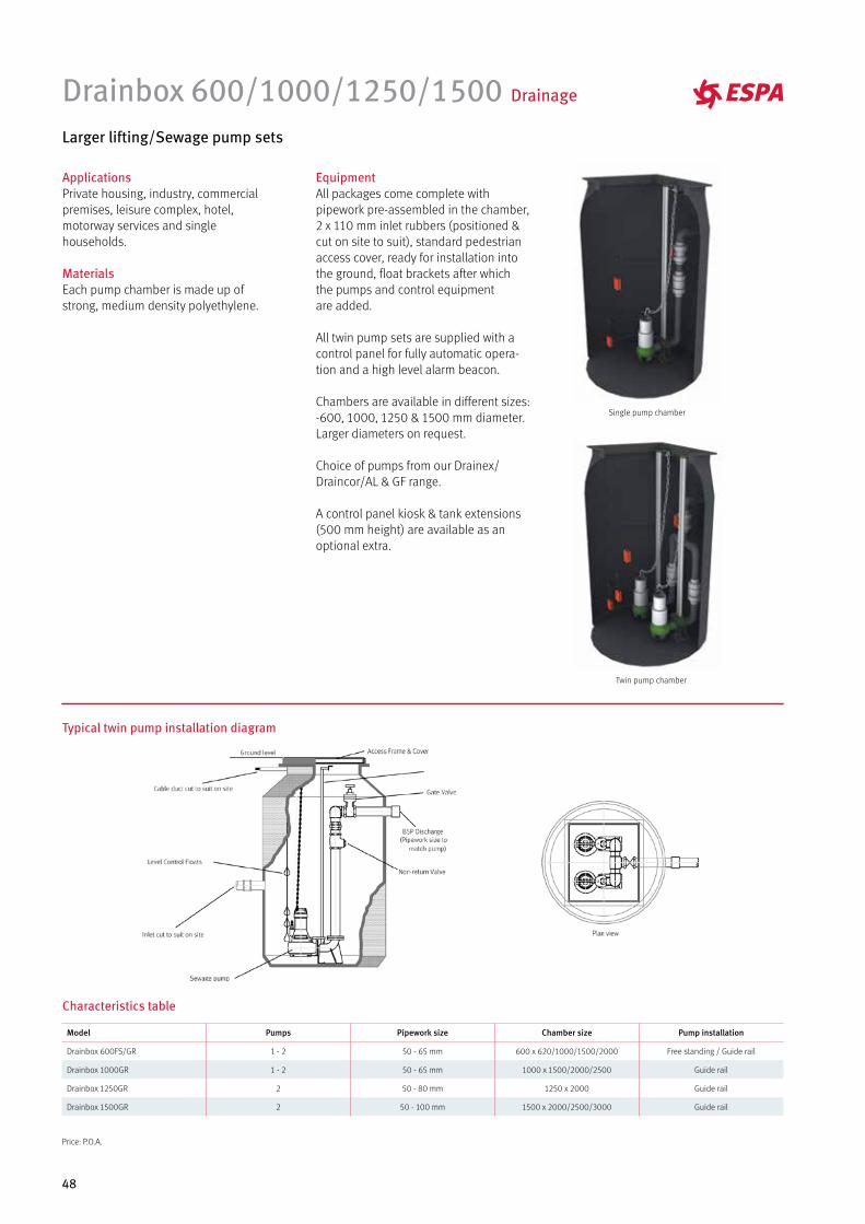
Drainbox 600/1000/1250/1500 Drainage
Larger lifting/Sewage pump sets
EquipmentAll packages come complete with pipework pre-assembled in the chamber, 2 x 110 mm inlet rubbers (positioned & cut on site to suit), standard pedestrian access cover, ready for installation into the ground, float brackets after which the pumps and control equipmentare added.
All twin pump sets are supplied with a control panel for fully automatic opera-tion and a high level alarm beacon.
Chambers are available in different sizes: -600, 1000, 1250 & 1500 mm diameter. Larger diameters on request.
Choice of pumps from our Drainex/Draincor/AL & GF range.
A control panel kiosk & tank extensions (500 mm height) are available as an optional extra.
ApplicationsPrivate housing, industry, commercial premises, leisure complex, hotel, motorway services and single households.
MaterialsEach pump chamber is made up of strong, medium density polyethylene.
Typical twin pump installation diagram
Characteristics table
Model Pumps Pipework size Chamber size Pump installation
Drainbox 600FS/GR 1 - 2 50 - 65 mm 600 x 620/1000/1500/2000 Free standing / Guide rail
Drainbox 1000GR 1 - 2 50 - 65 mm 1000 x 1500/2000/2500 Guide rail
Drainbox 1250GR 2 50 - 80 mm 1250 x 2000 Guide rail
Drainbox 1500GR 2 50 - 100 mm 1500 x 2000/2500/3000 Guide rail
Single pump chamber
Twin pump chamber
Price: P.O.A.
49
Control Panels Drainage
For controlling sewage and water pumping systems
Technical featuresSingle phase power supply 100-240Vac ±10% 50/60Hz (SMART EVO Mono);Three phase power supply 100-240Vac ±10% 50/60Hz (SMART EVO -Tri);Three phase power supply 310-450Vac ±10% 50/60Hz (SMART EVO -Tri);G/P1 and G/P2 normally open inputs for start-up command;3 inputs for single-pole level sensors (COM-MIN-MAX);T1 and T2 inputs for motor protection;Normally open input for alarm activation;AUTOMATIC-0-MANUAL buttons (spring return);DIP-SWITCH selectors for:• level alarm enable from sensors,• thermal cut-out activation delay 5/10 seconds,• alarm output settings,• alarm reset enable from motor protection,• Filling/Emptying mode,• start/stop float enable,• enable of delay on board activation on power mains return,• motor switching module enable (on SMART EVO 2);Green led: power ON / failure or incorrect phase sequence;
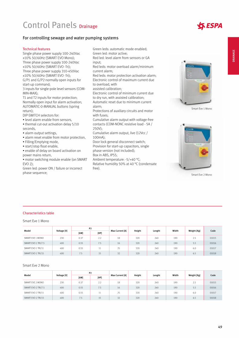
Smart Eve 1 Mono
Smart Eve 2 Mono
Model Voltage [V]P2
Max Current [A] Height Lenght Width Weight [Kg] Code[kW] [HP]
SMART EVE 1 MONO 230 0.37 2.2 18 320 240 190 2.5 01015
SMART EVO 1 TRI/7.5 400 0.55 7.5 16 320 240 190 5.5 01016
SMART EVO 1 TRI/11 400 0.55 11 25 320 240 190 6.0 01017
SMART EVO 1 TRI/15 400 7.5 15 32 320 240 190 6.5 01018
Model Voltage [V]P2
Max Current [A] Height Lenght Width Weight [Kg] Code[kW] [HP]
SMART EVE 2 MONO 230 0.37 2.2 18 320 240 190 2.5 01015
SMART EVO 2 TRI/7.5 400 0.55 7.5 16 320 240 190 5.5 01016
SMART EVO 2 TRI/11 400 0.55 11 25 320 240 190 6.0 01017
SMART EVO 2 TRI/15 400 7.5 15 32 320 240 190 6.5 01018
Green leds: automatic mode enabled;Green led: motor active;Red led: level alarm from sensors or GA input;Red leds: motor overload alarm/minimum current alarm;Red leds: motor protection activation alarm;Electronic control of maximum current due to overload, withassisted calibration;Electronic control of minimum current due to dry run, with assisted calibration;Automatic reset due to minimum current alarm;Protections of auxiliary circuits and motor with fuses;Cumulative alarm output with voltage-free contacts (COM-NONC resistive load - 5A / 250V);Cumulative alarm output, live (12Vcc / 100mA);Door lock general disconnect switch;Provision for start-up capacitors, single phase version (not included);Box in ABS, IP55;Ambient temperature: -5/+40 °C;Relative humidity 50% at 40 °C (condensate free).
Characteristics table
Smart Eve 1 Mono
Smart Eve 2 Mono
DRA
INAG
E

WATER SUPPLY SURFACEHORIZONTAL & VERTICAL
52
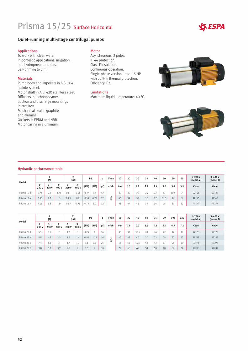
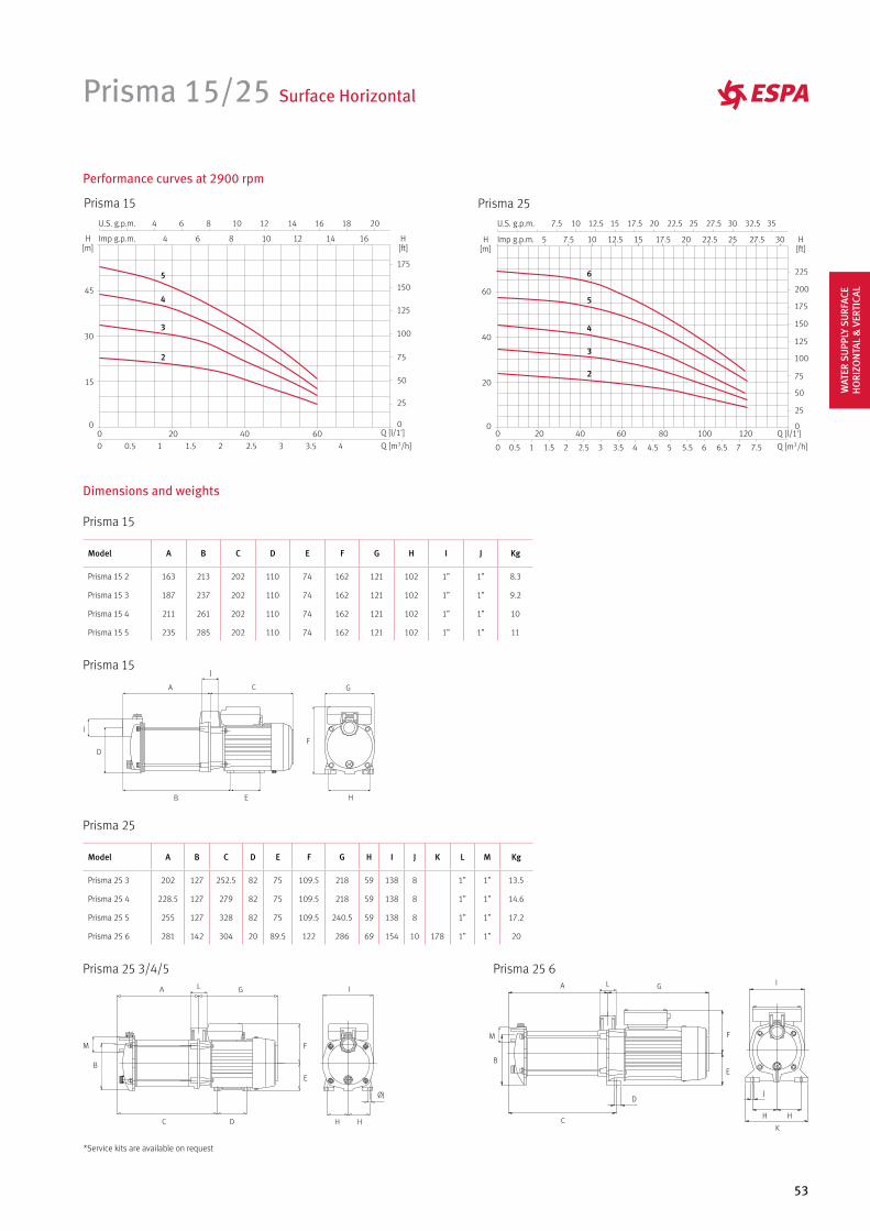
Prisma 15/25 Surface Horizontal
Quiet-running multi-stage centrifugal pumps
MotorAsynchronous, 2 poles.IP 44 protection.Class F insulation.Continuous operation.Single-phase version up to 1.5 HPwith built-in thermal protection.Efficiency IE2.
LimitationsMaximum liquid temperature: 40 °C.
ApplicationsTo work with clean waterin domestic applications, irrigation,and hydropneumatic sets.Self-priming to 2 m.
MaterialsPump body and impellers in AISI 304stainless steel.Motor shaft in AISI 420 stainless steel.Diffusers in technopolymer.Suction and discharge mountingsin cast iron.Mechanical seal in graphiteand alumine.Gaskets in EPDM and NBR.Motor casing in aluminium.
Hydraulic performance table
Model
I [A]
P1 [kW] P2 c l/min 10 20 30 35 40 50 60 65 1~230 V
(model M)3~400 V (model T)
1~230 V
3~230 V
3~400 V
1~230 V
3~400 V [kW] [HP] [µF] m3/h 0.6 1.2 1.8 2.1 2.4 3.0 3.6 3.9 Code Code
Prisma 15 3 2.74 2.1 1.21 0.61 0.61 0.37 0.5 12
mw
c
32 30 26 24 22 17 10.5 7 97141 97138
Prisma 15 4 3.53 2.3 1.3 0.79 0.7 0.55 0.75 12 43 39 35 32 27 21.5 14 9 97150 97148
Prisma 15 5 4.13 3.3 1.9 0.95 0.95 0.75 1.0 12 51 47 42 38 34 25 17 12 97159 97157
Model
I [A]
P1 [kW] P2 c l/min 15 30 45 60 75 90 105 120 1~230 V
(model M)3~400 V (model T)
1~230 V
3~230 V
3~400 V
1~230 V
3~400 V [kW] [HP] [µF] m3/h 0.9 1.8 2.7 3.6 4.5 5.4 6.3 7.2 Code Code
Prisma 25 3 5.5 3.5 2 1.2 1 0.75 1 16
mw
c
33 32 30.5 28 26 22 17 12 97178 97175
Prisma 25 4 6.8 4.3 2.5 1.5 1.4 0.92 1.25 16 43 42 40 37 33 28 22 15 97188 97185
Prisma 25 5 7.4 5.2 3 1.7 1.7 1.1 1.5 25 56 55 52.5 48 43 37 29 20 97196 97194
Prisma 25 6 9.8 6.7 3.9 2.2 2 1.5 2 30 72 68 65 58 50 40 32 24 97203 97202
53
Prisma 15/25 Surface Horizontal
Prisma 25Prisma 15
Performance curves at 2900 rpm
5
4
3
2
5
6
4
3
2
Prisma 15
Dimensions and weights
Model A B C D E F G H I J Kg
Prisma 15 2 163 213 202 110 74 162 121 102 1” 1” 8.3
Prisma 15 3 187 237 202 110 74 162 121 102 1” 1” 9.2
Prisma 15 4 211 261 202 110 74 162 121 102 1” 1” 10
Prisma 15 5 235 285 202 110 74 162 121 102 1” 1” 11
Prisma 25 3/4/5 Prisma 25 6
Prisma 25
Model A B C D E F G H I J K L M Kg
Prisma 25 3 202 127 252.5 82 75 109.5 218 59 138 8 1” 1” 13.5
Prisma 25 4 228.5 127 279 82 75 109.5 218 59 138 8 1” 1” 14.6
Prisma 25 5 255 127 328 82 75 109.5 240.5 59 138 8 1” 1” 17.2
Prisma 25 6 281 142 304 20 89.5 122 286 69 154 10 178 1” 1” 20
F
G
H
A
B
C
D
E
I
JPrisma 15
F
GA
B
C
D
E
HH
I
J
K
L
M
A
B
C D
E
F
G
H H
I
ØJ
L
M
*Service kits are available on request
WAT
ER S
UPP
LY S
URF
ACE
HO
RIZO
NTA
L &
VER
TICA
L
54
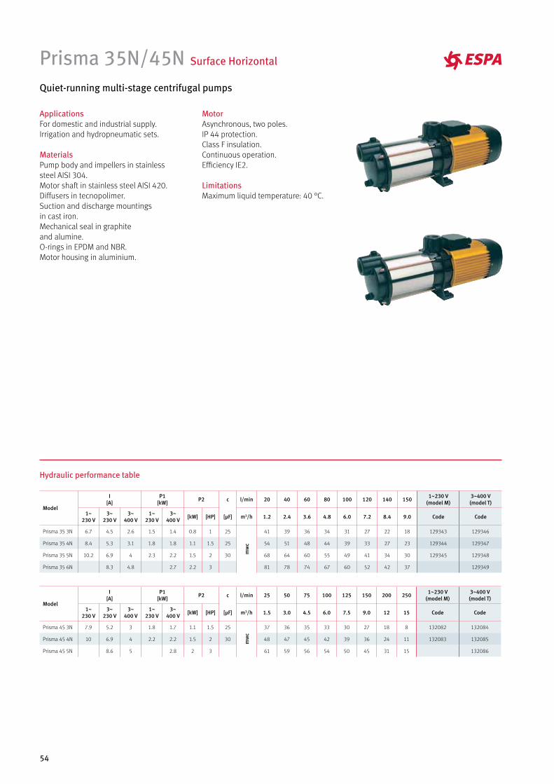
Prisma 35N/45N Surface Horizontal
Quiet-running multi-stage centrifugal pumps
MotorAsynchronous, two poles.IP 44 protection.Class F insulation.Continuous operation.Efficiency IE2.
LimitationsMaximum liquid temperature: 40 °C.
ApplicationsFor domestic and industrial supply. Irrigation and hydropneumatic sets.
MaterialsPump body and impellers in stainlesssteel AISI 304.Motor shaft in stainless steel AISI 420.Diffusers in tecnopolimer.Suction and discharge mountingsin cast iron.Mechanical seal in graphite and alumine.O-rings in EPDM and NBR.Motor housing in aluminium.
Hydraulic performance table
Model
I [A]
P1 [kW] P2 c l/min 20 40 60 80 100 120 140 150 1~230 V
(model M)3~400 V (model T)
1~230 V
3~230 V
3~400 V
1~230 V
3~400 V [kW] [HP] [µF] m3/h 1.2 2.4 3.6 4.8 6.0 7.2 8.4 9.0 Code Code
Prisma 35 3N 6.7 4.5 2.6 1.5 1.4 0.8 1 25
mw
c
41 39 36 34 31 27 22 18 129343 129346
Prisma 35 4N 8.4 5.3 3.1 1.8 1.8 1.1 1.5 25 54 51 48 44 39 33 27 23 129344 129347
Prisma 35 5N 10.2 6.9 4 2.3 2.2 1.5 2 30 68 64 60 55 49 41 34 30 129345 129348
Prisma 35 6N 8.3 4.8 2.7 2.2 3 81 78 74 67 60 52 42 37 129349
Model
I [A]
P1 [kW] P2 c l/min 25 50 75 100 125 150 200 250 1~230 V
(model M)3~400 V (model T)
1~230 V
3~230 V
3~400 V
1~230 V
3~400 V [kW] [HP] [µF] m3/h 1.5 3.0 4.5 6.0 7.5 9.0 12 15 Code Code
Prisma 45 3N 7.9 5.2 3 1.8 1.7 1.1 1.5 25
mw
c
37 36 35 33 30 27 18 8 132082 132084
Prisma 45 4N 10 6.9 4 2.2 2.2 1.5 2 30 48 47 45 42 39 36 24 11 132083 132085
Prisma 45 5N 8.6 5 2.8 2 3 61 59 56 54 50 45 31 15 132086
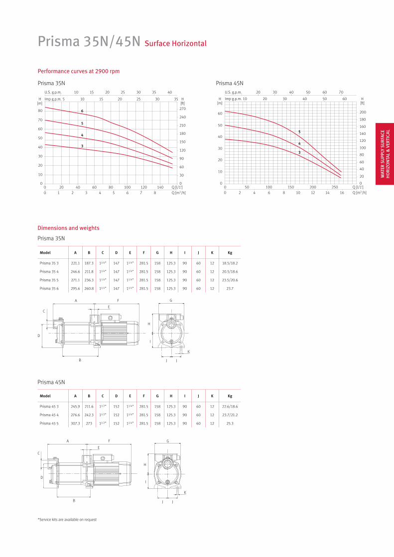
Prisma 35N
Prisma 45N
A
B
C
D
E
F
J J
G
H
I
K
A
B
C
D
E
F
J
G
H
I
K
J
Prisma 35N/45N Surface Horizontal
Prisma 35N Prisma 45N
Dimensions and weights
Performance curves at 2900 rpm
5
6
4
3
5
4
3
Model A B C D E F G H I J K Kg
Prisma 35 3 221.1 187.3 11/4” 147 11/4” 281.5 158 125.3 90 60 12 18.5/18.2
Prisma 35 4 246.6 211.8 11/4” 147 11/4” 281.5 158 125.3 90 60 12 20.5/18.6
Prisma 35 5 271.1 236.3 11/4” 147 11/4” 281.5 158 125.3 90 60 12 23.5/20.6
Prisma 35 6 295.6 260.8 11/4” 147 11/4” 281.5 158 125.3 90 60 12 23.7
Model A B C D E F G H I J K Kg
Prisma 45 3 245.9 211.6 11/2” 152 11/4” 281.5 158 125.3 90 60 12 22.6/18.6
Prisma 45 4 276.6 242.3 11/2” 152 11/4” 281.5 158 125.3 90 60 12 23.7/21.2
Prisma 45 5 307.3 273 11/2” 152 11/4” 281.5 158 125.3 90 60 12 25.3
*Service kits are available on request
WAT
ER S
UPP
LY S
URF
ACE
HO
RIZO
NTA
L &
VER
TICA
L
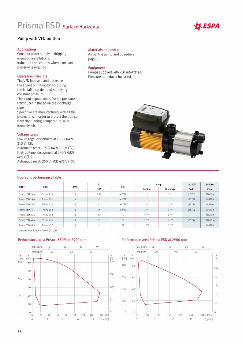
56
Prisma ESD Surface Horizontal
Pump with VFD built-in
ApplicationsConstant water supply in dripping irrigation installations. Industrial applications where constant pressure is required.
Operation principleThe VFD increase and decreasethe speed of the motor according the installation demand supplying constant pressure. The input signal comes from a pressure transducer installed on the discharge pipe. Speedrive are manufactured with all the protections in order to protect the pump, from dry running, temperature, over intensity, etc.
Voltage rangeLow voltage: disconnect at 180 V (M2) 310 V (T2).Automatic reset: 195 V (M2) 335 V (T2).High voltage: disconnect at 270 V (M2) 485 V (T2).Automatic reset: 250 V (M2) 475 V (T2).
Hydraulic performance table
Performance area Prisma ESDM at 2900 rpm
86420
140120100806040200 Q [l/min]
Q [m3/h]
10
10
20
20
30
30 40
Imp g.p.m.
U.S. g.p.m.
60
50
40
30
20
10
0
H[mwc]
200
150
100
50
0
H[ft]
600
400
200
0
H[kPa]
Performance area Prisma ESD at 2900 rpm
Q [l/min]
151050
300250200150100500
Q [m3/h]
20 40 60
20 40 60 80
Imp g.p.m.
U.S. g.p.m.
80
60
40
20
0
H[mwc]
800
600
400
200
0
H[kPa]
250
200
150
100
50
0
H[ft]
Model Pump UnitP2
VfdPump 1~230V 3~400V
[kW] Suction Discharge Code Code
Prisma ESD 25 4 Prisma 25 4 1 0.92 M2/T2 1” 1” 185785 185786
Prisma ESD 25 6 Prisma 25 6 1 1.5 M2/T2 1” 1” 185787 185788
Prisma ESD 35 4 Prisma 35 4 1 1.1 M2/T2 1 1/4” 1 1/4” 185789 185790
Prisma ESD 35 5 Prisma 35 5 1 1.5 M2/T2 1 1/4” 1 1/4” 185791 185792
Prisma ESD 35 6 Prisma 35 6 1 2.2 T2 1 1/4” 1 1/4” 185793
Prisma ESD 45 4 Prisma 45 4 1 1.5 T2 1 1/2” 1 1/4” 185794 185795
Prisma ESD 45 5 Prisma 45 5 1 2 T2 1 1/2” 1 1/4” 185796
Pressure transductor 4-20 mA (10 bar)
Materials and motorAs per the pump and Speedrive pages.
EquipmentPumps supplied with VDF integrated. Pressure transducer included.

57
Prisma ESD Surface Horizontal
Prisma ESD 25
Prisma ESD 35
Prisma ESD 45
Model A B C D E F G H I J Kg
Prisma ESD 25 4M 228.5 279 225 82 127 207 213 75 59 Ø8 16.5
Prisma ESD 25 4T 228.5 279 225 82 127 207 213 75 59 Ø8 16.5
Prisma ESD 25 6M 281 328 225 82 127 207 213 75 59 Ø8 19.3
Prisma ESD 25 6T 281 328 225 82 127 207 213 75 59 Ø8 19.3
Dimensions and weights
A
B
C
D
E
F
G
H
I I
J
G 1
” IS
O 2
28/1
G 1” ISO 228/1
A
B
C
D
E
F
G
H
I
G 1
1/4
” IS
O 2
28/1
G 1 1/4” ISO 228/1
H
A
B
C
D
E
F
G
H
I
G 1
1/2
” IS
O 2
28/1
G 1 1/4” ISO 228/1
H
Model A B C D E F G H I Kg
Prisma ESD 35 4M 246.6 211.8 280.5 147 212 90 207 60 Ø12 22.6
Prisma ESD 35 4T 246.6 211.8 280.5 147 212 90 207 60 Ø12 20.9
Prisma ESD 35 5M 271.1 236.3 280.5 147 212 90 207 60 Ø12 25.6
Prisma ESD 35 5T 271.1 236.3 280.5 147 212 90 207 60 Ø12 22.9
Prisma ESD 35 6T 295.6 260.8 280.5 147 212 90 207 60 Ø12 26
Model A B C D E F G H I Kg
Prisma ESD 45 4M 276.6 242.3 281.5 152 221 90 207 60 Ø12 25.8
Prisma ESD 45 4T 276.6 242.3 281.5 152 221 90 207 60 Ø12 23.5
Prisma ESD 45 5T 307.3 273 281.5 152 221 90 207 60 Ø12 27.5
WAT
ER S
UPP
LY S
URF
ACE
HO
RIZO
NTA
L &
VER
TICA
L
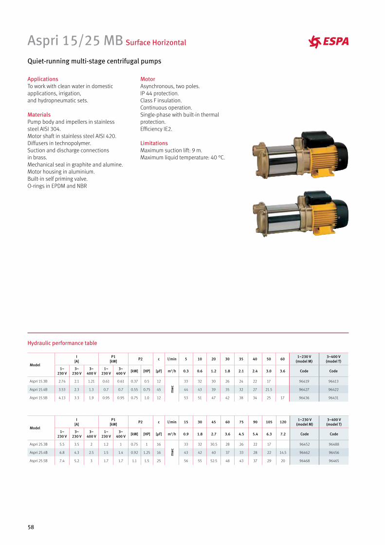
58
Aspri 15/25 MB Surface Horizontal
Quiet-running multi-stage centrifugal pumps
MotorAsynchronous, two poles.IP 44 protection.Class F insulation.Continuous operation.Single-phase with built-in thermal protection.Efficiency IE2.
LimitationsMaximum suction lift: 9 m.Maximum liquid temperature: 40 °C.
ApplicationsTo work with clean water in domestic applications, irrigation, and hydropneumatic sets.
MaterialsPump body and impellers in stainless steel AISI 304.Motor shaft in stainless steel AISI 420.Diffusers in technopolymer.Suction and discharge connections in brass.Mechanical seal in graphite and alumine.Motor housing in aluminium.Built-in self priming valve.O-rings in EPDM and NBR
Hydraulic performance table
Model
I [A]
P1 [kW] P2 c l/min 15 30 45 60 75 90 105 120 1~230 V
(model M)3~400 V (model T)
1~230 V
3~230 V
3~400 V
1~230 V
3~400 V [kW] [HP] [µF] m3/h 0.9 1.8 2.7 3.6 4.5 5.4 6.3 7.2 Code Code
Aspri 25.3B 5.5 3.5 2 1.2 1 0.75 1 16
mw
c
33 32 30.5 28 26 22 17 96452 96488
Aspri 25.4B 6.8 4.3 2.5 1.5 1.4 0.92 1.25 16 43 42 40 37 33 28 22 14.5 96462 96456
Aspri 25.5B 7.4 5.2 3 1.7 1.7 1.1 1.5 25 56 55 52.5 48 43 37 29 20 96468 96465
Model
I [A]
P1 [kW] P2 c l/min 5 10 20 30 35 40 50 60 1~230 V
(model M)3~400 V (model T)
1~230 V
3~230 V
3~400 V
1~230 V
3~400 V [kW] [HP] [µF] m3/h 0.3 0.6 1.2 1.8 2.1 2.4 3.0 3.6 Code Code
Aspri 15.3B 2.74 2.1 1.21 0.61 0.61 0.37 0.5 12
mw
c
33 32 30 26 24 22 17 96419 96413
Aspri 15.4B 3.53 2.3 1.3 0.7 0.7 0.55 0.75 45 44 43 39 35 32 27 21.5 96427 96422
Aspri 15.5B 4.13 3.3 1.9 0.95 0.95 0.75 1.0 12 53 51 47 42 38 34 25 17 96436 96431
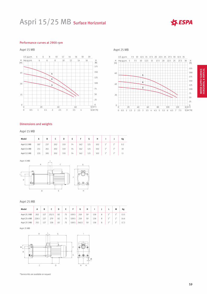
59
Aspri 15/25 MB Surface Horizontal
Performance curves at 2900 rpm
Aspri 15 MB Aspri 25 MB
4
5
34
5
3
Aspri 15 MB
Dimensions and weights
Model A B C D E F G H I J Kg
Aspri 15 3 MB 187 237 202 110 74 162 121 102 1” 1” 9.2
Aspri 15 4 MB 211 261 202 110 74 162 121 102 1” 1” 10
Aspri 15 5 MB 235 285 202 110 74 162 121 102 1” 1” 11
Aspri 25 MB
Model A B C D E F G H I J L M Kg
Aspri 25 3 MB 202 127 252.5 82 75 109.5 218 59 138 8 1” 1” 13.5
Aspri 25 4 MB 228.5 127 279 82 75 109.5 218 59 138 8 1” 1” 14.6
Aspri 25 5 MB 255 127 328 82 75 109.5 240.5 59 138 8 1” 1” 17.2
F
G
H
A
B
C
D
E
I
JAspri 15 MB
Aspri 25 MB
A
B
C D
E
F
G
H H
I
ØJ
L
M
*Service kits are available on request
WAT
ER S
UPP
LY S
URF
ACE
HO
RIZO
NTA
L &
VER
TICA
L
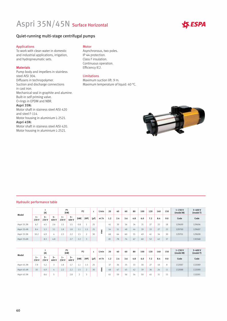
60
Aspri 35N/45N Surface Horizontal
Quiet-running multi-stage centrifugal pumps
ApplicationsTo work with clean water in domestic and industrial applications, irrigation, and hydropneumatic sets.
MaterialsPump body and impellers in stainless steel AISI 304.Diffusers in technopolymer.Suction and discharge connections in cast iron.Mechanical seal in graphite and alumine.Built-in self priming valve.O-rings in EPDM and NBR.Aspri 35N:Motor shaft in stainess steel AISI 420 and steel F-114.Motor housing in aluminium L-2521.Aspri 45N:Motor shaft in stainess steel AISI 420.Motor housing in aluminium L-2521.
MotorAsynchronous, two poles.IP 44 protection.Class F insulation.Continuous operation. Efficiency IE2.
LimitationsMaximum suction lift: 9 m.Maximum temperature of liquid: 40 °C.
Hydraulic performance table
Model
I [A]
P1 [kW] P2 c l/min 20 40 60 80 100 120 140 150 1~230 V
(model M)3~400 V (model T)
1~230 V
3~230 V
3~400 V
1~230 V
3~400 V [kW] [HP] [µF] m3/h 1.2 2.4 3.6 4.8 6.0 7.2 8.4 9.0 Code Code
Aspri 35.3N 6.7 4.5 2.6 1.5 1.5 0.8 1 25
mw
c
41 39 36 34 31 27 22 18 129699 129696
Aspri 35.4N 8.4 5.3 3.1 1.8 1.8 1.1 1.5 25 54 51 48 44 39 33 27 23 129700 129697
Aspri 35.5N 10.2 6.9 4 2.3 2.2 1.5 2 30 68 64 60 55 49 41 34 30 129701 129698
Aspri 35.6N 8.3 4.8 2.7 2.2 3 81 78 74 67 60 52 42 37 130368
Model
I [A]
P1 [kW] P2 c l/min 20 40 60 80 100 120 140 150 1~230 V
(model M)3~400 V (model T)
1~230 V
3~230 V
3~400 V
1~230 V
3~400 V [kW] [HP] [µF] m3/h 1.2 2.4 3.6 4.8 6.0 7.2 8.4 9.0 Code Code
Aspri 45.3N 7.9 5.2 3 1.8 1.7 1.1 1.5 25
mw
c
37 36 35 33 30 27 18 8 132087 132089
Aspri 45.4N 10 6.9 4 2.2 2.2 1.5 2 30 48 47 45 42 39 36 24 11 132088 132090
Aspri 45.5N 8.6 5 2.8 2 3 61 59 56 54 50 45 31 15 132091
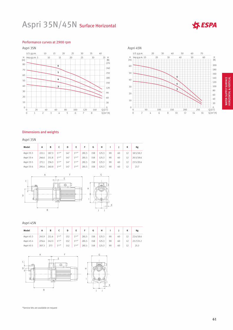
61
Dimensions and weights
Aspri 35N
Aspri 45N
A
B
C
D
E
F
J J
G
H
I
K
A
B
C
D
E
F
J
G
H
I
K
J
Aspri 35N/45N Surface Horizontal
Performance curves at 2900 rpm
Aspri 35N Aspri 45N
4
5
3
4
5
6
3
Model A B C D E F G H I J K Kg
Aspri 35 3 221.1 187.3 11/4” 147 11/4” 281.5 158 125.3 90 60 12 18.5/18.2
Aspri 35 4 246.6 211.8 11/4” 147 11/4” 281.5 158 125.3 90 60 12 20.5/18.6
Aspri 35 5 271.1 236.3 11/4” 147 11/4” 281.5 158 125.3 90 60 12 23.5/20.6
Aspri 35 6 295.6 260.8 11/4” 147 11/4” 281.5 158 125.3 90 60 12 23.7
Model A B C D E F G H I J K Kg
Aspri 45 3 245.9 211.6 11/2” 152 11/4” 281.5 158 125.3 90 60 12 22.6/18.6
Aspri 45 4 276.6 242.3 11/2” 152 11/4” 281.5 158 125.3 90 60 12 23.7/21.2
Aspri 45 5 307.3 273 11/2” 152 11/4” 281.5 158 125.3 90 60 12 25.3
*Service kits are available on request
WAT
ER S
UPP
LY S
URF
ACE
HO
RIZO
NTA
L &
VER
TICA
L
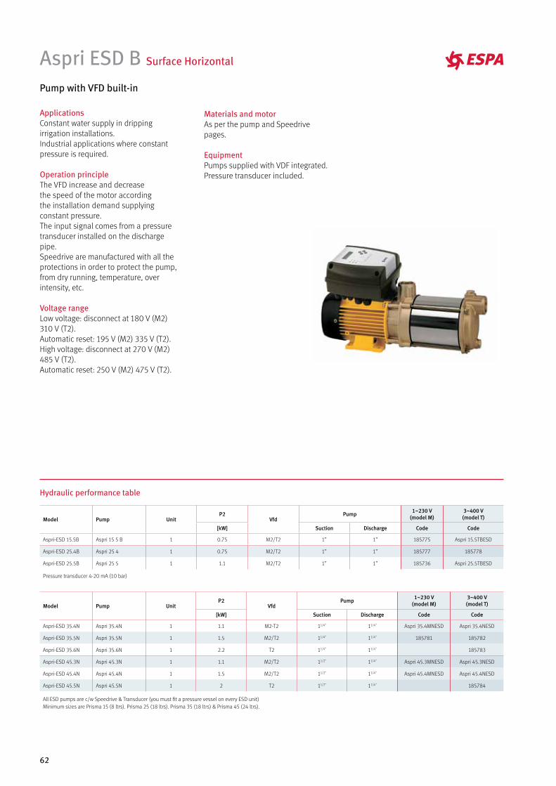
62
Aspri ESD B Surface Horizontal
Pump with VFD built-in
ApplicationsConstant water supply in dripping irrigation installations. Industrial applications where constant pressure is required.
Operation principleThe VFD increase and decreasethe speed of the motor according the installation demand supplying constant pressure. The input signal comes from a pressure transducer installed on the discharge pipe. Speedrive are manufactured with all the protections in order to protect the pump, from dry running, temperature, over intensity, etc.
Voltage rangeLow voltage: disconnect at 180 V (M2) 310 V (T2).Automatic reset: 195 V (M2) 335 V (T2).High voltage: disconnect at 270 V (M2) 485 V (T2).Automatic reset: 250 V (M2) 475 V (T2).
Hydraulic performance table
Model Pump UnitP2
VfdPump 1~230 V
(model M)3~400 V (model T)
[kW] Suction Discharge Code Code
Aspri-ESD 15.5B Aspri 15 5 B 1 0.75 M2/T2 1” 1” 185775 Aspri 15.5TBESD
Aspri-ESD 25.4B Aspri 25 4 1 0.75 M2/T2 1” 1” 185777 185778
Aspri-ESD 25.5B Aspri 25 5 1 1.1 M2/T2 1” 1” 185736 Aspri 25.5TBESD
Pressure transducer 4-20 mA (10 bar)
Model Pump UnitP2
VfdPump 1~230 V
(model M)3~400 V (model T)
[kW] Suction Discharge Code Code
Aspri-ESD 35.4N Aspri 35.4N 1 1.1 M2-T2 11/4” 11/4” Aspri 35.4MNESD Aspri 35.4NESD
Aspri-ESD 35.5N Aspri 35.5N 1 1.5 M2/T2 11/4” 11/4” 185781 185782
Aspri-ESD 35.6N Aspri 35.6N 1 2.2 T2 11/4” 11/4” 185783
Aspri-ESD 45.3N Aspri 45.3N 1 1.1 M2/T2 11/2” 11/4” Aspri 45.3MNESD Aspri 45.3NESD
Aspri-ESD 45.4N Aspri 45.4N 1 1.5 M2/T2 11/2” 11/4” Aspri 45.4MNESD Aspri 45.4NESD
Aspri-ESD 45.5N Aspri 45.5N 1 2 T2 11/2” 11/4” 185784
All ESD pumps are c/w Speedrive & Transducer (you must fit a pressure vessel on every ESD unit)Minimum sizes are Prisma 15 (8 ltrs). Prisma 25 (18 ltrs). Prisma 35 (18 ltrs) & Prisma 45 (24 ltrs).
Materials and motorAs per the pump and Speedrive pages.
EquipmentPumps supplied with VDF integrated. Pressure transducer included.
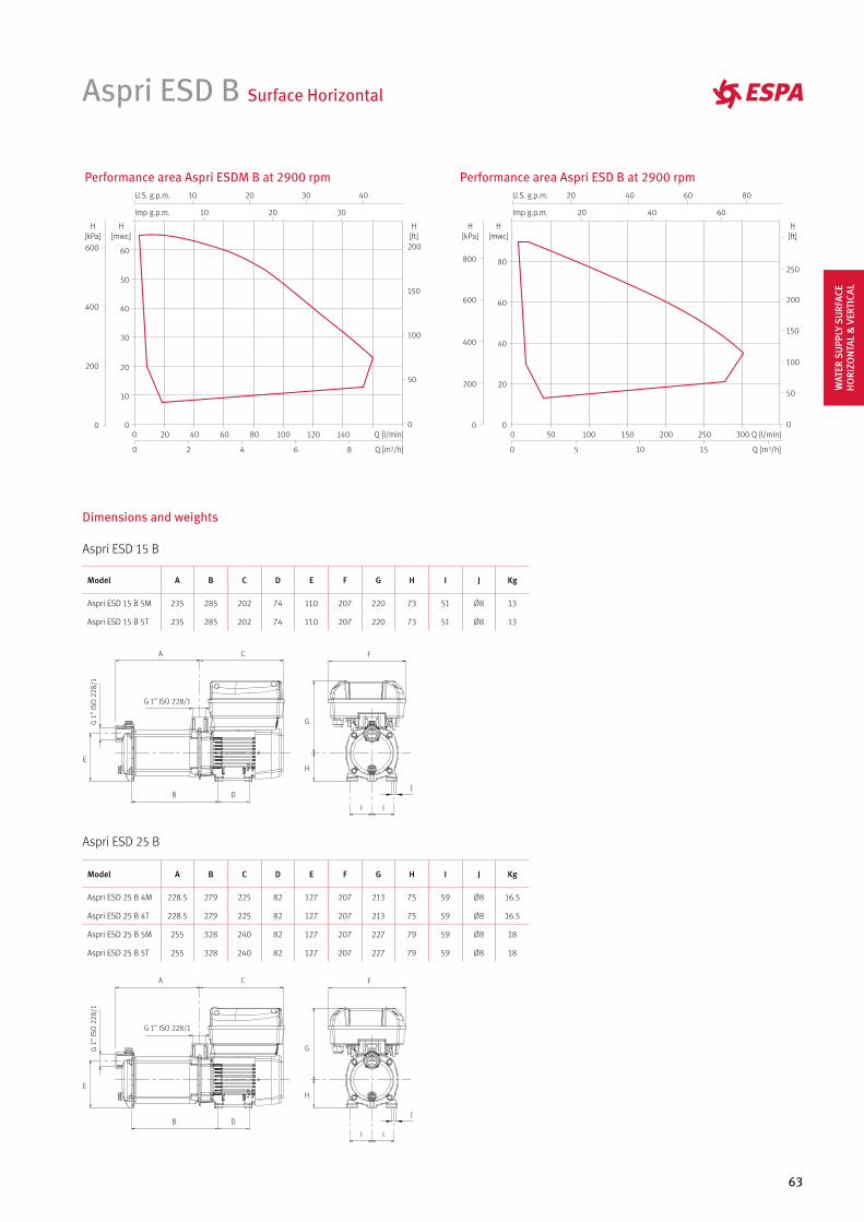
63
Aspri ESD B Surface Horizontal
Performance area Aspri ESDM B at 2900 rpm
86420
140120100806040200 Q [l/min]
Q [m3/h]
10
10
20
20
30
30 40
Imp g.p.m.
U.S. g.p.m.
60
50
40
30
20
10
0
H[mwc]
200
150
100
50
0
H[ft]
600
400
200
0
H[kPa]
Performance area Aspri ESD B at 2900 rpm
Q [l/min]
151050
300250200150100500
Q [m3/h]
20 40 60
20 40 60 80
Imp g.p.m.
U.S. g.p.m.
80
60
40
20
0
H[mwc]
800
600
400
200
0
H[kPa]
250
200
150
100
50
0
H[ft]
Dimensions and weights
Aspri ESD 15 B
Model A B C D E F G H I J Kg
Aspri ESD 15 B 5M 235 285 202 74 110 207 220 73 51 Ø8 13
Aspri ESD 15 B 5T 235 285 202 74 110 207 220 73 51 Ø8 13
A
B
C
D
E
F
G
H
I I
J
G 1
” IS
O 2
28/1
G 1” ISO 228/1
Aspri ESD 25 B
Model A B C D E F G H I J Kg
Aspri ESD 25 B 4M 228.5 279 225 82 127 207 213 75 59 Ø8 16.5
Aspri ESD 25 B 4T 228.5 279 225 82 127 207 213 75 59 Ø8 16.5
Aspri ESD 25 B 5M 255 328 240 82 127 207 227 79 59 Ø8 18
Aspri ESD 25 B 5T 255 328 240 82 127 207 227 79 59 Ø8 18
A
B
C
D
E
F
G
H
I I
J
G 1
” IS
O 2
28/1
G 1” ISO 228/1
WAT
ER S
UPP
LY S
URF
ACE
HO
RIZO
NTA
L &
VER
TICA
L
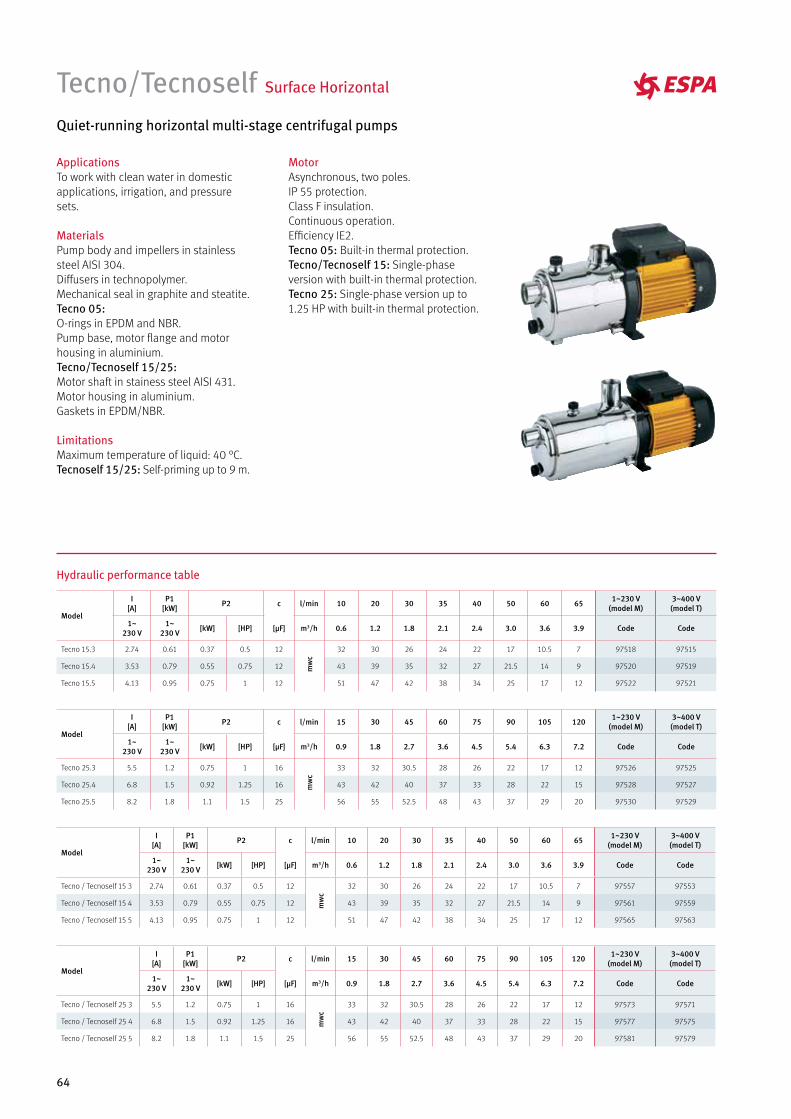
64
Tecno/Tecnoself Surface Horizontal
Quiet-running horizontal multi-stage centrifugal pumps
MotorAsynchronous, two poles.IP 55 protection.Class F insulation.Continuous operation.Efficiency IE2.Tecno 05: Built-in thermal protection.Tecno/Tecnoself 15: Single-phase version with built-in thermal protection.Tecno 25: Single-phase version up to 1.25 HP with built-in thermal protection.
ApplicationsTo work with clean water in domestic applications, irrigation, and pressure sets.
MaterialsPump body and impellers in stainless steel AISI 304.Diffusers in technopolymer.Mechanical seal in graphite and steatite.Tecno 05:O-rings in EPDM and NBR.Pump base, motor flange and motor housing in aluminium.Tecno/Tecnoself 15/25:Motor shaft in stainess steel AISI 431.Motor housing in aluminium.Gaskets in EPDM/NBR.
LimitationsMaximum temperature of liquid: 40 °C.Tecnoself 15/25: Self-priming up to 9 m.
Hydraulic performance table
Model
I [A]
P1 [kW] P2 c l/min 15 30 45 60 75 90 105 120 1~230 V
(model M)3~400 V (model T)
1~230 V
1~230 V [kW] [HP] [µF] m3/h 0.9 1.8 2.7 3.6 4.5 5.4 6.3 7.2 Code Code
Tecno 25.3 5.5 1.2 0.75 1 16
mw
c
33 32 30.5 28 26 22 17 12 97526 97525
Tecno 25.4 6.8 1.5 0.92 1.25 16 43 42 40 37 33 28 22 15 97528 97527
Tecno 25.5 8.2 1.8 1.1 1.5 25 56 55 52.5 48 43 37 29 20 97530 97529
Model
I [A]
P1 [kW] P2 c l/min 10 20 30 35 40 50 60 65 1~230 V
(model M)3~400 V (model T)
1~230 V
1~230 V [kW] [HP] [µF] m3/h 0.6 1.2 1.8 2.1 2.4 3.0 3.6 3.9 Code Code
Tecno 15.3 2.74 0.61 0.37 0.5 12
mw
c
32 30 26 24 22 17 10.5 7 97518 97515
Tecno 15.4 3.53 0.79 0.55 0.75 12 43 39 35 32 27 21.5 14 9 97520 97519
Tecno 15.5 4.13 0.95 0.75 1 12 51 47 42 38 34 25 17 12 97522 97521
Model
I [A]
P1 [kW] P2 c l/min 15 30 45 60 75 90 105 120 1~230 V
(model M)3~400 V (model T)
1~230 V
1~230 V [kW] [HP] [µF] m3/h 0.9 1.8 2.7 3.6 4.5 5.4 6.3 7.2 Code Code
Tecno / Tecnoself 25 3 5.5 1.2 0.75 1 16
mw
c
33 32 30.5 28 26 22 17 12 97573 97571
Tecno / Tecnoself 25 4 6.8 1.5 0.92 1.25 16 43 42 40 37 33 28 22 15 97577 97575
Tecno / Tecnoself 25 5 8.2 1.8 1.1 1.5 25 56 55 52.5 48 43 37 29 20 97581 97579
Model
I [A]
P1 [kW] P2 c l/min 10 20 30 35 40 50 60 65 1~230 V
(model M)3~400 V (model T)
1~230 V
1~230 V [kW] [HP] [µF] m3/h 0.6 1.2 1.8 2.1 2.4 3.0 3.6 3.9 Code Code
Tecno / Tecnoself 15 3 2.74 0.61 0.37 0.5 12
mw
c
32 30 26 24 22 17 10.5 7 97557 97553
Tecno / Tecnoself 15 4 3.53 0.79 0.55 0.75 12 43 39 35 32 27 21.5 14 9 97561 97559
Tecno / Tecnoself 15 5 4.13 0.95 0.75 1 12 51 47 42 38 34 25 17 12 97565 97563
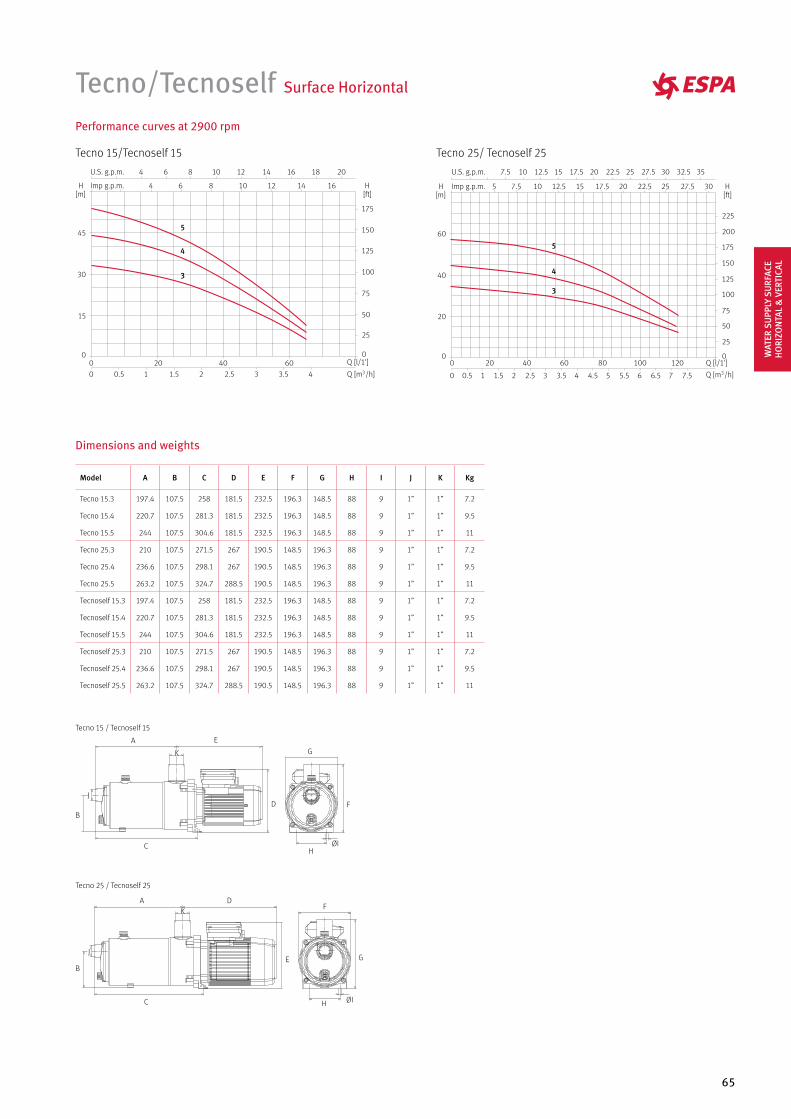
65
Dimensions and weights
Tecno 15 / Tecnoself 15
A
K
J
E
D
C
B
H
G
F
ØI
Tecno 25 / Tecnoself 25
ØIH
G
FA
K
JE
D
C
B
Tecno/Tecnoself Surface Horizontal
Performance curves at 2900 rpm
Tecno 15/Tecnoself 15 Tecno 25/ Tecnoself 25
4
5
3 4
5
3
Model A B C D E F G H I J K Kg
Tecno 15.3 197.4 107.5 258 181.5 232.5 196.3 148.5 88 9 1” 1” 7.2
Tecno 15.4 220.7 107.5 281.3 181.5 232.5 196.3 148.5 88 9 1” 1” 9.5
Tecno 15.5 244 107.5 304.6 181.5 232.5 196.3 148.5 88 9 1” 1” 11
Tecno 25.3 210 107.5 271.5 267 190.5 148.5 196.3 88 9 1” 1” 7.2
Tecno 25.4 236.6 107.5 298.1 267 190.5 148.5 196.3 88 9 1” 1” 9.5
Tecno 25.5 263.2 107.5 324.7 288.5 190.5 148.5 196.3 88 9 1” 1” 11
Tecnoself 15.3 197.4 107.5 258 181.5 232.5 196.3 148.5 88 9 1” 1” 7.2
Tecnoself 15.4 220.7 107.5 281.3 181.5 232.5 196.3 148.5 88 9 1” 1” 9.5
Tecnoself 15.5 244 107.5 304.6 181.5 232.5 196.3 148.5 88 9 1” 1” 11
Tecnoself 25.3 210 107.5 271.5 267 190.5 148.5 196.3 88 9 1” 1” 7.2
Tecnoself 25.4 236.6 107.5 298.1 267 190.5 148.5 196.3 88 9 1” 1” 9.5
Tecnoself 25.5 263.2 107.5 324.7 288.5 190.5 148.5 196.3 88 9 1” 1” 11
WAT
ER S
UPP
LY S
URF
ACE
HO
RIZO
NTA
L &
VER
TICA
L
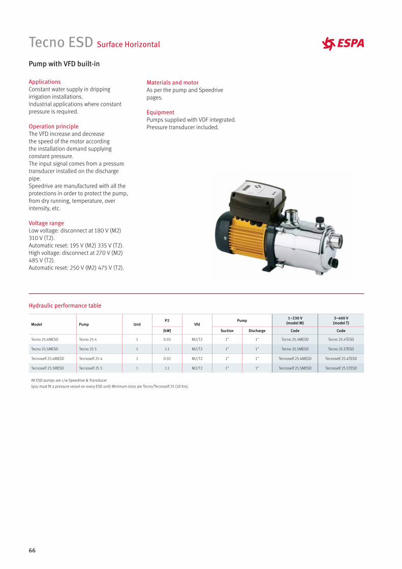
66
Tecno ESD Surface Horizontal
Pump with VFD built-in
ApplicationsConstant water supply in dripping irrigation installations. Industrial applications where constant pressure is required.
Operation principleThe VFD increase and decreasethe speed of the motor according the installation demand supplying constant pressure. The input signal comes from a pressure transducer installed on the discharge pipe. Speedrive are manufactured with all the protections in order to protect the pump, from dry running, temperature, over intensity, etc.
Voltage rangeLow voltage: disconnect at 180 V (M2) 310 V (T2).Automatic reset: 195 V (M2) 335 V (T2).High voltage: disconnect at 270 V (M2) 485 V (T2).Automatic reset: 250 V (M2) 475 V (T2).
Hydraulic performance table
Model Pump UnitP2
VfdPump 1~230 V
(model M)3~400 V (model T)
[kW] Suction Discharge Code Code
Tecno 25.4MESD Tecno 25 4 1 0.92 M2/T2 1” 1” Tecno 25.4MESD Tecno 25.4TESD
Tecno 25.5MESD Tecno 25 5 1 1.1 M2/T2 1” 1” Tecno 25.5MESD Tecno 25.5TESD
Tecnoself 25.4MESD Tecnoself 25 4 1 0.92 M2/T2 1” 1” Tecnoself 25.4MESD Tecnoself 25.4TESD
Tecnoself 25.5MESD Tecnoself 25 5 1 1.1 M2/T2 1” 1” Tecnoself 25.5MESD Tecnoself 25.5TESD
All ESD pumps are c/w Speedrive & Transducer
(you must fit a pressure vessel on every ESD unit) Minimum sizes are Tecno/Tecnoself 25 (18 ltrs).
Materials and motorAs per the pump and Speedrive pages.
EquipmentPumps supplied with VDF integrated. Pressure transducer included.
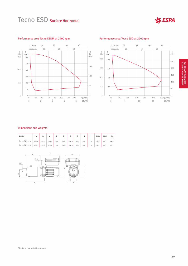
67
Tecno ESD Surface Horizontal
Performance area Tecno ESDM at 2900 rpm Performance area Tecno ESD at 2900 rpm
Q [l/min]
151050
300250200150100500
Q [m3/h]
20 40 60
20 40 60 80
Imp g.p.m.
U.S. g.p.m.
80
60
40
20
0
H[mwc]
800
600
400
200
0
H[kPa]
250
200
150
100
50
0
H[ft]
Model A B C D E F G H I DNa DNd Kg
Tecno ESD 25 4 236.6 107.5 298.1 270 272 196.3 207 88 9 G1’’ G1’’ 14.9
Tecno ESD 25 5 263.2 107.5 324.7 270 272 196.3 207 88 9 G1’’ G1’’ 16.2
Dimensions and weights
F
B
DNa
DNd
C
A
D
E G
HI
86420
140120100806040200 Q [l/min]
Q [m3/h]
10
10
20
20
30
30 40
Imp g.p.m.
U.S. g.p.m.
60
50
40
30
20
10
0
H[mwc]
200
150
100
50
0
H[ft]
600
400
200
0
H[kPa]
*Service kits are available on request
WAT
ER S
UPP
LY S
URF
ACE
HO
RIZO
NTA
L &
VER
TICA
L
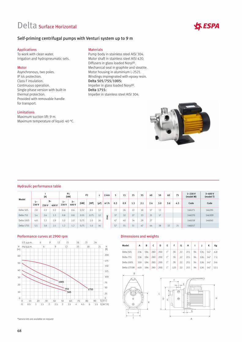
68
ApplicationsTo work with clean water. Irrigation and hydropneumatic sets.
MotorAsynchronous, two poles.IP 44 protection.Class F insulation.Continuous operation.Single-phase version with built-in thermal protection.Provided with removable handle for transport.
LimitationsMaximum suction lift: 9 m.Maximum temperature of liquid: 40 °C.
Delta Surface Horizontal
Self-priming centrifugal pumps with Venturi system up to 9 m
MaterialsPump body in stainless steel AISI 304.Motor shaft in stainless steel AISI 420.Diffusers in glass loaded Noryl®. Mechanical seal in graphite and steatite.Motor housing in aluminium L-2521.Windings impregnated with epoxy resin.Delta 505/755/1005: Impeller in glass loaded Noryl®.Delta 1755: Impeller in stainless steel AISI 304.
Hydraulic performance table
Dimensions and weightsPerformance curves at 2900 rpm
A
H
G
F
ED
C
E
K
JI
B
1755
1005
755505
Model
I [A]
P1 [kW] P2 c l/min 5 15 25 35 40 50 60 75 1~230 V
(model M)3~400 V (model T)
1~230 V
3~ 1~230 V
3~400 V [kW] [HP] [µF] m3/h 0.3 0.9 1.5 2.1 2.4 3.0 3.6 4.5 Code Code
230 V 400 V
Delta 505 2.8 2.2 1.2 0.6 0.6 0.37 0.5 12
mw
c
33 26 22 18 17 13 146271 146291
Delta 755 3.4 2.6 1.3 0.8 0.8 0.55 0.75 12 37 32 27 23 21 17 146270 146309
Delta 1005 4.8 3.3 1.9 1.0 1.0 0.75 1.0 16 47 40 34 29 27 146018 146061
Delta 1755 5.5 3.8 2.1 1.2 1.2 0.75 1.0 16 57 55 51 47 44 38 32 21 146017
Model A B C D E F G H I J K Kg
Delta 505 336 184 280 200 1” 78 22 215 94 126 147 6.8
Delta 755 336 184 280 200 1” 78 22 215 94 126 147 7.3
Delta 1005 359 184 280 200 1” 78 22 215 94 126 147 9.6
Delta 1755M 410 184 280 200 1” 125 22 215 94 126 147 12.1
*Service kits are available on request

69
ApplicationsSpray irrigation systems, hydropneumatic sets and industrial installations.
MaterialsPump body and impellers in stainless steel AISI 304.Diffusers in technopolymer.Mechanical seal in graphite and alumine.Motor housing in aluminium L-2521.Flanges, suction and discharge connections in cast iron.Motor shaft in stainless steel AISI 420.Multi35N 8 and 10 / Multi55N 6 and 7: in stainless steel AISI 303.
LimitationsMaximum temperature of liquid: 40 °C
EquipmentSupplied with oval counter flanges DIN 2558.
Multi Surface Vertical
Quiet-running vertical multi-stage centrifugal pumps, supplied with flanges
MotorAsynchronous, two poles.IP 44 protection.Class F insulation.Continuous operation.Efficiency IE3.Multi25: Single-phase version up to 1.5 HP built-in thermal protection.Multi35N: Single-phase version up to 1 HP built-in thermal protection.Energy Index MEI≥0,4 for Multi 25/35.Energy Index MEI≥0,4 for Multi 55.
Hydraulic performance table
Model
I [A]
P1 [kW] P2 c l/min 17 33 50 75 100 125 150 175 1~230 V
(Model M)3~400 V (Model T)
1~230 V
3~230 V
3~400 V
1~230 V
3~400 V [kW] [HP] [µF] m3/h 1.0 2.0 3.0 4.5 6.0 7.5 9.0 10.5 Code Code
MULTI 35.3MN 6.7 1.5 0.75 1 25
mw
c
39 37.5 35.5 31.5 27 21 15 7 129334 129338
MULTI 35.4MN 8.4 5.3 3.1 1.8 1.8 1.1 1.5 25 54 51 48 44 37 29.5 21 11.8 129335 129339
MULTI 35.5MN 10.2 6.9 4 2.3 2.2 1.5 2 30 65.4 63.5 60 54.5 46 36 26.2 15 129336 129340
MULTI 35.6N 8.3 4.8 2.7 2.2 3 82 79.5 76 69 61 49 36.7 23 129341
MULTI 35.8N 11.9 6.5 3.6 3 4 108 105 101 93 85 70 53 35 129342
MULTI 35.10N 15.4 8.9 4.9 4 5.5 134 130 125 117 105 90 70 47 129337
Model
I [A]
P1 [kW] P2 l/min 20 50 75 100 150 200 250 300 1~230 V
(Model M)3~400 V (model T)
3~230 V
3~400 V
3~400 V [kW] [HP] m3/h 1.2 3.0 4.5 6.0 9.0 12 15 18 Code Code
MULTI 55.3MN 6.6 3.8 2.1 1.5 2
mw
c
37 35 33 31 28 24 18 10 131483 131484
MULTI 55.4N 8.3 4.8 2.8 2.2 3 50 47 45 43 39 33 26 16 131485
MULTI 55.6N 12.1 7 4.2 3 4 77 73 70 66 60 52 43 29 131486
MULTI 55.7N 15.6 9 4.9 4 5.5 90 86 82 78 70 60 50 35 131487
Model
I [A]
P1 [kW] P2 c l/min 8 17 25 33 42 58 75 92 1~230 V
(model M)3~400 V (model T)
1~230 V
3~230 V
3~400 V
1~230 V
3~400 V [kW] [HP] [µF] m3/h 0.5 1.0 1.5 2.0 2.5 3.5 4.5 5.5 Code Code
MULTI 25.3M 4.5 3.2 1.9 1.0 0.9 0.55 0.75 6
mw
c
38.2 38 35.7 33.5 31 25 17 7.2 134926 134929
MULTI 25.4M 5.8 3.9 2.3 1.2 1.1 0.75 1 16 52.7 51 48.2 45.8 42 33 22 9 134927 134930
MULTI 25.5M 6.4 4.2 2.5 1.4 1.3 0.9 1.25 16 66.5 64 61.2 57.5 52.5 41 27 12 134928 134931
WAT
ER S
UPP
LY S
URF
ACE
HO
RIZO
NTA
L &
VER
TICA
L

70
Multi Surface Vertical
Multi35 N
10
8
6
54
3
Performance curves at 2900 rpm
Multi25
Multi55 N
7
6
4
3
5
4
3
L
K
J
IH
G
F
A
E
D
C
B
Multi25
G
F
B
A I
HE
D
C
Multi35 N 3. 4. 5. 6Multi55 N 3. 4. 5. 6
G
F
A I
HE
D
C
B
Multi35 N 8. 10Multi55 N 8. 10
Dimensions and weights
Multi25
Model A B C D E F G H I J K L Kg
MULTI 25.3M 398 194 170 42 182 191 11/4” 11/4” 125 197 193 125 16.2
MULTI 25.4M 422 205 170 42 182 191 11/4” 11/4” 125 197 193 125 17.3
MULTI 25.5M 441 226 170 42 182 191 11/4” 11/4” 125 197 193 125 17.9
Multi35 N / Multi55 N
Model A B C D E F G H I Kg
MULTI 35.3MN 487 201.5 184 203 37 133 201 11/2” 11/4” 20.2/20
MULTI 35.4MN 511.5 226 184 203 37 133 201 11/2” 11/4” 22.4/20.4
MULTI 35.5MN 536 250.5 184 203 37 133 201 11/2” 11/4” 25.1/22.7
MULTI 35.6N 561 275 184 203 37 133 201 11/2” 11/4” 25.7
MULTI 35.8N 657.5 323 184 233 37 133 201 11/2” 11/4” 32.6
MULTI 35.10N 707.5 373 184 233 37 133 201 11/2” 11/4” 39.4
MULTI 55.3MN 531 245 184 203 37 133 201 11/2” 11/4” 25.7/23.3
MULTI 55.4N 571 285 184 203 37 133 201 11/2” 11/4” 26.6
MULTI 55.6N 696 362 184 203 37 133 201 11/2” 11/4” 35.4
MULTI 55.7N 736 402 184 203 37 133 201 11/2” 11/4” 39.7
*Service kits are available on request
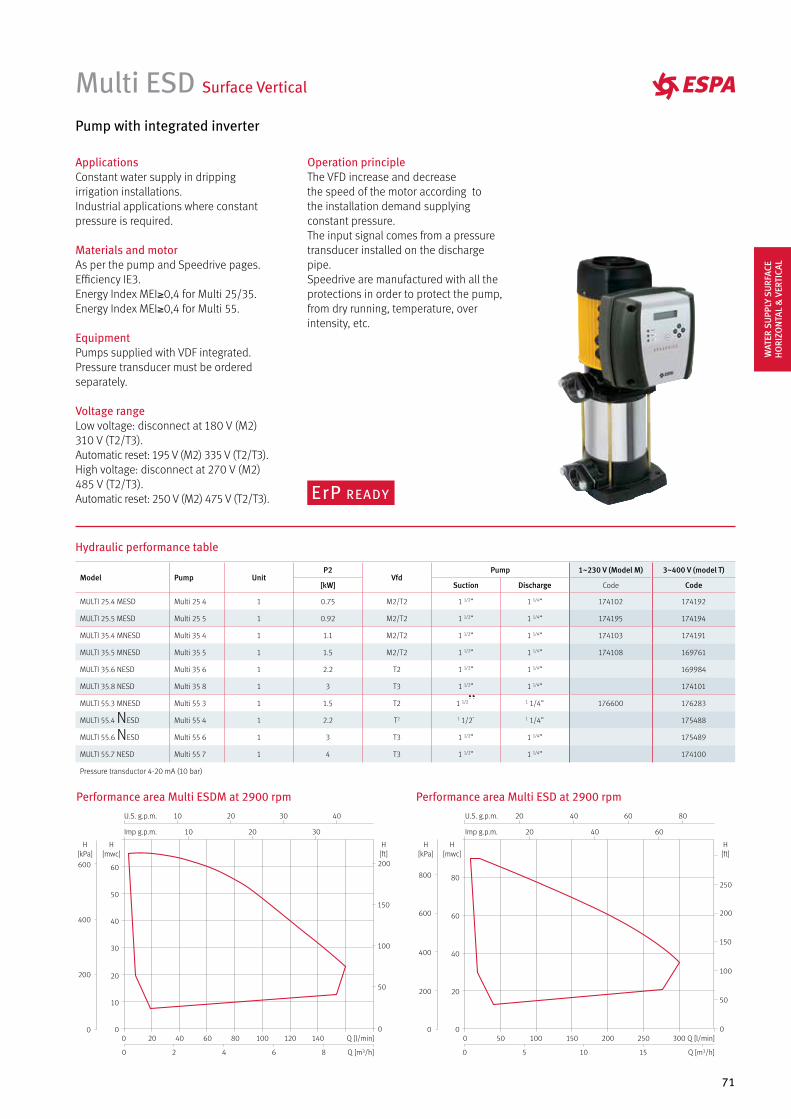
71
Multi ESD Surface Vertical
Pump with integrated inverter
ApplicationsConstant water supply in dripping irrigation installations. Industrial applications where constant pressure is required.
Materials and motorAs per the pump and Speedrive pages.Efficiency IE3.Energy Index MEI≥0,4 for Multi 25/35.Energy Index MEI≥0,4 for Multi 55.
EquipmentPumps supplied with VDF integrated. Pressure transducer must be ordered separately.
Voltage rangeLow voltage: disconnect at 180 V (M2) 310 V (T2/T3).Automatic reset: 195 V (M2) 335 V (T2/T3).High voltage: disconnect at 270 V (M2) 485 V (T2/T3).Automatic reset: 250 V (M2) 475 V (T2/T3).
Operation principleThe VFD increase and decreasethe speed of the motor according tothe installation demand supplying constant pressure. The input signal comes from a pressure transducer installed on the discharge pipe. Speedrive are manufactured with all the protections in order to protect the pump, from dry running, temperature, over intensity, etc.
Performance area Multi ESDM at 2900 rpm Performance area Multi ESD at 2900 rpm
Hydraulic performance table
Model Pump UnitP2
VfdPump 1~230 V (Model M) 3~400 V (model T)
[kW] Suction Discharge Code Code
MULTI 25.4 MESD Multi 25 4 1 0.75 M2/T2 1 1/2” 1 1/4” 174102 174192
MULTI 25.5 MESD Multi 25 5 1 0.92 M2/T2 1 1/2” 1 1/4” 174195 174194
MULTI 35.4 MNESD Multi 35 4 1 1.1 M2/T2 1 1/2” 1 1/4” 174103 174191
MULTI 35.5 MNESD Multi 35 5 1 1.5 M2/T2 1 1/2” 1 1/4” 174108 169761
MULTI 35.6 NESD Multi 35 6 1 2.2 T2 1 1/2” 1 1/4” 169984
MULTI 35.8 NESD Multi 35 8 1 3 T3 1 1/2” 1 1/4” 174101
MULTI 55.3 MNESD Multi 55 3 1 1.5 T2 1 1/2” 1 1/4” 176600 176283
MULTI 55.4 NESD Multi 55 4 1 2.2 T2 1 1/2” 1 1/4” 175488
MULTI 55.6 NESD Multi 55 6 1 3 T3 1 1/2” 1 1/4” 175489
MULTI 55.7 NESD Multi 55 7 1 4 T3 1 1/2” 1 1/4” 174100
Pressure transductor 4-20 mA (10 bar)
86420
140120100806040200 Q [l/min]
Q [m3/h]
10
10
20
20
30
30 40
Imp g.p.m.
U.S. g.p.m.
60
50
40
30
20
10
0
H[mwc]
200
150
100
50
0
H[ft]
600
400
200
0
H[kPa]
Q [l/min]
151050
300250200150100500
Q [m3/h]
20 40 60
20 40 60 80
Imp g.p.m.
U.S. g.p.m.
80
60
40
20
0
H[mwc]
800
600
400
200
0
H[kPa]
250
200
150
100
50
0
H[ft]
WAT
ER S
UPP
LY S
URF
ACE
HO
RIZO
NTA
L &
VER
TICA
L
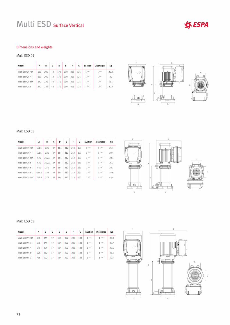
72
Multi ESD Surface Vertical
Multi ESD 25
Multi ESD 35
Model A B C D E F G Suction Discharge Kg
Multi ESD 25 4M 420 205 42 170 290 213 125 1 1/4” 1 1/4” 20.3
Multi ESD 25 4T 420 205 42 170 290 213 125 1 1/4” 1 1/4” 20
Multi ESD 25 5M 442 226 42 170 290 213 125 1 1/4” 1 1/4” 21.1
Multi ESD 25 5T 442 226 42 170 290 213 125 1 1/4” 1 1/4” 20.9
Multi ESD 55
Model A B C D E F G Suction Discharge Kg
Multi ESD 55 3M 531 245 37 184 352 228 133 1 1/2” 1 1/4” 26.3
Multi ESD 55 3T 531 245 37 184 352 228 133 1 1/2” 1 1/4” 28.7
Multi ESD 55 4T 571 285 37 184 352 228 133 1 1/2” 1 1/4” 29.6
Multi ESD 55 6T 696 362 37 184 352 228 133 1 1/2” 1 1/4” 38.4
Multi ESD 55 7T 736 402 37 184 352 228 133 1 1/2” 1 1/4” 42.7
Model A B C D E F G Suction Discharge Kg
Multi ESD 35 4M 511.5 226 37 184 312 213 133 1 1/2” 1 1/4” 25.4
Multi ESD 35 4T 511.5 226 37 184 312 213 133 1 1/2” 1 1/4” 23.4
Multi ESD 35 5M 536 250.5 37 184 312 213 133 1 1/2” 1 1/4” 28.1
Multi ESD 35 5T 536 250.5 37 184 312 213 133 1 1/2” 1 1/4” 25.7
Multi ESD 35 6T 561 275 37 184 312 213 133 1 1/2” 1 1/4” 28.7
Multi ESD 35 8T 657.5 323 37 184 312 213 133 1 1/2” 1 1/4” 35.6
Multi ESD 35 10T 707.5 373 37 184 312 213 133 1 1/2” 1 1/4” 42.4
Dimensions and weights
D
A
B
C
D
EF
G
G
D
A
B
C
D
EF
G
G
D
A
B
C
D
EF
G
G
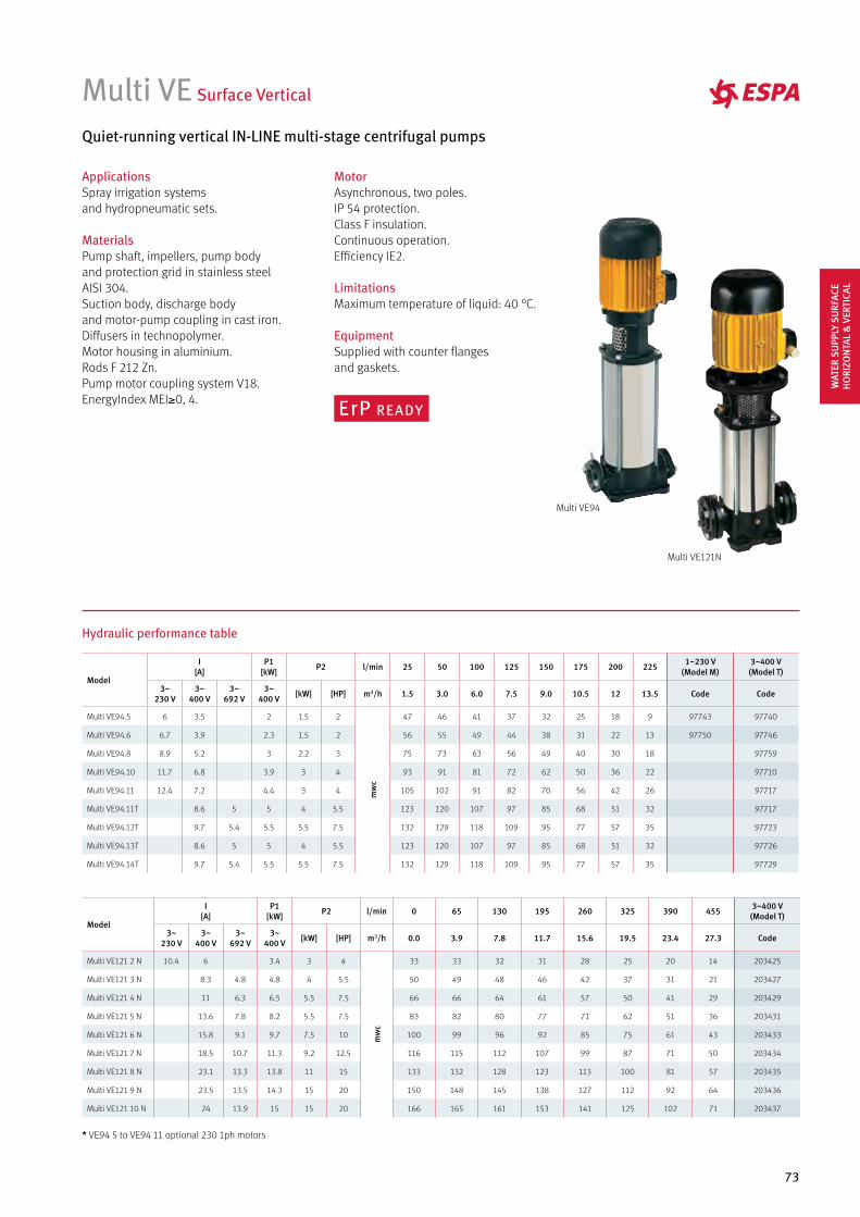
73
Multi VE Surface Vertical
ApplicationsSpray irrigation systemsand hydropneumatic sets.
MaterialsPump shaft, impellers, pump body and protection grid in stainless steelAISI 304.Suction body, discharge body and motor-pump coupling in cast iron.Diffusers in technopolymer.Motor housing in aluminium.Rods F 212 Zn.Pump motor coupling system V18.EnergyIndex MEI≥0, 4.
Quiet-running vertical IN-LINE multi-stage centrifugal pumps
MotorAsynchronous, two poles.IP 54 protection.Class F insulation.Continuous operation.Efficiency IE2.
LimitationsMaximum temperature of liquid: 40 °C.
EquipmentSupplied with counter flanges and gaskets.
Hydraulic performance table
* VE94 5 to VE94 11 optional 230 1ph motors
Multi VE94
Multi VE121N
Model
I [A]
P1 [kW] P2 l/min 25 50 100 125 150 175 200 225 1~230 V
(Model M)3~400 V (Model T)
3~230 V
3~400 V
3~692 V
3~400 V [kW] [HP] m3/h 1.5 3.0 6.0 7.5 9.0 10.5 12 13.5 Code Code
Multi VE94.5 6 3.5 2 1.5 2
mw
c
47 46 41 37 32 25 18 9 97743 97740
Multi VE94.6 6.7 3.9 2.3 1.5 2 56 55 49 44 38 31 22 13 97750 97746
Multi VE94.8 8.9 5.2 3 2.2 3 75 73 63 56 49 40 30 18 97759
Multi VE94.10 11.7 6.8 3.9 3 4 93 91 81 72 62 50 36 22 97710
Multi VE94.11 12.4 7.2 4.4 3 4 105 102 91 82 70 56 42 26 97717
Multi VE94.11T 8.6 5 5 4 5.5 123 120 107 97 85 68 51 32 97717
Multi VE94.12T 9.7 5.4 5.5 5.5 7.5 132 129 118 109 95 77 57 35 97723
Multi VE94.13T 8.6 5 5 4 5.5 123 120 107 97 85 68 51 32 97726
Multi VE94.14T 9.7 5.4 5.5 5.5 7.5 132 129 118 109 95 77 57 35 97729
Model
I [A]
P1 [kW] P2 l/min 0 65 130 195 260 325 390 455 3~400 V
(Model T)
3~230 V
3~400 V
3~692 V
3~400 V [kW] [HP] m3/h 0.0 3.9 7.8 11.7 15.6 19.5 23.4 27.3 Code
Multi VE121 2 N 10.4 6 3.4 3 4
mw
c
33 33 32 31 28 25 20 14 203425
Multi VE121 3 N 8.3 4.8 4.8 4 5.5 50 49 48 46 42 37 31 21 203427
Multi VE121 4 N 11 6.3 6.5 5.5 7.5 66 66 64 61 57 50 41 29 203429
Multi VE121 5 N 13.6 7.8 8.2 5.5 7.5 83 82 80 77 71 62 51 36 203431
Multi VE121 6 N 15.8 9.1 9.7 7.5 10 100 99 96 92 85 75 61 43 203433
Multi VE121 7 N 18.5 10.7 11.3 9.2 12.5 116 115 112 107 99 87 71 50 203434
Multi VE121 8 N 23.1 13.3 13.8 11 15 133 132 128 123 113 100 81 57 203435
Multi VE121 9 N 23.5 13.5 14.3 15 20 150 148 145 138 127 112 92 64 203436
Multi VE121 10 N 24 13.9 15 15 20 166 165 161 153 141 125 102 71 203437
WAT
ER S
UPP
LY S
URF
ACE
HO
RIZO
NTA
L &
VER
TICA
L
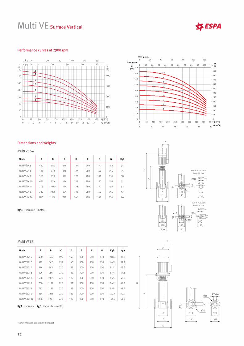
74
Model A B C D E F G KgB
Multi VE94 5 450 700 176 127 280 190 155 34
Multi VE94 6 486 738 176 127 280 190 155 35
Multi VE94 8 563 838 176 127 280 190 155 38
Multi VE94 10 666 974 194 138 280 190 155 51
Multi VE94 11 703 1010 194 138 280 190 155 52
Multi VE94 13 780 1086 194 138 280 190 155 57
Multi VE94 14 816 1134 220 146 280 190 155 66
Multi VE Surface Vertical
Dimensions and weights
Performance curves at 2900 rpm
1413
11
10
8
65
KgB: Hydraulic + motor.
Multi VE 94
Multi VE121
A
G
F
E
D
C
B
190
155
80
44
Ø18 R11/2”Gas
Multi VE-94/10...94/14
Flange DIN 2566
Multi VE-94/5...94/8
Flange DIN 2558
150
110
190
200
155
155
190
100
50 44
Ø12
M12 Ø14
R11/2”Gas
130
100
95
KgA: Hydraulic. KgB: Hydraulic + motor.
Model A B C D E F G KgB KgA
Multi VE121 2 470 776 195 140 300 210 130 58.4 37.8
Multi VE121 3 522 847 195 140 300 210 130 64.9 39.2
Multi VE121 4 574 943 220 182 300 210 130 81.7 42.6
Multi VE121 5 626 995 220 182 300 210 130 83.4 44.3
Multi VE121 6 678 1085 220 182 300 210 130 85.5 45.8
Multi VE121 7 730 1137 220 182 300 210 130 94.2 47.3
Multi VE121 8 782 1189 220 182 300 210 130 95.8 48.9
Multi VE121 9 834 1241 220 182 300 210 130 102.7 50.4
Multi VE121 10 886 1293 220 182 300 210 130 104.2 51.9
A
G
F
E
D
C
B
250
215
90
50
Ø18 R2”Gas
165
125Ø15
*Service kits are available on request
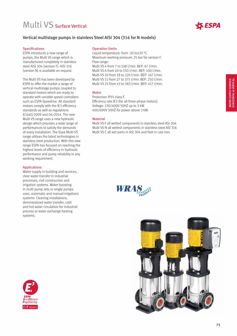
75
Multi VS Surface Vertical
Vertical multistage pumps in stainless Steel AISI 304 (316 for N models)
SpecificationsESPA introduces a new range of pumps, the Multi VS range which is manufactured completely in stainless steel AISI 304 (version F). AISI 316 (version N) is available on request.
The Multi VS has been developed by ESPA to offer the market a range of vertical multistage pumps coupled to standard motors which are ready to operate with variable speed controllers such as ESPA Speedrive. All standard motors comply with the IE3 efficiency standards as well as regulations EC640/2009 and 04/2014. The new Multi VS range uses a new hydraulic design which provides a wide range of performances to satisfy the demands of every installation. The Espa Multi VS range utilises the latest technologies in stainless steel production. With this new range ESPA has focused on reaching the highest levels of efficiency in hydraulic performance and pump reliability in any working requirement.
ApplicationsWater supply in building and services, clear water transfer in industrial processes, civil construction and irrigation systems. Water boosting in multi pump sets or single pumps uses, automatic and manual irrigations systems. Cleaning installations, demineralized water transfer, cold and hot water circulation for industrial process or water exchange heating systems.
Operation limitsLiquid temperature: from -20 to120 °C.Maximum working pressure: 25 bar for version F.Flow range: Multi VS 4 from 7 to 108 l/min. BEP: 67 l/min.Multi VS 6 from 10 to 150 l/min. BEP: 100 l/min.Multi VS 10 from 18 to 220 l/min. BEP: 167 l/min.Multi VS 15 from 27 to 375 l/min. BEP: 250 l/min.Multi VS 25 from 43 to 583 l/min. BEP: 417 l/min.
MotorProtection IP55 class F.Efficiency rate IE3 (for all three-phase motors).Voltage: 230/400V 50HZ up to 3 kW400/690V 50HZ for power above 3 kW.
Material Multi VS F all wetted components in stainless steel ASI 304Multi VS N all wetted components in stainless steel ASI 316Multi VS C all wet parts in ASI 304 and foot in cast iron.
WAT
ER S
UPP
LY S
URF
ACE
HO
RIZO
NTA
L &
VER
TICA
L
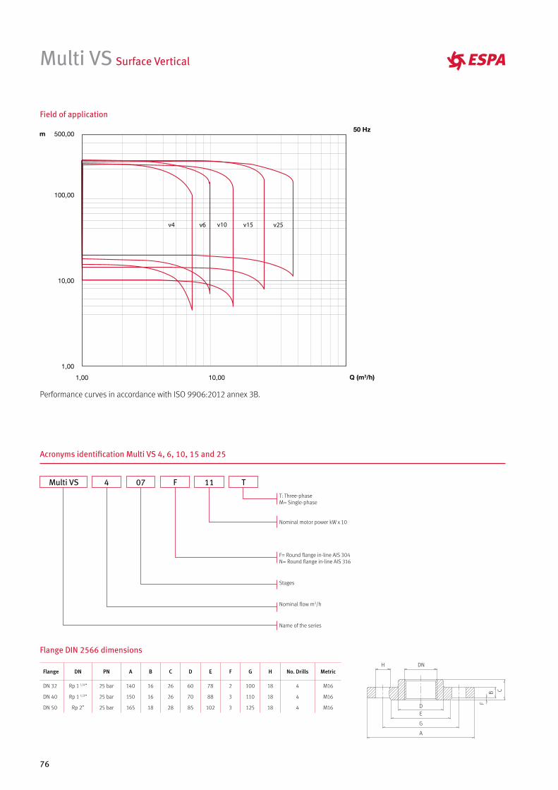
76
Multi VS Surface Vertical
Field of application
Performance curves in accordance with ISO 9906:2012 annex 3B.
Acronyms identification Multi VS 4, 6, 10, 15 and 25
Multi VS 4 07 11F T
Flange DIN 2566 dimensions
Flange DN PN A B C D E F G H No. Drills Metric
DN 32 Rp 1 1/4” 25 bar 140 16 26 60 78 2 100 18 4 M16
DN 40 Rp 1 1/2” 25 bar 150 16 26 70 88 3 110 18 4 M16
DN 50 Rp 2” 25 bar 165 18 28 85 102 3 125 18 4 M16
A
DN
B C
DE
G
H
F
T: Three-phaseM= Single-phase
Nominal motor power kW x 10
F= Round flange in-line AIS 304N= Round flange in-line AIS 316
Stages
Nominal flow m3/h
Name of the series

77
Hydraulic performance table and prices
Multi VS Surface Vertical
Model
I [A]
P1 [kW] P2 l/min 0 22 45 65 83 108 3~
F version
3~230 V
3~400 V 3~ [kW] [HP] m3/h 0 1.3 2.7 3.9 5.0 6.5 Code
MULTI VS4 05 3.1 1.8 1 0.75 1.0
mw
c
45.1 43.5 41.2 37.2 31.3 19.3 200123
MULTI VS4 07 4.2 2.4 1.3 1.1 1.5 63.1 60.9 57.7 52.1 43.8 27.1 200124
MULTI VS4 10 5.7 3.3 1.8 1.5 2.0 90.2 86.9 82.4 74.4 62.6 38.7 200125
MULTI VS4 14 8.2 4.7 2.6 2.2 3.0 126.3 121.7 115.4 104.2 87.6 54.1 200126
MULTI VS4 20 10.2 6.2 3.6 3.0 4.0 180.4 173.9 164.9 148.8 125.1 77.3 200127
Model
I [A]
P1 [kW] P2 l/min 0 36 70 98 125 150 3~
F version
3~230 V
3~400 V 3~ [kW] [HP] m3/h 0 2.2 4.2 5.9 7.5 9.0 Code
MULTI VS6 03 3.1 1.8 1 0.75 1.0
mw
c
29.5 28.1 26.3 23.9 20.3 15.2 200128
MULTI VS6 05 4.2 2.4 1.3 1.1 1.5 49.2 46.8 43.8 39.8 33.8 25.3 200129
MULTI VS6 07 5.7 3.3 1.8 1.5 2.0 68.8 65.5 61.4 55.7 47.3 35.5 200130
MULTI VS6 10 8.2 4.7 2.6 2.2 3.0 98.3 93.6 87.7 79.6 67.5 50.7 200131
MULTI VS6 14 10.2 6.2 3.6 3.0 4.0 137.6 131.0 122.8 111.4 94.5 71.0 200132
MULTI VS6 18 13.4 7.7 4.6 4.0 5.5 176.9 168.5 157.8 143.3 121.5 91.2 200133
MULTI VS6 22 17.5 10.1 6.3 5.5 7.5 216.3 205.9 192.9 175.1 148.6 111.5 200134
Model
I [A]
P1 [kW] P2 l/min 0 67 101 135 184 220 3~
F version
3~230 V
3~400 V 3~ [kW] [HP] m3/h 0 4.0 6.0 8.1 11.0 13.2 Code
MULTI VS10 03 3.1 1.8 1 1.1 1.5
mw
c
34.2 32.6 31.0 28.9 24.2 18.9 200135
MULTI VS10 04 4.2 2.4 1.3 1.5 2.0 45.6 43.5 41.4 38.5 32.2 25.3 200136
MULTI VS10 06 5.7 3.3 1.8 2.2 3.0 68.4 65.2 62.0 57.8 48.4 37.9 200137
MULTI VS10 08 8.2 4.7 2.6 3.0 4.0 91.2 86.9 82.7 77.1 64.5 50.5 200138
MULTI VS10 09 10.2 6.2 3.6 4.0 5.5 102.6 97.8 93.1 86.7 72.5 56.8 200139
MULTI VS10 11 13.4 7.7 4.6 4.0 5.5 125.5 119.5 113.8 106.0 88.7 69.5 200140
MULTI VS10 15 17.5 10.1 6.3 5.5 7.5 171.1 163.0 155.1 144.5 120.9 94.7 200141
MULTI VS10 17 22.9 13.2 8.4 7.5 10.0 193.9 184.7 175.8 163.8 137.0 107.3 200142
MULTI VS10 21 22.9 13.2 8.4 7.5 10.0 239.5 228.2 217.2 202.3 169.3 132.6 200143
Model
I [A]
P1 [kW] P2 l/min 0 67 133 200 267 375 3~
F version
3~230 V
3~400 V 3~ [kW] [HP] m3/h 0 4.0 8.0 12.0 16.0 22.5 Code
MULTI VS15 02 5.7 3.3 1.8 2.2 3.0
mw
c
29.2 28.3 27.5 26.1 24.1 18.4 200144
MULTI VS15 03 8.2 4.7 2.6 3.0 4.0 43.9 42.4 41.2 39.2 36.1 27.6 200145
MULTI VS15 04 10.2 6.2 3.6 4.0 5.5 58.5 56.6 55.0 52.2 48.1 36.7 200146
MULTI VS15 06 17.5 10.1 6.3 5.5 7.5 87.7 84.9 82.4 78.3 72.2 55.1 200147
MULTI VS15 08 22.9 13.2 8.4 7.5 10.0 116.9 113.2 109.9 104.4 96.3 73.5 200148
MULTI VS15 11 36.5 21 12.2 11.0 15.0 160.8 155.6 151.2 143.6 132.3 101.1 200149
MULTI VS15 17 49 28.2 16.6 15.0 20.0 248.5 240.5 233.6 221.9 204.5 156.2 200150
Model
I [A]
P1 [kW] P2 l/min 0 150 283 417 500 583 3~
F version
3~230 V
3~400 V 3~ [kW] [HP] m3/h 0 9.0 17.0 25.0 30.0 35.0 Code
MULTI VS25 01 5.7 3.3 1.8 2.2 3.0
mw
c
20.7 20.0 18.8 17.8 14.8 12.3 200151
MULTI VS25 02 10.2 6.2 3.6 4.0 5.5 41.4 39.9 37.5 35.6 29.7 24.6 200152
MULTI VS25 03 17.5 10.1 6.3 5.5 7.5 62.1 59.9 56.3 53.4 44.5 36.9 200153
MULTI VS25 04 22.9 13.2 8.4 7.5 10.0 82.8 79.8 75.0 71.2 59.4 49.2 200154
MULTI VS25 06 36.5 21 12.2 11.0 15.0 124.2 119.7 112.5 106.7 89.0 73.8 200155
MULTI VS25 08 49 28.2 16.6 15.0 20.0 165.6 159.6 150.0 142.3 118.7 98.4 200156
Multi VS4
Multi VS6
Multi VS10
Multi VS15
Multi VS25
WAT
ER S
UPP
LY S
URF
ACE
HO
RIZO
NTA
L &
VER
TICA
L
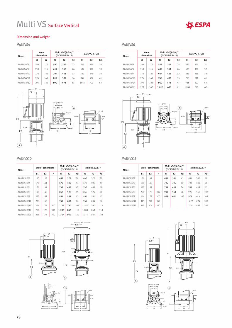
78
Multi VS Surface Vertical
Dimension and weight
Multi VS4
Multi VS10 Multi VS15
Multi VS6
Model
Motor dimensions
Multi VS(S)(-E) V/T(E-CASING PN16)
Multi VS (C/S) F
E1 E2 F1 F2 Kg F1 F2 Kg
Multi VS4/5 150 115 590 333 23 615 358 30
Multi VS4/6 150 115 612 355 26 637 380 30
Multi VS4/10 176 141 704 451 33 729 476 38
Multi VS4/14 176 141 819 537 36 844 562 41
Multi VS4/20 195 145 990 676 53 1015 701 53
ModelMotor dimensions
Multi VS(S)(-E) V/T(E-CASING PN16)
Multi VS (C/S) F
E1 E2 P F1 F2 Kg F1 F2 Kg
Multi VS10/3 150 115 647 372 36 647 372 39
Multi VS10/4 176 141 679 409 41 679 409 45
Multi VS10/6 176 141 747 462 45 747 462 49
Multi VS10/8 195 145 855 525 55 855 525 59
Multi VS10/9 223 167 891 551 62 891 551 65
Multi VS10/11 223 167 944 604 64 944 604 67
Multi VS10/15 266 178 300 1.155 790 108 1.155 790 112
Multi VS10/17 266 178 300 1.208 843 116 1.208 843 118
Multi VS10/21 266 178 300 1.314 949 120 1.314 949 122
ModelMotor dimensions
Multi VS(S)(-E) V/T(E-CASING PN16)
Multi VS (C/S) F
E1 E2 P F1 F2 Kg F1 F2 Kg
Multi VS15/2 176 141 641 356 41 651 366 47
Multi VS15/3 195 145 722 392 50 732 402 56
Multi VS15/4 223 167 759 419 56 769 429 62
Multi VS15/6 266 178 300 916 551 96 926 561 102
Multi VS15/8 266 178 300 969 604 103 979 614 109
Multi VS15/11 315 204 350 1.222 724 188
Multi VS15/17 315 204 350 1.381 883 207
Model
Motor dimensions
Multi VS(S)(-E) V/T(E-CASING PN16)
Multi VS (C/S) F
E1 E2 F1 F2 Kg F1 F2 Kg
Multi VS6/3 150 115 558 301 25 583 326 31
Multi VS6/5 150 115 608 351 26 633 376 32
Multi VS6/7 176 141 664 411 32 689 436 38
Multi VS6/10 176 141 768 486 35 793 511 41
Multi VS6/14 195 145 910 596 47 935 621 53
Multi VS6/18 223 167 1.016 696 61 1.044 721 62
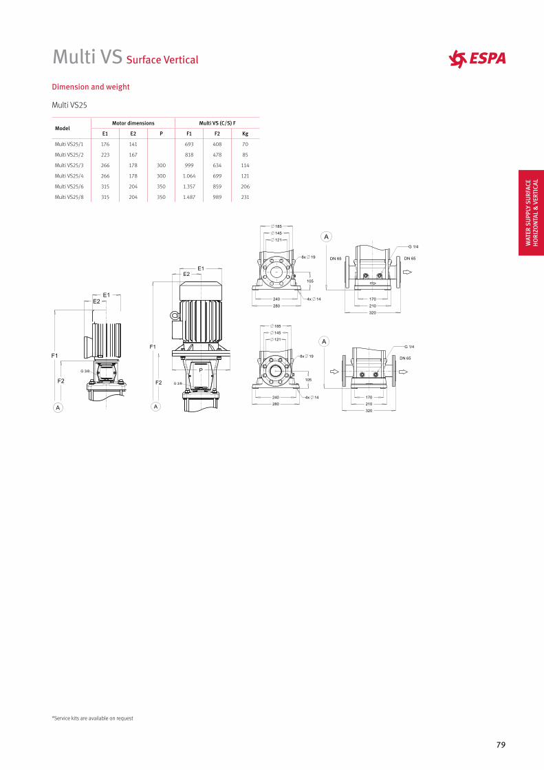
79
Dimension and weight
Multi VS25
ModelMotor dimensions Multi VS (C/S) F
E1 E2 P F1 F2 Kg
Multi VS25/1 176 141 693 408 70
Multi VS25/2 223 167 818 478 85
Multi VS25/3 266 178 300 999 634 114
Multi VS25/4 266 178 300 1.064 699 121
Multi VS25/6 315 204 350 1.357 859 206
Multi VS25/8 315 204 350 1.487 989 231
121
240
280
105
170
210
320
185
145
DN 65
G 1/4A
8x 19
4x 14
Multi VS Surface Vertical
*Service kits are available on request
WAT
ER S
UPP
LY S
URF
ACE
HO
RIZO
NTA
L &
VER
TICA
L
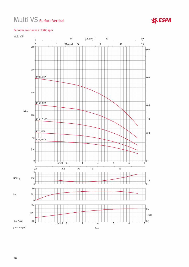
80
Multi VS Surface Vertical
Performance curves at 2900 rpm
Multi VS4
Height
Req. Power
Flow
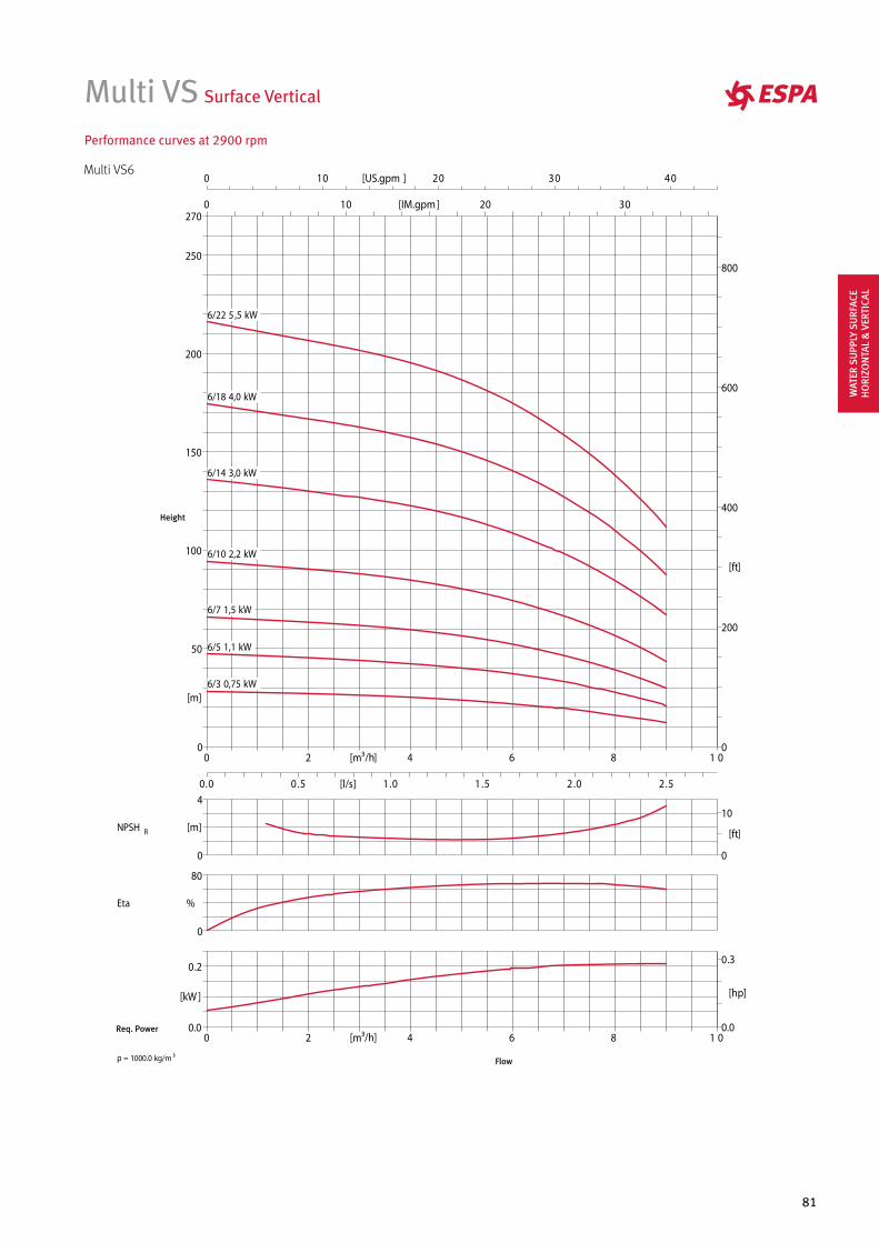
81
Multi VS Surface Vertical
Performance curves at 2900 rpm
Multi VS6
Height
Req. Power
Flow
WAT
ER S
UPP
LY S
URF
ACE
HO
RIZO
NTA
L &
VER
TICA
L
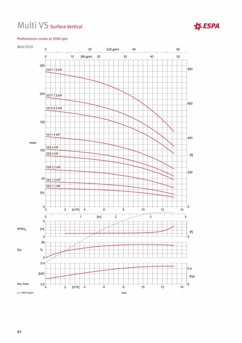
82
Multi VS Surface Vertical
Performance curves at 2900 rpm
Multi VS10
Height
Req. Power
Flow
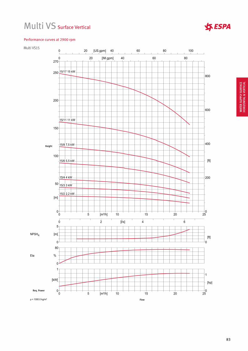
83
Multi VS Surface Vertical
Performance curves at 2900 rpm
Multi VS15
Height
Req. Power
Flow
WAT
ER S
UPP
LY S
URF
ACE
HO
RIZO
NTA
L &
VER
TICA
L
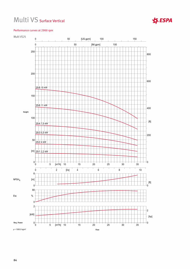
84
Multi VS Surface Vertical
Performance curves at 2900 rpm
Multi VS25
Height
Req. Power
Flow
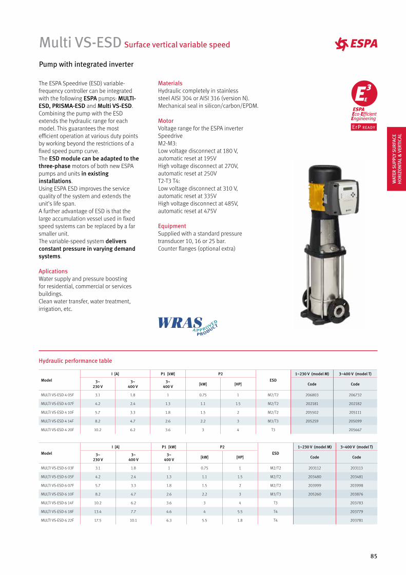
85
Multi VS-ESD Surface vertical variable speed
Pump with integrated inverter
The ESPA Speedrive (ESD) variable-frequency controller can be integrated with the following ESPA pumps: MULTI-ESD, PRISMA-ESD and Multi VS-ESD. Combining the pump with the ESD extends the hydraulic range for each model. This guarantees the most efficient operation at various duty points by working beyond the restrictions of a fixed speed pump curve.The ESD module can be adapted to the three-phase motors of both new ESPApumps and units in existing installations.Using ESPA ESD improves the service quality of the system and extends the unit’s life span.A further advantage of ESD is that the large accumulation vessel used in fixed speed systems can be replaced by a far smaller unit.The variable-speed system delivers constant pressure in varying demand systems.
AplicationsWater supply and pressure boosting for residential, commercial or services buildings.Clean water transfer, water treatment, irrigation, etc.
MaterialsHydraulic completely in stainless steel AISI 304 or AISI 316 (version N). Mechanical seal in silicon/carbon/EPDM.
MotorVoltage range for the ESPA inverter SpeedriveM2-M3:Low voltage disconnect at 180 V, automatic reset at 195VHigh voltage disconnect at 270V, automatic reset at 250VT2-T3 T4:Low voltage disconnect at 310 V, automatic reset at 335VHigh voltage disconnect at 485V, automatic reset at 475V
EquipmentSupplied with a standard pressure transducer 10, 16 or 25 bar.Counter flanges (optional extra)
Hydraulic performance table
Model
I [A] P1 [kW] P2
ESD
1~230 V (model M) 3~400 V (model T)
3~230 V
3~400 V
3~400 V [kW] [HP] Code Code
MULTI VS-ESD 4 05F 3.1 1.8 1 0.75 1 M2/T2 206803 206732
MULTI VS-ESD 4 07F 4.2 2.4 1.3 1.1 1.5 M2/T2 202181 202182
MULTI VS-ESD 4 10F 5.7 3.3 1.8 1.5 2 M2/T2 205502 205111
MULTI VS-ESD 4 14F 8.2 4.7 2.6 2.2 3 M3/T3 205259 205099
MULTI VS-ESD 4 20F 10.2 6.2 3.6 3 4 T3 205667
Model
I [A] P1 [kW] P2
ESD
1~230 V (model M) 3~400 V (model T)
3~230 V
3~400 V
3~400 V [kW] [HP] Code Code
MULTI VS-ESD 6 03F 3.1 1.8 1 0.75 1 M2/T2 203112 203113
MULTI VS-ESD 6 05F 4.2 2.4 1.3 1.1 1.5 M2/T2 203480 203481
MULTI VS-ESD 6 07F 5.7 3.3 1.8 1.5 2 M2/T2 203999 203998
MULTI VS-ESD 6 10F 8.2 4.7 2.6 2.2 3 M3/T3 205260 203876
MULTI VS-ESD 6 14F 10.2 6.2 3.6 3 4 T3 203783
MULTI VS-ESD 6 18F 13.4 7.7 4.6 4 5.5 T4 203779
MULTI VS-ESD 6 22F 17.5 10.1 6.3 5.5 1.8 T4 203781
WAT
ER S
UPP
LY S
URF
ACE
HO
RIZO
NTA
L &
VER
TICA
L
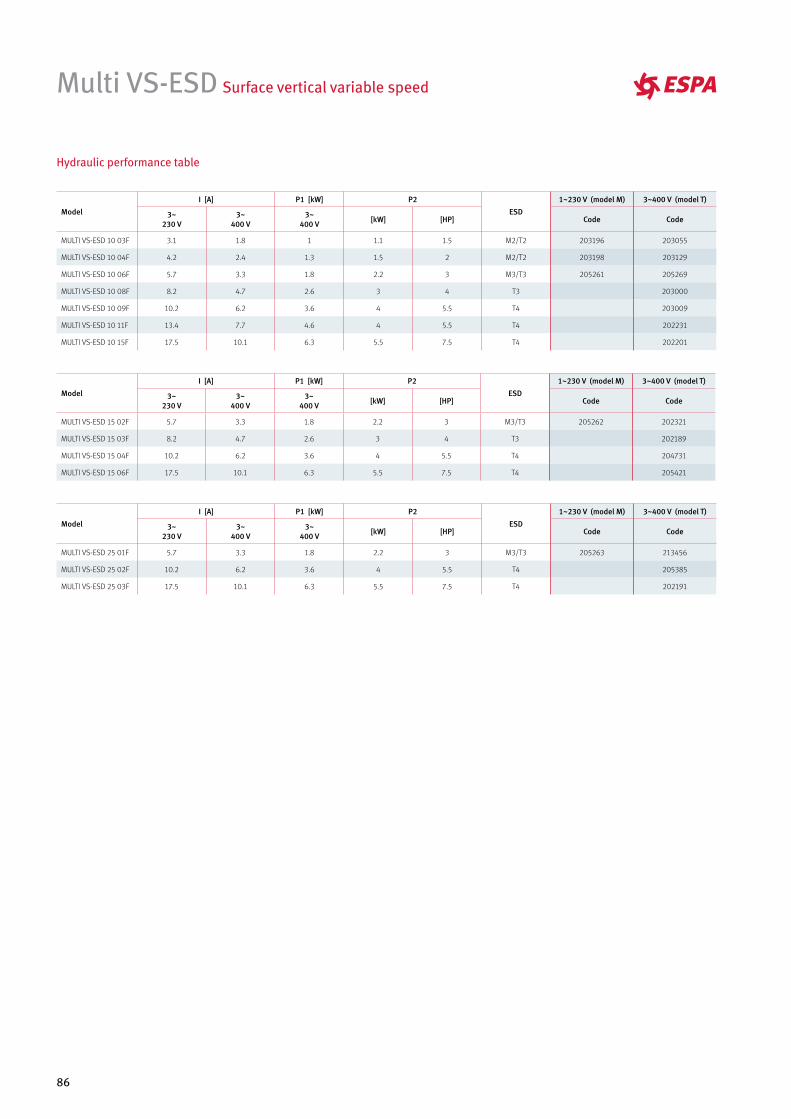
86
Model
I [A] P1 [kW] P2
ESD
1~230 V (model M) 3~400 V (model T)
3~230 V
3~400 V
3~400 V [kW] [HP] Code Code
MULTI VS-ESD 10 03F 3.1 1.8 1 1.1 1.5 M2/T2 203196 203055
MULTI VS-ESD 10 04F 4.2 2.4 1.3 1.5 2 M2/T2 203198 203129
MULTI VS-ESD 10 06F 5.7 3.3 1.8 2.2 3 M3/T3 205261 205269
MULTI VS-ESD 10 08F 8.2 4.7 2.6 3 4 T3 203000
MULTI VS-ESD 10 09F 10.2 6.2 3.6 4 5.5 T4 203009
MULTI VS-ESD 10 11F 13.4 7.7 4.6 4 5.5 T4 202231
MULTI VS-ESD 10 15F 17.5 10.1 6.3 5.5 7.5 T4 202201
Model
I [A] P1 [kW] P2
ESD
1~230 V (model M) 3~400 V (model T)
3~230 V
3~400 V
3~400 V [kW] [HP] Code Code
MULTI VS-ESD 15 02F 5.7 3.3 1.8 2.2 3 M3/T3 205262 202321
MULTI VS-ESD 15 03F 8.2 4.7 2.6 3 4 T3 202189
MULTI VS-ESD 15 04F 10.2 6.2 3.6 4 5.5 T4 204731
MULTI VS-ESD 15 06F 17.5 10.1 6.3 5.5 7.5 T4 205421
Model
I [A] P1 [kW] P2
ESD
1~230 V (model M) 3~400 V (model T)
3~230 V
3~400 V
3~400 V [kW] [HP] Code Code
MULTI VS-ESD 25 01F 5.7 3.3 1.8 2.2 3 M3/T3 205263 213456
MULTI VS-ESD 25 02F 10.2 6.2 3.6 4 5.5 T4 205385
MULTI VS-ESD 25 03F 17.5 10.1 6.3 5.5 7.5 T4 202191
Hydraulic performance table
Multi VS-ESD Surface vertical variable speed

POOL & WELLNESS
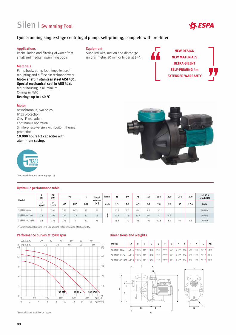
88
Dimensions and weights
Model A B C D E F G H I J K L Kg
SILEN I 33 8M 438.5 191.5 115 304 210 2 1/4” 221 2 1/4” 264 Ø9 108 Ø212 8.9
SILEN I 50 12M 438.5 191.5 115 304 210 2 1/4” 221 2 1/4” 264 Ø9 108 Ø212 10.2
SILEN I 100 15M 438.5 191.5 115 304 210 2 1/4” 221 2 1/4” 264 Ø9 108 Ø212 10.9
Performance curves at 2900 rpm
Silen I Swimming Pool
Quiet-running single-stage centrifugal pump, self-priming, complete with pre-filter
Hydraulic performance table
Model
I [A]
P1 [kW] P2 c * Pool
volume [m3]
l/min 25 50 75 100 150 200 250 290 1~230 V (model M)
1~230 V
1~230 V [kW] [HP] [µF] m3/h 1.5 3.0 4.5 6.0 9.0 12 15 17.4 Code
SILEN I 33 8M 2 0.45 0.25 0.33 12 65
mw
c
10.2 9.7 8.6 7.2 3.2 203144
SILEN I 50 12M 2.8 0.65 0.37 0.5 12 75 12.3 11.9 11.3 10.5 8.1 4.6 203145
SILEN I 100 15M 3.8 0.85 0.75 1 12 85 13.8 13.3 13 12.5 10.8 8.1 4.8 1.8 203146
(*) Swimming pool volume (m3): Considering water circulation of 8 hours/day.
Check conditions and terms at page 178
YEARSWARRANTY
NEW DESIGN
NEW MATERIALS
ULTRA-SILENT
SELF-PRIMING 4m
EXTENDED WARRANTY
ApplicationsRecirculation and filtering of water from small and medium swimming pools.
MaterialsPump body, pump foot, impeller, seal mounting and diffuser in technopolymer.Motor shaft in stainless steel AISI 431.Special mechanical seal in AISI 316.Motor housing in aluminium.O-rings in NBR.Bearings up to 160 °C
MotorAsynchronous, two poles.IP 55 protection.Class F insulation.Continuous operation.Single-phase version with built-in thermal protection.10.000 hours P2 capacitor with aluminium casing.
EquipmentSupplied with suction and discharge unions (metric 50 mm or Imperial 11/2”).
A
B C
D
E
F
G
H
JK
L
I100 15M50 12M33 8M
*Service kits are available on request
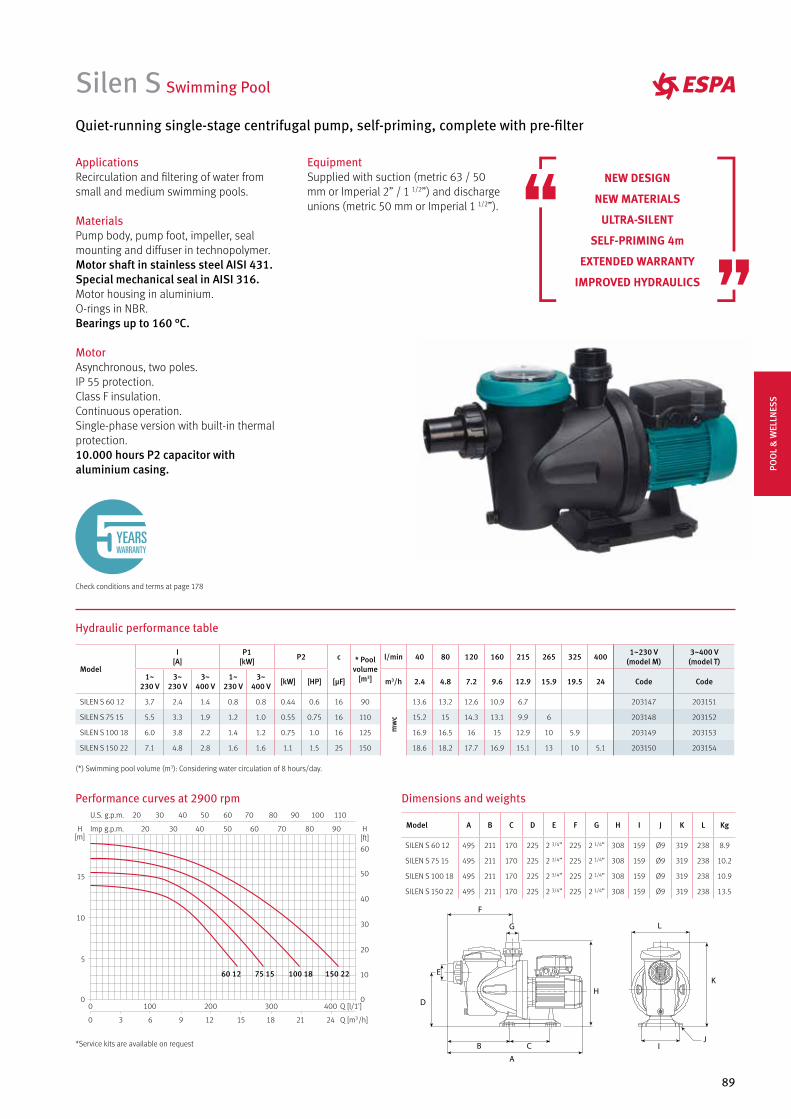
89
Dimensions and weights
Model A B C D E F G H I J K L Kg
SILEN S 60 12 495 211 170 225 2 3/4” 225 2 1/4” 308 159 Ø9 319 238 8.9
SILEN S 75 15 495 211 170 225 2 3/4” 225 2 1/4” 308 159 Ø9 319 238 10.2
SILEN S 100 18 495 211 170 225 2 3/4” 225 2 1/4” 308 159 Ø9 319 238 10.9
SILEN S 150 22 495 211 170 225 2 3/4” 225 2 1/4” 308 159 Ø9 319 238 13.5
Silen S Swimming Pool
Performance curves at 2900 rpm
Quiet-running single-stage centrifugal pump, self-priming, complete with pre-filter
Hydraulic performance table
Model
I [A]
P1 [kW] P2 c * Pool
volume [m3]
l/min 40 80 120 160 215 265 325 400 1~230 V (model M)
3~400 V (model T)
1~230 V
3~230 V
3~400 V
1~230 V
3~400 V [kW] [HP] [µF] m3/h 2.4 4.8 7.2 9.6 12.9 15.9 19.5 24 Code Code
SILEN S 60 12 3.7 2.4 1.4 0.8 0.8 0.44 0.6 16 90
mw
c
13.6 13.2 12.6 10.9 6.7 203147 203151
SILEN S 75 15 5.5 3.3 1.9 1.2 1.0 0.55 0.75 16 110 15.2 15 14.3 13.1 9.9 6 203148 203152
SILEN S 100 18 6.0 3.8 2.2 1.4 1.2 0.75 1.0 16 125 16.9 16.5 16 15 12.9 10 5.9 203149 203153
SILEN S 150 22 7.1 4.8 2.8 1.6 1.6 1.1 1.5 25 150 18.6 18.2 17.7 16.9 15.1 13 10 5.1 203150 203154
(*) Swimming pool volume (m3): Considering water circulation of 8 hours/day.
Check conditions and terms at page 178
YEARSWARRANTY
ApplicationsRecirculation and filtering of water from small and medium swimming pools.
MaterialsPump body, pump foot, impeller, seal mounting and diffuser in technopolymer.Motor shaft in stainless steel AISI 431.Special mechanical seal in AISI 316.Motor housing in aluminium.O-rings in NBR.Bearings up to 160 °C.
MotorAsynchronous, two poles.IP 55 protection.Class F insulation.Continuous operation.Single-phase version with built-in thermal protection.10.000 hours P2 capacitor with aluminium casing.
EquipmentSupplied with suction (metric 63 / 50 mm or Imperial 2” / 1 1/2”) and discharge unions (metric 50 mm or Imperial 1 1/2”).
NEW DESIGN
NEW MATERIALS
ULTRA-SILENT
SELF-PRIMING 4m
EXTENDED WARRANTY
IMPROVED HYDRAULICS
150 22100 1875 1560 12
*Service kits are available on request
POO
L &
WEL
LNES
S
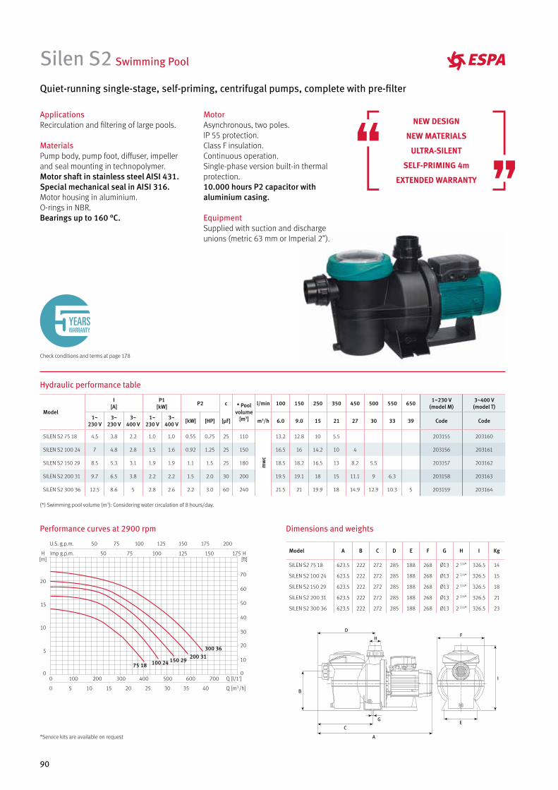
90
Silen S2 Swimming Pool
Quiet-running single-stage, self-priming, centrifugal pumps, complete with pre-filter
Hydraulic performance table
Performance curves at 2900 rpm Dimensions and weights
Model A B C D E F G H I Kg
SILEN S2 75 18 623.5 222 272 285 188 268 Ø13 2 3/4” 326.5 14
SILEN S2 100 24 623.5 222 272 285 188 268 Ø13 2 3/4” 326.5 15
SILEN S2 150 29 623.5 222 272 285 188 268 Ø13 2 3/4” 326.5 18
SILEN S2 200 31 623.5 222 272 285 188 268 Ø13 2 3/4” 326.5 21
SILEN S2 300 36 623.5 222 272 285 188 268 Ø13 2 3/4” 326.5 23
Model
I [A]
P1 [kW] P2 c * Pool
volume [m3]
l/min 100 150 250 350 450 500 550 650 1~230 V (model M)
3~400 V (model T)
1~230 V
3~230 V
3~400 V
1~230 V
3~400 V [kW] [HP] [µF] m3/h 6.0 9.0 15 21 27 30 33 39 Code Code
SILEN S2 75 18 4.5 3.8 2.2 1.0 1.0 0.55 0.75 25 110
mw
c
13.2 12.8 10 5.5 203155 203160
SILEN S2 100 24 7 4.8 2.8 1.5 1.6 0.92 1.25 25 150 16.5 16 14.2 10 4 203156 203161
SILEN S2 150 29 8.5 5.3 3.1 1.9 1.9 1.1 1.5 25 180 18.5 18.2 16.5 13 8.2 5.5 203157 203162
SILEN S2 200 31 9.7 6.5 3.8 2.2 2.2 1.5 2.0 30 200 19.5 19.1 18 15 11.1 9 6.3 203158 203163
SILEN S2 300 36 12.5 8.6 5 2.8 2.6 2.2 3.0 60 240 21.5 21 19.9 18 14.9 12.9 10.3 5 203159 203164
(*) Swimming pool volume (m3): Considering water circulation of 8 hours/day.
ApplicationsRecirculation and filtering of large pools.
MaterialsPump body, pump foot, diffuser, impeller and seal mounting in technopolymer.Motor shaft in stainless steel AISI 431.Special mechanical seal in AISI 316.Motor housing in aluminium.O-rings in NBR.Bearings up to 160 °C.
MotorAsynchronous, two poles.IP 55 protection.Class F insulation.Continuous operation.Single-phase version built-in thermal protection.10.000 hours P2 capacitor with aluminium casing.
EquipmentSupplied with suction and discharge unions (metric 63 mm or Imperial 2”).
NEW DESIGN
NEW MATERIALS
ULTRA-SILENT
SELF-PRIMING 4m
EXTENDED WARRANTY
Check conditions and terms at page 178
YEARSWARRANTY
F
I
E
A
B
H
D
C
G
75 18 100 24 150 29200 31
300 36
*Service kits are available on request
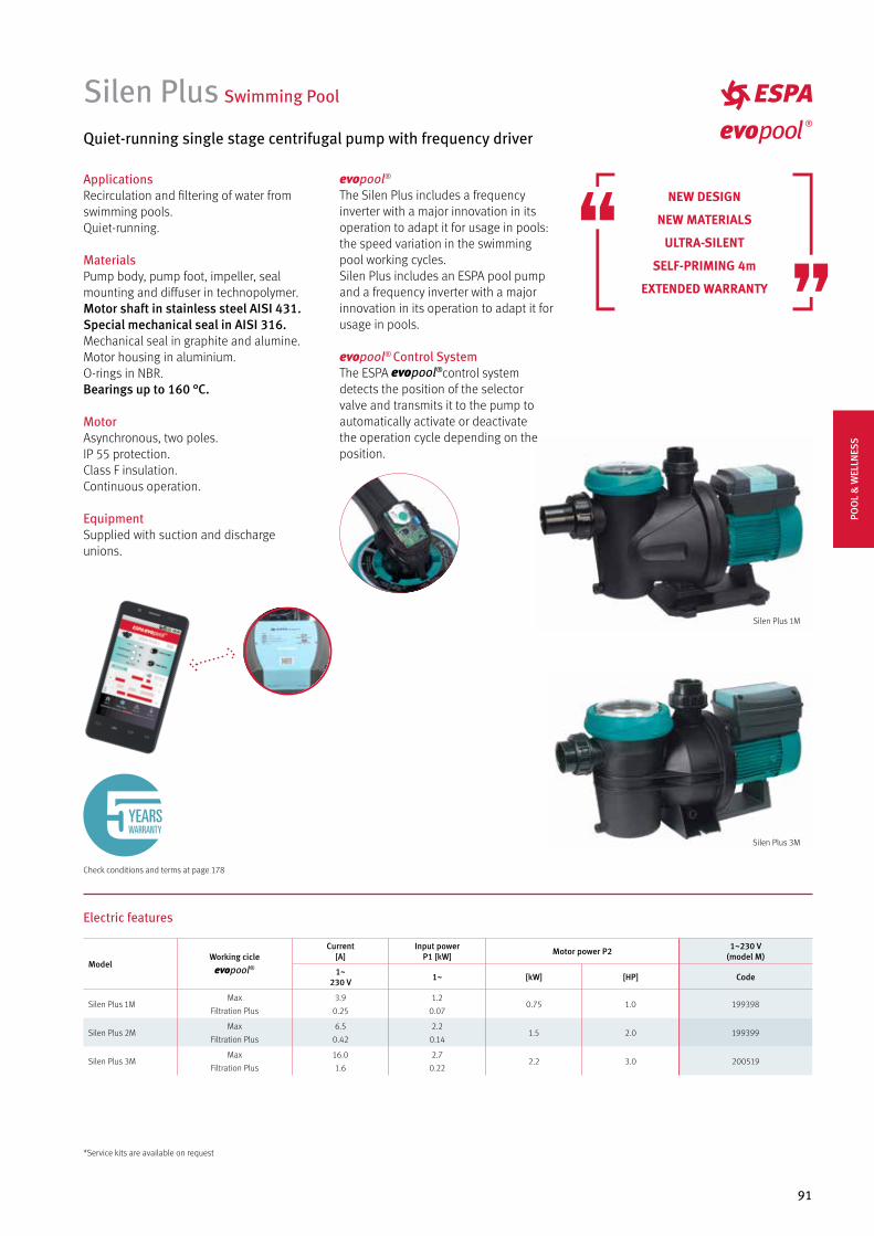
91
Silen Plus Swimming Pool
Quiet-running single stage centrifugal pump with frequency driver
Electric features
ModelWorking cicle
Current[A]
Input power P1 [kW] Motor power P2 1~230 V
(model M)
1~230 V 1~ [kW] [HP] Code
Silen Plus 1MMax
Filtration Plus
3.9
0.25
1.2
0.070.75 1.0 199398
Silen Plus 2MMax
Filtration Plus
6.5
0.42
2.2
0.141.5 2.0 199399
Silen Plus 3MMax
Filtration Plus
16.0
1.6
2.7
0.222.2 3.0 200519
Check conditions and terms at page 178
YEARSWARRANTY
Silen Plus 1M
Silen Plus 3M
ApplicationsRecirculation and filtering of water from swimming pools.Quiet-running.
MaterialsPump body, pump foot, impeller, seal mounting and diffuser in technopolymer.Motor shaft in stainless steel AISI 431.Special mechanical seal in AISI 316.Mechanical seal in graphite and alumine.Motor housing in aluminium.O-rings in NBR.Bearings up to 160 °C.
MotorAsynchronous, two poles.IP 55 protection.Class F insulation.Continuous operation.
EquipmentSupplied with suction and discharge unions.
evopool®
The Silen Plus includes a frequency inverter with a major innovation in its operation to adapt it for usage in pools: the speed variation in the swimming pool working cycles.Silen Plus includes an ESPA pool pump and a frequency inverter with a major innovation in its operation to adapt it for usage in pools.
evopool® Control SystemThe ESPA control system detects the position of the selector valve and transmits it to the pump to automatically activate or deactivate the operation cycle depending on the position.
NEW DESIGN
NEW MATERIALS
ULTRA-SILENT
SELF-PRIMING 4m
EXTENDED WARRANTY
*Service kits are available on request
POO
L &
WEL
LNES
S
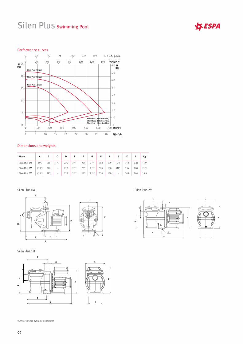
92
Dimensions and weights
Performance curves
Model A B C D E F G H I J K L Kg
Silen Plus 1M 495 211 170 225 2 1/4 ” 225 2 1/4 ” 308 159 Ø9 319 238 11.9
Silen Plus 2M 623.5 272 - 222 2 3/4 ” 285 2 3/4 ” 326 188 Ø13 334 268 21.9
Silen Plus 3M 623.5 272 - 222 2 3/4 ” 285 2 3/4 ” 326 188 - 368 268 23.9
Silen Plus Swimming Pool
Silen Plus 1M
Silen Plus 3M
Silen Plus 2M
*Service kits are available on request
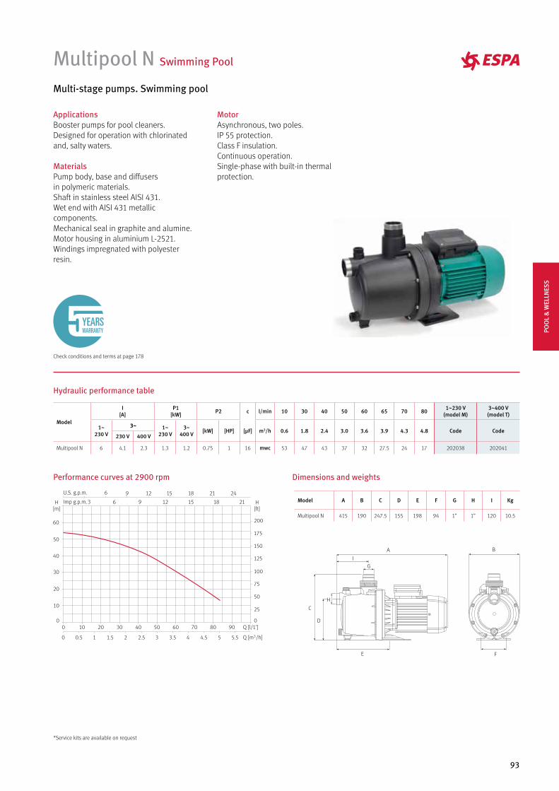
93
Multipool N Swimming Pool
Multi-stage pumps. Swimming pool
Hydraulic performance table
Performance curves at 2900 rpm Dimensions and weights
Model A B C D E F G H I Kg
Multipool N 415 190 247.5 155 198 94 1” 1” 120 10.5
A
I
H
G
E
D
C
F
B
MotorAsynchronous, two poles.IP 55 protection.Class F insulation.Continuous operation.Single-phase with built-in thermal protection.
ApplicationsBooster pumps for pool cleaners.Designed for operation with chlorinated and, salty waters.
MaterialsPump body, base and diffusersin polymeric materials.Shaft in stainless steel AISI 431.Wet end with AISI 431 metallic components.Mechanical seal in graphite and alumine.Motor housing in aluminium L-2521.Windings impregnated with polyester resin.
Model
I [A]
P1 [kW] P2 c l/min 10 30 40 50 60 65 70 80 1~230 V
(model M)3~400 V (model T)
1~230 V
3~ 1~230 V
3~400 V [kW] [HP] [µF] m3/h 0.6 1.8 2.4 3.0 3.6 3.9 4.3 4.8 Code Code
230 V 400 V
Multipool N 6 4.1 2.3 1.3 1.2 0.75 1 16 mwc 53 47 43 37 32 27.5 24 17 202038 202041
*Service kits are available on request
Check conditions and terms at page 178
YEARSWARRANTY PO
OL
& W
ELLN
ESS
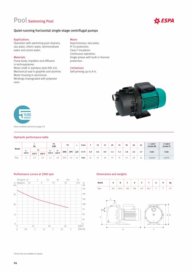
94
Pool Swimming Pool
Quiet-running horizontal single-stage centrifugal pumps
MotorAsynchronous, two poles.IP 55 protection.Class F insulation.Continuous operation.Single-phase with built-in thermal protection.
LimitationsSelf-priming up to 9 m.
ApplicationsOperation with swimming pool cleaners, sea water, chloric water, demineralised water and ozone water.
MaterialsPump body, impellers and diffusers in technopolymer.Motor shaft in stainless steel AISI 431.Mechanical seal in graphite and alumine.Motor housing in aluminium.Windings impregnated with polyester resin.
Hydraulic performance table
Performance curves at 2900 rpm Dimensions and weights
A
B
C
DE
F
G
H
Model A B C D E F G H Kg
Pool 343 201.5 190 196 147 84.7 1” 1” 8.2
Model
I [A]
P1 [kW] P2 c l/min 5 10 15 20 25 30 40 45 1~230 V
(model M)3~400 V (model T)
1~230 V
3~ 1~230 V
3~400 V [kW] [HP] [µF] m3/h 0.3 0.6 0.9 1.2 1.5 1.8 2.4 2.7 Code Code
230 V 400 V
Pool 5 3.3 1.9 1.1 1.0 0.97 1.0 16 mwc 47 43 40 37 35 33 28 26 146048 146054
Check conditions and terms at page 178
YEARSWARRANTY
*Service kits are available on request
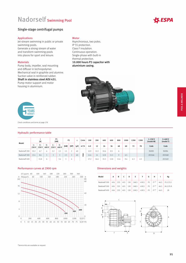
95
Nadorself Swimming Pool
Single-stage centrifugal pumps
ApplicationsJet-stream swimming in public or private swimming-pools.Generate a strong stream of water and transform swimming-pools into places for sport and leisure.
MaterialsPump body, impeller, seal mounting and diffuser in technopolymer.Mechanical seal in graphite and alumine.Suction valve in reinforced rubber.Shaft in stainless steel AISI 431.Pump-motor support and motor housing in aluminium.
MotorAsynchronous, two poles.IP 55 protection.Class F insulation.Continuous operation.Single-phase with built-in thermal protection.10.000 hours P2 capacitor with aluminium casing.
Hydraulic performance table
A
E
D
B
I
H
GF
C
H
Performance curves at 2900 rpm Dimensions and weights
Model
I [A]
P1 [kW] P2 c l/min 100 200 400 600 800 1000 1200 1300 1~230 V
(model M)3~400 V (model T)
1~230 V
3~230 V
3~400 V
1~230 V
3~400 V [kW] [HP] [µF] m3/h 6.0 12 24 36 48 60 72 78 Code Code
Nadorself 200 10.2 6.7 4 2.2 2.2 1.5 2 40
mw
c
12.9 12.2 10.6 8.5 6 96985 96984
Nadorself 300 13.4 8.6 5 3 3 2.3 3 60 14.6 14 12.8 11.3 9 6.5 203166 203168
Nadorself 400 11.8 6 3.4 3 4 17.2 16.6 15.3 13.8 11.6 9.4 6.3 4.5 203169
400300
200
Model A B C D E F G H I Kg
Nadorself 200 416 335 615 130 248.5 418.5 70 21/2” 46.5 25.1/23.1
Nadorself 300 416 335 615 130 248.5 418.5 70 21/2” 46.5 26.1/25.8
Nadorself 400 416 335 615 130 248.5 418.5 70 21/2” 46.5 28
Check conditions and terms at page 178
YEARSWARRANTY
*Service kits are available on request
POO
L &
WEL
LNES
S
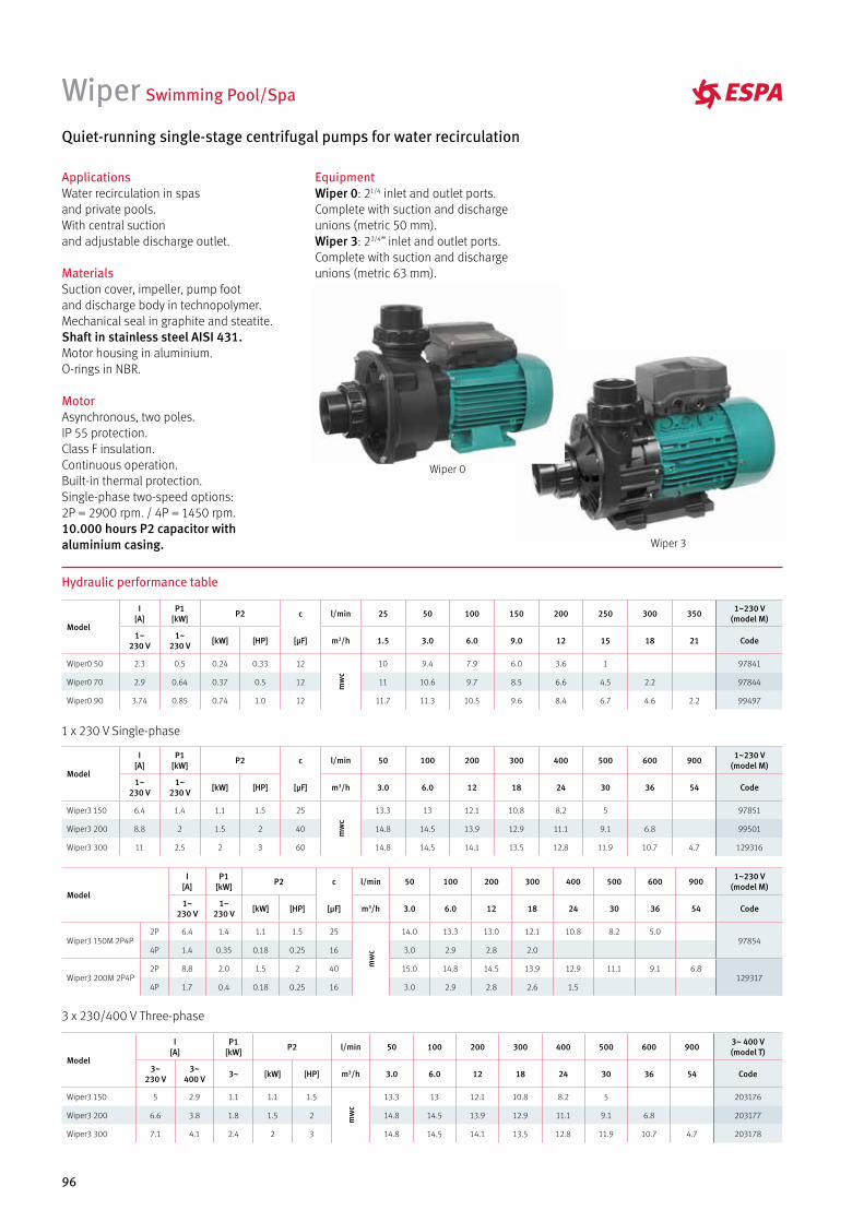
96
Wiper Swimming Pool/Spa
Quiet-running single-stage centrifugal pumps for water recirculation
ApplicationsWater recirculation in spas and private pools. With central suction and adjustable discharge outlet.
MaterialsSuction cover, impeller, pump foot and discharge body in technopolymer.Mechanical seal in graphite and steatite.Shaft in stainless steel AISI 431.Motor housing in aluminium.O-rings in NBR.
MotorAsynchronous, two poles.IP 55 protection.Class F insulation.Continuous operation.Built-in thermal protection.Single-phase two-speed options: 2P = 2900 rpm. / 4P = 1450 rpm.10.000 hours P2 capacitor with aluminium casing.
Hydraulic performance table
Model
I [A]
P1 [kW] P2 c l/min 25 50 100 150 200 250 300 350 1~230 V
(model M)
1~230 V
1~230 V [kW] [HP] [µF] m3/h 1.5 3.0 6.0 9.0 12 15 18 21 Code
Wiper0 50 2.3 0.5 0.24 0.33 12
mw
c
10 9.4 7.9 6.0 3.6 1 97841
Wiper0 70 2.9 0.64 0.37 0.5 12 11 10.6 9.7 8.5 6.6 4.5 2.2 97844
Wiper0 90 3.74 0.85 0.74 1.0 12 11.7 11.3 10.5 9.6 8.4 6.7 4.6 2.2 99497
Model
I [A]
P1 [kW] P2 c l/min 50 100 200 300 400 500 600 900 1~230 V
(model M)
1~230 V
1~230 V [kW] [HP] [µF] m3/h 3.0 6.0 12 18 24 30 36 54 Code
Wiper3 150 6.4 1.4 1.1 1.5 25
mw
c
13.3 13 12.1 10.8 8.2 5 97851
Wiper3 200 8.8 2 1.5 2 40 14.8 14.5 13.9 12.9 11.1 9.1 6.8 99501
Wiper3 300 11 2.5 2 3 60 14.8 14.5 14.1 13.5 12.8 11.9 10.7 4.7 129316
1 x 230 V Single-phase
Model
I [A]
P1 [kW] P2 l/min 50 100 200 300 400 500 600 900 3~ 400 V
(model T)
3~230 V
3~400 V 3~ [kW] [HP] m3/h 3.0 6.0 12 18 24 30 36 54 Code
Wiper3 150 5 2.9 1.1 1.1 1.5
mw
c
13.3 13 12.1 10.8 8.2 5 203176
Wiper3 200 6.6 3.8 1.8 1.5 2 14.8 14.5 13.9 12.9 11.1 9.1 6.8 203177
Wiper3 300 7.1 4.1 2.4 2 3 14.8 14.5 14.1 13.5 12.8 11.9 10.7 4.7 203178
3 x 230/400 V Three-phase
Wiper 0
Wiper 3
Model
I [A]
P1 [kW] P2 c l/min 50 100 200 300 400 500 600 900 1~230 V
(model M)
1~230 V
1~230 V [kW] [HP] [µF] m3/h 3.0 6.0 12 18 24 30 36 54 Code
Wiper3 150M 2P4P2P 6.4 1.4 1.1 1.5 25
mw
c
14.0 13.3 13.0 12.1 10.8 8.2 5.097854
4P 1.4 0.35 0.18 0.25 16 3.0 2.9 2.8 2.0
Wiper3 200M 2P4P2P 8.8 2.0 1.5 2 40 15.0 14.8 14.5 13.9 12.9 11.1 9.1 6.8
1293174P 1.7 0.4 0.18 0.25 16 3.0 2.9 2.8 2.6 1.5
EquipmentWiper 0: 21/4 inlet and outlet ports. Complete with suction and discharge unions (metric 50 mm).Wiper 3: 23/4’’ inlet and outlet ports. Complete with suction and discharge unions (metric 63 mm).
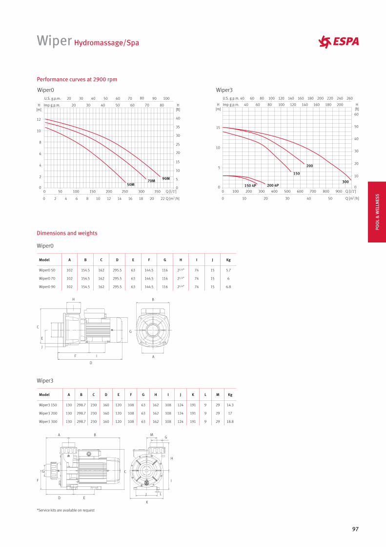
97
Wiper Hydromassage/Spa
Dimensions and weights
Wiper0
Model A B C D E F G H I J Kg
Wiper0 50 102 154.5 162 295.5 63 144.5 116 21/4” 74 15 5.7
Wiper0 70 102 154.5 162 295.5 63 144.5 116 21/4” 74 15 6
Wiper0 90 102 154.5 162 295.5 63 144.5 116 21/4” 74 15 6.8
A
B
D
C
E
F
H
G
I
J
Wiper3
Model A B C D E F G H I J K L M Kg
Wiper3 150 130 298.7 230 160 120 108 63 162 108 124 191 9 29 14.3
Wiper3 200 130 298.7 230 160 120 108 63 162 108 124 191 9 29 17
Wiper3 300 130 298.7 230 160 120 108 63 162 108 124 191 9 29 18.8
A B
D
C
E
F
G
H
I
J L
K
MG
Wiper0
Performance curves at 2900 rpm
90M70M50M
Wiper3
300
200
150
200 4P150 4P
*Service kits are available on request
POO
L &
WEL
LNES
S
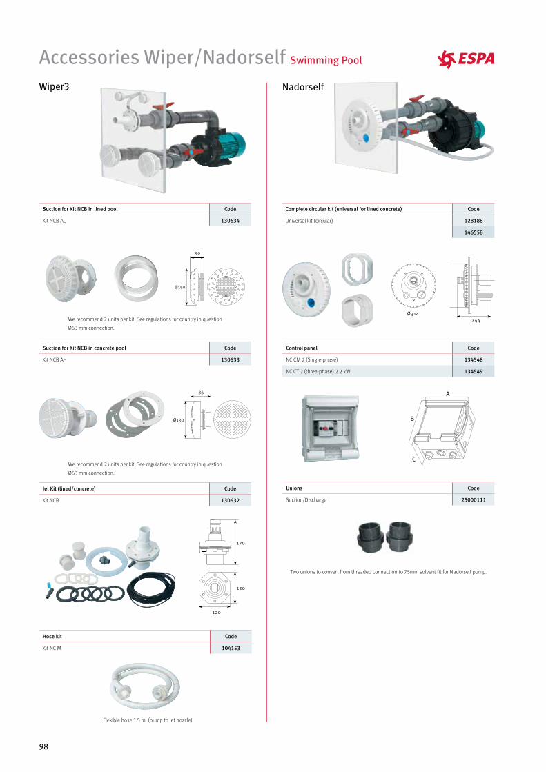
98
Complete circular kit (universal for lined concrete) Code
Universal kit (circular) 128188
146558
Suction for Kit NCB in concrete pool Code
Kit NCB AH 130633
Jet Kit (lined/concrete) Code
Kit NCB 130632
Hose kit Code
Kit NC M 104153
Unions Code
Suction/Discharge 25000111
Control panel Code
NC CM 2 (Single-phase) 134548
NC CT 2 (three-phase) 2.2 kW 134549
Suction for Kit NCB in lined pool Code
Kit NCB AL 130634
Accessories Wiper/Nadorself Swimming Pool Wiper3
Flexible hose 1.5 m. (pump to jet nozzle)
Two unions to convert from threaded connection to 75mm solvent fit for Nadorself pump.
Nadorself
We recommend 2 units per kit. See regulations for country in question
Ø63 mm connection.
We recommend 2 units per kit. See regulations for country in question
Ø63 mm connection.
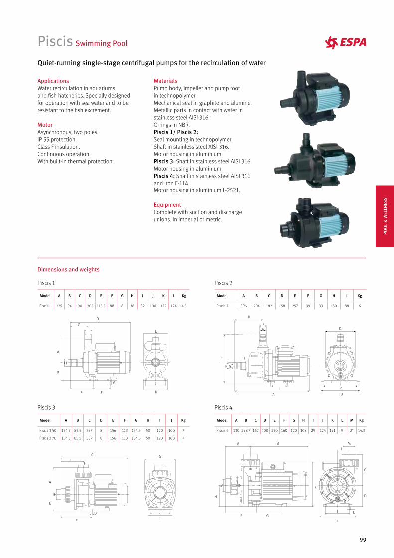
99
Piscis Swimming Pool
Quiet-running single-stage centrifugal pumps for the recirculation of water
ApplicationsWater recirculation in aquariumsand fish hatcheries. Specially designedfor operation with sea water and to beresistant to the fish excrement.
MotorAsynchronous, two poles.IP 55 protection.Class F insulation.Continuous operation.With built-in thermal protection.
MaterialsPump body, impeller and pump footin technopolymer.Mechanical seal in graphite and alumine.Metallic parts in contact with water instainless steel AISI 316.O-rings in NBR.Piscis 1/ Piscis 2:Seal mounting in technopolymer.Shaft in stainless steel AISI 316.Motor housing in aluminium.Piscis 3: Shaft in stainless steel AISI 316.Motor housing in aluminium.Piscis 4: Shaft in stainless steel AISI 316and iron F-114.Motor housing in aluminium L-2521.
EquipmentComplete with suction and dischargeunions. In imperial or metric.
Dimensions and weights
Piscis 1
Piscis 3
Piscis 2
Piscis 4
Model A B C D E F G H I J K L Kg
Piscis 1 125 94 90 305 115.5 88 8 38 32 100 122 124 4.5
Model A B C D E F G H I J Kg
Piscis 3 50 134.5 83.5 337 8 156 113 154.5 50 120 100 7
Piscis 3 70 134.5 83.5 337 8 156 113 154.5 50 120 100 7
Model A B C D E F G H I Kg
Piscis 2 396 204 182 158 257 39 33 150 88 6
Model A B C D E F G H I J K L M Kg
Piscis 4 130 298.7 162 108 230 160 120 108 29 124 191 9 2” 14.3
POO
L &
WEL
LNES
S
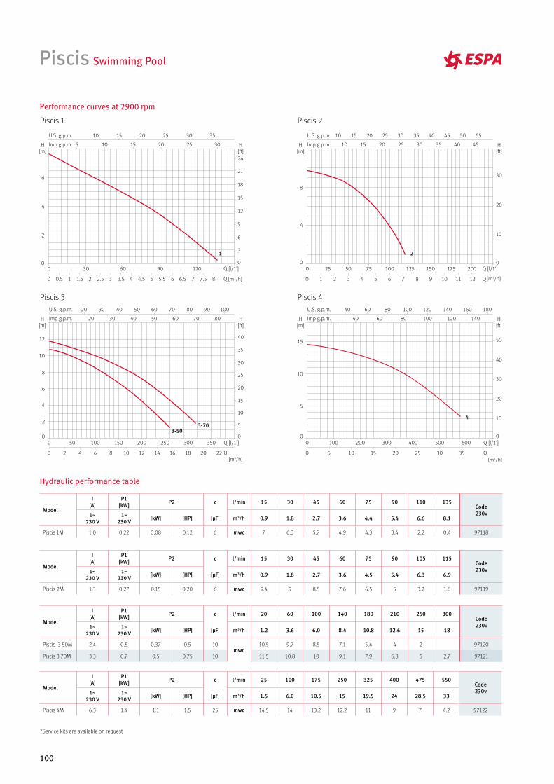
100
Piscis Swimming Pool
Performance curves at 2900 rpm
Hydraulic performance table
Piscis 1
Piscis 3
Piscis 2
Piscis 4
Model
I [A]
P1[kW] P2 c l/min 15 30 45 60 75 90 110 135
Code230v1~
230 V1~
230 V [kW] [HP] [µF] m3/h 0.9 1.8 2.7 3.6 4.4 5.4 6.6 8.1
Piscis 1M 1.0 0.22 0.08 0.12 6 mwc 7 6.3 5.7 4.9 4.3 3.4 2.2 0.4 97118
Model
I [A]
P1[kW] P2 c l/min 15 30 45 60 75 90 105 115
Code230v1~
230 V1~
230 V [kW] [HP] [µF] m3/h 0.9 1.8 2.7 3.6 4.5 5.4 6.3 6.9
Piscis 2M 1.3 0.27 0.15 0.20 6 mwc 9.4 9 8.5 7.6 6.5 5 3.2 1.6 97119
Model
I [A]
P1[kW] P2 c l/min 25 100 175 250 325 400 475 550
Code230v1~
230 V1~
230 V [kW] [HP] [µF] m3/h 1.5 6.0 10.5 15 19.5 24 28.5 33
Piscis 4M 6.3 1.4 1.1 1.5 25 mwc 14.5 14 13.2 12.2 11 9 7 4.2 97122
Model
I [A]
P1[kW] P2 c l/min 20 60 100 140 180 210 250 300
Code230v1~
230 V1~
230 V [kW] [HP] [µF] m3/h 1.2 3.6 6.0 8.4 10.8 12.6 15 18
Piscis 3 50M 2.4 0.5 0.37 0.5 10mwc
10.5 9.7 8.5 7.1 5.4 4 2 97120
Piscis 3 70M 3.3 0.7 0.5 0.75 10 11.5 10.8 10 9.1 7.9 6.8 5 2.7 97121
[m3/h] [m3/h]
[m3/h][m3/h]
*Service kits are available on request
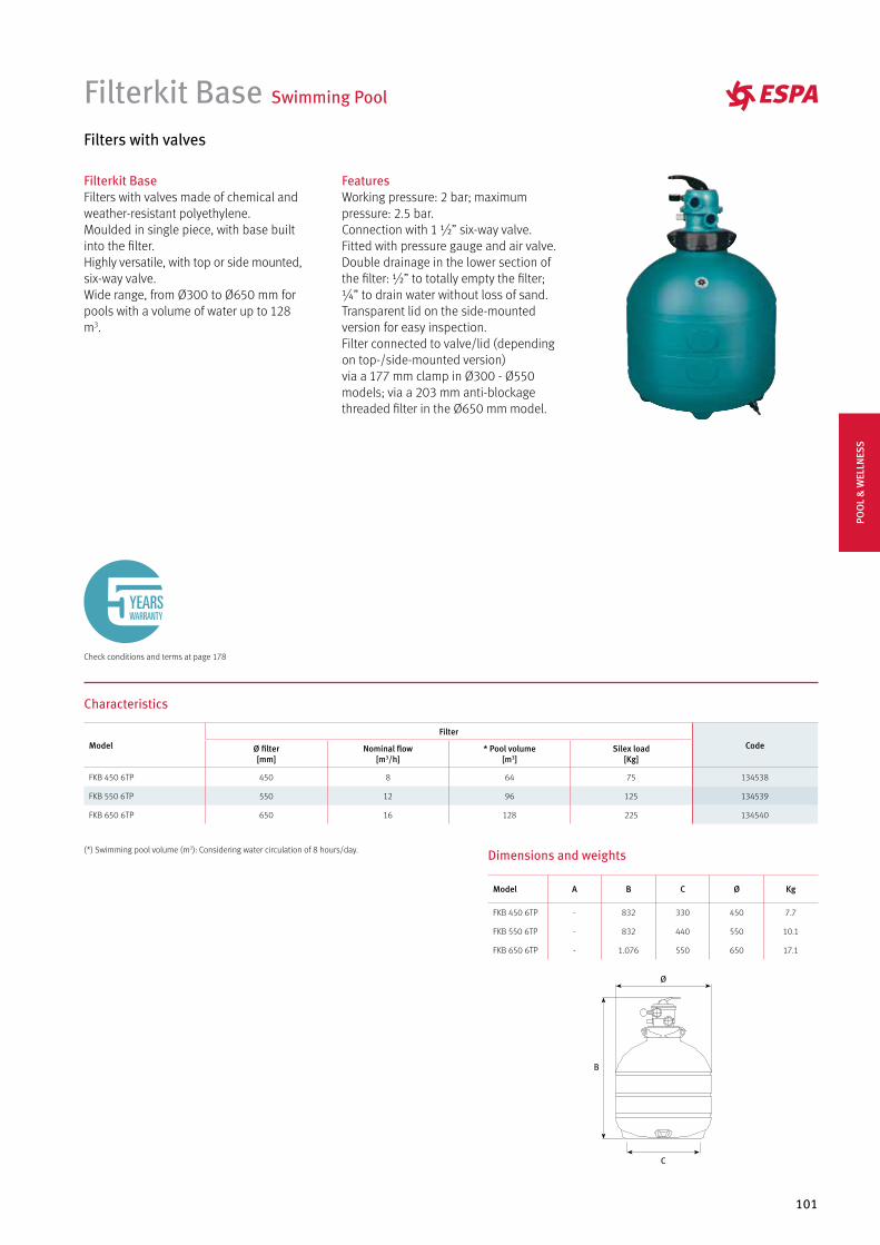
101
Filterkit Base Swimming Pool
Filters with valves
Filterkit BaseFilters with valves made of chemical and weather-resistant polyethylene.Moulded in single piece, with base built into the filter. Highly versatile, with top or side mounted, six-way valve. Wide range, from Ø300 to Ø650 mm for pools with a volume of water up to 128 m3.
Characteristics
Dimensions and weights
Model A B C Ø Kg
FKB 450 6TP - 832 330 450 7.7
FKB 550 6TP - 832 440 550 10.1
FKB 650 6TP - 1.076 550 650 17.1
FeaturesWorking pressure: 2 bar; maximum pressure: 2.5 bar. Connection with 1 ½” six-way valve. Fitted with pressure gauge and air valve. Double drainage in the lower section of the filter: ½” to totally empty the filter; ¼” to drain water without loss of sand.Transparent lid on the side-mounted version for easy inspection. Filter connected to valve/lid (depending on top-/side-mounted version) via a 177 mm clamp in Ø300 - Ø550 models; via a 203 mm anti-blockage threaded filter in the Ø650 mm model.
Model
Filter
CodeØ filter[mm]
Nominal flow[m3/h]
* Pool volume[m3]
Silex load[Kg]
FKB 450 6TP 450 8 64 75 134538
FKB 550 6TP 550 12 96 125 134539
FKB 650 6TP 650 16 128 225 134540
(*) Swimming pool volume (m3): Considering water circulation of 8 hours/day.
Check conditions and terms at page 178
YEARSWARRANTY
POO
L &
WEL
LNES
S
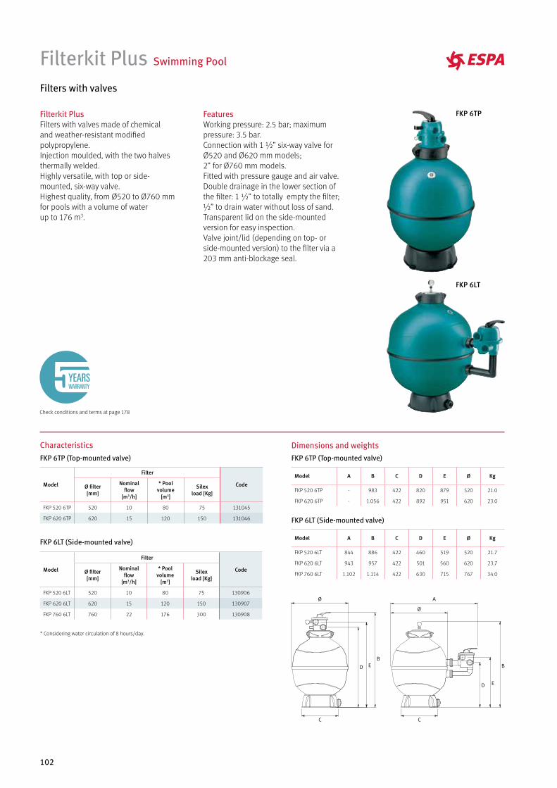
102
Filterkit Plus Swimming Pool
Filters with valves
Filterkit PlusFilters with valves made of chemical and weather-resistant modified polypropylene.Injection moulded, with the two halves thermally welded. Highly versatile, with top or side-mounted, six-way valve. Highest quality, from Ø520 to Ø760 mm for pools with a volume of waterup to 176 m3.
FeaturesWorking pressure: 2.5 bar; maximum pressure: 3.5 bar. Connection with 1 ½” six-way valve for Ø520 and Ø620 mm models; 2” for Ø760 mm models. Fitted with pressure gauge and air valve. Double drainage in the lower section of the filter: 1 ½” to totally empty the filter; ½” to drain water without loss of sand. Transparent lid on the side-mounted version for easy inspection. Valve joint/lid (depending on top- or side-mounted version) to the filter via a 203 mm anti-blockage seal.
Characteristics
* Considering water circulation of 8 hours/day.
Dimensions and weights
Model A B C D E Ø Kg
FKP 520 6LT 844 886 422 460 519 520 21.7
FKP 620 6LT 943 957 422 501 560 620 23.7
FKP 760 6LT 1.102 1.114 422 630 715 767 34.0
Model A B C D E Ø Kg
FKP 520 6TP - 983 422 820 879 520 21.0
FKP 620 6TP - 1.056 422 892 951 620 23.0
Model
Filter
CodeØ filter[mm]
Nominalflow
[m3/h]
* Poolvolume
[m3]
Silexload [Kg]
FKP 520 6TP 520 10 80 75 131045
FKP 620 6TP 620 15 120 150 131046
Model
Filter
CodeØ filter[mm]
Nominalflow
[m3/h]
* Poolvolume
[m3]
Silexload [Kg]
FKP 520 6LT 520 10 80 75 130906
FKP 620 6LT 620 15 120 150 130907
FKP 760 6LT 760 22 176 300 130908
FKP 6TP
FKP 6LT
FKP 6TP (Top-mounted valve) FKP 6TP (Top-mounted valve)
FKP 6LT (Side-mounted valve)
FKP 6LT (Side-mounted valve)
Check conditions and terms at page 178
YEARSWARRANTY
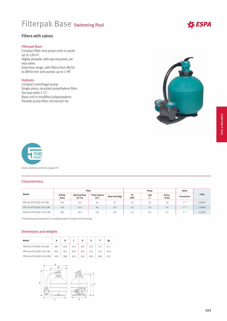
103
Filterpak Base Swimming Pool
Filters with valves
Filterpak BaseCompact filter and pump units in pools up to 128 m3. Highly versatile, with top-mounted, six-way valve.Extensive range, with filters from Ø450 to Ø650 mm and pumps up to 1 HP.
FeaturesCompact centrifugal pump.Single piece, moulded polyethylene filter.Six-way valve 1 ½”.Base unit in modified polypropylene.Flexible pump-filter connection kit.
Characteristics
(*) Swimming pool volume (m3): Considering water circulation of 8 hours/day.
Dimensions and weights
Model A B C D E F Kg
FPB 450 6TP SILEN I 50 12M 697 855 613 350 671 731 21.1
FPB 550 6TP SILEN I 100 15M 855 855 855 550 671 731 22.8
FPB 650 6TP SILEN S 100 18M 902 988 855 550 824 883 32.5
Model
Filter Pump Valve
CodeØ filter[mm]
Nominal flow[m3/h]
* Pool volume [m3] Silex load [Kg] P2
(HP)I (A)1~
Ø Suc.(mm) Connection
FPB 450 6TP SILEN I 50 12M 450 12.0 64 75 0.5 2.8 50 1 1/2" 134697
FPB 550 6TP SILEN I 100 15M 550 15.0 96 125 1.0 3.8 50 1 1/2" 134698
FPB 650 6TP SILEN S 100 18M 650 18.0 136 225 1.0 6.0 63 1 1/2" 131200
Check conditions and terms at page 178
YEARSWARRANTY
POO
L &
WEL
LNES
S
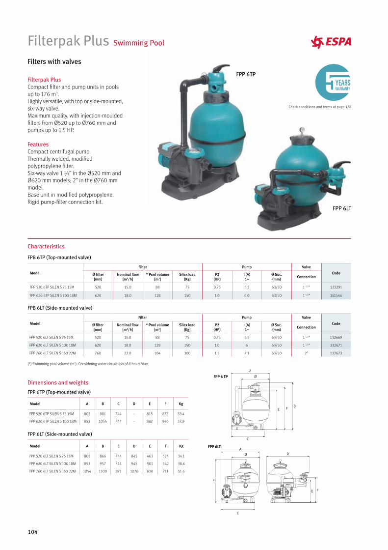
104
Filterpak Plus Swimming Pool
Filters with valves
Filterpak PlusCompact filter and pump units in pools up to 176 m3. Highly versatile, with top or side-mounted, six-way valve. Maximum quality, with injection-moulded filters from Ø520 up to Ø760 mm and pumps up to 1.5 HP.
FeaturesCompact centrifugal pump.Thermally welded, modified polypropylene filter.Six-way valve 1 ½” in the Ø520 mm and Ø620 mm models; 2” in the Ø760 mm model.Base unit in modified polypropylene.Rigid pump-filter connection kit.
Characteristics
Dimensions and weights
Model A B C D E F Kg
FPP 520 6TP SILEN S 75 15M 803 981 744 - 815 873 33.4
FPP 620 6TP SILEN S 100 18M 853 1054 744 - 887 946 37.9
Model A B C D E F Kg
FPP 520 6LT SILEN S 75 15M 803 866 744 845 463 524 34.1
FPP 620 6LT SILEN S 100 18M 853 957 744 945 501 562 38.6
FPP 760 6LT SILEN S 150 22M 1054 1100 871 1076 630 711 51.6
FPP 6LT
FPP 6 TP
FPP 6TP (Top-mounted valve)
FPB 6TP (Top-mounted valve)
FPB 6LT (Side-mounted valve)
FPP 6LT (Side-mounted valve)
(*) Swimming pool volume (m3): Considering water circulation of 8 hours/day.
Model
Filter Pump Valve
CodeØ filter[mm]
Nominal flow[m3/h]
* Pool volume [m3]
Silex load[Kg]
P2(HP)
I (A)1~
Ø Suc.(mm) Connection
FPP 520 6TP SILEN S 75 15M 520 15.0 88 75 0.75 5.5 63/50 1 1/2" 133291
FPP 620 6TP SILEN S 100 18M 620 18.0 128 150 1.0 6.0 63/50 1 1/2" 151546
Model
Filter Pump Valve
CodeØ filter[mm]
Nominal flow[m3/h]
* Pool volume [m3]
Silex load[Kg]
P2(HP)
I (A)1~
Ø Suc.(mm) Connection
FPP 520 6LT SILEN S 75 15M 520 15.0 88 75 0.75 5.5 63/50 1 1/2" 132669
FPP 620 6LT SILEN S 100 18M 620 18.0 128 150 1.0 6 63/50 1 1/2" 132671
FPP 760 6LT SILEN S 150 22M 760 22.0 184 300 1.5 7.1 63/50 2" 132673
FPP 6TP
FPP 6LT
Check conditions and terms at page 178
YEARSWARRANTY
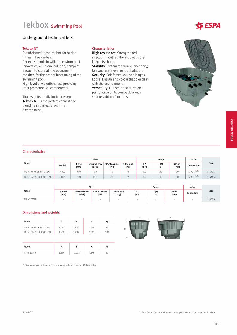
105
Tekbox Swimming Pool
Underground technical box
Tekbox NTPrefabricated technical box for buried fitting in the garden. Perfectly blends in with the environment. Innovative, all-in-one solution, compact enough to store all the equipment required for the proper functioning of the swimming pool. High level of watertightness providing total protection for components.
Thanks to its totally buried design, Tekbox NT is the perfect camouflage, blending in perfectly with the environment.
Characteristics
CharacteristicsHigh resistance: Strengthened, injection-moulded thermoplastic that keeps its shape. Stability: System for ground anchoring to avoid any movement or flotation.Security: Reinforced lock and hinges.Looks: Design and colour that blends in with the environment.Versatility: Full pre-fitted filtration-pump-valve units compatible with various add-on functions.
Model
Filter Pump Valve
CodeModel Ø filter
[mm]Nominal flow
[m3/h]* Pool volume
[m3]Silex load
[Kg]P2
(HP)I (A)1~
Ø Suc.(mm) Connection
TKB NT 450 SILEN I 50 12M ARIES 450 8.0 64 75 0.5 2.8 50 SIDE 1 1/2" 134425
TKP NT 520 SILEN I 100 15M LIBRA 520 11.0 88 75 1.0 3.8 50 SIDE 1 1/2" 134465
Model A B C Kg
TKB NT 450 SILEN I 50 12M 1.460 1.032 1.145 88
TKP NT 520 SILEN I 100 15M 1.460 1.032 1.145 102
Model
Filter Pump Valve
CodeØ filter[mm]
Nominal flow[m3/h]
* Pool volume [m3]
Silex load[Kg]
P2(HP)
I (A)1~
Ø Suc.(mm) Connection
TKP NT EMPTY - - - - - - - - 134529
Model A B C Kg
TK NT EMPTY 1.460 1.032 1.145 60
(*) Swimming pool volume (m3): Considering water circulation of 8 hours/day.
*For different Tekbox equipment options please contact one of our technicians.
Dimensions and weights
B
C A
Price: P.O.A.
POO
L &
WEL
LNES
S
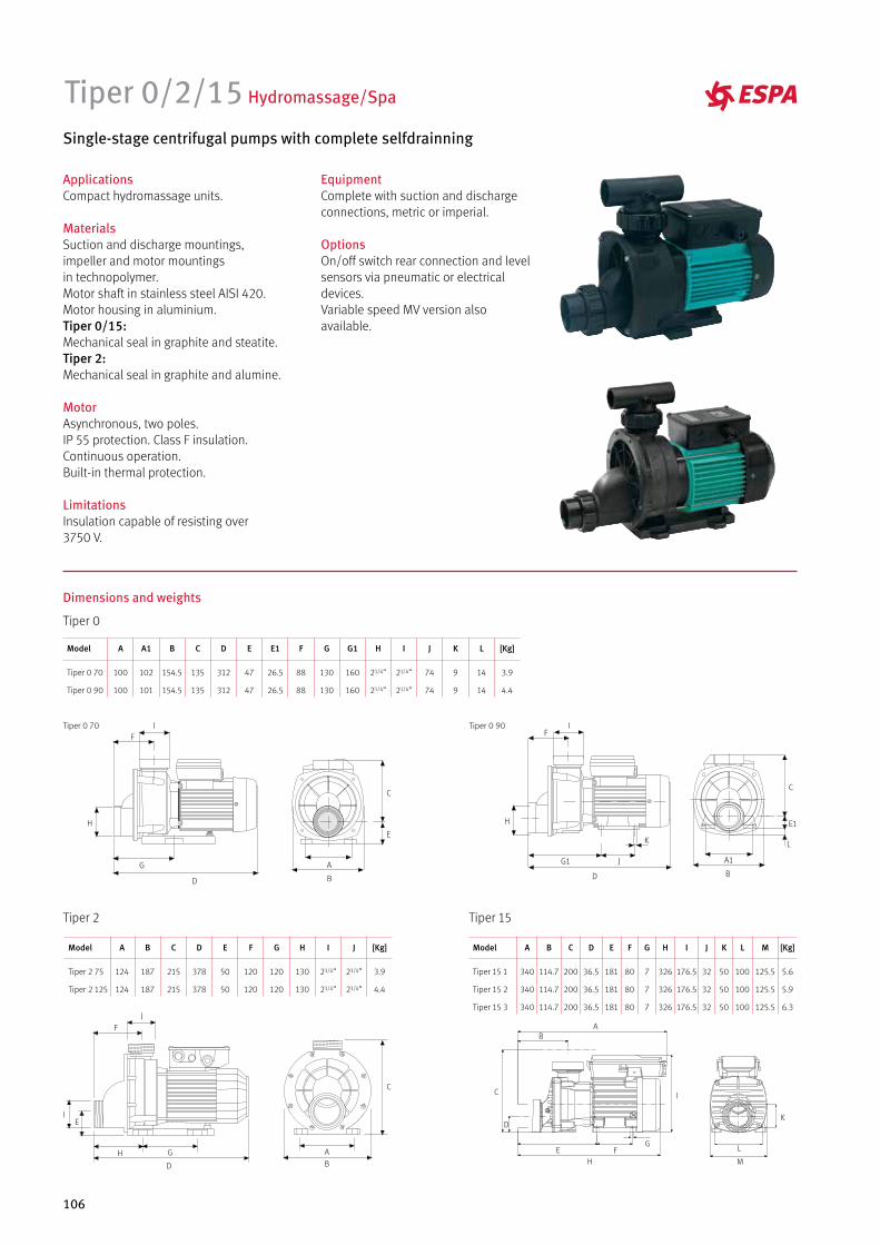
106
Tiper 0/2/15 Hydromassage/Spa
Single-stage centrifugal pumps with complete selfdrainning
EquipmentComplete with suction and discharge connections, metric or imperial.
OptionsOn/off switch rear connection and level sensors via pneumatic or electrical devices. Variable speed MV version also available.
ApplicationsCompact hydromassage units.
MaterialsSuction and discharge mountings, impeller and motor mountings in technopolymer.Motor shaft in stainless steel AISI 420.Motor housing in aluminium.Tiper 0/15: Mechanical seal in graphite and steatite.Tiper 2: Mechanical seal in graphite and alumine.
MotorAsynchronous, two poles.IP 55 protection. Class F insulation.Continuous operation.Built-in thermal protection.
LimitationsInsulation capable of resisting over 3750 V.
Tiper 0 70
Tiper 0 90
Model A
100
100
[Kg]
3.9
4.4
H
21/4”
21/4”
J
74
74
L
14
14
K
9
9
G
130
130
G1
160
160
I
21/4”
21/4”
F
88
88
E
47
47
E1
26.5
26.5
D
312
312
C
135
135
154.5
154.5
B
102
101
A1
Tiper 0
Tiper 0 70
A
B
C
E
D
F
G
H
I
D
F
H
I
G1 J
K
B
C
A1
E1
L
Tiper 0 90
A
B
C
D
E
F
GH
I
J
Tiper 15 1
Tiper 15 2
Tiper 15 3
Model A
340
340
340
C
200
200
200
E
181
181
181
H
326
326
326
L
100
100
100
F
80
80
80
J
32
32
32
K
50
50
50
G
7
7
7
[Kg]
5.6
5.9
6.3
I
176.5
176.5
176.5
M
125.5
125.5
125.5
D
36.5
36.5
36.5
114.7
114.7
114.7
B
Tiper 15
AB
C
D
E F
I
H
G
M
L
K
Tiper 2 75
Tiper 2 125
Model A
124
124
[Kg]
3.9
4.4
I
21/4”
21/4”
J
21/4”
21/4”
H
130
130
F
120
120
G
120
120
E
50
50
D
378
378
215
215
C
187
187
B
Tiper 2
Dimensions and weights
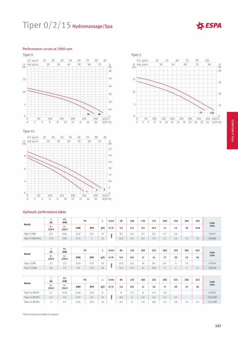
107
Hydraulic performance table
Performance curves at 2900 rpm
Tiper 15
Tiper 2
Tiper 0/2/15 Hydromassage/Spa
Tiper 0
907075 125
12 3
Model
I [A]
P1[kW] P2 c l/min 50 100 150 175 200 250 300 330
Code230v1~
230 V1~
230 V [kW] [HP] [µF] m3/h 3.0 6.0 9.0 10.5 12 15 18 19.8
Tiper 0 70M 2.9 0.64 0.37 0.5 12
mw
c 9.5 8.3 7.1 6.5 5.7 3.6 97622
Tiper 0 90M SP42 3.74 0.85 0.75 1 12 10.5 9.4 8.4 7.8 7.1 5.4 3.3 1.9 199188
Model
I [A]
P1[kW] P2 c l/min 83 133 183 233 283 333 383 433
Code230v1~
230 V1~
230 V [kW] [HP] [µF] m3/h 5.0 8.0 11 14 17 20 23 26
Tiper 2 75M 5.3 1.2 0.55 0.75 16
mw
c 12.3 11.1 10 8.5 6.5 5 2.5 137549
Tiper 2 125M 5.6 1.5 0.9 1.25 16 14.2 13.2 12 10.6 9 7 5 2.7 137578
Model
I [A]
P1[kW] P2 c l/min 83 133 183 233 283 333 383 433
Code230v1~
230 V1~
230 V [kW] [HP] [µF] m3/h 5.0 8.0 11 14 17 20 23 26
Tiper 15 1M SP1 1.7 0.36 0.18 0.25 6
mw
c
8 7.3 6 4.3 2.6 130795
Tiper 15 2M SP2 2.3 0.5 0.37 0.5 10 8.6 8 6.9 5.6 4.2 2.7 131343M
Tiper 15 3M SP2 3 0.7 0.55 0.75 12 9.5 9 7.9 6.8 5.3 3.9 2.2 1.5 131344M
*Service kits are available on request
POO
L &
WEL
LNES
S


PRESSURE BUILDING SERVICES
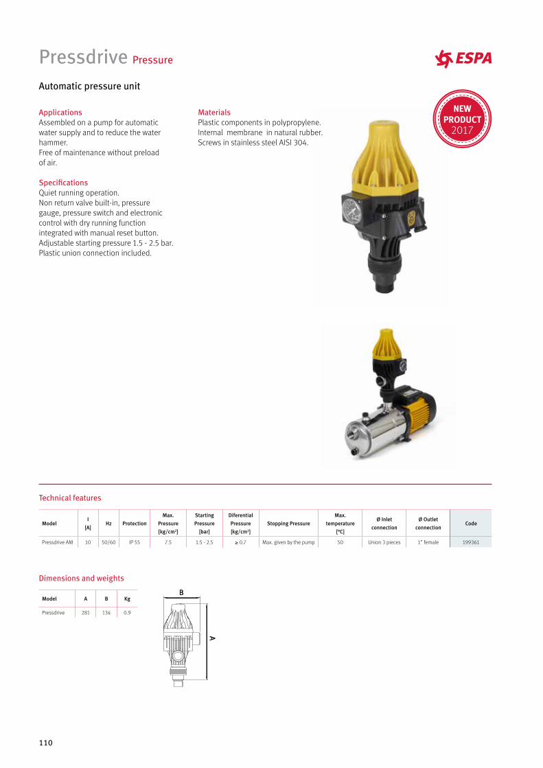
110
Pressdrive Pressure
Automatic pressure unit
MaterialsPlastic components in polypropylene. Internal membrane in natural rubber. Screws in stainless steel AISI 304.
ApplicationsAssembled on a pump for automatic water supply and to reduce the water hammer. Free of maintenance without preload of air.
SpecificationsQuiet running operation. Non return valve built-in, pressure gauge, pressure switch and electronic control with dry running function integrated with manual reset button.Adjustable starting pressure 1.5 - 2.5 bar.Plastic union connection included.
Technical features
Dimensions and weights
ModelI
[A]Hz Protection
Max.Pressure[kg/cm2]
StartingPressure
[bar]
DiferentialPressure[kg/cm2]
Stopping PressureMax.
temperature[°C]
Ø Inletconnection
Ø Outletconnection
Code
Pressdrive AM 10 50/60 IP 55 7.5 1.5 - 2.5 ≥ 0.7 Max. given by the pump 50 Union 3 pieces 1” female 199361
Model A B Kg
Pressdrive 281 134 0.9
NEWPRODUCT
2017
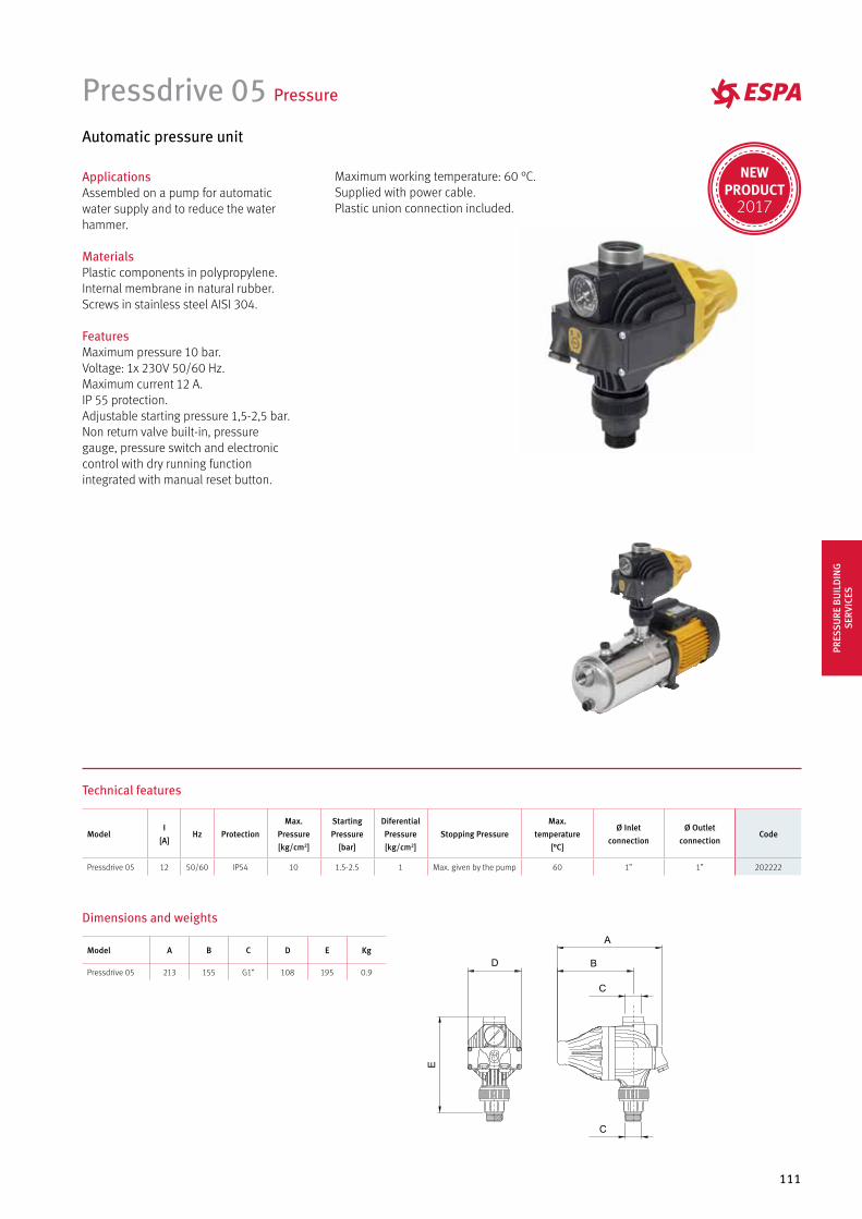
111
Pressdrive 05 Pressure
Automatic pressure unit
ApplicationsAssembled on a pump for automatic water supply and to reduce the water hammer.
MaterialsPlastic components in polypropylene. Internal membrane in natural rubber. Screws in stainless steel AISI 304.
FeaturesMaximum pressure 10 bar.Voltage: 1x 230V 50/60 Hz.Maximum current 12 A.IP 55 protection.Adjustable starting pressure 1,5-2,5 bar.Non return valve built-in, pressure gauge, pressure switch and electronic control with dry running function integrated with manual reset button.
Maximum working temperature: 60 °C.Supplied with power cable.Plastic union connection included.
Technical features
ModelI
[A]Hz Protection
Max.Pressure[kg/cm2]
StartingPressure
[bar]
DiferentialPressure[kg/cm2]
Stopping PressureMax.
temperature[°C]
Ø Inletconnection
Ø Outletconnection
Code
Pressdrive 05 12 50/60 IP54 10 1.5-2.5 1 Max. given by the pump 60 1” 1” 202222
Model A B C D E Kg
Pressdrive 05 213 155 G1” 108 195 0.9
Dimensions and weights
D
E
C
C
A
B
PRES
SURE
BU
ILD
ING
SE
RVIC
ES
NEWPRODUCT
2017
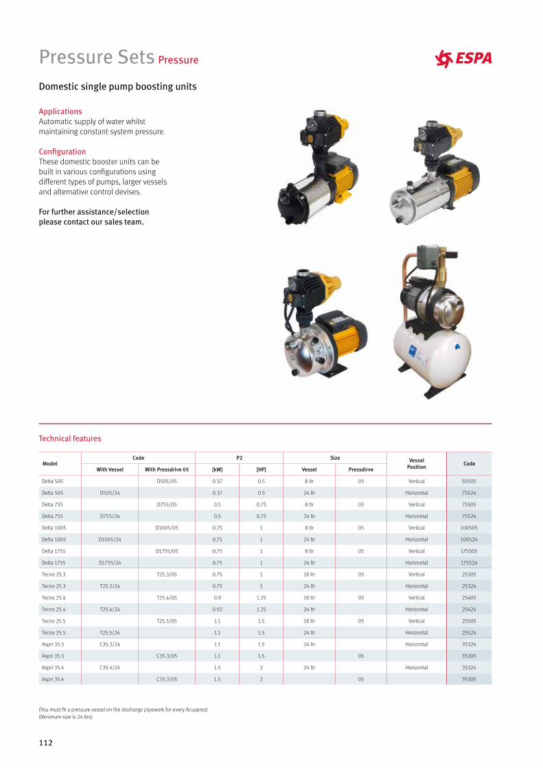
112
Pressure Sets Pressure
Domestic single pump boosting units
ApplicationsAutomatic supply of water whilstmaintaining constant system pressure.
ConfigurationThese domestic booster units can bebuilt in various configurations usingdifferent types of pumps, larger vesselsand alternative control devises.
For further assistance/selectionplease contact our sales team.
Technical features
ModelCode P2 Size Vessel
Position CodeWith Vessel With Pressdrive 05 [kW] [HP] Vessel Pressdirve
Delta 505 D505/05 0.37 0.5 8 ltr 05 Vertical 50505
Delta 505 D505/24 0.37 0.5 24 ltr Horizontal 75524
Delta 755 D755/05 0.5 0.75 8 ltr 05 Vertical 75505
Delta 755 D755/24 0.5 0.75 24 ltr Horizontal 75524
Delta 1005 D1005/05 0.75 1 8 ltr 05 Vertical 100505
Delta 1005 D1005/24 0.75 1 24 ltr Horizontal 100524
Delta 1755 D1755/05 0.75 1 8 ltr 05 Vertical 175505
Delta 1755 D1755/24 0.75 1 24 ltr Horizontal 175524
Tecno 25.3 T25.3/05 0.75 1 18 ltr 05 Vertical 25305
Tecno 25.3 T25.3/24 0.75 1 24 ltr Horizontal 25324
Tecno 25.4 T25.4/05 0.9 1.25 18 ltr 05 Vertical 25405
Tecno 25.4 T25.4/24 0.92 1.25 24 ltr Horizontal 25424
Tecno 25.5 T25.5/05 1.1 1.5 18 ltr 05 Vertical 25505
Tecno 25.5 T25.5/24 1.1 1.5 24 ltr Horizontal 25524
Aspri 35.3 C35.3/24 1.1 1.5 24 ltr Horizontal 35324
Aspri 35.3 C35.3/05 1.1 1.5 05 35305
Aspri 35.4 C35.4/24 1.5 2 24 ltr Horizontal 35324
Aspri 35.4 C35.3/05 1.5 2 05 35305
(You must fit a pressure vessel on the discharge pipework for every Acuapres)(Minimum size is 24 ltrs)
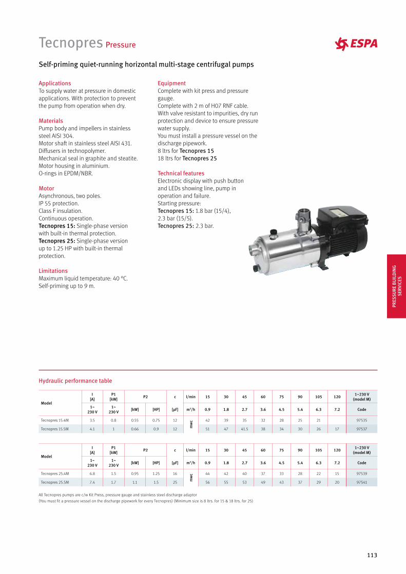
113
Tecnopres Pressure
Self-priming quiet-running horizontal multi-stage centrifugal pumps
ApplicationsTo supply water at pressure in domestic applications. With protection to prevent the pump from operation when dry.
MaterialsPump body and impellers in stainless steel AISI 304.Motor shaft in stainless steel AISI 431.Diffusers in technopolymer.Mechanical seal in graphite and steatite.Motor housing in aluminium.O-rings in EPDM/NBR.
MotorAsynchronous, two poles.IP 55 protection.Class F insulation.Continuous operation.Tecnopres 15: Single-phase version with built-in thermal protection.Tecnopres 25: Single-phase version up to 1.25 HP with built-in thermal protection.
LimitationsMaximum liquid temperature: 40 °C.Self-priming up to 9 m.
EquipmentComplete with kit press and pressure gauge.Complete with 2 m of H07 RNF cable.With valve resistant to impurities, dry run protection and device to ensure pressure water supply.You must install a pressure vessel on the discharge pipework.8 ltrs for Tecnopres 1518 ltrs for Tecnopres 25
Technical featuresElectronic display with push button and LEDs showing line, pump in operation and failure.Starting pressure: Tecnopres 15: 1.8 bar (15/4), 2.3 bar (15/5).Tecnopres 25: 2.3 bar.
Hydraulic performance table
Model
I [A]
P1 [kW] P2 c l/min 15 30 45 60 75 90 105 120 1~230 V
(model M)
1~230 V
1~230 V [kW] [HP] [µF] m3/h 0.9 1.8 2.7 3.6 4.5 5.4 6.3 7.2 Code
Tecnopres 25.4M 6.8 1.5 0.95 1.25 16
mw
c 44 42 40 37 33 28 22 15 97539
Tecnopres 25.5M 7.4 1.7 1.1 1.5 25 56 55 53 49 43 37 29 20 97541
Model
I [A]
P1 [kW] P2 c l/min 15 30 45 60 75 90 105 120 1~230 V
(model M)
1~230 V
1~230 V [kW] [HP] [µF] m3/h 0.9 1.8 2.7 3.6 4.5 5.4 6.3 7.2 Code
Tecnopres 15.4M 3.5 0.8 0.55 0.75 12
mw
c 42 39 35 32 28 25 21 97535
Tecnopres 15.5M 4.1 1 0.66 0.9 12 51 47 41.5 38 34 30 26 17 97537
All Tecnopres pumps are c/w Kit Press, pressure gauge and stainless steel discharge adaptor
(You must fit a pressure vessel on the discharge pipework for every Tecnopres) (Minimum size is 8 ltrs. for 15 & 18 ltrs. for 25)
PRES
SURE
BU
ILD
ING
SE
RVIC
ES
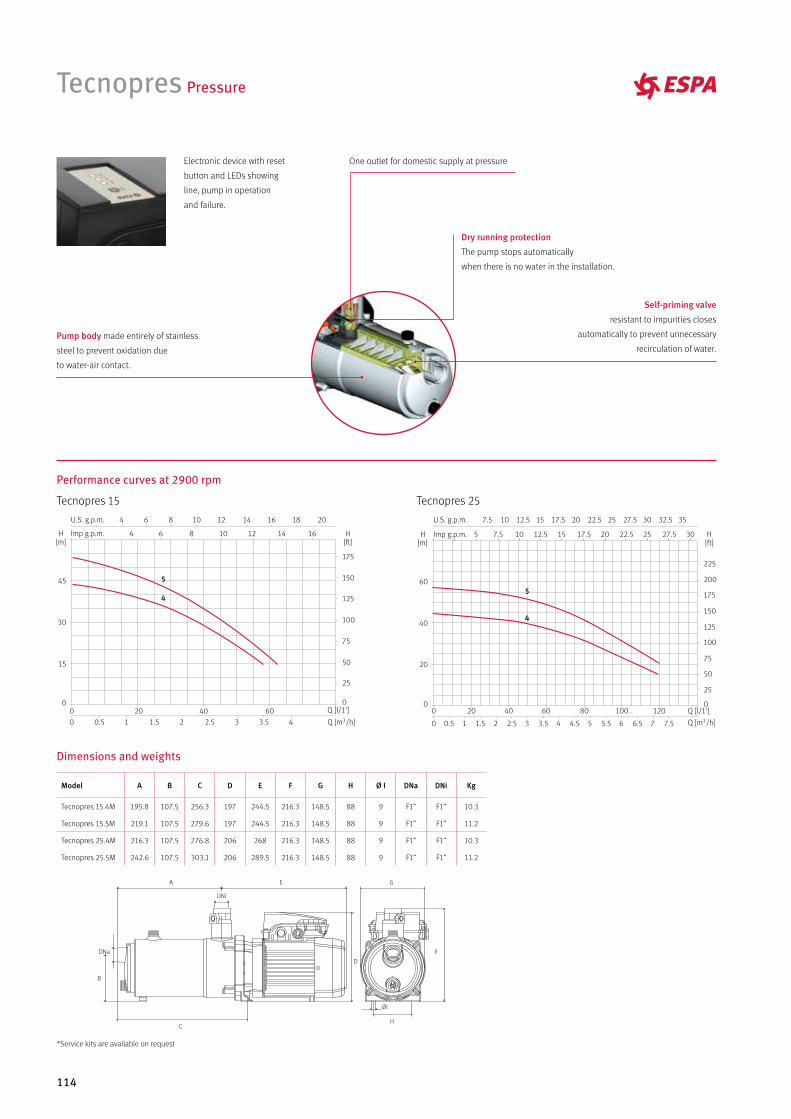
114
Performance curves at 2900 rpm
Tecnopres 15 Tecnopres 25
Tecnopres Pressure
5
45
4
Dry running protection
The pump stops automatically
when there is no water in the installation.
Pump body made entirely of stainless
steel to prevent oxidation due
to water-air contact.
Self-priming valve
resistant to impurities closes
automatically to prevent unnecessary
recirculation of water.
One outlet for domestic supply at pressureElectronic device with reset
button and LEDs showing
line, pump in operation
and failure.
Dimensions and weights
A
B
D
C
E
F
H
G
ØI
DNi
Model A B C D E F G H Ø I DNa DNi Kg
Tecnopres 15.4M 195.8 107.5 256.3 197 244.5 216.3 148.5 88 9 F1” F1” 10.3
Tecnopres 15.5M 219.1 107.5 279.6 197 244.5 216.3 148.5 88 9 F1” F1” 11.2
Tecnopres 25.4M 216.3 107.5 276.8 206 268 216.3 148.5 88 9 F1” F1” 10.3
Tecnopres 25.5M 242.6 107.5 303.1 206 289.5 216.3 148.5 88 9 F1” F1” 11.2
*Service kits are available on request
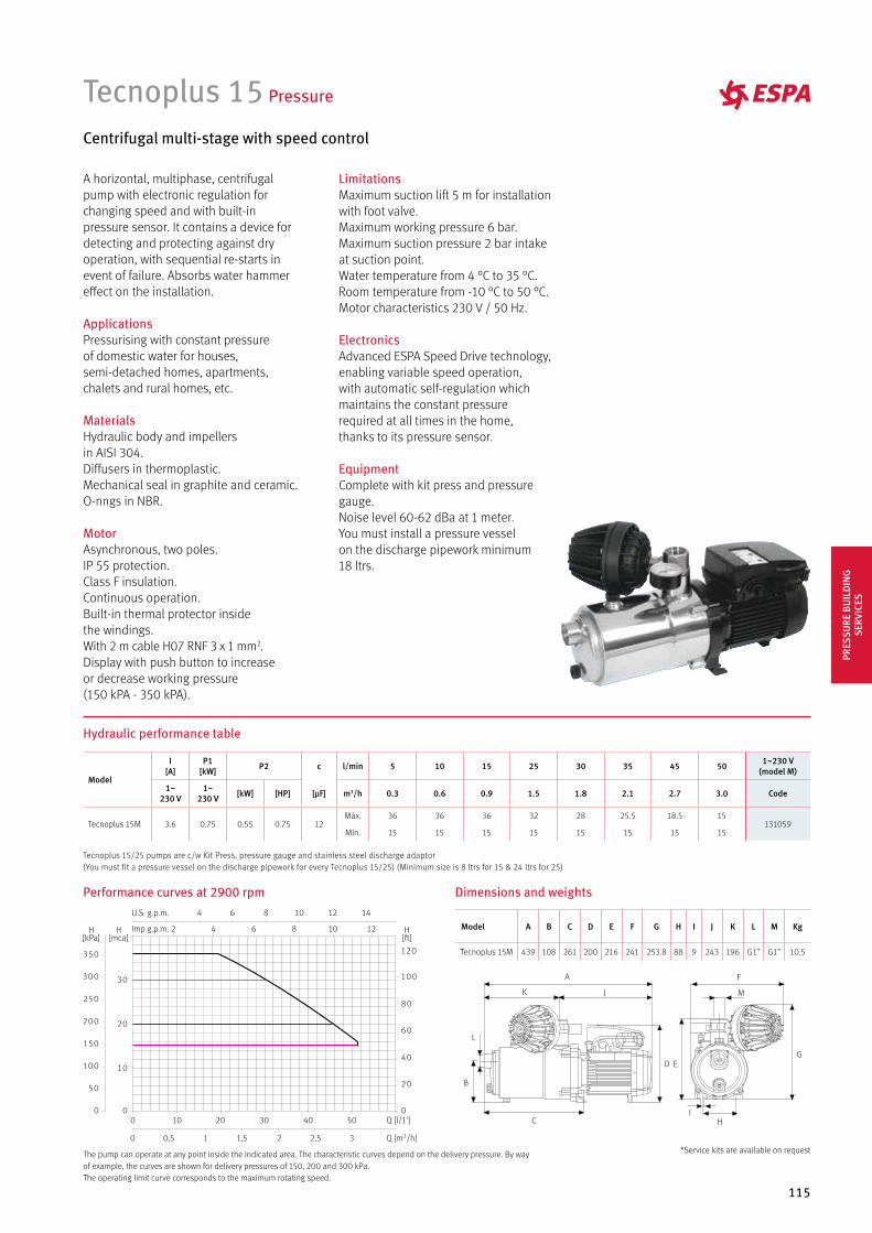
115
Performance curves at 2900 rpm
Hydraulic performance table
Tecnoplus 15 Pressure
Centrifugal multi-stage with speed control
A horizontal, multiphase, centrifugal pump with electronic regulation for changing speed and with built-in pressure sensor. It contains a device for detecting and protecting against dry operation, with sequential re-starts in event of failure. Absorbs water hammer effect on the installation.
ApplicationsPressurising with constant pressure of domestic water for houses, semi-detached homes, apartments, chalets and rural homes, etc.
MaterialsHydraulic body and impellers in AISI 304.Diffusers in thermoplastic.Mechanical seal in graphite and ceramic.O-nngs in NBR.
MotorAsynchronous, two poles.IP 55 protection.Class F insulation.Continuous operation.Built-in thermal protector inside the windings.With 2 m cable H07 RNF 3 x 1 mm2. Display with push button to increase or decrease working pressure (150 kPA - 350 kPA).
LimitationsMaximum suction lift 5 m for installation with foot valve.Maximum working pressure 6 bar.Maximum suction pressure 2 bar intake at suction point.Water temperature from 4 °C to 35 °C.Room temperature from -10 °C to 50 °C.Motor characteristics 230 V / 50 Hz.
ElectronicsAdvanced ESPA Speed Drive technology, enabling variable speed operation, with automatic self-regulation which maintains the constant pressure required at all times in the home, thanks to its pressure sensor.
EquipmentComplete with kit press and pressure gauge.Noise level 60-62 dBa at 1 meter.You must install a pressure vessel on the discharge pipework minimum 18 ltrs.
A
K J
L
B
C
D
M
F
EG
HI
The pump can operate at any point inside the indicated area. The characteristic curves depend on the delivery pressure. By way of example, the curves are shown for delivery pressures of 150, 200 and 300 kPa. The operating limit curve corresponds to the maximum rotating speed.
Dimensions and weights
Model
I [A]
P1 [kW] P2 c l/min 5 10 15 25 30 35 45 50 1~230 V
(model M)
1~230 V
1~230 V [kW] [HP] [µF] m3/h 0.3 0.6 0.9 1.5 1.8 2.1 2.7 3.0 Code
Tecnoplus 15M 3.6 0.75 0.55 0.75 12Máx. 36 36 36 32 28 25.5 18.5 15
131059Mín. 15 15 15 15 15 15 15 15
Model A B C D E F G H I J K L M Kg
Tecnoplus 15M 439 108 261 200 216 241 253.8 88 9 243 196 G1” G1” 10.5
Tecnoplus 15/25 pumps are c/w Kit Press, pressure gauge and stainless steel discharge adaptor(You must fit a pressure vessel on the discharge pipework for every Tecnoplus 15/25) (Minimum size is 8 ltrs for 15 & 24 ltrs for 25)
*Service kits are available on request
PRES
SURE
BU
ILD
ING
SE
RVIC
ES
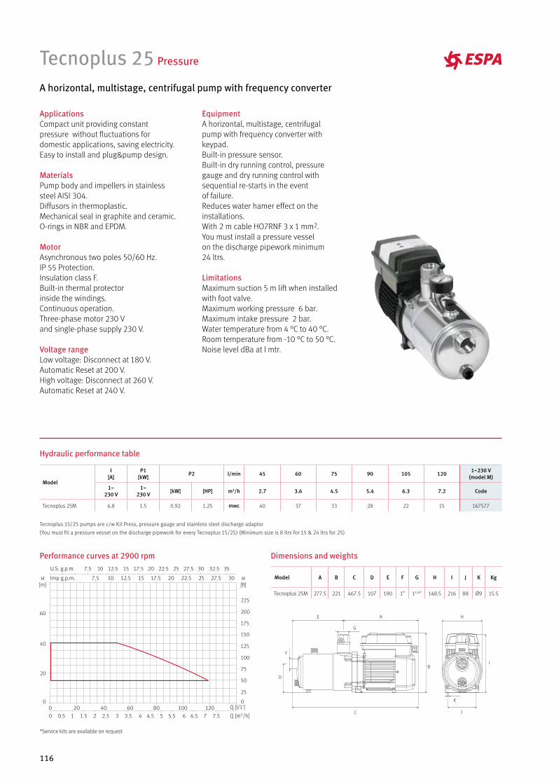
116
Tecnoplus 25 Pressure
A horizontal, multistage, centrifugal pump with frequency converter
ApplicationsCompact unit providing constant pressure without fluctuations for domestic applications, saving electricity.Easy to install and plug&pump design.
MaterialsPump body and impellers in stainlesssteel AISI 304.Diffusors in thermoplastic.Mechanical seal in graphite and ceramic.O-rings in NBR and EPDM.
MotorAsynchronous two poles 50/60 Hz.IP 55 Protection.Insulation class F.Built-in thermal protectorinside the windings.Continuous operation.Three-phase motor 230 V and single-phase supply 230 V.
Voltage rangeLow voltage: Disconnect at 180 V.Automatic Reset at 200 V. High voltage: Disconnect at 260 V.Automatic Reset at 240 V.
EquipmentA horizontal, multistage, centrifugal pump with frequency converter with keypad. Built-in pressure sensor. Built-in dry running control, pressure gauge and dry running control with sequential re-starts in the event of failure. Reduces water hamer effect on the installations. With 2 m cable HO7RNF 3 x 1 mm2.You must install a pressure vessel on the discharge pipework minimum 24 ltrs.
LimitationsMaximum suction 5 m lift when installed with foot valve. Maximum working pressure 6 bar. Maximum intake pressure 2 bar.Water temperature from 4 °C to 40 °C.Room temperature from -10 °C to 50 °C.Noise level dBa at l mtr.
J
K
H
I
C
E A
G
F
D
B
Performance curves at 2900 rpm
Hydraulic performance table
Dimensions and weights
Model
I [A]
P1 [kW] P2 l/min 45 60 75 90 105 120 1~230 V
(model M)
1~230 V
1~230 V [kW] [HP] m3/h 2.7 3.6 4.5 5.4 6.3 7.2 Code
Tecnoplus 25M 6.8 1.5 0.92 1.25 mwc 40 37 33 28 22 15 167577
Model A B C D E F G H I J K Kg
Tecnoplus 25M 277.5 221 467.5 107 190 1” 11/4” 148.5 216 88 Ø9 15.5
Tecnoplus 15/25 pumps are c/w Kit Press, pressure gauge and stainless steel discharge adaptor
(You must fit a pressure vessel on the discharge pipework for every Tecnoplus 15/25) (Minimum size is 8 ltrs for 15 & 24 ltrs for 25)
*Service kits are available on request
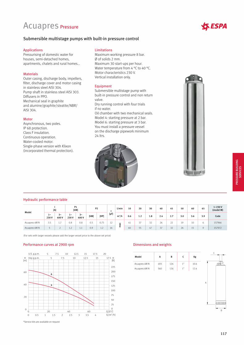
117
ApplicationsPressurising of domestic water for houses, semi-detached homes, apartments, chalets and rural homes...
MaterialsOuter casing, discharge body, impellers, filter, discharge cover and motor casing in stainless steel AISI 304. Pump shaft in stainless steel AISI 303.Diffusers in PPO. Mechanical seal in graphite and alumine/graphite/steatite/NBR/AISI 304.
MotorAsynchronous, two poles. IP 68 protection. Class F insulation.Continuous operation.Water-cooled motor. Single-phase version with Klixon (incorporated thermal protection).
Acuapres Pressure
Submersible multistage pumps with built-in pressure control
LimitationsMaximum working pressure 8 bar.Ø of solids 2 mm.Maximum 30 start-ups per hour.Water temperature from 4 °C to 40 °C.Motor characteristics 230 V.Vertical installation only.
EquipmentSubmersible multistage pump with built-in pressure control and non return valve.Dry running control with four trialsif no water.Oil chamber with two mechanical seals.Model 4: starting pressure at 2 bar.Model 6: starting pressure at 3 bar.You must install a pressure vessel on the discharge pipework minimum 24 ltrs.
A
B
C
Performance curves at 2900 rpm
Hydraulic performance table
Dimensions and weights
4
6
Model
I [A]
P1 [kW] P2
c[µF]
l/min 10 20 30 40 45 50 60 65 1~230 V (model M)
1~230 V
3~400 V
1~230 V
3~400 V [kW] [HP] m3/h 0.6 1.2 1.8 2.4 2.7 3.0 3.6 3.9 Code
Acuapres 4M N 3.5 1.7 0.8 0.8 0.5 0.75 12
mw
c 41 37 32 26 22 19 10 6 157966
Acuapres 6M N 5 2 1.2 1.1 0.9 1.2 16 60 55 47 37 32 26 15 9 157972
Model A B C Kg
Acuapres 4M N 493 126 1” 10.6
Acuapres 6M N 560 126 1” 12.4
(For sets with larger vessels please add the larger vessel price to the above set price)
*Service kits are available on request
PRES
SURE
BU
ILD
ING
SE
RVIC
ES
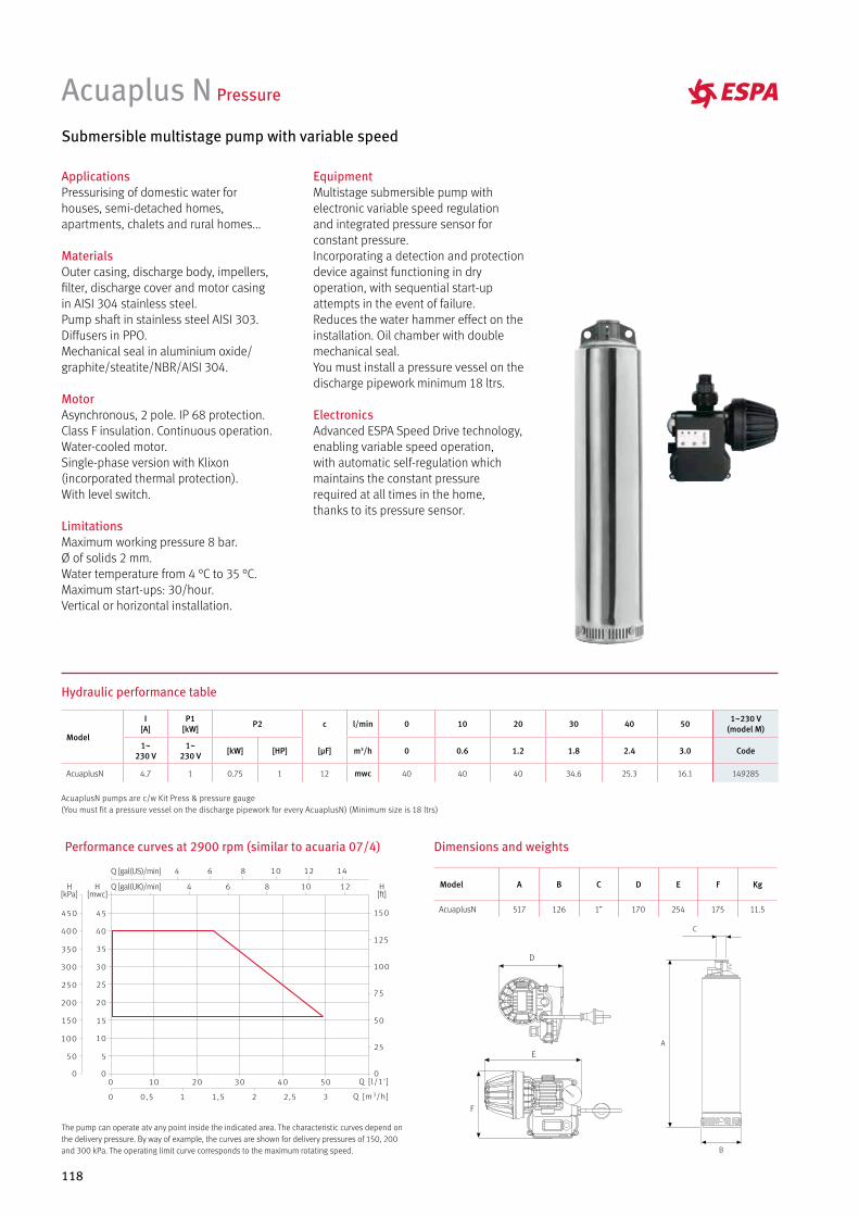
118
ApplicationsPressurising of domestic water for houses, semi-detached homes, apartments, chalets and rural homes...
MaterialsOuter casing, discharge body, impellers, filter, discharge cover and motor casing in AISI 304 stainless steel. Pump shaft in stainless steel AISI 303.Diffusers in PPO. Mechanical seal in aluminium oxide/graphite/steatite/NBR/AISI 304.
MotorAsynchronous, 2 pole. IP 68 protection. Class F insulation. Continuous operation. Water-cooled motor. Single-phase version with Klixon (incorporated thermal protection). With level switch.
LimitationsMaximum working pressure 8 bar.Ø of solids 2 mm.Water temperature from 4 °C to 35 °C.Maximum start-ups: 30/hour.Vertical or horizontal installation.
Acuaplus N Pressure
Submersible multistage pump with variable speed
EquipmentMultistage submersible pump with electronic variable speed regulation and integrated pressure sensor for constant pressure.Incorporating a detection and protection device against functioning in dry operation, with sequential start-up attempts in the event of failure. Reduces the water hammer effect on the installation. Oil chamber with double mechanical seal.You must install a pressure vessel on the discharge pipework minimum 18 ltrs.
ElectronicsAdvanced ESPA Speed Drive technology, enabling variable speed operation, with automatic self-regulation which maintains the constant pressure required at all times in the home, thanks to its pressure sensor.
Hydraulic performance table
D
F
EA
B
C
Dimensions and weightsPerformance curves at 2900 rpm (similar to acuaria 07/4)
The pump can operate atv any point inside the indicated area. The characteristic curves depend on the delivery pressure. By way of example, the curves are shown for delivery pressures of 150, 200 and 300 kPa. The operating limit curve corresponds to the maximum rotating speed.
Model
I [A]
P1 [kW] P2 c l/min 0 10 20 30 40 50 1~230 V
(model M)
1~230 V
1~230 V [kW] [HP] [µF] m3/h 0 0.6 1.2 1.8 2.4 3.0 Code
AcuaplusN 4.7 1 0.75 1 12 mwc 40 40 40 34.6 25.3 16.1 149285
Model A B C D E F Kg
AcuaplusN 517 126 1” 170 254 175 11.5
AcuaplusN pumps are c/w Kit Press & pressure gauge(You must fit a pressure vessel on the discharge pipework for every AcuaplusN) (Minimum size is 18 ltrs)
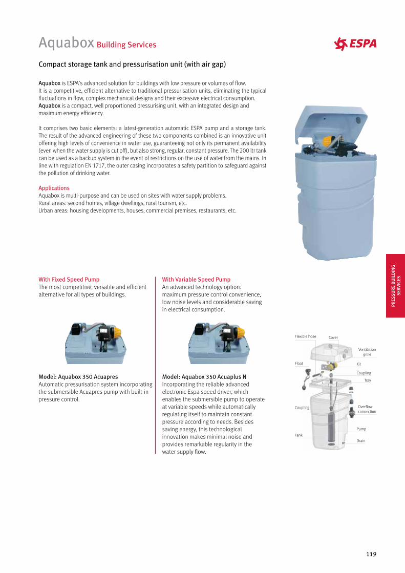
119
Aquabox Building Services
Compact storage tank and pressurisation unit (with air gap)
Model: Aquabox 350 Acuaplus N Incorporating the reliable advanced electronic Espa speed driver, which enables the submersible pump to operate at variable speeds while automatically regulating itself to maintain constant pressure according to needs. Besides saving energy, this technological innovation makes minimal noise and provides remarkable regularity in the water supply flow.
Model: Aquabox 350 AcuapresAutomatic pressurisation system incorporating the submersible Acuapres pump with built-in pressure control.
With Variable Speed PumpAn advanced technology option: maximum pressure control convenience, low noise levels and considerable saving in electrical consumption.
With Fixed Speed PumpThe most competitive, versatile and efficient alternative for all types of buildings.
Aquabox is ESPA’s advanced solution for buildings with low pressure or volumes of flow. It is a competitive, efficient alternative to traditional pressurisation units, eliminating the typical fluctuations in flow, complex mechanical designs and their excessive electrical consumption.Aquabox is a compact, well proportioned pressurising unit, with an integrated design and maximum energy efficiency.
It comprises two basic elements: a latest-generation automatic ESPA pump and a storage tank. The result of the advanced engineering of these two components combined is an innovative unit offering high levels of convenience in water use, guaranteeing not only its permanent availability (even when the water supply is cut off), but also strong, regular, constant pressure. The 200 ltr tank can be used as a backup system in the event of restrictions on the use of water from the mains. In line with regulation EN 1717, the outer casing incorporates a safety partition to safeguard against the pollution of drinking water.
Applications Aquabox is multi-purpose and can be used on sites with water supply problems. Rural areas: second homes, village dwellings, rural tourism, etc. Urban areas: housing developments, houses, commercial premises, restaurants, etc.
Ventilation grille
Flexible hose Cover
Kit
Coupling
Tray
Overflow connection
Pump
DrainTank
Float
Coupling
PRES
SURE
BU
ILD
ING
SE
RVIC
ES
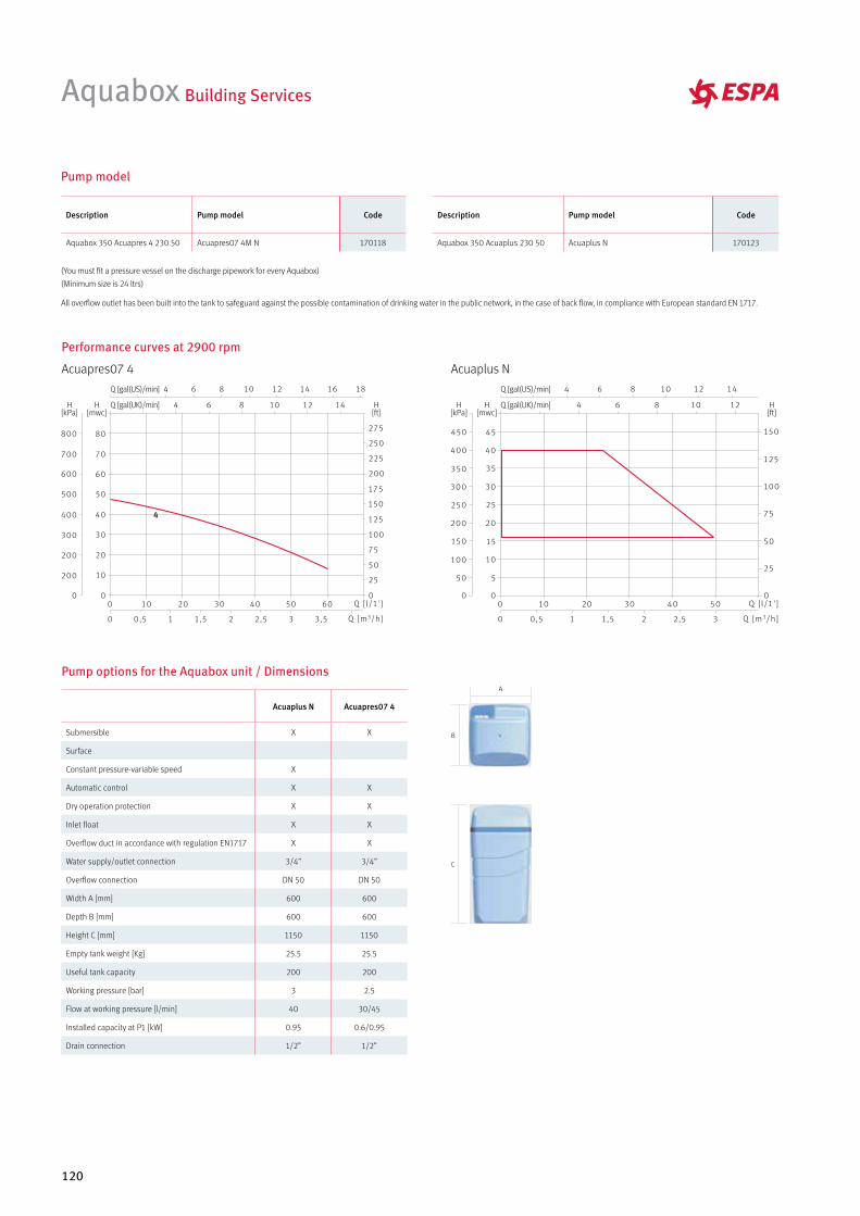
120
Pump options for the Aquabox unit / DimensionsA
B
C
Aquabox Building Services
Description Pump model Code
Aquabox 350 Acuapres 4 230 50 Acuapres07 4M N 170118
Description Pump model Code
Aquabox 350 Acuaplus 230 50 Acuaplus N 170123
Pump model
(You must fit a pressure vessel on the discharge pipework for every Aquabox)
(Minimum size is 24 ltrs)
All overflow outlet has been built into the tank to safeguard against the possible contamination of drinking water in the public network, in the case of back flow, in compliance with European standard EN 1717.
Performance curves at 2900 rpm
Acuapres07 4 Acuaplus N
Acuaplus N Acuapres07 4
Submersible X X
Surface
Constant pressure-variable speed X
Automatic control X X
Dry operation protection X X
Inlet float X X
Overflow duct in accordance with regulation EN1717 X X
Water supply/outlet connection 3/4” 3/4”
Overflow connection DN 50 DN 50
Width A [mm] 600 600
Depth B [mm] 600 600
Height C [mm] 1150 1150
Empty tank weight [Kg] 25.5 25.5
Useful tank capacity 200 200
Working pressure [bar] 3 2.5
Flow at working pressure [l/min] 40 30/45
Installed capacity at P1 [kW] 0.95 0.6/0.95
Drain connection 1/2” 1/2”
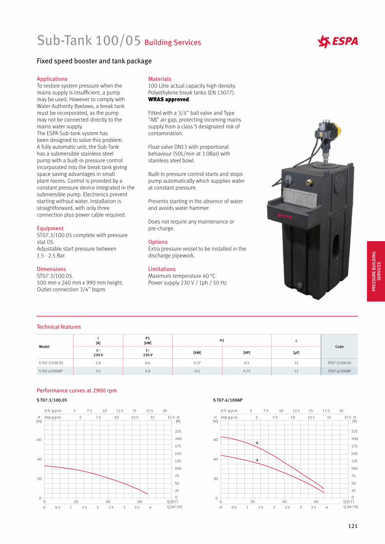
121
4
6
ApplicationsTo restore system pressure when themains supply is insufficient, a pumpmay be used. However to comply withWater Authority Byelaws, a break tankmust be incorporated, as the pumpmay not be connected directly to themains water supply.The ESPA Sub-tank system hasbeen designed to solve this problem.A fully automatic unit, the Sub-Tankhas a submersible stainless steelpump with a built-in pressure controlincorporated into the break tank givingspace saving advantages in smallplant rooms. Control is provided by a constant pressure device integrated in the submersible pump. Electronics preventstarting without water. Installation isstraightforward, with only threeconnection plus power cable required.
EquipmentST07.3/100.05 complete with pressure stat 05.Adjustable start pressure between1.5 - 2.5 Bar.
DimensionsST07.3/100.05.500 mm x 240 mm x 990 mm height.Outlet connection 3/4’’ bspm.
Materials100 Litre actual capacity high density. Polyethylene break tanks (EN 13077).WRAS approved.
Fitted with a 3/4’’ ball valve and Type “AB” air gap, protecting incoming mains supply from a class 5 designated risk of contamination.
Float valve DN13 with proportional behaviour (50L/min at 3.0Bar) with stainless steel bowl.
Built-in pressure control starts and stopspump automatically which supplies waterat constant pressure.
Prevents starting in the absence of waterand avoids water hammer.
Does not require any maintenance orpre-charge.
OptionsExtra pressure vessel to be installed in the discharge pipework.
LimitationsMaximum temperature 40 °C.Power supply 230 V / 1ph / 50 Hz.
Sub-Tank 100/05 Building Services
Fixed speed booster and tank package
Performance curves at 2900 rpm
Technical features
Model
I [A]
P1 [kW] P2 c
Code1~
230 V1~
230 V [kW] [HP] [µF]
S T07.3/100.05 2.8 0.6 0.37 0.5 12 ST07.3/100.05
S T07.4/100AP 3.5 0.8 0.5 0.75 12 ST07.4/100AP
S T07.3/100.05 S T07.4/100AP
PRES
SURE
BU
ILD
ING
SE
RVIC
ES
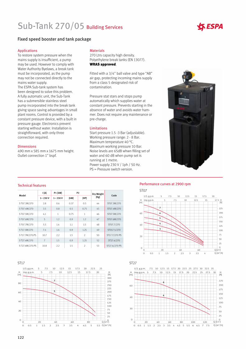
122
Performance curves at 2900 rpm
ApplicationsTo restore system pressure when themains supply is insufficient, a pumpmay be used. However to comply withWater Authority Byelaws, a break tankmust be incorporated, as the pumpmay not be connected directly to themains water supply.The ESPA Sub-tank system hasbeen designed to solve this problem.A fully automatic unit, the Sub-Tankhas a submersible stainless steelpump incorporated into the break tank giving space saving advantages in smallplant rooms. Control is provided by a constant pressure device, with a built in pressure gauge. Electronics preventstarting without water. Installation isstraightforward, with only threeconnection required.
Dimensions490 mm x 585 mm x 1675 mm height.Outlet connection 1’’ bspf.
Materials270 Ltrs capacity high density. Polyethylene break tanks (EN 13077).WRAS approved.
Fitted with a 3/4’’ ball valve and type “AB” air gap, protecting incoming mains supply from a class 5 designated risk of contamination.
Pressure stat stars and stops pump automatically which supplies water at constant pressure. Prevents starting in the absence of water and avoids water ham-mer. Does not require any maintenance or pre-charge.
LimitationsStart pressure 1.5 -3 Bar (adjustable).Working pressure range: 2 - 8 Bar.Maximum temperature 40 °C.Maximum working pressure 10 Bar.Noise levels are 65dB whwn filling set of water and 60 dB when pump set is running at 1 metre.Power supply 230 V / 1ph / 50 Hz.PS = Pressure switch version.
Sub-Tank 270/05 Building Services
Fixed speed booster and tank package
Technical features
ModelI [A] P1 [kW] P2 Dry Weight
[Kg] Code1~ 230 V 1~ 230 V [kW] [HP]
S T07.3M/270 2.8 0.6 0.37 0.5 44 ST07.3M/270
S T07.4M/270 3.5 0.8 0.5 0.75 45 ST07.4M/270
S T07.5M/270 4.1 1 0.75 1 46 ST07.5M/270
S T07.6M/270 5 1.2 0.9 1.2 47 ST07.6M/270
S T07.7M/270 5.5 1.4 1.1 1.5 48 ST07.7/270
S T17.5M/270 7.4 1.6 0.9 1.25 49 ST017.5/270
S T17.7M/270.PS 10.7 2.2 1.5 2 50 ST17.7/270 PS
S T27.4M/270 7 1.5 0.9 1.25 52 ST27.4/270
S T27.6M/270.PS 10.8 2.2 1.5 2 53 ST27.6/270 PS
ST07
ST17 ST27
7
5
6
4
7
6
5
4
3
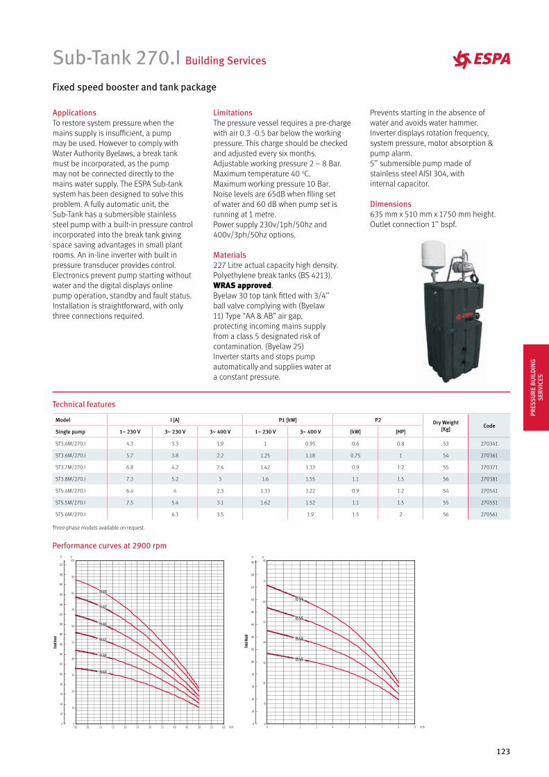
123
ApplicationsTo restore system pressure when themains supply is insufficient, a pumpmay be used. However to comply withWater Authority Byelaws, a break tankmust be incorporated, as the pumpmay not be connected directly to themains water supply. The ESPA Sub-tank system has been designed to solve this problem. A fully automatic unit, the Sub-Tank has a submersible stainless steel pump with a built-in pressure controlincorporated into the break tank givingspace saving advantages in small plant rooms. An in-line inverter with built in pressure transducer provides control. Electronics prevent pump starting without water and the digital displays online pump operation, standby and fault status. Installation is straightforward, with only three connections required.
LimitationsThe pressure vessel requires a pre-charge with air 0.3 -0.5 bar below the working pressure. This charge should be checked and adjusted every six months.Adjustable working pressure 2 – 8 Bar.Maximum temperature 40 oC.Maximum working pressure 10 Bar.Noise levels are 65dB when filing set of water and 60 dB when pump set is running at 1 metre.Power supply 230v/1ph/50hz and 400v/3ph/50hz options.
Materials227 Litre actual capacity high density. Polyethylene break tanks (BS 4213).WRAS approved.Byelaw 30 top tank fitted with 3/4’’ ball valve complying with (Byelaw 11) Type “AA & AB” air gap, protecting incoming mains supplyfrom a class 5 designated risk ofcontamination. (Byelaw 25)Inverter starts and stops pumpautomatically and supplies water at a constant pressure.
Prevents starting in the absence of water and avoids water hammer.Inverter displays rotation frequency,system pressure, motor absorption & pump alarm.5’’ submersible pump made of stainless steel AISI 304, withinternal capacitor.
Dimensions635 mm x 510 mm x 1750 mm height.Outlet connection 1’’ bspf.
Sub-Tank 270.I Building Services
Fixed speed booster and tank package
Technical features
Model I [A] P1 [kW] P2 Dry Weight[Kg] Code
Single pump 1~ 230 V 3~ 230 V 3~ 400 V 1~ 230 V 3~ 400 V [kW] [HP]
ST3.4M/270.I 4.3 3.3 1.9 1 0.95 0.6 0.8 53 270341
ST3.6M/270.I 5.7 3.8 2.2 1.25 1.18 0.75 1 54 270361
ST3.7M/270.I 6.8 4.2 2.4 1.42 1.33 0.9 1.2 55 270371
ST3.8M/270.I 7.3 5.2 3 1.6 1.55 1.1 1.5 56 270381
ST5.4M/270.I 6.4 4 2.3 1.33 1.22 0.9 1.2 54 270541
ST5.5M/270.I 7.5 5.4 3.1 1.62 1.52 1.1 1.5 55 270551
ST5.6M/270.I 6.1 3.5 1.9 1.5 2 56 270561
Three-phase models available on request.
Performance curves at 2900 rpm
PRES
SURE
BU
ILD
ING
SE
RVIC
ES
124
Model I [A] Motor PowerDry Weight [Kg]
270.DISP (variable speed. twin pump & twin inverters)
Single pump Single Phase Three Phase [kW] [HP] Code
ST3.4M/270.DI 3.46 1.8 0.55 0.75 53 270343
ST3.6M/270.DI 3.979 2.3 0.75 1 54 270363
ST3.7M/270.DI 4.325 2.5 0.9 1.2 55 270373
ST3.8M/270.DI 4.671 2.7 1.1 1.5 56 270383
ST5.4M/270.DI 3.806 2.2 0.75 1 54 270543
ST5.5M/270.DI 4.325 2.5 0.9 1.2 55 270543
ST5.6M/270.DI 4.671 2.7 1.1 1.5 56 270563
Twin variable speed booster and tank package
Technical features
ApplicationsTwo in-line inverters with built-in pressure transducers provides control.Duty/standby or duty/assist configuration.
LimitationsThe pressure vessel requires a pre-charge with air 0.3 -0.5 Bar below the working pressure.This charge should be checked and adjusted every six months.Adjustable working pressure 2 – 8 Bar.Maximum temperature 40 °C.Maximum working pressure 10 Bar.
Noise levels are 65 dB when filing set of water and 60 dB when pump set is running at 1 metre.
Dimensions270.DI. 650 mm x 520 mm x 1740 mm height.Outlet connection 2’’ bspf.
Three phase versions available on request.
Materials270 Litre actual capacity high density polyethylene break tanks (BS 4213). WRAS approved. Byelaw 30 top tank fitted with 3/4’’ ball valve(s) complying with (Byelaw 11). Type “AA & AB” air gap, protecting incoming mains supply from a class 5 designated risk of contamination. (Byelaw 25).Inverter starts and stops pump automatically and supplies water at a constant pressure.
Prevents starting in the absence of water and avoids water hammer.Inverter displays rotation frequency, system pressure, motor absorption & pump alarm.5’’ submersible pump(s) made of stainless steel AISI 304, with internal capacitor.
Sub-Tank 270.DI Building Services
*500L, 750L and 1000L optional, Please ask.
Three-phase models available on request.
Performance curves at 2900 rpm
125
ESPA Sub-Tank Series. A fully automatic unit for commercial and domestic applications
• To restore system pressure when the mains supply is insufficient, a pump may be used. However, to comply with Water Authority Byelaws a break tank must be incorporated, as the pump is precluded from direct connection to the mains water supply.
• The ESPA Sub-Tank system has been designed to solve this problem. A fully automatic unit, the Sub-Tank has a submersible stainless steel pump incorporated into the break tank giving space saving advantages in small plant rooms.
• An in-line inverter with built in pressure transducer provides control. Electronics prevent starting without water and the digital displays online pump operation, standby and fault.
• Installation is straightforward with only three connections required.
• Noise levels are 77dB when filling set of water and 60dB when pump is running.
• Each Espa Sub-Tank comes with an integrated pallet to ease transportation.
• A sloped design enables the unit to be emptied in situ.
• Please note, a pressure vessel is required to be installed on the discharge pipework.
• Twin pump option available, Duty/Assist or Duty/Standby.
Technical information
• 500/750/1000 Litre capacity (Nominal) high density Polyethylene break tanks
(BS4213).
• CAT 5 TANK
• Byelaws 30 top tank fitted with ¾” or 1” ball valve complying with (Byelaws 11) Type “AA & AB ” air gap, protecting incoming mains supply from a class 5 designated risk of contamination. (Byelaws 25)
• Inverter starts and stops pump automatically and supplies water at constant pressure.
• Prevents starting in the absence of water and avoids water hammer.
• Inverter displays rotation frequency and system pressure.
• The pressure vessel requires a pre-charge with air (0.3 – 0.5 Bar). This charge should be checked and adjusted every six months.
• Adjustable Nominal pressure.
Sub-Tank 500/750/1000 Building Services
Sub-Tank 750Sub-Tank 500
Pump Specification
• 5 Inch Stainless Steel (AISI404) submersible pumps
• 230v or 400v Three phase so no starting capacitor required
• IP68 Protection, Class F insulation.
• Mechanical seals in Ceramic/Carbon.NBR
• Liquid temperature from -5 to 40 degrees Centigrade.
• Motor cooling is guaranteed by the pumped liquid.
• Continuous operation
• Twin pump units available which can double flow rate
PRES
SURE
BU
ILD
ING
SE
RVIC
ES
126
Sub-Tank 500/750/1000 Building Services
Model I (A) (Per Pump) Motor Power (Per Pumps) Dry Weight (Kg) Single pump Twin pumps
Single pump Twin pumps Single Phase [kW] [HP] Single pump Twin pumps Code Code
ST3.4M/500.I SM3.4M/500.DI 3.5 0.55 0.75 106 130 500341 500342
ST3.6M/500.I SM3.6M/500.DI 4.0 0.75 1 108 132 500361 500362
ST3.7M/500.I SM3.7M/500.DI 4.3 0.9 1.2 110 134 500371 500372
ST3.8M/500.I SM3.8M/500.DI 4.7 1.1 1.5 112 136 500371 500382
ST5.4M/500.I SM5.4M/500.DI 3.8 0.75 1 108 132 500541 500542
ST5.5M/500.I SM5.5M/500.DI 4.3 0.9 1.2 110 134 500551 500552
ST5.6M/500.I SM5.6M/500.DI 4.7 1.1 1.5 112 136 500561 500562
Model I (A) (Per Pump) Motor Power (Per Pumps) Dry Weight (Kg) Single pump Twin pumps
Single pump Twin pumps Single Phase [kW] [HP] Single pump Twin pumps Code Code
ST3.4M/1000.I SM3.4M/1000.DI 3.5 0.55 0.75 146 170 1000341 1000342
ST3.6M/1000.I SM3.6M/1000.DI 4.0 0.75 1 148 172 1000361 1000362
ST3.7M/1000.I SM3.7M/1000.DI 4.3 0.9 1.2 150 174 1000371 1000372
ST3.8M/1000.I SM3.8M/1000.DI 4.7 1.1 1.5 152 176 1000381 1000382
ST5.4M/1000.I SM5.4M/1000.DI 3.8 0.75 1 148 172 1000541 1000542
ST5.5M/1000.I SM5.5M/1000.DI 4.3 0.9 1.2 150 174 1000551 1000552
ST5.6M/1000.I SM5.6M/1000.DI 4.7 1.1 1.5 152 176 1000561 1000562
Model I (A) (Per Pump) Motor Power (Per Pumps) Dry Weight (Kg) Single pump Twin pumps
Single pump Twin pumps Single Phase [kW] [HP] Single pump Twin pumps Code Code
ST3.4M/750.I SM3.4M/750.DI 3.5 0.55 0.75 126 150 750341 750342
ST3.6M/750.I SM3.6M/750.DI 4.0 0.75 1 128 152 750361 750362
ST3.7M/750.I SM3.7M/750.DI 4.3 0.9 1.2 130 154 750371 750372
ST3.8M/750.I SM3.8M/750.DI 4.7 1.1 1.5 132 156 750381 750382
ST5.4M/750.I SM5.4M/750.DI 3.8 0.75 1 128 152 750541 750542
ST5.5M/750.I SM5.5M/750.DI 4.3 0.9 1.2 130 154 750551 750552
ST5.6M/750.I SM5.6M/750.DI 4.7 1.1 1.5 132 156 750561 750562
Technical features
Three Phase Versions Available On Request
SUBTANK 500
SUBTANK 750
SUBTANK 1000
127
A Cat 5 Sub-Tank with a nominal capacity of 500, 750 and 1000 litres. This Espa Sub-Tank can be supplied in either a single or a twin pump configuration. Single pump with a 1 inch BSPF discharge and twin pump with a 2 inc BSPM manifold. An 18 litre expansion vessel will be supplied with each unit. Each Sub-Tank is water tested at our factory in Manningtree, Essex.
Dimensions
ST 750DI ST 1000DIST 500DI
Performance curves at 2900 rpm
Model A B C D
500 Single Pump 700 900 1092 1430
500 Twin Pump 700 900 1092 1780
750 Single Pump 700 900 1477 1815
750 Twin Pump 700 900 1477 2150
1000 Single Pump 700 900 1815 2200
1000 Twin Pump 700 900 1815 2485
A B
C
D
A B
C
D
A B
C
D
Sub-Tank 500/750/1000 Building Services
PRES
SURE
BU
ILD
ING
SE
RVIC
ES
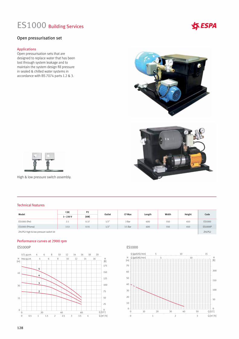
128
ES1000 Building Services
Open pressurisation set
ApplicationsOpen pressurisation sets that are designed to replace water that has been lost through system leakage and to maintain the system design fill pressure in sealed & chilled water systems in accordance with BS 7074 parts 1.2 & 3.
High & low pressure switch assembly.
Technical features
ModelI [A] P2
Outlet CF Max Length Width Height Code1~ 230 V [kW]
ES1000 (Per) 2.1 0.37 1/2’’ 3 Bar 600 550 450 ES1000
ES1000 (Prisma) 3.53 0.55 1/2’’ 3.5 Bar 600 550 450 ES1000P
ZHLPS2 high & low pressure switch kit ZHLPS2
ES1000P ES1000
Performance curves at 2900 rpm
5
4
3
2
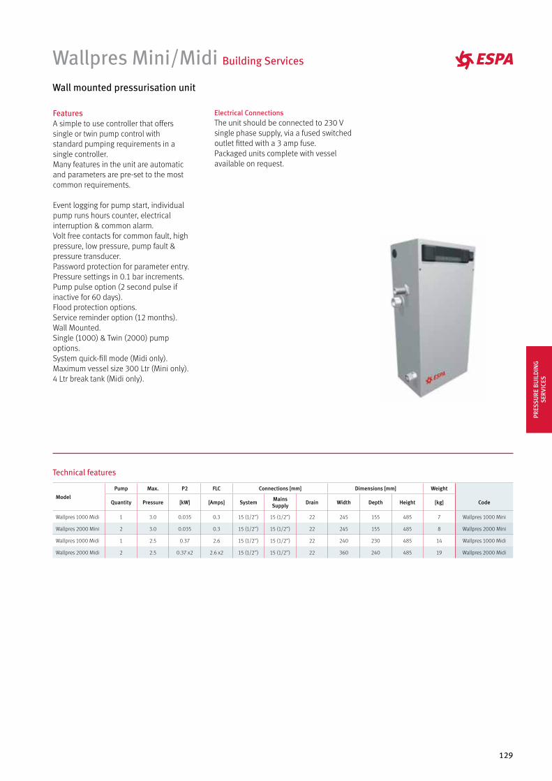
129
FeaturesA simple to use controller that offers single or twin pump control with standard pumping requirements in a single controller.Many features in the unit are automatic and parameters are pre-set to the most common requirements.
Event logging for pump start, individual pump runs hours counter, electrical interruption & common alarm.Volt free contacts for common fault, high pressure, low pressure, pump fault & pressure transducer.Password protection for parameter entry.Pressure settings in 0.1 bar increments.Pump pulse option (2 second pulse if inactive for 60 days).Flood protection options.Service reminder option (12 months).Wall Mounted.Single (1000) & Twin (2000) pump options.System quick-fill mode (Midi only).Maximum vessel size 300 Ltr (Mini only).4 Ltr break tank (Midi only).
Electrical ConnectionsThe unit should be connected to 230 V single phase supply, via a fused switched outlet fitted with a 3 amp fuse.Packaged units complete with vesselavailable on request.
Wallpres Mini/Midi Building Services
Wall mounted pressurisation unit
Technical features
Model
Pump Max. P2 FLC Connections [mm] Dimensions [mm] Weight
Quantity Pressure [kW] [Amps] System Mains Supply Drain Width Depth Height [kg] Code
Wallpres 1000 Midi 1 3.0 0.035 0.3 15 (1/2’’) 15 (1/2’’) 22 245 155 485 7 Wallpres 1000 Mini
Wallpres 2000 Mini 2 3.0 0.035 0.3 15 (1/2’’) 15 (1/2’’) 22 245 155 485 8 Wallpres 2000 Mini
Wallpres 1000 Midi 1 2.5 0.37 2.6 15 (1/2’’) 15 (1/2’’) 22 240 230 485 14 Wallpres 1000 Midi
Wallpres 2000 Midi 2 2.5 0.37 x2 2.6 x2 15 (1/2’’) 15 (1/2’’) 22 360 240 485 19 Wallpres 2000 Midi
PRES
SURE
BU
ILD
ING
SE
RVIC
ES
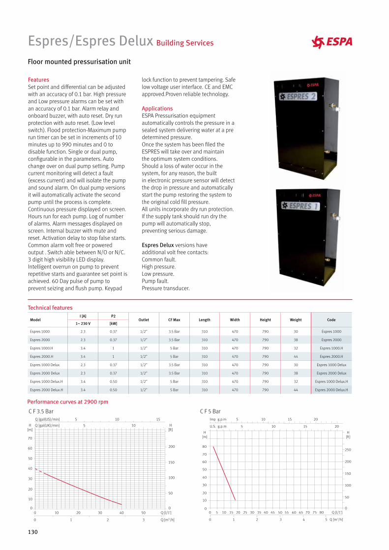
130
lock function to prevent tampering. Safe low voltage user interface. CE and EMC approved.Proven reliable technology.
ApplicationsESPA Pressurisation equipmentautomatically controls the pressure in asealed system delivering water at a predetermined pressure.Once the system has been filed theESPRES will take over and maintainthe optimum system conditions.Should a loss of water occur in the system, for any reason, the builtin electronic pressure sensor will detectthe drop in pressure and automaticallystart the pump restoring the system tothe original cold fill pressure.All units incorporate dry run protection.If the supply tank should run dry the pump will automatically stop,preventing serious damage.
Espres Delux versions have additional volt free contacts:Common fault.High pressure.Low pressure.Pump fault.Pressure transducer.
FeaturesSet point and differential can be adjusted with an accuracy of 0.1 bar. High pressure and Low pressure alarms can be set with an accuracy of 0.1 bar. Alarm relay and onboard buzzer, with auto reset. Dry run protection with auto reset. (Low level switch). Flood protection-Maximum pump run timer can be set in increments of 10 minutes up to 990 minutes and 0 to disable function. Single or dual pump, configurable in the parameters. Auto change over on dual pump setting. Pump current monitoring will detect a fault (excess current) and will isolate the pump and sound alarm. On dual pump versions it will automatically activate the second pump until the process is complete.Continuous pressure displayed on screen. Hours run for each pump. Log of number of alarms. Alarm messages displayed on screen. Internal buzzer with mute and reset. Activation delay to stop false starts.Common alarm volt free or poweredoutput . Switch able between N/O or N/C.3 digit high visibility LED display.Intelligent overrun on pump to preventrepetitive starts and guarantee set point is achieved. 60 Day pulse of pump to prevent seizing and flush pump. Keypad
Espres/Espres Delux Building Services
Floor mounted pressurisation unit
C F 5 BarC F 3.5 Bar
Performance curves at 2900 rpm
Technical features
ModelI [A] P2
Outlet CF Max Length Width Height Weight Code1~ 230 V [kW]
Espres 1000 2.3 0.37 1/2’’ 3.5 Bar 310 470 790 30 Espres 1000
Espres 2000 2.3 0.37 1/2’’ 3.5 Bar 310 470 790 38 Espres 2000
Espres 1000.H 3.4 1 1/2’’ 5 Bar 310 470 790 32 Espres 1000.H
Espres 2000.H 3.4 1 1/2’’ 5 Bar 310 470 790 44 Espres 2000.H
Espres 1000 Delux 2.3 0.37 1/2’’ 3.5 Bar 310 470 790 30 Espres 1000 Delux
Espres 2000 Delux 2.3 0.37 1/2’’ 3.5 Bar 310 470 790 38 Espres 2000 Delux
Espres 1000 Delux.H 3.4 0.50 1/2’’ 5 Bar 310 470 790 32 Espres 1000 Delux.H
Espres 2000 Delux.H 3.4 0.50 1/2’’ 5 Bar 310 470 790 44 Espres 2000 Delux.H
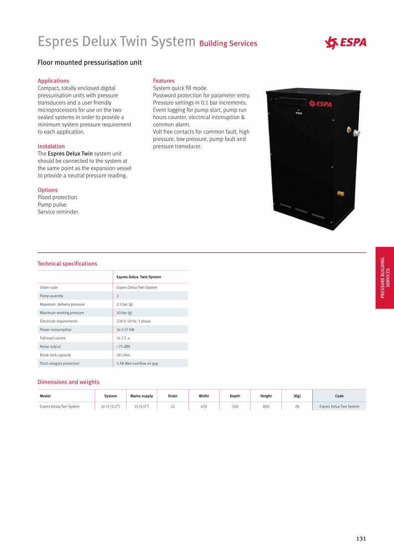
131
ApplicationsCompact, totally enclosed digital pressurisation units with pressure transducers and a user friendly microprocessors for use on the two sealed systems in order to provide a minimum system pressure requirement to each application.
InstalationThe Espres Delux Twin system unit should be connected to the system at the same point as the expansion vessel to provide a neutral pressure reading.
OptionsFlood protection.Pump pulse.Service reminder.
FeaturesSystem quick fill mode.Password protection for parameter entry.Pressure settings in 0.1 bar increments.Event logging for pump start, pump runhours counter, electrical interruption &common alarm.Volt free contacts for common fault, highpressure, low pressure, pump fault andpressure transducer.
Espres Delux Twin System Building Services
Floor mounted pressurisation unit
Technical specifications
Espres Delux Twin System
Order code Espres Delux Twin System
Pump quantity 2
Maximum delivery pressure 2.5 bar (g)
Maximum working pressure 10 bar (g)
Electricalr requirements 230 V, 50 Hz, 1 phase
Power consumption 2x 0.37 kW
Full load current 2x 2.5 a
Noise output < 75 dBA
Break tank capacity 18 Litres
Fluid category protection 5 AB Weir overflow air gap
Model System Mains supply Drain Widht Depth Height [Kg] Code
Espres Delux Twn System 2x 15 (1/2’’) 15 (1/2’’) 22 470 320 800 28 Espres Delux Twn System
Dimensions and weightsPR
ESSU
RE B
UIL
DIN
G
SERV
ICES
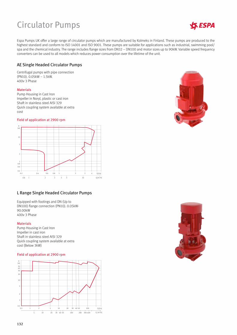
132
Circulator Pumps
Espa Pumps UK offer a large range of circulator pumps which are manufactured by Kolmeks in Finland. These pumps are produced to the highest standard and conform to ISO 14001 and ISO 9001. These pumps are suitable for applications such as industrial, swimming pool/spa and the chemical industry. The range includes flange sizes from DN32 – DN100 and motor sizes up to 90kW. Variable speed frequency converters can be used to all models which reduces power consumption over the lifetime of the unit.
Field of application at 2900 rpm
H[m]
10
5
2
10.8
0.6
0.4
10543210.8 Q [m3/h]
Q [l/s]3210.80.60.40.2 4
Centrifugal pumps with pipe connection (PN10). 0.05kW – 1.5kW.400v 3 Phase
MaterialsPump Housing in Cast IronImpeller in Noryl, plastic or cast ironShaft in stainless steel AISI 329Quick coupling system available at extra cost
Equipped with footings and DN (Up to DN100) flange connection (PN10). 0.05kW- 90.00kW400v 3 Phase
MaterialsPump Housing in Cast IronImpeller in cast ironShaft in stainless steel AISI 329Quick coupling system available at extra cost (Below 3kW)
Field of application at 2900 rpm
H[m]
30
20
10
5
2
1
0.5
4050
40030020010050403020105 Q [m3/h]
Q [l/s]50 100403020105210.5
AE Single Headed Circulator Pumps
L Range Single Headed Circulator Pumps
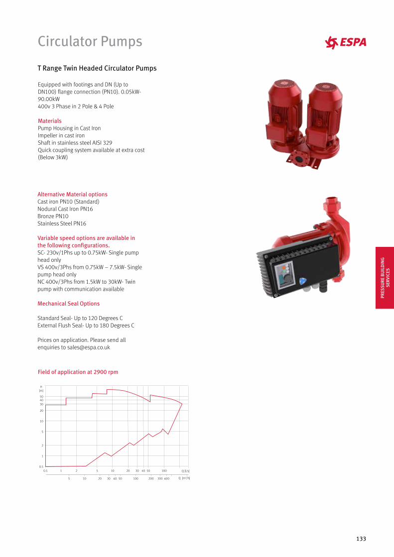
133
Equipped with footings and DN (Up to DN100) flange connection (PN10). 0.05kW- 90.00kW400v 3 Phase in 2 Pole & 4 Pole
MaterialsPump Housing in Cast IronImpeller in cast ironShaft in stainless steel AISI 329Quick coupling system available at extra cost (Below 3kW)
Field of application at 2900 rpm
H[m]
30
20
10
5
2
1
0.5
4050
40030020010050403020105 Q [m3/h]
Q [l/s]50 100403020105210.5
Circulator Pumps
Alternative Material optionsCast iron PN10 (Standard)Nodural Cast Iron PN16Bronze PN10Stainless Steel PN16
Variable speed options are available in the following configurations.SC- 230v/1Phs up to 0.75kW- Single pump head onlyVS 400v/3Phs from 0.75kW – 7.5kW- Single pump head onlyNC 400v/3Phs from 1.5kW to 30kW- Twin pump with communication available
Mechanical Seal Options
Standard Seal- Up to 120 Degrees CExternal Flush Seal- Up to 180 Degrees C
Prices on application. Please send all enquiries to [email protected]
T Range Twin Headed Circulator Pumps
PRES
SURE
BU
ILD
ING
SE
RVIC
ES
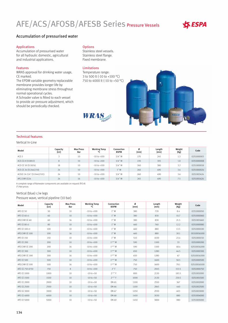
134
ApplicationsAccumulation of pressurised waterfor all hydraulic domestic, agriculturaland industrial applications.
FeaturesWRAS approval for drinking water usage, CE marked.The EPDM variable geometry replaceablemembrane provides longer life by eliminating membrane stress throughoutnormal operational cycles. A Schrader valve is fitted to each vessel to provide air pressure adjustment, which should be periodically checked.
AFE/ACS/AFOSB/AFESB Series Pressure Vessels
Accumulation of pressurised water
OptionsStainless steel vessels.Stainless steel flange.Fixed membrane.
LimitationsTemperature range:3 to 500 lt (-10 to +100 °C)750 to 4000 lt (-10 to +50 °C)
Technical features
Vertical In-Line
Model Capacity[Ltr]
Max PressBar
Working Temp°C
ConnectionBSPM
Ø[mm]
Length[mm]
Weight[Kg] Code
ACS 3 3 10 -10 to +100 3/4’’ M 170 245 1.3 0251000003
ACS CE 8 (510812) 8 10 -10 to +100 3/4’’ M 220 305 1.8 0251000008
ACS CE 18 (511824) 18 10 -10 to +100 3/4’’ M 260 380 3.2 0251000018
ACS CE 24 (512442/10) 24 10 -10 to +100 1’’ M 260 490 3.6 0251000024
ACSCE 24 3/4" (512442/101) 24 10 -10 to +100 3/4’’ M 260 490 3.6 0251003424
AFC/CAR CE24 24 16 -10 to +100 3/4’’ M 265 490 7.5 0251001624
Vertical (blue) c/w legsPressure wave, vertical pipeline (10 bar)
Model Capacity[Ltr]
Max PressBar
Working Temp°C
ConnectionBSPM
Ø[mm]
Length[mm]
Weight[Kg] Code
AFE CE 50 50 10 -10 to +100 1’’ M 380 720 8.4 0251000050
AFE CE 60 ct 60 10 -10 to +100 1’’ M 380 830 10.7 0251000060
AFE/CAR CE 60 60 16 -10 to +100 1’’ M 380 830 21.5 0251001660
AFE CE 80 ct 80 10 -10 to +100 1’’ M 460 760 12.2 0251000080
AFE CE 100 ct 100 10 -10 to +100 1’’ M 460 880 13.5 0251000100
AFE/CAR CE 100 100 16 -10 to +100 1’’ M 460 880 30.1 01510016100
AFE CE 150 150 10 -10 to +100 1’’ M 510 1030 23.4 0251000150
AFE CE 200 200 10 -10 to +100 11/4’’ M 590 1100 33 0251000200
AFE/CAR CE 200 200 16 -10 to +100 11/4’’ M 590 1100 48.4 02510016200
AFE CE 300 300 10 -10 to +100 11/4’’ M 650 1280 44.5 0251000300
AFE/CAR CE 300 300 16 -10 to +100 11/4’’ M 650 1280 67 02510016300
AFE CE 500 500 10 -10 to +100 11/4’’ M 750 1600 58.5 0251000500
AFE/CAR CE 500 500 16 -10 to +100 11/4’’ M 750 1600 78.1 02510016500
AFE CE 750 d750 750 8 -10 to +100 2’’ F 750 2045 153.5 0251000750
AFE CE 1000 1000 10 -10 to +50 21/2’’ F 800 2130 183.5 0251001000
AFE CE 1500 1500 10 -10 to +50 21/2’’ F 1000 2130 230.5 0251001500
AFE CE 2000 2000 10 -10 to +50 DN 65 1100 2550 367 0251002000
AFE CE 2500 2500 10 -10 to +50 DN 66 1100 2845 440 0251002500
AFE CE 3000 3000 10 -10 to +50 DN 67 1250 2930 603 0251003000
AFE CE 4000 4000 10 -10 to +50 DN 68 1450 3030 880 0251004000
AFE CE 5000 5000 10 -10 to +50 DN 69 1450 3800 980 0251005000
A complete range of Rainwater components are available on request (P.O.A)(*) Net prices
135
Dry check panels one 230V & 400V (submersible or surface pumps)
AFE/ACS/AFOSB/AFESB Series Pressure Vessels
Technical features
Horizontal (blue)
Model Capacity[Ltr]
Max PressBar
Working Temp°C
ConnectionBSPM
Ø[mm]
Length[mm]
Weight[Kg] Code
AFOSB CE 24 24 8 -10 to +100 3/4’’ M 260 485 4.7 0252003424
AFOSB CE 24 24 8 -10 to +100 1’’ M 260 485 4.7 0252000024
AFESB CE 60 ct 60 10 -10 to +100 1’’ M 380 690 10.4 0252000060
AFESB CE 80 ct 80 10 -10 to +100 1’’ M 460 655 12.3 0252000080
AFESB CE 100 ct 100 10 -10 to +100 1’’ M 460 780 14 0252000100
AFESB CE 200 200 10 -10 to +100 11/4’’ M 590 1000 34.2 0252000200
AFESB CE 300 300 10 -10 to +100 11/4’’ M 650 1150 44 0252000300
AFESB CE 500 500 10 -10 to +100 11/4’’ M 750 1420 58 0252000500
Replacement membranes
Vertical pipeline (25 bar)
Model Capacity[Ltr]
Max PressBar
Working Temp°C
ConnectionBSPM
Ø[mm]
Length[mm]
Weight[Kg] Code
UMB-8 LX 8 25 90 1’’ M 203 313 3.5 0301002508
UMB-24 LX 24 25 90 1’’ M 290 447 8.8 0301002524
Vertical c/w legs (25 bar)
Model Capacity[Ltr]
Max PressBar
Working Temp°C
ConnectionBSPM
Ø[mm]
Length[mm]
Weight[Kg] Code
SF 60 V 60 25 90 1’’ M 380 810 33 0301002560
SF 100 V 100 25 90 1’’ M 460 990 51 03010025100
SF 200 V 200 25 90 11/4’’ M 590 1120 112 03010025200
SF 300 V 300 25 90 11/4’’ M 640 1230 130 03010025300
SF 500 V 500 25 90 11/4’’ M 750 1550 202 03010025500
SF 750 V 750 25 90 2’’ M 750 1950 328 03010025750
SF 1000 V 1000 25 90 2’’ M 800 2180 344 030100251000
Model Capacity[Ltr] Code
ZMC100 60/100 ltrs without hole 09560100
ZMC100H 60/100 ltrs with hole 09560201
ZMC150 150 ltrs with hole 095150
ZMC200 200 ltrs with hole 095200
ZMC500 300/500/750 ltrs with hole 0953575
ZMC500/1000 1000/1500 ltrs with hole 0951015
ZMC2000 2000 ltrs with hole 0952000
Challenger pressure vessels (5 year warranty)
PRES
SURE
BU
ILD
ING
SE
RVIC
ES
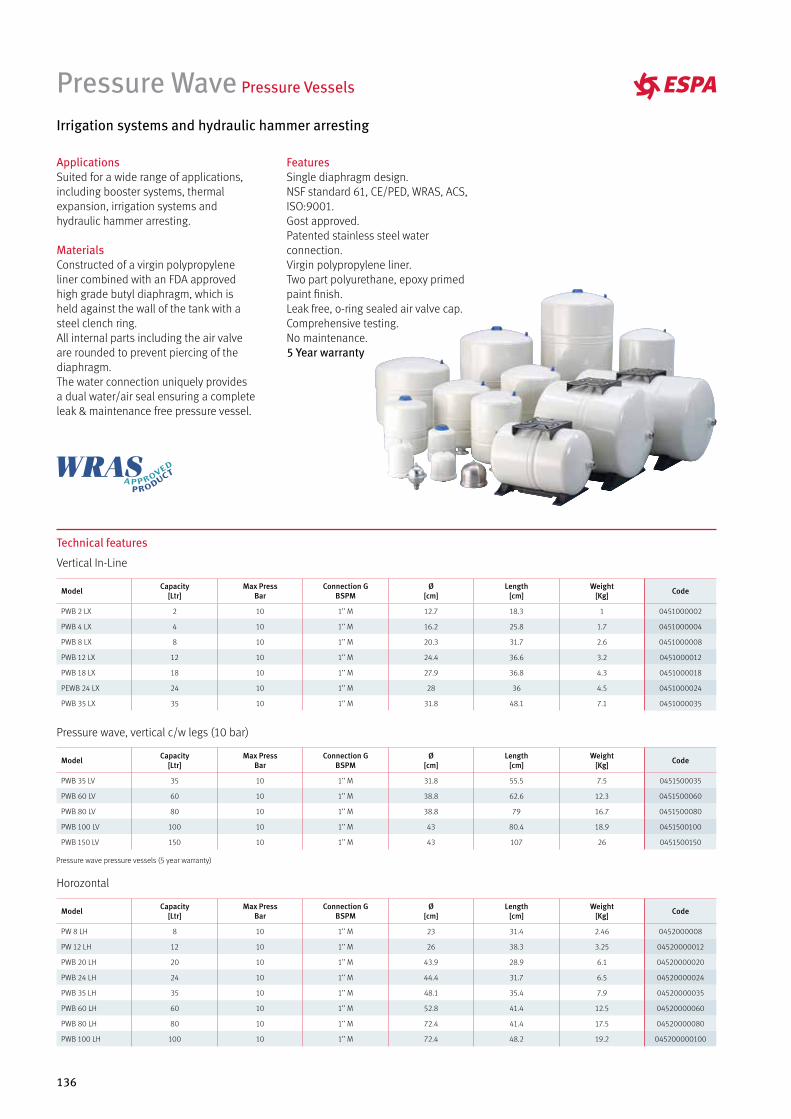
136
ApplicationsSuited for a wide range of applications, including booster systems, thermal expansion, irrigation systems and hydraulic hammer arresting.
MaterialsConstructed of a virgin polypropylene liner combined with an FDA approved high grade butyl diaphragm, which is held against the wall of the tank with a steel clench ring.All internal parts including the air valve are rounded to prevent piercing of the diaphragm.The water connection uniquely provides a dual water/air seal ensuring a complete leak & maintenance free pressure vessel.
Pressure Wave Pressure Vessels
Irrigation systems and hydraulic hammer arresting
FeaturesSingle diaphragm design.NSF standard 61, CE/PED, WRAS, ACS, ISO:9001.Gost approved.Patented stainless steel water connection.Virgin polypropylene liner.Two part polyurethane, epoxy primed paint finish.Leak free, o-ring sealed air valve cap.Comprehensive testing.No maintenance.5 Year warranty
Technical features
Vertical In-Line
Model Capacity[Ltr]
Max PressBar
Connection GBSPM
Ø[cm]
Length[cm]
Weight[Kg] Code
PWB 2 LX 2 10 1’’ M 12.7 18.3 1 0451000002
PWB 4 LX 4 10 1’’ M 16.2 25.8 1.7 0451000004
PWB 8 LX 8 10 1’’ M 20.3 31.7 2.6 0451000008
PWB 12 LX 12 10 1’’ M 24.4 36.6 3.2 0451000012
PWB 18 LX 18 10 1’’ M 27.9 36.8 4.3 0451000018
PEWB 24 LX 24 10 1’’ M 28 36 4.5 0451000024
PWB 35 LX 35 10 1’’ M 31.8 48.1 7.1 0451000035
Pressure wave, vertical c/w legs (10 bar)
Model Capacity[Ltr]
Max PressBar
Connection GBSPM
Ø[cm]
Length[cm]
Weight[Kg] Code
PWB 35 LV 35 10 1’’ M 31.8 55.5 7.5 0451500035
PWB 60 LV 60 10 1’’ M 38.8 62.6 12.3 0451500060
PWB 80 LV 80 10 1’’ M 38.8 79 16.7 0451500080
PWB 100 LV 100 10 1’’ M 43 80.4 18.9 0451500100
PWB 150 LV 150 10 1’’ M 43 107 26 0451500150
Horozontal
Model Capacity[Ltr]
Max PressBar
Connection GBSPM
Ø[cm]
Length[cm]
Weight[Kg] Code
PW 8 LH 8 10 1’’ M 23 31.4 2.46 0452000008
PW 12 LH 12 10 1’’ M 26 38.3 3.25 04520000012
PWB 20 LH 20 10 1’’ M 43.9 28.9 6.1 04520000020
PWB 24 LH 24 10 1’’ M 44.4 31.7 6.5 04520000024
PWB 35 LH 35 10 1’’ M 48.1 35.4 7.9 04520000035
PWB 60 LH 60 10 1’’ M 52.8 41.4 12.5 04520000060
PWB 80 LH 80 10 1’’ M 72.4 41.4 17.5 04520000080
PWB 100 LH 100 10 1’’ M 72.4 48.2 19.2 045200000100
Pressure wave pressure vessels (5 year warranty)
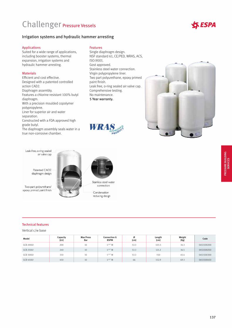
137
ApplicationsSuited for a wide range of applications, including booster systems, thermal expansion, irrigation systems and hydraulic hammer arresting.
MaterialsEfficient and cost effective.Designed with a patented controlled action CAD2.Diaphragm assembly.Features a chlorine resistant 100% butyl diaphragm.With a precision moulded copolymer polypropylene.Liner for superior air and water separation.Constructed with a FDA approved high grade butyl.The diaphragm assembly seals water in a true non-corrosive chamber.
Challenger Pressure Vessels
Irrigation systems and hydraulic hammer arresting
FeaturesSingle diaphragm design.NSF standard 61, CE/PED, WRAS, ACS, ISO:9001.Gost approved.Stainless steel water connection.Virgin polypropylene liner.Two part polyurethane, epoxy primed paint finish.Leak free, o-ring sealed air valve cap.Comprehensive testing.No maintenance.5 Year warranty.
Technical features
Vertical c/w base
Model Capacity[Ltr]
Max PressBar
Connection GBSPM
Ø[cm]
Length[cm]
Weight[Kg] Code
GCB 200LV 200 10 11/4’’ M 53.3 103.3 34.3 0451500200
GCB 250LV 240 10 11/4’’ M 53.3 121.2 36.5 0451500250
GCB 300LV 310 10 11/4’’ M 53.3 150 45.4 0451500300
GCB 450LV 450 10 11/4’’ M 66 152.9 69.3 0451500450
PRES
SURE
BU
ILD
ING
SE
RVIC
ES
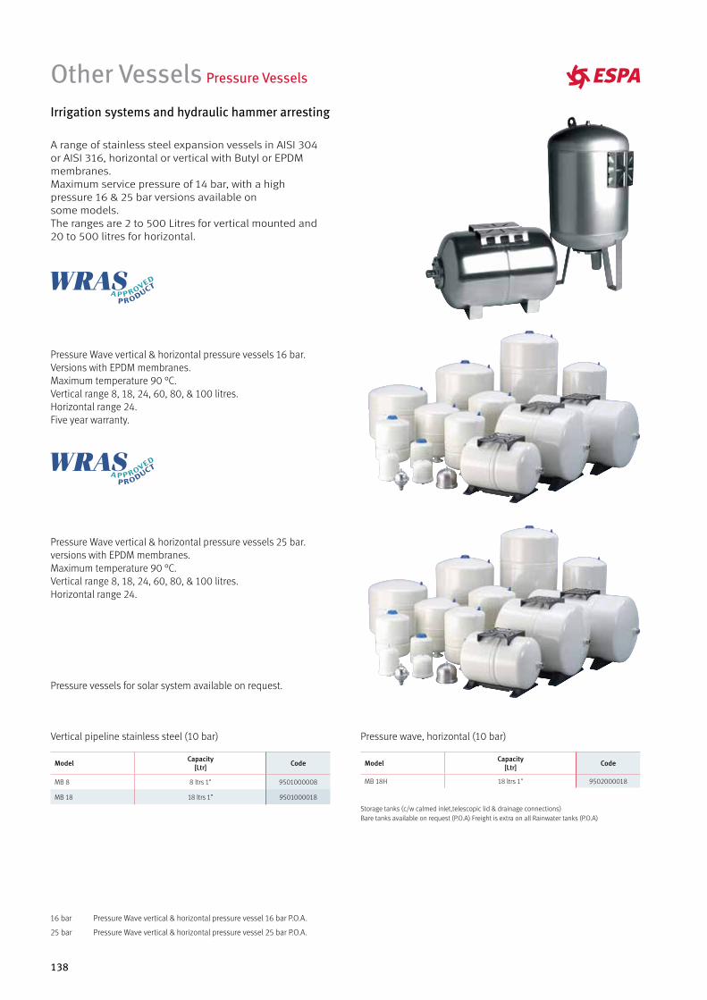
138
Other Vessels Pressure Vessels
Irrigation systems and hydraulic hammer arresting
Pressure Wave vertical & horizontal pressure vessels 16 bar.Versions with EPDM membranes.Maximum temperature 90 °C.Vertical range 8, 18, 24, 60, 80, & 100 litres.Horizontal range 24.Five year warranty.
Pressure Wave vertical & horizontal pressure vessels 25 bar.versions with EPDM membranes.Maximum temperature 90 °C.Vertical range 8, 18, 24, 60, 80, & 100 litres.Horizontal range 24.
Pressure vessels for solar system available on request.
A range of stainless steel expansion vessels in AISI 304 or AISI 316, horizontal or vertical with Butyl or EPDM membranes.Maximum service pressure of 14 bar, with a high pressure 16 & 25 bar versions available on some models.The ranges are 2 to 500 Litres for vertical mounted and 20 to 500 litres for horizontal.
Model Capacity[Ltr] Code
MB 8 8 ltrs 1" 9501000008
MB 18 18 ltrs 1” 9501000018
Model Capacity[Ltr] Code
MB 18H 18 ltrs 1" 9502000018
Vertical pipeline stainless steel (10 bar) Pressure wave, horizontal (10 bar)
16 bar Pressure Wave vertical & horizontal pressure vessel 16 bar P.O.A.
25 bar Pressure Wave vertical & horizontal pressure vessel 25 bar P.O.A.
Storage tanks (c/w calmed inlet,telescopic lid & drainage connections)Bare tanks available on request (P.O.A) Freight is extra on all Rainwater tanks (P.O.A)
139
ADVANCED SOLUTIONSIN AUTOMATIC BOOSTER SETS
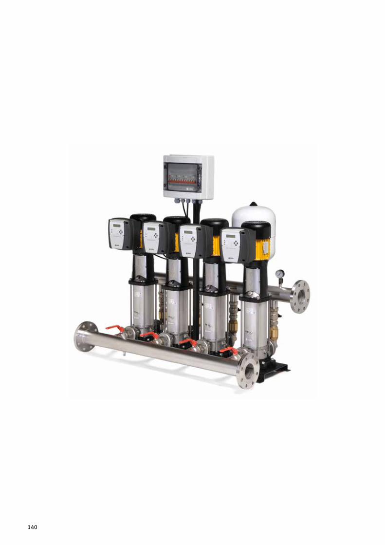
140

141
Advanced solutions in automatic pumping equipment’s
Water supply booster sets, firefighting units and special solutions in pumping systems.
ESPA offers a large range of solutions to provide the best solutions to the more challenging applications in pumping requirements for automatic water supply for household, building services, hotels, agricultural, hospitals and industrial processes.
ESPA evaluates, designs and manufactures booster sets for the automatic supply of water. The ESPA range of products can be adapted to the installation requirements. The ESPA engineering application department can adjust the standard range of ESPA booster sets to satisfy specific requirements in all installations.
The standard range of ESPA booster sets can be configured for various operational systems These include fixed speed DOL, star-delta, variable speed, duty assist in cascade operation and duty-standby configurations. As a result, the standard ESPA range booster sets can cover applications requiring the smallest and compact domestic systems to the largest commercial installations. Evidently, ESPA can offer a booster set to cover virtually all practical requirements.
The standard range of ESPA booster sets can be configured from 1 to 4 pumps with sophisticated communication enabling duty assist and periodic pump demand rotation. ESPA can also offer control systems for pump sets consisting of up to 8 pumps used in larger systems.
ESPA offers the best solutions in energy saving by utilising variable speed pump controllers. The aim of using these controllers is to ensure the booster set is operating at the BEP (Best Efficient Point) of the performance curve within a variable flow demand system. All standard ESPA motors comply with the new IE3 efficiency requirements.
In addition to the standard constant pressure booster sets, ESPA can also produce constant flow systems which utilise constant flow sensors. These systems can service applications such as golf course irrigation.
The ESPA Applications Engineering Department offers the assistance service for booster set sizing and can also analyse the best option regarding the LCC (Life Cycle Cost) of the system. The ESPA after sales service offers, on request, the commissioning and service of all ESPA booster sets which guarantees the equipment is operating to the best point of efficiency and reliability.
ESPA also offers a standard range of firefighting booster sets which are designed, manufactured and tested according to standards such as BS 12845:2015. The standard range includes duty, standby and jockey pumps which can be driven by either electrical motors or diesel engines. Please see our specific catalogue for more information on the firefighting booster sets ESPA can offer.
ADVA
NCE
D S
OLU
TIO
NS
IN
AUTO
MAT
IC B
OO
STER
SET
S
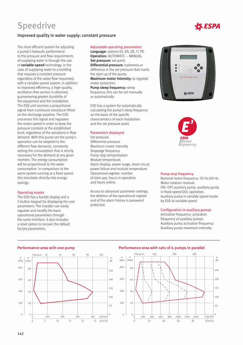
142
The most efficient system for adjustinga pump’s hydraulic performanceto the pressure and flow requirementsof supplying water is through the useof variable-speed technology. In thecase of supplying water to a buildingthat requires a constant pressureregardless of the water flow requested,with a variable-speed system, in additionto improved efficiency, a high-quality,oscillation-free service is obtained,guaranteeing greater durability ofthe equipment and the installation.The ESD unit receives a proportionalsignal from a pressure transducer fittedon the discharge pipeline. The ESDprocesses this signal and regulatesthe motor speed in order to keep thepressure constant at the establishedlevel, regardless of the variations in flowdemand. With this pump set the pump’soperation can be adapted to thedifferent flow demands, constantlysetting the consumption that is strictlynecessary for the demand at any givenmoment. The energy consumptionwill be proportional to the waterconsumption. In comparison to thesame system running at a fixed speed,this translates directly into energysavings.
Operating modesThe ESD has a backlit display and a5-button keypad for displaying the userparameters. The installer can easilyregulate and modify the basicoperational parameters throughthe same interface. It also includesa reset option to recover the defaultfactory parameters.
Adjustable operating parametersLanguage: options ES, EN, DE, IT, FR.Operation: AUTOMATIC – MANUAL.Set pressure: set point.Differential pressure: hysteresis ordifference in the set pressure that marksthe start-up of the pump.Maximum motor intensity: to regulatemotor protection.Pump sleep frequency: sleepfrequency; this can be set manuallyor automatically.
ESD has a system for automaticallycalculating the pump’s sleep frequencyon the basis of the specificcharacteristics of each installationand the set pressure point.
Parameters displayedSet pressure.Differential pressure.Maximum motor intensityStoppage frequency.Pump stop temporisation.Module temperature.Alarm display: power surge, short-circuit,power failure and module temperature.Operational register: numberof start-ups, hours in operationand hours online.
Access to advanced parameter settings,the deletion of the operational registerand of the alarm history is passwordprotected.
Pump stop frequencyNominal motor frequency: 50 Hz/60 Hz.Motor rotation reversal.ON–OFF auxiliary pump: auxiliary pumpin fixed-speed DOL operation.Auxiliary pump in variable speed modeby ESD at variable speed.
Configuration in auxiliary pumpsActivation frequency: activationfrequency of auxiliary pumps.Auxiliary pump activation frequency.Auxiliary pump maximum intensity.
Improved quality in water supply: constant pressure
Performance area with one pump Performance area with sets of 4 pumps in parallel
Speedrive
2520151050
4003002001000 Q [l/min]
Q [m3/h]
20 40 60 80 100Imp g.p.m.
250
200
150
100
50
0
H[ft]
600
800
200
400
0
H[kPa]
60
80
40
20
0
H[mwc]
H[mwc]
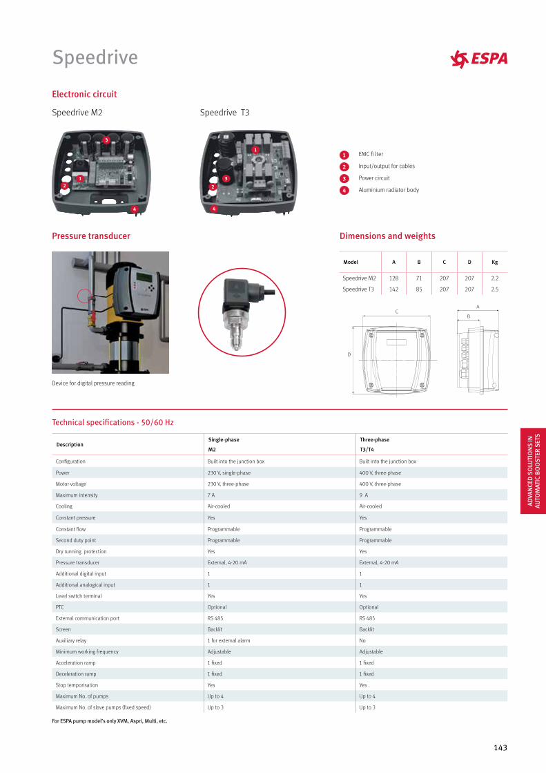
143
Speedrive
Electronic circuit
4
3
2
1
1
4
2
3
1
4
Speedrive M2 Speedrive T3
1
4
2
3
EMC fi lter
Input/output for cables
Power circuit
Aluminium radiator body
Pressure transducer
Device for digital pressure reading
Dimensions and weights
Model A B C D Kg
Speedrive M2 128 71 207 207 2.2
Speedrive T3 142 85 207 207 2.5
Technical specifications - 50/60 Hz
For ESPA pump model’s only XVM, Aspri, Multi, etc.
DescriptionSingle-phase
M2
Three-phase
T3/T4
Configuration Built into the junction box Built into the junction box
Power 230 V, single-phase 400 V, three-phase
Motor voltage 230 V, three-phase 400 V, three-phase
Maximum intensity 7 A 9 A
Cooling Air-cooled Air-cooled
Constant pressure Yes Yes
Constant flow Programmable Programmable
Second duty point Programmable Programmable
Dry running protection Yes Yes
Pressure transducer External, 4-20 mA External, 4-20 mA
Additional digital input 1 1
Additional analogical input 1 1
Level switch terminal Yes Yes
PTC Optional Optional
External communication port RS 485 RS 485
Screen Backlit Backlit
Auxiliary relay 1 for external alarm No
Minimum working frequency Adjustable Adjustable
Acceleration ramp 1 fixed 1 fixed
Deceleration ramp 1 fixed 1 fixed
Stop temporisation Yes Yes
Maximum No. of pumps Up to 4 Up to 4
Maximum No. of slave pumps (fixed speed) Up to 3 Up to 3
ADVA
NCE
D S
OLU
TIO
NS
IN
AUTO
MAT
IC B
OO
STER
SET
S
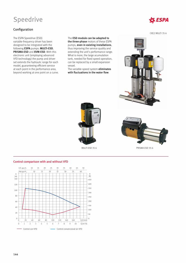
144
Speedrive
The ESPA Speedrive (ESD)variable-frequency driver has beendesigned to be integrated with thefollowing ESPA pumps: MULTI-ESD,PRISMA-ESD and XVM-ESD. With thiselectronic unit (employing advancedVFD technology) the pump and driverset extends the hydraulic range for eachmodel, guaranteeing efficient serviceat each point in the performance area,beyond working at one point on a curve.
The ESD module can be adapted tothe three-phase motors of these ESPApumps, even in existing installations,thus improving the service quality andextending the unit’s performance range.What is more, the large acumulationtank, needed for fixed speed operation,can be replaced by a small expansionvessel.The variable-speed system eliminateswith fluctuations in the water flow.
ConfigurationCKE2 MULTI 35 6
MULTI ESD 35 6 PRISMA ESD 35 6
Control con VFD Control convencional sin VFD
Control comparison with and without VFD
140
120
100
80
60
40
20
0
H[m]
450
400
350
300
250
200
150
100
50
0
H[ft]
160
109876543210
140120100806040200 Q [l/min]
Q [m3/h]
Imp g.p.m. 10 15 20 25 30 35 40
U.S. g.p.m. 10 15 20 25 30 35 40 45 50
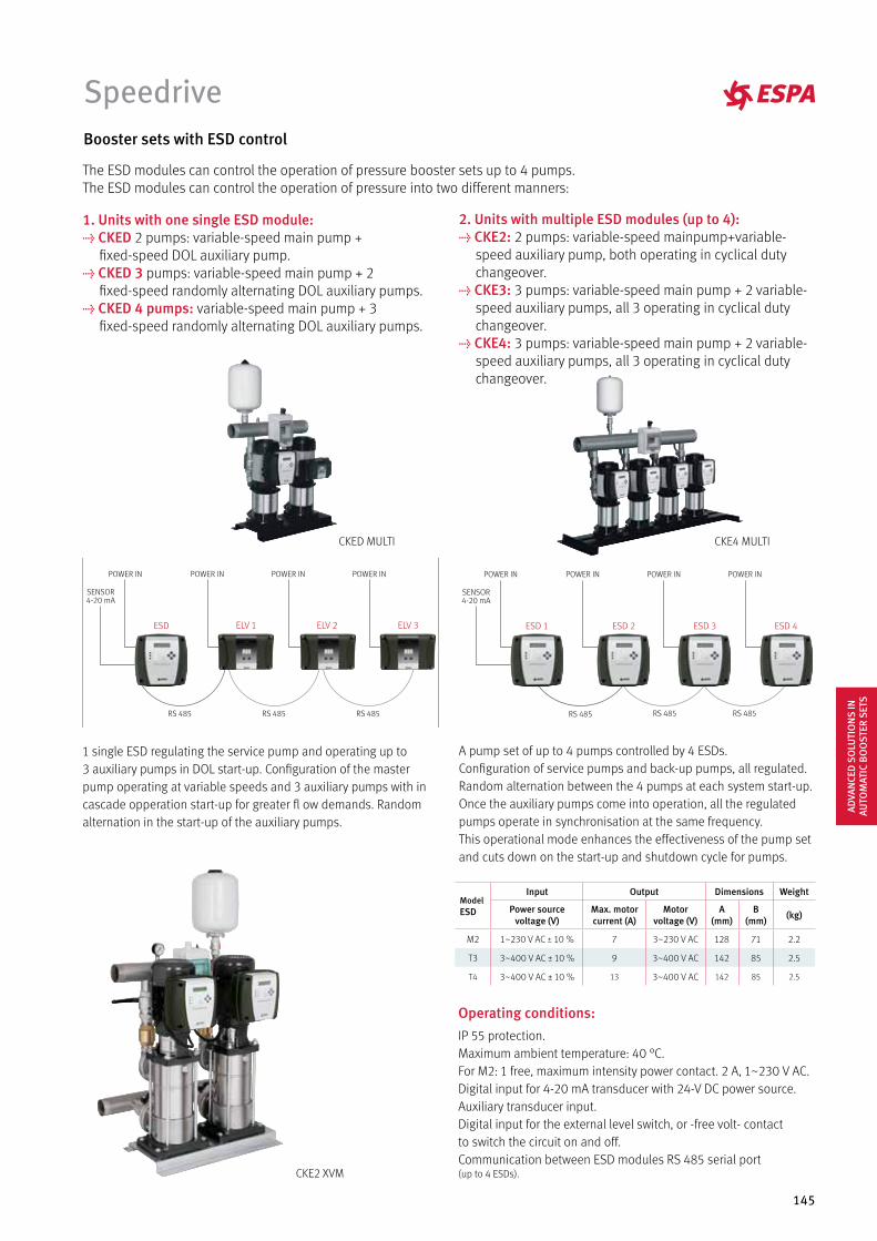
145
Speedrive
2. Units with multiple ESD modules (up to 4): t CKE2: 2 pumps: variable-speed mainpump+variable- speed auxiliary pump, both operating in cyclical duty changeover.t CKE3: 3 pumps: variable-speed main pump + 2 variable- speed auxiliary pumps, all 3 operating in cyclical duty changeover.t CKE4: 3 pumps: variable-speed main pump + 2 variable- speed auxiliary pumps, all 3 operating in cyclical duty changeover.
A pump set of up to 4 pumps controlled by 4 ESDs.Configuration of service pumps and back-up pumps, all regulated.Random alternation between the 4 pumps at each system start-up.Once the auxiliary pumps come into operation, all the regulatedpumps operate in synchronisation at the same frequency.This operational mode enhances the effectiveness of the pump setand cuts down on the start-up and shutdown cycle for pumps.
1. Units with one single ESD module: t CKED 2 pumps: variable-speed main pump + fixed-speed DOL auxiliary pump.t CKED 3 pumps: variable-speed main pump + 2 fixed-speed randomly alternating DOL auxiliary pumps.t CKED 4 pumps: variable-speed main pump + 3 fixed-speed randomly alternating DOL auxiliary pumps.
1 single ESD regulating the service pump and operating up to3 auxiliary pumps in DOL start-up. Configuration of the masterpump operating at variable speeds and 3 auxiliary pumps with incascade opperation start-up for greater fl ow demands. Randomalternation in the start-up of the auxiliary pumps.
The ESD modules can control the operation of pressure booster sets up to 4 pumps.The ESD modules can control the operation of pressure into two different manners:
Booster sets with ESD control
Operating conditions:IP 55 protection.Maximum ambient temperature: 40 °C.For M2: 1 free, maximum intensity power contact. 2 A, 1~230 V AC.Digital input for 4-20 mA transducer with 24-V DC power source.Auxiliary transducer input.Digital input for the external level switch, or -free volt- contactto switch the circuit on and off.Communication between ESD modules RS 485 serial port(up to 4 ESDs).CKE2 XVM
CKED MULTI CKE4 MULTI
Model ESD
Input Output Dimensions Weight
Power source voltage (V)
Max. motor current (A)
Motor voltage (V)
A (mm)
B (mm) (kg)
M2 1~230 V AC ± 10 % 7 3~230 V AC 128 71 2.2
T3 3~400 V AC ± 10 % 9 3~400 V AC 142 85 2.5
T4 3~400 V AC ± 10 % 13 3~400 V AC 142 85 2.5
ADVA
NCE
D S
OLU
TIO
NS
IN
AUTO
MAT
IC B
OO
STER
SET
S
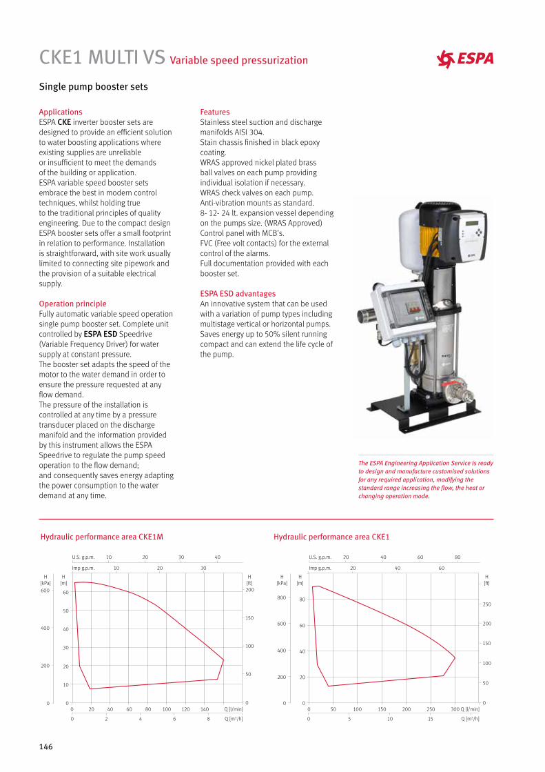
146
CKE1 MULTI VS Variable speed pressurization
ApplicationsESPA CKE inverter booster sets aredesigned to provide an efficient solutionto water boosting applications whereexisting supplies are unreliableor insufficient to meet the demandsof the building or application.ESPA variable speed booster setsembrace the best in modern controltechniques, whilst holding trueto the traditional principles of qualityengineering. Due to the compact designESPA booster sets offer a small footprintin relation to performance. Installationis straightforward, with site work usuallylimited to connecting site pipework andthe provision of a suitable electricalsupply.
Operation principleFully automatic variable speed operationsingle pump booster set. Complete unitcontrolled by ESPA ESD Speedrive(Variable Frequency Driver) for watersupply at constant pressure.The booster set adapts the speed of themotor to the water demand in order toensure the pressure requested at anyflow demand.The pressure of the installation iscontrolled at any time by a pressuretransducer placed on the dischargemanifold and the information providedby this instrument allows the ESPASpeedrive to regulate the pump speedoperation to the flow demand;and consequently saves energy adaptingthe power consumption to the waterdemand at any time.
Single pump booster sets
FeaturesStainless steel suction and dischargemanifolds AISI 304.Stain chassis finished in black epoxycoating.WRAS approved nickel plated brassball valves on each pump providingindividual isolation if necessary.WRAS check valves on each pump.Anti-vibration mounts as standard.8- 12- 24 lt. expansion vessel dependingon the pumps size. (WRAS Approved)Control panel with MCB’s.FVC (Free volt contacts) for the externalcontrol of the alarms.Full documentation provided with eachbooster set.
ESPA ESD advantagesAn innovative system that can be usedwith a variation of pump types includingmultistage vertical or horizontal pumps.Saves energy up to 50% silent runningcompact and can extend the life cycle ofthe pump.
Hydraulic performance area CKE1M
86420
140120100806040200 Q [l/min]
Q [m3/h]
10
10
20
20
30
30 40
Imp g.p.m.
U.S. g.p.m.
60
50
40
30
20
10
0
H[m]
200
150
100
50
0
H[ft]
600
400
200
0
H[kPa]
Hydraulic performance area CKE1
Q [l/min]
151050
300250200150100500
Q [m3/h]
20 40 60
20 40 60 80
Imp g.p.m.
U.S. g.p.m.
80
60
40
20
0
H[m]
800
600
400
200
0
H[kPa]
250
200
150
100
50
0
H[ft]
The ESPA Engineering Application Service is readyto design and manufacture customised solutionsfor any required application, modifying thestandard range increasing the flow, the heat orchanging operation mode.
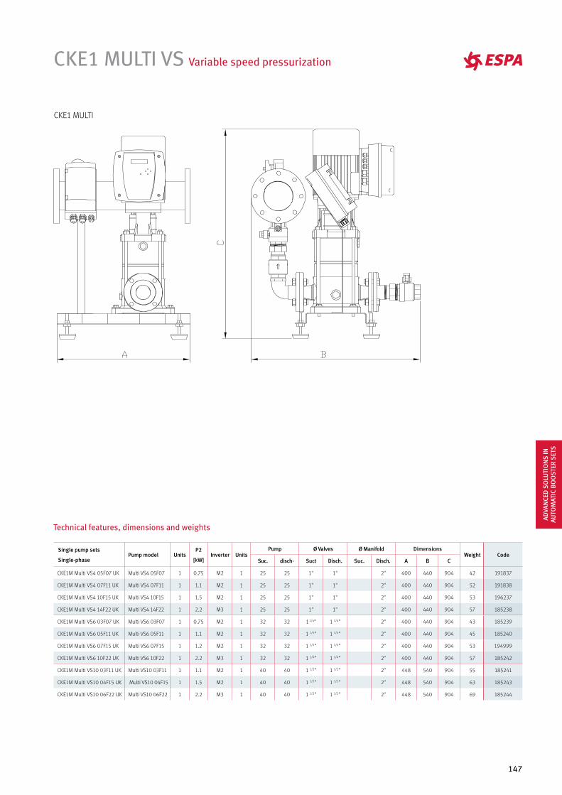
147
CKE1 MULTI VS Variable speed pressurization
Single pump sets
Single-phasePump model Units
P2
[kW]Inverter Units
Pump Ø Valves Ø Manifold Dimensions Weight Code
Suc. disch- Suct Disch. Suc. Disch. A B C
CKE1M Multi VS4 05F07 UK Multi VS4 05F07 1 0.75 M2 1 25 25 1" 1" 2" 400 440 904 42 191837
CKE1M Multi VS4 07F11 UK Multi VS4 07F11 1 1.1 M2 1 25 25 1" 1" 2" 400 440 904 52 191838
CKE1M Multi VS4 10F15 UK Multi VS4 10F15 1 1.5 M2 1 25 25 1" 1" 2" 400 440 904 53 196237
CKE1M Multi VS4 14F22 UK Multi VS4 14F22 1 2.2 M3 1 25 25 1" 1" 2" 400 440 904 57 185238
CKE1M Multi VS6 03F07 UK Multi VS6 03F07 1 0.75 M2 1 32 32 1 1/4" 1 1/4" 2" 400 440 904 43 185239
CKE1M Multi VS6 05F11 UK Multi VS6 05F11 1 1.1 M2 1 32 32 1 1/4" 1 1/4" 2" 400 440 904 45 185240
CKE1M Multi VS6 07F15 UK Multi VS6 07F15 1 1.2 M2 1 32 32 1 1/4" 1 1/4" 2" 400 440 904 53 194999
CKE1M Multi VS6 10F22 UK Multi VS6 10F22 1 2.2 M3 1 32 32 1 1/4" 1 1/4" 2" 400 440 904 57 185242
CKE1M Multi VS10 03F11 UK Multi VS10 03F11 1 1.1 M2 1 40 40 1 1/2" 1 1/2" 2" 448 540 904 55 185241
CKE1M Multi VS10 04F15 UK Multi VS10 04F15 1 1.5 M2 1 40 40 1 1/2" 1 1/2" 2" 448 540 904 63 185243
CKE1M Multi VS10 06F22 UK Multi VS10 06F22 1 2.2 M3 1 40 40 1 1/2" 1 1/2" 2" 448 540 904 69 185244
Technical features, dimensions and weights
CKE1 MULTI
ADVA
NCE
D S
OLU
TIO
NS
IN
AUTO
MAT
IC B
OO
STER
SET
S
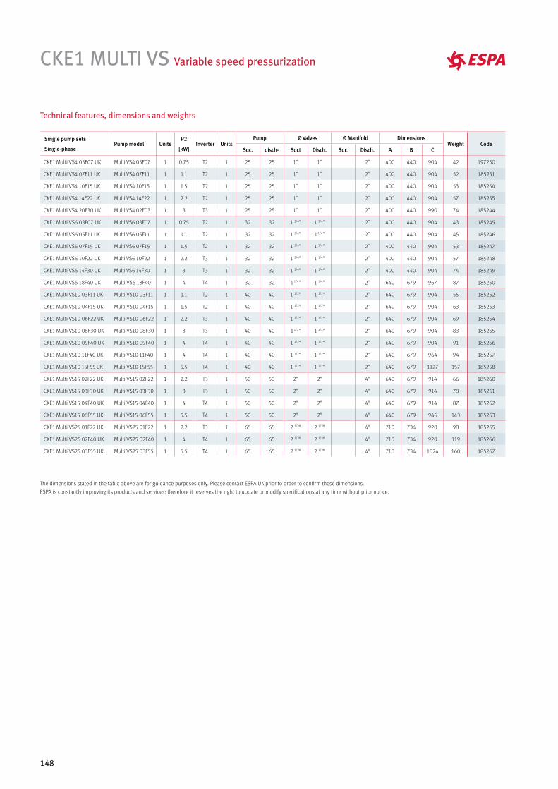
148
CKE1 MULTI VS Variable speed pressurization
Single pump sets
Single-phasePump model Units
P2
[kW]Inverter Units
Pump Ø Valves Ø Manifold Dimensions Weight Code
Suc. disch- Suct Disch. Suc. Disch. A B C
CKE1 Multi VS4 05F07 UK Multi VS4 05F07 1 0.75 T2 1 25 25 1" 1" 2" 400 440 904 42 197250
CKE1 Multi VS4 07F11 UK Multi VS4 07F11 1 1.1 T2 1 25 25 1" 1" 2" 400 440 904 52 185251
CKE1 Multi VS4 10F15 UK Multi VS4 10F15 1 1.5 T2 1 25 25 1" 1" 2" 400 440 904 53 185254
CKE1 Multi VS4 14F22 UK Multi VS4 14F22 1 2.2 T2 1 25 25 1" 1" 2" 400 440 904 57 185255
CKE1 Multi VS4 20F30 UK Multi VS4 02F03 1 3 T3 1 25 25 1" 1" 2” 400 440 990 74 185244
CKE1 Multi VS6 03F07 UK Multi VS6 03F07 1 0.75 T2 1 32 32 1 1/4" 1 1/4" 2” 400 440 904 43 185245
CKE1 Multi VS6 05F11 UK Multi VS6 05F11 1 1.1 T2 1 32 32 1 1/4" 1 1/4" 2” 400 440 904 45 185246
CKE1 Multi VS6 07F15 UK Multi VS6 07F15 1 1.5 T2 1 32 32 1 1/4" 1 1/4" 2” 400 440 904 53 185247
CKE1 Multi VS6 10F22 UK Multi VS6 10F22 1 2.2 T3 1 32 32 1 1/4" 1 1/4" 2” 400 440 904 57 185248
CKE1 Multi VS6 14F30 UK Multi VS6 14F30 1 3 T3 1 32 32 1 1/4" 1 1/4" 2” 400 440 904 74 185249
CKE1 Multi VS6 18F40 UK Multi VS6 18F40 1 4 T4 1 32 32 1 1/4" 1 1/4" 2” 640 679 967 87 185250
CKE1 Multi VS10 03F11 UK Multi VS10 03F11 1 1.1 T2 1 40 40 1 1/2" 1 1/2" 2” 640 679 904 55 185252
CKE1 Multi VS10 04F15 UK Multi VS10 04F15 1 1.5 T2 1 40 40 1 1/2" 1 1/2" 2” 640 679 904 63 185253
CKE1 Multi VS10 06F22 UK Multi VS10 06F22 1 2.2 T3 1 40 40 1 1/2" 1 1/2" 2” 640 679 904 69 185254
CKE1 Multi VS10 08F30 UK Multi VS10 08F30 1 3 T3 1 40 40 1 1/2" 1 1/2" 2” 640 679 904 83 185255
CKE1 Multi VS10 09F40 UK Multi VS10 09F40 1 4 T4 1 40 40 1 1/2" 1 1/2" 2” 640 679 904 91 185256
CKE1 Multi VS10 11F40 UK Multi VS10 11F40 1 4 T4 1 40 40 1 1/2" 1 1/2" 2” 640 679 964 94 185257
CKE1 Multi VS10 15F55 UK Multi VS10 15F55 1 5.5 T4 1 40 40 1 1/2" 1 1/2" 2” 640 679 1127 157 185258
CKE1 Multi VS15 02F22 UK Multi VS15 02F22 1 2.2 T3 1 50 50 2" 2" 4" 640 679 914 66 185260
CKE1 Multi VS15 03F30 UK Multi VS15 03F30 1 3 T3 1 50 50 2" 2" 4" 640 679 914 78 185261
CKE1 Multi VS15 04F40 UK Multi VS15 04F40 1 4 T4 1 50 50 2" 2" 4" 640 679 914 87 185262
CKE1 Multi VS15 06F55 UK Multi VS15 06F55 1 5.5 T4 1 50 50 2" 2" 4" 640 679 946 143 185263
CKE1 Multi VS25 01F22 UK Multi VS25 01F22 1 2.2 T3 1 65 65 2 1/2" 2 1/2" 4" 710 734 920 98 185265
CKE1 Multi VS25 02F40 UK Multi VS25 02F40 1 4 T4 1 65 65 2 1/2" 2 1/2" 4" 710 734 920 119 185266
CKE1 Multi VS25 03F55 UK Multi VS25 03F55 1 5.5 T4 1 65 65 2 1/2" 2 1/2" 4" 710 734 1024 160 185267
Technical features, dimensions and weights
The dimensions stated in the table above are for guidance purposes only. Please contact ESPA UK prior to order to confirm these dimensions.
ESPA is constantly improving its products and services; therefore it reserves the right to update or modify specifications at any time without prior notice.
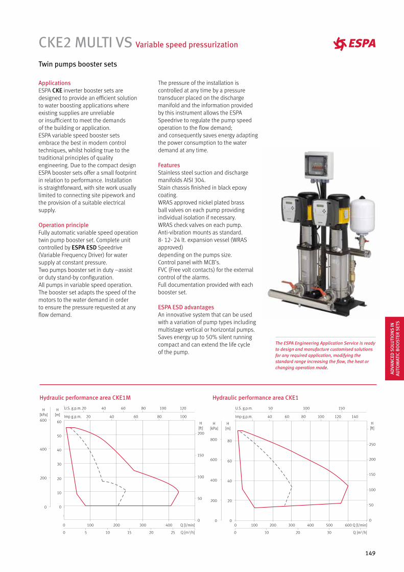
149
CKE2 MULTI VS Variable speed pressurization
Twin pumps booster sets
ApplicationsESPA CKE inverter booster sets aredesigned to provide an efficient solutionto water boosting applications whereexisting supplies are unreliableor insufficient to meet the demandsof the building or application.ESPA variable speed booster setsembrace the best in modern controltechniques, whilst holding true to thetraditional principles of qualityengineering. Due to the compact designESPA booster sets offer a small footprintin relation to performance. Installationis straightforward, with site work usuallylimited to connecting site pipework andthe provision of a suitable electricalsupply.
Operation principleFully automatic variable speed operationtwin pump booster set. Complete unitcontrolled by ESPA ESD Speedrive(Variable Frequency Driver) for watersupply at constant pressure.Two pumps booster set in duty –assistor duty stand-by configuration.All pumps in variable speed operation.The booster set adapts the speed of themotors to the water demand in orderto ensure the pressure requested at anyflow demand.
The pressure of the installation iscontrolled at any time by a pressuretransducer placed on the dischargemanifold and the information providedby this instrument allows the ESPASpeedrive to regulate the pump speedoperation to the flow demand;and consequently saves energy adaptingthe power consumption to the waterdemand at any time.
FeaturesStainless steel suction and dischargemanifolds AISI 304.Stain chassis finished in black epoxycoating.WRAS approved nickel plated brassball valves on each pump providingindividual isolation if necessary.WRAS check valves on each pump.Anti-vibration mounts as standard.8- 12- 24 lt. expansion vessel (WRAS approved)depending on the pumps size.Control panel with MCB’s.FVC (Free volt contacts) for the externalcontrol of the alarms.Full documentation provided with eachbooster set.
ESPA ESD advantagesAn innovative system that can be usedwith a variation of pump types includingmultistage vertical or horizontal pumps.Saves energy up to 50% silent runningcompact and can extend the life cycleof the pump.
Hydraulic performance area CKE1M Hydraulic performance area CKE1
The ESPA Engineering Application Service is readyto design and manufacture customised solutionsfor any required application, modifying thestandard range increasing the flow, the heat orchanging operation mode.
U.S. g.p.m.
2520151050
4003002001000 Q [l/min]
Q [m3/h]
20 40 60 80 100
20 40 60 80 100 120
Imp g.p.m.
200
150
100
50
0
H[ft]
50
40
30
20
10
0
60
H[m]
400
200
0
600
H[kPa]
Q [l/min]6005004003002001000
3020100 Q [m3/h]
40 60 80 100 120 140
50 100 150
Imp g.p.m.
U.S. g.p.m.
80
60
40
20
0
H[m]
800
600
400
200
0
H[kPa]
250
200
150
100
50
0
H[ft]
ADVA
NCE
D S
OLU
TIO
NS
IN
AUTO
MAT
IC B
OO
STER
SET
S
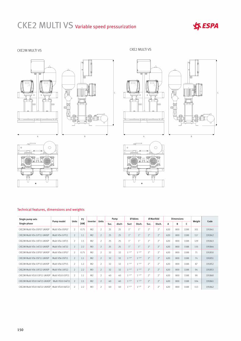
150
CKE2 MULTI VS Variable speed pressurization
Single pump sets
Single-phasePump model Units
P2
[kW]Inverter Units
Pump Ø Valves Ø Manifold Dimensions Weight Code
Suc. disch- Suct Disch. Suc. Disch. A B C
CKE2M Multi VS4 05F07 UKASP Multi VS4 05F07 2 0.75 M2 2 25 25 1" 1" 2" 2" 620 800 1188 101 191841
CKE2M Multi VS4 07F11 UKASP Multi VS4 07F11 2 1.1 M2 2 25 25 1" 1" 2" 2" 620 800 1188 117 191842
CKE2M Multi VS4 10F15 UKASP Multi VS4 10F15 2 1.5 M2 2 25 25 1" 1" 2" 2" 620 800 1188 129 191843
CKE2M Multi VS4 14F22 UKASP Multi VS4 14F22 2 2.2 M3 2 25 25 1" 1" 2" 2" 620 800 1188 135 191844
CKE2M Multi VS6 03F07 UKASP Multi VS6 03F07 2 0.75 M2 2 32 32 1 1/4" 1 1/4" 2" 2" 620 800 1188 71 191850
CKE2M Multi VS6 05F11 UKASP Multi VS6 05F11 2 1.1 M2 2 32 32 1 1/4" 1 1/4" 2" 2" 620 800 1188 74 191851
CKE2M Multi VS6 07F15 UKASP Multi VS6 07F15 2 1.2 M2 2 32 32 1 1/4" 1 1/4" 2" 2" 620 800 1188 87 191852
CKE2M Multi VS6 10F22 UKASP Multi VS6 10F22 2 2.2 M3 2 32 32 1 1/4" 1 1/4" 2" 2" 620 800 1188 94 191853
CKE2M Multi VS10 03F11 UKASP Multi VS10 03F11 2 1.1 M2 2 40 40 1 1/2" 1 1/2" 2" 2" 620 800 1188 90 191860
CKE2M Multi VS10 04F15 UKASP Multi VS10 04F15 2 1.5 M2 2 40 40 1 1/2" 1 1/2" 2" 2" 620 800 1188 104 191861
CKE2M Multi VS10 06F22 UKASP Multi VS10 06F22 2 2.2 M3 2 40 40 1 1/2" 1 1/2" 2" 2" 620 800 1188 113 191862
Technical features, dimensions and weights
CKE2M MULTI VS CKE2 MULTI VS
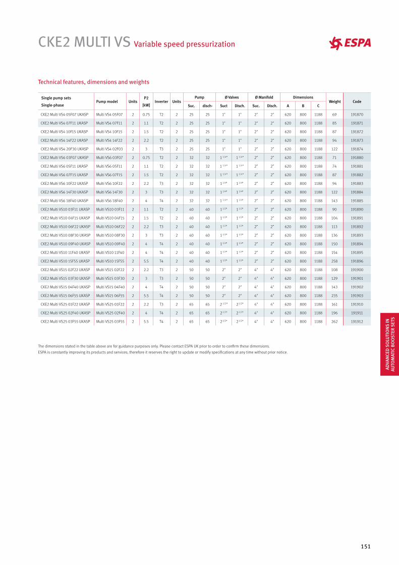
151
CKE2 MULTI VS Variable speed pressurization
Single pump sets
Single-phasePump model Units
P2
[kW]Inverter Units
Pump Ø Valves Ø Manifold Dimensions Weight Code
Suc. disch- Suct Disch. Suc. Disch. A B C
CKE2 Multi VS4 05F07 UKASP Multi VS4 05F07 2 0.75 T2 2 25 25 1" 1" 2" 2" 620 800 1188 69 191870
CKE2 Multi VS4 07F11 UKASP Multi VS4 07F11 2 1.1 T2 2 25 25 1" 1" 2" 2" 620 800 1188 85 191871
CKE2 Multi VS4 10F15 UKASP Multi VS4 10F15 2 1.5 T2 2 25 25 1" 1" 2" 2" 620 800 1188 87 191872
CKE2 Multi VS4 14F22 UKASP Multi VS4 14F22 2 2.2 T2 2 25 25 1" 1" 2" 2" 620 800 1188 94 191873
CKE2 Multi VS4 20F30 UKASP Multi VS4 02F03 2 3 T3 2 25 25 1" 1" 2” 2” 620 800 1188 122 191874
CKE2 Multi VS6 03F07 UKASP Multi VS6 03F07 2 0.75 T2 2 32 32 1 1/4" 1 1/4" 2” 2” 620 800 1188 71 191880
CKE2 Multi VS6 05F11 UKASP Multi VS6 05F11 2 1.1 T2 2 32 32 1 1/4" 1 1/4" 2” 2” 620 800 1188 74 191881
CKE2 Multi VS6 07F15 UKASP Multi VS6 07F15 2 1.5 T2 2 32 32 1 1/4" 1 1/4" 2” 2” 620 800 1188 87 191882
CKE2 Multi VS6 10F22 UKASP Multi VS6 10F22 2 2.2 T3 2 32 32 1 1/4" 1 1/4" 2” 2” 620 800 1188 94 191883
CKE2 Multi VS6 14F30 UKASP Multi VS6 14F30 2 3 T3 2 32 32 1 1/4" 1 1/4" 2” 2” 620 800 1188 122 191884
CKE2 Multi VS6 18F40 UKASP Multi VS6 18F40 2 4 T4 2 32 32 1 1/4" 1 1/4" 2” 2” 620 800 1188 143 191885
CKE2 Multi VS10 03F11 UKASP Multi VS10 03F11 2 1.1 T2 2 40 40 1 1/2" 1 1/2" 2” 2” 620 800 1188 90 191890
CKE2 Multi VS10 04F15 UKASP Multi VS10 04F15 2 1.5 T2 2 40 40 1 1/2" 1 1/2" 2” 2” 620 800 1188 104 191891
CKE2 Multi VS10 06F22 UKASP Multi VS10 06F22 2 2.2 T3 2 40 40 1 1/2" 1 1/2" 2” 2” 620 800 1188 113 191892
CKE2 Multi VS10 08F30 UKASP Multi VS10 08F30 2 3 T3 2 40 40 1 1/2" 1 1/2" 2” 2” 620 800 1188 136 191893
CKE2 Multi VS10 09F40 UKASP Multi VS10 09F40 2 4 T4 2 40 40 1 1/2" 1 1/2" 2” 2” 620 800 1188 150 191894
CKE2 Multi VS10 11F40 UKASP Multi VS10 11F40 2 4 T4 2 40 40 1 1/2" 1 1/2" 2” 2” 620 800 1188 154 191895
CKE2 Multi VS10 15F55 UKASP Multi VS10 15F55 2 5.5 T4 2 40 40 1 1/2" 1 1/2" 2” 2” 620 800 1188 258 191896
CKE2 Multi VS15 02F22 UKASP Multi VS15 02F22 2 2.2 T3 2 50 50 2" 2" 4" 4" 620 800 1188 108 191900
CKE2 Multi VS15 03F30 UKASP Multi VS15 03F30 2 3 T3 2 50 50 2" 2" 4" 4" 620 800 1188 129 191901
CKE2 Multi VS15 04F40 UKASP Multi VS15 04F40 2 4 T4 2 50 50 2" 2" 4" 4" 620 800 1188 143 191902
CKE2 Multi VS15 06F55 UKASP Multi VS15 06F55 2 5.5 T4 2 50 50 2" 2" 4" 4" 620 800 1188 235 191903
CKE2 Multi VS25 01F22 UKASP Multi VS25 01F22 2 2.2 T3 2 65 65 2 1/2" 2 1/2" 4" 4" 620 800 1188 161 191910
CKE2 Multi VS25 02F40 UKASP Multi VS25 02F40 2 4 T4 2 65 65 2 1/2" 2 1/2" 4" 4" 620 800 1188 196 191911
CKE2 Multi VS25 03F55 UKASP Multi VS25 03F55 2 5.5 T4 2 65 65 2 1/2" 2 1/2" 4" 4" 620 800 1188 262 191912
Technical features, dimensions and weights
The dimensions stated in the table above are for guidance purposes only. Please contact ESPA UK prior to order to confirm these dimensions.
ESPA is constantly improving its products and services; therefore it reserves the right to update or modify specifications at any time without prior notice.
ADVA
NCE
D S
OLU
TIO
NS
IN
AUTO
MAT
IC B
OO
STER
SET
S
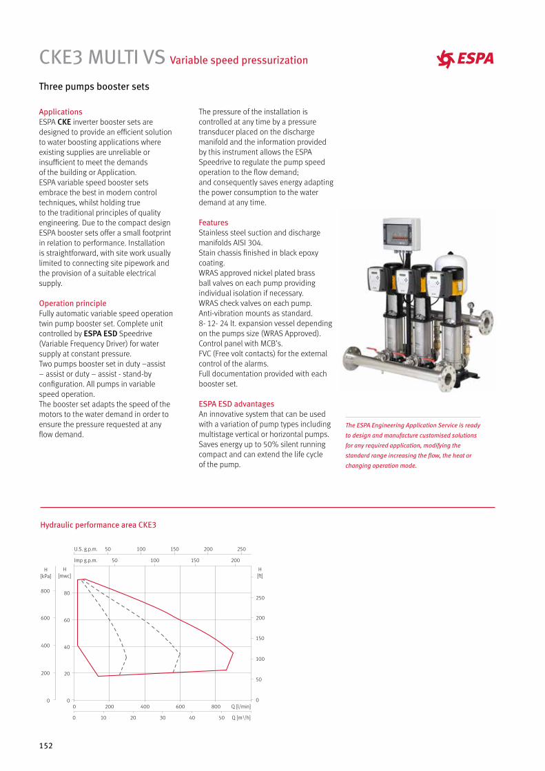
152
CKE3 MULTI VS Variable speed pressurization
Three pumps booster sets
Hydraulic performance area CKE3
ApplicationsESPA CKE inverter booster sets aredesigned to provide an efficient solutionto water boosting applications whereexisting supplies are unreliable orinsufficient to meet the demandsof the building or Application.ESPA variable speed booster setsembrace the best in modern controltechniques, whilst holding trueto the traditional principles of qualityengineering. Due to the compact designESPA booster sets offer a small footprintin relation to performance. Installationis straightforward, with site work usuallylimited to connecting site pipework andthe provision of a suitable electricalsupply.
Operation principleFully automatic variable speed operationtwin pump booster set. Complete unitcontrolled by ESPA ESD Speedrive(Variable Frequency Driver) for watersupply at constant pressure.Two pumps booster set in duty –assist– assist or duty – assist - stand-byconfiguration. All pumps in variablespeed operation.The booster set adapts the speed of themotors to the water demand in order toensure the pressure requested at anyflow demand.
The pressure of the installation iscontrolled at any time by a pressuretransducer placed on the dischargemanifold and the information providedby this instrument allows the ESPASpeedrive to regulate the pump speedoperation to the flow demand;and consequently saves energy adaptingthe power consumption to the waterdemand at any time.
FeaturesStainless steel suction and dischargemanifolds AISI 304.Stain chassis finished in black epoxycoating.WRAS approved nickel plated brassball valves on each pump providingindividual isolation if necessary.WRAS check valves on each pump.Anti-vibration mounts as standard.8- 12- 24 lt. expansion vessel dependingon the pumps size (WRAS Approved).Control panel with MCB’s.FVC (Free volt contacts) for the externalcontrol of the alarms.Full documentation provided with eachbooster set.
ESPA ESD advantagesAn innovative system that can be usedwith a variation of pump types includingmultistage vertical or horizontal pumps.Saves energy up to 50% silent runningcompact and can extend the life cycleof the pump.
Q [l/min]8006004002000
403020100 50 Q [m3/h]
50 100 150 200
50 100 150 200 250
Imp g.p.m.
U.S. g.p.m.
80
60
40
20
0
H[mwc]
800
600
400
200
0
H[kPa]
250
200
150
100
50
0
H[ft]
The ESPA Engineering Application Service is ready
to design and manufacture customised solutions
for any required application, modifying the
standard range increasing the flow, the heat or
changing operation mode.
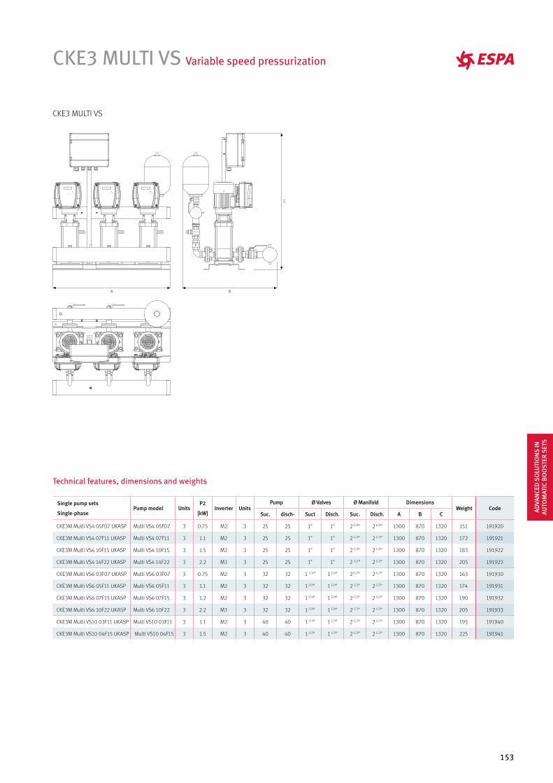
153
CKE3 MULTI VS Variable speed pressurization
Single pump sets
Single-phasePump model Units
P2
[kW]Inverter Units
Pump Ø Valves Ø Manifold Dimensions Weight Code
Suc. disch- Suct Disch. Suc. Disch. A B C
CKE3M Multi VS4 05F07 UKASP Multi VS4 05F07 3 0.75 M2 3 25 25 1" 1" 2 1/2" 2 1/2" 1300 870 1320 151 191920
CKE3M Multi VS4 07F11 UKASP Multi VS4 07F11 3 1.1 M2 3 25 25 1" 1" 2 1/2" 2 1/2" 1300 870 1320 172 191921
CKE3M Multi VS4 10F15 UKASP Multi VS4 10F15 3 1.5 M2 3 25 25 1" 1" 2 1/2" 2 1/2" 1300 870 1320 183 191922
CKE3M Multi VS4 14F22 UKASP Multi VS4 14F22 3 2.2 M3 3 25 25 1" 1" 2 1/2" 2 1/2" 1300 870 1320 205 191923
CKE3M Multi VS6 03F07 UKASP Multi VS6 03F07 3 0.75 M2 3 32 32 1 1/4" 1 1/4" 2 1/2" 2 1/2" 1300 870 1320 163 191930
CKE3M Multi VS6 05F11 UKASP Multi VS6 05F11 3 1.1 M2 3 32 32 1 1/4" 1 1/4" 2 1/2" 2 1/2" 1300 870 1320 174 191931
CKE3M Multi VS6 07F15 UKASP Multi VS6 07F15 3 1.2 M2 3 32 32 1 1/4" 1 1/4" 2 1/2" 2 1/2" 1300 870 1320 190 191932
CKE3M Multi VS6 10F22 UKASP Multi VS6 10F22 3 2.2 M3 3 32 32 1 1/4" 1 1/4" 2 1/2" 2 1/2" 1300 870 1320 205 191933
CKE3M Multi VS10 03F11 UKASP Multi VS10 03F11 3 1.1 M2 3 40 40 1 1/2" 1 1/2" 2 1/2" 2 1/2" 1300 870 1320 195 191940
CKE3M Multi VS10 04F15 UKASP Multi VS10 04F15 3 1.5 M2 3 40 40 1 1/2" 1 1/2" 2 1/2" 2 1/2" 1300 870 1320 225 191941
Technical features, dimensions and weights
CKE3 MULTI VS
ADVA
NCE
D S
OLU
TIO
NS
IN
AUTO
MAT
IC B
OO
STER
SET
S
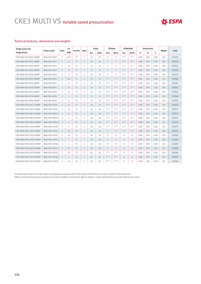
154
CKE3 MULTI VS Variable speed pressurization
Technical features, dimensions and weights
Single pump sets
Single-phasePump model Units
P2
[kW]Inverter Units
Pump Ø Valves Ø Manifold Dimensions Weight Code
Suc. disch- Suct Disch. Suc. Disch. A B C
CKE3 Multi VS4 05F07 UKASP Multi VS4 05F07 3 0.75 T2 3 25 25 1" 1" 2 1/2" 2 1/2" 1300 870 1320 150 191950
CKE3 Multi VS4 07F11 UKASP Multi VS4 07F11 3 1.1 T2 3 25 25 1" 1" 2 1/2" 2 1/2" 1300 870 1320 185 191952
CKE3 Multi VS4 10F15 UKASP Multi VS4 10F15 3 1.5 T2 3 25 25 1" 1" 2 1/2" 2 1/2" 1300 870 1320 190 191953
CKE3 Multi VS4 14F22 UKASP Multi VS4 14F22 3 2.2 T2 3 25 25 1" 1" 2 1/2" 2 1/2" 1300 870 1320 205 191954
CKE3 Multi VS4 20F30 UKASP Multi VS4 02F03 3 3 T3 3 25 25 1" 1" 2 1/2" 2 1/2" 1300 870 1320 265 191955
CKE3 Multi VS6 03F07 UKASP Multi VS6 03F07 3 0.75 T2 3 32 32 1 1/4" 1 1/4" 2 1/2" 2 1/2" 1300 870 1320 155 191960
CKE3 Multi VS6 05F11 UKASP Multi VS6 05F11 3 1.1 T2 3 32 32 1 1/4" 1 1/4" 2 1/2" 2 1/2" 1300 870 1320 160 191961
CKE3 Multi VS6 07F15 UKASP Multi VS6 07F15 3 1.5 T2 3 32 32 1 1/4" 1 1/4" 2 1/2" 2 1/2" 1300 870 1320 190 191962
CKE3 Multi VS6 10F22 UKASP Multi VS6 10F22 3 2.2 T3 3 32 32 1 1/4" 1 1/4" 2 1/2" 2 1/2" 1300 870 1320 205 191963
CKE3 Multi VS6 14F30 UKASP Multi VS6 14F30 3 3 T3 3 32 32 1 1/4" 1 1/4" 2 1/2" 2 1/2" 1300 870 1320 265 191964
CKE3 Multi VS6 18F40 UKASP Multi VS6 18F40 3 4 T4 3 32 32 1 1/4" 1 1/4" 2 1/2" 2 1/2" 1300 870 1320 310 191965
CKE3 Multi VS10 03F11 UKASP Multi VS10 03F11 3 1.1 T2 3 40 40 1 1/2" 1 1/2" 2 1/2" 2 1/2" 1300 870 1320 195 191970
CKE3 Multi VS10 04F15 UKASP Multi VS10 04F15 3 1.5 T2 3 40 40 1 1/2" 1 1/2" 2 1/2" 2 1/2" 1300 870 1320 225 191971
CKE3 Multi VS10 06F22 UKASP Multi VS10 06F22 3 2.2 T3 3 40 40 1 1/2" 1 1/2" 2 1/2" 2 1/2" 1300 870 1320 245 191972
CKE3 Multi VS10 08F30 UKASP Multi VS10 08F30 3 3 T3 3 40 40 1 1/2" 1 1/2" 2 1/2" 2 1/2" 1300 870 1320 295 191973
CKE3 Multi VS10 09F40 UKASP Multi VS10 09F40 3 4 T4 3 40 40 1 1/2" 1 1/2" 2 1/2" 2 1/2" 1300 870 1320 325 191974
CKE3 Multi VS10 11F40 UKASP Multi VS10 11F40 3 4 T4 3 40 40 1 1/2" 1 1/2" 2 1/2" 2 1/2" 1300 870 1320 335 191975
CKE3 Multi VS10 15F55 UKASP Multi VS10 15F55 3 5.5 T4 3 40 40 1 1/2" 1 1/2" 2 1/2" 2 1/2" 1300 870 1320 560 191976
CKE3 Multi VS15 02F22 UKASP Multi VS15 02F22 3 2.2 T3 3 50 50 2" 2" 4" 4" 1300 870 1320 235 191980
CKE3 Multi VS15 03F30 UKASP Multi VS15 03F30 3 3 T3 3 50 50 2" 2" 4" 4" 1300 870 1320 280 191981
CKE3 Multi VS15 04F40 UKASP Multi VS15 04F40 3 4 T4 3 50 50 2" 2" 4" 4" 1300 870 1320 310 191982
CKE3 Multi VS15 06F55 UKASP Multi VS15 06F55 3 5.5 T4 3 50 50 2" 2" 4" 4" 1300 870 1320 510 191983
CKE3 Multi VS25 01F22 UKASP Multi VS25 01F22 3 2.2 T3 3 65 65 2 1/2" 2 1/2" 4" 4" 1300 870 1320 350 191990
CKE3 Multi VS25 02F40 UKASP Multi VS25 02F40 3 4 T4 3 65 65 2 1/2" 2 1/2" 4" 4" 1300 870 1320 425 191991
CKE3 Multi VS25 03F55 UKASP Multi VS25 03F55 3 5.5 T4 3 65 65 2 1/2" 2 1/2" 4" 4" 1300 870 1320 570 191992
The dimensions stated in the table above are for guidance purposes only. Please contact ESPA UK prior to order to confirm these dimensions.
ESPA is constantly improving its products and services; therefore it reserves the right to update or modify specifications at any time without prior notice.
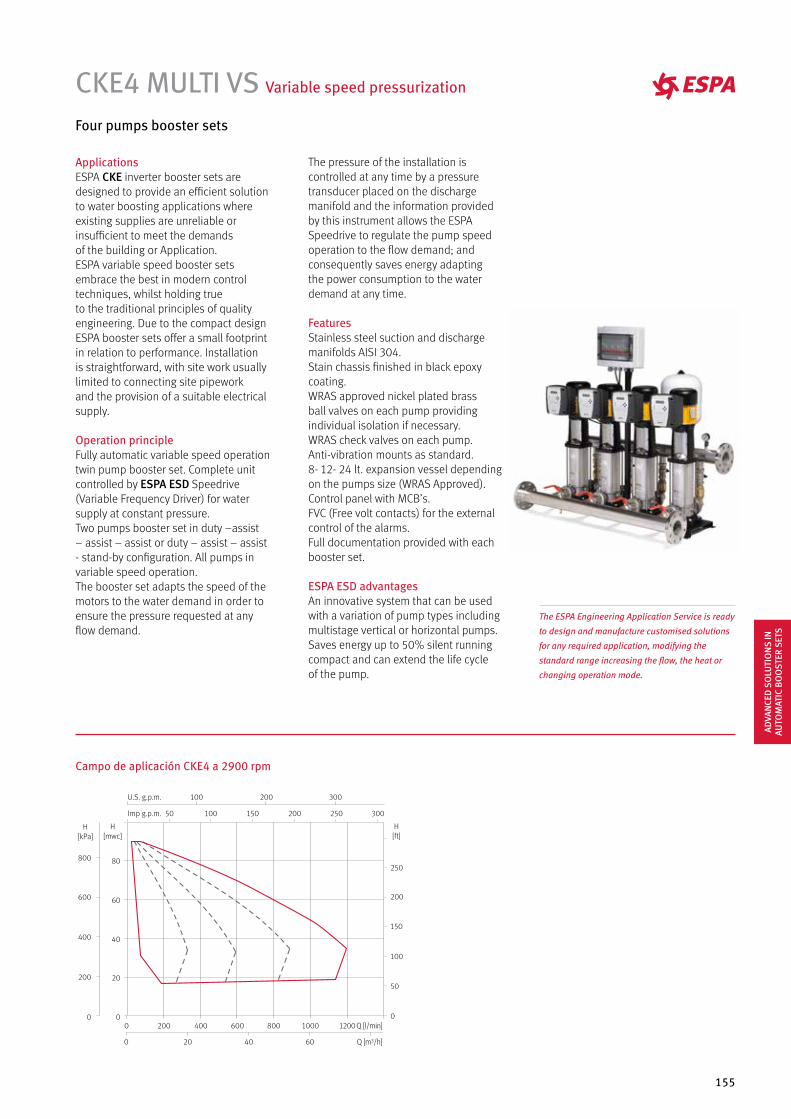
155
CKE4 MULTI VS Variable speed pressurization
Four pumps booster sets
ApplicationsESPA CKE inverter booster sets aredesigned to provide an efficient solutionto water boosting applications whereexisting supplies are unreliable orinsufficient to meet the demandsof the building or Application.ESPA variable speed booster setsembrace the best in modern controltechniques, whilst holding trueto the traditional principles of qualityengineering. Due to the compact designESPA booster sets offer a small footprintin relation to performance. Installationis straightforward, with site work usuallylimited to connecting site pipeworkand the provision of a suitable electricalsupply.
Operation principleFully automatic variable speed operationtwin pump booster set. Complete unitcontrolled by ESPA ESD Speedrive(Variable Frequency Driver) for watersupply at constant pressure.Two pumps booster set in duty –assist– assist – assist or duty – assist – assist- stand-by configuration. All pumps invariable speed operation.The booster set adapts the speed of themotors to the water demand in order toensure the pressure requested at anyflow demand.
The pressure of the installation iscontrolled at any time by a pressuretransducer placed on the dischargemanifold and the information providedby this instrument allows the ESPASpeedrive to regulate the pump speedoperation to the flow demand; andconsequently saves energy adaptingthe power consumption to the waterdemand at any time.
FeaturesStainless steel suction and dischargemanifolds AISI 304.Stain chassis finished in black epoxycoating.WRAS approved nickel plated brassball valves on each pump providingindividual isolation if necessary.WRAS check valves on each pump.Anti-vibration mounts as standard.8- 12- 24 lt. expansion vessel dependingon the pumps size (WRAS Approved).Control panel with MCB’s.FVC (Free volt contacts) for the externalcontrol of the alarms.Full documentation provided with eachbooster set.
ESPA ESD advantagesAn innovative system that can be usedwith a variation of pump types includingmultistage vertical or horizontal pumps.Saves energy up to 50% silent runningcompact and can extend the life cycleof the pump.
Campo de aplicación CKE4 a 2900 rpm
The ESPA Engineering Application Service is ready
to design and manufacture customised solutions
for any required application, modifying the
standard range increasing the flow, the heat or
changing operation mode.
Q [l/min]1000 12008006004002000
6040200 Q [m3/h]
250
200
150
100
50
0
H[ft]
50 100 150 200 250 300
100 200 300
Imp g.p.m.
U.S. g.p.m.
80
60
40
20
0
H[mwc]
800
600
400
200
0
H[kPa]
ADVA
NCE
D S
OLU
TIO
NS
IN
AUTO
MAT
IC B
OO
STER
SET
S
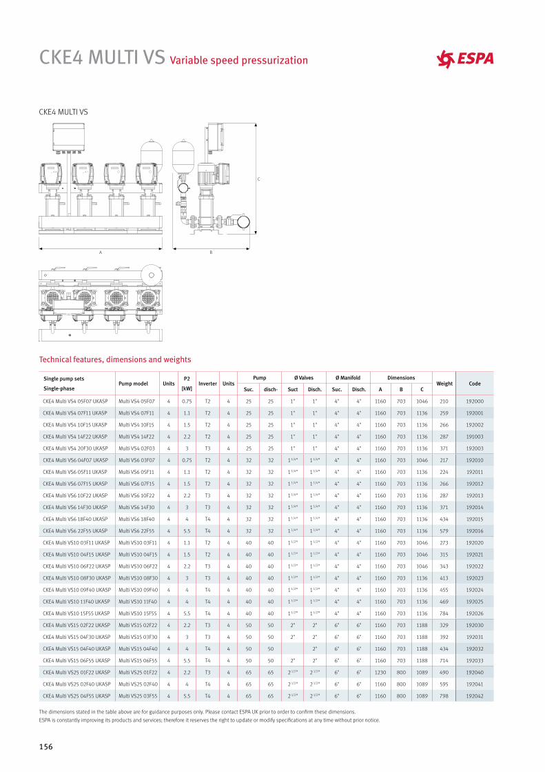
156
CKE4 MULTI VS Variable speed pressurization
Single pump sets
Single-phasePump model Units
P2
[kW]Inverter Units
Pump Ø Valves Ø Manifold Dimensions Weight Code
Suc. disch- Suct Disch. Suc. Disch. A B C
CKE4 Multi VS4 05F07 UKASP Multi VS4 05F07 4 0.75 T2 4 25 25 1" 1" 4" 4" 1160 703 1046 210 192000
CKE4 Multi VS4 07F11 UKASP Multi VS4 07F11 4 1.1 T2 4 25 25 1" 1" 4" 4" 1160 703 1136 259 192001
CKE4 Multi VS4 10F15 UKASP Multi VS4 10F15 4 1.5 T2 4 25 25 1" 1" 4" 4" 1160 703 1136 266 192002
CKE4 Multi VS4 14F22 UKASP Multi VS4 14F22 4 2.2 T2 4 25 25 1" 1" 4" 4" 1160 703 1136 287 191003
CKE4 Multi VS4 20F30 UKASP Multi VS4 02F03 4 3 T3 4 25 25 1" 1" 4" 4" 1160 703 1136 371 192003
CKE4 Multi VS6 04F07 UKASP Multi VS6 03F07 4 0.75 T2 4 32 32 1 1/4" 1 1/4" 4" 4" 1160 703 1046 217 192010
CKE4 Multi VS6 05F11 UKASP Multi VS6 05F11 4 1.1 T2 4 32 32 1 1/4" 1 1/4" 4" 4" 1160 703 1136 224 192011
CKE4 Multi VS6 07F15 UKASP Multi VS6 07F15 4 1.5 T2 4 32 32 1 1/4" 1 1/4" 4" 4" 1160 703 1136 266 192012
CKE4 Multi VS6 10F22 UKASP Multi VS6 10F22 4 2.2 T3 4 32 32 1 1/4" 1 1/4" 4" 4" 1160 703 1136 287 192013
CKE4 Multi VS6 14F30 UKASP Multi VS6 14F30 4 3 T3 4 32 32 1 1/4" 1 1/4" 4" 4" 1160 703 1136 371 192014
CKE4 Multi VS6 18F40 UKASP Multi VS6 18F40 4 4 T4 4 32 32 1 1/4" 1 1/4" 4" 4" 1160 703 1136 434 192015
CKE4 Multi VS6 22F55 UKASP Multi VS6 22F55 4 5.5 T4 4 32 32 1 1/4" 1 1/4" 4" 4" 1160 703 1136 579 192016
CKE4 Multi VS10 03F11 UKASP Multi VS10 03F11 4 1.1 T2 4 40 40 1 1/2" 1 1/2" 4" 4" 1160 703 1046 273 192020
CKE4 Multi VS10 04F15 UKASP Multi VS10 04F15 4 1.5 T2 4 40 40 1 1/2" 1 1/2" 4" 4" 1160 703 1046 315 192021
CKE4 Multi VS10 06F22 UKASP Multi VS10 06F22 4 2.2 T3 4 40 40 1 1/2" 1 1/2" 4" 4" 1160 703 1046 343 192022
CKE4 Multi VS10 08F30 UKASP Multi VS10 08F30 4 3 T3 4 40 40 1 1/2" 1 1/2" 4" 4" 1160 703 1136 413 192023
CKE4 Multi VS10 09F40 UKASP Multi VS10 09F40 4 4 T4 4 40 40 1 1/2" 1 1/2" 4" 4" 1160 703 1136 455 192024
CKE4 Multi VS10 11F40 UKASP Multi VS10 11F40 4 4 T4 4 40 40 1 1/2" 1 1/2" 4" 4" 1160 703 1136 469 192025
CKE4 Multi VS10 15F55 UKASP Multi VS10 15F55 4 5.5 T4 4 40 40 1 1/2" 1 1/2" 4" 4" 1160 703 1136 784 192026
CKE4 Multi VS15 02F22 UKASP Multi VS15 02F22 4 2.2 T3 4 50 50 2" 2" 6" 6" 1160 703 1188 329 192030
CKE4 Multi VS15 04F30 UKASP Multi VS15 03F30 4 3 T3 4 50 50 2" 2" 6" 6" 1160 703 1188 392 192031
CKE4 Multi VS15 04F40 UKASP Multi VS15 04F40 4 4 T4 4 50 50 2" 6" 6" 1160 703 1188 434 192032
CKE4 Multi VS15 06F55 UKASP Multi VS15 06F55 4 5.5 T4 4 50 50 2" 2" 6" 6" 1160 703 1188 714 192033
CKE4 Multi VS25 01F22 UKASP Multi VS25 01F22 4 2.2 T3 4 65 65 2 1/2" 2 1/2" 6" 6" 1230 800 1089 490 192040
CKE4 Multi VS25 02F40 UKASP Multi VS25 02F40 4 4 T4 4 65 65 2 1/2" 2 1/2" 6" 6" 1160 800 1089 595 192041
CKE4 Multi VS25 04F55 UKASP Multi VS25 03F55 4 5.5 T4 4 65 65 2 1/2" 2 1/2" 6" 6" 1160 800 1089 798 192042
Technical features, dimensions and weights
CKE4 MULTI VS
The dimensions stated in the table above are for guidance purposes only. Please contact ESPA UK prior to order to confirm these dimensions.
ESPA is constantly improving its products and services; therefore it reserves the right to update or modify specifications at any time without prior notice.
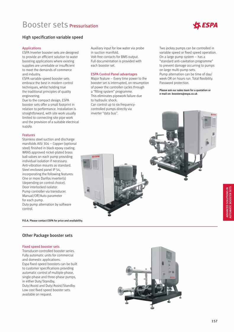
157
Auxiliary input for low water via probe in suction manifold.Volt-free contacts for BMS output.Full documentation is provided with each booster set.
ESPA Control Panel advantagesMajor feature – Every time power to the booster set is interrupted, on resumption of power the controller cycles through a “filling system” programme. This eliminates pipework failure due to hydraulic shock.Can control up to six frequency-controlled pumps directly via inverter “data bus”.
Booster sets Pressurisation
High specification variable speed
ApplicationsESPA Inverter booster sets are designed to provide an efficient solution to water boosting applications where existing supplies are unreliable or insufficient to meet the demands of commerce and industry.ESPA variable speed booster sets embrace the best in modern control techniques, whilst holding true the traditional principles of quality engineering.Due to the compact design, ESPA booster sets offer a small footprint in relation to performance. Installation is straightforward, with site work usually limited to connecting site pipe work and the provision of a suitable electrical supply.
FeaturesStainless steel suction and discharge manifolds AISI 304 – Copper (optional steel) finished in black epoxy coating.WRAS approved nickel-plated brass ball valves on each pump providing individual isolation if necessary.Anti-vibration mounts as standard.Steel enclosed panel IP 54, incorporating the following features: One or more Danfos inverter(s) (depending on control choice).Door interlocked isolator.Pump controller via transducer.Manual/Off/Auto parameter for each pump.Duty pump alternation by software control.
Other Package booster sets
Fixed speed booster setsTransducer-controlled booster series. Fully automatic units for commercial and domestic applications.Espa fixed-speed boosters can be built to customer specifications providing automatic control of multiple-phase, single-phase and three-phase pumps, in either Duty/Standby, Duty/Assist and Duty/Assist/Standby.Low cost fixed speed booster sets available on request.
Two jockey pumps can be controlled in variable speed or fixed speed operation.On a large pump system – has a “standard anti-cavitation programme” to prevent damage occurring to pumps on large multi-pump sets.Pump alternation can be time of day/week OR on hours run. Total flexibility.Password protection.
Please ask our sales team for a quotation or e-mail on: [email protected]
P.O.A. Please contact ESPA for price and availability.
ADVA
NCE
D S
OLU
TIO
NS
IN
AUTO
MAT
IC B
OO
STER
SET
S

FIRE-FIGHTING BOOSTER SETSRange overviewUE/U2E/UD/UED Fire sprinkler systems for domestic and residential occupancies according with BS 9251:2014 and BRE LPS 1131
RE/RD/RED for sprinklerswater supply according to BS 12845: 2015
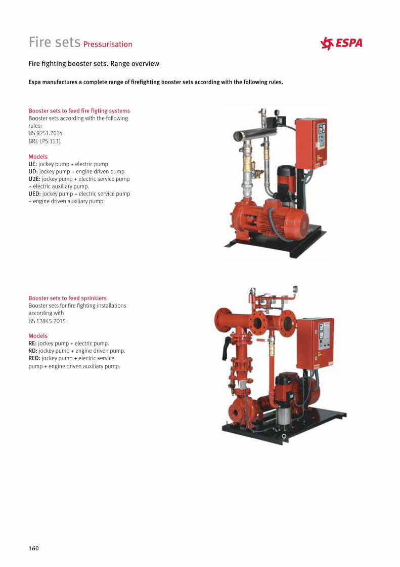
160
Fire sets Pressurisation
Booster sets to feed sprinklersBooster sets for fire fighting installations according with BS 12845:2015
ModelsRE: jockey pump + electric pump.RD: jockey pump + engine driven pump.RED: jockey pump + electric service pump + engine driven auxiliary pump.
Fire fighting booster sets. Range overview
Booster sets to feed fire figting systemsBooster sets according with the following rules: BS 9251:2014BRE LPS 1131
ModelsUE: jockey pump + electric pump.UD: jockey pump + engine driven pump.U2E: jockey pump + electric service pump + electric auxiliary pump.UED: jockey pump + electric service pump + engine driven auxiliary pump.
Espa manufactures a complete range of firefighting booster sets according with the following rules.
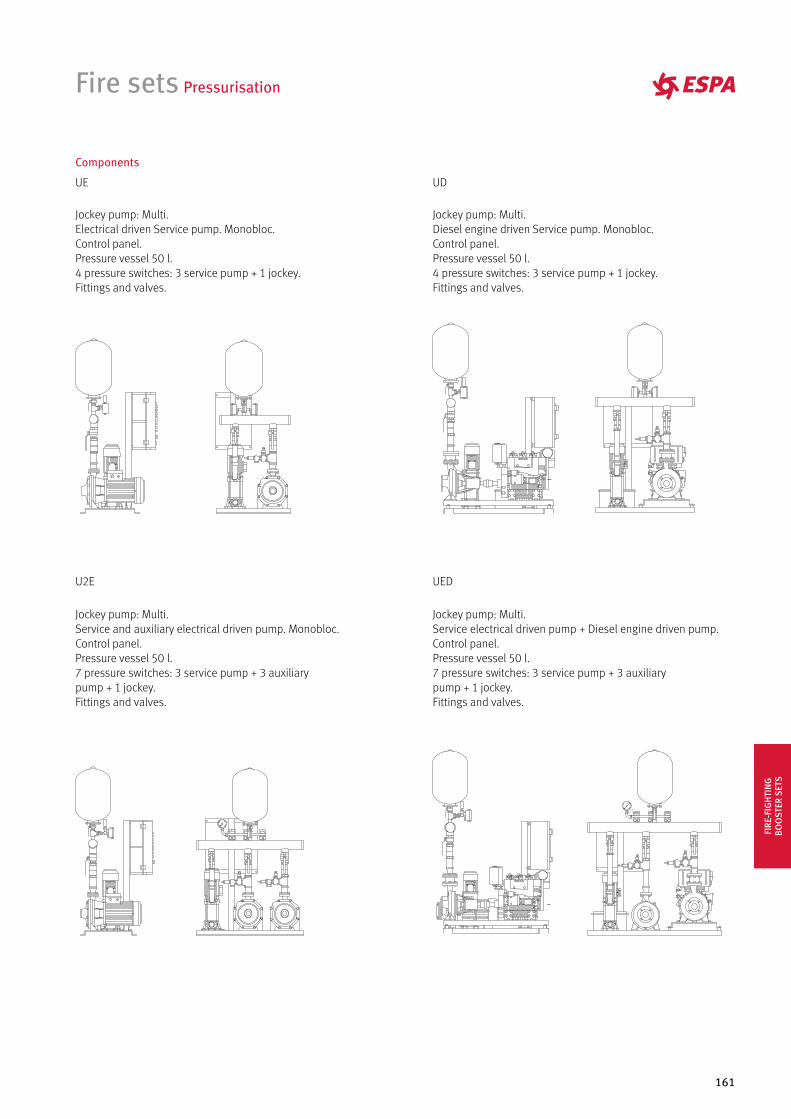
161
Fire sets Pressurisation
Components
UE
Jockey pump: Multi.Electrical driven Service pump. Monobloc.Control panel.Pressure vessel 50 l.4 pressure switches: 3 service pump + 1 jockey.Fittings and valves.
U2E
Jockey pump: Multi.Service and auxiliary electrical driven pump. Monobloc.Control panel.Pressure vessel 50 l.7 pressure switches: 3 service pump + 3 auxiliary pump + 1 jockey.Fittings and valves.
64
2
10
8
0 ESPA
UD
Jockey pump: Multi.Diesel engine driven Service pump. Monobloc.Control panel.Pressure vessel 50 l.4 pressure switches: 3 service pump + 1 jockey.Fittings and valves.
LOMBARDINI
UED
Jockey pump: Multi.Service electrical driven pump + Diesel engine driven pump.Control panel.Pressure vessel 50 l.7 pressure switches: 3 service pump + 3 auxiliary pump + 1 jockey.Fittings and valves.
LOMBARDINI
ESPA010
2
4
8
6
FIRE
-FIG
HTI
NG
BOO
STER
SET
S
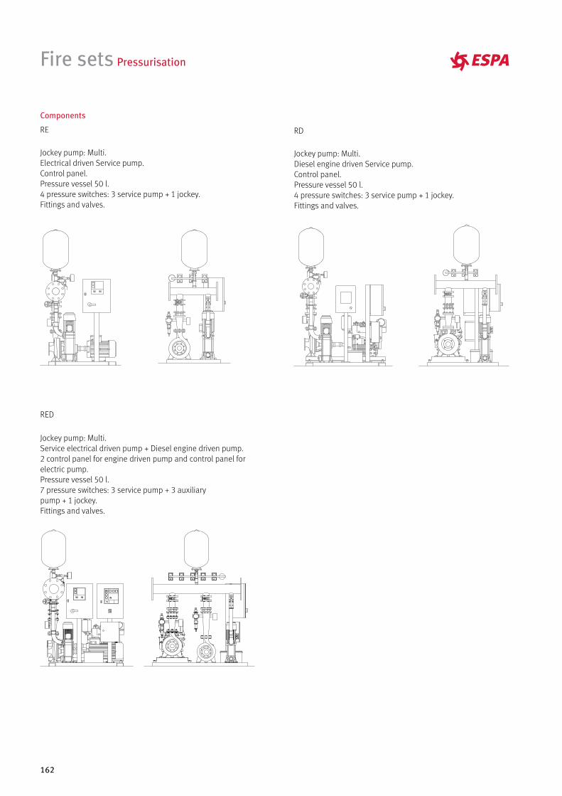
162
Fire sets Pressurisation
Components
RE RD
Jockey pump: Multi.Electrical driven Service pump.Control panel.Pressure vessel 50 l.4 pressure switches: 3 service pump + 1 jockey.Fittings and valves.
Jockey pump: Multi.Diesel engine driven Service pump.Control panel.Pressure vessel 50 l.4 pressure switches: 3 service pump + 1 jockey.Fittings and valves.
RED
Jockey pump: Multi.Service electrical driven pump + Diesel engine driven pump.2 control panel for engine driven pump and control panel for electric pump.Pressure vessel 50 l.7 pressure switches: 3 service pump + 3 auxiliary pump + 1 jockey.Fittings and valves.

RAINWATER HARVESTING
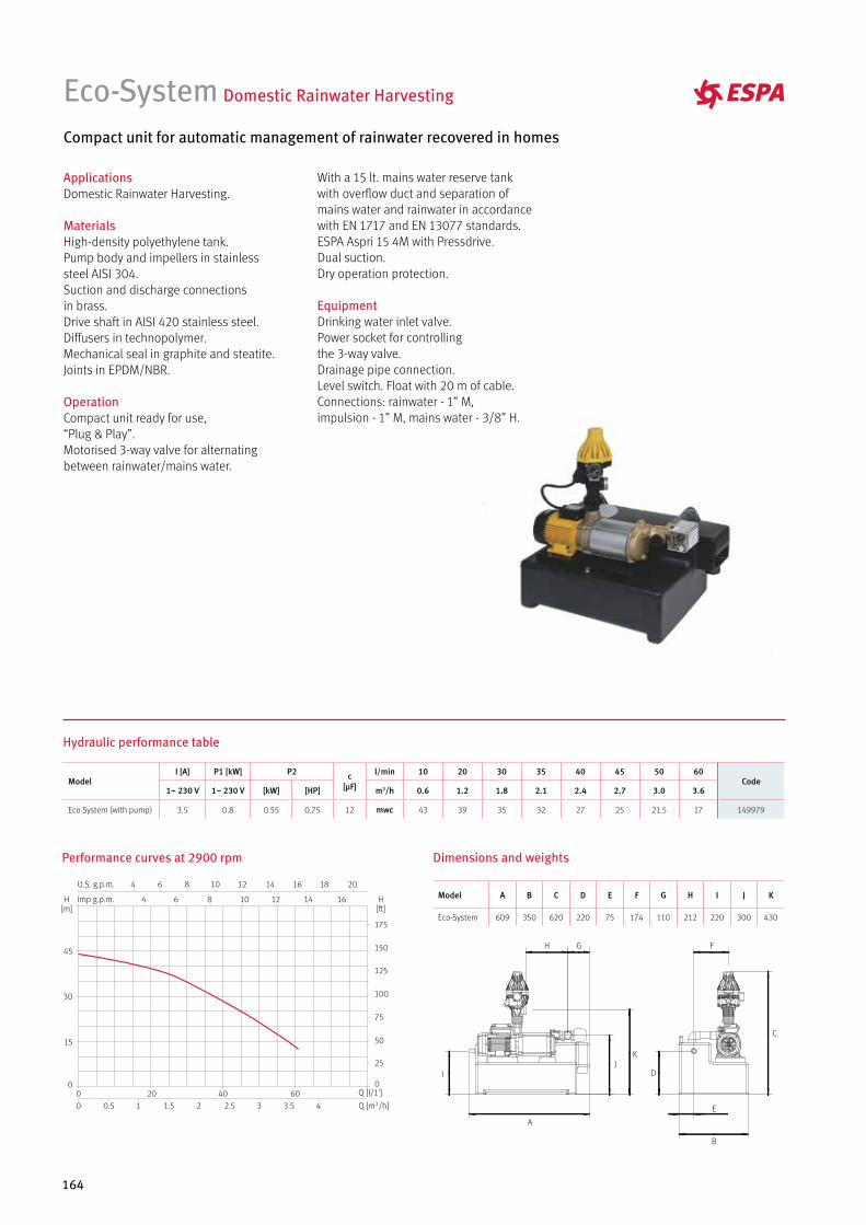
164
Eco-System Domestic Rainwater Harvesting
Compact unit for automatic management of rainwater recovered in homes
ApplicationsDomestic Rainwater Harvesting. MaterialsHigh-density polyethylene tank.Pump body and impellers in stainless steel AISI 304. Suction and discharge connections in brass.Drive shaft in AISI 420 stainless steel.Diffusers in technopolymer.Mechanical seal in graphite and steatite.Joints in EPDM/NBR.
OperationCompact unit ready for use, “Plug & Play”.Motorised 3-way valve for alternating between rainwater/mains water.
With a 15 lt. mains water reserve tank with overflow duct and separation of mains water and rainwater in accordance with EN 1717 and EN 13077 standards. ESPA Aspri 15 4M with Pressdrive.Dual suction. Dry operation protection.
EquipmentDrinking water inlet valve.Power socket for controlling the 3-way valve. Drainage pipe connection. Level switch. Float with 20 m of cable. Connections: rainwater - 1” M, impulsion - 1” M, mains water - 3/8” H.
Dimensions and weightsPerformance curves at 2900 rpm
Hydraulic performance table
ModelI [A] P1 [kW] P2 c
[µF]
l/min 10 20 30 35 40 45 50 60Code
1~ 230 V 1~ 230 V [kW] [HP] m3/h 0.6 1.2 1.8 2.1 2.4 2.7 3.0 3.6
Eco System (with pump) 3.5 0.8 0.55 0.75 12 mwc 43 39 35 32 27 25 21.5 17 149979
A
B
E
FGH
IJ
K
C
D
Model A B C D E F G H I J K
Eco-System 609 350 620 220 75 174 110 212 220 300 430
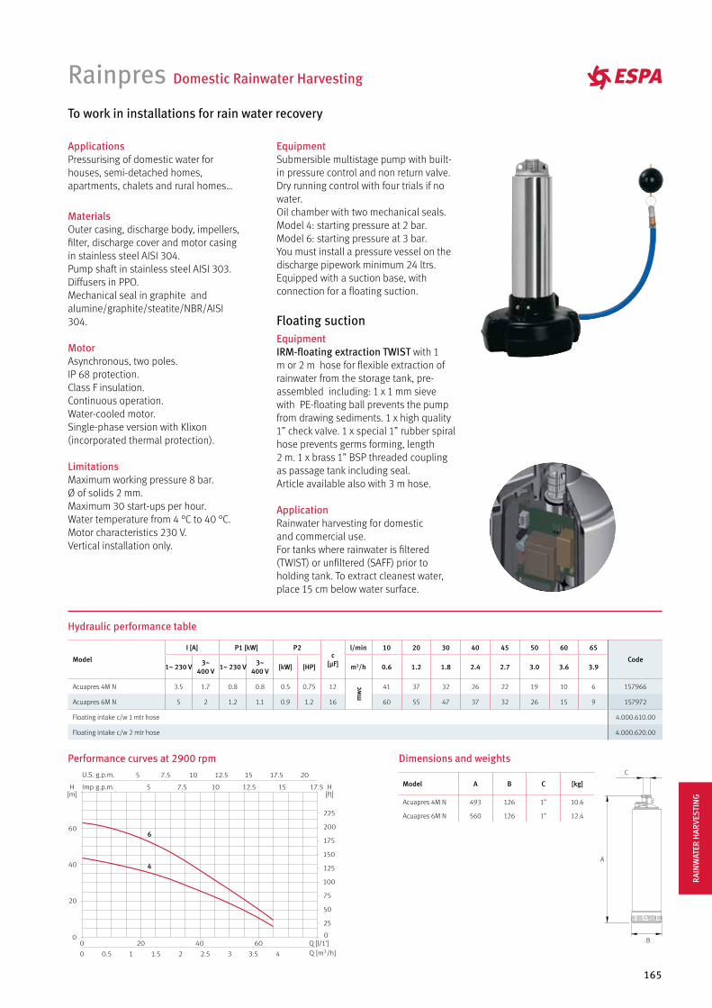
165
Model
I [A] P1 [kW] P2c
[µF]
l/min 10 20 30 40 45 50 60 65
Code1~ 230 V 3~
400 V 1~ 230 V 3~400 V [kW] [HP] m3/h 0.6 1.2 1.8 2.4 2.7 3.0 3.6 3.9
Acuapres 4M N 3.5 1.7 0.8 0.8 0.5 0.75 12
mw
c 41 37 32 26 22 19 10 6 157966
Acuapres 6M N 5 2 1.2 1.1 0.9 1.2 16 60 55 47 37 32 26 15 9 157972
Floating intake c/w 1 mtr hose 4.000.610.00
Floating intake c/w 2 mtr hose 4.000.620.00
Model A B C [kg]
Acuapres 4M N 493 126 1” 10.6
Acuapres 6M N 560 126 1” 12.4
Rainpres Domestic Rainwater Harvesting
To work in installations for rain water recovery
ApplicationsPressurising of domestic water for houses, semi-detached homes, apartments, chalets and rural homes…
MaterialsOuter casing, discharge body, impellers, filter, discharge cover and motor casing in stainless steel AISI 304. Pump shaft in stainless steel AISI 303.Diffusers in PPO. Mechanical seal in graphite and alumine/graphite/steatite/NBR/AISI 304.
MotorAsynchronous, two poles. IP 68 protection. Class F insulation.Continuous operation.Water-cooled motor. Single-phase version with Klixon (incorporated thermal protection).
LimitationsMaximum working pressure 8 bar.Ø of solids 2 mm.Maximum 30 start-ups per hour.Water temperature from 4 °C to 40 °C.Motor characteristics 230 V.Vertical installation only.
EquipmentSubmersible multistage pump with built-in pressure control and non return valve.Dry running control with four trials if no water.Oil chamber with two mechanical seals.Model 4: starting pressure at 2 bar.Model 6: starting pressure at 3 bar.You must install a pressure vessel on the discharge pipework minimum 24 ltrs.Equipped with a suction base, with connection for a floating suction.
Hydraulic performance table
A
B
C
Performance curves at 2900 rpm Dimensions and weights
4
6
EquipmentIRM-floating extraction TWIST with 1 m or 2 m hose for flexible extraction of rainwater from the storage tank, pre-assembled including: 1 x 1 mm sieve with PE-floating ball prevents the pump from drawing sediments. 1 x high quality 1” check valve. 1 x special 1” rubber spiral hose prevents germs forming, length 2 m. 1 x brass 1” BSP threaded coupling as passage tank including seal.Article available also with 3 m hose.
ApplicationRainwater harvesting for domestic and commercial use.For tanks where rainwater is filtered (TWIST) or unfiltered (SAFF) prior to holding tank. To extract cleanest water, place 15 cm below water surface.
Floating suction
RAIN
WAT
ER H
ARVE
STIN
G
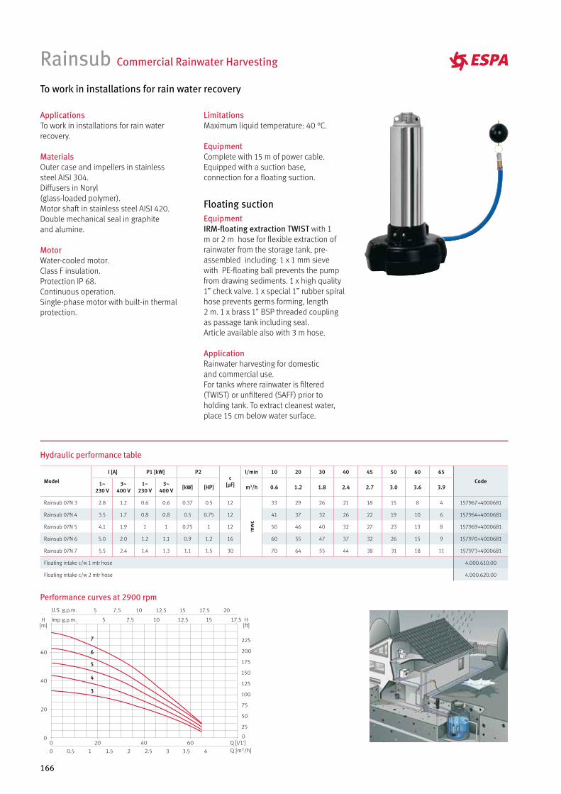
166
Model
I [A] P1 [kW] P2c
[µF]
l/min 10 20 30 40 45 50 60 65
Code1~ 230 V
3~400 V
1~ 230 V
3~400 V [kW] [HP] m3/h 0.6 1.2 1.8 2.4 2.7 3.0 3.6 3.9
Rainsub 07N 3 2.8 1.2 0.6 0.6 0.37 0.5 12
mw
c
33 29 26 21 18 15 8 4 157967+4000681
Rainsub 07N 4 3.5 1.7 0.8 0.8 0.5 0.75 12 41 37 32 26 22 19 10 6 157964+4000681
Rainsub 07N 5 4.1 1.9 1 1 0.75 1 12 50 46 40 32 27 23 13 8 157969+4000681
Rainsub 07N 6 5.0 2.0 1.2 1.1 0.9 1.2 16 60 55 47 37 32 26 15 9 157970+4000681
Rainsub 07N 7 5.5 2.4 1.4 1.3 1.1 1.5 30 70 64 55 44 38 31 18 11 157973+4000681
Floating intake c/w 1 mtr hose 4.000.610.00
Floating intake c/w 2 mtr hose 4.000.620.00
EquipmentIRM-floating extraction TWIST with 1 m or 2 m hose for flexible extraction of rainwater from the storage tank, pre-assembled including: 1 x 1 mm sieve with PE-floating ball prevents the pump from drawing sediments. 1 x high quality 1” check valve. 1 x special 1” rubber spiral hose prevents germs forming, length 2 m. 1 x brass 1” BSP threaded coupling as passage tank including seal.Article available also with 3 m hose.
ApplicationRainwater harvesting for domestic and commercial use.For tanks where rainwater is filtered (TWIST) or unfiltered (SAFF) prior to holding tank. To extract cleanest water, place 15 cm below water surface.
Floating suction
To work in installations for rain water recovery
Rainsub Commercial Rainwater Harvesting
ApplicationsTo work in installations for rain water recovery.
MaterialsOuter case and impellers in stainless steel AISI 304.Diffusers in Noryl (glass-loaded polymer).Motor shaft in stainless steel AISI 420.Double mechanical seal in graphite and alumine.
MotorWater-cooled motor. Class F insulation.Protection IP 68.Continuous operation.Single-phase motor with built-in thermal protection.
LimitationsMaximum liquid temperature: 40 °C.
EquipmentComplete with 15 m of power cable.Equipped with a suction base, connection for a floating suction.
Hydraulic performance table
Performance curves at 2900 rpm
7
6
5
4
3

ACCESSORIES,CONTROL PANELS & INVERTERS
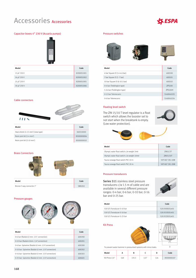
168
Accessories Accessories
Floating level switch
The ZIN 15/10 T level regulator is a float switch which allows the booster set to not start when the breaktank is empty. (Low water protection).
Pressure transducers
Series 511 stainless steel pressure transducers c/w 1.5 m of cable and are available in several different pressure ranges: 0-4 bar, 0-6 bar, 0-10 bar, 0-16 bar and 0-25 bar.
Model Code
12 µF 230 V 8200051001
16 µF 230 V 8200051002
25 µF 230 V 8200051005
30 µF 230 V 8200051006
Model Code
Heat shrink (1-2.5 mm2) (new type) 369210000
Resin joint kit (1-4 mm2) 8500000004
Resin joint kit (5-10 mm2) 8500000010
Model Code
Bronze 5 way connector 1” 5M0202
Model Code
518 S/S Transducer 0-10 bar 520.930S03L401
518 S/S Transducer 0-16 bar 520.931S03L401
518 S/S Transducer 0-25 bar 520.932S03L401
Model Code
0-6 bar (Radial 63 mm. 1/4" connection) 600200
0-10 bar (Radial 63mm. 1/4"connection) 600201
0-6 bar Gylcerine (Radial 63 mm. 1/4"connection) 600300
0-10 bar Gylcerine (Radial 63 mm. 1/4”connection) 600302
0-16 bar Gylcerine (Radial 63 mm. 1/4”connection) 600303
0-25 bar Gylcerine (Radial 63 mm. 1/4”connection) 600401
Model Code
Olympic water float switch c/w weight 3mtr ZIN15/3T
Olympic water float switch c/w weight 10mtr ZIN15/10T
Taurus sewage float switch PVC 10 m VVF A07 3X1-10M
Taurus sewage float switch PVC 20 m VVF A07 3X1-20M
Model Code
4 bar Square D (1.4-4.6 bar) 600100
7 bar Square D (3 -7 bar) 600101
10 bar Square D (6-10.5 bar) 600102
0-6 bar (Teddington type) ZPS100
5-24 bar (Teddington type) ZPS100H
0-12 bar Telemecanic 5140041035
0-6 bar Telemecanic 5140041034
Capacitor boxes 4” 230 V (Acuaria pumps)
Cable connectors
Brass Connectors
A
C
D
B
To prevent water hammer in pressurised systems with minor leaks.
Model A B C D Code
Kit Press 1/4” 148 135.5 1/4” 124 8500000107
Kit Press
Pressure gauges
Pressure switches
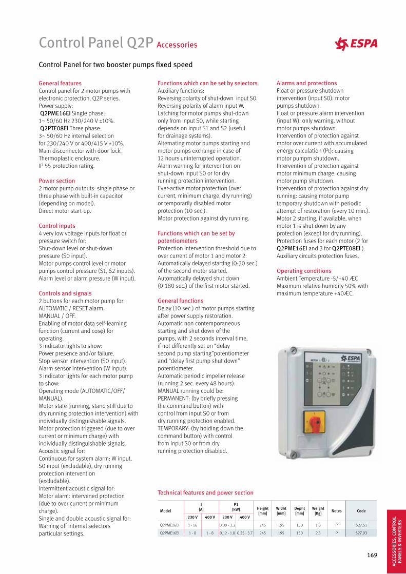
169
Control Panel Q2P Accessories
Control Panel for two booster pumps fixed speed
General featuresControl panel for 2 motor pumps withelectronic protection, Q2P series.Power supply: Q2PME16EI Single phase:1~ 50/60 Hz 230/240 V ±10%. Q2PTE08EI Three phase:3~ 50/60 Hz internal selectionfor 230/240 V or 400/415 V ±10%.Main disconnector with door lock.Thermoplastic enclosure.IP 55 protection rating.
Power section2 motor pump outputs: single phase orthree phase with built-in capacitor(depending on model).Direct motor start-up.
Control inputs4 very low voltage inputs for float orpressure switch for:Shut-down level or shut-downpressure (S0 input).Motor pumps control level or motorpumps control pressure (S1, S2 inputs).Alarm level or alarm pressure (W input).
Controls and signals2 buttons for each motor pump for:AUTOMATIC / RESET alarm.MANUAL / OFF.Enabling of motor data self-learningfunction (current and cosφ) foroperating.3 indicator lights to show:Power presence and/or failure.Stop sensor intervention (S0 input).Alarm sensor intervention (W input).3 indicator lights for each motor pumpto show:Operating mode (AUTOMATIC/OFF/ MANUAL).Motor state (running, stand still due to dry running protection intervention) with individually distinguishable signals.Motor protection triggered (due to over current or minimum charge) with individually distinguishable signals.Acoustic signal for:Continuous for system alarm: W input, S0 input (excludable), dry running protection intervention(excludable).Intermittent acoustic signal for:Motor alarm: intervened protection(due to over current or minimum charge).Single and double acoustic signal for:Warning off internal selectorsparticular settings.
Functions which can be set by selectorsAuxiliary functions:Reversing polarity of shut-down input S0.Reversing polarity of alarm input W.Latching for motor pumps shut-downonly from input S0, while startingdepends on input S1 and S2 (usefulfor drainage systems).Alternating motor pumps starting andmotor pumps exchange in case of12 hours uninterrupted operation.Alarm warning for intervention onshut-down input S0 or for dryrunning protection intervention.Ever-active motor protection (overcurrent, minimum charge, dry running)or temporarily disabled motorprotection (10 sec.).Motor protection against dry running.
Functions which can be set by potentiometersProtection intervention threshold due to over current of motor 1 and motor 2:Automatically delayed starting (0-30 sec.) of the second motor started.Automatically delayed shut down (0-180 sec.) of the first motor started.
General functionsDelay (10 sec.) of motor pumps startingafter power supply restoration.Automatic non contemporaneousstarting and shut down of thepumps, with 2 seconds interval time, if not differently set on “delaysecond pump starting”potentiometer and “delay first pump shut down” potentiometer.Automatic periodic impeller release(running 2 sec. every 48 hours).MANUAL running could be:PERMANENT: (by briefly pressingthe command button) withcontrol from input S0 or fromdry running protection enabled.TEMPORARY: (by holding down thecommand button) with controlfrom input S0 or from dryrunning protection disabled.
Alarms and protectionsFloat or pressure shutdownintervention (input S0): motorpumps shutdown.Float or pressure alarm intervention(input W): only warning, withoutmotor pumps shutdown.Intervention of protection againstmotor over current with accumulated energy calculation (I2t): causing motor pumpm shutdown.Intervention of protection againstmotor minimum charge: causingmotor pump shutdown.Intervention of protection against dryrunning: causing motor pumptemporary shutdown with periodicattempt of restoration (every 10 min.).Motor 2 starting, if available, whenmotor 1 is shut down by anyprotection (except for dry running).Protection fuses for each motor (2 forQ2PME16EI and 3 for Q2PTE08EI ).Auxiliary circuits protection fuses.
Operating conditionsAmbient Temperature -5/+40 ÆCMaximum relative humidity 50% withmaximum temperature +40ÆC.
Technical features and power section
Model
I [A]
P1 [kW] Height
[mm]Widht[mm]
Depht[mm]
Weight[Kg] Notes Code
230 V 400 V 230 V 400 V
Q2PME16EI 1 - 16 0.09 - 2.2 245 195 150 1.8 P 527.51
Q2PME16EI 1 - 8 1 - 8 0.12 - 1.8 0.25 - 3.7 245 195 150 2.5 P 527.93
ACCE
SSO
RIES
, CO
NTR
OL
PAN
ELS
& IN
VERT
ERS

TECHNICAL INFORMATION
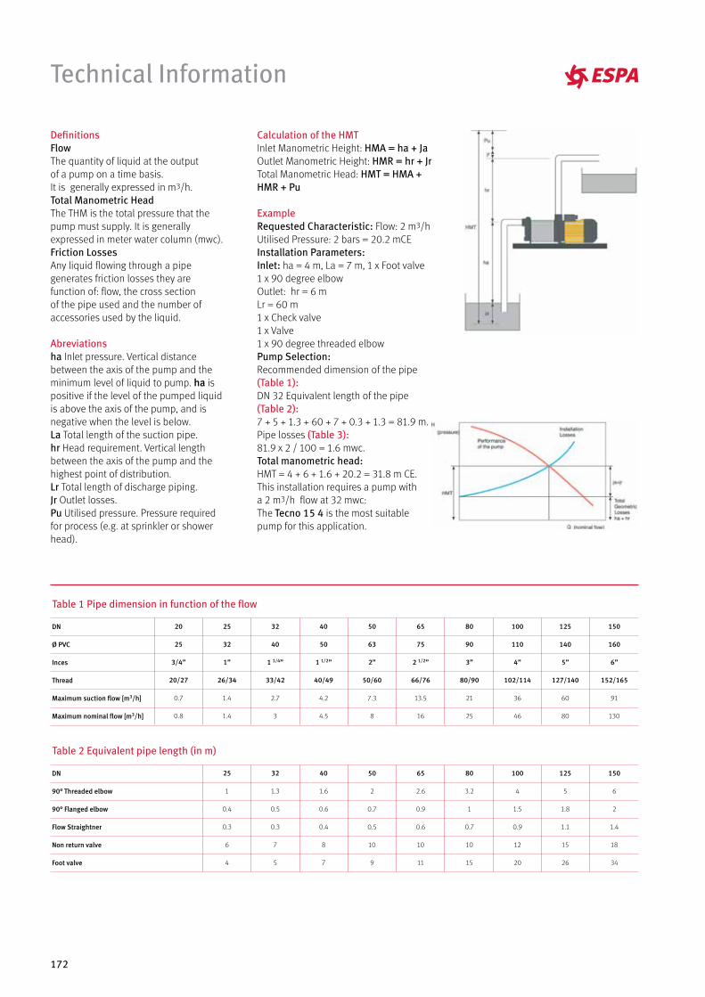
172
Technical Information
Table 1 Pipe dimension in function of the flow
Table 2 Equivalent pipe length (in m)
DN
Ø PVC
Inces
Thread
Maximum suction flow [m3/h]
Maximum nominal flow [m3/h]
20
25
3/4”
20/27
0.7
0.8
25
32
1”
26/34
1.4
1.4
32
40
1 1/4”
33/42
2.7
3
40
50
1 1/2”
40/49
4.2
4.5
80
90
3”
80/90
21
25
150
160
6”
152/165
91
130
125
140
5”
127/140
60
80
100
110
4”
102/114
36
46
65
75
2 1/2”
66/76
13.5
16
50
63
2”
50/60
7.3
8
DN
90° Threaded elbow
90° Flanged elbow
Flow Straightner
Non return valve
Foot valve
25
1
0.4
0.3
6
4
32
1.3
0.5
0.3
7
5
40
1.6
0.6
0.4
8
7
80
3.2
1
0.7
10
15
150
6
2
1.4
18
34
125
5
1.8
1.1
15
26
100
4
1.5
0.9
12
20
65
2.6
0.9
0.6
10
11
50
2
0.7
0.5
10
9
DefinitionsFlowThe quantity of liquid at the output of a pump on a time basis.It is generally expressed in m3/h.Total Manometric HeadThe THM is the total pressure that the pump must supply. It is generally expressed in meter water column (mwc).Friction LossesAny liquid flowing through a pipe generates friction losses they are function of: flow, the cross section of the pipe used and the number of accessories used by the liquid.
Abreviationsha Inlet pressure. Vertical distance between the axis of the pump and the minimum level of liquid to pump. ha is positive if the level of the pumped liquid is above the axis of the pump, and is negative when the level is below. La Total length of the suction pipe.hr Head requirement. Vertical length between the axis of the pump and the highest point of distribution.Lr Total length of discharge piping. Jr Outlet losses.Pu Utilised pressure. Pressure required for process (e.g. at sprinkler or shower head).
Calculation of the HMTInlet Manometric Height: HMA = ha + JaOutlet Manometric Height: HMR = hr + JrTotal Manometric Head: HMT = HMA + HMR + Pu
ExampleRequested Characteristic: Flow: 2 m3/hUtilised Pressure: 2 bars = 20.2 mCEInstallation Parameters:Inlet: ha = 4 m, La = 7 m, 1 x Foot valve1 x 90 degree elbow Outlet: hr = 6 mLr = 60 m1 x Check valve1 x Valve1 x 90 degree threaded elbowPump Selection:Recommended dimension of the pipe (Table 1): DN 32 Equivalent length of the pipe (Table 2):7 + 5 + 1.3 + 60 + 7 + 0.3 + 1.3 = 81.9 m.Pipe losses (Table 3): 81.9 x 2 / 100 = 1.6 mwc.Total manometric head:HMT = 4 + 6 + 1.6 + 20.2 = 31.8 m CE.This installation requires a pump with a 2 m3/h flow at 32 mwc: The Tecno 15 4 is the most suitable pump for this application.
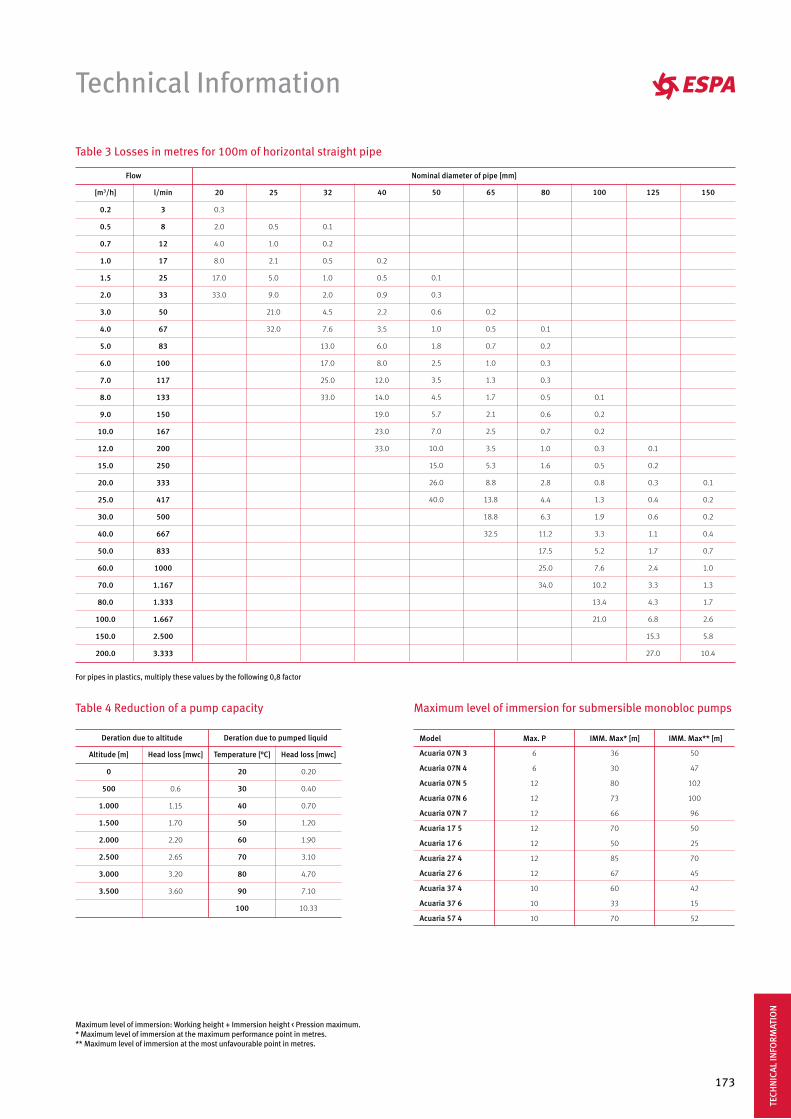
173
Technical Information
Table 4 Reduction of a pump capacity
Altitude [m]
0
500
1.000
1.500
2.000
2.500
3.000
3.500
Head loss [mwc]
0.6
1.15
1.70
2.20
2.65
3.20
3.60
Temperature [°C]
20
30
40
50
60
70
80
90
100
Head loss [mwc]
0.20
0.40
0.70
1.20
1.90
3.10
4.70
7.10
10.33
Deration due to pumped liquidDeration due to altitude
Table 3 Losses in metres for 100m of horizontal straight pipe
For pipes in plastics, multiply these values by the following 0,8 factor
[m3/h]
0.2
0.5
0.7
1.0
1.5
2.0
3.0
4.0
5.0
6.0
7.0
8.0
9.0
10.0
12.0
15.0
20.0
25.0
30.0
40.0
50.0
60.0
70.0
80.0
100.0
150.0
200.0
l/min
3
8
12
17
25
33
50
67
83
100
117
133
150
167
200
250
333
417
500
667
833
1000
1.167
1.333
1.667
2.500
3.333
20
0.3
2.0
4.0
8.0
17.0
33.0
25
0.5
1.0
2.1
5.0
9.0
21.0
32.0
32
0.1
0.2
0.5
1.0
2.0
4.5
7.6
13.0
17.0
25.0
33.0
40
0.2
0.5
0.9
2.2
3.5
6.0
8.0
12.0
14.0
19.0
23.0
33.0
80
0.1
0.2
0.3
0.3
0.5
0.6
0.7
1.0
1.6
2.8
4.4
6.3
11.2
17.5
25.0
34.0
150
0.1
0.2
0.2
0.4
0.7
1.0
1.3
1.7
2.6
5.8
10.4
125
0.1
0.2
0.3
0.4
0.6
1.1
1.7
2.4
3.3
4.3
6.8
15.3
27.0
100
0.1
0.2
0.2
0.3
0.5
0.8
1.3
1.9
3.3
5.2
7.6
10.2
13.4
21.0
65
0.2
0.5
0.7
1.0
1.3
1.7
2.1
2.5
3.5
5.3
8.8
13.8
18.8
32.5
50
0.1
0.3
0.6
1.0
1.8
2.5
3.5
4.5
5.7
7.0
10.0
15.0
26.0
40.0
Nominal diameter of pipe [mm]Flow
Maximum level of immersion for submersible monobloc pumps
IMM. Max* [m] IMM. Max** [m]Model Max. P
Acuaria 07N 3
Acuaria 07N 4
Acuaria 07N 5
Acuaria 07N 6
Acuaria 07N 7
Acuaria 17 5
Acuaria 17 6
Acuaria 27 4
Acuaria 27 6
Acuaria 37 4
Acuaria 37 6
Acuaria 57 4
6
6
12
12
12
12
12
12
12
10
10
10
36
30
80
73
66
70
50
85
67
60
33
70
50
47
102
100
96
50
25
70
45
42
15
52
Maximum level of immersion: Working height + Immersion height < Pression maximum. * Maximum level of immersion at the maximum performance point in metres.** Maximum level of immersion at the most unfavourable point in metres.
TECH
NIC
AL IN
FORM
ATIO
N
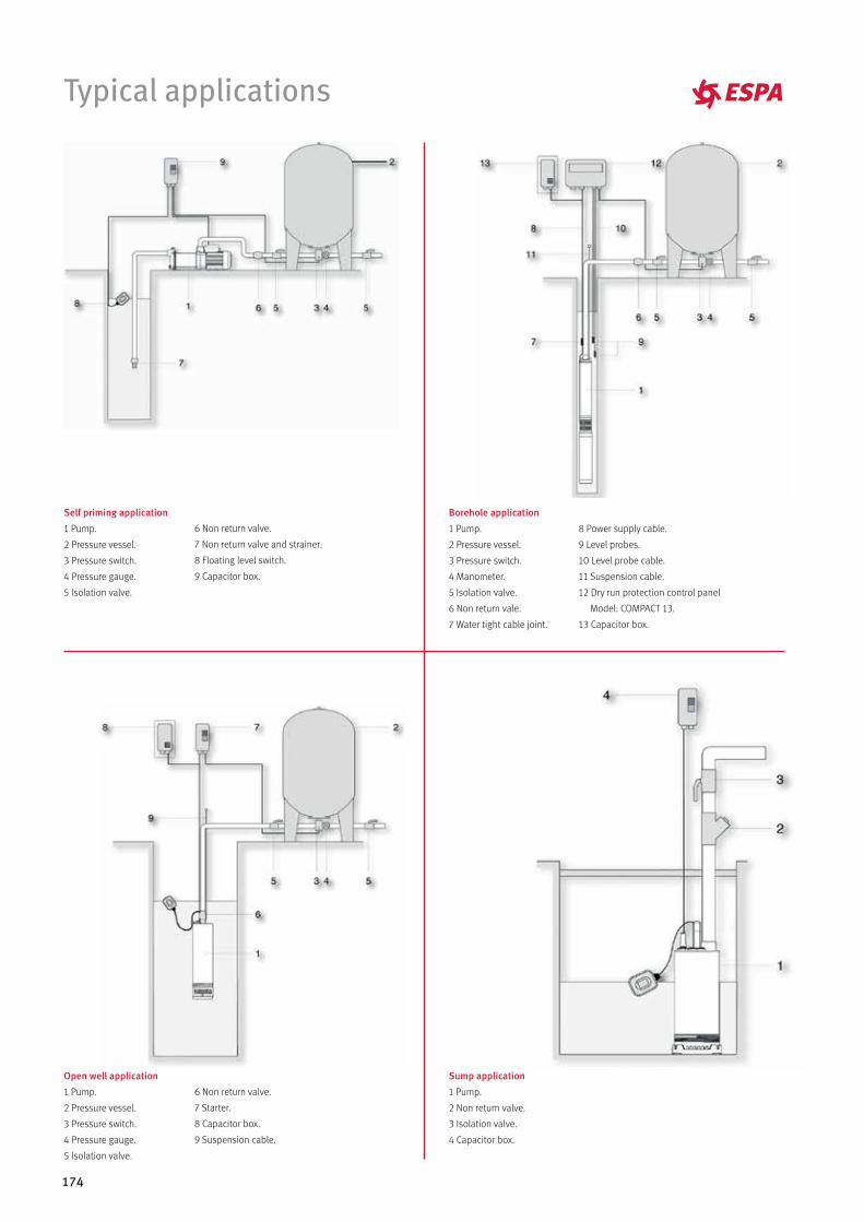
174
Typical applications
Open well application
1 Pump.
2 Pressure vessel.
3 Pressure switch.
4 Pressure gauge.
5 Isolation valve.
Sump application
1 Pump.
2 Non return valve.
3 Isolation valve.
4 Capacitor box.
8 Power supply cable.
9 Level probes.
10 Level probe cable.
11 Suspension cable.
12 Dry run protection control panel
Model: COMPACT 13.
13 Capacitor box.
Borehole application
1 Pump.
2 Pressure vessel.
3 Pressure switch.
4 Manometer.
5 Isolation valve.
6 Non return vale.
7 Water tight cable joint.
Self priming application
1 Pump.
2 Pressure vessel.
3 Pressure switch.
4 Pressure gauge.
5 Isolation valve.
6 Non return valve.
7 Non return valve and strainer.
8 Floating level switch.
9 Capacitor box.
6 Non return valve.
7 Starter.
8 Capacitor box.
9 Suspension cable.
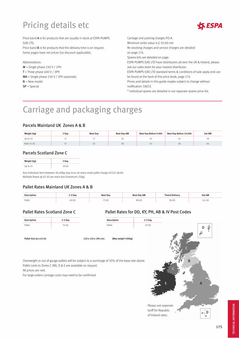
175
Price band A is for products that are usually in stock at ESPA PUMPS
(UK) LTD.
Price band B is for products that the delivery time is on request.
Some pages have net prices (no discount applicable).
Abbreviations:
M = Single phase 230 V / 1PH
T = Three phase 400 V / 3PH
MA = Single phase 230 V / 1PH automatic
N = New model
SP = Special
Carriage and packing charges P.O.A.
Minimum order value is £ 50.00 net.
Re-stocking charges and service charges are detailed
on page 174.
Spares kits are detailed on page.
ESPA PUMPS (UK) LTD have distributors all over the UK & Ireland, please
ask our sales team for your nearest distributor.
ESPA PUMPS (UK) LTD standard terms & conditions of sale apply and can
be found at the back of this price book, page 174.
Prices and details in this guide maybe subject to change without
notification. E&O.E.
* Individual spares are detailed in our separate spares price list.
Pricing details etc
Carriage and packaging charges
Any individual item between 26-40kg may incur an extra small pallet charge of £22-28,00.
Multiple Boxes @ £5.50 per extra box (maximum 25kg).
Overweight or out of gauge pallets will be subject to a surcharge of 50% of the base rate above.
Pallet costs to Zones C (NI), D & E are available on request.
All prices are nett.
For large orders carriage costs may need to be confirmed.
Please see seperate
tariff for Republic
of Ireland rates.
Weight (kg) 3 Day Next Day Next Day AM Next Day Before 9.000 Next Day Before 10.000 Sat AM
Up to 10 11 17 24 47 42 39
from 11-25 17 22 30 53 36 44
Weight (kg) 3 Day
Up to 25 20.00
Parcels Mainland UK Zones A & B
Parcels Scotland Zone C
Description 2-3 Day Next Day Next Day AM Timed Delivery Sat AM
Pallet 60.00 73.00 88.00 96.00 141.00
Description 2-3 Day
Pallet 75.00
Pallet Size (w x d x h): 120 x 120 x 190 cms (Max weight 500kg)
Description 2-3 Day
Pallet 97.00
Pallet Rates Mainland UK Zones A & B
Pallet Rates Scotland Zone C Pallet Rates for DD, KY, PH, AB & IV Post Codes
TECH
NIC
AL IN
FORM
ATIO
N
176
Re-Stocking/Service Charges
Any standard stock items returned to Espa Pumps (UK) Ltd as a result
the customer incorrectly ordering or no longer requiring them will be
subject to a standard 25% re-stocking charge to cover all
administration/testing charges.
Any additional work required to return the items to an “as new”
re-saleable condition will incur further charges.
Some exceptions are as follows:Booster Sets................................... 60%
Sub-Tank Sets................................ 45%
Special Pumps............................... 60%
If a returned item is deemed impossible to re-stock, due to its
condition, the customer will be advised that no credit will be granted
and the item will be scrapped if not collected within fourteen days.
Service in Espa Pumps (UK)Hourly charge labour.................... 50.00
CommissioningCentral London……………………........375.00
England & Wales…………………………365.00
Scotland……………………………………....415.00
Conditions of supplyInterpretationCUSTOMER means the person who accepts ESPAs quotation for the sale of equip-ment or whose order for equipment is accepted by ESPA.
CONDITIONS means the standard terms & conditions of supply set out in this do-cument and (unless the context otherwise requires) includes any special terms & conditions agreed in writing between the customer & Espa.
CONTRACT means the contract for the purchase and sale of equipment and where appropriate the provision of the Commissioning Services.
EQUIPMENT means equipment (including any instalment of the equipment or any parts for them) which ESPA is to supply in accordance with these conditions.
ESPA means ESPA PUMPS (UK) LTD, whose principal place of business is at: 15 Riverside Avenue West, Lawford, Manningtree, Essex, CO11 1UN.
COMMISSIONING SERVICE means the commissioning of the equipment by ESPA.
WRITING includes facsimile transmission and comparable means of communica-tion.
Any reference in these conditions to any provision of a statute shall be construed as a reference to that provision as amended, re-enacted or extended at the relevant time.
Basis of the SaleESPA shall sell and the Customer shall purchase the equipment in accordance with any written quotation of ESPA which is accepted by the Customer, or any written order of the Customer which is accepted by ESPA. Subject in either case to these Condi-tions, which shall govern the contract to the exclusion of any other terms and condi-tions subject to which any such quotation is accepted or purported to be accepted, or any such order is made or purported to be made by the Customer
The giving of any delivery instructions, the acceptance of, or payment for any pro-ducts or any conduct in confirmation by the Customer of the purchase hereby con-templated shall constitute unqualified acceptance by the Customer of these Con-ditions. No variation to these Conditions shall be binding unless agreed in writing between the authorised representative of the Customer and ESPA.
ESPAs employees or agents are not authorised to make representations concerning the Equipment unless confirmed by ESPA in writing. In entering into the Contract the Customer acknowledges that it does not rely on any such representations which are not confirmed.
Any advice or recommendation given by ESPA or its employees or agents to the Customer or its employees or agent as to the storage, application or use of the
Equipment which is not confirmed in writing by ESPA is followed or acted upon entirely at the Customers own risk; accordingly, ESPA shall not be liable for any such advice or recommendation which is not so confirmed. Any typographical, clerical or other error or omission in any sales literature, quotation, acceptance of offer, invoice or other document or information issued by ESPA shall be subject to correction without any liability on the part of ESPA.
Orders and SpecificationNo order submitted by the Customer shall be deemed to be accepted by ESPA un-less and until confirmed in Writing by ESPAs authorised representative.
The Customer shall be responsible to ESPA for ensuring the accuaracy of the terms of any order (including any applicable specification) submitted by the Customer, and for giving ESPA any necessary information relating to the Equipment within a sufficient time to enable ESPA to perform the Contract in accordance with its terms.ESPA shall not be liable if the Equipment ordered by the Customer is unsuitable for the Customer’s particular requirements unless a full written description of the process in which the equipment is to be used is submitted to ESPA with the order.
The quantity, quality and description of and any specification for the Equipment shall be set out in ESPA’s quotation (if accepted by the Customer) or the Customer’s order (if accepted by ESPA). Any illustrations or descriptive material of any sort ge-nerated by ESPA, including but not limited to drawings, specifications, performance data, weight, capacity, dimensions, output and consumption, are approximate and for information purposes only, and shall not be interpreted as warranties or repre-sentations given by ESPA or form part of the contract.
ESPA reserves the right to make any changes in the design, construction, composi-tion, materials, arrangement or specification of the Equipment which are required to conform with any applicable statutory or EC requirements, or which do not mate-rially affect its quality or performance. No order which has been accepted by ESPA may be cancelled by the customer except with the agreement in writing of ESPA and on terms that the Customer shall indemnify ESPA in full against all loss (including loss or profit), costs (including the cost of all labour and materials used), damages, charges and expenses incurred by ESPA as a result of cancellation.
Price of the EquipmentWhere ESPA provides a written quotation to the Customer, the price of the Equi-pment shall be ESPA’s quoted price, which shall be valid for 30 days only or until earlier acceptance by the customer, after which time they may be altered by ESPA without giving notice to the Customer. Where Equipment is supplied to the Custo-mer other than pursuant to a written quotation, prices shall be as set out in ESPA’s then current price list.
ESPA reserves the right, by giving notice to the Customer at any time before delivery, to increase the price of the Equipment to reflect any increase in the cost to ESPA which is due to any fact beyond the control of ESPA (such as, without limitation, any
177
Conditions of supply
foreign exchange fluctuation, currency regulation, alteration of duties, significant increase in the costs of labour, materials or other costs of manufacture), any change in delivery dates, quantities or specifications for the Equipment which is requested by the Customer, or any delay caused by any instructions of the Customer or failure of the Customer to give ESPA adequate information or instructions.
Except as otherwise stated under the terms of any quotation otherwise agreed in writing between the Customer and ESPA, all prices that are given by ESPA do not include carriage costs. The price is exclusive of any applicable value added tax, which the Customer shall be additionally liable to pay to ESPA.
CommissioningESPA shall commission the Equipment subject to these conditions. The Customer shall procure that ESPA is allowed free access to the site where the Equipment is installed and shall also procure the provision of all necessary services and facilities at the site as ESPA shall reasonably require in order to complete the Commissioning of the Equipment.
Further details about the Commissioning Service, and advice or recommendations about its provision or utilisation, which are not given in ESPA’s brochure or other promotional literature, may be made available on written request. ESPA warrants to the Customer that the Commissioning Service will be provided using reasonable care and skill and, as far as reasonably possible, within the time requested by the Customer.
ESPA shall not be liable to the Customer or be deemed to be in breach of the Con-tract by reason of any delay in performing, or any failure to perform, any of ESPA’s obiligations in relation to the Commissioning Service, if the delay or failure is due to any cause beyond ESPA’s reasonable control.
Terms of paymentSubject to any special terms agreed in Writing between the Customer and ESPA, ESPA shall be entitled to invoice the Customer for the price of the Equipment and, if appropriate the Commissioning Service, on or at any time after delivery of the Equipment, unless the Equipment is to be collected by the Customer or the Custo-mer wrongfully fails to take delivery of the Equipment, in which event ESPA shall be entitled to invoice the Customer for the price at any time after ESPA has notified the Customer that the Equipment is ready for collection or (as the case may be) ESPA has tendered delivery of the Equipment.
The Customer shall pay the price of the Equipment without any deduction on or before the last day of the month following the month in which ESPA’s invoice is dated, and ESPA shall be entitled to recover the price, notwithstanding that delivery may not have taken place at the property or that Equipment has not passed to the Customer. The time of payment of the price shall be of the essence of the Contract. Receipts for payment will be issued only upon request.
If the Customer should fail to make any payment on the due date then, without pre-judice to any other right or remedy available to ESPA, ESPA shall be entitled to: can-cel the contract or suspend any further deliveries to the Customer; appropriate any payment made by the Customer should fail Equipment (or the Equipment supplied under any other contract between the Customer and ESPA) as ESPA may think fair (notwithstanding any purported appropriation by the Customer); and Charge the customer interest (both before and after any judgment) on the amount unpaid, at the rate of three and half per cent per annum above current Bank base rate from for the delay, until payment in full is made (a part of a month being treated as a full month for the purpose of calculating interest).
DeliveryDelivery of the Equipment shall be made by the Customer collecting the Equipment at ESPA’s premises at any time after ESPA has notified the Customer that the Equip-ment is ready for collection or, if some other place for delivery is agreed by ESPA, by ESPA delivering the Equipment to that place.
Any dates quoted for delivery of the Equipment are approximate, and ESPA shall not be liable for any delay in delivery of the Equipment however caused. Time for delivery shall not be of the essence of the Contract unless previously agreed by ESPA in writing. The Equipment may be delivered by ESPA in advance of the quoted delivery date upon giving reasonable notice to the Customer. Where the Equipment is to be delivered in instalments, each delivery shall constitute a separate contract and failure by ESPA to deliver any one or more of the instalments in accordance with these Conditions or any claim by the Customer in respect of any one or more instal-ments shall not entitle the Customer to treat the contract as a whole as repudiated.
If the Equipment (or any instalment) has not be received by the Customer within 7 days of notification of despatch by ESPA, or if the quantity received differs from the quantity advised by ESPA as despatched, the Customer shall immediately give notice in Writing to ESPA of the relevant facts. If such notice is not received within 7 days of despatch by ESPA, ESPA will not be liable to the Customer in respect of any loss or damage suffered and the Customer shall accept liability as if all the Equip-ment has been received and shall not claim against ESPA in respect of non or short delivery or loss in transit.
Where Equipment is offered for delivery to site, ESPA’s obligation is to deliver only as near to the site as safe hard roads or other conditions permit. The Customer shall provide ESPA, free of charge, reasonable assistance in unloading Equipment.
If ESPA should fail to deliver the Equipment (or any instalment) for any reason other than any cause beyond ESPA’s reasonable control or the Customer’s fault, and ESPA is accordingly liable to the Customer, ESPA’s liability shall be limited to the excess (if any) of the cost to the Customer (in the cheapest available market), or similar Equipment to replace that not delivered over the price of the Equipment. If the Cus-tomer should fail to take delivery of the Equipment or fail to give ESPA adequate delivery instructions at the time stated for delivery (otherwise than by reason of any cause beyond the Customer’s reasonable control or by reason of ESPA’s fault) then, without prejudice to any other right or remedy available to ESPA, ESPA may: store the Equipment until actual delivery and charge the Customer for the reasonable costs (including insurance) of storage; or sell the Equipment at the best price readily obtainable and (after deducting all reasonable storage and selling expenses) ac-count to the Customer for the excess over the price under the Contract or charge the Customer for any shortfall below the price under the Contract.
Risk and propertyRisk of damage to or loss of the Equipment shall pass to the Customer: in the case of Equipment to be delivered at ESPA’s premises, at the time when ESPA notifies the Customer that the Equipment is available for collection; or in the case of Equipment to be delivered otherwise than at ESPA’s premises, at the time of delivery or, if the Customer should wrongfully fail to take delivery of the Equipment, the time when ESPA has tendered delivery of the Equipment. Notwithstanding delivery and the passing of risk in the Equipment, or any other provision of these conditions, the property in the Equipment shall not pass to the Customer until ESPA has received, in cash or cleared funds, payment in full of the price of the Equipment and all other Equipment agreed to be sold by ESPA to the Customer for which payment is then due.
Until such time as the property in the Equipment passes to the Customer, the Custo-mer shall hold the Equipment as ESPA’s fiduciary agent and bailee, and shall keep the Equipment separate from those of the Customer and third parties and properly stored, protected and insured and identified as ESPA’s property.
Until such time as the property in the Equipment passes to the Customer (and pro-vided the Equipment is still in existence and has not been resold), ESPA shall be en-titled at any time to require the Customer to deliver up the Equipment to ESPA and, if the Customer fails to do so forthwith, to enter upon any premises of the Customer or any third party where the Equipment are stored and repossess the Equipment. The Customer shall not be entitled to pledge or in any way charge by way of security for any indebtedness any of the Equipment which remains the property of ESPA, but if the Customer does so, all moneys owing by the Customer to ESPA shall (without prejudice to any other right or remedy of ESPA) forthwith become due and payable.
Warranties and liabilitySubject to the conditions set out below ESPA warrants that the Equipment will be free from defects in material and workmanship for a period of 24 months from in-voice date.
The above warranty is given by ESPA subject to the following conditions: ESPA shall be under no liability in respect of any defect in the Equipment arising from any drawing, design, or specification supplied by the Customer; ESPA shall be under no liability in respect of any Equipment which in ESPA’s absolute opinion has been improperly installed, maintained or operated; ESPA shall be under no liability in res-pect of any defect arising from wear and tear, wilful damage, negligence, abnormal working conditions, failure to follow ESPA’s instructions (whether oral or in writing), misuse or alteration or repair of the Equipment with out ESPA’s approval; ESPA shall be under no liability under the above warranty (or any other warranty), condition or guarantee) if the total price for the Equipment has not been paid by the due date for payment, or if the Customer is otherwise in breach of the contract; the above warranty does not extend to parts, materials or equipment not manufactured by ESPA, in respect of which, the Customer shall only be entitled to the benefit of any such warranty or guarantee as is given by the manufacturer to ESPA.
TECH
NIC
AL IN
FORM
ATIO
N
178
Conditions of supply
Any claim by the Customer which is based on any defect in the quality or condition of the Equipment or their failure to correspond with specification shall (whether or not delivery is refused by the Customer) be notified to ESPA within 7 days from the date of delivery of (where the defect or failure was not apparent on reasonable ins-pection) within a reasonable time after discovery of the defect or failure. If delivery is not refused, and the Customer does not notify ESPA accordingly, the Customer shall not be entitled to reject the Equipment and ESPA shall have no liability for such de-fect or failure, and the Customer shall be bound to pay the price as if the Equipment has been delivered in accordance with the Contract.
Where any valid claim in respect of any of the Equipment which is based on any defect in the quality or condition of the Equipment or their failure to meet specifica-tion is notified to ESPA in accordance with these Conditions, ESPA shall be entitled to replace the Equipment (or the part in question) free of charge or, at ESPA’s sole discretion, refund to the Customer the price of the Equipment (or a proportionate part thereof), but ESPA shall have no further liability to the Customer. All Equipment replaced shall be the property of ESPA.
Except in respect of death or personal injury caused by ESPA’s negligence, ESPA shall not be liable to the Customer by reason of any representation (unless fraudu-lent), or any implied warranty, condition or other term, or any duty at common law, or under the express terms of the Contract, for any indirect special or consequen-tial loss or damage (whether loss or profit or otherwise), costs, expenses or other claims for compensation whatsoever (whether caused by the negligence of ESPA, its employees or agents or the Customer), and the entire liability of ESPA under or in connection with the Contract shall not exceed the price of the Equipment, except as expressly provided in the Conditions.
Espa shall not be liable to the Customer or be deemed to be in breach of the Con-tract by reason of any delay in performing, or any failure to perform, any of ESPA’s obligations in relation to the Equipment, if the delay or failure is due to any cause beyond ESPA’s reasonable control. Without prejudice to the generality of the fore-going, the following shall be regarded as causes beyond ESPA’s reasonable control: act of God, explosion, flood, tempest, fire or accident; war or threat of war, sabotage, insurrection, civil disturbance or requisition; acts, restrictions, regulations, bye-laws, prohibitions or measures of any kind on the part of any governmental, parliamen-tary or local authority; strikes, lock-outs or other industrial actions or trade disputes (whether involving employees of ESPA or of a third party); difficulties in obtaining raw materials, labour, fuel, parts or machinery; power failure or breakdown in ma-chinery.
Insolvency of buyerThis clause applies if: the Customer makes any voluntary arrangement with its cre-ditors or (being an individual or firm) becomes bankrupt or (being a company) be-comes subject to an administration order or goes into liquidation (otherwise than for purposes or amalgamation or reconstruction); or an encumbrancer takes pos-session of, or a receiver is appointed for, of any of the property or assets of the Cus-tomer; or the customer ceases, or threatens to cease, to continue trading or ESPA reasonably apprehends that any of the events mentioned above is about to occur in relation to the Customer and notified the Customer accordingly.
If this cause applies then, without prejudice to any other right or remedy available to ESPA, ESPA shall be entitled to cancel the Contract or suspend any further delive-ries under the Contract without any liability to the Customer, and if the Equipment has been delivered but not paid for, the price shall become immediately due and payable, notwithstanding any previous agreement or arrangement to the contrary.
Export TermsIn these conditions ‘Incoterms’ means the international rules for the interpretation of trade terms of the International Chamber of Commerce as in force at the date when the Contract is made. Unless the context otherwise requires, any term or expression which is defined in or given a particular meaning by the provisions of In-coterms shall have the same meaning in these Conditions, but if there is any conflict between the provisions of Incoterms and these Conditions, the latter shall prevail.
Where the Equipment is supplied for export from the United Kingdom, the provi-sions of this Clause 11 shall (subject to any special terms agreed in writing between the Customer and ESPA) apply, notwithstanding any other provision of these Condi-tions. The Customer shall be responsible for complying with any legislation or regu-lations governing the importation of the Equipment into the country of destination and for the payment of any duties thereupon.
ESPA shall have no liability for any claim in respect of any defect in the Equipment which would be apparent on inspection and which is made after shipment, or in respect of any damage during transit. All prices quoted by ESPA are ex-works and the Customer must arrange transportation and pay all taxes and duties of any kind
payable in respect of the Equipment, whether levied in the UK or in the country of destination.
GeneralESPA is a member of the group of companies whose holding company is Bombas Electricas SA, and accordingly ESPA may perform any of its obligations or exercise any of its rights hereunder by itself or through any other member of its group, provi-ded that any act or omission of any such other member shall be deemed to be the act or omission of ESPA.
Any notice required or permitted to be given by either party to the other under these Conditions shall be made in writing and addressed to the other party at its registe-red office or principal place of business, or such other address as may at the relevant time have been notified pursuant to this provision to the party giving the notice. No waiver by ESPA of any breach of the Contract by the Customer shall be considered as a waiver of any subsequent breach of the same or any other provision.
If any provision of these Conditions is held by any competent authority to be invalid or unenforceable, in whole or in part, the validity of the other provisions of these Conditions and the remainder of the provision in question shall not be affected. Any dispute arising under or in connection with these Conditions or the sale of the Equi-pment shall be referred to arbitration by a single arbitrator appointed by agreement or (in default) nominated on the application of either party by the President for the time being of The Law Society.
The Contract shall be governed by the laws of England, and the Customer agrees to submit to the non-exclusive jurisdiction of the English courts.
New ESPA Pool pump range warrantyThe extended warranty is exclusively for the ESPA Pool pump range and its application is specified in the following conditions:
1. The geographic scope of the extended warranty is strictly limited to the countries of the EC.
2. Standard period of two years warranty from invoice date according to the general terms of ESPA guarantee.
3. Extended warranty for an additional period of two years by purchasing the product in one of the ESPA’s evopool® partner accredited distributors.
4. Extended warranty for an extra year if the end-user registers the product at the site filling, at least, all mandatory fields. The limit period for product registration will be a maximum of six months from the invoice date.
In any case, the maximum warranty period is five years from the product invoice date.
The terms of the warranty extension are the same as for the standard warranty, excluding all components of pump wear during normal use, such as:
- Mechanical seal- Gaskets- Capacitor - Bearings- Pre-filter basket

All the technical data contained in this catalogue is supplied by our Test laboratory in accordance with ISO 9906: 2012 Grade B3 and correspond to tests with clean water at Ta = 20 ° C, density d = 1.0 kg / dm3 and Kinematic viscosity m = 20 mm2 / s. This guarantees the veracity and the precision of the data that is supplied. Therefore, enabling the safe selection of the correct pump for your application. Non-binding pictures; the technical specifications and/or the equipment mightchange depending on the model. ESPA has the right to change the content of thepresent catalogue without any further notice, always with the intention to improve theinformation that is given to our clients. It is completely forbidden the total or partial use of this catalogue in any format ormedia. The data containing this catalogue is valid, except for any spelling or printingmistakes, until a new version of the catalogue is released.
© 2017
ESPA 2025 SL

ESPA Pumps (UK) Ltd15-16 Riverside Avenue WestLawfordManningtreeEssexCO11 1UNTel +44 1206 391291Fax +44 1206 391239
www.espa.comwww.espa-pumps.co.uk CA
T 10
011E
S 03
/17