2017 jeep wrangler owner's manual - dealer e process
TRANSCRIPT

Wrangler OW N E R ’ S M A N UA L
2 0 1 7

VEHICLES SOLD IN CANADAWith respect to any Vehicles Sold in Canada, the name FCAUS LLC shall be deemed to be deleted and the name FCACanada Inc. used in substitution therefore.
DRIVING AND ALCOHOLDrunken driving is one of the most frequent causes ofaccidents.Your driving ability can be seriously impaired with bloodalcohol levels far below the legal minimum. If you aredrinking, don’t drive. Ride with a designated non-drinking driver, call a cab, a friend, or use public trans-portation.
WARNING!
Driving after drinking can lead to an accident.Your perceptions are less sharp, your reflexes areslower, and your judgment is impaired when youhave been drinking. Never drink and then drive.
This manual illustrates and describes the operation offeatures and equipment that are either standard or op-tional on this vehicle. This manual may also include adescription of features and equipment that are no longeravailable or were not ordered on this vehicle. Pleasedisregard any features and equipment described in thismanual that are not on this vehicle.
FCA US LLC reserves the right to make changes in designand specifications, and/or make additions to or improve-ments to its products without imposing any obligationupon itself to install them on products previously manu-factured.
Copyright © 2016 FCA US LLC

TABLE OF CONTENTSSECTION PAGE
1 INTRODUCTION . . . . . . . . . . . . . . . . . . . . . . . . . . . . . . . . . . . . . . . . . . . . . . . . . . . . . . . . . . . . . . . . . . . 3
2 GRAPHICAL TABLE OF CONTENTS . . . . . . . . . . . . . . . . . . . . . . . . . . . . . . . . . . . . . . . . . . . . . . . . . . . . . . 9
3 GETTING TO KNOW YOUR VEHICLE . . . . . . . . . . . . . . . . . . . . . . . . . . . . . . . . . . . . . . . . . . . . . . . . . . . 15
4 GETTING TO KNOW YOUR INSTRUMENT PANEL . . . . . . . . . . . . . . . . . . . . . . . . . . . . . . . . . . . . . . . . . 179
5 SAFETY . . . . . . . . . . . . . . . . . . . . . . . . . . . . . . . . . . . . . . . . . . . . . . . . . . . . . . . . . . . . . . . . . . . . . . . . 213
6 STARTING AND OPERATING . . . . . . . . . . . . . . . . . . . . . . . . . . . . . . . . . . . . . . . . . . . . . . . . . . . . . . . . . 281
7 IN CASE OF EMERGENCY . . . . . . . . . . . . . . . . . . . . . . . . . . . . . . . . . . . . . . . . . . . . . . . . . . . . . . . . . . . 339
8 SERVICING AND MAINTENANCE . . . . . . . . . . . . . . . . . . . . . . . . . . . . . . . . . . . . . . . . . . . . . . . . . . . . . 365
9 TECHNICAL SPECIFICATIONS . . . . . . . . . . . . . . . . . . . . . . . . . . . . . . . . . . . . . . . . . . . . . . . . . . . . . . . . 431
10 MULTIMEDIA . . . . . . . . . . . . . . . . . . . . . . . . . . . . . . . . . . . . . . . . . . . . . . . . . . . . . . . . . . . . . . . . . . . . 443
11 CUSTOMER ASSISTANCE . . . . . . . . . . . . . . . . . . . . . . . . . . . . . . . . . . . . . . . . . . . . . . . . . . . . . . . . . . . . 497
12 INDEX . . . . . . . . . . . . . . . . . . . . . . . . . . . . . . . . . . . . . . . . . . . . . . . . . . . . . . . . . . . . . . . . . . . . . . . . . . 505
1
2
3
4
5
6
7
8
9
10
11
12


INTRODUCTION
CONTENTS� INTRODUCTION . . . . . . . . . . . . . . . . . . . . . . . . .4
� ROLLOVER WARNING . . . . . . . . . . . . . . . . . . . . .4
� HOW TO USE THIS MANUAL . . . . . . . . . . . . . . .5
▫ Essential Information . . . . . . . . . . . . . . . . . . . . . .5
▫ Symbols . . . . . . . . . . . . . . . . . . . . . . . . . . . . . . .5
� WARNINGS AND CAUTIONS . . . . . . . . . . . . . . . .7
� VEHICLE MODIFICATIONS/ALTERATIONS . . . . .7
1

INTRODUCTION
Congratulations on selecting your new FCA US LLC ve-hicle. Be assured that it represents precision workmanship,distinctive styling, and high quality.
The two-wheel drive version of this vehicle was designedfor on-road use only. It is not intended for off-road drivingor use in other severe conditions suited for a four-wheeldrive vehicle.
Before you start to drive this vehicle, read the Owner’sManual. Be sure you are familiar with all vehicle controls,particularly those used for braking, steering, transmission,and transfer case shifting. Learn how your vehicle handleson different road surfaces. Your driving skills will improvewith experience. When driving off-road, or working thevehicle, don’t overload the vehicle, or expect the vehicle toovercome the natural laws of physics.
Always observe federal, state, provincial, and local lawswherever you drive.
As with other vehicles of this type, failure to operate thisvehicle correctly may result in loss of control or a collision.Refer to “Driving Tips” in “Starting And Operating” forfurther information.
This Owner’s Manual has been prepared with the assis-tance of service and engineering specialists to acquaint youwith the operation and maintenance of your vehicle. It issupplemented by Warranty Information, and variouscustomer-oriented documents. Please take the time to readthese publications carefully. Following the instructions andrecommendations in this manual will help assure safe andenjoyable operation of your vehicle.
NOTE: After reviewing the owner information, it shouldbe stored in the vehicle for convenient referencing andremain with the vehicle when sold.
When it comes to service, remember that your authorizeddealer knows your Jeep® vehicle best, has factory-trainedtechnicians and genuine MOPAR® parts, and cares aboutyour satisfaction.
ROLLOVER WARNING
Utility vehicles have a significantly higher rollover ratethan other types of vehicles. This vehicle has a higherground clearance and a higher center of gravity than manypassenger vehicles. It is capable of performing better in awide variety of off-road applications. Driven in an unsafemanner, all vehicles can go out of control. Because of the
4 INTRODUCTION

higher center of gravity, if this vehicle is out of control itmay roll over while some other vehicles may not.
Do not attempt sharp turns, abrupt maneuvers, or otherunsafe driving actions that can cause loss of vehicle con-trol. Failure to operate this vehicle safely may result in acollision, rollover of the vehicle, and severe or fatal injury.Drive carefully.
Failure to use the driver and passenger seat belts providedis a major cause of severe or fatal injury. In fact, the U.S.
government notes that the universal use of existing seatbelts could cut the highway death toll by 10,000 or moreeach year and could reduce disabling injuries by twomillion annually. In a rollover crash, an unbelted person issignificantly more likely to die than a person wearing a seatbelt. Always buckle up.
HOW TO USE THIS MANUAL
Essential Information
Consult the Table of Contents to determine which sectioncontains the information you desire.
Since the specification of your vehicle depends on the itemsof equipment ordered, certain descriptions and illustra-tions may differ from your vehicle’s equipment.
The detailed index at the back of this Owner’s Manualcontains a complete listing of all subjects.
Symbols
Consult the following table for a description of the symbolsthat may be used on your vehicle or throughout thisOwner’s Manual:
Rollover Warning Label
1
INTRODUCTION 5

6 INTRODUCTION

WARNINGS AND CAUTIONS
This Owner’s Manual contains WARNINGS against oper-ating procedures that could result in a collision, bodilyinjury and/or death. It also contains CAUTIONS againstprocedures that could result in damage to your vehicle. Ifyou do not read this entire Owner’s Manual, you may missimportant information. Observe all Warnings and Cau-tions.
VEHICLE MODIFICATIONS/ALTERATIONS
WARNING!
Any modifications or alterations to this vehicle couldseriously affect its roadworthiness and safety and maylead to a collision resulting in serious injury or death.
1
INTRODUCTION 7


GRAPHICAL TABLE OF CONTENTS
CONTENTS� FRONT VIEW . . . . . . . . . . . . . . . . . . . . . . . . . . .10
� REAR VIEW. . . . . . . . . . . . . . . . . . . . . . . . . . . . .11
� INSTRUMENT PANEL . . . . . . . . . . . . . . . . . . . . .12
� INTERIOR . . . . . . . . . . . . . . . . . . . . . . . . . . . . . .13
2

FRONT VIEW
Front View
1 — Doors2 — Exterior Mirrors3 — Wheels/Tires
4 — Windshield5 — Hood/Engine Compartment6 — Headlights
10 GRAPHICAL TABLE OF CONTENTS

REAR VIEW
Rear View
1 — Rear Lights2 — Rear Windshield Wiper — If Equipped3 — Swing Gate
2
GRAPHICAL TABLE OF CONTENTS 11

INSTRUMENT PANEL
Instrument Panel
1 — Air Outlet 7 — Power Outlet2 — Instrument Cluster 8 — Climate Controls3 — Radio 9 — Lower Switch Bank4 — Power Window Switches 10 — Power Mirror Switch — If Equipped5 — Assist Handle 11 — Horn6 — Glove Compartment
12 GRAPHICAL TABLE OF CONTENTS

INTERIOR
Interior Features
1 — Seats2 — Power Window Switches3 — Radio
4 — Climate Controls5 — Switch Panel6 — Transmission Gear Selector
2
GRAPHICAL TABLE OF CONTENTS 13


GETTING TO KNOW YOUR VEHICLE
CONTENTS� KEY FOBS . . . . . . . . . . . . . . . . . . . . . . . . . . . . .19
▫ Key Fob . . . . . . . . . . . . . . . . . . . . . . . . . . . . . .19
� IGNITION SWITCH . . . . . . . . . . . . . . . . . . . . . . .21
▫ Ignition Key Removal . . . . . . . . . . . . . . . . . . . .21
� REMOTE STARTING SYSTEM — IF EQUIPPED . . .22
▫ How To Use Remote Start. . . . . . . . . . . . . . . . . .22
▫ Remote Start Abort Message . . . . . . . . . . . . . . .23
▫ To Enter Remote Start . . . . . . . . . . . . . . . . . . . .23
▫ To Exit Remote Start Mode Without Driving TheVehicle . . . . . . . . . . . . . . . . . . . . . . . . . . . . . . .24
▫ To Exit Remote Start Mode And Drive TheVehicle . . . . . . . . . . . . . . . . . . . . . . . . . . . . . . .24
▫ General Information . . . . . . . . . . . . . . . . . . . . .24
� SENTRY KEY . . . . . . . . . . . . . . . . . . . . . . . . . . .25
▫ Replacement Key Fobs . . . . . . . . . . . . . . . . . . .25
▫ Customer Key Programming . . . . . . . . . . . . . . .26
▫ General Information . . . . . . . . . . . . . . . . . . . . .27
� VEHICLE SECURITY ALARM — IF EQUIPPED . . .27
▫ Rearming The System . . . . . . . . . . . . . . . . . . . .27
▫ To Arm The System . . . . . . . . . . . . . . . . . . . . .27
▫ To Disarm The System . . . . . . . . . . . . . . . . . . .28
� DOORS . . . . . . . . . . . . . . . . . . . . . . . . . . . . . . .28
▫ Manual Door Locks . . . . . . . . . . . . . . . . . . . . .29
▫ Power Door Locks — If Equipped . . . . . . . . . . .30
▫ Child-Protection Door Lock System — RearDoors . . . . . . . . . . . . . . . . . . . . . . . . . . . . . . .31
▫ Upper Half Door Window Removal — IfEquipped . . . . . . . . . . . . . . . . . . . . . . . . . . . . .32
▫ Front Door Removal . . . . . . . . . . . . . . . . . . . . .32
▫ Rear Door Removal (Four-Door Models) . . . . . . .34
3

� SEATS . . . . . . . . . . . . . . . . . . . . . . . . . . . . . . . .37
▫ Manual Front Seats . . . . . . . . . . . . . . . . . . . . . .37
▫ Manual Rear Seats . . . . . . . . . . . . . . . . . . . . . . .41
▫ Heated Seats — If Equipped . . . . . . . . . . . . . . .45
� HEAD RESTRAINTS . . . . . . . . . . . . . . . . . . . . . .46
▫ Front Head Restraints . . . . . . . . . . . . . . . . . . . .46
▫ Rear Head Restraints — 2 Door Model . . . . . . . .47
▫ Rear Head Restraints — 4 Door Model . . . . . . . .48
� STEERING WHEEL . . . . . . . . . . . . . . . . . . . . . . .48
▫ Tilt Steering Column . . . . . . . . . . . . . . . . . . . . .48
� MIRRORS . . . . . . . . . . . . . . . . . . . . . . . . . . . . . .49
▫ Inside Day/Night Mirror — If Equipped . . . . . .49
▫ Automatic Dimming Mirror — If Equipped . . . . .50
▫ Outside Mirrors . . . . . . . . . . . . . . . . . . . . . . . .50
▫ Power Mirrors — If Equipped . . . . . . . . . . . . . .51
▫ Heated Mirrors — If Equipped . . . . . . . . . . . . .51
▫ Vanity Mirrors . . . . . . . . . . . . . . . . . . . . . . . . .52
� EXTERIOR LIGHTS . . . . . . . . . . . . . . . . . . . . . . .52
▫ Headlights And Parking Lights . . . . . . . . . . . . .52
▫ Daytime Running Lights — If Equipped . . . . . . .52
▫ High/Low Beam Switch . . . . . . . . . . . . . . . . . .53
▫ Flash-To-Pass . . . . . . . . . . . . . . . . . . . . . . . . . .53
▫ Automatic Headlights — If Equipped . . . . . . . . .53
▫ Front Fog Lights . . . . . . . . . . . . . . . . . . . . . . . .53
▫ Turn Signals . . . . . . . . . . . . . . . . . . . . . . . . . . .54
▫ Lane Change Assist — If Equipped . . . . . . . . . .54
▫ Lights-On Reminder. . . . . . . . . . . . . . . . . . . . . .54
� INTERIOR LIGHTS . . . . . . . . . . . . . . . . . . . . . . .54
▫ Courtesy/Reading Lights . . . . . . . . . . . . . . . . . .54
▫ Instrument Panel Dimmer . . . . . . . . . . . . . . . . .55
▫ Cargo Lamp . . . . . . . . . . . . . . . . . . . . . . . . . . .55
� WINDSHIELD WIPERS AND WASHERS . . . . . . . .56
▫ Windshield Wiper Operation. . . . . . . . . . . . . . . .57
▫ Intermittent Wiper System . . . . . . . . . . . . . . . . .58
16 GETTING TO KNOW YOUR VEHICLE

▫ Windshield Washers. . . . . . . . . . . . . . . . . . . . . .58
▫ Mist Feature . . . . . . . . . . . . . . . . . . . . . . . . . . .58
▫ Rear Window Wiper/Washer — If Equipped . . . .59
� CLIMATE CONTROLS . . . . . . . . . . . . . . . . . . . . .60
▫ Manual Climate Control Overview . . . . . . . . . . .60
▫ Automatic Climate Control Overview . . . . . . . . .64
▫ Operating Tips . . . . . . . . . . . . . . . . . . . . . . . . .68
� POWER WINDOWS — IF EQUIPPED . . . . . . . . . .70
▫ Wind Buffeting . . . . . . . . . . . . . . . . . . . . . . . . .71
� DUAL TOP — TWO-DOOR MODELS — IFEQUIPPED . . . . . . . . . . . . . . . . . . . . . . . . . . . . .72
▫ Removing The Soft Top — Two-Door Models . . . .72
▫ Installing The Soft Top — Two-Door Models . . . .73
� DUAL TOP — FOUR-DOOR MODELS — IFEQUIPPED . . . . . . . . . . . . . . . . . . . . . . . . . . . . .75
▫ Removing The Soft Top — Four-Door Models . . .76
▫ Installing The Soft Top — Four-Door Models . . . .79
� FREEDOM TOP THREE-PIECE MODULAR HARDTOP — IF EQUIPPED . . . . . . . . . . . . . . . . . . . . .82
▫ Front Panel(s) Removal . . . . . . . . . . . . . . . . . . .82
▫ Freedom Top Storage Bag . . . . . . . . . . . . . . . . . .85
▫ Front Panel(s) Installation . . . . . . . . . . . . . . . . . .88
▫ Front Panel(s) Installation With Rear Hard TopRemoved . . . . . . . . . . . . . . . . . . . . . . . . . . . . .89
▫ Rear Hard Top Removal . . . . . . . . . . . . . . . . . .89
▫ Rear Hard Top Installation . . . . . . . . . . . . . . . . .92
� DOOR FRAME. . . . . . . . . . . . . . . . . . . . . . . . . . .93
▫ Door Frame Removal . . . . . . . . . . . . . . . . . . . . .93
▫ Door Frame Installation — Two-Door Models — IfEquipped . . . . . . . . . . . . . . . . . . . . . . . . . . . . .95
▫ Door Frame Installation — Four-Door Models — IfEquipped . . . . . . . . . . . . . . . . . . . . . . . . . . . . .96
� SOFT TOP — TWO-DOOR MODELS . . . . . . . . . .99
▫ Quick Steps To Lowering The Soft Top. . . . . . . .101
▫ Quick Steps To Raising The Soft Top . . . . . . . . .105
3
GETTING TO KNOW YOUR VEHICLE 17

▫ Lowering The Soft Top . . . . . . . . . . . . . . . . . . .110
▫ Raising The Soft Top. . . . . . . . . . . . . . . . . . . . .119
� SUNRIDER (TWO-DOOR MODELS) — IFEQUIPPED . . . . . . . . . . . . . . . . . . . . . . . . . . . .128
▫ Opening The Sunrider . . . . . . . . . . . . . . . . . . .128
▫ Closing The Sunrider . . . . . . . . . . . . . . . . . . . .130
� SOFT TOP — FOUR-DOOR MODELS . . . . . . . . .130
▫ Quick Steps For Lowering The Soft Top . . . . . . .133
▫ Quick Steps For Raising The Soft Top. . . . . . . . .137
▫ Folding Down The Soft Top . . . . . . . . . . . . . . .143
▫ Putting Up The Soft Top . . . . . . . . . . . . . . . . . .153
� SUNRIDER (FOUR-DOOR MODELS) — IFEQUIPPED . . . . . . . . . . . . . . . . . . . . . . . . . . . .162
▫ Opening The Sunrider . . . . . . . . . . . . . . . . . . .162
▫ Closing The Sunrider . . . . . . . . . . . . . . . . . . . .165
� FOLDING WINDSHIELD . . . . . . . . . . . . . . . . . .165
▫ Lowering The Windshield And Removing SideBars . . . . . . . . . . . . . . . . . . . . . . . . . . . . . . . .166
▫ Raising The Windshield And Replacing SideBars . . . . . . . . . . . . . . . . . . . . . . . . . . . . . . . .169
� HOOD . . . . . . . . . . . . . . . . . . . . . . . . . . . . . . .170
▫ Opening The Hood . . . . . . . . . . . . . . . . . . . . .170
▫ Closing The Hood . . . . . . . . . . . . . . . . . . . . . .170
� REAR SWING GATE . . . . . . . . . . . . . . . . . . . . .171
� INTERNAL EQUIPMENT . . . . . . . . . . . . . . . . . .172
▫ Storage . . . . . . . . . . . . . . . . . . . . . . . . . . . . . .172
▫ Cupholders . . . . . . . . . . . . . . . . . . . . . . . . . . .174
▫ Electrical Power Outlets . . . . . . . . . . . . . . . . . .174
▫ Power Inverter — If Equipped . . . . . . . . . . . . .177
18 GETTING TO KNOW YOUR VEHICLE

KEY FOBS
Your vehicle uses a key start ignition system. The ignitionsystem consists of a Remote Keyless Entry (RKE) key fobwith an ignition switch.
Key Fob
The key fob allows you to lock or unlock the doors andliftgate from distances up to approximately 66 ft (20 m)using a handheld key fob. The key fob does not need to bepointed at the vehicle to activate the system.
NOTE: In the ON/RUN position, the lock button is dis-abled. Only the unlock button is enabled.
To Unlock The Doors And Swing Gate
Push and release the key fob unlock button once to unlockthe driver’s door only, or twice to unlock all the doors andswing gate. When the key fob unlock button is pushed, theIlluminated Entry will initiate, and the turn signal lightswill flash twice.
Key Fob
1 — Remote Start Button 3 — PANIC Button2 — Lock Button 4 — Unlock Button
3
GETTING TO KNOW YOUR VEHICLE 19

To Lock The Doors And Swing Gate
Push and release the lock button on the key fob to lock alldoors. The turn signals will flash, and the horn will chirponce to acknowledge the lock signal.
Key Fob Battery Replacement
The recommended replacement battery is CR2032.
NOTE: Perchlorate Material – special handling may apply.See www.dtsc.ca.gov/hazardouswaste/perchlorate .
1. With the key fob buttons facing down, use a flat bladescrewdriver to pry the two halves of the key fob apart.Use extreme care not to damage the seal or internalcomponents. 2. Remove and replace the battery. Avoid touching the new
battery with your fingers. Skin oils may cause batterydeterioration. If you touch a battery, clean it withrubbing alcohol.
3. To reassemble the key fob case, snap the two halvestogether.
Programming Additional Key Fobs
If you do not have a programmed key fob, contact yourauthorized dealer for details.
Separating Key Fob Halves
20 GETTING TO KNOW YOUR VEHICLE

Refer to “Sentry Key” in “Getting To Know Your Vehicle”for further information.
General Information
The following regulatory statement applies to all RadioFrequency (RF) devices equipped in this vehicle:
This device complies with Part 15 of the FCC Rules andwith Industry Canada license-exempt RSS standard(s).Operation is subject to the following two conditions:
1. This device may not cause harmful interference.
2. This device must accept any interference received, in-cluding interference that may cause undesired opera-tion.
NOTE: Changes or modifications not expressly approvedby the party responsible for compliance could void theuser’s authority to operate the equipment.
IGNITION SWITCH
Ignition Key Removal
1. Place the gear selector in PARK (if equipped with anautomatic transmission).
2. Turn the ignition switch to the ACC (Accessory) posi-tion.
3. Push the key and cylinder inward and rotate the key tothe LOCK position.
4. Remove the key from the ignition switch lock cylinder.
Ignition Switch Positions
1 — LOCK2 — ACC (ACCESSORY)3 — ON/RUN4 — START
3
GETTING TO KNOW YOUR VEHICLE 21

WARNING!
• Before exiting a vehicle, always shift the automatictransmission into PARK or the manual transmissioninto FIRST gear or REVERSE, apply the parkingbrake, turn the engine OFF, remove the key fob fromthe vehicle and lock your vehicle.
• Never leave children alone in a vehicle, or withaccess to an unlocked vehicle.
• Allowing children to be in a vehicle unattended isdangerous for a number of reasons. A child or otherscould be seriously or fatally injured. Childrenshould be warned not to touch the parking brake,brake pedal or the gear selector.
• Do not leave the key fob in or near the vehicle, or ina location accessible to children. A child could oper-ate power windows, other controls, or move thevehicle.
• Do not leave children or animals inside parkedvehicles in hot weather. Interior heat build-up maycause serious injury or death.
CAUTION!
An unlocked vehicle is an invitation for thieves. Al-ways remove key fob from the vehicle and lock alldoors when leaving the vehicle unattended.
REMOTE STARTING SYSTEM — IF EQUIPPED
This system uses the key fob to start the engine convenientlyfrom outside the vehicle while still maintaining security. Thesystem has a range of approximately 300 ft (91 m).
NOTE:
• The vehicle must be equipped with an automatic trans-mission to be equipped with Remote Start.
• Obstructions between the vehicle and key fob mayreduce this range.
How To Use Remote Start
All of the following conditions must be met before theengine will remote start:
• Gear selector in PARK
• Doors closed
• Hood closed
22 GETTING TO KNOW YOUR VEHICLE

• Hazard switch off
• Brake switch inactive (brake pedal not pushed)
• Ignition key removed from ignition
• Battery at an acceptable charge level
• PANIC button not pushed
• System not disabled from previous remote start event
• Vehicle security alarm not active
WARNING!
• Do not start or run an engine in a closed garage orconfined area. Exhaust gas contains Carbon Monox-ide (CO) which is odorless and colorless. CarbonMonoxide is poisonous and can cause serious injuryor death when inhaled.
• Keep key fobs away from children. Operation of theRemote Start System, windows, door locks or othercontrols could cause serious injury or death.
Remote Start Abort Message
The following messages will display in the instrumentcluster display if the vehicle fails to remote start or exitsremote start prematurely:
• Remote Start Aborted — Door Open
• Remote Start Aborted — Hood Open
• Remote Start Aborted — Fuel Low
• Remote Start Aborted — L/Gate Open
• Remote Start Aborted — System Fault
The instrument cluster display message stays active untilthe ignition is turned to the ON/RUN position.
To Enter Remote Start
Push and release the remote start button on the key fobtwice within five seconds. The vehicle doors will lock, theparking lights will flash and the horn will chirp twice (ifprogrammed). Then, the engine will start and the vehiclewill remain in the remote start mode for a 15-minute cycle.
NOTE:
• The park lamps will turn on and remain on duringremote start mode.
• For security, power window operation is disabled whenthe vehicle is in the remote start mode.
3
GETTING TO KNOW YOUR VEHICLE 23

• The engine can be started two consecutive times (two15-minute cycles) with the key fob. However, the igni-tion switch must be cycled to the ON/RUN positionbefore you can repeat the start sequence for a third cycle.
Remote start will also cancel if any of the following occur:
• The engine stalls or RPM exceeds 2500.
• Any engine warning lamps come on.
• The hood is opened.
• The hazard switch is pushed.
• The transmission is moved out of PARK.
• The brake pedal is pushed.
To Exit Remote Start Mode Without Driving TheVehicle
Push and release the remote start button one time or allowthe engine to run for the entire 15-minute cycle.
NOTE: To avoid unintentional shut downs, the system willdisable the one time push of the remote start button for twoseconds after receiving a valid remote start request.
To Exit Remote Start Mode And Drive The Vehicle
Before the end of the 15-minute cycle, push and release theunlock button on the key fob to unlock the doors anddisarm the vehicle security alarm (if equipped). Then,insert the key into the ignition and place the ignition in theON/RUN position.
NOTE: The ignition must be placed in the ON/RUNposition in order to drive the vehicle.
General Information
The following regulatory statement applies to all RadioFrequency (RF) devices equipped in this vehicle:
This device complies with Part 15 of the FCC Rules andwith Industry Canada license-exempt RSS standard(s).Operation is subject to the following two conditions:
1. This device may not cause harmful interference.
2. This device must accept any interference received, in-cluding interference that may cause undesired opera-tion.
NOTE: Changes or modifications not expressly approvedby the party responsible for compliance could void theuser’s authority to operate the equipment.
24 GETTING TO KNOW YOUR VEHICLE

SENTRY KEY
The Sentry Key Immobilizer System prevents unauthor-ized vehicle operation by disabling the engine. The systemdoes not need to be armed or activated. Operation isautomatic, regardless of whether the vehicle is locked orunlocked.
The system uses key fobs that have an embedded electronicchip (transponder) to prevent unauthorized vehicle opera-tion. Therefore, only key fobs that are programmed to thevehicle can be used to start and operate the vehicle. Thesystem will shut the engine off in two seconds if someoneuses an invalid key to try to start the engine.
NOTE: A key fob that has not been programmed is alsoconsidered an invalid key, even if it is cut to fit the ignitionor lock cylinder for that vehicle.
During normal operation, after placing the ignition in theon position, the vehicle security light will turn on for threeseconds for a bulb check. If the light remains on after thebulb check, it indicates that there is a problem with theelectronics. In addition, if the vehicle security light beginsto flash after the bulb check, it indicates that someone usedan invalid key to try to start the engine. Either of theseconditions will result in the engine being shut off after twoseconds.
If the vehicle security light turns on during normal vehicleoperation (vehicle running for longer than ten seconds), itindicates that there is a fault in the electronics. Should thisoccur, have the vehicle serviced as soon as possible by anauthorized dealer.
CAUTION!
The Sentry Key Immobilizer system is not compatiblewith some aftermarket remote starting systems. Use ofthese systems may result in vehicle starting problemsand loss of security protection.
All of the key fobs provided with your new vehicle havebeen programmed to the vehicle electronics.
Replacement Key Fobs
NOTE: Only key fobs that are programmed to the vehicleelectronics can be used to start and operate the vehicle.Once a key fob is programmed to a vehicle, it cannot beprogrammed to any other vehicle.
CAUTION!
Always remove the Sentry Keys from the vehicle andlock all doors when leaving the vehicle unattended.
3
GETTING TO KNOW YOUR VEHICLE 25
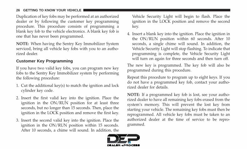
Duplication of key fobs may be performed at an authorizeddealer or by following the customer key programmingprocedure. This procedure consists of programming ablank key fob to the vehicle electronics. A blank key fob isone that has never been programmed.
NOTE: When having the Sentry Key Immobilizer Systemserviced, bring all vehicle key fobs with you to an autho-rized dealer.
Customer Key Programming
If you have two valid key fobs, you can program new keyfobs to the Sentry Key Immobilizer system by performingthe following procedure:
1. Cut the additional key(s) to match the ignition and lockcylinder key code.
2. Insert the first valid key into the ignition. Place theignition in the ON/RUN position for at least threeseconds, but no longer than 15 seconds. Then, place theignition in the LOCK position and remove the first key.
3. Insert the second valid key into the ignition. Place theignition in the ON/RUN position within 15 seconds.After 10 seconds, a chime will sound. In addition, the
Vehicle Security Light will begin to flash. Place theignition in the LOCK position and remove the secondkey.
4. Insert a blank key into the ignition. Place the ignition inthe ON/RUN position within 60 seconds. After 10seconds, a single chime will sound. In addition, theVehicle Security Light will stop flashing. To indicate thatprogramming is complete, the Vehicle Security Lightwill turn on again for three seconds and then turn off.
The new key is programmed. The key fob will also beprogrammed during this procedure.
Repeat this procedure to program up to eight keys. If youdo not have a programmed key fob, contact your autho-rized dealer for details.
NOTE: If a programmed key fob is lost, see your autho-rized dealer to have all remaining key fobs erased from thesystem’s memory. This will prevent the lost key fromstarting your vehicle. The remaining key fobs must then bereprogrammed. All vehicle key fobs must be taken to anauthorized dealer at the time of service to be repro-grammed.
26 GETTING TO KNOW YOUR VEHICLE

General Information
The following regulatory statement applies to all radiofrequency (RF) devices equipped in this vehicle:
This device complies with Part 15 of the FCC Rules andwith Industry Canada license-exempt RSS standard(s).Operation is subject to the following two conditions:
1. This device may not cause harmful interference, and
2. This device must accept any interference received, in-cluding interference that may cause undesired opera-tion.
NOTE: Changes or modifications not expressly approvedby the party responsible for compliance could void theuser’s authority to operate the equipment.
VEHICLE SECURITY ALARM — IF EQUIPPED
The vehicle security alarm monitors the vehicle doors,swing gate, and ignition for unauthorized operation. Whilethe vehicle security alarm is armed, interior switches fordoor locks are disabled. The vehicle security alarm pro-vides both audible and visible signals when alarming. Thehorn will sound, the headlights will turn on, the parklamps and/or turn signals will flash repeatedly for threeminutes. If the disturbance is still present (driver’s door,
passenger door, other doors, ignition) after three minutes,the headlights, park lamps and/or turn signals will flashfor an additional 15 minutes.
NOTE: The Panic Alarm and the vehicle security alarm arequite different. Please take a moment to activate the PanicAlarm and the vehicle security alarm to hear the differ-ences in the horn. In case one should go off in the future,you will need to know which mode has been activated inorder to deactivate it.
Rearming The System
If something triggers the alarm, and no action is taken todisarm it, the vehicle security alarm will turn off the hornafter three minutes, turn off all of the visual signals after 15minutes, and then the vehicle security alarm will rearmitself.
To Arm The System
The vehicle security alarm will set when you use theRemote Keyless Entry key fob to lock the doors and swinggate, or when you use the power door lock switch whilethe door is open. After all the doors are locked and closed,the vehicle security light (located on the instrument cluster)will flash rapidly for about 16 seconds to signal that thevehicle security alarm is arming. During this 16-second
3
GETTING TO KNOW YOUR VEHICLE 27

arming period, opening any door or the swing gate willcancel the arming. If the vehicle security alarm is success-fully set, the vehicle security light will flash at a slower rateto indicate the vehicle security alarm is armed.
To Disarm The System
To disarm the vehicle security alarm, you will need to pushthe unlock button on the key fob, or turn the ignitionswitch to the ON/RUN position. If something has trig-gered the vehicle security alarm in your absence, the hornwill sound three times, and the exterior lights blink threetimes when you unlock the doors. Check the vehicle fortampering.
The vehicle security alarm is designed to protect yourvehicle; however, you can create conditions where thevehicle security alarm will arm unexpectedly. If you remainin the vehicle and lock the doors with the key fob, once thevehicle security alarm is armed (after 16 seconds), whenyou pull the door handle to exit, the alarm will sound. Ifthis occurs, push the unlock button on the key fob to
disarm the vehicle security alarm. You may also acciden-tally disarm the vehicle security alarm by unlocking thedriver’s door with the key and then locking it. The doorwill be locked but the vehicle security alarm will not arm.
NOTE:
• Unlocking the doors with the manual door lock plung-ers or the driver’s door lock cylinder will not disarm thevehicle security alarm.
• When the vehicle security alarm is armed, the interiorpower door lock switches will not unlock the doors.
DOORS
CAUTION!
Careless handling and storage of the removable doorpanels may damage the seals, causing water to leakinto the vehicle’s interior.
28 GETTING TO KNOW YOUR VEHICLE

Manual Door Locks
All doors are equipped with an interior rocker-type doorlock lever. To lock a door when leaving your vehicle, pushthe rocker lever forward to the lock position and close thedoor. To unlock the door, push the rocker lever rearward.
NOTE: The ignition key that is used to start the vehicle isused to lock or unlock the doors, swing gate, glovecompartment, and console storage.
WARNING!
• For personal security reasons and safety in a colli-sion, lock the vehicle doors when you drive, as wellas when you park and leave the vehicle.
(Continued)
Manual Door Lock (Full Frame Doors)
Manual Door Lock (Half Doors)
3
GETTING TO KNOW YOUR VEHICLE 29

WARNING! (Continued)• When leaving the vehicle, always remove the key
from the ignition and lock your vehicle. Unsuper-vised use of vehicle equipment may cause severepersonal injuries and death.
• Never leave children alone in a vehicle, or withaccess to an unlocked vehicle.
• Allowing children to be in a vehicle unattended isdangerous for a number of reasons. A child or otherscould be seriously or fatally injured. Childrenshould be warned not to touch the parking brake,brake pedal or the gear selector.
• Do not leave the key fob in or near the vehicle or ina location accessible to children. A child could oper-ate power windows, other controls, or move thevehicle.
Power Door Locks — If Equipped
The power door lock switch is located on each front doorpanel. Push the switch forward to lock the doors, andrearward to unlock the doors.
WARNING!
• For personal security reasons and safety in a colli-sion, lock the vehicle doors when you drive, as wellas when you park and leave the vehicle.
• When leaving the vehicle, always remove the keyfrom the ignition and lock your vehicle. Unsuper-vised use of vehicle equipment may cause severepersonal injuries and death.
(Continued)
Power Door Lock Switch
30 GETTING TO KNOW YOUR VEHICLE

WARNING! (Continued)• Never leave children alone in a vehicle, or with
access to an unlocked vehicle.• Allowing children to be in a vehicle unattended is
dangerous for a number of reasons. A child or otherscould be seriously or fatally injured. Childrenshould be warned not to touch the parking brake,brake pedal or the gear selector.
• Do not leave the key fob in or near the vehicle or ina location accessible to children. A child could oper-ate power windows, other controls, or move thevehicle.
Child-Protection Door Lock System — Rear Doors
To provide a safer environment for small children riding inthe rear seats, the rear doors are equipped with Child-Protection Door Lock system.
To Engage Or Disengage The Child-Protection Door LockSystem
1. Open the rear door.
2. Insert the tip of the ignition key into the lock and rotateto the lock or unlock position.
3. Repeat steps one and two for the opposite rear door.
WARNING!
Avoid trapping anyone in a vehicle in a collision.Remember that the rear doors can only be opened fromthe outside when the Child-Protection locks are en-gaged (locked).
NOTE: For emergency exit with the system engaged, movethe rocker lever rearward (unlocked position), roll downthe window and open the door with the outside doorhandle.
Child Protection Door Lock Function
3
GETTING TO KNOW YOUR VEHICLE 31

Upper Half Door Window Removal — If Equipped
Grasp the half door window and pull upward.
Upper Half Door Window Installation — IfEquipped
1. Grasp the half door window and line up the pins withthe pockets in the lower door.
2. Push down to ensure the half door window is fullyseated.
Front Door Removal
WARNING!
Do not drive your vehicle on public roads with thedoors removed as you will lose the protection that theycan provide. This procedure is furnished for use dur-ing off-road operation only.
NOTE: Hinge pin can break if overtightened during doorreinstall (Max Torque: 10 N*m / 7.5 ft*lb).
Upper Half Door Window
Door Removal Warning Label
32 GETTING TO KNOW YOUR VEHICLE
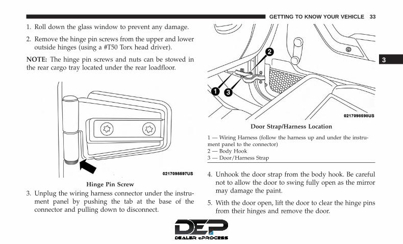
1. Roll down the glass window to prevent any damage.
2. Remove the hinge pin screws from the upper and loweroutside hinges (using a #T50 Torx head driver).
NOTE: The hinge pin screws and nuts can be stowed inthe rear cargo tray located under the rear loadfloor.
3. Unplug the wiring harness connector under the instru-ment panel by pushing the tab at the base of theconnector and pulling down to disconnect.
4. Unhook the door strap from the body hook. Be carefulnot to allow the door to swing fully open as the mirrormay damage the paint.
5. With the door open, lift the door to clear the hinge pinsfrom their hinges and remove the door.
Hinge Pin Screw
Door Strap/Harness Location
1 — Wiring Harness (follow the harness up and under the instru-ment panel to the connector)2 — Body Hook3 — Door/Harness Strap
3
GETTING TO KNOW YOUR VEHICLE 33

NOTE: Doors are heavy; use caution when removingthem.
To reinstall the door(s), perform the previous steps in theopposite order.
Rear Door Removal (Four-Door Models)
WARNING!
Do not drive your vehicle on public roads with thedoors removed as you will lose the protection that theycan provide. This procedure is furnished for use dur-ing off-road operation only.
NOTE: Hinge pin can break if overtightened during doorreinstall (Max Torque: 10 N*m / 7.5 ft*lb).
1. Roll down the glass window to prevent any damage.
2. Remove the hinge pin screws from the upper and loweroutside hinges (using a #T50 Torx head driver).
NOTE: The hinge pin screws and nuts can be stowed in therear cargo tray located under the rear load floor.
Door Removal Warning Label
34 GETTING TO KNOW YOUR VEHICLE

3. Slide the front seat(s) fully forward.
4. Remove the trim access door from the bottom of theB-pillar.
5. Unplug the wiring harness connector.
NOTE: Squeeze the tab on the base of the connector. Thiswill unlock the connector tab, allowing the harness to bedisconnected.
Hinge Pin Screw Trim Access Door
3
GETTING TO KNOW YOUR VEHICLE 35

6. Unhook the door strap from the body hook.
7. With the door open, lift the door to clear the hinge pinsfrom their hinges and remove the door.
NOTE: Doors are heavy; use caution when removing them.
To reinstall the door(s), perform the previous steps in theopposite order.
Connector Latched Connector Unplugged
36 GETTING TO KNOW YOUR VEHICLE

SEATS
Seats are a part of the Occupant Restraint System of thevehicle.
WARNING!
• It is dangerous to ride in a cargo area, inside oroutside of a vehicle. In a collision, people riding inthese areas are more likely to be seriously injured orkilled.
• Do not allow people to ride in any area of yourvehicle that is not equipped with seats and seat belts.In a collision, people riding in these areas are morelikely to be seriously injured or killed.
• Be sure everyone in your vehicle is in a seat andusing a seat belt properly.
Manual Front Seats
Front Seat Adjustment
The seat can be adjusted forward or rearward by using abar located by the front of the seat cushion, near the floor.While sitting in the seat, lift up on the bar located under theseat cushion and move the seat forward or rearward.Release the bar once you have reached the desired position.
Then, using body pressure, move forward and rearward onthe seat to be sure that the seat adjusters have latched.
WARNING!
• Adjusting a seat while driving may be dangerous.Moving a seat while driving could result in loss ofcontrol which could cause a collision and seriousinjury or death.
(Continued)
Adjusting Bar Location
3
GETTING TO KNOW YOUR VEHICLE 37

WARNING! (Continued)• Seats should be adjusted before fastening the seat
belts and while the vehicle is parked. Serious injuryor death could result from a poorly adjusted seat belt.
Manual Seat Height Adjustment — If Equipped
The driver’s seat height can be raised or lowered by usingthe ratcheting handle, located on the outboard side of theseat. Pull upward on the handle to raise the seat, pushdownward on the handle to lower the seat.
Front Seatback Recline
Lean forward before lifting the handle, then lean back tothe desired position and release the handle. Lift the handleto return the seatback to an upright position.
WARNING!
Do not ride with the seatback reclined so that theshoulder belt is no longer resting against your chest. Ina collision you could slide under the seat belt, whichcould result in serious injury or death.Seat Height Adjustment
Recline Lever
38 GETTING TO KNOW YOUR VEHICLE

Front Passenger Easy Entry Seat — Two-DoorModels
Pull upward on the recline lever (toward the rear of thevehicle) and slide the entire seat forward.
To return the seat to a sitting position, rotate the seatbackupright until it locks and push the seat rearward until thetrack locks.
NOTE:
• The front passenger seats have a track memory, whichreturns the seat to just past the halfway point of the trackregardless of its original position.
• The recliner and easy entry levers should not be usedduring the automatic returning of the seat to its sittingposition.
Easy Entry Lever
Easy Entry Seat
3
GETTING TO KNOW YOUR VEHICLE 39

Tip n’ Slide Seats — Two-Door Models
This feature allows the front seats to be rotated toward theinstrument panel to allow easier entry into the rear seats.
Driver’s Seat
Pull upward on the recline lever and bring the seatback toits full forward position.
Rotate the entire seat assembly toward the instrumentpanel.
Recline Lever
Tip n’ Slide
40 GETTING TO KNOW YOUR VEHICLE

Passenger Seat
In addition to Easy Entry, the front passenger seat is alsoequipped with Tip n’ Slide. This feature allows for easierentry for rear passengers.
Pull upward on the recline lever and slide the entire seatforward (Easy Entry).
With the seat forward, pull the entire seat assembly towardthe instrument panel.
Manual Rear Seats
Removing the Rear Seat — Two-Door Models
NOTE:
• Prior to folding the rear seat, it may be necessary toreposition the front seats.
• Be sure that the front seats are fully upright and posi-tioned forward. This will allow the rear seat to folddown easily.
Easy Entry Lever
Tip n’ Slide
3
GETTING TO KNOW YOUR VEHICLE 41

1. Lift the seatback release lever and fold the seatbackforward.
2. Slowly flip the entire seat forward.
WARNING!
Do not drive the vehicle with the seat in the forwardtumble position. The seat must be latched to all floorattachments when the vehicle is in motion.
3. Push down on the release bar on each side, and pull theseat out and away from the lower bracket.
4. Remove the seat from the vehicle.
Rear Seat Release
Folding Rear Seat
42 GETTING TO KNOW YOUR VEHICLE

WARNING!
• It is extremely dangerous to ride in a cargo area,inside or outside of a vehicle. In a collision, peopleriding in these areas are more likely to be seriouslyinjured or killed.
• Do not allow people to ride in any area of yourvehicle that is not equipped with seats and seat belts.
• Be sure everyone in your vehicle is in a seat andusing a seat belt properly.
(Continued)
WARNING! (Continued)• In a collision, you or others in your vehicle could be
injured if seats are not properly latched to their floorattachments. Always be sure that the seats are fullylatched.
Replacing The Rear Seat — Two-Door Models
Reverse the steps for removing the seat.
WARNING!
• To help protect against personal injury, passengersshould not be seated in the rear cargo area with therear seat folded down or removed from the vehicle.
• The rear cargo space is intended for load carryingpurposes only, not for passengers who should sit inseats and use seat belts.
60/40 Split Folding Rear Seat — Four-Door Models
To provide additional storage area, each rear seat can befolded flat to allow for extended cargo space.
Release Bar Location
3
GETTING TO KNOW YOUR VEHICLE 43

NOTE:
• Prior to folding the rear seat, it may be necessary toreposition the front seat to its mid-track position.
• Be sure that the front seats are fully upright and posi-tioned forward. This will allow the rear seat to folddown easily.
WARNING!
• It is extremely dangerous to ride in a cargo area,inside or outside of a vehicle. In a collision, peopleriding in these areas are more likely to be seriouslyinjured or killed.
• Do not allow people to ride in any area of yourvehicle that is not equipped with seats and seat belts.
• Be sure everyone in your vehicle is in a seat andusing a seat belt properly.
To Fold Down The Rear Seat
Locate the release lever (upper outboard side of seat), andlift it upward until the seatback releases.
Slowly fold down the seatback.
NOTE: You may experience deformation in the seat cush-ion from the seat belt buckles if the seats are left folded foran extended period of time. This is normal. By simplyopening the seats to the open position, the seat cushion willreturn to its normal shape over time.
To Raise The Rear Seat
Raise the seatback and lock it into place. If interferencefrom the cargo area prevents the seatback from fullylocking, you will have difficulty returning the seat to itsproper position.
Release Levers
44 GETTING TO KNOW YOUR VEHICLE

NOTE: If the rear seatback is not fully latched, the centershoulder belt will not be able to be extended for use. If youcannot extend the center shoulder belt, make sure yourseatback is fully latched.
WARNING!
Be certain that the seatback is securely locked intoposition. If the seatback is not securely locked intoposition the seat will not provide the proper stabilityfor child seats and/or passengers. An improperlylatched seat could cause serious injury.
Heated Seats — If Equipped
On some models, the front driver and passenger seats maybe equipped with heaters in both the seat cushions andseatbacks.
There are two heated seat switches that allow the driverand passenger to operate the seats independently. Thecontrols for each seat are located on a switch bank near thebottom center of the instrument panel.
You can choose from HI, LO or OFF heat settings. Amberindicator lights in each switch indicate the level of heat inuse. Two indicator lights will illuminate for HI, one for LOand none for OFF.
Push the switch once to select HI-level heating.Push the switch a second time to select LO-levelheating. Push the switch a third time to shut theheating elements OFF.
When the HI-level setting is selected, the heater willprovide a boosted heat level during the initial stages ofoperation. Then, the heat output will drop to the normalHI-level. If the HI-level setting is selected, the system willautomatically switch to LO-level after approximately 30minutes of continuous operation. At that time, the numberof illuminated LEDs changes from two to one, indicatingthe change. The LO-level setting will turn OFF automati-cally after approximately 30 minutes.
NOTE: When a heat setting is selected, heat will be feltwithin two to five minutes.
3
GETTING TO KNOW YOUR VEHICLE 45

WARNING!
• Persons who are unable to feel pain to the skinbecause of advanced age, chronic illness, diabetes,spinal cord injury, medication, alcohol use, exhaus-tion or other physical condition must exercise carewhen using the seat heater. It may cause burns evenat low temperatures, especially if used for longperiods of time
• Do not place anything on the seat or seatback thatinsulates against heat, such as a blanket or cushion.This may cause the seat heater to overheat. Sitting ina seat that has been overheated could cause seriousburns due to the increased surface temperature of theseat.
HEAD RESTRAINTS
Head restraints are designed to reduce the risk of injury byrestricting head movement in the event of a rear impact.Head restraints should be adjusted so that the top of thehead restraint is located above the top of your ear.
WARNING!
• All occupants, including the driver, should not oper-ate a vehicle or sit in a vehicle’s seat until the headrestraints are placed in their proper positions inorder to minimize the risk of neck injury in the eventof a crash.
• Head restraints should never be adjusted while thevehicle is in motion. Driving a vehicle with the headrestraints improperly adjusted or removed couldcause serious injury or death in the event of acollision.
Front Head Restraints
To raise the head restraint, pull upward on the headrestraint. To lower the head restraint, push the adjustmentbutton located on the base of the head restraint, and pushdownward on the head restraint.
To remove the head restraint, raise it as far as it can go thenpush the adjustment button and the release button at thebase of each post while pulling the head restraint up. Toreinstall the head restraint, put the head restraint posts intothe holes and push downward. Then adjust it to theappropriate height.
46 GETTING TO KNOW YOUR VEHICLE

WARNING!
• A loose head restraint thrown forward in a collisionor hard stop could cause serious injury or death tooccupants of the vehicle. Always securely stow re-moved head restraints in a location outside theoccupant compartment.
(Continued)
WARNING! (Continued)• ALL the head restraints MUST be reinstalled in the
vehicle to properly protect the occupants. Follow there-installation instructions above prior to operatingthe vehicle or occupying a seat.
NOTE: Do not reposition the head restraint 180 degrees tothe incorrect position in an attempt to gain additionalclearance to the back of the head.
Rear Head Restraints — 2 Door Model
The rear seat head restraints are not adjustable. They can beremoved to make it easier to take out the rear seat. Toremove the head restraint, push the button on each of thetwo head restraint guides and pull upward on the headrestraint. Replace the head restraint before driving thevehicle with passengers in the rear seat. To replace the headrestraint, insert the head restraint rods into the guides andpush downward on the head restraint until locked. Refer to“Occupant Restraint Systems” in “Safety” for informationon child seat tether routing.
Front Head Restraint
1 — Release Button2 — Adjustment Button
3
GETTING TO KNOW YOUR VEHICLE 47

WARNING!
• Do not drive the vehicle without the rear seat headrestraints installed while passengers are occupyingthe rear seat. In a collision, people riding in this areawithout the head restraints installed are more likelyto be seriously injured or killed.
• A loose head restraint thrown forward in a collisionor hard stop could cause serious injury or death tooccupants of the vehicle. Always securely stow re-moved head restraints in a location outside theoccupant compartment.
• ALL the head restraints MUST be reinstalled in thevehicle to properly protect the occupants. Follow thereinstallation instructions above prior to operatingthe vehicle or occupying a seat.
NOTE: Do not reposition the head restraint 180 degrees tothe incorrect position in an attempt to gain additionalclearance to the back of the head.
Rear Head Restraints — 4 Door Model
The rear seat is equipped with nonadjustable head re-straints. Refer to “Occupant Restraint Systems” in “Safety”for information on child seat tether routing.
STEERING WHEEL
Tilt Steering Column
This feature allows you to tilt the steering column upwardor downward. The tilt lever is located on the steeringcolumn, below the turn signal lever.
To Adjust The Tilt Steering Column
1. Push down on the lever to unlock the steering column.
2. With one hand firmly on the steering wheel, move thesteering column up or down, as desired.
3. Pull upwards on the lever to lock the column firmly inplace.
48 GETTING TO KNOW YOUR VEHICLE

WARNING!
Do not adjust the steering column while driving.Adjusting the steering column while driving or driv-ing with the steering column unlocked, could cause thedriver to lose control of the vehicle. Failure to followthis warning may result in serious injury or death.
MIRRORS
Inside Day/Night Mirror — If Equipped
The mirror head can be adjusted up, down, left, and rightfor various drivers. The mirror should be adjusted to centeron the view through the rear window.
Headlight glare from vehicles behind you can be reducedby moving the small control under the mirror to the nightposition (toward the rear of the vehicle). The mirror shouldbe adjusted while set in the day position (toward thewindshield).
Tilt Steering Column Lever
Adjusting Rearview Mirror
3
GETTING TO KNOW YOUR VEHICLE 49
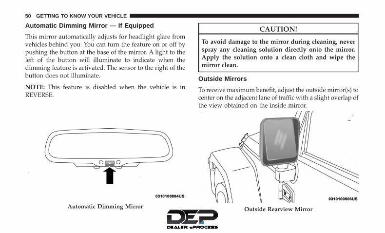
Automatic Dimming Mirror — If Equipped
This mirror automatically adjusts for headlight glare fromvehicles behind you. You can turn the feature on or off bypushing the button at the base of the mirror. A light to theleft of the button will illuminate to indicate when thedimming feature is activated. The sensor to the right of thebutton does not illuminate.
NOTE: This feature is disabled when the vehicle is inREVERSE.
CAUTION!
To avoid damage to the mirror during cleaning, neverspray any cleaning solution directly onto the mirror.Apply the solution onto a clean cloth and wipe themirror clean.
Outside Mirrors
To receive maximum benefit, adjust the outside mirror(s) tocenter on the adjacent lane of traffic with a slight overlap ofthe view obtained on the inside mirror.
Automatic Dimming Mirror Outside Rearview Mirror
50 GETTING TO KNOW YOUR VEHICLE

WARNING!
Vehicles and other objects seen in the passenger sideconvex mirror will look smaller and farther away thanthey really are. Relying too much on your passengerside mirror could cause you to collide with anothervehicle or other object. Use your inside mirror whenjudging the size or distance of a vehicle seen in thepassenger side mirror.
Power Mirrors — If Equipped
The power mirror switch is located on the center of theinstrument panel, below the climate controls. A rotary knobselects the left mirror, right mirror or off position. After selecting a mirror, move the knob in the same
direction you want the mirror to move. Use the center offposition to guard against accidentally moving a mirrorposition.
Heated Mirrors — If Equipped
These mirrors are heated to melt frost or ice. Thisfeature will be activated whenever you turn on the
rear window defroster (if equipped). Refer to “ClimateControls” in “Getting To Know Your Vehicles” for furtherinformation.
Power Mirror Switch
3
GETTING TO KNOW YOUR VEHICLE 51

Vanity Mirrors
Vanity mirrors are located on the sun visors. To use themirrors, rotate the sun visor down and swing the mirrorcover upward.
EXTERIOR LIGHTS
Headlights And Parking Lights
Turn the end of the multifunction lever to the first detentfor parking light operation. Turn to the second detent forheadlight operation.
Daytime Running Lights — If Equipped
The headlights come on at a low intensity level whenshifted into any position other than PARK (auto transmis-sion) or when the vehicle begins to move (manual trans-mission).
NOTE: The Daytime Running Light, on the same side ofthe vehicle as the active turn signal, will turn off automati-cally when a turn signal is in operation and turn on againwhen the turn signal is not operating.
Vanity Mirror
Headlight Switch
52 GETTING TO KNOW YOUR VEHICLE

High/Low Beam Switch
Push the multifunction lever away from you to switch theheadlights to high beam. Pull the multifunction levertoward you to switch the headlights back to low beam.
Flash-To-Pass
You can signal another vehicle with your headlights bylightly pulling the multifunction lever toward you. Thiswill cause the headlights to turn on at high beam andremain on until the lever is released.
Automatic Headlights — If Equipped
This system automatically turns the headlights on or offaccording to ambient light levels. To turn the system on,turn the end of the multifunction lever to the AUTOposition (third detent). When the system is on, the Head-light Time Delay feature is also on. This means the head-lights will stay on for up to 90 seconds after you turn theignition switch to the LOCK position. To turn the Auto-matic System off, turn the end of the multifunction leverout of the AUTO position.
NOTE: The engine must be running before the headlightswill turn on in the Automatic mode.
Front Fog Lights
The front fog light switch is located on the multi-function lever. To activate the front fog lights, turn
on the parking or low beam headlights and pull out theend of the lever.
NOTE: The fog lights will only operate with the parkinglights or the headlights on low beam. Selecting high beamheadlights will turn off the fog lights.
Headlight Switch
3
GETTING TO KNOW YOUR VEHICLE 53

Turn Signals
Move the multifunction lever up or down and the arrowson each side of the instrument cluster flash to show properoperation of the front and rear turn signal lights.
NOTE:
• If either light remains on and does not flash, or there isa very fast flash rate, check for a defective outside lightbulb. If an indicator fails to light when the lever ismoved, it would suggest that the indicator bulb isdefective.
• A tone will chime if the turn signals are left on for morethan 1 mile (2 km).
Lane Change Assist — If Equipped
Tap the lever up or down once, without moving beyondthe detent, and the turn signal (right or left) will flash threetimes then automatically turn off.
Lights-On Reminder
If the headlights, parking lights or cargo lights are left onafter the ignition is turned OFF, a chime will sound whenthe driver’s door is opened.
INTERIOR LIGHTS
Courtesy/Reading Lights
Two courtesy/reading lights are located in the bottom ofthe rearview mirror. You can turn these lights on and offfrom the switches in the mirror or from the dimmer control
Turn Signal Operation
54 GETTING TO KNOW YOUR VEHICLE

in the multifunction lever. These lights are also controlledautomatically by the Illuminated Entry System.
A courtesy light is also found in the rear of the centerconsole. You can turn this light on and off from the dimmercontrol in the multifunction lever. This light is also con-trolled automatically by the Illuminated Entry System.
Instrument Panel Dimmer
Rotate the center portion of the lever to the extreme bottomposition to fully dim the instrument panel lights andprevent the interior lights from illuminating when a door isopened.
Rotate the center portion of the lever up to increase thebrightness of the instrument panel lights when the parkinglights or headlights are on.
Rotate the center portion of the lever upward to the nextdetent position to brighten the odometer and radio whenthe parking lights or headlights are on.
Rotate the center portion of the lever upward to the lastdetent to turn on the interior lighting.
Cargo Lamp
The courtesy and dome lights will turn on when the frontdoors are opened, by rotating the control for the dimmer
Courtesy/Reading Light Switches
Dimmer Control
3
GETTING TO KNOW YOUR VEHICLE 55

switch on the multifunction lever fully upward, or ifequipped, when the unlock button is pushed on theRemote Keyless Entry key fob.
The sports bar reading lights (available on four-doormodels) can be turned on by pushing the switches, locatedon either side of the lens. Push a switch a second time toturn the light off.
The rear cargo light may be turned on by pushing the lens.Push the lens a second time to turn the light off.
When a door is open and the interior lights are on, rotatingthe dimmer control to the extreme bottom position willcause all the interior lights to turn off. This is also knownas the “Party” mode because it allows the doors to stayopen for extended periods of time without discharging thevehicle’s battery.
WINDSHIELD WIPERS AND WASHERS
The windshield wiper/washer control lever is located onthe right side of the steering column. The front wipers areoperated by rotating a switch, located at the end of the
Sports Bar Reading Light
Rear Cargo Light
56 GETTING TO KNOW YOUR VEHICLE

lever. For information on using the rear window wiper/washer, refer to “Rear Window Wiper/Washer” in thissection for more information.
Windshield Wiper Operation
Rotate the end of the lever upward to the second detentpast the intermittent settings for low-speed wiper opera-tion. Rotate the end of the lever upward to the third detentpast the intermittent settings for high-speed wiper opera-tion.
CAUTION!
In cold weather, always turn off the wiper switch andallow the wipers to return to the park position beforeturning off the engine. If the wiper switch is left onand the wipers freeze to the windshield, damage to thewiper motor may occur when the vehicle is restarted.
Windshield Wiper/Washer Lever
Front Wiper Control
3
GETTING TO KNOW YOUR VEHICLE 57

Intermittent Wiper System
Use the intermittent wiper when weather conditions makea single wiping cycle, with a variable pause between cycles,desirable. Rotate the end of the lever to the first detentposition for one of five intermittent settings. The delaycycle can be set anywhere between 1 to 18 seconds.
NOTE: The wiper delay times depend on vehicle speed. Ifthe vehicle is moving less than 10 mph (16 km/h), delaytimes will be doubled.
Windshield Washers
To use the washer, pull the lever toward you and holdwhile spray is desired. If the lever is pulled while in thedelay range, the wiper will start and continue to operatefor two or three wipe cycles after the lever is released.Then, the intermittent interval previously selected willresume.
If the lever is pulled while in the off position, the wiperswill operate for two or three wipe cycles. Then, the wiperswill turn off.
WARNING!
Sudden loss of visibility through the windshield couldlead to a collision. You might not see other vehicles orother obstacles. To avoid sudden icing of the wind-shield during freezing weather, warm the windshieldwith the defroster before and during windshieldwasher use.
Mist Feature
Push down on the wiper lever to activate a single wipe toclear off road mist or spray from a passing vehicle. As longas the lever is held down, the wipers will continue tooperate.
Front Wiper Control
58 GETTING TO KNOW YOUR VEHICLE

NOTE: The mist feature does not activate the washerpump; therefore, no washer fluid will be sprayed on thewindshield. The wash function must be used in order tospray the windshield with washer fluid.
Rear Window Wiper/Washer — If Equipped
A rotary switch on the center portion of the control lever(located on the right side of the steering column) controlsthe operation of the rear wiper/washer function.
Mist ControlRear Wiper/Washer Control
3
GETTING TO KNOW YOUR VEHICLE 59

Rotate the switch upward to the first detent positionfor rear wiper operation.
Rotate the switch upward past the first detent toactivate the rear washer. The washer pump andthe wiper will continue to operate as long as theswitch is held. Upon release, the wiper will cycle
two to three times before returning to the set position.
If the rear wiper is operating when the ignition is turned tothe LOCK position, the wiper will automatically return tothe “park” position. When the vehicle is restarted, thewiper will resume function at whichever position theswitch is set at.
CLIMATE CONTROLS
Manual Climate Control Overview
The air conditioning and heating system is designed tomake you comfortable in all types of weather.
Manual Temperature Controls
60 GETTING TO KNOW YOUR VEHICLE

Manual Climate Control Descriptions
Icon DescriptionA/C ButtonPush the A/C button to engage the Air Conditioning (A/C). An LED will illuminate when theA/C system is engaged.
Recirculation ButtonPush and release this button to change the system between recirculation mode and outside airmode. Recirculation can be used when outside conditions such as smoke, odors, dust, or highhumidity are present.
NOTE:• Continuous use of the Recirculation mode may make the inside air stuffy and window fog-
ging may occur. Extended use of this mode is not recommended.• The use of the Recirculation mode in cold or damp weather could cause windows to fog on
the inside, because of moisture buildup inside the vehicle. Select the outside air position formaximum defogging.
• Recirculation can be used in all modes except for Defrost.• The A/C can be deselected manually without disturbing the mode control selection.Front Defrost ModeTurn the Knob to the Front Defrost position. Air comes from the windshield and side windowdemist outlets. When the defrost mode is selected, the blower level will increase. Use Defrostmode with maximum temperature settings for best windshield and side window defrosting anddefogging.
3
GETTING TO KNOW YOUR VEHICLE 61

Icon DescriptionRear Defrost ButtonPush and release the Rear Defrost Control button to turn on the rear window defroster and theheated outside mirrors (if equipped). An indicator will illuminate when the rear window de-froster is on. The rear window defroster automatically turns off after 10 minutes.Temperature ControlUse this control to regulate the temperature of the air inside the passenger compartment. Rotat-ing the knob counterclockwise, from top center into the blue area of the scale, indicates coolertemperatures. Rotating the knob clockwise, into the red area, indicates warmer temperatures.Blower ControlThere are seven blower speeds. Use this control to regulate the amount of air forced through thesystem in any mode you select. The blower speed increases as you move the control clockwisefrom the off position.
NOTE: Depending on the configuration, your vehicle may be equipped with four blowerspeeds.Modes ControlTurn the knob to adjust airflow distribution. The airflow distribution mode can be adjusted soair comes from the instrument panel outlets, floor outlets, defrost outlets and demist outlets.
Panel Mode Panel ModeAir comes from the outlets in the instrument panel. Each of these outlets can be individuallyadjusted to direct the flow of air. The air vanes of the center outlets and outboard outlets can bemoved up and down or side to side to regulate airflow direction. There is a shut off wheel lo-cated below the air vanes to shut off or adjust the amount of airflow from these outlets.
62 GETTING TO KNOW YOUR VEHICLE

Icon DescriptionBi-Level Mode Bi-Level Mode
Air comes from the instrument panel outlets and floor outlets. A slight amount of air is directedthrough the defrost and side window demister outlets.
NOTE: BI-LEVEL mode is designed under comfort conditions to provide cooler air out of thepanel outlets and warmer air from the floor outlets.
Floor Mode Floor ModeAir comes from the floor outlets. A slight amount of air is directed through the defrost and sidewindow demister outlets.
Mix Mode Mix ModeAir is directed through the floor, defrost, and side window demister outlets. This setting worksbest in cold or snowy conditions that require extra heat to the windshield. This setting is goodfor maintaining comfort while reducing moisture on the windshield.
CAUTION!
Failure to follow these cautions can cause damage tothe heating elements:• Use care when washing the inside of the rear win-
dow. Do not use abrasive window cleaners on theinterior surface of the window. Use a soft cloth and a
(Continued)
CAUTION! (Continued)mild washing solution, wiping parallel to the heat-ing elements. Labels can be peeled off after soakingwith warm water.
• Do not use scrapers, sharp instruments, or abrasivewindow cleaners on the interior surface of the window.
• Keep all objects a safe distance from the window.
3
GETTING TO KNOW YOUR VEHICLE 63

Automatic Climate Control Overview
Automatic Climate Control Descriptions
Icon DescriptionA/C ButtonPush the A/C button to engage the Air Conditioning (A/C). An LED will illuminate when theA/C system is engaged.
Automatic Temperature Controls
64 GETTING TO KNOW YOUR VEHICLE

Icon DescriptionAutomatic OperationThe Automatic Temperature Control system automatically maintains the climate in the cabin ofthe vehicle at the comfort levels desired by the driver and passenger. Operation of the system isquite simple.Turn the Mode Control knob (on the right) and the Blower Control knob (on the left) to AUTO.
NOTE: The AUTO position performs best for front seat occupants only.Recirculation ButtonPush and release this button to change the system between recirculation mode and outside airmode. Recirculation can be used when outside conditions such as smoke, odors, dust, or highhumidity are present.
NOTE:• Continuous use of the Recirculation mode may make the inside air stuffy and window fog-
ging may occur. Extended use of this mode is not recommended.• The use of the Recirculation mode in cold or damp weather could cause windows to fog on
the inside, because of moisture buildup inside the vehicle. Select the outside air position formaximum defogging.
• Recirculation can be used in all modes except for Defrost.• The A/C can be deselected manually without disturbing the mode control selection.Rear Defrost ButtonPush and release the Rear Defrost Control button to turn on the rear window defroster and theheated outside mirrors (if equipped). An indicator will illuminate when the rear window de-froster is on. The rear window defroster automatically turns off after 10 minutes.
3
GETTING TO KNOW YOUR VEHICLE 65

Icon DescriptionTemperature ControlUse this control to regulate the temperature of the air inside the passenger compartment. Rotat-ing the knob counterclockwise, from top center into the blue area of the scale, indicates coolertemperatures. Rotating the knob clockwise, into the red area, indicates warmer temperatures.Blower ControlThere are seven blower speeds. Use this control to regulate the amount of air forced through thesystem in any mode you select. The blower speed increases as you move the control clockwisefrom the off position.
NOTE: Depending on the configuration, your vehicle may be equipped with four blowerspeeds.Modes ControlTurn the knob to adjust airflow distribution. The airflow distribution mode can be adjusted soair comes from the instrument panel outlets, floor outlets, defrost outlets and demist outlets.The Mode settings are as follows:
Panel Mode Panel ModeAir comes from the outlets in the instrument panel. Each of these outlets can be individuallyadjusted to direct the flow of air. The air vanes of the center outlets and outboard outlets can bemoved up and down or side to side to regulate airflow direction. There is a shut off wheel lo-cated below the air vanes to shut off or adjust the amount of airflow from these outlets.
66 GETTING TO KNOW YOUR VEHICLE

Icon DescriptionBi-Level Mode Bi-Level Mode
Air comes from the instrument panel outlets and floor outlets. A slight amount of air is directedthrough the defrost and side window demister outlets.
NOTE: BI-LEVEL mode is designed under comfort conditions to provide cooler air out of thepanel outlets and warmer air from the floor outlets.
Floor Mode Floor ModeAir comes from the floor outlets. A slight amount of air is directed through the defrost and sidewindow demister outlets.
Mix Mode Mix ModeAir is directed through the floor, defrost, and side window demister outlets. This setting worksbest in cold or snowy conditions that require extra heat to the windshield. This setting is goodfor maintaining comfort while reducing moisture on the windshield.
Front DefrostMode
Front Defrost ModeTurn the knob to the Front Defrost position. Air comes from the windshield and side windowdemist outlets. When the defrost mode is selected, the blower level will increase. Use Defrostmode with maximum temperature settings for best windshield and side window defrosting anddefogging.
3
GETTING TO KNOW YOUR VEHICLE 67

CAUTION!
Failure to follow these cautions can cause damage tothe heating elements:• Use care when washing the inside of the rear win-
dow. Do not use abrasive window cleaners on theinterior surface of the window. Use a soft cloth and amild washing solution, wiping parallel to the heat-ing elements. Labels can be peeled off after soakingwith warm water.
• Do not use scrapers, sharp instruments, or abrasivewindow cleaners on the interior surface of the win-dow.
• Keep all objects a safe distance from the window.
Manual Operation Override
This system offers a full complement of manual overridefeatures. The AUTO symbol in the front ATC display willbe turned off when the system is being used in the manualmode.
NOTE: The system will not automatically sense the pres-ence of fog, mist or ice on the windshield. Defrost modemust be manually selected to clear the windshield and sideglass.
Operating Tips
NOTE: Refer to the chart at the end of this section forsuggested control settings for various weather conditions.
Summer Operation
The engine cooling system must be protected with ahigh-quality antifreeze coolant to provide proper corrosionprotection and to protect against engine overheating. OATcoolant (conforming to MS.90032) is recommended.
Winter Operation
To ensure the best possible heater and defroster perfor-mance, make sure the engine cooling system is functioningproperly and the proper amount, type, and concentrationof coolant is used. Use of the Air Recirculation modeduring Winter months is not recommended, because it maycause window fogging.
Vacation/Storage
Before you store your vehicle, or keep it out of service (i.e.,vacation) for two weeks or more, run the air conditioningsystem at idle for about five minutes, in fresh air with theblower setting on high. This will ensure adequate systemlubrication to minimize the possibility of compressor dam-age when the system is started again.
68 GETTING TO KNOW YOUR VEHICLE

Window Fogging
Vehicle windows tend to fog on the inside in mild, rainyand/or humid weather. To clear the windows, select De-frost or Mix mode and increase the front blower speed. Donot use the Recirculation mode without A/C for longperiods, as fogging may occur.
Outside Air Intake
Make sure the air intake, located directly in front of thewindshield, is free of obstructions such as leaves. Leaves
collected in the air intake may reduce airflow, and if theyenter the plenum, they could plug the water drains. Inwinter months, make sure the air intake is clear of ice,slush, and snow.
Cabin Air Filter
The climate control system filters out dust and pollen fromthe air. Contact your authorized dealer to service yourcabin air filter, and to have it replaced when needed.
3
GETTING TO KNOW YOUR VEHICLE 69

Operating Tips Chart
POWER WINDOWS — IF EQUIPPED
The power window switches are located on the instrumentpanel below the radio. Push the switch downward to openthe window and upward to close the window.
The top left switch controls the left front window and thetop right switch controls the right front window.
70 GETTING TO KNOW YOUR VEHICLE

WARNING!
Never leave children unattended in a vehicle, and donot let children play with power windows. Do notleave the key fob in or near the vehicle, or in a locationaccessible to children. Occupants, particularly unat-tended children, can become entrapped by the win-dows while operating the power window switches.Such entrapment may result in serious injury or death.
NOTE:
• For vehicles not equipped with the instrument clusterdisplay, the power window switches will remain activefor 45 seconds after the ignition switch is turned to theLOCK position. Opening either front door will cancelthis feature.
• For vehicles equipped with the instrument cluster dis-play, the power window switches will remain active forup to 10 minutes after the ignition switch is turned to theLOCK position. Opening either front door will cancelthis feature.
Four-Door Models
The lower left switch controls the left rear passengerwindow, and the lower right switch controls the right rearpassenger window.
Wind Buffeting
Wind buffeting can be described as the perception ofpressure on the ears or a helicopter-type sound in the ears.Your vehicle may exhibit wind buffeting with the windowsdown in certain open or partially open positions. This is anormal occurrence and can be minimized by adjusting thewindow opening.
Power Window Switches
3
GETTING TO KNOW YOUR VEHICLE 71

DUAL TOP — TWO-DOOR MODELS — IFEQUIPPED
Please visit http://www.jeep.com/en/wrangler-rooftop-instructions/ for instructional videos.
If your vehicle is equipped with a Dual Top, you mustremove one of the tops from the vehicle. If the soft top isremoved, the pivot brackets must also be removed fromthe sport bar. The soft top was installed at the factory forshipping purposes only. The soft top and the hard top areto be used independently. Removal is mandatory toprevent any possible wear and tear on the soft top. Yourvehicle warranty will not cover damage resulting fromboth tops remaining on the vehicle at the same time forextended periods of time.
Removing The Soft Top — Two-Door Models
1. Locate and remove the two boxes that contain thefollowing items:• Right and left door frames• Four door frame attachment knobs• Right and left quarter windows• Rear window• Two rear window roll up straps
• Two Sunrider secure straps (if equipped)• Two rear swing gate brackets
2. Remove the hard top. Refer to “Freedom Top Three-Piece Modular Hard Top — Front/Rear Panel Removal”in this section.
3. Remove the soft top bow assembly pivot bracket screws(two per side) using a #T30 Torx head driver.
4. Disconnect the knuckles from the left and right metalpivot brackets. Remove the soft top from the vehicle andstore in a clean, dry location.
Step Three
72 GETTING TO KNOW YOUR VEHICLE

NOTE: To aid in disconnecting the knuckles, you maycarefully tap on the knuckles using a rubber mallet.
5. Unzip the zipper on the sport bar cover to expose thepivot brackets. Remove the brackets using a #T30 Torxhead driver. Recover and re-zip the sports bar cover.Store the pivot brackets and screws in a safe place.
6. Reinstall the hard top. Refer to “Freedom Top Three-Piece Modular Hard Top — Front/Rear Panel Installa-tion” in this section.
Installing The Soft Top — Two-Door Models
NOTE: The following procedures are for first time set uponly. For future soft top procedures, refer to “Soft Top” inthis section.
1. Locate and remove the following items prior to hard topremoval:• Right and left door frames• Door frame attachment knobs (four for two-door mod-
els, six for four-door models)• Right and left quarter windows• Rear window
2. Remove the hard top. Refer to “Freedom Top Three-Piece Modular Hard Top — Front/Rear Panel Removal”in this section.
3. Install the door frames. Refer to “Door Frame” in thissection.
Step Four
3
GETTING TO KNOW YOUR VEHICLE 73

4. If the soft top has been removed, follow these steps toreinstall the soft top. If the soft top is on the vehicle,proceed to step #5.
a. If the pivot brackets have been removed, unzip thesport bar covers and attach the pivot brackets to thesports bar with the four screws that were removedusing a #T30 Torx head driver. Re-cover and re-zipthe sport bar covers.
b. Lay the soft top into the rear of the vehicle with thebows pointing forward and the curved portion of thebows facing upward.
c. Reattach the knuckles onto the metal pivot brackets.
NOTE: To aid in reattaching the knuckles, you may care-fully tap on the knuckles using a rubber mallet.
d. Screw the pivot screws back into place using a #T30Torx head driver. Secure them until they are snug,being careful not to cross-thread the screws or over-tighten.
Step Four
74 GETTING TO KNOW YOUR VEHICLE

CAUTION!
Do not overtighten the screws. You can strip the screwsif they are overtightened.
5. Remove the swing gate bar (black metal bar for bottomof rear window) and set aside.
NOTE: Be sure the wire harness in the left rear corner isnot tangled in the soft top bows before you lift the top.
6. Unsnap and remove the black boot cover. This covershould be discarded. It was intended as a protectivecover for shipping only.
NOTE: A visual instruction sheet is enclosed in the dualtop wrap.
7. Put up the soft top. Refer to “Soft Top — Putting Up TheSoft Top” in this section.
DUAL TOP — FOUR-DOOR MODELS — IFEQUIPPED
Please visit http://www.jeep.com/en/wrangler-rooftop-instructions/ for instructional videos.
If your vehicle is equipped with a Dual Top, you mustremove one of the tops from the vehicle. If the soft top isremoved, the pivot brackets must also be removed fromthe sport bar. The soft top was installed at the factory forshipping purposes only. The soft top and the hard top areto be used independently. Removal is mandatory toprevent any possible wear and tear on the soft top. Yourvehicle warranty will not cover damage resulting fromboth tops remaining on the vehicle at the same time forextended periods of time.
Step Four
3
GETTING TO KNOW YOUR VEHICLE 75

Removing The Soft Top — Four-Door Models
1. Locate and remove the two boxes that contain thefollowing items:• Right and left door frames• Six door frame attachment knobs• Right and left quarter windows• Rear window• Two rear window roll up straps• Two Sunrider secure straps (if equipped)• Two rear swing gate brackets
2. Remove the hard top. Refer to “Freedom Top Three-Piece Modular Hard Top — Front/Rear Panel Removal”in this section.
3. Ensure the tether strap is secure to the pivot bracket.Unbutton the side bow tether strap (both sides).
4. Using the plastic reinforcement as a handle, slide thetether strap up the side bow (both sides).
Step Three
76 GETTING TO KNOW YOUR VEHICLE

5. The tether strap must be hooked onto the pivot bracketprior to removal of soft top from vehicle (both sides).
6. Remove the soft top bow assembly pivot bracket bolts(two per side) from the sport bar using a 10.0 mmwrench or socket driver.
7. Lift the soft top in a upward motion to release the pivotbracket from the sport bar bracket.
Step Four Step Five
3
GETTING TO KNOW YOUR VEHICLE 77

8. Remove the soft top from the vehicle and store in aclean, dry location (another person may be needed tohelp with this operation).
NOTE: If you are doing this alone, use one arm to hold thebundle up, the other to remove the brackets.
9. Reinstall the hard top. Refer to “Freedom Top Three-Piece Modular Hard Top — Front/Rear Panel Installa-tion” in this section.
Step Seven Step Eight
78 GETTING TO KNOW YOUR VEHICLE

Installing The Soft Top — Four-Door Models
NOTE: The following procedures are for first time set uponly. For future soft top procedures, refer to “Soft Top” inthis section.
1. Locate and remove the following items prior to hard topremoval:• Right and left door frames• Six door frame attachment knobs• Right and left quarter windows• Rear window
2. Remove the hard top. Refer to “Freedom Top Three-Piece Modular Hard Top — Front/Rear Panel Removal”in this section.
3. Install the door frames. Refer to “Door Frame” in thissection.
4. Install the soft top with the pivot brackets above thesport bar brackets, lower the soft top into the sport barbracket slots in a downward motion to lock tab on softtop. You will need to lift the top to get the brackets toline up. (Another person may be needed to help withthis operation.)
NOTE: If you are doing this alone, use one arm to hold thesoft top up, the other to align the brackets.
5. Lower the pivot bracket onto the sport bar bracketmounting tab in a downward motion to lock into tab.
Step Four
3
GETTING TO KNOW YOUR VEHICLE 79

6. Install the pivot bracket bolts back into place using a10.0 mm wrench or socket driver. Secure them until theyare snug, being careful not to cross-thread the screws orovertighten.
CAUTION!
Do not overtighten the screws. You can strip the screwsif they are overtightened.
7. Remove the tether strap from the pivot bracket.
Step Five
Step Seven
80 GETTING TO KNOW YOUR VEHICLE

8. Using the plastic reinforcement as a handle remove thetether strap from the bracket hook by sliding strap upoff hook and slide down the side bow (both sides).
9. Button the side bow tether strap (both sides).
10. Remove the swing gate bar (black metal bar for bottomof rear window) and set aside.
NOTE: Be sure the wire harness in the left rear corner isnot tangled in the soft top bows before you lift the top.
11. Unsnap and remove the black boot cover. This covershould be discarded. It was intended as a protectivecover for shipping only.
NOTE: A visual instruction sheet is enclosed in the dualtop wrap.
Step Eight
Step Nine
3
GETTING TO KNOW YOUR VEHICLE 81

12. Put up the soft top. Refer to “Soft Top — Putting UpThe Soft Top” in this section.
FREEDOM TOP THREE-PIECE MODULAR HARDTOP — IF EQUIPPED
CAUTION!
• The hard top is not designed to carry any additionalloads such as roof racks, spare tires, building, hunt-ing, or camping supplies, and/or luggage, etc. Also, itwas not designed as a structural member of thevehicle, and thus cannot properly carry any addi-tional loads other than environmental (rain, snow,etc.).
• Do not move your vehicle until the top has beeneither fully attached to the windshield frame andbody side or fully removed.
Failure to follow these cautions may cause interiorwater damage, stains or mildew:• It is recommended that the top be free of water prior
to panel removal. Removing the top, opening a dooror lowering a window while the top is wet may allowwater to drip into the vehicle’s interior.
(Continued)
CAUTION! (Continued)• The hard top assembly must be positioned properly
to ensure sealing. Improper installation can causewater to leak into the vehicle’s interior.
• Careless handling and storage of the removable roofpanels may damage the seals, causing water to leakinto the vehicle’s interior.
• The front panel(s) must be positioned properly toensure sealing. Improper installation can cause waterto leak into the vehicle’s interior.
Front Panel(s) Removal
NOTE: Left panel must be removed before removingright panel.
1. Fold down the sun visor, and move it to the side.
2. Turn the rear fasteners (knobs) (located on the overheadspeaker bar assembly) counterclockwise until they canbe removed.
82 GETTING TO KNOW YOUR VEHICLE

3. Turn the center L-shaped locks (two) from the center ofthe roof panel.
4. Turn the rear L-shaped lock (located above the shoulderbelt anchorage).
Step Two Step Three
3
GETTING TO KNOW YOUR VEHICLE 83

5. Unlatch the header panel latch located at the top of thewindshield.
6. Remove the left-hand panel.
To remove the right panel, follow the steps above exceptfor Step 3.
Step Four Step Five
84 GETTING TO KNOW YOUR VEHICLE

Freedom Top Storage Bag
Vehicles equipped with a Freedom Top Modular Hard Top,come with a Freedom Top storage bag that allows you tostore your Freedom Top panels. The storage bag containstwo compartments and fits behind the rear seat.
Lay the Freedom bag down so the loops and hooks arefacing downward. Unzip the bag and fold back the outerflap. Release the Velcro on the black panel divider and foldit back.
NOTE: Ensure the front Freedom Top panel latch is closedprior to inserting the panel into the Freedom bag.
1. Insert the right side Freedom panel into the bag with thelatches facing downward.
Step One
3
GETTING TO KNOW YOUR VEHICLE 85

2. Unfold the black panel divider (ensure the divider islaying flat). Secure the Velcro, located at the center of thedivider.
3. Insert the left-side Freedom panel into the bag with thelatches facing upward.
NOTE: Ensure the front Freedom panel latch is closedprior to inserting the panel into the bag.
Step TwoStep Three
86 GETTING TO KNOW YOUR VEHICLE

4. Unfold the outer flap and zip the Freedom bag closed. 5. Install the seat attachment strap (at the top of the bag)through the loops.
Step FourStep Five
3
GETTING TO KNOW YOUR VEHICLE 87

6. Lift the Freedom bag into the vehicle with the hooks andstraps facing the back of the rear seat. Attach the clips atthe bottom of the bag to the child restraint anchorages,located at the base of the rear seat.
7. Wrap the upper strap around the rear head restraintsand loop the strap through the buckle. Pull on the strapto tighten the Freedom bag securely against the rearseat.
Front Panel(s) Installation
NOTE: Set the panels on the windshield frame so thatthere is no overhang. Also, make sure that the panels aresitting flush with the body.
1. Install the right panel first, then the left panel.
2. Reinstall the panel(s) using the same steps for removalin reverse order.
Step Six
Step Seven
88 GETTING TO KNOW YOUR VEHICLE

Front Panel(s) Installation With Rear Hard TopRemoved
1. Turn the left and right panels over and move the spacerblock (located on the rear of the panel) upward 90degrees.
NOTE: The front panel(s) must be positioned properly toensure sealing. Set the panels on the windshield frame sothat there is no overhang. Also, make sure that the panelsare sitting flush with the body.
2. Install the right panel first, then the left panel.
3. Reinstall the panel(s) using the same steps for removalin reverse order.
Rear Hard Top Removal
1. Remove both front panels. Refer to “Front Panel(s)Removal” in this section.
2. Open both doors.
3. Remove the two Torx head screws that secure the hardtop at the B-pillar (near the top of the door) using a #40Torx head driver (Four–Door Only).
4. Remove the six Torx head screws that secure the hardtop to the vehicle (along the interior bodyside) using a#40 Torx head driver.
Step One
3
GETTING TO KNOW YOUR VEHICLE 89
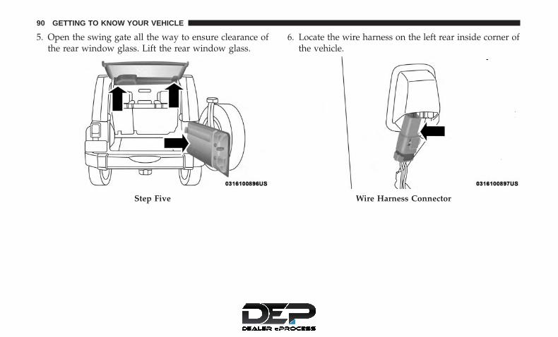
5. Open the swing gate all the way to ensure clearance ofthe rear window glass. Lift the rear window glass.
6. Locate the wire harness on the left rear inside corner ofthe vehicle.
Step Five Wire Harness Connector
90 GETTING TO KNOW YOUR VEHICLE

7. Release the red locking tab by pulling outward to theright.
8. To remove the wiring harness push the tab and pulldownward to disconnect.
9. To remove the washer hose, pinch the grips on hoseconnector and pull downward.Red Locking Tab
Push Tab To Disconnect
3
GETTING TO KNOW YOUR VEHICLE 91

10. Close the swing gate.
11. Remove the hard top from the vehicle. Place the hardtop on a soft surface to prevent damage.
CAUTION!
The removal of the Freedom Top requires four adultslocated on each corner. Failure to follow this cautioncould damage the Freedom Top.
Rear Hard Top Installation
NOTE: If the door frames are installed from soft top usage,they must be removed prior to installation of the hard top.
1. Inspect the hard top seals for damage and replace ifnecessary.
2. Install the hard top using the same steps for removal inreverse order.
Make sure that the hard top is sitting flush with the bodyat the sides and check to ensure that there is a uniform gapbetween the lift glass and hard top.
NOTE:
• The Torx fasteners that attach the hard top to the bodyshould be torqued to 88 in lb +/- 22 in lb (10 N·m +/-2.5 N·m).
• It is not necessary to pinch connection when reinstall-ing washer hose. Push on until click is heard.
Pinch Grip On Hose
92 GETTING TO KNOW YOUR VEHICLE

DOOR FRAME
WARNING!
• Do not drive your vehicle on public roads with thedoor frame(s) removed as you will lose the protectionthat they can provide. This procedure is furnishedfor use during off-road operation only.
• Do not drive your vehicle on public roads with thedoors removed as you will lose the protection thatthey can provide. This procedure is furnished for useduring off-road operation only.
CAUTION!
Failure to follow these cautions may cause interiorwater damage, stains or mildew:• Opening a door or lowering a window while the top is
wet may allow water to drip into the vehicle’s interior.• Careless handling and storage of the removable door
frame(s) may damage the seals, causing water to leakinto the vehicle’s interior.
• The door frame(s) must be positioned properly toensure sealing. Improper installation can cause waterto leak into the vehicle’s interior.
Door Frame Removal
1. Unscrew and remove the door frame attachment knobs(two per door).
WARNING!
Use both hands to remove the door frames. The doorframes will fold and could cause injury if both handsare not used.
2. Place one hand on the upper rear and one hand on thefront of the door frame.
Step One
3
GETTING TO KNOW YOUR VEHICLE 93

3. Pull the frame toward you with your rearward hand toremove the frame from the vehicle.
4. Screw the knobs back into the door frame and fold forstorage. Store in a secure location.
WARNING!
• Do not drive your vehicle on public roads with thedoor frame(s) removed as you will lose the protectionthat they can provide. This procedure is furnishedfor use during off-road operation only.
• Do not drive your vehicle on public roads with thedoors removed as you will lose the protection thatthey can provide. This procedure is furnished for useduring off-road operation only.
Step Three
Step Four
94 GETTING TO KNOW YOUR VEHICLE

Door Frame Installation — Two-Door Models — IfEquipped
1. Unfold door frame and unscrew thumbscrews.
2. Set the door frame pin into the hole on top of the bodyside, behind the door opening.
3. After the door frame pin has been set into the body sidehole, carefully set the front of the door frame into therubber seal at the top of the windshield.
4. Starting with the front of the door frame, clip it over themetal side bar and then clip the rear, making sure thatthe material for the side bar covers is not pinched by thedoor frame.
Step Two
Step Four
3
GETTING TO KNOW YOUR VEHICLE 95

5. Starting with the front knob, screw in and tighten bothknobs. Repeat on the other side.
Door Frame Installation — Four-Door Models — IfEquipped
1. Install the rear door frame first.
2. Set the door frame pin into the hole on top of the bodyside, just behind the rear door opening.
3. Position the top of the door frame against the metalsport bar and push onto the side bar, making sure not topinch the material of the sports bar covers and to ensureit is properly positioned on the seal above the front ofthe rear door.
Step Five
Step Two
96 GETTING TO KNOW YOUR VEHICLE

4. Loosely install the rear knob (long knob) to hold thedoor rail in position.
5. Carefully set the front of the front door frame in therubber seal at the top of the windshield.
6. Clip the front of the door rail over the side bar makingsure that the material for the side bar cover is notpinched by the door frame.
7. Position the rear of the front door frame to lay on top ofthe front of the rear door frame. Ensure the seals areinstalled correctly to avoid water leaks.
Step Three Step Five
3
GETTING TO KNOW YOUR VEHICLE 97

8. Loosely install both knobs beginning with the frontknob (long knob). Then, install the middle knob (shortknob) through the front and rear door frames and screwinto the top of the B-pillar.
9. Tighten the front knob, then the rear most knob, andthen the middle knob. Repeat this procedure for theother side.
Step Seven
Step Nine
98 GETTING TO KNOW YOUR VEHICLE

SOFT TOP — TWO-DOOR MODELS
Please visit http://www.jeep.com/en/wrangler-rooftop-instructions/ for instructional videos.
WARNING!
• Do not drive the vehicle with the rear windowcurtain up unless the side curtains are also removed.Dangerous exhaust gases could enter the vehiclecausing harm to the driver and passengers.
• The fabric upper doors and fabric top are designedonly for protection against the elements. Do not relyon them to contain occupants within the vehicle or toprotect against injury during an accident. Remember,always wear seat belts.
• Make sure hands and fingers are clear of all pinchpoints when installing and removing the soft tops.The zippers and side bows may cause serious injuryif fingers or hands get caught in between.
CAUTION!
The soft top is not designed to carry any additionalloads such as roof racks, spare tires, building, hunting,or camping supplies, and/or luggage, etc. Also, it wasnot designed as a structural member of the vehicle and,thus, cannot properly carry any additional loads otherthan environmental (rain, snow, etc.).
If the temperature is below 72°F (24°C) and/or the top hasbeen folded down for a period of time, the top will appearto have shrunk when you raise it, making it difficult to putup. This is caused by a natural contraction of the vinylcoating on the fabric top.
Place the vehicle in a warm area. Pull steadily on the topfabric. The vinyl will stretch back to its original size and thetop can then be installed. If the temperature is 41°F (5°C)or below, do not attempt to put the top down or roll therear or side curtains.
3
GETTING TO KNOW YOUR VEHICLE 99

CAUTION!
• Do not run a fabric top through an automatic carwash. Window scratches and wax build up mayresult.
• Do not lower the top when the temperature is below41°F (5°C). Damage to the top may result.
• Do not move your vehicle until the top has beeneither fully attached to the windshield frame, or fullylowered.
• Do not lower the top with the windows installed.Window and top damage may occur.
• Refer to “Appearance Care For Fabric Top Models”in “Bodywork” in “Servicing And Maintenance” forfurther information. It contains important informa-tion on cleaning and caring for your vehicle’s fabrictop.
• Do not use any tools (screwdrivers, etc.) to pry orforce any of the clamps, clips, or retainers securingthe soft top. Do not force or pry the soft top frame-work when opening or closing. Damage to the topmay result.
CAUTION!
Failure to follow these cautions may cause interiorwater damage, stains or mildew on the top material:• It is recommended that the top be free of water prior
to opening it. Operating the top, opening a door orlowering a window while the top is wet may allowwater to drip into the vehicle’s interior.
• Careless handling and storage of the soft top maydamage the seals, causing water to leak into thevehicle’s interior.
• The soft top must be positioned properly to ensuresealing. Improper installation can cause water to leakinto the vehicle’s interior.
100 GETTING TO KNOW YOUR VEHICLE

Quick Steps To Lowering The Soft Top
Refer to “Lowering The Soft Top” in this section for furtherinformation.
1. Remove the side windows.
2. Remove the back window.
Step One
Step Two
3
GETTING TO KNOW YOUR VEHICLE 101

3. Release header latches from the windshield frame.
4. Release the sail panel retainers from the body sidechannel at the rear corners of the vehicle.
NOTE: When releasing the sail panel retainers, it is helpfulto pull down on the rear roof bow.
Step Three
Step Four
102 GETTING TO KNOW YOUR VEHICLE

5. Make sure the plastic sleeves are slid rearward over theSunrider link to lock in the link (Sunrider Models only).
6. As you begin to lower the top, fold the sail panels so thatthey rest on top of the soft top.
Step Five Step Six
3
GETTING TO KNOW YOUR VEHICLE 103

7. Release the Sunrider latch (both sides). 8. Open the swing gate and lower the top.
NOTE: Ensure fabric does not overhang the sides of thevehicle.
Step Seven
Step Eight
104 GETTING TO KNOW YOUR VEHICLE

Quick Steps To Raising The Soft Top
Refer to “Raising The Soft Top” in this section for furtherinformation.
1. Open the swing gate and raise the top, engaging theSunrider latches (another person may be needed to helpwith this operation).
2. Engage header latches.
Step One
Step One
3
GETTING TO KNOW YOUR VEHICLE 105

3. Install rear corner panels. 4. Install the back window.Step Two Step Three
106 GETTING TO KNOW YOUR VEHICLE

5. Install the side windows.
6. To install the side windows, affix the window tempo-rarily by attaching to the Velcro in the rear corner. Startthe zipper but close only about 1 inch (2.5 cm).
7. Insert the front retainer of the window into the doorchannel, making sure the retainer is fully seated andproperly positioned on the door frame. Failure to do socan result in wind and water leaks or damage to thewindow.
Step Four Step Six
3
GETTING TO KNOW YOUR VEHICLE 107

Step Seven Retainer Insertion
1 — Incorrect Insertion2 — Correct Insertion
108 GETTING TO KNOW YOUR VEHICLE

8. Insert the retainer along the bottom edge of the windowinto the bottom side channel, beginning at the front andworking to the rear of the vehicle. Finish by closing thezipper completely and attaching the Velcro along the topand rear of the window. Repeat this step for the oppositeside.
Step Eight
3
GETTING TO KNOW YOUR VEHICLE 109

Lowering The Soft Top
Side View Top And Components
1 — 3–Bow 6 — Bottom Retainer — Quarter Window2 — 2–Bow 7 — Quarter Window3 — Header Bow 8 — Sail Panel4 — Front Retainer — Quarter Window 9 — Check Strap5 — Body Side Retainer
110 GETTING TO KNOW YOUR VEHICLE

Rear View Top And Components
1 — Sail Panels2 — Zipper Finish3 — Swing Gate Bar4 — Zipper Start5 — Swing Gate Brackets
3
GETTING TO KNOW YOUR VEHICLE 111

NOTE: Clean side and rear windows before removal toassist in preventing scratching during removal of the softtop. If zippers are difficult to operate due to road dust, etc.,clean them with a mild soap solution and a small brush.Cleaning products are available through your authorizeddealer.
1. If your vehicle has half doors, remove each half-doorwindow by opening the door and lifting the half-doorwindow out.
NOTE: Stow the half-door windows carefully outside ofthe vehicle, never inside, to avoid scratches.
2. Unclip and move the sun visors to the side.
3. Release the header latches and leave the hooks in theloops on the windshield.
4. Open the swing gate.Step Three
112 GETTING TO KNOW YOUR VEHICLE

5. Before unzipping the rear window, release the first 3inches (7.6 cm) of both sail panels from the channel.Remove the swing gate bar by pulling it straight rear-ward out of the swing gate brackets.
6. Unzip the rear window starting at the right lower cornerof the window. Pull the zipper up, across the top anddown to the left lower corner. Zipper pulls will stay onthe rear window. Pull down on the rear window todisengage it from the zipper on the top cover.
7. Remove the rear window retainer from the swing gatebracket on both the left and right sides.
Step Five
Step Six
3
GETTING TO KNOW YOUR VEHICLE 113

8. Stow the windows carefully to avoid scratching.
9. Undo the Velcro that runs along the top and rear edge ofthe side window.
10. Beginning from the rear lower corner, completely un-zip the window.
11. Once unzipped, remove the side window retainersfrom the door channel and body side channel. Repeatthis step on the opposite side.
12. Finish releasing the sail panel retainers from the bodyside channel at the rear corners of the vehicle.
Step Seven Step Ten
114 GETTING TO KNOW YOUR VEHICLE

NOTE: When releasing the sail panel retainers, it is helpfulto pull down on the rear roof bow.
13. As you begin to lower the top, fold the sail panels sothat they rest on top of the soft top.
14. The swing gate brackets do not need to be removedunless the hard top is being installed. To remove theswing gate brackets, pull the front of the bracketforward while rolling the entire bracket back in towardthe vehicle to disengage.
Step Twelve Step Thirteen
3
GETTING TO KNOW YOUR VEHICLE 115

15. Completely release the latches from the loops on thewindshield frame. If your vehicle is not equippedwith the Sunrider package, proceed to Step 18.
16. Make sure the plastic sleeves are slid rearward over theSunrider link to lock in the link (Sunrider Modelsonly).
Step Fourteen Step Fifteen
116 GETTING TO KNOW YOUR VEHICLE

17. Unlatch the side bows from both door rails (SunriderModels only).
18. Before lowering the top, open the swing gate to preventpossible damage to the rear center high-mounted brakelight. Move to the front of the vehicle. Grasp the sidebow behind the header and lift the top, folding ittoward the rear of the vehicle.
NOTE: Help from another person will ease this operation.
Step Sixteen Step Seventeen
3
GETTING TO KNOW YOUR VEHICLE 117

19. Tuck the fabric and the check straps between the bowsand as far inward as possible. This will keep anyportion of the top from flapping outside of the vehicle.
20. Close the front header latches.
21. Remove the door frames, if desired. Refer to “DoorFrame” in this section for further information.
Step Eighteen Step Nineteen
118 GETTING TO KNOW YOUR VEHICLE

Raising The Soft Top
1. Unclip and move the sun visors to the side.
2. Install door frames, if removed. Refer to “Door Frame”in this section for further information.
3. Make sure the plastic sleeve is slid over Sunrider link(Sunrider Models only).
4. Standing on the side of the vehicle, lift the top by theside bow and the 2–bow (middle bow) up and over thesports bar until the header rests on the top of thewindshield frame.
5. Make sure the Sunrider bracket on the side bows latchesto the door rails (Sunrider Models only).
Step Three
Step Four
3
GETTING TO KNOW YOUR VEHICLE 119
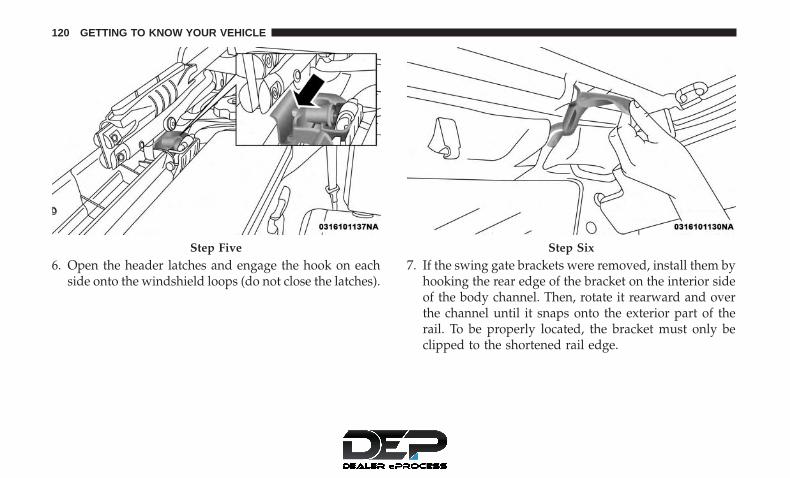
6. Open the header latches and engage the hook on eachside onto the windshield loops (do not close the latches).
7. If the swing gate brackets were removed, install them byhooking the rear edge of the bracket on the interior sideof the body channel. Then, rotate it rearward and overthe channel until it snaps onto the exterior part of therail. To be properly located, the bracket must only beclipped to the shortened rail edge.
Step Five Step Six
120 GETTING TO KNOW YOUR VEHICLE

8. Move to the rear of the vehicle and gently pull the sailpanels over the rear roof bow.
9. Partially install the sail panel retainers into the bodyside channel, leaving the last 3 in (7.6 cm) toward therear window loose (on both sides). Pulling down on therear roof bow (3–bow) will aid to reach the channel withthe retainers.
Step Seven Step Eight
3
GETTING TO KNOW YOUR VEHICLE 121

10. To install the side windows, affix the window tempo-rarily by attaching to the Velcro in the rear corner. Startthe zipper but close only about 1 in (2.5 cm).
11. Insert the front retainer of the window into the doorchannel, making sure the retainer is fully seated andproperly positioned on the door frame. Failure to do socan result in wind and water leaks or damage to thewindow.
Step Nine Step Ten
122 GETTING TO KNOW YOUR VEHICLE

12. Insert the retainer along the bottom edge of the win-dow into the bottom side channel, beginning at thefront and working to the rear of the vehicle. Finish byclosing the zipper completely and attaching the Velcroalong the top and rear of the window. Repeat this stepfor the opposite side.
Step Eleven Retainer Insertion
1 — Incorrect Insertion2 — Correct Insertion
3
GETTING TO KNOW YOUR VEHICLE 123

13. Locate the black swing gate bar. Slide the swing gatebar over the receiver at the bottom inside of the rearwindow. The spongy part of the seal should be downand pointed outward to seal with the swing gate whenclosed.
Step Twelve Step Twelve
124 GETTING TO KNOW YOUR VEHICLE

14. Install the rear window by starting both zipper ends atthe lower left corner of the rear window opening.Ensure that the zippers are properly started andaligned before zipping to prevent damage.
Step Thirteen Step Fourteen
3
GETTING TO KNOW YOUR VEHICLE 125

15. Run the zipper fully around to the right side of thewindow.
16. Grasp the swing gate bar and position it into the swinggate brackets.
17. Insert the rear window retainer into the swing gatebracket on both the left and right sides.
Step Fourteen Step Sixteen
126 GETTING TO KNOW YOUR VEHICLE

18. Apply downward pressure on the top corner of the rearsoft top bow (3–bow), then complete attaching the sailpanel retainers into the body side channel.
19. Close the header latches and return the sun visors totheir secured position.
Step Seventeen
Step Nineteen
3
GETTING TO KNOW YOUR VEHICLE 127

SUNRIDER (TWO-DOOR MODELS) — IF EQUIPPED
CAUTION!
Operating the top, opening a door or lowering awindow while the top is wet may allow water to dripinto the vehicle’s interior.
NOTE: If you are going to be driving faster than 40 mph(64 km/h) with the Sunrider feature open, it is recom-mended that you remove the rear window of the vehicle.
Opening The Sunrider
1. Unclip and move the sun visors to the side.
2. Release the header latches from the loops on the wind-shield frame.
3. Make sure to slide the plastic sleeves forward to unlockthe Sunrider links.
Step Two
128 GETTING TO KNOW YOUR VEHICLE

4. Grasp the header and lift the top back. Make sure thematerial is folded back as shown.
NOTE: The Sunrider latch on the door rail should not beactivated for Sunrider use. If activated, the soft top must bereinstalled starting from the sail panels.
5. Locate the straps to secure the side bows. Wrap thestraps around the bows as shown. Repeat on the otherside.
Step Three Step Four
3
GETTING TO KNOW YOUR VEHICLE 129

6. Reposition the sun visors.
Closing The Sunrider
1. Remove the straps from the side bows.
2. Unclip and move the sun visors to the side.
3. Grasp the front header and pull it to the front of thevehicle.
4. Hook the header latches to the loops on the windshieldframe, close latches, and return the sun visors to theiroriginal positions.
5. Slide the plastic sleeve rearward over the Sunrider link.
SOFT TOP — FOUR-DOOR MODELS
Please visit http://www.jeep.com/en/wrangler-rooftop-instructions/ for instructional videos.
WARNING!
• Do not drive the vehicle with the rear windowcurtain up unless the side curtains are also removed.Dangerous exhaust gases could enter the vehiclecausing harm to the driver and passengers.
• The fabric upper doors and fabric top are designedonly for protection against the elements. Do not relyon them to contain occupants within the vehicle or toprotect against injury during an accident. Remember,always wear seat belts.
• Make sure hands and fingers are clear of all pinchpoints when installing and removing the soft tops.The zippers and side bows may cause serious injuryif fingers or hands get caught in between.
Step Five
130 GETTING TO KNOW YOUR VEHICLE

CAUTION!
The soft top is not designed to carry any additionalloads such as roof racks, spare tires, building, hunting,or camping supplies, and/or luggage, etc. Also, it wasnot designed as a structural member of the vehicle and,thus, cannot properly carry any additional loads otherthan environmental (rain, snow, etc.).
If the temperature is below 72°F (24°C) and/or the top hasbeen folded down for a period of time, the top will appearto have shrunk when you raise it, making it difficult to putup. This is caused by a natural contraction of the vinylcoating on the fabric top.
Place the vehicle in a warm area. Pull steadily on the topfabric. The vinyl will stretch back to its original size and thetop can then be snapped into place. If the temperature is41°F (5°C) or below, do not attempt to put the top down orroll the rear or side curtains.
CAUTION!
• Do not run a fabric top through an automatic carwash. Window scratches and wax build up mayresult.
• Do not lower the top when the temperature is below41°F (5°C). Damage to the top may result.
• Do not move your vehicle until the top has beeneither fully attached to the windshield frame, or fullylowered.
• Do not lower the top with the windows installed.Window and top damage may occur.
• Refer to “Appearance Care For Fabric Top Models”in “Bodywork” in “Servicing And Maintenance” forfurther information. It contains important informa-tion on cleaning and caring for your vehicle’s fabrictop.
• Do not use any tools (screwdrivers, etc.) to pry orforce any of the clamps, clips, or retainers securingthe soft top. Do not force or pry the soft top frame-work when opening or closing. Damage to the topmay result.
3
GETTING TO KNOW YOUR VEHICLE 131

CAUTION!
Failure to follow these cautions may cause interiorwater damage, stains or mildew on the top material:• It is recommended that the top be free of water prior
to opening it. Operating the top, opening a door orlowering a window while the top is wet may allowwater to drip into the vehicle’s interior.
• Careless handling and storage of the soft top maydamage the seals, causing water to leak into thevehicle’s interior.
• The soft top must be positioned properly to ensuresealing. Improper installation can cause water to leakinto the vehicle’s interior.
NOTE: Do not remove any of the three attachment knobsunless you are planning on installing the hard top.
Attachment Knobs
132 GETTING TO KNOW YOUR VEHICLE

Quick Steps For Lowering The Soft Top
1. Remove the side windows.
2. Remove the back window.
NOTE: Start zipper from the right side to remove backwindow.
Step One
Step Two
3
GETTING TO KNOW YOUR VEHICLE 133

3. Release header latches from the windshield frame.
4. Release the sail panel retainers from the body sidechannel at the rear corners of the vehicle.
NOTE: When releasing the sail panel retainers, it is helpfulto pull down on the rear roof bow.
Step Three
Step Four
134 GETTING TO KNOW YOUR VEHICLE

5. Fold the sail panels so that they rest on top of the softtop.
6. Fold header rearward, pulling the fabric to the rear.
Step FiveStep Six
3
GETTING TO KNOW YOUR VEHICLE 135

7. Release Sunrider latch (both sides).
Step Six
Step Seven
136 GETTING TO KNOW YOUR VEHICLE

8. Open the swing gate and lower the top.
NOTE: Ensure the fabric does not overhang the sides of thevehicle.
Quick Steps For Raising The Soft Top
1. Open the swing gate and raise the top, engaging theSunrider latches (another person may be needed to helpwith this operation).
Step Eight
Step One
3
GETTING TO KNOW YOUR VEHICLE 137
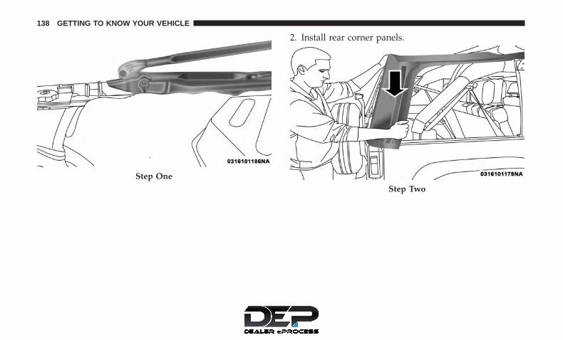
2. Install rear corner panels.
Step One
Step Two
138 GETTING TO KNOW YOUR VEHICLE

3. Rotate the header forward. 4. Engage the header latches.
Step Three Step Four
3
GETTING TO KNOW YOUR VEHICLE 139

5. Install the back window. 6. Install the side windows.
Step Five Step Six
140 GETTING TO KNOW YOUR VEHICLE
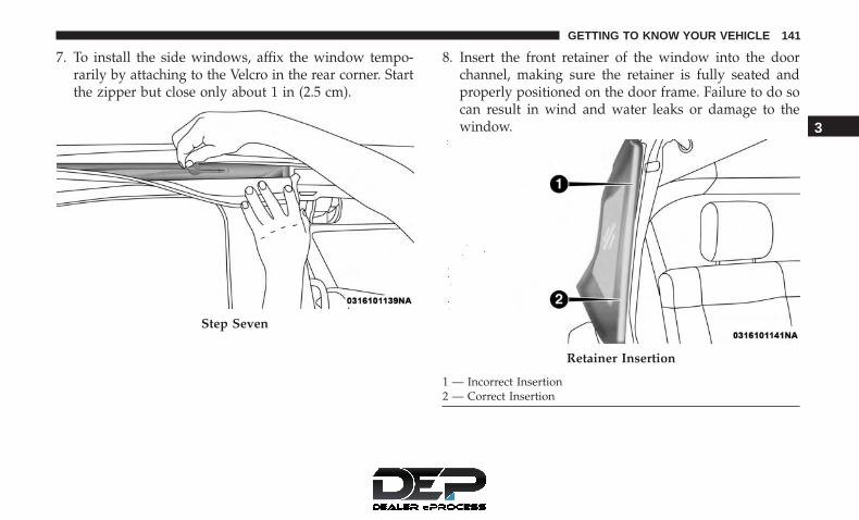
7. To install the side windows, affix the window tempo-rarily by attaching to the Velcro in the rear corner. Startthe zipper but close only about 1 in (2.5 cm).
8. Insert the front retainer of the window into the doorchannel, making sure the retainer is fully seated andproperly positioned on the door frame. Failure to do socan result in wind and water leaks or damage to thewindow.
Step Seven
Retainer Insertion
1 — Incorrect Insertion2 — Correct Insertion
3
GETTING TO KNOW YOUR VEHICLE 141

9. Insert the retainer along the bottom edge of the windowinto the bottom side channel, beginning at the front andworking to the rear of the vehicle. Finish by closing thezipper completely and attaching the Velcro along the topand rear of the window. Repeat this step for the oppositeside.
Step Nine
142 GETTING TO KNOW YOUR VEHICLE

Folding Down The Soft Top
Side View Top And Components
1 — 4– Bow 6 — Quarter Window2 — 3–Bow 7 — Body Side Retainer3 — 2–Bow 8 — Bottom Retainer — Quarter Window4 — Header Bow 9 — Sail Panel5 — Front Retainer — Quarter Window 10 — Check Strap
3
GETTING TO KNOW YOUR VEHICLE 143

Rear View Top And Components
1 — Sail Panels2 — Zipper Finish3 — Swing Gate Bar4 — Zipper Start5 — Swing Gate Brackets
144 GETTING TO KNOW YOUR VEHICLE

NOTE: Clean side and rear windows before removal toassist in preventing scratching during removal of the softtop. If zippers are difficult to operate due to road dust, etc.,clean them with a mild soap solution and a small brush.Cleaning products are available through your authorizeddealer.
1. If your vehicle has half-doors, remove each half-doorwindow by opening the door and lifting the half-doorwindow out.
NOTE: Stow half-door windows carefully outside of thevehicle, never inside, to avoid scratches.
2. Unclip and move the sun visors to the side.
3. Release the header latches and hooks from the loops onthe windshield frame.
4. Open the swing gate.
5. Before unzipping the rear window, release the first 3inches (7.6 cm) of both sail panels from the channel.Remove the swing gate bar by pulling it straight rear-ward out of the swing gate brackets.
Step Three
3
GETTING TO KNOW YOUR VEHICLE 145

6. Unzip the rear window starting at the right lower cornerof the window. Pull the zipper up, across the top anddown to the left lower corner. Zipper pulls will stay onthe rear window. Pull down on the rear window todisengage it from the zipper on the top cover.
7. Remove the rear window retainer from the swing gatebracket on both the left and right sides.
Step Five Step Six
146 GETTING TO KNOW YOUR VEHICLE

8. Stow the windows carefully to avoid scratching.
9. Undo the Velcro that runs along the top and rear edge ofthe side window.
10. Beginning from the rear lower corner, completely un-zip the window.
11. Once unzipped, remove the side window retainersfrom the door channel and body side channel. Repeatthis step on the opposite side.
12. Finish releasing the sail panel retainers from the bodyside channel at the rear corners of the vehicle.
Step Seven Step Ten
3
GETTING TO KNOW YOUR VEHICLE 147

NOTE: When releasing the sail panel retainers, it is helpfulto pull down on the rear roof bow.
13. Fold the sail panels so that they rest on top of the softtop.
Step Twelve
Step Thirteen
148 GETTING TO KNOW YOUR VEHICLE

14. The swing gate brackets do not need to be removedunless the hard top is being installed. To remove theswing gate brackets, pull the front of the bracketforward while rolling the entire bracket back in towardthe vehicle to disengage.
15. Grasp the front side bow behind the header, and lift thetop.
Step Fourteen
Step Fifteen
3
GETTING TO KNOW YOUR VEHICLE 149

16. Fold back the front section of the top, pulling the fabricrearward. Gently rest the header on top of the rearportion of the deck.
17. Fold the top so that the material forms a �W� as shown.Enter the vehicle and move the material into two folds.
Step SixteenStep Seventeen
150 GETTING TO KNOW YOUR VEHICLE

18. Release the side bows by pushing down on the latchabove the front of the rear door. Push the top rearwardto disengage. Repeat this step on the other side.
19. Before lowering the top, open the swing gate to preventpossible damage to the rear center high-mounted brakelight. Grasp the folded side bows and slide the topalong the door frame track to the rear door frame.
20. Gently slide the side bows off the door frame track andlower the top down into the vehicle.
NOTE: Help from another person will ease this operation.Step Eighteen
Step Nineteen
3
GETTING TO KNOW YOUR VEHICLE 151
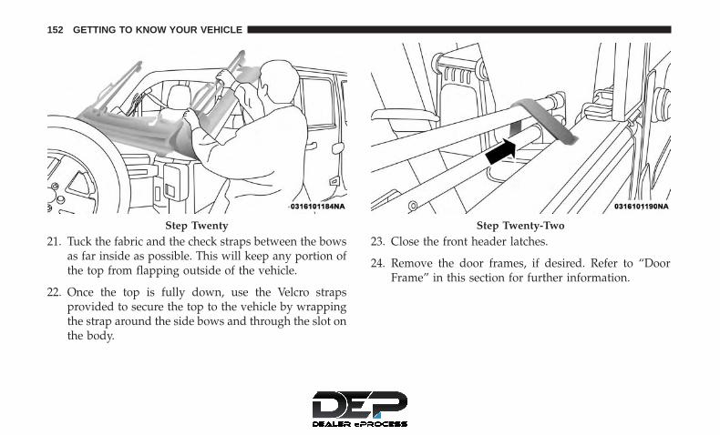
21. Tuck the fabric and the check straps between the bowsas far inside as possible. This will keep any portion ofthe top from flapping outside of the vehicle.
22. Once the top is fully down, use the Velcro strapsprovided to secure the top to the vehicle by wrappingthe strap around the side bows and through the slot onthe body.
23. Close the front header latches.
24. Remove the door frames, if desired. Refer to “DoorFrame” in this section for further information.
Step Twenty Step Twenty-Two
152 GETTING TO KNOW YOUR VEHICLE

Putting Up The Soft Top
NOTE: Be extremely careful when putting up the soft topto prevent the doors from getting scratched. It may behelpful to open the rear doors.
1. Install the door frames, if removed. Refer to “DoorFrame” in this section for further information.
2. Undo the straps used to secure the top in the downposition and store in secure location.
3. Open the swing gate.
4. Grasp the folded side bows and lift to the top of the reardoor frames.
NOTE: Help from another person will ease this operation.5. Insert the slider feature of the knuckles into the door
frame tracks and slide the top forward.
Step Four
3
GETTING TO KNOW YOUR VEHICLE 153

6. Ensure that the top locks into the Sunrider lockingmechanisms that are located above the front of the reardoors.
7. Unclip and move the sun visors to the side.
8. Standing on the side of the vehicle, lift the top by theside bow until it rests on the windshield frame.
Step Five Step Six
154 GETTING TO KNOW YOUR VEHICLE

9. Open the header latches and engage the hook on eachside onto the windshield loops (do not close the latches).
10. If the swing gate brackets were removed, install themby hooking the rear edge of the bracket on the interiorside of the body channel. Then, rotate it rearward andover the channel until it snaps onto the exterior part ofthe rail. To be properly located, the bracket must onlybe clipped to the shortened rail edge.
Step Eight Step Nine
3
GETTING TO KNOW YOUR VEHICLE 155

11. Ensure that the straps are positioned correctly beforepulling the sail panels over the rear roof bow (4–bow).
Step Ten Step Eleven
156 GETTING TO KNOW YOUR VEHICLE

Partially install the sail panel retainers into the body sidechannel, leaving the last 3 inches (7.6 cm) toward the rearwindow loose (on both sides). Pulling down on the rearroof bow (4–bow) will aid in reaching the channel with theretainers.
12. To install the side windows, affix the window tempo-rarily by attaching it to the Velcro in the upper rearcorner. Start the zipper but close only about 1 inch (2.5cm).
Step ElevenStep Twelve
3
GETTING TO KNOW YOUR VEHICLE 157

13. Insert the front retainer of the window into the doorchannel, making sure the retainer is fully seated andproperly positioned on the door frame. Failure to do socan result in wind and water leaks or damage to thewindow.
14. Insert the retainer along the bottom edge of the win-dow into the bottom side channel, beginning at thefront and working to the rear of the vehicle. Finish byclosing the zipper completely and attaching the Velcroalong the top and rear of the window. Repeat this stepfor the opposite side.
Step Thirteen
Retainer Insertion
1 — Incorrect Insertion2 — Correct Insertion
158 GETTING TO KNOW YOUR VEHICLE

15. Locate the black swing gate bar. Slide the swing gatebar over the receiver at the bottom inside of the rearwindow. The spongy part of the seal should be downand pointed outward to seal with the swing gate whenclosed.
Step Fourteen Step Fourteen
3
GETTING TO KNOW YOUR VEHICLE 159

16. Install the rear window by starting both zipper ends atthe lower left corner of the rear window opening.Ensure that the zippers are properly started andaligned before zipping to prevent damage.
17. Run the first zipper fully around to the right side of thewindow.
Step Fifteen Step Sixteen
160 GETTING TO KNOW YOUR VEHICLE

18. Grasp the swing gate bar and position it into the swinggate brackets.
19. Insert the rear window retainer into the swing gatebracket on both the left and right sides.
20. Complete the installation of the sail panel by insertingthe rest of the retainer into the body channel.Step Eighteen
Step Nineteen
3
GETTING TO KNOW YOUR VEHICLE 161

21. Close the header latches and return the sun visors totheir secured position.
SUNRIDER (FOUR-DOOR MODELS) — IFEQUIPPED
CAUTION!
Operating the top, opening a door or lowering awindow while the top is wet may allow water to dripinto the vehicle’s interior.
NOTE: If you are going to be driving faster than 40 mph(64 km/h) with the Sunrider feature open, it is recom-mended that you remove the rear window of the vehicle.
Opening The Sunrider
1. Unclip and move the sun visors to the side.
2. Release the header latches from the loops on the wind-shield frame.
Step Twenty-One
Step Two
162 GETTING TO KNOW YOUR VEHICLE

3. Make sure to slide the plastic sleeves forward to unlockthe Sunrider links.
4. Grasp the front side bow behind the header, and lift thetop.
Step Three Step Four
3
GETTING TO KNOW YOUR VEHICLE 163

5. Fold back the front section of the top and gently rest theheader on top of the rear portion of the deck.
6. Fold the top so that the material forms a �W� as shown.Enter the vehicle and move the material into two folds.
Step Five Step Six
164 GETTING TO KNOW YOUR VEHICLE

7. Secure the top by using the two provided straps. Eachstrap will wrap around the side bow and Velcro to itself;use one strap on each side of the vehicle.
Closing The Sunrider
Perform the above steps in the opposite order.
NOTE: Failure to fold the fabric rearward will allow thematerial to sag and may block the rearview mirror.
FOLDING WINDSHIELD
The fold-down windshield and removable side bars onyour vehicle are structural elements that can provide someprotection in some accidents. The windshield also providessome protection against weather, road debris and intrusionof small branches and other objects.
Do not drive your vehicle on-road with the windshielddown and the side bars removed as you lose the protectionthese structural elements can provide.
If required for certain off-road uses, the side bars can beremoved and the windshield folded down. However, theprotection afforded by these features is then lost. If youremove the side bars and fold down the windshield, driveslowly and cautiously. It is recommended that the speed ofthe vehicle be limited to 10 mph (16 km/h), with low rangeoperation preferred if you are driving off-road with thewindshield folded down.
Raise the windshield and reinstall the side bars as soon asthe task that required their removal is completed andbefore you return to on-road driving. Both you and yourpassenger should wear seat belts at all times, on-road andoff-road, regardless of whether the windshield is raised orfolded down.
Step Seven
3
GETTING TO KNOW YOUR VEHICLE 165

Outside rearview mirrors are mounted on the doors. If youchoose to remove the doors, see your authorized dealer fora replacement cowl-mounted outside mirror. Federal lawrequires outside mirrors on vehicles for on-road use.
WARNING!
Carefully follow these warnings to help protect againstpersonal injury:• Do not drive your vehicle on-road with the wind-
shield down.• Do not drive your vehicle unless the windshield is
securely fastened, either up or down.• Eye protection, such as goggles, should be worn at all
times when the windshield is down.• Be sure that you carefully follow the instructions for
raising the windshield. Make sure that the foldingwindshield, windshield wipers, side bars, and allassociated hardware and fasteners are correctly andtightly assembled before driving your vehicle. Fail-ure to follow these instructions may prevent yourvehicle from providing you and your passengers’protection in some accidents.
(Continued)
WARNING! (Continued)• If you remove the doors, store them outside the
vehicle. In the event of an accident, a loose door maycause personal injury.
Lowering The Windshield And Removing Side Bars
1. Lower the fabric top or remove the hard top followingthe instructions in this manual.
NOTE: To assist in properly reinstalling side bars, markthe original locations prior to removing.
2. Remove the two top hex bolts (13 mm), and the one sidehex bolt (13 mm) visible through the trim (Do notremove plastic corner trim, sun visor bolts, or sport barcovering).
166 GETTING TO KNOW YOUR VEHICLE

3. Remove the sun visor.
4. Remove the A-pillar cap.
5. Disconnect microphone (if equipped with Uconnectphone).
6. Open the sport bar Velcro covering.
7. Remove the one hex bolt (13 mm) visible through theplastic trim on the bottom side of the side bar, one hexbolt (13 mm) on the side of the side bar, and one hex bolt(13 mm) on top of the side bar.
NOTE: Pull side bar out horizontally when removing.
CAUTION!
Do not remove the head impact foam from the sidebars, as damage to the foam may result.
NOTE: Store all of the mounting bolts in their originalthreaded holes and tighten for safekeeping.
8. Remove the side bar assembly, and reattach the sportbar Velcro covering.
Step Two
Step Seven
3
GETTING TO KNOW YOUR VEHICLE 167

9. To safely store the side bars in your vehicle, use fourcinch straps (available from your authorized dealer).Attach the straps through the slots located on the floorbehind the folded rear seat at the front of the storage bincover.
WARNING!
You or others could be injured if you carry the side barsloose in your vehicle. Remove the side bars from thevehicle or securely store them as described or they maycause personal injury if an accident occurs. See yourauthorized dealer for the cinch straps.
10. Remove the windshield wiper arms by first pulling thewiper away from the windshield and out to the “lock”position. Unsnap the wiper arm nut caps, and removethe retaining nuts. Lift the wiper arms off and storethem in the center console or securely behind the rearseat.
NOTE: It may be necessary to use a battery terminal pullertool in order to separate the wiper arms from the shaft afterthe nuts have been removed.
11. Remove the lower windshield plates by removing thesix black round-headed Torx head screws (using a #40
Torx head driver) on each side of the base of thewindshield.
12. Lower the windshield gently until it contacts therubber hood bumpers.
13. Secure the windshield by passing a cinch strap throughthe footman hoop on the center of the hood and on thecenter of the windshield frame. Tighten the strap tosecure the windshield in place.
Step Eleven
168 GETTING TO KNOW YOUR VEHICLE

Raising The Windshield And Replacing Side Bars
1. Raise the windshield.
2. Loosely attach the rear of the side bar to the sport bar.Refer to Step 4 of “Lowering Windshield And RemovingSide Bars” earlier in this section.
3. Reattach the sport bar Velcro covering.
4. Attach the front of the side bar to the windshield frame.
5. Install the top two hex bolts (13 mm) first, then the lowerside hex bolt (13 mm). The lower side bolt will not alignuntil the top two bolts are installed.
6. Tighten all side bar attachment bolts.
7. Install the lower windshield plates with the six blackround-headed Torx head screws (using a #40 Torx headdriver) on each side of the base of the windshield.
Step Two
Step Five
3
GETTING TO KNOW YOUR VEHICLE 169

8. Reinstall the wiper arms.
HOOD
Opening The Hood
Release both the hood latches.
Raise the hood and locate the safety latch, located in themiddle of the hood opening. Push the safety latch to theleft side of the vehicle, to open the hood. You may have topush down slightly on the hood before pushing the safetylatch. Insert the support rod into the slot on the hood.
Closing The Hood
To close the hood, remove the support rod from the hoodpanel and place it in the retaining clip. Lower the hoodslowly. Secure both of the hood latches.
Step Seven Hood Latch
170 GETTING TO KNOW YOUR VEHICLE

WARNING!
Be sure the hood is fully latched before driving yourvehicle. If the hood is not fully latched, it could openwhen the vehicle is in motion and block your vision.Failure to follow this warning could result in seriousinjury or death.
REAR SWING GATE
The rear swing gate can be unlocked by using the key,Remote Keyless Entry key fob, or by activating the powerdoor lock switches located on the front doors.
To open the swing gate, push the button on the gatehandle.
NOTE: Close the rear flip-up window before attempting toclose the swing gate (hard top models only).
WARNING!
Driving with the flip-up window open can allowpoisonous exhaust gases into your vehicle. You andyour passengers could be injured by these fumes. Keepthe flip-up window closed when you are operating thevehicle.
Swing Gate Handle
3
GETTING TO KNOW YOUR VEHICLE 171
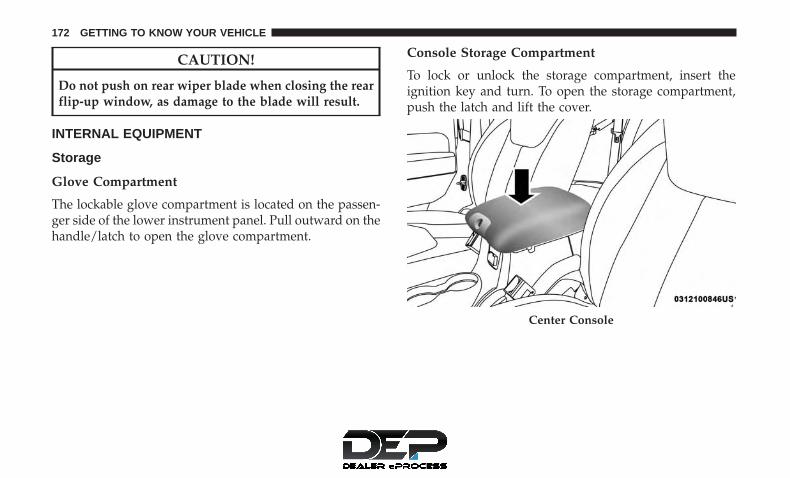
CAUTION!
Do not push on rear wiper blade when closing the rearflip-up window, as damage to the blade will result.
INTERNAL EQUIPMENT
Storage
Glove Compartment
The lockable glove compartment is located on the passen-ger side of the lower instrument panel. Pull outward on thehandle/latch to open the glove compartment.
Console Storage Compartment
To lock or unlock the storage compartment, insert theignition key and turn. To open the storage compartment,push the latch and lift the cover.
Center Console
172 GETTING TO KNOW YOUR VEHICLE

There is an extra storage area underneath the console lid.The console lid has an integrated paper clip feature thatcan hold small items.
Rear Storage Compartment — If Equipped
The rear cargo area storage compartment cover is held bya spring-loaded latch. In order to remove the rear storagecompartment cover, use the following procedure:
NOTE: The rear storage compartment latch should notbe used as cargo tie-down.
1. Flip up the pull loop so it is perpendicular (straight up)to the top surface of the tray.
2. Pull up on the loop and twist it 90 degrees, so it isparallel to the slotted hole in the tray.
3. Open the rear compartment cover.
Center Console Lid Storage
Rear Storage Cover
3
GETTING TO KNOW YOUR VEHICLE 173

Cupholders
The front cupholders are located in the center console.
The rear cupholders are located on the back of the centerconsole.
Electrical Power Outlets
There are two 12 Volt (13 Amp) auxiliary power outlets thatcan provide power for accessories designed for use withthe standard power outlet adapters.
The front power outlet is located in the center of theinstrument panel below the climate controls, and is pow-ered from the ignition switch. Power is available when theignition switch is in the ON or ACC position.
Front Cupholders
Rear Cupholders
174 GETTING TO KNOW YOUR VEHICLE

When the optional cigar lighter heating element is used inthe power outlet, it heats when pushed in and pops outautomatically when ready for use. To preserve the heatingelement, do not hold the lighter in the heating position.
A second power outlet is located inside the center consoleand is powered directly from the vehicle battery.
CAUTION!
• Do not exceed the maximum power of 160 Watts(13 Amps) at 12 Volts. If the 160 Watt (13 Amp) powerrating is exceeded the fuse protecting the system willneed to be replaced.
• Power outlets are designed for accessory plugs only.Do not insert any other object in the power outlets asthis will damage the outlet and blow the fuse.Improper use of the power outlet can cause damagenot covered by your New Vehicle Limited Warranty.
On vehicles equipped with a rear subwoofer, there is athird power outlet located in the right rear cargo area.
Front Power Outlet
3
GETTING TO KNOW YOUR VEHICLE 175

WARNING!
To avoid serious injury or death:• Do not insert any objects into the receptacles.• Do not touch with wet hands.• Close the lid when not in use.
(Continued)
Rear Power Outlet — If Equipped Power Outlet Fuse Locations
1 — M36 Fuse 20 A Yellow Power Outlet Console Bin2 — M6 Fuse 20 A Yellow Cigar Lighter Instrument Panel3 — M7 Fuse 20 A Yellow Power Outlet Rear With Sub Woofer(Opt.)
176 GETTING TO KNOW YOUR VEHICLE

WARNING! (Continued)• If this outlet is mishandled, it may cause an electric
shock and failure.
CAUTION!
• Many accessories that can be plugged in draw powerfrom the vehicle’s battery, even when not in use (i.e.,cellular phones, etc.). Eventually, if plugged in longenough, the vehicle’s battery will discharge suffi-ciently to degrade battery life and/or prevent theengine from starting.
• Accessories that draw higher power (i.e., coolers,vacuum cleaners, lights, etc.), will degrade the bat-tery even more quickly. Only use these intermit-tently and with greater caution.
• After the use of high power draw accessories, or longperiods of the vehicle not being started (with acces-sories still plugged in), the vehicle must be driven asufficient length of time to allow the alternator torecharge the vehicle’s battery.
• Power outlets are designed for accessory plugs only.Do not hang any type of accessory or accessory
(Continued)
CAUTION! (Continued)bracket from the plug. Improper use of the poweroutlet can cause damage.
Power Inverter — If Equipped
There is a 115 Volt, 150 Watt inverter outlet located on thefront of the center console to convert DC current to ACcurrent. This outlet can power cellular phones, electronicsand other low power devices requiring power up to 150Watts. Certain high-end video game consoles will exceedthis power limit, as will most power tools.
Power Inverter
3
GETTING TO KNOW YOUR VEHICLE 177

The power inverter is designed with built-in overloadprotection. If the power rating of 150 Watts is exceeded, thepower inverter will automatically shut down. Once theelectrical device has been removed from the outlet, theinverter should automatically reset. If the power ratingexceeds approximately 170 Watts, the power inverter mayhave to be reset manually. To reset the inverter manually,push the power inverter button to turn it off and then pushit again to turn it back on. To avoid overloading the circuit,check the power ratings on electrical devices prior to usingthe inverter.
The power inverter button is located onthe instrument panel below the climatecontrols. To turn on the power outlet,push the button once. The indicatorlight will illuminate. Push the button asecond time to turn the power inverteroutlet off.
NOTE: When the power inverter button is pushed, therewill be a delay of approximately one second before theinverter indicator light turns on.
WARNING!
To avoid serious injury or death:• Do not insert any objects into the receptacles.• Do not touch with wet hands.• Close the lid when not in use.• If this outlet is mishandled, it may cause an electric
shock and failure.
178 GETTING TO KNOW YOUR VEHICLE

GETTING TO KNOW YOUR INSTRUMENT PANEL
CONTENTS� INSTRUMENT CLUSTER . . . . . . . . . . . . . . . . . .180
▫ Instrument Cluster Descriptions . . . . . . . . . . . .181
� INSTRUMENT CLUSTER DISPLAY — IFEQUIPPED . . . . . . . . . . . . . . . . . . . . . . . . . . . . .183
▫ Instrument Cluster Display Location AndControls . . . . . . . . . . . . . . . . . . . . . . . . . . . . .183
▫ Instrument Cluster Display Messages . . . . . . . . .185
▫ Gear Shift Indicator (GSI) — If Equipped . . . . . .186
▫ Oil Change Required . . . . . . . . . . . . . . . . . . . .186
▫ Instrument Cluster Display Menu Items . . . . . .187
� WARNING/INDICATOR LIGHTS ANDMESSAGES . . . . . . . . . . . . . . . . . . . . . . . . . . . .193
▫ Red Telltale Lights . . . . . . . . . . . . . . . . . . . . .194
▫ Yellow Telltale Lights . . . . . . . . . . . . . . . . . . . .200
▫ Green Telltale Lights. . . . . . . . . . . . . . . . . . . . .207
▫ White Telltale Lights. . . . . . . . . . . . . . . . . . . . .208
▫ Blue Telltale Lights . . . . . . . . . . . . . . . . . . . . . .209
� ONBOARD DIAGNOSTIC SYSTEM — OBD II . . .210
▫ Onboard Diagnostic System (OBD II)Cybersecurity . . . . . . . . . . . . . . . . . . . . . . . . .210
▫ Loose Fuel Filler Cap Message . . . . . . . . . . . . .211
� EMISSIONS INSPECTION AND MAINTENANCEPROGRAMS . . . . . . . . . . . . . . . . . . . . . . . . . . .211
4

INSTRUMENT CLUSTER
Instrument Cluster
180 GETTING TO KNOW YOUR INSTRUMENT PANEL

Instrument Cluster Descriptions
1. Fuel Gauge• The pointer shows the level of fuel in the fuel tank
when the ignition switch is in the ON/RUN position.• The fuel pump symbol points to the side of the
vehicle where the fuel filler door is located.
2. Speedometer• Indicates vehicle speed.
3. Tachometer• Indicates the engine speed in revolutions per minute
(RPM x 1000).
CAUTION!
Do not operate the engine with the tachometer pointerin the red area. Engine damage will occur.
4. Temperature Gauge• The temperature gauge shows engine coolant tem-
perature. Any reading within the normal range indi-cates that the engine cooling system is operatingsatisfactorily.
• The gauge pointer will likely indicate a higher tem-perature when driving in hot weather, up mountaingrades, or when towing a trailer. It should not beallowed to exceed the upper limits of the normaloperating range.
WARNING!
A hot engine cooling system is dangerous. You orothers could be badly burned by steam or boilingcoolant. You may want to call an authorized dealer forservice if your vehicle overheats.
CAUTION!
Driving with a hot engine cooling system could dam-age your vehicle. If the temperature gauge reads “H”pull over and stop the vehicle. Idle the vehicle with theair conditioner turned off until the pointer drops backinto the normal range. If the pointer remains on the“H”, turn the engine off immediately and call anauthorized dealer for service.
4
GETTING TO KNOW YOUR INSTRUMENT PANEL 181

5. Odometer / Trip Odometer Display Area• The odometer display shows the total distance the
vehicle has been driven. The trip odometer showsindividual trip mileage. Refer to “Odometer/TripOdometer/ECO (Fuel Saver Indicator) Button” forfurther information.
• U.S. Federal regulations require that upon transfer ofvehicle ownership, the seller certify to the purchaserthe correct mileage that the vehicle has been driven. Ifyour odometer needs to be repaired or serviced, therepair technician should leave the odometer readingthe same as it was before the repair or service. If theycannot do so, then the odometer must be set at zero,and a sticker must be placed in the door jamb statingwhat the mileage was before the repair or service. It isa good idea for you to make a record of the odometerreading before the repair/service, so that you can besure that it is properly reset, or that the door jambsticker is accurate if the odometer must be reset at zero.
Vehicle Odometer Messages
All messages will display in the instrument cluster display,if equipped. Refer to “Instrument Cluster Display— IfEquipped” in this section for further information.
When the appropriate conditions exist, the followingodometer messages will display:
• ECO — Fuel Saver Indicator• door — Door Open• gATE — Swing Gate Open• LoW tirE — Low Tire Pressure• HOTOIL — Oil Temperature Above Normal Limits• gASCAP — Fuel Cap Fault• noFUSE — Fuse Fault• CHAngE OIL — Oil Change Required
6. Telltales• Hard and Soft Telltales (Symbols) appear based on
specific behaviors.
7. Instrument Cluster Display / Compass Mini-TripComputer Display — If Equipped• When the appropriate conditions exist, this display
shows the instrument cluster display messages. Referto “Instrument Cluster Display” in “Getting To KnowYour Instrument Panel” for further information.
• When the appropriate conditions exist, this displayshows the Mini-Trip Computer messages. Refer to“Mini-Trip Computer” in “Getting To Know YourInstrument Panel” for further information.
182 GETTING TO KNOW YOUR INSTRUMENT PANEL

INSTRUMENT CLUSTER DISPLAY — IF EQUIPPED
Your vehicle may be equipped with an instrument clusterdisplay, which offers useful information to the driver. Withthe ignition in the STOP/OFF mode, opening/closing of adoor will activate the display for viewing, and display thetotal miles, or kilometers, in the odometer. Your instrumentcluster display is designed to display important informa-tion about your vehicle’s systems and features. Using adriver interactive display located on the instrument panel,your instrument cluster display can show you how sys-tems are working and give you warnings when they aren’t.The steering wheel mounted controls allow you to scrollthrough and enter the main menus and submenus. You canaccess the specific information you want and make selec-tions and adjustments.
Instrument Cluster Display Location And Controls
The instrument cluster display features a driver-interactivedisplay that is located in the instrument cluster.
This system conveniently allows the driver to select avariety of useful information by pushing the switchesmounted on the steering wheel. The instrument clusterdisplay consists of the following:
• Compass Heading (N, S, E, W, NE, NW, SE, SW)
• Outside Temperature (°F or °C)
• ECO Display
Instrument Cluster Display
4
GETTING TO KNOW YOUR INSTRUMENT PANEL 183

• Digital Speedometer
• Average Fuel Economy
• Distance To Empty
• Tire Pressure Monitor System — If Equipped
• Elapsed Time
• Vehicle Info
• Units Selection
• System Status and Warnings (Door Open, etc.)
• Personal Settings (Customer-Programmable Features)
The system allows the driver to select information bypushing the following buttons mounted on the steeringwheel:
• MENU Button
Push and release the MENU button to advance the displayto each of the instrument cluster display Main Menufeatures or to return to the Main Menu from a submenu.Upon reaching the last item in the Main Menu the instru-ment cluster display will advance to the first item in theMain Menu with the next MENU button push and release.
Instrument Cluster Display Control Buttons
1 — MENU Button 3 — Down Arrow Button2 — Right Arrow Button 4 — Compass Button
184 GETTING TO KNOW YOUR INSTRUMENT PANEL

• Compass Button
Push and release the compass button to return to theCompass/Outside Temperature/Audio Information/ECOscreen whenever the current display is not the Compass/Outside Temperature/Audio Information/ECO screen.
• Right Arrow Button
Push and release the right arrow button when promptedby the instrument cluster display to Reset Main Menufeatures with a reset capability or to change PersonalSettings.
• Down Arrow Button
Push and release the down arrow button when promptedby the instrument cluster display to step through VehicleInfo submenu, stored system warning messages, or Per-sonal Settings features.
Instrument Cluster Display Messages
When the appropriate conditions exist, the instrumentcluster will display the following messages:
• Low Tire Pressure
• Low Fuel
• Service TPM System (refer to �Tire Pressure MonitoringSystem� in �Safety� for further information)
• Damaged Key
• Key in Ignition
• Turn Signal On (with a continuous warning chime)
• Left Front Turn Signal Lamp Out (with a single chime)
• Left Rear Turn Signal Lamp Out (with a single chime)
• Right Front Turn Signal Lamp Out (with a single chime)
• Right Rear Turn Signal Lamp Out (with a single chime)
• Key Fob Battery Low (with a single chime)
• Personal Settings Not Avail. – Vehicle Not in Park —automatic transmission
• Personal Settings Not Avail. – Vehicle in Motion —manual transmission
• Door Open (with vehicle graphic showing which door isopen. A single chime sounds if the vehicle is in motion).
• Gate Open (with vehicle graphic showing the Liftgate/back door open and a single chime sounds if the vehicleis in motion)
4
GETTING TO KNOW YOUR INSTRUMENT PANEL 185

• Check Gascap (refer to “Refueling The Vehicle” in“Starting And Operating” for further information)
• Oil Change Required (with a single chime)
• ECO (Fuel Saver Indicator) — if equipped
Gear Shift Indicator (GSI) — If Equipped
— Up Shift Indicator Light
— Down Shift Indicator Light
The Gear Shift Indicator (GSI) system is enabledon vehicles with a manual transmission, or whena vehicle with an automatic transmission is inmanual shift mode. The GSI provides the driver
with a visual indication when the recommended gear shiftpoint has been reached. This indication notifies the driverthat changing gear will allow a reduction in fuel consump-tion. When the up shift indicator is shown on the display,the GSI is advising the driver to engage a higher gear.When the down shift indicator is shown on the display, theGSI is advising the driver to engage a lower gear.
The GSI indicator remains illuminated until the driverchanges gear, or the driving conditions return to a situationwhere changing gear is not required to improve fuelconsumption.
Oil Change Required
Your vehicle is equipped with an engine oil change indi-cator system. The “Oil Change Required” message willdisplay in the instrument cluster display for approximately10 seconds after a single chime has sounded to indicate thenext scheduled oil change interval. The engine oil changeindicator system is duty cycle based, which means theengine oil change interval may fluctuate dependent uponyour personal driving style.
Unless reset, this message will continue to display eachtime you turn the ignition switch to the ON position. Toturn off the message temporarily, push and release theMENU button. To reset the oil change indicator system(after performing the scheduled maintenance), perform thefollowing procedure:
1. Turn the ignition switch to the ON position. Do not startthe engine.
2. Fully push the accelerator pedal slowly three timeswithin 10 seconds.
186 GETTING TO KNOW YOUR INSTRUMENT PANEL

3. Turn the ignition switch to the LOCK position.
NOTE: If the indicator message illuminates when youstart the vehicle, the oil change indicator system did notreset. If necessary, repeat this procedure.
Instrument Cluster Display Menu Items
NOTE: The instrument cluster display menu items displayin the center of the instrument cluster. Menu items mayvary depending on your vehicle features.
Compass, Outside Temperature Display / ECO (FuelSaver Mode) — If Equipped
The compass readings indicate the direction the vehicle isfacing. Push and release the compass button to display oneof eight compass headings, the outside temperature/ECOif the instrument cluster display is not already displayingthis screen.
NOTE: The system will display the last known outsidetemperature when starting the vehicle and may need to bedriven several minutes before the updated temperature isdisplayed. Engine temperature can also affect the dis-played temperature; therefore, temperature readings arenot updated when the vehicle is not moving.
ECO (Fuel Saver Mode) — If Equipped
The ECO message will display below the outside tempera-ture in the instrument cluster display (if the audio systemis on the ECO indicator will override the audio informationdisplay line if the �Display Fuel Saver� personal setting isON — see �Personal Settings� section). This message willappear whenever you are driving in a fuel efficient manner.
This feature allows you to monitor when you are driving ina fuel efficient manner, and it can be used to modifydriving habits in order to increase fuel economy.
Automatic Compass Calibration
This compass is self-calibrating, which eliminates the needto set the compass manually. When the vehicle is new, thecompass may appear erratic, and the instrument clusterdisplay will display “CAL” until the compass is calibrated.You may also calibrate the compass by completing one ormore 360–degree turns (in an area free from large metal ormetallic objects) until the “CAL” message displayed in theinstrument cluster display turns off. The compass will nowfunction normally.
NOTE: A good calibration requires a level surface and anenvironment free from large metallic objects such as build-ings, bridges, underground cables, railroad tracks, etc.
4
GETTING TO KNOW YOUR INSTRUMENT PANEL 187

Manual Compass Calibration
If the compass appears erratic and the “CAL” indicatordoes not appear in the instrument cluster display, you mustput the compass into the Calibration Mode manually asfollows:
1. Start the engine. Leave the gear selector in PARK inorder to enter the instrument cluster display Program-ming Menus.
2. Push the MENU button until Personal Settings(Customer-Programmable Features) displays in the in-strument cluster display.
3. Push the down arrow button until “Calibrate Compass”displays in the instrument cluster display.
4. Push and release the right arrow button to start thecalibration. The “CAL” indicator will display in theinstrument cluster display.
5. Complete one or more 360–degree turns (in an area freefrom large metal or metallic objects) until the “CAL”indicator turns off. The compass will now functionnormally.
Compass Variance
Compass Variance is the difference between MagneticNorth and Geographic North. To compensate for thedifferences, the variance should be set for the zone wherethe vehicle is driven, per the zone map. Once properly set,the compass will automatically compensate for the differ-ences and provide the most accurate compass heading.
NOTE: Magnetic materials should be kept away from thetop of the instrument panel; this is where the compasssensor is located.
Compass Variance Map
188 GETTING TO KNOW YOUR INSTRUMENT PANEL

To Change The Compass Variance:
1. Turn the ignition switch RUN (it is not necessary to startthe engine).
2. Push the MENU button until Personal Settings(Customer-Programmable Features) displays in the in-strument cluster display.
3. Push the down arrow button until “Compass Variance”message and the last variance zone number displays inthe instrument cluster display.
4. Push and release the right arrow button until the propervariance zone is selected according to the map.
5. Push and release the COMPASS button to exit.
Digital Speedometer
Shows the actual vehicle speed in mph or km/h.
Average Fuel Economy
Shows the average fuel economy since the last reset.Average fuel economy can be reset by pushing and holdingthe right arrow button (as prompted in the instrumentcluster display). Upon reset, the history information will beerased, and the averaging will continue from the last fuelaverage reading before the reset.
Distance To Empty (DTE)
Shows the estimated distance that can be traveled with thefuel remaining in the tank. This estimated distance isdetermined by a weighted average of the instantaneousand average fuel economy, according to the current fueltank level. DTE cannot be reset.
NOTE: Significant changes in driving style or vehicleloading will greatly affect the actual drivable distance ofthe vehicle, regardless of the DTE display value.
When the DTE value is less than 30 miles (48 km) estimateddriving distance, the DTE display will change to a textdisplay of �LOW FUEL.” This display will continue untilthe vehicle runs out of fuel. Adding a significant amount offuel to the vehicle will turn off the LOW FUEL text, and anew DTE value will display.
Tire Pressure — If Equipped
Push and release the MENU button until “Tire PSI/kpa:”displays in the instrument cluster display. It shows agraphic of the vehicle with a tire pressure value at eachcorner of the graphic.
4
GETTING TO KNOW YOUR INSTRUMENT PANEL 189

Elapsed Time
Shows the total elapsed time of travel since the last reset.Elapsed time will increment when the ignition switch is inthe RUN or START position.
Elapsed time displays Minutes: Seconds.
After 59 minutes: 59 seconds have elapsed, Hours will bedisplayed before Minutes.
Elapsed time can be reset by pushing and holding the rightarrow button (as prompted in the instrument cluster dis-play). Upon reset, all digits will change to zeros and timewill start again if the ignition switch is in RUN or START.
Vehicle Information
Push and release the MENU button until “Vehicle Infor-mation” displays in the instrument cluster display. Then,push the down arrow button to display any one of thefollowing choices:
• Coolant Temperature
Shows the actual coolant temperature.
• Oil Pressure
Shows the actual oil pressure.
• Transmission Temperature — Automatic TransmissionOnly
Shows the actual transmission fluid temperature.
• Oil Life Remaining (Automatic Oil Change Indicator)— If Equipped
Shows the oil life measured in percentage.
Units Selection (UNITS IN Display)
Displays the units used for the Outside Temperature,Average Fuel Economy and Distance to Empty features.Push and release the down arrow button to toggle unitsbetween �U.S.� and �METRIC.�
System Warnings
Displays “SYSTEM OK” if there are no active WarningMessages stored. Pushing and releasing the down arrowbutton when “SYSTEM OK” is displayed will do nothing.Displays “SYSTEM WARNINGS PRESENT” if there areactive Warning Messages stored. Pushing and releasing thedown arrow button when “SYSTEM WARNINGS PRES-ENT” is displayed will display each stored warning foreach button push. Push and release the MENU button toreturn to the Main Menu.
190 GETTING TO KNOW YOUR INSTRUMENT PANEL

Personal Settings (Customer-Programmable Features)
Personal Settings allows the driver to set and recall featureswhen the vehicle speed is at 0 mph (0 km/h) (manualtransmission) or when the gear selector is in PARK (autotransmission).
Push and release the MENU button until Personal Settingsdisplays in the instrument cluster display.
Use the down arrow button to display one of the followingchoices:
Language
When in this display you may select one of five languagesfor all display nomenclature, including the trip functionsand the navigation system (if equipped). Push the rightarrow button while in this display to select English,Espanol or Francais. Then, as you continue, the informa-tion will display in the selected language.
Auto Lock Doors — If Equipped
When this feature is selected, all doors will lock automati-cally when the vehicle reaches a speed of 15 mph(24 km/h). The auto door lock feature can be enabled ordisabled, to make your selection, push and release the rightarrow button until “On” or “Off” appears.
Auto Unlock On Exit
When ON is selected, all doors will unlock when thevehicle is stopped and the transmission is in the PARK orNEUTRAL position, and the driver’s door is opened. Tomake your selection, push and release the right arrowbutton until “On” or “Off” appears.
Key Fob Unlock — If Equipped
When “Driver Door 1st Press” is selected, only the driver’sdoor will unlock on the first push of the key fob unlockbutton. When “Driver Door 1st Press” is selected, you mustpush the key fob unlock button twice to unlock thepassenger’s doors. When “All Doors 1st Press” is selected,all of the doors will unlock on the first push of the key fobunlock button. To make your selection, push and releasethe right arrow button until “Driver Door 1st Press” or “AllDoors 1st Press” appears.
Sound Horn With Lock
When on is selected, a short horn sound will occur whenthe key fob lock button is pushed. This feature may beselected with or without the Flash Lamp with Lock feature.To make your selection, push and release the right arrowbutton until “On” or “Off” appears.
4
GETTING TO KNOW YOUR INSTRUMENT PANEL 191

Flash Lamp With Lock
When on is selected, the front and rear turn signals willflash when the doors are locked or unlocked with the keyfob. This feature may be selected with or without theSound Horn with Lock feature selected. To make yourselection, push and release the right arrow button until“On” or “Off” appears.
Headlamp Off Delay
When this feature is selected, the driver can choose to havethe headlights remain on for 0, 30, 60, or 90 seconds whenexiting the vehicle. To make your selection, push andrelease the right arrow button until “0,” “30,” “60,” or “90”appears.
Headlamps With Wipers (Available With AutoHeadlights Only)
When on is selected, and the headlight switch is in theAUTO position, the headlights will turn on approximately10 seconds after the wipers are turned on. If the headlightswere turned on by this feature, they will also turn off whenthe wipers are turned off. To make your selection, push andrelease the right arrow button until “ON” or “OFF”appears.
NOTE: Turning the headlights on during the daytimecauses the instrument panel lights to dim. To increase thebrightness, refer to “Lights” in “Getting To Know YourVehicle.”
Key Off Power Delay
When this feature is selected, the power window switches,radio, hands–free system (if equipped), DVD video system(if equipped), power sunroof (if equipped), and poweroutlets will remain active for up to 10 minutes after theignition switch is turned to the LOCK position. Openingeither front vehicle door will cancel this feature. To makeyour selection, push and release the right arrow buttonuntil “Off,” “45 sec.,” “5 min.,” or “10 min.” appears.
Illumin. Approach
When this feature is selected, the headlights will activateand remain on for up to 90 seconds when the doors areunlocked with the key fob. To make your selection, pushand hold the right arrow button until “Off,” “30 sec,” “60sec,” or “90 sec” appears.
192 GETTING TO KNOW YOUR INSTRUMENT PANEL
Hill Start Assist (HSA) — If Equipped
When “On” is selected, the HSA system is active. Refer to“Electronic Brake Control System” in “Starting And Oper-ating” for system function and operating information. Tomake your selection, push and release the right arrowbutton until “On” or “Off” appears.
Display Units In
The instrument cluster display can be changed betweenEnglish and Metric units of measure. The units apply to theOutside Temperature, Average Fuel Economy, and Dis-tance to Empty. To make your selection, push and releasethe right arrow button until “U.S.” or �METRIC� appears.
Nav–Turn By Turn — If Equipped
When on enables display of Navigation System streetname, turn direction, and distance to turn information inthe instrument cluster display. To make your selection,push and release the right arrow button until “On” or“Off” appears.
Display Fuel Saver — If Equipped
The “ECO” message is located in the compass/outsidetemperature/audio information/ECO display. If DisplayFuel Saver is selected as ON, only the ECO message will
display in the audio information/ECO line of the display. IfDisplay Fuel Saver is selected as OFF, only the audioinformation will display in the audio information/ECOline of the display when the audio system is on. To makeyour selection, push and release the right arrow buttonuntil “ON” or “OFF” appears.
Compass Variance
Refer to “Instrument Cluster Display” in “Getting To KnowYour Instrument Panel” for further information.
Calibrate Compass
Push the right arrow button to calibrate the compass.
WARNING/INDICATOR LIGHTS AND MESSAGES
The warning/indicator light switches on in the instrumentpanel together with a dedicated message and/or acousticsignal when applicable. These indications are indicativeand precautionary and as such must not be considered asexhaustive and/or alternative to the information containedin the Owner Manual, which you are advised to readcarefully in all cases. Always refer to the information in thischapter in the event of a failure indication.
4
GETTING TO KNOW YOUR INSTRUMENT PANEL 193
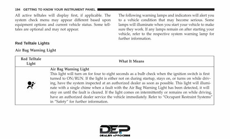
All active telltales will display first, if applicable. Thesystem check menu may appear different based uponequipment options and current vehicle status. Some tell-tales are optional and may not appear.
The following warning lamps and indicators will alert youto a vehicle condition that may become serious. Somelamps will illuminate when you start your vehicle to makesure they work. If any lamps remain on after starting yourvehicle, refer to the respective system warning lamp forfurther information.
Red Telltale Lights
Air Bag Warning Light
Red TelltaleLight
What It Means
Air Bag Warning LightThis light will turn on for four to eight seconds as a bulb check when the ignition switch is firstturned to ON/RUN. If the light is either not on during startup, stays on, or turns on while driv-ing, have the system inspected at an authorized dealer as soon as possible. This light will illumi-nate with a single chime when a fault with the Air Bag Warning Light has been detected, it willstay on until the fault is cleared. If the light comes on intermittently or remains on while driving,have an authorized dealer service the vehicle immediately. Refer to “Occupant Restraint Systems”in “Safety” for further information.
194 GETTING TO KNOW YOUR INSTRUMENT PANEL

Battery Charge Warning Light
Red TelltaleLight
What It Means
Battery Charge Warning LightThis light illuminates when the battery is not charging properly. If it stays on while the engine is run-ning, there may be a malfunction with the charging system. Contact your authorized dealer as soon aspossible. This indicates a possible problem with the electrical system or a related component.If jump starting is required, refer to “Jump-Starting Procedures” in “In Case Of Emergency” forfurther information.
Brake Warning Light
Red TelltaleLight
What It Means
English
Metric
Brake Warning LightThis light monitors various brake functions, including brake fluid level and parking brake appli-cation. If the brake light turns on it may indicate that the parking brake is applied, that the brakefluid level is low, or that there is a problem with the anti-lock brake system reservoir.If the light remains on when the parking brake has been disengaged, and the fluid level is at thefull mark on the master cylinder reservoir, it indicates a possible brake hydraulic system malfunc-tion or that a problem with the Brake Booster has been detected by the Anti-Lock Brake System(ABS) / Electronic Stability Control (ESC) system. In this case, the light will remain on until thecondition has been corrected. If the problem is related to the brake booster, the ABS pump willrun when applying the brake, and a brake pedal pulsation may be felt during each stop.
4
GETTING TO KNOW YOUR INSTRUMENT PANEL 195

The dual brake system provides a reserve braking capacityin the event of a failure to a portion of the hydraulicsystem. A leak in either half of the dual brake system isindicated by the Brake Warning Light, which will turn onwhen the brake fluid level in the master cylinder hasdropped below a specified level.
The light will remain on until the cause is corrected.
NOTE: The light may flash momentarily during sharpcornering maneuvers, which change fluid level conditions.The vehicle should have service performed, and the brakefluid level checked.
If brake failure is indicated, immediate repair is necessary.
WARNING!
Driving a vehicle with the red brake light on isdangerous. Part of the brake system may have failed. Itwill take longer to stop the vehicle. You could have acollision. Have the vehicle checked immediately.
Vehicles equipped with the Anti-Lock Brake System (ABS)are also equipped with Electronic Brake Force Distribution(EBD). In the event of an EBD failure, the Brake WarningLight will turn on along with the ABS Light. Immediaterepair to the ABS system is required.
Operation of the Brake Warning Light can be checked byturning the ignition switch from the OFF position to theON/RUN position. The light should illuminate for ap-proximately two seconds. The light should then turn offunless the parking brake is applied or a brake fault isdetected. If the light does not illuminate, have the lightinspected by an authorized dealer.
The light also will turn on when the parking brake isapplied with the ignition switch in the ON/RUN position.
NOTE: This light shows only that the parking brake isapplied. It does not show the degree of brake application.
196 GETTING TO KNOW YOUR INSTRUMENT PANEL

Coolant Temperature Warning Light
Red TelltaleLight
What It Means
Coolant Temperature Warning LightThis light warns of an overheated engine condition. If the light turns on while driving, safely pullover and stop the vehicle. If the A/C system is on, turn it off. Also, shift the transmission intoNEUTRAL and idle the vehicle. If the temperature reading does not return to normal, turn theengine off immediately and call for service.
NOTE: As the coolant temperature gauge approaches �H,� this indicator will illuminate and asingle chime will sound. Further overheating will cause the temperature gauge to pass �H.� Inthis case, a continuous chime will sound until the engine is allowed to cool or the 4 minute dura-tion is expired, whichever comes first.
4
GETTING TO KNOW YOUR INSTRUMENT PANEL 197

Electronic Throttle Control (ETC) Warning Light
Red TelltaleLight
What It Means
Electronic Throttle Control (ETC) Warning LightThis light informs you of a problem with the Electronic Throttle Control (ETC) system. If a prob-lem is detected while the vehicle is running, the light will either stay on or flash depending onthe nature of the problem. Cycle the ignition when the vehicle is safely and completely stoppedand the transmission is placed in the PARK position. The light should turn off. If the light re-mains on with the vehicle under power, your vehicle will usually be drivable; however, see anauthorized dealer for service as soon as possible.If the light continues to flash when the vehicle is under power, immediate service is required andyou may experience reduced performance, and your vehicle may require towing. The light willcome on when the ignition is placed in the ON/RUN position and remain on briefly as a bulbcheck. If the light does not come on during starting, have the system checked by an authorizeddealer.
198 GETTING TO KNOW YOUR INSTRUMENT PANEL

Oil Pressure Warning Light
Red TelltaleLight
What It Means
Oil Pressure Warning LightThis light indicates low engine oil pressure. If the light turns on while driving, stop the vehicleand shut off the engine as soon as possible. A chime will sound when this light turns on.Do not operate the vehicle until the cause is corrected. This light does not indicate how much oilis in the engine. The engine oil level must be checked under the hood.
Seat Belt Reminder Warning Light
Red TelltaleLight
What It Means
Seat Belt Reminder Warning LightWhen the ignition switch is first turned to ON/RUN, this light will turn on for four to eight sec-onds as a bulb check. During the bulb check, if the driver’s or passenger seat belt is unbuckled, achime will sound. After the bulb check or when driving, if the driver’s seat belt remains unbuck-led, the Seat Belt Reminder Light will flash or remain on continuously and a chime will sound.Refer to “Occupant Restraint Systems” in “Safety” for further information.
4
GETTING TO KNOW YOUR INSTRUMENT PANEL 199

Vehicle Security Warning Light — If Equipped
Red TelltaleLight
What It Means
Vehicle Security Warning Light — If EquippedThis light will flash at a fast rate for approximately 15 seconds when the vehicle security alarm isarming, and then will flash slowly until the vehicle is disarmed.
Yellow Telltale Lights
Low Fuel Warning Indicator Light
Yellow TelltaleLight
What It Means
Low Fuel Warning Indicator LightWhen the fuel level reaches approximately 2.8 gal (10.6 L), this light will turn on and a singlechime will sound.
200 GETTING TO KNOW YOUR INSTRUMENT PANEL

Anti-Lock Brake (ABS) Indicator Light
Yellow TelltaleLight
What It Means
Anti-Lock Brake (ABS) Indicator LightThis light monitors the Anti-Lock Brake System (ABS). The light will turn on when the ignitionswitch is placed in the ON/RUN position and may stay on for as long as four seconds.If the ABS light remains on or turns on while driving, then the Anti-Lock portion of the brakesystem is not functioning and service is required. However, the conventional brake system willcontinue to operate normally if the brake warning light is not on.If the ABS light is on, the brake system should be serviced as soon as possible to restore the ben-efits of Anti-Lock Brakes. If the ABS light does not turn on when the ignition switch is placed inthe ON/RUN position, have the light inspected by an authorized dealer.
Engine Malfunction Warning Light
Yellow TelltaleLight
What It Means
Vehicle Check/Malfunction Indicator Light (MIL)The Vehicle Check/Malfunction Indicator Light (MIL) is a part of an Onboard Diagnostic Systemcalled OBD II that monitors emissions control systems. The light will illuminate when the igni-tion is in the ON position before vehicle start up. If the bulb does not come on when placing theignition in the ON/RUN position, have the condition checked promptly.Certain conditions, such as a loose or missing gas cap, poor quality fuel, etc., may illuminate the
4
GETTING TO KNOW YOUR INSTRUMENT PANEL 201

Yellow TelltaleLight
What It Means
light after vehicle start. The vehicle should be serviced if the light stays on through several typi-cal driving styles. In most situations, the vehicle will drive normally and will not require towing.When the vehicle is running, the MIL may flash to alert serious conditions that could lead to im-mediate loss of power or severe catalytic converter damage. The vehicle should be serviced assoon as possible if this occurs.
WARNING!
A malfunctioning catalytic converter, as referencedabove, can reach higher temperatures than in normaloperating conditions. This can cause a fire if you driveslowly or park over flammable substances such as dryplants, wood, cardboard, etc. This could result in deathor serious injury to the driver, occupants or others.
CAUTION!
Prolonged driving with the Malfunction IndicatorLight (MIL) on could cause damage to the vehiclecontrol system. It also could affect fuel economy anddriveability. If the MIL is flashing, severe catalyticconverter damage and power loss will soon occur.Immediate service is required.
202 GETTING TO KNOW YOUR INSTRUMENT PANEL

Tire Pressure Monitoring System (TPMS) Warning Light
Yellow TelltaleLight
What It Means
Tire Pressure Monitoring System (TPMS) Warning LightThe warning light switches on and a message is displayed to indicate that the tire pressure islower than the recommended value and/or that slow pressure loss is occurring. In these cases,optimal tire duration and fuel consumption may not be guaranteed.Should one or more tires be in the condition mentioned above, the display will show the indica-tions corresponding to each tire in sequence.
CAUTION!
Do not continue driving with one or more flat tires ashandling may be compromised. Stop the vehicle,avoiding sharp braking and steering. Repair immedi-ately using the dedicated tire repair kit and contactyour authorized dealership as soon as possible.
Each tire, including the spare (if provided), should bechecked monthly when cold and inflated to the inflationpressure recommended by the vehicle manufacturer on thevehicle placard or tire inflation pressure label. (If yourvehicle has tires of a different size than the size indicated
on the vehicle placard or tire inflation pressure label, youshould determine the proper tire inflation pressure forthose tires.)
As an added safety feature, your vehicle has beenequipped with a tire pressure monitoring system (TPMS)that illuminates a low tire pressure telltale when one ormore of your tires is significantly under-inflated. Accord-ingly, when the low tire pressure telltale illuminates, youshould stop and check your tires as soon as possible, andinflate them to the proper pressure. Driving on a signifi-cantly under-inflated tire causes the tire to overheat andcan lead to tire failure. Under-inflation also reduces fuelefficiency and tire tread life, and may affect the vehicle’shandling and stopping ability.
4
GETTING TO KNOW YOUR INSTRUMENT PANEL 203

Please note that the TPMS is not a substitute for proper tiremaintenance, and it is the driver’s responsibility to main-tain correct tire pressure, even if under-inflation has notreached the level to trigger illumination of the TPMS lowtire pressure telltale.
Your vehicle has also been equipped with a TPMS malfunc-tion indicator to indicate when the system is not operatingproperly. The TPMS malfunction indicator is combinedwith the low tire pressure telltale. When the system detectsa malfunction, the telltale will flash for approximately oneminute and then remain continuously illuminated. Thissequence will continue upon subsequent vehicle start-upsas long as the malfunction exists. When the malfunctionindicator is illuminated, the system may not be able todetect or signal low tire pressure as intended. TPMSmalfunctions may occur for a variety of reasons, includingthe installation of replacement or alternate tires or wheelson the vehicle that prevent the TPMS from functioningproperly. Always check the TPMS malfunction telltale after
replacing one or more tires or wheels on your vehicle toensure that the replacement or alternate tires and wheelsallow the TPMS to continue to function properly.
CAUTION!
The TPMS has been optimized for the original equip-ment tires and wheels. TPMS pressures and warninghave been established for the tire size equipped onyour vehicle. Undesirable system operation or sensordamage may result when using replacement equip-ment that is not of the same size, type, and/or style.Aftermarket wheels can cause sensor damage. Usingaftermarket tire sealants may cause the Tire PressureMonitoring System (TPMS) sensor to become inoper-able. After using an aftermarket tire sealant it isrecommended that you take your vehicle to an autho-rized dealer to have your sensor function checked.
204 GETTING TO KNOW YOUR INSTRUMENT PANEL

Electronic Stability Control (ESC) Indicator Light
Yellow TelltaleLight
What It Means
Electronic Stability Control (ESC) Indicator Light — If EquippedThe “ESC Indicator Light” in the instrument cluster will come on when the ignition is placed inthe ON/RUN position. It should go out when the engine is running. If the “ESC Indicator Light”comes on continuously with the engine running, a malfunction has been detected in the ESC sys-tem. If this light remains on after several ignition cycles, and the vehicle has been driven severalmiles (kilometers) at speeds greater than 30 mph (48 km/h), see your authorized dealer as soonas possible to have the problem diagnosed and corrected.• The “ESC Off Indicator Light” and the “ESC Indicator Light” come on momentarily each
time the ignition switch is placed in the ON/RUN position.• Each time the ignition is placed in the ON/RUN position, the ESC system will be ON, even
if it was turned off previously.• The ESC system will make buzzing or clicking sounds when it is active. This is normal; the
sounds will stop when ESC becomes inactive following the maneuver that caused the ESCactivation.
NOTE: This telltale indicates that an ESC event is active.
4
GETTING TO KNOW YOUR INSTRUMENT PANEL 205

Electronic Stability Control (ESC) OFF Indicator Light — If Equipped
Yellow TelltaleLight
What It Means
Electronic Stability Control (ESC) OFF Indicator Light — If EquippedThis light indicates the Electronic Stability Control (ESC) is off.
Front Axle Lock Indicator Light — If Equipped
Yellow TelltaleLight
What It Means
Front Axle Lock Indicator LightIndicates when the front axle lock has been activated.
Rear Axle Lock Indicator Light — If Equipped
Yellow TelltaleLight
What It Means
Rear Axle Lock Indicator LightThis light indicates when the rear axle lock has been activated.
206 GETTING TO KNOW YOUR INSTRUMENT PANEL
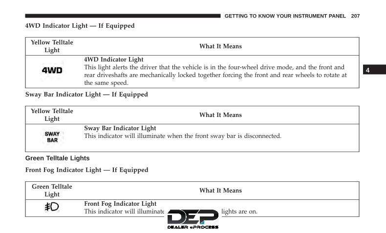
4WD Indicator Light — If Equipped
Yellow TelltaleLight
What It Means
4WD Indicator LightThis light alerts the driver that the vehicle is in the four-wheel drive mode, and the front andrear driveshafts are mechanically locked together forcing the front and rear wheels to rotate atthe same speed.
Sway Bar Indicator Light — If Equipped
Yellow TelltaleLight
What It Means
Sway Bar Indicator LightThis indicator will illuminate when the front sway bar is disconnected.
Green Telltale Lights
Front Fog Indicator Light — If Equipped
Green TelltaleLight
What It Means
Front Fog Indicator LightThis indicator will illuminate when the front fog lights are on.
4
GETTING TO KNOW YOUR INSTRUMENT PANEL 207

Turn Signal Indicator Lights
Green TelltaleLight
What It Means
Turn Signal Indicator LightsThe left or right arrow will flash with the corresponding exterior turn signal lights when the turnsignal lever is operated. A chime will sound if the vehicle is driven more than 1 mile (1.6 km)with either turn signal on.
NOTE: If either indicator flashes at a rapid rate, check for a defective outside light bulb.
White Telltale Lights
Cruise Control On Indicator Light
White TelltaleLight
What It Means
Cruise Control On Indicator LightThis indicator shows when the Speed Control System is turned on.
208 GETTING TO KNOW YOUR INSTRUMENT PANEL

Hill Descent Control (HDC) Indicator Light — If Equipped
White TelltaleLight
What It Means
Hill Descent Control (HDC) Indicator LightThis indicator shows when the Hill Descent Control (HDC) feature is turned on. The lamp willbe on solid when HDC is armed. HDC can only be armed when the transfer case is in the “4WDLOW” position and the vehicle speed is less then 30 mph (48 km/h). If these conditions are notmet while attempting to use the HDC feature, the HDC indicator light will flash on/off.
Blue Telltale Lights
High Beam Indicator Light
Blue TelltaleLight
What It Means
High Beam Indicator LightThis indicator shows that the high beam headlights are on. Push the multifunction control leveraway from you to switch the headlights to high beam. Pull the lever toward you to switch theheadlights back to low beam. Pull the lever toward you for a temporary high beam on, �flash topass� scenario.
4
GETTING TO KNOW YOUR INSTRUMENT PANEL 209

ONBOARD DIAGNOSTIC SYSTEM — OBD II
Your vehicle is equipped with a sophisticated OnboardDiagnostic system called OBD II. This system monitors theperformance of the emissions, engine, and automatic trans-mission control systems. When these systems are operatingproperly, your vehicle will provide excellent performanceand fuel economy, as well as engine emissions well withincurrent government regulations.
If any of these systems require service, the OBD II systemwill turn on the Malfunction Indicator Light (MIL). It willalso store diagnostic codes and other information to assistyour service technician in making repairs. Although yourvehicle will usually be drivable and not need towing, seeyour authorized dealer for service as soon as possible.
CAUTION!
• Prolonged driving with the MIL on could causefurther damage to the emission control system. Itcould also affect fuel economy and driveability. Thevehicle must be serviced before any emissions testscan be performed.
• If the MIL is flashing while the vehicle is running,severe catalytic converter damage and power losswill soon occur. Immediate service is required.
Onboard Diagnostic System (OBD II) Cybersecurity
Your vehicle is required to have an Onboard Diagnosticsystem (OBD II) and a connection port to allow access toinformation related to the performance of your emissionscontrols. Authorized service technicians may need to ac-cess this information to assist with the diagnosis andservice of your vehicle and emissions system.
WARNING!
• ONLY an authorized service technician should con-nect equipment to the OBD II connection port inorder to diagnose or service your vehicle.
• If unauthorized equipment is connected to the OBDII connection port, such as a driver-behavior trackingdevice, it may:• Be possible that vehicle systems, including safety
related systems, could be impaired or a loss ofvehicle control could occur that may result in anaccident involving serious injury or death.
• Access, or allow others to access, informationstored in your vehicle systems, including personalinformation.
210 GETTING TO KNOW YOUR INSTRUMENT PANEL

For further information, refer to “Privacy Practices” and“Uconnect CyberSecurity” in “All About Uconnect Access”in your Owner’s Manual Radio Supplement and “Cyber-security” in “Multimedia”.
Loose Fuel Filler Cap Message
After fuel is added, the vehicle diagnostic system candetermine if the fuel filler cap is possibly loose, improperlyinstalled, or damaged. A “gASCAP” message will bedisplayed in the odometer. Tighten the gas cap until a�clicking� sound is heard. This is an indication that the gascap is properly tightened. Push the odometer reset buttonto turn the message off. If the problem persists, themessage will appear the next time the vehicle is started.This might indicate a damaged cap. If the problem isdetected twice in a row, the system will turn on the MIL.Resolving the problem will turn the MIL off.
EMISSIONS INSPECTION AND MAINTENANCEPROGRAMS
In some localities, it may be a legal requirement to pass aninspection of your vehicle’s emissions control system.Failure to pass could prevent vehicle registration.
For states that require an Inspection and Mainte-nance (I/M), this check verifies the “Malfunction
Indicator Light (MIL)” is functioning and is not on whenthe engine is running, and that the OBD II system is readyfor testing.
Normally, the OBD II system will be ready. The OBD IIsystem may not be ready if your vehicle was recentlyserviced, recently had a dead battery or a battery replace-ment. If the OBD II system should be determined not readyfor the I/M test, your vehicle may fail the test.
Your vehicle has a simple ignition actuated test, which youcan use prior to going to the test station. To check if yourvehicle’s OBD II system is ready, you must do the follow-ing:
1. Cycle the ignition switch to the ON position, but do notcrank or start the engine.
NOTE: If you crank or start the engine, you will have tostart this test over.
2. As soon as you cycle the ignition switch to the ONposition, you will see the “Malfunction Indicator Light(MIL)” symbol come on as part of a normal bulb check.
4
GETTING TO KNOW YOUR INSTRUMENT PANEL 211

3. Approximately 15 seconds later, one of two things willhappen:
• The MIL will flash for about 10 seconds and then returnto being fully illuminated until you turn OFF the igni-tion or start the engine. This means that your vehicle’sOBD II system is not ready and you should not proceedto the I/M station.
• The MIL will not flash at all and will remain fullyilluminated until you place the ignition in the off posi-tion or start the engine. This means that your vehicle’sOBD II system is ready and you can proceed to the I/Mstation.
If your OBD II system is not ready, you should see yourauthorized dealer or repair facility. If your vehicle wasrecently serviced or had a battery failure or replacement,you may need to do nothing more than drive your vehicleas you normally would in order for your OBD II system toupdate. A recheck with the above test routine may thenindicate that the system is now ready.
Regardless of whether your vehicle’s OBD II system isready or not, if the MIL is illuminated during normalvehicle operation you should have your vehicle servicedbefore going to the I/M station. The I/M station can failyour vehicle because the MIL is on with the enginerunning.
212 GETTING TO KNOW YOUR INSTRUMENT PANEL

SAFETY
CONTENTS� SAFETY FEATURES . . . . . . . . . . . . . . . . . . . . . .214
▫ Anti-Lock Brake System (ABS) . . . . . . . . . . . . .214
▫ Electronic Brake Control System . . . . . . . . . . . .215
� AUXILIARY DRIVING SYSTEMS . . . . . . . . . . . . .227
▫ Tire Pressure Monitor System (TPMS) . . . . . . . .227
� OCCUPANT RESTRAINT SYSTEMS . . . . . . . . . .236
▫ Occupant Restraint Systems Features . . . . . . . .236
▫ Important Safety Precautions . . . . . . . . . . . . . .236
▫ Seat Belt Systems . . . . . . . . . . . . . . . . . . . . . .237
▫ Supplemental Restraint Systems (SRS) . . . . . . . .248
▫ Child Restraints . . . . . . . . . . . . . . . . . . . . . . .258
▫ Transporting Pets . . . . . . . . . . . . . . . . . . . . . .275
� SAFETY TIPS . . . . . . . . . . . . . . . . . . . . . . . . . . .275
▫ Transporting Passengers . . . . . . . . . . . . . . . . . .275
▫ Exhaust Gas . . . . . . . . . . . . . . . . . . . . . . . . . .276
▫ Safety Checks You Should Make Inside TheVehicle . . . . . . . . . . . . . . . . . . . . . . . . . . . . . .277
▫ Periodic Safety Checks You Should Make OutsideThe Vehicle . . . . . . . . . . . . . . . . . . . . . . . . . . .279
5

SAFETY FEATURES
Anti-Lock Brake System (ABS)
The Anti-Lock Brake System (ABS) provides increasedvehicle stability and brake performance under most brak-ing conditions. The system automatically prevents wheellock, and enhances vehicle control during braking.
The ABS performs a self-check cycle to ensure that the ABSis working properly each time the vehicle is started anddriven. During this self-check, you may hear a slightclicking sound as well as some related motor noises.
ABS is activated during braking when the system detectsone or more wheels begin to lock. Road conditions such asice, snow, gravel, bumps, railroad tracks, loose debris, orpanic stops may increase the likelihood of ABS activa-tion(s).
You also may experience the following when ABS activates:
• The ABS motor noise (it may continue to run for a shorttime after the stop).
• The clicking sound of solenoid valves.
• Brake pedal pulsations.
• A slight drop of the brake pedal at the end of the stop.
These are all normal characteristics of ABS.
WARNING!
• The ABS contains sophisticated electronic equip-ment that may be susceptible to interference causedby improperly installed or high output radio trans-mitting equipment. This interference can cause pos-sible loss of anti-lock braking capability. Installationof such equipment should be performed by qualifiedprofessionals.
• Pumping of the Anti-Lock Brakes will diminish theireffectiveness and may lead to a collision. Pumpingmakes the stopping distance longer. Just press firmlyon your brake pedal when you need to slow down orstop.
• The ABS cannot prevent the natural laws of physicsfrom acting on the vehicle, nor can it increase brak-ing or steering efficiency beyond that afforded by thecondition of the vehicle brakes and tires or thetraction afforded.
• The ABS cannot prevent collisions, including thoseresulting from excessive speed in turns, followinganother vehicle too closely, or hydroplaning.
(Continued)
214 SAFETY

WARNING! (Continued)• The capabilities of an ABS equipped vehicle must
never be exploited in a reckless or dangerous mannerthat could jeopardize the user’s safety or the safety ofothers.
ABS is designed to function with the OEM tires. Modifica-tion may result in degraded ABS performance.
Anti-Lock Brake Warning Light
The yellow “Anti-Lock Brake Warning Light” will turn onwhen the ignition is turned to the ON/RUN mode andmay stay on for as long as four seconds.
If the “Anti-Lock Brake Warning Light” remains on orcomes on while driving, it indicates that the anti-lockportion of the brake system is not functioning and thatservice is required. However, the conventional brake sys-tem will continue to operate normally if the “Brake SystemWarning Light” is not on.
If the “Anti-Lock Brake Warning Light” is on, the brakesystem should be serviced as soon as possible to restore the
benefits of anti-lock brakes. If the “Anti-Lock Brake Warn-ing Light” does not come on when the ignition is turned tothe ON/RUN mode, have the light repaired as soon aspossible.
Electronic Brake Control System
Your vehicle is equipped with an advanced ElectronicBrake Control system (EBC). This system includes Elec-tronic Brake Force Distribution (EBD), Brake Assist System(BAS), Hill Start Assist (HSA), Traction Control System(TCS), Electronic Stability Control (ESC), and ElectronicRoll Mitigation (ERM). These systems work together toenhance both vehicle stability and control in various driv-ing conditions.
Your vehicle may also be equipped with Trailer SwayControl (TSC) and Hill Descent Control (HDC).
Electronic Brake Force Distribution (EBD)
This function manages the distribution of the brakingtorque between the front and rear axles by limiting brakingpressure to the rear axle. This is done to prevent overslip ofthe rear wheels to avoid vehicle instability, and to preventthe rear axle from entering ABS before the front axle.
5
SAFETY 215

Brake System Warning Light
The red “Brake System Warning Light” will turn on whenthe ignition is turned to the ON/RUN mode and may stayon for as long as four seconds.
If the “Brake System Warning Light” remains on or comeson while driving, it indicates that the brake system is notfunctioning properly and that immediate service is re-quired. If the “Brake System Warning Light” does not comeon when the ignition is turned to the ON/RUN mode, havethe light repaired as soon as possible.
Brake Assist System (BAS)
The BAS is designed to optimize the vehicle’s brakingcapability during emergency braking maneuvers. The sys-tem detects an emergency braking situation by sensing therate and amount of brake application and then appliesoptimum pressure to the brakes. This can help reducebraking distances. The BAS complements the anti-lockbrake system (ABS). Applying the brakes very quicklyresults in the best BAS assistance. To receive the benefit ofthe system, you must apply continuous braking pressureduring the stopping sequence, (do not “pump” the brakes).Do not reduce brake pedal pressure unless braking is no
longer desired. Once the brake pedal is released, the BAS isdeactivated.
WARNING!
The Brake Assist System (BAS) cannot prevent thenatural laws of physics from acting on the vehicle, norcan it increase the traction afforded by prevailing roadconditions. BAS cannot prevent collisions, includingthose resulting from excessive speed in turns, drivingon very slippery surfaces, or hydroplaning. The capa-bilities of a BAS-equipped vehicle must never beexploited in a reckless or dangerous manner, whichcould jeopardize the user’s safety or the safety ofothers.
Hill Start Assist (HSA)
The HSA system is designed to mitigate roll back from acomplete stop while on an incline. If the driver releases thebrake while stopped on an incline, HSA will continue tohold the brake pressure for a short period. If the driverdoes not apply the throttle before this time expires, thesystem will release brake pressure and the vehicle will rolldown the hill as normal.
216 SAFETY

The following conditions must be met in order for HSA toactivate:
• The feature must be enabled.
• The vehicle must be stopped.
• Park brake must be off.
• Driver door must be closed.
• The vehicle must be on a sufficient grade.
• The gear selection must match vehicle uphill direction(i.e., vehicle facing uphill is in forward gear; vehiclebacking uphill is in REVERSE gear).
• HSA will work in REVERSE gear and all forward gears.The system will not activate if the transmission is inPARK or NEUTRAL. For vehicles equipped with amanual transmission, if the clutch is pressed, HSA willremain active.
WARNING!
There may be situations where the Hill Start Assist(HSA) will not activate and slight rolling may occur,such as on minor hills or with a loaded vehicle, or
(Continued)
WARNING! (Continued)while pulling a trailer. HSA is not a substitute foractive driving involvement. It is always the driver’sresponsibility to be attentive to distance to other ve-hicles, people, and objects, and most importantly brakeoperation to ensure safe operation of the vehicle underall road conditions. Your complete attention is alwaysrequired while driving to maintain safe control of yourvehicle. Failure to follow these warnings can result ina collision or serious personal injury.
Disabling And Enabling HSA
This feature can be turned on or turned off. To change thecurrent setting, proceed as follows:
• If disabling HSA using your instrument cluster display,refer to “Instrument Cluster Display” in “Getting ToKnow Your Instrument Panel” for further information.
• If disabling HSA using Uconnect Settings, refer to“Uconnect Settings” in “Multimedia” for further infor-mation.
5
SAFETY 217

For vehicles not equipped with an instrument clusterdisplay, perform the following steps:
1. Center the steering wheel (front wheels pointingstraight forward).
2. Shift the transmission into PARK.
3. Apply the parking brake.
4. Start the engine.
5. Rotate the steering wheel slightly more than one-halfturn to the left.
6. Push the “ESC Off” button located in the lower switchbank below the climate control four times within 20seconds. The “ESC Off Indicator Light” should turn onand turn off two times.
7. Rotate the steering wheel back to center and then anadditional slightly more than one-half turn to the right.
8. Turn the ignition to the OFF mode and then back to ON.If the sequence was completed properly, the “ESC OffIndicator Light” will blink several times to confirm HSAis disabled.
9. Repeat these steps if you want to return this feature toits previous setting.
Traction Control System (TCS)
This system monitors the amount of wheel spin of each ofthe driven wheels. If wheel spin is detected, the TCS mayapply brake pressure to the spinning wheel(s) and/orreduce engine power to provide enhanced acceleration andstability. A feature of the TCS, Brake Limited Differential(BLD), functions similar to a limited slip differential andcontrols the wheel spin across a driven axle. If one wheelon a driven axle is spinning faster than the other, thesystem will apply the brake of the spinning wheel. Thiswill allow more engine torque to be applied to the wheelthat is not spinning. BLD may remain enabled even if TCSand ESC are in a reduced mode.
Electronic Stability Control (ESC)
This system enhances directional control and stability ofthe vehicle under various driving conditions. The ESCcorrects for over/under steering of the vehicle by applyingthe brake of the appropriate wheel to assist in counteract-ing the over/under steer condition. Engine power may alsobe reduced to help the vehicle maintain the desired path.
ESC uses sensors in the vehicle to determine the vehiclepath intended by the driver and compares it to the actualpath of the vehicle. When the actual path does not match
218 SAFETY

the intended path, ESC applies the brake of the appropriatewheel to assist in counteracting the oversteer or understeercondition.
• Oversteer - when the vehicle is turning more thanappropriate for the steering wheel position.
• Understeer - when the vehicle is turning less thanappropriate for the steering wheel position.
The “ESC Activation/Malfunction Indicator Light” (lo-cated in the instrument cluster), starts to flash as soon asthe tires lose traction and the ESC system becomes active.The “ESC Activation/Malfunction Indicator Light” alsoflashes when TCS is active. If the “ESC Activation/Malfunction Indicator Light” begins to flash during accel-eration, ease up on the accelerator and apply as littlethrottle as possible. Be sure to adapt your speed anddriving to the prevailing road conditions.
WARNING!
• Electronic Stability Control (ESC) cannot prevent thenatural laws of physics from acting on the vehicle,nor can it increase the traction afforded by prevailing
(Continued)
WARNING! (Continued)road conditions. ESC cannot prevent accidents, in-cluding those resulting from excessive speed inturns, driving on very slippery surfaces, or hydro-planing. ESC also cannot prevent accidents resultingfrom loss of vehicle control due to inappropriatedriver input for the conditions. Only a safe, attentive,and skillful driver can prevent accidents. The capa-bilities of an ESC equipped vehicle must never beexploited in a reckless or dangerous manner whichcould jeopardize the user’s safety or the safety ofothers.
• Vehicle modifications, or failure to properly main-tain your vehicle, may change the handling charac-teristics of your vehicle, and may negatively affectthe performance of the ESC system. Changes to thesteering system, suspension, braking system, tiretype and size or wheel size may adversely affect ESCperformance. Improperly inflated and unevenlyworn tires may also degrade ESC performance. Anyvehicle modification or poor vehicle maintenancethat reduces the effectiveness of the ESC system canincrease the risk of loss of vehicle control, vehiclerollover, personal injury and death.
5
SAFETY 219

The ESC system has three available operating modes in 4Hrange. The system has one operating mode in 4L range.Two-wheel drive vehicles and four-wheel drive vehicles in2H range have two operating modes.
4H Range (4WD Models)
ESC On
This is the normal operating mode for ESC in 4H range.
ESC Partial Off
This mode is entered by momentarily pushing the ESCOFF switch. When in �ESC Partial Off� mode, the TCSportion of ESC (except for the limited slip feature describedin the TCS section), has been disabled and the �ESC OffIndicator Light� will be illuminated.
This mode is intended to be used if the vehicle is in deepsnow, sand, or gravel conditions and more wheel spin thanESC would normally allow is required to gain traction. Toturn ESC on again, momentarily push the ESC OFF switch.This will restore the normal “ESC On” mode of operation.
NOTE: To improve the vehicle’s traction when drivingwith snow chains, or starting off in deep snow, sand, orgravel, it may be desirable to switch to the �ESC Partial Off�mode by pushing the ESC OFF switch. Once the situationrequiring ESC to be switched to the �ESC Partial Off� modeis overcome, turn ESC back on by momentarily pushing theESC OFF switch. This may be done while the vehicle is inmotion.
WARNING!
• When in �ESC Partial Off� mode, the TCS function-ality of ESC, (except for the limited slip featuredescribed in the TCS section), has been disabled andthe “ESC Off Indicator Light” will be illuminated.When in �ESC Partial Off� mode, the engine powerreduction feature of TCS is disabled, and the en-hanced vehicle stability offered by the ESC system isreduced.
• Trailer Sway control (TSC) is disabled when the ESCsystem is in the �ESC Partial Off� mode.
220 SAFETY

ESC Full Off
This mode is entered by pushing and holding the ESC OFFswitch for five seconds.
In the �ESC Full Off� mode, the engine torque reductionand stability features are disabled. Therefore, the enhancedvehicle stability offered by ESC is unavailable. In anemergency evasive maneuver, the ESC system will notengage to assist in maintaining stability. “ESC Full Off”mode is intended for off-highway or off-road use only.
When in �ESC Full Off� mode, ESC and TCS, except for theBrake Limited Differential (BLD) feature described in the
TCS section, are turned off until the vehicle reaches anapproximate speed of 40 mph (64 km/h). For speeds at orexceeding approximately 40 mph (64 km/h) the ESC goesinto �ESC Partial Off�. When the vehicle speed drops below35 mph (56 km/h), the ESC system goes back to �ESC FullOff�. To turn ESC on again, momentarily push the ESC OFFswitch. This will restore normal “ESC On” mode of opera-tion. The �ESC Off Indicator Light” will always be illumi-nated when ESC is in �ESC Partial Off� and �ESC full Off�.
WARNING!
With the ESC in �ESC Full Off� mode, the enginetorque reduction and stability features offered by ESCand ERM are disabled. In an emergency evasive ma-neuver, the ESC and ERM systems will not engage toassist in maintaining stability. The �ESC Full Off�mode is intended for off-road use only.
4L Range (4WD Models)
ESC Full Off
This is the normal operating mode for ESC in 4L range.Whenever the vehicle is started in 4L range, or the transfercase (if equipped) is shifted from 4H range or NEUTRAL to4L range, the ESC system will be in this mode. In 4L range,
ESC OFF Switch
5
SAFETY 221

ESC and TCS, except for the Brake Limited Differential(BLD) feature described in the TCS section, are turned offuntil the vehicle reaches an approximate speed of 40 mph(64 km/h). For speeds at or exceeding approximately40 mph (64 km/h) the ESC goes into �ESC Partial Off�When the vehicle speed drops below 35 mph (56 km/h),the ESC system goes back to �ESC Full Off�. The ESC is in�ESC Full Off� at low vehicle speeds in 4L range so that itwill not interfere with off-road driving, but the ESCfunction returns to provide the stability feature at speedsabove 40 mph (64 km/h). The “ESC OFF Indicator Light”will always be illuminated in 4L range when ESC is in �ESCFull Off� or �ESC Partial Off�.
NOTE: The “ESC OFF” message will display and anaudible chime will sound when the gear selector is placedin the PARK position from any other position, and thenmoved out of the PARK position. This will occur even if themessage was previously cleared.
WARNING!
With the ESC in �ESC Full Off� mode, the enginetorque reduction and stability features offered by ESC
(Continued)
WARNING! (Continued)and ERM are disabled. In an emergency evasive ma-neuver, the ESC and ERM systems will not engage toassist in maintaining stability. The �ESC Full Off�mode is intended for off-road use only.
2H Range (4WD Models) Or 2WD Models
ESC On
This is the normal operating mode for ESC in 2H range andon 2WD vehicles.
ESC Partial Off
When in �ESC Partial Off� mode, the TCS portion of ESC(except for the limited slip feature described in the TCSsection), has been disabled and the �ESC Off IndicatorLight� will be illuminated.
This mode is intended to be used if the vehicle is in deepsnow, sand, or gravel conditions and more wheel spin thanESC would normally allow is required to gain traction. Toturn ESC on again, momentarily push the ESC OFF switch.This will restore the normal �ESC On� mode of operation.
222 SAFETY

NOTE: To improve the vehicle’s traction when drivingwith snow chains, or starting off in deep snow, sand, orgravel, it may be desirable to switch to the �ESC Partial Off�mode by pushing the �ESC Full Off� switch. Once thesituation requiring ESC to be switched to the �ESC PartialOff� mode is overcome, turn ESC back on by momentarilypushing the �ESC Full Off� switch. This may be done whilethe vehicle is in motion.
The ESC will restore to normal ESC On mode after eachkey on.
WARNING!
• When in “Partial Off” mode, the TCS functionalityof ESC, (except for the limited slip feature describedin the TCS section), has been disabled and the “ESCOff Indicator Light” will be illuminated. When in“Partial Off” mode, the engine power reductionfeature of TCS is disabled, and the enhanced vehiclestability offered by the ESC system is reduced.
• Trailer Sway Control (TSC) is disabled when the ESCsystem is in the �Partial Off� mode.
ESC Activation/Malfunction Indicator Light and ESCOFF Indicator Light
The “ESC Activation/Malfunction IndicatorLight” in the instrument cluster will come onwhen the ignition is turned to the ON mode. Itshould go out with the engine running. If the
“ESC Activation/Malfunction Indicator Light” comes oncontinuously with the engine running, a malfunction hasbeen detected in the ESC system. If this light remains onafter several ignition cycles, and the vehicle has beendriven several miles (kilometers) at speeds greater than30 mph (48 km/h), see your authorized dealer as soon aspossible to have the problem diagnosed and corrected.
The “ESC Activation/Malfunction Indicator Light” (lo-cated in the instrument cluster) starts to flash as soon as thetires lose traction and the ESC system becomes active. The“ESC Activation/Malfunction Indicator Light” also flasheswhen TCS is active. If the “ESC Activation/MalfunctionIndicator Light” begins to flash during acceleration, easeup on the accelerator and apply as little throttle as possible.Be sure to adapt your speed and driving to the prevailingroad conditions.
5
SAFETY 223

NOTE:
• The “ESC Activation/Malfunction Indicator Light” andthe “ESC OFF Indicator Light” come on momentarilyeach time the ignition is turned ON.
• Each time the ignition is turned ON, the ESC system willbe on even if it was turned off previously.
• The ESC system will make buzzing or clicking soundswhen it is active. This is normal; the sounds will stopwhen ESC becomes inactive following the maneuverthat caused the ESC activation.
The “ESC OFF Indicator Light” indicates thecustomer has elected to have the Electronic Sta-bility Control (ESC) in a reduced mode.
Electronic Roll Mitigation (ERM)
This system anticipates the potential for wheel lift bymonitoring the driver’s steering wheel input and the speedof the vehicle. When ERM determines that the rate ofchange of the steering wheel angle and vehicle’s speed aresufficient to potentially cause wheel lift, it then applies theappropriate brake and may also reduce engine power tolessen the chance that wheel lift will occur. ERM can onlyreduce the chance of wheel lift occurring during severe or
evasive driving maneuvers; it cannot prevent wheel liftdue to other factors, such as road conditions, leaving theroadway, or striking objects or other vehicles.
NOTE: ERM is disabled anytime the ESC is in “Full Off”mode (if equipped). Refer to “Electronic Stability Control(ESC)” in this section for a complete explanation of theavailable ESC modes.
WARNING!
Many factors, such as vehicle loading, road conditionsand driving conditions, influence the chance thatwheel lift or rollover may occur. ERM cannot preventall wheel lift or roll overs, especially those that involveleaving the roadway or striking objects or other ve-hicles. The capabilities of an ERM-equipped vehiclemust never be exploited in a reckless or dangerousmanner which could jeopardize the user’s safety or thesafety of others.
Trailer Sway Control (TSC)
TSC uses sensors in the vehicle to recognize an excessivelyswaying trailer and will take the appropriate actions toattempt to stop the sway. TSC will become active automati-cally once an excessively swaying trailer is recognized.
224 SAFETY

NOTE: TSC cannot stop all trailers from swaying. Alwaysuse caution when towing a trailer and follow the trailertongue weight recommendations. Refer to “Trailer Tow-ing” in “Starting And Operating” for further information.When TSC is functioning, the “ESC Activation/Malfunction Indicator Light” will flash, the engine powermay be reduced and you may feel the brakes being appliedto individual wheels to attempt to stop the trailer fromswaying. TSC is disabled when the ESC system is in the“Partial Off” or “Full Off” modes.
WARNING!
If TSC activates while driving, slow the vehicle down,stop at the nearest safe location, and adjust the trailerload to eliminate trailer sway.
Hill Descent Control (HDC) — If Equipped
HDC is only intended for low speed off-road driving. HDCmaintains vehicle speed while descending hills in off-roaddriving conditions by applying the brakes when necessary.
The symbol indicates the status of the Hill De-scent Control (HDC) feature. The lamp will be onsolid when HDC is armed. HDC can only bearmed when the transfer case is in the “4WD
LOW” position and the vehicle speed is less then 30 mph(48 km/h). If these conditions are not met while attemptingto use the HDC feature, the HDC indicator light will flashon/off.
When enabled, HDC senses the terrain and activates whenthe vehicle is descending a hill. HDC speed may beadjusted by the driver to suit the driving conditions. Thespeed corresponds to the transmission gear selected.
Gear Approximate HDC Set Speed1st 1 mph (1.5 km/h)2nd 2.5 mph (4 km/h)3rd 4 mph (6.5 km/h)4th 5.5 mph (9 km/h)
5
SAFETY 225
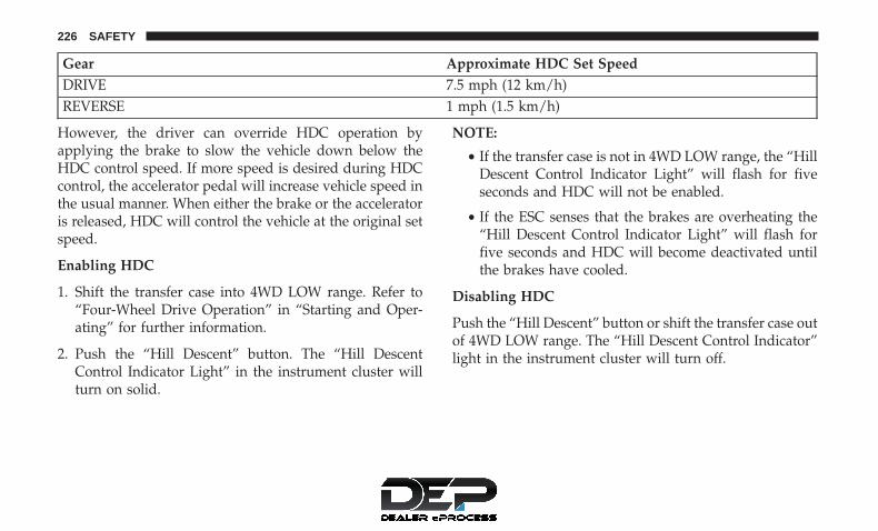
Gear Approximate HDC Set SpeedDRIVE 7.5 mph (12 km/h)REVERSE 1 mph (1.5 km/h)
However, the driver can override HDC operation byapplying the brake to slow the vehicle down below theHDC control speed. If more speed is desired during HDCcontrol, the accelerator pedal will increase vehicle speed inthe usual manner. When either the brake or the acceleratoris released, HDC will control the vehicle at the original setspeed.
Enabling HDC
1. Shift the transfer case into 4WD LOW range. Refer to“Four-Wheel Drive Operation” in “Starting and Oper-ating” for further information.
2. Push the “Hill Descent” button. The “Hill DescentControl Indicator Light” in the instrument cluster willturn on solid.
NOTE:
• If the transfer case is not in 4WD LOW range, the “HillDescent Control Indicator Light” will flash for fiveseconds and HDC will not be enabled.
• If the ESC senses that the brakes are overheating the“Hill Descent Control Indicator Light” will flash forfive seconds and HDC will become deactivated untilthe brakes have cooled.
Disabling HDC
Push the “Hill Descent” button or shift the transfer case outof 4WD LOW range. The “Hill Descent Control Indicator”light in the instrument cluster will turn off.
226 SAFETY

AUXILIARY DRIVING SYSTEMS
Tire Pressure Monitor System (TPMS)
The Tire Pressure Monitoring System (TPMS) will warn thedriver of a low tire pressure based on the vehicle recom-mended cold placard pressure.
The tire pressure will vary with temperature by about 1 psi(7.0 kPa) for every 12°F (6.5°C). This means that when theoutside temperature decreases, the tire pressure will de-crease. Tire pressure should always be set based on coldinflation tire pressure. This is defined as the tire pressureafter a vehicle has not been driven for more than threehours, or driven less than 1 mile (1.6 km) after a three-hourperiod. Refer to “Tires” in “Servicing and Maintenance” forinformation on how to properly inflate the vehicle’s tires.The tire pressure will also increase as the vehicle is driven;this is normal and there should be no adjustment for thisincreased pressure.
The TPMS will warn the driver of a low tire pressure if thetire pressure falls below the low pressure warning thresh-old for any reason, including low temperature effects, ornatural pressure loss through the tire.
The TPMS will continue to warn the driver of low tirepressure as long as the condition exists, and will not turn
off until the tire pressure is at or above recommended coldplacard pressure. Once the “Tire Pressure Monitoring Tell-tale Light” has been illuminated, the tire pressure must beincreased to the recommended cold placard pressure inorder for the “Tire Pressure Monitoring Telltale Light” to beturned OFF.
NOTE: When filling warm tires, the tire pressure may needto be increased up to an additional 4 psi (30 kPa) above therecommended cold placard pressure in order to turn theTire Pressure Monitoring Telltale Light off.
The system will automatically update and the “Tire Pres-sure Monitoring Telltale Light” will extinguish once theupdated tire pressures have been received. The vehiclemay need to be driven for up to 10 minutes above 15 mph(24 km/h) to receive this information.
For example, your vehicle may have a recommended cold(parked for more than three hours) air pressure of 35 psi(241 kPa). If the ambient temperature is 68°F (20°C) and themeasured tire pressure is 30 psi (207 kPa), a temperaturedrop to 20°F (-7°C) will decrease the tire pressure toapproximately 26 psi (179 kPa). This tire pressure is suffi-ciently low enough to turn ON the “Tire Pressure Moni-toring Telltale Light.” Driving the vehicle may cause thetire pressure to rise to approximately 30 psi (207 kPa), but
5
SAFETY 227

the “Tire Pressure Monitoring Telltale Light” will still beON. In this situation, the “Tire Pressure Monitoring TelltaleLight” will turn OFF only after the tires have been inflatedto the vehicle’s recommended cold placard pressure value.
CAUTION!
• The TPMS has been optimized for the originalequipment tires and wheels. TPMS pressures andwarnings have been established for the tire sizeequipped on your vehicle. Undesirable system op-eration or sensor damage may result when usingreplacement equipment that is not of the same size,type, and/or style. Aftermarket wheels can causesensor damage. Using aftermarket tire sealants maycause the Tire Pressure Monitoring System (TPMS)sensor to become inoperable. After using an after-market tire sealant it is recommended that you takeyour vehicle to an authorized dealership to have yoursensor function checked.
• After inspecting or adjusting the tire pressure, al-ways reinstall the valve stem cap. This will preventmoisture and dirt from entering the valve stem,which could damage the Tire Pressure MonitoringSensor.
NOTE:
• The TPMS is not intended to replace normal tire care andmaintenance, nor to provide warning of a tire failure orcondition.
• The TPMS should not be used as a tire pressure gaugewhile adjusting your tire pressure.
• Driving on a significantly under-inflated tire causes thetire to overheat and can lead to tire failure. Under-inflation also reduces fuel efficiency and tire tread life,and may affect the vehicle’s handling and stoppingability.
• The TPMS is not a substitute for proper tire mainte-nance, and it is the driver’s responsibility to maintaincorrect tire pressure, even if under-inflation has notreached the level to trigger illumination of the “TirePressure Monitoring Telltale Light.”
• Seasonal temperature changes will affect tire pressure,and the TPMS will monitor the actual tire pressure in thetire.
Base System
The Tire Pressure Monitor System (TPMS) uses wirelesstechnology with wheel rim-mounted electronic sensors to
228 SAFETY

monitor tire pressure levels. Sensors, mounted to eachwheel as part of the valve stem, transmit tire pressurereadings to the Receiver Module.
NOTE: It is particularly important for you to check the tirepressure in all of your tires regularly and to maintain theproper pressure.
The Tire Pressure Monitor System (TPMS) consists of thefollowing components:
• Receiver Module
• Four Tire Pressure Monitoring Sensors
• Tire Pressure Monitoring Telltale Light
A tire pressure monitoring sensor is located in the sparewheel if the vehicle is equipped with a matching full sizespare wheel and tire assembly. The matching full size sparetire can be used in place of any of the four road tires. A lowspare tire will not cause the “Tire Pressure MonitoringTelltale Light” to illuminate or the chime to sound whilestowed in the spare location.
The “Tire Pressure Monitoring Telltale Light” willilluminate in the instrument cluster, a “LOW TIRE
PRESSURE” message will display in the instrument cluster,and an audible chime will be activated when one or more
of the four active road tire pressures are low. Should thisoccur, you should stop as soon as possible, check theinflation pressure of each tire on your vehicle, and inflateeach tire to the vehicle’s recommended cold placard pres-sure value. The system will automatically update and the“Tire Pressure Monitoring Telltale Light” will extinguishonce the updated tire pressures have been received. Thevehicle may need to be driven for up to 10 minutes above15 mph (24 km/h) to receive this information.
The “Tire Pressure Monitoring Telltale Light” will flash onand off for 75 seconds, and will remain on solid when asystem fault is detected. The system fault will also sound achime. If the ignition key is cycled, this sequence willrepeat, providing the system fault still exists. The “TirePressure Monitoring Telltale Light” will turn off when thefault condition no longer exists. A system fault can occur byany of the following scenarios:
1. Jamming due to electronic devices or driving next tofacilities emitting the same Radio Frequencies as theTPM sensors.
2. Installing some form of aftermarket window tinting thataffects radio wave signals.
5
SAFETY 229

3. Lots of snow or ice around the wheels or wheel hous-ings.
4. Using tire chains on the vehicle.
5. Using wheels/tires not equipped with TPM sensors.
Vehicles not equipped with instrument cluster display willinform the driver which tire(s) are low but not provideactual tire pressure. The low tire ISO telltale will illuminatealong with “LoTIrE” message displayed in the ODO andthen it will scroll to which tire location is lower than thePlacard Value.
Tire location will be displayed as follows:
LF = Left Front
rF = right Front
Lr = Left rear
rr = right rear
NOTE:
• If your vehicle is equipped with a matching full-sizespare wheel and tire assembly, it has a tire pressuremonitoring sensor, and can be monitored by the TirePressure Monitoring System (TPMS) when swappedwith a low pressure road tire. In the event that the
matching full-size spare tire is swapped with a lowpressure road tire, the next ignition key cycle will stillshow the “Tire Pressure Monitoring Telltale Light” to beON, and a chime to sound. Driving the vehicle for up to10 minutes above 15 mph (24 km/h) will turn OFF the“Tire Pressure Monitoring Telltale Light” as long as noneof the road tires are below the low pressure warningthreshold.
• If your vehicle is not equipped with a matching full-sizespare wheel and tire assembly, it does not have a tirepressure monitoring sensor in the spare tire. The TPMSwill not be able to monitor the tire pressure. If you installthe spare tire in place of a road tire that has a pressurebelow the low-pressure warning limit, upon the nextignition key cycle, a chime will sound and the “TirePressure Monitoring Telltale Light” will turn ON. Afterdriving the vehicle for up to 10 minutes above 15 mph(24 km/h), the “Tire Pressure Monitoring Telltale Light”will flash on and off for 75 seconds and then remain onsolid. For each subsequent ignition key cycle, a chimewill sound and the “Tire Pressure Monitoring TelltaleLight” will flash on and off for 75 seconds and thenremain on solid. Once you repair or replace the originalroad tire, and reinstall it on the vehicle in place of thespare tire, the TPMS will update automatically and the
230 SAFETY

“Tire Pressure Monitoring Telltale Light” will turn OFF,as long as no tire pressure is below the low-pressurewarning limit in any of the four active road tires. Thevehicle may need to be driven for up to 10 minutesabove 15 mph (24 km/h) in order for the TPMS toreceive this information.
Premium System — If Equipped
The Tire Pressure Monitor System (TPMS) uses wirelesstechnology with wheel rim-mounted electronic sensors tomonitor tire pressure levels. Sensors, mounted to eachwheel as part of the valve stem, transmit tire pressurereadings to the Receiver Module.
NOTE: It is particularly important, for you to regularlycheck the tire pressure in all of your tires and to maintainthe proper pressure.
The Tire Pressure Monitor System (TPMS) consists of thefollowing components:
• Receiver Module
• Four Tire Pressure Monitoring Sensors
• Various Tire Pressure Monitoring System Messages,which display in the instrument cluster, and a graphicdisplaying tire pressures
Tire Pressure Monitor Display
5
SAFETY 231

• Tire Pressure Monitoring Telltale Light
A tire pressure monitoring sensor is located in the sparewheel, if the vehicle is equipped with a matching full-sizespare wheel and tire assembly. The matching full-size sparetire can be used in place of any of the four road tires.
Tire Pressure Monitoring Low Pressure Warnings
The Tire Pressure Monitoring Telltale Light willilluminate in the instrument cluster, and an audible
chime will be activated, when one or more of the fouractive road tire pressures are low. In addition, the instru-ment cluster will display a “LOW TIRE” message for aminimum of five seconds. A graphic display of the pressurevalue(s) with the low tire(s) highlighted or in a differentcolor will also be displayed. Refer to “Instrument ClusterDisplay” in “Getting To Know Your Instrument Panel” forfurther information.
NOTE: Your system can be set to display pressure units inPSI, kPa, or BAR.
Should a low tire condition occur on any of the four activeroad tire(s), you should stop as soon as possible, and inflatethe low tire(s) that is highlighted or shown in a differentcolor on the graphic display to the vehicle’s recommendedcold tire pressure inflation value. The system will auto-matically update, the graphic display of the pressurevalue(s) will no longer be highlighted or shown in adifferent color and the Tire Pressure Monitoring TelltaleLight will extinguish once the updated tire pressure(s)have been received.
Tire Pressure Monitor Display
232 SAFETY

NOTE: When filling warm tires, the tire pressure may needto be increased up to an additional 4 psi (30 kPa) above therecommended cold placard pressure in order to turn theTire Pressure Monitoring Telltale Light off.
The vehicle may need to be driven for up to 10 minutesabove 15 mph (24 km/h) to receive this information.
Service TPM System Warning
The “Tire Pressure Monitoring Telltale Light” will flash onand off for 75 seconds, and remain on solid when a systemfault is detected. The system fault will also sound a chime.The instrument cluster will display a “SERVICE TPMSYSTEM” message for a minimum of five seconds. Thismessage is then followed by a graphic display, with “- -“ inplace of the pressure value(s), indicating which Tire Pres-sure Monitoring Sensor(s) is not being received.
If the ignition switch is cycled, this sequence will repeat,providing the system fault still exists. If the system fault nolonger exists, the “Tire Pressure Monitoring Telltale Light”will no longer flash, the �SERVICE TPM SYSTEM� messagewill not be present, and a pressure value will be displayedinstead of dashes. A system fault can occur by any of thefollowing:
• Jamming due to electronic devices or driving next tofacilities emitting the same Radio Frequencies as theTPM sensors.
• Installing some form of aftermarket window tinting thataffects radio wave signals.
• Lots of snow or ice around the wheels or wheel hous-ings.
• Using tire chains on the vehicle.
• Using wheels/tires not equipped with TPM sensors.
5
SAFETY 233

NOTE:
• If your vehicle is equipped with a matching full-sizespare wheel and tire assembly, it has a tire pressuremonitoring sensor, and can be monitored by the TirePressure Monitoring System (TPMS) when swappedwith a low pressure road tire. In the event that thematching full-size spare tire is swapped with a lowpressure road tire, the next ignition switch cycle will stillshow the “Tire Pressure Monitoring Telltale Light” to beON, a chime to sound, a “LOW TIRE” message toappear in the instrument cluster, and the graphic displaywill still show the low tire pressure value highlighted orshown in a different color. Driving the vehicle for up to10 minutes above 15 mph (24 km/h) will turn OFF the“Tire Pressure Monitoring Telltale Light” as long as noneof road tires are below the low pressure warning thresh-old.
• If your vehicle is not equipped with a matching full-sizespare wheel and tire assembly, it does not have a tirepressure monitoring sensor in the spare tire. The TPMSwill not be able to monitor the tire pressure. If you installthe spare tire in place of a road tire that has a pressurebelow the low-pressure warning limit, upon the nextignition switch cycle, the “Tire Pressure MonitoringTelltale Light” will remain ON, a chime will sound, and
the instrument cluster will still display a highlighted ordifferent color pressure value in the graphic display.After driving the vehicle for up to 10 minutes above15 mph (24 km/h), the “Tire Pressure Monitoring Tell-tale Light” will flash on and off for 75 seconds and thenremain on solid. In addition, the instrument cluster willdisplay a “SERVICE TPM SYSTEM� message for aminimum of five seconds and then display dashes (- -) inplace of the pressure value. For each subsequent ignitionswitch cycle, a chime will sound, the “Tire PressureMonitoring Telltale Light” will flash on and off for 75seconds and then remain on solid, and the instrumentcluster will display a �SERVICE TPM SYSTEM� messagefor a minimum of five seconds and then display dashes(- -) in place of the pressure value.
• Once you repair or replace the original road tire, andreinstall it on the vehicle in place of the spare tire, theTPMS will update automatically.
In addition, the “Tire Pressure Monitoring Telltale Light”will turn OFF and the graphic in the instrument cluster willdisplay a new pressure value instead of dashes (- -), as longas no tire pressure is below the low-pressure warning limitin any of the four active road tires. The vehicle may need tobe driven for up to 10 minutes above 15 mph (24 km/h) inorder for the TPMS to receive this information.
234 SAFETY

TPMS Deactivation — If Equipped
The TPMS can be deactivated if replacing all four wheeland tire assemblies (road tires) with wheel and tire assem-blies that do not have TPMS Sensors, such as wheninstalling winter wheel and tire assemblies on your vehicle.
To deactivate the TPMS, first, replace all four wheel andtire assemblies (road tires) with tires not equipped withTire Pressure Monitoring (TPM) Sensors. Then, drive thevehicle for 10 minutes above 15 mph (24 km/h). The TPMSwill chime, the �TPM Telltale Light� will flash on and off for75 seconds and then remain on. The instrument cluster willdisplay the “SERVICE TPM SYSTEM” message and thendisplay dashes (--) in place of the pressure values.
Beginning with the next ignition cycle, the TPMS will nolonger chime or display the “SERVICE TPM SYSTEM”message in the instrument cluster but dashes (--) willremain in place of the pressure values.
To reactivate the TPMS, replace all four wheel and tireassemblies (road tires) with tires equipped with TPMsensors. Then, drive the vehicle for up to 10 minutes above15 mph (24 km/h). The TPMS will chime, the �TPM Telltale
Light� will flash on and off for 75 seconds and then turn off.The instrument cluster will display the “SERVICE TPMSYSTEM” message and then display pressure values inplace of the dashes. On the next ignition cycle the �SER-VICE TPM SYSTEM� message will no longer be displayedas long as no system fault exists.
General Information
The following regulatory statement applies to all radiofrequency (RF) devices equipped in this vehicle:
This device complies with Part 15 of the FCC Rules andwith Industry Canada license-exempt RSS standard(s).Operation is subject to the following two conditions:
(1) This device may not cause harmful interference, and
(2) This device must accept any interference received,including interference that may cause undesired operation.
NOTE: Changes or modifications not expressly approvedby the party responsible for compliance could void theuser’s authority to operate the equipment.
5
SAFETY 235

OCCUPANT RESTRAINT SYSTEMS
Some of the most important safety features in your vehicleare the restraint systems:
Occupant Restraint Systems Features
• Seat Belt Systems
• Supplemental Restraint Systems (SRS) Air Bags
• Child Restraints
Some of the safety features described in this section may bestandard equipment on some models, or may be optionalequipment on others. If you are not sure, ask your autho-rized dealer.
Important Safety Precautions
Please pay close attention to the information in this section.It tells you how to use your restraint system properly, tokeep you and your passengers as safe as possible.
Here are some simple steps you can take to minimize therisk of harm from a deploying air bag:
1. Children 12 years old and under should always ridebuckled up in a vehicle with a rear seat.
2. If a child from 2 to 12 years old (not in a rear-facing childrestraint) must ride in the front passenger seat, move the
seat as far back as possible and use the proper childrestraint (refer to “Child Restraints” in this section forfurther information).
3. Children that are not big enough to wear the vehicle seatbelt properly (refer to “Child Restraints” in this sectionfor further information) should be secured in a vehiclewith a rear seat in child restraints or belt-positioningbooster seats. Older children who do not use childrestraints or belt-positioning booster seats should rideproperly buckled up in a vehicle with a rear seat.
4. Never allow children to slide the shoulder belt behindthem or under their arm.
5. You should read the instructions provided with yourchild restraint to make sure that you are using itproperly.
6. All occupants should always wear their lap and shoul-der belts properly.
7. The driver and front passenger seats should be movedback as far as practical to allow the front air bags roomto inflate.
8. Do not lean against the door or window. If your vehiclehas side air bags, and deployment occurs, the side air
236 SAFETY
bags will inflate forcefully into the space between occu-pants and the door and occupants could be injured.
9. If the air bag system in this vehicle needs to be modifiedto accommodate a disabled person, refer to the “Cus-tomer Assistance” section for customer service contactinformation.
WARNING!
• NEVER use a rearward facing child restraint on aseat protected by an ACTIVE AIRBAG in front of it,DEATH or SERIOUS INJURY to the CHILD canoccur.
• Only use a rear-facing child restraint in a vehiclewith a rear seat.
• A deploying passenger front air bag can cause deathor serious injury to a child 12 years or younger,including a child in a rear-facing child restraint.
Seat Belt Systems
Buckle up even though you are an excellent driver, even onshort trips. Someone on the road may be a poor driver andcould cause a collision that includes you. This can happenfar away from home or on your own street.
Research has shown that seat belts save lives, and they canreduce the seriousness of injuries in a collision. Some of theworst injuries happen when people are thrown from thevehicle. Seat belts reduce the possibility of ejection and therisk of injury caused by striking the inside of the vehicle.Everyone in a motor vehicle should be belted at all times.
Enhanced Seat Belt Use Reminder System (BeltAlert)
Driver And Passenger BeltAlert — If Equipped
BeltAlert is a feature intended to remind the driverand outboard front seat passenger (if equipped withoutboard front passenger seat BeltAlert) to buckle theirseat belts. The Belt Alert feature is active whenever theignition switch is in the START or ON/RUN position.
Initial Indication
If the driver is unbuckled when the ignition switch is firstin the START or ON/RUN position, a chime will signal fora few seconds. If the driver or outboard front seat passen-ger (if equipped with outboard front passenger seatBeltAlert) is unbuckled when the ignition switch is first inthe START or ON/RUN position the Seat Belt ReminderLight will turn on and remain on until both outboard front
5
SAFETY 237

seat belts are buckled. The outboard front passenger seatBeltAlert is not active when an outboard front passengerseat is unoccupied.
BeltAlert Warning Sequence
The BeltAlert warning sequence is activated when thevehicle is moving above a specified vehicle speed rangeand the driver or outboard front seat passenger is unbuck-led (if equipped with outboard front passenger seatBeltAlert) (the outboard front passenger seat BeltAlert isnot active when the outboard front passenger seat isunoccupied). The BeltAlert warning sequence starts byblinking the Seat Belt Reminder Light and sounding anintermittent chime. Once the BeltAlert warning sequencehas completed, the Seat Belt Reminder Light will remain onuntil the seat belts are buckled. The BeltAlert warningsequence may repeat based on vehicle speed until thedriver and occupied outboard front seat passenger seatbelts are buckled. The driver should instruct all occupantsto buckle their seat belts.
Change Of Status
If the driver or outboard front seat passenger (if equippedwith outboard front passenger seat BeltAlert) unbuckles
their seat belt while the vehicle is traveling, the BeltAlertwarning sequence will begin until the seat belts are buck-led again.
The outboard front passenger seat BeltAlert is not activewhen the outboard front passenger seat is unoccupied.BeltAlert may be triggered when an animal or other itemsare placed on the outboard front passenger seat or whenthe seat is folded flat (if equipped). It is recommended thatpets be restrained in the rear seat (if equipped) in petharnesses or pet carriers that are secured by seat belts, andcargo is properly stowed.
BeltAlert can be activated or deactivated by your autho-rized dealer. FCA US LLC does not recommend deactivat-ing BeltAlert.
NOTE: If BeltAlert has been deactivated and the driver oroutboard front seat passenger (if equipped with outboardfront passenger seat BeltAlert) is unbuckled the Seat BeltReminder Light will turn on and remain on until the driverand outboard front seat passenger seat belts are buckled.
Lap/Shoulder Belts
All seating positions in your vehicle are equipped withlap/shoulder belts.
238 SAFETY

The seat belt webbing retractor will lock only during verysudden stops or collisions. This feature allows the shoulderpart of the seat belt to move freely with you under normalconditions. However, in a collision the seat belt will lockand reduce your risk of striking the inside of the vehicle orbeing thrown out of the vehicle.
WARNING!
• Relying on the air bags alone could lead to moresevere injuries in a collision. The air bags work withyour seat belt to restrain you properly. In somecollisions, the air bags won’t deploy at all. Alwayswear your seat belt even though you have air bags.
• In a collision, you and your passengers can suffermuch greater injuries if you are not properly buckledup. You can strike the interior of your vehicle orother passengers, or you can be thrown out of thevehicle. Always be sure you and others in yourvehicle are buckled up properly.
• It is dangerous to ride in a cargo area, inside oroutside of a vehicle. In a collision, people riding inthese areas are more likely to be seriously injured orkilled.
(Continued)
WARNING! (Continued)• Do not allow people to ride in any area of your
vehicle that is not equipped with seats and seat belts.• Be sure everyone in your vehicle is in a seat and
using a seat belt properly. Occupants, including thedriver, should always wear their seat belts whetheror not an air bag is also provided at their seatingposition to minimize the risk of severe injury ordeath in the event of a crash.
• Wearing your seat belt incorrectly could make yourinjuries in a collision much worse. You might sufferinternal injuries, or you could even slide out of theseat belt. Follow these instructions to wear your seatbelt safely and to keep your passengers safe, too.
• Two people should never be belted into a single seatbelt. People belted together can crash into one an-other in a collision, hurting one another badly. Neveruse a lap/shoulder belt or a lap belt for more than oneperson, no matter what their size.
5
SAFETY 239

WARNING!
• A lap belt worn too high can increase the risk ofinjury in a collision. The seat belt forces won’t be atthe strong hip and pelvic bones, but across yourabdomen. Always wear the lap part of your seat beltas low as possible and keep it snug.
• A twisted seat belt may not protect you properly. Ina collision, it could even cut into you. Be sure the seatbelt is flat against your body, without twists. If youcan’t straighten a seat belt in your vehicle, take it toyour authorized dealer immediately and have itfixed.
• A seat belt that is buckled into the wrong buckle willnot protect you properly. The lap portion could ridetoo high on your body, possibly causing internalinjuries. Always buckle your seat belt into thebuckle nearest you.
• A seat belt that is too loose will not protect youproperly. In a sudden stop, you could move too farforward, increasing the possibility of injury. Wearyour seat belt snugly.
• A seat belt that is worn under your arm is dangerous.Your body could strike the inside surfaces of the
(Continued)
WARNING! (Continued)vehicle in a collision, increasing head and neckinjury. A seat belt worn under the arm can causeinternal injuries. Ribs aren’t as strong as shoulderbones. Wear the seat belt over your shoulder so thatyour strongest bones will take the force in a collision.
• A shoulder belt placed behind you will not protectyou from injury during a collision. You are morelikely to hit your head in a collision if you do notwear your shoulder belt. The lap and shoulder beltare meant to be used together.
• A frayed or torn seat belt could rip apart in a collisionand leave you with no protection. Inspect the seatbelt system periodically, checking for cuts, frays, orloose parts. Damaged parts must be replaced imme-diately. Do not disassemble or modify the seat beltsystem. Seat belt assemblies must be replaced after acollision.
Lap/Shoulder Belt Operating Instructions
1. Enter the vehicle and close the door. Sit back and adjustthe seat.
2. The seat belt latch plate is above the back of the frontseat, and next to your arm in the rear seat (for vehicles
240 SAFETY

equipped with a rear seat). Grasp the latch plate andpull out the seat belt. Slide the latch plate up thewebbing as far as necessary to allow the seat belt to goaround your lap.
3. When the seat belt is long enough to fit, insert the latchplate into the buckle until you hear a “click.”
4. Position the lap belt so that it is snug and lies low acrossyour hips, below your abdomen. To remove slack in thelap belt portion, pull up on the shoulder belt. To loosenthe lap belt if it is too tight, tilt the latch plate and pullon the lap belt. A snug seat belt reduces the risk ofsliding under the seat belt in a collision.
Pulling Out The Latch Plate
Inserting Latch Plate Into Buckle
5
SAFETY 241

5. Position the shoulder belt across the shoulder and chestwith minimal, if any slack so that it is comfortable andnot resting on your neck. The retractor will withdrawany slack in the shoulder belt.
6. To release the seat belt, push the red button on thebuckle. The seat belt will automatically retract to itsstowed position. If necessary, slide the latch plate downthe webbing to allow the seat belt to retract fully.
Rear Center Lap/Shoulder Belt Retractor Lockout —If Equipped
This feature is designed to lock the retractor whenever therear seatback is not fully latched. This prevents someonefrom wearing the rear center lap/shoulder belt when therear seatback is not fully latched.
NOTE: If the rear center lap/shoulder belt cannot bepulled out, check that the rear seatback is fully latched. Ifthe rear seatback is properly latched and the rear centerlap/shoulder belt still cannot be pulled out, the Automatic-Locking Retractor (ALR) system may be activated. To resetthis feature you must let all of the seat belt webbing returninto the retractor. You will not be able to pull out morewebbing until all of the webbing has been returned backinto the retractor.
WARNING!
The rear center lap/shoulder belt is equipped with alock-out feature to ensure that the rear seatback is inthe fully upright and locked position when occupied.If the rear seatback is not fully upright and locked andthe rear center lap/shoulder belt can be pulled out of
(Continued)
Positioning The Lap Belt
242 SAFETY

WARNING! (Continued)the retractor, immediately take the vehicle to yourauthorized dealer for service. Failure to follow thiswarning could result in serious injury or death.
Lap/Shoulder Belt Untwisting Procedure
Use the following procedure to untwist a twisted lap/shoulder belt.
1. Position the latch plate as close as possible to the anchorpoint.
2. At about 6 to 12 inches (15 to 30 cm) above the latchplate, grasp and twist the seat belt webbing 180 degreesto create a fold that begins immediately above the latchplate.
3. Slide the latch plate upward over the folded webbing.The folded webbing must enter the slot at the top of thelatch plate.
4. Continue to slide the latch plate up until it clears thefolded webbing and the seat belt is no longer twisted.
Adjustable Upper Shoulder Belt Anchorage
In the driver and front passenger seats, the top of theshoulder belt can be adjusted upward or downward to
position the seat belt away from your neck. Push orsqueeze the anchorage button to release the anchorage, andmove it up or down to the position that serves you best.
As a guide, if you are shorter than average, you will preferthe shoulder belt anchorage in a lower position, and if youare taller than average, you will prefer the shoulder beltanchorage in a higher position. After you release theanchorage button, try to move it up or down to make surethat it is locked in position.
Adjustable Upper Anchorage
5
SAFETY 243

NOTE: The adjustable upper shoulder belt anchorage isequipped with an Easy Up feature. This feature allows theshoulder belt anchorage to be adjusted in the upwardposition without pushing or squeezing the release button.To verify the shoulder belt anchorage is latched, pulldownward on the shoulder belt anchorage until it is lockedinto position.
WARNING!
• Wearing your seat belt incorrectly could make yourinjuries in a collision much worse. You might sufferinternal injuries, or you could even slide out of theseat belt. Follow these instructions to wear your seatbelt safely and to keep your passengers safe, too.
• Position the shoulder belt across the shoulder andchest with minimal, if any slack so that it is comfort-able and not resting on your neck. The retractor willwithdraw any slack in the shoulder belt.
• Misadjustment of the seat belt could reduce theeffectiveness of the safety belt in a crash.
Seat Belt Extender
If a seat belt is not long enough to fit properly, even whenthe webbing is fully extended and the adjustable uppershoulder belt anchorage (if equipped) is in its lowestposition, your authorized dealer can provide you with aSeat Belt Extender. The Seat Belt Extender should be usedonly if the existing seat belt is not long enough. When theSeat Belt Extender is not required for a different occupant,it must be removed.
WARNING!
• ONLY use a Seat Belt Extender if it is physicallyrequired in order to properly fit the original seat beltsystem. DO NOT USE the Seat Belt Extender if,when worn, the distance between the front edge ofthe Seat Belt Extender buckle and the center of theoccupant’s body is LESS than 6 inches.
• Using a Seat Belt Extender when not needed canincrease the risk of serious injury or death in acollision. Only use the Seat Belt Extender when thelap belt is not long enough and only use in therecommended seating positions. Remove and storethe Seat Belt Extender when not needed.
244 SAFETY

Seat Belts And Pregnant Women
Seat belts must be worn by all occupants including preg-nant women: the risk of injury in the event of an accidentis reduced for the mother and the unborn child if they arewearing a seat belt.
Position the lap belt snug and low below the abdomen andacross the strong bones of the hips. Place the shoulder beltacross the chest and away from the neck. Never place theshoulder belt behind the back or under the arm.
Seat Belt Pretensioner
The front seat belt system is equipped with pretensioningdevices that are designed to remove slack from the seat beltin the event of a collision. These devices may improve theperformance of the seat belt by removing slack from theseat belt early in a collision. Pretensioners work for all sizeoccupants, including those in child restraints.
NOTE: These devices are not a substitute for proper seatbelt placement by the occupant. The seat belt still must beworn snugly and positioned properly.
The pretensioners are triggered by the Occupant RestraintController (ORC). Like the air bags, the pretensioners aresingle use items. A deployed pretensioner or a deployed airbag must be replaced immediately.
Energy Management Feature
This vehicle has a seat belt system with an Energy Man-agement feature in the front seating positions that mayhelp further reduce the risk of injury in the event of acollision. The seat belt system has a retractor assembly thatis designed to release webbing in a controlled manner.
Pregnant Women And Seat Belts
5
SAFETY 245

Switchable Automatic Locking Retractor (ALR)
The seat belts in the passenger seating positions areequipped with a Switchable Automatic Locking Retractor(ALR) which is used to secure a child restraint system. Foradditional information, refer to “Installing Child RestraintsUsing The Vehicle Seat Belt” under the “Child Restraints”section of this manual. The figure below illustrates thelocking feature for each seating position.
If the passenger seating position is equipped with an ALRand is being used for normal usage, only pull the seat beltwebbing out far enough to comfortably wrap around theoccupant’s mid-section so as to not activate the ALR. If theALR is activated, you will hear a clicking sound as the seatbelt retracts. Allow the webbing to retract completely inthis case and then carefully pull out only the amount ofwebbing necessary to comfortably wrap around the occu-pant’s mid-section. Slide the latch plate into the buckleuntil you hear a �click.�
ALR — Switchable Automatic Locking Retractor(Two-Door Models)
ALR — Switchable Automatic Locking Retractor(Four-Door Models)
246 SAFETY

In Automatic Locking Mode, the shoulder belt is automati-cally pre-locked. The seat belt will still retract to removeany slack in the shoulder belt. Use the Automatic LockingMode anytime a child restraint is installed in a seatingposition that has a seat belt with this feature. Children 12years old and under should always be properly restrainedin a vehicle with a rear seat.
WARNING!
• Never place a rear-facing child restraint in front of anair bag. A deploying passenger front air bag cancause death or serious injury to a child 12 years oryounger, including a child in a rear-facing childrestraint.
• Only use a rear-facing child restraint in a vehiclewith a rear seat.
How To Engage The Automatic Locking Mode
1. Buckle the combination lap and shoulder belt.
2. Grasp the shoulder portion and pull downward untilthe entire seat belt is extracted.
3. Allow the seat belt to retract. As the seat belt retracts,you will hear a clicking sound. This indicates the seatbelt is now in the Automatic Locking Mode.
How To Disengage The Automatic Locking Mode
Unbuckle the combination lap/shoulder belt and allow itto retract completely to disengage the Automatic LockingMode and activate the vehicle sensitive (emergency) lock-ing mode.
WARNING!
• The seat belt assembly must be replaced if theswitchable Automatic Locking Retractor (ALR) fea-ture or any other seat belt function is not workingproperly when checked according to the proceduresin the Service Manual.
• Failure to replace the seat belt assembly could in-crease the risk of injury in collisions.
• Do not use the Automatic Locking Mode to restrainoccupants who are wearing the seat belt or childrenwho are using booster seats. The locked mode is onlyused to install rear-facing or forward-facing childrestraints that have a harness for restraining thechild.
5
SAFETY 247

Supplemental Restraint Systems (SRS)
Some of the safety features described in this section may bestandard equipment on some models, or may be optionalequipment on others. If you are not sure, ask your autho-rized dealer.
The air bag system must be ready to protect you in acollision. The Occupant Restraint Controller (ORC) moni-tors the internal circuits and interconnecting wiring asso-ciated with the electrical Air Bag System Components.Your vehicle may be equipped with the following Air BagSystem Components:
Air Bag System Components
• Occupant Restraint Controller (ORC)
• Air Bag Warning Light
• Steering Wheel and Column
• Instrument Panel
• Knee Impact Bolsters
• Driver and Front Passenger Air Bags
• Supplemental Side Air Bags
• Front and Side Impact Sensors
• Seat Belt Pretensioners
• Seat Track Position Sensors
• Seat Belt Buckle Switch
Air Bag Warning Light
The ORC monitors the readiness of the electronic parts ofthe air bag system whenever the ignition switchis in the START or ON/RUN position. If theignition switch is in the OFF position or in theACC position, the air bag system is not on and
the air bags will not inflate.
The ORC contains a backup power supply system that maydeploy the air bag system even if the battery loses power orit becomes disconnected prior to deployment.
The ORC turns on the Air Bag Warning Light in theinstrument panel for approximately four to eight secondsfor a self-check when the ignition switch is first in theON/RUN position. After the self-check, the Air Bag Warn-ing Light will turn off. If the ORC detects a malfunction inany part of the system, it turns on the Air Bag WarningLight, either momentarily or continuously. A single chimewill sound to alert you if the light comes on again afterinitial startup.
248 SAFETY

The ORC also includes diagnostics that will illuminate theinstrument panel Air Bag Warning Light if a malfunction isdetected that could affect the air bag system. The diagnos-tics also record the nature of the malfunction. While the airbag system is designed to be maintenance free, if any of thefollowing occurs, have an authorized dealer service the airbag system immediately.
• The Air Bag Warning Light does not come on during thefour to eight seconds when the ignition switch is first inthe ON/RUN position.
• The Air Bag Warning Light remains on after the four toeight-second interval.
• The Air Bag Warning Light comes on intermittently orremains on while driving.
NOTE: If the speedometer, tachometer, or any enginerelated gauges are not working, the Occupant RestraintController (ORC) may also be disabled. In this conditionthe air bags may not be ready to inflate for your protection.Have an authorized dealer service the air bag systemimmediately.
WARNING!
Ignoring the Air Bag Warning Light in your instrumentpanel could mean you won’t have the air bag system toprotect you in a collision. If the light does not come onas a bulb check when the ignition is first turned on,stays on after you start the vehicle, or if it comes on asyou drive, have an authorized dealer service the air bagsystem immediately.
Front Air Bags
This vehicle has front air bags and lap/shoulder belts forboth the driver and front passenger. The front air bags area supplement to the seat belt restraint systems. The driverfront air bag is mounted in the center of the steering wheel.The passenger front air bag is mounted in the instrumentpanel, above the glove compartment. The words “SRSAIRBAG” or “AIRBAG” are embossed on the air bagcovers.
5
SAFETY 249

WARNING!
• Being too close to the steering wheel or instrumentpanel during front air bag deployment could causeserious injury, including death. Air bags need roomto inflate. Sit back, comfortably extending your armsto reach the steering wheel or instrument panel.
(Continued)
WARNING! (Continued)• Never place a rear-facing child restraint in front of an
air bag. A deploying passenger front air bag cancause death or serious injury to a child 12 years oryounger, including a child in a rear-facing childrestraint.
• Only use a rear-facing child restraint in a vehiclewith a rear seat.
Driver And Passenger Front Air Bag Features
The Advanced Front Air Bag system has multistage driverand front passenger air bags. This system provides outputappropriate to the severity and type of collision as deter-mined by the Occupant Restraint Controller (ORC), whichmay receive information from the front impact sensors (ifequipped) or other system components.
The first stage inflator is triggered immediately during animpact that requires air bag deployment. A low energyoutput is used in less severe collisions. A higher energyoutput is used for more severe collisions.
This vehicle may be equipped with a driver and/or frontpassenger seat belt buckle switch that detects whether the
Front Air Bag Locations
1 — Driver And Passenger Front Air Bags2 — Driver And Passenger Knee Impact Bolster
250 SAFETY

driver or front passenger seat belt is buckled. The seat beltbuckle switch may adjust the inflation rate of the Ad-vanced Front Air Bags.
This vehicle may be equipped with driver and/or frontpassenger seat track position sensors that may adjust theinflation rate of the Advanced Front Air Bags based uponseat position.
WARNING!
• No objects should be placed over or near the air bagon the instrument panel or steering wheel becauseany such objects could cause harm if the vehicle is ina collision severe enough to cause the air bag toinflate.
• Do not put anything on or around the air bag coversor attempt to open them manually. You may damagethe air bags and you could be injured because the airbags may no longer be functional. The protectivecovers for the air bag cushions are designed to openonly when the air bags are inflating.
• Relying on the air bags alone could lead to moresevere injuries in a collision. The air bags work withyour seat belt to restrain you properly. In some
(Continued)
WARNING! (Continued)collisions, air bags won’t deploy at all. Always wearyour seat belts even though you have air bags.
Front Air Bag Operation
Front Air Bags are designed to provide additional protec-tion by supplementing the seat belts. Front air bags are notexpected to reduce the risk of injury in rear, side, orrollover collisions. The front air bags will not deploy in allfrontal collisions, including some that may produce sub-stantial vehicle damage — for example, some pole colli-sions, truck underrides, and angle offset collisions.
On the other hand, depending on the type and location ofimpact, front air bags may deploy in crashes with littlevehicle front-end damage but that produce a severe initialdeceleration.
Because air bag sensors measure vehicle deceleration overtime, vehicle speed and damage by themselves are notgood indicators of whether or not an air bag should havedeployed.
Seat belts are necessary for your protection in all collisions,and also are needed to help keep you in position, awayfrom an inflating air bag.
5
SAFETY 251

When the ORC detects a collision requiring the front airbags, it signals the inflator units. A large quantity ofnon-toxic gas is generated to inflate the front air bags.
The steering wheel hub trim cover and the upper right sideof the instrument panel separate and fold out of the way asthe air bags inflate to their full size. The front air bags fullyinflate in less time than it takes to blink your eyes. Thefront air bags then quickly deflate while helping to restrainthe driver and front passenger.
Knee Impact Bolsters
The Knee Impact Bolsters help protect the knees of thedriver and front passenger, and position the front occu-pants for improved interaction with the front air bags.
WARNING!
• Do not drill, cut, or tamper with the knee impactbolsters in any way.
• Do not mount any accessories to the knee impactbolsters such as alarm lights, stereos, citizen bandradios, etc.
Supplemental Side Air Bags
Supplemental Seat-Mounted Side Air Bags (SABs) — IfEquipped
Your vehicle may be equipped with Supplemental Seat-Mounted Side Air Bags (SABs) that are located in theoutboard side of the front seats. The SABs are marked witha “SRS AIRBAG” or “AIRBAG” label sewn into the out-board side of the seats.
The SABs (if equipped with SABs) may help to reduce therisk of occupant injury during certain side impacts, inaddition to the injury reduction potential provided by theseat belts and body structure.
252 SAFETY

When the SAB deploys, it opens the seam on the outboardside of the seatback’s trim cover. The inflating SAB deploysthrough the seat seam into the space between the occupantand the door. The SAB moves at a very high speed andwith such a high force that it could injure occupants if theyare not seated properly, or if items are positioned in thearea where the SAB inflates. Children are at an even greaterrisk of injury from a deploying air bag.
WARNING!
Do not use accessory seat covers or place objectsbetween you and the SABs; the performance could beadversely affected and/or objects could be pushed intoyou, causing serious injury.
SABs (if equipped with SABs) are designed to activate incertain side impacts. The Occupant Restraint Controller(ORC) determines whether the deployment of the SAB in aparticular impact event is appropriate, based on the sever-ity and type of collision. The side impact sensors aid theORC in determining the appropriate response to impactevents. The system is calibrated to deploy the SAB on theimpact side of the vehicle during impacts that require SABoccupant protection. In side impacts, the SABs deployindependently: a left side impact deploys the left SAB onlyand a right side impact deploys the right side SAB only.Vehicle damage by itself is not a good indicator of whetheror not SABs should have deployed.
The SABs (if equipped with SABs) will not deploy in allside collisions, including some collisions at certain angles,or some side collisions that do not impact the area of thepassenger compartment.
Supplemental Seat-Mounted Side Air Bag Location
5
SAFETY 253

SABs (if equipped with SABs) are a supplement to the seatbelt restraint system. SABs deploy in less time than it takesto blink your eyes.
WARNING!
• Occupants, including children, who are up against orvery close to side air bags can be seriously injured orkilled. Occupants, including children, should neverlean on or sleep against the door, side windows, orarea where the side air bags inflate, even if they arein an infant or child restraint.
• Seat belts (and child restraints where appropriate)are necessary for your protection in all collisions.They also help keep you in position, away from aninflating side air bag. To get the best protection fromthe side air bags, occupants must wear their seat beltsproperly and sit upright with their backs against theseats. Children must be properly restrained in a childrestraint or booster seat that is appropriate for thesize of the child.
WARNING!
• SABs need room to inflate. Do not lean against thedoor or window. Sit upright in the center of the seat.
• Being too close to the SABs during deploymentcould cause you to be severely injured or killed.
• Relying on the SABs alone could lead to more severeinjuries in a collision. The SABs work with your seatbelt to restrain you properly. In some collisions,SABs won’t deploy at all. Always wear your seat belteven though you have SABs.
NOTE: Air bag covers may not be obvious to you, but theywill open during air bag deployment.
Air Bag System Components
• Occupant Restraint Controller (ORC)
• Air Bag Warning Light
• Steering Wheel and Column
• Instrument Panel
• Knee Impact Bolsters
• Driver and Front Passenger Air Bags
• Supplemental Side Air Bags
254 SAFETY

• Front and Side Impact Sensors
• Seat Belt Pretensioners
• Seat Track Position Sensors
• Seat Belt Buckle Switch
If A Deployment Occurs
The front air bags are designed to deflate immediately afterdeployment.
NOTE: Front and/or side air bags will not deploy in allcollisions. This does not mean something is wrong with theair bag system.
If you do have a collision which deploys the air bags, anyor all of the following may occur:
• The air bag material may sometimes cause abrasionsand/or skin reddening to the occupants as the air bagsdeploy and unfold. The abrasions are similar to frictionrope burns or those you might get sliding along a carpetor gymnasium floor. They are not caused by contact withchemicals. They are not permanent and normally healquickly. However, if you haven’t healed significantlywithin a few days, or if you have any blistering, see yourdoctor immediately.
• As the air bags deflate, you may see some smoke-likeparticles. The particles are a normal by-product of theprocess that generates the non-toxic gas used for air baginflation. These airborne particles may irritate the skin,eyes, nose, or throat. If you have skin or eye irritation,rinse the area with cool water. For nose or throatirritation, move to fresh air. If the irritation continues,see your doctor. If these particles settle on your clothing,follow the garment manufacturer’s instructions forcleaning.
Do not drive your vehicle after the air bags have deployed.If you are involved in another collision, the air bags willnot be in place to protect you.
WARNING!
Deployed air bags and seat belt pretensioners cannotprotect you in another collision. Have the air bags, seatbelt pretensioners, and the seat belt retractor assem-blies replaced by an authorized dealer immediately.Also, have the Occupant Restraint Controller Systemserviced as well.
5
SAFETY 255

NOTE:
• Air bag covers may not be obvious in the interior trim,but they will open during air bag deployment.
• After any collision, the vehicle should be taken to anauthorized dealer immediately.
Enhanced Accident Response System
In the event of an impact, if the communication networkremains intact, and the power remains intact, dependingon the nature of the event, the ORC will determine whetherto have the Enhanced Accident Response System performthe following functions:
• Cut off fuel to the engine.
• Flash hazard lights as long as the battery has power oruntil the hazard light button is pressed. The hazardlights can be deactivated by pressing the hazard lightbutton.
• Turn on the interior lights, which remain on as long asthe battery has power.
• Unlock the power door locks.
Enhanced Accident Response System ResetProcedure
In order to reset the Enhanced Accident Response Systemfunctions after an event, the ignition switch must bechanged from ignition START or ON/RUN to ignition OFF.Carefully check the vehicle for fuel leaks in the enginecompartment and on the ground near the engine compart-ment and fuel tank before resetting the system and startingthe engine.
Maintaining Your Air Bag System
WARNING!
• Modifications to any part of the air bag system couldcause it to fail when you need it. You could beinjured if the air bag system is not there to protectyou. Do not modify the components or wiring, in-cluding adding any kind of badges or stickers to thesteering wheel hub trim cover or the upper right sideof the instrument panel. Do not modify the frontbumper, vehicle body structure, or add aftermarketside steps or running boards.
(Continued)
256 SAFETY

WARNING! (Continued)• It is dangerous to try to repair any part of the air bag
system yourself. Be sure to tell anyone who works onyour vehicle that it has an air bag system.
• Do not attempt to modify any part of your air bagsystem. The air bag may inflate accidentally or maynot function properly if modifications are made.Take your vehicle to an authorized dealer for any airbag system service. If your seat, including your trimcover and cushion, needs to be serviced in any way(including removal or loosening/tightening of seatattachment bolts), take the vehicle to your authorizeddealer. Only manufacturer approved seat accessoriesmay be used. If it is necessary to modify the air bagsystem for persons with disabilities, contact yourauthorized dealer.
Event Data Recorder (EDR)
This vehicle is equipped with an event data recorder(EDR). The main purpose of an EDR is to record, in certaincrash or near crash-like situations, such as an air bagdeployment or hitting a road obstacle, data that will assistin understanding how a vehicle’s systems performed. TheEDR is designed to record data related to vehicle dynamics
and safety systems for a short period of time, typically 30seconds or less. The EDR in this vehicle is designed torecord such data as:
• How various systems in your vehicle were operating;
• Whether or not the driver and passenger safety beltswere buckled/fastened;
• How far (if at all) the driver was depressing the accel-erator and/or brake pedal; and,
• How fast the vehicle was traveling.
• These data can help provide a better understanding ofthe circumstances in which crashes and injuries occur.
NOTE: EDR data are recorded by your vehicle only if anon-trivial crash situation occurs; no data are recorded bythe EDR under normal driving conditions and no personaldata (e.g., name, gender, age, and crash location) arerecorded. However, other parties, such as law enforcement,could combine the EDR data with the type of personallyidentifying data routinely acquired during a crash investi-gation.
To read data recorded by an EDR, special equipment isrequired, and access to the vehicle or the EDR is needed. Inaddition to the vehicle manufacturer, other parties, such as
5
SAFETY 257

law enforcement, that have the special equipment, can readthe information if they have access to the vehicle or theEDR.
Child Restraints
Everyone in your vehicle needs to be buckled up at alltimes, including babies and children. Every state in theUnited States, and every Canadian province, requires thatsmall children ride in proper restraint systems. This is thelaw, and you can be prosecuted for ignoring it.
Children 12 years or younger should ride properly buckledup in a rear seat, if available. According to crash statistics,children are safer when properly restrained in the rearseats rather than in the front.
WARNING!
In a collision, an unrestrained child can become aprojectile inside the vehicle. The force required to holdeven an infant on your lap could become so great thatyou could not hold the child, no matter how strong youare. The child and others could be badly injured. Anychild riding in your vehicle should be in a properrestraint for the child’s size.
There are different sizes and types of restraints for childrenfrom newborn size to the child almost large enough for anadult safety belt. Always check the child seat Owner’sManual to make sure you have the correct seat for yourchild. Carefully read and follow all the instructions andwarnings in the child restraint Owner’s Manual and on allthe labels attached to the child restraint.
Before buying any restraint system, make sure that it has alabel certifying that it meets all applicable Safety Stan-dards. You should also make sure that you can install it inthe vehicle where you will use it.
NOTE:
• For additional information, refer to www.safercar.gov/parents/index.htm or call: 1–888–327–4236
• Canadian residents should refer to Transport Canada’swebsite for additional information: http://www.tc.gc.ca/eng/motorvehiclesafety/safedrivers-childsafety-index-53.htm
258 SAFETY

Summary Of Recommendations For Restraining Children In Vehicles
Child Size, Height, Weight Or AgeRecommended Type Of Child Re-
straintInfants and Toddlers Children who are two years old or
younger and who have not reachedthe height or weight limits of their
child restraint
Either an Infant Carrier or a Convert-ible Child Restraint, facing rearward
in the rear seat of the vehicle
Small Children Children who are at least two yearsold or who have out-grown the
height or weight limit of their rear-facing child restraint
Forward-Facing Child Restraint witha five-point Harness, facing forward
in the rear seat of the vehicle
Larger Children Children who have out-grown theirforward-facing child restraint, but
are too small to properly fit the vehi-cle’s seat belt
Belt Positioning Booster Seat and thevehicle seat belt, seated in the rear
seat of the vehicle
Children Too Large for Child Re-straints
Children 12 years old or younger,who have out-grown the height orweight limit of their booster seat
Vehicle Seat Belt, seated in the rearseat of the vehicle
Infant And Child Restraints
Safety experts recommend that children ride rear-facing inthe vehicle until they are two years old or until they reacheither the height or weight limit of their rear-facing child
restraint. Two types of child restraints can be used rear-facing: infant carriers and convertible child seats.
The infant carrier is only used rear-facing in the vehicle. Itis recommended for children from birth until they reachthe weight or height limit of the infant carrier. Convertible
5
SAFETY 259
child seats can be used either rear-facing or forward-facingin the vehicle. Convertible child seats often have a higherweight limit in the rear-facing direction than infant carriersdo, so they can be used rear-facing by children who haveoutgrown their infant carrier but are still less than at leasttwo years old. Children should remain rear-facing untilthey reach the highest weight or height allowed by theirconvertible child seat.
WARNING!
• Never place a rear-facing child restraint in front of anair bag. A deploying passenger front air bag cancause death or serious injury to a child 12 years oryounger, including a child in a rear-facing childrestraint.
• Only use a rear-facing child restraint in a vehiclewith a rear seat.
Older Children And Child Restraints
Children who are two years old or who have outgrowntheir rear-facing convertible child seat can ride forward-facing in the vehicle. Forward-facing child seats and con-vertible child seats used in the forward-facing direction arefor children who are over two years old or who haveoutgrown the rear-facing weight or height limit of their
rear-facing convertible child seat. Children should remainin a forward-facing child seat with a harness for as long aspossible, up to the highest weight or height allowed by thechild seat.
All children whose weight or height is above the forward-facing limit for the child seat should use a belt-positioningbooster seat until the vehicle’s seat belts fit properly. If thechild cannot sit with knees bent over the vehicle’s seatcushion while the child’s back is against the seatback, theyshould use a belt-positioning booster seat. The child andbelt-positioning booster seat are held in the vehicle by theseat belt.
WARNING!
• Improper installation can lead to failure of an infantor child restraint. It could come loose in a collision.The child could be badly injured or killed. Followthe child restraint manufacturer’s directions exactlywhen installing an infant or child restraint.
• After a child restraint is installed in the vehicle, donot move the vehicle seat forward or rearward be-cause it can loosen the child restraint attachments.
(Continued)
260 SAFETY

WARNING! (Continued)Remove the child restraint before adjusting the ve-hicle seat position. When the vehicle seat has beenadjusted, reinstall the child restraint.
• When your child restraint is not in use, secure it inthe vehicle with the seat belt or LATCH anchorages,or remove it from the vehicle. Do not leave it loose inthe vehicle. In a sudden stop or accident, it couldstrike the occupants or seatbacks and cause seriouspersonal injury.
Children Too Large For Booster Seats
Children who are large enough to wear the shoulder beltcomfortably, and whose legs are long enough to bend overthe front of the seat when their back is against the seatback,should use the seat belt in a rear seat. Use this simple 5-steptest to decide whether the child can use the vehicle’s seatbelt alone:
1. Can the child sit all the way back against the back of thevehicle seat?
2. Do the child’s knees bend comfortably over the front ofthe vehicle seat – while they are still sitting all the wayback?
3. Does the shoulder belt cross the child’s shoulder be-tween their neck and arm?
4. Is the lap part of the belt as low as possible, touching thechild’s thighs and not their stomach?
5. Can the child stay seated like this for the whole trip?
If the answer to any of these questions was “no,” then thechild still needs to use a booster seat in this vehicle. If thechild is using the lap/shoulder belt, check seat belt fitperiodically and make sure the seat belt buckle is latched.A child’s squirming or slouching can move the belt out ofposition. If the shoulder belt contacts the face or neck,move the child closer to the center of the vehicle, or use abooster seat to position the seat belt on the child correctly.
WARNING!
Never allow a child to put the shoulder belt under anarm or behind their back. In a crash, the shoulder beltwill not protect a child properly, which may result inserious injury or death. A child must always wear boththe lap and shoulder portions of the seat belt correctly.
5
SAFETY 261

Recommendations For Attaching Child Restraints
Restraint Type CombinedWeight of theChild + Child
Restraint
Use any attachment method shown with an “X” BelowLATCH – Lower
Anchors OnlySeat Belt Only LATCH – Lower
Anchors + TopTether Anchor
Seat Belt + TopTether Anchor
Rear-FacingChild Restraint
Up to 65 lbs(29.5 kg)
X X
Rear-FacingChild Restraint
More than 65 lbs(29.5 kg)
X
Forward-FacingChild Restraint
Up to 65 lbs(29.5 kg)
X X
Forward-FacingChild Restraint
More than 65 lbs(29.5 kg)
X
262 SAFETY

Lower Anchors And Tethers For CHildren (LATCH)Restraint System
Your vehicle is equipped with the child restraint anchoragesystem called LATCH, which stands for Lower Anchorsand Tethers for CHildren. The LATCH system has threevehicle anchor points for installing LATCH-equipped childseats. There are two lower anchorages located at the backof the seat cushion where it meets the seatback and one toptether anchorage located behind the seating position. Theseanchorages are used to install LATCH-equipped child seatswithout using the vehicle’s seat belts. Some seating posi-tions may have a top tether anchorage but no loweranchorages. In these seating positions, the seat belt must be
used with the top tether anchorage to install the childrestraint. Please see the following table for moreinformation.
LATCH Positions For Installing Child Restraints InThis Vehicle
LATCH Label
LATCH Positions (Two-Door Models)
• Lower Anchorage Symbol (2 Anchorages PerSeating Position)
• Top Tether Anchorage Symbol
5
SAFETY 263

Frequently Asked Questions About Installing Child Restraints With LATCHWhat is the weight limit (child’sweight + weight of the child re-
straint) for using the LATCH anchor-age system to attach the child re-
straint?
65 lbs (29.5 kg) Use the LATCH anchorage systemuntil the combined weight of the
child and the child restraint is 65 lbs(29.5 kg). Use the seat belt and tetheranchor instead of the LATCH system
once the combined weight is morethan 65 lbs (29.5 kg).
LATCH Positions (Four-Door Models)
• Lower Anchorage Symbol (2 Anchorages PerSeating Position)
• Top Tether Anchorage Symbol
264 SAFETY

Frequently Asked Questions About Installing Child Restraints With LATCHCan the LATCH anchorages and theseat belt be used together to attach a
rear-facing or forward-facing childrestraint?
No Do not use the seat belt when youuse the LATCH anchorage system toattach a rear-facing or forward-facing
child restraint.Can a child seat be installed in the
center position using the innerLATCH lower anchorages?
Yes Four Door Only: You can install childrestraints with flexible lower anchorsin the center position. The inner an-
chorages are 19 inches (484 mm)apart. Do not install child restraintswith rigid lower anchors in the cen-
ter position.Can two child restraints be attachedusing a common lower LATCH an-
chorage?
No Never “share” a LATCH anchoragewith two or more child restraints. If
the center position does not havededicated LATCH lower anchorages,use the seat belt to install a child seatin the center position next to a childseat using the LATCH anchorages in
an outboard position.
5
SAFETY 265

Frequently Asked Questions About Installing Child Restraints With LATCHCan the rear-facing child restraint
touch the back of the front passengerseat?
Yes The child seat may touch the back ofthe front passenger seat if the childrestraint manufacturer also allows
contact. See your child restraint own-er’s manual for more information.
Can the head restraints be removed? No — Four DoorYes — Two Door
Two Door Models — All
Locating The LATCH Anchorages
The lower anchorages are round bars that arefound at the rear of the seat cushion where itmeets the seatback, below the anchorage sym-bols on the seatback. They are just visible when
you lean into the rear seat to install the child restraint. Youwill easily feel them if you run your finger along the gapbetween the seatback and seat cushion.
LATCH Anchorages (Two-Door Models)
266 SAFETY

Locating The Upper Tether Anchorages
There are tether strap anchorages behind eachrear seating position located on the back of theseat, near the floor.
LATCH Anchorages (Four-Door Models) Tether Strap Anchorages (Two-Door Models)
5
SAFETY 267

LATCH-compatible child restraint systems will beequipped with a rigid bar or a flexible strap on each side.Each will have a hook or connector to attach to the loweranchorage and a way to tighten the connection to theanchorage. Forward-facing child restraints and some rear-facing child restraints will also be equipped with a tetherstrap. The tether strap will have a hook at the end to attachto the top tether anchorage and a way to tighten the strapafter it is attached to the anchorage.
Center Seat LATCH: Two Door
WARNING!
This vehicle does not have a center seating position.Do not use the center lower LATCH anchorages toinstall a child seat in the center of the back seat.
Center Seat LATCH: Four Door
Do not install child restraints with rigid lower attachmentsin the center seating position. Only install this type of childrestraint in the outboard seating positions. Child restraintswith flexible, webbing mounted lower attachments can beinstalled in any rear seating position.
WARNING!
Never use the same lower anchorage to attach morethan one child restraint. If you are installing LATCH-compatible child restraints next to each other, you mustuse the seat belt for the center position. You can thenuse either the LATCH anchors or the vehicle’s seat beltfor installing child seats in the outboard positions.Please refer to “Installing The LATCH-Compatible
(Continued)
Tether Strap Anchorages (Four-Door Models)
268 SAFETY
WARNING! (Continued)Child Restraint System” for typical installation in-structions.
Always follow the directions of the child restraint manu-facturer when installing your child restraint. Not all childrestraint systems will be installed as described here.
To Install A LATCH-Compatible Child Restraint
If the selected seating position has a Switchable AutomaticLocking Retractor (ALR) seat belt, stow the seat belt,following the instructions below. See the section “InstallingChild Restraints Using The Vehicle Seat Belt” to check whattype of seat belt each seating position has.
1. Loosen the adjusters on the lower straps and on thetether strap of the child seat so that you can more easilyattach the hooks or connectors to the vehicle anchor-ages.
2. Place the child seat between the lower anchorages forthat seating position. For some second row seats, youmay need to recline the seat and / or raise the headrestraint to get a better fit. If the rear seat can be movedforward and rearward in the vehicle, you may wish to
move it to its rear-most position to make room for thechild seat. You may also move the front seat forward toallow more room for the child seat.
3. Attach the lower hooks or connectors of the childrestraint to the lower anchorages in the selected seatingposition.
4. If the child restraint has a tether strap, connect it to thetop tether anchorage. See the section “Installing ChildRestraints Using The Top Tether Anchorage” for direc-tions to attach a tether anchor.
5. Tighten all of the straps as you push the child restraintrearward and downward into the seat. Remove slack inthe straps according to the child restraint manufactur-er’s instructions.
6. Test that the child restraint is installed tightly by pullingback and forth on the child seat at the belt path. Itshould not move more than 1 inch (25.4 mm) in anydirection.
How To Stow An Unused Switchable-ALR (ALR)Seat Belt
When using the LATCH attaching system to install a childrestraint, stow all ALR seat belts that are not being used byother occupants or being used to secure child restraints. An
5
SAFETY 269

unused belt could injure a child if they play with it andaccidentally lock the seat belt retractor. Before installing achild restraint using the LATCH system, buckle the seatbelt behind the child restraint and out of the child’s reach.If the buckled seat belt interferes with the child restraintinstallation, instead of buckling it behind the child re-straint, route the seat belt through the child restraint beltpath and then buckle it. Do not lock the seat belt. Remindall children in the vehicle that the seat belts are not toys andthat they should not play with them.
WARNING!
• Improper installation of a child restraint to theLATCH anchorages can lead to failure of the re-straint. The child could be badly injured or killed.Follow the child restraint manufacturer’s directionsexactly when installing an infant or child restraint.
• Child restraint anchorages are designed to withstandonly those loads imposed by correctly-fitted childrestraints. Under no circumstances are they to beused for adult seat belts, harnesses, or for attachingother items or equipment to the vehicle.
Installing Child Restraints Using The Vehicle SeatBelt
Child restraint systems are designed to be secured invehicle seats by lap belts or the lap belt portion of alap/shoulder belt.
WARNING!
• Improper installation or failure to properly secure achild restraint can lead to failure of the restraint. Thechild could be badly injured or killed.
• Follow the child restraint manufacturer’s directionsexactly when installing an infant or child restraint.
The seat belts in the rear passenger seating positions areequipped with a Switchable Automatic Locking Retractor(ALR) that is designed to keep the lap portion of the seatbelt tight around the child restraint so that it is notnecessary to use a locking clip. The ALR retractor can be“switched” into a locked mode by pulling all of thewebbing out of the retractor and then letting the webbingretract back into the retractor. If it is locked, the ALR willmake a clicking noise while the webbing is pulled back intothe retractor. Refer to the “Automatic Locking Mode”
270 SAFETY

description in “Switchable Automatic Locking Retractors(ALR)” under “Occupant Restraint Systems” for additionalinformation on ALR.
Please see the table below and the following sections formore information.
Lap/Shoulder Belt Systems For Installing ChildRestraints In This Vehicle
Automatic Locking Retractor (ALR) Locations (Two-DoorModels)
• ALR = Switchable Automatic Locking Retractor
• Top Tether Anchorage Symbol
Automatic Locking Retractor (ALR) Locations (Four-DoorModels)
• ALR = Switchable Automatic Locking Retractor
• Top Tether Anchorage Symbol
5
SAFETY 271

Frequently Asked Questions About Installing Child Restraints With Seat BeltsWhat is the weight limit (child’sweight + weight of the child re-
straint) for using the Tether Anchorwith the seat belt to attach a forward
facing child restraint?
Weight limit of the Child Restraint Always use the tether anchor whenusing the seat belt to install a for-
ward facing child restraint, up to therecommended weight limit of the
child restraint.Can the rear-facing child restraint
touch the back of the front passengerseat?
Yes Contact between the front passengerseat and the child restraint is al-
lowed, if the child restraint manufac-turer also allows contact.
Can the head restraints be removed? No — Four DoorYes — Two Door
All — Two Door
Can the buckle stalk be twisted totighten the seat belt against the belt
path of the child restraint?
No Do not twist the buckle stalk in aseating position with an ALR retrac-
tor.
Installing A Child Restraint With A SwitchableAutomatic Locking Retractor (ALR):
Child restraint systems are designed to be secured invehicle seats by lap belts or the lap belt portion of alap/shoulder belt.
WARNING!
• Improper installation or failure to properly secure achild restraint can lead to failure of the restraint. Thechild could be badly injured or killed.
• Follow the child restraint manufacturer’s directionsexactly when installing an infant or child restraint.
272 SAFETY

1. Place the child seat in the center of the seating position.For some second row seats, you may need to recline theseat and/or raise the head restraint to get a better fit. Ifthe rear seat can be moved forward and rearward in thevehicle, you may wish to move it to its rear-mostposition to make room for the child seat. You may alsomove the front seat forward to allow more room for thechild seat.
2. Pull enough of the seat belt webbing from the retractorto pass it through the belt path of the child restraint. Donot twist the belt webbing in the belt path.
3. Slide the latch plate into the buckle until you hear a“click.”
4. Pull on the webbing to make the lap portion tightagainst the child seat.
5. To lock the seat belt, pull down on the shoulder part ofthe belt until you have pulled all the seat belt webbingout of the retractor. Then, allow the webbing to retractback into the retractor. As the webbing retracts, you willhear a clicking sound. This means the seat belt is now inthe Automatic Locking mode.
6. Try to pull the webbing out of the retractor. If it islocked, you should not be able to pull out any webbing.If the retractor is not locked, repeat step 5.
7. Finally, pull up on any excess webbing to tighten the lapportion around the child restraint while you push thechild restraint rearward and downward into the vehicleseat.
8. If the child restraint has a top tether strap and theseating position has a top tether anchorage, connect thetether strap to the anchorage and tighten the tetherstrap. See the section “Installing Child Restraints Usingthe Top Tether Anchorage” for directions to attach atether anchor.
9. Test that the child restraint is installed tightly by pullingback and forth on the child seat at the belt path. Itshould not move more than 1 inch (25.4 mm) in anydirection.
Any seat belt system will loosen with time, so check thebelt occasionally, and pull it tight if necessary.
5
SAFETY 273

Installing Child Restraints Using the Top TetherAnchorage
WARNING!
Do not attach a tether strap for a rear-facing car seat toany location in front of the car seat, including the seatframe or a tether anchorage. Only attach the tetherstrap of a rear-facing car seat to the tether anchoragethat is approved for that seating position, locatedbehind the top of the vehicle seat. See the section“Lower Anchors and Tethers for CHildren (LATCH)Restraint System” for the location of approved tetheranchorages in your vehicle.
1. Look behind the seating position where you plan toinstall the child restraint to find the tether anchorage.You may need to move the seat forward to providebetter access to the tether anchorage. If there is no top
tether anchorage for that seating position, move thechild restraint to another position in the vehicle if one isavailable.
2. Route the tether strap to provide the most direct path forthe strap between the anchor and the child seat. If yourvehicle is equipped with adjustable rear head restraints,raise the head restraint, and where possible, route thetether strap under the head restraint and between thetwo posts. If not possible, lower the head restraint andpass the tether strap around the outboard side of thehead restraint.
Tether Strap Mounting (Two-Door Models)
274 SAFETY

3. Attach the tether strap hook of the child restraint to thetop tether anchorage as shown in the diagram.
4. Remove slack in the tether strap according to the childrestraint manufacturer’s instructions.
WARNING!
• An incorrectly anchored tether strap could lead toincreased head motion and possible injury to the
(Continued)
WARNING! (Continued)child. Use only the anchorage position directly be-hind the child seat to secure a child restraint toptether strap.
• If your vehicle is equipped with a split rear seat,make sure the tether strap does not slip into theopening between the seatbacks as you remove slackin the strap.
Transporting Pets
Air Bags deploying in the front seat could harm your pet.An unrestrained pet will be thrown about and possiblyinjured, or injure a passenger during panic braking or in acollision.
Pets should be restrained in the rear seat in pet harnesses orpet carriers that are secured by seat belts.
SAFETY TIPS
Transporting Passengers
NEVER TRANSPORT PASSENGERS IN THE CARGOAREA.
Tether Strap Mounting (Four-Door Models)
5
SAFETY 275

WARNING!
• Do not leave children or animals inside parkedvehicles in hot weather. Interior heat build-up maycause serious injury or death.
• It is extremely dangerous to ride in a cargo area,inside or outside of a vehicle. In a collision, peopleriding in these areas are more likely to be seriouslyinjured or killed.
• Do not allow people to ride in any area of yourvehicle that is not equipped with seats and seat belts.
• Be sure everyone in your vehicle is in a seat andusing a seat belt properly.
Exhaust Gas
WARNING!
Exhaust gases can injure or kill. They contain carbonmonoxide (CO), which is colorless and odorless.Breathing it can make you unconscious and can even-tually poison you. To avoid breathing (CO), followthese safety tips since vehicle equipped with a gasengine the following applies:
(Continued)
WARNING! (Continued)• Do not run the engine in a closed garage or in
confined areas any longer than needed to move yourvehicle in or out of the area.
• If you are required to drive with the trunk/liftgate/rear doors open, make sure that all windows areclosed and the climate control BLOWER switch is setat high speed. DO NOT use the recirculation mode.
• If it is necessary to sit in a parked vehicle with theengine running, adjust your heating or cooling con-trols to force outside air into the vehicle. Set theblower at high speed.
The best protection against carbon monoxide entry into thevehicle body is a properly maintained engine exhaustsystem.
Whenever a change is noticed in the sound of the exhaustsystem, when exhaust fumes can be detected inside thevehicle, or when the underside or rear of the vehicle isdamaged, have a competent mechanic inspect the completeexhaust system and adjacent body areas for broken, dam-aged, deteriorated, or mispositioned parts. Open seams orloose connections could permit exhaust fumes to seep into
276 SAFETY

the passenger compartment. In addition, inspect the ex-haust system each time the vehicle is raised for lubricationor oil change. Replace as required.
Safety Checks You Should Make Inside The Vehicle
Seat Belts
Inspect the seat belt system periodically, checking for cuts,frays, and loose parts. Damaged parts must be replacedimmediately. Do not disassemble or modify the system.
Front seat belt assemblies must be replaced after a collision.Rear seat belt assemblies must be replaced after a collisionif they have been damaged (i.e., bent retractor, torn web-bing, etc.). If there is any question regarding seat belt orretractor condition, replace the seat belt.
Air Bag Warning Light
The Air Bag warning light will turn on for four toeight seconds as a bulb check when the ignition switchis first turned to ON/RUN. If the light is either not onduring starting, stays on, or turns on while driving,have the system inspected at an authorized dealer assoon as possible. This light will illuminate with a singlechime when a fault with the Air Bag Warning Light hasbeen detected, it will stay on until the fault is cleared. Ifthe light comes on intermittently or remains on while
driving, have an authorized dealer service the vehicleimmediately. Refer to “Occupant Restraint Systems” in“Safety” for further information.
Defroster
Check operation by selecting the defrost mode and placethe blower control on high speed. You should be able tofeel the air directed against the windshield. See yourauthorized dealer for service if your defroster is inoper-able.
Floor Mat Safety Information
Always use floor mats designed to fit your vehicle. Onlyuse a floor mat that does not interfere with the operation ofthe accelerator, brake or clutch pedals. Only use a floor matthat is securely attached using the floor mat fasteners so itcannot slip out of position and interfere with the accelera-tor, brake or clutch pedals or impair safe operation of yourvehicle in other ways.
WARNING!
An improperly attached, damaged, folded, or stackedfloor mat, or damaged floor mat fasteners may cause
(Continued)
5
SAFETY 277

WARNING! (Continued)your floor mat to interfere with the accelerator, brake,or clutch pedals and cause a loss of vehicle control. Toprevent SERIOUS INJURY or DEATH:• ALWAYS securely attach your floor mat using
the floor mat fasteners. DO NOT install your floormat upside down or turn your floor mat over.Lightly pull to confirm mat is secured using thefloor mat fasteners on a regular basis.
• ALWAYS REMOVE THE EXISTING FLOOR MATFROM THE VEHICLE before installing anyother floor mat. NEVER install or stack an addi-tional floor mat on top of an existing floor mat.
• ONLY install floor mats designed to fit your vehicle.NEVER install a floor mat that cannot be properlyattached and secured to your vehicle. If a floor matneeds to be replaced, only use a FCA approved floormat for the specific make, model, and year of yourvehicle.
• ONLY use the driver’s side floor mat on the driver’sside floor area. To check for interference, with thevehicle properly parked with the engine off, fullydepress the accelerator, the brake, and the clutch
(Continued)
WARNING! (Continued)pedal (if present) to check for interference. If yourfloor mat interferes with the operation of any pedal,or is not secure to the floor, remove the floor matfrom the vehicle and place the floor mat in yourtrunk.
• ONLY use the passenger’s side floor mat on thepassenger’s side floor area.
• ALWAYS make sure objects cannot fall or slide intothe driver’s side floor area when the vehicle ismoving. Objects can become trapped under accelera-tor, brake, or clutch pedals and could cause a loss ofvehicle control.
• NEVER place any objects under the floor mat (e.g.,towels, keys, etc.). These objects could change theposition of the floor mat and may cause interferencewith the accelerator, brake, or clutch pedals.
• If the vehicle carpet has been removed and re-installed, always properly attach carpet to the floorand check the floor mat fasteners are secure to thevehicle carpet. Fully depress each pedal to check forinterference with the accelerator, brake, or clutchpedals then re-install the floor mats.
(Continued)
278 SAFETY
WARNING! (Continued)• It is recommended to only use mild soap and water
to clean your floor mats. After cleaning, always checkyour floor mat has been properly installed and issecured to your vehicle using the floor mat fastenersby lightly pulling mat.
Periodic Safety Checks You Should Make OutsideThe Vehicle
Tires
Examine tires for excessive tread wear and uneven wearpatterns. Check for stones, nails, glass, or other objectslodged in the tread or sidewall. Inspect the tread for cutsand cracks. Inspect sidewalls for cuts, cracks, and bulges.Check the wheel nuts for tightness. Check the tires (includ-ing spare) for proper cold inflation pressure.
Lights
Have someone observe the operation of brake lights andexterior lights while you work the controls. Check turnsignal and high beam indicator lights on the instrumentpanel.
Door Latches
Check for proper closing, latching, and locking.
Fluid Leaks
Check area under vehicle after overnight parking for fuel,coolant, oil, or other fluid leaks. Also, if gasoline fumes aredetected or if fuel, or brake fluid leaks are suspected. Thecause should be located and corrected immediately. 5
SAFETY 279


STARTING AND OPERATING
CONTENTS� STARTING PROCEDURES . . . . . . . . . . . . . . . . .283
▫ Manual Transmission — If Equipped . . . . . . . .283
▫ Automatic Transmission — If Equipped . . . . . .283
▫ Normal Starting — Gasoline Engine . . . . . . . . .283
▫ Extreme Cold Weather (Below –22°F Or −30°C) .284
▫ If Engine Fails To Start . . . . . . . . . . . . . . . . . .284
▫ After Starting. . . . . . . . . . . . . . . . . . . . . . . . . .285
� ENGINE BLOCK HEATER — IF EQUIPPED . . . .285
� ENGINE BREAK-IN RECOMMENDATIONS . . . .285
� PARKING BRAKE . . . . . . . . . . . . . . . . . . . . . . .286
� MANUAL TRANSMISSION — IF EQUIPPED . . .288
▫ Shifting . . . . . . . . . . . . . . . . . . . . . . . . . . . . . .289
▫ Downshifting. . . . . . . . . . . . . . . . . . . . . . . . . .289
▫ Reverse Shifting . . . . . . . . . . . . . . . . . . . . . . . .291
� AUTOMATIC TRANSMISSION — IF EQUIPPED .291
▫ Key Ignition Park Interlock . . . . . . . . . . . . . . . .292
▫ Brake/Transmission Shift Interlock System . . . .292
▫ Five-Speed Automatic Transmission — IfEquipped . . . . . . . . . . . . . . . . . . . . . . . . . . . .293
▫ Gear Ranges . . . . . . . . . . . . . . . . . . . . . . . . . .293
▫ Autostick . . . . . . . . . . . . . . . . . . . . . . . . . . . .297
� FOUR–WHEEL DRIVE OPERATION (COMMAND-TRAC I OR ROCK-TRAC) . . . . . . . . . . . . . . . . .299
▫ Operating Instructions/Precautions . . . . . . . . . .299
▫ Shift Positions . . . . . . . . . . . . . . . . . . . . . . . . .301
▫ Shifting Procedure . . . . . . . . . . . . . . . . . . . . . .301
▫ Trac-Lok Rear Axle — If Equipped . . . . . . . . . .302
▫ Axle Lock (Tru–Lok) — Rubicon Models . . . . . .303
▫ Electronic Sway Bar Disconnect — If Equipped .303
6

� POWER STEERING . . . . . . . . . . . . . . . . . . . . . .305
▫ Power Steering Fluid Check . . . . . . . . . . . . . . .306
� SPEED CONTROL — IF EQUIPPED . . . . . . . . . .306
▫ To Activate . . . . . . . . . . . . . . . . . . . . . . . . . . .307
▫ To Set A Desired Speed. . . . . . . . . . . . . . . . . . .308
▫ To Vary The Speed Setting . . . . . . . . . . . . . . . .308
▫ To Accelerate For Passing . . . . . . . . . . . . . . . . .309
▫ To Resume Speed . . . . . . . . . . . . . . . . . . . . . .309
▫ To Deactivate . . . . . . . . . . . . . . . . . . . . . . . . .309
� REFUELING THE VEHICLE . . . . . . . . . . . . . . . .310
▫ Fuel Filler Cap . . . . . . . . . . . . . . . . . . . . . . . .310
▫ Loose Fuel Filler Cap Message . . . . . . . . . . . . .311
� VEHICLE LOADING . . . . . . . . . . . . . . . . . . . . .311
▫ Certification Label . . . . . . . . . . . . . . . . . . . . . .311
� TRAILER TOWING . . . . . . . . . . . . . . . . . . . . . .313
▫ Common Towing Definitions. . . . . . . . . . . . . . .314
▫ Trailer Hitch Classification . . . . . . . . . . . . . . . .316
▫ Trailer Towing Weights (Maximum Trailer WeightRatings) . . . . . . . . . . . . . . . . . . . . . . . . . . . . .317
▫ Trailer And Tongue Weight . . . . . . . . . . . . . . .321
▫ Towing Tips. . . . . . . . . . . . . . . . . . . . . . . . . . .323
� RECREATIONAL TOWING (BEHINDMOTORHOME, ETC.) . . . . . . . . . . . . . . . . . . . .325
▫ Towing This Vehicle Behind Another Vehicle. . . .325
▫ Recreational Towing — Four-Wheel DriveModels . . . . . . . . . . . . . . . . . . . . . . . . . . . . . .325
� DRIVING TIPS . . . . . . . . . . . . . . . . . . . . . . . . . .328
▫ On-Road Driving Tips . . . . . . . . . . . . . . . . . . .328
▫ Off Road Driving Tips . . . . . . . . . . . . . . . . . . .329
282 STARTING AND OPERATING

STARTING PROCEDURES
Before starting your vehicle, adjust your seat, adjust bothinside and outside mirrors, and fasten your seat belts.
WARNING!
• When leaving the vehicle, always remove the key fobfrom the ignition and lock your vehicle.
• Never leave children alone in a vehicle, or withaccess to an unlocked vehicle.
• Allowing children to be in a vehicle unattended isdangerous for a number of reasons. A child or otherscould be seriously or fatally injured. Childrenshould be warned not to touch the parking brake,brake pedal or the gear selector.
• Do not leave the key fob in or near the vehicle, or ina location accessible to children. A child could oper-ate power windows, other controls, or move thevehicle.
• Do not leave children or animals inside parkedvehicles in hot weather. Interior heat build-up maycause serious injury or death.
Manual Transmission — If Equipped
Apply the parking brake, place the gear selector in NEU-TRAL, and press the clutch pedal before starting thevehicle. This vehicle is equipped with a clutch interlockingignition system. It will not start unless the clutch pedal ispressed to the floor.
Four-Wheel Drive Models Only
In 4L mode, this vehicle will start regardless of whether ornot the clutch pedal is pressed to the floor. This featureenhances off-road performance by allowing the vehicle tostart when in 4L without having to press the clutch pedal.The “4WD Indicator Light” will illuminate when thetransfer case has been shifted into this mode.
Automatic Transmission — If Equipped
Start the vehicle with the gear selector in the PARKposition (vehicle can also be started in NEUTRAL). Applythe brake before shifting to any driving range.
Normal Starting — Gasoline Engine
NOTE: Normal starting of either a cold or a warm engineis obtained without pumping or pressing the acceleratorpedal.
6
STARTING AND OPERATING 283

Cycle the ignition switch to the START position and releasewhen the engine starts. If the engine fails to start within 10seconds, cycle the ignition switch to the LOCK/OFF posi-tion, wait 10 to 15 seconds, then repeat the “NormalStarting” procedure.
Extreme Cold Weather (Below –22°F Or −30°C)
To ensure reliable starting at these temperatures, use of anexternally powered electric engine block heater (availablefrom your authorized dealer) is recommended.
If Engine Fails To Start
WARNING!
• Never pour fuel or other flammable liquid into thethrottle body air inlet opening in an attempt to startthe vehicle. This could result in flash fire causingserious personal injury.
• Do not attempt to push or tow your vehicle to get itstarted. Vehicles equipped with an automatic trans-mission cannot be started this way. Unburned fuelcould enter the catalytic converter and once theengine has started, ignite and damage the converterand vehicle.
(Continued)
WARNING! (Continued)• If the vehicle has a discharged battery, booster cables
may be used to obtain a start from a booster batteryor the battery in another vehicle. This type of startcan be dangerous if done improperly. Refer to“Jump-Starting Procedure” in “In Case Of Emer-gency” for further information.
Without Tip Start — Manual Transmission Only
If the engine fails to start after you have followed the“Normal Starting” or “Extreme Cold Weather” procedures,it may be flooded. Push the accelerator pedal all the way tothe floor and hold it there while cranking the engine. Thisshould clear any excess fuel in case the engine is flooded.
CAUTION!
To prevent damage to the starter, do not crank theengine for more than 15 seconds at a time. Wait 10 to 15seconds before trying again.
If the engine has been flooded, it may start to run, but nothave enough power to continue running when the key is
284 STARTING AND OPERATING

released. If this occurs, continue cranking with the accel-erator pedal pushed all the way to the floor. Release theaccelerator pedal and the key once the engine is runningsmoothly.
If the engine shows no sign of starting after two 15-secondperiods of cranking with the accelerator pedal held to thefloor, repeat the “Normal Starting” or “Extreme ColdWeather” procedures.
With Tip Start — Automatic Transmission Only
If the engine fails to start after you have followed the“Normal Starting” or “Extreme Cold Weather” procedures,it may be flooded. To clear any excess fuel, push theaccelerator pedal all the way to the floor and hold it. Then,turn the ignition switch to the START position and releaseit as soon as the starter engages. The starter motor willdisengage automatically in 10 seconds. Once this occurs,release the accelerator pedal, turn the ignition switch to theLOCK position, wait 10 to 15 seconds, then repeat the“Normal Starting” procedure.
CAUTION!
To prevent damage to the starter, wait 10 to 15 secondsbefore trying again.
After Starting
The idle speed is controlled automatically, and it willdecrease as the engine warms up.
ENGINE BLOCK HEATER — IF EQUIPPED
The engine block heater warms the engine, and permitsquicker starts in cold weather. Connect the cord to astandard 110-115 Volt AC electrical outlet with a grounded,three-wire extension cord.
The engine block heater must be plugged in at least onehour to have an adequate warming effect on the engine.
The engine block heater cord is found under the hoodbundled in front of the battery tray.
WARNING!
Remember to disconnect the engine block heater cordbefore driving. Damage to the 110-115 Volt AC electri-cal cord could cause electrocution.
ENGINE BREAK-IN RECOMMENDATIONS
A long break-in period is not required for the engine anddrivetrain (transmission and axle) in your vehicle.
6
STARTING AND OPERATING 285

Drive moderately during the first 300 miles (500 km). Afterthe initial 60 miles (100 km), speeds up to 50 or 55 mph (80or 90 km/h) are desirable.
While cruising, brief full-throttle acceleration within thelimits of local traffic laws contributes to a good break-in.Wide-open throttle acceleration in low gear can be detri-mental and should be avoided.
The engine oil installed in the engine at the factory is ahigh-quality energy conserving type lubricant. Oil changesshould be consistent with anticipated climate conditionsunder which vehicle operations will occur. For the recom-mended viscosity and quality grades, refer to “DealerService” in “Servicing And Maintenance”.
CAUTION!
Never use Non-Detergent Oil or Straight Mineral Oilin the engine or damage may result.
NOTE: A new engine may consume some oil during itsfirst few thousand miles (kilometers) of operation. Thisshould be considered a normal part of the break-in and notinterpreted as a problem.
PARKING BRAKE
Before exiting the vehicle, make sure that the parking brakeis fully applied. Also, be certain to leave an automatictransmission in PARK, or manual transmission in RE-VERSE or FIRST gear.
The parking brake lever is located in the center console. Toapply the parking brake, pull the lever up as firmly aspossible. To release the parking brake, pull the lever upslightly, push the center button, then lower the levercompletely.
Parking Brake Lever
286 STARTING AND OPERATING

When the parking brake is applied with the ignition switchON, the “Brake Warning Light” in the instrument clusterwill illuminate.
NOTE:
• When the parking brake is applied and the automatictransmission is placed in gear, the “Brake WarningLight” will flash. If vehicle speed is detected, a chimewill sound to alert the driver. Fully release the parkingbrake before attempting to move the vehicle.
• This light only shows that the parking brake is applied.It does not show the degree of brake application.
When parking on a hill, it is important to turn the frontwheels toward the curb on a downhill grade and awayfrom the curb on an uphill grade. For vehicles equippedwith an automatic transmission, apply the parking brakebefore placing the gear selector in PARK, otherwise theload on the transmission locking mechanism may make itdifficult to move the gear selector out of PARK. Theparking brake should always be applied whenever thedriver is not in the vehicle.
WARNING!
• Never use the PARK position on an automatic trans-mission as a substitute for the parking brake. Alwaysapply the parking brake fully when parked to guardagainst vehicle movement and possible injury ordamage.
• When leaving the vehicle, always remove the key fobfrom the ignition and lock your vehicle.
• Never leave children alone in a vehicle, or withaccess to an unlocked vehicle. Allowing children tobe in a vehicle unattended is dangerous for a numberof reasons. A child or others could be seriously orfatally injured. Children should be warned not totouch the parking brake, brake pedal or the gearselector.
• Do not leave the key fob in or near the vehicle, or ina location accessible to children. A child could oper-ate power windows, other controls, or move thevehicle.
• Be sure the parking brake is fully disengaged beforedriving; failure to do so can lead to brake failure anda collision.
(Continued)
6
STARTING AND OPERATING 287

WARNING! (Continued)• Always fully apply the parking brake when leaving
your vehicle or it may roll and cause damage orinjury. Also, be certain to leave an automatic trans-mission in PARK, a manual transmission in RE-VERSE or first gear. Failure to do so may cause thevehicle to roll and cause damage or injury.
CAUTION!
If the “Brake Warning Light” remains on with theparking brake released, a brake system malfunction isindicated. Have the brake system serviced by an au-thorized dealer immediately.
MANUAL TRANSMISSION — IF EQUIPPED
WARNING!
You or others could be injured if you leave the vehicleunattended without having the parking brake fullyapplied. The parking brake should always be appliedwhen the driver is not in the vehicle, especially on anincline.
CAUTION!
Never drive with your foot resting on the clutch pedal,or attempt to hold the vehicle on a hill with the clutchpedal partially engaged, as this will cause abnormalwear on the clutch.
NOTE: During cold weather, you may experience in-creased effort in shifting until the transmission fluid warmsup. This is normal.
Shift Pattern
288 STARTING AND OPERATING

Shifting
Fully press the clutch pedal before shifting gears. As yourelease the clutch pedal, lightly press the accelerator pedal.
You should always use first gear when starting from astanding position.
Recommended Vehicle Shift Speeds
To utilize your manual transmission efficiently for bothfuel economy and performance, it should be upshifted as
listed in recommended shift speed chart. Shift at thevehicle speeds listed for acceleration. When heavily loadedor pulling a trailer these recommended up-shift speedsmay not apply.
Manual Transmission Shift Speeds in MPH (KM/H)Engine Speeds 1 to 2 2 to 3 3 to 4 4 to 5 5 to 6
3.6L Accel. 15 (24) 24 (39) 34 (55) 47 (76) 56 (90)Cruise 10 (16) 19 (31) 27 (43) 37 (60) 41 (66)
NOTE: Vehicle speeds shown in the chart above are for 2Hand 4H only, vehicle speeds in 4L would be significantlyless.
Downshifting
Moving from a high gear down to a lower gear is recom-mended to preserve brakes when driving down steep hills.In addition, downshifting at the right time provides betteracceleration when you desire to resume speed. Downshift
progressively. Do not skip gears to avoid overspeeding theengine and clutch.
WARNING!
Do not downshift for additional engine braking on aslippery surface. The drive wheels could lose theirgrip, and the vehicle could skid.
6
STARTING AND OPERATING 289

CAUTION!
• Skipping gears and downshifting into lower gears athigher vehicle speeds can damage the engine andclutch systems, Any attempt to shift into lower gearwith clutch pedal depressed may result damage tothe clutch system. Shifting into lower gear andreleasing the clutch may result in engine damage.
• When descending a hill, be very careful to downshiftone gear at a time to prevent overspeeding the enginewhich can cause engine damage, and/or clutch dam-age, even if the clutch pedal is pressed. If transfercase is in low range the vehicle speeds to causeengine and clutch damage are significantly lower.
(Continued)
CAUTION! (Continued)• Failure to follow the maximum recommended down-
shifting speeds may cause the engine damage and/ordamage the clutch, even if the clutch pedal ispressed.
• Descending a hill in low range with clutch pedaldepressed could result in clutch damage.
Maximum Recommended Downshift Speeds
CAUTION!
Failure to follow the maximum recommended down-shifting speeds may cause the engine to overspeedand/or damage the clutch disc, even if the clutch pedalis pressed.
Manual Transmission Downshift Speeds in MPH (KM/H)Gear Selection 6 to 5 5 to 4 4 to 3 3 to 2 2 to 1
Maximum Speed 80 (129) 70 (113) 50 (81) 30 (48) 15 (24)
NOTE: Vehicle speeds shown in the chart above are for 2Hand 4H only, vehicle speeds in 4L would be significantlyless.
290 STARTING AND OPERATING

Reverse Shifting
To shift into REVERSE, bring the vehicle to a completestop. Press the clutch and pause briefly to allow the geartrain to stop rotating. Beginning from the NEUTRALposition, move the gear selector in one quick, smoothmotion straight across and into the REVERSE area (thedriver will feel a firm “click” as the shifter passes the“knock-over”). Complete the shift by pulling the gearselector into REVERSE.
The “knock-over” provides a resistance to the driver fromaccidentally entering the REVERSE shift area and warnsthe driver that they are about to shift the transmission intoREVERSE. Due to this feature, a slow shift to REVERSE canbe perceived as a high shift effort.
AUTOMATIC TRANSMISSION — IF EQUIPPED
CAUTION!
Damage to the transmission may occur if the followingprecautions are not observed:• Shift into or out of PARK or REVERSE only after the
vehicle has come to a complete stop.
(Continued)
CAUTION! (Continued)• Do not shift between PARK, REVERSE, NEUTRAL,
or DRIVE when the engine is above idle speed.• Before shifting into any gear, make sure your foot is
firmly pressing the brake pedal.
NOTE: You must press and hold the brake pedal whileshifting out of PARK.
WARNING!
• Never use the PARK position as a substitute for theparking brake. Always apply the parking brake fullywhen exiting the vehicle to guard against vehiclemovement and possible injury or damage.
• Your vehicle could move and injure you and others ifit is not in PARK. Check by trying to move the gearselector out of PARK with the brake pedal released.Make sure the transmission is in PARK before leav-ing the vehicle.
• It is dangerous to shift out of PARK or NEUTRAL ifthe engine speed is higher than idle speed. If yourfoot is not firmly pressing the brake pedal, the
(Continued)
6
STARTING AND OPERATING 291

WARNING! (Continued)vehicle could accelerate quickly forward or in re-verse. You could lose control of the vehicle and hitsomeone or something. Only shift into gear when theengine is idling normally and your foot is firmlypressing the brake pedal.
• Unintended movement of a vehicle could injurethose in or near the vehicle. As with all vehicles, youshould never exit a vehicle while the engine isrunning. Before exiting a vehicle always apply theparking brake, shift the transmission into PARK,turn the engine OFF, and remove the ignition key.Once the key is removed, the transmission is lockedin PARK, securing the vehicle against unwantedmovement.
• When leaving the vehicle, always remove the igni-tion key from the vehicle and lock the vehicle.
• Never leave children alone in a vehicle, or withaccess to an unlocked vehicle. Allowing children tobe in a vehicle unattended is dangerous for a numberof reasons. A child or others could be seriously orfatally injured. Children should be warned not to
(Continued)
WARNING! (Continued)touch the parking brake, brake pedal or the trans-mission gear selector.
• Do not leave the ignition key in or near the vehicle(or in a location accessible to children). A child couldoperate power windows, other controls, or move thevehicle.
Key Ignition Park Interlock
This vehicle is equipped with a Key Ignition Park Interlockwhich requires the transmission to be in PARK before theignition can be turned to the LOCK/OFF (key removal)position. The key can only be removed from the ignitionwhen the ignition is in the LOCK/OFF position, and onceremoved the transmission is locked in PARK.
NOTE: If a malfunction occurs, the system will trap thekey in the ignition to warn you that this safety feature isinoperable. The engine can be started and stopped but thekey cannot be removed until you obtain service.
Brake/Transmission Shift Interlock System
This vehicle is equipped with a Brake Transmission ShiftInterlock System (BTSI) that holds the transmission gearselector in PARK unless the brakes are applied. To shift the
292 STARTING AND OPERATING

transmission out of PARK, the ignition must be turned tothe ON/RUN position (engine running or not) and thebrake pedal must be pressed.
Five-Speed Automatic Transmission — If Equipped
The transmission gear position display (located in theinstrument cluster) indicates the transmission gear range.You must press the brake pedal to move the gear selectorout of PARK (refer to “Brake/Transmission Shift InterlockSystem” in this section). To drive, move the gear selectorfrom PARK or NEUTRAL to the DRIVE position.
The electronically-controlled transmission adapts its shiftschedule based on driver inputs, along with environmentaland road conditions. The transmission electronics are self-calibrating; therefore, the first few shifts on a new vehiclemay be somewhat abrupt. This is a normal condition, andprecision shifts will develop within a few hundred miles(kilometers).
Only shift from DRIVE to PARK or REVERSE when theaccelerator pedal is released and the vehicle is stopped. Besure to keep your foot on the brake pedal when shiftingbetween these gears.
The transmission gear selector has only PARK, REVERSE,NEUTRAL, and DRIVE shift positions. Manual shifts can
be made using the Autostick shift control (refer to�AutoStick� in this section). Moving the gear selector to theleft or right (-/+) while in the DRIVE position will manu-ally select the transmission gear and will display thecurrent gear in the instrument cluster as 1, 2, 3, etc.
Gear Ranges
DO NOT race the engine when shifting from PARK orNEUTRAL into another gear range.
Gear Selector
6
STARTING AND OPERATING 293

NOTE:
• After selecting any gear range, wait a moment to allowthe selected gear to engage before accelerating. This isespecially important when the engine is cold.
• If there is a need to restart the engine, be sure to cycle theignition to the LOCK/OFF position before restarting.Transmission gear engagement may be delayed afterrestarting the engine if the ignition is not cycled to theLOCK/OFF position first.
PARK (P)
This range supplements the parking brake by locking thetransmission. The engine can be started in this range.Never attempt to use PARK while the vehicle is in motion.Apply the parking brake when leaving the vehicle in thisrange.
When parking on a level surface, you may shift thetransmission into PARK first, and then apply the parkingbrake.
When parking on a hill, apply the parking brake beforeshifting the transmission to PARK, otherwise the load onthe transmission locking mechanism may make it difficultto move the gear selector out of PARK. As an added
precaution, turn the front wheels toward the curb on adownhill grade and away from the curb on an uphill grade.
NOTE: Be sure that the transfer case is in a drive position.
When exiting the vehicle, always:
• Apply the parking brake
• Shift the transmission into PARK
• Turn the engine OFF
• Remove the ignition key
WARNING!
• Never use the PARK position as a substitute for theparking brake. Always apply the parking brake fullywhen exiting the vehicle to guard against vehiclemovement and possible injury or damage.
• Your vehicle could move and injure you and others ifit is not in PARK. Check by trying to move the gearselector out of PARK with the brake pedal released.Make sure the transmission is in PARK before leav-ing the vehicle.
• It is dangerous to shift out of PARK or NEUTRAL ifthe engine speed is higher than idle speed. If your
(Continued)
294 STARTING AND OPERATING
WARNING! (Continued)foot is not firmly pressing the brake pedal, thevehicle could accelerate quickly forward or in re-verse. You could lose control of the vehicle and hitsomeone or something. Only shift into gear when theengine is idling normally and your foot is firmlypressing the brake pedal.
• Unintended movement of a vehicle could injurethose in or near the vehicle. As with all vehicles, youshould never exit a vehicle while the engine isrunning. Before exiting a vehicle always apply theparking brake, shift the transmission into PARK,turn the engine OFF, and remove the ignition key.Once the key is removed, the transmission is lockedin PARK, securing the vehicle against unwantedmovement.
• When leaving the vehicle, always remove the igni-tion key from the vehicle and lock the vehicle.
• Never leave children alone in a vehicle, or withaccess to an unlocked vehicle. Allowing children tobe in a vehicle unattended is dangerous for a numberof reasons. A child or others could be seriously orfatally injured. Children should be warned not to
(Continued)
WARNING! (Continued)touch the parking brake, brake pedal or the trans-mission gear selector.
• Do not leave the ignition key in or near the vehicle(or in a location accessible to children). A child couldoperate power windows, other controls, or move thevehicle.
CAUTION!
• Before moving the transmission gear selector out ofPARK, you must turn the ignition to the ON/RUNmode, and also press the brake pedal. Otherwise,damage to the gear selector could result.
• DO NOT race the engine when shifting from PARKor NEUTRAL into another gear range, as this candamage the drivetrain.
The following indicators should be used to ensure that youhave engaged the transmission into the PARK position (P):
• When shifting into PARK, firmly move the gear selectorall the way forward and to the left until it stops and isfully seated.
6
STARTING AND OPERATING 295

• Look at the transmission gear position display andverify that it indicates the PARK position (P).
• With brake pedal released, verify that the gear selectorwill not move out of PARK.
REVERSE (R)
This range is for moving the vehicle backward. Shift intoREVERSE only after the vehicle has come to a completestop.
NEUTRAL (N)
Use this range when the vehicle is standing for prolongedperiods with the engine running. The engine may bestarted in this range. Apply the parking brake and shift thetransmission into PARK if you must exit the vehicle.
WARNING!
Do not coast in NEUTRAL and never turn off theignition to coast down a hill. These are unsafe practicesthat limit your response to changing traffic or roadconditions. You might lose control of the vehicle andhave a collision.
CAUTION!
Towing the vehicle, coasting, or driving for any otherreason with the transmission in NEUTRAL can causesevere transmission damage. Refer to “RecreationalTowing” in “Starting And Operating” and “Towing ADisabled Vehicle” in “In Case Of Emergency” forfurther information.
DRIVE (D)
This range should be used for most city and highwaydriving. It provides the smoothest upshifts and downshifts,and the best fuel economy. The transmission automaticallyupshifts through underdrive first, second, and third gears,direct fourth gear and overdrive fifth gear. The DRIVEposition provides optimum driving characteristics underall normal operating conditions.
When frequent transmission shifting occurs (such as whenoperating the vehicle under heavy loading conditions, inhilly terrain, traveling into strong head winds, or whiletowing a heavy trailer), use the AutoStick shift control(refer to “AutoStick” in this section for further information)to select a lower gear. Under these conditions, using alower gear will improve performance and extend transmis-sion life by reducing excessive shifting and heat buildup.
296 STARTING AND OPERATING

Transmission Limp Home Mode
Transmission function is monitored electronically for ab-normal conditions. If a condition is detected that couldresult in transmission damage, Transmission Limp HomeMode is activated. In this mode, the transmission remainsin the current gear until the vehicle is brought to a stop.After the vehicle has stopped, the transmission will remainin second gear regardless of which forward gear is selected.PARK, REVERSE, and NEUTRAL will continue to operate.The Malfunction Indicator Light (MIL) may be illuminated.Limp Home Mode allows the vehicle to be driven to anauthorized dealer for service without damaging the trans-mission.
In the event of a momentary problem, the transmission canbe reset to regain all forward gears by performing thefollowing steps:
1. Stop the vehicle.
2. Shift the transmission into PARK.
3. Turn the ignition to the LOCK/OFF position.
4. Wait approximately 10 seconds.
5. Restart the engine.
6. Shift into the desired gear range. If the problem is nolonger detected, the transmission will return to normaloperation.
NOTE: Even if the transmission can be reset, we recom-mend that you visit your authorized dealer at your earliestpossible convenience. Your authorized dealer has diagnos-tic equipment to determine if the problem could recur. Ifthe transmission cannot be reset, authorized dealer serviceis required.
Overdrive Operation
The automatic transmission includes an electronically con-trolled Overdrive (fifth gear). The transmission will auto-matically shift into Overdrive if the following conditionsare present:
• The gear selector is in the DRIVE position.
• Vehicle speed is sufficiently high.
• The driver is not heavily pressing the accelerator.
Autostick
AutoStick is a driver-interactive transmission feature pro-viding manual shift control, giving you more control of the
6
STARTING AND OPERATING 297

vehicle. AutoStick allows you to maximize engine braking,eliminate undesirable upshifts and downshifts, and im-prove overall vehicle performance.
This system can also provide you with more control duringpassing, city driving, cold slippery conditions, mountaindriving, trailer towing, and many other situations.
Operation
When the gear selector is in the DRIVE position, thetransmission will operate automatically, shifting betweenthe five available gears. To engage AutoStick, simply tapthe gear selector to the right or left (+/-) while in theDRIVE position. Tapping (-) to enter AutoStick mode willdownshift the transmission to the next lower gear, whileusing (+) to enter AutoStick mode will retain the currentgear. When AutoStick is active, the current transmissiongear is displayed in the instrument cluster.
In AutoStick mode, the transmission will shift up or downwhen (+/-) is manually selected by the driver, unless anengine lugging or overspeed condition would result. It willremain in the selected gear until another upshift or down-shift is chosen, except as described below.
• The transmission will automatically upshift when nec-essary to prevent engine over-speed.
• Heavily pressing the accelerator pedal will generate anautomatic downshift (for improved acceleration) whenreasonable.
• The transmission will automatically downshift as thevehicle slows (to prevent engine lugging) and willdisplay the current gear.
• The transmission will automatically downshift to firstgear when coming to a stop. After a stop, the drivershould manually upshift (+) the transmission as thevehicle is accelerated.
• You can start out, from a stop, in first or second gear.Tapping (+) (at a stop) will allow starting in second gear.Starting out in second gear can be helpful in snowy oricy conditions.
• The system will ignore attempts to upshift at too low ofa vehicle speed.
• Avoid using speed control when AutoStick is engaged.
• Transmission shifting will be more noticeable whenAutoStick is enabled.
NOTE: When the transfer case is in the 4L (Low) range, thetransmission will shift automatically (but no higher thanthe displayed gear).
298 STARTING AND OPERATING

To disengage AutoStick mode, hold the gear selector to theright (+) until �D� is once again displayed in the instrumentcluster. You can shift in or out of the AutoStick mode at anytime without taking your foot off the accelerator pedal.
WARNING!
Do not downshift for additional engine braking on aslippery surface. The drive wheels could lose their gripand the vehicle could skid, causing a collision orpersonal injury.
FOUR–WHEEL DRIVE OPERATION (COMMAND-TRAC I OR ROCK-TRAC)
WARNING!
Failure to engage a transfer case position completelycan cause transfer case damage or loss of power andvehicle control. You could have a collision. Do notdrive the vehicle unless the transfer case is fullyengaged.
Operating Instructions/Precautions
The transfer case provides four mode positions:
• 2H (Two-Wheel Drive High Range)
• 4H (Four-Wheel Drive High Range)
• N (Neutral)
• 4L (Four-Wheel Drive Low Range)
The transfer case is intended to be driven in the 2Hposition for normal street and highway conditions, such ashard-surfaced roads.
Four-Wheel Drive Gear Selector
6
STARTING AND OPERATING 299

In the event that additional traction is required, the transfercase 4H and 4L positions can be used to lock the front andrear driveshafts together, forcing the front and rear wheelsto rotate at the same speed. The 4H and 4L positions areintended for loose, slippery road surfaces only and notintended for normal driving. Driving in the 4H and 4Lpositions on hard-surfaced roads will cause increased tirewear and damage to the driveline components. Refer to“Shifting Procedures” in this section for further informa-tion on shifting into 4H or 4L.
The “4WD Indicator Light” (located in the instrumentcluster) alerts the driver that the vehicle is in four-wheeldrive, and the front and rear driveshafts are locked to-gether. The light will illuminate when the transfer case isshifted into the 4H position.
NOTE: Do not attempt to shift when only the front or rearwheels are spinning. The transfer case is not equipped witha synchronizer, and the front and rear driveshaft speedsmust be equal for a shift to take place. Shifting while thefront or rear wheels are spinning at different speeds cancause damage to the transfer case.
When operating your vehicle in 4L, the engine speed willbe approximately three times (four times for Rubicon
models) that of the 2H or 4H positions at a given roadspeed. Take care not to overspeed the engine.
Proper operation of four-wheel drive vehicles depends ontires of equal size, type, and circumference on each wheel.Any difference will adversely affect shifting and causedamage to the transfer case.
Because four-wheel drive provides improved traction,there is a tendency to exceed safe turning and stoppingspeeds. Do not go faster than road conditions permit.
WARNING!
You or others could be injured or killed if you leave thevehicle unattended with the transfer case in the NEU-TRAL (N) position without first fully engaging theparking brake. The transfer case NEUTRAL (N) posi-tion disengages both the front and rear driveshaftsfrom the powertrain, and will allow the vehicle to roll,even if the automatic transmission is in PARK (ormanual transmission is in gear). The parking brakeshould always be applied when the driver is not in thevehicle.
300 STARTING AND OPERATING

Shift Positions
For additional information on the appropriate use of each4WD system mode position, see the information below:
2H Position
This range is used for normal street and highway drivingon hard-surfaced roads.
4H Position
This range locks the front and rear driveshafts together,forcing the front and rear wheels to rotate at the samespeed. This range (4H) provides additional traction forloose, slippery road surfaces and should not be used on drypavement.
The “4WD Indicator Light” (located in the instrumentcluster) will illuminate when the transfer case is shiftedinto the 4H position.
N (Neutral) Position
This range disengages the front and rear driveshafts fromthe powertrain. It is to be used for flat towing behindanother vehicle. Refer to “Recreational Towing” in “Start-ing And Operating” for further information.
4L Position
This range locks the front and rear driveshafts together,forcing the front and rear wheels to rotate at the samespeed. This range (4L) provides additional traction andmaximum pulling power for loose, slippery road surfacesonly. Do not exceed 25 mph (40 km/h).
CAUTION!
Exceeding 25 mph (40 km/h) while the transfer case isengaged in 4L may result in an engine overspeedcondition and engine damage.
The “4WD Indicator Light” (located in the instrumentcluster) will illuminate when the transfer case is shiftedinto the 4L position.
NOTE: When in 4L, the “ESC Off Indicator Light” willdisplay in the instrument cluster.
Shifting Procedure
2H to 4H or 4H to 2H
Shifting between 2H and 4H can be made with the vehiclestopped or in motion. With the vehicle in motion, the
6
STARTING AND OPERATING 301

transfer case will engage/disengage faster if you momen-tarily release the accelerator pedal after completing theshift. Apply a constant force when shifting the transfer caselever.
4H to 4L or 4L to 4H
With the vehicle rolling at 2 to 3 mph (3 to 5 km/h), shift anautomatic transmission into NEUTRAL (N), or press theclutch pedal on a manual transmission. While the vehicle iscoasting at 2 to 3 mph (3 to 5 km/h), shift the transfer caselever firmly to the desired position. Do not pause with thetransfer case in N (Neutral). Once the shift is completed,place the automatic transmission into DRIVE or release theclutch pedal on a manual transmission.
NOTE: Shifting into or out of 4L is possible with thevehicle completely stopped; however, difficulty may occurdue to the mating teeth not being properly aligned. Severalattempts may be required for clutch teeth alignment andshift completion to occur. The preferred method is with thevehicle rolling at 2 to 3 mph (3 to 5 km/h). Avoidattempting to engage or disengage 4L with the vehiclemoving faster than 2 to 3 mph (3 to 5 km/h).
WARNING!
Failure to engage a transfer case position completelycan cause transfer case damage or loss of power andvehicle control. You could have a collision. Do notdrive the vehicle unless the transfer case is fullyengaged.
Trac-Lok Rear Axle — If Equipped
The Trac-Lok rear axle provides a constant driving force toboth rear wheels and reduces wheel spin caused by the lossof traction at one driving wheel. If traction differs betweenthe two rear wheels, the differential automatically propor-tions the usable torque by providing more torque to thewheel that has traction.
Trac-Lok is especially helpful during slippery drivingconditions. With both rear wheels on a slippery surface, aslight application of the accelerator will supply maximumtraction.
302 STARTING AND OPERATING

WARNING!
On vehicles equipped with a limited-slip differential,never run the engine with one rear wheel off theground. The vehicle may drive through the rear wheelremaining on the ground and cause you to lose controlof your vehicle.
Axle Lock (Tru–Lok) — Rubicon Models
The AXLE LOCK switch is located on the instrument panel(to the left of the steering column).
This feature will only activate when the following condi-tions are met:
• Key in ignition, vehicle in 4L (Low) range.
• Vehicle speed should be 10 mph (16 km/h) or less.
To activate the system, push the bottom of the AXLE LOCKswitch once to lock the rear axle only (the “Rear Axle LockIndicator Light” will illuminate), push the bottom of theswitch again to lock the front axle (the “Front Axle LockIndicator Light” will illuminate). When the rear axle islocked, pushing the bottom of switch again will lock orunlock the front axle.
NOTE: The indicator lights will flash until the axles arefully locked or unlocked.
To unlock the axles, push the top of the AXLE LOCKswitch.
Axle lock will disengage if the vehicle is taken out of 4L(Low) range, or the ignition switch is turned to the OFFposition.
Electronic Sway Bar Disconnect — If Equipped
Your vehicle may be equipped with an electronic discon-necting stabilizer/sway bar. This system allows greaterfront suspension travel in off-road situations.
Axle Lock Switch
6
STARTING AND OPERATING 303

This system is controlled by the SWAY BAR switch locatedon the instrument panel (to the left of the steering column).
Push the SWAY BAR switch to activate the system. Pushthe switch again to deactivate the system. The “Sway BarIndicator Light” (located in the instrument cluster) willilluminate when the bar is disconnected. The “Sway BarIndicator Light” will flash during activation transition, orwhen activation conditions are not met. The stabilizer/sway bar should remain in on-road mode during normaldriving conditions.
WARNING!
Do not disconnect the stabilizer bar and drive onhard-surfaced roads or at speeds above 18 mph(29 km/h); you may lose control of the vehicle, whichcould result in serious injury. The front stabilizer barenhances vehicle stability and is necessary for main-taining control of the vehicle. The system monitorsvehicle speed and will attempt to reconnect the stabi-lizer bar at speeds over 18 mph (29 km/h). This isindicated by a flashing or solid “Sway Bar IndicatorLight.” Once vehicle speed is reduced below 14 mph(22 km/h), the system will once again attempt to returnto off-road mode.
To disconnect the stabilizer/sway bar, shift to either 4H or4L and push the SWAY BAR switch to obtain the off-roadposition. Refer to “Four-Wheel Drive Operation” in thissection for further information. The “Sway Bar IndicatorLight” will flash until the stabilizer/sway bar has beenfully disconnected.
Sway Bar Switch
304 STARTING AND OPERATING

NOTE: The stabilizer/sway bar may be torque locked dueto left and right suspension height differences. This condi-tion is due to driving surface differences or vehicle loading.In order for the stabilizer/sway bar to disconnect/reconnect, the right and left halves of the bar must bealigned. This alignment may require that the vehicle bedriven onto level ground or rocked from side to side.
To return to on-road mode, push the SWAY BAR switchagain.
WARNING!
If the stabilizer/sway bar will not return to on-roadmode, the “Sway Bar Indicator Light” will flash in theinstrument cluster and vehicle stability is greatly re-duced. Do not attempt to drive the vehicle over 18 mph(29 km/h). Driving faster than 18 mph (29 km/h) maycause loss of control of the vehicle, which could resultin serious injury. Contact your local authorized dealerfor assistance.
POWER STEERING
The standard power steering system will give you goodvehicle response and increased ease of maneuverability intight spaces. The system will provide mechanical steeringcapability if power assist is lost.
If for some reason the power assist is interrupted, it willstill be possible to steer your vehicle. Under these condi-tions, you will observe a substantial increase in steeringeffort, especially at very low vehicle speeds and duringparking maneuvers.
NOTE:
• Increased noise levels at the end of the steering wheeltravel are considered normal and do not indicate thatthere is a problem with the power steering system.
• Upon initial start-up in cold weather, the power steeringpump may make noise for a short amount of time. Thisis due to the cold, thick fluid in the steering system. Thisnoise should be considered normal, and it does not inany way damage the steering system.
6
STARTING AND OPERATING 305

CAUTION!
Prolonged operation of the steering system at the endof the steering wheel travel will increase the steeringfluid temperature and it should be avoided whenpossible. Damage to the power steering pump mayoccur.
Power Steering Fluid Check
Checking the power steering fluid level at a defined serviceinterval is not required. The fluid should only be checkedif a leak is suspected, abnormal noises are apparent,and/or the system is not functioning as anticipated. Coor-dinate inspection efforts through an authorized dealer.
CAUTION!
Do not use chemical flushes in your power steeringsystem as the chemicals can damage your power steer-ing components. Such damage is not covered by theNew Vehicle Limited Warranty.
WARNING!
Fluid level should be checked on a level surface andwith the engine off to prevent injury from movingparts and to ensure accurate fluid level reading. Do notoverfill. Use only manufacturer’s recommended powersteering fluid.
If necessary, add fluid to restore to the proper indicatedlevel. With a clean cloth, wipe any spilled fluid from allsurfaces. Refer to “Fluids And Lubricants” in “TechnicalSpecifications” for further information.
SPEED CONTROL — IF EQUIPPED
When engaged, the Speed Control takes over acceleratoroperations at speeds greater than 25 mph (40 km/h).
The Speed Control buttons are located on the right side ofthe steering wheel.
306 STARTING AND OPERATING

NOTE: In order to ensure proper operation, the SpeedControl System has been designed to shut down if multipleSpeed Control functions are operated at the same time. Ifthis occurs, the Speed Control System can be reactivated bypushing the Speed Control ON/OFF button and resettingthe desired vehicle set speed.
WARNING!
Speed Control can be dangerous where the systemcannot maintain a constant speed. Your vehicle couldgo too fast for the conditions, and you could losecontrol and have an accident. Do not use Speed Controlin heavy traffic or on roads that are winding, icy,snow-covered or slippery.
To Activate
Push the ON/OFF button. The Cruise Indicator Light inthe instrument cluster display will illuminate. To turn thesystem off, push the ON/OFF button a second time. TheCruise Indicator Light will turn off. The system should beturned off when not in use.
WARNING!
Leaving the Speed Control system on when not in useis dangerous. You could accidentally set the system orcause it to go faster than you want. You could losecontrol and have an accident. Always leave the systemoff when you are not using it.
Speed Control Buttons
1 — ON/OFF 3 — SET -2 — RES + 4 — CANCEL
6
STARTING AND OPERATING 307

To Set A Desired Speed
Turn the Speed Control on. When the vehicle has reachedthe desired speed, push the SET (-) button and release.Release the accelerator and the vehicle will operate at theselected speed.
NOTE: The vehicle should be traveling at a steady speedand on level ground before pushing the SET (-) button.
To Vary The Speed Setting
To Increase Speed
When the Speed Control is set, you can increase speed bypushing the RES (+) button.
The driver’s preferred units can be selected through theinstrument panel settings if equipped. Refer to “Getting ToKnow Your Instrument Panel” for more information. Thespeed increment shown is dependent on the chosen speedunit of U.S. (mph) or Metric (km/h):
U.S. Speed (mph)
• Pushing the RES (+) button once will result in a 1 mphincrease in set speed. Each subsequent tap of the buttonresults in an increase of 1 mph.
• If the button is continually pushed, the set speed willcontinue to increase until the button is released, then thenew set speed will be established.
Metric Speed (km/h)
• Pushing the RES (+) button once will result in a 1 km/hincrease in set speed. Each subsequent tap of the buttonresults in an increase of 1 km/h.
• If the button is continually pushed, the set speed willcontinue to increase until the button is released, then thenew set speed will be established.
To Decrease Speed
When the Speed Control is set, you can decrease speed bypushing the SET (-) button.
The driver’s preferred units can be selected through theinstrument panel settings if equipped. Refer to “Getting ToKnow Your Instrument Panel” for more information. Thespeed increment shown is dependent on the chosen speedunit of U.S. (mph) or Metric (km/h):
U.S. Speed (mph)
• Pushing the SET (-) button once will result in a 1 mphdecrease in set speed. Each subsequent tap of the buttonresults in a decrease of 1 mph.
308 STARTING AND OPERATING

• If the button is continually pushed, the set speed willcontinue to decrease until the button is released, then thenew set speed will be established.
Metric Speed (km/h)
• Pushing the SET (-) button once will result in a 1 km/hdecrease in set speed. Each subsequent tap of the buttonresults in a decrease of 1 km/h.
• If the button is continually pushed, the set speed willcontinue to decrease until the button is released, then thenew set speed will be established.
To Accelerate For Passing
Press the accelerator as you would normally. When thepedal is released, the vehicle will return to the set speed.
To Resume Speed
To resume a previously set speed, push the RES (+) buttonand release. Resume can be used at any speed above20 mph (32 km/h).
To Deactivate
A soft tap on the brake pedal, pushing the CANCELbutton, or normal brake pressure while slowing the vehiclewill deactivate the Speed Control without erasing the setspeed from memory.
Pushing the ON/OFF button or turning the ignition switchOFF erases the set speed from memory.
Using Speed Control On Hills
The transmission may downshift on hills to maintain thevehicle set speed.
NOTE: The Speed Control system maintains speed up anddown hills. A slight speed change on moderate hills isnormal.
On steep hills, a greater speed loss or gain may occur so itmay be preferable to drive without Speed Control.
6
STARTING AND OPERATING 309

WARNING!
Speed Control can be dangerous where the systemcannot maintain a constant speed. Your vehicle couldgo too fast for the conditions, and you could losecontrol and have an accident. Do not use Speed Controlin heavy traffic or on roads that are winding, icy,snow-covered or slippery.
REFUELING THE VEHICLE
Fuel Filler Cap
The fuel filler cap is located on the driver’s side of thevehicle. If the fuel filler cap is lost or damaged, be sure thereplacement cap is the correct one for this vehicle. WARNING!
• Never have any smoking materials lit in or near thevehicle when the gas cap is removed or the tank isbeing filled.
• Never add fuel when the engine is running. This isin violation of most state and federal fire regulationsand may cause the MIL to turn on.
• A fire may result if gasoline is pumped into aportable container that is inside of a vehicle. Youcould be burned. Always place gas containers on theground while filling.
Fuel Filler Cap
310 STARTING AND OPERATING

CAUTION!
• Damage to the fuel system or emission control sys-tem could result from using an improper fuel fillercap. A poorly fitting cap could let impurities into thefuel system. Also, a poorly fitting aftermarket capcan cause the “Malfunction Indicator Light (MIL)” toilluminate, due to fuel vapors escaping from thesystem.
• To avoid fuel spillage and overfilling, do not “topoff” the fuel tank after filling.
NOTE:
• When the fuel nozzle “clicks” or shuts off, the fuel tankis full.
• Tighten the fuel filler cap about 1/4 turn until you hearone click. This is an indication that the cap is properlytightened.
• If the fuel filler cap is not tightened properly, the MILwill come on. Be sure the cap is tightened every time thevehicle is refueled.
Loose Fuel Filler Cap Message
After fuel has been added, the vehicle diagnostic systemcan determine if the fuel filler cap is possibly loose,improperly installed, or damaged. If the system detects amalfunction, the “gASCAP” message will display in theodometer display. Tighten the gas cap until a �clicking�sound is heard. This is an indication that the gas cap isproperly tightened. Push the odometer reset button to turnthe message off. If the problem persists, the message willappear the next time the vehicle is started. This mightindicate a damaged cap. If the problem is detected twice ina row, the system will turn on the MIL. Resolving theproblem will turn the MIL off.
VEHICLE LOADING
Certification Label
As required by National Highway Traffic Safety Adminis-tration regulations, your vehicle has a certification labelaffixed to the driver’s side door or pillar.
This label contains the month and year of manufacture,Gross Vehicle Weight Rating (GVWR), Gross Axle WeightRating (GAWR) front and rear, and Vehicle IdentificationNumber (VIN). A Month-Day-Hour (MDH) number is
6
STARTING AND OPERATING 311

included on this label and indicates the Month, Day andHour of manufacture. The bar code that appears on thebottom of the label is your VIN.
Gross Vehicle Weight Rating (GVWR)
The GVWR is the total permissible weight of your vehicleincluding driver, passengers, vehicle, options and cargo.The label also specifies maximum capacities of front andrear axle systems (GAWR). Total load must be limited soGVWR and front and rear GAWR are not exceeded.
Payload
The payload of a vehicle is defined as the allowable loadweight a truck can carry, including the weight of the driver,all passengers, options and cargo.
Gross Axle Weight Rating (GAWR)
The GAWR is the maximum permissible load on the frontand rear axles. The load must be distributed in the cargoarea so that the GAWR of each axle is not exceeded.
Each axle GAWR is determined by the components in thesystem with the lowest load carrying capacity (axle,springs, tires or wheels). Heavier axles or suspension
components sometimes specified by purchasers for in-creased durability does not necessarily increase the vehi-cle’s GVWR.
Tire Size
The tire size on the Vehicle Certification Label representsthe actual tire size on your vehicle. Replacement tires mustbe equal to the load capacity of this tire size.
Rim Size
This is the rim size that is appropriate for the tire sizelisted.
Inflation Pressure
This is the cold tire inflation pressure for your vehicle forall loading conditions up to full GAWR.
Curb Weight
The curb weight of a vehicle is defined as the total weightof the vehicle with all fluids, including vehicle fuel, at fullcapacity conditions, and with no occupants or cargo loadedinto the vehicle. The front and rear curb weight values aredetermined by weighing your vehicle on a commercialscale before any occupants or cargo are added.
312 STARTING AND OPERATING
Loading
The actual total weight and the weight of the front and rearof your vehicle at the ground can best be determined byweighing it when it is loaded and ready for operation.
The entire vehicle should first be weighed on a commercialscale to insure that the GVWR has not been exceeded. Theweight on the front and rear of the vehicle should then bedetermined separately to be sure that the load is properlydistributed over the front and rear axle. Weighing thevehicle may show that the GAWR of either the front or rearaxles has been exceeded but the total load is within thespecified GVWR. If so, weight must be shifted from front torear or rear to front as appropriate until the specifiedweight limitations are met. Store the heavier items downlow and be sure that the weight is distributed equally. Stowall loose items securely before driving.
Improper weight distributions can have an adverse effecton the way your vehicle steers and handles and the waythe brakes operate.
CAUTION!
Do not load your vehicle any heavier than the GVWRor the maximum front and rear GAWR. If you do, partson your vehicle can break, or it can change the wayyour vehicle handles. This could cause you to losecontrol. Also overloading can shorten the life of yourvehicle.
TRAILER TOWING
In this section you will find safety tips and information onlimits to the type of towing you can reasonably do withyour vehicle. Before towing a trailer, carefully review thisinformation to tow your load as efficiently and safely aspossible.
To maintain the New Vehicle Limited Warranty coverage,follow the requirements and recommendations in thismanual concerning vehicles used for trailer towing.
6
STARTING AND OPERATING 313

Common Towing Definitions
The following trailer towing related definitions will assistyou in understanding the following information:
Gross Vehicle Weight Rating (GVWR)
The GVWR is the total allowable weight of your vehicle.This includes driver, passengers, cargo and tongue weight.The total load must be limited so that you do not exceedthe GVWR. Refer to “Vehicle Loading/Vehicle CertificationLabel” in “Starting And Operating” for further informa-tion.
Gross Trailer Weight (GTW)
The GTW is the weight of the trailer plus the weight of allcargo, consumables and equipment (permanent or tempo-rary) loaded in or on the trailer in its �loaded and ready foroperation� condition.
The recommended way to measure GTW is to put yourfully loaded trailer on a vehicle scale. The entire weight ofthe trailer must be supported by the scale.
Gross Combination Weight Rating (GCWR)
The GCWR is the total permissible weight of your vehicleand trailer when weighed in combination.
Gross Axle Weight Rating (GAWR)
The GAWR is the maximum capacity of the front and rearaxles. Distribute the load over the front and rear axlesevenly. Make sure that you do not exceed either front orrear GAWR. Refer to “Vehicle Loading/Vehicle Certifica-tion Label” in “Starting And Operating” for further infor-mation.
WARNING!
It is important that you do not exceed the maximumfront or rear GAWR. A dangerous driving conditioncan result if either rating is exceeded.
Tongue Weight (TW)
The tongue weight is the downward force exerted on thehitch ball by the trailer. You must consider this as part ofthe load on your vehicle.
Frontal Area
The frontal area is the maximum height multiplied by themaximum width of the front of a trailer.
314 STARTING AND OPERATING

Trailer Sway Control – If Equipped
The trailer sway control is a telescoping link that can beinstalled between the hitch receiver and the trailer tongue.It typically provides adjustable friction associated with thetelescoping motion to dampen any unwanted trailer sway-ing motions while traveling.
Weight-Carrying Hitch
A weight-carrying hitch supports the trailer tongue weight,just as if it were luggage located at a hitch ball or someother connecting point of the vehicle. These kinds ofhitches are the most popular on the market today and theyare commonly used to tow small and medium sizedtrailers.
Weight-Distributing Hitch
A weight-distributing system works by applying leveragethrough spring (load) bars. They are typically used forheavier loads to distribute trailer tongue weight to the towvehicle’s front axle and the trailer axle(s). When used inaccordance with the manufacturer’s directions, it providesfor a more level ride, offering more consistent steering andbrake control thereby enhancing towing safety. The addi-tion of a friction/hydraulic sway control also dampenssway caused by traffic and crosswinds and contributes
positively to tow vehicle and trailer stability. Trailer swaycontrol and a weight distributing (load equalizing) hitchare recommended for heavier Tongue Weights (TW) andmay be required depending on vehicle and trailerconfiguration/loading to comply with Gross Axle WeightRating (GAWR) requirements.
WARNING!
• An improperly adjusted Weight Distributing Hitchsystem may reduce handling, stability, braking per-formance, and could result in a collision.
• Weight Distributing Systems may not be compatiblewith Surge Brake Couplers. Consult with your hitchand trailer manufacturer or a reputable RecreationalVehicle dealer for additional information.
6
STARTING AND OPERATING 315

Trailer Hitch Classification
The following chart provides the industry standard for themaximum trailer weight a given trailer hitch class can tow
and should be used to assist you in selecting the correcttrailer hitch for your intended towing condition.
Trailer Hitch Classification DefinitionsClass Max. Trailer Hitch Industry Standards
Class I - Light Duty 2,000 lbs (907 kg)Class II - Medium Duty 3,500 lbs (1,587 kg)Class III - Heavy Duty 5,000 lbs (2,267 kg)
Class IV - Extra Heavy Duty 10,000 lbs (4,535 kg)Refer to the “Trailer Towing Weights (Maximum Trailer Weight Ratings)” chart for the Maximum Gross Trailer Weight(GTW) towable for your given drivetrain.All trailer hitches should be professionally installed on your vehicle.
316 STARTING AND OPERATING

Trailer Towing Weights (Maximum Trailer Weight Ratings)
Engine/Transmission
Axle Model
GCWR(Gross Com-
bined Wt.Rating)
Frontal AreaMax. GTW
(Gross TrailerWt.)
Max. TrailerTongue Wt.(See Note)
3.6L/Manual 3.21 Two–DoorSport Model
(4WD)
6,900 lbs(3 130 kg)
25 sq ft(2.32 sq m)
2,000 lbs(907 kg)
200 lbs (91 kg)
3.6L/Manual 3.73 Two–DoorSport Model
(4WD)
8,400 lbs(3 810 kg)
25 sq ft(2.32 sq m)
3,500 lbs(1 587 kg)
350 lbs(158 kg)
3.6L/Automatic
3.21 Two–DoorSport Model
(4WD)
6,900 lbs(3 130 kg)
25 sq ft(2.32 sq m)
2,000 lbs(907 kg)
200 lbs (91 kg)
3.6L/Automatic
3.73 Two–DoorSport Model
(4WD)
8,400 lbs(3 810 kg)
25 sq ft(2.32 sq m)
3,500 lbs(1 587 kg)
350 lbs(158 kg)
3.6L/Manual 3.21 Two–DoorSahara Model
(4WD)
7,000 lbs(3 175 kg)
25 sq ft(2.32 sq m)
2,000 lbs(907 kg)
200 lbs (91 kg)
3.6L/Manual 3.73 Two–DoorSahara Model
(4WD)
8,500 lbs(3 856 kg)
25 sq ft(2.32 sq m)
3,500 lbs(1 587 kg)
350 lbs(158 kg)
6
STARTING AND OPERATING 317

Engine/Transmission
Axle Model
GCWR(Gross Com-
bined Wt.Rating)
Frontal AreaMax. GTW
(Gross TrailerWt.)
Max. TrailerTongue Wt.(See Note)
3.6L/Automatic
3.21 Two–DoorSahara Model
(4WD)
7,000 lbs(3 175 kg)
25 sq ft(2.32 sq m)
2,000 lbs(907 kg)
200 lbs (91 kg)
3.6L/Automatic
3.73 Two–DoorSahara Model
(4WD)
8,500 lbs(3 856 kg)
25 sq ft(2.32 sq m)
3,500 lbs(1 587 kg)
350 lbs(158 kg)
3.6L/Manual 4.10 Two–DoorRubicon
Model (4WD)
8,600 lbs(3 900 kg)
25 sq ft(2.32 sq m)
3,500 lbs(1 587 kg)
350 lbs(158 kg)
3.6L/Automatic
3.73 Two–DoorRubicon
Model (4WD)
8,600 lbs(3 900 kg)
25 sq ft(2.32 sq m)
3,500 lbs(1 587 kg)
350 lbs(158 kg)
3.6L/Automatic
4.10 Two–DoorRubicon
Model (4WD)
8,600 lbs(3 900 kg)
25 sq ft(2.32 sq m)
3,500 lbs(1 587 kg)
350 lbs(158 kg)
3.6L/Manual 3.21 Four–DoorSport Model
(4WD)
7,400 lbs(3 357 kg)
32 sq ft(2.97 sq m)
2,000 lbs(907 kg)
200 lbs (91 kg)
318 STARTING AND OPERATING

Engine/Transmission
Axle Model
GCWR(Gross Com-
bined Wt.Rating)
Frontal AreaMax. GTW
(Gross TrailerWt.)
Max. TrailerTongue Wt.(See Note)
3.6L/Manual 3.73 Four–DoorSport Model
(4WD)
8,900 lbs(4 037 kg)
32 sq ft(2.97 sq m)
3,500 lbs(1 587 kg)
350 lbs(158 kg)
3.6L/Automatic
3.21 Four–DoorSport Model
(4WD)
7,400 lbs(3 357 kg)
32 sq ft(2.97 sq m)
2,000 lbs(907 kg)
200 lbs (91 kg)
3.6L/Automatic
3.73 Four–DoorSport Model
(4WD)
8,900 lbs(4 037 kg)
32 sq ft(2.97 sq m)
3,500 lbs(1 587 kg)
350 lbs(158 kg)
3.6L/Manual 3.21 Four–DoorSahara Model
(4WD)
7,500 lbs(3 402 kg)
32 sq ft(2.97 sq m)
2,000 lbs(907 kg)
200 lbs (91 kg)
3.6L/Manual 3.73 Four–DoorSahara Model
(4WD)
9,000 lbs(4 082 kg)
32 sq ft(2.97 sq m)
3,500 lbs(1 587 kg)
350 lbs(158 kg)
3.6L/Automatic
3.21 Four–DoorSahara Model
(4WD)
7,500 lbs(3 402 kg)
32 sq ft(2.97 sq m)
2,000 lbs(907 kg)
200 lbs (91 kg)
6
STARTING AND OPERATING 319

Engine/Transmission
Axle Model
GCWR(Gross Com-
bined Wt.Rating)
Frontal AreaMax. GTW
(Gross TrailerWt.)
Max. TrailerTongue Wt.(See Note)
3.6L/Automatic
3.73 Four–DoorSahara Model
(4WD)
9,000 lbs(4 082 kg)
32 sq ft(2.97 sq m)
3,500 lbs(1 587 kg)
350 lbs(158 kg)
3.6L/Manual 4.10 Four–DoorRubicon
Model (4WD)
9,200 lbs(4 173 kg)
32 sq ft(2.97 sq m)
3,500 lbs(1 587 kg)
350 lbs(158 kg)
3.6L/Automatic
3.73 Four–DoorRubicon
Model (4WD)
9,200 lbs(4 173 kg)
32 sq ft(2.97 sq m)
3,500 lbs(1 587 kg)
350 lbs(158 kg)
3.6L/Automatic
4.10 Four–DoorRubicon
Model (4WD)
9,200 lbs(4 173 kg)
32 sq ft(2.97 sq m)
3,500 lbs(1 587 kg)
350 lbs(158 kg)
Refer to local laws for maximum trailer towing speeds.
NOTE: The trailer tongue weight must be considered aspart of the combined weight of occupants and cargo (ie. theGVWR), and the GVWR should never exceed the weightreferenced on the Tire and Loading Information placard.Refer to “Tire Safety Information” in “Servicing AndMaintenance” for further information.
320 STARTING AND OPERATING

Trailer And Tongue Weight
Never exceed the maximum tongue weight stamped onyour bumper or trailer hitch.
Consider the following items when computing the weighton the rear axle of the vehicle:
• The tongue weight of the trailer.
• The weight of any other type of cargo or equipment putin or on your vehicle.
• The weight of the driver and all passengers.
NOTE: Remember that everything put into or on thetrailer adds to the load on your vehicle. Also, additionalfactory-installed options or dealer-installed options mustbe considered as part of the total load on your vehicle.Refer to the “Tire And Loading Information” placard forthe maximum combined weight of occupants and cargo foryour vehicle.
Towing Requirements — Tires
• Proper tire inflation pressures are essential to the safeand satisfactory operation of your vehicle. Refer to“Tires – General Information” in “Servicing And Main-tenance” for proper tire inflation procedures.
• Check the trailer tires for proper tire inflation pressuresbefore trailer usage.
• Check for signs of tire wear or visible tire damage beforetowing a trailer. Refer to “Tires – General Information”in “Servicing And Maintenance” for proper inspectionprocedure.
• When replacing tires, refer to “Tires – General Informa-tion” in “Servicing And Maintenance” for proper tirereplacement procedures. Replacing tires with a higherload carrying capacity will not increase the vehicle’sGVWR and GAWR limits.
6
STARTING AND OPERATING 321

Towing Requirements — Trailer Brakes
• Do not interconnect the hydraulic brake system orvacuum system of your vehicle with that of the trailer.This could cause inadequate braking and possible per-sonal injury.
• An electronically actuated trailer brake controller isrequired when towing a trailer with electronically actu-ated brakes. When towing a trailer equipped with ahydraulic surge actuated brake system, an electronicbrake controller is not required.
• Trailer brakes are recommended for trailers over1,000 lbs (453 kg) and required for trailers in excess of2,000 lbs (907 kg).
WARNING!
• Do not connect trailer brakes to your vehicle’s hy-draulic brake lines. It can overload your brake sys-tem and cause it to fail. You might not have brakeswhen you need them and could have a collision.
• Towing any trailer will increase your stopping dis-tance. When towing you should allow for additionalspace between your vehicle and the vehicle in frontof you. Failure to do so could result in a collision.
CAUTION!
If the trailer weighs more than 1,000 lbs (453 kg)loaded, it should have its own brakes and they shouldbe of adequate capacity. Failure to do this could lead toaccelerated brake lining wear, higher brake pedaleffort, and longer stopping distances.
Towing Requirements — Trailer Lights And Wiring
Whenever you pull a trailer, regardless of the trailer size,stop lights and turn signals on the trailer are required formotoring safety.
The Trailer Tow Package will include a four–pin wiringharness. Use a factory-approved trailer harness and con-nector.
NOTE: Do not cut or splice wiring into the vehicles wiringharness.
322 STARTING AND OPERATING

The electrical connections are all complete to the vehiclebut you must mate the harness to a trailer connector. Referto the following illustration.
Towing Tips
Before setting out on a trip, practice turning, stopping andbacking the trailer in an area away from heavy traffic.
If using a manual transmission vehicle for trailer towing,all starts must be in first gear to avoid excessive clutchslippage.
Automatic Transmission — If Equipped
Select the DRIVE range when towing. The transmissioncontrols include a drive strategy to avoid frequent shiftingwhen towing. However, if frequent shifting does occurwhile in DRIVE, you can use the AutoStick shift control tomanually select a lower gear.
NOTE: Using a lower gear while operating the vehicleunder heavy loading conditions will improve performanceand extend transmission life by reducing excessive shiftingand heat buildup. This action will also provide betterengine braking.
If you REGULARLY tow a trailer for more than 45 minutesof continuous operation, then change the transmissionfluid and filter as specified for police, taxi, fleet, or frequenttrailer towing. Refer to the “Maintenance Plan” for theproper maintenance intervals.
NOTE: Check the automatic transmission fluid level beforetowing.
Four-Pin Connector
1 — Female Pins 4 — Park2 — Male Pin 5 — Left Stop/Turn3 — Ground 6 — Right Stop/Turn
6
STARTING AND OPERATING 323

AutoStick — If Equipped
• When using the AutoStick shift control, select the high-est gear that allows for adequate performance andavoids frequent downshifts. For example, choose “4” ifthe desired speed can be maintained. Choose “3” or “2”if needed to maintain the desired speed.
• To prevent excess heat generation, avoid continuousdriving at high RPM. Reduce vehicle speed as necessaryto avoid extended driving at high RPM. Return to ahigher gear or vehicle speed when grade and roadconditions allow.
Electronic Speed Control — If Equipped
• Do not use in hilly terrain or with heavy loads.
• When using the speed control, if you experience speeddrops greater than 10 mph (16 km/h), disengage untilyou can get back to cruising speed.
• Use speed control in flat terrain and with light loads tomaximize fuel efficiency.
Cooling System
To reduce potential for engine and transmission overheat-ing, take the following actions:
City Driving
When stopped for short periods of time, shift the transmis-sion into NEUTRAL and increase engine idle speed.
Highway Driving
Reduce speed.
Air Conditioning
Turn off temporarily.
324 STARTING AND OPERATING

RECREATIONAL TOWING (BEHIND MOTORHOME, ETC.)Towing This Vehicle Behind Another Vehicle
Towing Condition Wheels OFF the Ground Four-Wheel Drive ModelsFlat Tow NONE See Instructions
• Automatic transmission in PARK.• Manual transmission in gear (NOT
in NEUTRAL [N]).• Transfer case in NEUTRAL (N).• Ignition in ACC position.• Tow in forward direction.
Dolly Tow Front NOT ALLOWEDRear NOT ALLOWED
On Trailer ALL OK
NOTE:• When towing your vehicle, always follow applicable state and provincial laws. Contact state and provincial High-
way Safety offices for additional details.
Recreational Towing — Four-Wheel Drive Models
NOTE: The transfer case must be shifted into NEUTRAL(N), automatic transmission must be in PARK, and manualtransmission must be in gear (NOT in NEUTRAL) forrecreational towing.
CAUTION!
• DO NOT dolly tow any 4WD vehicle. Towing withonly one set of wheels on the ground (front or rear)will cause severe transmission and/or transfer case
(Continued)
6
STARTING AND OPERATING 325

CAUTION! (Continued)damage. Tow with all four wheels either ON theground, or OFF the ground (using a vehicle trailer).
• Tow only in the forward direction. Towing thisvehicle backwards can cause severe damage to thetransfer case.
• Automatic transmissions must be placed in PARKfor recreational towing.
• Manual transmissions must be placed in gear (not inNeutral) for recreational towing.
• Before recreational towing, perform the procedureoutlined under “Shifting Into NEUTRAL (N)” to becertain that the transfer case is fully in NEUTRAL(N). Otherwise, internal damage will result.
• Towing this vehicle in violation of the above require-ments can cause severe transmission and/or transfercase damage. Damage from improper towing is notcovered under the New Vehicle Limited Warranty.
• Do not use a bumper-mounted clamp-on tow bar onyour vehicle. The bumper face bar will be damaged.
Shifting Into NEUTRAL (N)
Use the following procedure to prepare your vehicle forrecreational towing.
WARNING!
You or others could be injured or killed if you leave thevehicle unattended with the transfer case in the NEU-TRAL (N) position without first fully engaging theparking brake. The transfer case NEUTRAL (N) posi-tion disengages both the front and rear driveshaftsfrom the powertrain, and will allow the vehicle to roll,even if the automatic transmission is in PARK (ormanual transmission is in gear). The parking brakeshould always be applied when the driver is not in thevehicle.
CAUTION!
It is necessary to follow these steps to be certain thatthe transfer case is fully in NEUTRAL (N) beforerecreational towing to prevent damage to internalparts.
326 STARTING AND OPERATING

1. Bring the vehicle to a complete stop.
2. Press and hold the brake pedal.
3. Shift the automatic transmission into NEUTRAL ordepress the clutch pedal on a manual transmission.
4. Turn the engine OFF.
5. Shift the transfer case lever into NEUTRAL (N).
6. Start the engine.
7. Shift the transmission into REVERSE.
8. Release the brake pedal (and clutch pedal on manualtransmissions) for five seconds and ensure that there isno vehicle movement.
9. Repeat steps seven and eight with automatic transmis-sion in DRIVE or manual transmission in first gear.
10. Turn the engine OFF amd leave the ignition in theunlocked ACC position.
11. Firmly apply the parking brake.
12. Shift the transmission into PARK or place manualtransmission in gear (NOT in NEUTRAL).
CAUTION!
Damage to the transmission may occur if the transmis-sion is shifted into PARK with the transfer case inNEUTRAL (N) and the engine running. With thetransfer case in NEUTRAL (N) ensure that the engineis OFF before shifting the transmission into PARK.
13. Attach the vehicle to the tow vehicle using a suitabletow bar.
14. Release the parking brake.
Shifting Out of NEUTRAL (N)
Use the following procedure to prepare your vehicle fornormal usage.
1. Bring the vehicle to a complete stop, leaving it con-nected to the tow vehicle.
2. Firmly apply the parking brake.
3. Reconnect the negative battery cable.
4. Turn the ignition to the LOCK position.
5. Turn the ignition to the ON/RUN position, but do notstart the engine.
6
STARTING AND OPERATING 327

6. Press and hold the brake pedal.
7. Shift the transmission into NEUTRAL.
8. Shift the transfer case lever to the desired position.
NOTE: When shifting the transfer case out of NEUTRAL(N), the engine should remain OFF to avoid gear clash.
9. Shift the automatic transmission into PARK, or placemanual transmission in NEUTRAL.
10. Release the brake pedal.
11. Disconnect vehicle from the tow vehicle.
12. Start the engine.
13. Press and hold the brake pedal.
14. Release the parking brake.
15. Shift the transmission into gear, release the brake pedal(and clutch pedal on manual transmissions), and checkthat the vehicle operates normally.
DRIVING TIPS
On-Road Driving Tips
Utility vehicles have higher ground clearance and a nar-rower track to make them capable of performing in a widevariety of off-road applications. Specific design character-istics give them a higher center of gravity than conven-tional passenger cars.
An advantage of the higher ground clearance is a betterview of the road, allowing you to anticipate problems.They are not designed for cornering at the same speeds asconventional passenger cars any more than low-slungsports cars are designed to perform satisfactorily in off-road conditions. Avoid sharp turns or abrupt maneuvers.As with other vehicles of this type, failure to operate thisvehicle correctly may result in loss of control or vehiclerollover.
328 STARTING AND OPERATING

Off Road Driving Tips
Side Step Removal — If Equipped
NOTE: Prior to off-road usage, the side steps should beremoved to prevent damage if so equipped.
1. Remove the two nuts from the bodyside.
2. Remove one bolt from the underside of the vehicle.
3. Remove the side step assembly.
The Basics Of Off-Road Driving
You will encounter many types of terrain driving off-road.You should be familiar with the terrain and area beforeproceeding. There are many types of surface conditions:hard-packed dirt, gravel, rocks, grass, sand, mud, snowand ice. Every surface has a different effect on yourvehicle’s steering, handling and traction. Controlling yourvehicle is one of the keys to successful off-road driving, soalways keep a firm grip on the steering wheel and maintaina good driving posture. Avoid sudden accelerations, turns
Bodyside Nut
Underside Bolt
6
STARTING AND OPERATING 329

or braking. In most cases, there are no road signs, postedspeed limits or signal lights. Therefore, you will need to useyour own good judgment on what is safe and what is not.When on a trail, you should always be looking ahead forsurface obstacles and changes in terrain. The key is to planyour future driving route while remembering what you arecurrently driving over.
CAUTION!
Never park your vehicle over dry grass or other com-bustible materials. The heat from your vehicle exhaustsystem could cause a fire.
WARNING!
Always wear your seat belt and firmly tie down cargo.Unsecured cargo can become projectiles in an off-roadsituation.
When To Use 4L (Low) Range
When off-road driving, shift into 4L (Low) for additionaltraction and control on slippery or difficult terrain, ascend-ing or descending steep hills, and to increase low speedpulling power. This range should be limited to extremesituations such as deep snow, mud, steep inclines, or sand
where additional low speed pulling power is needed.Vehicle speeds in excess of 25 mph (40 km/h) should beavoided when in 4L (Low) range.
CAUTION!
Do not use 4L (Low) range when operating the vehicleon dry pavement. Driveline hardware damage canresult.
Simultaneous Brake And Throttle Operation
Many off-road driving conditions require the simultaneoususe of the brake and throttle (two-footed driving). Whenclimbing rocks, logs, or other stepped objects, using lightbrake pressure with light throttle will keep the vehicle fromjerking or lurching. This technique is also used when youneed to stop and restart a vehicle on a steep incline.
Driving In Snow, Mud And Sand
Snow
In heavy snow or for additional control and traction atslower speeds, shift the transmission into a low gear andthe transfer case into 4L (Low) if necessary. Do not shift toa lower gear than necessary to maintain headway. Over-revving the engine can spin the wheels and traction will be
330 STARTING AND OPERATING

lost. If you start to slow to a stop, try turning your steeringwheel no more than a 1/4 turn quickly back and forth,while still applying throttle. This will allow the tires to geta fresh �bite� and help maintain your momentum.
CAUTION!
On icy or slippery roads, do not downshift at highengine RPM or vehicle speeds, because engine brakingmay cause skidding and loss of control.
Mud
Deep mud creates a great deal of suction around the tiresand is very difficult to get through. You should use secondgear (manual transmission), or DRIVE (automatic trans-mission), with the transfer case in the 4L (Low) position tomaintain your momentum. If you start to slow to a stop, tryturning your steering wheel no more than a 1/4 turnquickly back and forth for additional traction. Mud holespose an increased threat of vehicle damage and gettingstuck. They are normally full of debris from previousvehicles getting stuck. As a good practice before enteringany mud hole, get out and determine how deep it is, ifthere are any hidden obstacles and if the vehicle can besafely recovered if stuck.
Sand
Soft sand is very difficult to travel through with full tirepressure. When crossing soft, sandy spots in a trail, main-tain your vehicle’s momentum and do not stop. The key todriving in soft sand is using the appropriate tire pressure,accelerating slowly, avoiding abrupt maneuvers and main-taining the vehicle’s momentum. If you are going to bedriving on large soft sandy areas or dunes, reduce your tirepressure to a minimum of 15 psi (103 kPa) to allow for agreater tire surface area. Reduced tire pressure will drasti-cally improve your traction and handling while driving onthe soft sand, but you must return the tires to normal airpressure before driving on pavement or other hard sur-faces. Be sure you have a way to reinflate the tires prior toreducing the pressure.
CAUTION!
Reduced tire pressures may cause tire unseating andtotal loss of air pressure. To reduce the risk of tireunseating, while at a reduced tire pressure, reduce yourspeed and avoid sharp turns or abrupt maneuvers.
6
STARTING AND OPERATING 331

Crossing Obstacles (Rocks And Other High Points)
While driving off-road, you will encounter many types ofterrain. These varying types of terrain bring different typesof obstacles. Before proceeding, review the path ahead todetermine the correct approach and your ability to safelyrecover the vehicle if something goes wrong. Keeping afirm grip on the steering wheel, bring the vehicle to acomplete stop and then inch the vehicle forward until itmakes contact with the object. Apply the throttle lightlywhile holding a light brake pressure and ease the vehicleup and over the object.
WARNING!
Crossing obstacles can cause abrupt steering systemloading which could cause you to loose control of yourvehicle.
Using A Spotter
There are many times where it is hard to see the obstacle ordetermine the correct path. Determining the correct pathcan be extremely difficult when you are confronting manyobstacles. In these cases have someone guide you over,through, or around the obstacle. Have the person stand a
safe distance in front of you where they can see theobstacle, watch your tires and undercarriage, and guideyou through.
Crossing Large Rocks
When approaching large rocks, choose a path which en-sures you drive over the largest of them with your tires.This will lift your undercarriage over the obstacle. Thetread of the tire is tougher and thicker than the side walland is designed to take the abuse. Always look ahead andmake every effort to cross the large rocks with your tires.
CAUTION!
• Never attempt to straddle a rock that is large enoughto strike your axles or undercarriage.
• Never attempt to drive over a rock which is largeenough to contact the door sills.
Crossing A Ravine, Gully, Ditch, Washout Or Rut
When crossing a ravine, gully, ditch, washout or a large rut,the angled approach is the key to maintaining your vehi-cle’s mobility. Approach these obstacles at a 45-degreeangle and let each tire go through the obstacle indepen-dently. You need to use caution when crossing largeobstacles with steep sides. Do not attempt to cross any
332 STARTING AND OPERATING

large obstacle with steep sides at an angle great enough toput the vehicle at risk of a rollover. If you get caught in arut, dig a small trench to the right or left at a 45-degreeangle ahead of the front tires. Use the removed dirt to fillthe rut ahead of the turnout you just created. You shouldnow be able to drive out following the trench you justcreated at a 45-degree angle.
WARNING!
There is an increased risk of rollover when crossing anobstacle, at any angle, with steep sides.
Crossing Logs
To cross a log, approach it at a slight angle (approximately10 to 15 degrees). This allows one front tire to be on top ofthe log while the other just starts to climb the log. Whileclimbing the log, modulate your brake and accelerator toavoid spinning the log out from under your tires. Thenease the vehicle off the log using your brakes.
CAUTION!
Do not attempt to cross a log with a greater diameterthan the running ground clearance or the vehicle willbecome high-centered.
Getting High-Centered
If you get hung up or high-centered on an object, get out ofthe vehicle and try to determine what the vehicle is hungup on, where it is contacting the underbody and what is thebest direction to recover the vehicle. Depending on whatyou are in contact with, jack the vehicle up and place a fewrocks under the tires so the weight is off of the high pointwhen you let the vehicle down. You can also try rocking thevehicle or winching the vehicle off the object.
CAUTION!
Winching or rocking the vehicle off hard objects in-creases the risk of underbody damage.
6
STARTING AND OPERATING 333

Hill Climbing
Hill climbing requires good judgment and a good under-standing of your abilities and your vehicle’s limitations.Hills can cause serious problems. Some are just too steep toclimb and should not be attempted. You should always feelconfident with the vehicle and your abilities. You shouldalways climb hills straight up and down. Never attempt toclimb a hill on an angle.
Before Climbing A Steep Hill
As you approach a hill, consider its grade or steepness.Determine if it is too steep. Look to see what the traction ison the hill side trail. Is the trail straight up and down?What is on top and the other side? Are there ruts, rocks,branches or other obstacles on the path? Can you safelyrecover the vehicle if something goes wrong? If everythinglooks good and you feel confident, shift the transmissioninto a lower gear with 4L (Low) engaged, and proceed withcaution, maintaining your momentum as you climb thehill.
Driving Up Hill
Once you have determined your ability to proceed andhave shifted into the appropriate gear, line your vehicle upfor the straightest possible run. Accelerate with an easy
constant throttle and apply more power as you start up thehill. Do not race forward into a steep grade; the abruptchange of grade could cause you to lose control. If the frontend begins to bounce, ease off the throttle slightly to bringall four tires back on the ground. As you approach the crestof the hill, ease off the throttle and slowly proceed over thetop. If the wheels start to slip as you approach the crest ofa hill, ease off the accelerator and maintain headway byturning the steering wheel no more than a 1/4 turn quicklyback and forth. This will provide a fresh �bite� into thesurface and will usually provide enough traction to com-plete the climb. If you do not make it to the top, place thevehicle in REVERSE and back straight down the gradeusing engine resistance along with the vehicle brakes.
WARNING!
Never attempt to climb a hill at an angle or turn aroundon a steep grade. Driving across an incline increasesthe risk of a rollover, which may result in severe injury.
Driving Downhill
Before driving down a steep hill, you need to determine ifit is too steep for a safe descent. What is the surfacetraction? Is the grade too steep to maintain a slow, con-trolled descent? Are there obstacles? Is it a straight descent?
334 STARTING AND OPERATING

Is there plenty of distance at the base of the hill to regaincontrol if the vehicle descends to fast? If you feel confidentin your ability to proceed, then make sure you are in 4L(Low) and proceed with caution. Allow engine braking tocontrol the descent and apply your brakes, if necessary, butdo not allow the tires to lock.
WARNING!
Do not descend a steep grade in NEUTRAL. Usevehicle brakes in conjunction with engine braking.Descending a grade too fast could cause you to losecontrol and be seriously injured or killed.
Driving Across An Incline
If at all possible, avoid driving across an incline. If it isnecessary, know your vehicle’s abilities. Driving across anincline places more weight on the downhill wheels, whichincreases the possibilities of a downhill slide or rollover.Make sure the surface has good traction with firm andstable soils. If possible, transverse the incline at an angleheading slightly up or down.
WARNING!
Driving across an incline increases the risk of a roll-over, which may result in severe injury.
If You Stall Or Begin To Lose Headway
If you stall or begin to lose headway while climbing a steephill, allow your vehicle to come to a stop and immediatelyapply the brake. Restart the engine and shift into RE-VERSE. Back slowly down the hill allowing engine brakingto control the descent and apply your brakes, if necessary,but do not allow the tires to lock.
WARNING!
If the engine stalls or you lose headway or cannotmake it to the top of a steep hill or grade, never attemptto turn around. To do so may result in tipping androlling the vehicle, which may result in severe injury.Always back carefully straight down a hill in RE-VERSE. Never back down a hill in NEUTRAL usingonly the vehicle brakes. Never drive diagonally acrossa hill, always drive straight up or down.
6
STARTING AND OPERATING 335

Driving Through Water
Extreme care should be taken crossing any type of water.Water crossings should be avoided, if possible, and only beattempted when necessary in a safe, responsible manner.You should only drive through areas which are designatedand approved. You should tread lightly and avoid damageto the environment. You should know your vehicle’sabilities and be able to recover it if something goes wrong.You should never stop or shut a vehicle off when crossingdeep water unless you ingested water into the engine airintake. If the engine stalls, do not attempt to restart it.Determine if it has ingested water first. The key to anycrossing is low and slow. Shift into first gear (manualtransmission), or DRIVE (automatic transmission), with thetransfer case in the 4L (Low) position and proceed veryslowly with a constant slow speed {3 to 5 mph (5 to 8km/h) maximum} and light throttle. Keep the vehiclemoving; do not try to accelerate through the crossing. Aftercrossing any water higher than the bottom of the axledifferentials, you should inspect all of the vehicle fluids forsigns of water ingestion.
CAUTION!
• Water ingestion into the axles, transmission, transfercase, engine or vehicle interior can occur if you drivetoo fast or through too deep of water. Water can causepermanent damage to engine, driveline or othervehicle components, and your brakes will be lesseffective once wet and/or muddy.
• This vehicle is capable of crossing through water at adepth of 30 inches (76 cm) at speeds no greater than5 mph (8 km/h). Water ingestion can occur causingdamage to your vehicle.
Before You Cross Any Type Of Water
As you approach any type of water, you need to determineif you can cross it safely and responsibly. If necessary, getout and walk through the water or probe it with a stick.You need to be sure of its depth, approach angle, currentand bottom condition. Be careful of murky or muddywaters; check for hidden obstacles. Make sure you will notbe intruding on any wildlife, and you can recover thevehicle if necessary. The key to a safe crossing is the waterdepth, current and bottom conditions. On soft bottoms, the
336 STARTING AND OPERATING
vehicle will sink in, effectively increasing the water level onthe vehicle. Be sure to consider this when determining thedepth and the ability to safely cross.
Crossing Puddles, Pools, Flooded Areas Or OtherStanding Water
Puddles, pools, flooded or other standing water areasnormally contain murky or muddy waters. These watertypes normally contain hidden obstacles and make itdifficult to determine an accurate water depth, approachangle, and bottom condition. Murky or muddy water holesare where you want to hook up tow straps prior toentering. This makes for a faster, cleaner and easier vehiclerecovery. If you are able to determine you can safely cross,than proceed using the low and slow method.
CAUTION!
Muddy waters can reduce the cooling system effective-ness by depositing debris onto the radiator.
Crossing Ditches, Streams, Shallow Rivers Or OtherFlowing Water
Flowing water can be extremely dangerous. Never attemptto cross a fast running stream or river even in shallowwater. Fast moving water can easily push your vehicle
downstream, sweeping it out of control. Even in veryshallow water, a high current can still wash the dirt outfrom around your tires putting you and your vehicle injeopardy. There is still a high risk of personal injury andvehicle damage with slower water currents in depthsgreater than the vehicle’s running ground clearance. Youshould never attempt to cross flowing water which isdeeper than the vehicle’s running ground clearance. Eventhe slowest current can push the heaviest vehicle down-stream and out of control if the water is deep enough topush on the large surface area of the vehicle’s body. Beforeyou proceed, determine the speed of the current, thewater’s depth, approach angle, bottom condition and ifthere are any obstacles. Then cross at an angle headingslightly upstream using the low and slow technique.
WARNING!
Never drive through fast moving deep water. It canpush your vehicle downstream, sweeping it out ofcontrol. This could put you and your passengers at riskof injury or drowning.
After Driving Off-Road
Off-road operation puts more stress on your vehicle thandoes most on-road driving. After going off-road, it is
6
STARTING AND OPERATING 337

always a good idea to check for damage. That way you canget any problems taken care of right away and have yourvehicle ready when you need it.
• Completely inspect the underbody of your vehicle.Check tires, body structure, steering, suspension, andexhaust system for damage.
• Inspect the radiator for mud and debris and clean asrequired.
• Check threaded fasteners for looseness, particularly onthe chassis, drivetrain components, steering, and sus-pension. Retighten them, if required, and torque to thevalues specified in the Service Manual.
• Check for accumulations of plants or brush. These thingscould be a fire hazard. They might hide damage to fuellines, brake hoses, axle pinion seals, and propeller shafts.
• After extended operation in mud, sand, water, or similardirty conditions, have the radiator, fan, brake rotors,wheels, brake linings, and axle yokes inspected andcleaned as soon as possible.
WARNING!
Abrasive material in any part of the brakes may causeexcessive wear or unpredictable braking. You mightnot have full braking power when you need it toprevent a collision. If you have been operating yourvehicle in dirty conditions, get your brakes checkedand cleaned as necessary.
• If you experience unusual vibration after driving inmud, slush or similar conditions, check the wheels forimpacted material. Impacted material can cause a wheelimbalance and freeing the wheels of it will correct thesituation.
338 STARTING AND OPERATING

IN CASE OF EMERGENCY
CONTENTS� HAZARD WARNING FLASHERS . . . . . . . . . . . .340
� BULB REPLACEMENT . . . . . . . . . . . . . . . . . . . .340
▫ Replacement Bulbs . . . . . . . . . . . . . . . . . . . . .340
▫ Bulb Replacement . . . . . . . . . . . . . . . . . . . . . .341
� FUSES . . . . . . . . . . . . . . . . . . . . . . . . . . . . . . . .344
▫ General Information . . . . . . . . . . . . . . . . . . . . .344
▫ Totally Integrated Power Module . . . . . . . . . . .345
� JACKING AND TIRE CHANGING . . . . . . . . . . .350
▫ Jack Location . . . . . . . . . . . . . . . . . . . . . . . . .350
▫ Spare Tire Removal . . . . . . . . . . . . . . . . . . . . .351
▫ Preparations For Jacking . . . . . . . . . . . . . . . . .351
▫ Jacking Instructions . . . . . . . . . . . . . . . . . . . . .352
▫ Road Tire Installation . . . . . . . . . . . . . . . . . . . .354
� JUMP-STARTING . . . . . . . . . . . . . . . . . . . . . . . .355
▫ Preparations For Jump-Start . . . . . . . . . . . . . . .355
▫ Jump-Starting Procedure . . . . . . . . . . . . . . . . . .357
� IF YOUR ENGINE OVERHEATS . . . . . . . . . . . . .358
� GEAR SELECTOR OVERRIDE . . . . . . . . . . . . . .359
� FREEING A STUCK VEHICLE . . . . . . . . . . . . . .360
� TOWING A DISABLED VEHICLE . . . . . . . . . . . .361
▫ Without The Ignition Key . . . . . . . . . . . . . . . . .363
▫ Four–Wheel Drive Models . . . . . . . . . . . . . . . .363
▫ Emergency Tow Hooks — If Equipped . . . . . . .363
� ENHANCED ACCIDENT RESPONSE SYSTEM(EARS) . . . . . . . . . . . . . . . . . . . . . . . . . . . . . . .364
� EVENT DATA RECORDER (EDR) . . . . . . . . . . . .364
7

HAZARD WARNING FLASHERS
The Hazard Warning flasher switch is located on theinstrument panel below the climate controls.
Push the switch to turn on the Hazard Warningflasher. When the switch is activated, all directional
turn signals will flash on and off to warn oncoming trafficof an emergency. Push the switch a second time to turn offthe Hazard Warning flashers.
This is an emergency warning system and it should not beused when the vehicle is in motion. Use it when yourvehicle is disabled and it is creating a safety hazard forother motorists.
When you must leave the vehicle to seek assistance, theHazard Warning flashers will continue to operate eventhough the ignition is placed in the OFF position.
NOTE: With extended use the Hazard Warning flashersmay wear down your battery.
BULB REPLACEMENTReplacement Bulbs
Interior Bulbs
Bulb NumberAutomatic Transmission Indicator Lamp 658Heater Control Lamps (2) 194Rocker Switch Indicator Lamp (Rear Window Defogger,and Rear Wash/Wipe)
**
Soundbar Dome Lamp 912** Bulbs only available from authorized dealer.
340 IN CASE OF EMERGENCY

Exterior Bulbs
Bulb NumberHeadlamps (2) H13Front Park/Turn Signal Lamps (2) 3157NAFront Side Marker Lamps (2) 168Fog Lamps PSX24WRear Stop/Tail/Turn Lamps (2) 3157Center High-Mounted Stop Lamp L.E.D.Backup Lamps (2) 3157License Lamp 194
NOTE: Numbers refer to commercial bulb types that can be purchased from your local authorized dealer.If a bulb needs to be replaced, visit your authorized dealer or refer to the applicable Service Manual.
Bulb Replacement
NOTE: Lens fogging can occur under certain atmosphericconditions. This will usually clear as atmospheric condi-tions change to allow the condensation to change back intoa vapor. Turning the lamps on will usually accelerate theclearing process.
Headlamp
1. Open hood and support using prop rod.
2. Remove the front grille. Turn the retainers along the top1/4 turn counterclockwise and remove.
3. Pull the bottom of the grille away starting at one sideand working toward the other.
4. Turn both park and turn signal socket assemblies 1/4turn counterclockwise and remove.
5. Remove the four screws holding the metal retainingring.
7
IN CASE OF EMERGENCY 341

6. Remove the lamp from the collar.
7. Grasp the bulb and turn 1/4 turn counterclockwise.
8. Pull the bulb from the housing.
9. Push connector locking tab to the unlock position.
10. Remove connector from bulb.
11. Push connector onto new bulb base, and push theconnector locking tab to the lock position.
CAUTION!
Do not touch the new bulb with your fingers. Oilcontamination will severely shorten bulb life. If thebulb comes in contact with any oily surface, clean thebulb with rubbing alcohol.
12. Reinstall bulb housing. Rotate the bulb 1/4 turn clock-wise.
Front Park/Turn Signal
1. Remove the front grille. Turn the retainers along the top1/4 turn counterclockwise and remove.
2. Pull the bottom of the grille away starting at one sideand working toward the other.
3. Turn the socket assembly 1/4 turn counterclockwise andremove from housing. Pull the bulb straight from thesocket to replace.
Front Side Marker
1. Reach under the front fender flare and locate the frontside marker socket.
2. Turn the socket assembly counterclockwise 1/3 turn andremove it from the housing. Pull the bulb straight fromthe socket to replace.
Front Fog Lamp
1. Reach under the vehicle to access the back of the frontfog lamp.
2. Disconnect the wire harness connector from the frontfog lamp connector receptacle.
3. Firmly grasp the bulb by the two latch features andsqueeze them together to unlock the bulb from the backof the front fog lamp housing.
4. Pull the bulb straight out from the keyed opening in thehousing and then connect the replacement bulb.
342 IN CASE OF EMERGENCY

CAUTION!
Do not touch the new bulb with your fingers. Oilcontamination will severely shorten bulb life. If thebulb comes in contact with any oily surface, clean thebulb with rubbing alcohol.
Rear Tail, Stop, Turn Signal, And Backup Lamp
1. Remove the two inboard screws attaching the tail lighthousing to the body. DO NOT REMOVE THE OUT-BOARD SCREWS AT ANY TIME.
2. Separate the housing from the body by pushing thelamp inboard while pulling the lamp away from thebody.
3. Rotate the appropriate socket 1/4 turn counterclock-wise, then remove it from the housing.
4. Pull the bulb straight from the socket to replace.
Center High-Mounted Stop Lamp (CHMSL)
The stop lamp is mounted on a bracket that extendsupward from the tailgate behind the spare tire. If service isneeded, obtain the LED/Cover Assembly from your localauthorized dealer.
1. Remove the spare tire.
2. Remove the four screws holding the lens/cover in placeon the spare tire carrier.
3. Disconnect the wire harness from the back of the LEDcover.
Inboard Screw Location
7
IN CASE OF EMERGENCY 343

FUSES
WARNING!
• When replacing a blown fuse, always use an appro-priate replacement fuse with the same amp rating asthe original fuse. Never replace a fuse with anotherfuse of higher amp rating. Never replace a blownfuse with metal wires or any other material. Failureto use proper fuses may result in serious personalinjury, fire and/or property damage.
• Before replacing a fuse, make sure that the ignition isoff and that all the other services are switched offand/or disengaged.
• If the replaced fuse blows again, contact an autho-rized dealer.
• If a general protection fuse for safety systems (airbag system, braking system), power unit systems(engine system, gearbox system) or steering systemblows, contact an authorized dealer.
General Information
The fuses protect electrical systems against excessive current.
When a device does not work, you must check the electri-cal circuit inside the fuse for a break/melt.
Also, please be aware that when using power outlets forextended periods of time with the engine off may result invehicle battery discharge.
Blade Fuses
1 — Electrical Circuit2 — Blade Fuse With Good Electrical Circuit3 — Blade Fuse With Bad Electrical Circuit
344 IN CASE OF EMERGENCY

Totally Integrated Power Module
The Totally Integrated Power Module is located in theengine compartment near the battery. This center containscartridge fuses, mini fuses, and relays. A label that identi-fies each component is printed on the inside of the cover.
Cavity Cartridge Fuse Mini Fuse DescriptionJ1 – – –J2 30 Amp Pink – Transfer Case ModuleJ3 – – –J4 25 Amp Clear – Driver Door NodeJ5 25 Amp Clear – Passenger Door NodeJ6 40 Amp Green – Anti-Lock Brake System (ABS) Pump/
Stability Control SystemJ7 30 Amp Pink – Anti-Lock Brake System (ABS) Valve/
Stability Control SystemJ8 – – –
Totally Integrated Power Module 7
IN CASE OF EMERGENCY 345

Cavity Cartridge Fuse Mini Fuse DescriptionJ9 40 Amp Green – PZEV Sec Motor/Flex Fuel – If EquippedJ10 30 Amp Pink – Headlamp Wash Relay/Manifold Tuning
ValveJ11 30 Amp Pink – Sway BarJ12 – – –J13 60 Amp Yellow – Ignition Off Draw (IOD) – MainJ14 40 Amp Green – Rear DefrosterJ15 40 Amp Green – Front BlowerJ17 40 Amp Green – Starter SolenoidJ18 20 Amp Blue – Powertrain Control Module (PCM) Trans
RangeJ19 60 Amp Yellow – Radiator FanJ20 30 Amp Pink – Front Wiper LO/HIJ21 20 Amp Blue – Front/Rear WasherJ22 – – SpareM1 – 15 Amp Blue Center High-Mounted Stop Light (CHMSL)/
Switch Stop Lamp FeedM2 – 20 Amp Yellow Relay Trailer Lighting (Stop lamp)M3 – 20 Amp Yellow Front/Rear Axle Locker RelayM4 – 2 Amp Grey Clock Spring
346 IN CASE OF EMERGENCY

Cavity Cartridge Fuse Mini Fuse DescriptionM5 – 25 Amp Clear Power Inverter – If EquippedM6 – 20 Amp Yellow Power Outlet #1/Rain SensorM7 – 20 Amp Yellow Power Outlet #2 (BATT/ACC SELECT)M8 – 20 Amp Yellow Front Heated SeatM9 – 20 Amp Yellow Rear Heated Seat – If EquippedM10 – 15 Amp Blue Ignition Off Draw – Vehicle Entertainment
System, Satellite Digital Audio Receiver(SDARS), DVD, Hands-Free Module, RA-
DIO, Antenna, Universal Garage DoorOpener, Vanity Lamp
M11 – 10 Amp Red (Ignition Off Draw) Climate Control System,Underhood Lamp
M12 – 30 Amp Green AmplifierM13 – 20 Amp Yellow Ignition Off Draw – Cabin Compartment
Node, Wireless Control Module, SIREN,Multifunction Control Switch
M14 – 20 Amp Yellow Trailer Tow (Export Only)
7
IN CASE OF EMERGENCY 347

Cavity Cartridge Fuse Mini Fuse DescriptionM15 – 20 Amp Yellow Climate Control System, Rear View Mirror,
Cabin Compartment Node, Transfer CaseSwitch, Multi-Function Control Switch, TirePressure Monitor, Glow Plug Module – Ex-
port Diesel OnlyM16 – 10 Amp Red Airbag ModuleM17 – 15 Amp Blue Left Tail/License/Park LampM18 – 15 Amp Blue Right Tail/Park/Run LampM19 – 25 Amp Clear Auto Shut Down (ASD #1 and #2)M20 – 15 Amp Blue Cabin Compartment Node Interior Light,
Switch BankM21 – 20 Amp Yellow Auto Shut Down (ASD #3)M22 – 10 Amp Red Right Horn (HI/LOW)M23 – 10 Amp Red Left Horn (HI/LOW)M24 – 25 Amp Clear Rear WiperM25 – 20 Amp Yellow Fuel Pump, Diesel Lift Pump – Export OnlyM26 – 10 Amp Red Power Window Switch, Driver Window
SwitchM27 – 10 Amp Red Ignition Switch Feed, Wireless ModuleM28 – 10 Amp Red Powertrain Control ModuleM29 – 10 Amp Red Powertrain
348 IN CASE OF EMERGENCY

Cavity Cartridge Fuse Mini Fuse DescriptionM30 – 15 Amp Blue Wiper Motor Frt, J1962 Diagnostic FeedM31 – 20 Amp Yellow Backup LampsM32 – 10 Amp Red Airbag Controller, TT EUROPEM33 – 10 Amp Red Powertrain ControllerM34 – 10 Amp Red Park Assist, Climate Control System, Head-
lamp Wash, CompassM35 – 10 Amp Red Heated MirrorsM36 – 20 Amp Yellow Power OutletM37 – 10 Amp Red Anti-Lock Brake System, Electronic Stability
Control, Stop Lamp Switch, Fuel Pump Re-lay
M38 – 25 Amp Clear Lock/Unlock Motors
CAUTION!
• When installing the Integrated Power Module cover,it is important to ensure the cover is properly posi-tioned and fully latched. Failure to do so may allowwater to get into the Integrated Power Module, andpossibly result in an electrical system failure.
(Continued)
CAUTION! (Continued)• When replacing a blown fuse, it is important to use
only a fuse having the correct amperage rating. Theuse of a fuse with a rating other than indicated mayresult in a dangerous electrical system overload. If aproperly rated fuse continues to blow, it indicates aproblem in the circuit that must be corrected.
7
IN CASE OF EMERGENCY 349

JACKING AND TIRE CHANGING
WARNING!
• Do not attempt to change a tire on the side of thevehicle close to moving traffic. Pull far enough offthe road to avoid the danger of being hit whenoperating the jack or changing the wheel.
• Being under a jacked-up vehicle is dangerous. Thevehicle could slip off the jack and fall on you. Youcould be crushed. Never put any part of your bodyunder a vehicle that is on a jack. If you need to getunder a raised vehicle, take it to a service centerwhere it can be raised on a lift.
• Never start or run the engine while the vehicle is ona jack.
• The jack is designed to be used as a tool for changingtires only. The jack should not be used to lift thevehicle for service purposes. The vehicle should bejacked on a firm level surface only. Avoid ice orslippery areas.
Jack Location
The jack and lug wrench are located in the rear storagecompartment.
Jack Storage
350 IN CASE OF EMERGENCY

NOTE: Turn the black plastic wing nut counterclockwise toloosen the jack from the storage bin.
Spare Tire Removal
To remove the spare tire from the carrier, remove the tirecover, if equipped, and remove the lug nuts with the lugwrench turning them counterclockwise.
NOTE: If you have added aftermarket accessories to thespare tire mounted carrier, it cannot exceed a gross weightof 85 lbs (38.5 kg) including the weight of the spare tire.
Preparations For Jacking
1. Park on a firm, level surface. Avoid ice or slippery areas.
WARNING!
Do not attempt to change a tire on the side of thevehicle close to moving traffic, pull far enough off theroad to avoid being hit when operating the jack orchanging the wheel.
2. Turn on the Hazard Warning flasher.
3. Set the parking brake.
4. Shift the automatic transmission into PARK, or a manualtransmission into REVERSE.
5. Turn the ignition to LOCK.
6. Block both the front and rear of the wheel diagonallyopposite of the jacking position. For ex-ample, if changing the right front tire, blockthe left rear wheel.
NOTE: Passengers should not remain in thevehicle when the vehicle is being jacked.
Plastic Wing Nut Location
7
IN CASE OF EMERGENCY 351

Jacking Instructions
WARNING!
Carefully follow these tire changing warnings to helpprevent personal injury or damage to your vehicle:• Always park on a firm, level surface as far from the
edge of the roadway as possible before raising thevehicle.
• Turn on the Hazard Warning flasher.• Block the wheel diagonally opposite the wheel to be
raised.• Set the parking brake firmly and set an automatic
transmission in PARK; a manual transmission inREVERSE.
• Never start or run the engine with the vehicle on ajack.
• Do not get under the vehicle when it is on a jack. Ifyou need to get under a raised vehicle, take it to aservice center where it can be raised on a lift.
• Only use the jack in the positions indicated and forlifting this vehicle during a tire change.
• If working on or near a roadway, be extremelycareful of motor traffic.
(Continued)
WARNING! (Continued)• To assure that spare tires, flat or inflated, are securely
stowed, spares must be stowed with the valve stemfacing the ground.
CAUTION!
Do not attempt to raise the vehicle by jacking onlocations other than those indicated.
Jack Warning Label
352 IN CASE OF EMERGENCY

1. Remove the spare tire, jack and tools from the storedlocation.
2. Loosen (but do not remove) the wheel lug nuts byturning them to the left one turn while the wheel is stillon the ground.
3. Assemble the jack and jacking tools. Connect the jackhandle driver to the extension, then to the lug wrench.
4. Operate the jack from the front or the rear of the vehicle.Place the jack under the axle tube, as shown. Do notraise the vehicle until you are sure the jack is fullyengaged.
5. Raise the vehicle by turning the jack screw clockwise.Raise the vehicle only until the tire just clears the surfaceand enough clearance is obtained to install the spare tire.Minimum tire lift provides maximum stability.
WARNING!
Raising the vehicle higher than necessary can make thevehicle less stable. It could slip off the jack and hurtsomeone near it. Raise the vehicle only enough toremove the tire.
Front Jacking Location
Rear Jacking Location
7
IN CASE OF EMERGENCY 353
6. Remove the lug nuts and wheel.
7. Position the spare wheel/tire on the vehicle and installthe lug nuts with the cone-shaped end toward thewheel. Lightly tighten the lug nuts clockwise.
WARNING!
To avoid the risk of forcing the vehicle off the jack, donot tighten the wheel nuts fully until the vehicle hasbeen lowered. Failure to follow this warning mayresult in serious injury.
8. Lower the vehicle by turning the jack screw to the left,and remove the jack.
9. Finish tightening the lug nuts. Push down on thewrench while tightening for increased leverage. Alter-nate nuts until each nut has been tightened twice. Referto “Torque Specifications” in “Technical Specifications”for correct lug nut torque.
10. Remove the jack assembly and wheel blocks.
11. Secure the tire, jack, and tools in their proper locations.
WARNING!
A loose tire or jack thrown forward in a collision orhard stop, could endanger the occupants of the vehicle.Always stow the jack parts and the spare tire in theplaces provided.
Road Tire Installation
1. Mount the road tire on the axle.
2. Install the remaining lug nuts with the cone shaped endof the nut toward the wheel. Lightly tighten the lugnuts.
WARNING!
To avoid the risk of forcing the vehicle off the jack, donot tighten the wheel nuts fully until the vehicle hasbeen lowered. Failure to follow this warning mayresult in serious injury.
3. Lower the vehicle to the ground by turning the jackhandle counterclockwise.
4. Finish tightening the lug nuts. Push down on thewrench while at the end of the handle for increasedleverage. Tighten the lug nuts in a star pattern until each
354 IN CASE OF EMERGENCY

nut has been tightened twice. For the correct lug nuttorque refer to “Torque Specifications” in “TechnicalSpecifications”. If in doubt about the correct tightness,have them checked with a torque wrench by yourauthorized dealer or service station.
5. After 25 miles (40 km) check the lug nut torque with atorque wrench to ensure that all lug nuts are properlyseated against the wheel.
JUMP-STARTING
If your vehicle has a discharged battery, it can be jump-started using a set of jumper cables and a battery in anothervehicle, or by using a portable battery booster pack.Jump-starting can be dangerous if done improperly, soplease follow the procedures in this section carefully.
WARNING!
Do not attempt jump-starting if the battery is frozen. Itcould rupture or explode and cause personal injury.
CAUTION!
Do not use a portable battery booster pack or any otherbooster source with a system voltage greater than 12Volts or damage to the battery, starter motor, alternatoror electrical system may occur.
NOTE: When using a portable battery booster pack, followthe manufacturer’s operating instructions and precautions.
Preparations For Jump-Start
The battery in your vehicle is located in the right rear of theengine compartment, behind the Power Distribution Cen-ter.
7
IN CASE OF EMERGENCY 355

1 — Positive Battery Post2 — Negative Battery Post
WARNING!
• Take care to avoid the radiator cooling fan whenever thehood is raised. It can start anytime the ignition switch isON. You can be injured by moving fan blades.
• Remove any metal jewelry such as rings, watchbands and bracelets that could make an inadvertentelectrical contact. You could be seriously injured.
(Continued)
WARNING! (Continued)• Batteries contain sulfuric acid that can burn your
skin or eyes and generate hydrogen gas which isflammable and explosive. Keep open flames orsparks away from the battery.
1. Set the parking brake, shift the automatic transmissioninto PARK (manual transmission in NEUTRAL) andturn the ignition to LOCK.
2. Turn off the heater, radio, and all unnecessary electricalaccessories.
3. If using another vehicle to jump-start the battery, parkthe vehicle within the jumper cables reach, set theparking brake and make sure the ignition is OFF.
WARNING!
Do not allow vehicles to touch each other as this couldestablish a ground connection and personal injurycould result.
Battery Posts
356 IN CASE OF EMERGENCY

Jump-Starting Procedure
WARNING!
Failure to follow this jump-starting procedure couldresult in personal injury or property damage due tobattery explosion.
CAUTION!
Failure to follow these procedures could result indamage to the charging system of the booster vehicleor the discharged vehicle.
NOTE: Make sure at all times that unused ends of jumpercables are not contacting each other or either vehicle whilemaking connections.
Connecting The Jumper Cables
1. Connect the positive (+) end of the jumper cable to theremote positive (+) post of the discharged vehicle.
2. Connect the opposite end of the positive (+) jumpercable to the positive (+) post of the booster battery.
3. Connect the negative end (-) of the jumper cable to thenegative (-) post of the booster battery.
4. Connect the opposite end of the negative (-) jumpercable to the remote negative (-) post of the vehicle withthe discharged battery.
WARNING!
Do not connect the jumper cable to the negative (-) postof the discharged battery. The resulting electrical sparkcould cause the battery to explode and could result inpersonal injury. Only use the specific ground point, donot use any other exposed metal parts.
5. Start the engine in the vehicle that has the boosterbattery, let the engine idle a few minutes, and then startthe engine in the vehicle with the discharged battery.
CAUTION!
Do not run the booster vehicle engine above 2000 rpmsince it provides no charging benefit, wastes fuel andcan damage booster vehicle engine.
7
IN CASE OF EMERGENCY 357

6. Once the engine is started, remove the jumper cables inthe reverse sequence:
Disconnecting The Jumper Cables
1. Disconnect the negative (-) end of the jumper cable fromthe remote negative (-) post of the discharged vehicle.
2. Disconnect the opposite end of the negative (-) jumpercable from the negative (-) post of the booster battery.
3. Disconnect the positive (+) end of the jumper cable fromthe positive (+) post of the booster battery.
4. Disconnect the opposite end of the positive (+) jumpercable from the remote positive (+) post of the dischargedvehicle.
5. Reinstall the protective cover over the remote positive(+) post of the discharged vehicle.
If frequent jump-starting is required to start your vehicleyou should have the battery and charging system tested atyour authorized dealer.
CAUTION!
Accessories plugged into the vehicle power outletsdraw power from the vehicle’s battery, even when notin use (i.e., cellular devices, etc.). Eventually, if pluggedin long enough without engine operation, the vehicle’sbattery will discharge sufficiently to degrade batterylife and/or prevent the engine from starting.
IF YOUR ENGINE OVERHEATS
In any of the following situations, you can reduce thepotential for overheating by taking the appropriate action.
• On the highways — slow down.
• In city traffic — while stopped, shift transmission intoNEUTRAL, but do not increase engine idle speed.
CAUTION!
Driving with a hot cooling system could damage yourvehicle. If the temperature gauge reads HOT (H), pullover and stop the vehicle. Idle the vehicle with the airconditioner turned off until the pointer drops backinto the normal range. If the pointer remains on HOT
(Continued)
358 IN CASE OF EMERGENCY

CAUTION! (Continued)(H), and you hear continuous chimes, turn the engineoff immediately and call for service.
NOTE: There are steps that you can take to slow down animpending overheat condition:
• If your air conditioner (A/C) is on, turn it off. The A/Csystem adds heat to the engine cooling system andturning the A/C off can help remove this heat.
• You can also turn the temperature control to maximumheat, the mode control to floor and the blower control tohigh. This allows the heater core to act as a supplementto the radiator and aids in removing heat from theengine cooling system.
WARNING!
You or others can be badly burned by hot enginecoolant (antifreeze) or steam from your radiator. If yousee or hear steam coming from under the hood, do notopen the hood until the radiator has had time to cool.Never try to open a cooling system pressure cap whenthe radiator or coolant bottle is hot.
GEAR SELECTOR OVERRIDE
If a malfunction occurs and the gear selector cannot bemoved out of the PARK position, you can use the followingprocedure to temporarily move the gear selector:
1. Turn the engine OFF.
2. Firmly apply the parking brake.
3. Using a small screwdriver or similar tool, remove thegear selector override access cover (located to the rightof the gear selector).
4. Turn the ignition to the ACC or ON/RUN position, butdo not start the engine.
7
IN CASE OF EMERGENCY 359

5. Press and maintain firm pressure on the brake pedal.
6. Insert the screwdriver or similar tool into the accessport, and push and hold the override release leverdown.
7. Move the gear selector to the NEUTRAL position.
8. The vehicle may then be started in NEUTRAL.
9. Reinstall the gear selector override access cover.
FREEING A STUCK VEHICLE
If your vehicle becomes stuck in mud, sand or snow, it canoften be moved using a rocking motion. Turn the steeringwheel right and left to clear the area around the frontwheels. Then, shift back and forth between DRIVE andREVERSE (with automatic transmission) or SECONDGEAR and REVERSE (with manual transmission), whilegently pressing the accelerator. Use the least amount ofaccelerator pedal pressure that will maintain the rockingmotion, without spinning the wheels or racing the engine.
CAUTION!
Racing the engine or spinning the wheels may lead totransmission overheating and failure. Allow the en-gine to idle with the transmission in NEUTRAL for atleast one minute after every five rocking-motioncycles. This will minimize overheating and reduce therisk of clutch or transmission failure during prolongedefforts to free a stuck vehicle.
Gear Selector Override Access Cover
360 IN CASE OF EMERGENCY

NOTE: Push the �ESC Off� switch to place the ElectronicStability Control (ESC) system in �Partial Off� mode beforerocking the vehicle. Refer to “Electronic Brake ControlSystem” in “Safety” for further information. Once thevehicle has been freed, push the �ESC Off� switch again torestore �ESC On� mode.
WARNING!
Fast spinning tires can be dangerous. Forces generatedby excessive wheel speeds may cause damage, or evenfailure, of the axle and tires. A tire could explode andinjure someone. Do not spin your vehicle’s wheelsfaster than 30 mph (48 km/h) or for longer than 30seconds continuously without stopping when you arestuck and do not let anyone near a spinning wheel, nomatter what the speed.
CAUTION!
• When “rocking” a stuck vehicle by shifting betweenDRIVE/SECOND GEAR and REVERSE, do not spinthe wheels faster than 15 mph (24 km/h), or drive-train damage may result.
(Continued)
CAUTION! (Continued)• Revving the engine or spinning the wheels too fast
may lead to transmission overheating and failure. Itcan also damage the tires. Do not spin the wheelsabove 30 mph (48 km/h) while in gear (no transmis-sion shifting occurring).
TOWING A DISABLED VEHICLE
This section describes procedures for towing a disabledvehicle using a commercial towing service. If the transmis-sion and drivetrain are operable, disabled vehicles mayalso be towed as described under “Recreational Towing” inthe “Starting And Operating” section.
7
IN CASE OF EMERGENCY 361

Towing Condition Wheels OFF The Ground 4WD MODELSFlat Tow NONE See instructions under “Recreational Towing” in
“Starting And Operating”.• Automatic Transmission in PARK
• Manual Transmission in gear ( NOT in NEU-TRAL)
• Transfer Case in NEUTRAL• Tow in forward direction
Wheel Lift Or Dolly Tow Front NOT ALLOWEDRear NOT ALLOWED
Flatbed ALL BEST METHOD
Proper towing or lifting equipment is required to preventdamage to your vehicle. Use only tow bars and otherequipment designed for this purpose, following equipmentmanufacturer’s instructions. Use of safety chains is man-datory. Attach a tow bar or other towing device to mainstructural members of the vehicle, not to bumpers orassociated brackets. State and local laws regarding vehiclesunder tow must be observed.
If you must use the accessories (wipers, defrosters, etc.)while being towed, the ignition must be in the ON/RUNposition, not the ACC position.
If the vehicle’s battery is discharged, refer to “Gear SelectorOverride” in this section for instructions on shifting theautomatic transmission out of PARK for towing.
CAUTION!
• Do not use sling type equipment when towing.Vehicle damage may occur.
• When securing the vehicle to a flat bed truck, do notattach to front or rear suspension components. Dam-age to your vehicle may result from improper towing.
(Continued)
362 IN CASE OF EMERGENCY
CAUTION! (Continued)• If the vehicle being towed requires steering, the
ignition switch must be in the ACC or ON/RUNposition, not in the LOCK/OFF position.
Without The Ignition Key
Special care must be taken when the vehicle is towed withthe ignition in the LOCK position. The only approvedmethod of towing without the ignition key is with a flatbedtruck. Proper towing equipment is necessary to preventdamage to the vehicle.
Four–Wheel Drive Models
The manufacturer recommends towing with all wheelsOFF the ground. Acceptable methods are to tow the vehicleon a flatbed or with one end of the vehicle raised and theopposite end on a towing dolly.
If flatbed equipment is not available and the transfer caseis operable, the vehicle may be towed (in the forwarddirection, with ALL wheels on the ground), IF the transfercase is in NEUTRAL (N) and the transmission is in PARK(for automatic transmissions) or in gear ( NOT in NEU-TRAL, for manual transmissions). Refer to “Recreational
Towing” in “Starting And Operating” for detailed instruc-tions.
CAUTION!
• Front or rear wheel lifts must not be used. Internaldamage to the transmission or transfer case willoccur if a front or rear wheel lift is used whentowing.
• Towing this vehicle in violation of the above require-ments can cause severe transmission and/or transfercase damage. Damage from improper towing is notcovered under the New Vehicle Limited Warranty.
Emergency Tow Hooks — If Equipped
If your vehicle is equipped with tow hooks, they aremounted in the front and the rear.
NOTE: For off-road recovery, it is recommended to useboth of the front tow hooks to minimize the risk of damageto the vehicle. Always use an appropriately rated towstrap.
7
IN CASE OF EMERGENCY 363

WARNING!
• Do not use a chain for freeing a stuck vehicle. Chainsmay break, causing serious injury or death.
• Stand clear of vehicles when pulling with tow hooks.Tow straps may become disengaged, causing seriousinjury.
CAUTION!
Tow hooks are for emergency use only, to rescue avehicle stranded off road. Do not use tow hooks fortow truck hookup or highway towing. You coulddamage your vehicle. Tow straps are recommendedwhen towing the vehicle, chains may cause vehicledamage.
ENHANCED ACCIDENT RESPONSE SYSTEM(EARS)
This vehicle is equipped with an Enhanced AccidentResponse System.
Please refer to “Occupant Restraint Systems” in “Safety”for further information on the Enhanced Accident Re-sponse System (EARS) function.
EVENT DATA RECORDER (EDR)
This vehicle is equipped with an Event Data Recorder(EDR). The main purpose of an EDR is to record data thatwill assist in understanding how a vehicle’s systems per-formed under certain crash or near crash-like situations,such as an air bag deployment or hitting a road obstacle.
Please refer to “Occupant Restraint Systems” in “Safety”for further information on the Event Data Recorder (EDR).
364 IN CASE OF EMERGENCY

SERVICING AND MAINTENANCE
CONTENTS� SCHEDULED SERVICING . . . . . . . . . . . . . . . . .367
▫ Maintenance Plan. . . . . . . . . . . . . . . . . . . . . . .368
▫ Heavy Duty Use Of The Vehicle . . . . . . . . . . . .372
� ENGINE COMPARTMENT . . . . . . . . . . . . . . . . .373
▫ Engine Compartment — 3.6L . . . . . . . . . . . . . .373
▫ Checking Oil Level . . . . . . . . . . . . . . . . . . . . .374
▫ Adding Washer Fluid . . . . . . . . . . . . . . . . . . .374
▫ Maintenance-Free Battery . . . . . . . . . . . . . . . . .374
� DEALER SERVICE . . . . . . . . . . . . . . . . . . . . . . .375
▫ Engine Oil . . . . . . . . . . . . . . . . . . . . . . . . . . .376
▫ Engine Oil Filter . . . . . . . . . . . . . . . . . . . . . . .377
▫ Engine Air Cleaner Filter . . . . . . . . . . . . . . . . .377
▫ Accessory Drive Belt Inspection . . . . . . . . . . . .380
▫ Air Conditioner Maintenance . . . . . . . . . . . . . .381
▫ Body Lubrication . . . . . . . . . . . . . . . . . . . . . .385
▫ Windshield Wiper Blades . . . . . . . . . . . . . . . . .385
▫ Exhaust System . . . . . . . . . . . . . . . . . . . . . . . .390
▫ Cooling System . . . . . . . . . . . . . . . . . . . . . . . .392
▫ Brake System . . . . . . . . . . . . . . . . . . . . . . . . .397
▫ Front/Rear Axle Fluid . . . . . . . . . . . . . . . . . . .398
▫ Transfer Case . . . . . . . . . . . . . . . . . . . . . . . . .399
▫ Automatic Transmission . . . . . . . . . . . . . . . . . .399
▫ Manual Transmission — If Equipped . . . . . . . .402
� RAISING THE VEHICLE . . . . . . . . . . . . . . . . . .402
� TIRES . . . . . . . . . . . . . . . . . . . . . . . . . . . . . . . .402
▫ Tire Safety Information . . . . . . . . . . . . . . . . . .402
▫ Tires — General Information . . . . . . . . . . . . . .410
▫ Tire Types . . . . . . . . . . . . . . . . . . . . . . . . . . . .416
8

▫ Spare Tires — If Equipped . . . . . . . . . . . . . . . .417
▫ Wheel And Wheel Trim Care . . . . . . . . . . . . . .419
▫ Tire Chains (Traction Devices) . . . . . . . . . . . . .420
▫ Tire Rotation Recommendations . . . . . . . . . . . .421
� DEPARTMENT OF TRANSPORTATION UNIFORMTIRE QUALITY GRADES . . . . . . . . . . . . . . . . . .422
▫ Treadwear . . . . . . . . . . . . . . . . . . . . . . . . . . . .422
▫ Traction Grades . . . . . . . . . . . . . . . . . . . . . . . .422
▫ Temperature Grades . . . . . . . . . . . . . . . . . . . . .423
� STORING THE VEHICLE . . . . . . . . . . . . . . . . . .423
� BODYWORK . . . . . . . . . . . . . . . . . . . . . . . . . . .424
▫ Protection From Atmospheric Agents . . . . . . . .424
▫ Body And Underbody Maintenance . . . . . . . . . .425
▫ Preserving The Bodywork . . . . . . . . . . . . . . . . .425
� INTERIORS . . . . . . . . . . . . . . . . . . . . . . . . . . . .428
▫ Seats And Fabric Parts . . . . . . . . . . . . . . . . . . .428
▫ Plastic And Coated Parts. . . . . . . . . . . . . . . . . .429
▫ Leather Parts . . . . . . . . . . . . . . . . . . . . . . . . . .429
▫ Glass Surfaces . . . . . . . . . . . . . . . . . . . . . . . . .430
366 SERVICING AND MAINTENANCE

SCHEDULED SERVICING
Your vehicle is equipped with an automatic oil changeindicator system. The oil change indicator system willremind you that it is time to take your vehicle in forscheduled maintenance.
Based on engine operation conditions, the oil changeindicator message will illuminate. This means that serviceis required for your vehicle. Operating conditions such asfrequent short-trips, trailer tow, extremely hot or coldambient temperatures will influence when the “ChangeOil” or “Oil Change Required” message is displayed.Severe Operating Conditions can cause the change oilmessage to illuminate as early as 3,500 miles (5,600 km)since last reset. Have your vehicle serviced as soon aspossible, within the next 500 miles (805 km).
On vehicles equipped with instrument cluster display, “OilChange Required” will be displayed and a single chimewill sound, indicating that an oil change is necessary.
On non-instrument cluster display equipped vehicles,“Change Oil” will flash in the instrument cluster odometerand a single chime will sound, indicating that an oil changeis necessary.
Your authorized dealer will reset the oil change indicatormessage after completing the scheduled oil change. If ascheduled oil change is performed by someone other thanyour authorized dealer, the message can be reset byreferring to the steps described under “Warning AndIndicator Lights” or “Instrument Cluster Display” in “Get-ting To Know Your Instrument Panel” for further informa-tion.
NOTE: Under no circumstances should oil change inter-vals exceed 10,000 miles (16,000 km), twelve months or 350hours of engine run time, whichever comes first. The 350hours of engine run or idle time is generally only a concernfor fleet customers.
Severe Duty All Models
Change Engine Oil at 4,000 miles (6,500 km) if the vehicleis operated in a dusty and off road environment or isoperated predominately at idle or only very low engineRPM’s. This type of vehicle use is considered Severe Duty.
8
SERVICING AND MAINTENANCE 367

Once A Month Or Before A Long Trip:
• Check engine oil level
• Check windshield washer fluid level
• Check the tire inflation pressures and look for unusualwear or damage
• Check the fluid levels of the coolant reservoir, brakemaster cylinder, power steering and automatic transmis-sion, and fill as needed
• Check function of all interior and exterior lights
Maintenance Plan
Required Maintenance Intervals
Refer to the maintenance plan on the following pages forthe required maintenance intervals.
At Every Oil Change Interval As Indicated By OilChange Indicator System:
• Change oil and filter• Rotate the tires
Rotate at the first sign of irregular wear, even if itoccurs before the oil indicator system turns on
• Inspect battery and clean and tighten terminals asrequired
• Inspect automatic transmission fluid if equippedwith dipstick
• Inspect brake pads, shoes, rotors, drums, hoses andpark brake
• Inspect engine cooling system protection and hoses• Inspect exhaust system• Inspect engine air cleaner if using in dusty or
off-road conditions• Inspect all door latches for presence of grease,
reapply if necessary.
368 SERVICING AND MAINTENANCE

Mileage or time passed (which-ever comes first)
20,0
00
30,0
00
40,0
00
50,0
00
60,0
00
70,0
00
80,0
00
90,0
00
100,
000
110,
000
120,
000
130,
000
140,
000
150,
000
Or Years: 2 3 4 5 6 7 8 9 10 11 12 13 14 15Or Kilometers:
32,0
00
48,0
00
64,0
00
80,0
00
96,0
00
112,
000
128,
000
144,
000
160,
000
176,
000
192,
000
208,
000
224,
000
240,
000
Additional InspectionsInspect the CV/Universal joints. X X X X X X XInspect front suspension, tie rodends, and replace if necessary. X X X X X X X
Inspect the front and rear axlefluid. X X X X
Inspect the brake linings, replaceas necessary X X X X X X X
Adjust parking brake on vehiclesequipped with four wheel discbrakes.
X X X X X X X
Inspect transfer case fluid. X X XAdditional MaintenanceReplace engine air cleaner filter. X X X X XReplace air conditioning/cabin airfilter. X X X X X X X
Replace spark plugs ** X
8
SERVICING AND MAINTENANCE 369

Mileage or time passed (which-ever comes first)
20,0
00
30,0
00
40,0
00
50,0
00
60,0
00
70,0
00
80,0
00
90,0
00
100,
000
110,
000
120,
000
130,
000
140,
000
150,
000
Or Years: 2 3 4 5 6 7 8 9 10 11 12 13 14 15Or Kilometers:
32,0
00
48,0
00
64,0
00
80,0
00
96,0
00
112,
000
128,
000
144,
000
160,
000
176,
000
192,
000
208,
000
224,
000
240,
000
Flush and replace the engine cool-ant at 10 years or 150,000 miles(240,000 km) whichever comesfirst.
X X
Change automatic transmissionfluid and filter if using your vehiclefor any of the following: police,taxi, fleet, or frequent trailer tow-ing.
X X
Change the automatic transmis-sion fluid and filter. X
Change the manual transmissionfluid if using your vehicle for any ofthe following: trailer towing, snowplowing, heavy loading, taxi, po-lice, delivery service (commercialservice), off-road, desert operationor more than 50% of your drivingis at sustained high speeds duringhot weather, above 90°F (32°C).
X X X X X
370 SERVICING AND MAINTENANCE

Mileage or time passed (which-ever comes first)
20,0
00
30,0
00
40,0
00
50,0
00
60,0
00
70,0
00
80,0
00
90,0
00
100,
000
110,
000
120,
000
130,
000
140,
000
150,
000
Or Years: 2 3 4 5 6 7 8 9 10 11 12 13 14 15Or Kilometers:
32,0
00
48,0
00
64,0
00
80,0
00
96,0
00
112,
000
128,
000
144,
000
160,
000
176,
000
192,
000
208,
000
224,
000
240,
000
Change transfer case fluid if usingyour vehicle for any of the follow-ing: police, taxi, fleet, or frequenttrailer towing.
X X
Inspect and replace PCV valve ifnecessary. X
Change front and rear axle fluid ifusing your vehicle for police, taxi,fleet, off-road or frequent trailertowing.
X X X
** The spark plug change interval is mileage based only,yearly intervals do not apply.
8
SERVICING AND MAINTENANCE 371

WARNING!
• You can be badly injured working on or around amotor vehicle. Do only service work for which youhave the knowledge and the right equipment. If youhave any doubt about your ability to perform aservice job, take your vehicle to a competent me-chanic.
• Failure to properly inspect and maintain your vehiclecould result in a component malfunction and effectvehicle handling and performance. This could causean accident.
Heavy Duty Use Of The Vehicle
Change Engine Oil at 4,000 miles (6,500 km) if the vehicleis operated in a dusty and off road environment or isoperated predominately at idle or only very low engineRPM’s. This type of vehicle use is considered Severe Duty.
372 SERVICING AND MAINTENANCE

ENGINE COMPARTMENTEngine Compartment — 3.6L
1 — Integrated Power Module (Fuses) 7 — Washer Fluid Reservoir2 — Battery 8 — Engine Coolant Reservoir3 — Engine Oil Dipstick 9 — Air Cleaner Filter4 — Automatic Transmission Dipstick (Under Engine Cover) 10 — Coolant Pressure Cap5 — Engine Oil Fill 11 — Power Steering Fluid Reservoir6 — Brake Fluid Reservoir
8
SERVICING AND MAINTENANCE 373

Checking Oil Level
To ensure proper lubrication of your vehicle’s engine, theengine oil must be maintained at the correct level. Theengine oil level should be checked five minutes after awarmed up engine has been shut off.
Checking the oil while the vehicle is on level ground willimprove the accuracy of the oil level readings. Alwaysmaintain the oil level within the SAFE zone on the dipstick.Adding 1 quart (0.95 liters) of oil when the reading is at thebottom of the SAFE zone will result in a reading at the topof the safe zone on these engines.
CAUTION!
Overfilling or underfilling the crankcase will causeaeration or loss of oil pressure. This could damage yourengine.
Adding Washer Fluid
The fluid reservoir for the windshield washers and the rearwindow washer (if equipped) is shared. The fluid reservoiris located in the engine compartment. Be sure to check thefluid level at regular intervals. Fill the reservoir withwindshield washer solvent only (not radiator antifreeze).When refilling the washer fluid reservoir, take some
washer fluid and apply it to a cloth or towel and wipe cleanthe wiper blades; this will help blade performance.
To prevent freeze-up of your windshield washer system incold weather, select a solution or mixture that meets orexceeds the temperature range of your climate. This ratinginformation can be found on most washer fluid containers.
WARNING!
Commercial windshield washer solvents are flam-mable. They could ignite and burn you. Care must beexercised when filling or working around the washersolution.
Maintenance-Free Battery
Your vehicle is equipped with a maintenance-free battery.You will never have to add water, nor is periodic mainte-nance required.
WARNING!
• Battery fluid is a corrosive acid solution and canburn or even blind you. Do not allow battery fluid tocontact your eyes, skin, or clothing. Do not lean over
(Continued)
374 SERVICING AND MAINTENANCE

WARNING! (Continued)a battery when attaching clamps. If acid splashes ineyes or on skin, flush the area immediately withlarge amounts of water. Refer to “Jump-StartingProcedure” in “In Case Of Emergency” for furtherinformation.
• Battery gas is flammable and explosive. Keep flameor sparks away from the battery. Do not use a boosterbattery or any other booster source with an outputgreater than 12 Volts. Do not allow cable clamps totouch each other.
• Battery posts, terminals, and related accessories con-tain lead and lead compounds. Wash hands afterhandling.
CAUTION!
• It is essential when replacing the cables on thebattery that the positive cable is attached to thepositive post and the negative cable is attached to thenegative post. Battery posts are marked positive (+)and negative (-) and are identified on the battery
(Continued)
CAUTION! (Continued)case. Cable clamps should be tight on the terminalposts and free of corrosion.
• If a “fast charger” is used while the battery is in thevehicle, disconnect both vehicle battery cables beforeconnecting the charger to the battery. Do not use a“fast charger” to provide starting voltage.
DEALER SERVICE
Your authorized dealer has the qualified service personnel,special tools, and equipment to perform all service opera-tions in an expert manner. Service Manuals are availablewhich include detailed service information for your ve-hicle. Refer to these Service Manuals before attempting anyprocedure yourself.
NOTE: Intentional tampering with emissions control sys-tems may void your warranty and could result in civilpenalties being assessed against you.
8
SERVICING AND MAINTENANCE 375

WARNING!
You can be badly injured working on or around amotor vehicle. Only do service work for which youhave the knowledge and the proper equipment. If youhave any doubt about your ability to perform a servicejob, take your vehicle to a competent mechanic.
Engine Oil
Change Engine Oil — Gasoline Engine
Refer to the “Maintenance Plan” in this section for theproper maintenance intervals.
NOTE: Under no circumstances should oil change inter-vals exceed 10,000 miles (16,000 km), twelve months or 350hours of engine run time, whichever comes first. The 350hours of engine run or idle time is generally only a concernfor fleet customers.
Gasoline Engine Oil Selection
For best performance and maximum protection under alltypes of operating conditions, the manufacturer only rec-ommends engine oils that are API Certified and meet therequirements of FCA Material Standard MS-6395.
American Petroleum Institute (API) Engine OilIdentification Symbol
This symbol means that the oil hasbeen certified by the American Pe-troleum Institute (API). The manu-facturer only recommends API Cer-tified engine oils.
This symbol certifies 0W-20, 5W-20,0W-30, 5W-30 and 10W-30 engineoils.
CAUTION!
Do not use chemical flushes in your engine oil as thechemicals can damage your engine. Such damage is notcovered by the New Vehicle Limited Warranty.
Engine Oil Viscosity (SAE Grade) — 3.6L Engine
MOPAR SAE 5W-20 engine oil approved to FCA MaterialStandard MS-6395 such as Pennzoil, Shell Helix or equiva-lent is recommended for all operating temperatures. Thisengine oil improves low temperature starting and vehiclefuel economy.
376 SERVICING AND MAINTENANCE

The engine oil filler cap also shows the recommendedengine oil viscosity for your engine. For information onengine oil filler cap location, refer to the “Engine Compart-ment” illustration in this section.
NOTE: MOPAR SAE 5W-30 engine oil approved to FCAMaterial Standard MS-6395 such as Pennzoil, Shell Helix orequivalent may be used when SAE 5W-20 engine oilmeeting MS-6395 is not available.
Lubricants which do not have both the engine oil certifi-cation mark and the correct SAE viscosity grade numbershould not be used.
Synthetic Engine Oils
You may use synthetic engine oils provided the recom-mended oil quality requirements are met, and the recom-mended maintenance intervals for oil and filter changes arefollowed.
Synthetic engine oils which do not have both the engine oilcertification mark and the correct SAE viscosity gradenumber should not be used.
Materials Added To Engine Oil
The manufacturer strongly recommends against the addi-tion of any additives (other than leak detection dyes) to the
engine oil. Engine oil is an engineered product and itsperformance may be impaired by supplemental additives.
Disposing Of Used Engine Oil And Oil Filters
Care should be taken in disposing of used engine oil andoil filters from your vehicle. Used oil and oil filters,indiscriminately discarded, can present a problem to theenvironment. Contact your authorized dealer, service sta-tion or governmental agency for advice on how and whereused oil and oil filters can be safely discarded in your area.
Engine Oil Filter
The engine oil filter should be replaced with a new filter atevery engine oil change.
Engine Oil Filter Selection
This manufacturer’s engines have a full-flow type dispos-able oil filter. Use a filter of this type for replacement. Thequality of replacement filters varies considerably. Onlyhigh quality filters should be used to assure most efficientservice. MOPAR engine oil filters are high quality oil filtersand are recommended.
Engine Air Cleaner Filter
Refer to the “Maintenance Plan” in this section for theproper maintenance intervals.
8
SERVICING AND MAINTENANCE 377

NOTE: Be sure to follow the “Severe Duty Conditions”maintenance interval if applicable.
WARNING!
The air induction system (air cleaner, hoses, etc.) canprovide a measure of protection in the case of enginebackfire. Do not remove the air induction system (aircleaner, hoses, etc.) unless such removal is necessaryfor repair or maintenance. Make sure that no one isnear the engine compartment before starting the ve-hicle with the air induction system (air cleaner, hoses,etc.) removed. Failure to do so can result in seriouspersonal injury.
Engine Air Cleaner Filter Selection
The quality of replacement engine air cleaner filters variesconsiderably. Only high quality filters should be used toassure most efficient service. MOPAR engine air cleanerfilters are a high quality filter and are recommended.
Engine Air Cleaner Filter Inspection andReplacement — Gasoline Engine
Follow the recommended maintenance intervals as shownin the Maintenance Schedule.
Engine Air Cleaner Filter Removal
1. Remove the bolts from the air cleaner intake tube.
Air Cleaner Filter Cover And Clean Air Intake Tube
1 — Spring Clips2 — Air Hose3 — Clean Air Hose Clamp4 — Clean Air Intake Tube Bolts5 — Air Cleaner Filter Cover6 — Clean Air Intake Tube
378 SERVICING AND MAINTENANCE

2. Remove air hose and loosen clean air hose clamp thenrelease the spring clips on the air intake cover.
3. Lift the air cleaner cover to access the air cleaner filter.
Air Cleaner Filter Cover
1 — Spring Clips2 — Air Hose3 — Clean Air Hose Clamp
Air Cleaner Air Hose
1 — Air Filter Cleaner Cover2 — Air Hose3 — Clean Air Intake Tube4 — Clean Air Hose Clamp5 — Air Cleaner Filter
8
SERVICING AND MAINTENANCE 379

4. Remove the air cleaner filter element from the housingassembly.
Engine Air Cleaner Filter Installation
NOTE: Inspect and clean the housing if dirt or debris ispresent before replacing the air filter element.
1. Install the air cleaner filter element into the housingassembly with the air cleaner filter inspection surfacefacing downward.
2. Install the air cleaner cover onto the housing assemblylocating tabs.
3. Latch the spring clips and lock the air cleaner cover tothe housing assembly and install air hose.
4. Tighten air intake clamp and tighten air cleaner intaketube bolts.
Accessory Drive Belt Inspection
WARNING!
• Do not attempt to inspect an accessory drive beltwith vehicle running.
• When working near the radiator cooling fan, discon-nect the fan motor lead. The fan is temperaturecontrolled and can start at any time regardless ofignition mode. You could be injured by the movingfan blades.
• You can be badly injured working on or around amotor vehicle. Only do service work for which youhave the knowledge and the proper equipment. Ifyou have any doubt about your ability to perform aservice job, take your vehicle to a competent me-chanic.
Air Cleaner Filter
1 — Air Cleaner Filter2 — Air Cleaner Filter Inspection Surface
380 SERVICING AND MAINTENANCE

When inspecting accessory drive belts, small cracks thatrun across ribbed surface of belt from rib to rib, areconsidered normal. These are not a reason to replace belt.However, cracks running along a rib (not across) are notnormal. Any belt with cracks running along a rib must bereplaced. Also have the belt replaced if it has excessivewear, frayed cords or severe glazing.
Conditions that would require replacement:
• Rib chunking (one or more ribs has separated from beltbody)
• Rib or belt wear
• Longitudinal belt cracking (cracks between two ribs)
• Belt slips
• “Groove jumping� (belt does not maintain correct posi-tion on pulley)
• Belt broken (note: identify and correct problem beforenew belt is installed)
• Noise (objectionable squeal, squeak, or rumble is heardor felt while drive belt is in operation)
Some conditions can be caused by a faulty component suchas a belt pulley. Belt pulleys should be carefully inspectedfor damage and proper alignment.
Belt replacement on some models requires the use ofspecial tools, we recommend having your vehicle servicedat an authorized dealer.
Air Conditioner Maintenance
For best possible performance, your air conditioner shouldbe checked and serviced by an authorized dealer at thestart of each warm season. This service should includecleaning of the condenser fins and a performance test.Drive belt tension should also be checked at this time.
Accessory Belt (Serpentine Belt)
8
SERVICING AND MAINTENANCE 381

WARNING!
• Use only refrigerants and compressor lubricants ap-proved by the manufacturer for your air conditioningsystem. Some unapproved refrigerants are flam-mable and can explode, injuring you. Other unap-proved refrigerants or lubricants can cause the sys-tem to fail, requiring costly repairs. Refer toWarranty Information Book, located in your owner’sinformation kit, for further warranty information.
• The air conditioning system contains refrigerant un-der high pressure. To avoid risk of personal injury ordamage to the system, adding refrigerant or anyrepair requiring lines to be disconnected should bedone by an experienced technician.
CAUTION!
Do not use chemical flushes in your air conditioningsystem as the chemicals can damage your air condition-ing components. Such damage is not covered by theNew Vehicle Limited Warranty.
Refrigerant Recovery And Recycling R134a — IfEquipped
R-134a Air Conditioning Refrigerant is a hydrofluoro-carbon (HFC) that is an ozone-friendly substance. Themanufacturer recommends that air conditioning service beperformed by an authorized dealer or other service facili-ties using recovery and recycling equipment.
NOTE: Use only manufacturer approved A/C system PAGcompressor oil and refrigerants.
Refrigerant Recovery And Recycling — R–1234yf
R–1234yf Air Conditioning Refrigerant is a hydrofluo-roolefin (HFO) that is endorsed by the EnvironmentalProtection Agency and is an ozone-friendly substance witha low global-warming potential. The manufacturer recom-mends that air conditioning service be performed byauthorized dealer using recovery and recycling equipment.
NOTE: Use only manufacturer approved A/C systemPAG compressor oil, and refrigerants.
382 SERVICING AND MAINTENANCE

Air Conditioning Filter Replacement (A/C Air Filter)
WARNING!
Do not remove the cabin air filter while the vehicle isrunning, or while the ignition is in the ACC or ON/RUN mode. With the cabin air filter removed and theblower operating, the blower can contact hands andmay propel dirt and debris into your eyes, resulting inpersonal injury.
The A/C air filter is located in the fresh air inlet behind theglove compartment. Perform the following procedure toreplace the filter:
1. Open the glove compartment and remove all contents.
2. Push in on the sides of the glove compartment andlower the door. 3. Pivot the glove compartment downward.
4. Disengage the two retaining tabs that secure the two airfilter access doors to the HVAC housing.
Glove Compartment
1 — Glove Compartment Travel Stops2 — Glove Compartment
8
SERVICING AND MAINTENANCE 383
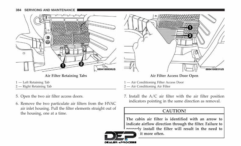
5. Open the two air filter access doors.
6. Remove the two particulate air filters from the HVACair inlet housing. Pull the filter elements straight out ofthe housing, one at a time.
7. Install the A/C air filter with the air filter positionindicators pointing in the same direction as removal.
CAUTION!
The cabin air filter is identified with an arrow toindicate airflow direction through the filter. Failure toproperly install the filter will result in the need toreplace it more often.
Air Filter Retaining Tabs
1 — Left Retaining Tab2 — Right Retaining Tab
Air Filter Access Door Open
1 — Air Conditioning Filter Access Door2 — Air Conditioning Air Filter
384 SERVICING AND MAINTENANCE

8. Close A/C Air Filter access doors and secure retainingtabs.
9. Rotate the glove compartment door back into position.
Refer to the “Maintenance Plan” for the proper mainte-nance intervals.
Body Lubrication
Locks and all body pivot points, including such items asseat tracks, door hinge pivot points and rollers, liftgate,tailgate, decklid, sliding doors and hood hinges, should belubricated periodically with a lithium based grease, such asMOPAR Spray White Lube to assure quiet, easy operationand to protect against rust and wear. Prior to the applica-tion of any lubricant, the parts concerned should be wipedclean to remove dust and grit; after lubricating excess oiland grease should be removed. Particular attention shouldalso be given to hood latching components to ensureproper function. When performing other underhood ser-vices, the hood latch, release mechanism and safety catchshould be cleaned and lubricated.
The external lock cylinders should be lubricated twice ayear, preferably in the Fall and Spring. Apply a smallamount of a high quality lubricant, such as MOPAR LockCylinder Lubricant directly into the lock cylinder.
Windshield Wiper Blades
Clean the rubber edges of the wiper blades and thewindshield periodically with a sponge or soft cloth and amild nonabrasive cleaner. This will remove accumulationsof salt or road film.
Operation of the wipers on dry glass for long periods maycause deterioration of the wiper blades. Always use washerfluid when using the wipers to remove salt or dirt from adry windshield.
Avoid using the wiper blades to remove frost or ice fromthe windshield. Keep the blade rubber out of contact withpetroleum products such as engine oil, gasoline, etc.
NOTE: Life expectancy of wiper blades varies dependingon geographical area and frequency of use. Poor perfor-mance of blades may be present with chattering, marks,water lines or wet spots. If any of these conditions arepresent, clean the wiper blades or replace as necessary.
The wiper blades and wiper arms should be inspectedperiodically, not just when wiper performance problemsare experienced. This inspection should include the follow-ing points:
• Wear Or Uneven Edges
• Foreign Material
8
SERVICING AND MAINTENANCE 385
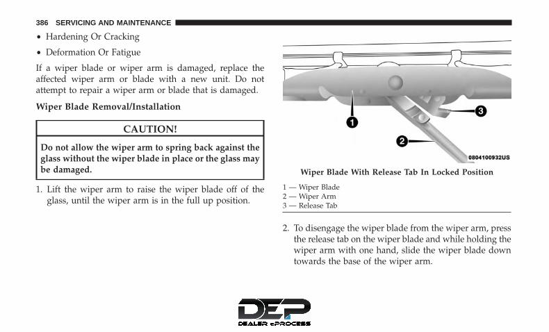
• Hardening Or Cracking
• Deformation Or Fatigue
If a wiper blade or wiper arm is damaged, replace theaffected wiper arm or blade with a new unit. Do notattempt to repair a wiper arm or blade that is damaged.
Wiper Blade Removal/Installation
CAUTION!
Do not allow the wiper arm to spring back against theglass without the wiper blade in place or the glass maybe damaged.
1. Lift the wiper arm to raise the wiper blade off of theglass, until the wiper arm is in the full up position.
2. To disengage the wiper blade from the wiper arm, pressthe release tab on the wiper blade and while holding thewiper arm with one hand, slide the wiper blade downtowards the base of the wiper arm.
Wiper Blade With Release Tab In Locked Position
1 — Wiper Blade2 — Wiper Arm3 — Release Tab
386 SERVICING AND MAINTENANCE

3. With the wiper blade disengaged, remove the wiperblade from the wiper arm.
4. Gently lower the wiper arm onto the glass.
Wiper Blade With Release Tab In Unlocked Position
1 — Wiper Blade2 — Wiper Arm3 — Release Tab
Wiper Blade Removed From Wiper Arm
1 — Wiper Blade2 — Wiper Arm3 — Release Tab
8
SERVICING AND MAINTENANCE 387

Installing The Front Wipers
1. Lift the wiper arm off of the glass, until the wiper arm isin the full up position.
2. Position the wiper blade near the hook on the tip of thewiper arm.
3. Insert the hook on the tip of the arm through theopening in the wiper blade.
4. Slide the wiper blade up into the hook on the wiper arm,latch engagement will be accompanied by an audibleclick.
5. Gently lower the wiper blade onto the glass.
Rear Wiper Blade Removal/Installation
1. Remove the rear wiper arm pivot cap To access thewiper arm nut.
Rear Wiper Assembly
1 — Wiper Arm Pivot Cap2 — Wiper Arm3 — Wiper Blade
388 SERVICING AND MAINTENANCE

2. To remove the wiper blade from the wiper arm, graspthe wiper blade nearest to wiper arm with your righthand. With your left hand hold the wiper arm as youpull the wiper blade away from the wiper arm past itsstop far enough to unsnap the wiper blade pivot pinfrom the receptacle on the end of the wiper arm.
NOTE: Resistance will be accompanied by an audiblesnap.
Wiper Blade Removed From Wiper Arm
1 — Wiper Arm2 — Wiper Blade
8
SERVICING AND MAINTENANCE 389

3. Still grasping the wiper blade, move the wiper bladeaway from the wiper arm to disengage.
Installing The Rear Wiper
1. Insert the wiper blade pivot pin into the opening on theend of the wiper arm. Grab the bottom end of the wiper
arm with one hand, and apply pressure to the wiperblade flush with the wiper arm until it snaps into place.
2. Lower the wiper blade onto the glass and snap thewiper arm pivot cap back into place.
Exhaust System
The best protection against carbon monoxide entry into thevehicle body is a properly maintained engine exhaustsystem.
If you notice a change in the sound of the exhaust system;or if the exhaust fumes can be detected inside the vehicle;or when the underside or rear of the vehicle is damaged;have an authorized technician inspect the complete ex-haust system and adjacent body areas for broken, dam-aged, deteriorated, or mispositioned parts. Open seams orloose connections could permit exhaust fumes to seep intothe passenger compartment. In addition, have the exhaustsystem inspected each time the vehicle is raised for lubri-cation or oil change. Replace as required.
Wiper Blade Removed From Wiper Arm
1 — Wiper Blade2 — Wiper Blade Pivot Pin3 — Wiper Arm Receptacle4 — Wiper Arm
390 SERVICING AND MAINTENANCE

WARNING!
• Exhaust gases can injure or kill. They contain carbonmonoxide (CO), which is colorless and odorless.Breathing it can make you unconscious and caneventually poison you. To avoid breathing CO, referto “Safety Tips” in “Safety” for further information.
• A hot exhaust system can start a fire if you park overmaterials that can burn. Such materials might begrass or leaves coming into contact with your exhaustsystem. Do not park or operate your vehicle in areaswhere your exhaust system can contact anything thatcan burn.
CAUTION!
• The catalytic converter requires the use of unleadedfuel only. Leaded gasoline will destroy the effective-ness of the catalyst as an emissions control deviceand may seriously reduce engine performance andcause serious damage to the engine.
• Damage to the catalytic converter can result if yourvehicle is not kept in proper operating condition. In
(Continued)
CAUTION! (Continued)the event of engine malfunction, particularly involv-ing engine misfire or other apparent loss of perfor-mance, have your vehicle serviced promptly. Contin-ued operation of your vehicle with a severemalfunction could cause the converter to overheat,resulting in possible damage to the converter andvehicle.
Under normal operating conditions, the catalytic converterwill not require maintenance. However, it is important tokeep the engine properly tuned to assure proper catalystoperation and prevent possible catalyst damage.
NOTE: Intentional tampering with emissions control sys-tems can result in civil penalties being assessed againstyou.
In unusual situations involving grossly malfunctioningengine operation, a scorching odor may suggest severe andabnormal catalyst overheating. If this occurs, stop thevehicle, turn off the engine and allow it to cool. Service,including a tune-up to manufacturer’s specifications,should be obtained immediately.
8
SERVICING AND MAINTENANCE 391

To minimize the possibility of catalytic converter damage:
• Do not interrupt the ignition when the transmission is ingear and the vehicle is in motion.
• Do not try to start the vehicle by pushing or towing thevehicle.
• Do not idle the engine with any ignition componentsdisconnected or removed, such as when diagnostictesting, or for prolonged periods during very rough idleor malfunctioning operating conditions.
Cooling System
WARNING!
• Turn vehicle off and disconnect the fan motor leadbefore working near the radiator cooling fan.
• You or others can be badly burned by hot enginecoolant (antifreeze) or steam from your radiator. Ifyou see or hear steam coming from under the hood,do not open the hood until the radiator has had timeto cool. Never open a cooling system pressure capwhen the radiator or coolant bottle is hot.
(Continued)
WARNING! (Continued)• Keep hands, tools, clothing, and jewelry away from
the radiator cooling fan when the hood is raised. Thefan starts automatically and may start at any time,whether the engine is running or not.
• When working near the radiator cooling fan, discon-nect the fan motor lead or turn the ignition to theOFF mode. The fan is temperature controlled and canstart at any time the ignition is in the ON mode.
• You or others can be badly burned by hot enginecoolant (antifreeze) or steam from your radiator. Ifyou see or hear steam coming from under the hood,do not open the hood until the radiator has had timeto cool. Never try to open a cooling system pressurecap when the radiator is hot.
Engine Coolant Checks
Check the engine coolant (antifreeze) protection every 12months (before the onset of freezing weather, where appli-cable). If the engine coolant (antifreeze) is dirty or rusty inappearance, the system should be drained, flushed andrefilled with fresh engine coolant (antifreeze). Check thefront of the A/C condenser (if equipped) or radiator forany accumulation of bugs, leaves, etc. If dirty, clean by
392 SERVICING AND MAINTENANCE

gently spraying water from a garden hose vertically downthe face of the A/C condenser (if equipped) or the back ofthe radiator core.
Check the engine cooling system hoses for brittle rubber,cracking, tears, cuts, and tightness of the connection at thecoolant recovery bottle and radiator. Inspect the entiresystem for leaks. DO NOT REMOVE THE COOLANTPRESSURE CAP WHEN THE COOLING SYSTEM IS HOT.
Cooling System — Drain, Flush And Refill
NOTE: Some vehicles require special tools to add coolantproperly. Failure to fill these systems properly could lead tosevere internal engine damage. If any coolant is needed tobe added to the system please contact your local autho-rized dealer.
If the engine coolant (antifreeze) is dirty or contains visiblesediment, have an authorized dealer clean and flush withOAT coolant (antifreeze) (conforming to MS.90032).
Refer to the “Maintenance Plan” in this section for theproper maintenance intervals.
Selection Of Coolant
Refer to “Fluids And Lubricants” in “Technical Specifica-tions” for further information.
CAUTION!
• Mixing of engine coolant (antifreeze) other thanspecified Organic Additive Technology (OAT) en-gine coolant (antifreeze), may result in engine dam-age and may decrease corrosion protection. OrganicAdditive Technology (OAT) engine coolant is differ-ent and should not be mixed with Hybrid OrganicAdditive Technology (HOAT) engine coolant (anti-freeze) or any “globally compatible” coolant (anti-freeze). If a non-OAT engine coolant (antifreeze) isintroduced into the cooling system in an emergency,the cooling system will need to be drained, flushed,and refilled with fresh OAT coolant (conforming toMS.90032), by an authorized dealer as soon as pos-sible.
(Continued)
8
SERVICING AND MAINTENANCE 393

CAUTION! (Continued)• Do not use water alone or alcohol-based engine
coolant (antifreeze) products. Do not use additionalrust inhibitors or antirust products, as they may notbe compatible with the radiator engine coolant andmay plug the radiator.
• This vehicle has not been designed for use withpropylene glycol-based engine coolant (antifreeze).Use of propylene glycol-based engine coolant (anti-freeze) is not recommended.
Adding Coolant
Your vehicle has been built with an improved enginecoolant (OAT coolant conforming to MS.90032) that allowsextended maintenance intervals. This engine coolant (anti-freeze) can be used up to ten years or 150,000 miles(240,000 km) before replacement. To prevent reducing thisextended maintenance period, it is important that you usethe same engine coolant (OAT coolant conforming toMS.90032) throughout the life of your vehicle.
Please review these recommendations for using OrganicAdditive Technology (OAT) engine coolant (antifreeze)that meets the requirements of FCA Material StandardMS.90032. When adding engine coolant (antifreeze):
• We recommend using MOPAR Antifreeze/Coolant 10Year/150,000 Mile (240,000 km) Formula OAT (OrganicAdditive Technology) that meets the requirements ofFCA Material Standard MS.90032.
• Mix a minimum solution of 50% OAT engine coolantthat meets the requirements of FCA Material StandardMS.90032 and distilled water. Use higher concentrations(not to exceed 70%) if temperatures below −34°F (−37°C)are anticipated.
• Use only high purity water such as distilled or deionizedwater when mixing the water/engine coolant (anti-freeze) solution. The use of lower quality water willreduce the amount of corrosion protection in the enginecooling system.
Please note that it is the owner’s responsibility to maintainthe proper level of protection against freezing according tothe temperatures occurring in the area where the vehicle isoperated.
394 SERVICING AND MAINTENANCE

NOTE:
• Some vehicles require special tools to add coolant prop-erly. Failure to fill these systems properly could lead tosevere internal engine damage. If any coolant is neededto be added to the system, please contact your localauthorized dealer.
• Mixing engine coolant (antifreeze) types is not recom-mended and can result in cooling system damage. IfHOAT and OAT coolant are mixed in an emergency,have a authorized dealer drain, flush, and refill withOAT coolant (conforming to MS.90032) as soon as pos-sible.
Cooling System Pressure Cap
The cap must be fully tightened to prevent loss of enginecoolant (antifreeze), and to ensure that engine coolant(antifreeze) will return to the radiator from the coolantrecovery tank.
The cap should be inspected and cleaned if there is anyaccumulation of foreign material on the sealing surfaces.
WARNING!
• Do not open hot engine cooling system. Never addengine coolant (antifreeze) when the engine is over-heated. Do not loosen or remove the cap to cool anoverheated engine. Heat causes pressure to build upin the cooling system. To prevent scalding or injury,do not remove the pressure cap while the system ishot or under pressure.
• Do not use a pressure cap other than the one speci-fied for your vehicle. Personal injury or enginedamage may result.
Disposal Of Used Coolant
Used ethylene glycol-based coolant (antifreeze) is a regu-lated substance requiring proper disposal. Check with yourlocal authorities to determine the disposal rules for yourcommunity. To prevent ingestion by animals or children,do not store ethylene glycol-based coolant in open contain-ers or allow it to remain in puddles on the ground. Ifingested by a child or pet, seek emergency assistanceimmediately. Clean up any ground spills immediately.
8
SERVICING AND MAINTENANCE 395

Coolant Level
The coolant bottle provides a quick visual method fordetermining that the coolant level is adequate. With theengine OFF and cold, the level of the engine coolant(antifreeze) in the bottle should be between the rangesindicated on the bottle.
The radiator normally remains completely full, so there isno need to remove the radiator/coolant pressure capunless checking for engine coolant (antifreeze) freeze pointor replacing coolant. Advise your service attendant of this.As long as the engine operating temperature is satisfactory,the coolant bottle need only be checked once a month.
When additional engine coolant (antifreeze) is needed tomaintain the proper level, only OAT coolant that meets therequirements of FCA Material Standard MS.90032 shouldbe added to the coolant bottle. Do not overfill.
Points To Remember
NOTE: When the vehicle is stopped after a few miles/kilometers of operation, you may observe vapor comingfrom the front of the engine compartment. This is normallya result of moisture from rain, snow, or high humidityaccumulating on the radiator and being vaporized whenthe thermostat opens, allowing hot engine coolant (anti-freeze) to enter the radiator.
If an examination of your engine compartment shows noevidence of radiator or hose leaks, the vehicle may besafely driven. The vapor will soon dissipate.
• Do not overfill the coolant expansion bottle.
• Check the coolant freeze point in the radiator and in thecoolant expansion bottle. If engine coolant (antifreeze)needs to be added, the contents of the coolant expansionbottle must also be protected against freezing.
• If frequent engine coolant (antifreeze) additions arerequired, the cooling system should be pressure testedfor leaks.
396 SERVICING AND MAINTENANCE

• Maintain engine coolant (antifreeze) concentration at aminimum of 50% OAT coolant (conforming toMS.90032) and distilled water for proper corrosion pro-tection of your engine which contains aluminum com-ponents.
• Make sure that the coolant expansion bottle overflowhoses are not kinked or obstructed.
• Keep the front of the radiator clean. If your vehicle isequipped with air conditioning, keep the front of thecondenser clean.
• Do not change the thermostat for Summer or Winteroperation. If replacement is ever necessary, install ONLYthe correct type thermostat. Other designs may result inunsatisfactory engine coolant (antifreeze) performance,poor gas mileage, and increased emissions.
Brake System
In order to assure brake system performance, all brakesystem components should be inspected periodically. Referto the “Maintenance Plan” in this section for the propermaintenance intervals.
WARNING!
Riding the brakes can lead to brake failure and possi-bly a collision. Driving with your foot resting or ridingon the brake pedal can result in abnormally high braketemperatures, excessive lining wear, and possiblebrake damage. You would not have your full brakingcapacity in an emergency.
Fluid Level Check — Brake Master Cylinder
The fluid level of the master cylinder should be checkedwhenever the vehicle is serviced, or immediately if thebrake system warning light is on. If necessary, add fluid tobring level to the full mark on the side of the reservoir ofthe brake master cylinder. Be sure to clean the top of themaster cylinder area before removing cap. With discbrakes, fluid level can be expected to fall as the brake padswear. Brake fluid level should be checked when pads arereplaced. If the brake fluid is abnormally low, check systemfor leaks.
Refer to “Fluids And Lubricants” in “Technical Specifica-tions” for further information.
8
SERVICING AND MAINTENANCE 397

WARNING!
• Use only manufacturer’s recommended brake fluid.Refer to “Fluids And Lubricants” in “TechnicalSpecifications” for further information. Using thewrong type of brake fluid can severely damage yourbrake system and/or impair its performance. Theproper type of brake fluid for your vehicle is alsoidentified on the original factory installed hydraulicmaster cylinder reservoir.
• To avoid contamination from foreign matter or mois-ture, use only new brake fluid or fluid that has beenin a tightly closed container. Keep the master cylin-der reservoir cap secured at all times. Brake fluid ina open container absorbs moisture from the airresulting in a lower boiling point. This may cause itto boil unexpectedly during hard or prolonged brak-ing, resulting in sudden brake failure. This couldresult in a collision.
• Overfilling the brake fluid reservoir can result inspilling brake fluid on hot engine parts, causing thebrake fluid to catch fire. Brake fluid can also damagepainted and vinyl surfaces, care should be taken toavoid its contact with these surfaces.
(Continued)
WARNING! (Continued)• Do not allow petroleum based fluid to contaminate
the brake fluid. Brake seal components could bedamaged, causing partial or complete brake failure.This could result in a collision.
Front/Rear Axle Fluid
For normal service, periodic fluid level checks are notrequired. When the vehicle is serviced for other reasons theexterior surfaces of the axle assembly should be inspected.If gear oil leakage is suspected inspect the fluid level. Referto “Fluids And Lubricants” in “Technical Specifications”for further information.
Fluid Level Check
Lubricant should be at the bottom edge of the oil fill hole.
Adding Fluid
Add lubricant only at the fill hole and only to the levelspecified above.
Selection Of Lubricant
Use only the manufacturer’s recommended fluid. Refer to“Fluids And Lubricants” in “Technical Specifications” forfurther information.
398 SERVICING AND MAINTENANCE

Transfer Case
Fluid Level Check
The fluid level should be to the bottom edge of the fill hole(A) when the vehicle is in a level position.
Adding Fluid
Add fluid at the filler hole, until it runs out of the hole,when the vehicle is in a level position.
Drain
First remove the fill plug (B), then the drain plug (C). Therecommended tightening torque for the drain and fill plugsis 15 to 25 ft lbs (20 to 34 N·m).
CAUTION!
When replacing the plugs, do not overtighten them.You could damage them and cause them to leak.
Selection Of Lubricant
Use only the manufacturer’s recommended fluid. Refer to“Fluids And Lubricants” in “Technical Specifications” forfurther information.
Automatic Transmission
Selection Of Lubricant
It is important to use the proper transmission fluid toensure optimum transmission performance and life. Useonly the manufacturer’s specified transmission fluid. Referto “Fluids And Lubricants” in “Technical Specifications”for fluid specifications. It is important to maintain thetransmission fluid at the correct level using the recom-mended fluid.
Transfer Case
8
SERVICING AND MAINTENANCE 399

NOTE: No chemical flushes should be used in any trans-mission; only the approved lubricant should be used.
CAUTION!
Using a transmission fluid other than the manufactur-er’s recommended fluid may cause deterioration intransmission shift quality and/or torque convertershudder, and will require more frequent fluid andfilter changes. Refer to “Fluids and Lubricants” in“Technical Specifications” for fluid specifications.
Special Additives
The manufacturer strongly recommends against using anyspecial additives in the transmission. Automatic Transmis-sion Fluid (ATF) is an engineered product and its perfor-mance may be impaired by supplemental additives. There-fore, do not add any fluid additives to the transmission.The only exception to this policy is the use of special dyesfor diagnosing fluid leaks. Avoid using transmission seal-ers as they may adversely affect seals.
CAUTION!
Do not use chemical flushes in your transmission asthe chemicals can damage your transmission compo-nents. Such damage is not covered by the New VehicleLimited Warranty.
Fluid Level Check
It is best to check the fluid level when the transmission isat normal operating temperature (approximately 180°F/82°C). This occurs after at least 15 miles (25 km) of driving.At normal operating temperature, the fluid cannot be heldcomfortably between the fingertips.
Use the following procedure to check the transmissionfluid level properly:
1. Park the vehicle on level ground.
2. Remove the engine cover by pulling it up off themounting studs (two in the front and two in the rear).
3. Run the engine at normal idle speed for at least 60seconds, and leave the engine running for the rest of thisprocedure.
4. Fully apply the parking brake, and press the brakepedal.
400 SERVICING AND MAINTENANCE

5. Place the gear selector momentarily into each gearposition (allowing time for the transmission to fullyengage in each position), ending with the transmissionin PARK.
6. Remove the dipstick, wipe it clean and reinsert it untilseated.
7. Remove the dipstick again and note the fluid level onboth sides. The fluid level reading is only valid if thereis a solid coating of oil on both sides of the dipstick.Note that the holes in the dipstick will be full of fluid ifthe actual level is at or above the hole. The fluid levelshould be between the HOT (upper) reference holes onthe dipstick at normal operating temperature. If thefluid level is low, add fluid through the dipstick tube tobring it to the proper level. Do not overfill. Use ONLYthe specified fluid (refer to �Fluids And Lubricants�under “Technical Specifications” for fluid specifica-tions). After adding any quantity of oil through thedipstick tube, wait a minimum of two minutes for the oilto fully drain into the transmission before recheckingthe fluid level.
NOTE:
• The holes in the dipstick will be full of fluid if theactual level is at or above the hole.
• If it is necessary to check the transmission below theoperating temperature, the fluid level should be be-tween the two COLD (lower) holes on the dipstickwith the fluid at approximately 80°F (27°C). If the fluidlevel is correctly established at 80° F (27°C), it shouldbe between the HOT (upper) reference holes when thetransmission reaches 180° F (82°C). Remember it is bestto check the level at the normal operating temperature.
CAUTION!
If the fluid temperature is below 50°F (10°C) it may notregister on the dipstick. Do not add fluid until thetemperature is elevated enough to produce an accuratereading. Run the engine at idle, in PARK, to warm thefluid.
8. Reinstall the engine cover and snap it down securelyonto the four mounting studs.
9. Check for leaks. Release the parking brake.
8
SERVICING AND MAINTENANCE 401

NOTE: To prevent dirt and water from entering thetransmission after checking or replenishing fluid, makesure that the dipstick cap is properly reseated. It is normalfor the dipstick cap to spring back slightly from its fullyseated position, as long as its seal remains engaged in thedipstick tube.
Fluid And Filter Changes
Refer to the “Maintenance Plan” for the proper mainte-nance intervals.
In addition, change the fluid and filter if the fluid becomescontaminated (with water, etc.), or if the transmission isdisassembled for any reason.
Manual Transmission — If Equipped
Selection Of Lubricant
Use only manufacturer’s recommended manual transmis-sion fluid. Refer to “Fluids And Lubricants” in “TechnicalSpecifications” for further information.
Fluid Level Check
Check the fluid level by removing the fill plug. The fluidlevel should be between the bottom of the fill hole and apoint not more than 3/16 of an inch (4.76 mm) below thebottom of the hole.
Add fluid, if necessary, to maintain the proper level.
Frequency Of Fluid Change
Under normal operating conditions, the fluid installed atthe factory will give satisfactory lubrication for the life ofthe vehicle. If the fluid becomes contaminated with water,it should be changed immediately. Otherwise, change thefluid as recommended in the Maintenance Plan. Refer tothe “Maintenance Plan” for the proper maintenance inter-vals.
RAISING THE VEHICLE
In the case where it is necessary to raise the vehicle, go toan authorized dealer or service station.
TIRES
Tire Safety Information
Tire safety information will cover aspects of the followinginformation: Tire Markings, Tire Identification Numbers,Tire Terminology and Definitions, Tire Pressures, and TireLoading.
402 SERVICING AND MAINTENANCE

Tire Markings NOTE:
• P (Passenger) — Metric tire sizing is based on U.S.design standards. P-Metric tires have the letter “P”molded into the sidewall preceding the size designation.Example: P215/65R15 95H.
• European — Metric tire sizing is based on Europeandesign standards. Tires designed to this standard havethe tire size molded into the sidewall beginning with thesection width. The letter �P� is absent from this tire sizedesignation. Example: 215/65R15 96H.
• LT (Light Truck) — Metric tire sizing is based on U.S.design standards. The size designation for LT-Metrictires is the same as for P-Metric tires except for the letters“LT” that are molded into the sidewall preceding thesize designation. Example: LT235/85R16.
• Temporary spare tires are designed for temporary emer-gency use only. Temporary high pressure compact sparetires have the letter “T” or “S” molded into the sidewallpreceding the size designation. Example: T145/80D18103M.
• High flotation tire sizing is based on U.S. design stan-dards and it begins with the tire diameter molded intothe sidewall. Example: 31x10.5 R15 LT.
Tire Markings
1 — U.S. DOT SafetyStandards Code (TIN)
4 — Maximum Load
2 — Size Designation 5 — Maximum Pressure3 — Service Description 6 — Treadwear, Traction
and Temperature Grades
8
SERVICING AND MAINTENANCE 403

Tire Identification Number (TIN)
The TIN may be found on one or both sides of the tire;however, the date code may only be on one side. Tires withwhite sidewalls will have the full TIN, including the datecode, located on the white sidewall side of the tire. Look for
the TIN on the outboard side of black sidewall tires asmounted on the vehicle. If the TIN is not found on theoutboard side, then you will find it on the inboard side ofthe tire.
EXAMPLE:DOT MA L9 ABCD 0301
DOT = Department of Transportation– This symbol certifies that the tire is in compliance with the U.S. Department of Transportation tire safetystandards and is approved for highway use
MA = Code representing the tire manufacturing location (two digits)L9 = Code representing the tire size (two digits)ABCD = Code used by the tire manufacturer (one to four digits)03 = Number representing the week in which the tire was manufactured (two digits)
– 03 means the 3rd week01 = Number representing the year in which the tire was manufactured (two digits)
– 01 means the year 2001– Prior to July 2000, tire manufacturers were only required to have one number to represent the year inwhich the tire was manufactured. Example: 031 could represent the 3rd week of 1981 or 1991
404 SERVICING AND MAINTENANCE

Tire Terminology And Definitions
Term DefinitionB-Pillar The vehicle B-Pillar is the structural member of the body located be-
hind the front door.Cold Tire Inflation Pressure Cold tire inflation pressure is defined as the tire pressure after the
vehicle has not been driven for at least three hours, or driven lessthan 1 mile (1.6 km) after sitting for a minimum of three hours. In-flation pressure is measured in units of PSI (pounds per square inch)or kPa (kilopascals).
Maximum Inflation Pressure The maximum inflation pressure is the maximum permissible coldtire inflation pressure for this tire. The maximum inflation pressure ismolded into the sidewall.
Recommended Cold Tire Inflation Pressure Vehicle manufacturer’s recommended cold tire inflation pressure asshown on the tire placard.
Tire Placard A label permanently attached to the vehicle describing the vehicle’sloading capacity, the original equipment tire sizes and the recom-mended cold tire inflation pressures.
8
SERVICING AND MAINTENANCE 405

Tire Loading And Tire Pressure
NOTE: The proper cold tire inflation pressure is listed onthe driver’s side B-Pillar or the rear edge of the driver’sside door.
Example Tire Placard Location (Door)
Example Tire Placard Location (B-Pillar)
406 SERVICING AND MAINTENANCE

Tire And Loading Information Placard
This placard tells you important information about the:
1. Number of people that can be carried in the vehicle.
2. Total weight your vehicle can carry.
3. Tire size designed for your vehicle.
4. Cold tire inflation pressures for the front, rear, and sparetires.
Loading
The vehicle maximum load on the tire must not exceed theload carrying capacity of the tire on your vehicle. You willnot exceed the tire’s load carrying capacity if you adhere tothe loading conditions, tire size, and cold tire inflationpressures specified on the Tire and Loading Informationplacard in “Vehicle Loading” in the “Starting And Operat-ing” section of this manual.
NOTE: Under a maximum loaded vehicle condition, grossaxle weight ratings (GAWRs) for the front and rear axlesmust not be exceeded.
For further information on GAWRs, vehicle loading, andtrailer towing, refer to “Vehicle Loading” in the “StartingAnd Operating” section of this manual.
To determine the maximum loading conditions of yourvehicle, locate the statement “The combined weight ofoccupants and cargo should never exceed XXX kg orXXX lbs” on the Tire and Loading Information placard. Thecombined weight of occupants, cargo/luggage and trailertongue weight (if applicable) should never exceed theweight referenced here.
Tire And Loading Information Placard8
SERVICING AND MAINTENANCE 407

Steps For Determining Correct Load Limit—
(1) Locate the statement “The combined weight ofoccupants and cargo should never exceed XXX kg orXXX lbs.” on your vehicle’s placard.
(2) Determine the combined weight of the driver andpassengers that will be riding in your vehicle.
(3) Subtract the combined weight of the driver andpassengers from XXX kg or XXX lbs.
(4) The resulting figure equals the available amount ofcargo and luggage load capacity. For example, if “XXX”amount equals 1400 lbs. and there will be five 150 lbpassengers in your vehicle, the amount of availablecargo and luggage load capacity is 650 lbs. (1400-750(5x150) = 650 lbs.)
(5) Determine the combined weight of luggage andcargo being loaded on the vehicle. That weight may notsafely exceed the available cargo and luggage loadcapacity calculated in Step 4.
(6) If your vehicle will be towing a trailer, load fromyour trailer will be transferred to your vehicle. Consult
this manual to determine how this reduces the availablecargo and luggage load capacity of your vehicle.
Metric Example For Load Limit
For example, if “XXX” amount equals 635 kg and there willbe five 68 kg passengers in your vehicle, the amount ofavailable cargo and luggage load capacity is 295 kg (635-340 (5x68) = 295 kg) as shown in step 4.
NOTE:
• If your vehicle will be towing a trailer, load from yourtrailer will be transferred to your vehicle. The followingtable shows examples on how to calculate total load,cargo/luggage, and towing capacities of your vehiclewith varying seating configurations and number andsize of occupants. This table is for illustration purposesonly and may not be accurate for the seating and loadcarry capacity of your vehicle.
• For the following example, the combined weight ofoccupants and cargo should never exceed 865 lbs(392 kg).
408 SERVICING AND MAINTENANCE

WARNING!
Overloading of your tires is dangerous. Overloadingcan cause tire failure, affect vehicle handling, andincrease your stopping distance. Use tires of the rec-ommended load capacity for your vehicle. Never over-load them.
8
SERVICING AND MAINTENANCE 409

Tires — General Information
Tire Pressure
Proper tire inflation pressure is essential to the safe andsatisfactory operation of your vehicle. Four primary areasare affected by improper tire pressure:
• Safety and Vehicle Stability
• Economy
• Tread Wear
• Ride Comfort
Safety
WARNING!
• Improperly inflated tires are dangerous and cancause collisions.
• Underinflation increases tire flexing and can resultin overheating and tire failure.
• Overinflation reduces a tire’s ability to cushionshock. Objects on the road and chuckholes can causedamage that result in tire failure.
(Continued)
WARNING! (Continued)• Overinflated or underinflated tires can affect vehicle
handling and can fail suddenly, resulting in loss ofvehicle control.
• Unequal tire pressures can cause steering problems.You could lose control of your vehicle.
• Unequal tire pressures from one side of the vehicleto the other can cause the vehicle to drift to the rightor left.
• Always drive with each tire inflated to the recom-mended cold tire inflation pressure.
Both under-inflation and over-inflation affect the stabilityof the vehicle and can produce a feeling of sluggishresponse or over responsiveness in the steering.
NOTE:
• Unequal tire pressures from side to side may causeerratic and unpredictable steering response.
• Unequal tire pressure from side to side may cause thevehicle to drift left or right.
410 SERVICING AND MAINTENANCE

Fuel Economy
Underinflated tires will increase tire rolling resistanceresulting in higher fuel consumption.
Tread Wear
Improper cold tire inflation pressures can cause abnormalwear patterns and reduced tread life, resulting in the needfor earlier tire replacement.
Ride Comfort And Vehicle Stability
Proper tire inflation contributes to a comfortable ride.Over-inflation produces a jarring and uncomfortable ride.
Tire Inflation Pressures
The proper cold tire inflation pressure is listed on thedriver’s side B-Pillar or rear edge of the driver’s side door.
At least once a month:
• Check and adjust tire pressure with a good qualitypocket-type pressure gauge. Do not make a visualjudgement when determining proper inflation. Tiresmay look properly inflated even when they are under-inflated.
• Inspect tires for signs of tire wear or visible damage.
CAUTION!
After inspecting or adjusting the tire pressure, alwaysreinstall the valve stem cap. This will prevent moistureand dirt from entering the valve stem, which coulddamage the valve stem.
Inflation pressures specified on the placard are always“cold tire inflation pressure”. Cold tire inflation pressure isdefined as the tire pressure after the vehicle has not beendriven for at least three hours, or driven less than 1 mile(1.6 km) after sitting for a minimum of three hours. Thecold tire inflation pressure must not exceed the maximuminflation pressure molded into the tire sidewall.
Check tire pressures more often if subject to a wide rangeof outdoor temperatures, as tire pressures vary with tem-perature changes.
Tire pressures change by approximately 1 psi (7 kPa) per12°F (7°C) of air temperature change. Keep this in mindwhen checking tire pressure inside a garage, especially inthe Winter.
Example: If garage temperature = 68°F (20°C) and theoutside temperature = 32°F (0°C) then the cold tire inflation
8
SERVICING AND MAINTENANCE 411

pressure should be increased by 3 psi (21 kPa), whichequals 1 psi (7 kPa) for every 12°F (7°C) for this outsidetemperature condition.
Tire pressure may increase from 2 to 6 psi (13 to 40 kPa)during operation. DO NOT reduce this normal pressurebuild up or your tire pressure will be too low.
Tire Pressures For High Speed Operation
The manufacturer advocates driving at safe speeds andwithin posted speed limits. Where speed limits or condi-tions are such that the vehicle can be driven at high speeds,maintaining correct tire inflation pressure is very impor-tant. Increased tire pressure and reduced vehicle loadingmay be required for high-speed vehicle operation. Refer toyour authorized tire dealer or original equipment vehicledealer for recommended safe operating speeds, loadingand cold tire inflation pressures.
WARNING!
High speed driving with your vehicle under maximumload is dangerous. The added strain on your tires couldcause them to fail. You could have a serious collision.Do not drive a vehicle loaded to the maximum capacityat continuous speeds above 75 mph (120 km/h).
Radial Ply Tires
WARNING!
Combining radial ply tires with other types of tires onyour vehicle will cause your vehicle to handle poorly.The instability could cause a collision. Always useradial ply tires in sets of four. Never combine themwith other types of tires.
Tire Repair
If your tire becomes damaged, it may be repaired if it meetsthe following criteria:
• The tire has not been driven on when flat.
• The damage is only on the tread section of your tire(sidewall damage is not repairable).
• The puncture is no greater than a ¼ of an inch (6 mm).
Consult an authorized tire dealer for tire repairs andadditional information.
Damaged Run Flat tires, or Run Flat tires that haveexperienced a loss of pressure should be replaced immedi-ately with another Run Flat tire of identical size and servicedescription (Load Index and Speed Symbol).
412 SERVICING AND MAINTENANCE
Run Flat Tires — If Equipped
Run Flat tires allow you the capability to drive 50 miles(80 km) at 50 mph (80 km/h) after a rapid loss of inflationpressure. This rapid loss of inflation is referred to as theRun Flat mode. A Run Flat mode occurs when the tireinflation pressure is of/or below 14 psi (96 kPa). Once aRun Flat tire reaches the run flat mode it has limiteddriving capabilities and needs to be replaced immediately.A Run Flat tire is not repairable.
It is not recommended driving a vehicle loaded at fullcapacity or to tow a trailer while a tire is in the run flatmode.
See the tire pressure monitoring section for more informa-tion.
Tire Spinning
When stuck in mud, sand, snow, or ice conditions, do notspin your vehicle’s wheels above 30 mph (48 km/h) or forlonger than 30 seconds continuously without stopping.
Refer to “Freeing A Stuck Vehicle” in “In Case Of Emer-gency” for further information.
WARNING!
Fast spinning tires can be dangerous. Forces generatedby excessive wheel speeds may cause tire damage orfailure. A tire could explode and injure someone. Donot spin your vehicle’s wheels faster than 30 mph(48 km/h) for more than 30 seconds continuously whenyou are stuck, and do not let anyone near a spinningwheel, no matter what the speed.
Tread Wear Indicators
Tread wear indicators are in the original equipment tires tohelp you in determining when your tires should be re-placed.
8
SERVICING AND MAINTENANCE 413

These indicators are molded into the bottom of the treadgrooves. They will appear as bands when the tread depthbecomes a 1/16 of an inch (1.6 mm). When the tread isworn to the tread wear indicators, the tire should bereplaced. Refer to “Replacement Tires” in this section forfurther information.
Life Of Tire
The service life of a tire is dependent upon varying factorsincluding, but not limited to:
• Driving style.
• Tire pressure - Improper cold tire inflation pressures cancause uneven wear patterns to develop across the tiretread. These abnormal wear patterns will reduce treadlife, resulting in the need for earlier tire replacement.
• Distance driven.
• Performance tires, tires with a speed rating of V orhigher, and Summer tires typically have a reduced treadlife. Rotation of these tires per the vehicle maintenanceschedule is highly recommended.
WARNING!
Tires and the spare tire should be replaced after sixyears, regardless of the remaining tread. Failure tofollow this warning can result in sudden tire failure.You could lose control and have a collision resulting inserious injury or death.
Tire Tread
1 — Worn Tire2 — New Tire
414 SERVICING AND MAINTENANCE

Keep dismounted tires in a cool, dry place with as littleexposure to light as possible. Protect tires from contact withoil, grease, and gasoline.
Replacement Tires
The tires on your new vehicle provide a balance of manycharacteristics. They should be inspected regularly forwear and correct cold tire inflation pressures. The manu-facturer strongly recommends that you use tires equivalentto the originals in size, quality and performance whenreplacement is needed. Refer to the paragraph on “TreadWear Indicators” in this section. Refer to the Tire andLoading Information placard or the Vehicle CertificationLabel for the size designation of your tire. The Load Indexand Speed Symbol for your tire will be found on theoriginal equipment tire sidewall.
See the Tire Sizing Chart example found in the “Tire SafetyInformation” section of this manual for more informationrelating to the Load Index and Speed Symbol of a tire.
It is recommended to replace the two front tires or two reartires as a pair. Replacing just one tire can seriously affectyour vehicle’s handling. If you ever replace a wheel, makesure that the wheel’s specifications match those of theoriginal wheels.
It is recommended you contact your authorized tire dealeror original equipment dealer with any questions you mayhave on tire specifications or capability. Failure to useequivalent replacement tires may adversely affect thesafety, handling, and ride of your vehicle.
WARNING!
• Do not use a tire, wheel size, load rating, or speedrating other than that specified for your vehicle.Some combinations of unapproved tires and wheelsmay change suspension dimensions and perfor-mance characteristics, resulting in changes to steer-ing, handling, and braking of your vehicle. This cancause unpredictable handling and stress to steeringand suspension components. You could lose controland have a collision resulting in serious injury ordeath. Use only the tire and wheel sizes with loadratings approved for your vehicle.
• Never use a tire with a smaller load index or capacity,other than what was originally equipped on yourvehicle. Using a tire with a smaller load index couldresult in tire overloading and failure. You could losecontrol and have a collision.
(Continued)
8
SERVICING AND MAINTENANCE 415

WARNING! (Continued)• Failure to equip your vehicle with tires having ad-
equate speed capability can result in sudden tirefailure and loss of vehicle control.
CAUTION!
Replacing original tires with tires of a different sizemay result in false speedometer and odometer read-ings.
Tire Types
All Season Tires — If Equipped
All Season tires provide traction for all seasons (Spring,Summer, Fall, and Winter). Traction levels may vary be-tween different all season tires. All season tires can beidentified by the M+S, M&S, M/S or MS designation on thetire sidewall. Use all season tires only in sets of four; failureto do so may adversely affect the safety and handling ofyour vehicle.
Summer Or Three Season Tires — If Equipped
Summer tires provide traction in both wet and dry condi-tions, and are not intended to be driven in snow or on ice.If your vehicle is equipped with Summer tires, be awarethese tires are not designed for Winter or cold drivingconditions. Install Winter tires on your vehicle when am-bient temperatures are less than 40°F (5°C) or if roads arecovered with ice or snow. For more information, contact anauthorized dealer.
Summer tires do not contain the all season designation ormountain/snowflake symbol on the tire sidewall. UseSummer tires only in sets of four; failure to do so mayadversely affect the safety and handling of your vehicle.
WARNING!
Do not use Summer tires in snow/ice conditions. Youcould lose vehicle control, resulting in severe injury ordeath. Driving too fast for conditions also creates thepossibility of loss of vehicle control.
416 SERVICING AND MAINTENANCE

Snow Tires
Some areas of the country require the use of snow tiresduring the Winter. Snow tires can be identified by a“mountain/snowflake” symbol on the tire sidewall.
If you need snow tires, select tiresequivalent in size and type to the origi-nal equipment tires. Use snow tires onlyin sets of four; failure to do so mayadversely affect the safety and handlingof your vehicle.
Snow tires generally have lower speed ratings than whatwas originally equipped with your vehicle and should notbe operated at sustained speeds over 75 mph (120 km/h).For speeds above 75 mph (120 km/h) refer to originalequipment or an authorized tire dealer for recommendedsafe operating speeds, loading and cold tire inflationpressures.
While studded tires improve performance on ice, skid andtraction capability on wet or dry surfaces may be poorerthan that of non-studded tires. Some states prohibit stud-ded tires; therefore, local laws should be checked beforeusing these tire types.
Spare Tires — If Equipped
NOTE: For vehicles equipped with Tire Service Kit insteadof a spare tire, please refer to “Tire Service Kit” in “In CaseOf Emergency” for further information.
CAUTION!
Because of the reduced ground clearance, do not takeyour vehicle through an automatic car wash with acompact or limited use temporary spare installed.Damage to the vehicle may result.
Spare Tire Matching Original Equipped Tire AndWheel — If Equipped
Your vehicle may be equipped with a spare tire and wheelequivalent in look and function to the original equipmenttire and wheel found on the front or rear axle of yourvehicle. This spare tire may be used in the tire rotation foryour vehicle. If your vehicle has this option, refer to anauthorized tire dealer for the recommended tire rotationpattern.
Compact Spare Tire — If Equipped
The compact spare is for temporary emergency use only.You can identify if your vehicle is equipped with a compact
8
SERVICING AND MAINTENANCE 417
spare by looking at the spare tire description on the Tireand Loading Information Placard located on the driver’sside door opening or on the sidewall of the tire. Compactspare tire descriptions begin with the letter “T” or “S”preceding the size designation. Example: T145/80D18103M.
T, S = Temporary Spare Tire
Since this tire has limited tread life, the original equipmenttire should be repaired (or replaced) and reinstalled onyour vehicle at the first opportunity.
Do not install a wheel cover or attempt to mount aconventional tire on the compact spare wheel, since thewheel is designed specifically for the compact spare tire.Do not install more than one compact spare tire and wheelon the vehicle at any given time.
WARNING!
Compact and collapsible spares are for temporaryemergency use only. With these spares, do not drivemore than 50 mph (80 km/h). Temporary use spareshave limited tread life. When the tread is worn to thetread wear indicators, the temporary use spare tire
(Continued)
WARNING! (Continued)needs to be replaced. Be sure to follow the warnings,which apply to your spare. Failure to do so could resultin spare tire failure and loss of vehicle control.
Full Size Spare — If Equipped
The full size spare is for temporary emergency use only.This tire may look like the originally equipped tire on thefront or rear axle of your vehicle, but it is not. This sparetire may have limited tread life. When the tread is worn tothe tread wear indicators, the temporary use full size sparetire needs to be replaced. Since it is not the same as youroriginal equipment tire, replace (or repair) the originalequipment tire and reinstall on the vehicle at the firstopportunity.
Limited Use Spare — If Equipped
The limited use spare tire is for temporary emergency useonly. This tire is identified by a label located on the limiteduse spare wheel. This label contains the driving limitationsfor this spare. This tire may look like the original equippedtire on the front or rear axle of your vehicle, but it is not.Installation of this limited use spare tire affects vehicle
418 SERVICING AND MAINTENANCE

handling. Since it is not the same as your original equip-ment tire, replace (or repair) the original equipment tireand reinstall on the vehicle at the first opportunity.
WARNING!
Limited use spares are for emergency use only. Instal-lation of this limited use spare tire affects vehiclehandling. With this tire, do not drive more than thespeed listed on the limited use spare wheel. Keepinflated to the cold tire inflation pressures listed onyour Tire and Loading Information Placard located onthe driver’s side B-Pillar or the rear edge of the driver’sside door. Replace (or repair) the original equipmenttire at the first opportunity and reinstall it on yourvehicle. Failure to do so could result in loss of vehiclecontrol.
Wheel And Wheel Trim Care
All wheels and wheel trim, especially aluminum andchrome plated wheels, should be cleaned regularly usingmild (neutral Ph) soap and water to maintain their lusterand to prevent corrosion. Wash wheels with the same soapsolution recommended for the body of the vehicle.
Your wheels are susceptible to deterioration caused by salt,sodium chloride, magnesium chloride, calcium chloride,etc., and other road chemicals used to melt ice or controldust on dirt roads. Use a soft cloth or sponge and mild soapto wipe away promptly. Do not use harsh chemicals or astiff brush. They can damage the wheel’s protective coatingthat helps keep them from corroding and tarnishing.
NOTE: Many aftermarket wheel cleaners contain strongacids or strong alkaline additives that can harm the wheelsurface.
CAUTION!
Avoid products or automatic car washes that use acidicsolutions or strong alkaline additives or harsh brushes.These products and automatic car washes may damagethe wheel’s protective finish. Such damage is notcovered by the New Vehicle Limited Warranty. Onlycar wash soap, MOPAR Wheel Cleaner or equivalent isrecommended.
When cleaning extremely dirty wheels including excessivebrake dust, care must be taken in the selection of tire andwheel cleaning chemicals and equipment to prevent dam-age to the wheels. Mopar Wheel Treatment or MoparChrome Cleaner or their equivalent is recommended or
8
SERVICING AND MAINTENANCE 419

select a non-abrasive, non-acidic cleaner for aluminum orchrome wheels. Do not use any products on Dark Vapor orBlack Satin Chrome Wheels. They will permanently dam-age this finish and such damage is not covered by the NewVehicle Limited Warranty.
CAUTION!
Do not use scouring pads, steel wool, a bristle brush,metal polishes or oven cleaner. These products maydamage the wheel’s protective finish. Such damage isnot covered by the New Vehicle Limited Warranty.Only car wash soap, MOPAR Wheel Cleaner or equiva-lent is recommended.
NOTE: If you intend parking or storing your vehicle for anextended period after cleaning the wheels with wheelcleaner, drive your vehicle for a few minutes before doingso. Driving the vehicle and applying the brakes whenstopping will reduce the risk of brake rotor corrosion.
Dark Vapor Or Black Satin Chrome Wheels
CAUTION!
If your vehicle is equipped with Dark Vapor or BlackSatin Chrome wheels DO NOT USE wheel cleaners,abrasives or polishing compounds. They will perma-nently damage this finish and such damage is notcovered by the New Vehicle Limited Warranty. USEONLY MILD SOAP AND WATER WITH A SOFTCLOTH. Used on a regular basis; this is all that isrequired to maintain this finish.
Tire Chains (Traction Devices)
Use of traction devices require sufficient tire-to-body clear-ance. Follow these recommendations to guard againstdamage.
• Traction device must be of proper size for the tire, asrecommended by the traction device manufacturer.
• Install on Rear Tires Only.
• P225/75R16 or a P235/65R17 tire with the use of atraction device that meets the SAE type “Class S”specification is recommended.
420 SERVICING AND MAINTENANCE

WARNING!
Using tires of different size and type (M+S, Snow)between front and rear axles can cause unpredictablehandling. You could lose control and have a collision.
CAUTION!
To avoid damage to your vehicle or tires, observe thefollowing precautions:• Because of restricted traction device clearance be-
tween tires and other suspension components, it isimportant that only traction devices in good condi-tion are used. Broken devices can cause seriousdamage. Stop the vehicle immediately if noise occursthat could indicate device breakage. Remove thedamaged parts of the device before further use.
• Install device as tightly as possible and then re-tighten after driving about ½ mile (0.8 km).
• Do not exceed 30 mph (48 km/h).• Drive cautiously and avoid severe turns and large
bumps, especially with a loaded vehicle.• Do not drive for a prolonged period on dry pave-
ment.
(Continued)
CAUTION! (Continued)• Observe the traction device manufacturer’s instruc-
tions on the method of installation, operating speed,and conditions for use. Always use the suggestedoperating speed of the device manufacturer’s if it isless than 30 mph (48 km/h).
• Do not use traction devices on a compact spare tire.
Tire Rotation Recommendations
The tires on the front and rear of your vehicle operate atdifferent loads and perform different steering, handling,and braking functions. For these reasons, they wear atunequal rates.
These effects can be reduced by timely rotation of tires. Thebenefits of rotation are especially worthwhile with aggres-sive tread designs such as those on On/Off Road type tires.Rotation will increase tread life, help to maintain mud,snow, and wet traction levels, and contribute to a smooth,quiet ride.
Refer to the “Maintenance Plan” for the proper mainte-nance intervals. The reasons for any rapid or unusual wearshould be corrected prior to rotation being performed.
8
SERVICING AND MAINTENANCE 421

The suggested rotation method is the “rearward-cross”shown in the following diagram.
CAUTION!
Proper operation of four-wheel drive vehicles dependson tires of equal size, type and circumference on eachwheel. Any difference in tire size can cause damage tothe transfer case. Tire rotation schedule should befollowed to balance tire wear.
DEPARTMENT OF TRANSPORTATION UNIFORMTIRE QUALITY GRADES
The following tire grading categories were establishedby the National Highway Traffic Safety Administration.The specific grade rating assigned by the tire’s manu-facturer in each category is shown on the sidewall of thetires on your vehicle.
All passenger vehicle tires must conform to Federalsafety requirements in addition to these grades.
Treadwear
The Treadwear grade is a comparative rating, based onthe wear rate of the tire when tested under controlledconditions on a specified government test course. Forexample, a tire graded 150 would wear one and one-halftimes as well on the government course as a tire graded100. The relative performance of tires depends upon theactual conditions of their use, however, and may departsignificantly from the norm due to variations in drivinghabits, service practices, and differences in road charac-teristics and climate.
Traction Grades
The Traction grades, from highest to lowest, are AA, A,B, and C. These grades represent the tire’s ability to stop
Tire Rotation
422 SERVICING AND MAINTENANCE

on wet pavement, as measured under controlled condi-tions on specified government test surfaces of asphaltand concrete. A tire marked C may have poor tractionperformance.
WARNING!
The traction grade assigned to this tire is based onstraight-ahead braking traction tests, and does notinclude acceleration, cornering, hydroplaning, orpeak traction characteristics.
Temperature Grades
The Temperature grades are A (the highest), B, and C,representing the tire’s resistance to the generation ofheat and its ability to dissipate heat, when tested undercontrolled conditions on a specified indoor laboratorytest wheel.
Sustained high temperature can cause the material ofthe tire to degenerate and reduce tire life, and excessivetemperature can lead to sudden tire failure. The grade Ccorresponds to a level of performance, which all pas-senger vehicle tires must meet under the Federal MotorVehicle Safety Standard No. 109. Grades B and A
represent higher levels of performance on the laboratorytest wheel, than the minimum required by law.
WARNING!
The temperature grade for this tire is established fora tire that is properly inflated and not overloaded.Excessive speed, under-inflation, or excessive load-ing, either separately or in combination, can causeheat buildup and possible tire failure.
STORING THE VEHICLE
If the vehicle should remain stationary for more than amonth, observe the following precautions:
• Park your vehicle in a covered, dry and possibly airylocation the windows open slightly.
• Check that the Electric Park Brake is not engaged.
• Disconnect the negative (-) terminal from the batterypost and be sure that the battery is fully charged. Duringstorage check battery charge quarterly.
• If you do not disconnect the battery from the electricalsystem, check the battery charge every thirty days, also
8
SERVICING AND MAINTENANCE 423

we recommend you use storage mode for more infor-mation refer to (“Instrument Cluster Display MenuItems” in “Getting To Know Your Instrument Panel”).
• Clean and protect the painted parts by applying protec-tive waxes.
• Clean and protect polished metal parts by applyingprotective waxes.
• Apply talcum powder to the front and rear wiper bladesand leave raised from the glass.
• Cover the vehicle with an appropriate cover taking carenot to damage the painted surface by dragging acrossdirty surfaces. Do not use plastic sheeting which will notallow the evaporation of moisture present on the surfaceof the vehicle.
• Inflate the tires at a pressure of +7.25 psi (+0.5 bar)higher than recommended on the tire placard and checkit periodically.
• Do not drain the engine cooling system.
• Whenever you leave the vehicle is stationary for two weeksor more, run idle the engine for approximately five minutes,with the air conditioning system on and high fan speed.This will ensure a proper lubrication of the system, thus
minimizing the possibility of damage to the compressorwhen the vehicle is put back into operation.
CAUTION!
Before removal of the positive and negative terminalsto the battery, wait at least a minute with ignitionswitch in the OFF position and close the driver’s door.When reconnecting the positive and negative terminalsto the battery be sure the ignition switch is in the OFFposition and the driver’s door is closed.
BODYWORK
Protection From Atmospheric Agents
Vehicle body care requirements vary according to geo-graphic locations and usage. Chemicals that make roadspassable in snow and ice and those that are sprayed ontrees and road surfaces during other seasons are highlycorrosive to the metal in your vehicle. Outside parking,which exposes your vehicle to airborne contaminants, roadsurfaces on which the vehicle is operated, extreme hot orcold weather and other extreme conditions will have anadverse effect on paint, metal trim, and underbody protec-tion.
424 SERVICING AND MAINTENANCE

The following maintenance recommendations will enableyou to obtain maximum benefit from the corrosion resis-tance built into your vehicle.
What Causes Corrosion?
Corrosion is the result of deterioration or removal of paintand protective coatings from your vehicle.
The most common causes are:
• Road salt, dirt and moisture accumulation.
• Stone and gravel impact.
• Insects, tree sap and tar.
• Salt in the air near seacoast localities.
• Atmospheric fallout/industrial pollutants.
Body And Underbody Maintenance
Cleaning Headlights
Your vehicle is equipped with plastic headlights and foglights that are lighter and less susceptible to stone breakagethan glass headlights.
Plastic is not as scratch resistant as glass and thereforedifferent lens cleaning procedures must be followed.
To minimize the possibility of scratching the lenses andreducing light output, avoid wiping with a dry cloth. Toremove road dirt, wash with a mild soap solution followedby rinsing.
Do not use abrasive cleaning components, solvents, steelwool or other aggressive material to clean the lenses.
Preserving The Bodywork
Washing
• Wash your vehicle regularly. Always wash your vehiclein the shade using MOPAR Car Wash, or a mild car washsoap, and rinse the panels completely with clear water.
• If insects, tar, or other similar deposits have accumulatedon your vehicle, use MOPAR Super Kleen Bug and TarRemover to remove.
• Use a high quality cleaner wax, such as MOPAR CleanerWax to remove road film, stains and to protect yourpaint finish. Take care never to scratch the paint.
• Avoid using abrasive compounds and power buffingthat may diminish the gloss or thin out the paint finish.
8
SERVICING AND MAINTENANCE 425

CAUTION!
• Do not use abrasive or strong cleaning materials suchas steel wool or scouring powder that will scratchmetal and painted surfaces.
• Use of power washers exceeding 1,200 psi (8,274 kPa)can result in damage or removal of paint and decals.
Special Care
• If you drive on salted or dusty roads or if you drive nearthe ocean, hose off the undercarriage at least once amonth.
• It is important that the drain holes in the lower edges ofthe doors, rocker panels, and trunk be kept clear andopen.
• If you detect any stone chips or scratches in the paint,touch them up immediately. The cost of such repairs isconsidered the responsibility of the owner.
• If your vehicle is damaged due to a collision or similarcause that destroys the paint and protective coating,have your vehicle repaired as soon as possible. The costof such repairs is considered the responsibility of theowner.
• If you carry special cargo such as chemicals, fertilizers,de-icer salt, etc., be sure that such materials are wellpackaged and sealed.
• If a lot of driving is done on gravel roads, consider mudor stone shields behind each wheel.
• Use MOPAR Touch Up Paint on scratches as soon aspossible. Your authorized dealer has touch up paint tomatch the color of your vehicle.
Appearance Care For Fabric Top Models
To maintain the appearanceof your vehicle’s interior trimand top, follow these precautions:
• Avoid leaving your vehicle unattended with the topdown, as exposure to sun or rain may damage interiortrim.
• Do not use harsh cleaners or bleaching agents on topmaterial, as damage may result.
• Do not allow any vinyl cleaner to run down and dry onthe paint, leaving a streak.
• After cleaning your vehicle’s fabric top, always makesure it is completely dry before lowering.
426 SERVICING AND MAINTENANCE

• Be especially careful when washing the windows byfollowing the directions for “Care of Fabric Top Win-dows.”
Washing – Use MOPAR Car Wash or equivalent, or mildsoap suds, lukewarm water, and a brush with soft bristles.If extra cleaning is required, use MOPAR Convertible ClothTop Cleaner or equivalent, or a mild foaming cleaner on theentire top, but support the top from underneath.
Rinsing – Be sure to remove all traces of cleaner by rinsingthe top thoroughly with clean water. Remember to allowthe top to dry before lowering it.
CAUTION!
Failure to follow these cautions may cause interiorwater damage, stains or mildew on the top material:• Avoid high-pressure car washes, as they can damage
the top material. Also, increased water pressure mayforce past the weather strips.
• It is recommended that the top be free of water priorto opening it. Operating the top, opening a door orlowering a window while the top is wet may allowwater to drip into the vehicle’s interior.
(Continued)
CAUTION! (Continued)• Use care when washing the vehicle, water pressure
directed at the weather strip seals may cause water toleak into the vehicle’s interior.
• Careless handling and storage of the removable roofpanels may damage the seals, causing water to leakinto the vehicle’s interior.
• The front panel(s) must be positioned properly toensure sealing. Improper installation can cause waterto leak into the vehicle’s interior.
Care Of Fabric Top Windows
Your vehicle’s fabrictop has pliable plastic windows whichcan be scratched unless specialcare is taken by followingthese directions:
1. Never use a dry cloth to remove dust. Instead, use amicrofiber towel or soft cotton cloth moistened withcold or warm, clean water, and wipe across the win-dow, not up and down. MOPAR Jeep Soft Glass Win-dow Cleaner or equivalent will safely clean all plasticwindows without scratching. It removes fine scratchesto improve visibility and provides UV protection to helpprevent yellowing.
8
SERVICING AND MAINTENANCE 427

2. When washing, never use hot water or anything stron-ger than a mild soap. Never use solvents such as alcoholor harsh cleaning agents.
3. Always rinse thoroughly with cold water, then wipewith a soft and slightly moist, clean cloth.
4. When removing frost, snow or ice, never use a scraperor de-icing chemicals. Use warm water only if you mustclean the window quickly.
5. Debris (sand, mud/dirt, dust, or salt) from off-roaddriving will have a major impact on zipper operation.Even normal on-road driving and vehicle washing willeventually impact window zipper operation. To main-tain ease of use of the window zippers, each windowzipper should be cleaned and lubricated regularly. UseMOPAR Soft Top Zipper Cleaner and Lubricant orequivalent to ease zipper operation. Before applying,make sure the zipper teeth are clear of sand, mud, andother materials. Clean both sides of the zipper, not justone side. Rinse both zipper halves with fresh water andallow to dry. Aggressively work the MOPAR Soft TopZipper Cleaner and Lubricant or equivalent into thezipper teeth. If a stuck zipper slide is experienced, workthe MOPAR Soft Top Zipper Cleaner and Lubricant or
equivalent into the zipper slide. Several applicationsmay be required before the zipper comes free.
6. Never paste stickers, gummed labels or any tape to thewindows. Adhesives are hard to remove and maydamage the windows.
INTERIORS
Seats And Fabric Parts
Use MOPAR Total Clean to clean fabric upholstery andcarpeting.
WARNING!
Do not use volatile solvents for cleaning purposes.Many are potentially flammable, and if used in closedareas they may cause respiratory harm.
Seat Belt Maintenance
Do not bleach, dye or clean the belts with chemical solventsor abrasive cleaners. This will weaken the fabric. Sundamage can also weaken the fabric.
If the belts need cleaning, use a mild soap solution orlukewarm water. Do not remove the belts from the vehicleto wash them. Dry with a soft cloth.
428 SERVICING AND MAINTENANCE

Replace the belts if they appear frayed or worn or if thebuckles do not work properly.
WARNING!
A frayed or torn belt could rip apart in a collision andleave you with no protection. Inspect the belt systemperiodically, checking for cuts, frays, or loose parts.Damaged parts must be replaced immediately. Do notdisassemble or modify the system. Seat belt assembliesmust be replaced after a collision if they have beendamaged (i.e., bent retractor, torn webbing, etc.).
Plastic And Coated Parts
Use MOPAR Total Clean to clean vinyl upholstery.
CAUTION!
• Direct contact of air fresheners, insect repellents,suntan lotions, or hand sanitizers to the plastic,painted, or decorated surfaces of the interior maycause permanent damage. Wipe away immediately.
• Damage caused by these type of products may not becovered by your New Vehicle Limited Warranty.
Cleaning Plastic Instrument Cluster Lenses
The lenses in front of the instruments in this vehicle aremolded in clear plastic. When cleaning the lenses, caremust be taken to avoid scratching the plastic.
1. Clean with a wet soft cloth. A mild soap solution may beused, but do not use high alcohol content or abrasivecleaners. If soap is used, wipe clean with a clean dampcloth.
2. Dry with a soft cloth.
Leather Parts
MOPAR Total Clean is specifically recommended forleather upholstery.
Your leather upholstery can be best preserved by regularcleaning with a damp soft cloth. Small particles of dirt canact as an abrasive and damage the leather upholstery andshould be removed promptly with a damp cloth. Stubbornsoils can be removed easily with a soft cloth and MOPARTotal Clean. Care should be taken to avoid soaking yourleather upholstery with any liquid. Please do not usepolishes, oils, cleaning fluids, solvents, detergents, orammonia-based cleaners to clean your leather upholstery.Application of a leather conditioner is not required tomaintain the original condition.
8
SERVICING AND MAINTENANCE 429

NOTE: If equipped with light colored leather, it tends toshow any foreign material, dirt, and fabric dye transfermore so than darker colors. The leather is designed to foreasy cleaning, and FCA recommends MOPAR total careleather cleaner applied on a cloth to clean the leather seatsas needed.
CAUTION!
Do not use Alcohol and Alcohol-based and/or Ketonebased cleaning products to clean leather seats, asdamage to the seat may result.
Glass Surfaces
All glass surfaces should be cleaned on a regular basis withMOPAR Glass Cleaner, or any commercial household-typeglass cleaner. Never use an abrasive type cleaner. Usecaution when cleaning the inside rear window equippedwith electric defrosters or windows equipped with radioantennas. Do not use scrapers or other sharp instrumentthat may scratch the elements.
When cleaning the rear view mirror, spray cleaner on thetowel or cloth that you are using. Do not spray cleanerdirectly on the mirror.
430 SERVICING AND MAINTENANCE

TECHNICAL SPECIFICATIONS
CONTENTS� VEHICLE IDENTIFICATION NUMBER . . . . . . . .432
� BRAKE SYSTEM . . . . . . . . . . . . . . . . . . . . . . . .432
� WHEEL AND TIRE TORQUE SPECIFICATIONS . .432
▫ Torque Specifications . . . . . . . . . . . . . . . . . . . .433
� FUEL REQUIREMENTS. . . . . . . . . . . . . . . . . . . .434
▫ 3.6L Engine . . . . . . . . . . . . . . . . . . . . . . . . . . .434
▫ Reformulated Gasoline . . . . . . . . . . . . . . . . . .434
▫ Materials Added To Fuel . . . . . . . . . . . . . . . . .434
▫ Gasoline/Oxygenate Blends . . . . . . . . . . . . . . .435
▫ E-85 Usage In Non-Flex Fuel Vehicles. . . . . . . . .435
▫ CNG And LP Fuel System Modifications . . . . . .436
▫ MMT In Gasoline . . . . . . . . . . . . . . . . . . . . . . .436
▫ Fuel System Cautions . . . . . . . . . . . . . . . . . . . .436
▫ Carbon Monoxide Warnings . . . . . . . . . . . . . . .437
� FLUID CAPACITIES . . . . . . . . . . . . . . . . . . . . . .438
� FLUIDS AND LUBRICANTS . . . . . . . . . . . . . . . .439
▫ Engine . . . . . . . . . . . . . . . . . . . . . . . . . . . . . .439
▫ Chassis . . . . . . . . . . . . . . . . . . . . . . . . . . . . .441
9

VEHICLE IDENTIFICATION NUMBER
The Vehicle Identification Number (VIN) is found on theleft front corner of the instrument panel pad, visible fromoutside of the vehicle through the windshield. This numberalso appears underbody, on the right side of the frame railnear the center of the vehicle, as well as on the AutomobileInformation Disclosure Label affixed to a window on yourvehicle. Save this label for a convenient record of yourvehicle identification number and optional equipment.
The VIN is also stamped on either right or left hand side ofthe engine block.
NOTE: It is illegal to remove or alter the VIN plate.
BRAKE SYSTEM
Your vehicle is equipped with dual hydraulic brake sys-tems. If either of the two hydraulic systems loses normalcapability, the remaining system will still function. How-ever, there will be some loss of overall braking effective-ness. You may notice increased pedal travel during appli-cation, greater pedal force required to slow or stop, andpotential activation of the “Brake System Warning Light.”
In the event power assist is lost for any reason (i.e.,repeated brake applications with the engine off) the brakeswill still function. However, the effort required to brake thevehicle will be much greater than that required with thepower system operating.
WHEEL AND TIRE TORQUE SPECIFICATIONS
Proper lug nut/bolt torque is very important to ensure thatthe wheel is properly mounted to the vehicle. Any time awheel has been removed and reinstalled on the vehicle, thelug nuts/bolts should be torqued using a properly cali-brated torque wrench.
Vehicle Identification Number
432 TECHNICAL SPECIFICATIONS

Torque Specifications
Lug Nut/Bolt Torque **Lug Nut/Bolt Size
Lug Nut/BoltSocket Size
100 Ft-Lbs (135 N·m) 1/2” x 20 19 mm
**Use only your authorized dealer recommended lug nuts/bolts and clean or remove any dirt or oil before tightening.
Inspect the wheel mounting surface prior to mounting thetire and remove any corrosion or loose particles.
Tighten the lug nuts/bolts in a star pattern until eachnut/bolt has been tightened twice.
After 25 miles (40 km), check the lug nut/bolt torque to besure that all the lug nuts/bolts are properly seated againstthe wheel.
WARNING!
To avoid the risk of forcing the vehicle off the jack, donot tighten the lug nuts fully until the vehicle has beenlowered. Failure to follow this warning may result inpersonal injury.Wheel Mounting Surface
Torque Patterns
9
TECHNICAL SPECIFICATIONS 433

FUEL REQUIREMENTS
3.6L Engine
This engine is designed to meet all emis-sions regulations and provide excellentfuel economy and performance whenusing high-quality unleaded “Regular”gasoline having an octane rating of 87 asspecified by the (R+M)/2 method. Theuse of higher octane “Premium” gaso-
line will not provide any benefit over “Regular” gasoline inthese engines.
While operating on gasoline with an octane number of 87,hearing a light knocking sound from the engine is not acause for concern. However, if the engine is heard makinga heavy knocking sound, see your dealer immediately. Useof gasoline with an octane number lower than 87 can causeengine failure and may void or not be covered by the NewVehicle Limited Warranty.
Poor quality gasoline can cause problems such as hardstarting, stalling, and hesitations. If you experience thesesymptoms, try another brand of gasoline before consider-ing service for the vehicle.
Reformulated Gasoline
Many areas of the country require the use of cleanerburning gasoline referred to as “Reformulated Gasoline”.Reformulated gasoline contains oxygenates and are specifi-cally blended to reduce vehicle emissions and improve airquality.
The use of reformulated gasoline is recommended. Prop-erly blended reformulated gasoline will provide improvedperformance and durability of engine and fuel systemcomponents.
Materials Added To Fuel
Besides using unleaded gasoline with the proper octanerating, gasolines that contain detergents, corrosion andstability additives are recommended. Using gasolines thathave these additives will help improve fuel economy,reduce emissions, and maintain vehicle performance.
Designated TOP TIER Detergent Gaso-line contains a higher level of detergentsto further aide in minimizing engineand fuel system deposits. When avail-able, the usage of Top Tier Detergent
434 TECHNICAL SPECIFICATIONS

gasoline is recommended. Visit www.toptiergas.com for alist of TOP TIER Detergent Gasoline Retailers.
Indiscriminate use of fuel system cleaning agents should beavoided. Many of these materials intended for gum andvarnish removal may contain active solvents or similaringredients. These can harm fuel system gasket and dia-phragm materials.
Gasoline/Oxygenate Blends
Some fuel suppliers blend unleaded gasoline with oxygen-ates such as ethanol.
CAUTION!
DO NOT use gasoline containing methanol or gasolinecontaining more than 15% ethanol (E-15). Use of theseblends may result in starting and drivability problems,damage critical fuel system components, cause emis-sions to exceed the applicable standard, and/or causethe “Malfunction Indicator Light” to illuminate. Pleaseobserve pump labels as they should clearly communi-cate if a fuel contains greater than 15% ethanol (E-15).
Problems that result from using gasoline containing morethan 15% ethanol (E-15) or gasoline containing methanolare not the responsibility of the manufacturer and mayvoid or not be covered under New Vehicle Limited War-ranty.
E-85 Usage In Non-Flex Fuel Vehicles
Non-Flex Fuel Vehicles (FFV) are compatible with gasolinecontaining up to 15% ethanol (E-15). Gasoline with higherethanol content may void the New Vehicle Limited War-ranty.
If a Non-FFV vehicle is inadvertently fueled with E-85 fuel,the engine will have some or all of these symptoms:
• Operate in a lean mode.
• OBD II “Malfunction Indicator Light” on.
• Poor engine performance.
• Poor cold start and cold drivability.
• Increased risk for fuel system component corrosion.
9
TECHNICAL SPECIFICATIONS 435

CNG And LP Fuel System Modifications
Modifications that allow the engine to run on compressednatural gas (CNG) or liquid propane (LP) may result indamage to the engine, emissions, and fuel system compo-nents. Problems that result from running CNG or LP arenot the responsibility of the manufacturer and may void ornot be covered under the New Vehicle Limited Warranty.
MMT In Gasoline
Methylcyclopentadienyl Manganese Tricarbonyl (MMT) isa manganese-containing metallic additive that is blendedinto some gasoline to increase octane. Gasoline blendedwith MMT provides no performance advantage beyondgasoline of the same octane number without MMT. Gaso-line blended with MMT reduces spark plug life andreduces emissions system performance in some vehicles.The manufacturer recommends that gasoline withoutMMT be used in your vehicle. The MMT content ofgasoline may not be indicated on the gasoline pump;therefore, you should ask your gasoline retailer whetherthe gasoline contains MMT. MMT is prohibited in Federaland California reformulated gasoline.
Fuel System Cautions
CAUTION!
Follow these guidelines to maintain your vehicle’sperformance:• The use of leaded gasoline is prohibited by Federal
law. Using leaded gasoline can impair engine perfor-mance and damage the emissions control system.
• An out-of-tune engine or certain fuel or ignitionmalfunctions can cause the catalytic converter tooverheat. If you notice a pungent burning odor orsome light smoke, your engine may be out of tune ormalfunctioning and may require immediate service.Contact your authorized dealer for service assistance.
• The use of fuel additives, which are now being soldas octane enhancers, is not recommended. Most ofthese products contain high concentrations of metha-nol. Fuel system damage or vehicle performanceproblems resulting from the use of such fuels oradditives is not the responsibility of the manufac-turer and may void or not be covered under the NewVehicle Limited Warranty.
436 TECHNICAL SPECIFICATIONS

NOTE: Intentional tampering with the emissions controlsystem can result in civil penalties being assessed againstyou.
Carbon Monoxide Warnings
WARNING!
Carbon monoxide (CO) in exhaust gases is deadly.Follow the precautions below to prevent carbon mon-oxide poisoning:• Do not inhale exhaust gases. They contain carbon
monoxide, a colorless and odorless gas, which can
(Continued)
WARNING! (Continued)kill. Never run the engine in a closed area, such as agarage, and never sit in a parked vehicle with theengine running for an extended period. If the vehicleis stopped in an open area with the engine runningfor more than a short period, adjust the ventilationsystem to force fresh, outside air into the vehicle.
• Guard against carbon monoxide with proper main-tenance. Have the exhaust system inspected everytime the vehicle is raised. Have any abnormal condi-tions repaired promptly. Until repaired, drive withall side windows fully open.
9
TECHNICAL SPECIFICATIONS 437

FLUID CAPACITIES
U.S. MetricFuel (Approximate)Two Door Models 18.6 Gallons 70 LitersFour Door Models 22.5 Gallons 85 LitersEngine Oil with Filter3.6L Engine 6 Quarts 5.6 LitersCooling System *3.6L Engine (MOPAR Antifreeze/Engine Coolant 10 Year/150,000 MileFormula or equivalent)
10.5 Quarts 9.9 Liters
* Includes coolant recovery bottle filled to MAX level.
438 TECHNICAL SPECIFICATIONS
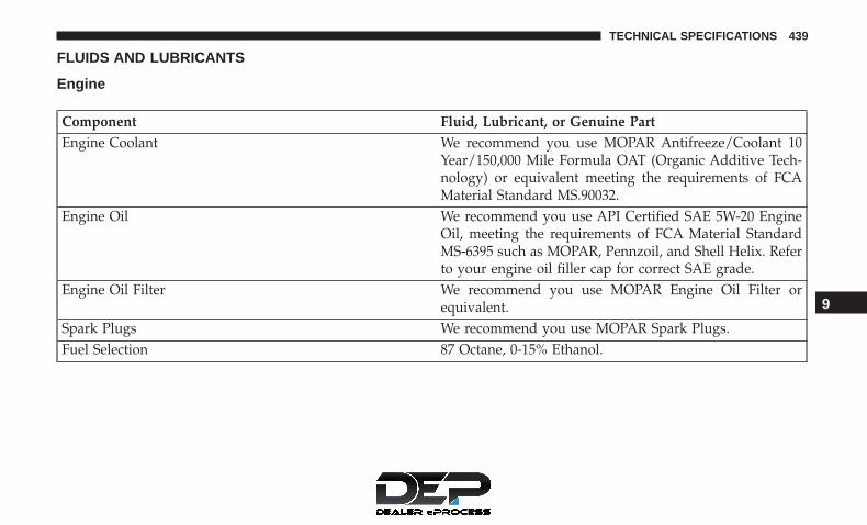
FLUIDS AND LUBRICANTS
Engine
Component Fluid, Lubricant, or Genuine PartEngine Coolant We recommend you use MOPAR Antifreeze/Coolant 10
Year/150,000 Mile Formula OAT (Organic Additive Tech-nology) or equivalent meeting the requirements of FCAMaterial Standard MS.90032.
Engine Oil We recommend you use API Certified SAE 5W-20 EngineOil, meeting the requirements of FCA Material StandardMS-6395 such as MOPAR, Pennzoil, and Shell Helix. Referto your engine oil filler cap for correct SAE grade.
Engine Oil Filter We recommend you use MOPAR Engine Oil Filter orequivalent.
Spark Plugs We recommend you use MOPAR Spark Plugs.Fuel Selection 87 Octane, 0-15% Ethanol.
9
TECHNICAL SPECIFICATIONS 439

CAUTION!
• Mixing of engine coolant (antifreeze) other thanspecified Organic Additive Technology (OAT) en-gine coolant (antifreeze), may result in engine dam-age and may decrease corrosion protection. OrganicAdditive Technology (OAT) engine coolant is differ-ent and should not be mixed with Hybrid OrganicAdditive Technology (HOAT) engine coolant (anti-freeze) or any “globally compatible” coolant (anti-freeze). If a non-OAT engine coolant (antifreeze) isintroduced into the cooling system in an emergency,the cooling system will need to be drained, flushed,
(Continued)
CAUTION! (Continued)and refilled with fresh OAT coolant (conforming toMS.90032), by an authorized dealer as soon as pos-sible.
• Do not use water alone or alcohol-based enginecoolant (antifreeze) products. Do not use additionalrust inhibitors or antirust products, as they may notbe compatible with the radiator engine coolant andmay plug the radiator.
• This vehicle has not been designed for use withpropylene glycol-based engine coolant (antifreeze).Use of propylene glycol-based engine coolant (anti-freeze) is not recommended.
440 TECHNICAL SPECIFICATIONS

Chassis
Component Fluid, Lubricant, or Genuine PartAutomatic Transmission – If Equipped Use only ATF+4 Automatic Transmission Fluid. Failure to
use ATF+4 fluid may affect the function or performance ofyour transmission. We recommend MOPAR ATF+4 fluid.
Manual Transmission – If Equipped We recommend you use MOPAR Manual TransmissionLubricant meeting the requirements of FCA Material Stan-dard MS-9224.
Transfer Case We recommend you use MOPAR ATF+4 Automatic Trans-mission Fluid.
Axle Differential (Front) We recommend you use MOPAR Gear & Axle Lubricant(SAE 80W-90) (API GL-5).
Axle Differential (Rear) 226 RBI (Model 44) – We recommend you use MOPARGear & Axle Lubricant (SAE 80W-90) (API GL-5) or equiva-lent. For trailer towing, use MOPAR Synthetic Gear & AxleLubricant (SAE 75W-140). Models equipped with Trac-Lokrequire an additive.
Brake Master Cylinder We recommend you use MOPAR DOT 3 Brake Fluid, SAEJ1703. If DOT 3, SAE J1703 brake fluid is not available, thenDOT 4 is acceptable.
Power Steering Reservoir We recommend you use MOPAR Power Steering Fluid +4,MOPAR ATF+4 Automatic Transmission Fluid.
9
TECHNICAL SPECIFICATIONS 441


MULTIMEDIA
CONTENTS� RADIO 130 . . . . . . . . . . . . . . . . . . . . . . . . . . . .445
▫ Operating Instructions — Radio Mode . . . . . . . .452
▫ Operation Instructions — CD MODE For CD AndMP3 Audio Play. . . . . . . . . . . . . . . . . . . . . . . .447
▫ Notes On Playing MP3 Files . . . . . . . . . . . . . . .449
▫ Operation Instructions — Auxiliary Mode . . . . .451
� RADIO 130 WITH SATELLITE RADIO . . . . . . . .452
▫ Operating Instructions — Radio Mode . . . . . . . .452
▫ Operation Instructions — CD MODE For CD AndMP3 Audio Play. . . . . . . . . . . . . . . . . . . . . . . .456
▫ Notes On Playing MP3 Files . . . . . . . . . . . . . . .458
▫ LIST Button — CD Mode For MP3 Play . . . . . . .460
▫ INFO Button — CD Mode For MP3 Play . . . . . .460
▫ Uconnect (Satellite Radio) — If Equipped . . . . .461
▫ Operating Instructions — Uconnect (Satellite)Mode . . . . . . . . . . . . . . . . . . . . . . . . . . . . . . .462
▫ Operating Instructions (Uconnect Phone) — IfEquipped . . . . . . . . . . . . . . . . . . . . . . . . . . . .464
� RADIO 430/430N CD/DVD/HDD/NAV — IFEQUIPPED . . . . . . . . . . . . . . . . . . . . . . . . . . . .464
▫ Operating Instructions (Voice Command System) —If Equipped . . . . . . . . . . . . . . . . . . . . . . . . . . .464
▫ Operating Instructions (Uconnect Phone) — IfEquipped . . . . . . . . . . . . . . . . . . . . . . . . . . . .464
� CYBERSECURITY . . . . . . . . . . . . . . . . . . . . . . . .464
� STEERING WHEEL AUDIO CONTROLS . . . . . . .465
▫ Radio Operation. . . . . . . . . . . . . . . . . . . . . . . .466
▫ CD Player . . . . . . . . . . . . . . . . . . . . . . . . . . . .466
� AUX/USB/MP3 CONTROL — IF EQUIPPED . . .467
� RADIO OPERATION AND MOBILE PHONES . . .467
10

▫ Regulatory And Safety Information . . . . . . . . . .467
� CD/DVD DISC MAINTENANCE . . . . . . . . . . . .469
� UCONNECT PHONE — IF EQUIPPED . . . . . . . .469
▫ Operation . . . . . . . . . . . . . . . . . . . . . . . . . . . .471
▫ Help Command . . . . . . . . . . . . . . . . . . . . . . . .472
▫ Cancel Command. . . . . . . . . . . . . . . . . . . . . . .472
▫ Pair (Link) Uconnect Phone To A Mobile Phone .472
▫ Dial By Saying A Number. . . . . . . . . . . . . . . . .473
▫ Call By Saying A Name . . . . . . . . . . . . . . . . . .473
▫ Phonebook Download – Automatic PhonebookTransfer From Mobile Phone . . . . . . . . . . . . . . .474
▫ Add Names To Your Uconnect Phonebook . . . . .474
▫ Edit Uconnect Phonebook Entries . . . . . . . . . . .475
▫ Delete Uconnect Phonebook Entry . . . . . . . . . . .475
▫ List All Names In The Uconnect Phonebook . . . .476
▫ Phone Call Features . . . . . . . . . . . . . . . . . . . . .476
▫ Uconnect Phone Features . . . . . . . . . . . . . . . . .479
▫ Advanced Phone Connectivity . . . . . . . . . . . . .483
▫ Things You Should Know About Your UconnectPhone . . . . . . . . . . . . . . . . . . . . . . . . . . . . . . .484
▫ General Information . . . . . . . . . . . . . . . . . . . .492
� VOICE COMMAND — IF EQUIPPED . . . . . . . . .492
▫ Voice Command System Operation . . . . . . . . . .492
▫ Commands . . . . . . . . . . . . . . . . . . . . . . . . . . .493
▫ Voice Training . . . . . . . . . . . . . . . . . . . . . . . . .496
444 MULTIMEDIA

RADIO 130
Operating Instructions — Radio Mode
NOTE: The ignition switch must be in the ON/RUN orACC position to operate the radio.
Power Switch/Volume Control (Rotary)
Push the ON/VOLUME control knob to turn on the radio.Push the ON/VOLUME control knob a second time to turnoff the radio.
Electronic Volume Control
The electronic volume control turns continuously (360degrees) in either direction, without stopping. Turning theON/VOLUME control knob to the right increases thevolume, and to the left decreases it.
When the audio system is turned on, the sound will be setat the same volume level as last played.
SEEK Buttons
Push and release the SEEK buttons to search for the nextlistenable station in AM/FM mode. Push the right switchto seek up and the left switch to seek down. The radio willremain tuned to the new station until you make anotherselection. Holding either button will bypass stations with-out stopping, until you release it.
Clock Setting Procedure
1. Push and hold the TIME button until the hours blink.
2. Adjust the hours by turning the right side TUNE/SCROLL control knob.
3. After adjusting the hours, push the right side TUNE/SCROLL control knob to set the minutes. The minuteswill begin to blink.
Radio 130
10
MULTIMEDIA 445

4. Adjust the minutes using the right side TUNE/SCROLLcontrol knob. Push the TUNE/SCROLL control knob tosave time change.
5. To exit, push any button/knob, or wait five seconds.
RW/FF
Pushing the RW (Rewind) or FF (Fast Forward) buttonscauses the tuner to search for the next frequency in thedirection of the arrows. This feature operates in either AMor FM frequencies.
TUNE Control
Turn the rotary TUNE/SCROLL control knob clockwise toincrease or counterclockwise to decrease the frequency.
Setting The Tone, Balance And Fade
Push the rotary TUNE/SCROLL control knob and BASSwill display. Turn the TUNE/SCROLL control knob to theright or left to increase or decrease the bass tones.
Push the rotary TUNE/SCROLL control knob a secondtime and MID will display. Turn the TUNE/SCROLLcontrol knob to the right or left to increase or decrease themid-range tones.
Push the rotary TUNE/SCROLL control knob a third timeand TREBLE will display. Turn the TUNE/SCROLL controlknob to the right or left to increase or decrease the trebletones.
Push the rotary TUNE/SCROLL control knob a fourth timeand BALANCE will display. Turn the TUNE/SCROLLcontrol knob to the right or left to adjust the sound levelfrom the right or left side speakers.
Push the rotary TUNE/SCROLL control knob a fifth timeand FADE will display. Turn the TUNE/SCROLL controlknob to the left or right to adjust the sound level betweenthe front and rear speakers.
Push the rotary TUNE/SCROLL control knob again to exitsetting tone, balance, and fade.
AM/FM Button
Push the buttons to select either AM or FM mode.
SET/RND Button — To Set The Pushbutton Memory
When you are receiving a station that you wish to committo pushbutton memory, push the SET/RND button. Thesymbol SET 1 will now show in the display window. Selectthe button (1 to 6) you wish to lock onto this station andpush and release that button. If a button is not selected
446 MULTIMEDIA

within five seconds after pushing the SET/RND button,the station will continue to play but will not be stored intopushbutton memory.
You may add a second station to each pushbutton byrepeating the above procedure with this exception: Pushthe SET/RND button twice and SET 2 will show in thedisplay window. Each button can be set for SET 1 and SET2 in both AM and FM. This allows a total of 12 AM and 12FM stations to be stored into pushbutton memory. Thestations stored in SET 2 memory can be selected bypushing the pushbutton twice.
Every time a preset button is used, a corresponding buttonnumber will display.
Buttons 1 - 6
These buttons tune the radio to the stations that youcommit to pushbutton memory (12 AM and 12 FM sta-tions).
Operation Instructions — CD MODE For CD AndMP3 Audio Play
NOTE:
• The ignition switch must be in the ON/RUN or ACCposition to operate the radio.
• This radio is capable of playing compact discs (CD),recordable compact discs (CD-R), rewritable compactdiscs (CD-RW), compact discs with MP3 tracks andmultisession compact discs with CD and MP3 tracks.
Inserting Compact Disc(s)
Gently insert one CD into the CD player with the CD labelfacing up. The CD will automatically be pulled into the CDplayer and the CD icon will illuminate on the radio display.If a CD does not go into the slot more than 1.0 inch (2.5 cm),a disc may already be loaded and must be ejected before anew disc can be loaded.
If you insert a disc with the ignition ON/RUN and theradio ON, the unit will switch from radio to CD mode andbegin to play when you insert the disc. The display willshow the track number, and index time in minutes andseconds. Play will begin at the start of track 1.
10
MULTIMEDIA 447

CAUTION!
• This CD player will accept 4–3/4 inch (12 cm) discsonly. The use of other sized discs may damage theCD player mechanism.
• Do not use adhesive labels. These labels can peelaway and jam the player mechanism.
• The Radio 130 is a single CD player. Do not attemptto insert a second CD if one is already loaded.
• Dual-media disc types (one side is a DVD, the otherside is a CD) should not be used, and they can causedamage to the player.
EJECT Button — Ejecting A CD
Push the EJECT button to eject the CD.
If you have ejected a disc and have not removed it within10 seconds, it will be reloaded. If the CD is not removed,the radio will reinsert the CD but will not play it.
A disc can be ejected with the radio and ignition OFF.
NOTE: Ejecting with the ignition OFF is not allowed onconvertible or soft-top models (if equipped.)
SEEK Button
Push the right SEEK button for the next selection on theCD. Push the left SEEK button to return to the beginning ofthe current selection, or return to the beginning of theprevious selection if the CD is within the first second of thecurrent selection. Pushing and holding the SEEK buttonwill allow faster scrolling through the tracks in CD andMP3 modes.
TIME Button
Push this button to change the display from a large CDplaying time display to a small CD playing time display.
RW/FF
Push and hold the FF (Fast Forward) button and the CDplayer will begin to fast forward until FF is released, or RWor another CD button is pushed. The RW (Reverse) buttonoperates in a similar manner.
AM/FM Button
Push the button to select either AM or FM mode.
448 MULTIMEDIA

SET/RND Button (Random Play Button)
Push this button while the CD is playing to activateRandom Play. This feature plays the selections on thecompact disc in random order to provide an interestingchange of pace.
Push the right SEEK button to move to the next randomlyselected track.
Push the RND button a second time to stop Random Play.
Notes On Playing MP3 Files
The radio can play MP3 files; however, acceptable MP3 filerecording media and formats are limited. When writingMP3 files, pay attention to the following restrictions.
Supported Media (Disc Types)
The MP3 file recording media supported by the radio areCDDA, CD-R, CD-RW, MP3, and CDDA+MP3.
Supported Medium Formats (File Systems)
The medium formats supported by the radio are ISO 9660Level 1 and Level 2 and includes the Joliet extension. Whenreading discs recorded using formats other than ISO 9660
Level 1 and Level 2, the radio may fail to read files properlyand may be unable to play the file normally. UDF andApple HFS formats are not supported.
The radio uses the following limits for file systems:
• Maximum number of folder levels: 8
• Maximum number of files: 255
• Maximum number of folders. (The radio display of filenames and folder names is limited. For large numbers offiles and/or folders, the radio may be unable to displaythe file name and folder name, and will assign a numberinstead. With a maximum number of files, exceeding 20folders will result in this display. With 200 files, exceed-ing 50 folders will result in this display.)
Maximum number of characters in file/folder names:
• Level 1: 12 (including a separator �.� and a three-character extension)
• Level 2: 31 (including a separator �.� and a three-character extension)
Multi-session disc formats are supported by the radio.Multi-session discs may contain combinations of normalCD audio tracks and computer files (including MP3 files).Discs created with an option such as �keep disc open after
10
MULTIMEDIA 449

writing� are most likely multi-session discs. The use ofmulti-session for CD audio or MP3 playback may result inlonger disc loading times.
Supported MP3 File Formats
The radio will recognize only files with the *.MP3 exten-sion as MP3 files. Non-MP3 files named with the *.MP3extension may cause playback problems. The radio isdesigned to recognize the file as an invalid MP3 and willnot play the file.
When using the MP3 encoder to compress audio data to anMP3 file, the bit rate and sampling frequencies in thefollowing table are supported. In addition, variable bitrates (VBR) are also supported. The majority of MP3 filesuse a 44.1 kHz sampling rate and a 192, 160, 128, 96 or VBRbit rate.
MPEG Specifi-cation
Sampling Fre-quency (kHz)
Bit Rate (kbps)
MPEG-1 AudioLayer 3
48, 44.1, 32 320, 256, 224,192, 160, 128,
112, 96, 80, 64,56, 48, 40, 32
MPEG-2 AudioLayer 3
24, 22.05, 16 160, 128, 144,112, 96, 80, 64,
56, 48, 40, 32, 24,16, 8
ID3 Tag information for artist, song title, and album titleare supported for version 1 ID3 tags. ID3 version 2 is notsupported by the radios.
Playlist files are not supported. MP3 Pro files are notsupported.
450 MULTIMEDIA

Playback Of MP3 Files
When a medium containing MP3 data is loaded, the radiochecks all files on the medium. If the medium contains a lotof folders or files, the radio will take more time to startplaying the MP3 files.
Loading times for playback of MP3 files may be affected bythe following:
• Media - CD-RW media may take longer to load thanCD-R media
• Medium formats - Multisession discs may take longer toload than non-multisession discs
• Number of files and folders - Loading times will increasewith more files and folders
To increase the speed of disc loading, it is recommended touse CD-R media and single-session discs. To create asingle-session disc, enable the “Disc at Once” option beforewriting to the disc.
Operation Instructions — Auxiliary Mode
The auxiliary (AUX) jack is an audio input jack, whichallows the user to plug in a portable device, such as an MP3player, or iPod, and utilize the vehicle’s audio system toamplify the source and play through the vehicle speakers.
Pushing the DISC/AUX button will change the mode toauxiliary device if the AUX jack is connected.
NOTE: The AUX device must be turned on and thedevice’s volume set to proper level. If the AUX audio is notloud enough, turn the device’s volume up. If the AUXaudio sounds distorted, turn the device’s volume down.
TIME Button (Auxiliary Mode)
Push this button to change the display to time of day. Thetime of day will display for five seconds (when ignition isOFF). 10
MULTIMEDIA 451

RADIO 130 WITH SATELLITE RADIO
Operating Instructions — Radio Mode
NOTE: The ignition switch must be in the ON/RUN orACC position to operate the radio.
Power Switch/Volume Control (Rotary)
Push the ON/VOLUME control knob to turn on the radio.Push the ON/VOLUME control knob a second time to turnoff the radio.
Electronic Volume Control
The electronic volume control turns continuously (360degrees) in either direction, without stopping. Turning theON/VOLUME control knob to the right increases thevolume, and to the left decreases it.
When the audio system is turned on, the sound will be setat the same volume level as last played.
SEEK Buttons
Push and release the SEEK buttons to search for the nextlistenable station in AM/FM mode. Push the right switchto seek up and the left switch to seek down. The radio willremain tuned to the new station until you make anotherselection. Holding either button will bypass stations with-out stopping, until you release it.
Voice Command System (Radio) — If Equipped
Refer to “Voice Command” in “Multimedia”.
Voice Command Button Uconnect Phone — IfEquipped
Push this button to operate the Uconnect Phone feature (ifequipped). Refer to “Uconnect Phone” in “Multimedia”.
Radio 130
452 MULTIMEDIA

If your vehicle is not equipped with or this feature is notavailable on your vehicle, a “Not Equipped With UconnectPhone” message will display on the radio screen.
Phone Button Uconnect Phone — If Equipped
Push this button to operate the Uconnect Phone feature (ifequipped). Refer to “Uconnect Phone” in “Multimedia”.
If your vehicle is not equipped with, or this feature is notavailable on your vehicle, a “Not Equipped With UconnectPhone” message will display on the radio screen.
TIME Button
Push the TIME button to alternate display of the time andradio frequency.
Clock Setting Procedure
1. Push and hold the TIME button until the hours blink.
2. Adjust the hours by turning the right side TUNE/SCROLL control knob.
3. After adjusting the hours, push the right side TUNE/SCROLL control knob to set the minutes. The minuteswill begin to blink.
4. Adjust the minutes using the right side TUNE/SCROLLcontrol knob. Push the TUNE/SCROLL control knob tosave time change.
5. To exit, push any button/knob, or wait five seconds.
INFO Button
Push the INFO button for an RDS station (one with callletters displayed). The radio will return a Radio Textmessage broadcast from an FM station (FM mode only).
RW/FF
Pushing the RW (Rewind) or FF (Fast Forward) buttonscauses the tuner to search for the next frequency in thedirection of the arrows. This feature operates in either AMor FM frequencies.
TUNE Control
Turn the rotary TUNE/SCROLL control knob clockwise toincrease or counterclockwise to decrease the frequency.
Setting The Tone, Balance And Fade
Push the rotary TUNE/SCROLL control knob and BASSwill display. Turn the TUNE/SCROLL control knob to theright or left to increase or decrease the bass tones.
10
MULTIMEDIA 453

Push the rotary TUNE/SCROLL control knob a secondtime and MID will display. Turn the TUNE/SCROLLcontrol knob to the right or left to increase or decrease themid-range tones.
Push the rotary TUNE/SCROLL control knob a third timeand TREBLE will display. Turn the TUNE/SCROLL controlknob to the right or left to increase or decrease the trebletones.
Push the rotary TUNE/SCROLL control knob a fourth timeand BALANCE will display. Turn the TUNE/SCROLLcontrol knob to the right or left to adjust the sound levelfrom the right or left side speakers.
Push the rotary TUNE/SCROLL control knob a fifth timeand FADE will display. Turn the TUNE/SCROLL controlknob to the left or right to adjust the sound level betweenthe front and rear speakers.
Push the rotary TUNE/SCROLL control knob again to exitsetting tone, balance, and fade.
MUSIC TYPE Button
Pushing this button once will turn on the Music Type modefor five seconds. Pushing the MUSIC TYPE button or
turning the TUNE/SCROLL control knob within five sec-onds will allow the program format type to be selected.Many radio stations do not currently broadcast Music Typeinformation.
Toggle the MUSIC TYPE button to select the followingformat types:
Program Type16-Digit Character Dis-
playNo program type or un-
definedNone
Adult Hits Adlt HitClassical Classicl
Classic Rock Cls RockCollege CollegeCountry Country
Foreign Language LanguageInformation Inform
Jazz JazzNews News
Nostalgia NostalgaOldies Oldies
454 MULTIMEDIA

Program Type16-Digit Character Dis-
playPersonality Persnlty
Public PublicRhythm and Blues R & B
Religious Music Rel MuscReligious Talk Rel Talk
Rock RockSoft Soft
Soft Rock Soft RckSoft Rhythm and Blues Soft R&B
Sports SportsTalk Talk
Top 40 Top 40Weather Weather
By pushing the SEEK button when the Music Type icon isdisplayed, the radio will be tuned to the next frequencystation with the same selected Music Type name. TheMusic Type function only operates when in the FM mode.
If a preset button is activated while in the Music Type(Program Type) mode, the Music Type mode will be exitedand the radio will tune to the preset station.
SETUP Button
Pushing the SETUP button allows you to select betweenthe following items:
• Set Clock — Pushing the SELECT button will allow youto set the clock. Adjust the hours by turning the TUNE/SCROLL control knob. After adjusting the hours, pushthe TUNE/SCROLL control knob to set the minutes. Theminutes will begin to blink. Adjust the minutes using theright side TUNE/SCROLL control knob. Push theTUNE/SCROLL control knob to save time change.
AM/FM Button
Push the buttons to select either AM or FM mode.
SET/RND Button — To Set The Pushbutton Memory
When you are receiving a station that you wish to committo pushbutton memory, push the SET/RND button. Thesymbol SET 1 will now show in the display window. Selectthe button (1 to 6) you wish to lock onto this station andpush and release that button. If a button is not selected
10
MULTIMEDIA 455

within five seconds after pushing the SET/RND button,the station will continue to play but will not be stored intopushbutton memory.
You may add a second station to each pushbutton byrepeating the above procedure with this exception: Pushthe SET/RND button twice and SET 2 will show in thedisplay window. Each button can be set for SET 1 and SET2 in both AM and FM. This allows a total of 12 AM and 12FM stations to be stored into pushbutton memory. Thestations stored in SET 2 memory can be selected bypushing the pushbutton twice.
Every time a preset button is used, a corresponding buttonnumber will display.
Buttons 1 - 6
These buttons tune the radio to the stations that youcommit to pushbutton memory (12 AM and 12 FM sta-tions).
DISC/AUX Button
Pushing the DISC/AUX button will allow you to switchfrom AM/FM modes to DISC/AUX mode.
Operation Instructions — CD MODE For CD AndMP3 Audio Play
NOTE:
• The ignition switch must be in the ON/RUN or ACCposition to operate the radio.
• This radio is capable of playing compact discs (CD),recordable compact discs (CD-R), rewritable compactdiscs (CD-RW), compact discs with MP3 tracks andmultisession compact discs with CD and MP3 tracks.
Inserting Compact Disc(s)
Gently insert one CD into the CD player with the CD labelfacing up. The CD will automatically be pulled into the CDplayer and the CD icon will illuminate on the radio display.If a CD does not go into the slot more than 1.0 inch (2.5 cm),a disc may already be loaded and must be ejected before anew disc can be loaded.
If you insert a disc with the ignition ON/RUN and theradio ON, the unit will switch from radio to CD mode andbegin to play when you insert the disc. The display willshow the track number, and index time in minutes andseconds. Play will begin at the start of track 1.
456 MULTIMEDIA

CAUTION!
• This CD player will accept 4–3/4 inch (12 cm) discsonly. The use of other sized discs may damage theCD player mechanism.
• Do not use adhesive labels. These labels can peelaway and jam the player mechanism.
• The Radio 130 is a single CD player. Do not attemptto insert a second CD if one is already loaded.
• Dual-media disc types (one side is a DVD, the otherside is a CD) should not be used, and they can causedamage to the player.
EJECT Button — Ejecting A CD
Push the EJECT button to eject the CD.
If you have ejected a disc and have not removed it within10 seconds, it will be reloaded. If the CD is not removed,the radio will reinsert the CD but will not play it.
A disc can be ejected with the radio and ignition OFF.
NOTE: Ejecting with the ignition OFF is not allowed onconvertible or soft-top models (if equipped.)
SEEK Button
Push the right SEEK button for the next selection on theCD. Push the left SEEK button to return to the beginning ofthe current selection, or return to the beginning of theprevious selection if the CD is within the first second of thecurrent selection. Pushing and holding the SEEK buttonwill allow faster scrolling through the tracks in CD andMP3 modes.
TIME Button
Push this button to change the display from a large CDplaying time display to a small CD playing time display.
RW/FF
Push and hold the FF (Fast Forward) button and the CDplayer will begin to fast forward until FF is released, or RWor another CD button is pushed. The RW (Reverse) buttonoperates in a similar manner.
AM/FM Button
Push the button to select either AM or FM mode.
10
MULTIMEDIA 457

SET/RND Button (Random Play Button)
Push this button while the CD is playing to activateRandom Play. This feature plays the selections on thecompact disc in random order to provide an interestingchange of pace.
Push the right SEEK button to move to the next randomlyselected track.
Push the RND button a second time to stop Random Play.
Notes On Playing MP3 Files
The radio can play MP3 files; however, acceptable MP3 filerecording media and formats are limited. When writingMP3 files, pay attention to the following restrictions.
Supported Media (Disc Types)
The MP3 file recording media supported by the radio areCDDA, CD-R, CD-RW, MP3, and CDDA+MP3.
Supported Medium Formats (File Systems)
The medium formats supported by the radio are ISO 9660Level 1 and Level 2 and includes the Joliet extension. Whenreading discs recorded using formats other than ISO 9660
Level 1 and Level 2, the radio may fail to read files properlyand may be unable to play the file normally. UDF andApple HFS formats are not supported.
The radio uses the following limits for file systems:
• Maximum number of folder levels: 8
• Maximum number of files: 255
• Maximum number of folders. (The radio display of filenames and folder names is limited. For large numbers offiles and/or folders, the radio may be unable to displaythe file name and folder name, and will assign a numberinstead. With a maximum number of files, exceeding 20folders will result in this display. With 200 files, exceed-ing 50 folders will result in this display.)
Maximum number of characters in file/folder names:
• Level 1: 12 (including a separator �.� and a three-character extension)
• Level 2: 31 (including a separator �.� and a three-character extension)
Multi-session disc formats are supported by the radio.Multi-session discs may contain combinations of normalCD audio tracks and computer files (including MP3 files).Discs created with an option such as �keep disc open after
458 MULTIMEDIA

writing� are most likely multi-session discs. The use ofmulti-session for CD audio or MP3 playback may result inlonger disc loading times.
Supported MP3 File Formats
The radio will recognize only files with the *.MP3 exten-sion as MP3 files. Non-MP3 files named with the *.MP3extension may cause playback problems. The radio isdesigned to recognize the file as an invalid MP3 and willnot play the file.
When using the MP3 encoder to compress audio data to anMP3 file, the bit rate and sampling frequencies in thefollowing table are supported. In addition, variable bitrates (VBR) are also supported. The majority of MP3 filesuse a 44.1 kHz sampling rate and a 192, 160, 128, 96 or VBRbit rate.
MPEG Specifi-cation
Sampling Fre-quency (kHz)
Bit Rate (kbps)
MPEG-1 AudioLayer 3
48, 44.1, 32 320, 256, 224,192, 160, 128,
112, 96, 80, 64,56, 48, 40, 32
MPEG-2 AudioLayer 3
24, 22.05, 16 160, 128, 144,112, 96, 80, 64,
56, 48, 40, 32, 24,16, 8
ID3 Tag information for artist, song title, and album titleare supported for version 1 ID3 tags. ID3 version 2 is notsupported by the radios.
Playlist files are not supported. MP3 Pro files are notsupported. 10
MULTIMEDIA 459

Playback Of MP3 Files
When a medium containing MP3 data is loaded, the radiochecks all files on the medium. If the medium contains a lotof folders or files, the radio will take more time to startplaying the MP3 files.
Loading times for playback of MP3 files may be affected bythe following:
• Media - CD-RW media may take longer to load thanCD-R media
• Medium formats - Multisession discs may take longer toload than non-multisession discs
• Number of files and folders - Loading times will increasewith more files and folders
To increase the speed of disc loading, it is recommended touse CD-R media and single-session discs. To create asingle-session disc, enable the “Disc at Once” option beforewriting to the disc.
LIST Button — CD Mode For MP3 Play
Pushing the LIST button will bring up a list of all folders onthe disc. Scrolling up or down the list is done by turningthe TUNE/SCROLL control knob. Selecting a folder by
pushing the TUNE/SCROLL control knob will begin play-ing the files contained in that folder (or the next folder insequence if the selection does not contain playable files).
The folder list will time out after five seconds.
INFO Button — CD Mode For MP3 Play
Pushing the INFO button repeatedly will scroll through thefollowing TAG information: Song Title, Artist, File Name,and Folder Name (if available).
Push the INFO button once more to return to �elapsedtime� priority mode.
Push and hold the INFO button for three seconds or moreand the radio will display song titles for each file.
Push and hold the INFO button again for three seconds toreturn to �elapsed time� display.
Operation Instructions — Auxiliary Mode
The auxiliary (AUX) jack is an audio input jack whichallows the user to plug in a portable device such as an MP3player and utilize the vehicle’s audio system to amplify thesource and play through the vehicle speakers.
Pushing the AUX button will change the mode to auxiliarydevice if the AUX jack is connected.
460 MULTIMEDIA

NOTE: The AUX device must be turned on and thedevice’s volume set to the proper level. If the AUX audio isnot loud enough, turn the device’s volume up. If the AUXaudio sounds distorted, turn the device’s volume down.
TIME Button (Auxiliary Mode)
Push this button to change the display to time of day. Thetime of day will display for five seconds (when the ignitionis OFF).
Uconnect (Satellite Radio) — If Equipped
Satellite radio uses direct satellite-to-receiver broadcastingtechnology to provide clear digital sound, coast to coast.The subscription service provider is Sirius Satellite Radio.This service offers over 130 channels of music, sports,news, entertainment, and programming for children, di-rectly from its satellites and broadcasting studios.
NOTE: Sirius service is not available in Hawaii and haslimited coverage in Alaska.
System Activation
Sirius Satellite Radio service is pre-activated, and you maybegin listening immediately to the one year of audioservice that is included with the factory-installed satelliteradio system in your vehicle. Sirius will supply a welcome
kit that contains general information, including how tosetup your online listening account. For further informa-tion, call the toll-free number 888-539-7474, or visit theSirius web site at www.siriusxm.com, or at www.siriusx-m.ca for Canadian residents.
Electronic Serial Number/Sirius IdentificationNumber (ESN/SID)
Please have the following information available whencalling:
1. The Electronic Serial Number/Sirius IdentificationNumber (ESN/SID).
2. Your Vehicle Identification Number.
To access the ESN/SID, refer to the following steps:
ESN/SID Access
With the ignition switch in the ON/RUN or ACC positionand the radio on, push the SETUP button and scroll usingthe TUNE/SCROLL control knob until Sirius ID is selected.Push the TUNE/SCROLL control knob and the Sirius IDnumber will display. The Sirius ID number display willtime out in two minutes. Push any button on the radio toexit this screen.
10
MULTIMEDIA 461

Selecting Uconnect (Satellite) Mode
Push the SAT button until �SAT� appears in the display. ACD may remain in the radio while in the Satellite radiomode.
Satellite Antenna
To ensure optimum reception, do not place items on theroof around the rooftop antenna location. Metal objectsplaced within the line of sight of the antenna will causedecreased performance. Larger luggage items such as bikesshould be placed as far rearward as possible, within theloading design of the rack. Do not place items directly onor above the antenna.
Reception Quality
Satellite reception may be interrupted due to one of thefollowing reasons:
• The vehicle is parked in an underground parking struc-ture or under a physical obstacle.
• Dense tree coverage may interrupt reception in the formof short audio mutes.
• Driving under wide bridges or along tall buildings cancause intermittent reception.
• Placing objects over or too close to the antenna can causesignal blockage.
Operating Instructions — Uconnect (Satellite)Mode
NOTE: The ignition switch must be in the ON/RUN orACC position to operate the radio.
SEEK Buttons
Push and release the SEEK buttons to search for the nextlistenable station in AM/FM mode. Push the right switchto seek up and the left switch to seek down. The radio willremain tuned to the new station until you make anotherselection. Holding either button will bypass stations with-out stopping, until you release it.
SCAN Button
Pushing the SCAN button causes the tuner to search for thenext channel, pausing for eight seconds before continuingto the next. To stop the search, push the SCAN button asecond time.
INFO Button
Pushing the INFO button will cycle the display informa-tion between Artist, Song Title, and Composer (if avail-able). Also, pushing and holding the INFO button for an
462 MULTIMEDIA
additional three seconds will make the radio display theSong Title all of the time (push and hold again to return tonormal display).
RW/FF
Pushing the RW (Rewind) or FF (Fast Forward) buttonscauses the tuner to search for the next channel in thedirection of the arrows.
TUNE Control
Turn the rotary TUNE/SCROLL control knob clockwise toincrease or counterclockwise to decrease the frequency.
MUSIC TYPE Button
Pushing this button once will turn on the Music Type modefor five seconds. Pushing the MUSIC TYPE button orturning the TUNE/SCROLL control knob within five sec-onds will allow the program format type to be selected.
Toggle the MUSIC TYPE button again to select the musictype.
By pushing the SEEK button when the Music Type functionis active, the radio will be tuned to the next channel withthe same selected Music Type name.
If a preset button is activated while in the Music Type(Program Type) mode, the Music Type mode will be exitedand the radio will tune to the preset channel.
SETUP Button
Pushing the SETUP button allows you to select the follow-ing items:
• Display Sirius ID number — Push the AUDIO/SELECTbutton to display the Sirius ID number. This number isused to activate, deactivate, or change the Sirius sub-scription.
SET Button — To Set The Pushbutton Memory
When you are receiving a channel that you wish to committo push button memory, push the SET button. The symbolSET 1 will now show in the display window. Select thebutton (1-6) you wish to lock onto this channel and pushand release that button. If a button is not selected withinfive seconds after pushing the SET button, the channel willcontinue to play but will not be stored into push buttonmemory.
You may add a second channel to each push button byrepeating the above procedure with this exception: Pushthe SET button twice and SET 2 will show in the displaywindow. Each button can be set for SET 1 and SET 2. This
10
MULTIMEDIA 463

allows a total of 12 Satellite channels to be stored into pushbutton memory. The channels stored in SET 2 memory canbe selected by pushing the push button twice.
Every time a preset button is used, a corresponding buttonnumber will display.
Buttons 1 - 6
These buttons tune the radio to the channels that youcommit to pushbutton memory (12 Satellite stations).
Operating Instructions (Uconnect Phone) — IfEquipped
Refer to “Uconnect Phone” in “Multimedia”.
RADIO 430/430N CD/DVD/HDD/NAV — IFEQUIPPED
Refer to your Uconnect Owner’s Manual Supplement fordetailed operating instructions.
Operating Instructions (Voice Command System)— If Equipped
Refer to “Voice Command” in “Multimedia” for furtherdetails.
Operating Instructions (Uconnect Phone) — IfEquipped
Refer to “Uconnect Phone” in “Multimedia” for furtherdetails.
CYBERSECURITY
Your vehicle may be a connected vehicle and may beequipped with both wired and wireless networks. Thesenetworks allow your vehicle to send and receive informa-tion. This information allows systems and features in yourvehicle to function properly.
Your vehicle may be equipped with certain security fea-tures to reduce the risk of unauthorized and unlawfulaccess to vehicle systems and wireless communications.Vehicle software technology continues to evolve over timeand FCA US LLC, working with its suppliers, evaluatesand takes appropriate steps as needed. Similar to a com-puter or other devices, your vehicle may require softwareupdates to improve the usability and performance of yoursystems or to reduce the potential risk of unauthorized andunlawful access to your vehicle systems.
464 MULTIMEDIA

The risk of unauthorized and unlawful access to yourvehicle systems may still exist, even if the most recentversion of vehicle software (such as Uconnect software) isinstalled.
WARNING!
• It is not possible to know or to predict all of thepossible outcomes if your vehicle’s systems arebreached. It may be possible that vehicle systems,including safety related systems, could be impairedor a loss of vehicle control could occur that mayresult in an accident involving serious injury ordeath.
• ONLY insert media (e.g., USB, SD card, or CD) intoyour vehicle if it came from a trusted source. Mediaof unknown origin could possibly contain malicioussoftware, and if installed in your vehicle, it mayincrease the possibility for vehicle systems to bebreached.
• As always, if you experience unusual vehicle behav-ior, take your vehicle to your nearest authorizeddealer immediately.
NOTE:
• FCA or your dealer may contact you directly regardingsoftware updates.
• To help further improve vehicle security and minimizethe potential risk of a security breach, vehicle ownersshould:• Routinely check www.driveuconnect.com/software-
update to learn about available Uconnect softwareupdates.
• Only connect and use trusted media devices (e.g.personal mobile phones, USBs, CDs).
Privacy of any wireless and wired communications cannotbe assured. Third parties may unlawfully intercept infor-mation and private communications without your consent.For further information, refer to “Onboard DiagnosticSystem (OBD II) Cybersecurity” in “Getting To Know YourInstrument Panel”.
STEERING WHEEL AUDIO CONTROLS
The remote sound system controls are located on the rearsurface of the steering wheel. Reach behind the wheel toaccess the switches.
10
MULTIMEDIA 465

The right-hand control is a rocker-type switch with apush-button in the center and controls the volume andmode of the sound system. Pushing the top of the rockerswitch will increase the volume, and pushing the bottom ofthe rocker switch will decrease the volume.
Pushing the center button will make the radio switchbetween the various modes available (AM/FM/SAT/CD/HDD/AUX, etc.).
The left-hand control is a rocker-type switch with a push-button in the center. The function of the left-hand control isdifferent depending on which mode you are in.
The following describes the left-hand control operation ineach mode.
Radio Operation
Pushing the top of the switch will “Seek” up for the nextlistenable station and pushing the bottom of the switch will“Seek” down for the next listenable station.
The button located in the center of the left-hand controlwill tune to the next preset station that you have pro-grammed in the radio preset button.
CD Player
Pushing the top of the switch once will go to the next trackon the CD. Pushing the bottom of the switch once will goto the beginning of the current track, or to the beginning ofthe previous track if it is within eight seconds after thecurrent track begins to play.
If you push the switch up or down twice, it plays thesecond track; three times, it will play the third, etc.
The center button on the left side rocker switch has nofunction for a single-disc CD player. However, when a
Remote Sound System Controls (Back View Of SteeringWheel)
466 MULTIMEDIA

multiple-disc CD player is equipped on the vehicle, thecenter button will select the next available CD in the player.
AUX/USB/MP3 CONTROL — IF EQUIPPED
This feature allows an external USB device to be pluggedinto the USB port, located in the center console.
Connecting an electronic audio device to the AUX portlocated in the radio faceplate plays media, but does not usethe control feature to control the connected device.
If the radio has a USB port, refer to your User Guide or theappropriate Uconnect Owner’s Manual Supplement forexternal USB device support capability.
WARNING!
Do not plug in or remove the iPod or external devicewhile driving. Failure to follow this warning couldresult in a collision.
RADIO OPERATION AND MOBILE PHONES
Under certain conditions, the mobile phone being on inyour vehicle can cause erratic or noisy performance fromyour radio. This condition may be lessened or eliminatedby relocating the mobile phone antenna. This condition is
not harmful to the radio. If your radio performance doesnot satisfactorily “clear” by the repositioning of the an-tenna, it is recommended that the radio volume be turneddown or off during mobile phone operation when notusing Uconnect (if equipped).
Regulatory And Safety Information
USA/CANADA
Exposure to Radio Frequency Radiation
The radiated output power of the internal wireless radio isfar below the FCC radio frequency exposure limits. Nev-ertheless, the wireless radio will be used in such a mannerthat the radio is 20 cm or further from the human body.
The internal wireless radio operates within guidelinesfound in radio frequency safety standards and recommen-dations, which reflect the consensus of the scientific com-munity.
The radio manufacturer believes the internal wireless radiois safe for use by consumers. The level of energy emitted isfar less than the electromagnetic energy emitted by wire-less devices such as mobile phones. However, the use ofwireless radios may be restricted in some situations or
10
MULTIMEDIA 467

environments, such as aboard airplanes. If you are unsureof restrictions, you are encouraged to ask for authorizationbefore turning on the wireless radio.
This device complies with Part 15 of the FCC Rules andwith Industry Canada license-exempt RSS standard(s).Operation is subject to the following two conditions:
1. This device may not cause harmful interference.
2. This device must accept any interference received, in-cluding interference that may cause undesired opera-tion.
NOTE:
• This equipment has been tested and found to complywith the limits for a Class B digital device, pursuant toPart 15 of the FCC Rules. These limits are designed toprovide reasonable protection against harmful interfer-ence in a residential installation. This equipment gener-ates, uses and can radiate radio frequency energy and, ifnot installed and used in accordance with the instruc-tions, may cause harmful interference to radio commu-nications. However, there is no guarantee that interfer-ence will not occur in a particular installation.
• If this equipment does cause harmful interference toradio or television reception, which can be determinedby turning the equipment off and on, the user is encour-aged to try to correct the interference by one or more ofthe following measures:
1. Increase the separation between the equipment andreceiver.
2. Consult the dealer or an experienced radio technicianfor help.
468 MULTIMEDIA

CD/DVD DISC MAINTENANCE
To keep a CD/DVD in good condition, take the followingprecautions:
1. Handle the disc by its edge; avoid touching the surface.
2. If the disc is stained, clean the surface with a soft cloth,wiping from center to edge.
3. Do not apply paper or tape to the disc; avoid scratchingthe disc.
4. Do not use solvents such as benzene, thinner, cleaners,or anti-static sprays.
5. Store the disc in its case after playing.
6. Do not expose the disc to direct sunlight.
7. Do not store the disc where temperatures may becometoo high.
NOTE: If you experience difficulty in playing a particulardisc, it may be damaged (e.g., scratched, reflective coatingremoved, a hair, moisture or dew on the disc) oversized, orhave protection encoding. Try a known good disc beforeconsidering disc player service.
UCONNECT PHONE — IF EQUIPPED
Uconnect Phone is a voice-activated, hands-free, in-vehiclecommunications system. Uconnect Phone allows you todial a phone number with your mobile phone* usingsimple voice commands (e.g., “Call” � “Mike” � “Work” or“Dial” � “248-555-1212”). Your mobile phone’s audio istransmitted through your vehicle’s audio system; the sys-tem will automatically mute your radio when using theUconnect Phone.
NOTE: The Uconnect Phone requires a mobile phoneequipped with the Bluetooth “Hands-Free Profile,” Version0.96 or higher. See the Uconnect website for supportedphones. For Uconnect customer support:
• U.S. residents - visit UconnectPhone.com or call 1-877-855-8400 (24 hours a day 7 days a week).
• Canadian Residents - visit UconnectPhone.com or call1-800-465-2001 (English) or 1-800-387-9983 (French).
• Mon. – Fri., 8:00 am – 8:00 pm, ET• Sat., 9:00 am – 5:00 pm, ET• Sun., Closed
10
MULTIMEDIA 469

Uconnect Phone allows you to transfer calls between thesystem and your mobile phone as you enter or exit yourvehicle and enables you to mute the system’s microphonefor private conversation.
The Uconnect Phone is driven through your Bluetooth“Hands-Free Profile” mobile phone. Uconnect featuresBluetooth technology - the global standard that enablesdifferent electronic devices to connect to each other with-out wires or a docking station, so Uconnect Phone worksno matter where you stow your mobile phone (be it yourpurse, pocket, or briefcase), as long as your phone is turnedon and has been paired to the vehicle’s Uconnect Phone.The Uconnect Phone allows up to seven mobile phones tobe linked to the system. Only one linked (or paired) mobilephone can be used with the system at a time. The system isavailable in English, Spanish, or French languages.
The Uconnect Phone is driven through your Bluetooth“Hands-Free Profile” mobile phone. Uconnect featuresBluetooth technology - the global standard that enablesdifferent electronic devices to connect to each other with-out wires or a docking station, so Uconnect Phone worksno matter where you stow your mobile phone (be it yourpurse, pocket, or briefcase), as long as your phone is turnedon and has been paired to the vehicle’s Uconnect Phone.
The Uconnect Phone allows up to seven mobile phones tobe linked to the system. Only one linked (or paired) mobilephone can be used with the system at a time. The system isavailable in English, Spanish, or French languages.
WARNING!
ALWAYS drive safely with your hands on the wheel.You have full responsibility and assume all risksrelated to the use of the Uconnect features and appli-cations in this vehicle. Only use Uconnect when it issafe to do so. Failure to do so may result in an accidentinvolving serious injury or death.
Uconnect Phone Button
The radio or steering wheel controls (ifequipped) will contain the two control buttons(Uconnect Phone button and Voice Com-mand button) that will enable you to access
the system. When you push the button you will hear theword Uconnect followed by a BEEP. The beep is yoursignal to give a command.
NOTE: The driver side upper windshield trim contains themicrophone for the Uconnect Phone.
470 MULTIMEDIA

Voice Command Button
WARNING!
Any voice commanded system should be used only insafe driving conditions following all applicable laws.Your attention should be focused on safely operatingthe vehicle. Failure to do so may result in a collisioncausing serious injury or death.
Actual button location may vary with the radio.The individual buttons are described in the “Op-eration” section.
The Uconnect Phone can be used with any Hands-FreeProfile certified Bluetooth mobile phone. See the Uconnectwebsite for supported phones. Refer to your mobile serviceprovider or the phone manufacturer for details.
The Uconnect Phone is fully integrated with the vehicle’saudio system. The volume of the Uconnect Phone can beadjusted either from the radio volume control knob or fromthe steering wheel radio control (right switch), if soequipped.
The radio display will be used for visual prompts from theUconnect Phone such as “CELL” or caller ID on certainradios.
Operation
Voice commands can be used to operate the UconnectPhone and to navigate through the Uconnect Phone menustructure. Voice commands are required after mostUconnect Phone prompts. You will be prompted for aspecific command and then guided through the availableoptions.
• Prior to giving a voice command, one must wait for thebeep, which follows the “Ready” prompt or anotherprompt.
• For certain operations, compound commands can beused. For example, instead of saying “Setup” and then“Phone Pairing,” the following compound commandcan be said: “Setup Phone Pairing.”
• For each feature explanation in this section, only thecompound form of the voice command is given. You canalso break the commands into parts and say each part ofthe command when you are asked for it. For example,you can use the compound form voice command
10
MULTIMEDIA 471

“Phonebook New Entry,” or you can break the com-pound form command into two voice commands:“Phonebook” and “New Entry.” Please remember, theUconnect Phone works best when you talk in a normalconversational tone, as if speaking to someone sitting afew feet/meters away from you.
Voice Command Tree
Refer to “Voice Tree” in this section.
Help Command
If you need assistance at any prompt, or if you want toknow your options at any prompt, say “Help” followingthe beep. The Uconnect Phone will play all the options atany prompt if you ask for help.
To activate the Uconnect Phone from idle, simply push thePhone button and follow the audible prompts fordirections. All Uconnect Phone sessions begin with apush of the Phone button on the faceplate.
Cancel Command
At any prompt, after the beep, you can say “Cancel” andyou will be returned to the main menu. However, in a fewinstances the system will take you back to the previousmenu.
Pair (Link) Uconnect Phone To A Mobile Phone
To begin using your Uconnect Phone, you must pair yourcompatible Bluetooth enabled mobile phone.
To complete the pairing process, you will need to referenceyour mobile phone Owner’s Manual. The Uconnect web-site may also provide detailed instructions for pairing.
The following are general phone to Uconnect Phone pair-ing instructions:
• Push the Phone button to begin.
• After the “Ready” prompt and the following beep, say“Setup Phone Pairing.”
• When prompted, after the beep, say “Pair a Phone” andfollow the audible prompts.
• You will be asked to say a four-digit Personal Identifi-cation Number (PIN), which you will later need to enterinto your mobile phone. You can enter any four-digitPIN. You will not need to remember this PIN after theinitial pairing process.
• For identification purposes, you will be prompted togive the Uconnect Phone a name for your mobile phone.Each mobile phone that is paired should be given aunique phone name.
472 MULTIMEDIA
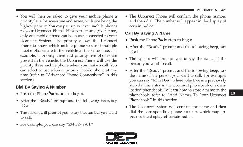
• You will then be asked to give your mobile phone apriority level between one and seven, with one being thehighest priority. You can pair up to seven mobile phonesto your Uconnect Phone. However, at any given time,only one mobile phone can be in use, connected to yourUconnect System. The priority allows the UconnectPhone to know which mobile phone to use if multiplemobile phones are in the vehicle at the same time. Forexample, if priority three and priority five phones arepresent in the vehicle, the Uconnect Phone will use thepriority three mobile phone when you make a call. Youcan select to use a lower priority mobile phone at anytime (refer to “Advanced Phone Connectivity” in thissection).
Dial By Saying A Number
• Push the Phone button to begin.
• After the “Ready” prompt and the following beep, say“Dial.”
• The system will prompt you to say the number you wantto call.
• For example, you can say “234-567-8901.”
• The Uconnect Phone will confirm the phone numberand then dial. The number will appear in the display ofcertain radios.
Call By Saying A Name
• Push the Phone button to begin.
• After the “Ready” prompt and the following beep, say“Call.”
• The system will prompt you to say the name of theperson you want to call.
• After the “Ready” prompt and the following beep, saythe name of the person you want to call. For example,you can say “John Doe,” where John Doe is a previouslystored name entry in the Uconnect phonebook or down-loaded phonebook. To learn how to store a name in thephonebook, refer to “Add Names To Your UconnectPhonebook,” in this section.
• The Uconnect system will confirm the name and thendial the corresponding phone number, which may ap-pear in the display of certain radios.
10
MULTIMEDIA 473

Phonebook Download – Automatic PhonebookTransfer From Mobile Phone
If equipped and specifically supported by your phone,Uconnect Phone automatically downloads names (textnames) and number entries from your mobile phone’sphonebook. Specific Bluetooth Phones with Phone BookAccess Profile may support this feature. See Uconnectwebsite for supported phones.
• To call a name from downloaded (or Uconnect) Phone-book, follow the procedure in “Call by Saying a Name”section.
• Automatic download and update, if supported, beginsas soon as the Bluetooth wireless phone connection ismade to the Uconnect Phone, for example, after you startthe vehicle.
• A maximum of 1,000 entries per phone will be down-loaded and updated every time a phone is connected tothe Uconnect Phone.
• Depending on the maximum number of entries down-loaded, there may be a short delay before the latestdownloaded names can be used. Until then, if available,the previous downloaded phonebook is available foruse.
• Only the phonebook of the currently connected mobilephone is accessible.
• Only the mobile phone’s phonebook is downloaded.SIM card phonebook is not part of the Mobile phone-book.
• This downloaded phonebook cannot be edited or de-leted on the Uconnect Phone. These can only be editedon the mobile phone. The changes are transferred andupdated to Uconnect Phone on the next phone connec-tion.
Add Names To Your Uconnect Phonebook
NOTE: Adding names to the Uconnect Phonebook isrecommended when the vehicle is not in motion.
• Push the Phone button to begin.
• After the “Ready” prompt and the following beep, say“Phonebook New Entry.”
• When prompted, say the name of the new entry. Use oflong names helps the Voice Command and it is recom-mended. For example, say “Robert Smith” or “Robert”instead of “Bob.”
474 MULTIMEDIA

• When prompted, enter the number designation (e.g.,“Home,” “Work,” “Mobile,” or “Other”). This will allowyou to store multiple numbers for each phonebook entry,if desired.
• When prompted, recite the phone number for the phone-book entry that you are adding.
After you are finished adding an entry into the phonebook,you will be given the opportunity to add more phonenumbers to the current entry or to return to the main menu.
The Uconnect Phone will allow you to enter up to 32 namesin the phonebook with each name having up to fourassociated phone numbers and designations. Each lan-guage has a separate 32-name phonebook accessible onlyin that language. In addition, if equipped and supportedby your phone, Uconnect Phone automatically downloadsyour mobile phone’s phonebook.
Edit Uconnect Phonebook Entries
• Push the Phone button to begin.
• After the “Ready” prompt and the following beep, say“Phonebook Edit.”
• You will then be asked for the name of the phonebookentry that you wish to edit.
• Next, choose the number designation (home, work,mobile, or other) that you wish to edit.
• When prompted, recite the new phone number for thephonebook entry that you are editing.
After you are finished editing an entry in the phonebook,you will be given the opportunity to edit another entry inthe phonebook, call the number you just edited, or returnto the main menu.
NOTE:
• Editing names in the phonebook is recommended whenthe vehicle is not in motion.
• Automatic downloaded phonebook entries cannot bedeleted or edited.
“Phonebook Edit” can be used to add another phonenumber to a name entry that already exists in the phone-book. For example, the entry John Doe may have a mobileand a home number, but you can add “John Doe’s” worknumber later using the “Phonebook Edit” feature.
Delete Uconnect Phonebook Entry
NOTE: Editing phonebook entries is recommended whenthe vehicle is not in motion.
10
MULTIMEDIA 475

To delete a Uconnect phonebook entry using Voice Com-mands:
1. Push the Phone button to begin.
2. After the “Ready” prompt and the following beep, say“Phonebook Delete.”
3. After you enter the Phonebook Delete menu, you willthen be asked for the name of the entry that you wish todelete. You can either say the name of a phonebookentry that you wish to delete, or you can say “ListNames” to hear a list of the entries in the phonebookfrom which you choose. To select one of the entries fromthe list, push the Voice Command button while theUconnect Phone is playing the desired entry and say“Delete.”
4. After you enter the name, the Uconnect Phone will askyou which designation you wish to delete: home, work,mobile, other, or all. Say the designation you wish todelete.• Note that only the phonebook entry in the current
language is deleted.
NOTE: Automatic downloaded phonebook entries cannotbe deleted or edited.
List All Names In The Uconnect Phonebook
• Push the Phone button to begin.
• After the “Ready” prompt and the following beep, say“Phonebook List Names.”
• The Uconnect Phone will play the names of all thephonebook entries, including the downloaded phone-book entries, if available.
• To call one of the names in the list, push the VoiceCommand button during the playing of the desiredname, and say “Call.”
NOTE: The user can also exercise “Edit” or “Delete”operations at this point.
• The Uconnect Phone will then prompt you as to thenumber designation you wish to call.
• The selected number will be dialed.
Phone Call Features
The following features can be accessed through theUconnect Phone if the feature(s) are available on yourmobile service plan. For example, if your mobile serviceplan provides three-way calling, this feature can be ac-cessed through the Uconnect Phone. Check with yourmobile service provider for the features that you have.
476 MULTIMEDIA

Answer Or Reject An Incoming Call — No CallCurrently In Progress
When you receive a call on your mobile phone, theUconnect Phone will interrupt the vehicle audio system, ifon, and will ask if you would like to answer the call. Pushthe Phone button to accept the call. To reject the call,push and hold the Phone button until you hear asingle beep, indicating that the incoming call was re-jected.
Answer Or Reject An Incoming Call — CallCurrently In Progress
If a call is currently in progress and you have anotherincoming call, you will hear the same network tones forcall waiting that you normally hear when using yourmobile phone. Push the Phone button to place thecurrent call on hold and answer the incoming call.
NOTE: The Uconnect Phone compatible phones in themarket today do not support rejecting an incoming callwhen another call is in progress. Therefore, the user canonly answer an incoming call or ignore it.
Making A Second Call While Current Call Is InProgress
To make a second call while you are currently on a call,push the Voice Command button and say “Dial” or“Call” followed by the phone number or phonebookentry you wish to call. The first call will be on holdwhile the second call is in progress. To go back to thefirst call, refer to “Toggling Between Calls” in thissection. To combine two calls, refer to “Conference Call”in this section.
Place/Retrieve A Call From Hold
To put a call on hold, push the Phone button until youhear a single beep. This indicates that the call is on hold.To bring the call back from hold, push and hold thePhone button until you hear a single beep.
Toggling Between Calls
If two calls are in progress (one active and one on hold),push the Phone button until you hear a single beep,indicating that the active and hold status of the two callshave switched. Only one call can be placed on hold at atime.
10
MULTIMEDIA 477

Conference Call
When two calls are in progress (one active and one onhold):
1. Push and hold the Phone button until you hear adouble beep, indicating that the two calls have beenjoined into one conference call.
Three-Way Calling
To initiate three-way calling, push the Voice Commandbutton while a call is in progress, and make a second
phone call, as described under “Making a Second CallWhile Current Call is in Progress.” After the second callhas established, push and hold the Phone buttonuntil you hear a double beep, indicating that the twocalls have been joined into one conference call.
Call Termination
To end a call in progress:
1. Momentarily push the Phone button.• Only the active call(s) will be terminated and if there is
a call on hold, it will become the new active call. If theactive call is terminated by the phone far end, a call onhold may not become active automatically. This is cellphone-dependent.
2. To bring the call back from hold, push and hold thePhone button until you hear a single beep.
Redial
To redial the last number called from your mobile phoneusing Voice Command:
1. Push the Phone button to begin.
2. After the “Ready” prompt and the following beep, say“Redial.”• The Uconnect Phone will call the last number that was
dialed from your mobile phone.
NOTE: This may not be the last number dialed from theUconnect Phone.
Call Continuation
Call continuation is the progression of a phone call on theUconnect Phone after the vehicle ignition has beenswitched to OFF. Call continuation functionality availableon the vehicle can be any one of three types:
1. After the ignition is switched to OFF, a call can continueon the Uconnect Phone either until the call ends, or until
478 MULTIMEDIA

the vehicle battery condition dictates cessation of thecall on the Uconnect Phone and transfer of the call to themobile phone.
2. After the ignition is cycled to OFF, a call can continue onthe Uconnect Phone for a certain duration, after whichthe call is automatically transferred from the UconnectPhone to the mobile phone.
3. An active call is automatically transferred to the mobilephone after the ignition is cycled to OFF.
Uconnect Phone Features
Language Selection
To change the language that the Uconnect Phone is using:
• Push the Phone button to begin.
• After the “Ready” prompt and the following beep, saythe name of the language you wish to switch to English,Espanol, or Francais.
• Continue to follow the system prompts to complete thelanguage selection.
After selecting one of the languages, all prompts and voicecommands will be in that language.
NOTE: After every Uconnect Phone language changeoperation, only the language-specific 32-name phonebookis usable. The paired phone name is not language-specificand usable across all languages.
Emergency Assistance
If you are in an emergency and the mobile phone isreachable:
• Pick up the phone and manually dial the emergencynumber for your area.
If the phone is not reachable and the Uconnect Phone isoperational, you may reach the emergency number asfollows:
• Push the Phone button to begin.
• After the “Ready” prompt and the following beep, say“Emergency” and the Uconnect Phone will instruct thepaired mobile phone to call the emergency number.
10
MULTIMEDIA 479

NOTE:
• The emergency number dialed is based on the countrywhere the vehicle is purchased (911 for the U.S. andCanada and 060 for Mexico). The number dialed maynot be applicable with the available mobile service andarea.
• If supported, this number may be programmable onsome systems. To do this, push the Phone button andsay “Setup,” followed by “Emergency.”
• The Uconnect Phone does slightly lower your chances ofsuccessfully making a phone call as to that for themobile phone directly.
WARNING!
To use your Uconnect Phone System in an emergency,your mobile phone must be:• Turned on.• Paired to the Uconnect System.• Have network coverage.
Roadside Assistance/Towing Assistance
If you need roadside assistance:
• Push the Phone button to begin.
• After the “Ready” prompt and the following beep, say“Towing Assistance.”
NOTE: You should program the desired Towing Assistancephone number using the Voice Command system. To dothis, push the Phone button and say “Setup,” fol-lowed by “Towing Assistance.” When prompted say1-800-521-2779 for U.S., 1-800-363-4869 for Canada, 55-14-3454 for Mexico City and 1-800-712-3040 for outsideMexico City in Mexico.
Paging
To learn how to page, refer to “Working With AutomatedSystems.” Paging works properly except for pagers ofcertain companies, which time out a little too soon to workproperly with the Uconnect Phone.
Voice Mail Calling
To learn how to access your voice mail, refer to “WorkingWith Automated Systems.”
Working With Automated Systems
This method is used in instances where one generally hasto press numbers on the mobile phone keypad whilenavigating through an automated telephone system.
480 MULTIMEDIA

You can use your Uconnect Phone to access a voice mailsystem or an automated service, such as a paging service orautomated customer service line. Some services requireimmediate response selection. In some instances, that maybe too quick for use of the Uconnect Phone.
When calling a number with your Uconnect Phone thatnormally requires you to enter in a touch-tone sequence onyour mobile phone keypad, you can push the Voice Com-mand button and say the sequence you wish to enter,followed by the word “Send.” For example, if requiredto enter your PIN followed with a pound, (3 7 4 6 #), youcan push the Voice Command button and say, “3 7 46 # Send.” Saying a number, or sequence of numbers,followed by “Send,” is also to be used for navigatingthrough an automated customer service center menustructure, and to leave a number on a pager.
You can also send stored Uconnect Phonebook entries astones for fast and easy access to voice mail and pagerentries. To use this feature, dial the number you wish to calland then push the Voice Command button and say,“Send.” The system will prompt you to enter the nameor number and say the name of the phonebook entryyou wish to send. The Uconnect Phone will then send
the corresponding phone number associated with thephonebook entry, as tones over the phone.
NOTE:
• You may not hear all of the tones due to mobile phonenetwork configurations. This is normal.
• Some paging and voice mail systems have system timeout settings that are too short and may not allow the useof this feature.
Barge In – Overriding Prompts
The “Voice Command” button can be used when you wishto skip part of a prompt and issue your voice commandimmediately. For example, if a prompt is asking “Wouldyou like to pair a phone, clear a...,” you could push theVoice Command button and say, “Pair a Phone” toselect that option without having to listen to the rest ofthe voice prompt.
Turning Confirmation Prompts On/Off
Turning confirmation prompts off will stop the systemfrom confirming your choices (e.g., the Uconnect Phonewill not repeat a phone number before you dial it).
10
MULTIMEDIA 481

To turn confirmation prompts on or off using Voice Com-mand:
1. Push the Phone button to begin.
2. After the “Ready” prompt and the following beep, say:• “Setup Confirmations Prompts On”• “Setup Confirmations Prompts Off”
Phone And Network Status Indicators
If available on the radio and/or on a premium display suchas the instrument panel cluster, and supported by yourmobile phone, the Uconnect Phone will provide notifica-tion to inform you of your phone and network status whenyou are attempting to make a phone call using UconnectPhone. The status is given for roaming, network signalstrength, phone battery strength, etc.
Dialing Using The Mobile Phone Keypad
You can dial a phone number with your mobile phonekeypad and still use the Uconnect Phone (while dialing viathe mobile phone keypad, the user must exercise cautionand take precautionary safety measures). By dialing anumber with your paired Bluetooth mobile phone, the
audio will be played through your vehicles audio system.The Uconnect Phone will work the same as if you dial thenumber using Voice Command.
NOTE: Certain brands of mobile phones do not send thedial ring to the Uconnect Phone to play it on the vehicleaudio system, so you will not hear it. Under this situation,after successfully dialing a number the user may feel thatthe call did not go through even though the call is inprogress. Once your call is answered, you will hear theaudio.
Mute/Un-Mute (Mute ON/OFF)
When you mute the Uconnect Phone, you will still be ableto hear the conversation coming from the other party, butthe other party will not be able to hear you. To mute theUconnect Phone:
• Push the Voice Command button.
• Following the beep, say “Mute.”
To un-mute the Uconnect Phone:
• Push the Voice Command button.
• Following the beep, say “Mute off.”
482 MULTIMEDIA

Advanced Phone Connectivity
Transfer Call To And From Mobile Phone
The Uconnect Phone allows ongoing calls to be transferredfrom your mobile phone to the Uconnect Phone withoutterminating the call. To transfer an ongoing call from yourUconnect Phone paired mobile phone to the UconnectPhone or vice versa, push the Voice Command buttonand say “Transfer Call.”
Connect Or Disconnect Link Between The UconnectPhone And Mobile Phone
Your mobile phone can be paired with many differentelectronic devices, but can only be actively �connected�with one electronic device at a time.
If you would like to connect or disconnect the Bluetoothconnection between a Uconnect Phone paired mobilephone and the Uconnect Phone, follow the instructionsdescribed in your mobile phone user manual.
List Paired Mobile Phone Names
• Push the Phone button to begin.
• After the “Ready” prompt and the following beep, say“Setup Phone Pairing.”
• When prompted, say “List Phones.”
• The Uconnect Phone will play the phone names of allpaired mobile phones in order from the highest to thelowest priority. To “Select” or “Delete” a paired phonebeing announced, push the Voice Command buttonand say “Select” or “Delete.” Also, see the next twosections for an alternate way to “Select” or “Delete” apaired phone.
Select Another Mobile Phone
This feature allows you to select and start using anotherphone paired with the Uconnect Phone.
• Push the Phone button to begin.
• After the “Ready” prompt and the following beep, say“Setup Select Phone” and follow the prompts.
• You can also push the Voice Command button at anytime while the list is being played, and then choosethe phone that you wish to select.
• The selected phone will be used for the next phone call.If the selected phone is not available, the UconnectPhone will return to using the highest priority phonepresent in or near (approximately within 30 ft (9 m) thevehicle.
10
MULTIMEDIA 483

Delete Uconnect Phone Paired Mobile Phones
• Push the Phone button to begin.
• After the “Ready” prompt and the following beep, say“Setup Phone Pairing.”
• At the next prompt, say “Delete” and follow theprompts.
• You can also push the Voice Command button at anytime while the list is being played, and then choosethe phone you wish to delete.
Things You Should Know About Your UconnectPhone
Uconnect Phone Tutorial
To hear a brief tutorial of the system features, push thePhone button and say “Uconnect Tutorial.”
Voice Training
For users experiencing difficulty with the system recogniz-ing their voice commands or numbers, the Uconnect PhoneVoice Training feature may be used. To enter this trainingmode, follow one of the two following procedures:
• From outside the Uconnect Phone mode (e.g., from radiomode), push and hold the Voice Command buttonfor five seconds until the session begins, or,
• Push the Voice Command button and say the “VoiceTraining,” “System Training,” or “Start Voice Train-ing” command.
You can either push the Uconnect Phone button to restorethe factory setting or repeat the words and phrases whenprompted by the Uconnect Phone. For best results, theVoice Training session should be completed when thevehicle is parked with the engine running, all windowsclosed, and the blower fan switched off.
This procedure may be repeated with a new user. Thesystem will adapt to the last trained voice only.
Reset
To Reset all settings using Voice Command:
1. Push the Phone button.
2. After the “Ready” prompt and the following beep, say“Setup,” then “Reset.”• This will delete all phone pairing, phone book entries,
and other settings in all language modes. The Systemwill prompt you before resetting to factory settings.
484 MULTIMEDIA

Voice Command
For best performance:
• Adjust the rearview mirror to provide at least ½ inch (1cm) gap between the overhead console (if equipped) andthe mirror.
• Always wait for the beep before speaking.
• Speak normally without pausing, just as you wouldspeak to a person sitting a few feet/meters away fromyou.
• Make sure that no one other than you is speaking duringa Voice Command period.
Performance is maximized under:
• Low-to-medium blower setting
• Low-to-medium vehicle speed
• Low road noise
• Smooth road surface
• Fully closed windows
• Dry weather condition
NOTE:
• Even though the system is designed for users speakingin North American English, French, and Spanish accents,the system may not always work for some.
• When navigating through an automated system such asvoice mail, or when sending a page, at the end ofspeaking the digit string, make sure to say “Send.”
• Storing names in the phonebook when the vehicle is notin motion is recommended.
• It is not recommended to store similar sounding namesin the Uconnect Phonebook.
• Phonebook (Downloaded and Uconnect Phone Local)name recognition rate is optimized when the entries arenot similar.
• Numbers must be spoken in single digits. “800” must bespoken “eight-zero-zero” not “eight hundred.”
• You can say “O” (letter “O”) for “0” (zero).
• Even though international dialing for most numbercombinations is supported, some shortcut dialing num-ber combinations may not be supported.
10
MULTIMEDIA 485
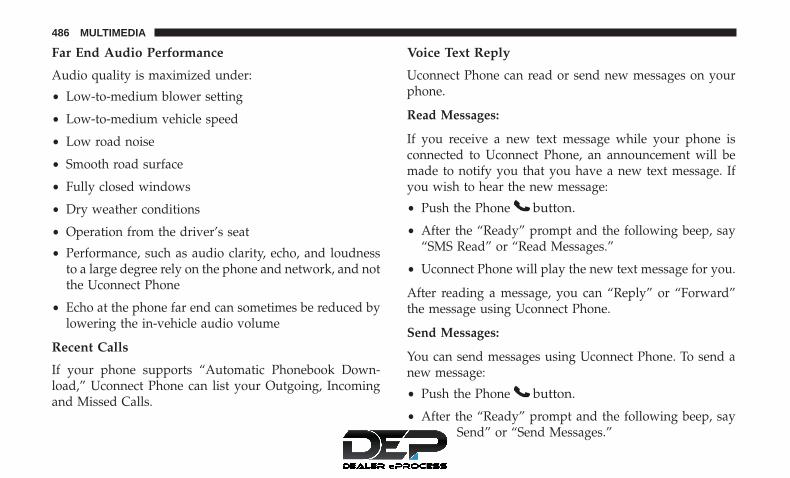
Far End Audio Performance
Audio quality is maximized under:
• Low-to-medium blower setting
• Low-to-medium vehicle speed
• Low road noise
• Smooth road surface
• Fully closed windows
• Dry weather conditions
• Operation from the driver’s seat
• Performance, such as audio clarity, echo, and loudnessto a large degree rely on the phone and network, and notthe Uconnect Phone
• Echo at the phone far end can sometimes be reduced bylowering the in-vehicle audio volume
Recent Calls
If your phone supports “Automatic Phonebook Down-load,” Uconnect Phone can list your Outgoing, Incomingand Missed Calls.
Voice Text Reply
Uconnect Phone can read or send new messages on yourphone.
Read Messages:
If you receive a new text message while your phone isconnected to Uconnect Phone, an announcement will bemade to notify you that you have a new text message. Ifyou wish to hear the new message:
• Push the Phone button.
• After the “Ready” prompt and the following beep, say“SMS Read” or “Read Messages.”
• Uconnect Phone will play the new text message for you.
After reading a message, you can “Reply” or “Forward”the message using Uconnect Phone.
Send Messages:
You can send messages using Uconnect Phone. To send anew message:
• Push the Phone button.
• After the “Ready” prompt and the following beep, say“SMS Send” or “Send Messages.”
486 MULTIMEDIA

• You can either say the message you wish to send or say“List Messages.” There are 20 preset messages.
To send a message, push the Voice Command buttonwhile the system is listing the message and say “Send.”
Uconnect Phone will prompt you to say the name ornumber of the person you wish to send the message to.
List of Preset Messages:
1. Yes
2. No
3. Where are you?
4. I need more direction
5. L O L
6. Why
7. I love you
8. Call me
9. Call me later
10. Thanks
11. See you in 15 minutes
12. I am on my way
13. I’ll be late
14. Are you there yet?
15. Where are we meeting?
16. Can this wait?
17. Bye for now
18. When can we meet?
19. Send number to call
20. Start without me
Turn SMS Incoming Announcement ON/OFF
Turning the SMS Incoming Announcement OFF will stopthe system from announcing the new incoming messages.
• Push the Phone button.
• After the “Ready” prompt and the following beep, say“Setup, Incoming Message Announcement,” you willthen be given a choice to change it.
10
MULTIMEDIA 487

Bluetooth Communication Link
Mobile phones have been found to lose connection to theUconnect Phone. When this happens, the connection cangenerally be reestablished by switching the phone off/on.Your mobile phone is recommended to remain in BluetoothON mode.
Power-Up
After switching the ignition key from OFF to either the ONor ACC position, or after a language change, you must waitat least 15 seconds prior to using the system.
488 MULTIMEDIA

10
MULTIMEDIA 489

Voice Commands
Primary Alternate (s)zeroonetwothree
Primary Alternate (s)fourfivesixseveneight
490 MULTIMEDIA

Primary Alternate (s)ninestar (*)plus (+)pound (#)add locationallcallcancelconfirmation promptscontinuedeletedialdownloadeditemergencyEnglisherase allEspanolFrancaishelp
Primary Alternate (s)homelanguagelist nameslist phonesmobilemutemute offnew entrynootherpair a phonephone pairing pairingphonebook phone bookpreviousrecord againredialreturn to main menu return or main menuselect phone selectsend
10
MULTIMEDIA 491

Primary Alternate (s)set up phone settings or phone
set uptowing assistancetransfer callUconnect Tutorialvoice trainingworkyes
General Information
The following regulatory statement applies to all radiofrequency (RF) devices equipped in this vehicle: Thisdevice complies with Part 15 of the FCC Rules and withIndustry Canada license-exempt RSS standard(s). Opera-tion is subject to the following two conditions: (1) Thisdevice may not cause harmful interference, and (2) Thisdevice must accept any interference received, includinginterference that may cause undesired operation.
NOTE: Changes or modifications not expressly approvedby the party responsible for compliance could void theuser’s authority to operate the equipment.
VOICE COMMAND — IF EQUIPPED
Voice Command System Operation
The Uconnect Voice Command system allowsyou to control your AM, FM radio, disk player,USB mass storage class device, iPod family ofdevices, Bluetooth Streaming Audio Device, sat-
ellite radio, and a memo recorder.
NOTE: Take care to speak into the Voice Interface Systemas calmly and normally as possible. The ability of the VoiceInterface System to recognize user voice commands may benegatively affected by rapid speaking or a raised voicelevel.
WARNING!
Any voice commanded system should be used only insafe driving conditions following all applicable laws.Your attention should be focused on safely operatingthe vehicle. Failure to do so may result in a collisioncausing serious injury or death.
When you push the Voice Command button, you willhear a beep. The beep is your signal to give a command.
492 MULTIMEDIA

NOTE: If you do not say a command within a few seconds,the system will present you with a list of options.
If you would like to interrupt the system while it listsoptions, push the Voice Command button, listen forthe beep, and say your command.
Pushing the Voice Command button while the systemis speaking is known as “barging in.” The system will beinterrupted, and after the beep, you can add or changecommands. This will become helpful once you start tolearn the options.
NOTE: At any time, you can say the words “Cancel,”“Help” or “Main Menu.”
These commands are universal and can be used from anymenu. All other commands can be used depending uponthe active application.
When using this system, you should speak clearly and at anormal speaking volume.
The system will best recognize your speech if the windowsare closed, and the heater/air conditioning blower is set tolow.
At any point, if the system does not recognize one of yourcommands, you will be prompted to repeat it.
To hear the first available Menu, push the Voice Commandbutton and say “Help” or “Main Menu.”
Commands
The Voice Command system understands two types ofcommands, Universal commands and Local commands.Universal commands are available at all times. Localcommands are available if the supported radio mode isactive.
Changing The Volume
1. Start a dialogue by pushing the Voice Command but-ton.
2. Say a command (e.g., “Help”).
3. Use the ON/OFF VOLUME rotary knob to adjust thevolume to a comfortable level while the Voice Com-mand system is speaking. Please note the volume set-ting for Voice Command is different than the audiosystem.
Main Menu
Start a dialogue by pushing the Voice Command but-ton. You may say “Main Menu” to switch to the mainmenu.
10
MULTIMEDIA 493

In this mode, you can say the following commands:
• “Radio AM” (to switch to the radio AM mode)
• “Radio FM” (to switch to radio FM mode)
• “Sat” (to switch to Satellite radio mode)
• “Disc” (to switch to the disc mode)
• “USB” (to switch to USB mode)
• “Bluetooth Streaming” (to switch to Bluetooth Stream-ing mode)
• “Memo” (to switch to the memo recorder)
• “System Setup” (to switch to system setup)
Radio AM
To switch to the AM band, say “AM” or “Radio AM.” Inthis mode, you may say the following commands:
• “Frequency #” (to change the frequency)
• “Next Station” (to select the next station)
• “Previous Station” (to select the previous station)
• “Radio Menu” (to switch to the radio menu)
• “Main Menu” (to switch to the main menu)
Radio FM
To switch to the FM band, say “FM” or “Radio FM.” In thismode, you may say the following commands:
• “Frequency #” (to change the frequency)
• “Next Station” (to select the next station)
• “Previous Station” (to select the previous station)
• “Menu Radio” (to switch to the radio menu)
• “Main Menu” (to switch to the main menu)
Satellite Radio
To switch to satellite radio mode, say “Sat” or “SatelliteRadio.” In this mode, you may say the following commands:
• “Channel Number” (to change the channel by its spokennumber)
• “Next Channel” (to select the next channel)
• “Previous Channel” (to select the previous channel)
• “List Channel” (to hear a list of available channels)
• “Select Name” (to say the name of a channel)
• “Menu Radio” (to switch to the radio menu)
• “Main Menu” (to switch to the main menu)
494 MULTIMEDIA

Disc Mode
To switch to the disc mode, say “Disc.” In this mode, youmay say the following commands:
• “Track” (#) (to change the track)
• “Next Track” (to play the next track)
• “Previous Track” (to play the previous track)
• “Main Menu” (to switch to the main menu)
USB Mode
To switch to USB mode, say “USB.” In this mode, you maysay the following commands:
• “Next Track” (to play the next track)
• “Previous Track” (to play the previous track)
• “Play” (to play an Artist Name, Playlist Name, AlbumName, Track Name, etc.)
Bluetooth Streaming (BT) Mode
To switch to Bluetooth Streaming (BT) mode, say“Bluetooth Streaming.” In this mode, you may say thefollowing commands:
• “Play” (to play the current track)
• “Pause” (to pause the current track)
• “Next Track” (to play the next track)
• “Previous Track” (to play the previous track)
Memo Mode
To switch to the voice recorder mode, say “Memo.” In thismode, you may say the following commands:
• “New Memo” (to record a new memo) — During therecording, you may push the Voice Command buttonto stop recording. You proceed by saying one of thefollowing commands:– “Save” (to save the memo)
– “Continue” (to continue recording)
– “Delete” (to delete the recording)
• “Play Memos” (to play previously recorded memos) —During the playback you may push the Voice Command
button to stop playing memos. You proceed bysaying one of the following commands:
– “Repeat” (to repeat a memo)
– “Next” (to play the next memo)
– “Previous” (to play the previous memo)
– “Delete” (to delete a memo)
– “Delete All” (to delete all memos)
10
MULTIMEDIA 495

Setup
To switch to system setup, you may say one of thefollowing:
• “Change to setup”
• “Switch to system setup”
• “Main menu setup”
• “Switch to setup”
In this mode, you may say the following commands:
• “Language English”
• “Language French”
• “Language Spanish”
• “Tutorial”
• “Voice Training”
NOTE: Keep in mind that you have to push the VoiceCommand button first and wait for the beep beforespeaking the “Barge In” commands.
Voice Training
For users experiencing difficulty with the system recogniz-ing their voice commands or numbers the Uconnect Voice“Voice Training” feature may be used.
1. Push the Voice Command button, say “SystemSetup” and once you are in that menu then say “VoiceTraining.” This will train your own voice to thesystem and will improve recognition.
2. Repeat the words and phrases when prompted byUconnect Voice. For best results, the “Voice Training”session should be completed when the vehicle is parked,engine running, all windows closed, and the blower fanswitched off. This procedure may be repeated with anew user. The system will adapt to the last trained voiceonly.
496 MULTIMEDIA

CUSTOMER ASSISTANCE
CONTENTS� SUGGESTIONS FOR OBTAINING SERVICE FOR
YOUR VEHICLE . . . . . . . . . . . . . . . . . . . . . . . .498
▫ Prepare For The Appointment . . . . . . . . . . . . . .498
▫ Prepare A List . . . . . . . . . . . . . . . . . . . . . . . . .498
▫ Be Reasonable With Requests . . . . . . . . . . . . . .498
� IF YOU NEED ASSISTANCE . . . . . . . . . . . . . . . .498
▫ FCA US LLC Customer Center . . . . . . . . . . . . .499
▫ FCA Canada Inc. Customer Center. . . . . . . . . . .499
▫ In Mexico Contact . . . . . . . . . . . . . . . . . . . . . .499
▫ Puerto Rico And U.S. Virgin Islands. . . . . . . . . .499
▫ Customer Assistance For The Hearing Or SpeechImpaired (TDD/TTY) . . . . . . . . . . . . . . . . . . . .500
▫ Service Contract . . . . . . . . . . . . . . . . . . . . . . .500
� WARRANTY INFORMATION . . . . . . . . . . . . . . .501
� MOPAR PARTS . . . . . . . . . . . . . . . . . . . . . . . . .501
� REPORTING SAFETY DEFECTS . . . . . . . . . . . . .501
▫ In The 50 United States And Washington, D.C. . .501
▫ In Canada . . . . . . . . . . . . . . . . . . . . . . . . . . . .502
� PUBLICATION ORDER FORMS . . . . . . . . . . . . .50211

SUGGESTIONS FOR OBTAINING SERVICE FORYOUR VEHICLE
Prepare For The Appointment
If you are having warranty work done, be sure to have theright papers with you. Take your warranty folder. All workto be performed may not be covered by the warranty.Discuss additional charges with the service manager. Keepa maintenance log of your vehicle’s service history. Thiscan often provide a clue to the current problem.
Prepare A List
Make a written list of your vehicle’s problems or thespecific work you want done. If you’ve had an accident orwork done that is not on your maintenance log, let theservice advisor know.
Be Reasonable With Requests
If you list a number of items and you must have yourvehicle by the end of the day, discuss the situation with theservice advisor and list the items in order of priority. Atmany authorized dealers, you may obtain a rental vehicleat a minimal daily charge. If you need a rental, it isadvisable to make these arrangements when you call for anappointment.
IF YOU NEED ASSISTANCE
The manufacturer and its authorized dealer are vitallyinterested in your satisfaction. We want you to be happywith our products and services.
Warranty service must be done by an authorized dealer. Westrongly recommend that you take the vehicle to an autho-rized dealer. They know your vehicle the best, and are mostconcerned that you get prompt and high quality service.The manufacturer’s authorized dealer have the facilities,factory-trained technicians, special tools, and the latestinformation to ensure the vehicle is fixed correctly and in atimely manner.
This is why you should always talk to an authorized dealerservice manager first. Most matters can be resolved withthis process.
• If for some reason you are still not satisfied, talk to thegeneral manager or owner of the authorized dealer.They want to know if you need assistance.
• If an authorized dealer is unable to resolve the concern,you may contact the manufacturer’s customer center.
498 CUSTOMER ASSISTANCE

Any communication to the manufacturer’s customer centershould include the following information:
• Owner’s name and address
• Owner’s telephone number (home and office)
• Authorized dealer name
• Vehicle Identification Number (VIN)
• Vehicle delivery date and mileage
FCA US LLC Customer Center
P.O. Box 21–8004
Auburn Hills, MI 48321–8004
Phone: (800) 247-9753
FCA Canada Inc. Customer Center
P.O. Box 1621
Windsor, Ontario N9A 4H6
Phone: (800) 465-2001 English / (800) 387-9983 French
In Mexico Contact
Av. Prolongacion Paseo de la Reforma, 1240
Sante Fe C.P. 05109
Mexico, D. F.
In Mexico City: 5081-7568
Outside Mexico City: 1-800-505-1300
Puerto Rico And U.S. Virgin Islands
Customer Service Chrysler International Services LLC
P.O. Box 191857
San Juan 00919-1857
Tel.: (787) 782-5757
Fax: (787) 782-3345
11
CUSTOMER ASSISTANCE 499
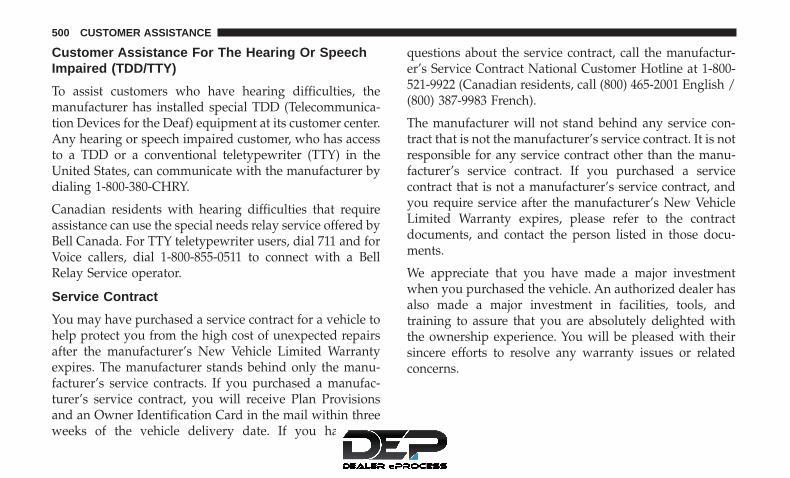
Customer Assistance For The Hearing Or SpeechImpaired (TDD/TTY)
To assist customers who have hearing difficulties, themanufacturer has installed special TDD (Telecommunica-tion Devices for the Deaf) equipment at its customer center.Any hearing or speech impaired customer, who has accessto a TDD or a conventional teletypewriter (TTY) in theUnited States, can communicate with the manufacturer bydialing 1-800-380-CHRY.
Canadian residents with hearing difficulties that requireassistance can use the special needs relay service offered byBell Canada. For TTY teletypewriter users, dial 711 and forVoice callers, dial 1-800-855-0511 to connect with a BellRelay Service operator.
Service Contract
You may have purchased a service contract for a vehicle tohelp protect you from the high cost of unexpected repairsafter the manufacturer’s New Vehicle Limited Warrantyexpires. The manufacturer stands behind only the manu-facturer’s service contracts. If you purchased a manufac-turer’s service contract, you will receive Plan Provisionsand an Owner Identification Card in the mail within threeweeks of the vehicle delivery date. If you have any
questions about the service contract, call the manufactur-er’s Service Contract National Customer Hotline at 1-800-521-9922 (Canadian residents, call (800) 465-2001 English /(800) 387-9983 French).
The manufacturer will not stand behind any service con-tract that is not the manufacturer’s service contract. It is notresponsible for any service contract other than the manu-facturer’s service contract. If you purchased a servicecontract that is not a manufacturer’s service contract, andyou require service after the manufacturer’s New VehicleLimited Warranty expires, please refer to the contractdocuments, and contact the person listed in those docu-ments.
We appreciate that you have made a major investmentwhen you purchased the vehicle. An authorized dealer hasalso made a major investment in facilities, tools, andtraining to assure that you are absolutely delighted withthe ownership experience. You will be pleased with theirsincere efforts to resolve any warranty issues or relatedconcerns.
500 CUSTOMER ASSISTANCE

WARNING!
Engine exhaust (internal combustion engines only),some of its constituents, and certain vehicle compo-nents contain, or emit, chemicals known to the State ofCalifornia to cause cancer and birth defects, or otherreproductive harm. In addition, certain fluids con-tained in vehicles and certain products of componentwear contain, or emit, chemicals known to the State ofCalifornia to cause cancer and birth defects, or otherreproductive harm.
WARRANTY INFORMATION
See the Warranty Information Booklet, located in theowner’s information kit, for the terms and provisions ofFCA US LLC warranties applicable to this vehicle andmarket.
MOPAR PARTS
MOPAR fluids, lubricants, parts, and accessories are avail-able from an authorized dealer. They are recommended foryour vehicle in order to help keep the vehicle operating atits best.
REPORTING SAFETY DEFECTS
In The 50 United States And Washington, D.C.
If you believe that your vehicle has a defect that couldcause a crash or cause injury or death, you shouldimmediately inform the National Highway TrafficSafety Administration (NHTSA) in addition to notifyingFCA US LLC.
If NHTSA receives similar complaints, it may open aninvestigation, and if it finds that a safety defect exists ina group of vehicles, it may order a recall and remedycampaign. However, NHTSA cannot become involvedin individual problems between you, your authorizeddealer or FCA US LLC.
To contact NHTSA, you may call the Vehicle SafetyHotline toll free at 1-888-327-4236 (TTY: 1-800-424-9153);or go to http://www.safercar.gov; or write to: Admin-istrator, NHTSA, 1200 New Jersey Avenue, SE., WestBuilding, Washington, D.C. 20590. You can also obtainother information about motor vehicle safety fromhttp://www.safercar.gov.
11
CUSTOMER ASSISTANCE 501

In Canada
If you believe that your vehicle has a safety defect, youshould contact the Customer Service Department imme-diately. Canadian customers who wish to report a safetydefect to the Canadian government should contactTransport Canada, Motor Vehicle Defect Investigationsand Recalls at 1-800-333-0510 or go to http://www.tc.gc.ca/roadsafety/.
PUBLICATION ORDER FORMS
To order the following manuals, you may use either thewebsite or the phone numbers listed below. Visa, Master-card, American Express, and Discover orders are accepted.If you prefer mailing your payment, please call for an orderform.
NOTE: A street address is required when ordering manu-als (no P.O. Boxes).
Service Manuals
These comprehensive Service Manuals provide the infor-mation that students and professional technicians need indiagnosing/troubleshooting, problem solving, maintain-ing, servicing, and repairing FCA US LLC vehicles. Acomplete working knowledge of the vehicle, system,and/or components is written in straightforward languagewith illustrations, diagrams, and charts.
Diagnostic Procedure Manuals
Diagnostic Procedure Manuals are filled with diagrams,charts and detailed illustrations. These practical manualsmake it easy for students and technicians to find and fixproblems on computer-controlled vehicle systems and fea-tures. They show exactly how to find and correct problemsthe first time, using step-by-step troubleshooting and driv-ability procedures, proven diagnostic tests and a completelist of all tools and equipment.
502 CUSTOMER ASSISTANCE

Owner’s Manuals
These Owner’s Manuals have been prepared with theassistance of service and engineering specialists to acquaintyou with specific FCA US LLC vehicles. Included arestarting, operating, emergency and maintenance proce-dures as well as specifications, capabilities and safety tips.
Call toll free at:
• 1-800-890-4038 (U.S.)
• 1-800-387-1143 (Canada)
Or
Visit us on the Worldwide Web at:
• www.techauthority.com
11
CUSTOMER ASSISTANCE 503


INDEX
12

About Your Brakes . . . . . . . . . . . . . . . . . . . . . . . . .432Adding Engine Coolant (Antifreeze) . . . . . . . . . . . . .394Adding Fuel . . . . . . . . . . . . . . . . . . . . . . . . . . . . . .310Additives, Fuel . . . . . . . . . . . . . . . . . . . . . . . . . . . .434Air Bag . . . . . . . . . . . . . . . . . . . . . . . . . . . . . . . . .249
Advance Front Air Bag . . . . . . . . . . . . . . . . . . . .249Air Bag Operation . . . . . . . . . . . . . . . . . . . . . . . .251Enhanced Accident Response . . . . . . . . . . . . .256, 364Event Data Recorder (EDR) . . . . . . . . . . . . . . . . .364Front Air Bag . . . . . . . . . . . . . . . . . . . . . . . . . . .249If A Deployment Occurs . . . . . . . . . . . . . . . . . . . .255Knee Impact Bolsters . . . . . . . . . . . . . . . . . . . . . .252Maintaining Your Air Bag System . . . . . . . . . . . . .256Transporting Pets . . . . . . . . . . . . . . . . . . . . . . . .275
Air Bag Light . . . . . . . . . . . . . . . . . . . . . . . . . .194, 277Air Bag Maintenance . . . . . . . . . . . . . . . . . . . . . . . .256Air Cleaner, Engine (Engine Air Cleaner Filter). . . . . .377Air Conditioner Maintenance . . . . . . . . . . . . . . . . . .381Air Conditioning Filter . . . . . . . . . . . . . . . . . . . .69, 383Air Conditioning, Operating Tips . . . . . . . . . . . . . . . .68Air Conditioning Refrigerant . . . . . . . . . . . . . . .381, 382Air Conditioning System . . . . . . . . . . . . . . . . . . . . .381Air Filter . . . . . . . . . . . . . . . . . . . . . . . . . . . . . . . .377Air Pressure, Tires . . . . . . . . . . . . . . . . . . . . . . . . . .411Alarm (Security Alarm) . . . . . . . . . . . . . . . . . . . .27, 200
Alterations/Modifications, Vehicle . . . . . . . . . . . . . . . .7Antenna, Satellite Radio . . . . . . . . . . . . . . . . . . . . . .462Antifreeze (Engine Coolant) . . . . . . . . . . . . . . . .393, 438
Disposal . . . . . . . . . . . . . . . . . . . . . . . . . . . . . . .395Anti-Lock Brake System (ABS) . . . . . . . . . . . . . . . . .214Anti-Lock Warning Light . . . . . . . . . . . . . . . . . . . . .201Arming System (Security Alarm) . . . . . . . . . . . . . . . .27Assistance Towing . . . . . . . . . . . . . . . . . . . . . . . . . .480Assist, Hill Start . . . . . . . . . . . . . . . . . . . . . . . . . . .216Automatic Dimming Mirror . . . . . . . . . . . . . . . . . . . .50Automatic Headlights . . . . . . . . . . . . . . . . . . . . . . . .53Automatic Oil Change Indicator . . . . . . . . . . . . . . . .186Automatic Transmission . . . . . . . . . . . . . . . . . .293, 402
Adding Fluid . . . . . . . . . . . . . . . . . . . . . . . . . . .402Fluid And Filter Changes . . . . . . . . . . . . . . . . . . .402Fluid Change . . . . . . . . . . . . . . . . . . . . . . . . . . .402Fluid Level Check . . . . . . . . . . . . . . . . . . . . .399, 400Fluid Type . . . . . . . . . . . . . . . . . . . . . . . . . .399, 441Special Additives . . . . . . . . . . . . . . . . . . . . . . . . .400
Autostick . . . . . . . . . . . . . . . . . . . . . . . . . . . . . . . .297Auxiliary Electrical Outlet (Power Outlet) . . . . . . . . .174Auxiliary Power Outlet . . . . . . . . . . . . . . . . . . . . . .174Axle Fluid . . . . . . . . . . . . . . . . . . . . . . . . . . . . . . .441Axle Lock . . . . . . . . . . . . . . . . . . . . . . . . . . . . . . . .303
506 INDEX

Battery. . . . . . . . . . . . . . . . . . . . . . . . . . . . . . .195, 374Charging System Light . . . . . . . . . . . . . . . . . . . .195Keyless Key Fob Replacement . . . . . . . . . . . . . . . .20
Belts, Seat . . . . . . . . . . . . . . . . . . . . . . . . . . . . . . . .277Body Mechanism Lubrication . . . . . . . . . . . . . . . . . .385B-Pillar Location . . . . . . . . . . . . . . . . . . . . . . . . . . .406Brake Assist System. . . . . . . . . . . . . . . . . . . . . . . . .216Brake Control System, Electronic. . . . . . . . . . . . . . . .215Brake Fluid . . . . . . . . . . . . . . . . . . . . . . . . . . .397, 441Brake System . . . . . . . . . . . . . . . . . . . . . . . . . .397, 432
Anti-Lock (ABS) . . . . . . . . . . . . . . . . . . . . . . . . .432Fluid Check . . . . . . . . . . . . . . . . . . . . . . . . . . . .397Master Cylinder . . . . . . . . . . . . . . . . . . . . . . . . .397Parking . . . . . . . . . . . . . . . . . . . . . . . . . . . . . . .286Warning Light . . . . . . . . . . . . . . . . . . . . . . . . . . .195
Brake/Transmission Interlock . . . . . . . . . . . . . . . . . .292Bulb Replacement . . . . . . . . . . . . . . . . . . . . . . .340, 341Bulbs, Light . . . . . . . . . . . . . . . . . . . . . . . . . . .279, 340
Calibration, Compass . . . . . . . . . . . . . . . . . . . . . . . .188Capacities, Fluid . . . . . . . . . . . . . . . . . . . . . . . . . . .438Caps, Filler
Fuel . . . . . . . . . . . . . . . . . . . . . . . . . . . . . . . . . .310Oil (Engine) . . . . . . . . . . . . . . . . . . . . . . . . . . . .373Power Steering . . . . . . . . . . . . . . . . . . . . . . . . . .306
Radiator (Coolant Pressure) . . . . . . . . . . . . . . . . .395Carbon Monoxide Warning . . . . . . . . . . . . . . . .276, 437Cargo Light . . . . . . . . . . . . . . . . . . . . . . . . . . . . . . .55Car Washes. . . . . . . . . . . . . . . . . . . . . . . . . . . . . . .425Cellular Phone . . . . . . . . . . . . . . . . . . . . . . . . .467, 469Center High Mounted Stop Light . . . . . . . . . . . . . . .343Certification Label . . . . . . . . . . . . . . . . . . . . . . . . . .311Chains, Tire . . . . . . . . . . . . . . . . . . . . . . . . . . . . . .420Changing A Flat Tire . . . . . . . . . . . . . . . . . . . . .350, 402Check Engine Light (Malfunction Indicator Light). . . .211Checking Your Vehicle For Safety . . . . . . . . . . . . . . .275Checks, Safety . . . . . . . . . . . . . . . . . . . . . . . . . . . . .275Child Restraint . . . . . . . . . . . . . . . . . . . . . . . . . . . .258Child Restraints
Booster Seats . . . . . . . . . . . . . . . . . . . . . . . . . . . .261Child Restraints . . . . . . . . . . . . . . . . . . . . . . . . .258Child Seat Installation . . . . . . . . . . . . . . . . . . . . .272How To Stow An Unused ALR Seat Belt . . . . . . . .269Infants And Child Restraints . . . . . . . . . . . . . . . .259LATCH Positions . . . . . . . . . . . . . . . . . . . . . . . . .263Locating The LATCH Anchorages . . . . . . . . . . . . .266Lower Anchors And Tethers For Children . . . . . . .263Older Children And Child Restraints . . . . . . . . . . .260Seating Positions . . . . . . . . . . . . . . . . . . . . . . . . .262
Child Safety Locks . . . . . . . . . . . . . . . . . . . . . . . . . .31
12
INDEX 507
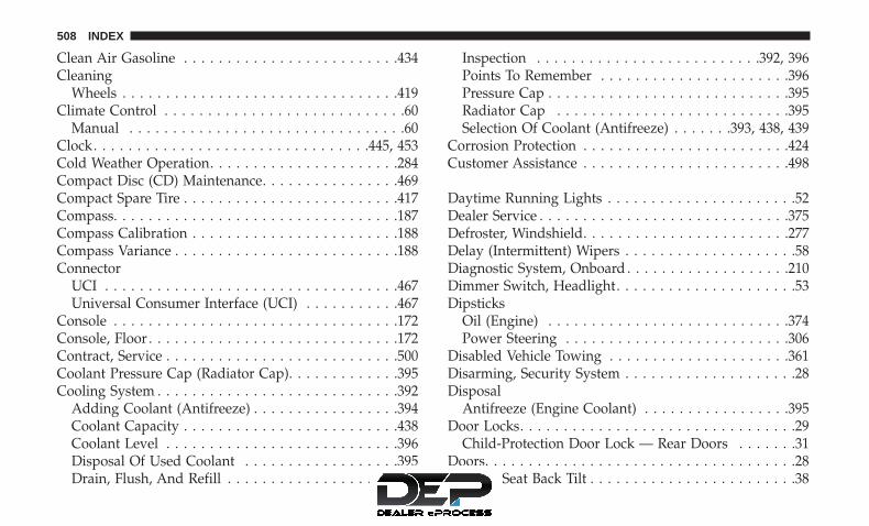
Clean Air Gasoline . . . . . . . . . . . . . . . . . . . . . . . . .434Cleaning
Wheels . . . . . . . . . . . . . . . . . . . . . . . . . . . . . . . .419Climate Control . . . . . . . . . . . . . . . . . . . . . . . . . . . .60
Manual . . . . . . . . . . . . . . . . . . . . . . . . . . . . . . . .60Clock. . . . . . . . . . . . . . . . . . . . . . . . . . . . . . . .445, 453Cold Weather Operation. . . . . . . . . . . . . . . . . . . . . .284Compact Disc (CD) Maintenance. . . . . . . . . . . . . . . .469Compact Spare Tire . . . . . . . . . . . . . . . . . . . . . . . . .417Compass. . . . . . . . . . . . . . . . . . . . . . . . . . . . . . . . .187Compass Calibration . . . . . . . . . . . . . . . . . . . . . . . .188Compass Variance . . . . . . . . . . . . . . . . . . . . . . . . . .188Connector
UCI . . . . . . . . . . . . . . . . . . . . . . . . . . . . . . . . . .467Universal Consumer Interface (UCI) . . . . . . . . . . .467
Console . . . . . . . . . . . . . . . . . . . . . . . . . . . . . . . . .172Console, Floor . . . . . . . . . . . . . . . . . . . . . . . . . . . . .172Contract, Service . . . . . . . . . . . . . . . . . . . . . . . . . . .500Coolant Pressure Cap (Radiator Cap). . . . . . . . . . . . .395Cooling System . . . . . . . . . . . . . . . . . . . . . . . . . . . .392
Adding Coolant (Antifreeze) . . . . . . . . . . . . . . . . .394Coolant Capacity . . . . . . . . . . . . . . . . . . . . . . . . .438Coolant Level . . . . . . . . . . . . . . . . . . . . . . . . . . .396Disposal Of Used Coolant . . . . . . . . . . . . . . . . . .395Drain, Flush, And Refill . . . . . . . . . . . . . . . . . . . .393
Inspection . . . . . . . . . . . . . . . . . . . . . . . . . .392, 396Points To Remember . . . . . . . . . . . . . . . . . . . . . .396Pressure Cap . . . . . . . . . . . . . . . . . . . . . . . . . . . .395Radiator Cap . . . . . . . . . . . . . . . . . . . . . . . . . . .395Selection Of Coolant (Antifreeze) . . . . . . .393, 438, 439
Corrosion Protection . . . . . . . . . . . . . . . . . . . . . . . .424Customer Assistance . . . . . . . . . . . . . . . . . . . . . . . .498
Daytime Running Lights . . . . . . . . . . . . . . . . . . . . . .52Dealer Service . . . . . . . . . . . . . . . . . . . . . . . . . . . . .375Defroster, Windshield. . . . . . . . . . . . . . . . . . . . . . . .277Delay (Intermittent) Wipers . . . . . . . . . . . . . . . . . . . .58Diagnostic System, Onboard . . . . . . . . . . . . . . . . . . .210Dimmer Switch, Headlight. . . . . . . . . . . . . . . . . . . . .53Dipsticks
Oil (Engine) . . . . . . . . . . . . . . . . . . . . . . . . . . . .374Power Steering . . . . . . . . . . . . . . . . . . . . . . . . . .306
Disabled Vehicle Towing . . . . . . . . . . . . . . . . . . . . .361Disarming, Security System . . . . . . . . . . . . . . . . . . . .28Disposal
Antifreeze (Engine Coolant) . . . . . . . . . . . . . . . . .395Door Locks. . . . . . . . . . . . . . . . . . . . . . . . . . . . . . . .29
Child-Protection Door Lock — Rear Doors . . . . . . .31Doors. . . . . . . . . . . . . . . . . . . . . . . . . . . . . . . . . . . .28Driver’s Seat Back Tilt . . . . . . . . . . . . . . . . . . . . . . . .38
508 INDEX

Driving. . . . . . . . . . . . . . . . . . . . . . . . . . . . . . . . . .328Dual Top. . . . . . . . . . . . . . . . . . . . . . . . . . . . . . .72, 75
Electrical Outlet, Auxiliary (Power Outlet) . . . . . . . . .174Electrical Power Outlets . . . . . . . . . . . . . . . . . . . . . .174Electric Remote Mirrors . . . . . . . . . . . . . . . . . . . . . . .51Electronic Brake Control System . . . . . . . . . . . . . . . .215
Anti-Lock Brake System . . . . . . . . . . . . . . . . . . . .214Electronic Roll Mitigation . . . . . . . . . . . . . . . . . . .224Traction Control System . . . . . . . . . . . . . . . . . . . .218
Electronic Speed Control (Cruise Control) . . . . . . . . .306Electronic Stability Control (ESC) . . . . . . . . . . . . . . .218Electronic Throttle Control Warning Light . . . . . . . . .198Emergency Brake. . . . . . . . . . . . . . . . . . . . . . . . . . .286Emergency, In Case Of
Jacking . . . . . . . . . . . . . . . . . . . . . . . . . . . .350, 402Jump Starting . . . . . . . . . . . . . . . . . . . . . . . . . . .355Tow Hooks . . . . . . . . . . . . . . . . . . . . . . . . . . . . .363
Emission Control System Maintenance. . . . . . . . . . . .211Engine . . . . . . . . . . . . . . . . . . . . . . . . . . . . . . . . . .373
Air Cleaner . . . . . . . . . . . . . . . . . . . . . . . . . . . . .377Block Heater . . . . . . . . . . . . . . . . . . . . . . . . . . . .285Break-In Recommendations . . . . . . . . . . . . . . . . .285Compartment . . . . . . . . . . . . . . . . . . . . . . . . . . .373Compartment Identification . . . . . . . . . . . . . . . . .373
Coolant (Antifreeze) . . . . . . . . . . . . . . . . . . . . . .439Cooling . . . . . . . . . . . . . . . . . . . . . . . . . . . . . . .392Exhaust Gas Caution . . . . . . . . . . . . . . . . . . .276, 437Fails To Start . . . . . . . . . . . . . . . . . . . . . . . . . . . .284Flooded, Starting . . . . . . . . . . . . . . . . . . . . . . . . .284Fuel Requirements . . . . . . . . . . . . . . . . . . . . . . . .438Jump Starting . . . . . . . . . . . . . . . . . . . . . . . . . . .355Oil . . . . . . . . . . . . . . . . . . . . . . . . . . . .376, 438, 439Oil Change Interval . . . . . . . . . . . . . . . . . . . . . . .186Oil Filler Cap . . . . . . . . . . . . . . . . . . . . . . . . . . .373Oil Filter . . . . . . . . . . . . . . . . . . . . . . . . . . . . . . .377Oil Selection . . . . . . . . . . . . . . . . . . . . . . . . .376, 438Oil Synthetic . . . . . . . . . . . . . . . . . . . . . . . . . . . .377Overheating . . . . . . . . . . . . . . . . . . . . . . . . . . . .358Starting . . . . . . . . . . . . . . . . . . . . . . . . . . . . . . .283
Engine Oil Viscosity. . . . . . . . . . . . . . . . . . . . . . . . .376Engine Oil Viscosity Chart . . . . . . . . . . . . . . . . . . . .376Enhanced Accident Response Feature . . . . . . . . .256, 364Ethanol. . . . . . . . . . . . . . . . . . . . . . . . . . . . . . . . . .435Exhaust Gas Caution . . . . . . . . . . . . . . . . . . . . .276, 437Exhaust System . . . . . . . . . . . . . . . . . . . . . . . .276, 390Exterior Lights . . . . . . . . . . . . . . . . . . . . . . . . . .52, 279
Fabric Care . . . . . . . . . . . . . . . . . . . . . . . . . . . . . . .426Fabric Top . . . . . . . . . . . . . . . . . . . . . . . . . . . . . . .426
12
INDEX 509

FiltersAir Cleaner . . . . . . . . . . . . . . . . . . . . . . . . . . . . .377Air Conditioning . . . . . . . . . . . . . . . . . . . . . .69, 383Engine Oil . . . . . . . . . . . . . . . . . . . . . . . . . .377, 439Engine Oil Disposal . . . . . . . . . . . . . . . . . . . . . . .377
FlashersHazard Warning . . . . . . . . . . . . . . . . . . . . . . . . .340Turn Signal . . . . . . . . . . . . . . . . . . . . . .279, 342, 343
Flash-To-Pass . . . . . . . . . . . . . . . . . . . . . . . . . . . . . .53Flooded Engine Starting . . . . . . . . . . . . . . . . . . . . . .284Fluid, Brake . . . . . . . . . . . . . . . . . . . . . . . . . . . . . .441Fluid Capacities. . . . . . . . . . . . . . . . . . . . . . . . . . . .438Fluid Leaks. . . . . . . . . . . . . . . . . . . . . . . . . . . . . . .279Fluid Level Checks . . . . . . . . . . . . . . . . . . . . . . . . .398
Brake . . . . . . . . . . . . . . . . . . . . . . . . . . . . . . . . .397Engine Oil . . . . . . . . . . . . . . . . . . . . . . . . . . . . .374Manual Transmission . . . . . . . . . . . . . . . . . . . . . .402Power Steering . . . . . . . . . . . . . . . . . . . . . . . . . .306
Fluids And Lubricants . . . . . . . . . . . . . . . . . . . . . . .439Fog Lights . . . . . . . . . . . . . . . . . . . . . . . . . . . . .53, 342Fog Light Service. . . . . . . . . . . . . . . . . . . . . . . . . . .342Fold And Tumble Rear Seat . . . . . . . . . . . . . . . . . . . .41Folding Rear Seat . . . . . . . . . . . . . . . . . . . . . . . . . . .43Folding Windshield . . . . . . . . . . . . . . . . . . . . . . . . .165Four-Way Hazard Flasher. . . . . . . . . . . . . . . . . . . . .340
Four Wheel Drive . . . . . . . . . . . . . . . . . . . . . . . . . .299Operation . . . . . . . . . . . . . . . . . . . . . . . . . . . . . .299Shifting . . . . . . . . . . . . . . . . . . . . . . . . . . . . . . .299Systems . . . . . . . . . . . . . . . . . . . . . . . . . . . . . . .299
Four Wheel Drive Operation . . . . . . . . . . . . . . . . . .299Freeing A Stuck Vehicle . . . . . . . . . . . . . . . . . . . . . .360Front Axle (Differential) . . . . . . . . . . . . . . . . . . . . . .398Fuel . . . . . . . . . . . . . . . . . . . . . . . . . . . . . . . . . . . .434
Adding . . . . . . . . . . . . . . . . . . . . . . . . . . . . . . .310Additives . . . . . . . . . . . . . . . . . . . . . . . . . . . . . .434Clean Air . . . . . . . . . . . . . . . . . . . . . . . . . . . . . .434Ethanol . . . . . . . . . . . . . . . . . . . . . . . . . . . . . . .435Filler Cap (Gas Cap) . . . . . . . . . . . . . . . . . . . . . .310Gasoline . . . . . . . . . . . . . . . . . . . . . . . . . . . . . . .434Gauge . . . . . . . . . . . . . . . . . . . . . . . . . . . . . . . .200Materials Added . . . . . . . . . . . . . . . . . . . . . . . . .434Methanol . . . . . . . . . . . . . . . . . . . . . . . . . . . . . .435Octane Rating . . . . . . . . . . . . . . . . . . . . . . . .434, 439Requirements . . . . . . . . . . . . . . . . . . . . . . . . . . .438Specifications . . . . . . . . . . . . . . . . . . . . . . . . . . .439Tank Capacity . . . . . . . . . . . . . . . . . . . . . . . . . . .438
Fueling. . . . . . . . . . . . . . . . . . . . . . . . . . . . . . . . . .310Fuses . . . . . . . . . . . . . . . . . . . . . . . . . . . . . . . . . . .344
Gas Cap (Fuel Filler Cap) . . . . . . . . . . . . . .211, 310, 311
510 INDEX

Gasoline, Clean Air . . . . . . . . . . . . . . . . . . . . . . . . .434Gasoline (Fuel) . . . . . . . . . . . . . . . . . . . . . . . . . . . .434Gasoline, Reformulated . . . . . . . . . . . . . . . . . . . . . .434Gauges
Fuel . . . . . . . . . . . . . . . . . . . . . . . . . . . . . . . . . .200Gear Ranges . . . . . . . . . . . . . . . . . . . . . . . . . . .289, 293Gear Select Lever Override. . . . . . . . . . . . . . . . . . . .359General Information. . . . . . . . . . . . . . . . . . . . . . . . .492Glass Cleaning . . . . . . . . . . . . . . . . . . . . . . . . . . . .430Gross Axle Weight Rating. . . . . . . . . . . . . . . . . . . . .314Gross Vehicle Weight Rating . . . . . . . . . . . . . . . . . . .314GVWR . . . . . . . . . . . . . . . . . . . . . . . . . . . . . . . . . .312
Hands-Free Phone (Uconnect). . . . . . . . . . . . . . . . . .469Hard Top . . . . . . . . . . . . . . . . . . . . . . . . . . . . . . . . .82Hard Top, Modular . . . . . . . . . . . . . . . . . . . . . . . . . .82Hard Top Removal . . . . . . . . . . . . . . . . . . . . . . . . . .89Hazard Warning Flasher. . . . . . . . . . . . . . . . . . . . . .340Headlights
Automatic . . . . . . . . . . . . . . . . . . . . . . . . . . . . . .53Bulb Replacement . . . . . . . . . . . . . . . . . . . . . . . .341Cleaning . . . . . . . . . . . . . . . . . . . . . . . . . . . . . . .425High Beam/Low Beam Select Switch . . . . . . . . . . .53Passing . . . . . . . . . . . . . . . . . . . . . . . . . . . . . . . .53Replacing . . . . . . . . . . . . . . . . . . . . . . . . . . . . . .341
Switch . . . . . . . . . . . . . . . . . . . . . . . . . . . . . . . . .52Head Restraints . . . . . . . . . . . . . . . . . . . . . . . . . . . .46Heated Mirrors . . . . . . . . . . . . . . . . . . . . . . . . . . . . .51Heated Seats. . . . . . . . . . . . . . . . . . . . . . . . . . . . . . .45Heater, Engine Block . . . . . . . . . . . . . . . . . . . . . . . .285High Beam/Low Beam Select (Dimmer) Switch . . . . . .53Hill Descent Control . . . . . . . . . . . . . . . . . . . . . . . .225Hill Descent Control Indicator . . . . . . . . . . . . . . . . .225Hill Start Assist . . . . . . . . . . . . . . . . . . . . . . . . . . . .216Hitches
Trailer Towing . . . . . . . . . . . . . . . . . . . . . . . . . . .316Hood Prop . . . . . . . . . . . . . . . . . . . . . . . . . . . . . . .170Hood Release . . . . . . . . . . . . . . . . . . . . . . . . . . . . .170
Immobilizer (Sentry Key) . . . . . . . . . . . . . . . . . . . . . .25Information Center, Vehicle . . . . . . . . . . . . . . . . . . .183Inside Rearview Mirror . . . . . . . . . . . . . . . . . . . . . . .49Instrument Cluster. . . . . . . . . . . . . . . . . . . . . . . . . .180Instrument Cluster Display
Information Display . . . . . . . . . . . . . . . . . . . . . . .187Instrument Panel Lens Cleaning . . . . . . . . . . . . . . . .429Integrated Power Module (Fuses) . . . . . . . . . . . . . . .345Interior And Instrument Lights. . . . . . . . . . . . . . . . . .54Interior Appearance Care . . . . . . . . . . . . . . . . . . . . .428Interior Lights. . . . . . . . . . . . . . . . . . . . . . . . . . . . . .54
12
INDEX 511

Intermittent Wipers (Delay Wipers) . . . . . . . . . . . . . . .58Introduction . . . . . . . . . . . . . . . . . . . . . . . . . . . . . . . .4Inverter, Power . . . . . . . . . . . . . . . . . . . . . . . . . . . .177iPod/USB/MP3 Control
Bluetooth Streaming Audio . . . . . . . . . . . . . . . . .495
Jacking Instructions . . . . . . . . . . . . . . . . . . . . . . . . .352Jack Location . . . . . . . . . . . . . . . . . . . . . . . . . . . . .350Jack Operation. . . . . . . . . . . . . . . . . . .350, 352, 353, 402Jump Starting . . . . . . . . . . . . . . . . . . . . . . . . . . . . .355
Key Fob Battery Service (Remote Keyless Entry) . . . . .20Key, Programming . . . . . . . . . . . . . . . . . . . . . . . . . .26Key, Replacement . . . . . . . . . . . . . . . . . . . . . . . . . . .25Keys . . . . . . . . . . . . . . . . . . . . . . . . . . . . . . . . . . . .19Key, Sentry (Immobilizer). . . . . . . . . . . . . . . . . . . . . .25
Lane Change Assist . . . . . . . . . . . . . . . . . . . . . . . . . .54Lap/Shoulder Belts . . . . . . . . . . . . . . . . . . . . . . . . .238Latches. . . . . . . . . . . . . . . . . . . . . . . . . . . . . . . . . .279Leaks, Fluid . . . . . . . . . . . . . . . . . . . . . . . . . . . . . .279Life Of Tires . . . . . . . . . . . . . . . . . . . . . . . . . . . . . .414Light Bulbs . . . . . . . . . . . . . . . . . . . . . . . . . . .279, 340Lights. . . . . . . . . . . . . . . . . . . . . . . . . . . . . . . . . . .279
Air Bag . . . . . . . . . . . . . . . . . . . . . . . . . . . .194, 277
Automatic Headlights . . . . . . . . . . . . . . . . . . . . . .53Back-Up . . . . . . . . . . . . . . . . . . . . . . . . . . . . . . .343Brake Assist Warning . . . . . . . . . . . . . . . . . . . . . .223Brake Warning . . . . . . . . . . . . . . . . . . . . . . . . . .195Bulb Replacement . . . . . . . . . . . . . . . . . . . . . . . .341Cargo . . . . . . . . . . . . . . . . . . . . . . . . . . . . . . . . .55Center Mounted Stop . . . . . . . . . . . . . . . . . . . . . .343Cruise . . . . . . . . . . . . . . . . . . . . . . . . . . . . . . . .208Daytime Running . . . . . . . . . . . . . . . . . . . . . . . . .52Dimmer Switch, Headlight . . . . . . . . . . . . . . . . . . .53Exterior . . . . . . . . . . . . . . . . . . . . . . . . . . . . . . .279Fog . . . . . . . . . . . . . . . . . . . . . . . . . . . . . . . .53, 342Hazard Warning Flasher . . . . . . . . . . . . . . . . . . .340Headlights . . . . . . . . . . . . . . . . . . . . . . . . . . .52, 341Headlight Switch . . . . . . . . . . . . . . . . . . . . . . . . .52High Beam . . . . . . . . . . . . . . . . . . . . . . . . . . . . . .53High Beam/Low Beam Select . . . . . . . . . . . . . . . . .53Hill Descent Control Indicator . . . . . . . . . . . . . . .225Instrument Cluster . . . . . . . . . . . . . . . . . . . . . . . .52Interior . . . . . . . . . . . . . . . . . . . . . . . . . . . . . . . .54Malfunction Indicator (Check Engine) . . . . . . . . . .201Passing . . . . . . . . . . . . . . . . . . . . . . . . . . . . . . . .53Rear Servicing . . . . . . . . . . . . . . . . . . . . . . . . . . .343Rear Tail Lamps . . . . . . . . . . . . . . . . . . . . . . . . .343Seat Belt Reminder . . . . . . . . . . . . . . . . . . . . . . .199
512 INDEX

Security Alarm . . . . . . . . . . . . . . . . . . . . . . . . . .200Service . . . . . . . . . . . . . . . . . . . . . . . . . . . . . . . .341Side Marker . . . . . . . . . . . . . . . . . . . . . . . . . . . .343Tire Pressure Monitoring (TPMS) . . . . . . . . . . . . .203Traction Control . . . . . . . . . . . . . . . . . . . . . . . . .223Turn Signal . . . . . . . . . . . . . . . . . . . .54, 279, 342, 343
Loading Vehicle. . . . . . . . . . . . . . . . . . . . . . . . . . . .311Tires . . . . . . . . . . . . . . . . . . . . . . . . . . . . . . . . . .406
Locking Axle. . . . . . . . . . . . . . . . . . . . . . . . . . . . . .303Locks
Child Protection . . . . . . . . . . . . . . . . . . . . . . . . . .31Door . . . . . . . . . . . . . . . . . . . . . . . . . . . . . . . . . .29Power Door . . . . . . . . . . . . . . . . . . . . . . . . . . . . .30
Lubrication, Body . . . . . . . . . . . . . . . . . . . . . . . . . .385Lug Nuts . . . . . . . . . . . . . . . . . . . . . . . . . . . . . . . .432
Maintenance Free Battery . . . . . . . . . . . . . . . . . . . . .374Maintenance Schedule . . . . . . . . . . . . . . . . . . . . . . .367Malfunction Indicator Light (Check Engine). . . . .201, 211Manual, Service. . . . . . . . . . . . . . . . . . . . . . . . . . . .502Manual Transmission . . . . . . . . . . . . . . . . . . . .288, 402
Fluid Level Check . . . . . . . . . . . . . . . . . . . . . . . .402Lubricant Selection . . . . . . . . . . . . . . . . . . . .402, 441Shift Speeds . . . . . . . . . . . . . . . . . . . . . . . . . . . .289
Methanol . . . . . . . . . . . . . . . . . . . . . . . . . . . . . . . .435
Mirrors . . . . . . . . . . . . . . . . . . . . . . . . . . . . . . . . . .49Automatic Dimming . . . . . . . . . . . . . . . . . . . . . . .50Electric Powered . . . . . . . . . . . . . . . . . . . . . . . . . .51Electric Remote . . . . . . . . . . . . . . . . . . . . . . . . . . .51Heated . . . . . . . . . . . . . . . . . . . . . . . . . . . . . . . . .51Outside . . . . . . . . . . . . . . . . . . . . . . . . . . . . . . . .50Rearview . . . . . . . . . . . . . . . . . . . . . . . . . . . . . . .49Vanity . . . . . . . . . . . . . . . . . . . . . . . . . . . . . . . . .52
Modifications/Alterations, Vehicle . . . . . . . . . . . . . . . .7Modular Hard Top . . . . . . . . . . . . . . . . . . . . . . . . . .82Monitor, Tire Pressure System. . . . . . . . . . . . . . . . . .227MOPAR Parts . . . . . . . . . . . . . . . . . . . . . . . . . . . . .501
New Vehicle Break-In Period . . . . . . . . . . . . . . . . . .285
Occupant Restraints . . . . . . . . . . . . . . . . . . . . . . . . .236Octane Rating, Gasoline (Fuel) . . . . . . . . . . . . . .434, 439Oil Change Indicator . . . . . . . . . . . . . . . . . . . . . . . .186Oil Change Indicator, Reset . . . . . . . . . . . . . . . . . . .186Oil, Engine . . . . . . . . . . . . . . . . . . . . . . . . . . . .376, 439
Capacity . . . . . . . . . . . . . . . . . . . . . . . . . . . . . . .438Change Interval . . . . . . . . . . . . . . . . . . . . . .186, 376Dipstick . . . . . . . . . . . . . . . . . . . . . . . . . . . . . . .374Disposal . . . . . . . . . . . . . . . . . . . . . . . . . . . . . . .377Filter . . . . . . . . . . . . . . . . . . . . . . . . . . . . . .377, 439
12
INDEX 513

Filter Disposal . . . . . . . . . . . . . . . . . . . . . . . . . . .377Identification Logo . . . . . . . . . . . . . . . . . . . . . . .376Materials Added To . . . . . . . . . . . . . . . . . . . . . . .377Pressure Warning Light . . . . . . . . . . . . . . . . . . . .199Recommendation . . . . . . . . . . . . . . . . . . . . .376, 438Synthetic . . . . . . . . . . . . . . . . . . . . . . . . . . . . . .377Viscosity . . . . . . . . . . . . . . . . . . . . . . . . . . .376, 438
Oil Filter, Change . . . . . . . . . . . . . . . . . . . . . . . . . .377Oil Filter, Selection. . . . . . . . . . . . . . . . . . . . . . . . . .377Oil Pressure Light . . . . . . . . . . . . . . . . . . . . . . . . . .199Onboard Diagnostic System . . . . . . . . . . . . . . . . . . .210Operating Precautions . . . . . . . . . . . . . . . . . . . . . . .210Operator Manual (Owner’s Manual) . . . . . . . . . . . . . . .5Outside Rearview Mirrors . . . . . . . . . . . . . . . . . . . . .50Overdrive . . . . . . . . . . . . . . . . . . . . . . . . . . . . . . . .297Overdrive OFF Switch . . . . . . . . . . . . . . . . . . . . . . .297Overheating, Engine . . . . . . . . . . . . . . . . . . . . . . . .358Owner’s Manual (Operator Manual) . . . . . . . . . . .5, 502
Paint Care. . . . . . . . . . . . . . . . . . . . . . . . . . . . . . . .424Parking Brake . . . . . . . . . . . . . . . . . . . . . . . . . . . . .286Personal Settings . . . . . . . . . . . . . . . . . . . . . . . . . . .191Pets . . . . . . . . . . . . . . . . . . . . . . . . . . . . . . . . . . . .275Phone, Cellular . . . . . . . . . . . . . . . . . . . . . . . . . . . .469Phone, Hands-Free (Uconnect) . . . . . . . . . . . . . . . . .469
Placard, Tire And Loading Information . . . . . . . . . . .406Power
Brakes . . . . . . . . . . . . . . . . . . . . . . . . . . . . . . . .432Door Locks . . . . . . . . . . . . . . . . . . . . . . . . . . . . . .30Inverter . . . . . . . . . . . . . . . . . . . . . . . . . . . . . . .177Mirrors . . . . . . . . . . . . . . . . . . . . . . . . . . . . . . . .51Steering . . . . . . . . . . . . . . . . . . . . . . . . . . . .305, 306Windows . . . . . . . . . . . . . . . . . . . . . . . . . . . . . . .70
Power Steering Fluid . . . . . . . . . . . . . . . . . . . . . . . .441Pregnant Women And Seat Belts . . . . . . . . . . . . . . . .245Preparation For Jacking . . . . . . . . . . . . . . . . . . . . . .351Pretensioners
Seat Belts . . . . . . . . . . . . . . . . . . . . . . . . . . . . . .245Programmable Electronic Features. . . . . . . . . . . . . . .191
Radial Ply Tires . . . . . . . . . . . . . . . . . . . . . . . . . . . .412Radiator Cap (Coolant Pressure Cap). . . . . . . . . . . . .395Radio 130
Operating Instructions Auxiliary Mode . . . . . . . . .451Operating Instructions Radio Mode . . . . . . . . . . . .445
Radio 130 With Satellite RadioMultimedia Satellite Radio . . . . . . . . . . . . . . . . . .461Operating Instructions Radio Mode . . . . . . . . . . . .452
Radio FrequencyGeneral Information . . . . . . . . . . . . . . . . . .21, 24, 27
514 INDEX

Radio Operation . . . . . . . . . . . . . . . . . . . . . . . . . . .467Rear Axle (Differential) . . . . . . . . . . . . . . . . . . . . . .398Rear Swing Gate . . . . . . . . . . . . . . . . . . . . . . . . . . .171Rear Wiper/Washer. . . . . . . . . . . . . . . . . . . . . . . . . .59Recreational Towing. . . . . . . . . . . . . . . . . . . . . . . . .325
Shifting Into Transfer Case Neutral (N) . . . . . . . . .326Shifting Out Of Transfer Case Neutral (N) . . . . . . .327
Reformulated Gasoline. . . . . . . . . . . . . . . . . . . . . . .434Refrigerant . . . . . . . . . . . . . . . . . . . . . . . . . . . . . . .382Reminder, Seat Belt . . . . . . . . . . . . . . . . . . . . . . . . .237Remote Control
Starting System . . . . . . . . . . . . . . . . . . . . . . . . . . .22Remote Sound System (Radio) Controls . . . . . . . . . . .465Remote Starting System . . . . . . . . . . . . . . . . . . . . . . .22Replacement Bulbs . . . . . . . . . . . . . . . . . . . . . . . . .340Replacement Keys . . . . . . . . . . . . . . . . . . . . . . . . . . .25Replacement Tires . . . . . . . . . . . . . . . . . . . . . . . . . .415Reporting Safety Defects . . . . . . . . . . . . . . . . . . . . .501Resetting Oil Change Indicator . . . . . . . . . . . . . . . . .186Restraint, Head . . . . . . . . . . . . . . . . . . . . . . . . . . . . .46Restraints, Child . . . . . . . . . . . . . . . . . . . . . . . . . . .258Roll Over Warning . . . . . . . . . . . . . . . . . . . . . . . . . . .4Rotation, Tires . . . . . . . . . . . . . . . . . . . . . . . . . . . . .421
Safety Checks Inside Vehicle . . . . . . . . . . . . . . . . . . .277
Safety Checks Outside Vehicle . . . . . . . . . . . . . . . . .279Safety Defects, Reporting . . . . . . . . . . . . . . . . . . . . .501Safety, Exhaust Gas . . . . . . . . . . . . . . . . . . . . . . . . .276Safety Information, Tire . . . . . . . . . . . . . . . . . . . . . .402Safety Tips . . . . . . . . . . . . . . . . . . . . . . . . . . . . . . .275Satellite Radio Antenna . . . . . . . . . . . . . . . . . . . . . .462Schedule, Maintenance. . . . . . . . . . . . . . . . . . . . . . .367Seat Belt
Adjustable Upper Shoulder Belt Anchorage . . . . . .243Automatic Locking Retractor (ALR) . . . . . . . . . . .246Energy Management Feature . . . . . . . . . . . . . . . .245Lap/Shoulder Belt Operation . . . . . . . . . . . . . . . .240Lap/Shoulder Belts . . . . . . . . . . . . . . . . . . . . . . .238Lap/Shoulder Belt Untwisting . . . . . . . . . . . . . . .243Pregnant Women . . . . . . . . . . . . . . . . . . . . . . . . .245Seat Belt Extender . . . . . . . . . . . . . . . . . . . . . . . .244Seat Belt Pretensioner . . . . . . . . . . . . . . . . . . . . .245Seat Belt Reminder . . . . . . . . . . . . . . . . . . . . . . .237
Seat Belt Maintenance . . . . . . . . . . . . . . . . . . . . . . .428Seat Belt Reminder . . . . . . . . . . . . . . . . . . . . . . . . .237Seat Belts . . . . . . . . . . . . . . . . . . . . . . . . . . . . .237, 277
Adjustable Shoulder Belt . . . . . . . . . . . . . . . . . . .243Adjustable Upper Shoulder Anchorage . . . . . . . . .243Child Restraint . . . . . . . . . . . . . . . . . . . . . . . . . .258Extender . . . . . . . . . . . . . . . . . . . . . . . . . . . . . . .244
12
INDEX 515
Front Seat . . . . . . . . . . . . . . . . . . . . . . .237, 238, 240Inspection . . . . . . . . . . . . . . . . . . . . . . . . . . . . . .277Operating Instructions . . . . . . . . . . . . . . . . . . . . .240Pregnant Women . . . . . . . . . . . . . . . . . . . . . . . . .245Pretensioners . . . . . . . . . . . . . . . . . . . . . . . . . . .245Rear Seat . . . . . . . . . . . . . . . . . . . . . . . . . . . . . .238Reminder . . . . . . . . . . . . . . . . . . . . . . . . . . . . . .199Untwisting Procedure . . . . . . . . . . . . . . . . . . . . .243
Seats . . . . . . . . . . . . . . . . . . . . . . . . . . . . . . . . . . . .37Adjustment . . . . . . . . . . . . . . . . . . . . . . . . . . . . .37Easy Entry . . . . . . . . . . . . . . . . . . . . . . . . . . . . . .39Fold And Tumble Rear . . . . . . . . . . . . . . . . . . . . .41Heated . . . . . . . . . . . . . . . . . . . . . . . . . . . . . . . . .45Height Adjustment . . . . . . . . . . . . . . . . . . . . . . . .38Rear Folding . . . . . . . . . . . . . . . . . . . . . . . . . . . . .43Removal . . . . . . . . . . . . . . . . . . . . . . . . . . . . . . .43Seatback Release . . . . . . . . . . . . . . . . . . . . . . . . . .38Tilting . . . . . . . . . . . . . . . . . . . . . . . . . . . . . . . . .38
Security Alarm . . . . . . . . . . . . . . . . . . . . . . . . . .27, 200Security System . . . . . . . . . . . . . . . . . . . . . . . . . . . .27Selection Of Coolant (Antifreeze) . . . . . . . . . . . . . . .439Sentry Key (Immobilizer) . . . . . . . . . . . . . . . . . . . . . .25Sentry Key Programming. . . . . . . . . . . . . . . . . . . . . .26Sentry Key Replacement . . . . . . . . . . . . . . . . . . . . . .25Service Assistance . . . . . . . . . . . . . . . . . . . . . . . . . .498
Service Contract . . . . . . . . . . . . . . . . . . . . . . . . . . .500Service Manuals . . . . . . . . . . . . . . . . . . . . . . . . . . .502Settings, Personal . . . . . . . . . . . . . . . . . . . . . . . . . .191Setting The Clock . . . . . . . . . . . . . . . . . . . . . . .445, 453Shifting . . . . . . . . . . . . . . . . . . . . . . . . . . . . . . . . .291
Automatic Transmission . . . . . . . . . . . . . . . . . . . .291Manual Transmission . . . . . . . . . . . . . . . . . . . . . .288Transfer Case, Shifting Into Transfer Case Neutral(N) . . . . . . . . . . . . . . . . . . . . . . . . . . . . . . . . . . .326Transfer Case, Shifting Out Of Transfer Case Neutral(N) . . . . . . . . . . . . . . . . . . . . . . . . . . . . . . . . . . .327
Shift Lever Override . . . . . . . . . . . . . . . . . . . . . . . .359Shoulder Belts . . . . . . . . . . . . . . . . . . . . . . . . . . . . .238Signals, Turn. . . . . . . . . . . . . . . . . . . . .54, 279, 342, 343Snow Chains (Tire Chains) . . . . . . . . . . . . . . . . . . . .420Snow Tires . . . . . . . . . . . . . . . . . . . . . . . . . . . . . . .417Soft Top. . . . . . . . . . . . . . . . . . . . . . . . . . . . . . .99, 130Spare Tire . . . . . . . . . . . . . . . . . . . . . . . . .351, 417, 418Spark Plugs . . . . . . . . . . . . . . . . . . . . . . . . . . . . . .439Specifications
Fuel (Gasoline) . . . . . . . . . . . . . . . . . . . . . . . . . .439Oil . . . . . . . . . . . . . . . . . . . . . . . . . . . . . . . . . . .439
Speed ControlAccel/Decel . . . . . . . . . . . . . . . . . . . . . . . . . . . .309Cancel . . . . . . . . . . . . . . . . . . . . . . . . . . . . . . . .309
516 INDEX

Resume . . . . . . . . . . . . . . . . . . . . . . . . . . . . . . .309Speed Control (Cruise Control) . . . . . . . . . . . . . . . . .306Starting . . . . . . . . . . . . . . . . . . . . . . . . . . . . . . .22, 283
Automatic Transmission . . . . . . . . . . . . . . . . . . . .283Cold Weather . . . . . . . . . . . . . . . . . . . . . . . . . . .284Engine Block Heater . . . . . . . . . . . . . . . . . . . . . .285Engine Fails To Start . . . . . . . . . . . . . . . . . . . . . .284Manual Transmission . . . . . . . . . . . . . . . . . . . . . .283Remote . . . . . . . . . . . . . . . . . . . . . . . . . . . . . . . .22
Starting And Operating . . . . . . . . . . . . . . . . . . . . . .283Starting Procedures . . . . . . . . . . . . . . . . . . . . . . . . .283Steering . . . . . . . . . . . . . . . . . . . . . . . . . . . . . . . . . .48
Power . . . . . . . . . . . . . . . . . . . . . . . . . . . . .305, 306Tilt Column . . . . . . . . . . . . . . . . . . . . . . . . . . . . .48Wheel, Tilt . . . . . . . . . . . . . . . . . . . . . . . . . . . . . .48
Steering Wheel Audio Controls . . . . . . . . . . . . . . . . .465Steering Wheel Mounted Sound System Controls . . . .465Storage, Behind the Seat. . . . . . . . . . . . . . . . . . . . . .173Storage, Vehicle. . . . . . . . . . . . . . . . . . . . . . . . . . . . .68Stuck, Freeing . . . . . . . . . . . . . . . . . . . . . . . . . . . . .360Sunrider. . . . . . . . . . . . . . . . . . . . . . . . . . . . . .128, 162Supplemental Restraint System - Air Bag . . . . . . . . . .249Sway Bar Disconnect, Electronic . . . . . . . . . . . . . . . .303Sway Control, Trailer . . . . . . . . . . . . . . . . . . . . . . . .224Swing Gate, Rear. . . . . . . . . . . . . . . . . . . . . . . . . . .171
Synthetic Engine Oil . . . . . . . . . . . . . . . . . . . . . . . .377System, Remote Starting . . . . . . . . . . . . . . . . . . . . . .22
Tilt Steering Column . . . . . . . . . . . . . . . . . . . . . . . . .48Tire And Loading Information Placard. . . . . . . . . . . .406Tire Markings . . . . . . . . . . . . . . . . . . . . . . . . . . . . .403Tires . . . . . . . . . . . . . . . . . . . . . . . . . .279, 410, 417, 422
Aging (Life Of Tires) . . . . . . . . . . . . . . . . . . . . . .414Air Pressure . . . . . . . . . . . . . . . . . . . . . . . . . . . .410Chains . . . . . . . . . . . . . . . . . . . . . . . . . . . . . . . .420Changing . . . . . . . . . . . . . . . . . . . . . . . . . . .350, 402Compact Spare . . . . . . . . . . . . . . . . . . . . . . . . . .417General Information . . . . . . . . . . . . . . . . . . .410, 417High Speed . . . . . . . . . . . . . . . . . . . . . . . . . . . . .412Inflation Pressures . . . . . . . . . . . . . . . . . . . . . . . .411Jacking . . . . . . . . . . . . . . . . . . . . . . . . .350, 353, 402Life Of Tires . . . . . . . . . . . . . . . . . . . . . . . . . . . .414Load Capacity . . . . . . . . . . . . . . . . . . . . . . .406, 407Pressure Monitor System (TPMS) . . . . . . . . . . . . .227Pressure Warning Light . . . . . . . . . . . . . . . . . . . .203Quality Grading . . . . . . . . . . . . . . . . . . . . . . . . .422Radial . . . . . . . . . . . . . . . . . . . . . . . . . . . . . . . .412Replacement . . . . . . . . . . . . . . . . . . . . . . . . . . . .415Rotation . . . . . . . . . . . . . . . . . . . . . . . . . . . . . . .421Safety . . . . . . . . . . . . . . . . . . . . . . . . . . . . .402, 410
12
INDEX 517

Snow Tires . . . . . . . . . . . . . . . . . . . . . . . . . . . . .417Spare Tire . . . . . . . . . . . . . . . . . . . . . . .351, 417, 418Spinning . . . . . . . . . . . . . . . . . . . . . . . . . . . . . . .413Tread Wear Indicators . . . . . . . . . . . . . . . . . . . . .413
Tire Safety Information. . . . . . . . . . . . . . . . . . . . . . .402Tongue Weight/Trailer Weight . . . . . . . . . . . . . . . . .321Tow Hooks, Emergency . . . . . . . . . . . . . . . . . . . . . .363Towing . . . . . . . . . . . . . . . . . . . . . . . . . . .313, 317, 361
24-Hour Towing Assistance . . . . . . . . . . . . . . . . .480Disabled Vehicle . . . . . . . . . . . . . . . . . . . . . . . . .361Recreational . . . . . . . . . . . . . . . . . . . . . . . . . . . .325Weight . . . . . . . . . . . . . . . . . . . . . . . . . . . . . . . .317
Towing Assistance . . . . . . . . . . . . . . . . . . . . . . . . . .480Towing Vehicle Behind A Motorhome . . . . . . . . . . . .325Trac-Lok Rear Axle . . . . . . . . . . . . . . . . . . . . . . . . .302Traction Control . . . . . . . . . . . . . . . . . . . . . . . . . . .218Trailer Sway Control (TSC) . . . . . . . . . . . . . . . . . . . .224Trailer Towing. . . . . . . . . . . . . . . . . . . . . . . . . . . . .313
Cooling System Tips . . . . . . . . . . . . . . . . . . . . . .324Hitches . . . . . . . . . . . . . . . . . . . . . . . . . . . . . . . .316Trailer And Tongue Weight . . . . . . . . . . . . . .317, 321Wiring . . . . . . . . . . . . . . . . . . . . . . . . . . . . . . . .322
Trailer Towing Guide . . . . . . . . . . . . . . . . . . . . . . . .317Trailer Weight . . . . . . . . . . . . . . . . . . . . . . . . . . . . .317
TransaxleAutostick . . . . . . . . . . . . . . . . . . . . . . . . . . . . . .297
Transfer Case . . . . . . . . . . . . . . . . . . . . . . . . . . . . .399Fluid . . . . . . . . . . . . . . . . . . . . . . . . . . . . . . . . .441Four-Wheel-Drive Operation . . . . . . . . . . . . . . . .299Maintenance . . . . . . . . . . . . . . . . . . . . . . . . . . . .399
TransmissionAutomatic . . . . . . . . . . . . . . . . . . . . . . . . . .293, 399Fluid . . . . . . . . . . . . . . . . . . . . . . . . . . . . . . . . .441Maintenance . . . . . . . . . . . . . . . . . . . . . . . . . . . .399Manual . . . . . . . . . . . . . . . . . . . . . . . . . . . . . . . .288Shifting . . . . . . . . . . . . . . . . . . . . . . . . . . . . . . .291
Transporting Pets . . . . . . . . . . . . . . . . . . . . . . . . . .275Tread Wear Indicators . . . . . . . . . . . . . . . . . . . . . . .413Turn Signals . . . . . . . . . . . . . . . . . . . . . . . .54, 342, 343
UCI Connector . . . . . . . . . . . . . . . . . . . . . . . . . . . .467Uconnect
Advanced Phone Connectivity . . . . . . . . . . . . . . .483Phone Call Features . . . . . . . . . . . . . . . . . . . . . . .476Phone Features . . . . . . . . . . . . . . . . . . . . . . . . . .479
Uconnect (Hands-Free Phone). . . . . . . . . . . . . . . . . .469Uniform Tire Quality Grades . . . . . . . . . . . . . . . . . .422Universal Consumer Interface (UCI) Connector . . . . .467
518 INDEX

Untwisting Procedure, Seat Belt . . . . . . . . . . . . . . . .243
Vanity Mirrors . . . . . . . . . . . . . . . . . . . . . . . . . . . . .52Variance, Compass. . . . . . . . . . . . . . . . . . . . . . . . . .188Vehicle Identification Number (VIN) . . . . . . . . . . . . .432Vehicle Loading . . . . . . . . . . . . . . . . . . . . . . . .311, 407Vehicle Modifications/Alterations. . . . . . . . . . . . . . . . .7Vehicle Storage . . . . . . . . . . . . . . . . . . . . . . . . . . . . .68Viscosity, Engine Oil . . . . . . . . . . . . . . . . . . . . . . . .376Voice Command
Commands . . . . . . . . . . . . . . . . . . . . . . . . . . . . .493System Operation . . . . . . . . . . . . . . . . . . . . . . . .492Voice Training . . . . . . . . . . . . . . . . . . . . . . . . . . .496
Voice Recognition System (VR) . . . . . . . . . . . . . . . . .492
Warning, Roll Over . . . . . . . . . . . . . . . . . . . . . . . . . . .4Warnings And Cautions . . . . . . . . . . . . . . . . . . . . . . .7Warranty Information . . . . . . . . . . . . . . . . . . . . . . .501Washers, Windshield . . . . . . . . . . . . . . . . . . . . . . . .374
Washing Vehicle . . . . . . . . . . . . . . . . . . . . . . . . . . .425Wheel And Wheel Trim . . . . . . . . . . . . . . . . . . . . . .419Wheel And Wheel Trim Care . . . . . . . . . . . . . . . . . .419Wind Buffeting . . . . . . . . . . . . . . . . . . . . . . . . . . . . .71Window Fogging . . . . . . . . . . . . . . . . . . . . . . . . . . .69Windows
Power . . . . . . . . . . . . . . . . . . . . . . . . . . . . . . . . .70Windshield Defroster . . . . . . . . . . . . . . . . . . . . . . . .277Windshield, Folding. . . . . . . . . . . . . . . . . . . . . . . . .165Windshield Washers . . . . . . . . . . . . . . . . . . . . . .56, 374
Fluid . . . . . . . . . . . . . . . . . . . . . . . . . . . . . . . . .374Windshield Wiper Blades . . . . . . . . . . . . . . . . . . . . .385Windshield Wipers . . . . . . . . . . . . . . . . . . . . . . . . . .56Wiper Blade Replacement. . . . . . . . . . . . . . . . . . . . .385Wiper, Rear . . . . . . . . . . . . . . . . . . . . . . . . . . . . . . .59
12
INDEX 519

INSTALLATION OF RADIO TRANSMITTINGEQUIPMENTSpecial design considerations are incorporated into thisvehicle’s electronic system to provide immunity to radiofrequency signals. Mobile two-way radios and telephoneequipment must be installed properly by trained person-nel. The following must be observed during installation.
The positive power connection should be made directlyto the battery and fused as close to the battery as possible.The negative power connection should be made to bodysheet metal adjacent to the negative battery connection.This connection should not be fused.
Antennas for two-way radios should be mounted on theroof or the rear area of the vehicle. Care should be usedin mounting antennas with magnet bases. Magnets mayaffect the accuracy or operation of the compass onvehicles so equipped.
The antenna cable should be as short as practical androuted away from the vehicle wiring when possible. Useonly fully shielded coaxial cable.
Carefully match the antenna and cable to the radio toensure a low Standing Wave Ratio (SWR).
Mobile radio equipment with output power greater thannormal may require special precautions.
All installations should be checked for possible interfer-ence between the communications equipment and thevehicle’s electronic systems.

First EditionPrinted in U.S.A.
17MK74-126-AA©2016 FCA US LLC. All Rights Reserved.Jeep is a registered trademark of FCA US LLC.
STICK WITH THE SPECIALISTS®