2004 design and construction practices manual anchorage water & wastewater utility
TRANSCRIPT
2004
DESIGNand
CONSTRUCTION PRACTICES
MANUAL
Anchorage Water & Wastewater Utility
TABLE OF CONTENTS
SECTION DESCRIPTION PAGE #
( i )
10.00 GENERAL REQUIREMENTS 1 10.01 Purpose 1 10.02 Acronyms, Abbreviations and Definitions 1 10.03 Materials and Workmanship 1 10.04 Accuracy and Adequacy of Plans 1 10.05 Laws, Regulations and Studies 1
10.05.01 Standard Sheets and Scales 1 10.05.02 Sanitary Sewer and Water Studies 2
20.00 GENERAL WATER AND WASTEWATER DESIGN REQUIREMENTS 3 20.01 General 3 20.02 Standard Submittals 3
20.02.01 Standard Sheets and Scales 3 20.02.02 Title Block 3 20.02.03 Title Sheet 4 20.02.04 Information Sheet 4 20.02.05 Plan/Profile Details and Additional Information 5 20.02.06 Drawing Standards 5
20.03 Plan and Profile Design Information 6 20.04 Standard Sanitary Sewer and Water Locations 6
20.04.01 Location in Dedicated and Implied R-O-W 6 20.04.02 Maintaining Traffic and Road Closures 7 20.04.03 Sanitary Sewer and/or Water Easements 7
20.05 Stationing and Orientation 8 20.06 Corrosion Protection 8
20.06.01 Cathodic Protection 8 20.07 Subsurface 8
20.07.01 Soils Data 8 20.07.02 Permafrost Conditions 8 20.07.03 Minimum Frequency of Routine Quality Control Tests 8
20.08 Burial Requirements 9 20.08.01 Bedding 9 20.08.02 Trench Backfill 9
20.09 Survey Control and Bench Marks 10 20.10 Other Permits/Approvals 10 20.11 Developers 11 20.12 Engineer's Responsibility 11 20.13 Sanitary Sewer and Water Inspections 12
20.13.01 General 12 20.13.02 Substantial Completion Inspection 13 20.13.03 Final Inspection 13 20.13.04 Service Connection Inspections 13 20.13.05 Warranty Period on Connects 14 20.13.06 Inspection Notice 14
20.14 Abandoning Sanitary Sewer and/or Water Mains and/or Services 14 21.00 DESIGN OF WATER AND WASTEWATER SERVICES 15
21.01 Separate Connections 15 21.02 Size and Grade 15
TABLE OF CONTENTS
SECTION DESCRIPTION PAGE #
( ii )
21.02.01 Sanitary Sewer 15 21.02.02 Water 15
21.03 Approvals and/or Permits 15 21.03.01 AWWU Permits 15 21.03.02 State Highways 15 21.03.03 Municipal Roads and Easements 16 21.03.04 ADEC Approvals 16
21.04 Bootlegged Services 16 21.05 Type of Structure Served 16
21.05.01 Single Family Residence 16 21.05.02 Townhouses 16 21.05.03 Zero Lot Lines 16 21.05.04 Condominiums 16 21.05.05 Mobile Home Parks 17
21.06 Private Systems 17 21.06.01 Private Lines 17 21.06.02 Branched Extensions 18
21.07 Inspections 20 21.08 Deficiencies 20 21.09 Permits for Repairs 21 21.10 Extended Connections 21 21.11 Sanitary Sewer Connections into Manholes 21 21.12 Surface and/or Subsurface Runoff 21 21.13 Water Connections into Transmission Mains 21
21.13.01 Procedures 22 21.14 Water Service Metering 22
30.00 DESIGN OF WASTEWATER FACILITIES 23 30.01 General 23
31.00 STANDARD WASTEWATER DESIGN ELEMENTS 24 31.01 Basis of Sizing 24
31.01.01 Design Capacity 24 31.01.02 Design Flow 24 31.01.03 Peak Design Flow 24 31.01.04 Slope 25
31.02 Size and Type of Pipe 26 31.03 Depth of Cover 26
31.03.01 Minimum Depth of Cover 27 31.03.02 Maximum Depth of Cover 27 31.03.03 Deep Service Risers 27
31.04 Sanitary Sewer Location in Dedicated and Implied R-O-W 27 31.05 Manholes 27
31.05.01 Location 27 31.05.02 Diameter 27 31.05.03 Flow Channel 28 31.05.04 Drop Connection 28 31.05.05 Beaver Slides 28 31.05.06 Watertight Manholes 28
TABLE OF CONTENTS
SECTION DESCRIPTION PAGE #
( iii )
31.05.07 Locking Manholes 29 31.06 Cleanouts 29 31.07 Sanitary Sewer Service Connections 29 31.08 Joints 29 31.09 Crossings 29
31.09.01 Creek Crossings 29 31.09.02 Aerial Crossings 30 31.09.03 Inverted Siphons 30 31.09.04 Storm Drain Crossings 30 31.09.05 Railway Crossings 30
31.10 Sanitary Sewer Mains/Connections in Relation to Water Mains/Connections 30 31.11 Wells 31
32.00 DESIGN AND CONSTRUCTION OF SANITARY SEWER SERVICES 32 32.01 General 32
32.01.01 Size of Connection 32 32.01.02 Grade 32 32.01.03 Depth 32 32.01.04 Bedding Material 32 32.01.05 Repairs or Replacement 33
32.02 Materials for Service Connections and Extensions 33 32.02.01 Authorized Materials and Fittings 33 32.02.02 Unauthorized Materials and Fittings 33 32.02.03 Cleanouts 33
32.03 Off-Property Connection (Main Line Taps) 33 32.04 On-Property Service (Extension) 34
32.04.01 General 34 32.04.02 On-Property Service 34 32.04.03 Service Connection Markers 34
32.05 Sanitary Sewer Connection Appurtenance 34 32.05.01 General 34 32.05.02 Control Manholes 34 32.05.03 Abandonment of Private Disposal Systems 35 32.05.04 Backwater Valves 35 32.05.05 Private Sewage Lift Stations 35 32.05.06 Grease Traps 36
32.06 Service Connection Abandonment 36 33.00 DESIGN OF SANITARY SEWAGE LIFT STATION 37
33.01 General 37 33.02 Design 37
33.02.01 Equipment Removal 37 33.02.02 Accessibility and Access 37 33.02.03 Construction Materials 37
33.03 Pumps 37 33.03.01 Multiple Units 37 33.03.02 Pump Openings 38 33.03.03 Priming 38 33.03.04 Electrical Equipment 38
TABLE OF CONTENTS
SECTION DESCRIPTION PAGE #
( iv )
33.03.05 Intake 38 33.04 Level Controls 38
33.04.01 Location 38 33.04.02 Alternation 38
33.05 Valves 38 33.05.01 Suction Line 38 33.05.02 Discharge Line 39
33.06 Wet Wells 39 33.06.01 Size 39 33.06.02 Floor Slope 39
33.07 Ventilation 39 33.07.01 Wet Well Ventilation 39
33.08 Water Supply 39 33.09 Suction Lift Pumps 39 33.10 Submersible Pump Stations 40
33.10.01 Construction 40 33.10.02 Pump Removal 40
33.11 Electrical 40 33.11.01 Power Supply and Control 40 33.11.02 Controls 40 33.11.03 Power Cord 40
33.12 Alarm Systems 40 33.13 Emergency Operation 40 33.14 Equipment Nameplates and Manuals 41 33.15 Station Cover 41 33.16 Electric Disconnects 41 33.17 Control Panels 41 33.18 Sensors 42 33.19 Wet Well Lighting 42 33.20 Corrosion 42 33.21 Controls 42 33.22 Supervisory Control And Data Acquisition (SCADA) 42 33.23 Private Pump or Lift Stations 42
34.00 DESIGN OF PRESSURE SANITARY SEWER (FORCE) MAINS 43 34.01 Type of Pipe 43 34.02 Continuity Straps 43 34.03 Testing 43 34.04 Draining of Force Main 43 34.05 Depth of Bury 43 34.06 Back Up Force Main 43 34.07 Air-Relief Device 43 34.08 On-Property 43
TABLE OF CONTENTS
SECTION DESCRIPTION PAGE #
( v )
35.00 WASTEWATER TREATMENT 44 35.01 General 44 35.02 Treatment Plant 44 35.03 Pretreatment Facilities 44
40.00 DESIGN OF WATERWORKS 45 40.01 General 45
41.00 STANDARD WATER DESIGN ELEMENTS 46 41.01 Distribution System 46 41.02 Water Location in Dedicated and Implied R-O-W 46 41.03 Size and Type of Pipe 46 41.04 Fire Hydrants 47
41.04.01 General 47 41.04.02 Private Fire Hydrant 48 41.04.03 Fire Hydrant Guard Posts 48
41.05 Depth of Bury 48 41.06 Fire Flows 48 41.07 Crossings 49
41.07.01 Sanitary Sewer Lines 49 41.07.02 Storm Drains 50 41.07.03 Rivers/Streams 50 41.07.04 ADOT Crossings 50 41.07.05 Railway Crossings 50
41.08 Materials 50 41.09 Valves 50 41.10 Tapping Sleeves and Valves 51 41.11 Fire Lines 51 41.12 Structural Consideration Use 51 41.13 Meters 52 41.14 Design Data 52
42.00 DESIGN AND CONSTRUCTION OF WATER SERVICES 54 42.01 General 54
42.01.01 Size and Cover 54 42.01.02 Depth 54 42.01.03 Bedding Material 54 42.01.04 Service Lines 54 42.01.05 Repairs or Replacement 54
42.02 Materials for Service Connections and Extensions 55 42.02.01 Authorized Materials and Fittings 55 42.02.02 Unauthorized Material and Fittings 55
42.03 Off-Property Connection (Main Line Taps) 55 42.04 On-Property Service (Extension) 55
42.04.01 General 55 42.04.02 Service Connect Markers 55 42.04.03 Property Line Fittings 56
42.05 Keyboxes 56 42.06 Abandonment 56
TABLE OF CONTENTS
SECTION DESCRIPTION PAGE #
( vi )
43.00 WELL AND PUMPING PLANT DESIGN 57 43.01 General 57 43.02 Pump Design 57
44.00 DESIGN OF BOOSTER STATIONS 58 44.01 Location Considerations 58 44.02 Building Layout 58 44.03 Standby Power 58 44.04 Meters 59 44.05 Equipment Nameplates and Manuals 59 44.06 Equipment Servicing 59 44.07 Heating 59 44.08 Ventilation and Dehumidification 59 44.09 Lighting 59 44.10 Pumps 59 44.11 Booster Pumps 60
44.11.01 In-line Booster Pumps 60 44.12 Supervisory Control And Data Acquisition (SCADA) 60 44.13 Appurtenances 60
44.13.01 Valves 60 44.13.02 Piping 60 44.13.03 Gauges 61 44.13.04 Water Seals 61 44.13.05 Controls 61 44.13.06 Water Pre-lubrication 61
44.14 Painting 61 45.00 DESIGN OF PRESSURE REDUCING VALVE (PRV) STATIONS 62
45.01 General 62 45.02 PRV Station Design 62 45.03 Stairways, Ladders and Bilco Hatches 62 45.04 Heating 62 45.05 Ventilation 63 45.06 Dehumidification 63 45.07 Lighting and Electrical 63 45.08 Dual Valve Installation 63 45.09 Design Check List for Reducing Valve 63 45.10 Sizing Reducing Valve 64 45.11 Supervisory Control And Data Acquisition (SCADA) 64
50.00 RECORD DRAWINGS AND FINAL DOCUMENT SUBMITTALS 65 50.01 General 65 50.02 Record Drawing Information 65 50.03 Drawings 65 50.04 Procedures for Changes to Original Drawings 65 50.05 Revisions 66 50.06 Survey and Field Installation Notes 66 50.07 Time Limit for Record Drawing Submittal 66 50.08 Buried or Unmarked Appurtenances 66 50.09 Sanitary Sewer and Water Record Drawings 67 50.10 As-Constructed Survey Notes 67
TABLE OF CONTENTS
SECTION DESCRIPTION PAGE #
( vii )
50.11 Engineer’s Responsibility on Record Drawings 67 50.12 Horizontal and Vertical Attribute Values 68
60.00 DESIGN TYPICAL AND SUPPLEMENTARY INFORMATION 69 60.01 Standard Symbols 70
60.01.01 Standard Symbols-1 of 5 70 60.01.02 Standard Symbols-2 of 5 71 60.01.03 Standard Symbols-3 of 5 72 60.01.04 Standard Symbols-4 of 5 73 60.01.05 Standard Symbols-5 of 5 74
60.02 AutoCAD Layer Naming Convention 75 60.02.01 Layer Standards 75
60.03 Standard Drawing Sheets 76 60.03.01 Cover Sheet - Anchorage 76 60.03.02 Cover Sheet – Eagle River 77 60.03.03 Control Sheet 78 60.03.04 Key Map Sheet 79 60.03.05 Plan and Profile Sheet 80 60.03.06 Detail Sheet 81 60.03.07 Record Drawing Stamp 82
60.04 Basic Construction Notes 83 60.04.01 General Construction Notes 84 60.04.02 Sanitary Sewer Construction Notes 85 60.04.03 Water Construction Notes 86 60.04.04 General Survey Notes 87
60.05 Lettering and Line Legends 88 60.05.01 Lettering and Line Legend - 1 of 4 88 60.05.02 Lettering and Line Legend - 2 of 4 89 60.05.03 Lettering and Line Legend - 3 of 4 90 60.05.04 Lettering and Line Legend - 4 of 4 91
60.06 Sanitary Sewer Flow Calculation 92 60.06.01 Manning Formula Pipe Flow Chart 92
60.07 Private Lift Station 93 60.07.01 Private Lift Station Detail 93
60.08 Transmission Main Connect 94 60.08.01 Transmission Main Connect Detail 94
60.09 Typical Meter Facility 95 60.09.01 Meter Facility Detail 95
70.00 APPENDICES 96 70.01 Acronyms and Abbreviations 96 70.02 Glossary 107 70.03 Corrosion Control 108
70.03.01 Standards 108 70.03.02 Materials Selection 109 70.03.03 Cathodic Protection 109 70.03.04 Protective Coatings 109 70.03.05 Typical Details 110
70.03.05.01 Magnesium Bag Anode Installation Detail 110
TABLE OF CONTENTS
SECTION DESCRIPTION PAGE #
( viii )
70.03.05.02 Magnesium Ribbon Anode Installation Detail 111 70.03.05.03 Exothermic Weld Details 112 70.03.05.04 Magnesium Ribbon Splice Details 113
70.04 Horizontal and Vertical Attribute Standards 114 70.04.01 Horizontal Plant Attribute Lists 115 70.04.02 Vertical Plant Attribute Lists 117
70.05 Industrial Coatings Standards 133 70.05.01 Quality Assurance 133 70.05.02 Coatings and Application Schedule 133 70.05.03 Surface Preparation 134 70.05.04 Coating Application 134
70.06 Supervisory Control and Data Acquisition (SCADA) 135 70.06.01 Motor Control Centers 135 70.06.02 Motor Starting and Operating Requirements 135 70.06.03 Motor Starter Application 135 70.06.04 Transfer Switches 137 70.06.05 Power Monitoring 137 70.06.06 Process Control and Communications 137 70.06.07 Logic Controllers 138 70.06.08 Logic Controller Peripherals 138 70.06.09 Operator Interface 139 70.06.10 Process Instruments 139 70.06.11 Facility Heating 139 70.06.12 Building Support 140 70.06.13 Raceway Systems 140 70.06.14 Wiring Practices 141 70.06.15 SCADA Details 142
70.06.15.01 Across-the-line Motor Starter 142 70.06.15.02 Solid-State Motor Starter 143 70.06.15.03 Logic Controller Enclosure 144 70.06.15.04 Pressure Transmitter Piping Detail 145 70.06.15.05 Intrusion Switch 146
- 1 - 2004 AWWU DESIGN AND CONSTRUCTION PRACTICES MANUAL
10.00 GENERAL REQUIREMENTS
10.01 Purpose
The purpose of this manual to consolidate the rules, regulations and guidelines covering the design and construction of water and wastewater facilities within the service areas of the Anchorage Water and Wastewater Utility (AWWU). The complexity of our system necessitates standardizing design practices which will provide a consolidated guideline to facilitate proper maintenance of the system. It is not the intention of this manual to limit or hinder new or innovative ideas or procedures. AWWU recognizes there will be cases in which connection to or extension from existing mains may require design and construction deviating from the design criteria suggested in this manual may be the case in repair and rehabilitation projects. Lack of description or criteria for a process does not deny use of an alternate, but only that AWWU will consider the alternate design on the basis of information submitted with the design. Variances may be granted provided the design reflects good engineering practices and does not violate Municipal, State and Federal codes. Should a conflict exist, the more stringent regulation or specification shall apply. The objective of this manual is to provide long-range service and to minimize costs to AWWU's rate payers. Standardized materials and practices reduce the cost of maintenance, thereby minimizing the cost borne by the rate payers. 10.02 Acronyms, Abbreviations and Definitions
Acronyms and abbreviations for general design standards and terms used are in Section 70.01 of this manual. Definitions are in the Section 70.02 of this manual. Construction terminology can be found in Section 10.01 of the Standard General Provisions Division of the current Municipality of Anchorage Standard Specifications (MASS). 10.03 Materials and Workmanship
All materials, workmanship and construction methods used shall conform to the current MASS. If the developer requests use of a new type of material or construction method and/or special conditions warrant exception from the above referenced standards, there must be prior approval in writing from the MOA PM&E, Municipal Engineer and AWWU Manager of the Engineering Division, with concurrence from AWWU Operations and Maintenance Division Manager. 10.04 Accuracy and Adequacy of Plans
All plans and documents stipulating construction requirements or soil reports and similar documents shall be stamped and signed by a registered professional engineer licensed to practice in the State of Alaska. This certification shall signify that the engineer (or under direct supervision) prepared the documents in accordance with the laws of the State of Alaska governing such practice. 10.05 Laws, Regulations and Studies
10.05.01 Standard Sheets and Scales
AWWU directs the developer's and engineer's attention to the latest edition of all applicable State laws, Municipal ordinances, rules, regulations and/or reports of all authorities having jurisdiction over construction of the project, but not inclusive of:
1. Anchorage Wastewater Utility Tariff - Certificate 126 2. Anchorage Water Utility Tariff - Certificate 122 3. AWWU Design and Construction Practices, most current addendum 4. Anchorage Municipal Code 5. CRFs including, but not limited to, the Environmental Protection Agency Regulations
- 2 - 2004 AWWU DESIGN AND CONSTRUCTION PRACTICES MANUAL
6. Municipality of Anchorage ordinances related to AWWU 7. Municipality of Anchorage Standard Specifications,(MASS) with current addendum 8. Recommended Standards for Water Works and/or Recommended Standards for Sewage
Works, most current edition, commonly called "The 10 State Standards" as adopted by Alaska State Statute
9. State of Alaska Statutes and Regulations 10. Water Pollution Control Federation Manual of Practice No. 9 11. Anchorage 2020, Anchorage Bowl Comprehensive Plan 12. Eagle River - Chugiak Comprehensive Plan 13. Turnagain Arm Comprehensive Plan 14. Hillside Wastewater Management Plan 15. International Building Code with local amendments 16. International Fire Code with local amendments 17. International Mechanical Code with local amendments 18. International Residential Code with local amendments 19. Uniform Plumbing Code with local amendments
10.05.02 Sanitary Sewer and Water Studies
The latest editions of the following reports and studies are available for use by engineers and shall be considered by AWWU when reviewing designs by engineers:
1. Anchorage Wastewater Master Plan with current addendum 1.1. Addendum #1, Vitrified Clay Pipe Study 1.2. Addendum #2, Northern Communities Wastewater Study
2. Anchorage Water Master Plan 2.1. Addendum #1, Northern Communities Water Study
3. Eagle River to Eklutna Wastewater Facilities Plan
- 3 - 2004 AWWU DESIGN AND CONSTRUCTION PRACTICES MANUAL
20.00 GENERAL WATER AND WASTEWATER DESIGN REQUIREMENTS
20.01 General
Complete plans and specifications for all proposed water and wastewater installations within a Municipal R-O-W or easement, including any necessary additional dedications and easements, shall be designed by and sealed by a professional engineer registered in the State of Alaska. The must be submitted to AWWU for review and receive the required approval prior to the beginning of construction of any such improvements. Such plans shall be complete and in accordance with these standards and project specific requirements. See Section 21.06 of this manual. 1. The complete regulations governing land subdivision are set forth under Titles 21 and 24 of the
AMC, Land Use Regulations. 2. Where the improvement plans submitted cover only a portion of the ultimate development, the
plans must be accompanied by an approved tentative plan, or a study plan. 3. Concept approvals will be given by AWWU provided Project ID numbers and appropriate
reimbursable numbers have been established. 4. The Municipality of Anchorage Project Management and Engineering (MOA PM&E) must
approve final design plans for any work in the Municipal R-O-W and ADOT/PF must issue a utility permit for work in a State R-O-W prior to AWWU plan approval.
5. Prior to the final acceptance of an improvement or subdivision development, single matte film reproducible tracings showing all changes made during construction must be submitted to AWWU. The tracings shall be labeled Record Drawing in accordance with Section 50.00 of this manual.
20.02 Standard Submittals
20.02.01 Standard Sheets and Scales
The standard plan sheet size shall be size D at 22" x 34".
Scales in order of preference shall be 1"= 50' horizontal and 1"= 5' or 10' vertical. For small congested areas, on approval, a scale of 1"= 20' horizontal may be used.
Use of an alternate scale requires approval of the Planning Supervisor of AWWU.
The standard plan sheet shall contain a graphic scale bar.
20.02.02 Title Block
All plan sheets shall include a title block with, at a minimum, the following: (See Section 60.00 of this manual)
1. The engineering firm name, address and telephone number 2. Engineer's stamp, signature and date of signature 3. Date of the drawings 4. Appropriate scale with a scale bar and written scale 5. MOA grid number(s), including the quadrant number 6. AWWU Project ID numbers and appropriate reimbursable number(s) 7. ADOT/PF R-O-W permit number 8. Owner's name, address, telephone number and signature 9. Project name
- 4 - 2004 AWWU DESIGN AND CONSTRUCTION PRACTICES MANUAL
20.02.03 Title Sheet
All plans with more than two sheets of design shall have a title sheet that shall show: (See Section 60.00 of this manual)
1. The project name as assigned by AWWU 2. An index of sheets 3. The engineering firm's name, address and phone number 4. The date of the drawings 5. AWWU's Project ID numbers and appropriate reimbursable number(s) 6. Owner's signature
20.02.04 Information Sheet
A general informational sheet shall be included with all sets of plans. For large subdivisions, locate the general information on the second sheet of the set; for smaller projects, put the information on an additional sheet or wherever space permits. Include the following on all sets of plans: (See Section 60.00 of this manual.)
1. General Legend -- symbols used to denote existing and proposed items on the plans. General Notes -- Include a note that states, "All construction shall be in accordance with MASS, current edition".
2. Water Notes – Specific notes that apply to the proposed water improvements and that may not be covered in MASS.
3. Sanitary Sewer Notes – Specific notes that apply to the proposed sanitary sewer improvements and that may not be covered in MASS.
4. Specify the type of service to be provided (i.e., residential-single family; zero lot line; townhouse; condominium; mobile home park; public utility district; commercial-office building or retail store; or, industrial).
5. Drainage Boundary Map -- for projects involving sanitary sewer improvements, all plans shall show the drainage boundary on the key map of the area served. The engineer shall submit copies of all pertinent computations of the design of the sanitary sewers and sewerage facilities. Include the expected population densities, acreage, zoning, and other pertinent information.
6. Vicinity Map -- include a map showing location of the project using a scale appropriate for identifying the project.
7. Key Map(s) – include a separate 1"= 300' scale key map for sanitary sewer and water showing all proposed and existing utilities all within five hundred (500) feet of the proposed development. At a minimum, the key maps shall include; subdivision names, street names, lot and block numbers, water mains, water main valves, fire hydrants, sanitary sewer mains, manholes, and sanitary sewer drainage boundaries.
8. MOA grid number(s), including the quadrant number. 9. AWWU Project ID number and appropriate reimbursable number(s). 10. State the elevation bench mark and information source used to establish the vertical control
datum for the project design. The bench mark utilized shall be from the Department of Public Works MOA Bench Mark Network or from the National Geodetic Survey Datum (NGS) 1st Order Control Bench Mark Network, 1972 Adjustment.
11. Horizontal datum references. 12. Design detail drawings of general nature such as trench section, compaction, etc., shall be
shown on the plans. Show any specific details on the sheet where it applies. If necessary, provide a separate sheet showing the details.
- 5 - 2004 AWWU DESIGN AND CONSTRUCTION PRACTICES MANUAL
13. Projects requiring an R-O-W crossing shall include a trench cross section designed by a registered engineer. Side slopes, compaction, etc. shall be specified.
20.02.05 Plan/Profile Details and Additional Information
Standard plan and profile sheets shall be used and shall depict all existing and proposed utilities. Include the following on all sets of plans: (See Section 60.00 of this manual.)
1. They shall address all utilities with a note referencing the continuation to other plan sheets, or proposed locations shown on the design drawing. These utilities shall be shown on both plan and profile views, where applicable, to the project.
2. Provide a survey control. (See Section 20.09 of this manual.) 3. All drawings shall be accurate, legible, clear and properly detailed (suitable for microfilming
or scanning). 4. On each applicable water sheet, provide a Service Connection Chart for the record drawing
information. The Service Connection Chart shall have, but not limited to, the following column information: Lot and block numbers; pipe station of the connection on the main; bottom of pipe elevation of the service connection at the main; bottom of pipe elevation of the service connection at property line; lineal footage of the service; and, service offset measured from the nearest property corner.
5. On each applicable sanitary sewer and water sheet, provide a Service Connection Chart for the record drawing information. The Service Connection Chart shall have, but not limited to, the following column information: Lot and block numbers; pipe station of the connection on the main; invert elevation of the service connection at the main; invert elevation of the service connection at property line; lineal footage of the service; slope; and, service offset measured from the nearest property corner.
6. Plans shall be signed, sealed and dated by a professional engineer registered in the State of Alaska
7. Plans will be computer generated, drawn in permanent black ink. Computer generated drawings shall equal all appearance criteria as set forth in this document.
20.02.06 Drawing Standards
Section 60.00 of this manual contains an accompaniment and examples of the AWWU AutoCAD standard drawings. The standards and example drawings were created in AutoCAD 2000 and may not be usable in previous versions AutoCAD or other CAD software. All drawings submitted to AWWU shall be created using a computer aided design (AutoCAD or equal) format. All ‘or equal’ products shall have the ability to create and save files in a .DWG format. These standards were developed to establish base criteria for drawings to be used on AWWU projects.
All AutoCAD drawings produced for AWWU shall follow a standard naming convention. Section 60.00 of this manual provides a detail of the AWWU Layer Naming Convention. The naming convention is a hierarchical system reflecting the most distinctive features of the drawing first, with a single character for each subsequent further definition.
Level 1 – The first letter of the layer name indicates which general type of information is contained on that layer. (i.e., plan view (P), profile view (R), and notes (N))
Level 2 – The second character of the layer names indicate the accuracy or condition of the entities represented. (i.e., proposed (P), existing (E), etc.)
- 6 - 2004 AWWU DESIGN AND CONSTRUCTION PRACTICES MANUAL
Level 3 – The third character of the layer names identifies the type of AutoCAD entity that is shown. (i.e., text (T), lines (L), symbols (S), hatch (H) and points (P))
Level 4 – The fourth character identifies a general grouping for the entity. (i.e., property (P), utility (U), topo (T), etc.)
Level 5 – The last characters of the layer name are used to give specific information about the entity.
Customizing Layer Names – Occasions may arise when an entity cannot be properly described using the AWWU standard layer naming convention beyond the fourth level or additional descriptive information in the layer name may be useful. In these cases, the designer may add other information to the end of the standard name. The customized information shall be preceded by the characters “-“.
20.03 Plan and Profile Design Information
All sanitary sewer and/or water improvements are to be presented on plan and profile sheets. The plan view shall clearly show R-O-W lines, the limits of traveled roads, wells, septic systems, existing and proposed building foot prints, lot lines, easements, section lines and corners, land grant lines and temporary construction easements. Proper dimensions shall be shown for all utilities. The plan view shall show all buildings, trees of two (2) inches diameter and larger, fences, retaining walls, planters, etc., within thirty (30) feet of the utility lines. Subdivision names, street names, lots, blocks, north arrow, size, length, and necessary information for field staking and locating pipe to be installed shall also be shown. The profile shall clearly show the existing and proposed profiles of sanitary sewers and water mains, sizes of the existing mains, clearances between all utility crossings, and elevations at fifty (50) foot intervals for irregular surfaces and at any abrupt change or break in elevation. On the profile; show size, class, slope, length and invert elevation of sanitary sewer pipe and bottom of pipe elevation for water pipe being installed. Also, show basement elevations of existing structures for sanitary sewer projects. (See Section 30.01 of this manual). 20.04 Standard Sanitary Sewer and Water Locations
All sanitary sewer and water utilities shall be designed and constructed in the Municipal or State R-O-Ws. AWWU will not approve sanitary sewer and water mains located in easements unless there is no feasible way to locate them in the street or traveled way (construction cost difference between R-O-W and easement is not a consideration). Sanitary sewer and water lines shall be located as per MASS details. Obtain exceptions to the standard horizontal location from AWWU Engineering Division Manager and MOA PM&E Municipal Engineer, or designated representative, prior to approval of the drawings. Branched extensions or private utility lines shall be installed in private traveled ways when ever possible and shall be accessible for maintenance access.
20.04.01 Location in Dedicated and Implied R-O-W
MASS requires designing the sanitary sewer mains ten (10) feet south or west of center line and water mains twelve (12) feet north or east of center line. There shall be a minimum of ten (10) feet horizontal and eighteen (18) inches of vertical separation (measured outside of the pipes) between water and storm or sanitary sewer mains and services. The plans shall include a horizontal offset dimension for the sanitary sewer and water mains to the center of the street and horizontally to the edge of the R-O-W. Wherever it is necessary for water and storm or sanitary sewer mains and services to cross each other, the crossing shall be at an angle of approximately ninety (90) degrees.
- 7 - 2004 AWWU DESIGN AND CONSTRUCTION PRACTICES MANUAL
The proposed sanitary sewer and/or water mains shall extend the full frontage of the last lot to be served. In a case where lot frontage may not be necessary (i.e., end of the distributions system, geographical constraints, etc.), AWWU may grant a waiver after review of engineered analysis justifying less than full lot frontage.
When required by AWWU and in accordance with the Utility’s tariffs, all waiver requests shall be in writing, supported by engineered analysis, and approved by the AWWU Engineering Division Manager.
In a new subdivision where the streets are being paved, the sanitary sewer and/or water mains shall be extended a minimum of fifteen (15) feet beyond the pavement limits for future extensions.
In cul-de-sacs, the manhole and the water main shall be extended to four (4) feet horizontally off the front of the curb towards the property line.
If either a sanitary sewer or water main must be located within an easement, the main shall be centered in a thirty (30) foot easement specific to sanitary sewer or water. If both sanitary sewer and water mains are located within the easement, a minimum of a forty (40) foot wide easement shall be required (See Section 20.04.03 of this manual). The sanitary sewer line shall be located generally south or west of the water line.
20.04.02 Maintaining Traffic and Road Closures
The engineer or contractor must submit and obtain approval of a traffic control plan with ADOT/PF or MOA PM&E permit offices for working in existing traveled State and Municipal R-O-Ws. Submit a copy of the traffic control plan to AWWU prior to signing the "Notice to Proceed." At the pre-construction conference, the contractor shall acknowledge and comply with the requirements of the road closure permit and not dig up or occupy with materials any more of the street or R-O-W than is absolutely necessary.
20.04.03 Sanitary Sewer and/or Water Easements
When AWWU allows sanitary sewer and water mains in permanent easements, AWWU requires a minimum width of thirty (30) feet for a single sanitary sewer or water main and a minimum of forty (40) feet if a nominal eight (8) through twelve (12) inch diameter sanitary sewer and water mains are installed. Larger mains will require an increase in the easement widths and shall be approved by the AWWU Engineering Division Manager. AWWU requires a minimum ten (10) foot separation (measured horizontally to the outside of the pipes) between the main lines and a minimum of fifteen (15) feet from the outside of the main to each easement line. The plans shall include a horizontal offset dimension for the sanitary sewer and water mains to the edge of the easement(s). AWWU may require permanent easements larger than mentioned above if necessary for proper operation and maintenance of the sanitary sewer and water systems. Extend easements fifteen (15) feet beyond last appurtenance.
AWWU requires sanitary sewer and/or water easements shown on a final plat or recorded document prior to plan approval. If the easement is acquired by a document, the recorded document number shall be shown and labeled on the construction plans.
In areas where contaminated soils may be present, AWWU will require the engineer to prepare an environmental evaluation or site characterization, acceptable to ADEC, prior to approving plans for construction of utilities in the easement.
- 8 - 2004 AWWU DESIGN AND CONSTRUCTION PRACTICES MANUAL
AWWU will not permit sanitary sewer and water service extensions within easements if the service can be extended from a main line in an R-O-W.
20.05 Stationing and Orientation
The stationing on plans and profile shall read from left to right and shall be pipe center line stationing where practical. Arrange the plans so that the north arrow is pointed toward the top or to the right edge of the sheet. All plan sheets shall contain a north arrow. 20.06 Corrosion Protection
All ductile iron pipe, cast iron pipe and appurtenances shall be wrapped with one (1) layer of eight (8) mil-thick polyethylene encasement baggies conforming to latest edition of ANSI/AWWA Standard C105/A21.5. The baggies shall be used in all areas of development or repair and rehabilitation of AWWU mains and/or services. Installation of the baggies shall conform to recommended procedures of the Ductile Iron Pipe Research Association (DIPRA).
20.06.01 Cathodic Protection
In addition to the polyethylene encasement, all water mains shall be cathodically protected. Section 70.03 of this manual will provide information and details for installation of cathodic protection systems.
20.07 Subsurface
20.07.01 Soils Data
Submit all available subsurface soil information to AWWU during the course of the project. Test holes and subsurface soil data shall be shown on the plans. Additional test holes and data may be requested by AWWU. Subsurface information shall include, but not be limited to; classification of soils, moisture content, grain size gradation, depth of frost (if present), depth of water table (if present), depths of different soil classifications and other pertinent information. The Engineer shall also submit copies of the subsurface soil information must be forwarded to the PM&E Soils Lab.
20.07.02 Permafrost Conditions
The engineer shall disclose all known permafrost or ice lens areas within the limits of the project on the drawings. The engineer will recommend remedial actions to AWWU.
20.07.03 Minimum Frequency of Routine Quality Control Tests
Following are the minimum construction test frequencies. Additional testing may be necessary depending on circumstances and failure rate and shall be addressed in the Engineer’s quality control plan specific for the development and as required in MASS.
Mechanical Analysis on Imported Material:
Collect one sample for approval, prior to use of the following, plus regular checks as shown:
Classified backfill one per 2000 tons Foundation material one per 500 L.F. Bedding, all types one per 500 L.F. Leveling course one per 1000 tons Seal coat aggregate one per 1000 tons
- 9 - 2004 AWWU DESIGN AND CONSTRUCTION PRACTICES MANUAL
Frequency of density testing of trench backfill:
1. Dedicated R-O-W: Three (3) per three hundred (300) LF of trench at spring line, mid-trench and surface.
2. Easements: One (1) per three hundred (300) LF of trench at spring line, mid-trench and surface.
Street and Road Construction - All work within public streets and roads shall conform to PM&E and/or ADOT/PF.
Any existing utility or facility disturbed shall be backfilled and tested in accordance with new construction or as directed by the Engineer.
20.08 Burial Requirements
The design engineer shall request a future (final) street grade, in writing, from MOA PM&E or ADOT/PF prior to establishing depth of bury. This final street grade profile shall be shown and labeled on the drawings. Sanitary sewer and water mains shall be designed to prevent damage from superimposed loads. Allowance for future loads on the mains shall be made considering the width and depth of trench. Where necessary to withstand extraordinary superimposed loading, special bedding, concrete cradling or special construction shall be used. Installation specifications shall contain appropriate requirements based on the criteria, standards and requirements established by industry in its technical publications and according to MASS. Consideration shall be given in the specifications for type of pipe; methods of bedding and backfill so as not to damage the pipe or its joints; for cleaning, operations and future tapping; and to avoid excessive side fill pressures, deformation of the pipe, and any impairment to flow capacity. Pipe Bedding and trench backfill shall be based current soils analysis. The engineer shall review the soils data and design the bedding and trench backfill accordingly. If no soils data was attained, the engineer shall state that the designed bedding and backfill was based upon assumed data and AWWU may require the most stringent bedding requirement. Following are typical bedding and trench backfill standards.
20.08.01 Bedding
Bedding shall be installed in accordance with MASS and the information attained from the soils data.
Exceptions shall be considered on a case-by-case basis reviewed and approved in writing by both AWWU Engineering Division Manager and PM&E Municipal Engineer or their designated representatives.
20.08.02 Trench Backfill
Trench backfill shall be installed in accordance with MASS and the information attained from the soils data.
1. Trench backfill shall be of a material obtained from trench excavation if the material is suitable and conforms to the specifications for backfill as defined in MASS. Debris, broken bituminous pavement, Portland Cement Concrete, frozen material, large clods or stones, organic matter, and other unstable or unsuitable materials shall not be used for backfill. All backfill shall be compacted to ninety five (95) percent of maximum density as defined in MASS (see Section 20.07.03).
- 10 - 2004 AWWU DESIGN AND CONSTRUCTION PRACTICES MANUAL
2. Trench backfill shall be placed in a manner to avoid disturbance to pipe bedding and alignment.
Exceptions shall be considered on a case-by-case basis reviewed and approved in writing by both AWWU Engineering Division Manager and PM&E Municipal Engineer, or their designated representatives.
20.09 Survey Control and Bench Marks
Provide a survey control drawing for each project, showing the specific legal location of the project based on record plat information and legal descriptions such as aliquot parts or in some cases, metes and bounds descriptions. The control sheet shall include the record monumentation, which the survey location and proposed improvement is based on. The basis of bearing and how the basis of bearing was derived shall be clearly stated. Include a list of the record document information as reference for future work on the project. 1. It is desired that the project horizontal control shall be tied into the State of Alaska Department
of Transportation’s Anchorage Bowl 2000 horizontal control network utilizing GPS measuring technology. The coordinates to be provided are Bowl 2000 local coordinates. The measurements shall be adjusted to North American Datum (NAD) 1983 adjustment dated 1992 or latest accepted adjustment utilized by the Anchorage Continuously Operating Receiver Stations (CORS).
2. Project vertical control shall be based on the Municipal Bench Mark Network and include the Bench Mark name, description and published elevation.
Bench marks, temporary bench marks, and survey control datum shall be clearly indicated on the plans and include location, description, and elevation. The vertical control datum shall be based on the 1972 National Geodetic Survey Datum or latest official update. Any and all disturbed or damaged markers shall be replaced by a licensed land surveyor. 20.10 Other Permits/Approvals
For developments that encroach on state maintained roads or streets, an ADOT/PF permit is required. Developments that encroach upon designated wetlands (see wetlands maps) require a wetland's permit issued by the Army Corps of Engineers or MOA if designated as developable wetlands. A State of Alaska, Department of Environmental Conservation (ADEC) Construction and Operation Certificate for Public Water Systems, "Approval to Construct" is required for water mainline extensions and an "Approval to Operate" is required before water service connection permits will be issued by AWWU. ADEC delegated plan review authority to AWWU for all private development extensions of AWWU mains or services as of April 5, 1984. An ADEC "Certificate of Construction for Domestic Wastewater Systems" shall be completed and administered by AWWU. AWWU will coordinate with ADEC to secure both construction and operational certifications. The Anchorage Fire Department shall approve all fire hydrant locations. The engineer shall secure the fire department approval and submit original to AWWU. Any water or wastewater projects located in Municipal R-O-W (including public easements) require approval from the PM&E Municipal Engineer or designated representative. AWWU will forward a copy of the original plans to PM&E for review comments. The developer shall be responsible for resolving any review comments with PM&E.
- 11 - 2004 AWWU DESIGN AND CONSTRUCTION PRACTICES MANUAL
Any water or wastewater projects located in State R-O-W require approval from the ADOT/PF or designated representative. The developer, or a designated representative, shall be responsible for coordinating and resolving any review comments with ADOT/PF. All plan sets within ADOT/PF shall include an engineered street cross section. Multiple permits could conceivably be required in association with a project. Permits could include or not necessarily be limited to the following: 1. Anadromous/Fish Habitat Waters -- Alaska Department of Fish and Game 2. Alaska Railroad Rights-of-Way -- Alaska Railroad 3. Building Board of Examiners and Appeals -- MOA PM&E 4. Environmental Issues -- Environmental Protection Agency 5. Flood Hazard Permits/Floodplain Ordinance -- MOA PM&E 6. Geotechnical Engineering/Material Testing -- MOA PM&E 7. Gravel Extraction -- MOA PM&E 8. Injection wells (a.k.a., dry wells) -- Environmental Protection Agency; Mayor Appointed Task
Forces -- Mayor’s Office 9. Planning and Zoning Commission-- MOA Community Planning & Development 10. Plats/Platting Issues -- MOA Community Planning & Development 11. R-O-W/Street permits or road closure permits -- MOA PM&E (Local), ADOT/PF (State) 12. Stormwater Protection Permits -- MOA PM&E 13. Water Wells/Single-Family -- MOA Health & Human Services 14. Water Wells/Multi-Family -- Alaska Department of Environmental Conservation 15. Water Rights -- Alaska Department of Natural Resources 16. Zoning/Rezoning/Appeals -- MOA Community Planning & Development
20.11 Developers
When required by a private development agreement, developers or individuals involved in construction of public improvements shall engage an engineer to provide services under Section 20.12 of this manual. 20.12 Engineer's Responsibility
The engineer shall issue a "Notice to Proceed" prior to the start of any construction. The "Notice to Proceed" shall designate the engineer, as defined in Article 10.01 of MASS, and shall be co-signed by AWWU. The engineer, or a representative designated by the engineer, shall be at the site to inspect the work on a daily basis. On a weekly basis, engineer will provide to AWWU Project Manager written daily reports documenting the progress of the work, including soils encountered, test results and action taken on the basis of test results, and special utility checklists as required by the Technical Provisions of MASS. The engineer shall be responsible for adherence to the quality control program approved for the project. Testing of water and sanitary sewer mains and services required by specifications and/or private development agreement will be scheduled with AWWU. The engineer shall be responsible for compilation of record (as-constructed) information and preparation of record drawings. Job progress and related problems shall be coordinated with the Project Management Supervisor of AWWU assigned to the project. Any proposed changes to the approved plans during the construction phase shall receive written AWWU approval prior to installation of the change Where reimbursement by MOA is involved, contract pay quantities shall be coordinated with AWWU Engineering Division. Periodic and final payment estimates shall denote reimbursable portions and be concurred with by MOA.
- 12 - 2004 AWWU DESIGN AND CONSTRUCTION PRACTICES MANUAL
Prior to final acceptance of any public improvement by MOA, a final inspection will be conducted as provided for in MASS, with the additional requirement that AWWU is represented. Requests for final inspection shall be accompanied by the engineer's statement that the work is complete and constructed in accordance with applicable standards. Final inspections shall not be performed unless test and daily inspection reports are current and satisfactory. Preparation of final utility checklists shall be done in conjunction with the final inspection process. Release of performance guarantees may be made by AWWU at this time, as provided for by the particular agreement. The engineer shall be available throughout the warranty period to effect, through the contractor, correction of warranted deficiencies. The engineers and/or their firm shall notify AWWU immediately if employment is terminated or if the scope of employment is reduced to the point that they can no longer perform the services described. 20.13 Sanitary Sewer and Water Inspections
20.13.01 General
AWWU will inspect any work on AWWU facilities within the Municipal R-O-W (or easements) and on property without exception. No service taps shall be made by any permittee without the AWWU inspector being present.
The AWWU inspector shall be allowed access to all parts of the work at all times and shall be furnished with every reasonable facility for ascertaining whether or not the work is performed in accordance with the requirements and intent of the approved plans and specifications.
The contractor's responsibility for work performed shall in be accordance with the contract and the presence or absence of an inspector shall not relieve the contractor of work performed.
Unless specified separately in the contract, the contractor shall replace any existing materials damaged within the road prism (i.e., utilities, insulation, fabric material, etc.) with an in-kind or better material. The contractor shall also restore any existing surface features disturbed during the construction.
The contractor shall abide by any special conditions required by the permitting agencies (i.e., ADOT/PF, ADF&G, ACOE, ARR, etc.)
Inspectors shall be authorized to inspect all work done and materials furnished. Such inspection may extend to all or any part of the work and to the preparations, fabrication or manufacture of the materials to be used. The inspector will not be authorized to alter or waive the provisions of the contract. The inspector will not be authorized to issue instructions contrary to the plans and specifications, or to act as foreman for the contractor.
At the inspector's request, the contractor shall, at any time before final acceptance of the work, remove or uncover such portions of the finished work as directed. After examination, the contractor shall restore said portions of the work to the standards required by MASS. Should the work thus exposed or examined prove acceptable, the uncovering or removing and the replacing of the coverage or the making good of the parts removed shall be paid for as extra work, by separate contract with AWWU, but should the work as exposed or examined prove unacceptable, the liability for costs shall be the contractor's under the terms of MASS.
- 13 - 2004 AWWU DESIGN AND CONSTRUCTION PRACTICES MANUAL
When connecting to a sanitary sewer line, the contractor shall take precautions to allow no sewage to enter the new sanitary sewer line until it has been inspected, tested, and accepted for operation and maintenance by AWWU.
20.13.02 Substantial Completion Inspection
Upon substantial completion of all work involved, the owner’s engineer shall notify the AWWU inspector of substantial completion and request a pre-final inspection of the project. This inspection shall be performed in the presence of representatives of the owner, the design engineer, and the contractor. Copies of a list of deficiencies, if any, indicated by this inspection shall be furnished to the contractor for remedial action.
When all corrective action has been completed, the owner shall notify the AWWU inspector and another inspection shall be performed. When the results of this inspection verify correction of the listed deficiencies and any additional noted deficiencies, AWWU shall accept substantial completion testing.
20.13.03 Final Inspection
Upon completion of all work involved, the owner shall notify the AWWU inspector of completion and request a final inspection of the project. This inspection shall be performed in the presence of representatives of the owner, the design engineer, and the contractor. Copies of a list of deficiencies, if any, indicated by this inspection shall be furnished to the contractor for remedial action.
When all corrective action has been completed, the owner shall notify the AWWU inspector and another inspection shall be performed. When the results of this inspection verify correction of the listed deficiencies and any additional noted deficiencies, the engineer shall accept requests for a Final Pay Estimate.
Final inspections shall not be performed unless test and daily inspection reports are current and approved by the AWWU Project Manager. Preparation of final utility checklists shall be done in conjunction with the final inspection process.
20.13.04 Service Connection Inspections
Without exception, an inspector of AWWU shall be present when the initial tap is made to an existing AWWU line.
The main line tap inspection includes, but is not limited to, the necessary excavation, pipe laying to the main, backfilling, compacting, and resurfacing of the roadway and easements to equal or better than original condition (as existed prior to excavation).
AWWU shall not approve any main line tap which is not in accordance with UPC and MASS.
For main line taps affecting roadways, the contractor shall not start the excavation for the main tap until a partial or full road closure permit is obtained.
The contractor shall not dig up or occupy with materials any portion of the Municipal street or R-O-W than is absolutely necessary. Travel shall not be obstructed unnecessarily and shall cause as little inconvenience as possible to occupants of abutting property and to the general public. Convenient access to driveways, houses, stores and buildings along the streets must be maintained wherever possible.
- 14 - 2004 AWWU DESIGN AND CONSTRUCTION PRACTICES MANUAL
The proper main tap inspection permit shall be at the location prior to the excavation for the main line tap. If the proper main line tap permit is not at the job site, a "stop work order" shall be placed into effect until the permit is made available by the contractor. The cost incurred by the "stop work" order shall be borne by the contractor. The contractor shall not hold AWWU responsible for any reimbursements.
The contractor performing the excavation for a main line tap is fully liable and responsible for restoring property disturbed by construction to a condition similar or equal to that which existed prior to construction. The contractor shall at all times keep the construction area free from accumulations of waste materials. Prior to completion of work, any waste material shall be removed from the construction site. At the completion of the project, the construction site shall be clean, neat and in satisfactory condition.
20.13.05 Warranty Period on Connects
For permits issued other than through a Subdivision or Private Development Extension Agreement, a one-year warranty period on main line taps begins when construction has been completed and inspection approved by AWWU. Permits must be signed off by AWWU at completion and acceptance of main line tap.
20.13.06 Inspection Notice
The permitee shall notify AWWU a minimum of twenty-four (24) hours prior to any main line tap inspection. Inspectors will be available Monday through Friday from 8:30 AM to 4:00 PM. After hour inspections shall be performed on a reimbursable basis only, as will inspections on Saturdays, Sundays and holidays.
20.14 Abandoning Sanitary Sewer and/or Water Mains and/or Services
The Planning Section of AWWU Engineering Division shall review and approve any sanitary sewer or water main proposed for abandonment. Any sanitary sewer or water abandonment work in a Municipal R-O-W or easement must be permitted by PM&E or by ADOT/PF when in the State of Alaska's R-O-W. The abandon in place method for sanitary sewer or water mains typically includes the following: placing one foot of concrete at the beginning of the pipe, calculating the total internal volume of the pipe, filling the pipe with sand slurry equal to the total calculated volume, and placing one foot of concrete at the end of the pipe. The concrete plugs the pipe and the slurry fills the pipe. Work is typically started on the downhill end of the pipe. The total lineal footage of the sanitary sewer and water mains abandoned in place shall be shown on the record drawings. Any sanitary sewer or water service connection proposed for abandonment shall require a disconnect permit from AWWU Customer Service Division and shall conform to any special requirements by AWWU Operations and Maintenance Division (refer to Sections 32.06 and 42.05 of this manual).
- 15 - 2004 AWWU DESIGN AND CONSTRUCTION PRACTICES MANUAL
21.00 DESIGN OF WATER AND WASTEWATER SERVICES
21.01 Separate Connections
Every single family residence shall have a separate sanitary sewer or water service connection. The minimum diameter shall be four (4) inches for sanitary sewer or one (1) inch for water. It is prohibited to inter-tie two or more residential units into a single and/or common service connection. The Uniform Plumbing Code prohibits services crossing property lines; this applies even when the properties are owned by the same entity. Lease lines are treated as if they were property lines. See Section 21.06 of this manual. If the lot is subdivided, the owner shall, if necessary, relocate the service connection or extend the mains in order to comply with the above regulations. For new construction, AWWU will not issue a service connection permit until a signed copy of the "Certificate to Operate" (issued by ADEC) is received. On each applicable sanitary sewer and water sheet, provide a Service Connection Chart for the record drawing information. Service Connection Chart shall have, but not limited to, the following information: Lot and block numbers; pipe station of the connection on the main; invert elevation of the service connection at the main; invert elevation of the service connection at property line; lineal footage of the service; finish grade and service offset measured from the nearest property corner. 21.02 Size and Grade
The service connection shall be constructed of size and of materials meeting MASS. 21.02.01 Sanitary Sewer
Each run of pipe shall be laid at a uniform grade between appurtenances and shall have a minimum grade of two (2) percent for four (4) inches and one (1) percent for six (6) inches from the structure to the service stub or main line. A backwater valve shall be installed (see Section 32.05.04 of this manual) where the lowest finished floor elevation or crawl space is less than thirty-six (36) inches above the crown of the sanitary sewer main.
21.02.02 Water
The connection shall be placed in a trench in a straight line perpendicular to the main being tapped. The material covering the service line shall conform to MASS. The line shall have a minimum cover of ten (10) feet to a point five (5) feet inside the footings.
21.03 Approvals and/or Permits
21.03.01 AWWU Permits
All service connections shall be issued a permit by AWWU Customer Service.
Every connection or extension permit issued by AWWU Customer Service Division, Permit Office shall expire by limitation and become null and void if the work authorized by such permit is not completed by December 31 of the year issued. The owner shall obtain a new permit before work can resume. A fee therefore shall be incurred by the owner.
21.03.02 State Highways
Any sanitary sewer or water construction within the State of Alaska’s R-O-W requires a DOT/PF permit issued after the AWWU issued permit.
- 16 - 2004 AWWU DESIGN AND CONSTRUCTION PRACTICES MANUAL
21.03.03 Municipal Roads and Easements
Any sanitary sewer or water construction within the Municipality of Anchorage's roadways, or easements requires a MOA PM&E issued R-O-W permit prior to an AWWU issued permit.
21.03.04 ADEC Approvals
ADEC approvals to construct and operate are required for sanitary sewer and water service extensions and connections when engineered plans are required. Reference Section 21.06 of this manual.
21.04 Bootlegged Services
AWWU prohibits any person to construct, repair or modify a service considered bootlegged. AWWU shall not be held liable for any bootlegged services and shall not be obligated to perform any maintenance, repairs or rerouting because of bootlegged lines freezing, breaking, etc. AWWU will not allow the reconnection of a bootlegged service encountered or severed during repairs, rehabilitation or construction of new mains. 21.05 Type of Structure Served
21.05.01 Single Family Residence
Each building structure on a single-family lot shall have individual service connections.
21.05.02 Townhouses
Townhouses that have property lines passing through the structure shall have an individual sanitary sewer and water service connections for each unit.
21.05.03 Zero Lot Lines
Zero lot line dwellings are treated in the same manner as townhouses. Structures classified or lots designed as zero lot line shall have individual services to each lot. The services shall not cross adjoining lot lines in order to receive service.
21.05.04 Condominiums
Condominiums are permitted one service connection per building regardless of the number of units because the buildings occupy only one lot. The Home Owner's Association shall maintain the on-property services. When constructing a condominium development, the following stipulations shall be met:
1. The developer shall submit engineered drawings, signed, sealed and dated by a professional engineer registered in the State of Alaska, to AWWU for review and approval in accordance with Section 21.06 of this manual.
2. Sanitary Sewer 2.1 The service shall tie into an AWWU main with a branched service extension. The
Home Owner’s Association shall maintain the entire branched service extension. 2.2 Once on-property connections to each building can be made, these connections shall be
extended from the branched service extension. The number of fixture units in each building shall determine the size of the service. Each building shall have a separate connection and each building shall be required to have an on-property permit. There shall be no services running under buildings tying two (2) or more buildings together. All services will be inspected by AWWU.
- 17 - 2004 AWWU DESIGN AND CONSTRUCTION PRACTICES MANUAL
3. Water 3.1. The service shall tie into an AWWU main with a branched service extension. The
Home Owner’s Association shall maintain the entire branched service extension. Any main tap greater than two (2) inches will be done by AWWU personnel.
3.2. Once on-property connections to each building can be made, these connections shall be extended from the branched service extension. The number of fixture units in each building shall determine the size of the service. Each building shall have a separate connection and each building shall be required to have an on-property permit. There shall be no services running under buildings tying two (2) or more buildings together. All services will be inspected by AWWU.
4. It shall state in the Home Owner's Association Agreement that the home owners will be responsible for maintaining the on-property (private) system and those funds shall be allotted for repairs. A copy of this agreement shall be submitted to AWWU prior to any domestic service being turned on.
5. All on-property mains will be clear of any permanent ground level obstructions for maintenance access. It is desired these mains be in traveled R-O-W's.
6. During and upon completion of the project, the lines shall be inspected by AWWU. 7. After the project is complete, record drawings shall be submitted in accordance with Section
50.00 of this manual. 21.05.05 Mobile Home Parks
Mobile home parks, as defined by and in accordance with MOA Zoning Ordinance, shall have a privately maintained sanitary sewer collection and water distribution systems where only one sanitary sewer and water connection is made into AWWU systems. This will be approved only if the connection is made into a manhole and the size of the connection is at least eight (8) inches in diameter. The water connection shall be metered with a backflow prevention device and sized to meet both domestic and fire flow requirements. Mobile Home Park plans shall be reviewed and approved in accordance with Section 21.06 of this manual. 21.06 Private Systems
Private Systems are sanitary sewer and/or water connections and extensions (also known as a private line or branched extension) that are privately owned and operated. All Private Systems shall be designed in accordance with Sections 20.00, 31.00 and 41.00 of this manual by an Engineer registered and licensed by the State of Alaska. All Private Systems shall be constructed and tested in accordance with tested procedures identified MASS as if the private system lines were main lines.
21.06.01 Private Lines
A private sanitary sewer line, or the sanitary sewer service connection and extension, is a pipeline or conduit carrying domestic wastewater from a single multi-family dwelling, single industrial establishment, single institution, and single commercial establishment to a treatment system, disposal system, or community sewer. For a single-family or duplex dwelling, see Section 32.00 of this manual.
A private water line, or water service connection or extension, connects to the municipal water distribution and is intended to service single or multi-family dwelling, single industrial establishment, single institution, or single commercial establishment. For a single-family or duplex dwelling, see Section 42.00 of this manual.
With the exception of single family or duplex dwellings, site specific plans must be submitted to the AWWU Customer Service Division, Permit Section for review and approval before a service
- 18 - 2004 AWWU DESIGN AND CONSTRUCTION PRACTICES MANUAL
connection permit is issued. The plans must be drawn by an Engineer for the applicant and reviewed and approved by AWWU. Also, any existing private lines that need to be repaired or restored will be required to have engineered plans submitted to the AWWU Customer Service Division, Permit Section for review and approval. AWWU may waive engineered plans for repairs if new pipe or appurtenances are not installed.
21.06.02 Branched Extensions
Branched extensions are all services that are not private lines and generally have branched collection and distribution lines that connect to the municipal systems. AWWU Customer Service Division, Permit Section shall determine if the system is a branched extension. All applicants for sanitary sewer and/or water service connections and extensions that are classified as branched extensions shall provide engineered plans as follows:
For preliminary submittal, three (3) sets of plan and profile sheets, signed and sealed by a Professional Engineer registered in the State of Alaska, shall be submitted to the AWWU Customer Service Division, Permit Section for review. Preliminary plans shall include the Engineer's name, address, and telephone number.
A contact person shall be named. Owner's name, address, telephone number and signature are required to be shown on the plan sets.
Submit one (1) set of plans to AWWU that have been reviewed and stamped and signed with an approval by the MOA Fire Department for the branched extension.
All applicants must complete a "Notice of Intent to Discharge Industrial Wastewater" and submit to AWWU for approval.
After preliminary plans have been reviewed by AWWU and corrections resolved by the design engineer, submittal of five (5) sets of final plan and profile are required for approval. Final plans shall be on “blue line”, or equal, film material. Size of the sheets shall be twenty two (22) by thirty four (34) inches.
If plans are for a single building less than one-hundred (100) feet from the main, clearly show invert and top elevations at the main, at the building foundation, at fittings, and changes in alignment or slope.
The minimum size of branched water extensions shall be six (6) inches, with a minimum of eight (8) inches if fire hydrants are required. The minimum size of a branched sanitary sewer extensions shall be six (6) inches or sized large enough to carry maximum flows. If a six (6) inch system is considered, the four (4) inch connection shall be installed to the six (6) inch with mechanical wyes; service saddles will not be permitted. All branched sanitary sewer extensions shall have a cleanout within two (2) feet of each building footer.
The plans shall include the following:
1. Horizontal dimension to existing AWWU sanitary sewer and water mains, Including horizontal dimensions to property lines, street centerlines, easements, other utilities lines and building foot prints.
2. Type, class, diameter, bearing, length and slope of pipe to be used. 3. A vicinity 300 scale map showing the proposed improvements, legal description, scale, north
arrow and shall show existing street names and sanitary sewer and/or water mains, and proposed service line locations. Reference shall be made to MASS.
- 19 - 2004 AWWU DESIGN AND CONSTRUCTION PRACTICES MANUAL
4. For sanitary sewer, a Service Connection Chart including, but not limited to, the following column information: Lot and block numbers; pipe station of the connection on the main; invert elevation of the service connection at the main; invert elevation of the service connection at property line; lineal footage of the service; slope; and, service offset measured from the nearest property corner.
5. For water, a Service Connection Chart including, but not limited to, the following column information: Lot and block numbers; pipe station of the connection on the main; bottom of pipe elevation of the service connection at the main; bottom of pipe elevation of the service connection at property line; lineal footage of the service; and, service offset measured from the nearest property corner.
6. An on-property Control Manhole is required for all business, commercial and/or industrial buildings unless AWWU Customer Service Division has issued a waiver in writing. This waiver requires a written request from applicant and approval prior to plan approval.
7. A minimum horizontal separation of ten (10) feet and a minimum vertical separation of eighteen (18) inches (measured outside of pipe) shall be provided between sanitary sewer and water service lines. Water service lines are required to have a minimum ten (10) feet cover, unless the existing main is less than ten (10) feet deep. In the case of existing shallow water mains, horizontal grade breaks shall be installed to attain a ten (10) foot depth and four (4) inches of high density extruded polystyrene board stock, or equivalent, shall be installed. It is desired that sanitary sewer service lines have eight (8) feet of cover wherever it can be maintained; however, they may be installed to a minimum depth of five and one-half (5 ½) feet.. Sanitary sewer service lines with less than five and one-half feet (5½) feet of cover are required to have arctic protection approved by AWWU Customer Services Division. The minimum sanitary sewer service depth for insulated or heat traced line is four and one-half (4½) feet.
8. The intended use of the building(s) being served and the building(s) foundation foot print shall be indicated on the plans.
9. Plans shall include offset dimensions or coordinates for the sanitary sewer and water improvements to be installed. At a minimum provide horizontal dimensions to existing AWWU facilities (i.e., fire hydrants, valves, manholes).
10. Water service connections intended for fire protection require restrained joints per MASS. 11. Plans for all branched extensions are to contain soils data, bedding classification and trench
backfill in accordance with MASS for main line extensions. Service lines are allowed to cross only the property line which fronts the main. Lease lot lines are considered property lines. Minimum horizontal distance of a sanitary sewer or water service line shall be five (5) feet as defined in MASS.
AWWU will not issue a connection permit until a PM&E R-O-W permit is obtained and presented with the application for the water and/or sanitary sewer permit.
ADOT/PF requires AWWU to issue a connection permit prior to issuing an R-O-W permit.
All branched extensions shall be inspected and pass the same testing procedures as main line extensions. Water extensions shall be pressure tested to the curb stop or valve in accordance with MASS. Sanitary sewer service extensions shall be tested to the building cleanout in accordance with testing procedures identified in MASS. Any proposed changes to the approved plans during the construction phase shall receive AWWU approval prior to installation of the change
- 20 - 2004 AWWU DESIGN AND CONSTRUCTION PRACTICES MANUAL
Final approvals of the subject service connections and extensions require submission of record drawing approved by AWWU. The drawings shall be signed, sealed and dated by a professional engineer registered in the State of Alaska. This mandates that the Engineer shall conduct basic inspection of the project during construction. Arrangements for inspection by AWWU personnel are the responsibility of the applicant. The Engineer shall furnish AWWU copies of recorded easements and/or any AWWU, PM&E, ADOT\PF, or ADEC required submittals, prior to final approval and/or service availability.
Record drawings of the on-property system must be submitted and conform to the requirements of Section 50.00 of this manual.
Water for domestic use will not be turned on until after AWWU has accepted the record drawings.
21.07 Inspections
AWWU will not approve any service connection and/or extension that is not in accordance with the current edition of the Uniform Plumbing Code, as amended by M.O.A. Title 23, MASS or this manual. The inspection permit shall be at the location and posted in a conspicuous place prior to the inspection. The inspection will be scheduled a minimum of forty eight (48) hours in advance and performed in the presence of the contractor or representatives. Inspectors are available Monday through Friday by advance appointment. After-hour inspections will be performed on a reimbursable basis at the owner's expense and may require additional time to schedule inspection. When the permit for after-hour inspections is required, a reimbursable account will be opened by AWWU in the applicant’s name. No private system or part thereof shall be covered, concealed or put into use until it has been inspected and accepted as prescribed in these specifications. Ditches with water shall be pumped out prior to or during inspection. Any private system or part thereof which is installed, covered or concealed before being inspected and approved as prescribed in these specifications shall be uncovered for inspection after notice to uncover the work has been issued by AWWU to the responsible person. Prior to placement of the backfill, an authorized representative of AWWU must inspect all installations. 1. Any installations not inspected by an AWWU authorized representative will not be accepted by
AWWU for service. 2. Failure to comply will result in notification of failure to the Municipal Building Department and
any financial Title-Trust institutions, and shall be recorded with the State of Alaska Recorder's Office, Anchorage District. A registered letter shall be sent to the Owner of Record.
3. Upon correction of deficiencies, a letter to the above mentioned departments and agencies shall be sent and recorded in the State of Alaska Recorder's Office, Anchorage District.
The owner shall assume all liabilities and costs of inspections, administrative costs, filing and recording fees and other fees that are fair and just. 21.08 Deficiencies
Copies of a list of deficiencies, if any, indicated by this inspection will be furnished to the contractor for remedial action. When all corrective actions have been completed, the contractor shall notify AWWU for an inspection of the corrected deficiencies. When this inspection verifies correction of all deficiencies, the inspector will approve the connection.
- 21 - 2004 AWWU DESIGN AND CONSTRUCTION PRACTICES MANUAL
21.09 Permits for Repairs
It shall be unlawful for any person to install or repair any portion of a service connection or extension without first obtaining a permit from AWWU. A separate permit shall be obtained for each structure to be served. A service connection permit requires obtaining a permit from the AWWU Customer Service Division, Permit Office and a R-O-W permit from either PM&E or ADOT/PF. A licensed and/or bonded contractor is required to work in the R-O-W. No licensed and/or bonded contractor listed on the permit shall allow any other person to do, or cause to be done, any work under a permit secured by permittee, except persons in their employ. A service extension permit requires obtaining a permit from the AWWU Customer Service Division, Permit Office. For either the connection or extension, the Owner may acquire the permit. The Owner shall notify AWWU Customer Service Division, Permit Office the name of the contractor or if the Owner changes contractors. All service connections or extensions that require replacement shall be permitted in accordance with Section 21.06 of this manual. 21.10 Extended Connections
From time to time, connection to the sanitary sewer and water systems may be evaluated and approved when mainline service is not available to the property. Connection is effected by an extended sanitary sewer or water service connection contract in accordance with the AWWU tariff. AWWU will only consider applications for extended sanitary sewer or water connections if and only if the property is located within two hundred (200) feet of an existing sanitary sewer or water main and one of the two following conditions are in effect: (1) an emergency situation is declared by the Municipal Health and Human Services Department or the Alaska Department of Environmental Conservation or (2) the parcel was not previously served and is the last parcel that can be served by the existing sanitary sewer or water main. AWWU approval for an extended sanitary sewer or water service connection shall require the property owner to enter into a formal contract with AWWU for such extended sanitary sewer or water services and to record such contract against the property. 21.11 Sanitary Sewer Connections into Manholes
Sanitary sewer service connections of a diameter less than the diameter of the sanitary sewer mainline are prohibited from being connected into a sanitary sewer mainline manhole. Sanitary sewer service connections to the main line or mainline manhole shall meet the same requirements as sanitary sewer main line construction standards. On-property sanitary sewer service extensions of a diameter less than the diameter of the on-property lateral sanitary sewer may connect into an on-property manhole. 21.12 Surface and/or Subsurface Runoff
It is prohibited to discharge any storm water, surface water, surface runoff, groundwater, roof runoff, and subsurface drainage, cooling water or other polluted water to the Municipal sanitary sewer system (see Section 30.01 of this manual). 21.13 Water Connections into Transmission Mains
Water service connections less than six (6) inches in diameter are prohibited from connecting to water transmission mains. AWWU may allow connection into a transmission main with a six (6)
- 22 - 2004 AWWU DESIGN AND CONSTRUCTION PRACTICES MANUAL
inch or large service connection if no other source of service is available. See Section 60.00 of this manual. To minimize damage by future construction, it is expected that the first customer to install a transmission main connection will install the service connection to the adjoining lot. There will be no reimbursement for the installation to the adjoining lot.
21.13.01 Procedures
Any proposed water service connection to an AWWU transmission main shall be approved by AWWU Manager of Engineering Division.
All requests for connections shall be in writing from the legal owner of the parcel. Requests will be reviewed on a case by case basis with a written response for approval or denial.
Eligibility for connections will be limited to parcels having no alternative solution or source of service. For example, corner lots where a lateral main can extend in another R-O-W will be denied direct connection to the transmission main and will require a lateral extension.
Connections will be limited to transmission mains with adequate pressure and type of material suitable for tapping (i.e., DIP or CIP).
The owner of the parcel requesting service will be liable for all costs in permitting, assessing, constructing (including the live-tap cost), and inspecting the connection. NOTE: Because of warehouse limitations, AWWU may not have the tap materials on hand. Therefore, some lead time may be required for ordering the materials.
21.14 Water Service Metering
Any water service connection that requires a meter per AWWU's water tariff shall have a meter installed appropriate to the size of the service connect. See Section 41.13 of this manual.
- 23 - 2004 AWWU DESIGN AND CONSTRUCTION PRACTICES MANUAL
30.00 DESIGN OF WASTEWATER FACILITIES
30.01 General
Sanitary sewers shall be designed to remove the domestic sewage from the lowest elevation of houses, business buildings, and other public and private establishments. Sanitary sewer shall not be designed to collect any runoff from precipitation or ground water intrusion. Non-polluted cooling waters shall be kept out of sanitary sewers. Any deviation of this policy requires approval from the AWWU Engineering Manager. Improvements to the sanitary sewer trunk and/or interceptor systems are made primarily through the Capital Improvements Program (CIP). If a developer desires to proceed ahead of the CIP, the developer shall finance the cost of the portion of the CIP project required to reach and front the desired property to be served. The size of the sanitary sewer trunk and/or interceptor lines and/or associated pumping stations will be determined by a facility and/or master plan adopted by AWWU. If the required size exceeds the needs of the development, AWWU will participate in oversizing when the funds for the specified CIP project are available. Sanitary sewer systems shall be designed to handle future loads that may reasonably be expected within a period of 30 to 50 years.
- 24 - 2004 AWWU DESIGN AND CONSTRUCTION PRACTICES MANUAL
31.00 STANDARD WASTEWATER DESIGN ELEMENTS
31.01 Basis of Sizing
31.01.01 Design Capacity
Sanitary sewer capacities shall be designed for the ultimate tributary population, except in parts of the systems that can be readily increased in capacity.
Consideration should be given to the maximum anticipated capacity of institutions, industrial parks, etc. When programming future relief sanitary sewers, economic analysis of alternatives must accompany initial permit applications.
Consider the following factors when determining the required capacities of sanitary sewers:
1. maximum hourly domestic sewage flow 2. additional maximum sewage or waste flow from industrial plants 3. inflow and ground water infiltration 4. topography of area 5. location of sewage treatment plant 6. depth of excavation 7. pumping requirements
The basis of design for all sanitary sewer projects shall accompany the design documents.
31.01.02 Design Flow
New sanitary sewer systems shall be designed on the basis of an average daily per capita flow of sewage of not less than one hundred fifty (150) gallons per day. This figure is assumed to cover normal infiltration.
For existing sanitary sewer systems, actual daily per captia flows shall be used with an additional per capita allowance made where the average annual flow exceeds the above value and immediate remedial measures.
31.01.03 Peak Design Flow
Design new sanitary sewers on a peak design flow basis using the ratio of peak to average daily flow or the values established from an infiltration and/or inflow study approved by AWWU.
Use of other values for peak design flow will be considered if justified on the basis of supporting documentation.
The following table is provided as a guideline to calculate peak flow calculations. As a general rule, estimate a discharge of one hundred fifty (150) gallons per person per day and take that value times a peaking factor of two (2). Then, calculate the total number of people per acre of the entire development drainage cell and multiply by the estimated discharge (including the peaking factor), then convert the gallons per acre to cubic feet per second.
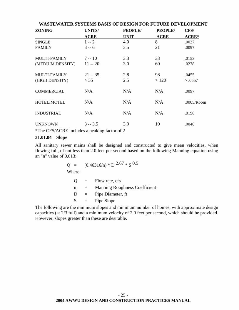
- 25 - 2004 AWWU DESIGN AND CONSTRUCTION PRACTICES MANUAL
WASTEWATER SYSTEMS BASIS OF DESIGN FOR FUTURE DEVELOPMENT ZONING UNITS/ PEOPLE/ PEOPLE/ CFS/ ACRE UNIT ACRE ACRE* SINGLE 1 -- 2 4.0 8 .0037 FAMILY 3 -- 6 3.5 21 .0097 MULTI-FAMILY 7 -- 10 3.3 33 .0153 (MEDIUM DENSITY) 11 -- 20 3.0 60 .0278 MULTI-FAMILY 21 -- 35 2.8 98 .0455 (HIGH DENSITY) > 35 2.5 > 120 > .0557 COMMERCIAL N/A N/A N/A .0097 HOTEL/MOTEL N/A N/A N/A .0005/Room INDUSTRIAL N/A N/A N/A .0196 UNKNOWN 3 -- 3.5 3.0 10 .0046 *The CFS/ACRE includes a peaking factor of 2 31.01.04 Slope
All sanitary sewer mains shall be designed and constructed to give mean velocities, when flowing full, of not less than 2.0 feet per second based on the following Manning equation using an "n" value of 0.013:
Q = (0.46316/n) * D 2.67 * S 0.5 Where:
Q = Flow rate, cfs n = Manning Roughness Coefficient D = Pipe Diameter, ft S = Pipe Slope
The following are the minimum slopes and minimum number of homes, with approximate design capacities (at 2/3 full) and a minimum velocity of 2.0 feet per second, which should be provided. However, slopes greater than these are desirable.
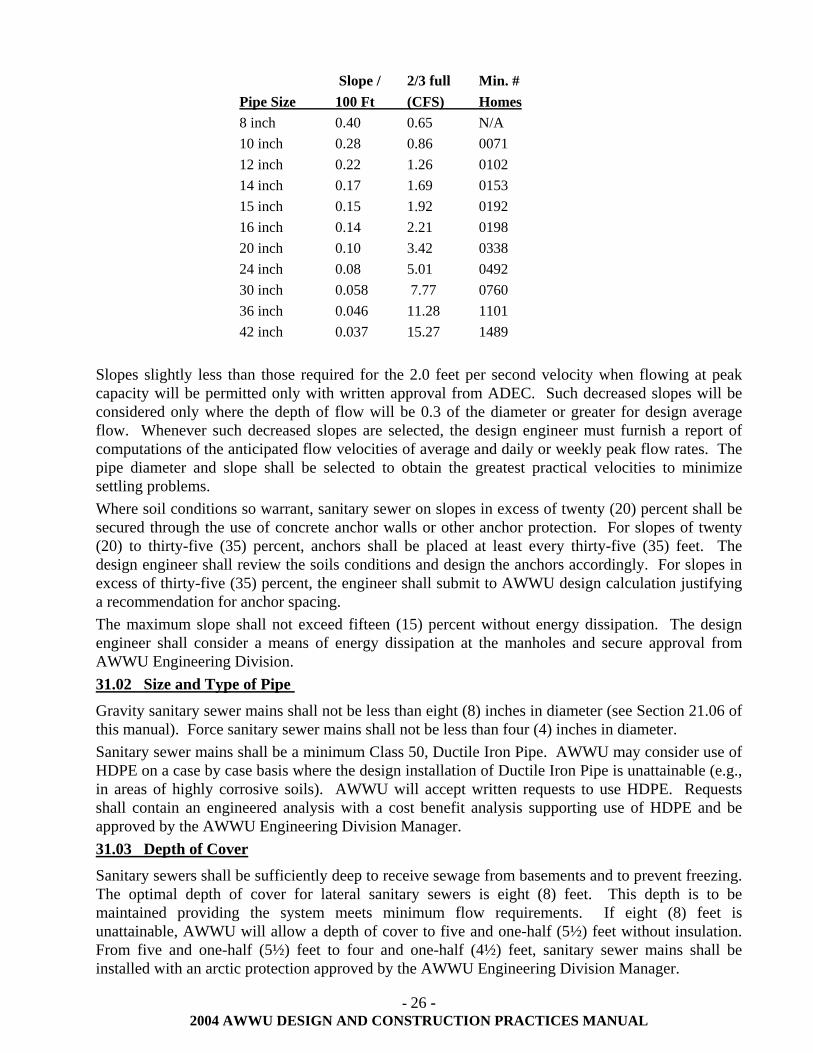
- 26 - 2004 AWWU DESIGN AND CONSTRUCTION PRACTICES MANUAL
Slope / 2/3 full Min. # Pipe Size 100 Ft (CFS) Homes 8 inch 0.40 0.65 N/A 10 inch 0.28 0.86 0071 12 inch 0.22 1.26 0102 14 inch 0.17 1.69 0153 15 inch 0.15 1.92 0192 16 inch 0.14 2.21 0198 20 inch 0.10 3.42 0338 24 inch 0.08 5.01 0492 30 inch 0.058 7.77 0760 36 inch 0.046 11.28 1101 42 inch 0.037 15.27 1489
Slopes slightly less than those required for the 2.0 feet per second velocity when flowing at peak capacity will be permitted only with written approval from ADEC. Such decreased slopes will be considered only where the depth of flow will be 0.3 of the diameter or greater for design average flow. Whenever such decreased slopes are selected, the design engineer must furnish a report of computations of the anticipated flow velocities of average and daily or weekly peak flow rates. The pipe diameter and slope shall be selected to obtain the greatest practical velocities to minimize settling problems. Where soil conditions so warrant, sanitary sewer on slopes in excess of twenty (20) percent shall be secured through the use of concrete anchor walls or other anchor protection. For slopes of twenty (20) to thirty-five (35) percent, anchors shall be placed at least every thirty-five (35) feet. The design engineer shall review the soils conditions and design the anchors accordingly. For slopes in excess of thirty-five (35) percent, the engineer shall submit to AWWU design calculation justifying a recommendation for anchor spacing. The maximum slope shall not exceed fifteen (15) percent without energy dissipation. The design engineer shall consider a means of energy dissipation at the manholes and secure approval from AWWU Engineering Division. 31.02 Size and Type of Pipe
Gravity sanitary sewer mains shall not be less than eight (8) inches in diameter (see Section 21.06 of this manual). Force sanitary sewer mains shall not be less than four (4) inches in diameter. Sanitary sewer mains shall be a minimum Class 50, Ductile Iron Pipe. AWWU may consider use of HDPE on a case by case basis where the design installation of Ductile Iron Pipe is unattainable (e.g., in areas of highly corrosive soils). AWWU will accept written requests to use HDPE. Requests shall contain an engineered analysis with a cost benefit analysis supporting use of HDPE and be approved by the AWWU Engineering Division Manager. 31.03 Depth of Cover
Sanitary sewers shall be sufficiently deep to receive sewage from basements and to prevent freezing. The optimal depth of cover for lateral sanitary sewers is eight (8) feet. This depth is to be maintained providing the system meets minimum flow requirements. If eight (8) feet is unattainable, AWWU will allow a depth of cover to five and one-half (5½) feet without insulation. From five and one-half (5½) feet to four and one-half (4½) feet, sanitary sewer mains shall be installed with an arctic protection approved by the AWWU Engineering Division Manager.
- 27 - 2004 AWWU DESIGN AND CONSTRUCTION PRACTICES MANUAL
31.03.01 Minimum Depth of Cover
Minimum depth of cover for gravity sanitary sewer is five and one-half (5½) feet or four and one-half (4½) feet if insulated with an arctic protection. If this standard cannot be maintained, a lift station shall be designed.
31.03.02 Maximum Depth of Cover
Pipe manufacturers supply the mathematical formulas for determining the necessary pipe thickness for a given combination of internal pressure and external load. They also supply graphs for the quick determination of pipe thickness for various combinations of standard conditions.
31.03.03 Deep Service Risers
Deep service risers shall be installed where the sanitary sewer is in excess of twelve (12) feet deep (see MASS, Standard Details). If a deep service riser is used, it shall be designed with a pipe restraint and to a height such that a service connection to the lowest elevation on the lot being serviced shall have eight (8) feet of cover. There shall not be more than two sanitary sewer service connections installed on a single deep service riser.
31.04 Sanitary Sewer Location in Dedicated and Implied R-O-W
The sanitary sewer mains shall be within the confines of the street R-O-W, located on the south and west sides (where possible), per MASS, Standard Details. 31.05 Manholes
31.05.01 Location
Manholes shall be installed at the end of each line; at all changes in grade, size, or alignment; at all intersections; and at distances between manholes not greater than 400 feet for sanitary sewers less than thirty (30) inches in diameter. AWWU may allow distances up to 500 feet, on a case by case base, provided the sanitary sewer is designed with greater than minimum slope. In some cases, the Contractor may be required to provide a CCTV inspection report to verify grade and bearing.
Greater spacing may also be permitted for larger sanitary sewers on a case by case basis.
On the plan and profile sheets, show the inverts, manhole numbering, stationing and top elevation.
31.05.02 Diameter
The minimum diameter of manholes shall be forty-eight (48) inches. The minimum access diameter shall be twenty-five (25) inches.
Sanitary sewer manhole Type A (see MASS Standard Details) shall be used on sanitary sewer mains with diameters eight (8) inches to twenty-four (24) inches.
Sanitary sewer manhole Type B (see MASS Standard Details) shall be used on sanitary sewer mains with diameters thirty (30) inches to thirty-six (36) inches. AWWU may require a Type B manhole in cases where the main is less than thirty (30) inches but where working conditions or inside fittings for sealed manholes require a larger inside diameter.
- 28 - 2004 AWWU DESIGN AND CONSTRUCTION PRACTICES MANUAL
31.05.03 Flow Channel
Flow vectors for the main and lateral connecting to a manhole will be at or less than ninety (90) degrees to prevent opposing flow conditions. Where this condition cannot be avoided, the lateral shall enter the manhole through an outside drop connection. The flow channel shall be constructed through the manholes to conform in shape and slope to that of the sanitary sewers.
When the slopes of the inlet and outlet sanitary sewer are equal, the slope through the manhole shall also be the same, allowing the pipe to be run straight through the manhole. The invert of a third or fourth pipe entering this manhole shall enter at an elevation at least 0.05 feet higher than the outlet inverts. When the slopes of the inlet and outlet are not equal, the minimum drop through the manhole shall be 0.05 feet. In manholes where lateral sanitary sewers are intercepted by mains, trunks or interceptors, the lateral sanitary sewers shall be laid such that under normal flow conditions in the interceptor sanitary sewer there will be no backing up of sewage in the lateral sanitary sewer. All smaller sanitary sewers shall match crowns of larger sanitary sewers. In some cases, the invert of the smaller sanitary sewer may be required to match the crown of the larger.
31.05.04 Drop Connection
A drop pipe shall be provided for a sanitary sewer entering a manhole at elevations shown in MASS, Standard Details. Where the difference in elevation between the incoming sanitary sewer and the manhole inverts are less than shown in MASS, the invert shall be filleted to prevent solids' deposition.
Construct drop manholes with an outside drop connection as shown in MASS. Inside drop connections require approval from AWWU Engineering and shall be installed in a Type B or greater manhole. The drop connect shall be secured to the interior wall of the manhole and access shall be provided for cleaning.
Due to the unequal earth pressures that would result from the backfill operation in the vicinity of the manhole, the outside drop connection shall be bedded in concrete per MASS, Standard Details.
31.05.05 Beaver Slides
AWWU requires beaver slides where the invert of the connecting sanitary sewer is above the crown of the receiving sanitary sewer and the drop into the manhole is short enough not to require a drop connection. Beaver slides shall be called out on the plans and shown in the profile view. Avoid beaver slides wherever possible. See MASS, Standard Details for typical beaver slide.
31.05.06 Watertight Manholes
Manholes shall be as a pre-cast concrete unit or from concrete, poured-in-place. Manholes shall have waterproof joints.
Inlet and outlet pipes shall be joined to the manhole with a flexible watertight gasket connection or any watertight connection arrangement that allows differential settlement of the pipe and manhole wall to take place. Grout shall be installed both inside and outside of the manhole at all connections unless Z-Lock gaskets (or equal) are used.
- 29 - 2004 AWWU DESIGN AND CONSTRUCTION PRACTICES MANUAL
31.05.07 Locking Manholes
Locking manhole covers shall be used wherever the manhole tops may be flooded by street runoff or high water table or where needed for security purposes.
31.06 Cleanouts
Cleanouts shall only be used at the terminus end of a lateral sanitary sewer or branched service extensions that will have a future extension and shall not be substituted for manholes. The horizontal distance between a manhole and cleanout shall not exceed 150 feet in length. Sanitary sewer cleanout for main line construction shall be installed with restrained fittings on both sides of the 45 degree bend and at the cleanout cover in accordance with MASS, Standard Details. 31.07 Sanitary Sewer Service Connections
Service connections are typically located five (5) to fifteen (15) feet from the property corner in the downhill one-third of the lot. Service connections shall be stubbed out to the property line of each lot that the proposed sanitary sewer main extension serves. The service shall be sized for the maximum size of structure that can be built according to the current zoning. The service connection at the property line shall have eight (8) feet of cover or eight (8) feet of cover below the lowest portion of the lot to be served, whichever is deeper. If this cannot be met because of the elevation of the main, then the service shall come off the main at minimum slope to the property line and the elevation of that service shown on the plan view of the drawings. For more information see Section 21.00 of this manual. 31.08 Joints
The designation of joints and materials used shall be included in the specifications. 31.09 Crossings
Sanitary sewers crossing water mains shall be laid to provide a minimum vertical separation of eighteen (18) inches between the outside of the water main and the outside of the sanitary sewer main. In cases where the water main is either above or below the sanitary sewer, the crossing shall be arranged, when practical, so that the sanitary sewer joints will be equidistant (a minimum of nine (9) feet) and as far as possible from the water main joints. Where a water main crosses under an existing sanitary sewer, adequate structural support shall be provided for the sanitary sewer to prevent damage to the sanitary sewer main. Sanitary sewer and water crossings shall be in accordance with ADEC.
31.09.01 Creek Crossings
The top of all sanitary sewers crossing streams shall be at a sufficient depth below the natural bottom of the stream bed to protect the sanitary sewer line. The following cover requirements must be met:
1. A minimum of one (1) foot of cover is required where the sanitary sewer is located in rock. 2. A minimum of three (3) feet of cover is required in other material. In major streams, more
than three (3) feet of cover plus rip rap may be required and the scour depth of the stream should be considered in the design.
Less than the minimum cover will be considered only if the proposed sanitary sewer crossing will not interfere with any future improvements to the stream channel. Other reasons for requesting lesser cover shall be considered on a case-by-case basis.
Sanitary sewer pipe in creek beds shall be encased in concrete where the cover is less than three (3) feet below scour depth.
- 30 - 2004 AWWU DESIGN AND CONSTRUCTION PRACTICES MANUAL
Provisions for frost protection shall be made and arctic type pipe, or approved equal, shall be used where freezing conditions are anticipated.
31.09.02 Aerial Crossings
Provide support for all joints in pipes utilized for aerial crossings. The supports shall be designed to resist frost heave, overturning and settlement.
Precautions against freezing, such as insulation and increased slope, shall be considered. Expansion joints shall be provided between above-ground and below-ground sanitary sewers.
For aerial stream crossings, the impact of flood waters and debris shall be considered. The bottom of the pipe shall be placed no lower than the estimated elevation of the one hundred (100) year flood plain plan established by the MOA Planning Department.
31.09.03 Inverted Siphons
Inverted siphons shall be installed with not less than two (2) parallel mains, with a minimum pipe size of six (6) inches and shall be provided with necessary appurtenances for convenient flushing and maintenance. The influent and effluent manholes shall have adequate clearances for rodding. Sufficient head shall be provided and pipe size selected to secure velocities of at least 3.0 feet per second for average flows. The inlet and outlet details shall be so arranged that the normal flow is diverted to one (1) main, and that either main may be isolated from service for cleaning. The vertical alignment shall permit cleaning and maintenance.
31.09.04 Storm Drain Crossings
Where the sanitary sewer main crosses the storm drain, a vertical separation of three (3) feet shall be maintained. If this minimum cannot be maintained, then four (4) inches of insulation (high density extruded polystyrene board stock or equivalent as defined in MASS) is required between the lines. When the storm drain is within three (3) feet of a manhole, the ladder in the manhole shall be rotated opposite the storm drain or insulation place between the storm drain and sanitary sewer manhole to prevent icing on the manhole ladder.
The horizontal separation between sanitary sewer mains and storm sewer mains shall not be less than 3 feet measured from the outside of pipes when the pipes are at the same elevation. When the sanitary sewer mains and storm sewer mains are at different elevations, the horizontal separation distance shall be such that neither pipe is located within the trench cross section of the other pipe.
31.09.05 Railway Crossings
When the sanitary sewer main crosses existing or proposed railways, the sanitary sewer shall be designed in accordance with the criteria set forth in Part 5 of the American Railway Engineering Association manual. A copy of the referenced manual can be obtained from the Engineering Division of the Alaska Railroad. All railway crossings shall be installed in accordance with the Alaska Railroad permit requirements.
31.10 Sanitary Sewer Mains/Connections in Relation to Water Mains/Connections
There shall be a minimum ten (10) foot horizontal and eighteen (18) inches vertical separation (measured from the outside of pipe) between sanitary sewer and water mains/services.
- 31 - 2004 AWWU DESIGN AND CONSTRUCTION PRACTICES MANUAL
31.11 Wells
All wells located within 200 feet of the project limits shall be clearly and accurately shown on the plans. The State of Alaska Department of Environmental Conservation (ADEC) well classification (A, B, C, Private Water Source), and the minimum separation distance (radii) for sanitary sewer pipe-to-well and sanitary sewer manhole/cleanout-to-well shall be graphically shown for each well. The minimum separation distances shall be in accordance with the State of Alaska Wastewater Disposal Regulations 18 AAC 72.015, Table A and the State of Alaska Drinking Water Regulations 18 AAC 80.030, Table A, or as specified by MOA, Department of Health and Human Services. All wells within 200 feet of the project limits shall be located by a field survey. If the minimum separation distances cannot be maintained, the engineer is required to prepare all necessary waiver requests for submittal to ADEC. AWWU shall review and concur with the waiver request prior to the engineer submitting to ADEC. The engineer will be required to comply with all conditions of approval.
- 32 - 2004 AWWU DESIGN AND CONSTRUCTION PRACTICES MANUAL
32.00 DESIGN AND CONSTRUCTION OF SANITARY SEWER SERVICES
32.01 General
The criteria in this section apply to residential service connections and extensions. For multi-family, commercial and industrial services refer to Section 21.06 of this manual. Sanitary sewer service lines shall be laid in straight runs, except for the beginning sweeps, unless prior approval in writing is received from AWWU Engineering Division in concurrence with AWWU Customer Services Division. The lines shall be at a uniform grade for the run except for the beginning sweeps. All sanitary sewer services shall extend from the sanitary sewer main to the property line. All sanitary sewer services shall be installed no closer than five (5) feet to a side lot line and must be a minimum of fifteen (15) feet from a fire hydrant, power poles or transformer pads; ten (10) feet from a waterline; twenty-five (25) feet from a private well; and, a minimum of ten (10) feet from any structural foundation or other appurtenance, such as, but not limited to, light poles or electrical/telephone/cable boxes.
32.01.01 Size of Connection
The minimum size of the gravity service shall be four (4) inches. Commercial and industrial connects shall be sized by calculation of the maximum available use of the building. Residential connects shall conform to the following table; usage greater than average requires approval from AWWU Engineering Division and MOA Building Safety:
Connect to Main Living Units 4" service connect -- 0-4 6" service connect -- 5-29 Connect to Manhole Living Units 8" service connect -- 30-106 10" service connect -- 107-187 12" service connect – 188 -328
32.01.02 Grade
The minimum slope for a four (4) inch service shall be two (2) percent. The minimum slope for a six (6) inch service shall be one (1) percent. Slopes for gravity sanitary sewer services larger than a six (6) inch shall be in accordance with Section 31.01.04 of this manual.
32.01.03 Depth
Sanitary sewer services shall be sufficiently deep to prevent freezing ant to receive sewage from the lowest elevation of the building.
The standard depth of cover for sanitary sewer services is eight (8) feet. This depth is to be maintained, providing the system will still flow by gravity. If eight (8) feet is unattainable, an exception will be considered by AWWU Engineering Division. On profile, show elevation of original ground, finish grade and sanitary sewer inverts at each manhole. Sanitary sewer services less than five and one-half (5½) feet deep require an arctic protected pipe upon approval by AWWU Engineering Division.
32.01.04 Bedding Material
The bedding material shall be of Class C, with a fine granular texture containing no material larger than one-half (½) inch. Bedding shall be laid the full extent of the ditch and up to the
- 33 - 2004 AWWU DESIGN AND CONSTRUCTION PRACTICES MANUAL
spring line of service connect pipe and compacted to ninety-five (95) percent of maximum density.
32.01.05 Repairs or Replacement
All on-property service extension repairs or replacements require an on-property permit and shall follow the same standards that apply to new connections. Existing materials shall be brought up to current standards. Replacement of any portion of an on-property private system will be required to have engineered plans in accordance with Section 21.06 of this manual.
32.02 Materials for Service Connections and Extensions
32.02.01 Authorized Materials and Fittings
The following materials are approved for sanitary sewer service connections and shall be installed and tested in accordance with MASS.
1. Ductile Iron with "Tyton" joints 2. Cast Iron with "Ty-seal" joints 3. HDPE (High Density Polyethylene) (see Section 31.02 of this manual) 4. Cast Iron with "No-hub" joints. No-hub joints shall be stainless steel. "Romac" model SC1-
4.50x4 (or equal) 32.02.02 Unauthorized Materials and Fittings 1. ABS (Acrylonitrile-Butadiene-Styrene) 2. Aluminum or steel corrugated metal pipe 3. Asbestos cement 4. Concrete cylinder 5. Galvanized or black iron pipe 6. Mild steel or seamless conduit 7. Orange-burg 8. PVC (Polyvinyl Chloride) 9. Vitrified clay 10. Wood stave 11. Caulder type couplings 32.02.03 Cleanouts
All cleanouts (both stand pipe and wye) shall be cast or ductile iron pipe. The cleanout at the structure shall be per UPC. See Section 32.04 of this manual.
32.03 Off-Property Connection (Main Line Taps)
A main line tap shall be installed using an approved saddle in the following manner: The diameter of the hole cut into the pipe shall be used no larger than one-eighth (1/8) inch greater than the outside diameter of pipe to be inserted or the inside lip of the saddle. Saddles shall be secured with a double strap or a two and one-half (2½) inch stainless steel strap for single strap. Adjoining taps to the main line shall not be closer than three (3) feet. No service connection shall be tapped into a sanitary sewer main closer than five (5) feet to a manhole. No service connection shall be closer than one (1) foot from a joint. Pavement shall be saw cut and removed to a point beyond patching. If this results in narrow unstable panels, pavement shall be removed to the next existing traffic lane or construction joint. Before replacing permanent
- 34 - 2004 AWWU DESIGN AND CONSTRUCTION PRACTICES MANUAL
pavement, the sub-grade shall be restored and compacted to ninety-five (95) percent of maximum density. The final grade in non-paved areas shall match existing grades at construction limits without producing drainage problems. Restoration of grass, shrubs, and other vegetation shall be done in conformance with construction contract documents. Tree damage shall be repaired in accordance with good horticultural practice. 32.04 On-Property Service (Extension)
32.04.01 General
The contractor shall verify the alignment and grade of the existing stub out from the main. Contractor shall make sure the line is free and clear of any obstruction prior to connecting with the service extension. If the contractor notes any deficiencies, AWWU shall be notified immediately.
32.04.02 On-Property Service 1. The lines shall be laid in straight runs 2. The lines shall be at a uniform grade for each run 3. There shall be a minimum of one (1) cleanout per 100 feet of run 4. Manholes may be substituted for the cleanouts. The maximum distance between manholes
for service lines shall not exceed three hundred (300) feet 5. There shall be a cleanout at all grade changes and combination of bends greater than 45
degrees 6. There shall be no more than two (2) bends not to exceed 45 degrees within a ten (10) foot run 7. The building clean-out shall be within twenty-four (24) inches from the structure 8. Acceptable types of piping for on-property service extensions are as follows:
8.1. Ductile Iron with "Tyton" joints 8.2. Cast Iron with "Ty-seal" joints 8.3. Cast Iron no-hub joints 8.4. Romac coupling (or equal) shall be used at any joint where the type of piping changes
9. There shall be a minimum of five (5) feet of pipe between the building cleanout and the 45 degree bend or building wye
32.04.03 Service Connection Markers
Services stubbed to the property line for future use shall be marked at the property line with a 2" X 4" X 8' marker, protruding three (3) feet above grade, painted green, and stenciled with the word "SEWER" in white two (2) inch high letters.
32.05 Sanitary Sewer Connection Appurtenance
32.05.01 General
On-property control manholes for commercial and industrial users are required by AWWU as per the Wastewater Tariff. The manhole shall be a minimum Type A and shall be installed in accordance with MASS.
32.05.02 Control Manholes
The owner of any structure discharging sewage containing industrial waste into AWWU's system shall install a control manhole on the sanitary sewer service extension to facilitate observation,
- 35 - 2004 AWWU DESIGN AND CONSTRUCTION PRACTICES MANUAL
sampling, and measurement of wastes. The manhole shall be constructed in accordance with AMC 26.50.130 and private system plans approved by AWWU. See Section 21.06 of this manual. The design plans shall include the horizontal location and vertical dimensions of the control manhole.
Control manholes shall be installed on the service extension by the owner(s) at the owner's expense and shall be maintained by them so as to be safe and accessible at all times.
Control manholes shall not be installed on in easements, R-O-W's or within a protective well radius.
AWWU requires the owner to submit a "Notice of Intent to Discharge Industrial Wastewater" form to the Customer Service Division prior to approval of plans. A determination of the necessity of control manhole will be made based on information provided on the form (see AMC Section 26.50.120, or Anchorage Ordinance No. 86-118).
32.05.03 Abandonment of Private Disposal Systems
Every abandoned on-property disposal system (cesspool, septic tank, seepage pit, drain field, etc.) shall comply with the UPC Appendix I. The contractor shall schedule inspection of the abandoned systems with AWWU Field Service office. The abandoned disposal system shall be shown on the record drawings.
32.05.04 Backwater Valves
The purpose of this standard is to implement Sections 209 and 409 of the UPC. Backwater valves are installed within the limits of a structure and therefore shall be the responsibility of the Municipal Building Department for review and permitting. AWWU may require installation of a backwater valve within existing structures that have a history of backups.
32.05.05 Private Sewage Lift Stations
Where practicable, all plumbing fixtures shall be drained to public sanitary sewer or private sewage disposal system by gravity. When the building plumbing fixture is located below the crown level of the main sanitary sewer, the sanitary sewage from the building drain or building sewer shall be pumped by approved ejectors, pumps or other equally efficient approved mechanical devices. The service and pumping mechanism(s) shall be provided and maintained by the property owner. All costs related to the installation, operation and maintenance of private sewage lift stations are the sole responsibility of the property owner.
Administrative authority and assistance shall be in accordance with the latest edition of the UPC and local amendments thereto.
1. If the lift station is located inside the foundation wall of the structure, the administrative authority rests with the MOA Building Official.
2. If the lift station is for a single family residential use and located on private property but outside the foundation wall, and if liquid waste is discharged to a private treatment system, the administrative authority rests with MOA Department of Health and Human Services.
3. If the lift station is for a commercial use and located on private property but outside the foundation wall, and if liquid waste is discharged to a private treatment system, the administrative authority rests with the Alaska Department of Environmental Conservation. (See Section 21.06 of this manual)
- 36 - 2004 AWWU DESIGN AND CONSTRUCTION PRACTICES MANUAL
4. If the lift station is located on private property but outside the foundation wall and if liquid waste is discharged to a public wastewater collection system, the administrative authority rests with AWWU Operations and Maintenance Division.
The owner of a lift station and plumbing system approved by AWWU may be requested to file with the AWWU Operations and Maintenance Division all plans and literature that pertain to the lift station. This information will be used to compile a reference library.
Regardless of the location of the private lift station, all lift station installations will be subject to a more thorough review by the AWWU Operations and Maintenance Division. Engineers must submit detailed plans for lift stations for review prior to installation (see Section 60.00 of this manual). These plans are to include all the following information:
1. A drawing showing the dimensions and capacity of the lift station tank (wet well), and the specific level of the "pump on", "pump off", and "high water alarm";
2. Construction materials, manufacturing details, insulation details (where applicable), and corrosion protection;
3. The make and model of the pump, and the criteria or data used in sizing the pump for the specific application;
4. Electrical controls, protected from corrosive environments and/or weather; 5. The high water alarm located inside the house and on a circuit separate from the pump. 32.05.06 Grease Traps
Administrative authority for the use and maintenance of grease traps is with AWWU in accordance with AMC 26.50.150 Wastewater Pretreatment Facilities. Grease traps shall be installed in accordance with the AMC 26.50.150D.
32.06 Service Connection Abandonment
The abandonment method for disconnection of a sanitary sewer service at the main line shall include the following:
1. Service shall be disconnected at the property line 2. Cut pipe and plug with a watertight cap or end plug 3. Install a sanitary sewer service connection marker 4. Provide AWWU a record drawing of the abandoned service connection
A disconnect permit will be required from AWWU. The contractor shall schedule inspection with AWWU and furnish the following information:
1. Date when disconnect was made 2. Where disconnect was made, including but not limited to lot, block, subdivision, address,
swing ties, depth, type of pipe and size 3. Who disconnected the service 4. Owners name, address, and telephone number
An AWWU inspector shall observe the disconnection to ensure quality.
- 37 - 2004 AWWU DESIGN AND CONSTRUCTION PRACTICES MANUAL
33.00 DESIGN OF SANITARY SEWAGE LIFT STATION
33.01 General
This section contains information relevant for designing lift stations and pump stations with a capacity of commonly less than one million gallons per day (MGD). The design and installation of these stations shall conform to the latest edition of MASS and all work shall be in accordance with the latest editions of IBC, IMC, UPC and NEC, all as revised and accepted by MOA. Stations larger than 1 MGD require special design considerations (e.g., generators, fuel facilities, etc.). Design of these stations shall be coordinated through AWWU Engineering Division and shall conform to MASS, IMC, UPC and NEC, all as revised and accepted by MOA. 33.02 Design
33.02.01 Equipment Removal
Provision shall be made to facilitate removal of pumps, motors, and other mechanical and electrical equipment.
33.02.02 Accessibility and Access
The pumping station shall be readily accessible by maintenance vehicles during all weather conditions. The facility shall be located off the traffic way of streets and alleys and in a dedicated easement whenever possible. No station shall be located in a ditch or snow storage area. The top elevation of the lift station and the elevation of the electrical junction box shall be sufficiently above surrounding ground and shall be protected from any water runoff or any accumulation of infiltration.
Suitable and safe means of access shall be provided into dry wells, and to wet wells containing mechanical equipment requiring inspection or maintenance. All controls, sensors and pumps shall be able to be removed without entering the wet well on any station where equipment is submerged in the wet wells.
Reference will be made to all local, State, and Federal safety codes with the most stringent code taking precedence.
33.02.03 Construction Materials
Due consideration shall be given to the selection of materials because of the presence of hydrogen sulfide and other corrosive gases, greases, oils, and other constituents frequently present in wastewater.
33.03 Pumps
All pumps shall be 3-phase. Where 3-phase power is not available, a frequency drive unit will be required to add the third phase.
33.03.01 Multiple Units
Each station shall be designed with at least two wastewater pumps. A minimum of three (3) pumps shall be provided for stations handling flows greater than one (1) MGD.
When only two (2) units are provided, they shall have the same capacity. Each unit shall be capable of handling maximum flows per Section 31.01.03 of this manual. Where three (3) or more units are provided, they shall be designed to fit actual flow conditions and shall be of such
- 38 - 2004 AWWU DESIGN AND CONSTRUCTION PRACTICES MANUAL
capacity that, with the largest unit out of service, the remaining units shall have capacity to handle maximum sewage flows.
33.03.02 Pump Openings
Pumps shall be capable of passing spheres of at least three (3) inches in diameter. Pump suction, discharge and piping shall be at least four (4) inches in diameter.
33.03.03 Priming
Pumps shall be of the self-priming type.
33.03.04 Electrical Equipment
Electrical systems and components (e.g., motors, cables, conduits, switch boxes, control circuits, etc.) in raw sewage wet walls, or in enclosed or partially enclosed spaces where hazardous concentrations of flammable gases or vapors may be present, shall comply with the National Electrical Code (NEC) requirements for Class 1, Group D, Division I locations. In addition, equipment located in the wet well shall be suitable for use under corrosive conditions. Each flexible cable shall be provided with watertight seal and separate strain relief. A fused disconnect switch located above ground shall be provided for all pumping stations.
Electrical panels and equipment not located in the wet wells or confined spaces do not need to meet Class I, Division 1, NEC. When such equipment is exposed to weather, it shall meet the requirements of weatherproof equipment (NEMA Type 4).
33.03.05 Intake
Each pump shall have an individual intake. Wet well design should be such as to avoid turbulence near the intake. Intake piping shall be as straight and short as possible.
33.04 Level Controls
In all wet wells, install a US Filter D-153 Duplex Level Controller using the A1000 Level Transducer, or equal. Any substitution to transducer or controller equipment will require review and approval by both AWWU’s Engineering and Operations and Maintenance Divisions. The transducer shall have the capacity to control pumps, regulate speed drives (if necessary), indicate and telemeter liquid levels. A typical two-pump station requires five (5) different operations: First pump start, second pump start off, high wet well and redundant high wet well. See Section 33.22 of this manual.
33.04.01 Location
The control system shall be located away from the turbulence of incoming flow and pump suction.
33.04.02 Alternation
In stations designed to handle flows of less than 1 MGD, provisions shall be made to automatically alternate the pump in use.
33.05 Valves
33.05.01 Suction Line
Shut-off valves shall be placed on the suction line of each pump for a dry pit operation. A wet pit with submersible pump does not require valves on the suction.
- 39 - 2004 AWWU DESIGN AND CONSTRUCTION PRACTICES MANUAL
33.05.02 Discharge Line
Mueller spring and lever type check valves (Model A-2600-6-02 or equivalent) and Mueller non-rising stem gate valves (Model A-2370-6 with hand wheel or equivalent) shall be placed on the discharge line of each pump. The check valve shall be located between the shut-off valve and the pump. Check valves shall be suitable for the material being handled and shall be capable of withstanding normal pressure and water hammer, and be of the spring and level type to allow manual back flushing of pumps. The gate valve and check valves shall be designed for installation above wet pit liquid levels during normal operation.
33.06 Wet Wells
33.06.01 Size
The wet well size and control setting shall be appropriate to avoid heat build-up in the pump motor due to frequent starting and to allow a minimum of two hours detention time at peak flows. In cases where the drainage area is larger than the current number of homes to be served, the station shall be designed for both maximum density and current service area.
To size wet wells in residential areas, multiply the maximum number of homes in the service area of the lift station by 50. This value will be the total volume in gallons required for the wet well. The wet well controls will then be adjusted for current number of homes in the service area. For business, commercial or industrial areas, the wet well shall be designed to handle the peak flows with two (2) hour retention. Deviation will require justification by the design engineer and approval by the AWWU Engineering Division Manager.
33.06.02 Floor Slope
The wet well floor shall have a minimum slope of one-to-one to the pump suction. The horizontal area of the hopper bottom shall not be greater than necessary for proper installation and function of the inlet.
33.07 Ventilation
Adequate ventilation shall be provided for all pump stations. Where the pumps are located in a dry pit, mechanical ventilation is required. Wet wells shall not be mechanically vented. All exterior ventilation piping shall be Schedule 40, steel pipe primed and painted to match exterior color of the facility. The exterior end of the ventilation piping shall be screened with a minimum of one-quarter (1/4) inch stainless steel screen. All exterior ventilation piping shall be painted caterpillar yellow.
33.07.01 Wet Well Ventilation
Wet wells shall have a stand pipe for air ventilation. No mechanical or powered ventilation shall be installed in the wet well portion of the station.
33.08 Water Supply
There shall be no physical connection between any potable water supply and a sewage pumping station in order to prevent contamination of the potable water supply. If a potable water supply is brought to the station, it shall comply with conditions stipulated. 33.09 Suction Lift Pumps
Sewage suction lift pumps are prohibited within MOA.
- 40 - 2004 AWWU DESIGN AND CONSTRUCTION PRACTICES MANUAL
33.10 Submersible Pump Stations
33.10.01 Construction
Submersible pumps and motors shall be designed and supplied by the same manufacturer specifically for raw sewage use, including totally submerged operation during a portion of each pumping cycle. The motor shall be of squirrel-cage type design without brushes or other arc-producing mechanisms.
33.10.02 Pump Removal
Submersible pumps shall be readily removable and replaceable without dewatering, disconnecting any piping, or personnel entry.
33.11 Electrical
33.11.01 Power Supply and Control
Electrical supply and control and alarm circuits shall be designed to provide strain relief and to allow disconnection from outside the wet well. Terminals and connectors shall be protected from corrosion by location outside the wet well or through use of watertight seals. If located outside, weatherproof equipment shall be used.
33.11.02 Controls
The motor control center shall be located outside the wet well and protected by a conduit seal, or other appropriate measures meeting the requirements of NEC, to prevent the atmosphere of the wet well from gaining access to the control center. The seal shall contain two spare conductors as a backup so the seal will not need to be broken should a conductor fail. The seal shall be located so that the motor may be removed and electrically disconnected without disturbing the seal. The location of the wet well junction box shall be identified at the motor control center.
33.11.03 Power Cord
Pump motor power cords shall be designed for flexibility and serviceability and shall meet the requirements of the Mine Safety and Health Administration for trailing cables. Power cord terminal fittings shall be corrosion-resistant and constructed in a manner to prevent the entry of moisture into the cable, be provided with strain relief appurtenances, and shall be designed to facilitate field connection. Power cords shall have the ability to be disconnected without entering the wet well or submerged station. This will require construction of an external junction box vault.
33.12 Alarm Systems
Electrical contacts, as specified by AWWU Operations and Maintenance Division, shall be provided in addition to electrical interfacing specific to the project. 33.13 Emergency Operation
Pumping stations and collection systems shall be designed to prevent or minimize bypassing of raw sewage. A 4-inch female cam lock fitting shall be provided on the discharge piping to facilitate emergency by-passing. For use during possible periods of extensive power outages, mandatory power reductions, or uncontrolled storm events, consideration should be given to providing a controlled, high-level wet well overflow to supplement alarm systems and emergency power generation. This will prevent backup of sewage into basements, or other discharges that may cause severe adverse impacts to public interests, including public health and property damage. Where a
- 41 - 2004 AWWU DESIGN AND CONSTRUCTION PRACTICES MANUAL
high level overflow is utilized, consideration shall also be given to the installation of storage and/or detention tanks, or basins, which shall be made to drain to the station wet well. Where such overflows affect public water supplies, surface water or waters used for culinary or food processing purposes, storage and/or detention basin, or tanks, shall be provided having 2-hour detention capacity at the anticipated overflow rate. 33.14 Equipment Nameplates and Manuals
For each sanitary sewage lift station and pumping station, provide six (6) complete sets of operation and maintenance manuals. In addition to the record drawings of the facility, provide a record drawing of all the electrical schematics and drawings (see Section 50.00 of this manual). Each operation and maintenance manual shall include: operational procedures to be followed in case of blockage, power outage, circuit overload, or emergency; station shut down and start up procedures, including lock out/tag out requirements; routine maintenance tasks and schedule for all equipment and assemblies; a list of any special tools required to operate or maintain the station; and mechanical and electrical drawings of the facility. In addition to the facility manuals, provide six (6) complete sets of equipment manuals for each item of equipment and each instrument panel in the facility. Each equipment manual shall contain: Summary showing: 1. Make, model, style, serial number, description, manufacturer's specifications, and location in the
construction. 2. Full names and addresses of manufacturer, vendor, prime contractor and installer. Manufacturer's literature properly marked to identify the specific item. The literature shall include: 1. Instruction for installation, operation, maintenance and repair. 2. Shop drawings, wiring diagrams, and system layouts, where such drawings are required in other
sections of the specifications.
Each piece of major equipment in the station shall have nameplates affixed in accessible location which includes make, model, serial number, manufacturer and power requirement. 33.15 Station Cover
Station cover shall be of a suitable material for each application, (e.g., reinforced steel meeting H-loading requirements for vehicle traffic, aluminum for standard no load applications). Lid shall be large enough to allow straight pulls for removing pumps from stations. 33.16 Electric Disconnects
There shall be an electrical disconnect within 12 feet of the station. 33.17 Control Panels
All panels exposed to weather shall be NEMA Type 4 (or equal) lockable enclosures. Panels shall be self-supporting pad mounted or electrical pole mounted and approximately five (5) feet at center elevation. All frost susceptible materials under pad location must be removed to a minimum depth of four (4) feet and replaced with a non-frost susceptible material with a fine granular texture containing material not larger than one-half (½) inch in diameter. This material must be compacted to a minimum of ninety (90) percent maximum density compaction. The control panel's meter base must be located as close as possible to the wet well in order to comply with NEC regulations and eliminate the need for wet well mounted disconnect switch.
- 42 - 2004 AWWU DESIGN AND CONSTRUCTION PRACTICES MANUAL
33.18 Sensors
Displacement type liquid level sensors shall be of Flygt Company manufacture (or equal) and shall consist of a mercury switch in a smooth chemical resistant casing. The sensors shall detect low wet well and high wet well. The sensors shall be suspended by cable from a stainless steel hanger securely mounted in wet well. The hanger shall be accessible from the hatch. 33.19 Wet Well Lighting
Each wet pit control panel shall have at least one grounded 20-amp duplex outlet. AWWU will supply portable lighting to the station. There shall be no lights or outlets in the wet well. 33.20 Corrosion
All equipment in manholes and/or wet wells shall be water-tight and corrosion-protected as defined in the specifications for the project and the manufacturer's specifications for equipment. 33.21 Controls
The fluid level controls shall be adjustable so that a minimum restart time of five (5) minutes for the pumps may be obtained. Each facility shall be equipped with dry contacts to accommodate AWWU's Supervisory Control And Data Acquisition (SCADA) system. Additional dry contact criteria may be obtained from the AWWU Engineering Division. 33.22 Supervisory Control And Data Acquisition (SCADA)
All lift stations shall be designed and constructed with SCADA equipment compatible to AWWU. Section 70.06 lists the minimum SCADA equipment necessary for a sanitary sewer lift station. 33.23 Private Pump or Lift Stations
On-property private lift pumps are the complete responsibility of the owner of said property (see Section 32.05.05 of this manual). Unless otherwise stated by written agreement, a developer of a subdivision requiring a temporary lift station (until gravity sanitary sewer is available) shall be responsible for operation and maintenance of the lift station and all sanitary sewer lines leading into and away from the lift station to the point of connection to public sanitary sewer. All on-property private lift stations shall be designed to include cabinetry and space for future SCADA equipment. Reference Section 70.06 of this document.
- 43 - 2004 AWWU DESIGN AND CONSTRUCTION PRACTICES MANUAL
34.00 DESIGN OF PRESSURE SANITARY SEWER (FORCE) MAINS
34.01 Type of Pipe
Pipe four (4) inches in diameter or larger shall be Class 52 DIP. Pipe three (3) inches or smaller shall be Type K, copper pipe. All bends shall have restrained joints to withstand water hammers which can be created by the wastewater pumps. Where the pressure mains enter or exit a manhole or other collection or discharge area, it shall be secured to prevent separation from such area. 34.02 Continuity Straps
All pressure sanitary sewer mains shall have continuity straps installed for the purpose of thawing. Straps shall be installed in accordance with standard specification for water systems. A continuity test will be made on the completed system. On-property pressure sanitary sewer systems shall have continuity for purposes of thawing. 34.03 Testing
Pressure sanitary sewer mains shall be hydrostatic pressure tested. The hydrostatic pressure test will be 150 psi, or 50 psi above the surge rate for the wastewater pump, whichever is greater. 34.04 Draining of Force Main
Where applicable to prevent sewage from becoming septic, pressure mains shall be designed to backflow into the wet well. The wet well pump discharge line shall have a spring and lever type check valve which can be manually operated once the pumping stops. The wet well shall be sized to handle the backflow sewage from the force main in addition to the normal sizing. 34.05 Depth of Bury
All pressure sanitary sewer mains must have ten (10) feet minimum bury. If ten (10) feet minimum bury cannot be maintained, then arctic type pipe, approved by the AWWU Engineering Division Manager, shall be used. There shall be no approval for pressure mains with less than five and one-half (5½) feet bury. 34.06 Back Up Force Main
At least two force mains shall be provided for stations handling flows greater than one-half (½) MGD. AWWU may require two force mains for flows with less than one-half (½) MGD when the lineal feet of a single force main causes excessive maintenance requirements. The second force main shall be used for emergencies only when the first force main is down for repairs. Both force mains shall have the capacity to handle maximum sewage flows when one or the other is out of service. Plans and record drawings shall include the pipe type, pipe class, size horizontal dimension between pipes, horizontal dimension to easement lines, lot lines, R-O-W, and etc. 34.07 Air-Relief Device
All high points of the force main shall have an appropriate air relief device. Plans shall include the horizontal location and vertical elevation of all air relief devices. Record drawings shall include manufacturer, make and model of all air relief devices. 34.08 On-Property
The previous provisions of pressure mains also apply to all on-property, private sanitary sewers and Private Systems. The AWWU Engineering Division will assist the property owner on recommendation of the type of system to install for residential use (see previous Section 32.05.05 of this manual).
- 44 - 2004 AWWU DESIGN AND CONSTRUCTION PRACTICES MANUAL
35.00 WASTEWATER TREATMENT
35.01 General
Each plant shall be subject to such requirements as the AWWU Engineering Manager may indicate based upon locale, degree of treatment, safety, layout, auxiliary equipment required for proper operation and maintenance, access, or any other item peculiar to that plant which may be required by AWWU. 35.02 Treatment Plant
AWWU operates and maintains wastewater treatment plants for the following service areas: Eagle River, Anchorage Bowl and Girdwood/Alyeska. 35.03 Pretreatment Facilities
All public sanitary sewer users shall meet requirements as stated in AMC Chapter 26.50, Sewer Service; Federal Pretreatment Requirements (40 CFR Part 403) and Federal Categorical Pretreatment Standards. Specifically, the following articles within AMC Chapter 26.50 apply.
AMC 26.50.050 Prohibited acts
AMC 26.50.060 Specific discharge limitations
AMC 26.50.090 Dilution of discharge as substitute for pretreatment is specifically prohibited
AMC 26.50.120 Notice of intent for non-domestic discharges
AMC 26.50.130 Control manhole required for non-domestic discharges
AMC 26.50.150 Wastewater pretreatment facilities required
AMC 26.50.170 Industrial Management Practice plans required
AMC 26.50.200 Requirement to obtain wastewater discharge permit
AMC 26.50.410 Recovery of costs incurred by the utility
Subject to review, AWWU may require equalization units to prevent peak flow conditions from adversely affecting operation of the sanitary sewer system. Said equalization or holding unit shall have a capacity suitable to serve its intended purpose and be equipped with acceptable outlet control facilities to provide flexibility in operation and accommodate changing conditions in the waste flow. It shall be the responsibility of the customer to install and satisfactorily operate and maintain pretreatment units at the owner's expense (AMC 26.50.150).
- 45 - 2004 AWWU DESIGN AND CONSTRUCTION PRACTICES MANUAL
40.00 DESIGN OF WATERWORKS
40.01 General
All property desiring water service from MOA shall be located within AWWU's service area as certified by the APUC, unless a special exception is authorized by the APUC. The developer or a designated design engineer shall submit water demands for the development and AWWU will model the projected demands. If the existing water distribution system is not adequate to serve the proposed development, the project shall not be approved for construction until the capacity of the distribution system has been augmented. Improvements to the transmission main system are made primarily through AWWU's Capital Improvements Program (CIP). If a developer desires to proceed ahead of the CIP, the developer shall finance the cost of the portion of the CIP project required to reach and front the property. The size of the water line or pumping station shall be determined by a facility or master plan adopted by AWWU. If the required size exceeds the needs of the development, the participation of oversizing will be available when the funds for the specific CIP project are available. Estimating water use requirements shall be in accordance with UPC, AWWA and sound civil engineering practice. Minimum fire flow requirements shall be determined by the Fire Prevention Division of the Anchorage Fire Department.
- 46 - 2004 AWWU DESIGN AND CONSTRUCTION PRACTICES MANUAL
41.00 STANDARD WATER DESIGN ELEMENTS
41.01 Distribution System
New water extensions shall be designed to be compatible with the existing grid network of the established transmission and distribution system. Interties to the existing system shall be provided wherever possible to establish loops. When evaluating the existing system for flow and pressure, the following criteria shall be used: 1. The Hazen-Williams equation where C = 100. 2. Hydrant flow test data, orifice size, and assumed coefficient of discharge. 3. Fire flow available at twenty pounds per square inch (20 psi) residual pressure. 4. Minimum and maximum pressures as defined in the AWWU Water Tariff and the latest edition
of the AWWU Water Master Plan.
41.02 Water Location in Dedicated and Implied R-O-W
The water mains shall be within the confines of the street R-O-W, located on the north and east sides (where possible), per MASS, Standard Details. 41.03 Size and Type of Pipe
The minimum diameter of water main for providing fire protection and serving fire hydrants shall be eight (8) inches. Larger size mains will be required if necessary to allow the withdrawal of required fire flow while maintaining minimum residual pressure of 20 psi at ground level at all points in the distribution system. Smaller mains may be allowed for cul-de-sacs and dead end mains and shall be justified by hydraulic analysis. No water main shall be less than six (6) inches in diameter. If AWWU desires mains larger than the maximum development needs including fire protection requirements, AWWU may pay oversizing costs as described in the current AWWU Water Utility Tariff. On all mains less than twelve (12) inch in diameter, or unless otherwise specified on the drawings, continuity straps shall be installed in accordance with Division 60 of MASS. If the Contractor elects to install continuity straps that will be connected in the trench, the straps shall be joined with a crimp connection and the crimp connection shall be sealed to protect any exposed wire. In no case shall split bolts or mechanical bolt connection of the wires be allowed. In residential areas, typical main sizes are six (6) and eight (8) inches in diameter. If larger mains are necessary for fire flows or transmission purposes and traverse through residential developments, continuity straps shall be installed for purposes of thawing service connections. Exceptions shall be reviewed and approved by the AWWU Engineering Division Manager. For commercial and industrial districts, mains on collector streets shall be a minimum of twelve (12) inches in diameter. If fire flows permit, mains on intersecting interior streets may be a minimum of eight (8) inches in diameter. Water mains shall be Class 52, Ductile Iron Pipe. AWWU may consider use of HDPE on a case by case basis where the design installation of Ductile Iron Pipe is unattainable (e.g., in areas of highly corrosive soils). AWWU will accept written requests to use HDPE. Requests shall contain an engineered analysis with a cost benefit analysis supporting use of HDPE and be approved by the AWWU Engineering Division Manager.
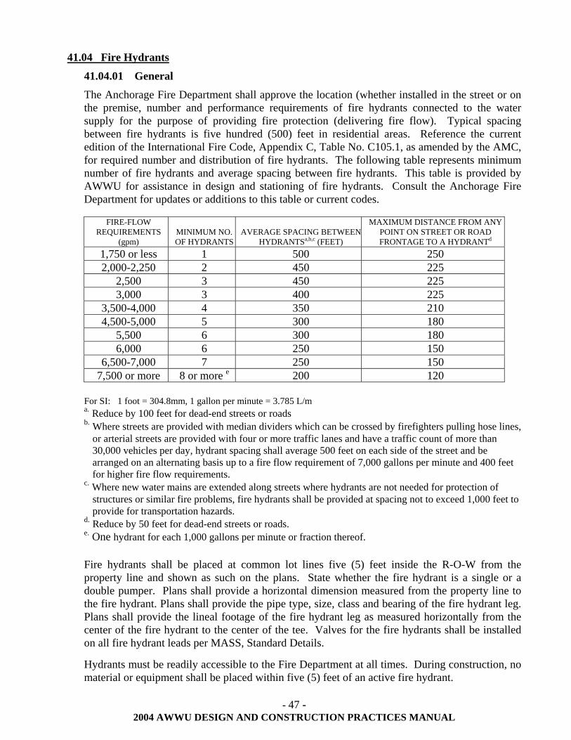
- 47 - 2004 AWWU DESIGN AND CONSTRUCTION PRACTICES MANUAL
41.04 Fire Hydrants
41.04.01 General
The Anchorage Fire Department shall approve the location (whether installed in the street or on the premise, number and performance requirements of fire hydrants connected to the water supply for the purpose of providing fire protection (delivering fire flow). Typical spacing between fire hydrants is five hundred (500) feet in residential areas. Reference the current edition of the International Fire Code, Appendix C, Table No. C105.1, as amended by the AMC, for required number and distribution of fire hydrants. The following table represents minimum number of fire hydrants and average spacing between fire hydrants. This table is provided by AWWU for assistance in design and stationing of fire hydrants. Consult the Anchorage Fire Department for updates or additions to this table or current codes.
FIRE-FLOW REQUIREMENTS
(gpm) MINIMUM NO. OF HYDRANTS
AVERAGE SPACING BETWEEN HYDRANTSa,b,c (FEET)
MAXIMUM DISTANCE FROM ANY POINT ON STREET OR ROAD FRONTAGE TO A HYDRANTd
1,750 or less 1 500 250 2,000-2,250 2 450 225
2,500 3 450 225 3,000 3 400 225
3,500-4,000 4 350 210 4,500-5,000 5 300 180
5,500 6 300 180 6,000 6 250 150
6,500-7,000 7 250 150 7,500 or more 8 or more e 200 120
For SI: 1 foot = 304.8mm, 1 gallon per minute = 3.785 L/m a. Reduce by 100 feet for dead-end streets or roads b. Where streets are provided with median dividers which can be crossed by firefighters pulling hose lines,
or arterial streets are provided with four or more traffic lanes and have a traffic count of more than 30,000 vehicles per day, hydrant spacing shall average 500 feet on each side of the street and be arranged on an alternating basis up to a fire flow requirement of 7,000 gallons per minute and 400 feet for higher fire flow requirements.
c. Where new water mains are extended along streets where hydrants are not needed for protection of structures or similar fire problems, fire hydrants shall be provided at spacing not to exceed 1,000 feet to provide for transportation hazards.
d. Reduce by 50 feet for dead-end streets or roads. e. One hydrant for each 1,000 gallons per minute or fraction thereof. Fire hydrants shall be placed at common lot lines five (5) feet inside the R-O-W from the property line and shown as such on the plans. State whether the fire hydrant is a single or a double pumper. Plans shall provide a horizontal dimension measured from the property line to the fire hydrant. Plans shall provide the pipe type, size, class and bearing of the fire hydrant leg. Plans shall provide the lineal footage of the fire hydrant leg as measured horizontally from the center of the fire hydrant to the center of the tee. Valves for the fire hydrants shall be installed on all fire hydrant leads per MASS, Standard Details.
Hydrants must be readily accessible to the Fire Department at all times. During construction, no material or equipment shall be placed within five (5) feet of an active fire hydrant.
- 48 - 2004 AWWU DESIGN AND CONSTRUCTION PRACTICES MANUAL
Hydrants shall not be placed within sidewalks, proposed or existing drives, or within other utilities' easements without an encroachment permit. When Municipal maintained fire hydrants are placed outside of the Municipal R-O-W, a permanent easement around the hydrant shall be provided. The easement shall be ten (10) feet wide, centered on the hydrant lead and extending five (5) feet beyond the hydrant.
All single-pumper hydrant leads shall be six (6) inches in diameter and installed on both eight (8) and ten (10) inch water mains.
All double-pumper hydrant leads shall be eight (8) inches in diameter and installed on mains twelve (12) inches and larger. Exception may be granted in residential areas where fire flows do not require double pumper and the main has been oversized for distribution.
41.04.02 Private Fire Hydrant
Any fire hydrant located on private property shall be classified as a private fire hydrant. These hydrants are owned by, and are the responsibility of, the owners of the property. AWWU will provide a winter check and servicing to private hydrants for operational readiness. Any repair work or other major service may be provided pursuant to written agreement with AWWU on a cost reimbursement basis. All private fire hydrants shall be adjusted to grade in accordance with MASS. The adjustment to grade may be done by the owner with AWWU inspection or adjusted by AWWU on a reimbursable basis.
41.04.03 Fire Hydrant Guard Posts
Guard Posts shall be installed around each fire hydrant in accordance with MASS Details. The only exception will be in a residential development where the fire hydrant is placed behind the curb and sidewalk areas and the location approved by AWWU.
41.05 Depth of Bury
Standard depth of bury shall be ten (10) feet to the top of pipe without prior approval by the AWWU Engineering Division. When cover on existing pipe is less than standard due to road excavation, etc., the existing water line shall be lowered or insulated, as directed by AWWU. Additional depth of bury is recommended in cul-de-sacs and other permanent dead end situations to protect against freezing. 41.06 Fire Flows
Fire flow duration shall be sustained in accordance with Appendix B, Table No. B105.1 of the current edition of the International Fire Code, as amended by the AMC. The Fire Prevention Division of the Anchorage Fire Department shall make the final determination of the specific fire flow required. In most cases, the fire flow duration cannot come from a single well source. Therefore, large transmission mains and reservoirs may be required. The minimum fire flow requirements for one (1) and two (2) family dwellings having a fire area which does not exceed 3.600 square feet shall be 1,000 gallons per minute. Fire flow and flow duration for dwellings having a fire area in excess of 3,600 square feet shall not be less than that specified in Table B105.1 of the International Fire Code, including any local amendments. The following table was extracted and is reprinted from Appendix B, Table B105.1 of the current edition of the International Fire Code, as currently amended by the MOA. Consult the Anchorage Fire Department for updates or additions to this table or current codes.
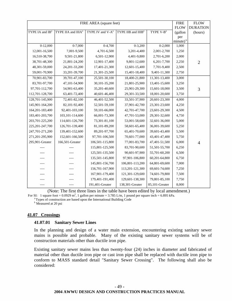
- 49 - 2004 AWWU DESIGN AND CONSTRUCTION PRACTICES MANUAL
FIRE AREA (square feet) FIRE FLOW
FLOW DURATION
TYPE IA and IBa TYPE IIA and IIIAa TYPE IV and V-Aa TYPE IIB and IIIBa TYPE V-Ba (gallon per
minute) b
(hours)
0-12,000 0-7,000 0-4,700 0-3,200 0-2,000 1,000 12,001-16,500 7,001-9,500 4,701-6,500 3,201-4,400 2,001-2,700 1,250 16,510-38,700 9,501-21,800 6,501-12,900 4,401-9,800 2,701-6,200 2,000 38,701-48,300 21,801-24,200 12,901-17,400 9,801-12,600 6,201-7,700 2,250 2 48,301-59,000 24,201-33,200 17,401-21,300 12,601-15,400 7,701-9,400 2,500 59,001-70,900 33,201-39,700 21,301-25,500 15,401-18,400 9,401-11,300 2,750
70,901-83,700 39,701-47,100 25,501-30,100 18,400-21,800 11,301-13,400 3,000 83,701-97,700 47,101-54,900 30,101-35,200 21,801-25,900 13,401-15,600 3,250
97,701-112,700 54,901-63,400 35,201-40,600 25,901-29,300 15,601-18,000 3,500 3 112,701-128,700 63,401-72,400 40,601-46,400 29,301-33,500 18,001-20,600 3,750
128,701-145,900 72,401-82,100 46,401-52,500 33,501-37,900 20,601-23,300 4,000 145,901-164,200 82,101-92,400 52,501-59,100 37,901-42,700 23,301-23,600 4,250 164,201-183,400 92,401-103,100 59,101-66,000 42,701-47,700 23,601-29,300 4,500 183,401-203,700 103,101-114,600 66,001-73,300 47,701-53,000 29,301-32,600 4,750 203,701-225,200 114,601-126,700 73,301-81,100 53,001-58,600 32,601-36,000 5,000 225,201-247,700 126,701-139,400 81,101-89,200 58,601-65,400 36,001-39,600 5,250 247,701-271,200 139,401-152,600 89,201-97,700 65,401-70,600 39,601-43,400 5,500 271,201-295,900 152,601-166,500 97,701-106,500 70,601-77,000 43,401-47,400 5,750 295,901-Greater 166,501-Greater 106,501-115,800 77,001-83,700 47,401-51,500 6,000 4
---- ---- 115,801-125,500 83,701-90,600 51,501-55,700 6,250 ---- ---- 125,501-135,500 90,601-97,900 55,701-60,200 6,500 ---- ---- 135,501-145,800 97,901-106,800 60,201-64,800 6,750 ---- ---- 145,801-156,700 106,801-113,200 64,801-69,600 7,000 ---- ---- 156,701-167,900 113,201-121,300 69,601-74,600 7,250 ---- ---- 167,901-179,400 121,301-129,600 74,601-79,800 7,500 ---- ---- 179,401-191,400 129,601-138,300 79,801-85,100 7,750 ---- ---- 191,401-Greater 138,301-Greater 85,101-Greater 8,000
(Note: The first three lines in the table have been edited by local amendment.) For SI: 1 square foot = 0.0929 m2, 1 gallon per minute = 3.785 L/m, 1 pound per square inch = 6.895 kPa.
a Types of construction are based upon the International Building Code b Measured at 20 psi
41.07 Crossings
41.07.01 Sanitary Sewer Lines
In the planning and design of a water main extension, encountering existing sanitary sewer mains is possible and probable. Many of the existing sanitary sewer systems will be of construction materials other than ductile iron pipe.
Existing sanitary sewer mains less than twenty-four (24) inches in diameter and fabricated of material other than ductile iron pipe or cast iron pipe shall be replaced with ductile iron pipe to conform to MASS standard detail "Sanitary Sewer Crossing". The following shall also be considered:
- 50 - 2004 AWWU DESIGN AND CONSTRUCTION PRACTICES MANUAL
5. Within a horizontal and perpendicular distance of ten (10) foot on both sides of the water crossing. The crossing shall be arranged so that the sanitary sewer joints will be equidistant and as far as possible from the water main joints.
6. Wherever the mains have less than eighteen (18) inches vertical separation at the crossing, measured outside edge to outside edge, the new water main shall be designed to provide a minimum of eighteen (18) inches separation.
Existing sanitary sewer mains twenty-four (24) inches and greater will be reviewed individually by the AWWU Engineering Division for replacement requirements.
41.07.02 Storm Drains
Water lines crossing storm drains require a minimum vertical separation of three (3) feet. If this minimum cannot be attained, then four (4) inches of Styrofoam (DOW HI or equivalent) insulation is required between the lines. Eighteen (18) inches is the minimum insulated separation distance. If eighteen (18) inches can not be obtained, the water line will have to be relocated.
41.07.03 Rivers/Streams
Water lines crossing streams with a top width greater than ten (10) feet require valves on each side of the crossing. Valves will be located back from the banks to prevent damage from lateral bank migration.
41.07.04 ADOT Crossings
Water facilities and public facilities located within ADOT/PF rights-of-way shall be installed in accordance with ADOT/PF permits.
41.07.05 Railway Crossings
When the water main crosses existing or proposed railways, the water main shall be designed in accordance with the criteria set forth in Part 5 of the American Railway Engineering Association manual. A copy of the referenced manual can be obtained from the Engineering Division of the Alaska Railroad. All railway crossing shall be installed in accordance with the Alaska Railroad permit requirements.
41.08 Materials
Ductile Iron Pipe (DIP) for water mains or transmission mains shall conform to the requirements of AWWA C-150 ("Thickness Design of DIP"), and AWWA C-151 ("Ductile Iron Pipe, Centrifugally Cast, for Water or Other Liquids") with cement mortar lining. All appurtenant piping materials shall conform to the requirements of MASS or as specified within this manual. Class 52 DIP shall be used for all mains eight (8) to twenty (20) inches in diameter. This provides a minimum pipe thickness of 0.33 inch. The class of pipe larger than twenty (20) inches in diameter requires approval by AWWU Engineering Division. 41.09 Valves
Valves shall be installed as follows: General:
1. Valves shall have the same diameter as the mains to which they are installed. 2. A sufficient number of valves shall be installed so that a break or other failure will not affect
more than 1000 feet of main.
- 51 - 2004 AWWU DESIGN AND CONSTRUCTION PRACTICES MANUAL
3. Valves shall be installed on the loop network at such places as to isolate branch sections as may be necessary.
4. A minimum of two (2) valves shall be installed at three-way intersections and a minimum of three (3) valves at four-way intersections.
5. Valves shall be located at the property line extended. 6. Valves shall be located inside the paved area where pavement exists. 7. All valves and valve can material shall be wrapped with a minimum of 8-mils of
polyethylene encasement. Valves on Fire Hydrants:
1. Valves shall be installed on all fire hydrant leads and in all cases shall be tied back to the main with restrained joints. Refer to MASS details for location.
Valves on Stub Outs: 1. Generally, stub outs shall not be valved. However, a valve may be installed at the tee or
property line extended depending on the extent of the overall development (i.e., paving limits, benefited area, future development, and the integrity of the completed water system).
2. Stub outs for future on-property connections shall be valved at the main, continuity straps installed, and restrained joints placed the entire length from the main to the plug.
Gate Valves: 1. All mains twelve (12) inches and smaller in diameter shall have gate valves furnished and
installed in accordance with MASS. Butterfly Valves:
1. Butterfly valves shall be installed on all mains larger than twelve (12) inches. 2. Butterfly valves shall be installed with the operating nut located on the side of the main to
the nearest property line and shall be furnished in accordance with MASS. Resilient Seat Gate Valves:
1. Resilient seat gate valves will be allowed on twelve (12) inch and smaller water mains. 41.10 Tapping Sleeves and Valves
Tapping sleeves and valves may be required for branch connections to existing water mains when the connection would unduly interrupt domestic water service, cause health risk or jeopardize fire protection capability. Where used, all live taps to the existing water distribution system shall be scheduled through and provided by AWWU on a cost reimbursement basis. Taps will not be permitted on reinforced concrete cylinder pipe, wood stave, or some classes of asbestos cement pipe, unless approved by the AWWU Engineering Division. 41.11 Fire Lines
Fire lines shall be sized for fire flow requirements of sprinkler systems, fire hydrants, and domestic services if provided. Fire lines shall be installed in accordance with MASS. Newly constructed fire lines that fail testing procedures as defined in MASS shall not be repaired with a bell repair clamp. Repairs shall be made with mechanical joint sleeves rated at a minimum of 200 psi. 41.12 Structural Consideration Use
Thrust Restraints: 1. Bends, tees, fire hydrants and dead-ends shall have restrained joints to the minimum
requirements of MASS. Poor soil conditions shall require special consideration. 2. It is the responsibility of the engineer to review soil conditions and design the thrust restraint
applicable for the project.
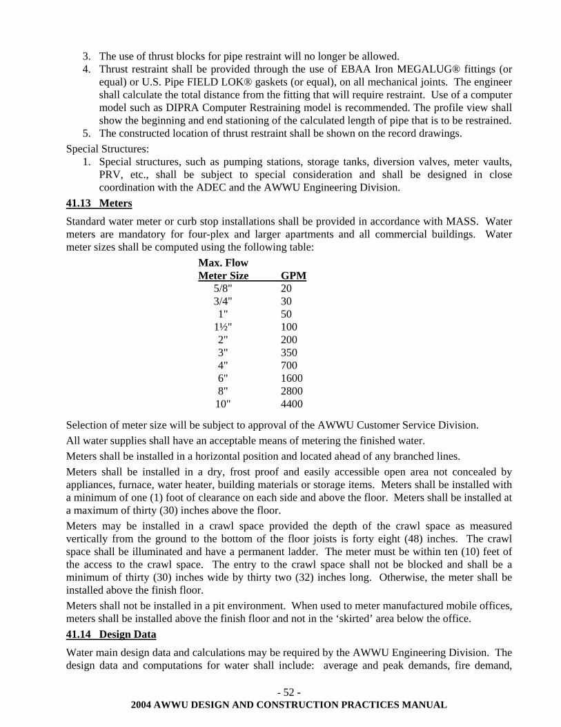
- 52 - 2004 AWWU DESIGN AND CONSTRUCTION PRACTICES MANUAL
3. The use of thrust blocks for pipe restraint will no longer be allowed. 4. Thrust restraint shall be provided through the use of EBAA Iron MEGALUG® fittings (or
equal) or U.S. Pipe FIELD LOK® gaskets (or equal), on all mechanical joints. The engineer shall calculate the total distance from the fitting that will require restraint. Use of a computer model such as DIPRA Computer Restraining model is recommended. The profile view shall show the beginning and end stationing of the calculated length of pipe that is to be restrained.
5. The constructed location of thrust restraint shall be shown on the record drawings. Special Structures:
1. Special structures, such as pumping stations, storage tanks, diversion valves, meter vaults, PRV, etc., shall be subject to special consideration and shall be designed in close coordination with the ADEC and the AWWU Engineering Division.
41.13 Meters
Standard water meter or curb stop installations shall be provided in accordance with MASS. Water meters are mandatory for four-plex and larger apartments and all commercial buildings. Water meter sizes shall be computed using the following table:
Max. Flow Meter Size GPM 5/8" 20 3/4" 30 1" 50 1½" 100 2" 200 3" 350 4" 700 6" 1600 8" 2800 10" 4400
Selection of meter size will be subject to approval of the AWWU Customer Service Division. All water supplies shall have an acceptable means of metering the finished water. Meters shall be installed in a horizontal position and located ahead of any branched lines. Meters shall be installed in a dry, frost proof and easily accessible open area not concealed by appliances, furnace, water heater, building materials or storage items. Meters shall be installed with a minimum of one (1) foot of clearance on each side and above the floor. Meters shall be installed at a maximum of thirty (30) inches above the floor. Meters may be installed in a crawl space provided the depth of the crawl space as measured vertically from the ground to the bottom of the floor joists is forty eight (48) inches. The crawl space shall be illuminated and have a permanent ladder. The meter must be within ten (10) feet of the access to the crawl space. The entry to the crawl space shall not be blocked and shall be a minimum of thirty (30) inches wide by thirty two (32) inches long. Otherwise, the meter shall be installed above the finish floor. Meters shall not be installed in a pit environment. When used to meter manufactured mobile offices, meters shall be installed above the finish floor and not in the ‘skirted’ area below the office. 41.14 Design Data
Water main design data and calculations may be required by the AWWU Engineering Division. The design data and computations for water shall include: average and peak demands, fire demand,
- 53 - 2004 AWWU DESIGN AND CONSTRUCTION PRACTICES MANUAL
future requirements, probable pressures, losses, calculations, computations for determining pipe sizes, project cost estimates, and proposed construction schedule.
- 54 - 2004 AWWU DESIGN AND CONSTRUCTION PRACTICES MANUAL
42.00 DESIGN AND CONSTRUCTION OF WATER SERVICES
42.01 General
The criteria in this section applies to residential service connections and extensions. For multi-family, commercial and industrial services refer to Section 21.06 of this manual. Water lines shall be installed in accordance with the standard details of MASS. All water services shall extend from the water main to the property line or to the edge of the easement where the key box is installed. All water services shall be installed no closer than five (5) feet to a side lot line and must be a minimum of fifteen (15) feet from a fire hydrant, power poles or transformer pads and a minimum of ten (10) feet from any structural foundation or other appurtenance such as sanitary sewer lines, storm drains, footing drains, light poles, or electrical/telephone/cable boxes.
42.01.01 Size and Cover
Water service lines shall be the size determined by Municipal Building Safety, PM&E. Trench excavation shall be done in such a manner as to prevent damage to the service line, and backfill will be of material outlined in MASS. The service line shall have a minimum depth of ten (10) feet and bedded with material to prevent damage to the service line.
The minimum size service for commercial and industrial connects shall be sized by calculation of the maximum available use of the building including maximum sizing necessary for fire protection systems. The minimum size of residential service shall be one (1) inch and shall also follow the following table, unless prior approval is obtained from AWWU Engineering and MOA Building Safety:
1 - 2 living units: one (1) inch service connect
3 - 4 living units: one and one-half (1 ½) inch service connect
5 or more living units, industrial, commercial, or business serving twenty five (25) or more employees or the general public: refer to Section 21.06 of this manual.
42.01.02 Depth
Water services shall be installed at a depth to prevent freezing.
The standard depth of cover for water services is ten (10) feet. This shall also apply where the service connection crosses ditch lines.
42.01.03 Bedding Material
The bedding shall be of a non-frost susceptible material, with a fine granular texture containing no material larger than one-half (½) inch in diameter. The bedding shall be laid the full extent of the ditch and completely cover the service pipe.
42.01.04 Service Lines 1. The lines shall be laid in straight runs. 2. Copper pipe shall be continuous. Use of 3-part unions is prohibited. 3. The lines shall be at a uniform grade. 4. The service line shall extend five (5) feet inside the footings at the ten (10) foot depth. 42.01.05 Repairs or Replacement
All on-property service extension repairs or replacements require an on-property permit and shall follow the same standards that apply to new connections. Existing materials shall be brought up
- 55 - 2004 AWWU DESIGN AND CONSTRUCTION PRACTICES MANUAL
to current standards. Replacement of any portion of an on-property private system will be required to have engineered plan in accordance with Section 21.06 of this manual.
42.02 Materials for Service Connections and Extensions
42.02.01 Authorized Materials and Fittings
The following materials are approved for water service connections and shall be installed and tested in accordance with MASS.
1. Ductile Iron, Class 52 2. Type K seamless copper tubing 3. HDPE (High Density Polyethylene) (see Section 41.03 of this manual) 4. "Tyton" joints (for ductile iron) 5. Mechanical joints 6. Flare joints or silver soldered copper joints 42.02.02 Unauthorized Material and Fittings 1. ABS (Acrylonitrile Butadiene-Styrene) 2. Aluminum or steel corrugated metal 3. Galvanized or black iron pipe 4. Mild steel or seamless conduit 5. PVC (Polyvinyl Chloride) 6. Non or reinforced concrete 7. Transite 8. Wood stave 9. Lead or non-silver solder.
42.03 Off-Property Connection (Main Line Taps)
A main line tap is accomplished with an appropriate tapping machine which has the capability of drilling, threading, and inserting a corporation stop under pressure with a minimum loss of water. Taps two (2) inches and smaller may be done by a licensed and bonded contractor or by AWWU on a reimbursable basis. Taps larger than two (2) inches shall be done by AWWU personnel only (prior arrangements for reimbursements are needed). All connects require a permit issued by AWWU Permit Office. The final grade in non-paved areas shall match existing grades at construction limits without producing drainage problems. Restoration of grass, shrubs, and other vegetation shall be done in conformance with construction contract documents. Tree damage shall be repaired in accordance with good horticultural practice. 42.04 On-Property Service (Extension)
42.04.01 General
The contractor shall ensure that the key box is in good working condition prior to installing the service extension. If the key box is not in good condition, the contractor shall not tie the extension on to the key box, AWWU shall be notified immediately.
42.04.02 Service Connect Markers
Services stubbed to property line for future use shall be marked with a wooden 2" x 4" x 8' protruding above ground three (3) feet, painted blue and stenciled with the word "WATER" in white two (2) inch high letters.
- 56 - 2004 AWWU DESIGN AND CONSTRUCTION PRACTICES MANUAL
42.04.03 Property Line Fittings
Property line fittings shall be consistent with material outlined in the standard details of MASS to include a curb stop with a rod attached by a copper wire the same diameter as the hole provided, and the appropriately sized key box.
42.05 Keyboxes
Keyboxes shall be installed in standard location as defined in MASS. Keyboxes located within pavement or concrete shall be adjusted to finish grade and installed in a valve box top section per MASS Details. Horizontal adjustment of keyboxes shall be accomplished by removing the keybox lid, installing a black iron pipe coupling, installing a section of black iron pipe and replacing the keybox lid at the finish grade. 42.06 Abandonment
The abandonment method for disconnection of a water service at the main line shall include the following: 1. Turn off corporation stop 2. Cut or disconnect copper 3. For three quarter (¾) and one (1) inch services, placement of a solid copper retainer disc
(Mueller Co. Catalog No. H-15535 or equal) on the end of the corporation stop and securely tighten with the flair nut
4. For greater than one (1)inch services, cut copper pipe within one foot of corporation stop, crimp cut end of copper and securely tighten the flair nut
5. Cut or disconnect thaw wire 6. Record drawing of the abandoned service connection
A disconnect permit will be required from AWWU and the contractor shall schedule inspection with AWWU and furnish the following information: 1. When disconnect is scheduled 2. Where disconnect will be made, including, but not limited to, lot, block, subdivision, address,
swing ties, depth, type of pipe and size 3. Who disconnected the service
An AWWU inspector shall observe the disconnection to ensure quality.
- 57 - 2004 AWWU DESIGN AND CONSTRUCTION PRACTICES MANUAL
43.00 WELL AND PUMPING PLANT DESIGN
43.01 General
Criteria related to well and pumping plant design can be found in "Improving Well and Pump Efficiency", Otto J. Helweg, Scott, Verne H., and Scalmanini, Joseph C., 1983, published by the American Water Works Association and the “Recommended Standards for Water Works” (a.k.a. "10 States Standards"), Great Lakes-Upper Mississippi River Board of State Sanitary Engineers, current edition. By reference, the above documents, or an alternate approved in writing by AWWU, are made a part of this manual. 43.02 Pump Design
Consideration shall be given to the existing and future service area when designing pumping equipment. When areas are not at maximum development, pumps shall be designed to meet the ratio-to-peak flows for the current users.
- 58 - 2004 AWWU DESIGN AND CONSTRUCTION PRACTICES MANUAL
44.00 DESIGN OF BOOSTER STATIONS
All booster station facilities shall be designed as above ground structures to maintain the sanitary quality of pumped water. Subsurface package stations, pits or pump rooms and inaccessible installations shall be avoided. Use of a subsurface station requires written approval from the Engineering Manager of AWWU. The design and installation of these stations shall conform to the latest edition of MASS and all work shall be in accordance with the latest editions of IBC, IMC, UPC and NEC. (All, as amended and accepted by MOA). 44.01 Location Considerations
The station shall be located so that the proposed site will meet the requirements for sanitary protection of water quality, hydraulics of the system and protection against interruption of service by fire, flood or any other hazard. Additional design considerations are: 1. Functional aspects of the building layout 2. Provisions for future building expansion 3. Site grading and drainage elevated to a minimum of three feet above the highest recorded flood
elevation, or protected to such elevation 4. Graded around the station so as to lead surface drainage away from the station 5. Designed with a site plan to include secondary access roads with level parking for maintenance
trucks and equipment and with access to the doors of the station and related walkways 6. Compatibility with surrounding architectural designs 7. Exterior fencing 8. A site for snow storage 44.02 Building Layout
Design shall provide for: 1. Adequate space for the installation of additional units if needed, and for the safe servicing of all
equipment 2. Durable construction, fire and weather resistant, with outward-opening doors 3. A floor elevation of at least six (6) inches above finished grade and drained in such a manner that
the quality of potable water will not be endangered. Floors shall slope at least three (3) inches in every ten (10) feet to a suitable drain
4. A suitable outlet for drainage from pump glands without discharging onto the floor 5. Accessibility of equipment for operation, servicing, and removal 6. Hydro-pneumatic tanks 44.03 Standby Power
If power failure results in cessation of minimum essential service, power supply shall be provided from at least two (2) independent sources, a standby or an auxiliary source may be required by AWWU. Standby power may be required by AWWU. If not, the station shall be wired for external hook up for a portable generator. Electrical supply and control and alarm circuits shall be designed to provide strain relief and to allow disconnection from outside the booster station. Terminals and connectors shall be protected from corrosion and location outside the booster station. When located outside, weatherproof equipment shall be used. The booster station shall have a disconnect switch with a manual transfer switch including an external plug to match portable generation. Contact AWWU Operations and Maintenance Division for correct generator receptacle connection. The electrical disconnect and transfer switch shall be within twelve (12) feet of the station.
- 59 - 2004 AWWU DESIGN AND CONSTRUCTION PRACTICES MANUAL
44.04 Meters
When required by AWWU, booster stations shall have meters installed per AWWU and MASS details and meet SCADA requirements. 44.05 Equipment Nameplates and Manuals
For each station, provide six (6) complete sets of operation and maintenance manuals. Each operation and maintenance manual shall include: operational procedures to be followed in case of blockage, power outage, circuit overload, or emergency; station shut down and start up procedures, including lock out/tag out requirements; routine maintenance tasks and schedule for all equipment and assemblies; a list of any special tools required to operate or maintain the station; and mechanical and electrical drawings of the facility. In addition to the facility manuals, provide six (6) complete sets of equipment manuals for each item of equipment and each instrument panel in the facility. Each equipment manual shall contain: Summary showing: 1. Make, model, style, serial number, description, manufacturer's specifications, and location in the
construction. 2. Full names and addresses of manufacturer, vendor, prime contractor and installer. Manufacturer's literature properly marked to identify the specific item. The literature shall include: 1. Instruction for installation, operation, maintenance and repair. 2. Shop drawings, wiring diagrams, and system layouts, where such drawings are required in other
sections of the specifications. Each piece of major equipment in the station shall have nameplates affixed in an accessible location which includes make, model and serial number, manufacture and power requirement. Further details on submission to AWWU are found in Section 70.04 of this manual. 44.06 Equipment Servicing
AWWU Operations and Maintenance Division shall review and approve all equipment necessary for servicing a booster station. At a minimum, booster stations shall be provided with: 1. Crane-ways, hoist beams, eyebolts, or other adequate facilities for servicing or removal of
pumps, motors or other heavy equipment 2. Openings in floors, roofs, or whatever is needed for removal of heavy or bulky equipment
(largest) 3. A convenient tool board or other facilities as needed, for proper maintenance of the equipment
44.07 Heating
Stations shall have a natural gas heater as the primary heat source with an electric heater for back-up heating. Heating equipment shall meet all applicable codes. 44.08 Ventilation and Dehumidification
Ventilation and dehumidification shall conform to existing local, State and/or Federal codes. All ventilation switches shall be located at the entryway. 44.09 Lighting
Pump stations shall have adequate lighting for installation, removal and maintenance of all equipment. All electrical work shall conform to NEC. 44.10 Pumps
At least two (2) pumping units shall be provided. More than two pumps may be required to meet all flow conditions. With any pump out of service, the remaining pump or pumps shall be capable of
- 60 - 2004 AWWU DESIGN AND CONSTRUCTION PRACTICES MANUAL
providing the maximum daily pumping demand of the system. The pumping units shall be approved by AWWU and: 1. Have ample capacity to supply the peak demand without dangerous overloading 2. Be driven by a prime mover able to operate against the maximum head and air temperature
which may be encountered 3. Be low maintenance pumps 4. Have any unique spare parts or tools readily available
44.11 Booster Pumps
Booster pumps shall be located or controlled so that: 1. They will not produce negative pressure in the suction lines 2. The intake pressure shall be at least twenty (20) psi when the pump is in normal operation 3. Automatic cutoff pressure shall be at least ten (10) psi in the suction line 4. Automatic or remote control devices shall have a range between the start and cutoff pressure
which will prevent excess cycling 5. A bypass is available
44.11.01 In-line Booster Pumps
In addition to the other requirements of this section, in-line booster pumps shall be accessible for servicing and repairs.
44.12 Supervisory Control And Data Acquisition (SCADA)
All stations shall be designed and constructed with SCADA equipment compatible to AWWU which will report data from the station in both operation and out of service modes. All stations shall be electrically-operated and controlled and shall have signaling apparatus of proven performance. Installation of electrical equipment shall conform to the applicable State and local electrical codes and the National Electric Code. See Section 70.06 of this document lists the minimum SCADA equipment necessary for a sanitary sewer lift station. 44.13 Appurtenances
44.13.01 Valves
Pumps shall be adequately valved to permit satisfactory operation, maintenance and repair of the equipment. Each pump shall have a positive-acting pressure reducing valve on the pump discharge prior to the shut-off valve. All valves shall be epoxy coated. The valve harness design shall be determined by AWWU.
44.13.02 Piping
In general, piping shall:
1. Be designed so that the friction losses will be minimized 2. Not be subject to contamination 3. Have watertight joints 4. Be protected against surge or water hammer 5. Be such that each pump has an individual suction line or that the lines shall be so manifold
that they will ensure similar hydraulic and operating conditions 6. Adequate vibration dampers 7. Paint coating per Section 70.05 of this manual
- 61 - 2004 AWWU DESIGN AND CONSTRUCTION PRACTICES MANUAL
44.13.03 Gauges
Each pump shall have standard pressure gauges on the suction and discharge lines and telemetry lines to measures and discharge (when required by AWWU) flows. All gauges shall be high quality four (4) inch glycerin filled with one-quarter (¼) inch national pipe threads (Ashcroft or equal). The pressure range of the gauges shall be specific so that the normal system working pressure does not exceed sixty (60) percent of the pressure range of the gauge.
44.13.04 Water Seals
Water seals shall not be supplied with water of a lesser sanitary quality than that of the water being pumped. Where pumps are sealed with potable water and are pumping water of lesser sanitary quality, the seal shall:
1. Be provided with a break tank open to atmospheric pressure 2. Have an air gap of at least six (6) inches or two (2) pipe diameters, whichever is greater,
between the feeder line and the spill line of the tank.
44.13.05 Controls
Pumps, their prime movers and accessories shall be controlled in such a manner that they will operate at rated capacity without dangerous overload and should provide for lead/lag operation of multiple pumps. Where (2) two or more pumps are installed, provision shall be made for independent alternation. Provision shall be made to prevent energizing the motor in the event of a backspin cycle. Electrical controls shall be located above grade.
44.13.06 Water Pre-lubrication
When automatic pre-lubrication of pump bearings is necessary and an auxiliary power supply is provided, the pre-lubrication line shall be provided with a valved bypass around the automatic control so that the bearings can, if necessary, be lubricated manually before the pump is started.
44.14 Painting
All booster stations shall be completely painted inside and outside including, but not limited to, all walls, piping, equipment, appurtenances, etc. The facility shall be painted in accordance with the best building practices of the International Building Codes. (Reference Section 70.05 of this manual)
- 62 - 2004 AWWU DESIGN AND CONSTRUCTION PRACTICES MANUAL
45.00 DESIGN OF PRESSURE REDUCING VALVE (PRV) STATIONS
45.01 General
PRV stations shall be designed to maintain the sanitary quality of the water system. Inaccessible installation shall be avoided. The PRV station shall be generally an above ground facility so located that the proposed site will meet the requirements for sanitary protection of water quality, hydraulics of the system and protection against interruption of service. No PRV station shall be subject to flooding. The design and installation shall conform to the latest edition of MASS and all work shall be in accordance with the latest editions of IBC, IMC, UPC and NEC. (All, as amended and accepted by MOA). All PRV stations shall be designed with the same considerations as provided in Section 44.00 of this manual. Underground vaults shall only be designed on special conditions approved by the AWWU Engineering Division Manager. 45.02 PRV Station Design
The station shall be: 1. Readily accessible at all times 2. Graded around the station so as to lead surface drainage away from the station 3. Designed with a site plan to include level parking of maintenance trucks and equipment,
including a site for snow storage 4. Protected to prevent vandalism and entrance by unauthorized persons or animals 5. Designed with adequate space for the installation of additional units if needed, and for the safe
servicing of all equipment 6. Of a pre-fabricated or cast in place durable construction, weather-resistant and waterproofed as
required by AWWU. Precast manhole sections may not be considered as an acceptable alternate by AWWU
7. Provided with sump pumps, crane-ways, hoist beams, eyebolts, or other adequate facilities for servicing heavy equipment
8. Completely painted inside and outside including, but not limited to, all walls, piping, equipment, appurtenances, etc
9. Key locked entries 10. Sump pumps and discharge lines 11. Stairway access when ever possible.
45.03 Stairways, Ladders and Bilco Hatches
When a PRV station is approved as a vault, stairways, ladders and lockable "Bilco" hatches shall: 1. Be provided in pits or compartments which must be entered 2. Have handrails on both sides, and treads of non-slip material 3. Be designed per IBC Stairs are preferred in areas where there is frequent traffic. They shall have risers not exceeding nine (9) inches and treads wide enough for safety.
45.04 Heating
Provisions shall be made for heating in accordance with the IBC, UPC and NEC. Whenever possible, install gas heating. In PRV stations not occupied by personnel, only enough heat need be provided to prevent freezing of equipment or treatment process.
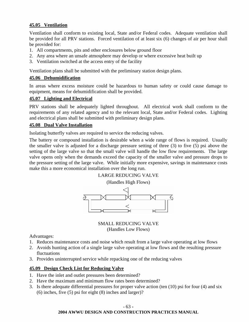
- 63 - 2004 AWWU DESIGN AND CONSTRUCTION PRACTICES MANUAL
45.05 Ventilation
Ventilation shall conform to existing local, State and/or Federal codes. Adequate ventilation shall be provided for all PRV stations. Forced ventilation of at least six (6) changes of air per hour shall be provided for: 1. All compartments, pits and other enclosures below ground floor 2. Any area where an unsafe atmosphere may develop or where excessive heat built up 3. Ventilation switched at the access entry of the facility
Ventilation plans shall be submitted with the preliminary station design plans. 45.06 Dehumidification
In areas where excess moisture could be hazardous to human safety or could cause damage to equipment, means for dehumidification shall be provided. 45.07 Lighting and Electrical
PRV stations shall be adequately lighted throughout. All electrical work shall conform to the requirements of any related agency and to the relevant local, State and/or Federal codes. Lighting and electrical plans shall be submitted with preliminary design plans. 45.08 Dual Valve Installation
Isolating butterfly valves are required to service the reducing valves. The battery or compound installation is desirable when a wide range of flows is required. Usually the smaller valve is adjusted for a discharge pressure setting of three (3) to five (5) psi above the setting of the large valve so that the small valve will handle the low flow requirements. The large valve opens only when the demands exceed the capacity of the smaller valve and pressure drops to the pressure setting of the large valve. While initially more expensive, savings in maintenance costs make this a more economical installation over the long run.
LARGE REDUCING VALVE (Handles High Flows)
SMALL REDUCING VALVE (Handles Low Flows)
Advantages: 1. Reduces maintenance costs and noise which result from a large valve operating at low flows 2. Avoids hunting action of a single large valve operating at low flows and the resulting pressure
fluctuations 3. Provides uninterrupted service while repacking one of the reducing valves
45.09 Design Check List for Reducing Valve 1. Have the inlet and outlet pressures been determined? 2. Have the maximum and minimum flow rates been determined? 3. Is there adequate differential pressures for proper valve action (ten (10) psi for four (4) and six
(6) inches, five (5) psi for eight (8) inches and larger)?
- 64 - 2004 AWWU DESIGN AND CONSTRUCTION PRACTICES MANUAL
4. Are there quick acting valves in the system? (This may require a separate cushioning device.) 5. Design maximum continuous line velocity at fifteen (15) fps. 6. If a single reducing valve is used, is a manual bypass installed? 7. Does wide range of flows call for dual installation (large and small valve in parallel)? 8. Does a high differential or low flow rate call for special trim materials (i.e., stainless steel)? 9. Does high differential and low outlet pressure make cavitations likely? 10. Is valve sized properly for differential pressure and flow rates (not necessarily line size)? 11. Is the valve properly supported (under flanges and not under bottom cap)? 12. Is there adequate clearance above and around the valve to facilitate servicing? 13. Are there inlet and outlet pressure gauges? 14. Proper gauges and telemetry devices?
45.10 Sizing Reducing Valve
The correct sizing of a pressure reducing valve depends on several factors: differential pressure, maximum and minimum flow rates, anticipated future requirements, etc. Each application shall be investigated using its own conditions. The maximum flow rates are intended to limit the line velocity to approximately fifteen (15) fps. The valve should be capable of passing larger quantities of water for relatively short periods of time. All valves (when in good operating condition) shall be capable of drip-tight shut-off. Wide fluctuations in flow are best handled by using the dual valve installation illustrated in Section 45.08 of this manual. 45.11 Supervisory Control And Data Acquisition (SCADA)
All PRVs shall be designed and constructed with SCADA equipment compatible to AWWU. Section 70.06 lists the minimum SCADA equipment necessary for a pressure reducing station.
- 65 - 2004 AWWU DESIGN AND CONSTRUCTION PRACTICES MANUAL
50.00 RECORD DRAWINGS AND FINAL DOCUMENT SUBMITTALS
50.01 General
AWWU requires approved record drawings, survey notes and contractor field installation notes as a condition of final acceptance for all constructed or partially constructed sanitary sewer and water improvement projects. All record drawings to be submitted should be done so in accordance with the procedures set forth in this section. Furthermore, record drawings shall also be in accordance with those regulations as set forth by the State of Alaska Department of Environmental Conservation for both wastewater and/or water systems (Wastewater Disposal Regulations 18 AAC 72 and Drinking Water Regulations 18 AAC 80, latest editions). Submitted record drawings not meeting ADEC regulations shall not be considered approved. 50.02 Record Drawing Information
Record drawing information required in the submittal for acceptance includes a complete set of drawings, construction contractor's field installation notes of the facilities as-constructed, engineer's inspection reports, all lab and on-site materials testing reports/results, original construction field survey notes, and the original copy of the approved "Certificate of Construction for Domestic Wastewater Systems" and/or "Construction and Operation Certificate for Public Water Systems" as required by State of Alaska Department of Environmental Conservation. 50.03 Drawings
Record drawings submitted for acceptance shall be of good quality original single matte film with a minimum thickness of three (3) mil, legibly printed and rendered to provide for clear blue line copies and microfilm slides and prints. The record drawing reproducible single matte film shall contain the same data shown on the construction contractor’s field installation notes, appropriate symbols and identifiers of data provided by the construction contractor, and data provided by the engineer. Record drawings shall identify or include: 1. Construction Contractor's name. 2. Engineering firm's name and address. 3. All certifications or professional seals as required by the State of Alaska Department of
Environmental Conservation's regulations as stated in the foregoing.
50.04 Procedures for Changes to Original Drawings
All revised work shall be in a permanent drafting style black ink and in size, type and scale of the original drawing. AWWU will reject record drawing done with ball point and non black ink pens. A straight line shall be drawn through any changes in stationing, elevations and other notes that have been revised. The correction shall be in italic and show any changes, deletions or omissions, and shall be followed with the appropriate symbol. Any utility line or construction note that has been deleted or relocated shall be crosshatched with the original information remaining legible. The scale and line weight of new utilities, asbuilt information or new construction shall conform to the scale of original drawings. Reference information used in preparation of record drawings, such as inspector's prints and field installation books, shall be noted on drawings. Profile changes shall be made with elevations or stationing only. The original profile line need not be modified unless the change is greater than one (1) foot.
- 66 - 2004 AWWU DESIGN AND CONSTRUCTION PRACTICES MANUAL
50.05 Revisions
Revisions to drawings are defined as all changes made between the dates the project plans are approved by AWWU and the date the record drawings are accepted as complete by AWWU. The particular area of the drawing where the revision has been made shall be clouded, and the appropriate revision number placed in a triangle shall be shown in that location. The clouded area shall not be shaded or in any form of grey tones. Revisions shall be listed in the title block of the drawing and shall show: 1. The revision number in a triangle (revisions shall be consecutively numbered on each drawing
beginning with number one) Note: A particular set of revisions which may affect several drawings will not necessarily be identified with the same revision number, depending on the number of prior revisions made to each particular drawing.
2. The date the revision was made on the drawing Note: A particular set of revisions which may affect several drawings shall be assigned the same date even though the actual work involved may take several days to complete.
3. The initials of the person making the revision 4. A brief description of the revision
50.06 Survey and Field Installation Notes
Construction surveys shall be accomplished by a surveyor licensed in the state of Alaska and the notes shall include: 1. Contractor's name and address 2. Line and grade survey notes 3. Surveyor’s firm's name and address 4. Construction survey notes
Field installation notes from the Contractor shall contain the horizontal and vertical location information as constructed including, but not limited to: 1. Manholes and cleanouts, horizontal station and vertical elevations; 2. Valves, fire hydrants, key boxes, PRV's and mechanical joint fittings; 3. Make, model and location of all thrust restraint fittings and total footage of pipe restrained; 4. Service connections at the mains and stationing; 5. Special fittings; 6. All encountered utilities, any pipe or street insulation and limits of all fabric material; 7. Changes in pipe size, slope or type; and, 8. Service locations at property lines swing-tied to above-ground facilities, such as fire hydrants,
houses, light poles, or water key boxes. For sanitary sewer, give the invert elevation of the connection at the property line or easement line.
50.07 Time Limit for Record Drawing Submittal
Final acceptance of the development will not occur until the Record Drawing has been approved by AWWU. The system improvements shall not be available for domestic use until Record Drawings have been approved by AWWU and have met the requirements of ADEC Regulations 18 AAC 72 and 18 AAC 80. 50.08 Buried or Unmarked Appurtenances
Buried or unmarked appurtenances are not justifiable reasons for not submitting Record Drawings. If necessary, in order to provide the proper information, the developer or engineer shall, at their
- 67 - 2004 AWWU DESIGN AND CONSTRUCTION PRACTICES MANUAL
expense, uncover or expose the appurtenances and all utilities encountered to effect survey measurements required for proper records. The Record Drawings should state who provided the record information. 50.09 Sanitary Sewer and Water Record Drawings
Minimum record drawing information to be obtained is as follows: 1. Vertical and horizontal location on all tees, bends, valves, restrained piping and fittings,
hydrants, manholes, cleanouts changes in alignment and ends of pipe. Vertical and horizontal location at minimum intervals of three hundred (300) feet on extended runs without alignment change or fittings.
2. Lineal footage of pipe installed, including revisions to stationing and elevations. 3. Vertical and horizontal location on all existing utilities exposed by the trench excavation.
Horizontal location may be relative to the line being installed. 4. Horizontal location on new surface features such as valves, hydrants, key boxes, manholes,
cleanouts, any repair coupling, etc. This information should be relative to street center lines and/or property lines. Key boxes and sanitary sewer service connections shall be measured from property corners.
5. Horizontal location or stationing from the nearest feature at any change in pipe material (i.e., transite to ductile, change in pipe class, etc.).
6. Areas where foundation material is used and/or where bedding material is imported. 7. Water service key box locations and sanitary sewer service connections shall be recorded and
submitted on the Service Connection Record to facilitate distribution of this information to concerned departments.
8. Vertical elevation of the service connection at the main and at the property line. 9. Horizontal offset measurement of the service connection to the property line. 10. Information on subsurface soil conditions encountered in trenches every three hundred (300) or
feet where significant changes occur. Particular emphasis shall be placed on native materials at the bottom of the trench. Areas where over-excavation is performed and foundation material is placed shall be delineated.
11. Subsurface soil data should be forwarded to the PM&E Soils Lab. 12. Location and stationing of all pipe abandonment. Include both length of pipe removed and pipe
abandoned in place. 13. Horizontal and vertical location of any approved sanitary sewer or water service connection Pig-
Tail(s). 14. Location size and type of all cathodic protection devices. 15. Horizontal dimensions of building foot prints. 16. Horizontal dimensions of all easements.
Any changes authorized in the field shall be shown and noted as "field change". 50.10 As-Constructed Survey Notes
Post-construction survey shall be performed by a surveyor licensed in the state of Alaska and shall include the items addressed in this section and Division 65.00 of MASS. The post construction survey notes, the construction contractor’s field installation notes, the engineer's daily inspection notes and the record drawings shall be submitted to AWWU for review and approval. 50.11 Engineer’s Responsibility on Record Drawings
At a minimum, the engineer shall transfer to the original single matte film the following information: 1. The construction contractor's redline drawings of the facilities as-constructed. 2. The field installation notes from the line and grade books.
- 68 - 2004 AWWU DESIGN AND CONSTRUCTION PRACTICES MANUAL
3. Station and elevation of all utilities encountered in the trench.
The engineer shall certify that the record drawing reflects accurate as-constructed information. The engineer shall resolve any errors in the calculations with the construction contractor prior to submittal to AWWU for approval. The engineer shall put all numbers for permits issued during design and construction (i.e., ADOT/PF, ROW, Wetlands, Recorded Easements, etc.) on the record drawing. The engineer shall verify that any waivers acquired either during the design or construction are noted on the record drawings. 50.12 Horizontal and Vertical Attribute Values
The engineer or contractor shall submit horizontal and vertical attribute values in accordance with Section 70.04 of this document.
- 69 - 2004 AWWU DESIGN AND CONSTRUCTION PRACTICES MANUAL
60.00 DESIGN TYPICAL AND SUPPLEMENTARY INFORMATION
This section deals with information that may provide the designer with additional useful information in preparing plans for AWWU review submittals. Use of standard symbols, acronyms, abbreviations, etc., can reduce the chances of misunderstandings and therefore serve to reduce review time and possibly the need for field design changes. Use of the following details is strongly recommended.
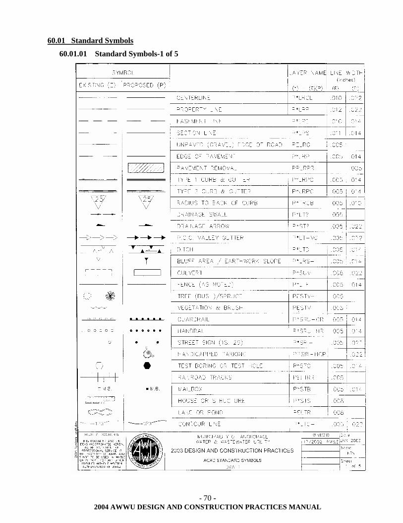
- 70 - 2004 AWWU DESIGN AND CONSTRUCTION PRACTICES MANUAL
60.01 Standard Symbols
60.01.01 Standard Symbols-1 of 5
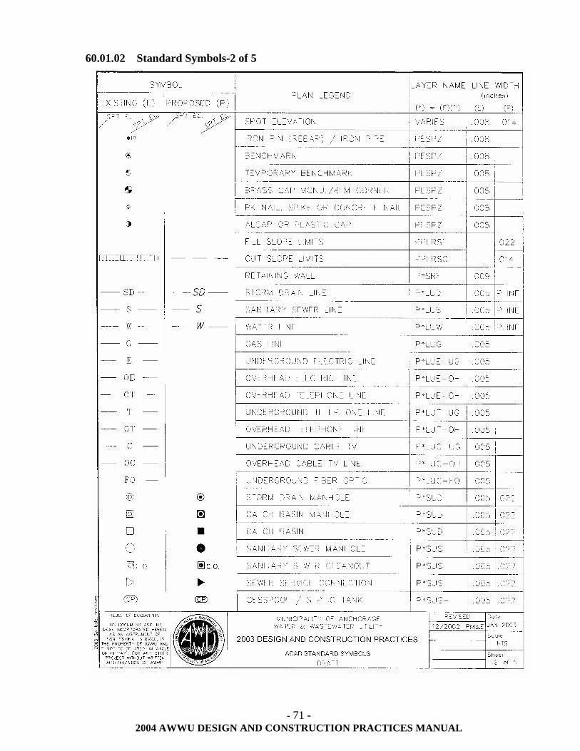
- 71 - 2004 AWWU DESIGN AND CONSTRUCTION PRACTICES MANUAL
60.01.02 Standard Symbols-2 of 5
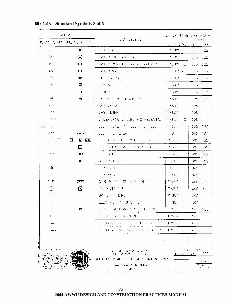
- 72 - 2004 AWWU DESIGN AND CONSTRUCTION PRACTICES MANUAL
60.01.03 Standard Symbols-3 of 5
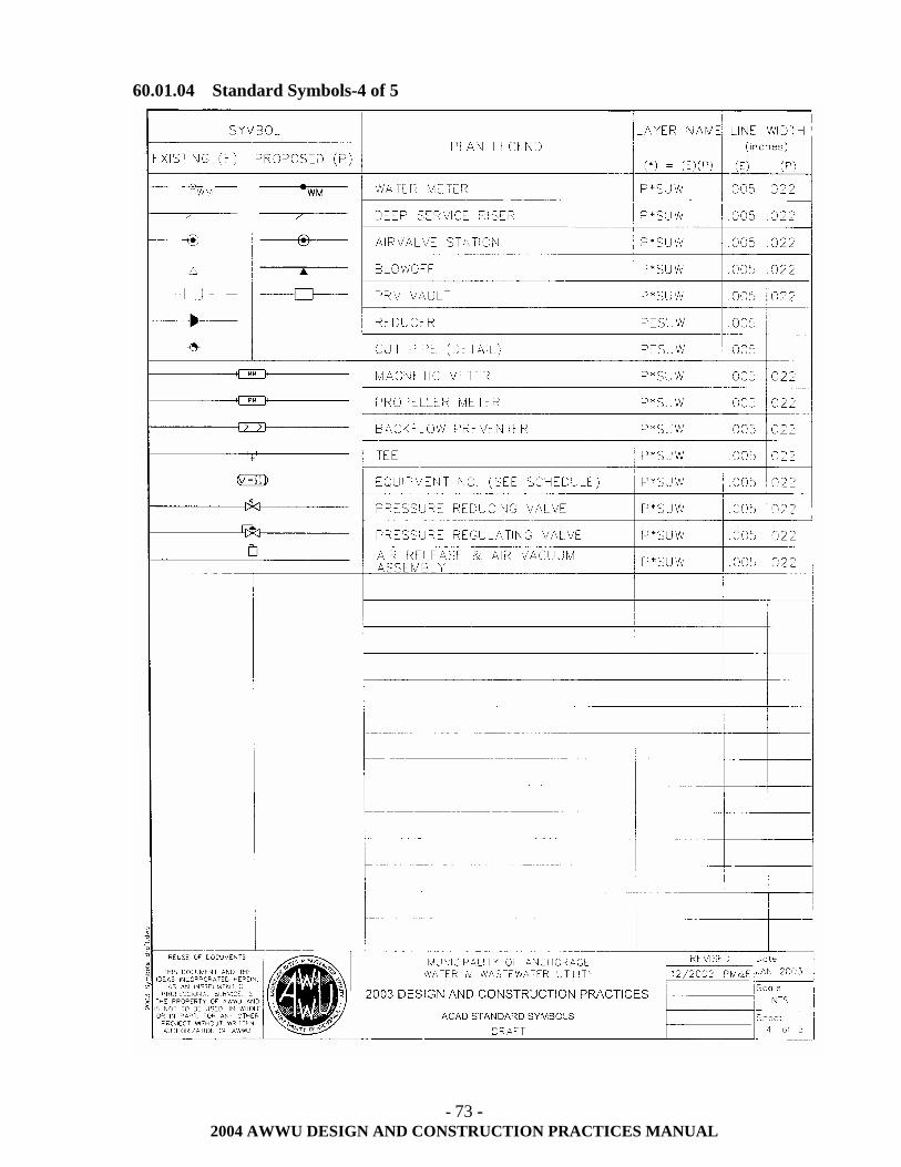
- 73 - 2004 AWWU DESIGN AND CONSTRUCTION PRACTICES MANUAL
60.01.04 Standard Symbols-4 of 5
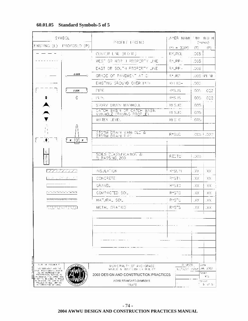
- 74 - 2004 AWWU DESIGN AND CONSTRUCTION PRACTICES MANUAL
60.01.05 Standard Symbols-5 of 5
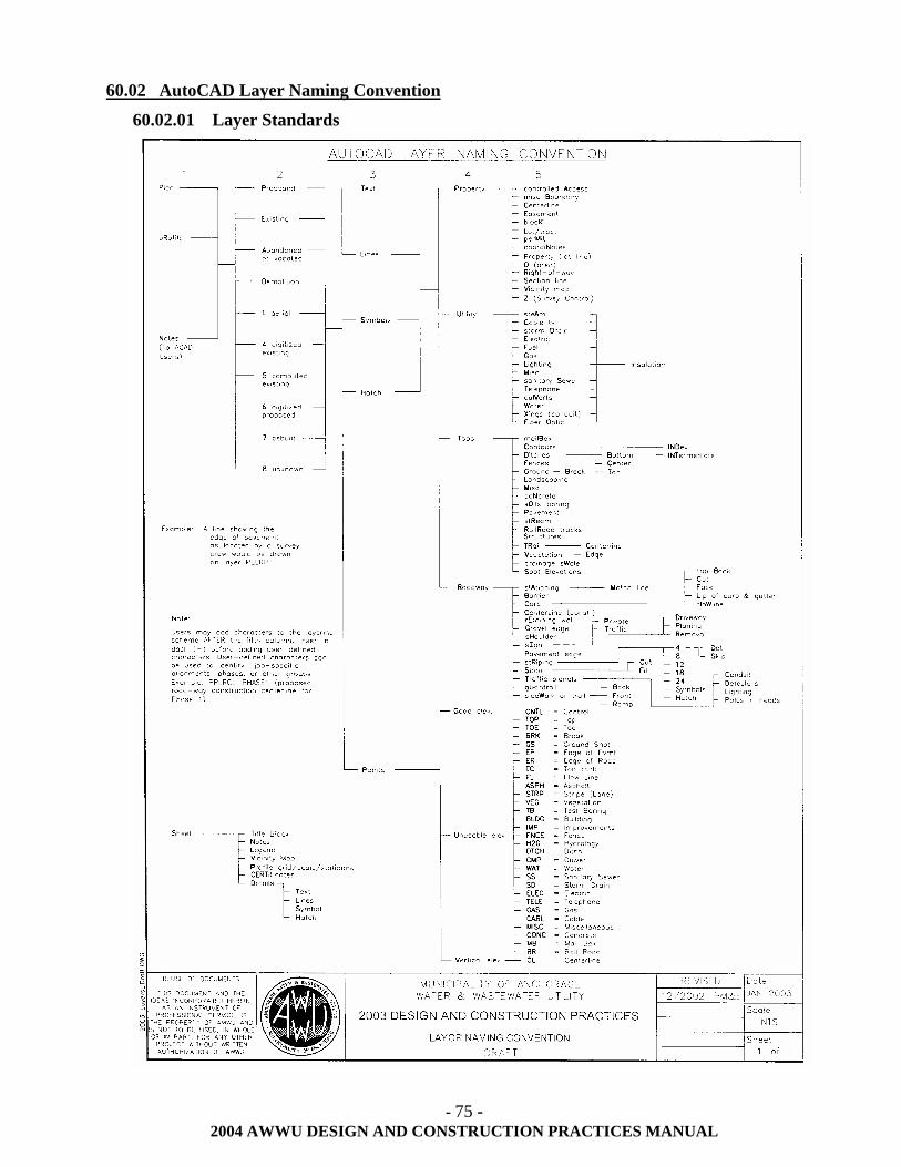
- 75 - 2004 AWWU DESIGN AND CONSTRUCTION PRACTICES MANUAL
60.02 AutoCAD Layer Naming Convention
60.02.01 Layer Standards
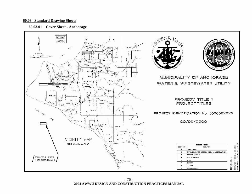
- 76 -
2004 AWWU DESIGN AND CONSTRUCTION PRACTICES MANUAL
60.03 Standard Drawing Sheets
60.03.01 Cover Sheet - Anchorage
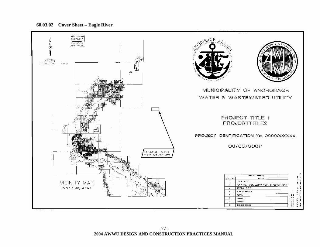
- 77 -
2004 AWWU DESIGN AND CONSTRUCTION PRACTICES MANUAL
60.03.02 Cover Sheet – Eagle River
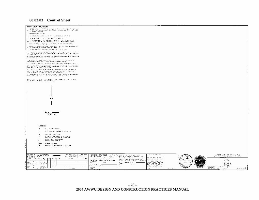
- 78 -
2004 AWWU DESIGN AND CONSTRUCTION PRACTICES MANUAL
60.03.03 Control Sheet
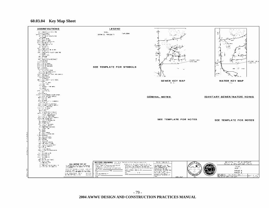
- 79 -
2004 AWWU DESIGN AND CONSTRUCTION PRACTICES MANUAL
60.03.04 Key Map Sheet
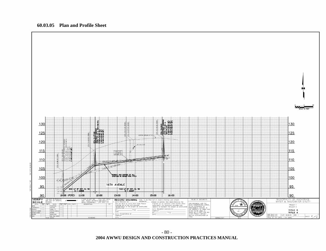
- 80 -
2004 AWWU DESIGN AND CONSTRUCTION PRACTICES MANUAL
60.03.05 Plan and Profile Sheet
- 81 -
2004 AWWU DESIGN AND CONSTRUCTION PRACTICES MANUAL
60.03.06 Detail Sheet
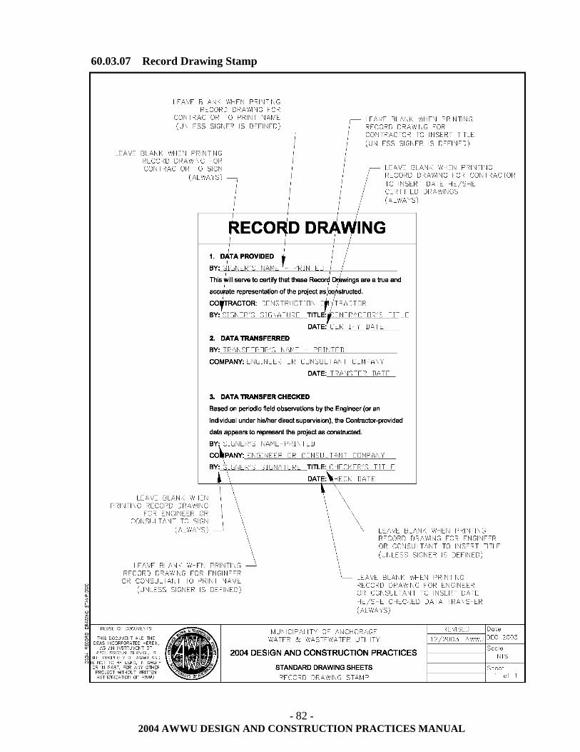
- 82 -
2004 AWWU DESIGN AND CONSTRUCTION PRACTICES MANUAL
60.03.07 Record Drawing Stamp
- 83 -
2004 AWWU DESIGN AND CONSTRUCTION PRACTICES MANUAL
60.04 Basic Construction Notes
The following general, sanitary sewer and water construction notes along with the general survey notes are examples of what shall be used on the drawings.
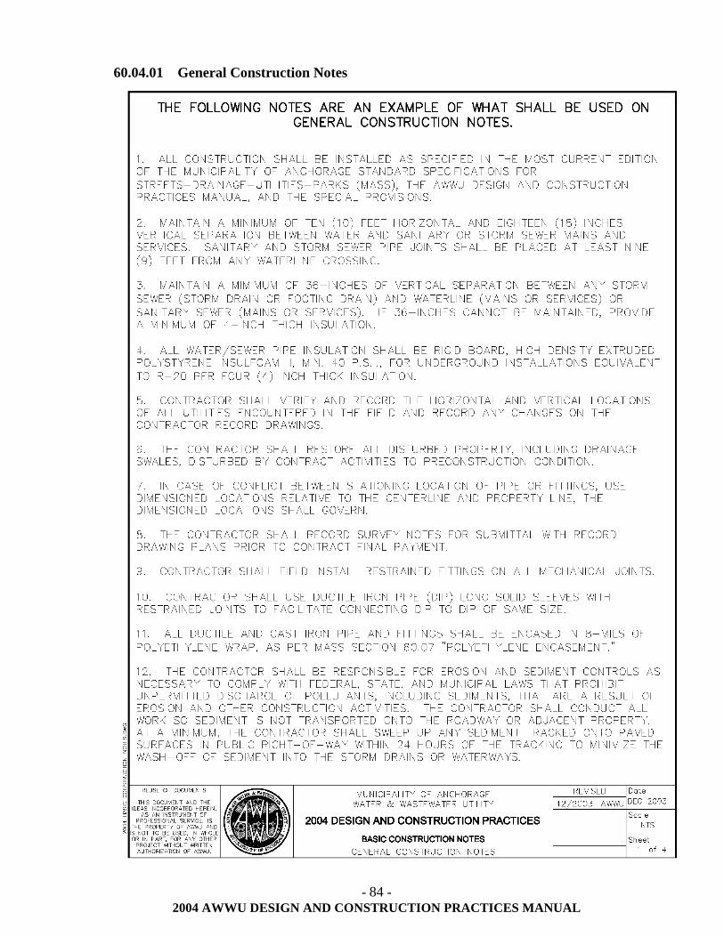
- 84 -
2004 AWWU DESIGN AND CONSTRUCTION PRACTICES MANUAL
60.04.01 General Construction Notes
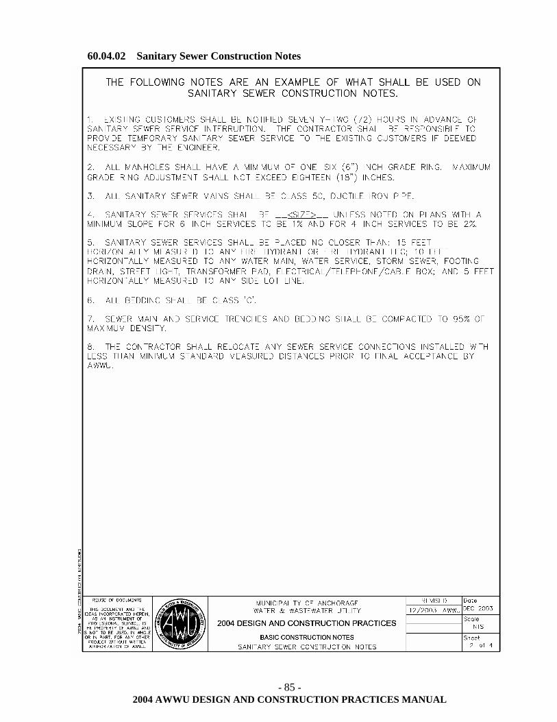
- 85 -
2004 AWWU DESIGN AND CONSTRUCTION PRACTICES MANUAL
60.04.02 Sanitary Sewer Construction Notes
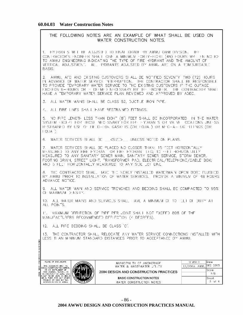
- 86 -
2004 AWWU DESIGN AND CONSTRUCTION PRACTICES MANUAL
60.04.03 Water Construction Notes
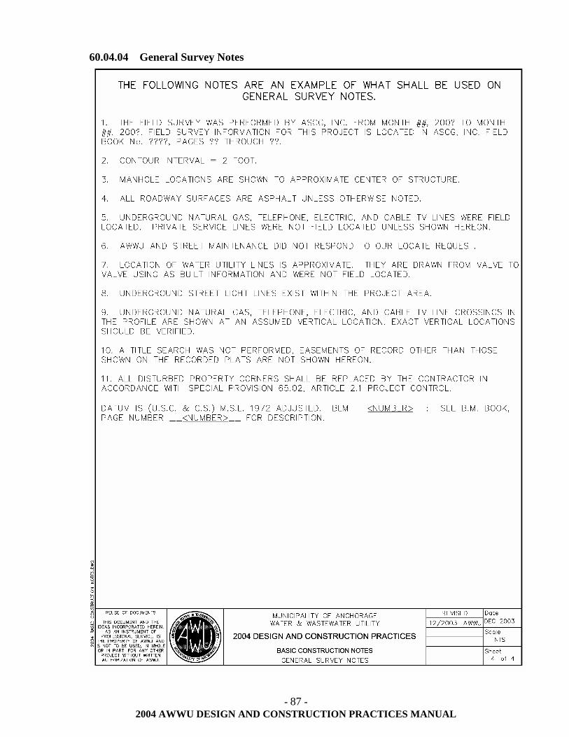
- 87 -
2004 AWWU DESIGN AND CONSTRUCTION PRACTICES MANUAL
60.04.04 General Survey Notes
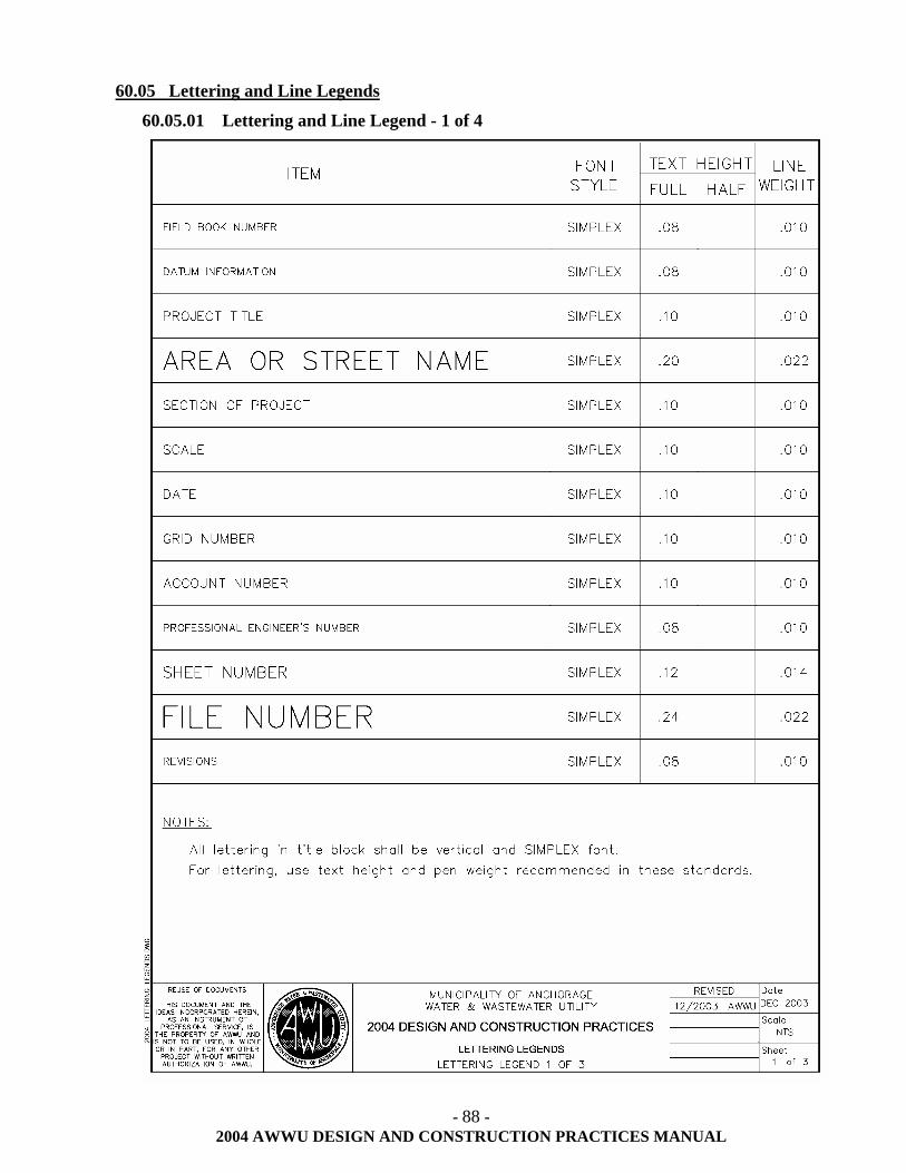
- 88 -
2004 AWWU DESIGN AND CONSTRUCTION PRACTICES MANUAL
60.05 Lettering and Line Legends
60.05.01 Lettering and Line Legend - 1 of 4
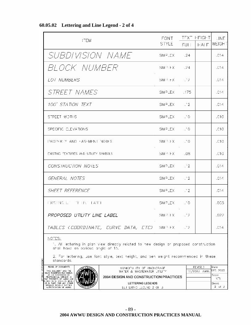
- 89 -
2004 AWWU DESIGN AND CONSTRUCTION PRACTICES MANUAL
60.05.02 Lettering and Line Legend - 2 of 4
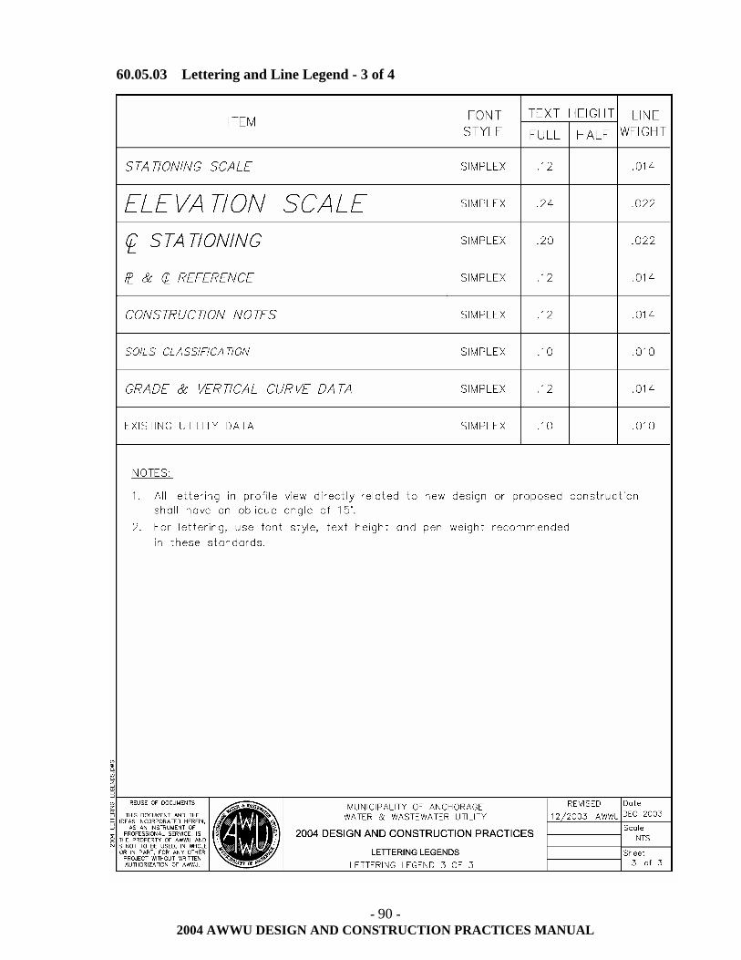
- 90 -
2004 AWWU DESIGN AND CONSTRUCTION PRACTICES MANUAL
60.05.03 Lettering and Line Legend - 3 of 4
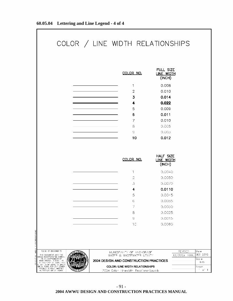
- 91 -
2004 AWWU DESIGN AND CONSTRUCTION PRACTICES MANUAL
60.05.04 Lettering and Line Legend - 4 of 4
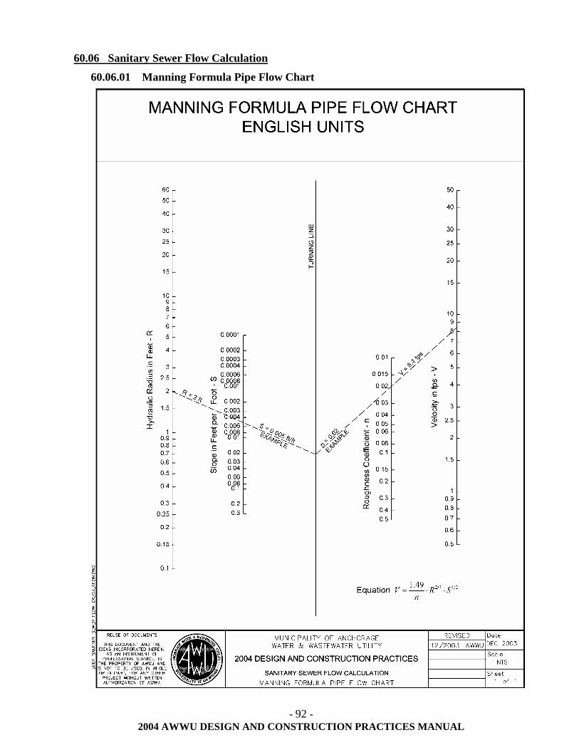
- 92 -
2004 AWWU DESIGN AND CONSTRUCTION PRACTICES MANUAL
60.06 Sanitary Sewer Flow Calculation
60.06.01 Manning Formula Pipe Flow Chart
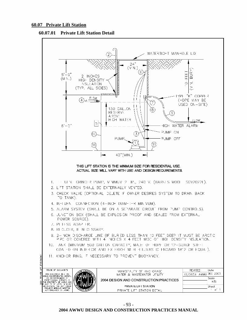
- 93 -
2004 AWWU DESIGN AND CONSTRUCTION PRACTICES MANUAL
60.07 Private Lift Station
60.07.01 Private Lift Station Detail
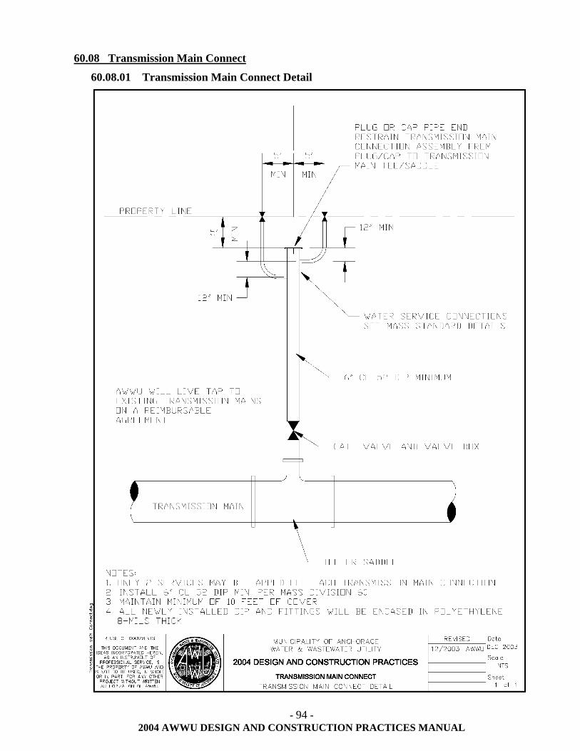
- 94 -
2004 AWWU DESIGN AND CONSTRUCTION PRACTICES MANUAL
60.08 Transmission Main Connect
60.08.01 Transmission Main Connect Detail
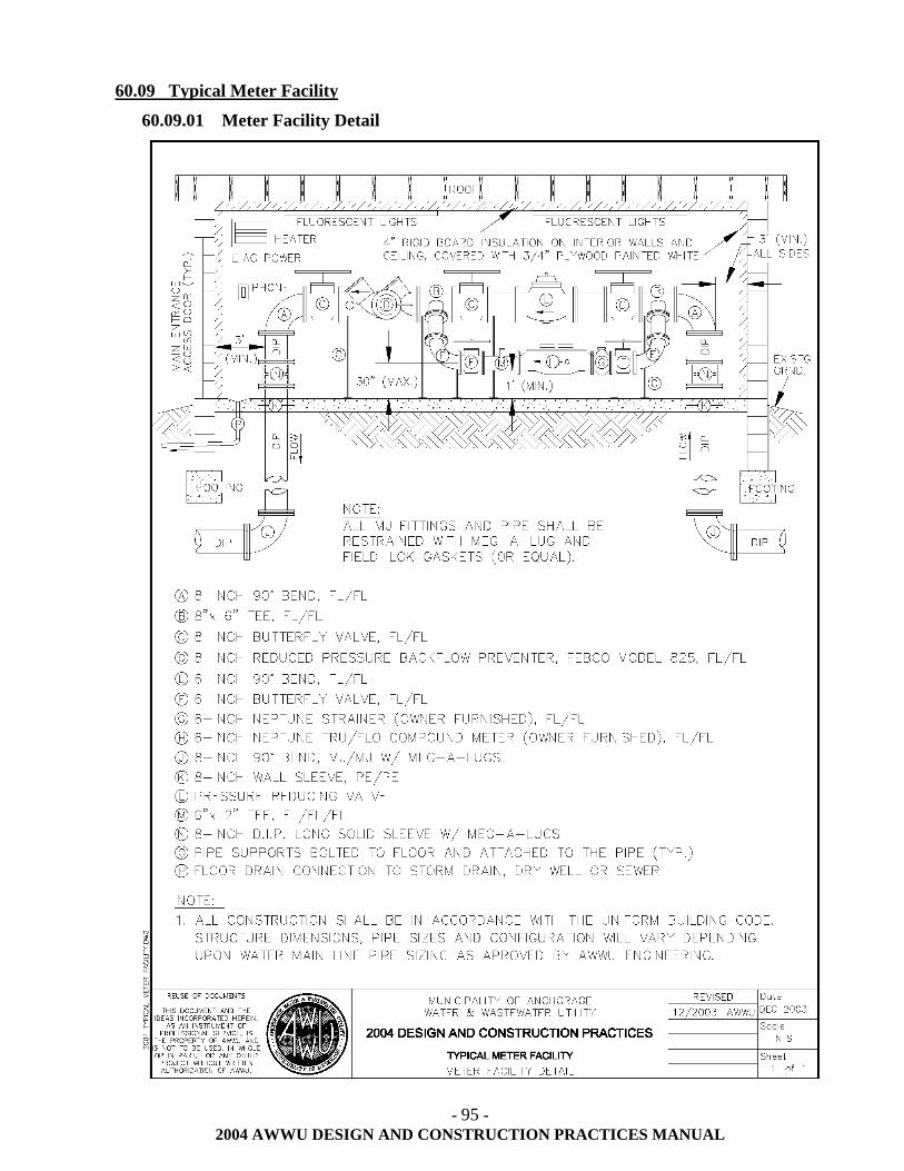
- 95 -
2004 AWWU DESIGN AND CONSTRUCTION PRACTICES MANUAL
60.09 Typical Meter Facility
60.09.01 Meter Facility Detail
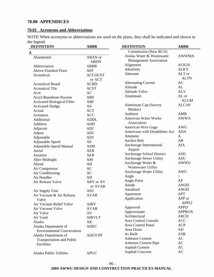
- 96 -
2004 AWWU DESIGN AND CONSTRUCTION PRACTICES MANUAL
70.00 APPENDICES
70.01 Acronyms and Abbreviations
NOTE: When acronyms or abbreviations are used on the plans, they shall be indicated and shown in the legend.
DEFINITION ABBR A
Abandoned ABAN or ABDN
Abbreviation ABBR Above Finished Floor AFF Acoustical ACCOUST
or ACT Acoustical Board ACBD Acoustical Tile ACST Acre AC Acryl-Butadiene-Styrene ABS Activated Biological Filter ABF Activated Sludge AS Actual ACT Actuators ACC Additional ADDL Additive ADD Adjacent ADJ Adjust ADJ Adjustable ADJ Adjustable Speed AS Adjustable Speed Manual ASM Aerial AER Aeration AER After Midnight AM Ahead AH Air Compressor AC Air Conditioning AC Air Handler AH Air Release Valve ARV or AV
or AVAR Air Supply Unit ASU Air Vacuum & Air Release
Valve AVAR
Air Vacuum Relief Valve AIRV Air Vacuum Valve AVAR Air Valve AV Air Vault AIRVLT Alaska AK Alaska Department of
Environmental Conversation ADEC
Alaska Department of Transportation and Public Facilities
ADOT/PF
Alaska Public Utilities APUC
DEFINITION ABBR Commission (Now RCA)
Alaska Water & Wastewater Management Association
AWWMA
Alignment ALIGN Alkalinity ALKY Alternate ALT or
ALTN Alternating Current AC Altitude AL Altitude Valve ALV Aluminum AL or
ALUM Aluminum Cap (Survey
Marker) ALCAP
Ambient AMB American Water Works
Association AWWA
American Wire Gage AWG Americans with Disabilities Act ADA Ammeter A Anchor Bolt AB Anchorage International
Airport AIA
Anchorage School District ASD Anchorage Sewer Utility ASU Anchorage Water &
Wastewater Utility AWWU
Anchorage Water Utility AWU Angle < Angle Point AP Anode ANOD Anodized ANOD Apartment APT Application APP or
APPLI Approved APPD Approximate APPROX Architectural ARCH Area Control Console ACC Area Control Panel ACP Area Drain AD As Built ASB Asbestos Cement AC Asbestos Cement Pipe AC Asphalt Cement AC Asphalt Concrete AC
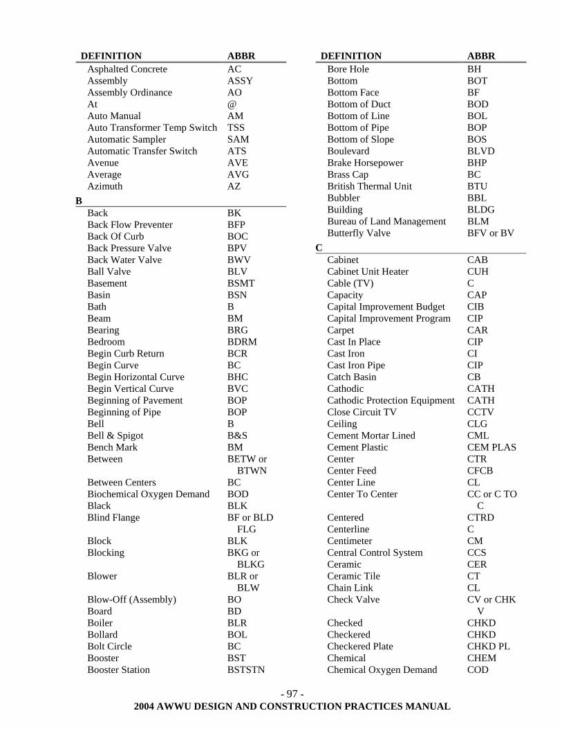
- 97 -
2004 AWWU DESIGN AND CONSTRUCTION PRACTICES MANUAL
DEFINITION ABBR Asphalted Concrete AC Assembly ASSY Assembly Ordinance AO At @ Auto Manual AM Auto Transformer Temp Switch TSS Automatic Sampler SAM Automatic Transfer Switch ATS Avenue AVE Average AVG Azimuth AZ
B Back BK Back Flow Preventer BFP Back Of Curb BOC Back Pressure Valve BPV Back Water Valve BWV Ball Valve BLV Basement BSMT Basin BSN Bath B Beam BM Bearing BRG Bedroom BDRM Begin Curb Return BCR Begin Curve BC Begin Horizontal Curve BHC Begin Vertical Curve BVC Beginning of Pavement BOP Beginning of Pipe BOP Bell B Bell & Spigot B&S Bench Mark BM Between BETW or
BTWN Between Centers BC Biochemical Oxygen Demand BOD Black BLK Blind Flange BF or BLD
FLG Block BLK Blocking BKG or
BLKG Blower BLR or
BLW Blow-Off (Assembly) BO Board BD Boiler BLR Bollard BOL Bolt Circle BC Booster BST Booster Station BSTSTN
DEFINITION ABBR Bore Hole BH Bottom BOT Bottom Face BF Bottom of Duct BOD Bottom of Line BOL Bottom of Pipe BOP Bottom of Slope BOS Boulevard BLVD Brake Horsepower BHP Brass Cap BC British Thermal Unit BTU Bubbler BBL Building BLDG Bureau of Land Management BLM Butterfly Valve BFV or BV
C Cabinet CAB Cabinet Unit Heater CUH Cable (TV) C Capacity CAP Capital Improvement Budget CIB Capital Improvement Program CIP Carpet CAR Cast In Place CIP Cast Iron CI Cast Iron Pipe CIP Catch Basin CB Cathodic CATH Cathodic Protection Equipment CATH Close Circuit TV CCTV Ceiling CLG Cement Mortar Lined CML Cement Plastic CEM PLAS Center CTR Center Feed CFCB Center Line CL Center To Center CC or C TO
C Centered CTRD Centerline C Centimeter CM Central Control System CCS Ceramic CER Ceramic Tile CT Chain Link CL Check Valve CV or CHK
V Checked CHKD Checkered CHKD Checkered Plate CHKD PL Chemical CHEM Chemical Oxygen Demand COD
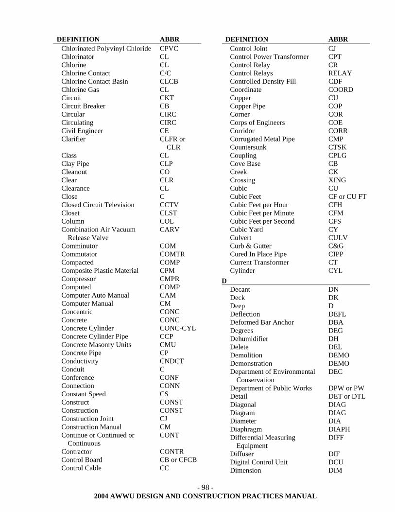
- 98 -
2004 AWWU DESIGN AND CONSTRUCTION PRACTICES MANUAL
DEFINITION ABBR Chlorinated Polyvinyl Chloride CPVC Chlorinator CL Chlorine CL Chlorine Contact C/C Chlorine Contact Basin CLCB Chlorine Gas CL Circuit CKT Circuit Breaker CB Circular CIRC Circulating CIRC Civil Engineer CE Clarifier CLFR or
CLR Class CL Clay Pipe CLP Cleanout CO Clear CLR Clearance CL Close C Closed Circuit Television CCTV Closet CLST Column COL Combination Air Vacuum
Release Valve CARV
Comminutor COM Commutator COMTR Compacted COMP Composite Plastic Material CPM Compressor CMPR Computed COMP Computer Auto Manual CAM Computer Manual CM Concentric CONC Concrete CONC Concrete Cylinder CONC-CYL Concrete Cylinder Pipe CCP Concrete Masonry Units CMU Concrete Pipe CP Conductivity CNDCT Conduit C Conference CONF Connection CONN Constant Speed CS Construct CONST Construction CONST Construction Joint CJ Construction Manual CM Continue or Continued or
Continuous CONT
Contractor CONTR Control Board CB or CFCB Control Cable CC
DEFINITION ABBR Control Joint CJ Control Power Transformer CPT Control Relay CR Control Relays RELAY Controlled Density Fill CDF Coordinate COORD Copper CU Copper Pipe COP Corner COR Corps of Engineers COE Corridor CORR Corrugated Metal Pipe CMP Countersunk CTSK Coupling CPLG Cove Base CB Creek CK Crossing XING Cubic CU Cubic Feet CF or CU FT Cubic Feet per Hour CFH Cubic Feet per Minute CFM Cubic Feet per Second CFS Cubic Yard CY Culvert CULV Curb & Gutter C&G Cured In Place Pipe CIPP Current Transformer CT Cylinder CYL
D Decant DN Deck DK Deep D Deflection DEFL Deformed Bar Anchor DBA Degrees DEG Dehumidifier DH Delete DEL Demolition DEMO Demonstration DEMO Department of Environmental
Conservation DEC
Department of Public Works DPW or PW Detail DET or DTL Diagonal DIAG Diagram DIAG Diameter DIA Diaphragm DIAPH Differential Measuring
Equipment DIFF
Diffuser DIF Digital Control Unit DCU Dimension DIM
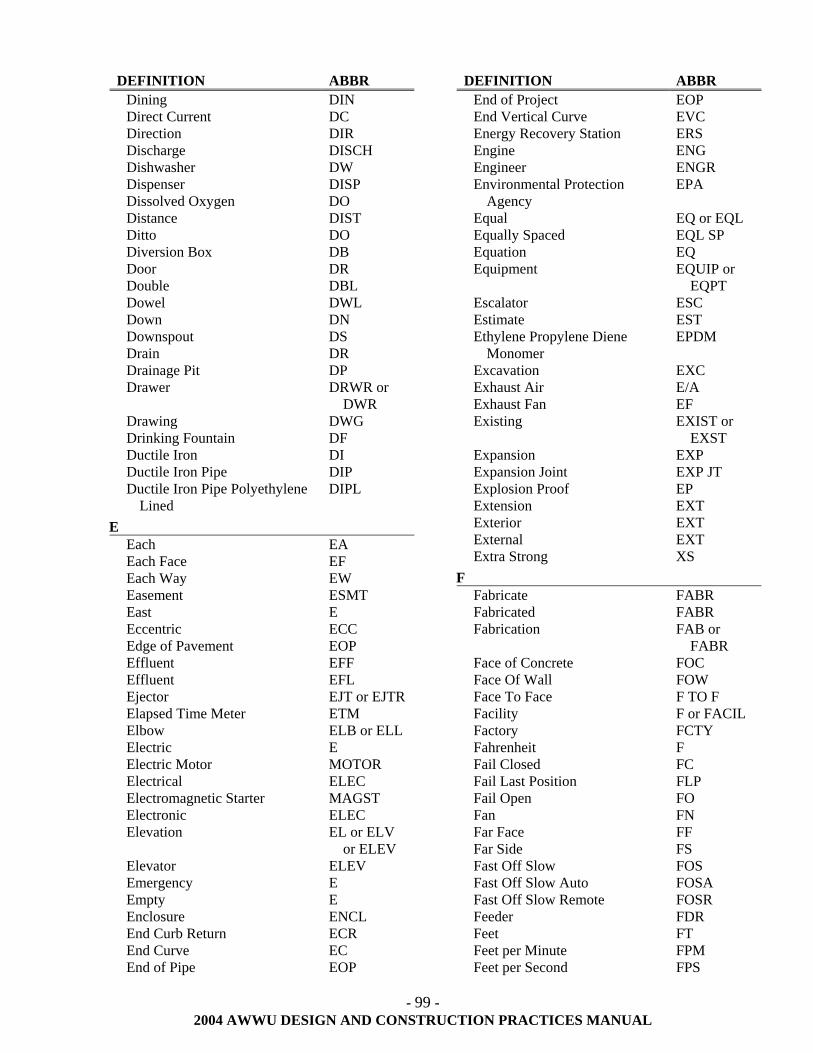
- 99 -
2004 AWWU DESIGN AND CONSTRUCTION PRACTICES MANUAL
DEFINITION ABBR Dining DIN Direct Current DC Direction DIR Discharge DISCH Dishwasher DW Dispenser DISP Dissolved Oxygen DO Distance DIST Ditto DO Diversion Box DB Door DR Double DBL Dowel DWL Down DN Downspout DS Drain DR Drainage Pit DP Drawer DRWR or
DWR Drawing DWG Drinking Fountain DF Ductile Iron DI Ductile Iron Pipe DIP Ductile Iron Pipe Polyethylene
Lined DIPL
E Each EA Each Face EF Each Way EW Easement ESMT East E Eccentric ECC Edge of Pavement EOP Effluent EFF Effluent EFL Ejector EJT or EJTR Elapsed Time Meter ETM Elbow ELB or ELL Electric E Electric Motor MOTOR Electrical ELEC Electromagnetic Starter MAGST Electronic ELEC Elevation EL or ELV
or ELEV Elevator ELEV Emergency E Empty E Enclosure ENCL End Curb Return ECR End Curve EC End of Pipe EOP
DEFINITION ABBR End of Project EOP End Vertical Curve EVC Energy Recovery Station ERS Engine ENG Engineer ENGR Environmental Protection
Agency EPA
Equal EQ or EQL Equally Spaced EQL SP Equation EQ Equipment EQUIP or
EQPT Escalator ESC Estimate EST Ethylene Propylene Diene
Monomer EPDM
Excavation EXC Exhaust Air E/A Exhaust Fan EF Existing EXIST or
EXST Expansion EXP Expansion Joint EXP JT Explosion Proof EP Extension EXT Exterior EXT External EXT Extra Strong XS
F Fabricate FABR Fabricated FABR Fabrication FAB or
FABR Face of Concrete FOC Face Of Wall FOW Face To Face F TO F Facility F or FACIL Factory FCTY Fahrenheit F Fail Closed FC Fail Last Position FLP Fail Open FO Fan FN Far Face FF Far Side FS Fast Off Slow FOS Fast Off Slow Auto FOSA Fast Off Slow Remote FOSR Feeder FDR Feet FT Feet per Minute FPM Feet per Second FPS
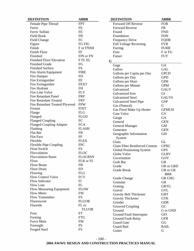
- 100 -
2004 AWWU DESIGN AND CONSTRUCTION PRACTICES MANUAL
DEFINITION ABBR Female Pipe Thread FPT Ferric FE Ferric Sulfate FE Field Book FB Field Change FC Figure FG FIG Finish F or FNSH Finish Floor FF Finished FIN or FN Finished Floor Elevation F FL EL Finished Grade FG Finished Surface FS Fire Alarm Equipment FIRE Fire Damper FD Fire Extinguisher FE Fire Extinguisher FEXT Fire Hydrant FH Fire Line Valve FLV Fire Retardant Panel FRP Fire Retardant Treated FRT Fire Retardant Treated Plywood FPW Fixture FIXT Flange FLG Flanged FLGD Flanged Coupling FC Flanged Coupling Adapter FCA Flashing FLASH Flat Bar FB Flat Face FF Flexible FLEX Flexible Pipe Coupling FPC Float Switch FS Flocculation FLOC Flocculation Basin FLOCBSN Floor FLR or FL Floor Beam FB Floor Drain FD Flooring FLG Flow Control Valve FCV Flow Indicator FI Flow Line FL Flow Measuring Equipment FLOW Flow Meter FM Flow Transmitter FS Fluorescent FLUOR Fluoride FL or
FLUOR Foot FT Footing FTG Force Main FM Foresight FS Forged Steel FS
DEFINITION ABBR Forward Off Reverse FOR Forward Reverse FR Found FND Foundation FDN Frequency Drive FQDR Full Voltage Reversing FVR Furring FURR Fuse F or FU Future FUT
G Gage GA Gallon GAL Gallons per Capita per Day GPCD Gallons per Day GPD Gallons per Hour GPH Gallons per Minute GPM Galvanized GALV Galvanized Iron GI Galvanized Steel GALVS Galvanized Steel Pipe GSP Gas (Natural) G Gas Fired Make Up Heater GFMUH Gate Valve GV Gauge GA General GEN General Manager GM Generator GEN Geographic Information
System GIS
Glass GL Glass Fiber Reinforced Cement GFRC Global Positioning System GPS Globe Valve GLBV Government GOV Grab Bar GB Grade GR or GRD Grade Break GB or GR
BRK Grade Change GR CHG Granular GR Grating GRTG Gravel GVL Gravity Belt Thickener GBT Gravity Thickener GTK Grinder GDR Grooved Coupling GC Ground G or GND Ground Fault Interrupter GFI Ground Fault Relay GFR Guard Gate GG Guard Rail RAIL Gutter G
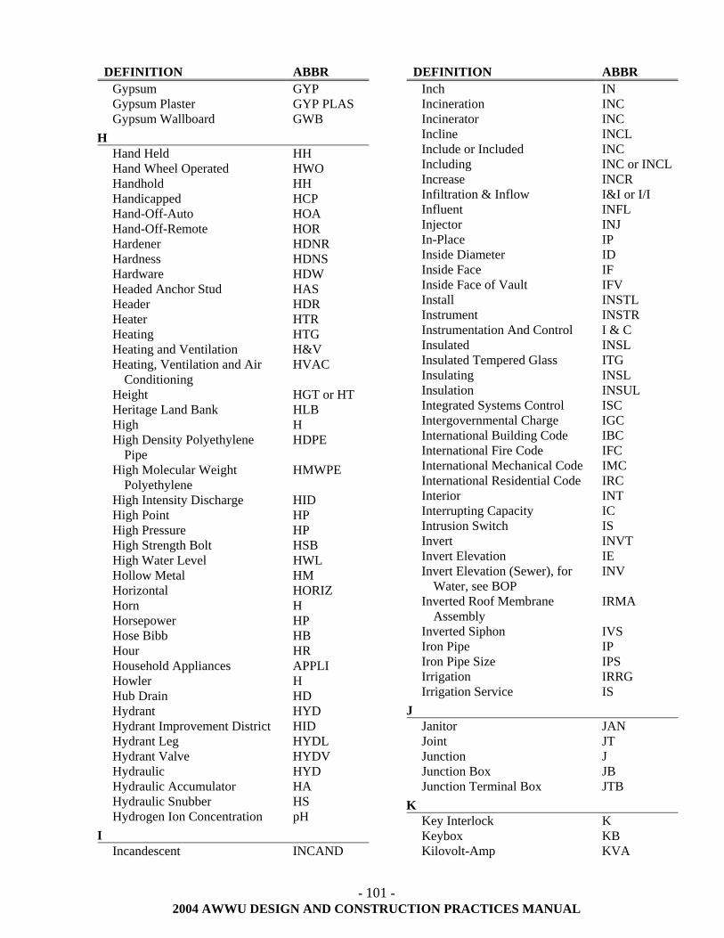
- 101 -
2004 AWWU DESIGN AND CONSTRUCTION PRACTICES MANUAL
DEFINITION ABBR Gypsum GYP Gypsum Plaster GYP PLAS Gypsum Wallboard GWB
H Hand Held HH Hand Wheel Operated HWO Handhold HH Handicapped HCP Hand-Off-Auto HOA Hand-Off-Remote HOR Hardener HDNR Hardness HDNS Hardware HDW Headed Anchor Stud HAS Header HDR Heater HTR Heating HTG Heating and Ventilation H&V Heating, Ventilation and Air
Conditioning HVAC
Height HGT or HT Heritage Land Bank HLB High H High Density Polyethylene
Pipe HDPE
High Molecular Weight Polyethylene
HMWPE
High Intensity Discharge HID High Point HP High Pressure HP High Strength Bolt HSB High Water Level HWL Hollow Metal HM Horizontal HORIZ Horn H Horsepower HP Hose Bibb HB Hour HR Household Appliances APPLI Howler H Hub Drain HD Hydrant HYD Hydrant Improvement District HID Hydrant Leg HYDL Hydrant Valve HYDV Hydraulic HYD Hydraulic Accumulator HA Hydraulic Snubber HS Hydrogen Ion Concentration pH
I Incandescent INCAND
DEFINITION ABBR Inch IN Incineration INC Incinerator INC Incline INCL Include or Included INC Including INC or INCLIncrease INCR Infiltration & Inflow I&I or I/I Influent INFL Injector INJ In-Place IP Inside Diameter ID Inside Face IF Inside Face of Vault IFV Install INSTL Instrument INSTR Instrumentation And Control I & C Insulated INSL Insulated Tempered Glass ITG Insulating INSL Insulation INSUL Integrated Systems Control ISC Intergovernmental Charge IGC International Building Code IBC International Fire Code IFC International Mechanical Code IMC International Residential Code IRC Interior INT Interrupting Capacity IC Intrusion Switch IS Invert INVT Invert Elevation IE Invert Elevation (Sewer), for
Water, see BOP INV
Inverted Roof Membrane Assembly
IRMA
Inverted Siphon IVS Iron Pipe IP Iron Pipe Size IPS Irrigation IRRG Irrigation Service IS
J Janitor JAN Joint JT Junction J Junction Box JB Junction Terminal Box JTB
K Key Interlock K Keybox KB Kilovolt-Amp KVA
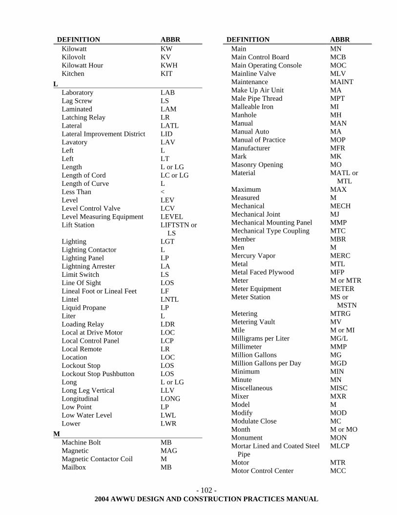
- 102 -
2004 AWWU DESIGN AND CONSTRUCTION PRACTICES MANUAL
DEFINITION ABBR Kilowatt KW Kilovolt KV Kilowatt Hour KWH Kitchen KIT
L Laboratory LAB Lag Screw LS Laminated LAM Latching Relay LR Lateral LATL Lateral Improvement District LID Lavatory LAV Left L Left LT Length L or LG Length of Cord LC or LG Length of Curve L Less Than < Level LEV Level Control Valve LCV Level Measuring Equipment LEVEL Lift Station LIFTSTN or
LS Lighting LGT Lighting Contactor L Lighting Panel LP Lightning Arrester LA Limit Switch LS Line Of Sight LOS Lineal Foot or Lineal Feet LF Lintel LNTL Liquid Propane LP Liter L Loading Relay LDR Local at Drive Motor LOC Local Control Panel LCP Local Remote LR Location LOC Lockout Stop LOS Lockout Stop Pushbutton LOS Long L or LG Long Leg Vertical LLV Longitudinal LONG Low Point LP Low Water Level LWL Lower LWR
M Machine Bolt MB Magnetic MAG Magnetic Contactor Coil M Mailbox MB
DEFINITION ABBR Main MN Main Control Board MCB Main Operating Console MOC Mainline Valve MLV Maintenance MAINT Make Up Air Unit MA Male Pipe Thread MPT Malleable Iron MI Manhole MH Manual MAN Manual Auto MA Manual of Practice MOP Manufacturer MFR Mark MK Masonry Opening MO Material MATL or
MTL Maximum MAX Measured M Mechanical MECH Mechanical Joint MJ Mechanical Mounting Panel MMP Mechanical Type Coupling MTC Member MBR Men M Mercury Vapor MERC Metal MTL Metal Faced Plywood MFP Meter M or MTR Meter Equipment METER Meter Station MS or
MSTN Metering MTRG Metering Vault MV Mile M or MI Milligrams per Liter MG/L Millimeter MMP Million Gallons MG Million Gallons per Day MGD Minimum MIN Minute MN Miscellaneous MISC Mixer MXR Model M Modify MOD Modulate Close MC Month M or MO Monument MON Mortar Lined and Coated Steel
Pipe MLCP
Motor MTR Motor Control Center MCC
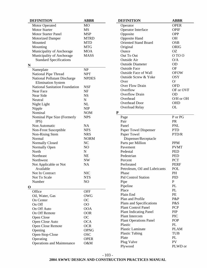
- 103 -
2004 AWWU DESIGN AND CONSTRUCTION PRACTICES MANUAL
DEFINITION ABBR Motor Operated MO Motor Starter MS Motor Starter Panel MSP Motorized Damper MTRD Mounted MTD Mounting MTG Municipality of Anchorage MOA Municipality of Anchorage
Standard Specifications MASS
N Nameplate NP National Pipe Thread NPT National Pollutant Discharge
Elimination System NPDES
National Sanitation Foundation NSF Near Face NF Near Side NS Neutral N Night Light NL Nipple NIP Nominal NOM Nominal Pipe Size (Formerly
IPS) NPS
Non Automatic NA Non-Frost Susceptible NFS Non-Rising Stem NRS Normal NORM Normally Closed NC Normally Open NO North N Northeast NE Northwest NW Not Applicable or Not
Available NA
Not In Contract NIC Not To Scale NTS Number NO
O Office OFF Oil, Water, Gas OWG On Center OC On Off OO On Off Auto OOA On Off Remote OOR Open Close OC Open Close Auto OCA Open Close Remote OCR Opening OPNG Open-Stop-Close OSC Operating OPER Operations and Maintenance O&M
DEFINITION ABBR Operator OPER Operator Interface OPIF Opposite OPP Opposite Hand OH Oriented Stand Board OSB Original ORIG Ounce OZ Out To Out O TO O Outside Air O/A Outside Diameter OD Outside Face OF Outside Face of Wall OFOW Outside Screw & Yoke OSY Over O/ Over Flow Drain OFD Overflow OF or OVF Overflow Drain OD Overhead O/H or OH Overhead Door OHD Overload Relay OL
P Page P or PG Pair PR Panel PNL Paper Towel Dispenser PTD Paper Towel
Dispenser/Receptacle PTD/R
Parts per Million PPM Pavement PVMT Pedestal PED Pedestrian PED Percent PCT Perforated PERF Petroleum, Oil and Lubricants POL Phase PH Pid Control Station PID Pipe P Pipeline PL Place PL Plain End PE Plan and Profile P&P Plans and Specifications P&S Plant Control Panel PCP Plant Indicating Panel PIP Plant Intercom PIC Plant Operations Panel POP Plastic PL Plastic Laminate PLAM Plastic Tubing TUB Plate PL Plug Valve PV Plywood PLWD or
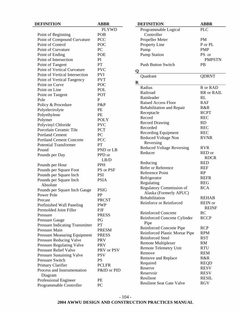
- 104 -
2004 AWWU DESIGN AND CONSTRUCTION PRACTICES MANUAL
DEFINITION ABBR PLYWD
Point of Beginning POB Point of Compound Curvature PCC Point of Control POC Point of Curvature PC Point of Ending POE Point of Intersection PI Point of Tangent PT Point of Vertical Curvature PVC Point of Vertical Intersection PVI Point of Vertical Tangency PVT Point on Curve POC Point on Line POL Point on Tangent POT Pole P Policy & Procedure P&P Polyelectrolyte PE Polyethylene PE Polymer POLY Polyvinyl Chloride PVC Porcelain Ceramic Tile PCT Portland Cement PC Portland Cement Concrete PCC Potential Transformer PT Pound PND or LB Pounds per Day PPD or
LB/D Pounds per Hour PPH Pounds per Square Foot PS or PSF Pounds per Square Inch PSI Pounds per Square Inch
Absolute PSIA
Pounds per Square Inch Gauge PSIG Power Pole PP Precast PRCST Prefinished Wall Paneling PWP Premolded Joint Filler PJF Pressure PRESS Pressure Gauge PG Pressure Indicating Transmitter PT Pressure Main PRESM Pressure Measuring Equipment PRESS Pressure Reducing Valve PRV Pressure Regulating Valve PRV Pressure Relief Valve PRV or PSV Pressure Sustaining Valve PSV Pressure Switch PS Primary Clarifier PCLFR Process and Instrumentation
Diagram P&ID or PID
Professional Engineer PE Programmable Controller PC
DEFINITION ABBR Programmable Logical
Controller PLC
Propeller Meter PM Property Line P or PL Pump PMP Pump Station PS or
PMPSTN Push Button Switch PB
Q Quadrant QDRNT
R Radius R or RAD Railroad RR or RAIL Rainleader RL Raised Access Floor RAF Rehabilitation and Repair R&R Receptacle RCPT Record REC Record Drawing RD Recorded REC Recording Equipment REC Reduced Voltage Non
Reversing RVNR
Reduced Voltage Reversing RVR Reducer RED or
RDCR Reducing RED Refer or Reference REF Reference Point RP Refrigerator REFR Regulating REG Regulatory Commission of
Alaska (Formerly APUC) RCA
Rehabilitation REHAB Reinforce or Reinforced REIN or
REINF Reinforced Concrete RC Reinforced Concrete Cylinder
Pipe RCCP
Reinforced Concrete Pipe RCP Reinforced Plastic Mortar Pipe RPM Reinforced Steel RST Remote Multiplexer RM Remote Telemetry Unit RTU Remove REM Remove and Replace R&R Required REQD Reserve RESV Reservoir RESV Resilient RESIL Resilient Seat Gate Valve RGV
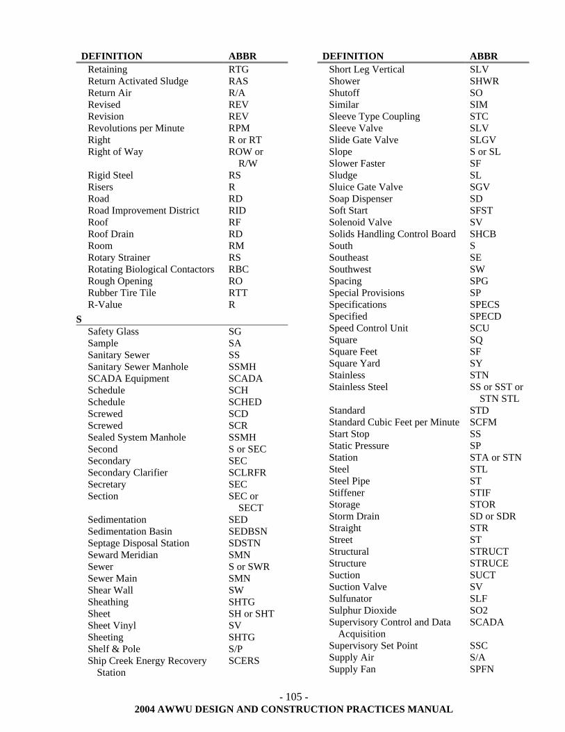
- 105 -
2004 AWWU DESIGN AND CONSTRUCTION PRACTICES MANUAL
DEFINITION ABBR Retaining RTG Return Activated Sludge RAS Return Air R/A Revised REV Revision REV Revolutions per Minute RPM Right R or RT Right of Way ROW or
R/W Rigid Steel RS Risers R Road RD Road Improvement District RID Roof RF Roof Drain RD Room RM Rotary Strainer RS Rotating Biological Contactors RBC Rough Opening RO Rubber Tire Tile RTT R-Value R
S Safety Glass SG Sample SA Sanitary Sewer SS Sanitary Sewer Manhole SSMH SCADA Equipment SCADA Schedule SCH Schedule SCHED Screwed SCD Screwed SCR Sealed System Manhole SSMH Second S or SEC Secondary SEC Secondary Clarifier SCLRFR Secretary SEC Section SEC or
SECT Sedimentation SED Sedimentation Basin SEDBSN Septage Disposal Station SDSTN Seward Meridian SMN Sewer S or SWR Sewer Main SMN Shear Wall SW Sheathing SHTG Sheet SH or SHT Sheet Vinyl SV Sheeting SHTG Shelf & Pole S/P Ship Creek Energy Recovery
Station SCERS
DEFINITION ABBR Short Leg Vertical SLV Shower SHWR Shutoff SO Similar SIM Sleeve Type Coupling STC Sleeve Valve SLV Slide Gate Valve SLGV Slope S or SL Slower Faster SF Sludge SL Sluice Gate Valve SGV Soap Dispenser SD Soft Start SFST Solenoid Valve SV Solids Handling Control Board SHCB South S Southeast SE Southwest SW Spacing SPG Special Provisions SP Specifications SPECS Specified SPECD Speed Control Unit SCU Square SQ Square Feet SF Square Yard SY Stainless STN Stainless Steel SS or SST or
STN STL Standard STD Standard Cubic Feet per Minute SCFM Start Stop SS Static Pressure SP Station STA or STN Steel STL Steel Pipe ST Stiffener STIF Storage STOR Storm Drain SD or SDR Straight STR Street ST Structural STRUCT Structure STRUCE Suction SUCT Suction Valve SV Sulfunator SLF Sulphur Dioxide SO2 Supervisory Control and Data
Acquisition SCADA
Supervisory Set Point SSC Supply Air S/A Supply Fan SPFN
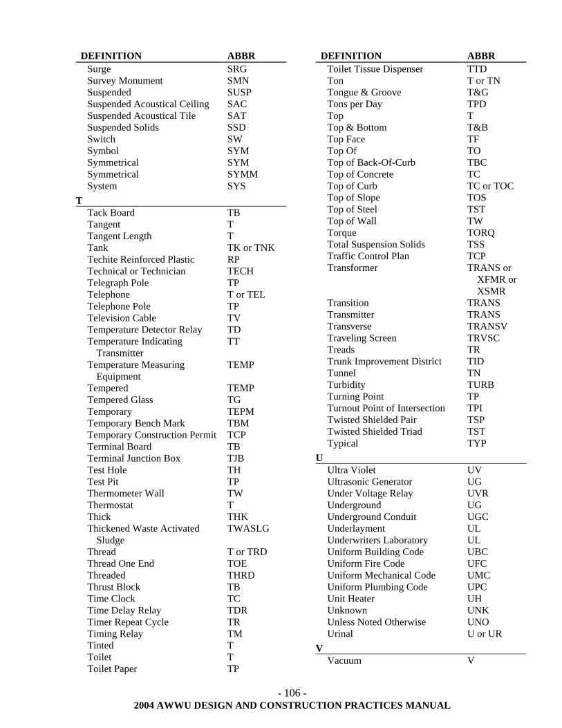
- 106 -
2004 AWWU DESIGN AND CONSTRUCTION PRACTICES MANUAL
DEFINITION ABBR Surge SRG Survey Monument SMN Suspended SUSP Suspended Acoustical Ceiling SAC Suspended Acoustical Tile SAT Suspended Solids SSD Switch SW Symbol SYM Symmetrical SYM Symmetrical SYMM System SYS
T Tack Board TB Tangent T Tangent Length T Tank TK or TNK Techite Reinforced Plastic RP Technical or Technician TECH Telegraph Pole TP Telephone T or TEL Telephone Pole TP Television Cable TV Temperature Detector Relay TD Temperature Indicating
Transmitter TT
Temperature Measuring Equipment
TEMP
Tempered TEMP Tempered Glass TG Temporary TEPM Temporary Bench Mark TBM Temporary Construction Permit TCP Terminal Board TB Terminal Junction Box TJB Test Hole TH Test Pit TP Thermometer Wall TW Thermostat T Thick THK Thickened Waste Activated
Sludge TWASLG
Thread T or TRD Thread One End TOE Threaded THRD Thrust Block TB Time Clock TC Time Delay Relay TDR Timer Repeat Cycle TR Timing Relay TM Tinted T Toilet T Toilet Paper TP
DEFINITION ABBR Toilet Tissue Dispenser TTD Ton T or TN Tongue & Groove T&G Tons per Day TPD Top T Top & Bottom T&B Top Face TF Top Of TO Top of Back-Of-Curb TBC Top of Concrete TC Top of Curb TC or TOC Top of Slope TOS Top of Steel TST Top of Wall TW Torque TORQ Total Suspension Solids TSS Traffic Control Plan TCP Transformer TRANS or
XFMR or XSMR
Transition TRANS Transmitter TRANS Transverse TRANSV Traveling Screen TRVSC Treads TR Trunk Improvement District TID Tunnel TN Turbidity TURB Turning Point TP Turnout Point of Intersection TPI Twisted Shielded Pair TSP Twisted Shielded Triad TST Typical TYP
U Ultra Violet UV Ultrasonic Generator UG Under Voltage Relay UVR Underground UG Underground Conduit UGC Underlayment UL Underwriters Laboratory UL Uniform Building Code UBC Uniform Fire Code UFC Uniform Mechanical Code UMC Uniform Plumbing Code UPC Unit Heater UH Unknown UNK Unless Noted Otherwise UNO Urinal U or UR
V Vacuum V
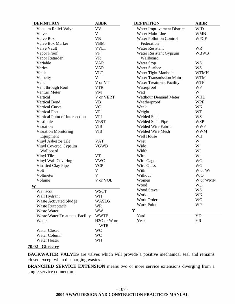
- 107 -
2004 AWWU DESIGN AND CONSTRUCTION PRACTICES MANUAL
DEFINITION ABBR Vacuum Relief Valve VV Valve V Valve Box VB Valve Box Marker VBM Valve Vault VVLT Vapor Proof VP Vapor Retarder VR Variable VAR Varies VAR Vault VLT Velocity V Vent V or VT Vent through Roof VTR Venturi Meter VM Vertical V or VERT Vertical Bond VB Vertical Curve VC Vertical Feet VF Vertical Point of Intersection VPI Vestibule VEST Vibration VIB Vibration Monitoring
Equipment VIB
Vinyl Asbestos Tile VAT Vinyl Covered Gypsum
Wallboard VGWB
Vinyl Tile VT Vinyl Wall Covering VWC Vitrified Clay Pipe VCP Volt V Voltmeter V Volume V or VOL
W Wainscot WSCT Wall Hydrant WH Waste Activated Sludge WASLG Waste Receptacle WR Waste Water WW Waste Water Treatment Facility WWTF Water H2O or W or
WTR Water Closet WC Water Column WC Water Heater WH
DEFINITION ABBR Water Improvement District WID Water Main Line WMN Water Pollution Control
Federation WPCF
Water Resistant WR Water Resistant Gypsum
Wallboard WBWB
Water Stop WS Water Surface WS Water Tight Manhole WTMH Water Transmission Main WTM Water Treatment Facility WTF Waterproof WP Watt W Watthour Demand Meter WHD Weatherproof WPF Week WK Weight WT Welded Steel WS Welded Steel Pipe WSP Welded Wire Fabric WWF Welded Wire Mesh WWM Well House WH West W Wide W Width WI Wire W Wire Gage WG Wire Glass WG With W or W/ Without W/O Women W or WMN Wood WD Wood Stave WS Work WK Work Order WO Work Point WP
Y Yard YD Year YR
70.02 Glossary
BACKWATER VALVES are valves which will provide a positive mechanical seal and remains closed except when discharging wastes. BRANCHED SERVICE EXTENSION means two or more service extensions diverging from a single service connection.
- 108 -
2004 AWWU DESIGN AND CONSTRUCTION PRACTICES MANUAL
BOOTLEGGED SERVICES are lines constructed of un-approved or un-acceptable material; or constructed without permits and/or approval letters; or utilized without being accepted by AWWU, including service lines crossing adjacent property lines. DESIGN CAPACITY is the existing measured flow plus capacity for future development. DISTRIBUTION MAIN is a water conduit whose inside diameter may range in size from four (inclusive) to twenty-four (exclusive) inches. EXTENDED SERVICE CONNECT is a connection for a lot which does not have mains currently available to provide legal service to the property. INDUSTRIAL WASTES are wastes discharged by an industrial user, having characteristics distinct from commercial and domestic wastes, and having a BOD of 250 ppm or greater and/or a TSS of 250 PPM or greater. INTERCEPTOR SEWER is the sanitary sewer conduit which carries flow from the TRUNK SEWER to the point of treatment. LATERAL SEWER is a wastewater conduit of eight (8) inches in nominal diameter which collects flows from SERVICE CONNECTIONS and carries it to TRUNK SEWERS. MAIN is that part of the sanitary sewer or water system intended to serve more than one SERVICE CONNECTION. ON-PROPERTY SYSTEM is a private distribution or collection system solely on private property. ON-PROPERTY SYSTEM'S are not owned or operated by AWWU. PRIVATE SYSTEM - see Section 21.06 of this manual. RECORD DRAWING is a plan and profile reproducible drawing verified by a registered professional engineer depicting the location of improvements constructed as reflected on survey notes, construction contractor's field installation notes, line and grade notes and/or engineer's notes (see Section 50.00 of this manual). SERVICE CONNECTION is the sanitary sewer or water pipe and appurtenances extending from a main to a user' property line or easement. SERVICE EXTENSION is the sanitary sewer or water pipe and appurtenances required to extend the SERVICE CONNECTION to the structure. TRANSMISSION MAIN is a water conduit whose inside diameter is twenty-four (24) inches or greater. Service connections smaller than six (6) inches diameter will not be permitted. TRUNK SEWER is a sanitary sewer conduit which collects flow from LATERAL SEWERS or SERVICE CONNECTIONS and carries it to the INTERCEPTOR SEWER. 70.03 Corrosion Control
This section discusses the corrosion control design criteria to be used on new or retrofitted AWWU pipelines. The corrosion control portion of the design includes materials selection, cathodic protection and coatings provisions. All below ground metallic piping and facilities will be designed with appropriate corrosion control systems.
70.03.01 Standards 1. American Water Works Association (AWWA) 2. National Association of Corrosion Engineers (NACE) 3. Ductile Iron Pipe Research Association (DIPRA)
- 109 -
2004 AWWU DESIGN AND CONSTRUCTION PRACTICES MANUAL
70.03.02 Materials Selection
Material selection for corrosion control requires that the overall system be evaluated for the intended service and environment that the piping is being installed in. Non-metallic materials or metallic systems with adequate corrosion protection may be evaluated.
A soil corrosivity evaluation shall be performed to determine the corrosion control requirements. A NACE certified corrosion or cathodic protection specialist shall be responsible for the evaluation and shall determine which soil characteristics need to be included in the evaluation and the number of tests that are required. Soil characteristics to be considered may include, but are not limited to, soil strata, resistivity, pH, redox, sulfides and moisture content. At a minimum, resistivity and pH shall be considered. The evaluation is to be submitted for AWWU approval.
70.03.03 Cathodic Protection
If non-metallic materials are installed, such as high-density polyethylene (HDPE) piping, cathodic protection and protective coatings are not required.
If metallic piping is installed, the pipelines shall have adequate corrosion control systems installed. Adequate corrosion control systems shall include installation of protective coatings and cathodic protection systems. If the soil corrosivity evaluation determines a non-corrosive or low corrosive soil condition, the NACE certified corrosion or cathodic protection specialist may submit a recommendation, for AWWU approval, to eliminate the requirement for a cathodic protection system installation.
1. For metallic pipelines less than 18” in diameter, high potential prepackaged magnesium anodes shall be installed. Other cathodic protection materials may be evaluated by a NACE certified corrosion or cathodic protection specialist and submitted for AWWU approval.
2. For metallic pipelines 18” in diameter or greater, high potential magnesium ribbon anodes shall be installed. Other cathodic protection materials may be evaluated by a NACE certified corrosion or cathodic protection specialist and submitted for AWWU approval.
All cathodic protection systems shall have a design life in excess of 25 years and shall conform to AWWU standard cathodic protection details and color-coding schemes.
Impressed current cathodic protection systems shall not be utilized for AWWU pipelines without prior approval. Installation of impressed current cathodic protection systems by other operators should be coordinated with AWWU personnel to ensure stray currents are not adversely affecting AWWU lines.
70.03.04 Protective Coatings
Each buried metallic pipeline system component shall have an external protective coating designed to mitigate corrosion. Tightly bonded coatings or polyethylene encasements may be used as conditions warrant.
Metallic components exposed to the atmosphere shall be coated with a tightly bonded coating system.
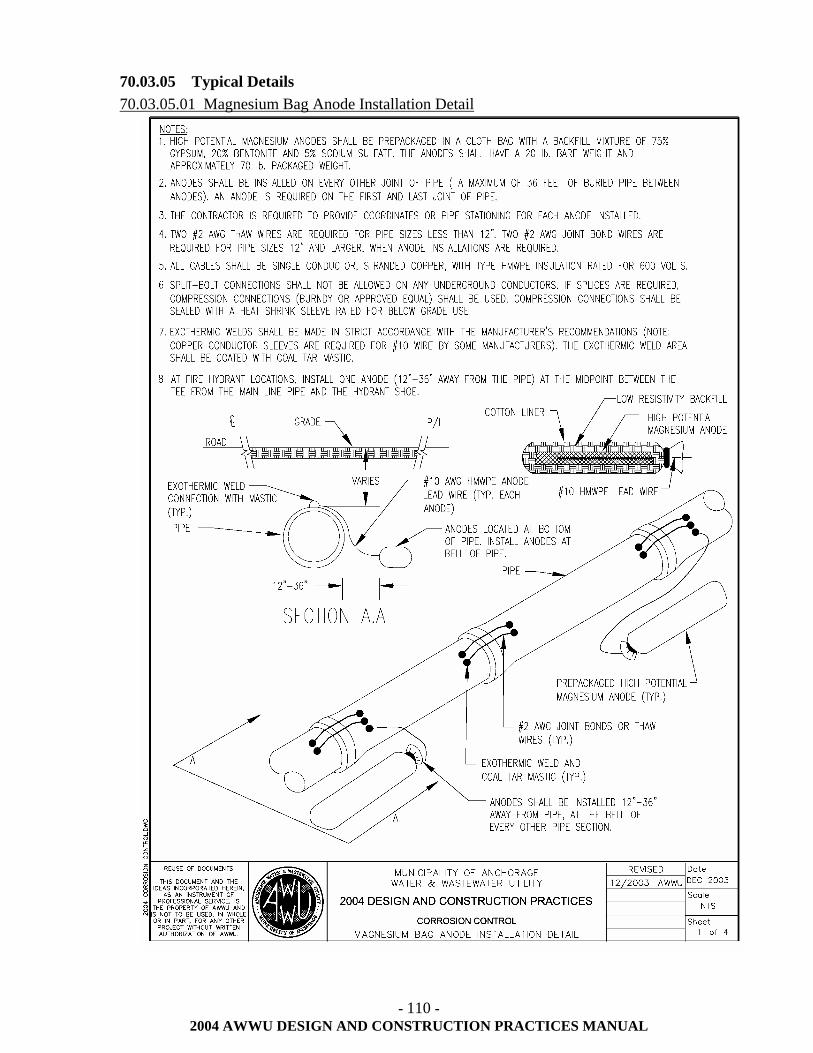
- 110 -
2004 AWWU DESIGN AND CONSTRUCTION PRACTICES MANUAL
70.03.05 Typical Details 70.03.05.01 Magnesium Bag Anode Installation Detail
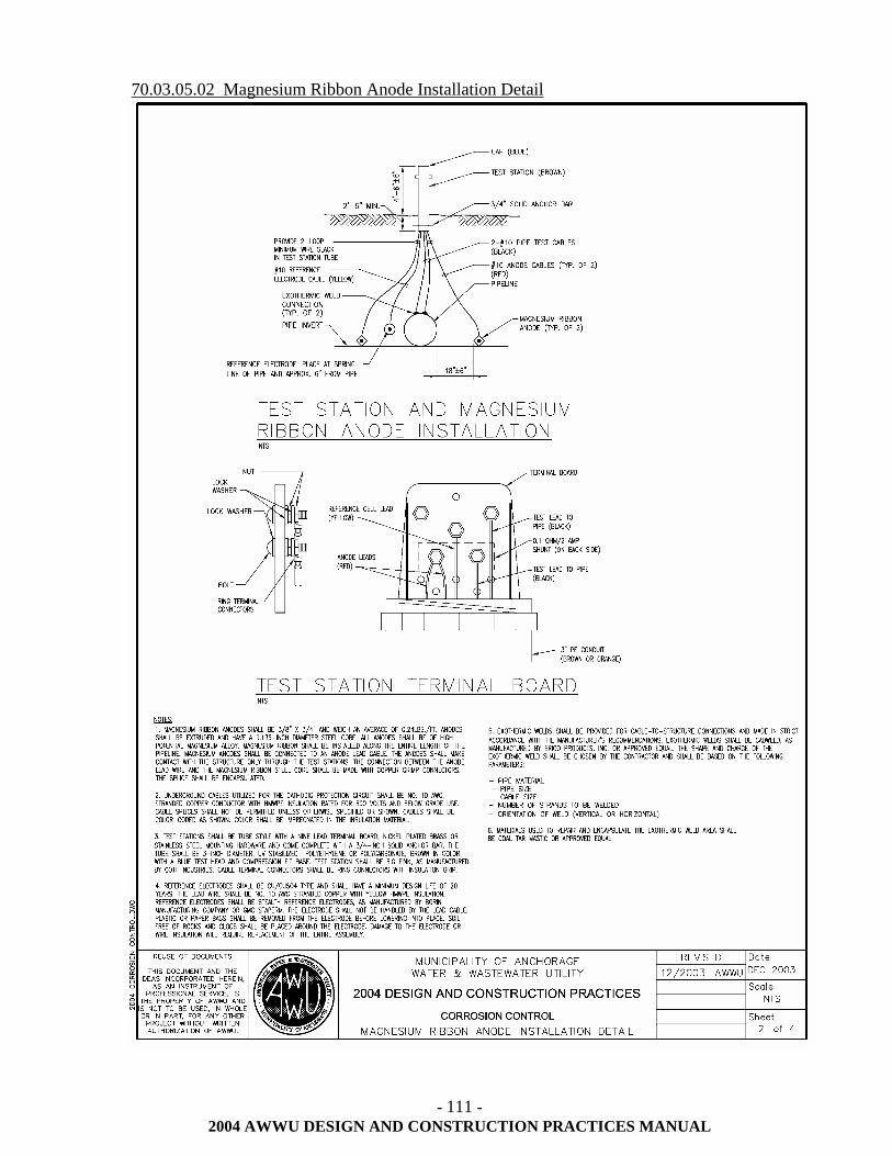
- 111 -
2004 AWWU DESIGN AND CONSTRUCTION PRACTICES MANUAL
70.03.05.02 Magnesium Ribbon Anode Installation Detail
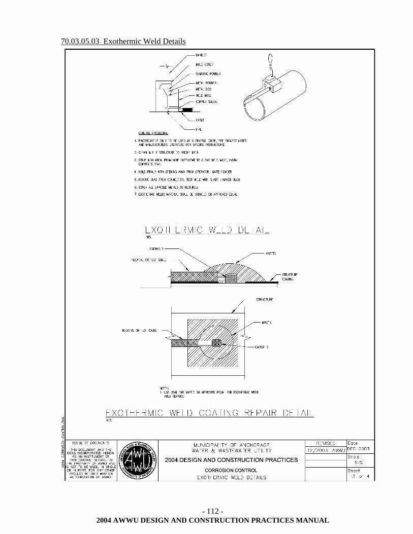
- 112 -
2004 AWWU DESIGN AND CONSTRUCTION PRACTICES MANUAL
70.03.05.03 Exothermic Weld Details
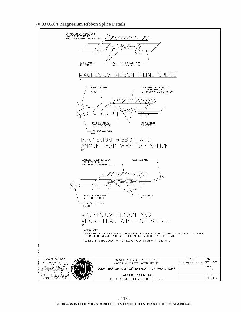
- 113 -
2004 AWWU DESIGN AND CONSTRUCTION PRACTICES MANUAL
70.03.05.04 Magnesium Ribbon Splice Details
- 114 -
2004 AWWU DESIGN AND CONSTRUCTION PRACTICES MANUAL
70.04 Horizontal and Vertical Attribute Standards
AWWU employees a computerized work management program to track and maintain data on all of its assets as part of each construction project, AWWU will require the Engineer and/or Contractor of each project to submit attribute values of each feature installed for both the equipment and the location of the equipment. AWWU will require values for both horizontal and vertical plant. Horizontal plant equipment is the underground piping and all the appurtenances. The vertical plant is equipment in the treatment plants, lift stations, PRVs, booster stations, and etc. In addition to the attribute values, AWWU will also require the manufacturer’s name, supplier’s name and any warranty dates. The attribute values shall be in a form provided AWWU and shall consist of the following.
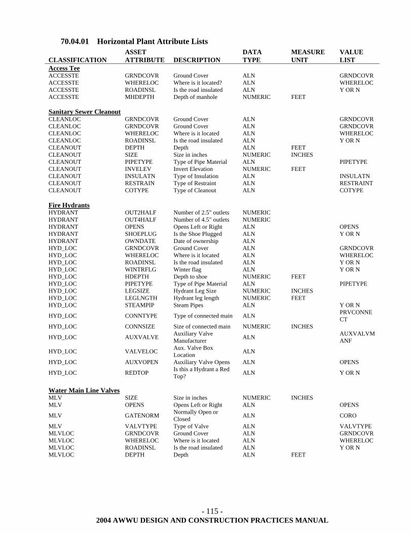
- 115 -
2004 AWWU DESIGN AND CONSTRUCTION PRACTICES MANUAL
70.04.01 Horizontal Plant Attribute Lists CLASSIFICATION
ASSET ATTRIBUTE
DESCRIPTION
DATA TYPE
MEASURE UNIT
VALUE LIST
Access Tee ACCESSTE GRNDCOVR Ground Cover ALN GRNDCOVR ACCESSTE WHERELOC Where is it located? ALN WHERELOC ACCESSTE ROADINSL Is the road insulated ALN Y OR N ACCESSTE MHDEPTH Depth of manhole NUMERIC FEET Sanitary Sewer Cleanout CLEANLOC GRNDCOVR Ground Cover ALN GRNDCOVR CLEANLOC GRNDCOVR Ground Cover ALN GRNDCOVR CLEANLOC WHERELOC Where is it located ALN WHERELOC CLEANLOC ROADINSL Is the road insulated ALN Y OR N CLEANOUT DEPTH Depth ALN FEET CLEANOUT SIZE Size in inches NUMERIC INCHES CLEANOUT PIPETYPE Type of Pipe Material ALN PIPETYPE CLEANOUT INVELEV Invert Elevation NUMERIC FEET CLEANOUT INSULATN Type of Insulation ALN INSULATN CLEANOUT RESTRAIN Type of Restraint ALN RESTRAINT CLEANOUT COTYPE Type of Cleanout ALN COTYPE Fire Hydrants HYDRANT OUT2HALF Number of 2.5" outlets NUMERIC HYDRANT OUT4HALF Number of 4.5" outlets NUMERIC HYDRANT OPENS Opens Left or Right ALN OPENS HYDRANT SHOEPLUG Is the Shoe Plugged ALN Y OR N HYDRANT OWNDATE Date of ownership ALN HYD_LOC GRNDCOVR Ground Cover ALN GRNDCOVR HYD_LOC WHERELOC Where is it located ALN WHERELOC HYD_LOC ROADINSL Is the road insulated ALN Y OR N HYD_LOC WINTRFLG Winter flag ALN Y OR N HYD_LOC HDEPTH Depth to shoe NUMERIC FEET HYD_LOC PIPETYPE Type of Pipe Material ALN PIPETYPE HYD_LOC LEGSIZE Hydrant Leg Size NUMERIC INCHES HYD_LOC LEGLNGTH Hydrant leg length NUMERIC FEET HYD_LOC STEAMPIP Steam Pipes ALN Y OR N
HYD_LOC CONNTYPE Type of connected main ALN PRVCONNECT
HYD_LOC CONNSIZE Size of connected main NUMERIC INCHES
HYD_LOC AUXVALVE Auxiliary Valve Manufacturer ALN AUXVALVM
ANF
HYD_LOC VALVELOC Aux. Valve Box Location ALN
HYD_LOC AUXVOPEN Auxiliary Valve Opens ALN OPENS
HYD_LOC REDTOP Is this a Hydrant a Red Top? ALN Y OR N
Water Main Line Valves MLV SIZE Size in inches NUMERIC INCHES MLV OPENS Opens Left or Right ALN OPENS
MLV GATENORM Normally Open or Closed ALN CORO
MLV VALVTYPE Type of Valve ALN VALVTYPE MLVLOC GRNDCOVR Ground Cover ALN GRNDCOVR MLVLOC WHERELOC Where is it located ALN WHERELOC MLVLOC ROADINSL Is the road insulated ALN Y OR N MLVLOC DEPTH Depth ALN FEET
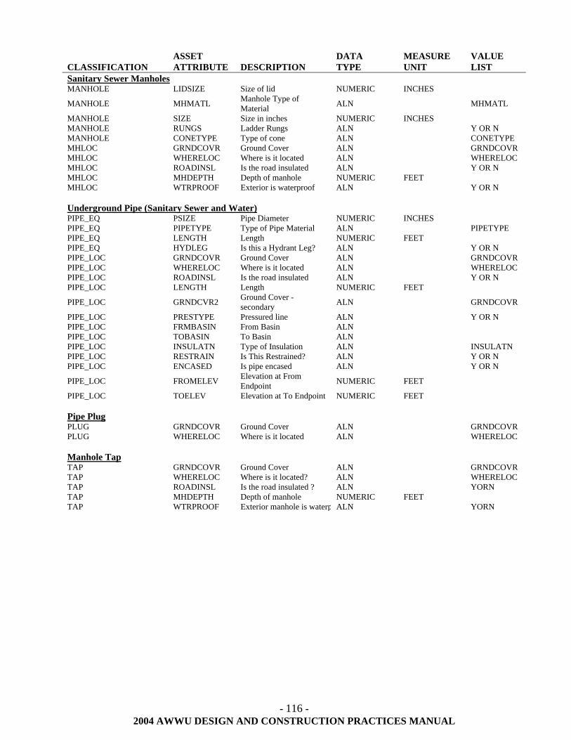
- 116 -
2004 AWWU DESIGN AND CONSTRUCTION PRACTICES MANUAL
CLASSIFICATION
ASSET ATTRIBUTE
DESCRIPTION
DATA TYPE
MEASURE UNIT
VALUE LIST
Sanitary Sewer Manholes MANHOLE LIDSIZE Size of lid NUMERIC INCHES
MANHOLE MHMATL Manhole Type of Material ALN MHMATL
MANHOLE SIZE Size in inches NUMERIC INCHES MANHOLE RUNGS Ladder Rungs ALN Y OR N MANHOLE CONETYPE Type of cone ALN CONETYPE MHLOC GRNDCOVR Ground Cover ALN GRNDCOVR MHLOC WHERELOC Where is it located ALN WHERELOC MHLOC ROADINSL Is the road insulated ALN Y OR N MHLOC MHDEPTH Depth of manhole NUMERIC FEET MHLOC WTRPROOF Exterior is waterproof ALN Y OR N Underground Pipe (Sanitary Sewer and Water) PIPE_EQ PSIZE Pipe Diameter NUMERIC INCHES PIPE_EQ PIPETYPE Type of Pipe Material ALN PIPETYPE PIPE_EQ LENGTH Length NUMERIC FEET PIPE_EQ HYDLEG Is this a Hydrant Leg? ALN Y OR N PIPE_LOC GRNDCOVR Ground Cover ALN GRNDCOVR PIPE_LOC WHERELOC Where is it located ALN WHERELOC PIPE_LOC ROADINSL Is the road insulated ALN Y OR N PIPE_LOC LENGTH Length NUMERIC FEET
PIPE_LOC GRNDCVR2 Ground Cover -secondary ALN GRNDCOVR
PIPE_LOC PRESTYPE Pressured line ALN Y OR N PIPE_LOC FRMBASIN From Basin ALN PIPE_LOC TOBASIN To Basin ALN PIPE_LOC INSULATN Type of Insulation ALN INSULATN PIPE_LOC RESTRAIN Is This Restrained? ALN Y OR N PIPE_LOC ENCASED Is pipe encased ALN Y OR N
PIPE_LOC FROMELEV Elevation at From Endpoint NUMERIC FEET
PIPE_LOC TOELEV Elevation at To Endpoint NUMERIC FEET Pipe Plug PLUG GRNDCOVR Ground Cover ALN GRNDCOVR PLUG WHERELOC Where is it located ALN WHERELOC Manhole Tap TAP GRNDCOVR Ground Cover ALN GRNDCOVR TAP WHERELOC Where is it located? ALN WHERELOC TAP ROADINSL Is the road insulated ? ALN YORN TAP MHDEPTH Depth of manhole NUMERIC FEET TAP WTRPROOF Exterior manhole is waterp ALN YORN
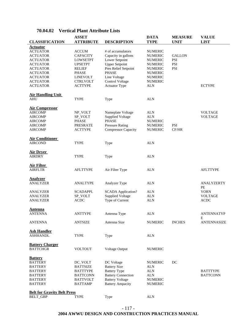
- 117 -
2004 AWWU DESIGN AND CONSTRUCTION PRACTICES MANUAL
70.04.02 Vertical Plant Attribute Lists
CLASSIFICATION
ASSET ATTRIBUTE
DESCRIPTION
DATA TYPE
MEASURE UNIT
VALUE LIST
Actuator ACTUATOR ACCUM # of accumulators NUMERIC ACTUATOR CAPACITY Capacity in gallons NUMERIC GALLON ACTUATOR LOWSETPT Lower Setpoint NUMERIC PSI ACTUATOR UPSETPT Upper Setpoint NUMERIC PSI ACTUATOR RELIEF Pres Relief Setpoint NUMERIC PSI ACTUATOR PHASE PHASE NUMERIC ACTUATOR LINEVOLT Line Voltage NUMERIC ACTUATOR CTRLVOLT Control Voltage NUMERIC ACTUATOR ACTTYPE Actuator Type ALN ECTYPE Air Handling Unit AHU TYPE Type ALN Air Compressor AIRCOMP NP_VOLT Nameplate Voltage ALN VOLTAGE AIRCOMP SP_VOLT Supplied Voltage ALN VOLTAGE AIRCOMP PHASE PHASE NUMERIC AIRCOMP PRESRATE Pressure Rating NUMERIC PSI AIRCOMP ACTTYPE Compressor Capacity NUMERIC CF/HR Air Conditioner AIRCOND TYPE Type ALN Air Dryer AIRDRY TYPE Type ALN Air Filter AIRFLTR AFLTTYPE Air Filter Type ALN AFLTTYPE Analyzer ANALYZER ANALTYPE Analyzer Type ALN ANALYZERTY
PE ANALYZER SCADAPPL SCADA Application? ALN YORN ANALYZER SP_VOLT Supplied Voltage ALN VOLTAGE ANALYZER ACDC Type of Current ALN ACDC Antenna ANTENNA ANTTYPE Antenna Type ALN ANTENNATYP
E ANTENNA ANTSIZE Antenna Size NUMERIC INCHES ANTENNASIZE Ash Handler ASHHANDL TYPE Type ALN Battery Charger BATTCHGR VOLTOUT Voltage Output NUMERIC Battery BATTERY DC_VOLT DC Voltage NUMERIC DC BATTERY BATTSIZE Battery Size ALN BATTERY BATTTYPE Battery Type ALN BATTTYPE BATTERY BATTCONN Battery Connection ALN BATTCONN BATTERY BATTVOLT Battery Voltage NUMERIC BATTERY BATTAMP Battery Ampacity NUMERIC Belt for Gravity Belt Press BELT_GBP TYPE Type ALN
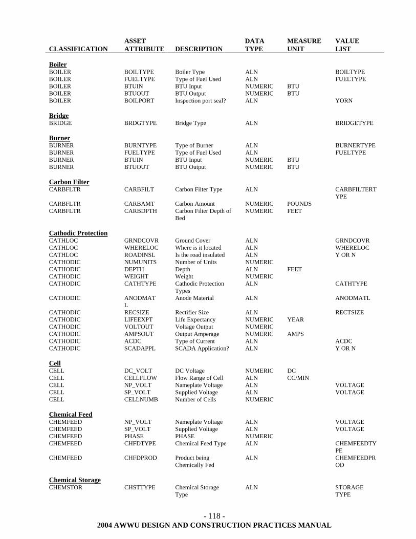
- 118 -
2004 AWWU DESIGN AND CONSTRUCTION PRACTICES MANUAL
CLASSIFICATION
ASSET ATTRIBUTE
DESCRIPTION
DATA TYPE
MEASURE UNIT
VALUE LIST
Boiler BOILER BOILTYPE Boiler Type ALN BOILTYPE BOILER FUELTYPE Type of Fuel Used ALN FUELTYPE BOILER BTUIN BTU Input NUMERIC BTU BOILER BTUOUT BTU Output NUMERIC BTU BOILER BOILPORT Inspection port seal? ALN YORN Bridge BRIDGE BRDGTYPE Bridge Type ALN BRIDGETYPE Burner BURNER BURNTYPE Type of Burner ALN BURNERTYPE BURNER FUELTYPE Type of Fuel Used ALN FUELTYPE BURNER BTUIN BTU Input NUMERIC BTU BURNER BTUOUT BTU Output NUMERIC BTU Carbon Filter CARBFLTR CARBFILT Carbon Filter Type ALN CARBFILTERT
YPE CARBFLTR CARBAMT Carbon Amount NUMERIC POUNDS CARBFLTR CARBDPTH Carbon Filter Depth of
Bed NUMERIC FEET
Cathodic Protection CATHLOC GRNDCOVR Ground Cover ALN GRNDCOVR CATHLOC WHERELOC Where is it located ALN WHERELOC CATHLOC ROADINSL Is the road insulated ALN Y OR N CATHODIC NUMUNITS Number of Units NUMERIC CATHODIC DEPTH Depth ALN FEET CATHODIC WEIGHT Weight NUMERIC CATHODIC CATHTYPE Cathodic Protection
Types ALN CATHTYPE
CATHODIC ANODMATL
Anode Material ALN ANODMATL
CATHODIC RECSIZE Rectifier Size ALN RECTSIZE CATHODIC LIFEEXPT Life Expectancy NUMERIC YEAR CATHODIC VOLTOUT Voltage Output NUMERIC CATHODIC AMPSOUT Output Amperage NUMERIC AMPS CATHODIC ACDC Type of Current ALN ACDC CATHODIC SCADAPPL SCADA Application? ALN Y OR N Cell CELL DC_VOLT DC Voltage NUMERIC DC CELL CELLFLOW Flow Range of Cell ALN CC/MIN CELL NP_VOLT Nameplate Voltage ALN VOLTAGE CELL SP_VOLT Supplied Voltage ALN VOLTAGE CELL CELLNUMB Number of Cells NUMERIC Chemical Feed CHEMFEED NP_VOLT Nameplate Voltage ALN VOLTAGE CHEMFEED SP_VOLT Supplied Voltage ALN VOLTAGE CHEMFEED PHASE PHASE NUMERIC CHEMFEED CHFDTYPE Chemical Feed Type ALN CHEMFEEDTY
PE CHEMFEED CHFDPROD Product being
Chemically Fed ALN CHEMFEEDPR
OD Chemical Storage CHEMSTOR CHSTTYPE Chemical Storage
Type ALN STORAGE
TYPE
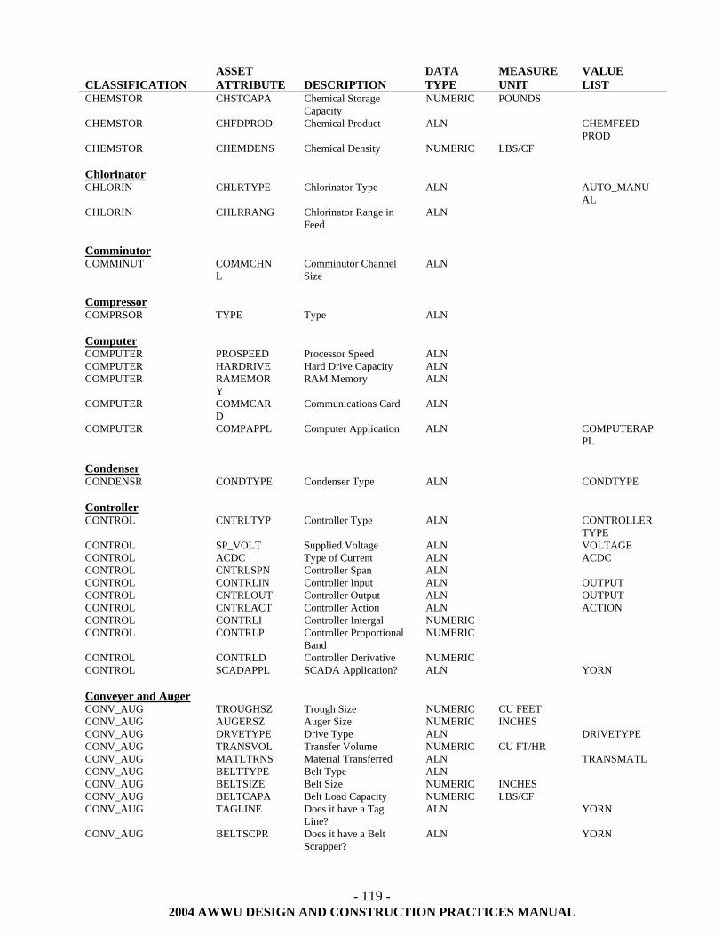
- 119 -
2004 AWWU DESIGN AND CONSTRUCTION PRACTICES MANUAL
CLASSIFICATION
ASSET ATTRIBUTE
DESCRIPTION
DATA TYPE
MEASURE UNIT
VALUE LIST
CHEMSTOR CHSTCAPA Chemical Storage Capacity
NUMERIC POUNDS
CHEMSTOR CHFDPROD Chemical Product ALN CHEMFEED PROD
CHEMSTOR CHEMDENS Chemical Density NUMERIC LBS/CF Chlorinator CHLORIN CHLRTYPE Chlorinator Type ALN AUTO_MANU
AL CHLORIN CHLRRANG Chlorinator Range in
Feed ALN
Comminutor COMMINUT COMMCHN
L Comminutor Channel Size
ALN
Compressor COMPRSOR TYPE Type ALN Computer COMPUTER PROSPEED Processor Speed ALN COMPUTER HARDRIVE Hard Drive Capacity ALN COMPUTER RAMEMOR
Y RAM Memory ALN
COMPUTER COMMCARD
Communications Card ALN
COMPUTER COMPAPPL Computer Application ALN COMPUTERAPPL
Condenser CONDENSR CONDTYPE Condenser Type ALN CONDTYPE Controller CONTROL CNTRLTYP Controller Type ALN CONTROLLER
TYPE CONTROL SP_VOLT Supplied Voltage ALN VOLTAGE CONTROL ACDC Type of Current ALN ACDC CONTROL CNTRLSPN Controller Span ALN CONTROL CONTRLIN Controller Input ALN OUTPUT CONTROL CNTRLOUT Controller Output ALN OUTPUT CONTROL CNTRLACT Controller Action ALN ACTION CONTROL CONTRLI Controller Intergal NUMERIC CONTROL CONTRLP Controller Proportional
Band NUMERIC
CONTROL CONTRLD Controller Derivative NUMERIC CONTROL SCADAPPL SCADA Application? ALN YORN Conveyer and Auger CONV_AUG TROUGHSZ Trough Size NUMERIC CU FEET CONV_AUG AUGERSZ Auger Size NUMERIC INCHES CONV_AUG DRVETYPE Drive Type ALN DRIVETYPE CONV_AUG TRANSVOL Transfer Volume NUMERIC CU FT/HR CONV_AUG MATLTRNS Material Transferred ALN TRANSMATL CONV_AUG BELTTYPE Belt Type ALN CONV_AUG BELTSIZE Belt Size NUMERIC INCHES CONV_AUG BELTCAPA Belt Load Capacity NUMERIC LBS/CF CONV_AUG TAGLINE Does it have a Tag
Line? ALN YORN
CONV_AUG BELTSCPR Does it have a Belt Scrapper?
ALN YORN
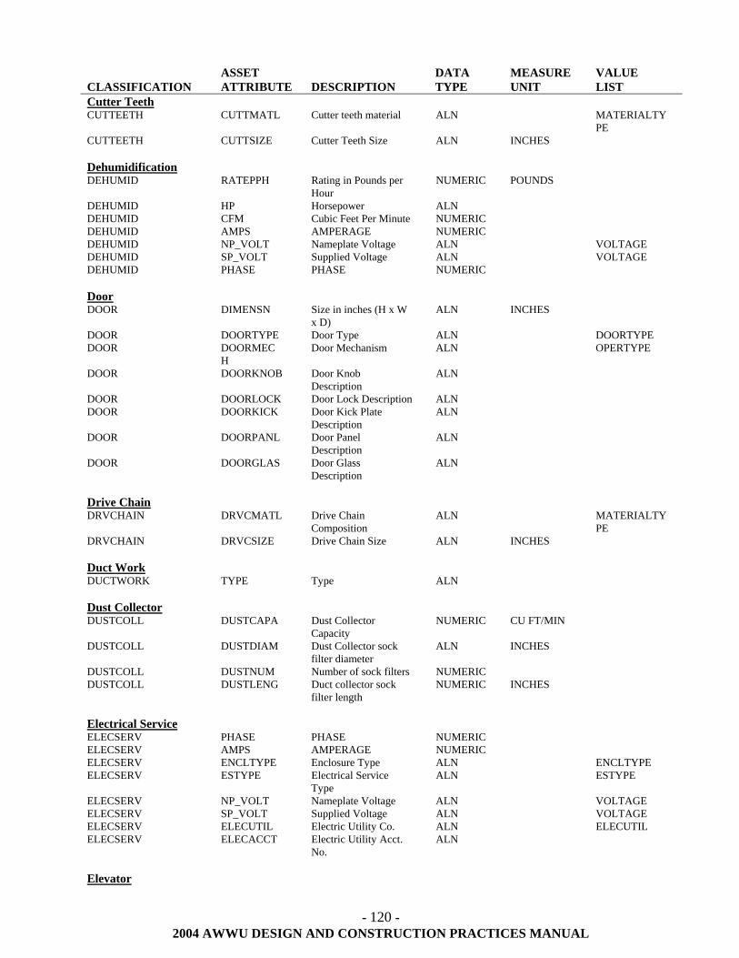
- 120 -
2004 AWWU DESIGN AND CONSTRUCTION PRACTICES MANUAL
CLASSIFICATION
ASSET ATTRIBUTE
DESCRIPTION
DATA TYPE
MEASURE UNIT
VALUE LIST
Cutter Teeth CUTTEETH CUTTMATL Cutter teeth material ALN MATERIALTY
PE CUTTEETH CUTTSIZE Cutter Teeth Size ALN INCHES Dehumidification DEHUMID RATEPPH Rating in Pounds per
Hour NUMERIC POUNDS
DEHUMID HP Horsepower ALN DEHUMID CFM Cubic Feet Per Minute NUMERIC DEHUMID AMPS AMPERAGE NUMERIC DEHUMID NP_VOLT Nameplate Voltage ALN VOLTAGE DEHUMID SP_VOLT Supplied Voltage ALN VOLTAGE DEHUMID PHASE PHASE NUMERIC Door DOOR DIMENSN Size in inches (H x W
x D) ALN INCHES
DOOR DOORTYPE Door Type ALN DOORTYPE DOOR DOORMEC
H Door Mechanism ALN OPERTYPE
DOOR DOORKNOB Door Knob Description
ALN
DOOR DOORLOCK Door Lock Description ALN DOOR DOORKICK Door Kick Plate
Description ALN
DOOR DOORPANL Door Panel Description
ALN
DOOR DOORGLAS Door Glass Description
ALN
Drive Chain DRVCHAIN DRVCMATL Drive Chain
Composition ALN MATERIALTY
PE DRVCHAIN DRVCSIZE Drive Chain Size ALN INCHES Duct Work DUCTWORK TYPE Type ALN Dust Collector DUSTCOLL DUSTCAPA Dust Collector
Capacity NUMERIC CU FT/MIN
DUSTCOLL DUSTDIAM Dust Collector sock filter diameter
ALN INCHES
DUSTCOLL DUSTNUM Number of sock filters NUMERIC DUSTCOLL DUSTLENG Duct collector sock
filter length NUMERIC INCHES
Electrical Service ELECSERV PHASE PHASE NUMERIC ELECSERV AMPS AMPERAGE NUMERIC ELECSERV ENCLTYPE Enclosure Type ALN ENCLTYPE ELECSERV ESTYPE Electrical Service
Type ALN ESTYPE
ELECSERV NP_VOLT Nameplate Voltage ALN VOLTAGE ELECSERV SP_VOLT Supplied Voltage ALN VOLTAGE ELECSERV ELECUTIL Electric Utility Co. ALN ELECUTIL ELECSERV ELECACCT Electric Utility Acct.
No. ALN
Elevator
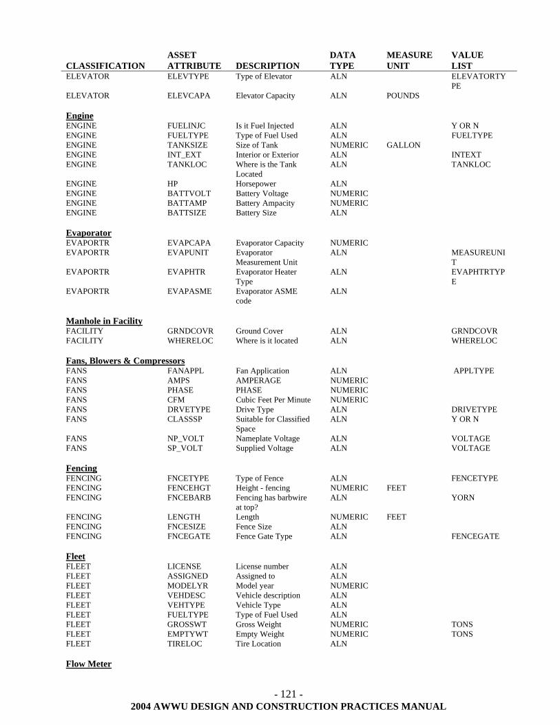
- 121 -
2004 AWWU DESIGN AND CONSTRUCTION PRACTICES MANUAL
CLASSIFICATION
ASSET ATTRIBUTE
DESCRIPTION
DATA TYPE
MEASURE UNIT
VALUE LIST
ELEVATOR ELEVTYPE Type of Elevator ALN ELEVATORTYPE
ELEVATOR ELEVCAPA Elevator Capacity ALN POUNDS Engine ENGINE FUELINJC Is it Fuel Injected ALN Y OR N ENGINE FUELTYPE Type of Fuel Used ALN FUELTYPE ENGINE TANKSIZE Size of Tank NUMERIC GALLON ENGINE INT_EXT Interior or Exterior ALN INTEXT ENGINE TANKLOC Where is the Tank
Located ALN TANKLOC
ENGINE HP Horsepower ALN ENGINE BATTVOLT Battery Voltage NUMERIC ENGINE BATTAMP Battery Ampacity NUMERIC ENGINE BATTSIZE Battery Size ALN Evaporator EVAPORTR EVAPCAPA Evaporator Capacity NUMERIC EVAPORTR EVAPUNIT Evaporator
Measurement Unit ALN MEASUREUNI
T EVAPORTR EVAPHTR Evaporator Heater
Type ALN EVAPHTRTYP
E EVAPORTR EVAPASME Evaporator ASME
code ALN
Manhole in Facility FACILITY GRNDCOVR Ground Cover ALN GRNDCOVR FACILITY WHERELOC Where is it located ALN WHERELOC Fans, Blowers & Compressors FANS FANAPPL Fan Application ALN APPLTYPE FANS AMPS AMPERAGE NUMERIC FANS PHASE PHASE NUMERIC FANS CFM Cubic Feet Per Minute NUMERIC FANS DRVETYPE Drive Type ALN DRIVETYPE FANS CLASSSP Suitable for Classified
Space ALN Y OR N
FANS NP_VOLT Nameplate Voltage ALN VOLTAGE FANS SP_VOLT Supplied Voltage ALN VOLTAGE Fencing FENCING FNCETYPE Type of Fence ALN FENCETYPE FENCING FENCEHGT Height - fencing NUMERIC FEET FENCING FNCEBARB Fencing has barbwire
at top? ALN YORN
FENCING LENGTH Length NUMERIC FEET FENCING FNCESIZE Fence Size ALN FENCING FNCEGATE Fence Gate Type ALN FENCEGATE Fleet FLEET LICENSE License number ALN FLEET ASSIGNED Assigned to ALN FLEET MODELYR Model year NUMERIC FLEET VEHDESC Vehicle description ALN FLEET VEHTYPE Vehicle Type ALN FLEET FUELTYPE Type of Fuel Used ALN FLEET GROSSWT Gross Weight NUMERIC TONS FLEET EMPTYWT Empty Weight NUMERIC TONS FLEET TIRELOC Tire Location ALN Flow Meter
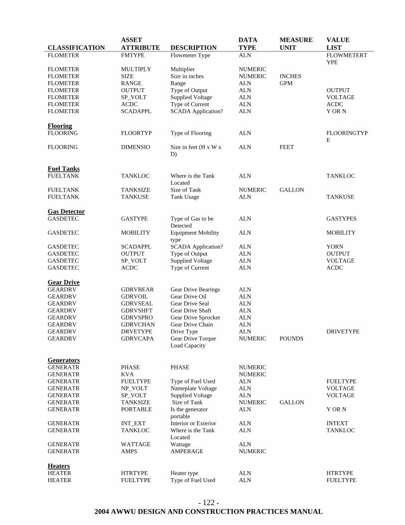
- 122 -
2004 AWWU DESIGN AND CONSTRUCTION PRACTICES MANUAL
CLASSIFICATION
ASSET ATTRIBUTE
DESCRIPTION
DATA TYPE
MEASURE UNIT
VALUE LIST
FLOMETER FMTYPE Flowmeter Type ALN FLOWMETERTYPE
FLOMETER MULTIPLY Multiplier NUMERIC FLOMETER SIZE Size in inches NUMERIC INCHES FLOMETER RANGE Range ALN GPM FLOMETER OUTPUT Type of Output ALN OUTPUT FLOMETER SP_VOLT Supplied Voltage ALN VOLTAGE FLOMETER ACDC Type of Current ALN ACDC FLOMETER SCADAPPL SCADA Application? ALN Y OR N Flooring FLOORING FLOORTYP Type of Flooring ALN FLOORINGTYP
E FLOORING DIMENSIO Size in feet (H x W x
D) ALN FEET
Fuel Tanks FUELTANK TANKLOC Where is the Tank
Located ALN TANKLOC
FUELTANK TANKSIZE Size of Tank NUMERIC GALLON FUELTANK TANKUSE Tank Usage ALN TANKUSE Gas Detector GASDETEC GASTYPE Type of Gas to be
Detected ALN GASTYPES
GASDETEC MOBILITY Equipment Mobility type
ALN MOBILITY
GASDETEC SCADAPPL SCADA Application? ALN YORN GASDETEC OUTPUT Type of Output ALN OUTPUT GASDETEC SP_VOLT Supplied Voltage ALN VOLTAGE GASDETEC ACDC Type of Current ALN ACDC Gear Drive GEARDRV GDRVBEAR Gear Drive Bearings ALN GEARDRV GDRVOIL Gear Drive Oil ALN GEARDRV GDRVSEAL Gear Drive Seal ALN GEARDRV GDRVSHFT Gear Drive Shaft ALN GEARDRV GDRVSPRO Gear Drive Sprocket ALN GEARDRV GDRVCHAN Gear Drive Chain ALN GEARDRV DRVETYPE Drive Type ALN DRIVETYPE GEARDRV GDRVCAPA Gear Drive Torque
Load Capacity NUMERIC POUNDS
Generators GENERATR PHASE PHASE NUMERIC GENERATR KVA NUMERIC GENERATR FUELTYPE Type of Fuel Used ALN FUELTYPE GENERATR NP_VOLT Nameplate Voltage ALN VOLTAGE GENERATR SP_VOLT Supplied Voltage ALN VOLTAGE GENERATR TANKSIZE Size of Tank NUMERIC GALLON GENERATR PORTABLE Is the generator
portable ALN Y OR N
GENERATR INT_EXT Interior or Exterior ALN INTEXT GENERATR TANKLOC Where is the Tank
Located ALN TANKLOC
GENERATR WATTAGE Wattage ALN GENERATR AMPS AMPERAGE NUMERIC Heaters HEATER HTRTYPE Heater type ALN HTRTYPE HEATER FUELTYPE Type of Fuel Used ALN FUELTYPE
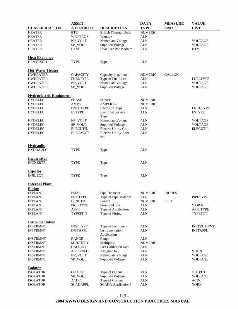
- 123 -
2004 AWWU DESIGN AND CONSTRUCTION PRACTICES MANUAL
CLASSIFICATION
ASSET ATTRIBUTE
DESCRIPTION
DATA TYPE
MEASURE UNIT
VALUE LIST
HEATER BTU British Thermal Units NUMERIC HEATER WATTAGE Wattage ALN HEATER NP_VOLT Nameplate Voltage ALN VOLTAGE HEATER SP_VOLT Supplied Voltage ALN VOLTAGE HEATER HTM Heat Transfer Medium ALN HTM Heat Exchange HEATEXCH TYPE Type ALN Hot Water Heater HWHEATER CAPACITY Capacity in gallons NUMERIC GALLON HWHEATER FUELTYPE Type of Fuel Used ALN FUELTYPE HWHEATER NP_VOLT Nameplate Voltage ALN VOLTAGE HWHEATER SP_VOLT Supplied Voltage ALN VOLTAGE Hydroelectric Equipment HYDELEC PHASE PHASE NUMERIC HYDELEC AMPS AMPERAGE NUMERIC HYDELEC ENCLTYPE Enclosure Type ALN ENCLTYPE HYDELEC ESTYPE Electrical Service
Type ALN ESTYPE
HYDELEC NP_VOLT Nameplate Voltage ALN VOLTAGE HYDELEC SP_VOLT Supplied Voltage ALN VOLTAGE HYDELEC ELECUTIL Electric Utility Co. ALN ELECUTIL HYDELEC ELECACCT Electric Utility Acct.
No. ALN
Hydraulic HYDRAULC TYPE Type ALN Incinerator INCNERTR TYPE Type ALN Injector INJEJECT TYPE Type ALN Internal Plant Piping
INPLANT PSIZE Pipe Diameter NUMERIC INCHES INPLANT PIPETYPE Type of Pipe Material ALN PIPETYPE INPLANT LENGTH Length NUMERIC FEET INPLANT PRESTYPE Pressured line ALN Y OR N INPLANT APPL Type of Application ALN APPLTYPE INPLANT TYPEFITT Type of Fitting ALN TYPEFITT Instrumentation INSTRMNT INSTTYPE Type of Instrument ALN INSTRUMENT INSTRMNT INSTAPPL Instrumentation
Application ALN INSTAPPL
INSTRMNT RANGE Range ALN INSTRMNT MULTIPLY Multiplier NUMERIC INSTRMNT CALIBDT Last Calibrated Date ALN INSTRMNT ASSIGNED Assigned to ALN VHON INSTRMNT NP_VOLT Nameplate Voltage ALN VOLTAGE INSTRMNT SP_VOLT Supplied Voltage ALN VOLTAGE Isolator ISOLATOR OUTPUT Type of Output ALN OUTPUT ISOLATOR SP_VOLT Supplied Voltage ALN VOLTAGE ISOLATOR ACDC Type of Current ALN ACDC ISOLATOR SCADAPPL SCADA Application? ALN YORN
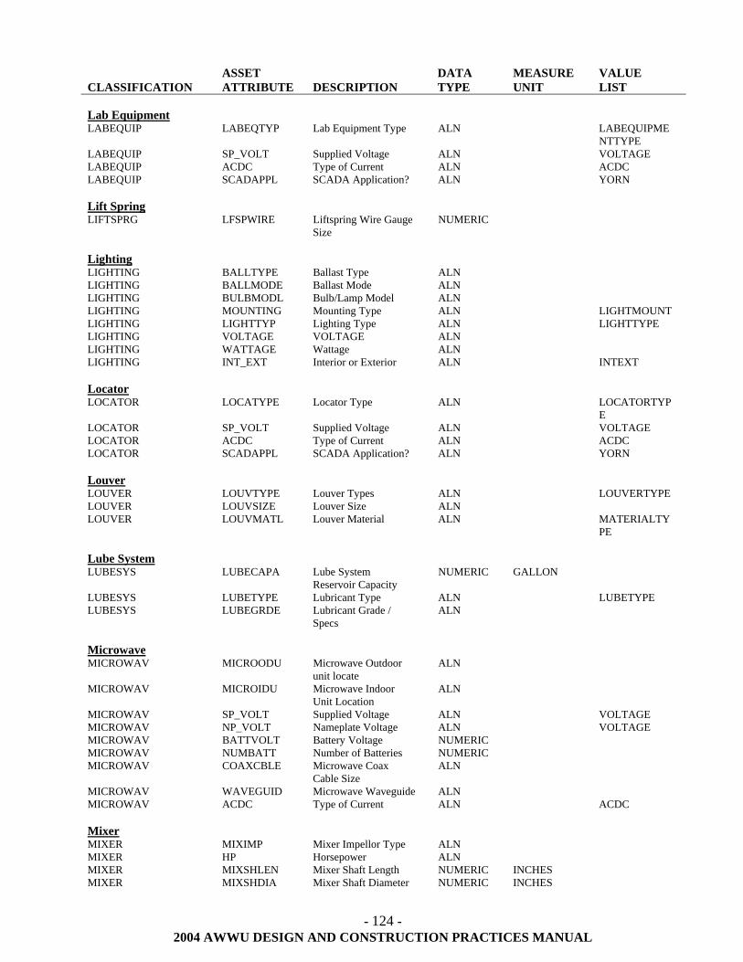
- 124 -
2004 AWWU DESIGN AND CONSTRUCTION PRACTICES MANUAL
CLASSIFICATION
ASSET ATTRIBUTE
DESCRIPTION
DATA TYPE
MEASURE UNIT
VALUE LIST
Lab Equipment LABEQUIP LABEQTYP Lab Equipment Type ALN LABEQUIPME
NTTYPE LABEQUIP SP_VOLT Supplied Voltage ALN VOLTAGE LABEQUIP ACDC Type of Current ALN ACDC LABEQUIP SCADAPPL SCADA Application? ALN YORN Lift Spring LIFTSPRG LFSPWIRE Liftspring Wire Gauge
Size NUMERIC
Lighting LIGHTING BALLTYPE Ballast Type ALN LIGHTING BALLMODE Ballast Mode ALN LIGHTING BULBMODL Bulb/Lamp Model ALN LIGHTING MOUNTING Mounting Type ALN LIGHTMOUNT LIGHTING LIGHTTYP Lighting Type ALN LIGHTTYPE LIGHTING VOLTAGE VOLTAGE ALN LIGHTING WATTAGE Wattage ALN LIGHTING INT_EXT Interior or Exterior ALN INTEXT Locator LOCATOR LOCATYPE Locator Type ALN LOCATORTYP
E LOCATOR SP_VOLT Supplied Voltage ALN VOLTAGE LOCATOR ACDC Type of Current ALN ACDC LOCATOR SCADAPPL SCADA Application? ALN YORN Louver LOUVER LOUVTYPE Louver Types ALN LOUVERTYPE LOUVER LOUVSIZE Louver Size ALN LOUVER LOUVMATL Louver Material ALN MATERIALTY
PE Lube System LUBESYS LUBECAPA Lube System
Reservoir Capacity NUMERIC GALLON
LUBESYS LUBETYPE Lubricant Type ALN LUBETYPE LUBESYS LUBEGRDE Lubricant Grade /
Specs ALN
Microwave MICROWAV MICROODU Microwave Outdoor
unit locate ALN
MICROWAV MICROIDU Microwave Indoor Unit Location
ALN
MICROWAV SP_VOLT Supplied Voltage ALN VOLTAGE MICROWAV NP_VOLT Nameplate Voltage ALN VOLTAGE MICROWAV BATTVOLT Battery Voltage NUMERIC MICROWAV NUMBATT Number of Batteries NUMERIC MICROWAV COAXCBLE Microwave Coax
Cable Size ALN
MICROWAV WAVEGUID Microwave Waveguide ALN MICROWAV ACDC Type of Current ALN ACDC Mixer MIXER MIXIMP Mixer Impellor Type ALN MIXER HP Horsepower ALN MIXER MIXSHLEN Mixer Shaft Length NUMERIC INCHES MIXER MIXSHDIA Mixer Shaft Diameter NUMERIC INCHES
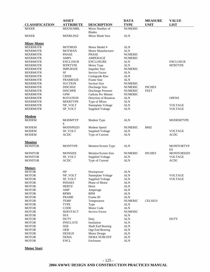
- 125 -
2004 AWWU DESIGN AND CONSTRUCTION PRACTICES MANUAL
CLASSIFICATION
ASSET ATTRIBUTE
DESCRIPTION
DATA TYPE
MEASURE UNIT
VALUE LIST
MIXER MIXNUMBL Mixer Number of Blades
NUMERIC
MIXER MIXBLDSZ Mixer Blade Size ALN Mixer Motor MIXRMOTR MOTMOD Motor Model # ALN MIXRMOTR MOTMAN Motor Manufacturer ALN MIXRMOTR PHASE PHASE NUMERIC MIXRMOTR AMPS AMPERAGE NUMERIC MIXRMOTR ENCLOSUR ENCLOSURE ALN ENCLOSUR MIXRMOTR MTRTYPE Motor Type ALN MTRTYPE MIXRMOTR IMPLRSZE Impeller Size NUMERIC MIXRMOTR SF Service Factor ALN MIXRMOTR CRISE Centigrade Rise ALN MIXRMOTR FRAMESZE Frame Size ALN MIXRMOTR SUCTION Suction Size NUMERIC MIXRMOTR DISCHSZ Discharge Size NUMERIC INCHES MIXRMOTR DISCHPR Discharge Pressure NUMERIC FEET MIXRMOTR GPM Gallons Per Minute NUMERIC MIXRMOTR ROTATION Direction of Rotation ALN OPENS MIXRMOTR MIXRTYPE Type of Mixer ALN MIXRMOTR NP_VOLT Nameplate Voltage ALN VOLTAGE MIXRMOTR SP_VOLT Supplied Voltage ALN VOLTAGE Modem MODEM MODMTYP
E Modem Type ALN MODEMTYPE
MODEM MODSPEED Modem Speed NUMERIC MHZ MODEM SP_VOLT Supplied Voltage ALN VOLTAGE MODEM ACDC Type of Current ALN ACDC Monitor MONITOR MONTYPE Monitor/Screen Type ALN MONITORTYP
ES MONITOR MONSIZE Monitor/Screen Size NUMERIC INCHES MONITORSIZE MONITOR SP_VOLT Supplied Voltage ALN VOLTAGE MONITOR ACDC Type of Current ALN ACDC Motors MOTOR HP Horsepower ALN MOTOR NP_VOLT Nameplate Voltage ALN VOLTAGE MOTOR SP_VOLT Supplied Voltage ALN VOLTAGE MOTOR PHASES Phase of Motor ALN MOTOR HERTZ Hertz ALN MOTOR AMP Amperage ALN MOTOR RPMS RPM ALN MOTOR FRAME Frame ID ALN MOTOR TEMP Temperature NUMERIC CELSIUS MOTOR TYPE Type ALN MOTOR CODE Motor Code ALN MOTOR SERVFACT Service Factor NUMERIC MOTOR SFA ALN MOTOR DUTY Duty ALN DUTY MOTOR INSULATE Insulation ALN MOTOR SEB Shaft End Bearing ALN MOTOR OEB Opp End Bearing ALN MOTOR DESIGN Motor Design ALN MOTOR NEMA NEMA NOM EFF ALN MOTOR ENCL Enclosure ALN Motor Start
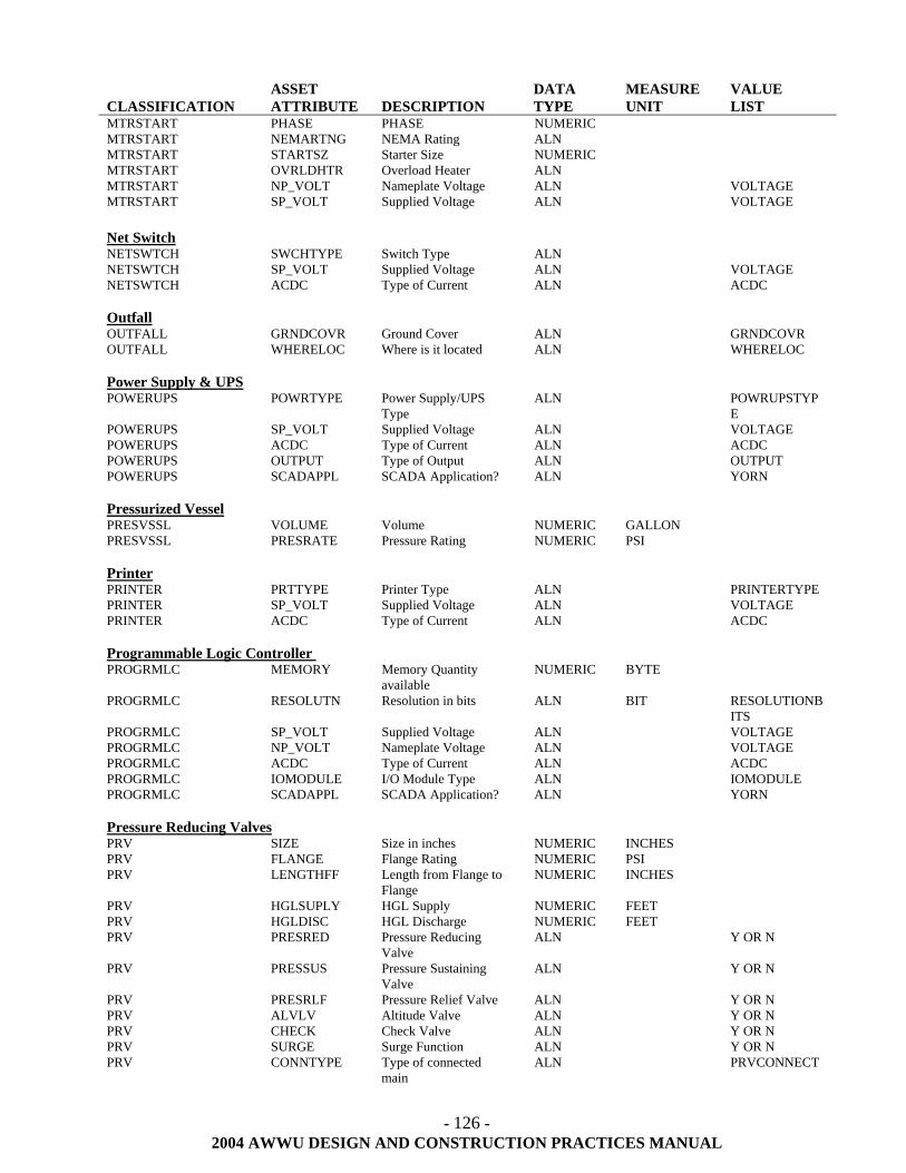
- 126 -
2004 AWWU DESIGN AND CONSTRUCTION PRACTICES MANUAL
CLASSIFICATION
ASSET ATTRIBUTE
DESCRIPTION
DATA TYPE
MEASURE UNIT
VALUE LIST
MTRSTART PHASE PHASE NUMERIC MTRSTART NEMARTNG NEMA Rating ALN MTRSTART STARTSZ Starter Size NUMERIC MTRSTART OVRLDHTR Overload Heater ALN MTRSTART NP_VOLT Nameplate Voltage ALN VOLTAGE MTRSTART SP_VOLT Supplied Voltage ALN VOLTAGE Net Switch NETSWTCH SWCHTYPE Switch Type ALN NETSWTCH SP_VOLT Supplied Voltage ALN VOLTAGE NETSWTCH ACDC Type of Current ALN ACDC Outfall OUTFALL GRNDCOVR Ground Cover ALN GRNDCOVR OUTFALL WHERELOC Where is it located ALN WHERELOC Power Supply & UPS POWERUPS POWRTYPE Power Supply/UPS
Type ALN POWRUPSTYP
E POWERUPS SP_VOLT Supplied Voltage ALN VOLTAGE POWERUPS ACDC Type of Current ALN ACDC POWERUPS OUTPUT Type of Output ALN OUTPUT POWERUPS SCADAPPL SCADA Application? ALN YORN Pressurized Vessel PRESVSSL VOLUME Volume NUMERIC GALLON PRESVSSL PRESRATE Pressure Rating NUMERIC PSI Printer PRINTER PRTTYPE Printer Type ALN PRINTERTYPE PRINTER SP_VOLT Supplied Voltage ALN VOLTAGE PRINTER ACDC Type of Current ALN ACDC Programmable Logic Controller PROGRMLC MEMORY Memory Quantity
available NUMERIC BYTE
PROGRMLC RESOLUTN Resolution in bits ALN BIT RESOLUTIONBITS
PROGRMLC SP_VOLT Supplied Voltage ALN VOLTAGE PROGRMLC NP_VOLT Nameplate Voltage ALN VOLTAGE PROGRMLC ACDC Type of Current ALN ACDC PROGRMLC IOMODULE I/O Module Type ALN IOMODULE PROGRMLC SCADAPPL SCADA Application? ALN YORN Pressure Reducing Valves PRV SIZE Size in inches NUMERIC INCHES PRV FLANGE Flange Rating NUMERIC PSI PRV LENGTHFF Length from Flange to
Flange NUMERIC INCHES
PRV HGLSUPLY HGL Supply NUMERIC FEET PRV HGLDISC HGL Discharge NUMERIC FEET PRV PRESRED Pressure Reducing
Valve ALN Y OR N
PRV PRESSUS Pressure Sustaining Valve
ALN Y OR N
PRV PRESRLF Pressure Relief Valve ALN Y OR N PRV ALVLV Altitude Valve ALN Y OR N PRV CHECK Check Valve ALN Y OR N PRV SURGE Surge Function ALN Y OR N PRV CONNTYPE Type of connected
main ALN PRVCONNECT
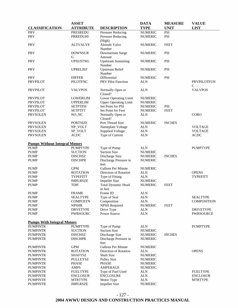
- 127 -
2004 AWWU DESIGN AND CONSTRUCTION PRACTICES MANUAL
CLASSIFICATION
ASSET ATTRIBUTE
DESCRIPTION
DATA TYPE
MEASURE UNIT
VALUE LIST
PRV PRESREDU Pressure Reducing NUMERIC PSI PRV PRREDUHI Pressure Reducing
(High) NUMERIC PSI
PRV ALTVALVE Altitude Valve Number
NUMERIC FEET
PRV DOWNSURG
Downstream Surge Amount
NUMERIC PSI
PRV UPSUSTNG Upstream Sustaining Number
NUMERIC PSI
PRV UPRELIEF Upstream Relief Number
NUMERIC PSI
PRV DIFFER Differential NUMERIC PSI PRVPILOT PILOTFNC PRV Pilot Function ALN PRVPILOTFUN
C PRVPILOT VALVPOS Normally Open or
Closed? ALN VALVPOS
PRVPILOT LOWERLIM Lower Operating Limit NUMERIC PRVPILOT UPPERLIM Upper Operating Limit NUMERIC PRVPILOT SETPTPSI Set Point for PSI NUMERIC PSI PRVPILOT SETPTFT Set Point for Feet NUMERIC FEET PRVSOLEN NO_NC Normally Open or
Closed? ALN CORO
PRVSOLEN PORTSIZE Port Thread Size NUMERIC INCHES PRVSOLEN NP_VOLT Nameplate Voltage ALN VOLTAGE PRVSOLEN SP_VOLT Supplied Voltage ALN VOLTAGE PRVSOLEN ACDC Type of Current ALN ACDC Pumps Without Integral Motors PUMP PUMPTYPE Type of Pump ALN PUMPTYPE PUMP SUCTION Suction Size NUMERIC PUMP DISCHSZ Discharge Size NUMERIC INCHES PUMP DISCHPR Discharge Pressure in
feet NUMERIC
PUMP GPM Gallons Per Minute NUMERIC PUMP ROTATION Direction of Rotation ALN OPENS PUMP TYPEFITT Type of Fitting ALN TYPEFITT PUMP IMPLRSZE Impeller Size NUMERIC PUMP TDH Total Dynamic Head
in feet NUMERIC FEET
PUMP FRAME Frame ID ALN PUMP SEALTYPE Type of Seal ALN SEALTYPE PUMP COMPOSTN Composition ALN COMPOSITION PUMP NPSHR NPSH Required NUMERIC FEET PUMP DRVETYPE Drive Type ALN DRIVETYPE PUMP PWRSOURC Power Source ALN PWRSOURCE Pumps With Integral Motors PUMPINTR PUMPTYPE Type of Pump ALN PUMPTYPE PUMPINTR SUCTION Suction Size NUMERIC PUMPINTR DISCHSZ Discharge Size NUMERIC INCHES PUMPINTR DISCHPR Discharge Pressure in
feet NUMERIC
PUMPINTR GPM Gallons Per Minute NUMERIC PUMPINTR ROTATION Direction of Rotation ALN OPENS PUMPINTR SHAFTSZ Shaft Size NUMERIC PUMPINTR PULLEYSZ Pulley Size NUMERIC PUMPINTR PHASE PHASE NUMERIC PUMPINTR AMPS AMPERAGE NUMERIC PUMPINTR FUELTYPE Type of Fuel Used ALN FUELTYPE PUMPINTR ENCLOSUR ENCLOSURE ALN ENCLOSUR PUMPINTR MTRTYPE Motor Type ALN MTRTYPE PUMPINTR IMPLRSZE Impeller Size NUMERIC
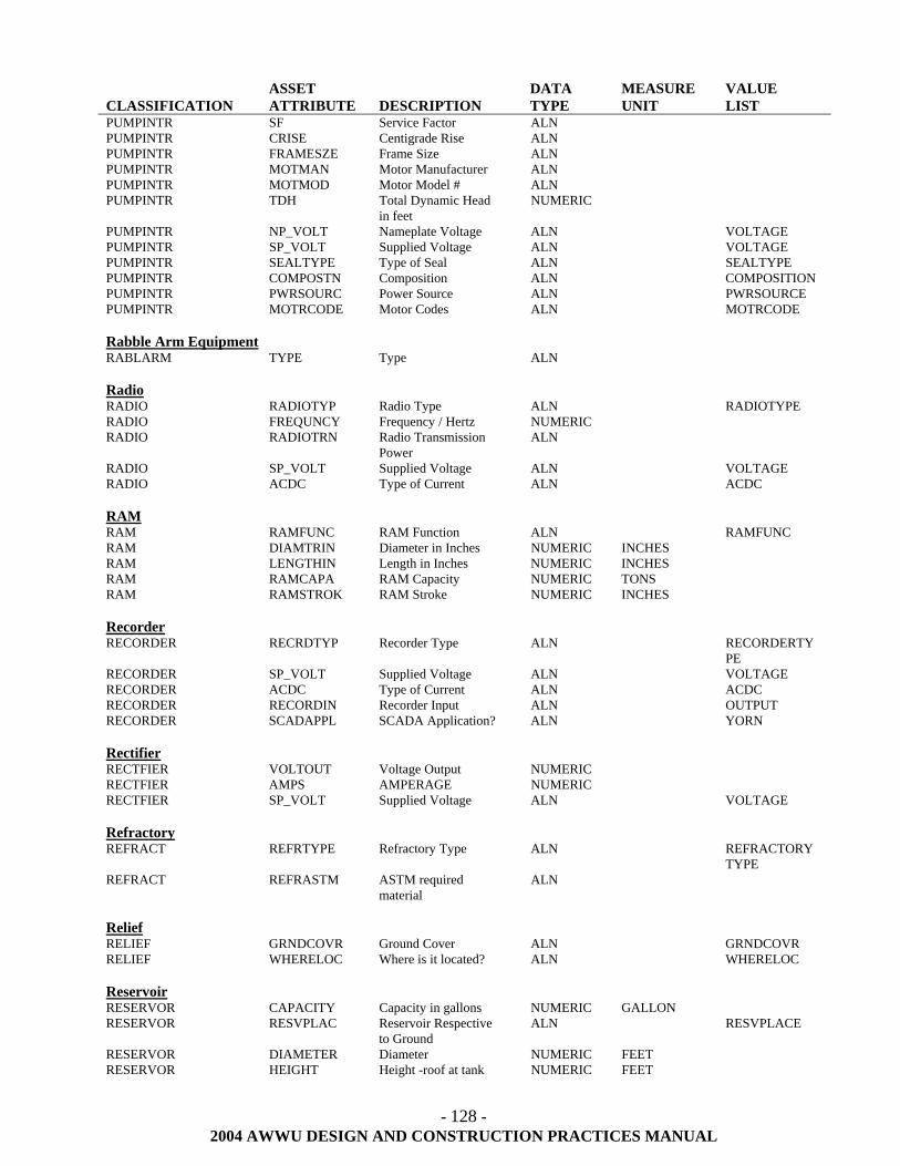
- 128 -
2004 AWWU DESIGN AND CONSTRUCTION PRACTICES MANUAL
CLASSIFICATION
ASSET ATTRIBUTE
DESCRIPTION
DATA TYPE
MEASURE UNIT
VALUE LIST
PUMPINTR SF Service Factor ALN PUMPINTR CRISE Centigrade Rise ALN PUMPINTR FRAMESZE Frame Size ALN PUMPINTR MOTMAN Motor Manufacturer ALN PUMPINTR MOTMOD Motor Model # ALN PUMPINTR TDH Total Dynamic Head
in feet NUMERIC
PUMPINTR NP_VOLT Nameplate Voltage ALN VOLTAGE PUMPINTR SP_VOLT Supplied Voltage ALN VOLTAGE PUMPINTR SEALTYPE Type of Seal ALN SEALTYPE PUMPINTR COMPOSTN Composition ALN COMPOSITION PUMPINTR PWRSOURC Power Source ALN PWRSOURCE PUMPINTR MOTRCODE Motor Codes ALN MOTRCODE Rabble Arm Equipment RABLARM TYPE Type ALN Radio RADIO RADIOTYP Radio Type ALN RADIOTYPE RADIO FREQUNCY Frequency / Hertz NUMERIC RADIO RADIOTRN Radio Transmission
Power ALN
RADIO SP_VOLT Supplied Voltage ALN VOLTAGE RADIO ACDC Type of Current ALN ACDC RAM RAM RAMFUNC RAM Function ALN RAMFUNC RAM DIAMTRIN Diameter in Inches NUMERIC INCHES RAM LENGTHIN Length in Inches NUMERIC INCHES RAM RAMCAPA RAM Capacity NUMERIC TONS RAM RAMSTROK RAM Stroke NUMERIC INCHES Recorder RECORDER RECRDTYP Recorder Type ALN RECORDERTY
PE RECORDER SP_VOLT Supplied Voltage ALN VOLTAGE RECORDER ACDC Type of Current ALN ACDC RECORDER RECORDIN Recorder Input ALN OUTPUT RECORDER SCADAPPL SCADA Application? ALN YORN Rectifier RECTFIER VOLTOUT Voltage Output NUMERIC RECTFIER AMPS AMPERAGE NUMERIC RECTFIER SP_VOLT Supplied Voltage ALN VOLTAGE Refractory REFRACT REFRTYPE Refractory Type ALN REFRACTORY
TYPE REFRACT REFRASTM ASTM required
material ALN
Relief RELIEF GRNDCOVR Ground Cover ALN GRNDCOVR RELIEF WHERELOC Where is it located? ALN WHERELOC Reservoir RESERVOR CAPACITY Capacity in gallons NUMERIC GALLON RESERVOR RESVPLAC Reservoir Respective
to Ground ALN RESVPLACE
RESERVOR DIAMETER Diameter NUMERIC FEET RESERVOR HEIGHT Height -roof at tank NUMERIC FEET
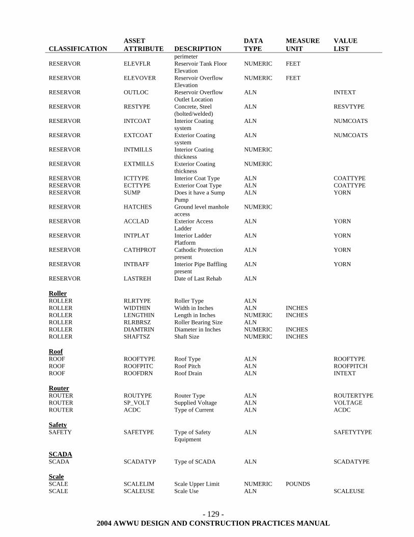
- 129 -
2004 AWWU DESIGN AND CONSTRUCTION PRACTICES MANUAL
CLASSIFICATION
ASSET ATTRIBUTE
DESCRIPTION
DATA TYPE
MEASURE UNIT
VALUE LIST
perimeter RESERVOR ELEVFLR Reservoir Tank Floor
Elevation NUMERIC FEET
RESERVOR ELEVOVER Reservoir Overflow Elevation
NUMERIC FEET
RESERVOR OUTLOC Reservoir Overflow Outlet Location
ALN INTEXT
RESERVOR RESTYPE Concrete, Steel (bolted/welded)
ALN RESVTYPE
RESERVOR INTCOAT Interior Coating system
ALN NUMCOATS
RESERVOR EXTCOAT Exterior Coating system
ALN NUMCOATS
RESERVOR INTMILLS Interior Coating thickness
NUMERIC
RESERVOR EXTMILLS Exterior Coating thickness
NUMERIC
RESERVOR ICTTYPE Interior Coat Type ALN COATTYPE RESERVOR ECTTYPE Exterior Coat Type ALN COATTYPE RESERVOR SUMP Does it have a Sump
Pump ALN YORN
RESERVOR HATCHES Ground level manhole access
NUMERIC
RESERVOR ACCLAD Exterior Access Ladder
ALN YORN
RESERVOR INTPLAT Interior Ladder Platform
ALN YORN
RESERVOR CATHPROT Cathodic Protection present
ALN YORN
RESERVOR INTBAFF Interior Pipe Baffling present
ALN YORN
RESERVOR LASTREH Date of Last Rehab ALN Roller ROLLER RLRTYPE Roller Type ALN ROLLER WIDTHIN Width in Inches ALN INCHES ROLLER LENGTHIN Length in Inches NUMERIC INCHES ROLLER RLRBRSZ Roller Bearing Size ALN ROLLER DIAMTRIN Diameter in Inches NUMERIC INCHES ROLLER SHAFTSZ Shaft Size NUMERIC INCHES Roof ROOF ROOFTYPE Roof Type ALN ROOFTYPE ROOF ROOFPITC Roof Pitch ALN ROOFPITCH ROOF ROOFDRN Roof Drain ALN INTEXT Router ROUTER ROUTYPE Router Type ALN ROUTERTYPE ROUTER SP_VOLT Supplied Voltage ALN VOLTAGE ROUTER ACDC Type of Current ALN ACDC Safety SAFETY SAFETYPE Type of Safety
Equipment ALN SAFETYTYPE
SCADA SCADA SCADATYP Type of SCADA ALN SCADATYPE Scale SCALE SCALELIM Scale Upper Limit NUMERIC POUNDS SCALE SCALEUSE Scale Use ALN SCALEUSE
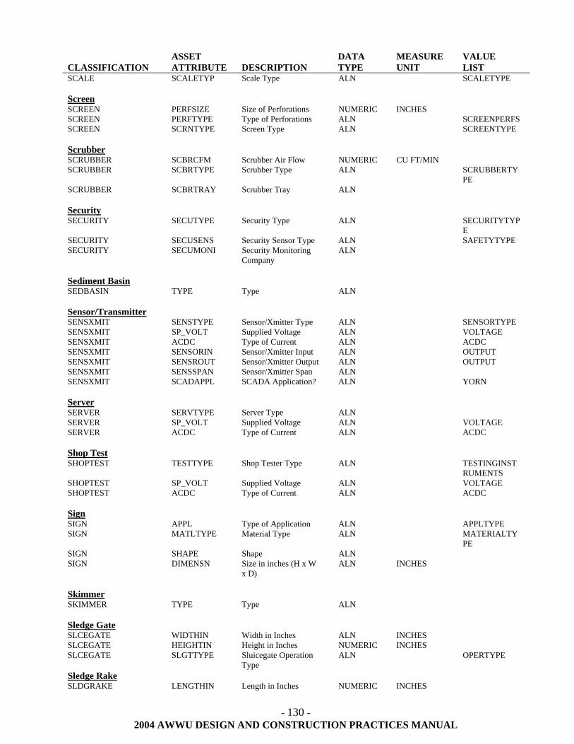
- 130 -
2004 AWWU DESIGN AND CONSTRUCTION PRACTICES MANUAL
CLASSIFICATION
ASSET ATTRIBUTE
DESCRIPTION
DATA TYPE
MEASURE UNIT
VALUE LIST
SCALE SCALETYP Scale Type ALN SCALETYPE Screen SCREEN PERFSIZE Size of Perforations NUMERIC INCHES SCREEN PERFTYPE Type of Perforations ALN SCREENPERFS SCREEN SCRNTYPE Screen Type ALN SCREENTYPE Scrubber SCRUBBER SCBRCFM Scrubber Air Flow NUMERIC CU FT/MIN SCRUBBER SCBRTYPE Scrubber Type ALN SCRUBBERTY
PE SCRUBBER SCBRTRAY Scrubber Tray ALN Security SECURITY SECUTYPE Security Type ALN SECURITYTYP
E SECURITY SECUSENS Security Sensor Type ALN SAFETYTYPE SECURITY SECUMONI Security Monitoring
Company ALN
Sediment Basin SEDBASIN TYPE Type ALN Sensor/Transmitter SENSXMIT SENSTYPE Sensor/Xmitter Type ALN SENSORTYPE SENSXMIT SP_VOLT Supplied Voltage ALN VOLTAGE SENSXMIT ACDC Type of Current ALN ACDC SENSXMIT SENSORIN Sensor/Xmitter Input ALN OUTPUT SENSXMIT SENSROUT Sensor/Xmitter Output ALN OUTPUT SENSXMIT SENSSPAN Sensor/Xmitter Span ALN SENSXMIT SCADAPPL SCADA Application? ALN YORN Server SERVER SERVTYPE Server Type ALN SERVER SP_VOLT Supplied Voltage ALN VOLTAGE SERVER ACDC Type of Current ALN ACDC Shop Test SHOPTEST TESTTYPE Shop Tester Type ALN TESTINGINST
RUMENTS SHOPTEST SP_VOLT Supplied Voltage ALN VOLTAGE SHOPTEST ACDC Type of Current ALN ACDC Sign SIGN APPL Type of Application ALN APPLTYPE SIGN MATLTYPE Material Type ALN MATERIALTY
PE SIGN SHAPE Shape ALN SIGN DIMENSN Size in inches (H x W
x D) ALN INCHES
Skimmer SKIMMER TYPE Type ALN Sledge Gate SLCEGATE WIDTHIN Width in Inches ALN INCHES SLCEGATE HEIGHTIN Height in Inches NUMERIC INCHES SLCEGATE SLGTTYPE Sluicegate Operation
Type ALN OPERTYPE
Sledge Rake SLDGRAKE LENGTHIN Length in Inches NUMERIC INCHES
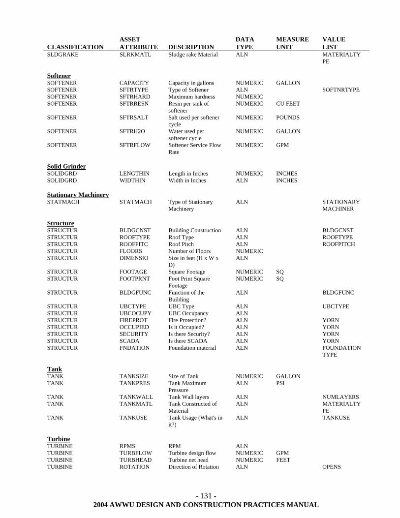
- 131 -
2004 AWWU DESIGN AND CONSTRUCTION PRACTICES MANUAL
CLASSIFICATION
ASSET ATTRIBUTE
DESCRIPTION
DATA TYPE
MEASURE UNIT
VALUE LIST
SLDGRAKE SLRKMATL Sludge rake Material ALN MATERIALTYPE
Softener SOFTENER CAPACITY Capacity in gallons NUMERIC GALLON SOFTENER SFTRTYPE Type of Softener ALN SOFTNRTYPE SOFTENER SFTRHARD Maximum hardness NUMERIC SOFTENER SFTRRESN Resin per tank of
softener NUMERIC CU FEET
SOFTENER SFTRSALT Salt used per softener cycle
NUMERIC POUNDS
SOFTENER SFTRH2O Water used per softener cycle
NUMERIC GALLON
SOFTENER SFTRFLOW Softener Service Flow Rate
NUMERIC GPM
Solid Grinder SOLIDGRD LENGTHIN Length in Inches NUMERIC INCHES SOLIDGRD WIDTHIN Width in Inches ALN INCHES Stationary Machinery STATMACH STATMACH Type of Stationary
Machinery ALN STATIONARY
MACHINER Structure STRUCTUR BLDGCNST Building Construction ALN BLDGCNST STRUCTUR ROOFTYPE Roof Type ALN ROOFTYPE STRUCTUR ROOFPITC Roof Pitch ALN ROOFPITCH STRUCTUR FLOORS Number of Floors NUMERIC STRUCTUR DIMENSIO Size in feet (H x W x
D) ALN
STRUCTUR FOOTAGE Square Footage NUMERIC SQ STRUCTUR FOOTPRNT Foot Print Square
Footage NUMERIC SQ
STRUCTUR BLDGFUNC Function of the Building
ALN BLDGFUNC
STRUCTUR UBCTYPE UBC Type ALN UBCTYPE STRUCTUR UBCOCUPY UBC Occupancy ALN STRUCTUR FIREPROT Fire Protection? ALN YORN STRUCTUR OCCUPIED Is it Occupied? ALN YORN STRUCTUR SECURITY Is there Security? ALN YORN STRUCTUR SCADA Is there SCADA ALN YORN STRUCTUR FNDATION Foundation material ALN FOUNDATION
TYPE Tank TANK TANKSIZE Size of Tank NUMERIC GALLON TANK TANKPRES Tank Maximum
Pressure ALN PSI
TANK TANKWALL Tank Wall layers ALN NUMLAYERS TANK TANKMATL Tank Constructed of
Material ALN MATERIALTY
PE TANK TANKUSE Tank Usage (What's in
it?) ALN TANKUSE
Turbine TURBINE RPMS RPM ALN TURBINE TURBFLOW Turbine design flow NUMERIC GPM TURBINE TURBHEAD Turbine net head NUMERIC FEET TURBINE ROTATION Direction of Rotation ALN OPENS
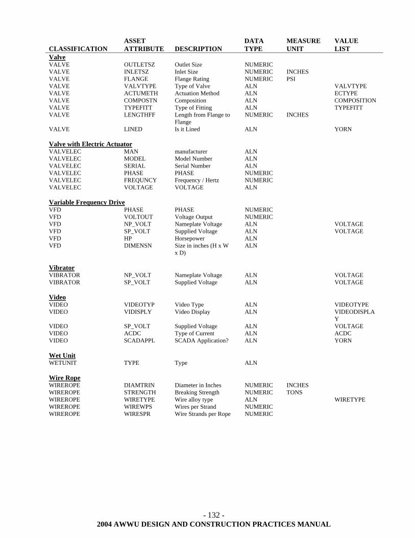
- 132 -
2004 AWWU DESIGN AND CONSTRUCTION PRACTICES MANUAL
CLASSIFICATION
ASSET ATTRIBUTE
DESCRIPTION
DATA TYPE
MEASURE UNIT
VALUE LIST
Valve VALVE OUTLETSZ Outlet Size NUMERIC VALVE INLETSZ Inlet Size NUMERIC INCHES VALVE FLANGE Flange Rating NUMERIC PSI VALVE VALVTYPE Type of Valve ALN VALVTYPE VALVE ACTUMETH Actuation Method ALN ECTYPE VALVE COMPOSTN Composition ALN COMPOSITION VALVE TYPEFITT Type of Fitting ALN TYPEFITT VALVE LENGTHFF Length from Flange to
Flange NUMERIC INCHES
VALVE LINED Is it Lined ALN YORN Valve with Electric Actuator VALVELEC MAN manufacturer ALN VALVELEC MODEL Model Number ALN VALVELEC SERIAL Serial Number ALN VALVELEC PHASE PHASE NUMERIC VALVELEC FREQUNCY Frequency / Hertz NUMERIC VALVELEC VOLTAGE VOLTAGE ALN Variable Frequency Drive VFD PHASE PHASE NUMERIC VFD VOLTOUT Voltage Output NUMERIC VFD NP_VOLT Nameplate Voltage ALN VOLTAGE VFD SP_VOLT Supplied Voltage ALN VOLTAGE VFD HP Horsepower ALN VFD DIMENSN Size in inches (H x W
x D) ALN
Vibrator VIBRATOR NP_VOLT Nameplate Voltage ALN VOLTAGE VIBRATOR SP_VOLT Supplied Voltage ALN VOLTAGE Video VIDEO VIDEOTYP Video Type ALN VIDEOTYPE VIDEO VIDISPLY Video Display ALN VIDEODISPLA
Y VIDEO SP_VOLT Supplied Voltage ALN VOLTAGE VIDEO ACDC Type of Current ALN ACDC VIDEO SCADAPPL SCADA Application? ALN YORN Wet Unit WETUNIT TYPE Type ALN Wire Rope WIREROPE DIAMTRIN Diameter in Inches NUMERIC INCHES WIREROPE STRENGTH Breaking Strength NUMERIC TONS WIREROPE WIRETYPE Wire alloy type ALN WIRETYPE WIREROPE WIREWPS Wires per Strand NUMERIC WIREROPE WIRESPR Wire Strands per Rope NUMERIC
- 133 -
2004 AWWU DESIGN AND CONSTRUCTION PRACTICES MANUAL
70.05 Industrial Coatings Standards
The design of structures that include reservoirs, pipe and appurtenances, pressure reducing equipment, booster pumps, wells, metering equipment, sewage lift pumps, and electrical equipment and controls, shall include specifications for industrial coatings. These specifications will include quality assurance requirements, surface preparation requirements, primers, surface coatings, number of coats, and dry film thickness of applied product and will address both interior linings as well as exterior coatings. Typical facilities to which this standard applies include Pressure Reducing Stations, Booster Stations, Well Houses, Meter Facilities, and Lift and Pump Stations Surfaces to be coated include:
• All piping and appurtenances within the above facilities • All galvanized metal surfaces • All other ferrous metal surfaces • All other surfaces shall be coated per Paragraph 70.05.02, except reservoirs, for which the
designer shall confer directly with AWWU Engineering. 70.05.01 Quality Assurance
Specify that the Contractor provide an independent third-party Inspector who is a NACE (National Association of Corrosion Engineers) Certified Coatings Inspector to examine any and all phases of the work to be performed during the preparation and application as outlined for the project. The contractor shall be responsible for furnishing access to prepared and painted surfaces sufficiently to allow the inspector to verify the product meets the requirements of the specifications.
The Inspector shall supply to the Engineer a report(s) that shall include these minimum elements: Environmental conditions, wet and dry bulb temperatures, steel temperatures, dew points, humidity, tests, work performed, wet and dry coating thickness (mils), pre-cleaning preparation, and coating problems. The contractor shall be required to remedy all deficiencies identified by the inspector and all rework shall be subject to re-inspection and testing.
70.05.02 Coatings and Application Schedule
The designer shall specify coatings “systems” that include minimum requirements for surface preparation (cleaning, profile), primers, and intermediate and top coat film thickness. While there are many coatings system available in the market place, this standard outlines basic guidance on coating selections for various environments.
• For submerged metal in municipal sewage specify SP-5 cleaning criteria and polyamide or coal tar epoxies
• For submerged metal in potable water applications specify SP-5 cleaning criteria and NSF-61 approved epoxy.
• For exposed metal in highly corrosive environments specify SP-10 cleaning criteria, epoxy undercoats and aliphatic polyurethane topcoats for UV resistance, durability, and color and gloss retention.
• For exposed metals in non-corrosive environments specify SP-6 cleaning criteria, all purpose primers, and alkyd enamel topcoats.
• For inside valve bodies and other in-line appurtenances specify fusion-bonded epoxies or elastomeric linings suitable for the intended service. See other standards in this manual regarding the selection of materials for these in-line appurtenances.
- 134 -
2004 AWWU DESIGN AND CONSTRUCTION PRACTICES MANUAL
• For galvanized and non-ferrous (copper, alloys) metal surfaces meet cleaning criteria recommended by the coating manufacturer including any recommended wash primers and use epoxies, (poly)urethanes, or alkyd enamels as dictated by the service conditions.
• Concrete coatings shall be application specific and shall be approved by AWWU Engineering.
• For wood and gypsum wallboard meet cleaning criteria recommended by coating manufacturer, use primer appropriate to the substrate, and apply semi-gloss acrylic latex or alkyd enamel topcoats.
The designer may propose alternative coatings systems on an application specific basis. AWWU will review these alternatives to ensure they exceed the performance of the systems and applications described above. The designer shall propose only those alternatives that have a proven track record under similar service conditions.
70.05.03 Surface Preparation
In general, specify the surface preparation requirements recommended by the coating manufacturer that conform to the standards of the Steel Structures Painting Council (SSPC). However, the minimum SSPC cleaning criteria shall be as noted in Standard 70.05.02 above. Surface preparation specifications shall address treatment of surface defects (pits, weld spatter, etc.) removal of oils and similar foreign substances, the abrasion-blast criteria, and the desired surface profile.
Some surfaces require the use of nonabrasive cleaning techniques during the cleaning process. This may include solvent cleaning, high-pressure water with surfactants, and acid etching. Specify those combinations of methods appropriate to the substrate, the coating, and the ultimate service conditions.
70.05.04 Coating Application
The coatings manufacturer publishes product information specific to the various products it markets. It is essential that the designer be aware of the environmental conditions, application rates, time between coats, time to cure, pot life, shelf life, thinners, and other elements affecting the application process. Also, conditions during the cure period vary for solvent and water-borne coatings – this should be addressed in the specifications. Refer to any special ventilation or personal protective equipment (PPE) required by federal, state, or local regulations.
The designer shall also address those surfaces not intended to receive coatings, such as factory finished motors, rotating-equipment, data nameplates, electrical enclosures, stainless alloys, etc. Protection of this equipment during coating application is essential to project quality standards and the specifications shall be developed describing how the Contractor is to tape, cover, or otherwise protect these surfaces from being coated.
Address the qualifications of the applicator in performing work under conditions similar to those anticipated during construction. Address touch-up of holidays and post-application defects, as well as proper handling, storage, cleanup, and disposal of coatings and the related materials.
Project specifications shall also indicate that spare coating materials shall be provided for touch-up and re-coating by the facility Owner. Finish coat colors are to be coordinated with the facility Owner to provide a uniform appearance with other AWWU facilities.
- 135 -
2004 AWWU DESIGN AND CONSTRUCTION PRACTICES MANUAL
70.06 Supervisory Control and Data Acquisition (SCADA)
70.06.01 Motor Control Centers
Installations require a compartmentalized motor control center (MCC). The MCC is to be mounted on a three and one-half (3 ½) inch house keeping concrete pad. Sufficient pad space is to be provided to allow expansion of the MCC by twenty (20) percent or one (1) column, whichever is greater. The logic controller is not to be housed within the MCC. The following equipment is required, at a minimum:
1. If not available at the facility service entrance, provide a circuit breaker as a main-disconnect.
2. A 120/208-volt lighting transformer in 480-volt applications. 3. A 4-wire load center for building support. 4. Power monitoring equipment.
70.06.02 Motor Starting and Operating Requirements
The following guidelines are to be used for determining motor starting and operating techniques. The first applicable circumstance is to be used.
Electronic Drives:
1. Any application which requires regulation of the process, applied to the system load. 2. Any application in which three-phase power is not readily available and the motor
requirements exceed three horsepower. 3. All applications in which the motor drives a pump used to transport sewage and three-phase
power is not available requires a PWM electronic drive that is capable of producing three (3) phase power for the connected load and meets the requirements of 70.06.03.
Solid-state Starter:
1. Any application having three-phase utility power and load deceleration is required to mitigate the detrimental effects of water-hammer.
2. Any application having three-phase power and the connected equipment is rated as having a full load running current in excess of fourteen (14) amperes.
Conventional Across-the-Line Starter:
3. All remaining single-phase applications not listed above. 4. All remaining three-phase applications not listed above.
70.06.03 Motor Starter Application
The following are requirements for each of the motor starting techniques.
Conventional Across-the-Line (single and three-phase applications):
1. Equipment short-circuit protection is to be provided through the use of a properly applied circuit breaker.
2. Each starter is to employ an appropriately rated Allen-Bradley E3 Plus DeviceNet overload relay. It is to be connected to the DeviceNet network originating from the logic controller.
3. Each starter is to have connected to the load side of the circuit breaker a 120-volt AC control power transformer rated no less than 100VA and in accordance to the application. If the application requires controls for associated field equipment, the equipment is to be powered by this transformer.
- 136 -
2004 AWWU DESIGN AND CONSTRUCTION PRACTICES MANUAL
4. Each starter is to have a switch for locally starting and stopping the motor and in addition, the switch operator shall have contacts for signaling remote and hand operations. Provide a standard Hand-Off-Auto style switch operator. Adjacent to the switch operator, provide a green LED indicating lamp, 30MM trade size, which is on when the associated equipment is operating.
5. All equipment is to be supplied from the same manufacturer. 6. All field terminations are to be made at a Manufacturer’s supplied terminal strip. Field
terminations are not to be made at equipment terminals within the motor controller. 7. See Section 70.06.15 of this manual for a typical across-the-line motor starter wiring
schematic. Solid-State Starter:
1. Equipment short circuit protection is to be provided through the use of a properly applied circuit breaker.
2. All starters are to be of the Allen-Bradley SMC Plus type with the pump control option and a shunting contactor. The starter is to be protected with fast-acting SCR fuses physically located between the shunting contactor line side taps and the electronic starter. In no case are the motor or current carrying conductors to be protected by fuses.
3. Each starter is to employ a properly rated Allen-Bradley E3 Plus DeviceNet overload relay. It is to be connected to the DeviceNet network originating from the logic controller.
4. Each starter is to have connected to the load side of the circuit breaker a control power transformer rated no less than 100VA and in accordance to the application. If the application requires controls for associated field equipment, the equipment is to be powered by this transformer.
5. Each starter is to have a switch for locally starting and stopping the motor and in addition the same, switch operator shall have a position for signaling remote operations, a standard Hand-Off-Auto style switch operator. Adjacent the switch operator there is to be a green LED indicating lamp, 30MM trade size, which is on when the associated equipment is operating.
6. All field terminations are to be made at a Manufacturer’s supplied terminal strip. Field terminations are not to be made at equipment terminals within the motor controller.
7. See Section 70.06.15 of this manual for a typical solid-state motor wiring schematic.
Electronic Drives in Three-phase Applications:
1. Equipment short-circuit protection is to be provided through the use of a properly applied circuit breaker.
2. All electronic drive units are to be manufactured by Allen-Bradley and come from the PowerFlex 700 family of drive units. They are to have the following options: 2.1. Ethernet communications board option. 2.2. Each installed unit is to have a HMI, which allows for local on/off and remote
operation. 2.3. Each drive unit will be controlled by a logic controller through the Ethernet interface.
3. Properly sized five percent line reactors are to be used in accordance with the manufacturer’s recommendations if any of the following conditions exist. 3.1. Line side impedance to the first transformer is less than 1 percent of the total circuit
impedance. 3.2. Presence of power factor correction equipment is employed at any point on the facility
power system.
- 137 -
2004 AWWU DESIGN AND CONSTRUCTION PRACTICES MANUAL
3.3. Installations which have short circuit current of 100,000 amperes or more and the connected load is ten (10) horsepower or less.
3.4. The drive is intended to operate on either a permanent or portable power generator. 3.5. Any facility having an electrical service in excess of 800 amperes. 3.6. Line reactors are not to be used in applications where the drive is used to manufacture a
third phase.
4. Every effort is to be made to keep the distance between the drive unit and the motor as short as possible. The following measures are to be taken when specifying and installing drive and motor support equipment. 4.1. Motor branch circuit conductors shall use cross-linked polyethylene as an insulating
material. Poly-vinyl chlorite is acceptable only as a cable jacket. (For example Belden 29500).
4.2. The installer must demonstrate that the installed equipment will manage common mode currents in a fashion that will not interfere with other sensitive equipment.
4.3. The installer must demonstrate that the drive and support equipment is installed is such a way that reflective wave voltages are not impressed on adjacent systems.
4.4. A test is to be performed at the main disconnect to show that no more than 5 percent total harmonic distortion is present when any combination of drives are operating.
70.06.04 Transfer Switches
Transfer switches are to be members of the MCC, have a DeviceNet connection that incorporates power source availability, transfer switch position and the ability to force a transfer. The generator run request is to be wired to the transfer switch so that loss of utility power sensed at the switch will start the generator. The transfer switch is to be manufactured by ASCO, be of the 7000 series, and appropriately sized for the application.
70.06.05 Power Monitoring
Each facility is to have power monitoring accomplished through the use of an Allen-Bradley Powermonitor 3000, Bulletin 1404-M6, having an Ethernet connection to the local network. The power monitor is to be factory installed and be a member of the MCC.
70.06.06 Process Control and Communications
Each facility requiring process control and/or remote communications is to accomplish this through the use of a logic controller and the Utility’s RF communications system. Communications between nodes are to use an Ethernet 10BaseT system and communicate using the TCP/IP suite of protocols.
The logic controller is to communicate with the equipment in the MCC via DeviceNet, Ethernet, or both. Hardwired connections to the logic controller from the MCC are not permitted with the exception of branch circuits, derived at the load center dedicated to provide operating power for the logic controller.
All Components within the logic controller cabinet, with the exception of the work light and duplex receptacle, are to be powered by a 24-volt Class II DC system. This power system is to have a battery backup capacity that will also power all instruments associated with the facility for no less than six hours for water distribution facilities and twelve hours for wastewater collection facilities.
- 138 -
2004 AWWU DESIGN AND CONSTRUCTION PRACTICES MANUAL
1. All physical Ethernet connections are to be made through an N-Tron 405TX-N DIN rail mounted switch powered by the 24 volt DC system.
2. The RF communications network requires the following equipment. 2.1. A Microwave Data Systems, Inc. EntraNet 900 Wireless IP/Ethernet Transceiver and is
to be physically located in the same cabinet that houses the logic controller. 2.2. Antenna, coaxial cables and fittings shall be furnished and installed by the Contractor:
2.2.1. Antenna type, height, and location are site specific and will be determined by AWWU.
2.2.2. All coaxial cables will have less than 3 dB loss per 100 feet. 2.2.3. Coaxial cable installations shall be unspliced. 2.2.4. The Contractor shall provide a SWR test of the antenna, cabling, and
connectors. The reflected power shall be less than 10 percent of the forward power (= 2:1 SWR).
3. The system batteries are to be no smaller than 108 amp hours. The batteries are to be mounted six (6) inches above the floor using a stainless steel bracket and be adequately secured.
70.06.07 Logic Controllers
Logic controller model selection is determined using the following criteria.
1. If the application requires redundant processing or more than 240 words of memory, the Allen-Bradley ControlLogix series of controller is required.
2. If the memory requirements placed on the logic controller processor by the peripheral I/O modules and DeviceNet equipment is less than 240 words, a CompactLogix family of controller is to be used.
3. The Utility explicitly specifies the controller family, no exceptions. 4. See Section 70.06.15 of this manual for a typical logic controller enclosure and controller
required accessories. 5. The Contractor is to demonstrate connectivity between the logic controller and all field
devices. The equipment is to be delivered fully functional to the manufacturer’s claims. 6. All programming will be done by the AWWU SCADA Department.
70.06.08 Logic Controller Peripherals
Logic controller peripheral modules required by a particular project are to be selected from the following and are dependant on controller family. This is not a complete list of the hardware required to construct a complete and operational system. It is the contractor’s responsibility to identify and incorporate the materials necessary to construct a complete deliverable system. Substitutes for analog and discrete I/O modules are not allowed.
CompactLogix Series:
Central Processor 1769-L35 DeviceNet Scanner 1769-SDN Expansion Power Supply 1769-PB4 Analog Input Module 1769-IF4 Analog Output Module 1769-OF2 Discrete Input Module 1769-IQ16 Discrete Output 1769-OB16
ControlLogix Series:
- 139 -
2004 AWWU DESIGN AND CONSTRUCTION PRACTICES MANUAL
Chassis Series B Power Supply 1756-PB72/B Processor and Memory 1756-L55Mxx ControlNet Bridge 1756-CNB/D Redundancy Module 1756-SRM/B Ethernet/IP Bridge 1756-ENBT Analog Input Module 1756-IF16 Analog Output Module 1756-OF8 Discrete Input Module 1756-IB16 Discrete Output Module 1756-OB16E
70.06.09 Operator Interface
Each facility building is to have an operator interface connected to the network via the Ethernet switch. The interface is to be a facility designed to carry or produce 1 MGD or more which has a stand-by generator equipped with an Allen-Bradley Panel View Plus 1000. All other facilities are required to have the Allen-Bradley Panel View Plus 700.
70.06.10 Process Instruments
Process instruments used in any project are to be of stainless steel construction, have a corrosion resistant electronics housing, produce a 4-20mA linear signal and where possible be two-wire, loop powered devices. The transmitters are to employ the HART communications protocol and have a history of being supported by the Fluke 744 calibration instrument. See Section 70.06.15 of this manual for a typical pressure transmitter piping detail.
1. Pressure and level transmitters are to be supplied from the following manufacturers and be of the specified model:
Endress & Hauser Model PCM 41 Fisher-Rosemount Model 2088 Honeywell Model ST-3000
2. Temperature transmitters for process monitoring are to be supplied from the following manufacturers and be of the specified model. Thermowells and sensors are to be matched by the manufacture to produce a single transmitter unit.
Fisher-Rosemount Model 644 Honeywell Endress & Hauser
3. Insertion flow monitoring transmitters for process equipment shall be : Endress & Hauser Magphant
4. Wetwell level transmitter shall be U.S. Filter A1000 Submersible Level Transducer, or equal. 70.06.11 Facility Heating
The facility heating system(s) are to be controlled via the logic controller. Each room physically isolated from another shall have a separate heating system. Each heating unit is to be powered by a dedicated circuit and breaker. No other equipment is allowed to be powered by a heating circuit.
The natural gas heat is to be operated as the primary source of heat and is to have a thermostat wired in parallel with the control circuit terminated at the logic controller. This circuit is to be on the low voltage side of the heating unit. This thermostat will serve to provide heating control until the logic controller is commissioned, then operate as a backup to the logic controller.
- 140 -
2004 AWWU DESIGN AND CONSTRUCTION PRACTICES MANUAL
Electric heaters shall be manufactured by Chromalox; have a 24 volt power source supplied within the heater for control; and the control circuit shall be controlled by the logic controller. Control conductors are to be members of the building support raceway system 70.06.12. When a facility has three-phase power and the unit heater requirement is in excess of 3 kW, three-phase power is to be used. The circuits are to derive from the MCC in a bucket(s) dedicated for the purpose.
Each room physically isolated is to have a 4-20mA ambient temperature transmitter connected to the logic controller. The transmitter is to provide information for control and monitoring of the facility temperature.
70.06.12 Building Support
Each building is to have the following equipment connected to the logic controller. This equipment is to be serviced by a single raceway system.
1. Allen-Bradley 802T-HP limit switch having an 802MC-W2B switch operating lever at each outside door for intrusion detection. See Section 70.06.15 of this manual.
2. General Electric 541NCRXT smoke detector powered by the 24-volt system. 3. Flood switch mounted two and one-half (2 ½) inches above the floor at the lowest level in
the facility. See Section 70.06.15 of this manual. 4. An appropriately applied voltage monitoring relay that is either an Entrelec PVN type for 3-
phase applications, or an Entrelec ESS single-phase type. Operating power is to be derived from the L series terminals (lineside). The monitor is to: be connected to the first incoming power source; be protected by a circuit breaker no larger than 15 amperes; and be a member of the MCC. Upon voltage loss, the monitor is to open a discrete circuit connected to the DeviceNet network.
The ventilation system is to have a hand-off-auto switch, and wired such that when in the auto position the logic controller can start the ventilation system. No other connection between the logic controller and ventilation system is desired.
Facilities requiring a sump pump are to have a controller that meets the criteria set forth in 70.06.02. The sump float system is to employ Allen-Bradley’s 840-A7 switch, 840-1AD float, and a minimum of one Contractor-supplied rod guide. Mounting and support hardware are to be constructed with stainless steel materials.
Sump pump controllers are to provide hand, auto, fault and run indication to the logic controller. The float(s) are to be wired to the motor controller’s E3 plus overload relay. The logic controller will provide the sump pump run request.
In the event the sump pump is tied to the line side of the main disconnect, the E3 plus overload relay is to be omitted. The float(s) are to control the sump pump directly without intervention from the logic controller. All aforementioned contact closures are to be hardwired as discrete inputs to the logic controller.
70.06.13 Raceway Systems
The number of raceway systems is to be kept to a manageable level and will not be smaller than three-quarter (¾) inch trade size. Raceways are to be constructed using rigid metallic material with threaded fittings. The systems should follow the following guidelines and be filled in compliance to applicable codes.
- 141 -
2004 AWWU DESIGN AND CONSTRUCTION PRACTICES MANUAL
Limit switches, pressure switches, pilot devices, transmitters, and the like are allowed to be connected to the appropriate raceway system using one half (½) LFMC, provided the device has no ports larger than the raceway system. The transition from LFMC to the rigid raceway is to employ a Crouse-Hinds GUA-type box. In no case is the serviced device or the LFMC to provide support for a conduit body. The GUA-type box is to be rigidly supported.
1. Each motor branch circuit is to be housed in a dedicated raceway. 2. All 24-volt discrete circuits, not associated with building support, are to be housed in a single
raceway system. 3. All 120-volt discrete circuits, not associated with building support, are to be housed in a
single raceway system. 4. All analog signals are to be housed in a single raceway system including the ambient
temperature transmitter. In no case is the raceway to be greater than one and one-quarter (1 ¼) inches trade size. When a raceway is filled to eighty (80) percent capacity an additional system is required.
70.06.14 Wiring Practices 1. All panel wiring is to be legibly marked. Each conductor is to be marked at all terminus
points using a permanently marked, heat-shrunk marker. 2. Field wiring is to bear the marking THHN, have a minimum of 19 strands, and be legibly
marked at all terminus points using a permanently marked, heat-shrunk marker. 3. All conductors are to be run from their point of origin to their terminus point without splices
or taps. 4. Conductors used for convenience outlets, general lighting, and bonding need not be included
with 70.06.14.B. 5. Non-current carrying grounded conductors sized #10 AWG or smaller are allowed to be
solid. 6. All current carrying grounded conductors are to have an insulation jacket that is white in
color. Tape is not allowed on conductors #6 AWG or smaller.
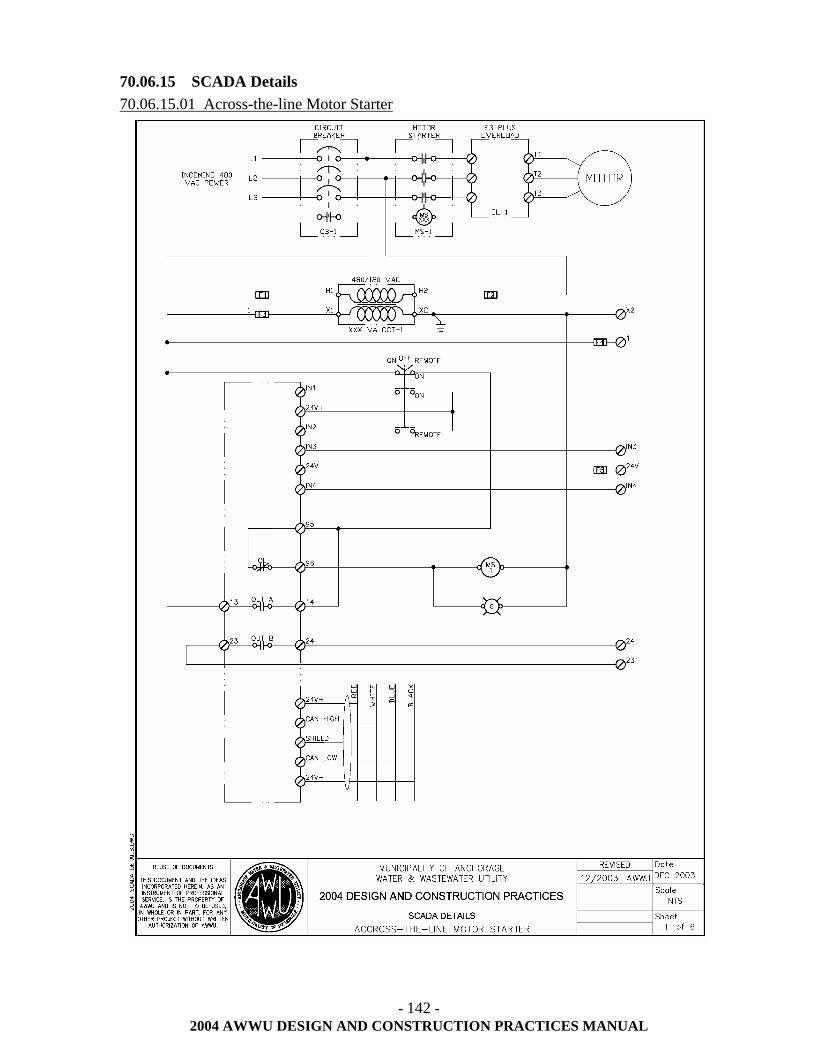
- 142 -
2004 AWWU DESIGN AND CONSTRUCTION PRACTICES MANUAL
70.06.15 SCADA Details 70.06.15.01 Across-the-line Motor Starter
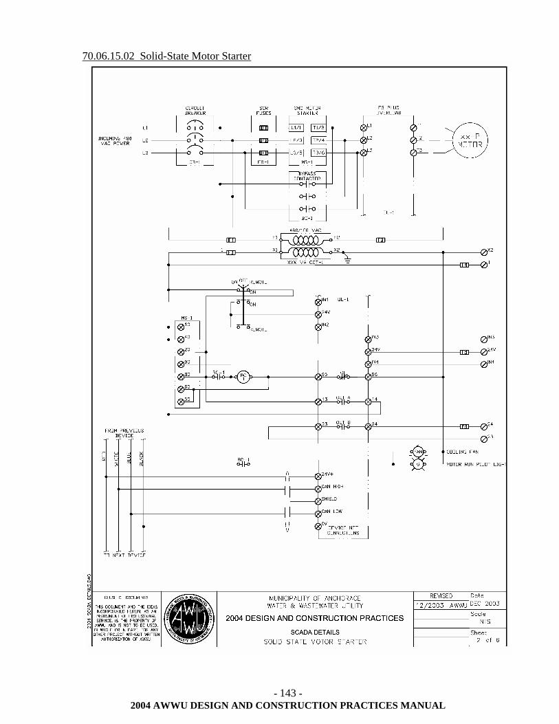
- 143 -
2004 AWWU DESIGN AND CONSTRUCTION PRACTICES MANUAL
70.06.15.02 Solid-State Motor Starter
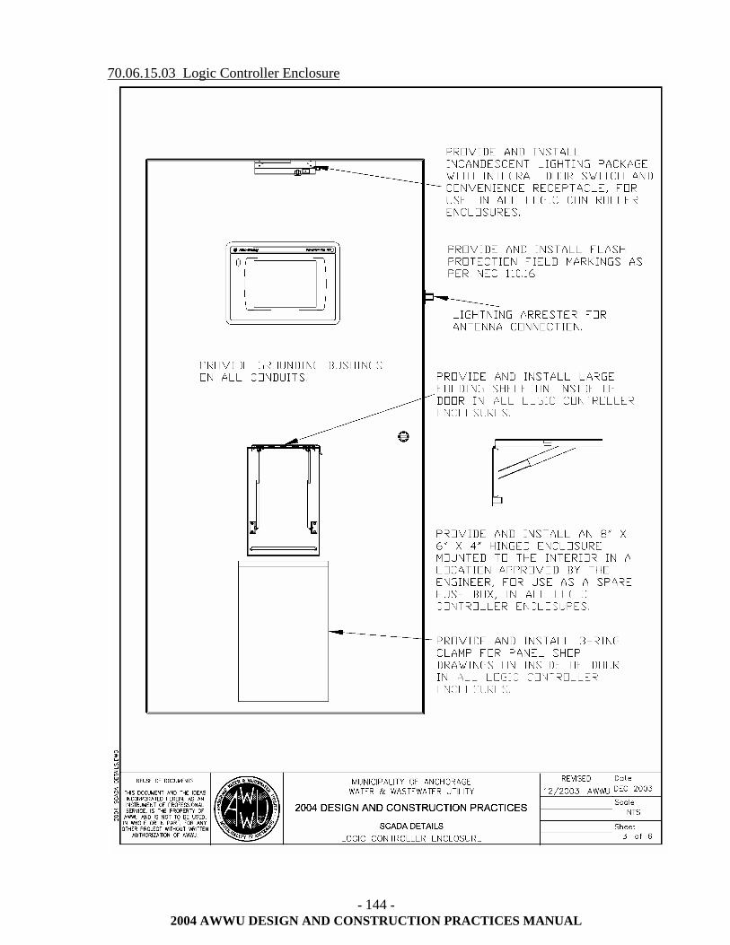
- 144 -
2004 AWWU DESIGN AND CONSTRUCTION PRACTICES MANUAL
70.06.15.03 Logic Controller Enclosure
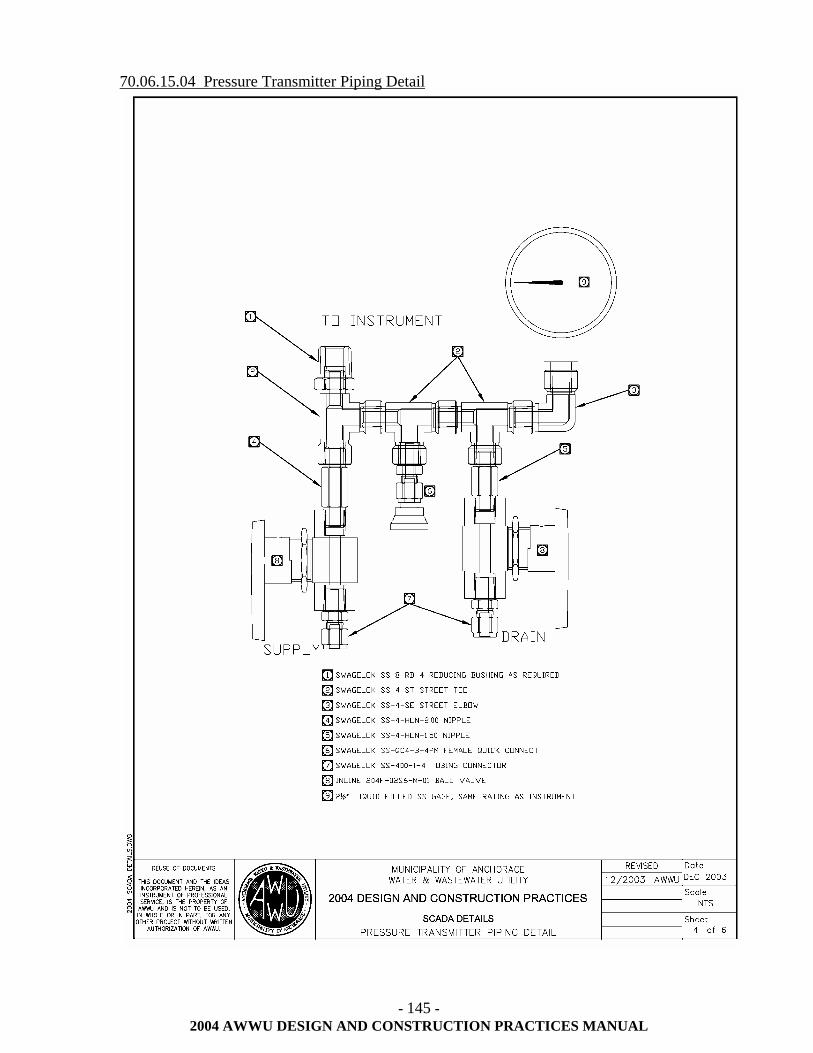
- 145 -
2004 AWWU DESIGN AND CONSTRUCTION PRACTICES MANUAL
70.06.15.04 Pressure Transmitter Piping Detail
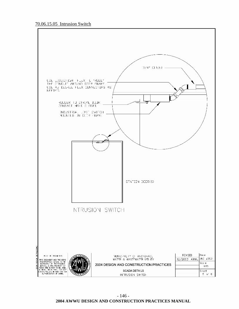
- 146 -
2004 AWWU DESIGN AND CONSTRUCTION PRACTICES MANUAL
70.06.15.05 Intrusion Switch
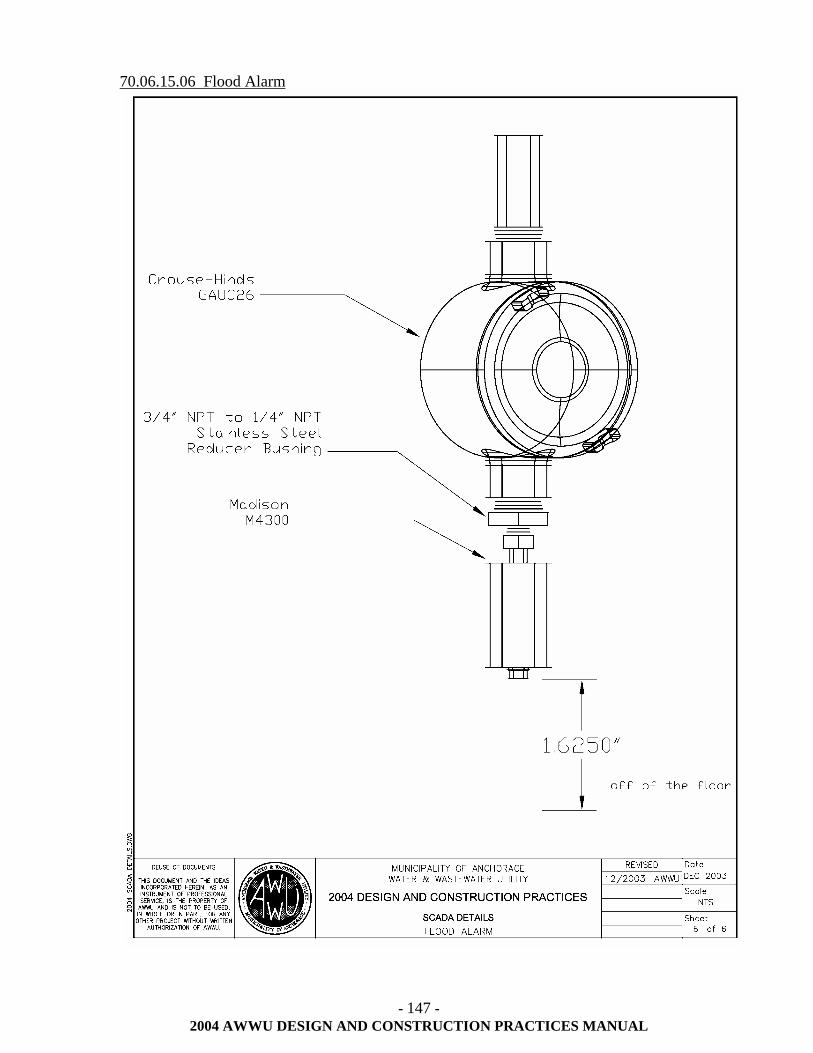
- 147 -
2004 AWWU DESIGN AND CONSTRUCTION PRACTICES MANUAL
70.06.15.06 Flood Alarm