2002-01-2071 ultra light compact economical vehicle concept
TRANSCRIPT
400 Commonwealth Drive, Warrendale, PA 15096-0001 U.S.A. Tel: (724) 776-4841 Fax: (724) 776-5760 Web: www.sae.org
SAE TECHNICALPAPER SERIES 2002-01-2071
Ultra Light Compact Economical Vehicle Concept
Hugh PriceHatwal Whiting
Bernard CriquiRenault
Steve ThompsonLand Rover
Reprinted From: Proceedings of the 2002 SAE International Body Engineering Conferenceand Automotive & Transportation Technology Conference on CD-ROM
(IBAT2002CD)
International Body Engineering Conference & Exhibition andAutomotive & Transportation Technology Conference
Paris, FranceJuly 9–11, 2002
The appearance of this ISSN code at the bottom of this page indicates SAE’s consent that copies of thepaper may be made for personal or internal use of specific clients. This consent is given on the condition,however, that the copier pay a per article copy fee through the Copyright Clearance Center, Inc. OperationsCenter, 222 Rosewood Drive, Danvers, MA 01923 for copying beyond that permitted by Sections 107 or108 of the U.S. Copyright Law. This consent does not extend to other kinds of copying such as copying forgeneral distribution, for advertising or promotional purposes, for creating new collective works, or forresale.
Quantity reprint rates can be obtained from the Customer Sales and Satisfaction Department.
To request permission to reprint a technical paper or permission to use copyrighted SAE publications inother works, contact the SAE Publications Group.
No part of this publication may be reproduced in any form, in an electronic retrieval system or otherwise, without the prior writtenpermission of the publisher.
ISSN 0148-7191Copyright © 2002 Society of Automotive Engineers, Inc.
Positions and opinions advanced in this paper are those of the author(s) and not necessarily those of SAE. The author is solelyresponsible for the content of the paper. A process is available by which discussions will be printed with the paper if it is published inSAE Transactions. For permission to publish this paper in full or in part, contact the SAE Publications Group.
Persons wishing to submit papers to be considered for presentation or publication through SAE should send the manuscript or a 300word abstract of a proposed manuscript to: Secretary, Engineering Meetings Board, SAE.
Printed in USA
All SAE papers, standards, and selectedbooks are abstracted and indexed in theGlobal Mobility Database
2002-01-2071
Ultra Light Compact Economical Vehicle Concept
Hugh PriceHawtal Whiting
Bernard CriquiRenault
Steve ThompsonLand Rover
Copyright © 2002 Society of Automotive Engineers, Inc
ABSTRACT
State of the art demonstrates that weight ofvehicle increases with length of car body.Integration of powertrain in mid rear underfloorlocation enables to shorten car body by morethan 0,5m and to save partially heavylongitudinal members. Underfloor integration ofpower train induces higher stance floor formore conviviality of passengers visibility.Safety factors are improved by lowering gravitycentre, better repartition of front / rear massesduring braking, easier management of crash bystraighter and higher front longitudinalmembers and free front space.Space frame architecture simplifies light weighttechnologies application by using 2D bendedaluminum profiles. Low investment is ensuredby minimising castings application tosuspension attachments and interlinkingupperbody to underbody. Floor and externalpanels are designed for aluminum sheetstampings.
INTRODUCTION
This study has been carried out in the frame ofa themetic network Low Weight Activities« Float » funded by European Commission.The aim of this approach is to identify weightsavings opportunities by changing architectureof car based on the hypothesis that weight isdepending on body size, design and materials.First step is to assume that weight saving isafforded by change in architecture by keepingsimilar interior package as C size class vehiclei.e. Renault Megane Sedan. Second step is toconsider further weight saving by using weightsaving technology i.e. easy design for lightmaterials use. Third step will be to make aglobal weight savings evaluation taking intoaccount induced weight savings via
mechanical components such as enginedownsizing and introducing new technologiesavailable in 2005 year, demonstrating thatmaximum weight saved is achieved withinminimum extracost.
MAIN SECTION
SURVEY OF VEHICLE WEIGHT VERSUSLENGTH – A survey of vehicles proves thehypothesis that the weight of a car increaseswith its length (Fig.1) There are someinstances of lighter weights in older vehiclesvehicles due to less equipment, lowerperformance and also when powered by rearengine
Fig.1 Mass of vehicles versus body length
A further survey of interior of smaller vehicleasseses that there is a proportionality ofinterior length and volume compared withweight (Fig2) This is quite evident that interiorcar increases with car length and is to be keptsimilar for coherent weight saving approach.
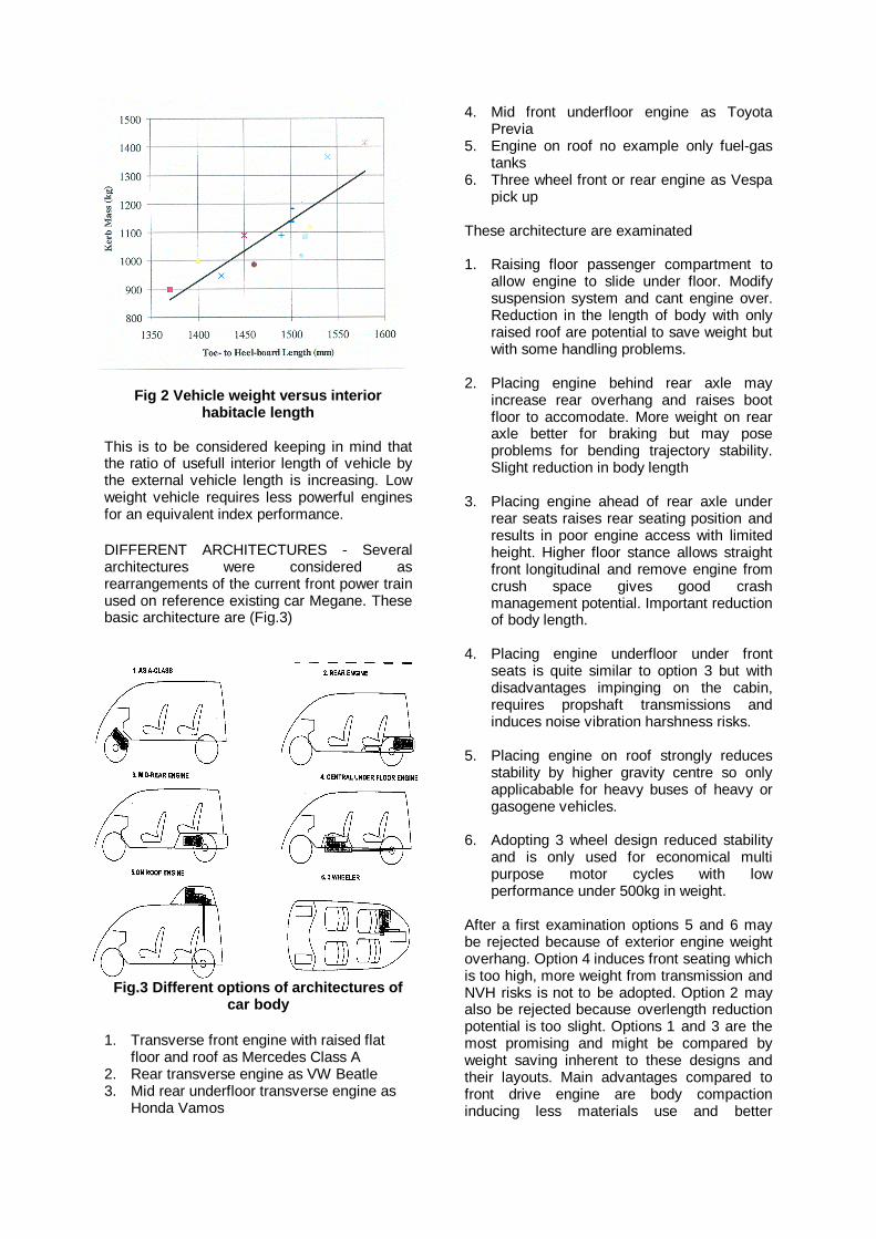
Fig 2 Vehicle weight versus interiorhabitacle length
This is to be considered keeping in mind thatthe ratio of usefull interior length of vehicle bythe external vehicle length is increasing. Lowweight vehicle requires less powerful enginesfor an equivalent index performance.
DIFFERENT ARCHITECTURES - Severalarchitectures were considered asrearrangements of the current front power trainused on reference existing car Megane. Thesebasic architecture are (Fig.3)
Fig.3 Different options of architectures ofcar body
1. Transverse front engine with raised flatfloor and roof as Mercedes Class A
2. Rear transverse engine as VW Beatle3. Mid rear underfloor transverse engine as
Honda Vamos
4. Mid front underfloor engine as ToyotaPrevia
5. Engine on roof no example only fuel-gastanks
6. Three wheel front or rear engine as Vespapick up
These architecture are examinated
1. Raising floor passenger compartment toallow engine to slide under floor. Modifysuspension system and cant engine over.Reduction in the length of body with onlyraised roof are potential to save weight butwith some handling problems.
2. Placing engine behind rear axle mayincrease rear overhang and raises bootfloor to accomodate. More weight on rearaxle better for braking but may poseproblems for bending trajectory stability.Slight reduction in body length
3. Placing engine ahead of rear axle underrear seats raises rear seating position andresults in poor engine access with limitedheight. Higher floor stance allows straightfront longitudinal and remove engine fromcrush space gives good crashmanagement potential. Important reductionof body length.
4. Placing engine underfloor under frontseats is quite similar to option 3 but withdisadvantages impinging on the cabin,requires propshaft transmissions andinduces noise vibration harshness risks.
5. Placing engine on roof strongly reducesstability by higher gravity centre so onlyapplicabable for heavy buses of heavy orgasogene vehicles.
6. Adopting 3 wheel design reduced stabilityand is only used for economical multipurpose motor cycles with lowperformance under 500kg in weight.
After a first examination options 5 and 6 maybe rejected because of exterior engine weightoverhang. Option 4 induces front seating whichis too high, more weight from transmission andNVH risks is not to be adopted. Option 2 mayalso be rejected because overlength reductionpotential is too slight. Options 1 and 3 are themost promising and might be compared byweight saving inherent to these designs andtheir layouts. Main advantages compared tofront drive engine are body compactioninducing less materials use and better
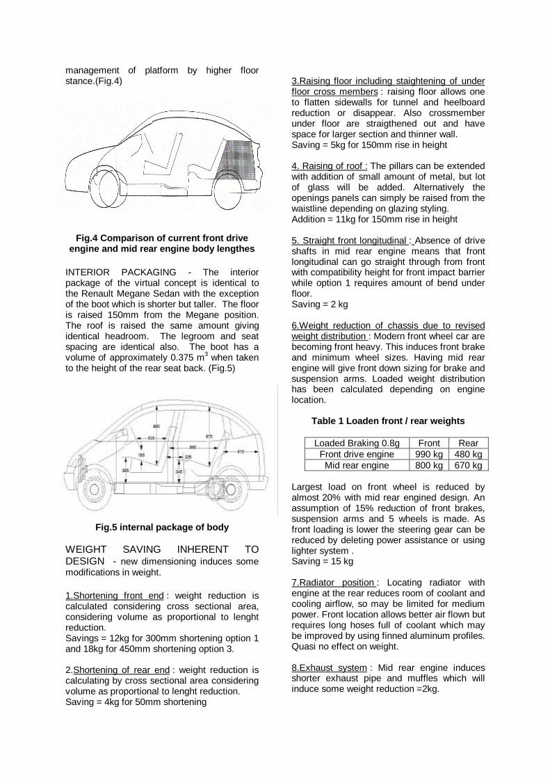
management of platform by higher floorstance.(Fig.4)
Fig.4 Comparison of current front driveengine and mid rear engine body lengthes
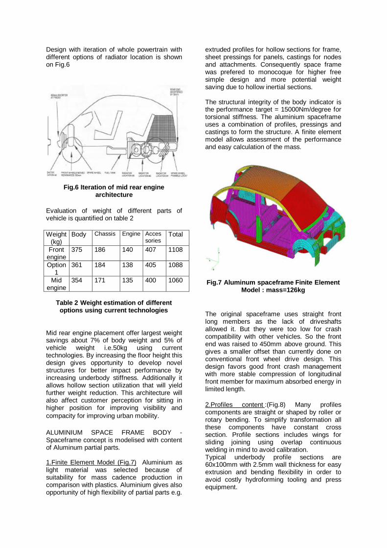
INTERIOR PACKAGING - The interiorpackage of the virtual concept is identical tothe Renault Megane Sedan with the exceptionof the boot which is shorter but taller. The flooris raised 150mm from the Megane position.The roof is raised the same amount givingidentical headroom. The legroom and seatspacing are identical also. The boot has avolume of approximately 0.375 m3 when takento the height of the rear seat back. (Fig.5)
Fig.5 internal package of body
WEIGHT SAVING INHERENT TODESIGN - new dimensioning induces somemodifications in weight.
1.Shortening front end : weight reduction iscalculated considering cross sectional area,considering volume as proportional to lenghtreduction.Savings = 12kg for 300mm shortening option 1and 18kg for 450mm shortening option 3.
2.Shortening of rear end : weight reduction iscalculating by cross sectional area consideringvolume as proportional to lenght reduction.Saving = 4kg for 50mm shortening
3.Raising floor including staightening of underfloor cross members : raising floor allows oneto flatten sidewalls for tunnel and heelboardreduction or disappear. Also crossmemberunder floor are straigthened out and havespace for larger section and thinner wall.Saving = 5kg for 150mm rise in height
4. Raising of roof : The pillars can be extendedwith addition of small amount of metal, but lotof glass will be added. Alternatively theopenings panels can simply be raised from thewaistline depending on glazing styling.Addition = 11kg for 150mm rise in height
5. Straight front longitudinal : Absence of driveshafts in mid rear engine means that frontlongitudinal can go straight through from frontwith compatibility height for front impact barrierwhile option 1 requires amount of bend underfloor.Saving = 2 kg
6.Weight reduction of chassis due to revisedweight distribution : Modern front wheel car arebecoming front heavy. This induces front brakeand minimum wheel sizes. Having mid rearengine will give front down sizing for brake andsuspension arms. Loaded weight distributionhas been calculated depending on enginelocation.
Table 1 Loaden front / rear weights
Loaded Braking 0.8g Front RearFront drive engine 990 kg 480 kgMid rear engine 800 kg 670 kg
Largest load on front wheel is reduced byalmost 20% with mid rear engined design. Anassumption of 15% reduction of front brakes,suspension arms and 5 wheels is made. Asfront loading is lower the steering gear can bereduced by deleting power assistance or usinglighter system .Saving = 15 kg
7.Radiator position : Locating radiator withengine at the rear reduces room of coolant andcooling airflow, so may be limited for mediumpower. Front location allows better air flown butrequires long hoses full of coolant which maybe improved by using finned aluminum profiles.Quasi no effect on weight.
8.Exhaust system : Mid rear engine inducesshorter exhaust pipe and muffles which willinduce some weight reduction =2kg.
Design with iteration of whole powertrain withdifferent options of radiator location is shownon Fig.6
Fig.6 Iteration of mid rear enginearchitecture
Evaluation of weight of different parts ofvehicle is quantified on table 2
Weight(kg)
Body Chassis Engine Accessories
Total
Frontengine
375 186 140 407 1108
Option1
361 184 138 405 1088
Midengine
354 171 135 400 1060
Table 2 Weight estimation of differentoptions using current technologies
Mid rear engine placement offer largest weightsavings about 7% of body weight and 5% ofvehicle weight i.e.50kg using currenttechnologies. By increasing the floor height thisdesign gives opportunity to develop novelstructures for better impact performance byincreasing underbody stiffness. Additionally itallows hollow section utilization that will yieldfurther weight reduction. This architecture willalso affect customer perception for sitting inhigher position for improving visibility andcompacity for improving urban mobility.
ALUMINIUM SPACE FRAME BODY -Spaceframe concept is modelised with contentof Aluminum partial parts.
1.Finite Element Model (Fig.7) Aluminium aslight material was selected because ofsuitability for mass cadence production incomparison with plastics. Aluminium gives alsoopportunity of high flexibility of partial parts e.g.
extruded profiles for hollow sections for frame,sheet pressings for panels, castings for nodesand attachments. Consequently space framewas prefered to monocoque for higher freesimple design and more potential weightsaving due to hollow inertial sections.
The structural integrity of the body indicator isthe performance target = 15000Nm/degree fortorsional stiffness. The aluminium spaceframeuses a combination of profiles, pressings andcastings to form the structure. A finite elementmodel allows assessment of the performanceand easy calculation of the mass.
Fig.7 Aluminum spaceframe Finite ElementModel : mass=126kg
The original spaceframe uses straight frontlong members as the lack of driveshaftsallowed it. But they were too low for crashcompatibility with other vehicles. So the frontend was raised to 450mm above ground. Thisgives a smaller offset than currently done onconventional front wheel drive design. Thisdesign favors good front crash managementwith more stable compression of longitudinalfront member for maximum absorbed energy inlimited length.
2.Profiles content :(Fig.8) Many profilescomponents are straight or shaped by roller orrotary bending. To simplify transformation allthese components have constant crosssection. Profile sections includes wings forsliding joining using overlap continuouswelding in mind to avoid calibration.Typical underbody profile sections are60x100mm with 2.5mm wall thickness for easyextrusion and bending flexibility in order toavoid costly hydroforming tooling and pressequipment.
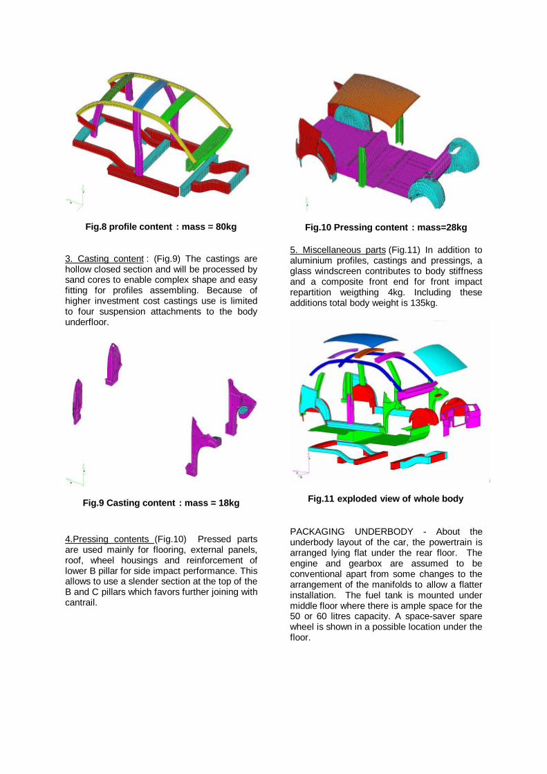
Fig.8 profile content : mass = 80kg
3. Casting content : (Fig.9) The castings arehollow closed section and will be processed bysand cores to enable complex shape and easyfitting for profiles assembling. Because ofhigher investment cost castings use is limitedto four suspension attachments to the bodyunderfloor.
Fig.9 Casting content : mass = 18kg
4.Pressing contents (Fig.10) Pressed partsare used mainly for flooring, external panels,roof, wheel housings and reinforcement oflower B pillar for side impact performance. Thisallows to use a slender section at the top of theB and C pillars which favors further joining withcantrail.
Fig.10 Pressing content : mass=28kg
5. Miscellaneous parts (Fig.11) In addition toaluminium profiles, castings and pressings, aglass windscreen contributes to body stiffnessand a composite front end for front impactrepartition weigthing 4kg. Including theseadditions total body weight is 135kg.
Fig.11 exploded view of whole body
PACKAGING UNDERBODY - About theunderbody layout of the car, the powertrain isarranged lying flat under the rear floor. Theengine and gearbox are assumed to beconventional apart from some changes to thearrangement of the manifolds to allow a flatterinstallation. The fuel tank is mounted undermiddle floor where there is ample space for the50 or 60 litres capacity. A space-saver sparewheel is shown in a possible location under thefloor.
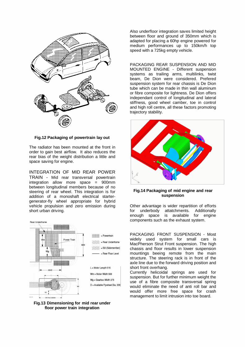
Fig.12 Packaging of powertrain lay out
The radiator has been mounted at the front inorder to gain best airflow. It also reduces therear bias of the weight distribution a little andspace saving for engine.
INTEGRATION OF MID REAR POWERTRAIN - Mid rear transversal powertrainintegration allow more space = 900mmbetween longitudinal members because of nosteering of rear wheel. This integration is foraddition of a monoshaft electrical starter-generator-fly wheel appropriate for hybridvehicle propulsion and zero emission duringshort urban driving.
Fig.13 Dimensioning for mid rear underfloor power train integration
Also underfloor integration saves limited heightbetween floor and ground of 350mm which isadapted for placing a 60hp engine powered formedium performances up to 150km/h topspeed with a 725kg empty vehicle.
PACKAGING REAR SUSPENSION AND MIDMOUNTED ENGINE - Different suspensionsystems as trailing arms, multilinks, twistbeam, De Dion were considered. Preferedsuspension system for rear chassis is De Diontube which can be made in thin wall aluminumor fibre composite for lightness. De Dion offersindependant control of longitudinal and lateralstiffness, good wheel camber, toe in controland high roll centre, all these factors promotingtrajectory stability.
Fig.14 Packaging of mid engine and rearsuspension
Other advantage is wider repartition of effortsfor underbody attatchments. Additionallyenough space is available for enginecomponents such as the exhaust system.
PACKAGING FRONT SUSPENSION - Mostwidely used system for small cars isMacPherson Strut Front suspension. The highchassis and floor results in lower suspensionmountings beeing remote from the mainstructure. The steering rack is in front of theaxle line due to the forward driving position andshort front overhang.Currently helicoidal springs are used forsuspension. But for further minimum weight theuse of a fibre composite transversal springwould eliminate the need of anti roll bar andwould offer more free space for crashmanagement to limit intrusion into toe board.
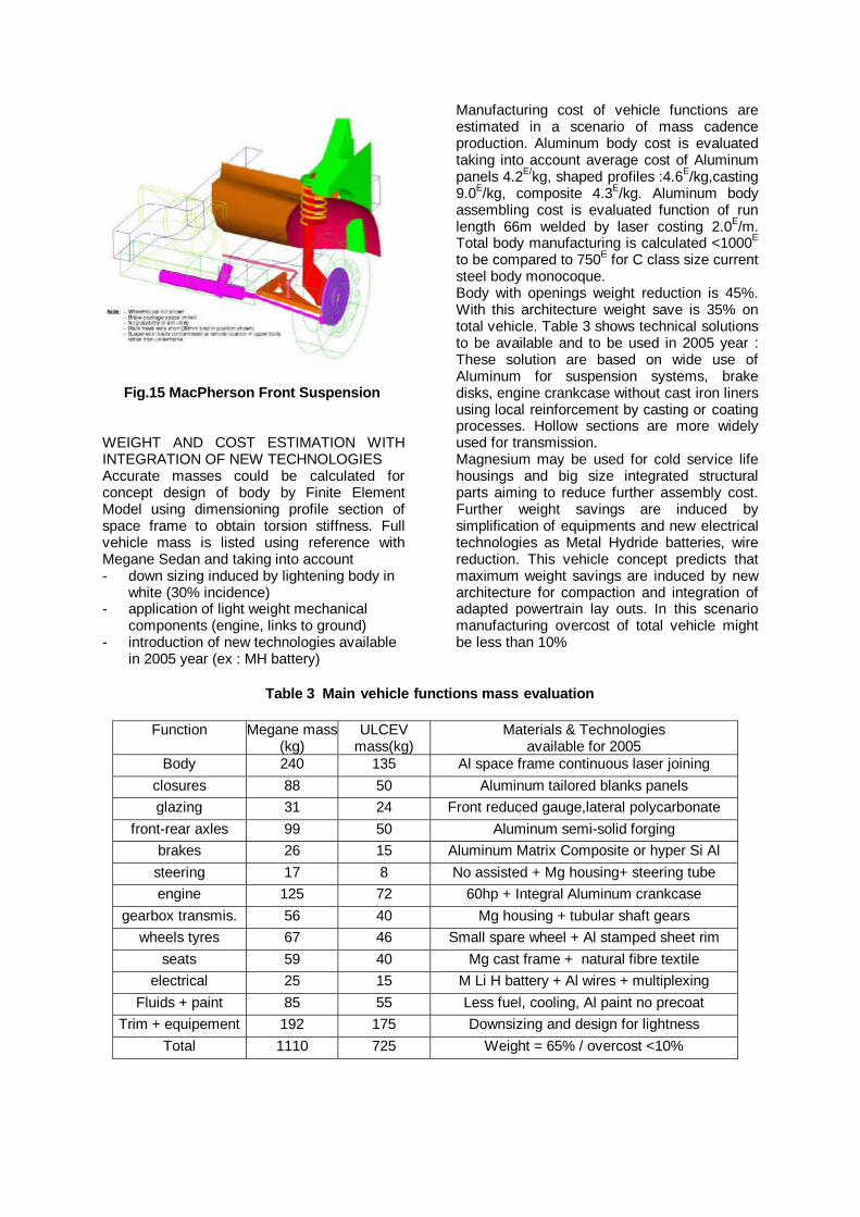
Fig.15 MacPherson Strut suspension
Fig.15 MacPherson Front Suspension
WEIGHT AND COST ESTIMATION WITHINTEGRATION OF NEW TECHNOLOGIESAccurate masses could be calculated forconcept design of body by Finite ElementModel using dimensioning profile section ofspace frame to obtain torsion stiffness. Fullvehicle mass is listed using reference withMegane Sedan and taking into account- down sizing induced by lightening body in
white (30% incidence)- application of light weight mechanical
components (engine, links to ground)- introduction of new technologies available
in 2005 year (ex : MH battery)
Manufacturing cost of vehicle functions areestimated in a scenario of mass cadenceproduction. Aluminum body cost is evaluatedtaking into account average cost of Aluminumpanels 4.2E/kg, shaped profiles :4.6E/kg,casting9.0E/kg, composite 4.3E/kg. Aluminum bodyassembling cost is evaluated function of runlength 66m welded by laser costing 2.0E/m.Total body manufacturing is calculated <1000E
to be compared to 750E for C class size currentsteel body monocoque.Body with openings weight reduction is 45%.With this architecture weight save is 35% ontotal vehicle. Table 3 shows technical solutionsto be available and to be used in 2005 year :These solution are based on wide use ofAluminum for suspension systems, brakedisks, engine crankcase without cast iron linersusing local reinforcement by casting or coatingprocesses. Hollow sections are more widelyused for transmission.Magnesium may be used for cold service lifehousings and big size integrated structuralparts aiming to reduce further assembly cost.Further weight savings are induced bysimplification of equipments and new electricaltechnologies as Metal Hydride batteries, wirereduction. This vehicle concept predicts thatmaximum weight savings are induced by newarchitecture for compaction and integration ofadapted powertrain lay outs. In this scenariomanufacturing overcost of total vehicle mightbe less than 10%
Table 3 Main vehicle functions mass evaluation
Function Megane mass(kg)
ULCEVmass(kg)
Materials & Technologiesavailable for 2005
Body 240 135 Al space frame continuous laser joiningclosures 88 50 Aluminum tailored blanks panelsglazing 31 24 Front reduced gauge,lateral polycarbonate
front-rear axles 99 50 Aluminum semi-solid forgingbrakes 26 15 Aluminum Matrix Composite or hyper Si Al
steering 17 8 No assisted + Mg housing+ steering tubeengine 125 72 60hp + Integral Aluminum crankcase
gearbox transmis. 56 40 Mg housing + tubular shaft gearswheels tyres 67 46 Small spare wheel + Al stamped sheet rim
seats 59 40 Mg cast frame + natural fibre textileelectrical 25 15 M Li H battery + Al wires + multiplexing
Fluids + paint 85 55 Less fuel, cooling, Al paint no precoatTrim + equipement 192 175 Downsizing and design for lightness
Total 1110 725 Weight = 65% / overcost <10%
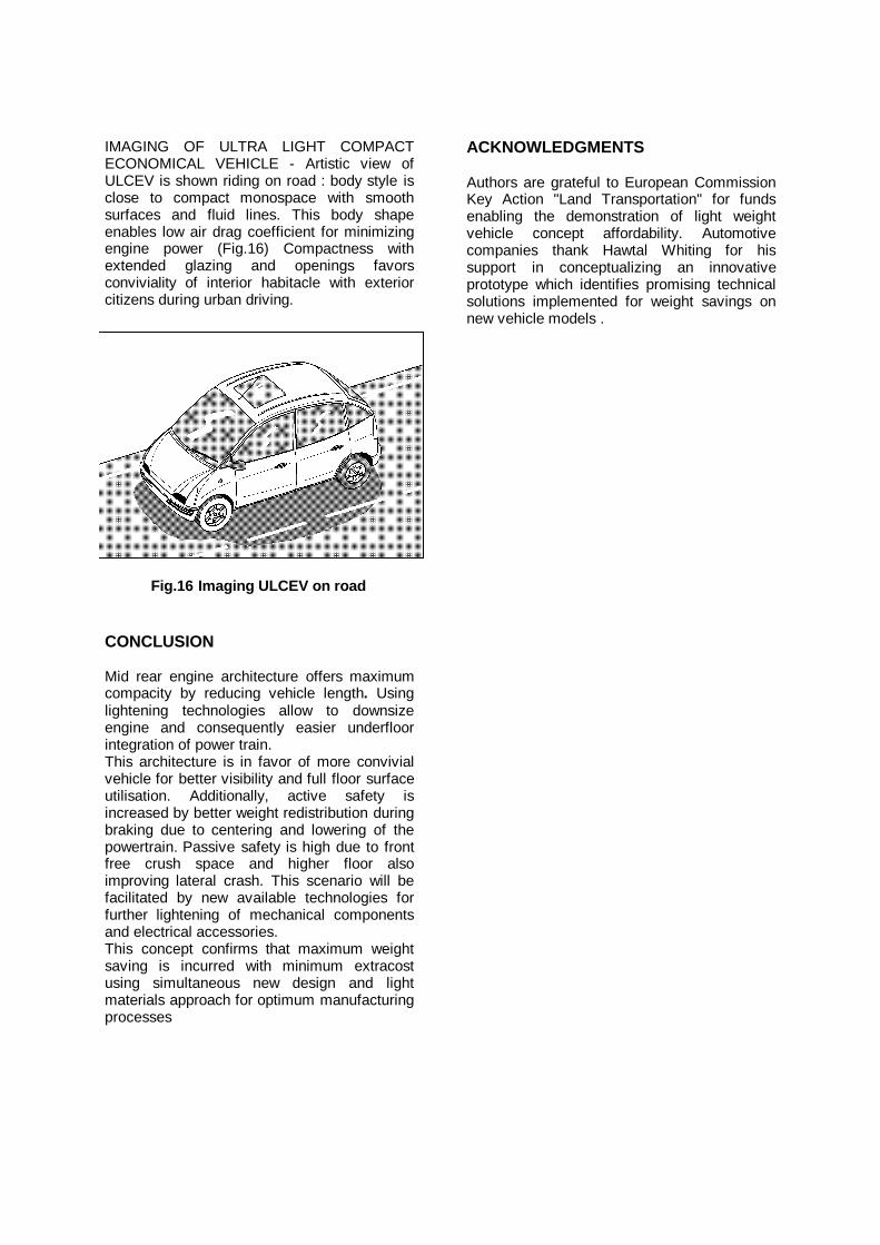
IMAGING OF ULTRA LIGHT COMPACTECONOMICAL VEHICLE - Artistic view ofULCEV is shown riding on road : body style isclose to compact monospace with smoothsurfaces and fluid lines. This body shapeenables low air drag coefficient for minimizingengine power (Fig.16) Compactness withextended glazing and openings favorsconviviality of interior habitacle with exteriorcitizens during urban driving.
Fig.16 Imaging ULCEV on road
CONCLUSION
Mid rear engine architecture offers maximumcompacity by reducing vehicle length. Usinglightening technologies allow to downsizeengine and consequently easier underfloorintegration of power train.This architecture is in favor of more convivialvehicle for better visibility and full floor surfaceutilisation. Additionally, active safety isincreased by better weight redistribution duringbraking due to centering and lowering of thepowertrain. Passive safety is high due to frontfree crush space and higher floor alsoimproving lateral crash. This scenario will befacilitated by new available technologies forfurther lightening of mechanical componentsand electrical accessories.This concept confirms that maximum weightsaving is incurred with minimum extracostusing simultaneous new design and lightmaterials approach for optimum manufacturingprocesses
ACKNOWLEDGMENTS
Authors are grateful to European CommissionKey Action "Land Transportation" for fundsenabling the demonstration of light weightvehicle concept affordability. Automotivecompanies thank Hawtal Whiting for hissupport in conceptualizing an innovativeprototype which identifies promising technicalsolutions implemented for weight savings onnew vehicle models .