13.6 overall structural behaviour 13.7 design of structural components
TRANSCRIPT
investigated in depth and confirmed in the findings of a reportby Walker and Gray.6
The advantages of using profiled steel decking may thereforebe summarized for both composite and noncomposite floors asfollows:
(1) Steel decks provide permanent formwork and do not nor-mally require the use of additional temporary formwork orpropping.
(2) The low weight of the steel deck unit means they can bemanhandled with comparative ease, thus reducing or elimi-nating mechanical handling costs.
(3) Faster construction times are obtained with improvedsafety.
(4) Maximum efficiency and cost-effectiveness is obtainedwhere regular grids are adopted, although the designer hasfreedom to arrange the structural support framing to ac-commodate irregular shapes.
(5) For floors acting compositely there is an efficient use of thetwo basic construction materials of steel and concrete, sincethe steel deck acts as both formwork and tensile reinforce-ment.
13.6 Overall structural behaviour
Having referred frequently to British Standards for design, i.e.BS 449, BS 153, BS 5400, BS 5500 and BS 5950, a word ofcaution is warranted. These documents, as all British Standards,are drafted by committees of experienced people drawn from allquarters, charged with the task of formulating design rules inthe light of the state of knowledge at the time, incorporating thebest modern practice and exploiting the latest research. This isno easy task. They recognize that many of those who would usethe documents would not understand, indeed would not want tounderstand, the background theory behind many of the require-ments. Inevitably, many areas of doubt and uncertainty areencountered and differences of opinion expressed. At the end ofthe day, they rightly tend on the conservative side in suchsituations though, in one or two instances, subsequent researchhas indicated that their rules were not sufficiently cautious in theearlier standards. However, these documents have stood the testof time and, by and large, when properly interpreted result instructures in which safety and economy are reasonably inbalance. But they tended to lay undue emphasis on the determi-nation of exact values of permissible stresses and insufficientattention (certainly in the case of BS 449) to questions of overallstructural behaviour and stability, particularly during erection.
The young designer can be forgiven for supposing that, if allmembers and connections in a structure are assessed anddesigned strictly in accordance with the British Standard, thenthe complete structure will be adequate for its task. In the greatmajority of cases this will be so, but in rare instances it has beenfound to be a fatal error. In a number of cases the designer has,unconsciously perhaps, relied on the stiffening effect of thecladding to provide overall stability and a collapse has occurred,sometimes under the weight of an erection crane before thecladding has been fixed. What one does not know, and cannotassess, is how many structures are satisfactorily in service whichwere within a hair's breadth of collapse at some stage duringerection. As an illustration, it may seem an economic solution inthe design of a frame for a multistorey building to have anumber of load-carrying plane frames, interconnected with lightties. In the absence of temporary bracing, such a structure reliesfor stability on the stiffness of the joints at the ends of the tiebeams. Such joints, being on nominally unloaded or lightmembers, are often regarded as being unimportant and aresometimes detailed as simple connections, instead of joints
which have some moment capacity. Thus, in the unclad state theframe possesses insufficient longitudinal stability. This illustra-tion is but one of many which could have been quoted but it ishoped that the point has been driven home. Overall supervisionof the design of both members and connections by a competentengineer, and the intelligent assessment of the problems by theerection supervisor, should be sufficient to prevent such mis-haps.
The stiffening effect of cladding, which has been referred to, isvery great indeed but, except in the case of very simple struc-tures, it is likely to remain impossible to assess in the foreseeablefuture. Because of this and because of the accidental andunquantifiable composite action which occurs between steelmembers and other materials, the actual stresses experienced inservice are likely to be very different and usually much lowerthan those calculated. This fact, coupled with the fact thatloadings which are specified, particularly wind loadings, are atbest only general estimates, means that great nicety of calcula-tion is largely misplaced. Thus, the pursuit of notional absoluteeconomy is a cardinal error if it means that under pressure oftime the consideration of overall behaviour is omitted.
A related problem frequently encountered and on which littleguidance is available, concerns the amount of sway or hori-zontal deflection permitted at the top of a tall multistoreybuilding under wind loading. It has been common to limit suchsway to 1/500 of the height, calculated on the stiffness of thebare steel frame. This largely begs the question, since most ofthe wind force would be absent without cladding. With it inplace, the deflection must be considerably reduced in conse-quence of its stiffening effect. What is being considered here isnot structural safety - that is not in question - but serviceability.In the absence of any knowledge at all of cases where discomforthas been caused to occupants or damage to finishes throughexcessive sway, the authors conclude that the above notionallimit is conservative. Clearly, long-term observations are calledfor which may take years to yield worthwhile data. Meanwhile,it is suggested that if the above limitation is deemed acceptablefor dwellings with curtain walling, then relaxation of the limi-tation would seem appropriate in respect of two factors:(1) other uses; and (2) stiffer cladding. Again, in city centres,the sheltering effect of neighbouring buildings may be taken intoaccount in assessing wind forces. Is one to take into account thepossibility of some, or all, of them being demolished some timein the future? Such considerations need careful assessment, andauthoritative advice.
13.7 Design of structural components
There would seem little point in including worked examples inthis section, in view of the fact that the old design standards areunlikely to be used for most new projects, whilst designs to thenew standards are doubtless covered in numerous recent publi-cations such as that by the Steel Construction Institute.
13.7.1 Importance of correct loading assessment
Great care should be taken in the assessment of dead and liveloading, as mistakes at this stage can make all subsequentcalculations abortive and, in extreme cases, result in completedmembers being scrapped. This has been known to happen andunfortunately not all that infrequently. Some common causes ofmistakes in this matter are: (1) failing to make adequate allow-ances for finishes as, for instance, in providing screeding to fallsin a roof slab to provide adequate drainage; (2) failure to makeproper allowance for surges in gantry structures; (3) incorrectinterpretation of wind loading requirements; and (4) effect onpressure of flow in granular materials, etc. Safety requires that a
full loading schedule for the intended structure should be drawnup and checked independently before the detailed design ofstructural frames and members is commenced.
13.7.2 Determination of structural layout
It is all too rarely, in building structures at least, that thestructural engineer is summoned sufficiently early in the plan-ning of a project to be able to contribute to the overall efficiencyof the building by influencing the choice of layout. The steel-work designer more often is set an almost impossible problemby a form of building already finalized by others with littlethought being given to structural needs. Between these twoextremes fall the majority of problems. Thus, frequently itcomes about that the structural layout merely 'occurs' and thesteelwork design engineer has little room to manoeuvre inplanning such matters as column layout, overall beam depth,pitch of roof, etc. Where such freedom does exist, however, andtime permits, the structural designer should explore the effectupon overall economy of various arrangements before any oneparticular layout is finally selected.
13.7.3 Calculations
All calculations for a project should be neatly prepared inlogical sequence, properly indexed and cross-referenced. Itshould be remembered that in most cases schemes includingcalculations have to be submitted to a local authority forapproval. Incomprehensible papers invite criticism and do notsmooth the road to acceptance. Additionally, mistakes are moreeasily spotted if the work is clearly presented, and the effect ofstructural alterations, either during the contract period orperhaps at a much later date, can be more readily followed.
13.7.4 Consideration of individual members
13.7.4.1 Angle members
Angle members, e.g. purlins, cladding or sheeting rails, bracingmembers, truss components, usually act as simple beams, overone or two spans, or pin-ended struts and ties. Within the stressrules laid down, having regard to deduction for holes andeccentricity of connections, etc. design is a matter of trial anderror and simple arithmetic. Certain practical points, though,are worth bearing in mind. Typical mistakes made by designersin the past include: (1) the transport of double-angle rafters intoo-long lengths, resulting in extensive damage in transit;(2) the design of diagonal bracing to resist longitudinal surge ina gantry, which although structurally adequate, was much tooflimsy (in this case, when examined, the bracing looked far toolight, and since the gantry served a scrapyard it was obvious thatthe bracing members would be quickly damaged); (3) long spanpurlins and side rails which, prior to placing cladding, requiredsag-rods; and (4) angles have sometimes been used forunloaded (tie) members in frameworks when heavier I or [_sections, having greater inertia, would have been more sensible.
13.7.4.2 Simply supported beams
Such members fall into two categories: (1) laterally restrained;and (2) laterally unrestrained. In (1), direct design is possibleand simple arithmetic will usually be enough to give the requiredsection modulus, either elastic or plastic depending on thedesign method. The necessary lateral support is often providedeither by the load itself or connecting load-bearing beams, afloor of steel chequer plate, profiled steel sheeting, in situ orprecast concrete or timber suitably secured in some way to thebeam. In the case of long spans, it is sometimes economic toprovide restraint in the form of light tie beams rather than
design the main beam as an unrestrained member. The laterallyunrestrained beam is designed to a lower working stress depend-ing on a number of factors: (1) section shape; (2) slendernessratio; (3) effective length; and (4) torsional restraint at thesupports. The designer must first assess the effective length ofthe compression flange in lateral buckling and both BS 449 andBS 5950 provide guidance which in turn depends partly ontorsional restraint at the supports. A trial section is thenselected, the slenderness ratio /: r (length: radius of gyration)calculated, the shape parameter allowed for and a permissiblestress derived. Thus, design is a trial-and-error method.
It must be understood that the assignment of an effectivelength is a somewhat arbitrary process and therefore it followsthat permissible stresses based on this value are themselvessomewhat notional. Again, great accuracy in calculating actualstresses is therefore unnecessary.
One word of warning: the safe load tables for beams refer tobeams fully laterally restrained, and therefore beam sizes cannotbe selected direct from these tables if there is any doubtwhatever on this issue. Examples of unrestrained beams includewall-bearing beams not at a floor level (as, for instance, at therear of a lift shaft), beams supporting runways or hoists and, ofcourse, the worst possible case - gantry beams - where the load,far from restraining the compression flange, can impart disturb-ing horizontal forces due to surge and impact.
13.7.4.3 Plate girders
This is a subject on which whole books have been written. Atone time most steel bridges were built of plate girders in oneform or another but in recent years box girders have entered thescene in a big way. Plate girders have also themselves been thesubject of rapid development and change, owing to the almostcomplete supersession of riveting in favour of welding. Nowa-days most plate girders consist principally of three plates.Variations include asymmetrical girders with larger tensionflanges than compression for use in composite action with aconcrete deck, and girders which are the opposite, where the topcompression flange is wider than the tension flange particularlyfor use in unrestrained conditions or to resist surge in the case ofgantry girders. Plate girders can also have continuous or cur-tailed flanges. The wisdom of curtailing flanges depends on thesize of the girder, and to an extent the form of the loading orrather the shape of the bending moment diagram or envelope. Itcan be said in general terms that, if the size of the girder is suchthat flanges can be supplied in one piece, it is never economic tocurtail the flanges by introducing butt welds in them, with allthat this entails in terms of machined preparations, possiblepreheating, welding and final nondestructive testing. It is mostimportant for designers to recognize that minimum weight doesnot necessarily mean minimum cost, and it is in the latter thatmost clients are really interested. Lower weight constructionsusually require a more expensive fabrication.
It is rare in the case of rolled beams that the web requiresstiffening to resist buckling tendencies, and then only at thesupports and points of concentrated loads. In plate girders,however, the web thickness is decided by the designer and is notsimply presented as one of the dimensions of a section ofadequate bending resistance. Thus, the web can be much thinnerrelative to the girder depth than in the case of rolled beams,bringing in its train the necessity to provide web stiffeners.Stiffeners do not have to be of great size, except in the case ofbearing stiffeners, and those under a concentrated load. Quitesmall restraining forces are needed to keep an initially flat platein that condition. Thus, if appearance requires it, stiffeners canbe provided on one side of the web only.
Whilst many rolled beams are used as simply supportedmembers, worthwhile economy can be derived particularly in

plate girders by making them continuous or semicontinuous, i.e.alternate cantilevers and suspended spans. This creates a situa-tion over the supports where maximum bending moment andmaximum shear force act together, a circumstance which re-quires special consideration of combined stresses.
Plate girders with thin webs often display waves in the websduring fabrication owing to the shortening of the weld and HAZin the, web-to-flange joint. This can make the subsequent fittingof the stiffeners difficult. Where possible, therefore, the stiffenersshould be welded to the web beforehand, but this precludes theuse of automatic welding, which is a disadvantage. Thus, it cancome about that it is not necessarily economic to design with thebare minimum web thickness, and additional web area does alsoadd to the bending resistance.
If it is necessary to make a full-strength splice in a plate girderthe web and flange welds should coincide. With the flangesbutted for welding there should be a clearance in the web toallow for shrinkage when welding the flanges, otherwise thewaviness mentioned above will again be evident. The reason thewelds should coincide is that there will inevitably be a slightdifference between the two web depths, making fit-up difficult.Only by great good luck will the fit be exact.
13.7.4.4 Columns
Columns can be continuous as, for example, in a multistoreybuilding, or discontinuous, as in a column-and-truss shed. Theymay be laterally restrained at intervals by other members, orentirely unrestrained throughout their lengths (or heights).These factors are taken into account in the design of an axiallyloaded column in accordance with BS 449 by assigning an'effective length' somewhat arbitrarily as a first step in design.Thereafter, a section is selected for trial, its slenderness ratio, i.e.effective length divided by the relevant radius of gyration,calculated, and from this a permissible stress found from acolumn-stress formula. Such a formula is usually presented inthe form of tables or curves. In BS 5950, a similar procedure isadopted, with the exception that four different column curvesare presented. The choice of curve will depend on the sectionshape, it having been established experimentally that upon thisdepends the level of residual stress, which influences columnbehaviour.
There are many stress formulae similar to those of BS 449used in various codes throughout the world. Most of themincorporate some factor to cover notional initial imperfections,and none of them is exact, since they are all attempts to expressmathematically what is in essence a naturally occurring situa-tion. Further, all of them are based on the behaviour, underlaboratory tests, of pin-ended struts, and it should be under-stood that a truly pin-ended strut is a very rare occurrence instructural engineering, since a special bearing would be neces-sary at each end to meet this requirement.
Almost equally rare is a truly axially loaded column, andsome bending moment is almost invariably imparted by theconnecting members, about one or both axes, at one or bothends. The values of these bending moments may be insignificantor they may be such that the stresses induced thereby dominatethe situation and render the axial stress insignificant. In order totake account of this, some form of stress interaction formula isused. The permissible stress in bending is established in the samemanner as for a laterally unrestrained beam. It can be arguedthat this manoeuvre is not accurate, as indeed it is not, but it hasthe virtue of simplicity and can be readily applied to a variety ofcases. Suffice it to say that it has stood the test of time andresults generally in safe columns.
Effective lengths, or lengths between points of contraflexure,have also been seen to vary with the magnitude of the axial load;they also vary with the loading pattern. Thus, in a multistorey
Figure 13.20 Column bending moments
13.7.4.5 Box girders
In the early 1970s nationwide research was undertaken at thebehest of the Merrison Committee into a number of governingparameters in box-girder design in order to establish new designrules following the failures of certain bridges, as noted in section13.5.7. Much of the information published in the public presswas misleading and some was downright wrong. It may there-fore be helpful to spell out some of the first principles in order toput matters into perspective.
Firstly, box girder construction is not new; some structuresbuilt in Victorian times incorporated steel box girders, albeit ofriveted construction. The particular virtue of box constructionis its much greater torsional resistance compared with normalsingle web girders. For this reason, welded box girders havebeen used for a number of years in crane construction, particu-larly heavy electric overhead travelling (EOT) cranes subjected
frame, variations of loading can induce conditions ranging fromfull double curvature to full single curvature, i.e. effectivelengths of 0.5/ and 1.0/ (Figure 13.13(a) and (b). One discountsthe possibility of 'chequerboard' loading and adopts an inter-mediate value, say 0.7/ or 0.85/.
The foregoing refers to elastic design of columns and, asindicated, the accepted methods err on the side of conservatism.Plastic design methods cannot as yet be universally adopted,and form the subject of widespread research. The first practicaldesign method, for columns in portal frames, was evolved byProfessor M. R. Home. An extended version of ProfessorHome's method is given by Morris and Randall.19 It is incolumn design that the greatest potential exists for achievingeconomy through research in pursuit of realistic design meth-ods.
Bending moment diagram
to racking and surge forces. Of course, with the completechangeover from riveting to welding since the Second WorldWar has come the greater ease with which one can tailor amember to suit a need. It is worth remembering that manyhundreds of welded box-girder bridges have been successfullyput into service, on the Continent and elsewhere, and none hasfailed in service.
Clearly, therefore, such structures could be designed success-fully. Had it not been for the pressure to build the cheapestpossible structure (which in the eyes of some wrongly equates tominimum weight9 (see section 13.7.4.3)) there would have beenno great problems. It was in pursuit of maximum economy,particularly in plate thicknesses, that the trouble arose.
With the exception of the long suspended span, it is true tosay that box-girder construction is almost always more expen-sive than using discrete single web girders, with or withoutcross-beams. For a straight bridge this is always so - it is onlywhen the structure is subject to high torsional forces as, forinstance, in a curved bridge, that the particular virtue of hightorsional resistance renders box construction economic. For themost part it has been the clean appearance and good corrosionperformance of boxes which have determined the choice.
The Merrison Committee report led to the promulgation ofthe Interim Design and Workmanship Rules (IDWR)20 which inturn were replaced by BS 5400:1982, Part 3. Experience hasshown that when properly applied this code leads to cheaperbox girders, albeit a bit heavier.
Turning to detailed design, one must accept that it hasbecome a speciality of its own. The determination of approxi-mate web and flange sizes to suit the calculated bendingmoments and shear forces is not of itself difficult, if a bit tediousin the absence of a computer program. But it is in the refinementof the outline design in regard to such matters as supportdiaphragms, web and flange stiffening, torsional stresses, theeffect of shear lag, etc. that the process becomes complicated.
13.7.4.6 Simple bridges
In recent years, there has been some resurgence of the use ofsteelwork in bridges and viaducts of small and medium span. Insome cases alternative designs submitted at the tender stagehave demonstrated significant savings and have thus beenadopted. In these situations, the cheapest solution has fre-quently been found to consist of continuous universal beamsspaced at 2.5 to 3.0m apart, acting compositely with thereinforced concrete deck. In all cases the transverse distributioncapacity of the deck has been fully utilized by way of a grillageanalysis. It is to be noted that design to the new bridge code, BS5400:1982, Part 3 has increased somewhat the maximum spansfor which rolled beams can be acceptable from 22 m to the orderof 25 m. For greater spans, welded plate girders of constantdepth, at somewhat greater spacing, have been adopted, againcontinuous and composite. The common characteristic in thesesuccessful alternatives has been great simplicity of detail, so asto reduce the workmanship content to the minimum.
Bridges with gracefully curved lower flanges are undoubtedlyelegant, but do entail greater workmanship content. Spliceshave to be carefully detailed and made, and diaphragm bracingscontain few common parts. However, only the client authoritycan indicate where the balance is to be drawn between eleganceand economy. Current evidence suggests, rightly or wrongly,that greater emphasis is placed on lowest first cost. This is not tosay, though, that parallel girders cannot of themselves bevisually attractive, given cleanliness of detail.
13.7.4.7 Square hollow section (SHS) members
Circular hollow sections (CHS) have been available for many
years, supplemented in the 1960s by square and rectangularhollow sections (RHS) in a large range of sizes. The use of thesemembers is accelerating annually. Initially inhibited by a highprice, ex-mill, compared with traditional sections, this factor isof decreasing importance having regard to the greater rise infabrication labour rates and, architecturally, the cleaner linespresented.
Although it has long been appreciated that a CHS is techni-cally the most efficient form of strut, the greater ease with whichconnections can be effected with the square and rectangularshapes has led to their wide acceptance. For example, tofabricate a lattice girder from circular sections requires the useof a profiling machine to generate the interpenetration curvesnecessary to give a fit-up adequate for welding, whereas onlystraight cuts are needed for square hollow sections (SHS) orRHS.
Care must be taken, however, in detailing the joints in suchstructures. It is unwise to use hollow sections for the secondaryinternal members which are significantly smaller than the mainchords, unless some form of stiffening can be used, since theeffect of applying a load to a small area of a flat face can lead topremature distortions in the main member. Such mistakes canlead to yielding occurring at or below working load.
Square hollow sections are widely used for space structures,which have aesthetic appeal, but the problems of jointing areconsiderable. Consequently, the cost of jointing dominates. Inorder to overcome this difficulty, the Tubes Division of the BSCdeveloped and patented a special joint for space frames which iscalled the Nodus joint.
It is unfortunate that the way tubular fabrication has de-veloped into a specialization has tended to lead to structureswhich are either all-tubular or all-traditional. Clearly, thegreatest potential for both types of section will be realized onlywhen they are fully blended.
The versatility of SHS is demonstrated by the very wide rangeof applications, from steel furniture to aircraft hangar roofs. Onthis topic, a notable success was achieved with the constructionof the 'jumbo jet' hangar at Heathrow Airport in 1969 whichbroke new ground on two counts: (1) it was the largest spaceframe built at that time, the fascia girder carrying the doorsspanning 130 m (the roof behind supports heavy loads fromservicing equipment); (2) it was the first large structure in theUK to make use of BS 4360 Grade 55 steel of 448 to 463 N/mm2
yield strength which was successfully shop- and site-welded inlarge thicknesses, notably in the main chords which were formedfrom curved plate into hollow sections 2.74 m in diameter. Thisstructure clearly pointed the way for others and since itsconstruction many equally imposing large-span structures havebeen built.
13.7.4.8 Cold-formed members
As indicated earlier, cold-rolled purlins have already establisheda wide market. Other shapes are used in the industrializedbuilding field and in proprietary components such as light-weight lattice beams. These forms of structural sections havecertain advantages: (1) when the loading is light, as in the caseof purlins and cladding rails, the section can be structurallymore efficient than a hot-rolled section owing to the limitednumber of smaller sizes of the latter; (2) they can be made fromtight-coated galvanized strip which, with a subsequent paintcoat, gives excellent corrosion protection.
It is not always appreciated that a cold-forming mill is arelatively cheap piece of equipment, only a fraction of the costof a hot-forming mill. Thus, if a reasonable market is antici-pated the designer has the freedom to design his own 'tailor-made' section to suit his particular requirement. This is not tosay that it would be economic to design secti6ns for a particular
Figure 13.21 Cold-forming mill
In the design of sections, prevention of local buckling is theprime consideration, and the derivation of exact solutions canbe most complex. To prevent local buckling the edges ofmembers are frequently lipped, inwards or outwards, andcomparatively slender webs are often formed with a ridge orgroove, longitudinally. In deriving a section it is often helpful toensure that sections will 'nest'. Apart from saving space intransport it also ensures that the minimum damage will occur intransit, to which cold-formed sections are otherwise somewhatsensitive.
It is worth pointing out that, in the manufacturing process,since it is done cold, a significant amount of work-hardeningtakes place, particularly in those zones bent to a small radius.Thus, a section tends to be stronger than calculated on the basisof the yield strength of the flat strip. This effect is not at presenttaken into account in design and, hence, one has more margin ofstress than might be supposed. When published, BS 5950, Part 5will give much-needed guidance on this subject.
13.7.4.9 Gantry girders
These members are being considered separately since theypresent unique problems, not found in other members. Onemust admit that there is a degree of irrationality in BritishStandards, as it would seem logical for gantry girders to bedesigned to the same stresses and safety factors as the cranesthey support. However, this is not the case and cranes aredesigned with higher margins than the supporting structure. Ofcourse, a line of demarcation has to be drawn somewhere andone can put up a good case for making this between the movingand the static structure, which is the situation which obtains.Nonetheless, this brings in its train certain difficulties:
(1) For insurance purposes EOT cranes are subjected to a testload higher than the normal crane capacity. If this shouldbe done with the crane midway between columns, with thecrab at the end of its cross-travel, flange stresses in thegantry girder may well be approaching yield stress.
(2) Because the operatives are aware of the test overloadrequirement, a blind eye is often turned on the specifiedsafe working load (SWL) when a particularly heavy loadhas to be lifted, and again it is often not possible toestimate the weight of a complicated piece of machinery orother load accurately. These factors lead to occasionaloverloading of the gantries.
(3) In many applications, notably in steelworks, it is notuncommon for a crane to be uprated by retesting, withlittle thought being given to the supporting structure.
In view of all this, it is most unwise to design gantry girders, or
indeed their supporting columns, to fine limits. Prudencesuggests that a fair margin of stress be left, consistent withreasonable economy. These comments apply with particularforce to the heavier types of crane supported by plate girders,and less so to lighter cranes carried on rolled beams.
Turning to the principles of design, BS 449 and BS 5950 laydown certain factors for longitudinal and transverse surge andvertical impact. These represent a reasonable average, althoughone suspects that the factors tend to be too conservative forheavy cranes and the opposite for light cranes. The treatment ofload combinations is given, vertical loading being takentogether with surge either along the rail or transverse to it.
In calculating vertical bending moments, one must know notonly the load to be lifted but also the crane characteristics interms of self-weight, crab weight, end-carriage wheel spacing,etc. Envelope diagrams of shear and bending moment should bederived. In this context it is worth bearing in mind that twocranes often run on the same track. One therefore has to takeinto account how closely they can be spaced. Sometimes longbuffers are fixed to the cranes in order to prevent the two cranesfrom running on to one girder. But beware, it has been knownfor such buffers to be removed by the operatives because theyare inconvenient!
The worst condition, which usually governs the design, is thatwith maximum vertical bending moment and transverse surge.In the calculation of stresses it is usual to consider that only thetop flange resists the transverse surge, this being somewhatconservative. If a rolled beam can be used it will offer by far thecheapest solution. The next-best alternative is a rolled beam as acore section with either a flat plate or a toe-down channelconnected to the top flange to accommodate surge stresses. Ifcalculations suggest that the bottom flange also should bereinforced, one should then turn to a tailormade plate girder,since there will be no difference in the number of main weld runsand the section will be lighter. Finally, very heavy gantries areoften built in two parts connected at intervals, i.e. main girder toresist vertical loads and horizontal surge girder for transverseloads, this latter often serving also as a maintenance walkway.
Final selection of section size is a trial-and-error processwhich can be very tedious. As a first trial one could assume aspan:depth ratio of about 15 and a top flange with 30 to 50%greater cross-sectional area than the bottom. At this stage it isworth examining the shear situation at the supports in order todetermine an appropriate web thickness, which will affect theoverall moment of resistance. Ideally, one should arrive at asection where maximum permissible bending stresses areapproached simultaneously in top and bottom flanges. This canonly rarely be achieved and in any case it is an illusion tocalculate stresses1 to a greater degree of accuracy than one's realknowledge of the loads.
Finally, certain detail points should be considered. Ex-perience with the earliest welded gantry girders was unfortu-nate, since little regard had been paid to the local effect of rollingwheel loads. In the absence of accurate web-to-flange fit-up, thefillet welds were required to transmit the whole of the localcompressive stresses under the wheel. This was sometimescompounded by a slightly eccentric rail, creating a rocking effectto the top flange. The result was early fatigue failure of the web-to-flange fillet welds. Several solutions have subsequentlydemonstrated their effectiveness: (1) the rail can be mounted ona resilient pad to give overall rather than point contact on thehigh spots; (2) where possible, the weld position can be movedto a zone of lower local stress by using a T-section top flange,formed by using a universal T-section, i.e. by splitting a univer-sal beam, the web plate being butt-welded to the stalk; and (3) ifthis is not possible, the web-to-flange weld should be made by afull-strength double-V butt.
The effect of misalignment should also be considered. With
building but it would be for a range of standard buildings. Thereare several manufacturers willing to undertake such work and togive guidance.
the best of efforts, no foundation can be guaranteed free fromsome degree of settlement in the lifetime of a building and, ifmagnified by height, some realignment of the track may beneeded. This is greatly facilitated if there is some means pro-vided at the girder supports for transverse adjustment. If this isnot provided, the only solution is to realign the rail on the topflange, leading to eccentricity of loading. Some degree ofeccentricity is, however, inevitable, owing to lack of fit of therail, even with a pad, and the wheels not running on the crownof the rail. For this reason, web stiffeners should not be spacedtoo widely apart and it may be desirable to introduce shortintermediate stiffeners supporting the top flange.
Various means have been used for securing the rails ongantries. For light work, bolts through both rail and girderflanges suffice, but these should not be at too wide a spacing,otherwise each bolt will in turn suffer the benefit of fulltransverse surge. Rail clips are more popular, can be purpose-made, and offer the possibility of adjustment without thenecessity to slot holes. Direct welding of rail to flange has beentried, often unsuccessfully. This is mostly due to the fact that railsteels have a high manganese content to give resistance to wearand require a welding technique foreign to many fabricatingshops. Also, rail replacement is a most difficult operation!
13.7.4.10 Curved steel sections
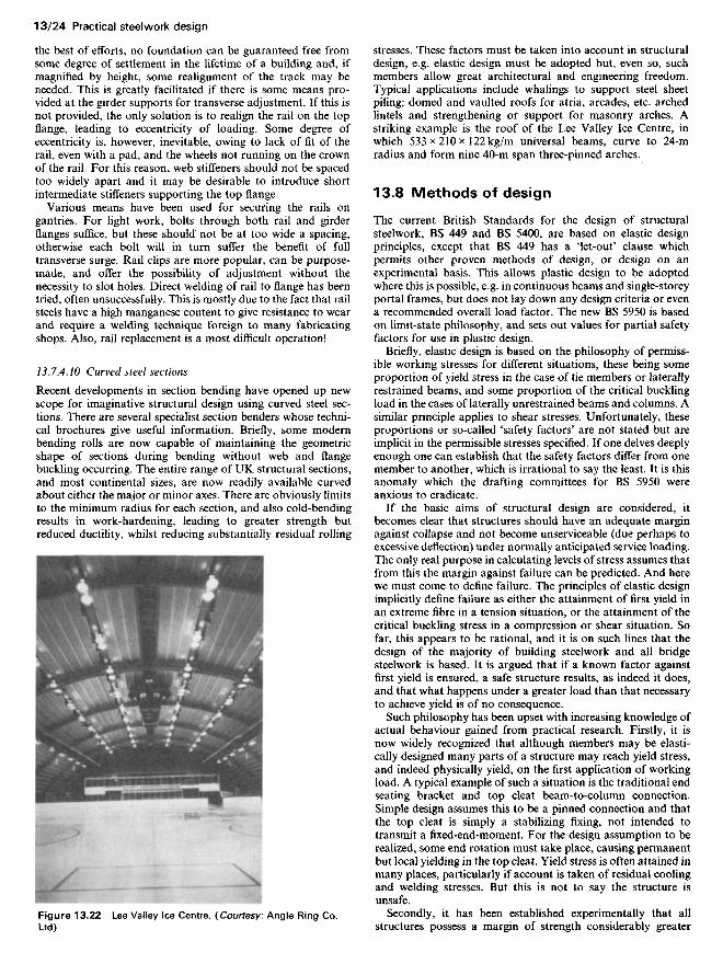
Recent developments in section bending have opened up newscope for imaginative structural design using curved steel sec-tions. There are several specialist section benders whose techni-cal brochures give useful information. Briefly, some modernbending rolls are now capable of maintaining the geometricshape of sections during bending without web and flangebuckling occurring. The entire range of UK structural sections,and most continental sizes, are now readily available curvedabout either the major or minor axes. There are obviously limitsto the minimum radius for each section, and also cold-bendingresults in work-hardening, leading to greater strength butreduced ductility, whilst reducing substantially residual rolling
stresses. These factors must be taken into account in structuraldesign, e.g. elastic design must be adopted but, even so, suchmembers allow great architectural and engineering freedom.Typical applications include whalings to support steel sheetpiling; domed and vaulted roofs for atria, arcades, etc. archedlintels and strengthening or support for masonry arches. Astriking example is the roof of the Lee Valley Ice Centre, inwhich 533 x210* 122kg/m universal beams, curve to 24-mradius and form nine 40-m span three-pinned arches.
13.8 Methods of design
The current British Standards for the design of structuralsteelwork, BS 449 and BS 5400, are based on elastic designprinciples, except that BS 449 has a 'let-out' clause whichpermits other proven methods of design, or design on anexperimental basis. This allows plastic design to be adoptedwhere this is possible, e.g. in continuous beams and single-storeyportal frames, but does not lay down any design criteria or evena recommended overall load factor. The new BS 5950 is basedon limit-state philosophy, and sets out values for partial safetyfactors for use in plastic design.
Briefly, elastic design is based on the philosophy of permiss-ible working stresses for different situations, these being someproportion of yield stress in the case of tie members or laterallyrestrained beams, and some proportion of the critical bucklingload in the cases of laterally unrestrained beams and columns. Asimilar principle applies to shear stresses. Unfortunately, theseproportions or so-called 'safety factors' are not stated but areimplicit in the permissible stresses specified. If one delves deeplyenough one can establish that the safety factors differ from onemember to another, which is irrational to say the least. It is thisanomaly which the drafting committees for BS 5950 wereanxious to eradicate.
If the basic aims of structural design are considered, itbecomes clear that structures should have an adequate marginagainst collapse and not become unserviceable (due perhaps toexcessive deflection) under normally anticipated service loading.The only real purpose in calculating levels of stress assumes thatfrom this the margin against failure can be predicted. And herewe must come to define failure. The principles of elastic designimplicitly define failure as either the attainment of first yield inan extreme fibre in a tension situation, or the attainment of thecritical buckling stress in a compression or shear situation. Sofar, this appears to be rational, and it is on such lines that thedesign of the majority of building steelwork and all bridgesteelwork is based. It is argued that if a known factor againstfirst yield is ensured, a safe structure results, as indeed it does,and that what happens under a greater load than that necessaryto achieve yield is of no consequence.
Such philosophy has been upset with increasing knowledge ofactual behaviour gained from practical research. Firstly, it isnow widely recognized that although members may be elasti-cally designed many parts of a structure may reach yield stress,and indeed physically yield, on the first application of workingload. A typical example of such a situation is the traditional endseating bracket and top cleat beam-to-column connection.Simple design assumes this to be a pinned connection and thatthe top cleat is simply a stabilizing fixing, not intended totransmit a fixed-end-moment. For the design assumption to berealized, some end rotation must take place, causing permanentbut local yielding in the top cleat. Yield stress is often attained inmany places, particularly if account is taken of residual coolingand welding stresses. But this is not to say the structure isunsafe.
Secondly, it has been established experimentally that allstructures possess a margin of strength considerably greater
Figure 13.22 Lee Valley Ice Centre. (Courtesy: Angle Ring Co.Ltd)

than that calculated on the elastic basis. That is to say, onyielding, stresses will be redistributed extensively before a struc-ture shows permanent deformation such as to render it unser-viceable. What now appears to make the elastic philosophyirrational is that this extra margin of strength differs from onesituation to another as, for instance, a laterally restrained beamcompared to a slender strut. Redefining failure as excessive andunacceptable permanent deformation, ultimate load philosophy(plastic design in the case of steelwork) attempts to quantify thisadditional margin of strength in different situations, and toutilize it as part of the overall margin against failure, with theaim of achieving economy.
The principles of plastic design were originated by Sir JohnBaker at Cambridge, developed there by him, with others, andlater taken up extensively at Manchester and Lehigh Universit-ies, and elsewhere. As a result, plastic design can now be readilyapplied to continuous beams and portal frames of variousshapes. The majority of steel portal frames built in this countryare now designed plastically. The justification, if any is needed,for the extensive research which is proceeding lies in the fact thatplastic design is by far the most accurate method of predictingthat load at which real structural failure will occur.
As stated, plastic design consists of recognizing, and quantify-ing, the additional margin of strength in bending, beyond theattainment of first yield in an !-section. It has been establishedexperimentally that before a beam or structure can be made tocollapse it must be transformed from a structure to a mechan-ism. This occurs due to the formation of 'plastic hinges' atpoints of severe moment, which occur only when the wholedepth of a member has reached yield stress, compressive on oneside of the neutral axis and tensile on the other, i.e. no portion ofthe member depth remains elastic. The principles of design ofcontinuous beams and portal frames are clearly set forth insome Constrado publications and other works. The Constradobrochure by Morris and Randall,19 last published in 1979,together with its supplement (which incorporates design chartsextracted and metricated from earlier publications21) has beenpublished in various editions during the past two decades. It hasbeen an invaluable source of information on the subject ofplastic design worldwide, and contains details of numerousstructural forms and design processes including details of twodesign methods applicable to multistorey frames.
A Constrado monograph by Home and Morris,22 and a paperby Morris23 provides the most up-to-date information availableon the subject of plastic analysis.
Having established that a structure has a known marginagainst collapse one has satisfied the strength criterion, and thevalue of stresses in various parts under working load are of littlesignificance provided overall and local stability requirements aresatisfied. Serviceability conditions, i.e. elastic deflections underworking load, may however, not have been satisfied, and ineffect one has to do an elastic analysis in order to establish theposition, which lengthens the design process somewhat. Com-puter programs now exist for portal frames which, for givenloading conditions, will select a section found plastically andprovide values for elastic deflections.
Fully rigid multistorey frames, however, present considerableproblems. Under sway conditions a large frame may requirevery many hinges to form before a mechanism is created and atany intermediate stage the frame is part elastic and part plastic.Proper understanding and control of stability considerations isessential and as yet rules of thumb suitable for codes of practicecannot be produced.
As an intermediate step it was proposed, many years ago, thatframes could be designed as 'semi-rigid', i.e. with certain con-nection requirements satisfied, part transference of momentfrom beam to column could be assumed. This never foundfavour, owing to a complicated design process, but a gross
simplification of it is allowed in BS 449 and BS 5950, Part 1whereby beam moments may be reduced by 10% provided thecolumns are designed to resist such extra moment and arestructurally cased. This is a swings-and-roundabouts situation,not leading to any great economy.
13.9 Partial load factors
Alongside the development of ultimate load philosophy, i.e.plastic design, has come consideration of appropriate loadfactors, i.e. the determination of the right margin necessaryagainst collapse. As indicated earlier, there are inconsistencies inpresent practice, using the principles given in BS 449.
Clearly, a structure must never closely approach collapseconditions in service, but have some margin. This margin is toallow for a number of uncertainties, including design inaccura-cies, variations in material strengths, fabrication errors, lack-of-fit, foundation settlement, residual stresses and errors inassumed loading. Most of these uncertainties will never bequantified, but must be allowed for by a global factor, with twoexceptions: (1) material strength which can be treated statisti-cally; and (2) errors in assumed loading. Strength data suffi-cient for a rational statistical treatment has been accumulatedover the past decade or so. This, together with loading datawhich has also been reviewed, has resulted in a new BS 6399Loading for buildings. The BS 6399:1984, Part 1 'Code ofpractice for dead and imposed loads', which replaces CP 3:1967,Part 1, Chapter V, enables a more satisfactory design treatmentto be adopted than hitherto according to BS 449, i.e. the conceptof partial safety factors has been introduced. Different factorsare to be applied to dead, imposed and wind loading, etc. bywhich the specified loads are to be multiplied. These factoredloads are summated and the structure designed to be on thepoint of collapse under such factored loading. There is thus nofixed value for an overall safety factor, since it will depend onthe proportions of the loadings from the several sources.
In the design of a building, for instance, one can calculate andcontrol self-weight or dead load quite closely. The magnitude ofapplied load is very much less certain, and with possible changeof use in the lifetime of a building, control is difficult, even bylegislation. Further, naturally occurring loading such as windloading and snow loading entail the consideration of the likelyfrequency of attainment and the probability of this occurringsimultaneously with maximum service loading. One must alsoconsider in continuous or semi-continuous structures that deadload may have a counterbalancing effect to certain live-loadsituations. Since it is possible for self-weight to be overestimatedit is therefore necessary to apply minimum as well as maximumdead-load factors.
A rational approach, therefore, is to adopt maximum andminimum dead-load factors acting either alone or in combi-nation with different factors for imposed and wind loads, thevalues of the latter depending on whether they act together orseparately. This procedure has been adopted in BS 5950 and isfully documented in Part 1 of that standard.
The effect of this, however, will be to complicate the designprocess somewhat, but the benefit will be a much greaterconsistency in safety margins. When applied it will appear tomake little difference to the run-of-the-mill structure previouslydesigned to BS 449, but for the type of structure in which onekind of loading dominates, e.g. dead load or wind load, signifi-cant differences will be apparent.
13.10 Limit-state design
The fundamental objectives of structural design are to provide a
structure which is safe and serviceable in use, economical tobuild and maintain, and which satisfactorily performs itsintended function. All design rules, whatever the philosophy,aim to assist the designer to fulfil these basic requirements.However, as mentioned in section 13.9, it must be appreciatedthat design procedures are formulated to produce a satisfactorystructure without necessarily representing its exact behaviour.
The design rules given in the various codes and standardsrepresent the consensus of opinion of many experienced engi-neers. The rules, however, are not able to cover in detail everysituation which designers may encounter, and so judgementmust be exercised in their interpretation and application.
By using limit-state philosophy the design engineer has toconsider two possible conditions of failure:
(1) The serviceability limit state, i.e. when a structure, althoughstanding and experiencing safe stresses, will not be of usedue to, say, excessive deformations.
(2) The ultimate limit state, i.e. when the structure has reachedthe point when it is unsafe for its intended purpose, andcatastrophic failure is about to take place or already hastaken place.
The appropriate factors of safety must therefore be determined,and whilst the primary object is to ensure that it is consistentthroughout the structure, it must be recognized that parts of theframework are more sensitive than others to failure.
The change from working stress analysis, according to BS449, to limit-state philosophy in accordance with BS 5950, Part1, will produce certain changes in the structural design of acomparable framework. Hence, consideration must be given toeconomic as well as safety aspects by those responsible forestablishing safety levels.
Safety can seldom, if ever, be absolute, but an increase in thelevel of safety will almost invariably be accompanied by anincrease in the construction cost. The public, however, areextremely sensitive to the risk of failure and unserviceability but,whilst extreme care must be exercised, it should not be at theexpense of pricing the structure such that it becomes unecono-mic to build. An excellent resume on this topic is given byTordoff.24
13.11 Corrosion protection
The British Standard document giving guidance on this topic isBS 5493 Code of practice for protective coating of iron and steelstructures against corrosion., It gives details of how to specify achosen protective system, how to ensure its correct application,and how to maintain it. Many textbooks have also been writtenon the subject, to which reference may be made.13'25 For special-ist advice the BSC runs a Corrosion Advice Bureau for dealingwith ad hoc problems. The BSC also publishes various leafletson the subject of corrosion protection of structures, which maybe obtained from BSC sections and commercial steels.
Generally, one must admit that, at one time, corrosionprotection was given far-too-scant attention, as regards theeffect of both structural detail and protective treatment. Inrecent years great advances have been made in both directions.Welding has relieved a lot of detail difficulties, and sophisticatedsurface and paint treatments have been developed which pro-mise long repaint lives.
Whilst major exposed structures such as big bridges, whererepainting is expensive, rightly receive 'Rolls-Royce' treatment,it should be remembered that such may not be appropriate ineach and every case. It seems to the authors that in somerespects the pendulum has swung too far the other way, someengineers specifying treatments and inspection standards not
warranted in many cases. Once again, judgement enters thepicture and in any design it must be first assessed whether aproblem exists at all. In the case of steelwork which can beguaranteed to be kept dry (say internal to a heated building)little problem exists. If exposed within the building, painting isusually carried out for cosmetic reasons only.
Steelwork exposed to the elements presents an entirely differ-ent problem which should receive attention before design com-mences, let alone detailing. Again, although account should betaken of the probable life of the structure, its use, atmosphericenvironment and location before coming to a judgement, struc-tures in the public eye rightly demand the full treatment.Industrial structures of a temporary or semi-temporary naturedo not warrant expensive treatment, particularly if they arelikely to be subject to accidental damage.
The treatment appropriate to a particular case can thus varyfrom nothing to the blast-cleaned, metal spray and four-coatpaint system. Further information on methods of treatment isgiven in Chapter 4.
As mentioned in section 13.5.7 it may sometimes be advan-tageous to consider the use of weathering steel to solve thecorrosion problem as an alternative solution to protecting steelfrom corrosion. Whilst a sacrificial surface can sometimes beallowed, as required by the Department of Transport for bridgeworks, weathering grade steels painted subsequently usuallyprovide a more durable protective system than ordinary gradesteels.
When using universal sections requiring a sacrificial weather-ing allowance, the design properties are obviously different fromthose given in BS 4 and other informative documents. In thisrespect Constrado produced a useful brochure26 which providesproperties adjusted to give a 1 or 2 mm weathering allowance.The use of this brochure is not, however, necessarily confined tobridgework only.
13.12 Detailed design
Ideally, design should be carried out only by those familiar withshopfloor problems and procedures, but this is a counsel ofperfection. Where doubt exists an approach to a fabricator isworth while.
What are referred to here are the difficulties which arisebecause a designer may sometimes interpret technical informa-tion literally without recognizing its limitations. The tablespublished in BS 4:1980 Structural steel sections, Part 1; BS 4848Specification for hot-rolled structural steel sections, Parts 2,4 and5 and in various handbooks18- 27~29 giving dimensions and weband flange thicknesses, are average values only. All steel mem-bers are subject to weight rolling margins of ±2.5%. Sectionscan also be out of square and the limits of tolerance on shape aregiven in the relevant publications. Whilst it would be unfair toassume that all member sizes and shapes are at the tolerancelimits, it is also unfair to suppose that all dimensions are strictlyaccurate to three significant figures. One must have some regardto the possibility of members being slightly out of true. No bar isever completely straight, no plate flat, and no flange at rightangles to its web. Fortunately, in most cases the work can beforced into alignment (albeit introducing locked-in stresses) butoccasions can sometimes arise where this is not possible. Whenthis occurs it becomes necessary to use packing pieces, occasio-nally needing costly machining which cannot be charged for.The designer's aim, therefore, must be to eliminate the need foraccurate fit-up and to use machining only as a last resort.
Another point frequently overlooked is the matter of accessi-bility for welding. The easiest and therefore the best fillet weldresults when the electrode, either manual or automatic, can beoffered at 45°. The limits for satisfactory work are roughly 120
and 60° and outside these limits poor welds result since theelectrode must be bent, breaking the flux coating and introduc-ing many stops and starts. The designer cannot be expected toforesee all possible difficulties, but having made some attempthe should retain an open mind and be prepared to considersequences and procedures suggested from the shop floor.
Handling and floor space also deserve some thought. Forstraightforward fabrication one should aim to keep complicatedweldments small so that they can be handled readily to enableall welding to be done downhand. A complicated end detail to along member makes this difficult if not impossible. If design canbe effected such that all that long members need is to be cut tolength and drilled, probably on an automatic machine, competi-tive tender sums will be offered. This is at least partly due to thefact that shop-floor space used is kept to a minimum and hencethroughput can be high.
Where possible, repetition should be the aim. Money will notbe saved if in the pursuit of imaginary economy a great varietyof member sizes is used for broadly similar loading conditions.An example, for instance, occurred in a bridge consisting of 54girders, all of which were different. Admittedly, this is anextreme case but some saving through repetition must have beenpossible. Since building structures generally offer the greatestscope for repetition, this should not be overlooked at the designconcept stage.
13.13 Connections
The greater part of the cost of a steel structure is in theconnections, whether they be bolted or welded. Simplicitytherefore must be the keynote, with the greatest standardizationpossible if economy is to result. Typical examples of a greatvariety of connections are illustrated in the Steel designers'manual.™ Suffice it to say here that the general trend is to useshop welding and site bolting. Site welding tends to be veryexpensive and should be considered only if extensive work is inhand as, for instance, in a big bridge or long pipeline, whilstshop bolting is usually more expensive than welding.
13.13.1 Welding
The British Standards for welding of greatest concern to thestructural engineer are:
BS 5135:1984 Specification for the process of arc weldingof carbon and carbon manganese steels. Thisstandard supersedes BS 1856:1964 and BS2642:1965 which have been withdrawn by theBSI.
BS 639:1976 Covered electrodes for the manual metal-arcwelding of carbon and carbon manganese steels.
There are many other current British Standards coveringvarious welding processes, inspection procedures, and weldingof special alloy steels and other materials. Indeed, so extensive isthe coverage that to the uninitiated great difficulty may beexperienced in selecting the appropriate standard or mosteffective procedure. However, excellent guidance is availablefrom the Welding Institute which publishes a series of booklets,some of which have already been mentioned, but Richards4 isparticularly recommended. It is couched in easily understoodlanguage and defines the fundamentals and points out pitfallsfor the unwary. Armed with such guidance, an attempt can bemade to propose details and procedures for a particular case,but an open mind should be retained for ideas and proposalsfrom the welding engineers responsible for carrying out thework.
The PD 6493:1980 referred to in section 13.2.5 is alsoinvaluable, as is BS 4870:1981 Specification for approval testingof welding procedures, Part 1, 'Fusion welding of steels'. Thisstandard gives details of various processes, types of test weldand test pieces and recommended test procedures.
13.13.2 Bolting
The various types of bolts in structural use and the respectiveBritish Standard to which they are made, or governing their use,are as follows (the user must ensure that the version incorporat-ing the latest amendments is used):
(1) Black bolts: BS 4190:1967 Specification for ISO metricblack hexagon bolts, screws and nuts. Two obsolete stan-dards covering imperial sizes, namely BS 325:1947 and BS916:1953 have not yet been withdrawn by BSI.
(2) High-tensile bolts: BS 3692:1967 Specification for ISOmetric precision hexagon bolts, screws and nuts. Metricunits.
(3) High strength friction grip (HSFG) bolts: BS 4395:1969:High strength friction grip bolts and associated nuts andwashers for structural engineering, Part 1, 'General grade';Part 2, 'Higher-grade bolts and nuts and general-gradewashers'; and Part 3, 'Higher-grade bolts (waisted shank)nuts and general grade washers'. BS 4604, Specification forthe use of high strength friction grip bolts in structuralsteelwork. Metric series, Part 1, 'General grade'; Part 2,'Higher grade (parallel shank)'; and Part 3, 'Higher grade(waisted shank)'.
Whilst at one time the most popular structural bolt was theblack bolt to BS 4190 (Grade 4.6), in recent years there has beena move towards the much wider use of Grade 8.8 bolts coveredby BS 3692. But since these bolts are mostly used in clearanceholes, the shank diameter precision is not exploited. Conse-quently, manufacturers now supply bolts of Grade 8.8 strengthgrade to BS 4190 tolerances, specifically for structural purposes.These Grade 8.8 bolts are of material properties comparable toHSFG bolts to BS 4395, Part 1, but whereas the latter aresupplied with Grade 10 nuts, the former come with Grade 8nuts. Further, the HSFG nut is thicker in order to limit threadstresses during tightening. The result is that bearing and shear-ing values for Grade 8.8 bolts are greater than slip values forHSFG bolts, and the designer must decide whether some slightinitial movement is admissible - usually it is in building struc-tures, except where reversals of load may occur. Thus, in thesecases Grade 8.8 bolts offer economy compared to HSFG bolts,particularly since they do not require controlled tightening orspecial tools. One would suggest, however, that the greaterstrength in tension offered by HSFG bolts, due to their thickerand harder nuts, justifies their adoption in wholly tensionsituations. An amendment in 1982 to BS 4604, Part 1 permitssuch bolts to be used without controlled tightening in thesecircumstances, which is quite acceptable for most buildingstructures.
In the past, turned and fitted bolts were used only whereaccurate fit-up was essential. These are not now used havingbeen superseded by HSFG bolts.
Turned barrel bolts are bolts in which the machined shank isof a larger diameter than the protruding threaded end, beingshouldered at the spigot. They are for situations in which it isnecessary to secure the bolt effectively without gripping thework and exerting pressure between the plies. Such a situationoccurs in an expansion joint where one of the holes is slotted toallow for movement.
High strength friction grip bolts are now widely used, havingalready become popular in the mid 1960s. Both general- andhigher-grade bolts, as the name implies, resist shear through the

interface friction arising from bolt tension. The coefficient offriction to be assumed is called the slip factor, and the strengthof a bolt is calculated as bolt tension x (slip factor/load factor)x number of interfaces. It is assumed that bolts are tightened-up to their proof load in tension and, to ensure this, alternativemethods of tightening are specified in BS 4604. These are thepart-turn method and the torque-control method. In the formerthe bolts are brought up hand-spanner tight, to bring thesurfaces into contact, the nuts and threads marked, and tighten-ing is then continued by a predetermined amount depending ondimensions. The latter method depends upon the use of either amanual or power-driven tool preset to slip at a particular torquevalue, which can be adjusted to suit the case. Of the twomethods, the former is the more accurate and reliable, buttedious, whilst the latter is much quicker but less accurate owingto the fact that torque and bolt tension do not necessarily relateexactly, being dependent on thread fit.
Additionally, and not referred to in any British Standard,since there is only one manufacturer, is the use of 'Coronet' loadindicating washers. These are washers, with raised nibs, to beinserted under the bolt heads. These raised nibs are flattenedwhen the specified shank tension has been attained during nut-tightening. Since they do not require special calibrated tools,nor any marking procedure, they are very much simpler to usethan either of the other two methods. Accordingly, their usenow accounts for some 80% of cases. It is important, however,that pattern tightening of bolt groups is retained, or relaxationof the bolts tightened first will occur. Also, proper inspectionduring and after bolting is still essential.
The slip factor normally adopted is 0.45 for untreated sur-faces, but BS 4604 Specification for the use of high strengthfriction grip bolts in structural steelwork, metric series givesdetails of a slip factor test to determine the value in other cases.It also recommends a load factor in design of 1.4. BritishStandard 449 refers to BS 4604 whereas BS 153 called for higherload factors depending on load combinations. In the new bridgeand buildings codes (BS 5400 and 5950) the load factors aremore closely related.
The reason for the apparently low load factor of 1.4 lies in thefact that a bolt possesses a margin of strength after slip hasoccurred, when the bolt starts to act in bearing as well asfriction.
It might be supposed from the apparently full coverage inBritish Standards outlined above that all outstanding problemsregarding HSFG bolts had been solved. Unfortunately, this isfar from being the case. In the first place, post-slip strength isuncertain and clearly depends to some extent on the thickness ofplies. Secondly, the test to determine slip factors consists of fourbolts in line, two either side of the joint, with double cover platesputting the bolts into double shear. The effect of eccentricityarising in single-shear conditions is not determined. Moreparticularly, though, it has been established that very large orlong joints do not behave in the simple fashion assumed. Forinstance, a very long cover plate acting in tension transverse toits length also develops longitudinal tension. The Poisson's ratioeffect in this biaxial tension situation brings about a reduction inthickness and, thus, bolt relaxation. This can reduce boltstrengths by as much as 20%. Similar biaxial tension effects canoccur in large joints in lattice girders, particularly when morethan three plies are involved. Indeed, the effect of a largenumber of plies is completely unknown.
Another difficulty arises in large joints, i.e. that if faces are notmachined truly flat an indeterminate amount of bolt tension isused to bring the surfaces in contact, even with the bestfabrication. An extreme case would occur in a splice in a boxgirder. If the overall widths and depths of the two lengths do notcoincide exactly towards the corners, proper contact cannot bemade without the use of machined packings. Proper contact
would be made only towards the middle of the faces wherebiaxial tensions exist. Large joints therefore need carefulthought and cannot be treated by applying rule-of-thumbmethods. It should be noted that where HSFG bolts are used,machining of faying surfaces is detrimental since the slip factorwill be considerably reduced due to the smoother surface; hencemore or larger-sized bolts will be required in the joint.
Two papers by Needham31-32 on the subject of connections areavailable. They cover in some detail the basic principles anddesign philosophy underlying the design of both welded andbolted joints. They emphasize the need for joint design to beconsistent with assumed structural behaviour.
13.14 Inspection of structuralsteelwork during construction
Any inadequacies of materials and structural frameworks ofbuilding and bridge structures always causes concern, especiallyamong owners who are frequently faced with the high costs ofremedial work.
Many of the defects producing constructions not complyingwith the design specification may be found to originate from oneor more of the following:
(1) Material: supply of incorrect grade or out-of-standardmaterial - wrong sizes, etc.
(2) Detail design: poor and inaccurate details.(3) Fabrication: incorrect material and size selected. Inade-
quate or incorrect assembly of joints - use of wrong-gradeweld material or bolts.
(4) Site erection: misplacing of similar sized but different-grade sections. Wring-grade weld material or bolts. Lackof fit - overstraining of components. Poor foundationconnections; omission of, or inadequate, bracing.
Thus, from the outset, the design concept and process shouldinclude considerations of:
(1) Availability and reliability of proposed materials.(2) Special requirements for control of quality and speed of
fabrication and erection.(3) The degree of supervision and inspection likely to be
present during fabrication and erection.(4) The type of contract and its effect on the design/construc-
tion process.
It is important to recognize the contractual relationship asdefined in the contract documents and that legal responsibilityfor satisfactory erection rests with the contractor. It is necessaryto have good site management by way of planning at all stages,including delivery sequence, laying out of stock and positioningof cranes. Correct setting out is a prerequisite for satisfactorycompletion of a project, followed by inspection of steelwork ondelivery and during erection, temporary and permanent brac-ing, lining and levelling and examination of all connections.
Two publications on this subject are by the Institution ofStructural Engineers33 and by Needham.34
References
1 Richards, K. G. (ed.) (1971) Brittle fracture of welded structures.The Welding Institute, London.
2 Richards, K. G. (ed.) (1969) The fatigue strength of weldedstructures. The Welding Institute, London.
3 Gray, T. F. and Spence, J. (1982) Rational welding design, 2ndedn. Butterworth Scientific, Guildford.
4 Richards, K. G. (ed.) (1967) The weldability of steel. The WeldingInstitute, London.
5 Needham, F. H. (1977) The economics of steelwork design'.Struct. Engr, 55, 9.
6 Walker, H. B. and Gray, B. A. (1985) Steel-framed multistoreybuildings - the economics of construction in the UK, 2nd edn.Constrado, London.
7 British Constructional Steelwork Association (1983) Internationalstructural steelwork handbook (No. 6). BCSA, London.
8 Horridge, J. F. and Morris, L. J. (1986) 'Comparative costs ofsingle-storey steel-framed structures'. Struct. Engr, 64A, 7.
9 Bryan, E. R. (1972) The stressed skin design of steel buildings(Constrado monograph). Crosby Lock wood Staples, London.
10 Her Majesty's Stationery Office (1985) The building regulations.HMSO, London.
11 British Steel Corporation (1983) 'Protection of steel fromcorrosion', in: Steel protection guide. BSC, London.
12 British Steel Corporation (1982) 'Interior environments', in:Steelwork corrosion protection guide. BSC, London.
13 Chandler, K. A. and Bayliss, D. A. (1985) Corrosion protection ofsteel structures. Elsevier Applied Science, London.
14 Hendry, A. W. and Jaegar, L. G. (1958) The analysis of gridframeworks and related structures. Chatto and Windus, London.
15 Morice, P. H. and Little, G. The analysis of right bridge deckssubjected to abnormal loading. Cement and Concrete AssociationPublication No. D6/11. CCA, London.
16 Nash, G. F. J. (1984) Composite universal beam - simply supportedspan. Constrado, London.
17 Constrado (1983) Weather-resistant steel for bridgework.Constrado, London.
18 British Constructional Steel Association (1985) Guide to BS 5950,vol. 1 Section properties - member capacities. Constrado, BritishSteel Corporation and BCSA, London; British ConstructionalSteelwork Association (1986) Guide to BS 5950, vol. 2 Workedexamples. Steel Construction Institute, London.
19 Morris, L. J. and Randall, A. L. (1975) Plastic design. Constrado,London.
20 Merrison, A. W. (1973) Inquiry into the basis of design and methodof erection of steel box-girder bridges. Report of the committee intointerior design and workmanship rules, Parts 1, 2, 3 and 4.Department of the Environment/Scottish DevelopmentOffice/Welsh Office. HMSO, London.
21 Constrado (1979) Plastic design supplement. Constrado, London.22 Home, M. R. and Morris, L. J. (1981) Plastic design of low-rise
frames (Constrado monograph). Granada, London.23 Morris, L. J. (1983) 'A commentary on portal frame design'.
Struct. Engr, 59A, 12; discussion, 61 A, 6 and 7.24 Tordorf, D. (1983) Introduction to the limit-state design of
structural steelwork. Constrado, London.25 Fancutt, F., Hudson, J. C. and Stanners, J. F. Protective paintings
of structural steel. Chapman and Hall, London.26 Constrado (1983) Weather-resistant steel for bridgework.
Constrado, London.27 British Steel Corporation and British Constructional Steel
Association (1982) The sections book. BSC and BCSA, London.28 British Constructional Steel Association (1978 and 1973)
Structural steelwork handbook: properties and safe load tables forsections to BS 4:1978; Structural steelwork handbook: propertiesand safe load tables for metric angles to BS 4848:1973. Constradoand BCSA, London.
29 Steel Construction Institute (1986) A checklist for designers. SCI,London.
30 The steel designer's manual, 4th edn. Crosby Lockwood, London.31 Needham, F. H. (1980) 'Connections in structural steelwork for
buildings'. Struct. Engr, 58A, 9.32 Needham, F. H. (1983) 'Site connections to BS 5400, Part 3'.
Struct. Engr, 61A, 3.33 Institution of Structural Engineers (1983) Inspection of building
structures during construction. ISE, London.34 Needham, F. H. (1981) 'Site inspection of structural steelwork'.
Proc. Instn Civ. Engrs, 70, Part 1.