1,.:::. :::21.,:i. - tu delft repositories
TRANSCRIPT
,, , ,,
7.::.:Ii:::?::::::',.*?:::::::::::....1,.:::. :::21.,:i.:':1.1.::::.::::::::::::.:.s..::::ii:).::.:;:....i::....:::.:11...,;.:,.:::-.......x.:.. .
.
.
. . SHIP VIBRATION..
T
r/E` '7.
:vo,
,

TABLE OF CONTENTS
Page
PREFACE P. 1
NOTATION N- 1
CHAPTER 1 HISTORICAL BACKGROUND 1- 1
CHAPTER 2 QUALITATIVE DISCUSSION OF SHIP DYNAMICS 2- 1A. Introduction 2- 1B. Rigid Body Motions 2- 1C. Elastic Vibrations of the Entire Hull 2- 3D. Added Mass 2- 6E. Local Effects 2- 8F. Shallow Water Effects 2- 8
CHAPTER 3 BASIC BEAM THEORY OF SHIP VIBRATION 3- 1A. Introduction 3- 1B. Basic Differential Equations for the Ship 3- 6C. Methods of Calculating Natural Frequencies and Normal Modes
of Vibration of Ships 3-10
CHAPTER 4 BEAM THEORY OF STEADY-STATE SHIP VIBRATIONA. IntroductionB. Digital MethodC. Analog MethodD. Normal Mode Method
4- 14- 14- 34- 54- 7
E. Method of Mechanical Impedance 4-10
CHAPTER 5 BEAM THEORY OF TRANSIENT SHIP VIBRATION 5- 1A. Introduction 5- 1B. Normal Mode Method 5- 2C. Digital Method 5- 6D. Analog Method 5- 9
CHAPTER 6 EFFECT OF LOCAL FLEXIBILITY ON THE VIBRATORYCHARACTERISTICS OF A HULL 6- 1
A. Introduction The "Sprung Mass" Effect 6- 1B. Local Elastic Structures 6- 2C. Resiliently Mounted Assemblies 6- 4D. Summary of Effects of Sprung Masses on Hull Vibration 6-11
Page
CHAPTER 7 PROPELLER-EXCITING FORCES 7- 1
Introduction 7- 1
Pitch Unbalance Forces 7- 2
Blade-Frequency Forces 7- 2
Experimental Force Data Available 7-10
CHAPTER 8 DAMPING OF HULL VIBRATION 8- 1
A. Introduction 8- 1
B. Analytical Treatment of Hull Damping 8- 3
C. Experimental Methods of Determining Damping 8- 5
D. Available Data on Hull Damping 8- 7
E. Damping Action of Lifting Surfaces 8- 7
CHAPTER 9 ANTIVIBRATION DEVICES 9- 1
A. Introduction 9- 1
B. The Tuned Vibration Neutralizer 9- 1C. Adjustable Rotating Eccentrics 9- 3
D. Synchronizing Devices 9- 5
E. Flexible Materials in the Vicinity of Propellers 9- 7
F. Summary 9- 7
CHAPTER 10 DESIGN CONSIDERATIONS RELATING TOSTEADY-STATE HULL VIBRATION 10- 1
A. Introduction 10- 1
B. General Procedure 10- 2
C. Reducing Propeller Forces 10- 5
D. Avoiding Hull Resonance 10- 6
E. Avoiding Local Resonance 10- 8
F. Balancing 10- 9
CHAPTER 11 DESIGN CONSIDERATIONS RELATING TOTRANSIENT VIBRATIONS 11- 1
A. Introduction 11- 1
B. The Hull Girder 11- 2
C. Local Structures 11- 4
D. Resiliently Mounted Assemblies 11- 5
CHAPTER 12 DESIGN CONSIDERATIONS RELATING TOVIBRATION OF THE PROPULSION-SHAFTING SYSTEM 12- 1
A. Introduction 12- 1
B. Torsional Vibration 12- 2
iv
Page
C. Longitudinal Vibration 12- 2D. Lateral Vibration of Propeller Shafts 12- 3
CHAPTER 13 DESIGN CONSIDERATIONS RELATING TORESILIENT MOUNTINGS 13- 1
CHAPTER 14 HYDROELASTICITY 14- 1
A. Introduction 14- 1B. Rudder-Hull Vibration 14- 3C. The Singing Propeller 14- 7
D. Commentary 14- 8
CHAPTER 15 SHIP VIBRATION RESEARCH 15- 1
A. Introduction. 15- 1
B. Vibration Generators 15- 2C. Ship Vibration Instruments 15- 5
D. Experimental Techniques 15- 7E. Correlating Theory and Experiment 15-10-
APPENDIX A ILLUSTRATION OF A CALCULATION OF A VERTICALNORMAL MODE BY THE DIGITAL PROCESS A- 1
APPENDIX B ILLUSTRATION OF A CALCULATION OF TRANSIENTRESPONSE BY THE DIGITAL METHOD B- 1
APPENDIX C EMPIRICAL FORMULAS FOR HULL FREQUENCIES C- 1
APPENDIX D EMPIRICAL FORMULAS FOR ESTIMATING THE LEVELOF STERN VIBRATION , D- 1
APPENDIX E.- SHIP VIBRATION SURVEYS E- 1
APPENDIX F LEVELS OF SERVICE VIBRATION F- 1
APPENDIX G SCALING CONSIDERATIONS IN MODEL VIBRATIONEXPERIMENTS G- 1
APPENDIX H MISCELLANEOUS INFORMATION ON VIBRATION OFSHIPS IN SERVICE H- 1
GENERAL BIBLIOGRAPHY Bi- 1
INDEX In- 1
PREFACE
In treating the subject of ship vibration it is necessary to recognize that it falls in theborder region between exact science and empiricism. While it is true that intensive researchhas been Conducted in this field in several parts of the world and much progress has beenmade, at the time of this writing (1960) it cannot be said that an adequate method of vibrationanalysis of a ship exists.
It is true that one can consider the hull as an ideal mass-elastic system and can writedown a certain set of partial differential equations which govern the behavior of such a system,but, in attempting to predict the level of service vibration of a ship in the design stage, onemust be well aware of the limitations of such a treatment.
It is also possible to present empirical data on the level of service vibration of shipsof various types together with the principal design features of the ships involved. Thisapproach is also inadequate since the level of vibration will vary with a number of parameterssimultaneously.
In the preparation of this book an attempt has been made to follow a path midway be-tween the theoretical and empirical approaches. This leads to what may be called a "rationaltheory of ship vibration." Use is made of the properties of ideal free-free beams to obtain aninsight into the effects of various design changes on the vibratory response characteristics ofhulls. However, it is also attempted to guard the reader and the user against extending thecalculations into realms in which they have no validity. One aim is to show that the vibra-tory Characteristics are closely related to the structural strength characteristics.
While intended principally for the naval architect, the book has been prepared alsowith the research worker and the student in mind. It has not been attempted, however, toinclude a treatment of the fundamentals of mechanical vibration. It is presupposed that thereader has or can acquire a background such as furnished by the courses in mechanical vi-bration now given in practically all colleges of engineering. Specific references are includedat the end of each chapter and a general bibliography is given at the end of the book.
The contrast between the problem of avoiding serious steady-state vibration and with-standing the effects of severe transient vibrations due to heavy seas is pointed out. Theproblem of setting up design specifications with regard to vibration is also discussed.However, no attempt is made to disguise the fact that the present state of the art of predictinghull vibratory response characteristics is primitive. Where controversial issues arise onlyopinions can be furnished.
In the mathematical treatment of the subject and in the illustrations given in theappendixes, the aim has been to emphasize the physical principles involved without burdeningthe reader with too many details. It is assumed that the designer who makes use of the meth-ods discussed in the book will assign the task of carrying out the adtual vibration calculationsto a member of his staff who can consult the references when further details are needed.Thus this book is not of the manual or handbook variety although concrete procedures for the
P-1
designer are suggested. With the rapid pace of development of computational aids today it isclear that procedures that are written out in great detail may become obsolete almost over-night, but the principles involved are durable.
Except as otherwise noted, the statements made apply to either surface ships or sub-mersibles. Although most of the information given was obtained from research sponsored byeither the United States Navy or jointly by the Navy and the Society of Naval Architects andMarine Engineers, the book is not intended specifically for naval designers, and problemsthat are strictly naval are not discussed. Thus submarines are mentioned only because theymay become future commercial carriers and questions that relate to the detection of underseacraft are omitted.
The relatively new field of hydroelasticity has been included since this is recognizedas a field of growing importance. In fact, in the broadest definition of hydroelasticity, thesubject of hull vibration itself would have to be included.
The book is based chiefly on the work of the U.S. Experimental Model Basin and theDavid Taylor Model Basin and an exhaustive commentary on the work of other agencies isnot attempted here.
It is not overlooked that more elaborate analyses of the dynamical system comprisingthe hull and the surrounding water than the beam-theory analysis presented in this book areconceivable. However, it is felt that even after such analyses have been developed, thedesigner will still be restricted to the methods discussed here in the preliminary design stage.The data required for more elaborate analyses will, in general, be available only at a veryadvanced stage of the design.
While this book is concerned chiefly with the problem of hull vibration, there has beenincluded among the chapters on design considerations, one dealing with the vibration of thepropulsion system itself. Here, however, the treatment is relatively brief and intended toserve chiefly as a guide to other sources of information on this subject in the technicalliterature. In dealing with the hull itself, no attempt has been made to review all the avail-able literature, but to concentrate on the techniques that appear most fruitful.
In choosing a notation it was found impossible to adhere strictly either to standardsin naval architecture or in engineering since the subject involves both fields. In recent yearsthe American Standards Association has extended its sphere from acoustics into the field ofmechanical shock and vibration. Many of the symbols used conform to the ASA standards,but the common symbols for the principal dimensions of ships used in naval architecture arealso retained. The common use of nondimensional notation in naval architecture has not beenfollowed here, as this has not found such wide acceptance in the field of mechanical vibration.Nevertheless, it is pointed out in the chapter on hydroelasticity that the aeroelastici an hasalso found such notation preferable.
Finally it seems in order to point out that vibration theory plays a central role in shipdynamics just as it does in mechanics in general. An acquaintance with the vibratory
P-2
characteristics of the hull not only assists the designer in avoiding serious vibration diffi-culties when his product goes into service but also gives him a deeper insight into manyfactors involved in good structural design.
ACKNOWLEDGMENTS
Due to widespread interest in ship vibration Rear Admiral E.A. Wright, Director of theDavid Taylor Model Basin at the time, authorized the preparation of a book on that subjectearly in 1959. His enthusiastic support and encouragement made possible the preparation ofthe present edition.
The author gratefully acknowledges constructive criticism and suggestions from thefollowing individuals during the preparation of the drafts from which the present manuscriptwas prepared:
Dr. N.H. Jasper, Dr. E. Buchmann, Mr. R.C. Leibowitz,Mr. N.L. Ficken, Jr., Dr. W.L. Haberman, and Mr. W.B.
Hinterthan of the David Taylor Model Basin; Mr. F.F.Vane, Mr. O.H. Oakley, Mr. D.L. Stevens, Mr. J. Vasta,Capt. H.E. Saunders, USN (Ret), and Mr. L.K. Losee ofthe Bureau of Ships; and Mr. A.J. Tachmindji of theInstitute for Defense Analysis.
P-3
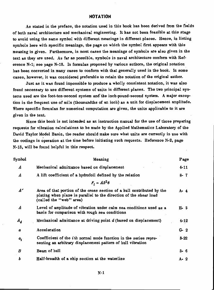
NOTATION
As stated in the preface, the notation used in this book has been derived from the fieldsof both naval architecture and mechanical engineering. It has not been feasible at this stageto avoid using the same symbol with different meanings in different places. Hence, in listingsymbols here with specific meanings, the page on which the symbol first appears with thismeaning is given. Furthermore, in most cases the meanings of symbols are also given in thetext as they are used. As far as possible, symbols in naval architecture conform with Ref-erence N-1; see page N-13. In formulas proposed by various authors, the original notationhas been converted in many cases to conform with that generally used in the book. In somecases, however, it was considered preferable to retain the notation of the original author.
Just as it was found impossible to produce a wholly consistent notation, it was alsofound necessary to use different systems of units in different places. The two principal sys-tems used are the foot-ton-second system and the inch-pound-second system. A major excep-tion is the frequent use of mils (thousandths of an inch) as a unit for displacement amplitude.Where specific formulas for numerical computation are given, the units applicable to it aregiven in the text.
Since this book is not intended as an instruction manual for the use of those preparingrequests for vibration calculations to be made by the Applied Mathematics Laboratory of theDavid Taylor Model Basin, the reader should make sure what units are currently in use withthe codings in operation at the time before initiating such requests. Reference N-2, pageN-13, will be found helpful in this respect.
Symbol Meaning Page
A Mechanical admittance based on displacement 4-11
A A lift coefficient of a hydrofoil defined by the relation 8- 7
F1= A829
A' Area of that portion of the cross section of a hull contributed by the A- 4plating when plane is parallel to the direction of the shear load(called the "web" area)
A Level of amplitude of vibration under calm sea conditions used as a 5
basis for comparison with rough sea conditions
Ad Mechanical admittance at driving point d (based on displacement) 4-12
a Acceleration G- 2
ai Coefficient of the ith normal mode function in the series repre- 3-22senting an arbitrary displacement pattern of hull vibration
Beam of hull 3- 6
Half-breadth of a ship section at the waterline A- 2
N-1
Lumped_viscous damping constant of a hull (equal
Viacoae damping constant of a vibratory system of a single degreeof freedom
'Electrical capacitance
'Linearized (viscous) daraping Constant applicable to-the translationaldegree of freedom of a control surface systein oftWo degrees of free-
, dom at zero,velocity
- Lewis' two-dithenaionarEidded mass coefficient giving the ratio of the A- 2added mass of .a,ship form (in vertical vibration).ta that of ,a CirCular,forth of the same beam
Moment Coefficient of .,a spade rudder 14- 2
The effective, damping constant of a hull in its ith 'normal'mode of vibration and with respect to driving point d
Viscous damping constant equivalent to iionvisdOus damping on the.basis of energy dissipation, damping force per unit velocity
-Linearized (viscous) damping constant applicable to the rotational. degree of freedom of a control surface system of two degrees of
freedom at zero'velodity
-COefficient ler, the inertia effect of water appearing in Prohaska'sformula for the fundamental vertical frequency of a hull
Viscous damping constant, damping force per unit velocity in .3- 1sense opposing the velocity
Velocity of wave propagation 3- 5
Distributed viscous damping constant of a hull, damping force perunit length poi. unit velooity
c' Angular viscous damping constant
Critical viscous damping constant
c/cc 'Ratio of damping.to critical damping
Blade frequencyin cycles per minute
Depth Of hull_
Draft
d - A driving point in a mass-elastic system
d Rectilinear displacement
N-2
Symbol Meaning Page
Semichord length of a hydrofoil or an aircraft Wing .15- 8
Schlick's empirical constant appearing in formula for the fundamental 3- 3vertical frequency of a hull
'4- 3
4-10
4-11
14- 4
4-10
8,- 2
14- 4
C- '4
4- 2
G 2
8- 3
G- 2
4-13
3- 6
A- 2
4-96-2
MeaningSymbol
Propeller diameter
Young's modulus of elasticity
Electrical voltage
El Bending rigidity of a beam
EV H Equivalent horizontal virtual inertia factoreffective added weight of water
for horizontal vibration(\1+
displacement of ship
Page
7- 5
3- 2
D- 1
3- 2
C- 6
Eccentricity of a rotating mass of a mechanical vibration generator 9- 4
F' A concentrated force acting on a hull at an arbitrary point and treated 5-22as constant over a short interval of time in the digital treatment oftransient response
F' Force G- 2
F' (t) A concentrated driving force (acting on a hull) which is an arbitrary 5- 4function of time
Lift force acting on a hydrofoil 8- 7
F vp Rotating time vector representing the vertical component of the blade 9- 6frequency force due to the port propeller.
Rotating time vector representing the vertical component of the blade 9- 6Fvs frequency force due to the starboard propeller
Area enclosed by the shell plating of the midship section of a hull C- 7(not the area of the material)
Frequency 7-11
G Shear modulus of elasticity 3- 4
Gel Torsional rigidity of a shaft 3- 4
We Effective torsional rigidity of a hull with respect to its longitudinal 3- 8axis
g Acceleration of gravity 3- 6
li Draft 7-11
11 Impulse applied to a hull at driving point d 5- 5
la Distance from the axis of a control surface to the center of gravity of 14- 4the rotating element (based on an allowance for added mass effect ofwater) considered positive if the c.g. is downstream
Distance from the top of a polemast to the elastic axis of a hull 11- 4
Moment of inertia of the cross section of a beam With respect to its 3- 2neutral axis (based on the area of the material)
N-3
Symbol Meaning Page
/ Mass moment of inertia of the rotatable assembly of a control surface 14- 4system of two degrees of freedom including the added mass moment ofinertia effect of the water
Electrical current D- 1
Mass moment of inertia of the entire ship with respect to the longitu- D- 3dinal axis through its center of gravity without any allowance for theinertia effect of the surrounding water
Mass moment of inertia G- 2
Moment of inertia of an area G- 2
Moment of inertia of the area of the midship section of a hull for C- 6bending in the horizontal plane
Mass moment of inertia of a resiliently mounted assembly or "sprung 6-10mass" with respect to an axis through its center of gravity
Moment of inertia of the area of the midship section of a hull for C- 6bending in a vertical plane
Mass moments of inertia of a resiliently mounted rigid assembly with 6- 8respect to the X-, Y-5 and Z-axes, respectively, with origin at thecenter of gravity of the assembly
Mass products of inertia of a resiliently mounted rigid assembly with 6- 8respect to axes X-Y, X-Z, and Y-Z, respectively, with origin at thecenter of gravity of the assembly
Mass polar moment of inertia of a beam or shaft per unit length withrespect to its longitudinal axis
Mass moment of inertia of a hull per unit length with respect to thex-axis including the allowance for the inertia effect of the surround-ing water
Rotary inertia of hull per unitlength (difference between the massmoment of inertia of the hull including the effect of added mass ofwater and the value that would apply if all the mass were con-centrated at the longitudinal axis)
Polar moment of inertia of the section area of a beam or shaft(based on the area of the material)
inflow velocityPropeller advance ratio
nd
Longitudinal coefficient applied by F.M. Lewis to values ofadded mass of water in ship vibration to correct for departure frotwo-dimensional flow
Effective polar moment of inertia of the midship section area of ahull (based on the area of the material)
N-i
3- 4
3- 9
3-3
3-4 \
7- 6
A- 2
3- 6
Symbol Meaning ' Page'.
1 \-1-7. (imaginary unit) 3-16.--..',.
' K Spring constant of 'a vibratory syStem or a singledegree of freedom - *10
K Translational spring cOnSlant rOf 'a control surface systemf of two l'i's'' 14-- 4
degrees of freedom-
Shear rigidity, factor for beinf or hull such that the slope of"thedeflection due to shearis, equal to the total shearine,force at,the...section divided by kAG, where A is the cross section area (of,thematerial) and G is the shear modulus of elasticity
,r--;
Pressure coefficient =
Thrust coefficient =pn2,a'4
-
The effective spring constant of a hull in itS ith.normal mode ovibration and with respect to driving point,d _r
Spring constant of an entire set of resilient mountings relating a.displacement of the mounted assembly in the )7-direction with therestoring force in the X-direction and conversely. ,A displacementyin, the positive 7-direction evokes a force K in the X-direction;,if v and Kuv are both positive the force is directed toward0. Similarly, a displacement u toward +0 evokes a forcein the Y-direction '
Ku;:olcce, Spring constants of an entire set of resilient mountings defined by.obvious extension of definitions of Kuv and K.8.. For K.u, ,K
'etc
K11
N-5
the same axis is used twice _
Spring constant of an entire set of resilient mountings giving either therestoring, force in the X-direction due to a Unit rotation of the mountedassembly ,about the Y-axis, or the restoring torque about the Y-axis dueto unit displacement of the assembly in the X-direction: - The signconvention corresponds to that for Kuv .
Spring constant of entire set of resilient mod-ntings installed between-
the cradle and the hull in a compound isolation mounting sySteni-
Spring OOnatant of an entire set of resilient mOuntingi inStallecl-betweenthe assembly and the cradle in a compound isolaticin thoutithig`sYstemdetermined by holding the cradle fixed ,
-.
K" Spring constant of an entire set of resilient mountingibetween the assembly and the cradle in a compound iSolation.mounting System determined by holding the assembly: fixed"
KAG Shear rigidity of a beam or hull
K.E. Kinetic energy
3, 8
6- 7
6, 7
6-12
6,12
Symbol Meaning
KW Power
Spring constant, restoring force per unit displacdment
Horn's empirical coefficient appearing in formula for .fundamental.torsional frequency of a hull
Torsional spring, constant of a rudder-steering system
TorsiOnal'spring constant of a control sniface system of two degrees -of fieddeiti
Angular spring Constant
Axial spring constant of a resilient mounting
Effective spring constant of a local ship structure referred to itscenter of gravity
Generalized elastic constant of a mass-elastic system applicable toits ith normal mode of vibration
Radial spring constant of resilient mounting
Length of a hull (usually assumed to bd"the'distance between theforward and after perpendiculars)
Electrical ,inductance
Distance from the axis of a control surface to the center of lift,considered positive if the center of lift is upstream
N-6
Page
G- 2
3- 1
37 6
14.2
14- 4
G- 2
6- 6
6 3
4-8
6- 6
3- 3
. 4-11
14-5
A characteristic length or dimension of a ship 15- 8
Bending moment 3- 2
Mass of a vibratory system of a single degree of freedom 4-10
That part of the mass-of a control surface system of two degrees 14- 4of freedom which can-vibrate only in translation
Total mass.Of "a unifonn bar C- 5
Imaginary component of the rotating time vector representing, avibrator)? bencling.moment.
Generalized mass. of a mass-elastic system applicable to its ithnormal mode of vibration
,
Effective mass of a hull in its ith normal mode of vibration andreferred to the driving point d
.Effective mass of a local ship structure referred to US center of gravity
,Hydrodynamic moment acting on a spade rudder
Mass of a rigid' body.
'
4- 4
4..
4- 9
6- 3
14- 2
3= 1
Symbol Meaning page
Mass of the rotatable element of a control surface system of two 14- 4degrees of freedom including an allowance for added mass effectof the water
ins Mass of a resiliently mounted rigid assembly or "sprung mass" G-10flexibly supported in a hull
Frequency of fundamental vertical flexural mode of a surface ship 3- 3
Maximum rpm of a rotating member 10-10
N Number of significant vertical flexural modes of a hull 4- 7
Fundamental torsional frequency of a hull 3- 6
Frequency of the 2-node horizontal flexural mode of a hull C- 6
Predicted fundamental vertical natural frequency of a new ship C- 2
Nv Frequency of the 2-node vertical flexural mode of a hull C- 6
Known fundamental vertical natural frequency of an old ship C- 2
Frequency of a simple harmonic vibration 3-11
Revolutions per second (rps) 7- 5
Rpm of a rotating member 10-10
n1Frequency of the fundamental mode of vibration of a system 3- 5
Single amplitude of a simple harmonic driving force P sin cot 4- 9
Po Single amplitude of the vertical component of the propeller D- 2exciting force (at blade frequency)
Po Single amplitude of a simple harmonic driving force 3- 1
P .E . Potential energy of a vibrating beam 4- 8
P (t) Concentrated driving force acting on an element of a hull of 4- 3length Ax
P t) Driving force per unit length acting on a beamin a direction A- 2
normal to the X-axis
P h(t) Horizontal component of the force produced by a rotating 9- 4eccentric mass
P(1) Vertical component of the force produced by a rotating 9- 4v
eccentric mass
Pressure 7- 5
Resonance magnification factor, 8- 4
di(t) Generalized driving force on a hull applicable to the ith normal mode 5- 4and referred to the driving point d
Symbol
Q(t) Generalized driving force on a,hull applicable to the ith normal mode. 5- 3but without reference to any specific driving poi*
Mass distribution coefficient appearing in Prohaskit's formula for the ' C-fundamental.-Vertical frequency of ,a,hull
A generalized displacement in matrix notation -
Nurnbáófclei used in estiniating the'lOgarithibic'tleareMent fromrecord of freely decaying vibration 2 .
Generalized displacement of a vibrating beam in its Oh normal mode 4- 8
Electrical resistance 4711--
Lever arm ofiweight,unbalance of a rotating member .1040
Factor appearing,in prohasica"s formula for the .fundam,ental verticalfrequency of a hull
J. Lockwood Taylor's shear correction factor
Correction factor for variable inertia used in applying Prohaska's formulafor the fundamental vertical frequencyof a hull
,
Meaning Page
Correction factor for shearing force used in applyingProhaska's.'formula for the fundamental vertical frequency of a.hull
,
Correction factor for transverSe corapresSion_and:dilitation used inapplying.PiohaOka's .formula for the'ftindaniental Vertical frequencyof a hull
Velocity of:undisturbed;water relative to,a hydrofoil ..
Distance from a fixed point measured along the:Shell:Plating of a hull.in a plane:normal't,OAu- longitudinal Uxis of tlie hull
Torque with respect to the longitudinal axis of a cylindricaisshaft
Moment about the longitudinal axis of a hull due to all shearingstresses, in the cross Section
. .
Torque
Propeller thrust
Single amplitñdé'of bladeLfrequency driving torque with respect to thelongitudinal axis of
Single:amplitude-Of blade-frequency exciting couple with respect to the- axiabt a hull
Time
Tip clearance between propeller and hull (in the plane of the propeller)
MaidinuniallOWebte residual unbalance Of a. LI:kitting- Member
N-8
8- 5,
C- 3
8- 7
c- 3
3-4
The net shearing force in the direction of flexural vibrationtransmitted by one section of a hull to the adjoining section
The real component of the rotating time vector representinga vibratory shearing force
Velocity of an aircraft wing relative to the undisturbed air
Velocity of a ship
Volume
V' The imaginary component of the rotating time vector representinga vibratory shearing force
V Vertical virtual inertia factoradded weight of water for
+displacement of the ship
vertical vibration
A displacement in the Y-direction
N-9
6- 7
G- 2
8- 3
6
4-8
2-2
2-6
Symbol Meaning Page
A displacement in the X-direction 6- 7
v, W Displacement in the x-, y-, and 2-directions, respectively 6- 7
7
3
15- 8
15- 8
G- 2
4- 4
C- 6
10-10
10-10
7
2- 2
6-12
6-12
Rectilinear velocity
Energy dissipated per cycle in a simple harmonic vibration in thepresence of damping
Weight of .a rotating member
WR Weight unbalance of a rotating member
Displacement in the 2-direction
x, y, z Rectangular coordinate axes fixed in space
x1, y1,z1 Rectangular coordinate axes with origin at the center of gravity of thecradle in a compound isolation mounting system
x2' Y2' Rectangular coordinate axes with origin at the center of gravity of the
22 assembly in a compound isolation mounting system
X Distance in the longitudinal direction forward of the plane of thepropeller
X Displacement in the X-direction
Zr The X-coordinate of a point r on a beam subject to vibration
A rectangular coordinate axis fixed in space
The displacement of points of a hull in the Y-direction whenvibrating in one of its normal modes of vibration
Symbol Meaning Page
The single amplitude of a vibratory system of a single degree of freedom 4-11
The steady-state single amplitude of vibration at the stern of a ship due 4-12to a simple harmonic driving force of single amplitude P0
Displacement in the Y-direction of the axis of rotation of a control 14- 4surface member
Ydi The single amplitude of a hull in its ith normal mode of vibration at the 4- 9driving point d
Ya(z) Amplitude pattern assumed as a starting mode shape in the calculation 3-19of a hull flexural mode by the Stodola method
Y L(x) Amplitude pattern used in the calculation of a hull flexural mode by the 3-20Stodola method and obtained from Ya(x) by a parallel shift of the X-axis
Y;:(z) Amplitude pattern used in the calculation of a hull flexural mode by the 3-20Stodola method and obtained from Ya(x) by a combination of a parallelshift and a rotation of the X-axis
Y (x) An arbitrarily assumed normal mode pattern of vibration of a hull 3-22
Y(x) Pattern of displacement in the Y-direction of a hull vibrating in its 3-22ith normal mode
y Displacement in the Y-direction 3- 2
y Real component of the rotating time vector representing a vibratory 1- 3displacement in the Y-direction
Y' Displacement in the Y-direction of the center of mass of an element 3- 8of the hull of length Az
Y' Imaginary component of the rotating time vector representing a vibratory 4- 4displacement in the Y-direction
y.. Displacement in the Y-direction of the center of shear of the cross 3- 8section of a hull
Velocity in the Y-direction 3-16
Acceleration in the Y-direction 3-12
Ycg Single amplitude of vibration in the Y-direction of the center of 6- 3gravity of a local ship structure
The amplitude of vibration at a point s of a beam due to a simple 4- 8Yrs
harmonic driving force applied at point r
Displacement in the Y-direction at the nth station of the hull at the s 5- 8Yn
interval of time in the digital calculation of transient response of a hull
"(z) Mode shape obtained in the calculation of hull modes by the Stodola 3-20method on a graph in which its magnitude differs by the factor 1/4)2from that of the curve assumed in starting the calculation
N-10
Symbol Meaning page
Mechanical impedance based on displacement 4.11
'Electrical impedance D- 1
Electrical impedance of a circuit having resistance, inductance, and 4-11capacitance all in series
Mechanical impedance based on velocity 4-11
Zdi Mechanical displacement impedance of a hull in its i t h normal mode of 4-11vibration at driving point d
Number of blades per propeller 7- 4
7 Z-coordinate of the center of mass of an element of a hull of length 3- 7Ax (including allowance for added mass of water)
Z-coordinate of the center of shear of the cross section of a hull 3- 7vibrating flexurally in the Y-direction
a Empirical constant appearing in impedance-type formulas for stern 7-11vibration of a ship
a Angle of attack of a spade rudder 14- 2
aA Empirical constant in impedance-type formula for athwartship 7-11vibration of hulls
aT Empirical constant in impedance-type formula for torsional 7-11vibration of hulls
a Empirical constant in impedance-type formula for vertical 7-11vibration of hulls
a, f3, y9 Angular displacements with respect to the X-, Y-, and Z-axes, 6- 7respectively
Angular displacement with respect to the Y-axis 6- 7Section area coefficient A- 2Empirical coefficient appearing in the formula of Todd and Marwood C- 5for the fundamental vertical frequency of a hull
P' Component of the slope of the elastic line of a hull due to shearing 5- 2only
Real component of the rotating time-vector representing a vibratory 4- 3angular displacement of the cross section of a hull with respect to aZ-axis
Angular displacement with respect to the Z-axis 3- 8
Y Imaginary component of the rotating time-vector representing a 4- 4vibratory angular displacement of the cross section of a hull withrespect to a Z-axis
A Displacement of a ship 3- 3
N-11

Symbol Meaning page
AS A small distance along the shell plating in the plane of the section C- 6
Az Length of a small element of a hull measured in the direction of its 3- 7longitudinal axis
8 Logarithmic decrement for a free vibration 8- 3
Shell plating thickness C- 6
o Angle of attack of a hydrofoil 8- 7
0 Angular displacement of a control surface from its equilibrium position 14- 4
0 Angular displacement G- 2
Complex exponential term in the expression for vibratory motion whose 14- 5real part indicates the rate of decay or buildup and whose imaginarypart indicates the circular frequency (A = + j co)
Scale factor by which a dimension of a ship is multiplied to obtain the G- 1corresponding dimension for the ship model
Wavelength 3- 5
Frequency of free vibration in the ith normal mode in the presence of 5- 5damping
Mass per unit length 3- 8
Real part of complex exponential term in the expression for vibratory 14- 6motion indicating the rate of decay or buildup of the vibration, that is,the degree of positive or negative damping
Radius of curvature of the elastic line of a deformed beam 3- 2
Mass density of water 7- 5
Time at any instant between 0 and t 5- 5
Rotation of the cross section of a beam or hull with respect to its 2- 4longitudinal axis
Phase angle by which the driving force leads the displacement in a 4- 9simple harmonic vibration
Steady-state single angular amplitude of a hull at the stern and with 4-13respect to its longitudinal axis due to a simple harmonic drivingtorque of single amplitude To
Empirical coefficient appearing in Burrill's formula for the C- 3fundamental vertical frequency of a hull
Single amplitude in rotation about the longitudinal axis of a hull D- 3
s61 (z) The ith function of a series of orthogonal functions of z 4- 8
Circular frequency of a simple harmonic time-varying quantity 3- 1
N-12
Meaning
A column matrix
:A matrix
The midship section of a hull
Equals approximately
' Desigiaies differentiation with respect to time, irben over a symbol
Designates double differentiation with resped to time when over
-1 Saunders, H.E.; "'Hydrodynamics in Ship Design," published by SNAME (1957),.
N-2. Leibowitz, R.C. and Kennard, E.H., "Theory of Freely Vibrating Nonuniform Beams-
Including Methods of Solution and .Application to Ships," TMB Report 1317 (May 1961):
Page
6- 9
- 9
A- 1
4-33
3- 1
CHAPTER 1
HISTORICAL BACKGROUND
Although ship vibration phenomena were undoubtedly encountered much earlier, thesubject appears to have first attracted scientific study toward the end of the 19th century.As might be expected, the impetus came from the occurrence of resonance which indicatedthe need for a method of predicting the natural frequency of vibration of the hull.
In 1894 0. Schlick1-1 proposed a formula for the fundamental vertical hull frequencyand this provided the naval architect of that time with a guide for designing his propulsionsystem so that the operating propeller shaft rpm would not coincide with this hull frequency.
Other evidence of interest in the subject in this early period is the French textbook"Theorie du Navire,"1-2 published in 1894 which included a chapter on ship vibration amongits four volumes. In that work, examples were cited in which the rated speed of ships had tobe reduced to avoid hull vibration. It does not detract from the pioneering contribution of theauthors of that classical work that they were led astray in their speculations regarding hullvibration by the observation that the ratios of natural frequencies of hulls to the fundamentalfrequency corresponded more nearly to those of the string than to those of the solid bar with
free ends.Another early investigator in this field was A.N. Krylov who recorded hull vibration on
a naval cruiser in 1900.1'3 His work on both the theoretical and practical aspects of the sub-ject led to a complete book on the subject of ship vibration published in 1936.1-4 This workis devoted chiefly to the fundamentals of mechanical vibration and the application of classi-cal beam theory to the hull vibration problem.
Increasing interest in the subject is evident in the technical literature from about 1900to World War II. A picture of the status of the development of the theory of hull vibrationaround 1932 is given by the paper of E. Schadlofsky 1-5 where it is suggested that the fun-damental vertical frequency of the hull can be estimated by a beam-type analysis involvinggraphical integration. This process, based on the method of Stodola, 1-6 is discussed in de-tail in Chapter 3. As indicated in the bibliography on page Bi-1, numerous other authors haveexplored the application of beam theory to the analysis of hull vibration.
About the time Schadlofsky's paper was published, considerable impetus was givento the experimental phase of ship vibration research by the manufacture of machines capableof vibrating entire hulls. This development took place in Germany where such machines hadbeen previously designed by the firm of Losenhausen in Dusseldorf for the dynamic testingof riveted and welded bridges. These machines contained adjustable eccentric masses soarranged that unidirectional sinusoidal forces and couples could be produced, as discussedin Chapter 15.
1-1References are listed at end of each chapter. For complete bibliography, see page Bi-1.
1-1
The largest machine of this type was delivered to the U.S. Experimental Model Basinin Washington, D.C. in 1931. Starting from that date, the U.S. Experimental Model Basin andits successor, the David Taylor Model Basin, continued to maintain and develop machines ofthis general type and to conduct experiments to verify theoretical predictions of hull vibrationcharacteristics.
Since World War II ship vibration research has been carried on at an expanding rate byall the principal maritime nations of the world. This is evident from the bibliography. In theUnited States, the Society of Naval Architects and Marine Engineers has done much to stim-ulate interest in ship vibration and has cooperated closely with the Bureau of Ships of theNavy Department in this field. Two of its research panels, in particular, have been directlyconcerned with the ship vibration problem.
In recent years the development of analog and digital computers has contributed greatlyto the development of hull vibration analysis. 1-7 Simultaneously, experimental techniques havebeen devised to determine the vibratory response characteristics of the hu111-7 as well as theforces tending to excite vibration in the hull." So broad is the horizon that has been madevisible by modern developments in computing techniques that methods of vibration analysisentirely independent of the beam theory of the hull are now under investigation. Thesemethods are along the line suggested by Professor H.A. Schade in his discussion of Refer-ence 1-7. In these "three-dimensional" analyses, the restriction that all points at the samecross section of the hull partake of the lateral motion of the "hull girder" is removed. No.results of these investigations, however, are available at this time (1960).
REFERENCES
1-1. Schlick, 0., Series of Articles on Ship Vibration in TINA (1884, 1893, 1894, 1901,and 1911).
1-2. Pollard, J. and Dudebout, A., "Theorie du Navire,"Treizieme Partie, "Vibrationsdes Coques des Navires a Helice," Vol. IV, Chapt. LXIX., "Causes et Periodes des Vibra-tions," Paris (1894).
1-3. Babaev, N.N., "Contemporary Status of Development of. the Problem of Ship Vibra-tion," TMB Translation 291 (Jul 1959) from Russian paper in Sudostroenie, No. 3 (161)(Mar 1950.
1-4. Krylov, A.N., "Vibration of Ships," in Russian (1936).
1-5. Schadlofsky, E., "The Calculation and Measurement of Elastic Natural Frequencies ofShip Hulls," STG, Vol. 33 (1932). Also EMB Translation 7 (Jun 1934). Supplement (Nov 1935).
1-6. Stodola, A., "Steam and Gas Turbines," (Dampf-und Gasturbinen). Translated byDr. Lewis C. Lowenstein, P. Smith, New York (1945).
1-2

:14. _McGoldrick, R.T. and Russo, V.L., "Hull. Vibration Investigation on SS GOPHERMARINER," Trans. SNAME, Vol. 63 (1955). Also TMH Report 1060 (Jul 1956).
1-8. Pien, P.C. and -Ficken,N.L.,"The Measurement of Propeller Induced VibratoryForces on Scale Ship Models," Paper presentedat Conference (Sep 1959).
CHAPTER 2
QUALITATIVE DISCUSSION OF SHIP DYNAMICS
A. INTRODUCTION
Unlike the case of a body free in space, the dynamical system considered in this bookmust include both the body itself and its surrounding medium. The density of the medium inthis case is comparable with the density of the material of which the vehicle is constructed;this is contrary to the situation in aeronautics. It is therefore to be expected that the waterwill have a marked effect on the dynamical behavior of the ship, and there is abundant evi-dence that this is the case.
The forces exerted by the water on the hull arise either from pressure, which acts in adirection normal to the hull surface at any point, or from friction or shear, which acts in a di-rection tangential to the surface. As far as rigid body motions are concerned, when these twosets of forces are integrated over the wetted surface of the hull, the entire system of forcescan be reduced to effective forces acting at the center of gravity in each of the three principaldirections (vertical, longitudinal, and athwartship) and effective moments about the three axesthrough this point. In general, these forces and moments depend not only on the rectilinearand angular displacements of the hull with respect to these axes but also on the rectilinearand angular velocities and accelerations; or, in the case of rough seas, on the motion of thewater surface relative to the ship.
Concurrently with these rigid body motions the hull may execute elastic vibrations ofnumerous types. Although these latter vibrations are the main subject of this book, they can-not be considered as entirely independent of the rigid body motions. In fact, in rough seasthe rigid body motions frequently lead to vibrations accompanying large hydrodynamic impacts,and, even in calm seas, the forward motion of the ship may generate hydrodynamic flow exci-tations of different types. It is shown in Reference 2-1 that, although the effect of buoyancymay be detectable for the frequency of the fundamental mode of vibration of long, slender hulls,it is in general justifiable to neglect the effect.
B. RIGID BODY MOTIONS
When considered as a rigid body, a ship has six degrees of freedom, and hence thereare six displacement-like quantities to be taken into account in completely specifying itsmotion. The steady forward velocity, the only motion desired in the normal operation of theship, is not ordinarily considered in discussing its rigid body motions. They are the motionssuperimposed on this steady forward velocity by the sea action, and always involve time-varying velocities and accelerations. With reference to the axes shown in Figure 2-1, therigid body displacements in translation in the X-, Y-, and Z-directions are called, respectively,surge, sway (or sidling), and heave, whereas the angular displacements about the same axes
2-1
are called roll, pitch, and yaw. Of these six displacements, the three most important are roll,pitch, and heave.
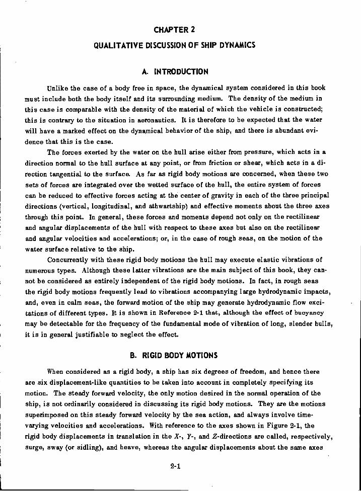
Although right-hand systems of coordinate axes are used throughout this book, it hasbeen found convenient, where elastic vibrations are dealt with, to orient the Y-axis in thedirection of the vibration. Thus when horizontal (athwartship) hull vibration is under discus-sion the axes are oriented as in Figure 2-1, but when vertical hull vibration is discussed theY-axis is taken vertical and the Z-axis horizontal (with positive direction out of the paper.)
Figure 2-1 Axes through the Center of Gravity of a Ship with Respect toWhich Forces and Moments Exerted by the Water May Be Defined
In the dynamics of rigid bodies, motions are defined in terms of the translation of thecenter of mass and rotation about the center of mass. While this procedure is also appliedto the ship, it must be realized that, since the hull is elastic, these relatively slow motionsare also accompanied by elastic deformations. These elastic deformations are not the onesconsidered in the discussion of hull vibration. Furthermore, the hull by itself is not usuallyconsidered as an isolated body because the component of the water forces due to accelerationis usually accounted for by adding mass to the hull mass to take care of this inertia effect.Since the rolling, heaving, and pitching motions, although slow, are still oscillatory and thushave the essential characteristics of vibrations, it is important to distinguish them from theelastic vibrations which, as has been stated, are the main subject of this book.
In the absence of an external alternating force, a body in free space could not executemotions in which the displacement of the center of mass was oscillatory. The ship is sub-ject to the constant force of gravity and to gravity moments which vary with its angular dis-placements about axes other than those through its center of gravity. The buoyancy momentsaccompanying rolling, heaving, and pitching are due to buoyancy forces that vary with thesemotions. Although elastic deformations in general accompany these motions, they are toosmall to play an essential role in determining these motions, and the term "rigid body mo-tions" is retained to distinguish them from the motions of the hull in which the elastic de-formations do play an essential role.
2-2
X

A ship stopped in a calm sea, if initially disturbed, will execute damped rigid bodymotions and eventually again come to rest. In disturbed seas, the surrounding water providesnot only the restoring forces and moments necessary for oscillatory rigid body motions and theforces associated with the added mass, but also the forces and moments required to maintainthese motions in the presence of damping.
C. ELASTIC VIBRATIONS OF THE ENTIRE HULL
When a ship is subjected to an impulsive load, such as occurs when a descending an-chor is suddenly arrested, it will execute elastic vibrations in addition to whatever rigidbody motions are excited. Of these vibrations some are observed only locally and some areobserved throughout the hull. The latter, in general, are of the type that may exist in a beamfree in space and so are called "beamlike." Although the surrounding water plays an impor-tant role in these vibrations, it does not destroy their beamlike characteristic and it is help-ful to consider the vibrations of the ideal solid beam free in space. This is frequently spokenof as the free-free beam (both ends free).
As emphasized in standard works on mechanical vibration,2-2 2-3' 2-4 the two terms
"modes" and "nodes" are used repeatedly in the discussion of continuous systems and mustnot be confused with each other in spite of the similarity in spelling. Thus the mode is thepattern or configuration which the body assumes periodically while in the vibratory condition,whereas the node is a point in the body which has no displacement when the vibration is con-fined to one particular mode. "Normal mode" of vibration is another very common term. Thenormal modes are the patterns in which the body can vibrate freely after the removal of ex-ternal forces.
A beam free in space may undergo four principal types of elastic deformation designatedas bending, twisting, shearing, and extensional deformations. These may all occur simulta-neously. In a solid beam, these same types of deformation may exist with respect to any ofthe three principal directions even though the relative magnitudes of bending, shearing, andtorsion may be very different with respect to the different axes. In the case of the ship, theelastic deformations that play a significant role in its vibration are limited to bending andshearing in both the vertical and horizontal planes through its longitudinal axis, and to tor-sion about the longitudinal axis. The identification of extensional (longitudinal) beamlikevibrations of hulls has so far been inconclusive, and this type of vibration is ordinarily con-sidered insignificant in slips although it may be quite significant in the propulsion systemsthemselves, as shown in Chapter 12.
In a symmetrical beam the bending and shearing effects combine to produce what areusually called the flexural modes, as illustrated in Figure 2-2.
The curves plotted in Figure 2-2 indicate the displacements in the Y-direction of pointsfalling on the X-axis when the bar is at rest. Similar modes exist for displacements in theZ-direction.
2-3

.Figure .2-2 'flextiral Modes Of.;.a...Free-Free Uniform Bar
,. .,Figiii-e,..21,Tilltiatrates'the:tOr.eioniiirmodeilif which a iinitoriii bellin'ifiliiy.':Vibrate, and
. . .
the'CurVeS.plottid show At-lei-hit 'displacement versus distance from 'the.ieci:. , - .:.::.47: .. - .: . ,- ' . -
3 -.196O-de Mode
4-.Mode .Mode
X Tar"-
In both the flexural andtorsional types of vibration, a natUral..fresiuencila'asSOCiated
with each pattern of vibration and the natural frequencies.increase,-aa the number of nbdes,,
(points. at-Whioh the -ciirVeS cross the X-axis) increases. ,
2,4
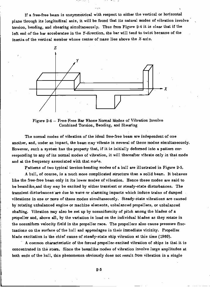
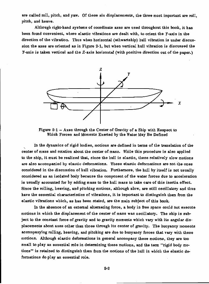
If a free-free beam is unsymmetrical with respect to either the vertical or horizontalplane through its longitudinal axis, it will be found that its natural modes of vibration involve -
torsion, bending, and shearing simultaneously. Thus from Figure 2-4 it is clear that if theleft end of the bar accelerates in the li-direction, the bar will tend to twist because of theinertia of the vertical member whose center of mass lies above the X-axis.
Figure 2-4 Free-Free Bar Whose Normal Modes of Vibration InvolveCombined Torsion, Bending, and Shearing
The normal modes of vibration of the ideal free-free beam are independent of oneanother, and, under an impact, the beam may vibrate in several of these modes simultaneously.However, such a system has the property that, if it is initially deformed into a pattern cor-responding to any of its normal modes of vibration, it will thereafter vibrate only in that modeand at the frequency associated with that mode.
Patterns of two typical torsion-bending modes of a hull are illustrated in Figure 2-5.A hull, of course, is a much more complicated structure than a solid beam. It behaves
like the free-free beam only in its lower modes of vibration. Hence these modes are said tobe beamlike,and they may be excited by either transient or steady-state disturbances. Thetransient disturbances are due to wave or slamming impacts which induce trains of dampedvibrations in one or more of these modes simultaneously. Steady-state vibrations are causedby rotating unbalanced engine or machine elements, unbalanced propellers, or unbalanced
shafting. Vibration may also be set up by nonuniformity of pitch among the blades of apropeller and, above all, by the variation in load on the individual blades as they rotate inthe nonuniform velocity field in the propeller race. The propellers also cause pressure fluc-tuations on the surface of the hull and appendages in their immediate vicinity. Propellerblade excitation is the chief cause of steady-state ship vibration at this time (1960).
A common characteristic of the forced propeller-excited vibration of ships is that it isconcentrated in the stern. Since the beamlike modes of vibration involve large amplitudes atboth ends of the hull, this phenomenon obviously does not result from vibration in a single
2-5
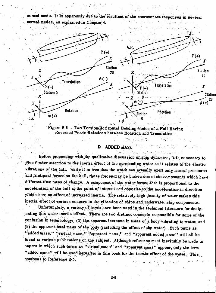
normal mode. It is aPparentlY dire tO theesüItantófthe nonresonint responses in severalnormal modes, aS explained in,Chapter 4.
Y(--)Station 0
Translation
Rotation
Y(+)
X
Station20
(-)X
y(.-)Translation
tatitiii-- -2 - 0 ------
Station
Figure 2-5 - Two:Torsionilorizontal Bending Modes of a Hull HavingReversed Phase Relations between Rotation and Translation .;
D. ADDED MASS,
Before proceeding with the qualitative discussion of ship dynamics, it is necessary togive further attention to the inertia effect of the surrounding water as it relates to the elasticvibrations of the hull. While it is true that the water can actually exert only normal pressuresand frictional forces on the hull, these forces may be broken down into components which have
, different time rates of change. A component of the water forces that is proportional to theacceleration of the hull at the point of interest and opposite to the acceleration in directionyields here an effect of increased inertia. The relatively high density of water makes thisinertia effect of serious concern in the vibration of ships and underwater ship components.
Unfortunately, a variety of terms have been used in the technical literature for desig-nating this water inertia effect. There are two distinct concepts responsible for some of theconfusion in terminology:_ (1) the apparent increase in mass of a body vibrating in water; and
. .
(2) the apparent total mass of the body (including the effect of the water). Such terms as"added mass," "virtual mass," "apparent mass," and "apparent added mass" will all befound in various publications on the subject. Although reference must inevitably be made topipers in which such terms ,as ""virtual.mass" and "apparent Mass" appear, only the term"added mass" will be used hereafter in this book for the inertia effect of the water. Thisconforms to Reference 2-5.
A'
Station20
X
Station20
95(+)
2-6
Not only is there much confusion about terminology regarding water inertia but there isalso a growing feeling that the concept of added mass of bodies vibrating in water has out-lived its usefulness. This arises from the fact that as the frequency increases, the assump-tion of incompressibility of the water on which the added mass concept is based becomesuntenable and the vibrating body becomes, in effect, a source of underwater sound.
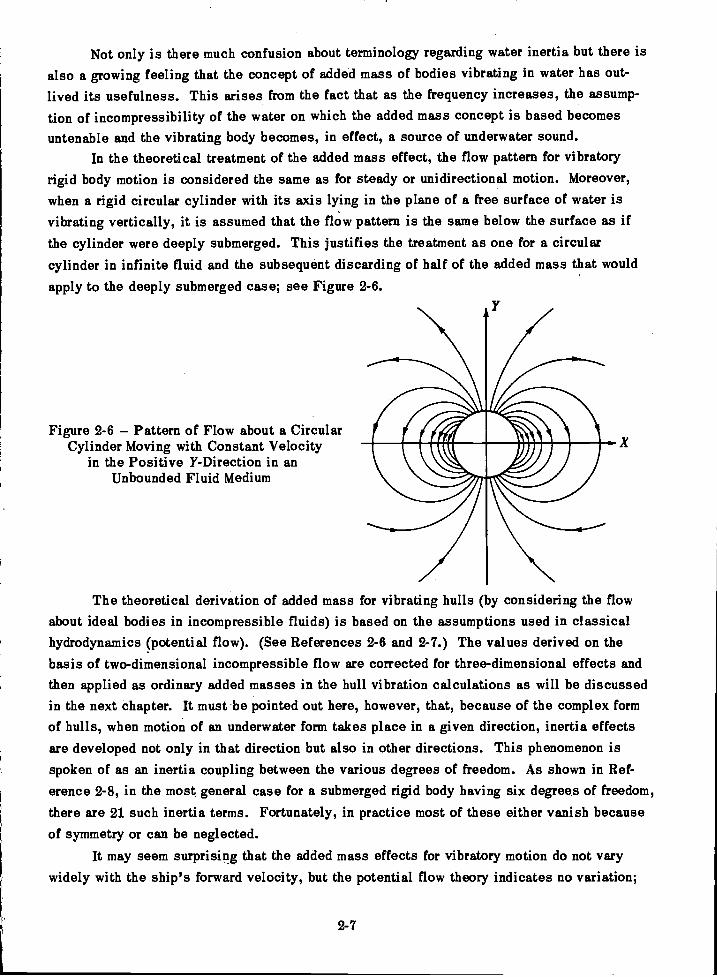
In the theoretical treatment of the added mass effect, the flow pattern for vibratoryrigid body motion is considered the same as for steady or unidirectional motion. Moreover,when a rigid circular cylinder with its axis lying in the plane of a free surface of water isvibrating vertically, it is assumed that the flow pattern is the same below the surface as ifthe cylinder were deeply submerged. This justifies the treatment as one for a circularcylinder in infinite fluid and the subsequent discarding of half of the added mass that wouldapply to the deeply submerged case; see Figure 2-6.
Figure 2-6 Pattern of Flow about a CircularCylinder Moving with Constant Velocity
in the Positive Y-Direction in anUnbounded Fluid Medium
ma.%
The theoretical derivation of added mass for vibrating hulls (by considering the flowabout ideal bodies in incompressible fluids) is based on the assumptions used in classicalhydrodynamics (potential flow). (See References 2-6 and 2-7.) The values derived on thebasis of two-dimensional incompressible flow are corrected for three-dimensional effects andthen applied as ordinary added masses in the hull vibration calculations as will be discussedin the next chapter. It must be pointed out here, however, that, because of the complex formof hulls, when motion of an underwater form takes place in a given direction, inertia effectsare developed not only in that direction but also in other directions. This phenomenon isspoken of as an inertia coupling between the various degrees of freedom. As shown in Ref-erence 2-8, in the most general case for a submerged rigid body having six degrees of freedom,there are 21 such inertia terms. Fortunately, in practice most of these either vanish becauseof symmetry or can be neglected.
It may seem surprising that the added mass effects for vibratory motion do not varywidely with the ship's forward velocity, but the potential flow theory indicates no variation;
2-7
this has been borne out by experimental observations. For further discussion of this point,see pages 59 and 60 of Reference 2-7.
E. LOCAL EFFECTS
In view of the complexity of a ship's structure, the number of "local" hull structuresis enormous. However, these structures may be divided into categories of different relativeimportance. The most important distinction to be made as far as hull vibration is concernedis between those structures that have an appreciable effect on the vibration characteristicsof the ship as a whole and those that do not. The possibility of affecting the ship as a wholeobviously depends primarily on the mass of the local structure, but it also depends on itslocation and its stiffness.
When a mass and spring are attached to a free-free beam, the "sprung mass" partic-ipates in the normal mode vibrations of the combined system. It can introduce an extra modeso that, as far as the beam itself is concerned, there may then exist two flexural modes withthe same number of nodes. Its effect on the previously existing modes depends on both itsmass and the proximity of the beam frequencies to the natural frequency of the mass-springcombination, that is, to the natural frequency of the mass when the end of the spring is heldfixed.
When local flexibilities of ship structures produce a sprung mass effect the normalmodes of the hull tend to depart from beamlike form, and modes of vibration of the ship maybe found in which the local vibration is excessive, whereas at the ends of the ship the vi-bration is well within tolerable limits.
When local structures are of relatively small mass in comparison to the mass of theship, their effect on the vibratory characteristics of the ship as a whole will be negligible.However, because of resonance, they may themselves vibrate excessively. If their naturalfrequencies coincide with the frequency of some source of excitation prevailing at the oper-ating speed of the ship, these structures may respond to an imperceptible hull vibration so asto produce an intolerable local condition. Obviously, the cure for such a condition is to changethe natural frequency of the local structure.
F. SHALLOW WATER EFFECTS
The vibration characteristics of ships are materially modified in passing from deep toshallow water. In the first place, there is a marked increase in the added mass effect forvertical vibration, and in the second place, the propeller exciting forces may be greatlychanged.
The change in added mass effect is due to the alteration of the noncirculatory flowpattern. A rough rule for the limit of depth at which this effect is no longer evident is six
2-8
times the draft. When the depth is less than this a lowering of the frequencies of the vertical
modes of the hull is observed.The variation in propeller excitation in restricted waters arises from a modification of
the steady flow due to the restriction of the channel around the ship. As will be pointed outin Chapter 7, any effect that disturbs the uniformity of flow into the propeller races will setup lateral forces which are transmitted to the hull through the propeller shaft bearings.
In addition to these two effects there will usually be a reduction in operating speed onentering shallow water. Thus the vibratory level may vary because of any one of these sep-
arate effects.Although it is not inconceivable under the circumstances that a particular ship might
experience less vibration while operating in shallow water, the chances are that it will ex-perience more. Specific examples of increased vibration in shallow water are cited in Ref-
erences 2-9 and 2-5. If a particular hull happens to be subject to resonant vibration whenoperating at its designed speed in deep Water, then it is quite possible that resonance willbe avoided at the speed assigned to shallow water operation.
REFERENCES
2-1. McGoldrick, R.T., "Buoyancy Effect on Natural Frequency of Vertical Modes of Hull
Vibration," JSR (Jul 1957).
2-2. Den Hartog, J.P., "Mechanical Vibrations," McGraw-Hill Book Co., New York (1956).
2-3. Timoshenko, S., "Vibration Problems in Engineering," D. Van Nostrand Co., New
York (1955).
2-4. Rayleigh, Lord, "Theory of Sound," Second Edition, Dover Publications, NewYork (1945).
2-5. Saunders, H.E., "Hydrodynamics in Ship Design," published by SNAME (1957).
2-6. Lewis, F.M., "The Inertia of Water Surrounding a Vibrating Ship," Trans. SNAME,Vol. 37 (1929).
2-7. Wendel, K., "Hydrodynamic Masses and Hydrodynamic Moments of Inertia," STG,
Vol. 44 (1950). Also TMB Translation 260 (Jul 1956).
2-8. Lamb, H., "Hydrodynamics," Dover Publications, New York (1945).
2-9. Noonan, E.F., et al., "Vibration Measurements on Ship S6-2 during Builders Trials,"prepared for Hull Structure Committee of SNAME by Noonan, Knopfle, and Feldman, Professional
Engineers (Nov 1959).
2-9
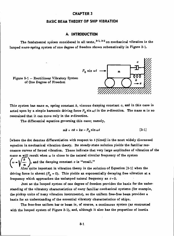
Figure 3-1 Rectilinear Vibratory Systemof One Degree of Freedom
CHAPTER 3
BASIC BEAM THEORY OF SHIP VIBRATION
A. INTRODUCTION
The fundamental sykem considered in all texts,34 3- 2 on mechanical vibration is thelumped mass-spring system of one degree of freedom shown schematically in Figure 3-1.
This system has mass m, spring constant k, viscous damping constant c, and in this ease isacted upon by a simple harmonic driving force P0 sin cot in the x-direction. The mass in is sorestrained that it can move only in the x-direction.
The differential equation governing this case; namely,
mi + kx = Po sin cot [3-1]
[where the dot denotes differentiation with respect to t (time)] is the most widely discussedequation in mechanical vibration theory. Its steady-state solution yields the familiar res-onance curves of forced vibration. These indicate that very large amplitudes of vibration of themass m will result when co is close to the natural circular frequency of the system
(6)and the damping constant c is "small."
Also quite important in vibration theory is the solution of Equation [3-1] when thedriving force is absent (P0 = 0). This yields an exponentially decaying free vibration at afrequency which approaches the undamped natural frequency as c- 0.
Just as the lumped system of one degree of freedom provides the basis for the under-standing of the vibratory characteristics of many familiar mechanical systems (for example,the pickup units of many vibration instruments), so the uniform free-free beam provides abasis for an understanding of the essential vibratory characteristics of ships.
The free-free uniform bar or beam is, of course, a continuous system (as contrastedwith the lumped system of Figure 3-1), and, although it also has the properties of inertia
8-1
P0 sin cot
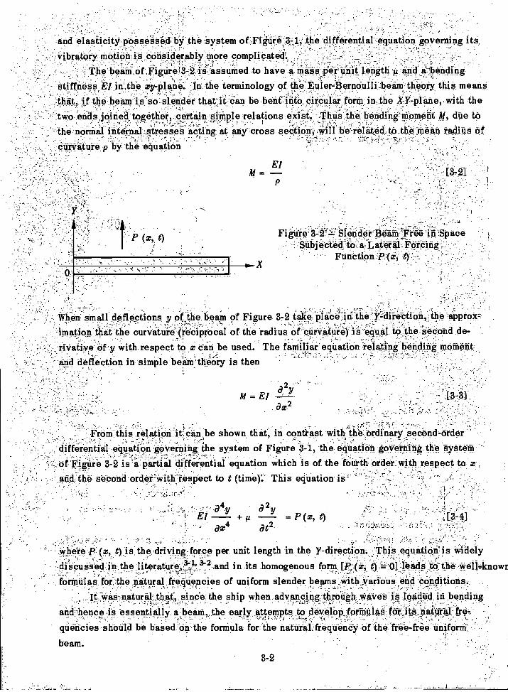
and elasticity. possessed by thesystem of Figure the differential ,equation governing its.vibratory motion is considerably More complicated'.
' The beaM'of.Figure 6-2 is'assumed to have a mass per unit length 'A and a-bendingstiffness El in the xy-plane: in the terminology of the Euler-Berneulli beard theory this meansthat, if the beam is so slender that it Can be bent' into Circular form in the X Y-plane, with thetwo ends joined together, certain simple relations exisi. !thus the bending moment 31, due tothe normal internal stresses acting at any cross section,- Will be related to the -Mean radius of
=
..curvature p by the equation
- When small deflections y Of the beam of Figure 3-2 take place in the y-direciion,. the approx-imation that the curvature (reciprocal of the "radius of curvature) is equal to the second de-
' riVative of y with respect to x can be used The familiar equation -relating bending momentand deflection in simple bearn'theOry is then
ElM =
Fignie3-2===,..' Men det Beath Treeiñ.SpaceSubjected to a Lateral Forcing
Function PO, .
= El -
a z2
From this relation it can be shown that, in contrast with the Ordinary second-orderdifferential equation governing the system of Figure -3-1, the eqUation governing the Systeinof Figure 3-2 is partial differential equation which is of the fourth order with respect to xand the seCond ordei'with respect to t (time).` This eqUation-is''
.
where P:(x, t) is the driving force per unit length in the Y-direction. This equation is widely-'-discussed in the_literature;V!:3-.and in its homogenous form [P .(x, t) 0] leads to the well-known, ,
formulas for the natural frequencies of uniform slender beams with various end coUditions.It was natural that, since the ship when advancing:.throdgli,,Wairee is loaded in bending
and hence is essentially a beard the early attempts to develop formulas for its natural fre--
quencies should be basecfdruthe forniula for the natural frequendy,bf the free-free uniform'
beam.
3.2
[3-4]

is:
a 4y a2y a 4ya 4YEl + +a x4 1." aw2at2 a t2 KAO at4
3-3
This equation has been discussed in many publications in addition to Reference 3-2.Even when the term for rotary inertia (/ ) is omitted, it has not been found possible toderive from it a direct formula for the natural frequency of the free-free beam. However,curves can be plotted showing how the frequencies of various modes vary with the ratios
4 Eland , as shown in Reference 3-6. The first of these ratios appears in the
El 2K AGL 2
The best known of such formulas is the Schlick formula for the fundamental vertical
frequency of a surface ship:
N =Cl!-CAL3
[3-5]
This formula is given in mixed units for convenience in practical application; thus
N is the fundamental vertical frequency in cpm,C is Schlick's empirical "constant,"
is the area moment of inertia of the midship section in ft2-in.2 units,A is the displacement in long tons, andL is the length in ft.
For ranges of values of C and further discussion of this formula, see Appendix C. Otherwell-known formulas such as those of Burri11,3-3 Todd and Marwood,3-4or Prohaska3-3 are
also discussed in that appendix.Here the empirical formulas are contrived to account for the many ways in which the ship
departs from the free-free uniform beam. Aside from its nonuniformity, one of the chief re-spects in which a ship departs from a slender beam in its vibratory characteristics is in therelatively much greater shearing flexibility of the ship. This is because the ship is not, infact, as slender as the beams for which the Euler-Bernoulli assumptions are valid.
The modification of the Euler-Bernoulli uniform beam to allow for shearing flexibilityyields what is now generally referred to as the "Timoshenko beam." This is still a uniformsolid beam, but when it is deformed, the slope of its elastic line is considered to have onecomponent due to bending and another due to shearing.. In the actual equation discussed byTimoshenko,3-2 there was included not only a term for shearing rigidity but also a term forrotary inertia, neither of which appear in the equation for the Euler-Bernoulli vibrating beam.The rotary inertia represents the increased inertia effect because the mass of the ship is notconcentrated along its longitudinal axis.
The homogeneous form of Timoshenko's equation in the notation adopted for this book
e y= 0 [3-61
K AG ax2 at2
formula for the slender uniform beam in which shearing flexibility is neglected. This formulais r,
= 22.4 [3-71pi, 4
The second ratio involves the relative magnitudes of the bending and shearing rigidities.Many questions may be raised as to the interpretation of Equation [3-61 and of the
wave solutions to which it gives rise. Since the ship is not a uniform beam, and analyticalexpressions cannot be given for the parameters El, lc, I, and KAG as functions of z,. thereader is referred to the literature for further discussion of this equation. (See the bibli-ography at the end of the book.)
Before considering the equations that provide the basis for the rational theory of shipvibration proposed in this book, it is necessary to discuss briefly the torsional vibrations ofthe free-free uniform beam. As in the case of the flexural vibrations, in which the Euler-Bernoulli assumptions provided an integrable equation, a simplified theory of torsional vibra-tion of beams or hulls is based on the torsional equations for the uniform (cylindrical) shaft.
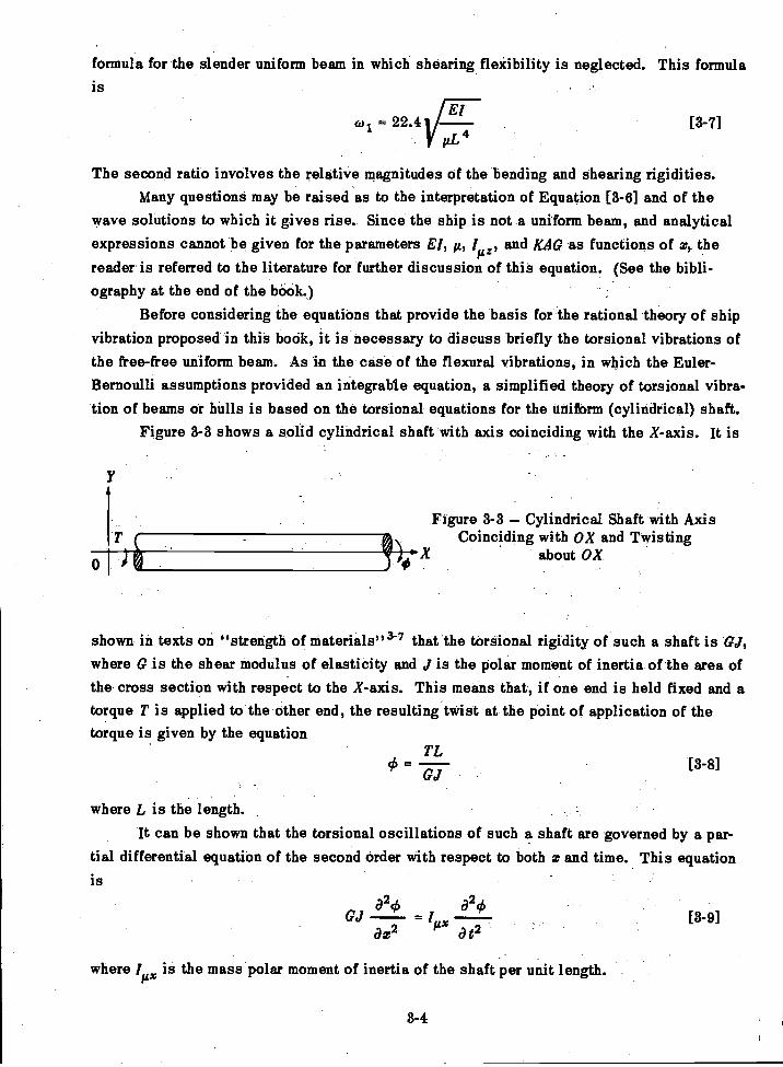
Figure 3-3 shows a solid cylindrical shaft with axis coinciding with the X-axis. It is
Figure 3-3 Cylindrical Shaft with Axis140_...x Coinciding with OX and Twisting
about OX
shown in texts on "strength of materials"3-7 that the torsional rigidity of such a shaft is al,where G is the shear modulus of elasticity and el is the polar moment of inertia of the area ofthe cross section with respect to the X-axis. This means that, if one end is held fixed and atorque T is applied to the other end, the resulting twist at the point of application of thetorque is given by the equation
TLgS =
GJ[3-8]
where L is the length.It can be shown that the torsional oscillations of such a shaft are governed by a par-
tial differential equation of the second order with respect to both z and time. This equationis
a20 (920
[3-9]az2 at2
where l is the mass polar moment of inertia of the shaft per unit length.
3-4
wave equation
This equation merits special attention because it has the form of the one-dimensional
In this_welkknown equation u may represent any displacement-like quantity,.and cthe yelocityof wave propagation._ Thus, if in Figuro.3-2,u is the displacement in,the.X-direction and c
is the velocity of propagation of longitudinal waves along the beam, the longitudinal vibrations
of the beam are governed by Equation [3-10] In the torsional case Of Figure 3-3 the velocity
of propagation is-
formulas for the natural. frequencies Can be readily deriyed froin the relations among frequency,-
wave velocity, and wavelength
[3-10]C2 at2
-1 a2u
c
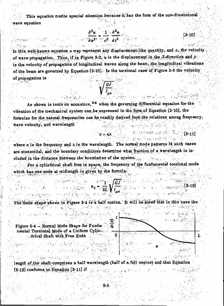
Theiiidaii.shipeshov`in" in Figure 3-4 ie-ichalf .coSine.
where n is the frequency and kis the wavelength. The normal plode patterns in such cases-
are sinusoidal, and the boundary conditions determine what fraction Of a wavelength is in-.
eluded in the distance between the boundaries of the system.For a cylindrical, Shaft free in space, the frequency of the fundamental torsional mode
which has one node at nikllength is given by the formula:
[341]
It be,iOtect thii'case the,
Figure 3-4 --- Normal Mode Shape for Ftinda-_
mental Torsional Mode of a Uniformdrical Shaft Free Ends
As shown in textS en acoustics," when the governing differential equation for thevibration ofthe mechanical system cantbe,,expressed in thelorm,of Equation [3.10], the
: ;.,
length 9E.z.the...,shaft. comprises a half wavelength (half of a full cosine) and that Equation
[3-12) conformsto.Equation,[3-11] if ,
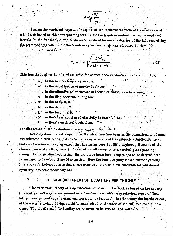
Just as the empirical formula of Schlick for the fundamental vertical flexural ifiOde ofa hull was based on the dOiresponding.fOrmula for the free-free uniform bar; so an empiricalformula for the frequency of the fundamental mode of torsional vibration of the hull resemblingthe corresponding formula for the free-free cylindriCal. shaft. was proposed by Horn
For
3-6
g eoN = 60k
A(B2 + b2)L[3-13]
This formula is given here in mixed units for convenience in practical application; thus;
--Ne is the natural frequency in cpm,-
g - is the acceleration of gravity in ft/sec 2,-
je0 is the effective polar momentof inertia Of inidahip'section area,A is the displaceinent in long tons,B is the beam, inft,D is the depth in ft,L. 'is the length in ft;'`G is the shear modulus of elasticity in tons/f0, and
, k is Horn's einpiriaal:doefficient;
discussion Of the evaluation of k and J eo, see Appendix C.Not only does the hull depart from the ideal free-free beam in the nonuniforrnity of mass
and stiffness distributions, but it also lacks symmetry, and this property complicates its vi-
bration characteristics to an extent that has so far been but little explored. Because of theclose approximation- to symmetry of most ships with respect to a vertical plane passingthrough the longitudinal centerline, the prototype beam-for-the equations to be derived hereis assumed to have One plane of symmetry. Here the term symmetry means mirror symmetry.It is shown in Reference 3q0 that mirror symmetry is a sufficient condition for vibrationalsymmetry, but not a necessary-One.
B. BASIC, DIFFERENTIAL EQUATIONS, FOR THE SHIP
The "rational" theory of ship vibration proposed in this "book is based On the assump-tion that the hull may be considered as a free-free beam with three principal types of flexi-bility, namely, bending, shearing, and torsional (or twisting). In this theory the inertia effectof the water is treated' as -equivalent to mass added to the mass of the hull at suitable loca-tiona. The elastic axes for bending are assumed to be vertical and horizentif.----
The longitudinal (X) axis is taken as passing through a point halfway between the main deck
and the keel at the midship section; this is considered to be parallel to the keel whether or
not the ship is actually at zero trim. The orientation of the y- and Z-axes are dependent on
the modes of vibration considered.This analysis provides for a coupling of horizontal vibration with torsional vibration,
but, because of the symmetry, no coupling of vertical vibration with either torsional or hori-
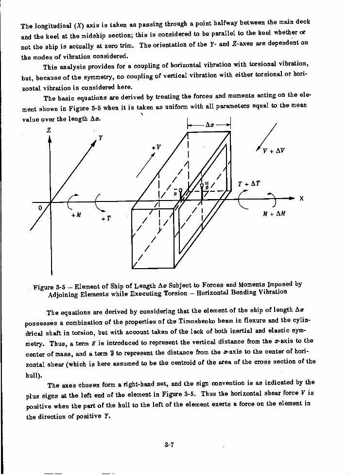
zontal vibration is considered here.The basic equations are derived by treating the forces and moments acting on the ele-
ment shown in Figure 3-5 when it is taken as uniform with all parameters equal to the mean
value over the length Az.
3-7
M + AM
Figure 3-5 Element of Ship of Length Az Subject to Forces and Moments Imposed byAdjoining Elements while Executing Torsion Horizontal Bending Vibration
The equations are derived by considering that the element of the ship of length Az
possesses a combination of the properties of the Timoshenko beam in flexure and the cylin-
drical shaft in torsion, but with account taken of the lack of both inertial and elastic sym-
metry. Thus, a term i is introduced to represent the vertical distance from the z-axis to the
center of mass, and a term 5 to represent the distance from the z-axis to the center of hori-
zontal shear (which is here assumed to be the centroid of the area of the cross section of the
hull).The axes chosen form a right-hand set, and the sign convention is as indicated by the
plus signs at the left end of the element in Figure 3-5. Thus the horizontal shear force V is
positive when the part of the hull to the left of the element exerts a force on the element in
the direction of positive Y.
Application of Newton's law to 'motion in the 1-direction gives,
a2= A
a t2
yi = y 1 95., for small motions
Hence
Newton's equation for moments about a Z-axis gives
AM = V +" Az a2Y [3-17]gz 2at
where M is the moment with respect to a Z-axis exerted on the element by the part of thehull to its left. From the Timoshenko beam properties
MAzAy =
El
where y is the rotation of the cross section with respect to Z-axis.,
VAzAy". yAz
' KAG
where y" is the displacement in the 1-direction of the center of shear and fad is the shearrigidity. The last equationalso implies that the displacement of the center of shear dependsonly on shearing and bending action and not on torsion, that is, thatthe hull twists about thecenter of shear.
The simple concept of torsional rigidity defines the quantity GJ by the torque requiredto produce a given rate of twist with respect to the longitudinal- axis. The complete set ofshear stresses in the cross section has a moment about the X-axis designated in Figure 8-5As T. In the absence or a net vertical shear force, the torque with respect to the longitudinalaxis is obtained by subtracting from T the moment due to the net horizontal shear force.This is V F. ,Hence, from the definition of GJ, and the sign conventionsindicated in Figure 3-5 .
8-8
82y a20.AV = FAT. ILAzi
at2 at2
where y is the displacement in the 1-direction of the center of mass of the elethen-t. Since
whence
CJ Irk - (T + V1)Ax
Afk, -VI)Ax---
GJe
Since y' ck, and the element of length Ax is treated as uniform in the approximationto the continuously Varying hull,- AY"= Ay AqS. So
VAz FTAz VAT 2Ax
AY = RAC - Gcle 0-4
Since I is specified with respect to the arbitrarily chosen X-axis, the equation for the timerate of change of moment of momentum about the X-axis gives
set of partial differential equations is obtained:,
where / is the -mass moment of inertia pet unit length With respect to the X-axis, includingthe allowance for the inertia effect of the water.
The first term in this equation is the rate of change with respect to the X-axis of themoment of momentum associated with the center of mass; the second term is the rate of changeof moment of momentum about a parallel- axis through the center of mass. Therefore
LX'at2 .
If the foregoing equations are set in differential form with respect to x the following
[3-20]-
[3-211
[3-221
[3-243
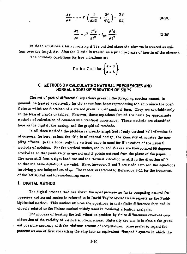
ay1 -22 ) T= y V +
az KAG GJe GJe
a2 a2y a20
-_IILXa t2
In these equations a term involving A5 is omitted since the element is treated as uni-form over the length Ax. Also the X-axis is treated as a principal axis of inertia of the element.
The boundary conditions for free vibrations are
V = M = T = 0 for fzx :1,01
C. METHODS OF CALCULATING NATURAL FREQUENCIES ANDNORMAL MODES OF VIBRATION OF SHIPS
The set of partial differential equations given in the foregoing section cannot, ingeneral, be treated analytically for the nonuniform beam representing the ship since the coef-ficients which are functions of z are not given in mathematical form. They are available onlyin the form of graphs or tables. However, these equations furnish the basis for approximatemethods of calculation of considerable practical importance. These methods are classifiedhere as the digital, the analog, and the graphical methods.
In all three methods the problem is greatly simplified if only vertical hull vibration isof concern, for here, unless the ship is of unusual design, the symmetry eliminates the cou-pling effects. In this book, only the vertical case is used for illustration of the generalmethods of solution. For the vertical modes, the y- and Z-axes are then rotated 90 degreesclockwise so that positive Y is upward and Z points outward from the plane of the paper.The axes still form a right-hand set and the flexural vibration is still in the direction of yso that the same equations are valid. Here, however, 3 and are made zero and the equationsinvolving y are independent of 0. The reader is referred to Reference 3-11 for the treatmentof the horizontal and torsion-bending cases.
1. DIGITAL METHOD
The digital process that has shown the most promise so far in computing natural fre-quencies and normal modes is referred to in David Taylor Model Basin reports as the Prohl-Myklestad method. This method utilizes the equations in their finite difference form and isclosely related to the Holzer method widely used in torsional vibration analysis.
The process of treating the hull vibration problem by finite differences involves con-sideration of the validity of various approximations. Naturally the aim is to obtain the great-est possible accuracy with the minimum amount of computation. Some prefer to regard theprocess as one of first converting the ship into an equivalent "lumped" system in which the
3-10
[3-29]
[3-30]
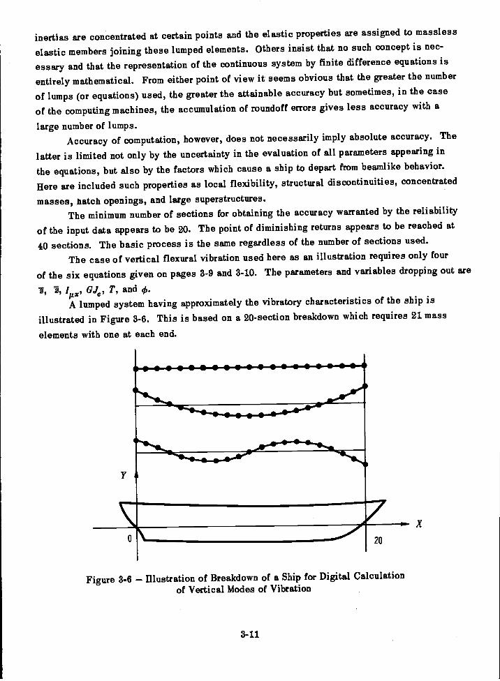
inertias are concentrated at certain points and the elastic properties are assigned to massless
elastic members joining these lumped elements. Others insist that no such concept is nec-
essary and that the representation of the continuous system by finite difference equations is
entirely mathematical. From either point of view it seems obvious that the greater the number
of lumps (or equations) used, the greater the attainable accuracy but sometimes, in the case
of the computing machines, the accumulation of roundoff errors gives less accuracy with a
large number of lumps.Accuracy of computation, however, does not necessarily imply absolute accuracy. The
latter is limited not only by the uncertainty in the evaluation of all parameters appearing in
the equations, but also by the factors which cause a ship to depart from beamlike behavior.
Here are included such properties as local flexibility, structural discontinuities, concentrated
masses, hatch openings, and large superstructures.The minimum number of sections for obtaining the accuracy warranted by the reliability
of the input data appears to be 20. The point of diminishing returns appears to be reached at
40 sections. The basic process is the same regardless of the number of sections used.
The case of vertical flexural vibration used here as an illustration requires only four
of the six equations given on pages 3-9 and 3-10. The parameters and variables dropping out are
, 1, ItLx, Gele, T, and ch.
A lumped system having approximately the vibratory characteristics of the ship is
illustrated in Figure 3-6. This is based on a 20-section breakdown which requires 21 mass
elements with one at each end.
Figure 3-6 Illustration of Breakdown of a Ship for Digital Calculationof Vertical Modes of Vibration
3-11

The mass elements are points of Concentration of the translational inertia fiAx and therotational inertia ! Az. The elastic properties of the hull are concentrated in the masslessconnecting members;' 'In this case there are the bending rigidity El and the shearing rigidityKAO. Hence, two principal modifications are made of the equations given on pages 3-9 and 3-10for this particular calculation.- First, they are converted froni.differential form to algebraic formwith respect to time by using the fact that the desired solutions will be simple harmonic vi-brations which can be expressed in the form
W(x, = - Yi (2) sin (di
where Y (z) is the normal mode pattern for the ith normal mode Second, they are expressed.in finite difference form with respect z.
The equations are then converted from differential forth to finite difference form withrespect to z. As given here,'they are in their simplest form.
-
y = Yi(x) sin coi t
= iiAx y (02
AM ..VAz !izz-Azyico2
3-12
V AxAy = yAz -
-KAO
2 YO,
[3-31]
-
[3-32]
. [3-33]
[3-34]
[3-35]
[3-36]
AsIshown.in Reference 3-11, a staggering system is usually used for increased accuracy ofcalculation. This requires introducing half stations and considering forces and displace-ments at staggered. intervals with the boundary conditions - V ; =0 at each end. In this
_ .
simplified form the subscript notation required to identify a value at any particular Stationalong the -length of the hull i unnecessary,, as is also the use of half-station staggering ofcertain terms for increased accuracy of computation. Each.ofthe four equations indicatesthe difference'betwe0.n. two values of the variable on the left side Of the equation in advanc-ing a distance Ax_.tO.the tight when-the hull is executing a simple harmonic vibration of
- circular frequency w.The computation is Stated-by assigning an arbitrary value to wand unit value to y at
' the left-end station. ' It is known that Vo = 0.and Mo-= 0 but the value of yo must remain. ,
undetermined temporarily. The set of four difference equations will then permit advancingfrom Station 0 to Station '1 with V, hi, y, and y all known in terms of yo. This process can
.which -s
then be continued cyclicly until the right end of the hull is reached. Here it is known that ifthe frequency co assumed was a natural frequency, it will be possible to find a value of yosuch that the boundary conditions, that V and M are both zero at this end, will be satisfied.Once yo is determined numerical values are then fixed for V, M, y, and y throughout the ship.
There are a number of ways in which this basic process can be carried out. Thus, usecan be made of the fact that the desired solution can be formed from a linear combination ofcalculations made by starting at the left end, first with the values y = 1 and y = 0 and thenwith the values y 0, y = 1. A range of values of co is then explored for which it is possibleto find a linear combination of these two calculations, which will make V and M both zero atthe right end of the hull.
Since the lumped system used here to represent the hull has only 21 degrees of freedom,it can have only 21 natural frequencies and normal modes, whereas a continuous free-free beamhas a theoretically infinite number of modes. In practice, such a calculation would not becarried beyond about the sixth or eighth mode, the number depending on the length to depthratio of the hull. If the method were valid beyond this number of modes it would be necessaryto use a larger number of elements in the breakdown in order to realize its potentialities.
Several points should be noted concerning this method of computation. The naturalfrequencies are found by a process of searching for values of co at which the boundary con-ditions can be satisfied. At each frequency thus found the calculation automatically gives anormal mode pattern. There is no significance to the absolute amplitudes used in such a cal-culation, but only to their relative values. Thus, the calculation shows what values V, M, y,and y would have throughout the hull if it were possible for it to vibrate with unit amplitude atthe left end at the particular frequency in question. In the foot-ton-second system of unitsthis would mean an amplitude of 1 ft at station zero, clearly an excessive value. However,since the equations used are linear the result can be used to obtain the values associatedwith amplitudes of practical magnitude, that is, fractions of an inch.
The Model Basin has for the present (1960) adopted the station designations as 0 at thestern and 20 at the bow for the vibration calculations. This is the opposite to that used in thenaval architects' lines drawings-but preserves the convention of having the bow to the rightin the ship's profile.
In spite of the increased number of variables and parameters, the basic process of cal-culating torsion bending modes by digital caloulation is the same as for the simpler case justillustrated. When a normal mode of this type is found by digital calculation there will beobtained sets of values of y, y, 40, V, M, and T for each natural frequency on the basis ofunit amplitude in y at station zero. When y and are plotted there may be found pairs oftorsion-horizontal bending modes in which there are the same number, of torsional and flexuralnodes in each mode. However, there is reversal of phase between rotation and translationas illustrated in Figure 2-5.
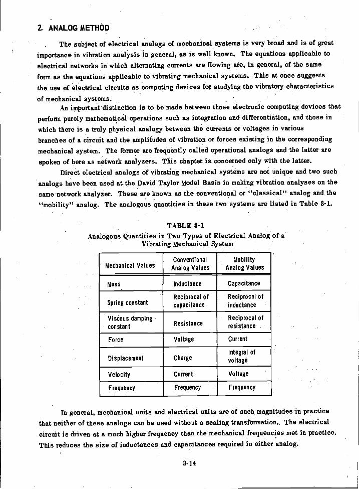
2. ANALOG METHOD
The subject of electrical analogs of mechanical systems is very broad and is of greatimportance in vibration analysis in general, as is well known. The equations applicable toelectrical networks in which alternating currents are flowing are, in general, of the same
form as the equations applicable to vibrating mechanical systems. This at once suggeststhe use of electrical circuits as computing devices for studying the vibratory characteristics
of mechanical systems.An important distinction is to be made between those electronic computing devices that
perform purely mathematical operations such as integration and differentiation, and those inwhich there is a truly physical analogy between the currents or voltages in variousbranches of a circuit and the amplitudes of vibration or forces existing in the correspondingmechanical system. The former are frequently called operational analogs and the latter arespoken of here as network analyzers. This chapter is concerned only with the latter.
Direct electrical analogs of vibrating mechanical systems are not unique and two suchanalogs have been used at the David Taylor Model Basin in making vibration analyses on thesame network analyzer. These are known as the conventional or "classical" analog and the"mobility" analog. The analogous quantities in these two systems are listed in Table 3-1.
TABLE 3-1Analogous Quantities in Two Types of Electrical Analog of a
Vibrating Mechanical System
In general, mechanical units and electrical units are of such magnitudes in practicethat neither of these analogs can be used without a scaling transformation.. The electricalcircuit is driven at a much higher frequency than the mechanical frequencies met in practice.
This reduces the size of inductances and capacitances required in either analog.
3-14
'
Mechanical ValuesConventional
Analog ValuesMobility
Analog Values
Mass Inductance Capacitance
Spring constantReciprocal ofcapacitance
Reciprocal of
inductance
Viscous dampingconstant. Resistance
Reciprocal ofresistance
Force Voltage Current
Displacement ChargeIntegral ofvoltage
Velocity Current Voltage
Frequency Frequency Frequency
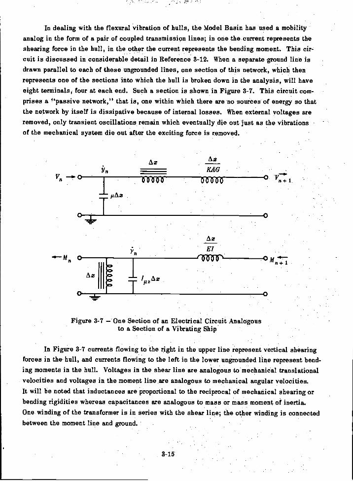
m n
In dealing with the flexural vibration of hulls, the Model Basin has used a mobilityanalog in the form of a pair of coupled transmission lines; in one the current represents theshearing force in the hull, in the other the current represents the bending moment. This cir-cuit is discussed in considerable detail in Reference 3-12. When a separate ground line isdrawn parallel to each of these ungrounded lines, one section of this network, which thenrepresents one of the sections into which the hull is broken down in the analysis, will haveeight terminals, four at each end. Such a section is shown in Figure 3-7. This circuit com-prises a "passive network," that is, one within which there are no sources of energy so thatthe network by itself is dissipative because of internal losses. When external voltages areremoved, only transient oscillations remain which eventually die out just as the vibrationsof the mechanical system die out after the exciting force is removed.
Yn KAG
01000 06300 0 C1
3-15
Figure 3-7 One Section of an Electrical Circuit Analogousto a Section of a Vibrating Ship
In Figure 3-7 currents flowing to the right in the upper line represent vertical shearingforces in the hull, and currents flowing to the left in the lower ungrounded line represent bend-ing moments in the hull. Voltages in the shear line are analogous to mechanical translationalvelocities and voltages in the moment line are analogous to mechanical angular velocities.It will be noted that inductances are proportional to the reciprocal of mechanical shearing orbending rigidities whereas capacitances are analogous to mass or mass moment of inertia.One winding of the transformer is in series with the shear line; the other winding is connectedbetween the moment line and ground.
gAx
0
To find the natural frequencies of a hull experimentally, the usual procedure is to in-stall a vibration generator that is operated over a wide range of speeds and to observe thosespeeds at which resonance peaks of amplitude are found. Similarly, with the analog the nat-ural frequencies of the circuit are found not by observing free oscillations but by applyingcontinuous excitation by means of an oscillator. In the case of the mobility analog the con-dition corresponding to resonance in the mechanical system is actually an electrical anti-resonance. This is advantageous in that little power is taken from the oscillator. A highresistance is inserted between the ungrounded terminal of the oscillator and one end of theshear line in the circuit. If this resistance is high enough, the current fed into the shear linewill remain practically constant regardless of the frequency since the change in impedance ofthe circuit will have little effect on the total impedance. At each antiresonance the voltagewill rise at the ends of the shear line, and the normal mode pattern of the hull may then befound by plotting the voltage measured along the shear line at the 20 stations.
To show that this electrical system is analogous to the vibrating hull it is requiredmerely to show that the application of Kirchhoff's laws for electrical circuits when applied tothe section shown in Figure 3-7 will yield the same set of difference equations as Equations[3-33] through [3-36]. Thus, the difference in currents at the two ends of the shear line ofthe section must equal the current flowing from the shear line to ground. The latter current,however, is the product of the voltage and the admittance jcofiAz, where j = F:17 n a-c cir-cuit theory, differentiation with respect to time is effected by multiplying by the operator ico,and integration with respect to time by dividing by jco. Hence the current to ground is
jcoicAzi = 1LAzco2y
Hence
Vn pAzw2y + Vn + 1
Or
AzM.
El
AV = icAzyco2 [3-33]
In the moment line Kirchhoff's current equation involves four currents: M M-n+19 VnAx(through the transformer minding which is coupled to the shear line V), and (jogpzAz) through
the capacitance. When the directions of these currents are taken into account there results
the equation
AM = V Az Azyco2Az
3-16
[8-84]
The remaining two equations follow from Kirchhofrs potential relations. Thus the voltage dropAz
in the inductance is equal to the inductance times the rate of change of current, i.e.,El
HenceAx
+ 1= M
or, on integrating with respect to time,
MAzAy =
El
Finally, since the voltage drop in the winding of the transformer in the shear line isAx times the voltage across the other winding () and since the voltage drop in the induct-
Ax Az .ance is equal to - V, the potential equation is
MG KAG
= ;AX+ 1 ) +KAG
On integrating this gives
V AzAy = yAZ
KAG[3-36]
It is seen that the boundary conditions of the free-free hull are satisfied in the analogif the shear and moment lines are isolated at the ends since this makes V = M = 0. Of course,when an oscillator is connected to one end, it gives an input current which is analogous toapplying an external simple harmonic driving force to one end of the hull. The voltages de-veloped at the ends correspond to the rectilinear and angular velocities at the ends of the hull.
A photograph of the TMB Network Analyzer used for vibration analysis by means ofthe electrical analog is given in Figure 3-8. A complete description of this network analyzeris given in Reference 3-13.
3. GRAPHICAL INTEGRATION - STODOLA METHOD
Some success has been attained in computing the lower modes of hull vibration bygraphical integration. This is of practical importance since analog or digital computing fa-cilities are not universally available. In this chapter the application of graphical integrationto the Stodola method is discussed, but it must be emphasized that numerical integration canalso be applied to this method. In applying this method the added mass must have been pre-viously computed and added to the mass of the hull as a distributed mass. Here the hull isconsidered as a beam free in space and the added mass is assumed to remain constant in time.
The case of vertical vibration is again used to illustrate the method, since in this casecoupling with torsion is negligible. As a further simplification the effect of rotary inertia isneglected here. The set of differential equations to be integrated is then:
3-17
[3-35]
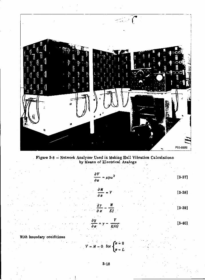
4
OV= ityco 2
ce
ay M
x El
ay-Y -
KAG
With boundary conditions
= 0= M = 0 forf-
3-18
x = L
[3-37]
[3-38]
[3-39]
[3-40]
04
cs
II
PSD-66050
Figure 3-8 Network Analyzer Used in Making Hull Vibration Calculationsby Means of Electrical Analogs
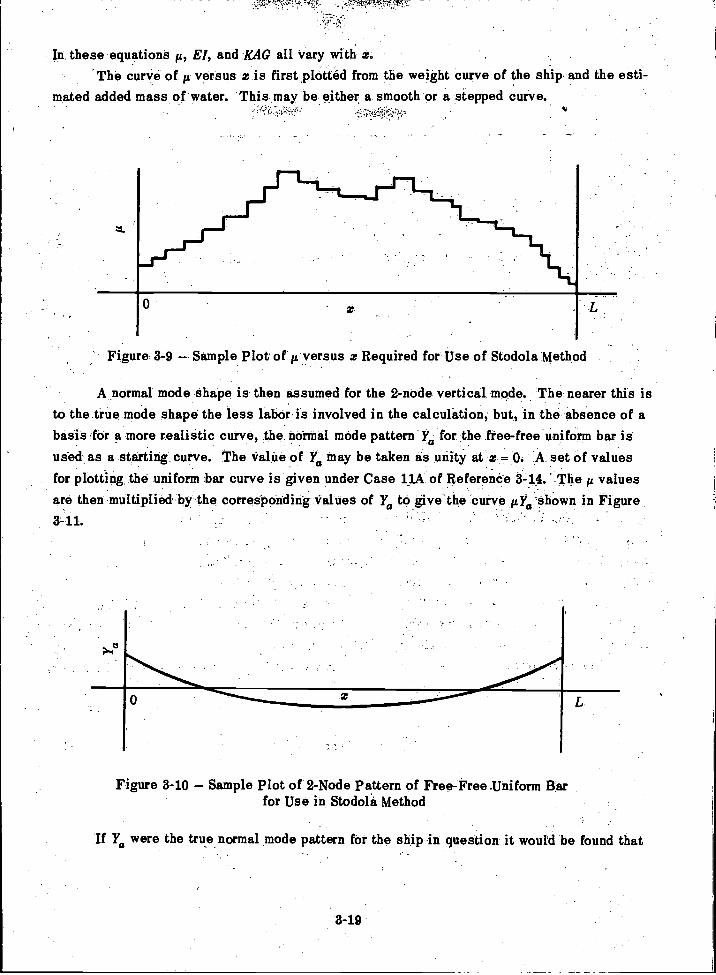
In these equations A, El, and RAG all vary with x.The curve of fL versus x is first plotted from the weight curve of the ship and the esti-
mated added mass of water. This may be either a smooth or a stepped curve.
0
' Figure 3-9 Sample Plot of p. versus x Required for Use of Stodola Method
A normal mode shape is then assumed for the 2-node vertical mode. The nearer this isto the true mode shape the less labor is involved in the calculation, but, in the absence of abasis for a more realistic curve, the normal mode pattern Y0 for the free-free uniform bar isused as a starting curve. The Value of Ya may be taken as unity at z = 0. A set of valuesfor plotting the uniform bar curve is given under Case 14A of Reference 3-14. The 1.1 valuesare then multiplied by the corresponding Values of Ya to give the curve AY0 shown in Figure3-11.
Figure 3-10 Sample Plot of 2-Node Pattern of Free-Free Uniform Barfor Use in Stodola Method
If Ywere the true normal mode pattern for the ship in question it would be found that
8-19
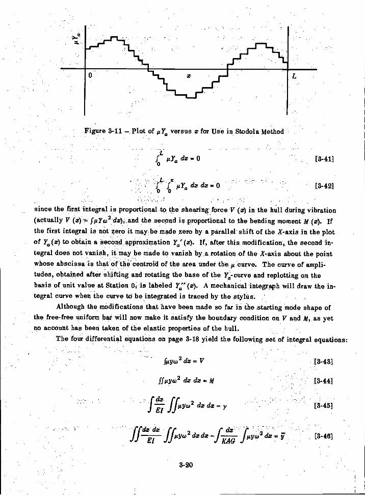
L, x10 So taa dz dz = 0 [3-42]
since the first integral is proportional to the shearing force V (0 in the hull during vibration(actually V (z)= f FY6,2 dx), , and the second is proportional to the bending moment M (z). Ifthe first integral is not zero it may be made zero by a parallel shift of the X-axis in the plotof Ya(0 to obtain a second approximation F0'(0. If, after this modification, the second in-tegral does not vanish, it may be made to vanish by .a rotation of the X-axis about the pointwhose abscissa is that of the centroid of the area under the j curve. The curve of ampli-tudes, obtained after shifting and rotating the base of the Ye-curve and replotting on thebasis of unit value at Station 0, is labeled Ya" (0. A mechanical integraph will draw the in-tegral curve when the curve to be integrated is traced by the stylus.
Although the modifications that have been made so far in the starting mode shape ofthe free-free uniform bar will now make it satisfy the boundary condition on V and M, as yetno account has been taken of the elastic properties of the hull.
The four differential equations on page 3-18 yield the following set of integral equations:
Figure 3-11 Plot of Alia versus z for Use in Stodola Method
ya dz = 0 [3-41]
filyco2 dx = V
ff 10(1)2 dz dz = M
ffiy(02 dz dz = y
j:f4d2 ffilyw2 dx -f
3-20
[3-43]
fis; 02 dx F., [3-46]
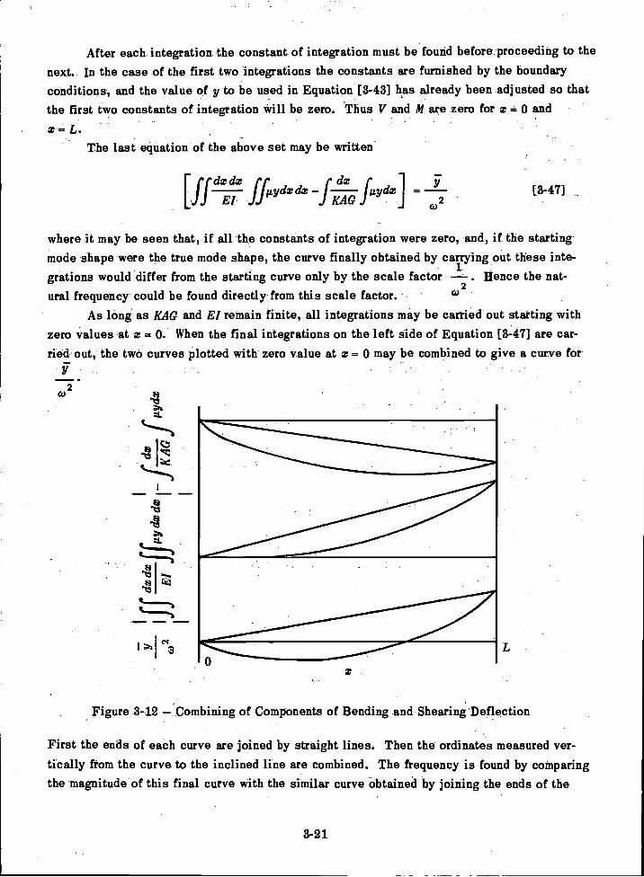
After each integration the constant of integration must be found before proceeding to thenext. In the case of the first two integrations the constants are furnished by the boundaryconditions, and the value of y to be used in Equation [3-43] has already been adjusted so thatthe first two constants of integration will be zero. Thus V and ill are zero for z 0 and
z = LThe last equation of the above set may be written
3-21
where it may be seen that, if all the constants of integration were zero, and, if the startingmode shape were the true mode shape, the curve finally obtained by carrying out these inte-grations would differ from the starting curve only by the scale factor . Hence the nat-ural frequency could be found directly from this scale factor. °)
As long as KAG and El remain finite, all integrations may be carried out starting withzero values at z = 0. When the final integrations on the left side of Equation [3-47] are car-ried out, the two curves plotted with zero value at x = 0 may be combined to give a curve for
F
co2
41 I
Ia
Figure 3-12 Combining of Components of Bending and Shearing Deflection
First the ends of each curve are joined by straight lines. Then the ordinates measured ver-tically from the curve to the inclined line are combined. The frequency is found by comparingthe magnitude of this final curve with the similar curve obtained by joining the ends of the
[ffdzEd7 ffilYdz&T 1.4;TK f"dd =
F2
[3-47]
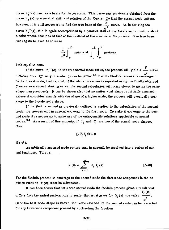
curve Ya" (x) used as a basis for the gy curve. This curve was previously obtained from thecurve Ya (x) by a parallel shift and rotation of the X-axis. To find the normal mode pattern,
however, it is still necessary to find the true base of the curve. As in deriving theco 2
curve y (x), this is again accomplished by a parallel shift of the X-axis and a rotation abouta point whose abscissa is that of the centroid of the area under the curve. The true basemust again be such as to make
1 rLrX-2f fly& and gy dx dx
(`) o 0 0
both equal to zero.If the curve ye" (x) is the true normal mode curve, the process will yield a curve
(02differing from Ya" only in scale. It can be proven' that the Stodola process is convergentto the lowest mode; that is, that, if the whole procedure is repeated using the finally obtainedY curve as a second starting curve, the second calculation will come closer to giving the sameshape than previously. It can be shown also that no matter what shape is initially assumed,unless it coincides exactly with the shape of a higher mode, the process will eventually con-verge to the 2-node mode shape.
If the Stodola method as previously outlined is applied to the calculation of the secondmode, the process will in general converge to the first mode. To make it converge to the sec-
,
ond mode it is necessary to make use of the orthogonality relations applicable to normalmodes.34 As a result of this property, if Yi and 7, two of the normal mode shapes,then
fz Yi dx = 0
if i j-An arbitrarily assumed mode pattern can, in general, be resolved into a series of nor-
mal functions. This is,
00
(x) = 2" a (x) [3-48]
i=
For the Stodola process to converge to the second mode the first mode component in the as-sumed function y (x) must be eliminated.
It has been shown that for a true normal mode the Stodola process gives a result that(x)
differs from the initial pattern only in scale; that is, it gives for Yi (x) the value(02
Once the first mode shape is known, the curve assumed for the second mode can be correctedfor any first-mode component present by subtracting the function
3-22
is seen that this quantityis equal- to al Y1 (z) of the summation in Equation [3748]-
- since = .
;Lf y f (a1 Y1 + a2 1'2 etc) y1 dz,
Bythe-brdiogonality relation all term-s'of the integration vanish except
.f A:ai Yi?0
-
For further discussion of the Stoclola method as applied to this problem, see Reference 3-6.
' 4. GENERAL
This chapter presents only the essential elements of the methods used so far at theDavid Taylor Model Basin to calculate the natural frequencies and normal modes of vibration-.of ,a hull. A recent.TMR reports" goes much further into the mathematical details of suchcalculations than is feasible in a book dealing with the general subject of ship vibtation. -This reference also goes into the extension of the beam theory to the cases in which part ofthe mass contributing to the displacement of the ship is considered flexibly attached to the
. hull girder. This question is also discussed in Chapters 5 and 13 of this book.
REFERENCES
3-1. Den Hartog, J.P, "Mechanical Vibrations," McGraw-Hill Book Co., New York (1956).
3-2. Timoshenko, S., "Vibration Problems in Engineering," D.,Vari Nostrand Co.,.New York (1955).
-
3-3. &mill, L.C., "Ship Vibration: Simple Methods of Estimating Critical Frequencies,"NEC! Trans, Vol. 51 (1984-35).
3-4 Todd, F.H, and Marwood, W.J., "Ship Vibration," NEC! Trans, Vol. 64 (1948)._
3-5. Prohaska, C.W., "The Vertical Vibration of Ships," Shipbuilder, Vol. 54 (Oct, Nov
1947).
3-6. Ormondroyd, J., et al., "Dynamics of a Ship's Structure," Engin Res Inst, Univ ofMichigan, Ann Arbor (Mar 1949) (out of ptint).
3-7. Boyd, J.E., "Strength of Materials," McGraw-Hill Book Co., New ,York (1924).
3723
_
3- 8- Rayleigh, Lcird"Theory of Sound," Second Edition, Dover Publications,New York (1945
3- 9. Horn,."Horizontal--und TorsionsSchiffschWingnagen auf Frachischiffeni"WRH, Vol. 6, No.218 (1925).
.3-10. Vane; .F.F., s"A GUide for the Selection and Application-of Resilient'Monntings toShipboard Equipment," TMB Report 880, Revised Edition (Feb 1958).
3-11 Leibowitz, R.C. and Kennard, E.H., "Theory of Freely Vibrating Nonuniform -
Beams Including Methods Of Solution and Application to Ships," TMB Report 1317 (May 1961).
3-12. Kapiloff, E., "calculation of Normal Modes and Natural Frequencies of Ship Hullsby Means of the Electrical Analog," TMB Report 742 (Jul 1954).
3-13. Kenny, J.H. and Leibowitz, R.C., "Design Details and Operating Procedure for theNB Network Analyzer," TMB Report 1272 (Apr 1959).
3-14- McGoldrick, R.T.i."A Vibration Manual for EngineerS,"-TMB Report R7189,Second Edition (Dec 1957).
3-24

CHAPTER 4
BEAM THEORY OF STEADY-STATE SHIP VIBRATION
A. INTRODUCTION
As in the previous chapter the treatment of hulls given here is based on beam theory.However, at this point, account must be taken of the limitations of this theory. This leadsto what is called here the "rational" theory of ship vibration. The methods presented in thischapter are thus essentially heuristic and "quasi-mathematical."
When there is applied to the ideal Euler-Bernoulli beam (otherwise free in space) anexternal forcing function, the differential equation applicable to the system is
a4y a2 yEl + = P (x,
a w4 a
where p (a, t) is the driving force in the Y-direction per unit length of the beam. It is to benoted that in general p varies both with distance from the left end of the beam and with time.When the forcing function is specified mathematically particular solutions of Equation [4-1]can be given, as shown in References 4-1 and 4-2.
For the nonuniform Euler-Bernoulli beam the differential equation has the more generalform
a2 (El (a)a2y 82y
+ (x) = P(z,t)a;r2 are2 a t2
where El and now vary with x. Even if the ship were of such construction that El (x) and(x) could be expressed mathematically it can be appreciated that Equation [4-2] would have
severe limitations in indicating the manner in which the hull would vibrate under a given ex-citing force. In the first place, the inertia effect of the surrounding water is accounted forsimply by the added mass component of 11; second, there is no dissipation or damping term inthe equation; and third, there is no provision for deflection due to shearing. Last, but notleast, there is nothing to indicate that the equation is not equally valid regardless of the fre-quency of the driving force. Thus, whether the driving force has a frequency of 1 cps or10,000 cps, the patterns of vibratory response should be expected to be beamlike.
On the basis of experience the rational theory must recognize both the beantlike be-havior of ships in their lower modes of vibration and the sharp departure from beamlike re-sponse characteristics in the higher modes. The beam theory itself cannot automatically dothis. Although approaches to the vibration analysis of ships other than the beam theory ap-proach have been suggested (see example in Reference 4-3), one of the chief aims in this
[4-1]
4-1
[4-2]
book is to show that the beam theory can be combined with past experience to yield a pre-diction of hull vibratory response characteristics of practical use to both the ship designerand the ship vibration research worker. While a flexural mode of a hull may be excited byeither a force or a moment, only the lateral force is considered at this stage.
In the first method of calculating forced vibration to be discussed, namely, the digitalmethod, the ship is approximated by a lumped system exactly as in the digital method of cal-culating normal modes, but now a simple harmonic driving force is applied at one station anddamping forces must be introduced. These damping forces limit the amplitude calculated atresonance, that is, when the driving frequency coincides with one of the natural frequenciesof the system. The precise nature of the damping process in hull vibration is not well under-stood at the present time. The subject is discussed at some length in Chapter 8. Here it isonly pointed out that in those calculations presented in this book which involve damping, thedamping action is visualized as produced by equivalent viscous dampers distributed along thehull. These produce forces opposing the velocity at each point and proportional to that ve-locity. This involves the use of distributed damping constants c having the dimensions offorce per unit length per unit velocity, and lumped damping constants C having the dimensionsof force per unit velocity. In this book the damping constant is also usually assumed to be of
the Rayleigh type, that is, viscous and proportional to mass (which makes a constant).fL
However, there is also used in places a frequency-dependent damping defined by the relation
= constant.Pea The importance of damping in the attempt to calculate forced vibration of hulls cannotbe overemphasized since it is the damping alone that limits the amplitude of a mass-elasticsystem when resonance is encountered. This subject is discussed in more detail in Chapter8 where it is pointed out that experience has shown the utility of introducing equivalent vis-cous damping constants based on the rate of energy dissipation even when the actual dampingprocess is believed to be much more complicated.
A characteristic of the forced vibration of mass-elastic systems in general is that, ifthe driving frequency is steadily increased, the forced response exhibits a succession of res-onance peaks which indicate that the driving frequency coincides with one of the natural fre-quencies of the system. The minimum points between these peaks are designated as pointsof antiresonance. Although the response at the driving point passes through a minimum at anantiresonance, this is not necessarily true of the response at all points of the system. Infact, at certain points, there may be a peak of response at the antiresonance frequency.
Just as in the case of free vibrations the differential equations for forced vibration ofships cannot be integrated directly, and indirect methods must be devised. The methods dis-cussed in this chapter are the finite difference or digital method, the analog method, and thenormal mode method. For further details of the theory of beam vibration other than discussedin this chapter, the reader should see Reference 4-4.
4-2
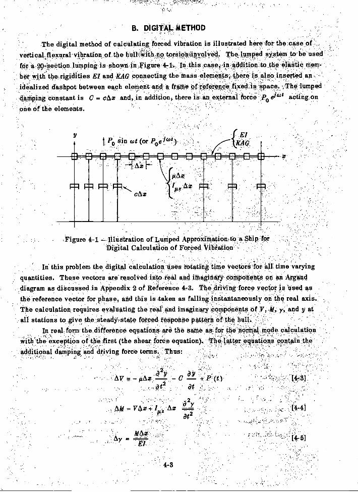
B. DI GI TAL ./A ETHOD
The digital method of calculating forced vibration is illustrated here for the case o
vertical, flexural vibration of the hair With ,no toraiOnfinvoleti. The lumped system to be used-
for a 207-section lumping shown.in.Figure 4-1. In this case, in addition to the:elaSiiC them-_ __
bOr with the rigidities El and -KAG connecting the mass elements, , there is also inserted an..idealized dishpot between each element and a frame of ieference,fixedin 'apace.:,The lumpeddamping constant is C = cAz and, in addition, there is an external force p efidt acting on
.
Of the elements.
Po rain cot (o_
:Figure 4-1 Illustration of Lumped Approxi-mation,to_a.Ship forDigital Calculation of Forced Vibration
In this problem the digital .calculation uses rotating time vectors for all time varyingquantities. These vectors are resolved into real and imaginary components on an Argand,diagram as discussed in Appendix 2 of Reference 4-3. The driving force vector is used as-
the reference vector for phase, and this is taken as falling instantaneously on the real axis.The calculation requires evaluating the real` and imaginary components of 7,41, y_,. and y at
- all stations to give the steady-state forced response pattern of the hull.r
In real form the difference equations are the same as- for the hotinal !node calculationwith'the:-excePtiOn of the first (the Shear force equation). The fatter eqinationS-Centain theadditional damping mid driving force terms.. Thus:

The boundary conditiOns are
= 0V =V =M=M' = 0 for= L
The linearity of the equations makes it convenient to set the driving force amplitudepc, equal to unity. Hence P0 will equal one at the driving point and zero at all other points.Various schemes of coding this problem for a digital computer may be used as in the normalmode problem. Here there are four unknown quantities at Station 0 (z = 0), namely, y, y', yand y'. One scheme is to solve the complete set of equations successively with each of thefollowing sets of initial values and then to find a linear combination of these solutions whichmakes V, V', Al, and M' all zero at the right end of the system (Station 20).
The solution will give the real and imaginary components of V, M, y, and y at allstations. The magnitudes (absolute values) will be the square root of the sum of the squares
imaginary componentof the real and. imaginary components, and the arctan ( ) will give the
real component
4-4
In the rotating time-vector notation there must now be substituted for V the complexvalue V + jr, and similarly for AI, Al + iM', etc. If these substitutions are made in Equa-tions [4-3] through [4-6], and the differences in the real and imaginary parts are separatedout, there results the following set of eight difference equations:
Av. p,Azyw2 + Ccol +P0 [4- 7]
Ay =1LAxy'co2 Coy [4-8]
AM = V Az - I Azy(o2 [4- 9]
Am = Az - y' (02 [4-10]
Ax[4-11]
AY M= El
, Az[4-12]Ay' = M
El
V Az[4-13]
Ay = KAG
AzAy. [4-14]=
KAG
VAzAy = yAx
KAG[4- 6]
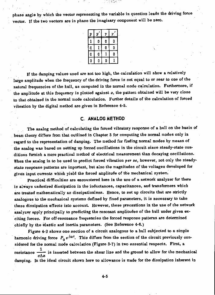
phase angle by which the vector representing the variable in question leads the driving force
vector. If the two vectors are in phase the imaginary component will be zero.
If the damping values used are not too high, the calculation will show a relatively
large amplitude when the frequency of the driving force is set equal to or near to one of the
natural frequencies of the hull, as computed in the normal mode calculation. Furthermore, if
the amplitude at this frequency is plotted against z, the pattern obtained will be very close
to that obtained in the normal mode calculation. Further details of the calculation of forced
vibration by the digital method are given in Reference 4-5.
C. ANALOG METHOD
The analog method of calculating the forced vibratory response of a hull on the basis of
beam theory differs from that outlined in Chapter 3 for computing the normal modes only inregard to the representation of damping. The method for finding normal modes by means of
the analog was based on setting up forced oscillations in the circuit since steady-state con-ditions furnish a more practical method of electrical measurement than decaying oscillations.When the analog is to be used to predict forced vibration per se, however, not only the steady-
state response patterns are important, but also the magnitudes of the voltages developed for
given input currents which yield the forced amplitude of the mechanical system.Practical difficulties are encountered here in the use of a network analyzer for there
is always undesired dissipation in the inductances, capacitances, and transformers whichare treated mathematically as dissipationless. Hence, to set up circuits that are strictlyanalogous to the mechanical systems defined by fixed parameters, it is necessary to takethese dissipation effects into account. However, these precautions in the use of the networkanalyzer apply principally to predicting the resonant amplitudes of the hull under given ex-
.
citing forces. For off-resonance frequencies the forced response patterns are determinedchiefly by the elastic and inertia parameters. (See Reference 4-6.)
Figure 4-2 shows one section of a circuit analogous to a hull subjected to a simpleharmonic driving force Po ei°18. This differs from the section of the circuit previously con-sidered for the normal mode calculation (Figure 3-7) in two essential respects. First, a
1resistance -- is inserted between the shear line and the ground to allow for the mechanical
cAzdamping. In the ideal circuit shown here no allowance is made for the dissipation inherent in
4-5
y YI r1000o o o00100001
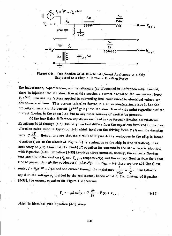
II
M- ' 7
Figure 4-2 - One Section of an Electrical Circuit Analogous to a ShipSubjected to a Simple Harmonic Exciting Force
the inductances, capacitances, and transformers (as discussed in Reference 4-6). Second,there is injected into the shear line at this section a current / equal to the mechanical forceP0e1t. The scaling factors applied in converting from mechanical to electrical values arenot considered here. This current injection device is also an idealization since it has theproperty to maintain the current /coal& going into the shear line at this point regardless of thecurrent flowing in the shear line due to any other sources of excitation present.
Of the four finite difference equations involved in the forced vibration calculationsEquations [4-3] through [4-6], the only one that differs from the equations involved in the freevibration calculation is Equation [4-3] which involves the driving force p (0 and the damping
Yterm C a. 'Hence, to show that the circuit of Figure 4-2 is analogous to the ship in forceddt
vibration (just as the circuit of Figure 3-7 is analogous to the ship in free vibration), it isnecessary only to show that the Kirchhoff equation for currents in the shear line is identicalwith Equation [4-3]. Equation [3-33] involves three currents, namely, the currents flowinginto and out of the section (V. and V.+ /, respectively) and the current flowing from the shearline to ground through the condenser (- iLAxco2y). In Figure 4-2 there are two additional cur-rents, I = Poe = P (t) and the current through the resistance -1 = .2-.. The latter is
cAzequal to the voltage divided by the resistance, hence equal to C. Instead of Equation[3-33], the current equation for Figure 4-2 becomes
El0000000 n +1
43YV. = - 116,z(02y + C - P (t) + V.+at
which is identical with Equation [4-1] since
4-6
[4-15]
a2y
a t2and AV V Vn+1
It must be emphasized that when the network analyzer is used to compute the forced
response of a continuous system, such as a hull, the circuit setup is actually the analog of a
lumped approximation to the hull. Hence, if a 20-section breakdown of the hull is used, the
circuit will in reality have only 20 degrees of freedom. Thus, while the off-resonance forced
response may agree very well with digital calculations, it is subject to the same limitations
as the digital calculations in giving a less and less realistic picture of the hull behavior as
the driving frequency is raised above the frequency range of the first few normal modes of
flexural vibration of the hull. The practical upper limit has been found to be the sixth vertical
mode for hulls of usual length to depth ratios, as indicated in the following section.
D. NORMAL MODE METHOD
The normal mode method of calculating the forced vibratory response of hulls presented
here is quasi-mathematical in that it combines only a limited number of terms of a series that
is not converging rapidly in the mathematical sense. The justification is that it has been
found by experience that the higher terms of the series are insignificant in the physical sense.
As a matter of fact, it can readily be shown that in many cases the terms that are discarded
are mathematically larger than the terms that are included.First it is assumed (on the basis of experience only) that under a simple harmonic
driving force the hull can respond in only a limited number of normal mode components. As a
guide to the number of normal mode components to be used in forced vibration calculations,
the formula originally proposed by Baier and Ormondroye7 for the number of significant ver-
tical modes of a hull N'may be used as a guide. Assume
5L9D
where the letters L, D, and B refer to ship length, depth, and beam, respectively. The ratio
of the number of significant horizontal modes to the number of significant vertical modes may
be taken as 2/3, and of torsional to vertical as 1/2.While the method involves the selection of the number of terms to be used in the series
on the basis of experience, it still retains certain important properties of the normal modes
which are found in the theoretical analysis of ideal systems.
Three properties of the normal modes of ideal beams are of particular significance
(see Reference 4-8, page 6), namely, the properties of orthogonality, influence function,
and reciprocity.Orthogonality of mathematical functions in general is discussed in Reference 4-9, and
if a series of functions of a single variable possess this property within certain limits of
4-7
this variable, then the integral of the product of any two is zero. Thus
f (z) (z) = 0a
if i j. In the case of the ideal-beam the orthogonality property involves the "weightingfunction" it (x) and is
foL (x) (x) (z) = 0
---
When a beam possesses this property its kinetic and potential energies can be ex-pressed in terms of vibrations in its normal modes, and, in fact, as shown by Rayleigh,#'°the kinetic and potential energies of mass-elastic systems in general can be expressed interms of the squares of generalized coordinates each involving the deformation or velocityin one of the normal modes. Thui
and
The itormal moire influence relation states that the normal mode pattern determines the.influence of thepoiht-of application of a simple harmonic driving force on the magnitude ofthe amplitudecercited in that mode. Thus, a given force will not excite a mode which has a
° nil point' ikitsto,oint of application, and will excite the maximum amplitude in this modewhen applied At the point at which the normal mode pattern is a maximum.
Pain
recinrocity relation implies that, if a simple harmonic driving force applied at ax of t eitlial.beam produces an amplitude of vibration yr at x8, then
Yrs Ysr [4-18]
4-8
1K. E. =
2
P. E. = q.22
.\4itere K. E. is-ithe kinetic energy,P. E. i53heip=otentil-al energy,
-is the generali5ed velocity in the ith normal mode,is the gen-ramified displacement in the ith normal mode,0is a--generalized mass applicable to the ith normal mode, and.1
F.= -st-is-eigelieralized elastic constant applicable to the ith normal mode.
A more precise definition of these terms is not essential here.
[4-16]
[4-17]
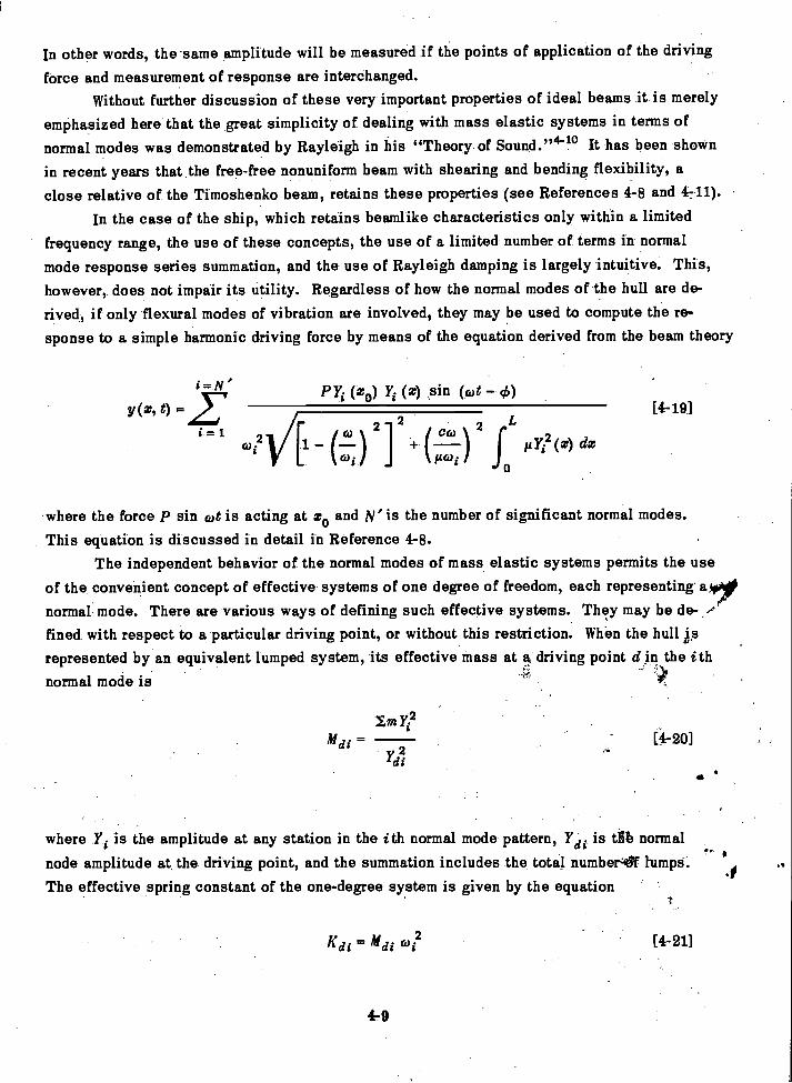
In other words, the same amplitude will be measured if the points of application of the driving
force and measurement of response are interchanged.Without further discussion of these very important properties of ideal beams it is merely
emphasized here that the great simplicity of dealing with mass elastic systems in terms ofnormal modes was demonstrated by Rayleigh in his "Theory of Sound."4-10 It has been shownin recent years that the free-free nonuniform beam with shearing and bending flexibility, aclose relative of the Timoshenko beam, retains these properties (see References 4-8 and 4711).
In the case of the ship, which retains beamlike characteristics only within a limitedfrequency range, the use of these concepts, the use of a limited number of terms in normalmode response series summation, and the use of Rayleigh damping is largely intuitive. This,however, does not impair its utility. Regardless of how the normal modes of the hull are de-rived, if only flexural modes of vibration are involved, they may be used to compute the re-sponse to a simple harmonic driving force by means of the equation derived from the beam theory
401
P Y (zo) (x) sin (cot ch)
2
where the force p sin cat is acting at zo and N' is the number of significant normal modes.This equation is discussed in detail in Reference 4-8.
The independent behavior of the normal modes of mass elastic systems permits the useof the convenient concept of effective systems of one degree of freedom, each representing alnormal mode. There are various ways of defining such effective systems. They may be de-/fined with respect to a particular driving point, or without this restriction. When the hull isrepresented by an equivalent lumped system, its effective mass at s, driving point d in the ithnormal mode is
Mdi= [4-20]
di
where Yi is the amplitude at any station in the ith normal mode pattern, Y di is tlib normalnode amplitude at the driving point, and the summation includes the total number4f lumps.The effective spring constant of the one-degree system is given by the equation
K = Mdi co? [4-21]
4-9
(Cø 2
f gY? (z) dx116)i
[4-19]

and the effective damping constant is given for Rayleigh damping by the equation
Cdi= (constant) x Mdi [4-22]
The effective system can thus be visualized as the familiar one-degree-of-freedom sys-tem usually considered in vibration theory and shown in Figure 4-3.
P sin cot
If each normal mode is thus treated, the component of driving point amplitude in each mode isfound from the familiar equation for the one-degree system:
P sin (cot -- \AK mc02)2 c2 (02
4-10
Figure 4-3 - Effective System of One Degreeof Freedom Representing a Hull in One
of Its Normal Modes
[4-23]
where the effective values are used in each case for K, M, and C. To obtain the net responsethe component of response at the driving point is multiplied by its normal mode function, andthe patterns are combined with account taken of the algebraic signs. The result will be thesame as given by Equation [4-19] if the same number of terms is used in both cases.
E. METHOD OF MECHANICAL IMPEDANCE
The term impedance, well known in electrical engineering, has become familiar in me-chanical vibration analysis only recently. It is most commonly used in connection with therotating vector to represent a steady-state vibratory component. Although a mechanical im-pedance may be defined on the basis of either displacement amplitude or velocity amplitude,the American Standards Association's Committee on mechanical shock and vibration prefersthe latter. This stems from the fact that this committee was formerly affiliated with the ASA
Committee on Acoustics. In the latter field the acoustic impedance concept has been in wideuse for some time.
When the mechanical impedance is based on displacement it is the ratio of the ampli-tude of the driving force to the displacement amplitude at the driving point. Thus
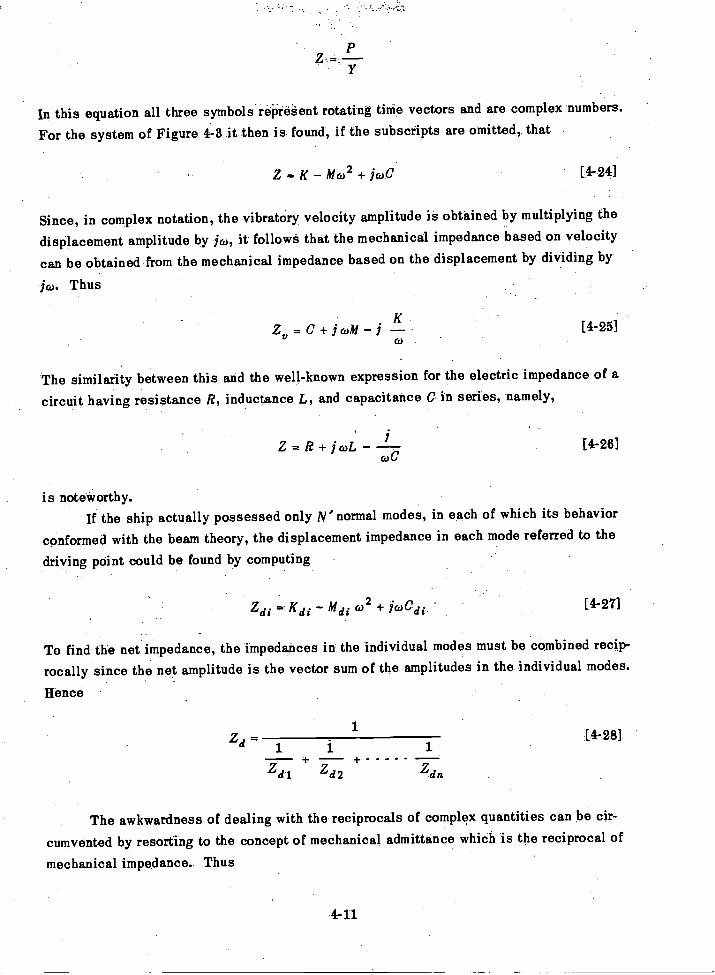
In this equation all three symbols rep- regent rotating time vectors and are complex numbers.
For the system of Figure 4-3 it then is found, if the subscripts are omitted, that
Z = K Mco2 + jcoe [4-24]
Since, in complex notation, the vibratory velocity amplitude is obtained by multiplying the
displacement amplitude by jco, it follows that the mechanical impedance based on velocity
can be obtained from the mechanical impedance based on the displacement by dividing by
jco. Thus
Zy=C+j caM [4-25]
The similarity between this and the well-known expression for the electric impedance of a
circuit having resistance R, inductance L, and capacitance C in series, namely,
Z = R + j c()L [4-26]
is noteworthy.If the ship actually possessed only N'normal modes, in each of which its behavior
conformed with the beam theory, the displacement impedance in each mode referred to the
driving point could be found by computing
Zdi K di Mdi 2 + j/1o.h. di [4-27]
To find the net impedance, the impedances in the individual modes must be combined recip-
rocally since the net amplitude is the vector sum of the amplitudes in the individual modes.
Hence
2d1
1 1+ +
Z di Zd2
4-11
1
2dn
[4-28]
The awkwardness of dealing with the reciprocals of complex quantities can be cir-
cumvented by resorting to the concept of mechanical admittance which is the reciprocal of
mechanical impedance. Thus
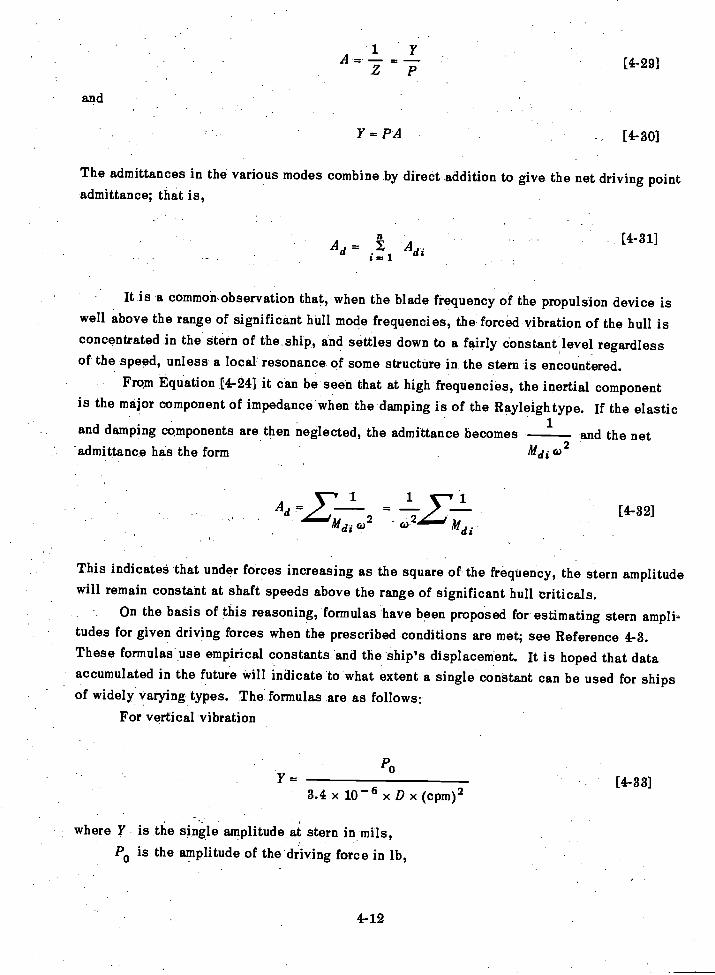
and
Ad= i1 Ad.=
It is a commomobservation that, when the blade frequency of the propulsion device iswell above the range of significant hull mode frequencies, the forced vibration of the hull isconcentrated in the stern of the.ship, and settles down to a fairly constant level regardlessof the speed, unless a local resonance of some structure in the stern is encountered.
From Equation [4-24] it can be seen that at high frequencies, the inertial componentis the major component of impedance when the damping is of the Rayleigh type. If the elastic
1and damping components are then neglected, the admittance becomes and the neta)2admittance has the form
1
1,Alai 632
2co mdi
3.4 x 10⁻⁶ x D x (cpm)2
where Y is the single amplitude at stern in mils,P0 is the amplitude of the driving force in lb,
4-12
[4-29]
[4-31]
[4-32]
This indicates that under forces increasing as the square of the frequency, the stern amplitudewill remain constant at shaft speeds above the range of significant hull criticals.
On the basis of this reasoning, formulas have been proposed for estimating stern ampli-tudes for given driving forces when the prescribed conditions are met; see Reference 4-3.These formulas use empirical constants and the ship's displacement. It is hoped that dataaccumulated in the future will indicate to what extent a single constant can be used for shipsof widely varying types. The formulas are as follows:
For vertical vibration
Po[4-33]
Y = PA [4-30]
The admittances in the various modes combine by direct addition to give the net driving pointadmittance; that is,
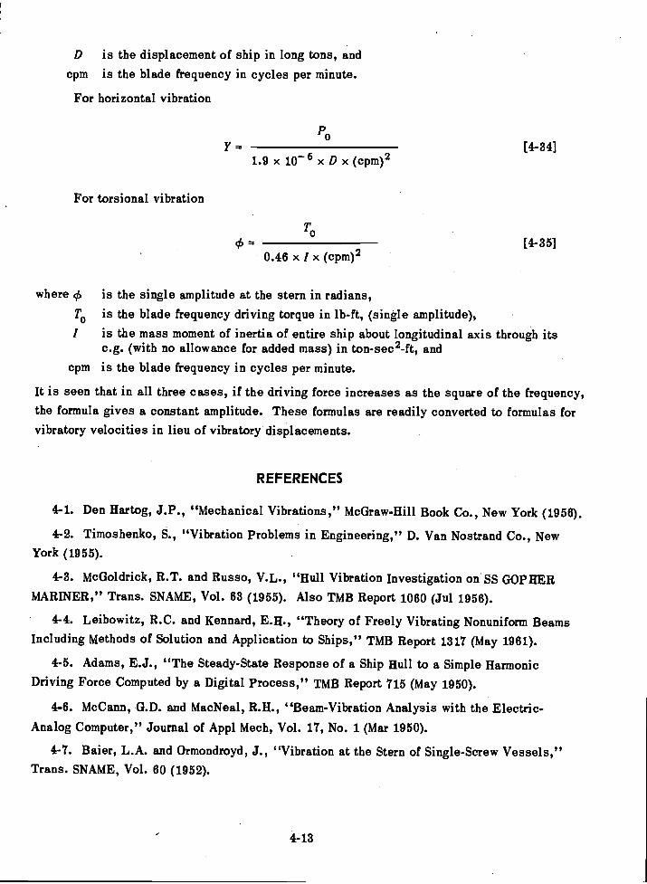
where c6
To
1
cpm
D is the displacement of ship in long tons, andcpm is the blade frequency in cycles per minute.
For horizontal vibration
Y [4-34]1.9 x 10⁻⁶ x D x (cpm)2
For torsional vibration
0cIS (4-35]
0.46 x 1 x (cpm)2
is the single amplitude at the stern in radians,is the blade frequency driving torque in lb-ft, (single amplitude),is the mass moment of inertia of entire ship about longitudinal axis through itsc.g. (with no allowance for added mass) in ton-sec2-ft, andis the blade frequency in cycles per minute.
It is seen that in all three cases, if the driving force increases as the square of the frequency,the formula gives a constant amplitude. These formulas are readily converted to formulas forvibratory velocities in lieu of vibratory displacements.
REFERENCES
4-1. Den Hartog, J.P., "Mechanical Vibrations," McGraw-Hill Book Co., New York (1956).
4-2. Timoshenko, S., "Vibration Problems in Engineering," D. Van Nostrand Co., NewYork (1955).
4-3. McGoldrick, R.T. and Russo, V.L., "Hull Vibration Investigation on SS GOPHERMARINER," Trans. SNAME, Vol. 63 (1955). Also TMB Report 1060 (Jul 1956).
4-4. Leibowitz, R.C. and Kennard, E.H., "Theory of Freely Vibrating Nonuniform BeamsIncluding Methods of Solution and Application to Ships," TMB Report 1317 (May 1961).
4-5. Adams, E.J., "The Steady-State Response of a Ship Hull to a Simple HarmonicDriving Force Computed by a Digital Process," TMB Report 715 (May 1950).
4-6. McCann, G.D. and MacNeal, R.H., "Beam-Vibration Analysis with the Electric-
Analog Computer," Journal of Appl Mech, Vol. 17, No. 1 (Mar 1950).
4-7. Baier, L.A. and Ormondroyd, J., "Vibration at the Stern of Single-Screw Vessels,"Trans. SNAME, Vol. 60 (1952).
4-13

4-- 8. McGoldrick, R.T., et al..,,-"Recent-DevelopmentS in the Theory of Ship Vibration,TMB Report 739, Revised Edition (Oct'1953).
4- 9. Wylie, C.R., "Advanced Engineering Mathematics," McGraw-hill Book Co., New
York. (1951)."
, 4-10. Rayleigh, Lord, "Theory of .Sound," Second-Edition;Dovei,Publications, New York(1945). -
4-11. orinondroyd, J., et al., "Dynamics of a Ship's Structure," Engin Reel,Inst; Univ. OfMichigan, Afin'Arbor-(Mar 1949) (Out Of print).
,4q4
. .
CHAPTER 5
BEAM THEORY OF TRANSIENT SHIP VIBRATION
A. INTRODUCTION
Although the steady-state vibration of ships under normal operating conditions is avery important consideration in naval architecture, it is clear that under rough sea conditionsmuch more severe vibrations of a transient nature are encountered. If quasi-mathematicalmethods must be resorted to in dealing with steady-state ship vibration, this applies to amuch greater degree in dealing with its transient vibrations. It is to be noted at once thatthe transient vibrations of ships are occasionally of such large amplitude as to deform thehull girder beyond the linear range within which the beam theory of hull vibration is con-sidered to have a fair degree of validity.
Obviously, just as in the case of steady-state vibration, the transient vibrations ofships depend on both the exciting forces and the dynamical properties or response charac-teristics of the hull. The forces, however, in this case are quite complex and cannot beexpressed in such simple mathematical terms as can the steady-state forces.
Much progress has been made in recent years in correlating the stress variations andmotions encountered in ships in a seaway with the statistical data available on ocean waves;see Reference 5-1. It is merely pointed out here that useful correlations have been discoveredbetween the statistical distributions of wave heights encountered at sea and the distributionsof motions and stresses in hulls. All that is attempted in this chapter is to indicate that,within the linear range of deflections, the rational theory applied to steady-state forced vi-bration in Chapter 4 should also be applicable to transient vibrations. The linear range iseven lower than the range of deflections within which hull girder stresses reach the yieldpoint of shipbuilding steel, since buckling of members in compression will ordinarily occurbefore this point is reached.
The value of the consideration here of the transient response of hulls to low magnitudeexcitation is that it provides the naval architect with insight into the processes that takeplace before damage actually occurs under slamming conditions in a seaway. Furthermore,as far as possible damage to local structures and to equipment installed in the ship is con-cerned, it points the way to avoid some of the alterations that frequently have to be madeafter the builders' trials of a ship. There is no implication intended here that, up to thistime (1960), experimental verification has been obtained of the adequacy of the treatment ofthe response of ship hulls to transient loading by the rational beam theory advocated in thisbook, or in fact by any other theory. This must await the verdict of investigations stillunderway. Although it is shown in this chapter how the same general methods applied inChapter 4 to steady-state vibration are extended to the transient case, the presentation isonly analytical and does not encompass a practical evaluation of these methods.
5-1
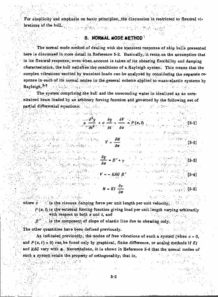
For simplicity and emphasis on basic principles, the discussion is restricted to flexural vi-brations of the hull.
B. .NORMAL MODE METHOD
The normal mode method of dealing with the transient response of ship hulls presentedhere is discussed in more detail- in Reference 5-2. Basically, ', it rests onthe assumption thatin its flexure response-;.:evenivhen.aCcount is taken of its shearing flexibility and dampingcharatteristiCS;:the_hull. satisfies the conditions of-a_.Rayleigh ,systenr. This means that thecomplex vibrations excited byArrinsientloads can be analyzed by considering the Separate re-
.
sponse in each of its normal modes in the general scheme ipplied,to'mass4elastib systems byRayleigh..-5;7 .
The.syster&comprising the hull and the surrounding water is idealized as an unre-strained beam lciaded by an -arbitrary forcing functionand-gOVe-rned by the .folloyving_set ofpartial differential squationS:
aYM = El
ax:
and /MG vary with z..:-Isievertheless, it is shown in Reference 5-4 that the normal modes ofstch a system retain the -property of orthogonality; that is,
._Where c is-,the.viscons :diinping force per unit' length perunit VelOdity;p thej.externril- fcirding-function giving load per unit length varying 'arbitrarily
Wiih-reipeCt to' both.* and t, andtlie, bcimp-onent cif Slope of elastic line due to shearing only;
The other-quantitieS haVe been.defined previously.As indioated._.preVioti-Slyi the-Anodes of free vibration& of .such Systeni (*hen c = 0,
and p (x, 0).Caritlie found only by graphical, finite.difference, br anilog.ifiethodS E/,
5-2
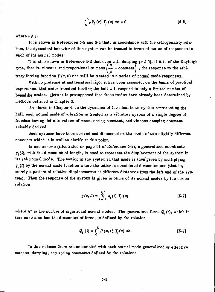
[ 5 - 7 ]
5-3
fo (x) (z) dx = 0 [5-6]
where i A j.It is shown in References 5-2 and 5-4 that, in accordance with the orthogonality rela-
tion, the dynamical behavior of this system can be treated in terms of series of responses ineach of its normal modes.
It is also shown in Reference 5-2 that even with damping (c A 0), if it is of the Rayleigh(ctype, that is, viscous and proportional to mass = constant) , the response to the arbi-
Atrary forcing function- P (z, t) can still be treated in a series of normal mode responses.
With no pretense at mathematical rigor it has been assumed, on the basis of practicalexperience, that under transient loading the hull will respond in only a limited number ofbeamlike modes. Here it is presupposed that these modes have already been determined bymethods outlined in Chapter 3.
As shown in Chapter 4, in the dynamics of the ideal beam system representing the
hull, each normal mode of vibration is treated as a vibratory system of a single degree offreedom having definite values of mass, spring constant, and viscous damping constantsuitably derived.
Such systems have been derived and discussed on the basis of two slightly differentconcepts which it is well to clarify at this point.
In one scheme (illustrated on page 21 of Reference 5-2), a generalized coordinateqi(t), with the dimension of length, is used to represent the displacement of the system inits ith normal mode. The motion of the system in that mode is then given by multiplyingqi (t) by the normal mode function where the latter is considered dimensionless (that is,merely a pattern of relative displacements at different distances from the left end of the sys-tem). Then the response of the system is given in terms of its normal modes by the seriesrelation
NY (x91) = I q(t) (x). 1
where N' is the number of significant normal modes. The generalized force Qi(t), which inthis case also has the dimension of force, is defined by the relation
(t) = P (xt t) Y1(x) [5-8]
In this scheme there are associated with each normal mode generalized or effectivemasses, damping, and spring constants defined by the relations

here as is the Undamped natnral frequency associated With the tth normal mode. ..The other scheme; ba'sred on the same general- theory, More useful. here the forcing
. .
function is concentrated at one point (called the driving point d). In this caae'thebehaViorof the system is derived by Visualizing each normal male Of the ,system as presenting to thedriving force at d'aneffectiv,e inertia; 'spring constant, aipzi damping Constant, all based notonly on the normal mode pattern of each mode but alicvon:the location of,the-dkiying paintitgelf.
-; Thus, if the external force acting at d is F (t), then
It then results that the response in each norinal mode is governed by the same equationas the vibratory system of one degree of freedom shown in Figure 3-1., that is, .
[5-16]M.diYdi CdiYdi+ 1diYd1= Qdi()
It is shown in numerous text, hooks (e.g., Reference 5-5) that when an external forcestarts to act on such a,airsteM,:if,at rest at t.:=0, the response at time t ie given by the
5-4
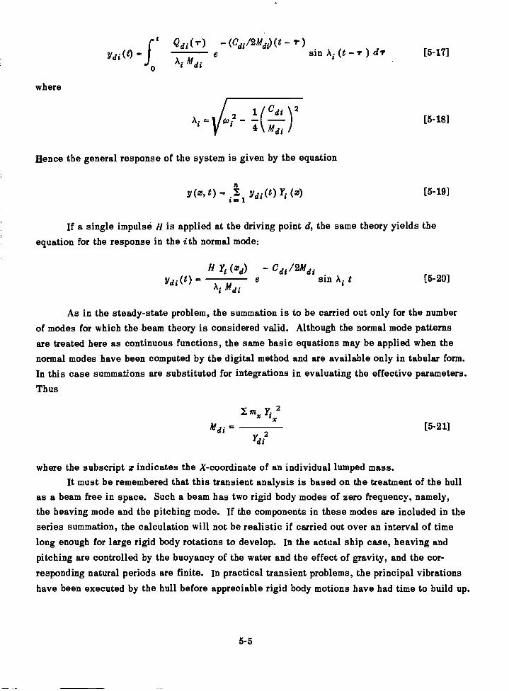
where
1/d1(t) =ft e 2 di(r) (C 2Mdi) (1 )
sin Ai (t drM di0
( C di )2Voi24 M
Hence the general response of the system is given by the equation
y(z, t) = di(t) (z)1.1
If a single impulse H is applied at the driving point d, the same theory yields theequation for the response in the ith normal mode:
Yi(zd) Cdi/2MdiYdi(t)
AiMdie sin Ai t
As in the steady-state problem, the summation is to be carried out only for the numberof modes for which the beam theory is considered valid. Although the normal mode patternsare treated here as continuous functions, the same basic equations may be applied when thenormal modes have been computed by the digital method and are available only in tabular form.In this case summations are substituted for integrations in evaluating the effective parameters.
Thus
5-5
[5-17]
[5-18]
[5-19]
[5-20]
M di = [5-21]idI
where the subscript z indicates the X-coordinate of an individual lumped mass.It must be remembered that this transient analysis is based on the treatment of the hull
as a beam free in space. Such a beam has two rigid body modes of zero frequency, namely,the heaving mode and the pitching mode. If the components in these modes are included in theseries summation, the calculation will not be realistic if carried out over an interval of timelong enough for large rigid body rotations to develop. In the actual ship case, heaving andpitching are controlled by the buoyancy of the water and the effect of gravity, and the cor-responding natural periods are finite. In practical transient problems, the principal vibrationshave been executed by the hull before appreciable rigid body motions have had time to build up.
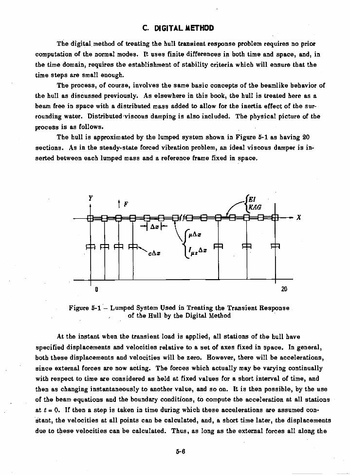
C. DIGITAL METHOD
The digital method of treating the hull transient response problem requires no priorcomputation of the normal modes. It uses finite differences in both time and space, and, inthe time domain, requires the establishment of stability criteria which will ensure that thetime steps are small enough.
The process, of course, involves the same basic concepts of the beamlike behavior ofthe hull as discussed previously. As elsewhere in this book, the hull is treated here as abeam free in space with a distributed mass added to allow for the inertia effect of the sur-rounding water. Distributed viscous damping is also included. The physical picture of theprocess is as follows.
The hull is approximated by the lumped system shown in Figure 5-1 as having 20sections. As in the steady-state forced vibration problem, an ideal viscous damper is in-serted between each lumped mass and a reference frame fixed in space.
5-6
20
Figure 5-1 Lumped System Used in Treating the Transient Responseof the Hull by the Digital Method
At the instant when the transient load is applied, all stations of the hull havespecified displacements and velocities relative to a set of axes fixed in space. In general,both these displacements and velocities will be zero. However, there will be accelerations,since external forces are now acting. The forces which actually may be varying continuallywith respect to time are considered as held at fixed values for a short interval of time, andthen as changing instantaneously to another value, and so on. It is then possible, by the useof the beam equations and the boundary conditions, to compute the acceleration at all stationsat t = 0. If then a step is taken in time during which these accelerations are assumed con-stant, the velocities at all points can be calculated, and, a short time later, the displacementsdue to these velocities can be calculated. Thus, as long as the external forces all along the
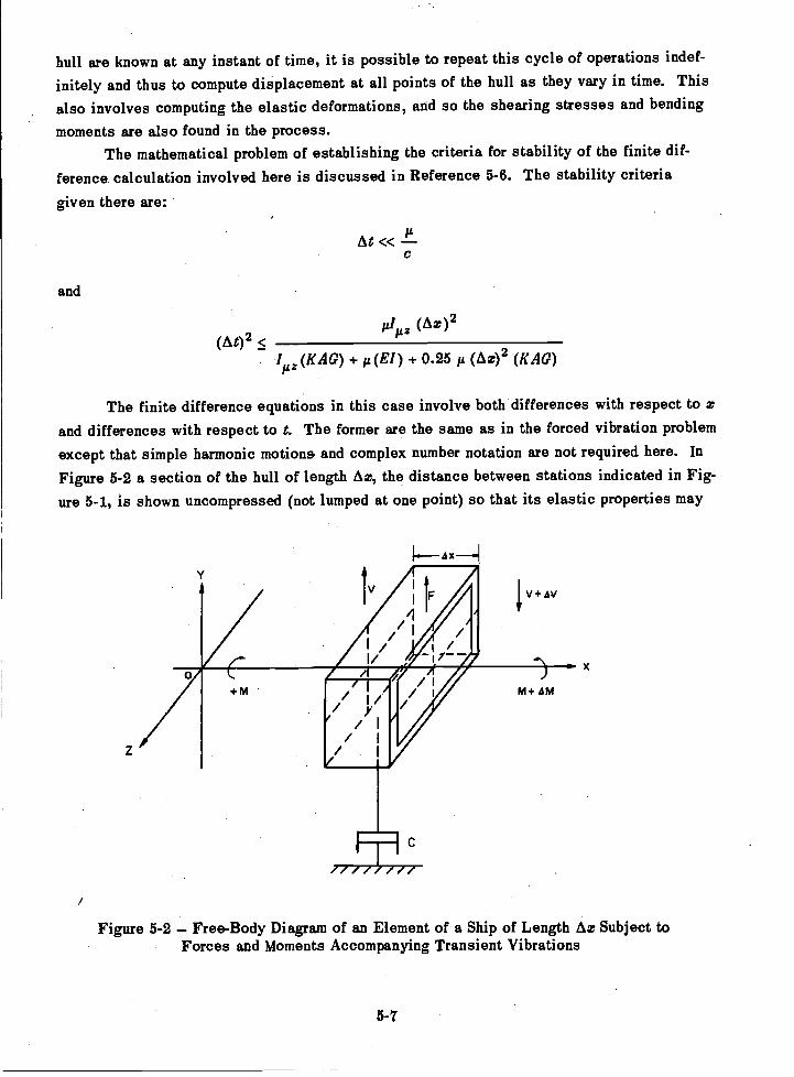
hull are known at any instant of time, it is possible to repeat this cycle of operations indef-
initely and thus to compute displacement at all points of the hull as they vary in time. Thisalso involves computing the elastic deformations, and so the shearing stresses and bending
moments are also found in the process.The mathematical problem of establishing the criteria for stability of the finite dif-
ference calculation involved here is discussed in Reference 5-6. The stability criteria
given there are:
At
and
td,z (Ax)2(A02 <
I (K AG) + p(EI) + 0.25 (Ax)2 (KAG)itz
The finite difference equations in this case involve both differences with respect to xand differences with respect to t. The former are the same as in the forced vibration problem
except that simple harmonic motion& and complex number notation are not required here. InFigure 5-2 a section of the hull of length Ax, the distance between stations indicated in Fig-ure 5-1, is shown uncompressed (not lumped at one point) so that its elastic properties may
+m
Figure 5-2 Free-Body Diagram of an Element of a Ship of Length Ax Subject toForces and Moments Accompanying Transient Vibrations
5-7
M+ AM
be visualized. Here its mass could be conceived as concentrated at the midspan. It must beemphasized that in any scheme of representation of the hull as an equivalent lumped system,for the purpose of setting up difference equations for a digital treatment, there will be con-flicting requirements in the schematic representation. It is not attempted here to indicate thenotation which will yield the maximum accuracy for a given number of sections. Accordingly,the equations in the differences with respect to x are given in simplified form as follows:
It should be noted that in Equation [5-23] the term for rotary inertia is included, where-as in Equation [5-2] it is neglected. Experience so far has shown that its inclusion makeslittle difference in hull vibration calculations, and the demonstration of orthogonality of thenormal modes given in Reference 5-4 was based on the set of equations in which the termwas omitted. Also, although it is not exploited here, it might also be noted that the finitedifference method is not restricted to Rayleigh damping but can be applied to both nonlinearand linear systems.
The equations in the differences with respect to time (also in simplified form) are
= At [5-26]
Ayns At [5-27]
It is necessary in this case to use both subscripts and superscripts. The formerindicate the space coordinate, the latter the time coordinate.
If the calculation starts from the rest condition, the boundary conditions are
0 0Yn = Yn = = =
n
VS=Ais =V'20 20s= 00 0 20 20
At any instant of time there are sufficient equations to compute the accelerations at all pointsalong the beam. It is then possible to compute the velocities and displacements at the nexttime step, and thus to continue the process indefinitely.
5-8
AV = - gAr.y. - Cy + F [5-22]
AM = VAx + I [5-23]
MAx[5-24]Ay -
El
VAx[5-25]Ay = yA
KAG
In this form of the problem, since the hull is considered free in space, no gravity or
buoyancy forces are acting. Although the calculation will give the net result of the com-
bination of rigid body motions and elastic deformations, the rigid body motions will not be
realistic if it is carried out for a total time comparable with the pitching or heaving periods
of the ship because there are no restoring forces to limit the rigid body displacements.Obviously, many variations of this problem are possible. Thus the damping forces
need not be restricted to the Rayleigh type and gravitational and buoyancy effects can be
included. As given here the virtual mass is constant in time and thus does not vary with
amplitude, frequency, or mode shape. While the method theoretically takes care of any elasticwave effects that may exist in such a system, no use is made of the traveling wave concept
in setting up the problem.Further discussion of this calculation is given in References 5-6 and 5-7 and a sample
calculation is given in Appendix B.
D. ANALOG METHOD
Both the classical (conventional) and the mobility analogs discussed in Chapter 3 areapplicable to the hull transient response problem as computing devices. It cannot be said,however, at this time that their potentialities in this field have been more than superficially
explored.While the networks representing the inertial and elastic parameters of the hull con-
sidered as a beam are the same as for the steady-state vibration problem considered inChapter 4, the techniques of exciting the network and measuring its response are obviously
radically different.Instead of a simple oscillator capable of injecting a sinusoidal current (in the mobility
analog) at any frequency desired within a given range, the transient problem requires a specialtransient injection circuit which can deliver a current of the desired waveform regardless ofthe impedance characteristics of the network. Thus it may be desired to inject a single half-sine pulse, a rectangular pulse, a triangular pulse, or a current pulse that rises "instantly"to a given value and then decays exponentially.
The measurement of transient response is also more complicated than in the steady-state case. In that case, an oscillogram is not really necessary if both an indicating a-cvoltmeter and a phasemeter are available. In the transient case, a record must be made onan oscillograph or on magnetic tape of the transient signal at a number of points along the
network.In lieu of a single transient injection, it is often preferable to inject a series of input
signals at intervals far enough apart to permit the transient to die out between intervals. If
these intervals are not too far apart they will permit direct observation of the response at anypoint in the network on a cathode ray oscilloscope since the pattern will be retained both bythe screen and the retina.
5-9
Further details of the use of the electrical analog for such calculations will be foundin Reference 5-8. Obviously, at best, the analog predictions of hull response cannot be anymore reliable than the theory from which the analogous circuit is derived. Furthermore, theanalog may give a distorted picture of the true response as predicted by the mathematicaltheory used. The advantages of the analog, however, in permitting the operator to vary theinertia and stiffness parameters of the hull simply by turning dials make this method anattractive one.
A recent proposal by Dr. N.H. Jasper considered by the David Taylor Model Basin isthe development of a transient computer for ship hulls which forecasts the stresses and vi-brations encountered in seas of various wave heights. This is discussed in Reference 5-9.The idea is to use an electrical network to represent the hull as a beam, but, instead of treat-ing it as an ideal system free in space to which loads that are known with respect to time areapplied, the computer automatically applies the loads that are exerted by the sea, allowingfor the fact that the buoyancy and added mais effects vary with the rigid body motions of theship.
REFERENCES
5-1. Jasper, N.H., "Statistical Distribution Patterns of Ocean Waves and of Wave-InducedShip Stresses and Motions, with Engineering Applications," Trans. SNAME, Vol. 64_ (1956).Also TMB Report 921 (Oct 1957).
5-2. McGoldrick, R.T., et al., "Recent Developments in the Theory of Ship Vibration,"TMB Report 739, Revised Edition (Oct 1953).
5-3. Rayleigh, Lord, "Theory of Sound," Second Edition, Dover Publications, New York(1945).
5-4. Ormondroyd, J., et al., "Dynamics of a Ship's Structure," Engin Res Inst, Univ ofMichigan, Ann Arbor (Mar 1949) (out of print).
5-5. von Karman, T. and Biot, M.A., "Mathematical Methods in Engineering," McGraw-HillBook Co. (1940).
5-6. Polachek, H., "Calculation of Transient Excitation of Ship Hulls by Finite DifferenceMethods," TMB Report 1120 (Jul 1957).
5-7. McGoldrick, R.T., "Calculation of the Response of a Ship Hull to a Transient Loadby a Digital Process," TMB Report 1119 (Mar 1957).
5-8. McCann, G.D. and MacNeal, R.H., "Bean-Vibration Analysis with the Electric-Analog Computer," Journal of Appl Mich, Vol. 17, No. 1 (Mar 1950).
5-9. Hoyt, E.D., "Simulation of the Sea and Analog Computation of the Forces on a Shipin Waves," Report to TMB on Contract Nobs 72376, T.O. 9, Project RR-1458-N by ReedResearch, Inc (Nov 1959).
5-10
CHAPTER 6
EFFECT OF LOCAL FLEXIBILITY ON THE VIBRATORYCHARACTERISTICS OF A HULL
A. INTRODUCTION - THE "SPRUNG MASS" EFFECT
While the chief aim in this book is to exploit the dynamics of a ship's hull when con-sidered as a nonuniform free-free Timoshenko beam, it has been pointed out that in its vi-bratory behavior, a ship departs from such a beam to an increasing extent as the driving
frequency rises. In the response to a steady-state simple harmonic driving force, this de-parture from ideal beam behavior is evident in two respects of special significance to thenaval architect: First, at high driving frequencies the amplitudes of vibration at points in thehull lying in the same transverse plane (normal to the longitudinal axis of the ship) cease tobe the same. Second, when the blade frequency is higher than the frequency of (roughly) thesixth vertical flexural mode, the propeller-excited vibration is usually concentrated at thestern of the ship.
When the amplitudes of vertical vibration at points lying in the same transverse planeare not the same the situation is ascribed colloquially to "local flexibility." This localflexibility, which at low frequencies may completely escape attention, may become so pro-nounced at high frequencies as to fully control the vibratory response. For instance, if amechanical vibration generator were installed on the main deck of a ship in either the bow orthe stern, but in the middle of a panel of deck plating, it would be found that the lower flexuralmodes of the hull could be readily excited, but that beyond a certain running speed (drivingfrequency), the machine would be quite incapable of exciting the hull. This is true in spiteof the fact that its driving force amplitude increases as the square of the speed. If, however,there are installed under this deck heavy shoring members that transmit the load to points onthe deck below, where there are either vertical bulkheads or sections of shell plating, then therange of frequencies over which the hull can be excited by the vibration generator is greatly
extended.In dealing analytically with local flexibility, it has proven fruitful to consider the
vibratory characteristics of an ideal beam having one or more masses elastically attached toit. The attached mass has been designated a "sprung mass" and thus the effect of localflexibility is often spoken of as the "sprung mass effect." In this book the term sprung massis applied to local elastic structures themselves; to relatively rigid assemblies that aresupported in the hull by means of resilient mountings; and to heavy items of equipment thatare installed on foundations nominally rigid, but which in practice exhibit flexibility as aconsequence of the large mass attached to them. A discussion of the properties of the idealbeam with an attached sprung mass is given in Reference 6-1.
6-1
B. LOCAL ELASTIC STRUCTURES
The chief structures falling in the category of local elastic structures are deck panels(including plating and stiffeners supported only at the edges), longitudinal and transversebulkheads, panels of shell plating, stiffened shell plating panels supported only at the edges,deck houses or superstructures, masts, docking keels or skegs, shaft struts, and controlsurface members such as rudders or (in the case of submarines) diving planes.
The effect of these structures on the vibratory characteristics of the hull as a wholedepends chiefly on two properties, namely, the local natural frequency and the local effectivemass. Both properties require special consideration here. By the "local natural frequency"is meant the natural frequency that would be measured if the surrounding structure could notmove. The identification of local natural frequencies in practice is not always clear, and,strictly speaking, any natural frequency observed may be considered as the frequencyassociated with a mode of vibration of the entire hull system. Obviously, large local structurescannot vibrate independently of the ship as a whole when the hull is unrestrained. When theyare excited by impact, the frequency measured locally is then definitely a frequency of oneof the modes of vibration of the hull considered as a beam, with the local structure actingas a sprung mass. If, however, the test is made in drydock, in which case the hull is re-strained, the observed frequency may be a true local natural frequency.
The mass of the local structure, or rather, the ratio of the sprung mass to the mass ofthe ship, furnishes a criterion of the distinction between a local natural frequency and thelocal manifestation of a hull natural frequency. Unfortunately, the precise determination ofsuch a criterion is not feasible. Moreover, it is not the actual mass of the local structurebut its effective mass that furnishes the criterion.
The concept of effective mass was discussed in Chapter 4 in connection with thedetermination of the driving point mechanical impedance of the hull. It will be recalled that,from the impedance point of view, at any desired driving point the hull may be considered topresent an effective mass for each of its normal modes of vibration. This mass has such avalue that, if vibrating with a given amplitude at the frequency corresponding to the normalmode in question, it will have the same kinetic energy as will the entire hull if vibrating inthis normal mode with the same amplitude at this driving point. The same concepts areapplicable to the effective mass of the local structure. Although it is usually the fundamentalmode of vibration of the local structure that is of concern, this is not always the case. Wheremore than one mode of vibration of the local structure is of concern, an effective mass mustbe evaluated for each mode.
In the mode involved the local structure presents to the hull the effect of a sprung massattached at a selected point. The point at which the equivalent sprung mass is consideredattached is somewhat arbitrary, and the value to be assigned to the effective mass dependson the point selected. In general, this point may be taken at the center of gravity of the localstructure. The normal mode pattern and also the local natural frequency for the local structure
6-2
must be known approximately. The effective mass is then such a mass that, if vibrating at
this frequency and with unit amplitude, it will have the same kinetic energy as the local
structure would have when vibrating in the mode in question with unit amplitude of the center
of gravity; the ship itself is considered at rest (restrained) in both cases.In general, the determination of the effective mass of the local structure would have
to be carried out by an approximate method in which its volume was broken down into a large
number of elements; to each element an amplitude was assigned in accordance with the known
or assumed normal mode pattern. Then
mecg v 2
my2[641
cg
where me is the effective mass of the local structure at its center of gravity for thecg local mode of vibration in question,
m is the mass of one of the elements into which the local structure is brokendown for the evaluation of effective mass,is the amplitude (in any arbitrary units) of the element in when the localstructure is vibrating in this mode, and
ycg is the amplitude in the same arbitrary units at the c.g. of the local structurewhen vibrating in this mode.
Once the effective mass has been evaluated, the effective spring constant can be found from
the relation
coo
1Ccg[6-2]
cg
where coo is the natural circular frequency of the local structure and ke is the effectivecg
spring constant to be associated with me .cg
Reference 6-2 discusses experiments conducted on a cargo ship in which the experi-mental data indicated a considerable departure in the vibration characteristics of the hullfrom those predicted by the beam theory. This reference indicates that there was reason tobelieve that local flexibility accounted for the departure from beamlike vibratory responsecharacteristics. Exploratory calculations were later made by the electrical analog in whicha circuit was set up to represent this hull as a beam but with part of the mass flexibilityattached to the main hull girder. As indicated in Reference 6-3, these calculations showedqualitatively that the sprung mass effect could account for the observed vibratory response
characteristics.While sufficient information has not been obtained at this time to fix definitely the
magnitude required of flexibly attached masses before their effect on the normal modes ofhull vibration becomes perceptible, the following criteria are suggested here: (1) the effective
6-3
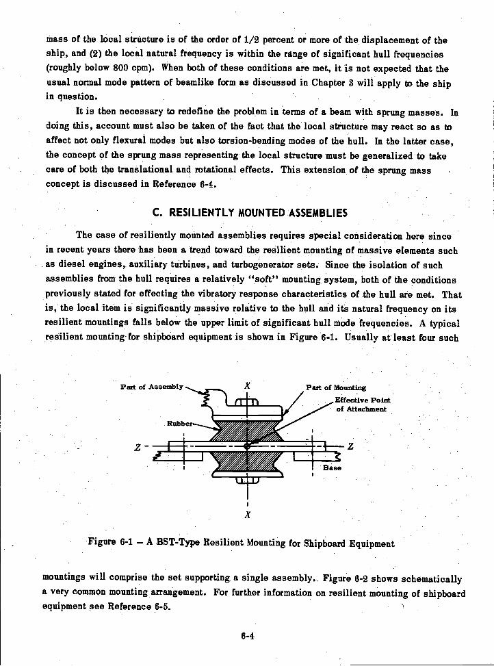
mass of the local structure is of the order of 1/2 percent or more of the displacement of theship, and (2) the local natural frequency is within the range of significant hull frequencies(roughly below 800 cpm). When both of these conditions are met, it is not expected that theusual normal mode pattern of beamlike form as discussed in Chapter 3 will apply to the shipin question.
It is then necessary to redefine the problem in terms of a beam with sprung masses. Indoing this, account must also be taken of the fact that the local structure may react so as toaffect not only flexural modes but also torsion-bending modes of the hull. In the latter case,the concept of the sprung mass representing the local structure must be generalized to takecare of both the translational and rotational effects. This extension of the sprung massconcept is discussed in Reference 6-4.
C. RESILIENTLY MOUNTED ASSEMBLIES
The case of resiliently mounted assemblies requires special consideration here sincein recent years there has been a trend toward the resilient mounting of massive elements suchas diesel engines, auxiliary turbines, and turbogenerator sets. Since the isolation of suchassemblies from the hull requires a relatively "soft" mounting system, both of the conditionspreviously stated for effecting the vibratory response characteristics of the hull are met. Thatis, the local item is significantly massive relative to the hull and its natural frequency on itsresilient mountings falls below the upper limit of significant hull mode frequencies. A typicalresilient mounting-for shipboard equipment is shown in Figure 6-1. Usually at least four such
Part of Assembly A Part of Mounting
1141MINEM
imi9==AN.11 Mt
Rubber
Base
Effective Pointof Attachment
Figure 6-1 A BST-Type Resilient Mounting for Shipboard Equipment
mountings will comprise the set supporting a single assembly.. Figure 6-2 shows schematicallya very common mounting arrangement. For further information on resilient mounting of shipboardequipment see Reference 6-5.
6-4
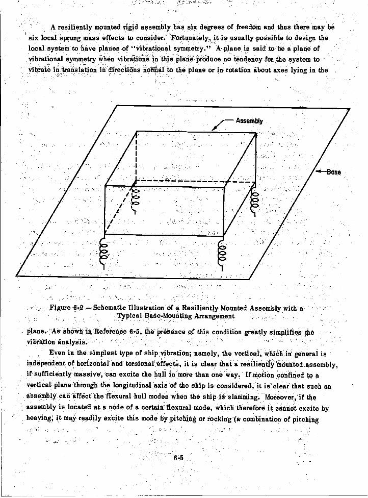
A resiliently mounted rigid assembly has six degrees of freedom and thus there may besix local sprung mass effects to consider.' Fortunately, it is usually possible to design thelocal system to have planes of "vibrational symmetry." kplane is said to be a ,plane ofvibrational symmetry when vibretioei in this plenePitiduce no -tendency for the ,system tovibrate in translation in directidins normal to the plane or in rotation about axes lying in the .
, .
Figure 64 Schematic Illustration of' Resiliently Mounted Assembly...with a-Typical Base-Mounting Arrangement
plane. :AS shown in Reference 6-5 the presence of this condition greedy simplifies thevibration
Even in the simplest type of ship vibration; namely, the vertical; which in general isindependent of horizontal and torsional effects, it is clear that -a resiliently mounted assembly,if sufficiently' massive', 'can excite the hull in-more than one'way. If motion confined to avertical plane, through the longitudinal -axis of the ship is considered;.it is'cleaf that such an.assembly can effect the flexural hull modes when the ship is slamming Moreover, if theassembly is located at a node of a certain flexural mode, which therefore it cannot excite byheaving, it may readily excite this mode by pitching or rocking (a combination of pitching
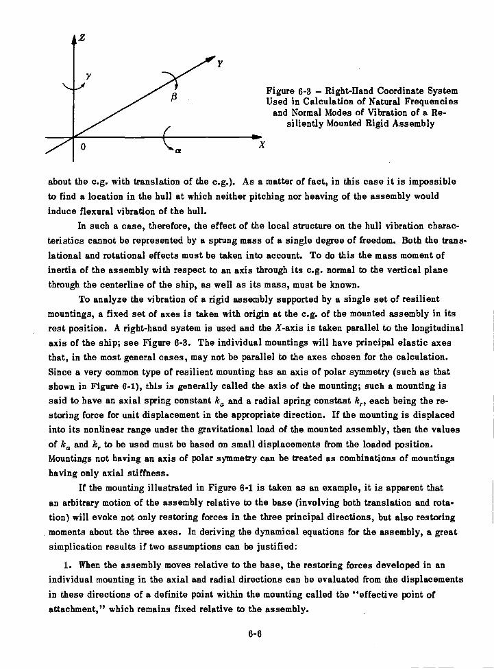
6-6
Figure 6-3 Right-Hand Coordinate SystemUsed in Calculation of Natural Frequencies
and Normal Modes of Vibration of a Re-siliently Mounted Rigid Assembly
about the e.g. with translation of the c.g.). As a matter of fact, in this case it is impossibleto find a location in the hull at which neither pitching nor heaving of the assembly wouldinduce flexural vibration of the hull.
In such a case, therefore, the effect of the local structure on the hull vibration charac-teristics cannot be represented by a sprung mass of a single degree of freedom. Both the trans-lational and rotational effects must be taken into account,. To do this the mass moment ofinertia of the assembly with respect to an axis through its e.g. normal to the vertical planethrough the centerline of the ship, as well as its mass, must be known.
To analyze the vibration of a rigid assembly supported by a single set of resilientmountings, a fixed set of axes is taken with origin at the e.g. of the mounted assembly in itsrest position. A right-hand system is used and the X-axis is taken parallel to the longitudinalaxis of the ship; see Figure 6-3. The individual mountings will have principal elastic axesthat, in the most general cases, may not be parallel to the axes chosen for the calculation.Since a very common type of resilient mounting has an axis of polar symmetry (such as thatshown in Figure 6-1), this is generally called the axis of the mounting; such a mounting issaid to have an axial spring constant ka and a radial spring constant k,., each being the re-storing force for unit displacement in the appropriate direction. If the mounting is displacedinto its nonlinear range under the gravitational load of the mounted assembly, then the valuesof ka and kr to be used must be based on small displacements from the loaded position.Mountings not having an axis of polar symmetry can be treated as combinations of mountingshaving only axial stiffness.
If the mounting illustrated in Figure 6-1 is taken as an example, it is apparent thatan arbitrary motion of the assembly relative to the base (involving both translation and rota-tion) will evoke not only restoring forces in the three principal directions, but also restoringmoments about the three axes. In deriving the dynamical equations for the assembly, a greatsimplication results if two assumptions can be justified:
1. When the assembly moves relative to the base, the restoring forces developed in anindividual mounting in the axial and radial directions can be evaluated from the displacementsin these directions of a definite point within the mounting called the "effective point ofattachment," which remains fixed relative to the assembly.
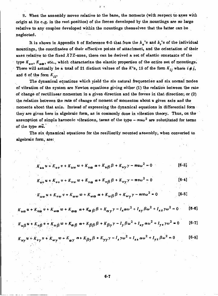
2. When the assembly moves relative to the base, the moments (with respect to axes withorigin at its e.g. in the rest position) of the forces developed by the mountings are so largerelative to any couples developed within the mountings themselves that the latter can beneglected.
It is shown in Appendix 5 of Reference 6-5 that from the ka's and kr's of the individualmountings, the coordinates of their effective points of attachment, and the orientation of theiraxes relative to the fixed X YZ-axes, there can be derived a set of elastic constants of thetype Icy, Kau, etc., which characterize the elastic properties of the entire set of mountings.There will actually be a total of 21 distinct values of the K's, 15 of the form Kii where i# I,and 6 of the form Ku.
The dynamical equations which yield the six natural frequencies and six normal modesof vibration of the system are Newton equations giving either (1) the relation between the rateof change of rectilinear momentum in a given direction and the forces in that direction; or (2)the relation between the rate of change of moment of momentum about a given axis and themoments about that axis. Instead of expressing the dynamical equations in differential formthey are given here in algebraic form, as is commonly done in vibration theory. Thus, on theassumption of simple harmonic vibrations, terms of the type muco2 are substituted for terms
of the type mu.The six dynamical equations for the resiliently mounted assembly, when converted to
algebraic form, are:
Kuuu + IC uti v + Kw + K0 0+ K up g + KY vauco2 = 0 [6-3]
K vu+KVVv+ Kv.w+ KK,,0a+ Kvp /3 + Ku
K vwu + Kvw v + Kww w + ca a + Kwpf3 + Kmyy mwco = 0 [6-5]
a y Y P(')2 xz ycL)2Kuzz u +K0 v+ K0 a+ Ka pg+K yI xaca2 + + r = o [6-6]Oa
Kap + !cog 0 Kgy y06)2 + 0(02 2 0'zy Yz
6-7
mvco2 = 0 [6-4]
[6-7]
Kuy +-Icy V + Kwyw + K KgyP + Kyy y _ zyco2 + /xz al02 06)2 0 [6-8]
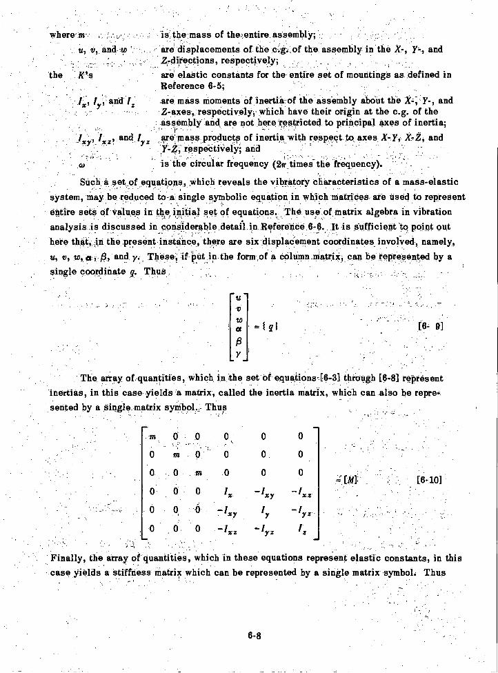
where 'm iathe mass of theentire assembly;u, v, and to . are displacements of the c.g: of the assembly in the X-, y-, and
2-directions, respectively;the K's are elastic constants for the entire set of mountings as defined in
Reference 6-5;are mass moments of inertia ofthe assembly about the X-, y-, andZ-axes, respectively; which have their origin at the c.g. of theassembly and are not here restricted to principal axes of inertia;
xY1 x_z? and / are mass products of inertia with respect to axes iy-y, xrz, and1-z; respectively, and
cu is the circular frequency (2ff times-the frequency).
Such a set of equations, which reveals the vibratory characteristics of a mass-elasticsystem, may be reduced to-a, single symbolic equation in which matrices are used to represententire seta of values in the initial set of equations The use of matrix algebra in vibrationanalysis is discussed in considerable:detailin Reference 6-6. It is Sufficient to point out
, .
here that, in the present instance, there are six displacement Coordinates, involved', namely,u, v, to, a, /3, and y. These, if:put.in the form of a column.Matrix,,can be represented by asingle coordinate q. Thus
0 0 o,
o m o o o
o o
-1 y - ix z
1, a
-1 z iz
. Finally, the array of quantities, which in these equations represent elastic constants, in thiscase yields a stiffness Matrix which can be represented by a single matrix symbol. Thus
toa
6-8
=10 [6-9]
The array of quantities which in the set of equaiions-[6-3] through [6-8] representinertias, in this case yields a matrix, called the inertia matrix, which can also be repre-sented by a single matrix syMbol Thus
0.0 rn. .0
0 0 0 ix
O on 6 - ixy
0 0 0 -4z
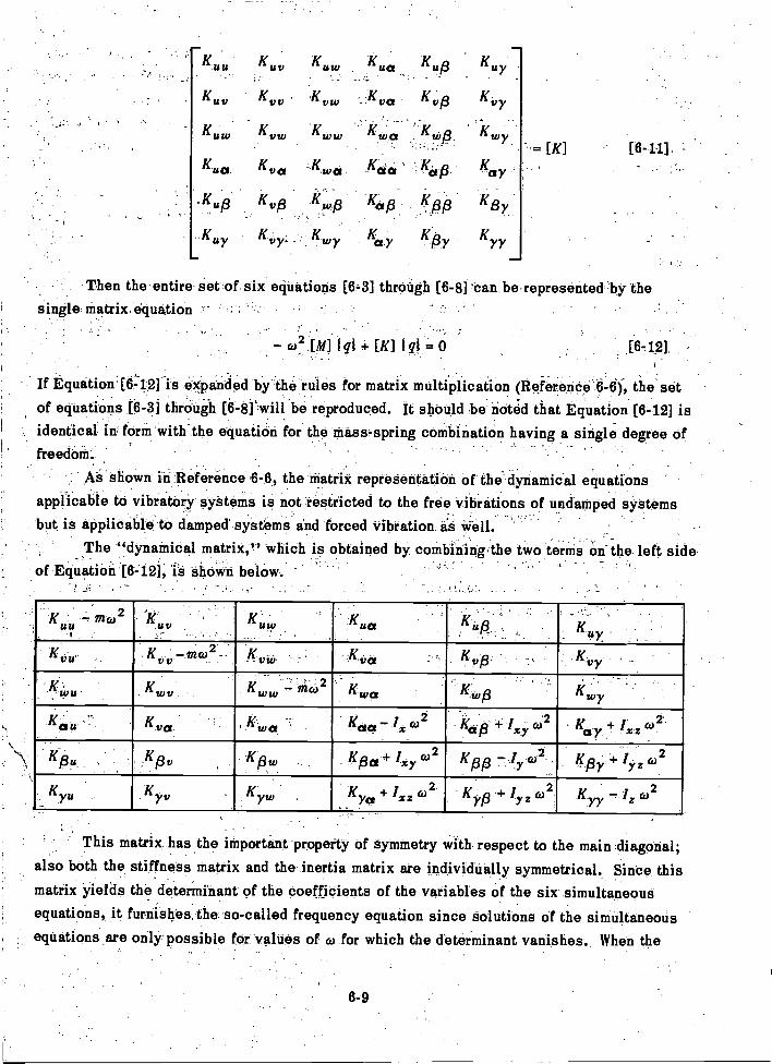
uu. K uv K u.
K uv K
Ku. Kv. ww
Kua Kua -Kwa
.Ku p K K./4
..K fuy vy- -
K u'a
,-Kva
6-9
Then the entire set of six equations [64] through [6-8] can be represented by thesingle matrix equation
o,2lqi + [id I = 0 J6,121
If Equationienfis expanded by the rules for matrix multiplication (Reference the setof equations [6-3] through [6-8] will be reproduced. It should be rioted that Equation [6-12] isidentical in form with the equation for the mass spring combination having a single degree offreedom.
As shown in Reference 6-6, the matrix representation of the dynamical equationsapplicable to vibratory systems is not restricted to the free vibrations of undamped systemsbut is applicable to damped systems and forced vibration as
The "dynamical matrix," which is obtained by combining the two terms orithe left sideof Equation [642], is shown below.
2K u co Icy
" K
Kva
we'
:Yz
vy
gy+ lyz
This matrix has the important property of symmetry with respect to the main diagonal;also both the stiffness matrix and the inertia matrix are individually symmetrical. Since thismatrix yields the determinant of the coefficients of the variables of the six simultaneousequations, it furnishes the so-called frequency equation since solutions of the simultaneousequations are only possible for values of co for which the determinant vanishes. When the
[K] [6-11]
2K pp
determinant is expanded and set equal to zero, the resulting equation is of the sixth degreein (02. The positive values of co for which the determinant vanishes will be the natural fre-quencies of the assembly. Corresponding to each root there will be a set of relative valuesof u, v, w, a, f3, and y constituting a normal mode pattern. These patterns are found by solv-ing the simultaneous equations obtained when each of the natural circular frequencies is sub-stituted for co in the set of equations [6-3] through [6-8].
When planes of vibrational symmetry exist many of the K's and the mass products ofinertia may be zero. Then it will be found that all equations of the resulting set may be in-dependent or will reduce to small groups of equations which are independent of the other
groups.As an illustration of the manner in which the effect of a relatively massive item of
equipment, resiliently mounted in a hull, may be taken into account in the hull vibrationanalysis, a special case, chosen for its simplicity, will be considered here. The case se-lected is the analysis of the vertical vibration of a ship in which there is to be installed aheavy resiliently mounted assembly whose center of gravity will fall on the longitudinalcenterline of the hull, and of such design that the vertical plane through the longitudinalaxis of the hull will be a plane of vibrational symmetry of the resiliently mounted system.
The assembly now has three normal modes of vibration in this vertical plane when thehull is held fixed. In general, each of these modes will involve the displacements u, w, andf3, and thus a combination of heaving, pitching, and surging motions is involved. Here, forconsistency with Reference 6-5, the Y-axis is taken as horizontal and not vertical, as in thetreatment of vertical hull vibration in Chapter 3.
In the finite difference equations used for finding the vertical normal modes of the hull,the only equations requiring modification due to the presence of the resiliently mounted as-sembly are those for the element of the hull of length Ax within which the assembly is mounted.
If the mass of the assembly is designated ms and its mass moment of inertia about theathwartship axis through its e.g. (the Y-axis in this case) is designated fa, the finite differ-ence equations (in simplified form) become for this element:
AV = - itAzzco2 - K. (a - as) + Ku. us - Ku,p (13 - Ps) [6-13]
AM = - I ill AxPc02 + V Az + K ugus - K 8u) (a - as) - K pp (13 - f3 s) [6-14]
MAx= [6-15]
El
V AzAz= -AzKAG
[6-16]
6-10
Here the displacement amplitude of the assembly in the Z-direction is designated zs ratherthan tos in conformity with the notation for the displacement amplitude of the hull in that di-rection; whereas for the displacement amplitude at the assembly in the X-direction the des-ignation us is retained. The force and moment equations for the assembly are, respectively:
m82,4)2 =Kww(a- Zs)-K,,,us+ Kwp(P - Ps) [6-17]
and
I st3 sco2 = - K uptis + K isw (a - a s) +Kfjp(P 'PO [6-18]
When these equations for the section containing the resiliently mounted assembly arecombined with the usual equations for the remainder of the hull, and the digital process iscarried out as described in Chapter 3, the solution then shows not only how the isolationmounting affects the natural frequencies of the ship but also how it affects the normal modesof the hull. It also shows how the resiliently mounted assembly vibrates in each of the nor-mal modes of the entire system. From such a calculation it can be predicted whether the localvibration of the resiliently mounted assembly will be excessive when the level of vibration ofthe hull in its vicinity is within permissible limits. A more general treatment of the hull as abeam with sprung masses is given in Reference 6-4. It can readily be seen that the additionalequations involved in the hull calculation to allow for the sprung mass effect of a resilientlymounted assembly (Equations [6-13] through [6-18]) are directly derivable from the dynamicalmatrix shown on page 6-9.
A further development in the isolation mounting of shipboard equipment has been theuse of a compound mounting system. Here the equipment to be isolated is supported by oneset of mountings attached to a cradle. The latter, in turn, is supported in the hull by anotherset of isolation mountings. Such a system is shown schematically in Figure 6-4. It hastwelve degrees of freedom, six for each body, and accordingly has twelve natural frequenciesand twelve normal modes of vibration.
A discussion of the calculation of the normal modes and natural frequencies of a com-pound isolation mounting system is given in Reference 8-7. A treatment of the same problemby means of the electrical analog, which in this case was derived from the Lagrangian equa-tions, is given in Reference 6-8.
D. SUMMARY OF EFFECTS OF SPRUNG MASSES ON HULL VIBRATION
Both analytical studies and available experimental data indicate that the local flexi-bility or the sprung mass effect can cause a considerable modification of the beamlike vibra-tory response characteristics of a hull. The general effects of lowering hull natural frequen-cies that are below the local natural frequency and raising hull frequencies that are above
6-11
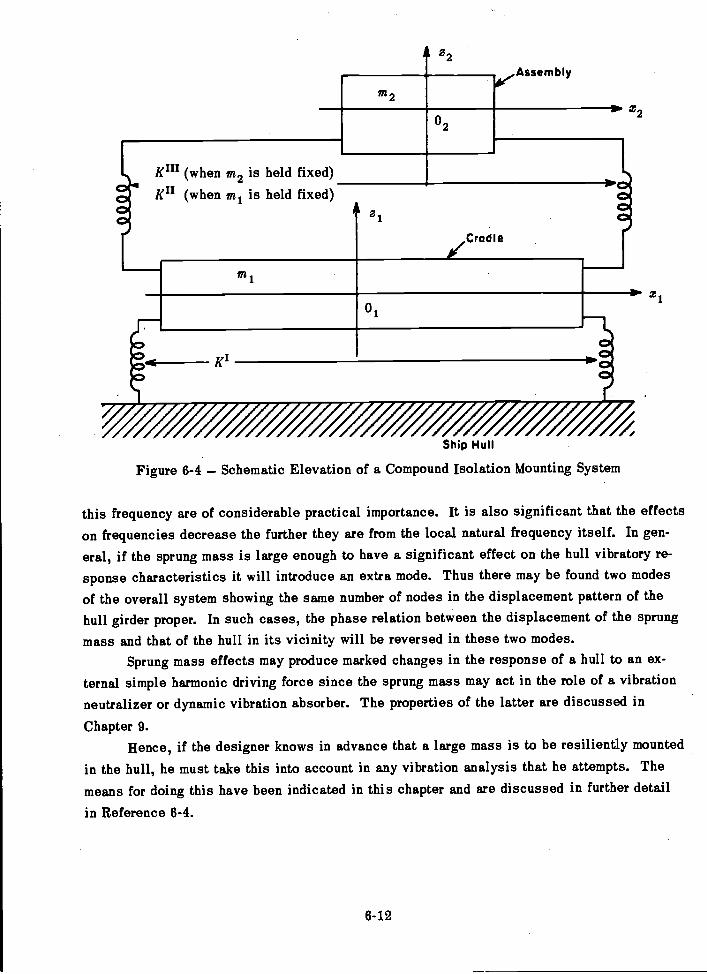
Kin (when m2 is held fixed)
Ku (when m1 is held fixed)A
m2
6-12
A 22
Cradle
Ae.Assembly
Ship Hull
Figure 6-4 Schematic Elevation of a Compound Isolation Mounting System
this frequency are of considerable practical importance. It is also significant that the effectson frequencies decrease the further they are from the local natural frequency itself. In gen-
eral, if the sprung mass is large enough to have a significant effect on the hull vibratory re-sponse characteristics it will introduce an extra mode. Thus there may be found two modesof the overall system showing the same number of nodes in the displacement pattern of thehull girder proper. In such cases, the phase relation between the displacement of the sprungmass and that of the hull in its vicinity will be reversed in these two modes.
Sprung mass effects may produce marked changes in the response of a hull to an ex-ternal simple harmonic driving force since the sprung mass may act in the role of a vibrationneutralizer or dynamic vibration absorber. The properties of the latter are discussed in
Chapter 9.Hence, if the designer knows in advance that a large mass is to be resiliently mounted
in the hull, he must take this into account in any vibration analysis that he attempts. Themeans for doing this have been indicated in this chapter and are discussed in further detail
in Reference 6-4.
x2
REFERENCES
6-1. Kennard, E.H., "Forced Vibrations of Beams and the Effect of Sprung Masses,"
TMB Report 955 (Jul 1955).
6-2. McGoldrick, R.T. and Russo, V.L., "Hull Vibration Investigation on SS GOPHERMARINER," Trans. SNAME, Vol. 63 (1955). Also TMB Report 1060 (Jul 1956).
6-3. Leibowitz, R.C., "Natural Modes and Frequencies of Vertical Vibration of a Beam
with an Attached Sprung Mass," TMB Report 1215 (Sep 1958).
6-4. Leibowitz, R.C. and Kennard, E.H., "Theory of Freely Vibrating Nonuniform BeamsIncluding Methods of Solution and Application to Ships," TMB Report 1317 (May 1961).
6-5. Vane, F.F., "A Guide for the Selection and Application of Resilient Mountings toShipboard Equipment," TMB Report 880, Revised Edition (Feb 1958).
6-6. Pipes, L.A., "Applied Mathematics for Engineers and Physicists," McGraw-HillBook Co. (1946).
6-7. McGoldrick, R.T., "Calculation of Natural Frequencies and Normal Modes of Vibra-tion for a Compound Isolation Mounting System," TMB Report 1420 (Jul 1960).
6-8. Ryder, F.L. and Zaid, M., "Direct Electrical Analogs of Double 6-Degree-of-FreedomSystems," Report on Contract Nonr-2952 (00) (X), Scientific Research Staff, Republic AviationCorp., Farmingdale, New York (Feb 1960).
6-13

CHAPTER 7
PROPELLER-EXCITING FORCES
A. INTRODUCTION
This chapter is devoted chiefly to propeller-exciting forces, but it must be recognized
that propulsion devices other than screw propellers may also generate vibratory forces. It is
only the lack of information on the time-varying forces from paddle wheels and other propulsion
devices of infrequent use in naval architecture that necessarily confines the discussion to
screw propellers at this writing. A change in propulsion system design practice would neces-
sitate detailed study of the forces produced by the new propulsion devices. A further restric-
tion in this chapter is to hydrodynamic forces only. The forces arising from mass unbalance
are discussed in Chapter 10.The generic term "forces" is used in the title of this chapter to cover any type of hy-
drodynamic excitation of the hull arising from propeller action whether this be a force or amoment, and it may be recalled here that the significant flexural modes of the hull may be ex-
cited by either a force, a moment, or a combination of both.The vibratory hydrodynamic forces arising from the operation of propellers may be sep-
arated into pitch-unbalance forces and blade-frequency forces. The former are due to irregu-larities in the manufacture of the propeller and appear even when the flow into the propeller
is perfectly uniform.The term "blade-frequency forces" is used here in a broad sense to cover the hydro-
dynamic forces which will exist regardless of the degree of perfection in the manufacture ofthe propeller. These forces are usually understood when the term "propeller-exciting forces"is used and their fundamental frequency is the blade frequency (rpm times the number of blades
per propeller).It is clearly of great value to the designer to be able to predict whether, under a pro-
posed design, the propeller-exciting forces will be excessive. However, it is not the absolutemagnitude of these forces that is of prime significance but their magnitude relative to themechanical impedance of the hull at the "point" where these forces act. The vibratory re-sponse characteristics of the hull are discussed in Chapter 4.
The designer would like to be able not only to predict whether the 'level of hull vibra-tion will be excessive for a proposed design, but to say what Changes should be made in thedesign to reduce the level of service vibration to acceptable limits. This chapter, however,is concerned only with the forces themselves.
The propeller hydrodynamic forces exciting hull vibration operate both directly on the
hull in the vicinity of the propeller ad a fluctuating pressure and indirectly through the pro-peller shaft bearing as a result of lift, drag, and moment on the individual blades. In thelatter case, all three components may vary in time even though the propeller maintains a con-
stant angular velocity.
7-1
PITCH UNBALANCE FORCES
The first-order hull vibration due to pitch unbalance is usually strikingly in evidencewhen a propeller blade has been bent because of running into an obstruction. When this un-balance is due merely to imperfection in manufacture of the propeller, it is of much smalleramplitude than in the case of damage but is still of first-order frequency (frequency same asthe shaft rpm). When a perfectly formed screw propeller operates at constant angular velocityin a uniform axial wake, its polar symmetry requires that it develop constant torque, constantthrust, zero lateral force variation at its bearing, and zero moment variation about any axisnormal to its shaft axis.
The effect of nonuniformity of the blades may be seen qualitatively by considering aone-bladed propeller. While the latter will still produce constant thrust and constant torqueif the velocity field is uniform, the bearing will now be subject to simple harmonic verticaland athwartship forces and moments about both the vertical and horizontal axes. Theseforces and moments will be of a frequency which is the same as the shaft rpm (one cycle perrevolution). Moreover, if the velocity field in the propeller race is not uniform there will bea superimposed variation effect whose fundamental frequency is also of the first order, butwhich may have harmonic components depending on the irregularity of the velocity field(wake pattern). Thus, pitch unbalance gives rise to first-order hydrodynamic forces andmoments at the propeller shaft bearing and to harmonics of the first-order frequency.
Since, under current practice in the manufacture of propellers, forces due to pitch un-
balance are usually within acceptable limits, this phase of hydrodynamic propeller excitationhas not attracted much attention so far. However, when first-order hull vibration is encoun-tered on the trials of a new class of ship, the naval architect must always recognize thateither mass unbalance or pitch unbalance may be the culprit.
BLADE-FREQUENCY FORCES
1. FIRST PRINCIPLES
Although the term "blade frequency" is now in general use for the forces under dis-cussion in this section, it must be emphasized that harmonics of this frequency may be im-portant in many hull vibration problems. Although it had been under investigation severalyears before, the subject of blade-frequency excitation of hulls attracted increased attentionafter World War II; see References 7-1 and 7-2. In spite of this, the information available onthis subject at the present time must be considered relatively scant.
The forces that vary at blade frequency or harmonics of the blade frequency will existin spite of extreme precision in the manufacture of a screw propeller and are directly charge-able to the hydrodynamics of the ship design. While they may be greatly magnified by non-uniformity of the wake, it is important to recognize that a fluctuating pressure field will existforward of the propeller even in a uniform wake. In fact, the hull pressure forces (called the
7-2
"surface forces" in Reference 7-1) and the bearing forces are generally treated quite inde-
pendently. Thus, to predict the blade-frequency exciting forces, the surface forces and the
bearing forces must be combined, taking account of any relative phase shifts.
Although the theoretical treatment of the pressure fields in the vicinity of the propeller
(from which the hull forces must be deduced) is usually based on incompressible potential
flow, which implies an infinite'velocity of propagation, it must be recognized that such low
intensity fields cannot actually propagate at a velocity,greater than the velocity of sound.
Since the latter is in the neighborhood of 5000 ft/sec, it is clear that if the pressure field
extended over 100 ft from the propeller there could be appreciable phase shifts between the
forces transmitted through the propeller shaft bearing and the surface forces. However, be-
cause these pressure fields usually are not significant beyond a distance of one-half diameter
forward of the propeller (see Reference 7-3), and blade frequencies above 3000 cpm are rare
for ships of 2000 tons or more, this phase shift is not a serious consideration at present.
The phase relation between the bearing forces and the surface forces, however, in-
volves not only the consideration of the effect of finite velocity of propagation but the effect of
algebraic sign or direction in space as well. Thus, if a one-bladed outboard-turning propeller
is considered, when the blade is in the 3 o'clock position looking from astern, the bearing
force will be directed upward. The pressure field forward of the blade, however, will be neg-
ative (suction) and will peak when the blade is in the 12 o'clock position. For instantaneouspropagation, therefore, the bearing force and the vertical component of the surface force for-
ward of the propeller would be 90 deg out of phase (with the bearing force leading) if repre-
sented on a rotating time-vector diagram such as described in Chapter 4. Thus, it is obvious
that the separate determination of bearing and surface blade-frequency components is insuf-
ficient to predict the resultant hull driving force, and their phase relations must be taken into
account.On multiple screw ships the phase relations between the blade-frequency-force com-
ponents are still further complicated by the fact that the forces from the different propellers
will continually shift in phase unless the propulsion system has a synchronizing device.
This effect and the pitching of the hull in a seaway are the principal causes of the fluctuation
in the amplitude of propeller-excited vibration at the stern of a ship.When propellers with different numbers of blades are used on the same ship, there will
also be a "beating" at a frequency equal to the difference in the two blade frequencies. Thus,
if four- and five-bladed propellers were operating at 200 rpm, there would be a beating at a
frequency of 200 x (5 4) = 200 beats per min or 3.67 beats per sec, and the beat frequency
would be of the same order of magnitude as the component frequencies. In such a case, the
usual form of beats, which appears when the difference in the two frequencies is very small
relative to their absolute values, would not be in evidence in the signal from a vibration
pickup. Since the shaft speeds would actually be varying, the hull vibration record would
appear quite irregular.
7-3
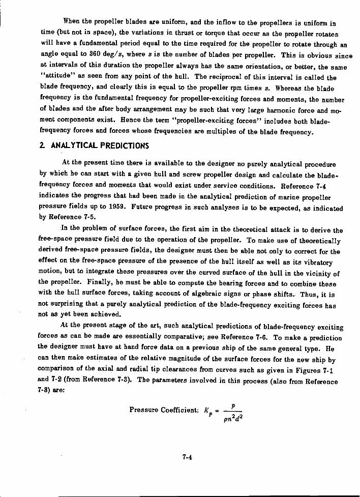
When the propeller blades are uniform, and the inflow to the propellers is uniform intime (but not in space), the variations in thrust or torque that occur as the propeller rotateswill have a fundamental period equal to the time required for the propeller to rotate through anangle equal to 360 deg/a, where a is the number of blades per propeller. This is obvious sinceat intervals of this duration the propeller always has the same orientation, or better, the same"attitude" as seen from any point of the hull. The reciprocal of this interval is called theblade frequency, and clearly this is equal to the propeller rpm times s. Whereas the bladefrequency is the fundamental frequency for propeller-exciting forces and moments, the numberof blades and the after body arrangement may be such that very large harmonic force and mo-ment components exist. Hence the term "propeller-exciting forces" includes both blade-frequency forces and forces whose frequencies are multiples of the blade frequency.
2. ANALYTICAL PREDICTIONS
At the present time there is available to the designer no purely analytical procedureby which he can start with a given hull and screw propeller design and calculate the blade-frequency forces and moments that would exist under service conditions. Reference 7-4indicates the progress that had been made in the analytical prediction of marine propellerpressure fields up to 1959. Future progress in such analyses is to be expected, as indicatedby Reference 7-5.
In the problem of surface forces, the first aim in the theoretical attack is to derive thefree-space pressure field due to the operation of the propeller. To make use of theoreticallyderived free-space pressure fields, the designer must then be able not only to correct for theeffect on the free-space pressure of the presence of the hull itself as well as its vibratorymotion, but to integrate these pressures over the curved surface of the hull in the vicinity ofthe propeller. Finally, he must be able to compute the bearing forces and to combine thesewith the hull surface forces, taking account of algebraic signs or phase shifts.. Thus, it isnot surprising that a purely analytical prediction of the blade-frequency exciting forces hasnot as yet been achieved.
At the present stage of the art, such analytical predictions of blade-frequency excitingforces as can be made are essentially comparative; see Reference 7-6. To make a predictionthe designer must have at hand force data on a previous ship of the same general type. Hecan then make estimates of the relative magnitude of the surface forces for the new ship bycomparison of the axial and radial tip clearances from curves such as given in Figures 7-1and 7-2 (from Reference 7-3). The parameters involved in this process (also from Reference7-3) are:
Pressure Coefficient: If -2 72pn a
7-4
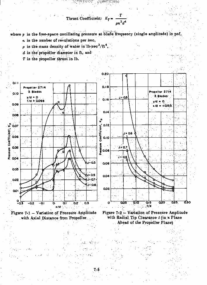
0.1 1
0.10
0.09,
0.08
-0.07
C:
E 0.0500
0.94
0.03
0.02
0.01
11,mem=1111111111E
IN
J 0.3
Q7-
J 0.8
LPropeller
27143 Blades
yeti = 9 . .
i/d =0.098.. .,
Figure 7-1 - Variation of Pressdre,Athplitudewith,Axial,Distance from Propeller. .
Thrust Coeftioieht: KT =pn4 d4
where p is the free-space oscillating pressure at blade frequency single amplitude in psf,n is the number of revolutions per sec,p is the mass density of *rater in lb-:sec2/ft4,
d is the' propeller diameter in ft, andT is the propeller thrusi in lb.
0.20
ser.
0.
J=Q3
Propeller 27143 :Blade!'
y/d ,= 0_/d = 4-4155
-
Figure 7-2 - Variation of Pressure Amplitudewith Radial Tip Clearance t (in a Plane
Ahead of the Propeller Plane)
0.06
0.04
0.02
0 0.05 0.10 0.15, ttd
0.20 025 0.300.3-0.5 -0.2 -0.1 .0::6 al- 0.2'x-/d
0.16
0.14
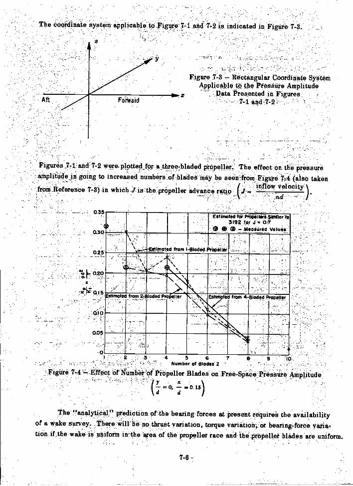
The CO-Ordinate system applicable: to ;Figure 7-1 and 7,2 is indicated in Figure 7-3:,
0.35
0.05
74 7'
Figure 7-3 Rectangular Coordinate SystemApplicable to the Pressure Amplitude
Data Presented in Figures-- '7-1 ,
Figures .7-1, and-7-2 were.plotted for a_three7bladed prOpeller. The effect on the 'Pressureamplitude in going to increased, numbers:of:blades-may be se-elf-from Figure 74 (also takenfroni.Reference 7-3) in which J is ctpropeller advance ratio J. .
nd
_ inflow Velocity )
. . .
Estithated fik Prefiellore Similar:to3192 for 07
e G9 Meatitired ValUes
Estirbated from l-61aelod-Praliiitlei-
EMMY tet from 4. Bladed Propeller,
4 5 6 7Number of Blades Z
Figure 7-4 ' ..-Effect of Amber of Propeller Blades on Free-Space Pressure Amplitude
= 0; 0..15
The `.!analytioal" prediction of the bearing forces at Present require the availabilityof a wake survey. -There will he no thrust variation, torque variation, or bearing-force varia-tion. if the wake is uniform in-the in,ea of the propeller race andthe propeller blades are uniform.

Thus, the process is similar to that of estimating the thrust and torque variation, the differencebeing that the lift and drag on the individual blades are resolved into components normal to theshaft axis. Details of the torque and thrust calculation are given in Reference 7-7. Althoughthe bearing forces will be zero if the torque and thrust variation are zero, it does not followthat a wake pattern that gives high blade-frequency thrust variation will necessarily givelarge bearing-force variations. This is because the components of force on the individualblades may be additive as far as thrust is concerned while canceling as far as vertical orhorizontal forces in the plane of the propeller are concerned.
It is clear that, regardless of the complexity of the wake pattern, as long as it is con-stant in time and the blades are uniform in pitch, such an analysis requires advancing thepropeller through an angle of only 360 deg/a. The time taken for this angular displacementis the fundamental period of the bearing-force variation.
Thus, for a four-bladed propeller the estimate can be started with one blade in the12 o'clock position. The lift and drag on each blade for this position are then estimatedfrom the wake survey just as the thrust variation is estimated. Instead of combining theblade forces to give the net thrust, however, they are now combined to give the net verticalforce (or horizontal force as the case may be). The propeller is then advanced a few degrees;this process is repeated until the propeller (here assumed four-bladed) which was originallyin the 12 o'clock position has advanced to the 3 o'clock position. If the tabulated values ofnet vertical force are then plotted against time, a smooth curve through the plotted pointsgives one cycle of the bearing-force variation. The time interval will be the reciprocal ofthe blade frequency and in that period the four-bladed propeller will have rotated 90 deg.
The total hull driving force is then estimated by combining the bearing and surfaceforces. Although the estimate of their phase relation is uncertain, the maximum conditionwill obviously be obtained if they are assumed in phase.
3. MODEL PREDICTIONS
In view of the difficulties involved in the analytical prediction of blade-frequencyexciting forces, it was inevitable that the possibilities of model predictions would be ex-plored. The problem, however, also involves numerous difficulties which up to now havenot been completely resolved.
In the United States the attempt to determine blade-frequency exciting forces frommodel tests was initiated by Professor F.M. Lewis under the auspices of the Society ofNaval Architects and Marine Engineers. The measurements were made at the U.S. Experi-mental Model Basin and the results are discussed in References 7-8 and 7-9.
The basic idea of the method was to measure the overall or effective driving forceacting on a self-propelled model by nullification of the model vibration by means of a me-chanical vibration generator installed in the model and geared to the propeller drive shaft.Both the unbalance of the eccentrics of the vibration generator and their phase relative topropeller could be varied while the model was underway.
7-7
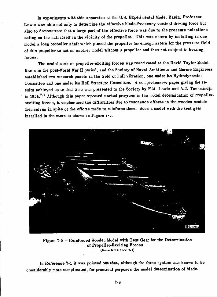
In experiments with this apparatus at the U.S. Experimental Model Basin, ProfessorLewis was able not only to determine the effective blade-frequency vertical driving force but
also to demonstrate that a large part of the effective force was due to the pressure pulsations
acting on the hull itself in the vicinity of the propeller. This was shown by installing in one
model a long propeller shaft which placed the propeller far enough astern for the pressure field
of this propeller to act on another model without a propeller and thus not subject to bearing
forces.The model work on propeller-exciting forces was reactivated at the David Taylor Model
Basin in the post-World War II period, and the Society of Naval Architects and Marine Engineersestablished two research panels in the field of hull vibration, one under its Hydrodynamics
Committee and one under its Hull Structure Committee. A comprehensive paper giving the re-sults achieved up to that time was presented to the Society by F.M. Lewis and A.J. Tachmindji
in 1954." Although this paper reported marked progress in the model determination of propeller-
exciting forces, it emphasized the difficulties due to resonance effects in the wooden models
themselves in spite of the efforts made to reinforce them. Such a model with the test gearinstalled in the stern is shown in Figure 7-5.
t
7-8
N P21-57560
Figure 7-5 Reinforced Wooden Model with Test Gear for the Determinationof Propeller-Exciting Forces
(From Reference 7-1)
In Reference 7-1 it was pointed out that, although the force system was known to beconsiderably more complicated, for practical purposes the model determination of blade-
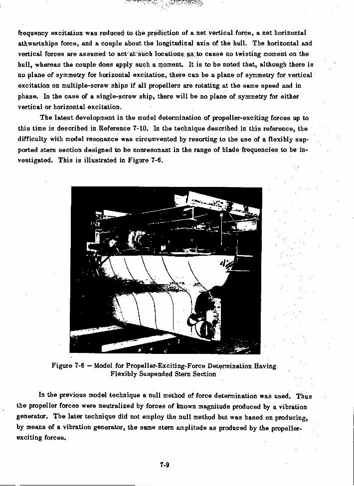
;7"
7-9
frequency excitation was reduced to the prediction of a net vertical force, a net horizontalathwartships force, and a couple about the longitudinal axis of the hull. The horizontal andvertical forces are assumed to act'at'such locations; as AO cause no twisting moment on thehull, whereas the couple does apply such a moment. It is to be noted that, although there isno plane of symmetry for horizontal excitation, there can be a plane of symmetry for verticalexcitation on multiple-screw ships if all propellers are rotating at the same speed and inphase. In the case of a single-screw ship, there will be no plane of symmetry for eithervertical or horizontal excitation.
The latest development in the model determination of propeller-exciting forces up tothis time is described in Reference 7-10. In the technique described in this reference, thedifficulty with model resonance was circumvented by resorting to the use of a flexibly sup-ported stern section designed to be nonresonant in the range of blade frequencies to be in-vestigated. This is illustrated in Figure 7-6.
4.-
Figure 7-6 Model for Propeller-Exciting-Force Determination HavingFlexibly Suspended Stern Section
In the previous model technique a null method of force determination was used. Thusthe propeller forces were neutralized by forces of known magnitude produced by a vibrationgenerator. The later technique did not employ the null method but was based on producing,by means of a vibration generator, the same stern amplitude as produced by the propeller-exciting forces.
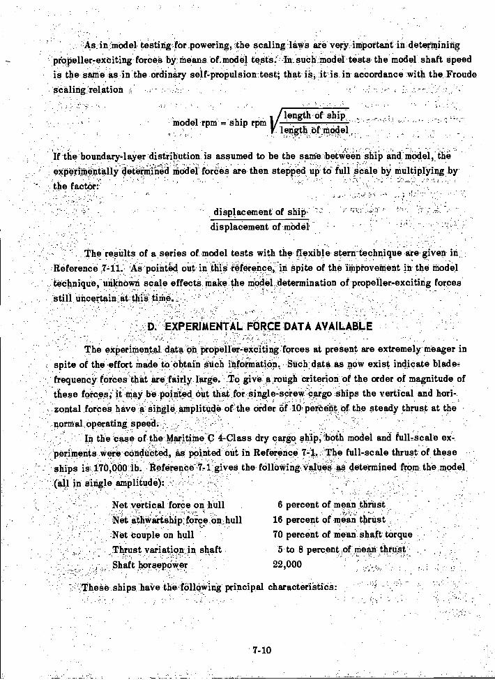
As inModel testing fOr_powering, the scaling lit*Fs ar verjrzint-portant in deterinining
propeller-exciting forces by means of model tests: In such model tests the model shaft speedis the same as in 'the ordinary self-proPulsiontest; that iS, it is in accordance with the Froudescaling relation - .
If the boundary-layer 'distribution is assumed to be the same betWeeii ship and-niOdel,.the
experimentally determined niddet forces are then stepped UP to full Scale by multiplying by, 1
displacement of shiP.-
the factor:
in single amPlitude): .
Net vertical force on .hullNet ithweirtehip', force , On:, hull
:Net Couple on hull -
Thrust variation in shaft_ Shaft horsepower
model rpm = ship rpm
displacement of model
'These ships have the following principal characteristics:
7-10
length of ship, _ ,
length of model
The results of a series of model tests with the flexible stern-technique are given in_
Reference .7-11: As pointed out in this reference, in spite of the improvement in the model*technique; unknown scale effects make the niodel _determination of propeller-exciting forces
still uncertain at this time
D.- EXPERIMENTAL FORCE DATA AVAILABLE
The experimental data on propeller-exciting forces at present are extremely meager inspite of the effort Made to obtainsuch itlformation., Such data as now exist indicate blade,frequency forces that are fairly large. ,To give a ,rough criterion of the order of magnitude ofthese forcesi it May be pointed out that for single-screw cargo ships the vertical and hori-zontal forces have a single amplitude or the order of 100pm:bent. of the steady thrust at the
,
.normal operating speed._
' In the case of the Maritime C 4-Class dry cargo ship, both model and fullfacale ex-.peritnents were conducted, as pointed out in Reference 7-1. The full-scale thrust of theseships is 170,000 lb. Reference-'7,1:gives the following values as determined from the model
6 percent of mean thrust16 percent of mein thrust,70 percent of Mean shaft torque
5 to 8 percent.of nieeri thrust22,000
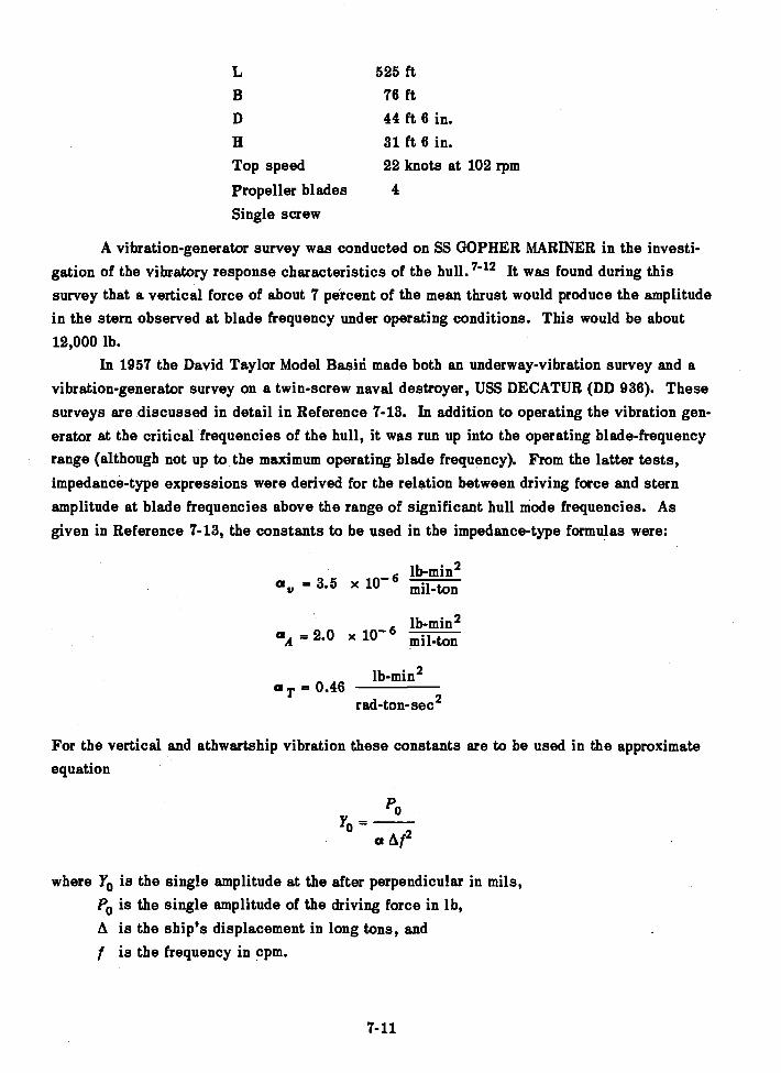
525 ft76 ft44 ft 6 in.31 ft 6 in.
Top speed 22 knots at 102 rpm
Propeller blades 4
Single screw
A vibration-generator survey was conducted on SS GOPHER MARINER in the investi-gation of the vibratory response characteristics of the hull. 7-12 It was found during thissurvey that a vertical force of about 7 percent of the mean thrust would produce the amplitudein the stern observed at blade frequency under operating conditions. This would be about12,000 lb.
In 1957 the David Taylor Model Basin made both an underway-vibration survey and avibration-generator survey on a twin-screw naval destroyer, USS DECATUR (DD 936). Thesesurveys are discussed in detail in Reference 7-13. In addition to operating the vibration gen-erator at the critical frequencies of the hull, it was run up into the operating blade-frequencyrange (although not up to the maximum operating blade frequency). From the latter tests,impedance-type expressions were derived for the relation between driving force and sternamplitude at blade frequencies above the range of significant hull mode frequencies. Asgiven in Reference 7-13, the constants to be used in the impedance-type formulas were:
av = 3.5 x mil-ton
lb-min 2aA 2.0 x 10⁻⁶ mil-ton
lb-min2a T 0.46
red-ton-sec 2
For the vertical and athwartship vibration these constants are to be used in the approximateequation
Po-a Af2
where Yo is the single amplitude at the after perpendicular in mils,P0 is the single amplitude of the driving force in lb,A is the ship's displacement in long tons, andf is the frequency in cpm.
7-11
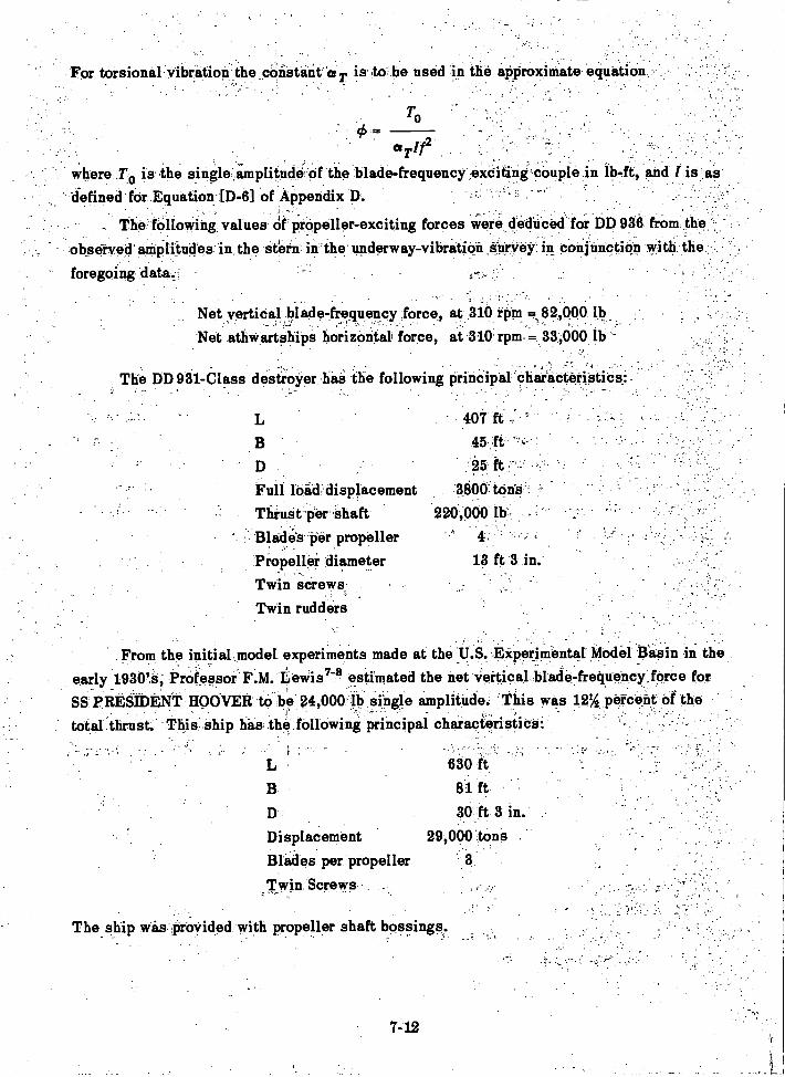
To
a Tlf2where .T0 is the single amplitude 'of the blade-frequency exciting couplein lb-ft, and (is asdefined for Equation [D-6] of Appendix D.
_ The following values Of Propeller-exciting forces Were, deduced for DD 936 from the
observed' amplitudes in the stern in the underway-vibration survey in conjunction with the
- foregoing data.'
Net vertical blade-frequency force, at 310 rpm =82,000 lbNet athwartahips horizontal force, at 310' rpm -= 33,000 lb -
The DD 931-Class destroyer has the following principal characteristics:-
D.Full loii&displacementThinst Per 'shaftBlade's per propellerPeopeller diameterTwin sCrews,
Twin rudders
DisplacementBlades per propeller
,Twin Screws
The ship was provided with propeller shaft bossings.
7-12
he constant T is to be used in the approximate 'equation
407 ft -
45, ft
-25 -
3800 tons220,000 lb
13 ft 3 in.
630 ft
81 ft30,ft 3 in.
29,000 tons3
For torsional
From the initial model experiments made at the U.S.-Experimental Model Basin in theearly 1930's, Professor F.M. Lewis7-8 estimated the net vertical blade-frequency force forSS PRESIDENT HOOVER to be 24,000 lb single amplitude. This was 12% percent of thetotal lthrust. This ship has the following principal characteristics:
In Reference 7-14 the author suggested as a round number that the bearing forcesaccount for 25 percent of the total blade-frequency exciting force acting on the hull, andthat the remainder was due to the surface forces.
An example of reduction of blade-frequency vibration by the use of a fin to reduce thenonuniformity of flow to the propeller is discussed in Reference 7-15.
REFERENCES
7- 1. Lewis, F.M. and Tachmindji, A., "Propeller Forces Exciting Hull Vibration,"Trans. SNAME, Vol. 62 (1954).
7- 2. Breslin, J.P., "The Pressure Field Near a Ship Propeller," JSR, Vol. 1, No. 4(Mar 1958).
'T- 3. Tachmindji, A.J. and McGoldrick, ELT., "Note on Propeller-Excited HullVibrations," JSR, Vol. 3, No. 1 (Jun 1959).
7- 4. Breslin, J.P. and Tsakonas, S., "Marine Propeller Pressure Field Including Effectsof Loading and Thickness," Trans. SNAME, Vol. 67 (1959).
7- 5. Reed, F.E. and Bradshaw, R.T., "The Distribution of Exciting Forces Generatedby Propellers," CONESCO Report F-101-2, Contract Nobs 77150 (Jun 1960).
7- 6. Breslin, J.P., "Ship Vibration. Part I - Propeller-Generated Excitations," ApplMech Rev, Vol. 18, No. 7 (Jul 1960).
7- 7. Yeh, H.Y., "Thrust and Torque Fluctuations for APA 249, TMB Model 4414,"TMB Report 1364 (Jan 1960).
7- 8. Lewis, F.M., "Propeller Vibration," Trans. SNAME, Vol. 43 (1935).
7- 9. Lewis, F.M., "Propeller Vibration," Trans. SNAME, Vol. 44 (1936).
7-10. Pien, P.C. and Ficken, N.L., "The Measurement of Propeller Induced VibratoryForces on Scale Ship Models," Paper presented at ATTC Conference (Sep 1959).
7-11. Stuntz, G.R., et al., "Series 60.- The Effect of Variations in Afterbody Shapeupon Resistance, Power, Wake Distribution, and Propeller-Excited Vibratory Forces,"Paper prepared for Annual Meeting of SNAME (1960).
7-12. McGoldrick, R.T. and Russo, V.L., "Hull Vibration Investigation on SS GOPHERMARINER," Trans. SNAME, Vol. 63 (1955). Also TMB Report 1060 (Jul 1956).
7-13. Paladino, A.R., "Vibration Survey on USS DECATUR (DD 986)," TMB Report1271 (Mar 1960).
7-14. Babaev, N.N., "Contemporary Status of Development of the Problem of Ship Vibra-tion," TMB Trans. 291 (Jul 1959) from Russian paper in Sudostroenie, No. 3 (161) (Mar 1956).
7-15. Baier, L.A. and Ormondroyd, J., "Vibration at the Stern of Single-Screw Vessels,"Trans. SNAME, Vol. 60 (1952).
7-13

CHAPTER 8
DAMPING OF HULL VIBRATION
A. INTRODUCTION
Damping plays a very important role in ship vibration, as in most other areas of me-
chanical vibration, and it is unfortunate that so little is known about the actual damping
process at this time. It is not generally appreciated that the power required to maintain a
quite perceptible vibration in a structure as large as a ship is relatively minute. It is alsogenerally overlooked that an undamped mass-elastic system can be maintained in forced vi-
bration at a nonresonant frequency with zero net power input to the system. Even under
damped resonant conditions the power required to maintain noticeable hull vibration is amaz-ingly small. Thus a ship of 5000-ton displacement can be maintained in vibration in its fun-damental vertical mode with single amplitudes at bow and stern of the order of 10 mils with a
mechanical power input of only 100 watts, as follows from the driving force and driving pointamplitude data given in the first line of Table 5 of Reference 8-1.
While the designer will naturally aim to avoid resonance involving any of the signif-icant hull modes with either the blade frequency, the shaft frequency, or the running rpm of
any major piece of machinery, cases will inevitably arise in which this is not feasible. It
may well be necessary in many cases to operate a ship at a shaft speed at which the bladefrequency coincides with one of the natural frequencies of the hull. Furthermore, it must notbe overlooked that, even when the operating blade frequencies are well clear of the range of
significant hull frequencies, it will still be necessary to pass through critical speeds in
coming up to the operating speed.As shown in Chapter 4, the resonant amplitudes of the hull depend on the magnitude
of the driving force, the location of its point of application relative to nodal points in the
mode in question, and the damping itself. Clearly, the importance of being able to predictthe damping values depends on the other factors determining the resonant amplitude. Thus,
if there is assurance that the driving forces will be negligible, the need for the damping pre-
diction is greatly diminished. If all the critical speeds with respect to hull vibration are
known to fall well below the operating speed range of the ship, it may not be necessary toestimate the hull damping. In general, however, it is desirable to do so.
The difficulty in estimating damping values for the entire hull is due to the presentscant knowledge of the actual damping mechanism. To cite obvious sources of damping is
far easier than to assess their relative importance. Thus there is an immediate tendency to
assume, since the hull cannot vibrate without imparting motion to the surrounding water, that
this is an important source of hull damping. There is ample evidence, however, that in the
range of frequencies of significant or beamlike hull modes, the damping action of the water
is extremely small. Thus the decay rates for free vibration of ships are no greater than for
steel structures in air.
8-1
Aside from the surrounding water there are two other obvious sources of hull damping;one is the internal friction in the hull structural material, the other is friction between slip-ping or sliding surfaces within the hull, associated with equipment or cargo.
The experiments on GOPHER MARINER 8- 2 show that at the levels of vibration excit-ed by propeller action, the most important source of damping appears to be the cargo friction,if by "cargo" there is included here everything movable inside the hull proper. The dampingsource next in importance seems to be the hysteresis in the hull itself if the structure is weld-ed. With a riveted construction, the working of the joints can cause a dissipation of energywhich is chargeable to the hull although not to the material. The least important source ofdamping appears to be the water. This statement applies to practical conditions under whichthe amplitudes are too small to set up appreciable surface waves, and to frequencies at whichacoustics radiation is not an important factor. Here it should be noted that acoustic powerlevels are ordinarily extremely low as contrasted with the level of mechanical power requiredto vibrate a hull. Present evidence (see References 8-1 and 8-2) indicates that hull dampingis actually dependent on both amplitude and frequency.
As in the case of the hull itself, damping also determines the magnitude of resonantvibration of local structures. Here both cargo and water damping effects are, in general, notinvolved, and the damping source must be attributed to the material of which the local struc-ture is fabricated, the type of joints, or the type of support which determines the transmissionof energy to other parts of the ship.
In harmony with the rational beam theory of hull vibration presented in Chapters 3 and4, the treatment of damping in this book is also a rational or semiempirical treatment. Thus,in the case of flexural vibration, the damping coefficient c is used which represents a dampingforce per unit velocity, per unit length. This coefficient is further restricted to either of two
types: the Rayleigh type which is viscous and proportional to mass, so that is constant
(where IL is the mass per unit length of the hull including the allowance for added mass of
the surrounding water); or the type increasing with frequency so that is constant, whereiLcoco is the circular frequency.
In this scheme of treating hull damping, the c values to be used in actual calculationscannot be determined analytically from given hull design data but must be based on experi-mentally determined values obtained on other ships.
The reader will find in the technical literature numerous treatments of beam vibrationwith other types of damping; see, for example, References 8-3 and 8-4. In the belief that theprincipal source of damping of ship vibration is the cargo, these methods are not evaluatedhere. It is pointed out, however, that while the use of equivalent viscous damping constantsbased on energy dissipation is a makeshift expedient, the viscous damping constant that isalmost universally used in the treatment of lumped vibratory systems in standard textbooks on
mechanical vibration also involves an idealization of the actual damping process.
8-2
ANALYTICAL TREATMENTIOF.HULL DAMPING-
The most widely used assumption in the analytical treatment of the,damping of- ame-chanical system in vibration is that it is of the visCaii-ariype, as indicated in the previoussection; As appliedto the elementary system of one degree of freedom, this is the type ofdamping produced by a frictional force proportional to the Velocity and having .a direction
- opposite tO that -velocity. This gives for the free vibrations the familiar differential equation,
InY+ ce + ko 0 [8711
where c is the viscous damping constant,is the mass, and
k is the spring constant.
In Spite Of the'fact'that mechanical damping is rarely of the true viscous type, an"equivalent viscous" constant is widely used because the solutions Of the -resulting linear
_
differential equations are well known. The equivalent viscous constant is based on energydissipation per cycle. If this is designated W, then
*Thera Yls the single amplitude and is the circular frequency. The Viscous deriving,
concept is also commonly retained in establishing damping constants from the logarithmicdecrements deduced from observations of decaying free vibrations. Thus, in the elementarysystem of one degree Of freedom, the critical Viscous ,damping constant is given by the equation
For small damping
and thezlogarithrnic decrement: is
8=
8-3
[8-5]
, A common Criterion of the degree of damping iã the resonance magnification factor._
This is frequently designated by the symbol Q, widely used in electrical circuit theory as an-
-.- . . .
index of dissipation for indiletanees.- The lower the dissipation in the coil, the higher is its. . ,
.. -'. 1 --,Q. For viscous damping_.
and for low damping
is closer to reality .th_an the relation
K - MKa
In:the case of the hull, the complexity and uncertaintyregarding the actual dampingprocesses have forced an extension of these concepts.: By assuming that the dainping of theflexural vibration of the hull can be represented by a distributed viscous damping constant
. : , ;
proportional to the mass per unit length (includingthe Et-ddell:mass of surrounding water), theship can be treated as a !!"Rayleigh system," at least in dealing with Vibration in its sig-nificant flexural inode'e. The Rayleigh-type of damping is then of the type C/A = constant,where c is the equivalent damping force per unit velocity per unit length (axial), and A is the
.. mass per unit length including theadded mass of water..
.
Under,.suchassUmptions, the free and forced vibrations Of the hull may be treated interms of normal mode reap:on-gee. This ,effects great sirnplifiCation. -In this procedure theith flexural mode of the hullieredUceckto an effective-syatem-of one degree of freedom re-
_
ferred to a specific driving point d. 'According to the equations given on pages 4-.2 to 411,the steady-state amplitude is
constantAco
= constant
8-4
(42 *fedi' 0)
This gives not only the magnitude of the displacement aniplitudein the ith inedebut-also thephase of its rotating VeCtor in :relation to that of the driving force of circular frequency co. .
I Experience has indicated that the damping is actually dependent on both amplitudeand frequency. For frequency dependence the indication is that the relation
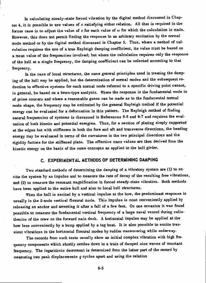
In calculating steady-state forced vibration by the digital method discussed in Chap-
ter 4, it is possible to use values of c satisfying either relation. All that is required in the
former case is to adjust the value of c for each value of co for which the calculation is made.
However, this does not permit finding the response to an arbitrary excitation by the normal
mode method or by the digital method discussed in Chapter 5. Thus, where a method of cal-
culation requires the use of a true Rayleigh damping coefficient, its value must be based on
a mean value of the frequencies involved; but where the calculation requires only the response
of the hull at a single frequency, the damping coefficient can be selected according to that
frequency.In the case of local structures, the same general principles used in treating the damp-
ing of the hull may be applied, but the determination of normal modes and the subsequent re-
duction to effective systems for each normal mode referred to a specific driving point cannot,
in general, be based on a beam-type analysis. Where the response in the fundamental mode is
of prime concern and where a reasonable guess can be made as to the fundamental normal
mode shape, the frequency may be estimated by the general Rayleigh method if the potential
energy can be evaluated for a deformation in this pattern. The Rayleigh method of finding
natural frequencies of systems is discussed in References 8-6 and 8-7 and requires the eval-
uation of both kinetic and potential energies. Thus, for a section of plating simply supported
at the edges but with stiffeners in both the fore and aft and transverse directions, the bending
energy may be evaluated in terms of the curvatures in the two principal directions and the
rigidity factors for the stiffened plate. The effective mass values are then derived from the
kinetic energy on the basis of the same concepts as applied to the hull girder.
C. EXPERIMENTAL METHODS OF DETERMINING DAMPING
Two standard methods of determining the damping of a vibratory system are (1) to ex-
cite the system by an impulse and to measure the rate of decay of the resulting free vibrations,
and (2) to measure the resonant magnification in forced steady-state vibration. Both methods
have been applied to the entire hull and also to local hull structures.When the hull is excited by a vertical impulse at the bow, the predominant response is
usually in the 2-node vertical flexural mode. This impulse is most conveniently applied by
releasing an anchor and arresting it after a fall of a few feet. On one occasion it was found
possible to measure the fundamental vertical frequency of a large naval vessel during calis-
thenics of the crew on the forward main deck. A horizontal impulse may be applied at the
bow less conveniently by a bump applied by a tug boat. It is also possible to excite tran-
sient vibrations in the horizontal flexural modes by rudder maneuvering while underway.
The records from such tests usually show an initial complex vibration with high fre-
quency components which shortly settles down to a train of damped sine waves of constantfrequency. The logarithmic decrement is determined from the latter part of the record by
measuring two peak displacements q cycles apart and using the relation
8-5

As applied to local structures, the impulse method of determining damping is similar,but in this case it is often difficult to produce a decaying vibration in a single mode. Blowswith a heavy timber comprise the most common method of excitation.
The rational theory permits the evaluation of the damping constant to be used in thecalculation of forced vibration of ships directly from the experimentally determined logarithmicdecrement. Thus, suppose a calculation is to be made by the digital process outlined in Chap-ter 4. Here the Rayleigh damping constant is retained and this means that c/ g is treated asconstant for all points along the hull and at all driving frequencies. Let Mdi be the effectivemass at any arbitrary point for the mode of vibration in which the logarithmic decrement wasobserved (here called the ith mode). Then the effective Rayleigh damping constant for thismode and at this point of the hull is given by the equation
77 C di
The damping constants c used in the digital calculation are then evaluated from the relation
C di=
g Mdi
CdiIf hull damping were truly of the Rayleigh type, would be independent of the mode
Mdiand it would follow from Equation [8-10] that the logarithmic decrement would vary inverselywith the frequency of the mode. Since experience has shown it more feasible to assume thatthe logarithmic decrement remains constant, it is expedient to assume
C di- constant
M .d;
[8-11]
[8-12]
in any calculations dealing with response in a single mode.Naturally, if experimental decrement values are available for a previous ship of gen-
erally similar design these are the best to use, but as pointed out in Reference 8-2, an aver-C di
age value of obtained from experiments on a variety of ships is 0.03.Mditai
In deriving hull damping values from vibration generator tests, use can be made of thefact that at resonance the mechanical impedance (defined in Chapter 4) in the mode in ques-tion is solely the damping impedance C dicai. Hence, from the known exciting force of the
8-6
1 An8 log e
An+q [8- 9]
Si-Mdiwi
[8-10]
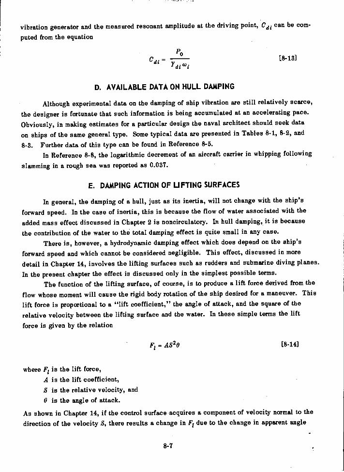
vibration generator and the measured resonant amplitude at the driving point, Cdi can be com-
puted from the equation
PoCdi =
dicui
D. AVAILABLE DATA ON HULL DAMPING
Although experimental data on the damping of ship vibration are still relatively scarce,the designer is fortunate that such information is being accumulated at an accelerating pace.
Obviously, in making estimates for a particular design the naval architect should seek data
on ships of the same general type. Some typical data are presented in Tables 8-1, 8-2, and
8-3. Further data of this type can be found in Reference 8-5.In Reference 8-8, the logarithmic decrement of an aircraft carrier in whipping following
slamming in a rough sea was reported as 0.037.
E. DAMPING ACTION OF LIFTING SURFACES
In general, the damping of a hull, just as its inertia, will not change with the ship's
forward speed. In the case of inertia, this is because the flow of water associated with the
added mass effect discussed in Chapter 2 is noncirculatory. In hull damping,, it is becausethe contribution of the water to the total damping effect is quite small in any case.
There is, however, a hydrodynamic damping effect which does depend on the ship's
forward speed and which cannot be considered negligible. This effect,, discussed in more
detail in Chapter 14, involves the lifting surfaces such as rudders and submarine diving planes.
In the present chapter the effect is discussed only in the simplest possible terms.The function of the lifting surface, of course, is to produce a lift force derived from the
flow whose moment will cause the rigid body rotation of the ship desired for a maneuver. This
lift force is proportional to a "lift coefficient," the angle of attack, and the square of therelative velocity between the lifting surface and the water. In these simple terms the lift
force is given by the relation
F1= A820 [8-141
where F1 is the lift force,A is the lift coefficient,S is the relative velocity, and0 is the angle of attack.
As shown in Chapter 14, if the control surface acquires a component of velocity normal to thedirection of the velocity S, there results a change in F1 due to the change in apparent angle
8-7
[8-13]
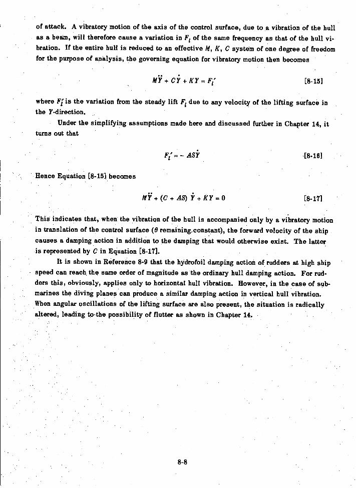
of attack. A vibratory motion of the axis of the control surface, due to a vibration of the hullas a beam, will therefore cause a variation in Fi of the same frequency as that of the hull vi-bration. If the entire hull is reduced to an effective M, K, C system of one degree of freedomfor the purpose of analysis, the governing equation for vibratory motion then becomes
+ Ci + KY = [8-15]
where FT is the variation from the steady lift Fl due to any velocity of the lifting surface inthe Y-direction.
Under the simplifying assumptions made here and discussed further in Chapter 14, itturns out that
F1' = ASY 18-18]
Hence Equation [8-15] becomes
+ (C + AS) + KY = 0 [8-17]
This indicates that, when the vibration of the hull is accompanied only by a vibratory motionin translation of the control surface (0 remaining,constant), the forward velocity of the shipcauses a damping action in addition to the damping that would otherwise exist. The latteris represented by C in Equation [8-17].
It is shown in Reference 8-9 that the hydrofoil damping action of rudders at high shipspeed can reach the same order of magnitude as the ordinary hull damping action. For rud-ders this, obviously, applies only to horizontal hull vibration. However, in the case of sub-marines the diving planes can produce a similar damping action in vertical hull vibration.When angular oscillations of the lifting surface are also present, the situation is radicallyaltered, leading to.the possibility of flutter as shown in Chapter 14.
8-8
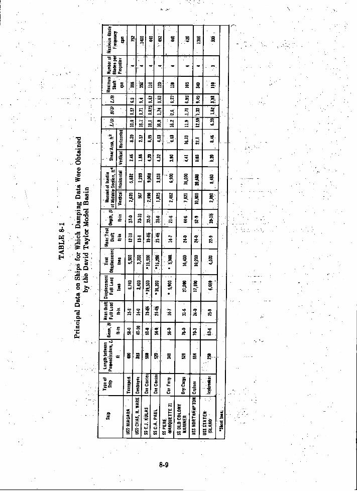
TA
BL
E 8
-1
Prin
cipa
l Dat
a on
Shi
ps f
or W
hich
Dam
ping
Dat
a W
ere
Obt
aine
dby
th'e
Dav
id T
aylo
r M
odel
Bas
in
Shi
pT
ype
ofS
hip
Leng
th b
etw
een
1Per
pend
icul
ars,
L
ft
..
Bea
m,
B
It in
.
'Mea
n D
raft
Ful
l Loa
d
ft.in
I
Dis
plac
emen
tF
ull L
oad
tons
Tes
tD
ispl
acem
ent
tons
Mea
n T
est
Dra
ft
ft=in
'-
,D
Dep
th ft in
,.
,M
omen
of I
nert
iaof
MId
ship
Sec
tion,
fte
-.
,
.
She
ar'A
reaD
2.L
ID. B
/D L
IBM
axim
um
Sha
ft -.
.
4, m
Num
ber
of
Bla
des
per
Pro
pelle
r
Max
imum
Bla
de
Fre
quen
cy
cpm
Ved
ical
Hor
izon
tal
Ver
tical
Hor
izon
tal
US
S.N
IAG
AR
A.
Tra
nspo
rt40
058
415
-66,
740
5,50
01V
1137
42,
620
5,83
224
68.
2010
:81.
576.
9-
188
475
2U
SS
,CH
AS
, R. W
AR
E D
estr
oyer
.38
340
-10
144
3,40
032
00,
13-8
23-1
056
71,
289
.1.
8825
716
.1,1
319A
350
4.1
400
MU
. KU
LAS
Ore
Car
rier
- --
-58
060
-019
-8)4
. 19,
500
*19,
500
19-8
I4-
32-0
..Z
490
9;00
84.
208.
9918
118
75 9
A7
110
-44
0S
S C
IA. P
AU
LO
re C
arrie
r51
0
,
544-
21-4
14*1
6,20
0...
16,2
00-
.21
;4%
.317
0-
1,82
51A
314.
324.
6316
.813
496
2- .
123
4
.
492
SS
PE
RE
MA
RQ
UE
TT
E 2
1C
ar F
erry
348
56-0
14-7
5,90
0;
5900
-14
-121
4"
2,48
269
003.
904.
6316
.2 I2
66:
211
110
444
0
SS
OLD
CO
LON
YM
AR
INE
RD
ry :C
argo
528
76-0
314
-21
000
16,4
0024
-044
-6..
- 78
21.
1600
04.
4116
.13
11.9
:1.7
16.
951
105
4
'
420
US
S N
OR
TH
AM
PT
ON
Cru
iser
664
70-3
24-0
17,1
0016
200
24-0
52-9
1080
0,
2060
0C
O3
27.1
12.5
9 '1
.33
945'
340
413
60
US
S.S
TA
TE
N-
ISLA
ND
''
Iceb
reak
er-
250
63-6
25-9
6,66
04,
500
22-9
3971
%28
9084
808.
2084
663
9 16
2- .3
93,
110
. 330
*Sho
rt to
ns:
.
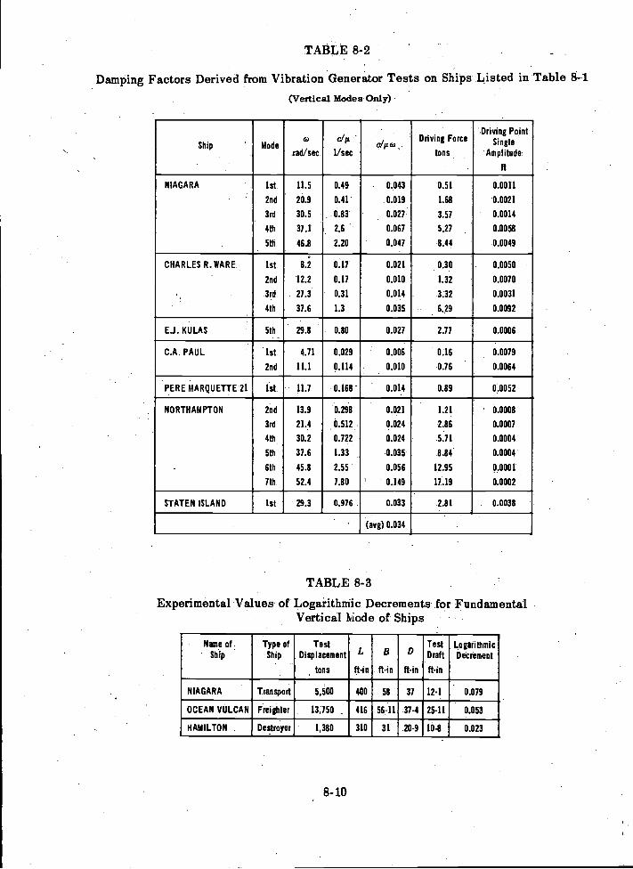
TABLE 8-2
Damping Factors Derived from Vibration Generator Tests on Ships Listed in Table 8-1(Vertical Modes Only)
TABLE 8-3
Experimental Values of Logarithmic Decrements for FundamentalVertical Mode of Ships
8-10
Ship Modeea
rad/sec
c/ g
1/secc/p co
Driving Force
tons
Driving PointSingle
Amplitude
ft
NIAGARA 1st 11.5 0.49 . 0.043 0.51 0.0011
2nd 20.9 0.41 0.019 1.68 0.0021
3rd 30.5 0.83 0.021 3.57 0.0014
4th 37.1 2.6 0.067 5.27 0.0058
5th 46.8 2.20 0.047 8.44 0.0049
CHARLES R. WARE 1st 8.2 0.17 0.021 0.30 0.0050
2nd 12.2 0.17 0.010 1.32 0.0070
3rd 27.3 0.31 0.014 3.32 0.0031
4th 37.6 1.3 0.035 6.29 0.0092
E.J. KULAS 5th 29.8 0.80 0.027 2.77 0.0006
C.A. PAUL 1st 4.71 0.029 0.006 0.16 0.0079
2nd 11.1 0.114 0.010 0.76 0.0064
PERE MARQUETTE 21 1st 11.7 0.168 - 0.01.4 0.89 0.0052
NORTHAMPTON 2nd 13.9 0.298 0.021 1.21 ' 0.0008
3rd 21.4 0.512 0.024 2.86 0.0007
4th 30.2 0.722 0.024 5.71 0.0004
5th 37.6 1.33 '0.035 8.84 0.0004
6th 45.8 2.55 0.056 12.95 0.0001
7th 52.4 7.80 ' 0.149 17.19 0.0002
STATEN ISLAND 1st 29.3 0.976 0.033 2.81 0.0038
' (avg) 0.034
Name ofShip
Type ofShip
TestDisplacement
tons
L
ft-in
B
ft-in
D
ft-in
TestDraft
ft-in
LogarithmicDecrement
NIAGARA Transport 5,500 400 58 37 12-1 0.079
OCEAN VULCAN Freighter 13,750 416 56-11 37-4 25-11 0.053
HAMILTON Destroyer 1,380 310 31 20-9 10-8 0.023
REFERENCES
8-1. McGoldrick, R.T., "Comparison between Theoretically and Experimentally DeterminedNatuial Frequencies and Modes of Vibration of Ships," .TMB Report 906 (Aug 1954).
8-2. McGoldrick, R.T. and Russo, V.L., "Hull Vibration Investigation on SS GOPHERMARINER," Trans. SNAME, Vol. 63 (1955). Also TMB Report 1060 (Jul 1956).
8-3. Kumai, T., "Damping Factors in the Higher Modes of Ship Vibrations," EuropeanShipbldg, Vol. VII, No. 1 (1958).
8-4. Sezawa, K., "The Effect of the Distribution of Damping Resistance in a Ship on HerVibration," J Soc Nay Arch Japan, Vol. 66 (Jun 1940).
8-5. Vane, F.F., "Shock and Vibration in Ships," Handbook of Shock and Vibration Con-trol, Harris, C.M. and Crede, C.E, Editors, McGraw-Hill Book Co. (to be published in 1961).
8-6. Den Hartog, J.P., "Mechanical Vibrations," McGraw-Hill Book Co., New York (1956)..-
8-7. Timoshenko, S., "Vibration Problems in Engineering," D. Van Nostrand Co.,New York (1955).
8-8. Jasper, N.H. and Birmingham, J.T., "Strains and Motions of USS ESSEX (CVA 9)during Storms Near Cape Horn," TMB Report 1216 (Aug 1958).
8-9. McGoldrick, R.T., "Rudder-Excited Hull Vibration on USS FORREST SHERMAN(DD 931) A Problem in Hydroelasticity," Trans. SNAME (1959). Also TMB Report 1431(Jun 1960).
8-11
CHAPTER 9
ANTI VIBRATION DEVICES
A. INTRODUCTION
The technical literature reports many developments in the field of antirolling devicesfor ships, such as bilge keels, antirolling tanks, gyrostabilizers, and activated fin stabilizers.Aside from the fact that the rolling frequencies of ships are of the order of 1/10 or less of thelowest frequency normally associated with hull vibration, these devices perform the samebasic function as antivibration devices. In one way or another they set up moments opposingthe rolling motion of the ship. It may therefore seem surprising that relatively little attentionhas been given to the development of antivibration devices for hulls. This is true in spite ofthe fact that antivibration devices in the form of pendulum dampers have been used extensivelyin large internal combustion engines to suppress torsional vibration in the crankshaft system.
The presumption in seeking any antivibration device is that the source of disturbancecannot be eliminated. In the case of hull vibration (as shown in Chapter 7), while first-orderexciting forces can be reduced by improved methods of balancing propellers, shafting, and
machinery, or by closer tolerances for machining of propeller blades, the blade-frequency ex-citing forces cannot be reduced without changing the number of blades per propeller, or al-tering the stern configuration. Thus, a practical antivibration device for hulls could find applicationunder the following situations: (1) when hull vibration develops unexpectedly on the initialtrials of a new class of ship; (2) when the design study indicates that an excessive level ofvibration will exist, but there are overriding advantages in the particular design adopted whichwarrant its retention; and (3) when an unusual type of propulsion system known to producelarge vibratory exciting forces is required for special reasons.
In this chapter a brief discussion is given of certain antivibration devices that haveactually been used to a limited extent for the purpose of reducing the level of service vibra-tion of ships. These devices are the tuned vibration neutralizer, often spoken of in the lit-erature as the "dynamic vibration absorber"; the adjustable rotating eccentric; shaft synchro-nizing devices; and flexible materials used in the vicinity of propellers. Both the tunedvibration neutralizer and the adjustable rotating eccentric set up forces equal and opposite tothe external forces exciting the hull vibration. The synchronizing device, which is applicableto multiple-screw ships, in effect reduces the external exciting force; the flexible materialattenuates the exciting force, that is, reduces the force transmitted to the hull.
B. THE TUNED VIBRATION NEUTRALIZER
The principle of the tuned vibration neutralizer is well known and is discussed ratherthoroughly in most textbooks dealing with the fundamentals of mechanical vibration; see
9-1
Reference 9-1. The device is often referred to in the literature as the "dynamic vibration
absorber."The effect of a "sprung mass" on the vibratory characteristics of ship hulls is dis-
cussed in Chapter 6. The vibration neutralizer is in essence nothing but a sprung mass with
provision for tuning its natural frequency and possibly having adjustable damping. It might
seem that, if the designer is concerned about the prevention of a buildup of hull vibration in
a particular normal mode, he has only to install in the ship a sprung mass tuned to the fre-
quency of this mode. It follows from the discussion in Chapter 6, however, that the desired
objective may not be attained that easily. If the sprung mass is large enough to counteract
the external driving force, it will probably be large enough to substitute a pair of hull modes
for the single mode otherwise existing. Hence, for practical application, it is incumbent on
the designer to provide the vibration neutralizer with variable tuning so that its natural fre-
quency can be adjusted to the frequency of the driving force over a considerable range of ship
speeds.Figure 9-1 shows a large vibration neutralizer that was actually installed on an Italian
motorship and reported to have eliminated 94 percent of the previously existing vibration; see
Reference 9-2. In this case the vibration was caused by machinery and not by propeller action.
Of particular interest is the fact that .the apparatus had a gross weight of 12 tons which was
about 0.1 percent of the displacement of the ship. An interesting feature also was that the
inertia element was a tank divided into many cells that could be flooded with sea water. Thus
the tuning was adjusted by varying the mass, and, in service, an operator was required to ma-
nipulate the valves which flooded or emptied various cells.
The U.S. Experimental Model Basin conducted laboratory experiments with the vibration
neutralizer around 1938 with a view toward exploring its potentialities for use on naval vessels;
see Reference 9-3. While these experiments indicated that electronically controlled energizing
devices could improve the performance of the vibration neutralizer under service conditions at
varying operating speeds, they did not appear promising enough to warrant the development of
a full-scale ship neutralizer at the time.With regard to the feasibility of installing a full-scale shipboard vibration neutralizer,
one point brought out in References 9-2 and 9-3 deserves emphasis here. It may not be nec-
essary to install the apparatus in the immediate vicinity of the exciting source to obtain the
desired neutralizing action. It is true that setting up an equal and opposite force at the driving point
is the most direct method of neutralizing the driving force. However, it follows from the beam
theory of hull vibration that a mass-spring combination will produce an antiresonance of the
system at the frequency to which it is tuned when installed at either end. In the absence of
damping it will maintain whatever amplitude is necessary to hold motionless that point of the
system to which it is attached.It will be of interest to the reader that, at a much later date than that of the experi-
ments discussed in Reference 9-3, it was discovered, on the trials of a naval destroyer with
9-2
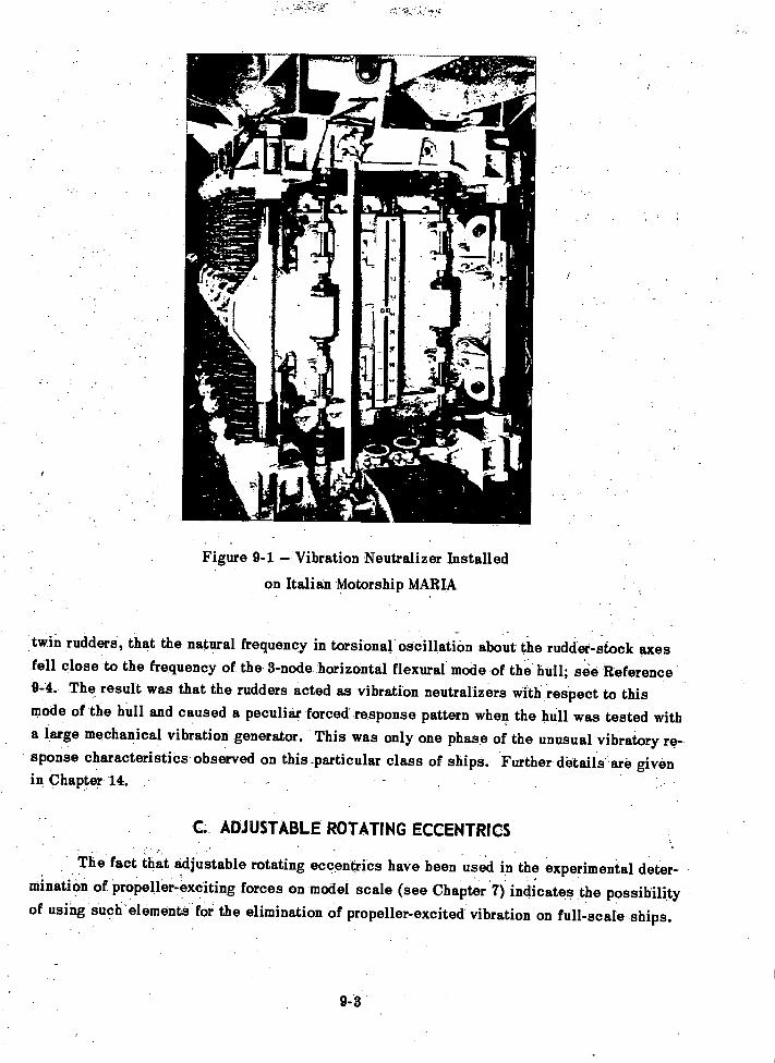
,°roe,
k
9-3
Figure 9-1 Vibration Neutralizer Installed
on Italian Motorship MARIA
twin rudders, that the natural frequency in torsional oscillation about the rudder-stock axesfell close to the frequency of the 3-node horizontal flexural mode of the hull; see Reference9-4. The result was that the rudders acted as vibration neutralizers with respect to thismode of the hull and caused a peculiar forced response pattern when the hull was tested witha large mechanical vibration generator. This was only one phase of the unusual vibratory re-sponse characteristics observed on this _particular class of ships. Further details .are givenin Chapter 14.
C ADJUSTABLE ROTATING ECCENTRICS
The fact that adjustable rotating eccentrics have been used in the experimental deter-mination of propeller-exciting forces on model scale (see Chapter 7) indicates the possibilityof using such elements for the elimination of propeller-excited vibration on full-scale ships.
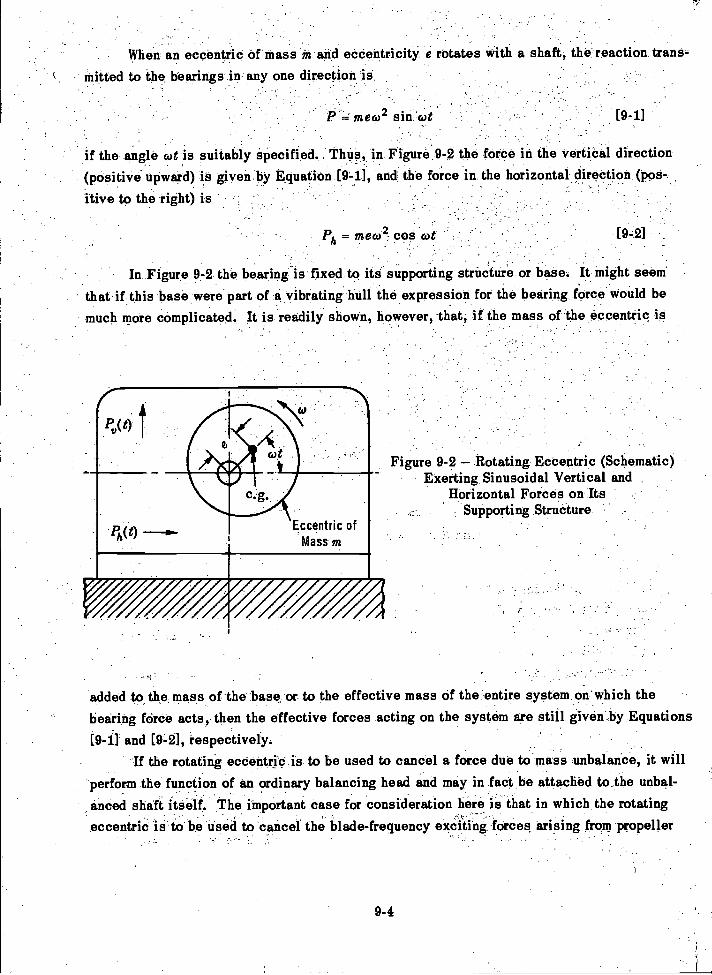
When an eccentric Of mass in and eccentricity e rotates with a shaft, the reaction trans-mitted to the bearings in any one direction is
- -
- In Figure 9-2 the bearing is fixed to its supporting structure or base. It might seemthat if this base were part of a vibrating hull the expression for the bearing force would bemuch more complicated. It is readily. shown, however, that, if the mass of the eccentric is
9-4
if the angle cot is suitably Specified.. Thus, in Figure 9-2 the force in the vertioal direction(positive upward) is given by Equation [9-1], and the force in the horizontal direction (pos-
.
itive to the right) is
Figure 9-2 Rotating Eccentric (Schematic)Exerting Sinusoidal Vertical and
Horizontal Forces on ItsSupporting Structure
added to.the mass of the base, or to the effective mass of the entire system on'which thebearing force acts, then the effective forces acting on the system are still given_by Equations
(9-1] and [9-2], respectively.If the rotating eccentric is to be used to cancel a force due to mass unbalance, it will
perform the function of an ordinary balancing head and may in fact be attached to the unbal-anced shaft itself. The important case for consideration here is that in which the rotatingeccentric is to be used to cancel the blade-frequency exciting :forces arising from propeller
, _

action. In this case, if the propeller shaft has an angular velocity co, the propeller-excitingforces have a circular frequency sco where z is the number of blades of the propeller. To cancelthese forces, any rotating eccentric device installed in the hull must therefore be driven atan angular velocity z times that of the propeller shaft.
It is clear that, as contrasted with the vibration neutralizer which introduces a tuningproblem, the adjustable rotating eccentric, if driven through a suitable gear train by the pro-peller shaft itself, will always synchronize in frequency with the blade-frequency exciting
forces.In spite of this advantage over the tuned vibration neutralizer, a number of problems
need to be solved in designing a rotating eccentric device to cancel the blade-frequency pro-peller forces. A single eccentric such as shown in Figure 9-2 yields a rotating force withsinusoidal vertical and horizontal components. To obtain a pure sinusoidal force in one di-rection, a pair of eccentrics rotating in opposite directions must be used. Phase control isalso necessary. Thus the device becomes essentially a vibration generator of the type usedto vibrate hulls in ship vibration research, as discussed in Chapter 15.
A complete rotating eccentric device should be designed for both components of theblade-frequency force and for the couple with respect to the longitudinal axis of the ship aswell. When it is considered how limited the space inside the hull may be in the vicinity ofthe propellers, it is apparent that a difficult design problem is involved with such a device.The problem is discussed further in Reference 9-5.
D. SYNCHRONIZING DEVICES
Synchronizing devices used as antivibratiOn devices are applicable only to multiple-screw ships. Elementary considerations show that the scheme should be very effective incertain cases.
If a twin-screw design is considered for illustration, and, if there exists perfect sym-metry of the geometry of the two propellers and of the flow with respect to the vertical planethrough the longitudinal axis of the ship, then the vertical components of blade-frequency,propeller-exciting force will be equal for the two propellers. These forces will then be rein-forcing when the two propellers, rotating at the same angular velocity and in opposite direc-tions, are so phased that a blade of each propeller reaches the 12 o'clock position at the sameinstant. There is no implication here that the vertical force reaches its maximum value when
a propeller blade passes through the 12 o'clock position. This is merely a convenient ref-erence for phase between the port and starboard force vectors shown in Figure 9-3.
9-5
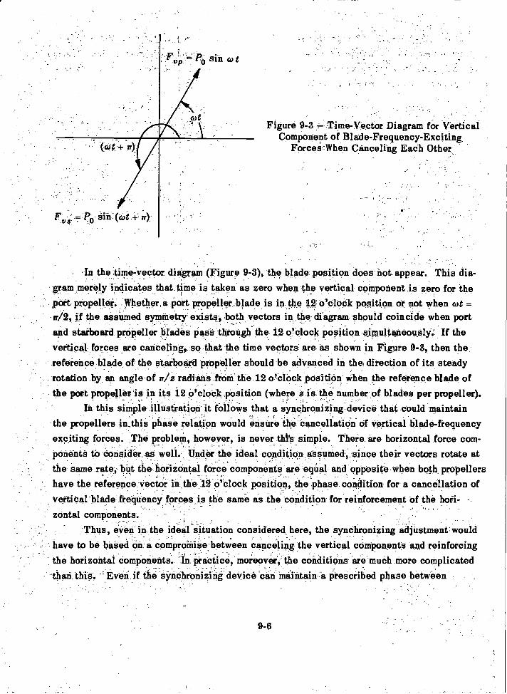
9-6
Figure 9-3 Time-Vector Diagram for VerticalComponent of Blade-Frequency-Exciting
Forces-When Canceling Each Other
-In the time-vector diagram (Figure 9-3), the blade position does not appear. This dia-gram merely indicates that time is taken as zero when the vertical component is zero for the,port propeller.. Whether ,a port propeller,blade.is in the 12 o'clock position or not when cot =w/2, if the assumed symmetry exists, both vectors in the diagram should coincide when portand starboard propeller blades pass through the 12 o'clock position simultaneously: If thevertical forces are canceling, so that the time vectors are as shown in Figure 9-3, then thereference blade of the starboard propeller should be advanced in the direction of its steadyrotation by an angle of ,r /a a radians from the 12 o'clock position when the reference blade ofthe port propeller is in its 12 o'clock position (where a is the number of blades per propeller).
In this simple illustration it fellows that a synchronizing device that could maintainthe propellers in this phase relation would ensure the cancellation of vertical blade-frequencyexciting forces. The problem, however, is never this simple. There are horizontal force com-ponents to consider as well Under the ideal condition assumed, since their vectors rotate atthe same rate, but the horizontal force components are equal and opposite when both propellershave the reference vector in the 12 o'clock position, the phase condition for a cancellation ofvertical blade frequency forces is the same as the condition for reinforcement of the hoii-zontal components.
- Thus, even in the ideal situation considered here, the synchronizing adjustment wouldhave to be based on a compromise between canceling the vertical components and reinforcingthe horizontal components'. 1In practice, moreover', the conditions are much more complicatedthan this --Even if the synchronizing device can Maintain a Prescribed phase between
propeller rotations, the flow conditions change with speed, heading, rolling, pitching, andtrim of the ship. Nevertheless, if it synchronizing device can ameliorate one severe vibratorycondition on a particular class of ship, it may well justify its installation.
Reference 9-6 discusses the synchronizing devices in detail and points out that thescheme is most feasible in connection with electric drives. Reference 9-7 describes a syn-chronizing gear applicable to diesel drives for which considerable success has been claimed.In this case it was found that the optimum synchronizing angle could best be obtained exper-imentally. It should also be noted that on multiple-screw ships it is invariably observed thatthe blade-frequency vibration is rarely steady but has a beating characteristic. When the shipis not pitching appreciably, this beating effect is due to the shifting phase accompanying theslight changes in speeds of the shafts. Thus the degree of benefit to be derived from a syn-chronizing device is indicated by vibration records that show this beating characteristic.The synchronizing device, if performing its function, holds the hull vibration level at theminimum value observed in the beating records.
E. FLEXIBLE MATERIALS IN THE VICINITY OF PROPELLERS
As pointed out in Chapter 7, a large fraction of the propeller-exciting forces acting onthe hull is associated with the pressure field in the vicinity of the propellers. Just as thevibratory force due to an unbalanced piece of machinery may be attenuated by installing iton isolation mountings, so, theoretically at least, the effect of the blade-frequency pressurefield at the stern of a ship can be attenuated by the use of flexible material at the stern.
Elementary considerations suggest that the benefit of such an expedient is highlyfrequency-dependent, and, by analogy with the simple problem of attenuating the force trans-mitted by a machine having a single degree of freedom, the natural frequency must be wellbelow the frequency of the force that it is required to attenuate.
Blade frequencies are, in general, at the low-frequency extremity of the spectrum ofmechanical vibration. To produce a stern structure with a frequency well below the lowestblade-frequency disturbance is a difficult design task. Nevertheless, according to Reference9-8, this was accomplished on the survey ship NORD. In this case the pressure field direct-ly over the propeller was attenuated sufficiently by the use of a rubber plate backed by anairtight box to attain a marked reduction in the level of hull vibration.
F. SUMMARY
This chapter mentions only a few of the most promising antivibration devices thathave been suggested for ameliorating the effects of vibratory exciting forces acting on hulls.A friction damper such as the Lanchester damper discussed in Reference 9-1 could con-ceivably be developed for such a purpose and it has even been suggested that the propellerbearing forces be isolated from the hull by flexibly supported struts. No doubt many otherschemes could be tried.
9-7
The question naturally arises as to whether or not antivibration devices should beconsidered in the early stages of the design of a ship. This is certainly a very importantquestion, for, if the designer could be assured that vibration difficulties could be circum-vented with such devices, he need not concern himself with the problems of estimating themagnitude of the propeller-exciting forces or of avoiding hull resonances. He could then con-centrate on designing the afterbody and propellers strictly from the point of view of propulsiveefficiency.
The available information on the results obtained so far with antivibration devices forships and the difficulty of maintenance of such devices suggest that they should not be con-sidered by the designer from the beginning. Rather, they should be regarded as a last resortto be used when- a design study indicates that large vibratory exciting forces are unavoidablewithout alterations in the design which are otherwise inadmissible.
REFERENCES
9-1. Den Hartog, J.P., "Mechanical Vibrations," McGraw-Hill Book Co., New York (1956).
9-2. Loser, U., "Vibration Neutralizer for Ships," Vol. 12, No. 1 (Jan-Feb 1934). EMB
Translation 12 (Jan 1936).
9-3. McGoldrick, R.T., "Experiments with Vibration Neutralizers," EMB Report 449
(May 1938).
9-4. McGoldrick, R.T., "Rudder-Excited Hull Vibration on USS FORREST SHERMAN
(DD 931) A Problem in Hydroelasticity," Trans. SNAME (1959). Also TMB Report 1431
(Jun 1960).
9-5. MacNaught, D.F., Discussion of paper "Hull Vibration Investigation onSS GOPHER MARINER," by R.T. McGoldrick and V.L. Russo, Trans. SNAME, Vol. 63 (1955).
9-6. Lewis, F.M., "Dynamic Effects," Chapter 2, Vol. 2 of Marine Engin, edited byH.L. Seward, published by SNAME (1944).
9-7. Description of Schelde Synchronizing Gear in Private Communication to SNAME(26 Aug 1957).
9-8. Wass, H. and Walter, H., "Technische Neuerungen auf dem Vermessungsschiff'Nord' der Wasser-und Schiffahrtsverwaltung," Schiffstechnik, Vol. 3, No. 12/13
(Nov 1955).
9-8
CHAPTER 10
DESIGN CONSIDERATIONS RELATING TOSTEADY-STATE HULL VIBRATION
A. INTRODUCTION
Up to the time of this writing, it cannot be said that the consideration of steady-statehull vibration has been a major item in what may be termed the paper stage of a ship design.Although, as shown by the existence of Reference 10-1, the subject could not escape the navalarchitect's attention, the simple fact is that so little concrete information on ship vibrationhas really been available to the naval architect that the question of hull vibration has beenlargely ignored. Only when serious vibration was encountered during the builder's trials of anew ship did its consideration assume importance. Then measures were taken to modify thehull or the propulsion machinery to reduce or eliminate the vibration.
While it is true that a large number of technical papers on the subject of ship vibrationwere available to the naval architect (as may be seen from the general bibliography includedin this book), the practicing naval architect could not spare the time to digest the mass ofscattered information contained in these papers. He had to rely on such summaries as givenin Reference 10-1, and it is only because of the increasing tempo of research in this fieldsince World War II that it is at all feasible to go beyond the limits of Reference 10-1 in thisbook.
There was, of course, for many years among naval architects a realization that unbal-anced forces and moments set up by the propulsion machinery would cause hull vibration. Infact, studies leading to improved balancing of rotating and reciprocating machinery had beenunderway for over 50 years. It was indeed clearly recognized that, in avoiding serious first-order hull vibration (frequency same as the propeller shaft rpm), the remedy lay chiefly in re-ducing the forces rather than in trying to reduce the hull response to given forces.
Specifications for static and dynamic balancing of propellers and shafting as well asthe specifications for finishing of propellers were gradually introduced over the years as theimprovement in balancing and manufacturing techniques permitted.
The lack of information was most acute in the area of propeller hydrodynamic excitingforces, and, fortunately, some progress has been made in that area in recent years. It isobvious that, if the exciting forces can be reduced to negligible magnitude, steady-state vi-bration will not be a problem regardless of the natural frequencies of the hull. A possibleexception to this is the production of "flow-excited" vibration which, under special circum-stances, may produce a fairly steady vibration above a certain critical speed. This point isdiscussed further in Chapter 14. There it is also pointed out that control surfaces may induceflutter phenomena. The latter are not considered flow-excited vibrations in the ordinary sense.In general, the vibration due to sea action is of a transient nature and depends not only on the
10-1
dynamical characteristics of the hull but also on the sea state and the seakeeping character-istics of the hull.
In the design of ships to be driven by conventional screw-propellers, at least one ofthe naval architect's chief concerns is the avoidance of serious vibration due to propeller-exciting forces of blade frequency or integer multiples of the blade frequency.
As will be shown in the next chapter, a serious vibration problem may develop whentransient vibrations of the entire hull (resulting from rough seas) are magnified in local hullstructures. This situation, however, is not chargeable to lack of attention to the items con-sidered in the present chapter. Furthermore, the fact that transient vibrations may involvehull amplitudes anywhere from ten to a thousand times those considered under steady-statevibration does not give the steady-state hull-vibration problem a status of minor importance.A ship may be slowed down temporarily in rough seas, and its heading may be changed tominimize the effects of transient vibrations, but it must operate over long periods of time andat full speed under normal sea conditions in the presence of steady-state vibration.
It is not attempted in this chapter to lay out a rigid design schedule for avoidingsteady-state hull vibration with conventional screw-propeller-driven ships. The subject ofhull vibration is still too obscure to permit this. In fact, too many of the ideas introducedhere are a matter of opinion to justify a manual-type presentation. It is attempted in thischapter, however, to furnish the naval architect with specific recommendations based on bothexperimental and analytical studies which, if followed, will reduce the "calculated risk" ofhull vibration that must still be taken by the ship designer.
Although this chapter deals only with considerations relating to hull vibration, it mustbe pointed out that the selection of a propeller which is to be satisfactory from the hull-vibration standpoint must be based also on considerations relating to vibration in the pro-pulsion system, as discussed in Chapter 12.
B. GENERAL PROCEDURE
Since the level of steady-state hull vibration that will be encountered in service de-pends on both the magnitude of the exciting forces and the response characteristics of thehull, the designer naturally first must consider whether there are any unusual specificationsfor the ship in question which would cause either abnormally large exciting forces or an un-usual sensitivity of the hull to vibratory forces. It has been attempted to make it clear inprevious chapters that in neither category can accuracy of calculation be expected at present.The only exception is the internal excitation due to mass unbalance. For this the designercan fall back on the specifications for balancing of machinery, shafting, and propellers (seeSection F) to get an estimate of the first-order exciting forces and moments.
If the ship is to house some novel piece of machinery which develops large unbalancedforces, then vibration trouble is to be anticipated unless hull natural frequencies are keptwell clear of the operating frequency of this machine.
10-2
It is also obvious that, if hull natural frequencies can be kept clear of the range ofoperating shaft rpm's, close attention to mass unbalance of propellers and shafting is lessurgent than when they fall in this range.
If the propulsion system is not to include the conventional screw-propeller, a vibrationproblem for which little guidance is now available may be imminent. This applies to paddlewheels of either the side or stern type. The exception is the shrouded propeller, for theshrouding is intended to smooth out the flow in the propeller race.
If both the hull design and the design of the propulsion system are to be "conventional,"the next consideration for the designer is the location of the range of operating blade fre-quencies with respect to the range of significant hull critical frequencies. When these tworanges do not overlap, the likelihood of propeller-excited hull vibration difficulties is greatlydiminished. When they coincide, the reverse is true.
Presumably the designer will have on hand at this stage a design specification for apropulsion system with a particular range of operating shaft speeds and a particular numberof blades per propeller. He should also have a general idea of the hull scantlings and anapproximate weight distribution plot.
The operating range of blade frequencies is equal to the operating range of shaft rpm'smultiplied by the number of blades per propeller 2. The range of significant hull frequenciescan only be estimated on the basis of the hull scantlings and weight distribution data avail-
able at this stage. A simple estimate of the frequencies can be made in accordance with therational beam theory if: (1) all decks and expanses of shell plating are provided with longi-tudinal and transverse stiffeners, so spaced that local natural frequencies are not abnormallylow; (2) no heavy pieces of equipment (heavier than 1/2 percent of the displacement of the ship)are installed on resilient mountings; (3) the cargo will not have unusual flexibility such aspossessed by automobiles on inflated tires, large quantities of rubber or plastic material, orlarge quantities of springs; (4) there are no abnormally large expanses of deck unsupportedby bulkheads or stanchions; and (5) the ship does not have abnormally large hatch openingsor unusual structural discontinuities.
If the designer knows that the foregoing conditions can be met, he can then make avery simple estimate of the range of hull critical frequencies. First, he can estimate the
fundamental or 2-node vertical frequency by one of the empirical formulas given in AppendixC. Better than this, he can use his own value of a constant to be substituted in the Schlickformula. This formula is
N=C rAL3 [10-11
where N is the frequency in cpm,C is an empirical constant,1 is the area moment of inertia of the midship section in ft2-in.2 units,
10-3
A is the displacement of the ship in long tons, andis the length in ft.
In lieu of assuming some value of C within the range of values given in Appendix C, the de-signer can devise his own value of C if he has available data on a previous ship of the samegeneral type. Thus, if he knows N, I, D, and L for the other ship, he can solve Equation[10-1] for C. Then from the values of!, D, and L for the proposed design, he can use thesame equation to find N for the new ship.
Unless the LID exceeds 18, the designer can then assume that there will be not morethan six vertical modes, four horizontal modes, or three torsional modes of significance. Ifthe LID exceeds 18, the formula suggested by Baier and Ormondroyd lc" can be used; namely
5LN'
D
10-4
[10-2]
where N' is the number of significant vertical modes,is the hull length, andis the hull depth.
The number of horizontal and torsional modes considered significant would then have to beincreased proportionately.
At this stage the designer can make the assumption that the ratios of the frequenciesof the vertical modes fall in the series 1, 2, 3, etc., so that he has only to double the 2-nodefrequency to estimate the 3-node frequency, and so on.
Next, the rough rule can be used that the 2-node horizontal frequency will be 1.5 timesthe 2-node vertical frequency and that the horizontal frequencies also follow the 1, 2, 3 rule.It is not intended to furnish here any empirical rules for the frequencies of submarines butsuch rules can be developed as information on such ships is accumulated.
Finally, an estimate can be made of the fundamental torsional frequency by Horn'sformula given in Appendix C. While there is little information on which to base the ratiosof the frequencies of the higher torsional modes to that of the fundamental, on the basisof the information obtained on GOPHER MARINER,G4 it is suggested here that the de-signer assume that the frequency of the third torsional mode will not be over 2.5 times the
fundamental torsional frequency (for GOPHER MARINER the ratios were 1: 1.6 : 2.2).The next step depends on whether or not the range of hull critical frequencies is clear
of the range of operating blade frequencies. For large ships it is a common occurrence thatthe highest significant hull critical frequency is lower than the lowest operating blade fre-quency. In this case resonance with the blade-frequency forces is not to be anticipated, andit is to be expected that the blade-frequency vibration will be concentrated in the stern. Thevibration level, of course, will depend on both the driving force and the driving moment. Theforce and moment estimating is discussed in Chapter 7. The formulas for estimating the sternamplitude for known forces and moments are given in Appendix D.
When it is indicated that the frequency of any of the significant hull modes will fall in
the operating range of blade frequencies, the designer should attempt to predict the level of
resonant vibration that would exist if the two frequencies should coincide. Again the level
will depend on the magnitude of the exciting force, but the response will depend also on the
damping. The force can be estimated in accordance with the information given in Chapter 7,
and the forced vibration calculation can be made by the methods given in Chapter 4.
If the design is such that the conditions specified on page 10-3 cannot be met, then
no vibration predictions are feasible in the early design stage and the designer must wait
until the design has advanced to the stage at which the parameters required for a more de-
tailed vibration analysis are available. A sample calculation of a vertical hull mode by the
digital process is given in Appendix A. For details of the calculation of hull modes when
heavy units are to be installed on resilient mountings, see Reference 10-5.In lieu of attempting to estimate the propeller-exciting forces, the designer should con-
sider the possibility of negotiating for a model determination of these forces. The state of
the art of doing this at the present time is indicated in Chapter 7 as well as in Reference 10-6.
C REDUCING PROPELLER FORCES
The first-order propeller forces (those due to mass and pitch unbalance of the propeller)
are considered in Section F of this chapter. The present discussion refers to the blade-
frequency forces and to forces whose frequencies are multiples of the blade frequency.
As pointed out in Chapter 7, these forces depend on both the pressure fluctuations at
the hull surfaces due to the individual propeller blades and the bearing forces. The latter
forces in turn depend on the uniformity of the flow into the propeller races. Obviously, moving
the propeller astern will usually reduce both components of the forces since the pressure field
at the hull will be weakened and the wake variation (which is aggravated by the boundary
layer when the propeller is close to the hull) will be reduced.It is equally clear, however, that there are severe limitations to the process of moving
the propellers astern. Some limitations are the danger of fouling the propeller, in docking,
the weakening of the support of the aftermost propeller shaft bearing, and the loss of thrust
due to the high wake near the hull. It is possible, however, to obtain increased propeller tipclearance without moving the propeller by giving the propeller blades a rake in the aft direction.
The use of a propeller tunnel or shrouding is an obvious means of reducing propeller-
exciting forces. This is discussed in some detail in Reference 10-7. If absence of hull vi-
bration is an especially important requirement for the proposed ship, it may well warrant in-
stallation of a shrouded propeller for this reason alone.In the past the most common expedient to ameliorate the effects of blade-frequency
hull vibration (when encountered on the initial trials of a ship) was to substitute for the
original propeller another of similar thrust and torque characteristics but with a different
10-5
number of blades. Obviously, this expedient may also be introduced in the design stage.The trend has been from three to four-, five-, and six-bladed propellers.
Increasing the number of propeller blades will, in general, decrease both the forcesdue to the pressure field acting on the stern and the bearing forces. The effect of increasingthe number of blades may be compared in a qualitative way to increasing the number of cyl-inders in an internal combustion engine. The thrust per blade and the contribution to the lat-eral force per blade are both reduced. Any given variation in wake will obviously cause lessvariation in the lift and drag on a single blade when the blade area or angle of attack is re-duced. Thus, in general, the net effect on the resultant force due to all blades will be re-duced. The exception occurs when the wake pattern is such that there is greater reinforce-ment of lateral force components with an increased number of blades. Hence, an analysissuch as discussed in Chapter 7 is really necessary before it is assured that increasing thenumber of blades will reduce the exciting forces in the specific case in question. Thus,when the supporting arrangement is such that two or more blades pass through the wakes ofobstructions simultaneously, large blade-frequency thrust variations may be expected. Ofcourse, the reinforcement of the thrust variations does not necessarily mean that the lateralforce variations will reinforce. The thrusts are unidirectional, whereas the lateral forceshave different directions for different blades. Details of the calculation of bearing forcesfrom the wake survey are given in Reference 10-8.
Hence, in seeking to reduce propeller-exciting forces without introducing unconven-tional changes, the designer must, in general, compromise between the expedients of in-creasing the propeller tip clearances and increasing the number of propeller blades.
D. AVOIDING HULL RESONANCE
The urgency of avoiding hull resonance depends, of course, on the magnitudes of theexciting forces and the damping. When either the forces are small or the damping is large,hull resonance is not intolerable and many a ship must operate under such a condition atparticular speeds. While it may be noted here that first-order disturbing forces will steadilydiminish as improved methods of balancing and machining are developed, the question atissue here is: How can resonance be avoided?
It is, in general, feasible for the designer to avoid first-order resonance if the ship isto operate at a fixed rpm. The reason is that, although propeller shaft speeds are relativelylow, there is a considerable spread in the frequencies of the lower hull modes. The advan-tage of avoiding such resonance is obvious since, under such circumstances, a slight un-
balance in propellers, shafting, or machinery will not cause excessive hull vibration.Keeping the blade frequencies clear of the range of significant hull critical frequencies
is usually relatively easy on large ships and relatively difficult on small ships. This isbecause on large ships the operating blade frequencies are usually well above the range ofhull critical frequencies, whereas on small ships they are usually right in this range.
10-6
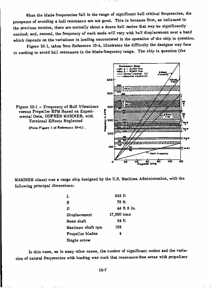
When the blade frequencies fall in the range of significant hull critical frequencies, the
prospects of avoiding a hull resonance are not good. This is because first, as indicated in
the previous section, there are normally about a dozen hull modes that may be significantly
excited; and, second, the frequency of each mode will vary with hull displacement over a band
which depends on the variations in loading encountered in the operation of the ship in question.
Figure 10-1, taken from Reference 10-4, illustrates the difficulty the designer may face
in seeking to avoid hull resonance in the blade-frequency range. The ship in question (the
Oloabbarmont RangeLight A 13,750 TonsHeavy A 16,840 Tons---- Vertical Vibration (V)- - --Hordontal Vibration (H)
600
10-7
20 40 60 80Propeller RPM
MARINER class)-was a cargo ship designed by the U.S. Maritime Administration, with the
following principal dimensions:
525 ft76 ft44 ft 6 in.
Displacement 17,000 tons
Mean draft 24 ft
Maximum shaft rpm 105
Propeller blades 4
Single screw
In this case, as in many other cases, the number of significant modes and the varia-
tion of natural frequencies with loading was such that resonance-free areas with propellers
500
Figure 10-1 Frequency of Hull Vibrations 400versus Propeller RPM Based on Experi-mental Data, GOPHER MARINER, with
2a.
Torsional Effects Neglected 3. 300
(From Figure 1 of Reference 10-4.)
200
100
100 120
of the usual number of blades were almost nonexistent. The designer might, however, by re-sorting to a six-bladed propeller, have been able to boost the operating blade frequency abovethe range of significant hull mode frequencies. This was not done in the case of the MAR-INER Class, which operated satisfactorily with a four-bladed propeller, since the excitingforces were not excessive for that ship.
When any prospect of keeping the operating blade frequencies above the range of hullmode frequencies is indicated, the designer should attempt more refined calculations than aregiven by the preliminary estimates to more definitely pinpoint the critical speeds. If, afterthis, it is still indicated that the blade frequency will inevitably fall in the range of hull crit-icals, then every effort must be made to reduce the forces.
Of course, blade frequencies can also be increased by using higher shaft speeds. Ifthe machinery design is not already frozen, this possibility should be considered. A fasterturning propeller can develop the same thrust with a smaller diameter; this also gives in-creased tip clearance. A high-speed supercavitating propeller can bring the blade frequencieswell above the range of significant hull critical frequencies, and this might be tried if notruled out by other considerations.
E. AVOIDING LOCAL RESONANCE
As in the case of vibration of the entire hull, the amplitude of steady-statelocal vibra-tion will also depend on both the magnitude of the exciting force and the damping. Althoughthe classification "local structure" is somewhat arbitrary, here it means any structure thatcan be excited by a local disturbance so as to vibrate without appreciable vibration of thehull girder. These are the structures considered in Chapter 6 and include masts, deck housesof short longitudinal extent, panels of deck plating, bulkheads, heavy items of machinery onnonrigid foundations, as well as items of equipment installed on resilient mountings.
Obviously, changing the natural frequency of a local structure to avoid a condition ofresonance is It possibility, whereas changing a natural frequency of the hull itself after it isfabricated is extremely difficult.
One unfortunate aspect of the problem of local resonance is that the use of largenumbers of propeller blades to reduce the propeller-exciting forces often brings the blade-frequency into the range of natural frequencies of many local structures whose frequencieswould otherwise be well out of range.
There are, of course, some relatively large local structures for which major alterationswould be required if it were considered necessary to raise their natural frequencies. In suchcases, however, it will usually be found that the local natural frequencies fall in the range ofsignificant hull mode frequencies, and, in fact, that these structures may even modify the vi-bratory response characteristics of the entire hull. Under such circumstances calculationsshould be made of the natural frequencies and normal modes of the hull with these local struc-tures treated as equivalent sprung masses; see Chapter 6. The modes found in such
10-8
calculations will indicate to what extent the amplitude of the local structure will exceed the
hull amplitude in the modes in which it plays a significant role. These modes must now be
considered modes of the combined system and the conditions which ensure that they will not
be dangerously excited are the same considerations that apply to resonant vibration of the hull.
The fortunate aspect of the local resonance problem is that trouble due to this can be
anticipated before the ship is ready for the builder's trials. The naval architect can use the
relatively small and portable vibration generators such as described in Reference 10-9 to de-
termine local natural frequencies. Even without these, such frequencies can be found by the
"bop" or impact test in which a heavy timber is used to excite the structure and the transient
vibrations following the impact are recorded with sensitive instruments. Some tests of this
type can be made even before launching, whereas those in which the bottom plating may have
an effect must be delayed until after launching.
F. BALANCING
The subject of balancing, in general, is a very important one for the naval architect
concerned with avoiding ship vibration. It is treated in considerable detail in Reference 10-1
and the basic principles are discussed in standard textbooks on mechanical vibration; e.g.,
References 10-10 and 10-11. The naval architect (as contrasted with the marine engineer) is
not so much concerned with the techniques of balancing propulsion machinery as with the spec-
ifications that should be set for balance. He must have assurance that, if he establishes a
specification for maximum permissible unbalanced forces or moments on the basis of his
estimate of the hull response characteristics, these specifications can be met by the manu-
facturer.Since the advent of steam turbine power plants the chief concern of the naval architect
with regard to balancing at least for large ships, has been the specifications for balance of
propellers and shafting.It has been pointed out that a screw propeller is subject to both mass unbalance and
pitch unbalance. The latter requires further consideration here. Pitch unbalance is caused
by lack of uniformity or symmetry in the geometry of the propeller, and may exist even when
mass unbalance is negligible.If the pitch of one propeller blade is greater than that of the remaining blades, then,
under uniform flow conditions in the propeller race, the lift, drag, and moments on small,
elements or strips of this blade are not the same as for the corresponding elements of any of
the other blades. To exaggerate the pitch unbalance effect, one can consider the situation
of a propeller having only one blade. The hydrodynamic force-system acting on the propeller
could then be reduced to a constant axial force, a force lying in a plane normal to the shaft
axis, a constant torque about the shaft axis, and a moment in a plane passing through the
shaft axis. The vectors representing the lateral force and the moment would be constant in
magnitude but would rotate with the propeller. It is seen that where the flow is uniform there
is no thrust variation and no torque variation but that the propeller bearing will be subject to
10-9
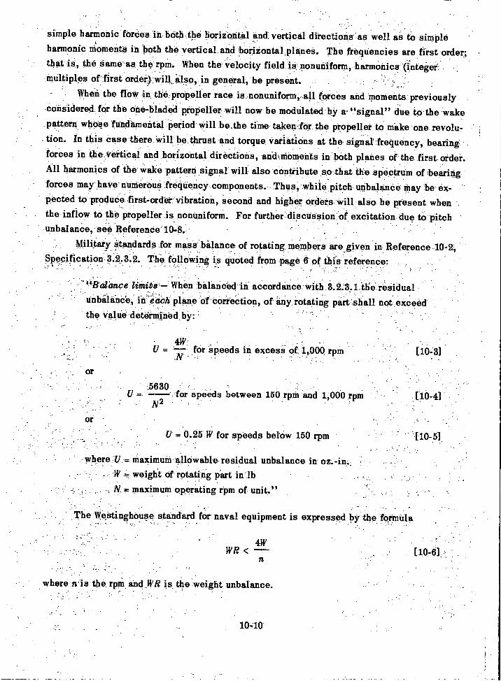
simple harmonic fordes inboth the boritontal and vertical directions as well as to simpleharmonic moments in both the vertical and horizontal planee. The frequencies are first order;that is, the same as the rpm When the velocity field is nonuniform, harmonics (integerMultiples of first also, in general, be present
When the flow in:the:propeller race is nonuniform, all forces and moments previouslyconsidered' for the one-bladed propeller will now be modulated by a "signal" due tO the wakepattern whose fundamental period Will be.the time taken :for the propeller to make .one revolu-tion. In this case there will be thrust and torque VatiatiOns at the signal' frequency, bearingforces in the:Vettical and horizontal directions, aidMoinents in both planes of the first order.All harmonics of the Wake pattern signal will also contribute so that the spectrum of bearingforces may have numerous frequency components. Thus, while pitch unbalance may be ex-pected to produce first-order:vibration, second and higher orders will also be present whenthe inflow to the propeller is nonuniform. For further.discuseion of excitation due to pitchnnbalanOe, see Reference 10-8.
Military standards for mass balance of rotating members are given in Reference 10-2,k
Specification:3.2.3.2. The following is quoted from page 6 of this reference:
- "Balance When balanced in accordance with 3 2 3 1 the residualunbalance, in ed671, plane Of'Correction, of any rotating part shall not exceedthe value determined by:
4W: _
= fOr speeds in excess or 1,000 rpm [10,3l
V = 0.25 W for speeds below 150 rpm
where U maximum allowable residual unbalance in oz.-in.W weight of rotating pSrt in-lb
, N maximum operating rpm of unit."
,The Westinghouse standard for naval equipment is expressed by the formula
5630for speeds between 156 'rp in and 1,000 rpm
N2
4WWI? <
n
where n is the rpm, and WR is the weight unbalance.
10-10
[10-41
-
An intensive study of tolerance for shafting unbalance was made as a result of first-
order hull vibration on a recent class of naval destroyers. The results of this study are dis-
cussed in Reference 10-12.Reference 10-13, which deals with relatively stall units rotating at high speed, also
discusses the principles of dynamic balancing.A frequent rule of thumb is that for the maximum running speed of the rotor
WRca 2 W< -100
or that, hence
R(02<0.01 [10-8]
In this formula a consistent set of units must be used. Thus, if R is in in. g must be
in./sec2, and cv must be the angular velocity in radi/sec.In the case of reciprocating machinery, if cancellation cannot be obtained by arranging
the crank angles suitably, it may be necessary to install auxiliary reciprocating masses
driven by the machine to be balanced. This is discussed in Reference 10-1.
REFERENCES
10-1. Lewis, F.M., "Dynamic Effects," Chapter 2, Vol. 2 of Marine Engin, edited by
H.L. Seward, published by SNAME (1944).10-2. "Military Standard Mechanical Vibrations of Shipboard Equipment," MIL-STD-167
(Ships) (20 Dec 1954).
10-3. Baier, L.A. and Ormondroyd, J., "Vibration at the Stern of Single-Screw Vessels,"Trans. SNAME, Vol. 60 (1952).
10-4. McGoldrick, R.T. and Russo, V.L., "Hull Vibration Investigation on SS GOPHERMARINER," Trans. SNAME, Vol. 63 (1955). Also TMB Report 1060 (Jul 1956).
10-5. Leibowitz, R.C. and Kennard, Eli., "Theory of Freely Vibrating NonuniformBeams Including Methods of Solution and Application to Ships," TMB Report 1317 (May
1961).
10-6. Stuntz, G.R., et. al., "Series 60 The Effect of Variations in Afterbody Shape
upon Resistance, Power, Wake Distribution, and Propeller-Excited Vibratory Forces,"
Paper prepared for Annual Meeting of SNAME (1960).
10-7. Saunders, H.E., "Hydrodynamics in Ship Design," published by SNAME (1957).
10-8. Reed, F.E. and Bradshaw, R.T., "The Distribution of Exciting Forces Generatedby Propellers," CONESCO Report F-101-2, Contract Nobs 77150 (Jun 1960).
10-11
[10-7]
10-.9, Robinson,.- Q.R.,4714bri,tion Machines at the David N.:Taylor:Model.
-TMB ReppiC821'(Jul 1952).:.
1040. ben Harbig, J.P.; "Mechanical Vibrations," McGraw-Hill Book Con'.,Isievi York-.
10,11: TiMoshenko S "Vibration Problems in Engineering "D Vin-Nostianct Co.;NeW..-York.(1955).
.
Jasper, N.H., -"Structural Vibration Problems of Ships A: Study of the DD 692-,-;Class of Destroyers,:" TMB Report C-36,(Feb 1950) Unclaeeffied.-
:10-13,. peldman,, S., "Dynamic Balancing for Noise Reduction,.. -Dept of the,Navy,. J.-.
Bureau Of ShiPe-(COde 371) R &D Report 371-V-24 (Apr 19.50:
10-12
-
CHAPTER 11
DESIGN CONSIDERATIONS RELATINGTO TRANSIENT VIBRATIONS
A. INTRODUCTION
The basic beam theory of ship vibration discussed in Chapter 3 is a general dynamicaltheory and is applicable to the transient response characteristics of ships, as shown in Chap-ter 5. However, this theory cannot be applied indiscriminately to problems such as the slam-ming of ships in a seaway which may involve deflections so large that buckling and plasticstrain of structural members occur.
No sharp line of demarcation can be drawn between the field of structural seaworthinessand the field of ship vibration. Certainly, in the structural strength of ships, the transientvibration problem is of far more importance than the steady-state vibration problem. In fact,
the hull girder stresses due to steady-state vibration are almost negligible. Tolerances forsteady-state vibration must be based, not on hull girder stress levels, but on permissibleamplitudes determined from physiological factors, satisfactory operation of equipment in-stalled in the ships, or by local stress and fatigue considerations.
All that is attempted in this chapter is to show that the rational beam theory of shipvibration advocated in this book can be used as a guide in considering, at least qualitatively,the transient response characteristics of a hull. Thus, for instance, after a severe slam in aseaway, a ship will execute a complex pattern of decaying vibrations which eventually settledown into vibrations in the normal modes considered in Chapter 3. Since these vibrationsoften persist for a large fraction of a minute, and are much larger in amplitude than thoseusually considered under steady-state vibration, they may cause intolerable vibrations oflocal structures whose natural frequencies happen to coincide with their frequencies.
It is also appropriate to point out in this chapter that, although the bending momentsto which a hull is subjected in a seaway are actually of a transient nature, the componentshaving the frequency of wave encounter vary at such a slow rate that they are treated asstatic in the standard strength calculation; see Reference 11-1. The static beam theory to beused in this case, however, should logically coincide with the rational beam theory consideredto be valid in the low frequency range of hull vibration. Hence the designer should be ableto derive certain conclusions as to the hull strength in a seaway from its vibratory responsecharacteristics. Therefore, it is suggested here that the hull girder characteristics as de-termined from the vibration analysis are applicable regardless of whether the naval architectcontinues to rely, on the time-honored standard strength calculation which uses a static loaddetermined from an assumed wave profile, or undertakes to forecast the extreme loading con-ditions in a seaway.
The dynamical system treated in this book is actually an ideal system considered freein space with mass added to account for the inertia effect of the water and viscous dampersinserted to allow for the energy dissipation effects.
The transient loading in a seaway which imposes peak stresses in the hull involvesrigid body motions that cause both large variations in the buoyant forces (which are entirelyneglected in the vibration analysis) and large variations in the added mass effect of the sur-rounding water (which for convenience has so far been treated as constant in time in thevibration analysis).
Although this treatment of the hull as a system free in space for the purpose of the vi-bration analysis may seem highly artificial, the designer should realize that the hull by itselfis actually a system free in space subject to a complex system of forces imposed by the sur-rounding water. If all these forces could be predicted in advance as functions of time, thenthe transient problem discussed in Chapter 5 would be valid, at least up to loadings that didnot produce strains exceeding the elastic limit.
It is especially interesting to recall that the hull proper is never permitted to executefree vibrations, for, no matter how calm the sea may be, the pressures associated with theinertia of the surrounding water will always force it to vibrate at frequencies other than itsnatural frequencies in free space. As pointed out in Reference 11-2, it was a common prac-tice around 1932 to compute the 2-node vertical frequency which a ship would have in air(free space) and then to apply to this frequency (called the "theoretical frequency") a numberof correction factors. The largest of these was, of course, the factor for the inertia effect ofthe surrounding water. Roughly, this effect lowers the free space fundamental vertical fre-quency by 25 percent.
Although the free space natural frequencies of the hull are considerably higher thanthe natural frequencies in water, the corresponding mode shapes are not very different be-cause the inertia effect of the water conforms roughly with the weight and rigidity distribu-tions. Since the corresponding components of water pressure drive the hull at a frequencybelow its natural frequency, they are in phase with the vibratory displacement, whereas thevibratory buoyancy forces are 180 deg out of phase with the vibratory displacement.
B. THE HULL GIRDER
Although the designer has not been accustomed to think of the structural design of thehull girder as a vibration problem, he has been accustomed to regard the hull as a beam. Ifthe hull is designed structurally as a beam, then it may be expected to exhibit the vibratorycharacteristics of a beam. In fact it is advocated here that the extent to which its vibratoryresponse characteristics are beamlike may be used as a design criterion. This statement, ofcourse, requires some clarification because it has been pointed out that if large items ofequipment are deliberately installed on flexible mountings, they can distort the normal modepatterns considerably from beamlike form.
11-2
Clearly, the fundamental vertical frequency of a hull increases with its bending rigid-ity or El. Although a thin-walled box girder will not be able to develop its nominal El, anadequately stiffened thin-walled box girder can be made to approach this as a limit. Asstiffeners are added to increase the bending rigidity, the fundamental flexural frequency ofthe free-free girder increases and thus the frequency is an indication of the flexural rigidityin this simple case.
The theory also shows, however, that the frequency depends on the mass distributionand hence it cannot be the sole criterion of bending rigidity. Furthermore, as suggested in thecase of GOPHER MARINER, 11-3 nonbeamlike vibratory characteristics may be caused by thecargo which a ship is carrying. The exception in this case proves the rule; it does not inval-idate it.
If the hull is designed so that its vibratory characteristics are beamlike, in the absenceof heavy items of equipment resiliently mounted, they will then be predictable to a reasonabledegree. If they are predictable, then the propulsion system can be designed to avoid hull res-onance. Even when it is known that a ship must carry cargo that will make the prediction ofits vibratory response characteristics difficult, there is still an advantage in producing a hullthat will have predictable vibration characteristics with a "normal" cargo. It may be possibleto operate at a slower speed whenever such abnormal cargo must be carried.
The transient loading of hulls in heavy seas can be treated only on a statistical basisas pointed out in Reference 11-4. It is not intended to imply here that designing to producebeamlike vibratory characteristics can reduce the slamming loads in a seaway. These dependon seakeeping characteristics which involve, among other factors, the shape of the hull andits speed. As a matter of fact, GOPHER MARINER experiments indicate that a cargo thatintroduces nonbeamlike vibratory characteristics may introduce a desirable damping action.The main contention here is that beamlike vibration characteristics for the hull proper aredesirable.
Another factor pertinent to the present discussion is the presence of structural dis-continuities. These are usually associated with local stress concentrations and are con-sidered undesirable in design. In a beam simply supported at its ends and uniformlyloaded statically, there would be an abrupt change of curvature in the deflection curve atthe point of discontinuity. Similarly, if such a beam were set vibrating in its fundamentalnormal mode the pattern would also show a sharp change of curvature at this point.
Thus the rule (but a rule with exceptions) advocated here is that the vibratory responsecharacteristics should be beamlike. The exceptions occur when large units are to be installedin the hull on resilient mountings or when unusual cargo having "springy" material is to becarried. In such cases the hull, even if designed for beamlike characteristics without suchconditions, will not exhibit them in practice.
While it is not advocated here that the digital method of transient response calculationgiven in Chapter 5 is applicable to severe slamming load conditions, it might be noted that
11-3
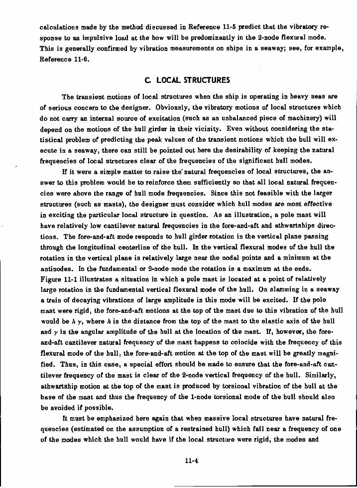
calculations made by the method discussed in Reference 11-5 predict that the vibratory re-sponse to an impulsive load at the bow will be predominantly in the 2-node flexural mode.This is generally confirmed by vibration measurements on ships in a seaway; see, for example,Reference 11-8.
C. LOCAL STRUCTURES
The transient motions of local structures when the ship is operating in heavy seas areof serious concern to the designer. Obviously, the vibratory motions of local structures whichdo not carry an internal source of excitation (such as an unbalanced piece of machinery) willdepend on the motions of the hull girder in their vicinity. Even without considering the sta-tistical problem of predicting the peak values of the transient motions which the hull will ex-ecute in a seaway, there can still be pointed out here the desirability of keeping the naturalfrequencies of local structures clear of the frequencies of the significant hull modes.
If it were a simple matter to raise the° natural frequencies of local structures, the an-swer to this problem would be to reinforce them sufficiently so that all local natural frequen-cies were above the range of hull mode frequencies. Since this not feasible with the largerstructures (such as masts), the designer must consider which hull modes are most effectivein exciting the particular local structure in question. As an illustration, a pole mast willhave relatively low cantilever natural frequencies in the fore-and-aft and athwartships direc-tions. The fore-and-aft mode responds to hull girder rotation in the vertical plane passingthrough the longitudinal centerline of the hull. In the vertical flexural modes of the hull therotation in the vertical plane is relatively large near the nodal points and a minimum at theantinodes. In the fundamental or 2-node mode the rotation is a maximum at the ends.Figure 11-1 illustrates a situation in which a pole mast is located at a point of relativelylarge rotation in the fundamental vertical flexural mode of the hull. On slamming in a seawaya train of decaying vibrations of large amplitude in this mode will be excited. If the polemast were rigid, the fore-and-aft motions at the top of the mast due to this vibration of the hullwould be h y, where h is the distance from the top of the mast to the elastic axis of the hulland y is the angular amplitude of the hull at the location of the mast. If, however, the fore-and-aft cantilever natural frequency of the mast happens to coincide with the frequency of thisflexural mode of the hull, the fore-and-aft motion at the top of the mast will be greatly magni-fied. Thus, in this case, a special effort should be made to ensure that the fore-and-aft can-tilever frequency of the mast is clear of the 2-node vertical frequency of the hull. Similarly,athwartship motion at the top of the mast is produced by torsional vibration of the hull at thebase of the mast and thus the frequency of the 1-node torsional mode of the hull should alsobe avoided if possible.
It must be emphasized here again that when massive local structures have natural fre-quencies (estimated on the assumption of a restrained hull) which fall near a frequency of oneof the modes which the hull would have if the local structure were rigid, the modes and
11-4
Figure 11-1 Illustration of Case in Which a Pole Mast Is Located at aNodal Point of the Fundamental Vertical Mode of a Hull
frequencies of the hull itself are modified by the "sprung mass" effect. Details of analyticalmethods of dealing with this situation are given in Reference 11-7. Unfortunately, it is onlypossible to carry out such analytical treatments when the hull design has reached a relativelyadvanced stage. Only then can the parameters required in the equations be evaluated.
D. RESILIENTLY MOUNTED ASSEMBLIES
When all six of the natural frequencies of a rigidly mounted assembly (computed on theassumption of an immovable hull) are well above the range of significant hull mode frequen-cies, it may then be assumed that under transient excitation of the hull the assembly willmove with the hull. Under such circumstances the resilient mounting is installed for the pur-pose of isolating the assembly either from blade-frequency vibrations that are well above thehull natural frequency domain or from high-frequency vibrations accompanying shocks whichproduce local vibrations in the area of the mounting.
As in the case of local structures, a massive assembly such as an engine, if installedon isolation mountings, will affect the hull frequencies themselves, and then it must be con-sidered as a sprung mass. For details of analysis in such cases, see Reference 11-7. Inthe case of machinery, the resilient mounting is used chiefly to isolate the hull from the un-
balanced forces and moments due to the operation of the machine itself. Such isolation willbe achieved only when all six natural frequencies of the assembly are below the operatingfrequencies (or speeds) of the machine.
A matter of chief concern in the selection of an isolation mounting system for an as-sembly is whether the mountings will bottom under rough sea conditions. Should this happenthe equipment may suffer more severe damage than if it had been rigidly secured to the hull.As a safeguard against this, shock tests have been devised for military equipment, as dis-cussed in Reference 11-8. The damaging effect of bottoming can also be reduced by the useof snubbers; see Reference 11-9.
11-5
REFERENCES
11-1. Rossell, H.E. and Chapman, L.B., Editors "Principles of Naval Architecture,"published by SNAME* Vols. 1 and 2 (1939).
11-2. McGoldrick, R.T., "A Study of Ship Hull Vibration," EMB Report 395 (Feb 1935).
11-3. McGoldrick, R.T. and Russo, V.L., "Hull Vibration Investigation on SS GOPHERMARINER," Trans. SNAME, Vol. 63 (1955). Also TMB Report 1060 (Jul 1956).
11-4. Jasper, N.H., "Statistical Distribution Patterns of Ocean Waves and of Wave-Induced Ship Stresses and Motions, with Engineering Applications," Trans. SNAME, Vol. 64
(1956). Also TMB Report 921 (Oct 1957).
11-5. McGoldrick, R.T., "Calculation of the Response of a Ship Hull to a Transient Loadby a Digital Process," TMB Report 1119 (Mar 1957).
11-6. Jasper, N.H. and Birmingham, J.T., "Strains and Motions of USS ESSEX (CVA 9)during Storms Near Cape Horn," TMB Report 1216 (Aug 1958).
11-7. Leibowitz, R.C. and Kennard, E.H., "Theory of Freely Vibrating Nonuniform BeamsIncluding Methods of Solution and Application to Ships," TMB Report 1317 (May 1961).
11-8. Vane, F.F., "A Guide for the Selection and Application of Resilient Mountings toShipboard Equipment," TMB Report 880, Revised Edition (Feb 1958).
11-9. Crede, C.E., "Vibration and Shock Isolation," John Wiley & Sons, Inc., New York
(1951).
11-6
CHAPTER 12
DESIGN CONSIDERATIONS RELATING TO VIBRATION OFTHE PROPULSION-SHAFTING SYSTEM
A. INTRODUCTION
Machinery vibration per se is a subject which is outside the domain of hull vibration.However, there are various types of vibration in the propulsion system of a ship which may beexcited by the propeller itself regardless of the degree of mass balance attained in the manu-facture of the propulsion machinery. Since the designer is not free to select a propeller onthe basis of hull vibration characteristics alone but must also take such propeller-excitedmachinery vibration into account, some consideration of the latter has been included in thisbook. The vibration types in question are torsional vibration of the propulsion-shafting sys-tem, longitudinal vibration of the propulsion-shafting system, and lateral vibration of the pro-peller shaft.
Torsional vibration of propulsion systems is characterized by sinusoidal time vari-ations in the angular velocity of the rotating members or, in other words, by the superpositionof angular oscillations on the steady rotation of these members.
Longitudinal vibration is characterized by fore-and-aft oscillations of the propeller,the shafting, and the entire propulsion machinery, including both rotating and nonrotatingmembers.
Lateral vibration of the propeller shaft is frequently spoken of as whirling. Under thistype of vibration the shaft center describes a circular or elliptical path in a plane normal tothe shaft axis. In some cases the ellipse may be very narrow and in the limit yield a recti-linear path.
In all three cases the basic phenomenon is now well understood and has been discussedin the technical literature in recent years. This does not mean, however, that the criticalspeeds can in all cases be predicted with high precision. As a matter of fact, in the evalua-tion of the parameters used in predicting such vibration, difficulties exist similar to thosepertaining to the evaluation of the parameters used in the hull vibration calculations.
The analysis of all three types of vibration in the propulsion system follows the samegeneral line as in the case of the hull. Thus, an estimate is usually made of the natural fre-quencies and normal modes of vibration of the system. Then an estimate is made of the ex-citing forces. It must be noted here that in the case of diesel drives, torsional excitation ex-ists not only at the propeller but also in the prime mover. Next, an estimate is made of thedamping in the system, and finally, a calculation is made of the forced vibratory response.This is then compared with permissible levels established on the basis of past experience,and, if predicted to be excessive, steps are taken to reduce it.
12-1
B. TORSIONAL VIBRATION
The subject of torsional vibration of propulsion systems has been treated extensivelyin the technical literature; see Reference 12-1. Historically, the phenomenon first became aserious problem in internal combustion engine systems and the literature on the subject inthis connection is extensive; see Reference 12-2. The basic theory is the same as appliedto the pure torsional modes of the hull itself. In the propulsion system, however, the analy-sis is complicated by the presence of reduction gears, high and low pressure turbine sys-tems, or, in the case of diesel drives, by reciprocating members.
For the immediate problem of this book, the designer needs assurance that a selectedpropeller will not create a torsional vibration condition which would not exist if the propellerwere replaced by a cylindrical mass of the same mass moment of inertia. The latter parameter,incidentally, must include an allowance for water inertia effect and this also poses a problemin evaluation of parameters; see Reference 12-3.
Fortunately, it is usually feasible to keep the operating range of blade frequenciesclear of the range of torsional criticals. In the case of geared turbine drives, which at pre-sent comprise the majority of ocean-going ships, a common practice is for the designer toselect a "nodal drive"; see Reference 12-1. In this case the first torsional critical speed isso low compared to the normal operating speed of the ship that excitation from the propelleris negligible. The second torsional mode is "tuned out." This is accomplished by design-ing the two turbine branches so that they will have the same torsional natural frequency (thebull gear being held fixed). This produces a mode such that the entire propulsion system fromthe propeller to the bull gear is a node and hence, torque variations at the propeller will notexcite this mode. The third and higher torsional modes fall well above the maximum operatingblade frequency.
A general scheme for the torsional vibration analysis of propulsion systems developedat the Bureau of Ships of the Navy Department is given in Reference 12-4. The principal aimof the designer in applying this method is to guarantee that significant torsional vibration willnot exist in the propulsion system in normal operation of the ship.
C. LONGITUDINAL VIBRATION
Longitudinal vibration of propulsion systems has attracted general attention more re-cently than torsional vibration although the phenomenon undoubtedly occurred long before itwas recognized. It was brought strikingly to attention when it appeared unexpectedly on largenaval vessels during World War H.12-5
In this case, the analysis involves equations quite similar to those involved in tor-sional vibration analysis; the only difference is that forces and rectilinear displacementsare involved instead of torques and angular displacements.
The chief difficulty in the analysis is in the evaluation of the longitudinal stiffness ofthe thrust bearing and machinery foundations, but, fortunately, in those propulsion systems in
12-2
which the longitudinal natural frequencies are most likely to fall in the operating range of
blade frequencies, the shafts are relatively long, and the frequencies of the lower longitudinal
modes do not vary widely for large variations in the foundation stiffness.
Here, as elsewhere, the designer is more concerned with obtaining assurance that the
longitudinal critical frequencies are clear of the operating range of blade frequencies than
with being able to predict the frequencies with precision.In general, longitudinal and torsional vibrations of propulsion systems may be con-
sidered as independent of one another, but this is not always the case, as pointed out in
References 12-3 and 12-6. The propeller couples the longitudinal and torsional degrees of
freedom of the system to some extent under all conditions, but the coupling effect is signif-
icant chiefly when the critical frequencies that would exist without this coupling effect are
close to one another. In such cases the mode excited is actually a longitudinal-torsional
mode and the excitation involves a generalized force which combines the effect of torque
and thrust variations. However, for the designer, it is more important to ensure that the
longitudinal and torsional frequencies are kept far apart than to be able to predict the ampli-
tude when. they are close together.It is obvious that, where short drive shafts are involved, as when the machinery is
installed far aft, the stiffnesses in the propulsion system are so high relative to the stiffness
which the hull presents to the thrust bearing foundation that analyses of longitudinal vibra-
tion that consider the hull as fixed are not realistic. Here, as in numerous other cases, the
longitudinal vibrations of the propulsion system merge into vibrations of the entire hull-
machinery system for which, as yet, reliable methods of prediction have not been developed.
The fortunate circumstance is that (at least in the case of surface ships) in such instances
the highest operating blade frequency is usually below the first longitudinal critical frequency.
D. LATERAL VIBRATION OF PROPELLER SHAFTS
Considerable impetus was given recently to the study of lateral vibration of propeller
shafts when it was suspected that the phenomenon of shaft whirl was the principal cause of
the failures of tailshafts that occurred at an alarming rate on single-screw merchant ships
shortly after World War II. Although it was later found that the chief stress variations in thetailshafts were due to thrust eccentricity, 12r7 the investigation of the problem led to improved
methods of predicting tailshaft whirling speeds and stresses; see References 12-8 and 12-9.
As emphasized in Reference 12-9, the combination of a heavy propeller and a long
overhang from the tailshaft bearing may result in a low whirling speed of the tailshaft. TheBureau of Ships procedure for ensuring against a whirling speed in the running range is out-
lined in Reference 12-10. A general discussion of design stage calculations for marineshafting is given in Reference 12-11. Inertia effects of the surrounding water on propellers
are discussed in Reference 12-3.
12-3
REFERENCES
12- 1. Lewis, F.M., "Dynamic Effects," Chapter 2, Vol. 2 of Marine Engin, edited byH.L. Seward, published by SNAME (1944).
12- 2. Wilson, W.K., "Practical Solution of Torsional Vibration Problems," 2 Vols.,John Wiley & Sons, Inc, New York (1956).
12- 3. Lewis, F.M. and Auslaender, J., "Vertical Inertia of Propellers," JSR (Mar 1960).
12- 4. Gariboldi, R.J., "Procedure for Torsional Vibration Analysis of Multimass Systems,"Dept of the Navy, Bureau of Ships (Code 371), R & D Report 371-V-19 (Dec 1953).
12- 5. Kane, J.R. and McGoldrick, R.T., "Longitudinal Vibrations of Marine Propulsion-Shafting Systems," Trans. SNAME, Vol. 57 (1949). Also TMB Report 1088 (Nov 1956).
12- 6. Panagopulos, E.P., Discussion of Paper "Longitudinal Vibrations of MarinePropulsion-Shafting Systems," by J.R. Kane and R.T. McGoldrick, Trans. SNAME, Vol. 57(1949).
12- 7. Jasper, N.H. and Rupp, L.A., "An Experimental and Theoretical Investigation ofPropeller Shaft Failures," Trans. SNAME (1952).
12- 8. Neifert, H.R. and Robinson, J.H., "Further Results from the Society's Investi-gation of Tailshaft Failures," Trans. SNAME (1955).
12- 9. Jasper, N.H., "A Design Approach to the Problem of Critical Whirling Speeds ofShaft-Disk Systems," TMB Report 890 (Dec 1954).
12-10. Michel, R., "Interim Design Data Sheet DDS 4301, Propulsion Shafting," Dept ofthe Navy, Bureau of Ships, S1/1-2(415), DDS 4301 (1 May 1957).
12-11. Panagopulos, E.P., "Design-Stage Calculations of Torsional, Axial, and LateralVibrations of Marine Shafting," Trans. SNAME, Vol. 58 (1950).
12-4
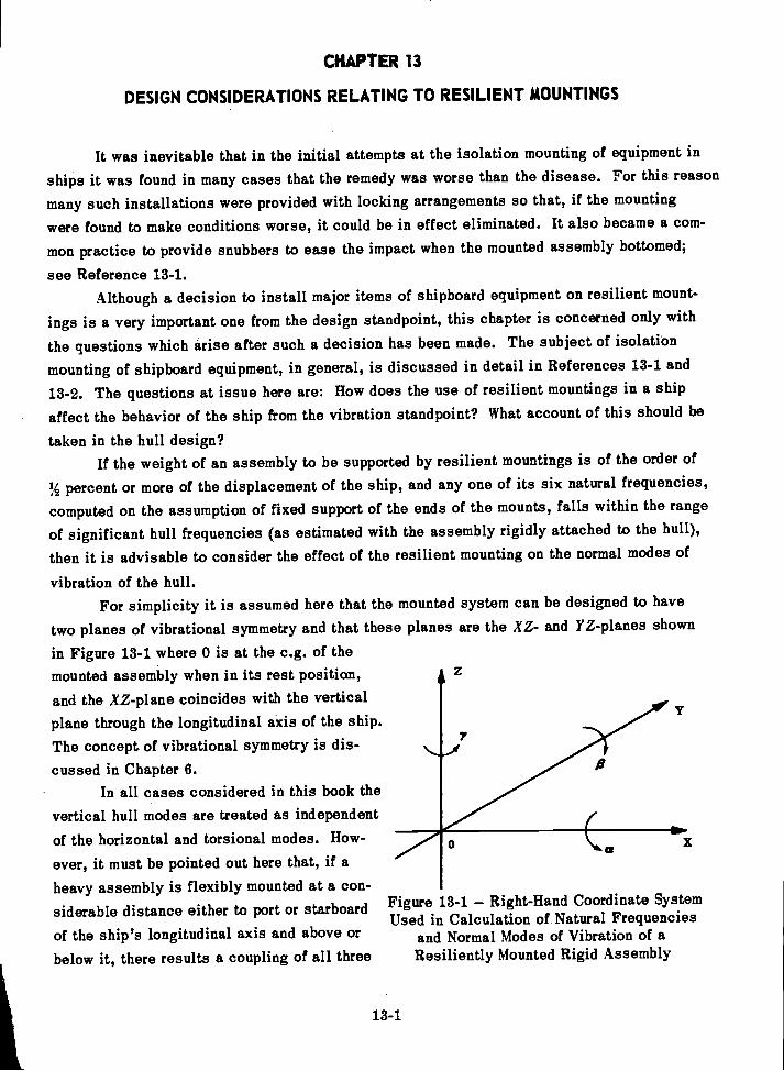
CHAPTER 13
DESIGN CONSIDERATIONS RELATING TO RESILIENT MOUNTINGS
It was inevitable that in the initial attempts at the isolation mounting of equipment in
ships it was found in many cases that the remedy was worse than the disease. For this reason
many such installations were provided with locking arrangements so that, if the mounting
were found to make conditions worse, it could be in effect eliminated. It also became a com-
mon practice to provide snubbers to ease the impact when the mounted assembly bottomed;
see Reference 13-1.Although a decision to install major items of shipboard equipment on resilient mount-
ings is a very important one from the design standpoint, this chapter is concerned only with
the questions which arise after such a decision has been made. The subject of isolation
mounting of shipboard equipment, in general, is discussed in detail in References 13-1 and
13-2. The questions at issue here are: How does the use of resilient mountings in a ship
affect the behavior of the ship from the vibration standpoint? What account of this should be
taken in the hull design?If the weight of an assembly to be supported by resilient mountings is of the order of
% percent or more of the displacement of the ship, and any one of its six natural frequencies,
computed on the assumption of fixed support of the ends of the mounts, falls within the range
of significant hull frequencies (as estimated with the assembly rigidly attached to the hull),
then it is advisable to consider the effect of the resilient mounting on the normal modes of
vibration of the hull.For simplicity it is assumed here that the mounted system can be designed to have
two planes of vibrational symmetry and that these planes are the XZ- and YZ-planes shown
in Figure 13-1 where 0 is at the c.g. of themounted assembly when in its rest position,and the XZ-plane coincides with the verticalplane through the longitudinal axis of the ship.The concept of vibrational symmetry is dis-cussed in Chapter 6.
In all cases considered in this book thevertical hull modes are treated as independentof the horizontal and torsional modes. How-ever, it must be pointed out here that, if aheavy assembly is flexibly mounted at a con-siderable distance either to port or starboardof the ship's longitudinal axis and above orbelow it, there results a coupling of all three
13-1
a
Figure 13-1 Right-Hand Coordinate SystemUsed in Calculation of Natural Frequencies
and Normal Modes of Vibration of aResiliently Mounted Rigid Assembly

(vertical flexural, horizontal flexural, and torsional) types of vibration. The equations forthe more general cases of hulls with sprung masses are given in Reference 13-3.
The designer first must carry out the calculation of the natural frequencies and normalmodes of the mounted assembly on the assumption that the hull is immovable. This processis discussed in Chapter 6. Also, the estimates of natural frequencies and normal modes ofthe hull must be made on the assumption that the mounted assembly is blocked so that it can-not move relative to the hull.
If it is recalled that the effect of the sprung mass on the hull is significant only formodes whose frequency is near the natural frequency of the sprung mass, and that the effectis to lower the frequency of a mode below and to raise the frequency of a mode above, it isapparent that the designer can derive some guidance from the two foregoing calculations evenwithout making the more elaborate calculations for the hull with the masses treated as sprung.Thus, if the operating blade frequencies fall well above the range of significant hull modefrequencies predicted with rigid mountings, no difficulty with steady-state, propeller-excitedvibration is indicated when the natural frequencies of the assembly fall well within the rangeof hull mode frequencies. Of course, if an assembly has a natural frequency near that of thehighest significant hull mode, and the lowest operating blade frequency is only slightly abovethis, a possibility of resonance exists and the need for further calculations is indicated.However, the designer is still faced with the possibility of excessive transient vibrations.If the mountings have locking devices it may still be possible to avoid bottoming of the mount-
ings under rough sea conditions. When a sprung mass effect is due to the flexibility of amassive local structure itself, this possibility, of course, does not exist.
One might argue that, if the resilient mountings of an engine were to be locked out underrough sea conditions, they should not have been installed in the first place. Such reasoning,however, is not sound. If the mountings are intended primarily to isolate the hull from therelatively high frequency vibrations of the engine, then this will be accomplished under normaloperating speed conditions in relatively calm seas. When the sea gets rough, the engineswould be slowed down and thus their unbalanced forces and moments would be reduced.Furthermore, if severe transient vibrations should be set up in the hull under these sea con-ditions, the vibration induced by the engine would probably be relatively unimportant as longas these conditions prevailed. Thus, if an isolation mounting system is designed mainly foreliminating steady-state vibration, it may be justified to lock it out under slamming conditionsin which it would be required to act as a shock mounting which should be designed for moresevere conditions.
Although the subject of mass-unbalanced rudders is discussed in some detail in con-nection with hydroelasticity in the following chapter, it is in order to point out here that suchappendages can have a marked sprung mass effect on the horizontal vibration of a hull. Atthe present time it is indicated that with a hydraulic steering gear the effective torsionalstiffness of the rudder system may be relatively low. Thus, it cannot always be assumed that
13-2
rudder torsional frequencies will be above the range of significant horizontal hull modefrequencies. The vibration analysis of such systems is discussed further in References13-4 and 13-5.
In summary, whenever the isolation mounting of large masses (of the order of % percentor more of the mass of the ship) is under consideration, the designer should look into itseffect on the vibration characteristics of the ship as a whole.
It must be kept in mind that the discussion of isolation mountings in this book doesnot extend into the range of acoustic frequencies in which wave effects, such as discussedin Reference 13-6, take place.
REFERENCES
13-1. Crede, C.E., "Vibration and Shock Isolation," John Wiley & Sons, Inc., New York
(1951).
13-2. Vane, F.F., "A Guide for the Selection and Application of Resilient Mountings toShipboard Equipment," TMB Report 880, Revised Edition (Feb 1958).
13-3. Leibowitz, R.C. and Kennard, E.H., "Theory of Freely Vibrating Nonuniform BeamsIncluding Methods of Solution and Application to Ships," TMB Report 1317 (May 1961).
13-4. McGoldrick, R.T., "Rudder-Excited Hull Vibration on USS FORREST SHERMAN
(DD 931) A Problem in Hydroelasticity," Trans. SNAME (1959). Also TMB Report 1431
(Jun 1960).
13-5. Leibowitz, R.C., "Modes of Vibration of Rudder of USS ALBACORE (AGSS569),"
TMB Report C-952 (Feb 1959) CONFIDENTIAL.
13-6. Harrison, M., et al., "Wave Effects in Isolation Mounts," TMB Report 766 (Jan 1952).
13-3
CHAPTER 14
HYDROELASTICITY
A. INTRODUCTION
At this time hydroelasticity must be regarded as a new science for the naval architect.Although the basic phenomena dealt with in hydroelasticity are not new, for the most part theiroccurrence has been rare in the operation of ships, and until recently they have been dealt
with individually as isolated phenomena.What is really new is the recognition that these separate phenomena comprise a group
falling under the definition of the term "hydroelasticity." Although various definitions ofthis term will be found in the literature (see References 14-1, 11-2, and 14-3), it seems suffi-cient to state here that hydroelasticity is concerned with those problems in which water vehi-cles are subjected to time-varying forces imposed by the water, but governed also by the elas-tic properties of the hull or its appendages. In general, hydroelasticity in naval architectureparallels the well-established field of aeroelasticity in aeronautical engineering; seeReference 14-4.
Note that the definition of hydroelasticity just given is really broad enough to includepropeller-excited hull vibration itself, which is the chief topic discussed in this book. How-ever, the term is currently restricted to problems with hulls or appendages which involve the
water flow past the hull, with the exception of propeller-excited hull vibration, since thelatter is of such common occurrence as to warrant individual consideration.
Lateral vibrations of circular cylinders moving in fluids are frequently observed, andthis phenomenon has been found to be associated with the shedding of vortices. In particular,such vortices are commonly called larmgn vortices and the series of these observed in thewake of a towed cylinder is called a larmEin vortex street. The frequency of shedding suchvortices depends on both the towing velocity and the diameter of the towed cylinder, andhence, in the design of appendages such as propeller struts, the use of a streamlined sectionis important not only in reducing drag but also in preventing vibration. The larmgn vortexshedding phenomenon is discussed in further detail in Reference 14-1.
Another hydroelastic phenomenon that can be troublesome to the naval architect is theso-called "Helmholtz resonator" phenomenon. It is illustrated very simply by the productionof a musical tone by blowing over an opening in an air-filled chamber. In naval architecturethe term is something of a misnomer since the chamber is an enclosure whose walls also mayvibrate and play an important role in determining the frequency. Nevertheless, the hydro-elastic phenomenon is similar to the one in air in the sense that it is the flow over an open-ing in a compartment that produces it.
Two other phenomena of prime importance in aeroelasticity have their counterparts inhydroelasticity although they occur less often in the latter case. These phenomena are
14-1
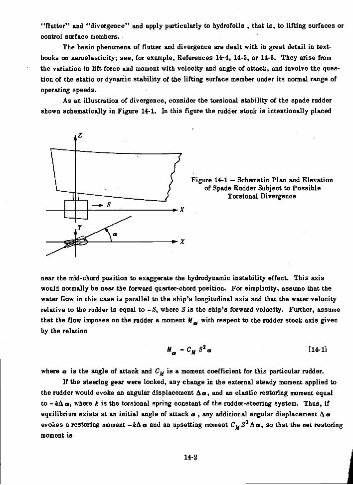
"flutter" and "divergence" and apply particularly to hydrofoils , that is, to lifting surfaces orcontrol surface members.
The basic phenomena of flutter and divergence are dealt with in great detail in text-books on aeroelasticity; see, for example, References 14-4, 14-5, or 14-6. They arise fromthe variation in lift force and moment with velocity and angle of attack, and involve the ques-tion of the static or dynamic stability of the lifting surface member under its normal range ofoperating speeds.
As an illustration of divergence, consider the torsional stability of the spade ruddershown schematically in Figure 14-1. In this figure the rudder stock is intentionally placed
11
Figure 14-1 Schematic Plan and Elevationof Spade Rudder Subject to Possible
Torsional Divergence
near the mid-chord position to exaggerate the hydrodynamic instability effect. This axiswould normally be near the forward quarter-chord position. For simplicity, assume that thewater flow in this case is parallel to the ship's longitudinal axis and that the water velocityrelative to the rudder is equal to S, where S is the ship's forward velocity. Further, assumethat the flow imposes on the rudder a moment Ma with respect to the rudder stock axis givenby the relation
Ma = CM S2 [14-11
where a is the angle of attack and Cm is a moment coefficient for this particular rudder.If the steering gear were locked, any change in the external steady moment applied to
the rudder would evoke an angular displacement Act, and an elastic restoring moment equalto kA a, where k is the torsional spring constant of the rudder-steering system. Thus, ifequilibrium exists at an initial angle of attack a, any additional angular displacement A aevokes a restoring moment kA a and an upsetting moment Cm S2 A a, so that the net restoringmoment is
14-2
(k CM 8)A a
Thus, in this case, the hydrodynamic moment produces a negative torsion spring effect which
varies with the speed of the ship. If the ship should attain such a speed that
k C m S2 = 0 [14-2]
the torsional rigidity of the system would vanigh, and, at any speed higher than this, the hydro-
dynamic moment would twist the rudder to failure. In this simplified example the value of S
obtained by solving Equation [14-2] would be called the speed of torsional divergence. Diver-
gence is thus a condition of static instability or instability under a nonoscillatory flow
condition.Flutter is a condition of dynamic instability and is discussed in more detail later in
this chapter. As applied to a control surface member, the phenomenon may be explained in
simple terms also by reference to Figure 14-1. Suppose that, instead of steady conditions
prevailing, the stern of the ship is vibrating horizontally (in the athwartship direction).
Then, if the rudder lacks mass balance with respect to the rudder stock axis, angular oscil-
lations of the rudder will also be generated. The latter will evoke variations in the hydro-
dynamic lift force acting on the rudder. The effect of these variations in lift force on the
system will depend, of course, on their frequency, magnitude, and phase. If conditions are
such that the lift force variation is in phase with the vibratory velocity and in the same direc-
tion, it will exert a negative damping effect on the system. Since the lift force variation in-
creases as the ship's speed increases, it may happen that it is suitably phased and of such
magnitude at a certain speed as to cancel out all positive damping effects in the system. A
speed at which this condition was reached would be called a critical flutter speed. At a
higher speed, if the phase did not shift, the system would have a net negative damping. Under
such a circumstance an oscillation once started would build up exponentially until damage or
failure occurred.Still another phenomenon falling under the category of hydroelasticity is the "singing"
propeller, also discussed in more detail later in this chapter. This is by no means a new
phenomenon to the naval architect (see Reference 14-7), but it is still not thoroughly under-
stood. It involves the development of vibration of a propeller blade when the shaft attains a
certain speed, the frequencies usually being in the audible range. It is clearly a hydroelastie
phenomenon since it depends on both the flow past the blade as it rotates and the mass-elastic
properties of the propeller.
B. RUDDER-HULL VIBRATION
In spite of the fact that W. Ker Wilson (Reference 14-8) had cited rudder flutter as a
recognized phenomenon in 1954, few cases of rudder vibration had been reported in the
14-8
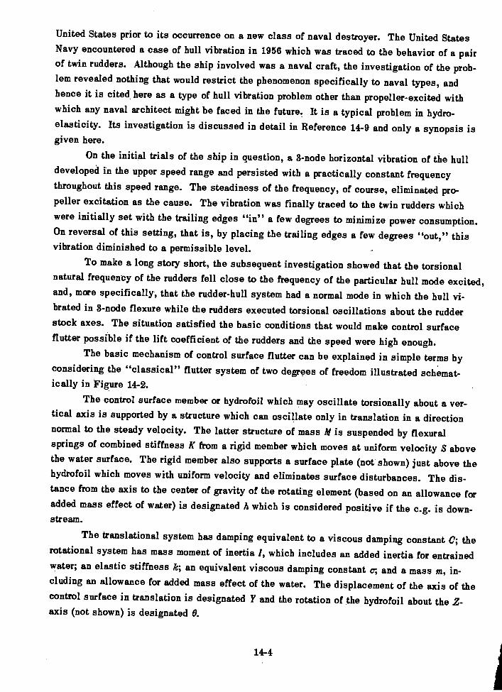
United States prior to its occurrence on a new class of naval destroyer. The United StatesNavy encountered a case of hull vibration in 1956 which was traced to the behavior of a pairof twin rudders. Although the ship involved was a naval craft, the investigation of the prob-lem revealed nothing that would restrict the phenomenon specifically to naval types, andhence it is cited here as a type of hull vibration problem other than propeller-excited withwhich any naval architect might be faced in the future. It is a typical problem in hydro-elasticity. Its investigation is discussed in detail in Reference 14-9 and only a synopsis isgiven here.
On the initial trials of the ship in question, a 3-node horizontal vibration of the hulldeveloped in the upper speed range and persisted with a practically constant frequencythroughout this speed range. The steadiness of the frequency, of course, eliminated pro-peller excitation as the cause. The vibration was finally traced to the twin rudders whichwere initially set with the trailing edges "in" a few degrees to minimize power consumption.On reversal of this setting, that is, by placing the trailing edges a few degrees "out," thisvibration diminished to a permissible level.
To make a long story short, the subsequent investigation showed that the torsionalnatural frequency of the rudders fell close to the frequency of the particular hull mode excited,and, more specifically, that the rudder-hull system had a normal mode in which the hull vi-brated in 3-node flexure while the rudders executed torsional oscillations about the rudderstock axes. The situation satisfied the basic conditions that would make control surfaceflutter possible if the lift coefficient of the rudders and the speed were high enough.
The basic mechanism of control surface flutter can be explained in simple terms byconsidering the "classical" flutter system of two degrees of freedom illustrated schemat-ically in Figure 14-2.
The control surface member or hydrofoil which may oscillate torsionally about a ver-tical axis is supported by a structure which can oscillate only in translation in a directionnormal to the steady velocity. The latter structure of mass M is suspended by flexuralsprings of combined stiffness K from a rigid member which moves at uniform velocity S abovethe water surface. The rigid member also supports a surface plate (not shown) just above thehydrofoil which moves with uniform velocity and eliminates surface disturbances. The dis-tance from the axis to the center of gravity of the rotating element (based on an allowance foradded mass effect of water) is designated A which is considered positive if the c.g. is down-stream.
The translational system has damping equivalent to a viscous damping constant C; therotational system has mass moment of inertia I, which includes an added inertia for entrainedwater; an elastic stiffness k; an equivalent viscous damping constant c; and a mass m, in-cluding an allowance for added mass effect of the water. The displacement of the axis of thecontrol surface in translation is designated Y and the rotation of the hydrofoil about the Z-axis (not shown) is designated O.
14-4
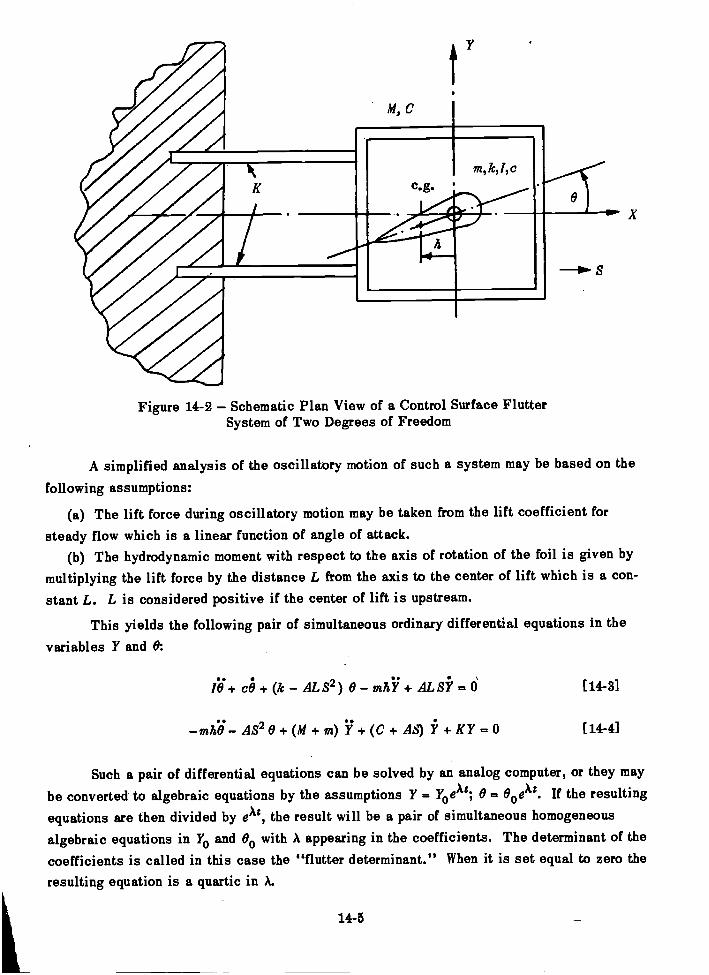
Figure 14-2 Schematic Plan View of a Control Surface FlutterSystem of Two Degrees of Freedom
A simplified analysis of the oscillatory motion of such a system may be based on the
following assumptions:
The lift force during oscillatory motion may be taken from the lift coefficient for
steady flow which is a linear function of angle of attack.The hydrodynamic moment with respect to the axis of rotation of the foil is given by
multiplying the lift force by the distance L from the axis to the center of lift which is a con-stant L. L is considered positive if the center of lift is upstream.
This yields the following pair of simultaneous ordinary differential equations in thevariables Y and 0:
10. + ce + (k AL 82) 0 AL Si = [14-3]
AS2 0 +(M+ In) + (c + AS) 11 + KY [14-4]
Such a pair of differential equations can be solved by an analog computer, or they maybe converted to algebraic equations by the assumptions Y = YoeAt; 0 = 00eAt. If the resultingequations are then divided by eAt , the result will be a pair of simultaneous homogeneousalgebraic equations in Yo and 00 with A appearing in the coefficients. The determinant of thecoefficients is called in this case the "flutter determinant." When it is set equal to zero theresulting equation is a quartic in A.
14-5
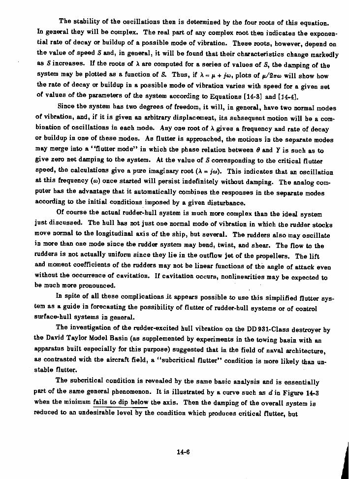
The stability of the oscillations then is determined by the four roots of this equation.In general they will be complex. The real part of any complex root then indicates the exponen-tial rate of decay or buildup of a possible mode of vibration. These roots, however, depend onthe value of speed S and, in general, it will be found that their characteristics change markedlyas S increases. If the roots of A are computed for a series of values of S, the damping of thesystem may be plotted as a function of S. Thus, if A = + ja), plots of 1.1/ 2n co will show howthe rate of decay or buildup in a possible mode of vibration varies with speed for a given setof values of the parameters of the system according to Equations [14-3] and [14-41.
Since the system has two degrees of freedom, it will, in general, have two normal modesof vibration, and, if it is given an arbitrary displacement, its subsequent motion will be a com-bination of oscillations in each mode. Any one root of A gives a frequency and rate of decayor buildup in one of these modes. As flutter is approached, the motions in the separate modesmay merge into a "flutter mode" in which the phase relation between 0 and Y is such as togive zero net damping to the system. At the value of S corresponding to the critical flutterspeed, the calculations give a pure imaginary root (A = jol). This indicates that an oscillationat this frequency (co) once started will persist indefinitely without damping. The analog com-puter has the advantage that it automatically combines the responses in the separate modesaccording to the initial conditions imposed by a given disturbance.
Of course the actual rudder-hull system is much more complex than the ideal systemjust discussed. The hull has not just one normal mode of vibration in which the rudder stocksmove normal to the longitudinal axis of the ship, but several. The rudders also may oscillatein more than one mode since the rudder system may bend, twist, and shear. The flow to therudders is not actually uniform since they lie in the outflow jet of the propellers. The liftand moment coefficients of the rudders may not be linear functions of the angle of attack evenwithout the occurrence of cavitation. If cavitation occurs, nonlinearities may be expected tobe much more pronounced.
In spite of all these complications it appears possible to use this simplified flutter sys-tem as a guide in forecasting the possibility of flutter of rudder-hull systems or of controlsurface-hull systems in general.
The investigation of the rudder-excited hull vibration on the DD 931-Class destroyer bythe David Taylor Model Basin (as supplemented by experiments in the towing basin with anapparatus built especially for this purpose) suggested that in the field of naval architecture,as contrasted with the aircraft field, a "subcritical flutter" condition is more likely than un-stable flutter.
The subcritical condition is revealed by the same basic analysis and is essentiallypart of the same general phenomenon. It is illustrated by a curve such as d in Figure 14-3when the minimum fails to dip below the axis. Then the damping of the overall system isreduced to an undesirable level by the condition which produces critical flutter, but
14-6
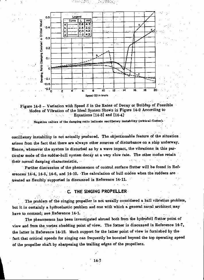
7-a>
1-6
00.0
0.5
0.4
03
0.2
-0.15
-0.2
Legend
L
0'
.0
2 4 8 10 - la 14 16 18 20
-Speed (S) in knots
Figure 14-3 Variation with Speed S in the Rates of Decay or Buildup of PossibleModes of Vibration of the Ideal System Shown in Figure 14-2 According to
Equations [14-3] and [14-4]iregative values of the damping ratio indicate oscillatory instability (critical flutter).
oscillatory instability is not actually produced. The objectionable feature of the situation
arises from the fact that there are always other sources of disturbance on a ship underway.Hence, whenever the system is disturbed as by a wave impact, the vibrations In this par-ticular mode of the rudder-hull system decay at a very slow rate. The other modes retaintheir normal damping characteristic.
Further discussion of the phenomenon of control surface flutter will be found in Ref-
erences 144, 14-5, 14-6, and 14-10. The calculation of hull modes when the rudders are
treated as flexibly Supported is discussed in Reference 14-11.'
C. THE SINGING PROPELLER
The problem of the singing propeller is not usually considered a hull vibration problem,but it is certainly a hydroelastic problem and one with which a general naval architect may
have to contend; see Reference 14-1.The phenomenon has been investigated abroad both from the hydrofoil flutter point of
view and from the vortex shedding point of view. The former is discussed in Reference 14-7,- .
the latter in Reference 14-12. Much support for the latter point of view is furnished by thefact that critical speeds for singing can frequently be boosted beyond the top operating speedOf the propeller shaft by sharpening the trailing edges of the propellers.
'14-7
. Curvea -----2.8 4.3b 2.8 2.0
---- 2.0 4.31.0 4.3
In the case of commercial ships, the chief objection to the singing propeller is the an-noyance of the high frequency vibration to human ears rather than the absolute level of vibra-tion amplitude produced. It is well-known that the levels of acoustic power that are intoler-able from the physiological standpoint are extremely low from the mechanical vibrationstandpoint. This means that singing propellers may become intolerable because of noise atamplitudes far below those at which they are in danger of structural failure.
D. COMMENTARY
The naval architect will become increasingly aware of the science of hydroelasticityin the future. This will require an acquaintance not only with the subject of mechanical vi-bration but also with the hydrodynamics of flow about streamlined and unstreamlined forms.Only the barest outline of the subject of hydroelasticity has been sketched in this chapter.The subject is but little understood at this time. When one surveys the extensive literatureavailable in aeroelasticity, the amount of literature on hydroelasticity published so far ampears meager indeed.
Studies in hydroelasticity up to the present time indicate that there are large discrep-ancies between experimental results and analytical predictions based on the classical theoryused in aeroelasticity. This is emphasized in the discussions of Reference 14-9. The phys-ical magnitudes involved in the two fields are, of course, quite different, and thus it might beexpected that effects that can be neglected in one field could play a dominant role in theother.
In spite of the present lack of information in the field of hydroelasticity, certain areasin which hydroelastic problems may be expected in the future can be pointed out here.
Control surface flutter has been discussed in this chapter; for surface ships the onlycontrol surface members are the rudders, except when activated fin stabilizers are used.However, should the submarine become a commercial ship, its diving planes are clearly sub-ject to the same flutter mechanism as the rudders. Its periscopes, if it retains them, will ofcourse be subject to vortex shedding excitation, as will, in fact, any protruding member notproperly streamlined. Antipitching fins will introduce hydroelastic effects.
The designer of hydrofoil boats will be concerned not only with the static stability ofthe hydrofoils but also with their dynamic stability. Thus, they will warrant a hydroelasticanalysis as detailed as the aeroelastic analyses currently made in aircraft design.
For a discussion of panel flutter and further details of hydroelasticity, the reader isreferred to 14-13, 14-14, and 14-15. The classical treatment of flutter as used in aeroelastic-ity is given in Reference 14-16. Hydrofoil flutter is discussed in Reference 14-17.
14-8
REFERENCES
14- 1. Saunders, H.E., "Hydrodynamics in Ship Design," published by SNAME (1957).
14- 2. Heller, S.R., Jr. and Abramson, H.N., "Hydroelasticity: A New Naval Science,"
Journal ASNE (May 1959).
14- 3. Flax, A.H., "Aero-Hydro-Elasticity," Structural Mechanics, Proceedings of First
Symposium on Naval Structural Mechanics, Pergamon Press, New York (1960).
14- 4. Bisplinghoff, R.L., et al., "Aeroelasticity," Addison-Wesley Publishing Co. (1955).
14- 5. Fung, Y.C., "An Introduction to the Theory of Aeroelasticity," John Wiley
& Sons, New York (1955).
14- 6. Scanlan, R.H. and Rosenbaum, R., "Introduction to the Study of Aircraft Vibration
and Flutter," Mac Millan Co., New York (1951).
14- 7. Taylor, J. Lockwood, "Propeller Blade Vibration," TINA (1943).
14- 8. Wilson, W. Ker, "A Review of Ship Vibration Problems," Mar Engr and Nay Arch
(Jul, Aug, Oct, Nov 1955). Also published in ASNE Journal (May 1954).
14- 9. McGoldrick, R.T., "Rudder-Excited Hull Vibration on USS FORREST SHERMAN
(DD 931) - A Problem in Hydroelasticity," Trans. SNAME (1959). Also TMB Report 1431
(Jun 1960).
14-10. McGoldrick, R.T. and Jewell, D.A., "A Control-Surface Flutter Study in the Field
of Naval Architecture," TMB Report 1222 (Sep 1959).
14-11. Leibowitz, R.C. and Kennard, E.H., "Theory of Freely Vibrating Nonuniform Beams
Including Methods of Solution and Application to Ships," TMB Report 1317 (May 1961).
14-12. Krivtsov, Y.V. and Pernik, kJ., "The Singing of Propellers," TMB Translation
281 (Oct 1958).
14-13. Abramson, H.N. and Chu, W.H., "Problems of Hydroelasticity," JSR, Vol. 3,
No. 1 (Jun 1959).
14-14. Henry, C.J., et al., "Aeroelastic Stability of Lifting Surfaces in High-Density
Fluids," JSR (Mar 1959).
14-15. Jewell, D.A., "A Note on Hydroelasticity," JSR, Vol. 3, No. 4 (Mar 1960).
14-16. Theodorsen, T., "General Theory of Aerodynamic Instability and the Mechanism
of Flutter," NACA Report 496 (1934).
14-17. Abramson, H.N. and Chu, W.H., "A Discussion of the Flutter of Submerged
Hydrofoils," JSR, Vol. 3, No. 2 (Oct 1959).
14-9
CHAPTER 15
SHIP VIBRATION RESEARCH
A. INTRODUCTION
Ship vibration research was initiated toward the end of the nineteenth century. Creditfor pioneering is usually given to 0. Schlick who proposed the now famous Schlick formulafor the frequency of the 2-node flexural mode of surface ships in 1894. Among other earlyinvestigators was A. N. Krylov who reported on the recording of ship vibration in 1900.Although the analogy to string vibration cited therein was unsound, it is of historical interestthat the subject was also discussed in a French treatise on naval architecture published in
1894; see Reference 15-1.As in so many other fields of research, progress has been slow but at an accelerating
pace, and the development of theory has proceeded hand in hand with the development of
experimental techniques. This is a field in which full-scale experimentation is costly. Themere tying up of a ship for the length of time required for vibration experiments is often pro-
hibitive, to say nothing of the cost of installing and operating the necessary equipment. How-ever, it must be emphasized that the correction of vibration unexpectedly encountered on the
trials of a new ship may be much more costly.It is not attempted in this chapter to survey the ship vibration research work which is
now carried on by all the principal maritime nations abroad. This discussion is confinedchiefly to the ship vibration research in the United States which, for the most part, has beencarried on by the United States Navy either independently or in collaboration with the Societyof Naval Architects and Marine Engineers.
On the experimental side, this research has involved the following principal phases:
(a) The development of instrumentation for recording vibration of ships and ship models.
The development of machines capable of vibrating ships and ship models.
The development of apparatus for determining propeller-exciting forces on model scale.
The conduct of full-scale experiments with vibration generators to determine the vibra-
tory characteristics of ships in service.
Running of vibration surveys on ships in service and the systematic storage of data
so obtained.
The conduct of model experiments for determining propeller-exciting forces.
Model experiments for the determination of the added mass effect of the surrounding
water.
15-1
On the theoretical side, ship vibration research in the United States has involved:
The development of analytical methods of predicting the normal modes and naturalfrequencies of vibration of ships.
The development of analytical methods of predicting the steady-state forced vibrationof a ship under given exciting forces.
The development of analytical methods of calculating transient vibrations within theelastic range.
The development of analytical methods of predicting the vibratory exciting forceswhich will act on a ship of given design.
The development of computing techniques, either analog or digital, for carrying outcalculations by the analytical methods developed.
The research program, of course, has also included the comparison of analytical pre-dictions with experimental results and the evaluation of the analytical methods on the basisof these comparisons. Most of the theoretical research accomplishments have been coveredin previous chapters. Hence, the present chapter is devoted chiefly to the experimental phaseof ship vibration research and to the attempts to correlate theory with experiment.
B. VIBRATION GENERATORS
The development of vibration generators for ship vibration research in the United Stateswas based chiefly on the prior development of such machines for research on bridges by thefirm of Losenhausen in Dusseldorf, Germany, prior to World War II. Their successful use inGermany led the U.S. Experimental Model Basin to purchase from Losenhausen in 1931 thelargest machine of this type when built. These generators consist of eccentric masses whichmay be so unbalanced and so phased as to produce sinusoidal forces in one direction only,sufficient to maintain a vibration of the entire hull of a magnitude permitting experimentaldeterminatibn of the normal-mode pattern. The machine had a force amplitude of 49,000 lband a deadweight of 25 tons. Its two eccentrics each weighed 6000 lb and could be offsetup to about 12 in. It was operated by two d-c motors, each of 15-kw capacity.
There was also purchased from Losenhausen at the same time a very small vibrationgenerator, weighing only about 140 lb, and having eccentric weights at each end of twoparallel shafts. This machine was not only suitable for vibration experiments on model scalebut was also capable of exciting local structures on full-scale ships and was used repeatedlyfor many years. As originally furnished, it had a maximum force rating of 440 lb and a maxi-
mum speed of 3600 rpm.
The David Taylor Model Basin later undertook the development of vibration generatorsfor full-scale ship experiments of greater versatility than possible with the huge machineoriginally purchased from Losenhausen. The Taylor Model Basin medium vibration generator
15-2
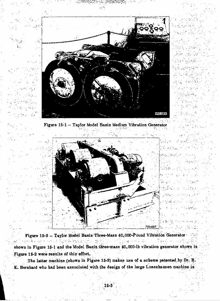
4740-1ftwirszammige4
J PSC45fif
Figure 15-2 Taylor Model Basin Three-Mass 40,000-Pound Vibration Generator
shown in Figure 15-1 and the Model Basin three-mass40,000-lb vibration generator shown in
Figure 15-2 were results of this effort._
The latter machine (shown in Figure 15-2) makes use of a scheme patented by Dr. R.K. Bernhard who had been associated with the design of the large Losenhausen machine in
NP21.52810
Figure 15-1 Tay/or Model Basin Medium Vibration 'Generator
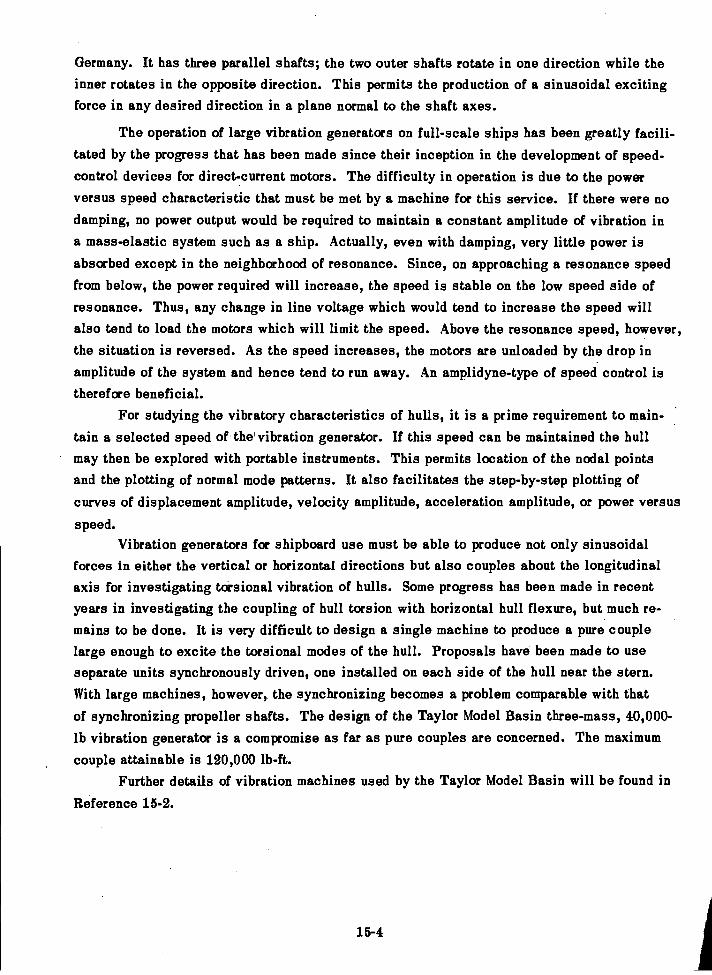
Germany. It has three parallel shafts; the two outer shafts rotate in one direction while theinner rotates in the opposite direction. This permits the production of a sinusoidal excitingforce in any desired direction in a plane normal to the shaft axes.
The operation of large vibration generators on full-scale ships has been greatly facili-tated by the progress that has been made since their inception in the development of speed-control devices for direct-current motors. The difficulty in operation is due to the powerversus speed characteristic that must be met by a machine for this service. If there were nodamping, no power output would be required to maintain a constant amplitude of vibration ina mass-elastic system such as a ship. Actually, even with damping, very little power isabsorbed except in the neighborhood of resonance. Since, on approaching a resonance speedfrom below, the power required will increase, the speed is stable on the low speed side ofresonance. Thus, any change in line voltage which would tend to increase the speed willalso tend to load the motors which will limit the speed. Above the resonance speed, however,the situation is reversed. As the speed increases, the motors are unloaded by the drop inamplitude of the system and hence tend to run away. An amplidyne-type of speed control istherefore beneficial.
For studying the vibratory characteristics of hulls, it is a prime requirement to main-tain a selected speed of the' vibration generator. If this speed can be maintained the hullmay then be explored with portable instruments. This permits location of the nodal pointsand the plotting of normal mode patterns. It also facilitates the step-by-step plotting ofcurves of displacement amplitude, velocity amplitude, acceleration amplitude, or power versus
speed.Vibration generators for shipboard use must be able to produce not only sinusoidal
forces in either the vertical or horizontal directions but also couples about the longitudinalaxis for investigating torsional vibration of hulls. Some progress has been made in recentyears in investigating the coupling of hull torsion with horizontal hull flexure, but much re-mains to be done. It is very difficult to design a single machine to produce a pure couplelarge enough to excite the torsional modes of the hull. Proposals have been made to useseparate units synchronously driven, one installed on each side of the hull near the stern.With large machines, however, the synchronizing becomes a problem comparable with that
of synchronizing propeller shafts. The design of the Taylor Model Basin three-mass, 40,000-lb vibration generator is a compromise as far as pure couples are concerned. The maximumcouple attainable is 120,000 lb-ft.
Further details of vibration machines used by the Taylor Model Basin will be found in
Reference 15-2.
15-4
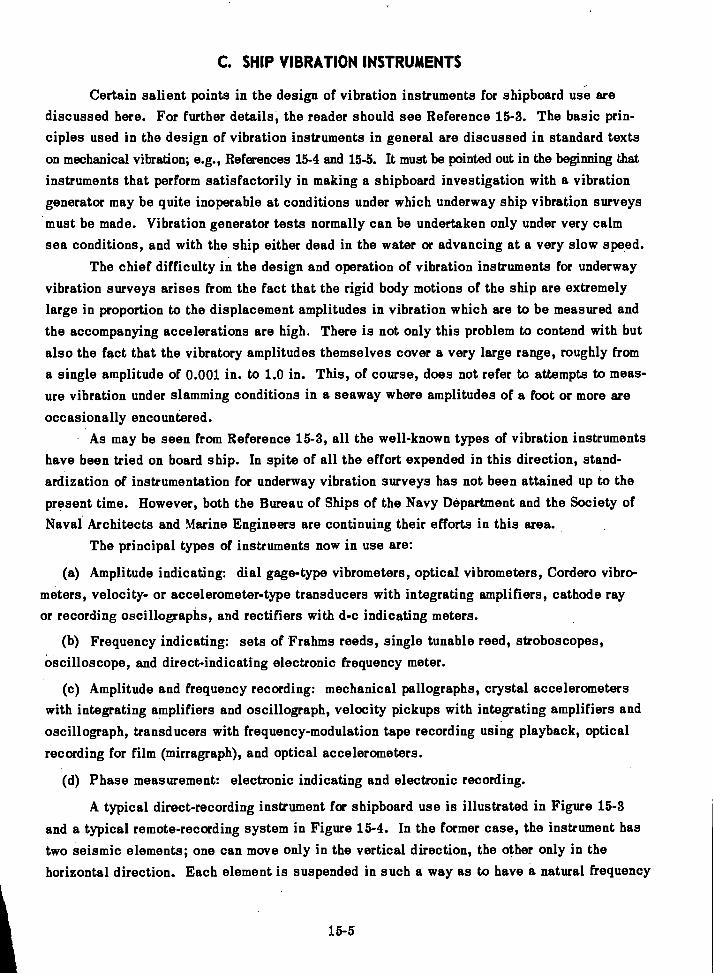
C. SHIP VIBRATION INSTRUMENTS
Certain salient points in the design of vibration instruments for shipboard use arediscussed here. For further details, the reader should see Reference 15-3. The basic prin-ciples used in the design of vibration instruments in general are discussed in standard textson mechanical vibration; e.g., References 15-4 and 15-5. It must be pointed out in the beginning that
instruments that perform satisfactorily in making a shipboard investigation with a vibrationgenerator may be quite inoperable at conditions under which underway ship vibration surveysmust be made. Vibration generator tests normally can be undertaken only under very calmsea conditions, and with the ship either dead in the water or advancing at a very slow speed.
The chief difficulty in the design and operation of vibration instruments for underwayvibration surveys arises from the fact that the rigid body motions of the ship are extremelylarge in proportion to the displacement amplitudes in vibration which are to be measured andthe accompanying accelerations are high. There is not only this problem to contend with butalso the fact that the vibratory amplitudes themselves cover a very large range, roughly froma single amplitude of 0.001 in. to 1.0 in. This, of course, does not refer to attempts to meas-ure vibration under slamming conditions in a seaway where amplitudes of a foot or more are
occasionally encountered.As may be seen from Reference 15-3, all the well-known types of vibration instruments
have been tried on board ship. In spite of all the effort expended in this direction, stand-ardization of instrumentation for underway vibration surveys has not been attained up to thepresent time. However, both the Bureau of Ships of the Navy Department and the Society ofNaval Architects and Marine Engineers are continuing their efforts in this area.
The principal types of instruments now in use are:
Amplitude indicating: dial gage-type vibrometers, optical vibrometers, Cordero vibro-meters, velocity- or accelerometer-type transducers with integrating amplifiers, cathode rayor recording oscillographs, and rectifiers with d-c indicating meters.
Frequency indicating: sets of Frahms reeds, single tunable reed, stroboscopes,oscilloscope, and direct-indicating electronic frequency meter.
Amplitude and frequency recording: mechanical pallographs, crystal accelerometerswith integrating amplifiers and oscillograph, velocity pickups with integrating amplifiers andoscillograph, transducers with frequency-modulation tape recording using playback, optical
recording for film (mirragraph), and optical accelerometers.
Phase measurement: electronic indicating and electronic recording.
A typical direct-recording instrument for shipboard use is illustrated in Figure 15-3and a typical remote-recording system in Figure 15-4. In the former case, the instrument hastwo seismic elements; one can move only in the vertical direction, the other only in thehorizontal direction.. Each element is suspended in such a way as to have a natural frequency
15-5
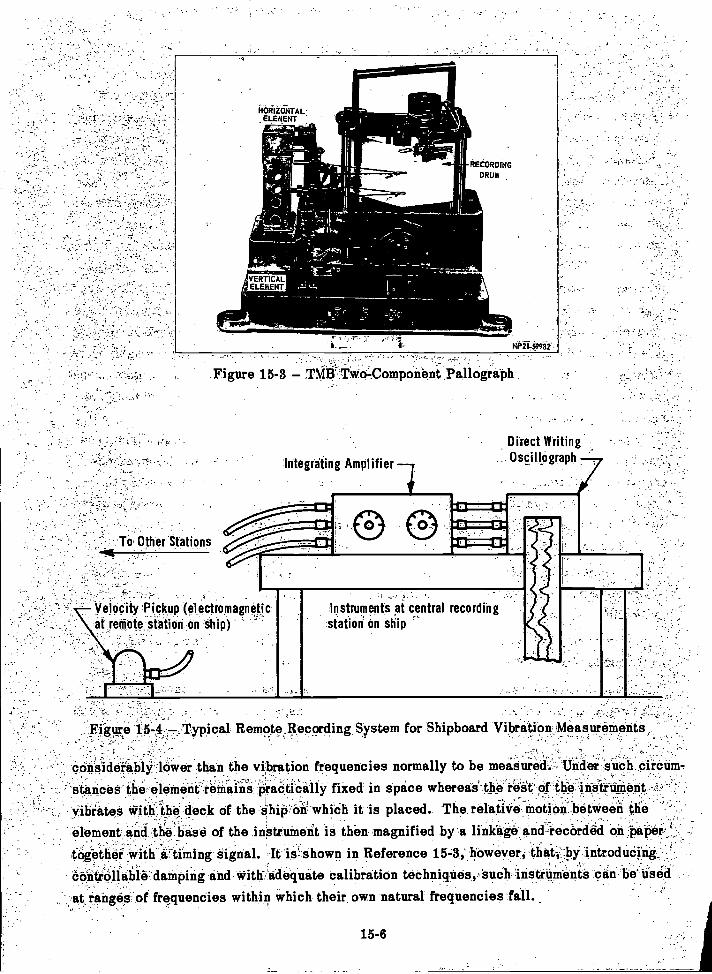
Figure 15-3 TMI3 Two-Component Pallograph-
Integrating Amplifier
:Instruments at central recordingstationOn Ship
15-6
Direct WritingOscillograph
Velocity Pickup (electromagneticat remote station on ship)
Figure 15-4 .Typical RemoteJ3,ecording System for Shipboard Vibration Measurements
. .considerably lower than the vibration frequencies normally to be measured. Under such circum-stances -the-element remains practically fixed in space whereai-the'reet of the instrument
vibrates with the deck of the hip on which it is placed. The relative motion between the
element and the base of the instrument is then magnified by a linkage and -recorded on paliei
together with a liming signal. It is shown in Reference 15-3; however, that, by introducingControllable damping and with adequate calibration techniques, such installments can be Used
at ranges of frequencies within which their own natural frequencies fall.

In the remote recording system shown in Figure 15-4, the pickup unit also containsa seismic element. In this instance the element is a magnet whose field cuts across a coilfixed to the base of the pickup. The voltage generated in the coil is proportional to therelative velocity between the base and the element. An integrating amplifier converts thesignal to one proportional to vibratory displacement which is recorded on the oscillograph.If desired, the velocity signal can be recorded directly without integration.
In general, instrumentation satisfactory for underway vibration surveys can be usedfor vibration-generator surveys but the reverse does not hold. The limitation, if any, willbe in its sensitivities and frequency ranges. However, although the earlier use of vibrationgenerators on board ship was chiefly for determining the natural frequencies of the hull andits normal mode patterns, recently it has been found practical to use such machines for de-termining forced vibratory response characteristics over the range of blade frequencies en-countered in the normal operation of the ship.
Under very calm water conditions and with very sensitive vibration-recording equip-ment, vibration-generator surveys may be made with amazingly low amplitudes, as in thecase of PONTCHARTRAIN15-6 in which normal modes were plotted with amplitudes of the
order of 0.01 mil.The investigation of torsion-bending modes and pure torsional modes of hulls requires
special attention to instrumentation. Here it is required to separate the rotational and trans-lational components of the hull vibration. This can be done with translational instrumentsonly by simultaneous recording of signals from pickups at opposite deck edges and obser-vation of phase. A recording angular accelerometer with integrating amplifier will give theangular amplitude directly if its sensitivity to rectilinear vibration is sufficiently low.
D. EXPERIMENTAL TECHNIQUES
1. MODEL
Considerable model experimentation has been carried out in the United States in theeffort to clarify the added mass effect of the surrounding water on hull vibration character-istics; see Reference 15-7. At this writing, however, the effort on model scale in the fieldof ship vibration research is concentrated on the problem of determining model forces. Asstated in Chapter 7, this work is an extension of the pioneering work of F.M. Lewis.
In all model work one encounters the problem of similitude or scaling. This subjectis discussed further in Appendix G. It should be noted here that it is not feasible (becauseof conflicting scaling rules; see Appendix G) to build a complete self-propelled dynamicmodel of a ship from which the propeller-excited vibration of the prototype can be predictedfrom direct measurements of the vibration of the model. Quite aside from the difficulties offabricating structural models of ships, the research scientist is confronted with scaling rulesfor ship vibration that do not conform with those for ship propulsion.
15-7
In F.M. Lewis' original scheme, a continuous wooden model was used for the propeller-exciting force determination and the line of reasoning was that, since the determination wasmade by nullification of the forces by forces produced by a balancing machine inside of themodel, the dynamic characteristics of the wooden model itself were irrelevant.
In later experiments it was found that resonance of the wooden model was deleteriousand a scheme of flexibly suspending the stern portion from the rest of the model was adopted.As shown in detail in Reference 15-8, the present setup yields the following values:
Blade-frequency vertical force,
Blade-frequency horizontal force, and
Blade-frequency torsional moment about the longitudinal axis.
In the field of hydroelasticity (see Chapter 14), the question of the feasibility of modelexperimentation is quite important. It must be decided whether it is feasible to predict a con-trol surface flutter condition by model techniques. As shown in Reference 15-9, flutter modeltesting has been found practical in aeronautical engineering. In naval architecture, however,its use will have to be much more restricted. The criterion of similitude in flutter experimentsis the nondimensional Strouhal number or "reduced frequency." In aeroelasticity, this is
bcocommonly expressed in the notation , where b is the half-chord dimension of a wing, co
V
is the circular frequency of the vibration, and V is the velocity of the wing relative to theundisturbed air. This relation indicates that for a scaled model of the same material as theprototype, the flutter speed should be the same as for the prototype.
In the hydroelastic field, if a dynamical model were manufactured of the same materialas the ship (since the natural frequencies vary inversely as the scale), the numerator in theexpression for the Strouhal number would be the same for model and prototype. Hence, theStrouhal number itself would be the same if the model speed were the same as the speed ofthe prototype. Obviously, for surface craft the flow patterns will not be similar if model andprototype run at the same speed since the law for similitude of bow waves is the Froude law;that is,
V2= constant
Lg
where V is the velocity,L is a characteristic length, andg is the acceleration of gravity.
Although it has been pointed out that in the case of a deeply submerged submarine
model the flow pattern is independent of the speed unless flow separation develops, thereremains the problem of fabricating the dynamical model and of running it at such a high speed.
In the aircraft field, flutter model testing is well established and here the high speed re-quired is feasible. It is also possible in wind tunnels to vary the density to reduce
15-8
discrepancies between model and full-scale Reynolds numbers. Furthermore, as pointed outin Appendix G, in the field of ship slamming it is feasible to experiment with dynamic modelsbased on Froude's law since here the propulsion system itself is not involved. In such modelsthe elastic characteristics are not represented in the shell but in a special girder installedalong the longitudinal axis of the model.
In dealing with vibration problems of local structures it is easier to satisfy the con-ditions of similitude than when the entire hull is involved, since hydrodynamic forces arenot involved. Thus, similitude for vibratory characteristics is theoretically satisfied if the
model is made of the same material as the prototype and duplicates it to scale. The practicaldifficulties here lie in the fabrication of the model and in the simulation of boundary re-straints and damping characteristics. These difficulties, however, are so great that compara-tively little has been accomplished to date in solving vibration problems of local hull struc-tures by dynamic model experiments.
2. FULL SCALE
Full-scale experiments in the field of ship vibration are at present confined chieflyto tests with mechanical vibration generators. These machines are installed at either end
of the ship and operated over a sufficient range of speed and driving force to excite the nor-
mal modes of vibration of the hull, one at a time. During the operation of the vibration gen-erator, the vibration of the hull is recorded either by a multichannel oscillograph system ortape recording system, or by exploring the hull with portable vibration instruments. The aim
is usually to record enough data to permit plotting the normal mode patterns for all modes ofthe hull that can be excited. This includes the vertical, horizontal, torsional, or torsion-bending modes. It is also possible in such tests to determine phase relations among thedisplacements at stations along the hull. These show whether a standing or traveling wave
condition exists.A useful adjunct to the vibration generator test is the anchor drop test. While such a
test usually excites only the 2-node vertical flexural mode of the hull, the recording of the
subsequent vibration permits a determination of the logarithmic decrement; that is, the damp-ing. Furthermore, since the 2-node vertical flexural is the mode of the hull lowest in frequency,it may be found in some cases that the vibration generator cannot produce sufficient force toexcite this mode even when the machine is set at its maximum eccentricity. The anchor drop
may then be the only means of determining the fundamental vertical frequency.
Although used less often for this purpose in the past, the vibration generator, if in-stalled directly over the propellers, furnishes a means of determining the full-scale propeller-exciting forces. Conceivably, it could be used as a balancing device to cancel out the pro-
peller forces when the ship is under way in the same manner as in the model determination
of propeller-exciting forces by the null method. This technique has not been used full scale
15-9
to any extent up to the present time, and synchronizing of the vibration generator with theship's shafts is not easily attained. However, if with the ship dead in the water, the vibra-tion generator is operated at speeds (rpm) coinciding with operating blade frequencies (cpm),the data so obtained may be used to estimate the underway propeller forces, provided theunderway hull vibration is also recorded. This, of course, involves the assumption that thedamping and added mass characteristics of the hull are the same underway as in still water.In the case of vertical vibration, only the hydrofoil action of the propellers appears to causea variation in damping. In the case of horizontal vibration, the hydrofoil damping action ofthe rudders is to be taken into account. In the case of submarines, the diving planes providea source of damping of vertical vibration. It should be noted, however, that where the opera-ting blade frequency falls above the range of significant hull mode frequencies, the mechanicalimpedance at the stern is chiefly an inertial impedance.
Aside from the full-scale vibration-generator experiments just described, both the U.S.Navy and the Society of Naval Architects and Marine Engineers have initiated a systematicseries of underway vibration surveys on new classes of ships. Such surveys play an impor-tant role in the overall ship vibration research program. Even if nothing unusual developsduring such a survey from the ship vibration standpoint, the data obtained are still extremelyvaluable in establishing acceptable levels of vibration for various classes of ships. If asevere vibratory condition is discovered, the investigation of this is likely to lead to a def-inite advance in ship vibration theory. It is never desirable from the naval architect's pointof view to dismiss a case of serious ship vibration which has been corrected by the trial anderror process without really tracking down the phenomenon. Unfortunately, however, economicconsiderations sometimes impose such an outcome.
With the advent of the application of statistical methods to the study of the performanceof ships in a seaway (see Reference 15-10), more attention has been given in recent years tothe collection of data on the transient vibrations of ships. As pointed out in Chapter 2, thesevibrations are much more important from the point of view of structural integrity of the hullthan the steady-state vibrations which are excited by the propeller.
While, in principle, the instruments already mentioned in this chapter can be used forrecording transient vibrations, it is in order to point out here that the severe sea conditionsunder which large transient hull vibrations are generated rule out an instrument of the typeshown in Figure 15-3 for such a purpose. The trend at this time is in the direction of remote-recording systems using magnetic tape recording. This permits subsequent playback of therecord into vibration analyzers in the laboratory.
E. CORRELATING THEORY AND EXPERIMENT
The complexity of the ship vibration problem is such that exact theories are nonexist-ent. While the theory of vibration of ideal mass-elastic systems can serve as a guide, it isonly by continually comparing theoretical predictions with experimental results that a rationaltheory can be established.
15-10
The theory advocated in this book is a beam theory with important modifications. Theidealized beam is considered to be free in space, but it carries added mass nonuniformly dis-tributed to account for the inertia effect of the surrounding water. Thus it is nonuniform inboth its mass and rigidity distributions along its length. It can bend, twist, and shear, butdoes not execute significant longitudinal vibration and its torsion is only about its longitudinalaxis. If longitudinal vibrations of surface vessels, and especially submarines, are "signif-icant" from some points of view, this arises from considerations not dealt with in this bookand involves amplitudes of a lower order of magnitude. The damping of the idealized systemis provided by external and distributed viscous damping between itself and axes fixed in space.It may have one or several flexibly attached masses and these may move relative to it in bothrotation and translation. Finally, it has the unique, property (for a beam) that it can vibratein only a limited number of modes.
In checking this theory, the simplest criterion is the comparison between predicted andmeasured natural frequencies. Such a comparison requires merely tabulating the frequenciesand identifying them by the node shapes, then listing the predicted frequencies and the per-centage of errors in the predictions.
The second best criterion is the comparison of the experimental and computed normalmode patterns. Even if the frequencies check, the theory will have less and less validity,the greater the departure of the experimentally determined normal mode patterns from thosepredicted. In this connection, beamlike modal patterns are not to be expected if there isconsiderable local flexibility, especially when the local structure is massive. Hence, whenthe observed modal patterns are not beamlike, calculations must be tried with various localstructures treated as flexibly attached, if correlation is to be improved.
The third area to be explored is that of the forced vibratory response of the hull. Heremuch depends on whether the vibration is resonant or nonresonant. The forced resonant re-sponse depends chiefly on the damping and the magnitude of the driving force. Since thelatter is known when a vibration generator is used, the forced resonant response in thiscase yields an experimental value of damping.
In the range of frequencies above that of the significant hull modes, the observed forcedresponse in the stern provides a check on the proposed formula for mechanical impedance atthe stern of a ship discussed in Chapter 4.
If the experimentally determined horizontal modes are observed to be torsion-free, orvery nearly so, then the same criteria for comparing theory and experiment in vertical vibra-tion are applicable to horizontal vibration. When it comes to torsion-bending modes, it isnecessary to convert the mechanical system to a generalized system which combines theeffects of translation and rotation before the comparison can be made. The general schemeused for doing this is outlined in Chapter 4.
15-11
- 15-1. Pollard, J. and Dudebout, A.:,"Theorie du Nivirei"Treizieme Paitie; "Vibrationsdes CoqueS.dis 'Ntivires a Helice," Vol. IV, Chapt. LXIX, "dailies et'PeriOdes des.Vibra-
dons," Paris (1894).c
15.;2. Robinson, Q.R `I,Vibration Machines at the David W. TaylorModel,BaSin TMB
Report 821 (Jul 1952).:
15-3.Allnutt, R.B.. and Mintz, F, " Instruments at.the.,David Taylor Model Basin
Measuring VibratiOn'ancl,t_hOck on Ship .Structures and Machinery," TMB Report 563. (Jul 1948).
15-4 Defi'llartogl..J.P., "Mechanical Vibrations,"-.McGittilltOcik Co, New York (1956):
15-5... -
'York (1955).
Allnutt, R.B.,'70),".TMB,Report..ft-29:4:(Aug 1948).
154. Kaplan, "A Study Of the Virtual Mass AssOciatfed,with-4e,Vertical Vihraticin of.
Ships inWater,SIT, Davidson Lab Report 734 (Dec 1959): - - =-:,1; :4'
Siunti, GAL; et fil!; "Series 60 The Effect of Variations in Aft4irliddy Shape tipohRetilice:nee, Fairer; Wake Distributibh; and PropellerEibitect VibratOtyFOraes;".4!aper pre-
. .
pared for Ann't al Medi:Mg of SNAMRi(1960):
BisplinglisOft,'`IEL., et al, "Aeroelasticity," A'dfcliSon4edrei`Publishilig Co. (1955).
-15-10. Jasper; 'N.H., "Statistical Distribution Patterns of Ocean Waves andof Wave-InducedShip Stresses and MOtions,..withEngineerifig Applications," Trans. SNAME, Vol. 64 (1956).Also TMB Report 921 (Oct 1957)..
_.---.1!IEFERENCES,
15-12
"Vibration Problems in Engineering," D. Van NoStriind'6o., New
:, :7 ; ;
"Investigation of Hull 'Vibrations of,USCGC PONTCHARTRA* (WPG- , - _ --
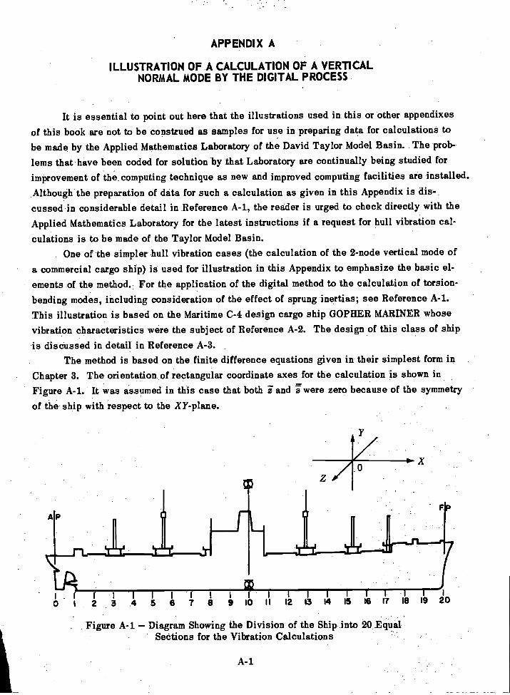
APPENDIX A
ILLUSTRATION OF A CALCULATION OF A VERTICALNORMAL MODE BY THE DIGITAL PROCESS
It is essential to point out here that the illustrations used in this or other appendixesof this book are not to be construed as samples for use in preparing data for calculations tobe made by the Applied Mathematics Laboratory of the David Taylor Model Basin. The prob-lems that have been coded for solution by that Laboratory are continually being studied forimprovement of the computing technique as new and improved computing facilities are installed.Although the preparation of data for such a calculation as given in this Appendix is dis-.cussed in considerable detail in Reference A-1, the reader is urged to check directly with theApplied Mathematics Laboratory for the latest instructions if a request for hull vibration cal-
culations is to be made of the Taylor Model Basin.One of the simpler hull vibration cases (the calculation of the 2-node vertical mode of
a commercial cargo ship) is used for illustration in this Appendix to emphasize the basic el-
ements of the method.. For the application of the digital method to the calculation of torsion-bending modes, including consideration of the effect of sprung inertias; see Reference A-1.This illustration is based on the Maritime C-4 design cargo ship GOPHER MARINER whosevibration characteristics were the subject of Reference A-2. The design of this class of shipis discussed in detail in Reference A-3.
The method is based on the finite difference equations given in their simplest form inChapter 3. The orientation of rectangular coordinate axes for the calculation is shown inFigure A-1. It was assumed in this case that both iand were zero because of the symmetry
of the ship with respect to the XY-plane.
A
I 1 I I I I- 1- 1 1 1 1 I I
5 8 7 8 9 10 II 12 13 14 15 18 17 18 19 20
Figure A-1 Diagram Showing the Division of the Ship into 20 EqualSections for the Vibration Calculations
A-1
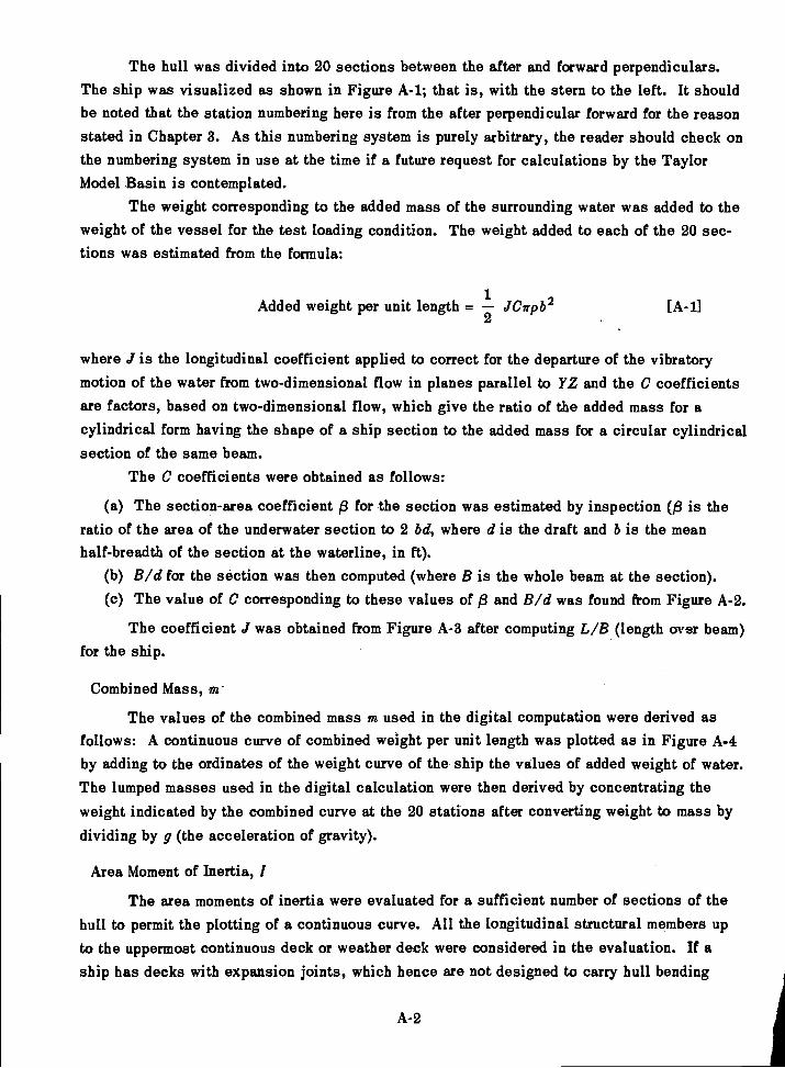
The hull was divided into 20 sections between the after and forward perpendiculars.The ship was visualized as shown in Figure A-1; that is, with the stern to the left. It shouldbe noted that the station numbering here is from the after perpendicular forward for the reasonstated in Chapter 3. As this numbering system is purely arbitrary, the reader should check onthe numbering system in use at the time if a future request for calculations by the TaylorModel Basin is contemplated.
The weight corresponding to the added mass of the surrounding water was added to theweight of the vessel for the test loading condition. The weight added to each of the 20 sec-tions was estimated from the formula:
Added weight per unit length = JCffpb22
where J is the longitudinal coefficient applied to correct for the departure of the vibratorymotion of the water from two-dimensional flow in planes parallel to YZ and the C coefficientsare factors, based on two-dimensional flow, which give the ratio of the added mass for acylindrical form having the shape of a ship section to the added mass for a circular cylindricalsection of the same beam.
The C coefficients were obtained as follows:
The section-area coefficient f3 for the section was estimated by inspection is theratio of the area of the underwater section to 2 lid, where d is the draft and b is the meanhalf-breadth of the section at the waterline, in ft).
B/d for the section was then computed (where B is the whole beam at the section).The value of C corresponding to these values of f3 and B/d was found from Figure A-2.
The coefficient J was obtained from Figure A-3 after computing L/B (length over beam)for the ship.
Combined Mass, m.
The values of the combined mass m used in the digital computation were derived asfollows: A continuous curve of combined weight per unit length was plotted as in Figure A-4by adding to the ordinates of the weight curve of the ship the values of added weight of water.The lumped masses used in the digital calculation were then derived by concentrating theweight indicated by the combined curve at the 20 stations after converting weight to mass bydividing by g (the acceleration of gravity).
Area Moment of Inertia, I
The area moments of inertia were evaluated for a sufficient number of sections of thehull to permit the plotting of a continuous curve. All the longitudinal structural members upto the uppermost continuous deck or weather deck were considered in the evaluation. If aship has decks with expansion joints, which hence are not designed to carry hull bending
[A-1]
A-2
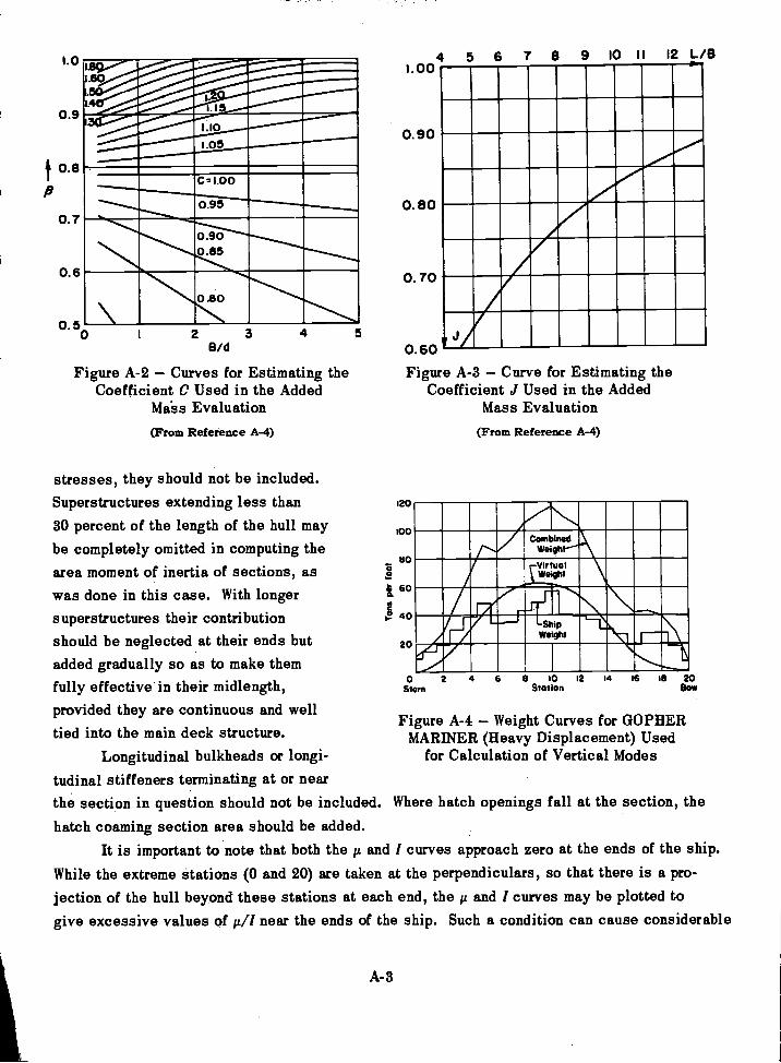
I.0
0.9
0.6
0.58/d
Figure A-2 Curves for Estimating theCoefficient C Used in the Added
Ma-ss Evaluation
(From Reference A-4)
stresses, they should not be included.Superstructures extending less than30 percent of the length of the hull maybe completely omitted in computing thearea moment of inertia of sections, aswas done in this case. With longersuperstructures their contributionshould be neglected at their ends butadded gradually so as to make themfully effective in their midlength,provided they are continuous and welltied into the main deck structure.
Longitudinal bulkheads or longi-tudinal stiffeners terminating at or nearthe section in question should not be inhatch coaming section area should be a
A-3
120
1.00
0.90
0.60
0.70
0.60 V
Figure A-8 Curve for Estimating theCoefficient J Used in the Added
Mass Evaluation(From Reference A-4)
1111111111EMI111111=1111VA1111/011ME_
21/1111111111011a.:21111 1111111.,
Figure A-4 Weight Curves for GOPHERMARINER (Heavy Displacement) Used
for Calculation of Vertical Modes
cluded. Where hatch openings fall at the section, thedded.
It is important to note that both the and I curves approach zero at the ends of the ship.While the extreme stations (0 and 20) are taken at the perpendiculars, so that there is a pro-jection of the hull beyond these stations at each end, the it and I curves may be plotted to
give excessive values of near the ends of the ship. Such a condition can cause considerable
I... ,,......._____...........,.....,.
i.,......
Lio1.05
ME0
_
C=1.00
0.95
0 900.85
.80 hilimilh._e
8 10 12 14 16 18 20Stem Station BOW
9 10 11 12 L/B8456
100
uo
2I 60
1°. 40
20

error in the digital calculation of the natural frequencies because it effectively makes theends of the ship very "flabby." If the ship actually had such a construction, the lowestmode Would-be determined by this local condition at the ends- On the other hand, no amountof overestimating of I at the ends can have much effect on the naturalfrequency since itsimply means that the overhang at each end is rigidly attached to the ship at the perpendic-ular. Therefore, the rule is to check at the ends to make surethat the value of a// does notrise abruptly. This precaution Was followed in this illustration.
acmo
2
232
1111111121MINIIIII111M11111111111MPill11111111111E11111111111111111111
:Stara
'a -
SternB 10 12
Station,
10- -12 ,18 20Station Bow
Shear Rigidity Factor, K -
For GOPHER MARINER the shear rigidity factor was evaluated by letting KA = A',where 'A is the total area used in the evaluation of I, and A' is the area of the vertical platingonly (such as the side shell plating and continuous longitudinal bulkhead plating) The "web"area A' was plotted for as many sections as were available (in this case six) and a smoothcurve was drawn-as shown in Figure A-6.
16 LB 20Bow
The values actually -furnished for the digital calculation of the vertical modes ofGOPHER MARINER for a heavy displacement loading are given in Table A-1. In this case,the term for rotary inertia was omitted on the assumption that its effect would be negligibleThe reader is :cautioned against using Table A-1 as a sample for furnishing data to the
A-4
Figure A-5 Area Moment of Inertia CurveUsed for Calculation of Vertical Modes of
GOPHER. MARINER
Figure A-6 Side Plating Area Curve Usedin Evaluating Vertical Shearing Rigidity
of GOPHER MARINER
' 2 6.000
4,000
o 2,000
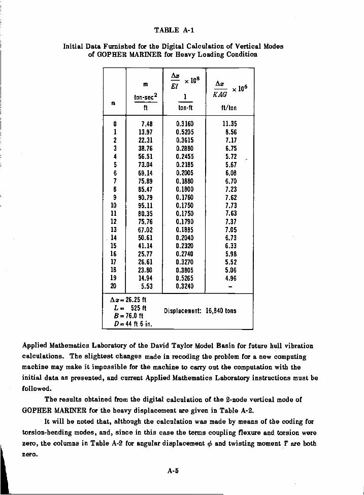
TABLE A-1
Initial Data Furnished for the Digital Calculation of Vertical Modesof GOPHER MARINER for Heavy Loading Condition
Applied Mathematics Laboratory of the David Taylor Model Basin for future hull vibrationcalculations. The slightest changes made in recoding the problem for a new computingmachine may make it impossible for the machine to carry out the computation with theinitial data as presented, and current Applied Mathematics Laboratory instructions must befollowed.
The results obtained from the digital calculation of the 2-node vertical mode ofGOPHER MARINER for the heavy displacement are given in Table A-2.
It will be noted that, although the calculation was made by means of the coding fortorsion-bending modes, and, since in this case the terms coupling flexure and torsion werezero, the columns in Table A-2 for angular displacement irk and twisting moment T are bothzero.
A-5
n
m
ton-sec2
Az i8 n- x AuEl
1
Az106x
K AG
ft/tonft ton-ft
0 7.48 0.3160 11.351 13.97 0.5205 8.562 22.31 0.3615 7.173 38.76 0.2880 6.754 56.51 0.2455 5.72 ,5 73.04 0.2185 5.676 69.14 0.2005 6.087 75.89 0.1880 6.708 85.47 0.1800 7.239 90.79 0.1760 7.62
10 95.11 0.1750 7.7311 80.35 0.1750 7.6312 75.76 0.1790 7.3713 67.02 0.1885 7.0514 50.61 0.2040 6.7315 41.14 0.2320 6.3316 25.77 0.2740 5.9817 26.61 0.3270 5.5218 23.80 0.3805 5.0619 14.94 0.5265 4.9620 5.53 0.3240 -Az= 26.25 ft
L = 525 ft Displacement: 16,840 tonsB= 76.0 ftD.44 ft 6 in.
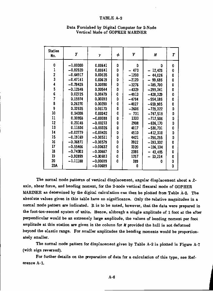
TABLE A-2
Data Furnished by Digital Computer for 2-NodeVertical Mode of GOPHER MARINER
The normal mode patterns of vertical displacement, angular displacement about a 2-axis, shear force, and bending moment, for the 2-node vertical flexural mode of GOPHERMARINER as determined by the digital calculation can then be plotted from Table A-2. Theabsolute values given in this table have no significance. Only the relative magnitudes in anormal mode pattern are indicated. It is to be noted, however, that the data were prepared inthe foot-ton-second system of units. Hence, although a single amplitude of 1 foot at the afterperpendicular would be an extremely large amplitude, the values of bending moment per footamplitude at this station are given in the column for Ai provided the hull is not deformedbeyond the elastic range. For smaller amplitudes the bending moments would be proportion-ately smaller.
The normal mode pattern for displacement given by Table A-2 is plotted in Figure A-7(with sign reversed).
For further details on the preparation of data for a calculation of this type, see Ref-erence A-1.
A-6
StationNo. Y r 0 V Ai T
0 -1.00000 0.00641 0 0 0 01 -0.82620 0.00641 0 - 473 - 12,426 02 -0.64917 0.00635 0 -1203 - 44,026 03 -0.47141 0.00619 0 -2120 - 99,686 04 -0.29428 0.00590 0 -3276 -185,700 05 -0.12648 0.00544 0 -4329 -299,341 06 0.02725 0.00479 0 -4913 -428,329 07 0.15974 0.00393 0 -4794 -554,186 08 0.26270 0.00289 0 -4027 -659,905 09 0.32635 0.00170 0 -2606 -728,322 0
10 0.34308 0.00042 0 - 731 -747,518 0
11 0.30958 -0.00088 0 1333 -712,506 012 0.23148 -0.00213 0 2908 -636,170 013 0.11606 -0.00326 0 4017 -530,701 014 -0.02779 -0.00426 0 4510 -412,310 015 -0.19169 -0.00511 0 4421 -296,255 016 -0.36871 -0.00579 0 3922 -193,302 017 -0.55466 -0.00632 0 3320 -106,134 018 -0.74303 -0.00667 0 2386 - 43,485 019 -0.92899 -0.00683 0 1267 - 10,214 020 -1.11188 -0.00689 0 389 0 020A -0.00689 0 0
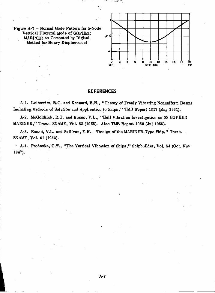
Figure A-7 Normal Mode Pattern for 2-NodeVertical Flexural Mode of GOPHERMARINER as Computed by Digital
Method for Heavy Displacement
A-7
>7 0
AP2 4 6 9 10 12 14 16 19 20
Sta Ions FP
REFERENCES
Leibowitz, R.C. and Kennard, E.H., "Theory of Freely Vibrating Nonuniform BeamsIncluding. Methods of Solution and Application to Ships," TMB Report 1317 (May 1961).
McGoldrick, R.T. and Russo, V.L., "Hull Vibration Investigation on SS GOPHERMARINER," Trans. SNAME, Vol. 63 (1955). Also TMB Report 1060 (Jul 1956).
Russo, V.L. and Sullivan, E.K., "Design of the MARINER-Type Ship," Trans.SNAME, Vol. 61 (1953).
Prohaska, C.W., "The Vertical Vibration of Ships," Shipbuilder, Vol. 54 (Oct, Nov1947).
APPENDIX B
ILLUSTRATION OF A CALCULATION OF TRANSIENTRESPONSE BY THE DIGITAL METHOD
As in Appendix A, the calculation presented in this Appendix serves to illustrate thebasic principles involved, but it is not intended as 'a sample to be used in preparing requestsfor transient hull vibration calculations to be carried out by the Applied Mathematics Labora-tory of the David Taylor Model Basin. As a matter of fact, the recoding of this particularproblem with the addition of buoyancy forces is in progress at this time.
The analysis of transient vibration discussed in this book is confined to vibrationswithin the elastic range, as pointed out in Chapter 5. For a discussion of the general prob-lem of ship slamming in a seaway, see Reference B-1. The digital method of transientanalysis discussed in Chapter 5 was applied to GOPHER MARINER in the prototype exampleused in coding the initial treatment of this problem on the UNIVAC. Further details of theprototype calculation will be found in References B-2 and B-3.
The loading conditions for the calculation were as follows: a vertical force of 1 tonwas instantaneously applied amidships, held constant for 1 sec, then instantaneously re-moved. No special significance is to be attached to the particular loading chosen for thisexample, at least for simulating the loading encountered by a ship in a seaway. Mathemati-cally, however, this is a standard type of forcing function sometimes described as a "rectan-gular pulse load."
The reference axes were the same as indicated in Figure A-1, and an element of lengthAz is shown in Figure 5-2. The hull data used for this calculation were the same as used inthe calculation of the 2-node vertical normal mode given in Appendix A (same ship and samedisplacement in both cases) with the exception that the parameters /in (rotary inertia) andC (damping) were added. These additional parameters are given in Table B-1.
The rotary inertia values /.x were estimated in this case by treating each lumped massm (which includes a value for added mass of water) as though it were uniformly distributedthroughout a rectangular parallelepiped bounded by the main deck, the bottom plating, and thehull side plating, and taking the mass moment of inertia of this parallelepiped with respectto a Z-axis passing through its centroid.
The damping values C were based on a value of 1 for the ratio c/A . The experimentalbasis for this value is discussed in Chapter 8. In this calculation the time steps selected(A t) were 0.02 sec. Hence, the load data was 1 ton at Station 10 for time steps 0 through49 and zero at this station for all subsequent times. At all other stations the load was zeroat all times.
The calculation was carried out for 250 time steps or for a total duration of 5 sec andthe results were printed for each step.
B-1
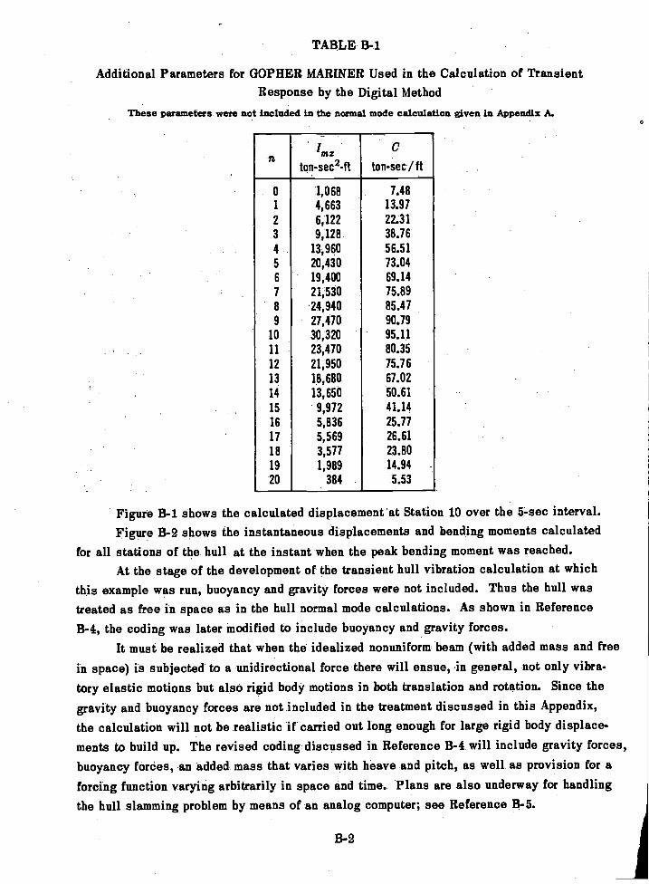
TABLE B-1
Additional Parameters for GOPHER MARINER Used in the Calculation of TransientResponse by the Digital Method
These parameters were not included in the normal mode calculation given in Appendix A.
Figure B-1 shows the calculated displacement at Station 10 over the 5-sec interval.Figure B-2 shows the instantaneous displacements and bending moments calculated
for all stations of the hull at the instant when the peak bending moment was reached.At the stage of the development of the transient hull vibration calculation at which
this example was run, buoyancy and gravity forces were not included. Thus the hull wastreated as free in space as in the hull normal mode calculations. As shown in ReferenceB-4, the coding was later modified to include buoyancy and gravity forces.
It must be realized that when the idealized nonuniform beam (with added mass and freein space) is subjected to a unidirectional force there will ensue, in general, not only vibra-tory elastic motions but also rigid body motions in both translation and rotation. Since thegravity and buoyancy forces are not included in the treatment discussed in this Appendix,the calculation will not be realistic if carried out long enough for large rigid body displace-ments to build up. The revised coding discussed in Reference B-4 will include gravity forces,buoyancy forces, an added mass that varies with heave and pitch, as well as provision for aforcing function varying arbitrarily in space and time. Plans are also underway for handlingthe hull slamming problem by means of an analog computer; see Reference B-5.
B-2
I i:C
n g 171Z
ton-sec2-ft ton-sec / ft
0 1,068 7.481 4,663 13.972 6,122 22.313 9,128 38.164 13,960 56.515 20,430 73.046 19,400 69.147 21,530 15.898 24,940 85.479 27,470 90.79
10 30,320 95.1111 23,470 80.35
12 21,950 75.7613 18,680 67.0214 13,650 50.61
15 9,972 41.1416 5,836 253117 5,569 26.6118 3,577 23.8019 1,989 14.94
20 384 5.53
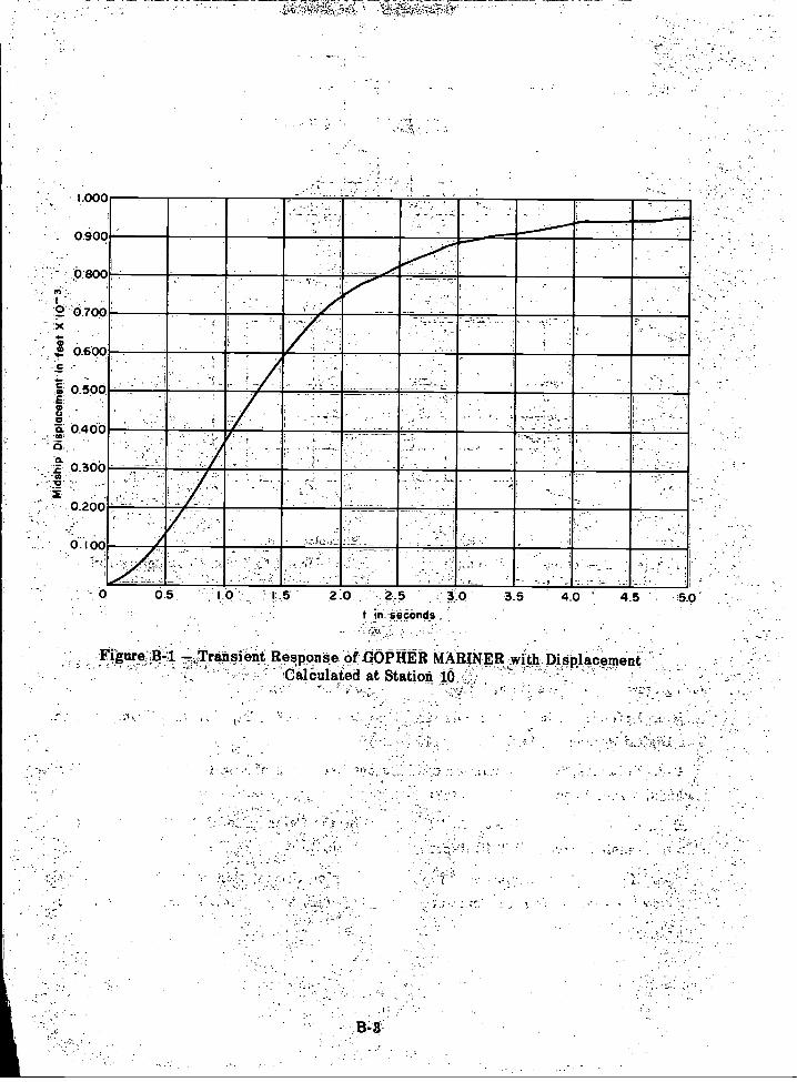
0 5 10 5 2.0 25 3.0t in .010,bncls
Figure A-1Transient Response of .GOPHER MARINER with DisplacementCalculated at Station 1.
35 40 45

cLc, .......
.200
a- 40
_
9. 6
Figure 13-2u --Bending-Monient',
Methods," TMB Report 11201(Jul 1957).
Figure, Vertidal..Diiittlacen*itt,-
REFERENCES
B-4
20
Figure B-2 --Transient ResponSe. of GOPHER MARINER to 1-Ton Rectingulat PulseLoad Amidships at Instant of Peak Bending Moment by Digital Calculation- .f .
-
B-1. Jaspar, N.H. and Birmingham, J T, "Straiiii.and_Motione of USS ESSEX (CVA 9)during Stains near Cape Horn," TMB Report 1216 (Aug 1958).
McGoldrick, R.t., "Calculation of the Response of a Ship HUH to a Transient Load
by a Digital Process," TMI3 Report 1119 (Mar 1957).
Polachek, H., "Calculation of Transient Excitation of Ship Hulls by Finite Difference
B-4.- Cuthill, E., and Olsten, E., "A Routine for the Calculation of the Response of a
Ship to Transient Forces," TMB Report (in preparation).
B-5. Hoyt, E D, ``Simulation of the .Sea and Analog Computation of the Forces on a Ship
in Waves," Report to TMB on Contract Nobs 72876, T.O. 9, Project RR-1458-N by Reed Re-
search,_Inc (Nov 1959).
.10 12 -14 16 718
'Sto ion4 6
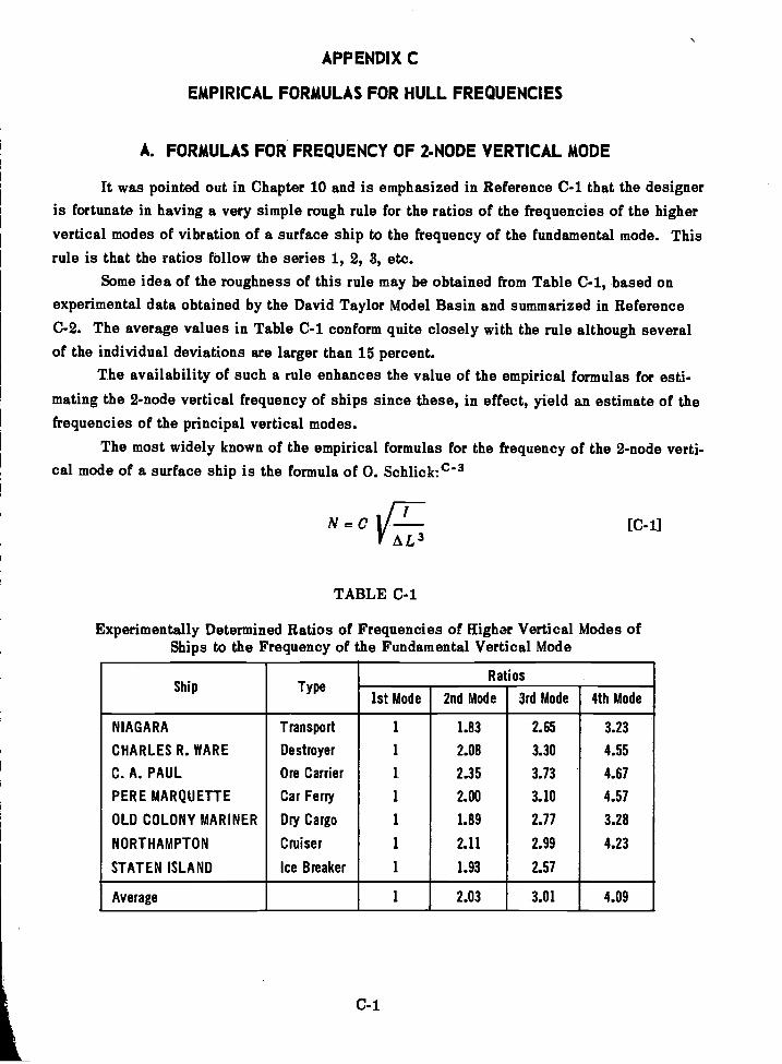
APPENDIX C
EMPIRICAL FORMULAS FOR HULL FREQUENCIES
A. FORMULAS FOR FREQUENCY OF MODE VERTICAL MODE
It was pointed out in Chapter 10 and is emphasized in Reference C-1 that the designeris fortunate in having a very simple rough rule for the ratios of the frequencies of the highervertical modes of vibration of a surface ship to the frequency of the fundamental mode. Thisrule is that the ratios follow the series 1, 2, 8, etc.
Some idea of the roughness of this rule may be obtained from Table C-1, based onexperimental data obtained by the David Taylor Model Basin and summarized in ReferenceC-2. The average values in Table C-1 conform quite closely with the rule although severalof the individual deviations are larger than 15 percent.
The availability of such a rule enhances the value of the empirical formulas for esti-
mating the 2-node vertical frequency of ships since these, in effect, yield an estimate of thefrequencies of the principal vertical modes.
The most widely known of the empirical formulas for the frequency of the 2-node verti-cal mode of a surface ship is the formula of 0. Schlick:c-3
N =C ItV AL3
TABLE C-1
Experimentally Determined Ratios of Frequencies of Higher Vertical Modes ofShips to the Frequency of the Fundamental Vertical Mode
C-1
[C-1]
Ship TypeRatios
1st Mode 2nd Mode 3rd Mode 4th Mode
NIAGARA Transport 1 1.83 2.65 3.23
CHARLES R. WARE Destroyer 1 2.08 3.30 4.55
C. A. PAUL Ore Carrier 1 2.35 3.73 4.67
PERE MARQUETTE Car Ferry 1 2.00 3.10 4.57
OLD COLONY MARINER Dry Cargo 1 1.89 2.77 3.28
NORTHAMPTON Cruiser 1 2.11 2.99 4.23
STATEN ISLAND Ice Breaker 1 1.93 2.57
Average 1 2.03 3.01 4.09
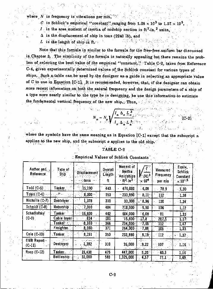
where ...N is frequency in vibrations per Min;-'
C is Schlick's emirical f.`cong-tant", ranging from 1-.28 x 10.5 to 1.57 x 10I is the area monient of inertia of midshik section in ft2-in. 2 units,6. is the displacement of ship in tons (2240 lb), andL is the length Of Ship fri' ft.'
Note thatthis ,formula is similar to the formula for the free-free uniform bar discussedin Chapter _3. The simplicity of the formula is naturally appealing but there remains the prob-lem of selecting the best.Valie Of the ernpirical-"constant.'..,! "Table 0-2, taken from: Reference0-4, gives experimentally determined values-of:the SchliCk Constant for various types ofships A,. table can be used by the .designer as -:a guide selecting an appropriate :Value. , .
of C-to use in Equation. [C-i] It is recommended, .however, that, if the designer can obtainmore recent information orPboth the ,natural frequency and the design parameters of a ship ofa type more nearly similar to the type he is designing, he use this information to estimatethe,fundamental vertical, frequency, of the new ship.Thus,
Na
-where the symbols have the same meaning as in Equation [c-i] except that the subscript napplies to the new ship, and the subscript o applies to the old Ship.r 4
TABLE C-2
,Empirical Values of Schlick Constants
C-2
Author and. qReference ,
'Type of
-ShiO,
-
_. .," -;
Displacement_ ',
----tons --
.0yerallLength
ft
Moment of
net ia-Amidships
--ft2-in2 -
7
---i=. 0L3
x,104
MeasuredFrequency
'per min -
Equiv.Schlick_
Constant- x-irs
Todd (C-3) Tanker,' ' :15,190 440 . - 476,000 . 6.08 , 78.9 .1.30Tobin (C-6) - - - _8,300 --; 350 - 233,890- - ' 8:11" 112 1.38
Nicholls (C,77.)- .l5estroye:r : 1,378 310 33,000 . 8.96 - 120 1.34
Schmidt (0-8). , Motorshin'" 7,010 484 718,000 9.50 106 112-
Schadlofsky(C-9)
tanker ' : 16,600 1 462 664,000 ' 6.08 ' 81 1.33Cable layer' 834 ' . 181 '15,600 - 47.8 207Z 1.17-Tanke r,-, 8,160 366 234;000.. -7.65 - --- 112 - 1.47Freighter_ :8,350 371 264,000: ' 7.88_ -105 1.33
Cole (C-10) Tanker -8 151. , ' 350 233 890 '8 19-- 112 1.37
EMB Report- -
Destroyer ,- .1,3_82 310 35,000 ,9.22 107 1.16 ?
' Roop (C-12) Tanker 15,430 475 447,000 5.20'-- 60.3Battleship - 32,000 583 1,325,000 4.57 77.1 . " 1.69_
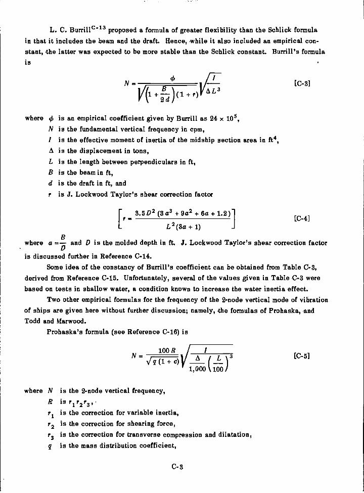
L. C. Burrilic-13 proposed a formula of greater flexibility than the Schlick formulain that it includes the beam and the draft. Hence, while it also included an empirical con-stant, the latter was expected to be more stable than the Schlick constant. Burrill's formulais
N= [C-3]L3+ + r)
2 d
where ek is an empirical coefficient given by Burrill as 24 x 105,is the fundamental vertical frequency in cpm,
/ is the effective moment of inertia of the midship section area in ft4,A is the displacement in tons,
is the length between perpendiculars in ft,is the beam in ft,is the draft in ft, andis J. Lockwood Taylor's shear correction factor
[r 3.502 (3 a3 + 9a2 + 6a + 1.2)][C-4]
L2(3a + 1)
where a and D is the molded depth in ft. J. Lockwood Taylor's shear correction factor
is discussed further in Reference C-14.Some idea of the constancy of Burrill's coefficient can be obtained from Table C-3,
derived from Reference C-15. Unfortunately, several of the values given in Table C-3 werebased on tests in shallow water, a condition known to increase the water inertia effect.
Two other empirical formulas for the frequency of the 2-node vertical mode of vibrationof ships are given here without further discussion; namely, the formulas of Prohaska, andTodd and Marwood.
Prohaska's formula (see Reference C-16) is
100 R V IN= A L )3c)
1,000 100
where N is the 2-node vertical frequency,is r1r2r3,.is the correction for variable inertia,
r2 is the correction for shearing force,
r3 is the correction for transverse compression and dilatation,q is the mass distribution coefficient,
C-3
[C-5]
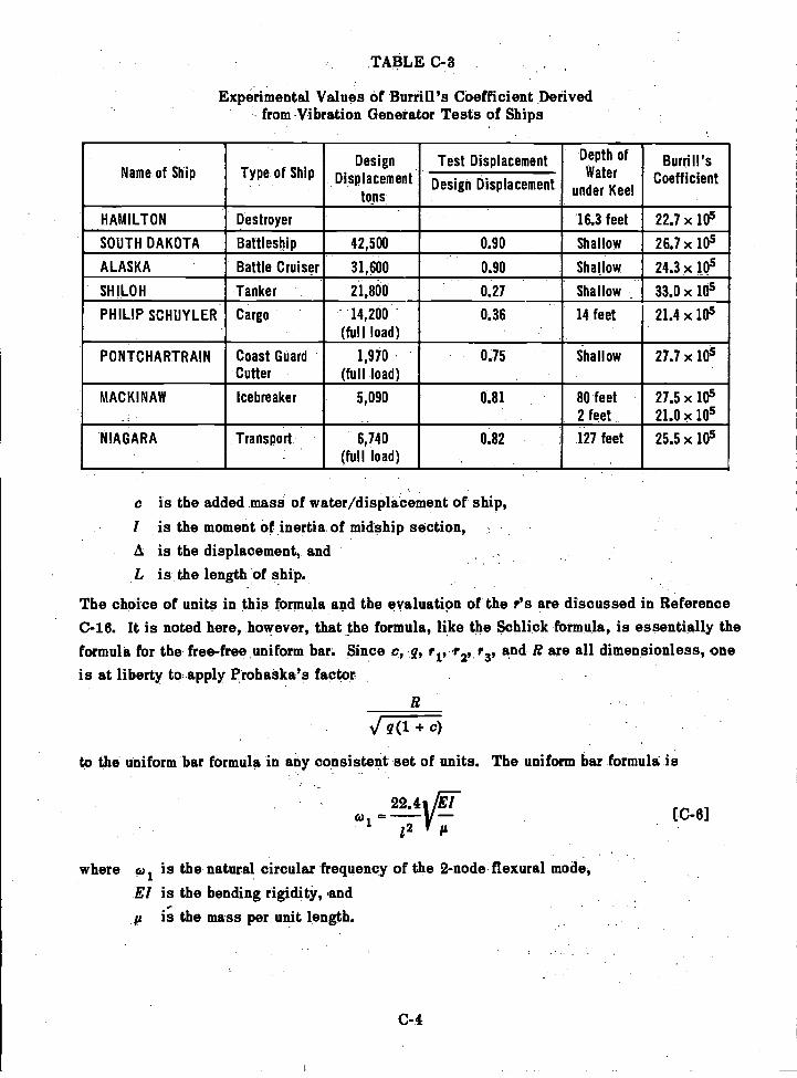
TABLE C-3
Experimental Values of Burrill's Coefficient Derivedfrom Vibration Generator Tests of Ships
c is the added mass of water/displacement of ship,/ is the moment of inertia of midship section,A is the displacement, andL is the length of ship.
The choice of units in this formula and the evaluation of the r's are discussed in ReferenceC-16. It is noted here, however, that the formula, like the Schlick formula, is essentially theformula for the free-free uniform bar. Since c, q, ri,r2, r3, and R are all dimensionless, oneis at liberty to apply Prohaska's factor
c)
to the uniform bar formula in any consistent set of units. The uniform bar formula is
22.4r12 a[C-6]
where co is the natural circular frequency of the 2-node flexural mode,El is the bending rigidity, andp is the mass per unit length.
C-4
Name of Ship Type of ShipDesign
Displacementtons
Test Displacement Depth ofWater
under K IKeel
Burri II'sCoefficientDesign Displacement
HAMILTON Destroyer 16.3 feet 22.7x 10⁵
SOUTH DAKOTA Battleship 42,500 0.90 Shallow 26.7x 10⁵
ALASKA Battle Cruiser 31,600 0.90 Shallow 24.3x 10⁵
SHILOH 'Tanker 21,800 0.27 Shallow 33.0 x 10⁵
PHILIP SCHUYLER Cargo 14,200 .
(full load)0.36 14 feet 21.4 x 10⁵
PONTCHARTRAIN Coast GuardCutter
1,970
(full load)0.75 Shallow 27.7 x 10⁵
MACKINAW Icebreaker 5,090 0.81 80 feet2 feet
27.5 X 10⁵
21.0 x 10⁵
NIAGARA Transport 6,740(full load)
0.82 127 feet 25.5 x 10⁵
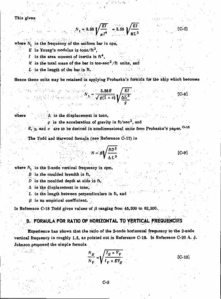
-
This gives
= 3.58El ifErl
II /4 mL3
where N is the frequency of the uniform bar in cps,is Young's modulus in tons/ft2,
I is the area moment of inertia in ft4,M is the total mass of the bar in ton-sec /ft units, and
is the length of the bar.- in ft
Hence these units may be retaineirin applying Prohaska's fornifila for the ship which becomes
Where
The Todd and Marwood formula (see Reference d-17) is. -
A is the displacement in tons,g is the acceleration of gravity in ft/sec2, and
, g, and c are to be derived in nondimensione.1 units from Prohaska's paper. C-16
where N1 is We 2-node vertical frequency in cpm,. -
is the moulded breadth in ft,is the moulded depth at side in ft,:-
[C-7]
[C-8]
A is the displacement in tons,is the length between perpendiculars in ft, and -
p is an empirical coefficient.
In Reference C-18 Todd gives values of /3 ranging from 45,200 to 62,500._
FORMULA FOR RATIO OF HORIZONTAL TO VERTICAL FREQUENCIES
Experience has shown that the ratio of the 2-node horizontal frequency to the 2-nodevertical frequency is roughly 1.5, as pointed out in Reference C-19. In Reference C-20 A. J.
Johnson proposed the simple formula
C-5
N IH x Vy
N y IV x EVH
[C-10]
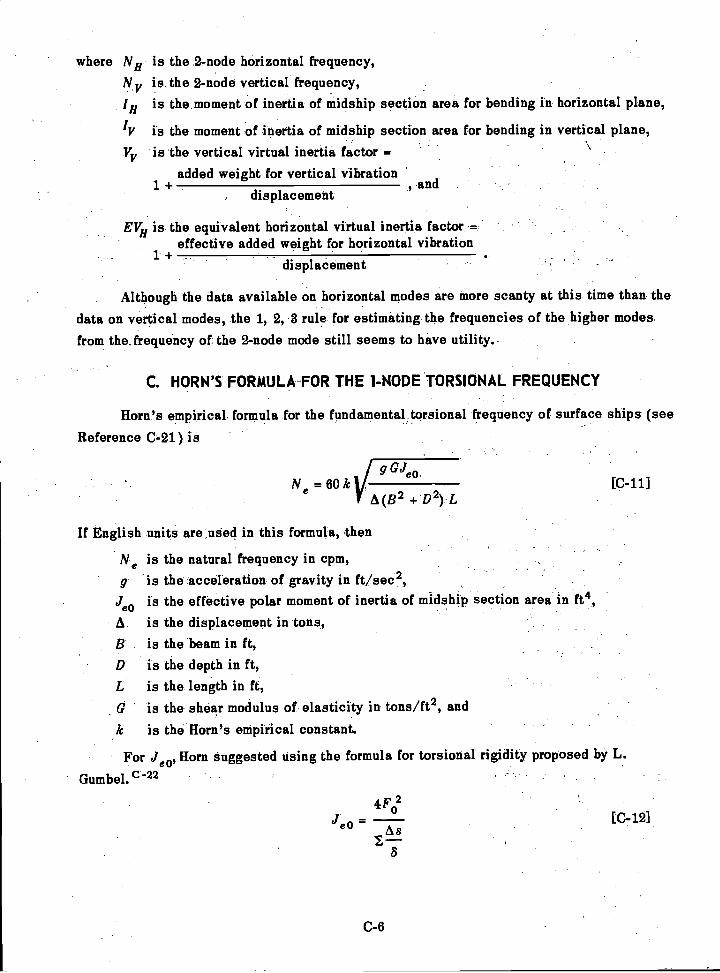
where NH is the 2-node horizontal frequency,N y is the 2-node vertical frequency,IH is the moment of inertia of midship section area for bending in horizontal plane,
IV is the moment of inertia of midship section area for bending in vertical plane,V is the vertical virtual inertia factor =V
added weight for vertical vibration1+. , anddisplacement
EVH is the equivalent horizontal virtual inertia factor =effective added weight for horizontal vibration
1..+displacement
Although the data available on horizontal modes are more scanty at this time than thedata on vertical modes, the 1, 2,8 rule for estimating the frequencies of the higher modesfrom the. frequency of. the 2-node mode still seems to have utility.
C. HORN'S FORMULA-FOR THE 1-NODE TORSIONAL FREQUENCY
Horn's empirical formula for the fundamental torsional frequency, of surface ships see
Reference C-21) is
1 g GJeoN
=6O1 A(B2 + D ) L
If English units are used in this formula, then
N is the natural frequency in cpm,g is the acceleration of gravity in ft/sec2,
Jeo is the effective polar moment of inertia of midship section area in ft4,
A is the displacement in tons,is the beam in ft,is the depth in ft,is the length in ft,is the shear modulus of elasticity in tons/ft2, and
k is the Horn's empirical constant.
For Jeo, Horn suggested using the formula for torsional rigidity proposed by L.
Gumbel. C22
4F02
C-6
[C-11]
[C-12]
where F0 is the area enclosed by the shell plating of the midship section (not the areaof the material),
8 is the plating thickness, andAs is a small distance along the shell plating in the plane of the section.
This formula follows from the shear flow concept and does not take account of the effect ofinner decks and longitudinal bulkheads.
Horn assigned the value of 1.58 to k for a freighter (SS WASGENWALD). As in the
case of the Schlick formula, the best procedure for the designer is to use Equation [C-11] inconjunction with data on the torsional frequency of a ship of the general type he is designing,if such data can be obtained. Moreover, in estimating Jeo he is not restricted to Equation[C-12] but may apply any method of estimating torsional rigidity of hulls; see, for example,Reference C-23.
In estimating the frequencies of higher torsional modes from the fundamental torsionalfrequency, little guidance can be offered at this time. It may be pointed out that Horn c-21
found for the first three torsional frequencies of a freighter the ratios 1 : 1.6 : 1.9, whereas forGOPHER MARINER, if the apparent torsion bending modes are considered as flexure-free
torsional modes, the corresponding ratios were found to be 1 : 1.6 : 2.2.
REFERENCES
McGoldrick, R.T. and Russo, V.L., "Hull Vibration Investigation on SS GOPHER
MARINER," Trans. SNAME, Vol 63 (1955). Also TMB Report 1060 (Jul 1956).
McGoldrick, R.T., "Comparison between Theoretically and Experimentally Deter-mined Natural Frequencies and Modes of Vibration of Ships," TMB Report 906 (Aug 1954).
Schlick, 0., Series of Articles on Ship Vibration in TINA (1884, 1893, 1894, 1901,
and 1911).
McGoldrick, R.T., "A Study of Ship Hull Vibration," EMB Report 395 (Feb 1935).
Todd, F.H., "Ship VibrationA Comparison of Measured and Calculated Frequencies,"NECI Trans (1933).
Tobin, T.C., "A Method of Determining the Natural Periods of Vibration of Ships,"TINA (1922).
Nicholls, H.W., "Vibration of Ships," TINA (1924).
Schmidt, F., "Die Berechnung von Schiffschwingungen," WRH, No. 6 (22 Mar 1930).
Schadlofsky, E., "The Calculation and Measurement of Elastic Natural Frequenciesof Ship Hulls," STG, Vol. 33 (1932). Also EMB Translation 7 (Jun 1934).
C-10. Cole, A.P., "The Natural Periods of Vibrations of Ships," Trans Inst of Engrs andShipb Scotland, Vol. LXXII (1928-29).
C-7
'McGoldrick.; R.T.,; "Vibration Tests on uss.HAMa:41pisr,ItiWa-oi4gton Navy Yard;"2 ,
EMH Report:372 (Dec 1933).. , .
J-12. Hoop, W.P., "Natural Frequencies of Hull Vibraiiiii;"' TranS.' S.N4ME,.(1930).
C=13. BurriII, L.C., "Ship Vibration: 'Simple Methods of Estinfaiing.CiiiiO'aiTioqiiiinciaS,"" ;
, NECI.-Trana;:-VOL 51 (1934=35). ' -.1'. ,. t. ) '-.- : ,- -,,-r'. ,
,
C-14. Taylor, J.L., "Vibration of Ships," TINA (1630)...', ...,; 4,. c, , ..,-, ;.:, ..1'..: -.U.: ..,' -,'. .; I '_:,-..,
,
C,15.. Hardy, V.S., "Vibration .Studies of Ship Hulls by Means of VibraticiaGeneraterS,-' r 41 _.
TM)S-RepOrt C-80 (Nov 1946) Unclassified.. - .
,C46.;:-.Pro_haska, C.W., "The Vertical Vibration of Ships," ShipbUilderiNoL.:54 (Oct, Nov,
'
C-17. Todd, F.H. and Marwood, W.J., "Ship Vibration," NECI Trans, Vol. (64(1948).-
Todd, "Theltindanientals of Ship VibratiOn," Shiftbiiilder,.VOL:Ai.,(May, Jun,Jul 1947).
,;C-19. -,Tachmindji, A.J.,and McGoldrick, R.T., "Note on Propeller-Excited - Hull Vibrations,"
j: , ' - 4
JSR;.:Vol. 3; No, 1 (Jun 1959).
C-20 Johnson, A.J., "Vibration Tests on All-Welded and All-Riveted 10,000 Ton DryCargo Ships,"- NEC! Trans, Vol. 67 (1951).
,
-C-21.- Horn, F., "Horizontal und Torsions--Schiffschwingungen_auf 'Frachtschiffen,"_
WRH, Vol. 6, No. 18 (1925)..
,-
C-22::.Gurubel, L., ',Torsional Vibrations of Elastic Shafts of Any Cross section and`.- '"
ass Distribution and Their Application to the Vibration of Sh45s,'"fINA :Vol ,LIV (1912)
C-23. -Vedeler, G "On the Torsion of Ships," TINA,,y0,17_1.,_.x,-
C-8
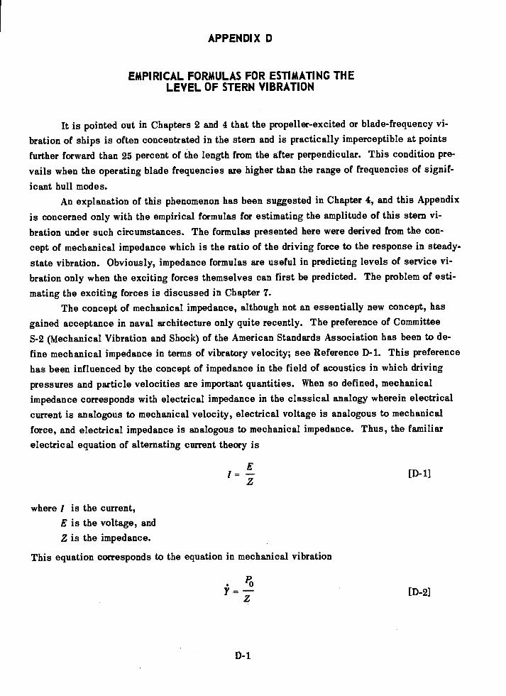
APPENDIX D
EMPIRICAL FORMULAS FOR ESTIMATING THELEVEL OF STERN VIBRATION
It is pointed out in Chapters 2 and 4 that the propeller-excited or blade-frequency vi-
bration of ships is often concentrated in the stern and is practically imperceptible at pointsfurther forward than 25 percent of the length from the after perpendicular. This condition pre-vails when the operating blade frequencies are higher than the range of frequencies of signif-
icant hull modes.An explanation of this phenomenon has been suggested in Chapter 4, and this Appendix
is concerned only with the empirical formulas for estimating the amplitude of this stern vi-bration under such circumstances. The formulas presented here were derived from the con-cept of mechanical impedance which is the ratio of the driving force to the response in steady-state vibration. Obviously, impedance formulas are useful in predicting levels of service vi-bration only when the exciting forces themselves can first be predicted. The problem of esti-mating the exciting forces is discussed in Chapter 7.
The concept of mechanical impedance, although not an essentially new concept, hasgained acceptance in naval architecture only quite recently. The preference of CommitteeS-2 (Mechanical Vibration and Shock) of the American Standards Association has been to de-fine mechanical impedance in terms of vibratory velocity; see Reference D-1. This preferencehas been influenced by the concept of impedance in the field of acoustics in which drivingpressures and particle velocities are important quantities. When so defined, mechanicalimpedance corresponds with electrical impedance in the classical analogy wherein electricalcurrent is analogous to mechanical velocity, electrical voltage is analogous to mechanicalforce, and electrical impedance is analogous to mechanical impedance. Thus, the familiarelectrical equation of alternating current theory is
'=i [D-1]
where I is the current,E is the voltage, andZ is the impedance.
This equation corresponds to the equation in mechanical vibration
D-1
[D-2]
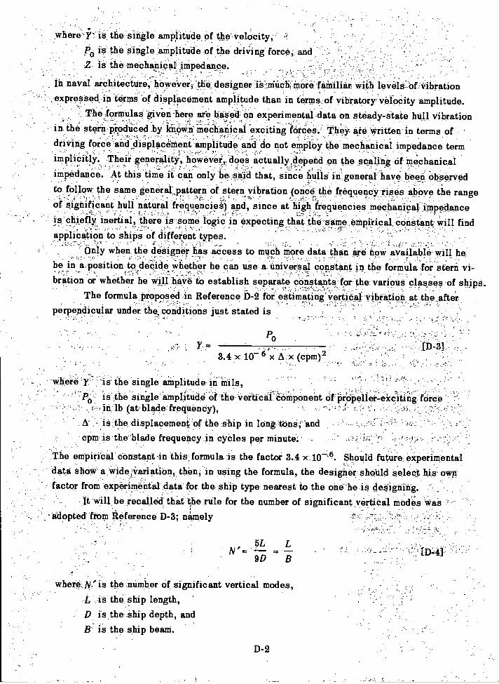
where Yis the single amplitude Of the.velocity,'po is the single anipliiide of the dris-ring force2 is the mechanical iMpedance.
In naval architecture, however; the designer i's-,.inuchniore 'familiar With levels Of -Vibration
expressed. in terms of displacement amplitude than in terms of vibratory velocity amplitude.The .formulaSgiven-here are based, on experimental data on steady-state hull vibration
in the stern produced by lthoWn mechanical exciting forces.' They are written in terms ofdriving force and displacement amplitude and do not employ the mechanical impedance tern'
-
'implicitly. Their generality, however, does actually depend on the scaling of mechanical_
iinpedance. At this time it can only be said that, since hulls' in general have been observedto follow the same general,pattern of stern vibration (once the frequency Imes above the range
,; . 1., -
of significant hull natural frequencies) and, since at high ,frequencies mechanical impedanceis chiefly, inertial, there is some logic in expecting that the seine empirical constant will findapplication to ships of different types.
only when the designer has access to much more data than are now available will hebe in nposition to decide whether he can use a universal constant in the formula for stern vi-bration or whether he Will have to establish separate constants for the various classes of ships.
The formula proposed in Reference D-2 for estimating-yertioal yibeation at the afterperpendicular under the conditions just stated is
Po
*ere Y' is the single amplitude in mils,ii the single' amplitude of the vertical'OOmponent of Propeller-exciting 'forcein lb (at blade;is.the displacement of the ship in long.tone;'and :;-,,'
r . .- ..
cpm is the blade frequency in cyCles per minute:
The empirical constant in this formula is the factor 3.4 x.10'6. Should future experimentaldata show a wideA .variation, then, in using the formula, the designer should select his own
factor from experimental data for the ship type nearest to the one he is designing.It will be recalled that the rule for the number of significant vertical modes Was
- adopted from Reference D-3; namely
5L LN
9D B
where, N,' is the number of significant vertical modes,
I, is the ship length,D is the ship depth, and
B: is the ship beam.D-2
F ;
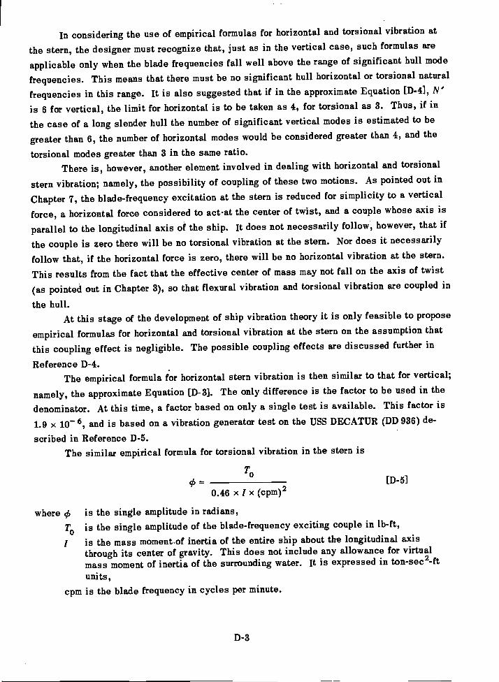
In considering the use of empirical formulas for horizontal and torsional vibration at
the stern, the designer must recognize that, just as in the vertical case, such formulas are
applicable only when the blade frequencies fall well above the range of significant hull mode
frequencies. This means that there must be no significant hull horizontal or torsional natural
frequencies in this range. It is also suggested that if in the approximate Equation [D-4], N'
is 6 for vertical, the limit for horizontal is to be taken as 4, for torsional as 3. Thus, if in
the case of a long slender hull the number of significant vertical modes is estimated to be
greater than 6, the number of horizontal modes would be considered greater than 4, and the
torsional modes greater than 3 in the same ratio.There is, however, another element involved in dealing with horizontal and torsional
stern vibration; namely, the possibility of coupling of these two motions. As pointed out in
Chapter 7, the blade-frequency excitation at the stern is reduced for simplicity to a vertical
force, a horizontal force considered to act-at the center of twist, and a couple whose axis is
parallel to the longitudinal axis of the ship. It does not necessarily follow, however, that if
the couple is zero there will be no torsional vibration at the stern. Nor does it necessarily
follow that, if the horizontal force is zero, there will be no horizontal vibration at the stern.
This results from the fact that the effective center of mass may not fall on the axis of twist
(as pointed out in Chapter 3), so that flexural vibration and torsional vibration are coupled in
the hull.At this stage of the development of ship vibration theory it is only feasible to propose
empirical formulas for horizontal and torsional vibration at the stern on the assumption that
this coupling effect is negligible. The possible coupling effects are discussed further in
Reference D-4.The empirical formula for horizontal stern vibration is then similar to that for vertical;
namely, the approximate Equation [D-3]. The only difference is the factor to be used in the
denominator. At this time, a factor based on only a single test is available. This factor is
1.9 x 10⁻⁶, and is based on a vibration generator test on the USS DECATUR (DD 936) de-
scribed in Reference D-5.The similar empirical formula for torsional vibration in the stern is
To[D-5]
0.46 x I x (cpm)2
where çS is the single amplitude in radians,
T0is the single amplitude of the blade-frequency exciting couple in lb-ft,
I is the mass moment.of inertia of the entire ship about the longitudinal axisthrough its center of gravity. This does not include any allowance for virtualmass moment of inertia of the surrounding water. It is expressed in ton-see2-ftunits,
cpm is the blade frequency in cycles per minute.
D-3
Here again the factor 0.49 is based on a single test made on DECATUR, described in Ref-erence D-5. The designer should inquire for later information if available in the future.
A final word of caution in the use of the formulas given in this Appendix is necessary.If any local stern structure or appendage has a natural frequency in the range of the drivingblade frequencies to be specified by the designer then, even though the conditions for freedomfrom hull natural frequencies are met, the empirical formulas cannot forecast the stern ampli-tude under a given excitation, and the designer must either resort to the more detailed analysesdiscussed in Reference D-4 or assure himself that the exciting forces will be within safe limits.
REFERENCES
American Standards Association, "Proposed American Standard Nomenclature andSymbols for Mechanical Impedance of Structures," (pending).
McGoldrick, R.T. and Russo, V.L., "Hull Vibration Investigation on SS GOPHERMARINER," Trans. SNAME, Vol. 63 (1955). Also TMB Report 1060 (Jul 1956).
Baier, L.A. and Ormondroyd, J., "Vibration at the Stern of Single-Screw Vessels,"Trans. SNAME, Vol. 60 (1952).
Leibowitz,'R.C. and Kennard, E.H., "Theory of Freely Vibrating Nonuniform BeamsIncluding Methods of Solution and Application to Ships," TMB Report 1317 (May 1961).
0-5. ilaladino, A.R., "Vibration Survey on USS DECATUR (DD 936)," TMB Report 1271(Mar 1960).
D-4
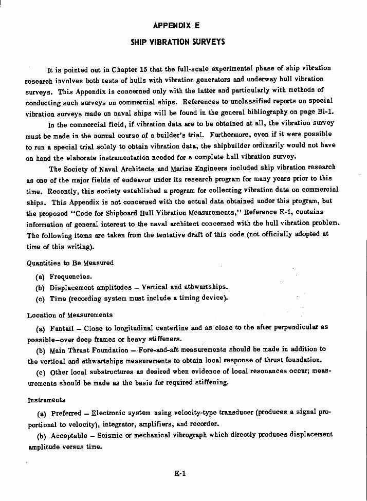
APPENDIX E
SHIP VIBRATION SURVEYS
It is pointed out in Chapter 15 that the full-scale experimental phase of ship vibration
research involves both tests of hulls with vibration generators and underway hull vibration
surveys. This Appendix is concerned only with the latter and particularly with methods of
conducting such surveys on commercial ships. References to unclassified reports on special
vibration surveys made on naval ships will be found in the general bibliography on page Bi-1.
In the commercial field, if vibration data are to be obtained at all, the vibration survey
must be made in the normal course of a builder's trial. Furthermore, even if it were possible
to run a special trial solely to obtain vibration data, the shipbuilder ordinarily would not have
on hand the elaborate instrumentation needed for a complete hull vibration survey.
The Society of Naval Architects and Marine Engineers included ship vibration research
as one of the major fields of endeavor under its research program for many years prior to this
time. Recently, this society established a program for collecting vibration data on commercial
ships. This Appendix is not concerned with the actual data obtained under this program, but
the proposed "Code for Shipboard Hull Vibration Measurements," Reference E-1, contains
information of general interest to the naval architect concerned with the hull vibration problem.
The following items are taken from the tentative draft of this code (not officially adopted at
time of this writing).
Quantities to Be Measured
Frequencies.Displacement amplitudes Vertical and athwartships.Time (recording system must include a timing device).
Location of Measurements
Fantail Close to longitudinal centerline and as close to the after perpendicular as
possibleover deep frames or heavy stiffeners.Main Thrust Foundation Fore-and-aft measurements should be made in addition to
the vertical and athwartships measurements to obtain local response of thrust foundation.Other local substructures as desired when evidence of local resonances occur; meas-
urements should be made as the basis for required stiffening.
Instruments
Preferred Electronic system using velocity-type transducer (produces a signal pro-
portional to velocity), integrator, amplifiers, and recorder.
Acceptable Seismic or mechanical vibrograph which directly produces displacement
amplitude versus time.
E-1
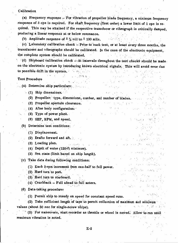
Calibration
Frequency response 7 For vibration of propeller blade frequency, a minimum frequency;response of 3 cps is required. For shaft frequency (first order) a lower limit of 1 cps is re-quired. this may be attained if the respective transducer or vibrograph is critically damped,producing a linear respoziab at Or below resonance.
Amplitude response of -± %-millo-± 100 mils.
'Laboratory calibration chebk prior ta' each teSt, or At least every three months, thetransducers and vibrOgraphs Should be calibrated. In the case of the elect-ronic equipment,the complete system should be calihrated.
'(d) Shipboard Calibration check -,At intervals throughout the test check should be madeon the electfOnic system by introducing -kiiONitn.electrictil signals.. This will avoid error dueto possible drift in the system.
Test Procedure
(a) Determine ship particulars:.-
Ship dimensions:
Propeller:" -type, dimensions, number, and number of'blades.Propeller aperture clearance.After body bonfigurationrType of-poWer plant.
SHP, RPM, and speed.
(b) Determine test conditions:
Displacement.
Drafts forward and aft.Loading plan.Depth of water (120-ft minimum).
Sea state (limit based on ship length).
(c) Take data during f011owing conditions:
Each 5-rpm increment from one-half to full power.Hard turn to port.Hard turn to starboard'.
-
Crashbaek Full ahead to full astern.
(d) Data-taking procedure:
Permit ship to steady on speed for constant speed runs.Take sufficient length of tape to permit collection of maximum and mit-1111AM
values (about 30 sec for single-screw ships).' (3) For maneuvers, start recorder as throttle or wheel is moved: Allow to run until
maximum vibration is noted.
E-2
E-3
Data Analysis and Reporting
(a) The following data are to be evaluated for all runs:
Maximum overall values of amplitude.
Maximum first-order amplitude.Maximum amplitude of blade frequency.
Maximum amplitude of blade-frequency harmonics.
(b) Data presentation should include the following curves plotted on a basis of shaft rpm:
Vertical hull vibration.Athwartship hull vibration.Vertical vibration at main thrust bearing.Athwartship vibration at main thrust bearing.Fore-and-aft vibration at main thrust bearing.Other curves as appropriate.
(c) Method of presentation of data:
All curves should show single amplitude of displacement in mils plotted
against rpm.Maximum amplitudes obtained during maneuvering runs should be presented in
tabular form giving frequencies and amplitudes.
It will be noted that this draft of the Code makes no provision for measuring torsional
vibration of the hull. The reason for this is that trouble with hull torsional vibration is sounusual that if a case develops a special investigation will probably be authorized.
REFERENCE
E-1. Noonan, Knopfle, and Feldman, a proposal for "A Code for Shipboard Hull Vibration
Measurements," in preparation for SNAME.

APPENDIX F
LEVELS OF SERVICE VIBRATION
Even if hull vibration analysis were developed to the stage at which the designer couldaccurately predict the level of service vibration for a ship of given design, he would still befaced with the question of whether the level of vibration thus predicted was acceptable. Thisbrings up the vital problem of vibration norms and the definition of such terms as "normal,""tolerable," "permissible," "acceptable," "severe," "intolerable," or "unacceptable,"as applied to ship vibration.
Although at the present time it is safe to state that the naval architect is well awareof the need for standards of comparison in this field, no definite standards have as yet beenestablished in the United States. As a matter of fact, there is a natural reluctance on thepart of both the shipbuilder and the ship operator to collaborate in any program for estab-lishing such standards because of adverse effect that publicity regarding the vibration levelson a particular ship might have on its earning capacity. Furthermore, in the case of navalships, there is the added hazard of revealing classified information in presenting data on thelevels of service vibration.
Accordingly, it seems feasible to include in this Appendix only certain data which havebeen accumulated in the course of the ship vibration research carried on by the David TaylorModel Basin, and which have already been disclosed elsewhere in unclassified reports orpapers. Such information will serve to familiarize the reader with some of the levels of hullvibration encountered in practice. Much additional information on this phase of the subjectwill be found in the references listed in the general bibliography, and certainly much morewill be available in the future.
The following quotation is taken from Reference F-1:
"While it would be of great assistance to the naval architect if tolerances of vibrationamplitudes could be established over the entire range of frequencies encountered on shipsbelow which the vibration could be assumed acceptable, it appears premature to proposesuch standards at present. Criteria based on vibration velocity, acceleration, and the rateof change of acceleration have all been proposed and these have been based on physiologicaleffects as well as on engineering considerations. As a very rough indication oft present con-
,ditions, it may be stated that single amplitudes of 50 mils at 100 cpm may be consideredhigh as may also single amplitudes of 2 mils at 2000 cpm."
One of the chief points to keep in mind in connection with levels of service vibrationof ships is the enormous difference between the levels of steady-state vibration due to pro-
pellers or machinery, and the levels of transient vibration due to slamming in a seaway.This point is brought out in the following quotation from Reference F-2 which deals withshock and vibration instrumentation for ships.
F-1
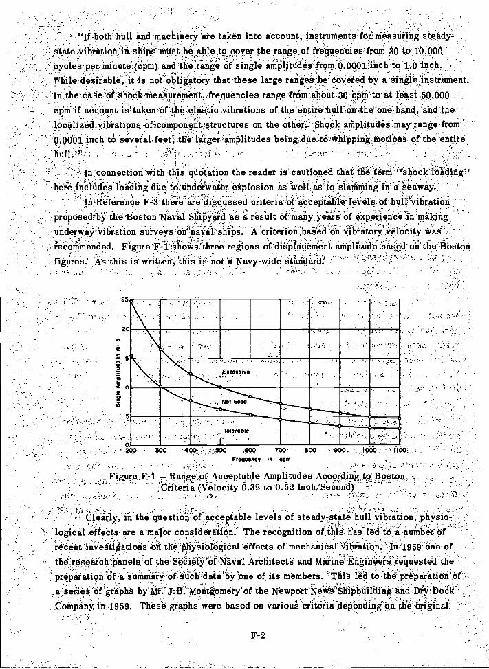
"If both lull and machinery are taken into account, instruments for measuring steady-state Vibration in ships must be able to cover the range of frequencies from 30 to 10,000cycles per minute (Cpm) and therange of single amplitudes from 0.0001 inch to 1-.0 inch.
- While' desirable it is no63bligatOry that these large ranges be COvered by a single instrument,
In the case of shock measurement, frequencies range from about 30 cpm to at least 50,000,
ccini if account i& taken the elastic vibrations of the 'entire hull,on.the one hand, and the, -
localized vibrations of component structures on the other amplitudes may range from
' 0.0001 inch to several feet;;;.thw larger c.amplitudes being;dne,:t.:Oilkhipping-motions of the entire
hull." . r_. '-
In;connection with this quotation the reader is cautioned that-the,.terni "shock loading"here.iriClndes loading due ; explosion as 'Weil' 'aS'io(SiaMiiiing in a SedWay.
inzReferefice Fz.3 tliere'ale`disenssed criteria of 'acceptable leVelk of hulf-VibratiOn
:proposed by the Boston Naval Shipyard as r;tt result of many years of experience in Makingunderway vibration suiveys'On-riaVaL,Ships. A criterion based On vibratory velocity was
ieCoMmended. Figure F-r,ehowsAhree regions of displacement amplitude based on'tne3Boston
figures.' As this is written, this is not a Navy wide staiclard:;
.25
.r:;?...."--'s7
20
5
-
L,
.500 ,099. 700 800 900,Frequency In cpm
4., r.",..
Figure F-1 Range Of Acceptable Amplitudes According to Boston,Criteria (Velocity 0.32 to 0.52 Inch/SeCOiiii).
;
-
Clearly, in the question of"acceptable levels of steady-,state hall vibration, phYsio-,'logical effects are a major consideritiOn:' The recognition of this has led to a number of
,
recent investigations on the physiological effects of mechanical Vibration. In1959'one ofthe'researcif;panels Of the-SO-Ciefy-OfraVal Architects and Marine Engineers requested thepreparation ofsummary of uch:ilatE0bY one of its membera. 'This-lei:1'th the preparatiOn'of
,a,serieS of graphs bk,Mt.:J:B'.,Montgomery of the Newport News Shipbuilding and Dry DockCompany in 1959. These graphs Were based on varioui criteria depending on the original-'_
F-2
0 1
15
< 10,
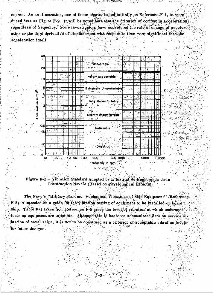
Source. As an illustration,,one of these,chart§:i-j*secWiii.o.any.pkiRefereilio,T.-4.,is
repro-.
,dUced.here .as Figure F-2.. be noted here that the criterion Conifort'ipacCeleration'.,.. . ,
regardless of frequency. ome investigators have considered the rate of change of acceler-ation or the third derivative of displacemeit with respeCt:istrtime more significant '.than theacceleration itself.
40
10
6
0.6
_
Haidiy Supportable
ExtrOmely UncomfOitable
_
Slightly Uncoinfortabli.
Noticeable
f0.1
10 2'6: 40.1. 60: :100 200 600 locoFrequenCy, in cpm
Figure F-2 Vibration Stand'ard Adopted by L'Iestitaf.de ReCkerclkes de laConstruction Navale (3a10d on Physiological tffece§)-,y;
Wri-Undbinfortciple...._
The Navy's '-'Military StandardMechanical VibtatiOns,of11,4Equipment" (Reference. -
F-5) is intended as 'a guide for the Vibration testing of equipment to be installed on boardship. -Table P-1 taken from Reference F:-5 gives the level of vibration at which endut:anCe' .
tests on equipment are to be run. Although this is based on accumulated data on aervice'vi-.-
bration-of naval ships, it is not to be construed as a criterion of acceptable vibration levels.
for future designs. ,
_ 4060-'I 01,000'
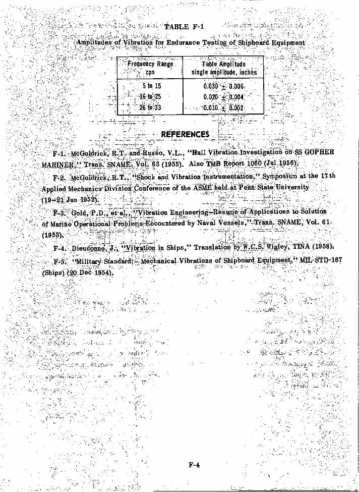
,
F-4
tABLE F-1'
Amplitudes of vibrationi for Endurance Testing of Shipboard Equipment-
REOERENCES- .
F-1.- McGoldrick; R...77-anci-Ru.Sso, V.L., "Hull Vibration'Inyestikition,on.SS GOPHER
MARINER,,!! ti (195'5): Also7iMB Report i:66-6 ,(Jul 1956).:-
(19-21., Jun.1952). _
Applied MechanicsrDivision-Conference Of the Asmg-held4if Penn State UniversityF-9. McGoldrick;.R.T., "Shock and Vibration Instr_u;::.n:a,t_i, on," Symposium at the 17th
Ar'..0 r'rr--rr rrrrr -C2 -
F-3 -'7'dold D' "Vibration EngineeringResume'-oC-Applications to Solution
Of Matine'Operationalr'PrObletriecountered.by Naval Vessels,'-Trans.;SNAMi, Vol. 61
(1953). ' ',7.--' -,t. ,
,,
,
-- - -I
-.1,--(.--;: -.,;-, -_-A4_ 2,..L____.; t -.-12--''- :-Dieudiinne l'.'- "Vibration in Ships," Translation bYTIV.t.S.11Vigley TINA (19581:
.: "Military Standard .L'IMeChanical -Vibrations of Shipboard Equipment," MIL-STD-1671 1..(Ships) (20.Oed 1954). %
. -,,i'''
Frequency Range ,
cpsTable Amplitude
single amplitude, inches
to, 15 tr.O*:+: 0.606,
46-td-25 0.02047.0.904. -
,26:013
.. , '0.010--+ 6,662._ , ,.
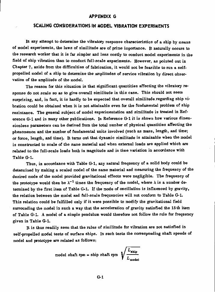
APPENDIX G
SCALING CONSIDERATIONS IN MODEL VIBRATION EXPERIMENTS
In any attempt to determine the vibratory response characteristics of a ship by meansof model experiments, the laws of similitude are of prime importance. It naturally occurs tothe research worker that it is far simpler and less costly to conduct model experiments in thefield of ship vibration than to conduct full-scale experiments. However, as pointed out inChapter 7, aside from the difficulties of fabrication, it would not be feasible to run a self-propelled model of a ship to determine the amplitudes of service vibration by direct obser-vation of the amplitude of the model.
The reason for this situation is that significant quantities affecting the vibratory re-sponse do not scale so as to give overall similitude in this case. This should not seem
surprising, and, in fact, it is hardly to be expected that overall similitude, regarding ship vi-bration could be obtained when it is not attainable even for the fundamental problem of shipresistance. The general subject of model experimentation and similitude is treated in Ref-erence G-1 and in many other publications. In Reference G-1 it is shown how various dimen-
sionless parameters can be derived from the total number of physical quantities affecting thephenomenon and the number of fundamental units involved (such as mass, length, and time;
or force, length, and time). It turns out that dynamic similitude is attainable when the modelis constructed to scale of the same material and when external loads are applied which arerelated to the full-scale loads both in magnitude and in time variation in accordance with
Table G-1.Thus, in accordance with Table G-1, any natural frequency of a solid body could be
determined by making a scaled model of the same material and measuring the frequency of thedesired mode of the model provided gravitational effects were negligible. The frequency ofthe prototype would then be A.-1 times the frequency of the model, where A is a number de-termined by the first item of Table G-1. If the mode of oscillation is influenced by gravity,the relation between the model and full-scale frequencies will not conform to Table G-1.This relation could be fulfilled only if it were possible to modify the gravitational fieldsurrounding the model in such a way that the acceleration of gravity satisfied the 15th itemof Table G-1. A model of a simple pendulum would therefore not follow the rule for frequencygiven in Table 0-1.
It is thus readily seen that the rules of similitude for vibration are not satisfied inself-propelled model tests of surface ships. In such tests the corresponding shaft speeds ofmodel and prototype are related as follows:
model shaft rpm = ship shaft rpmL8hip
L model
G-1
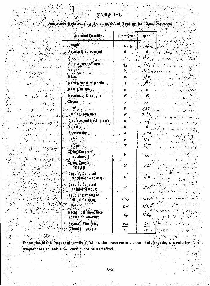
TABLE .G71.
Since the blade frequencies-woUldjall in the same ratio as the shaft, speeds, the rule forfrequencies in Table G-1-would-not be satisfied.
-RelatiOns in.Dynamic MOdel Testing for Equal Stresses
G-2
, . . ..Measured Quantity . Prototype --
, ..Model_
.Lefilthr".
Angular Displacement
,' ' Area ..: . ,
Area,MomentOfnertiaI:.-- .:M- . .-vnzi--. 1 ' - 4. L .., .: ..
Volume "..;....,-2.1..,,-..r,- .....,
Mass
matimoment_of, Inertia
. Matspensity;
Modulus_ of Elasticity
. Strits - ..,
;Tifitel. ,,.'.:-.`' ' ' -
Natural Frequency
'Displacement; (rectilinear),: -'-_,,----__-:',,-;,--: -
-VeIocity
Acceleration ,
Force
_Torque:::
Spring Constant(rectilinear)
.
'S'PhOg 'C'enttant- '.(angular) '' '
- -1Damping 1C6ristant(rectilinear viscous) ,:
Damping Constant(angular viscous)
Raticref,Damping.to .Critidat'Damptog
.,,,.power ;:-?..,,..
.--;-,-)`''.'14CliPti it ai inifielante
(based on velocity). ......,
! 'Reducetl.Fieriuency, (SArtkeii:31.41#11.40
L.-H.. ,
0
A,
/ ''..a - - 1
V.,.
m
jP
E
at
. N.,
d
v
a
T
ic'
..
c,
c/cc
KW
Zv
bco
;.- f AL
, 0- .. 2
4A-'a
' . A3.17 -'...L. .. , -:
_
, :.., i f"
..
At
A .NAd
,. -
v,--
A2F
A3 r1..
Ak....,
A 3k ' .
.i ,os,-!
,
c - '
2' ' "-A KW-
A.24
bco-
- V :
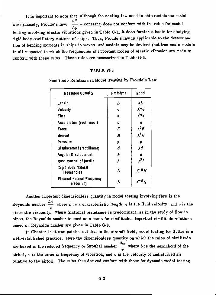
It is important to note that, although the scaling law used in ship resistance model-v2
work (namely, Froude's law: = constant) does not conform with the rules for modelLg
testing involving elastic vibrations given in Table G-1, it does furnish a basis for studyingrigid body oscillatory motions of ships. Thus, Froude's law is applicable to the determina-tion of bending moments in ships in waves, and models may be devised (not true scale modelsin all respects) in which the frequencies of important modes of elastic vibration are made toconform with these rules. These rules are summarized in Table G-2.
TABLE G-2
Similitude Relations in Model Testing by Froude's Law
Another important dimensionless quantity in model testing involving flow is the
Reynolds number where L is a characteristic length, v is the fluid velocity, and v is the
kinematic viscosity. Where frictional resistance is predominant, as in the study of flow inpipes, the Reynolds number is used as a basis for similitude. Important similitude relationsbased on Reynolds number are given in Table G-3.
In Chapter 14 it was pointed out that in the aircraft field, model testing for flutter is awell-established practice. Here the dimensionless quantity on which the rules of similitude
are based is the reduced frequency or Strouhal number where b is the semichord of the
airfoil, co is the circular frequency of vibration, and v is the velocity of undisturbed airrelative to the airfoil. The rules thus derived conform with those for dynamic model testing
G-3
Measured Quantity prototype model
Length
Velocity
Time
Acceleration (rectilinear)
Force
Moment
Pressure
Displacement (rectilinear)
Angular Displacement
Mass moment of Inertia
Rigid Body NaturalFrequencies
Flexural Natural Frequency(required)
L
v
taFM
P
d
0
I
N
N
AL
A1/2v
A1/2t
aAFA4M
P
Ad
0
A51
r1/2N
r1/2N
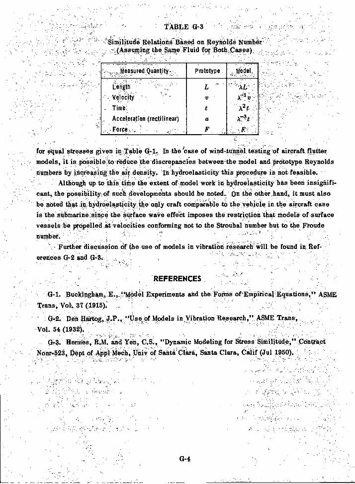
for equal stresses given in Table In the 'case of wind-tunnel testing of aircraft fluttermodels, it is poisiblelo reduce the-discrepancies between-the model and ,Prcitotype Reynoldsnumbers by increasing the air density 'In hydroelasticity this procedure is not feasible.
Although up to thiS`tinie the extent of model work in hydrobieStibity has been ,insignifi-cant, the possibility l Of such developments should be noted. On the other,hand, it must alsobe noted tliat.in,shYtithelastiCity_te only craft comparable to the vehicle in the aircraft Case
,
is the submarine since the 'Surface wave effect imposes the restriction that models of surfacevessels be propelled at velocities conforming not to the Strouhal number but to the Froudenumber.
,
- Further discussion of theuse of models in vibration research will be found in Ref-,
erences G-2 and G-3.
TABLE G-3 -
Similitude Relations Based on Reynolds Numberthe_Same.Fluid for Both,Cases)
G-4
, Measured. Quantity , ...
_
Prototype-
godel,
:.
.- ...
Length
Velocity
Time.
Acceleration (rectilinear)
Force..," -
L
v
aF
- '--4 -X. v =_ .
X2t .:
-3A -t- F:
REFERENCES
Buckingharu,, "Model Experiments and the Forms otEmpiriba-EquationS," ASME
Trans, Vol. 37 (1915)::
Den Bairtog,,J. ., "Use of Models in Vibration Research," ASME Trans,
-Vol. 54 (1932).
Hennes, R.M. and Yen, C.S., "Dynamic Modeling for Stress Similitude," ContractNonr-523 Dept of Appl Mech, Univ of Santa Clara, Santa Clara, Calif (Jul 1950).
-
APPENDIX H
MISCELLANEOUS INFORMATION ON VIBRATION OF SHIPS IN SERVICE
Certain unclassified data with regard to vibration of ships in service are presented inthis Appendix without comment. A designer will often find such miscellaneous information
helpful in his efforts to guard against the occurrence of hull vibration in a ship of new design.
There is no attempt here to present a complete compendium of the information available at the
time of this writing.Table 11-1 presents observed values of natural frequencies of hulls reported in tech-
nical literature. Table 13-2 gives the frequencies of vertical flexural modes of hulls as deter-
mined in vibration generator tests conducted by the David Taylor Model Basin. Table 11-3
gives the frequencies Of the horizontal flexural modes (considered as torsion-free) for the
ships listed in Table 11-2.Among the eight ships tested with a vibration generator (Tables 11-2 and H-3), there
were a few for which a 1-node torsional mode was either identified or appeared likely. The
frequencies for these cases are given in Table 11-4.During and immediately after World 'VVar II the U.S. Navy conducted extensive investi-
gations of shock effects on naval ships. In connection with these investigations, data on the
natural frequencies of various local structures were obtained and summarized in an unclassi-fied report; see Tables H-5 and II-6 taken from Reference 11-15. Of special interest to thedesigner are the data on the natural frequencies of panels of side plating, deck plating, andtransverse bulkheads which are reproduced here from that reference.
In connection with an investigation of environmental conditions at the location of radarequipment on naval ships, the David Taylor Model Basin obtained information in 1959 as tothe relative magnitudes of various types of ship vibration in calm and rough seas; see Table11-7 taken from Reference 11-16. While these data are based on statistical analysis and werean innovation at the time they were presented, they may serve to give the designer some idea
of the augmentation of vibration levels which accompanies a change in the sea state.The normal flexural modes of the free-free Euler-Bernoulli uniform beam are often used
as assumed modes in starting calculations of natural frequencies and normal modes of hulls
by the Stodola process. Values that may be used in plotting the first three modes are givenin Table 11-8.
A sample test schedule for a vibration-generator survey on a commercial cargo ship isgiven in Table 11-9. The ship is GOPHER MARINER, which has been used as an example inmany places in this book. The survey is discussed in detail in Reference H-17, and it should
be noted that this included propeller-exciting force determination as well as hull-vibratory
response characteristics.
H-1
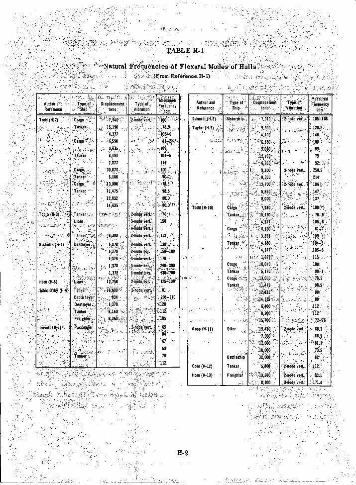
TABLE H-1
Naturdl-Ftequendie.e 1:-.)f :Flexural; Mocik-cif }liars-e.
11-2
. - .
Author and
Reference.
,-; .- "?"" Typi;of,,...
..,..' ''''ShrP !'....
o t-1,_,'";''' .7- ,...
Displacement:;':" " tOns:. . 'i
. ,...'' " ; '-- T.5'0...°i:, Vibration
..- .. o...o"Measuredi
Freirriricy
Todd (lii2) Cargo":.. ,
-- .7,940 r.,2-.nole,yert. (4.,,.
.:-.- 'linker,. .
..'-..,.. ';::-.,,,, ,,.`Cargo,,>,...,
F. 15,190
' 4,377. .
6;590
. -',-,S7.!3-'9: '.. ....:105167' ---111-2"
;--.. ....:
'; 3,835, . .. . - .109
-
Tanker ,.
. ... '
Y4,180
- 1,877
104,5
115'
crirgO(...,.. ;
.."Tanker '
- 10,070,. ,
5,180 .
k ,, .,.. 100
I0=1-'.' ,fi.,; . i
;Cargo:, . ....N.
Tinker :-.. 13,000 ;
' 11,475..
, .- - -,
1
--48.5
90.5
. - 12,832 " 80-.9
.. ' '.`... '.. ,._: ." --.....-. . 14,635' ' .' " . 80.0'F. 411.... . ....
Tobin (1173,:_,,,f; :.Tanker ,1/4 .5; ' ; ii.-1;..,-. . .2-nOrliirLy: ' t qs't-: , . Liner.' .... 3-node :Vert.: 150 !
-..-.:".'....- :... ;:ii,"E:',.,' ,-;r.+ `767-.:$:''!,-4-imie-v-ert.f;
' ..., ; 1 -' -;: :konker-;:5:., ,r_.:-; _18,300 ,'.2-node verf. --, :112,
-Nicholls (ii-4)--! 'Distriyer. 1.37,8:. ,2-tide.veri.,.' ..-'120r:
'
..:_,
.
1378. '- -2-nodelior.. '
3-nOdi...ierLi..; .
'.:__150.180
. 170 -,
1;378... .,3-nicle.lior . 260,390
1,378 : H.lit'O4OtoTs7. .=63ef706'
Horn (H-5) Line) 1Z750. 2-nodehor.... ',. -125-130
.Schadledski (1+0 faii50,-,..Cable layer
Destroier.',.
::!,...,-I6 600i-,-..-2
'834, , .,,
- 1,3711.
::nfilie::iit.--5,
...r ,, .'..?.'.. ,-':
: al-205.-210
'r'.120
.. , .
lankeic, -;
Freighter.. . . ..
8161:1:' :-.,
. 1 8,361:1!,i-;;,i
1 i.11f,
..105,.. .
. Lovitf(1.1-i) . 0as:it:pier ";2 node vert.4 -
,_ . .,..,
. ,.
: J;.1--,!'",,.1../..<,.,7r84:."....._
;,_=..r, - :. ::,;. -,..,.-' 67 .--:,
, . - .74' -;
Tanker '.,. -.
.,..1:,
59' .
76_
' J-112'
Author and'.. 'Reference
,
..',:,:i1:*;pe Of':
l. ...Ship... :114.1aCerient
tons' . -
..'TYPe of- yibtatiOn.-;,
Maiiiired 7Frequency-',.
Schmidf(117,8). i :?' Meforsiiii:. ""7,010.--; :?-2=iiiiii.seiC ''..-10-5-408i
' '
.,. .
Taylor (1.1-9) _...., .,:t.:,.,,, 9,300,--. _ : 1202,'
::': .......
4,100 . 148 . .,
-6,550 .. ; -.100!',.
.:9,050 , ;89, ,..
' -1,-: . .. :
42;700' 79
'''" 050.'19,3007' 3-oode 'seri - i 250.5
i" ,"..!.;. :; ,.",8,000 " .. '.. .214
''-"::' " ' 11;700 f.'- s- '..:2-inirliitiii;,=] ' 106-h.
'tx
', 68511,_-_, - 147' i: t ".!...,--.. .r.,_ '
8000 .4 . 137
'(H-Todd 10)
;
Cargo '
Tenkei..14-,=
.2-node'vert'.1! .i,940. ' , "100(?)
.".:15;1904: -:: ..- 78-9
..3.,377:-..-...,.,. .. : 105,6
. Cargo .--': : ',.:.6, 96 ::. ',:-..,''....:::.,..'-:814:21-
3,835: '(;.,',..-..,-,::)s,:. '..; - !..--16-9;..":2. ..!_. ,
Tanker -', . , .4,180 104,5; . - -,4;377 . ' " ,105,6
2.:
Cargo 1,
Tanker' .71
-2,,,,1,877-i''..-,,, -115;
"'10070' ":.; ' . 100'
-," '.5;1"80' ,- ... .. '. 9.0L1
CargO"...:::.:":,
Tanker .
.:...'...:7:77. .-2
,,:;0,000 ..." ,....,... LT--_, ''. 7e.5.
.:-. 11,475 . . : ."_. 00.5: .,..(, .,--- .....,,f!--.; '' 12;832.., ' ' "., 80".,.,. . _ _...,
.,...44:6_35:-',. .,' : ...1i.-...' . ., 88'
6400 " --. 112':.8;200 112' '
Roop (H-11) Oiler
15,708 , - ......? 72,76 .
....15,430 , - ''..2:etde iert: 60.3 ....-.
. i,sop. '.. - 88.5
1261:10- ". 81.1-
-,. ,. ''.. (1,-008 - T3.5
Battleship- . 32,008,. 82
'Cole (H-12) Tanker, ."..'.5,800, 2-node veil. . 112- ._ .
Horrf(11-13) ' Freighter
-; -,1,9286 .., - 2-iode yell... 83.1
; -- 8,100,..... . 3-irid.e''OerL,- : 171.4- ',
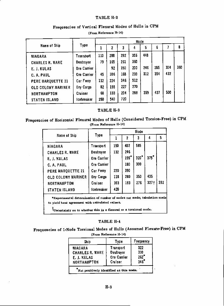
TABLE 11-2
Frequencies of Vertical Flexural Modes of Hulls in CPM(From Reference 11-14)
TABLE H-3
Frequencies of Horizontal Flexural Modes of Hulls (Considered Torsion-Free) in CPM(From Reference 11-14)
TABLE H-4
Frequencies of 1-Node Torsional Modes of Hulls (Assumed Flexure-Free) in CPM(From Reference 11-14)
Name of Ship TypeMode
1 2 3 4 5 6 7 8
NIAGARA Transport 110 200 292 355 448
CHARLES R. WARE Destroyer 79 165 261 360
E. J. KU LAS Ore Carrier 92 150 200 246 285 304 360
C. A. PAUL Ore Carrier 45 106 168 210 312 354 432
PERE MARQUETTE 21 Car Ferry 112 224 346 512
OLD COLONY MARINER Dry Cargo 82 155 227 270
NORTHAMPTON Cruiser 68 133 204 288 359 437 500
STATEN ISLAND Icebreaker 280 540 720
Name of Ship TypeMode
1 2 3 4 5
NIAGARA Transport 190 402 585
CHARLES R. WARE Destroyer 132 246
E. J. KULAS Ore Carrier 195* 320* 375*
C. A. PAUL Ore Carrier 180 300
PERE MARQUETTE 21 Car Ferry 220 390
OLD COLONY MARINER Dry Cargo 118 280 350 435
NORTHAMPTON Cruiser 103 183 276 327t 392
STATEN ISLAND Icebreaker 420
*Experimental determination of number of nodes not made; tabulation madeto yield best agreement with calculated values.
tuncertainty as to whether this is a flexural or a torsional mode.
Ship Type Frequency
NIAGARA Transport 322
CHARLES R. WARE Destroyer 310
E. J. KULAS Ore Carrier 262*
NORTHAMPTON Cruiser 346*
* .
Not positively identified as this mode.
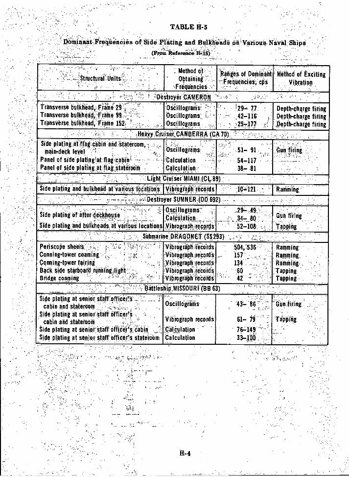
r ,
Dominant 'Fre-iiiieneiera of Siddrtatiug and. Bulkhiadi on Various, Naval Sliipa
(FroM RefereiCii 14=, it)
TABLE H-5
11-4
. ... . .....1
', , ,,'.Structural..Units. :
..
.....
',. Method orObtaining '
Frequencies
tRakie_s of Dominant_,,FreqUenciet:,- cps
, -.
Method of ExcitingVibration
i Destroyer CAMERON
Transverse buikhOad,,Fiiiiire':29 OitillOgradis: ' ' ' 1297 77 Depth-charge firingTransverse bulkhead,'Pritne 99 .,- Oscillograms: ... - ' ,42-116 Depth-charge firingTransverse bulkhead,- Frame 152 . ,,,,
, _Oscillograms . :25-477 ,Depth-charge firing
.,HeaVyCruisit,..CANBERRA (CA 70)
Side plating at flat cabin and stateroom, .: ..,,,
main-deck level " ;--!.
' ';!,.., .,_ -,
'Oacillograms;--_i-1:-.
51- 91
_.
Gun firing
, Panel of side.platineat flag cabin -- - 'Calculation 54-117 - -- --- .
Panel of_aide-platihg at flag statetoom Calculationf..-.. - 387 .81
. Light Cruiser MIAMI (CL 89)
Side -plating and bulkhead at various locations._ Viiirogiapti-retOr-dt I 10121- Radii-ding
eStroYer SUMNER .(DD 692)'I_ r- - - . -
7
Side plating Of after dickhouae ,
Side plating and bulkheads at various locations
'Oscillogiams- ,
iCalculationyibrograp11,-,ricordi
,29- 4934- 80
-52-108
-
Gun firing
Tapping-- _
Submarine,ORAGONET (SS,293)- -
Periscope sheers - '.7,,,:' ! ' .. - : VibrOgriph records '504,':536 Ramming:Conning tower coamirig, ...,..Conning-tower fairing .
Bath Side starboard running lightBridge coming - - e :- -, : :
:Ilibrograp_h :record's. , . .
Vibrogralih records,Vibrographjeto-rdaVibrograph-rettirds-
'
'-' '
157
194 '
60
4i c '
Ramming
Ramming,TappingTapping .
;13afilestriti_MISSOURr(BB 63). .
Side plating at senior staff.officerS _ ._ IP ''''-- '-'._-_2.-: -
cabin and stateroom . .. ,-,
Side plating at senior Staff officer's.._ ,
cabin arid stateroom - - ,;.: -, _ .,
Oscillograms
Vibrograph records
'437 '86
61- 79 -
- ' - Gun firing
itiiiig:Tapping
Side plating at senior staff office'sitabin . ;Calaulation 767149_
Side plating at senior staftoffiter's state-66m, Calculation 33loa.
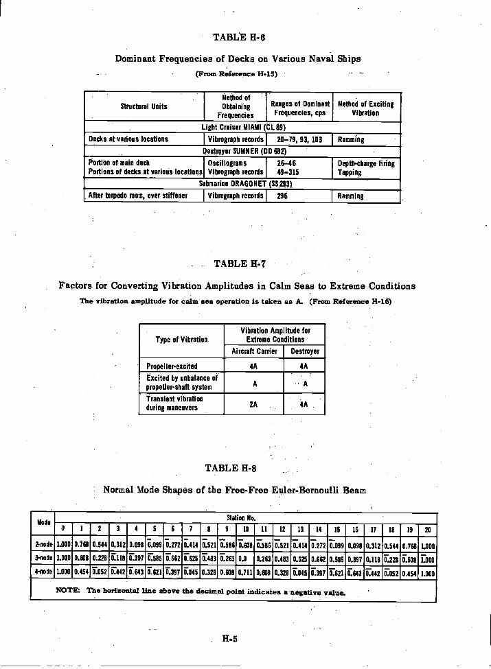
TABLE H-6
Dominant Frequencies of Decks on Various Naval Ships(From Reference H-15)
TABLE H-7
Factors for Converting Vibration Amplitudes in Calm Seas to Extreme ConditionsThe vibration amplitude for calm sea operation is taken as A. (From Reference H-16)
TABLE H-8
Normal Mode Shapes of the Free-Free Euler-Bernoulli Beam
H-5
Structural UnitsMethod ofObtaining
Frequencies
Ranges of DominantFrequencies, cps
Method of ExcitingVibration
Light Cruiser MIAMI (CL 89)
Decks at various locations I Vibrograph records I 20-79, 93, 103 I Ramming
Destroyer SUMNER (DD 692)
Portion of main deckPortions of decks at various locations
OscillogramsVibrograph records
26-4649-315
I Depth-charge firingTapping
Submarine DRAGONET (SS 293)
After torpedo room, over stiffener I Vibrograph records I 296 I Ramming
Type of VibrationVibration Amplitude for
Extreme Conditions
Aircraft Carrier Destroyer
Propeller-excited 4A 4A
Excited by unbalance ofpropeUer-shaft system A . A
Transient vibrationduring maneuvers 2A 4A
ModeStation No.
2 3 4 5 6 7 8 9 10 11 12 13 14 15 16 17 18 19 20
2-node 1.000 0.768 0.544 0.312 0.098 0.099 0.272 0.414 0.521 7.586 1608 1.586 11.521 7.414 0.272 0.099 0.098 0.312 0.544 0.768 1.000
3-node 1.000 0.608 0.228 0:118 0:397 0.585 1662 i:625 F.483 7.263 0.0 0.263 0.483 0.625 0.662 0.585 0.397 0.118 0.228 1.608 1.000
4-node 1.000 0.454 1.052 6:442 (1.643 0.621 0.397 0.045 0.328 0.608 0.711 0.608 0.328 1045 1.397 0.621 0.643 0.442 0.052 0.454 1.000
NOTE: The horizontal line above the decimal point indicates a negative value.,

_
TABLE 11-9
.Schedule of Vibration Testa! on GOPHER MARINER'_ .
Transverse Vibration
1st! Day
2:15
6:00 a.m. ''.Cht-cl(tifiefAibri:.1...If ecjuirimerit.
7:00 a:m. Start thsting iinmediately following:the1.61earariceit the7307fathom
7:15 a.m. 7-:Oper_ate Shiplt 5.knots., . =
Itartrininingliribriticiiigeneratni..?Make frequency surveyto 'deterininelransverse
, .
!natural modes.
10:15 a.m. !Continue freouency survey with increased. eccen-tricity = check important frequencies.
p.m. Finish frequency survey.!Prepare for continuous acceleration.
230 p m !Build Up froM'5 knots tofull power in periodOf W hour.
,
Record transverse vibration.
300 p.m. 7-, ,Fini.sh, continuous acceleration test:. r -
-P, re pare for propeller force measureMents.
;- 1:1553.m.:=.:Operate at .106-rpm. ,
_ _
, rudder ±2 degrees..c"=OecOrd transverse'Vibration.
.330 p.m.! --Operate :al 100 rpm.;!--"'Hold rudder ±-2 degrees.
Record transverse vibtOtion.- -
3:45 p.m. Operate at 95 r1310,-
- ,H,old,rudder±!,2 'degrees.Record transverse vibration.
' 400 p.m: Operate it 90 !rOm.'Hold !rudder ± 2 degrees.Record transverse vibration.
4:15 p.m. .Finish propeller forcesBUildupto95 rpm.PrOPare fot turning tests.
, 4:30 p.rii.!= Execute turning tests at 95 rpm.Record bending,_torsional,,and axial strains on rudder post..
= AcComplish90,_degree change of heading with following -
rudder angles:
- 5-degree left rudder 5-degree right rudder'4--..104egree_left rudder 10-degree right rudder
,-;,,15-degree left 'rudder 15-degree 'fight rudder'tiine between change of heading 3 minutes.
5:30..m-.Finish! turning tests. - _ .
' Build up to -normal power.Prepare for hull calibration test.
II-6

TABLE H-9 (Continued)
Schedule of Vibration Tests on GOPHER MARINER
H-7
.. _Transverse Vibration
2nd Day
6:00 a.m. Calibrate hull for transverse propeller forces.Operate at 106 rpm.Run vibrator at equivalent of 90 and 95 rpm.
8:00 a.m. Operate at 85 rpm.Run vibrator at equivalent of 100 and 106 rpm.
10:00 a.m. Finish hull vibration.Shift generator for producing vertical force.Operate at cruising speed.
Vertical Vibration
2:00 p.m. Operate ship at 5 knots.Start running vibration generator.Make frequency survey to determine verticalnatural modes.
4:00 p.m. Continue frequency survey with increasedeccentricitycheck important frequencies.
7:00 p.m. Finish frequency survey.Prepare for continuous acceleration.
7:15 p.m. Build up from 5 knots to full power in periodof hour. -
Record vertical vibration.
7:45 p.m. Finish acceleration run.Operate at cruising speed.
3rd Day
6:00 a.m. Calibrate hull for vertical propeller forces.Operate at 106 rpm.Run vibrator at equivalent of 90 and 95 rpm.
8:00 a.m. Operate at 85 rpm.Run vibrator at equivalent of 100 and 106 rpm.
10:00 a.m. Finish hull calibration.Shift eccentrics for torque.Prepare for propeller force measurements. .
Record vertical vibration.
10:15 a.m. Operate at 106 rpm.
Hold rudder ± 2 degrees.
10:30 a.m. Operate at 100 rpm.
Hold rudder ± 2 degrees.
10:45 a.m. Operate at 95 rpm.Hold rudder ±2 degrees.
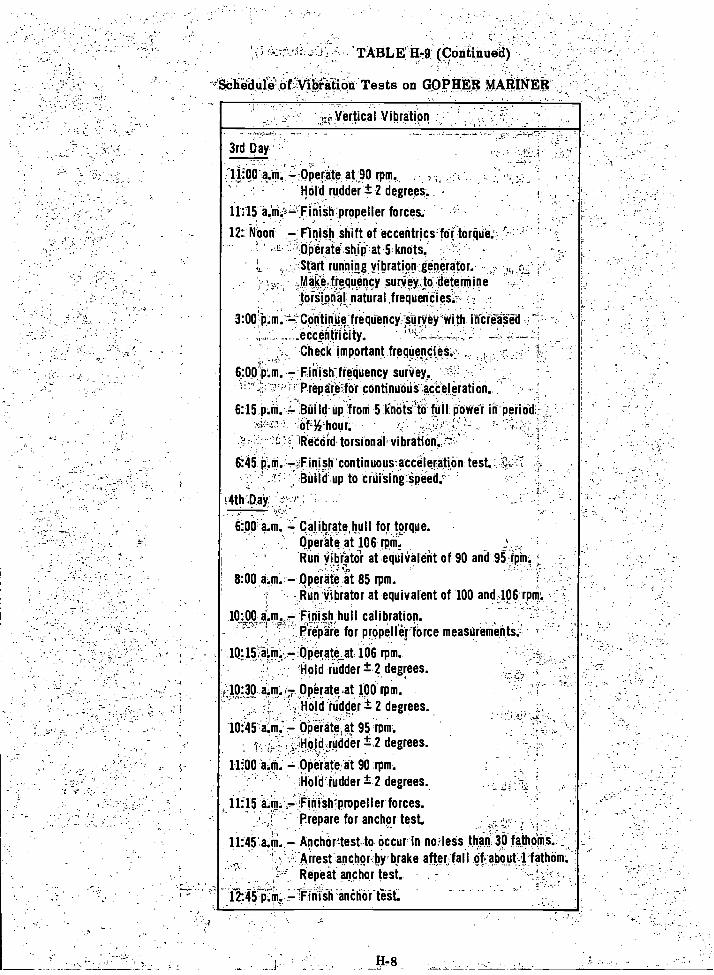
'TABLE14i79 (Continued)
.-,,yertical Vibration
3rd Day
Operate at 90 rpm.
Reid rudder ± 2 degrees.. -
II:15 a.iiii-,=Finieh-propeller forces.
It Noon Finish shift of eccentrics'fOiiorque.Operate ship at ,5 .knrits.Start running vibration generator
,M00,frequency survey to -determinetor-Signal natural frequendies.
300:p.m. Continue frequency Survey With increaseds ,
...Accentricity. - -
. Check important freqUencies.-
,
()pirate, at 95 rpm.
L :Hotd_JOddir ±.2 degrees.
11:00.a.M. Operate...it 90 rpm.
Hold:rudder .degrees..
6:00 p.m. .Finith:friquency survey.;' PrepOreJor cdritinuotita0eleration.
6:15 P.M. := Build up from 5 knots to Nil power in period"
RetOrd-torsion at vibration.
6:45 p.m. Finish continuouszaccilerition. test.-Bilild'.up to ciiiiting,Speed.
.4th-,Day
600 a.m.. -Catilyite,hull for torque.Operate at .106 rpm.'Run Vibrator at equivalent of 90 and 951.ipin.
8:00 a.m. Operate at 85 rpm.Run vibrator at equivalent of 100 and 106 rpre.
10:00 Finish, hull calibration.Prepare for propeller force measurements
Orierateat 106 rpm.Hold (udder ± 2 degrees.
-Jo; 40, a.rif..f-r Operate at 100 rpm.-
Hold Odder ± 2 degrees.
1115 a.M. Finish propeller forces.- prepare for anchor test.
1145 a.1m Anchor test tooccur in no less than 30 fatheMs.Arrest anchor,.brbfake .afterjfal I of about -1 fathom.Repeat anchor test. -
12:45 p:nr. finish anCtieffeit:
itife,tiOir Tests on GOPHER MARINER
_
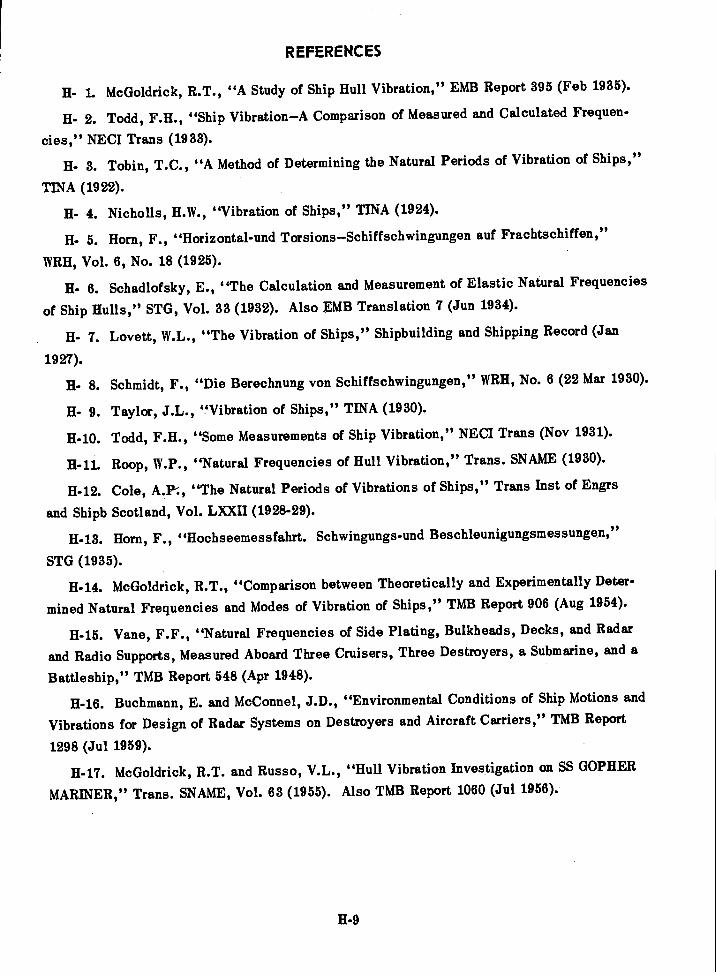
REFERENCES
H- 1. McGoldrick, R.T., "A Study of Ship Hull Vibration," EMB Report 395 (Feb 1935).
II- 2. Todd, F.H., "Ship Vibration-A Comparison of Measured and Calculated Frequen-
cies," NEC! Trans (1933).
Tobin, T.C., "A Method of Determining the Natural Periods of Vibration of Ships,"
TINA (1922).
Nicholls, H.W., "Vibration of Ships," TINA (1924).
Horn, F., "Horizontal-und Torsions-Schiffschwingungen auf Frachtschiffen,"
WRH, Vol. 6, No. 18 (1925).
El- 6. Schadlofsky, E., "The Calculation and Measurement of Elastic Natural Frequencies
of Ship Hulls," STG, Vol. 33 (1932). Also EMB Translation 7 (Jun 1934).
Lovett, W.L., "The Vibration of Ships," Shipbuilding and Shipping Record (Jan
1927).
Schmidt, F., "Die Berechnung von Schiffschwingungen," WRH, No. 6 (22 Mar 1930).
Taylor, J.L., "Vibration of Ships," TINA (1930).
11-10. Todd, F.H., "Some Measurements of Ship Vibration," NEC! Trans (Nov 1931).
H-11. Roop, W.P., "Natural Frequencies of Hull Vibration," Trans. SNAME (1930).
11-12. Cole, A.P-., "The Natural Periods of Vibrations of Ships," Trans Inst of Engrs
and Shipb Scotland, Vol. LXXII (1928-29).
11-13. Horn, F., "Hochseemessfahrt. Schwingungs-und Beschleunigungsmessungen,"
STG (1935).
11-14. McGoldrick, R.T., "Comparison between Theoretically and Experimentally Deter-
mined Natural Frequencies and Modes of Vibration of Ships," TMB Report 906 (Aug 1954).
II-15. Vane, F.F., "Natural Frequencies of Side Plating, Bulkheads, Decks, and Radar
and Radio Supports, Measured Aboard Three Cruisers, Three Destroyers, a Submarine, and a
Battleship," TMB Report 548 (Apr 1948).
11-16. Buchmann, E. and McConnel, J.D., "Environmental Conditions of Ship Motions and
Vibrations for Design of Radar Systems on Destroyers and Aircraft Carriers," TMB Report
1298 (Jul 1959).
II-17. McGoldrick, R.T. and Russo, V.L., "Hull Vibration Investigation on SS GOPHER
MARINER," Trans. SNAME, Vol. 63 (1955). Also TMB Report 1060 (Jul 1956).
H-9
GENERAL BIBLIOGRAPHY
Abramson, H.N. and Chu, W.H., "Problems of Hydroelasticity," JSR, Vol. 3, No. 1 (Jun 1959).
Abramson, H.N. and Chu, W.H., "A Discussion of the Flutter of Submerged Hydrofoils,"JSR, Vol. 3, No. 2 (Oct 1959).
Adams, E.J., "The Steady-State Response of a Ship Hull to a Simple Harmonic Driving
Force Computed by a Digital Process," TMB Report 715 (May 1950).
Allnutt, R.B., "Investigation of Hull Vibrations of USCGC PONTCHARTRAIN (WPG 70),"
TMB Report R-294 (Aug 1946).
Allnutt, R.B. and Mintz, F., "Instruments at the David Taylor Model Basin for MeasuringVibration and Shock on Ship Structures and Machinery," TMB Report 563 (Jul 1948).
American Standards Association, "Proposed American Standard Nomenclature and Symbols
for Mechanical Impedance of Structures," (pending).
Arkenbout Schokker, J.C., et al., "Design of Merchant Ships," N.V. De Technische
Vitgerei, H. Stam-Haarlem-Holland (1953).
Babaev, N.N., "Contemporary Status of Development of the Problem of Ship Vibration(Sovremennoe Sostoianie I Razvitie Voprosa 0 Vibratsii Sudov)," Sudostroenie, No. 3 (161)(Mar 1956), pp. 4-10. TMB Translation 291 (Jul 1959).
Baier, L.A. and Ormondroyd, J., "Vibration at the Stern of Single-Screw Vessels,"
Trans SNAME, Vol. 60 (1952).
Bisplinghoff, R.L., et al., "Aeroelasticity," Addison-Wesley Publishing Co. (1955).
Boyd, J.E., "Strength of Materials," McGraw-Hill Book Co., New York (1924).
Breslin, J.P., "The Pressure Field near a Ship Propeller," JSR, Vol. 1, No. 4 (Mar 1958).
Breslin, J.P., "Ship Vibration. Part I Propeller-Generated Excitations," Appl Mech
Rev, Vol. 13, No. 7 (Jul 1960).
Breslin, J.P. and Tsakonas, S., "Marine Propeller Pressure Field Including Effects ofLoading and Thickness," Trans SNAME, Vol. 67 (1959).
Buchmann, E. and McConnell, J.D., "Environmental Conditions of Ship Motions and Vibra-
tions for Design of Radar Systems on Destroyers and Aircraft Carriers," TMB Report 1298
(Jul 1959).
Buckingham, E., "Model Experiments and the Forms of Empirical Equations," Trans ASML',
Vol. 37 (1915).
Bi-1
Bunyan, T.W., "Practical Approach to Some Vibration and Machinery Problems in Ships,"Paper presented to Inst of Mar Engin and Inst of Nay Arch (Feb 1955).
Burrill, L.C., "Ship Vibration: Simple Methods of Estimating Critical Frequencies,"NEC! Trans, Vol. 51 (1934-35).
Burrill, L.C., "Calculation of Marine Propeller Characteristics," NEC! Trans, Vol. 60(1943-44).
Cole, A.P., "The Natural Periods of Vibrations of Ships," Trans Inst of Engrs and ShipbScotland, Vol. LXXII (1928-29).
Crede, C.E., "Vibration and Shock Isolation," John Wiley & Sons, Inc, New York (1951).
Csupor, D., "Methods for Calculating the Free Vibrations of a Ship's Hull (Methoden zurBerechnung der Freien Schwingungen des SchiffskOrpers)," Jahrb. d. STG, Vol. 50 (1956).TMB Translation 288 (May 1959).
Cuthill, E. and Olsten, E., "A Routine for the Calculation of the Response of a Ship toTransient Forces," TMB Report (in preparation).
Den Hartog, J.P., "Mechanical Vibrations," McGraw-Hill Book Co., New York, FourthEdition (1956).
Den Hartog, J.P., "Use of Models in Vibration Research," ASME Trans, Vol. 54 (1932).
Description of Schelde Synchronizing Gear in Private Communication to SNAME (26 Aug 195'T).
Dieudonn, J., "Vibration in Ships," Translation by W.C.S. Wigley, TINA (1958).
Feldman, S., "Dynamic Balancing for Noise Reduction," Dept of Navy, Bureau of Ships(Code 371), R D Report 371-V-24 (Apr 1955).
Flax, A.M., "Aero-Hydro-Elasticity," Struc Mech, Proceedings of First Symposium on NayStruc Mech, Pergamon Press, New York (1960).
Fothergill, A.E., "Vibrations in Marine Engineering," Trans Inst of Engrs and ShipbScotland, Vol. 95, Part 4 (1951-52).
Francis, J.J. and Antkowiak, E.T., "Marine Vibration Diagnosis," Paper presented atNew England Section Meeting, SNAME (Oct 1960).
Fung, Y.C., "An Introduction to the Theory of Aeroelasticity," John Wiley & Sons, Inc,New York (1955).
Gariboldi, R.J., "Procedure for Torsional Vibration Analysis of Multimass Systems," Deptof Navy, Bureau of Ships (Code 371), R & D Report 371-V-19 (Dec 1953).
Gold, P.D., et al., "Vibration Engineering Resumof Applications to Solution of MarineOperational Problems Engountered by Naval Vessels," Trans SNAME, Vol. 61 (1953).
Gumbel, L., "Torsional Vibrations of Elastic Shafts of Any Cross Section and Mass Dis-tribution and Their Application to the Vibration of Ships," TINA, Vol. LIV (1912).
Bi-2
Hardy, V.S., "Vibration Studies of Ship Hulls by Means of Vibration Generators," TMB
Report C-80 (Nov 1949) Unclassified.
Harrison, M., et al., "Wave Effects in Isolation Mounts," TMB Report 766 (Jan 1952).
Heller, S.R., Jr., and Abramson, H.N., "Hydroelasticity: A New Naval Science," JournalASNE (May 1959).
Henry, C.J., et al., "Aeroelastic Stability of Lifting Surfaces in High-Density Fluids,"JSR (Mar 1959).
Hermes, R.M. and Yen, C.S., "Dynamic Modeling for Stress Similitude," Contract N8onr-523, Dept of Applied Mechanics, Univ of Santa Clara, Santa Clara, Calif. (Jul 1950).
Hirowatari, T., "On the Natural Frequencies of the Vertical Flexural Vibrations of aShip's Hull (Part 3)," J Soc Nay Arch, Japan, Vol. 97 (Aug 1955).
Horn, F., "Hon zOhtal-und Torsi onsSchiffsschwingungen auf Frachtschiffen," WRH,Vol. 6, No. 18 (1925).
Horn, F., "Tilgung Elastischer Schwingungen des SchiffskOrpers," Schiffbau, Vol. 43 (1942).
Horn, F., "Hochseemessfahrt. Schwingungs-und Beschleunigungsrnessungen," STG, Vol.
37 (1936).
Hoyt, E.D., "Simulation of the Sea and Analog Computation of the Forces on a Ship inWaves," Report to TMB on Contract Nobs 72376, T.O. 9, Project RR-1458-N by Reed Re-
search, Inc. (Nov 1959).
Inglis, C.E., "A Suggested Method of Minimizing Vibration in Ships," TINA (1933).
Jacklin, H.M., "Human Reactions to Vibration," SAE Journal, Vol. 39 (1936).
Jaeger, H.E., "The Determination of the Natural Frequency of Ship Vibrations," Journalof BSRA, Vol. 5 (1950).
Jasper, N.H., "Structural Vibration Problems of Ships A Study of the DD 692-Class of
Destroyers," TMB Report C-36 (Feb 1950) Unclassified.
Jasper, N.H., "Statistical Distribution Patterns of Ocean Waves and of Wave-InducedShip Stresses and Motions, with Engineering Applications," Trans SNAME, Vol. 64 (1956).
Also TMB Report 921 (Oct 1957).
Jasper, N.H., "A Design Approach to the Problem of Critical Whirling Speeds of Shaft-
Disk Systems," TMB Report 890 (Dec 1954).
Bi-3
Jasper, N. H. and Birmingham, J.T., "Strains and Motions of USS ESSEX (CVA 9) d'uringStorms near Cape Horn," TMB Report 1216 (Aug 1958).
Jasper, N.H. and Rupp, L.A., "An Experimental and Theoretical Investigation of PropellerShaft Failures," Trans SNAME (1952).
Jewell, D.A., "A Note on Hydroelasticity," JSR, Vol. 3, No. 4 (Mar 1960).
Johnson, A.J., "Vibration Tests on All-Welded and All-Riveted 10,000 Ton Dry CargoShips," NECI Trans, Vol. 67 (1951).
Johnson, A.J. and Ayling, P.W., "Graphical Presentation of Hull Frequency Data and theInfluence of Deck-Houses on Frequency Predictions," NEC! Trans, Vol. 73 (1956-57).
Kapiloff, E., "Calculation of Normal Modes and Natural Frequencies of Ship Hulls byMeans of the Electrical Analog," TMB Report 742 (Jul 1954).
Kaplan, P., "A Study of the Virtual Mils; Associated with the Vertical Vibration of Shipsin Water," SIT, Davidson Lab Report 734 (Dec 1959).
Kane, J.R. and McGoldrick, R.T., "Longitudinal Vibrations of Marine Propulsion-ShaftingSystems," Trans SNAME, Vol. 57 (1949). Also TMB Report 1088 (Nov 1956).
Kennard, E.H., "Forced Vibrations of Beams and the Effect of Sprung Masses," TMBReport 955 (Jul 1955).
Kenny, J.H. and Leibowitz, R.C., "Design Details and Operating Procedure for the TMBNetwork Analyzer," TMB Report 1272 (Apr 1959).
Kjaer, V.A., "Vertical Vibrations in Cargo and Passenger Ships," Acta PolytechnicaScandinavica, A.P. 244/1948; Mech Engin Series 2, Copenhagen (1958).
Koch, J.J. "Eine Experimentelle Methode zur Bestimmung der Reduzierten Masse desMitschwingenden Wassers bei Schiffschwingungen," IngenieurrArchiv, Vol. IV, No. 2 (1933).
Krivtsov, Y.V. and Pernik, A.J., "The Singing of Propellers (Penie Grebnykh Vintov),"Sudostroeniye, No. 10 (Oct 1957). TMB Translation 281 (Oct 1958).
Krylov, A.N., "Vibration of Ships," in Russian (1936).
Kurdiumov, A.A., "Ship Vibration," in Russian (1953).
Kumai, T., "Some Notes on the Local Vibrations of Ships," Reports of Research Inst forApplied Mechanics, Kyushu Univ, Japan, Vol. III, No. 12 (1955).
Kumai, T., "Estimation of Natural Frequencies of Torsional Vibration of Ships," Reportsof Research Inst for Applied Mechanics, Kyushu Univ, Japan, Vol. IV, No. 13 (1955).
Kumai, T., "Shearing Vibration of Ships," Reports of Research Inst for Applied Mechanics,Kyushu Univ, Japan, Vol. IV, No. 15 (1955). In English.
Bi-4
Kumai, T., "Coupled Torsional-Horizontal Bending Vibrations in Ships," European
Shipbldg, Vol. V, No. 4 (1956).
Kumai, T., "Damping Factors in the Higher Modes of Ship Vibrations," European Shipbldg,Vol. VII, No. 1 (1958).
Kumai, T., "Some Measurements of Hull Vibration and Human Sensitivity to Vibration,"European Shipbldg, Vol. VI, No. 3 (1957).
Lamb, H., "Hydrodynamics," Dover Publications, New York (1945).
Landweber, L. and de Macagno, M.C., "Added Mass of Two-Dimensional Forms Oscillating
in a Free Surface," JSR (Nov 1957).
Leibowitz, R.C., "Natural Modes and Frequencies of Vertical Vibration of a Beam with anAttached Sprung Mass," TMB Report 1215 (Sep 1958).
Leibowitz, R.C., "Modes of Vibration of Rudder of USS ALBACORE (AGSS569)," TMB
Report C-952 (Feb 1959) CONFIDENTIAL.
Leibowitz, R.C. and Kennard, E.H., "Theory of Freely Vibrating Nonuniform Beams In-cluding Methods of Solution and Application to Ships," TMB Report 1317 (May 1961).
Lewis, F.M., "The Inertia of Water Surrounding a Vibrating Ship," Trans SNAME, Vol. 37(1929).
Lewis, F.M., "Propeller Vibration," Trans SNAME, Vol. 43 (1935).
Lewis, F.M., "Propeller Vibration," Trans SNAME, Vol. 44 (1936).
Lewis, F.M., "Dynamic Effects," Chapter 2, Vol. 2, Marine Engin, edited by H.L. Seward,published by SNAME (1944).
Lewis, F.M., "Vibration and Engine Balance in Diesel Ships," Trans SNAME (1927).
Lewis, F.M. and Auslaender, J., "Virtual Inertia of Propellers," JSR (Mar 1960).
Lewis, F.M. and Tachmindji, A., "Propeller Forces Exciting Hull Vibration," TransSNAME, Vol. 62 (1954).
Little, R.S., "Bibliography on the Longitudinal Strength of Ships and Related Subjects,"Tech and Res Bulletin No. 2-3, SNAME (Sep 1958).
Loser, U., "Vibration Neutralizer for Ships (Neutralizzatore di vibrazioni per navi),"Ric. di Ingegn., Vol. 12, No. 1 (Jan-Feb 1934). EMB Translation 12 (Jan 1936). *
*EMB stands for U.S. Experimental Model Basin. These reports are available on request to David TaylorModel Basin (Code 141).
Bi-5
Lovett, W.L., "The Vibration of Ships," Shipbldg and Shipping Record (Jan 1927).
MacNaught, D.F., Discussion of Paper "Hull Vibration Investigation on SS GOPHERMARINER," by R.T. McGoldrick and V.L. Russo, Trans SNAME, Vol. 63 (1955).
Mathewson, A.W., "Preparation of Data for Computation of Vertical Flexural Modes of HullVibration by Digital Process," TMB Report 632 (Sep 1949).
McCann, G.D. and MacNeal, R.H., "Beam-Vibration Analysis with the Electric-AnalogComputer," Journal of Appl Mech, Vol. 17, No. 1 (Mar 1950).
McGoldrick, R.T., "A Study of Ship Hull Vibration," EMB Report 395 (Feb 1935).
McGoldrick, R.T., "Experiments with Vibration Neutralizers," EMB Report 449 (May 1938).
McGoldrick, R.T., "Vibration Tests on USS HAMILTON at Washington Navy Yard," EMBReport 372 (Dec 1933).
McGoldrick, R.T., "Comparison between Theoretically and Experimentally DeterminedNatural Frequencies and Modes of Vibration of Ships," TMB Report 906 (Aug 1954).
McGoldrick, R.T., "A Vibration Manual for Engineers," TMB Report R-189, SecondEdition (Dec 1957).
McGoldrick, R.T., "Calculation of the Response of a Ship Hull to a Transient Load by aDigital Process," TMB Report 1119 (Mar 1957).
McGoldrick, R.T., "Calculation of Natural Frequencies and Normal Modes of Vibration fora Compound Isolation Mounting System," TMB Report 1420 (Jul 1960).
McGoldrick, R.T., "Rudder-Excited Hull Vibration on USS FORREST SHERMAN (DD 931)A Problem in Hydroelasticity," Trans SNAME (1959). Also TMB Report 1.431 (Jun 1960).
McGoldrick, R.T., "Shock and Vibration Instrumentation," Symposium at the 17th ApplMech Div Conf of the ASME held at Penn State Univ (19-21 Jun 1952).
McGoldrick, R.T., "Buoyancy Effect on Natural Frequency of Vertical Modes of Hull Vi-bration," JSR (Jul 1957).
McGoldrick, R.T. and Jewell, D.A., "A Control-Surface Flutter Study in the Field of NavalArchitecture," TMB Report 1222 (Sep 1959).
McGoldrick, R.T. and Russo, V.L., "Hull Vibration Investigation on SS GOPHER MARINER,"Trans SNAME, Vol. 63 (1955). Also TMB Report 1060 (Jul 1956).
McGoldrick, R.T., et al., "Recent Developments in the Theory of Ship Vibration," TMBReport 739, Revised Edition (Oct 1953).
Bi-6
Michel, R., "Interim Design Data Sheet DDS 4301, Propulsion Shafting," Dept of Navy,
Bureau of Ships, S1/1-2 (415), DDS 4301 (1 May 1957).
"Military Standard Mechanical Vibrations of Shipboard Equipment," MIL-STD-167
(Ships) (20 Dec 1954).
Motors, S., "On the Effect of the Free Surfaces upon the Virtual Mass of Submerged Bodies
and Ships," J Soc Nay Arch, Japan, Vol. 86 (Mar 1954).
Neifert, H.R. and Robinson, J.H., "Further Results from the Society's Investigation ofTailshaft Failures," Trans SNAME (1955).
Noonan, Knopfle, and Feldman, A Proposal for "A Code for Shipboard Hull Vibration
Measurements," in preparation for SNAME.
Noonan, E.F., et al., "Vibration Measurements on Ship S6-2 during Builder's Trials,"prepared for Hull Structure Committee of SNAME by Noonan, Knopfle, and Feldman,
Professional Engineers (Nov 1959).
Nicholls, H.W., "Vibration of Ships," TINA (1924).
Okabe, T., et al., "Vibration Measurements of 32,000 DW Super Tanker," Reports of Re-search Inst for Applied Mechanics, Kyushu Univ, Japan, Vol. IV, No. 13 (1955). In English.
Ormondroyd, J., et al., "Dynamics of a Ship's Structure," Engin Res mat, Univ ofMichigan, Ann Arbor (Mar 1949). Out of print.
Paladino, A.R., "Vibration Survey of USS DECATUR (DD 936)," TMB Report 1271 (Mar
1960).
Panagopulos, E.P., Discussion of Paper "Longitudinal Vibrations of Marine Propulsion-Shafting Systems," by J.R. Kane and R.T. McGoldrick, Trans SNAME, Vol. 57 (1949).
Panagopulos, E.P., "Design-Stage Calculations of Torsional, Axial, and Lateral Vibra-tions of Marine Shafting," Trans SNAME, Vol. 58 (1950).
Pavlenko, G.E., "A Method of Calculating Ship Vibration Frequencies," Engineering(25 Jun 1926).
Pien, P.C. and Ficken, N.L., "The Measurement of Propeller-Induced Vibratory Forceson Scale Ship Models," Paper presented at ATTC Conference (Sep 1959).
Pipes, L.A., "Applied Mathematics for Engineers and Physicists," McGraw-Hill Book
Co (1946).
Pohl, K.H., "Unstationary Pressure Field in the Neighborhood of a Ship Propeller and thePeriodic Forces Produced in Its Neighborhood" (in German), Schiffstechnik, 6, 32 (Jun 1959).
Bi-7
Polachek, H., "Calculation of Transient Excitation of Ship Hulls by Finite DifferenceMethods," TMB Report 1120 (Jul 1957).
Pollard, J. and Dudebout, A., "Theorie du Navire," Treizieme Partie, "Vibrations desCoques des Navires a Helice," Vol. IV, Chapter LXIX, "Causes et Periodes des Vibrations,"Paris (1894).
Prohaska, C.W., "The Vertical Vibration of Ships," Shipbuilder, Vol. 54 (Oct, Nov 1947).
Ramsay, J.W., "Aspects of Ship Vibration Induced by Twin Propellers," TINA (1956).
Rayleigh, Lord, "Theory of Sound," Second Edition, Dover Publications, New York (1945).
Reed, F.E. and Bradshaw, R.T., "Ship Hull Vibrations. Part II The Distribution ofExciting Forces Generated by Propellers," CONESCO Report F-101-2, Contract Nobs 77150(Jun 1960).
Richards, J.E., "An Analysis of Ship Vibration Using Basic Functions," NECI Trans (1951).
Robinson, Q.R., "Vibration Machines at the David W. Taylor Model Basin," TMB Report821 (Jul 1952).
Roop, W.P., "Natural Frequencies of Hull Vibration," Trans SNAME (1930).
Rossell, H.E. and Chapman, L.B., Editors, "Principles of Naval Architecture," publishedby SNAME, Vols. 1 and 2 (1939).
Russo, V.L. and Sullivan, E.K., "Design of the MARINER-Type Ship," Trans SNAME,Vol. 61 (1953).
Ryder, F.L. and Zaid, M., "Direct Electrical Analogs of Double 6-Degree-of-FreedomSystems," Report on Contract Nonr-2952 (00) (X), Scientific Research Staff, RepublicAviation Corp, Farmingdale, New York (Feb 1960).
Saunders, H.E., "Hydrodynamics in Ship Design," published by SNAME (1957).
Scanlan, R.H. and Rosenbaum, R., "Introduction to the Study of Aircraft Vibration andFlutter," Macmillan Co, New York (1951).
Schade, H.A., Discussion of Paper "Hull Vibration Investigation on SS GOPHER
MARINER," by R.T. McGoldrick and V.L. Russo, Trans SNAME, Vol. 63 (1955).
Schadlofsky, E., "The Calculation and Measurement of Elastic Natural Frequencies of ShipHulls (Uber Rechnung und Messung der elastischen Eigenschwingungen von Schiffskorpern),"Jahrb. d. STG, Vol. 33 (1932). EMB Translation 7 (Jun 1934) Supplement (Nov 1935).
Schlick, 0., Series of Articles on Ship Vibration in TINA (1884, 1893, 1894, 1901, 1911).
Schmidt, F., "Die Berechnung von Schiffschwingungen," WRH, No. 6 (22 Mar 1930).
Bi-8

Schmitz, M.A. and Simons, A.K., "Man's Response to Low Frequency Vibration," ASME
Paper 59-A-200, presented at Annual Meeting (1959).
Sezawa, K., "The Effect of the Distribution of Damping Resistance in a Ship on Her Vi-
bration," J Soc Nay Arch, Japan, Vol. 66 (Jun 1940).
Spath, W., "Theory and Practice of Vibration Testing Machines (Theorie und Praxis derSchwingungsprUfmasehinen)," Julius Springer, Berlin (1934). EMB Translation 51 (Mar 1938).
Stodola, A., "Steam and Gas Turbines" (Dampf-und Gasturbinen), Translated by Dr. Lewis
C. Lowenstein, P. Smith, New York (1945).
Stuntz, G.R., et al., "Series 60 The Effect of Variations in Afterbody Shape upon Re-
sistance, Power, Wake Distribution, and Propeller-Excited Vibratory Forces," Paper pre-pared for Annual Meeting of SNAME (1960).
Suetsugu, I., "A Contribution to the Vibration of the Stern of Single-Screw Vessels,"Internatl Shipbldg Progress, Vol. 2, No. 10 (1955).
Tachmindji, A.J. and McGoldrick, R.T., "Note on Propeller-Excited Hull Vibrations,"
JSR, Vol. 3, No. 1 (Jun 1959).
Taylor, J. Lockwood, "Propeller Blade Vibration," TINA (1943).
Taylor, J.L., "Vibration of Ships," TINA (1930).
Taylor, J.L., "Ship Vibration Periods," NEC! (1927-28).
Taylor, K.V., "Vibration of Ships," Journal of BSRA, Vol. 6 (1951).
Theodorsen, T., "General Theory of Aerodynamic Instability and the Mechanism of Flutter,"
NACA Report 496 (1934).
Thornton, D.L., "Mechanics Applied to Vibration and Balancing," Chapman & Hall, Ltd,
London (1951).
Timoshenko, S., "Vibration Problems in Engineering," D. Van Nostrand Co, New York
(1955).
Tobin, T.C., "A Method of Determining the Natural Periods of Vibration of Ships," TINA
(1922).
Todd, F.H., "Some Measurements of Ship Vibration," NECI (Nov 1931).
Todd, F.H., "Ship Vibration A Comparison of Measured with Calculated Frequencies,"
NEC! (1933).
Todd, F.H., "The Fundamentals of Ship Vibration," Shipbuilder, Vol. 54 (May, Jun, Jul 1947).
Bi-9

Todd, F.H. and Marwood, W.J., "Ship Vibration," NECI Trans, Vol. 64 (1948).
Toms.lin, P.G., "Marine Engineering as Applied to Small Vessels," Trans SNAME, Vol.61 (1953).
Vane, F.F., "A Guide for the Selection and Application of Resilient Mountings to Ship-board Equipment," TMB Report 880, Revised Edition (Feb 1958).
Vane, F.F., "Shock and Vibration in Ships," Handbook of Shock and Vibration Control,Harris, C.M. and Crede, C.E., Editors, McGraw-Hill Book Co. (to be published in 1961).
Vane, F.F., "Natural Frequencies of Side Plating, Bulkheads, Decks, and Radar and RadioSupports, Measured Aboard Three Cruisers, Three Destroyers, a Submarine, and a Battleship,"TMB Report 548 (Apr 1948).
Vedeler, G., "On the Torsion of Ships," TINA, Vol. LXVI (1924).
von Karman, T. and Biot, M.A., "Mathematical Methods in Engineering," McGraw-HillBook Co., New York (1940).
Voight, H., "Recent Findings and Empirical Data Obtained in the Field of Ship Vibrations(Einige neuere Erkenntnisse und Erfahrungen bei Schiffsvibrationen)," Jahrb. d. STG, Vol. 47(Feb 1953). TMB Translation 268 (Feb 1958).
Waas, H., "Federnde Lagerung von Kolbenmaschinene auf Schiffen," ZVDI, Vol. 18,No. 26 (1937).
Wass, H., "Erfahrungen bei der Untersuchung und Bekampfung von Schiffschwingungen,"Forschungshefte fur Schiffstechnik, No. 3 (1953).
Wass, H. and Walter, H., "Technische Neuerungen auf dem Vermessungsschiff 'Nord' derWasser-und Schiffahrtsverwaltung," Schiffstechnik, Vol. 3, No. 12/13 (Nov 1955).
Wendel, K., "Hydrodynamic Masses and Hydrodynamic Moments of Inertia (Hydrodynamische
Massen und Hydrodynamische Massentragheitsmomente)," Jahrb. d. STG, Vol. 44 (1950). TMBTranslation 260 (Jul 1956).
Weinblum, G., "Uber Hydrodynamische Massen," Schiff und Hafen, Vol. 3, No. 12 (1951).
Whitaker, J., "Vibration in Small Ships," Paper read before the FAO International FishingBoat Congress, Paris (Oct 1952).
Wilson, W.K., "Practical Solution of Torsional Vibration Problems," 2 Vols., John Wiley& Sons, Inc, New York (1956).
Wilson, W.K., "A Review of Ship Vibration Problems," Mar Engr & Nay Arch (Jul, Aug,Oct, Nov 1955). Also published in ASNE Journal (May 1954).
Bi-10

Wright, E.A., "New Research Resources at the David Taylor Model Basin " Paper.pre-.
sented at Spring Meeting of SNAME (Jun 1956). Also TMB Report 1292 (Jan 1959)
Wylie, C.R., "Advanced Engineering Mathematics " McGraw-Hill Book CO, NeW York (1951).
Yeh, H.Y., "Thrust and Torque Fluctuations for APA 249, TMB Model 4414,"-TMB
Report 1364 (Jan 1960).
Yoshiki, M., "A Simple Method for Estimating the Natural Frequencies of Flexural Vi-bration of Ships," J Soc Nay Arch Japan, Vol. 73 (Jul 1951).
Bi-11
INDEX
Accuracy of hull vibration calculations, P-1;3-11; 15-10
Acoustic radiation, 8-2Added mass, 2-6 to 2-8; 3-17; 4-1; 5-10; 15-1;
A-2determination of by model experiments,
15-7effect, 11-2shallow water effect on, 2-8
Admittance, mechanical, 4-11; 4-12Advance ratio, propeller, 7-6Aeroelasticity, 14-1; 14-8
model experimentation in, 15-8Amplidyne speed control for vibration gen-
erators, 15-4Amplitude indicating instruments, 15-5Analog calculations, 15-2Analog computers, 1-2
use of in flutter calculations, 14-5Analog method
as applied to transient vibration, 5-9; 5-10of calculating forced vibration, 4-5 to 4-7of calculating hull modes, 3-10; 3-14 to
3-16
Analogyconventional electrical, 3-14mobility electrical, 3-14
Analysis of hull vibration data, E-3Analytical methods of determining normal
modes, 15-2Analytical prediction of propeller-exciting
forces, 7-4 to 7-7Analytical treatment of hull damping, 8-3 to 8-5Analyzers, network, 3-14Anchor drop test, 8-5; 15-9
Angular accelerometer, 15-7Antipitching fins, 14-8Antiresonance,in mobility analog, 3-16;
4-2
Antivibration devices, 9-1 to 9-8
Apparent mass, 2-6Appendages, effect of, D-4Applied Mathematics Laboratory of DTMB, A-1
In-1
Arbitrary forcing function, 5-3Assembly of six degrees of freedom, 6-4
to 6-11
Axescoordinate, 2-1; 2-2coordinate for treatment of vibrating hull,
3-7; 3-10Axis, shift of in the Stodola method, 3-20
Baier and Ormondroyd, formula for numberof significant vertical modes, D-2
Baier, L.A., 10-4formula for number of significant vertical
modes of a hull, 4-7Balancing, 9-1; 10-2; 10-9 to 10-11
head, 9-4of propellers and shafting, 10-1
Beamfree-free, 2-3; 2-5; 3-1radius of curvature of a, 3-2theory, P-1; 1-2; 3-1 to 3-23; 4-1 to 4-13
Beamlike modes, 15-11Beamlike vibrations, 2-3
characteristics, significance of, 11-2Bearing forces, 7-3; 7-4; 7-6; 10-5Beating effect on multiple-screw ships, 9-7Beats in propeller-exciting forces, 7-3Bending, of a hull, 2-3Bernhard, R.K., 15-3Bibliography, general, Bi-1 to Bi-11Blade-frequency force, 7-2 to 7-9; 10-2Blade-frequency range, effect of, 10-3; 10-4"Bop" test, 10-9Boston Naval Shipyard criterion for vibratory
velocity, F-2Bottoming, of a resiliently mounted assembly,
11-5
Boundary conditions for freely vibratinghull, 3-10satisfying of in Stodola method, 3-21
Boundary restraints, difficulty of fulfill-ment in model tests, 15-9

Builder's trials, 10-9; E-1Bulkheads, flexibility of, 6-1
longitudinal, treatment of, A-3Bull gear, torsional, vibration of, 12-2Buoyancy, effect of on vertical modes of hull
vibration, 2-1Buoyancy forces, 5-9; B-2Bureau of Ships, U.S. Navy Department, 15-5Burrill's formula, for 2-node vertical
frequency, 3-3; C-3
C.A. PAUL, SS, 8-9Calculation of forced vibration of hulls,
4-3 to 4-13; 15-2
Calculation of hull modes and naturalfrequencies, 3-1 to 3-24; A-1 to A-7
Calibration of vibration instruments, E-2Cargo, damping action of, 8-2Cavitation, effects of in control surface
systems, 14-6Center of mass, 2-2CHARLES R. WARE, USS, 8-9
Classical flutter theory, 14-8Coding of digital computer, possibility of
changing, A-5Commercial ships, vibration surveys of,
E-1 to E-3Complex notation, 4-11Complex numbers, use of in forced vibration
calculations, 4-3Compound isolation mounting system, 6-11Computational methods, rats of development
of, P-2Computers, analog, 1-2Computers, digital, 1-2Constants of integration, in Stodola method,
3-21
Control surfaceflutter, 8-8; 10-1; 14-3 to 14-7lift force of, 8-7members, 6-2members, damping action of, 8-7 to 8-8;
15-10
In-2
Conventional electrical analogy, 3-14Convergence of the Stodola method, 3-22Corder° vibrometer, 15-5Correlation of theory and experiment, 15-10
to 15-11
Couple exciting hull, 7-9Coupling of torsional and flexural vibration
of hulls, 15-4Coupling of torsional vibration with hori-
zontal flexural vibration, D-3Criteria for ratio of stiffness to mass at ends
of the hull, A-3Criteria of validity of theory, 15-10 to 15-11Critical flutter speed, 14-3Critical speeds, 10-8
of shafts, 12-1Crystal accelerometer, 15-5
Dampingaction of cargo, 8-2action of control surface members, 8-7
to 8-8action of lifting surfaces, 8-7 to 8-8action of water, 8-1analytical treatment of hull, 8-3 to 8-5constants, 4-2data, on hull, 8-7; 8-9 to 8-10effect of diving planes, 8-7 to 8-8effect of riveted construction, 8-2effect of rudders, 8-7 to 8-8equivalent viscous, 4-2; 8-4experimental methods of determining of
hulls, 8-5 to 8-7; 15-9 to 15-10frequency dependence of hull, 8-4full-scale determination of, 15-9 to 15-10hydrofoil, 15-10hysteresis, of hull, 8-2in propulsion shafting systems, 12-1in vibration instruments, 15-6negative, 14-3of hull vibration, 4-2; 8-1 to 8-11Rayleigh, 4-2; 4-9; 4-12; 5-8; 8-2; 8-6viscous, 4-2; 8-3
Data analysis, E-3Data, on hull damping, 8-7; 8-9 to 8-10
David Taylor Model Basin, P-2; 1-2; 7-8;7-11; 14-6; 15-2
DD 931-Class Destroyer, 7-11; 7-12; 14-6;D-3; D-4
DECATUR, USS, D-3; D-4vibration survey of, 7-11
Decay of free vibration, 8-5Deck panels
experimental values of frequencies, H-4flexibility of, 6-2
Degrees of freedom, 2-1; 3-13Design considerations relating to steady-
state hull vibration, 10-1 to 10-12Design criteria, hull, 11-2Diesel drives, torsional vibration in, 12-2Difference equations
for forced vibration, 4-3for transient vibration, 5-8for vibrating beam, 3-8
Digital computers, 1-2; 15-2Digital method
as applied to forced vibration, 4-2; 4-3to 4-5
as applied to hull with resiliently mountedassembly, 6-11
as applied to transient vibration, 5-6to 5-9
of calculating hull modes, 3-10 to 3-13Dissipation effects in electrical analogs, 4-5Divergence, torsional, 14-2 to 14-3Diving planes, damping effect of, 8-7 to
8-8; 15-10
Driving force, 10-4Driving moment, 10-4
Driving point, 4-9DTMB, P-2; 1-2; 7-8; 7-11; 14-6; 15-2Dynamic balance, 10-11Dynamic instability, 14-3Dynamic vibration absorber, 9-1 to 9-3Dynamical equations, for resiliently mounted
assembly, 6-7Dynamical matrix, of a resiliently mounted
assembly, 6-9Dynamical theory of hull, general, 11-1
In-3
Dynamics, ship, P-2; 2-1 to 2-9
Eccentric, adjustable as antivibration device,9-1; 9-3 to 9-4
Effective mass, 6-2 to 6-3Effective point of attachment of a resilient
mounting, 6-4; 6-6 to 6-7Effective system of one-degree-of-freedom, 8-8Effective systems representing normal modes,
4-9
E.J. KULAS, SS, 8-9Elastic constants, of a set of resilient
mountings, 6-6; 6-7
Elastic range of hull vibration, B-1Electrical analogies, 3-10; 3-14 to 3-16; 4-5
to 4-7; 5-9; 5-10as applied to compound isolation mounting,
6-11of beam with sprung mass, 6-3
Electrical impedance, D-1Empirical aspect of ship vibration problem, P-1Empirical formulas for estimating the level of
stern vibration, D-1 to D-4Empirical formulas for hull frequencies, 3-3;
C-1 to C-7Energy dissipation per cycle, 8-3Endurance tests for shipboard equipment,
F-3; F-4Engines, resilient mounting of, 13-2Equation, differential, for vibrating beam, 3-2Equivalent viscous damping, 4-2; 8-4Euler-Bernouilli beam theory, 3-2; 4-1Euler-Bernouilli uniform beam, normal mode
patterns of, H-5Exciting forces, propeller, 7-1 to 7-13
analytical determination of, 7-4 to 7-7; 15-2Expansion joints, effect of, A-2Experimental methods of determining damping,
8-5 to 8-7Extensional deformation of a hull, 2-3
Fatigue, due to vibration, 11-1

Fin, use of to reduce propeller-excitingforce, 7-13
Finite difference equations, for hull with aresiliently mounted assembly, 6-10; 6-11
Finite difference method, A-1 to A-7; B-1 toB-4of vibration analysis, 3-10 to 3-13; 4-3 to
4-5
First-order hull vibration, 7-2First-order resonance, avoiding of, 10-6Flexible materials, use of to reduce vibration,
9-1; 9-7
Flow-excited vibration, 10-1Flexural modes, 2-3Flexural rigidity, as indicated by natural
frequency, 11-3
Flutterclassical, theory, 14-8critical, 14-3determinant, 14-5model testing for, 6-4; 15-8of control surfaces, 8-8; 14-3 to 14-7panel, 14-8sub-critical, 14-6speed, 14-3
Forced vibrationanalog method of calculating, 4-5 to 4-7calculations, 15-2
imaginary numbers, use of in, 4-3complex numbers, use of in, 4-3linear combination, use of in, 4-4
difference equations for, 4-3; 4-4digital method as applied in, 4-3 to 4-5normal mode method of calculating, 4-7
to 4-9of hulls, 4-1 to 4-13
experimental determination of, 15-7phase, in, 4-3
Forced vibratory response, 15-11Forces, propeller-exciting, 7-1 to 7-13; 15-2Forcing function, 4-1; 5-2Formula
Baier, L.A., for number of significantvertical modes of a hull, 4-7
Burrill's, for frequency of 2-node verticalmode of a hull, C-3
empirical, for hull frequencies, 3-3; C-1 toC-7
In-4
Horn's, for frequency of 1-node torsionalmode of a hull, 3-6; C-6 to C-7
Ormondroyd, J., for number of significantvertical modes of a hull, 4-7
Prohaska's, for 2-node vertical mode of ahull, C-3; C-4
Schlick's, for frequency of 2-node verticalmode of a hull, 3-3; C-1
Todd and Marwood, for frequency of 2-nodevertical mode of a hull, C-5
Forward velocity of ship, effect on dampingaction of control surface members, 8-8
Frahms reeds, 15-5Free-free beam, 2-3; 2-5; 3-1Free-free uniform bar, normal mode of, 3-19
Free space natural frequencies of hulls, 11-2Frequency dependence of hull damping, 84Frequency equation, for a resiliently mounted
assembly, 6-9Frequency indicating instruments, 15-5Frequency modulation, 15-5Froude law, 15-8; G-3; G-4Full-scale experiments in field of ship
vibration, 15-9; 15-10
Generalized coordinates, 4-8Generalized force, 5-3
concept in coupled longitudinal-torsionalvibration of propulsion systems, 12-3
Generalized mass, 4-8; 5-4Generalized system for torsion-bending modes,
15-11
Generalized velocity, 4-8GOPHER MARINER, SS, 10-4; 11-3; A-1 to
A-7; B-1 to B-3; C-7; H-6 to 11-8exciting forces on, 7-11exciting frequencies for, 10-8
Graphical integration, 1-2Graphical methods of calculating hull modes,
3-10; 3-17 to 3-23Gravity forces, B-2
HAMILTON, USS, 8-10
Harmonics, of blade-frequency exciting forces,7-2
Hatch openings, effect of, A-3Heave, 2-1; 2-2Helmholtz resonator phenomena, 14-1Historical background, 1-1; 1-2Holzer method, 3-10Horizontal exciting force, 7-9Horizontal forces, blade frequency, 15-8Horizontal modes, experimental values of
frequencies, H-3Horizontal stern vibration, empirical
formula for, D-3
Horizontal vibration, sample test schedulefor, H-6; H-7
Horn's formula, 10-4for frequency of 1-node torsional mode
of a hull, 3-6; C-6 to C-7Hull
bending of a, 2-3Hull(s)
couple exciting, 7-9criteria for ratio of stiffness to mass at
the ends of the ship, A-3; A-4dynamical theory of, 11-1extensional deformation of a, 2-3forced vibration of a, 4-1 to 4-13free space natural frequencies of, 11-2hysteresis damping of a hull, 8-2loading of hull, effect of on
frequencies, 10-7mechanical impedance of a, 7-1; 4-10 to
4-13; D-1 to D-4natural frequencies of a, 3-10; 15-11;
H-1;normal modes of vibration of, 2-3 to 2-6;
3-10power required to vibrate a, 8-1rigid body motions of the, 2-1; 2-2;
11-2; 15-5shearing of a, 2-3; 3-6steady-state vibration of,
structural design of, 11-2theoretical frequency of a, 11-2torsional modes of, 3-6; 15-7; C-6torsional vibration of, 4-13; 7-11; 7-12;
15-4; 15-7; D-3; E-3transient vibration of, 5-1 to 5-10; 11-1 to
11-6; 15-10; B-1 to B-4twisting of a, 2-3
In-5
Hull design criteria, 11-2Hull girder, structural design of, 11-2 to 11-4Hull vibration
analysis, graphical method of, 3-17 to 3-23analysis, linear combinations in digital
method of, 3-13
Hull vibrationbuoyancy, effect of on vertical modes of,
2-1calculations, accuracy of, 3-11characteristics, 1-2
effect of isolation mounting on, 6-4 to6-13
effect of local flexibility on, 6-1 to 6-13effect of water on, 2-1; 2-6 to 2-9sample test schedule for, H-6 to II-8
damping of, 4-2; 8-1 to 8-11data, analysis of, E-3due to shock, F-2effect of rudders on, 8-7 to 8-8; 9-3; 10-1;
14-3 to 14-7; 15-10first order, 7-2levels of, due to slamming, 7-1normal modes of, methods of calculating,
3-10propeller-excited, 2-5; 10-1 to 10-8rudder maneuvering to excite, 8-5steady state, design considerations relating
to, 10-1 to 10-11Hydroelasticity, P-2; 14-1 to 14-9 G-3 to G-4
feasibility of model work in, 15-8; G-4Hydrofoil boats, 14-8Hydrofoil damping action, 8-7 to 8-8; 15-10Hysteresis damping of hull, 8-2
Imaginary numbers, use of in forced vibrationcalculations, 4-3
Impact test, 10-9Impedance, electrical, D-1Impedance formulas, for stern vibration, 4-12;
1-13; 7-11; 7-12; D-1 to D-4
Impedance, mechanical, 4-10 to 4-13; 7-1;D-1 to D-4
Impedance-type formula for stern vibration,7-11; 7-12; D-1 to D-4; D-12; D-13
Impulse excitation, 5-5; 8-5; 10-9
Inertia matrix, of a resiliently mountedassembly, 6-8
Influence function, 4-7; 4-8Instruments for ship vibration measure-
ment, 15-1; 15-5 to 15-7Integral equations, in Stodola method, 3-20Integrating amplifier, 15-5Isolation mounting, effects of on hull
vibration characteristics, 6-4 to6-12; 11-5
Johnson, A.J., formula of, for ratio of hori-zontal to vertical frequencies, C-5; C-6
Karm' 1;,n vortices, 14-1
Kinetic energy, 6-3; 8-5in terms of normal modes, 4-8
Kirchhoff's equations in the mobility analog,3-16; 4-6
Krylov, A.N., 1-1; 15-1
Lateral vibration of propeller shaft, 12-1;12-3
Levels of service vibration, F-1 to F-4Levels of ship vibration, 15-10; F-1 to F-4Lewis, F.M., 7-7; 7-8; 7-12; 15-7; 15-8Lift force of control surface, 8-7Lifting surfaces, damping action of, 8-7 to
8-8; 15-10Linear combination, use of in forced vibra-
tion calculations, 4-1Linear combinations, in digital method of
hull vibration analysis, 3-13; 4-4Loading of hull, effect on frequencies, 10-7Local flexibility, effect of on hull vibra-
tion characteristics, 6-1 to 6-13Local natural frequency, 6-2Local resonance, avoiding of, 10-8; 10-9Local structures, 2-8; D-4
feasibility of model testing of, 15-9frequencies of, experimental, H-4specification of, 10-8sprung mass effect of, 6-1 to 6-13; 15-11
In-6
vibration, 10-2; 11-1; 11-4; 11-5vibration testing of, 15-2
Local vibration, 2-8Locking arrangements for resilient mountings,
13-1
Locking out of resilient mountings under slam-ming conditions, 13-2
Logarithmic decrement, 8-3; 8-5; 8-6; 15-9
Longitudinal vibrationof hulls, 15-11of propulsion-shafting system, 12-1 to 12-3of propulsion systems, coupling with
torsional vibration, 12-3Losenhausen, 1-1; 15-2Lumped system, 3-1; 3-11; 4-3; 5-6
approximating a vibrating hull, 3-11Lumping, A-2
Machinery, propulsion, vibration in, 12-1 to12-4
Machines, vibration, 15-2 to 15-4MARIA, SS, 9-3
Maritime Administration, U.S., 10-7
Massadded, 2-6 to 2-8apparent, 2-6center of, 2-2effective, 6-2; 6-3generalized, 4-8; 5-4sprung, 2-8; 6-10 to 6-12virtual, 2-6
Mass-spring system of one-degree-of-freedom,3-1
Mass-unbalance effect, 7-2Mass-unbalance of rudders, effect of, 14-3Masts, flexibility of, 6-2; 11-4; 11-5Masts, natural frequencies of, 11-4Matrix
dynamical, of a resiliently mountedassembly, 6-9
inertia, of a resiliently mountedassembly, 6-8
notation, in treatment of resilientlymounted assemblies, 6-8
stiffness, of a set of resilientmountings, 6-8; 6-9
Measurement of hull vibration, E-1 to E-3Mechanical admittance, 4-11; 4-12Mechanical impedance, 4-10 to 4-18; 6-2;
7-1; 15-10; 15-11; D-1 to D-4of a hull, of the stern of
a ship, 7-1; 15-11
Medium vibration generator, TMB, 15-2;15-3
Method(s)analog, of calculating hull modes,
3-14 to 3-16digital, of calculating hull modes,
3-10 to 3-13graphical, of calculating hull modes,
3-17 to 3-23Holzer, 3-10Myklestad, 3-10Prohl-Myklestad, of vibration
analysis, 3-10Stodola, 1-1; 3-10; 3-17 to 3-23
Mobility analogantiresonance in, 3-16Kirchhoff's equations in the, 3-16; 3-17oscillator, use of in, 3-17
Mobility electrical analogy, 3-14Mode, normal
analog method of calculating hull,3-14 to 3-16
digital method of calculating hull,8-10 to 3-13
flexural, 2-3graphical methods of calculating hull,
3-10; 3-17 to 3-23of vibration, 2-3orthogonality of normal, 3-22; 3-28; 4-7;
4-8; 5-2; 5-3torsional, 2-3; 3-6; 10-4; 15-7; C-6; 11-3torsion-bending, 2-6; 3-16 to 3-24; 15-7
Mode of vibration, 2-3Model experiments in the field of ship vi-
bration, 7-7 to 7-10; 15-7 to 15-9Model prediction of exciting forces, 7-7 to
7-10; 10-5; 15-7 to 15-9
Model prediction of propeller-exciting forces,7-7 to 7-10; 10-5; 15-7 to 15-9
In-7
Model, with flexible stern, 7-9; 15-8Models for ship vibration research, 15-1;
G-1 to G-4Moment of inertia of section areas, A-2 to
A-4
Montgomery, J.B., F-2Motions, rigid body, of a ship, 2-1; 2-2; 11-2
Myklestad method, 3-10
Natural frequencies of hullscomparison of calculated and measured,
15-10; 15-11experimental values of, H-1; 11-2methods of calculating, 3-1 to 3-24
Natural frequency of local structure, possi-bility of changing, 10-8
Navy, U.S., P-2; 15-10; H-1Negative damping, 14-3Network analyzers, 3-14
TMB, 3-17; 3-18
Neutralizer, vibration, 9-1 to 9-3
NIAGARA, USS, 8-9; 8-10
Nodal drive, use of to avoid torsional vibra-tion, 12-2
Nodes, 2-3; 2-4Nonresonant forced response, 15-11Nondimensional notation, P-2NORD, SS, 9-7
Normal mode methodas applied to transient vibration, 5-2 to
5-5; 8-5of calculating forced vibration, 4-7 to 4-10orthogonality of, 3-22; 3-23; 4-7; 4-8; 5-2;
5-3
Normal mode of vibration, 2-3Normal mode pattern from digital calculation,
A-7
Normal modescomparison of calculated and measured,
15-11experimental determination of, 15-1; 15-9;
15-10in control surface system, 14-6of vibration of hull, methods of calculating,
3-1 to 3-24

Norms of ship vibration, F-1NORTHAMPTON, USS, 8-9; 8-10
Notation, P-2; N-1 to N-13nondimensional, P-2
Null method of determining propeller-exciting force, 7-9
Number of propeller blades, effect of, 7-6
OCEAN VULCAN, SS, 8-10
OLD COLONY MARINER, SS, 8-9
One-bladed propeller, 7-2; 10-9vibratory effect of, 7-2; 10-9
One-degree-of-freedom system, 3-1representing a normal mode, 4-9
Operational analogs, 3-14Ormondroyd, J., 10-4Ormondroyd, J., formula for number of sig-
nificant vertical modes of a hull, 4-7Orthogonality of normal modes, 3-22; 3-23;
4-7; 4-8; 5-2; 5-3Oscillator, use in mobility analog, 3-17Oscillograph, 15-5
multi-channel, 15-9
Pallograph, 15-5TMB two component, 15-6
Panel flutter, 14-8PERE MARQUETTE, SS, 8-9
Phasein forced vibration, 4-3measurement, 15-9meter, 15-5relations, 15-9shift, between exciting forces from
different propellers, 7-3shift, between surface and bearing
forces, 7-3
Pitchpropeller, nonuniformity of, 2-5unbalance effect of propellers, 7-2;
10-9; 10-10
Pitching of hull, 2-2Planes of vibrational symmetry, 6-5Plating, experimental values of frequencies,
H-4
In-8
Polar symmetry, of a resilient mounting, 6-6Pole mast, natural frequencies of, 11-4PONTCHARTRAIN, USCGS, 15-7
Portable vibration instruments, use of, 15-9Potential energy, 4-8; 8-5Potential flow, 2-8Power required to vibrate a hull, 8-1PRESIDENT HOOVER, SS, propeller-
exciting forces on, 7-12Pressure coefficient, 7-4Pressure field (fluctuating), 7-2Pressure, fluctuating due to water inertia,
2-6
Principal axes of inertia, of a resilientlymounted assembly, 6-8
Prohaska's formula for 2-node vertical fre-quency, 3-3; C-3 to C-5
Prohl-Myklestad method of vibration analysis,3-10
Propellersadvance ratio, 7-6blades, number of, 10-5; 10-6clearances, 7-5; 10-5excited vibration, 2-5; 2-6; 10-1 to 10-9;
14-1number of blades, effect of, 7-6; 10-5; 10:6one-bladed, 7-2; 10-9pitch unbalance of, 7-2; 10-9shrouded, 10-3; 10-5singing, 14-7supercavitating, 10-8tip clearances of, 7-5; 10-5unbalance of, 7-2; 10-9vibratory effect of, 2-5; 2-6; 10-1 to 10-9
Propeller-exciting forcesanalytical prediction of, 7-4 to 7-7; 15-2beats in, 7-3experimental data on, 7-10 to 7-13fin, use of to reduce, 7-13full-scale determination of, 15-9; 15-10model determination of, 15-12model prediction of, 7-7 to 7-10; 15-7;
15-8on PRESIDENT HOOVER, SS, 7-12reducing, 9-5 to 9-7; 10-5; 10-6synchronizing devices for reducing, 9-5
to 9-7
Propeller shaftslateral vibration of, 12-1; 12-3stresses in, 12-3whirling of, 12-1; 12-3
Propulsion-shafting systemsdamping in, 12-1longitudinal vibration of, 12-1; 12-2; 12-3torsional vibration of, 12-2vibration of, 12-1 to 12-4
Propulsion system, vibration of, P-2; 10-2;12-1 to 12-4
Radius of curvature of a beam, 3-2Range of blade frequencies, 10-3; 10-4; 10-7Range of significant hull frequencies, 10-4;
10-7
"Rational" theory of ship vibration, P-1;3-6; 4-1; 15-11
Ratios of frequencies of higher modes to thefundamental, 10-4; C-1
Ratios of frequencies of hull modes, 10-4; C-1Rayleigh, Lord, 4-9; 5-2
damping, 4-2; 4-9; 4-12; 5-8; 8-2; 8-6method of finding natural frequencies, 8-5system, 5-2; 8-4
Reciprocity, 4-7; 4-8Reduced frequency, 15-8; G-3
Reed tunable, 15-5Research, ship vibration, 1-2; 15-1 to 15-12
Resilient mountingassembly, 6-4 to 6-13
bottoming of a, 11-5digital method, applied to hull with,
6-10 to 6-12dynamical equations for, 6-10 to 6-11dynamical matrix of a, 6-9finite difference equations for hull with
a, 6-10frequency equation for a, 6-9inertia matrix of a, 6-8matrix notation, in treatment of, 6-8principal axes of inertia of a, 6-8snubbers for, 11-5stiffness matrix of a set of, 6-8; 6-9
design considerations relating to, 13-1 to13-3
effect of, 11-2effect of slamming with, 13-2
In-9
Resilient mountingeffective point of attachment of a, 6-4;
6-6; 6-7elastic constants, of a set of, 6-6; 6-7locking arrangements for, 13-1locking out of, under slamming conditions,
13-2of engines, 13-2polar symmetry of a, 6-6snubbers, use of in, 11-5; 13-1
Resonance, avoiding of, 8-1; 10-6 to 10-8local, 10-8 to 10-9
Resonance, in wooden model, 7-9Resonance magnification, 8-4; 8-5Resonant forced response, 15-11Response to transient excitation, 5-1 to 5-10Reynolds number, 15-9; G-4Rigid body motions of a ship, 2-1; 2-2; 11-2;
15-5
Riveted construction, damping effect of, 8-2
Rolling, 2-2Rotary inertia, 3-17; B-1; B-2Rotating vectors, 4-4; 4-10; 4-11; 8-4; 9-6
Ruddersdamping effect of, 8-7; 8-8effect of on hull vibration, 8-7; 8-8; 9-3;
10-1; 14-3 to 14-7; 15-10flexibility of, 6-2hydrofoil damping action of, 8-7; 8-8; 9-3;
10-1; 14-3 to 14-7; 15-10maneuvering to excite hull vibration, 8-5torsional divergence of, 14-2; 14-3
Rudder-hull vibration, 14-3 to 14-7
Scaling considerations in model vibrationexperiments, G-1 to G-4
Schadlofslcy, E., 1-1Schlick, 0., 1-1; 15-1
formula, 3-3; 10-3; C-1for frequency of 2-node vertical mode of
a hull, 3-3; 10-3; C-1Sea state, variation of vibration levels with,
13-5
Seaworthiness, structural, 11-1Service vibration, miscellaneous information
on, H-1 to 11-9

Shaftcylindrical, torsional vibration of,
3-4 to 3-6cylindrical, torsional rigidity of, 3-4speeds, use of higher, to avoid hull
resonance, 10-8Shafting, unbalanced, 2-5; 10-11Shallow water effects, 2-8; 2-9;
C-3
Shear deflection, 2-3; 3-3; 3-6; 4-1Shear rigidity, 3-8; A-4Shearing force, 3-7; 3-20Shearing of a hull, 2-3Shell plating, flexibility of, 6-2Ship vibration, experiments, similitude in,
15-7; G-1 to 0-4Ship vibration
full-scale experiments in field of, 15-7to 15-10
instruments for measurement of, 15-1; 15-5to 15-7standardization of, 15-5
levels of, 15-11; H-1 to H-9model experiments in field of, 7-7 to 7-10;
15-7 to 15-9norms of, F-1problem, empirical aspect of, P-1"rational" theory of, P-1; 3-6; 4-1; 15-11research, 1-2; 15-1 to 15-12surveys, 15-1; 15-7; E-1 to E-3
commercial, code for, E-1of USS DECATUR (DD 936), 7-11
Shock, H-1hull vibration due to, F-2tests for equipment, 11-5
Shrouded propeller, 10-3; 10-5Side plating in estimate of vertical shear
rigidity, A-4Sidling, 2-1
Significant hull frequencies, number of, 4-7;4-9; 10-4
Significant hull frequency range, effect of,10-4; 10-7
Significant modes, 4-7; 4-9number of, 4-7; 4-9; 10-4
Similitude in ship vibration experiments,15-7 to 15-9
In-10
Similitude, laws of, 6-1 to 0-4Singing propeller, 14-7Six-bladed propeller, possible use of to avoid
resonance, 10-8Skegs, flexibility of, 6-2Slamming, 2-5; 5-1 to 5-10; 11-1 to 11-6; 15-10;
B-2effect of with resilient mountings, 11-5; 13-2levels of hull vibration due to, F-1
SNAME, P-2; 1-2; 7-7; 15-1; 15-5; E-1Snubbers, for resiliently mounted assemblies,
11-5; 13-1
Society of Naval Architects and MarineEngineers, P-2; 1-2; 7-7; 15-1; 15-5; E-1code for vibration surveys of commercial
vessels, E-1Speed control of vibration generators, 15-4Sprung mass effect, 2-8; 6-1 to 6-13; 9-1 to
9-3; 10-8; 13-2; 15-11
Stability of finite difference calculation, 5-7Staggering in finite difference calculation,
3-12
Standardization of instrumentation for shipvibration measurement, 15-5
Standing wave, 15-9
STATEN ISLAND, USS, 8-9; 8-10
Statistical methods applied to transient vi-brations, 15-10
Steady-state vibration, 4-1 to 4-14; 10-1 to10-12hull, design consideration relating to,
10-1 to 10-12
Stern vibration, 4-12; 4-13; 7-12; 10-4; D-1 toD-4empirical formulas for, 4-12; 4-13; D-1 to
D-4impedance formula for, 4-12; 4-13; 7-12;
D-1 to D-4
Stiffness matrix, of a set of resilient mount-ings, 6-8; 6-9
Stodola method, 1-1; 3-17 to 3-23axis, shift of in the, 3-20boundary conditions, satisfying of in, 3-21constants of integration, 8-21convergence of the, 3-22integral equations in, 3-20

Stresses, hull girder, due to vibration, 11-1Stresses in propeller shafts, 12-3Stroboscope, 15-5Strouhal number, G-3
use of in flutter experiments, 15-8Structural design of hull from the vibration
standpoint, 11-2 to 11-4Structural integrity as related to transient
vibration, 15-10Structural strength, relation to vibration
characteristics, P-8; 11-1 to 14-4Structures, local ship, 2-8; 11-4; 11-5Sub-critical flutter, 14-6Submarines, P-2; 14-8; 15-8; 15-11; 6-4
diving planes, damping effect of, 8-7;8-8; 15-10
feasibility of model experiments with,15-8
Supercavitating propeller, 10-8Superstructures, treatment of, A-3
Surface forces, 7-3; 10-5
Surge, 2-1Surveys, vibration, of ships, 15-1; 15-7; E-1
to E-3Sway, 2-1Symmetry, in vertical modes, A-1Symmetry, vibrational, 3-7; 6-5; 13-1Synchronizing device, for propeller shafts,
7-3
Synchronizing devices for reducing propeller-exciting forces, 7-3; 9-1; 9-5 to 9-7
Synchronizing vibration machines, 15-4
Systemslumped, 3-1; 3-11; 4-8; 5-6
approximating a vibrating hull, 3-11mass-spring system of one-degree-of-
freedom, 3-1one-degree-of-freedom, 3-1propulsion, vibration of, P-2; 10-2; 12-1
to 12-4Rayleigh, 5-2; 8-4
Tachmindji, A.J., 7-8Test schedule for hull vibration charac-
teristics, sample of, H-6 to H-8
Theoretical frequency of a hull, 11-2
Theorybeam, P-1; 3-1 to 3-23; 4-1 to 4-13Euler-Bernouilli beam, 3-2; 3-3limitations of, P-1; 4-1"rational," of ship vibration, P-1; 3-6;
4-1; 15-11Timoshenko beam, 3-3
Three-mass, 40,000-lb vibration generator,15-3; 15-4
Thrust coefficient, 7-5Thrust variation, 7-7; 10-6Time steps in calculation of transient vibra-
tion, B-1Timoshenko beam theory, 3-3Tip clearances of propeller, 7-5; 10-5TMB network analyzer, 3-17; 8-18Todd and Marwood formula for 2-node vertical
frequency, C-5
Torque variation, 7-7Torsional modes, 2-3; 3-6; 10-4; 15-7; C-6;
H-3experimental values of frequencies, H-3of hulls, experimental investigation of,
15-7ratio of frequencies, 10-4
Torsional moments, blade frequency, 7-4; 7-9;7-12; 15-8
Torsional rigidity of cylindrical shaft, 3-4Torsional vibration
at stern, empirical formula for, 4-13; D-3in diesel drives, 12-2in propulsion system, coupling with longi-
tudinal vibration, 12-3of bull gear, 12-2of free-free uniform beam, 3-5of hulls, 4-13; 7-11; 7-12; 15-4; 15-7; D-5;
E-3experimental investigation of, 15-7impedance formula for, 7-11; 7-12
of propulsion-shafting system, 12-2of turbine drives, 12-2use of nodal drive to avoid, 12-2
Torsion-bending modes, 2-6; 3-16 to 3-24;15-7experimental investigation of, 15-7
In-11
Transient vibration.analog method as applied to, 5-9; 5-10
difference equations for, 5-8digital method as applied to, 5-8in impact test, 10-9in resiliently mounted equipment in, 13-1instruments for, 15-10normal mode method as applied to, 5-2 to
5-5; 8-5of hulls, 5-1 to 5-10; 11-1 to 11-6; 15-10;
B-1 to B-4design considerations relating to, 11-1
to 11-6statistical methods applied to, 15-10structural integrity as related to, 15-10time steps in calculation of, B-1
Transmission lines in electrical analog of avibrating hull, 3-15
Traveling wave, 15-9Trials of new ships, 15-1Turbine drives, torsional vibration of, 12-2Twisting of a hull, 2-3
Unbalance, limits for, 10-9 to 10-11US EMB, P-2; 1-2; 7-7; 7-12; 9-2U.S. Experimental Model Basin, P-2; 1-2;
7-7; 7-12; 9-2U.S. Maritime Administration, 10-7U.S. Navy, P-2; 15-10; H-1
Vector, rotating, 4-4; 4-10; 4-11; 8-4;.9-6Velocity pickup, 15-5Vertical exciting force, 7-9Vertical forces, blade frequency, 15-8; 15-13Vertical vibration sample, test schedule for,
II-8
Vibrationbeamlike, 2-3flow excited, 10-1hull girder stresses due to, 11-1in propulsion machinery, 12-1 to 12-4lateral, of propeller shaft, 12-1; 12-3normal mode of, 2-3of local structures, 10-2; 11-1; 11-3; 11-4of propulsion-shafting systems 12-1 to
12-4
In-12
of propulsion system, P-2; 10-2; 12-1 to12-4
propeller-excited, 4-1 to 4-13; 14-1; 15-11;D-1 to D-4; F-1
rudder-hull, 14-3 to 14-7service, levels of, F-1 to F-4steady-state, 4-1 to 4-13stern, 4-12; 4-13; 7-12; 10-4; D-1 to D-4testing, of local structures, 15-2transient, 5-1 to 5-10; 8-5; 10-9; 11-1 to
11-6; 13-1; B-1 to B-4Vibration analysis, Prohl-Myklestad method
of, 3-10Vibration analysis, finite difference method
of, 3-10 to 3-13; 4-3 to 4-5Vibration generator, 15-2 to 15-4; 15-11
mechanical, 3-16; 7-7; 7-9; 9-3 to 9-15;10-9; 15-2 to 15-4; 15-11difficulty of finding fundamental mode
with, 15-9TMB medium, 15-3
Vibration generatorthree-mass, 40,000-lb, 15-3speed control of, 15-4
amplidyne, 15-4Vibration instruments, 15-5 to 15-7; E-1; E-2
calibration of, E-2damping in, 15-6for transient vibration, 15-10portable, 15-9
Vibration machines, 15-2 to 15-4; 15-11Vibration measurements, E-1 to E-3Vibration neutralizer, 9-1 to 9-3Vibration surveys of ships, 15-7; E-1 to E-3
sample test schedule, H-6 to 11-8Virtual mass, 2-6 to 2-8; 3-17; 4-1; 5-10; 15-1;
A-2shallow water effect on, 2-8
Viscous damping, 4-2; 8-3Vortex shedding, 14-1; 14-7
Wake, effect of nonuniformity, 7-2; 7-6
Water, damping action of, 8-1Water, effect of on hull vibration character-
istics, 2-1Wave equation, one-dimensional, 3-5

Wkirizt- /notion, -10-9, - ,
Westinghouee standard- forinlance of netritiequipment, .10f10
Whirling -of Airopeller.ehafti, 12-1;
Wileou,I.W..*er,.-143',,
Wind t'uOiiel;;.iise-bf..in-:.aiicraft: fluttertestingV10-8
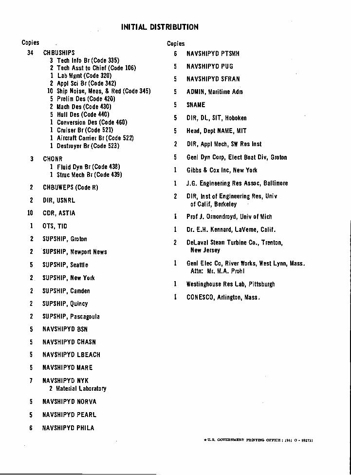
INITIAL DISTRIBUTION
*U.S. GOVERNMENT PRINTING OFFICE: 1961 0- 592731
Copies Copies
34 CHBUSHIPS 6 NAVSHIPYD PTSMH3 Tech Info Br (Code 335)2 Tech Asst to Chief (Code 106) 5 NAVSHIPYD PUG
1 Lab Mgmt (Code 320)2 Appl Sci Br (Code 342)
5 NAVSHIPYD SFRAN
10 Ship Noise, Meas, & Red (Code 345) 5 ADMIN, Maritime Adm5 Prelim Des (Code 420)2 Mach Des (Code 430) 5 SNAME
5 Hull Des (Code 440)1 Conversion Des (Code 460)
5 DIR, DL, SIT, Hoboken
1 Cruiser Br (Code 521) 5 Head, Dept NAME, MIT1 Aircraft Carrier Br (Code 522)1 Destroyer Br (Code 523) 2 DIR, Appl Mech, SW Res Inst
3 CHONR 5 Genl Dyn Corp, Elect Boat Div, Groton
1 Fluid Dyn Br (Code 438)1 Struc Mech Br (Code 439)
1 Gibbs & Cox Inc, New York
2 CHBUWEPS (Code R)1 J.G. Engineering Res Assoc, Baltimore
2 DIR, USNRL2 DIR, Inst of Engineering Res, Univ
of Calif, Berkeley
10 CDR, ASTIA1 Prof J. Ormondroyd, Univ of Mich
1 OTS, TID1 Dr. E.H. Kennard, LaVeme, Calif.
2 SUPSHIP, Groton2 DeLaval Steam Turbine Co., Trenton,
2 SUPSHIP, Newport News New Jersey
5 SUPSHIP, Seattle 1 Genl Elec Co, River Works, West Lynn, Mass.Attn: Mr. M.A. Prohl
2 SUPSHIP, New York1 Westinghouse Res Lab, Pittsburgh
2 SUPSHIP, Camden1 CONESCO, Arlington, Mass.
2 SUPSHIP, Quincy
2 SUPSHIP, Pascagoula
5 NAVSHIPYD BSN
5 NAVSHIPYD CHASN
5 NAVSHIPYD LBEACH
5 NAVSHIPYD MARE
7 NAVSHIPYD NYK2 Material Laboratory
5 NAVSHIPYD NOR VA
5 NAVSHIPYD PEARL
6 NAVSHIPYD PHILA