dmm ile elektriksel parametrelerin karşılaştırması
TRANSCRIPT
GULFMET.EM-S2 Final Report
1/34
GULFMET.EM-S2
AC Power at Power Frequencies
Bilateral comparison between SASO NMCC and TÜBİTAK UME
Final Report
Hüseyin Çaycı and Özlem Yılmaz
TÜBİTAK UME
January, 2018
Pilot Lab. SASO NMCC
TÜBİTAK UME Abdullah M. AlRobaish
NMI of Turkey Shafi S. AlAnazi
P.O.Box:54, Gebze 41470 Ahmed R. AlAyali
Kocaeli, TURKEY Rashed A. AlRumie
GULFMET.EM-S2 Final Report
2/34
Abstract
A supplementary bilateral comparison measurement on AC Power at 50/60 Hz between SASO
NMCC (GULFMET) and TÜBİTAK UME (EURAMET) was performed with the primary power
standards of each partner. Measurement methods and setups which are very similar of the
participants, measurement results, calculation of differences in the results, evaluation of
uncertainties are given within this report.
Contents
Abstract
Contents ....................................................................................................................................... 2
1. Introduction ....................................................................................................................... 3
2. Travelling Standard ........................................................................................................... 3
3. Participant Laboratories .................................................................................................... 4
4. Time Schedule .................................................................................................................. 5
5. Measurement Quantities and Points ................................................................................. 6
6. Methods of Measurement .................................................................................................. 7
6.1 Reference Measurement System ...................................................................................... 7
6.2 Travelling Standard ........................................................................................................... 8
7. Discussion of the Results ................................................................................................ 10
8. Measurement Results ..................................................................................................... 11
Conclusion
References ................................................................................................................................. 17
ANNEX A. UNCERTAINTY BUDGET ......................................................................................... 18
A.1. Uncertainty budget of TÜBİTAK UME .................................................................................. 18
A.2. Uncertainty budget of SASO NMCC .................................................................................... 21
ANNEX B. Technical Protocol....................................................................................................... 26
GULFMET.EM-S2 Final Report
3/34
1. Introduction
A bilateral comparison on AC Power was organised between SASO NMCC and TÜBİTAK UME, in
the frame of the Project of Development and Realization Measurement and Calibration System for
the National Measurement and Calibration Center (NMCC) at Saudi Standards, Metrology and
Quality Organization (SASO). And, it was approved by GULFMET as a supplementary comparison
(GULFMET.EM-S2).
A well-known travelling standard was provided by the pilot Institute (TÜBİTAK UME). Comparison
measurements were performed at several AC power values according to the Technical Protocol of
Bilateral Comparison (Annex B).
TÜBİTAK UME was responsible for monitoring standard performance during the circulation and the
evaluation and reporting of the comparison results. The comparison was carried out in accordance
with the CCEM Guidelines for Planning, Organizing, Conducting and Reporting Key,
Supplementary and Pilot Comparisons [1].
2. Travelling Standard
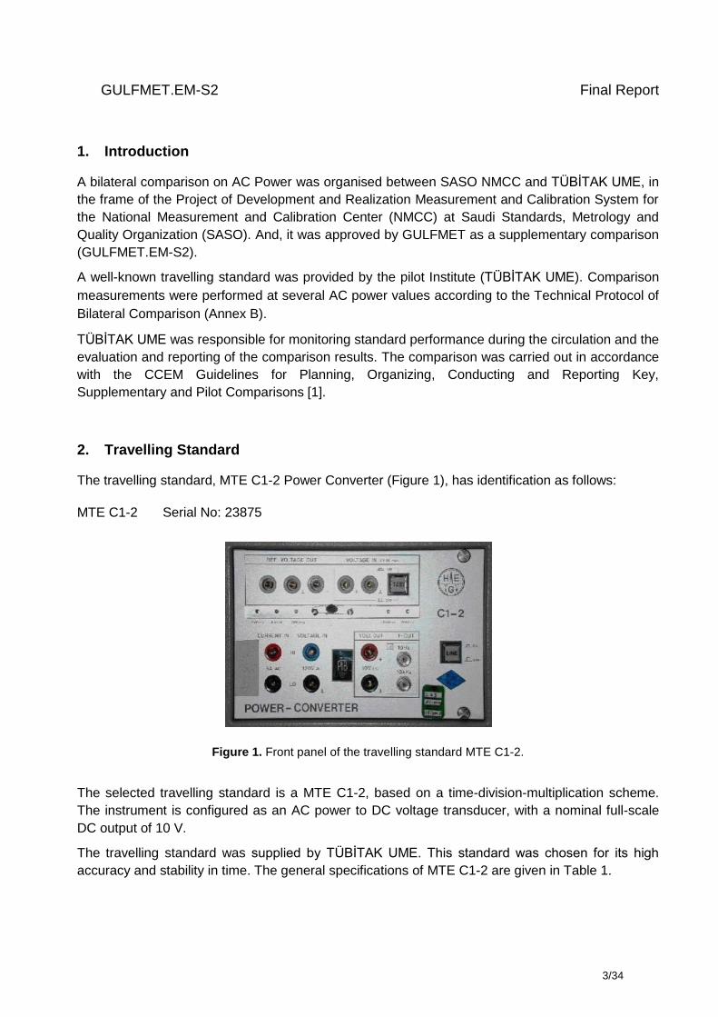
The travelling standard, MTE C1-2 Power Converter (Figure 1), has identification as follows:
MTE C1-2 Serial No: 23875
Figure 1. Front panel of the travelling standard MTE C1-2.
The selected travelling standard is a MTE C1-2, based on a time-division-multiplication scheme.
The instrument is configured as an AC power to DC voltage transducer, with a nominal full-scale
DC output of 10 V.
The travelling standard was supplied by TÜBİTAK UME. This standard was chosen for its high
accuracy and stability in time. The general specifications of MTE C1-2 are given in Table 1.
GULFMET.EM-S2 Final Report
4/34
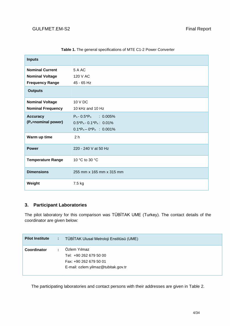
Table 1. The general specifications of MTE C1-2 Power Converter
Inputs
Nominal Current
Nominal Voltage
Frequency Range
5 A AC
120 V AC
45 - 65 Hz
Outputs
Nominal Voltage
Nominal Frequency
10 V DC
10 kHz and 10 Hz
Accuracy
(Pn=nominal power)
Pn - 0.5*Pn : 0.005%
0.5*Pn - 0.1*Pn : 0.01%
0.1*Pn – 0*Pn : 0.001%
Warm up time 2 h
Power 220 - 240 V at 50 Hz
Temperature Range 10 °C to 30 °C
Dimensions 255 mm x 165 mm x 315 mm
Weight 7.5 kg
3. Participant Laboratories
The pilot laboratory for this comparison was TÜBİTAK UME (Turkey). The contact details of the
coordinator are given below:
Pilot Institute : TÜBİTAK Ulusal Metroloji Enstitüsü (UME)
Coordinator : Özlem Yılmaz
Tel: +90 262 679 50 00
Fax: +90 262 679 50 01
E-mail: [email protected]
The participating laboratories and contact persons with their addresses are given in Table 2.
GULFMET.EM-S2 Final Report
5/34
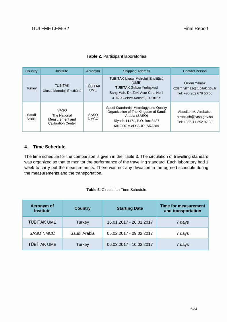
Table 2. Participant laboratories
Country Institute Acronym Shipping Address Contact Person
Turkey TÜBİTAK
Ulusal Metroloji Enstitüsü
TÜBİTAK UME
TÜBİTAK Ulusal Metroloji Enstitüsü (UME)
TÜBİTAK Gebze Yerleşkesi
Barış Mah. Dr. Zeki Acar Cad. No:1
41470 Gebze-Kocaeli, TURKEY
Özlem Yılmaz
Tel: +90 262 679 50 00
Saudi Arabia
SASO
The National Measurement and Calibration Center
SASO NMCC
Saudi Standards, Metrology and Quality Organization of The Kingdom of Saudi
Arabia (SASO)
Riyadh 11471, P.O. Box 3437
KINGDOM of SAUDI ARABIA
Abdullah M. Alrobaish
Tel: +966 11 252 97 30
4. Time Schedule
The time schedule for the comparison is given in the Table 3. The circulation of travelling standard
was organized so that to monitor the performance of the travelling standard. Each laboratory had 1
week to carry out the measurements. There was not any deviation in the agreed schedule during
the measurements and the transportation.
Table 3. Circulation Time Schedule
Acronym of Institute
Country Starting Date Time for measurement
and transportation
TÜBİTAK UME Turkey 16.01.2017 - 20.01.2017 7 days
SASO NMCC Saudi Arabia 05.02.2017 - 09.02.2017 7 days
TÜBİTAK UME Turkey 06.03.2017 - 10.03.2017 7 days
GULFMET.EM-S2 Final Report
6/34
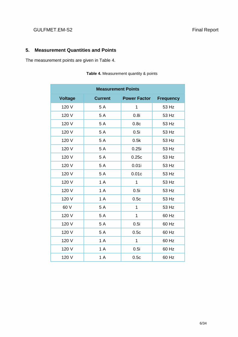
5. Measurement Quantities and Points
The measurement points are given in Table 4.
Table 4. Measurement quantity & points
Measurement Points
Voltage Current Power Factor Frequency
120 V 5 A 1 53 Hz
120 V 5 A 0.8i 53 Hz
120 V 5 A 0.8c 53 Hz
120 V 5 A 0.5i 53 Hz
120 V 5 A 0.5k 53 Hz
120 V 5 A 0.25i 53 Hz
120 V 5 A 0.25c 53 Hz
120 V 5 A 0.01i 53 Hz
120 V 5 A 0.01c 53 Hz
120 V 1 A 1 53 Hz
120 V 1 A 0.5i 53 Hz
120 V 1 A 0.5c 53 Hz
60 V 5 A 1 53 Hz
120 V 5 A 1 60 Hz
120 V 5 A 0.5i 60 Hz
120 V 5 A 0.5c 60 Hz
120 V 1 A 1 60 Hz
120 V 1 A 0.5i 60 Hz
120 V 1 A 0.5c 60 Hz
GULFMET.EM-S2 Final Report
7/34
6. Methods of Measurement
6.1 Reference Measurement System
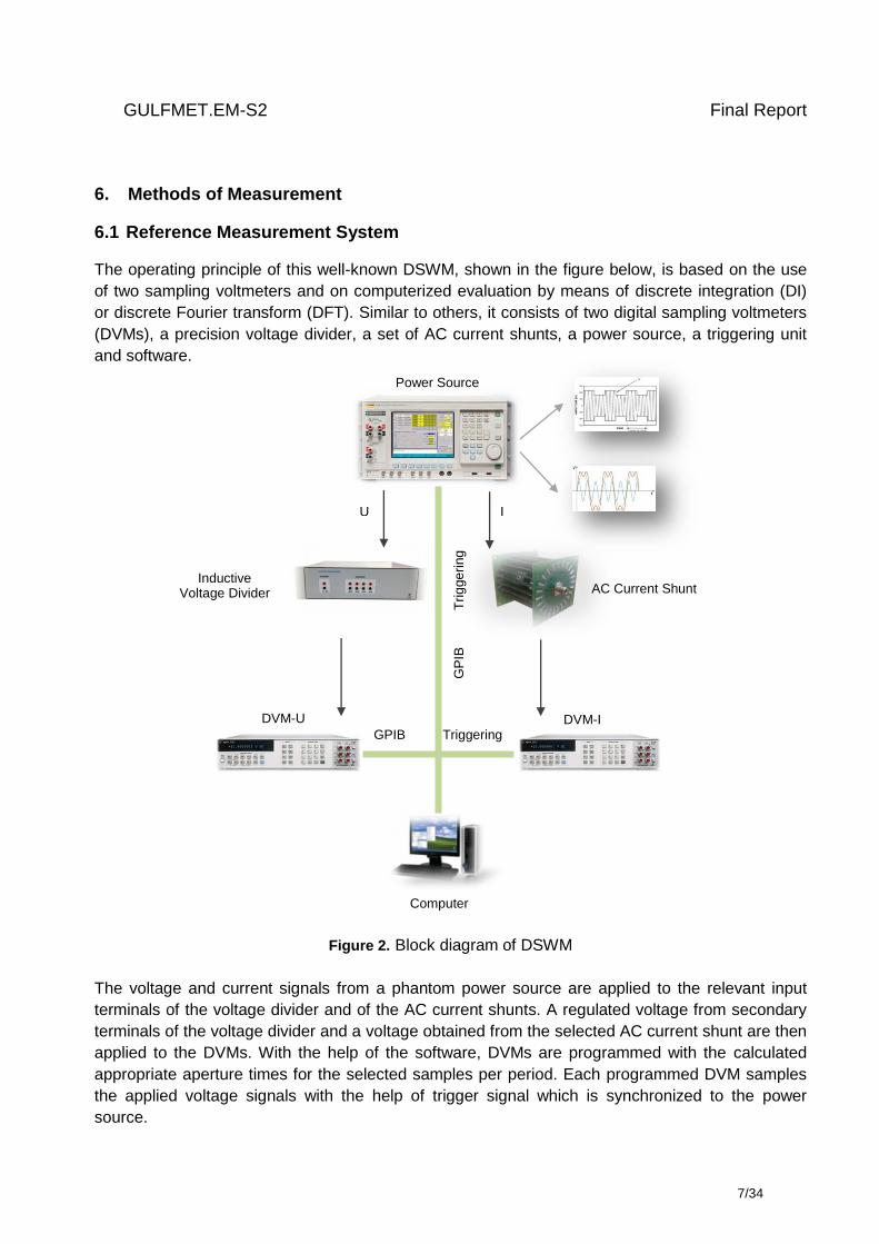
The operating principle of this well-known DSWM, shown in the figure below, is based on the use
of two sampling voltmeters and on computerized evaluation by means of discrete integration (DI)
or discrete Fourier transform (DFT). Similar to others, it consists of two digital sampling voltmeters
(DVMs), a precision voltage divider, a set of AC current shunts, a power source, a triggering unit
and software.
Figure 2. Block diagram of DSWM
The voltage and current signals from a phantom power source are applied to the relevant input
terminals of the voltage divider and of the AC current shunts. A regulated voltage from secondary
terminals of the voltage divider and a voltage obtained from the selected AC current shunt are then
applied to the DVMs. With the help of the software, DVMs are programmed with the calculated
appropriate aperture times for the selected samples per period. Each programmed DVM samples
the applied voltage signals with the help of trigger signal which is synchronized to the power
source.
Power Source
DVM-U
DVM-
Inductive Voltage Divider
U
Computer
DVM-I
AC Current Shunt
I
GPIB Triggering
GP
IB
T
rig
ge
ring
GULFMET.EM-S2 Final Report
8/34
The data from both DVMs are then transferred to the computer via IEEE488. The ratio and phase
angle errors of the voltage divider and current shunts were corrected by the software. The
amplitudes of both signals, the phase angles between them and the calculated results are
displayed during the measurements.
Calibration of the travelling standard was performed by measuring the DC voltage output of the
power converter with a precision voltmeter and multiplying the measured value with a scale factor
to find the measured active power.
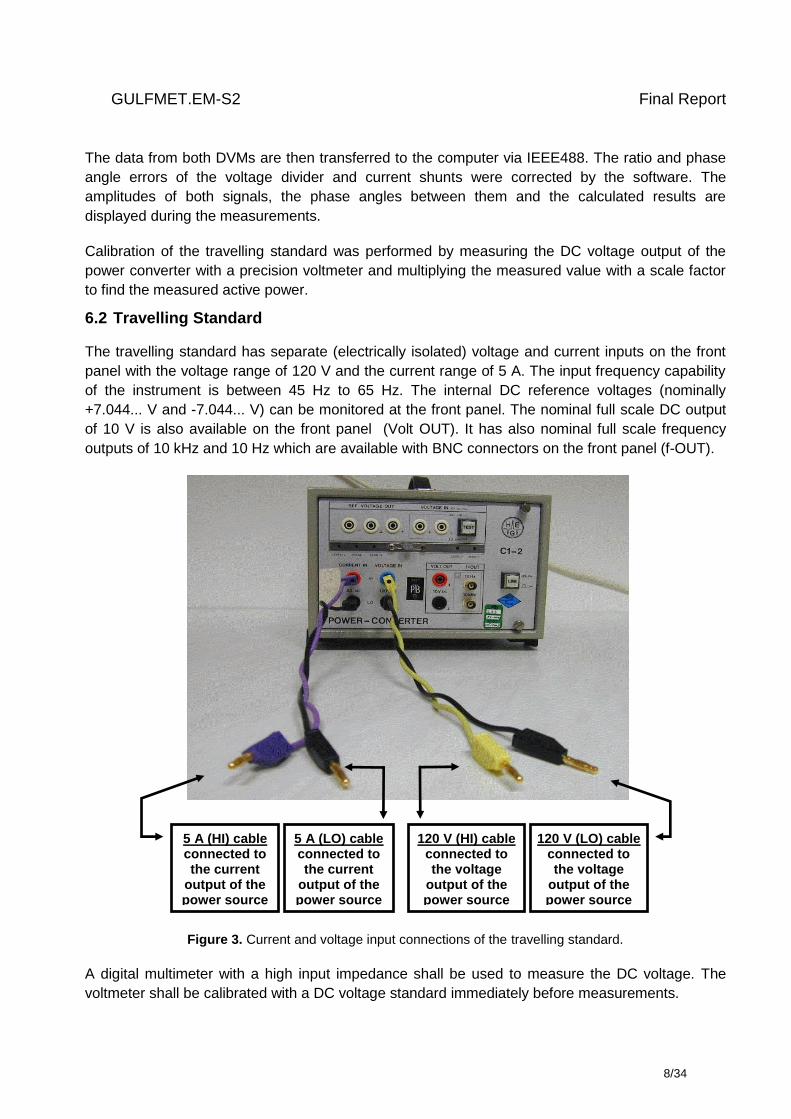
6.2 Travelling Standard
The travelling standard has separate (electrically isolated) voltage and current inputs on the front
panel with the voltage range of 120 V and the current range of 5 A. The input frequency capability
of the instrument is between 45 Hz to 65 Hz. The internal DC reference voltages (nominally
+7.044... V and -7.044... V) can be monitored at the front panel. The nominal full scale DC output
of 10 V is also available on the front panel (Volt OUT). It has also nominal full scale frequency
outputs of 10 kHz and 10 Hz which are available with BNC connectors on the front panel (f-OUT).
Figure 3. Current and voltage input connections of the travelling standard.
A digital multimeter with a high input impedance shall be used to measure the DC voltage. The
voltmeter shall be calibrated with a DC voltage standard immediately before measurements.
5 A (HI) cable connected to the current
output of the power source
120 V (LO) cable connected to the voltage
output of the power source
120 V (HI) cable connected to the voltage
output of the power source
5 A (LO) cable connected to the current
output of the power source

GULFMET.EM-S2 Final Report
9/34
An Agilent 3458A digital multimeter is given in the Figure 4, to show a sample connection for the
measurement of DC voltage values from the travelling standard. Voltage and current input
connections are not shown in the figure.
Figure 4. Connections and DC voltage measurement from the voltage output (VOLT.OUT) of the travelling
standard.
The internal DC reference voltages can be measured before comparison measurements. Only
positive output connection is given in the Figure 5. Negative reference voltage can be measured by
removing the cable used for HI connection and reconnecting it to the next banana connector which
is signed with (-) negative.
The multimeter were programmed to measure the DC reference values with the best resolution
and accuracy.
Figure 5. DC reference voltage measurements from the reference voltage output (REF. VOLTAGE OUT) of
the travelling standard by means of a digital multimeter.
GULFMET.EM-S2 Final Report
10/34
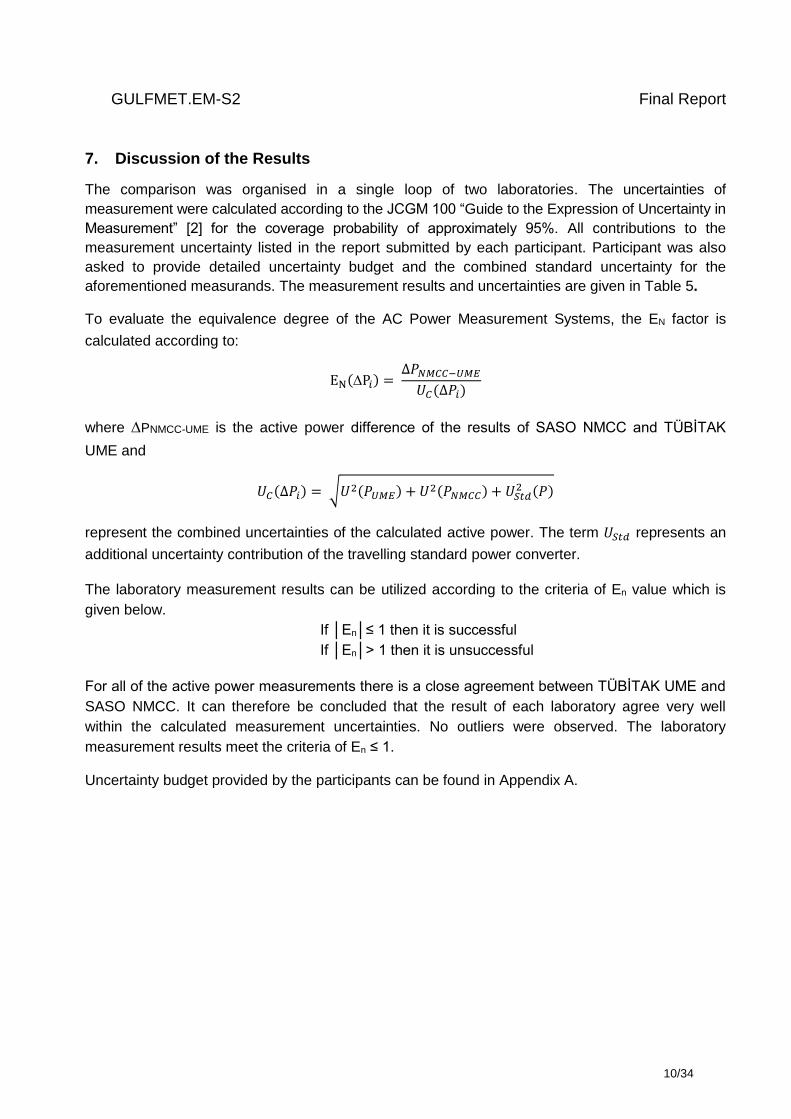
7. Discussion of the Results
The comparison was organised in a single loop of two laboratories. The uncertainties of
measurement were calculated according to the JCGM 100 “Guide to the Expression of Uncertainty in
Measurement” [2] for the coverage probability of approximately 95%. All contributions to the
measurement uncertainty listed in the report submitted by each participant. Participant was also
asked to provide detailed uncertainty budget and the combined standard uncertainty for the
aforementioned measurands. The measurement results and uncertainties are given in Table 5.
To evaluate the equivalence degree of the AC Power Measurement Systems, the EN factor is
calculated according to:
EN(P𝑖) = ∆𝑃𝑁𝑀𝐶𝐶−𝑈𝑀𝐸
𝑈𝐶(∆𝑃𝑖)
where PNMCC-UME is the active power difference of the results of SASO NMCC and TÜBİTAK
UME and
𝑈𝐶(∆𝑃𝑖) = √𝑈2(𝑃𝑈𝑀𝐸) + 𝑈2(𝑃𝑁𝑀𝐶𝐶) + 𝑈𝑆𝑡𝑑2 (𝑃)
represent the combined uncertainties of the calculated active power. The term 𝑈𝑆𝑡𝑑 represents an
additional uncertainty contribution of the travelling standard power converter.
The laboratory measurement results can be utilized according to the criteria of En value which is
given below.
If │En│≤ 1 then it is successful
If │En│> 1 then it is unsuccessful
For all of the active power measurements there is a close agreement between TÜBİTAK UME and
SASO NMCC. It can therefore be concluded that the result of each laboratory agree very well
within the calculated measurement uncertainties. No outliers were observed. The laboratory
measurement results meet the criteria of En ≤ 1.
Uncertainty budget provided by the participants can be found in Appendix A.
GULFMET.EM-S2 Final Report
11/34
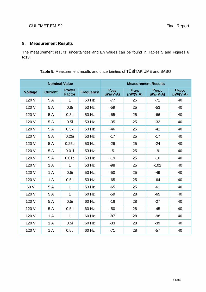
8. Measurement Results
The measurement results, uncertainties and En values can be found in Tables 5 and Figures 6
to13.
Table 5. Measurement results and uncertainties of TÜBİTAK UME and SASO
Nominal Value Measurement Results
Voltage Current Power Factor
Frequency PUME
μW/(V·A) UUME
μW/(V·A) PNMCC
μW/(V·A) UNMCC
μW/(V·A)
120 V 5 A 1 53 Hz -77 25 -71 40
120 V 5 A 0.8i 53 Hz -59 25 -53 40
120 V 5 A 0.8c 53 Hz -65 25 -66 40
120 V 5 A 0.5i 53 Hz -35 25 -32 40
120 V 5 A 0.5k 53 Hz -46 25 -41 40
120 V 5 A 0.25i 53 Hz -17 25 -17 40
120 V 5 A 0.25c 53 Hz -29 25 -24 40
120 V 5 A 0.01i 53 Hz -5 25 -9 40
120 V 5 A 0.01c 53 Hz -19 25 -10 40
120 V 1 A 1 53 Hz -98 25 -102 40
120 V 1 A 0.5i 53 Hz -50 25 -49 40
120 V 1 A 0.5c 53 Hz -65 25 -64 40
60 V 5 A 1 53 Hz -65 25 -61 40
120 V 5 A 1 60 Hz -59 28 -65 40
120 V 5 A 0.5i 60 Hz -16 28 -27 40
120 V 5 A 0.5c 60 Hz -50 28 -45 40
120 V 1 A 1 60 Hz -87 28 -98 40
120 V 1 A 0.5i 60 Hz -33 28 -39 40
120 V 1 A 0.5c 60 Hz -71 28 -57 40
GULFMET.EM-S2 Final Report
12/34
Figure 6. The comparison results and its uncertainty for 120 V, 5 A, 53 Hz (%95, k=2)
Figure 7. The comparison results and its uncertainty for 120 V, 1 A, 53 Hz (%95, k=2)
GULFMET.EM-S2 Final Report
13/34
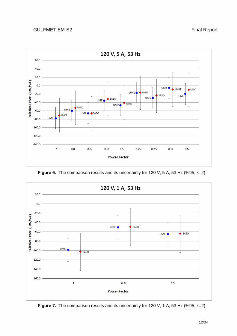
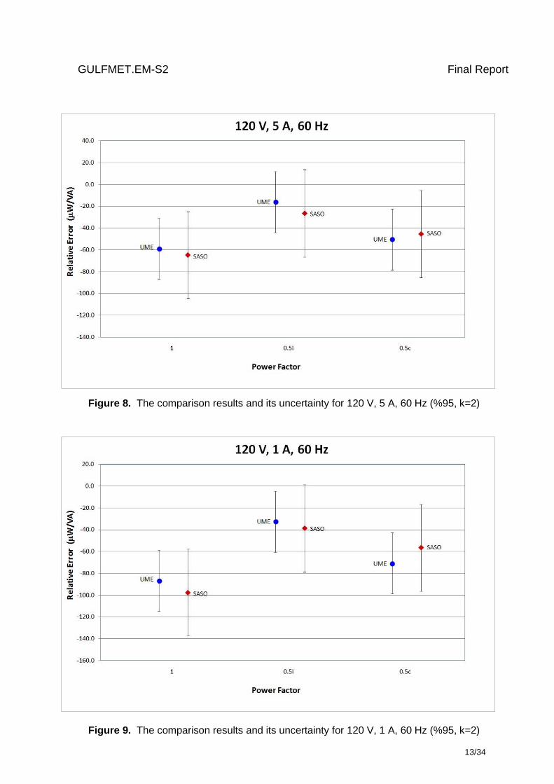
Figure 8. The comparison results and its uncertainty for 120 V, 5 A, 60 Hz (%95, k=2)
Figure 9. The comparison results and its uncertainty for 120 V, 1 A, 60 Hz (%95, k=2)
GULFMET.EM-S2 Final Report
14/34
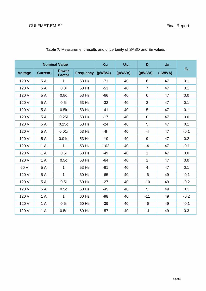
Table 7. Measurement results and uncertainty of SASO and En values
Nominal Value Xlab Ulab D UD
En Voltage Current
Power Factor
Frequency (µW/VA) (µW/VA) (µW/VA) (µW/VA)
120 V 5 A 1 53 Hz -71 40 6 47 0.1
120 V 5 A 0.8i 53 Hz -53 40 7 47 0.1
120 V 5 A 0.8c 53 Hz -66 40 0 47 0.0
120 V 5 A 0.5i 53 Hz -32 40 3 47 0.1
120 V 5 A 0.5k 53 Hz -41 40 5 47 0.1
120 V 5 A 0.25i 53 Hz -17 40 0 47 0.0
120 V 5 A 0.25c 53 Hz -24 40 5 47 0.1
120 V 5 A 0.01i 53 Hz -9 40 -4 47 -0.1
120 V 5 A 0.01c 53 Hz -10 40 9 47 0.2
120 V 1 A 1 53 Hz -102 40 -4 47 -0.1
120 V 1 A 0.5i 53 Hz -49 40 1 47 0.0
120 V 1 A 0.5c 53 Hz -64 40 1 47 0.0
60 V 5 A 1 53 Hz -61 40 4 47 0.1
120 V 5 A 1 60 Hz -65 40 -6 49 -0.1
120 V 5 A 0.5i 60 Hz -27 40 -10 49 -0.2
120 V 5 A 0.5c 60 Hz -45 40 5 49 0.1
120 V 1 A 1 60 Hz -98 40 -11 49 -0.2
120 V 1 A 0.5i 60 Hz -39 40 -6 49 -0.1
120 V 1 A 0.5c 60 Hz -57 40 14 49 0.3
GULFMET.EM-S2 Final Report
15/34
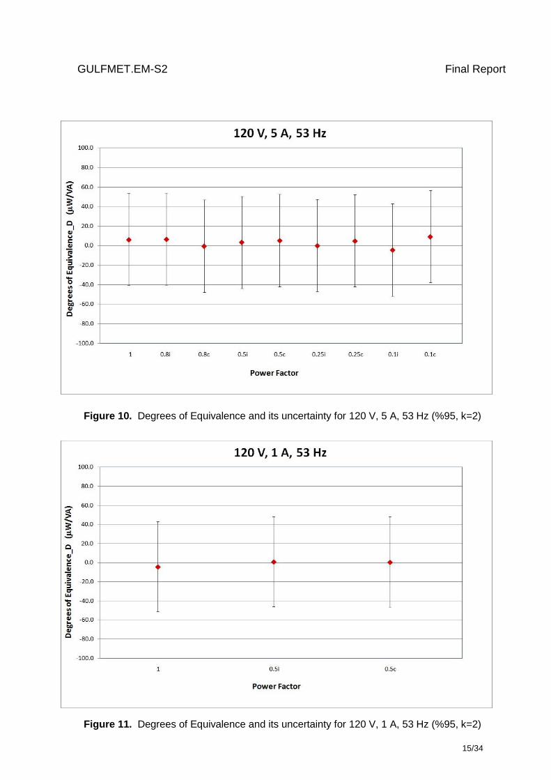
Figure 10. Degrees of Equivalence and its uncertainty for 120 V, 5 A, 53 Hz (%95, k=2)
Figure 11. Degrees of Equivalence and its uncertainty for 120 V, 1 A, 53 Hz (%95, k=2)
GULFMET.EM-S2 Final Report
16/34
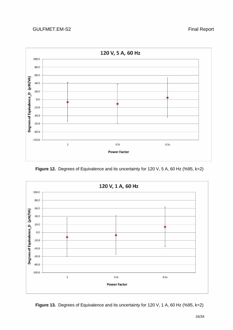
Figure 12. Degrees of Equivalence and its uncertainty for 120 V, 5 A, 60 Hz (%95, k=2)
Figure 13. Degrees of Equivalence and its uncertainty for 120 V, 1 A, 60 Hz (%95, k=2)
GULFMET.EM-S2 Final Report
17/34
Conclusions
Bilateral comparison schedule was planned for a very short circulating time of the travelling
standard between the participants to eliminate the long-term drifts and any other behaviour of it.
And, those effects were successfully declared with the repetitive measurements on the travelling
standard, by the pilot laboratory. The measurand and the parameters (voltage, current, power
factor, and frequency) were selected carefully to be able compare each participant’s measurement
capabilities as wider as possible.
The results for each measurement points are found very close each other and show a good
agreement with the given uncertainties. Both measurement standards used by the participants are
based on the digital sampling method but with minor differences in the hardware. In this point of
view, this comparison might have a meaning of a direct check of two similar primary power
measurement standards.
References
[1] CCEM Guidelines for Planning, Organizing, Conducting and Reporting Key, Supplementary
and Pilot Comparisons, 2007 (available on the BIPM website:
http://www.bipm.org/utils/common/pdf/CC/CCEM/ccem_guidelines.pdf).
[2] Evaluation of measurement data - Guide to the Expression of Uncertainty in Measurement
(GUM), JCGM 100, First edition, September 2008 (available on the BIPM website:
http://www.bipm.org/utils/common/documents/jcgm/JCGM_100_2008_E.pdf).
[3] Hüseyin Çaycı, “Final Report of Key Comparison EUROMET.EM-K5.1 Comparison of 50/60
Hz Power,” March 2011.
[4] Technical Protocol, “Bilateral Comparison of AC Power Standards Between TÜBİTAK UME
and SASO NMCC”, UME-EM-D3-2.22.6.a, 2016.
GULFMET.EM-S2 Final Report
18/34
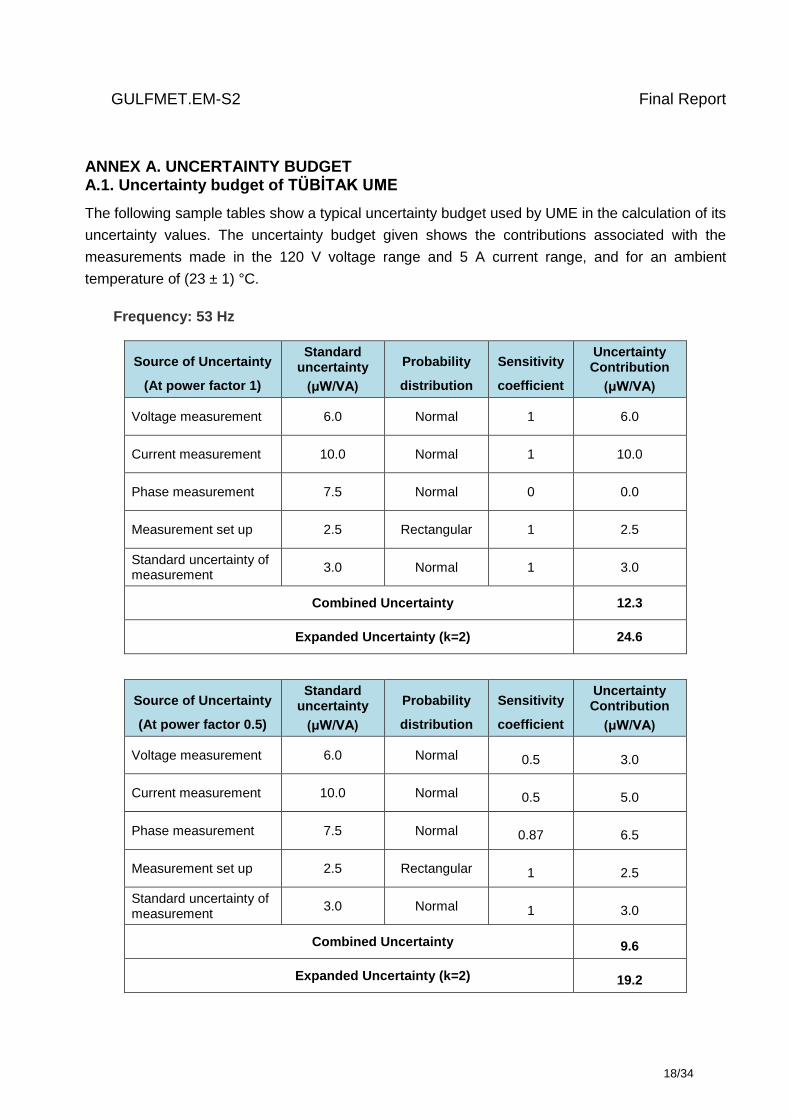
ANNEX A. UNCERTAINTY BUDGET A.1. Uncertainty budget of TÜBİTAK UME
The following sample tables show a typical uncertainty budget used by UME in the calculation of its
uncertainty values. The uncertainty budget given shows the contributions associated with the
measurements made in the 120 V voltage range and 5 A current range, and for an ambient
temperature of (23 ± 1) °C.
Frequency: 53 Hz
Source of Uncertainty
(At power factor 1)
Standard uncertainty
(μW/VA)
Probability
distribution
Sensitivity
coefficient
Uncertainty Contribution
(μW/VA)
Voltage measurement 6.0 Normal 1 6.0
Current measurement 10.0 Normal 1 10.0
Phase measurement 7.5 Normal 0 0.0
Measurement set up 2.5 Rectangular 1 2.5
Standard uncertainty of measurement
3.0 Normal 1 3.0
Combined Uncertainty 12.3
Expanded Uncertainty (k=2) 24.6
Source of Uncertainty
(At power factor 0.5)
Standard uncertainty
(μW/VA)
Probability
distribution
Sensitivity
coefficient
Uncertainty Contribution
(μW/VA)
Voltage measurement 6.0 Normal 0.5 3.0
Current measurement 10.0 Normal 0.5 5.0
Phase measurement 7.5 Normal 0.87 6.5
Measurement set up 2.5 Rectangular 1 2.5
Standard uncertainty of measurement
3.0 Normal 1 3.0
Combined Uncertainty 9.6
Expanded Uncertainty (k=2) 19.2
GULFMET.EM-S2 Final Report
19/34
Source of Uncertainty
(At power factor 0)
Standard uncertainty
(μW/VA)
Probability
distribution
Sensitivity
coefficient
Uncertainty Contribution
(μW/VA)
Voltage measurement 6.0 Normal 0 0.0
Current measurement 10.0 Normal 0 0.0
Phase measurement 7.5 Normal 1 7.5
Measurement set up 2.5 Rectangular 1 2.5
Standard uncertainty of measurement
3.0 Normal 1 3.0
Combined Uncertainty 8.5
Expanded Uncertainty (k=2) 16.9
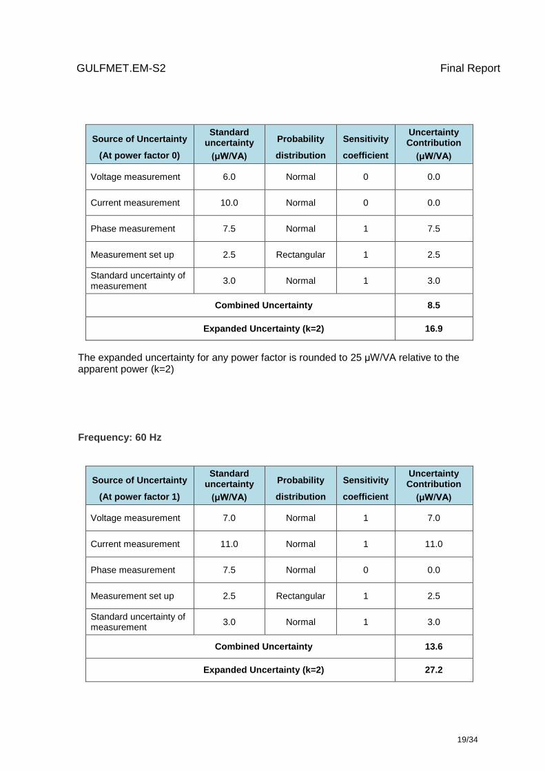
The expanded uncertainty for any power factor is rounded to 25 μW/VA relative to the apparent power (k=2)
Frequency: 60 Hz
Source of Uncertainty
(At power factor 1)
Standard uncertainty
(μW/VA)
Probability
distribution
Sensitivity
coefficient
Uncertainty Contribution
(μW/VA)
Voltage measurement 7.0 Normal 1 7.0
Current measurement 11.0 Normal 1 11.0
Phase measurement 7.5 Normal 0 0.0
Measurement set up 2.5 Rectangular 1 2.5
Standard uncertainty of measurement
3.0 Normal 1 3.0
Combined Uncertainty 13.6
Expanded Uncertainty (k=2) 27.2
GULFMET.EM-S2 Final Report
20/34
Source of Uncertainty
(At power factor 0.5)
Standard uncertainty
(μW/VA)
Probability
distribution
Sensitivity
coefficient
Uncertainty Contribution
(μW/VA)
Voltage measurement 7.0 Normal 0.5 3.5
Current measurement 11.0 Normal 0.5 5.5
Phase measurement 7.5 Normal 0.87 6.5
Measurement set up 2.5 Rectangular 1 2.5
Standard uncertainty of measurement
3.0 Normal 1 3.0
Combined Uncertainty 10.0
Expanded Uncertainty (k=2) 20.0
Source of Uncertainty
(At power factor 0)
Standard uncertainty
(μW/VA)
Probability
distribution
Sensitivity
coefficient
Uncertainty Contribution
(μW/VA)
Voltage measurement 7.0 Normal 0 0.0
Current measurement 11.0 Normal 0 0.0
Phase measurement 7.5 Normal 1 7.5
Measurement set up 2.5 Rectangular 1 2.5
Standard uncertainty of measurement
3.0 Normal 1 3.0
Combined Uncertainty 8.5
Expanded Uncertainty (k=2) 16.9
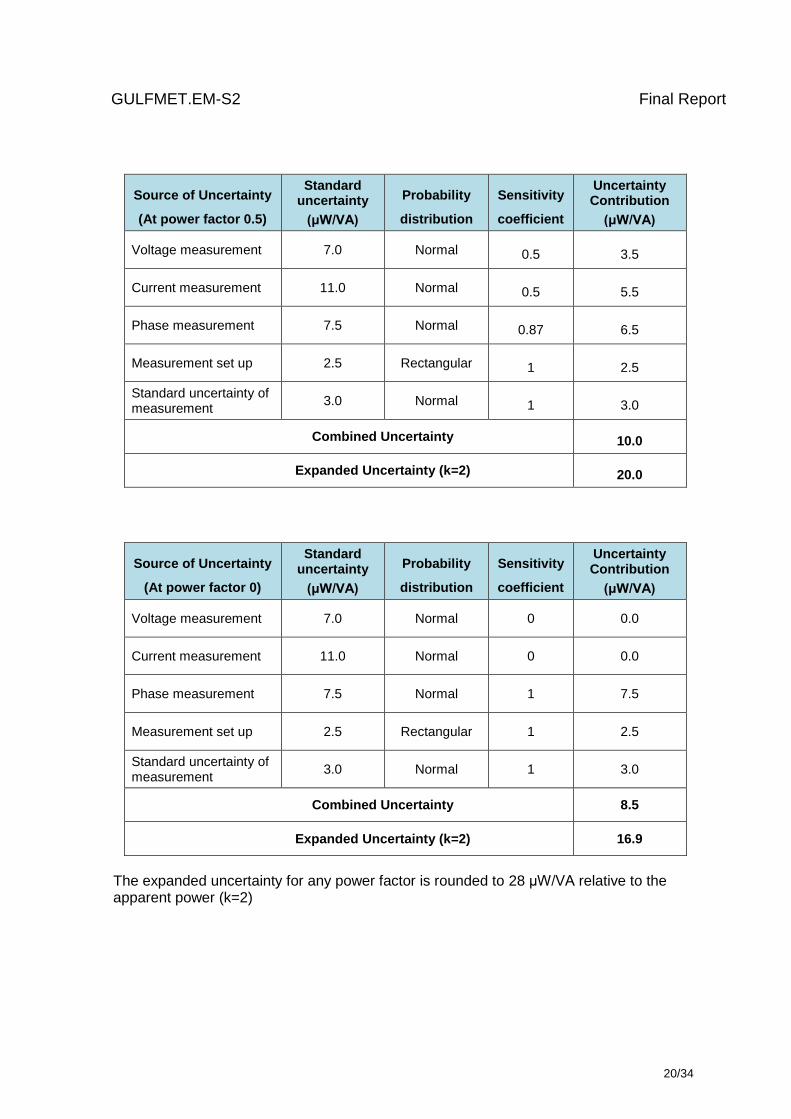
The expanded uncertainty for any power factor is rounded to 28 μW/VA relative to the apparent power (k=2)
GULFMET.EM-S2 Final Report
21/34
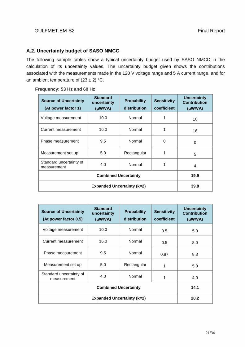
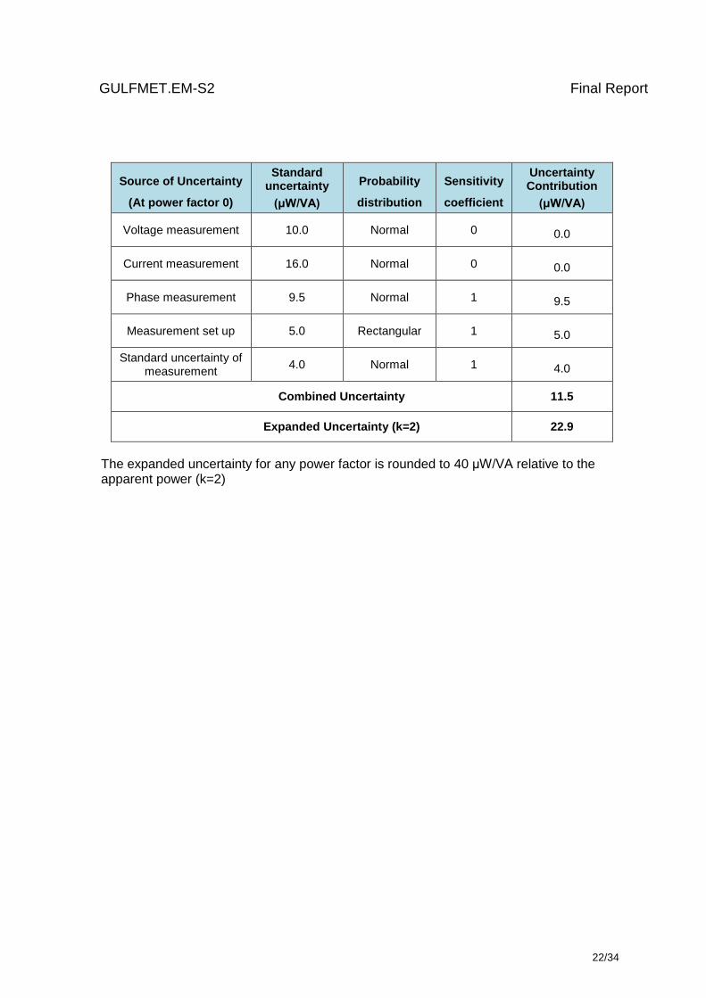
A.2. Uncertainty budget of SASO NMCC
The following sample tables show a typical uncertainty budget used by SASO NMCC in the
calculation of its uncertainty values. The uncertainty budget given shows the contributions
associated with the measurements made in the 120 V voltage range and 5 A current range, and for
an ambient temperature of (23 ± 2) °C.
Frequency: 53 Hz and 60 Hz
Source of Uncertainty
(At power factor 1)
Standard uncertainty
(μW/VA)
Probability
distribution
Sensitivity
coefficient
Uncertainty Contribution
(μW/VA)
Voltage measurement 10.0 Normal 1 10
Current measurement 16.0 Normal 1 16
Phase measurement 9.5 Normal 0 0
Measurement set up 5.0 Rectangular 1 5
Standard uncertainty of measurement
4.0 Normal 1 4
Combined Uncertainty 19.9
Expanded Uncertainty (k=2) 39.8
Source of Uncertainty
(At power factor 0.5)
Standard uncertainty
(μW/VA)
Probability
distribution
Sensitivity
coefficient
Uncertainty Contribution
(μW/VA)
Voltage measurement 10.0 Normal 0.5 5.0
Current measurement 16.0 Normal 0.5 8.0
Phase measurement 9.5 Normal 0.87 8.3
Measurement set up 5.0 Rectangular 1 5.0
Standard uncertainty of measurement
4.0 Normal 1 4.0
Combined Uncertainty 14.1
Expanded Uncertainty (k=2) 28.2
GULFMET.EM-S2 Final Report
22/34
Source of Uncertainty
(At power factor 0)
Standard uncertainty
(μW/VA)
Probability
distribution
Sensitivity
coefficient
Uncertainty Contribution
(μW/VA)
Voltage measurement 10.0 Normal 0 0.0
Current measurement 16.0 Normal 0 0.0
Phase measurement 9.5 Normal 1 9.5
Measurement set up 5.0 Rectangular 1 5.0
Standard uncertainty of measurement
4.0 Normal 1 4.0
Combined Uncertainty 11.5
Expanded Uncertainty (k=2) 22.9
The expanded uncertainty for any power factor is rounded to 40 μW/VA relative to the apparent power (k=2)
GULFMET.EM-S2 Final Report
23/34
ANNEX B. Technical Protocol
TECHNICAL PROTOCOL
Bilateral Comparison of AC Power Standards
Between TÜBİTAK UME and SASO NMCC
UME-EM-D3-2.22.6.a
TÜBİTAK UME
(Rev. 0)
August 19, 2016
GULFMET.EM-S2 Final Report
24/34
Contents
Contents ..................................................................................................................................... 27
1. Introduction ..................................................................................................................... 25
2. Travelling Standard ......................................................................................................... 25
3. Participant Laboratories .................................................................................................. 27
4. Time Schedule ................................................................................................................ 27
5. Transport Case ............................................................................................................... 28
6. Transportation of Travelling Standard ............................................................................. 28
6.1. Failure of Travelling Standard 28
6.2. Financial aspects 28
7. Measurement Quantities and Points ............................................................................... 29
8. Calculation of the Comparison Reference Value ............................................................. 30
9. Measurement Instructions ............................................................................................... 30
10. Measurement Uncertainty ............................................................................................... 32
11. Reporting of Results ........................................................................................................ 32
12. Final Report of the Comparison....................................................................................... 34
13. References ..................................................................................................................... 34
GULFMET.EM-S2 Final Report
25/34
1. Introduction
It was planned to organise a bilateral comparison on AC Power between SASO NMCC and
TÜBİTAK UME, in the frame of the Project of Development and Realization Measurement and
Calibration System for the National Measurement and Calibration Center (NMCC) at Saudi
Standards, Metrology and Quality Organization (SASO).
The bilateral comparison will be performed by measuring a power converter at several AC power
values.
UME is acting as the pilot institute. The travelling standard will be provided by TÜBİTAK UME.
TÜBİTAK UME will be responsible to monitoring standard performance during the circulation and
the evaluation and reporting of the comparison results.
The comparison will be carried out in accordance with the CCEM Guidelines for Planning,
Organizing, Conducting and Reporting Key, Supplementary and Pilot Comparisons [1].
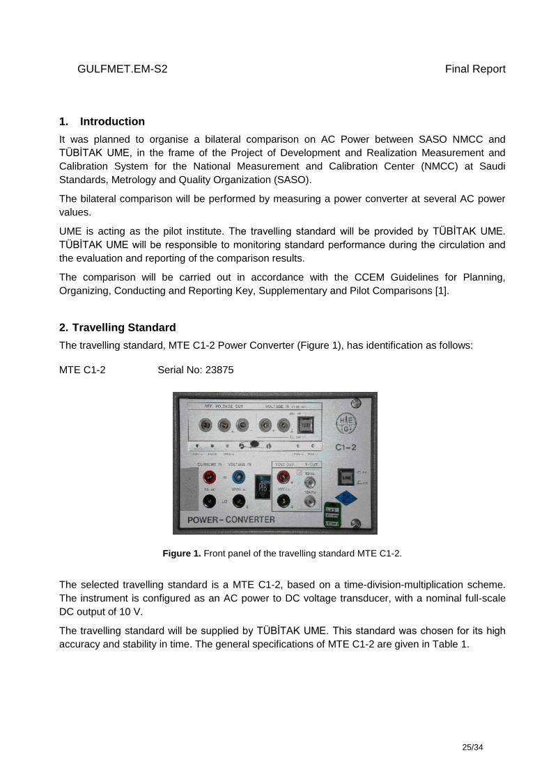
2. Travelling Standard
The travelling standard, MTE C1-2 Power Converter (Figure 1), has identification as follows:
MTE C1-2 Serial No: 23875
Figure 1. Front panel of the travelling standard MTE C1-2.
The selected travelling standard is a MTE C1-2, based on a time-division-multiplication scheme.
The instrument is configured as an AC power to DC voltage transducer, with a nominal full-scale
DC output of 10 V.
The travelling standard will be supplied by TÜBİTAK UME. This standard was chosen for its high
accuracy and stability in time. The general specifications of MTE C1-2 are given in Table 1.
GULFMET.EM-S2 Final Report
26/34
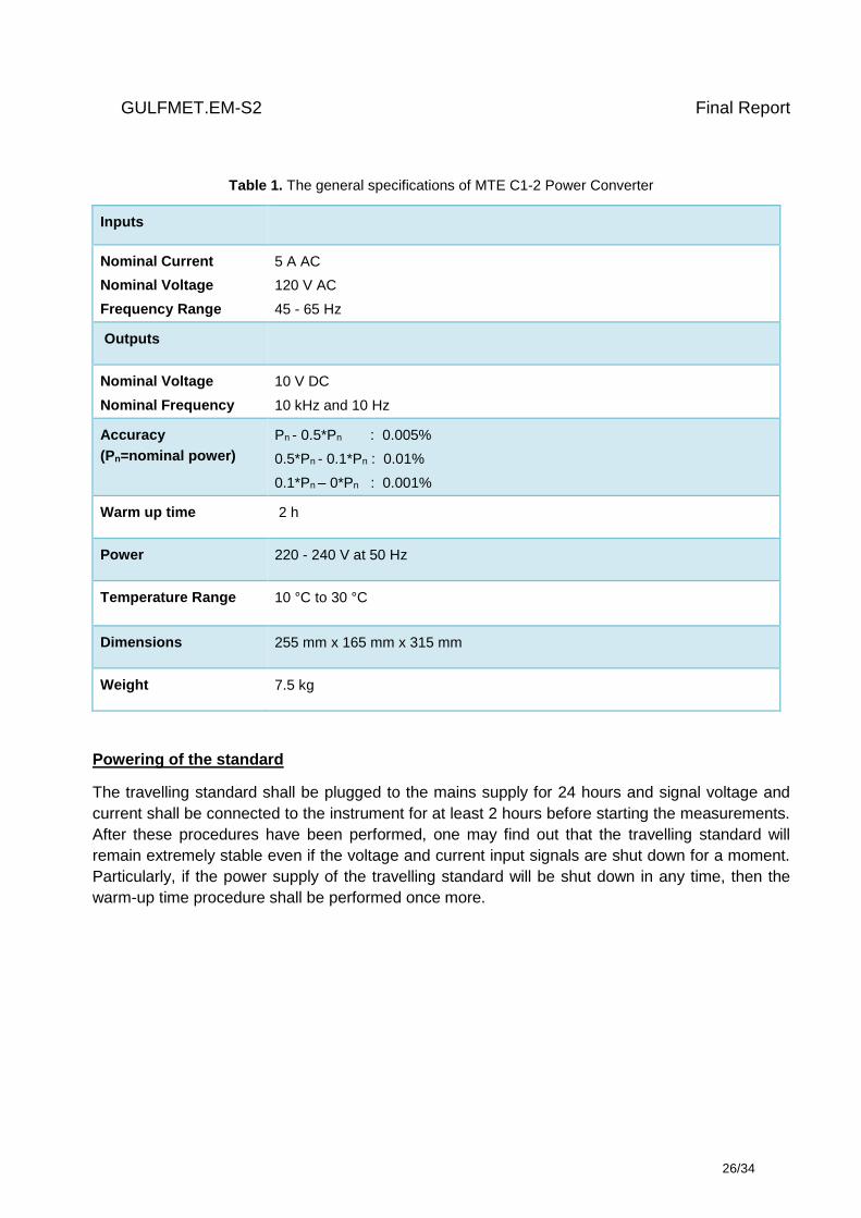
Table 1. The general specifications of MTE C1-2 Power Converter
Inputs
Nominal Current
Nominal Voltage
Frequency Range
5 A AC
120 V AC
45 - 65 Hz
Outputs
Nominal Voltage
Nominal Frequency
10 V DC
10 kHz and 10 Hz
Accuracy
(Pn=nominal power)
Pn - 0.5*Pn : 0.005%
0.5*Pn - 0.1*Pn : 0.01%
0.1*Pn – 0*Pn : 0.001%
Warm up time 2 h
Power 220 - 240 V at 50 Hz
Temperature Range 10 °C to 30 °C
Dimensions 255 mm x 165 mm x 315 mm
Weight 7.5 kg
Powering of the standard
The travelling standard shall be plugged to the mains supply for 24 hours and signal voltage and
current shall be connected to the instrument for at least 2 hours before starting the measurements.
After these procedures have been performed, one may find out that the travelling standard will
remain extremely stable even if the voltage and current input signals are shut down for a moment.
Particularly, if the power supply of the travelling standard will be shut down in any time, then the
warm-up time procedure shall be performed once more.
GULFMET.EM-S2 Final Report
27/34
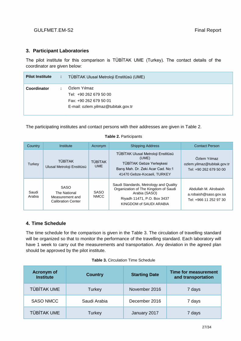
3. Participant Laboratories
The pilot institute for this comparison is TÜBİTAK UME (Turkey). The contact details of the
coordinator are given below:
Pilot Institute : TÜBİTAK Ulusal Metroloji Enstitüsü (UME)
Coordinator : Özlem Yılmaz
Tel: +90 262 679 50 00
Fax: +90 262 679 50 01
E-mail: [email protected]
The participating institutes and contact persons with their addresses are given in Table 2.
Table 2. Participants
Country Institute Acronym Shipping Address Contact Person
Turkey TÜBİTAK
Ulusal Metroloji Enstitüsü
TÜBİTAK UME
TÜBİTAK Ulusal Metroloji Enstitüsü (UME)
TÜBİTAK Gebze Yerleşkesi
Barış Mah. Dr. Zeki Acar Cad. No:1
41470 Gebze-Kocaeli, TURKEY
Özlem Yılmaz
Tel: +90 262 679 50 00
Saudi Arabia
SASO
The National Measurement and Calibration Center
SASO NMCC
Saudi Standards, Metrology and Quality Organization of The Kingdom of Saudi
Arabia (SASO)
Riyadh 11471, P.O. Box 3437
KINGDOM of SAUDI ARABIA
Abdullah M. Alrobaish
Tel: +966 11 252 97 30
4. Time Schedule
The time schedule for the comparison is given in the Table 3. The circulation of travelling standard
will be organized so that to monitor the performance of the travelling standard. Each laboratory will
have 1 week to carry out the measurements and transportation. Any deviation in the agreed plan
should be approved by the pilot institute.
Table 3. Circulation Time Schedule
Acronym of Institute
Country Starting Date Time for measurement
and transportation
TÜBİTAK UME Turkey November 2016 7 days
SASO NMCC Saudi Arabia December 2016 7 days
TÜBİTAK UME Turkey January 2017 7 days
GULFMET.EM-S2 Final Report
28/34
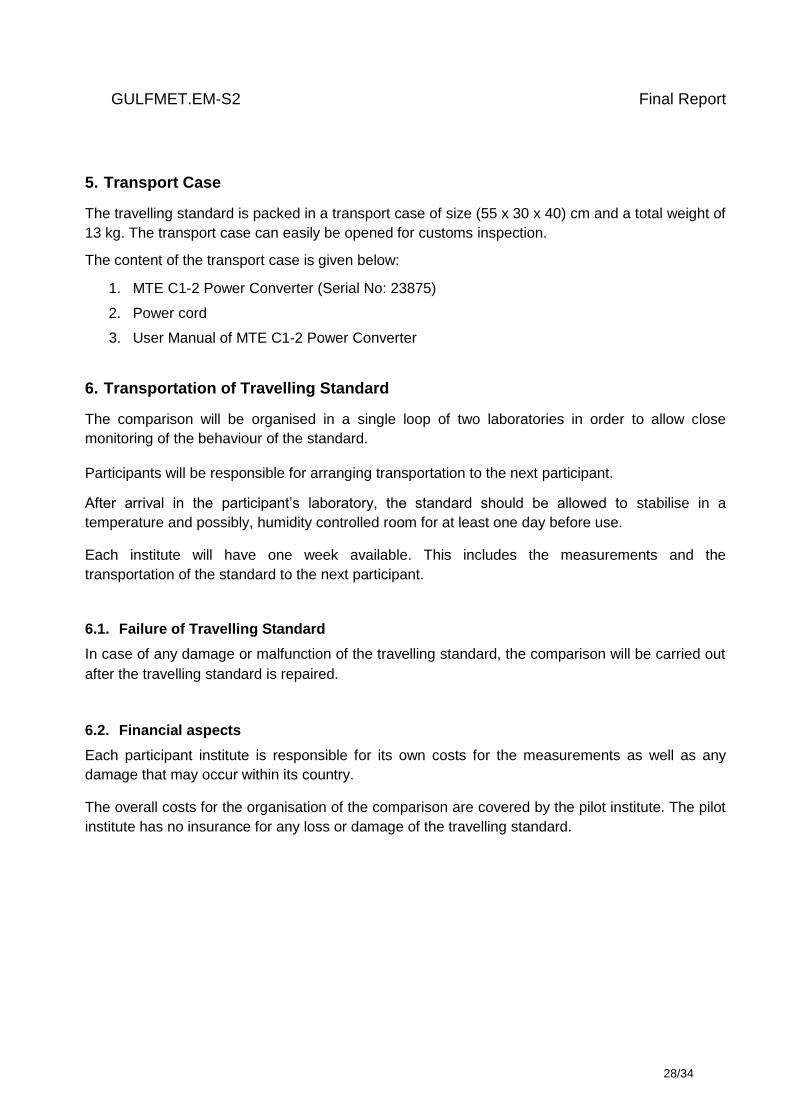
5. Transport Case
The travelling standard is packed in a transport case of size (55 x 30 x 40) cm and a total weight of
13 kg. The transport case can easily be opened for customs inspection.
The content of the transport case is given below:
1. MTE C1-2 Power Converter (Serial No: 23875)
2. Power cord
3. User Manual of MTE C1-2 Power Converter
6. Transportation of Travelling Standard
The comparison will be organised in a single loop of two laboratories in order to allow close
monitoring of the behaviour of the standard.
Participants will be responsible for arranging transportation to the next participant.
After arrival in the participant’s laboratory, the standard should be allowed to stabilise in a
temperature and possibly, humidity controlled room for at least one day before use.
Each institute will have one week available. This includes the measurements and the
transportation of the standard to the next participant.
6.1. Failure of Travelling Standard
In case of any damage or malfunction of the travelling standard, the comparison will be carried out
after the travelling standard is repaired.
6.2. Financial aspects
Each participant institute is responsible for its own costs for the measurements as well as any
damage that may occur within its country.
The overall costs for the organisation of the comparison are covered by the pilot institute. The pilot
institute has no insurance for any loss or damage of the travelling standard.
GULFMET.EM-S2 Final Report
29/34
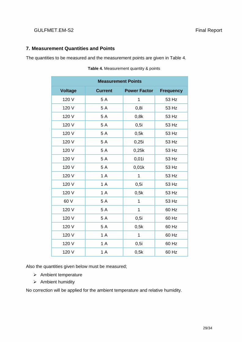
7. Measurement Quantities and Points
The quantities to be measured and the measurement points are given in Table 4.
Table 4. Measurement quantity & points
Measurement Points
Voltage Current Power Factor Frequency
120 V 5 A 1 53 Hz
120 V 5 A 0,8i 53 Hz
120 V 5 A 0,8k 53 Hz
120 V 5 A 0,5i 53 Hz
120 V 5 A 0,5k 53 Hz
120 V 5 A 0,25i 53 Hz
120 V 5 A 0,25k 53 Hz
120 V 5 A 0,01i 53 Hz
120 V 5 A 0,01k 53 Hz
120 V 1 A 1 53 Hz
120 V 1 A 0,5i 53 Hz
120 V 1 A 0,5k 53 Hz
60 V 5 A 1 53 Hz
120 V 5 A 1 60 Hz
120 V 5 A 0,5i 60 Hz
120 V 5 A 0,5k 60 Hz
120 V 1 A 1 60 Hz
120 V 1 A 0,5i 60 Hz
120 V 1 A 0,5k 60 Hz
Also the quantities given below must be measured;
Ambient temperature
Ambient humidity
No correction will be applied for the ambient temperature and relative humidity.
GULFMET.EM-S2 Final Report
30/34
8. Calculation of the Comparison Reference Value
The Comparison Reference Value (CRV) for each measurement point will be calculated using the
results of the pilot institute.
9. Measurement Instructions
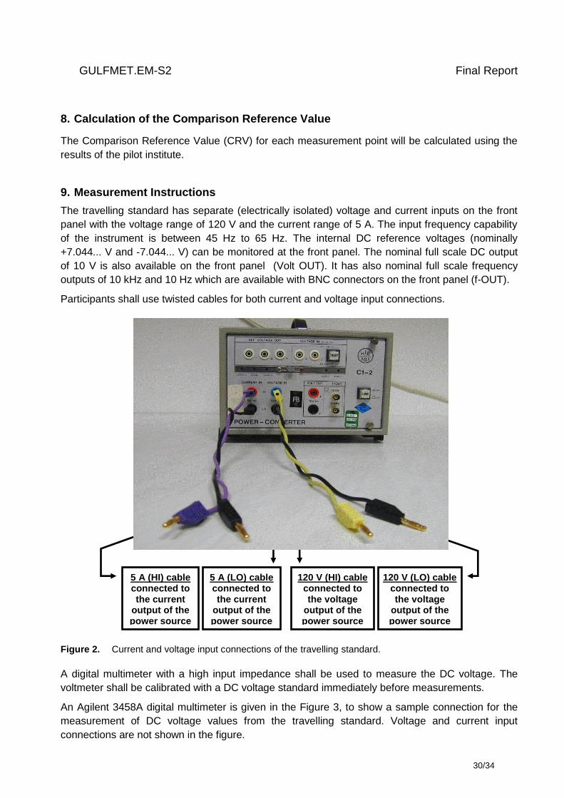
The travelling standard has separate (electrically isolated) voltage and current inputs on the front
panel with the voltage range of 120 V and the current range of 5 A. The input frequency capability
of the instrument is between 45 Hz to 65 Hz. The internal DC reference voltages (nominally
+7.044... V and -7.044... V) can be monitored at the front panel. The nominal full scale DC output
of 10 V is also available on the front panel (Volt OUT). It has also nominal full scale frequency
outputs of 10 kHz and 10 Hz which are available with BNC connectors on the front panel (f-OUT).
Participants shall use twisted cables for both current and voltage input connections.
Figure 2. Current and voltage input connections of the travelling standard.
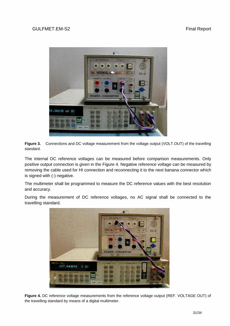
A digital multimeter with a high input impedance shall be used to measure the DC voltage. The
voltmeter shall be calibrated with a DC voltage standard immediately before measurements.
An Agilent 3458A digital multimeter is given in the Figure 3, to show a sample connection for the
measurement of DC voltage values from the travelling standard. Voltage and current input
connections are not shown in the figure.
5 A (HI) cable connected to the current
output of the power source
120 V (LO) cable connected to the voltage
output of the power source
120 V (HI) cable connected to the voltage
output of the power source
5 A (LO) cable connected to the current
output of the power source
GULFMET.EM-S2 Final Report
31/34
Figure 3. Connections and DC voltage measurement from the voltage output (VOLT.OUT) of the travelling
standard.
The internal DC reference voltages can be measured before comparison measurements. Only
positive output connection is given in the Figure 4. Negative reference voltage can be measured by
removing the cable used for HI connection and reconnecting it to the next banana connector which
is signed with (-) negative.
The multimeter shall be programmed to measure the DC reference values with the best resolution
and accuracy.
During the measurement of DC reference voltages, no AC signal shall be connected to the
travelling standard.
Figure 4. DC reference voltage measurements from the reference voltage output (REF. VOLTAGE OUT) of
the travelling standard by means of a digital multimeter.
GULFMET.EM-S2 Final Report
32/34
10. Measurement Uncertainty
The uncertainty of measurement must be calculated according to the JCGM 100 “Guide to the
Expression of Uncertainty in Measurement” [3] for the coverage probability of approximately 95%.
All contributions to the measurement uncertainty should be listed in the report submitted by each
participant.
Even though the contributions to the uncertainty are specific to the measurement method used, it
may be useful to consider the list of uncertainty sources given below.
1. Type A
2. AC Power Measurement Standard uncertainty
This is not a complete list and should be extended with uncertainty contributions that are specific
for the participant’s measurement system.
11. Reporting of Results
The results should be communicated to the pilot institute within 30 days of completing the
measurements.
The participant shall report their results using the standard certificate that they would normally
issue to a customer.
However, results shall also be reported in the pilot institute. The report must contain at least:
Details of participating institute,
The date and time of the measurements,
A detailed description of the method used,
The measurement standards used in the comparison measurements,
Software used in the comparison measurements
The environmental conditions during the measurements,
- ambient temperature
- relative humidity
Results of measurement; The measurement results shall be provided in the following format
(Table 5).
GULFMET.EM-S2 Final Report
33/34
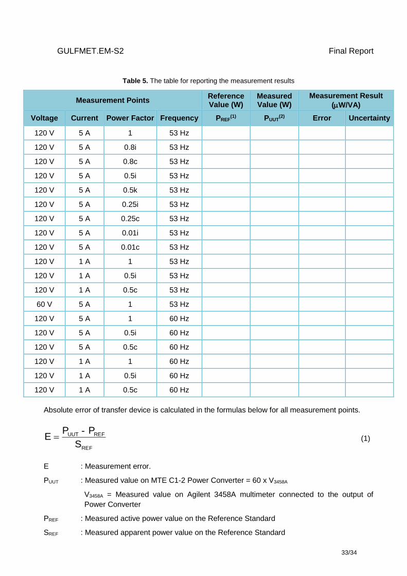
Table 5. The table for reporting the measurement results
Measurement Points Reference Value (W)
Measured Value (W)
Measurement Result
(W/VA)
Voltage Current Power Factor Frequency PREF(1) PUUT
(2)
Error Uncertainty
120 V 5 A 1 53 Hz
120 V 5 A 0.8i 53 Hz
120 V 5 A 0.8c 53 Hz
120 V 5 A 0.5i 53 Hz
120 V 5 A 0.5k 53 Hz
120 V 5 A 0.25i 53 Hz
120 V 5 A 0.25c 53 Hz
120 V 5 A 0.01i 53 Hz
120 V 5 A 0.01c 53 Hz
120 V 1 A 1 53 Hz
120 V 1 A 0.5i 53 Hz
120 V 1 A 0.5c 53 Hz
60 V 5 A 1 53 Hz
120 V 5 A 1 60 Hz
120 V 5 A 0.5i 60 Hz
120 V 5 A 0.5c 60 Hz
120 V 1 A 1 60 Hz
120 V 1 A 0.5i 60 Hz
120 V 1 A 0.5c 60 Hz
Absolute error of transfer device is calculated in the formulas below for all measurement points.
REF
REFUUT
S
PPE
- (1)
E : Measurement error.
PUUT : Measured value on MTE C1-2 Power Converter = 60 x V3458A
V3458A = Measured value on Agilent 3458A multimeter connected to the output of
Power Converter
PREF : Measured active power value on the Reference Standard
SREF : Measured apparent power value on the Reference Standard
GULFMET.EM-S2 Final Report
34/34
A statement of traceability,
The Type A standard uncertainty;
Detailed uncertainty budget with the different sources of uncertainty and their values, as;
Expanded measurement uncertainty, estimated for the coverage probability of approximately
95%.
12. Final Report of the Comparison
The pilot institute is responsible for the preparation of a comparison report.
The draft version of the comparison report will be issued within two months after receiving the
participant report by the pilot institute. Draft report will be sent to the SASO NMCC for discussion
and approval. This draft will be confidential to the participants.
The participant will have one week to send their comments on Draft Report. After approval, Draft
Report will become the Final Report. The Final Report will form the basis for the publication of
results.
13. References
[1] CCEM Guidelines for Planning, Organizing, Conducting and Reporting Key, Supplementary
and Pilot Comparisons, 2007 (available on the BIPM website:
http://www.bipm.org/utils/common/pdf/CC/CCEM/ccem_guidelines.pdf)
[2] Evaluation of measurement data - Guide to the Expression of Uncertainty in Measurement
(GUM), JCGM 100, First edition, September 2008 (available on the BIPM website:
http://www.bipm.org/utils/common/documents/jcgm/JCGM_100_2008_E.pdf)
[3] Hüseyin Çaycı, “Final Report of Key Comparison EUROMET.EM-K5.1 Comparison of 50/60
Hz Power,” March 2011.