distribution management system open++ opera v.3 · 2018-05-09 · used to export/import line...
TRANSCRIPT

Distribution Management SystemOpen++ Opera v.3.2MicroSCADA Integration Manual


1MRS 751468-MUM Open++ Opera v.3.2Issued: 31.12.1999Version: B/21.2.2001Checked: MKApproved: PV
MicroSCADA Integration Manual
We reserve the right to change data without prior notice
1
Contents
Page
1 How to Use This Manual................................................................3
1.1 General ............................................ Error! Bookmark not defined.
2 Integration of Open++ Opera and MicroSCADA..........................5
2.1 General ........................................................................................... 5
2.2 LIB 500 Opera Interface Package ................................................... 5
2.3 Functionality .................................................................................... 5
2.3.1 Starting Open++ Opera Session .......................................... 5
2.3.2 Opening Station Pictures via OperaWS ............................... 6
2.3.3 Opening Control Dialog Box for Manually Operated Switches6
2.3.4 Opening Control Dialog Box for Remote Operated Switches 7
3 Engineering Guidelines .................................................................8
3.1 General ........................................................................................... 8
3.2 Automatically Started Processes ..................................................... 8
3.2.1 Adding Open++ Opera Start-Up Items to LIB 500 Menus..... 8
3.3 Building Pictures for Remotely Operated Switches........................ 10
3.4 Creating MicroSCADA Database for Manually Operated Switches 11
3.4.1 Adding Virtual Point Creation Tool to Tool Manager........... 11
3.4.2 Functionality of the Virtual Point Creation Tool................... 11
3.5 Configuring DMS Data Transfer Groups........................................ 12
3.5.1 Adding DMS Grouping Tool to Tool Manager..................... 12
3.5.2 Functionality of the DMS Grouping Tool............................. 13

Open++ Opera v.3.2Contents
MicroSCADA IntegrationManual
1MRS751468-MUM
_________________________________________________________________________________
2
3.6 Fault Location Engineering ........................................................... 16
3.6.1 General Description........................................................... 18
3.6.2 Work to Do ........................................................................ 18
3.6.3 List of Usable Products...................................................... 23
3.7 Automatic Fault Isolation And Restoration Procedure ................... 24
3.8 Reading Relay Settings to Open++ Opera via MicroSCADA......... 26
3.9 Application Engineering Information.............................................. 31
3.9.1 Pictures and Programs ...................................................... 31
3.9.2 Language Text Files .......................................................... 32
3.9.3 Other Text Files................................................................. 32
3.9.4 Help Text Files .................................................................. 32
Glossary of Terms ..............................................................................33
Index ....................................................................................................41

1MRS 751468-MUM MicroSCADA IntegrationManual
Open++ Opera v.3.21 About This Manual
________________________________________________________________________________
3
1 About This Manual
1.1 Notices
Notice 1
The information in this document is subject to change without notice and should notbe construed as a commitment by ABB. ABB assumes no responsibility for any errorthat may occur in this document.
Notice 2
This document complies with the program revision v. 3.2
Notice 3
1.2 Open++ Opera Documents
The following documents are associated with Open++ Opera:
User Manual 1MRS 751464-MUM
Administrator Manual 1MRS 751465-MUM
Installation Manual 1MRS 751466-MUM
System Description 1MRS 751467-MUM
MicroSCADA Integration Manual 1MRS 751468-MUM
Microsoft is a trademark of Microsoft Corporation. Other brand or product names aretrademarks or registered trademarks of their respective holders.
1.3 How to Use This Manual
This MicroSCADA Integration Manual describes the tasks made with the LIB 500Opera Interface Package in the MicroSCADA environment for the integration ofOpen++ Opera and MicroSCADA.
A general description of Open++ Opera is given in the System Description.Installation of Open++ Opera is described in the Installation Manual. TheAdministrator Manual describes initialization of the Open++ Opera distributionmanagement system and the functions needed by the administrator of the system(available in OperaSA and OperaNE). All the functions needed by the everyday userof the system (available in OperaWS) are described in the User Manual.
The manner in which functions are presented in all manuals is described below:
• Menu commands are presented in bold text, for example File. Submenucommands are separated from main menu commands with =>, for example

Open++ Opera v.3.21 About This Manual
MicroSCADA IntegrationManual
1MRS751468-MUM
_________________________________________________________________________________
4
Open++ Opera => OperaWS. Command buttons are also presented in cursivetext, for example Cancel.
• The fields, list boxes, option buttons (i.e. boxes) and check boxes in dialog boxesare shown as bold texts.

1MRS 751468-MUM MicroSCADA IntegrationManual
Open++ Opera v.3.22 Integration of Open++ Opera
and MicroSCADA
________________________________________________________________________________
5
2 Integration of Open++ Opera and MicroSCADA
2.1 General
The Open++ Opera distribution management system is created by the InstallationProgram of Open++ Opera, MicroSCADA tools, and OperaNE.
Open++ Opera can be installed and used without MicroSCADA. Connection betweenMicroSCADA and Open++ Opera functions if there is Open++ Opera license forMicroSCADA connection.
MicroSCADA LIB 500 Opera Interface Package contains tools for the integration ofOpen++ Opera and MicroSCADA. Other MicroSCADA tools are also needed. LicenseManagement Tool and Authorization Tool are used in defining the functionality andthe user levels of the system (See MicroSCADA manuals System Management andLIB 500 Backbone User’s guide). Topology Generator is used in HV/MV stationdiagram import (See MicroSCADA manual Engineering Guideline for LIB 500Busbar Coloring).
2.2 LIB 500 Opera Interface Package
The LIB 500 Opera Interface Package contains support for the integration of theOpen++ Opera distribution management system (DMS) and MicroSCADA. It holdsfunctions for starting the Open++ Opera session via LIB 500 menus. With the OperaInterface Package it is possible to control the remotely controlled switches (DTUs andREC501 coming with the LIB 510 package) directly by selecting the switch from theOperaWS. In the same way the station and control pictures with full functionality areopened when selected from the OperaWS.
The fault location function of OperaWS can be utilized by collecting the requiredprocess data from the field devices with MicroSCADA and sending it to the OperaWSto be processed. The possible fault locations are then presented in the OperaWSnetwork window to speed up the restoration of the network.
In order to integrate the local substation busbar coloring into the eventually overlayingnetwork coloring covered by OperaWS, a special line indicator picture function can beused to export/import line coloring information. The line indicator is the arrow inMicroSCADA station pictures pointing in the way the power is going. The color ofthese arrows is the same as the color of corresponding lines in Open++ Opera networkwindows.
2.3 Functionality
2.3.1 Starting Open++ Opera Session
The OperaNE and OperaWS sessions can be started from the LIB 500 menus (Figure1). The Options => Open++ Opera menu contains the OperaNE and OperaWScommands. If OperaWS and OperaNE are started from MicroSCADA, the

Open++ Opera v.3.22 Integration of Open++ Operaand MicroSCADA
MicroSCADA IntegrationManual
1MRS751468-MUM
_________________________________________________________________________________
6
authorization of the user logged into MicroSCADA is checked (See the AdministratorManual and the MicroSCADA manual LIB 500 Backbone User’s guide). Then theappropriate Open++ Opera program is started and the MicroSCADA window ishidden. All required services are started automatically when starting up the program.
Important The Open++ Opera programs need to be installed on each computerwhere the Open++ Opera programs are to be used.
Figure 1. LIB 500 menus
2.3.2 Opening Station Pictures via OperaWS
Station pictures made with LIB 5xx packages can be opened via OperaWS by clickingthe station or switch inside the station on the OperaWS network window or diagram orby clicking the appropriate menu commands. The opening station picture has fullfunctionality, what comes to the process control functions and dialog boxes, but thenavigation to other LIB 500 pictures is prevented.
2.3.3 Opening Control Dialog Box for Manually Operated Switches
The package contains a control dialog box for manually operated switches (Figure 2).With the help of the dialog box the operator updates the system to match the actualstate of the network. Clicking the switch on the OperaWS network window or diagramor by clicking the appropriate menu commands opens it. The switch state changesmade are saved in the MicroSCADA database and the switching events can be seen inthe LIB 500 event list and printed in the event printer. The changes are also seen inOperaWS network windows.

1MRS 751468-MUM MicroSCADA IntegrationManual
Open++ Opera v.3.22 Integration of Open++ Opera
and MicroSCADA
________________________________________________________________________________
7
Figure 2. Control dialog box for manually operated switches
2.3.4 Opening Control Dialog Box for Remote Operated Switches
The control pictures and dialog boxes (Figure 3) for remotely operated switches(DTUs and REC 501 in the LIB 510 package) can be opened via OperaWS by clickingthe switch on the OperaWS network window or diagram or by clicking the appropriatemenu commands. The choices of how to present and build functionality for the remoteoperated switches are described in more detail in "Building Pictures for RemotelyOperated Switches" on page 10.
Figure 3. An example of a LIB 500 control picture and dialog box for remote controlleddisconnector.

Open++ Opera v.3.23 Engineering Guidelines
MicroSCADA IntegrationManual
1MRS751468-MUM
_________________________________________________________________________________
8
3 Engineering Guidelines
3.1 General
There should be a menu command in LIB 500 menus for starting the OperaWS andOperaNE sessions (See "Adding Open++ Opera Start-Up Items to LIB 500 Menus" onpage 8). Remotely operated switches should be engineered to the station pictures (See"Building Pictures for Remotely Operated Switches" on page 10), and MicroSCADAdatabase points for manually operated switches need to be created with the VirtualPoint Creation Tool (See "Creating MicroSCADA Database for Manually OperatedSwitches" on page 11). The data transfer definitions should be made with the DMSGrouping Tool (See "Configuring DMS Data Transfer Groups" on page 12).
If fault location functionality is needed, relays and their network database pointsshould be created in the system (See "Fault Location Engineering" on page 16).
3.2 Automatically Started Processes
After starting the MicroSCADA application, after LIB 500 Opera Interface Packageinstallation, the execution of the BDU_SSI:C is added to the application initializationcommand procedure APL_INIT_2:C. This command procedure automatically startsthe AEP -program BDU_SSIAEP.EXE handling the connection to Open++ Opera.The AEP -program also installs the BDU_SSISER.EXE running as a service and startsthe Opera Server Application (OperaSA) if it is not running. The OperaSA is openedonly on the same computer where the MicroSCADA is installed.
Important In the case where you have to remove the DMS directory, you have tostop and remove the service BDU_SSISER.EXE. This can be done withBDU_SSI_CONTROL_PANEL.EXE located in directory… /SC/LIB4/BASE/DMS/USE (Figure 4).
Figure 4. The dialog box of BDU_SSI_CONTROL_PANEL.EXE installing/removing the SupportSystem Interface (BDU_SSISER.EXE)
3.2.1 Adding Open++ Opera Start-Up Items to LIB 500 Menus
The LIB 500 default menus include the start-up item for Open++ Opera. In the case ofan existing MicroSCADA application, the item has to be added to the customizedmenus. This can be done by using the following procedure:

1MRS 751468-MUM MicroSCADA IntegrationManual
Open++ Opera v.3.23 Engineering Guidelines
________________________________________________________________________________
9
1 Take any picture (built with LIB 500) to the Picture Editor.
2 Click Edit => Picture Functions from the Picture Editor menus.
3 Click the background of the picture (base picture function becomes selected).
4 Open Standard Configuration Tool with the tool icon on the left.
5 Open Menu Configuration Tool from the tool page.
6 Add OperaWS menu commands to the Standard part of the menus.
7 For menu action definitions select advanced radio button and open advancedprogram.
8 Write the following as action program: #if mon:bdt=="VS" #then !new_pic b_use/bdu_start #else #block @bgu_info_txt = bgu_head1:vnot_vs_monitor @bgu_info_window = "not_vs_monitor" !win_name root/not_vs_monitor !win_pic root/not_vs_monitor b_use/bgu_info5 !win_pos root/not_vs_monitor (15,15) !show root/not_vs_monitor #block_end
9 Add the OperaNE menu commands to the Standard part of the menus.
10 For menu action definitions select the advanced radio button and open theadvanced program.
11 Write the following as an action program (Note: the command lines must bewritten in one line):
; user authorization@auth_tmp ;Initialize variable@auth_group ;Initialize variable@auth_level = 0 ;Authorization level set = 0@auth_tmp = MON:BSV9 ;Read users authorization definitions in#error ignore@auth_level = auth_tmp:vgeneral;Authorization level set = generals@auth_level = auth_tmp:vtopology;Level set = auth. groups#error continue#if %auth_level>1 #then #block
@mon_bsd = mon:bsd#if %mon_bsd == "" #then #block@i_status1=ops_process("OperaNE.exe")@stat = console_output(date + " " + tods +
" OperaNE started to server PC")#block_end#else #block@i_status2 = workstation_call("EXECUTE","OperaNE.exe")@stat = console_output(date + " " + tods +

Open++ Opera v.3.23 Engineering Guidelines
MicroSCADA IntegrationManual
1MRS751468-MUM
_________________________________________________________________________________
10
" OperaNE started to remote workstation")#block_end
#block_end#else #block@bgu_info_txt = bgu_head1:vno_tool_access@bgu_info_window = "not_authorized"!win_name root/not_authorized!win_pic root/not_authorized b_use/bgu_info5!win_pos root/not_authorized (15,15)!show root/not_authorized#block_end
12 Save and exit.
3.3 Building Pictures for Remotely Operated Switches
The remotely operated switches can be presented as a normal substation picture withdisconnectors installed (Figure 5). This is convenient in the case where multipleswitching devices are located in a node.
Figure 5. An example of a remotely controllable disconnector substation
In the case of a single switching device, it is often more suitable to open the plaincontrol dialog box. This is done by creating a picture consisting of a single picturefunction made especially for this purpose. The picture function consists of a graybackground covering the whole picture and of the configuration support (the basepicture function is not required). The configuration is done as for the normal picturefunction for DTUs or REC 501. When the disconnector is selected in OperaWS, thepicture is opened with the control dialog box already open.

1MRS 751468-MUM MicroSCADA IntegrationManual
Open++ Opera v.3.23 Engineering Guidelines
________________________________________________________________________________
11
The picture functions are found under the \LIB 4.0.2\LIB 510\NETWORKTOPOLOGY\ directory in the installation tool tree. For more information on how toinstall and configure the picture functions, please refer to the LIB 510 MV processdocumentation for REC 501 and for DTUs.
3.4 Creating MicroSCADA Database for Manually Operated Switches
The manually operated switches saved in the network database of OperaNE needcorresponding process objects in the MicroSCADA database. A file holding data ofthe switches can be produced with OperaNE (See the Administrator Manual). It can beimported to MicroSCADA with the Virtual Point Creation Tool.
The Virtual Point Creation Tool (VPCT) is a tool for managing the MicroSCADAprocess objects made for virtual points. These virtual points can be, for example,manually operated disconnectors or circuit breakers, which have no real connection tothe process. The switch states are maintained in the MicroSCADA database and eventsof the state changes are printed to the LIB 500 event list and event printer according tothe switch changes made by the operator.
3.4.1 Adding Virtual Point Creation Tool to Tool Manager
The Virtual Point Creation Tool can be added to the Tool Manager by the proceduredescribed in the following:
1 Select the Tool Managers notebook tab where you want the tool to be placed.
2 Click Edit => Insert Tool from the Tool Manager menu.
3 Click User Defined from the opening dialog box.
4 Insert icon description VPCT.
5 Insert file name \SC\LIB4\BASE\DMS\USE\BDU_VPCTA.VSO.
6 Click OK.
Now the icon for the tool is available on the Tool Manager.
3.4.2 Functionality of the Virtual Point Creation Tool
The Virtual Point Creation Tool (VPCT) () uses an input file that can be generatedfrom the OperaNE. The file is opened with a browser via the menus with the File =>Open command. The input files have an extension .VPC by default. The defaultObject texts (OX) used when creating the database can be modified or translated to thedialog box (BDU_VPCTA.VSO).

Open++ Opera v.3.23 Engineering Guidelines
MicroSCADA IntegrationManual
1MRS751468-MUM
_________________________________________________________________________________
12
Figure 6
Figure 6. The Virtual Point Creation Tool dialog box
The tab of the new objects (New) shows objects of the input file not found from theMicroSCADA database. These objects can be created with the Create New button.
The tab of modified objects (Modified) shows objects of the input file found from theMicroSCADA database, but with unequal OI, OX or RX attributes. The objects can bemodified according to the input file with the Update modified button.
The tab of existing objects (Existing) shows objects already existing in theMicroSCADA database. The existing objects can be deleted by selecting them fromthe list and then clicking the Delete selected button.
The lists show about 1000 first objects. If there are more than 1000 objects, they canbe seen by clicking the button marked as 1000 with an arrow pointing upwards.
3.5 Configuring DMS Data Transfer Groups
The DMS Grouping Tool is used for configuring the communication betweenMicroSCADA and Open++ Opera. This tool is used for defining which MicroSCADAprocess database values are transferred to Open++ Opera. Vice versa the colors offeeder root points of OperaWS are transferred to MicroSCADA. The tool holdsgeneral communication definitions and it is also used for defining the MicroSCADAstation and control pictures and dialog boxes opened via OperaWS.
3.5.1 Adding DMS Grouping Tool to Tool Manager
The DMS Grouping Tool can be added to the Tool Manager by the followingprocedure:

1MRS 751468-MUM MicroSCADA IntegrationManual
Open++ Opera v.3.23 Engineering Guidelines
________________________________________________________________________________
13
1 Select the Tool Manager notebook tab where you want the tool to be placed.
2 Click Edit => Insert Tool from the Tool Manager menu.
3 Click User Defined from the opening dialog box.
4 Insert icon description DMS grouping.
5 Insert file name \SC\LIB4\BASE\DMS\USE\BDU_SSI.VSO.
6 Click OK.
Now the icon for the tool is available on the Tool Manager.
3.5.2 Functionality of the DMS Grouping Tool
3.5.2.1 General Parameters
The parameters on the General parameters tab of the DMS Grouping Tool are listedbelow (Figure 7):
• Working directory contains the name of the directory where the grouping data issaved.
• TCP Port (1000-10000) contains the TCP port used (normally no need to bechanged).
• Ping interval (5-180 s) contains the ping interval for the TCP/IP connection(normally no need to be changed)
• TCP-IP username contains the user name used in the TCP-IP connection betweenSSI-service and OperaSA (normally no need to be changed)
• TCP-IP password contains the password used in the TCP-IP connection betweenSSI-service and OperaSA (normally no need to be changed)
• Primary address contains the TCP-IP address of the primary OperaSA.
• Secondary address (HSB) contains the TCP-IP address of the secondary OperaSA(in Hot-Stand-By configuration)
• Integration number contains the integration number, which is a unique number forthe application. Normally it is the MicroSCADA application number.
Important The MicroSCADA application number might be different in the HSBsys.
• Comment contains the freely editable user comments.

Open++ Opera v.3.23 Engineering Guidelines
MicroSCADA IntegrationManual
1MRS751468-MUM
_________________________________________________________________________________
14
Figure 7. DMS Grouping Tool, General parameters tab
3.5.2.2 Transport Group Parameters
The data transfer groups define the process database values transferred fromMicroSCADA to Open++ Opera or vice versa. The groups should include theswitching device position indication objects, fault detector objects, line indicatorobjects and objects holding the pen color definitions (LN = TOPOPEN). The picturescalled for when the objects are selected on OperaWS are also defined by using thistool (Figure 8).
The data transfer groups are made separately for each process object type. Each groupcan contain a maximum of 1000 objects, but less than 500 objects per group arerecommended. The first 1000 objects found in the MicroSCADA process database areshown on a list. By clicking the 1000 up/down buttons the next 1000 objects can beseen.
Each group can have a group comment and a default picture. If the Spontaneous DataTransfer check box is selected, the object state changes are immediately transferred toOperaWS. Otherwise the object states are cyclically polled. The polling cycle isconfigurable in OperaSA by setting the data transfer intensity level. (See theAdministrator Manual).
It is recommended to group objects of MicroSCADA according to the following rules:

1MRS 751468-MUM MicroSCADA IntegrationManual
Open++ Opera v.3.23 Engineering Guidelines
________________________________________________________________________________
15
• Grouping all TOPOPEN objects to the same group, which is not definedspontaneously transferable.
• Defining most of the switching state objects (BI and DB types) spontaneouslytransferable.
• Defining most of the measurement objects (AI types) not spontaneouslytransferable.
Each object can have a picture of its own (Picture for selected object) that is defined,which is then used instead of the default picture.
Figure 8. DMS Grouping Tool, Transport group parameters tab
The tool generates codes for each object included in the groups in the followingformat:
<logical name>:P<object type><index >
where
• <logical name>: The logical name of the process object (LN), a string witha length of 1 to 10 characters.
• The database object type of MicroSCADA (P=process object).

Open++ Opera v.3.23 Engineering Guidelines
MicroSCADA IntegrationManual
1MRS751468-MUM
_________________________________________________________________________________
16
• <object type>: The type of process object. Integration supports three types:
BI binary input
DB double binary input
AI analog input
• <index>: The index number of a process object. An integer whose limits arebetween 1 and 10000.
This code is called scadacode in the documentation.
3.6 Fault Location Engineering
This chapter should give a basic understanding in how to route data of fault situations(Figure 9) from MicroSCADA to Open++ Opera. The fault location can beaccomplished in more than one level depending on the equipment used. The minimumsolution just automatically presents the faulty feeder on the OperaWS networkwindow (Figure 10). The accuracy of the possible fault locations becomes more andmore precise when the amount of available data increases.
Figure 9. DTU line disconnector assembly

1MRS 751468-MUM MicroSCADA IntegrationManual
Open++ Opera v.3.23 Engineering Guidelines
________________________________________________________________________________
17
Figure 10. The user interface of OperaWS in fault situation

Open++ Opera v.3.23 Engineering Guidelines
MicroSCADA IntegrationManual
1MRS751468-MUM
_________________________________________________________________________________
18
3.6.1 General Description
O p e r a W SM i c r o S C A D A M o n i t o r
U n i t : F o r e x a m p l eS P A C O M o r R E F 5 4 x
0
I
S P A C 3 31 C
M i c r o S C A D A
C o m m a n d P r o c e d u r e s
- Messages t o t h e un i t- B D U _ F A U L T : C
23
O p e r a S A
5
64
1
Figure 11. General description.
Figure 11 is described in the following:
1 An Event tripped message is generated in the unit and sent to MicroSCADA.MicroSCADA receives the message.
2 Message is checked in the MicroSCADA database.
3 The Command Procedure attached to the process object is run.
4 First in the Command Procedure are the messages to the unit. When they are sentreturn messages will be expected. Fault information is formed and sent to theBDU_FAULT:C command procedure, which sends collected data to OperaSA.
5 OperaSA forms a snapshot of the faulted feeder and creates a fault file in the Operadatabase.
6 OperaSA sends the message about the fault information to OperaWS. OperaWSchecks the Opera database and performs the fault location functions and indicatesthe possible fault situations on the network window.
3.6.2 Work to Do
How to make the system work as described in earlier chapters?

1MRS 751468-MUM MicroSCADA IntegrationManual
Open++ Opera v.3.23 Engineering Guidelines
________________________________________________________________________________
19
Important It should be emphasized that every unit has a different kind ofconfiguration in MicroSCADA and different kinds of commands to handle faultsituations. This description presumes that the net has been configured for theMicroSCADA system and that other necessary preparations have been carried out.
Process and virtual points in this section are the same as described earlier. The part inthe system concerning Open++ Opera makes an exception. It is described in theAdministrator Manual of Open++ Opera and briefly in the following.
1 Create station object in the system with the System Configuration Tool: ClickConfiguration => Open Active to create the information of the active system. Createthe new object (new REF unit to the system) by clicking MicroSCADAConfiguration/Link/Node/Line from the list and by clicking Object => New… fromthe menu. Again, click REX Station from the list appearing and give the number ofthe new station. It is possible that some of the created station attributes should be setwith new values.
Insert and configure the relay with the Picture Editor.
The unit is installed from the LIB 500 Protection Package and configured to theMicroSCADA system with the Picture Editor available in the Tool Manager.
By adding the relay to the picture, an object is created and named as in theLIB_OBJECT_NAME box. In the Configuration Tool, the type of the relay is alsoasked for. After a proper configuration the system is aware of the process object andthe process points for the object.
Station numbers (STA) given in the SYS_BASCON.COM and in the LIB 510 picturefunction configuration should be the same.
2 Now it is possible to see the process object names as inserted in the box at step.
This can be done in the following way, with the help of the Object Navigator availablein the Tool Manager:
Click Process Objects from the list.
Select the process object as named in the previous point.
Many points have been created to the process object.
The point which to handle has the text (OX) like ‘I> TRIP’ or ‘I>> TRIP’ withSPACOM relays and the text with REFxx relays depends on the configuration. Thetrip event will come from the relay to these points.
These points can be edited with the Object Navigator in the following way:
• Select the notebook page Events from the screen of the selected process object.
• Click Action Enabled (AE).

Open++ Opera v.3.23 Engineering Guidelines
MicroSCADA IntegrationManual
1MRS751468-MUM
_________________________________________________________________________________
20
• Write the name of the event channel to be executed, in case of the tripping event,to the Action Name (AN) box.
• Select the value in the Action Activation (AA) box to be 'updated'. This meansthat the action is started when the process object is updated.
• Event object should be Enabled (EE) and In Use (IU) should be selected.
• By clicking Show… the chosen event channel can be edited and from there thechosen command procedure can also be edited.
• If there is no event channel, it can be created in the Object Navigator by clickingEvent Channels from the list and by clicking Object => New from the menu.
• By clicking the Set button, the name of the command procedure wanted to be runafter an event trip can be set to the Primary Object box.
• If there is no command procedure, it can be created in the Object Navigator byclicking Command Procedures from the list and by clicking Object => Newfrom the menu.
The In Use (IU) check box should be selected.
3 These procedures can be edited in the following way:
• Click Command Procedures from the list of the Object Navigator.
• Double-click the procedure you want to edit.
Click the Edit button to be able to edit the procedure.
4 SPA messages sent to the unit should be inserted in the procedure. Informationabout the trip event occurred will be collected with these messages. Different unitshave different kinds of messages. The messages for each unit should be found in thespecifications and relay documentation.
• SPA-messages sent to the unit are formed as follows:
#SET STA’stanum’:SSM=“R’ch’’code’”
where
stanum Station number of the unit
ch Channel
code SPA-code sent to the unit
• The response of the message sent can be as follows:
@var=STA’stanum’:SSM
where

1MRS 751468-MUM MicroSCADA IntegrationManual
Open++ Opera v.3.23 Engineering Guidelines
________________________________________________________________________________
21
var Name of the variable, where information will be set
stanum Station number of the unit
• Information from MicroSCADA to the OperaSA will be handled with theBDU_FAULT:C command procedure. Below there is the list of the informationneeded to be passed to the BDU_FAULT:C.
Variable name Type Description
e_Event_time time Event time, RT attribute from tripping event object.Default value 0.
i_Event_ms integer Event milliseconds, RM attribute from tripping eventobject.
t_Source_ln text Breakers Scadacode defined in OperaNE. In case thestation has only one relay in a feeding bay capable ofmeasuring the fault currents, then this is the Scadacode ofthe breaker from where the currents are measured. Thescadacode of the breaker is given in the format describedearlier. If there is no fault current measurement at thestation this is the Scadacode of the station object.
t_Type text Fault type. “unknown”, “short_circuit” or “earth_fault”Default value “unknown”.
t_Trigger text Trigger information. “unknown”, “final”, “reclosing”Default value “final”.
t_Notation text Notation of all measurement values “relative” or “real”Default value “real”.
t_Phase text Phase information “unknown”, “1_phase_short",2_phase_short” or “3_phase_short”. Default value“unknown”
v_I_Msr vector Short circuit currents (A). The type of the element is real.The first element got the newest value and the oldestvalue is in the last of the elements.
r_I_Load real Load current before fault (A) for example average valuefrom the last 5 history DB values
r_I0_Msr real Zero current (A). Not in use at the moment, reserved forfuture use with earth fault situation.
r_U0_Msr real Zero voltage (kV). Not in use at the moment, reserved forfuture use with earth fault situations.
r_X_Msr real Feeding network reactance (ohm).
r_ Z_Msr real Feeding network resistance (ohm).
v_Transformer_ LN vector Transformer Scadacode defined in OperaNE. The type ofthe element is text.
v_ P_Msr vector Transformer active power (kVA). Average value from thelast 5 history DB values the type of the element is real.

Open++ Opera v.3.23 Engineering Guidelines
MicroSCADA IntegrationManual
1MRS751468-MUM
_________________________________________________________________________________
22
v_ Q_Msr vector Transformer reactive power (kVar) before fault. Averagevalue from the last 5 history DB valuesthe type of the element is real.
• BDU_FAULT:C command procedure should be called as follows:
#EXEC BDU_FAULT:C @e_Event_time=time, @t_Source_ln=source)
where
time Event time in seconds
source Opened breakers scadacode given in OperaNE
For using the procedure there are some notations to make:
A - ‘Atleast’ –values to the message are Time in seconds (e_Event_time) and the logicalname of the unit (t_Source_ln).
- Result is that OperaWS zooms the faulty feeder but cannot calculate the exact faultlocation.
B - If fault type is short circuit, there are two possible ways to give message values to themethod.
Simple short circuit fault message:
- ‘Atleast’ –values.
- Fault type is “short_circuit”.
- Short circuit current and load current before fault should be given.
- Default fault phase is "3_phase_short".
Exact short circuit fault message:
- ‘Atleast’ –values.
- Fault type is “short_circuit”.
- Phase information, short circuit currents and load current before fault should be given.
- Feeding network resistance and reactance values should be given.
C -If fault type is earth fault and network is earthed, there are two possible ways to givemessage values to the method.
Simple earth fault message:
- ‘Atleast’ –values
- Fault type is “earth_fault”.
- Short circuit current and load current before fault should be given.
- Default fault phase is "1_phase_short".
Exact earth fault message:
1MRS 751468-MUM MicroSCADA IntegrationManual
Open++ Opera v.3.23 Engineering Guidelines
________________________________________________________________________________
23
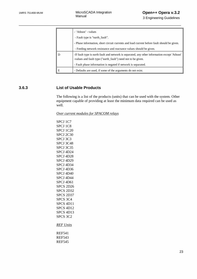
- ‘Atleast’ –values
- Fault type is “earth_fault”.
- Phase information, short circuit currents and load current before fault should be given.
- Feeding network resistance and reactance values should be given.
D -If fault type is earth fault and network is separated, any other information except 'Atleast'-values and fault type ("earth_fault") need not to be given.
- Fault phase information is negated if network is separated.
E - Defaults are used, if some of the arguments do not exist.
3.6.3 List of Usable Products
The following is a list of the products (units) that can be used with the system. Otherequipment capable of providing at least the minimum data required can be used aswell.
Over current modules for SPACOM relays
SPCJ 1C7SPCJ 1C8SPCJ 1C20SPCJ 2C30SPCJ 3C3SPCJ 3C48SPCJ 3C35SPCJ 4D24SPCJ 4D28SPCJ 4D29SPCJ 4D34SPCJ 4D36SPCJ 4D40SPCJ 4D44SPCJ 4D61SPCS 2D26SPCS 2D32SPCS 2D37SPCS 3C4SPCS 4D11SPCS 4D12SPCS 4D13SPCS 3C2
REF Units
REF541REF543REF545

Open++ Opera v.3.23 Engineering Guidelines
MicroSCADA IntegrationManual
1MRS751468-MUM
_________________________________________________________________________________
24
3.7 Automatic Fault Isolation And Restoration Procedure
The sequence of controls generated by automatic fault isolation and restorationfunction of OperaWS is executed using SCIL programming in MicroSCADAapplication. These programs have the responsibility for safety checks etc.
Important ABB assumes no responsibility for any error that may occur in thecontrol sequence.
Below you can find a template procedure for reading the control sequence file. Bydefault the procedure name is OPERASEQ:C and the process object name for givingthe sequence status is sqc_state type (AI) and index is 1. However these names can bechanged using OperaNE (For more information about the settings, see theAdministrator Manual).
At least checking of the programmed blockings and the success of control actionsmust be added to the program. The procedure must not continue to the next actionbefore last control action is verified. If not verified (e.g. time out occurs) the proceduremust update process object (seqln) to 2.
When the procedure is called from OperaWS the value of process object is updated to1 (seqln=1).
Return values to be updated to process object (seqln):
0 = successful sequence
2 = sequence not successful
3= object not found
4= unknown error in .INI file
In the case of the process object value 4, check the MicroSCADA NotificationWindow.
;THIS TEMPLATE PROCEDURE READS THE STATES OF SWITCHES;FROM A .INI-FILE AND CHANGES THEM TO DATABASE; MN/HP 31.10.2000#ERROR EVENT;##########################################;Define here the path of the sequence-file and the;process object name including the sequence status@openpath="C:\opera\AutoFaultSeq.INI"@seqln="sqc_state:pai1";##########################################@nr_objects=READ_PARAMETER(%openpath,"COMMON",
"Number_of seqs")@nr_obj=nr_objects:vvalue@rloop=dec_scan(%nr_obj)@faultnr=READ_PARAMETER(%openpath,"common","FaultID")@faultID=faultnr:vvalue@i=0

1MRS 751468-MUM MicroSCADA IntegrationManual
Open++ Opera v.3.23 Engineering Guidelines
________________________________________________________________________________
25
@time=times@dot=locate(%openpath,".")@openlogfile=substr(%openpath,1,%dot-1)@logfile=%openlogfile+".log"@AutoSeqLog(1)="'time' Sequence is started"@log=write_text("'logfile'",%AutoSeqLog,1)#LOOP_WITH R=1..%rloop#ON ERROR #BLOCK@S=STATUS@HP=CONSOLE_OUTPUT ("Opera: Automatic fault isolation
sequence error 'S'")#IF %S==2056 #THEN #set 'seqln'=3#ELSE #IF %S==2057 #THEN #set 'seqln'=3#ELSE #IF %S==2020 #THEN #set 'seqln'=3#ELSE #IF %S==2001 #THEN #set 'seqln'=3#ELSE #IF %S==7005 #THEN #set 'seqln'=3#ELSE #IF %S==266 #THEN #set 'seqln'=3#ELSE #IF %S==201 #THEN #set 'seqln'=3#ELSE #IF %S==114 #THEN #set 'seqln'=3#ELSE #set 'seqln'=4#BLOCK_END@i=%i+1@a=dec(%i,1)@object="Object"+%a@oper="Oper"+%a@seqswitch=READ_PARAMETER(%openpath,
"Sequence objects",%object)@switchstate=READ_PARAMETER(%openpath,"Operation_seq",
%oper)@switch=seqswitch:vvalue@lnapu=locate(%switch,":")@ln=substr(%switch,1,%lnapu-1)@status1=seqswitch:vstatus@state=switchstate:vvalue@status2=switchstate:vstatus#if %status1<>0 OR %status2<>0 #then #block#set 'seqln'=2@AutoSeqLog(1)="'time' Error in reading INI-file -
Status 'status1' 'status2'"@log=write_text("'logfile'",%AutoSeqLog,1)#loop_exit#block_end#if %state=="CLOSE" #then #BLOCK; Here you have to write the code to control the switch; Procedure must check that the state was really changed beforecontinuing to next control#set 'switch'=1 ;for testing only@AutoSeqLog(1)="'time' 'switch' -> 1"@log=write_text("'logfile'",%AutoSeqLog,1)#BLOCK_END#if %state=="OPEN" #then #BLOCK; Here you have to write the code to control the switch; Procedure must check that the state was really changed beforecontinuing to next control#set 'switch'=2 ;for testing only@AutoSeqLog(1)="'time' 'switch' -> 2"@log=write_text("'logfile'",%AutoSeqLog,1)#BLOCK_END#LOOP_END

Open++ Opera v.3.23 Engineering Guidelines
MicroSCADA IntegrationManual
1MRS751468-MUM
_________________________________________________________________________________
26
;if successful sequence status must be set to 0#set 'seqln'=0@AutoSeqLog(1)="'time' Sequence executed succesfully"@log=write_text("'logfile'",%AutoSeqLog,1)@HP=CONSOLE_OUTPUT ("Opera: Automatic fault isolation
sequence executed succesfully")
3.8 Reading Relay Settings to Open++ Opera via MicroSCADA
Data source for all relay settings can be changed workstation specific betweennetwork model and active relay settings via MicroSCADA. The relay settings ofSPACOM and RED 500 typed relays can be obtained via MicroSCADA by the menucommand. The loaded settings are used for all protection analysis calculations. Thischapter describes the steps needed for reading the relay settings via MicroSCADA.
Check that network.mdb includes the following three tables and three queries:
• EARTHFAULTRELAYSCADA
• OVERCURRENTRELAYSCADA
• RECLOSERELAYSCADA
• SC_OPERA_EFRELAY
• SC_OPERA_OCRELAY
• SC_OPERA_RCRELAY
Create a button to Relay Setting Tool. Open the Dialog Editor from MicroSCADAtool menu. The dialog file of SPACOM relays, for example, can be found fromSC\LIB4\FMOD\SPA_TOOL\SPAMMI\SPAMMI.VSO.
1. Open the dialog file.
2. Select MAIN from Visual SCIL Object List
3. Select the Dialog => New Item => VS_Button command.
4. Drag the button to the desired location.
5. Select the Dialog => Edit Item command.
6. Insert the Name of button and the Title of button in the Button tab.
7. In the Action from the Methods tab select Notify and click Edit, writeRoot.BtnOpera and select File => Update and Exit.
8. Close VS_Button dialog.
Do the next steps in VS_MAIN_dialog:
1. Select Private from the Methods tab.

1MRS 751468-MUM MicroSCADA IntegrationManual
Open++ Opera v.3.23 Engineering Guidelines
________________________________________________________________________________
27
2. Click the New button
3. Insert Name (BtnOpera)
4. Click OK
5. Click Edit
6. Insert the following program:
;Start of program
@v_active=vector()@v_active=this.GetParameterValue(vector("_N_0V150"),2)
;Variable v_active includes information which settings,; primary/secondary, are active;GetParameterValue function returns desired settings in a; vector;Second argument of that function is the module number;The module number of a unit and can be found from values.ini –; file;Define different vectors for reclosing and earth fault units.; (Because of only settings of one;module can be read at once (with GetParameterValue – function;Loop 1 is for primary settings and loop 2 for secondary
#loop_with j=1..2
#case %j #when 1 #block
;Define those primary settings you would like to transfer to; Opera's database;The desired settings of each unit unit and can be found from; values.ini – file;Define different vectors for relosing and earth fault units.
@v_apu=vector() @v_apu=this.GetParameterValue(vector("_N_0S21",- "_N_0S22",- "_N_0S23",- "_N_0S24",- "_N_0S25",- "_N_0S26",- "_N_0S27",- "_N_0S28"),2)
;Settings are assigned to the following variables;NOTE1! Some settings used in the Opera can not be obtained; directly from relays;Those values have to be calculated in this program before they; are assigned to the variables below;NOTE2! An variable in SCIL-language is not allowed to have; more than 255 characters;(including the assigned values) See variables sql1, sql2, sql3; and sql4

Open++ Opera v.3.23 Engineering Guidelines
MicroSCADA IntegrationManual
1MRS751468-MUM
_________________________________________________________________________________
28
@tpjk=0.19;Rest time in fast reclose (s)
@tajk=201;Rest time in delayed reclose (s)
@pjk_lkm=1;No. of fast reclosings in overcurrent unit
@ajk_lkm=1;No. of delayed reclosings in overcurrent unit
@Iyli=%v_apu(1);Operating current (A) in time tripping, setting value
@t1yli=%v_apu(2) ;S.C. time before fast reclose in time tripping
@t2yli=0.56;S.C. time after fast reclose in time tripping
@t3yli=0.9;S.C. time after delayed reclose in time tripping
@Imom=%v_apu(3);Operating current (A) in instant tripping, setting value
@t1mom=%v_apu(4);S.C. time before fast reclose in instant tripping
@t2mom=0.14 ;S.C. time after fast reclose in instant tri pping
@t3mom=0.17 ;S.C. time after delayed reclose in instant tripping
@I0aika=%v_apu(5);Neutral current setting I0 secondary (A) in time tripping
@U0aika=5;Neutral voltage U0 secondary (V) (in both trippings)
@T0aika=%v_apu(6);Time settings T0 (longest in reclosing) in time tripping
@I0pika=%v_apu(7);Neutral current setting I0 secondary (A) in instant; tripping
@T0pika=%v_apu(8);Time settings T0 (longest in reclosing) in in stant; tripping
@pjk_lkm_maa=1;No. of fast reclosings in earthfault unit
@ajk_lkm_maa=1;No. of delayed reclosings in earthfault unit
@ehto = "Background=0"
#if %v_active(1)=="0" #then #block @active=1 #block_end
#if %v_active(1)=="1" #then #block @active=0 #block_end #block_end
#when 2 #block
;Define those secondary settings you would like to transfer to; Opera's database;The desired settings of each unit unit and can be found from; values.ini – file

1MRS 751468-MUM MicroSCADA IntegrationManual
Open++ Opera v.3.23 Engineering Guidelines
________________________________________________________________________________
29
@v_apu=vector() @v_apu=this.GetParameterValue(vector("_N_0S41",- "_N_0S42",- "_N_0S43",- "_N_0S44",- "_N_0S45",- "_N_0S46",- "_N_0S47",- "_N_0S48"),2)
;Settings is assigned to the following variables;NOTE! An variable in SCIL-language is not allowed to have more; than 255 characters;(including the assigned values) See variables sql1, sql2, sql3; and sql4
@tpjk=0.19 ;Rest time in fast reclose (s)
@tajk=201 ;Rest time in delayed reclose (s)
@pjk_lkm=14 ;No. of fast reclosings in overcurrent unit
@ajk_lkm=14 ;No. of delayed reclosings in overcurrent unit
@Iyli=%v_apu(1) ;Operating current (A) in time tripping, setting value
@t1yli=%v_apu(2) ;S.C. time before fast reclose in time tripping
@t2yli=0.56 ;S.C. time after fast reclose in time tripping
@t3yli=0.9 ;S.C. time after delayed reclose in time tripping
@Imom=%v_apu(3);Operating current (A) in instant tripping, setting value
@t1mom=%v_apu(4);S.C. time before fast reclose in instant tripping
@t2mom=0.14 ;S.C. time after fast reclose in instant tripping
@t3mom=0.17 ;S.C. time after delayed reclose in instant tripping
@I0aika=%v_apu(5);Neutral current setting I0 secondary (A) in time tripping
@U0aika=5;Neutral voltage U0 secondary (V) (in both trippings)
@T0aika=%v_apu(6);Time settings T0 (longest in reclosing) in time tripping
@I0pika=%v_apu(7); Neutral current setting I0 secondary (A) in instant; tripping
@T0pika=%v_apu(8);Time settings T0 (longest in reclosing) in instant; tripping
@pjk_lkm_maa=9;No. of fast reclosings in earthfault unit
@ajk_lkm_maa=10;No. of delayed reclosings in earthfault unit
@ehto = "Background=1"
#if %v_active(1)=="0" #then #block

Open++ Opera v.3.23 Engineering Guidelines
MicroSCADA IntegrationManual
1MRS751468-MUM
_________________________________________________________________________________
30
@active=0 #block_end
#if %v_active(1)=="1" #then #block @active=1 #block_end
#Block_end#Case_end
;In this section the Scadacode of the circuit breaker is; defined.;NOTE! The naming convention of Process Objects is usually; different in different applications;Scadacode of the cicuit breaker is assigned to the scode-; variable
@ln_apu=%ObjKey@count=locate(%ln_apu, "_")@ln1=substr(%ln_apu, 1, %count-1)@ln=%ln1+"_Q0:PDB10"@scode=%ln
;The Data source, username and password is defined here;NOTE! This Data source has to be defined also to the NT's; ODBC-definitions
@dsn = "RELAYSETTODMS"@user ="Opera"@psw = "opera"
#loop_with i=1..4
@ret = sql_connect(%dsn, %user, %psw) #if ret:vstatus == SQL_SUCCESS or ret:vstatus ==
SQL_SUCCESS_WITH_INFO #then #block @conn_id = ret:vconnection_id
;A SQL-query is executed
@Sql1="UPDATE SC_OPERA_OCRELAY SET I_='Iyli',I__='Imom',T1_='t1yli',T2_='t2yli',T3_='t3yli',Active ='active'"
@Sql1=%Sql1+" WHERE Scadacode='''scode''' AND 'ehto';"
@Sql2="UPDATE SC_OPERA_OCRELAY SET T1_= 't1mom',T2_='t2mom',T3_='t3mom',FAST_RECLOSING_COUNT='pjk_lkm',"
@Sql2=%Sql2+"DELAYED_RECLOSING_COUNT = 'ajk_lkm'WHERE Scadacode='''scode''' AND 'ehto';"
@Sql3="UPDATE SC_OPERA_RCRELAY SET T_FAST_RECLOSE='tpjk', T_DELAYED_RECLOSE ='tajk'"
@Sql3=%Sql3+" WHERE Scadacode='''scode''' AND 'ehto';"
@Sql4="UPDATE SC_OPERA_EFRELAY SET I0_='I0aika',I0__='I0pika',U0='U0aika',T0_='T0aika',T0__='T0pika',"

1MRS 751468-MUM MicroSCADA IntegrationManual
Open++ Opera v.3.23 Engineering Guidelines
________________________________________________________________________________
31
@Sql4=%Sql4+"FAST_RECLOSING_COUNT='pjk_lkm_maa',DELAYED_RECLOSING_COUNT='ajk_lkm_maa'WHERE Scadacode='''scode''' AND 'ehto';"
@ret = sql_execute(%conn_id,%sql'i') @statement_id = ret:vstatement_id #block_end
@ret=sql_disconnect(%conn_id) #loop_end#loop_end
; End of the program
7. Select File => Update and Exit.
An ODBC data source is defined (System DSN, Microsoft Access-driver). The sourcedatabase is the database (network.mdb) of Open++ Opera fileserver.
This has to be done in every workstation from where the relay setting values ofdatabase are wanted to update.
These same settings (Data Source Name, Login name and Password) are defined intothe BtnOpera method (see above).
Note Only settings of one bay can be transferred at once.
3.9 Application Engineering Information
Location of files is described in next chapters.
3.9.1 Pictures and Programs
The following pictures and programs are located in the LIB4/BASE/DMS/USEdirectory:
Picture/Program Functionality
BDU_MONRA.PIC Picture opened only when OperaSA connection is ended abnormally.
BDU_START.PIC Picture without HMI, used in OperaWS start-up.
FORM4BDBI1.PIC Format picture for manually operated switches.
BDU_SSIAEP.EXE Application External Program. It is started at program start-up.
BDU_SSISER.EXE Application External Program. It is installed as a service.
BDU_SSIS_CONTROL_PANEL.EXE
A program that can be used for installing/removing theBDU_SSISER.EXE (normally not used).
BDU_MON.VSO Dialog box without HMI. Used in OperaWS start-up.
BDU_SSI.VSO DMS Configuration Tool. Used for defining signal transfer groups and
Open++ Opera v.3.23 Engineering Guidelines
MicroSCADA IntegrationManual
1MRS751468-MUM
_________________________________________________________________________________
32
communication settings.
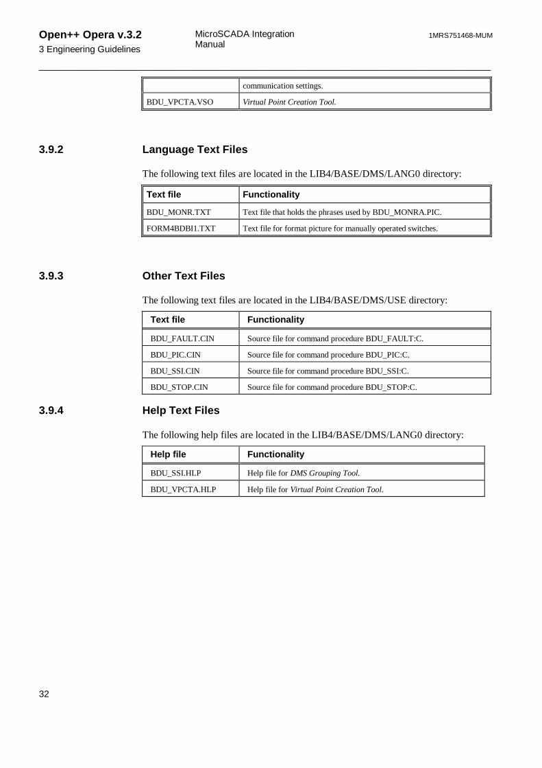
BDU_VPCTA.VSO Virtual Point Creation Tool.
3.9.2 Language Text Files
The following text files are located in the LIB4/BASE/DMS/LANG0 directory:
Text file Functionality
BDU_MONR.TXT Text file that holds the phrases used by BDU_MONRA.PIC.
FORM4BDBI1.TXT Text file for format picture for manually operated switches.
3.9.3 Other Text Files
The following text files are located in the LIB4/BASE/DMS/USE directory:
Text file Functionality
BDU_FAULT.CIN Source file for command procedure BDU_FAULT:C.
BDU_PIC.CIN Source file for command procedure BDU_PIC:C.
BDU_SSI.CIN Source file for command procedure BDU_SSI:C.
BDU_STOP.CIN Source file for command procedure BDU_STOP:C.
3.9.4 Help Text Files
The following help files are located in the LIB4/BASE/DMS/LANG0 directory:
Help file Functionality
BDU_SSI.HLP Help file for DMS Grouping Tool.
BDU_VPCTA.HLP Help file for Virtual Point Creation Tool.

1MRS 751468-MUM MicroSCADA IntegrationManual
Open++ Opera v.3.2Glossary of Terms
________________________________________________________________________________
33
Glossary of Terms
AEP
See Application Extension Program.
AI
Analog Input.
Application Extension Program
An external program which extends the application by using Application ProgramInterface. See also Application Program Interface.
Application Program Interface
A set of routines that an applications program uses to request and carry out lower-levelservices performed by a computer operating system.
bdu_ssi.ini
Configuration settings of the Support System Interface. See also Support SystemInterface.
bdu_ssi_control_panel.exe
The program for managing the Open++ Opera Communication Service(bdu_ssiser.exe). See also bdu_ssiser.exe.
bdu_ssiaep.exe
Application Extension Program of the Support System Interface. See also ApplicationExtension Program and Support System Interface.
bdu_ssiser.exe
Service program of the Support System Interface. See also Support System Interface.
BI
Binary Input.
control picture
A MicroSCADA picture.
data transfer group
User defined process object group, which consists of the same kind of process objects.

Open++ Opera v.3.2Glossary of Terms
MicroSCADA IntegrationManual
1MRS751468-MUM
_________________________________________________________________________________
34
DB
Double Binary input.
default picture
Special station or control picture, which is opened by default for every integratedprocess object group member.
DMS
Distribution network Management System.
DTU
Disconnector station.
hlp
Online help file.
Hot-Stand-By
A system to secure database connection with two servers which are capable tocontinue service alone, if connection to the other is lost.
HSB
See Hot-Stand-By
HV
High Voltage.
intensity level
Data transmission intensity level, which can be set from 1 to 5 (5= very low).
Internet Protocol
The messenger protocol of TCP/IP, is responsible for addressing and sending TCPpackets over the network. IP provides a best-effort, connectionless delivery systemthat does not guarantee that packets arrive at their destination or that they are receivedin the sequence in which they were sent. See also Transmission Control Protocol.
IP
See Internet Protocol and IP address.
IP address
Internet address (for example 127.0.0.1)

1MRS 751468-MUM MicroSCADA IntegrationManual
Open++ Opera v.3.2Glossary of Terms
________________________________________________________________________________
35
isolation
During clearing of the fault the switching actions are made to isolate the fault. Theisolation isolates the located fault as soon as possible and at the same time to cause asfew disadvantages to the customers as possible.
LAN
Local Area Network. A group of computers and other devices dispersed over arelatively limited area and connected by a communications link that enables anydevice to interact with any other device on the network. See also WAN.
LIB 500
MicroSCADA base tool.
LIB 510
MicroSCADA tool.
LN
Logical Name.
log
Program's log file, which contains on-going information.
MicroSCADA SYS
MicroSCADA system computer.
monitor
Same as the X-Window in MicroSCADA.
MV
Medium Voltage.
network database
Relational MS Access based network database of Open++ Opera. See alsonetwork.mdb.
network.mdb
File name of the Open++ Opera relational network database. See also networkdatabase.
Opera database
Dynamic MS Access based database of Open++ Opera, which contains for examplethe real time states of switches. See also opera.mdb.

Open++ Opera v.3.2Glossary of Terms
MicroSCADA IntegrationManual
1MRS751468-MUM
_________________________________________________________________________________
36
Opera Interface Package
Opera Interface Package is a tool of LIB 500 used to cross-connect MicroSCADA andOpen++ Opera.
Opera Network Editor
The Opera Network Editor (OperaNE) is a program primarily used to model thedistribution network onto the network database. See also network database.
Opera Server Application
Opera Server Application (OperaSA) is used for data exchange betweenMicroSCADA and instances of OperaWS. See also Opera Workstation.
Opera Workstation
Opera Workstation (OperaWS) is a program for the operation's personnel of electriccompanies in monitoring and operating their networks.
opera.mdb
File name of the Open++ Opera dynamic database. See also Opera database.
OperaNE
See Opera Network Editor.
OperaSA
See Opera Server Application.
OperaWS
See Opera Workstation.
primary address
An address, which defines the location of the primary Open++ Opera ServerApplication.
process object
A MicroSCADA process object, which has a connection to a real process.
restoration
During clearing of the fault the switching actions are made to locate the fault(experimental switching), isolate the fault (isolation) and restore the connectionsduring the fault (restoration). In the restoration, the outage areas are restored in orderof importance, which is assumed to be proportional to the load.

1MRS 751468-MUM MicroSCADA IntegrationManual
Open++ Opera v.3.2Glossary of Terms
________________________________________________________________________________
37
SC\LIB4\BASE\DMS\USE
A MicroSCADA directory which consists of all LIB 500 Opera Interface Packagefile.
SCADA
Supervisory Control And Data Acquisition.
scada code
An Open++ Opera process object identification, which consists of the process object’slogical name, type, and MicroSCADA index number.
scadapic.lst
List of MicroSCADA pictures in Open++ Opera.
SCIL
Supervisory Control Implementation Language. SCIL is a picture and object oriented,high level language for application programming in MicroSCADA.
scode.lst
The defined scada codes of the Support System Interface. See also Support SystemInterface.
secondary address
An address, which defines the location of the secondary Open++ Opera ServerApplication location.
service
Program, which runs as a background process in MS Windows NT.
spontaneous transfer
Data transmission, which starts as an event in a MicroSCADA process object.
SSI
See Support System Interface.
station diagram
Diagram presentation mode of station components.
station picture
A MicroSCADA picture.

Open++ Opera v.3.2Glossary of Terms
MicroSCADA IntegrationManual
1MRS751468-MUM
_________________________________________________________________________________
38
Support System Interface
A standardized method of transferring data between the applications.
TCP
See Transmission Control Protocol.
TCP/IP
See Transmission Control Protocol/Internet Protocol.
TCP-port
Service Access Point of a TCP-port. See also Transmission Control Protocol.
Transmission Control Protocol
A software protocol developed by the Department of Defense for communicationsbetween computers. This is a connection-based Internet protocol responsible forbreaking data into packets, which the IP protocol sends over the network. Thisprotocol provides a reliable, sequenced communication stream for networkcommunication. See also Internet Protocol.
Transmission Control Protocol/Internet Protocol
This is a set of networking protocols that provide communications acrossinterconnected networks made up of computers with diverse hardware architecturesand various operating systems. TCP/IP includes standards for how computerscommunicate and conventions for connecting networks and routing traffic. See alsoTransmission Control Protocol and Internet Protocol.
user defined picture
A special MicroSCADA picture, which is opened by a user request for an integratedprocess object.
WAN
See Wide Area Network.
Wide Area Network
A communications network that connects geographically separated areas. See alsoLAN.
Virtual Point Creation Tool
A MicroSCADA tool to create virtual process points. See also virtual process point.
virtual process point
A MicroSCADA process point, which does not have a connection to a real process.

1MRS 751468-MUM MicroSCADA IntegrationManual
Open++ Opera v.3.2Glossary of Terms
________________________________________________________________________________
39
virtual.vpc
List of virtual process points. Generated by OperaNE.
VPCT
See Virtual Point Creation Tool.
VS local monitor
Visual SCIL local monitor. See also SCIL.
VS remote monitor
Visual SCIL remote monitor. See also SCIL.
X-window
A window system, which has been developed at the Massachusetts Institute ofTechnology during the Athena project with the DEC company. X-window offers abase technology for higher level standards (OSF, Motif, OpenLook).


1MRS 751468-MUM MicroSCADA IntegrationManual
Open++ Opera v.3.2Index
________________________________________________________________________________
41
Index
A
AEP program 5authorization group 2
C
color definitions 2, 9, 11control pictures 2, 4, 9
D
data transfer groups 9, 11defaults 5, 8, 11, 17
E
earth fault 18
F
fault detector 11fault files 15files
exe 5txt 28
H
Hot-Stand-By 10
I
initialization 1, 5Installation Program 2
L
language 28LIB 500 1, 2, 3, 4, 5, 8, 15
Opera Interface Package 1, 2, 5LIB 510 2, 4, 7, 15licenses 2line colors 2load current 18
M
mapsvector 18
measurements 12, 17message 15, 16MicroSCADA
Authorization Tool 2

Open++ Opera v.3.2Index
MicroSCADA IntegrationManual
1MRS751468-MUM
_________________________________________________________________________________
42
control pictures 2, 4, 9data transfer groups 9, 11DMS Grouping Tool 5, 9, 10, 12, 29LIB 500 1, 2, 3, 4, 5, 8, 15LIB 510 2, 4, 7, 15License Management Tool 2Menu Configuration Tool 6Picture Editor 5, 15process objects 8, 11, 15scadacode 13, 17Standard Configuration Tool 6System Configuration Tool 15Tool Manager 8, 9, 15Topology Generator 2Virtual Point Creation Tool 5, 8, 28, 29
MicroSCADA Integration Manual 1
N
network colors 2, 9, 11
O
opera database 15opera.mdb 15
P
process objects 8, 11, 15
R
reclosing unit 17root point coloring 9
S
scadacode 13, 17settings 10, 11, 28SSI 5, 10, 29station diagrams 2Support System Interface 5, 10, 29
T
TCP/IP 10
V
vector maps 18

1MRS 751468-MUM MicroSCADA IntegrationManual
Open++ Opera v.3.2Index
________________________________________________________________________________
43
ABB Substation Automation Oy
P.O. Box 699FIN-65101 VAASAFinlandTel. +358 10 224 000Fax. +358 10 224 1094www.abb.com/substationautomation
1MR
S 7
5146
8-M
UM