distr. general trans/wp.29/grrf/2002/5 · pdf fileeconomic commission for europe inland...
TRANSCRIPT

Distr. GENERAL TRANS/WP.29/GRRF/2002/5 26 November 2001 ORIGINAL: ENGLISH
ECONOMIC COMMISSION FOR EUROPE INLAND TRANSPORT COMMITTEE World Forum for Harmonization of Vehicle Regulations (WP.29) Working Party on Brakes and Running Gear (GRRF) (Fifty-first session, 4-8 February 2002, agenda item 5.)
PROPOSAL FOR DRAFT 02 SERIES OF AMENDMENTS TO REGULATION No. 79
(Steering Equipment)
Transmitted by the Experts of the ad-hoc GRRF informal group “Electronic Steering” (EST)
Note: The text reproduced below was prepared by the experts of the ad-hoc GRRF Informal Group “Electronic Steering” (EST) in order to add technical requirements of electronic steering systems to Regulation No. 79. This draft should become Revision 2 of Regulation No. 79 as agreed by the experts of the ad-hoc GRRF Informal Group “Electronic Steering” (EST).
____________ _____________ Note: This document is distributed to the Experts on Brakes and Running Gear only. GE.01-

TRANS/WP.29/GRRF/2002/5 page 2
Regulation No. 79
UNIFORM PROVISIONS CONCERNING THE APPROVAL OF VEHICLES WITH REGARD TO STEERING EQUIPMENT
CONTENTS
REGULATION 1. Scope 2. Definitions 3. Application for approval 4. Approval 5. Construction provisions 6. Test provisions 7. Conformity of production 8. Penalties for non-conformity of production 9. Modification and extension of approval of the vehicle type 10. Production definitely discontinued 11. Names and addresses of technical services responsible for
conducting approval tests and of administrative departments ANNEXES Annex 1 Communication concerning the approval or refusal or extension or
withdrawal of approval or production definitely discontinued of a vehicle type with regard to steering equipment pursuant to Regulation No. 79
Annex 2 Arrangements of approval marks Annex 3 Braking performance for vehicles using the same energy source
to supply steering equipment and braking device Annex 4 Additional provisions for vehicles equipped with ASE Annex 5 Provision for trailers having hydraulic steering transmission Annex 6 Special requirements to be applied to the safety aspects of
complex electronic vehicle control systems

TRANS/WP.29/GRRF/2002/5 page 3
Regulation No. 79
UNIFORM PROVISIONS CONCERNING THE APPROVAL OF VEHICLES WITH REGARD TO STEERING EQUIPMENT
1. SCOPE 1.1. This Regulation applies to the steering equipment of vehicles of
categories M, N and O. 1/ 1.2. It does not cover steering equipment with a purely pneumatic
transmission. 1.3. The Regulation does not cover autonomous steering systems. Until
such time as harmonised provisions concerning data transmission protocols are incorporated into the Regulation, Contracting Parties may approve such systems for national use according to national or other international requirements or standards and by applying the principles of annex 6 to this Regulation.
1.4. Automatically commanded steering systems may only be approved
for use in traffic situations below a maximum speed of 50 km/h or for manoeuvring or parking operations.
1.5. Automatically commanded and corrective steering systems may only
be approved where the driver retains overall control of the vehicle and is required to remain alert to, or aware of, its direction and path.
1.6. Full power steering systems fitted to trailers in which the
energy is transmitted from the towing vehicle are not covered by this Regulation until standards for the energy media connectors have been agreed.
1.7. Electric control of full power steering systems fitted to
trailers, other than additional steering systems, is not covered by this Regulation until ISO 11992 has been amended to include requirements for steering control functions(s) (see paragraph 5.2.3.1.)
2. DEFINITIONS For the purposes of this Regulation: 2.1. "Approval of a vehicle" means the approval of a vehicle type
with regard to its steering equipment. ___________________ 1/ (As defined in annex 7 of the consolidated Resolution of the Construction of Vehicles (RE3) (TRANS/SC.1/WP2.9/78/Rev.1/Amend.2).

TRANS/WP.29/GRRF/2002/5 page 4
2.2. "Vehicle type" means a vehicle which does not differ with respect to the manufacturer’s designation of the vehicle type and in essential characteristics such as:
2.2.1. type of steering equipment, steering control, steering
transmission, steered wheels, and energy source. 2.3. "Steering equipment" means all the equipment the purpose of
which is to determine the direction of movement of the vehicle. The steering equipment consists of: The steering control, The steering transmission, The steered wheels, The energy supply, if any. 2.3.1. "Steering control" means the part of the steering equipment
which controls its operation; it may be operated with or without direct intervention of the driver. For steering equipment in which the steering forces are provided solely or partly by the muscular effort of the driver the steering control includes all parts up to the point where the steering effort is transformed by mechanical, hydraulic or electrical means;
2.3.2. "Steering transmission" means all components which form a
functional link between the steering control and the road wheels.
The transmission is divided into two independent functions: The control transmission and the energy transmission.
Where the term "transmission " is used alone in this Regulation,
it means both the control transmission and the energy transmission. A distinction is drawn between mechanical, electrical and hydraulic transmission systems or combinations thereof, according to the means by which the signals and/or energy is transmitted.
2.3.2.1. "Control transmission" means all components by means of which
signals are transmitted for control of the steering equipment. 2.3.2.2. "Energy transmission" means all components by means of which the
energy required for control/regulation of the steering function of the wheels is transmitted.
2.3.3. "Autonomous steering" means the function within a complex
electronic control system which causes the vehicle to follow a defined path or to alter its path without the need for a driver or without the driver having to be alert to, or aware of, the direction of the vehicle and which may achieve this by responding to signalled information.

TRANS/WP.29/GRRF/2002/5 page 5
2.3.4. "Automatically commanded steering" means the function within a
complex electronic control system where actuation of the steering system for the purpose of determination of the direction of movement of the vehicle may result from automatic evaluation of signals initiated on board the vehicle but where the driver is required to remain alert to and to be aware of the direction and path of the vehicle.
2.3.5. "Corrective steering" means the function within a complex
electronic control system which responds to signals initiated on board the vehicle to cause an automatic actuation of the steering system or individual wheels of the system, independent of the driver, to assist in maintaining the chosen course or to correct steering errors.
Corrective steering also includes systems which warn the driver
of a deviation from the ideal path of the vehicle or of an unseen hazard where the warning is transmitted via the steering control.
2.3.6. "Steered wheels" means the wheels, the alignment of which may be
altered directly or indirectly in relation to the longitudinal axis of the vehicle in order to determine the direction of movement of the vehicle. (The steered wheels include the axis around which they are rotated in order to determine the direction of movement of the vehicle);
2.3.7. "Energy supply" includes those parts of the steering equipment
which provide it with energy, control the energy and where appropriate, process and store it. It also includes any storage reservoirs for the operating medium and the return lines, but not the vehicle’s engine (except for the purpose of paragraph 5.3.2.1.) or its drive to the energy source.
2.3.7.1. "Energy source" means the part of the energy supply, which
provides the energy in the required form. 2.3.7.2. "Energy reservoir" means that part of the energy supply in which
the energy provided by the energy source is stored, for example, a pressurised fluid reservoir or vehicle battery.
2.3.7.3. "Storage reservoir" means that part of the energy supply in
which the operating medium is stored at or near to the atmospheric pressure, for example a fluid reservoir.
2.4. Steering parameters 2.4.1. "Steering control effort" means the force applied to the
steering control in order to steer the vehicle. 2.4.2. "Steering time" means the period of time from the beginning of
the movement of the steering control to the moment at which the steered wheels have reached a specific steering angle.
TRANS/WP.29/GRRF/2002/5 page 6
2.4.3. "Steering angle" means the angle between the projection of a longitudinal axis of the vehicle and the line of intersection of the wheel plane (being the central plane of the wheel, normal to the axis around which it rotates) and the road surface.
2.4.4. "Steering forces" mean all the forces operating in the steering
transmission 2.4.5. "Mean steering ratio" means the ratio of the angular
displacement of the steering control to the mean of the swept steering angle of the steered wheels for a full lock-to-lock turn;
2.4.6. "Turning circle" means the circle within which are located the
projections onto the ground plane of all the points of the vehicle, excluding the external mirrors and the front direction indicators, when the vehicle is driven in a circle;
2.4.7. "Nominal radius of steering control" means in the case of a
steering wheel the shortest dimension from its centre of rotation to the outer edge of the rim. In the case of any other form of control it means the distance between its centre of rotation and the point at which the steering effort is applied. If more than one such point is provided, the one requiring the greatest effort shall be used.
2.5. Types of steering equipment Depending on the way the steering forces are produced, the
following types of equipment are distinguished: 2.5.1. For motor vehicles: 2.5.1.1. "Main steering system" means the steering equipment of a vehicle
which is mainly responsible for determining the direction of travel. It may comprise:
2.5.1.1.1. "Manual steering equipment" in which the steering forces result
solely from the muscular effort of the driver. 2.5.1.1.2. "Power assisted steering equipment" in which the steering forces
result from both the muscular effort of the driver and the energy supply (supplies).
2.5.1.1.2.1. Steering equipment in which the steering forces result solely
from one or more energy supplies when the equipment is intact, but in which the steering forces can be provided by the muscular effort of the driver alone if there is a fault in the steering (integrated power systems), is also considered to be power assisted steering equipment;
2.5.1.1.3. "Full-power steering equipment" in which the steering forces are
provided solely by one or more energy supplies; 2.5.1.2. "Self-tracking steering equipment" means a system designed to
create a change of steering angle on one or more wheels only

TRANS/WP.29/GRRF/2002/5 page 7
when acted upon by forces and/or moments applied through the tyre to road contact.
2.5.1.3. "Auxiliary steering equipment (ASE)" means a system in which the
wheels on axle(s) of vehicles of categories M and N are steered in addition to the wheels of the main steering equipment in the same or opposite direction to those of the main steering equipment and/or the steering angle of the front and/or the rear wheels may be adjusted relative to vehicle behaviour.
2.5.2. For trailers: 2.5.2.1. "Self-tracking steering equipment" means a system designed to
create a change of steering angle on one or more wheels only when acted upon by forces and/or moments applied through the tyre to road contact.
2.5.2.2. "Articulated steering" means equipment in which the steering forces are produced by a change in direction of the towing vehicle and in which the movement of the steered trailer wheels is firmly linked to the relative angle between the longitudinal axis of the towing vehicle and that of the trailer;
2.5.2.3. "Self-steering" means equipment in which the steering forces are
produced by a change in direction of the towing vehicle and in which the movement of the steered trailer wheels is firmly linked to the relative angle between the longitudinal axis of the trailer frame or a load replacing it and the longitudinal axis of the sub-frame to which the axle(s) is (are) attached;
2.5.2.4. "Additional steering equipment" means an independent system by
which the steering angle of one or more axle(s) of the steering system can be influenced selectively for manoeuvring purposes.
2.5.3. Depending on the arrangement of the steered wheels, the
following types of steering equipment are distinguished: 2.5.3.1. "Front-wheel steering equipment" in which only the wheels of the
front axle(s) are steered. This includes all wheels which are steered in the same direction.
2.5.3.2. "Rear-wheel steering equipment" in which only the wheels of the
rear axle(s) are steered. This includes all wheels which are steered in the same direction.
2.5.3.3. "Multi-wheel steering equipment" in which the wheels of one or
more of each of the front and the rear axle(s) are steered; 2.5.3.3.1. "All-wheel steering equipment" in which all the wheels are
steered; 2.5.3.3.2. "Buckle steering equipment" in which the movement of chassis
parts relative to each other is directly produced by the steering forces.

TRANS/WP.29/GRRF/2002/5 page 8
2.6. Types of steering transmission Depending on the way the steering forces are transmitted, the
following types of steering transmission are distinguished: 2.6.1. "Purely mechanical steering transmission" means a steering
transmission in which the steering forces are transmitted entirely by mechanical means.
2.6.2. "Purely hydraulic steering transmission" means a steering
transmission in which the steering forces, somewhere in the transmission, are transmitted only by hydraulic means.
2.6.3. "Purely electric steering transmission" means a steering
transmission in which the steering forces, somewhere in the transmission, are transmitted only through electric means.
2.6.4. "Hybrid steering transmission" means a steering transmission in
which part of the steering forces is transmitted through one and the other part through another of the above mentioned means. However, in the case where any mechanical part of the transmission is designed only to give position feedback and is too weak to transmit the total sum of the steering forces, this system shall be considered to be purely hydraulic or purely electric steering transmission.
2.7. "Electric control line" means the electrical connection which
provides the steering control function to the trailer. It comprises the electrical wiring and connector and includes the parts for data communication and the electrical energy supply for the trailer control transmission.
3. APPLICATION FOR APPROVAL 3.1. The application for approval of a vehicle type with regard to
the steering equipment shall be submitted by the vehicle manufacturer or by his duly accredited representative.
3.2. It shall be accompanied by the under mentioned documents in
triplicate, and by the following particulars: 3.2.1. a description of the vehicle type with regard to the items
mentioned in paragraph 2.2. above; the vehicle type shall be specified;
3.2.2. a brief description of the steering equipment with a diagram of
the steering equipment as a whole, showing the position on the vehicle of the various devices influencing the steering.
3.2.3. in the case of full power steering systems and systems to which
annex 6 of this Regulation applies, an overview of the system indicating the philosophy of the system and the fail safe procedures, redundancies and warning systems necessary to ensure operation in the vehicle.
TRANS/WP.29/GRRF/2002/5 page 9
The necessary technical files relating to such systems shall be made available for discussion with manufacturer and the type approval authority and/or technical service. Such files will be discussed on a confidential basis.
3.3. A vehicle representative of the vehicle type to be approved
shall be submitted to the technical service responsible for conducting approval tests.
4. APPROVAL 4.1. If the vehicle submitted for approval pursuant to this
Regulation meets all relevant requirements given in this Regulation, approval of that vehicle type with regard to the steering equipment shall be granted.
4.1.1. The type approval authority shall verify the existence of
satisfactory arrangements for ensuring effective control of the conformity of production as given in paragraph 7. of this Regulation, before type approval is granted.
4.2. An approval number shall be assigned to each type approved. Its
first two digits (at present 02) shall indicate the series of amendments incorporating the most recent major technical amendments made to the Regulation at the time of issue of the approval. The same Contracting Party shall not assign this number to another vehicle type or to the same vehicle type submitted with different steering equipment from that described in the documents required by paragraph 3.
4.3. Notice of approval or of extension or refusal of approval of a
vehicle type pursuant to this Regulation shall be communicated to the Parties to the 1958 Agreement which apply this Regulation, by means of a form conforming to the model in annex 1 to this Regulation.
4.4. There shall be affixed, conspicuously and in a readily
accessible place specified on the approval form, to every vehicle conforming to a vehicle type approved under this Regulation, an international approval mark consisting of:

TRANS/WP.29/GRRF/2002/5 page 10
4.4.1. a circle surrounding the letter "E" followed by the
distinguishing number of the country which has granted approval; 2/
4.4.2. the number of this Regulation, followed by the letter "R", a
dash and the approval number to the right of the circle prescribed in paragraph 4.4.1.
4.5. If the vehicle conforms to a vehicle type approved, under one or
more other Regulations annexed to the Agreement, in the country which has granted approval under this Regulation, the symbol prescribed in paragraph 4.4.1. need not be repeated; in such a case the regulation and approval numbers and the additional symbols of all the Regulations under which approval has been granted in the country which has granted approval under this
Regulation shall be placed in vertical columns to the right of the symbol prescribed in paragraph 4.4.1.
4.6. The approval mark shall be clearly legible and shall be
indelible. 4.7. The approval mark shall be placed close to or on the vehicle
data plate affixed by the manufacturer. 4.8. Annex 2 to this Regulation gives examples of arrangements of
approval marks. __________________ 2/ 1 for Germany, 2 for France, 3 for Italy, 4 for Netherlands, 5 for Sweden, 6 for Belgium, 7 for Hungary, 8 for the Czech Republic, 9 for Spain, 10 for Yugoslavia, 11 for the United Kingdom, 12 Austria, 13 for Luxembourg, 14 for Switzerland, 15 (vacant), 16 for Norway, 17 for Finland, 18 for Denmark, 19 for Romania, 20 for Poland, 21 for Portugal, 22 for the Russian Federation, 23 for Greece, 24 for Ireland, 25 for Croatia, 26 for Slovenia, 27 for Slovakia, 28 for Belarus, 29 for Estonia, 30 (vacant), 31 for Bosnia and Herzegovina, 32 for Latvia, 33 (vacant), 34 for Bulgaria, 35-36 (vacant), 37 for Turkey, 38-39 (vacant), 40 for The former Yugoslav Republic of Macedonia, 41 (vacant), 42 for the European Community (Approvals are granted by its member States using their respective ECE symbol), 43 for Japan, 44 (vacant), 45 for Australia, and 46 for Ukraine. Subsequent numbers shall be assigned to other countries in the chronological order in which they ratify or accede to the Agreement Concerning the Adoption of Uniform Technical Prescriptions for Wheeled Vehicles, Equipment and Parts which can be Fitted and/or be Used on Wheeled Vehicles and the Conditions for Reciprocal Recognition of Approval Granted on the Basis of these Prescriptions, and the numbers thus assigned shall be communicated by the Secretary-General of the United Nations to the Contracting Parties to the Agreement.

TRANS/WP.29/GRRF/2002/5 page 11
5. CONSTRUCTION PROVISIONS 5.1. General provisions 5.1.1. The steering system shall ensure easy and safe handling of the
vehicle up to its maximum design speed or in case of a trailer up to its technically permitted maximum speed. There must be a tendency to self-centre when tested in
accordance with paragraph 6.2. with the intact steering equipment. The vehicle shall meet the requirements of paragraph 6.2. in the case of motor vehicles and of paragraph 6.3. in the case of trailers. If a vehicle is fitted with an auxiliary steering system, it shall also meet the requirements of annex 4. Trailers equipped with hydraulic steering transmissions shall comply also with annex 5.
5.1.2. It must be possible to travel along a straight section of road without unusual steering correction by the driver and without unusual vibration in the steering system at the maximum design speed of the vehicle.
5.1.3. The direction of operation of the steering control shall
correspond to the intended change of direction of the vehicle and there shall be a continuous and monotonic relationship between the steering control deflection and the steering angle. These requirements do not apply to automatically commanded steering, corrective steering or auxiliary steering equipment.
5.1.4. The steering equipment shall be designed, constructed and fitted
in such a way that it is capable of withstanding the stresses arising during normal operation of the vehicle, or combination of vehicles. The maximum steering angle shall not be limited by any part of the steering transmission unless specifically designed for this purpose. Unless otherwise specified, it will be assumed that for the purpose of this regulation, not more than one failure can occur in the steering equipment at any one time and two axles on one bogie shall be considered as one axle.
5.1.5. The effectiveness of the steering equipment, including the
electrical control lines, shall not be adversely affected by magnetic or electric fields. Conformity with the technical requirements of Regulation No. 10, to the amendment in force at the time of Type Approval shall be demonstrated.
5.1.6. Steering transmission 5.1.6.1. Adjustment devices for steering geometry must be such that after
adjustment a positive connection can be established between the adjustable components by appropriate locking devices.
5.1.6.2. Steering transmission which can be disconnected to cover
different configurations of a vehicle (e.g. on extendable semi-trailers), must have locking devices which ensure positive relocation of components; where locking is automatic, there must be an additional safety lock which is operated manually.

TRANS/WP.29/GRRF/2002/5 page 12
5.1.7. Steered wheels
The steered wheels shall not be solely the rear wheels. This requirement does not apply to semi-trailers.
5.1.8. Energy supply
The same energy supply may be used for the steering equipment
and other systems. However in the case of a failure in any system which shares the same energy supply steering shall be ensured in accordance with the relevant failure conditions of paragraph 5.3.
5.1.9. Control systems - The requirements of annex 6 shall be applied
to the safety aspects of all electronic vehicle control systems which provide or form part of the control transmission of the steering function including those which utilise the steering system for automatically commanded steering or corrective steering. However, systems or functions, which use the steering system as the means of achieving a higher stability level objective, are subject to annex 6 only insofar as they have a direct effect on the steering system. If such systems are provided, they shall not be deactivated during type approval testing of the steering system.
5.2. Special provisions for trailers 5.2.1. Trailers (with the exception of semi-trailers and centre-axle
trailers) which have more than one axle with steered wheels and semi-trailers and centre-axle trailers which have at least one axle with steered wheels must fulfil the conditions given in paragraph 6.3. below. However, for trailers with self-tracking steering equipment a test under Paragraph 6.3. is not necessary if the axle load ratio between the unsteered and the self-tracking axles equals or exceeds 1.6. under all loading conditions.
However for trailers with self-tracking steering equipment, the axle load ratio between unsteered or articulated steered axles and friction-steered axles shall be at least 1 under all loading conditions.
5.2.2. If the towing vehicle of a vehicle combination is driving
straight ahead, the trailer and towing vehicle must remain aligned. If alignment is not retained automatically, the trailer must be equipped with a suitable adjustment facility for maintenance.
5.2.3. Connections between the motor vehicle and the trailer 5.2.3.1. The electrical control line shall conform to ISO 11992 and be a
point-to-point type using the seven-pin connector according to ISO 7638-1 or 7638-2:1997. The data contacts of the ISO 7368 connector shall be used to transfer information exclusively for braking (including ABS) and running gear (steering, tyres and suspension) functions as specified in ISO 1192. The braking and

TRANS/WP.29/GRRF/2002/5 page 13
steering functions have priority and shall be maintained in the normal and failed modes. The transmission of other running gear information shall not delay braking or steering functions. The power supply, provided by the ISO 7638 connector, shall be used exclusively for braking and running gear functions and that required for the transfer of trailer related information not transmitted via the electric control line. The power supply for all other functions shall use other measures 3/.
5.2.3.2. Energy transmission between towing vehicle and trailer
see 1.6. of this Regulation:
Until standards have been agreed for connectors for transmitting energy from the towing vehicle to the trailer, electrical control of trailer steering systems and equipment may only be approved to this Regulation if the energy source for the trailer steering equipment is wholly independent of the towing vehicle.
5.3. Failure provisions and performance 5.3.1. General 5.3.1.1. For the purposes of this Regulation the steered wheels, the
steering control and all mechanical parts of the steering transmission shall not be regarded as liable to breakage if they are amply dimensioned, are readily accessible for maintenance, and exhibit safety features at least equal to those prescribed for other essential components (such as the braking system) of the vehicle. Where the failure of any such part would be likely to result in loss of control of the vehicle, that part must be made of metal or of a material with equivalent characteristics and must not be subject to significant distortion in normal operation of the steering system.
5.3.1.2. The requirements of paragraphs 5.1.2., 5.1.3. and 6.2.1. shall
also be satisfied with a failure in the steering equipment as long as the vehicle can be driven with the speeds required in the respective paragraphs.
In this case paragraph 5.1.3. shall not apply for full power steering systems when the vehicle is stationary.
5.3.1.3. Any failure in a transmission other than purely mechanical must
clearly be brought to the attention of the vehicle driver as given in paragraph 5.4. When a failure occurs, a change in the average steering ratio is permissible if the steering effort given in paragraph 6.2.6. below is not exceeded.
5.3.1.4. In the case where the braking system of the vehicle shares the
same energy source as the steering system and this energy source fails, the braking performance shall not drop below the prescribed service brake performance, as given in annex 3 of this Regulation, on the first brake application.
__________________ 3/ Until ISO 11992 is updated to include steering messages electronic communication of trailer steering control is not yet applicable.

TRANS/WP.29/GRRF/2002/5 page 14
5.3.1.5. In the case where the braking system of the vehicle shares the same energy supply as the steering system and this energy supply fails, the braking performance must comply with the prescriptions of annex 3 of this Regulation.
5.3.1.6. In the case of trailers the requirements of paragraphs 5.2.2.
and 6.3.4.1. shall also be met when there is a failure in the steering system.
5.3.2. Power assisted steering systems 5.3.2.1. Should the engine stop or a part of the transmission fails, with
the exception of those parts listed in paragraph 5.3.1.1., there shall be no immediate changes in steering angle. As long as the vehicle is capable of being driven at a speed greater than 10 km/h then the requirements given in paragraph 6., relating to a system with a failure, shall be met.
5.3.3. Full power steering systems 5.3.3.1. The system shall be designed such that the vehicle cannot be
driven indefinitely at speeds above 10 km/h where there is any fault which requires operation of the warning signal referred to in paragraph 5.4.2.1.1.
5.3.3.2. In case of a failure within the control transmission, with the
exception of those parts listed in paragraph 5.1.4., it shall be still possible to steer with the performance laid down in paragraph 6. for the intact steering system.
5.3.3.3. In the event of a failure of the energy supply of a control
transmission system, it shall be possible to carry out at least 25 "figure of eight" manoeuvres, where each loop of the figure is 40 m diameter at 10 km/h speed and at the performance level given for an intact system in paragraph 6. The test manoeuvres shall begin at an energy storage level given in paragraph 5.3.3.5.
5.3.3.4. In the event of a failure within the energy transmission, with
the exception of those parts listed in paragraph 5.3.1.1., there shall not be any immediate changes in steering angle. As long as the vehicle is capable of being driven at a speed greater than 10 km/h then the requirements of paragraph 6. with a system with a failure shall be met after the completion of at least 25 "figure of eight" manoeuvres at 10 km/h minimum speed, where each loop of the figure is 40 m diameter.
The test manoeuvres shall begin at an energy storage level given in paragraph 5.3.3.5.
5.3.3.5. The energy level to be used for the tests referred to in
paragraphs 5.3.3.3. and 5.3.3.4. shall be the energy storage level at which a failure is indicated to the driver.
In the case of electrically powered systems subject to annex 6, this level shall be the worst case situation outlined by the

TRANS/WP.29/GRRF/2002/5 page 15
manufacturer in the documentation submitted in connection with annex 6 and shall take into account the effects of e.g. temperature and ageing on battery performance.
5.4. Warning signals 5.4.1. General provisions 5.4.1.1. Any fault which impairs the steering function and is not
mechanical in nature must be signalled clearly to the driver of the vehicle.
Despite the requirements of 5.1.2. the deliberate application of vibration in the steering system may be used as an additional indication of a fault condition in this system.
In the case of a motor vehicle, an increase in steering force is considered to be a warning indication; in the case of a trailer, a mechanical indicator is permitted.
5.4.1.2. If the same energy source is used to supply the steering system
and other systems, an acoustic or optical warning shall be given to the driver, when the stored energy/fluid in the energy/storage reservoir drops to a level liable to cause an increase in steering effort. This warning may be combined with a device provided to warn of brake failure if the brake system uses the same energy source. The satisfactory condition of the warning device must be easily verifiable by the driver.
5.4.2. Special provisions for full-power steering equipment 5.4.2.1. Power-driven vehicles shall be capable of providing steering
failure and defect warning signals, as follows: 5.4.2.1.1. A red warning signal, indicating failures defined in
paragraph 5.3.1.3. within the main steering equipment. 5.4.2.1.2. Where applicable, a yellow warning signal indicating an
electrically detected defect within the steering equipment, which is not indicated by the red warning signal.
5.4.2.1.3. If a symbol is used, it must comply with the relevant symbol as
defined in ISO 2575: 2000. 5.4.2.1.4. The warning signal(s) mentioned above shall light up when the
electrical equipment of the vehicle (and the steering system) is energised. With the vehicle stationary, the steering system shall verify that none of the specified failures or defects is present before extinguishing the signal. Specified failures or defects which should activate the warning signal mentioned above, but which are not detected under static conditions, shall be stored upon detection and be displayed at start-up and at all times when the ignition (start) switch is in the "on" (run) position, as long as the failure persists.

TRANS/WP.29/GRRF/2002/5 page 16
5.4.3. In the case where additional steering equipment is in operation and/or where the steering angle generated by that equipment has not been returned to normal driving position a warning signal must be given to the driver.
5.5. Provisions for the periodic technical inspection of steering
equipment 5.5.1. The steering equipment shall be so designed that the mechanical
components by which the function or effectiveness is influenced by wear, corrosion or ageing can be checked without disassembly or if necessary can be checked with commonly used measuring instruments, methods or test devices.
5.5.2. It must be possible to verify in a simple way the correct
operational status of those Electronic Systems, which have control over steering. If special information is needed, this shall be made freely available.
5.5.2.1. At the time of Type Approval the means implemented to protect
against simple unauthorised simple modification to the operation of the verification means chosen by the manufacturer (e.g. warning signal) shall be confidentially outlined.
Alternatively this protection requirement is fulfilled when a secondary means of checking the correct operational status is available.
6. TEST PROVISIONS 6.1. General provisions 6.1.1. The test shall be conducted on a level surface affording good
adhesion. 6.1.2. During the test(s), the vehicle shall be loaded to its
technically permissible maximum mass and its technically permissible maximum load on the steered axle(s).
In the case of axles fitted with ASE, this test shall be repeated with the vehicle loaded to its technically permissible maximum mass and the axle equipped with ASE loaded to its maximum permissible mass.
6.1.3. Before the test begins, the tyre pressures shall be as
prescribed by the manufacturer for the mass specified in paragraph 6.1.2. when the vehicle is stationary.
6.1.4. In the case of any systems that use electrical energy for part
or all of the energy supply, all performance tests shall be carried out under conditions of actual or simulated electrical load of all essential systems or systems components which share the same energy supply. Essential systems shall comprise at least lighting systems, windscreen wipers, engine management and braking systems.

TRANS/WP.29/GRRF/2002/5 page 17
6.2. Provisions for motor vehicles 6.2.1. It must be possible to leave a curve with a radius of 50 m at a
tangent without unusual vibration in the steering equipment at the following speed:
Category M1 vehicles: 50 km/h Category M2, M3, N1, N2 and N3 vehicles: 40 km/h or the maximum
design speed if this is below the speeds given above. 6.2.2. When the vehicle is driven in a circle with its steered wheels
at approximately half lock and a constant speed of at least 10 km/h, the turning circle must remain the same or become larger if the steering control is released.
6.2.3. During the measurement of control effort, forces with a duration
of less than 0.2 seconds shall not be taken into account. 6.2.4. The measurement of steering efforts on motor vehicles with
intact steering equipment. 6.2.4.1. The vehicle shall be driven from straight ahead into a spiral at
a speed of 10 km/h. The steering control effort shall be measured at the nominal radius of the steering control until the position of the steering control corresponds to turning radius given in the table below for the particular category of vehicle with intact steering. One steering movement shall be made to the right and one to the left.
6.2.4.2. The maximum permitted steering time and the maximum permitted
steering control effort with intact steering equipment are given in the table below for each category of vehicle.
6.2.5. The measurement of steering efforts on motor vehicles with a
failure in the steering equipment. 6.2.5.1. The test described in paragraph 6.2.4. shall be repeated with a
failure in the steering equipment. The steering effort shall be measured until the position of the steering control corresponds to the turning radius given in the table below for the particular category of vehicle with a failure in the steering equipment.
6.2.5.2. The maximum permitted steering time and the maximum permitted steering control effort with a failure in the steering equipment are given in the table below for each category of vehicle.
TRANS/WP.29/GRRF/2002/5 page 18
Table
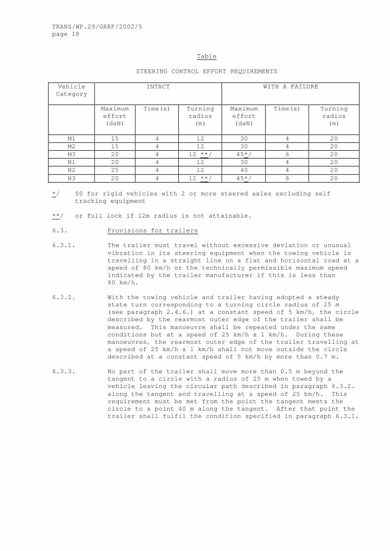
STEERING CONTROL EFFORT REQUIREMENTS
Vehicle Category
INTACT WITH A FAILURE
Maximum effort (daN)
Time(s) Turning radius (m)
Maximum effort (daN)
Time(s)
Turning radius (m)
M1 15 4 12 30 4 20 M2 15 4 12 30 4 20 M3 20 4 12 **/ 45*/ 6 20 N1 20 4 12 30 4 20 N2 25 4 12 40 4 20 N3 20 4 12 **/ 45*/ 6 20
*/ 50 for rigid vehicles with 2 or more steered axles excluding self
tracking equipment **/ or full lock if 12m radius is not attainable.
6.3. Provisions for trailers 6.3.1. The trailer must travel without excessive deviation or unusual
vibration in its steering equipment when the towing vehicle is travelling in a straight line on a flat and horizontal road at a speed of 80 km/h or the technically permissible maximum speed indicated by the trailer manufacturer if this is less than 80 km/h.
6.3.2. With the towing vehicle and trailer having adopted a steady
state turn corresponding to a turning circle radius of 25 m (see paragraph 2.4.6.) at a constant speed of 5 km/h, the circle described by the rearmost outer edge of the trailer shall be measured. This manoeuvre shall be repeated under the same conditions but at a speed of 25 km/h ± 1 km/h. During these manoeuvres, the rearmost outer edge of the trailer travelling at a speed of 25 km/h ± 1 km/h shall not move outside the circle described at a constant speed of 5 km/h by more than 0.7 m.
6.3.3. No part of the trailer shall move more than 0.5 m beyond the
tangent to a circle with a radius of 25 m when towed by a vehicle leaving the circular path described in paragraph 6.3.2. along the tangent and travelling at a speed of 25 km/h. This requirement must be met from the point the tangent meets the circle to a point 40 m along the tangent. After that point the trailer shall fulfil the condition specified in paragraph 6.3.1.
TRANS/WP.29/GRRF/2002/5 page 19
6.3.4. The annular ground area swept by the towing vehicle/trailer combination with an intact steering system, driving at no more than 5 km/h in a constant radius circle with the front outer corner of the towing vehicle describing a radius of 0.67 x vehicle combination length but not less than 12.5 m is to be measured.
6.3.4.1. If, with a fault in the steering system, the measured swept
annular width is > 8.3 m, then this must not be an increase of more than 15 per cent compared with the corresponding value measured with the intact steering system. There shall not be any increase in the outer radius of the swept annular width.
6.3.5. The tests described in paragraphs 6.3.2., 6.3.3. and 6.3.4. shall be conducted in both clockwise and anti-clockwise directions.
7. CONFORMITY OF PRODUCTION The Conformity of Production Procedures shall comply with those
set out in the 1958 Agreement, Appendix 2 (E/ECE/324 – E/ECE/TRANS/505/Rev.2), with the following
requirements: 7.1. The holder of the approval must ensure that results of the
conformity of production tests are recorded and that the annexed documents remain available for a period determined in agreement with the approval authority or technical service. This period must not exceed 10 years counted from the time when production is definitely discontinued.
7.2. The type approval authority or technical service which has
granted type approval may at any time verify the conformity control methods applied in each production facility. The normal frequency of these verifications shall be once every two years.
8. PENALTIES FOR NON-CONFORMITY OF PRODUCTION 8.1. The approval granted in respect of a vehicle type pursuant to
this Regulation may be withdrawn if the requirement laid down in paragraph 7.1. is not complied with or if sample vehicles fail to comply with the requirements of paragraph 6. of this Regulation.
8.2. If a contracting Party to the Agreement applying this Regulation
withdraws an approval it has previously granted, it shall forthwith so notify the other Contracting Parties applying this Regulation, by means of a communication form conforming to the model in annex 1 to this Regulation.
9. MODIFICATION AND EXTENSION OF APPROVAL OF THE VEHICLE TYPE 9.1. Every modification of the vehicle type shall be notified to the
approval authority which granted the approval. The approval authority may then either:

TRANS/WP.29/GRRF/2002/5 page 20
9.1.1. Consider that the modifications made are unlikely to have an
appreciable adverse effect and that in any case the vehicle still complies with the requirements; or
9.1.2. Require a further test report from the technical service
responsible for conducting the tests. 9.2. Confirmation or extension or refusal of approval, specifying the
alterations, shall be communicated by the procedure specified in paragraph 4.3. above to the Parties to the Agreement this Regulation.
9.3. The approval authority issuing the extension of approval shall
assign a series number for such an extension and inform thereof the other Parties to the 1958 Agreement applying this Regulation by means of a communication form conforming to the model in annex 1 to this Regulation.
10. PRODUCTION DEFINITELY DISCONTINUED If the holder of the approval completely ceases to manufacture a
type of vehicle approved in accordance with this Regulation, he shall so inform the authority which granted the approval. Upon receiving the relevant communication that authority shall inform thereof the other Parties to the 1958 Agreement applying this Regulation by means of a communication form conforming to the model in annex 1 to this Regulation.
11. NAMES AND ADDRESSES OF TECHNICAL SERVICES RESPONSIBLE FOR
CONDUCTING APPROVAL TESTS AND OF ADMINISTRATIVE DEPARTMENTS The Parties to the 1958 Agreement applying this Regulation shall
communicate to the United Nations Secretariat the names and addresses of the technical services responsible for conducting approval tests and of the administrative departments which grant approval and to which forms certifying approval or extension or refusal or withdrawal of approval, issued in other countries, are to be sent.
_____________
______________ Note by the secretariat: GRRF should consider if transitional provisions are requested.

TRANS/WP.29/GRRF/2002/5 page 21
Annex 1
COMMUNICATION
(Maximum format: A 4 (210 x 297 mm))
issued by: Name of administration: ....................... .......................
Concerning: 2/ APPROVAL GRANTED APPROVAL EXTENDED APPROVAL REFUSED APPROVAL WITHDRAWN PRODUCTION DEFINITELY DISCONTINUED of a vehicle type with regard to steering equipment pursuant to Regulation No. 79 Approval No.
Extension No. ... 1. Trade name or mark of vehicle .............................. 2. Vehicle type ............................................... 3. Manufacturer’s name and address ............................ 4. If applicable, name and address of manufacturer’s ..........
representative ............................................. 5. Brief description of the steering equipment ................ 5.1. Type of steering equipment ................................. 5.2. Steering control ........................................... 5.3. Steering transmission ...................................... 5.4. Steered wheels ............................................. ___________ 1/ Distinguishing number of the country which has granted/extended/refused/withdrawn approval (see approval provisions in the Regulation).

TRANS/WP.29/GRRF/2002/5 page 22
5.5. Energy source .............................................. 6. Results of tests, vehicle characteristics .................. 6.1. Steering effort required to achieve a turning circle of 12 m
radius with an intact system and 20 m radius with a system in the failed condition .......................................
6.1.1. Under normal conditions .................................... 6.1.2. After failure of special equipment ......................... 6.2. Other tests required by this Regulation ............................................ pass/fail 2/ 6.3. Adequate documentation in accordance with Annex 6 was supplied
in respect of the following parts of the steering system: ...........................................................
7. Vehicle submitted for approval on 8. Technical service responsible for conducting approval tests 9. Date of report issued by that service 10. Number of report issued by that service 11. Approval granted/extended/refused/withdrawn 2/ 12. Position of approval mark on vehicle 13. Place 14. Date 15. Signature 16. Annexed to this communication is a list of documents in the
approval file deposited at the administration services having delivered the approval and which can be obtained upon request.
____________ ____________ 2/ Strike out what does not apply.

TRANS/WP.29/GRRF/2002/5 page 23
Annex 2
ARRANGEMENTS OF APPROVAL MARKS
Model A
(See paragraph 4.4. of this Regulation)
a = 8 mm min The above approval mark affixed to a vehicle shows that the vehicle type concerned has, with regard to steering equipment, been approved in the Netherlands (E4) pursuant to Regulation No. 79 under approval No. 022439. The approval number indicates that the approval was granted in accordance with the requirements of Regulation No. 79 incorporating the 02 series of amendments.
Model B (See paragraph 4.5. of this Regulation)
a = 8 mm min The above approval mark affixed to a vehicle shows that the vehicle type concerned has been approved in the Netherlands (E4) pursuant to Regulations Nos. 79 and 31 */. The approval numbers indicate that, at the dates when the respective approvals were given, Regulation No. 79 incorporating the 02 series of amendments and Regulation No. 31 included the 01 series of amendments. _____________ */ The second number is given merely as an example.
79 R - 022439
79 022439 31 011628
TRANS/WP.29/GRRF/2002/5 page 24
Annex 3
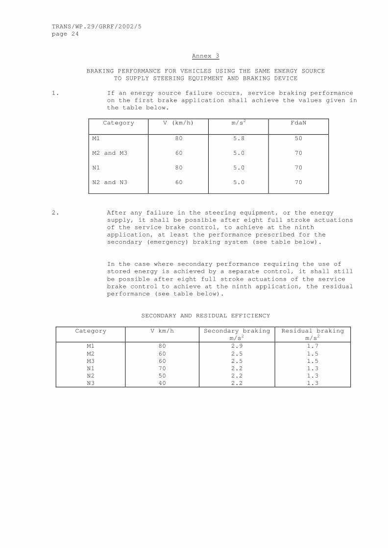
BRAKING PERFORMANCE FOR VEHICLES USING THE SAME ENERGY SOURCE
TO SUPPLY STEERING EQUIPMENT AND BRAKING DEVICE 1. If an energy source failure occurs, service braking performance
on the first brake application shall achieve the values given in the table below.
Category V (km/h) m/s2 FdaN
M1 M2 and M3 N1 N2 and N3
80
60
80
60
5.8
5.0
5.0
5.0
50
70
70
70
2. After any failure in the steering equipment, or the energy
supply, it shall be possible after eight full stroke actuations of the service brake control, to achieve at the ninth application, at least the performance prescribed for the secondary (emergency) braking system (see table below).
In the case where secondary performance requiring the use of
stored energy is achieved by a separate control, it shall still be possible after eight full stroke actuations of the service brake control to achieve at the ninth application, the residual performance (see table below).
SECONDARY AND RESIDUAL EFFICIENCY
Category V km/h Secondary braking m/s2
Residual braking m/s2
M1 M2 M3 N1 N2 N3
80 60 60 70 50 40
2.9 2.5 2.5 2.2 2.2 2.2
1.7 1.5 1.5 1.3 1.3 1.3
TRANS/WP.29/GRRF/2002/5 page 25
Annex 4
ADDITIONAL PROVISIONS FOR VEHICLES EQUIPPED WITH ASE.
1. General Provisions Vehicles fitted with auxiliary steering equipment (ASE) in
addition to the requirements given in the body of this Regulation shall also comply with the provisions of this Annex.
2. Specific Provisions 2.1. Transmission 2.1.1. Mechanical steering transmissions Paragraph 5.3.1.1. of this Regulation applies. 2.1.2. Hydraulic steering transmissions The hydraulic steering transmission must be protected from
exceeding the maximum permitted service pressure T. 2.1.3. Electric steering transmissions The electric steering transmission must be protected from excess
energy supply. 2.1.4. Combination of steering transmissions A combination of mechanical, hydraulic and electric
transmissions shall comply with the requirements specified in paragraphs 2.1.1., 2.1.2. and 2.1.3. above.
2.2. Testing requirements for failure 2.2.1. Malfunction or failure of any part of the ASE (except for parts
not considered to the susceptible to breakdown as specified in paragraph 5.3.1.1. of this Regulation) shall not result in a sudden significant change in vehicle behaviour and the relevant requirements of paragraphs 6. of this Regulation shall still be met. Furthermore, it must be possible to control the vehicle without abnormal steering correction. This shall be verified by the following tests:

TRANS/WP.29/GRRF/2002/5 page 26
2.2.1.1. Circular test The vehicle shall be driven into a test circle with a
radius „R„ m and a speed „v„ km/h corresponding to its category and the values given in the table below:
Vehicle category
R 3/ v 1/ 2/
M1 and N1 100 80 M2 and N2 50 50 M3 and N3 50 45
The failure shall be introduced when the specified test speed has been reached. The test shall include driving in a clockwise direction, and in a counter-clockwise direction.
___________ 1/ If the ASE is in a mechanically locked position at this
specified speed, the test speed will be modified to correspond to the maximum speed where the system is functioning. Maximum speed means the speed when the ASE becomes locked minus 5 km/h.
2/ If the dimensional characteristics of the vehicle imply an
overturning risk, the manufacturer shall provide to the Technical Service behaviour simulation data demonstrating a lower maximum safe speed for conducting the test. Then the Technical Service will choose this test speed.
3/ If, due to the configuration of the test site, the values of the
radii cannot be observed, the tests may be carried out on tracks with other radii, (maximum variation: ? 25%) provided that the speed is varied to obtain the transverse acceleration resulting from the radius and speed indicated in the table for the particular category of vehicle
2.2.1.2. Transient test 2.2.1.2.1. Until uniform test procedures have been agreed, the vehicle
manufacturer shall provide the technical services with their test procedures and results for transient behaviour of the vehicle in the case of failure.
2.3. Warning signals in case of failure. 2.3.1. Except for parts of ASE not considered susceptible to breakdown
as specified in paragraph 5.3.1.1. of this Regulation, the following failure of ASE shall be clearly brought to the attention of the driver.
2.3.1.1. A general cut-off of the ASE electrical or hydraulic control. 2.3.1.2. Failure of the ASE energy supply. 2.3.1.3. A break in the external wiring of the electrical control if
fitted.
_____________

TRANS/WP.29/GRRF/2002/5 page 27
Annex 5
PROVISIONS FOR TRAILERS HAVING HYDRAULIC STEERING TRANSMISSIONS
1. General provisions Vehicles fitted with hydraulic steering transmission, in
addition to the requirements given in the body of this Regulation shall also comply with the provisions of this annex.
2. Specific provisions 2.1. Performance of hydraulic lines and hose assemblies. 2.1.1. The hydraulic lines of hydraulic transmission must be capable of
withstanding a pressure at least four times the maximum normal service pressure (T) specified by the manufacturer. Hose assemblies shall comply with ISO Standards 1402:1984, 6605:1986 and 7751:1983.
2.2. In systems dependent on an energy supply; 2.2.1. the energy supply must be protected from excess pressure by a
pressure limiting valve which operates at the pressure T. 2.3. Protection of steering transmission; 2.3.1. the steering transmission must be protected from excess pressure
by a pressure limiting valve which operates at between 1.5 T and 2.2 T.

TRANS/WP.29/GRRF/2002/5 page 28
Annex 6
SPECIAL REQUIREMENTS TO BE APPLIED TO THE SAFETY ASPECTS OF COMPLEX ELECTRONIC VEHICLE CONTROL SYSTEMS
1. GENERAL This annex defines the special requirements for documentation,
fault strategy and verification with respect to the safety aspects of Complex Electronic Vehicle Control Systems (paragraph 2.3. below) as far as this Regulation is concerned.
This annex may also be called, by special paragraphs in this Regulation, for safety related functions which are controlled by electronic system(s).
This annex does not specify the performance criteria for "The System" but covers the methodology applied to the design process and the information which must be disclosed to the technical service, for type approval purposes.
This information shall show that "The System" respects, under normal and fault conditions, all the appropriate performance requirements specified elsewhere in this Regulation.
2. DEFINITIONS For the purposes of this annex, 2.1. "Safety concept" is a description of the measures designed into
the system, for example within the electronic units, so as to address system integrity and thereby ensure safe operation even in the event of an electrical failure. The possibility of a fall-back to partial operation or even to a back-up system for vital vehicle functions may be a part of the safety concept.
2.2. "Electronic control system" means a combination of units,
designed to co-operate in the production of the stated vehicle control function by electronic data processing. Such systems, often controlled by software, are built from discrete functional components such as sensors, electronic control units and actuators and connected by transmission links. They may include mechanical, electro-pneumatic or electro-hydraulic elements. "The System", referred to herein, is the one for which type approval is being sought.
2.3. "Complex electronic vehicle control systems" are those
electronic control systems which are subject to a hierarchy of control in which a controlled function may be over-ridden by a higher level electronic control system/function. A function which is over-ridden becomes part of the complex system.
TRANS/WP.29/GRRF/2002/5 page 29
2.4. "Higher-Level control" systems/functions are those which employ additional processing and/or sensing provisions to modify vehicle behaviour by commanding variations in the normal function(s) of the vehicle control system. This allows complex systems to automatically change their objectives with a priority which depends on the sensed circumstances.
2.5. "Units" are the smallest divisions of system components which
will be considered in this annex, since these combinations of components will be treated as single entities for purposes of identification, analysis or replacement.
2.6. "Transmission links" are the means used for inter-connecting
distributed units for the purpose of conveying signals, operating data or an energy supply. This equipment is generally electrical but may, in some part, be mechanical, [pneumatic] or hydraulic.
2.7. "Range of control" refers to an output variable and defines the
range over which the system is likely to exercise control.
2.8. "Boundary of functional operation" defines the boundaries of the external physical limits within which the system is able to maintain control.
3. DOCUMENTATION. 3.1. Requirements
The manufacturer shall provide a documentation package which gives access to the basic design of "The System" and the means by which it is linked to other vehicle systems or by which it directly controls output variables. The function(s) of "The System" and the safety concept, as laid down by the manufacturer, shall be explained. Documentation shall be brief, yet provide evidence that the design and development has had the benefit of expertise from all the system fields which are involved. For periodic technical inspections, the documentation shall describe how the current operational status of "The System" can be checked.
3.1.1. Documentation shall be made available in two parts: (a) The formal documentation package for the approval,
containing the material listed in paragraph 3. (with the exception of that of paragraph 3.4.4.) which shall be supplied to the technical service at the time of submission of the type approval application. This will be taken as the basic reference for the verification process set out in paragraph 4. of this annex.
(b) Additional material and analysis data of
paragraph 3.4.4., which shall be retained by the
TRANS/WP.29/GRRF/2002/5 page 30
manufacturer, but made open for inspection at the time of type approval.
3.2. Description of the functions of "The System"
A description shall be provided which gives a simple explanation of all the control functions of "The System" and the methods employed to achieve the objectives, including a statement of the mechanism(s) by which control is exercised.
3.2.1. A list of all input and sensed variables shall be provided and
the working range of these defined. 3.2.2. A list of all output variables which are controlled by "The
System" shall be provided and an indication given, in each case, of whether the control is direct or via another vehicle system. The range of control (paragraph 2.7.) exercised on each such variable shall be defined.
3.2.3. Limits defining the boundaries of functional operation
(paragraph 2.8.) shall be stated where appropriate to system performance.
3.3. System layout and schematics 3.3.1. Inventory of components.
A list shall be provided, collating all the units of "The
System" and mentioning the other vehicle systems which are needed to achieve the control function in question.
An outline schematic showing these units in combination, shall be provided with both the equipment distribution and the interconnections made clear.
3.3.2. Functions of the units
The function of each unit of "The System" shall be outlined and
the signals linking it with other units or with other vehicle systems shall be shown. This may be provided by a labelled block diagram or other schematic, or by a description aided by such a diagram.
3.3.3. Interconnections
Interconnections within "The System" shall be shown by a circuit
diagram for the electric transmission links, by a piping diagram for pneumatic or hydraulic transmission equipment and by a simplified diagrammatic layout for mechanical linkages.
3.3.4. Signal flow and priorities
There shall be a clear correspondence between these transmission
links and the signals carried between Units. Priorities of signals on multiplexed data paths shall be stated, wherever priority may be an issue affecting performance or safety as far as this Regulation is concerned.

TRANS/WP.29/GRRF/2002/5 page 31
3.3.5. Identification of units
Each unit shall be clearly and unambiguously identifiable
(e.g. by marking for hardware and marking or software output for software content) to provide corresponding hardware and documentation association.
Where functions are combined within a single unit or indeed within a single computer, but shown in multiple blocks in the block diagram for clarity and ease of explanation, only a single hardware identification marking shall be used. The manufacturer shall, by the use of this identification, affirm that the equipment supplied conforms to the corresponding document.
3.3.5.1. The identification defines the hardware and software version
and, where the latter changes such as to alter the function of the Unit as far as this Regulation is concerned, this identification shall also be changed.
3.4. Safety concept of the manufacturer 3.4.1. The manufacturer shall provide a statement which affirms that
the strategy chosen to achieve "The System" objectives will not, under non-fault conditions, prejudice the safe operation of systems which are subject to the prescriptions of this Regulation.
3.4.2. In respect of software employed in "The System", the outline
architecture shall be explained and the design methods and tools used shall be identified. The manufacturer shall be prepared, if required, to show some evidence of the means by which they determined the realisation of the system logic, during the design and development process.
3.4.3. The Manufacturer shall provide the technical authorities with an
explanation of the design provisions built into "The System" so as to generate safe operation under fault conditions. Possible design provisions for failure in "The System" are for example:
(a) Fall-back to operation using a partial system.
(b) Change-over to a separate back-up system.
(c) Removal of the high level function.
In case of a failure, the driver shall be warned for example by warning signal or message display. When the system is not deactivated by the driver, eg. by turning the ignition (run) switch to "off", or by switching off that particular function if a special switch is provided for that purpose, the warning shall be present as long as the fault condition persists.
3.4.3.1. If the chosen provision selects a partial performance mode of
operation under certain fault conditions, then these conditions
TRANS/WP.29/GRRF/2002/5 page 32
shall be stated and the resulting limits of effectiveness defined.
3.4.3.2. If the chosen provision selects a second (back-up) means to
realise the vehicle control system objective, the principles of the change-over mechanism, the logic and level of redundancy and any built in back-up checking features shall be explained and the resulting limits of back-up effectiveness defined.
3.4.3.3. If the chosen provision selects the removal of the Higher Level
Function, all the corresponding output control signals associated with this function shall be inhibited, and in such a manner as to limit the transition disturbance.
3.4.4. The documentation shall be supported, by an analysis which
shows, in overall terms, how the system will behave on the occurrence of any one of those specified faults which will have a bearing on vehicle control performance or safety.
This may be based on a Failure Mode and Effect Analysis (FMEA), a Fault Tree Analysis (FTA) or any similar process appropriate to system safety considerations.
The chosen analytical approach(es) shall be established and maintained by the Manufacturer and shall be made open for inspection by the technical service at the time of the type approval.
3.4.4.1. This documentation shall itemise the parameters being monitored
and shall set out, for each fault condition of the type defined in paragraph 3.4.4. above, the warning signal to be given to the driver and/or to service/technical inspection personnel.
4. VERIFICATION AND TEST 4.1. The functional operation of "The System", as laid out in the
documents required in paragraph 3., shall be tested as follows: 4.1.1. Verification of the function of "The System"
As the means of establishing the normal operational levels, verification of the performance of the vehicle system under non-fault conditions shall be conducted against the manufacturer's basic benchmark specification unless this is subject to a specified performance test as part of the approval procedure of this or another Regulation.
4.1.2. Verification of the safety concept of paragraph 3.4. The reaction of "The System" shall, at the discretion of the type approval authority, be checked under the influence of a failure in any individual unit by applying corresponding output signals to electrical units or mechanical elements in order to simulate the effects of internal faults within the unit.

TRANS/WP.29/GRRF/2002/5 page 33
4.1.2.1. The verification results shall correspond with the documented
summary of the failure analysis, to a level of overall effect such that the safety concept and execution are confirmed as being adequate.
________________