discrete production plants - automatic control · discrete production plants ... the initial...
TRANSCRIPT
FRTN20
Lecture2
DiscreteProductionPlants
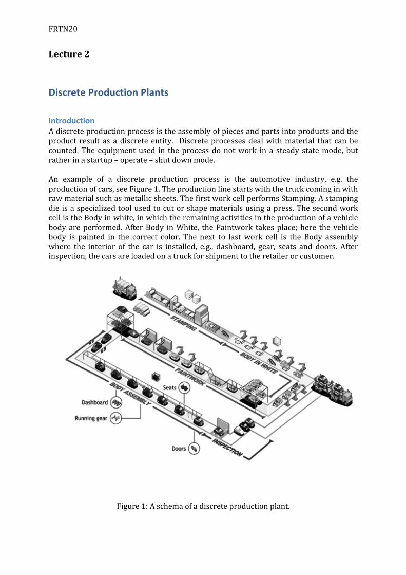
IntroductionAdiscreteproductionprocessistheassemblyofpiecesandpartsintoproductsandtheproduct result as a discrete entity. Discrete processes dealwithmaterial that can becounted. The equipmentused in theprocess donotwork in a steady statemode, butratherinastartup–operate–shutdownmode.An example of a discrete production process is the automotive industry, e.g. theproductionofcars,seeFigure1.Theproductionlinestartswiththetruckcominginwithrawmaterialsuchasmetallicsheets.ThefirstworkcellperformsStamping.Astampingdieisaspecializedtoolusedtocutorshapematerialsusingapress.ThesecondworkcellistheBodyinwhite,inwhichtheremainingactivitiesintheproductionofavehiclebodyareperformed.AfterBody inWhite, thePaintwork takesplace; here thevehiclebody is painted in the correct color. The next to last work cell is the Body assemblywhere the interior of the car is installed, e.g., dashboard, gear, seats and doors. Afterinspection,thecarsareloadedonatruckforshipmenttotheretailerorcustomer.
Figure1:Aschemaofadiscreteproductionplant.
FRTN20
Thereareanumberofcharacteristicstypicaltodiscreteprocesses:• Theproductisadiscreteentity.• Assembly-orientedproduction.• Stagedproductionthroughworkcells• Well-definedproductionruns.• Theprocessismostoften“visible”.• Theequipmentoperatesinon-offmanner.• Theproductionprocessissequential.
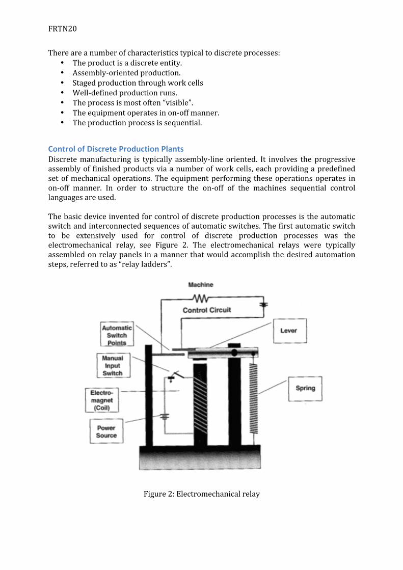
ControlofDiscreteProductionPlantsDiscretemanufacturing is typically assembly-line oriented. It involves theprogressiveassemblyof finishedproductsviaanumberofworkcells,eachprovidingapredefinedsetofmechanicaloperations.Theequipmentperforming theseoperationsoperates inon-off manner. In order to structure the on-off of the machines sequential controllanguagesareused.Thebasicdeviceinventedforcontrolofdiscreteproductionprocessesistheautomaticswitchandinterconnectedsequencesofautomaticswitches.Thefirstautomaticswitchto be extensively used for control of discrete production processes was theelectromechanical relay, see Figure 2. The electromechanical relays were typicallyassembledonrelaypanels inamannerthatwouldaccomplishthedesiredautomationsteps,referredtoas“relayladders”.
Figure2:Electromechanicalrelay
FRTN20
Formalspecificationlanguagesandformalmodelingtechniquesareusedtodescribethebehaviouroftheequipmentand/orproductionprocess.Formalanalysistechniquesarethen used to verify certain critical properties. A number of approaches have beendeveloped.Theyarebasedon;logics,finitestatemachines,andPetriNets.Therearedifferenttoolsandlanguagesforimplementationofdiscretecontrollers.Withbetterabstractionandstructuringpossibilitiesitiseasiertogetagoodoverviewofthecontrol problem and the implementation is drastically simplified. Most of these toolsand languagesaregraphicalprogramming languages.Grafcet isoneexampleofsuchalanguage.GrafcetisnowpartoftheIEC1131-3standard(laterrenamedIEC61131-3),under the name Sequential Function Charts (SFC). JGrafchart is a toolbox based onGrafcet, implemented in Java. JGrafchart was developed at Department of AutomaticControl,LTH,LundUniversity.
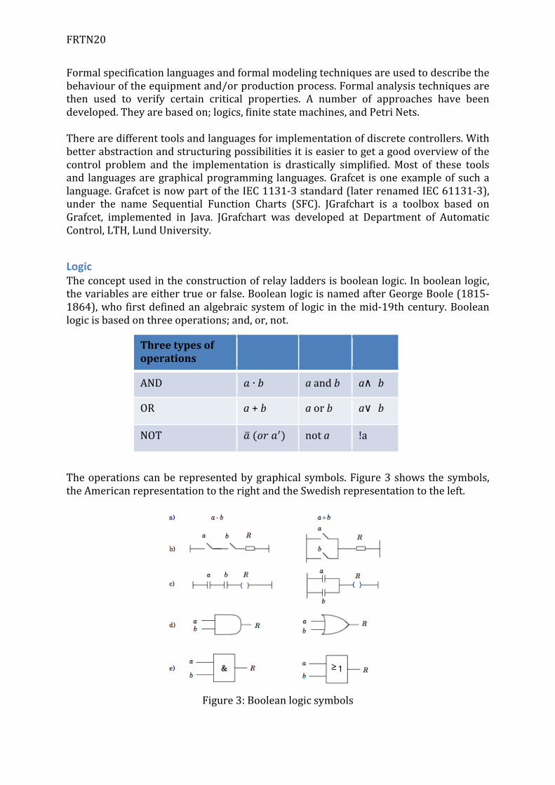
LogicTheconceptusedintheconstructionofrelayladdersisbooleanlogic.Inbooleanlogic,thevariablesareeithertrueorfalse.BooleanlogicisnamedafterGeorgeBoole(1815-1864),whofirstdefinedanalgebraicsystemof logic inthemid-19thcentury.Booleanlogicisbasedonthreeoperations;and,or,not.Theoperationscanberepresentedbygraphicalsymbols.Figure3showsthesymbols,theAmericanrepresentationtotherightandtheSwedishrepresentationtotheleft.
Figure3:Booleanlogicsymbols
Threetypesofoperations
AND 𝑎 ∙ 𝑏 aandb a∧ b
OR a+b aorb a∨ b
NOT 𝑎 (𝑜𝑟 𝑎!) nota !a
FRTN20
Inlogicthecommutative,associative,distributivelawsandDeMorgan’slawareused.Commutative 𝑎 ∙ 𝑏 = 𝑏 ∙ 𝑎Associative 𝑎 ∙ 𝑏 ∙ 𝑐 = (𝑎 ∙ 𝑏) ∙ 𝑐Distributive 𝑎 ∙ 𝑏 + 𝑐 = 𝑎 ∙ 𝑏 + 𝑎 ∙ 𝑐DeMorgan 𝑎 + 𝑏 = 𝑎 ∙ 𝑏, 𝑎 ∙ 𝑏 = 𝑎 + 𝑏In the 1960s the digital computer technology started to be popular for manyapplications, so also for the construction of relay ladders, this was referred to as“ProgrammableLogicControllers(PLC)”.TheinitiallanguageofPLCwascalledladderlogic.Todaythereexistaninternationalstandard,IEC1131-3,forPLCprogramminglanguages.It specifies the syntax, semantics and display for the following PLC programminglanguages:
• Ladderdiagram• Structuredtext• Instructionlist• FunctionBlockDiagram• SequentialFunctionCharts
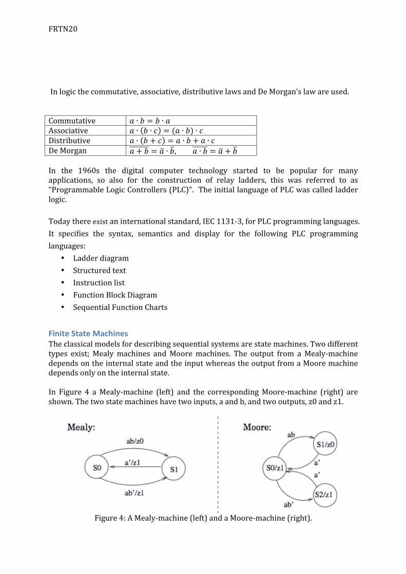
FiniteStateMachinesTheclassicalmodelsfordescribingsequentialsystemsarestatemachines.Twodifferenttypes exist; Mealymachines andMooremachines. The output from aMealy-machinedependsontheinternalstateandtheinputwhereastheoutputfromaMooremachinedependsonlyontheinternalstate.In Figure 4 aMealy-machine (left) and the correspondingMoore-machine (right) areshown.Thetwostatemachineshavetwoinputs,aandb,andtwooutputs,z0andz1.
Figure4:AMealy-machine(left)andaMoore-machine(right).
FRTN20
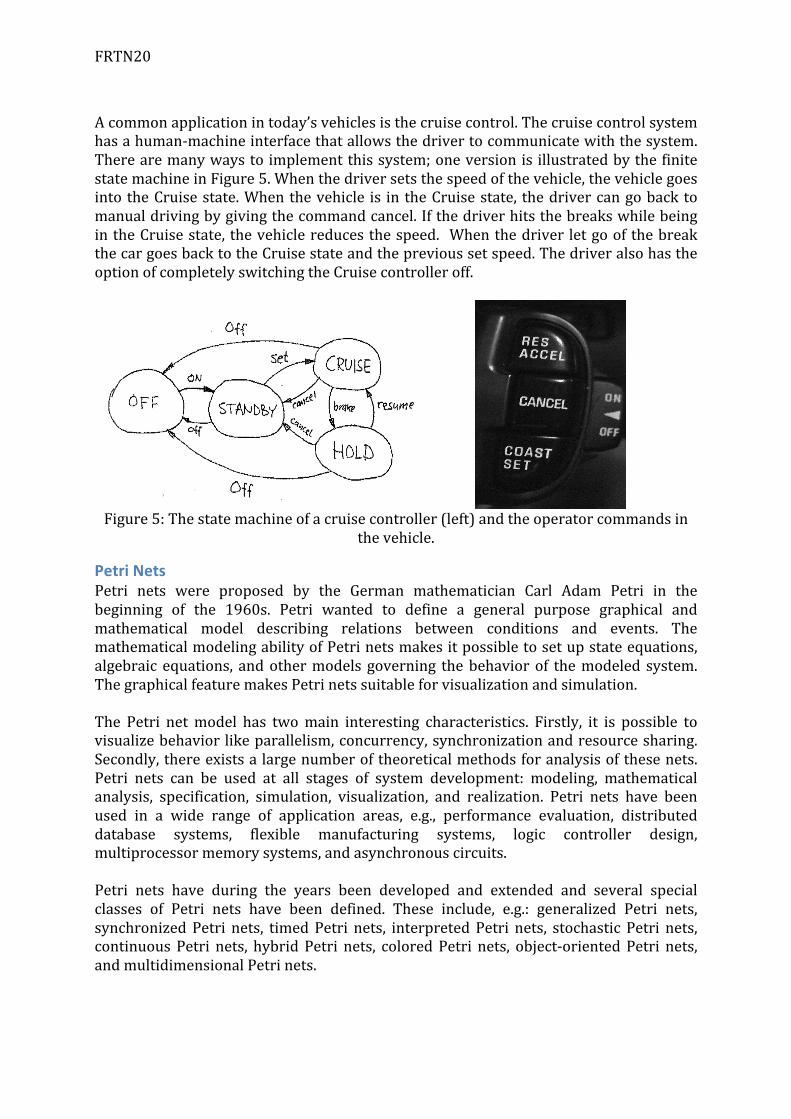
Acommonapplicationintoday’svehiclesisthecruisecontrol.Thecruisecontrolsystemhasahuman-machineinterfacethatallowsthedrivertocommunicatewiththesystem.Therearemanywaystoimplementthissystem;oneversionis illustratedbythefinitestatemachineinFigure5.Whenthedriversetsthespeedofthevehicle,thevehiclegoesintotheCruisestate.Whenthevehicle is intheCruisestate, thedrivercangobacktomanualdrivingbygivingthecommandcancel.IfthedriverhitsthebreakswhilebeingintheCruisestate, thevehiclereducesthespeed. Whenthedriver letgoofthebreakthecargoesbacktotheCruisestateandtheprevioussetspeed.ThedriveralsohastheoptionofcompletelyswitchingtheCruisecontrolleroff.
Figure5:Thestatemachineofacruisecontroller(left)andtheoperatorcommandsin
thevehicle.
PetriNetsPetri nets were proposed by the German mathematician Carl Adam Petri in thebeginning of the 1960s. Petri wanted to define a general purpose graphical andmathematical model describing relations between conditions and events. ThemathematicalmodelingabilityofPetrinetsmakesitpossibletosetupstateequations,algebraic equations, andothermodels governing thebehaviorof themodeled system.ThegraphicalfeaturemakesPetrinetssuitableforvisualizationandsimulation.The Petri netmodel has twomain interesting characteristics. Firstly, it is possible tovisualizebehaviorlikeparallelism,concurrency,synchronizationandresourcesharing.Secondly,thereexistsalargenumberoftheoreticalmethodsforanalysisofthesenets.Petri nets can be used at all stages of system development: modeling, mathematicalanalysis, specification, simulation, visualization, and realization. Petri nets have beenused in a wide range of application areas, e.g., performance evaluation, distributeddatabase systems, flexible manufacturing systems, logic controller design,multiprocessormemorysystems,andasynchronouscircuits.Petri nets have during the years been developed and extended and several specialclasses of Petri nets have been defined. These include, e.g.: generalized Petri nets,synchronizedPetri nets, timedPetri nets, interpretedPetri nets, stochastic Petri nets,continuousPetri nets, hybrid Petri nets, coloredPetri nets, object-orientedPetri nets,andmultidimensionalPetrinets.
FRTN20
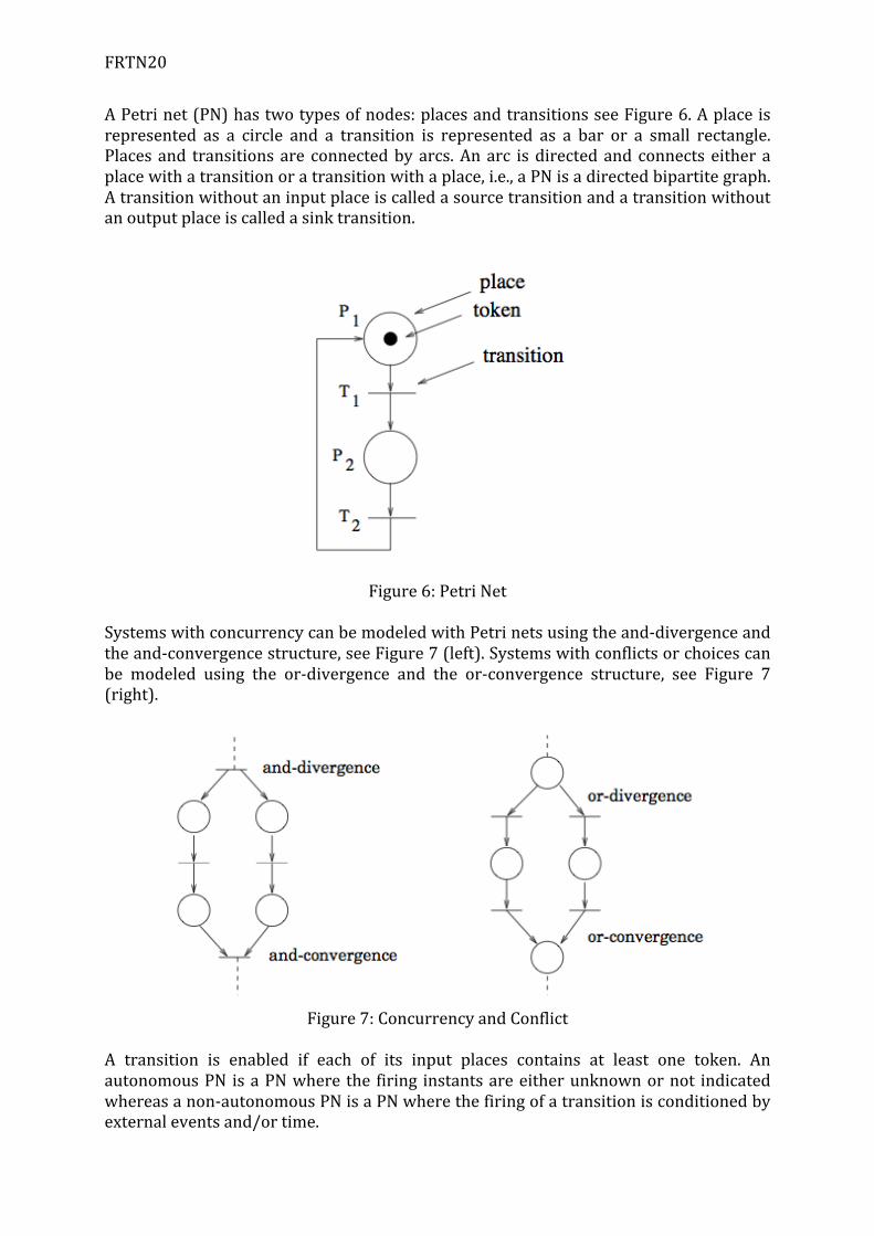
APetrinet(PN)hastwotypesofnodes:placesandtransitionsseeFigure6.Aplaceisrepresented as a circle and a transition is represented as a bar or a small rectangle.Places and transitionsare connectedbyarcs.Anarc isdirectedand connects either aplacewithatransitionoratransitionwithaplace,i.e.,aPNisadirectedbipartitegraph.Atransitionwithoutaninputplaceiscalledasourcetransitionandatransitionwithoutanoutputplaceiscalledasinktransition.
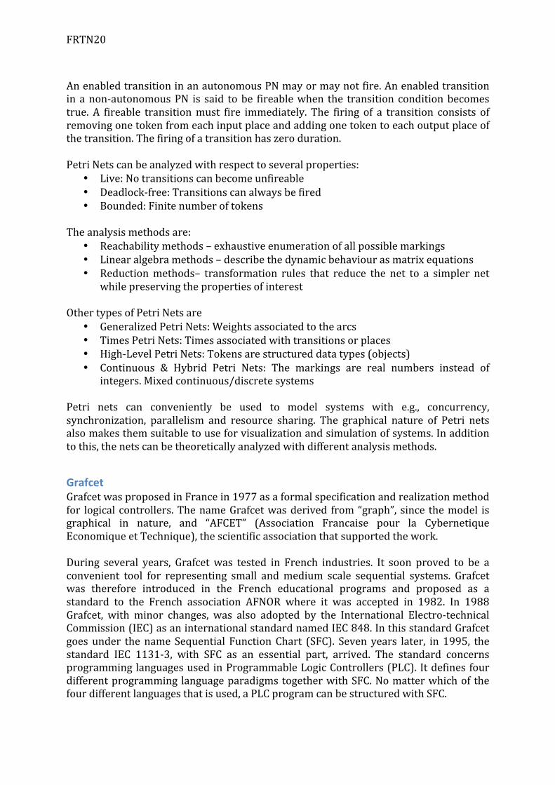
Figure6:PetriNetSystemswithconcurrencycanbemodeledwithPetrinetsusingtheand-divergenceandtheand-convergencestructure,seeFigure7(left).Systemswithconflictsorchoicescanbe modeled using the or-divergence and the or-convergence structure, see Figure 7(right).
Figure7:ConcurrencyandConflict
A transition is enabled if each of its input places contains at least one token. AnautonomousPN isaPNwhere the firing instantsareeitherunknownornot indicatedwhereasanon-autonomousPNisaPNwherethefiringofatransitionisconditionedbyexternaleventsand/ortime.
FRTN20
AnenabledtransitioninanautonomousPNmayormaynotfire.Anenabledtransitionin anon-autonomousPN is said tobe fireablewhen the transition conditionbecomestrue. A fireable transitionmust fire immediately. The firing of a transition consists ofremovingonetokenfromeachinputplaceandaddingonetokentoeachoutputplaceofthetransition.Thefiringofatransitionhaszeroduration.PetriNetscanbeanalyzedwithrespecttoseveralproperties:
• Live:Notransitionscanbecomeunfireable• Deadlock-free:Transitionscanalwaysbefired• Bounded:Finitenumberoftokens
Theanalysismethodsare:
• Reachabilitymethods–exhaustiveenumerationofallpossiblemarkings• Linearalgebramethods–describethedynamicbehaviourasmatrixequations• Reductionmethods– transformation rules that reduce the net to a simpler net
whilepreservingthepropertiesofinterestOthertypesofPetriNetsare
• GeneralizedPetriNets:Weightsassociatedtothearcs• TimesPetriNets:Timesassociatedwithtransitionsorplaces• High-LevelPetriNets:Tokensarestructureddatatypes(objects)• Continuous & Hybrid Petri Nets: The markings are real numbers instead of
integers.Mixedcontinuous/discretesystemsPetri nets can conveniently be used to model systems with e.g., concurrency,synchronization, parallelism and resource sharing. The graphical nature of Petri netsalsomakesthemsuitabletouseforvisualizationandsimulationofsystems.Inadditiontothis,thenetscanbetheoreticallyanalyzedwithdifferentanalysismethods.
GrafcetGrafcetwasproposedinFrancein1977asaformalspecificationandrealizationmethodfor logical controllers.ThenameGrafcetwasderived from“graph”, since themodel isgraphical in nature, and “AFCET” (Association Francaise pour la CybernetiqueEconomiqueetTechnique),thescientificassociationthatsupportedthework.During several years, Grafcetwas tested in French industries. It soon proved to be aconvenient tool for representing small andmedium scale sequential systems. Grafcetwas therefore introduced in the French educational programs and proposed as astandard to the French association AFNOR where it was accepted in 1982. In 1988Grafcet, with minor changes, was also adopted by the International Electro-technicalCommission(IEC)asaninternationalstandardnamedIEC848.InthisstandardGrafcetgoes under thename Sequential FunctionChart (SFC). Seven years later, in 1995, thestandard IEC 1131-3, with SFC as an essential part, arrived. The standard concernsprogramminglanguagesusedinProgrammableLogicControllers(PLC). Itdefinesfourdifferentprogramming languageparadigmstogetherwithSFC.Nomatterwhichof thefourdifferentlanguagesthatisused,aPLCprogramcanbestructuredwithSFC.
FRTN20
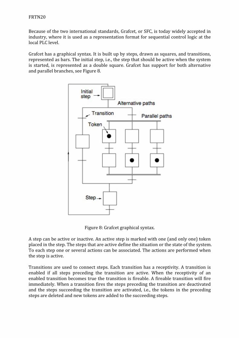
Becauseofthetwointernationalstandards,Grafcet,orSFC,istodaywidelyacceptedinindustry,whereitisusedasarepresentationformatforsequentialcontrollogicatthelocalPLClevel.Grafcethasagraphicalsyntax.Itisbuiltupbysteps,drawnassquares,andtransitions,representedasbars.Theinitialstep,i.e.,thestepthatshouldbeactivewhenthesystemis started, is represented as a double square. Grafcet has support for both alternativeandparallelbranches,seeFigure8.
Figure8:Grafcetgraphicalsyntax.Astepcanbeactiveorinactive.Anactivestepismarkedwithone(andonlyone)tokenplacedinthestep.Thestepsthatareactivedefinethesituationorthestateofthesystem.Toeachsteponeorseveralactionscanbeassociated.Theactionsareperformedwhenthestepisactive.Transitionsareusedtoconnectsteps.Eachtransitionhasareceptivity.A transition isenabled if all steps preceding the transition are active. When the receptivity of anenabledtransitionbecomestruethetransitionisfireable.Afireabletransitionwillfireimmediately.Whenatransitionfiresthestepsprecedingthetransitionaredeactivatedand the steps succeeding the transition are activated, i.e., the tokens in the precedingstepsaredeletedandnewtokensareaddedtothesucceedingsteps.
FRTN20
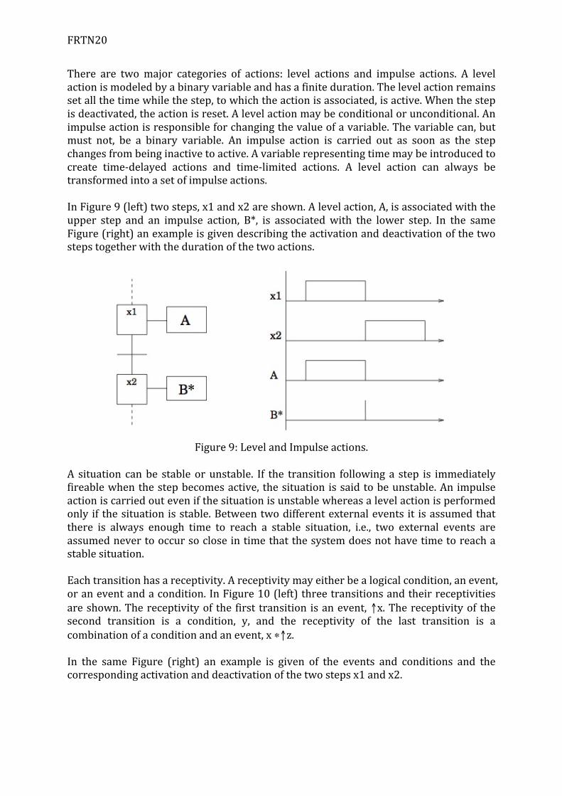
There are twomajor categories of actions: level actions and impulse actions. A levelactionismodeledbyabinaryvariableandhasafiniteduration.Thelevelactionremainssetallthetimewhilethestep,towhichtheactionisassociated,isactive.Whenthestepisdeactivated,theactionisreset.Alevelactionmaybeconditionalorunconditional.Animpulseactionisresponsibleforchangingthevalueofavariable.Thevariablecan,butmust not, be a binary variable. An impulse action is carried out as soon as the stepchangesfrombeinginactivetoactive.Avariablerepresentingtimemaybeintroducedtocreate time-delayed actions and time-limited actions. A level action can always betransformedintoasetofimpulseactions.InFigure9(left)twosteps,x1andx2areshown.Alevelaction,A,isassociatedwiththeupper step and an impulse action, B*, is associatedwith the lower step. In the sameFigure(right)anexampleisgivendescribingtheactivationanddeactivationofthetwostepstogetherwiththedurationofthetwoactions.
Figure9:LevelandImpulseactions.
A situation canbe stableorunstable. If the transition following a step is immediatelyfireablewhenthestepbecomesactive, thesituation issaidtobeunstable.An impulseactioniscarriedoutevenifthesituationisunstablewhereasalevelactionisperformedonly if thesituation isstable.Betweentwodifferentexternalevents it isassumedthatthere is always enough time to reach a stable situation, i.e., two external events areassumednevertooccursocloseintimethatthesystemdoesnothavetimetoreachastablesituation.Eachtransitionhasareceptivity.Areceptivitymayeitherbealogicalcondition,anevent,oraneventandacondition.InFigure10(left)threetransitionsandtheirreceptivitiesareshown.Thereceptivityof the first transition isanevent,↑x.Thereceptivityof thesecond transition is a condition, y, and the receptivity of the last transition is acombinationofaconditionandanevent,x∗↑z.In the same Figure (right) an example is given of the events and conditions and thecorrespondingactivationanddeactivationofthetwostepsx1andx2.

FRTN20
Figure10:Threetransitionsandtheirreceptivities
To facilitate thedescriptionof largeandcomplex systemsmacrosteps canbeused.Amacro step is a step with an internal representation that facilitates the graphicalrepresentationandmakesitpossibletodetailcertainpartsseparately.Amacrostephasoneinputandoneoutputstep.Whenthetransitionprecedingthemacrostepfirestheinputstepofthemacrostepisactivated.Thetransitionsucceedingthemacrostepdoesnotbecomeenableduntil theexecutionof themacrostepreaches itsoutputstep.ThemacrostepconceptisshowninFigure11.
Figure11:Amacrostep.ThedynamicbehaviorofGrafcetisdefinedbyfiverules:
1. TheinitialsituationofaGrafcetisdeterminedbyitsinitialsteps.2. Atransitionisenabledifallofitspreviousstepsareactive.Aenabledtransition
isfireableifitsassociatedreceptivityistrue.Afireabletransitionisimmediatelyfired.
FRTN20
3. Firingofatransitionresultsindeactivationofitspreviousstepandasimultaneousactivationofitsfollowingsteps.
4. Simultaneouslyfireabletransitionsaresimultaneouslyfired.5. Ifanactivestepistobesimultaneouslydeactivatedandactivateditremains
active.The aim of Grafcet, or SFC, in the standards has gradually shifted from being arepresentation format for logical controllers towards being a graphical programminglanguage for sequential control problems at the local level. One main advantage ofGrafcet,orSFC,isitssimpleandintuitivegraphicalsyntax.TodayGrafcetiswidelyusedandwellacceptedinindustry.
JGrafchartJGrafchart is a Grafcet/SFC editor and execution environment developed at theDepartmentofAutomaticControl,LundUniversity.JGrafchart provides graphical representation and execution of operation sequences,procedures,andstatemachines.ItintegratesfeaturesfromGrafcetinIEC61131-3,andStatechartswithconceptsfromproceduralandobject-orientedprogramming.JGrafchartis implemented in Java/Swing and runs on all platforms that support Java. The toolcombinesaninteractivegraphicalprogrammingenvironmentwitharun-timeengineforexecutionofJGrafchartfunctioncharts.JGrafchartcanbeusedforalltypesofdiscrete-eventbasedapplications,e.g.,logicalcontrol,operatingproceduremanagement,recipe-basedbatchcontrol,andworkflowmodelling.ThehighgeneralityofJGrafchartmakesitapplicableinawidevarietyofprocesscontrolandoperatorsupportsituations.JGrafchartsupportsthefollowinglanguageelements:
• workspaceobjects• Steps• initialsteps• transitions• parallelsplitsandparalleljoins• macrosteps• exceptiontransitions
Inadditionthereissupportfor:• digitalinputsanddigitaloutputs• analoginputsandanalogoutputs• socketinputsandsocketoutputs• internalvariables(real,boolean,string,andinteger)• actionbuttonsandfreetextforcomments.
Sequence diagrams are created interactively using drag-and-drop from a palettecontaining the different language elements. The sequence diagrams are stored onJGrafchartworkspaceobjects,seeFigure12.

FRTN20
Figure12:AnexampleofaJGrafchart.JGrafchartispresentedinLaboratoryExercise1.
SummaryIntoday’slecturethefocushasbeenonDiscreteProductionProcesses,seeFigure13.
Figure13:Thediscreteproductionprocess.

FRTN20
References:• P.MartinandG.Hale[2010]:Automationmadeeasy.PublishedbyISA.ISBN978-
1-936007-06-6• C.Johnsson[1999]:Agraphicallanguageforbatchcontrol,Ph.Dthesis,Dept.of
Automaticcontrol,LundUniversity,Number1051• R.DavidandH.Allaand[1992]:Grafcet&Petrinets:ToolsforModellingDiscrete
EventSystems,Prentice-Hall,SBN:013327537X• KJÅströmandR.Murray[2008]:FeedbackSystems:Anintroductionfor
ScientistsandEngineers,PrincetonUniversityPress,ISBN978-0-691-13576-2