for plants and production of architectural precast ... · pdf filefor plants and production of...
TRANSCRIPT

Manual for
QUALITY CONTROLFor Plants and Production of
ARCHITECTURAL PRECASTCONCRETE PRODUCTS
THIRD EDITION
MNL-117-96
I 1PRECASTiPRESTRESSED
CONCRETE INSTITUTE
MNL-117 3rd Edition

Copyright 0 1996 byPRECAST/PRESTRESSED CONCRETE INSTITUTE
All rights reserved. No part of this book may bereporduced in any form without permission in writing
from the publisher. Printed in the U.S.A.
First Edition, 1968Second Edition, 1977
Second Edition, Third Printing, 1984Second Edition, Fourth Printing, 1988
Third Edition, 1996
ISSN O-937040-48-7
II MNL-117 3rd Edition
FOREWORDThis Manual has been prepared as a guideline for quality assurance of architectural precast con-crete. Since the products are custom designed, the many combinations of shape, size, color andtexture require a great degree of craftsmanship. Therefore it is important to implement and main-tain the quality control Standards as given in this Manual to achieve the specific performance andaesthetic requirements of a project.
Materials and performance requirements for the architectural precast concrete should be clearlystated in the plans and specifications. These requirements should neither be open to interpreta-tion nor unduly restrictive for the project, but should be written to conform with the intended use ofthe architectural precast concrete. Personnel in the manufacturer’s organization should be thor-oughly trained and competent in order to achieve quality architectural precast concrete products.
The first edition of the Manual for Quality Control for Plants and Production of Architectural PrecastConcrete Products was prepared by the PCI Plant Certification Subcommittee for Plant Productionof Architectural Precast Concrete Products. Subsequent to the publication and use of the first edi-tion, a plant certification program was established for the precast and prestressed concrete industry.The inspection of architectural precast concrete production facilities, carried out under this program,was based on the recommended practices and criteria outlined in that Manual. Experience by boththe manufacturers and the inspection teams led to the second edition in 1977.
The third edition which is even more demanding of a high standard of industry practice was pre-pared by the PCI Architectural Precast Concrete Services Committee and the PCI PlantCertification Committee. It represents state-of-the-art procedures and is the industry standard forachieving consistently high quality. Committee members working on this Manual were as follows:
ARCHITECTURAL PRECAST CONCRETE SERVICES COMMITTEE
Donald G. Clark, Chairperson
Kevin AndersonJames T. EngleDonald L. Faust, Sr.Charles L. FisterSidney Freedman*Marvin F. Hartsfield‘Principal author“Past Chairman
Tom KelleyEdward S. KnowlesDouglas L. LorahRichard C. NashRichard C. Page, Jr.*’Ned PiccininiArthur G. Salzman
PLANT CERTIFICATION COMMITTEE
Dino J. Scalia. Chairperson
Ray Andrew% Jr.John H. Bachman, Jr.Henry ClarkTheodore W. CoonsJohn S. DickLarry G. Fischer
Ted J. GuttRay L. KennedyJoel KessellMichael W. LaNierRobert McCrossenGary E. OakesStanley J. Ruden
MNL-I17 3rd Edition Ill

k MNL-117 3rd Edition

INTRODUCTIONMNL 117, Third Edition
The Standard and Commentary are presented in a side-by-side column format, with the Standard textplaced in the left column and the corresponding Commentary text aligned in the right column. The Stan-dard has been printed in Helvetica, the same type face in which this paragraph is set.
This paragraph is set in Times, all portions of the Commentary are printed in this type face. Commentary article numbers arepreceded by a “c” to further distinguish them from Standard article numbers. The information contained in the Commentary
is not part of the Standard. It shall not be used in judging quality control or production procedures. It does provide sugges-
tions to help in carrying out the requirements or intent of the standard.
Architectural precast concrete panels, through the application of finish, shape, color or texture, contribute to thearchitectural form and finished effect of a structure. Not generally included are the so-called industrialized pre-cast products (standard shapes), such as double or single tees, channel sections, and flat or hollow-core slabsusually produced in fixed, long-line forms. Architectural precast concrete units may be manufactured with con-ventional mild steel reinforcement, or they can be prestressed. Design flexibility in surface appearance is possi-ble by incorporating various textures and finishes and through the use of different cements, coarse and fineaggregates, and pigments into the concrete mix. Natural stone or clay products may be used as a veneer finishor alternatively, panels may be painted or stained to achieve the required colors.
The architect/engineer is directed to Appendix B for a listing of the responslbllitles which are to be consideredin the preparation of plans and specifications for an architectural concrete project.
This manual is divided into two parts. The first part contains Divisions 1 through 7 which form the basis for PCIPlant Certification in product Group Al - architectural precast concrete products. It is conformance to theseStandards which is audited during each PCI plant inspection and provides the criteria for evaluation of theplant’s capabilities.
The final part - Appendices -contains summaries of useful information for both the manufacturer and specifier.
The Standard is intended to be used as the basis for a quality assurance program for the manufacture of archi-tectural precast concrete products and to provide requirements for quality production practices. The Standardportion is intended to serve as a specification reference document. It should be augmented as required for spe-cific operations and products by the specifier or producer. The Commentary provides amplification and expla-nation of the Standard to assist the manufacturer.
Routine conformance to requirements of this Standard should result in products of consistent and optimumquality if used in concert with proven and documented plant-specific procedures. Optimum quality is defined asthat level of quality, in terms of appearance, strength and durability, which is appropriate for the specific prod-uct and its particular application. In other words, it is that quality which is both economical to achieve and suit-able for the particular purpose it serves as a component in the overall project.
MNL-t 17 3 r d E d i t i o n v
This Standard provides a minimum level of quality, but there is no intent to place a ceiling on excellence. Thedegree of success in specifying and obtaining optimum quality for products will depend on the combined effortsof designers and manufacturers to define and coordinate their individual requirements, responslbllltles andexpectations.
No Manual of this type can be all-inclusive. The requirements and recommendations given herein are a generalpresentation of the important factors governing the quality of architectural precast concrete. Their value isdependent on rational application and a determination on the part of the individual producer to establish a stan-dard of quality that will be recognized and respected by the specifier.
Quality assurance begins when the architect determines shape, size, color and texture for the architectural pre-cast concrete products for a specific project. These characteristics may then determine the methods of manu-facture, as well as the handling and installation techniques. Consultation with qualified representatives of expe-rienced manufacturers will be of great value in achieving high quality products at a reasonable cost to theowner.
The Standard indicates the requirements to obtain the desired quality but not the means or methods. It is notthe intention of the Manual to restrict individual plant techniques. For example, a manufacturer’s methods formixing, placement, consolidation and curing of concrete will be acceptable, provided these methods can con-sistently result in uniform and durable concrete of the specified quality.
The Commentary contains suggestions to help in carrying out the requirements or intent of the Standard.
This Manual has been prepared on the basis of current good practice. As significant changes in materials orprocess technology occur, revisions will be made to this Manual.
Note: The production of architectural precast con-crete may involve hazardous materials, operations,and equipment. This manual does not purport toaddress the safety problems associated with produc-tion. It is the responsibility of the plant to establishappropriate safety and health practices. The p/antshould determine the applicability of any regulatory/imitations.
VI MNL-117 3rd Edtiion
TABLE OF CONTENTS
Foreword.. .............................................. iiiIntroduction ............................................ vDefinitions ............................................ .xi
DIVISION 1 - QUALITY SYSTEM
1.1 Objective
1.21.211.2.21.2.3
Plant Quality Assurance ProgramGenera/ ................................................... 1Documented Procedures.. ..................... .2. . . .Management Responsrbrkbes ................ .3
1.31.3.11.3.21.3.31.3.41.3.5
PersonnelGenera/. ................................................. .4Engineering ............................................ .4Drafting .................................................. .4Production .............................................. .5Quality Control ....................................... .5
1.41.4.11.4.2
Design ResponsibilitiesGeneral .................................................. .5Shop Drawings ...................................... .6
1.51.5.11.5.21.531.54
Project SamplesGeneral.. ................................................ .6Size and Shape ..................................... .6ldentifica tion........................................... .7Visual Mockups and initial ProductionApproval of Architectural finishes.. ....... .7
DIVISION 2 -PRODUCTIONPRACTICE$
2.1 General Objectives and Safety2.1.1 General.. .92.1.2 Plant Safety . 9
2.22.2. I2.2.22.2.3
2.2.42.2.52.2.62.2.72.2.8
Production and Curing FacilitiesArea Requirements . . . . . . . . . . . . . . . . . 9Mold fabrication . 10Storage of Release Agents andRetarders . . . . . . . . . . . . . . . . . . . . . . . . . . . . . . . . . . . 10Hardware Fabrication and Storage....... 10C a s t i n g A r e a a n d E q u i p m e n t 11C u r i n g a n d F i n i s h i n g A r e a s 1 2Handling Equipment __ .12Storage Area for Finished Products...... 13
2.3 Welding
2.3.1 Structural Steel ..................................... 132.3.2 Reinforcement ..................................... .162.3.3 Stud Welding ....................................... .20
2.4 Molds2.4.1 Materials and Construction ................... 212.4.2 Verification and Maintenance .............. .24
2.5 Herdware installation ........................ 24
2.62.6.12.6.22.6.32.6.42.6.5
Product HandlingGeneral ................................................. 2 7Stripping.............................................. ..2 8Yard Storage............................. .......... .28Cleaning.. ............................................ ..2 9Loading ................................................. 29
2.7 Surfsce Finishes2.7.1 General. ............................................... .302.7.2 Smooth ................................................. 312.7.3 Sand or Abrasive Blast ......................... 322.7.4 Acid Etched.. ........................................ .332.7.5 Retarded.. ............................................ .342.7.6 Tooled or Bushhammered.. ................. .352.77 Honed or Polished. .............................. .352.76 Form Liner ........................................... .362.7.9 Veneer Facing Material. ....................... .362.7.10 Sand Embedded Materials .................. .392.7.11 Unformed Surface Finishes.. .............. ..4 02.7.12 Applied Coatings. ................................. .4 7
2.6 Repairs. ............................................... 41
2.9 Acceptability of Appearance ............ 42
2.10 Sealers or Clear Surface Coatings....4 4
DIVISION 3 - RAW MATERIALS ANDACCESSORIES
3.13.7.13.1.23.1.33.1.43.1.5
Concrete Materials
3.1.63.1.7
General ,.., ,., ,..,_.._ ._.__._..___...................... 47Cement . . . . . . . . . . . . . . . . . . . . . . . . . . . . . 47Facing Aggregates . 47Backup Aggregates . .49Aggregates for LightweightConcrete ._.._.___. ._. _..___. 50Mixing Water ___. ._. _..___. ..50Admixtures. 51
3.2 Reinforcement and Hardware
MNL-I17 3rd Edition vii
3.2.1 Reinforcing Steel .533.2.2 Prestressing Materials .553.2.3 Hardware and Miscellaneous
Materials ..__._..__.,.,.,,,...,,,....................... 583.2.4 Handling and Lifting Devices __.. ,_ ,.,...,.,. 62
3.3 tnsulation 63
3.4 W e l d i n g E l e c t r o d e s 63
DIVISION 4 - CONCRETE
4.14.1.14.1.24.1.3
4.1.4
4.2
4.3
4.4
4.5
4.6
4.74.7.14.Z2
4.7.3
4.8
4.9
4.9.14.9.24.9.34.9.4
4.10
Mix ProportioningQualification of New Concrete Mixes-67Specified Concrete Strength.. ,.., ,...,.,._, .68Statistical Concrete StrengthConsidera tfons. .68Proportioning to Ensure Durability ofConcrete ..___..__. .__.. 69
Special Considerations for AirEntrainment ._.___._. ., ,_., ,,..., ,, ,.., ,,_. ,. .__. 70
Compatibility of Face and BackupMixes. .___...__. ..___. .___.. .__. ,_.,., ,. ,, ,.., ,, 71
Proportioning for Appearance ofConcrete Surfaces .___. ._. .__. ,_..,...,, 71
Mix Proportioning for Concrete madewith Structural LightweightAggregate 71
Proportioning for ConcreteW o r k a b i l i t y 72
Water-Cement RatioG e n e r a l 72Relationship of Water-Cement Ratio toStrength, Durability and Shrinkage. 73Relationship of Water-Cement Ratio toWorkability. .___._. .__. .___. .__. .__. ._.___. 73
Effects of Admixtures.. ..__. .._. ,, ,.., 73
Storage and Handling of ConcreteMaterialsGeneral... .__...___..._. .___,, ,., ,, ,...,.,.,., ,..,., 74Storage and Handling of Aggregates.... 74Storage and Handling of Cement .._._._. 75Storage and Handling of Admixtures andPigments.. __ 76
Batching Equipment Tolerances...... 78
4.11
4.12
Scale Requirements .......................... 79
Requirements for Water MeasuringEquipment .......................................... 80
4.13
4.13.14.13.24.13.34.13.4
Requirements for Batchers andMixing PlantsGeneral.. .............................................. 81Requirements for Concrete Mixers.......8 2Mixer Requirements............................ ..8 2Maintenance Requirements for ConcreteMixers .................................................. .83
4.144.14.14.14.2
Concrete Transportation EquipmentGeneral.. .............................................. 83Requirements for Concrete AgitatingDelivery Equipment.. ........................... ..8 3
4.15 Placing and Handling Equipment..... 83
4.16 Batching and Mixing Operations4.18.1 General ................................................ 844.16.2 Batching of Aggrega tes ....................... .854.16.3 Batching of Cement and Pigments.......8 64.16.4 Batching of Water ................................. 864.16.5 Batching of Admixtures......................... 86
4.174.17.14.17.24.17.34.17.44.17.54.17.64.17.7
4.17.84.17.9
Mixing of ConcreteGenera/. ............................................... 88Methods of Concrete Mixing.. .............. .88Mixing Time and Concrete Uniformity...8 9Mixing Time - Stationary Mixers ........... 90Mixing Time - Shrink Mixing.. ................ 90Mixing Time - Truck Mixing.. ................ .90Special Batching and MixingRequirements for LightweightAggregates .......................................... .90Cold Weather Mixing.. ......................... .97Hot Weather Mixing ............................ ..9 2
4.18
4.18.14.18.24.18.34.18.44.18.5
4.18.6
4.18.7
4.18.8
4.18.94.18.10
Requirements for Transporting andPlacing of ConcreteGeneral ................................................ .92Transporting and Placing Concrete.. . -9 3Preventing Aggregate Segregation.......9 3Preparation of the Molds.. .................... .94Placing Concrete Under Severe WeatherConditions ............................................ .94P/acing Concrete in Wet and RainyConditions ............................................ .94Placing Concrete in Hot or WindyConditions ............................................ .95P/acing Concrete in Cold WeatherConditions ......... .................................. .96P/acing Facing Concrete ...................... .96P/acing Sackup Concrete .................... .97
VIII MNL-117 3rd Edition
4.194.19.14.19.2
4.19.3
4.19.44.19.54.19.64.19.7
4.204.20.14.20.24.203
4.21421.14.21.24.21.3
4.22
4.22.14.22.24.22.3
Consolidation of ConcreteGeneral................................................. 97Consolidation of LightweightConcrete .............................................. .98Consolidation of Face and BackupMixes ................................................... .98Use of lntemal Vibrators ....................... 98Use of External Vibrators.. ................... .99Use of Surface Vibrators...................... .99Use of Vibrating Tab/es ...................... 100
Requirements for Curing ConcreteGenera/ ............................................... 100Curing Temperature Requirements.. ,100Curing to Attain Specified Stripping orRelease Strength ............................... ,101
Accelerafed Curing of ConcreteGeneral ............................................... 101Cuting with Live Steam.. ..................... 103Curing with Radiant Heat andMoisture .............................................. 103
Curing by Moisture Retention withoutSupplemental HeatGeneral ............................................... 103Moisture Retention Enclosure.. .......... ,104Curing with Membrane CuringCompound.. ....................................... ,104
DIVISION 5 - REINFORCEMENT AND
5.15.1.15.7.25.1.35.1.4
Reinforcing SteelGeneral 105Storage of Reinforcing Steel 105Fabrication of Reinforcing Steel 106installation of Reinforcing Steel 107
5.25.2.15.2.25.2.35.2.452.55.2.652.7
TensioningGeneral Tensioning Requirements..... 110Tensioning of Tendons ,___._................. 1 IOMethods of Force Measurement 111Gauging Systems . . . . . . .._.___.................. 112Control of Jacking Force ___._................ 112Wire Failure in Strand or Tendon 112Calibration Records for JackingEquipment .___......................,................ 113
5.3 Pretensioning53.1 Storage of Prestressing Steel . 1135.3.2 Genera/ .._,.._____.__............., ,..,..,.._.___._._. 1145.3.3 Strand Surfaces . . . . . . . . . . . . . . . . . . . . . . . . . . . . 1145.3.4 Stringing of Strands .._..................... 115
PRESTRESSING
5.3.5 Strand Chucks and Splice Chucks.. ... i 155.3.6 Strand Splices.................................... .I 165.3.7 Strand Position .................................. ,1165.3.8 Initial Tensioning ................................. 1165.3.9 _ Measurementof Elongation.. .............. 1175.3.10 Elongation Calculation and
Corrections ......................................... 1175.3.11 Force Corrections ............................... 1195.3.12 Final Stressing of Strands.. ................ .1205.3.13 Detensioning ....................................... 1205.3.14 Protection of Strand Ends and
Anchorages ......................................... 121
5.4 Post-Tensioning of Plant-ProducedProducts
5.4.1 Genera/. .............................................. 7225.4.2 Details and Positions for Ducts.. ........ ,1235.4.3 Friction in Ducts .................................. 1245.4.4 Tensioning .......................................... 12454.5 Anchorages. ........................................ 1245.4.6 Grouting ............... ,__ ............... .,, .......... 1255.4.7 Sealing of Anchorages........................ 125
DIVISION 6 - QUALITY CONTROL
6.7 Inspection6.1.1 Necessity for Inspection...................... 1276.1.2 Scope of inspection ............................ 127
6.2 Testing6.2.1 General.. ............................................. 1286.2.2 Acceptance Testing of Materials.. ...... ,1296.2.3 Production Testing. ............................ ,1386.2.4 Special Testing.. ................................ ,153
6.3 Records6.3.1 Recordkeeping. .................................. ,1538.3.2 Suppliers’ Test Reports ..................... ,1546.3.3 Tensioning Records ............................ 1556.3.4 Concrete Records ............................... 1566.3.5 Calibration Records for Equipment..... 156
6.4 Laboratory Facilities6.4.1 General.. ............................................. 1576.4.2 Quality Control Testing Equipment ..... 1578.4.3 Test Equipment Operating
Instructions ......................................... 157
DIVISION 7 - PRODUCT TOLERANCES
7.1 Requirements for Finished Product7.1.1 Product Tolerances - General ........... .I597.1.2 Product Tolerances ............................ .160
MNL-117 3rd Edition ix

APPENDICESAPPENDIX AGuidelines for Developing P/ant Quality SystemManual . . . . . .._..__.......................................... 167
APPENDIX BDesign Responsibilities and Considerations.. ,, ,175
APPENDIX Cfinish Samples.. .._.___... .._.._.__ 179
APPENDIX DChuck Use and Maintenance Procedure .___._.__ 161
APPENDIX ESample Record Forms ___, ,.,., ,,.......__. ..___._... ,, ,.. 183
APPENDIX FPCI Plant Certification Program .___..._._. ._., 189
APPENDIX GReference Literature .._...___. ._........ .._._____. 19 1
APPENDIX HS a m p l e T e n s i o n i n g C a l c u l a t i o n s 197
APPENDJX IErection T o l e r a n c e s 207
APPENDIX JArchitectural Trim Units ,..,,.__...____..___..,...,,...,.,. 209
INDEX . . . .._...__........,,....,.....,........,,,,..,,.,.,..... 215
x MNL-117 3rd Edition
DEFINITIONS
Accelerated curing - See Curing.
Admixture - A material other than water, aggre-gates and cement used as an ingredient in con-crete, mortar or grout to impart special charac-teristics.
Aggregate - Granular maferial. such as sand,gravel, and crushed stone used with a cement-ing medium to form a hydraulic-cement con-crete or mortar.
Aggregate, structural lightweight - Aggregatewith a dry, loose weight of 70 Ibs/fF (1121kg/ma) or less.
Air entraining admixture - A chemical added tothe concrete for the purpose of providing minutebubbles of air (generally smaller than 1 mm) inthe concrete during mixing to improve the dura-bility of concrete exposed to cyclical freezingand thawing in the presence of moisture.
Ambient temperature - The temperature of theair surrounding the forms and molds into whichconcrete is to be cast, or of the air surroundingan element during curing.
Anchorage - The means by which the prestress-ing force is permanently transmitted from theprestressing steel to the concrete. In post-ten-sioned applications, a mechanical device com-prising all components required to anchor theprestressing steel and transmit the prestress-ing force to the concrete.
Architectural precast concrete - A product witha specified standard of uniform appearance,surface details, color, and texture.
Architectural precast concrete Trim Units- Wetcast products with a high standard of finishquality and of relatively small size that can beinstalled with equipment of limited capacity,such as sills, lintels, coping, cornices, quoins,medallions, bollards, benches, planters, andpavers.
Backup mix - The concrete mix cast into themold after the face mix has been placed andconsolidated.
Bleeding -A form of segregation in which some ofthe water in a mix rises to the surface of freshlyplaced concrete: also known as water gain.
Blocking - Materials used for keeping concrete
elements from touching each other or othermaterials during storage and transportation.
Bondbreaker - A substance placed on a materialto prevent it from bonding to the concrete, orbetween a face material such as natural stoneand the concrete backup.
Bonding agent - A substance used to increasethe bond between an existing piece of concreteand a subsequent application of concrete suchas a patch.
Bull float -A tool comprising a large, flat, rectan-gular piece of wood, aluminum, or magnesiumusually 8 in. (ZOO mm) wide and 42 to 60 in.(1.0 to 1.5 m) long, and a handle 4 to 16 ft.(1 to 5 m) in length used to smooth unformedsurfaces of freshly placed concrete.
Bugholes - Small holes on formed concrete sur-faces formed by air or water bubbles, some-times called blowholes.
Camber - (1) The deflection that occurs in pre-stressed concrete elements due to the netbending resulting from application of a pre-stressing force. (It does not include dimension-al inaccuracies); and (2) A built-in curvature toimprove appearance.
Certification - Assurance by a competent thirdparty organization, operating on objective crite-ria and which is not subject to undue influencesfrom the manufacturer or purchaser or to finan-cial considerations, that elements are consis-tently produced in conformity with a specifica-tion. It not only proclaims compliance of a prod-uct with a specification, but also that the manu-facturer’s quality control arrangements havebeen approved and that a continuing audit iscarried out.
Clearance - Interface space (distance) betweentwo items.
Coarse aggregate - Aggregate predominatelyretained on the U.S. Standard No. 4 (4.75 mm)sieve; or that portion of an aggregate retainedon the No. 4 (4.75 mm) sieve.
Compaction - The process whereby the volumeof the concrete is reduced to the minimumpractical space by the reduction of voids usual-ly by vibration, tamping or some combination ofthese.
MNL-117 3rd Edition xi
Connection - Device for the attachment of pre-cast concrete units to each other or to thebuilding or structure.
Covermeter -See R-meter.
Crazing - A network of visible, fine hairlinecracks in random directions breaking theexposed face of a panel into areas of fromi/4 in. to 3 in. (6 to 75 mm) across.
Creep - The time dependent deformation(shortening) of prestressing steel or concreteunder sustained loading.
Curing - The maintenance of humidity and tem-perature of freshly placed concrete duringsome definite period following placing, casting,or finishing to assure satisfactory hydration ofthe cementitious materials and proper harden-ing of the concrete; where the curing tempera-ture remains in the normal environmentalrange [generally between 50 and 90 deg. F(10 and 32 deg. C)] use the term normal cur-ing; where the curing temperature is increasedto a higher range [generally between 90 and150 deg. F (32 and 66 deg. C)] use the termaccelerated curing.
Detensioning of strand or wire - The transferof strand or wire tension from the bed anchor-age to the concrete.
Draft-The slope of concrete surface in relationto the direction in which the precast concreteelement is withdrawn from the mold; it is pro-vided to facilitate stripping with a minimum ofmold breakdown.
Dunnage - See Blocking.
Elastic shortening-The shortening of a mem-ber which occurs immediately after the appli-cation of the prestressing force.
Elongation - Increase in length of the pre-stressing steel (strand) under the appliedprestressing force.
.Exposed aggregate concrete - Concretemanufactured so that the aggregate on theface is left protruding.
Face mix - The concrete at the exposed faceof a concrete unit used for specific appear-ance purposes.
Fine aggregate -Aggregate passing the 3/8 in.(9.5 mm) sieve and almost entirely passingthe No. 4 (4.75 mm) sieve and predominatelyretained on the No. 200 (75 ,um) sieve; orthat portion of an aggregate passing theNo. 4 (4.75 mm) sieve and predominatelyretained on the No. 200 (75 pm) sieve.
xii MNL-117 3rd Edition
Form -See Mold.
Formed surface - A concrete surface that hasbeen cast against formwork.
Form release agent -A substance applied to themold for the purpose of preventing bondbetween the mold and the concrete cast in it.
Friction loss - In post-tensioned applications, thestress (force) loss in a prestressing tendonresulting from friction created between thestrand and sheathing due to curvature in thetendon profile during stressing.
Gap-graded concrete - A mix with one or arange of normal aggregate sizes eliminated,and/or with a heavier concentration of certainaggregate sizes over and above standard gra-dation limits. It is used to obtain a specificexposed aggregate finish.
Grout - A mixture of cementitious materials andwater, with or without sand or admixtures.
Hardware - Items used in connecting precastconcrete units or attaching or accommodatingadjacent materials or equipment. Hardware isnormally divided into three categories:
Contractor’s hardware - Items to be placedon or in the structure in order to receive theprecast concrete units, e.g., anchor bolts,angles, or plates with suitable anchors.
Plant hardware - Items to be embedded inthe concrete units themselves, either for con-nections and precast concrete erector’s work,or for other trades, such as mechanical, plumb-ing, glazing, miscellaneous iron, masonry, orroofing trades.
Erection hardware - All loose hardware nec-essary for the installation of the precast con-crete units.
Homogeneous mix - A uniform concrete mixused throughout a precast concrete element.
Initial prestress - The stress (force) in the ten-don immediately after transferring the pre-stressing force to the concrete.
Jacking force - The maximum temporary forceexerted by the jack while introducing the pre-stressing force into the concrete through theprestressing strand.
Jig - A template or device to align parts of anassembly, usually for pre-assembling reinforc-ing steel and hardware cages, with a minimumof measurement to attain consistent accuracyfrom one cage to the next.
Laitance - Residue of weak and nondurable
material consisting of cement, aggregate fines, the form of diagrams and text which containor impurities brought to the surface of plastic all the information necessary for the manufac-concrete by bleed water. turer to produce the unit.
Lifting frame (or beam) - A rigging devicedesigned to provide two or more lifting points ofa precast concrete element with predictableload distribution and pre-arranged direction ofpulling force during lifting.
Mark number - The individual identifying markassigned to each precast concrete unit prede-termining its position in the building.
Quality - The appearance, strength and durabil-iv which is appropriate for the specific prod-uct, its particular application and its expectedperformance requirements. The totality of fea-tures and characteristics of a product thatbear on its ability to satisfy stated or impliedneeds.
Master mold - A mold which allows a maximumnumber of casts per project; units cast in suchmolds need not be identical, provided thechanges in the units can be simply accom-plished as pre-engineered mold modifications.
Matrix - The portion of the concrete mix contain-ing only the cement and fine aggregates (sand).
Quality assurance (QA) - All those planned orsystematic actions necessary to ensure thatthe final product or service will satisfy givenrequirements for quality and perform intendedfunction.
Miter-An edge that has been beveled to an angleother than 90 deg.
Mold - The container or surface against whichfresh concrete is cast to give it a desiredshape; sometimes used interchangeably withform. (The term is used in this Manual for cus-tom made forms for specific jobs while formsare used for standard forms or forms of stan-dard cross section.)
Quality control (QC) - Those actions related tothe physical characteristics of the materials,processes, and services, which provide ameans to measure and control the character-istics to predetermined quantitative criteria.
Quirk miter-A corner formed by two chamferedmembers to eliminate sharp corners and easealignment.
R-meter - An electronic device used to locateand size reinforcement in hardened concrete.
Retarder - An admixture which delays the set-ting of cement paste and therefore of con-crete.
Pattern or positive -A replica of all or part of theprecast element sometimes used for formingthe molds in concrete or plastic.
Plastic cracking - Short cracks often varying inwidth along their length that occur in the sur-face of fresh concrete soon after it is placedand while it is still plastic.
Retarder, surface - A material used to produceexposed aggregate concrete by retarding ordelaying the hardening of the cement pasteon a concrete surface within a time period andto a depth to facilitate removal of this pasteafter the concrete element is otherwise cured.
Post-tensioning - A method of prestressing con-crete whereby the tendon is kept from bondingto the plastic (wet) concrete, then elongated andanchored directly against the hardened con-crete, imparting stresses through end bearing.
Retempering - The addition of water or admix-ture and remixing of concrete which has start-ed to stiffen in order to make it more work-able.
Return -A projection which is angles away fromthe main face or plane of view.
Precast engineer - The person or firm whodesigns precast concrete members for specifiedloads and who may also direct the preparationof the shop drawings.
Pretensioning - A method of prestressing con-crete whereby the tendons are elongated,anchored while the concrete in the member iscast, and released when the concrete is strongenough to receive the forces from the tendonthrough bond.
Production drawings - A set of instructions in
Reveal - (1) Groove in a panel face generallyused to create a desired architectural effect;and (2) The depth of exposure of the coarseaggregate in the matrix after production of anexposed aggregate finish.
Rustication -A groove in a panel face for archi-tectural appearance; also reveal.
Sandwich wall panel - A prefabricated panelwhich is a layered composite formed byattaching two wythes or skins of concreteseparated by an insulating core.
MNL-117 3rd Edition
Scabbing - A finish defect in which parts of theform face including release agent adhere to theconcrete, some probable causes are an exces-sively rough form face, inadequate applicationof release agent, or delayed stripping.
Scouring - Irregular eroded areas or channelswith exposed stone or sand particles: someprobable causes of this finish defect are exces-sively wet concrete mix, insufficient fines, waterin form when placing, poor vibration practices,and low temperature when placing.
Sealer - A clear chemical compound applied tothe surface of precast concrete units for thepurpose of improving weathering qualities orreducing water absorption.
Segregation - The tendency for the coarse part-cles to separate from the finer particles in han-dling; in concrete, the coarse aggregate anddrier material remaining behind and the mortarand wetter material flowing ahead; this alsooccurs in a vertical direction when wet concreteis overvibrated or dropped vertically into theforms, the mortar and wetter material rising tothe top; in aggregate, the coarse particles rollto the outside edges of the stockpile.
Self stressing form - A form provided with suit-able end bulkheads and sufficient cross-sec-tional strength to resist the total prestressingforce.
Set-up-The process of preparing molds or formsfor casting, including installation of materials(reinforcement and hardware) prior to the actu-al placing of concrete.
Sheathing - A material covering forming anenclosure around the prestressing steel toavoid temporary or permanent bond betweenthe prestressing steel and the surrounding con-crete.
Shrinkage - The volume change in precast con-crete units caused by drying normally occurringduring the hardening process of concrete.
Shop drawings - (1) Collective term used forerection drawings, production drawings andhardware details; and (2) Diagrams of precastconcrete members and their connecting hard-ware, developed from information in the con-tract documents. They show information neededfor both field assembly (erection) and manufac-ture (production) of the precast concrete units.
Specially Finished Structural Precast Concrete- A product fabricated using forms and tech-
niques common to the production of structuralelements as defined in MNL-116 and havingspecified surface finishes that require uniformityand detailing more demanding than the require-ments of MNL-116. These surface finishrequirements should be clearly specified, andverified with appropriate samples and mockups.
Spreader beam - A frame of steel channels orbeams attached to the back of a panel, prior tostripping, for the purpose of evenly distributingloads to inserts and for lifting the panel aboutits center of gravity.
Strand - A group of wires laid helically over acentral-core wire. A seven-wire strand wouldthus consist of six outer wires laid over a singlewire core.
Strand anchor - A device for holding a strandunder tension, sometimes called a strandchuck or vice.
Stripping - The process of removing a precastconcrete element from the form in which it wascast.
StrongbackMffback - A steel or wooden mem-ber which is attached to a panel for the pur-pose of adding stiffness during handling, ship-ping and/or erection.
Structural lightweight concrete - Structural con-crete made with lightweight aggregate with anair-dry unit weight of the concrete in the rangeof 90 to 115 Ib/ft3 (1440 to 1850 kg/m3) and a28-day compressive strength of more than2500 psi (17.24 MPa).
Superplasticizer - A high range water reducing(HRWR) admixture producing concrete of sig-nificantly higher slump without addition ofwater.
Surface retarder - A material used to retard orprevent the hardening of the cement paste at aconcrete surface to facilitate removal of thispaste after curing.
Tendon - A high strength steel element consist-ing of one or more wires, strands or bars, or abundle of such elements, used to impart pre-stressing forces to the concrete. In post-ten-sioned applications, a complete assembly con-sisting of anchorages, prestressing steel(strand), corrosion inhibiting coating andsheathing. It imparts the prestressing force tothe concrete.
Tolerance - Specified permissible variation fromstated requirements such as dimensions, loca-tion, alignment, strength, and air entrainment.
XIV MNL-117 3rd Ediiion
Product tolerances - Those variations indimensions relating to individual precast con-crete members.
Erection tolerances - Those variations indimensions required for acceptable matchingof precast members after they are erected.
Interfacing tolerances - Those variations indimensions associated with other materials incontact with or in close proximity to precastconcrete.
Transfer strength - The minimum concretestrength specified for the individual concreteelements before the prestressing force may betransferred to them, sometimes called deten-sioning strength or release strength.
Unbonded tendon - A tendon in which the pre-stressing steel (strand) is prevented from bond-ing to the concrete. When unbonded tendonsare used, prestressing force is permanentlytransferred to the concrete by the anchorageonly.
Veneered construction - The attachment ofother materials, such as natural stone or clayproducts, to a concrete panel.
Wedges - Pieces of tapered metal with teethwhich bite into the prestressing steel (strand)during transfer of the prestressing force. Theteeth are bevelled to assure gradual develop-ment of the tendon force over the length of thewedge.
Wedge set - The relative movement of thewedges into the anchorage cavity during thetransfer of the prestressing force to the anchor-age.
Workability - The ease with which a given set ofmaterials can be mixed into concrete and sub-sequently handled, transported, placed, andfinished with a minimum loss of homogeneity.
MNL-117 3rd Edition x v

XVI MNL-I 17 3rd Edition
DIVISION I - QUALITY SYSTEM
Standard Commentary
1.1 Objective
The general objective of this standard is to definethe required minimum practices for the productionof architectural precast concrete units and for aprogram of quality control to monitor the produc-tion by measurement or comparison to acceptablestandards.
Cl.1 Objective
Quality control shall be an accepted and function-ing part of the plant operation. Overall productquality results from individual as well as corporateefforts. Plant management must make a commit-ment to quality before it can be effectively adoptedor implemented at the operational level. Manage-ment shall establish a corporate standard of qualitybased on uniform practices in all stages of produc-tion, and shall require strict observance of suchpractices by all levels of personnel.
The individuals in control of operations should have the desireto produce products of proper quality, and should delegate thenecessary authority and assign the necessary responsibility forresults. Quality products can be expected if proper proceduresare established and then carried out.
While the guidelines in this standard deal with the quality con-trol function, it is recognized that the primary responsibility forquality in any product rests with those people who are in-volved in its production. Production personnel are responsiblefor quality, and they must understand the role of quality con-trol and work to assure effective monitoring and timely re-sponse for necessary correction and improvement.
1.2 Plant Quality Assurance Program
1.2.1 General
The plant shall implement and maintain a docu-mented quality assurance program in addition tothis manual (MNL-117). Each plant shall have aunique manual based on operations at that facility.
The quality assurance program document shall, asa minimum, cover the following:
a. Management commitment to quality.
Supervisory personnel are an integral pat of the process andshould be committed to quality standards. The production ofquality products requires uniformity in expectation by manage-ment for all areas of operations and types of pmducts.
Construction project specifications and manuals can prescribeand explain proper quality control criteria for all phases of pro-duction consistent with products of the highest quality. To en-sure that these criteria are followed, inspection personnel and aregular program of auditing all aspects of production should beprovided in all plants.
Although production personnel should be responsible for qual-ity of products, prudence dictates a system of checks and bal-ances which inspection of operations and products provides.Quality control inspections arc a necessary and vital manage-ment tool to monitor production. This inspection does not re-move the responslbddles of the production staff, but providesmanagement with an objective review. The number of personsrequired to perform services will vary with the size and extentof plant operations.
Cl.2 Plant Quality Assurance Program
Cl.z.lGeneral
The use of a written plant practices manual requires an initialeffort and commitment by plant management for developmentof the document and should include an ongoing means of prac-tice guideline development in accordance with the changingnature of products or size of the production facility.
Plant procedures should be documented in the form of speciticinstructions to operating personnel in a manner that will assureuniformity of both operations and training for present and newemployees. See Appendix A for guidelines in developing a
MNL-117 3rd Edition 1
Standard
b. Organizational structure and relationships, re-sponsibilities and qualifications of key personnel.
Management review of the quality assuranceprogram at regular intervals, not to exceed oneyear, to ensure its continuing suitability and ef-fectiveness. This review will include non-con-formance, corrective actions and customercomplaints.
Plant facilities in the form of a plant layout, not-ing allocation of areas, services, machineryand equipment.
e. Purchasing procedures for quality control com-pliance, including project specification reviewfor specific requirements.
f. Identification of training needs and provisionsfor training personnel in quality assurance re-quirements.
g. Control, calibration and maintenance of neces-sary inspection, measuring and test apparatus.
h. Uniform methods for reporting, (include sam-ple forms), reviewing and maintaining records.Each precast concrete unit shall be traceableto a specific set of applicable quality controlrecords.
i. Standards for shop (erection and production)drawings to ensure accuracy and uniform in-terpretation of instructions for manufacturingand handling.
j. Procedures for review and dissemination ofproject specific requirements to production andquality control personnel.
1.2.2 Documented Procedures
Control of documented procedures and data, rela-tive to the effective functioning of the quality assur-ance program, shall cover as a minimum:
a. Inspecting and verifying purchased materialsfor conformance with specification require-ments. Vendors shall be required to submitproof of compliance for both materials andworkmanship.
b. Sampling methods and frequency of tests.
c. Checking and approval of shop drawings.
d. Inspecting and verifying the accuracy of di-mensions. Checking adequacy and sealing ofthe mold to produce units without undesirable
Commentary
plant quality system manual.
When the listed items are closely controlled through adequateinspection, testing, and documentation review, the objective ofquality control - the production at minimal practical cost ofproducts of uniform quality to assure satisfactory servicethrough the intended operating life - will be realized. Thebest of materials and design practice will not be sufficiently ef-fective unless the actual production practices and proceduresare performed properly. Wherever possible, highly variedpractices, which are subject to human error or mistakes injudgement among the various production groups, should beeliminated.
The most important aspects of a quality assurance programZ-e:
a. Adequate inspection personnel to assure review of allmaterials and procews.
b. Clearly defined responslbdmes and required function foreach inspector.
c. Recognition and acceptance by superviwxy personnel ofthe importance and impact of the quality aswrance pm-gram and a uniform plant standard of quality.
d. Clear and complete records of inspection and testing.
e. Updating and calibration of testing equipment in a timelymanner.
Information gained through quality control inspections shouldbe reviewed on a weekly basis with production personnel. Thisreview may be useful in identifying areas that may require re-training in proper production procedures or modified proce-dures, or equipment that needs to be repaired or replaced.
Cl.22 Documented Procedures
A complete and accurate record of operations and inspectionthereof is beneficial to a producer if questions are raised duringthe use of plant products.
See Division 6, Quality Confrol for additional information.
2 MNC-I 17 3rd Edition

Commentary
distortion or surface non-compliances.
e. Procedures for and inspection of batching,mixing, material handling, placing, consolidat-ing, curing, finishing, repairing, product han-dling, storing and loading.
f. Inspecting the fabrication, placement and se-curing of reinforcement and hardware, quan-tity, location and attachment of cast-in items,blockout, and surface features.
g. Inspection of tensioning operations to ensureconformance with specified procedures.
h. Preparing or evaluating mix designs for de-sired properties.
i. Sampling and testing of materials, includingconcrete, as required.
j. Inspecting detensioning and stripping proce-dures.
k. Inspecting all finished products for confor-mance with shop drawings, approved samplesand project requirements.
I. Repair procedures for finish non-compliances.
m. Preparing and maintaining complete qualitycontrol records.
n. Maintenance and calibration requirements(items and frequency) of plant equipment af-fecting product quality.
1.2.3 Management Responsibilities
In order to achieve a satisfactory level of qualitycontrol, certain fundamental requirements shall bemet by management. These include, but are notlimited to:
a. A standard of quality shall be set and ob-served.
Cl.23 Management Responsibilities
Plant management must be committed to quality, and this com-mitment must be demonstrated to all personnel. Quality con-trol inspection functions cannot overcome a lack of dedicationto quality by management. Those responsible for producingthe product mw understand that management is interested inproducing a high quality product.
b. Utilization of a written plant manual which willestablish a uniform order or practice for allmanufacturing operations.
c. Personnel, whose primary function is qualitycontrol, shall be responsible to the generalmanager or chief engineer in functional struc-ture.
d. Establish an acceptance program of finishedproducts prior to shipping.
e. Establish uniform methods for reporting, re-viewing and keeping records. Each precast
MNL-117 3rd Edition 3

Standard
concrete unit produced shall be traceable to aspecific set of applicable quality controlrecords.
f. Establish engineering operations to meet re-quired codes, standards, specifications, andin-plant performance requirements.
1.3 Personnel
1.3.1 General
Each plant shall have personnel qualified to per-form the functions of the various positions outlinedin this section, and shall clearly define responsibili-ties and establish the relationship between qualitycontrol, engineering, and production.
At least one individual in the plant organizationshall be certified as a Level I Technician/Inspectorin the PCI Quality Control Personnel Certificationprogram.
1.3.2 Engineering
Plants shall have available the selvices of a regis-tered professional engineer experienced in the de-sign of precast concrete. The precast engineershall prescribe design policies for precast concreteelements and be competent to review designs pre-pared by others. The precast engineer shall be re-sponsible for the design of all products forproduction, handling, and erection stresses.
The precast engineer shall be responsible for pre-scribing or approving methods and procedures fortensioning, computations and measurements forelongations, camber and deflections, compensa-tions for operational stress variations and any othervariables related to prestressing that may affect thequality of the product.
1.3.3 Drafting
Plants shall utilize experienced personnel compe-tent to prepare shop (production and erection)drawings in general accordance with the “PC1Drafting Handbook - Precast and PrestressedConcrete”, MNL-128.
Cl.3 Personnel
c13.1 General
In this section, the functional responsibilities of certain basic po-sitions are outlined. Whether one or more of these functions isassigned to one person, or whether several penons are assignedto a specific function, is the prerogative of management and willdepend on the purpose of the pmduct and the size of the plant.
Roper and responsible perfomxutce of persons involved in themanufacture of precast concrete products requires specializedtechnical knowledge and experience.
The PC1 Personnel Certification program currently outlinestraining programs and certification of personnel at three lev-4s. It is recommended that all personnel doing precast con-crete inspection and testing work as described in this Manualbe certified at the appropriate level. In some operations, thecenified individual may perform several tasks, including qual-ity control functions.
C13.2 Engineering
Engineering personnel should review the design of precastconcrete elements prepared by the engineer of record. The pre-cast engineer should have the ability to solve problems and de-vise methods, as required. for the design, production, handlingand/or erection of precast concrete products. The engineer ofrecord should also approve the sequence of erection, when se-quence may affect structural stability of supporting elementswhich they designed.
Cl33 Drafting
Shop drawing details should be of such clarity and complete-ness to reflect the contract documents in a manner that mini-mizes the possibility of errors during the manufacturing anderection processes.
4 MNL-117 3rd Edition
Standard
1.3.4 Production
Production personnel shall be qualified to produceunits in accordance with the production drawings,approved samples and the plant’s quality controlrequirements.
Commentary
CU.4 Production
Production personnel have the immediate responsibility of su-pervising all shop operations involved in the manufacture ofproducts to ensure compliance with pmduction drawings, spec-ifications and established plant standards.
1.3.5 Quality Control
This function shall have lines of communication toengineering, production and management with re-sponsibility only to management, Quality controlpersonnel shall not report to production personnel.
Responslbrlrtres shall include assuring that the fol-lowing activities are performed at a frequencyshown to be adequate to meet quality objectives oras prescribed in this manual.
a. Inspecting and verifying the accuracy of di-mensions and condition of molds.
b. Verifying batching, mixing, material handling,placing, consolidating, curing, product han-dling and storage procedures.
c. Verifying the proper fabrication and placementof reinforcement, and quantity and location ofcast-in items.
d. Inspecting tensioning operations to ensureconformance with specified procedures.
e. Preparing or evaluating mix designs.
f. Taking representative test samples and per-forming all required testing.
g. Inspecting finished products for conformancewith shop drawings, approved samples andproject requirements.
h. Preparing and maintaining complete qualitycontrol records.
1.4 Design Responsibilities
1.4.1 General
The manufacturer shall be responsible for translat-ing the project requirements into samples, shopdrawings, tooling, manufacturing and installationprocedures. The manufacturer shall analyze allprecast concrete units for anticipated handlingstresses or temporary loadings imposed on themprior to and during final incorporation into the fin-ished structure. The manufacturer shall design andprovide reinforcement or temporary strengthening
Cl.35 Quality Control
Quality assurance is the primary responsibility of a plant’squality control staff. Production personnel may be involved insome quality activities but results and records should be au-dited by quality contml personnel for evaluation.
The qualifications of personnel conducting inspections andtests are critical to providing adequate assurance that the pre-cast concrete products will satisfy the desired level of quality.
Quality control personnel should observe and report anychanges in plant equipment, working conditions, weather andother items which have the potential for affecting the quality ofproducts.
Cl.4 Design Responsibilities
C1.4.1 General
Local practices regarding the design of precast concrete unitsvary widely as do, to a lesser extent, relevant codes or statutesgoverning professional design and the responsibility of manu-facturers. Hence the points made in this section should lx eval-uated for conditions applicable to the particular location or toindividual projects.
In the interest of both precaster and architectiengineer, the de-sign respansrbddles of each party should be clearly defined Itis recommended that this be done in the contract documents.
MNL-117 3rd Edition 5

Standard
of the units to ensure that no adverse stresses areintroduced which will exceed the limitations ofcodes or standards governing the project.
Commentary
The responslbtlltles of the architect/engineer are subject tocontractual relationships with the owner and are discussed inAppendix B, Design Responsibilities and Considerations.
1.4.2 Shop Drawings
The manufacturer shall prepare and submit erec-tion drawings and product details as required forapproval in general accordance with the “PC1 Draft-ing Handbook - Precast and Prestressed Con-crete”, MNL-128, and the project specifications.
Production drawings shall be prepared to conveyall pertinent information necessary for fabricationand inspection of the precast concrete products.
The manufacturer shall have a procedure for keep-ing project documents for at least 5 years following
project completion, or as required by local statutes.
1.5 Project Samples
1.5.1 General
After award of the contract, and before producingany units, the precast concrete manufacturer shallprepare and submit for approval, a representativesample or samples of the required color and tex-ture. If the back face of a precast concrete unit is tobe exposed, samples of the workmanship, color,and texture of the backing shall be shown as wellas the facing. Any changes in the source of materi-als or in mix proportions to facilitate productionshall require new reference samples and approvalreview. If specified, or if the color or appearance ofthe cement or the aggregates is likely to vary signif-icantly, samples showing the expected range ofvariations shall be supplied.
The concrete placement and consolidation methodused to make samples shall be representative ofthe intended production methods.
1.5.2 Size and Shape
Samples shall reflect a shape relationship to theactual casting. Flat samples shall only be used forflat castings.
The size of the samples shall reflect the relation-ship between materials (maximum size of aggre-gate to be used), finishes, shapes and casting
Cl.42 Shop Drawings
The primary function of precast concrete shop (erection andproduction) drawings is the translation of contract documents
into usable information for accurate and efficient manufacture,handling and erection of the units. The erection drawings pm-vide the architect/engineer with a means of checking the inter-face with adjacent materials and the @recaster’s interpretationof the contract drawings. Good production drawings provideeffective communications between the engineering/draftingand the production/erection departments of a precast concreteplant.
Cl.5 Project Samples
Cl.51 General
AU project samples should be submitted promptly for early ac-ceptance to provide sufficient lead time for procurement ofmaterials and production of units for the project.
Sample appm+al should be in writing with reference to thecorrect sample code number and written on the sample itself.Approval of the sample by the architect/engineer should indi-cate authorization to pmceed with production, unless such au-thorization is expressly withheld.
If small samples are used to select the aggregate color, the a-chitect should be made auwe that the general appearance oflarge areas of a building wall may vary fmm the samples.
Color selection should be made under lighting conditions simi-lar to those under which the precast concrete will be used, suchas the strong light and shadows of natural daylight.
Cl52 Size and Shape
For non-planar, curved. or other complex shapes, a flat-castsample may not represent the anticipated appearance of thefinal product. Select sample shapes that will offer a reasonablecomparison to the precast units represented.
6 MNL-117 3rd Edition
Standard
techniques, such as mold types, orientation of ex-posed surfaces during casting, and consolidationprocedures.
1.5.3 Identification
Samples shall be supplied for each of the differentfinishes for a project and all submitted samplesshall be clearly identified.
1.5.4 Visual Mockups and Initial Production C15.4 Visual Mockups and Initial ProductionApproval of Architectural Finishes Approval of Architectural Finishes
Projects which use new shapes, shape combina-tions, finishes or aggregates shall utilize a mockupconsisting of a full-scale portion of a unit for initialproduction approval. Previously completed pro-jects, mockups or samples may be used for initialproduction approval of products which are similar.When approved, these samples shall form thebasis of judgment for the purpose of accepting theappearance of finishes. These samples shall estab-lish the range of acceptability with respect to colorand texture variations, surface defects, and overallappearance. Samples shall be viewed at a distanceconsistent with their viewing distance on the struc-ture but not less than 20 ft (6 m). Samples shallalso serve as testing areas for remedial work. Ap-proved samples shall be kept at the manufacturingfacility and shall be used to monitor the acceptabil-ity of the production panels.
The production of uniform, blemish-free samples, whichdemonstrate the abilities of a single master craftsman, will becompletely misleading and could cause endless difficultieswhen the production personnel, using actual manufacturing fa-cilities, have to match “the sample”. Samples should be madeas nearly as possible in the same manner intended for the ac-tual units.
Small 12 in. (300 mm) square samples do nut generally reflectthe relationship between materials, finishes, shapes, castingtechniques, mold types, thickness of concrete section, orienta-tion of exposed surfaces during production and consolidationprocedures. Where mockup units are not used, the manufac-turer should request the architectiengineer and/or owner to in-spect and approve (sign and date) initial production units.Larger production samples will remove uncertainties in theminds of the arcbitectlengineer and owner alike.
At least three range samples of a size sufficient to demonstrateactual planned production conditions may be used to establish arange of acceptability with respect to color and texture varia-tions, uniformity of returns, frequency, size and uniformity of airvoids distribution, surface blemishes and overall appearance.When specified, the acceptability of repair techniques for chips,spalls or other surface blemishes should also be established onthese samples.
See Appendix C, Finish Samples for additional information.
The samples shall be stored outdoors and posi-tioned to allow comparison with production units.They shall be stored adjacent to each other to allowproper lighting (sun and shade) for daily compar-isons of the production units for finish and exposure.
MNL-117 3rd Edition 7

DIVISION 2 - PRODUCTION PRACTICES
Standard
2.1 General Objectives and Safety
2.1 .l General
The plant facility shall be adequate for production,finish processing, handling and storage of productin accordance with this Manual.
2.1.2 Plant Safety
Each operation shall establish and maintain a writ-ten program that encourages workers’ safety andhealth. It shall be patterned after OSHA Safety andHealth Standard 29CFR 1910 and/or other juris-dictional safety and health standards.
2.2 Production and Curing Facilities
2.2.1 Area Requirements
The production and curing areas shall be designedfor controlled production of quality architectural pre-cast concrete units and be of adequate size in rela-tion to the volume and characteristics of theproducts manufactured for a well-organized, contin-uous operation. Consideration for production flexi-bility and flow patterns shall be made keeping inmind health and safety provisions.
All materials shall be stored in a manner that willprevent contamination or deterioration and in ac-
Commentary
C2.1 General Objectives and Safety
C2.1.1 General
Plant facilities represent the tools of the industry and as suchshould he maintained in good operating condition. Facilitiessuitable for the production of precast concrete units will varyfrom plant to plant. These facilities will be affected by size.weight, and volume of units produced, variety of surface fin-ishes offered, climate.
c2.12 Plant safety
A safety program is an important element of any productionoperation. PC1 encourages safety and loss prevention programs.The PC1 Safety and Loss Prevention Manual, SLP-100, can beused to stat a pmgmm. Such programs should outline generalsafety practices as they relate to the precast concrete industry andexisting federal regulations.
A safety program should include aspects of the following basicelements:
1 . Policy. A written statement of plant or company policyfor safety with clear lines of authority should be devel-oped.
2. Rules. The management of each plant should develop aset of safety rules designed to help employees avoid in-
jw.
3. Training. Each plant should have a training program toensure new and old employees are instructed in safedaily operating procedures.
4. Accident investigation. Accident investigation by man-agement may identify causes or areas needing impmve-merit. better supervision, or employee training.
The details of a safety program are not specified in this Mat-ual, but are left to the individual plants to tailor to their facili-
ties, products and operations.
C22 Production and Curing Facilities
C22.1 Area Requirements
The molds should be pmtected against detrimental environmen-tal conditions. The production areas should provide a reason-ably uniform ambient environment to maintain the desiredconcrete temperature. Adequate lighting should he providedfor all operations.
MNL-117 3rd Edition 9

Standard Commentary
cordance with the manufacturer’s instructions, ifapplicable.
2.2.2 Mold Fabrication C22.2 Mold Fabrication
Mold fabrication facilities shall be tooled to provide forthe building of molds to a level of accuracy sufficientto maintain the product within required tolerances.
Mold fabrication facilities should be capable of maintainingconstant working temperatures above the minimum requiredfor specific raw matexials and processes used. Resins, cata-lysts. accelerators and acetone, etc., for plastic molds shouldbe stored within the manufacturer’s recommended temperaturerange and away from the production areas.
Molds shall be stored in such a manner to protectthem from damage that could result in dimensionalchange or general surface or structural degradation.
For the fabrication of prestressed architecturalproducts, self-stressing molds or forms, bed abut-ments and anchorages shall be designed by quali-fied engineers. Information on the capacity of eachbed and self-stressing form in terms of allowableprestress force and its corresponding height of ap-plication above the form base shall be kept on file.
2.2.3 Storage of Release Agents and Retarders
Release agents and retarders shall be stored in ac-cordance with manufacturer’s recommendations,particularly with regard to temperature extremes.Before use, release agents and retarders shall bechecked for sediment. If solids have settled out,uniformity and original consistency shall be main-tained by periodic mechanical mixing or stirring inaccordance with manufacturers recommendations.
Release agents and retarders containing volatilesolvents shall be stored in airtight containers toprevent a change in concentration. Release agentsshall not be diluted unless specifically permitted bythe manufacturer.
2.2.4 Hardware Fabrication and Storage
Materials shall be handled and stored to avoid dis-tortion beyond allowable variations. Steel withoutcorrosion protection shall be stored on pallets,blocks, racks or in containers as well as protectedfrom contamination.
Stainless steel hardware shall be protected fromcontamination from other metals during storageand fabrication. Stainless steel hardware shall behandled with nonmetallic or stainless materialsonly.
Adequate space and equipment shall be providedfor the fabrication of hardware. Fabrication equip-ment for hardware shall be of a type, capacity, and
1 0 MNL-117 3rd Edition
The design of prestressing forms and beds should be basedupon stated factors of safety according to sound engineeringprinciples taking into account the magnitude, position and fre-quency of the forces anticipated to be impacted onto the formor bed. Foundations should be sufficiently firm to prevent un-desirable movements.
CL23 Storage of Release Agents and Retarders
Release agents and retarders should have a reasonably longand stable storage life, but may be susceptible to damage fromextreme temperature changes.
Certain weather conditions can affect the performance ofwater-based release agents or retarders. Generally, they can’tbe used in cold weather because they might freeze. Even attemperatures slightly above freezing, some water-based prod-ucts thicken enough to produce more bugholes and/or reducepfXfO~C3IlC%%
Some oils have a critical emulsifier content and dilution makesthe emulsion unstable and causes poor performance.
Standard Commentary
accuracy capable of fabricating hardware assem-blies to the required tolerances and quality.
Electrodes used for welding operations shall bebought in hermetically sealed containers. Low hy-drogen SMAW electrodes shall be stored either intheir original air tight containers or at the recom-mended elevated temperature in a suitable oven.Once containers are opened, welding electrodesand wires shall be kept in dry heated storage.
It is necessary to st01e electrcdes in a controlled environmentto prevent moisture absorption into the flux from ambienthumidity
If hardware is fabricated by an outside supplier, thatsupplier shall furnish records of compliance tospecification requirements and mill certificates formaterial used.
Periodic review of hardware fabrication shall beperformed by quality control personnel at the fabri-cation area.
2.2.5 Casting Area and Equipment C2.25 Casting Area and Equipment
The concrete handling equipment shall be such thatit will convey concrete from the mixer to the mold:
1. In sufficient quantities to avoid undue delays inplacement and consolidation.
2 . Without segregation of aggregates and paste.
3. With uniform consistency.
4 . With ease of discharge into molds.
5. With equipment capable of being thoroughlycleaned.
6 . With consideration for concrete temperatures.
The casting area shall be supplied with equipmentin good operating condition for consolidation of theconcrete after placement in the mold. Concrete vi-brators may be internal, external or surface types,depending on the service required. These vibratorsmay be used singly or in various combinations. Pro-visions shall be made to supply adequate and safepower for these units.
Before a vibratory unit is put into use, it shall be
The casting area should provide flexibility in planning andspacing of the molds and efficient movement of workers, ma-terials and equipment involved in placing, initial curing and
stripping of products. Facilities should he provided for post-tensioning or pretensioning, if required.
Provision should be made to control the temperature with rea-sonahle accuracy, since chemical retarders and form releaseagents may react differently under varying temperature and hu-midity ranges. To meet the provisions of Division 4, it may benecessary to provide heating and/or proper ventilation for thecasting area and the molds, depending on the geographic loca-tion of the plant.
MNL-117 3rd Edition 11
Standard Commentary
checked to verify that it is working properly.
2.2.6 Curing and Finishing Areas
The plant shall be capable of maintaining a mini-mum concrete temperature of 50 deg. F (10 deg.C) during the initial curing cycle (prior to stripping).
C2.2.6 Curing and Finishing Areas
Configuration of curing facilities will depend on the compo-nents being made and the method of curing.
When moist curing is used, facilities shall provide awell drained area with adequate covering to main-tain the required relative humidity and temperature.
The capacity of the heat source for acceleratedcuring shall be related to the volume of concrete tobe cured, the stripping or transfer strength level,the length of the curing cycle, and the effectivenessof the heat enclosure. The heat source and the dis-tribution system shall be protected from operationalhazards and shall provide uniform controlled heatfor each unit or series of units being cured. Heatenclosures shall not damage the products nor shallthey affect the uniformity of heat distribution to theunits. Equipment shall be available to control orrecord the time and temperature relationship for theaccelerated curing cycle. The number of ther-mometers or thermocouples shall be sufficient toestablish that uniform heat is supplied to each unit.
One temperature measuring device should be used for each setof units cast: (1) within one hour of each other; (2) with similarmix; and (3) cured under the same methods/controls.
Temperature measuring devices should be located near theconcrete test units. if they are cured with the product, or at a lo-cation furthest from the heat source, if a master-slave control isused.
The finishing areas shall provide for the varyingtypes of finishes to be produced by the plant (seeArticle 2.7).
Lighting is extremely important in the finishing area and at thepoint where final inspection is made before transport to thestorage area This is where comparison to the approved sam-ples is made for color and texture. Where possible, indoorlighting should compare to daylight as closely as possible.
In the case where units are to receive no furtherfinish treatment prior to storage and delivery, theyshall be protected from damage that cannot bereadily removed by cleaning. Products that are toreceive a sealer shall be treated and cured as re-quired by the sealer manufacturer.
Provision shall be made for an area to patch flawedor damaged products.
2.2.7 Handling Equipment
The production facilities shall include adequateproduct handling equipment maintained in goodworking condition. Handling equipment shall be ca-pable of stripping, moving, stacking, retrieving, andloading units without damaging the products.
C22.7 Handling Equipment
The type and capacity of equipment for handling finished pmd-ucts will depend on the actual products and the operating con-ditions.
12 MNL-I 17 3rd Edition

Standard Commentary
2.2.8 Storage Area for Finished Products
The storage area shall be of adequate size to allowsafe storage and easy access to the products bythe handling equipment. The area shall be clean,well-drained and stabilized to minimize differentialsettlements under all weather conditions and tominimize soiling, warping, bowing, chipping orcracking of the product.
C22.8 Storage Area for Finished Products
Access should be provided in the storage facilities to allow forproduct inspection.
The subgrade in the storage area should be stabilized to avoidsoft spots where one end of a member can settle. This settle-ment creates twisting OI tensile stresses which can cause crack-ing and damage. For example, units should not be stored onfrozen ground without proper safeguards to prevent settlementwhen the ground thaws. The storage area should be inspectedafter hard rains or large snow melts for washouts and otherdamage.
Storage racks shall be designed to safely store prod-uct to prevent units from tipping over and damagingadjacent units. Storage racks such as horses, A-frames, and vertical racks shall be well constructed tominimize warping, bowing, chipping, or cracking ofthe products. Storage systems actually carrying prod-ucts shall be reviewed by the plant engineer for theirsafe load capacity. Where necessary, such storageequipment shall be protectively coated to avoid anystaining or discoloration of the finished products.
2.3 Welding
2.3.1 Structural Steel
Welding of steel plates, angles, and other shapesshall be in conformance with AWS Di .I. All weldsshall be performed by welders qualified in accor-dance with AWS D1.l and D1.4. Welding proce-dure specifications for structural steel shall bewritten by plant engineering or quality control. Weld-ing current shall be within the range recommendedby the electrode manufacturer (typically on the sideof the package). The size, length, type, and locationof all welds shall conform to those shown on theshop drawings, and no unspecified welds shall beadded without approval of the precast engineer.Surfaces to be welded, and surfaces adjacent to aweld, shall be uniform, free from fins, tears, cracksand other discontinuites and free from loose or thickscale, slag, rust, moisture, grease, and other foreignmaterial that would prevent proper welding or pro-duce objectionable fumes. Mill scale that can with-stand vigorous wire brushing, a thin rust-inhibitivecoating, or antispatter compound may remain.
The preheat requirements of insert plates shall bein accordance with Table 2.3.1. Welding shall notbe done when the temperature in the immediatevicinity of the weld is below 0 deg. F (-18 deg. C).When the insert plate temperature is below 32 deg.F (0 deg. C), the plate shall be preheated to a tem-perature of at least 70 deg. F (21 deg. C) and this
C2.3 Welding
C23.1 Structural Steel
Temperature sensitive crayons are frequently used to give anapproximate preheat temperature indication. This measurementusually should be made within one inch (‘25 mm) of the weldon the base metal. Crayon marks should never be made directlyon the weld because of possible contamination.
MNL-117 3rd Edition 13

Standard
Table 2.3.1. Minimum preheat temperatures for
MlnlmumTemperature (m
“F (“C)
NOW
50 (10)
150 (66)
225 (107)
Commentary
temperature maintained throughout the entire weld-ing process. Three inches of the insert plate, ineach direction around the weld, shall be preheatedto at least the minimum required temperature.
Slag from each pass shall be completely removedbefore depositing the next pass to avoid porosityand slag entrapment. Slag shall be removed fromall completed welds, and the weld and adjacentbase metal shall be cleaned by brushing or othersuitable means. Tightly adherent spatter remainingafter the cleaning operation is acceptable. Accessi-ble welds of corrosion protected material (galva-nized or painted) shall be touched up after welding.Zinc-rich paint shall be brush or spray applied to athickness of approximately 0.004 in. (100 pm) overthe welded areas to replace the removed galvaniz-ing or in conformance with ASTM A780.
One of the two following procedures shall be usedfor welding galvanized steel:
1. Removal of galvanizing on mating surfaces tobe welded and use of standard procedures.
2. Use of welding procedures using galvanizedbase metal and qualified by test in accordancewith the AWS Dl .l
When galvanized steel is welded, some of the zinc coating isvolatilized on each side of the weld and. while a thin layer ofzinc-iron alloy remains, there is a loss in corrosion resistance.In the case of zinc-rich painted steel, welding causes decompo-sition of the paint film which is burnt off for some distanceeach side of the weld. The width of the damaged zone will de-pend on the heat input.
Zinc-rich paints are available which have been specially for-mulated such that it is not necessary to remove the coatingfrom the weld path prior to welding. A letter should be ob-tained from paint manufacturer stating it to be “weldable.”
Some galvanizers supply steel with predetermined areas un-coated to enable the steel to be welded without concern for pmb-lems that can arise from the presence of zinc during welding.
14 MNL-I 17 3rd Edition

Commentary
It is not uncommon to find small cracks in a fillet weld on galva-nized steel, extending from the nwf toward the face of the bead.Whether cracking will occur depends on many factors such asthe silicon content of the weld metal, the degree of penetration ofthe weld, the gap between metals, the thickness of the base metalwhich influences restraint of the joint, and the coating weight ofthe zinc and the microstructure of the zinc coating which areboth influenced by the composition of the base plate, particularlywith respect to silicon content. Law-silicon or rutile (non-low-hydrogen) base electrodes with low-silicon content (0.2% orlower) generally reduce cracking.
Removal of zinc, where weld is to be placed, is the most conser-vative approach in welding galvanized steel. Welding procedureswill then be the same as for uncoated steel. Zinc can be removedby burning with an oxygen fuel gas torch, by shot blasting withportable equipment or grinding with abrasive discs.
In general, manual metal arc welding procedures for galva-nized steel are similar to welding uncoated steel. However,welding of galvanized steel generally requires that the welderreceive specialized training. In addition, qualification of thewelder and welding procedure using the thickest coating antici-pated is strongly recommended.
Stainless steels have many properties that differ from those ofcarbon or other steels and the differences become more pro-nounced with higher chromium contents. For example:
I, Their thermal conductivity is much lower so they aremore susceptible to local overheating and to distortionwhen they are welded.
2. Their thermal expansion is higher and this tends to in-crease distortion and results in higher stresses on the weldduring cooling.
3. They resist oxidation until heated to temperatures amundtheir melting points in the presence of air. Then a highlyrefractory chromium oxide is formed preventing these al-loys from being cut with an ordinary oxyacetylene cuttingtorch. In welding stainless steels, the molten metal mustbe well pro&&-d from the air.
4. Some martensitic alloys, as the carbon content increases,are highly hardenable and become brittle when heatedand cooled, due to excessive grain growth at high temper-atures. Other martensitic alloys suffer a loss in corrosionresistance if there is appreciable carbon in the base orweld metal.
Because of the relatively high coefficient of themud expansion[9.2 v iniin. deg. F (16.6 pm/m deg. C)] and lower thermalconductivity [9.1 Btu/hr ft deg. F (15.7 w/n&)] of austeniticstainless steel, precautions are necessary to avoid weld beadcracking, minimize distortion of steel and avoid cracking ofconcrete. The following procedures may be used to minimizethese problems: lower weld current settings, skip-weld tech-niques to minimize heat concentration, use of copper backupchill bars or other cooling techniques to dissipate heat, tackwelding to hold the parts in alignment during welding andsmall weld passes.
Stainless steels cannot be cut smooth with an ordinary oxy-
MNL-I 17 3rd Edition 15
When welding stainless steel plates to other stain-less steel or to low carbon steel, the general proce-dure for welding low carbon steels shall be followed,taking into account the stainless steel characteris-tics that differ, such as higher thermal expansionand lower thermal conductivity. Welding of stainlesssteel shall be in conformance with AWS 82.1, AWSA.54 and AWS Dl .l. Welding of stainless steelshall be done by qualified welders familiar with thewelding requirements of these alloys. Preheating orpostheating is not necessary.
Standard
A method for cutting stainless steel shall be usedthat produces a clean, smooth edge. Powder cut-ting processes such as plasma arc shall be used.
The edges of a thermally cut weld joint shall becleaned by machining or grinding to remove sur-face contamination, particularly iron. Surfaces to bewelded shall be sanded smooth, not ground, andall blue heat tint removed. Parts to be joined shallalso be free of oil, grease, paint, dirt, and othercontaminants.
Commentary
In joining austenitic stainless steels to carbonsteels or low-alloy steels, a stainless steel weldingrod that is sufficiently high in total alloy content,such as Type 309, shall be used. When, due toservice requirements, the depositing of carbonsteel or low-alloy steel weld metal on stainlesssteel is required, the short-circuiting method ofmetal transfer shall be used.
Welds and the surrounding area on stainless steelshall be cleaned of weld spatter, flux, or scale toavoid imoairment of corrosion resistance.
2.3.2 Reinforcement
Welding procedure specifications for reinforcing barsshall be written by plant engineering or quality con-trol. Welding of reinforcing bars shall be executedconsidering steel weldability and proper welding pro-cedures, whether performed in-plant or by an outsidesupplier.
acetylene torch
Cleaning of stainless steel to be welded is important. Contami-nation from grease and oil can lead to carburization in the weldarea with subsequent reduction of corrosion resistance. Postweld clean-up is also important and should not be done withcarbon steel files and brushes. Stainless steel wire brushesshould be used. Carbon steel cleaning to&, as well as grindingwheels that are used on carbon steel, can leave fine articles em-bedded in the stainless steel surface that will later rust and stainif not removed by chemical cleaning.
This will prevent martensite formation while at the same timepreserving residual amounts of ferrite, which counteract thetendencies for hot cracking (at the time of welding) even underconditions of severe restraint.
CLX? Reinforcement
The grade, bar size and chemical composition of the reinforc-ing bar should be known prior to welding. Assuming a carbonequivalent higher than what actually exists could result in amore complicated and costly welding process. The weldabilityof steel established by its chemical analysis limits the applica-ble welding procedures and sets preheat and interpass tempera-ture requirements. Weldability properties are specificallyexcluded from the ASTM A615, A616, and A617 specifica-tions. Most reinforcing bars which meet ASTM A615. Grade60 (420), will require preheating. A615, Gmde 40 (300) barsmay or may not require preheating. ASTM A706 bars are spe-cially formulated to be weldable; hence, the specification con-tains chemical composition requirements and calculation of thecarbon equivalent.
The ASTM specifications for billet-steel, rail-steel, axle-steeland low-alloy steel reinforcing bars (A 615, A 616, A 617, andA 706 respectively) require identification marks to be rolledinto the surface of one side of the bar to denote the producer’smill designation, bar size, type of steel and minimum yield des-ignation, Fig. C2.3.1.
Minimum yield designation is used for Grade 60 (420) andGrade 75 (520) bars only. Grade 60 (420) bars can either haveone (I) single longitudinal line (grade line) or the number 60(420) (grade mark). Grade 75 (520) ban can either have two (2)grade lines or the grade mark 75 (520).
A grade line is smaller and between the two main ribs whichare on opposite sides of all U.S. made bars. A grade line mustbe continued at least 5 deformation spaces. A grade mark is the4th mark on a bar.
16 MNL-117 3rd Edition
Standard Commentary
Welding procedures shall be in conformance withAWS D1.4 using shielded metal arc (SMAW), gasmetal arc (GMAW), or flux cored arc (FCAW) pro-cesses. Striking an arc on the reinforcing bar out-side of the weld area shall not be permitted. Qualitycontrol or engineering shall review the mill test re-port to determine the carbon equivalent (C.E.) andthe preheat requirements. Minimum preheat and in-terpass temperatures for welding of reinforcing barsshall be in accordance with Table 2.3.2 using thehighest carbon equivalent number of the basemetal. Temperature sensitive crayons shall be usedto determine approximate preheat and interpasstemperatures.
For bi l let-steel bars, conforming to ASTMA615/A615M, the carbon equivalent shall be calcu-lated using the chemical composition, as shown inthe mill test report, by the following formula:
C.E. = %C + %Mn/6
If mill test reports are not available, chemical analy-sis may be made on bars representative of the barsto be welded. If the chemical composition is notknown or obtained:
1. For bars No. 6 (19) or less, use a minimumpreheat of 300 deg. F (150 deg. C).
2. For bars No. 7 (22) or larger, use a minimumpreheat of 400 deg. F (200 deg. C).
3 . For all ASTM A706 bar sizes, use Table 2.3.2C.E. values of 0.46 percent to 0.55 percent in-clusive.
Surfaces of reinforcing bars to be welded and sur-faces adjacent to a weld shall be free from loose orthick scale, slag, rust, moisture, grease, epoxycoating, or other foreign material that would preventproper welding or produce objectionable fumes. Millscale that withstands vigorous wire brushing, a thinrust inhibitive coating, or anti-spatter compound,may remain.
The ends of reinforcing bars in direct butt jointsshall be shaped to form the weld groove by oxygen
Grade 40 (300) and 50 (350) bars are required to have only theti~st three identification marks (no minimum yield designa-tion).
VARIATIONS: Bar identification marks may be oriented as il.lustrated or rotated, 90”. Grade mark numbers may be placedwithin separate consecutive deformation spaces. Grade linemay be placed on the side opposite the bar marks.
AWS D1.4 indicates that most reinforcing bars can be welded.However, stringent preheat and other quality control measuresare required for bars with high carbon equivalents. Except forwelding shops with proven quality control procedures thatmeet AWS D1.4, it is recommended that carbon equivalents be
less than 0.45 percent for No. 7 (22) and larger bars, and 0.55percent for No. 6 (19) and smaller bars.
Welding procedures are critical for reinforcing steel becausethis steel has a relatively high carbon content. The more carbonthe steel contains, the more brittle the material and the higherthe susceptibility to embrittlement occurring after a weld be-
gins to cool. As a weld cools, a very brittle form of iron calledmartensite forms just outside the weld zone. This material issubject to fracture upon impact. For example, if a welded as-
sembly which had not been welded using proper procedures israised to shoulder height and dropped to the floor, it is quitepossible the bars would literally break off at the weld point like
a shattered piece of crystal. This is due to the brittle fomntionof martensite.
MNL-117 3rd Edition
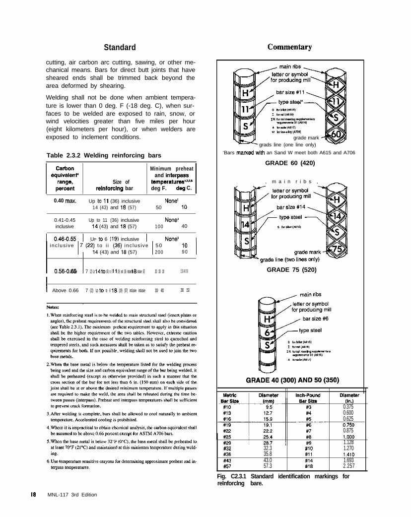
Standard
cutting, air carbon arc cutting, sawing, or other me-chanical means. Bars for direct butt joints that havesheared ends shall be trimmed back beyond thearea deformed by shearing.
Welding shall not be done when ambient tempera-ture is lower than 0 deg. F (-18 deg. C), when sur-faces to be welded are exposed to rain, snow, orwind velocities greater than five miles per hour(eight kilometers per hour), or when welders areexposed to inclement conditions.
Table 2.3.2 Welding reinforcing bars
Size ofrelnforclng bar
Minimum preheatand interpass
temperatures”‘~deg F. deg C.
0.40 max. Up lo 11 (36) inclusive14 (43) and 18 (57)
NUll?~50 10
0.41-0.45 Up to 11 (36) inclusive Nonesinclusive 14 (43) and 18 (57) 100 40
1 0.46-0.55 1 UP lo 6 (19) inclusive 1 NOM1 inc lus ive 17 (%?) t o i i ($6) inc lus ive 1 50
I
14 (43) and 16 (57) 200IO 19 0
I 0.56-0.65 inclusive I 7 (22) Up 14 to (43) to 6 11 (19) and (36) inclusive 16 inclusive (57) 200 300 100 150 40 90
I Above 0.66 7 (22) Up to to 6 18 (19) (57) inclusive inclusive 300 400 200 150
w briorrw,*mi
grade mark -grads line (one line only)
‘Bars marxed with an Sand W meet both A615 and A706
GRADE 60 (420)
, m a i n r i b s , -
GRADE 75 (520)
Inch+o”nd olam*lar(I”.,
0.3750.6000.6250.7500.8751 .ooo1.128
#32 32.3 #IO 1.270836 35.8 #11 1.410843 43.0 #14 1.693#57 57.3 1118 2.257
Fig. C2.3.1 Standard identification markings forrelnforclng bare.
18 MNL-117 3rd Edition

Standard
Preparation for welding on coated base metal shallpreferably be made before coating. Welding galva-nized metal, without prior removal of the coating,shall be performed in accordance with AWS D1.4or AWS WZC (D19.0). Welding of galvanized metalmay also be done after removing all coating fromwithin 2 in. (50 mm) of the weld joint. The weldingshall be performed in accordance with AWS Di .4for uncoated reinforcing bars. The galvanized coat-ing shall be removed with oxyfuel gas flame, abra-sive shot blasting, or other suitable means.
When welding or preheating epoxy coated basemetal, the epoxy coating shall be removed from thesurfaces to be heated.
After welding, suitable coating protection (zinc-richor epoxy paint) shall be applied to the finished jointto restore the corrosion resistant properties of thecoated bars.
Tack welds that do not become a part of perma-nent welds shall not be made unless shown on theapproved shop drawings - for all reinforcing barsincluding ASTM A706 bars. Tack welds shall bemade in conformance with all the requirements ofAWS D1.4, i.e., preheating, slow cooling, use ofproper electrodes, and the same quality require-ments as permanent welds.
Tack welding shall be carried out without signifi-cantly diminishing the effective steel area or the bararea shall be one-third larger than required. A lowheat setting shall be used to reduce the undercut-ting of the effective steel area of the reinforcing bar.
Reinforcing bars which cross shall not be weldedunless shown on the approved shop drawings.
Reinforcing bars shall not be welded within 2 bardiameters of the beginning point of tangency of acold bend.
Tack welding, unless done in conformance with AWS Dl.4,may produce crystallization (embrittlement or metallurgicalnotch) of the reinforcing steel in the area of the tack weld. Tackwelding seems to be particularly detrimental to ductility (impactresistance) and fatigue resistance, and, to a lesser extent, tostatic yield strength and ultimate strength. Where a small bar istack welded to a larger bar, a detrimental “metallurgical notch”effect is exaggerated in the large bar. Fast cooling under coldweather conditions is likely to aggiavate these effects.
There is essentially no difference in the potential for embrittle-merit and chemical change the material undergoes during tackwelding as compared to a larger fillet, flare, 0~ flare bevelweld. This is because tack welding produces the same tempera-tures as stmctial welding. Therefore, if the reinforcing steelrequires the use of preheat and low hydrogen electrodes, itmust also be employed when tack welding is used to hold acage together. Tack welding should be limited to straight sec-tions of bars and within the limitations indicated in the shopdrawing section.
When bars are bent cold without the addition of heat, they be-come sensitive to heat. Subsequently, the application of too muchheat will cause the bars to crystallize and result in unpredictablebehavior of the reinforcing bar at the bend. Therefore, as a pre-caution it is necessary to keep welds away from cold bends.While AWS Dl.4 suggests allowing a cold bend at two bar diameta from a weld, experience shows that a minimum distance of2 in. (50 mm) with 3 in. (75 mm) preferred is better with thesmall bars commonly used in precasting, see Fig. C2.3.2.
MNL-117 3rd Edition 1 9
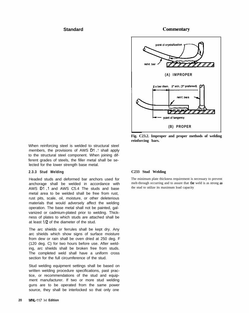
Standard
(A) IMPROPER
(B) PROPER
When reinforcing steel is welded to structural steelmembers, the provisions of AWS Di .l shall applyto the structural steel component. When joining dif-ferent grades of steels, the filler metal shall be se-lected for the lower strength base metal.
2.3.3 Stud Welding
Headed studs and deformed bar anchors used foranchorage shall be welded in accordance withAWS Dl .l and AWS C5.4 The studs and basemetal area to be welded shall be free from rust,rust pits, scale, oil, moisture, or other deleteriousmaterials that would adversely affect the weldingoperation. The base metal shall not be painted, gal-vanized or cadmium-plated prior to welding. Thick-ness of plates to which studs are attached shall beat least 112 of the diameter of the stud.
The arc shields or ferrules shall be kept dry. Anyarc shields which show signs of surface moisturefrom dew or rain shall be oven dried at 250 deg. F(120 deg. C) for two hours before use. After weld-ing, arc shields shall be broken free from studs.The completed weld shall have a uniform crosssection for the full circumference of the stud.
Stud welding equipment settings shall be based onwritten welding procedure specifications, past prac-tice, or recommendations of the stud and equip-ment manufacturer. If two or more stud weldingguns are to be operated from the same powersource, they shall be interlocked so that only one
20 MNL-It7 3rd Edition
Fig. C23.2. Improper and proper methods of weldingreinforcing bars.
C233 Stud Welding
The minimum plate thickness requirement is necessary to preventmelt-through occurring and to assure that the weld is as strong asthe stud to utilize its maximum load capacity
Standard Commentary
gun can operate at a time, so that the powersource has fully recovered from making one weldbefore another weld is started. While in operation,the welding gun shall be held in position withoutmovement until the weld metal has solidified.
Stud welding shall not be done when the basemetal temperature is below 0 deg. F (-18 deg. C) orwhen the surface is wet or exposed to falling rain orsnow. When the temperature of the base metal isbelow 32 deg. F (0 deg. C), one additional stud ineach 100 studs welded shall be tested by methodsspecified in Article 6.1.3(g), except that the angle oftesting shall be approximately 15 deg. This is in ad-dition to the first two studs tested for each start of anew production period or change in set-up.
When studs are welded using prequalified FCAW,GMAW or SMAW processes, the following require-ments shall be met:
The stud welding arc is normally of sufficient intensity and du-ration to bum or vaporize thin layers such as light coatings ofpaint, scale. rust, or oil. However, initial metal-to-metal con-tact should be made between the stud and work to draw the arc.Most controllers provide a high-voltage pilot surge to start thearc. A center punch or other mechanical means can be used topenetrate a thick coating.
1.
2.
3.
4.
Surfaces to be welded and surfaces adjacentto a weld shall be free from loose or thickscale, slag, rust, moisture, grease, and otherforeign material that would prevent properwelding or produce objectionable fumes.
For fillet welds, the end of the stud shall beclean and the stud base prepared so that thebase of the stud fits against the base metal.The minimum size of the fillet weld shall be thelarger of those required in Table 2.2 or Table7.2 of AWS D1.l.
The base metal to which studs are weldedshall be preheated in accordance with the re-quirements of Table 2.3.1.
SMAW welding shall be performed using lowhydrogen electrodes 5/32 or 3/16 in. (4 or 5mm) in diameter, except that a smaller diame-ter electrode may be used on studs 7/l 6 in.(11 mm) or less in diameter for out-of-positionwelds.
2.4 Molds
2.4.1 Materials and Construction
All molds, regardless of material, shall conform tothe profiles, dimensions and tolerances indicatedby the contract documents and the approved shopdrawings.
Molds shall be dimensionally stable to produce therequired finish and tolerance. Repeated use ofmolds shall not affect the dimensions or planes of
Low-carbon (mild) steels can be stud welded with no majormetallurgical problems. The upper carbon limit for base platesteel to be arc stud welded without preheat is 0.30%.
If medium- and high-carbon base-plate materials are to be studwelded, it is imperative that preheat be used to prevent crack-ing in the heat-affected zones. In some instances, a combina-tion of preheating and postheating after welding isrecommended.
Generally, the high-strength low alloy steels are satisfactorilystud welded when their carbon content is 0.15% or lower. Ifthe carbon content exceeds 0.15%. it may be necessary to pre-heat the work to a low preheat temperature to obtain desiredtoughness in the weld area.
Most classes of stainless steel may be stud welded. Only theaustenitic stainless steels (300 grades except 303) are recom-mended for general applications.
C2.4 Molds
C2d.l Materials and Construction
The overall quality of the project starts with molds capable ofallowing the production personnel to make units which meetall the specifications with ease and accuracy.
The appearance of the finished surface is directly related to thechoice of mold material and the quality of the mold itself. Thein-service life of a mold is also a function of the choice of
MNL-117 3rd Edition 2 1
Standard
the molds beyond allowable tolerances. The moldfabrication and set-up tolerances shall be sufficient
to produce units within specific tolerances. Moldmaterials shall not warp or buckle due to tempera-ture change or moisture, which can cause unsightlydepressions and uneven swells in the finished sur-face. The mold materials shall be nonabsorbent orsealed to prevent excessive moisture absorption inorder to minimize variations in finish due to differ-ential moisture movements resulting from varyingdegrees of absorbency. The precaster shall evalu-ate the effect of different materials on the color of thefinished surface when they are combined in thesame mold.
Molds shall be coated with release agents that willpermit release without damaging or staining the con-crete, and without affecting subsequent coating,painting or caulking operations. Release agentsshall be applied in accordance with manufacturer’sdirections. Just prior to applying a release agent,the surfaces of the mold shall be clean and free ofwater, dust, dirt, or residues that could be trans-ferred to the surface of the concrete or affect theability of the release agent to function properly. Ex-cess release agent shall be removed from the moldsurface prior to casting. Prestressing tendons, an-chorages for miscellaneous connections and rein-forcement shall not be contaminated by form releaseagents.
Molds shall be built sufficiently rigid to provide di-mensional stability during handling. The assembledmold shall not allow leakage of water or cementpaste. Joints in the mold material shall be made sothat they will not be reflected in the concrete surface
Commentary
mold material, which must therefore be selected with care.Molds for architectural precast concrete can be made of vti-ous materials such as plywood, concrete, steel, plastics,polyester resins reinforced with glass fibers, plaster, or a com-bination of these materials. For complicated details, molds ofplaster, elastomeric rubber, foam plastic, or sculptured sandmay be used. These molds are often combined or reinforcedwith wood or steel depending on the size and complexity of theunit to be produced.
Mold design should take into account the special requirements ofprecast concrete products. Sharp angles and thin projectionsshould be avoided whenever possible, and chamfers or radii at in-side comers of the mold should be incorporated due to the possi-bility of chipping and spalling at the comers during shipping.
In general, the mold fabrication and set-up tolerances should beone-half of the tolerances of the units they are to produce or amaximum of &l/8 in. (+3mm).
The selection of a release agent should include investigation ofthe following factors:
1. Compatibility of the agent with the mold material, formsealer or admixtures in the concrete mix. Because of therapid loss of slump, most superplasticized concrete needsa smooth “frictionless” surface along which the concretecan easily move.
2. Possible interference with the later application of sealants,sealers. or paints to the mold contact area
3.
4.
Discoloration and staining of the concrete face.
Amount of time allowed between application and con-crete placement and the minimum and maximum timelimits for molds to stay in place before stripping. Releaseagent may require a curing period before being used. Iftoo fresh, some of the release agent will become embed-ded in the concrete.
5. Effect of weather and curing conditions on ease ofstripping.
6. Uniformity of perfomwnce.
7. Meet current local environmental regulations regardingthe use of a volatile organic compound (VOC) compliantform release agent.
Applying too much of the release agent can cause excessivesurface dusting on the fmished concrete.
Mineral oil, oil-solvent based release agents, or paraffin waxshould not be used on rubber or elastomeric liners as the hy-drocarbon solvent will soften the rubber. The rubber or elas-tomeric supplier’s recommendations should he carefullyfollowed.
Mold seams as well as welds on steel molds should he checkeddaily during the mold preparation stage. Mold seams resultingfrom jointing of loose parts, such as bulkheads, side or topmolds. or any mold modification pieces should be minimizedto the extent required by the finished surface, well-fitted, se-cured, and sealed to prevent leakage.
2 2 MNL-117 3rd Edition
Commentary
and mar the appearance of the product,
Molds shall be capable of supporting their ownweight and the pressure of the fresh concrete with-out deflection or deformation which exceeds toler-ances. Molds shall be sufficiently rigid to withstandthe forces necessary for consolidating the concrete.Molds subjected to external vibration shall be capa-ble of transmitting the vibration over a sufficientarea in a relatively uniform manner without flexingor plate flutter. The molds shall be designed to en-sure that resonant vibrations which may be im-parted into local areas of the forms are minimized.
Molds shall permit controlled, fixed positioning orjigging of hardware and allow for the suspension orplacement of the reinforcing cage in a position thatmaintains the specified concrete cover. Blockoutsshall be of the size, shape and located as shownon the shop drawings. Blockouts shall be heldrigidly in place within tolerance. Mold parts shallallow for stripping without damage to the units.
Molds shall be designed to prevent damage to theconcrete from: (1) restraint as the concrete shrinks;(2) the stripping operation; and (3) dimensionalchanges due to pretensioning.
Wood molds shall be sealed with suitable materialsto prevent absorption. The sealer manufacturer’sinstructions regarding application shall be followed.Surface condition, joints and coating material shallbe visually inspected prior to each use.
Concrete molds shall be treated with a coatingwhich renders the concrete non-absorbent to re-duce mold damage and to improve the release ofthe product during the stripping operations.
Plastic molds shall not be used when tempera-tures above 140 deg. F (60 deg. C) are anticipated.The susceptibility of the plastic mold to attack bythe proposed release agents shall be determinedprior to usage. Surface conditions, joints and gelcoat material shall be visually inspected prior toeach use.
Steel molds shall be visually inspected prior toeach use for rust, welding distortion and tightnessof steel sheet joints. If it is planned to apply a pre-stressing force by jacking against the form, themold shall be sufficiently strong to withstand theforce without buckling or wrinkling and still maintainthe required dimensional tolerances.
Molds should have high rigidity, minimum deflection, and min.imum movement of the mold material between the stiffeners
Sealing wood molds minimizes non-uniformity in surface fin-ish and will stabilize the mold dimensions. The manufacturer’sinstructions regarding application of the sealer should be fol-lowed. For some sealers there are minimum temperaturesstated below which they must not be applied. An appropriatedrying or curing time should he allowed.
Steel molds should be well braced and frequently examined forbulging or buckling. Dimpling, twisting, or bending may occurif they are not properly stacked for storage. When joining twoor more steel sheets by welding, care is required to avoid dis-tortion from the heat of the welding operation. If joining is re-quired. the welds should be ground smooth and coated with anepoxy or similar material to hide the joint. Forms should allowfor shortening and movements of the precast comxete units
during transfer of prestress and application of heat when accel-erated curing is used.
MNL-I 17 3rd Edition 23
Standard
2.4.2 Verification and Maintenance
The mold surfaces and dimensions shall be checkedin detail after construction and before the first unit ismade and after any modifications. A completecheck of the first product from the mold shall be per-formed. Molds shall be thoroughly cleaned and in-spected before each use for defects that will affectperformance or appearance.
Commentary
C2d2 Verification and Maintenance
When a new mold is placed into production a complete dimen-sional check should be made taking into account main dimen-sions, warping, squareness, flatness, reveals, blockouts andquality of the surface finish. Fixtures and/or templates can aidin checking. The report of this check should be kept on tile.
The molds should be reassembled within the dimensional limi-tations specified for the product on the shop drawings. Theoverall length, width, thickness, and other basic dimensionsshould be checked on all sides of the mold. The squareness ofthe mold should be checked by comparing diagonal measure-ments to the comers of the mold. Any discrepancy noted inmold dimensional accuracy should be transmitted to pmduc-tion personnel for correction.
A basic assessment of the mold should be made in advance ofeach casting. Assessment should ensure:
I. The mold has been assembled correctly within specifiedtolerances.
2. The release agent has been applied satisfactorily and ex-cessive pending has not occuned in recesses, for example.
3. Concrete splatter, wire ties, dust, and the like have notcontaminated the mold surface.
Bulkheads, templates, and similar equipment shallbe regularly inspected and maintained as neces-sary. All anchorage locations on the mold for hold-ing any cast-in materials to a given position shallbe checked for wear. If more than one mold isused to produce a given unit, a comparative dimen-sional check shall be made.
2.5 Hardware installation
All connection hardware, anchors, inserts, plates,angles, handling and lifting devices, and other ac-cessories shall be checked prior to casting to verifythat they are accounted for, of the proper size andtype, and accurately located as detailed on theshop drawings.
Hardware shall be firmly held in the correct positionand alignment, during placement, consolidationand finishing of the concrete, by attachment to thereinforcing cage or by jigs, positioning fixtures,mold brackets, or stiffbacks. Hardware shall haveprovisions (holes, lugs, nuts, etc.) so that it can besecured to the support.
C2.5 Hardware Installation
Inserts should be placed accurately because their capacity de-pends on the depth of embedment, spacing and distance fromfree edges. Inserts should also be placed accurately becausetheir capacity decreases sharply if they are not positioned per-pendicular to the bearing surface, or if they are not in astraight line with the applied force. It is important to place in-serts so that the depth of thread is constant for the same sizeinsert throughout a particular job. Otherwise an erection crewmay make mistakes in the field by not always engaging thefull thread, (see Fig. C2.5.1). Also, a typical size and threaddepth for inserts on projects will minimize the possibility oferection crews using the incorrect size and length of bolts.
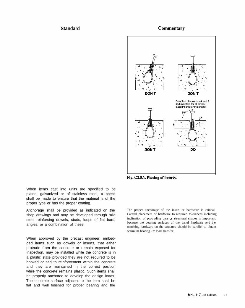
Standard
When items cast into units are specified to beplated, galvanized or of stainless steel, a checkshall be made to ensure that the material is of theproper type or has the proper coating.
Anchorage shall be provided as indicated on theshop drawings and may be developed through mildsteel reinforcing dowels, studs, loops of flat bars,angles, or a combination of these.
When approved by the precast engineer, embed-ded items such as dowels or inserts, that eitherprotrude from the concrete or remain exposed forinspection, may be installed while the concrete is ina plastic state provided they are not required to behooked or tied to reinforcement within the concreteand they are maintained in the correct positionwhile the concrete remains plastic. Such items shallbe properly anchored to develop the design loads.The concrete surface adjacent to the item shall beflat and well finished for proper bearing and the
DO
The proper anchorage of the insert or hardware is critical.Careful placement of hardware to required tolerances includinginclination of protruding bars or structural shapes is important,because the bearing surfaces of the panel hardware and thematching hardware on the structure should be parallel to obtainoptimum bearing or load transfer.
MNL-117 3rd Edition 2 5
Standard Commentary
item shall be placed perpendicular to this surface.
Reinforcement shall not be modified, relocated oreliminated to accommodate hardware. If hardwareanchors or reinforcing steel cannot be located asshown on the shop drawings, approval for revisionsshall be obtained from the precast engineer and allrevisions shall be recorded. Connection hardware,carrying load from the member to supports, or han-dling inserts shall not be plunged or vibrated intoconcrete already placed in the mold without ap-proval of the precast engineer. If approved by theprecast engineer, non-structural hardware itemsmay be installed after the concrete has beenplaced, and care shall be taken to ensure that con-crete around anchorages has been consolidatedand that no misplacement of the reinforcing cagehas occurred.
Reinforcement extending out of the elements toprovide structural connection for sequential castingor cast-in-place concrete shall be located withinf112 in. (+12 mm) of shop drawing dimensionsunless closer tolerances are indicated. Paste ad-hering to extended reinforcement shall be removedsufficiently to ensure bonding’of bars to concretethat is cast later.
Where angles are used for connections and fas-tened to the concrete with bolts and inserts, theconcrete surface behind the angle shall be flat andwell finished for proper bearing. The inserts shallbe placed perpendicular to this surface. Such an-gles may also be anchored with studs or welded toplates in the precast concrete units.
The concrete under plates or angles shall be con-solidated in a manner to avoid honeycombing orexcessive air voids beneath the plate or angle.
Excessive honeycombing beneath the plate or angle mayin diminished structural capacity.
Voids in sleeves, inserts, and anchor slots shall befilled temporarily with readily removable material toprevent entry of concrete during casting. Insertsand sleeves shall be kept clean of dirt or ice by pro-tecting them temporarily with plastic caps or othersuitable devices installed in the plant after strip-ping. Threads on projecting bolts shall be kept freefrom any deleterious materials and shall be pro-tected from damage and rust.
Stainless steel bolts shall be used to connect stain-less steel plates or angles. Carbide inserts shall beused for high speed drilling of holes in stainlesssteel. Threaded parts of stainless steel bolts shallbe lubricated with an antiseize thread lubricant dur-ing assembly.
2 6 MNL-117 3rd Edition
Standard Commentary
Dissimilar metals shall not be placed near or in di-rect contact with each other in moist or saturatedconcrete unless experience has shown that nodetrimental chemical or electrochemical (galvanic)reactions will occur or surfaces are permanentlyprotected against corrosion. Sleeves, pipes, or con-duits of aluminum shall not be embedded in con-crete unless they are effectively coated or coveredto prevent aluminum-concrete reaction, or elec-trolytic action between aluminum and steel.
The installation of inserts and fastenings by explo-sive actuated or power driven tools shall only ba al-lowed where such installation will not damage thestructural integrity of the units by being too close toreinforcement or strands, or mar the finish by caus-ing spalling, chipping or cracking of the unit.
Multiple component lifting devices shall be keptmatched to avoid non-compatible usage.
When grouped in multiples, lifting loops shall bealigned for equal lifting. Projection of lifting loopsfor multiple liff point members shall be maintainedwithin a tolerance of f1/2 in. (f12 mm) from de-sign or plant standard.
Treated or naturally deterioration resistant lumbershall be used, if cast in the concrete. A wood sealershall be applied to prevent moisture migration fromconcrete into the wood.
All inserts which are on an exposed face shall bechecked to ensure that they are properly recessedto give adequate cover and permit future patching.
2.6 Product Handling
2.6.1 General
All precast concrete units shall be handled in a po-sition consistent with their shape, size, and designto avoid damage or excessive stresses. Units shallbe handled and supported only by appropriate de-vices at designated locations. Liking devices shallbe checked to ensure their locations conform to theshop drawings.
All lifting from threaded inserts shall be with appro-priate swivel bolt hardware suitable for the insertunless such lifts are made axial with the inserts,such as by direct bolt fastening to lifting beams orframes. If inclined lifting lines are employed, theangle to the horizontal shall not be less than 45deg. unless specifically shown by the shop draw-ings. The bolts being used in the handling insertsshall be of sufficient length to fully engage all
Placing wood in concrete should be avoided since the tendencyof wood to swell under moist conditions can cause cracking ofthe concrete even if the wood is sealed.
C2.6 Product Handling
C2.6.1 General
Permanent connection hardware should not be used far handling,except when designed for such additional service and shown onthe shop drawings, to prevent damage to the connection or im-pairment of its performance.
MNL-117 3rd Edition 27
Standard
threads plus extending as recommended by manu-facturer beyond the threaded position when coil in-serts are used. In addition, bolts shall be inspectedfor cracks, wear or deformations and defectivebolts discarded.
Units shall be handled to avoid structural damage, Each plant should develop specific unit handling procedures.
detrimental cracking, architectural impairment or These should include demolding, lifting, storage, and prepara-
permanent distortion. tions for transport.
2.6.2 Stripping C2.6.2 Stripping
Tests shall be performed to confirm that concretestrength meets or exceeds the required values forstripping or detensioning.
All removable inserts, fastenings and mold partsshall be released and/or removed prior to stripping.
Care shall be exercised in removing the precastconcrete unit from the mold to prevent damage.The minimum concrete strength, number and loca-tion of lifting points for handling of units and detailsof lifting devices shall be shown on the shop draw-ings. Units shall only be stripped at points indicatedon approved shop drawings or as approved by au-thorized personnel. Initial lifting shall be made cau-tiously and gradually and equipment for initialrelease shall have controls allowing such operation.
Proper rigging procedures should be established and docu-mented. Methods of hooking onto different lifting devices andpetissible sling angles should be covered in plant procedures.Where more than two lifting points are used, the lifting shouldbe rigged to allow the planned disbibution of pull on lifting de-vices. Veneered units should be lifted cleanly to prevent chip-ping OI spalling of the veneer edges.
Uniformity of stripping age from unit to unit should be main-tained to minimize concrete color hue differences.
A product which is stripped or detensioned prior to achievingadequate concrete strength can crack, spall, or suffer a loss ofbond between the strands and the concrete.
Significant member stresses are often produced during demold-ing. Proper care should be taken to minimize demoldingstresses and keep them within acceptable limits.
Individual precast concrete elements shall beclearly marked with identification as shown on theshop drawing, including date of casting or seriallynumbered.
Panel markings may be made in the wet concrete,painted on the units, or they may be made by tag-ging as long as the tags are securely fastened tothe units. In all cases the markings shall remainlegible for the longest storage period that can beanticipated.
Surface of unit shall be checked for any dents ormarks that may be the result of mold wear or deteri-oration. Also, unit shall be checked for voids or ex-cessive air holes that would indicate impropervibration.
A system for evaluating product deficiencies should be estab-lished so that problems and their sources can be identified.Problems which CCCUI when products arc stripped cannot be re-solved easily if they are not identified prior to product storage.
2.6.3 Yard Storage
Storage shall be planned carefully to ensure deliv-
C2.63 Yard Storage
Units are generally stored with two-point supports spaced ap-
28 MNL-117 3rd Edition

Standard Commentary
ery and erection of the units in an acceptable con-dition. Units shall be supported and stored on un-yielding supports at designated blocking pointlocations. Units shall be stored on a firm, level andwell-drained surface with identification marks visi-ble. Dunnage and storage racks, such as A-framesand vertical racks, shall be well constructed andaligned to ensure that the precast concrete unitsare supported in a given plane to minimize warp-ing, bowing or cracking of the units and stabilizedagainst potential lateral loads.
proximately at the fifth point. Two-point support is recom-mended because if support is continuous across three or morepoints, the member may bridge over one of the supports (be-came of differential support movement) and result in bowingand cracking.
Proper member support during storage will minimize warpingand bowing. Walpage in storage may be caused by tetnperafllreor shrinkage differential between surfaces, creep and storage
conditions. Warpage and bowing cannot be totally eliminated,although it can be minimized by providing blocking so that theunit remains plane.
Units stored leaning on one another may induce high stressloads in long storage lanes. The “domino effect” (cumulativeloading) should be considered. Units should be stacked againstboth sides of the supports to equalize loading and to avoidoverturning.
Protective material should be provided at points of bearing andcontact with exposed surfaces. Care should be taken to preventsurface staining and chipping or spalltig of the edges and COT-ners of the units. All blocking, packing, and protective materi-als should be of a type that will not cause damage, staining, orobjectionable disfigurement of the units. Staggered or irregularblocking should be avoided. When setting one unit against an-other, non-staining, protective blocks should be placed immed-ately in line with the supports of the first unit.
The precast concrete units should be protected from contactwith earth, oil, gas, tar, or smoke.
Dunnage shall be placed between products them-selves as well as between products and storagedevices. Such dunnage shall be of a material andtype that will not create stacking or staining marksor otherwise cause damage to the finished prod-ucts. Where necessary, storage apparatus shall beprotectively covered to avoid any discoloration orstaining of the finished products.
Embedded items and sleeves shall be protectedfrom penetration of water or snow during coldweather.
2.6.4 Cleaning
All surfaces of the precast concrete units to be ex-posed to view shall be cleaned, as necessary,prior to shipping to remove dirt and stains whichmay be on the units. The cleaning procedures shallnot detrimentally affect the concrete surface finish.
2.6.5 Loading
Units shall be loaded as necessary:
1. to permit their removal for erection from theload in proper sequence and orientation tominimize handling.
2. with proper supports, blocking, cushioning,and tie-downs to prevent or minimize in-transitdamage.
All blocking, packing and protective materials
shall be of a type that will not cause damage,
C2.6.4 Cleaning
A small area should be cleaned and appraised to be certainthere is no adverse effect on the surface finish before proceed-ing with the work.
For information on removing specific stains from concrete, ref-erence should be made to “Removing Stains and Cleaning
Concrete Surfaces,” IS 214, published by the Portland CementAssociation, Skokie, IL.
C2.6.5 Loading
Protective covering of the units during transportation is nor-mally not required.
MNL-117 3rd Edition 29
Standard
staining or other disfigurement of the units.
The blocking points and orientation of the units
on the shipping equipment shall be as desig-
nated on the shop drawings.
3. with proper padding between units and chains
or straps to preclude chipping of edges or
damage to returns.
2.7 Surface Finishes
2.7.1 General
Each plant shall develop quality requirements for
all architectural finishes prior to undertaking actual
production of such finishes. Such requirements
shall include samples and production procedures.
A finishing process shall produce an acceptable
uniform appearance without detriment to required
material properties.
All finishes of precast concrete units shall be stated
on shop drawings. Reference samples or mockup
units shall be available in the plant so that all con-
cerned can be assured that standards of finish and
exposure are being maintained.
30 MNL-117 3rd Edition
C2.7 Surface Finishes
C2.7.1 General
Concrete is a variable material and, even after final finishing,there will he a range in color or texture. Some differences areto be expected. Finishing techniques vary considerably be-tween individual plants. Many plants have developed specifictechniques supported by skilled operators or special facilities.In addition, many finishes cannot be achieved with equal visualquality on all faces of the unit. The reason for this comprisesseveral factors such as mix proportions, variable depths(and pressures) of concrete, and small differences in consolida-tion techniques, particularly in the case of intricate shapes withcomplex flow of concrete.
It should be recognized that some blemishes or variations incolor occur in architectural precast concrete. For example,units containing aggregates and matrices of contrasting colorswill appear less uniform than those containing materials ofsimilar colors. Consistency in apparent color of all finishescan be enhanced by color compatibility of materials. If thecoarse aggregate, tine aggregate and cement paste are similarin color, the depth of exposure and “patchy” effects (minorsegregation of aggregate) will not he as noticeable in maintain-ing color consistency. In contrast, if material colors ax quitedifferent, products may appear blotchy for the same reason.
Further, form-finished units may appear less uniform in colorthan the same units subsequently given an exposed aggregatefinish. Uniformity in color, even within small units finishedwith black coloring, and for units using gray or buff cement,may vary from unit fo unit. The color of precast concrete canvary between adjacent elements due to daily variations in thewater-cement ratio and curing conditions for the concrete.This is less pronounced in mixes using white cement than thoseusing gray or buff cement. Additionally, this color variationwill be less pnnuxmced in finishes that have some degree ofaggregate exposure. The degree of uniformity normally im-proves with an increased depth of exposure. Buff colorachieved with fine aggregate is more easily controlled even incombination with gray cemenf. When fabrication continuesover extended periods, color can v”y because of the changesin the physical characteristics of cements, coarse aggregatesand sands, even though they may be fmm the same sources.
The effect of gravity during consolidation forces the larger ag-gregates to the bottom and the smaller aggregates, plus thesand and cement content, upwards. Consequently, the down-face in the mold will nearly always be the most uniform anddense surface of the unit. The final orientation of aggregates
Standard Commentary
may also result in differences in exposure between the down-face and returns in exposed aggregate surfaces. Emphasisshould be placed on choosing suitable concrete mixes with ag-gregates which are reasonably spherical or cubical to minimizedifferences. For large returns, or situations where it is neces-sary to minimize variations in appearance, concrete mixesshould be selected where the aggregate gradation can be uni-formly controlled and preferably fully graded. Exposuresshould be medium to deep and color differences between theingredients of the mix should be minimal.
Panels with large returns may also be cast in separate piecesand joined with dry joints. This enables all faces to be castwith the same orientation. If this is the indicated productionmethod, attention should be paid to suitable fillets and rein-forcement at the corners, and a groove or architectural featureshould be incorporated at the dry joint. Although the dry jointmay not show with certain mixes and textures, a groove isgenerally required to help mask it.
The extent to which aggregates are exposed or “re-vealed” shall be no greater than one-third the aver-age diameter of the coarse aggregate particles, ornot more than one-half the diameter of the smallestsized coarse aggregate.
A demarcation feature shall be incorporated intothe surface of a unit having two or more differentmixes or finishes. The different face mixes shallhave reasonably similar behavior with respect toshrinkage in order to avoid cracking at the demar-cation feature due to differential shrinkage.
Appearance, color, and texture of surface finish ofall units shall match within the acceptable range ofthe color, texture, and general appearance of theapproved sample panels.
2.7.2 Smooth
The molds shall be carefully made and finished soas to present a smooth, unmarked surface. If airvoids are anticipated on return surfaces, the sam-ple shall be used to establish acceptability of suchvoids with respect to frequency, size and uniformityof distribution of the voids.
As a general rule, a textured surface is aesthetically more satis-factory than a smooth surface because the texture of the surfaceto a very large extent camouflages subtle differences in textureand color of the concrete.
C2.7.2 Smooth
A smooth off-the-form finish may be one of the most economi-cal, but is perhaps the most difficult to produce, as the coloruniformity of gray, buff, or pigmented surfaces is extremelyhard to achieve. The cement exerts the primary color influenceon a smooth finish because it coats the exposed surface.In some instances the sand may also have some effect. Initially,this is unlikely to be significant unless the sand contains a highpercentage of fines or is itself highly colored. As the surfaceweathers, the sand will become mope exposed. causing its colorto become more pmnounced. The color of the coarse aggre-gate should not be significant unless the particular unit requiresextremely heavy consolidation. Under this circumstance, someaggregate transparency may occur, causing a blotchy, non-uni-foml appearance.
Aggregate transparency or “shadowing” is a condition in whicha light colored, formed concrete surface is marked by darkareas similar in size and shape to particles of dark or deeplycolored coarse aggregate in the concrete mix. When encoun-tered, it usually appears on smooth surfaces.
MNL-117 3rd Edition 3 1
Standard Commentary
Formwork for smooth-surfaced concrete is perhaps the mostcritical and the most difficult to control of any type of formwork encountered for precast concrete, particularly where largesingle-plane surface areas are involved. Any imperfection inthe surface of the mold or any misalignment is immediately ap-parent and becomes the predominant factor in the character ofthe surface. An impervious surface such as plastic liners, steel,overlaid plywood, or fiberglass surfaced plywood will usuallyresult in a lighter color and more uniform appearance if jointshave been properly prepared. In general, the joints of the mate-rials used to construct the casting surfaces are difficult to hide.
The smooth cement film on the concrete may be susceptible tosurface crazing, i.e., fine and random hairline cracks, when ex-posed to wetting and drying cycles. This is. in most cases, asurface phenomenon and will not affect structural properties ordurability. In some environments, crazing will be accentuatedby dirt collecting in these minute cracks. This will be moreapparent in white than gray finishes and in horizontal morethan vertical surfaces.
When air voids of a reasonable sire. l/8 to I14 in. (3 to 6 mm)are encountered on return surfaces, it may be desirable to retainthem rather than filling and sack rubbing them in. Color varia-tions can occur when sacking is performed.
Even with good quality control, smooth finished concrete willexhibit some negative aesthetic features such as color varia-tions, air voids, minor surface crazing, and blotchiness, ape-cially on non-profiled flat panels. Repairs to this finish tend tobe even more noticeable after weathering.
2.7.3 Sand or Abrasive Blast
Uniformly texturing a panel by sand or abrasiveblasting requires trained operators. The type andgrading of abrasives utilized during the blastingprocess shall remain the same throughout the en-tire project.
C2.7.3 Sand or Abrasive Blast
Sand or abrasive blasting of surfaces is suitable for exposure ofeither large or small aggregates. Uniformity of depth of expo-sure between panels and within panels is essential in abrasiveblasting, as in all other exposed aggregate processes, and is afunction of the skill and experience of the operator. As muchas possible, the sandblasting crew and equipment used shouldremain the same throughout the job. The type and grading ofabrasives affect the resulting surface finish. Different shadingsand to some extent, color tone will vary with depth of expo-sure. The age of the panel at time of blasting will also affectthe speed and depth of exposure. The age and strength of theconcrete at time of blasting should be consistent thmughout theproject in order to achieve the desired uniform finish and colorfrom panel to panel.
The degree of uniformity obtainable in a sandblasted finish isgenerally in direct proportion to the depth of sandblasting. Alight sandblasting may look acceptable on a small sample, butuniformity is rather difficult to achieve in a full size unit. Alight sandblast will emphasize visible defects, paticularly bug-holes, and reveal defects previously hidden by the surface skinof the concrete. The lighter the sandblasting, the more criticalthe skill of the operator, particularly if the units are sculptured.Small variances in concrete strength at time of blasting mayfurther complicate results.
Sculptured units will have air voids on the returns which mightshow strongly in a light sandblasted texture. If such air holes areof a reasonable size, l/8 to I14 in. (3 to 6 mm), it is strongly rec-
3 2 MNL-117 3rd Edition
Standard Commentary
ommended that they be accepted as part of the texture becausefilling and sack-mbbing may cause color variations.
The objective of a brush-blast, which is little more than a uni-form scour cleaning that lightly textures the surface skin, is toremove minor surface variations. A brush-blast surface seldomappears uniform at close inspection and should be viewed at adistance for uniformity. Brush-blast is only used: (1) on revealsand other small areas for accents due to its non-uniform ap-pearance on large areas or (2) to improve bond of coatings tounit..
Sands used for blasting operations shall be free ofdeleterious substances such as fine clay particles.If sand is used as the abrasive, a high silica con-tent sand shall be used rather than bank or riversand. The abrasive used shall not cause any colorcontamination.
2.7.4 Acid Etched
Acid etching may be accomplished by: (1) brushingthe surface with a stiff bristled fiber brush immersedin the acid solution; (2) spraying acid and hot wateronto the panel surface using specially designedpumps, tanks and nozzles; or (3) immersing theunit for a maximum of 15 minutes in a tank contain-ing from 5 to 35 percent hydrochloric acid. In sand-wich wall panels, where the insulation is exposedat the edges of the panel only those methods thatprevent damage to the insulation shall be used.
An acceptable range of concrete temperatures andstrength levels during the application of the acidshall be established to provide uniform finish quality.
In cases where aggregates are to be exposed toconsiderable depth, only acid resistive siliceous ag-gregates shall be used. The concrete unit shall bewell wetted with clean water prior to acid treatmentbecause acids will penetrate faster and deeper intodry concrete. Acid shall not be allowed to lie on thesurface longer than 15 min. Deep etch shall beachieved by multiple treatments. After completionof acid etching, the unit shall be thoroughly flushedwith water.
C2.7.4 Acid Etched
Acid etching is most commonly used for light or medium expc-sure dissolving the surface cement paste to reveal the sand withonly a small percentage of coarse aggregate being visible. Acidetching of concrete surfaces will result in a fine. sandy texture ifthe concrete mix and its consolidation have produced a uniformdistribution of aggregates and cement paste at the exposed SUE-faces. Concentrations of cement paste and under and over etchingof different parts of a concrete surface, or variation in sand coloror content may cause some uniformity problems, particularlywhen the acid etching is light or used for large, plain surfaces.Carbonate aggregates e.g., limestones, dolomites and marbles,may discolor OI dissolve due to their high calcium content.
With lighter textures, color compatibility of the cement and theaggregates becomes more important to avoid a blotchy effect.White or light colors are forgiving to the eye and increase thelikelihood of better color match from unit to unit.
There is a minimum depth of etch that is required to obtain auniform suface. To attempt to go any lighter than this will resultin a blotchy panel finish. This depth will expose sand and onlythe very tip of the coarse aggregate. It is difficult to achieve a to-tally uniform very light exposure on a panel that is highly sculp-tured. This is due to the acid spray being deflected to other areas
MNL-117 3rd Edition
Standard Commentary
of the panel, paticulady at inside corners. This may be accept-able if the sculpturing creates differential shadowing.
Prewetting the concrete with water fills the pores and capillar-ies and prevents the acid from etching too deeply, and also al-lows all acid to be flushed after etching. Older dried concretesare likely to be more carbonated. Although the reactions of car-bonates with the acid might not be much faster than those withother cement compounds, they cause greater effervescence sothat the reaction is far more obvious and seems to be goingfaster.
Acid solutions lose their strength quickly once they are in con-tact with cement paste or mortar, however, even weak, residualsolutions can be harmful to concrete due to possible penetra-tion of chlorides. Failure to completely rinse the acid solutionoff the surface may result in efflorescence or other damagingeffects.
Prior to acid etching, all exposed metal surfaces,particularly galvanized metal, shall be protectedwith acid-resistant coatings. These include vinylchlorides, chlorinated rubber, styrene butadienerubber (not latex), bituminous paints and enamelsand polyester coatings.
Touch-up of all exposed galvanized metals cast inthe precast concrete units affected by acid washingor etching shall be done utilizing a 3-mil thicknessof a single component zinc-rich compound with 95percent pure zinc in the dried film.
2.7.5 Retarded
Surface retarders that are to be used to expose theaggregate shall ba thoroughly evaluated prior to use.A sample panel shall be made to determine the ef-fects created by the mold and concrete materials.This involves using the particular type of cement, ag-gregate, and specific mix selected for the product.
When using a retarder, the manufacturer’s recom-mendations shall be followed. Surface retardersshall be applied by roller, brush, or spray, and careshall be taken to ensure uniform application of re-tarders to the mold surface. Water shall not con-tact the retarder on the mold surface before theconcrete is placed to prevent activation of the re-tarder.
C2.75 Retarded
Retardation involves the application of a specialized chemicalto the concrete surface (normally the mold surface) that delaysthe surface cement paste from hardening within a time periodand to a depth depending upon the type or concentration of re-tarder used.
Chemical retarders are available for the face-down or face-upmethods of casting, and for horizontal as well as vertical SWfaces. Retarders are available for light, medium and deep expo-SUPS. The degree of uniformity normally improves with anincreased depth of exposure.
The effectiveness of the retarder will vary as it is extremelysensitive to changes in the rate of hydration due to differenttemperatures, humidity or user content of the face mix. Thedepth of reveal or retardation will be deeper: (1) the wetter themix; (2) the slower the time of set; (3) the more aggregate inthe mix; and (4) the closer together the coarse aggregate.
Retarders function by delaying, not preventing, the set of agiven amount of cement paste in order that the aggregate canbe easily exposed. This concept will help in analyzing variousmix designs for depth of retardation. If more sand or coarseaggregate is added to a mix; with proper consolidation, therewill be less cement paste per volume of material at the surface,thus a deeper exposure.
34 MNL-117 3rd Edition
Standard Commentary
Some retarders are effective for long periods of time while oth-ers are active for only a few hours Water in contact with theretarder before the concrete is placed activates the retarder’saction prematurely and may result in a non-uniform surface.
The retarded concrete should be removed the same day that theunits are stripped. Any delay in removing the matrix will resultin a lighter, less uniform etch. Preliminary tests should be per-formed before planning the casting for a large project to deter-mine the most suitable finishing time. The timing of thesurface finishing operation should be consistent each day assome retarders cease to delay the hardening process as theproduct cures.
C2.7.6 Tooled or Bushhammered
Concrete may be mechanically spalled or chipped with a vati-ety of hand and power tools to produce an exposed aggregatetexture. The technique usually is called tooling or bushham-meting and is most suitable for flat or convex surfaces. Pneu-matic or electric tools may be fitted with a bushhammer, combchisel, crandall, or multiple pointed attachments. The type oftool will be determined by the surface effect desired. Handtools may be used for small areas, comers, and for restrictedlocations where a power tool cannot reach.
Orientation of equipment and direction of movement for tool-ing should be kept uniform throughout the tooling process astooling produces a definite pattern on the surface. Variationsdue to more than one person working on the panels may occurwith this finish. Care should be exercised to avoid exerting ex-cessive pressure on the tool,~especially when starting, so as notto remove more material than either necessary OT desirable.
Bushhammering at outside comers may cause jagged edges. Ifsharp comers are desired, bushhammering should be held backfrom the comer. It is quite feasible to execute tooling alongspecific lines. If areas near comers are to be tooled, this shouldnormally be done by hand since tools will not reach into insidecomers. Chamfered comers are preferred with tooled surfacesand with care a 1 in. (25 mm) chamfer may be tooled.
C2.1.7 Honed or Polished
The grinding of concrete surfaces produces smooth, exposedaggregate surfaces. Grinding is also called honing and polish-ing depending on the degree of smoothness of the finish. Ingeneral, honed finishes are produced by using grinding toolsvarying from about No. 24 coarse grit to a fine grit of aboutNo. 220 to produce a smooth but matte finish free of pits andscratches. Polishing is accomplished after honing. Polishingconsists of several successive grinding steps, each employing afiner grit than the preceding step, then a buffer brick or felt padwith tin oxide polishing powder is used to produce a high glosspolish.
Mold flatness should be +3/32 over 13 ft (+2 mm over 4 m), Fora very large project requiring many castings it could be viable tohave the mold surface machined flat during mold manufacturesince minor vtiations in flatness can increase cutting time dur-ing initial polishing operations. In addition, panels should beplaced onto pre-levelled blocks with the final alignment carriedout using a laser beam, then wedged for final adjustment.
MNL-I 17 3rd Edition 35
The retarded surface shall be exposed by removingthe matrix material to match the approved sample.
2.7.6 Tooled or Bushhammered
Operators shall be trained to produce a uniformlytextured surface to match the approved samplewhen exposing aggregate by tooling or bushham-mering
2.7.7 Honed or Polished
Care shall be taken to obtain a uniform depth ofgrind from unit to unit to minimize finish variations,An approved sample unit shall be kept near thegrinding for comparison and evaluation of the prod-uct finish. Air voids in the concrete surface shall befilled before each of the first few grinding opera-tions or no later than half-way through the thirdgrinding step using a sand-cement mixture thatmatches the matrix of the concrete. Careful fillingand curing are required and the next grinding oper-ation shall not be performed until the fill materialhas reached sufficient strength.
Standard Commentary
Uniformity of appearance should not be a problem on flat castfaces hut vertical faces arc likely to show variation in aggre-gate density. Careful consideration should be given to manu-facturing methods when panel returns do not align withadjacent window glass but abut with flat panels as this willhighlight the textural differences.
When a 90 deg. return of a panel is honed or polished, it mayprove beneficial to sequentially cast the return to allow it to becast in a horizontal position which will create a more denseuniform surface.
Care shall be exercised in the application of polish-ing compounds to prevent creating a visually unac-ceptable halo effect on the surface, particularly ifapplied manually over a portion of surface duringthe blending of defective spots.
Compressive strength of the concrete shall be5000 psi (35 MPa) before starting any honing orpolishing operations. The concrete shall have auniform and dense surface. When choosing aggre-gates special consideration shall be given to theirhardness.
2.7.9 Form Liner
Form liner panels shall be secured in molds bymethods which will not permit impressions of nailheads, screw heads, rivets or the like to be im-parted to the surface of the concrete unless this fea-ture is desired. Attempts shall be made tocamouflage anomalies to within the pattern of thetexture.
An investigation shall be made to determinewhether staining or discoloration may occur fromthe liner material, its fastenings, or joint sealers.Care shall be taken to use mold release agents andretarders that are compatible with the liner and theliner shall not be subjected to temperatures in ex-cess of those recommended by the manufacturer.
2.7.9 Veneer Facing Materials
Quality requirements (design and production proce-dures) for finishes derived from materials such asnatural cut stone (granite, limestone, marble), brick,ceramic or quarry tile, and architectural terra cottashall be based on previous records with the identi-cal materials, or sufficient testing of sample and
C2.7.8 Form Liner
Form linen may be incorporated in or attached to the surfaceof a mold to produce the desired pattern, shape or texture in thesurface of the finished units. The method of attaching the formliner should be studied for resulting visual effect.
A form liner texture can be of considerable influence in assist-ing as-cast surfaces to appear more uniform. Form liner mate-rial selection depends on the amount of usage and whether ornot the pattern has undercut (negative) drafts. Matching jointsbetween liners, is very difficult. Liners should either be limitedto widths less than the available width of the liner, or linerjoints should be at form edges or be detailed as an architecturalfeature in the form of a groove, recess or rib.
C2.7.9 Veneer Facing Materials
Color control or blending for uniformity should be done in thestone fabricator’s plant since ranges of color and shade, fin-ishes, and markings such as veining, seams and intrusions areeasily seen during the finishing stages. A qualified representa-tive of the owner who understands the aesthetic appearance re-quested by the owner or architect should perform this colorcontrol. Acceptable color of the stone should be judged for an
3 6 MNL-117 3rd Edition
Standard Commentary
entire building elevation rather than for individual panels.
All testing to determine the physical properties of the stone ve-neer with the same thickness and finish as will be used on thestructure should be conducted by the owner prior to the awardof the contract. This will reduce the need for potentiallycostly repairs or replacement should deficiencies in the stoneveneer be found after start of fabrication.
The physical properties of the clay products should be com-pared with the properties of the concrete backup. These proper-ties include the coefficient of thermal expansion, modulus ofelasticity and volume change due to moisture.
mockup units to establish performance criteriaunder the service conditions. Particular attentionshall be paid to the compatibility of materials withrespect to differential expansion and contractioncaused by thermal and moisture changes: and alsothe differential volume change (shrinkage) betweenthe veneer facings and concrete backup. If the ma-terials do not have similar physical properties, thefinal design shall include compensation for someinteraction of the different materials.
Natural stone. Cut stones that are easily stainedby oils and rust, require the molds to be lined withpolyethylene sheets or other non-staining materi-als
A complete bondbreaker between natural stone ve-neer and concrete shall be used. Bondbreakersshall be one of the following: (1) a liquid bondbreaker applied to the veneer back surface prior toplacing the concrete; (2) a minimum 4 mil polyethy-lene sheet; or (3) a l/8 in. (3 mm) polyethylenefoam pad or sheet. The bondbreaker shall preventconcrete from entering the spaces between piecesof veneer and thereby potentially inhibiting differen-tial movements. Connection of the veneer to theconcrete shall be with mechanical anchors whichcan accommodate some relative movement. Pre-formed anchors, fabricated from Type 302 or 304stainless steel shall be used. Close supervision isrequired during the insertion and setting of the an-chors If the anchor is placed in epoxy, it shall notbe disturbed while the epoxy sets.
When using epoxy in anchor holes, l/2 in. (12 mm)long compressible rubber or elastomeric grommetsor sleeves shall be used on the anchor at the backsurface of the stone, and the epoxy manufacturer’srecommendations as to mixing and curing tempera-ture limitations shall be followed.
The strength of the stone veneer material shall beknown or determined along with that of the anchor-age system to assure adequate strength to resiststresses during handling, transportation, erection,and service conditions.
Veneer joints within a concrete element shall allowfor differential movement between materials. In themold, the veneer pieces shall be temporarilyspaced with a non-staining, compressible spacingmaterial, which will not adversely affect the sealantto be applied later. Shore A hardness of the gasketshall be less than 20 durometer.
MNL-117 3rd Edition 3 7
Standard
The gaskets shall be of a size and configurationthat will provide a pocket to receive the sealant andalso prevent any of the concrete backup from en-tering the joints between the veneer units. Spacermaterials shall be removed after the panel hasbeen stripped from the mold unless a resilientsealant backup is utilized.
When stone veneer is used as an accent or featurestrip on precast concrete panels, a space shall beleft between the edge of the stone and the precastconcrete to allow for differential movements of thematerials, This space shall be caulked as if it werea conventional joint.
Clay products. Bricks with an initial rate of absorp-tion (suction) of less than 30 g per 30 sq in. per min(30 g per 194 cm2 per min), when tested in accor-dance with ASTM C67, are not required to be wet-ted. However, brick with high suction or with aninitial rate of absorption in excess of 30 g per 30 sqin. per min (30 g per 194 cm2 per min) shall be wet-ted prior to placement of the concrete. Unglazedquarry tile and frost-resistant glazed wall tiles, gen-erally, are not required to be wetted. Terra cottaunits shall be soaked in water for at least one hourprior to placement to reduce suction and be dampat the time of concrete placement.
Because variations in brick or tile color will occur,the clay product supplier shall preblend any colorvariations and provide units which fall within thecolor range selected by the architect. Clay productsthat suffer from various surface defects, such aschips, spalls, face score lines and cracks shall beculled from the bulk of acceptable units by the clayproduct supplier or precaster according to the ar-chitect’s requirements and applicable ASTM speci-fications.
Ceramic glaze units, where required for exterioruse, may craze from freeze-thaw cycles or thebond may fail on exposure; therefore, the manufac-turer shall be consulted for suitable materials andtest data backup.
Clay product faced units shall have joint widthscontrolled by locating the units in a suitable tem-plate or grid system set out accurately on the moldface. If an elastomeric form liner is used, it shall beproduced to a tolerance of *l/32 in. (f0.8 mm).
In addition to normal dimensional checks, clayproduct coursings shall be rechecked for alignmentand all clay products shall be fully seated againstthe mold face. Clay product units shall be checkedfor tight fit and wedged if not tightly secured - espe-
38 MNL-117 3rd Edition
Clay products. Whole bricks are generally not used in precast-ing because of the difiiculty in adequately grouting the thinjoints and the resultant necessity to use mechanical anchors.
Clay products with high suction or with a high initial rate of a&sorption should be wetted prior to placement of the concrete toreduce the amount of mix water absorbed and thus improvebond.
Some bricks are too dimensionally inaccurate for precast con-crete applications. They may conform to an ASTM specifica-tion suitable for site laid-up applications. but they are notmanufactured accurately enough to permit their use in a pre-formed grid that is used to position bricks for a precast concrete
Standard
cially on return sections - to prevent grout leakageto the exposed face of the panel. Concentrations ofclay products of the same shade shall be avoided,and chipped or warped units shall be checked andremoved.
Care shall be taken during mortar or concrete plac-ing and consolidation to prevent movement of theindividual facing materials, which would upset theappearance of the finished surface.
After the concrete cures and the unit is removedfrom the mold, joints shall be filled, if necessary,with pointing mortar or grout carefully formulated forcolor and texture. Before pointing, joints shall besaturated with clean water. After the joints areproperly pointed and have become thumbprint hard,they shall be: (1) tooled to a smooth concave sur-face, which offers the best durability, or (2) struckand troweled flush with the face of the clay units.Initial grout cleanup shall be done within 15 minutesof pointing to avoid hard sening of the grout on theunits. Final cleanup shall be completed within 60 to90 minutes.
Thin brick and ceramic tile shall be applied to a re-cessed concrete surface that has been properlyroughened by sandblasting or bushhammeringusing dry-set mortar conforming with ANSI Al 18.1or latex-portland cement mortar conforming withANSI Al 18.4. Installation using either dry-set orlatex-Portland cement mortars shall conform toANSI A108.5. When dry-set mortar is used, thenecessity of wetting either the concrete surface orclay product is eliminated. Since lattices vary con-siderably, each latex manufacturer’s directionsshall be followed explicitly, particularly with regardto curing.
Units shall be grouted and tooled using dry-set orlatex-Portland cement grouts conforming with mate-rial and installation specifications contained inANSI A118.6 and ANSI A108.10.
2.7.10 Sand Embedded Materials
Bold and massive, rock-like architectural qualitiesmay be achieved by hand placing large diameterstones (cobbles or boulders), fieldstone or flag-stone into a sand bed or other special bedding ma-terial. The depth of the bedding material shall keepthe backup concrete 25 to 35 percent of the stone’sdiameter away from the face.
Extreme care shall be taken to ensure that the ag-gregate is distributed evenly and densely on all sur-
Commentary
unit. Tolerances in an individual brick of +3/32 in. (+Z mm) ornwre cause problems. Brick may be available from some suppliers to the close tolerances [*l/16 in. (i2 mm)] necessary forprecasting. Close tolerances also can be obtained by saw cuttingeach brick, but this substantially increases cost.
C2.7.10 Sand Embedded Materials
The sand embedment technique reveals the facing material andproduces the appearance of a mortar joint on the finished panel.
MNL-I17 3rd Edition 3 9
Standard Commentary
faces, particularly around corners, edges andopenings. To achieve uniform distribution and ex-posure all aggregate shall be of one size gradation.Where facing materials are of mixed colors, theirplacement in the mold shall be carefully checkedfor the formation of unintended patterns or localhigh incidence of a particular color. If it is the inten-tion to expose a particular facet of the stone, plac-ing shall be carefully checked with this in mindbefore the backup concrete is placed.
2.7.11 Unformed Surface Finishes C2.7.11 Unformed Surface Finishes
For unformed surfaces, visible (exposed) areasshall have finishes which are realistic in relation tothe exposure, production techniques, unit configu-ration, and quality requirements. The finish require-ments for all unformed surfaces shall be shown onthe shop drawings.
The back of a precast concrete unit may be given a variety offinishes depending on the intended service or appearance.These may include a screed, light broom, float, trowel, stip-pled, or water-washed or retarded exposed aggregate finish.
Troweling shall not be done on a surface that hasnot been floated. Magnesium screeds and floatsshall be used with air-entrained or lightweight con-crete to minimize surface rippling, tearing, or pull-outs.
To obtain a durable surface on unformed concrete,proper procedures shall be carefully followed. Sur-faces shall be filled and struck off immediately afterconcrete placing and consolidation and then roughfloated. The operations of screeding, floating andfirst troweling shall be performed in such a mannerthat the concrete will be worked and manipulatedas little as possible in order to obtain the desiredresult. Over-manipulation of the surface shall beavoided. Overworking of the surface of structurallightweight aggregate concrete shall be avoidedeven more so than with normal weight concrete.
Over-manipulation of the concrete surface brings excessivefines and water to the top which impairs the quality of the fin-ished surface causing such undesirable effects as checking,crazing, dusting, and discoloring.
Each step in the finishing operation from bull float-ing to the final floating or troweling, shall be de-layed as long as possible to permit the desiredgrade and surface smoothness to be obtained. Ifexcess moisture or bleed water does accumulate,it shall either be allowed to evaporate or, if exces-sive, it shall be removed by blotting with mats,draining, or pulling off with a loop of hose, so thesurface can lose its water sheen before the nextfinishing operation is performed. Under no circum-stances shall any finishing tool be used in an areabefore accumulated water has been removed, norshall neat cement or mixtures of sand and cementbe worked into the surface to dry such areas.During final troweling, the surface shall be manip-ulated only as required to produce the specifiedfinish and to close any surface cracks that may
Excess moisture or bleed water is not as likely to appear andaccumulate between finishing operations if proper mix propor-tions and consistency are used.
40 MNL-117 3rd Edition
Standard
have developed.
Prior to initial set of the concrete, a check shall bemade to ensure that the floating or finishing opera-tion do not result in high areas or ridges aroundplates or inserts that have been cast into the unit.Also, screeding of units shall be checked to ensureuniform thickness across the entire unit.
2.7.12 Applied Coatings
Whenever concrete is to be painted or stained, onlymold release agents compatible with coating shall bepermitted unless surface preparation is required toassure good adhesion between the coating and theconcrete.
Coating applied to exterior surfaces shall be of thebreathing type, (permeable to water vapor but im-permeable to liquid water). The coating manufac-turer’s instructions regarding mixing, thinning,tinting, and application shall be strictly followed.
Whenever concrete is so smooth that it makes ad-hesion of some coatings difficult to obtain, suchsurfaces shall be lightly sandblasted, acid etched,or ground with silicon carbon stones to provide aslightly roughened, more bondable surface.
2.8 Repairs
Plant personnel involved with repairs shall have de-tailed written repair procedures.
When objectionable discrepancies do occur, imme-diate action shall be taken to determine the causeof such discrepancies and apply solutions to pre-vent their further occurrence.
Since the techniques and materials for repairing ar-chitectural precast concrete are affected by a vari-ety of factors including mix ingredients, final finish,size and location of damaged area, temperatureand humidity conditions, age of member, surfacetexture, etc., precise methods of repairing cannotbe detailed in this Manual.
C2.7.12 Applied Coatings
Paints may be used for purely decorative reasons. See Article2.10 for discussion on sealers, both clear and pigmented.Every paint is formulated to give certain performance underspecific conditions. Since there is a vast difference in paint orstain types, brands. prices, and performances, knowledge ofcomposition and performance standards is necessary for ob-taining a satisfactory concrete paint or stain.
C2.8 Repairs
The written repair procedure should clearly define when qual-ity control is required to consult with the precast engineer todetermine an appropriate fix or repair. Major repairs shouldnot be attempted until an engineering evaluation is made to de-termine whether the unit will be structurally sound, and, if sodetermined. the repair procedure should be approved by theprecast engineer.
A certain amount of product repair is to be expected. Repairwork requires expert craftsmanship and careful selection andmixing of materials, if the end result is to be structurally sound,durable and aesthetically pleasing. Repairs are acceptable pro-vided the structural adequacy, serviceability, and the appear-ance of the product are not impaired. Excessive variation incolor and texture of repairs fmm the sumxmding surfaces mayresult in the panels not being approved until the variation isminimized.
Repairs should be done which ensure that the repaired area willconform to the balance of the work with respect to appearance,structural adequacy and durability. Repairs should be made atthe plant well in advance of shipping to allow for proper curingof repaired area. Provision should be made to repair damagedproducts in either the finish or curing area of the plant or a spe-cial area set aside for this purpose. Repairs should be avoidedin the yard storage area or on the truck just prior to shipment.Slight color variations can be expected between the repaired
WI-1 17 3rd Edition 41
Standard Commentary
area and the original surface due to the different age and curingconditions of the repair. Time (several weeks) will tend toblend the repair into the rest of the member so that it shouldbecome less noticeable. Gross variation in color and texture ofrepairs from the surrounding surfaces will require removal ofthe repair material and reapplication of new repair material.Small cracks, under 0.010 in. (0.25 mm), may not need repair,unless failure to do so can cause corrosion of reinforcement. Ifcrack repair is required for the restoration of structural integrityor member finish, cracks may be filled or pressure injectedwith a low viscosity epoxy.
Adequate curing methods for repairs shall be imple-mented as soon as possible to ensure that the re-pair does not dry out too quickly. Corrosionprotected materials shall be touched-up upon com-pletion of all intended curing and acid cleaning.
All repaired products shall be inspected by qualitycontrol personnel to ensure that proper repair pro-cedures including curing have been followed andthat the results are acceptable. Repairs shall beevaluated after having been cured.
2.9 Acceptability of Appearance
Uniformity of color and intensity of shading aregenerally a matter of subjective individual judg-ment. Therefore, it is beyond the scope of thisStandard to establish definitive rules for productacceptability on the basis of appearance. The fin-ished face surface shall have no obvious imper-fections other than minimal color and texturevariations from the approved samples or evidenceof repairs when viewed in good typical daylight il-lumination with the unaided naked eye at a 20 ft(6 m) viewing distance. Appearance of the sur-face shall not be evaluated when light is illuminat-ing the surface from an extreme angle as thistends to accentuate minor surface irregularities.
Unless approved otherwise in the sample/mockup process (see Article 1.5.4) the following is alist of finish defects that shall be properly repaired, ifobvious when viewed at a 20 ft (6 m) distance.
1. Ragged or irregular edges.
To match specified architectural finishes, repair mixes shouldbe developed early, following approval of initial sample. Atrial and error process is normally required for each newly de-veloped face mix to effectively match color and texture.
C2.9 Acceptability of Appearance
It should be stated in the contract documents who the acceptingauthority will be - contractor, architect, engineer of record,owner or jobsite inspector.
At the time the visual mockups or initial production units areapproved, the acceptable range in color, texture and uniformityshould be determined.
I, It is strongly recommended that all edges of precast con-crete units be detailed with a reasonable radius or chan-fer, rather than leaving them as sharp corners. Sharpcomers chip easily during handling and during service inthe building. It can be difficult to cast concrete to a 45 de-gree point because of the size of the aggregates. Whenthe edge is sharp, only fine aggregate collects there andthis weakens the edge. Also, voids occur due to the inter-ference of larger aggregate. Therefore, this edge shouldhave a cutoff or quirk. The size of the quirk return shouldnot be less than 3/4 in. (20 mm), nor less than 1.5 timesthe maximum aggregate size used in the concrete mix.
42 MNL-117 3rd Edition
Standard Commentary
2. Excessive air voids (commonly called bug-holes) larger than l/4 in. (6 mm) evident on theexposed surfaces.
2. Sculptured panels, channel panels, and panels with deepreturns may have visible air voids on the returns. Theseair voids or “bugiblow holes,” become accentuated whenthe surface is smooth, acid-etched or lightly sandblasted.If the air holes are of a reasonable size, l/8 to l/4 in. (3 to6 mm), it is recommended that they be accepted as pat ofthe texture. Filling and sack-rubbing could be used toeliminate the voids. However, thiS procedure may causecolor differences. Samples or the mockup panel should beused to establish acceptable air void frequency, sire, anddistribution.
3. Adjacent flat and return surfaces with greatertexture and/or color differences than the ap-proved samples or mockups.
3. Returns in some finishes will not appear exactly like thefront face (down-face) due to a number of factors such asmix proportions, variable depths (and pressures) of con-crete, and small differences in consolidation techniques,particularly in the case of intricate shapes with complexflow of concrete. The effect of gravity during consolida-tion forces the large aggregates to the bottom and thesmaller aggregates, plus the sand and cement content, up-wards. Consequently, the down-face in the mold willnearly always be more uniform and denser than the re-turn or upper radius.
4. Casting and/or aggregate segregation lines ev-ident from different concrete placement liftsand consolidation.
5. Visible mold joints or irregular surfaces.
6. Rust stains on exposed surfaces.
7.
6. Rust stains caused by reactive iron pyrites or other con-taminants will occur where such contaminants are foundas pan of the aggregates. Rust stains may also be causedby particles of steel left by the aggregate crusher, piecesof tie wire from the cage assembly, or particles of steelburned off in welding and accidentally left in the mold.These stains (and steel particles) should be removed fromthe surface as soon as they are observed. Rust stainscaused by corroding reinforcing steel aze not common.When reinforcing steel does corrode. it reflects shortcom-ings in design, concrete quality or workmanship. Ruststains due to corrosion of hardware should not occur ifthe hardware has been protectively coated or where it isentirely behind a weatherproofed joint.
Units with excessive variation of texture and/orcolor from the approved samples, within theunit or compared with adjacent units.
1. It should be recognized that some blemishes or variationsin color occur in architectural precast concrete panels.Uniformity in color is directly related to ingredients sup-plying the color.
Panels containing aggregates and matrices of contrastingcolors will appear less uniform than those containing matetials of similar color (as the sire of the cease aggregate decreases, less matrix is seen and the more uniform the colorof the panel will appear). It is advisable to match the coloror tone of the matrix to that of the coarse aggregate sominor segregation of the aggregate will not be noticeable.
Color uniformity is difficult to achieve on gray, buff, andpigmented concrete surfaces. The use of white cementwill give hefter color uniformity than gray cement. Al-
MNL-117 3rd Edition 4 3
Commentary
lowable color variation in the gray cement is enough tocause noticeable color differences in precast concretepanels. The slightest change of color is readily apparenton the uninterrupted surfaces of smooth off-the-moldconcrete, and any variation is likely to be regarded as asurface blemish. As a general rule, a textured surface isaesthetically more satisfactory (greater uniformity) than asmooth surface. The surface highlights and natural “aria-tions in aggregate color will, to a large extent, camou-flage subtle differences in texture and color of theconcrete. The degree of uniformity (different shadingsand to some extent, depth of color) between panels andwithin panels in a sandblasted finish, as in all exposed ag-gregate processes is generally in direct proportion to thedepth of exposure. For example, a light sandblasting maylook acceptable on a small sample; but uniformity israther difficult to achieve in reality.
Sunlight, and exposure to the elements may even out thevariation to a great extent.
6 . Blocking stains evident on exposed surface. 8. Blocking used to separate production pieces from eachother in the storage yard or during shipment should con-sist of non-staining material. Blocking used for extendedperiods of time should allow the precast concrete unit tocure in a similar environment as the rest of the unit, bothunder and around the blocking. by not trapping moistureor preventing air circulation to the blocked area. Plasticbubble type pads are available and are well suited for thispurpose. Lumber or padding wrapped with plastic shouldnot be used for blocking, unless in an area that is not visi-ble in the final stmctur~
9 . Areas of backup concrete bleeding through thefacing concrete.
10. Foreign material embedded in the face.
11. Visible repairs at 20 ft. (6 m) viewing distance.
12. Reinforcement shadow lines, 12. Reinforcing steel in some finishes may show up as lightshadow lines usually directly over the steel depending onmix, concrete cover, vibration of reinforcement, placing,etc. In a few cases, a dark shadow pattern is displacedfmm the steel above.
13. Cracks visible at a 20 ft (6 m) viewing distance. 13. It should be recognized that a certain amount of crazing orcracking may occur without being detrimental. With re-spect to acceptability of cracks, the cause shouldbe determined as well as the stress condition a crack willbe under with the precast concrete unit in place.
While some of these cracks may be repaired and effec-tively sealed, their acceptability should be governed by theimpatance and the function of the panel under considera-tion. The decision regarding acceptability must be made onan engineering basis as well as on visual appearance.
2.10 Sealers or Clear Surface Coatings
If sealers or clear surface coatings are specified,they shall be tested on reasonably sized samples of
C2.10 Sealers or Clear Surface Coatings
Sealers or clear surface coatings may be considered for thepossible improvement of weathering characteristics. The qual-ity of concrete normally specified for architectural precast con-
44 MNL-117 3rd Edition
Standard
varying age, and their performance verified over asuitable period of exposure or be based on prior ex-perience under similar exposure conditions. Sealersshall be applied in accordance with manufacturer’swritten recommendations. Any clear sealer usedshall be guaranteed by the supplier or applicator notto stain, soil, darken or discolor the finish, causejoint sealants to stain the panel surface or affect thebond of the sealant. The manufacturers of both thesealant and the sealer shall be consulted before ap-plication, or the materials specified shall bepretested before application.
Commentary
crete, even with minimum practical thickness, does not requiresealers for waterproofing.
MNL-117 3rd Edition 45

46 MNL-117 3rd Edition
DIVISION 3 - RAW MATERIALS AND ACCESSORIES
Standard
3.1 Concrete Materials
3.1.1 General
An inspector shall continually check for any changein materials or proportions that will affect the sur-face appearance.
3.1.2 Cement C3.1.2 Cement
The type and kind of cements shall be selected toprovide predictable strength and durability as wellas proper color. Cements shall conform to ASTMC150. Concrete mixes using cements conformingto ASTM C595, C845 or Cl 157 shall be tested andevaluated for the intended applications.
Unless otherwise specified, the producer should have thechoice of type and kind of cement to use to achieve the speci-fied physical properties. Different cements have different colorand strength development characteristics that affect the desiredconcrete. Copies of the cement strength uniformity tests coo-ducted in accordance with ASTM C917 should be requestedfrom the cement supplier. The cement color exerts a consider-able influence on the color of the finished product due to itstremendous surface area per unit of weight.
To minimize the color variation of the surfaces ex-posed to view in the finished structure, cement ofthe same type, brand and color from the same millshall be used throughout a given project. The ce-ment used in the work shall correspond to thatupon which the selection of concrete proportionswas based.
3.1.3 Facing Aggregates
Commentary
C3.1 Concrete Materials
C3.1.1 General
A change in aggregate proportions, color or gradation will af-fect the uniformity of the finish, particularly where the aggre-gate is exposed. In smooth concrete the color of the cement(plus pigment) is dominant. If the concrete surface is progres-sively removed by sandblasting, retarders or other means, thecolor becomes increasingly dependent on the fine and coarseaggregates.
Colored cements conforming to ASTM Cl50 which are pro-duced by adding pigments to white cement during the produc-tion process may also be used.
Cement performance can be influenced by atmospheric condi-tions, and cement has an influence on finishing techniques,mix design requirements and casting procedures. Normal pro-duction variables such as changes in water content, curing cy-cles, temperature, humidity and exposure to climaticconditions at varying strength levels all tend to cause colorvariation. Color variation in a gray cement matrix is generallygreater than those matrices made with white cement. A graycolor may be produced by using white cement with a blackpigment or a blend of white and gray cement. Uniformity nor-mally increases with increasing percentage of white, but thegray color is dominant.
The temperatures of the mixing water and aggregates play amore important role in determining the concrete temperature.
C3.13 Facing Aggregates
The choice of fine and coarse aggregates to be used for facemixes should be based on a visual inspection of samples pre-pared by the precaster.
Selection of aggregates should be governed by the following:
I. Aggregates should have proper durability and be free ofstaining or deleterious materials. They should be nome-active with cement and available in particle shapes(rounded or cubical rather than slivers) required for goodconcrete and appearance.
2. Final selection of colors, should be made from concretesamples tbhat have the proper matrix and are finished inthe same manner as planned for production. Some finish-
MNL-117 3rd Edition 47
Standard Commentary
ing processes change the appearance of the aggregates. Ifsmall concrete samples are used to select the aggregatecolor, the architect/engineer should be aware that thegeneral appearance of large areas after installation tendsto be different than indicated by the trial samples.
3. Aggregates with a dull appearance may appear brighterin a white matrix than a gray matrix.
4. Weathering may influence newly crushed aggregate.When first crushed, many aggregates are bright but willdull slightly with time. Similarly, some of the sparklecaused by acid etching or hushhammering may not sur-vive more than a few weeks. The architect/engineershould recognize that samples maintained indoors maynot retain their exact appearance after exposure toweather for a few weeks.
5. The method used to expose the aggregate in the finishedproduct may influence the final appearance.
6. The maximum size of coarse aggregate is usually con-trolled by (I) the dimensions of the unit to he cast, (2)clear distance between reinforcement, (3) clear distancebetween the reinforcement and the form, and (4) the de-sired finish.
Fine Aggregate. Fine aggregates have a major effect on thecolor of white and light buff colored concrete, and can be usedto add color tones. Where the color depends mainly on the fineaggregates, gradation control is required, particularly where thecolor tone depends on the finer particles.
For the fine aggregate, the material passing the No. IO0 (150.pm) sieve should not exceed 5 percent, and the maximum vari-ation of the material passing the No. 100 (150.pm) sieve fromthe fine aggregate used in the initial mix design should not ex-ceed I percent to ensure uniformity of concrete mixes.
Fine Aggregate. Fine aggregates for face mixes,other than lightweight aggregates, shall consist ofhigh quality natural sand or sand manufacturedfrom coarse aggregate. Fine aggregates shall com-ply with ASTM C33, except for gradation which candeviate to achieve desired texture. Variations infineness modulus of fine aggregate shall not ex-ceed f 0.20 from the value used for the mix designand the amount retained on any two consecutivesieves shall not change by more than 10 percentby weight of the total fine aggregate sample.
Fine aggregates shall be obtained from sourcesfrom which representative samples have been sub-jected to all tests prescribed in the governing speci-fications and the concrete-making properties of theaggregates have been demonstrated by trial mixes.
Coarse Aggregate. Coarse aggregates for facemixes other than lightweight aggregates shall con-form to the requirements of ASTM C33, except forgradation.
The nominal maximum size of coarse aggregate inthe face mix shall not exceed:
1. One-fifth of the narrowest dimension betweensides of molds.
2 . One-third of the thickness of panels.
3. Three-fourths of the minimum clear depth ofcover.
4. Two-thirds of the spacing between individual
4s MNL-117 3rd Edition
Coarse Aggregate. Coarse aggregates may be selected on thebasis of color, hardness, size, shape, gradation, method of sur-face exposure, cost and availability provided levels of strength,durability and workability are met. Colors of natural aggre-gates may vary considerably according to their geological clas-sification and even among rocks of one type
Aggregate size should also be selected on the basis of the totalarea to be cast and the distance from which it is to be viewedAggregates exposed on the face of the precast concrete unitmay vary from l/4 in. (6 mm) up to stones and rubble 6 to 7 in.(150 to I75 mm) in diameter and larger. Larger aggregates arerequired on large areas for any degree of apparent relief. Whensurfaces are some distance from the main flow of traffic, largeaggregate is required for a rough-textured look. A suggestedvwbday scale is given in Table C3.1.3~
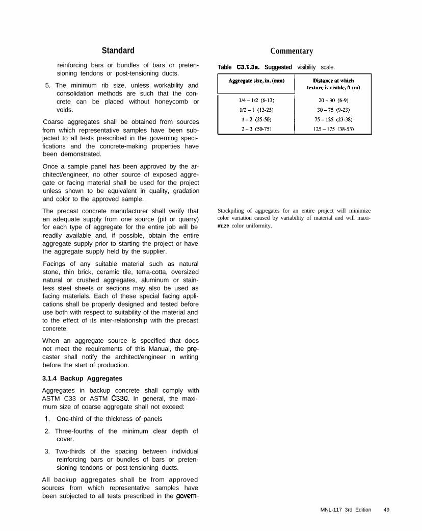
Standard Commentary
reinforcing bars or bundles of bars or preten-sioning tendons or post-tensioning ducts.
Table C3.1.3a. Suggested visibility scale.
5. The minimum rib size, unless workability andconsolidation methods are such that the con-crete can be placed without honeycomb orvoids.
Coarse aggregates shall be obtained from sourcesfrom which representative samples have been sub-jected to all tests prescribed in the governing speci-fications and the concrete-making properties havebeen demonstrated.
Once a sample panel has been approved by the ar-chitect/engineer, no other source of exposed aggre-gate or facing material shall be used for the projectunless shown to be equivalent in quality, gradationand color to the approved sample.
The precast concrete manufacturer shall verify thatan adequate supply from one source (pit or quarry)for each type of aggregate for the entire job will bereadily available and, if possible, obtain the entireaggregate supply prior to starting the project or havethe aggregate supply held by the supplier.
Stockpiling of aggregates for an entire project will minimizecolor variation caused by variability of material and will maxi-mize color uniformity.
Facings of any suitable material such as naturalstone, thin brick, ceramic tile, terra-cotta, oversizednatural or crushed aggregates, aluminum or stain-less steel sheets or sections may also be used asfacing materials. Each of these special facing appli-cations shall be properly designed and tested beforeuse both with respect to suitability of the material andto the effect of its inter-relationship with the precastconcrete.
When an aggregate source is specified that doesnot meet the requirements of this Manual, the pre-caster shall notify the architect/engineer in writingbefore the start of production.
3.1.4 Backup Aggregates
Aggregates in backup concrete shall comply withASTM C33 or ASTM C330. In general, the maxi-mum size of coarse aggregate shall not exceed:
1. One-third of the thickness of panels
2. Three-fourths of the minimum clear depth ofcover.
3. Two-thirds of the spacing between individualreinforcing bars or bundles of bars or preten-sioning tendons or post-tensioning ducts.
All backup aggregates shall be from approvedsources from which representative samples havebeen subjected to all tests prescribed in the govern-
MNL-117 3rd Edition 49

Standard Commentary
ing specifications and the concrete making proper-ties have been satisfactorily demonstrated.
3.1.5 Aggregates for Lightweight Concrete C3.15 Aggregates for Lightweight Concrete
Lightweight aggregates shall conform to the re-quirements of ASTM C330. Provisions for testingshall be as stipulated in Articles 6.12 and 6.1.3 ex-cept tests for gradation, unit weight, and impuritiesshall be made in accordance with requirements ofASTM C330.
Precasters using lightweight aggregates should be experiencedin mixing and placing lightweight concrete mixes since theirweight and shrinkage characteristics often require special at-tention in order to obtain a reasonable uniformity in appear-
ance when exposed. The combination of normal weight facemix and a backup mix with lightweight aggregates may in-crease the possibility of bowing or warping. Before producingsuch a combination, pilot units, produced and stored under an-ticipated pmduction conditions, are desirable to verify satisfac-tory pelfomlance.
Lightweight aggregates tend to take on moisture and if not sat-urated will puU water from the mix causing a rapid slump losscreating problems in handling and placing.l%e AC1 Committee213 report, Guide for Structural Lightweight Aggregate Con-crete, provides a thorough discussion of lightweight aggregatepmperties including proportioning and mixing practices.
3.1.6 Mixing Water
Water shall be free from deleterious matter thatmay interfere with the color, setting or strength ofthe concrete.
Water, either potable or non-potable, shall be freefrom injurious amounts of oils, acids, alkalies, salts,organic materials, chloride ions or other substancesthat may be deleterious to concrete or steel. Thewater shall not contain iron or iron oxides which will
c3.1.6 Mixing w a t e r
Excessive impurities in mixing water not only may affect set-ting time and strength, but also may cause efflorescence, stain-
ing, increased volume change and reduced durability.Therefore, certain optional limits should be set on chlorides,sulfates, alkalis, and solids in the mixing water or appropriate
r Substance MaXImUm Concentration, ppm
Soluble carbon dioxide 600
Calcium plus magnesium 400
Chloride, as Cl 500
Iron 20
Phosphate 100
Arsenic 100
Boron and berates 100
Alkalies. as Na,O + 0.658 K,O 600
Sik or suspended palticles 2000
PH 6.0 to 6.0
Dissolved solids 2000
lodate 500
Sugars and oils Not detectable
kk., “.dh3. “- ,*.n* *” “,“b, ~“~h,&~ -mn3”iPI -,- -“...lh. I.ddsn^^l
ASTM Test Method’
D513
D511
D512
b
D4327
D2972
D3092
D4191 8 4192
01686
D1067
D1869
c
c
50 MNL-117 3rd Edition

Standard
cause staining in light colored or white concrete.Water from a source other than a municipal watersupply shall be tested on an annual basis as requiredin Article 6.12. The water shall not exceed the maxi-mum concentration limits given in Table 3.1.6.
Commentary
tests can be performed to determine the effect the impurity hason various properties. Some impurities may have little effecton strength and setting time, yet they can adversely affectdurability and other properties.
The chloride ion content should be limited to a level well belowthe recommended maximum, if practical. Chloride ions con-tained in the aggregate and in admixtures should be consideredin evaluating the acceptability of total chloride ion content ofmixing water.
C3.1.7 AdmixturesAll types of admixtures used should be materials of standardmanufacture having well established records of tests to con-firm their properties. Expected performance of a given brand,class, or type of admixture may be projected from one or moreof the following sources:
1. Results from jobs which have used the admixture undergood technical control, preferably using the same materi-als and under conditions similar to those to be expected.
2. Technical literature and information from the manufac-turer of the admixture.
3. Laboratory fests made to evaluate the admixture.
Trial mixtures can he made at midrange slump and air con-tents expected or specified for the project. The cement contentor water/cement ratio should be that required for the specifieddesign strength and durability requirements for the job, Trialmixtures also can be made with a range of cement contents -water/cement ratios, slumps or other properties to bracket theproject requirements. In this manner, the optimum mixtureproportions can be selected and the required results achieved.
Various results can be expected with a given admixture due todifferences in dosage, cement composition and fineness, cementcontent, aggregate size and gradation, the presence of other ad-mixtures, addition sequence, changes in water/cement ratio, andweather conditions from day to day.
Differences in setting times and early strength development alsocan be expected with different types and sources of cement asweU as concrete and ambient temperatures.
The use of air entrainment is recommended to enhance dura-bility when concrete will be subjected to freezing and thawingwhile wet.
Use of water-reducing admixtures results in a desirable reduc-tion in water-cement ratio for a given consistency (slump) andcement content, an increased consistency for the same water-cement ratio and cement contenf or obtaining specified strength
at lower cement content while keeping the water-cement ratiothe same. The reduction in water-cement ratio achieved byeliminating excess mixing water may produce greater strengthimprovement than a similar reduction obtained by adding ce-ment. Generally, the effect of use of these materials on thehardened concrete is increased compressive strength and somereduction in permeability and, in combination with adequate airentrainment, improved resistance to freezing and thawing.Water-reducing admixtures also may impmve the properties ofconcrete containing harsh facing mixes which necessarily have
MNL-117 3rd Edition 51
3.1.7 Admixtures
If a satisfactory history of admixture performancewith the concrete making materials to be used in aproject is not available, a trial mixture program withthose materials, particularly the cement, shall beconducted. The trial mixture program shall demon-strate satisfactory performance of the admixturerelative to slump, workability, air content, andstrength under the conditions of use, particularlywith respect to temperature and humidity. Admix-tures shall be carefully checked for compatibilitywith the cement or other admixtures used to ensurethat each performs as required without affecting theperformance of the other admixtures. Admixturesupplier’s recommendations shall be observed sub-ject to plant checking and experience. The effect ofvariations in dosage and the sequence of chargingthe admixtures into the mixer shall be determinedfrom the recommendations of the admixture sup-plier or by trial mixes.
The same brand and type admixtures shall be usedthroughout any part of a project where color unifor-mity is required.
Air entraining admixtures shall conform to the re-quirements of ASTM C260.
Water reducing, retarding or accelerating admix-tures shall conform to the requirements of ASTMC494. High-range water-reducing admixtures(HRWRA) or (superplasticizers) shall conform tothe requirements of ASTM C494 Type For G, or forflowing concrete to ASTM Cl01 7, Type 1 or 2. Ad-mixtures containing chloride ions shall not be usedin prestressed concrete, or in concrete containingaluminum embedments or galvanized reinforce-ment and/or hardware, if their use will produce adeleterious concentration of chloride ions in themixing water and cause corrosion.
Commentary
poor aggregate gradation. Dosages required to produce specificresults are usually recommended by the manufacturers.
There are mid-range water-reducing admixtures which may beclassified under ASTM C494 as Type A or Type F dependingon dosage rate.
Retarding admixtures are used primarily to offset the accelerat-ing and damaging effect of high temperature, or in some casesto keep concrete plastic for a sufficiently long period of time(retard or control the initial set of the concrete) so that succeed-ing lifts can be placed without development of cold joints ordiscontinuities in the unit. For example, to achieve good bondbetween facing and backup concrete.
High-range water-reducing admixtures can be used to signifi-cantly increase slump without adding more water, or to greatlyreduce water content without a loss in slump. Concretes con-taining these admixtures, particularly those with initial slumpsless than 3 to 4 in. (75 to 100 mm) and low water-cement ra-tios, tend to lose slump and stiffen rapidly. While, some high-range water-reducing retarders can maintain the necessaryslump for extended periods at elevated concrete temperatures.
Calcium chloride and admixtures containing chloride ions willpromote corrosion of steel reinforcement and galvanized oraluminum embedments, may cause non-uniformity in color ofthe concrete surface (darkening and mottling), and may disruptthe efficiency of surface retarders.
To avoid corrosion problems admixtures containingchloride ions shall be limited to a maximum watersoluble chloride ion (Cl-) in prestressed concrete to0.06 percent by weight of cement or 0.30 in rein-forced concrete when tested in conformance toASTM Cl213
Mineral admixtures or pozzolans meeting ASTMC616 or Cl240 may be added for additional worka-bility, increased strength and reduced permeabilityand efflorescence provided no detrimental changeis experienced in the desired architectural appear-ance. If a HRWRA is to be used with silica fume,ensure that the admixture to be used is compatiblewith that already in the silica fume, if any. Theamount of silica fume or metakaolin in concreteshall not exceed 10 percent by mass of the port-land cement unless evidence is available indicatingthat the concrete produced with a larger amountwill have satisfactory strength, durability, and vol-ume stability.
Coloring admixtures or pigments shall conform tothe requirements of ASTM C979. All coloring pig-ments required for a project shall be ordered in onelot. The coloring pigment shall be a finely groundnatural or synthetic mineral oxide or an organic ph-thalocyanine dye with a history of satisfactory colorstability in concrete. Pigments shall be insoluble inwater, free of soluble salts and acids, colorfast insunlight, resistant to alkalies and weak acids, andvirtually free of calcium sulfate. The amount andtype of pigment used shall be harmless to concretesetting time or strength. Amounts of pigment usedshall not exceed IO percent of the weight of cement.
52 MNL-117 3rd Edition
Where a particularly smooth surface is desired, the addition ofhe minerals or pozzolans conforming to ASTM C618 may bedesirable. These materials also may be added to improve work-ability or to reduce the possibility of efflorescence provided nodetrimental change is experienced in the desired architecturalappearance. The use of fly ash or silica fume (microsilica) in aconcrete mixture will darken the concrete color and may makeit difficult to achieve color uniformity. The color of silica fumedepends on carbon content and several other variables. Silicafume from one source could be almost white in color, while thatfmm another may be black. Metakaolin is a white dry powderand does not darken white or gray concrete.
Pigments often are added to the matrix to obtain colors whichcannot be obtained through combinations of cement and fineaggregate alone. Variable amounts of a pigment, expressed as apercentage of the cement content by weight, prcduce variousshades of color. High percentages of pigment reduce concretestrength because of the high percentage of fines introduced tothe mix by the pigments. For these reasons, the amount of pig-ment should be controlled within the limits of strength and absorption requirements. Different shades of color can beobtained by varying the amount of coloring material or bycombining two or more pigments. Brilliant concrete colors arenot possible with either natural or synthetic pigments due totheir low allowable addition rates and the masking effects ofthe cement and aggregates. White portland cement will pm-
3.2 Reinforcement and Hardware
3.2.1 Reinforcing Steel
Steel reinforcing bars shall bs deformed bars of thedesignated types of steel, sizes and grades andshall conform to the following applicable specifica-tions as shown on the production drawings:
Billet-Steel Deformed Bars ASTM A61 5/A615M
Low Alloy Steel Deformed Bars ASTM A706/A706M
Rail-Steel Deformed Bars ASTM A616/A616M
Axle-Steel Deformed Bars ASTM A61 7/A617M
It shall be permissible to substitute: a metric sizebar of Grade 300 for the corresponding inch-poundsize bar of Grade 40; a metric size bar of Grade350 for the corresponding inch-pound size bar of
Commentary
duce cleaner, brighter colors and should be used in preferenceto gray cement.
When using pigment dosages of less than 1% by weight of ce-ment, the sensitivity of color intensity to minor pigment quan-tity variations is very high, causing potential unit to unit colorvariation. When using dosages from 1% to 5%. this sensitivityis much lower, and color variation will be more easily con-trolled. Addition of synthetic iron oxide pigments above 5%will not increase color intensity, while for natural pigments thesaturation points are closer to 10%.
Coloring pigments of iron oxides are generally preferred be-cause of better performance, but they may react chemicallywith other products, such as surface retarders or muriatic acid,and should be tested prior to use.
Green is quite permanent, except in light shades. Some bluesare not uniform or pemxment. Cobalt blue should be used toavoid problems. Dark colors have more tendency to show ef-florescence that forms on all concrete surfaces. If the lighten-ing of the color becomes too objectionable, the color can berestored by washing with dilute hydrochloric acid and rinsingthoroughly. Carbon black, due to its extremely fine particlesize, has a tendency to wash out of a concrete matrix and is notrecommended. Synthetic black iron oxide will produce a morestable charcoal color.
Architects can best specify the color they desire by referring toa swatch or color cad. A cement color card is preferable butone published by a paint manufacturer is acceptable. An excel-lent color reference is the Federal Color Standard 595 B, pub-lished by the U.S. Government Printing Office.
C3.2 Reinforcement and Hardware
C32.1 Reinforcing Steel
Efflorescence deposited on the surface may mask the truecolor and give the appearance of fading even though the ce-ment paste itself has undergone no change. In addition, weath-ering of the pigmented cement paste exposes more of theaggregate to view. If the color of the aggregate is in contrast tothat of the pigment, a change in the overall color of the surfacemay be noted.
Grades of reinforcing steel required for a specific applicationare determined by the structural design of the precast concreteunits.
Many mills will mark and supply bars only with the metricdesignation, which is a soft conversion. Soft means that themetric bars have exactly the same dimensions and propertiesas the equivalent in:lb designation.
The size of reinforcing bars is often governed by dimensionsof the element, required concrete cover over steel, and functionof the element. In general, bar sires should be kept reasonablysmall even where this will reduce the spacing of the bars.Smaller bars closely spaced will decrease the size of potentialcracks and improve the distribution of temperature stresses.The use of additional reinforcing bars as compared with fewerheavier bars becomes more important in thinner concrete sec-tions. Since the sum of potential cracks in concrete is more or
MNL-117 3rd Edition 53

Standard
Grade 50; a metric size bar of Grade 420 for thecorresponding inch-pound size bar of Grade 60;and a metric size bar of Grade 520 for the corre-sponding inch-pound size bar of Grade 75.
Zinc-coated (galvanized) reinforcement shall con-form to ASTM A767/A767M and be chromatetreated.
Commentary
less constant for a given set of conditions, the more bars thereare the smaller and less visible the cracks.
Epoxy coated reinforcement shall conform to ASTMA775/A775M or A934/A934M. Any plant supplyingepoxy coated reinforcement shall be a participant inthe CRSI Voluntary Certification Program for Fu-sion-Bonded Epoxy Coating Applicator Plants.
Fading of the epoxy coating color shall not because for rejection of epoxy coated reinforcing bars.
Bar mats shall conform to ASTM Al 84/A184M andshall be assembled from the bars described above.If bars other than the types listed above are to beused, their required properties shall be shown onthe production drawings. In addition to the ASTMspecification requirements, all reinforcing bars shallmeet the requirements of ACI 318.
The weldability of reinforcing bars other than ASTMA706/A706M shall be evaluated according to provi-sions of AWS D1.4.
Welded wire reinforcement shall conform to the fol-lowing applicable specifications:
Plain Wire ASTM A82
Deformed Wire ASTM A496
Welded Plain Wire Reinforcement ASTM Al 85
Welded Defoned Wire Reinforcement ASTM A497
Galvanized welded wire reinforcement shall bemade from zinc-coated (galvanized) carbon steelwire conforming to ASTM A841; or be hot-dippedgalvanized and be chromate treated; or be allowedto weather. Epoxy-coated welded wire reinforce-ment shall conform to ASTM A884/A884M, Class A.All damaged areas of epoxy coating shall be re-paired (touched-up) with patching material.
Welded wire reinforcement mesh spacings and wire
Where galvanizing of reinforcing bars is required, galvanizingis usual ly per formed af te r fabr ica t ion . The ASTMA767iA767M specification prescribes minimum finished benddiameters for bars that are fabricated before galvanizing.Smaller finished bend diameters are permitted if the bars arestress-relieved. The ASTM A767lA767M specification has twoclasses of zinc coating weights. Class II [LO oz.isq. ft (610g/n?)] is normally specified for precast concrete units.
When epoxy-coated reinforcing bars axe exposed to sunlightover a period of time, fading of the color of some epoxy coat-ings may occur. Since the discoloration does not ham the coat-ing nor affect its corrosion-protection properties, such fadingshould not be cause for rejection of the coated bars.
ASTM A706/A706M is specifically intended for welding.Chemical analyses are not ordinarily meaningful for rail-steel(ASTM A616/A616M) and axle-steel (ASTM A617/A617M)reinforcing bars. Welding of these bars is not recommended.
Welded wire reinforcement may be used as the main reinforce-ment and, if necessary, reinforcing bars are added in ribs orother locations to provide the area of steel required.
Galvanized or epoxy-coated reinforcement is generally re-quired when cover over reinforcement is 314 in. (I9 mm). Inthese cases, the use of galvanizing or epoxy-coating should bespecifically called for in the contract documents and shown onthe shop drawings.
It is recommended that welded wire reinforcement be pur-
54 MNL-117 3rd Edition
Standard
sizes (gages) shall be shown on the productiondrawings. In addition to the ASTM specification re-quirements, all wire reinforcement shall meet therequirements of ACI 318.
Reinforcement, with rust, seams, surface irregulari-ties, or mill scale shall be considered as satisfac-tory, provided the minimum nominal dimensions,including minimum average height of deformations,and nominal weight of a hand-wire-brushed testspecimen are not less than the applicable ASTMspecification requirements.
Plastics for welded wire and bar supports shall becomposed of polyethylene, styrene copolymer rub-ber-resin blends, poly-(vinyl chlorides), Types I andII, and polytetrafluoroethylene. Plastics shall be al-kali resistant and should have at least 25 percent oftheir gross plane area perforated.
3.2.2 Prestressing Materials
Strand materials for prestressing shall consist of:
1. Pretensioning
a. Uncoated, low-relaxation strand conformingto ASTM A416, Grade 250 (1725) or Grade270 (1860).
b. Uncoated, stress-relieved (normal relax-ation) strand, conforming to ASTM A416,Grade 250 (1725) or Grade 270 (1660).
2. Post-Tensioning
a. Strand as described above either singly orin multiple parallel strand units with wedgetype or other adequate anchorages.
b. Uncoated, stress-relieved wire conformingto ASTM A421 in multiple parallel wire unitswith wedge-type, button head or other ade-quate anchorages.
c. High strength, stress-relieved bars conform-ing to ASTM A722 with wedge type,threaded, or other adequate anchorages.
A light bond coating of tight surface rust on pre-stressing tendons is permissible, provided strandsurface shows no pits visible to the unaided eyeafter rust is removed with a non-metallic pad.
Commentary
chased in large sheets rather than rolls for better control of flat-“SS.
Plastic bar supports and spacers have about fifteen times thethermal expansion coeffkient of concrete. The plane surfacehas to be perforated to permit the concrete to weave into thesection and restrain movement. This inhibits tbennal punchingand transverse cracking in thin sections.
C3.22 Prestressing Materials
Due to the bond development required of concrete to preseess-ing skmd, bars or wires, the surface condition of tendons iscritical to prestressed concrete. The presence of light rust on astrand has proven fo be an enhancement to hood over brightstrand and therefore should not be a deterrent to the use of thestrand. A pit visible fo the unaided eye, when examined as de-scribed in “Evaluation of Degree of Rusting on PrestressedConcrete Strand:’ &son, Augusta S., PC1 JOURNAL. MayJune 1992, V.37, No. 3, pp. 25-30 is cause for rejection. A pitof this magnitude is a stress miser and greatly reduces the ca-pacity of the strand to withstand repeated or fatigue loading. In
MNL-117 3rd Edition 55
Standard
Strand chucks for pretensioning shall be capable ofanchoring the strand without slippage after seating.Length of grips and configuration of serrations shallbe such as to ensure against strand failure withinthe vise jaws at stresses less than 95 percent ofstrand ultimate strength. Steel casings for strandvises shall be verified by the manufacturer as capa-ble of holding at least 100 percent of the ultimatestrength of the strand.
Tendon anchorages for post-tensioning shall meetthe following requirements:
1. Anchorages for bonded tendons tested in anunbonded state shall develop 95 percent ofthe actual ultimate strength of the prestressingsteel, without exceeding anticipated set at timeof anchorage. Anchorages which develop lessthan 100 percent of the minimum specified ul-timate strength shall be used only where thebond length provided is equal to or greaterthan the bond length required to develop 100percent of the minimum specified ultimatestrength of the tendon. The required bondlength between the anchorage and the zonewhere the full prestressing force is requiredunder service and ultimate loads shall be suffi-cient to develop the specified ultimate strengthof the prestressing steel. Determine the bondlength by testing a full-sized tendon. If in theunbonded state the anchorage develops 100percent of the minimum specified ultimatestrength it need not be tested in the bondedstate.
2. Anchorages for unbonded tendons shall de-velop 95 percent of the minimum specified ulti-mate strength of the prestressing steel with anamount of permanent deformation which willnot decrease the expected ultimate strength ofthe assembly.
3 . The minimum elongation of a strand under ulti-mate load in an anchorage assembly tested inthe unbonded state shall be not less than 2percent when measured in a gauge length of10 ft (3 m).
Anchorage castings shall be nonporous and free ofsand, blow holes, voids and other defects.
For wedge type anchorages, the wedge grippersshall be designed to preclude premature failure of
5 6 MNL-I 17 3rd Edition
Commentary
many cases, a heavily rusted strand with relatively large pitswill still test to an ultimate strength greater than specificationrequirements. However, it will not meet the fatigue test re-quirements.
Strand chuck maintenance should be in force for all elementsin use based on guidelines in Article 5.3.5 and Appendix D.
Post-tensioning tendons subject to exposure or condensation,and which are not to be grouted, should be permanently pro-tected against corrosion by plastic coating or other approvedmeans.
3. Elongation based on tests with a gauge length less than10 ft (3 m) should not be cause for rejection.
Standard
the prestressing steel due to notch or pinching ef-fects under static test load conditions to determineyield strength, ultimate strength, and elongation ofthe tendon.
Anchorages other than the types listed may be usedprovided they are shown by an adequate programof tests to meet the basic requirements listed above.
Sheathing for bonded post-tensioned tendons shallbe strong enough to retain its shape, resist unre-pairable damage during production, and preventthe entrance of cement paste or water from theconcrete. Sheathing material left in place shall notcause harmful electrolytic action or deteriorate. Theinside diameter shall be at least 114 in. (6 mm)larger than the nominal diameter of single wire, bar,or strand tendons; or in the case of multiple wire,bar, or strand tendons, the inside cross-sectionalarea of the sheath shall be at least twice the netarea of the prestressing steel. Sheaths shall be ca-pable of transmitting forces from the grout to thesurrounding concrete. Sheaths shall have groutholes or vents at each end and at all high pointsexcept where the degree of tendon curvature issmall and the tendon is relatively level.
Grout shall consist of a mixture of cement andwater unless the gross inside cross-sectional areaof the sheath exceeds four times the tendon cross-sectional area, in which case fine aggregate maybe added to the mixture. Fly ash and pozzolanicmineral admixtures may be added at a ratio not toexceed 0.30 by weight of cement. Mineral admix-tures shall conform to ASTM C618. Aluminum pow-der of the proper fineness and quantity or otherapproved shrinkage-compensating material whichis well dispersed through the other admixture maybe used to obtain 5 to 10 percent unrestrained ex-pansion of the grout. Admixtures containing morethan trace amounts of chlorides, fluorides, alu-minum, zinc, or nitrates shall not be used. Fine ag-gregate, if used, shall conform to ASTM C404, SizeNo. 2, except that all material shall pass the No. 16sieve. Grout shall achieve a minimum compressivestrength of 2500 psi (17.2 MPa) at 7 days and 5000psi (34.5 MPa) at 28 days when tested in accor-dance with ASTM Cl 107, and have a consistencythat will facilitate placement. Water content shall bethe minimum necessary for proper placement, andthe water-cement ratio shall not exceed 0.45 byweight.
Sheathing for unbonded tendons (monostrandpost-tensioning system) shall be polypropylene,high-density polyethylene, or other plastic which is
Commentary
Different requirements are imposed upon sheathings forbonded and ““bonded tendons. In unbended tendons, thesheathing does not transmit any bond stresses from the pre-stressing steel to the conaete and therefore has to assure thefreedom of movement of the prestressing steel and form an ad-equate cover over the coated tendon. In bonded tendons, bondstresses will be trausmitted through the sheathing, and it mustbe of such material and/or configuration to effectively allowthis stress transfer.
The void in the concrete in which the tendon is to be locatedcan also be pre-formed (e.g. by inflatable and removabletubes) and the tendon subsequently pulled through. With pre-formed voids no additional sheathing will be required.
Due to variations in the manufacturing process, slight varia-tions may occur concentrically in the wall thickness. Thesheathing should provide a smooth circular outside surface and
MNL-117 3rd Edition 57
Standard Commentary
not reactive with concrete, coating, or steel. Thematerial shall be watertight and have sufficientstrength and durability to resist damage and deteri-oration during fabrication, transport, storage, instal-lation, concreting, and tensioning. The sheath shallhave a coefficient of friction with the strand of lessthan 0.05. Tendon covering shall be continuousover the unbonded length of the tendon and shallprevent the intrusion of water or cement paste andthe loss of the coating material during concreteplacement. The sheaths shall not become brittle orsoften over the anticipated exposure temperatureand service life of the structure. The minimum wallthickness of sheaths for noncorrosive conditionsshall be 0.04 in. (1 mm.) The sheathing shall havean inside diameter at least 0.030 in. (0.76 mm)greater than the maximum diameter of the strand.
should not visibly reveal the lay of the strand.
Tendons shall be lubricated and protected againstcorrosion by a properly applied coating of grease orother approved material. Minimum weight of coat-ing material on the prestressing strand shall be notless than 2.5 pounds (1.1 kg) of coating materialper 100 ft (30.5m) of 0.5 in. (12mm) diameterstrand, and 3.0 pounds (1.4 kg) of coating materialper 100 ft (30.5m) of 0.6 in. (15.24mm) diameterstrand. The amount of coating material used shallbe sufficient to ensure essentially complete filling ofthe annular space between the strand and thesheathing. The coating shall extend over the entiretendon length. Coatings shall remain ductile andfree from cracks at the lowest anticipated tempera-ture and shall not flow out from the sheath at themaximum anticipated temperature. Coatings shallbe chemically stable and nonreactive to the tendon,the concrete and the sheath.
32.3 Hardware and Miscellaneous Materials
All hardware - connection items, inserts or otherappurtenances - shall be clearly detailed in theproject documents showing size and yield strengthfor architect/engineer approval.
C3.23 Hardware and Miscellaneous Materials
Hardware shall be made from materials that areductile. Plates and angles shall be low carbon(mild) steel and steel for anchors shall be of agrade and strength similar to the hardware materialwhich it anchors to minimize welding complications.Brittle materials, such as low shock resistant, highcarbon steels or gray iron castings, shall not beused. Malleable cast iron is satisfactory.
Precautions should be taken to assure that hardware elementswelded together are compatible. The degree of pmtection fromcorrosion required will depend on the actual conditions towhich the connections will be exposed in service. The mostcormnon condition requiring protection is exposure to climaticconditions. Connection hardware generally needs protectionagainst humidity or a corrosive environment. Corrosion couldcause subsequent rusting and marring of adjacent elements orfailure of the unit or connection. The use of oil based primerscontaining lead may be restricted due to local environmentalregulations. Protective coatings should be of such quality andapplied in such a manner that embrittlement cannot occur.Also, no loss of connection strength or reinforcement bond loss
55 MNL-117 3rd Edition

Standard Commentary
should occur which had not been anticipated and allowed forin the design. Often, final finishing of the products causes theprotective finish of the hardware to be damaged. When this oc-curs, a final touch up coating of the original protective materialis required. This work should be performed in accordance withthe recommendations of the coating material manufacturer.Since the final connection of a unit to a structure may require afield weld, the protective coating (zinc rich or epoxy paint)should he applied according to the manufacturer’s require-ments after final welding and cleaning of the welded area.
Materials used in ferrous items embedded in theconcrete, for the purpose of connecting precast el-ements or attaching or accommodating adjacentmaterials or equipment, shall conform to the re-quirements of the following specifications:
Structural steel: ASTM A36/A36M, (for carbon steelconnection assemblies) except that silicon (Si) con-tent shall be in the range of 0 to 0.04% or 0.15 to0.20% and phosphorus (P) content in the range of0 to 0.02% for materials to be galvanized. Steelwith chemistry conforming to the formula Si + 2.5Ps 0.09 is also acceptable.
Stainless steel: ASTM A666, Type 300 series,Grades A or B, (stainless steel anchors for usewhen resistance to staining merits extra cost.)
Carbon steel plate: ASTM A283/A283M. GradesA, B, C or D.
Malleable iron castings: ASTM A47/A447M,Grades 32510 or 35028.
Carbon steel castings: ASTM A27/A27M, Grade60-30 (for cast steel casting clamps).
Anchor bolts: ASTM A307 (carbon steel) orA325/A325M (high strength steel) for low-carbonsteel bolts, nuts and washers).
Carbon steel bars: ASTM A675/A675M, Grade 65(for completely encased anchors).
Carbon steel structural tubing: ASTM A500, GradeB (for rounds and shapes).
High-strength low-alloy structural steel: ASTM orA572/A572M except that silicon (Si) content shallbe in the range of 0 to 0.04% or 0.15 to 0.20% andphosphorus (P) content in the range of 0 to 0.02%for materials to be galvanized. Steel with chemistryconforming to the formula Si + 2.5P s 0.09 is alsoacceptable.
Welded headed studs: ASTM A108 Grades 1010through 1020 inclusive or ASTM A276 (stainlesssteel) with the following mechanical property re-quirements (Table 3.2.3):
MNL-117 3rd Edition 59
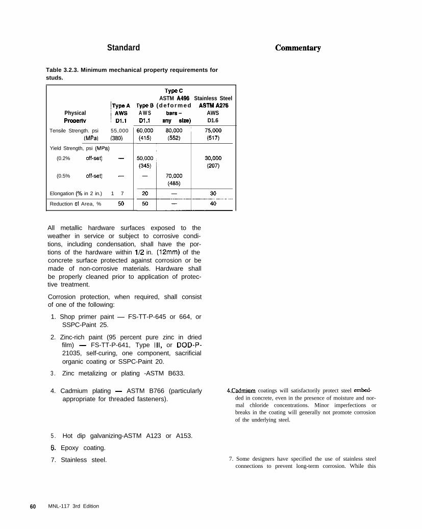
Standard
Table 3.2.3. Minimum mechanical property requirements for
studs.
PhysicalPrODHI”
Tensile Strength. psi 55,000
fMPal (3801
Yield Strength, psi (MPa)
(0.2% off-set) -
(0.5% Off-set) -
Elongation (% in 2 in.) 1 7
Reduction of Area, % ~ 50
TYPO CASTM A466, Stainless Steel
rype0 (de formed ~ ASTMA276A W S bars- AWSDl .I any SW D1.6
All metallic hardware surfaces exposed to theweather in service or subject to corrosive condi-tions, including condensation, shall have the por-tions of the hardware within 112 in. (12mm) of theconcrete surface protected against corrosion or bemade of non-corrosive materials. Hardware shallbe properly cleaned prior to application of protec-tive treatment.
Corrosion protection, when required, shall consistof one of the following:
1. Shop primer paint - FS-TT-P-645 or 664, orSSPC-Paint 25.
2. Zinc-rich paint (95 percent pure zinc in driedfilm) - FS-TT-P-641, Type III, or DOD-P-21035, self-curing, one component, sacrificialorganic coating or SSPC-Paint 20.
3 . Zinc metalizing or plating -ASTM B633.
4. Cadmium plating - ASTM B766 (particularlyappropriate for threaded fasteners).
4Cadmium coatings will satisfactorily protect steel embed-ded in concrete, even in the presence of moisture and nor-mal chloride concentrations. Minor imperfections orbreaks in the coating will generally not promote corrosionof the underlying steel.
5 . Hot dip galvanizing-ASTM A123 or A153.
6. Epoxy coating.
7. Stainless steel. 7. Some designers have specified the use of stainless steelconnections to prevent long-term corrosion. While this
60 MNL-117 3rd Edition
Standard Commentary
8. Other coatings or steels proven suitable bytest.
8.
Threaded parts of bolts, nuts or plates shall not behot dip galvanized or epoxy coated unless theyare subsequently rethreaded prior to use. Con-nection hardware shall be galvanized, if required,following fabrication. To avoid possible strain-ageembrittlement and hydrogen embrittlement, thepractices given in ASTM Al43 shall be adheredto. Malleable castings shall be heat-treated, priorto galvanizing by heating to 1250 deg. F (677 deg.C) and water quenching.
may appear to be the ultimate in corrosion protection,users are cautioned that the welding of stainless steel pm-duces more heat than convention welding. That, plus ahigher coefficient of thermal expansion, can create ad-verse hardware expansion adjacent to the assembly beingwelded, thus causing cracking in the adjacent concreteand promoting accelerated long-term deterioration. Whenstainless steel connection plates are used, edger shouldbe kept free from adjacent concrete to allow expansionduring welding without spalling the concrete. Heat dissi-pation can also be facilitated by the use of a thicker plate.In addition, the 300 Series stainless steels are susceptibleto stress corrosion cracking when the temperature is over140 deg. F (60 deg. C) and chloride solutions are in con-tact with the material.
Embedded natural weathering steels generally do not per-form well in concrete containing moisture and chloride.Weathering steels adjoining concrete may discharge rustand cause staining of concrete surfaces.
In order to ensure that the strengths of the various elements ofa connection arc not reduced by hot-dip galvanizing, severalprecautions are necessary. When items of a connection assem-bly require welding, such as anchor bars to plates, the follow-ing recommendations by the American Hot-Dip GalvanicersAssociation have been found to produce satisfactory results:
1 . An uncoated electrode should be used whenever possibleto prevent flux deposits.
2. If coated electrode is used, it should provide for “self-slagging” as recommended by welding equipment sup-pliers. All welding flux residues must be removed bywire brushing, flame cleaning, chipping, grinding, needlegun or abrasive blast cleaning. This is necessary becausewelding flux residues are chemically inert in the normalpickling solutions used by galvanizers; their existencewill produce rough and incomplete zinc coverage.
3. A welding process such as metal-inert gas (MI@, tung-sten-inert gas (TIG). or CO, shielded arc is recom-
mended when possible since they produce essentially noslag.
Special care should be taken when galvanized assembles areused. Many parts of connection components are fabricatedusing cold rolled steel or cold working techniques, such asbending of anchor bars. Any form of cold working reduces theductility of steel. Operations such as punching holes. notching,producing fillets of small radii, shearing and shalp bendingmay lead to strain-age embrittlement of susceptible steels, par-ticularly those with high carbon content. The embrittlementmay not be evident until after the work has been galvanized.This occurs because aging is relatively slow at ambient tem-peratures but is more rapid at the elevated temperature of thegalvanizing bath.
Care shall be taken to prevent chemicals, such asmuriatic acid, from contacting the hardware andcausing corrosion.
MNL-117 3rd Edition 61
Standard Commentary
The materials of a connection shall be selected andjoined in a manner such that embrittlement of anypart of the assembled connection will not occur.Nonferrous inserts shall have proven to be resis-tant to electrolytic action and alkali attack. Docu-mentation shall be provided showing satisfactoryresults over a reasonable period of time. If morethan one material is used in a connection, abuttingmaterials shall be selected such that corrosion isnot induced. Dissimilar metals shall not be embed-ded near or in direct contact with each other inmoist or saturated concrete unless experience hasshown that no detrimental chemical or electro-chemical (galvanic) reactions will occur or surfacesare permanently protected against corrosion.
Nonferrous metals embedded in concrete may corrode in twoways: (I) by direct oxidation in stmng alkaline solutions nor-mally occurring in fresh concrete and mortar; or (2) by gal-vanic currents that occur when two dissimilar metals are incontact in the presence of an electrolyte, or when an alloy ormetal is not perfectly homogeneous, or when different parts ofa metal have been subjected to different heat treatments or me-chanical stresses.
Aluminum suffers attack when embedded in concrete. Initially,when aluminum is placed in fresh concrete, a reaction occursresulting in the formation of aluminum oxide and the evolutionof hydrogen. The greater volume occupied by these oxidationproducts causes expansive pressures around the embeddedmetal and may lead to increased porosity of the surroundingconcrete as well as cracking and/or spalling of the concrete.
Wooden inserts in the concrete shall be sealed tominimize volume changes during concrete placing,curing, and freezing weather conditions.
A wood sealer should be applied to prevent moistwe migrationfrom concrete into the wood. The high volume change of lumberwhich occurs even with changes in atmospheric humidity maylead to cracking of the concrete. Also, the embedment of lumberin concrete has sometimes resulted in leaching of the woodresins by calcium hydroxide with subsequent deterioration.
3.2.4 Handling and Lifting Devices
Since lifting devices are subject to dynamic loads,handling and liking devices shall be fabricated fromductile material. Reinforcing bars shall not be usedas lifting devices. If smooth bars are required forliking, ASTM A36 steel of a known steel grade bentto correct size and shape shall be used providedadequate embedment or mechanical anchorageexists. Each bar size and configuration shall besubstantiated, by testing, to ensure it meets loadand handling requirements. The diameter shall besuch that localized failure will not occur by bearingon the liking device. Coil rods and bolts shall not bewelded when used in lifting operations
To avoid overstress in one lifting loop when usingmultiple loops, care shall be taken in the fabricationto ensure that all strands are bent the same to as-sure even distribution of load between loops.Strands undergo physical changes when bent intoloops; therefore, care shall be exercised with multi-ple bending.
Shop drawings shall clearly define insert dimen-sions and location for fabrication and placement orrefer to standard details. Corrosion protection shallbe considered where such hardware is left in theunits.
All lifting devices shall be capable of supporting theelement in all positions planned during the courseof manufacture, storage, delivery and erection.
C32A Handling and Lifting Devices
The most common lifting devices are prestressing strand orcable loops projecting from the concrete, coil threaded inserts,or pmprietary devices.
Deformed reinforcing bars should not be used since the defor-mations result in stxss concentrations from the shackle pin.Also, reinforcing bars may be hard grade or re-mlled rail steelwith little ductility and low impact strength at cold tempemtw%.Therefore, sudden impact loads, such as those encountered dw-ing stripping and handling, may cause failure.
62 MNL-I 17 3rd Edition
Standard
Safe loads for lifting inserts or devices shall be es-tablished by full-scale tests to failure performed bya licensed professional engineer or supplied bymanufacturer of proprietary devices. Informationalso shall be supplied by manufacturer on use andinstallation of the devices to assure proper perfor-mance.
Connection hardware shall not be used for lifting orhandling, unless carefully reviewed and approvedby the precast engineer.
3.3 Insulation
Insulation types shall conform to ASTM standardsfor material production. These standards presentquality control minimums for each product matrixand are as follows:
Expanded PolystyreneASTM C-576 Type I, II, VIII, IX, Xl
Extruded PolystyreneASTM C-576 Type IV, V, VI, VII, X
PolyurethaneASTM C-591 Type1,2,3
PolyisocyanurateASTM C-591 Typel,2,3
PhenolicASTM C-l 126 Type I, II, Ill
All relevant information on properties of insulatingmaterials shall be on file at the plant.
Care shall be exercised when the insulation is ex-posed to temperatures greater than 140 deg. F (60deg. C).
3.4 Welding Electrodes
Commentary
C33 Insulation
Cellular (rigid) insulations used in the manufacturing of sand-wich panels come in two primary forms, thermoplastic andthermosetting. The thermoplastic insulations are known asmolded expanded polystyrene or beadboard and extruded poly-styrene or extruded board. Thermosetting insulations consist ofpolyurethane, polyisocyanurate and phenolic.
Although there are many insulation types on the market today,sandwich panels utilize a cellular (rigid) insulation due to thematerial properties needed to perform between two indepen-dent layers of concrete. These material properties include, hutare not limited to, thermal and vapor transmission characteris-tics, moisture absorption, dimensional stability, coefficient ofexpansion and compressive and flenural strengths.
Since the insulation is generally placed in direct contact withthe plastic concrete, excessive dewateering of the fresh concretemay occur with the use of highly absorbent insulation prevent-ing cement from hydrating properly. The insulating quality ofa material also will diminish if it absorbs moisture. For thisreason, a. material which exhibits no capillarity, or has suitablevapor barriers, should be selected. Some insulating materialssuch as molded polystyrene have high absorption.
C3.4 Welding Electrodes
Electrodes for shielded metal arc welding (SMAW)shall conform to the requirements of AWS Dl .I,Section 4 or AWS Di .4. Section 5 (AWS A5.1 orA5.5). All welding electrodes shall be of a type suit-
MNL-I 17 3rd Edition 6 3

Standard
Table 3.4.1. Filler metal requirements
Commentary
Electrode Classifications for Welding Processes
Grade 60 (420)
Grade AGrade B
ASTM A441ASTM A572
Grade 42Grade 50
E70XXE70XX.X
AWS A5.1 or A5.5E7015, E7016E7016, E7026
E7015-X, E7016-XE7016-X
EGXT-XE7XT-X
(Except -2, -3, -10, -GS)
AWS A520E7XT-X
(Except -2, -3, -10. -GS)
ASTM A572 AWS A5.5 AWS A529Grade 60 E6015-X, EBOI 6-X EBXTX-XGrade 65 E8016-X
““-.E...C
able for the chemistry of the steel being welded(see Table 3.4.1).
The electrodes and the shielding for gas metal arcwelding (GMAW) or flux-cored arc welding (FCAW),for producing weld metal with minimum specified yieldstrengths of 60 ksi (415 MPa) or less, shall conform tothe requirements of AWS A5.18 or AWS A5.20.
Electrodes for welded reinforcing bar lap splices incontact or lap welds with splice plates or angles neednot comply with Table 3.4.1. The length and size ofwelds shall be as shown on the shop drawings.
Weld metal having a minimum specified yieldstrength greater than 60 ksi (415 MPa) shall con-
Design tensile capacity of lap welds is determined by lengthand size of welds using various electrodes not by compatibilityof material tensile strength. However, the chemical composi-tion of the materials should be compatible.
6 4 MNL-117 3rd Edition
Standard Commentary
form to the following requirements:
1. The electrodes and shielding for gas metal arcwelding for producing weld metal with a mini-mum specified yield strength greater than 60ksi (415 MPa) shall conform with AWS A5.28.
2 . The electrodes and shielding gas for flux-coredarc welding for producing weld metal with a min-imum specified yield strength greater than 60 ksi(415 MPa) shall conform to AWS A5.29.
3 . The plant shall have on file the electrode man-ufacturer’s certification that the electrode willmeet the above requirements of classification.
When a gas or gas mixture is used for shielding ingas metal arc or flux-cored arc welding, it shall beof a welding grade having a dew point of -40 deg. F(-40 deg. C) or lower. The plant shall have on filethe gas manufacturer’s certification that the gas orgas mixture will meet the dew point requirement.
All low hydrogen electrodes conforming to AWSA5.1 shall be purchased in hermetically-sealedcontainers or shall be dried for at least 2 hrs. at atemperature between 500 deg. F (260 deg. C) and800 deg. F (430 deg. C) before they are used.
All low hydrogen electrodes conforming to AWSA5.5 shall be purchased in hermetically-sealedcontainers or shall be dried at least 1 hr. at temper-atures between 700 deg. F (370 deg. C) and 800deg. F (430 deg. C) before being used.
Electrodes shall be dried as specified above priorto use if the hermetically-sealed containers aredamaged, improperly stored, or for any reason theelectrodes are exposed to high moisture condi-tions. Immediately after removal from hermetically-sealed containers or from drying ovens, electrodesshall be stored in holding ovens and held at a tem-perature of 250 deg. F (120 deg. C) above ambienttemperature. E70 series electrodes that are notused within 4 hrs., E80 series within 2 hrs., E90 se-ries electrodes within 1 hr., or El00 series withini/2 hr., after removal from hermetically-sealed con-tainers or from a drying or storage oven, shall beredried in a drying oven before use. Electrodesshall be dried only once for any reason. Electrodeswhich have been wet shall not be used.
All low hydrogen and stainless steel shielded metalarc electrode coverings should be protected frommoisture pickup. Normally, electrodes packaged inhermetically sealed containers can be stored forseveral months without deteriorating. However,after the container is opened, the coating begins toabsorb moisture and, depending on the ambient aircondition, may need to be reconditioned after onlyfour hours of exposure, otherwise porosity may re-sult, especially at arc starts.
Only low hydrogen welding rods (EXX-X5, 6, or 8)should be kept in an oven once removed from theirair tight container. Although they must not get wet,the coating of other rods (60-l 1) will be damaged ifheated.
When joining different grades of steels, the electrodeshall be selected for the lower strength base metal.
When steel cannot be completely cleaned of scale,rust, paint, moisture or dirt, an E6010 or E6011electrode shall be used.
MNL-117 3rd Edition 65

Standard
Martensitic stainless steels that are to be posthe-ated - (annealed, stress-relieved, or used underhigh temperature conditions) shall be welded withstraight-chromium stainless steel electrodes of theE-400 series. Any of these alloys that will not bepostheated shall be welded with austeniticchromium-nickel electrodes of the E-300 series.
The maximum diameter of electrodes shall be:
1. 5/16 in. (6.0 mm) for all welds made in the flatposition, except root passes
2 . l/4 in. (6.4 mm) for horizontal fillet welds
3 . i/4 in. (6.4 mm) for root passes of fillet weldsmade in the flat position and groove weldsmade in the flat position with backing and witha root opening of l/4 in. or more
4 . 5/32 in. (4.0 mm) for welds made with low hy-drogen electrodes in the vertical and overheadpositions
5. 3/16 in. (4.6 mm) for root passes of groovewelds and for all other welds not includedabove.
Commentary
66 MNL-117 3rd Edition
DIVISION 4 - CONCRETE
Standard
4.1 Mix Proportioning
The properties of concrete mixtures and the colorand texture of the unit shall be as specified in theproject specifications.
4.1.1 Qualification of New Concrete Mixes
Concrete mixes for precast concrete shall be estab-lished initially by laboratory methods. The propor-tioning of mixes shall be done either by a qualifiedcommercial laboratory or qualified precast concretequality control personnel. Mixes shall be evaluatedby trial batches prepared in accordance with ASTMCl 92 and production tests under conditions simulat-ing as closely as possible actual production and fin-ishing. Tests shall be made on all mixes to be usedin production of units. When accelerated curing is tobe used, it is necessary to base the mix proportionson similarly cured test specimens.
Commentary
C4.1 Mix Proportioning
Much of the skill, knowledge and technique of producing qual-ity architectural precast concrete centers around the proper pro-portioning of the mix. Before a concrete mix can be properlyproportioned, several factors must be known. The finish, sizeand shaper of units to be cast should be considered. The methodof consolidation should be known to determine the requiredworkability. The maximum size of the coarse aggregate shouldbe established. The required compressive strength affects theamount of cement to be used as well as the maximum water al-lowed. The required surface finish frequently will control theratio of coarse to fine aggregate. The extent of exposure to se-vere weather or other harsh environments will affect the dura-bility requirements of the concrete mix design.
Concrete mixes arc usually divided into two groups, namely,face and backup. Face mixes arc usually composed of specialdecorative aggregates, and are frequently made with white orbuff cement and/or pigments, where exposed aggregate surfacefinishes are desired. Backup mixes are usually composed ofmore economical local aggregates and gray cement and are usedto reduce material costs in large units employing face mixes.Backup concrete mixes are also used where exposed aggregateor other special finishes are not required, and where the size anddistribution of aggregate an not critical. In precast concreteunits of complicated shapes and deep narrow sections, the facemix may be used throughout the member if procedures for sepa-rating the face and backup mixes become too cumbersome.
C4.1.1 Quditication of New Concrete Mixes
Accepted methods of mix proportioning are given in detail inthe following publications:
1. Portland Cement Association:
a. Design and Control of Concrete Mixrures.
2. American Concrete Institute:
a. Standard Practice for Selecting Proportions forNo rma l and Heavyweighr and Mass Concrete
(AC1211 .I).
b. Standard Practice for Selecting Proportions for
Structural Lightweight Concrete (AC1 211.2).
c. Standard Practice for Selecting Proportions for No-
Slump Concrete (ACI2113).
d. Spec;ficafions for Srrucrural Concrete for Buiid-
ings (AC1 301).
Each concrete mix used shall be developed usingthe brand and type of cement, the source ar.<I gra-dation of aggregates, and the brand of admixtureproposed for use in the production mixes. If any ofthese variables are changed the proportions of themixture shall be re-evaluated.
MNL-117 3rd Edition 67

Standard
Concrete mixes shall be proportioned and/or evalu-ated for each individual project with respect tostrength, absorption, volume change, and resis-tance to freezing and thawing, where such environ-ments exist, as well as desired surface finish (colorand texture). The mix shall have adequate workabil-ity for proper placement and consolidation.
Commentary
An architectural precast concrete mix has demanding criteriasince its appearance will be a governing item, but strength anddurability will also be required. Mix design factors which in-fluence appearance are selection and proportioning of fine andcoarse aggregate, color of cement and use of pigments. Oftenseveral aggregates must be blended and the properties of themixture considered in proportioning the mix. Typically a largerportion of the mix will be coarse aggregate which affects con-sistency, finishability and strength. Careful selection of aggre-gate sizes, colors and mix proportions is needed to provide thedesired emphasis upon the matrix or the exposed surface tex-ture. These considerations vary significantly from those forproportioning for strength and durability alone and the use ofsamples becomes a necessary step in the mix design process.
C4.1.2 Specified Concrete Strength
A minimum design strength for concrete should be determinedby the architect/engineer, based upon in-service requirements.Consideration for production and erection are the responsibilityof the precaster. The mix is generally proportioned for appear-ance, and strength becomes a secondary consideration. Exceptfor load-bearing units, stresses on units ax usually higher dur-ing fabrication and erection than those anticipated in the stmc-tural design for in-service conditions. Production requirementsfor early stripping of units or early stress transfer and subse-quent rapid reuse of forms demand high levels of early com-pressive strength. The minimum transportation and erectionstrength levels will depend on shape of the unit, handling, ship-ping and erection techniques and on schedule, which will nor-mally result in 2%day strengths higher than the specifiedminimum.
In cases where the typical 28 day strength of 5000 psi (34.5MPa) is not structurally necessary, or may be difficult to attaindue to special cements or aggregates, sufficient durability andweathering qualities may often be obtained by controllingproper air entrainment and absorption limits at a strength levelas low as 4000 psi (27.6 MPa).
C4.1.3 Statistical Concrete Strength Consideration
4.1.2 Specified Concrete Strength
Concrete strengths shall be determined on the basisof test specimens either at time of stripping or at aspecified age, usually 28 days, although other agesmay be specified. A minimum acceptable strength attime of stripping shall be established by the precastengineer and shall be stated on the drawings.When members are prestressed, the concrete shallhave a specified compressive strength suitable fortransfer of prestress at time of stripping and 28 daystrength as required by the specifications, unlessotherwise specified by the Engineer.
4.1.3 Statistical Concrete StrengthConsiderations
For commonly used concrete mixes such as backupmixes, or for face mixes where the size of the pro-ject warrants, a plant shall maintain up-to-date doc-umentation of the compressive strength variability.Based on this information, a design strength shallbe chosen for the concrete which will comply withthe statistical interpretation of the strength require-ments given in ACI 318.
Concrete strength test evaluation should follow methods out-lined in AC1 214.
Strength tests failing to meet these criteria may occur occasion-ally (probably about once in 100 tests), even though strengthlevel and uniformity are satisfactory. Allowance should bemade for such statistically normal deviations in decidingwhether or not the strength level being produced is adequate.
Mix designs and concrete propottions may be selected on thebasis of established records for the concrete production facility.The better the control, as measured by the coefficient of vtia-tion or standard deviation, the more economical the selectedmix may become. Under the best control, there still are manyvariables that can influence concrete saength, such as variationsof ingredients, variations in batching, and testing. Concrete forwhich all specimens can be expected to show strengths abovethe specified minimum strength is generally impractical, andevaluation of strength tests should recognize this fact.
66 MNL-I 17 3rd Edition
Standard Commentary
Concrete for background tests to determine standard deviationis considered ta have been “similar” to that required if it wasmade with the same general types of ingredients under nomore restrictive conditions of control over material quality andproduction methods than will exist on the proposed work, andif its specified strength did not deviate more than 1000 psi (6.9MPa) from the required saength. A change in the type of ce-ment or a major increase in the required strength level may in-crease the standard deviation.
Adequate statistical records are based on at least 30 consecu-tive strength tests obtained within the past year representingsimilar materials and conditions to those expected. The 30 con-secutive strength tests may represent either a group of 30 con-secutive batches of the same class of concrete or the statisticalaverage for two groups totaling 30 or more batches.
Average strengths, used as the basis for selecting proportions.should exceed the specified strength by at least:
400 psi (2.76 MPa) if the standard deviation is less
than 300 psi (2.07 MPa).
550 psi (3.79 MPa)if the standard deviation is 300
(2.07 MPa) to 400 psi (2.76 MPa).
700 psi (4.82 MPa) if the standard deviation is 400
(2.76 MPa) to 500 psi (3.45 MPa).
900 psi (6.20 MPa) if the standard deviation is 500
(3.45 MPa) to 600 psi (4.14 MPa).
If the standard deviation exceeds 600 psi (4.14 MPa) or
if a suitable record of strength test performance is not
available, proportions should be selected to produce anaverage strength at least 1200 psi (8.27 MPa) greater
than the specified strength
C4.1.4 Proportioning To Ensure Durability ofConcrete
Selection of fine and coarse aggregate affects bath density andappearance. The high quality of the aggregate does not neces-sarily by itself assure good mix design, hut it does relate toquality of concrete as evidenced by its durability. If the aggrc-gate material is not durable, deterioration can be expected inareas where the concrete is in contact with corrosive atmo-spheres, salts, excessive moisture, and/or severe temperaturechanges.
Achieving low absorption rates for the surface of the concretedemands a high density of the concrete surface.
The strength level of the concrete shall be consideredsatisfactory if the average of each set of any threeconsecutive strength tests equals or exceeds thespecified strength and no individual test falls below thespecified strength by more than 500 psi (3.5 MPa).
4.1.4 Proportioning to Ensure Durability ofConcrete
Concrete strength and durability shall be achievedthrough proper consideration in the mix design ofair, water and cement contents, and workability.Low water-cement ratios shall be used to providespecified strength, durability and low absorption.Drying shrinkage characteristics shall be controlledby aggregate size, gradation, mineralogy, aggre-gate-cement ratio, cement factor, water-cementratio, additives, and admixtures. All of these aboveitems shall be considered.
All combinations of cement and aggregates shall bethose for which chemical and physical properties orlong experience have shown conclusively that thevarious components are compatible and will not re-sult in serious volume changes, cracking or deterio-ration of the concrete as it ages. In particular, theuse of high alkali cement together with alkali reac-tive aggregates is prohibited. Also to be avoidedare aggregates subject to “pop-outs”, rusting, stain-ing, or other surface deterioration. These precau-
MNL-117 3rd Edition 69
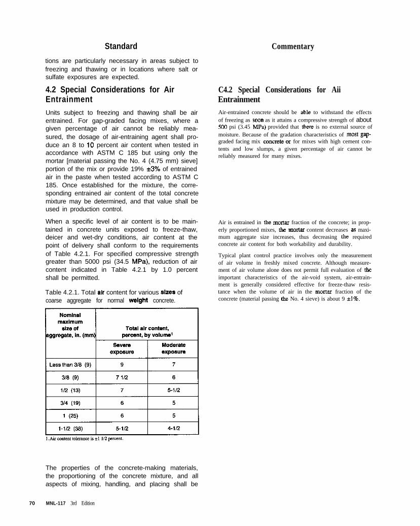
Standard
tions are particularly necessary in areas subject tofreezing and thawing or in locations where salt orsulfate exposures are expected.
4.2 Special Considerations for AirEntrainment
Units subject to freezing and thawing shall be airentrained. For gap-graded facing mixes, where agiven percentage of air cannot be reliably mea-sured, the dosage of air-entraining agent shall pro-duce an 8 to 10 percent air content when tested inaccordance with ASTM C 185 but using only themortar [material passing the No. 4 (4.75 mm) sieve]portion of the mix or provide 19% *3% of entrainedair in the paste when tested according to ASTM C185. Once established for the mixture, the corre-sponding entrained air content of the total concretemixture may be determined, and that value shall beused in production control.
When a specific level of air content is to be main-tained in concrete units exposed to freeze-thaw,deicer and wet-dry conditions, air content at thepoint of delivery shall conform to the requirementsof Table 4.2.1. For specified compressive strengthgreater than 5000 psi (34.5 MPa). reduction of aircontent indicated in Table 4.2.1 by 1.0 percentshall be permitted.
Table 4.2.1. Total air content for various sizes ofcoarse aggregate for normal weight concrete.
Commentary
C4.2 Special Considerations for AiiEntrainment
Air-entrained concrete should be able to withstand the effectsof freezing as soon as it attains a compressive strength of about500 psi (3.45 MPa) provided that there is no external source ofmoisture. Because of the gradation characteristics of most gap-graded facing mix concrete- or for mixes with high cement con-tents and low slumps, a given percentage of air cannot bereliably measured for many mixes.
Air is entrained in the nn’ta~ fraction of the concrete; in prop-erly proportioned mixes, the mortar content decreases as maxi-mum aggregate size increases, thus decreasing the requiredconcrete air content for both workability and durability.
Typical plant control practice involves only the measurementof air volume in freshly mixed concrete. Although measure-ment of air volume alone does not permit full evaluation of theimportant characteristics of the air-void system, air-entrain-ment is generally considered effective for freeze-thaw resis-tance when the volume of air in the mortar fraction of theconcrete (material passing the No. 4 sieve) is about 9 *l%.
The properties of the concrete-making materials,the proportioning of the concrete mixture, and allaspects of mixing, handling, and placing shall be
70 MNL-117 3rd Edition
Standard
maintained as constant as possible in order thatthe air content will be uniform and within the rangespecified for the work.
4.3 Compatibility of Face and BackupMixes
In order to assure compatibility of face and backupmixes the following shall be investigated for theirconsequences on the unit design: (1) relativeshrinkage characteristics; (2) relative thermal coef-ficients of expansion; and (3) relative modulus ofelasticity.
Special attention shall be given to mix compatibilitywhen normal weight face mixes are combined withlightweight backup mixes.
Commentary
4.4 Proportioning for Appearance ofConcrete Surface
The face mix for architectural concrete units shallbe designed to produce the desired appearancetaking into account the technique for obtaining thesurface finish.
4.5 Mix Proportioning for Concrete Madewith Structural Lightweight Aggregate
Lightweight concrete proponions shall be selected tomeet the specified limit on maximum air-dry unitweight as measured in accordance with ASTM C567.
C4.3 Compatibility of Face and BackupMixes
Face and backup mixes should be proportioned to minimizevariations in shrinkage, thermal coeffXent of expansion, andmodulus of elasticity such that finished products meet the tol-erance requirements for bowing and warping. These mixesshould have similar water-cement and cement-aggregate ratios.
The combination of a normal weight face mix and a backupwith lightweight aggregates may increase the possibility ofbowing or warping. Before using such a combination, sampleunits produced, cured and stored under anticipated productionconditions, should be made to verify satisfactory performance.
C4.4 Proportioning for Appearance ofConcrete Surface
The type of finish to be achieved is the key factor to considerwhen making the decision regarding the quantity of coarse ag-gregate desired in the architectural concrete face mix. The ma-terial requirements will vary with the depth and amount ofsurface removed. The shallower the reveal, the more visual in-fluence the aggregate fines and cement will have, and thedeeper the reveal the more visual influence the coarse aggre-gate will have.
Proportioning of fine and coarse aggregate is of importance toworkability of the mix and, thus, to final appearance.
In general, where appearance and color uniformity are ofprime importance; mixes may have considerably higher ce-ment content than is normally required to achieve a specifiedstrength. If the cement is the main contributor to the color ofconcrete, the color will become more intense or darker with in-creased cement content or decreased water-cement ratio.
C4.5 Mix Proportioning for Concrete Madewith Structural Lightweight Aggregate
Mix proportioning methods for structural lightweight aggre-gate concrete (AC1 211.2) generally differ somewhat fromthose for normal weight concrete. The principal properties thatrequire modification of proportioning and control proceduresare the greater total water absorption and rate of absorption oflightweight aggregates, plus their low weight. The absorptionof water by the aggregate has little effect on compressivestrength, provided that enough water is supplied to saturate theaggregate. The moisture content of the aggregate must beknown, and adjustments must be made from batch to batch toprovide constant cement and air contents, similar slumps, and aconstant volume of aggregates.
Standard
4.6 Proportioning for ConcreteWorkability
The slump and workability of a mix shall be suitablefor the conditions of each individual job, i.e., to per-mit the concrete to be worked readily into the formsand around reinforcement under the conditions ofplacement to be used, without excessive segrega-tion or bleeding. Workability considerations shall in-clude the shape of the unit, height of casting, theamount and complexity of reinforcement, and themethod of consolidation.
Commentary
C4.6 Proportioning for ConcreteWorkability
It is difficult and unnecessary to establish limits for slump fortypical precast concrete production. Very stiff mixes requiremore labor to place and special vibration techniques.
Required workability is related to the shape of the precast con-crete unit and the method of consolidation. Methods of consoli-dation using mechanical equipment require less fines forworkability. The lower the percentages of fines, the lower thespecific surface arca of the aggregates and the lower the waterand cement requirements of the mix, which leads to a higherquality potential of the concrete. However, very low fines con-tent mixes may bleed excessively and require a high water con-tent for workability.
Workability under the influence of a properly selected vibratoris the important consideration and not slump. Workability offreshly mixed concrete is the property that determines the easeand homogeneity with which it can be mixed, placed, com-pacted, and finished.
Slump is a measure of concrete consistency. However, it is not,by itself, a measure of workability. Other considerations suchas cohesiveness, harshness, segregation, bleeding, ease of con-solidation, and finish ability are also important, and these prop-erties ale not entirely measured by slump.
The consistency of concrete. as measured by the slump test, isan indicator of the relative water content of the same concretemixture. Additional water increases the water-cement ratio andhas the undesirable effect of reducing the cohesion within themixture and increasing the potential for segregation and cxcwsive bleeding.
Excessive water will affect strength, shrinkage, density and ab-sorption and uniformity of color.
Concrete slumps in color sensitive architectural panels shouldnot exceed 3 in. (75 mm) in most instances, prior to the addi-tion of high range water reducer, exceptions to this are gap-graded mixes which should generally not have slumps greaterthan 2 in. (50 mm)
In color sensitive units, the slump shall be as lowas possible and constant from batch to batch inorder to provide uniformity of color in the end prod-uct. Slump tolerances of +l in. (*25 mm) prior tothe addition of HRWR shall be maintained for mixconsistency and color control.
When superplasticized concrete falls below thespecified slump due to a delay, it shall be retem-pered with superplasticizing admixtures only ratherthan additional water.
4.7 Water-Cement Ratio
4.7.1 General
The water-cement ratio shall not exceed 0.45 byweight with an allowable variation during produc-tion of *0.02. In all mix designs for precast con-crete production the importance of a lowwater-cement ratio shall be recognized, but thisratio shall also be evaluated in relation to the work-ability required for satisfactory placing and consoli-
72 MNL-117 3rd Edition
C4.7 Water-Cement Ratio
C4.7.1 General
With given materials, the optimum mixture proportions use theleast anwunt of total water per unit volume of concrete to ob-tain the required slump and workability. With a fixed water-ce-ment ratio, material costs are reduced by using mixtures havingthe least paste. The cement in the paste is typically the mostcostly ingredient of the concrete; therefore, using more paste
than required adds unnecessarily to the cost of the concrete.However, when using extremely high-priced aggregates, the
Standard
dation techniques for the actual mix application.Water shall be limited to the minimum needed forproper placing and consolidation by means of vi-bration. Low water-cement ratios shall be accom-panied by controls on total water content.
4.7.2 Relationship of Water-Cement Ratio toStrength, Durability and Shrinkage
Since the water-cement ratio is one of the funda-mental keys governing the strength and durabilityof the concrete the proportioning of the concretemix design process shall minimize the water-ce-ment ratio to the maximum extent possible consis-tent with acceptable workability of the concrete mixin the intended application.
4.7.3 Relationship of Water-Cement Ratio toWorkability
The water-cement ratio shall not be increased forreasons of improving workability. Use of suitableworkability improving admixtures shall be employedif additional workability is needed in concrete mixeswhich are already proportioned at the maximum al-lowable water-cement ratio.
4.8 Effects of Admixtures
All types of admixtures used shall be materials ofstandard manufacture having well establishedrecords of tests to confirm their properties and theirshort term and long term effects on the propertiesof both fresh and cured concrete. The manufactur-ers’ recommendations shall be followed in theiruse.
Whenever more than one admixture is used in aconcrete mix, it shall be verified prior to productionthat each material performs as required without ad-versely affecting the performance of the other.
Commentary
cost of paste should be balanced against the aggregate cost,
Most chemical admixtures of the water-reducing type arewater solutions. The water they contain becomes a part of themixing water in the concrete and should be considered in thecalculation of water-cement ratio. The proportional volume ofthe solids included in the admixture is so small in relation tothe size of the batch that it can be neglected in the mix designcalculations.
When using a silica fume slurry, the water portion of the slurrymust be taken into account when determining mix proportions.This entails reducing the amount of batch water to correct forthe water in the slurry.
C4.72 Relationship of Water-Cement Ratio toStrength, Durability and Shrinkage
A reasonable balance should be established between a maxi-mum cement content for stripping and service strength require-ments and a minimum cement content to diminish its negativequalities, such as shrinkage and a matrix hardness lower thanthat of the aggregates.
Minimizing the paste is desirable because water in the paste isthe primary cause of shrinkage as the concrete hardens anddries. The more water (i.e., the more paste), the greater thedrying shrinkage. Also, cement prcduces heat as it hydrates.Therefore, high cement contents may produce an undesirabletemperature rise during curing and crack-producing tempera-ture differentials.
C4.7.3 Relationship of Water-Cement Ratio toWorkability
The water content of concrete is influenced by a number offactors: aggregate size and shape, slump, water-cement ratio,air content, cement content, admixtures, and environmentalconditions. Increased air content and aggregate size, reductionin water-cement ratio and slump, rounded aggregates, and theuse of water-reducing admixtures reduce water demand. Onthe other hand, increased temperatures, increased cement cm-tents, increased slump, increased water-cement ratio, aggregateangularity, and a decreased proportion of coarse aggregate totine aggregate increase water demand.
C4.8 Effects of Admixtures
The development of admixtures to modify and improve theproperties of fresh and cured concrete is one of the mostrapidly changing areas of concrete technology. Some con-crete admixtures have been in successful service for manyyears and can be considered well proven performers with no
adverse side effects.
MNL-I 17 3rd Edition 73
Standard Commentary
Regardless of the form of the admixture, provisionshall be made for controlling the quantity and uni-form introduction with other concrete componentsto ensure it’s well distributed incorporation into themix.
4.9 Storage and Handling of ConcreteMaterials
4.9.1 General
C4.9 Storage and Handling of ConcreteMaterials
Concrete batching plants and their operation shallbe in conformance with ASTM C94. Concrete batchplants shall be capable of producing concrete ofthe quality required for architectural precast con-crete members; and they shall be properlyequipped, maintained and operated. Batching andmixing facilities shall have provisions for producingconcrete during the expected range of hot and coldambient temperatures normally encountered. Thereshall be an adequate water supply, with pressuressufficiently constant or regulated to prevent interfer-ence with accuracy of measurement.
Concrete supplied to a plant by an outside batchplant shall meet the same requirements of on sitebatch plant facilities. Evidence of conformanceshall be certification of the outside plant by NRMCA(National Ready Mixed Concrete Association).
4.9.2 Storage and Handling of Aggregates
Each aggregate shall be handled and stored bymethods that will minimize variability in grading andmoisture content upon arrival at batch weighingequipment. Rehandling of aggregates shall be mini-mized to avoid the aggregate segregation whichcan occur as result of each handling operation.
Wet or moist aggregates shall be stockpiled in suf-ficient time before use so that they can drain to uni-form moisture contents. Required storage times,depending primarily on the grading and particleshapes of the aggregate, shall be verified by mois-ture tests or measurements.
C4.9.2 Storage and Handling of Aggregates
F’rocedures for handling and storage of aggregates are outlinedin further detail in AC1 221 and AC1 304.
Unless uniformity of aggregates as batched is assured. pmduc-tion of uniform concrete is unlikely. It is essential that aggre-gates be kept clean and that contamination of one aggregate byanother is prevented
Stockpiles. When aggregates are to be stockpiled,the use of aggregate bins is preferred; but failingthis, it is imperative that a hard, clean and well-drained base shall be provided for each aggregatestockpile. If contamination from underlying materialcannot otherwise be avoided, the area shall beplanked or paved. Stockpiles shall be built up inhorizontal or gently sloping layers. Conical stock-piles or any unloading procedure involving thedumping of aggregate down sloping sides of piles
Stockpiles. Stockpiles of coarse aggregate inevitably tend toaccumulate an excess of tines near their bases. Enough of thistine material should be periodically removed and discarded SOthe coarse aggregate as delivered to the batching bins is withinspecified gradation limits.
7 4 MNL-117 3rd Edition
Standard Commentary
shall be prohibited. A front-end loader or reclaimershall remove slices from the edges of the pile sothat every slice will contain a portion of each hori-zontal layer. Trucks, bulldozers, or other vehicularor track equipment shall not be operated on thestockpiles because in addition to breaking the ag-gregate, dirt is frequently tracked onto the piles. In-termixing of different materials shall be preventedby suitable walls or ample distance between piles.
Fine aggregate shall be handled in a damp state tominimize the separating of dry fine aggregate bywind action. Stockpiles shall not be contaminatedby spillage from swinging aggregate filled buckets,conveyor belts, or clams over the various stock-piled aggregate sizes.
Bins. When bins are used for storing aggregates,separate compartments shall be provided for fineaggregates and for each required size of coarseaggregate. Each compartment shall be capable ofreceiving and storing material without cross ,con-tamination. Bins shall be filled by material fallingvertically, directly over the outlet. Each compart-ment shall be designed to discharge freely and in-dependently into the weigh hopper. Bins shall bekept as full as practicable at all times.
Bins. Aggregate bins in cold climates may have to be appropri-ately heated in winter.
Chuting the aggregate into a bin at an angle and against the binsides will cause it to segregate. Baftle plates m dividers willhelp minimize segregation. Round bins are preferred.
By keeping bins full, breakage and changes in grading will beminimized as the materials are drawn down.
Storage bins shall have the smallest practicableequal horizontal dimensions. To avoid accumula-tion of fines in dead storage areas, bottoms of circu-lar bins shall slope at angles not less than 50degrees from the horizontal toward center outlets.The bottom slope of rectangular bins shall slope atangles not less than 55 degrees from the horizontal.
Bags. When bagged aggregates are used, the indi-vidual sizes shall be stored on pallets in a welldrained, reasonably dry area. Bagged fine aggre-gate shall be stored under dry conditions. Baggedaggregate shall be weighed prior to usage.
Bags. If stored outside, aggregates bagged in burlap should beprotected with a weather protective cover to prevent deteriom-don of the hags from moisture in wet regions. If aggregatesare to be stored in polypropylene bags, the bags should be pro-tected from sunlight to prevent deterioration of the bags. Longperiods of storage may require rebagging or other means toprevent breaking of bags when handled. Storage should besuch that there is no mixing of sizes if wme bags break and theaggregate is recovered.
4.9.3 Storage and Handling of Cement
Any cement that develops hard lumps (due to par-tial hydration or dampness) which cannot be re-duced by light finger pressure shall not be used,unless tested for strength or loss-on-ignition
Bulk Cement. Bulk cement shall be stored inweather-tight bins or silos which exclude moistureand contaminants. Storage silos shall be drawndown frequently, at least once per month, to pre-vent cement caking. Each brand, type and color of
C4.93 Storage and Handling of Cement
Cement can be supplied in bags or in bulk. Portland cementhas great affinity for water and if left exposed to the atnm-sphere will gradually absorb water from the air and thereby be-come “set” into small lumps. If kept dry it will retain itsquality indefinitely.
Bulk Cement. Most of the contamination of cements occursduring shipping and handling. It is generally caused by failureto clean out trucks and rail cars in which cement is to beshipped. Changes in color or texture or the presence of coarseparticles may be evidence of a problem.
MNL-117 3rd Edition 7 5
Standard
cement shall be stored in a separate bin.
Silos and Bins. Compartments shall be designedto discharge freely and independently into theweighing hopper. The interior of a cement silo shallbe smooth with a minimum bottom slope of 50 deg.from the horizontal for a circular silo and 55 deg.for a rectangular silo. Silos not of circular construc-tion shall be equipped with features to loosen ce-ment which has settled tightly in the silos.
Each bin compartment from which cement isbatched shall include a separate gate, screw con-veyor, air slide, rotary feeder, or other conveyancewhich effectively combines characteristics of con-stant flow with a precise cut off feature to obtain ac-curate automatic batching and weighing of cement.
Procedures shall be in place to avoid cement beingtransferred to the wrong cement silo, either byfaulty procedures or equipment.
Bagged Cement. Cement in bags shall be stackedon pallets or similar platforms to avoid contact withmoisture and to permit proper air circulation. Bagsshall be stored clear of wall areas where condensa-tion may occur. Bags to be stored for long periodsshall be covered with waterproof coverings. Bagsshall be stacked so that the first in are the first out.
4.9.4 Storage and Handling of Admixtures andPigments
All manufacturers of admixtures and pigments havespecific recommendations for storage, handling,batching and use of their particular materials.These instructions shall be followed at all times.Adequate storage facilities shall be provided to en-sure uninterrupted supplies of admixtures duringbatching operations. Liquid admixtures shall bestored separately in weather-tight containers ortanks, with each one clearly labeled with type,brand and manufacturer.
Provision shall be made for proper venting so thatforeign materials cannot enter storage tanks ordrums through openings and tanks or drums do notbecome air bound, restricting the admixture flow.Facilities for straining, flushing, draining, and clean-ing the storage tanks shall be provided. Fill nozzlesand other tank openings shall be capped when notin use to avoid contamination.
In addition to mechanical or electromechanical dis-pensing systems used for measuring and chargingof the admixtures to the concrete batch, a cali-brated holding tank shall be part of each system sothat plant operators can visually verify that the
7s MNL-I 17 3rd Edition
Bagged Cement. Portland cement should be kept sealed in itsoriginal bags and well protected from water 01 humidity untiluse. Mixes should be sized to use full bags of cement wheneverpossible. If it is necessary to store partially used bags of ce-ment, they should be folded closed and then enclosed in apolyethylene bag. Old cement may reduce the strength of theconcrete.
C49.4 Storage and Handling of Admixture andPigments
The requirements for storage of powdered admixtures are thesame as those for storage of cement.
Admixture manufacturers usually furnish either complete star-age and dispensing systems or at least information regardingthe degree of agitation or recirculation required for their ad-mixtures. Timing devices commonly are used to contml r&r-culation of the contents of storage tanks to avoid settlement or,with some pmducts, polymerization.
High volume liquid admixtures, such as non-chloride accelera-tors or silica fume slurries may not use a calibrated holdingtank. They may be metered directly into the mixer.
CommentaryStandard
proper amounts of each admixture are batched.
All admixture dispensers shall provide for diversionof the measured dosages for verification of thebatch quantity. Batching accuracy shall bechecked at least every 90 days. Calibrated sighttubes shall be vented so that they do not becomeair bound and restrict flow. Piping for liquid admix-tures shall be free from leaks and properly fittedwith valves to prevent backflow or siphoning and toensure that measured amounts are completely dis-charged.
Every volumetric admixture dispenser shall be pro-vided with visual indication or interlock cutoff whenits liquid admixture supply is depleted. Dispensercontrol panels shall be equipped with timer-relaydevices to ensure that all admixtures have beendischarged from the conveying hoses or pipes.
Tanks, lines, and dispensing equipment for liquidadmixtures shall be protected and configured toprevent freezing, contamination, dilution, evapora-tion and shall have a means for preventing settle-ment or separation of the admixtures. To preventfreezing, storage tanks and their contents shall beeither heated or placed in heated environments.The manufacturers’ instructions regarding the ef-fects of heat or freezing on the admixtures shall beobserved.
Some admixtures become quite viscous at lower temperatureswhich might cause difficulty in their use in cold weather.Freezing can cause ingredients of some liquid admixtures toseparate and, therefore, affect concrete quality control.
Separate dispensers shall be used for each admix-ture, although multiple use of dispensing controls ispermitted. Compatible admixtures may be storedin the same holding or checking reservoir afterbatching and prior to introduction into the mixer. Ifthe same dispensing equipment is used for non-compatible admixtures, the dispenser shall beflushed at the end of each cycle.
Storage areas for pigments shall be adequatelyclean and dry. Pigments shall remain in sealedcontainers until used, and all opened packagesshall be protected from contamination.
Pigments are packaged in bags (dry powder pigments) anddrums (liquid pigments).
Silica fume shall be packaged in bags or in drums(slurry). Silica fume slurries in drums will stiffen orgel during storage without appreciable settling andshall be remixed before being used. Bulk storagetanks shall be equipped with a mechanical agitationdevice or with a recirculation system that is de-signed to appropriately remix all of the silica fume.Metakaolin shall be packaged in powder form inbags or bulk.
MNL-117 3rd Edition 77
Standard Commentary
4.10 Batching Equipment Tolerances C4.10 Batching Equipment Tolerances
Batching equipment shall be maintained and oper-ated in accordance with ASTM C94.
The quantities of ingredients used for each batchshall be recorded separately for each batch.
When measuring by bulk volume, batching shall bein accordance ASTM C 665 with the weight toler-ance waived.
If graphical recorders are used, they shall registerscale readings within f 2 percent of total scale ca-pacity, while digital recorders shall reproduce thescale reading within * 0.1 percent of scale capac-ity.
For ingredients batched by weight, the accuracy The range of tolerance control, weight control limitations of
tolerances required of the batching equipment shall batching equipment and batching controls are covered in the
be applicable for batch quantities between 10 and Concrete Plant Mixer Standards of the Concrete Plant Maw
100 percent of scale capacity. factums Bureau.
For water or admixtures batched by volume, the re-quired accuracy tolerances shall be applicable forall batch sizes from minimum to maximum, as isdetermined by the associated cement or aggregatehatcher rating.
Operation and maintenance of batching equipmentshall be such that the concrete ingredients are con-sistently measured within the following tolerances:
For Individual Batchers, the following tolerancesshall apply based on the required scale reading:
Cement and other Cementitious Materials:
+I percent of the required weight of material beingweighed, or f 0.3 percent of scale capacity,whichever is greater.
Aggregates:
f 2 percent of the required weight of material beingweighed, or f 0.3 percent of scale capacity,whichever is greater.
Water:
f 1 percent of the required weight of material beingweighed, or f 0.3 percent of scale capacity, or+ 10 Ibs, whichever is greater.
Admixtures:
f 3 percent of the required weight of material beingweighed, or f 0.3 percent of scale capacity, orf the minimum dosage rate for one 94 lb (43kg) bag of cement, whichever is greater.
Pigments in powder form are used in extremelysmall dosages and shall be batched by hand from
78 MNL-117 3rd Edition
Standard
pre-measured containers packaged in amountssufficient for proper dosages per unit volume ofconcrete. Pigments shall be weighed to the nearestf 1% of the required weight.
For Cumulative Batchers without a tare compen-sated control, the following tolerances shall applyto the required cumulative scale reading:
Cement and other Cementitious Materials or Ag-gregates:
* 1 percent of the required cumulative weight ofmaterial being weighed, or f 0.3 percent of scalecapacity, whichever is greater.
Admixtures:
* 3 percent of the required cumulative weight ofmaterial being weighed, or i- 0.3 percent of scalecapacity, or f the minimum dosage rate per bag ofcement, whichever is greater.
For Volumetric Batching Equipment the followingtolerances shall apply to the required volume ofmaterial being batched:
Water: Water:
f 1 percent of the required weight of material being The mechanisms in most commercial water meters cannot re-
batched, or f 1 gallon, whichever is greater. spend to quantities less than l-gallon increments.
Admixtures: Admixtures:
f 3 percent of the required volume of materialbeing batched but not less than f 1 ounce (30 gm)or f the minimum recommended dosage rate per94 lb. (43 kg) bag of cement, whichever is greater.
Dispensers for liquid admixtures may measure either by vol-ume or weight. Powdered admixtures should be measured byweight. Generally better results are obtained from admixturesin liquid form. Modem liquid admixture batching equipmentincorporating effective controls and interlocks have virtuallyeliminated the requirement for weighing admixtures in thepowdered state.
Aggregates
When measuring lightweight aggregate by bulk vol-ume, batching shall be in accordance with ASTMC685 with the weight tolerance waived.
4.11 Scale Requirements
Each scale in the plant shall consist of a suitablesystem of levers or load cells that weigh consis-tently within specified tolerances, with loads indi-cated either by means of a beam with balanceindicator, a full-reading dial, or a digital read-out ordisplay.
For all types of batching systems, the batch opera-
When high-volume usage of pigments is contemplated, thesupplier of the pigment may supply n suitable bulk dispensingsystem.
Aggregates:
In some instances the accurate control of concrete withlightweight aggregate is more feasible measuring by bulk vol-ume rather than by weight.
MNL-117 3rd Edition 7 9
Standard Commentary
tor shall be able to read the load-indicating devicesfrom the operator’s normal station. Where controlsare remotely located with respect to the batchingequipment, monitors or scale-follower devices shallrepeat the indication of the master scale within*0.2 percent of scale capacity.
Separate scales shall be provided for weighting ce-ment and other cementitious materials. Gates,valves, controlled screw feeders, air slides or othereffective devices that will permit a precise cutoff forcement shall be used to charge the cement weigh-ing equipment.
The reading face capacity or the sum of weigh-beam capacities of a scale on a cement hatchershall be not less than 660 pounds per cubic yard(390 kg per m3) of rated hatcher capacity.
Fine and coarse aggregates shall be weighed onseparate scales or on a single scale which will firstweigh one aggregate, then the cumulative total of ag-gregates. The reading face capacity or the sum ofweigh-beam capacities of a scale on an aggregatehatcher shall be not less than 3,300 pounds percubic yard (5236 kg per m3) of rated hatcher capacity.
All scales shall be maintained so they are capableof accuracy within 1 percent of loads weighedunder operating conditions or within * 0.20 percentof scale capacity throughout the range of use. Fordirect digital read-out, the tolerance shall be in-creased to f 0.25 percent, to allow for the fact thatdigital readings may be limited to whole-numbervalues which cannot reproduce weight indicationscloser than * 0.05 percent of capacity. All exposedfulcrums, clevises and similar working parts shallbe kept clean. Beam type scales shall be checkedto zero load with the bins empty each time the mixis changed and at least once during each day’s op-eration. Scales shall register loads at all stages ofthe weighing operations from zero to full capacity.
For calibration of scales, standard test weights ag-gregating at least 500 lb. (227 kg) (each accuratewithin f 0.01 percent of indicated values) shall beused. Calibration of scales shall be performed at in-tervals not greater than 6 months, and wheneverthere is reason to question their accuracy. Scalecalibration certificates and charts shall be displayedprominently at the batch control location.
4.12 Requirements for Water MeasuringEquipment
The reading face capacity or the sum of weigh-beam capacities of a scale on a water hatcher shall
C4.12 Requirements for Water MeasuringEquipment
Water meters should confom to the Standards of the AmericanWater Works Association.
Standard Commentary
be not less than 320 pounds (Ions per cubic yard (188 litersrated hatcher capacities.
145.5 kg) or 38 gal-per cubic meter) of
Measuring tanks for water should be equipped with outsidetaps and valves to provide for checking metes calibration notless frequently than every 90 days. Volumetric tank waterb&hers should be equipped with a valve to ~ernwe overloads.
In the case of truck mixers used to supply the plant, if washwater is permitted to be used as a portion of the mixing watt(back up mixes only don’t use wash water for face mixes) forthe succeeding batch, it shall be measured accurately in a sepa-mte tank and taken into account in determining the amount ofadditional water required.
If added water is to be measured by volume, thewater measuring device shall be arranged so themeasurements will not be affected by variablepressures in the water supply line.
4.13 Requirements for Batchers andMixing Plants
4.13.1 General
It is not the purpose of this Article to specify anyparticular type of concrete plant. The batch plantwhich supplies concrete to the precast concretefabricating activity shall be so equipped that batch-ing, mixing, and transporting equipment providesufficient quantities of concrete to maintain thecasting schedule. The concrete mix shall be prop-erly proportioned and mixed to the desired unifor-mity and consistency, and be capable ofdeveloping the required strength.
Batchers for weighing cement, aggregates, waterand admixtures (if measured by weight) shall con-sist of suitable containers freely suspended fromscales, equipped with necessary charging and dis-charging mechanisms. Batchers shall be capableof receiving rated load without contact of theweighed material with the charging mechanisms.
Charging or dispensing devices shall be capable ofcontrolling the rate of flow and stopping the flow ofmaterial within the weighing tolerances. Chargingand discharging devices shall not permit loss ofmaterials when closed. Systems shall contain in-terlocks which prevent hatcher charging and dis-charging from occurring simultaneously andprovide that, in the event of electrical or mechanicalmalfunctions, materials cannot be over batched.Provision shall be made for removal of material
C4.13 Requirements for Batchers andMixing Plants
C4.13.1 General
Concrete batching plants include simple manual equipment inwhich the operator sets batch weights and discharges materialsmanually; semi-automatic plants in which batch weights areset manually and materials are discharged automatically; 01fully automated electronically controlled plants in which mixesare controlled by means of selectors or punch cards or com-puter memory.
Any of the methods described il~e acceptable as long as con-crete is of consistent quality and operations conform to ASTMc94.
When batch plants of outside suppliers are used they should bereviewed regularly by plant staff to confirm compliance withNational Ready Mixed Concrete Association Plant Certifica-tion requirements and other applicable requirements of this di-vision.
MNL-117 3rd Edition 81
Standard
overloads.
The hatchers shall be equipped with provisions toaid in the smooth and complete discharge of thebatch. Vibrators or other appurtenances shall be in-stalled in such a way as not to affect accuracy ofweighing, and wind protection shall be sufficient toprevent interference with weighing accuracy.
Cementitious materials hatchers shall be providedwith a dust seal between charging mechanism andhatcher, installed in such a manner that it will notaffect weighing accuracy. The weigh hopper shallbe vented to permit escape of air. The hopper shallbe self-cleaning and fitted with mechanisms to en-sure complete discharge of the batch.
4.13.2 Requirements for Concrete Mixers
Mixing equipment shall be of capacity and type toproduce concrete of uniform consistency, and uni-form distribution of materials as required by ASTMc94.
Commentary
High intensity stationary mixers, of the vertical orhorizontal shaft type capable of producing uniformlow slump concrete, shall be used for architecturalconcrete face mixes. Backup mixes may be mixedby any of the methods listed in Article 4.17.2.
Mixers with a rated capacity of 1 cu. yd. (0.8 m3) orlarger shall conform to the requirements of theStandards of the Concrete Plant Mixer Standards,Mixer Manufacturers Division of the Concrete PlantManufacturers Bureau Truck mixers shall conformto the requirements of the Truck Mixer and Agita-tor Standards of the Truck Mixer Manufacturers Bu-reau. Truck mixers shall be equipped with countersby which the revolutions of the drum, blades orpaddles may be verified.
4.13.3 Mixer Requirements
For each mixer and agitator, the plant shall have onfile, the capacity of the drum or container in termsof the volume of mixed concrete.
A mixer shall not be used to mix quantities greaterthan those recommended by the mixer manufac-turer. The rate of rotation of drum or blades for sta-
C4.13.2 Requirements for Concrete Mixers
An important aspect of mixer performance is batch-to-batchuniformity of the concrete which is also largely affected by theuniformity of materials and their measurements as well as bythe efficiency of the mixer. Visual observation of the concreteduring mixing and discharge from the mixer is an important aidin maintaining a uniform mix, particularly uniform consis-tency. Some recording consistency meters, such as those oper-ating from the amperage draw on the electric motor drives forrevolving drum mixers, have also occasionally proved to beuseful. However, the most positive control method for main-taining batch-to-batch uniformity is a regularly scheduled pro-gram of tests of the fresh concrete including unit weight, aircontent, slump, coarse aggregate content, and temperatw.
For a description of the various mixer types. refer to the Con-crete Plant Mixer Standards, Mixer Manufacturers Division ofthe Concrete Plant Manufacturers Bureau.
C4.133 Mixer Requirements
Low-slump concrete may require smaller loads than ratedmixer capacity.
8 2 MNL-It7 3rd Edition
Standard
tionary or truck mixers shall be in accordance withmanufacturer’s recommendations.
4.13.4 Maintenance Requirements for ConcreteMixers
All mechanical aspects of mixers or agitators, suchas water measuring and discharge apparatus, con-dition of blades, speed and rotation of the drum orblades, general mechanical condition of the unitsand cleanliness shall be checked daily. Mixers shallbe examined daily for changes in condition due toaccumulation of hardened concrete or mortar, ordue to wear of blades. Accumulations of hardenedconcrete shall be removed.
4.14 Concrete Transportation Equipment
4.14.1 General
Properly designed bottom dump buckets or hoppersshall be used to allow placement of concrete at low-est practical slump consistent with consolidation byvibration. Discharge gates shall have a clear open-ing no less than one-third the maximum interior hor-izontal area or five times the maximum aggregatesize being used. If dump buckets are used sideslopes of transportation containers shall be steep,being no less than 60 degrees from the horizontal.Controls on the gates shall permit personnel toopen and close them during any portion of the dis-charge cycle.
All conveying equipment shall be thoroughlycleaned at frequent intervals during a prolongedcasting, between casting of different mixtures, orbetween stages of the same units such as betweenfacing mix and backup concrete.
4.14.2 Requirements for Concrete Agitating De-livery Equipment
Agitators, truck mixers or truck agitators, shall becapable of maintaining the concrete in a thor-oughly mixed and uniform mass and of discharg-ing the concrete with a satisfactory degree ofuniformity. All types of mixers and agitators shallbe capable of discharging concrete at its specifiedslump.
4.15 Placing and Handling Equipment
Placing equipment shall be capable of handlingconcrete of designed proportions so it can be read-ily consolidated by vibration. Account shall betaken of any special degree of harshness or stiff-ness of the mixes used, of any unusual variationsin shape and position of casting, and of obstruc-
Commentary
C4.15 Placing and Handling Equipment
Adequate attention to placing and handling equipment is nec-essary to allow efficient handling of relatively low-slump con-crete, particularly gap-graded concrete, which will not readilyflow down a chute, drop out of a bucket or hopper, or dis-charge through gates, although it is workable in place whenpmperly vibrated.

Standard
tions resulting from any unusual items to be castinto the concrete. The assessment of any specialmethod or procedure shall be based on the unifor-mity and the quality of the end product.
Limitations on concrete consistencies and propor-tions shall not be imposed by inadequate chutes,hoppers, buckets or gates.
Chutes shall be amply steep, metal or metal-lined,round bottomed, of large size, rigid, and protectedfrom overflow. Discharge gates, bucket openingsand hoppers shall be large enough to allow con-crete of the lowest slump likely to be used to passquickly and freely. Chutes shall have a slope notexceeding 1 vertical to 2 horizontal and not lessthan 1 vertical to 3 horizontal.
Chutes having a length that causes segregation[more than 20 fl (0.3 m)] or having a slope greaterthan 1 vertical to 2 horizontal may be used if con-crete materials are recombined by a hopper orother means before distribution.
4.16 Batching and Mixing Operations
4.16.1 General
All concrete shall be batched and mixed so that itrepresents a uniform mixture, with a uniform appearance, and with all of the ingredients in the de-signed amounts evenly distributed throughout themixture.
Once an appropriate mix design has been devel-oped and confirmed by laboratory testing or byother means to assure the suitability of the mix forthe intended purpose, the constituent materialsshall be accurately, uniformly, and consistentlycombined to produce a uniform mixture with the de-sired properties.
To produce concrete of uniform quality, the ingredi-ents shall be measured accurately for each batch.
84 MNL-117 3rd Edition
Commentary
C4.16 Batching and Mixing Operations
C4.16.1 General
The aim of all batching and mixing procedures is to produceuniform concrete containing the required proportions of mate-rials. To attain this, it is necessary to ~SIUK the following:
1. The equipment provided will accurately batch the requiredamounts of material and the amounts can be easilychanged, when required.
2. The required proportions of materials are maintained frombatch to batch.
3. All materials are introduced into the mixer in proper se-quence.
4. All ingredients are thoroughly intermingled during mix-ing, and all aggregate particles are completely coated withcement paste.
5. The concrete, when discharged from the mixer, will beuniform and homogeneous within each batch and frombatch to batch.
Batching is the process of weighing or volumetrically measur-ing and introducing into the mixer the ingredients for a batch
Standard
In addition to accurate measurement of materialscorrect operating procedures for the batching andmixing operation shall also be used. Care shall betaken to ensure that the weighed materials areproperly sequenced and blended during chargingof the mixers to maintain batch-to-batch uniformity.
Materials shall enter the mixer at a point near thecenter of the mixer.
Information on mix designs, batching and mixingprocedures shall be recorded and maintained asrequired for other quality control records as out-lined in Division 6.
Ready mixed concrete delivered to the plant viatruck from off-site batching locations shall be docu-mented with tickets showing batch quantities, ad-mixtures, mix designation, design slump and timeof batching.
4.16.2 Batching of Aggregates
Low variation of aggregate grading as batched isrequired for the production of uniform concrete.This is a necessary prerequisite, even when a highorder of accuracy in measurement and superiormixing and placing are provided.
Under normal conditions all of the aggregates shallbe batched to the mixer after the initial 5 to 10 per-cent of the mix water has been charged. Eightypercent of the water is added at this same time.When heated water is used in cold weather, the ad-dition of the cement shall be delayed until most ofthe aggregate and water have intermingled in thedrum.
Batch weight of normal weight aggregates shall bebased on the required weight of saturated surface-dry aggregate corrected for the moisture conditionsat the time of batching. The weight setting systemshall provide adjustments of aggregate batchweights for aggregate moisture, and the moisturemeter shall be able to detect changes of 1 percentin the moisture content of fine aggregate. Thebatch weight tolerance shall apply to the accuracyof measurement of the corrected weight.
If moisture meters are not used, the free moistureof the fine aggregate shall be determined at leastdaily, or any time a change in moisture content be-comes apparent. Corrections based on the resultsof the tests shall be made. Moisture testing shallbe per ASTM C70 and ASTM C566.
Refer to Article 4.17.7 for lightweight aggregatebatching.
Commentary
of concrete. Consistency in all phases of batching and mixingis a key to having a quality finished product. Each mix shouldbe batched in the fame sequence and then mixed the samelength of time. Water content, dispersion of color and cement,and slump are all controlled through uniform batching andmixing.
C4.16.2 Batching of Aggregates
When heated water is used in cold weather, the order of charg-ing may require some modification to prevent possible rapidstiffening.
Cement can fluff up a.s much as 35 percent when aerated forhulk handling, and sand with intermediate amounts of surfacemoisture can buIk and occupy more space in a bin or stockpilethan a very dry or very wet sand. It is for this reason that batch-ing of cement and aggregates is done by weight far the mostPart.
MNL-117 3rd Edition 8.5
Standard
4.16.3 Batching of Cement and Pigments
Cement and pigments shall be batched in a man-ner that assures uniform distribution in the mix. Ce-ment and coloring pigments shall be charged withthe fine and coarse aggregates but shall enter thestream after approximately 10 percent of the aggre-gate is in the mixer. Free fall of cement shall not bepermitted. Cement shall flow from its hopper intothe stream of aggregates through a suitable enclo-sure chute, usually a tube of canvas or rubber.
If batching by bag, the weight of full bags of cementshall be checked for conformation to stated weightonce for every 10 bags used and to determine thattolerances are being met. Any fractional bags shallnot be used unless they are weighed.
4.16.4 Batching of Water
When mixing normal weight concrete, a portion ofthe mixing water, between 5 and 10 percent, shallprecede and a like quantity should follow dischargeof other materials. The remainder of the water shallbe introduced uniformly with other materials.Charging of water shall be complete within the first25 percent of the mixing time. Where mixers of 1cu yd (0.8 m3) capacity or less are used, the ag-gregates may be placed into the mixer first andthen the cement and water introduced at the sametime.
4.16.5 Batching of Admixtures
Admixtures shall be charged into the mix as solu-tions and the liquid shall be considered part of themixing water. Admixtures that cannot be added insolution may be either weighed or measured byvolume as recommended by the manufacturer. Aprocedure for controlling the rate of admixture ad-dition to the concrete batch and the timing in thebatch sequence shall be established and followed.Admixture discharge shall ensure uniform distribu-tion of the admixture throughout the concrete mix-ture during the charging cycle.
Admixtures shall be charged to the mixer at thesame point in the mixing sequence batch afterbatch in accordance with the admixture manufac-turer’s recommendations. Regardless of whether inliquid, paste or powdered form, the introduction ofadmixtures shall generally be at a rate proportionalto that of the other concrete components to assureuniform distribution into the mix. Liquid chemical
Be MNL-It7 3rd Edition
Commentary
C4.163 Batching of Cement and Pigments
Of the constituent elements of the concrete mixture the propor-tioning of the cement in the mixture is the most important de-terminant of the characteristics of the concrete. The provisionsoutlined hen for batching and mixing the cement recognize theimportance of the cement in the mixture and should be ob-served.
C4.16.4 Batching of Water
Next to the cement, the amount of water in the concrete mix-ture has the most significant effect on the properties of the con-crete. Because of the adverse consequences of the addition ofexcess water to the mix at various stages of the manufacturingprocess, stringent controls on the handling, measurement, andintroduction of water to the mix should be observed.
C4.165 Batching of Admixtures
Most admixtures are furnished in liquid form and often do not re-quire dilution or continuous agitation to maintain their solutionstability. For ease of handling and increased precision in batch-ing, admixtures arc preferable in liquid form
If the admixture is supplied in the form of powder. flakes, orsemisolids, a solution should be prepared prior to use, follow-ing the recommendations of the manufacturer. When this isdone. mixing drums or storage tanks from which the admixturewill be dispensed should be equipped with agitation or mixingequipment to keep solids in suspension.
Because of the fact that small quantities of admixtures, andcombinations of admixtures. can create large changes in theproperties of the fresh and cured concrete, the handling, star-age, and measurement of admixtures, which have been givenspecial attention in this document should be observed.
In some instances. changing the time at which the admixture isadded during mixing can vary the degree of effectiveness ofthe admixture. This may cause the water demand to vary whichmay cause inconsistent finish and color. For some admixture-cement combinations. varying the time at which they are addedduring mixing may result in varying degrees of retardation oracceleration. Varying dosage rates in different hatches maycause color variations.

Standard
admixtures shall not be added directly to the ce-ment or to dry, absorptive aggregate. Liquid admix-tures shall, in most cases, be charged with the lastportion of mix water. The entire amount of non-re-tarding admixtures shall be added prior to the com-pletion of the addition of the mixing water. Additionof retarding admixtures shall be completed within 1min. after addition of water to the cement has beencompleted, or prior to the start of the last three-fourths of the mixing cycle, whichever occurs first.
If two or more admixtures are used in the concrete,they shall be added separately to avoid possibleadverse interaction. This practice shall be followedunless tests indicate there will be no adverse ef-fects or the manufacturer’s advice permits intermix-ing of admixtures.
Tanks, conveying lines, and ancillary equipmentshall be drained and flushed on a regular basis permanufacturer’s recommendations. Calibrationtubes shall have water fittings installed to allow theplant operator to water flush the tubes so that divi-sions or markings can be clearly seen at all times.
A manually operated admixture dispenser systemshall be furnished a valve with a locking mecha-nism to prolong the discharge cycle until it is ascer-tained that all admixture has been discharged.
When finely divided mineral admixtures are used inbulk, the weighing sequence shall be cement firstand admixture or pigment second, followed by ag-gregates. This procedure shall be followed whencement and finely divided mineral admixtures areweighed cumulatively on the same scale beam.Pigments shall be preweighed and batched frompackages that are of a size appropriate for a singlebatch. Mineral admixtures shall not be charged intoa wet mixer ahead of the other materials. Likewise,they shall not be charged into the mixer at thesame time as the mixing water.
With central mixed concrete, silica fume shall beadded after (or if ribbon fed, along with) all other in-gredients. For truck mixed concrete, the silica fumeshall be added to the truck before any other ingre-dients since it contains much of the batch waterneeded for the mix. Metakaolin shall be added tothe batch along with the cement or added after allother ingredients. Care shall be taken when addingmetakaolin after all other ingredients to ensure thatthe mixer is not overloaded and the slump of theconcrete is greater than 4 in. (100 mm).
If more than one admixture is being used through a single dis-penser without flushing of the dispenser with water after eachcycle, it is necessary to ascertain that the admixtures are com-patible and that the mixing of the admixtures prior to introduc-tion in the mix will not be detrimental. An adverse interactionmight interfere with the efficiency of either admixture or ad-versely affect the concrete.
Although admixture batching systems usually are installed andmaintained by the admixture producer, plant operators shouldthoroughly understand the system and be able to adjust it andperform simple maintenance. Prior to installation of the dis-penser, the system should be analyzed carefully to determinewhat possible batching errors could occur and, with the help ofthe admixture supplier, they should be eliminated.
Mineral admixtures have a tendency to stick to the sides of awet mixer drum when charged ahead of other materials. Also,they have a tendency to ball up when charged into the mixer atthe same time as the mixing water.
Adding silica fume last to a truck mixer may result in “headpacking” and inadequate mixing, particularly in larger loads.Adding dry densified silica fume last to a truck mixer may pro-duce inadequate mixing, particularly in larger loads.
MNL-117 3rd Edition 87
Standard Commentary
C4.17 Mixing of Concrete
C4.17.1 General
Concrete of satisfactory quality requires the materials to bethoroughly mixed until there is a uniform distribution of thematerials and the mix is uniform in appearance. The necessarymixing time will depend on many factors including batch size,workability of the batch, size and grading of the aggregate,type of mixer, condition of blades, and the ability of the mixerto produce uniform concrete throughout the batch and frombatch to batch. With some mixes, to reduce the potential of sur-face voids (bugholes), the concrete should be mixed slightlylonger than normal to help break up water droplets and largeair pockets and at the same time pmduce better workability inthe CoDcrete mass.
Varying the mixing time from batch to batch may cause differ-ent degrees of dispersion of cement or coloring pigment, ifused, and therefore, different shades of color. This is particu-larly important when using white cement with or without colorpigments and when the colors of the sand and cement are differ-ent.
4.17 Mixing of Concrete
4.17.1 General
All mixers and methods used shall be capable ofthoroughly combining the concrete materials con-taining the largest specified aggregate into a uni-form mass of the lowest slump practical for theproduct being produced within the established mix-ing time or number of revolutions.
Care shall be taken to ensure that the weighed ma-terials are properly sequenced and blended duringcharging of the mixers. All concrete materials shallbe discharged to the mixer while the drum orblades are rotating. In the discharge of componentmaterials from batching facilities to the mixer, thesolid materials shall, if possible, be arranged in thecharging hoppers so proportional amounts of eachwill be ribbon fed to the mixer.
4.17.2 Methods of Concrete Mixing
Concrete shall be mixed by one of the followingmethods:
1. Central mixed concrete - concrete mixed in acentral stationary mixer and delivered to thecasting area by buckets, truck agitator or non-agitating trucks.
2. Shrink mixed concrete - concrete that is par-tially mixed in a stationary mixer, then mixedcompletely and delivered to the casting site ina truck mixer.
3. Truck mixed concrete - concrete that is com-pletely mixed in a truck mixer as it is deliveredto the casting site (for backup mixes only)
All requirements for mixing of concrete as given inthis Article are valid for both normal weight aggre-oates as soecified in ASTM C33 and for liahtweiohtaggregates for structural concrete as specified-inASTM C330.
The time from start of mixing to placement shallnot exceed 1 hour. Retempering (with water) ofconcrete which has started to stiffen shall not beallowed.
When colored concrete, or buff or white cementmixes are used in conjunction with grayconcrete-e.g., with facing and backup mixes,-sep-
88 MNL-it7 3rd Edition
C4.17.2 Methods of Concrete Mixing
3. Truck mixing is only suitable for back-up mixes because it
usually results in insufficient uniformity for uniform vi-sual appearance in architectural units.
The practice of adding superplasticizer to counteract slumploss must be carefully monitored to avoid potential unifor-mity problems.
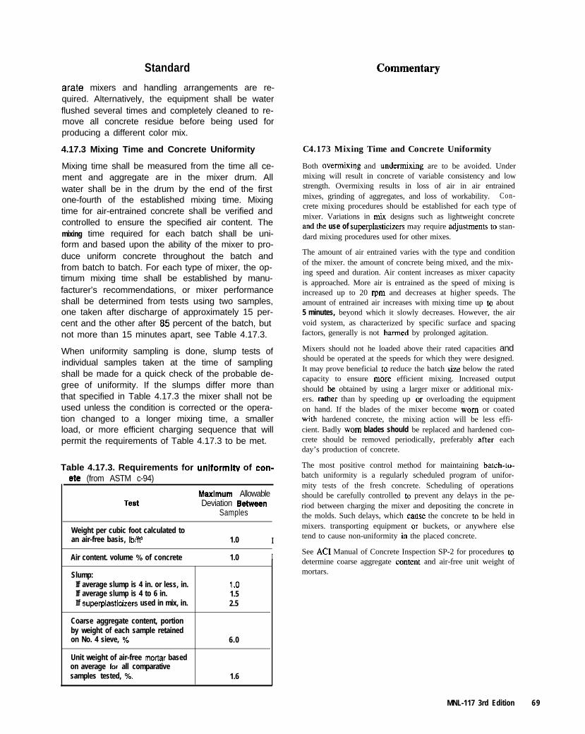
Standard
arate mixers and handling arrangements are re-quired. Alternatively, the equipment shall be waterflushed several times and completely cleaned to re-move all concrete residue before being used forproducing a different color mix.
4.17.3 Mixing Time and Concrete Uniformity C4.173 Mixing Time and Concrete Uniformity
Mixing time shall be measured from the time all ce-ment and aggregate are in the mixer drum. Allwater shall be in the drum by the end of the firstone-fourth of the established mixing time. Mixingtime for air-entrained concrete shall be verified andcontrolled to ensure the specified air content. Themixing time required for each batch shall be uni-form and based upon the ability of the mixer to pro-duce uniform concrete throughout the batch andfrom batch to batch. For each type of mixer, the op-timum mixing time shall be established by manu-facturer’s recommendations, or mixer performanceshall be determined from tests using two samples,one taken after discharge of approximately 15 per-cent and the other after 85 percent of the batch, butnot more than 15 minutes apart, see Table 4.17.3.
Both overmixing and undermixing are to be avoided. Undermixing will result in concrete of variable consistency and lowstrength. Overmixing results in loss of air in air entrainedmixes, grinding of aggregates, and loss of workability. Con-crete mixing procedures should be established for each type ofmixer. Variations in mix designs such as lightweight concreteand the use of superplasticizers may require adjusbnents to stan-dard mixing procedures used for other mixes.
The amount of air entrained varies with the type and conditionof the mixer. the amount of concrete being mixed, and the mix-ing speed and duration. Air content increases as mixer capacityis approached. More air is entrained as the speed of mixing isincreased up to 20 rpm and decreases at higher speeds. Theamount of entrained air increases with mixing time up to about5 minutes, beyond which it slowly decreases. However, the airvoid system, as characterized by specific surface and spacingfactors, generally is not harmed by prolonged agitation.
When uniformity sampling is done, slump tests ofindividual samples taken at the time of samplingshall be made for a quick check of the probable de-gree of uniformity. If the slumps differ more thanthat specified in Table 4.17.3 the mixer shall not beused unless the condition is corrected or the opera-tion changed to a longer mixing time, a smallerload, or more efficient charging sequence that willpermit the requirements of Table 4.17.3 to be met.
Mixers should not he loaded above their rated capacities andshould be operated at the speeds for which they were designed.It may prove beneficial to reduce the batch size below the ratedcapacity to ensure more efficient mixing. Increased outputshould be obtained by using a larger mixer or additional mix-ers. rather than by speeding up or overloading the equipmenton hand. If the blades of the mixer become worn or coatedwith hardened concrete, the mixing action will be less effi-cient. Badly worn blades should be replaced and hardened con-crete should be removed periodically, preferably after eachday’s production of concrete.
Table 4.17.3. Requirements for uniformitv of con- The most positive control method for maintaining batch-to-batch uniformity is a regularly scheduled program of unifor-mity tests of the fresh concrete. Scheduling of operationsshould be carefully controlled to prevent any delays in the pe-riod between charging the mixer and depositing the concrete inthe molds. Such delays, which cawe the concrete to be held inmixers. transporting equipment or buckets, or anywhere elsetend to cause non-uniformity in the placed concrete.
ete (from ASTM c-94)
TestMsxlmum AllowableDeviation aehveen
Samples
Weight per cubic foot calculated toan air-free basis, Ibift’ 1.0 I
Air content. volume % of concrete 1.0 I
Slump:If average slump is 4 in. or less, in.If average slump is 4 to 6 in.If superplasticizers used in mix, in.
Coarse aggregate content, portionby weight of each sample retainedon No. 4 sieve, %
Unit weight of air-free mortar basedon average for all comparativesamples tested, %.
1.01.52.5
6.0
1.6
See AC1 Manual of Concrete Inspection SP-2 for procedures todetermine coarse aggregate contend and air-free unit weight ofmortars.
MNL-117 3rd Edition 69
Standard
4.17.4 Mixing Time - Stationary Mixers
Unless otherwise recommended by the mixer man-ufacturer, for stationary mixers, the minimum mix-ing time shall be one minute for batches of 1 cu yd(0.8 m3) or less. This mixing time shall be increasedby at least 15 seconds for each cubic yard, or frac-tion hereof, of capacity in excess of 1 cu yd (0.8m’). The mixing time shall be increased when nec-essary to secure the required uniformity, particu-larly for colored concrete, and consistency of theconcrete, but mixing time shall not exceed threetimes the specified time. In case a batch has to beheld in the mixer for a longer period, the speed ofthe drum or blades shall be reduced to an agitatingspeed or the mixer stopped for intervals to preventover mixing. Both undermixing and overmixingshall be avoided.
4.17.5 Mixing Time-Shrink Mixing
When a stationary mixer is used for partial mixingof the concrete, the time may be reduced to a mini-mum of 30 seconds, followed by not less than 50 ormore than 100 revolutions at mixing speed in atruck mixer. Any additional revolutions in the truckmixer shall be at agitating speed in accordancewith mixer manufacturers recommendations.
4.17.6 Mixing Time - Truck Mixing
For mixing in a truck mixer loaded to its maximumcapacity, the number of revolutions of the drum orblades at mixing speed shall be not less than 70 normore than 100. If the batch is at least 112 cu yd(0.4 m’) less than the maximum capacity, the num-ber of revolutions at mixing speed may be reducedto 50. All revolutions in excess of 100 shall be at ag-itating speed per mixer manufacturer’s recommen-dations.
An absolute minimum of 100 revolutions at a speedof at least 15 revolutions per minute shall be usedfor truck mixers mixing concrete containing silicafume or metakaolin. When using dry densified sil-ica fume, these requirements must be increased to120 revolutions at a minimum speed of 15 revolu-tions per minute. The load size shall be limited tonot more than 75 percent of rated mixing capacitywhen truck mixing mixes including silica fume.
4.17.7 Special Batching and MixingRequirements for Lightweight Aggregates
Lightweight aggregate concrete shall be batched andmixed as recommended by the producer of the ag-gregate. Batch weights of lightweight aggregatesshall be based on oven-dfy weights corrected for ab-
en MNL-117 3rd Edition
Commentary
C4.17.4 Mixing Time _ Stationary Mixers
Mixing time less than that specified by the manufacturer maybe permitted provided performance tests indicate that the timeis sufftcient to produce uniform concrete.
C4.17.7 Special Batching and MixingRequirements for Lightweight Aggregates
AC1 211.2 Standard Practice for Selecting Proportions forStructural Lightweight Concrete provides additional informa-tion on the use of lightweight aggregates.
When a lightweight concrete mix is used for the first time, the
Standard Commentary
sorbed moisture or absorbed moisture plus surfacemoisture.
mixing and handling procedures should be checked to makesure they are adequate to produce uniform concrete of thequality specified. In such a case, the aggregate producer’s rec.ommendations may be particularly helpful.
Lightweight aggregate may require pre-dampeningprior to batching. Aggregate shall be tested forwater absorption with the minimum moisture con-tent likely to occur during production.
With aggregates having less than 10 percent totalabsorption by weight or shown to absorb less than2 percent water by weight during the first hour afterimmersion in water, pre-dampening prior to mixingis not required.
If lightweight aggregate absorbs more than 2 per-cent water by weight, it shall be pre-dampened anda mixing procedure developed that is shown to pro-duce concrete of uniform quality.
4.17.8 Cold Weather Mixing
Concrete temperatures at the mixer shall be main-tained above a minimum of 50 deg. F (10 deg. C).Materials shall be free from ice, snow and frozenlumps before entering the mixer.
When exposure to cold weather is severe, due ei-ther to low air temperature, or because the concretesections are thin, the temperature of concrete shallbe increased by heating to assure the concrete tem-perature does not fall below 50 deg. F (10 deg. C).To accomplish this, the mixing water and, if neces-sary, the fine aggregates shall be heated. Aggre-gates shall not be heated above 180 deg. F (80deg. C).
To avoid the possibility of premature stiffening orflash set of the cement when either the water or ag-gregates are heated to a temperature over 100deg. F (40 deg. C), water and aggregate shallcome together first in the mixer so that the temper-ature of the combination is reduced below 100 deg.F (40 deg. C) before the cement is added.
Any material used in a liquid or slurry form shall beprotected from freezing. Powdered materials shallbe protected from moisture. Any material that hasdeteriorated, has been damaged by frost, or has
Knowledge of the aggregate water absorption characteristicssimplifies the process of batching lightweight mixtures, assur-ing proper mixing in a miuimum of time. If lightweight aggre-gate unit weight varies, then batching by volume rather than byweight is necessary
C4.17.8 Cold Weather Mixing
To help provide for products of uniform color, concrete tem-peratures should be as uniform as practicable from batch tobatch.
When concrete temperatures are less than 50 deg. F (10 deg.C) the time required for the concrete to gain strength is greatlyextended or stopped.
Where hot water is used for mu&mining a minimum concretetemperature, provisions should be made for the operator toread the temperature of the water before it enterS the mixer andafter possible blending with cold water.
MNL-117 3rd Edition 9 1

Standard
been contaminated shall not be used in the produc-tion of concrete.
4.17.9 Hot Weather Mixing
Concrete temperature at the mixer shall be main-tained below a maximum of 95 deg. F (35 deg. C)
Commentary
If high temperatures are encountered, the ingredi-ents shall be cooled before or during mixing, orflake ice or well-crushed ice of a size that will meltcompletely during mixing, may be substituted for allor part of the mixing water to avoid low slump, flashset or cold joints.
4.18 Requirements for Transporting andPlacing of Concrete
4.18.1 General
Proven and effective procedures for placing con-crete are described in detail in the following publi-cations of the American Concrete Institute:
1. Recommended Practice for Measuring, Mix-ing, Transporting, and Placing Concrete (ACI304)
2. Recommended Practice for Hot Weather Con-creting (ACI 305).
3. Recommended Practice for Cold WeatherConcreting (ACI 306)
These publications shall be available in precastconcrete plants and supervisory personnel shall befamiliar with their contents.
Sufficient mixing and placing capacity shall be pro-vided so the products are free from unplanned cold
9 2 MNL-117 3rd Edition
C4.17.9 Hot Weather Mixing
Care should be taken in hot climates to protect batch materialstorage bins and water lines from direct sun.
Concrete temperatures higher than 80 deg. F (27 deg. C) willresult in a faster setting rate, visible flow lines, and possiblecold joints. Since high temperature concrete has a reducedworkability time available for placing and consolidating,proper scheduling of the concrete placement is necessary.
High temperatures in face mixes at time of placing can createunacceptable finishes and variations in color.
If false set occurs, the mix should sit for I to 3 minutes andthen the mixer restarted for 30 additional seconds. The remix-ing of false set will mechanically break the false set and pro-vide a usable mix.
C4.18 Requirements for ‘hansporting andPlacing of Concrete
C4.18.1 General
In arranging equipment to minimize separation or segregation,it is important that the concrete drop vertically into the centerof whatever container receives it. The importance of this in-creases greatly with increases in slump, maximum size andamounts of coarse aggregate, and with reduction in cementcontent. The height of free fall of concrete need not be limitedunless a separation of coarse particles occurs (resulting in hon-eycomb) or uniformity of appearance is affected, in which casea limit of 3 to 5 ft (0.9 to 1.5 m) may be adequate. However,to protect spacers, embedded features and mold surfaces, andto prevent displacement of reinforcement, concrete fall inmolds should be limited, by means of a suitable drop chute orother device, to within a few feet of concrete in place. Whethersuch a fall is into mold or into a hopper OI bucket, the finalportion of the drop should be vertical and without interference.If molds are sufficiently open so concrete can be dropped intothem with little or no disturbance to reinforcement or face mix,etc., direct discharge into molds is usually faster and saves thelabor of placing. moving and removing hoppers and dropchutes. Where direct dumping is practicable, it results in littlebut unimportant scattered separation, whereas fixed dropchutes often cause considerable separation due either to flow-ing or stacking of the concrete.
If concrete is placed in layers to produce a monolithic and vi-sually acceptable finished placement, it is important each layer
Standard Commentary
joints or a plane of separation. If delays occurwhich result in the concrete attaining its initial setso it will not receive a vibrator and again becomeplastic, partially filled molds shall be washed out orpartially cast units rejected.
of concrete be shallow enough so it may be placed while theprevious layer is still plastic (prior to initial set and/or evaporn-tion of bleed water) and the two layers be vibrated together.
The concrete consistency and desired surface ap-pearance will also affect the placement methodemployed; the lower the slump or water-cementratio, the shallower the lift that shall be used. Thetime lapse between placing face mix and backupmix shall be short enough to ensure proper plasticbonding between the layers and shall occur prior toface mix attaining its initial set.
4.10.2 Transporting and Placing Concrete
Since the workability of concrete decreases withtime after mixing, the concrete shall be transportedfrom mixer to forms in the shortest possible timeand in such a manner as to prevent segregation orloss of mortar.
Free water or excess grout shall not drip frombuckets onto a retarder film or previously finishedconcrete during the placing operation.
Before the beginning of a new run of concrete,hardened concrete and foreign matter shall be re-moved from the surfaces of the equipment in-volved.
The need for agitation during transportation will de-pend on the length of time between completion ofmixing and discharge of the concrete.
Regardless of the manner of transportation, con-crete shall be discharged into the molds while in itsoriginal mixed or plastic state. Retempering byadding water and remixing concrete which hasstarted to stiffen shall not be permitted.
4.18.3 Preventing Aggregate Segregation
Only those methods and arrangements of equip-ment shall be used which result in placing concretein a uniform, compacted condition without separa-tion of coarse aggregate and paste. Obvious clus-ters and pockets of coarse aggregate areobjectionable and shall be scattered prior to placingconcrete over them to prevent rock pockets andhoneycomb in the completed unit. Placing methodsused shall preserve the quality of the concrete, interms of water-cement ratio, slump, air content,and homogeneity.
C4.182 Transporting and Placing Concrete
Transportation of concrete to the placing site should be evalu-ated and procedures maintained to avoid unnecessary changesto the concrete.
The use of non-agitating trucks to transport concrete contain-ing silica fume or m&kaolin is not recommended.
C4.183 Preventing Aggregate Segregation
Scattered individual pieces of separated coarse aggregate arenot objectionable if they are readily enclosed and consolidatedinto the concrete as it is placed and vibrated.
It is a common fallacy to believe that segregation occurring inhandling will be eliminated by subsequent placing and consoli-dation operations.
Concrete should not be dumped in separate piles and then lev-eled and worked together; nor should the concrete be depositedin large piles and moved horizontally into final position. Suchpractices result in segregation because mortar tends to flowahead of coarser material with resultant visible flow lines onexposed surface. Also, placing concrete on concrete already inthe mold minimizes loose aggregate rollout and swirl patternsduring consolidation, and it minimizes additional entrapped air
MNL-I17 3rd Edition 93
Commentary
between the deposits at the mold face
Where mixtures of dry or stiff consistencies are required. theplacement rate should be slow enough to permit proper vibra-tion in order to avoid bugholes and honeycombing. Placingconcrete too slowly can produce layer lines or cold joints dueto improper consolidation. The rate of placement and vibrationfactors (intensity. spacing) should be selected to minimize en-trapped air in the concrete. Thin, even layers of 6 in. (150mm) or less can be consolidated with only small air holeslikely to show; layers thicker than 12 in. (300 mm) will in-crease the possibility of trapping more and larger air holes. Forthis reason, the use of a face mix or a specially placed mix ofonly 1 to 2 in. (25 to 50 mm) thick may be advisable.
4.18.4 Preparation of the Molds
Prior to concreting, the mold shall be cleaned andany unwanted materials, such as tie wire clippings,shall be removed by compressed air, vacuumcleaning, or other methods. If required, beforeplacing either reinforcing steel or concrete, a formrelease agent or retarder shall be carefully and uni-formly applied to all mold surfaces that will be incontact with the concrete to provide easy releaseand stripping of the element from the mold consis-tent with the required finish.
4.18.5 Placing Concrete Under Severe WeatherConditions
Freshly deposited concrete shall be protected fromfreezing, excessively high or differential tempera-tures, premature drying, and moisture loss for a pe-riod of time necessary to develop the desiredproperties of the concrete.
Concrete as placed shall be at a temperature be-tween 50 deg. F (10 deg. C) and 95 deg. F (35deg. C) and as uniform as is practical from onebatch of concrete to another for a specific project.Measures shall be taken during severe weatherconcreting operations so that the concrete remainsplastic for a suitable placing and finishing periodand then gains strength under favorable curingconditions.
4.18.8 Placing Concrete in Wet and RainyConditions
Because of the nature of the architectural precastconcrete production process, the producer shallhave adequate weather protection provisions onhand at all times for outside production activities. Itshall be possible to deploy the weather protectionprovisions without compromising the quality of theoroduct.
C4.185 Placing Concrete Under Severe WeatherConditions
Using weather data for the production area, temperature ex-tretnes and durations can be identified. A plan of proceduresfor severe weather conditions should be developed for usewhenever weather conditions dictate.
Optimum concrete temperature for placing is recommended as70deg.F(20deg.C).
94 MNL-117 3rd Ednion
Standard
4.18.7 Placing Concrete in Hot or WindyConditions
For concrete placed in hot weather, the tempera-ture of concrete at time of placing shall not beabove 95 deg. F (35 deg. C). Adequate moistureshall be retained in the concrete during the curingperiod to prevent surface drying. The temperatureof the concrete as placed shall not be so high as tocause difficulty from loss of slump, flash set, or coldjoints.
When the ambient temperature is above 30 deg. F(27 deg. C). methods shall be taken to protect con-crete in place from the effects of hot and/or dryingweather conditions.
Commentary
C4.18.7 Placing Concrete in Hot or Wind)Conditions
The upper limit of 95 deg. F (35 deg. C) for concrete place-ment temperature is a guideline which may need to be loweredfor specific materials which respond negatively at higher tem-peratures. If problems are encountered using 95 deg. F (35 deg.C) as an upper limit for materials in use, the maximum temper-ature should be reduced until problems are eliminated.
Wind or direct sunlight can have significant and rapid dryingand shrinkage effects. These along with low humidity areitems which must he considered and adjusted for during place-ment of concrete.
If hot and/or drying weather conditions occur, any of tbc fol-lowing procedures or combination of procedures may be usedto prevent plastic shrinkage cracking of concrete or loss ofstrength:
1. Shaded storage for aggregates.
2. Sprinkling or fog spraying of aggregates or chilling ag-gregates with liquid nitrogen
3. Burying, insulating and/or shading water-supply facili-ties.
4. Use of cold water in batching,
5. Use of shaved or crushed ice for a portion of the mixingwater. Only as much ice should be used as will be en-tirely melted at the completion of the mixing period.
6. Maintaining concrete surfaces in a cool and moist condi-tion by use of coverings such as wet burlap or by sprin-kling or ponding as soon as exposed concrete surfaces arefinished. or as soon as water sheen disappear. ‘Ibis is es-pecially important for hot, windy. exposed locations.
I. Shading of product surface during and after casting toavoid heat buildup in direct sunlight.
8. Do not use cement with temperatures over 170 deg. F (77deg. C)
9. White pigmented membranes may be used but are not EC-ommended in very hot weather for the first 24 hr. aftercasting since they do not cool the concrete as much as wetcuring methods.
10. A set-retarding admixture included in the concrete mixmay delay concrete setting time in hot weather and give alonger period for placing and finishing.
11, When the temperature of steel is greater than 120 deg.F (50 deg. C). steel molds and reinforcement should besprayed with water just prior to placing the concrete. Sw-face of mold should be free of visible water droplets priorto placing concrete since water droplets will often appearas voids on the concrete surface, even if properly vi-brated.
MNL-117 3rd Edition 9 5
Standard
4.18.8 Placing Concrete in Cold WeatherConditions
Special precautions shall be taken to protect con-crete placements in cold weather [below 40 deg. F(5deg. C)] so that the concrete gains strengthunder favorable curing conditions.
4.18.9 Placing Facing Concrete
When placing the initial concrete face mix, careshall be taken to avoid coating the reinforcementwith cement paste which may endanger properbonding in the second stage of concreting. Wherethis coating cannot be prevented, the placing of thebackup concrete mix shall be done prior to thehardening of such coating, or it shall be cleanedoff. Alternatively the placement of the reinforce-ment shall follow the consolidation of the face mix.
Facing concrete shall be carefully placed andworked into all details of the mold. This is particu-larly important in external and internal comers fortrue and sharp casting lines. Concrete shall beplaced so that flow is away from comers and endsrather than toward them. Each batch of concreteshall be carefully ribboned on, as nearly as possi-ble, in final position, into previously cast concreteuntil the mold is filled and the whole mass consoli-dated by vibration with as little shifting as possible.Concrete shall be spread, if necessary, with ashort-handled, square-end shovel, a come-along,hoe, or similar solid faced tools. If toothed rakesare used to spread concrete, care shall be taken toprevent concrete segregation
Commentary
C4.18.8 Placing Concrete in Cold WeatherConditions
Concrete can be placed successfully when ambient temperaturefalls below 40 deg. F (5 deg. C). This is done by heating themolds to maintain a minimum concrete temperature of 50 deg.F (10 deg. C). The existence of windy and cold conditions maydictate added protection to maintain temperature of the moldand the couc~efe after placement.
The mold temperature should be about the same as the concretetemperature. An optimum of 75 to 80 deg. F (21 to 27 deg. C)is desirable. It is more important that the temperatures remainrelatively constant from unit to unit throughout the projectrather than whether they are near the upper or lower level of atemperature range.
C4.189 Placing Facing Concrete
Paste coating of strand or mild steel reinforcement duringplacement should be of no concern up to the top of the sec-tion; above that, paste should be kept from or cleaned from allreinforcement.
The use of separate face and backup mixes or the use of a uni-form concrete mix throughout the unit depends on economics,the type of fiuish required, the configuration of the unit and thepractice of the particular precasting plant. Members with infri-cate shapes and deep narrow sections generally~require oneuniform concrete mix throughout.
Where an aggregate or finished face material changes within apanel, a definite feature (demarcation strip) should be insertedinto the panel face to facilitate casting and to achieve an ac-ceptable demarcation joint between finishes. Two concretemixes with different colored matrices exposed at the face of thepanel should generally not be used within one unit unless atechnique is used to prevent mixing of the two mixes. For ex-ample, the two-stage (sequential) precasting method where onepan of a unit is cast first of one mix and, after curing. is castinto the total unit has been successfully used.
Units with large or steep returns (such as channel column COY-ers and some spandrels) may be cast in separate pieces in orderto achieve matching high quality finishes on all exposed facesand then joined with dry joints. Although the dry joint may notshow with certain mixes and textures, a groove or quirk willhelp to mask the joint. Where desired, this joint can be re-cased deep enough to allow installation of a small backer rodand placement of a 114 in. (6 mm) bead of joint sealant. Some-times precautions may be necessity to ensure water tightnessof the dry joints. Care should be taken to ensure that the returnis jigged and held securely at the proper angle during produc-tion of the base panel.
Concrete shall not be subjected to any procedurewhich will cause segregation or flow lines. When a
es MNL-117 3rd Edition
Standard Commentary
retarder is used, the concrete shall not be movedover the mold in such a manner that it would disturbthe retarder. Concrete placing on a slope shall beginat the lower end of the slope and progress upwardthereby increasing compaction of the concrete.
The thickness of a face mix after consolidationshall be at least 1 in. (25 mm) or a minimum of I-112 times the maximum size of the coarse aggre-gate, whichever is larger. A face mix shall be thickenough to prevent any backup concrete from show-ing on the exposed face.
The 1 inch (25mm) minimum thickness of face mix dimensionis chosen because the consolidated face is normally used toprovide the proper concrete cover over the reinforcement. Forunits not exposed to weather or for face mixes applied face-up,this dimension may be reduced to 314 in. (20 mm) providedthe backup mix does not bleed through the face mix.
4.18.10 Placing Backup Concrete
In placing backup concrete, care shall be taken tobreak the fall into the mold so that it will not dis-place the face mix.
C4.18.10 Placing Backup Concrete
The allowable time interval between placing face mix andbackup mix depends on the concrete mix, the temperatures ofthe mix and the ambient air. and the drying conditions near themold.
4.19 Consolidation of Concrete
4.19.1 General
Concrete used in architectural precast concreteunits may be uniformly consolidated by internal, orexternal vibration (with or without vibrating table),surface vibrators, spading, by impact, or a combi-nation of these methods.
Consolidation of concrete mixes shall accomplishfull coating of the coarse aggregate and reinforce-ment with cement paste. Air pockets around un-coated reinforcement which create potentiallycorrosive environments shall be avoided by the se-lected consolidation methods.
After the proper vibrating equipment has been se-lected, it shall be operated by conscientious andwell-trained operators who will consistently main-tain the proper vibrator spacing and vibration times,and who have been trained to judge when the con-crete is adequately consolidated.
Regardless of the techniques used for vibration, itseffectiveness shall be judged by the surface condi-tion of the finished concrete, unless circumstancesindicate a more in-depth evaluation is needed. Ifsurface defects such as honeycombing, aggregateor mortar pockets and excessive air bubbles arecommon, the vibration procedure, number anddepth of lifts or other procedures shall be revisedas necessary to produce acceptable surfaces.
Vibration procedures shall be evaluated at the be-ginning of a project to determine the vibration timefor each type of vibrator for each mixture, mold
C4.19 Consolidation of Concrete
C4.19.1 General
Vibration should be distributed so the concrete is thoroughlyconsolidated, producing a dense, uniform mass with surfacesfree of imperfections or blemishes. The optimum time of vi-bration depends on the type of vibrator. the mix characteristics,and the configurations of mold and reinforcement. Reducingthe vibration time on the last lift in returns will result in in-creased bugholes.
The selection of the best vibrator or vibration method involvesfactors such as:
I. Size, shape, type and stiffness of molds.
2. Concrete mix and consistency.
3. Plant preference based on experience.
Unless there is a gross violation of recommended mix pmpor-tioning and vibration procedures, it is difficult to harm con-crete by excessive vibration, provided that the forms aredesigned to withstand the longer durations of high frequencyvibration. Under vibration is far more cormnon than over vi-bration.
MNL-117 3rd Edition 97
Standard Commentary
type and configuration. Each member and concretelayer shall be vibrated for the same time duration,consistent with the slump of the concrete as deliv-ered to the mold.
4.19.2 Consolidation of Lightweight Concrete C4.19.2 Consolidation of Lightweight Concrete
In consolidation of lightweight concrete precautionsshall be taken to avoid aggregate floatation causedby over vibration.
In consolidation of lightweight aggregate concrete, care shouldbe taken not to over vibrate. Since the coarse aggregate part-cles are the lightest solid ingredients in the mix, over vibrationcan cause the particles to rise, so that finishing problems resultfrom “floating” aggregate which could cause the strength to benon-uniform through the depth of the member. In addition tocare in vibration, the use of slumps less than 4 in. (100 mm)helps greatly in avoiding segregation, during both handling ofthe mix and consolidation and finishing.
4.193 Consolidation of Face and Backup Mixes
Special attention is required for consolidation offace mixes, especially if the aggregates are to beexposed later by removing the paste from the sur-face.
The layers of face mix concrete shall be as level aspossible so that the vibrator does not need to movethe concrete laterally, since this will cause segrega-tion, see Article 4.18.9. Where there are somemounds or high spots in the surface of the concreteas placed, a vibrator shall not be stuck into the cen-ter of each mound to knock it down, but insteadleveling shall be by hand or mechanical screed.
4.19.4 Use of Internal Vibrators
Care shall be taken to ensure proper vibration withminimal penetration of the backup mix into the facemix. All vibrating shall be done by workers specifi-cally trained to use internal vibrators in the correctmanner, with emphasis on the fact that vibrators inconcrete must be moving at all times.
C4.19.3 Consolidation of Face and Backup Mixes
During vibration each individual coarse aggregate particlemoves in all directions through the mortar. At the same timeeach particle is turning about its shorter axis and striving to oc-cupy a position so that it can penetrate the cement mortar mosteasily. As the aggregate penetrates and thoroughly mixes withthe mortar, any water or air bubbles that are trapped beneath itbecome released and start to move upward. The process canoccur only if there is sufficient mortar present.
Experienced and competent vibrator operators working withregularly maintained vibrators and sufficient standby units areessential to a satisfactory consolidation program. There is atendency for inexperienced vibrator operators to merely flattenthe batch. Proper consolidation is assured only when the otheritems evidencing adequate vibration are sought and attained.
C4.19.4 Use of Internal Vibrators
The distance between vibrator insertions shall generally beabout I to l-l/Z times the radius of action, or such that the areavisibly affected by the vibrator overlaps the adjacent just-vi-brated area by a few inches. The vibrator shall not be insertedwithin 2 ft. (0.6 m) of any leading (unconfined) edge.
Employing internal vibrators in this manner will minimize en-trapped air between the concrete and the mold and blend thetwo layers.
Consolidating Flowing Concrete. When casting units withconstricted dimensions or limitations on the amount of consoli-dation effort which may be applied, a high slump, flowing con-crete should be used. When consolidating this concrete, use alarge amplitude (i.e., large diameter) internal vibrators insertedat a close spacing and withdrawn slowly. While consolidatingin this manner, the surface should be examined for evidence ofexcess water or paste, and if this does appear the amount ofconsolidation effort used should be reduced. The high-slump,self-leveling characteristics of the flowing concrete may appearnot to need any consolidation effort. However, at least nominalvibration should be provided to eliminate large air voids.
MNL-117 3rd Edition

Standard
Vibrators shall not be allowed to contact forms forexposed concrete surfaces. Internal vibrators shallnot be inserted closer to the form than 2 to 3 in.(50 to 75 mm). Care shall be taken to avoid vibrat-ing the reinforcement. Also, care shall be taken notto displace cast-in hardware or disturb the facemix.
Commentary
The vibration frequencies which affect the aggregates andtines of a concrete mix range fmm 1,200 to 14,000 cycles perminute The lower frequencies activate the large diameter par-ticles, and the higher frequencies affect the fines and cement inthe mix and assure coverage of larger particles with a completefilm of grout.
Vibrators contacting forms for exposed concrete surfaces maymar and disfigure the concrete surface. Internal vibrators in-serted close to the form may cause the coarse aggregate to bedriven away from the form face producing local pockets offine material (stinger marks) on the surface. Vibration of rein-forcement may cause reinforcing steel reflection features visi-ble in the surface of the finished product.
When internal vibrators are used to consolidateconcrete around epoxy-coated steel reinforcingbars, the vibrators shall be equipped with rubber ornonmetallic vibrator heads.
4.19.5 Use of External Form Vibrators
External vibrators shall be securely fixed to theforms to obtain the maximum vibration effect and toavoid damage to vibrators and forms. During thecasting operation, a check shall be made to verifythat the vibrators are in operation and firmly inplace.
The size and spacing of form vibrators shall besuch that the proper intensity of vibration is dis-tributed evenly over the desired area of form andno form damage occurs.
4.19.6 Use of Surface Vibrators C4.19.6 Use of Surface Vibrators
Surface vibrators shall be of a type and shape, andshall be applied in such a manner that will preventsuction action during use. Surface vibrators shall bemoved at a rate so vibration is sufficient to embedthe coarse aggregate and bring enough paste to thesurface for finishing. The vibration and rate ofmovement shall be sufficient to compact the fulldepth of the concrete layer. Solid plate and bull floatvibrators shall be operated at a slight angle from theplane of the concrete surface for best results.
Surface vibrators which may be used to consolidate thin layersof concrete like facing mixes include vibrating screeds; a smallplate or grid vibratory tamper [usually 2 to 3 ft (0.6 to 0.9 m)square in area] powered by an external air vibrator; hand jitter-bug; bull floats with vibrators mounted along the rib section ofthe floats. Vibrators on the bull floats should be mounted sothat their shafts rotate in opposite directions.
When using surface vibrators, care should be exercised to pn-vent a smooth face mix back surface which may result in poorbond of backup concrete.
If grate tampers are used, the concrete slump shallnot be over 2 in. (50 mm). Vibrating grate tampersshall not be used for structural lightweight aggre-gate concrete.
C4.195 Use of External Form Vibrators
The spacing of external form vibrators is a function of thetype, stiffness and shape of the form, depth and thickness ofthe concrete, force output per vibrator, workability of the mix,and vibrating time.
Forms should be placed on neoprene isolation pads or other re-silient base material to prevent transmission and loss of vibra-tion to the suppotting foundation.
On large projects trial production of typical pieces may be ap-propriate as present knowledge is inadequate to predict anexact solution to the complex problem of vibrator spacing.
MNL-I 17 3rd Edition
Standard
4.19.7 Use of Vibrating Tables
Care shall be taken to obtain the proper distributionof vibration. The number and location of external vi-brators to be used on a vibrating table shall be de-termined on the basis of adequate amplitudes ofvibration and uniform distribution over the entireconcrete surface. The frequency and amplitudeshall be checked at several points on the table,using a vibrograph, vibrating reed tachometer, orother suitable method. The vibrators shall bemoved around until dead spots are eliminated andthe most uniform vibration is attained.
4.20 Requirements for Curing Concrete
4.20.1 General
Freshly deposited and consolidated concrete shallbe protected from premature drying and extremesof temperature. The curing concrete shall be main-tained with minimal moisture loss at a relativelyconstant temperature for the period of time neces-sary for the hydration of the cement and properhardening of the concrete. Curing procedures shallbe well established and properly controlled to de-velop the required concrete quality and stripping ortransfer strength. Curing procedures shall minimizeany appearance blemishes, such as non-uniformityof color, staining or plastic shrinkage cracking.
To produce concrete of uniform appearance, consis-tent and uniform curing conditions shall be provided.
Protection of concrete surfaces against moistureloss to prevent shrinkage cracking of silica fume ormetakaolin concrete shall begin immediately afterfinishing, whatever the finishing process may be.High dosages of silica fume or metakaolin produceconcrete with significantly reduced bleeding.Therefore, there is no requirement to wait for thebleeding to conclude before initiating protection ofsurface.
4.20.2 Curing Temperature Requirements
The concrete in the mold shall be maintained at atemperature of not less than 50 deg. F (IO deg. C)during the curing period. Curing shall be started im-mediately following initial set of the concrete. Thetime between placing of concrete and the start ofcuring shall be minimized in hot or windy weatherto prevent loss of moisture, and the resultant dryingand plastic shrinkage cracking.
Commentary
C4.19.7 Use of Vibrating Tables
Vibrating tables or casting decks are best used for flat or lowprofile units, and provide an easy and effective method for ap-plication of external vibration
The frequency and amplitude of vibrating forms and vibratingtables equipped with external vibrators should be determined atsufficient points to establish their distribution over the surface.Inadequate amplitudes cause poor consolidation, while exces-sive local amplitudes cause the concrete to roll and tumble sothat it does not consolidate properly.
C4.20 Requirements for Curing Concrete
C4.20.1 General
The curing of concrete depends on many variables, includingthe mass of the member, type and properties of cement, airtemperature, humidity and other variables. The curing periodof concrete which is of significant interest is during the earlystages of strength development fmm initial set until the con-crete has reached a design strength for stripping or saessing themember. Curing involves the maintaining of a satisfactorymoisture content and temperature in concrete. If concrete is al-lowed to lose moisture, it may suffer a lack of s@ength devel-opment and potential plastic shrinkage cracking as the surfacemoisture is lost. Therefore. concrete surfaces should be pro-tected to prevent rapid loss of moisture while the concrete isplastic.
C4.202 Curing Temperature Requirements
100 MNL-117 3rd Edition

During the initial curing period (prior to stripping)positive action shall be taken to provide heat (ifnecessary to maintain minimum temperatures) andto prevent loss of moisture from the unit. Curingmaterials or methods shall not allow one portion ofan element to cure differently or dry out faster thanother portions of the element.
4.20.3 Curing to Attain Specified Stripping orRelease Strength
Curing temperature and duration of curing shall as-sure the stripping strength indicated on the produc-tion drawings has been reached before a product isremoved from its mold. The stripping strength shallbe set by the design engineer, based on the char-acteristics of the product. It shall be high enoughto ensure that the stripping does not have a delete-rious effect on the performance or the appearanceof the final product.
Prior to stripping, transfer of stress, or handling, thestrength of the product shall be determined by testspecimens cured, as nearly as possible, in thesame manner as the product.
In addition to regular test cylinders cured in accor-dance with ASTM requirements, for units where ship-ping or erection strength may be critical, extra testcylinders shall be made and cured similarly to theprecast concrete units to verify curing results and es-timate the strength of units at time of shipping.
The establishment of a strength level where expo-sure to low.1 climatic conditions is considered safeby individual plant standards or local practices (seeArticle C4.2.) shall not relieve the precast concretemanufacturer of responsibility to verify that theproducts have reached the required final designstrength.
4.21 Accelerated Curing of Concrete
4.21 .l General
Accelerated curing procedures shall be developedbased on efficiency of concrete strength develop-ment without damaging the concrete. Temperatureguidelines for accelerated curing, no matter whichmethod is used. are as follows:
Commentary
Retention of the heat released by the hydration of the cementcan be used advantageously by precasters to provide much ofthe heat for curing. Insulated tarpaulins ax effectively used fora combination of moisture and heat retention. Accelerated CUI-ing is the use of added heat to increase the rate of the hydrationreactions.
Differential curing of an element may produce color variationsin the finished product and differential shrinkage of the con-crete which can lead to warping of the element.
C4.20.3 Curing to Attain Specified Stripping or Re-lease Strength
Usually stripping 01 release stxngths are specified at a mini-mum of 2000 psi (13.8 MPa) for non-prestressed precast and3000 psi (20.7 MPa) for prestressed units
C4.21 Accelerated Curing of Concrete
c4.21.1 General
Curing procedures should be determined on au experimentalbasis and are important, since they fix the total curing timewithin the 24-h cycle essential to economic production.
Proper precautions should be taken with accelerated curing ofunits using surface retarders to make cetiain that the proper re-tada is selected and that retardation is uniform and effectiveat time of stripping and treating the surface.
1. The controlling temperatures shall be thoseachieved within the concrete elements, not
MNL-117 3rd Edition 101
Standard Commentary
ambient temperatures of the curing area.
2. The beginning point for adding heat or elevat-ing curing temperature over placed concretetemperatures shall be determined by usingASTM C403 to determine when the mortarstrength has reached 500 psi (3.4 MPa) (initialset). For each mix design being considered,the results of three or more time of settingtests shall be plotted together. The best fittingsmooth curve shall be drawn through the datapoints. These shall be used to determine thepreset time which will be just beyond the de-velopment of 500 psi (3.4 MPa) mortar com-pressive strength.
2. After placing, consolidation and finishing, the concreteshould be allowed to attain its initial set before heat is ap-
plied; otherwise the elevated temperature may have a
detrimental effect on the long-term strength of the con-
crete. Enough heat should be applied to the mold and itssurrounding atmosphere to maintain the concrete at not
less than 50 deg. F (IO deg. C). A period of 3 to 5 hr., de-
pending on climatic conditions, type and brand of cementand admixtures. temperature of the mix and water-cement
ratio is required for the concrete to attain its initial set.
Delay periods in excess of 10 hr. may result in loss of ef-fectiveness of heat curing. During the initial set period,
provisions should he made to prevent surface drying.
Care shall be taken to maintain the ASTMC403 test sample within the temperaturerange of 66 deg. to 77 deg. F (20 deg. to 25deg. C). Once the preset time has been estab-lished for a particular mix design, it shall beadhered to. Heat application to the curing areamay be required immediately in cold weather[below 50 deg. F (10 deg. C)] to maintain orregain placed concrete temperatures.
3. For accelerated curing, heat shall be appliedat a controlled rate following the initial set ofconcrete in combination with an effectivemethod of supplying or retaining moisture.Heat gain of not over 80 deg. F (27 deg. C)per hour is acceptable for the curing concreteas long as a proper delay period is used(ASTM C403).
3. If plant production pmcedures require early application
of steam, the rate of temperature rise should be restricted
to less than 20 deg. F (11 deg. C) per hr. Due to the slowrise of ambient temperature with radiant heat, application
of the radiant heat cycle may be accelerated to meet cli-
matic conditions.
4. The maximum sustained concrete temperatureduring the curing cycle shall be 160 deg. F (70deg. C).
4. The optimum curing temperature is from 140 deg. F to
160 deg. F (60 deg. C to 70 deg. C). In no case should the
concrete temperature exceed 190 deg. F (88 deg. C) ashigher temperatures may have a detrimental effect on
strength. Duration of heat curing should he dictated by
strength requirements for stripping as measured by test
cylinders cured with the pmducts. Caution should also beexercised when infra-red lamps are used. Localized “hot
areas” should be avoided. When members produced with
non-air entrained concrete are exposed to damp or wet
conditions frequently or for lengthy periods, the maxi-mum concrete temperature should he controlled to avoid
possible pmblems with delayed ettringite formation and
cracking of the concrete.
5. Maximum peak concrete temperature during thecuring cycle shall be 190 deg. F (66 deg. C).
6. Maximum cooling rate from sustained acceler-ated curing temperature shall be 50 deg. F
6. Units should be allowed to cool gradually to preventthermal shock and rapid temperature changes, which maycause cracking. When the concrete is warmer than the air
102 MNL-117 3rd Edition
Standard
per hr (28 deg. C per hr) and cooling at thisrate shall continue until the concrete tempera-ture is no more than 40 deg. F (22 deg. C)above the ambient temperature outside theenclosure in order to prevent surface crazing.
Self-recording thermometers shall be providedshowing the time-temperature relationshipthrough the curing period from placing con-crete to stripping or transfer of prestress. Atleast one recording thermometer per contigu-ous form group with a common heat sourceshall be used to monitor the product at appro-priate locations (usually the coolest position).
Commentary
during cold weather, there is a tendency for soluble salts(efflorescence) to migrate to the surface immediately onshipping. In addition, cool water should not be used toaccomplish aggregate exposure until the unit has cooledto ambient temperature.
7.
4.21.2 Curing with Live Steam
Steam curing shall be performed under a suitableenclosure to retain the live steam to minimize mois-ture and heat losses. The enclosure shall allowfree circulation of the steam. Steam jets.shall bepositioned so they do not discharge directly ontothe concrete, forms, or test cylinders.
4.21.3 Curing with Radiant Heat and Moisture
During the cycle of radiant heat curing, effectivemeans shall be provided to prevent rapid loss ofmoisture in any part of the member.
4.22 Curing by Moisture Retention With-out Supplemental Heat
4.22.1 General
For curing of the concrete without supplementalheat, the surface of the concrete shall be kept cov-ered or moist until such time as the compressivestrength of the concrete reaches the strength spec-ified for detensioning or stripping.
I. To aid personnel who control the temperature during cur-ing, it is recommended that the desired curing time-tem-perature relations be placed on the chart of the recordingthermometer. With this information available, the desired
temperature may be more easily maintained. Formsshould be checked for uniformity of heat application.Temperature monitoring should be at the coolest positionon a form.
C421.2 Curing with Live Steam
Monitoring techniques will require temperature checks at variouspoints on a bed in different casts to effectively control curing.
C4.213 Curing with Radiant Heat and Moisture
Radiant heal may be applied to forms by means of pipes circu-lating steam, hot oil or hot water, by electric blankets, or heat-
ing elements on forms, or by circulating warm air under andaround forms. Pipes blankets or other heating elements shouldnot be in direct contact with concrete, forms or test cylinders.
Moisture may be applied by a cover of moist burlap, cottonmatting, or other effective means. Moisture may be retainedby covering the member with an impermeable sheet in combi-nation with an insulating cover, or by applying a liquid sealcoat or membrane curing compound.
Due to the slow rise of ambient temperatures with radiant heat,application of the heat cycle may be accelerated to meet cli-matic conditions. In all cases, the curing procedure to be usedshould be well established and carefully controlled to meet therequirements outlined in Article 4.21.
C4.22 Curing by Moisture Retention Witb-out Supplemental Heat
C4.22.1 General
Acceptable methods of curing are:
1. Leaving the element in the form with the side forms inplace and keeping the tip surfaces continually moist byfogging, spraying or covering with moist burlap or cottonmats, or by covering top the top surface with imperme-able coven or membrane curing compound.
2. Removing side forms and preventing loss of moisturefmm the sides and top surfaces by applicable methodsdescribed above.
MNL-I 17 3rd Edition 103
Standard
4.22.2 Moisture Retention Enclosures
Any enclosures used for the purpose of retainingmoisture during the curing period shall provide forretention of moisture to the extent that free water isat all times present on all concrete surfaces. Mois-ture retention enclosures shall be resistant to tear-ing and shall be positively fastened in place toavoid displacement by wind or other means duringthe curing cycle. Moisture retention enclosuresshall remain in place until the completion of the cur-ing cycle as described above.
4.22.3 Curing with Membrane Curing Compound
In the use of membrane curing compound to retainmoisture within the concrete during curing the fol-lowing shall be observed:
1. The coating of membrane curing compoundshall cover the entire surface to be cured witha uniform film which will remain in place with-out gaps or omissions until full curing cycle iscomplete. Positive means shall be taken to de-tect and recoat areas of incomplete coating.
2. Membrane curing compound shall be appliedat a rate of coverage which assures that theamount of compound applied per unit area ofthe surface being cured is at least the mini-mum coverage recommended by the manu-facturer.
3. Membrane curing compound shall be appliedto the top surface of the concrete elementbeing cured as soon after casting as the sur-face water sheen disappears.
4. Membrane curing compound shall be compati-ble with coatings or other materials to be ap-plied to the product in later constructionstages.
C4.223 Curing with Membrane Curing Compound
Curing compounds should only be used on the backs of unitsbecause of their tendency to discolor or stain. Some curingcompounds function as bond breakers and may interfere withadhesion of repairs or surface coverings such as paints, fabrics.insulation materials or other specified protective coatings.Manufacturers should be consulted as to the effect that theircompound has in these respects. In addition, membrane curingcompounds should not be used in areas where joint sealantsmay be applied, unless they are entirely removed at the end ofthe curing period by sandblasting or by using an approved sol-vent, or unless conclusive tests show that the residue of themembrane does not reduce bond.
104 MNL-It7 3rd Edition
DIVISION 5 - REINFORCEMENT AND PRESTRESSING
Standard
5.1 Reinforcing Steel
5.1.1 General
Procedures for fabrication and placement of rein-forcing steel shall be developed, implemented andunderstood by appropriate personnel. Proceduresand practice shall be reviewed frequently to assureconformance.
5.1.2 Storage of Reinforcing Steel
The reinforcing steel deliveries shall be identifiedwith a heat number which can be tied back to amill certificate. Reinforcing steel shall be kept freeof contamination, stored separately in a neat andorderly fashion and identified so that differenttypes, grades, sizes and preheat requirements canbe identified and recognized through the entire re-inforcement preparation process. Bundles of rein-forcing materials shall be kept straight and free ofkinks until cut and bent to final shape to facilitatedimensional control within established placing tol-erances. All reinforcing steel shall be stored onblocks, racks or sills, up off the ground. Special at-tention shall be given to prevent loose rust fromforming or the steel from becoming contaminatedwith grease or oil or any material that would ad-versely affect the bond.
Equipment for handling coated welded wire or re-inforcing bars shall have protected contact areas.Nylon slings or padded wire rope slings shall beused. Bundles of coated welded wire or reinforc-ing bars shall be lifted at multiple pick-up pointsto minimize abrasion from sags in the bundles.Hoisting with a spreader beam or similar deviceshall be used to prevent sags in bundlesCoated reinforcement shall not be dropped ordragged. Coated reinforcement shall be storedon timbers or other suitable protective cribbingwith the dunnage spaced close enough to pre-vent sags in the bundles.
Epoxy-coated reinforcing bars shall be handled ina manner so that the protective coating is not dam-aged beyond what is permitted by ASTMA775lA775M or A934/A934M.
Each bundle of flat sheets of welded wire rein-forcement shall have attached a suitable tag bear-ing the name of the manufacturer, style designa-tion, width, length, and any other information spec-ified by the purchase agreement. Steel strapping
Commentary
C5.12 Storage of Reinforcing Steel
Reinforcing steel should be subdivided into categories of px-heat unless a uniform high preheat is chosen for all welded a.-semblies. To designate different preheat requirements, it is EC-ommended that either B tagging 01 a coloring system be used todesignate preheat requirements when the bars are received.
Good bond between reinforcement and concrete is essential ifthe steel is to perform its functions of resisting tension and ofkeeping cracks small. Therefore, the reinforcement should befree of materials injurious to bond, including loose rust. Millscale that withstands hard wire brushing or a coating of tightrust is not detrimental to bond.
If it is necessary to store epoxy-coated bars outdoors for anextended period of time, usually more than 2 months, the banshould be protected from direct rays of sunlight and shelteredfmm the weather.
MNL-117 3rd Edition 105
Standard
used to bundle the welded wire sheets shall not beused to lift the bundles.
5.1.3 Fabrication of Reinforcing Steel
The fabrication equipment shall be of a type, ca-pacity, and accuracy capable of fabricating rein-forcing cages to the required quality, including tol-erances
Review of fabrication shall be performed by qualitycontrol personnel to check that reinforcement hasbeen cut and bent to correct shapes and dimen-sions, and is of correct size and grade.
Reinforcing bars shall be bent cold, unless other-wise permitted by the precast engineer, and shallnot be bent or straightened in a manner that will in-jure the material. Bars with kinks or improper bendsshall not be used. Diameter of bend measured onthe inside of the bar shall be in accordance withACI 316. Bars to be galvanized shall be bent in ac-cordance with ASTM A767/A767M.
When zinc-coated (galvanized) reinforcment isdamaged, the area to be repaired shall be coatedwith a zinc-rich paint (92 to 95 percent metallic zincin the dry film) conforming to ASTM A767/A767M inaccordance with ASTM A760.
Small spots of epoxy coating damage might occurduring handling and fabrication and shall be re-paired with patching material when the limits statedin the project specifications are exceeded. Themaximum amount of repaired coating damage atthe precast plant shall not exceed 2 percent of thetotal surface area per linear foot (0.3 m) of thecoated bar. This means that a careful inspectionand evaluation is needed prior to the approval oftouch-up or re-coating.
Damaged epoxy-coating shall be repaired withpatching material conforming to ASTM A775/A775M and in accordance with patching materialmanufacturer’s recommendations,
When epoxy-coated reinforcing bars are welded orcut during fabrication, the weld area and the endsof the bars shall be coated with the same materialused for repair of coating damage.
The starting and ending points of a welded wire re-inforcement bend shall be located at least 4 wire di-ameters from the nearest welded cross wire. Fordeformed wires larger than W or D6, the diameterof the mandrel about which the bend is made shallbe 4 wire diameters but only 2 wire diameters forall other wires.
It is recommended that reinforcing bars be bent after galvaniz-ing when possible. When galvanizing is performed beforebending, some cracking and flaking of the galvanized coatingat the bend is to be expected and is not a cause for rejection,The tendency for cracking of the galvanized coating increaseswith bar diameter and with severity and rate of bending.
Local removal of the galvanized coating in the area of welds,bends, or sheared ends will not significantly affect the proteetion offered by galvanizing, provided the exposed surface areais small compared to the adjacent surface area of galvanizedsteel. When the exposed area is excessive, and gaps are evidentin the galvanized coating, the area should be repaired.
106 MNL-117 3rd Edition
Standard
If reinforcing steel is fabricated by an outside sup-plier, that supplier shall furnish records of compli-ance to specification requirements and mill cettifi-cates for material used.
Cage assemblies, whether’made for the entirecasting or consisting of several sub-assemblies,shall be constructed so that they fit into moldswithout being forced. Cages shall have sufficientthree dimensional stability so that it can be liftedfrom the jig and placed into the mold without per-manent distortion. Also, the reinforcing cages shallbe sufficiently rigid to prevent dislocation duringconsolidation in order to maintain the requiredcover over the reinforcement.
Reinforcing bars shall be tied using black annealedwire or welded in accordance with AWS Di .4 withthe approval of the precast engineer. Zinc-coatedreinforcement shall be tied with zinc-coated an-nealed tie wire, non-metallic coated tie wire, softstainless steel or other acceptable materials.Epoxy-coated reinforcement shall be tied withplastic- or epoxy-coated tie wire or other accept-able material. All tie wires shall be bent back awayfrom formed-surfaces to provide maximum con-crete cover.
Where cages are tied, ends of ties shall not en-croach on the concrete cover of the reinforcement.When cages are welded, care shall be taken thattack welding does not undercut reinforcing barsand thus diminish their area and strength.
All splicing of welded wire reinforcement or rein-forcing bars, whether by lapping, mechanical con-nections or by welding shall be shown on the ap-proved shop drawings. The concrete cover and barspacings as a result of splicing shall conform toACI 318. Mechanical connections or splices shallbe installed in accordance with the splice devicemanufacturer’s recommendations. After installationof mechanical connections on zinc- or epoxy-coated reinforcing bars, coating damage shall berepaired appropriately. All parts of mechanical con-nections used on coated bars, including steelsplice sleeves, bolts, and nuts, shall be coatedwith the same material used for repair of coatingdamage.
5.1.4 Installation of Reinforcing Steel
The size, shape and spacing of all reinforcementshall be checked against the approved shop draw-ings. Variations in spacing of reinforcement ex-ceeding allowable tolerances shall be corrected.
C5.1.4 Installation of Reinforcing Steel
MNL-117 3rd Edition 107

Standard Commentary
All reinforcement, at the time concrete is placed,shall be free of grease, form oil, wax, dirt, paint,loose rust or mill scale, or other contaminants thatmay reduce bond between steel and concrete orstain the surface of the concrete.
If there is more than one mat of reinforcement, barsshall be vertically aligned above each other in allhorizontal directions during casting to minimize in-terference with placing and consolidating concrete.
Reinforcement shall be accurately located in themold as indicated on the approved shop drawingsand securely anchored to maintain its designed lo-cation within allowable tolerances while concrete isplaced and consolidated. If spacers are used, theyshall be of a type and of material which will notcause spalling of the concrete, rust marking orother deleterious effects. Metal chairs, with or with-out coating, shall not be used in a finished face.For smooth cast facing, chairs shall be plastictipped or all-plastic to ensure absence of surfacerust staining. If possible, reinforcement cages shallbe securely suspended from the the back of themolds. Non-coated reinforcement shall be sup-ported on reinforcemht supports made of plastic.
Reinforcement should be placed as symmetrically as possibleabout the panel’s cross sectional centmid to minimize bowingand distortion of panels. Non-symmetrical placement maycause panel warpage due to restraint of drying shrinkage ortemperature movements.
Spacers (bar supports) or chairs may mar the finished surfaceof an element which will eventually be exposed to weathering.
Zinc-coated (galvanized) reinforcement supportedfrom the mold shall rest on bar supports made ofdielectric material or other acceptable materials.Galvanized reinforcement shall not be directly cou-pled to large areas of uncoated steel reinforcementunless plastic tie wire is used and local insulation isprovided with dielectric materials, such as polyethy-lene or similar tape.
The bimetallic couple established by direct contact betweengalvanized steel and uncoated steel should not exhibit corn-sive reactions as long as the depth to zinc/steel contact is nolless than Lhe cover required to protect uncoated sfeel aloneunder the same conditions or the galvanized ma~s is larger thanthe uncoated steel mass.
Epoxy-coated reinforcing bars supported from moldshall rest on bar supports made of plastic or otheracceptable dielectric material. Reinforcing barsused as support bars for epoxy-coated materialshall be coated with epoxy as well. Proprietarycombination bar clips and spreaders used withepoxy-coated reinforcing bars shall be made of cor-rosion-resistant material or coated with non-con-ductive material.
Supports shall be sufficient in number and strengthto carry the reinforcement they support and preventdisplacement before and during concreting. Theyshall be spaced so that any sagging between sup-ports will not intrude on the specified concretecover.
After reinforcement is set to its final position withinthe mold, clearances or cover to the nearest defor-mation of surface for smooth wire shall be checkedby measurement. Care shall be taken to maintain
Protection of reinforcing steel from corrosion and the resultantpossibility of surface staining is obtained by providing ade-quate cwer. A protective iron oxide film forms on the surfaceof the bar as a result of the high alkalinity of the cemenf paste.
108 MNL-117 3rd Edition
Standard
the critical dimensions determining the cover overreinforcement. The reinforcement type, sizes andspacing shall also be checked against the approvedshop drawings. Variations in spacing of reinforce-ment exceeding allowable tolerances shall be car-rected. The horizontal clear distance between rein-forcement and mold shall be equal to the specifiedconcrete cover or 1.5 times maximum aggregatesize, whichever is larger.
For exposed aggregate surfaces, the concretecover to surface of steel shall be measured fromthe mold surface and the typical depth of mortar re-moval between the pieces of coarse aggregateshall be subtracted. Attention shall also be given toscoring, false joints or rustications, and drips; therequired minimum cover shall be measured fromthe thinnest location to the reinforcement.
Reinforcement shall be placed within the allowabletolerances, but the concrete cover shall be set sothat the resulting concrete cover is never less thanthe specified cover.
Care shall be observed in placing of bars which ex-tend out of the member and which are intended toprovide structural connection for cast-in-place con-nections or use in sequential casting. The exten-sions shall be within fl/Z in. (12 mm) of plan di-mensions. Exposed reinforcing bars shall be pro-tected from corrosion with a cold zinc coat orcement slurry to prevent rust washing down ontothe exposed face during storage. Paste adhering toextended steel shall be removed to ensure bondingof bars to concrete in a later pour.
Reinforcement shall not be bent, without approvalof the precast engineer, after being embedded inhardened concrete.
Commentary
As long as this alkalinity is maintained, the film is effective inpreventing cormsion. The protective high alkalinity of the ce-ment paste is usually lost only by leaching or carbonation.
Therefore, concrete of sufficiently low permeability with therequired ccwer over the steel will pmvide adequate protection.Low permeability is characteristic of well-consolidated con-crete with a low water-cement ratio and high cement content.This composition is typical of architectural precast concrete.
For concrete surfaces exposed to weather, prestressing strandshould be protected by a ccmcrete cover of not less than 1 in.(25 mm).Reinforcing steel should be protected by ccmcretecover equal to nominal diameter of bars but not less than 314in. (19 mm).
For concrete surfaces not exposed to weather, ground, orwater, prestressing strand should be protected by a concretecover of not less than 314 in. (19 mm). Reinforcing steelshould be protected by concrete cover of not less than thenominal diameter of bars but not less than 518 in. (16 mm).
Cover requirements over reinforcement should be increased tol-112 in. (38 mm) for non-galvanized reinforcement or be 3/4in. (19 mm) with galvanized or epoxy coated reinforcementwhen the precast concrete elements are acid treated or exposedto a corrosive environment or to severe exposure conditions. Inaddition, the 314 in. (19 mm) cover is realistic only if the maxi-mum aggregate size does not exceed l/2 in. (12 mm) and thereinforcing cage is not complex.
Reinforcing bar sizes No. 3 through No. 5 may be bent cold thefirst time provided reinforcing bar temperature is above 32 deg.F (0 deg. C). For bar sizes larger than No. 5 reinforcing barsshould be preheated before bending. Heat may be applied byany method which does not harm the reinforcing bar material or
cause damage to the concrete. A length of reinforcing bar equalto at least 5 bar diameters in each direction from the center ofthe bend should be preheated hut preheating should not extendbelow the surface of the concrete. The temperature of the rein-forcing bar at the concrete interface should not exceed 500 deg.F. (260 deg. C). The preheat temperatllIe of the reinforcing barshould be between 1100 to 1200 deg. F (593 to 649 deg. C).
MNL-117 3rd Edition 109
Standard Commentary
The preheat temperature should be maintained until bending orstraightening is complete. The preheat temperature should bemeasured by temperature measurement crayons, contact py-rometer, or other acceptable method. The heated bars shouldnot be zutiiicially cc&d (with water or forced air) until aftercooling to at least 600 deg. F (316 deg. C).
If reinforcing steel or hardware anchors cannot belocated as shown on the drawings, all changesshall be reviewed and approved by the precast en-gineer and drawings in turn corrected to show theas-cast position. Under no circumstances shallmain reinforcement or prestressing steel be elimi-nated to accommodate hardware. Reinforcementclose to anchors, on which hardware units rely foranchorage, shall also be provided and maintained.
5.2 Tensioning
5.2.1 General Tensioning Requirements’
In all methods of tensioning, stressing of tendonsshall be accomplished within close limits, as theforce is critical for both performance and structuralsafety of the member and the structure of which itforms a part. Because the force cannot be checkedaccurately later in the production process, thestressing operation is important and shall be sub-ject to careful production and quality controls.
5.2.2 Tensioning of Tendons
In all methods of tensioning, force in the tendonsshall be determined by monitoring applied forceand independently by measuring elongation. Ap-plied force may be monitored by direct measure-ment using a pressure gauge piped into the hy-draulic pump and jack system, dynamometer, loadcell, or other accurate devices. At the completion ofstressing operations, the two control measure-ments, force and elongation, shall agree with theircomputed theoretical values within a tolerance ofi5 percent. If discrepancies are in excess of 5 per-cent, the tensioning operation shall be suspendedand the source of error determined andevaluated by qualified personnel before proceed-ing. Additionally, the control measurements of forceand elongation shall algebraically agree with eachother within 5 percentage points. If the measure-ments do not agree within 5 percent, a load cell
(3.2 Tensioning
CU.1 General Tensioning Requirements
The ultimate capacity of a prestressed cOnc*ete member is usu-ally not affected by moderate variations in the stressing of in-dividual tendons; however. inaccurate and variable stressingcan result in differential camber, inaccurate concrete stresses,lateral bowing of members, and reduction of the cracking load,all of which can contribute to the manufacture of unsatisfac-tory members.
C52.2 Tensioning of Tendons
In tensioning of tendons, the gauging system indicates theproper force has been applied. A check of elongation indicatesthe correct size of tendon has been used and operational lossesare within tolerance limits, and it provides a check on thegauging system. Elongation aids in confirming the physicalproperties and characteristics of the strand used. Informationon elongation corrections is in Article 5.3.10 and informationon force corrections is in Article 5.3.11.
110 MNL-117 3rd Edition
Standard Commentary
may be added at the “dead end” and if force mea-surements agree within 5 percent between thegauge at the live and the load cell at the dead end,the elongation agreement can be waived.
After an initial force has been applied to the tendon,reference points for measuring elongation due toadditional tensioning forces shall be established.
Calculations for elongation and gauge readingsshall include appropriate allowances for friction,chuck seating, movement of abutments, bed short-ening if under load, thermal corrections, and anyother compensation for the setup.
5.2.3 Methods of Force Measurement
Methods of measurement of the tensioning forceshall consist of one or more of the following:
1. Pressure gauges to measure force from thepressure applied to hydraulic jacks.
2. Dynamometers connected in tension into thestressing system.
3 . Load cells connected into the stressing systemso the action of the stressing operation impartsa compressive force to the sensing element.
4 . Digital readouts connected to a pressure trans-ducer to measure force from the pressure ap-plied to the hydraulic jack.
5. Force computed from the actual elongation ofthe strand based on its physical properties andcompensation adjustment. This method is usedas a review of the four methods above.
C5.23 Methods of Force Measurement
1. Pressure gauges or transducers should have dials OI digital
readout calibrated to show jacking force by means of an
approved and calibrated load cell. The gauges can showhydraulic pressure which, through correlation with the area
of the ram in use, determines the actual load used for the
tensioning process.
It is preferable to calibrate hams and gauges together as a
system. However, gauges may be calibrated against a mas-
ter gauge of known accuracy, provided the rams are cali-brated against the same master gauge.
2. Dynamometers can be used for initial tensioning opera-
tions due to the lower level of forces involved in initial
tensioning.
3. Properly calibrated load cells will provide the most accu-
rate measure of tendon stress at their point of application.Jacking systems are available with load cells in the jack
head or pressure transducer and a digital readout instead of
a gauge.
5. To determine the stressing force (P) from elongation (A),
use the equation:
p=@L
where A is cross-sectional area of the strand and E is mod-ulus of elasticity of the strand and L is the stressing length
chuck-to-chuck.
Sample calculations for tensioning setups are shown in Ap-pendix H.
MNL-117 3rd Edition 111
Standard Commentary
52.4 Gauging Systems C52.4 Gauging Systems
Hydraulic gauges, dynamometers, load cells orother devices for measuring the stressing load shallbe graduated so they can be read within a toler-ance of f2 percent. Gauges, jacks, pumps, hosesand connections shall be calibrated as a system inthe same manner they are used in tensioning oper-ations. Calibrations shall be performed by an ap-proved testing laboratory, calibration service, orunder the supervision of a registered professionalengineer on the staff of a production plant or as aconsultant, according to the equipment manufac-turer’s recommendations. A certified calibrationcurve shall accompany each tensioning system.Pressure readings can be used directly if the cali-bration determines a reading is within a f2 percenttolerance of actual load. Calibrations shall be per-formed at any time a tensioning system indicateserratic results, and at intervals not greater than 12months.
Gauges or digital readouts for single strand jacks may be cali-brated by means of an approved and calibrated load cell.Gauges for large multiple strand jacks acting singly or in mul-tiple should be calibrated by proving rings or by load cellsplaced on either side of the movable end carriage.
In multiple strand tensioning, use of a master gauge system tomonitor accuracy of hydraulic gauges is acceptable as an on-going calibration method, since the cycles of tensioning areonly a fraction of the cycles in a single strand system.
Pressure gauges, pressure transducers for hy-draulic systems, or other measuring devices, suchas digital readout, shall have a full range of mea-surement of 1 -l/2 to 2 times their normal workingpressure, whether for initial or final force. If thesame unit is used for both initial and final tension-ing, the jacking system shall have separate gaugesor separate scales to ensure accurate measure-ment of both the initial and final force. Gaugenrans-ducer readings based on system pressure shall notbe made below 10 percent or above 90 percent ofthe full-scale capacity of the gauge/transducer un-less the gauge/transducer is calibrated within thatrange and 2 percent accuracy verified.
Forces to be measured should not be less than one-fourth andnot more than three-quarters of the total graduated capacity,unless calibration information clearly establishes consistent ac-curacy over a wider range. Gauges should have indicating dialsat least 6 in. (150 mm) in diameter. Gauges should also bemounted at or “ea.1 working eye level and within 6 fl(1.8 m) ofthe operator, positioned so that readings may be obtained with-out parallax. A gauging system should have at least twogauges, a working gauge and a check gauge.
Tensioning methods employing hydraulic gaugesshall have appropriate bypass valve snubbers and fit-tings so that the gauge pointer will not fluctuate butwill remain steady until the jacking load is released.
52.5 Control of Jacking Force
Pressure bypass valves may be used for stoppingthe jack at the required force or for manually stop-ping the application of force with the valve. The ac-curacy of setting of automatic cutoff valves shall beverified by running to the desired cutoff force when-ever there is reason to suspect improper results,and at a minimum, at the beginning of the opera-tion each day.
C52.5 Control of Jacking Force
When manual cutoffs are used for control of jacking force, rateof force application should be slow enough to petit the oper-ator to stop the jack within the limits of specified force toler-ances.
5.2.6 Wire Failure in Strand or Tendon
Failure of individual wires in a pretensioning strandor post-tensioning tendon is acceptable provided
CU.6 Wire Failure in Strand or Tendon
The 2 percent limit of the total area of tendons in a memberrepresents a relatively limited number of broken wires that canbe accepted in a setup. When the 2 percent tolerance is ex-
MNL-117 3rd Edition
Standard
the 5 percent allowable variation in prestress forcefor all strands in the entire element is not exceededand provided the total area of broken wires is notmore than 2 percent of the total area of tendons ina member, and providing the breakage is not symp-tomatic of a more extensive distress condition.
The entire strand shall be considered ineffective if awire breaks in a 3-wire strand.
Welding shall not be performed near any prestress-ing strand. The prestressing strand shall not be ex-posed to spatter, direct heat, or short-circuited cur-rent flow.
52.7 Calibration Records for JackingEquipment
Calibration records shall show the following data:
1. Date of calibration.
2. Agency, laboratory or registered engineer su-pervising the calibration.
3. Method of calibration; i.e., proving ring, loadcell, testing machine, etc., and its calibrationreference.
4. The full range of calibration with gauge read-ings indicated against actual load (force),
Calibration records for all tensioning systems in useshall be on hand for use in preparing theoreticaltensioning values and shall be maintained until thenext calibration. Personnel involved in preparingtensioning calculations shall have a copy of theserecords for reference.
5.3 Pretensioning
5.3.1 Storage of Prestressing Steel
Prestressing steel reels and coiled tendons shall bestored with identifying tags listing the heat numberto relate the reel or tendon to a mill certificate. It isrecommended that the reel or coil numbers beidentified on the stressing sheets. Care shall betaken in storage to avoid confusion between differ-ent types [low relaxation or stress relieved (normalrelaxation) strand] or diameters. Material handlingof prestressing steel in the plant shall be done care-fully to avoid abrading, nicking or kinking thestrands, bars or wire as they are moved through theplant or set up for stressing. Special attention shallbe given to protecting sheathing when unloadingand storing coiled, sheathed tendons.
Care shall be taken in the storage of prestressingsteel to prevent corrosion due to humidity, galvanic
Commentary
ceded, an adjustment is required which may sometimes ne-cessitate detensioning and replacing the affected strands.
In any event, the setup with broken wires should be examinedto determine the reason for the break, and engineering shouldbe alerted for an evaluation. Strands which have welds withinthe coils sometimes demonstrate broken wires at these weldpoints. Other problem areas include incorrectly aligned strandchucks which create a bind at the front of the chuck duringseating, or improperly maintained chucks.
Weld spatter can cause stress concentrations, and the tempera-tme rise due to the direct effect of welding heat or the indirecteffect of current flow through the high-tensile prestressingsteel can cause a sudden loss of tension (strand rupture).
C5.2.7 Calibration Records for Jacking Equipment
Tensioning systems must be calibrated on a regular basis orwhenever erratic results are encountered to provide effectivecontrol of tensioning. Tensioning calculations should be donewith correct and current calibration data, therefore these datashould be distributed to personnel preparing these calculations.
C5.3 Pretensioning
c53.1 storage of Prestressing Steel
The minimum yield of low relaxation and stress-relieved (nor-mal relaxation) strand are different so the strands need to beidentified to avoid overstressing the stress-relieved strand tolow relaxation strand loads.
High strength steel is much more susceptible to corrosion thansteel of lower strengths. Where prestressing steel is exposed to
MNL-117 3rd Edition 113
Standard
or battery action which can occur when dissimilarmetals are adjacent to an ionized medium commonto both, or electric ground currents.
Sands on strand packs shall not be cut by torch.Cutting or welding around strands in storage orprior to casting shall not be allowed.
5.3.2 General
In all methods of pretensioning, the force shall beapplied in two increments. An initial force shall beapplied to the individual strands to straighten them,eliminate slack, and provide a starting or referencepoint for measuring elongation due to additionaltensioning forces. The final force shall then be ap-plied and elongation of strands computed and mea-sured from the reference points. This method of op-eration shall be mandatory except as provided inArticle 52.2.
Each plant shall develop written stressing proce-dures providing step by step instruction to person-nel performing the stressing operation. Personnelshall be well trained, and personnel authorized toperform and/or record the stressing process shallbe identified as part of the written procedures.
Stressing procedures shall include instructions for:
1. Operation and control of jacking equipment.
2 . Operation and control of gauging system.
3. Stressing to an initial force and marking strandin preparation for measuring elongation.
4. Stressing to a given final force, measuring andrecording the corresponding elongation.
5 . Checking for strand anchor seating.
6 . Procedures in case of out-of-tolerance results.
7 . Procedures in case of wire failure.
8. Alternative stressing methods or measure-ments.
9. Detensioning and stripping.
5.3.3 Strand Surfaces
Special care shall be exercised to prevent contami-nation of strands from form release agent, mud,grease or other contaminants that would reducethe bond between steel and concrete. Form re-lease agent shall be applied to the mold so that itdoes not contaminate any strand.
114 MNL-117 3rd Edition
Commentary
wet weather 01 excessively humid conditions in storage, cone-sion damage may occur within a few weeks. Storage underCOY~I is prefened as a means of minimizing corrosion. Corro-sion which deeply etches or pits the surfaces cannot be toler-ated on prestressing steels; however, a light coating of tightsurface rust is beneficial to bond.
Strand properties are altered by concentrated heat or arcingelectrical current. This alteration can result in lowered ultimatestrength which could result in strand failure under load.
c5.3.2 General
Two methods of pretension&g are in general use. Single strandtensioning consists of stressing each strand individually. Muiti-pie strand tensioning consists of tensioning several strands si-multaneously. Either method may be used subject to pmper al-lowances and controls. Both methods should utilize initial ten-sion, then a final tension increment. Usually, prestressing in amember, after all losses, is in the range of 150 to 800 psi (1 to55 MPa).
C5.3.3 Strand Surfaces
Prior to stringing of strands, bottom forms should be inspectedfor cleanliness and accuracy of alignment due to the difficultyin making corrections after the strands have been tensioned.The entire force of a strand is transferred into the concretethrough bonding of the hardened concrete to the strand. There-fore, it is extremely important that the strands be clean prior to
Standard Commentary
concrete placement to ensure that bonding takes place. Since itis extremely difticult to effectively clean strands that have beencontaminated, it is desirable to plan a program of prevention ofcontamination rather than depending upon cleaning after con-tamination occurs.
Release agents which do not dry but remain as an oil should beevenly applied to assure release, but without excess CR puddleswhich would contaminate stand placed in the mold. Any ex-cess release agent should be removed from the mold surface.
C53.4 Stringing of Strands
An orderly procedure of stringing and tensioning strands facili-tates the keeping of records and is essential when data from aforce recording device are to be identified with a particularstrand.
Strand may be furnished either in coils, reel-less packs, or onreels. Strands may be strung singly OT in multiples. Strandpaid-out from a coil or reel-less pack will rotate each time arevolution is pulled from the coil. Provision should be made torelieve these rotations.
Strands may be threaded through bulkheads or cages of rein-forcing steel. In this case, care should be taken so the strandpasses through freely and binding does not occur during thestressing operation.
The practice of continuous stranding is not allowed due to thepotential of placing nicked strand within a member. All strandchucks notch or nick the wires of the strand. The nicks resultin local stress concentrations which may result in failure of thestrand during stressing and which through fatigue lower the ul-timate strength of the strand.
5.3.4 Stringing of Strands
To avoid possible entanglement of strands andminimize unbalanced loads on the molds duringtensioning, a planned sequence of stringing andtensioning shall be followed.
Strands shall be pulled from the correct side of thepack, as identified by the manufacturer. Eachlength of strand shall be cut between the strandchuck and the coil or reel. Stringing of lengths ofstrand incorporating points previously gripped bystrand chucks within lengths to be stressed shallnot be permitted.
After stringing and tensioning, the strand shall beinspected for contamination by form release agentor other surface coatings and, if contaminated, shallbe cleaned using an approved method.
5.3.5 Strand Chucks and Splice Chucks
Strand chucks and splice chucks shall be capableof securely anchoring maximum tensioning forces.Chucks shall be used as complete units. Strandchucks designed with spring-equipped caps shallbe used with caps. Strand chuck components shallbe inspected between each use, cleaned, and lubri-cated as necessary. Barrels, wedges or caps thatbecome visibly worn, cracked, distorted, or whichallow slippage, shall be discarded. Strand chucksshall be assembled of compatible components fromthe same manufacturer to avoid improper fit andseating on strands. Inspection and maintenance ofstrand chucks in use shall include matching ofchuck barrels and wedges by strand size and man-ufacturer. During inspection and reassembly, careshall be taken to avoid assembling improperchucks; i.e., l/2 in. (13 mm) barrels with 7/16 in.
C53.5 Strand Chucks and Splice Chucks
Strand chucks generally consist of a barrel, grooved wedgeswith an O-ring pulling them together, and a spring-equippedC8.P.
Proper care of strand chucks cannot be overemphasized. InAppendix D guidelines are given for daily inspections ofstrand chucks. The beginning cracks which can be observed inwedges and barrels are evidence that the elements should hetaken from service immediately to avoid a potential failure.
Strand chucks which are not equipped with spring caps have atendency to seat the wedges unevenly. producing stress-riserson sides of the strand at the forward contact point. When thesechucks are used, proper attention should be given to assureeven seating of the sections.
MNL-117 3rd Etiiion 115
Standard Commentary
(11 mm) wedges, etc. Chuck maintenance is an im-portant aspect of tensioning and is further outlinedin Appendix D.
5.3.6 Strand Splices
Strand lengths spliced together shall have thesame lay of wire to avoid unraveling. Only onesplice per strand shall be permitted. The ends ofthe strand to be spliced shall be cut by shears orabrasive saws or grinders,
The location of strand splices shall be such thatthey will not fall within a member unless they are ofa type that will develop the full ultimate strength ofthe strand.
For single strand tensioning, as the seating lossesof individual splices can be checked and correctedfor differential seating, the number of strands perbed that may be spliced is not restricted.
For multiple strand tensioning either all or none ofthe strands may be spliced.
6.3.7 Strand Position
Strands shall be positioned in accordance with de-tailed dimensions shown in the production draw-ings. Strands shall be supported as required tomaintain the vertical and horizontal position withinthe tolerances as specified in Article 7.1.2.
5.3.6 Initial Tensioning
Care shall be taken to ensure that a valid startingpoint is established for elongation measurement byinitial tension After strands have been positioned,an initial force in the range between 5 and 25 per-cent of the final force shall be applied to eachstrand which will have elongation measured to pro-
CU.6 Strand Splices
When strand sections are spliced together with opposing lay(twist), the splice will rotate, resulting in considerable stressloss in the strand.
As the structural properties of the strand in the immediatevicinity of torch-cutting are affected by beat, it is required thatthe ends of the strand to be spliced be cut by shears or abrasivesaws or grinders.
C5.3.7 Strand Position
The importance of the correct quantity and position of pre-stressing strand cannot be overemphasized. These factors arecritical to the product performing as designed. Af the veryleast, strand position should be checked initially at the ends ofthe members and at all intermediate bulkheads along the formMember behavior is relatively insensitive to horizontal loca-tion of tendons in typical flat panels or members significantlywider than thick.
Check beds and equipment (headers, etc.) initially to assure de-sired strand position. It is particularly important to check strandposition requirements when incidental reinforcing steel is supported partially or entirely by the strands, as the weight of theincident4 steel will pull the strand out of position if not moni-tored closely. On long-line products or heavily reinforced cagesections, strand should be chaired to assure design position. Onpanels the vertical position of prestresring steel is critical andshould be closely controlled and monitored. The sequence ofplacement and location of reinforcing steel, inserts, and block-outs should be carefully planned to avoid interference with thedesigned vertical position of the prestressing steel.
C53.8 Initial Tensioning
Initial tension is an important point to eStablish during the ten-sioning operations. For that reason, the initial tension shouldbe enough to remove the slack from the strand so that a pointcan be established for elongation measurement that is valid,but not too excessive as to eliminate too much of the elonga-tion which will take place to reach final load.
116 MNL-117 3rd Edition

Standard
vide an initial force in all strands that will result in auniform final force. Regardless of the method used,initial force shall be measured within a tolerance offlO0 lb (f45.4 kg) per strand if initial force is equalto or less than 10 percent of final force, or *200 lb(f90.7 kg) per strand if initial force is greater than10 percen! of final force. Elongation measurementsas a measure of initial force are impractical andshall not be used. In self-stressing forms, care mustbe taken to tension strand symmetrically on theform to prevent warping of the form due to eccentricloading.
5.3.9 Measurement of Elongation
At the completion of initial tension, reference marksshall be established from which elongation by finaltensioning forces can be measured. Elongationsare then accurately measured from these referencepoints. Elongations shall be measured as requiredin Articles 52.2 and 53.12.
5.3.10 Elongation Calculation and Corrections
Elongation measurement shall take into account alloperational losses and compensations in the ten-sioning system. For computation of the elongation,the modulus of elasticity and steel area of the ten-don shall be determined from mill certificates pro-vided by the manufacturer of the strand. An aver-age area and modulus may be used provided theforce indicated falls within the tolerance limit speci-fied herein. Corrections to the basic computed elon-gation for a bed setup vary between casting bedsand shall be evaluated and compensated for incomputing elongation. Principal operating variablesare:
1. Chuck seating.
a. Dead end seating
Commentary
A s”fGcient initial force should be applied to produce the ma-jority of strand seating into the dead end chuck. If a finalstressing force of less than 0.4Of,, is used, special procedures
are required to prevent strand slippage in the chuck. Consultthe strand supplier for details.
C53.9 Measurement of Elongation
For single strand te”sioning, elongation meas”rementr shouldbe made by marking the strand to allow measurement of thatstrand.
For multiple strand setups, elongation can be measured bytravel of stressing header. Both types should be monitored toconfirm operational losses and adjustments. The operationalcorrections considered in the measuranent of elongation areoutlined in Article 5.3.10 and should be included in each setup.
Measurement for elongation m”st be actual measurementsrather than estimates so that an evaluation can be made in de-termining the validity of corrections and the validity of the ten-sioning process. The degree of accuracy necessary in measur-ing elongations depends on the magnitude of elongation,which is a function of the length of the bed. Accuracy of mea-surement to closer than the nearest 114 in. (6 mm), correspond-ing to a maximum error of 118 in. (3 mm). is considered im-practical. For forces used normally with l/2 in. (13 mm) diam-eta high tensile strength strand and wire,acc”racy of 114 in. (6mm) corresponds to force variations of approximately 3 per-cent in a 50 ft (15 m) length of bed or member and I percentfor a 150 ft (46 m) bed or member. Accuracies of this ordercan and should be attained.
C5.3.10 Elongation Calculation and Corrections
Sample calculations for tensioning setups are shown in Ap-pendix H.
The computation of elongation is based on force applied to thestrand which is a percentage of the ultimate capacity of thestrand. Forms should be surveyed and monitored to establishappmpriate elongation correctio”s. Any alterations of the fomlwill require reevaluation of corrections and many new setupswill require variation in assumptions. The following are themost common corrections for consideration:
I. Chuck seating
a. Dead end seating. The initial force placed on the
MNL-117 3rd Edition 117
Standard
b. Live end seating.
c. Splice chuck seating.
2. Form shortening (self-stressing forms)
3.
Commentary
strand seats the strand into the dead end chuck; how-ever, from that initial tension force to the tinal tension
force, additional seating will typically occur and will
show up as added elongation in the measurement.
b. Live end seating. As a strand is seated into the live end
chuck, seating loss occurs. In multiple strand tension-
ing, this is a relatively nominal amount similar to deadend seating loss. However, in single strand tensioning,
stress is transferred fmm the jack to the chuck after the
final load is reached. If the chucks are in good condi-
tion with properly functioning spring caps. this seatingloss is not too great, but it must be anticipated and will
generally range from 318 in. to 314 in. (IO to 19 mm).
This should be monitored by plant personnel to deter-mine an appropriate value for the tensioning system in
use at the plant.
c. Splice chuck seating. Similar to dead end seating loss,
the strands are seated in the splice chuck by the initialtension loads. A small amount of seating loss will still
take place from the initial force to the final force.
Strands should be marked on each side of the splice toconfirm the assumed seating loss. This should be done
often enough to confm assumptions of seating used in
calculations.
2. Form shortening. Self-stressing forms will shorten under
the stressing load on its ends Since elongation is typically
measured as a reference to the end of the form. the form
shortening shows up as increased elongation. As one sin-gle strand is tensioned, the form shortening is very slight,
However, members do not move instantaneously under
load, and the form is no exception. Many times the formhas enough friction on the subsurface to restrain move-
ment until a given point. That is why an average value is
best used, since there is no way to predict when shorteningwill take place.
Abutment rotation or movement of anchorages(fixed abutment forms) - elongation of abut-ment anchoring rods.
3. Movement of anchorages. This is most commonly a phe-
nomenon for abutment forms where the loads are imposed
onto the abutments which deflect elastically. The founda-tion has potential movement as well. The movements BT~
usually very small for well constructed abutments, but
they should be evaluated and compensated for in calcula-tions.
4. Thermal effects. 4. Thermal effects. In the event that thermal changes are an-
ticipated, as the strand is warmed from a cold morningstressing to concrete placement, then the calculated elon-
gation must be changed to correspond to the changes in
stress.
5 . Gauge correction based on calibration data
118 MNL-117 3rd Edition
Standard
53.11 Force Corrections
Operational conditions resulting in variations ofstress as indicated by jacking pressure consist of:
1. Friction in jacking system. Rams used injacks for single strand tensioning are typicallysmall; therefore, friction losses in the jackingsystem can usually be ignored provided gaugesand systems are calibrated in accordance withArticle 5.2.7. The anchorages are not part ofthe jacking system.
Multiple strand tensioning methods, because ofthe large jacking ram and the heavy sliding orrolling anchorage to which all strands are at-tached, are subject to friction which must beovercome by the jack in addition to the force re-quired to tension the strand. There may be sub-stantial variations in friction between variousstrand patterns. To minimize friction, the slidingsurfaces shall be clean and well lubricated. If twomethods of force measurement exceed the al-lowable variation, a third method shall be used.
2. Thermal effects. For abutment anchorage setups, where strands are anchored to abutmentsthat are independent from the form, thermal ad-justments are required if the temperature of thesteel at the time it is tensioned and at the timethe concrete starts to set differ by more than 25deg. F (15 deg. C) and the net effect is greaterthan a 2-l/2 percent force differential. Consid-eration shall be given to partial bed lengthusage and adjustments made when the net ef-fect on the length of bed used exceeds the al-lowable. The thermal coefficient of expansion ofsteel shall be taken as 6.5 x IWdeg. F (12 x10Ydeg. C). Since tensioned strands are heldat a fixed length, variation between ambienttemperature at time of stressing and concretetemperature at time of placing results inchanges of stress. Lowering of strand tempera-ture increases force while a temperature riseresults in force loss. For strands stressed to ap-proximately 70 to 75 percent of the strand ulti-mate tensile strength, a temperature variation inthe strand of 10 deg. F (5 deg. C) will result in avariation of 1 percent. Allowance shall be madein the stressing for temperature variation of 25deg. F (15 deg. C) or more by understressing oroverstressing at the rate of 1 percent for 10deg. F (5 deg. C). of anticipated temperaturevariation, depending respectively on whether areduction or rise of temperature is anticipated.This adjustment is typically not required for self-
Commentary
C5.3.11 Force Corrections
Any instance where friction is excessive for multiple strandsystems, rendering the gauge pressure ineffective for a control,load cells would be required for the substantiation as a thirdmethod for verification of the stressing force.
2. Thermal effects. This item is important for abutment beds
as the abutments are not affected by the temperature rise of
the strand from the temperature at stressing on a cold
morning to the concrete temperature at placement in the
forms at mid-day or afternoon. The actions would be re-
versed for strands tensioned at elevated temperatures with
cooler concrete cast around it. Self-stressing beds are not
affected by this phenomenon because the bed itself under-goes ,a similar change. As the strand is warmed and ex-
pands, the bed does as well. Since the strand is anchored to
the bed, the force in the strand is relative to the bed length.As the strand is expanding and trying to relax, the bed is
expanding and holding the strand at its desired value.
MNL-t 17 3rd Edition 119

Standard Commentary
stressing beds.
Live end seating overpull. Release of strandsfrom single strand jacks results in a force lossas the strand seats into the live end chuck. Tocompensate for this loss, strands shall bestressed and elongated additionally to offsetthe seating. The extra force shall be added tothe desired theoretical force.
3 .
5.3.12 Final Stressing of Strands
For single strand tensioning, after application of theinitial force and establishment of reference marksfor measuring elongation, the full strand force shallbe applied. Strand force indicated by gauging sys-tems shall control the tensioning, with elongationchecked on every strand. An exception is the caseof a completely open bed with no bulkheads orother possible sources of friction. In such in-stances, strand elongation shall be checked on thefirst and last strands stressed and at least 10 per-cent of the remaining strands.
For multiple strand tensioning, following applicationof initial force and seating of each strand on the an-chorage header, reference marks shall be estab-lished for measuring elongation and seating. Refer-ence marks for seating shall be made by marking astraight line across the strands in each row alongthe face of the anchorage. For uniform applicationof force to strands, the face of anchorage at finalload shall be in a plane parallel to its position underinitial force. Parallel movement shall be verified bymeasurement of movement on opposite sides ofthe anchorage and a check of its plumb positionbefore and after application of the final force.
The allowable jacking force during tensioning shallnot exceed the values stated in the latest edition ofthe PCI Design Handbook.
5.3.13 Datensioning
Stress shall not be transferred to pretensionedmembers until concrete strength, as indicated bytest cylinders or other properly calibrated nonde-structive test technique, is in accordance with spec-ified transfer strength.
If concrete has been heat-cured, detensioning shallbe performed immediately following the curing pe-riod while the concrete is still warm and moist.
3. Live end seating overpull. To add additional elongation
to offset seating losses requires additional force to stretch
the strand. The extra force must be added to the desiredtheoretical force.
Since elongation is measured by travel of the anchorage, a ref.erence mark is usually made at the face of the anchorage oneach side of the bed.
C5.3.1.2 Final Stressing of Strands
Straight strands are the most straightforward tensioning setup.Care is required to be sure a valid starting point is establishedby pulling to initial force for elongation measurement and thatall appropriate corrections are made in the setup calculations.
C53.13 D&miming
Tests have shown bond transfer length for wet mix concrete isnot appreciably affected by concrete strengths in the range of2500 psi to 4000 psi (17.2 to 27.6 MPa) at release. Concretestrength does influence camber and dimensional changes dueto strains in the concrete. Minimum’concrete transfer strengthof 3,ooO psi (20.7 MPa) is recommended.
If concrete is allowed to dry and cool prior to detensioning, di-mensional changes take place which may cause contractioncracking or undesirable stress building up in the concrete. Be-fore detensioning, temperature differentials should be minimizedbetween the concrete mass and the ambient air to which the top
1 2 0 MNL-117 3rd Edition
Standard Commentary
surface is exposed. Strands should be detensioned immediatelyupon stripping off covers, or a way developed to detensionstrands before stipping the covers (or patially detensioned be-fore stripping covers). The use of self-stressing forms reducesthe effect of dimensional changes.
In single strand detensioning, both ends of the bedshall be released simultaneously and symmetricallyto minimize sliding of members. Forms, ties, in-serts, or other devices that would restrict longitudi-nal movement of the members along the bed shall
be removed or loosened. Alternately, detensioningshall be performed in such manner and sequencethat longitudinal movement is precluded.
In multiple strand detensioning, strands are re-leased simultaneously by hydraulic dejacking. Thetotal force is taken from the header by the jack,then released gradually. The overstress required toloosen lock nuts or other anchoring devices at theheader shall not exceed the force in the strand bymore than 5 percent.
The sequence used for detensioning strands shallbe according to a pattern and schedule that keepsthe stresses nearly symmetrical about the verticalaxis of the members, and shall be applied in a man-ner that will minimize sudden shock or loading.Maximum eccentricity about the vertical axis of themember in the casting bed shall be limited to onestrand or 10 percent of the strand group. Limitationof vertical axis eccentricity shall be at initial cuttingof ends of bed and as strands are cut betweenmembers in setup. For unusual shapes and heavilystressed shapes, production drawings shall showdetensioning procedures.
5.3.14 Protection of Strand Ends andAnchorages
Special attention shall be paid to finishing of endsof members in the area of strand ends and anchor-ages, as specified on the shop drawings beforemembers are yarded. Unless such areas are main-tained in a permanently dry condition after erection,strand ends and anchorages shall be protectedagainst moisture penetration.
For stress to be released gradually, strands should not be cutquickly but should be heated until the metal gradually loses itsstrength. This becomes much more significant as the ratio ofprestressing force to the area of member increases.
Loss of prestress due to slippage between concrete and strandalso reduces load carrying capacity since moment capacity re-duces as slippage increases into the section. The affectedlength of slipped strand is determined by considering an OWI-lap of the zone of flexural bond with the zone of strand stressdevelopment bond.
C5.3.14 Protection of Strand Ends and Anchorages
Lack of proper protection of end anchorages allows an accesspoint for moisture and a developing point for corrosion. If saltsare present in the moisture or water that accesses an anchorage,then corrosion is enhanced and often accelerated, making ade-quate end protection mandatory.
When exposed to view, anchorages (stressing pockets) shouldbe recessed and packed with a minimum of a I-in. (25 mm)thickness of non-metallic, non-shrink mortar and receive asack finish. Prior to installing the pocket moflar, the insideconcrete surfaces of the pocket should be coated or sprayedwith an epoxy bonding agent. This mortar seal should be ade-quately covered for curing since shrinkage or contractioncracks will petit moisture penetration. When not exposed toview, strand ends should be coated with a rust inhibitor, suchas bitumastic. zinc rich- or epoxy-paint to avoid corrosion andpossible rust spots.
MNL-117 3rd Edition 121
Standard
5.4 Post-Tensioning of Plant-ProducedProducts
54.1 General
The stressing of post-tensioned members is gov-emed by many of the considerations applicable topretensioned concrete.
Commentary
(3.4 Post-Tensioning of Plant-ProducedProducts
(X.4.1 General
Many architectural panels which do not lend themselves tobeing pretensioned because of difficulties with long line cast-ing, such as jacking bulkhead or self-stressing form require-ments, can be easily post-tensioned. Tbe process of post-ten-sioning incorporates the installation of either bonded or un-bonded tendons in preformed voids or ducts throughout thelength of the member, or through a section of the member.After curing the member. strands are stressed and anchoredagainst the hardened concrete.
Bonded tendons are installed in preformed voids or ducts andare made monolithic with the member and protected from COT-rosion by grouting after the stressing operation is completed.Unbended tendons are protected against corrosion by a prop-erly applied coating of galvanizing. epoxy, grease, wax, plas-tic, bituminous or other approved material, and are carefullycast in concrete in a sheathing of heavy paper or plastic. Un-bonded tendons are connected to the member only through theanchorage hardware, which should be sired and designed inaccordance with AC1 318.
Stress in the tendons shall always be measured bygauge readings and verified by elongation. Due tofrictional losses peculiar to post-tensioned mem-bers and generally due to their relatively shortlength (as compared to most pretensioning beds)the predetermination of jacking loads and elonga-tions and accuracy and reconciliation in measure-ment are particularly important. The elastic short-ening of the concrete member during tensioningshall be given due consideration in computing ap-parent elongations.
Records shall be maintained for plant post-tension-ing operations in a similar fashion to other plant op-erations.
Post-tensioning systems shall be installed in accor-dance with manufacturers’ directions and provenprocedures. Manufacturers’ recommendations shallbe observed regarding end block details and spe-cial reinforcement in anchorage zones applicable totheir particular systems.
Plastic coated unbonded tendons with a low coeff-cient of angular friction looped within the panel, andanchorages installed at one end only or at bothends may be used. Curvature in the tendon profileshall preferably not be closer than 3 feet (0.9 m)from the stressing anchorage. Tendons shall befirmly supported at intervals not exceeding 4 feet(1.2 m) to prevent displacement during concreteplacement.
The strand (tendon) most frequently used in architectural pre-cast post-tensioned concrete is called the monostrand. Al-though monostrands can be fabricated to be grouted, they areusually coated with grease and covered with paper or plastic.Thus, they axe typically used in the unbended condition. Iffriction is exceptionally high due to length or curvature of thetendon, a strand coated with teflon and encased in a plastictube is available. These monostrands have a low coefficient ofangular friction (,, = 0.03 to 0.05). Anchorages and pocket for-ums should be rigidly attached to the forms to prevent intrw
122 MNL-117 3rd Edition
Standard Commentary
sion of cement paste into the anchorage cavity. Ties betweenthe sheathed tendon and support steel should not be so tight asto cause visible deformations (indentations) in the sheating.
C5.4.2 Details and Positions for Duets
Materials commonly used for formed ducts are 22 to 28 gaugegalvanized or bright spirally wound or longitudinally seamedsteel strip with flexible or semi-rigid seams.
Although most ducts are formed using metal tubing, occasion-ally collapsible or inflated rubber tubes that can be removedafter the concrete has hardened are used to form a void in themember. This would not be a preferred method if groutingwere to be utilized, due to the lack of composite action be-tween the cylinder left by the void and the grout placed in thevoid. For grouted tendons a corrugated HDPE or polypropy-lene duct may be used if the materials meet the appropriatePost-Tensioning Institute recommendations.
Short kinks or wobbles in alignment will result in appreciableincreases in friction during tensioning.
5.4.2 Details and Positions for Ducts
Ducts for post-tensioning tendons shall be con-structed of flexible or semi-rigid metal or corrugatedHOPE/polypropylene tubing installed within themember. Tendons which are not to be bonded bygrouting may be installed in ducts of plastic, orother material. Metal ducts shall be of a ferrousmetal and may be galvanized. Aluminum or PVCshall not be used for ducts.
The alignment and position of ducts within themember shall be controlled. The trajectory of ductsshall not depart from the curved or straight linesshown on the design drawings by more than l/2 in.(13 mm) per IO ft (3 m). For curved members, thetendons, and consequently the ducts, shall beplaced on or symmetrically about the axis of themember that is parallel to the direction of the curva-ture. The position of ducts with respect to the thick-ness of the member, especially at critical locationsshall be maintained within a dimensional toleranceconsistent with the size and usage of the members,with a maximum variation from specified position off114 in. (*6 mm) or i/8 in. per foot of depth,whichever is smaller.
The alignment of ducts shall be such that tendonsare free to move within them and, if grouting is tobe used, area shall be sufficient to permit free pas-sage of grout. The inside diameter shall be at leastl/4 in. (6 mm) larger than the nominal diameter ofsingle wire, bar or strand tendons; for multiple wireor strand tendons, the inside cross-sectional areaof the duct shall be at least twice the net area of theprestressing steel.
Ducts installed in members prior to casting the con-crete shall be of such construction that they will notadmit concrete or mortar during casting. Ducts orduct forms shall be so supported and fastened thatthey will maintain their positions during casting andcompaction of concrete. Joints between duct sec-tions shall be adequately coupled and taped tomaintain geometry and prevent concrete paste in-trusion during casting. After placing of ducts and re-inforcement and forming is complete, an inspectionshall be made to locate possible duct damage. Allholes, openings, or excessive dents shall be re-
Tendons may be installed in the ducts either prior to or subse-quent to placing concrete. In general, it is preferable to placethe tendons subsequent to the concreting operation so thatwater and grow can be blown or cleaned from the duct toavoid blockage of the duct.
MNL-117 3rd Edition 1W
Standard
paired prior to concrete placing.
All ducts shall have grout openings at both ends.Grout openings and vents shall be securely an-chored to the duct and to either the forms or to re-inforcing steel to prevent displacement during con-crete placing operations.
54.3 Friction in Ducts C5d.3 Friction in Ducts
The jacking force necessary to provide the requiredstress and overcome frictional force shall be indi-cated. Production documents shall also show thetechniques to be observed in jacking, which mayconsist of over-jacking and over-elongation fol-lowed by a reduction of load for seating the anchor-ages or of jacking from both ends.
Maximum jacking force shall not exceed the appli-cable limits in ACI 318.
Friction on the post-tensioning tendon is due to length and cur-vature of the ducts The length effect is the amount of frictionthat would be expected in a straight tendon due to minor mis-alignment (wobble of the duct). The curvature effect resultsfrom friction due to the prwxibed curvature of the duct. Bothcomponents of this friction are pmportional to the respectivecoefficients of friction between the tendon and the side of theduct. Coefficients and constants to be used for computing fric-tional effect have been established by research for all duct andtendon combinations in common usage.
5.4.4 Tensioning
A schedule indicating the minimum jacking strengthand a sequence of tensioning tendons to keepstresses within predetermined limits of symmetryabout the axis of the member shall be establishedand shown on the production drawings. The con-crete compressive strength shall be determinedfrom test cylinders.
A minimum initial force of 10 percent of the jackingforce shall be applied to the tendon to take up slackand to provide a starting point for elongation mea-surement. The jacking force shall then be applied,including any overload and release that may becalled for in the procedure. The rate of applicationof the force shall be in accordance with thepost-tensioning manufacturers’ recommended pro-cedure.
Final force applied to tendon and actual elongationmeasured shall check the theoretical values within7 percent and shall agree with each other within 7percent. If stressing is not achieved within this tol-erance, then procedures shall be altered until toler-ance limits are observed. For post-tensioned ten-dons the stress at the end anchorages, immedi-ately after tendon anchorage lock-off shall notexceed 0.70 f,,.
5.4.5 Anchorages
Anchorage devices for all post-tensioning systemsshall be aligned with the direction of the axis of the
C5.4d Tensioning
Post-tensioning in plant produced members is generally in shortlengths so elongation is usually a small value which placesadded emphasis on carefully obtaining accurate readings.
For post-tensioned tendons shorter than 25 ft (7.6 m), specialstressing methods and elongation measurement methods arerequired.
An accurate gauge is a necessity for unbended tendons sincestressing the strands by calculating the elongation would bedifficult because of the elaborate strand configurations (multi-tude of tendon curvatures) and losses which occur during thejacking process.
The actual elongation of the unbended strand should bechecked against the theoretical elongation to ensure that thestrand is entirely stressed. The strand may become bonded orkinked or the anchor may not be working pmperly preventingthe strand from being fully stressed.
Sample calculations for tensioning setups are shown in Ap-pendix H.
C5d.S Anchorages
For unbended systems, the anchorage provides the only trans-fer point from tendon to member; therefore, it is critical thatthe anchorages be capable of 95 percent of the ultimate devel-
124 MNL-117 3rd Edition
Standard
tendon at the point of attachment; concrete sur-faces against which the anchorage devices bearshall be perpendicular to the tendon axis. Anchor-age losses, due to seating loss or other causes,shall be measured accurately and compared withthe assumed losses shown in the post-tensioningschedule and shall be adjusted or corrected in theoperation when necessary.
The connections attaching the anchorages to theform shall be sufficiently rigid to avoid accidentalloosening during concrete placement. The anchor-age area shall be sealed immediately after the ten-dons or strand are post-tensioned. Minimum con-crete cover for the anchorage shall not be lessthan the minimum cover to the reinforcement atother locations.
Plastic pocket formers used as a void form atstressing anchorages shall prevent intrusion of con-crete or cement paste into the wedge cavity duringconcrete placement. Pocket formers shall becoated with grease prior to insertion to help preventconcrete leakage into the anchorage and to aid intheir removal during form stripping.
5.4.6 Grouting
Ducts shall be blown free of water after curing ofthe concrete and provision made to keep water outof the ducts prior to grouting. To provide maximumprotection to the tendons, grouting shall be per-formed within ten days after completion of the ten-sioning operation unless otherwise specified. If adelay is expected in grouting, a rust inhibitor can beapplied to the tendon before placement in the duct.
Grout shall always be applied by pumping towardopen vents. Grout shall be applied continuouslyunder moderate pressure at one point in the ductuntil all entrapped air is forced out the open vent orvents. Vents shall not be closed until they dis-charge a steady stream of grout. Once all vents areclosed, pumping shall continue until a steady pres-sure of 100 psi is maintained for ten seconds.
Thixotropic grouts shall be mixed with a shear-typemixer rather than a paddle mixer.
5.4.7 Sealing of Anchorages
Tendon anchorages shall receive a concrete or groutseal to provide the minimum cover required for thetendon material elsewhere in the structure. This sealshall be adequately covered for curing since shrink-age or contraction cracks will permit moisture pene-
Commentary
opment of the tendon.
Alignment of anchorages is critical for seating of tendons.Misalignment during casting can reduce effectiveness of an-chorages.
C5d.6 Grouting
Post-tensioning members which are to catty heavy fluctuatingor dynamic loads or which are subject to frequent wetting ordrying or severe climatic exposure should have the ducts con-taining the tendons pressure grouted following the completionof tensioning. Grouting is an important operation, serving toprotect the tendons, relieve the anchorage of stress fluctuation,and increase the efficiency of the tendon in resisting ultimatemoments.
C5.4.7 Sealing of Anchorages
Care should be exercised to protect end anchorages of tendons.Even with grouted tendons, the end anchorage is an integralpart of the post-tensioned system.
Lack of proper protection allows an access point for moistureand a developing point for corrosion. If salts are present in the

Standard
tration. Low-shrinkage, non-metallic grout shall bechosen for anchorage pocket sealing.
Commentary
moisture or water that accesses an anchorage, then cormsion isenhanced and often accelerated, making adequate end pmtec-tion mandatory.
If a concrete or grout seal cannot be provided, thenthe anchorage and tendon end shall be completelycoated with a corrosion-resistant paint or other effec-tive sealer. The anchorage and tendon end shallthen receive a cover which will provide fire resis-tance at least equal to that required for the structure.
126 MNL-117 3rd Edition
DIVISION 6 - QUALITY CONTROL
Standard Commentary
6.1 Inspection
6.1.1 Necessity for Inspection
To ensure that proper methods for all phases ofproduction are being followed and the finishedproduct complies with specified requirements, in-spection personnel and a regular program of in-specting all aspects of production shall be providedin all plants. Inspectors shall be responsible for themonitoring of quality only and shall not be responsi-ble for or primarily concerned with production.
C6.1 Inspection
C6.1.1 Necessity for Inspection
PR- and post-pour inspections are useful for managing qual-ity. Recurring defects require decisive action by management.
Every effort toward cooperation shall be observedbetween production personnel, who are responsi-ble for quantity and quality, and inspection person-nel, who are responsible for observation and moni-toring quality.
Plant management should give the quality control departmentsufficient time and resources to do an adequate job. Inspectionoperations should be so managed that production is not de-layed as long as specified procedures are being followed.Many items must he checked during the pre-pour inspectionand each type of panel (different mark numbers) has a differ-ent set of requirements. A plant’s training program should in-clude a definitive outline of items to be inspected.
6.1.2 Scope of Inspection
To establish evidence of proper manufacture andquality of precast concrete, a system of recordsshall be utilized in each plant which will provide fullinformation regarding the testing of materials, ten-sioning, concrete proportioning, placing and cur-ing, and finishing.
In general, the scope of quality control inspec-tions to be performed in precast concrete plantsshall include, but not necessarily be limited to thefollowing:
All required plant testing of materials for accep-tance prior to initial placement and daily checktesting for quality maintenance.
Mix design for all concrete and required con-crete testing.
Inspection of molds and new set-up changesprior to placement of concrete. The plant shallprepare its own list of items to be checked aspart of the pre-pour inspection, and emphasisshall be on items that cannot readily bechecked after concrete placement.
Checking of blockout positioning, sealing strips,rustication strips, cast-in items, position andamount of reinforcement, and any other criticaltolerance items, as well as the proper securingof these items during placement of concrete.
C6.1.2 Scope of Inspection
To document the pre-pour inspection, quality control recordsshould be identified with the same job number, mark number,and other information used to identify the product after in-spection.
The post-pour inspection is frequently the last and sometimesthe only opportunity to confirm that products were made inconformance with the shop drawings. The most important as-pect of the post-pour inspection is the timeliness of the in-spection. Post-pour inspections should be made as soon aspractical after products are stripped from their molds. If a de-fect is evident or a mistake has been made and that defect ormistake is detected during the post-pour inspection, similardefects or mistakes in products yet to be cast can be pre-
vented.
The number of persons required to perform inspecting ser.vices will vary with the size and scope of operations withinthe plant. It is important that a sufficient number of inspectionpersonnel are available to carry out all prescribed tasks tomaintain the thoroughness of inspections and tests. Assign-ments and responslblhtxs for all inspecting functions shouldbe clearly defined and planned for in production scheduling.
Information gained through quality control inspection shouldbe reviewed on a daily basis with production personnel. Thisreview should be useful in identifying areas that may needproduction procedures reinforced or modified, or equipmentthat needs to be repaired or replaced.
MNL-I 17 3rd Edition
Standard Commentary
5. Checking of molds and appurtenances formaintenance of tightness, dimensions and gen-eral quality with continued use.
6. Daily detailed inspection of batching, mixing,conveying, placing, compacting, curing and fin-ishing of concrete.
7 . Daily inspection of stripping from mold.
6. General observation of plant, equipment, work-ing conditions, weather and other items affect-ing production.
9. Preparation of concrete specimens for testingand performing of tests for slump, air content,compressive strength, and other concrete tests.
10. Inspection of finish to make sure that the prod-uct matches the standard established by theapproved project mockup or sample in color,texture, and uniformity. Finish defects, crack-ing, and other problems shall be reported anda decision made as to acceptance, repairs, ormanufacturing change. Units which are dam-aged are to be recorded and marked.
11. Check finished product against approvedshop drawings and approved samples to en-sure that proper finishes are on all requiredareas, product measurements are correct,cast-in items are correctly located, panel isproperly identified and marked, and that allmeasurements are within allowable toler-ances
12. General observations of storage area forproper blocking, methods for prevention ofchippage, warpage, cracking, contamination orblocking stains, and any other items that mayadversely affect the quality of the product.
13. Final inspection of product during loading forproper blocking and to detect stains, chips,cracks, warpage or other defects.
14. Inspection of products following any repair.
6.2 Testing C6.2 Testing
6.2.1 General C62.1 General
Testing shall be an integral part of the total qualitycontrol program. Testing for quality control of theprecast concrete unit shall follow plant standardsas well as standards required by the specificationsfor a particular project.
Testing is necessary for internal plant quality control as wellas quality control of the precast concrete unit. Testing shouldbe directed towards maintaining a uniform level of plantstandards.
Testing operations should be incorporated into plant operationsto avoid unnecessary delays in production, and provide ade-quate product and process review.
For control of concrete, testing of specimens, andthe design and control of concrete mixes, each pre-
128 MNL-117 3rd Edition
Standard
cast concrete plant shall be equipped with adequatetesting equipment, staffed with personnel trained inits use, or if the plant has contracted for quality con-trol to be performed by an outside independent lab-oratory, that laboratory shall be accredited by theCement and Concrete Reference Laboratory of theNational Institute of Standards and Technology (Na-tional Voluntary Laboratory Accreditation Program).The laboratory shall conform to the requirements ofASTM E329 and the plant or independent laboratoryshall meet the concrete inspection and testing sec-tion requirements of ASTM C1077.’
Specified properties of all materials in Divisions 3and 4 shall be verified by appropriate ASTM stan-dards performed by either the material supplier orthe precaster.
In order to establish evidence of proper manufac-ture and conformance with plant standards andproject specifications, a system of records shall bekept to provide full information on material tests,mix designs, concrete tests, and any other neces-sary information.
6.2.2 Acceptance Testing of Materials
Suppliers of materials shall be required to furnishcertified test reports for cement, aggregates, ad-mixtures, curing materials, reinforcing and pre-stressing steel, and hardware materials, indicatingthat these materials comply with the applicableASTM standards, project specifications and plantstandards.
1. Cement. If mill certificates are not suppliedwith each shipment, testing of cement is re-quired. The mill certificate shall contain the al-kali content in percent expressed as Na,Oequivalent. Mill certificates or test reports of ce-ment shall be kept on file in the plant for atleast 5 years after use.
C6.2.2 Acceptance Testing of Materials
In some instances, materials may not conform to nationallyrecognized specifications but may have a long history of sat-isfactory performance. Such nonconforming materials arepermitted when approved by the architecffengineer when ac-ceptable evidence of satisfactory performance is provided.
1. Cement. Mill test reports should be reviewed forchanges from previous reports. Lower concrete strengthshould he expected from: lower cube strength; lowerC,S; lower fineness; higher % retained on No. 325 sieve(45 pm); and higher loss on ignition. Increase in total al-kali may reduce concrete strength gain after 7 days andimpair the strength-producing efficiency of water-reduc-ing admixtures. Variation in a gray cement’s color mayin part be traced to a variable Fe,O, content (a 2% varia-tion being significant).
An additional report is available from cement producersthat allows the concrete producer to evaluate cementstrength uniformity (ASTM C917). The data will show 7and 28.day cube strengths with 5 day moving averagesand standard deviations. It is suggested that precastas rowtinely obtain these reports for the previous 6 to 12 monthsto monitor consistency of cube strengths.
If the tricalcium silicate (C!,S) content varies by morethan 4W, the ignition loss by more than 0.5%. or thefineness by more than 375 cn?lg, Blaine (ASTM C204).then problems in maintaining a uniform high strength
MNL-117 3rd Edition 129
2.
Standard
Characteristics of special cements not confom+ing to ASTM Cl50 shall be investigated prior touse to be certain that they do not exhibit undesir-able attributes of high slump loss, strength retrc-gression, plateau-strength or other aberrationsunder typical casting and curing conditions.
Aggregates. Fine and coarse aggregates shallbe regarded as separate ingredients. Aggre-gates shall conform to ASTM C33 or C330 ex-cept for grading and soundness. The gradingrequirements (only) of ASTM C33 or C330 shallbe waived or modified to meet the special re-quirements of gap-graded face mixes and pro-vide the advantages in having the backup mixas compatible as possible with the face mix.Sieve analysis in accordance with ASTM Cl36shall be conducted on samples taken from theinitial shipment received at the plant. Specificgravity, absorption, and petrographic analysistests performed within the past 5 years shall beobtained from the supplier prior to the time offirst usage or when a new lift or horizon in aquarry is utilized or there appears to be achange in quality of the aggregate.
2.
The specific gravity factor of lightweight aggre-gate shall be determined in accordance with
Commentary
may result. Sulfate (SO,) variations should be limited to* 0.20%.
It is good practice to keep a 10 to 15 lb cement sample(composite from 2 or 3 subsamples) in an airtight andmoisture proof container with minimum air space oversample, until project acceptance, to check color andstrength development, if necessary.
If problems have occurred with cement color variations, avisual check in sunlight of a cement sample for color con-formity for each project should be made before allowingthe cement to be loaded into the silo. A visual check of ce-ment color should be made and compared to previous sam-ples by placing the sample between two pieces of plateglass and taping the edges to hold in the cement. This ishelpful in verifying that cement is from a standard millsource. Unannounced changes in mill sources may resultin variable concrete properties, such as: air content,strength, setting and color.
Aggregates. Sampling of stockpiles or conveyor belts foraggregates should be in accordance with ASTM D75.Once a sample has been taken, the sample should bemixed and then quar tered in accordance wi thASTM C702. Once the sample has been reduced to a testsize, testing should follow ASTM C136. Sieve analysistests are required to ensure uniformity of materials re-ceived and to check consistency of gradation with the ag-gregate supplier’s reported sieve analysis, taking into ac-count expected changes in gradation that may be causedby rough handling in shipment.
Specific gravity and absorption of normal weight coarseaggregate should be determined according to ASTM Cl27and for tine aggregate according to ASTM C128.
The specific gravity and absorption of an aggregate areused in certain computations for mixture proportioningand control. such as the absolute volume occupied by theaggregate. It is not generally used as a measure of aggre-gate quality. though some porous aggregates that exhibitaccelerated freeze-thaw deterioration do have low specificgravities.
Petrographic analysis should be made in accordance with
ASTM C295 to ensure that selected aggregates aredurable, inert and free from iron sulfide (pyrite) and otherdeleterious materials. Petrographic examination may elim-inate need for alkali reactivity tests. The frequency of test-ing will vary depending cm the nature of the source of theaggregate.
For some relatively smooth surfaced, lightweight coarseaggregates, regular specific gravity and absorption proce-
130 MNL-117 3rd Edition
Standard Commentary
dues by ASTM Cl27 can be used; however, a lid isneeded on the basket to confine floating pieces.
Lightweight aggregates should be ordered with specifica-tion restrictions. Uniformity of specific gravity and dry
loose unit weight are important concerns for lightweightconcrete. However. some scwces do not consistently pro-vide this material within a reasonable set of limits; there-fore, adjustments in mix proportions may be required.Suppliers should forward gradation analyses and specificweight tests of the material with initial shipments. Thespecific weight test or weight of specific volume of loadshould be performed on each shipment so adjustmentz inbatching can be made as the material changes in specificgravity from that assumed in the mix design.
Whenever possible, aggregates should be evaluated fromtheir service records, taking into account the alkali con-tents of the cements used, whether the aggregate was usedalone or in combination with another aggregate, and theexposure conditions and age of the concrete.
procedures described in ACI 211.2, Appendix A- Pycnometer Method. The oven-dry looseunit weight (ASTM C29) of the lightweight ag-gregate shall be determined. A maximum 10percent change in unit weight of successiveshipments from sample submitted for accep-tance tests is allowed.
Evaluation of aggregates for potential alkali-sil-ica or alkali-carbonate reactions (excessive ex-pansion, cracking or popouts in concrete) shallbe based on at least 15 years of exposure tomoist conditions of structures made wtth the ag-gregate in question, if available, or petrographicexamination (ASTM C295) to characterize ag-gregates and determine the presence of poten-tially reactive components. If an aggregate isfound to be susceptible to alkali-silica reactionusing ASTM C295, it shall be evaluated furtherusing ASTM Cl260 and CSA A23.2-14A. Aggre-gates which exhibit ASTM Cl260 mean mortarbar expansion at 14 days greater than 0.10 per-cent shall be considered potentially reactive. Ag-gregates further evaluated by CSA A23.2-14Athat exhibit mean concrete prism expansion atone year greater than 0.04 percent, shall be con-sidered potentially reactive. Aggregate sourcesexhibiting expansions no more than 0.04 percentand demonstrating no prior evidence of reactivityin the field shall be considered nonreactive. Re-liance shall not be placed upon results of onlyone kind of test in any evaluation.
If an aggregate is judged to be susceptible toalkali-carbonate reaction using ASTM C295, itshould be evaluated further for alkali-carbonatereaction in accordance with ASTM C566 orASTM Cl 105.
ASTM D4791 shall be used to determine thepercentage of flat and elongated particles incrushed coarse aggregate. Flat and elongatedaggregate particles (slivers) shall be limited to amaximum of 15 percent by weight of the total ag-gregate. If aggregate is to be exposed in panelreturns, the percentage shall be limited to10 percent. ASTM Cl252 (Method A) shall beused to evaluate angularity of fine aggregate.
One generally accepted definition of a flat particle is onein which the width or length exceed the thickness by someratio, usually 3: 1, An elongated particle is one where thelength exceeds tbe width by some ratio. usually 3: 1. Flatpieces and elongated pieces (slivers) will produce irregularand non-uniform finishes when exposed and do not holdwell in the concrete matrix during high pressure washing.Rough-textured, angular. elongated particles require morewater to produce workable concrete than do smooth,rounded, compact aggregatees. Hence, aggregate particles
MNL-I 17 3rd Edition 131
Standard
These requirements may be waived if perfor-mance testing demonstrates satisfactory results.
Tests for deleterious substances and organicimpurities shall be done at the start of a new ag-gregate supply and annually thereafter, unlessproblems are encountered requiring more fre-quent testing. Deleterious substances in aggre-gates shall be limited to the allowances given inASTM C33 for exposed architectural concretelocated in severe weathering regions with thefollowing exceptions: (1) fine aggregate shallnot exhibit a color darker than Organic Plate 1when tested for organic impurities in accor-dance with ASTM C40; and (2) clay lumps andfriable particles in fine aggregate shall be limitedto maximum of 1 percent and in coarse aggre-gate to a maximum of 0.25 percent.
Coarse aggregates may occasionally containparticles with an iron sulfide content that re-sults in unsightly stains. Since this aggregatecould meet the staining requirements ofASTM C330, the requirements shall be tight-ened. If ASTM C295 indicates the presence ofiron sulfides, then aggregates tested byASTM C641 shall show a stain index less than20.
Unless all aggregate is stockpiled at the begin-ning of a project, a sample of the approved ag-gregate for exposed surfaces shall be main-tained until all units are accepted by the archi-tect. As shipments of aggregates are received,a visual inspection shall be made such that thegeneral appearance of the material can be com-pared with the approved aggregate sample.
3. Water. Water shall be potable or chemicallyanalyzed when a private well or non-potablewater is used in concrete mix. Except for waterfrom a municipal supply, an analysis of thewater shall be on file at the plant, be updatedannually and be clearly related to the water inuse.
Mortar cubes made in accordance with ASTMCl09 using non-potable or questionable mixingwater shall have 7-day strengths equal to atleast 90 percent of the strengths of companionspecimens made with potable or distilled water.Time of set (ASTM C191) for mortar made withquestionable water may vary from one hourearlier to i-1/2 hours later than control sample
Commentary
that are angular require more cement to maintain the samewater-cement ratio. In addition, long, slivery aggregatepieces produce concrete difficult to adequately consolidatebecause of aggregate interlock.
Many times friable particles or clay balls in aggregate,which are detected by ASTM C142, are weakened on wet-ting and may degrade on repeated wetting and drying.
Precast concrete units, although not normally exposed tosalting or intense freezing and thawing, may be exposed tostrong wet-dry cycling. Wet-dry sensitive coarse aggre-gates may crumble and such crumbling may be noticeableeven if aggregate is used in small quantities.
Staining due to iron sulfides generally becomes noticeableat a later date due to moisture and oxidation fmm exposureto the atmosphere.
132 MNL-117 3rd Edition
Standard Commentary
(made with municipal or distilled water). Waterresulting in greater variations shall not be used.
4. Reinforcing Steel and Prestressing Materials.Plant testing of reinforcing steel, welded wirereinforcement, or prestressing materials shallnot be required if mill certificates and coatingreports are supplied. Mill certificates of reinforc-ing steel, welded wire reinforcement, and pre-stressing materials in stock or in use shall berequired and indicate that they meet the re-quirements of applicable ASTM specificationsand ACI 316. Mill certificates shall be kept onfile in the plant for at least 5 years after use.Certificates shall be obtained for each size andshipment and for each grade of steel. Certifi-cates shall be obtained for each ten reels orcoils of prestressing strand or wire in each size,and for each heat or at least for each shipmentif less than ten reels or coils. Certificates forprestressing materials shall be kept on file foreach size, lo-ton shipment, each heat, or eachshipment if less than 10 tons. Incoming steel,wire and strand shall be examined for damage,excessive scaling or pitting.
4 . Reinforcing Steel and Prestressing Materials. It shouldbe a standard practice to review mill certificates fmm sup-pliers of reinforcing bars for conformance to the purchas-ing requirements and shop drawings. As reinforcing ship-ments are reviewed, bar size and grade should be con-firmed. Based on the chemical analysis, the weldingcriteria (if welding is to be utilized for reinforcing steel)should be established and the reinforcing steel marked ac-cordingly. If the reinforcing steel is weldable according toAWS Dl .I and D1.4, the preheat required will vary de-pending on the chemical analysis of the steel.
Upon receipt of a shipment, bars should be reviewed fortheir general condition. Bars are acceptable with a certain de-gree of mill scale as well as some rusting. Bars should nothave excessive pitting or loss of section caused by rusting. Ifthe rust is easily removed by either finger pressure or a pen-cil eraser and no significant pitting is observed, the bars arein conformance with acceptable standards.
Upon receipt of prestressing steel, the mill certificates fromthe supplier should be reviewed for conformance with thepurchase requirements. The presuessing steel should bephysically inspected for confirmation of the material sizeand that the reels or the shipments are properly tagged andidentified with a mill certificate and identifying that it islow relaxation or stress relieved strand. These materialsshould be inspected for excessive rust, nicks, and kinkswhich can cause problems in tensioning of the material.Rusting is generally acceptable if the rusting is light and ifpitting has not begun. If rust can he removed by fingerpressure or by the use of a non-metallic pad, it generally isnot a cause for rejection. It should be noted that there arecertain states, California being one, which for publicly-funded projects require that strands be bright and shiny andcontain essentially no rust when used. Suppliers and plantpersonnel need to be aware of these special requirementswhen ordering, shipping, and storing strand. Kinks or nicksin strands. bars or wire provide an area where stresses areconcentrated, and breakage can occur. Material which is re-ceived with kinks or nicks should not be accepted.
When it is required to restrict the range in thechemical composition of steel to provide satis-factory weldability, conformance with thesesupplemental requirements shall be certified inwriting by the supplier.
The in-plant review and monitoring of weldedwire reinforcement shall include a periodic in-spection as it is received to confirm that thestyles conform to the required size and spac-ing specified. Spacing of the wires shall bewithin l/4 in. (6 mm) of the desired spacing,and the resistance welds at intersections ofwires shall have not more than 1 percent bro-
MNL-117 3rd Edition 133
5 .
6 .
Standard
ken welds. Additionally, if specific finish re-quirements are specified, such as galvanizingor epoxy coating, this shall be confirmed atthe point of delivery.
The stress-strain curve of the prestressing steelshall be on record. Stress-strain curves shall befor material tested from heats used to producereel packs and shall be referenced to those reelpacks. Average, typical or generic curves arenot acceptable.
In lieu of mill certificates, reinforcing steel shallbe tested for its physical and chemical propertiesin accordance with ASTM A370 to verify confor-mance with the applicable ASTM specifications.
Admixtures. The manufacturer of the admix-ture shall certify that individual lots meet theappropriate ASTM requirements. All relevantadmixture information with respect to perfor-mance, dosages, and application methods andlimitations shall be on file at the plant. Air-en-training admixtures shall conform to the re-quirements of ASTM C260. Other admixturesshall conform to the requirements of ASTMC494, Types A, B, D, F and G or ASTM C1017.The supplier shall certify these admixtures donot contain calcium chloride. Fly ash or otherpouolans used as admixtures shall conform toASTM C616. Metakaolin shall conform toASTM C618, Class N requirements and silicafume to ASTM C1240.
Laboratory test reports submitted by the sup-plier of chemical admixtures, shall include infor-mation on the chloride ion content and alkalicontent expressed as Na,O equivalent. Test re-ports are not required for air-entraining admix-tures used at dosages less than 130 mL per100 kg (2 fl oz per 100 lb) of cement ornonchloride chemical admixtures used at maxi-mu,m dosages less than 325 mL per 100 kg (5fl oz per 100 lb). Both the chloride ion and totalalkali content of the admixture are to be ex-pressed in percent by mass of cement for astated or typical dosage of the admixture, gen-erally in milliliters per 100 kg or fluid ounces per100 lb of cement.
Pigments and Pigmented Admixtures. Thesupplier shall certify that pigments or other col-oring agents comply with the requirements ofASTM C979.
Commentary
Admixtures. Tbe proprietary name and the net quantity inpounds (kilograms) or gallons (liters) should be plainly in-dicated on the package or containers in which the admix-ture is delivered The admixture should meet ASTM re-quimments on allowable variability within each lot and be-tween lots and between shipments.
It is desirable to determine that an admixture is the sameas that previously tested or that successive lots or ship-ments are the same. Tests that can be used to identify ad-mixtures include solids content, specific gravity using by-drometer, infrared spectrophotomehy for organic materi-als, chloride content using silver nitrate solution, pH, andothers. Admixture manufacturers can recommend whichtests are most suitable for their admixtures and the resultsthat should be expected. Guidelines for determining uni-
formity of chemical admixtures are given in ASTM C494,C233 and C1017.
Normal setting admixtures that contribute less than 0.1percent chloride by weight (mass) of cement are mostcommon and their use should be evaluated based cm an ap-
plication basis. If chloride ions in the admixture are lessthan 0.01 percent by weight (mass) of cementitious mate-rial, such contribution represents an insignificant ammmtand may be considered innocuous.
tigments and Pigmented Admixhues. Synthetic mineraloxide pigments may react chemically with other productsused on the surface, such as surface retarders or mu&tic
acid, and should be tested for these reactions prior to use.
134 MNL-117 3rd Edition
Standard Commentary
7 . Hardware and Inserts. Plant tests shall not berequired for hardware but certification shall beobtained for all steel materials and each differ-ent grade of steel to verify compliance withspecifications. Inserts need not be plant tested ifused only as recommended by the suppliersand within their stated (certified) capacities andapplication qualifications. Records shall be onfile establishing working capacity of each kindand size of insert used for handling and/or con-nection corresponding to the actual concretestrengths when inserts are used, unless themanufacturer’s load table indicates adequatecapacity at a strength lower than the maximumstrength at time of use. No extrapolation of thesuppliers test data is permitted. In lieu of certifi-cation for hardware, six specimens of each sizeand material heat number of a steel item shallbe tested in accordance with ASTM A370 toverify conformance with the applicable ASTMspecification. For other hardware items informa-tion shall be on hand describing the material, itsqualities and applications, including limitations.
7. Hardware and Inserts. If suppliers load tables indicateadequate capacity at a concrete strength lower than the de-sign strength, the insert capacity is satisfactory
8 . Stud Welding. Headed stud and deformed baranchor materials and base metal materialsshall be compatible with the stud welding pro-cess. Suppliers of both materials shall providephysical and chemical certification on the prod-ucts supplied. The certification test shall havebeen made within the six month period beforedelivery of the studs.
8. Stud Welding. The heads of anchor studs are sometimessubject to cracks OT “bursts” during manufacturing. This isessentially a crack starting at the edge of the head and pro-gressing toward the center. As long as the cracks do notextend more than half the distance from the edge to theshank, as determined by a visual inspection, the crack isnot cause for rejection. These interruptions do not ad-versely affect the structural strength, corrosion resistanceor other requirements of the headed studs.
When assemblies are produced outside theprecast concrete plant, the vendor producingthe assemblies shall test assemblies in accor-dance with the testing procedure in Article6.2.3(g). The procedure shall be provided tovendor and written into the sales agreement re-quiring conformance. Vendor personnel shallmaintain records on an hourly basis and theserecords shall be provided to the precast plant.
In addition, random sampling shall be done foreach production lot of assemblies received atthe precast plant. One unit for each 50 assem-blies received shall be selected and the studweld(s) visually inspected, and one stud bendtested, in accordance with the procedures de-tailed in Article 6.2.3(g). Any failure of the vi-sual inspection or the bend test shall requirelike testing on a random 10 percent sample ofthe production lot. Any failure within this 10 per-cent sample shall require inspection and bendtesting of 100 percent of the production lot, or
Au assembly failure in service can be inelastic and occurwithout warning. Two failures in 10 percent of a produc-tion lot is cause for serious concern. In addition to testingthe entire lot, the manufacturer should he consulted andtheir procedures and materials checked for conformancewith standards.
A “production lot” is any collection of like assemblies re-ceived in a single shipment. Separate shipments of thesame assembly type constitutes multiple production lots.
MNL-117 3rd Edition 135
Standard Commentary
replacement of the entire lot.
Substitution of reinforcing bars for deformedbar anchors shall not be allowed unless ap-proved by the precast engineer.
W&lability characteristics of reinforcing bars are usually
different, and strengths may not be the same.
9. Curing Compounds, Form Release Agents,Surface Retarders and WeatherproofingSealers. Instructions for proper use and appli-cation shall be obtained from suppliers andkept on file at the plant for all such materialsused in the plant. If membrane curing com-pounds are used to retain moisture in concrete,such materials shall conform to ASTM C309; ifsheet materials are used they shall conform toASTM Cl 71. Any coating used should be guar-anteed by the supplier or applicator not to stain,soil, or discolor the precast concrete finish orcause joint sealants to stain concrete. Consultmanufacturers of both sealants and coatings orpretest before applying the coating.
10. Concrete Mixtures. Concrete mix proportionsshall be established under carefully controlledlaboratory conditions. For lightweight concretemixes, representative cylinders shall be castand cured under plant production conditions todemonstrate the strength and weight of theconcrete produced. All concrete mixes shall bedeveloped using the brand and type of cement,the type and gradation of aggregates, and thetype of admixtures proposed for use in produc-tion mixes. If at any time these variables arechanged, the mix shall be re-evaluated. Thisre-evaluation may include one or more of thefollowing concrete properties: (1) color, surfacetexture, or aggregate exposure; (2) air contentor durability; or (3) strength (selected tests atappropriate ages).
10. Concrete Mixtures. Casting of a mix in a critical part ofan actual mold is often advisable for checking a mix underproduction conditions.
Records of all concrete mixes used in a plantand their respective test results shall be onfile. Acceptance tests for concrete mixes shallinclude:
a. Compressive Strength. Standard testspecimens [6 x 12-m. (150 x 300 mm) or 4 x8-in. (100 x 200 mm) cylinders or 4-in. (100mm) cubes] shall be made and cured in ac-cordance with ASTM Cl92 and tested in ac-cordance with ASTM C39. Test specimensusing 4-in. (100 mm) cylinders or cubes arepermitted providing proper and proven cor-relation with the standard 6 x 12-m. (150 x300 mm) test cylinder is available. In addi-tion to the 26-day tests, compression tests
a. Compressive strength. Typically, the 28.day designstrength established for face mixes and backup con-crete should be not less than 5Mx) psi (34.5 MPa).
MNL-117 3rd Edition
Standard
shall be made at the time of stripping theproduction unit from the mold to determine ifstripping strength requirements have beenmet.
b. Absorption. The maximum water absorp-tion for normal weight concrete (150 Ibs. percu. ft.) (2403 kg/m3) facing mixes at 28 days,shall not exceed 6 percent by weight. Alter-natively, absorption expressed by volumeshall not exceed 14 percent. The absorptionof the facing mix of a continuous productionrun shall be verified every 6 months, foreach new project, and whenever the matert-als and/or production methods are modified.
c. Slump. Slump tests shall be made in accor-dance with ASTM C143.
d. Unit Weight. Unit weight shall be tested inaccordance with ASTM Cl36 or C567.
e. Air Content. Air content in concrete shall bemeasured in accordance with ASTM Cl73or C231 as applicable.
b. Absorption. A water absorption test of the proposedfacing mixes may provide an early indication ofweathering properties of the concrete (rather thandurability).
Samples for testing. Three 4 x S-in. (100 x 200 mm)cylinders or 4-i”. (100 mm) cubes should be cast withconcrete fmm three different batches from each of themixes being tested. If possible, samples should be castin containers made from the mold material intendedfor the actual pmduction unit. Test samples should beconsolidated. cured and finished similar to the prod-ucts they represent. Test samples should be clean andfree from any parting or form release agent or anysealer.
Test procedure. Specimens should be tested after 28days in accordance with ASTM C 642 except pmce-dures described in Sections 5.3 and 5.4 of the ASTMtest are not required. The percentage absorption is theaverage absorption of the three specimens. This figuremay be transformed to volume percentage based onthe specific weight of the concrete tested.
A comparison of water quantities absorbed after agiven time, for instance 15 minutes, may he deter-mined from Rilem Test Method 11.4, Water Absorption under Low Pressure (Pipe Method). This test pro-cedure can be used to assess the effectiveness of asealer. However, a correlation to ASTM C 642 hasnot been developed, therefore acceptance criteria havenot been established for the Rilem Test.
c. Slump. The standard slump test may be inadequate asa measure of the workability of concretes with highproportions of coarse aggregate.
e. Au Content. The volumetric method of checking airentrainment (ASTM C173) may be used on any typeof aggregate, whether it be dense, cellular orlightweight. The pressure method (ASTM C231) givesexcellent results when used with concrete made withrelatively dense natural aggregates for which an aggre-gate correction factor can be determined satisfactorily.It is not recommended for use on concretes made withlightweight aggregates, air-cooled blast furnace slag,or aggregates of high porosity. It also may not workproperly on very harsh or low-slump mixtures.
Since architectural precast concrete units are generallyerected in an above-grade vertical position, which is amoderate environment, air contents as low as 3 to 6percent in the concrete or 7% air in the mortar factionappear to provide the required durability. Air-entiain-merit levels no higher than necessary are preferred,
MNL-117 3rd Edition 137

Standard Commentary
since the compressive strength of concrete is reducedby approximately 5 percent for each 1 percent of en-trained air (when the water-cement ratio is held con-stant). Strength reductions tend to be greater in mixescontaining more than 550 lb. of cement per cubic yard(326 kg/m’). Since most precast concrete mixes con-tain a high cement factor, relatively high reductions instrength may be anticipated with high levels of air en-trainment. Also, as compressive strengths increase andwater-cement ratios decrease, air-void parameters im-prove and entrained air percentages can be set at themoderate exposure limits.
The addition of normal amounts of an air-entrainingagent to harsh gap-graded facing mixes will improvethe workability and increase resistance to freezing andthawing even though only a small amount of air isusually entrained.
C.6.23 Production Testing
Quality-control charts displaying pmduction test results shouldbe used to uncover unanticipated variations in materials, batch-ing, mixing, curing, and testing concrete. The primary objec-tive of quality-control charts is to test whether or not a processis in statistical control. Contml charts are valuable in visuallypresenting the data in a manner where variation can be readilyseen. These charts can provide information on whether a pmh-lem exists in a concretiing operation; however, quality-controlcharts may not locate where the variability is occurring. Qual-ity-control chats do provide clues on where to look for pro-cess variability. Quality-control charts provide the benefits of(1) limiting defective batches, (2) fewer rejected batches, and(3) better overall quality.
For further information on the use of control charts refer to AC1Mznual of Concrete In.spection, W-2 and Gehkr, Steven H., In-terpretation of Qualify ConWol Chrts for Concrete Production”AC1 Materials Journal, July/August, 1990, pp. 319.326.
1. Aggregates. Sampling preferably should be from convey-ors or from the discharge opening of bins. Stockpiles aremost difficult to sample properly and should be avoided assample sources, if possible. The most representative sam-ple possible is that from a conveyor belt. For fine aggre-gate take scoopfuls from the belt until a bucketful is ob-tained, from which the test sample can be split or quar-tered. For coarse aggregate, take samples from the beltonly if it is practicable to stop it while all material on ashort length of belt is removed. If arrangements cannot bemade to stop the belt, or if there are no belt conveyors atthe plant, other means must be used. The next best methodis to take the entire momentary discharge of coarse aggre-gate from a chute or bin gate. Take at least several cubicfeet of material and quarter the test sample from thisamount. Such samples are most representative when it ispossible. to quarter them from material taken fmm the first,middle, and last of the material to be tested.
Close control over gradation of aggregates is essential tominimize variations in surface texture and color in the tin-
6.23 Production Testing
Production testing shall be directed towards main-taining production and product uniformity by routinetesting of materials and concrete to ensure that theyare consistent with supplier’s reported data or es-tablished requirements.
1. Aggregates. A sieve analysis (ASTM Cl 36)and unit weight test (ASTM C29) shall be con-ducted in the plant with test samples taken atany point between and including stockpile andbatching hopper. Such tests shall be carriedout for each aggregate type and size at leastonce every 2 weeks or for each of the followingaggregate volumes, where usage in a ?-weekperiod exceeds such volume:
a. Aggregates used in architectural face mixes,...............,,.,.,,.,,. 40 cu. yds. (31 m3)
b. Fine aggregates used for backup mixes. . . . . . . . . . . 200 cu. yds. (150 m3)
c. Coarse aggregates used for backup mixes. . . . . . . . . . 400 cu. yds. (310 m3)
Each shipment of aggregate shall be visuallycompared with the approved aggregate sample.
MNL-117 3rd Edition
Standard Commentary
ished product. Aggregates should be handled and stored ina way that minimizes segregation and degradation and prevents contamination by deleterious substances. Dry-roddedunit weight of aggregate is important for mix design whilevariations in *-mdded unit weight may indicate a changein gradation, specific gravity or particle shape.
It is good practice to maintain a running average on from 5to 10 previous gradation tests, dropping the results of theoldest and adding the mwt recent to the total on which thisaverage is calculated. These averages can then be used tomake necessary adjustments to mix propoltions.
For coarse aggregate, determine the loose density and thencalculate void content based on the specific gravity of theaggregate. If the “umber changes fmm the initial supplyhave the aggregate supplier investigate the variation.
Compensation for surface “moisture is particularly impor-tant for face mixes where the amount of fine aggregatesbatched by weight may vary enough to seriously affect thecolor and texture of the finished face. The free moisture onaggregates affects net aggregate weights as well as theamount of water added to the batch and may cause eitherover- or under-yielding of concrete mixes. It is recom-mended that weighing hoppers be equipped with properlymaintained moisture meters periodically calibrated to de-tect changes of I percent in the free moisture content oftine and coarse aggregates so corrections can be made andmixes adjusted at any time. Readings from moisture me-tering devices based on conductivity will vary with thedensity of the aggregates and are not recommended forlightweight aggregates. Determination of moisture contentby drying is time consuming and not necessarily accuratefor practical concrete proportioning as it tests only an iso-lated sample.
Moisture tests are not required for bagged ag-gregates stored indoors. Surface moisture inbulk aggregates shall be evaluated and compen-sated for in all concrete proportioning. Moisturecontent shall be determined by drying (ASTMC566), by a meter that measures moisture bythe pressure of chemically generated gas, by anelectric probe with moisture indicated by the re-sistance between electrodes, by microwave en-ergy absorption, or other devices calibratedagainst ASTM C566..
Either the moisture meter or electric probe aresatisfactory for continuous moisture determina-tion provided they are calibrated against thedrying method (ASTM C566). If moisture me-ters are not used, the free moisture shall be de-termined at least daily, or at any time a changein moisture content becomes obvious and ap-propriate corrections shall be made.
2. Concrete Strength. During production, con-crete shall be sampled and specimens made inaccordance with the following specifications ex-cept as modified herein:
ASTM Cl72 - Sampling Fresh Concrete.
ASTM C31 - Making and Curing ConcreteTest Specimens in the Field.
Each sample shall be obtained from a differentbatch of concrete on a random basis, avoidingany selection of the test batch other than by a
2. Concrete Strength. Testing of concrete strengths by usingtest specimens is a critical part of the quality control pro-gram. I” addition, properly correlated rebound hammer orother nondestructive tests may be used to indicate strip-ping strength.
Samples for strength tests must be taken on a strictly ran-dom basis if they are to measure pmperly the acceptabilityof the concrete. A predetermined sampling plan (chanceapproach) should be set up before the starl of production
MNL-I 17 3rd Edition 139
Standard
number selected at random before commence-ment of concrete placement.
The size of specimens made and cured in ac-cordance with ASTM C31 are modified to per-mit use of either 6 x 12-in. (150 x 300 mm) or 4x 8-in. (100 x 200 mm) test cylinders or 4-in.(100 mm) cubes. Test specimens using 4 x 8-in. (100 x 200 mm) cylinders or 4-in. (100 mm)cubes shall be considered acceptable, providedthat proper correlation with standard 6 x 12-in.(150 x 300 mm) test cylinders is available.
Maximum size of aggregate in 4 x 8-in. (100 x200 mm) cylinder or 4-in. (100 mm) cubesshould not exceed 1 in. (25 mm). If largersized aggregate is contained in the concrete,the compressive strength shall be measuredusing standard 6 x 12-in. (150 x 300 mm) cylin-ders. Special cube size may be used whenthey more adequately represent particularproducts, if correlation to standard 6 x 12-in.(150 x 300 mm) cylinders is provided.
Four compression specimens shall be madedaily for each individual concrete mix (whetherfacing or backup mix), or for each 40 cu. yds.(31 m3) of any one mix where the daily con-sumption exceeds this volume.
Commentary
by establishing the intervals at which samples will betaken. The intervals may be set in terms of either timeelapsed OI yardage placed. The choice of times of sam-pling or the batches of concrete to be sampled must bemade on the basis of chance alone within the period ofplacement in order to be representative. If batches of con-crete to be sampled are selected on the basis of appear-ance, convenience, or other possibly biased criteria, statis-tical concepts lose their validity. Obviously, not mure thanone test should be taken from a single batch, and watershould not be added after the sample is taken.
Development of a correlation curve allows the use of anew or unapproved testing method after correlating thatmethod to an appmved method of testing. Correlation test-ing should be done annually as a minimum and at the statof a new mix design and should include the following:
1. A correlation curve should be established for eachcombination of concrete mix design, curing procedure,and age of test.
2. A minimum of 30 tests should be used for each corr.s-lation curve.
3. Test results should fall within the 95 percent confi-dence limit of the correlation curw.
If values cannut be obtained during testing which are con-sistently within the 95 percent confidence limit, then a validconrlation curve cannot be established. It is recommendedthat the specific procedure, specimen size or test methodbeing considered not be used, since it cannut be related tothe standard with the required degree of confidence.
Although 4-i”. (100 mm) diameter cylinders or cubes tendto test slightly higher than 6-in. (150 mm) diameter cylin-ders, the difference is usually insignificant. In the absenceof adequate test data for a correction factor, a factor of 80percent of the strength should be used as a temporary con-servative measurement tu ccmvert to standard (6 x 12 in.)(150 x 300 mm) cylinder strength for the same concrete.
Reparation and testing of cubes should be nearly as con-sistent with the appropriate requirements fur cylinders aspossible, with the exception that the crmcrete be placed ina single layer of 4 in. ( 100 mm). Rodding or external vi-bration methods would then proceed as outlined in theASTM designations. Internal vibration should not be ap-plied to the consolidation of cubes.
The required average strength of the concrete
MNL-117 3rd Edition

Standard Commentary
shall be selected in accordance with Chapter 5,ACI 318.
Cylinder molds shall be kept clean and freefrom deformations and conform to require-ments of ASTM C470.
Test specimens shall be made as near as pos-sible to the location where they will be curedand shall not be disturbed in any way from l/Zhour after casting until they are either ready tobe stripped or tested. Specimens shall be pro-tected from rough handling at all ages.
Test specimens shall be cured with and by thesame methods as the units they represent upto the time of stripping or detensioning fromform or mold. Cylinders stored next to a prod-uct shall have their curing conditions verified assimilar to the product. In lieu of actual curingwith the member, cylinders may be cured incuring chambers correlated in temperature withthe product they represent. In such a case, thecorrelation shall be constantly verified by use ofrecording thermometers in the curing chambersand comparison with the temperature recordsof the product, and by use of the same meth-ods of moisture retention for curing chambersand casting beds.
After stripping of the unit, test specimens shallbe removed from their molds and stored in amoist condition at 73.4 deg. F f 3 deg. F (23 f1.7 deg. C) until the time of testing.
Unless specimen ends are cast or ground towithin 0.002 in. (0.05 mm) of a plane surface,they shall be capped prior to testing or un-bonded caps (elastomeric pads) may be usedin accordance with ASTM C1231. Capping pro-cedures shall be as specified in ASTM C617except that with fast setting sulfur compounds,especially manufactured for capping, compres-sion testing may be performed i/2 hr. after thecaps have been in place. The casting tempera-ture of capping compounds shall be controlled.Thermostatically controlled heating pots shallbe used.
Molds for making test specimens should be in accordancewith applicable requirements of ASTM C31 and C470.
The strength of a test specimen can be greatly affected byjostling, changes in temperature, and exposure to drying,particularly within the first 24 hours after casting. Thus,test specimens should be cast in locations where subse-quent movement is unnecessary and where protection ispossible. Cylinders should be protected from rough han-dling at all ages. Because of the danger of producingcracks and weakened planes, concrete with slumps lessthan about 1 in. (25 nun) should not he moved even in thefirst 15 to 20 min. Concrete in cylinders may be consoli-dated by rodding OI by vibration as specified in ASTMC3 1. Any deviations from the requirements of ASTM C31should he recorded in the test report. If vibrators are used,techniques should be developed to preclude segregation.
MM-1 17 3rd Edition 141
Standard
Testing of specimens to determine compres-sive strength shall be performed in accordancewith ASTM C39. The strength of concrete atany given age shall be determined as the aver-age of two specimens except one specimencan be used to determine stripping or stresstransfer strength as production progresses. Ifeither specimen shows definite evidence, otherthan low strength, of improper sampling, mold-ing, handling, curing or testing, it shall be dis-carded, and the strength of the remaining cylin-der shall be considered the test result.
The strength level shall be considered satisfac-tory if both of the following requirements aremet:
1. The average of all sets of three consecutivestrength tests equal or exceed the specified28-day strength.
2. No individual strength test (average of twocylinders) is more than 500 psi (3.4 MPa)below the specified strength.
Non-destructive tests can be useful tools tosupplement, but not replace, cylinder tests, ex-cept as noted. They can serve to give a com-parative or qualitative evaluation of concretestrengths. They may serve to determine strip-ping or transfer strengths when cylinders havebeen damaged or have all been used and toindicate shipping strength.
Non-destructive test methods shall be accept-able provided the following conditions are met:
1. A correlation curve is established for eachcombination of concrete mix design, curingprocedure, and age of test.
2. A minimum of 30 tests is used for each cor-relation curve.
3. Test results fall within the 95 percent ,confi-dence limits of the correlation curve.
4. Correlation curves are established for eachtest instrument, even of the same type.
Where concrete strengths are to be evaluatedby an impact hammer in accordance withASTM C805, at least 3 sets of readings (testareas) shall be taken along the member. Thearea to be tested shall have a uniform surfaceproduced by stone rubbing. Care shall betaken not to take readings on an isolatedpiece of coarse aggregate or on any surfaceimperfection or directly over reinforcing steelor other steel near the surface.
Non-destructive testing is testing generally performed onthe product rather than a sample and does not destroy theproduct or ma tested. The most cmrmux method is theimpact hammer. For all such testing, the most importantcriterion is correlation testing back to cylinders to providea correlation factor. Such testing should be done at the be-ginning of use of non-destructive testing and annuallythereafter.
142 MNL-117 3rd Edition
Standard
The compressive strength for concrete in thearea tested shall be taken from the point on thecalibration curve corresponding to the averagereading; and the strength of the unit shall betaken as the average of the strengths indicatedat the three test areas.
If the compressive strength of a unit is ques-tionable because test results were more than500 psi below specified strength (Article 5.5.1),at least three cores shall be taken from eachunit considered potentially deficient. Test coresshall be obtained, prepared and tested in ac-cordance with ASTM C42. If the panel repre-sented by the cores will be dry under serviceconditions, cores shall be air dried (at roomtemperature with the relative humidity less than60 percent) for 7 days, and shall be tested dry.Concrete in the unit represented by the coretests shall be considered structurally adequateif both of the following requirements are met:
1. The average strength of three cores is equalto at least 85 percent of the specifiedstrength
2. No single core is less than 75 percent of thespecified strength.
3 . Slump. Slump tests for each concrete mixdesign shall be made in accordance withASTM Cl43 at the start of operations eachday, when making strength test specimens,whenever consistency of concrete appearsto vary, and every second or third air contenttest.
The following tolerances shall be allowed forindividual batches provided the slump variationdoes not affect appearance or other qualitiesof the concrete beyond that allowed in thespecifications:
Slump, where specified as “maximum” or “notto exceed,” for a// values +0 in.
Specified slump 3 in. (75 mm) or less+0, -I-1/2in. (+O, -38 mm)
Specified slump more than 3 in. (75 mm)
3,
If it is necessary to drill cores, their location should be de-termined by the precast engineer to least impair thestrength of the structure and exposed surface finish. Coreholes can often be adequately patched without damage tothe appearance or structural integrity of the element.
When possible, cores should be drilled so that the test loadis applied in the same direction as the service load. Ho%zontally (in relation to casting) drilled cores may be up to15 percent weaker than vertically drilled cores. Coresshould be drilled with a diamond bit to avoid an irregularcross section and damage from drilling. If possible, coresshould be drilled completely through the member to avoidhaving to break out the core. If the core must be broken,wooden wedges should he used to minimize the likelihoodof damage and allow 2 extra in. (50 mm) of length at thebroken end to permit sawing off ends to plane surfaces be-fore capping. If any core shows evidence of damage priorto testing, it should be replaced.
The inclusion of reinforcing steel in the cores may eitherincrease or reduce the strength. The variation tends to belarger for cores containing two bars rather than one. Thecorer, therefore, should be trimmed to eliminate the rein-forcement provided a length to diameter ratio of 1.00 01greater can be attained.
Slump. The slump test is a measure of concrete consis-tency. For given proportions of cement and aggregatewithout admixtures, the higher the slump, the wetter themixture. Slump is indicative of workability when assessingsimilar mixtures. However, it should not be used to com-pare mixtures of totally different proportions. When usedwith different batches of the same mixture, a change inslump indicates a change in consistency, aggregate gradingor moisture content, cement or admixture properties,amount of entrained air or temperature. Thus, slump testvalues are indicative of hour-to-hour or day-to-day wia-dons in the uniformity of concrete.
Flowable concrete achieved by the incorporation of highrange water reducers (HRWR) (superplasticizers), are difIi-cult to CO~IJOI within tight tolerances at specified slumps of Iin. (175 mm) or greater. In addition. it is difficult to accu-rately measure high slumps. Consideration should be given toeliminating a maximum slump requirement when a HRWR isused to achieve flowable concrete.
MM-1 17 3rd Edition 143
4 .
5 .
Standard Commentary
+O, -2-l/2 in. (+O, -63 mm)
Slump, when specified as a single value
Specified slump 4 in. (100 mm) or lessf 1 in. (+25 mm)
Specified slump more than 4 in. (100 mm)f l-1/2 in. (*36 mm)
Where range is specified there is no tolerance.
F o r s u p e r p l a s t i c i z e d c o n c r e t e. f 2-i/2 in. (263 mm)
Air Content. If an air-entraining admixture isused, the air content of concrete shall be mea-sured in accordance with ASTM Cl73 or C231as applicable. Air content shall be tested peri-odically during the daily operation with a mini-mum of one daily check per mix design orwhen making strength test specimens.
4. Air Content. The volumetric method of measuring air con-tent (ASTM C173) may be used on any type of aggregate,whether it be dense, cellular or lightweight. The pressuremethod (ASTM C231) gives excellent results when usedwith concrete made with relatively dense natural aggre-gates for which an aggregate correction factor can be deter-mined satisfactorily. It may not work properly on veryharsh or low-slump mixtures. With such mixtures, the application of pressure to the surface of the concrete may notresult in the expected compression of the air in the voidsystem. The volumetric method ASTM C173, is not su&ject to this limitation and should produce accurate resultson even the driest concrete.
Variations from the established value of aircontent shall not exceed l-1/2 percentagepoints to avoid adverse effects on compressivestrength, workability, or durability.
A check on the air content shall be made whenthe slump varies more than f 1 in. (25 mm),temperature of the concrete varies more than f10 deg. F (5 deg. C), a change in aggregategrading occurs, or there is a loss in concreteyield.
Unit Weight. Unit weight tests of concrete inaccordance with ASTM Cl36 shall be carriedout at least once per week for each mix designused regularly except for lightweight concretewhich shall be tested daily in accordance withASTM C567 to confirm batching consistency.When the nominal fresh unit weight varies fromthe established value by more than 52 Ibs. percu. ft (+32 kg/ma) for normal weight concrete or+2 percent for structural lightweight concrete,batch adjustments shall be made.
5.
Although these tests measure only air volume and not air-void characteristics which can only be determined micro-scopically (ASTM C457), it has been shown by laboratorytests that these methods are generally indicative of the ade-quacy of the air-void system.
Unit Weight. The unit weight is a quick and useful mea-surement for controlling quality. A change in unit weightgenerally indicates a change in either air content or aggre-gate weight. When unit weight measurements (ASTMCl38 or C567) indicate a variation of the calculated freshunit weight from the laboratory mix design of more than 2lbs. pa cu. ft. (32 kg/m’) for normal weight concrete or +2 percent for structural lightweight concrete, the air con-tent should he checked first to establish if the correctamount of air has been entrained. If air contents are COT-red, then a check should be made on the aggregates tomake certain that the unit weight, gradation, moisture con-tent or proportions used have not changed. Results of thesechecks generally will reveal the cause of the variations in
MNL-117 3rd Edition

Standard Commentary
unit weight of concrete and indicate what mix adjustmentsneed to be made. After adjustments are made, the unitweight should again be measured.
The unit weight test results are used to calculate the vol-ume or yield produced from known weights of materialsand to calculate the cement content in pounds per cubicyard of concrete.
6. Temperature of Concrete. Temperature of fresh concreteaffects a number of properties of concrete. Warm concretesets faster than cool concrete. Warm concrete requiresmore water per cubic yard than cool concrete to producethe same slump. So for mixes of the same slump, unlessmore cement is used in the warmer concrete, the concretewill have a higher water-cement ratio. Warm concretegains strength faster than cool concrete, but the svength atlater ages may be lower than that of cool concrete. Aknowledge of the temperature of fresh concrete permits thebatch plant operator to adjust mixes. Higher concrete tern-peratures result in more air-entraining agent being neededto produce a given air content. Warm concrete tends to dqfaster so curing of warm concrete is even more importantthan cuing of cool concrete. Also important is maintaininga given minimum temperature during cold weather con-crete operations, both during placement and during the timethat protection is necessary.
6 . Temperature of Concrete. The temperature offreshly mixed concrete shall be measured inaccordance with ASTM Cl064 and recordedwhenever slump or air content tests and com-pressive test specimens are made, at frequentintervals in hot or cold weather, and at start ofoperations each day.
7. Air Temperature. Ambient air temperatureshall be recorded at the time of sampling foreach strength test.
6. Welding. Quality control shall verify thewelder’s qualification, making certain that theproper electrodes (oven dry) are available andused, and that the preheat temperature indicat-ing devices are at hand. Welder qualificationshall be for the welding process, expected weldtypes and position of welds to be performed. Asa minimum, welder shall be qualified for com-plete joint penetration groove welds and flare-groove welds.
The welder’s qualification shall be considered asremaining in effect indefinitely unless: (1) thewelder is not engaged in a given process ofwelding for which the welder is qualified for a pe-riod exceeding six months, or (2) there is somespecific reason to question a welder’s ability.
Personnel responsible for acceptance or rejec-tion of welding workmanship shall be qualified.The following are acceptable qualificationbases:
a. Current or previous certification as an AWSCertified Welding Inspector (CWI) in accor-dance with the provisions of AWS QCl.
b. Current or previous qualification by the
8. Welding.
MNL-I 17 3rd Edition 145
Standard
Canadian Welding Bureau (CWB) to the re-quirements of the Canadian Standard Asso-ciation (CSA) Standard W178.2.
c. An engineer or technician who, by training,or experience, or both, in metals fabrication,inspection and testing, is competent to per-form inspection of the work.
The qualification of the responsible personnelshall remain in effect indefinitely, provided theyremain active in inspection of welded steel fab-rication, unless there is specific reason to ques-tion the personnel’s ability.
Inspectors shall have passed an eye examina-tion with or without corrective lenses to prove:(1) near vision acuity of Snellen English, orequivalent, at 12 in. (305 mm); and (2) far vi-sion acuity of 20/40, or better. Vision examina-tion of all inspection personnel is requiredevery three years or less if necessary todemonstrate adequacy.
Prior to welding, inspection shall include thefollowing:
a. Reviewing welding drawings and weldingprocedure specifications.
b. Assuring that welding materials and consum-ables are in accordance with specifications.
c. Checking and identifying materials as theyare received against specifications.
d. Checking storage of filler material.
e. Checking welding equipment to be used.
f. Checking weld joint preparations.
g. Checking for base metal discontinuities.
h. Establishing a plan for the recording of re-sults.
Visual inspection during welding by weld operatorshall include:
a. Quality of weld root bead.
b. Joint root preparation, such as slag removal,prior to welding the second side.
c. Preheat and interpass temperatures.
d. Sequence of weld passes.
e. Subsequent layers for apparent weld quality.
f. Cleaning between passes (use of a wirebrush and chipping hammer to get rid of anyslag).
g. Conformance with the applicable procedure,i.e., voltage, amperage, heat input, speed.
Visual inspection guidelines are given in AWS B1.llwhile radiographic and ultrasonic testing procedures andlimits are given in AWS D1.1 and D1.4 and should be ref-erenced, if needed. Radiographic testing is good and ultra-
sonic testing is poor in detecting volumetric discontinu-ities. such as porosity. Ultrasonic testing is good for de-tecting planar discontinuities, such as incomplete sidewallfusion, while radiographic testing can miss such disconti-nuities unless these are oriented parallel or near parallel tothe radiation.
146 MNL-117 3rd Edition
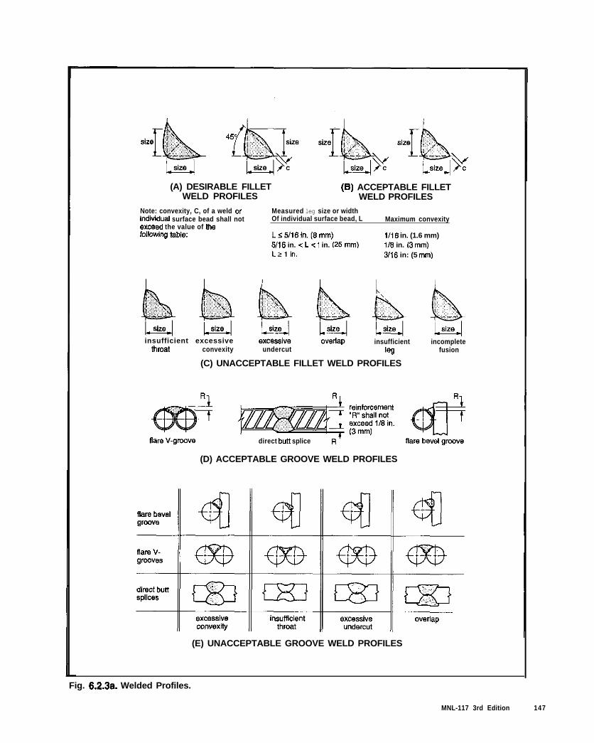
(A) DESIRABLE FILLET (6) ACCEPTABLE FILLETWELD PROFILES WELD PROFILES
Note: convexity, C, of a weld orindiiidual surface bead shall notexceed the value of thefdlowing table:
Lzfin.
Measured leg size or widthOf individual surface bead, L
Ls5!16in.(*mm)
5/16 in. <L c 1 in. 125 mm)
3/16 in: (5 A)
Maximum convexity
1116 in. (1.6 mm)118 in. (3 mm1
insufficient excessivethroat convexity undercut
insufficient
‘9Q
incompletefusion
(C) UNACCEPTABLE FILLET WELD PROFILES
direct bun splice R
(D) ACCEPTABLE GROOVE WELD PROFILES
(E) UNACCEPTABLE GROOVE WELD PROFILES
Fig. 6.2.3a. Welded Profiles.
MNL-117 3rd Edition 147
Standard
The following items shall be checked on atleast 10 percent of all assemblies after weldingto determine the quality of the welds:
a. Geometric imperfections. The fillet weldfaces shall be slightly convex or slightly con-cave as shown in Fig. 6.2.3a, A and B orflat, and with none of the unacceptable pro-files exhibited in Fig. 6.2.3a, C.
b. Welds shall have no cracks in either theweld metal or heat-affected zone of the basemetal.
c. There shall be thorough fusion betweenweld metal and base metal and betweensuccessive passes in the weld.
d. All craters shall be filled to the full cross sec-tion of the weld, except for the ends of inter-mittent fillet welds outside their effectivelength.
e. Welds shall be free from overlap.
f. For materials less than lin. (25 mm) thick,undercut depth greater than l/32 in. (1 mm)in the solid section of the bar or structuralmembers shall not be allowed except atraised reinforcing bar deformation wherel/16 in. (1.5 mm) is allowed. For steel, referto AWS D1.l for the requirements of thespecific structure type.
g. For reinforcing bars, the sum of diameters ofpiping porosity in flare-groove, and filletwelds shall not exceed 318 in. (10 mm) inany linear inch (25 mm) of weld and shallnot exceed 9/16 in. (14 mm) in any 6 in.(150 mm) length of weld. For steel, refer toAWS Di .l for the requirements of the spe-cific structure type.
h. Incomplete joint penetration.
i. Slag inclusions.
j. Amount of distortion.
In addition to checking that required weld size,length, location and type are as indicated onthe approved drawings, and that no welds areomitted, a check shall be made that no weldshave been added without approval.
Weldments shall be checked after fabricationfor brittleness by striking at least one out ofevery 50 pieces with a 3 lb (1.3 kg) hammer.Brittle weldments break under a hammer blowand if brittle weldment is found, all assembliesmade using similar procedures become sus-pect and shall be checked for acceptance.
MNL-117 3rd Edition
b. Visual inspection for cracks in welds and base metal andother discontinuities should be aided by a strong light,magnitiers,or such other devices as may be found helpful.
c. Only incomplete fusion apparent during a visual in-spection need be considered unless specifications re-quire radiography or ultrasonic examination.
Size, length, and contour of welds should be measuredwith suitable weld-size gaugen. Groove welds should bemeasured for proper reinforcement on both sides of thejoint. Quality control should compare the welds withthree-dimensional “workmanship samples” available fromAWS. These are actual welded samples, or plastic replicasof welded samples that depict actual weld conditions.
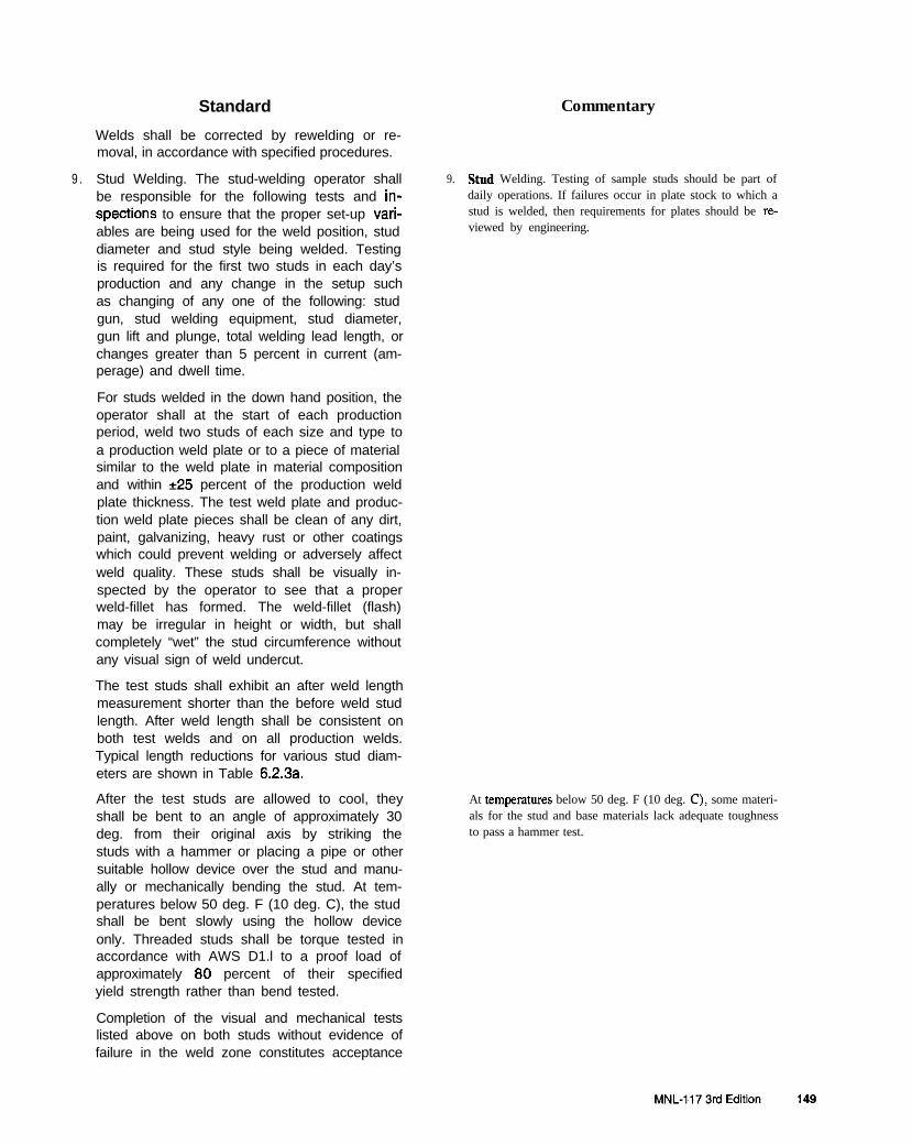
Standard
Welds shall be corrected by rewelding or re-moval, in accordance with specified procedures.
Commentary
9 . Stud Welding. The stud-welding operator shall 9. Stud Welding. Testing of sample studs should be part of
be responsible for the following tests and in- daily operations. If failures occur in plate stock to which a
spections to ensure that the proper set-up vari- stud is welded, then requirements for plates should be re-
ables are being used for the weld position, stud viewed by engineering.
diameter and stud style being welded. Testingis required for the first two studs in each day’sproduction and any change in the setup suchas changing of any one of the following: studgun, stud welding equipment, stud diameter,gun lift and plunge, total welding lead length, orchanges greater than 5 percent in current (am-perage) and dwell time.
For studs welded in the down hand position, theoperator shall at the start of each productionperiod, weld two studs of each size and type toa production weld plate or to a piece of materialsimilar to the weld plate in material compositionand within +25 percent of the production weldplate thickness. The test weld plate and produc-tion weld plate pieces shall be clean of any dirt,paint, galvanizing, heavy rust or other coatingswhich could prevent welding or adversely affectweld quality. These studs shall be visually in-spected by the operator to see that a properweld-fillet has formed. The weld-fillet (flash)may be irregular in height or width, but shallcompletely “wet” the stud circumference withoutany visual sign of weld undercut.
The test studs shall exhibit an after weld lengthmeasurement shorter than the before weld studlength. After weld length shall be consistent onboth test welds and on all production welds.Typical length reductions for various stud diam-eters are shown in Table 6.2.3a.
After the test studs are allowed to cool, theyshall be bent to an angle of approximately 30deg. from their original axis by striking thestuds with a hammer or placing a pipe or othersuitable hollow device over the stud and manu-ally or mechanically bending the stud. At tem-peratures below 50 deg. F (10 deg. C), the studshall be bent slowly using the hollow deviceonly. Threaded studs shall be torque tested inaccordance with AWS D1.l to a proof load ofapproximately 80 percent of their specifiedyield strength rather than bend tested.
At tetnpcratures below 50 deg. F (10 deg. C), some materi-als for the stud and base materials lack adequate toughnessto pass a hammer test.
Completion of the visual and mechanical testslisted above on both studs without evidence offailure in the weld zone constitutes acceptance
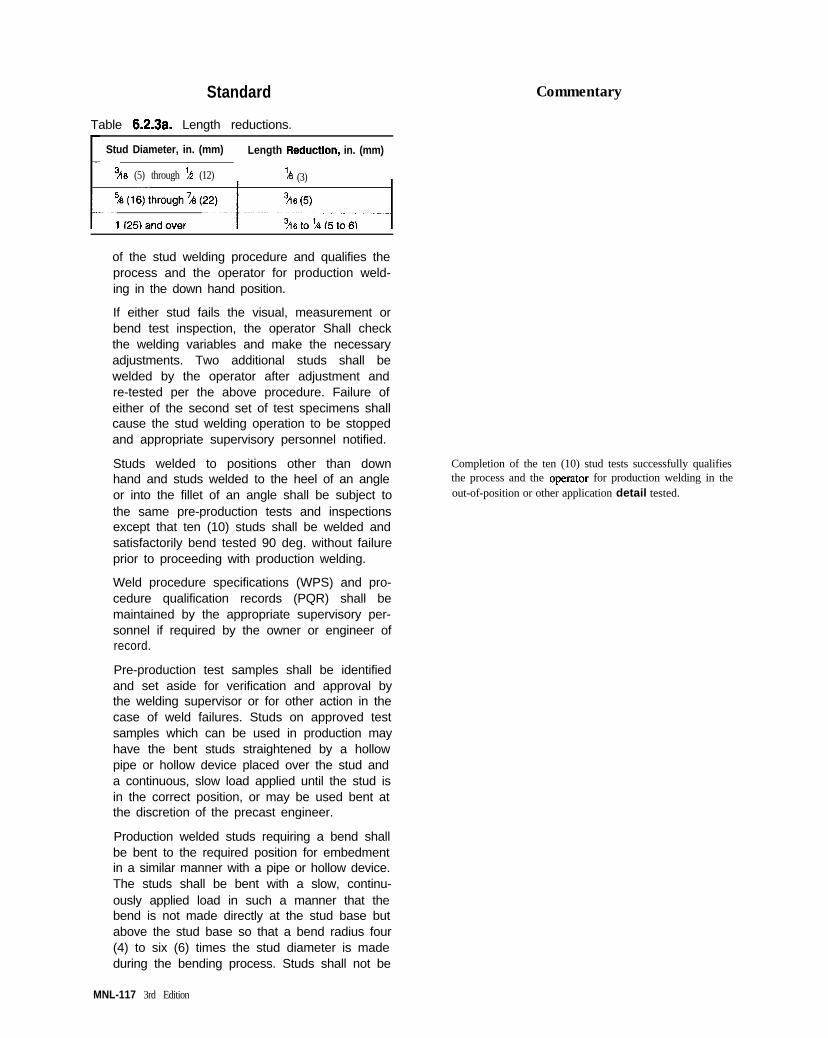
Standard
Table 6.2.3a. Length reductions.
Stud Diameter, in. (mm) Length Reduction, in. (mm)
3ir6 (5) through ‘LT (12) ‘ A (3)
Commentary
of the stud welding procedure and qualifies theprocess and the operator for production weld-ing in the down hand position.
If either stud fails the visual, measurement orbend test inspection, the operator Shall checkthe welding variables and make the necessaryadjustments. Two additional studs shall bewelded by the operator after adjustment andre-tested per the above procedure. Failure ofeither of the second set of test specimens shallcause the stud welding operation to be stoppedand appropriate supervisory personnel notified.
Studs welded to positions other than downhand and studs welded to the heel of an angleor into the fillet of an angle shall be subject tothe same pre-production tests and inspectionsexcept that ten (10) studs shall be welded andsatisfactorily bend tested 90 deg. without failureprior to proceeding with production welding.
Completion of the ten (10) stud tests successfully qualifiesthe process and the operator for production welding in theout-of-position or other application detail tested.
Weld procedure specifications (WPS) and pro-cedure qualification records (PQR) shall bemaintained by the appropriate supervisory per-sonnel if required by the owner or engineer ofrecord.
Pre-production test samples shall be identifiedand set aside for verification and approval bythe welding supervisor or for other action in thecase of weld failures. Studs on approved testsamples which can be used in production mayhave the bent studs straightened by a hollowpipe or hollow device placed over the stud anda continuous, slow load applied until the stud isin the correct position, or may be used bent atthe discretion of the precast engineer.
Production welded studs requiring a bend shallbe bent to the required position for embedmentin a similar manner with a pipe or hollow device.The studs shall be bent with a slow, continu-ously applied load in such a manner that thebend is not made directly at the stud base butabove the stud base so that a bend radius four(4) to six (6) times the stud diameter is madeduring the bending process. Studs shall not be
MNL-117 3rd Edition
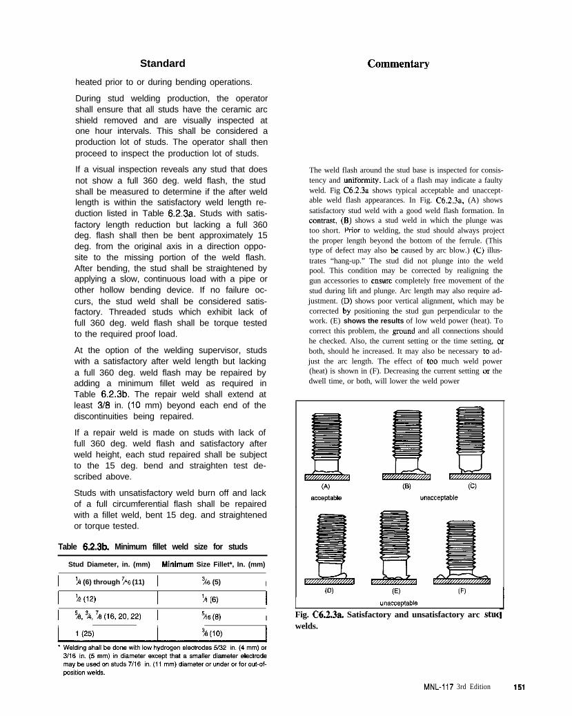
Standard
heated prior to or during bending operations.
During stud welding production, the operatorshall ensure that all studs have the ceramic arcshield removed and are visually inspected atone hour intervals. This shall be considered aproduction lot of studs. The operator shall thenproceed to inspect the production lot of studs.
If a visual inspection reveals any stud that doesnot show a full 360 deg. weld flash, the studshall be measured to determine if the after weldlength is within the satisfactory weld length re-duction listed in Table 6.2.3a. Studs with satis-factory length reduction but lacking a full 360deg. flash shall then be bent approximately 15deg. from the original axis in a direction oppo-site to the missing portion of the weld flash.After bending, the stud shall be straightened byapplying a slow, continuous load with a pipe orother hollow bending device. If no failure oc-curs, the stud weld shall be considered satis-factory. Threaded studs which exhibit lack offull 360 deg. weld flash shall be torque testedto the required proof load.
At the option of the welding supervisor, studswith a satisfactory after weld length but lackinga full 360 deg. weld flash may be repaired byadding a minimum fillet weld as required inTable 6.2.3b. The repair weld shall extend atleast 3/6 in. (10 mm) beyond each end of thediscontinuities being repaired.
If a repair weld is made on studs with lack offull 360 deg. weld flash and satisfactory afterweld height, each stud repaired shall be subjectto the 15 deg. bend and straighten test de-scribed above.
Studs with unsatisfactory weld burn off and lackof a full circumferential flash shall be repairedwith a fillet weld, bent 15 deg. and straightenedor torque tested.
Table 6.2.313. Minimum fillet weld size for studs
Stud Diameter, in. (mm) Mlnlmum Size Fillet*, In. (mm)
I k (6) through ?A6 (11) 1 % (5) I
I ?+(12) I ‘A (6) I1 %,%,%(16,20,22) 1 316(6) I
The weld flash around the stud base is inspected for consis-tency and Yniformity. Lack of a flash may indicate a faultyweld. Fig C6.2.3a shows typical acceptable and unaccept-able weld flash appearances. In Fig. C6.2.3a. (A) showssatisfactory stud weld with a good weld flash formation. Inconaast, (B) shows a stud weld in which the plunge wastoo short. Prior to welding, the stud should always projectthe proper length beyond the bottom of the ferrule. (Thistype of defect may also be caused by arc blow.) (C) illus-trates “hang-up.” The stud did not plunge into the weldpool. This condition may be corrected by realigning thegun accessories to ensure completely free movement of thestud during lift and plunge. Arc length may also require ad-justment. (D) shows poor vertical alignment, which may becorrected by positioning the stud gun perpendicular to thework. (E) shows the results of low weld power (heat). Tocorrect this problem, the ground and all connections shouldhe checked. Also, the current setting or the time setting, orboth, should he increased. It may also be necessary to ad-just the arc length. The effect of too much weld power(heat) is shown in (F). Decreasing the current setting or thedwell time, or both, will lower the weld power
Fig. C6.2.3a. Satisfactory and unsatisfactory arc stucwelds.
MNL-117 3rd Edition 151
Standard
Studs which fail the inspection test by breakingoff or tearing in the weld zone shall be re-moved. The weld spot shall be ground smoothand the stud replaced.
The welding supervisor shall verify that theseinspections have been made and identify anystuds repaired or replaced.
Inspection and testing during production weld-ing for studs welded in positions other thandown hand shall be identical to those proce-dures listed above.ln addition, because of thegreater risk of incomplete welding, these studsexcept for threaded studs shall receive 100%testing by striking with a heavy, short-handledmachinists hammer. Any studs that break offshall be shown to the supervisor, and re-placed with new studs or repaired by arc weld-ing. Repaired or replaced studs shall be in-spected by bending 15 deg. and straighteningwithout failure.
After a production welding period of one hour,the two (2) stud pre-production testing proce-dure outlined above shall be repeated for studswelded downhand or in any other position. If ei-ther of the two (2) studs on this production test-ing fails the test, the supervisor and the opera-tor together shall proceed as follows:
a. Working backward from the studs welded forthis test, test the previous ten (10) most re-cently welded studs, If any fail, test ten (10)more and continue working backward until 10studs are tested successfully without failure.
b. In addition, the supervisor shall visually in-spect all studs welded from the ten (10) suc-cessful stud tests backward to the previousregular production test.
c. The pre-production test shall be repeatedwith appropriate equipment and weld settingadjustments until satisfactory welds areachieved before proceeding with further pro-duction.
The stud welding operator shall maintain arecord of the start-up and hourly testing pro-gram testing and record the date, time of thentest, conformance or non-conformance of theresults and if non-conformance, the further test-ing required and performed. The sheet shall bekept in the stud welding operator’s work areaand shall be inspected at least daily by qualitycontrol inspector as a monitoring technique. Inaddition, the quality control inspector shall per-
152 MNL-117 3rd Edition

Standard
form bend tests and visual inspection on onestud for every 50 assemblies,
62.4 Special Testing
Commentary
C6.2.4 Special T&ing
1.
2.
Heat of Hydration. When massive castings, orcastings in partly insulated molds are beingmade, excessive concrete temperatures maybe produced as the cement hydrates. Thismay, in turn, cause warpage or excessiveshrinkage of the casting. When such castingsare being produced, the temperature history ofone typical casting shall be recorded by self-recording thermometers and, if over 150 deg. F(66 deg. C), steps must be taken in all castingsto cool the concrete.
1.
Freeze-Thaw Tests. Routine freeze-thawdurability tests of vertical elements are not re-quired. If, due to special environmental condi-tions, freeze-thaw tests are specified, the testconditions of freezing in air, thawing in water(ASTM C666, Method 6) shall be followed.Under this test method, the minimum allowabledurability factor shall be 70.
2.
Heat of Hydration. In precast concrete members most ofthe heat generated by the hydrating cement is dissipated al-most as fast as it is generated, and there is little temperaturedifferential from the inside to the outside of the member.
Extreme differences between internal and outside tempera-tures of massive members may result in surface cracking.For example, temperature stxsses occur as the temperatureof the concrete rises because of heat of hydration and thendrops essentially to the temperature of its surroundings. Asthe outer surface cools and tends to shrink, compressivestresses are set up in the center and tensile stresses in thecooler outer surfaces. When these tensile stiesses becomegreater than the tensile strength of the concrete, crackingoccurs. Since the interior reacts so much more slowly thanthe surface to cycles of temperature, it is as though the sur-face were restrained by the interior concrete.
The maximum permissible gradient for a nominallyreinforced sfructu~e is generally less than 100 deg. F(38 deg. C).
Freeze-Thaw Tests. Laboratory freezing and thawingtests may be conducted to evaluate the durability of con-crete under severe climatic conditions. These tests can bemade on prismatic samples prepared fmm laboratory trialmixes or even from cores cut from the face of finishedproduction units. Such tests, however, take several monthsto complete. The verticality of wall units seldom allowsconcrete to reach the critical saturation point (above 90percent) on which such tests rue based. However, wherehorizontal areas allow water or snow to accumulate orwhere ground level panels may be subjected to splashingby deicing salts and to freezing conditions at moisture con-tents above critical saturation, an air-entraining admixtureshould be used. In addition, it is probably a prudent policyto have air entrained concrete in all precast concrete ex-
posed to freeze-thaw cycles.
These tests take several months to complete. Equivalentevaluations can be obtained more rapidly by conducting“air void studies” (amount and character of entrained air incores taken fmm the production unit) in accordance withASTM C457.
6.3 Records
6.3.1 Recordkaaping
In order to establish evidence of proper manufac-ture and conformance with plant standards and pro-ject specifications, a system of recordkeeping shallbe used which will provide full information regardingtesting of materials, mix designs, production tests,and any other information specified for each project.
C6.3 Records
C63.1 Recordkeeping
Records provide the vehicle for transmitting and evaluating,and should result in correction of deficient procedures or prod-ucts by communication of problems.
MNL-I 17 3rd Edition 153
Standard
Records shall be designed for a minimum of writing(see Sample Record Forms in Appendix E).
Each precast concrete unit shall be marked on thebackside or edges of the unit with the date pro-duced and a unique identification number that canbe referenced to production and erection drawingsand testing records.
Recordkeeping shall be the responsibility of thequality control inspection personnel. In the absenceof project specification requirements or statestatue, records shall be kept for a minimum of 5years after final acceptance of the structure, or forthe period of product warranty provided by themanufacturer, whichever is longer.
6.3.2 Suppliers’ Test Reports
Certified test reports for materials not in-plant testedshall be required of suppliers. Refer to Article 2.1.2for this requirement. These reports shall show theresults of suppliers’ mill or plant tests, tests by an in-dependent testing laboratory, petrographic analysisof aggregates for face mixes, and other testing re-quired by the project specifications. These reportsshall state compliance with applicable specifications.
Mill or suppliers’ test certificates or standard testresults shall be available for the following materials:
1. Cement.
2. Aggregates.
3. Admixtures.
4. Reinforcing steel (all grades).
5. Prestressing tendons.
6 . Studs or deformed anchors.
7 . Structural steel or other hardware items.
6 . Inserts or proprietary items as specified for indi-vidual projects.
9. Pigments.
10. Curing compounds.
These records shall be kept for the same period oftime as the other project records.
Commentary
Units should be marked in an area of the member not exposedto view when in place on the structure, but accessible for re-view and inspection while in storage at the precast concreteplant.
Member markings. related to mold number when several iden-tical molds are needed, make it possible to relate quality con-trol data to specific units. They also facilitate documentation ofmember production, inspection and repair.
C6.32 Suppliers’ Test Reports
All project specifications require standards for materials usedin production. A manufacturing facility must obtain certificatesof compliance to ensure the integrity of the product and to pro-tect its own interests. Correlation to a specific project isneeded for conformance with the design and specifications.
Plants which utilize materials that are fabricated or supplied byoutside vendors should periodically inspect those vendors toassure that they are in compliance with the specifications ofthis manual. All vendors should be required to submit proof ofcompliance for bath materials and workmanship.
154 MNL-117 3rd Edition
Standard
6.3.3 Tensioning Records
An accurate record of all tensioning operationsshall be kept and reviewed by qualified personnel.This record shall include. but not be limited to, thefollowing:*
Commentary
C633 Tensioning Records
Variations of actual values from computed theoretical valuesshould be computed each day to monitor developing trends andto make personnel aware of tolerances.
1. Date of tensioning.
2. Casting bed identification.
3 . Description, identification and number of elements,
4 . Manufacturer, size, grade, and type of strand.
5 . Coil or pack number of strand, identifying heat.
6. Sequence of stressing (and detensioning, ifcritical).
7 . Identification of jacking equipment,
8. For all pretensioning:
a. Required total force per strand.
b. Initial force.
c. Anticipated and actual gauge pressure foreach strand or each group of strandsstressed in one operation.
d. Anticipated elongation for each differentjacking force.
Tensioning calculations shall show a sum-mary of anticipated operational losses suchas strand chuck seating, splice chuck seat-ing, abutment movements, thermal effectsand self-stressing form shortening.
9. For single strand pretensioning:
a. If the setup is open, where no friction is im-posed on the strand between strand chucks,the record shall contain jacking force foreach strand and the actual elongation of thefirst strand tensioned in each different stressgroup and the elongation of at least 10% ofthe remaining strand.
b. If one system is used for determination ofthe jacking load and friction is expected tobe imposed on the strand, the actual elonga-tion of every strand and the jacking forceshall be recorded.
10. For multiple strand pretensioning, the actualelongation of the strand group measured bymovement of the jacking header.
11. For post-tensioning:
a. The actual net elongation of each tendon
MNL-117 3rd Edition 155
Standard
with allowance made for elastic shorteningof the member, as well as jacking force.
b. Data on and date of grouting.
12. Any unanticipated problems encountered dur-ing tensioning such as wire breakage, exces-sive seating, restressing, or other factors hav-ing an influence on the net stress.
6.3.4 Concrete Records
Records of concrete operations and tests shall bekept so the following data will be available:*
1. Unit and job identification.
2. Production date.
3. Mix proportions by weight.
4 . Mixing water corrections and/or aggregate cor-rections due to surface moisture.
5 . Yardage, design and actual yield or unit weight.
6 . Identification of production area, mold or bed.
7. Test specimen identification.
8. Concrete temperature.
9. Air temperature, weather conditions, if applica-ble, and any measures taken for cold or hotweather concreting.
10. Slump.
11. Air content.
12. Unit weight (fresh).
13. Inspection of batching, mixing, conveying, place-ment, consolidation and finishing of concrete.
14. Method and duration of curing, e.g., tempera-ture charts for accelerated curing.
15. Strength at stress release or stripping.
16. 28-day strength.
17. Absorption on concrete exposed to weathering.
18. Cylinder strength tests and air-dry unit weightfor lightweight concrete.
19. Fresh unit weight for lightweight concrete.
20. Inspection reports.
6.3.5 Calibration Records for Equipment
Calibration records for plant equipment such asbatch plant scales, compression testing machine,
C63.4 Concrete Records
In evaluating mix design efficiency or performance, all infor-mation as listed is needed to eliminate variables. If a problemoccur, information is needed for evaluation in the same man-“U.
C6.3.5 Calibration Records for Equipment
Calibration records are required as specified for each type ofequipment and equipment should be re-calibrated as required.
156 MNL-117 3rd Edition

Standard Commentary
impact hammer, or non-destructive testing devicesand other necessary equipment shall be supplied bythe testing agency and the equipment operator shallhave ready access to the records.
Records that show deviations should be used by plant person-nel to obtain cot~ect readings.
6.4 Laboratory Facilities
6.4.1 General
The plant shall maintain an adequately equipped lab-oratory or retain the services of a testing agency inwhich investigation and development of suitable con-crete mixes may be conducted, and ongoing qualitycontrol testing may be performed.
The laboratory facilities shall be in a protected areawfth environmental controls to ensure proper workingconditions. Laboratory equipment shall be maintainedin proper condition and calibrated as needed, but notless than annually. Calibration records shall be kepton file.
6.4.2 Quality Control Testing Equipment
The plant shall have all equipment required for per-forming the testing procedures. Equipment shallmeet the requirements of the test procedure specifi-cation.
C6d.2 Quality Control Testing Equipment
The laboratory should have the facilities necessary for the devel-opment and assesstnent of concrete mixes and the quality controltests to be performed by the manufacturer in accordance withASTM (21077.
6.4.3 Test Equipment Operating Instructions
Operating instructions shall be obtained for all testingequipment as well as national and industry stan-dards, for materials and testing. These instructionsshall be kept in the laboratory and shall be carefullyfollowed by all testing personnel.
Testing machines shall be kept clean and no attemptshall be made to use them beyond their rated capaci-ties. Machines shall be capable of applying loads atthe specified rate. Testing machines shall be cali-brated so that the maximum error is not more than*l percent of full scale reading. Calibration shall beperformed whenever there is reason to question the
Since the compressive strength of concrete must k determinedprior to stripping or stress transfer, testing equipment should beprovided at all plants. It is preferable to have this equipment atthe plant to avoid delays and possible damage to cylinders by
transporting them to a centml laboratory
Testing machines should be equipped with a guard that willprotect personnel fmm flying debris.
Care in using capping compounds is required because of thepotential for fire. If the compound is overheated. a fire mayresult, so a functioning thermostat is required. Due to fumesproduced, the capping compound heater should be vented tothe exterior of the testing area.
MNL-It7 3rd Edition 157

Standard Commentary
accuracy of indicated loads, or at least annually. Cali-bration curves shall be available at all times and usedby testing personnel.
158 MNL-117 3rd Edilion
DIVISION 7 - PRODUCT TOLERANCES
Standard Commentary
7.1 Requirements for Finished Product C7.1 Requirements for Finished Product
7.1 .I Product Tolerances - General C7.1.1 Product Tolerances - General
The tolerances listed in this Division shall governunless other tolerances are noted in the contractdocuments for a specific project.
Tolemnces are divided into three categories: product tolerances,erection tolerances and interfacing tolerances. See Appendix Ifor erection tolerances.*
Tolerance is a specified permissible variation from exact re-quirements of the contract documents. A tolerance may he ex-
pressed as an additive or subtractive (i) variation from a spec-
itied dimension or relation or as an absolute deviation from aspecified relation. Tolerances should be established for the
following reasons:
1 . Structural. To ensure that the structural design properly
accounts for factors sensitive to variations in dimensional
control. Examples include eccentric loading conditions,bearing areas, reinforcement locations, and hardware and
hardware anchorage locations.
2 . Feasibility. To ensure acceptable performance of jointsand interfacing materials in the finished stmctwe and to
ensure that designs and details are dimensionally feasible
from manufacturing and construction points of view.
3 . Visual efkct3. To ensure that the variations will be contm-
Iable and result in an acceptable looking structure
4. Economics. To ensure ease and speed of production anderection by having a known degree of accuracy in the
dimensions of the precast concrete units.
5. Legal. To avoid encroaching on property lines and toestablish a tolerance standard against which the work can
be compared in the event of a dispute.
6. Contractual. To establish a known acceptability rangeand also to establish responsibility for developing, achiev-
ing and maintaining mutually agreed tolerances.
It is very important that the entity (architect, engineer of record,
or precaster) taking responsibility for establishing the project
tolerances be clearly defined at the onxt of the project.
The architect/engineer should he responsible for coordinatingthe tolerances for precast concrete work with the requirementsof other trades whose work adjoins the precast concrete con-struction. In all cases the tolerances must be reasonable, real-istic and within generally accepted limits. It should be under-stood by those involved in the design and construction processthat tolerances shown in Article 7.1.2 must he considered asguidelines for an acceptable range and not limits for rejection.If these tolerances are met, the unit should be accepted. If
MNL-117 3rd Edition 159
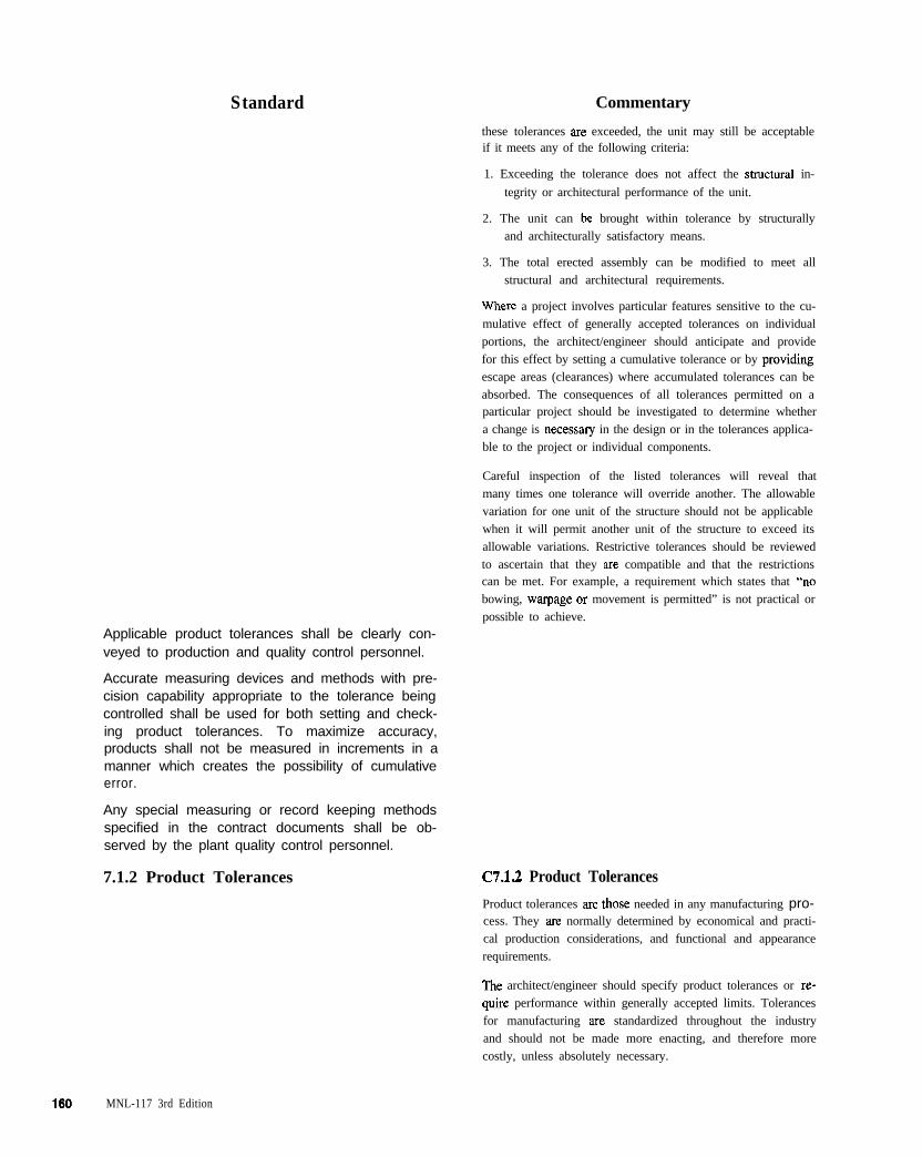
Standard Commentary
these tolerances are exceeded, the unit may still be acceptableif it meets any of the following criteria:
1. Exceeding the tolerance does not affect the sbuctural in-
tegrity or architectural performance of the unit.
2. The unit can be brought within tolerance by structurally
and architecturally satisfactory means.
3. The total erected assembly can be modified to meet all
structural and architectural requirements.
where a project involves particular features sensitive to the cu-
mulative effect of generally accepted tolerances on individual
portions, the architect/engineer should anticipate and provide
for this effect by setting a cumulative tolerance or by pmviding
escape areas (clearances) where accumulated tolerances can be
absorbed. The consequences of all tolerances permitted on aparticular project should be investigated to determine whether
a change is necessary in the design or in the tolerances applica-
ble to the project or individual components.
Careful inspection of the listed tolerances will reveal that
many times one tolerance will override another. The allowable
variation for one unit of the structure should not be applicable
when it will permit another unit of the structure to exceed its
allowable variations. Restrictive tolerances should be reviewed
to ascertain that they are compatible and that the restrictionscan be met. For example, a requirement which states that “no
bowing, warpage or movement is permitted” is not practical or
possible to achieve.
Applicable product tolerances shall be clearly con-veyed to production and quality control personnel.
Accurate measuring devices and methods with pre-cision capability appropriate to the tolerance beingcontrolled shall be used for both setting and check-ing product tolerances. To maximize accuracy,products shall not be measured in increments in amanner which creates the possibility of cumulativeerror.
Any special measuring or record keeping methodsspecified in the contract documents shall be ob-served by the plant quality control personnel.
7.1.2 Product Tolerances C7.1.2 Product Tolerances
Product tolerances are those needed in any manufacturing pro-cess. They are normally determined by economical and practi-
cal production considerations, and functional and appearance
requirements.
The architect/engineer should specify product tolerances or re-
quire performance within generally accepted limits. Tolerances
for manufacturing are standardized throughout the industry
and should not be made more enacting, and therefore more
costly, unless absolutely necessary.
MNL-117 3rd Edition
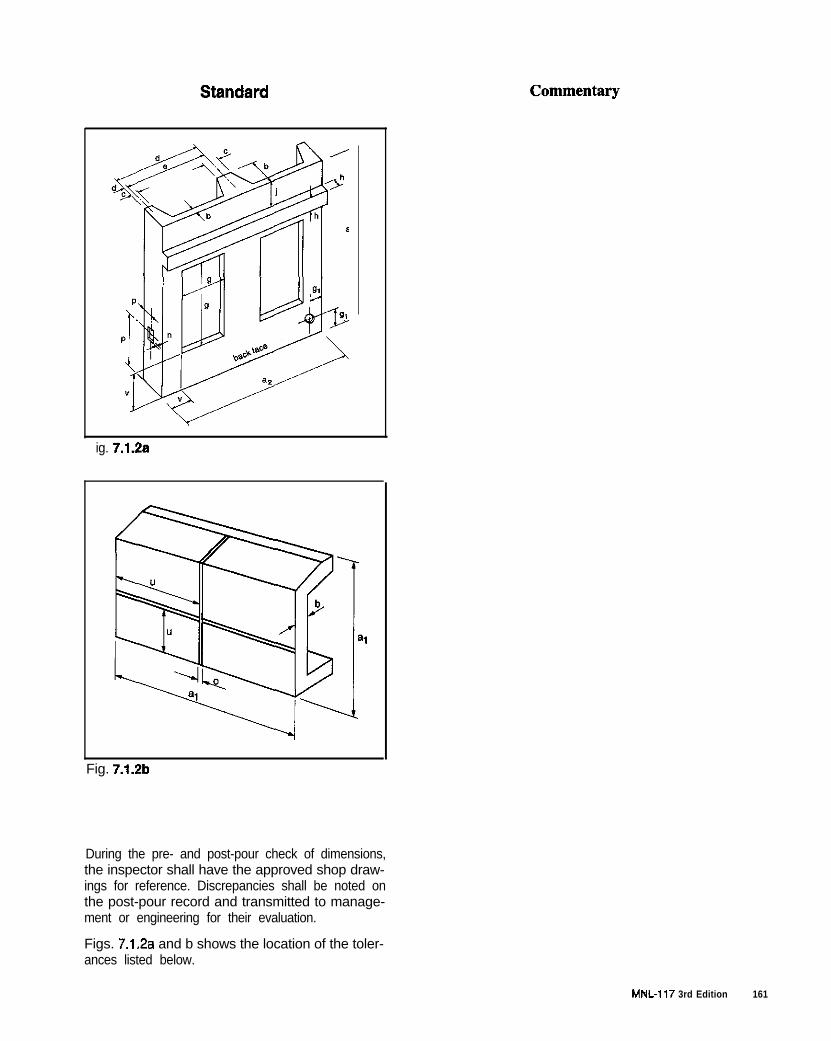
ig. 7.1.2a
Fig. 7.1.2b
During the pre- and post-pour check of dimensions,the inspector shall have the approved shop draw-ings for reference. Discrepancies shall be noted onthe post-pour record and transmitted to manage-ment or engineering for their evaluation.
Figs. 7.1.2a and b shows the location of the toler-ances listed below.
MNL-117 3rd Edition 161
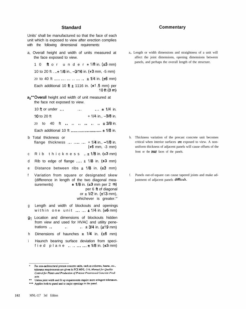
Standard Commentary
Units’ shall be manufactured so that the face of eachunit which is exposed to view after erection complieswith the following dimensional requirements:
a, Overall height and width of units measured atthe face exposed to view.
1 0 ft o r u n d e r r l/8 in. (i3 mm)
10 to 20 ft . ..+ l/8 in., -3/16 in. (+3 mm, -5 mm)
20 to 40 ft ,._. __. ._. _. ._. ._ f l/4 in. (*6 mm)
Each additional 10 ft f 1116 in. (+I .5 mm) perlOft(3m)
a,. Length or width dimensions and straightness of a unit will
affect the joint dimensions, opening dimensions between
panels, and perhaps the overall length of the structure.
a,*‘Overall height and width of unit measured atthe face not exposed to view.
10 ft or under ._. ._. ._. f l/4 in.
10 to 20 ft + l/4 in., -318 in.
20 to 40 ft _. _. _. _. _. _. * 3/8 in.
Each additional 10 ft _...._..._.................. f l/8 in.
b Total thickness orflange thickness ._. .__. ._. + l/4 in., -118 in.
(+6 mm, -3 mm)
c R i b t h i c k n e s s _. f l/8 in. (*3 mm)
d Rib to edge of flange ._.. f l/8 in. (+3 mm)
e Distance between ribs f l/6 in. (+3 mm)
f Variation from square or designated skew(difference in length of the two diagonal mea-surements) f i/8 in. (*3 mm per 2 m)
per 6 ft of diagonalor * l/2 in. (*13 mm),
whichever is greater.“’
b. Thickness variation of the precast concrete unit becomescritical when interior surfaces are exposed to view. A non-
uniform thickness of adjacent panels will cause offsets of the
front or the rear faces of the panels.
f . Panels out-of-square can cause tapered joints and make ad-
justment of adjacent panels difficult.
g Length and width of blockouts and openingsw i t h i n o n e u n i t ._. ._. f l/4 in. (+6 mm)
gt Location and dimensions of blockouts hiddenfrom view and used for HVAC and utility pene-trations _. _. _. * 3/4 in. (*19 mm)
h Dimensions of haunches * l/4 in. (*6 mm)
i Haunch bearing surface deviation from speci-f i e d p l a n e _. _. ._. ._. * l/8 in. (*3 mm)
162 MNL-117 3rd Edition

Standard Commentary
j Difference in relative position of adjacenthaunch bearing surfaces from specified relativeposition f l/4 in. (*6 mm)
k Bowing _.___,......,,.,,...,,.,..,....,,., i L/360max. 1 in. (25 mm)
k. Bowing is an overall out-of-planeness condition which differs
from warping in that while the corners of the panel may fall in
the same plane, the portion of the panel between two paralleledges is out of plane. Bowing conditions are shown in Fig.
c7.1.2a
Bowing and warping tolerances have a” important effect on
the edge match up during erection and on the visual appear-
ance of the erected panels, both individually and whenviewed together. The requirements for bowing and warping
of panels may be overridden by tolerances for panels as in-
stalled with reference to joint widths, jog in alignment and
step in face
I
PLANpm”ex bowing)
PLAN@maw bowing,
ELEVATIONboth plan andslewon
Fig. C7.1.2a. Bowing definitions for panels
A special appearance requirement may be necessary for
honed or polished flat concrete walls where bowing orwarping tolerances might have to be decreased to 75 or
50% of tolerances in Article 7.1.2 in order to avoid joint
shadows. Another special case might be tolerances for di-
mensions controlling the matching of open shaped panels.
These tolerances may have to be smaller than the standard
dimensional tolerance (75% or 50%), unless the architect
has recognized and solved the alignment problem as part ofthe design.
Local smoothness l/4 in. in 10 ft (6 mm in 3 m)Does not apply to visually concealed surfaces.(Refer to Fig. C7.1.2~ for definition.) For clay
I. Surface out-of-planeness, which is not a characteristic of theentire panel shape, is defined as a local smc~thness variation
rather than a bowing variation. Examples of local smc.3thness
MNL-I 17 3rd Edition
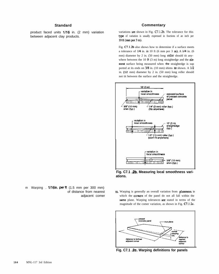
Standard Commentary
product faced units 1116 in. (2 mm) variationbetween adjacent clay products.
variations are shown in Fig. C7.1.2b. The tolerance for thistype of variation is usually expressed in fractions of an inch per
lOft(mmper3m).
Fig. C7.1.2b also shows how to determine if a surface meets
a tolerance of l/4 in. in 10 ft (6 mm per 3 m). A l/4 in. (6
mm) diameter by 2 in. (50 mm) long roller should tit any-where between the 10 ft (3 m) long straightedge and the ele
merit surface being measured when the straightedge is sup
ported at its ends on 3/S in. (10 mm) shims as shown. A l/2in. (12 mm) diameter by 2 in. (50 mm) long roller should
not tit between the surface and the straightedge.
Fig. C7.1 .Zb. Measuring local smoothness vari-ations.
m Warping . V16in. perft (1.5 mm per 300 mm)of distance from nearest m. Warping is generally an overall variation from planeness in
adjacent comer which the comers of the panel do not all fall within the
same plane. Warping tolerances are stated in terms of themagnitude of the comer variation, as shown in Fig. C7.1.7.c.
Fig. C7.1 .Zc. Warping definitions for panels
164 MNL-117 3rd Edition
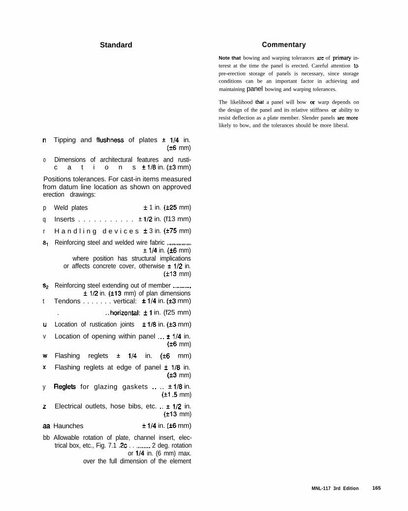
Standard Commentary
Note that bowing and warping tolerances are of primary in-
terest at the time the panel is erected. Careful attention to
pre-erection storage of panels is necessary, since storageconditions can be an important factor in achieving and
maintaining panel bowing and warping tolerances.
The likelihood that a panel will bow or warp depends on
the design of the panel and its relative stiffness or ability to
resist deflection as a plate member. Slender panels are morelikely to bow, and the tolerances should be more liberal.
n Tipping and flushness of plates f i/4 in.(*6 mm)
o Dimensions of architectural features and rusti-c a t i o n s f l/8 in. (*3 mm)
Positions tolerances. For cast-in items measuredfrom datum line location as shown on approvederection drawings:
p Weld plates f 1 in. (225 mm)
q Inserts . . . . . . . . . . . f i/2 in. (f13 mm)
r H a n d l i n g d e v i c e s f 3 in. (i75 mm)
s, Reinforcing steel and welded wire fabric ,......,.,.,..,+ l/4 in. (*6 mm)
where position has structural implicationsor affects concrete cover, otherwise f l/2 in.
(*I3 mm)
ss Reinforcing steel extending out of member .,_,___._..f i/2 in. (*I3 mm) of plan dimensions
t Tendons . . . . . . . vertical: f l/4 in. (i3 mm)
. ..horizontal. f 1 in. (f25 mm)
u Location of rustication joints k 118 in. (*3 mm)
v Location of opening within panel .__ f l/4 in.(+6 mm)
w Flashing reglets f l/4 in. (*6 mm)
x Flashing reglets at edge of panel f l/8 in.(*3 mm)
y Reglets for glazing gaskets _. _, f i/8 in.(*I .5 mm)
z Electrical outlets, hose bibs, etc. _. f 112 in.(*I3 mm)
aa Haunches f l/4 in. (f6 mm)
bb Allowable rotation of plate, channel insert, elec-trical box, etc., Fig. 7.1 .2c . . ..___... 2 deg. rotation
or l/4 in. (6 mm) max.over the full dimension of the element
MNL-117 3rd Edition 165
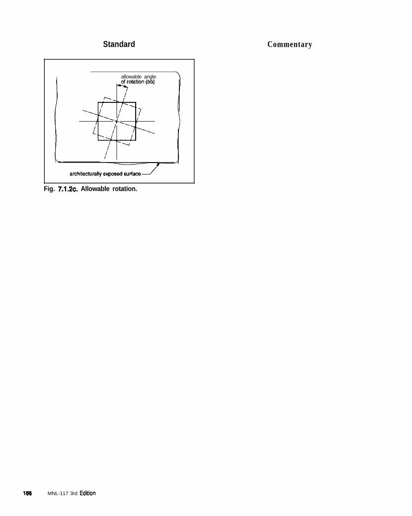
Standard Commentary
allowable angle -l
Fig. 7.1.2~. Allowable rotation.
166 MNL-117 3rd Edition
APPENDIX A
Guidelines for Developing Plant Quality System Manual
INTRODUCTION MANUAL CONTENTS
Documented quality system procedures should be thebasis for the overall planning and administration of activ-ities which impact on quality. These documented proce-dures should cover all the elements of the company’squality system standard. They should describe (to thedegree of detail required for adequate control of the activ-ities concerned) the responsibilities, authorities, andinterrelationships of the personnel who manage, perform,verify, or review work affecting quality, how the diifer-ent activities are to be performed, the documentation tobe used, and the controls to be applied. All of this is pw-titularly important for personnel who need the organiza-tional freedom and authority to (a) initiate action to pre-vent non-conformances of any kind; (b) identify and doc-ument any problems relating to product, process and/orquality systems; (c) initiate, recommend or provide solu-tions through designated channels; (d) verify the imple-mentation of solutions; and (e) control further processing,delivery or installation of non-conforming productionuntil the problem(s) have been corrected.
A quality manual should normally contain the follow-ing:
Table of Contents
The table of contents of a quality manual should showthe titles of the sections within it and how they can befound. The numbering or coding system of sections,subsections, pages, figures, exhibits, diagrams, tables,etc., should be clear and logical and should include revi-sion status.
Definitions
Definitions of terms or concepts that are uniquely usedwithin the plant should be included, although it is rec-ommended, when practical, to use standard definitionsand terms shown in MNL-117.
I. MANAGEMENT RESPONSIBILITY
A. Quality Policy Statement
Documented quality system procedures should not, as arule, enter into purely technical details of the type nor-mally documented in detailed work instructions.
The quality manual should identify the managementfunctions, address or reference the documented qualitysystem and procedures, and briefly cover all the appli-cable requirements of the quality system standardselected by the organization. Wherever appropriate, andto avoid unnecessary duplication, reference to existingrecognized standards or documents available to thequality manual user should be incorporated
Release of the quality manual should be approved bythe management responsible for its implementation.Each copy should bear evidence of this release autho-rization.
In the most general sense, a quality policyshould be a short, clear statement of com-mitment to a standard of quality and awarranty from the highest level of man-agement that quality will not be compro-mised when it is in conflict with otherimmediate interests. The quality policyalso should define objectives pertainingto quality. The objectives focus and directthe quality system toward concrete goals,giving the plant’s personnel the motiva-tion to develop and maintain the system.To the customer, the objectives are anexpression of an implied promise that sat-isfaction of their needs is going to be thepoint of reference in their relationshipwith the plant.
Although there is no required structure or format for aquality manual, it should convey accurately, complete-ly, and concisely the quality policy, objectives, and gov-erning documented procedures of the organization.
One of the methods of assuring that the subject matter isadequately addressed and located would be to key thesections of the quality manual to the quality elements ofthe F’CI quality manual (MNL-117). Other approaches,such as structuring the manual to reflect the nature ofthe organization, are equally acceptable.
This section should also describe how thequality policy is made known to, andunderstood by, all employees and how itis implemented and maintained at all lev-els. Management should ensure that indi-viduals are familiar with those contents ofthe manual appropriate to e&h user with-in the organization.
Include a brief description of the docu-
MNL-117 3rd Edition 167

mented procedures used to identify thestatus and to control the distribution of thequality manual, whether or not it containsconfidential information, whether it isused only for the plant’s internal purposes,or whether it can be made available exter-nally.
B. Organization
1. Responsibility and Authority
a. This section of the manual should pro-vide a graphical organization chartshowing key personnel, their dutiesand responsibilities, authorities andthe interrelationship structure. This isthe most effective and straightforwardway to define and document an organi-zation’s structure. Include a generalorganization chart for the whole com-pany, supplementing it with moredetailed charts that present internalorganizations of departments directlyconcerned with the QA and QC activi-ties. It is not practical nor required toinclude in the charts the names ofassigned personnel. Documents evi-dencing individual assignments toorganizational functions shall be main-tained elsewhere - for example, in thepersonnel department.
b. While the charts document generalfunctional responslblhtles, there is alsoa need to assign personnel the authori-ty and responsibility to carry out spe-cific actions referenced in the qualitysystem. Details of the responsibilities,authorities, and hierarchy of, all func-tions which manage, perform, and veri-fy work affecting quality should beprovided. Assignment and documenta-tion of those specific respohsibilities isbest made directly within proceduresdealing with the corresponding actions.For example, personnel responsible foridentifying and recording product qual-ity problems can be defined in theinspection and testing procedures sec-tion.
2. Verification Resources and Persotinel
a. Procedures and quality plans shouldcompletely define the review, monitor-ing, inspection and testing needs atspecific points in purchasing, receiv-ing, manufacturing and shipping. The
166 MNL-117 3rd Edition
II. QUALITY SYSTEM
The manual should describe and document theapplicable elements of the plant quality manage-ment system. The description should be dividedinto logical sections revealing a well-coordinatedquality system. The quality manual should includepolicies, operating procedures, work instructions,process procedures, company standards, PC1 stan-dards, and the production and quality plans. Thismay be done by inclusion of, or reference to, doc-umented quality system procedures. Auditing andreview of the implementation of the quality sys-tem should be discussed.
The purpose is to:
1. Define purpose, contents and format of thequality system documentation.
2. Assign responsibilities for establishing andmaintaining the quality system documentation.
III. DOCUMENT CONTROL
b
extent and scope of the verificationsmust be established by the plant.
The verification activities should besupported with qualified personnel andadequate resources. The plant shouldidentify what level of training andexperience is needed to perform specif-ic verification functions and to evi-dence that the assigned personnel meetthose requirements. All training, nomatter how informal, should be docu-mented and recorded.
Self-inspection may be adopted pro-vided that it is qualified, documentedand regularly audited. Audits should becarried out by personnel independentfrom those having direct responsibilityfor the work. Inspection and testing areexcluded from this requirement ofindependence.
C. Management Review
I n a d d i t i o n t o a n a l y s i s o f PC1 P l a n tCertification audit results, rules for scheduling,conducting and recording management reviewsof the quality system should be established.
The purpose, scope and responsibility for control-ling each type of quality system document shouldbe defined. This section should provide a systemand instructions and assign responsibilities forestablishment, review, authorization, issue, distribu-tion and revisions of the quality system documents.
IV.
V.
VI.
A brief description of how the quality manual isrevised and maintained, who reviews its contentsand how often, who is authorized to change thequality manual, and who is authorized to approveit; this information may also be given under thesystem element concerned; a method for determin-ing the history of any change in procedure may beincluded, if appropriate.
To ensure that each manual is kept up to date, amethod is needed to assure that all changes arereceived by each manual holder and incorporatedinto each manual. A table of contents, a separaterevision-status page, or other suitable meansshould be used to assure the users that they havethe authorized manual.
2.
3.
4.
VII. INSPECTION AND TESTING
A. Receiving Inspection and Testing
instructions and change orders.
Production equipment checking and monitor-ing.
Qualification and control of special processessuch as welding.
Establish criteria and responsibility for maintt-nance of the production environment - itemsthat adversely affect performance.
PURCHASING
There should be a clear and full description ofordered products and the vendor monitoring pro-cedures to verify that quality requirements of theplant are met. Procedures for disposition of non-conforming materials should be described.
Rules applicable to preparation, review andapproval of purchasing documents and use ofapproved vendors should be provided.
PRODUCT IDENTIFICATION ANDTRACEABILITY
Describe the system to readily identify each unitproduced and to distinguish between differentgrades of otherwise similar materials, components,subassemblies and products and maintenance pro-cedures for records.
PROCESS CONTROL
Process covers all activities connected with pro-duction such as production planning, environment,equipment, technology, process control, workinstructions, product characteristics control, crite-ria for workmanship, and so forth.
The production plan should define, document andcommunicate all manufacturing processes andinspection points as well as workmanship stan-dards. A production flow chart should be included.Work instructions should indicate how to operateand adjust equipment, what steps are required toperform certain operations and inspections, warnagainst safety hazards, etc. Maintenance and cali-bration of equipment and testing apparatus sched-ules should be established and recorded.
Provide for a system and inshwtions, and assignresponsibilities for:
1. Establishing and “se of work order, work
B,
The purpose of this section is to provide for asystem and instmctions, and to assign responsi-bilities for performing and recording thereceiving inspections of purchased products.Scope and form of receiving inspections shouldbe established.
As a minimum, the scope of receiving QCinspections comprises:
1.
2.
3.
4.
Review of material certification, sourceinspection and test records, compliancecertificates and other such documentationdelivered with the product.
Visual inspection to detect any damage orother visible quality problems.
Taking measurements and testing, asrequired.
Recording the actual measurements andtest results.
In-Process Inspection and Testing
Degree, scope and manner of in-processinspections should be established to ensureproducts are produced in accordance with pro-duction drawings and approved samples.Inspection of special processes such as weldingmust be monitored and controlled. Includesample copies of checklists or forms used byplant personnel for quality control functions.
Specific requirements to be covered are:
1. Planning and documentation of inspection inthe company’s quality plans or pmced”res.
2. Handling of changes to shop drawingsduring production.
3. Identification of inspection statlls of product.
4. Handling of non-conforming product.
Identify those product characteristics that can beinspected only at specific stages of production.
MNL-117 3rd Edition 169
C.
D.
Final Inspection
The quality plan and procedures should definethe extent and scope of the final inspectionsand tests to verify that all receiving and in-pro-cess inspections specified for the product havebeen carried out with satisfactory results. Themeans of identifying non-conforming productsshould be described.
Inspection and Test Records
Describe the recording of each inspection,sign-off procedure and the maintenance of therecords.
VIII. INSPECTION, MEASURING AND TESTEQUIPMENT
The purpose of this section is to provide for a sys-tem and instructions, and to assign responslbllmesfor calibration at prescribed intervals, identifica-tion including type, model, range and accuracy,and maintenance of measuring and test equipment.Calibration procedures and records should be
established and maintained.
Identification of measuxments to be made and thetolerances allowed should be documented in thequality plan, product drawings and specificationsfor use by production and inspection personnel.
The system of checking and certifying jigs, tem-plates and patterns or molds used in manufactur-ing or inspection should be established.
IX. INSPECTION AND TEST STATUS
The purpose of this section is to provide for a sys-tem and instructions, and to assign responslbdmesfor:
1. Identification of a product’s inspection status.
2. Release of conforming product for storage orshipment.
The most common methods for inspection statusidentification are marking, tagging or labeling theproduct itself, entering an inspection record in atraveler accompanying the product, and physicalsegregation of products according to their inspec-tion status. Whatever system is adopted, it mustbe clearly documented in appropriate procedures.
X. CONTROL OF NON-CONFORMINGPRODUCT
The purpose of this section is to provide for a sys-tem and instructions, and to assign responsibilitiesfor:
1. Identifying, documenting and evaluating non-
170 MNL-117 3rd Edition
conforming incoming materials, materials inproduction, products that preclude repair andproducts that are repairable.
2. Disposition of a non-conforming product.
F’rocedures in this section must demonstrate clear-ly that the non-conforming product is being pre-vented from shipping and that the non-conformityis recorded. Reinspection procedures for repairedor reworked products should be described.
A non-conformity may be an isolated minur defectthat can be repaired immediately by a simple pro-cess or, at the other extreme, a serious public safe-ty hazard potentially involving a large number ofalready shipped products. In dealing with thisproblem, it is useful to divide the possible non-conformities into categories such as minor ormajor or cosmetic or structural defects and assignto them different levels of authority for disposi-tion. The classes should distinguish between smalland large number of products affected, isolatederrors and system problems, possibility of impacton already shipped products and seriousness of thenon-conformity. Such classification will also bevery helpful in planning and implementing correc-tive actions. The responsibility and procedure forthe preparation of concrete repair mixes should be.defined.
XI. CORRECTIVE ACTION
All activities relating to corrective actions shouldbe covered by written procedures. The correctiveaction system should comprise investigation ofcauses, implementation of corrective actions andverification of their effectiveness.
XII. HANDLING, STORAGE, ANDLOADING/DELIVERY
A.
B.
C.
Ge”U”l
The putpose of this section is to define specificrules for handling different units, prescribe amanagement system for stored units, and spec-fy arrangements for protection of products dur-ing transpatation
Handling
Describe procedures to regulate the use andinstruct in operating handling equipment aswell as handling equipment maintenance.
storage
The purpose of this section is to provide for asystem and instructions, and to assign respon-
sibilities for:
1. Ensuring products are stored in accordancewith drawings.
2. Use and maintenance of storage areas forboth materials and finished product.
3. Periodical assessment of stored materialsand pmduct to check on damage, stains orcontamination.
D . Loadin@elimy
Describe procedure to provide for a system andinstructions, and to assign responsibilities forloading products and protecting products dur-
ing delivery whether or not delivery is requiredby contract.
XIII. QUALITY RECORDS
Compliance with the following requirementsshould be documented in written procedures:
1. Identifiable and legible records.
2. Easily retrievable records from files in a suit-able environment.
3. Retention of records for a specified period oftime.
Format, identification, applicable processing andfiling location for a record should be stipulated inthe procedure that requires creation of the record.There should be an index listing types of recordsand their locations.
XIV. INTERNAL QUALITY AUDITS
The purpose of this section is to provide for a sys-tem and instructions, and to assign responsibilitiesfor conducting and documenting internal qualityaudits to verify compliance to the quality manualand the effectiveness of activities to achievedefined quality objectives. The audit plan shouldlist all the activities in the various sections of thecompany’s quality manual, identify the locationwhere the activities are takiig place, and schedulethe audit for each activity and location. Activitieswhich receive more frequent auditing by plant per-sonnel should be described. A corrective actionand follow-up procedure for any deficienciesfound during an audit should be established anddocumented to verify the implementation andeffectiveness of the corrective action. In addition,discuss the external audit procedures of the PC1Plant Certification program and the correctiveaction and follow-up procedures.
XV. TRAINING
The purpose. of this section is to pmvide for a sys-tem and instructions, and to assign responsibilities
for determining training needs, providing thetraining and keeping training records.
As a minimum, the training should comprise thefollowing topics:
1. Product orientation with emphasis on crucialquality characteristics.
2. Presentation of the company’s quality system.
3. The role of employees in maintaining the qual-ity system and improving its efficiency.
Recording procedures for employee paticipation intraining and maintenance of the records should hediscussed.
MNL-I 17 3rd Edition 171
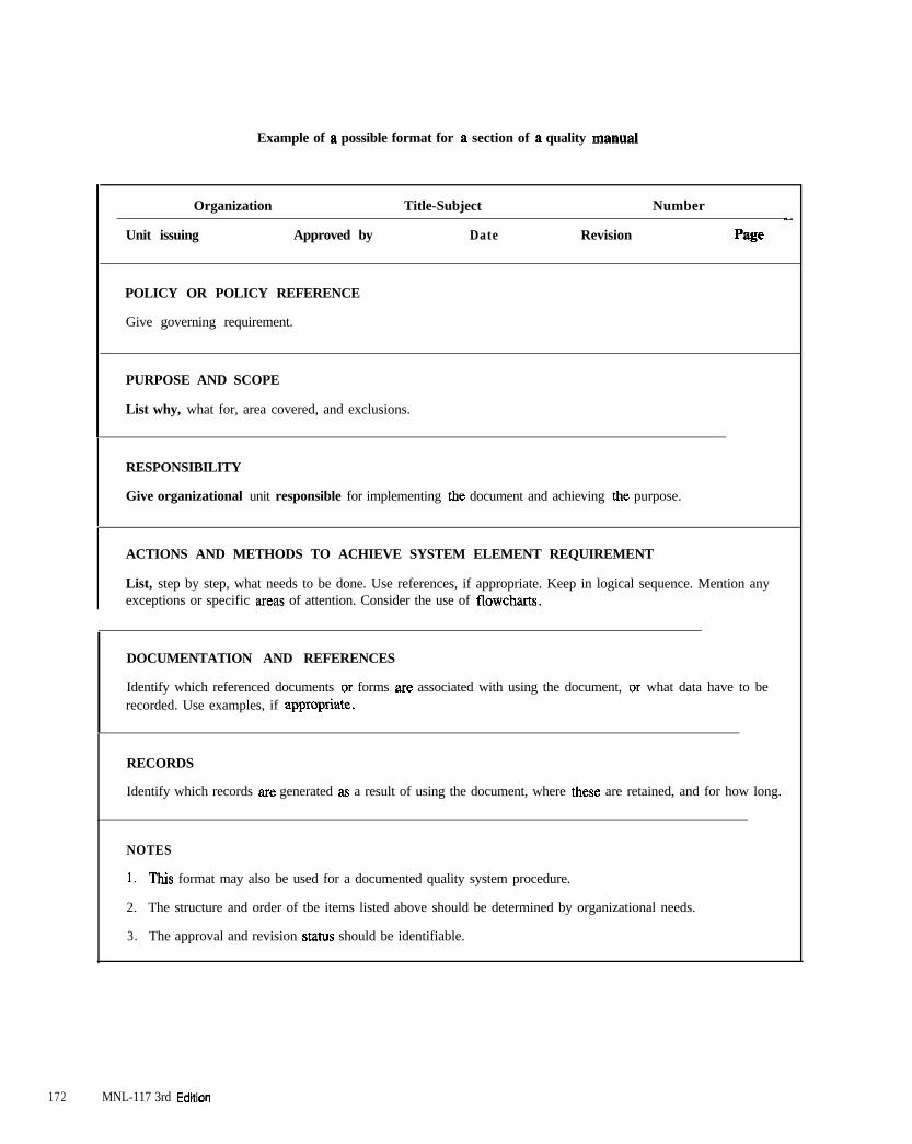
Example of a possible format for a section of a quality manual
Organization Title-Subject Number-
Unit issuing Approved by Date Revision Page
POLICY OR POLICY REFERENCE
Give governing requirement.
PURPOSE AND SCOPE
List why, what for, area covered, and exclusions.
RESPONSIBILITY
Give organizational unit responsible for implementing the document and achieving the purpose.
ACTIONS AND METHODS TO ACHIEVE SYSTEM ELEMENT REQUIREMENT
List, step by step, what needs to be done. Use references, if appropriate. Keep in logical sequence. Mention anyexceptions or specific areas of attention. Consider the use of flowchats.
DOCUMENTATION AND REFERENCES
Identify which referenced documents or forms are associated with using the document, or what data have to berecorded. Use examples, if appropriate.
RECORDS
Identify which records are generated as a result of using the document, where these are retained, and for how long.
NOTES
1. This format may also be used for a documented quality system procedure.
2. The structure and order of tbe items listed above should be determined by organizational needs.
3. The approval and revision stahw should be identifiable.
172 MNL-117 3rd Edfiion
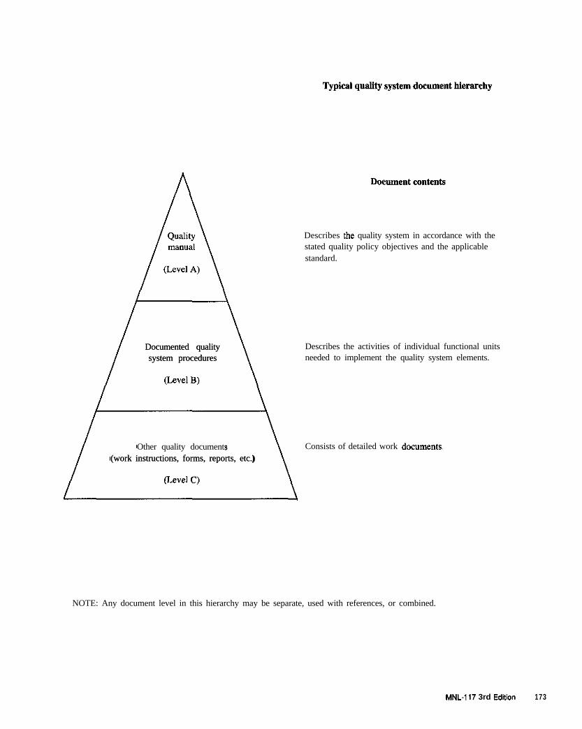
Documented qualityDocumented qualitysystem proceduressystem procedures
Other quality documents(work instructions, forms, reports, etc.)(work instructions, forms, reports, etc.)
Describes the quality system in accordance with thestated quality policy objectives and the applicablestandard.
Describes the activities of individual functional unitsneeded to implement the quality system elements.
Consists of detailed work documents~
NOTE: Any document level in this hierarchy may be separate, used with references, or combined.
MNL-117 3rd Ed&m 173

174 MNL-I 17 3rd Ediiion
APPENDIX B
Design Responsibilities and Considerations
Design calculations should be performed under thesupervision of a registered professional engineer withexperien$e in precast design and should be stamped(sealed). The precast manufacturer should be preparedto assist in the design of panels and connections. Theowner’s designer (architect/engineer) should provide allof the design load information and maintains overalldesign responsibility.
The architect/engineer inexperienced in precast designcan benefit fmm early contact with experienced manu-facturers who can offer constructive advice during pre-liminary design.
It is common practice for the architect/engineer to relyon the precast manufacturer for handling and erectionprocedures, and for ensuring that the unit is adequatelydesigned for the loads incurred during manufacturing,handling, shipping, and installation. All proceduresshould be checked to ensure that they do not cause: (1)cracking, (2) structmal damage, (3) architectural impair-ment, or (4) permanent distortion.
Contract drawings prepared by the architect/engineershould show connection locations in sufficient detail topermit design, estimating, and bidding. Panel manufac-turers, during the preparation of shop drawings, shouldreview connections for tolerances, clearances, practicali-ty, and performance. The manufacturer should call tothe architect/engineer’s attention any foreseen problems.Whether all reinforcement and connection details areshown by the designer or left entirely to the precaster isthe prerogative of the architect/engineer. This decisionmay be determined by local practices or by the projectspecifications.
The general contractor is responsible for the location ofall panel bearing surfaces and anchorages on non-precastconcrete shuctural frames. Changes, other than adjust-ments within the prescribed tolerances, require approvalby the architectiengineer.
Architect/Fmgineer Responsibilities
Responsibility for both stmctmal and aesthetic design ofarchitectural precast concrete should rest with the archi-tect/engineer who should:
1
2
3
4
5,
6,
I.
8.
9.
10.
Provide clear and concise drawings and specifica-tions and, where necessary, interpretation of thecontract documents. Identify the design loads andapplicable codes on the contract drawings.
Establish the standards of acceptability for surfacefinish, color range and remedial procedures fordefects and damage. The architect/engineer’s rightto reject work is provided to protect the owneragainst work which does not meet these standards.
Determine the part, if any, played by the precastconcrete in the support of the structure as a whole.
As part of the design, allow for the effect of differ-ences in material properties, stiffness, temperatures,and other elements which might influence the inter-action of precast concrete units with the stmchxe.
Determine the load reactions necessary for the accu-rate design of both reinforcement and connections.
Evaluate thermal movements as they might affectrequirements for joints, connections, reinforcementand compatibility with adjacent materials.
Analyze the water-tightness of concrete wall panelsystems, evaluating joint treatment, including theperformance of adjacent materials for compatibilityin joint treatment, and the proper sealing of win-dows and other openings, except where such sys-tems are manufactured and marketed as proprietmyitems.
Make selection of surface finishes recognizing cer-tain limitations in materials and production tech-niques in regard to uniform color, texture,repairability and performance, especially the limita-tions which are inherent in natural materials.
Design the supporting shuctme so that it will carrythe weight of the precast concrete as well as anysuperimposed loads; including provisions fordeflection and rotation of the supporting structureduring and after erection of the precast concrete.Specify which members of the supporting struchueare to support the architectural precast concrete,e.g., beams,columns or slabs.
Design the supporting structure for the temporaryloading conditions associated with the proposed erec-
MNL-117 3rd Edition 175
tio” sequence and methods. However, the generalcontractor is responsible for the c~nst~ction means,methods, techniques, sequences, or procedures.
11. Provide details for the interfacing of precast con-Crete and other materials and coo&“& with gener-al co”trac!tor.
12
1 3
14
1 5
16
Make selection of interior panel finishes definingthe area of exposure and the interior appearance foroccupancy requirements, again recognizing materialand production limitations.
Design sandwich wall panels, where applicable, forproper structural and insulating performance.
Design for durable exterior walls with respect toweathering, corrosive environments, heat transfer,fire resistance rating, vapor diffusion, and moist airor rain penetration.
Review and approve precaster’s shop drawings(erection and typical shape drawings) and typicalcalculations.
Specify dimensional and erection tolerances for theprecast concrete, and tolerances for supportingstructure and contractor’s hardware. Any excep-tions to PC1 standard tolerances should be clearlyidentified.
Contract drawings should provide a clear interpretationof the configuration and dimensions of individual “nits,their relation to the stmc~re, and to other materials. Thedrawings must supply the following information:
1. All sections and dimensions necessary to define thesize and shape of the unit.
The transition from one mass of concrete to anotherwithin a precast concrete unit is a prime considera-tion in finalizing shape. Wherever possible, thistransition should be gradual. As a” example, a largeradius or fillet is preferred for the transition from amullion, sill, or eyebmw to a flat portion within aprecast concrete element. This is necessary to mini-mize the possibility of shrinkage stresses causingcrack formation as the point where two concretesections of distinctly different mass meet. A gradu-al flowing transition of shape along with well dis-tributed reinforcement will reduce the risk of thistype of cracking. Where a reasonable transition isnot possible, a concrete mix with low shrinkagecharacteristics (low water and cement content)becomes increasingly important. Alternatively, thetransition may be accomplished by two stage(sequential) casting.
2. Location of all joints, both real (functional) and
3.
4.
5.
6.
I.
8.
9.
10.
11.
12.
13.
false (aesthetic). Joints between units should becompletely detailed.
The materials and finishes required on all surfaces,and a clear indication of which surfaces are to beexposed when in place.
When the surface of a precast concrete element hastwo or more different mixes or finishes, a demarca-tion (reveal) feature is a necessary part of thedesign. The depth of the gmove should be at leastl-1/2 times the aggregate size and the width shouldbe in dimensional lumber increments such as 314or I-10 in. (19 to 38 mm). The groove should gen-erally be wider th”” it is deep in order to strip theelement without damaging the mold. The impor-tance of the separation provided by a demarcationfeature depends on the configuration of the unit onwhich the finishes are combined. For example, agroove or offset is necessary when a” exposedaggregate flat surface is located between widelyspaced ribs with a different surface finish, but notnecessary when a similar flat surface lies betweenclosely spaced ribs. Proper samples should be usedto assess the problem. The importance of the sepa-ration also depends on the specific types of finishesinvolved. If a demarcation groove occurs “ear achange of section, it may create a weakness andcounter any attempt to provide a gradual transitionfrom one. rna.sS to another.
Details for the comers of the stmct”re.
Details for jointing to other materials.
Details for unusual conditions and tire endurancerequirements.
Design loads and moments, which include eccen-tricities.
Deflection limitations.
Specified tolerances and clearance requirements forproper product installation.
Support locations for gravity and lateral loads.
Specific mention of any required erectionsequences.
Reinforcement of units, see Option 1, Table Bl.
Details of connections to the supporting sttuctllre,see Option 1, Table Bl.
This information should be sufficiently detailed toenable the precaster to design and produce the “nitsand for the erector to install them. In mostinstances, precasters will make their own erection
MNL-117 3rd Edition
drawings to identify the information for precastconcrete units and translate these details into pro-duction and erection requirements. A major reasonfor leaving most panel design and hardware detailsto the precaster would be that they normally haveextensive experience in this field and can choosedetails suitable for their plant’s production anderection techniques.
If reinforcement and connections are not detailed by thearchitect/engineer, the performance requirements for thedesign must be clearly identified. The amount of spaceallowed for connections should also be indicated. It isgenerally recommended that the architect/engineer definedead, live, wind and seismic loads and describe a sectionadequate to receive loads, and design the connection foreach typical unit. This approach provides a design com-patible with structural capability, concrete cover, hard-ware protection, appearance, and clearance for mechan-cal services. In addition, it will establish parameters forreasonable modifications which may be suggested by theprecaster to suit their production and erection techniques,and at the same time satisfy project design requirements.Design deviations requested by the precaster or erectorwill be permitted only after the architect/engineer’sapproval of the proposed change.
Constructor Responsibilities
The general conditions of the construction contract usual-ly state the responsibility of the constructor (usually thegeneral contractor) in coordinating the constructionwork. The constructor is typically responsible for projectschedule, dimensions and quantities, coordination withall other construction trades, and for the adequacy ofconstruction means, methods, techniques, sequences, andprocedures of construction, in addition to sz.fety precau-tions and programs in connection with the project. Theprecast concrete manufacturer should not proceed withfabrication of any products prior to receiving approval oferection drawings by the constructor.
The constructor should:
Be responsible for coordinating all information nec-essary to produce the precast concrete erectiondrawings.
Review and approve 01 obtain approval for all pmcast concrete shop drawings which include thescheme of handling, transporting, and erecting theunits, as well as the plan of temporary bracing ofthe structure. (Handling and transporting responsi-bilities depend on whether precast concrete is soldF.O.B. plant, F.O.B. jobsite or erected.)
Be responsible for the coordination of dimensionalin&facing of the precast concrete units with other
materials and construction trades.
Assure that proper tolerances are maintained in thesupporting shucture to provide for accurate fit andoverall conformity with precast concrete erectiondrawings.
Incorporate on or in the structure contractor’s bard-ware according to a layout or anchor plan suppliedby the precaster.
It is the responsibility of the constructor to establish andmaintain, at convenient locations, control points andbenchmarks in an undisturbed condition for use by theerector until final completion and acceptance of a project.
The constructor must be responsible for coordinating pre-cast concrete erection drawings with shop drawings fromother trades so that related items can be transmitted to thedesigner in one package. The constructor must immed-ately notify the precaster of any deviations found indimensions due to plan or construction errors of changesto the structure.
After erection of the precast concrete panels, the con-structor should notify the architect for the pre-finalinspection of the work. Representatives of the precastaand the erector should be prepared to participate in thisinspection tour and answer any questions posed by thearchitect.
Precast Concrete Manufacturer Responsibillities
The extent of design responsibility vested with the pre-cast concrete manufacturer should be clearly defined bythe architect/engineer in the contract documents. TableBl outlines the typical options.
Most work is covered in Option II Table B 1, due to thespecialized nature of precast concrete design. Additionaldesign responsibilities for the manufacturer may occurwhen the architect/engineer uses methods of communica-tion described in Options II and III in Table Bl OptionII (b) may OCCUI when no engineer is involved with thearchitect for precast pmduct design and where doubtfulareas of responsibility may exist. Under this option, theprecaster should employ or retain a structural engineerexperienced in the design of precast concrete, who willensure the adequacy of those structural aspects of theerection drawings, manufacture and installation forwhich the manufacturer is responsible. Option IIl is notyet a common practice but might be used for design ofsystems buildings or with performance specifications.
MNL-117 3rd Edition 177
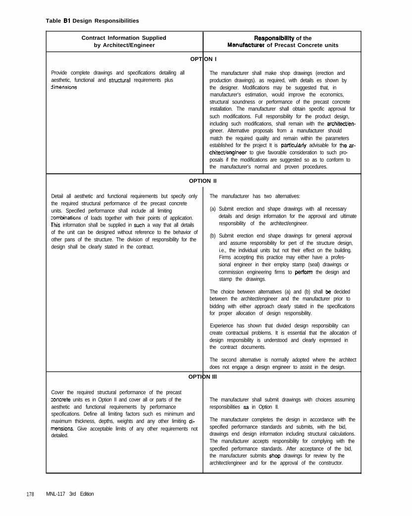
Table 81 Design Responsibilities
Contract Information Suppliedby Architect/Engineer
Responsiblllty of theManufacturer of Precast Concrete units
OPTION I
Provide complete drawings and specifications detailing allaesthetic, functional and structureI requirements plus3imensions
The manufacturer shall make shop drawings (erection andproduction drawings). as required, with details es shown bythe designer. Modifications may be suggested that, inmanufacturer’s estimation, would improve the economics,structural soundness or performance of the precast concreteinstallation. The manufacturer shall obtain specific approval forsuch modifications. Full responsibility for the product design,including such modifications, shall remain with the architectlen-gineer. Alternative proposals from a manufacturer shouldmatch the required quality and remain within the parametersestablished for the project It is palticulady advisable for the ar-chitectiengineer to give favorable consideration to such pro-posals if the modifications are suggested so as to conform tothe manufacturer’s normal and proven procedures.
OPTION II
Detail all aesthetic and functional requirements but specify onlythe required structural performance of the precast concreteunits. Specified performance shall include all limitingxmbinations of loads together with their points of application.lhis information shall be supplied in such a way that all detailsof the unit can be designed without reference to the behavior ofother pans of the structure. The division of responsibility for thedesign shall be clearly stated in the contract.
The manufacturer has two alternatives:
(a) Submit erection and shape drawings with all necessarydetails and design information for the approval and ultimateresponsibility of the architect/engineer.
(b) Submit erection end shape drawings for general approvaland assume responsibility for pert of the structure design,i.e., the individual units but not their effect on the building.Firms accepting this practice may either have a profes-sional engineer in their employ stamp (seal) drawings orcommission engineering firms to pertarm the design andstamp the drawings.
The choice between alternatives (a) and (b) shall be decidedbetween the architect/engineer and the manufacturer prior tobidding with either approach clearly stated in the specificationsfor proper allocation of design responsibility.
Experience has shown that divided design responsibility cancreate contractual problems. It is essential that the allocation ofdesign responsibility is understood and clearly expressed inthe contract documents.
The second alternative is normally adopted where the architectdoes not engage a design engineer to assist in the design.
OPTION Ill
Cover the required structural performance of the precast:oncrete units es in Option II and cover all or parts of theaesthetic and functional requirements by performancespecifications. Define all limiting factors such es minimum andmaximum thickness, depths, weights and any other limiting di-mensions. Give acceptable limits of any other requirements notdetailed.
The manufacturer shall submit drawings with choices assumingresponsibilities es in Option II.
The manufacturer completes the design in accordance with thespecified performance standards and submits, with the bid,drawings end design information including structural calculations.The manufacturer accepts responsibility for complying with thespecified performance standards. After acceptance of the bid,the manufacturer submits shop drawings for review by thearchitect/engineer and for the approval of the constructor.
178 MNL-117 3rd Edition
APPENDIX C
Finish Samples
PRE-BID SAMPLES
&-bid samples, as for all samples, shall only be regard-ed as a standard for performance within the variations ofworkmanship and materials to be expected.
Due to individual preferences, differences in sources ofsupply, or different techniques developed in variousplants serving the same area, the architect/engineershould not expect to select one sample and obtain exactmatching by all precast concrete producers.
Many architects have developed a practice of makingsample selection and approval just prior to bid closing.Thus, for a specific project, the approved precasters Lnames and corresponding sample code numbers, may bepublished in an addendum or approval list given in writ-ing to the general contractor.
This practice may result in a slight variation in color,aggregate or texture (but not necessatily quality) fromdifferent bidders, since the individual precast.%, withinspecification limits, selects the materials and employsthe placing and finishing techniques best suited to theirplant operation. The architect/engineer, when makingprebid approval of samples part of the specifications,should adhere to the following requirements:
Sufficient time should be allowed for the bidder tosubmit samples or information for approval. Timeshould also be provided to enable such approvals tobe conveyed to the precaster in writing so that the
precasta can estimate and submit a bid.
Any prebid submittal should be treated in confi-dence, and the individual producer’s solutionsand/or techniques protected both before and afterbidding.
If the characteristics of submitted prebid samples in anyway deviate from the specifications, the manufacturershould make this clear to the architect/engineer whensubmitting the samples and other required information.For proper evaluation and approval of the samples, themanufacturer should state the reasons for the deviations.These reasons might be the precasta’s concern overcontrolling variation in either color or texture withinspecified limits. In regard to adequacy of specified mate-rials, concerns about satisfying all conditions of thespecifications must be based upon practical plant pro-
duction requirements, and the paformance or weather-ing of the product in its final location.
The architect/engineer may request data as described inArticle 1.5.3 in order to evaluate these deviations. Ifsuch deviations and samples are approved, the originalproject specifications and contract drawings should bechanged accordingly by the architect/engineer.
Since some samples are developed for specific projectswith particular shapes or other characteristics, while oth-ers are more general for simple applications, it is theresponsibility of the precaster either to make sure thatthe architect/engineer does not retain these specific pm-ject samples, or that they are clearly marked with respectto limits of application to prevent their use for unsuitableapplications.
Some examples of use of samples for specific applica-tions are sandblasted lightweight aggregate units forinterior applications, or units that use mixes with lowercompressive strength and/or higher absorption percent-ages for dry, non-corrosive atmospheric conditions, orthe use of concrete elements in temporary buildings,such as exhibit halls.
IDENTIFICATION
A file of sample code numbers with all related datashould be maintained by the precaster to ensure futureduplication of any sample submitted.
MOCKUPS AND PRODUCTION APPROVAL
Aesthetic mockups can offer the opportunity to evaluatethe following factors:
1. Range of acceptable appearance in regard to color,texture, details on the exposed face, and uniformityof rehlms.
2. Sequence of erection.
3. Available methods of bracing units prior to finalstruchual connections being made.
4. Desirability of the method of connection in light ofhandling equipment and erection procedures.
5. Colors and finishes of adjacent materials (windowframes, glass, sealants, etc.)
MNL-I 17 3rd Edition 179
6. Dimensional accuracy of the precast concrete workand the constmctibility of the specified tolerances.
I. The acceptability of the precast concrete panel insidesurface finish (where exposed).
8. Available methods for the repair of chips, spalls orother surface blemishes. Tbe mockup will also estab-lish the extent and acceptability of defects and repairwork.
9. Suitability of the selected sealers.
10. The weathering patterns or rain run-off on a typicalsection of precast concrete panel facade.
Mockups should be pmduced using standard productionequipment and techniques. Some important variables thatshould be controlled as close to actual cast conditionsinclude: retarder coverage rate and m&cd of application,mix design and slump, admixtures, heat of plastic andcured concrete, age, vibration, piece thickness andmethod of cleaning. This is especially important withlight etches which are particularly affected by changingconditions. Special details such as reveal patterns andintersections, comer joinery, drip sections, patterns, colorand texture, and other visual panel characteristics shouldbe demonstrated in large production samples for approval.Changes in aggregate orientation, color tone, and texturecan easily be noted on full scale mockup panels.
The objective of the mockup sample can also be todemonstrate the more detailed conditions that may beencountered in the project ( recesses , reveals ,outside/inside corners, multiple finishes, textures,veneers, etc.). This sample may not be fully representa-tive of the exact finishes that can be reasonably achievedduring mass production.
Mockup panels should contain typical cast-in-inserts,reinforcement, and plates as required for the project.Handling tbe mockup panels saves as a check that thestripping methods and lifting hardware will be suitable.
The architect should visit the precast cc~ncrete plant forexamination and approval (sign and date) of tbe first pro-duction units. To avoid possible later controversies, thisapproval should precede a release for production. Thearchitect should realize, however, that delays in visitingplants for such approvals may upset normal plant opera-tions and the job schedule. It should be clearly stated inthe contract documents how long the production units orthe mockup structure should be kept in the plant or job-site for comparison purposes. It is recommended that thecontract documents permit the approved full-sized unitsto be used in the job installation in the late stages of con-struction. The units should remain identifiable even onthe shucture, until final acceptance of the project. The
panels should be erected adjacent to each other on thebuilding to allow continued comparison, if necessary.
The face of each sample should contain at least two areasof approved size and shape which have been chipped outand then patched and repaired. The color, texture andappearance of patched areas should match that of adja-cent surface; see Article 2.8.
Plant inspection by the architect during panel productionis encouraged. This helps assure both the architect andthe precaster that the desired end results can and arebeing obtained.
MNL-117 3rd Edition
APPENDIX D
Chuck Use and Maintenance Procedure
Strand chucks are precision pieces of equipmentdesigned to hold thousands of pounds of force. It is criti-cal that inspections and preventive maintenance be per-formed periodically to insure their performance. The fol-lowing procedure lists both general rules for usingchucks on a bed and for their maintenance in the shop.
A. Bed Crews
1. Chucks should always be kept clean. Chucks noton the strand should never be thrown on theground. All used chucks should be retuned to thechuck cleaning bench.
2. To secure strand, always use a chuck that ismarked the same size as the strand.
3. Visually inspect each chuck barrel before placing iton the strand. This can be done by glancing downthe center of the chuck to be certain all 3 wedgesare in alignment and that the chuck is clean.
4. To release a chuck from a piece of strand, simplygrasp the chuck and push the barrel forward toremove the wedges. A second alternative would beto force the narrow end of a chuck removal toolinto the barrel end of the assembled chuck. Thiswill force the wedges back into the chuck andrelease it from the strand.
5. If the barrel still does not release, use a grinder tocut the strand approximately two feet on either sideof the chuck and take the chuck with the strand init to the chuck cleaning room so it can be removedproperly. The chuck barrel should never be hit witha hammer, rock, rebar or anything else.
7. If the chuck comes off the strand easily, put thewedges back into the barrel.
8. All chucks and wedges should be cleaned, inspect-ed and lubricated before using.
B. Chuck Mainrenance and Inspection Personnel
1. To remove a chuck which has been brought to theshop on a length of strand, use a chuck removaltool, a vice and a sliding hammer.
a. Place the chuck removal tool over the strand andpush the narrow end up into the barrel end of thechuck.
b. Place the strand (with the chuck removal tool inplace) upright in the vise so that the chuck
removal tool rests flat against the vise. Leave thejaws of the vice loose enough so the strand canmove between them.
c. Use the sliding hammer to strike the open end ofthe chuck. If necessary, another hammer can beused to strike the sliding hammer. Do not strikethe chuck barrel itself with any hard object.
d. Striking the open end with the sliding hammerwill force the chuck aganinst the removal toolpushing the wedges back into the barrel and jar-ring the chuck loose. The chuck can then beremoved either by pressing the removal tool intothe barrel and sliding the chuck~off the strand orby disassembling the chuck.
2. To inspect and lubricate the chucks, use the fol-lowing procedure:
a. Separate all chucks by size. Inspect one size ofchuck completely before placing another sizechuck on the bench.
b. Disassemble all chucks by removing the wedgesand the rubber retaining ring.
c. Put on safety goggles before using the brushesto clean the chucks. Rubber gloves or glovesthat will not get caught in the brushes shouldalso be used.
d. The chuck body can be cleaned with a taperedwire brush.
e. Before removing the rubber retaining ring, thewedges can be cleaned with a motorized taperednylon brush. Care m”st be taken to assure thewire body brush is never used to clean thewedges as damage could result.
f. After cleaning, remove the rubber retaining ringand inspect the wedges for signs of scratches,chipped threads, and score marks. Examine therubber retaining rings for signs of splitting ordamage. Inspect the barrels for signs of excessiverust, corrosion or dents. Discard all damagedparts to assure they are not used in reassembly.
g. Clean and lubricate the barrels and allow themto dry approximately five minutes. Lubricatethe exterior of the jaw assembly.
h. Reassemble the chucks and store them in a rackdesigned to keep them clean and out of the weather.
i. Repeat the process for the next size of chuck.
MNL-117 3rd Edition 181

182 MNL-117 3rd Edition

APPENDIX E
Sample Record Forms
Numerous items which require recordkeeping for confir-mation and evaluation rue outlined in this quality controlmanual. The following record forms are suggested forconsideration in a quality control program. These arc notthe only forms needed for operations, but will provide abeginning paint for form development. It should be rec-ognized that these are only SAMPLE record forms andthat a plant may design its own forms to best serve itsoperation. The importance of any recording form is theinformation that it contains and not its format. Thereports serve as a record of the manufacturing process incase this information is required at some future date.
recorded in numerical terms. Items that must be evah-ated subjectively should be rated in a consistent fash-ion. Items such as length and width measurements canbe given a check mark or “O.K.” if they are within thetolerances listed in Article 7.1.2.
Where extra attention is required to improve material orproduct quality, or improve worker quality perfor-mance, or to identify matters beyond the control of theworker, remarks or sketches should be used. Remarkscan be made on the back of the forms when there is notroom on the front side.
Items that can be measured quantitatively are to be The following forms are included:
1, Aggregate Gradation, Material Finer than 200 Sieve,Aggregate Moisture Content, Organic Impurities
2. Batch Plant Scale Check
3. Concrete Tests Report
4. Tensioning Report
5. Inspection Report
MNL-117 3rd Edition 183

QUALITY CONTROL
AGGREGATE GRADATIONMATERIAL FINER THAN 200
MOISTURE TESTORGANIC IMPURITIES
Date:
IInspector:L
MATERIALSCONTROLS
Sheet No.:
AGGREGATES
Applicable Spec.:
Sieve Weight %Size Retained (g) Retained
FINE AGGREGATE Date Del.:
Specifications Remarks
Cum. % %Passing ASTM C33 Bin_ Tons Rep. _
INo.
IN0.16 I
No. 30
No. 50
No. 100
Pan
F.M.1 ]
Applicable Spec.: COARSE AGGREGATE Date Del.:
Specifications Remarks
Sieve Weight % Cum. % %Size Retained (g) Retained Passing ASTM C33 Bin_ Tons Rep. -
1”
344”
l/2”
3/w
No. 4
No. 6
No. 16
MATERIAL FINER THAN 200 SIEVE (ASTM C117)
I Coarse Agg. Fine Agg. 1 Original Wt. of Sample (at least 2.5 kg
Supplier
Date Del.
Dry Wt. of Orig. Sample
Dry Wt. Sample After Washing
% Material Finer than 200 Sieve =
=E
= C
=I
AGGREGATE MOISTURE CONTENT (C566) ORGANIC IMPURITIES IN SAND (C40)
1 Wt. Sample & Container (Wet), CD)
Wt. Sample & Container (Dry) (E)
Wt. of Container F)
Wt. of Moisture (D-E)
Net Dry Wt. of Sample (E-F)
G)
(H)
% Moisture = 5 x 100 =H
SDeedV Moisture Test %
1 Circle Colorof SodiumHydroxideSolution
Organic Plate No
12
3 (standard)45
Sand Supplier
Date

QUALITY CONTROL Sheet No.:Date:
BATCH PLANTSCALE CHECK
EQUIPMENTCALIBRATION
0 Balance Point at Zero at Start of Check
0 Balance Point Off _ _ Pts.0 Under 0 Over
0 Adjustment Required on Bar to Balance
Scale Report to be CompletedOn first Day of Each Week
Checked by
MNL-117 3rd Edition 185

QUALITY CONTROL
CONCRETETEST REPORT
Job Name Job No.
MATERIALSCONTROLS
Sheet No.:
ALL PRODUCTS
FACE MIX Mix Designation (sample number) Design Strength
BACKUP MIX Mix Designation (sample number)
Impact Hammer (ASTM C805)
Average Rebound CompressiveReading (R) Strength (psi)
COMMENTS:
Concrete Yield Computation (ASTM C138) Air Measurement (ASTM C231)
Cement _ Wt. Container & Concrete- Aggregate Correction Factor(G)
Fine Aggregate _ Wt. Container h, =
Coarse Aggregate __ Wt. Concrete hs =
Admixtures - Slump G = h, - h, =
Admixture (Pigment) _ Entrained Air ~ Apparent Concrete Air Content (A,)
Water No. Gals.- x 8.33- Container Size cu. R. h, =
Total Wt. per Cu. Yd. (A) _ Wt. per Cu. Ft. (B) ha =
Yield = !L =A, = h, - h, =
B A (Air Content) = A, - G =
18% MNL-117 3rd Edition

TENSIONING REPORT
1FAE;EfN
QUALITY CONTROLDate:
I__- __I_.._, mspac,ur; I
Job NamePLOT STRANDS ON GRID
Job No. Pour No. 2322
Bed No. Product 2 120
Member Identifications 191817
Jack Identification 16151 4
:z1 1109a
i54321
A S C D E F G H I J K L M N O P Q R S T U V W X
LOAD CELLS
Strand Size NO. Pattern Strand Brand
Type of Tensioning At End
Strand Temperature “F Theoretical Elongation
Theorelica Gauge Reading Ibs.
Temperature Correction for Elongation ~ ” - * ” Total Elongation
Temperature Correction for Gauge Reading Ibs. = ** Correct& Reading
MNL-I 17 3rd Edition 187
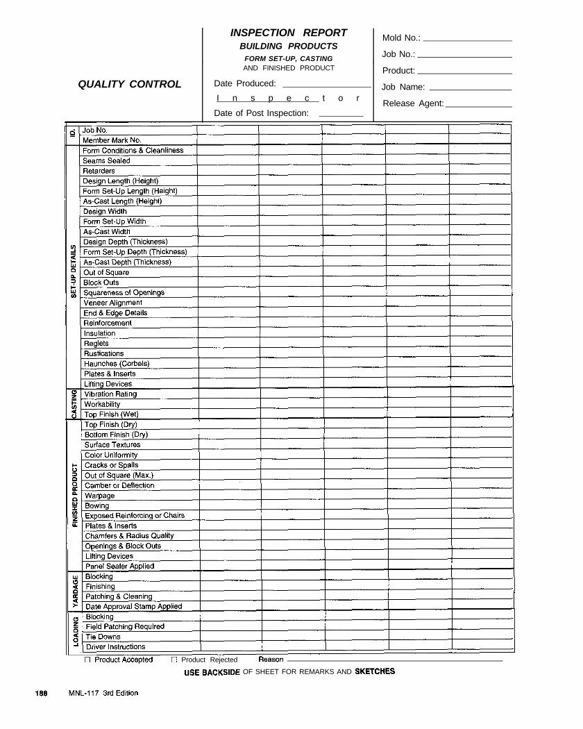
INSPECTION REPORTBUILDING PRODUCTS
FORM SET-UP, CASTINGAND FINISHED PRODUCT
Date Produced:
I n s p e c t o r
Date of Post Inspection:
Mold No.:
Job No.:
Product:
Job Name:
Release Agent:
QUALITY CONTROL
C Product Rejected Fleason
“SE SACKSlOE OF SHEET FOR REMARKS AND SKETCIIES
APPENDIX F
PCI Plant CertMcation Program
In 1958, the Precast!Prestressed Concrete Institute rec-ognized that a dedicated effort to produce quality prod-ucts was necessary and that such an effort would playan integral role in the development of the precast andprestressed concrete industry Following the publishingof several quality and standards manuals, in 1967, theInstitute inaugurated its Plant Certification Programwhich has continued to grow since that time. The pro-gram is now mandatory for all PC1 members and theexpense is borne primarily by the individual participat-ing plants. Unannounced audits are performed twice ayear by a nationally recognized structural engineeringconsultant to assure impartial and uniform evaluations.Auditom ax graduate and professional structural engi-neers with experience in design, construction, and man-ufacture of precast and prestressed concrete products.
The Plant Certification Program was expanded in 1970to include production of architectural precast concreteand again in 1979 to include glass fiber reinforced con-crete products.
In 1988, PC1 implemented a further expansion of thePlant Certification Program to require certification bythe type of products manufactured. This refinement ofthe program requires a more product-specific inspectionand evaluation of a plant’s specialized capabilities.Plants may be cextified in up to four product groups:
Group A Group B Group C Group GArchitectural Bridges Commercial Glass FiberCO”Ck+ (StNctural) Reinforced
concrete
Group A includes two (2) categories; category AT formiscellaneous Architectural Trim elements and catego-ry Al for Architectural precast Concrete,
Within pmduct groups B and C are four (4) categoriesthat identify product types that more effectively conveythe expertise and capability of the individual plant. Thecategories reflect differences in the ways in which theproducts are produced.
PCI’s Plant Certification Program is recognized as aquality assurance agency by the following:
* International Conference of Building Officials(ICBO)
l Building Officials and Code Administrators (COBA)
l Southern Building Code Congress International, Inc.(SBCC)
PC1 Plant Certification is listed in the following specifi-cations:
l Master Specification - American Institute ofArchitects @IA)
l Naval Facilities Engineering Command
* U.S. Army Corps of Engineers
PC1 Plant Certification is highly endorsed by theFederal Highway Administration and is now requiredby more than twelve (12) individual state departmentsof transportation.
Stiztement of Purpose
The certification of a producing plant by PC1 indicatesthe plant has a system of quality in place starting withmanagement. Further, the quality system extends to allareas of plant operations including a thorough and welldocumented quality control program. Certification indi-cates that plant practices are in conformance with time-tested industry standards. It means that the plant regu-larly demonstrates the capability to produce qualityproducts of the type in which they are certified.
PC1 certification does not guarantee the quality of spe-cific precast concrete products.
Qualification of CerriJcation Applicants
Applicants for PC1 Plant Cextification must be produc-ers of precast and/or prestressed concrete products, andmust have been in production for twelve (12) monthsprior to the Initial audit, Participants may be either PC1producer members or non-members.
ojwation of Certifcation Progrfam
All plants are audited at least twice each year. Auditsare unannounced and are usually of two days duration.New participants are audited three times during the fmtYCU.
Auditors compile numerical grades and prepare an in-depth written audit report.
MNL-I 17 3rd Edition 199
Grading is organized in keeping with the Divisions inthis manual, MNL-117, and a specific numericalgrade is required for certification. The audit covers allaspects of production and quality control as well asengineering and general plant practices. During eachaudit, stored products are reviewed and selected pan-els are measured and compared to shop drawings toverify conformance with tolerances. The product eval-uations performed by in-house quality control person-nel are also reviewed to determine if regular monitor-ing is correct and accurate.
Audits and grading of structural precast/prestressedconcrete are based on MNI-116. Audits and grading ofglass fiber reinforced concrete are based on MNL-130.
A list of Certified Plants is published quarterly by PCI.Failure to meet standards results in loss of certification.In this event, certification may be regained only bypassing a new, special audit. Grades cannot be negotiat-ed or mitigated. Specific grades are confidential and are
not released
Plant Certification continues to be rated by users as ahighly effective tool for auditing their internal qualityassurance programs. For further information about theprogram and a list of Certified Plants, please contact:
Director of Certitication ProgramsPrecast’Prestressed Concrete Institute175 West Jackson BoulevardChicago, Illinois 60604(312) 786-0300
GUIDE QUALIFICATION
SPECIFICATION
ARCHITECTURAL PRECAST
The architectural precast concrete manufacturing plantshall be certified by the PrecasUPrestressed ConcreteInstitute PC1 Plant Certification Program. Manufacturershall be certified at time of bidding. Certification shallbe in product group and category [select one or both:AT-Miscellaneous Architectural Trim Units; AI-Architectural Precast Concrete].
190 MNL-117 3rd Edition
APPHVDIX G
Reference Literature
This manual and its commentary refer to many stan-dards and outline recommendations based on the avail-able body of knowledge involving precast and pre-stressed concrete. This appendix provides a basic o”t-line of applicable standards and reference material It isessential that a production facility’s personnel be fur-nished with current reference literature and be encour-age to read and utilize it.
A minimum reference list should include applicable andcurrent publications of the American Society forTesting and Materials: the America” Concrete Institute:the FYecasVF’restressed Concrete Institute; the PortlandCement Association; and similar agencies having perti-nent applicable specifications dealing with manufactureof precast concrete.
American Society for Testing and Materials (ASTM)100 Barr Harbor DriveWest Conshohocken, Pennsylvania 194428-2959
The ASTM Book of Standards contains specificationsand test methods for most of the materials and standardpractices used in the production of architectmal precastconcrete. They also contain specifications and methodsof test for related materials.
The following is a list of individual standards which canbe ordered in section gro”ps published by the society.
ASTMDesignation
A 27lA27M
A 36lA36M
A41
A 47M
A 82
A 108
A 123
Title
Specification for Steel Castings,Carbon, for General Application
Specification for Carbon StructuralSteel
Specification for Ferritic MalleableIron Castings
Specification for Fenitic MalleableIron Castings (Metric)
Specification for Steel Wire, Plain forConcrete Reinforcement
Specification for Steel Bars, Carbon,Cold Finished, Standard Quality
Specification for Zinc (Hot-DipGalvanized) Coatings on Iron andSteel Products
A 143
A 153
A 184/A] 84M
A 185
A216
A 283lA283M
A 307
A325
A 370
A416/A416M
A421
A 496
A 491
A 500
A 512lA572M
Practice for Safeguarding AgainstEmbrittlement of Hot-Dip GalvanizedStructural Steel Products andProcedure for Detecting Embrittlement
Specification for Zinc Coating (Hot-Dip) on Iron and Steel Hardware
Specification for FabricatedDeformed Steel Bar Mats forConcrete Reinforcement
Specification for Steel Welded WireFabric, Plain, for Concrete Rein-forcement
Specification for Stainless and Heat-Resisting Steel Bars and Shapes
Specification for Low and Inter-mediate Tensile Strength CarbonSteel Plates
Specification for Carbon Steel Boltsand Studs. 60,000 PSI TensileStrength
Specification for Structural Bolts,Steel, Heat Treated, 120/105 ksiMinimum Tensile Strength
Test Methods and Definitions forMechanical Testing of Steel Products
Specif icat ion for Steel Strand,Uncoated Seven-Wire for Prestressedconcrete
Specification for Uncoated Stress-Relieved Steel Wire for PrestressedConcrete
Specification for Steel Wire, De-famed, for Concrete Reinforcement
Specification for Steel Welded WireFabric, Deformed, for ConcreteReinforcement
Specif icat ion for Cold-FormedWelded and Seamless Carbon SteelStructural Tubing in Rounds andShapes
Specification for High-Strength Low-
MM-117 3rd Edition 191
A 615/A615M Specification for Deformed and PlainBil let-Steel Bars for ConcreteReinforcement
A 616lA616M Specification for Rail-Steel Deformeda n d P l a i n B a r s f o r C o n c r e t eReinforcement
A617iA617M Specification for Axle-Steel Deformeda n d P l a i n B a r s f o r C o n c r e t eReinforcement
A641 Specif icat ion for Zinc-Coated(Galvanized) Carbon Steel Wire
A 641M Specificat ion for Zinc-Coated(Galvanized) Carbon Steel Wire(Metric)
A 666
A 675lA675M
A 706lA706M
Specification for Austenitic StainlessSteel, Sheet, Strip, Plate and Flat Bar
Specification for Steel Bars, Carbon,Hot-Wrought, Special Quality,Mechanical Properties
Specification for Low-Alloy SteelD e f o r m e d B a r s f o r C o n c r e t eReinforcement
A 722 Specification for Uncoated High-Strength Steel Bar for PrestressingConcrete
A 767lA767M Specificat ion for Zinc-Coated(Galvanized) Steel Bars for ConcreteReinforcement
A 775lA775M
A780
Specif icat ion for Epoxy-CoatedR&forcing Steel Bars
Practice for Repair of Damaged andU n c o a t e d A r e a s o f H o t - D i pGalvanized Coatings
A 884 Specification for Epoxy-Coated SteelWire and Welded Wire Fabric forReinforcement
A 934lA934M
B 633
B 766
C 29
Specificat ion for Epoxy-CoatedPrefabricated Steel Reinforcing Bars
Specification for ElectrodepositedCoatings of Zinc on Iron and Steel
Specification for ElectrodepositedCoatings of Cadmium
Test Method for Unit Weight andVoids in Aggregate
c 3 1 Practice for Making and Curing
Alloy Columbium-Vanadium Struc-tural steel
c 33
c 39
C40
C 4 2
C67
c 70
C 88
c 94
c 109
c 117
C 125
C 127
C 128
c 131
C 136
C 138
C 142
c 143
c 144
Concrete Test Specimens in the Field
Specitication for Concrete Aggregates
T e s t M e t h o d f o r C o m p r e s s i v eStrength of Cylindrical ConcreteSpecimens
Test Method for Organic Impurities inFine Aggregates for Concrete
Test Method for Obtaining andTesting Drilled Cores and SawedBeams of Concrete
Test Methods of Sampling and TestingBrick and Structural Clay Tile
Test Method for Surface Moisture inFine Aggregate
Test Method for Soundness ofAggregates by Use of Sodium Sulfateor Magnesium Sulfate
Specif icat ion for Ready-MixedConcrete
T e s t M e t h o d f o r C o m p r e s s i v eStrength of Hydraulic Cement Mortars( U s i n g 2.in. OI 50-mm C u b eSpecimens)
Test Method for Materials Finer thanNo. 200 (75.pm) Sieve in MineralAggregates by Washing
Terminology Relating to Concrete andConcrete Aggregates
Test Method for Specific Gravity and
Absorption of Coarse Aggregate
Test Method for Specific Gravity andAbsqtion of Fine Aggregate
Test Method for Resistance toDegradation of Small-Size CoarseAggregate by Abrasion and Impact inthe Los Angeles Machine
Test Method for Sieve Analysis ofFine and Coarse Aggregates
Test Method for Unit Weight, Yield,and Air Content (Gravimetric) ofConcrete
Test Method for Clay Lumps and
Friable Particles in Aggregates
Test Method for Slump of HydraulicCement Concrete
Specification for Aggregate for
192 MNL-117 3rd Edition

c 150
c 171
C 172
c 173
c 185
Cl88
Cl91
C 192
c204
c 221
C 231
C233
C260
C295
c309
c330
C342
c 370
c403
Masonry Mortar
Specification for Portland Cement
Specification for Sheet Material8 forCuring concrete
Practice for Sampling Freshly Mixedconcrete.
Test Method for Air Content ofFreshly Mixed Concrete by theVolumetric Method
Test Method for Air Content ofHydraulic Cement Mortar
Test Method for Density of HydraulicCement
Test Method for Time of Setting ofHydraulic Cement by Vicat Needle
Practice for Making and CuringConcrete Test Specimens in theLaboratory
Test Method for Fineness of HydraulicC e m e n t b y A i r P e r m e a b i l i t yApparatus
Test Method for Potential AlkaliReactivity of Cement-AggregateCombinations (Mortar-Bar Method)
Test Method for Air Content ofFreshly Mixed Concrete by thePressure Method
Test Method for Air-EntrainingAdmixtures for Concrete
Specificat ion for Air-EntrainingAdmixtures for Concrete
Guide for Petrographic Examinationof Aggregates for Concrete.
Specification for Liquid Membraw-Forming Compounds for CuringConcrete
S p e c i f i c a t i o n f o r L i g h t w e i g h tAggregates for Structural Concrete
Test Method for Potential VolumeC h a n g e o f C e m e n t - A g g r e g a t eCOlllbiiSiOOS
Test Method for Moisture Expansionof Fired Whiteware F’roducts
Test Method for Time of Setting ofConcrete Mixtures by PenetrationResistance
c457
C 469
Test Method for MicroscopicalDetetination of Parameters of the Aii-Void System in Hardened Conazte
Test Method for Static Modulus ofElasticity and Poisson’s Ratio ofConcrete in Compression
c470 Specification for Molds for FormingConcrete Test Cylinders Vertically
c494 Specification for ChemicalAdmixtures for Concrete
c566 Test Method for Total MoistureContent of Aggregate by Drying
C561 Test Method for Unit Weight ofStmctuml Lightweight Concrete
C578 Specification for Rigid, CellularPolystyrene Thermal Insulation
C586 Test Method for Potential AlkaliReactivity of Carbonate Rocks forConcrete Aggregates (Rock CylinderMethod)
c591 Specification for Unfaced PreformedRigid Cellular PolyisocyanurateThermal Insulation
c595 Specification for Blended HydraulicCements
C 617 Practice for Capping CylindricalConcrete Specimens
C618 Specification for Coal Fly Ash andRaw or Calcined Natural Pozzolan forUse as a Mineral Admixture inConcrete
c641 Test Method for Staining Materials inLightweight Concrete Aggregates
c642 Test Method for Specific Gravity,Absorption, and Voids in HardenedConcrete
C666
C685
C702
C80.5
Test Method for Resistance of Concreteto Rapid Freezing and Thawing
Specification for Concrete Made byVolumetric Batching and ContinuousMixing
Practice for Reducing Samples ofAwgate to Testing Size
Test Method for Rebound Number ofHardened Concrete
c 84.5 Specification for Expansive HydraulicCement
MNL-117 3rd Edition 193
C881
c 9 1 7
c 979
c 989
c 1017
c 1059
c 1064
c 1077
c 1105
C 1126
Specification for Epoxy-Resin-BaseBonding Systems for Concrete
Test Method for Evaluation of CementStrength Uniformity from a Singlesource
Specification for Pigments forIntegrally Colored Concrete
Specification for Ground GranulatedBlast-Furnace Slag for Use inConcrete and Mortars
Specification for ChemicalAdmixtures for Use in ProducingFlowing Concrete
Specification for Latex Agents forBonding Fresh to Hardened Concrete
Test Method for Temperature ofFreshly Mixed Portland Cementconcrete
Practice for Laboratories TestingConcrete and Concrete Aggregates forUse in Construction and Criteria forLaboratory Evaluation
Test Method for Length Change ofConcrete Due to Alkali-CarbonateRock Reaction
Specification for Faced or UnfacedRigid Cellular Phenolic ThermalInsulation
C 1157/C1157M Performance Specif icat ion forBlended Hydraulic Cement
C 1218 Test Method for Water-SolubleChloride in Mortar and Concrete
C 1231 Practice for Use of Unbended Caps inDetermination of CompressiveStrength of Hardened ConcreteCylinders
C 1240 Specification for Silica Fume for Usein Hydraulic-Cement Concrete andMortar
c 1252 Test Methods for Uncompacted VoidContent of Fine Aggregate (asInfluenced by Particle Shape, SurfaceTexture and Grading)
c 1260 Test Method for Potential AlkaliReactivity of Aggregates (Mortar-BarMethod)
D 75 Practice for Sampling Aggregates
D 4791 Test Method for Flat or ElongatedParticles in Coarse Aggregate
E 4 Practices for Force Verification ofTesting Machines
El1 Specification for Wire Cloth Sievesfor Testing Purposes
E 105 Practice for Probability Sampling ofMaterials
E 329 Specification for Agencies Engaged inthe Testing and/or Inspection ofMaterials Used in Construction
For all materials and equipment used in tlte manufactureof precast and prestressed concrete, for which an appro-priate ASTM designation has not been developed, man-ufacturer’s specifications and directions should be avail-able. Such materials and equipment should be used onlywhen they have been shown by tests to be adequate forthe purpose intended and their usage has been approvedby the purchasing entity.
American Concrete InstituteP.O. Box 9094Fmington Hills, MI 48333
1. Manual of Concrete Inspection, SP-2
2. Manual for Concrete Practice
Part 1 Materials and General Properties ofConcrete
Pat 2 Construction Practices and Inspectionof Pavements
Part 3 Use of Concrete in Building - Design,Specifications, and Related Topics
Part 4 Bridges, Substructures, Sanitary, andOther Special Structures; StructuralROptiW
Part 5 Masonry; Precast Concrete; SpecialProcesses
These volumes contain accepted AC1 Standards includ-ing the Building Code requirements and appropriatepublications covering all aspects of concrete proportion-ing, batching, mixing, placing, and curing. They shouldbe available in all precast plants. Some of the more per-tinent recommended practices and guides are as follows:
AC1Designation
116R
117R
Title
Cement and Concrete Terminology
Standard Specifications for Tolerancesfor Concrete Construction andMaterials
194 MNL-117 3rd Edition

201.2R
211.1
211.2
211.3
212.3R
212.4
213R
214
214.3R
221.R
224.1R
225R
301
303R
304R
304.5
305R
306R
308
309R
309.1R
309.2R
311SR
Guide to Durable Concrete
Standard Pract ice for Select ingProportions for Normal, Heavyweight,and Mass Concrete
Standard Pract ice for Select ingProportions for Structural LightweightConcrete
Standard Pract ice for Select ingProportions for No-Slump Concrete
Chemical Admiitures for Concrete
Guide for the Use of High-Rangew a t e r Reducing Admixtures(Supcrplasticizers) in Concrete
Guide for Structural LightweightAggregate Concrete
Recommended Practice for Evaluationof Strength Test Results of Concrete
Simplified V e r s i o n o f theRecommended Practice for Evaluationof Strength Test Results of Concrete
Guide for Use of Normal WeightAggregates in Concrete
Causes, Evaluation, and Repair ofCracks in Concrete Structures
Guide to the Selection and Use ofHydraulic Cements
Specifications for Structural Concretefor Buildings
Guide to Cast-in-Place Architecturalconcrete Practice
Guide for Measuring, Mixing,Transporting, and Placing Concrete
Batching, Mixing, and Job Control ofLightweight Concrete
Hot Weather Concreting
Cold Weather Concreting
Standard Practice for Curing Concrete
Guide for Consolidation of Concrete
Behavior of Fresh Concrete DuringVibration
I d e n t i f i c a t i o n a n d C o n t r o l o fConsolidation-Related SurfaceDefects in Formed Concrete
Batch Plant Inspection and FieldTesting of Ready-Mixed Concrete
318
363R
423.3R
Building Code Requirements forStmchual Concrete and Commentary
State-of-the-Art Report on High-strength concrete
Recommendations for ConcreteMembers Prestressed with UnbondedTendons
439.4R Steel Reinforcement - PhysicalPqmties and U.S. Availability
517.2R Accelerated Curing of Concrete atAtmospheric Pressure
Precast.&%&r&ed Concrete Institute175 W. Jackson Blvd.Chicago, IL 60604
PC1Designation Tiue
MNL-116 Manual for Quality Control for Plantsand Production of Precast andPrestressed Concrete Products
MNL119 PC1 Drafting Handbook Precast andPrestressed Concrete
MNL-120 PC1 Design Handbook - Precast andPrestressed Concrete
MNL-122
SLP-122
Architectural Precast Concrete
PC1 Safety and Loss PreventionMt3IW3l
JR-307 Tolerances for Precast and Prestressedconcrete
TN-3 Efflorescence on Precast Concrete
Portland Cement Association5420 Old Orchard RoadSkokie, IL 60077
PCADwignation Title
EB 1 Design and Control of ConcreteMixtures
IS 214 Removing Stains and Cleaningconcrete Surfaces
American Welding Society550 N.W. LeJeune Rd.P.O. Box 351040Miami, FL 33135
AWSDesignation Title
A5.1 Specif icat ion for Carbon SteelElectrodes for Shielded Metal Arc
MNL-117 3rd Edition 195

A5.4
A5.5
A5.18
A5.20
A5.28
A5.29
B1. l l
B2.1
c5.4
D1.l
D1.4
QCl
z49.1
Welding
Specification for Stainless SteelElectrodes for Shielded Metal ArcWelding
Specification for Low Alloy SteelCovered Arc Welding Electrodes
Specification for Carbon Steel FillerMetals for Gas Shielded Arc Welding
Specif icat ion for Carbon SteelElectrodes for Flux Cored ArcWelding
NRMCADesignation
Pub. #102
Title
Recommended Guide Specificationsfor Batching Equipment and ControlSystems in Concrete Batch Plants
l Concrete Plant Standards of theConcrete Plant ManufacturersBUX?U
l Concrete Plant Mixer Standards ofPlant M i x e r M a n u f a c t u r e r sDivision, CPMB
Specification for Low Alloy Steel l Truck Mixer and Agitator StandardsFiller Metals for Gas Shielded Arc of the Truck Mixer ManufacturersWelding BUl%%J
Specification for Low Alloy SteelElectrodes for Flux Cored ArcWelding
l Certification of Ready MixedConcrete Production Facilities
Guide for Visual Inspection of Welds
Standard for Welding Procedure andPerformance Qualification
Recommended Practices for StudWelding
US. Bureau of ReclamationDenver Federal CenterDenver, CO 80225
. Concrete Manual
Structural Welding Code StructuralSteel
Structural Welding Code - Reinforcingsteel
Specification for Qualification andCertification of Welding Inspectors
Concrete Reinforcing Steel Institute933 N. Plum Gmve RoadSchaumburg, IL 60173
CRSIDesignation Title
l Guidelines for Inspection andAcceptation of Epoxy-CoatedReinforcing Bars at the Job Site
Safety in Welding, Cutting and AlliedProcesses
l Field Handling Techniques forEpay-Coated Rebar at the Job Site
Canadian Standards Association178 Rexdale BoulevardEtobicoke (Toronto)Ontario, Canada M9W lR3
CSADesignation
A23.1iA23.2
Title
Concrete Materials and Methods ofConcrete Construction/Methods ofTest for Concrete
A23.Ul4A Potential Expansivity of Aggregates(FYocedure for Length Change due toA l k a l i - A g g r e g a t e R e a c t i o n i nconcrete Prisms)
National Ready Mixed Concrete Association900 spring StreetSilver Spring, MD 20910
l Fusion Bonded Epoxy CoatingApplicator Plant Cert i f icat ionProgram
196 MNL-117 3rd Edition
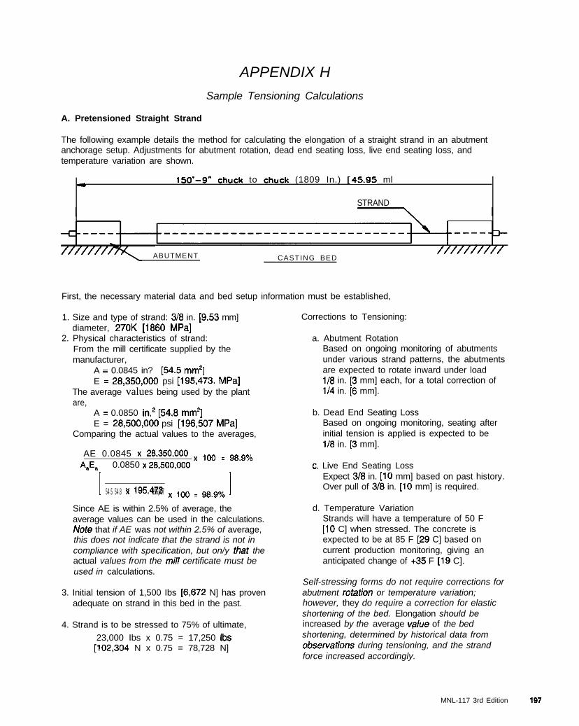
APPENDIX H
Sample Tensioning Calculations
A. Pretensioned Straight Strand
The following example details the method for calculating the elongation of a straight strand in an abutmentanchorage setup. Adjustments for abutment rotation, dead end seating loss, live end seating loss, andtemperature variation are shown.
* lM’-9” chuck to chuck (1809 In.) [45x95 ml
STRAND
ABUTMENT //////////CASTING BED
First, the necessary material data and bed setup information must be established,
1. Size and type of strand: 3/8 in. [9.53 mm]diameter, 270K [1860 MPa]
2. Physical characteristics of strand:From the mill certificate supplied by themanufacturer,
A = 0.0845 in? [54.5 mm’]E = 28,350,OOO psi [195,473. MPa]
The average values being used by the plantare,
Corrections to Tensioning:
A = 0.0850 in.’ [54.8 mm*]E = 28,500,OOO psi [196,507 MPa]
Comparing the actual values to the averages,
AE 0.0845 x 28,350,OOO x ,oo = g8.go/ 0*A 0.0850 x 28,500,OOO
I 54.5 54.8 x x 195,473 196,507 x 100 = 98.9% I
Since AE is within 2.5% of average, theaverage values can be used in the calculations.Note that if AE was not within 2.5% of average,this does not indicate that the strand is not incompliance with specification, but on/y fhat theactual values from the mi// certificate must beused in calculations.
3. Initial tension of 1,500 Ibs [6,672 N] has provenadequate on strand in this bed in the past.
4. Strand is to be stressed to 75% of ultimate,
23,000 Ibs x 0.75 = 17,250 Ibs[102,304 N x 0.75 = 78,728 N]
a. Abutment RotationBased on ongoing monitoring of abutmentsunder various strand patterns, the abutmentsare expected to rotate inward under loadl/8 in. [3 mm] each, for a total correction ofl/4 in. [6 mm].
b. Dead End Seating LossBased on ongoing monitoring, seating afterinitial tension is applied is expected to bel/8 in. [3 mm].
c. Live End Seating LossExpect 318 in. [lo mm] based on past history.Over pull of 3/8 in. [lo mm] is required.
d. Temperature VariationStrands will have a temperature of 50 F[lo C] when stressed. The concrete isexpected to be at 85 F [29 C] based oncurrent production monitoring, giving ananticipated change of +35 F [19 C].
Self-stressing forms do not require corrections forabutment rotation or temperature variation;however, they do require a correction for elasticshortening of the bed. Elongation should beincreased by the average value of the bedshortening, determined by historical data fromobservations during tensioning, and the strandforce increased accordingly.
MNL-117 3rd Edition 197
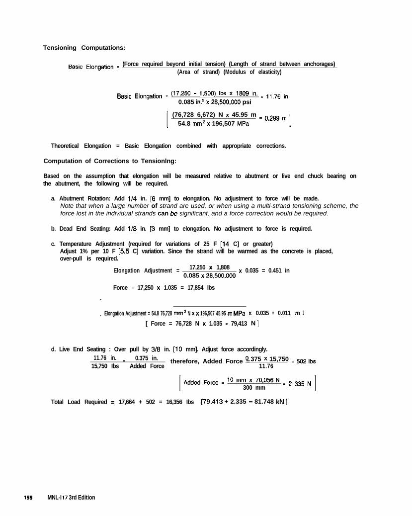
Tensioning Computations:
Basic E,ongation = (Force required beyond initial tension) (Length of strand between anchorages)(Area of strand) (Modulus of elasticity)
Basic Elongation = (17,250 - 1,50’3) Ibs x 1809 in. = 11.76 in,0.085 in.* x 28,500,OOO psi
(76,728 6,672) N x 45.95 m = o,2g8 m
54.8 mm* x 196,507 MPa 1Theoretical Elongation = Basic Elongation combined with appropriate corrections.
Computation of Corrections to Tensionlng:
Based on the assumption that elongation will be measured relative to abutment or live end chuck bearing onthe abutment, the following will be required.
a. Abutment Rotation: Add l/4 in. [6 mm] to elongation. No adjustment to force will be made.Note that when a large number of strand are used, or when using a multi-strand tensioning scheme, theforce lost in the individual strands can be significant, and a force correction would be required.
b. Dead End Seating: Add l/6 in. [3 mm] to elongation. No adjustment to force is required.
c. Temperature Adjustment (required for variations of 25 F [14 C] or greater)Adjust 1% per 10 F [5.5 C] variation. Since the strand will be warmed as the concrete is placed,over-pull is required.
Elongation Adjustment = 17,250 x 1,808 x 0.035 = 0.451 in0.085 x 28.500,OOO
Force = 17,250 x 1.035 = 17,854 Ibs
: Elongation Adjustment = 54.8 76,728 mm* N x x 196,507 45.95 m MPa x 0.035 = 0.011 Ill 1
[ Force = 76,728 N x 1.035 = 79,413 N ]
d. Live End Seating : Over pull by 3/6 in. [lo mm]. Adjust force accordingly.
11.76 in. 0.375 in.15,750 Ibs = Added Force
therefore, Added Force =0 375 x 15,750 = 502 Ibs11.76
Added F,,m = 10 mm X 70.056 N = 2 335 N300 mm I
Total Load Required = 17,664 + 502 = 16,356 Ibs pg.413 + 2.335 = 81.748 kN ]
199 MNL-I 17 3rd Edition
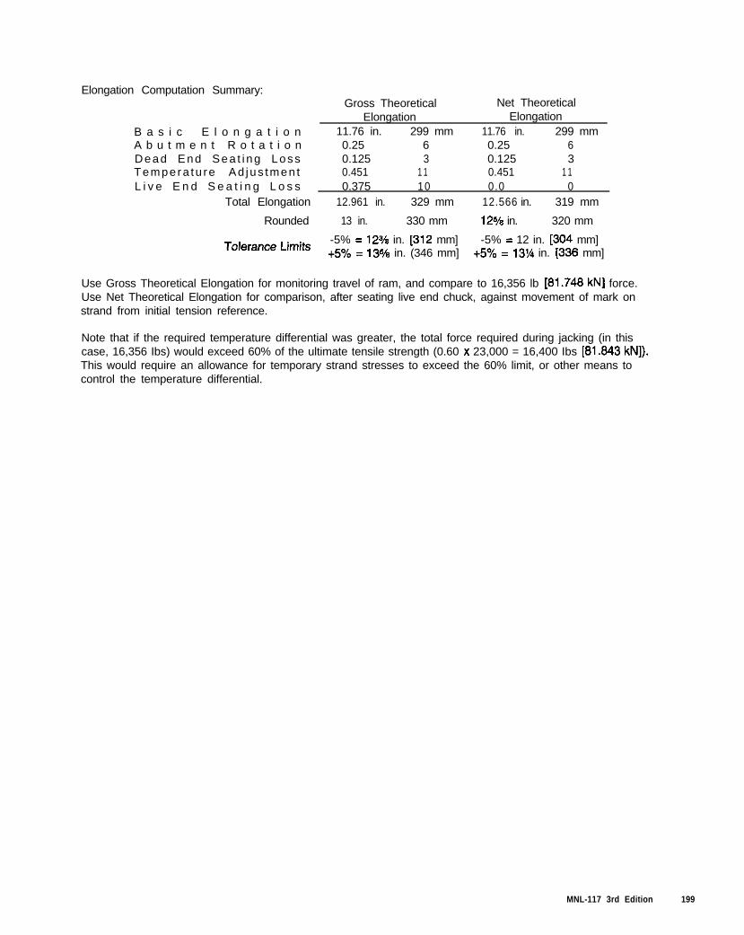
Elongation Computation Summary:Gross Theoretical Net Theoretical
B a s i c E l o n g a t i o nElongation
11.76 in. 299 mmElongation
11.76 in. 299 mmA b u t m e n t R o t a t i o n 0.25 6 0.25 6Dead End Sea t i ng Loss 0.125 3 0.125 3Tempera tu re Ad jus tmen t 0.451 1 1 0.451 1 1L i v e E n d S e a t i n g L o s s 0.375 10 0.0 0
Total Elongation 12.961 in. 329 mm 12.566 in. 319 mm
Rounded 13 in. 330 mm 12*/8 in. 320 mm
T”‘erance Limits-5% = 12V8 in. [312 mm] -5% = 12 in. [304 mm]+5% = 135/s in. (346 mm] +5% = 13% in. [336 mm]
Use Gross Theoretical Elongation for monitoring travel of ram, and compare to 16,356 lb [61.746 kN] force.Use Net Theoretical Elongation for comparison, after seating live end chuck, against movement of mark onstrand from initial tension reference.
Note that if the required temperature differential was greater, the total force required during jacking (in thiscase, 16,356 Ibs) would exceed 60% of the ultimate tensile strength (0.60 x 23,000 = 16,400 Ibs [61.643 kN]).This would require an allowance for temporary strand stresses to exceed the 60% limit, or other means tocontrol the temperature differential.
MNL-117 3rd Edition 199
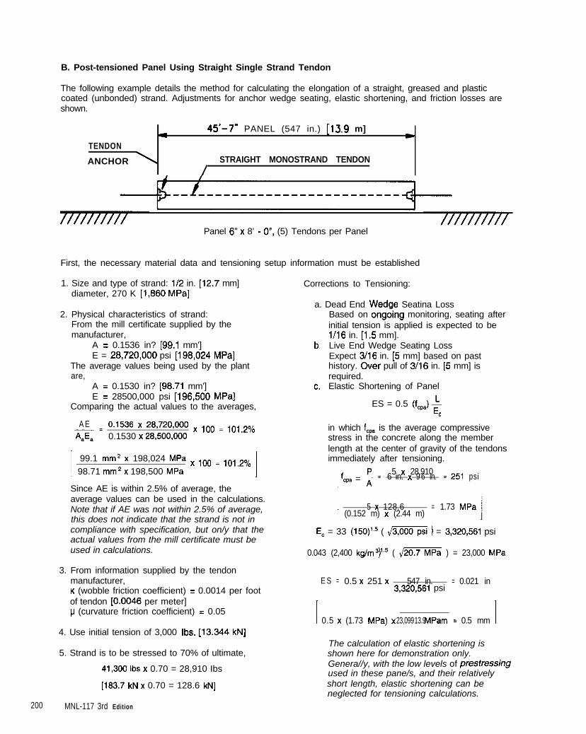
B. Post-tensioned Panel Using Straight Single Strand Tendon
The following example details the method for calculating the elongation of a straight, greased and plasticcoated (unbonded) strand. Adjustments for anchor wedge seating, elastic shortening, and friction losses areshown.
a45’-7” PANEL (547 in.) [13.9 m]
LTENDON
ANCHOR \ STRAIGHT MONOSTRAND TENDON
/
Panel 6” x 8’ - O”, (5) Tendons per Panel
First, the necessary material data and tensioning setup information must be established
1. Size and type of strand: 112 in. [12.7 mm]diameter, 270 K [1,660 MPa]
2. Physical characteristics of strand:From the mill certificate supplied by the
Corrections to Tensioning:
a. Dead End Wedge Seatina Loss
manufacturer,
Based on ongoing monitoring, seating afterinitial tension is applied is expected to bel/16 in. [1.5 mm].
A = 0.1536 in? [99.1 mm’]E = 26,720,OOO psi [196,024 MPa]
The average values being used by the plantare,
b,
A = 0.1530 in? [96.71 mm’]E = 28500,000 psi [196,500 MPa]
Comparing the actual values to the averages,
c.
A E-= 0.1538 x 28,720,ooO x ,oo = ,o,,20,0AS, 0.1530 x 28,500,OOO
I 99.1 mm2 x 198,024 MPa x ,oo = ,o,,23,098.71 mm* x 198,500 MPa I
Since AE is within 2.5% of average, theaverage values can be used in the calculations.Note that if AE was not within 2.5% of average,this does not indicate that the strand is not incompliance with specification, but on/y that theactual values from the mill certificate must beused in calculations.
3. From information supplied by the tendonmanufacturer,K (wobble friction coefficient) = 0.0014 per footof tendon [0.0046 per meter]p (curvature friction coefficient) = 0.05
4. Use initial tension of 3,000 Ibs. [13.344 kN]
5. Strand is to be stressed to 70% of ultimate,
41.300 Ibs x 0.70 = 28,910 Ibs
[183.7 kN x 0.70 = 128.6 kN]
200 MNL-117 3rd Edition
Live End Wedge Seating LossExpect 3/16 in. [5 mm] based on pasthistory. Over pull of 3/16 in. [5 mm] isrequired.Elastic Shortening of Panel
ES = 0.5 (f,,,) +c
in which f,, is the average compressivestress in the concrete along the memberlength at the center of gravity of the tendonsimmediately after tensioning.
f p;cpa = n5 x 28,910 = 2516 in. psix 9 6 in.
: 5 x 128.6 = 1.73 MPa(0.152 m) x (2.44 m)
E, = 33 (150)‘.5 ( \1- ) = 3,320,561 psi
0.043 (2,400 kg/m3)‘,’ ( 420.7 ) = 23,000 MPa
E S = 0.5 x 251 x 547 in. = 0.021 in3,320,561 psi
I 0.5 x (1.73 MPa) x 23,099 13.9 MPa m = 0.5 mm I
The calculation of elastic shortening isshown here for demonstration only.Genera//y, with the low levels of prestressingused in these pane/s, and their relativelyshort length, elastic shortening can beneglected for tensioning calculations.
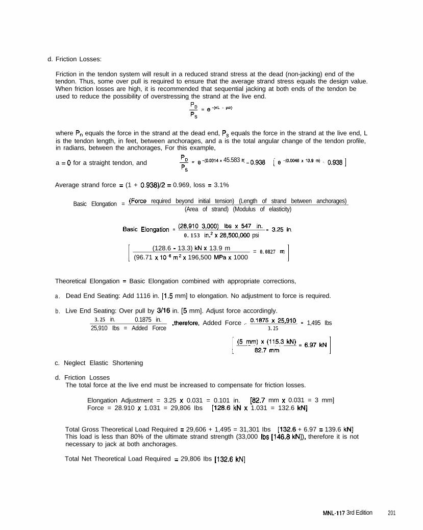
d. Friction Losses:
Friction in the tendon system will result in a reduced strand stress at the dead (non-jacking) end of thetendon. Thus, some over pull is required to ensure that the average strand stress equals the design value.When friction losses are high, it is recommended that sequential jacking at both ends of the tendon beused to reduce the possibility of overstressing the strand at the live end.
where P, equals the force in the strand at the dead end, P, equals the force in the strand at the live end, Lis the tendon length, in feet, between anchorages, and a is the total angular change of the tendon profile,in radians, between the anchorages, For this example,
a = 0 for a straight tendon, and I!= e -,0.0014 x 45.583 ft) = 0,938
PS
[ e -(O.Oc-m x 13.9 rn) = 0.938 ]
Average strand force = (1 + 0.938)/Z = 0.969, loss = 3.1%
Basic Elongation = (F orce required beyond initial tension) (Length of strand between anchorages)(Area of strand) (Modulus of elasticity)
Basic Elongation = (2C’lO 3,000) Ibs x 547 in. = 3.25 in,0.153 in.* x 28,500,oOO psi
:
(128.6 - 13.3) kN x 13.9 m = 0.0827 m(96.71 x lOmE m2 x 196,500 MPa x 1000 I
Theoretical Elongation = Basic Elongation combined with appropriate corrections,
a . Dead End Seating: Add 1116 in. [1.5 mm] to elongation. No adjustment to force is required.
b. Live End Seating: Over pull by 3/16 in. [5 mm]. Adjust force accordingly.3.25 in. 0.1875 in.
25,910 Ibs = Added Force,therefore, Added Force = o.1875 ’ 25*g10
3.25= 1,495 Ibs
(5 mm;2y7t7(jn1y W = 6,g7 kNI
c. Neglect Elastic Shortening
d. Friction LossesThe total force at the live end must be increased to compensate for friction losses.
Elongation Adjustment = 3.25 x 0.031 = 0.101 in. [82.7 mm x 0.031 = 3 mm]Force = 28.910 x 1.031 = 29,806 Ibs [128.6 kN x 1.031 = 132.6 kN]
Total Gross Theoretical Load Required = 29,606 + 1,495 = 31,301 Ibs [132.6 + 6.97 = 139.6 kN]This load is less than 80% of the ultimate strand strength (33,000 Ibs [146.8 kN]), therefore it is notnecessary to jack at both anchorages.
Total Net Theoretical Load Required = 29,806 Ibs [132.6 kN]
MNL-117 3rd Edition 201
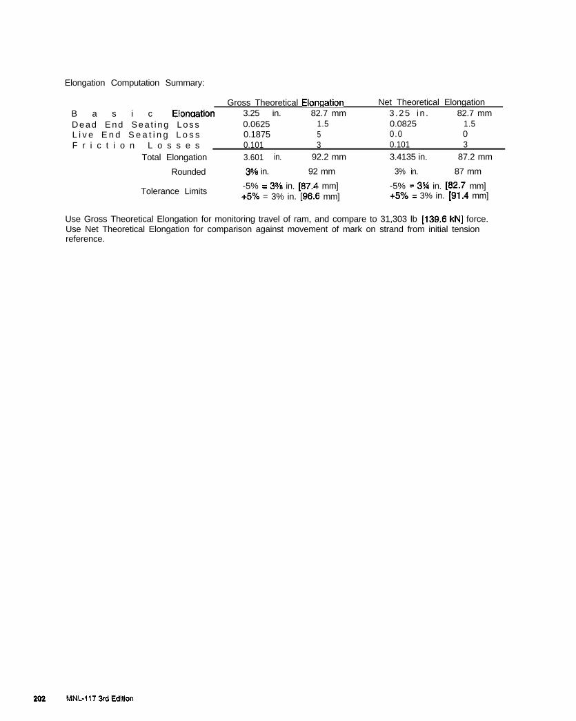
Elongation Computation Summary:
B a s i c ElonaationGross Theoretical Elonqation Net Theoretical Elongation
3.25 in. 82.7 mm 3.25 in . 82.7 mmDead End Sea t i ng Loss 0.0625 1.5 0.0825 1.5L i v e E n d S e a t i n g L o s s 0.1875 5 0.0 0F r i c t i o n L o s s e s 0.101 3 0.101 3
Total Elongation 3.601 in. 92.2 mm 3.4135 in. 87.2 mm
Rounded 34/8 in. 92 mm 3% in. 87 mm
Tolerance Limits-5% = 3% in. [87.4 mm] -5% = 3% in. [82.7 mm]+5% = 3% in. [96.6 mm] +5% = 3% in. [91.4 mm]
Use Gross Theoretical Elongation for monitoring travel of ram, and compare to 31,303 lb 1139.6 kN] force.Use Net Theoretical Elongation for comparison against movement of mark on strand from initial tensionreference.

C. Post-tensioned Panel Using Looped Single Strand Tendon
The following example details the method for calculating the elongation of a looped, greased and plasticcoated (unbonded) strand. Adjustments for anchor wedge seating, and friction losses are shown. Note thatwith the exception of including the curvature friction loss factor, the procedure for calculating the tensioningparameters is the same as for Sample B.
TENDON ANCHOR\
T-8’-0” [2.44 m ]
L\\ .-----------------------,
\
:/
c-_--__--_--__--__-_~-~~~
,’
\ SINGLE MONOSTRAND TENDON
6 ” [D.lS m]
PANEL THICKNESS: 4 in . [O.l m]TENDON CURVATURE: CIRCULAR
First, the necessary material data and tensioning setup information must be established,
2’-4” CO.71 m]
1. Size and type of strand: l/2 in. 112.7 mm]diameter, 270K [1,860 MPa].
2. Physical characteristics of strand:From the mill certificate supplied by themanufacturer,
A = 0.1532 in? [96&l mm’]E = 28,650,OOO psi [197,542 MPa]
The average values being used by the plantare,
A = 0.1530 in? [98.71 mm*]E = 28,500,OOO psi [196,500 MPa]
Comparing the actual values to the averages,
AE _ 0.1532 x 28,650,OOO x ,oo = ,oo,,o/0*Ja 0.1530 x 28,500,OOO
I 98.84 mm2 x 107,542 MPa x ,oo = ,oo.79,098.71 mm* x 106,500 MPa I
Since AE is within 2.5% of average, theaverage values can be used in the calculations.Note that if AE was nof within 2.5% of average,this does not indicate that the strand is not incompliance with specification, buf on/y that theactual values from the mi// certificate must beused in calculations.
3. From information supplied by the tendonmanufacturer,K (wobble friction coefficient) = 0.0007 per footof tendon [0.0023 per meter]p (curvature friction coefficient) = 0.05
Corrections to Tensioning:
a. Dead End Wedge Seating LossBased on ongoing monitoring, seating afterinitial tension is applied is expected to bel/8 in. [3 mm].
b. Live End Wedge Seating LossExpect l/8 in. [3 mm] based on past history.Over pull of 116 in. [3 mm] is required.
c. Elastic Shortening of PanelNeglect effects of elastic shortening for thisshort panel.
MNL-117 3rd Edition 203
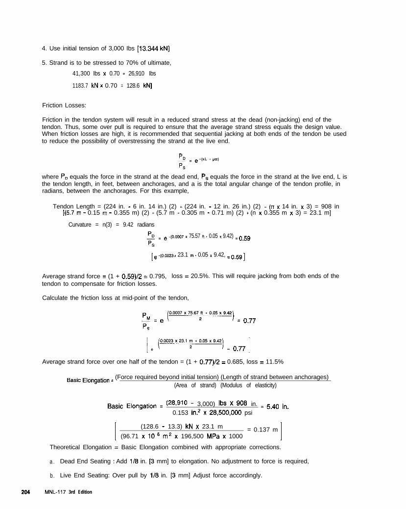
4. Use initial tension of 3,000 Ibs [13.344 kN]
5. Strand is to be stressed to 70% of ultimate,
41,300 Ibs x 0.70 = 26,910 Ibs
1183.7 kN x 0.70 = 128.6 kN]
Friction Losses:
Friction in the tendon system will result in a reduced strand stress at the dead (non-jacking) end of thetendon. Thus, some over pull is required to ensure that the average strand stress equals the design value.When friction losses are high, it is recommended that sequential jacking at both ends of the tendon be usedto reduce the possibility of overstressing the strand at the live end.
where P, equals the force in the strand at the dead end, P, equals the force in the strand at the live end, L isthe tendon length, in feet, between anchorages, and a is the total angular change of the tendon profile, inradians, between the anchorages. For this example,
Tendon Length = (224 in. - 6 in. 14 in.) (2) + (224 in. - 12 in. 26 in.) (2) + (rr x 14 in. x 3) = 908 in[(5.7 m - 0.15 m - 0.355 m) (2) + (5.7 m - 0.305 m - 0.71 m) (2) + (n x 0.355 m x 3) = 23.1 m]
Curvature = n(3) = 9.42 radians
5= e -(O.mm )I 75.57 ” * 0.05 x 9.42) = o,5gPS
[ e -(0.0023 x 23.1 m * 0.05 x 9.42, = 0.59 ]
Average strand force = (1 + 0.59)/2 = 0.795, loss = 20.5%. This will require jacking from both ends of thetendon to compensate for friction losses.
Calculate the friction loss at mid-point of the tendon,
+ = e~joooo7x75.67~*0.05~9.42) = o,77
s
i (e
~o.oo23x23.1~.o.05x9.42) = o,77 ]
Average strand force over one half of the tendon = (1 + 0.77)/2 = 0.685, loss = 11.5%
Basic Elongation _ (Force required beyond initial tension) (Length of strand between anchorages)(Area of strand) (Modulus of elasticity)
Basic Elongation = (28,910 - 3,000) IbS x 908 in. = 5.40 in,0.153 in.’ x 26,500,OOO psi
1
(128.6 - 13.3) kN x 23.1 m = 0.137 m(96.71 x lo-” m2 x 196,500 MPa x 1000 I
Theoretical Elongation = Basic Elongation combined with appropriate corrections.
a . Dead End Seating : Add l/8 in. [3 mm] to elongation. No adjustment to force is required,
b. Live End Seating: Over pull by l/8 in. [3 mm] Adjust force accordingly.
204 MNL-117 3rd Edition
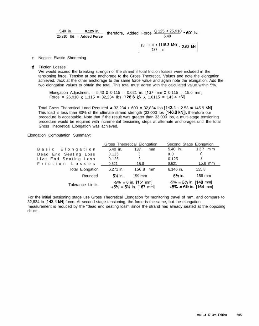
c. Neglect Elastic Shortening
d, Friction LossesWe would exceed the breaking strength of the strand if total friction losses were included in thetensioning force. Tension at one anchorage to the Gross Theoretical Values and note the elongationachieved. Jack at the other anchorage to the same force value and again note the elongation. Add thetwo elongation values to obtain the total. This total must agree with the calculated value within 5%.
5.40 in. 0.125 in.25,910 Ibs = Added Force
therefore, Added Force =0 125 x 25,910 = so0 ,bs5.40
(3 mm) x (115.3 W = 2,53 kN137 mm I
Elongation Adjustment = 5.40 x 0.115 = 0.621 in. 1137 mm x 0.115 = 15.6 mm]Force = 26,910 x 1.115 = 32,234 Ibs [128.6 kN x 1.0115 = 143.4 kN]
Total Gross Theoretical Load Required = 32,234 + 600 = 32,834 Ibs [143.4 + 2.53 = 145.9 kN]This load is less than 80% of the ultimate strand strength (33,000 Ibs [146.8 kN]), therefore ourprocedure is acceptable. Note that if the result was greater than 33,000 Ibs, a multi-stage tensioningprocedure would be required with incremental tensioning steps at alternate anchorages until the totalGross Theoretical Elongation was achieved.
Elongation Computation Summary:
Gross Theoretical Elonqation Second Staqe ElonqationB a s i c E l o n g a t i o n 5.40 in. 137 mm 5.40 in. 1 3 7 m mDead End Sea t i ng Loss 0.125 3 0.0 0L i v e E n d S e a t i n g L o s s 0.125 3 0.125 3F r i c t i o n L o s s e s 0.621 15.8 0.621 15.8 mm
Total Elongation 6.271 in. 156.8 mm 6.146 in. 155.8
Rounded 6’/4 in. 159 mm 8’/8 in. 156 mm
Tolerance Limits-5% = 6 in. [I51 mm] -5% = 5% in. [148 mm]
+5% = 6% in. [167 mm] +5% = 6% in. [164 mm]
For the initial tensioning stage use Gross Theoretical Elongation for monitoring travel of ram, and compare to32,834 lb [143.4 kN] force. At second stage tensioning, the force is the same, but the elongationmeasurement is reduced by the “dead end seating loss”, since the strand has already seated at the opposingchuck.
MNL-I 17 3rd Edition 205

206 MNL-117 3rd Edition
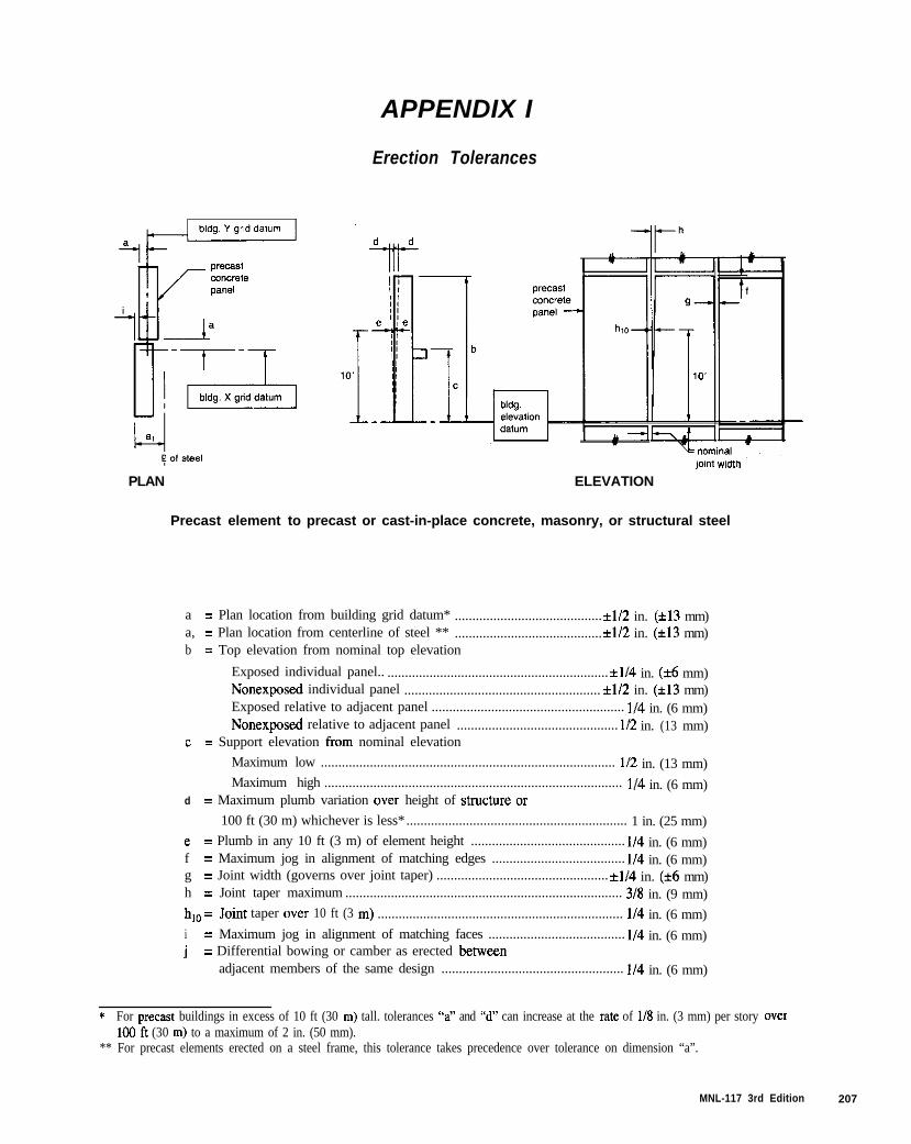
APPENDIX I
Erection Tolerances
PLAN
Precast element to
joint Width
ELEVATION
precast or cast-in-place concrete, masonry, or structural steel
a = Plan location from building grid datum* ..........................................*l/2 in. (i13 mm)a, = Plan location from centerline of steel ** ..........................................*l/2 in. (*13 mm)b = Top elevation from nominal top elevation
Exposed individual panel.. ............................................................... *l/4 in. (*6 mm)Nonexposed individual panel ........................................................ *l/2 in. (k13 mm)Exposed relative to adjacent panel ....................................................... l/4 in. (6 mm)Nonexposed relative to adjacent panel .............................................. l/2 in. (13 mm)
c = Support elevation from nominal elevation
Maximum low .................................................................................... l/2 in. (13 mm)Maximum high ..................................................................................... l/4 in. (6 mm)
d = Maximum plumb variation over height of shucture 01
100 ft (30 m) whichever is less*............................................................... 1 in. (25 mm)
e = Plumb in any 10 ft (3 m) of element height ............................................ 114 in. (6 mm)f = Maximum jog in alignment of matching edges ...................................... l/4 in. (6 mm)g = Joint width (governs over joint taper) ................................................. iI/4 in. (+6 mm)h = Joint taper maximum ............................................................................... 3/S in. (9 mm)h,, = Joint taper over 10 ft (3 m) ...................................................................... l/4 in. (6 mm)
i = Maximum jog in alignment of matching faces ....................................... 114 in. (6 mm)j = Differential bowing or camber as erected between
adjacent members of the same design .................................................... l/4 in. (6 mm)
* For pxcast buildings in excess of 10 ft (30 m) tall. tolerances “a” and “d” can increase at the rate of l/8 in. (3 mm) per story over100 ft (30 m) to a maximum of 2 in. (50 mm).
** For precast elements erected on a steel frame, this tolerance takes precedence over tolerance on dimension “a”.
MNL-117 3rd Edition 207

208 MNL-I 17 3rd Edition
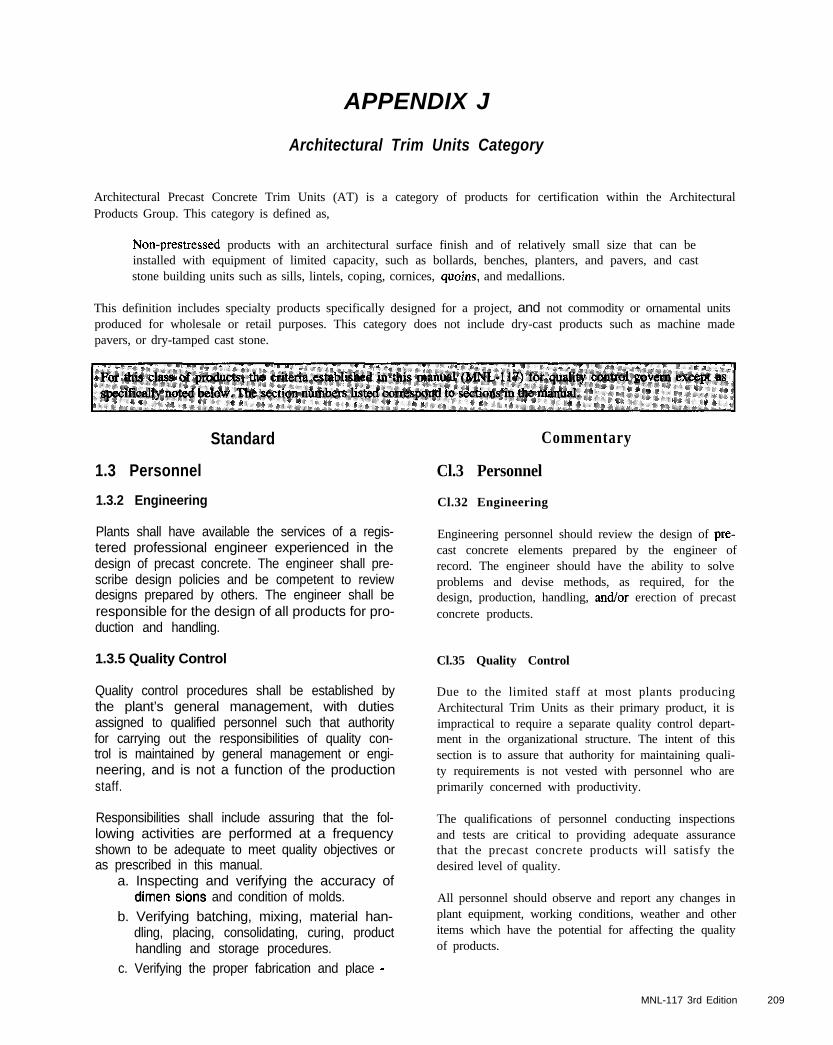
APPENDIX J
Architectural Trim Units Category
Architectural Precast Concrete Trim Units (AT) is a category of products for certification within the ArchitecturalProducts Group. This category is defined as,
Non-prestressed products with an architectural surface finish and of relatively small size that can beinstalled with equipment of limited capacity, such as bollards, benches, planters, and pavers, and caststone building units such as sills, lintels, coping, cornices, quoins, and medallions.
This definition includes specialty products specifically designed for a project, and not commodity or ornamental unitsproduced for wholesale or retail purposes. This category does not include dry-cast products such as machine madepavers, or dry-tamped cast stone.
Standard Commentary
1.3 Personnel Cl.3 Personnel
1.3.2 Engineering Cl.32 Engineering
Plants shall have available the services of a regis-tered professional engineer experienced in thedesign of precast concrete. The engineer shall pre-scribe design policies and be competent to reviewdesigns prepared by others. The engineer shall beresponsible for the design of all products for pro-duction and handling.
Engineering personnel should review the design of pre-cast concrete elements prepared by the engineer ofrecord. The engineer should have the ability to solveproblems and devise methods, as required, for thedesign, production, handling, and/or erection of precastconcrete products.
1.3.5 Quality Control Cl.35 Quality Control
Quality control procedures shall be established bythe plant’s general management, with dutiesassigned to qualified personnel such that authorityfor carrying out the responsibilities of quality con-trol is maintained by general management or engi-neering, and is not a function of the productionstaff.
Due to the limited staff at most plants producingArchitectural Trim Units as their primary product, it isimpractical to require a separate quality control depart-ment in the organizational structure. The intent of thissection is to assure that authority for maintaining quali-ty requirements is not vested with personnel who areprimarily concerned with productivity.
Responsibilities shall include assuring that the fol-lowing activities are performed at a frequencyshown to be adequate to meet quality objectives oras prescribed in this manual.
a. Inspecting and verifying the accuracy ofdimen sions and condition of molds.
b. Verifying batching, mixing, material han-dling, placing, consolidating, curing, producthandling and storage procedures.
c. Verifying the proper fabrication and place -
The qualifications of personnel conducting inspectionsand tests are critical to providing adequate assurancethat the precast concrete products will satisfy thedesired level of quality.
All personnel should observe and report any changes inplant equipment, working conditions, weather and otheritems which have the potential for affecting the qualityof products.
MNL-117 3rd Edition 209
Standardment of reinforcement, and quantity andlocation of cast-in items.
d. Preparing or evaluating mix designs.
e. Taking representative test samples and per-forming all required testing.
f. Inspecting all finished products for conformance with shop drawings, approved sam-ples and project requirements.
g. Preparing and maintaining complete qualitycontrol records.
3.2 Reinforcement and Hardware
3.2.2 Prestressing Materials
This section does not apply to Category AT.
3.3 Insulation
This section does not apply to Category AT.
4.1 Mix Proportioning
4.1 .l Qualification of New Concrete Mixes
Concrete mixes for precast concrete shall be estab-lished initially by laboratory methods. The propor-tioning of mixes shall be done either by a qualifiedcommercial laboratory or qualified precast concreteplant personnel. Mixes shall be evaluated by trialbatches prepared in accordance with ASTM Cl92and plant tests under conditions simulating asclosely as possible actual production and finishing.
Each concrete mix used shall be developed usingthe brand and type of cement, source and gradationof aggregates, and the brand of admixture proposedfor use in the production mixes. If any of these vari-ables are changed, the proportions of the mixtureshall be re-evaluated.
Where a history of use of a coocrete mix with simi-lar proportions and materials to those of the pro-posed production mix is available, laboratory test-ing and evaluation is not required.
Commentary
C4.1 Mix Proportioning
C4.1.1 Quatiftcatfon of New Concrete Mtxes
Due to the large variety of concrete mixes used for rela-tively small volume production runs, it is impractical torequire separate trial batches for all mix designs. Initialmix proportions can be based on previously used con-crete mix designs for which sufficient data is availableto predict strength, durability, and workability of thenew design. Tests for strength and air content should beconducted during the preparation of color and texturesamples to confirm the applicability of the referenceconcrete mix.
Concrete mixes shall be proportioned and/or evalu-ated for each individual project with respect to
210 MNL-I Ii’ 3rd Edition
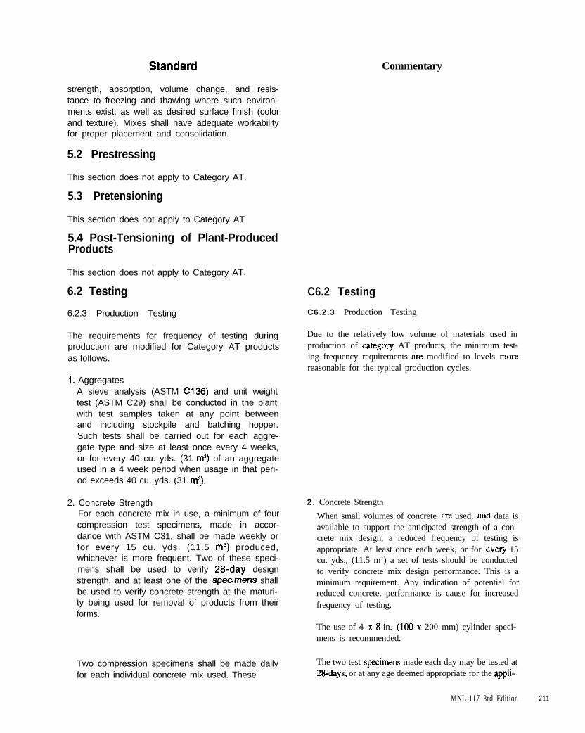
Commentary
strength, absorption, volume change, and resis-tance to freezing and thawing where such environ-ments exist, as well as desired surface finish (colorand texture). Mixes shall have adequate workabilityfor proper placement and consolidation.
5.2 Prestressing
This section does not apply to Category AT.
5.3 Pretensioning
This section does not apply to Category AT
5.4 Post-Tensioning of Plant-ProducedProducts
This section does not apply to Category AT.
6.2 Testing
6.2.3 Production Testing
The requirements for frequency of testing duringproduction are modified for Category AT productsas follows.
1. AggregatesA sieve analysis (ASTM C136) and unit weighttest (ASTM C29) shall be conducted in the plantwith test samples taken at any point betweenand including stockpile and batching hopper.Such tests shall be carried out for each aggre-gate type and size at least once every 4 weeks,or for every 40 cu. yds. (31 ma) of an aggregateused in a 4 week period when usage in that peri-od exceeds 40 cu. yds. (31 mS).
2. Concrete StrengthFor each concrete mix in use, a minimum of fourcompression test specimens, made in accor-dance with ASTM C31, shall be made weekly orfor every 15 cu. yds. (11.5 m3) produced,whichever is more frequent. Two of these speci-mens shall be used to verify 28-day designstrength, and at least one of the specjmens shallbe used to verify concrete strength at the maturi-ty being used for removal of products from theirforms.
Two compression specimens shall be made dailyfor each individual concrete mix used. These
C6.2 Testing
C6.2.3 Production Testing
Due to the relatively low volume of materials used inproduction of categmy AT products, the minimum test-ing frequency requirements are modified to levels morereasonable for the typical production cycles.
2. Concrete Strength
When small volumes of concrete are used, and data isavailable to support the anticipated strength of a con-crete mix design, a reduced frequency of testing isappropriate. At least once each week, or for every 15cu. yds., (11.5 m’) a set of tests should be conductedto verify concrete mix design performance. This is aminimum requirement. Any indication of potential forreduced concrete. performance is cause for increasedfrequency of testing.
The use of 4 x 8 in. (100 x 200 mm) cylinder speci-mens is recommended.
The two test specimens made each day may be tested at28&y% or at any age deemed appropriate for the appli-
MNL-117 3rd Edition 211
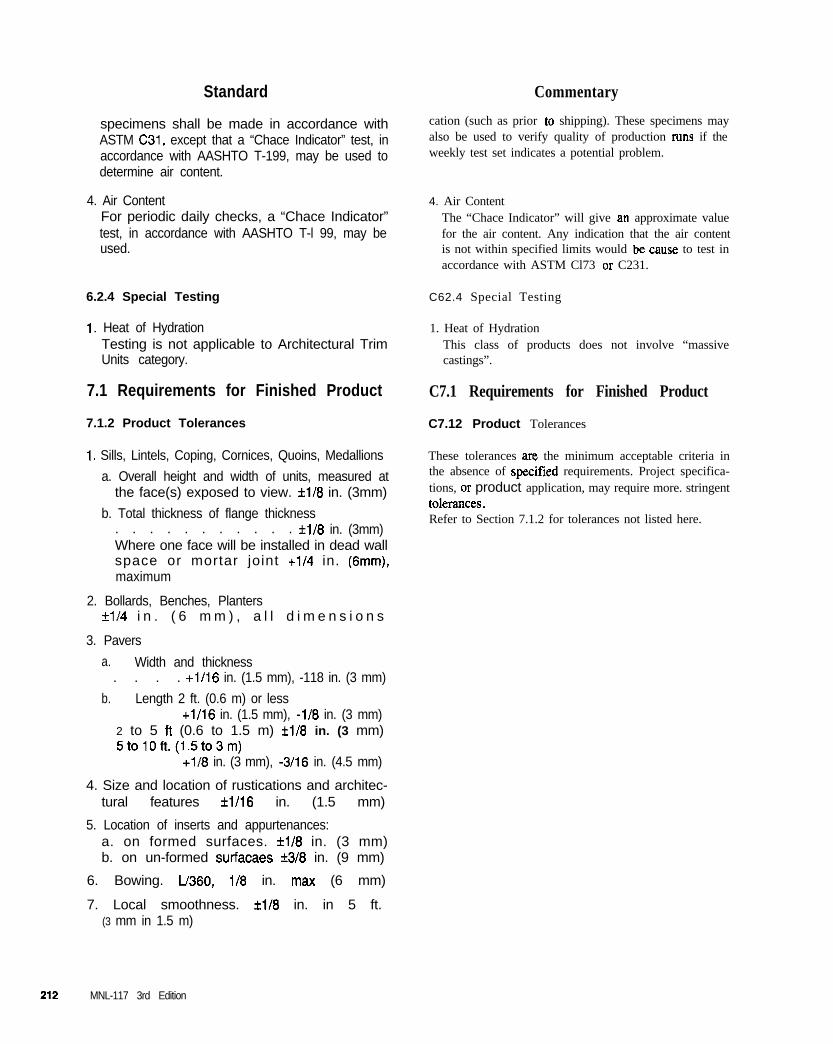
Standard Commentary
specimens shall be made in accordance withASTM C31, except that a “Chace Indicator” test, inaccordance with AASHTO T-199, may be used todetermine air content.
4. Air ContentFor periodic daily checks, a “Chace Indicator”test, in accordance with AASHTO T-l 99, may beused.
6.2.4 Special Testing
1. Heat of HydrationTesting is not applicable to Architectural TrimUnits category.
7.1 Requirements for Finished Product
7.1.2 Product Tolerances
1. Sills, Lintels, Coping, Cornices, Quoins, Medallions
a. Overall height and width of units, measured atthe face(s) exposed to view. f118 in. (3mm)
b. Total thickness of flange thickness. . . . . . . . . . . *l/8 in. (3mm)Where one face will be installed in dead wallspace or mortar joint +1/4 in. (6mm),maximum
2. Bollards, Benches, Plantersf1/4 i n . ( 6 m m ) , a l l d i m e n s i o n s
3. Pavers
a. Width and thickness. . . . +1/16 in. (1.5 mm), -118 in. (3 mm)
b. Length 2 ft. (0.6 m) or less+1/16 in. (1.5 mm), -i/8 in. (3 mm)
2 to 5 ft (0.6 to 1.5 m) f1/8 in. (3 mm)5tolOft.(1.5to3m)
+I/8 in. (3 mm), -3/16 in. (4.5 mm)
4. Size and location of rustications and architec-tural features *l/16 in. (1.5 mm)
5. Location of inserts and appurtenances:a. on formed surfaces. *l/8 in. (3 mm)b. on un-formed surfacaes f3/8 in. (9 mm)
6. Bowing. L/360, l/8 in. max (6 mm)
7. Local smoothness. ii18 in. in 5 ft.(3 mm in 1.5 m)
cation (such as prior to shipping). These specimens mayalso be used to verify quality of production runs if theweekly test set indicates a potential problem.
4. Air ContentThe “Chace Indicator” will give an approximate valuefor the air content. Any indication that the air contentis not within specified limits would be cause to test inaccordance with ASTM Cl73 or C231.
C62.4 Special Testing
1. Heat of HydrationThis class of products does not involve “massivecastings”.
C7.1 Requirements for Finished Product
C7.12 Product Tolerances
These tolerances ax the minimum acceptable criteria inthe absence of specitied requirements. Project specifica-tions, or product application, may require more. stringenttolerances.Refer to Section 7.1.2 for tolerances not listed here.
MNL-117 3rd Edition

6. Warping:
a. Pavers.The numerically greater of l/16 in. (1.5
mm)‘or l/32 in. per foot, (0.75 mm per 300mm) of distance from nearest adjacent corner.
b. Other productsl/16 in. per foot (1.5 mm per 300 mm)
of distance from nearest adjacent corner,II4 in. maximum (3 mm)
MNL-117 3rd Edflion 213

214 MNL-117 3rd Edition
INDEX
Term Section Number TWIII Section Number
Absorption Test .............................................. 6.2.2 (10)
Accelerated Curing ................................................ 2.2.6General ............................................................. 4.21.1Live Steam ....................................................... 4.21.2Radiant Heat & Moisture ................................. 4.21.3Temperature ..................................................... 4.21.1
Acceptability.. ......................................................... 1.5.4Appearance ............................................................ 2.9
Acid Etching ........................................................... 2.7.4
Admixtures.. ........................................................... 3.1.7Accelerating ....................................................... 3.1.7Air Entraining .................................................... 3.1.7Batching ........................................................... 4.16.5Certification .................................................. 6.2.2 (5)Cololing ............................................................. 3.1.7Dispensers.. ........................................................ 4.9.4Effects of.. ............................................................. 4.8High Range Water Reducer ........................ 3.1.7, 4.6Mineral ............................................................... 3.1.7Retarding.. .......................................................... 3.1.7storage ............................................................... 4.9.4
AggregateBatching ........................................................... 4.16.2Exposure ............................................................. 2.7.1Gradation ............................ 3.1.3, 6.2.2 (2). 6.2.3 (1)Moisture Content .............................................. 4.16.2Segregation.. ..................................................... 4.18.3Segregation Lines .................................................. 2.9Storage ............................................................... 4.9.2Temperature. .................................................... C3.1.2Testing .......................................... 6.2.2 (2). 6.2.3 (1)Transparency or Shadowing ............................ C2.7.2
Aggregates, Backup ............................................... 3.1.4
Aggregates, Facing ................................................. 3.1.3
Air ContentTesting.. ...................................... 6.2.2 (IO), 6.2.3 (4)
Air Entrainment ......................................... 4.2, C4.17.3
Air Temperature .............................................. 6.2.3 (7)
Alkali-Carbonate ReactionTesting. ......................................................... 6.2.2 (2)
Alkali-Silica ReactionTesting.. ........................................................ 6.2.2 (2)
AnchorageProtection ......................................................... 5.3.14
Architectural Trim Units ............................. Appendix J
Backup ConcreteAggregates ......................................................... 3.1.4Bleeding ................................................................ 2.9Consolidation.. ................................................. 4.19.3Placing.. ........................................................... 4.18.10
Backup Mix ...................................................... C4.1, 4.3
Bar Supports ................................................ 3.2.1, 5.1.4
Batch Plant.. ........................................................... 4 .9.1
Batcbers, General.. .............................................. 4.13.1
BatchingAdmixtures.. ..................................................... 4.16.5Aggregates ....................................................... 4.16.2Cement ............................................................. 4.16.3General ............................................................. 4.16.1Lightweight Aggregates ................................... 4.17.7Pigment ............................................................ 4.16.3Water.. .............................................................. 4.16.4
Batching Equipment
Tolerances ........................................................... 4.10
Blocking Stains.. ........................................................ 2.9
Bond Breakers.. ...................................................... 2.7.9
Brick ........................................................................ 2.7.9
Bugboles ........................................... 2.9, C2.7.2, C2.7.3
Cage Assemblies.. ................................................... 5.1.3
Calibration Records.. ............................................. 6.3.5Gauging Systems ................................................ 5.2.4Jacking Equipment ............................................. 5.2.7
Cement .................................................................... 3.1.2Batching ........................................................... 4.16.3Lumps ................................................................. 4.9.3Mill Certificates.. .......................................... 6.2.2 (1)storage ............................................................... 4.9.3Temperature.. ................................................. C4.18.7
Chlorides ................................................................. 3.1.7
Chuck Seating ...................................................... 5.3.10
Chucks .................................................................... 3.2.2Splice .................................................................. 5.3.5Strand ................................................................. 5.3.5Use and Maintenance ............................. Appendix D
Cleaning .................................................................. 2.6.4
Coarse Aggregates ................................................. 3.1.3
MNL-117 3rd Edition 215
TL?rm Section Number Term Section Number
Size. .................................................................... 3.1.3Weighing ............................................................. 4.1 1
Coatings.. .............................................................. 2.7.12
Cold Weather, Mixing.. ....................................... 4.17.8
COkWUniformity .................................. 2.9, 3.1.2, 3.1.7, 4.6
Compressive Strength
Testing ........................................ 62.2 (10). 6.2.3 (2)
ConcreteHandling. ............................................................ 2.2.5Temperature.. ...................................... 2.2.6, 6.2.3 (6)
Concrete Mixtures.......................................... 6.2.2 (10)
Concrete Records ................................................... 6.3.4
ConcreteTemperature.. .............. 4.18.5,4.18.7,4.18.8
Concrete Transportation EquipmentAgitating ............................................... 4.14.2, 4.18.2General ............................................................. 4.14.1
ConsolidationBackup Mixes .................................................. 4.19.3External Form Vibrators .................................. 4.19.5Face Mixes ....................................................... 4.19.3Flowing Concrete .......................................... C4.19.4General ............................................................. 4.19.1lnternai Vibrators ............................................. 4.19.4Lightweight Concrete.. ..................................... 4.19.2Surface Vibrators ............................................. 4.19.6Vibrating Tables ............................................... 4.19.7
Corrosion ProtectionHardware.. .......................................................... 3.2.3Lifting Devices.. ................................................. 3.2.4
Cover of Reinforcing Steel.. .................................. 5.1.4
Cracks .............................................................. C2.8, 2.9
Crazing ....................................................... C2.1.2, C2.9
Curing ..................................................................... 2.2.6Facilities ............................................................. 2.2.6General ............................................................. 4.20.1Membrane Curing Compound ......................... 4.22.3Mois t ............................................................... 4.22.1Moisture Retention Enclosures ........................ 4.22.2Temperature ..................................................... 4.20.2
Design Responsibilities.. ............................. Appendix B
Detensioning ......................................................... 5.3.13
Dissimilar Metals ............................................ 2.5, 3.2.3
Dunnage.. ................................................................ 2.6.3
Durability ................................................................ 4.1.4
EtIlorescence.. ...................................................... C3.1.7
Electrodes .................................................................. 3.4
ElongationCalculations ...................................................... 5.3.10Corrections ....................................................... 5.3.10Measurement ...................................................... 5.3.9Strand.. ............................................................... 3.2.2
Epoxy Coated Reinforcement. .............................. 5.1.2Bar Supports ....................................................... 5.1.4Repair.. ............................................................... 5.1.3
Face Mix ........................................................... C4.1, 4.3Consolidation ................................................... 4.19.3Gap-graded ................................................... 6.2.2 (2)Placing .............................................................. 4.18.9Thickness ......................................................... 4.18.9
Facing Aggregates.................................................. 3.1.3
FalseSet ............................................................. C4.17.9
Fine Aggregates ...................................................... 3.1.3Weighing.. ........................................................... 4.1 1
FinishAcceptability ...................................................... 1.5.4Samples ................................................... Appendix C
FinishesAcid Etched. ....................................................... 2.7.4Clay Product Veneer Facing .............................. 2.7.9Form Liner.. ....................................................... 2.7.8Honed or Polished. ............................................. 2.7.7Retarded ............................................................. 2.7.5Sand Embedded Materials ............................... 27.10Sand or Abrasive Blast ........................................ 2.73Smooth............................................................... 2.7.2Stone Veneer Facing.. ........................................ 2.7.9Tooled or Bushhammered .................................. 2.7.6Unformed Surface ............................................ 2.7.1 I
Finishing Areas ...................................................... 2.2.6
Flash Set ................................................................ 4.17.8
Floating ................................................................. 2.7.11
Fly Ash ................................................................. C3.1.7
Force Corrections ................................................ 5.3.11
Force Measurement.. ................................... 5.2.2, 5.2.3Tolerance ............................................................ 5.3.8
Form Release Agents ....................................... 6.2.2 (9)
Form Shortening .................................................. 5.3.10
FormsRecords ................................................... Appendix E
Freeze-Thaw Resistance ................................. 4.1.4, 4.2
216 MNL-117 3rd Edition
Term Section Number TerLll Section Number
Freeze-Thaw Tests ........................................... 6.2.4 (2)
Galvanized Hardware ........................................... 3.2.3Galvanized Reinforcement ................................. 3.2.1Bar Supports ....................................................... 5.1.4Repair ................................................................. 5.1.3
Galvanizing.. ........................................................... 2.3.1
Gauging Systems .................................................... 5.2.4
Grout.. ..................................................................... 3.2.2
HandlingProduct ............................................................... 2.6.1
Hardware.. .............................................................. 3.2.3Anchorage ............................................................. 2.5Certification. ................................................. 6.2.2 (7)Fabrication ......................................................... 2.2.4Galvanized ......................................................... 3.2.3Installation.. ........................................................... 2.5Materials.. ........................................................... 3.2.3Storage ............................................................... 2.2.4
Heat of Hydration ............................................ 6.2.4 (1)
Hot WeatherMixing .............................................................. 4.179
IIlS&SCertification.. ................................................ 6.2.2 (7)Nonferrous ......................................................... 3.2.3Wood.. ................................................................ 3.2.3
InspectionPost-pour ............................................................ 6.1.2Pre-pour.. ............................................................ 6.1.2
Insulation ................................................................... 3.3
Jacking ForceAllowable ......................................................... 5.3.12
LiftingDevices ............................................................... 3.2.4Loops.. ................................................................... 2.5
Lightweight Aggregates.................................. 3 J.5, 4.3Batching ........................................................... 4.17.7Consolidation ................................................... 4.19.2Mix Proportioning.. ............................................... 4.5
Loading.. ........ . .............................................. 2.2.7, 2.6.5
Lumber ...................................................................... 2.5
M&kaolin.. ............................................................ 3.1.7Batching ........................................................... 4.16.5Curing ............................................................... 4.20.1storage ............................................................... 4.9.4
MixProportioning _._,.,.___, 4.1,4.1.1,4.4,4.1.4,4.5,4.6
Mixers
Maintenance ..................................................... 4.13.4Requirements ....................................... 4.13:2,4.13.3
MixingCold Weather ................................................... 4.17.8General.. ............................................... 4.16.1.4.17.1Hot Weather.. ................................................... 4.17.9Methods.. .......................................................... 4.17.2Shrink Mixing .................................................. 4.17.5Stationary Mixers.. ........................................... 4.17.4Time ................................................................. 4.17.3Truck Miiing ................................................... 4.17.6
Mixing Water ............................................ C3.1.2, 3.1.6
Mockup Process ........................................................ 2.9
Mockups .................................................................. 1.5.4
Moisture Meters ................................................... 4.16.2
Mold .................................................... 2.2.2, 2.4.1, 2.4.2Beds ................................................................. C2.2.2Construction ....................................................... 2.4.1Envelope .......................................................... C2.4.1Fabrication ......................................................... 2.2.2Master.. ........................................................... C.2.4.1Materials.. ........................................................... 2.4.1Plastic ................................................................. 2.4.1Preparation ....................................................... 4.18.4Steel.. .................................................................. 2.4.1
Nonferrous Metals ................................................. 3.2.3
Paint ...................................................................... 2.7.12
Pigments ................................................................. 3.1.7Batching ........................................................... 4.16.3Certification.. ................................................ 6.2.2 (6)storage ............................................................... 4.9.4
PlacingAggregate Segregation ..................................... 4.1 X.3Backup Concrete ............................................ 4.18.10Cold Weather Conditions.. ............................... 4.18.8Concrete Temperature.. ............ 4.18.5,4.18.7,4.18.8Equipment ........................................................... 4.15Facing Concrete ............................................... 4.18.9General ............................................................. 4.18.1Hot and Windy Conditions .............................. 4.18.7Severe Weather Conditions.. ............................ 4.18.5Wet and Rainy Conditions ............................... 4.18.6
Plant Certification Program ...................... Appendix F
Plant Facilities. ............................................. 2.2.1, 2.2.5
Plant Manual .......................... 1.2.1, 1.2.2, Appendix A
Plastic Shrinkage Cracking ...................... 4.8.7.4.20.1
Post TensioningBars .................................................................... 3.2.2
MNL-117 3rd Edition 217
Term Section Number Term Section Number
Ducts .................................................................. 5.4.2Elongation Measurement ................................... 5.4.1Final force .......................................................... 5.4.4Friction in Ducts ................................................. 5.4.3Grouting ............................................................. 5.4.6Initial force ......................................................... 5.4.4Records ............................................................... 5.4.1Sealing.. .............................................................. 5.4.7Sheathing ............................................................ 3 2.2Strand ................................................................. 32.2Stress Measurement ........................................... 5.4.1Tensioning .......................................................... 5.4.4Unbended Tendons ............................................ 5.4.1Wire .................................................................... 3.2.2
Post Tensioned Anchorages ........................ 3.2.2,5.4.5
Prestressing SteelCorrosion ............................................................ 5.3.1Mill Certificates ............................................ 6.2.2 (4)Rust .................................................................... 3.2.2storage ............................................................... 5.3.1Strand Surfaces .................................................. 5.3.3
Quality Control ...................................................... 1.3.1Personnel .................................................. 1.2.3, 1.3.5Records.. ............................................................. 1.2.2
. . . .Responstbtbttes .................................................. 1.3.5
Recordkeeping.. ...................................................... 6.3.1Calibration Records ............................................ 6.3.5Concrete Records ............................................. 6.3.14Forms ...................................................... Appendix ESupplier’s Tests.. ................................................ 6.3.2Tensioning Records.. .......................................... 6.3.3
References ................................................... Appendix G
ReinforcementEpoxy Coated ......................................... 3.2.1, 4.19.4Fabrication ......................................................... 5.1.3Galvanized ......................................................... 3.2.1Identification ................................................... C2.3.2Installation. ......................................................... 5.1.4Mill Certificates.. .......................................... 6.2.2 (4)Rust .................................................................... 3.2.1Shadow Lines ........................................................ 2.9Splices ................................................................ 5.1.3Storage ............................................................... 5.1.2Welded Wire ....................................................... 3.2.1Welding.. .................................................. 2.3.2, 3.2.1
Release Agents ................................. 2.2.3, C2.2.5, 2.4.1
Release Strength..................................................... 4.1.2Curing ............................................................... 4.20.3
Repairs ....................................................................... 2.8
Retarded Surface ................................................... 2.7.5
Retarders.. ......................................................... 6.2.2 (9)
Retempering ......................................................... 4.18.2
Returns .......................................................... C2.7.1, 2.9
safety.. ..................................................................... 2.1.2
Samples.. ...................................... 1.5.1, 1.5.2, 1.5.3.2.9Finish ...................................................... Appendix CMockups ................................................. Appendix CPre-Bid.. .................................................. Appendix C
Sand Embedment ................................................. 2.7.10
Scale RequirementsTolerances ........................................................... 4.11
Seder.. .................................. 2.2.6, 2.4.1,2.10,6.2.2 (9)
Sheathing ................................................................ 3.2.2
Shop Drawings ................................... 1.3.3, 1.4.2, 3.2.4
Silica Fume.. ............................................... 3.1.7, C4.7.1Batching ........................................................... 4.16.5Curing.. ............................................................. 4.20.1storage ............................................................... 49.4
Slump ................................................... 3.1.7, 4.6, 4.17.3Testing ........................................ 6.22 (lo), 6.2.3 (4)
StainingWater.. ................................................................ 3.1.6
Staining (iron sulfides) ..................................... 6.2.2 (2)
Stainless Steel ............................................... 2.2.4, 3.2.3Hardware ............................................................ 2.3.1Installation ............................................................. 2.5Studs ................................................................ C2.3.3
Stains.. ..................................................................... 2.6.4Blocking ............................................................. C2.9Rust ....................................................................... 2.9
StCWageFinished Products ............................................... 2.2.8Hardware ............................................................ 2.2.4Product ............................................................... 2.6.3Release Agents and Retarders.. .......................... 2.2.3
Storage Racks ..................................... 2.2.7,2.2.8,2.6.3
Strand.. .................................................................... 3.2.2Elongation .......................................................... 3.2.2Position. .............................................................. 5.3.7Protection of Ends ............................................ 5.3.14Splices ................................................................ 5.3.6
Strength (of Concrete). .......................................... 4.1.2Design, Stripping, Transfer ................................ 4.1.3
Stressing of StrandsFinal ................................................................. 5.3.12
218 MNL-I 17 3rd Edition
Term Section Number Term Section Number
Stressing Procedure ............................................... 5.3.2
Stringing of Strands ............................................... 5.3.4
Stripping ........................................... 2.6.2,4.1.2,4.20.3
Structural Steel ...................................................... 32.3
Stud Welding ......................................................... 2.3.3Certification .................................................. 62.2 (8)Inspection ..................................................... 62.3 (9)Vendor Testing ............................................. 6.22 (8)
Studs.. ...................................................................... 2.3.3
Supplier’s Test Reports ......................................... 6.3.2
Surface Finishes (see Finishes) ................................ 2.7
Tack Welds.. ........................................................... 2.3.2
TemperatureConcrete ............................................................. 2.2.6Curing.. ............................................................. 4.20.2Measuring ........................................................... 2.2.6
Tensioning .............................................................. 5.22Calculations ............................................ Appendix HForce Application.. ............................................. 5.3.2Force Measurement.. .......................................... 5.2.4Initial .................................................................. 5.3.8Jacking Force Control ........................................ 5.2.5Records ............................................................... 6.3.3
Terra Cotta.. ........................................................... 2.7.9
Testing Equipment.. ............................................... 6.4.2Operating Instructions ........................................ 6.4.3
TextureSurface Finish .................................................... 2.7.1Variations .............................................................. 2.9
Tile.. .......................................................................... 2.7.9
TolerancesErection.. .................................................. Appendix IRoduct ..................................................... 7.1.1.7.1.2
Transfer Strength .................................................. 4.1.2
Transporting Concrete.. ...................................... 4.182Agitating Equipment.. .......................... 4.14.1,4.142
Unformed Surface Finishes.. ............................... 2.7.11
Uniformity.. ................................................ C2.7.1, 3.1 .l
Uniformity of Concrete ....................................... 4.17.3
Unit Weight, Testing ..................... 6.2.2 (lo), 6.2.3 (5)
Vibration (See Consolidation)
Vibrators ................................................................. 2.2.5
Water, Testing .................................................. 6.22 (3)
Water Absorption, Testing.. .......................... 6.2.2 (10)
Water Measuring Equipment.. .............................. 4.12
Water-Cement Ratio .................. 4.7,4.7.1,4.7.2,4.7.3
Welded Wire Reinforcement ...................... 3.2.1, 5.1.2Bending .............................................................. 5.1.3Inspection ..................................................... 6.2.2 (4)Mill Certificates.. .......................................... 6.2.2 (4)
WelderQualiication ....................................................... 2.3 .l
Welding.. ....................................................... 2.2.4.2.3.2Bar Identification Marks ................................. C2.3.2Carbon Equivalent .............................................. 2.3.2Electrodes.. .............................. 2.2.4.2.3.1.2.3.2, 3.4Galvanized Steel ...................................... 2.3.1,2.3.2Headed Studs.. .................................................... 3.2.3Inspection ..................................................... 6.2.3 (8)Mill Scale ........................................................... 2.3.2Reheat ...................................................... 2.3.1, 2.3.2Reinforcement .................................................... 2.3.2Reinforcing Bars ................................................ 3.2.1Stainless Steel .................................................... 2.3.1Structural Steel ................................................... 2.3 .lTack Welding.. ......................................... 2.3.2.2.3.3
Welding Slag.. ......................................................... 2.3.2
Wire Failure in Strand .......................................... 5.2.6’
Zinc Coated Reinforcement (see GalvanizedReinforcement)
Zinc Rich Paint ...................................................... 2.3 .l
MNL-117 3rd Edition 219
