directional drilling locating system - dci.zendesk.com · digital control incorporated...
TRANSCRIPT

DIGITAL
CONTROL
INCORPORATED [email protected]
www.DigiTrak.com
FCD
Falcon Compact Display for Directional Drilling Locating System
Operator’s Manual

DIGITAL CONTROL INCORPORATED
ii DigiTrak FCD Operator’s Manual
403-4210-00-A, Apr 2015, 11/25
© 2015 by Digital Control Incorporated. All rights reserved.
Trademarks
The DCI logo and DigiTrak® are U.S. registered trademarks and DigiTrak Falcon™ and
F Series™ are trademarks of Digital Control Incorporated.
Patents
U.S. and foreign patents apply to the product covered by this manual. For details, please visit www.DigiTrak.com/patents.
Limited Warranty
All products manufactured and sold by Digital Control Incorporated (DCI) are subject to the terms of a Limited Warranty. A copy of the Limited Warranty is included at the end of this manual; it can also be obtained by contacting DCI Customer Service, 425-251-0559 or 800-288-3610, or at www.DigiTrak.com.
Important Notice
All statements, technical information, and recommendations related to DCI products are based on information believed to be reliable. However, DCI does not warrant or guarantee the accuracy or completeness of such information. Before using any DCI product, the user should determine the suitability of the product for its intended use. All statements herein refer to DCI products as delivered by DCI for use with horizontal directional drilling in the ordinary course, and do not apply to any user customizations, third-party products, or any usage of the DCI product outside of the ordinary course. Nothing herein shall constitute a warranty by DCI nor will anything herein be deemed to modify the terms of DCI’s existing Limited Warranty applicable to all DCI products. DCI may update or correct the information in this manual from time to time. You may find the most recent version of this manual on DCI's website, www.DigiTrak.com. Under Service & Support, click Documentation and select from the Manuals drop-down menu.
Compliance Statement
This equipment complies with Part 15 of the Rules of the FCC and with Industry Canada license-exempt RSS standards and with Australia Class License 2000 for LIPD (low interference potential devices). Operation is subject to the following two conditions: (1) this equipment may not cause harmful interference, and (2) this equipment must accept any interference received, including interference that may cause undesired operation. DCI is responsible for FCC compliance in the United States: Digital Control Incorporated, 19625 62nd Ave S, Suite B103, Kent WA 98032; phone 425-251-0559 or 800-288-3610.
Changes or modifications to any DCI equipment not expressly approved and carried out by DCI will void the user’s Limited Warranty and the FCC’s authorization to operate the equipment.
CE Requirements
DigiTrak receivers are classified as Class 2 radio equipment per the R&TTE Directive and may not be legal to operate or require a user license to operate in some countries. The list of restrictions and the required declarations of conformity are available on DCI’s website, www.DigiTrak.com. Under Service & Support, click Documentation and select from the CE Documents drop-down menu.

DIGITAL CONTROL INCORPORATED
DigiTrak FCD Operator’s Manual iii
Contact Us
United States
DCI Headquarters
19625 62nd Ave S, Suite B103
Kent, Washington 98032, USA
+1.425.251.0559 / 1.800.288.3610
+1.425.251.0702 fax
Australia 2/9 Frinton Street
Southport QLD 4215
+61.7.5531.4283
+61.7.5531.2617 fax
China 368 Xingle Road
Huacao Town
Minhang District
Shanghai 201107, P.R.C.
+86.21.6432.5186
+86.21.6432.5187 fax
Europe Brueckenstraße 2
97828 Marktheidenfeld
Germany
+49.9391.810.6100
+49.9391.810.6109 fax
India DTJ 1023, 10th Floor
DLF Tower A, DA District Center
Jasola, New Delhi 110044
+91.11.4507.0444
+91.11.4507.0440 fax
Russia Molodogvardeyskaya Street, 4
Building 1, Office 5
Moscow, Russia 121467
+7.499.281.8177
+7.499.281.8166 fax

DIGITAL CONTROL INCORPORATED
iv DigiTrak FCD Operator’s Manual
Dear Customer,
Thank you for choosing a DigiTrak locating system. We are extremely proud of the equipment we have been designing and building in Washington State since 1990. We believe in providing a unique, high-quality product and standing behind it with superior customer service and training.
Please take the time to read this entire manual, especially the section on safety. Please also register your equipment online at access.DigiTrak.com. Or, fill in the product registration card provided with this equipment and either fax it to us at 253.395.2800 or fax/mail it to your regional DCI office.
Product registration entitles you to free telephone support (in the USA and Canada), notification of product updates, and helps us provide you with future product upgrade information.
Our Customer Service department is available 24 hours a day, 7 days a week in the U.S. to help with problems or questions. International contact information is available in this document and on our website.
As the horizontal directional drilling industry grows, we’re keeping our eye on the future to develop equipment that makes your job faster, easier, and safer. Visit us online any time to see what we’re up to.
We welcome your questions, comments, and ideas.
Digital Control Incorporated Kent, Washington 2015
Watch our DigiTrak Training Videos at www.youtube.com/dcikent
For system component name and model information, refer to Appendix A on page 13.

DIGITAL CONTROL INCORPORATED
DigiTrak FCD Operator’s Manual v
Table of Contents
Important Safety Instructions vi
Introduction 1
Overview 2 General Description ......................................................................................... 2
Installing and Removing the Battery Pack ................................................... 3 Push Button ............................................................................................. 3 Audible Tones .......................................................................................... 3 Adjusting the Viewing Angle ...................................................................... 4
Main Menu ...................................................................................................... 5 Remote Mode .......................................................................................... 5 Power On/Off ........................................................................................... 5 Settings .................................................................................................. 6 Contrast Adjustment ................................................................................. 6 System Information .................................................................................. 7
Display Screens .............................................................................................. 7 Remote Mode Locating Screen ................................................................... 7 Depth Screen ........................................................................................... 8 Predicted Depth Screen ............................................................................. 9
Remote Steering 10 Steering to the Target .................................................................................... 10
Remote Steering in Interference Areas ......................................................... 12 Turning Remote Steering Off ......................................................................... 12
Appendix A: System Specifications 13 Power Requirements ..................................................................................... 13 Environmental Requirements ........................................................................ 13
LIMITED WARRANTY

DIGITAL CONTROL INCORPORATED
vi DigiTrak FCD Operator’s Manual
Important Safety Instructions
Always operate your DigiTrak locating system properly to obtain accurate depth, pitch, roll, and locate points. If you have any questions about the operation of the system, please contact DCI Customer Service for assistance.
This manual is a companion to your locating system operator's manual, which contains a more thorough list of warnings regarding the potential for serious injury and death, work slowdowns, property damage, and other hazards and warnings regarding the operation of horizontal drilling equipment. Please read and understand your system operator's manual completely before operating the equipment described in this manual.

DIGITAL CONTROL INCORPORATED
DigiTrak FCD Operator’s Manual 1
Introduction
Typical DigiTrak Falcon System
A DigiTrak Falcon™
locating system is used during horizontal directional drilling operations to locate and track a transmitter installed in the drill head. A complete system consists of a handheld receiver, transmitter, remote display on the drill rig, battery charger, rechargeable batteries with charger, and carry case.
This manual discusses only operation of the FCD remote display for use with Falcon and SE locating systems. For additional information on the other components of a DigiTrak locating system noted above, such as batteries and charger, transmitters, and helpful information on drilling and locating, please see the corresponding DigiTrak Operator’s Manual, available on the flash drive that accompanied the equipment or online at www.DigiTrak.com.
Receiver
Falcon Compact
Display
Batteries, charger,
and cable
Transmitter

DIGITAL CONTROL INCORPORATED
2 DigiTrak FCD Operator’s Manual
Overview
DigiTrak FCD Remote Display
General Description
The FCD remote display provides the drill rig operator with information from the receiver about the depth, orientation, and status of the transmitter. The display is powered by a DCI battery pack and is operated with a single push button.
An external telemetry antenna is supplied with your remote display to enhance signal reception up to 1000 ft. with line of sight to the receiver.
The receiver’s serial number is located on a label inside the battery compartment.
Screen
Push button
Magnetic base
Antenna

DIGITAL CONTROL INCORPORATED
DigiTrak FCD Operator’s Manual 3
Installing and Removing the Battery Pack
Insert the battery into the battery compartment with the tab facing up and away from the display. The battery pack is properly installed when the tab is latched and the battery is flush with the battery compartment.
Remote Display with Battery Pack Installed
To remove the battery, push down on the battery tab and remove the battery from the battery compartment.
Push Button
The push button on the remote display works much like the trigger on the Falcon receiver. Pressing and releasing (clicking) the button versus holding the button briefly results in different actions.
Click Click to open the main menu and advance through menu options.
Hold Hold briefly and release to select menu items
Audible Tones
The remote display gives audible tones to signal power on/off, menu changes, transmitter (Tx) temperature increases, and the pass/fail status of actions.
Power On One short beep followed by a long beep.
Power Off Four long beeps.
Confirmation Signal Four short beeps to confirm a successful menu selection.
Failure Signal A failure screen is accompanied by two long beeps to indicate a problem with the menu item selected. Click to close the failure screen.
Tx Temp Warning A beep that occurs without user interaction signifies a transmitter temperature increase.
Battery Tab
Battery Tab
Battery

DIGITAL CONTROL INCORPORATED
4 DigiTrak FCD Operator’s Manual
Adjusting the Viewing Angle
The remote display's viewing angle is adjustable through a range of 180° left/right, 90° up/down, and 270° sideways about the display’s center.
Up/Down – Loosen and squeeze together the two lock knobs on the back of the remote display, then adjust the display as desired and tighten the knobs. If the knobs are left loose, the display will hold its vertical position only until the knobs are squeezed together or the display is vibrated. Always tighten the knobs before drilling.
Left/Right – With the magnetic base secure, adjust the left-right viewing angle by rotating the display around the base.
Center – With the magnetic base secure, grasp the display and rotate it sideways to the desired orientation.
Remote Display View Angle Adjustments
Lock knobs
Up/down
Left/right
Sideways
DIGITAL CONTROL INCORPORATED
DigiTrak FCD Operator’s Manual 5
Main Menu
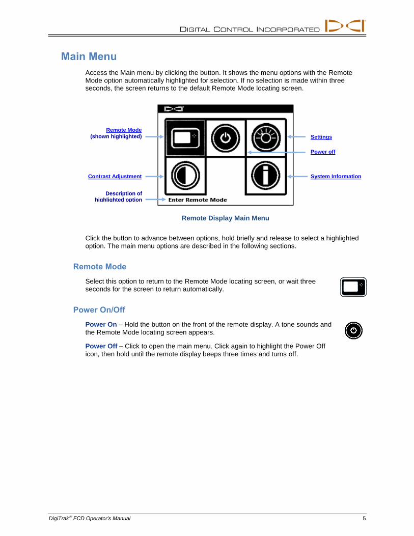
Access the Main menu by clicking the button. It shows the menu options with the Remote Mode option automatically highlighted for selection. If no selection is made within three seconds, the screen returns to the default Remote Mode locating screen.
Remote Display Main Menu
Click the button to advance between options, hold briefly and release to select a highlighted option. The main menu options are described in the following sections.
Remote Mode
Select this option to return to the Remote Mode locating screen, or wait three seconds for the screen to return automatically.
Power On/Off
Power On – Hold the button on the front of the remote display. A tone sounds and the Remote Mode locating screen appears.
Power Off – Click to open the main menu. Click again to highlight the Power Off icon, then hold until the remote display beeps three times and turns off.
Remote Mode
(shown highlighted)
Contrast Adjustment
Power off
System Information
Settings
Description of highlighted option
DIGITAL CONTROL INCORPORATED
6 DigiTrak FCD Operator’s Manual
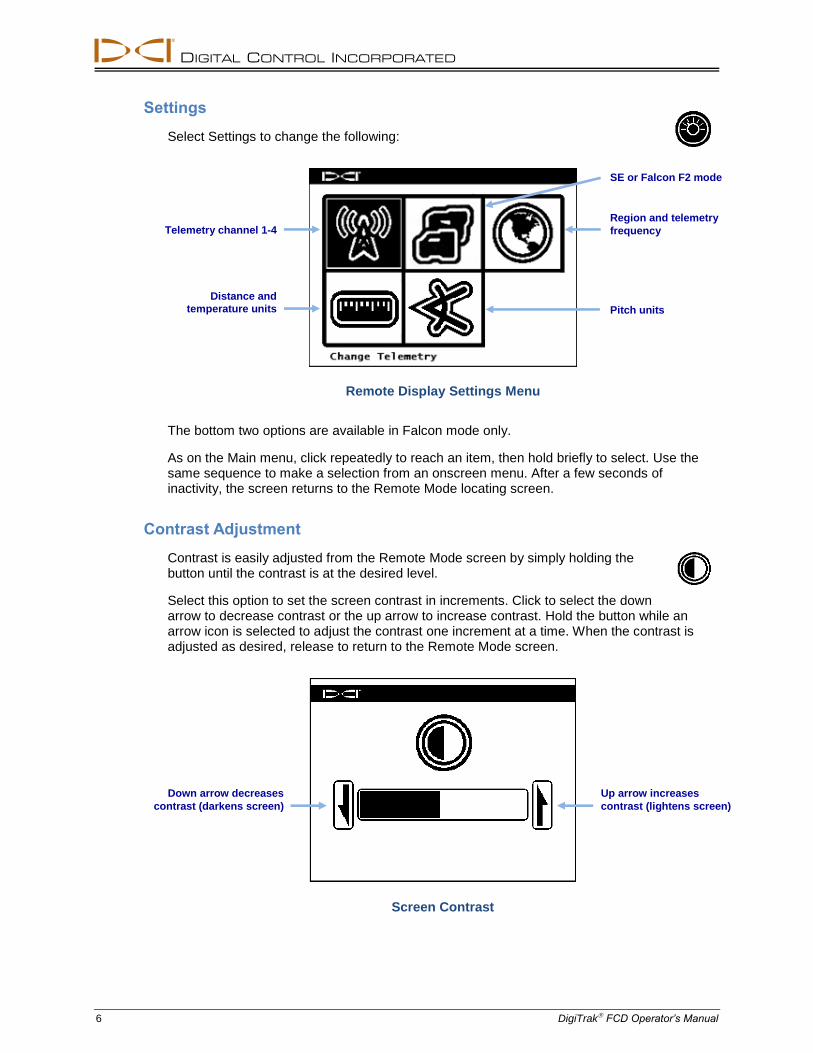
Settings
Select Settings to change the following:
Remote Display Settings Menu
The bottom two options are available in Falcon mode only.
As on the Main menu, click repeatedly to reach an item, then hold briefly to select. Use the same sequence to make a selection from an onscreen menu. After a few seconds of inactivity, the screen returns to the Remote Mode locating screen.
Contrast Adjustment
Contrast is easily adjusted from the Remote Mode screen by simply holding the button until the contrast is at the desired level.
Select this option to set the screen contrast in increments. Click to select the down arrow to decrease contrast or the up arrow to increase contrast. Hold the button while an arrow icon is selected to adjust the contrast one increment at a time. When the contrast is adjusted as desired, release to return to the Remote Mode screen.
Screen Contrast
Down arrow decreases
contrast (darkens screen)
Up arrow increases
contrast (lightens screen)
Telemetry channel 1-4 Region and telemetry
frequency
Distance and
temperature units Pitch units
SE or Falcon F2 mode

DIGITAL CONTROL INCORPORATED
DigiTrak FCD Operator’s Manual 7
System Information
Select this option to display system information such as the software version, serial number, and current settings.
Display Screens
Remote Mode Locating Screen
The Remote Mode locating screen is the default screen seen when the remote display turns on. It shows the transmitter pitch, roll, battery status, and temperature, as well as the display's battery status, receiver type, telemetry channel, telemetry update meter, and remote steering data (if programmed).
Remote Mode Locating Screen
The telemetry update meter displays the quality of signal being received from the receiver. If data is received less frequently, fewer bars display on the meter. When the meter is empty, no telemetry data is being received and all transmitter information will disappear.
Warning If the meter is decreasing or low, ensure you have stable data before making steering decisions.
If the roll offset function is set on the receiver, RO displays at the bottom right of the roll indicator.
Transmitter temperature
Transmitter battery strength
(alkaline only)
Transmitter pitch
Receiver type and
telemetry channel
FCD battery status
Roll indicator
Telemetry update meter
Roll offset indicator (displays if roll offset is
set on receiver)

DIGITAL CONTROL INCORPORATED
8 DigiTrak FCD Operator’s Manual
Depth Screen
Transmitter depth appears on the remote display when the receiver operator holds the trigger at the locate line (LL).
Depth at LL with HAG On
When the Height-Above-Ground (HAG) function is enabled on the receiver, the receiver icon is shown elevated above the ground with the HAG setting displayed, as shown above; the receiver must be held the noted distance above the ground for an accurate depth reading. If a HAG value has not been programmed on the receiver, the receiver icon will display on the ground with no HAG value.
The depth will display for 10 seconds after the trigger on the receiver is released, then the display returns to the Remote Mode locating screen.
Height Above Ground (HAG) setting on
Depth of transmitter

DIGITAL CONTROL INCORPORATED
DigiTrak FCD Operator’s Manual 9
Predicted Depth Screen
Warning Because both locate points appear identical to the receiver, an invalid depth prediction can be generated when the receiver is over the rear locate point (RLP). Only a reading at the front locate point (FLP) produces a valid predicted depth.
The Predicted Depth screen appears when the receiver is positioned at the front locate point (FLP) with the trigger held in. Predicted depth is what the estimated depth of the transmitter will be when it passes below the receiver if the drill head remains at its current pitch.
Predicted Depth at FLP with HAG On
When the transmitter pitch information cannot be obtained at the receiver due to range restrictions or interference, the remote display will assume the transmitter has a pitch of zero for depth and predicted depth readings. In this case, the remote display will show the transmitter pitch as:
"Warning, Pitch is Unknown, Assume Zero"
Predicted depth of
transmitter
DIGITAL CONTROL INCORPORATED
10 DigiTrak FCD Operator’s Manual
Remote Steering
Instructions for setting up the receiver for using the Remote Steering feature can be found in the operator's manual for your locating system. Most of the setup for Remote Steering is done by the receiver (locator) operator. This section discusses how to use Remote Steering data on the remote display.
In general, Remote Steering should be used to maintain a bore path, not to bring a significantly off-course bore back on track. If the drill head is already significantly off course, use front and rear locate methods as described in your DigiTrak system operator’s manual to get back on course.
Notice After learning the concepts of Remote Steering, practice its use before using on a jobsite where time and money are at a premium. A Look-Ahead Locating animation is also available at www.youtube.com/dcikent. If you need further assistance, please contact DCI Customer Service.
Remote Steering requires a stable signal from both the transmitter and receiver.
Remote Steering will not work properly with passive interference in the vicinity of the bore.
Steering to the Target
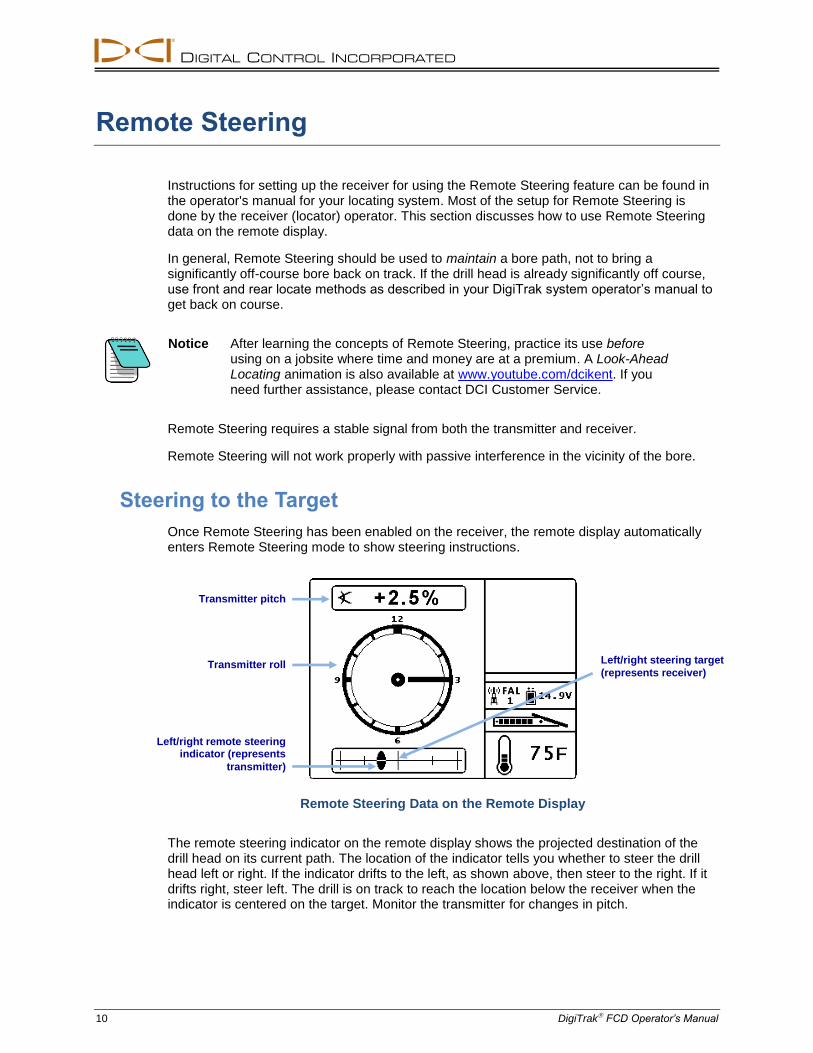
Once Remote Steering has been enabled on the receiver, the remote display automatically enters Remote Steering mode to show steering instructions.
Remote Steering Data on the Remote Display
The remote steering indicator on the remote display shows the projected destination of the drill head on its current path. The location of the indicator tells you whether to steer the drill head left or right. If the indicator drifts to the left, as shown above, then steer to the right. If it drifts right, steer left. The drill is on track to reach the location below the receiver when the indicator is centered on the target. Monitor the transmitter for changes in pitch.
Left/right remote steering indicator (represents
transmitter)
Left/right steering target
(represents receiver) Transmitter roll
Transmitter pitch
DIGITAL CONTROL INCORPORATED
DigiTrak FCD Operator’s Manual 11
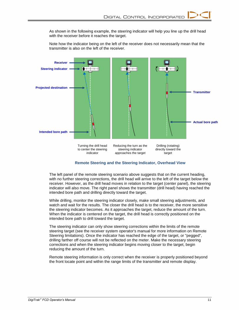
As shown in the following example, the steering indicator will help you line up the drill head with the receiver before it reaches the target.
Note how the indicator being on the left of the receiver does not necessarily mean that the transmitter is also on the left of the receiver.
Turning the drill head to center the steering
indicator
Reducing the turn as the steering indicator
approaches the target
Drilling (rotating) directly toward the
target
Remote Steering and the Steering Indicator, Overhead View
The left panel of the remote steering scenario above suggests that on the current heading, with no further steering corrections, the drill head will arrive to the left of the target below the receiver. However, as the drill head moves in relation to the target (center panel), the steering indicator will also move. The right panel shows the transmitter (drill head) having reached the intended bore path and drilling directly toward the target.
While drilling, monitor the steering indicator closely, make small steering adjustments, and watch and wait for the results. The closer the drill head is to the receiver, the more sensitive the steering indicator becomes. As it approaches the target, reduce the amount of the turn. When the indicator is centered on the target, the drill head is correctly positioned on the intended bore path to drill toward the target.
The steering indicator can only show steering corrections within the limits of the remote steering target (see the receiver system operator's manual for more information on Remote Steering limitations). Once the indicator has reached the edge of the target, or "pegged", drilling farther off course will not be reflected on the meter. Make the necessary steering corrections and when the steering indicator begins moving closer to the target, begin reducing the amount of the turn.
Remote steering information is only correct when the receiver is properly positioned beyond the front locate point and within the range limits of the transmitter and remote display.
Actual bore path
Projected destination
Transmitter
Steering indicator
Receiver
Intended bore path

DIGITAL CONTROL INCORPORATED
12 DigiTrak FCD Operator’s Manual
Remote Steering in Interference Areas
Warning Interference can cause inaccuracies in the measurement of depth and loss of the transmitter’s pitch, roll, or heading.
In areas of passive and/or active interference, it may help to physically elevate the receiver above the ground.
Turning Remote Steering Off
When the receiver exits Remote Steering mode, the remote display automatically returns to the normal Remote Mode locating screen.

DIGITAL CONTROL INCORPORATED
DigiTrak FCD Operator’s Manual 13
Appendix A: System Specifications
The power and environmental requirements for the DigiTrak Falcon™ Locating System are listed below.
Power Requirements
Device (Model Number) Operational Voltage Operational Current
DigiTrak Falcon Compact Display (FCD)
12–30 V (nominal) 150 mA max
DigiTrak SE NiMH Battery Charger (SBC)
Input 100–240 VAC Output 25 V (nominal)
350 mA max 700 mA max
DigiTrak SE NiMH Battery Pack (SBP)
14.4 V (nominal) 2.0 Ah 29 Wh max
DigiTrak F Series Battery Charger (FBC)
Input 10–28 V Output 19.2 V
5.0 A max 1.8 A max
DigiTrak F Series Lithium-Ion Battery Pack (FBP)
14.4 V (nominal) 4.5 Ah 65 Wh max
Environmental Requirements
Device Relative Humidity Operating Temperature
DigiTrak Falcon Compact Display (FCD)
with NiMH Battery Pack
with Li-Ion Battery Pack
<90%
14 to 149° F -4 to 140° F
DigiTrak SE NiMH Battery Charger (SBC)
<90% 32 to 104° F
DigiTrak SE NiMH Battery Pack (SBP)
<99% for <50° F <95% for 50–95° F <75% for 95–149° F
14 to 149° F
DigiTrak F Series Battery Charger (FBC)
<99% for 32–50° F <95% for 50–95° F
32 to 95° F
DigiTrak F Series Lithium-Ion Battery Pack (FBP)
<99% for <50° F <95% for 50–95° F <75% for 95–140° F
-4 to 140° F
System working altitude: up to 6561 ft.

DIGITAL CONTROL INCORPORATED
14 DigiTrak FCD Operator’s Manual

DIGITAL
CONTROL
INCORPORATED
19625 62nd Ave S, Suite B103
Kent Washington 98032, USA
425.251.0559 / 800.288.3610
[email protected], www.DigiTrak.com
DigiTrak FCD Operator’s Manual - Warranty 1
LIMITED WARRANTY
Digital Control Incorporated ("DCI") warrants that, when shipped from DCI, each DCI product (other than software products) will conform to DCI’s current published specifications in existence at the time of shipment and will be free, for the warranty period (“Warranty Period”) specified below, from material defects in materials and workmanship. In addition, DCI warrants that each DCI software product will perform in substantial accordance with the specifications set forth in the documentation for such software for the Warranty Period specified below. The following limited warranty (“Limited Warranty”) is made solely to and for the benefit of the first end-user (“User”) purchasing the DCI product from either DCI or a dealer expressly authorized by DCI to sell DCI products (“Authorized DCI Dealer”) and is not assignable or transferable.
The foregoing Limited Warranty is subject to the following terms, conditions and limitations:
1. A Warranty Period of twelve (12) months shall apply to the following new DCI products: receivers/locators, remote displays, battery chargers and rechargeable batteries, and software programs and applications. A Warranty Period of ninety (90) days shall apply to all other new DCI products, including transmitters and accessories. A Warranty Period of ninety (90) days shall also apply to services provided by DCI, including testing, servicing, and repairing an out-of-warranty DCI product. The Warranty Period shall begin from the later of: (i) the date of shipment of the DCI product from DCI, or (ii) the date of shipment (or other delivery) of the DCI product from an Authorized DCI Dealer to User.
2. If a DCI product (excluding software products) does not perform as warranted during the Warranty Period, DCI will inspect the product and if DCI determines such product to be defective, DCI will, at its sole option and discretion, either repair or replace the product. If a software product does not perform as warranted during the Warranty Period, DCI will, at its sole option and discretion, either bring the defective software into material compliance with the specifications for such software or refund the purchase price paid for the defective software. THE FOREGOING ARE USER’S SOLE AND EXCLUSIVE REMEDIES FOR BREACH OF THIS LIMITED WARRANTY. All warranty inspections, repairs and adjustments must be performed either by DCI or by a warranty claim service authorized in writing by DCI. All warranty claims must include proof of purchase, including proof of purchase date, identifying the DCI product by serial number, and be submitted before the end of the Warranty Period.
3. The Limited Warranty shall only be effective if: (i) within fourteen (14) days of receipt of the DCI product, User registers the DCI product
with DCI through its product registration website at access.DigiTrak.com; (ii) User makes a reasonable inspection upon first receipt of the DCI product and immediately notifies DCI of any apparent defect; and (iii) User complies with all of the Warranty Claim Procedures described below.
4. The service period for this equipment is five years from the date of manufacture. During this period, DCI will support the repair or replacement of the products featured in this manual. A fee for repairs and replacements may be charged if the product is outside the warranty period.
What is not covered
This Limited Warranty excludes all damage, including damage to any DCI product, due to: failure to follow DCI’s operator’s manual and other DCI instructions; use of a DCI product outside the specifications for which the DCI product is designed (including, without limitation, temperature); abuse; misuse; neglect; accident; fire; flood; Acts of God; improper applications; connection to incorrect line voltages and improper power sources; use of incorrect fuses; overheating; contact with high voltages or injurious substances; use of batteries or other products or components not manufactured or supplied by DCI; or other events beyond the control of DCI. This Limited Warranty does not apply to any equipment not manufactured or supplied by DCI nor, if applicable, to any damage or loss resulting from use of any DCI product outside the designated country of use. User agrees to carefully evaluate the suitability of the DCI product for User’s intended use and to thoroughly read and strictly follow all instructions supplied by DCI (including any updated DCI product information which may be obtained from the DCI website). In no event shall this Limited Warranty cover any damage arising during shipment of the DCI product to or from DCI.
User agrees that the following will render the above Limited Warranty void: (i) alteration, removal or tampering with any serial number, identification, instructional, or sealing labels on the DCI product, or (ii) any unauthorized disassembly, repair or modification of the DCI product. In no event shall DCI be responsible for the cost of or any damage resulting from any changes, modifications, or repairs to the DCI product not expressly authorized in writing by DCI, and DCI shall not be responsible for the loss of or damage to the DCI product or any other equipment while in the possession of any service agency not authorized by DCI.
DCI does not warrant or guarantee the accuracy or completeness of data generated by HDD locating systems. The accuracy or completeness of such data may be impacted by a variety of factors, including (without limitation) active or passive interference (including from salt water) and other environmental conditions, failure to calibrate or use the device properly and other factors. DCI also does not warrant or guarantee, and disclaims liability for, the accuracy and completeness of any data generated by any external source or derived from data generated by any external source that may be displayed on a DCI device, including (without limitation) data received from any HDD drill rig.
DCI reserves the right to make changes in design and improvements upon DCI product from time to time, and User understands that DCI shall have no obligation to upgrade any previously manufactured DCI product to include any such changes.

DIGITAL CONTROL INCORPORATED
2 DigiTrak FCD Operator’s Manual - Warranty
THE FOREGOING LIMITED WARRANTY IS DCI’S SOLE WARRANTY AND IS MADE IN PLACE OF ALL OTHER WARRANTIES, EXPRESS OR IMPLIED, INCLUDING BUT NOT LIMITED TO THE IMPLIED WARRANTIES OF MERCHANTABILITY AND FITNESS FOR A PARTICULAR PURPOSE, IMPLIED WARRANTY OF NON-INFRINGEMENT, AND ANY IMPLIED WARRANTY ARISING FROM COURSE OF PERFORMANCE, COURSE OF DEALING, OR USAGE OF TRADE, ALL OF WHICH ARE HEREBY DISCLAIMED AND EXCLUDED. If DCI has substantially complied with the warranty claim procedures described below, such procedures shall constitute User’s sole and exclusive remedy for breach of the Limited Warranty.
Limitation of remedies and liability
In no event shall DCI or anyone else involved in the creation, production, or delivery of the DCI product be liable for any damages arising out of the use or inability to use the DCI product, including but not limited to indirect, special, incidental, or consequential damages, or for any cover, loss of information, profit, revenue or use, based upon any claim by User for breach of warranty, breach of contract, negligence, strict liability, or any other legal theory, even if DCI has been advised of the possibility of such damages. In no event shall DCI’s liability exceed the amount User has paid for the DCI product. To the extent that any applicable law does not allow the exclusion or limitation of incidental, consequential or similar damages, the foregoing limitations regarding such damages shall not apply.
This Limited Warranty gives you specific legal rights, and you may also have other rights which vary from state to state. This Limited Warranty shall be governed by the laws of the State of Washington.
Warranty claim procedures
1. If you are having problems with your DCI product, you must first contact the Authorized DCI Dealer where it was purchased. If you are unable to resolve the problem through your Authorized DCI Dealer, contact DCI’s Customer Service Department in Kent, Washington, USA at 1.800.288.3610 (or, for international markets, the corresponding telephone number for that market) between 6:00 a.m. and 6:00 p.m. Pacific Time and ask to speak with a customer service representative. Prior to returning any DCI product to DCI for service, you must obtain a Return Merchandise Authorization (RMA) number. Failure to obtain an RMA may result in delays or return to you of the DCI product without repair.
2. After contacting a DCI customer service representative by telephone, the representative will attempt to assist you in troubleshooting while you are using the DCI product during actual field operations. Please have all related equipment available together with a list of all DCI product serial numbers. It is important that field troubleshooting be conducted because many problems do not result from a defective DCI product, but instead are due to either operational errors or adverse conditions occurring in User’s drilling environment.
3. If a DCI product problem is confirmed as a result of field troubleshooting discussions with a DCI customer service representative, the representative will issue an RMA number authorizing the return of the DCI product and will provide shipping directions. You will be responsible for all shipping costs, including any insurance. If, after receiving the DCI product and performing diagnostic testing, DCI determines the problem is covered by the Limited Warranty, required repairs and/or adjustments will be made, and a properly functioning DCI product will be promptly shipped to you. If the problem is not covered by the Limited Warranty, you will be informed of the reason and be provided an estimate of repair costs. If you authorize DCI to service or repair the DCI product, the work will be promptly performed and the DCI product will be shipped to you. You will be billed for any costs for testing, repairs and adjustments not covered by the Limited Warranty and for shipping costs. In most cases, repairs are accomplished within 1 to 2 weeks.
4. DCI has a limited supply of loaner equipment available. If loaner equipment is required by you and is available, DCI will attempt to ship loaner equipment to you by overnight delivery for your use while your equipment is being serviced by DCI. DCI will make reasonable efforts to minimize your downtime on warranty claims, limited by circumstances not within DCI’s control. If DCI provides you loaner equipment, your equipment must be received by DCI no later than the second business day after your receipt of loaner equipment. You must return the loaner equipment by overnight delivery for receipt by DCI no later than the second business day after your receipt of the repaired DCI product. Any failure to meet these deadlines will result in a rental charge for use of the loaner equipment for each extra day the return of the loaner equipment to DCI is delayed.
Product demonstrations
DCI personnel may be present at a jobsite to demonstrate basic usage, features, and benefits of DCI products. User acknowledges that DCI personnel are present only to demonstrate a DCI product. DCI does NOT provide locating services or other consulting or contracting services. DCI does not assume any duty to train User or any other person, and does not assume responsibility or liability for the locating or other work performed at a jobsite at which DCI personnel or equipment are or have been present.