07 directional drilling
TRANSCRIPT

8/10/2019 07 Directional Drilling
http://slidepdf.com/reader/full/07-directional-drilling 1/89
1
DIRECTIONAL DRILLING
The well bore is deliberately deviated from the verticalalong a predetermined course to a target reservoirOBJECTIVES:
• Multi wells from Single Structureand/or location
• Shoreline drilling• Fault control• Inaccessible location• Stratigraphic traps (Salt dome)
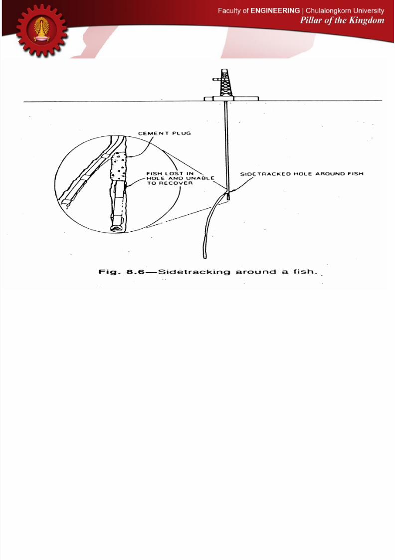
• Relief well control• Sidetracking off the
obstruction (fish)• Deviate well course to more
promising target (s)

8/10/2019 07 Directional Drilling
http://slidepdf.com/reader/full/07-directional-drilling 2/89
2

8/10/2019 07 Directional Drilling
http://slidepdf.com/reader/full/07-directional-drilling 3/89
3

8/10/2019 07 Directional Drilling
http://slidepdf.com/reader/full/07-directional-drilling 4/89
4

8/10/2019 07 Directional Drilling
http://slidepdf.com/reader/full/07-directional-drilling 5/89
5
8/10/2019 07 Directional Drilling
http://slidepdf.com/reader/full/07-directional-drilling 6/89
6

8/10/2019 07 Directional Drilling
http://slidepdf.com/reader/full/07-directional-drilling 7/89
7

8/10/2019 07 Directional Drilling
http://slidepdf.com/reader/full/07-directional-drilling 8/89
8

8/10/2019 07 Directional Drilling
http://slidepdf.com/reader/full/07-directional-drilling 9/89
9
Type I Type II Type III
8/10/2019 07 Directional Drilling
http://slidepdf.com/reader/full/07-directional-drilling 10/89
10

8/10/2019 07 Directional Drilling
http://slidepdf.com/reader/full/07-directional-drilling 11/89
11
DIRECTIONAL DRILLING TOOLS
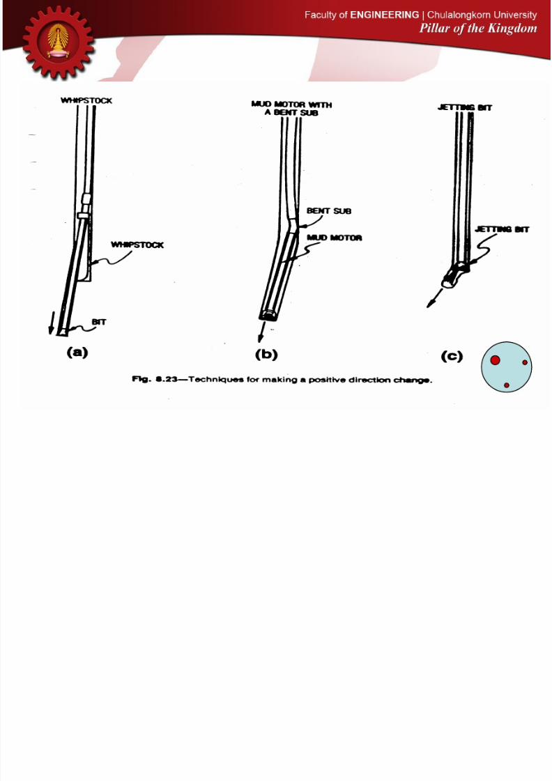
JETTING BIT
1. One nozzle is fully blanked (big Boy), the rest
are plugged or restricted
2. Orient the blank nozzle to designed direction3. Jetting the formation with hydraulic and with
none rotating pipe
4. Once the deviated hole pattern have been
formed, rotating pipe to make a new hole
5. Repeat the jetting/rotating sequence until
inclination is achieved
6. Good for soft and unconsolidated formations
7. Good for anti-collision purpose
Steps

8/10/2019 07 Directional Drilling
http://slidepdf.com/reader/full/07-directional-drilling 12/89

8/10/2019 07 Directional Drilling
http://slidepdf.com/reader/full/07-directional-drilling 13/89
13
DOWNHOLE MOTOR WITH BENT SUB
BENT SUB was used in earlyStage when Down hole Motor
had first been introduced.
It was presently an obsoletetool in directional drilling dueto the limitation of rotating thepipe combine with an advancedTechnology on down hole Motorsof which extensively high efficiencyand more steerable friendly.
DIRECTIONAL DRILLING TOOLS

8/10/2019 07 Directional Drilling
http://slidepdf.com/reader/full/07-directional-drilling 14/89
14
DOWNHOLE MOTOR (STEERABLE)
DIRECTIONAL DRILLING TOOLS
BENT HOUSING SUB) FIXED ON THE BODY
8/10/2019 07 Directional Drilling
http://slidepdf.com/reader/full/07-directional-drilling 15/89
15
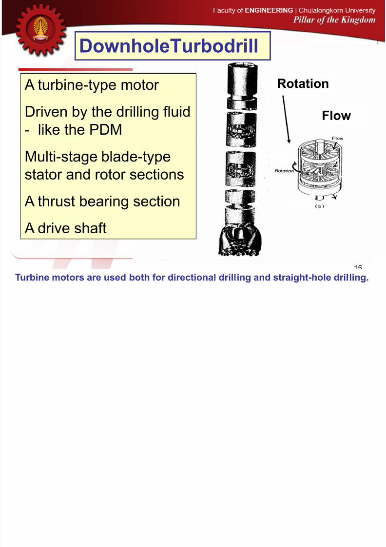
Flow
Rotation
DownholeTurbodrill
Turbine motors are used both for directional drilling and straight-hole drilling.
A turbine-type motor
Driven by the drilling fluid
- like the PDMMulti-stage blade-type
stator and rotor sections
A thrust bearing section
A drive shaft

8/10/2019 07 Directional Drilling
http://slidepdf.com/reader/full/07-directional-drilling 16/89
16
Top Sub
Turbine Section
Bearing Section
Stator/Rotor-
One Stage
Rotor (Rotating)
Stator (Stationary)
Turbine Section
Typical
turbine
design.
PDC or Diamond Bit

8/10/2019 07 Directional Drilling
http://slidepdf.com/reader/full/07-directional-drilling 17/89
17
DownholeTurbodrill
Number of rotor/stator sections
may vary from ~25 to 250
Stator remains stationary - itsmain function is to deflect the
mud to the rotor blades
The rotor blades are connectedto the drive shaft, which is
connected to the bit

8/10/2019 07 Directional Drilling
http://slidepdf.com/reader/full/07-directional-drilling 18/89
18
DOWNHOLE MOTOR (STEERABLE)
DIRECTIONAL DRILLING TOOLS
MAIN COMPONENTS (Top to Bottom)
•Top Stabilizer (optional)•Bypass Vale•Flexible Bent Sub (optional)•Rotor/Stator Housing (power sub)•Flexible Bent Sub (Standard)•U-joint Housing
•Bearing Assembly Housing (outsideBody is Near Bit Stabilizer)
•Bit Box
MWD

8/10/2019 07 Directional Drilling
http://slidepdf.com/reader/full/07-directional-drilling 19/89
19
DOWNHOLE MOTOR (STEERABLE)
DIRECTIONAL DRILLING TOOLS
INSIDE
OUTSIDE
8/10/2019 07 Directional Drilling
http://slidepdf.com/reader/full/07-directional-drilling 20/89
20
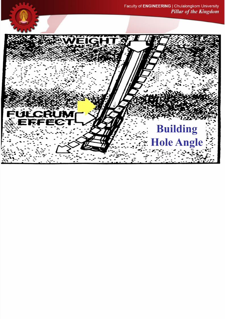
Building
Hole Angle

8/10/2019 07 Directional Drilling
http://slidepdf.com/reader/full/07-directional-drilling 21/89
21
Holding
Hole Angle

8/10/2019 07 Directional Drilling
http://slidepdf.com/reader/full/07-directional-drilling 22/89
22
MONITORINGDIRECTIONAL DRILLING
PRESENT TECHNOLOGY
FOR ROTARY ASSY.

8/10/2019 07 Directional Drilling
http://slidepdf.com/reader/full/07-directional-drilling 23/89
23
MONITORINGDIRECTIONAL DRILLING
LATEST TECHNOLGY
FOR DIRECTIONAL DRILLING
An advanced BHA that steers itself During continuous drill string.
Electronic control 3-pad Stabilizer onthe sleeve which is programmed wellPath controlling.More smooth in well bore than drillwith Motor.
Product Propaganda
“Auto Trak” - Baker Hughes
“Power Drive” – Schlumberger
“Geo-Pilot” – Sperry Sun, Halliburton
ROTARY STEERABLE SYSTEM

8/10/2019 07 Directional Drilling
http://slidepdf.com/reader/full/07-directional-drilling 24/89
24
MONITORINGDIRECTIONAL DRILLING
LATEST TECHNOLGY
FOR DIRECTIONAL DRILLING

8/10/2019 07 Directional Drilling
http://slidepdf.com/reader/full/07-directional-drilling 25/89
25

8/10/2019 07 Directional Drilling
http://slidepdf.com/reader/full/07-directional-drilling 26/89
26
Tool Face Angle

8/10/2019 07 Directional Drilling
http://slidepdf.com/reader/full/07-directional-drilling 27/89
27
Inclination Angle
q a
, I
Direction Angle
f e
, A

8/10/2019 07 Directional Drilling
http://slidepdf.com/reader/full/07-directional-drilling 28/89
28
N18E
N55WS20W
S23E Azimuth
Angle

8/10/2019 07 Directional Drilling
http://slidepdf.com/reader/full/07-directional-drilling 29/89
29
Directional Drilling Measurements
• The trajectory of a wellbore is
determined by the measurement of:
inclination q, a, I
direction f, e, A
measured depth DMD, DL, L

8/10/2019 07 Directional Drilling
http://slidepdf.com/reader/full/07-directional-drilling 30/89
30
Directional Drilling Measurements
• A tool-face measurement is
required to orient:
A whipstock
The large nozzle on a jetting bit
A bent sub or bent housing

8/10/2019 07 Directional Drilling
http://slidepdf.com/reader/full/07-directional-drilling 31/89
31
Directional Drilling Measurements
• Tools available
Single-shot magnetic or gyroscopicMulti-shot magnetic or gyroscopic
Magnetometers, accelerometers,
MWD tools

8/10/2019 07 Directional Drilling
http://slidepdf.com/reader/full/07-directional-drilling 32/89
32
Survey Methods
• Single-Shot

8/10/2019 07 Directional Drilling
http://slidepdf.com/reader/full/07-directional-drilling 33/89

8/10/2019 07 Directional Drilling
http://slidepdf.com/reader/full/07-directional-drilling 34/89
34
• Steering Tools
Survey Methods
8/10/2019 07 Directional Drilling
http://slidepdf.com/reader/full/07-directional-drilling 35/89
35
Steering Tools:
• When a mud motor with a bent sub isused, it may be more economical torun a steering tool than tocontinuously run magnetic singleshot surveys.
• An instrument probe is lowered by awireline unit and is seated in themule-shoe orienting sleeve.

8/10/2019 07 Directional Drilling
http://slidepdf.com/reader/full/07-directional-drilling 36/89
36
Steering Tools - cont’d
• The wireline can be passed through acirculating head mounted on thedrillpipe. Every 90 ft the tool is
retrieved so another stand of pipe maybe added.
• Alternatively, a side entry sub may beused for the wire. A stuffing box thatprevents fluid leakage is built into theside of the sub.

8/10/2019 07 Directional Drilling
http://slidepdf.com/reader/full/07-directional-drilling 37/89

8/10/2019 07 Directional Drilling
http://slidepdf.com/reader/full/07-directional-drilling 38/89

8/10/2019 07 Directional Drilling
http://slidepdf.com/reader/full/07-directional-drilling 39/89
39
Steering Tools - cont’d
• Most steering tools continuouslysense
– inclination– direction
– tool-face angle

8/10/2019 07 Directional Drilling
http://slidepdf.com/reader/full/07-directional-drilling 40/89
40
Steering Tools - cont’d
• The steering tool takes the guess-workout of correcting the tool-face angle forreverse torque.
• A steering tool is one of the mosteconomical means of making a trajectory
change when a mud motor and bent subare used for drilling, especially when rigcosts are high.

8/10/2019 07 Directional Drilling
http://slidepdf.com/reader/full/07-directional-drilling 41/89
41
MWD(Measurement While Drilling)
• While drilling it is possible to transmit tothe surface downhole information on:
inclination temperature
direction weight on bit
tool-face angle torque on bit
gamma ray sonic velocity
resistivity

8/10/2019 07 Directional Drilling
http://slidepdf.com/reader/full/07-directional-drilling 42/89
42
MWD - cont’d
• Inclination, direction, and tool-face angle areof particular interest in directional drilling. Alower cost MWD tool can be used if onlydirectional drilling information is required.
• Information is typically transmitted throughthe mud column by:
• + ve or - ve pressure pulses, or• pressure pulse modulation

8/10/2019 07 Directional Drilling
http://slidepdf.com/reader/full/07-directional-drilling 43/89

8/10/2019 07 Directional Drilling
http://slidepdf.com/reader/full/07-directional-drilling 44/89

8/10/2019 07 Directional Drilling
http://slidepdf.com/reader/full/07-directional-drilling 45/89
45
Basic types of mud pulsers
~ 3-5 minutes per update

8/10/2019 07 Directional Drilling
http://slidepdf.com/reader/full/07-directional-drilling 46/89
46
Basic types of mud pulsers
Mud Siren - 0’s and 1’s

8/10/2019 07 Directional Drilling
http://slidepdf.com/reader/full/07-directional-drilling 47/89
47
In the BUILD
Section
Dx = r (1 - cos I)
D
y = r sin I
DL = r Irad
degIr 180
=L ÷÷
÷÷÷
÷ pD
BUR*
000,18r
p
=
Dx
Dy
I
I
r
r DL

8/10/2019 07 Directional Drilling
http://slidepdf.com/reader/full/07-directional-drilling 48/89
48

8/10/2019 07 Directional Drilling
http://slidepdf.com/reader/full/07-directional-drilling 49/89
49
42131 xr r andxr

8/10/2019 07 Directional Drilling
http://slidepdf.com/reader/full/07-directional-drilling 50/89

8/10/2019 07 Directional Drilling
http://slidepdf.com/reader/full/07-directional-drilling 51/89

8/10/2019 07 Directional Drilling
http://slidepdf.com/reader/full/07-directional-drilling 52/89

8/10/2019 07 Directional Drilling
http://slidepdf.com/reader/full/07-directional-drilling 53/89
53

8/10/2019 07 Directional Drilling
http://slidepdf.com/reader/full/07-directional-drilling 54/89
54

8/10/2019 07 Directional Drilling
http://slidepdf.com/reader/full/07-directional-drilling 55/89

8/10/2019 07 Directional Drilling
http://slidepdf.com/reader/full/07-directional-drilling 56/89
56
CLOSURE
LEAD ANGLE
(HORIZONTAL) DEPARTURE

8/10/2019 07 Directional Drilling
http://slidepdf.com/reader/full/07-directional-drilling 57/89
57
• Average Angle
• Balanced Tangential
• Minimum Curvature• Radius of Curvature
• Tangential
Wellbore Surveying Methods

8/10/2019 07 Directional Drilling
http://slidepdf.com/reader/full/07-directional-drilling 58/89

8/10/2019 07 Directional Drilling
http://slidepdf.com/reader/full/07-directional-drilling 59/89
59
Example - Wellbore Survey Calculations
• Point C has coordinates:
• x = 1,000 (ft) positive towards the east
• y = 1,000 (ft) positive towards the north• z = 3,500 (ft) TVD, positive downwards
Dz
E (x)
N (y)C
DDz
N
D
C
Dy
Dx

8/10/2019 07 Directional Drilling
http://slidepdf.com/reader/full/07-directional-drilling 60/89
60
Example - Wellbore Survey Calculations+
• I. Calculate the x, y, and z coordinatesof points D using:
• (i) The Average Angle method• (ii) The Balanced Tangential method
• (iii) The Minimum Curvature method
• (iv) The Radius of Curvature method• (v) The Tangential method

8/10/2019 07 Directional Drilling
http://slidepdf.com/reader/full/07-directional-drilling 61/89
61
Find the coordinates of point D using
the Average Angle Method
At point C, x = 1,000 ft
y = 1,000 ft
z = 3,500 ft
80 A 24I
20 A 14I
DD
CC
=
=
ft400MDD,toCfromdepthMeasured =
The Average Angle Method

8/10/2019 07 Directional Drilling
http://slidepdf.com/reader/full/07-directional-drilling 62/89
62
80A 24
20A 14I
ft400MDD,toCfromdepth
D
CC
==
==
=D
D I
Measured
Dz
E (x)
N (y)
C
DDz
N
D
C
Dy
Dx
8/10/2019 07 Directional Drilling
http://slidepdf.com/reader/full/07-directional-drilling 63/89
63
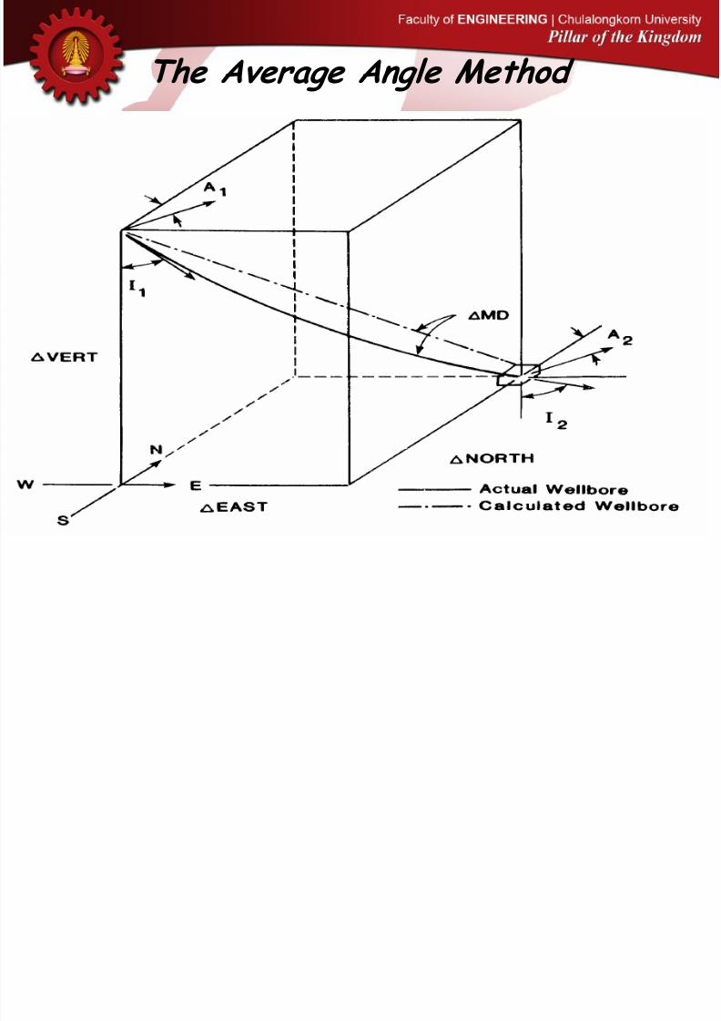
The Average Angle Method

8/10/2019 07 Directional Drilling
http://slidepdf.com/reader/full/07-directional-drilling 64/89
64
This method utilizes the averageof I1 and I2 as an inclination,the average of A1 and A2 as adirection, and assumes the
entire survey interval (DMD)to be tangent to the averageangle.
2
III 21AVG
=
2AAA 21
AVG =
AVGAVG AsinIsinMDEast D
AVGIcosMDVert D
AVGAVG AcosIsinMDNorth D
The Average Angle Method

8/10/2019 07 Directional Drilling
http://slidepdf.com/reader/full/07-directional-drilling 65/89
65
The Average Angle Method

8/10/2019 07 Directional Drilling
http://slidepdf.com/reader/full/07-directional-drilling 66/89
66
AVGIcos400Vert =
cos19400z =
AVGAVG AcosIsinMDNorth D
ft84y =D
50cossin19400y =
ft 378z =D
The Average Angle Method

8/10/2019 07 Directional Drilling
http://slidepdf.com/reader/full/07-directional-drilling 67/89
67
• At Point D,
• x = 1,000 + 100 = 1,100 ft
• y = 1,000 + 84 = 1,084 ft
• z = 3,500 + 378 = 3,878 ft
The Average Angle Method

8/10/2019 07 Directional Drilling
http://slidepdf.com/reader/full/07-directional-drilling 68/89
68
The Balanced Tangential Method
This method treats half the measureddistance (DMD/2) as being tangent toI1 and A1 and the remainder of the
measured distance (DMD/2) as beingtangent to I2 and A2.
2211 AsinIsinAsinIsin2
MDEast =
2211 AcosIsinAcosIsin2MDNorth =
12 IcosIcos
2
MDVert =

8/10/2019 07 Directional Drilling
http://slidepdf.com/reader/full/07-directional-drilling 69/89
69
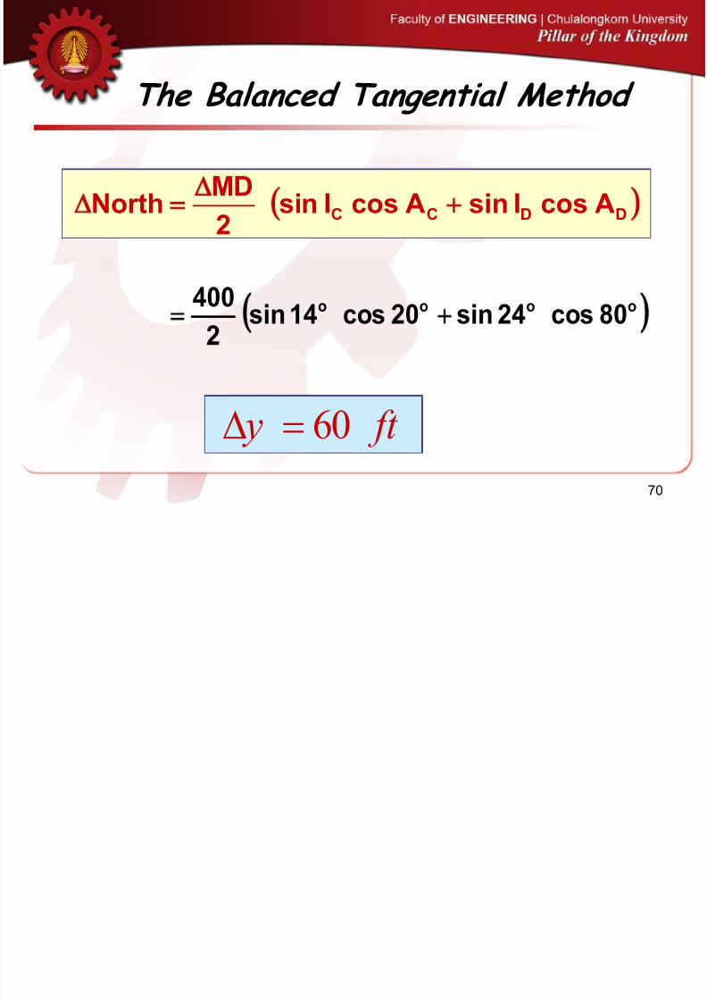
The Balanced Tangential Method
DDCC AsinIsinAsinIsin2
MDEast =
oooo 80sin24sin20sin14sin2
400
ft x 97=D
8/10/2019 07 Directional Drilling
http://slidepdf.com/reader/full/07-directional-drilling 70/89
70
The Balanced Tangential Method
DDCC AcosIsinAcosIsin2
MDNorth =
oooo 80cos24sin20cos14sin2
400
ft y 60=D
8/10/2019 07 Directional Drilling
http://slidepdf.com/reader/full/07-directional-drilling 71/89
71
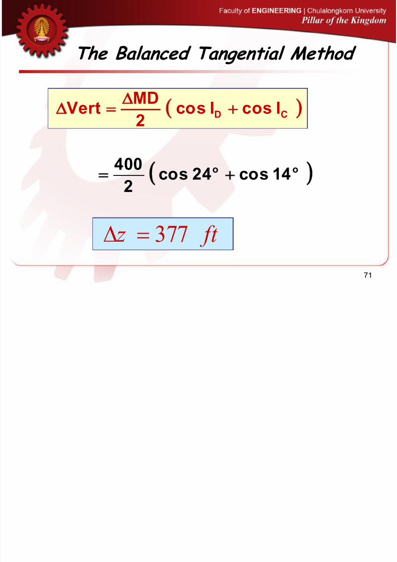
The Balanced Tangential Method
CD IcosIcos2
MDVert
=
oo 14cos24cos2
400
ft z 377=D

8/10/2019 07 Directional Drilling
http://slidepdf.com/reader/full/07-directional-drilling 72/89
72
The Balanced Tangential Method
• At Point D,
• x = 1,000 + 97 = 1,097 ft
• y = 1,000 + 60 = 1,060 ft
• z = 3,500 + 377 = 3,877 ft

8/10/2019 07 Directional Drilling
http://slidepdf.com/reader/full/07-directional-drilling 73/89
73
Minimum Curvature Method

8/10/2019 07 Directional Drilling
http://slidepdf.com/reader/full/07-directional-drilling 74/89

8/10/2019 07 Directional Drilling
http://slidepdf.com/reader/full/07-directional-drilling 75/89
75
)2080cos(124sin14sin1424cos o00ooo
)AAcos(1IsinIsinIIcoscos CDDCCD
cos b = 0.9356
b = 20.67o
= 0.3608 radians
The Dogleg Angle, b, is given by:
Minimum Curvature Method

8/10/2019 07 Directional Drilling
http://slidepdf.com/reader/full/07-directional-drilling 76/89

8/10/2019 07 Directional Drilling
http://slidepdf.com/reader/full/07-directional-drilling 77/89
77
Minimum Curvature Method
RFAsinIsinAsinIsin2
MDEast DDCC =
0110.180sin24sin20sin14sin2
400 oooo
ft x 98=D
ft 98011.1*66.96 ==

8/10/2019 07 Directional Drilling
http://slidepdf.com/reader/full/07-directional-drilling 78/89
78
Minimum Curvature Method
RFAcosIsinAcosIsin2
MDNorth DDCC =
ft y 60=D
ft 60011.1*59.59 ==
0110.180cos24sin20cos14sin2
400 oooo

8/10/2019 07 Directional Drilling
http://slidepdf.com/reader/full/07-directional-drilling 79/89
79
Minimum Curvature Method
RFIcosIcos2
MDVert CD =
0110.114cos24cos2
400 oo
ft z 381=D
ft 3810110.1*77.376 ==

8/10/2019 07 Directional Drilling
http://slidepdf.com/reader/full/07-directional-drilling 80/89
80
Minimum Curvature Method
• At Point D,
• x = 1,000 + 98 = 1,098 ft
• y = 1,000 + 60 = 1,060 ft
• z = 3,500 + 381 = 3,881 ft

8/10/2019 07 Directional Drilling
http://slidepdf.com/reader/full/07-directional-drilling 81/89

8/10/2019 07 Directional Drilling
http://slidepdf.com/reader/full/07-directional-drilling 82/89
82
The Radius of Curvature Method
2
CDCD
CDDC 180
)AA()II(
)AsinA(sin)IcosI(cosMDNorth
p
=
2180
)2080)(1424(
)20sin80)(sin24cos400(cos14
p
=
ft80y =D

8/10/2019 07 Directional Drilling
http://slidepdf.com/reader/full/07-directional-drilling 83/89
83
The Radius of Curvature Method
p
=
180
II
)IsinI(sinMDVert
CD
CD
ft783z =D
p
=
180
1424
)14sin24(sin400 oo

8/10/2019 07 Directional Drilling
http://slidepdf.com/reader/full/07-directional-drilling 84/89
84
The Radius of Curvature Method
• At Point D,
• x = 1,000 + 95 = 1,095 ft
• y = 1,000 + 80 = 1,080 ft
• z = 3,500 + 378 = 3,878 ft

8/10/2019 07 Directional Drilling
http://slidepdf.com/reader/full/07-directional-drilling 85/89
85
The Tangential Method
ft400MDD,toCfromdepthMeasured =
80 A 24I
20 A 14I
DD
CC
=
=
80sinsin24400=
DD AsinIsinMDEast D
ft160x =D

8/10/2019 07 Directional Drilling
http://slidepdf.com/reader/full/07-directional-drilling 86/89
86
The Tangential Method
24cos400=
ft365z =D
ft28=D y
oo 80cos24sin400

8/10/2019 07 Directional Drilling
http://slidepdf.com/reader/full/07-directional-drilling 87/89
87
The Tangential Method

8/10/2019 07 Directional Drilling
http://slidepdf.com/reader/full/07-directional-drilling 88/89
88
Summary of Results (to the nearest ft)
• x y z
• Average Angle 1,100 1,084 3,878• Balanced Tangential 1,097 1,060 3,877• Minimum Curvature 1,098 1,060 3,881• Radius of Curvature 1,095 1,080 3,878• Tangential Method 1,160 1,028 3,865
Q i

8/10/2019 07 Directional Drilling
http://slidepdf.com/reader/full/07-directional-drilling 89/89
Question
Plan a build and hold trajectory where thekick-off depth is at 2000’, and thetarget bull’s-eye is 5500’ from thesurface location at a TVD of 8100’. Usea build-up rate of 2 deg/100’. Your planshould include maximum inclination
angle, measured depth to the end of thebuild and to the target depth andhorizontal departure to the end of the