dimensioning and tolerancing principles for gages and fixtures
TRANSCRIPT

Dimensioning and Tolerancing Principles for Gages and FixturesEngineering Drawing and Related Documentation Practices
A N A M E R I C A N N A T I O N A L S T A N D A R D
ASME Y14.43-2011[Revision of ASME Y14.43-2003 (R2008)]
--`,`,,`,`,``,,`,````,,`,````-`-`,,`,,`,`,,`---

ASME Y14.43
ADOPTION NOTICE
ASME Y14.43, Dimensioning and Tolerancing Principles for Gages and Fixtures, was adopted on 28 January 2003for use by the Department of Defense (DoD). Proposed changes by DoD activities must be submitted to theDoD Adopting Activity: Commander, U.S. Army Research, Development and Engineering Center (ARDEC),ATTN: RDAR-QES-E, Picatinny Arsenal, NJ 07806-5000. Copies of this document may be purchased from TheAmerican Society of Mechanical Engineers (ASME), 22 Law Drive, P.O. Box 2900, Fairfield, NJ 07007-2900,http://www.asme.org.
Custodians: Adopting Activity:Army — AR Army — ARNavy — SAAir Force — 16 (Project DRPR-2010-001)DLA — DH
Reviewer Activities:Army — CR, MI, PT, TMNavy — AS, CG, CH, EC, MC, NP, TDAir Force — 13, 99DLA — ISOther — MP, NS
NOTE: The activities listed above were interested in this document as of the dateof this document. Since organizations and responsibilities can change, you shouldverify the currency of the information above using the ASSIST Online databaseat http://assist.daps.dla.mil.
AMSC N/A FSC DRPR
DISTRIBUTION STATEMENT A. Approved for public release, distribution is unlimited.
--`,`,,`,`,``,,`,````,,`,````-`-`,,`,,`,`,,`---

ASME Y14.43-2011[Revision of ASME Y14.43-2003 (R2008)]
Dimensioningand TolerancingPrinciples forGages andFixturesEngineering Drawing and RelatedDocumentation Practices
A N A M E R I C A N N A T I O N A L S T A N D A R D
Three Park Avenue • New York, NY • 10016 USA
--`,`,,`,`,``,,`,````,,`,````-`-`,,`,,`,`,,`---

Date of Issuance: August 22, 2011
This Standard will be revised when the Society approves the issuance of a new edition.
ASME issues written replies to inquiries concerning interpretations of technical aspects of thisStandard. Periodically, certain actions of the ASME Y14 Committee may be published as Code Cases.Cases and interpretations are published on the ASME Web site under the Committee Pages athttp://cstools.asme.org as they are issued.
ASME is the registered trademark of The American Society of Mechanical Engineers.
This code or standard was developed under procedures accredited as meeting the criteria for American NationalStandards. The Standards Committee that approved the code or standard was balanced to assure that individuals fromcompetent and concerned interests have had an opportunity to participate. The proposed code or standard was madeavailable for public review and comment that provides an opportunity for additional public input from industry, academia,regulatory agencies, and the public-at-large.
ASME does not “approve,” “rate,” or “endorse” any item, construction, proprietary device, or activity.ASME does not take any position with respect to the validity of any patent rights asserted in connection with any
items mentioned in this document, and does not undertake to insure anyone utilizing a standard against liability forinfringement of any applicable letters patent, nor assumes any such liability. Users of a code or standard are expresslyadvised that determination of the validity of any such patent rights, and the risk of infringement of such rights, isentirely their own responsibility.
Participation by federal agency representative(s) or person(s) affiliated with industry is not to be interpreted asgovernment or industry endorsement of this code or standard.
ASME accepts responsibility for only those interpretations of this document issued in accordance with the establishedASME procedures and policies, which precludes the issuance of interpretations by individuals.
No part of this document may be reproduced in any form,in an electronic retrieval system or otherwise,
without the prior written permission of the publisher.
The American Society of Mechanical EngineersThree Park Avenue, New York, NY 10016-5990
Copyright © 2011 byTHE AMERICAN SOCIETY OF MECHANICAL ENGINEERS
All rights reservedPrinted in U.S.A.
--`,`,,`,`,``,,`,````,,`,````-`-`,,`,,`,`,,`---

CONTENTS
Foreword . . . . . . . . . . . . . . . . . . . . . . . . . . . . . . . . . . . . . . . . . . . . . . . . . . . . . . . . . . . . . . . . . . . . . . . . . . . . . . ivCommittee Roster . . . . . . . . . . . . . . . . . . . . . . . . . . . . . . . . . . . . . . . . . . . . . . . . . . . . . . . . . . . . . . . . . . . . . viCorrespondence With the Y14 Committee . . . . . . . . . . . . . . . . . . . . . . . . . . . . . . . . . . . . . . . . . . . . . . vii
1 General. . . . . . . . . . . . . . . . . . . . . . . . . . . . . . . . . . . . . . . . . . . . . . . . . . . . . . . . . . . . . . . . . . . . . . . . . . . 1
2 References . . . . . . . . . . . . . . . . . . . . . . . . . . . . . . . . . . . . . . . . . . . . . . . . . . . . . . . . . . . . . . . . . . . . . . . . 1
3 Definitions . . . . . . . . . . . . . . . . . . . . . . . . . . . . . . . . . . . . . . . . . . . . . . . . . . . . . . . . . . . . . . . . . . . . . . . . 1
4 Principles. . . . . . . . . . . . . . . . . . . . . . . . . . . . . . . . . . . . . . . . . . . . . . . . . . . . . . . . . . . . . . . . . . . . . . . . . 4
5 Gage Design . . . . . . . . . . . . . . . . . . . . . . . . . . . . . . . . . . . . . . . . . . . . . . . . . . . . . . . . . . . . . . . . . . . . . . 10
6 Dimensioning and Tolerancing . . . . . . . . . . . . . . . . . . . . . . . . . . . . . . . . . . . . . . . . . . . . . . . . . . . . . 18
7 Usage . . . . . . . . . . . . . . . . . . . . . . . . . . . . . . . . . . . . . . . . . . . . . . . . . . . . . . . . . . . . . . . . . . . . . . . . . . . . 30
8 Fixtures. . . . . . . . . . . . . . . . . . . . . . . . . . . . . . . . . . . . . . . . . . . . . . . . . . . . . . . . . . . . . . . . . . . . . . . . . . . 33
Figures5-1 Fixed Pin Construction . . . . . . . . . . . . . . . . . . . . . . . . . . . . . . . . . . . . . . . . . . . . . . . . . . . . . . . . . . . 145-2 Push Pin Construction — Type 1 . . . . . . . . . . . . . . . . . . . . . . . . . . . . . . . . . . . . . . . . . . . . . . . . . 155-3 Push Pin Construction — Type 2 . . . . . . . . . . . . . . . . . . . . . . . . . . . . . . . . . . . . . . . . . . . . . . . . . 166-1 Datum Target Symbol . . . . . . . . . . . . . . . . . . . . . . . . . . . . . . . . . . . . . . . . . . . . . . . . . . . . . . . . . . . . 206-2 Absolute Tolerancing Method . . . . . . . . . . . . . . . . . . . . . . . . . . . . . . . . . . . . . . . . . . . . . . . . . . . . 216-3 Gagemakers’ Tolerance Classes . . . . . . . . . . . . . . . . . . . . . . . . . . . . . . . . . . . . . . . . . . . . . . . . . . . 226-4 Gagemakers’ Tolerance Chart . . . . . . . . . . . . . . . . . . . . . . . . . . . . . . . . . . . . . . . . . . . . . . . . . . . . 22
Tables6-1 Plug Gage Limit Dimensions — Classes ZM, YM, and XM . . . . . . . . . . . . . . . . . . . . . . . . 236-2 Plug Gage Limit Dimensions — Class XXM . . . . . . . . . . . . . . . . . . . . . . . . . . . . . . . . . . . . . . . 256-3 Ring and Snap Gage Limit Dimensions — Classes ZM, YM, and XXM . . . . . . . . . . . . . 276-4 Ring and Snap Gage Limit Dimensions — Class XXXM . . . . . . . . . . . . . . . . . . . . . . . . . . . 29
Mandatory AppendicesI Illustrations of Gaging Policy . . . . . . . . . . . . . . . . . . . . . . . . . . . . . . . . . . . . . . . . . . . . . . . . . . . . . 35II Material Condition Explanation . . . . . . . . . . . . . . . . . . . . . . . . . . . . . . . . . . . . . . . . . . . . . . . . . . 41
Nonmandatory AppendicesA Examples of Gage Characteristics . . . . . . . . . . . . . . . . . . . . . . . . . . . . . . . . . . . . . . . . . . . . . . . . 47B Gaging Examples and Illustrations . . . . . . . . . . . . . . . . . . . . . . . . . . . . . . . . . . . . . . . . . . . . . . . 61C Regardless of Feature Size (RFS) and Regardless of Material Boundary (RMB) . . . . . 129
iii--`,`,,`,`,``,,`,````,,`,````-`-`,,`,,`,`,,`---

FOREWORD
This Standard contains information showing methods for creating gages and fixtures for featuresthat use principles found in ASME Y14.5, Dimensioning and Tolerancing. It addresses GO gagesfor measuring maximum material condition (MMC) and NOGO gages for measuring least materialcondition (LMC). This material was developed from ANSI B4.4-1981, Inspection of workpieces,which has since been retired. This Standard addresses functional gages used for the measurementof geometric tolerances, specifically for the verification of virtual condition boundaries [MMCand maximum material boundary (MMB) concepts]. It also shows examples of functional gagesand fixtures used for the measurement of workpiece geometric tolerances referenced at regardlessof feature size (RFS) and regardless of material boundary (RMB). GO, NOGO, and functionalgages are primarily used for the collection of attribute data. Fixtures are used to properly simulatedatum features while an end product is being measured for variable data collection and in certainstages of manufacturing.
This Standard shows the principles and choices available to design, dimension, and tolerancegages and fixtures in compliance with the principles in ASME Y14.5-2009 and previous editions.The gages and fixtures displayed in this Standard represent the physical embodiment of thetheory shown in ASME Y14.5 for the simulation of virtual condition (MMC concept) boundariesand proper datum feature simulation.
Gages discussed in this Standard deal with the collection of attribute data only (good versusbad information), while fixtures are to be used in conjunction with variable data collection devices.As illustrated in this Standard, fixtures differ from gages in that gages represent referenced datumfeatures and controlled features, while fixtures represent only the referenced datum features.
The rules and principles in this Standard are consistent with those in ANSI B4.4 and ASME Y14.5.More information and examples of gages and fixtures are presented in this Standard.
The understanding of gages and fixtures is the key to understanding dimensioning and toleranc-ing of products in accordance with ASME Y14.5.
This Standard is intended to serve the needs of those professionals who are designing gagesand fixtures for workpieces dimensioned and toleranced per ASME Y14.5.
Following are the revisions to this edition of ASME Y14.43:(a) Tables have been added to show definitions, sizes, tolerances, tolerance distribution, and
roughness averages for various gage types and classes of fit (ZM, YM, XM, XXM, and XXXM).(b) The datum feature translation symbol is used and its meaning simulated in gages.(c) Moveable datum target simulators are shown for the movable datum target symbol.(d) Oddly configured datum features are simulated in gages with more information on gage
element sizes.(e) More examples of push pin gages are shown.(f) Threaded holes are shown gaged in improved detail.(g) Completely disassemblable gages are shown in greater and improved detail.(h) Curved surfaces as datum features are simulated in gages.(i) Releasing and invoking spatial degrees of freedom for datum features is demonstrated and
gaged.(j) Radii referenced as datum features are simulated in gages.(k) Offset slotted datum features are gaged.(l) The new symbol for unequal or unilateral profile tolerances is shown on gages.(m) Planar gaging elements referenced at basic locations are shown.(n) More examples of RFS and RMB datum feature simulators are illustrated.(o) Planar datum features are simulated at RMB and MMB.(p) Datum feature patterns are simulated at RMB with expanding gage pins.(q) More examples of profile of a surface used on oddly configured holes are shown gaged.(r) Conical datum features are shown fixtured in order to gage radial holes.(s) Complex datum patterns referenced at RMB and MMB were added.
iv--`,`,,`,`,``,,`,````,,`,````-`-`,,`,,`,`,,`---

These revisions are intended to provide the user with more detailed information and a morein-depth understanding of the design, dimensioning, and tolerancing of gages and fixtures thanpreviously presented.
Suggestions for improvement of this Standard are welcome. They should be sent to TheAmerican Society of Mechanical Engineers; Attn: Secretary, Y14 Committee; Three Park Avenue;New York, NY 10016.
This Standard was approved by ANSI as an American National Standard on January 28, 2011.
v
--`,`,,`,`,``,,`,````,,`,````-`-`,,`,,`,`,,`---

ASME Y14 COMMITTEEEngineering Drawing and Related Documentation
Practices(The following is the roster of the Committee at the time of approval of this Standard.)
STANDARDS COMMITTEE OFFICERS
F. Bakos, Jr., ChairW. A. Kaba, Vice ChairC. J. Gomez, Secretary
STANDARDS COMMITTEE PERSONNEL
A. R. Anderson, Dimensional Control Systems, Inc.F. Bakos, Jr., ConsultantJ. V. Burleigh, ConsultantD. E. Day, TEC-EASE, Inc.K. Dobert, UGS PLM SolutionsC. J. Gomez, The American Society of Mechanical EngineersB. A. Harding, Purdue UniversityD. H. Honsinger, ConsultantW. A. Kaba, Spirit AeroSystems, Inc.K. S. King, BAE Systems
SUBCOMMITTEE 43 — DIMENSIONING AND TOLERANCING PRINCIPLES FOR GAGES AND FIXTURES
J. D. Meadows, Chair, James D. Meadows & Associates, Inc.J. D. Keith, Vice Chair, Spirit AeroSystems, Inc.P. J. McCuistion, Secretary, Ohio UniversityR. G. Campbell, Harper CollegeB. R. Fischer, Advanced Dimensional Management, LLCP. Hastie, Consultant
vi
A. Krulikowski, Effective Training, Inc.E. F. McCarthy, Raytheon Missile SystemsP. J. McCuistion, Ohio UniversityJ. D. Meadows, James D. Meadows & Associates, Inc.M. E. Meloro, Northrop Grumman Corp.H. W. Oakes, U.S. Air ForceN. H. Smith, Spirit AeroSystems, Inc.M. J. Stahl, Caterpillar, Inc.N. Stern, United States ArmyR. G. Wilhelm, University of North CarolinaB. A. Wilson, The Boeing Co.
M. E. Hoganson, Visteon Corp.R. Hughes, El Camino CollegeP. Mares, The Boeing Co.E. F. McCarthy, Raytheon Missile SystemsJ. I. Miles, Sr., Lockheed Martin AeronauticsR. A. Wheeler, Goodrich Aerostructures
--`,`,,`,`,``,,`,````,,`,````-`-`,,`,,`,`,,`---

CORRESPONDENCE WITH THE Y14 COMMITTEE
General. ASME Standards are developed and maintained with the intent to represent theconsensus of concerned interests. As such, users of this Standard may interact with the Committeeby requesting interpretations, proposing revisions, and attending Committee meetings. Corre-spondence should be addressed to:
Secretary, Y14 Standards CommitteeThe American Society of Mechanical EngineersThree Park AvenueNew York, NY 10016-5990http://go.asme.org/Inquiry
Proposing Revisions. Revisions are made periodically to the Standard to incorporate changesthat appear necessary or desirable, as demonstrated by the experience gained from the applicationof the Standard. Approved revisions will be published periodically.
The Committee welcomes proposals for revisions to this Standard. Such proposals should beas specific as possible, citing the paragraph number(s), the proposed wording, and a detaileddescription of the reasons for the proposal, including any pertinent documentation.
Proposing a Case. Cases may be issued for the purpose of providing alternative rules whenjustified, to permit early implementation of an approved revision when the need is urgent, or toprovide rules not covered by existing provisions. Cases are effective immediately uponASME approval and shall be posted on the ASME Committee Web page.
Requests for Cases shall provide a Statement of Need and Background Information. The requestshould identify the Standard, the paragraph, figure or table number(s), and be written as aQuestion and Reply in the same format as existing Cases. Requests for Cases should also indicatethe applicable edition(s) of the Standard to which the proposed Case applies.
Interpretations. Upon request, the Y14 Committee will render an interpretation of any require-ment of the Standard. Interpretations can only be rendered in response to a written request sentto the Secretary of the Y14 Standards Committee.
The request for interpretation should be clear and unambiguous. It is further recommendedthat the inquirer submit his/her request in the following format:
Subject: Cite the applicable paragraph number(s) and the topic of the inquiry.Edition: Cite the applicable edition of the Standard for which the interpretation is
being requested.Question: Phrase the question as a request for an interpretation of a specific requirement
suitable for general understanding and use, not as a request for an approvalof a proprietary design or situation. The inquirer may also include any plansor drawings, that are necessary to explain the question; however, they shouldnot contain proprietary names or information.
Requests that are not in this format may be rewritten in the appropriate format by the Committeeprior to being answered, which may inadvertently change the intent of the original request.
ASME procedures provide for reconsideration of any interpretation when or if additionalinformation that might affect an interpretation is available. Further, persons aggrieved by aninterpretation may appeal to the cognizant ASME Committee or Subcommittee. ASME does not“approve,” “certify,” “rate,” or “endorse” any item, construction, proprietary device, or activity.
Attending Committee Meetings. The Y14 Standards Committee regularly holds meetings thatare open to the public. Persons wishing to attend any meeting should contact the Secretary ofthe Y14 Standards Committee.
vii
--`,`,,`,`,``,,`,````,,`,````-`-`,,`,,`,`,,`---

INTENTIONALLY LEFT BLANK
viii
--`,`,,`,`,``,,`,````,,`,````-`-`,,`,,`,`,,`---

ASME Y14.43-2011
DIMENSIONING AND TOLERANCING PRINCIPLESFOR GAGES AND FIXTURES
1 GENERAL
1.1 Scope
This Standard presents the design practices for dimen-sioning and tolerancing of gages and fixtures used forthe verification of maximum material condition (MMC)size envelopes and virtual condition boundaries gener-ated by geometric tolerances controlled at MMC, anddatum features controlled at maximum material bound-ary (MMB). Some examples of gages and fixtures usedto inspect workpieces using regardless of feature size(RFS) and regardless of material boundary (RMB) areshown in Nonmandatory Appendix C.
Most of these practices focus on the design of receiver-type gages that collect attribute data when used for theverification of workpieces dimensioned and tolerancedin accordance with ASME Y14.5-2009. Some examplesof fixturing workpieces for the collection of variablesdata are shown. These practices represent examples ofproduct definitions allowed by ASME Y14.5. SinceASME Y14.5 is not a gaging standard, ASME Y14.43shows the practical embodiment of the theory displayedin ASME Y14.5 by illustrating how the workpieces canbe fixtured and gaged for tolerance verification.
For gaging and fixturing principles and practices, seesections 4 through 8 and Mandatory Appendices I and II.
1.2 Units
The International System of Units (SI) is featured inthis Standard as it commonly supersedesU.S. Customary units specified on engineering draw-ings. U.S. Customary units could equally well have beenused without prejudice to the principles established.
1.3 Figures
The figures in this Standard are in accordance withASME Y14.5-2009. The figures are intended only as illus-trations to aid the user in understanding the designprinciples and methods of gaging and fixturing designdescribed in the text. Figures may show added detailfor emphasis or be incomplete by intent. Numerical val-ues of dimensions and tolerances are illustrative only.
1.4 Reference to This Standard
Where drawings are based on this Standard, it shallbe noted on the drawing or in a document referenced
1
on the drawing. Reference to this Standard shall state“Prepared in accordance with ASME Y14.43-2011.”
2 REFERENCES
The following revisions of American NationalStandards form a part of this Standard to the extentspecified herein. A more recent revision may be usedprovided there is no conflict with the text of thisStandard. In the event of a conflict between the text ofthis Standard and the references cited herein, the textof this Standard shall take precedence.
ASME B4.2, Preferred Metric Limits and FitsASME B46.1, Surface Texture (Surface Roughness,
Waviness, and Lay)ASME B89.6.2, Temperature and Humidity Environment
for Dimensional MeasurementASME B89.7.2, Dimensional Measurement PlanningASME Y14.36M-1996, Surface Texture SymbolsASME Y14.5-2009, Dimensioning and TolerancingASME Y14.5M-1994, Dimensioning and TolerancingASME Y14.5.1M-1994, Mathematical Definition of
Dimensioning and Tolerancing Principles
Publisher: The American Society of MechanicalEngineers (ASME), Three Park Avenue, New York,NY 10016-5990; ASME Order Department: 22 LawDrive, P.O. Box 2900, Fairfield, NJ 07007-2900(www.asme.org)
3 DEFINITIONS
3.1 General
The following terms are defined as their use appliesin this Standard. Some terms used in this Standard arerepeated from ASME Y14.5-2009 or ASME Y14.5M-1994and are unique to those issues. In other cases, the termsare common to several versions of ASME Y14.5 and nodate is shown.
3.2 Gaging
3.2.1 Actual Local Size
actual local size: the measured value of any individualdistance at any cross section of a feature of size.
--`,`,,`,`,``,,`,````,,`,````-`-`,,`,,`,`,,`---

ASME Y14.43-2011
3.2.2 Actual Mating Envelope
3.2.2.1 Actual Mating Envelope(ASME Y14.5-2009)
actual mating envelope: an envelope outside of the mate-rial. It is a similar perfect feature(s) counterpart of small-est size that can be contracted about an externalfeature(s) or largest size that can be expanded withinan internal feature(s) so that it coincides with the sur-face(s) at the highest points. Two types of actual matingenvelopes — unrelated (not constrained to datums) andrelated (constrained to datums) — are described below.
related actual mating envelope: a similar perfect featurecounterpart expanded within an internal feature(s) orcontracted about an external feature(s) while con-strained either in orientation or location or both to theapplicable datum(s).
unrelated actual mating envelope: a similar perfect fea-ture(s) counterpart expanded within an internal fea-ture(s) or contracted about an external feature(s), andnot constrained to any datum(s).
3.2.2.2 Actual Mating Envelope(ASME Y14.5M-1994)
actual mating envelope: an envelope defined according tothe type of feature, as follows:
(a) For an External Feature: A similar perfect featurecounterpart of smallest size that can be circumscribedabout the feature so that it just contacts the surface atthe highest points, for example, a smallest cylinder ofperfect form or two parallel planes of perfect form atminimum separation that just contact(s) the highestpoints of the surface(s). For features controlled by orien-tation or positional tolerances, the actual mating enve-lope is oriented relative to the appropriate datum(s), forexample, perpendicular to a primary datum plane.
(b) For an Internal Feature: A similar perfect featurecounterpart of largest size that can be inscribed withinthe feature so that it just contacts the surface at thehighest points, for example, a largest cylinder of perfectform or two parallel planes of perfect form at maximumseparation that just contact(s) the highest points of thesurface(s). For features controlled by orientation or posi-tional tolerances, the actual mating envelope is orientedrelative to the appropriate datum(s).
3.2.3 Attribute Gage
attribute gage: the family of receiver gages used to collectattributes data, for example, GO and functional gages.
3.2.4 Attributes Data
attributes data: information obtained from an inspectionprocess that indicates only whether a part is acceptableor not acceptable.
2
3.2.5 Calibration
calibration: the act of inspecting and subsequentadjusting of a gage, where needed, to meet a specificparameter.
3.2.6 Certification
certification: the act of documenting that a gage meets aspecific parameter.
3.2.7 Complex Feature (ASME Y14.5-2009)
complex feature: a single surface of compound curvatureor a collection of other features that constrains up to sixspatial degrees of freedom.
3.2.8 Datum Feature Simulator
NOTE: ASME Y14.5-2009 defines a datum feature simulator ashaving two definitions: datum feature simulator (theoretical) anddatum feature simulator (physical). Although in ASME Y14.5-2009the default meaning of the term is theoretical, in ASME Y14.43 thedefault meaning of the term is physical.
3.2.8.1 Datum Feature Simulator (ASMEY14.5M-1994)
datum feature simulator: a surface of adequately preciseform (such as a surface plate, a gage surface, or a man-drel) contacting the datum feature(s) and used to estab-lish the simulated datum(s).
NOTE: Simulated datum features are used as the practicalembodiment of the datums during manufacture and inspection.
3.2.8.2 Datum Feature Simulator (Physical)(ASME Y14.5-2009)
datum feature simulator (physical): the physical boundaryused to establish a simulated datum from a specifieddatum feature.
NOTE: For example, gages, fixture elements, or digital data (suchas machine tables, surface plates, a mandrel, or mathematical simu-lation), although not true planes, are of sufficient quality that theplanes derived from them are used to establish simulated datums.Physical datum feature simulators are used as the physical embodi-ment of the theoretical datum feature simulators during manufac-turing and inspection.
3.2.9 Feature of Size, Irregular (ASME Y14.5-2009)
irregular feature of size: the two types of irregular featureof size are as follows:
(a) a directly toleranced feature or collection of fea-tures that may contain or be contained by an actualmating envelope that is a sphere, cylinder, or pair ofparallel planes
(b) a directly toleranced feature or collection of fea-tures that may contain or be contained by an actualmating envelope other than a sphere, cylinder, or pairof parallel planes
3.2.10 Feature of Size, Regular (ASME Y14.5-2009)
regular feature of size: one cylindrical or spherical surface,a circular element, and a set of two opposed parallel
--`,`,,`,`,``,,`,````,,`,````-`-`,,`,,`,`,,`---

ASME Y14.43-2011
elements or opposed parallel surfaces, each of which isassociated with a directly toleranced dimension.
3.2.11 Fixed Limit Gage
fixed limit gage: a device of defined geometric form andsize used to assess the conformance of a feature(s) of aworkpiece to a dimensional specification. Also referredto as a “limit gage.”
3.2.12 Fixture
fixture: a device used to hold parts securely in the correctposition in a tool or gage during manufacturing, assem-bly, or inspection.
3.2.13 Functional Fixture
functional fixture: a device having integral gage elementsthat make physical contact with part datum features.It typically holds parts as they would be held whenassembled. The fixture and its gage elements representsimulated datum features from the part and are identi-fied on drawings using techniques found inASME Y14.5.
3.2.14 Functional Gage
functional gage: a fixed limit gage used to verify virtualcondition boundaries (MMC concept) generated by thecollective effect of the feature’s MMC and the applicablegeometric tolerance at the MMC size.
3.2.15 Gage Element
gage element: a physical feature of the gage used in theverification of workpiece compliance to the associatedtolerance requirement. These physical features representdatum feature simulators, virtual condition, or datummaterial boundaries.
3.2.16 GO Gage
GO gage: a fixed limit gage that checks a feature of sizefor acceptance within MMC perfect form boundary.
3.2.17 Least Material Boundary (LMB)(ASME Y14.5-2009)
least material boundary (LMB): the limit defined by a toler-ance or combination of tolerances that exists on or insidethe material of a feature(s).
3.2.18 Least Material Condition (LMC)
least material condition (LMC): the condition in which afeature of size contains the least amount of materialwithin the stated limits of size (e.g., maximum holediameter, minimum shaft diameter).
3.2.19 Maximum Material Boundary (MMB)(ASME Y14.5-2009)
maximum material boundary (MMB): the limit defined bya tolerance or combination of tolerances that exists onor outside the material of a feature(s).NOTE: To calculate the appropriate MMB for datum feature sim-ulation, see ASME Y14.5-2009, Fig. 4-16 and paras. 4.11.5 and 4.11.6.
3
3.2.20 Maximum Material Condition (MMC)
maximum material condition (MMC): the condition inwhich a feature of size contains the maximum amountof material within the stated limits of size (e.g., mini-mum hole diameter, maximum shaft diameter).
3.2.21 NOGO Gage
NOGO gage: a fixed limit gage that checks a feature ofsize for violation of the LMC actual local size. This gageis also referred to as a “NOT GO gage.”
3.2.22 Regardless of Feature Size (RFS)
regardless of feature size (RFS): indicates that a geometrictolerance applies at any increment of size of the actualmating envelope of the feature of size.
3.2.23 Regardless of Material Boundary (RMB)(ASME Y14.5-2009)
regardless of material boundary (RMB): indicates that adatum feature simulator progresses from MMB towardLMB until it makes maximum contact with the extremi-ties of a feature(s).
3.2.24 Resultant Condition
3.2.24.1 Resultant Condition (ASME Y14.5-2009)
resultant condition: the single worst-case boundary gener-ated by the collective effects of a feature of size’s speci-fied MMC or LMC, the geometric tolerance for thatmaterial condition, the size tolerance, and the additionalgeometric tolerance derived from the feature’s departurefrom its specified material condition.
3.2.24.2 Resultant Condition (ASMEY14.5M-1994)
resultant condition: the variable boundary generated bythe collective effects of a size feature’s specified MMCor LMC, the geometric tolerance for that material condi-tion, the size tolerance, and the additional geometrictolerance derived from the feature’s departure from itsspecified material condition.
3.2.25 Separate Gaging Requirement
separate gaging requirement: the condition in which fea-tures or patterns of features that are located from acommon datum reference frame do not need to beinspected together (this does not affect the within-pattern requirement). If simultaneous gaging is notrequired, the abbreviation “SEP REQT” is placed underthe feature control frame. See simultaneous gagingrequirement.
3.2.26 Simultaneous Gaging Requirement
simultaneous gaging requirement: the condition in whichall of the features or patterns of features that are locatedfrom a common datum reference frame are inspectedtogether as a single pattern relative to that common
--`,`,,`,`,``,,`,````,,`,````-`-`,,`,,`,`,,`---

ASME Y14.43-2011
datum reference frame. The lower segment of a compos-ite feature control frame does not share the requirementunless specified by the abbreviation “SIM REQT.”
3.2.27 Variables Data
variables data: information obtained from an inspectionprocess that indicates the level of acceptability of a partby yielding a measured value. Therefore, the level ofacceptability is recorded as a numerical value.
3.2.28 Virtual Condition
virtual condition: a constant boundary generated by thecollective effects of a considered feature of the size’sspecified MMC or LMC and the geometric tolerance forthat material condition.
3.2.29 Virtual Condition (MMC Concept)
virtual condition (MMC concept): for all internal featuresof size this is calculated by subtracting the geometrictolerance applicable at MMC from the MMC size of thefeature. For all external features of size, this is calculatedby adding the geometric tolerance applicable at MMCto the MMC size of the feature. For additional informa-tion see maximum material boundary.
3.2.30 Workpiece/Part
workpiece/part: the general term denoting a discrete endproduct, subassembly, or final assembly.
3.2.31 Zero Force
zero force: the theoretical condition of a gage elementbeing brought into conjunction with a workpiece featurewithout the application of any force. As used withinthis Standard, zero force is understood as the use of theminimum amount of physical force without distortingor altering the feature or the gage. When the applicationof physical force distorts or alters the feature or thegage from its free state characteristic, it is consideredexcessive force.
3.3 Tolerancing
3.3.1 Absolute Tolerance (Pessimistic)
absolute tolerance (pessimistic): the policy of tolerancinggages that ensures complete random assemblability ofparts by applying gagemakers’ tolerances, workpiecelimits of size, and geometric control. See para. 4.3.1.
3.3.2 Gagemakers’ Tolerance
gagemakers’ tolerance: the manufacturing toleranceallowed a gagemaker that is applied to gages and com-parator setting masters.
3.3.3 Measurement Uncertainty
measurement uncertainty: the difference between the cor-rected measured size and the actual size. In cases wherethere is adequate information based on a statistical dis-tribution, the estimate may be associated with a specific
4
probability. In other cases, an alternative form of numeri-cal expression of the degree of confidence to be attachedto the estimate may be given.
3.3.4 Optimistic Tolerance
optimistic tolerance: the policy of tolerancing gages thatensures all part features within tolerance that are gagedare accepted by the gage. See para. 4.3.2.
3.3.5 Practical Absolute Tolerancing
practical absolute tolerancing: the policy of tolerancinggages that predicts most part features within tolerancewill be accepted by the gage, some borderline part fea-tures within tolerance will not be accepted by the gage,and a very low probability that some borderline partfeatures not within tolerance will be accepted by thegage. See para. 4.3.4 and Mandatory Appendix II.
3.3.6 Tolerant Tolerance
tolerant tolerance: the policy of tolerancing gages thatensures most part features within tolerance that aregaged are accepted by the gage and most part featuresnot within tolerance that are gaged are rejected by thegage. See para. 4.3.3.
3.3.7 Wear Allowance Tolerance
wear allowance tolerance: an additional amount of sizetolerance applied to gage elements that accounts for thewear of the gage over time.
3.3.8 Workpiece/Part Tolerance
workpiece/part tolerance: for tolerancing GO and NOGOgages, this is the difference between the LMC and theMMC. For tolerancing functional gages, this is the differ-ence between the virtual condition (MMC concept) andthe LMC (LMC concept).
4 PRINCIPLES
4.1 General
4.1.1 Gage Design Principles. Gages that checkenvelopes or boundaries are all designed on similar prin-ciples whether they inspect MMC or virtual condition(MMC concept). GO gages determine compliance withthe MMC envelope that is defined by ASME Y14.5. Func-tional gages are used to inspect for compliance with thevirtual condition boundary created by use of the MMCconcept defined by ASME Y14.5. NonmandatoryAppendix B shows examples of functional gagesdesigned, dimensioned, and toleranced to verify work-piece compliance with their applicable virtual conditionboundaries. These gages are often limited to attributedata collection (pass/fail). Nonmandatory Appendix Cshows examples of functional gages designed, dimen-sioned, and toleranced to verify workpiece compliancewith geometric tolerances specified at RFS and datumfeatures referenced at RMB. Gages that verify workpiece
--`,`,,`,`,``,,`,````,,`,````-`-`,,`,,`,`,,`---

ASME Y14.43-2011
compliance with geometric tolerances referenced at RFSand/or datum features referenced at RMB are often morecomplex in design and are therefore commonly aug-mented with expanding or contracting gage elementsand probes that are capable of collecting variables data.
4.1.2 Goal of Gaging. While the goal of gaging isto accept all good parts and reject all bad parts, manufac-turing of gaging equipment introduces variability mak-ing this impossible. Depending upon the tolerancingpolicy chosen, the size range of gage elements may belarger, smaller, or straddle the boundaries they areinspecting. The tolerance policy chosen will determinewhether borderline part features are accepted orrejected. The practice of gage tolerancing requires a gagedesigned with size tolerances and/or geometric toler-ances be as small as economically feasible.
4.1.3 Economic Context. The design and manufac-ture of gages and fixtures takes place within a specificeconomic context. The smaller the allowed tolerancesfor the gage, the more expensive it is to manufactureand the larger the number of parts within specificationit will accept when used properly. Alternatively, smallergage tolerance allows less room for gage wear, thereforeshortening the life of the gage. As it wears beyondacceptable limits, it begins to accept technically badparts. Gages shall be inspected periodically and replacedor repaired before this happens.
Larger toleranced gages will less reliably distinguishin-tolerance parts from out-of-tolerance parts and mayreject more in-tolerance parts or accept more out-of-tolerance parts depending on the gage tolerancing policyused. The cost of the gage shall be weighed against thecost of the workpiece accept/reject rate. Therefore, thedesigner shall give consideration to the break-even pointand decide on the correct balance between the gage withprohibitive up-front costs and prohibitive long-rangecosts caused by rejection of good parts (i.e., parts meet-ing drawing specification) compared to the acceptanceof bad parts.
4.2 Function and Use of Gages
Fixed limit gages, in theory, accept all workpiecesdimensionally conforming to specification and reject allworkpieces that do not conform. The GO gage and thefunctional gage shall fully receive the workpiece to beinspected. If used properly, the NOGO gage shall notreceive the workpiece in any position.
4.2.1 GO Plug Gages. A GO plug gage shall enterthe hole over its full length when applied by hand with-out using excessive force. If it is not possible to use afull form plug gage or if the rule concerning perfectform at MMC is not in effect, GO segmental gages, ifused, are applied to the hole in axial planes uniformlydistributed around the circumference. Unless otherwisespecified, perfect form is required at MMC for rigid
5
features, necessitating the use of full form MMC sizedcylindrical plug gages for holes and full form MMCsized cylindrical ring gages for shafts. When nonrigidworkpieces such as thin-walled parts are gaged, zeroforce must be used, as more than zero force may distortthe hole and give a false result. For nonrigid features,perfect form at MMC is not required.
4.2.2 NOGO Gages. The LMC limit of the workpieceis checked with a gage designed to contact the work-piece, if a cylinder, at two diametrically opposed pointsseparated by a distance exactly equal to the LMC sizelimit. This NOGO gage shall not pass into or over theworkpiece at any position. If it is determined that thistwo-point opposing point type of measurement cannotbe used, a NOGO cylindrical or spherical plug gageshall not enter the hole when applied by hand withoutusing excessive force. Excessive force shall be consideredforce that is sufficient to damage or deform either theworkpiece or the gage. The hole shall be checked fromboth ends, if possible. A NOGO gage with segmentalspherical gaging surfaces is introduced into the hole bytilting it, and it shall not be possible to erect the gagein the hole without using excessive force. The inspectoris responsible for all cross sections within the hole.
4.2.3 GO Cylindrical Ring Gage. This gage shallencompass the complete length of the shaft whenapplied by hand using zero measuring force (or anycorrected value specified). If a cylindrical ring gage can-not be used because the perfect form at MMC rule hasbeen eliminated for a specific workpiece and a GO snapgage is to be used, the GO snap gage shall
(a) pass over a dimensionally conforming shaft witha horizontal axis under its own weight or the forcemarked on the gage
(b) pass over a dimensionally conforming shaft witha vertical axis when applied by hand without usingexcessive force
4.2.4 NOGO Snap Gages. A NOGO snap gage shall(a) not pass over a dimensionally conforming shaft
with a horizontal axis under its own weight or the forcemarked on the gage
(b) not pass over a dimensionally conforming shaftwith a vertical axis when applied by hand without usingexcessive force
4.2.5 Functional Gages. A functional gage pin shallbe able to enter the hole being gaged over the entiredepth of the hole without excessive force being applied.A functional gage hole (ring) shall be able to receive theshaft being gaged over the entire length of the shaftwithout excessive force being applied. If planar datumfeatures are simulated on the gage, the datum featureson the workpiece shall contact the datum feature simula-tors on the gage as appropriate (for example, a minimumof three points of high point contact on a primary planar
--`,`,,`,`,``,,`,````,,`,````-`-`,,`,,`,`,,`---

ASME Y14.43-2011
datum feature, a minimum of two points of high pointcontact on a secondary planar datum feature, and aminimum of one point of high point contact on a tertiaryplanar datum feature). To construct a valid datum planewhere a datum rocker is an issue, see ASME Y14.5.1M.If restraint is to be applied to the datum features, it shallbe specified on the workpiece drawing, or the workpieceshall be restrained so as not to alter the measurementreadings of the same part measured in the free state.
(a) When using functional gaging principles, it is rec-ommended that
(1) gages, production tooling, and parts (to includetolerances and allowances) should be designed using aconcurrent engineering team
(2) gages be defined using the same geometric char-acteristics that define the part being gaged
(b) When using functional gaging principles, it isrequired that
(1) gages simulate datum features as defined bypart datum features or datum targets.
(2) functional gages that verify positional require-ments have gaging elements located at basic dimensionsconforming to feature locations dimensioned on theproduct drawings.
(3) gages simulate the MMC concept of the con-trolled features’ virtual condition or MMC, as applicable,while datum features of size are simulated at theirappropriate MMB or RMB. Simulating datum featuresat their appropriate LMB, while possible in softwareprograms, has proven impractical in hard gaging.
(4) all functional gage elements go into or over thepart features in a single gage where simultaneousrequirements are invoked by the product specification.
(c) When using functional gaging principles, it isobserved that
(1) specifying one datum reference frame per partwill permit one gage to be used for acceptance whenthere are no separate requirements invoked
(2) any increase in the number of datum referenceframes will increase the number of gages or requiremultiple setups on a gage with multiple datum referenceframes and inspection setups
4.3 Gaging Tolerance Policies
Paragraphs 4.3.1 through 4.3.4 explain alternativeforms of gage tolerancing policy. A gage or fixturedesigner may select one of these policies for specificimplementation.
This Standard recommends the absolute tolerancingpolicy for GO gages and the practical absolute toleranc-ing policy for functional gages. The result is that GOgages designed, dimensioned, and toleranced per ASMEY14.43 accept no parts that have violated their MMCenvelope of perfect form, and functional gages, in practi-cality, accept no parts that have violated their virtualcondition boundaries (MMC concept), their MMC, or
6
their MMB, as applicable. A very small statistical possi-bility exists that the practical absolute gage tolerancingpolicy will accept parts that are in violation of theirgeometric tolerances. This is a risk taken to allow moreof the borderline but technically in-tolerance parts to beaccepted, thereby reducing the long-term cost of theproducts being gaged. The absolute tolerancing policyis also acceptable for use on functional gages, but if thesame amount of tolerance is used that would have beenused for a gage toleranced with the practical absolutegage tolerancing policy, a larger part of that toleranceapplies in the range that will reject in-tolerance parts.For NOGO gages, this Standard recommends that thegage acts in the spirit of the absolute tolerancing policy,accepting no parts that have violated their LMC. ForNOGO gages, this is accomplished by subtracting sizetolerance from gage pins, which are designed at LMC,and adding size tolerance to gage holes, which aredesigned at LMC.
The larger the gage tolerance, the more likely it isthat in-tolerance parts are either rejected or accepted,depending on the gage policy chosen from those definedin paras. 4.3.1 through 4.3.4.
4.3.1 Absolute Tolerancing (PessimisticTolerancing). Absolute tolerancing (pessimistic toler-ancing) is a policy of tolerancing gages that ensurescomplete random assemblability of parts by applyinggagemakers’ tolerances, wear allowances, measurementuncertainties, and form controls, all within the work-piece limits of size and geometric control. Gage toler-ances add material to the gaging element, beginning atthe limit [e.g., MMC or virtual condition (MMC concept)of the feature being gaged]. Gages produced under thispolicy will accept most part features that are withintolerance, reject all part features not within tolerance,and reject a small percentage of borderline part featuresthat are technically within tolerance. See MandatoryAppendix I, Fig. I-2.
4.3.2 Optimistic Tolerancing. Optimistic toleranc-ing is the policy of tolerancing gages that ensures all partfeatures within tolerance that are gaged are accepted bythe gage. This is accomplished by applying gagemakers’tolerances, wear allowances, measurement uncertain-ties, and form controls all outside of the workpiece limitsof size and geometric control. Gage tolerances subtractmaterial from the gage beginning at the limit [e.g., MMCor virtual condition (MMC concept) of the feature beinggaged]. Gages produced in accordance with this policywill accept part features that are within tolerance, rejectmost features not within tolerance, and accept a smallpercentage of borderline part features that are techni-cally not within tolerance. See Mandatory Appendix I,Figs. I-3(a) and I-3(b).
4.3.3 Tolerant Tolerancing. Tolerant tolerancing isthe policy of tolerancing gages that ensures most part
--`,`,,`,`,``,,`,````,,`,````-`-`,,`,,`,`,,`---

ASME Y14.43-2011
features within tolerance that are gaged are accepted bythe gage, and most part features not within tolerancethat are gaged are rejected by the gage. This is accom-plished by applying gagemakers’ tolerances, wearallowances, measurement uncertainties, and form con-trols in such a way that some of the tolerance on thegage is within the workpiece limits of size and geometriccontrol and some of the tolerance on the gage is outsidethe workpiece limits of size and geometric control. Gagetolerances both add and subtract material from the gage,beginning at the limit [e.g., MMC or virtual condition(MMC concept) of the feature being gaged]. Gages pro-duced in accordance with this policy will accept mostpart features that are within tolerance; reject most partfeatures not within tolerance; accept a small percentageof borderline, out-of-tolerance features; and reject asmall percentage of borderline, in-tolerance features. SeeMandatory Appendix I, Fig. I-4.
4.3.4 Practical Absolute Tolerancing. Practical abso-lute tolerancing is the policy of tolerancing gages thatpredicts most part features within tolerance will beaccepted by the gage, some borderline part featureswithin tolerance will not be accepted by the gage, andthat there is a very low probability that some borderlinepart features not within tolerance will be accepted bythe gage. This is accomplished by applying gagemakers’tolerances, wear allowances, measurement uncertain-ties, and form controls in such a manner that all of thetolerance on the size of the gage is inside the workpiecelimits of size, but allows geometric tolerance a smallinfringement on the acceptable virtual condition bound-ary of the workpiece. See Mandatory Appendix II.
4.4 Statistics: Statistical Tolerancing
Statistical tolerancing is a method of assigning toler-ances based on the principles of statistics and is typicallyapplied to components of an assembly. Component parttolerances are increased beyond 100% of the arithmeti-cally calculated tolerances from the assembly. The pro-cess distribution is considered in determining if theassembled components will produce a usable assembly.Component tolerances are assessed as a population char-acteristic in place of individual piece part data. Processcapability knowledge may be a factor in the productionof the components with their increased tolerance. Vari-ables data is needed to establish the populationcharacteristics.
Therefore, it is the recommendation of this Standardthat statistically toleranced (ST) features not be verifiedusing hard (attribute) gages. Variables data collectors,such as coordinate measuring machines, are bettersuited to validating statistical tolerances. Measurementaccuracy is improved when using variables data collec-tion processes where fixtures are used to simulate datumfeatures.
7
4.5 Gage Geometric Tolerances Reflect PartGeometric Tolerances
Each feature of the gage that represents a feature onthe workpiece is recommended to receive a tolerancebetween 5% and 10% of the tolerance assigned to thatparticular workpiece feature. The selection of a gagingpolicy, as described in para. 4.3, will associate the gagetolerances to the workpiece tolerances and determinewhether they are contained within or additive.
NOTE: This Standard recommends that the gage designer con-sider 5% of the part tolerance used as gage tolerance with anadditional 5% considered for wear allowance. These are intendedas guidelines from which to begin the gage design. Gage toleranceselection shall take part function, safety, and economic ramifica-tions into consideration. Caution shall be used in consideration ofaccumulated (tolerance stack-up) error with the gage components.
4.5.1 Effects of Tolerance Stack-Up. Gages are to bedimensioned in the same manner as the parts that theygage, using from 5% to 10% of the tolerance assignedto the features being gaged. It is recommended that basicdimensions be used to reduce tolerance stack-up. If 5%to 10% of the tolerance on all features being gaged isrepresented in the gage, consideration should be givento the entire gage tolerance that has accumulated. It isrecommended that this tolerance not exceed 50% of thetolerance for the specific workpiece feature being gaged.For example, if a pattern of holes is being gaged for aposition tolerance and the maximum position tolerancefor the holes is 0.3 (which includes any possible bonustolerance drawn from the size limits of the holes), thenthe gage that inspects that hole pattern (which mayinclude the gage flatness tolerance on the primary datumfeature simulator, the size tolerance and the perpendicu-larity tolerance on the secondary datum feature simula-tor, the size tolerance and the position tolerance on thetertiary datum feature simulator, and the gage pins sizetolerance and position tolerance for the hole pattern),when added, should not exceed 50% of the 0.3 parttolerance on the holes. In this example, the accumulationof all pertinent gage tolerances that simulate the part’sdatum features and represent the gage pins that inspectthe hole pattern on the part should not exceed a toleranceof 0.15.
4.6 Gage Design Requirements
All workpieces being gaged shall be adequatelydimensioned and toleranced to enable a gage to be cre-ated and used to check features on the workpiece.
4.6.1 Gage Design Criteria. It is the goal of eachgage is to ensure the compliance of each feature beinggaged. Gages shall be designed to reflect the workpiecespecification. Therefore, the workpiece shall be fullydimensioned and toleranced so that the functionalrequirements are clear to manufacturing and inspection.An incomplete part specification can result in a situation
--`,`,,`,`,``,,`,````,,`,````-`-`,,`,,`,`,,`---

ASME Y14.43-2011
wherein a gage can not be designed, dimensioned, andtoleranced.
4.6.2 Completeness. All gages shall be fully dimen-sioned and toleranced.
4.7 Principles of Gage Size and Full Engagement ofFeatures
4.7.1 Principle of GO and NOGO Gaging. MMC andLMC are separately verifiable size requirements.
(a) The MMC limit of the feature being gaged ischecked using a plug gage or ring gage with a lengthequal to the maximum length of the feature or the maxi-mum length of engagement of the workpiece to its mat-ing part, and a diameter equal to the MMC of theworkpiece feature. This GO gage should fully pass intoor over an in-tolerance workpiece feature with zeroforce.
(b) The LMC limit of the workpiece is checked witha gage designed to contact the workpiece at two diamet-rically opposite points separated by a distance equal tothe LMC limit of the workpiece. This NOGO gage shouldnot pass into or over an in-tolerance workpiece featureat any position.
(c) Functional gaging of virtual condition boundaries(MMC concept) is a separately verifiable requirementfrom size limits, unless the MMC and virtual conditionboundary are the same (as is the case with zero toleranc-ing at MMC), wherein both the MMC envelope and thevirtual condition boundary may be verified with thefunctional gage. The virtual condition boundary of thefeature or pattern of features being gaged is checkedwith a plug gage or ring gage of a diameter equal tothe virtual condition (MMC concept) and of length equalto the maximum length of the feature(s), or the maxi-mum length of engagement of the feature to its matingpart (as indicated by feature length, partial feature con-trol, or projected tolerance zone, as applicable). Thesefunctional gage elements should be able to fully passinto or over an in-tolerance workpiece feature with zeroforce. Datum features are simulated by gage elementsthat are the geometric inverse of the part features. Datumfeatures of size are simulated at their appropriate MMBor RMB. Datum features of size that must be simulatedat their LMB are best simulated in software by computer-assisted measurement machines rather than hard (physi-cal) gages.
4.7.2 Departure from Principles(a) Some examples of considerations of departure
from the principles given in paras. 4.7.1(a) and (c) [gag-ing MMC and virtual condition (MMC concept)] are
(1) The length of a GO or functional gage plug orring may be less than the length of engagement of themating workpieces if it is known that, with the manufac-turing process used, the error of straightness or orienta-tion (as applicable) of the hole or shaft or other feature
8
of size is so small that it does not affect the characterof fit of the assembled workpieces. This deviation fromthe ideal facilitates the use of standard gage blanks.
(2) For gaging a large hole, a GO or functional cylin-drical plug gage may be too heavy for convenient useand it is permissible to use a segmental cylindrical baror spherical gage if it is known that, with the manufac-turing process used, the error of roundness andstraightness of the hole is so small that it does not affectthe character of fit of the assembled workpieces.
(3) A GO or functional cylindrical ring gage is ofteninconvenient for gaging shafts and may be replaced bya snap-type gage if it is known that, with the manufac-turing process used, the errors of roundness andstraightness of the shaft are so small that they do notaffect the character of fit of the assembled workpieces.The straightness of long shafts that have small diametersshould be checked separately.
(b) Some examples of considerations of departurefrom the principles given in para. 4.7.1(b) (gaging LMC)are given below. Gaging the LMC with a two-pointchecking device is not always necessary or used if
(1) point contacts are subject to rapid wear, and inmost cases may be replaced, where appropriate, by smallplanar, cylindrical, or spherical surfaces.
(2) for gaging very small holes, a two-point check-ing device is difficult to design and manufacture. ANOGO plug gage of full cylindrical form may have tobe used, but the user shall be aware that there is apossibility of accepting workpieces having diametersoutside the NOGO limit.
(3) nonrigid workpieces may be deformed to anoval by a two-point mechanical contact device operatedunder a finite contact force. If it is not possible to reducethe contact force to almost zero, then it will be necessaryto use a NOGO ring or plug gage of full cylindrical form.
NOTE: A dedicated NOGO gage to check LMC at every set oftwo opposing points may often be simulated sufficiently by simpleinspection tools such as micrometers with appropriate measure-ment tips, vernier calipers, or even small hole gages.
4.8 Distortion of a Workpiece During Gaging
A gage may distort a workpiece if used without propercare. This shall be avoided by proper handling duringthe gaging process. Distortion of either the part or thegage during use will impair the correctness of the gagingoperation and can lead to acceptance of nonconformingparts or rejection of conforming parts.
4.8.1 All Measurements Free State. The workpieceshall not be distorted to obtain compliant measurementresults. Unless otherwise specified, all workpieces areto be inspected in the free state. [See ASME Y14.5-2009,paras. 1.4(m) and 5.5.]
4.8.2 Restraint. If a workpiece is to be inspectedin a restrained state (see ASME Y14.5-2009, para. 5.5.2),it shall be so noted on the design drawing and on the
--`,`,,`,`,``,,`,````,,`,````-`-`,,`,,`,`,,`---

ASME Y14.43-2011
dimensional measurement plan (see ASME B89.7.2) forthe workpiece or the feature being inspected. Thesenotes shall be as complete as necessary to ensure that theworkpiece will be inspected as it will actually function.
4.8.3 Flexible Parts. Unless otherwise specified, allflexible parts are to be inspected in the free state [seeASME Y14.5-2009, para. 1.4(m)]. If restrained stateinspection is desired, it shall be noted on the workpiecedrawing and accompanying inspection methods plan.
4.9 Size Controls Form Principle (Envelope Principle)
(a) For Holes. The diameter of the largest perfectimaginary cylinder that can be inscribed within the holeso that it just contacts the high points of the surface shallbe no smaller than the MMC limit of size. The maximumdiameter at any position in the hole shall not exceedthe LMC limit of size at any two diametrically opposedpoints.
(b) For Shafts. The diameter of the smallest perfectimaginary cylinder that can be circumscribed about theshaft so that it just contacts the high points of the surfaceshall be no larger than the MMC limit of size. The mini-mum diameter at any position on the shaft shall not beless than the LMC limit of size at any two diametricallyopposed points.
(c) The above interpretations require that if the work-piece is everywhere at its maximum material limit, theworkpiece shall be perfectly round and straight (i.e., aperfect cylinder). Size limits control the surface form forall features of size such as cylinders, spheres, and anytwo parallel opposed planar surfaces, such that if thefeature of size is produced uniformly at its MMC, itshall have perfect form. Unless otherwise specified, andsubject to the above requirements, departures from per-fect form for all features of size may reach the full valueof the size tolerance specified when the feature of sizeis produced at its LMC.
(d) In cases where the maximum errors of form per-mitted by the size tolerances are too large to allow satis-factory functioning of the assembled parts, separatetolerances of form should be specified (e.g., flatness,straightness, circularity, and cylindricity). In other cases,where the maximum errors of form permitted by thesize tolerances are too small, the perfect form at MMCrule may be eliminated or relaxed using one of the fol-lowing methods:
(1) using the independency symbol on a feature ofsize (see ASME Y14.5-2009)
(2) an average dimension may be shown denotingthat the feature’s size only has to average within the sizetolerance
(3) using a control such as straightness of thederived median line or flatness of the derived medianplane
(4) a drawing note such as “Perfect form at MMCis not required”
9
(e) The above rules about perfect form being requiredat MMC do not apply to
(1) nonrigid features.(2) features of stock size in the as-purchased
condition.(3) features geometrically controlled by feature
control frames that use an LMC symbol after the speci-fied geometric tolerance. Such features controlled atLMC, when measured for size violations, shall conformto perfect form at LMC and for MMC violations at everytwo diametrically opposed points (for example, on adiameter).
4.9.1 Cross Section Versus Two Point VersusEnvelope. Unless otherwise specified, all rigid regularfeatures of size are inspected for an envelope of perfectform at MMC violation with a full form GO gage or asimulation thereof. Unless otherwise specified, LMC isinspected with a two-point opposed point inspectiontool approximating a NOGO gage. If a two-pointopposed point NOGO gage is not available, LMC viola-tions may be approximated through the use of a gagethat measures feature cross sections, such as a smallhole gage.
4.10 Functional Gages Verify Assemblability
The common usage of a functional gage is to verifya workpiece’s ability to assemble. This shall be accom-plished through inspection of the size and geometriccharacteristics of the workpiece feature or features underconsideration.
4.11 Gaging Temperatures
Gages shall be calibrated at 20°C (68°F). See para. 7.2.1.
4.12 Economics
When a GO or functional gage is not economicallyfeasible, suitable simulations may be constructed usingother inspection tools. For example, acomputer-controlled coordinate measurement machinemay be used to acquire a digital data set. The pointsmay then be used to model actual values and comparethese with a worst-case computer design model of thefeature under test to determine violations of the bound-aries normally inspected with a hard (physical) GO orfunctional gage. These computer-generated GO andfunctional gages simulate the function of hard gages.The simulated soft gage will verify or reject only thepoints probed, which are not necessarily representativeof all points on the workpiece being gaged. Also, it isrecommended for features being gaged for interrelation-ships to datums that these workpieces be fixtured when-ever possible to give a better simulation of the high-point planes and axes than may be possible through theuse of probes directly on the datum features. Fixturesshall be produced at a sufficient level of accuracy toensure acceptable uncertainty.
--`,`,,`,`,``,,`,````,,`,````-`-`,,`,,`,`,,`---

ASME Y14.43-2011
4.12.1 Initial Cost Justification. Fixed limit func-tional gages and fixtures may be used for inspection ofworkpieces when
(a) the ease of use serves the purpose of inspection(b) the number of workpieces to be checked is great
enough to justify the cost of manufacturing the gages(c) plain limit gages may be designed to match the
shape of the workpiece(d) a large number of workpieces are to be verified
for attribute data, whereas variables data will be col-lected on a smaller number of sample parts
(e) flexible parts are being inspected that will requirerestraint
4.12.2 Speed and Capability: Hard Versus SoftGage. When considering the initial cost of investmentof GO and functional gages, the speed at which such agage will verify or reject part features should be consid-ered. These gages will normally inspect complex featuregeometry at a much greater speed than many otherinspection tools. However, unless a computer-generatedsoft gage is used, only attribute data is collected by hardGO and functional gages. Whereas variables data is notnormally associated with hard GO and hard functionalgage use, variables data is commonly collected by softGO and functional gages.
5 GAGE DESIGN
5.1 GO/NOGO Gages
5.1.1 Plug Gages(a) Full Form Cylindrical Plug Gages (Recommended). A
full form cylindrical plug gage has a gaging surface inthe form of an external cylinder. The method of attachingthe gage to the handle shall not affect the size and formof the gage by producing an undesirable stress.
(b) Modified Full Form Cylindrical Plug Gages (NotRecommended). A small circumferential groove near theleading end of the gage and a slight reduction in diame-ter of the remaining short cylindrical surface at the endmay be used to serve as a pilot to facilitate the insertionof the gage into the workpiece hole. This Standard doesnot recommend this practice. However, if used, theactual end gaging diameter shall remain as sharp aspossible. For safety purposes, it is recommended that thecorner be broken with a 10% or 0.25 maximum chamfer,whichever is less. A chamfer larger than this will act asa lead and may damage the gage and/or the workpiece.
(c) Segmented Cylindrical Plug Gage [Not Recommendedby This Standard for Features Being Gaged for Violations ofthe MMC Envelope or the Virtual Condition Boundary(MMC Concept)]. A segmented cylindrical plug gage hasa gaging surface in the form of an external cylinder fromwhich two axial segments are either relieved or removed.
(d) Segmented Spherical Plug Gage [Not Recommendedby This Standard for Features Being Gaged for Violations of
10
the MMC Envelope or the Virtual Condition Boundary(MMC Concept)]. A segmented spherical plug gage issimilar to a full form spherical plug gage but has twoequal segments cut off by planes normal to the axis ofthe handle. In the transverse plane, the diameter shalleverywhere conform to the limiting dimensions of thegage.
(e) Segmented Cylindrical Plug Gage with ReducedMeasuring Faces [Not Recommended by This Standard forFeatures Being Gaged for Violations of the MMC Envelopeor the Virtual Condition Boundary (MMC Concept)]. Seg-mented cylindrical plug gages with reduced measuringfaces are similar to segmented cylindrical plug gagesbut have reduced measuring faces in a plane parallel tothe axis of the handle. In the transverse plane, the diame-ter shall everywhere conform to the limiting dimensionsfor the gage.
5.1.2 Spherical Ended Rod Gages [Not Recommendedby This Standard for Features Being Gaged for Violationsof the MMC Envelope or the Virtual Condition Boundary(MMC Concept)]. For spherical and gaging faces, thecontact radius shall not be greater than 50% of the mini-mum workpiece dimension. The gage shall be suffi-ciently rigid so as not to flex significantly in use. Rodgages may be either fixed or adjustable (e.g., telescopinggage). Spherical-ended rod gages are recommended bythis Standard for features being gaged for violations ofthe applicable actual local size limit(s).
5.1.3 Full Form Cylindrical Ring Gage(Recommended). A full form cylindrical ring gage hasa gaging surface in the form of an internal cylinder. Thewall of the ring gage shall be sufficiently thick to avoiddeformation under normal conditions of use.
5.1.4 Snap Gage. A snap gage has, for its workingsize, flat and parallel gaging surfaces. The GO andNOGO gaps should lie on the same side of the snapgage. The snap gage should be either fixed or adjustable.
5.1.5 Setting Master Disc. A setting master disc hasa gaging surface in the form of an external cylinder.
5.1.6 Setting Master Ring. A setting master ringhas a gaging surface in the form of an internal cylinder.
5.1.7 Differentiation. GO and NOGO gages shallbe easily distinguishable. This may be achieved by usingdifferent shapes or lengths of gaging elements, such asa short NOGO gage as compared to a long GO gage.Alternately, a colored marker, preferably green for GOand red for NOGO, or a groove should be used to indi-cate NOGO. Either way, the gages should also be markedin a manner that will not wear off with normal usage(e.g., stamping into a nonfunctional area on the gage).
5.2 Functional Gage ConfigurationA functional gage takes its physical and functional
configuration from the product description of the com-ponent that is to be gaged.
--`,`,,`,`,``,,`,````,,`,````-`-`,,`,,`,`,,`---

ASME Y14.43-2011
5.2.1 Gaging of Detail Parts to Achieve Assembly orFunctional Requirements. Each feature(s) to be gagedis to be inspected to ensure features meet the detail partrequirements that were derived from assembly require-ments. If the functional criteria are something other thanassembly, the gage shall ensure the detail part require-ments derived from functional requirements.
5.2.2 Datum Feature Simulator. In designing gages,simulated datums are established by the interaction ofworkpiece datum features and datum feature simulatorscontained on the gage. These simulators shall be of ade-quate precision and governed by the following shape,size, orientation, and location descriptions:
(a) Planar Feature(1) Shape. A planar datum feature shall be simu-
lated by a flat surface. This surface shall be of sufficientarea to allow contact with the entire datum feature. Ifanother configuration is chosen, the risk of acceptingan out-of-tolerance part or rejecting an in-tolerance partmust be considered.
(2) Orientation. A gage surface intended for thesimulation of a primary datum feature needs no specificorientation since it establishes the orientation of othergage elements. A gage surface intended for the simula-tion of a secondary or tertiary datum feature shall beoriented at the specified or implied basic angle to thedatum(s) of higher precedence.
(b) Cylindrical Hole(1) Shape. A hole used as a primary or secondary
datum feature shall be simulated by an external cylindri-cal surface (pin) of sufficient length to allow engagementwith the entire datum feature. If the hole is a tertiarydatum feature, it shall be simulated by a cylindricalsurface. If another configuration is chosen, the risk ofaccepting an out-of-tolerance part or rejecting an in-tolerance part must be considered.
(2) Orientation. A gage surface intended for thesimulation of a primary datum feature needs no specificorientation since it establishes the orientation of othergage elements. A gage surface intended for the simula-tion of a secondary or tertiary datum feature shall beoriented at the specified or implied basic angle to thedatum(s) of higher precedence.
(3) Size. For a single hole referenced on an MMBbasis, the gage pin will be of fixed size. The pin size forthe simulation of a primary datum feature will be theMMC size of the feature if the feature’s axis is not con-trolled by a straightness tolerance. If the datum feature’saxis is controlled by a straightness tolerance, the simula-tor shall be the virtual condition size (MMB). The pinsize for the simulation of a secondary and/or tertiarydatum feature shall be the MMB size. For a single holereferenced as a datum feature on an RMB basis, the gagepin shall be capable, as a minimum, of simulating therange of sizes from the inner boundary to the LMC. That
11
is, rather than a fixed-size pin, a series of graduated-size pins or an expandable device shall be used. Thissimulator shall center the datum feature regardless ofthe feature’s size while maintaining its basic orientationand location to the datums of higher precedence.
(4) Location. A gage pin intended for the simulationof a primary datum feature has no specific location sinceit establishes the location of other gage elements. Sec-ondary and tertiary simulators shall be located withrespect to the simulators of higher precedence.
(c) Cylindrical Shaft(1) Shape. A shaft that is a primary or secondary
datum feature shall be simulated by an internal cylindri-cal surface (hole) of sufficient length to allow engage-ment with the entire datum feature. If the shaft is atertiary datum feature, it shall be simulated by an inter-nal cylindrical surface. If another configuration is cho-sen, the risk of accepting an out-of-tolerance part orrejecting an in-tolerance part must be considered.
(2) Orientation. A gage surface intended for thesimulation of a primary datum feature needs no specificorientation since it establishes the orientation of othergage elements. A gage surface intended for the simula-tion of a secondary or tertiary datum feature shall beoriented at the specified or implied basic angle to thedatum(s) of higher precedence.
(3) Size. For a shaft referenced on an MMB basis,the gage hole shall be of fixed size. The gage hole sizefor the simulation of a primary datum feature will bethe MMC size of the feature if the feature’s axis is notcontrolled by a straightness tolerance. If the datum fea-ture’s axis is controlled by a straightness tolerance, thesimulator shall be the virtual condition size (MMB). Thehole size for the simulation of a secondary and/or ter-tiary datum feature shall be the MMB size. For a shaftreferenced on an RMB basis, the gage hole shall be capa-ble, as a minimum, of simulating the range of sizes fromthe inner boundary to the LMC. That is, rather than afixed-size hole, a contractible device shall be used. Thissimulator shall center the datum feature regardless ofthe material boundary’s size while maintaining its basicorientation and location to the datums of higherprecedence.
(4) Location. A gage hole intended for the simula-tion of a primary datum feature has no specific locationsince it establishes the location of other gage elements.Secondary and tertiary simulators shall be located withrespect to the simulators of higher precedence.
(d) Slot Widths(1) Shape. A slot width shall be simulated by a pair
of parallel external opposed planar surfaces (block) thatare of sufficient area to allow association with the entiredatum feature.
(2) Orientation. Gage surfaces intended for the sim-ulation of a primary slot width have no specific orienta-tion since they establish the orientation of other gage
--`,`,,`,`,``,,`,````,,`,````-`-`,,`,,`,`,,`---

ASME Y14.43-2011
elements. Gage surfaces intended for the simulation ofsecondary and/or tertiary slot widths shall be orientedat the specified or implied basic angle to the datum(s)of higher precedence.
(3) Size. For a slot width referenced on an MMBbasis, the gage surfaces will be at a fixed separation.The fixed separation used for the simulation of a primarydatum feature shall be the MMC size of the feature ifthe feature’s center plane is not controlled by a flatnesstolerance. If the datum feature’s center plane is con-trolled by a flatness tolerance, the simulator shall be thevirtual condition size (MMB). The fixed separation forthe simulation of secondary and/or tertiary datum fea-tures shall be the virtual condition size (MMB) of thefeature. For a slot width referenced on an RMB basis,the gage surfaces shall be capable, as a minimum, ofsimulating the range of sizes from the inner boundaryto the LMC. That is, rather than a fixed-size block, aseries of graduated-size blocks or an expandable deviceshall be used. This simulator shall center the datumfeature regardless of the material boundary’s size whilemaintaining its basic orientation and location to thedatum or datums of higher precedence.
(4) Location. Gage surfaces intended for the simula-tion of a primary datum feature have no specific locationsince they establish the location of other gage elements.Secondary and tertiary simulators shall be located withrespect to the simulators of higher precedence.
(e) Tab(1) Shape. A tab shall be simulated by a pair of
internal opposed planar surfaces (gap) that are of suffi-cient area to allow engagement with the entire datumfeature.
(2) Orientation. Gage surfaces intended for the sim-ulation of primary datum features have no specific orien-tation since they establish the orientation of other gageelements. Gage surfaces intended for the simulation ofsecondary and/or tertiary datum features shall be ori-ented at the specified or implied basic angle to thedatum(s) of higher precedence.
(3) Location. Gage surfaces intended for the simula-tion of a primary datum feature have no specific locationsince they establish the location of other gage elements.Secondary and tertiary simulators shall be located withrespect to the simulators of higher precedence.
(4) Size. For a tab referenced on an MMB basis, thegage surfaces shall be at a fixed separation. The fixedseparation used for the simulation of a primary datumfeature will be the MMC size of the feature if the feature’scenter plane is not controlled by a flatness tolerance. Ifthe datum feature’s center plane is controlled by a flat-ness tolerance, the simulator shall be the virtual condi-tion size (MMB). The fixed separation for the simulationof secondary and/or tertiary datum features shall bethe virtual condition size (MMB) of the feature. For atab referenced on an RMB basis, the gage surfaces shall
12
be capable, as a minimum, of simulating the range ofsizes from the inner boundary to the LMC. That is, ratherthan a fixed-size slot width, a contractible device shallbe used. This simulator shall center the datum featureregardless of the material boundary’s size while main-taining its basic orientation and location to the datumor datums of higher precedence.
(f) Contoured and Mathematically Defined Surfaces. If acurved or contoured surface is used as a datum feature,it shall be represented by a datum feature simulatormeant to simulate the appropriate boundary condition.
(g) Special Condition Datum Simulators(1) Cylindrical datum features of size are simulated
for purposes of location and angular orientation bycylindrical gaging elements that are fixed at their basiclocation. However, if a translation symbol is used afterthe datum feature reference in the feature control frameon the workpiece, the gaging element shall be capableof a sliding motion. This movement shall be allowedin a direction that shall contain the part’s remainingfunctional degrees of freedom.
(2) Width datum features of size are simulated forpurposes of location and angular orientation by widthgaging elements that are fixed at their basic location.However, if a translation symbol is used after the datumfeature reference in the feature control frame on theworkpiece, the gaging element shall be capable of asliding motion. This movement shall be allowed in adirection that shall contain the part’s remaining func-tional degrees of freedom.
(3) Datum features are referenced in feature controlframes to eliminate spatial degrees of freedom (x, y, z,u, v, and w) for part features. The spatial degrees offreedom that each datum feature eliminates may also bespecified next to the datum feature reference in brackets.This overrides the natural ability of the datum featuresto stem certain degrees of spatial freedom in favor ofsubsequently referenced datum features in that featurecontrol frame. In these instances, the gage elements thatsimulate the datum features shall be representative ofthe workpiece’s specified design requirements. SeeFig. B-24.
5.2.3 Gage Element Configuration(a) Fixed Versus Removable Elements. Fixed elements
are used as datum feature simulators for simple partsand when small quantities are to be gaged/fixturedwhere element wear is minimal. Fixed elements mayalso be used in machining fixtures where rigidity duringclamping is required. Removable elements may be usedfor datum feature simulators for complex parts whenloading/unloading or indexing cannot be accomplishedwith fixed elements. Removable elements may also beused when large quantities of parts are to be gaged/fixtured where ease of replacement of elements, such asgage pins, due to wear is required. In designing a gagewith removable elements, consideration shall be given
--`,`,,`,`,``,,`,````,,`,````-`-`,,`,,`,`,,`---

ASME Y14.43-2011
to the effect of the removable gaging element fit onmeasurement uncertainty.
(b) Movable/Rotational Elements. Elements that swingaway or rotate to allow clearance or access for part load-ing require an indexing feature to provide repeatability.In designing a gage with rotational elements, consider-ation should be given to the effect of the rotational gag-ing element fit on measurement uncertainty.
5.2.4 Datum Target Configuration(a) Datum Target Point Simulator. Spherical or hemi-
spherical pins are used to represent datum target pointsimulators. The center of the spherical simulator shallbe located offset normal to the nominal part surface byan amount equal to the spherical radius. Datum targetpoint simulators are fixed in location by default. Wherethe moveable datum target symbol is applied or wheredatum targets establish a center point, axis, or centerplane on an RMB basis, a moveable datum target simula-tor is used. In these instances, the surface configurationon the workpiece at the point of contact may dictate theuse of a conical pin. If the target point to be contactedis on a radius or other curved surface, the cone tip maystabilize the part and contact the target point better thana sphere. The tip of the pin is to be set at any specifiedbasic dimensions, but may move in the direction at thebasic angle implied normal or as dimensioned on thepart drawing. Datum target simulators shall contact theworkpiece surfaces normal to the desired geometry ofthe surface unless otherwise specified. Therefore, move-able datum target simulators shall be capable of move-ment that brings them into contact with the workpiecesurface as defined on the workpiece drawing at thespecified point of contact.
(b) Datum Target Line Simulator. The use of the sideof a cylindrical pin to represent datum target lines ispreferred in most instances. Datum target line simula-tors are fixed in location by default. Where the moveabledatum target symbol is applied or where datum targetsestablish a center point, axis, or center plane on an RMBbasis, a moveable datum target simulator is used. Thesimulator is to be set at the specified basic dimensionsand may move in the direction at the basic angle impliednormal or as dimensioned on the part drawing. Datumtarget simulators shall contact the workpiece surfacesnormal to the desired geometry of the surface unlessotherwise specified. Therefore, moveable datum targetsimulators shall be capable of movement that bringsthem into contact with the workpiece surface as definedon the workpiece drawing at the specified line of contact.
(c) Datum Target Area Simulator. The use of a datumtarget area simulator that is representative of the areawith which it is making contact is recommended. Forexample, if datum target areas are planar, datum targetarea simulators shall be planar. Ideally, planar area simu-lators require full area contact with the workpiece fea-ture. Surface irregularities will limit the contact to
13
appropriate high points. The part is placed on the targetsimulator in an unrestrained condition, unless restrainedcontact is specified in a drawing note. Full area contactis attempted, but irregularities in the part surface willrelegate the fixture to contacting high points within thetarget area or areas. If multiple areas are used to con-struct the same datum, then all areas are treated asthough they were one continuous surface seeking toestablish high point contact appropriate to the datum.If multiple areas are used to establish a datum referenceframe, precedence shall be given to the order of thedatum and appropriate contact made on that basis. Ifthe datum target area is implied or designated as amoveable datum target area, the same rules apply tothe gage or fixture datum target simulators as stated inparas. 5.2.4(a) and (b).
5.2.5 Material Condition and Boundary Modifiers.Material condition symbols and material boundary sym-bols, also known as modifiers, are used in geometriccontrols on gaging elements that represent datum fea-tures of size. Gaging elements that are features of sizemay be specified at MMC, LMC, or RFS. If referencedon the gage as datum features, they may be referencedat MMB, LMB, or RMB. Each material condition symbolused has an effect on the cost of the gage and the numberof workpieces that will be accepted by the gage. As withthe tolerancing of workpieces, the tolerancing of gageswill rely on the engineering team to determine the mostappropriate use of material condition symbols.
Referencing gage datum features of size at either MMBor LMB allows the controlled gaging elements to shiftas a pattern as the datum feature(s) depart from theirapplicable MMB or LMB. This allows the gage to be lessaccurate in determining an in-tolerance workpiece froman out-of-tolerance workpiece. It may allow the gage toaccept a workpiece with features that have shiftedbeyond their tolerance in the same direction as the gageelements. However, it is more likely that the gage patternshift will not be in the same direction as the workpiecepattern shift. This may cause the gage to rejectin-tolerance workpieces due to the inaccuracies allowedby the pattern shift.
This Standard therefore recommends the use of theRMB concept when referencing gage datum features ofsize. This concept allows no pattern shift on the gageas the datum features change size or become more geo-metrically perfect. The use of the RMB concept on datumfeatures may cause the initial cost of the manufactureof the gage to increase. This initial increase should beoffset over time by the benefits of a more accurate, reli-able gage.
For a discussion of the ramifications of material condi-tion symbol selection and examples of each, seeMandatory Appendix II and NonmandatoryAppendix A.
--`,`,,`,`,``,,`,````,,`,````-`-`,,`,,`,`,,`---

ASME Y14.43-2011
Fig. 5-1 Fixed Pin Construction
5.2.6
5.2.6 Controlled Feature Influence on Gage. Con-trolled features of the workpiece are to be representedby the gage elements at their virtual condition size forall features using the MMC concept. If the controlledfeature is a shaft, it is represented with a gage hole, suchas a full form ring gage. If the controlled feature is a hole,it is represented with a full form gage pin. Whatever thecontrolled feature configuration, it is represented witha gage element that is the natural inverse of the configu-ration being gaged.
(a) Fixed Pins. When inspecting internal features ofsize for orientation or location, fixed pin gages may beused, however, it may be difficult to determine if datumfeatures are making appropriate contact with their repre-sentative gaging elements.
Fixed gage pins are designed to be assembled andremain fixed to their respective gage base or body duringthe use of the gage. See Fig. 5-1. For through holes, theminimum gage length of the gage pin is the maximumlength of the feature being gaged. For blind holes, thegage length of the gage pin is the minimum length ofthe feature being gaged. The functional corners of thegage pins shall remain as sharp as possible withoutbeing a safety concern to prevent the workpiece fromleading onto the gage, accepting a bad part, and/orpossibly damaging the workpiece or the gage. The pilotend of the gage pin should be chamfered to aid in assem-bling the gage pin into the gage base or body.
(b) Push Pins. To facilitate loading and unloading theworkpiece, push pin gage design may often be moredesirable than the fixed pin concept. The push pin con-cept allows the part to seat appropriately in its datumreference frame before an attempt is made to insert thegage pins into the gage and the part being gaged.
An additional application of the push pin gage designis to inspect multiple patterns of features that allowseparate gaging requirements. This can reduce the totalnumber of gages required.
If the push pin gage design is employed, the parttolerance shall be divided between the gage pin size
14
limits and its counterpart gage hole’s positional toler-ance. Consideration shall also be given to the fit betweenthe gage pin and its counterpart gage hole. Caution shallbe used in the design of push pin gages to ensure thattolerances given to the gage holes and the pins that areused in them provide for a pin that can be easily insertedand extracted from its gage hole, yet with a minimumof clearance.
With the absolute gage tolerancing and practical abso-lute gage tolerancing methods, the tolerance on the gagepin size is to be all plus and no minus. The gage holereceiving the pin shall have tolerance as well. Its sizeshall be at least as large as the gage pin’s MMC if thegage pin is always to enter its gage hole.
It is recommended that projected tolerance be usedon these types of gage holes, since the gage hole givesorientation to the gage pin. The amount of toleranceused can increase the virtual size of the gage pin (MMCconcept virtual condition), consequently infringing onthe controlled hole’s virtual condition boundary (MMCconcept). This creates a gage pin virtual condition largerthan the virtual condition of the hole it checks. The moretolerance given to the projected tolerance zone of thegage hole, the greater the probability of rejecting con-trolled part holes theoretically acceptable in accordancewith the engineering drawing. Size tolerances given tothe gage pin shall be kept to a minimum. See ASME B4.2for sliding fits.
Push pins are designed to be moveable or removabledepending upon the application. The two types of pushpins will be referred to as Type 1 and Type 2.
(1) Type 1 push pins are designed to be removedfrom the gage base or body while loading and unloadingthe workpiece being inspected. See Fig. 5-2. The pilot isthe portion of the push pin that guides the pin intothe gage body, positioning the gage pin in the properlocation and orientation. The engagement length of thepilot is the interface between the pilot and the gagebody before the gage diameter reaches the workpiece.Engagement length is recommended to be 2.5 to 3 times
--`,`,,`,`,``,,`,````,,`,````-`-`,,`,,`,`,,`---

ASME Y14.43-2011
Fig. 5-2 Push Pin Construction — Type 1
5.2.6
15
--`,`,,`,`,``,,`,````,,`,````-`-`,,`,,`,`,,`---

ASME Y14.43-2011
Fig. 5-3 Push Pin Construction — Type 2
5.2.6
the diameter of the pilot to ensure the gage pin is fullypositioned and oriented before the gage diameterreaches the workpiece. The gage diameter is the actualgaging element of the gage pin. The length of the gagediameter shall be, at a minimum, the maximum lengthof the feature being gaged. The functional corners of thegage diameter shall remain as sharp as possible withoutbeing a safety concern.
(2) Type 2 push pins are designed to remain assem-bled with the gage block or body, but are retracted tofacilitate loading and unloading the workpiece. SeeFig. 5-3. The engagement length of the pilot is the inter-face between the pilot and the gage body before thegage diameter reaches the workpiece. The engagementlength is recommended to be at least four times thediameter of the pilot to ensure stable positioning of thepush pin. The pilot is the portion of the push pin thatengages the gage body, giving the push pin proper loca-tion and orientation. The pilot length shall be, at a mini-mum, the sum of the width of the gage body and anydistance between the gage body and the workpiece. Thepilot diameter should be of a standard size, approxi-mately 30% larger than the gage diameter. Gage diame-ter is the actual gaging element of the push pin. The
16
minimum gage length is the maximum length of thefeature being gaged. The functional corners of the gagediameter shall remain as sharp as possible without beinga safety concern.
(c) Boundary Concept. The boundary concept is usedwhen tolerance zones are to be verified by gaging theMMC concept generated. Originally explained in previ-ous editions of ASME Y14.5 for elongated holes andshafts, the concept was expanded in ASME Y14.5M-1994to include the more unusually shaped features not con-sidered features of size in prior editions of ASME Y14.5.Still, the concept is the same for a common cylindricalfeature being oriented or positioned as it is for an oddlyconfigured feature. If a virtual condition boundary canbe calculated for the controlled feature, a gage can beconstructed to gage that boundary. When the boundaryis to be gaged specifically in lieu of a tolerance zone,the word “BOUNDARY” may be noted beneath the con-trolled feature’s feature control frame as an option.
(d) Simultaneous Versus Separate Requirements. Thesimultaneous gaging principle is invoked when the samedatums in the same order of precedence are used forlocation in controls on feature patterns, and use the samematerial boundary modifiers after any datum features
--`,`,,`,`,``,,`,````,,`,````-`-`,,`,,`,`,,`---

ASME Y14.43-2011
referenced. Multiple patterns of features that fall underthe simultaneous gaging requirement rule shall beinspected with the same gage simultaneously. This ismore restrictive than a separate requirement. Separategaging requirements use a separate gage for each patternand for many reasons (such as rocking on datum featuresand patterns shifting in different directions) are lessrestrictive than a simultaneous requirement. In concept,separate gaging requirements accept a greater numberof workpieces gaged. Such gaging methods do notensure the multiple patterns of features gaged with sepa-rate gages will assemble with one part that containsmating features for all patterns simultaneously.
One main purpose of using a simultaneous gagingrequirement is to ensure that multiple patterns of fea-tures will function as though they were one pattern,for example, all simultaneously mating with multiplepatterns of features that are also simultaneously gagedon the mating parts in the assembly. To clarify that pat-terns are to be simultaneously gaged, a note (as allowedby ASME Y14.5) such as SIM REQT may be placed on theproduct drawing next to or beneath the feature controlframes of all features that are part of the simultaneousgaging requirement. To clarify that patterns may be sepa-rately gaged, a note such as SEP REQT may be placedon the product drawing next to or beneath the featurecontrol frames of all features that may be otherwiseconsidered or confused as a simultaneous gagingrequirement.
The simultaneous gaging requirement rule does notautomatically apply to the lowest segment of a compos-ite feature control frame. If such a requirement exists, anote such as SIM REQT shall be placed on the productdrawing to the right of the lowest level of the compositefeature control frame.
5.3 Design Constraints
As with any measurement tool, consideration shall begiven to the advantages and disadvantages of gagesas they pertain to the design, manufacture, use, andmaintenance of the gage.
5.3.1 Useful Life. Gages wear as they are used.Eventually the gage will wear beyond acceptable limitsand begin to accept parts that are not within tolerance.Therefore, gages shall be closely monitored for wear todetermine when it is appropriate to replace or refurbishthe gage. Where possible, the original gage designshould facilitate both the monitoring and maintenance.
5.3.2 Availability of Commercial Components. Whenit is possible to purchase off-the-shelf components forgages, they should be considered for use. This practicehas the potential to reduce the original and refur-bishment cost of the gages.
5.3.3 Size and Weight. Whenever possible, gagesshould be made at a physical size and weight that allows
17
the gage to be easily handled for optimal use. A gagethat is unnecessarily heavy may be difficult to maneuverand use. If difficult to handle, damage may be causedto the workpiece or the gage while inspecting theworkpiece.
5.3.4 Physical Properties. The material used forgages shall be selected with consideration to stability,durability, and rigidity.
(a) Material. Gaging elements shall normally be man-ufactured from a high-quality tool steel suitably selectedto provide a high degree of wear resistance after heattreatment. Other wear-resistant materials, for example,tungsten carbide, may be used, provided that their wearqualities are not less than those of the tool steel specifiedabove.
Hard chromium plating may also be applied to gagingsurfaces, but the thickness of deposit shall at least accom-modate the normal wear of the gage.
There may be specific applications where uses of spe-cial materials, (e.g., glass) are necessitated by the natureof the workpiece or the manufacturing environment. Insuch applications, care shall be taken to establish gagecalibration procedures at sufficient frequency such thatwear of the gages is adequately controlled.
(b) Hardness. The hardness of the gaging surface shallbe at least 700HV (Vickers Hardness scale)/ RHC60(Rockwell C Hardness).
(c) Stabilization. The gage manufacturer shall ensurethat the gages are adequately stabilized by a methodappropriate to the material, shape, and size.
(d) Surface Texture. The surface texture shall be con-sistent with the accuracy of the gage desired. The maxi-mum roughness values are expressed in roughnessaverage values, Ra, for the preferred classes as follows:
Roughness Average (Ra)Gagemakers’Tolerance ISO-1302, ASME Y14.36M,
Class micrometers microinches
ZM 0.2 8YM 0.1 4XM 0.1 4
XXM 0.05 2XXXM 0.05 2
See ASME B4.2 and ASME B46.1. Consideration shouldbe given to specifying additional surface texture param-eters that provide greater control of surface topographythan the Ra specification and may allow greater likeli-hood of conforming to the design criteria listed insection 5.
5.3.5 Marking. Each gage and fixture and its associ-ated hardware shall be legibly and permanently markedwith the following:
(a) the workpiece limits or, alternatively, the value ofthe basic size and the symbol designating the tolerancezone of the workpiece
--`,`,,`,`,``,,`,````,,`,````-`-`,,`,,`,`,,`---

ASME Y14.43-2011
(b) GO or NOGO as applicable(c) the manufacturer’s name or trademark(d) serial or part number (optional)The marking shall be on other than gaging surfaces
and shall not affect the accuracy of the gages.
NOTE: For plug gages with renewable ends, marking shallappear on the handle and on the renewable ends.
5.3.6 Ergonomic Requirements. A gage shall bedesigned that considers ease of use. Size and weightare to be considered, as well as configuration. Whereappropriate, handling features such as gripping featuresand lift rings should be designed into the gage. Gagetables or other similar types of handling devices maybe included as part of the design.
(a) Safety Considerations. Consideration shall be givento safety. Whenever possible, sharp corners should beremoved, weight should be minimized, and size andconfiguration optimized for handleability and safety.
(b) Process Aids. To ensure the correct use of the gag-ing device, consideration shall be given to providingprocess aids such as picture panels or process picturesthat will aid in the performance of the gaging operation.
(c) Separate Gage Details. Where the gage designincludes separate details that comprise the gage device,provision shall be made to store the loose componentsof the gage assembly and ensure proper use of the gageassembly. Examples include push pins, setting blocks,and calibration artifacts.
5.3.7 Environment(a) Storage Environment. Gages shall be stored in an
environment that is conducive to optimal preservation.Whenever possible, gages shall be repackaged betweenuses. It is recommended that the gage be coated with acorrosion-preventive substance (e.g., light machine oilor its equivalent). Caution shall be used with oil andplastic parts. Compatibility shall be investigated.
(b) Use Environment. In designing the gage, consider-ation shall be given to environmental factors that mayhave a detrimental influence on use or maintenance ofthe gage. Some of these factors may include oil, chips,water, atmosphere, contaminants, and vibration.
5.4 Coefficient of Expansion
Coefficient of expansion is the value that representsthe amount that a material expands or contracts relativeto a change in temperature, resulting in thermal expan-sion. See ASME B89.6.2
(a) Gages With Components of the Same Material. Wherepractical, some components of the gage may be fabri-cated of the same material as the parts being gaged inorder to minimize the effects of thermal expansion (e.g.,an aluminum base for a gage checking an aluminumpart). However, the datum feature simulators and thegaging elements shall meet the requirements ofpara. 5.3.4(b).
18
(b) Gages With Components of Different Materials.When gages have components of different material thanthe part being gaged, such as a steel gage base for analuminum part, the effect of thermal expansion shall beanalyzed for its affect on the gaging process. However,inspecting the parts at 20°C (68°F) will control the effectsof thermal expansion.
5.5 Gaging of Flexible Parts
The design of gages that are intended to be used withflexible parts shall recognize the restraint requirementsas defined on the engineering drawing and simulatethese requirements as prescribed. It is assumed that theengineering drawing shall describe the restraint require-ments sufficiently to duplicate the expected functionalconditions. The gage can then be designed to reproducethese requirements and minimize the gaging error. Theprocess tooling (e.g., tooling fixtures) may include addi-tional supports used for machining purposes that maynot appear on the gage.
5.6 Repeatability
Gages are designed to produce optimum repeatabilityof measurements taken. Repeatability is greatly affectedby the form and orientation controls given to gage ele-ments. The tighter the form and orientation controls, theeasier it is to seat and orient the part on the gage in thesame manner each time the gage is used. Inspectors willvary in their handling of gages. This also may affect therepeatability of the gaging results.
Environmental stability is a major factor in repeatabil-ity. An unstable environment will cause gaging results tovary. Therefore, the environment should be as carefullycontrolled as possible.
6 DIMENSIONING AND TOLERANCING
6.1 General
Gages shall be dimensioned and toleranced in a man-ner that is reflective of the dimensioning and tolerancingmethod used on the workpieces being gaged. Whenpractical, tolerances are assigned to be 10 to 20 timestighter than the features being gaged.
6.2 Tolerance Calculation
6.2.1 GO Gages. GO gages are made to the MMCsize of the feature(s) they gage. GO gages check perfectform at MMC by gaging the MMC size for an envelopeviolation.
6.2.2 Functional Gages. Functional gages are maderelative to the virtual condition (MMC concept) of thefeature(s) they gage. Functional gages check for a viola-tion of the virtual condition boundary (MMC concept).See dimensioning and tolerancing options inNonmandatory Appendix A.
--`,`,,`,`,``,,`,````,,`,````-`-`,,`,,`,`,,`---

ASME Y14.43-2011
6.2.3 Gage Tolerance. It is recommended that 5%of the workpiece tolerance be used as gagemakers’ toler-ance with an additional 5% considered for wear allow-ance. Combined, they make up the total gage tolerance(5% to 10%) that is applied to the MMC size limit for aGO gage or to the virtual condition (MMC concept) limitfor a functional gage. See para. 6.4.
6.2.4 Workpiece Tolerance. Workpiece tolerance fora GO gage is the difference between the MMC and LMCsize of the feature being gaged.
Workpiece tolerance for a functional gage is the differ-ence between the virtual condition (MMC concept) andthe LMC size of the feature being gaged.
6.2.5 Virtual Condition (MMC Concept). Virtual con-dition (MMC concept) for all internal features of size iscalculated by subtracting the geometric tolerance appli-cable at MMC from the MMC size of the feature. Virtualcondition (MMC concept) for all external features of sizeis calculated by adding the geometric tolerance applica-ble at MMC to the MMC size of the feature.
6.2.6 Datum Target Tolerances. All geometric char-acteristics of datum target simulators may be toleranced.This includes form, size, orientation, location, and, forlines and areas, extents.
6.2.6.1 Datum Target Basic Dimensions. Whendatum targets are defined with basic dimensions,ASME Y14.5 states that tooling or gaging tolerancesapply. This method benefits greatly from a company’sinternal process standard (or other general or local toler-ance specifications) to provide the applicable tolerancesto the basic dimensions. When such documentationexists, it is recommended that it be referenced on theworkpiece drawing or in a document referenced thereon.
However, when there is no company documentationor workpiece definition, and basic dimensions areshown (or implied) to define the form, size, orientation,or location of datum target simulators, and no toleranceis given, this Standard defines default tolerances for useon the basic dimensions for the datum target simulatorsas follows:
(a) For Form: 10% or less of the largest tolerance thatcontrols form given to the surfaces on which the datumtargets reside.
(b) For Orientation: 10% or less of the largest tolerancethat controls orientation between the surfaces on whichthe datum targets reside. This control is typically usedwith target line and area simulators.
(c) For Location: 10% or less of the largest tolerancethat controls location between the datum targets andthe part features located (usually by position or profile)from them.
(d) For Size: 10% or less of the largest tolerance thatcontrols size given to the feature on which the datumtargets reside. If no size tolerance for the workpiece
19
feature is given, then 10% or less of the largest tolerancethat controls form shall be used.
NOTE: ASME Y14.5-2009 indicates the use of this Standard forinformation on datum feature simulator tolerances and tolerancedrelationships between the simulators. Reference on a workpiecedrawing to this Standard is only required when the workpiecedrawing is based on using the defaults contained herein. Whereit is desired to invoke the defaults of this Standard, the workpiecedrawing shall contain a note such as “Default datum target toler-ances per ASME Y14.43.”
6.2.6.2 Datum Target Toleranced Dimensions.When datum targets are defined with toleranced dimen-sions, this Standard recommends that a note be addedto the workpiece drawing or in a document referencedthereon indicating if 100% of the tolerances specifiedwith the datum target are for use in the tooling andgaging processes or if some other interpretation isintended.
Considerations for the development of datum targettolerances should include the following:
(a) Using 10% of the datum feature form, size, orienta-tion, or location tolerance to shape or to relate datumtargets to each other.
(b) In some instances, it is necessary to define thedimension and tolerances of the target simulator, suchas the spherical diameter of a simulator. Due to flawsin the part surface, these dimensions and tolerances willdetermine how effectively the simulator touches thepoint(s) on the part surface.
6.2.6.3 Dimensional Interpretation. The followingconditions exist for the interpretation of dimensionsrelated to the upper portion of the datum target symbol.See Fig. 6-1. It should be understood, since ASME Y14.5makes no interpretation of the value used with thedatum target symbol (either inside or outside), as tobeing either basic or toleranced. Coordination with thepreparer of the workpiece drawing is necessary to ensurefull understanding of all requirements. The followinginformation applies when this Standard is listed on thegage or fixture drawing:
(a) The value contained in the upper portion of thesymbol defaults to a basic dimension. No box aroundthe dimension is required. See Fig. 6-1(a).
(b) The use of a nonbasic dimension without a toler-ance applied to the symbol with a leader line indicatesthe title block tolerance applies. See Fig. 6-1(b).
(c) The use of a limit dimension or a plus and minustoleranced dimension applied to the symbol with aleader line indicates the allowable tolerance. SeeFig. 6-1(c).
(d) The use of a basic dimension placed outside thesymbol with a leader, the dimension shall be enclosedin a box. See Fig. 6-1(d).
NOTE: When using either method (b) or (c), the total tolerancespecified represents the full tooling tolerance requirement.
--`,`,,`,`,``,,`,````,,`,````-`-`,,`,,`,`,,`---
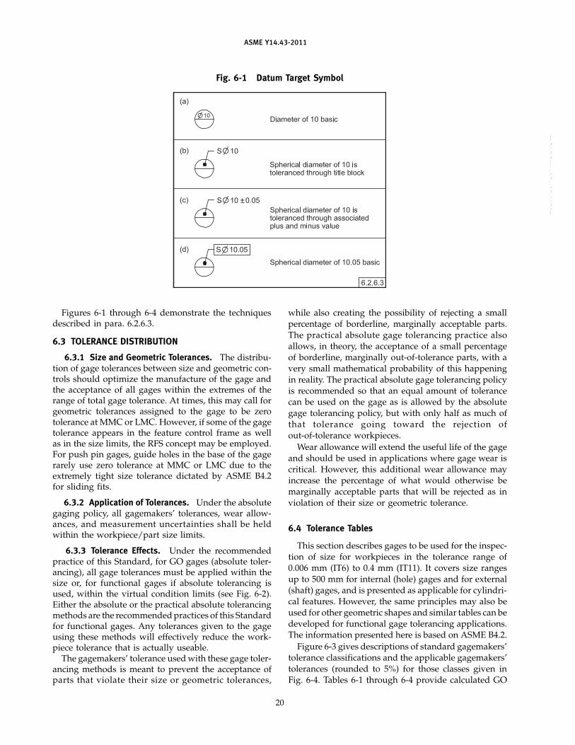
ASME Y14.43-2011
Fig. 6-1 Datum Target Symbol
Figures 6-1 through 6-4 demonstrate the techniquesdescribed in para. 6.2.6.3.
6.3 TOLERANCE DISTRIBUTION
6.3.1 Size and Geometric Tolerances. The distribu-tion of gage tolerances between size and geometric con-trols should optimize the manufacture of the gage andthe acceptance of all gages within the extremes of therange of total gage tolerance. At times, this may call forgeometric tolerances assigned to the gage to be zerotolerance at MMC or LMC. However, if some of the gagetolerance appears in the feature control frame as wellas in the size limits, the RFS concept may be employed.For push pin gages, guide holes in the base of the gagerarely use zero tolerance at MMC or LMC due to theextremely tight size tolerance dictated by ASME B4.2for sliding fits.
6.3.2 Application of Tolerances. Under the absolutegaging policy, all gagemakers’ tolerances, wear allow-ances, and measurement uncertainties shall be heldwithin the workpiece/part size limits.
6.3.3 Tolerance Effects. Under the recommendedpractice of this Standard, for GO gages (absolute toler-ancing), all gage tolerances must be applied within thesize or, for functional gages if absolute tolerancing isused, within the virtual condition limits (see Fig. 6-2).Either the absolute or the practical absolute tolerancingmethods are the recommended practices of this Standardfor functional gages. Any tolerances given to the gageusing these methods will effectively reduce the work-piece tolerance that is actually useable.
The gagemakers’ tolerance used with these gage toler-ancing methods is meant to prevent the acceptance ofparts that violate their size or geometric tolerances,
20
while also creating the possibility of rejecting a smallpercentage of borderline, marginally acceptable parts.The practical absolute gage tolerancing practice alsoallows, in theory, the acceptance of a small percentageof borderline, marginally out-of-tolerance parts, with avery small mathematical probability of this happeningin reality. The practical absolute gage tolerancing policyis recommended so that an equal amount of tolerancecan be used on the gage as is allowed by the absolutegage tolerancing policy, but with only half as much ofthat tolerance going toward the rejection ofout-of-tolerance workpieces.
Wear allowance will extend the useful life of the gageand should be used in applications where gage wear iscritical. However, this additional wear allowance mayincrease the percentage of what would otherwise bemarginally acceptable parts that will be rejected as inviolation of their size or geometric tolerance.
6.4 Tolerance Tables
This section describes gages to be used for the inspec-tion of size for workpieces in the tolerance range of0.006 mm (IT6) to 0.4 mm (IT11). It covers size rangesup to 500 mm for internal (hole) gages and for external(shaft) gages, and is presented as applicable for cylindri-cal features. However, the same principles may also beused for other geometric shapes and similar tables can bedeveloped for functional gage tolerancing applications.The information presented here is based on ASME B4.2.
Figure 6-3 gives descriptions of standard gagemakers’tolerance classifications and the applicable gagemakers’tolerances (rounded to 5%) for those classes given inFig. 6-4. Tables 6-1 through 6-4 provide calculated GO
--`,`,,`,`,``,,`,````,,`,````-`-`,,`,,`,`,,`---

ASME Y14.43-2011
Fig. 6-2 Absolute Tolerancing Method
21
--`,`,,`,`,``,,`,````,,`,````-`-`,,`,,`,`,,`---

ASME Y14.43-2011
Fig. 6-3 Gagemakers’ Tolerance Classes
Gagemakers’Tolerance
Workpiece ToleranceISO SymbolClass [Note (1)] IT Grade Recommended Usage
Rejection ZM 0.05IT11 IT11 Low-precision gages recommended used to inspect workpieces held to internalof good (hole) tolerances C11 and H11 (see Table 6-1) and to external (shaft)parts tolerances c11 and h11 (see Table 6-3)increase
YM 0.05IT9 IT9 Gages recommended used to inspect workpieces held to internal (hole)tolerances C9 and H9 (see Table 6-1) and to external (shaft) tolerances c9and h9 (see Table 6-3).
XM 0.05IT8 IT8 Precision gages recommended used to inspect workpieces held to internal(hole) tolerances F8 and H8 (see Table 6-1).
XXM 0.05IT7 IT7 Recommended used for gages to inspect workpieces held to internal (hole)tolerances G7, H7, K7, N7, P7, S7, and U7 (see Table 6-2) and to external(shaft) tolerances f7 and h7 (see Table 6-3).
Gage cost XXXM 0.05IT6 IT6 High-precision gages recommended used to inspect workpieces held toincrease external (shaft) tolerances g6, h6, k6, n6, p6, s6, and u6 (see Table 6-4).
GENERAL NOTE: For closer gagemakers’ tolerance classes than Class XXXM, specify 5% of IT5, IT4, or IT3 (see ANSI B4.2, Table BI) and usethe designation 0.05 IT5, 0.05 IT4, etc.
NOTE:(1) Gagemakers’ tolerance is equal to 5% of workpiece tolerance or 5% of applicable IT grade value (see Fig. 6-4).
▲
▼
Fig. 6-4 Gagemakers’ Tolerance Chart
Basic Size Class ZM Class YM Class XM Class XXM Class XXXMOver To (0.05IT11) (0.05IT9) (0.05IT8) (0.05IT7) (0.05IT6)
0 3 0.0030 0.0012 0.0007 0.0005 0.00033 6 0.0037 0.0015 0.0009 0.0006 0.00046 10 0.0045 0.0018 0.0011 0.0007 0.0005
10 18 0.0055 0.0021 0.0013 0.0009 0.000618 30 0.0065 0.0026 0.0016 0.0010 0.000730 50 0.0080 0.0031 0.0019 0.0012 0.000850 80 0.0090 0.0037 0.0023 0.0015 0.001080 120 0.0110 0.0043 0.0027 0.0017 0.0011
120 180 0.0125 0.0050 0.0031 0.0020 0.0013180 250 0.0145 0.0057 0.0036 0.0023 0.0015250 315 0.0160 0.0065 0.0040 0.0026 0.0016315 400 0.0180 0.0070 0.0044 0.0028 0.0018400 500 0.0200 0.0077 0.0048 0.0031 0.0020
22
--`,`,,`,`,``,,`,````,,`,````-`-`,,`,,`,`,,`---

ASME Y14.43-2011
Table 6-1 Plug Gage Limit Dimensions — Classes ZM, YM, and XM
Class ZM (0.05IT11) [Note (1)] Class YM (0.05IT9) Class XM (0.05IT8)
C11 [Note (2)] H11 D9 H9 F8 H8
Basic Size GO NOGO GO NOGO GO NOGO GO NOGO GO NOGO GO NOGO
1 Max. 1.0630 1.1200 1.0030 1.0600 1.0212 1.0450 1.0012 1.0250 1.0067 1.0200 1.0007 1.0140Min. 1.0600 1.1170 1.0000 1.0570 1.0200 1.0438 1.0000 1.0238 1.0060 1.0193 1.0000 1.0133
1.2 Max. 1.2630 1.3200 1.2030 1.2600 1.2212 1.2450 1.2067 1.2250 1.2067 1.2200 1.2007 1.2140Min. 1.2600 1.3170 1.2000 1.2570 1.2200 1.2438 1.2000 1.2238 1.2060 1.2193 1.2000 1.2133
1.6 Max. 1.6630 1.7200 1.6030 1.6600 1.6212 1.6450 1.6012 1.6250 1.6067 1.6200 1.6007 1.6140Min. 1.6600 1.7170 1.6000 1.6570 1.6200 1.6438 1.6000 1.6238 1.6060 1.6193 1.6000 1.6133
2 Max. 2.0630 2.1200 2.0030 2.0600 2.0212 2.0450 2.0012 2.0250 2.0067 2.0200 2.0007 2.0140Min. 2.0600 2.1170 2.0000 2.0570 2.0200 2.0438 2.0000 2.0238 2.0060 2.0193 2.0000 2.0133
2.5 Max. 2.5630 2.6200 2.5030 2.5600 2.5212 2.5450 2.5012 2.5250 2.5067 2.5200 2.5007 2.5140Min. 2.5600 2.6170 2.5000 2.5570 2.5200 2.5438 2.5000 2.5238 2.5060 2.5193 2.5000 2.5133
3 Max. 3.0630 3.1200 3.0030 3.0600 3.0212 3.0450 3.0012 3.0250 3.0067 3.0200 3.0007 3.0140Min. 3.0600 3.1170 3.0000 3.0570 3.0200 3.0438 3.0000 3.0238 3.0060 3.0193 3.0000 3.0133
4 Max. 4.0737 4.1450 4.0037 4.0750 4.0315 4.0600 4.0015 4.0300 4.0109 4.0280 4.0009 4.0180Min. 4.0700 4.1413 4.0000 4.0713 4.0300 4.0585 4.0000 4.0285 4.0100 4.0271 4.0000 4.0171
5 Max. 5.0737 5.1450 5.0037 5.0750 5.0315 5.0600 5.0015 5.0300 5.0109 5.0280 5.0009 5.0180Min. 5.0700 5.1413 5.0000 5.0713 5.0300 5.0585 5.0000 5.0285 5.0100 5.0271 5.0000 5.0171
6 Max. 6.0737 6.1450 6.0037 6.0750 6.0315 6.0600 6.0015 6.0300 6.0109 6.0280 6.0009 6.0180Min. 6.0700 6.1413 6.0000 6.0713 6.0300 6.0585 6.0000 6.0285 6.0100 6.0271 6.0000 6.0171
8 Max. 8.0845 8.1700 8.0045 8.0900 8.0418 8.0760 8.0018 8.0360 8.0141 8.0350 8.0011 8.0220Min. 8.0800 8.1655 8.0000 8.0855 8.0400 8.0742 8.0000 8.0342 8.0130 8.0339 8.0000 8.0209
10 Max. 10.0845 10.1700 10.0045 10.0900 10.0418 10.0760 10.0018 10.0360 10.0141 10.0350 10.0011 10.0220Min. 10.0800 10.1655 10.0000 10.0855 10.0400 10.0742 10.0000 10.0342 10.0130 10.0339 10.0000 10.0209
12 Max. 12.1005 12.2050 12.0055 12.1100 12.0521 12.0930 12.0021 12.0430 12.0173 12.0430 12.0013 12.0270Min. 12.0950 12.1995 12.0000 12.1045 12.0500 12.0909 12.0000 12.0409 12.0160 12.0417 12.0000 12.0257
16 Max. 16.1005 16.2050 16.0055 16.1100 16.0521 16.0930 16.0021 16.0430 16.0173 16.0430 16.0013 16.0270Min. 16.0950 16.1995 16.0000 16.1045 16.0500 16.0909 16.0000 16.0409 16.0160 16.0417 16.0000 16.0257
20 Max. 20.1165 20.2400 20.0065 20.1300 20.0676 20.1170 20.0026 20.0520 20.0216 20.0530 20.0016 20.0330Min. 20.1100 20.2335 20.0000 20.1235 20.0650 20.1144 20.0000 20.0494 20.0200 20.0514 20.0000 20.0314
25 Max. 25.1165 25.2400 25.0065 25.1300 25.0676 25.1170 25.0026 25.0520 25.0216 25.0530 25.0016 25.0330Min. 25.1100 25.2335 25.0000 25.1235 25.0650 25.1144 25.0000 25.0494 25.0200 25.0514 25.0000 25.0314
30 Max. 30.1165 30.2400 30.0065 30.1300 30.0676 30.1170 30.0026 30.0520 30.0216 30.0530 30.0016 30.0330Min. 30.1100 30.2335 30.0000 30.1235 30.0650 30.1144 30.0000 30.0494 30.0200 30.0514 30.0000 30.0314
40 Max. 40.1280 40.2800 40.0080 40.1600 40.0831 40.1420 40.0031 40.0620 40.0269 40.0640 40.0019 40.0390Min. 40.1200 40.2720 40.0000 40.1520 40.0800 40.1389 40.0000 40.0589 40.0250 40.0621 40.0000 40.0371
50 Max. 50.1380 50.2900 50.0080 50.1600 50.0831 50.1420 50.0031 50.0620 50.0269 50.0640 50.0019 50.0390Min. 50.1300 50.2820 50.0000 50.1520 50.0800 50.1389 50.0000 50.0589 50.0250 50.0621 50.0000 50.0371
60 Max. 60.1495 60.3300 60.0095 60.1900 60.1037 60.1740 60.0037 60.0740 60.0323 60.0760 60.0023 60.0460Min. 60.1400 60.3205 60.0000 60.1805 60.1000 60.1703 60.0000 60.0703 60.0300 60.0737 60.0000 60.0437
23
--`,`,,`,`,``,,`,````,,`,````-`-`,,`,,`,`,,`---

ASME Y14.43-2011
Table 6-1 Plug Gage Limit Dimensions — Classes ZM, YM, and XM (Cont’d)
Class ZM (0.05IT11) [Note (1)] Class YM (0.05IT9) Class XM (0.05IT8)
C11 [Note (2)] H11 D9 H9 F8 H8
Basic Size GO NOGO GO NOGO GO NOGO GO NOGO GO NOGO GO NOGO
80 Max. 80.1595 80.3400 80.0095 80.1900 80.1037 80.1740 80.0037 80.0740 80.0323 80.0760 80.0023 80.0460Min. 80.1500 80.3305 80.0000 80.1805 80.1000 80.1703 80.0000 80.0703 80.0300 80.0737 80.0000 80.0437
100 Max. 100.1810 100.3900 100.0110 100.2200 100.1243 100.2070 100.0043 100.0870 100.0387 100.0900 100.0027 100.0540Min. 100.1700 100.3790 100.0000 100.2090 100.1200 100.2027 100.0000 100.0827 100.0360 100.0873 100.0000 100.0513
120 Max. 120.1910 120.4000 120.0110 120.2200 120.1243 120.2070 120.0043 120.0870 120.0387 120.0900 120.0027 120.0540Min. 120.1800 120.3890 120.0000 120.2090 120.1200 120.2027 120.0000 120.0827 120.0360 120.0873 120.0000 120.0513
160 Max. 160.2225 160.4600 160.0125 160.2500 160.1500 160.2450 160.0050 160.1000 160.0461 160.1060 160.0031 160.0630Min. 160.2100 160.4475 160.0000 160.2375 160.1450 160.2400 160.0000 160.0950 160.0430 160.1029 160.0000 160.0599
200 Max. 200.2545 200.5300 200.0145 200.2900 200.1757 200.2850 200.0057 200.1150 200.0536 200.1220 200.0036 200.0720Min. 200.2400 200.5155 200.0000 200.2755 200.1700 200.2793 200.0000 200.1093 200.0500 200.1184 200.0000 200.0684
250 Max. 250.2945 250.5700 250.0145 250.2900 250.1757 250.2850 250.0057 250.1150 250.0536 250.1220 250.0036 250.0720Min. 250.2800 250.5555 250.0000 250.2755 250.1700 250.2793 250.0000 250.1093 250.0500 250.1184 250.0000 250.0684
300 Max. 300.3460 300.6500 300.0160 300.3200 300.1965 300.3200 300.0065 300.1300 300.0600 300.1370 300.0040 300.0810Min. 300.3300 300.6340 300.0000 300.3040 300.1900 300.3135 300.0000 300.1235 300.0560 300.1330 300.0000 300.0770
400 Max. 400.4180 400.7600 400.0180 400.3600 400.2170 400.3500 400.0070 400.1400 400.0664 400.1510 400.0044 400.0890Min. 400.4000 400.7420 400.0000 400.3420 400.2100 400.3430 400.0000 400.1330 400.0620 400.1466 400.0000 400.0846
500 Max. 500.5000 500.8800 500.0200 500.4000 500.2377 500.3850 500.0077 500.1550 500.0728 500.1650 500.0048 500.0970Min. 500.4800 500.8600 500.0000 500.3800 500.2300 500.3773 500.0000 500.1473 500.0680 500.1602 500.0000 500.0922
NOTES:(1) Plug gage tolerance Class XXM, which is equal to the rounded 5% of International Tolerance IT11 (see Fig. 6-4).(2) Workpiece hole tolerance G7 (see ANSI B4.2, Table 4).
24--`,`,,`,`,``,,`,````,,`,````-`-`,,`,,`,`,,`---

ASME Y14.43-2011
Table 6-2 Plug Gage Limit Dimensions — Class XXM
Class XXM (0.05IT7) [Note (1)]
G7 [Note (2)] H7 K7 N7 P7 S7 U7
Basic Size GO NOGO GO NOGO GO NOGO GO NOGO GO NOGO GO NOGO GO NOGO
1 Max. 1.0630 1.1200 1.0005 1.0100 0.9905 1.0000 0.9865 0.9960 0.9845 0.9940 0.9765 0.9860 0.9725 0.9820Min. 1.0600 1.1170 1.0000 1.0095 0.9900 0.9995 0.9860 0.9955 0.9840 0.9935 0.9760 0.9855 0.9720 0.9815
1.2 Max. 1.2630 1.3200 1.2005 1.2100 1.1905 1.2000 1.1065 1.1960 1.1845 1.1940 1.1765 1.1860 1.1725 1.1820Min. 1.2600 1.3170 1.2000 1.2095 1.1900 1.1995 1.1060 1.1955 1.1840 1.1935 1.1760 1.1855 1.1720 1.1815
1.6 Max. 1.6630 1.7200 1.6005 1.6100 1.5905 1.6000 1.5865 1.5960 1.5845 1.5940 1.5765 1.5860 1.5725 1.5820Min. 1.6600 1.7170 1.6000 1.6095 1.5900 1.5995 1.9860 1.9955 1.5840 1.5935 1.5760 1.5855 1.5720 1.5815
2 Max. 2.0630 2.1200 2.0005 2.0100 1.9905 2.0000 1.9865 1.9960 1.9845 1.9940 1.9765 1.9860 1.9725 1.9820Min. 2.0600 2.1170 2.0000 2.0095 1.9900 1.9995 1.9860 1.9955 1.9840 1.9935 1.9760 1.9855 1.9720 1.9815
2.5 Max. 2.5630 2.6200 2.5005 2.5100 2.4905 2.5000 2.4865 2.4960 2.4845 2.4940 2.4765 2.4860 2.4725 2.4820Min. 2.5600 2.6170 2.5000 2.5095 2.4900 2.4995 2.4860 2.4955 2.4840 2.4935 2.4760 2.4855 2.4720 2.4815
3 Max. 3.0630 3.1200 3.0005 3.0100 2.9905 3.0000 2.9865 2.9960 2.9845 2.9940 2.9765 2.9860 2.9725 2.9820Min. 3.0600 3.1170 3.0000 3.0095 2.9900 2.9995 2.9860 2.9955 2.9840 2.9935 2.9760 2.9855 2.9720 2.9815
4 Max. 4.0737 4.1450 4.0006 4.0120 3.9916 4.0030 3.9846 3.9960 3.9806 3.9920 3.9736 3.9850 3.9696 3.9810Min. 4.0700 4.1413 4.0000 4.0114 3.9910 4.0024 3.9840 3.9954 3.9800 3.9914 3.9730 3.9844 3.9690 3.9804
5 Max. 5.0737 5.1450 5.0006 5.0120 4.9916 5.0030 4.9846 4.9960 4.9806 4.9920 4.9736 4.9850 4.9696 4.9810Min. 5.0700 5.1413 5.0000 5.0114 4.9910 5.0024 4.9840 4.9954 4.9800 4.9914 4.9730 4.9844 4.9690 4.9804
6 Max. 6.0737 6.1450 6.0006 8.0120 5.9916 6.0030 5.9846 5.9980 5.9806 5.9920 5.9736 5.9850 5.9696 5.9810Min. 6.0700 6.1413 6.0000 6.0114 5.9910 6.0024 5.9840 5.9954 5.9800 5.9914 5.9730 5.9844 5.9690 5.9804
8 Max. 8.0845 8.1700 8.0007 8.0150 7.9907 8.0050 7.9817 7.9960 7.9767 7.9910 7.9687 7.9830 7.9637 7.9780Min. 8.0800 8.1655 8.0000 8.0143 7.9900 8.0043 7.9810 7.9953 7.9760 7.9903 7.9680 7.9823 7.9630 7.9773
10 Max. 10.0845 10.1700 10.0007 10.0150 9.9907 10.0050 9.9817 9.9960 9.9767 9.9910 9.9687 9.9830 9.9637 9.9780Min. 10.0800 10.1655 10.0000 10.0143 9.9900 10.0043 9.9810 9.9953 9.9760 9.9903 9.9680 9.9823 9.9630 9.9773
12 Max. 12.1005 12.2050 12.0009 12.0180 11.9889 12.0060 11.9779 11.9950 11.9719 11.9890 11.9619 11.9790 11.9569 11.9740Min. 12.0950 12.1995 12.0000 12.0171 11.9880 12.0051 11.9770 11.9941 11.9710 11.9881 11.9610 11.9781 11.9560 11.9731
18 Max. 16.1005 16.2050 16.0009 16.0180 15.9889 16.0060 15.9779 15.9950 15.9719 15.9890 15.9619 15.9790 15.9569 15.9740Min. 16.0950 16.1995 16.0000 16.0171 15.9880 16.0051 15.9770 15.9941 15.9710 15.9881 15.9610 15.9781 15.9560 15.9731
20 Max. 20.1165 20.2400 20.0010 20.0210 19.9860 20.0060 19.9730 19.9930 19.9660 19.9860 19.9530 19.9730 19.9470 19.9670Min. 20.1100 20.2335 20.0000 20.0200 19.9850 20.0050 19.9720 19.9920 19.9650 19.9850 19.9520 19.9720 19.9460 19.9660
25 Max. 25.0080 25.0280 25.0010 25.0210 24.9860 25.0060 24.9730 24.9930 24.9660 24.9860 24.9530 24.9730 24.9400 24.9600Min. 25.0070 25.0270 25.0000 25.0200 24.9850 25.0050 24.9720 24.9920 24.9650 24.9850 24.9520 24.9720 24.9390 24.9590
30 Max. 30.0080 30.0280 30.0010 30.0210 29.9860 30.0060 29.9730 29.9930 29.9660 29.9860 29.9530 29.9730 29.9400 29.9600Min. 30.0070 30.0270 30.0000 30.0200 29.9850 30.0050 29.9720 29.9920 29.9650 29.9850 29.9520 29.9720 29.9390 29.9590
40 Max. 40.0102 40.0340 40.0012 40.0250 39.9832 40.0070 39.9682 39.9920 39.9592 39.9830 39.9422 39.9660 39.9252 39.9490Min. 40.0090 40.0328 40.0000 40.0238 39.9820 40.0058 39.9670 39.9908 39.9580 39.9818 39.9410 39.9648 39.9240 39.9478
50 Max. 50.0102 50.0340 50.0012 50.0250 49.9832 50.0070 49.9682 49.9920 49.9592 49.9830 49.9422 49.9660 49.9152 49.9390Min. 50.0090 50.0328 50.0000 50.0238 49.9820 50.0058 49.9670 49.9908 49.9580 49.9818 49.9410 49.9648 49.9140 49.9378
60 Max. 60.0115 60.0400 60.0015 60.0300 59.9805 60.0090 59.9625 59.9910 59.9505 59.9790 59.9295 59.9580 59.8955 59.9240Min. 60.0100 60.0385 60.0000 60.0285 59.9790 60.0075 59.9610 59.9895 59.9490 59.9775 59.9280 59.9565 59.8940 59.9225
80 Max. 80.0115 80.0400 80.0015 80.0300 79.9805 80.0090 79.9625 79.9910 79.9505 79.9790 79.9235 79.9520 79.8805 79.9090Min. 80.0100 80.0385 80.0000 80.0285 79.9790 80.0075 79.9610 79.9895 79.9490 79.9775 79.9220 79.9505 79.8790 79.9075
100 Max. 100.0137 100.0470 100.0017 100.0350 99.9767 100.0100 99.9567 99.9900 99.9427 99.9760 99.9087 99.9420 99.8557 99.8890Min. 100.0120 100.0453 100.0000 100.0333 99.9750 100.0083 99.9550 99.9883 99.9410 99.9743 99.9070 99.9403 99.8540 99.8873
25
--`,`,,`,`,``,,`,````,,`,````-`-`,,`,,`,`,,`---

ASME Y14.43-2011
Table 6-2 Plug Gage Limit Dimensions — Class XXM (Cont’d)
Class XXM (0.05IT7) [Note (1)]
G7 [Note (2)] H7 K7 N7 P7 S7 U7
Basic Size GO NOGO GO NOGO GO NOGO GO NOGO GO NOGO GO NOGO GO NOGO
120 Max. 120.0137 100.0470 120.0017 120.0350 119.9767 120.0100 119.9567 119.9900 119.9427 119.9760 119.9007 119.9340 119.8357 119.8690Min. 120.0120 120.0453 120.0000 120.0333 119.9750 120.0083 119.9550 119.9883 119.9410 119.9743 119.8990 119.9323 119.8340 119.8673
160 Max. 160.0160 160.0540 160.0020 160.0400 159.9740 160.0120 159.9500 159.9880 159.9340 159.9720 159.8770 159.9150 159.7870 159.8250Min. 160.0140 160.0520 160.0000 160.0380 159.9720 160.0100 159.9480 159.9860 159.9320 159.9700 159.8750 159.9130 159.7850 159.8230
200 Max. 200.0173 200.0610 200.0023 200.0460 199.9693 200.0130 199.9423 199.9860 199.9233 199.9670 199.8513 199.8950 199.7373 199.7810Min. 200.0150 200.0587 200.0000 200.0437 199.9670 200.0107 199.9400 199.9837 199.9210 199.9647 199.8490 199.8927 199.7350 199.7787
250 Max. 250.0173 250.0610 250.0023 250.0460 249.9693 250.0130 249.9423 249.9860 249.9233 249.9670 249.8333 249.8770 249.6893 249.7330Min. 250.0150 250.0587 250.0000 250.0437 249.9670 250.0107 249.9400 249.9837 249.9210 249.9647 249.8310 249.8747 249.6870 249.7307
300 Max. 300.0196 300.0690 300.0026 300.0520 299.9666 300.0160 299.9366 299.9860 299.9146 299.9640 299.8006 299.8500 299.6206 299.6700Min. 300.0170 300.0664 300.0000 300.0494 299.9640 300.0134 299.9340 299.9834 299.9120 299.9614 299.7980 299.8474 299.6180 299.6674
400 Max. 400.0208 400.0750 400.0028 400.0570 399.9628 400.0170 399.9298 399.9840 399.9048 399.9590 399.7588 399.8130 399.5318 399.5860Min. 400.0180 400.0722 400.0000 400.0542 399.9600 400.0142 399.9270 399.9812 399.9020 399.9562 399.7560 399.8102 399.5290 399.5832
500 Max. 500.0231 500.0830 500.0031 500.0630 499.9581 500.0180 499.9231 499.9830 499.8951 499.9550 499.7111 499.7710 499.4231 499.4830Min. 500.0200 500.0799 500.0000 500.0599 499.9550 500.0149 499.9200 499.9799 499.8920 499.9519 499.7080 499.7679 499.4200 499.4799
NOTES:(1) Plug gage tolerance Class XXM, which is equal to the rounded 5% of International Tolerance IT11 (see Fig. 6-4).(2) Workpiece hole tolerance G7 (see ANSI B4.2, Table 4).
26
--`,`,,`,`,``,,`,````,,`,````-`-`,,`,,`,`,,`---

ASME Y14.43-2011
Table 6-3 Ring and Snap Gage Limit Dimensions — Classes ZM, YM, and XXM
Class ZM (0.05IT11) [Note (1)] Class YM (0.05IT9) Class XXM (0.05IT7)
c11 [Note (2)] h11 d9 h9 f7 h7
Basic Size GO NOGO GO NOGO GO NOGO GO NOGO GO NOGO GO NOGO
1 Max. 0.9400 0.8830 1.0000 0.9430 0.9800 0.9562 1.0000 0.9762 0.9940 0.9845 1.0000 0.9905Min. 0.9370 0.8800 0.9970 0.9400 0.9788 0.9550 0.9988 0.9750 0.9935 0.9840 0.9995 0.9900
1.2 Max. 1.1400 1.0830 1.2000 1.1430 1.1800 1.1562 1.2000 1.1762 1.1940 1.1845 1.2000 1.1905Min. 1.1370 1.0800 1.1970 1.1400 1.1788 1.1550 1.1988 1.1750 1.1935 1.1840 1.1995 1.1900
1.6 Max. 1.5400 1.4830 1.6000 1.5430 1.5800 1.5562 1.6000 1.5762 1.5940 1.5845 1.6000 1.5905Min. 1.5370 1.4800 1.5970 1.5400 1.5788 1.5550 1.5988 1.5750 1.5935 1.5840 1.5995 1.5900
2 Max. 1.9400 1.8830 2.0000 1.9430 1.9800 1.9562 2.0000 1.9762 1.9940 1.9845 2.0000 1.9905Min. 1.9370 1.8800 1.9970 1.9400 1.9788 1.9550 1.9988 1.9750 1.9935 1.9840 1.9995 1.9900
2.5 Max. 2.4400 2.3830 2.5000 2.4430 2.4800 2.4562 2.5000 2.4762 2.4940 2.4845 2.5000 2.4905Min. 2.4370 2.3800 2.4970 2.4400 2.4788 2.4550 2.4988 2.4750 2.4935 2.4840 2.4995 2.4900
3 Max. 2.9400 2.8830 3.0000 2.9430 2.9800 2.9562 3.0000 2.9762 2.9940 2.9845 3.0000 2.9905Min. 2.9370 2.8800 2.9970 2.9400 2.9788 2.9550 2.9988 2.9750 2.9935 2.9840 2.9995 2.9900
4 Max. 3.9300 3.8587 4.0000 3.9287 3.9700 3.9415 4.0000 3.9715 3.9900 3.9786 4.0000 3.9886Min. 3.9263 3.8550 3.9963 3.9250 3.9685 3.9400 3.9985 3.9700 3.9894 3.9780 3.9994 3.9880
5 Max. 4.9300 4.8587 5.0000 4.9287 4.9700 4.9415 5.0000 4.9715 4.9900 4.9786 5.0000 4.9886Min. 4.9263 4.8550 4.9963 4.9250 4.9685 4.9400 4.9985 4.9700 4.9894 4.9780 4.9994 4.9880
6 Max. 5.9300 5.8587 6.0000 5.9287 5.9700 5.9415 6.0000 5.9715 5.9900 5.9786 6.0000 5.9886Min. 5.9263 5.8550 5.9963 5.9250 5.9685 5.9400 5.9985 5.9700 5.9894 5.9780 5.9994 5.9880
8 Max. 7.9200 7.8345 8.0000 7.9145 7.9600 7.9258 8.0000 7.9658 7.9870 7.9727 8.0000 7.9857Min. 7.9155 7.8300 7.9955 7.9100 7.9582 7.9240 7.9982 7.9640 7.9863 7.9720 7.9993 7.9850
10 Max. 9.9200 9.8345 10.0000 9.9145 9.9600 9.9258 10.0000 9.9658 9.9870 9.9727 10.0000 9.9857Min. 9.9155 9.8300 9.9955 9.9100 9.9582 9.9240 9.9982 9.9640 9.9863 9.9720 9.9993 9.9850
12 Max. 11.9050 11.8005 12.0000 11.8955 11.9500 11.9091 12.0000 11.9591 11.9840 11.9669 12.0000 11.9829Min. 11.8995 11.7950 11.9945 11.8900 11.9479 11.9070 11.9979 11.9570 11.9831 11.9660 11.9991 11.9820
18 Max. 15.9050 15.8005 16.0000 15.8955 15.9500 15.9091 16.0000 15.9591 15.9840 15.9669 16.0000 15.9829Min. 15.8995 15.7950 15.9945 15.8900 15.9479 15.9070 15.9979 15.9570 15.9831 15.9660 15.9991 15.9820
20 Max. 19.8900 19.7665 20.0000 19.8765 19.9350 19.8856 20.0000 19.9506 19.9800 19.9600 20.0000 19.9800Min. 19.8835 19.7600 19.9935 19.8700 19.9324 19.8830 19.9974 19.9480 19.9790 19.9590 19.9990 19.9790
25 Max. 24.8900 24.7665 25.0000 24.8765 24.9350 24.8856 25.0000 24.9506 24.9800 24.9600 25.0000 24.9800Min. 24.8835 24.7600 24.9935 24.8700 24.9324 24.8830 24.9974 24.9480 24.9790 24.9590 24.9990 24.9790
30 Max. 29.8900 29.7665 30.0000 29.8765 29.9350 29.8856 30.0000 29.9506 29.9800 29.9600 30.0000 29.9800Min. 29.8835 29.7600 29.9935 29.8700 29.9324 29.8830 29.9974 29.9480 29.9790 29.9590 29.9990 29.9790
40 Max. 39.8800 39.7280 40.0000 39.8480 39.9200 39.8611 40.0000 39.9411 39.9750 39.9512 40.0000 39.9762Min. 39.8720 39.7200 39.9920 39.8400 39.9169 39.8580 39.9969 39.9380 39.9738 39.9500 39.9988 39.9750
50 Max. 49.8700 49.7180 50.0000 49.8480 49.9200 49.8611 50.0000 49.9411 49.9750 49.9512 50.0000 49.9762Min. 49.8620 49.7100 49.9920 49.8400 49.9189 49.8580 49.9969 49.9380 49.9738 49.9500 49.9988 49.9750
60 Max. 59.8600 59.6795 60.0000 59.8195 59.9000 59.8297 60.0000 59.9297 59.9700 59.9415 60.0000 59.9715Min. 59.8505 59.6700 59.9905 59.8100 59.8963 59.8260 59.9963 59.9260 59.9685 59.9400 59.9985 59.9700
80 Max. 79.8500 79.6695 80.0000 79.8195 79.9000 79.8297 80.0000 79.9297 79.9700 79.9415 80.0000 79.9715Min. 79.8405 79.6600 79.9905 79.8100 79.8963 79.8260 79.9963 79.9260 79.9685 79.9400 79.9985 79.9700
100 Max. 99.8300 99.6210 100.0000 99.7910 99.8800 99.7973 100.0000 99.9173 99.9640 99.9307 100.0000 99.9667Min. 99.8190 99.6100 99.9890 99.7800 99.8963 99.7930 99.9957 99.9130 99.9623 99.9290 99.9983 99.9650
27
--`,`,,`,`,``,,`,````,,`,````-`-`,,`,,`,`,,`---

ASME Y14.43-2011
Table 6-3 Ring and Snap Gage Limit Dimensions — Classes ZM, YM, and XXM (Cont’d)
Class ZM (0.05IT11) [Note (1)] Class YM (0.05IT9) Class XXM (0.05IT7)
c11 [Note (2)] h11 d9 h9 f7 h7
Basic Size GO NOGO GO NOGO GO NOGO GO NOGO GO NOGO GO NOGO
120 Max. 119.8200 119.6110 120.0000 119.7910 119.8800 119.7973 120.0000 119.9173 119.9640 119.9307 120.0000 119.9667Min. 119.8090 119.6000 119.9890 119.7800 119.8757 119.7930 199.9957 119.9130 119.9623 119.9290 119.9983 119.9650
160 Max. 159.7600 159.5525 160.0000 159.7625 159.8550 159.7600 160.0000 159.9050 159.9570 159.9190 160.0000 159.9620Min. 159.7775 159.5400 159.9875 159.7500 159.8500 159.7550 159.9950 159.9000 159.9550 159.9170 159.9980 159.9600
200 Max. 199.7600 199.4845 200.0000 199.7245 199.8300 199.7207 200.0000 199.8907 199.9500 199.9063 200.0000 199.9563Min. 199.7455 199.4700 199.9855 199.7100 199.8243 199.7150 199.9943 199.8850 199.9477 199.9040 199.9977 199.9540
250 Max. 249.7200 249.4445 250.0000 249.7245 249.8300 249.7207 250.0000 249.8907 249.9500 249.9063 250.0000 249.9563Min. 249.7055 249.4300 249.9855 249.7100 249.8243 249.7150 249.9943 249.8850 249.9477 249.9040 249.9977 249.9540
300 Max. 299.6700 299.3660 300.0000 299.6960 299.8100 299.6865 300.0000 299.8765 299.9440 299.8946 300.0000 299.9506Min. 299.6540 299.3500 299.9840 299.6800 299.8035 299.6800 299.9935 299.8700 299.9414 299.8920 299.9974 299.9480
400 Max. 399.6000 399.2580 400.0000 399.8580 399.7900 399.6570 400.0000 399.8670 399.9380 399.8838 400.0000 399.9458Min. 399.5820 399.2400 399.9820 399.6400 399.7830 399.6500 399.9930 399.8600 399.9352 399.8810 399.9972 399.9430
500 Max. 499.5200 499.1400 500.0000 499.6200 499.7700 499.6227 500.0000 499.8527 499.9320 499.8721 500.0000 499.9401Min. 499.5000 499.1200 499.9800 499.6000 499.7623 499.6150 499.9923 499.8450 499.9289 499.8690 499.9969 499.9370
NOTES:(1) Plug gage tolerance Class ZM, which is equal to the rounded 5% of International Tolerance IT11 (see Fig. 6-4).(2) Workpiece hole tolerance C11 (see ANSI B4.2, Table 2).
28
--`,`,,`,`,``,,`,````,,`,````-`-`,,`,,`,`,,`---

ASME Y14.43-2011
Table 6-4 Ring and Snap Gage Limit Dimensions — Class XXXM
Class XXXM (0.05IT6) [Note (1)]
g6 [Note (2)] h6 k6 n6 p6 s6 u6
Basic Size GO NOGO GO NOGO GO NOGO GO NOGO GO NOGO GO NOGO GO NOGO
1 Max. 0.9980 0.9923 1.0000 0.9943 1.0060 1.0003 1.0100 1.0043 1.0120 1.0063 1.0200 1.0143 1.0240 1.0183Min. 0.9977 0.9920 0.9997 0.9940 1.0057 1.0000 1.0097 1.0040 1.0117 1.0060 1.0197 1.0140 1.0237 1.0180
1.2 Max. 1.1980 1.1923 1.2000 1.1943 1.2060 1.2003 1.2100 1.2043 1.2120 1.2063 1.2200 1.2143 1.2240 1.2183Min. 1.1977 1.1920 1.1997 1.1940 1.2057 1.2000 1.2097 1.2040 1.2117 1.2060 1.2197 1.2140 1.2237 1.2180
1.6 Max. 1.5980 1.5923 1.6000 1.5943 1.6060 1.6003 1.6100 1.6043 1.6120 1.6063 1.6200 1.6143 1.6240 1.6183Min. 1.5977 1.5920 1.5997 1.5940 1.6057 1.6000 1.6097 1.6040 1.6117 1.6060 1.6197 1.6140 1.6237 1.6180
2 Max. 1.9980 1.9923 2.0000 1.9943 2.0060 2.0003 2.0100 2.0043 2.0120 2.0063 2.0200 2.0143 2.0240 2.0183Min. 1.9977 1.9920 1.9997 1.9940 2.0057 2.0000 2.0097 2.0040 2.0117 2.0060 2.0197 2.0140 2.0237 2.0180
2.5 Max. 2.4980 2.4923 2.5000 2.4943 2.5060 2.5003 2.5100 2.5043 2.5120 2.5063 2.5200 2.5143 2.5240 2.5183Min. 2.4977 2.4920 2.4997 2.4940 2.5057 2.5000 2.5097 2.5040 2.5117 2.5060 2.5197 2.5140 2.5237 2.5180
3 Max. 2.9980 2.9923 3.0000 2.9943 3.0060 3.0003 3.0100 3.0043 3.0120 3.0063 3.0200 3.0143 3.0240 3.0183Min. 2.9977 2.9920 2.9997 2.9940 3.0057 3.0000 3.0097 3.0040 3.0117 3.0060 3.0197 3.0140 3.0237 3.0180
4 Max. 3.9960 3.9884 4.0000 3.9924 4.0090 4.0014 4.0160 4.0084 4.0200 4.0124 4.0270 4.0194 4.0310 4.0234Min. 3.9956 3.9880 3.9996 3.9920 4.0086 4.0000 4.0156 4.0080 4.0196 4.0120 4.0266 4.0190 4.0306 4.0230
5 Max. 4.9960 4.9884 5.0000 4.9924 5.0090 5.0014 5.0160 5.0084 5.0200 5.0124 5.0270 5.0194 5.0310 5.0234Min. 4.9956 4.9880 4.9996 4.9920 5.0086 5.0010 5.0156 5.0080 5.0196 5.0120 5.0266 5.0190 5.0306 5.0230
6 Max. 5.9960 5.9884 6.0000 5.9924 6.0090 6.0014 6.0160 6.0084 6.0200 6.0124 6.0270 6.0194 6.0310 6.0234Min. 5.9956 5.9880 5.9996 5.9920 6.0086 6.0010 6.0156 6.0080 6.0196 6.0120 6.0266 6.0190 6.0306 6.0230
8 Max. 7.9950 7.9865 8.0000 7.9915 8.0100 8.0015 8.0190 8.0105 8.0240 8.0155 8.0320 8.0235 8.0370 8.0285Min. 7.9945 7.9860 7.9995 7.9910 8.0095 8.0010 8.0185 8.0100 8.0235 8.0150 8.0315 8.0230 8.0365 8.0280
10 Max. 9.9950 9.9865 10.0000 9.9915 10.0100 10.0015 10.0190 10.0105 10.0240 10.0155 10.0320 10.0235 10.0370 10.0285Min. 9.9945 9.9860 9.9995 9.9910 10.0095 10.0010 10.0185 10.0100 10.0235 10.0150 10.0315 10.0230 10.0365 10.0280
12 Max. 11.9940 11.9836 12.0000 11.9896 12.0120 12.0016 12.0230 12.0126 12.0290 12.0186 12.0390 12.0286 12.0440 12.0336Min. 11.9934 11.9830 11.9994 11.9890 12.0114 12.0010 12.0224 12.0120 12.0284 12.0180 12.0384 12.0280 12.0434 12.0330
18 Max. 15.9940 15.9836 16.0000 15.9896 16.0120 16.0016 16.0230 16.0126 16.0290 16.0186 16.0390 16.0286 16.0440 16.0336Min. 15.9934 15.9830 15.9994 15.9890 16.0114 16.0010 16.0224 16.0120 16.0284 16.0180 16.0384 16.0280 16.0434 16.0330
20 Max. 19.9930 19.9807 20.0000 19.9877 20.0150 20.0027 20.0280 20.0157 20.0350 20.0227 20.0480 20.0357 20.0540 20.0417Min. 19.9923 19.9800 19.9993 19.9870 20.0143 20.0020 20.0273 20.0150 20.0343 20.0220 20.0473 20.0350 20.0533 20.0410
25 Max. 24.9930 24.9807 25.0000 24.9877 25.0150 25.0027 25.0280 25.0157 25.0350 25.0227 25.0480 25.0357 25.0610 25.0487Min. 24.9923 24.9800 24.9993 24.9870 25.0143 25.0020 25.0273 25.0150 25.0343 25.0220 25.0473 25.0350 25.0603 25.0480
30 Max. 29.9930 29.9807 30.0000 29.9877 30.0150 30.0027 30.0280 30.0157 30.0350 30.0227 30.0480 30.0357 30.0480 30.0357Min. 29.9923 29.9800 29.9993 29.9870 30.0143 30.0020 30.0273 30.0150 30.0343 30.0220 30.0473 30.0350 30.0603 30.0350
40 Max. 39.9910 39.9758 40.0000 39.9848 40.0180 40.0028 40.0330 40.0178 40.0420 40.0268 40.0590 40.0438 40.0760 40.0608Min. 39.9902 39.9750 39.9992 39.9840 40.0172 40.0020 40.0322 40.0170 40.0412 40.0260 40.0582 40.0430 40.0752 40.0600
50 Max. 49.9910 49.9758 50.0000 49.9848 50.0180 50.0028 50.0330 50.0178 50.0420 50.0268 50.0590 50.0438 50.0860 50.0708Min. 49.9902 49.9750 49.9992 49.9840 50.0172 50.0020 50.0322 50.0170 50.0412 50.0260 50.0582 50.0430 50.0852 50.0700
60 Max. 59.9900 59.9720 60.0000 59.9820 60.0210 60.0030 60.0390 60.0210 60.0510 60.0330 60.0720 60.0540 60.1060 60.0880Min. 59.9890 59.9710 59.9990 59.9810 60.0200 60.0020 60.0380 60.0200 60.0500 60.0320 60.0710 60.0530 60.1050 60.0870
80 Max. 79.9900 79.9720 80.0000 79.9820 80.0210 80.0030 80.0390 80.0210 80.0510 80.0330 80.0780 80.0600 80.1210 80.1030Min. 79.9890 79.9710 79.9990 79.9810 80.0200 80.0020 80.0380 80.0200 80.0500 80.0320 80.0770 80.0590 80.1200 80.1020
100 Max. 99.9880 99.9671 100.0000 99.9791 100.0250 100.0041 100.0450 100.0241 100.0590 100.0381 100.0930 100.0721 100.1460 100.1251Min. 99.9869 99.9660 99.9989 99.9780 100.0239 100.0030 100.0439 100.0230 100.0579 100.0370 100.0919 100.0710 100.1449 100.1240
29--`,`,,`,`,``,,`,````,,`,````-`-`,,`,,`,`,,`---

ASME Y14.43-2011
Table 6-4 Ring and Snap Gage Limit Dimensions — Class XXXM (Cont’d)
Class XXXM (0.05IT6) [Note (1)]
g6 [Note (2)] h6 k6 n6 p6 s6 u6
Basic Size GO NOGO GO NOGO GO NOGO GO NOGO GO NOGO GO NOGO GO NOGO
120 Max. 119.9880 119.9671 120.0000 119.9791 120.0250 120.0041 120.0450 120.0241 120.0590 120.0381 120.1010 120.0801 120.1660 120.1451Min. 119.9869 119.9660 119.9989 119.9780 120.0239 120.0030 120.0439 120.0230 120.0579 120.0370 120.0999 120.0790 120.1649 120.1440
160 Max. 159.9860 159.9623 160.0000 159.9763 160.0280 160.0043 160.0520 160.0283 160.0680 160.0443 160.2150 160.1913 160.2150 160.1913Min. 159.9847 159.9610 159.9987 159.9750 160.0267 160.0030 180.0507 160.0270 160.0667 160.0430 160.2137 160.1900 160.2137 160.1900
200 Max. 199.9850 199.9575 200.0000 199.9725 200.0330 200.0055 200.0600 200.0325 200.0790 200.0515 200.1510 200.1235 200.2650 200.2375Min. 199.9835 199.9560 199.9985 199.9710 200.0315 200.0040 200.0585 200.0310 200.0775 200.0500 200.1495 200.1220 200.2635 200.2360
250 Max. 249.9850 249.9575 250.0000 249.9725 250.0330 250.0055 250.0600 250.0325 250.0790 250.0515 250.1690 250.1415 250.3130 250.2855Min. 249.9835 249.9560 249.9985 249.9710 250.0315 250.0040 250.0585 250.0310 250.0775 250.0500 250.1675 250.1400 250.3115 250.2840
300 Max. 299.9830 299.9526 300.0000 299.9686 300.0360 300.0056 300.0660 300.0356 300.0880 300.0576 300.2020 300.1716 300.3820 300.3516Min. 299.9614 299.9510 299.9984 299.9680 300.0344 300.0040 300.0644 300.0340 300.0864 300.0560 300.2004 300.1700 300.3804 300.3500
400 Max. 399.9820 399.9478 400.0000 399.9658 400.0400 400.0058 400.0730 400.0388 400.0980 400.0638 400.2440 400.2098 400.4710 400.4368Min. 399.9802 399.9460 399.9982 399.9640 400.0382 400.0040 400.0712 400.0370 400.0962 400.0620 400.2422 400.2080 400.4692 400.4350
500 Max. 499.9800 499.9420 500.0000 499.9620 500.0450 500.0070 500.0800 500.0420 500.1080 500.0700 500.2920 500.2540 500.5800 500.5420Min. 499.9780 499.9400 499.9980 499.9600 500.0430 500.0050 500.0780 500.0400 500.1060 500.0680 500.2900 500.2520 500.5780 500.5400
NOTES:(1) Plug gage tolerance Class XXXM, which is equal to the rounded 5% of International Tolerance IT6 (see Fig. 6-4)(2) Workpiece hole tolerance g6 (see ANSI B4.2, Table 2).
and NOGO gage limit dimensions based on the toler-ances in Fig. 6-4 and the first choice sizes fromASME B4.2.
When GO gage limit dimensions are calculated forgages with wear allowances, the applicable gagemakers’tolerances from Fig. 6-4 must be added to or subtractedfrom the GO gage limits of sizes shown in Tables 6-1through 6-4.
All gagemakers’ tolerances, wear allowances, andmeasurement uncertainties must be held within theworkpiece’s size limits to meet the absolute gage toler-ancing policy.
7 USAGE
7.1 General
Functional gages inspect for violations of the MMCconcept created by the use of the MMC concept. Func-tional gages are dimensioned and toleranced relativeto the virtual condition of the features they check (seeexamples of gage policy and wear allowance inNonmandatory Appendix A). Gages should be used ina manner that closely duplicates how the feature beinggaged will function. If the part is to be used in an assem-bly, the gage design should duplicate assemblyconditions.
7.2 Environmental Conditions
7.2.1 Temperature. All part dimensions and toler-ances apply at a temperature of 20°C (68°F). If both thegage and the workpiece are at 20°C (68°F) there is nomeasurement error caused by temperature. For other
30
conditions, the effects of thermal expansion on the gageand the workpiece shall be considered. Should the gageand the workpiece be at the same temperature that isother than 20°C (68°F), both will expand by an amountthat can be calculated by the formula
KL (T − 20)
whereK p coefficient of expansionL p lengthT p temperature, °C
With the same coefficients of expansion, no tempera-ture-related measurement uncertainty is introduced.However, when dealing with different coefficients ofexpansion, temperature-related measurement uncer-tainty becomes a factor. If the gage or the workpieceis constructed of more than one component and thesecomponents have different coefficients of expansion, thestructure should be examined to see if an additionaluncertainty could occur because of twist or bend.Among the many other factors to consider are
(a) Slowly Changing Temperature. Should the air tem-perature slowly change over time and thermalconductivities that are in the structures of the gage andthe workpiece happen to be high, uncertainty causedby temperature can be scrutinized based on the premisethat the temperatures of the gage and the workpiece areuniform but not equal.
(b) Quickly Changing Temperature. If minor, fast airtemperature changes take place and if the gage and theworkpiece are of large mass, the effect of the temperature
--`,`,,`,`,``,,`,````,,`,````-`-`,,`,,`,`,,`---

ASME Y14.43-2011
changes could be small. In these situations, not enoughheat flows in and out of the gage and the workpiece tochange the temperature significantly. Rapid and/orlarge magnitude air temperature fluctuations mayimpose differential temperature changes on the gageand the workpiece that can cause them to twist andbend. The uncertainty of this shall be taken into consid-eration and avoided, if possible.
(c) Radiant Energy Such as Sunlight and ArtificialLighting. Sunlight should be avoided and artificial light-ing and radiant energy outside the visible spectrumshould be held to a minimum. Indirect lighting is ofteneffective. Lighting should be as uniform as possible toprevent uneven heating of gage and workpiece. One ofthe most prevalent problems caused by radiant energyis in the flatness of large surfaces. Some other factors oftemperature that shall be considered are workpieces notstabilized to the inspection environment, air from heat-ing or cooling ducts, and the body heat of the inspector.See ASME B89.6.2 for further information on environ-mental conditions.
7.2.2 Humidity. The presence of excessive humiditycan cause deterioration of gage elements due to corro-sion of metal surfaces and can also cause discomfort topersonnel. Both of these factors can have a negativeeffect on gaging accuracy. Therefore, it is important tohave a measuring environment where humidity is main-tained at a level that does not allow this to occur. It isrecommended that the relative humidity shall notexceed 45%. See ASME B89.6.2 for further informationon environmental conditions.
7.2.3 Contamination. Contamination of the measur-ing environment can have detrimental effects on gageaccuracy. Therefore, it is important to maintain a cleanenvironment that is free of grease, grime, and dirt. Gageprecision will be affected by the presence of foreignparticles, especially when tolerances are small.
7.3 Certification and Calibration
7.3.1 Certification. Certification is a process that isdone either when the gage is first brought into the facilityor after the gage is reworked. A gage is certified bybeing checked in a controlled environment to see thatall of the dimensions and tolerances are met. A gagecan be certified as a master gage for use in checkingother gages. A master gage is tightly toleranced. A gagecan be certified for use in a sample checking area forchecking parts and be held to a more open tolerance. Ashop gage is used on the shop floor to check a part asit comes off the machine. A part can be checked on asample checking gage when the shop gage shows thata part is out of tolerance. A gage used in a shop is notrequired to be as accurate as a master or sample checkinggage, and so only needs to be accurate to a greatertolerance range, but still within specified gagetolerances.
31
7.3.2 Calibration. Calibration is what is done ingiven time frames, according to the usage of the gageand material of the gage and part. Calibration is doneafter the gage is certified. The time frame is stated eitheron the gage or on documentation with the gage. Thedimensions and tolerances are checked again to see thatthey still meet the dimensional requirements of the gage.If they meet the requirements of the gage drawing, thegage is still certified, but this is not a recertification ofthe gage. If the gage does not meet specifications, it canbe downgraded from a master gage to a sample checkinggage or in another way. The gage can also become outof tolerance. If this happens, the gage is either scrappedor reworked. If a gage is reworked, then it shall berecertified.
7.3.3 Frequency. The frequency of use of a gagecan have deteriorating effects over time. Depending onthe gage design, the effects of wear, damage, burrs, ordimensional instability can cause measuring errors ifgage deterioration is not detected accurately.
7.3.4 Methodology(a) Control of Geometric Characteristics. The composite
tolerance on size and geometric characteristics of fixedgages shall not exceed 50% of the applicable tolerance onthe workpiece feature being gaged. For a more completeexplanation of the 50% rule, see para. 4.5.1. Geometrictolerances that may be used on gages include the samegeometric characteristic symbols that are used on work-pieces: straightness, flatness, circularity, cylindricity,profile of a line, profile of a surface, perpendicularity,parallelism, angularity, position, concentricity, symme-try, circular runout, and total runout. SeeASME Y14.5-2009.
(b) Fixed Limit Gage Size Checking. There are manymethods that may be used to determine the gage size.It is important that the gaging surfaces of the snap gage,the gage block, and the setting master disc (dependingon the method used) be carefully wiped clean beforeany measurements are performed. For setting masterdiscs, it is also recommended that the disc should begreased with a thin film of petroleum jelly and thencarefully wiped, without rubbing off the petroleum jelly.Four basic methods for checking the sizes of fixed limitgages are as follows:
(1) Setting Master Disc Method. For a GO snap gage,two setting master discs are used. The snap gage shouldpass over the setting master disc for a new GO snapgage in a vertical direction under the working load afterhaving been brought carefully to rest in contact with thedisc and then released. Inertia forces are thus avoided.
The GO snap gage should not pass over the wearcheck disc when this is applied in the same mannerdescribed above. If the GO snap gage passes over thewear check reference disc, then the gage should be
--`,`,,`,`,``,,`,````,,`,````-`-`,,`,,`,`,,`---

ASME Y14.43-2011
reworked or replaced. The wear check disc is slightlylarger than the setting master disc.
For a NOGO snap gage, the snap gage should justpass over the appropriate setting master disc when thisis applied in the manner described above.
(2) Gage Block Method. This method uses a set ofgage blocks and is appropriate to both GO and NOGOsnap gages. A combination of gage blocks is wrung tothe appropriate workpiece limit. The gage block combi-nation is then progressively increased or decreased asrequired until the snap gage just passes over the gageblock combination in a vertical direction under theworking load. An acceptable alternative is for the gageblocks, applied vertically to the snap gage, to just passthrough the gap under their own weight.
The size of the gage block combination should benoted and compared with the GO and NOGO gagelimits as appropriate.
(3) Setting Master Disc and Gage Block Method. Thismethod uses a setting master disc with a diametersmaller than the working size of the snap gage used inconjunction with a set of gage blocks and is appropriateto both GO and NOGO snap gages. The gage blockcombination is adjusted so that the gap gage just passesover the combined width of the gage block(s) and thesetting master disc in a vertical direction under theworking load.
The sum of the sizes of the gage block(s) and thesetting master disc should be noted and compared withthe GO and NOGO gage limit as appropriate.
(4) Comparison to Setting Masters by Indication. Aright angle plate is placed on a surface plate and thesnap gage to be calibrated is mounted on the right angleplate with its gaging surfaces parallel to the surfaceplate. An indicator (mechanical or electronic, dependingon accuracy requirement) mounted on a transfer standis used to transfer the known size from the calibratedsetting master to the gaging surfaces of the snap gage,and any deviation from the known size may be recordedfrom the indicator reading.NOTE: All of the preceding methods are applicable for fixed oradjustable snap gages except the setting master disc method, whichis mainly used for fixed snap gages.
7.4 Referee Gaging
In situations where mediation is required to accept/reject a part, a referee gage may be required. This gagetakes precedence over all other gages and is the finalarbiter on whether a part is good or bad.
There are many different applications for gages. ThisStandard mainly deals with gaging finished productrequirements. There are also requirements for in-processgaging procedures. It is considered good gaging practiceto have two sets of gages available. One set will be usedfor in-process gaging and the other for final inspection.
If workpieces are rejected by the in-process gages,they can be set aside for a final inspection procedure
32
using the more tightly toleranced final inspection gage.Since this gage is stored in a controlled environmentmore conducive to gage preservation and appropriateusage, it is generally the more reliable of the gages andused as the final arbiter in the status of the workpiece.The more tightly toleranced gages are known as refereegages.
7.4.1 In-Process Gaging. In-process gaging has sev-eral uses. One use is to audit the product of a controlledprocess. GO and functional gages will not show theactual quantitative value of the part, however, they willshow if a part is outside of the acceptable limits. Sincegaging will not satisfy the quantitative data collectionrequired for statistical process capability studies, if suchdata is required, augmenting inspection methods shallbe used. Another benefit is that in-process gaging can beused in place of building nearly duplicate final productgaging. Normally, this set of in-process gages used bymanufacturing personnel will be provided with a largerwear allowance than the final acceptance gages. Thisis because the in-process gage will receive use in anenvironment more hostile to optimum gage handlingand preservation. These gages tend to wear out fasterthan a gage used in an inspection-controlledenvironment.
7.4.2 Final Acceptance Gaging. Final acceptancegaging may have tighter tolerances and is likely to behoused in a controlled environment more conducive togage preservation and appropriate usage. It is generallythe more reliable of the gages and is used as the finalarbiter in determining the status of the workpiece. Worngages may actually make better final acceptance gages,because as long as they do not violate the boundarythey are designed to verify, more good parts will beaccepted by them than by the newer gage with morematerial. If a process is not reliable, gaging 100% of theproduct as final acceptance may be required.
7.5 Alignment Principle
The principle of alignment should be followed asclosely as possible in all instruments for measuringdimensions. For example, the axis or centerplane of thefeature or dimension being measured should be alignedwith the appropriate reference element of the gage. Theappropriate alignment may be perpendicular to the axisor centerplane, oriented to the datums to which thefeature is controlled, or oriented to the desired geometryof the feature being gaged. Whatever the appropriatealignment is, it should be observed during gaging forthe best results.
7.6 Measurement Force
All measuring and gaging operations involving thisStandard are understood to be implemented with zeromeasuring force.
--`,`,,`,`,``,,`,````,,`,````-`-`,,`,,`,`,,`---

ASME Y14.43-2011
NOTE: This statement is not meant to supersede drawing notesthat describe part restraint necessary to measure parts that aresubject to variation in the free state.
If a measurement is carried out with a measuring forceexerted on the part other than zero, its result shouldbe corrected accordingly. A correction, however, is notalways required for parts where the measurement forceexerted is not sufficient to interfere with the accuracyof measurements as they pertain to part function.
7.7 Handling
Where appropriate, it is recommended that gages beinsulated against the warmth of the hand of the user asthis is likely to significantly affect the gage dimensions.
8 FIXTURES
8.1 General
There are two common types of fixtures. The first isdesigned to hold and seat the workpiece during manu-facture. The second is designed as a checking fixtureused to hold (when appropriate) and seat the workpieceduring inspection.
8.2 Similarities to Gages
Fixtures and gages share the same datum feature ele-ment representation. Unlike gages, fixtures do not nor-mally contain elements representing the controlledfeatures.
8.2.1 Datums. Depending on the specified materialcondition, part features are represented by simulateddatum features using standard gage components (off-the-shelf, catalogue listed), such as collets, arbors, pins,bushings, etc. Datum target points are contacted byspherical locators, datum target lines by tangent surfaceson dowel pins, datum target areas by rest pads or jiglegs, and part datum feature planar surfaces by groundtool stock.
Dimensions locating and interrelating part featuresoriginate from the datum reference frames specified onthe workpiece drawing. Dimensions that locate andinterrelate gage elements originate from simulateddatum features (fixtures), also identified as datums inaccordance with ASME Y14.5-2009 on gage drawings.
33
Parts and gages have corresponding basic dimensions,geometric characteristics, and datum references. As onpart drawings, datum features on gages shown perpen-dicular, coaxial, or symmetrical to each other shall becontrolled for location or orientation to avoid incompletedrawing specifications.
Measurement uncertainty (set-up error) can occurwhen form and other geometric tolerances are not speci-fied to refine and interrelate part and gage datum fea-tures. Tolerance stack-ups and candidate referenceframes (see ASME Y14.5.1M) occur when part locationin three-dimensional space is uncertain due to inaccuratepart or gage datum features.
Gage fixture features shall make physical contact withor engage part datum features, and contact or engage-ment shall be maintained and verified before other partfeatures are gaged. Verification of physical contact orengagement shall be included in the design of functionalgages.
8.2.2 Overriding Constraints. Fixtures, although notusually as costly as gages, require an initial investmentof capital to design and construct. It is assumed that afixture will pay for itself over time by making workpiecefabrication and measurement faster and more accurate.
8.2.3 Repeatability. As with other tools used toassist in the manufacture and inspection of workpieces,repeatability of measurement is greatly affected by theform and orientation of the elements of the fixture thatcontact the datum features on the part. The better theform and orientation, and the less times a part isremoved from the fixture between measurements, themore repeatable the measurements.
8.3 Differences From Gages
The only difference between a fixture and a gage isthat the fixture contains no elements to represent thecontrolled features. It is constructed with gage or fixtureelements that represent the part’s datum features butnone of the controlled features, and may include clamp-ing elements where appropriate. It is understood that,unlike a gage, a checking fixture will be required to beused in conjunction with some method of collectingvariables data, such as a computer-controlled coordinatemeasuring machine.
--`,`,,`,`,``,,`,````,,`,````-`-`,,`,,`,`,,`---

INTENTIONALLY LEFT BLANK
34
--`,`,,`,`,``,,`,````,,`,````-`-`,,`,,`,`,,`---

ASME Y14.43-2011
MANDATORY APPENDIX IILLUSTRATIONS OF GAGING POLICY
The figures in this Mandatory Appendix are intendedonly as illustrations of gaging applications and policies.The absence of a figure illustrating the desired applica-tion is neither reason to assume inapplicability nor basisfor drawing rejection. In some instances, the figureshows added detail for emphasis; in other instances, thefigure is incomplete by intent.
35
--`,`,,`,`,``,,`,````,,`,````-`-`,,`,,`,`,,`---

ASME Y14.43-2011
Fig. I-1 Workpiece for Gaging Policy Examples
36
--`,`,,`,`,``,,`,````,,`,````-`-`,,`,,`,`,,`---

ASME Y14.43-2011
Fig. I-2 Absolute Gaging Policy Example
4.3.1
37
--`,`,,`,`,``,,`,````,,`,````-`-`,,`,,`,`,,`---

ASME Y14.43-2011
Fig. I-3(a) Optimistic Gaging Policy Example
4.3.2
Fig. I-3(a)
38--`,`,,`,`,``,,`,````,,`,````-`-`,,`,,`,`,,`---

ASME Y14.43-2011
Fig. I-3(b) Optimistic Gaging Policy Example
Fig. I-3(b)
5.2.6
39
--`,`,,`,`,``,,`,````,,`,````-`-`,,`,,`,`,,`---

ASME Y14.43-2011
Fig. I-4 Tolerant Gaging Policy Example
4.3.3
40
--`,`,,`,`,``,,`,````,,`,````-`-`,,`,,`,`,,`---

ASME Y14.43-2011
MANDATORY APPENDIX IIMATERIAL CONDITION EXPLANATION
Figure II-1 shows the differences between, as well asthe advantages and disadvantages derived from, eachmaterial condition symbol. It is controlled with zeropositional tolerancing at MMC to allow the total work-piece hole tolerance to be shown in the size require-ments. Each hole diameter is 11.8 to 12.2. This willgenerate an inner boundary diameter for the hole of11.8 (11.8 − 0) and an outer boundary of 12.6 (12.2 + 0.4).The difference between these two boundaries equals atolerance of 0.8 (12.6 − 11.8) between the inner and outerhole boundaries.
Therefore, the gage pins, as shown in Fig. II-2, can besized and geometrically controlled by 2 � 11.80 − 11.84DIA with a zero positional tolerance at MMC. If theMMC modifier is used in the gage pin’s feature controlframe, it will generate an inner boundary for the gagepin of a diameter of 11.76 (11.80 − 0.04) and an outerboundary of 11.84 (11.84 + 0). The actual smallest gagepin diameter is 11.8.
For comparison, if the gage pins, as shown in Fig. II-3,were to use a positional tolerance of zero at LMC withthe gage pin size limits remaining at 11.80 to 11.84, eachgage pin will generate an inner boundary diameter of11.8 (11.8 − 0) and an outer boundary diameter of 11.88(11.84 + 0.04). The actual smallest gage pin diameterwill be 11.8.
If a hole is produced that is in violation of its positionaltolerance, it will most likely be rejected by either anMMC- or LMC-controlled gage pin, since the actualsmallest gage pin diameter (in either the MMC- or LMC-controlled gage) is 11.8. However, in theMMC-controlled gage pin, because of its allowed move-ment (bonus tolerance) as it departs from MMC, thereis a remote possibility that a technically bad part maybe accepted. If, for example, an 11.8 hole is produced outof position (which violates its zero at MMC tolerance) bythe same amount and in the same direction as its gagepin, the 11.8 gage pin may accept the hole. Any othertype of hole movement will cause the gage pin’s outerboundary and physical size to interfere and the holewill be rejected.
In an LMC-controlled gage pin, since the inner bound-ary of the gage pin is not smaller than the inner boundaryof the hole on the workpiece, an out-of-tolerance work-piece hole will not be accepted even in the most favorableposition.
However, since an LMC-controlled gage pin will gen-erate an outer boundary diameter of 11.88, a greater
41
number of technically in-tolerance workpiece holes willbe rejected by the gage than will be rejected by an MMC-controlled gage pin (since the MMC-controlled gagepin’s outer boundary diameter will be only 11.84).
Therefore, a small statistical possibility exists that anMMC-controlled gage pin may accept an out-of-tolerance workpiece hole. This possibility is muchsmaller than if the gage pin had been given a size toler-ance that allowed it to be smaller than the MMC conceptvirtual condition boundary of the hole being inspected.Much larger than the possibility of an MMC-controlledgage pin accepting out-of-tolerance workpieces is thepossibility that an LMC-controlled gage pin will rejecta greater percentage of workpieces that are in tolerancethan an MMC-controlled gage pin will. This increasedpossibility that in-tolerance workpieces may be rejectedby an LMC-controlled gage pin exists because outerboundaries of gage pins are more likely encounteredthan inner boundaries by holes being inspected, andthe LMC-controlled gage pin generates a larger outerboundary than the MMC-controlled gage pin.
In both MMC- and LMC-controlled gage pins, thetotal tolerance used by the gages discussed in this sectionis the same: the MMC-controlled gage pin uses the toler-ance difference between the 11.84 and 11.76 diameterboundaries it generated, while the LMC-controlled gagepin uses the tolerance difference between the 11.88 and11.80 diameter boundaries it generated. In each case,the total tolerance used is a diameter of 0.08. This is10% of the tolerance between the 12.6 outer boundaryand 11.8 inner boundary generated by the hole on theworkpiece to be gaged. Since the total tolerance usedby both the MMC- and LMC-controlled gages is thesame, the cost of manufacturing the gages is assumedto be the same.
Gages controlled with RFS shall also be considered.The same workpiece shown in Fig. II-1 may be gagedusing gage pins controlled at RFS. This gage optionmay not use a zero positional tolerance, since no bonustolerance is to be derived by a departure from eitherMMC or LMC gage pin sizes. Therefore, the gage pinsize tolerance will be reduced by the portion of thetolerance that will be put into the feature control frameto replace the zero tolerance. For example, as shown inFig. II-4, if the gage pin size tolerance is a diameter of11.80 to 11.82, then a positional tolerance of 0.02 RFSmay be used in the feature control frame. If no axial outof straightness is experienced by the gage pin, then the
--`,`,,`,`,``,,`,````,,`,````-`-`,,`,,`,`,,`---

ASME Y14.43-2011
gage pin will generate an inner boundary of a diameterof 11.78 (11.80 − 0.02) and an outer boundary of 11.84(11.82 + 0.02). As with the MMC- and LMC-controlledgage tolerancing concepts, the actual smallest gage pindiameter is 11.8. This method only uses a diameter of0.06 gage tolerance (11.84 − 11.78). This is less tolerancethan is available to either the MMC- or the LMC-controlled gages (which both have a range of 0.08). This
42
RFS-controlled gage is therefore theoretically moreexpensive to manufacture than the MMC- or LMC-controlled gages described. As with the MMC conceptgage, a remote possibility exists that an RFS-controlledgage pin moving in the same direction as the hole beinggaged could accept an out-of-tolerance hole.
--`,`,,`,`,``,,`,````,,`,````-`-`,,`,,`,`,,`---

ASME Y14.43-2011
Fig. II-1 Workpiece for Material Condition Modifier Examples
43
--`,`,,`,`,``,,`,````,,`,````-`-`,,`,,`,`,,`---

ASME Y14.43-2011
Fig. II-2 MMC Modifier for Gages
TO BE INTERPRETED PER ASME Y14.43-2011 THIS DRAWING UTILIZES THE PRACTICAL ABSOLUTE GAGING POLICY
44
--`,`,,`,`,``,,`,````,,`,````-`-`,,`,,`,`,,`---

ASME Y14.43-2011
Fig. II-3 LMC Modifier for Gages
TO BE INTERPRETED PER ASME Y14.43-2011 THIS DRAWING UTILIZES THE ABSOLUTE GAGING POLICY
45
--`,`,,`,`,``,,`,````,,`,````-`-`,,`,,`,`,,`---

ASME Y14.43-2011
Fig. II-4 RFS Modifier for Gages
TO BE INTERPRETED PER ASME Y14.43-2011 THIS DRAWING UTILIZES THE PRACTICAL ABSOLUTE GAGING POLICY
46
--`,`,,`,`,``,,`,````,,`,````-`-`,,`,,`,`,,`---

ASME Y14.43-2011
NONMANDATORY APPENDIX AEXAMPLES OF GAGE CHARACTERISTICS
A-1 CHARACTERISTICS
The characteristics of a gage are based on how thedesigner chooses to apply the different principles avail-able, such as gaging policy, percent of workpiece toler-ance used, material condition modifier, and wear factorallowance. With all these choices available, it is possiblefor a single workpiece drawing to provide the basis forseveral gages to be designed with different characteris-tics. Different gages developed from a single workpiecemight include a shop floor gage, a referee gage, and amaster gage, with each gage requiring a higher degreeof accuracy. Understanding these different principleswill aid the gage designer with the task of designing agage to perform a specific functional requirement. It ismandatory for each gage drawing to identify the func-tional characteristics of the gage using drawing notes,associated documentation, or marking on the gage tofully describe these specific requirements. Tables A-1through A-3 and Figs. A-1 through A-4(f) show gagedesign examples based on different functional character-istics from the use of various policies, material condi-tions, and wear allowance.
A-2 GAGING POLICY
The gaging policy should be the first decision made,as this will define the functional acceptance characteris-tic of the gage. Other gage design decisions will bedeveloped in support of the desired policy.
The choices are absolute, practical absolute, tolerant,and optimistic policies.
The absolute policy is intended to ensure that no out-of-tolerance part is accepted by the gage. To do this, theworst-case inner boundary of the gage pin shall be equalto or larger than the MMC/virtual condition of theworkpiece hole. [See Tables A-2 and A-3, and Figs. A-3(a)through A-4(f).]
The practical absolute policy is designed to apply astatistical probability to the principle of never acceptinga noncompliant part, while recognizing the slight chanceof accepting a noncompliant part. [See Table A-1 andFigs. A-2(a) through (d).]
The tolerant policy is a designed condition where thetolerances are assigned to fall between the acceptable/rejectable limits. Unlike the practical absolute policy,which requires that a very specific set of circumstancesoccur in order to accept a noncompliant workpiece, thetolerant method is designed to allow a much larger set
47
of circumstances to occur and is more likely to acceptnoncompliant workpieces. It is also possible that a gagedesigned to the tolerant policy and built near the uppertolerance range will not accept any noncompliant work-pieces and reject only a small number of compliant work-pieces. (See Tables A-2 and A-3.)
The optimistic policy may be used when no compliantworkpieces are to be rejected and the acceptance of bor-derline noncompliant parts will not be detrimental tothe final product. (See Tables A-2 and A-3.)
Wear allowance and the effect of the material modifi-ers shall be considered in the design of all gages.
A-3 PERCENT OF WORKPIECE TOLERANCE USEDBY GAGE
The gage tolerance is based on a percentage of theworkpiece tolerance (as defined by the differencebetween LMC and virtual condition). This percentagevalue is determined by the gage designer and may varyfrom one gage to another as function changes. ThisStandard uses 10% of the workpiece tolerance appliedto the location of the gage pins as the basis in the figurescontained herein. This 10% value is illustrated as eitherthe total gage tolerance or the combination of gage toler-ance plus wear allowance. The percentage value chosenfor the gage tolerance is applied to the gage pin sizetolerance with the location tolerance of position (TOP)of zero at MMC (or LMC). The gage pin location TOP,when used with the RFS method, will get a portion ofthe size tolerance applied to the location tolerance, sincezero tolerance at RFS is not allowed.
There are two methods of gage tolerancing illustratedin this Nonmandatory Appendix.
The first method, called direct percentage, is whenthe gage tolerance (10%) is applied to the gage pin sizewith the location TOP of zero at MMC or LMC. Theeffects of bonus tolerance being added to the specifiedtolerance will increase the boundary beyond the originalpercentage value. When RFS is applied, the specifiedtolerance causes the inner boundary to be less than theMMC pin diameter, which increases the boundarybeyond the original percentage value. The use of thedirect percentage method will create gages that yield atotal tolerance boundary larger than the original percent-age value. These gages intrude further into the work-piece tolerance, thus reducing the total acceptance rangeof the workpiece.
--`,`,,`,`,``,,`,````,,`,````-`-`,,`,,`,`,,`---

ASME Y14.43-2011
The second method, called adjusted boundary, is toselect the desired tolerance percentage value as the totalboundary for the gage and develop the resulting gageelements, including the effect of bonus and specifiedtolerance, within these values. When this method is usedwith the MMC, LMC, or RFS modifiers, it yields sizeand location tolerance values that are less than the directpercentage values. This is due to the addition of thebonus to the specified tolerance for the gage elementsand may be more expensive to build. However, it doesprovide the largest remaining workpiece acceptancerange and will reject fewer good parts.
A-4 MATERIAL CONDITION MODIFIER USED ONGAGE ELEMENTS
Selection of appropriate material condition modifiersis important in determining where the gage size ele-ments fall within the gage tolerance range. Each modifiercontributes a different characteristic to the gage and
48
examples are shown in Figs. A-1 through A-4. Consider-ation should be given to understanding where the gagepin size occurs within the tolerance band. Inner andouter boundaries are also shown to indicate the totaltolerance used by the gage.
A-5 WEAR ALLOWANCE
When gage element wear is considered a factor in thegage design, a percentage of the gage tolerance can beapplied to increase the gage element lower size limit toaccount for wear. Wear allowance applied to a new gagewill reject a larger number of good parts, and as it wearsoward the lower size limit, will tend to accept moregood parts. Minimum pin actual local size of the gageelement shall be indicated on the gage so that the gageis removed from service or repaired when the wear limitof any element is reached. Wear allowance is shown inthis Nonmandatory Appendix only with the absoluteand practical absolute methods, but could be appliedas desired to any of the other gaging policies.
--`,`,,`,`,``,,`,````,,`,````-`-`,,`,,`,`,,`---

ASME Y14.43-2011
Fig. A-1 Workpiece and Associated Gage
49
--`,`,,`,`,``,,`,````,,`,````-`-`,,`,,`,`,,`---

ASME Y14.43-2011
Fig. A-2(a) Practical Absolute — Direct Percentage Tolerance Method
= Gage pin diameter = �11.80–11.84
A B C0�
11.84 outer boundary (gage pin)
Practical absolute policy 10% (0.04) workpiece toleranceGage pin size = �11.80–11.84Tolerance of position �0 at MMC = 20% (0.08) total gage tolerance
11.76 inner boundary (gage pin)(11.7)
�11.8 hole =VC
0.4 workpiece tolerance (hole size)
�12.2 hole LMC
M
Fig. A-2(b) Practical Absolute — Direct Percentage Tolerance Method
= Gage pin diameter = �11.82–11.84
A B C0�
11.84 outer boundary (gage pin)
Practical absolute policy 5% (0.02) workpiece tolerance Gage pin size = �11.82–11.84 (before wear) Tolerance of position �0 at MMC = 10% (0.04) gage tolerance + 5% (0.02) wear allowance = 15% (0.06) total gage tolerance
11.80 inner boundary (before wear)
(11.7)
�11.8 hole =VC
0.4 workpiece tolerance (hole size)
�12.2 hole LMC
M
Gage pin 5% (0.02) wear allowance11.80 minimum gage pin size (after wear)(11.80 � 0.02) = 11.78 inner boundary (after wear)
50
--`,`,,`,`,``,,`,````,,`,````-`-`,,`,,`,`,,`---

ASME Y14.43-2011
Fig. A-2(c) Practical Absolute — Direct Percentage Tolerance Method
= Gage pin diameter = �11.80–11.82
A B C0.02�
11.84 outer boundary (gage pin)
Practical absolute policy 10% (0.04) workpiece toleranceGage pin size = �11.80–11.82 (5%)Tolerance of position �0.02 at RFS (5%) = 15% (0.06) total gage tolerance
11.78 inner boundary (gage pin)
(11.7)
�11.8 hole =VC
0.4 workpiece tolerance (hole size)
�12.2 hole LMC
Fig. A-2(d) Practical Absolute — Direct Percentage Tolerance Method
= Gage pin diameter = �11.81–11.82
A B C0.01�
11.83 outer boundary (gage pin)
Practical absolute policy 5% (0.02) workpiece tolerance Gage pin size = �11.81–11.82 (2.5%) (before wear) Tolerance of position �0.01 at RFS (2.5%) = 7.5% (0.03) gage tolerance (before wear)
11.80 inner boundary (before wear)
(11.7)
�11.8 hole =VC
0.4 workpiece tolerance (hole size)
�12.2 hole LMC
Gage pin 5% (0.02) wear allowance(11.80 � 0.02) = 11.78 inner boundary (after wear)[12.5% (0.05) total after wear gage tolerance]
51
--`,`,,`,`,``,,`,````,,`,````-`-`,,`,,`,`,,`---

ASME Y14.43-2011
Fig. A-3(a) Absolute — Direct Percentage Based Gage Tolerance Method
= Gage pin diameter = �11.84–11.88
A B C0�
11.88 outer boundary (gage pin)
Absolute policy 10% (0.04) workpiece toleranceGage pin size = �11.84–11.88Tolerance of position �0 at MMC = 20% (0.08) total gage tolerance
11.80 inner boundary (gage pin)
(11.7)
�11.8 hole =VC
0.4 workpiece tolerance (hole size)
�12.2 hole LMC
M
Fig. A-3(b) Absolute — Direct Percentage Based Gage Tolerance Method
= Gage pin diameter = �11.84–11.86
A B C0�
11.86 outer boundary (gage pin)
Absolute policy 5% (0.02) workpiece tolerance Gage pin size = �11.84–11.86 (before wear) Tolerance of position �0 at MMC = 10% (0.04) total gage tolerance + 5% (0.02) wear allowance = 15% (0.06) total gage tolerance
11.82 inner boundary (before wear)
(11.7)
�11.8 hole =VC
0.4 workpiece tolerance (hole size)
�12.2 hole LMC
M
Gage pin 5% (0.02) wear allowance11.82 minimum gage pin size (after wear)(11.82 � 0.02) = 11.80 inner boundary (after wear)
52
--`,`,,`,`,``,,`,````,,`,````-`-`,,`,,`,`,,`---

ASME Y14.43-2011
Fig. A-3(c) Absolute — Direct Percentage Based Gage Tolerance Method
= Gage pin diameter = �11.80–11.84
A B C0�
11.88 outer boundary (gage pin)
Absolute policy 10% (0.04) workpiece toleranceGage pin size = �11.80–11.84Tolerance of position �0 at LMC = 20% (0.08) total gage tolerance
11.80 inner boundary (gage pin)(11.7)
�11.8 hole =VC
0.4 workpiece tolerance (hole size)
�12.2 hole LMC
L
Fig. A-3(d) Absolute — Direct Percentage Based Gage Tolerance Method
= Gage pin diameter = �11.82–11.84
A B C0�
11.86 outer boundary (gage pin)
Absolute policy 5% (0.02) workpiece tolerance Gage pin size = �11.82–11.84 (before wear) Tolerance of position �0 at LMC = 10% (0.04) gage tolerance + 5% (0.02) wear allowance = 15% (0.06) total gage tolerance
11.82 inner boundary (before wear)
(11.7)
�11.8 hole =VC
0.4 workpiece tolerance (hole size)
�12.2 hole LMC
Gage pin 5% (0.02) wear allowance11.80 minimum gage pin (after wear)(11.82 � 0.02) = 11.80 inner boundary (after wear)
L
53
--`,`,,`,`,``,,`,````,,`,````-`-`,,`,,`,`,,`---

ASME Y14.43-2011
Fig. A-3(e) Absolute — Direct Percentage Based Gage Tolerance Method
= Gage pin diameter = �11.82–11.84
A B C0.02�
11.86 outer boundary (gage pin)
Absolute policy 10% (0.04) workpiece toleranceGage pin size = �11.82–11.84 (5%)Tolerance of position �0.02 at RFS (5%) = 15% (0.06) total gage tolerance
11.80 inner boundary (gage pin)
(11.7)
�11.8 hole =VC
0.4 workpiece tolerance (hole size)
�12.2 hole LMC
Fig. A-3(f) Absolute — Direct Percentage Based Gage Tolerance Method
= Gage pin diameter = �11.83–11.84
A B C0.01�
11.85 outer boundary (gage pin)
Absolute policy 5% (0.02) workpiece tolerance Gage pin size = �11.83–11.84 (2.5%) (before wear) Tolerance of position �0.01 at RFS (2.5%) = 7.5% (0.03) gage tolerance + 5% (0.02) wear allowance = 12.5% (0.05) total gage tolerance
11.82 inner boundary (before wear)
(11.7)
�11.8 hole =VC
0.4 workpiece tolerance (hole size)
�12.2 hole LMC
Gage pin 5% (0.02) wear allowance11.81 minimum gage pin size (after wear)(11.82 � 0.02) = 11.80 inner boundary (after wear)
54
--`,`,,`,`,``,,`,````,,`,````-`-`,,`,,`,`,,`---

ASME Y14.43-2011
Fig. A-4(a) Absolute — Adjusted Boundary Based Gage Tolerance Method
= Gage pin diameter = �11.82–11.84
A B C0�
11.84 outer boundary (gage pin)
Absolute policy 10% (0.04) boundary toleranceGage pin size = �11.82–11.84Tolerance of position �0 at MMC = 10% (0.04) total gage tolerance
11.80 inner boundary (gage pin)
(11.7)
�11.8 hole =VC
0.4 workpiece tolerance (hole size)
�12.2 hole LMC
M
Fig. A-4(b) Absolute — Adjusted Boundary Based Gage Tolerance Method
= Gage pin diameter = �11.83–11.84
A B C0�
11.84 outer boundary (gage pin)
Absolute policy 5% (0.02) boundary tolerance Gage pin size = �11.83–11.84 (before wear) Tolerance of position �0 at MMC = 5% (0.02) gage tolerance + 5% (0.02) wear allowance = 10% (0.04) total gage allowance
11.82 inner boundary (before wear)
(11.7)
�11.8 hole =VC
0.4 workpiece tolerance (hole size)
�12.2 hole LMC
Gage pin 5% (0.02) wear allowance11.81 minimum gage pin � (after wear)11.82 � 0.02 = 11.80 inner boundary (after wear)
M
55--`,`,,`,`,``,,`,````,,`,````-`-`,,`,,`,`,,`---

ASME Y14.43-2011
Fig. A-4(c) Absolute — Adjusted Boundary Based Gage Tolerance Method
= Gage pin diameter = �11.80–11.82
A B C0�
11.84 outer boundary (gage pin)
Absolute policy 10% (0.04) boundary toleranceGage pin size = �11.80–11.82Tolerance of position �0 at LMC = 10% (0.04) total gage tolerance boundary
11.80 inner boundary (gage pin)
(11.7)
�11.8 hole =VC
0.4 workpiece tolerance (hole size)
�12.2 hole L
Fig. A-4(d) Absolute — Adjusted Boundary Based Gage Tolerance Method
= Gage pin diameter = �11.82–11.83
A B C0�
11.84 outer boundary (gage pin)
Absolute policy 5% (0.02) boundary tolerance Gage pin size = �11.82–11.83 (before wear) Tolerance of position �0 at LMC = 5% (0.02) gage tolerance + 5% (0.02) wear allowance = 10% (0.04) total gage tolerance
11.82 inner boundary (before wear)
(11.7)
�11.8 hole =VC
0.4 workpiece tolerance (hole size)
�12.2 hole
Gage pin 5% (0.02) wear allowance11.80 minimum gage pin size (after wear)(11.82 � 0.02) = 11.80 inner boundary (after wear)
L
56
--`,`,,`,`,``,,`,````,,`,````-`-`,,`,,`,`,,`---

ASME Y14.43-2011
Fig. A-4(e) Absolute — Adjusted Boundary Based Gage Tolerance Method
= Gage pin diameter = �11.81–11.83
A B C0.01�
11.84 outer boundary (gage pin)
Absolute policy 10% (0.04) boundary toleranceGage pin size = �11.81–11.83 (5%)Tolerance of position �0.01 at RFS (2.5%) = 10% (0.04) total gage tolerance
11.80 inner boundary (gage pin)
(11.7)
�11.8 hole =VC
0.4 workpiece tolerance (hole size)
�12.2 hole LMC
Fig. A-4(f) Absolute — Adjusted Boundary Based Gage Tolerance Method
= Gage pin diameter = �11.825–11.835
A B C0.005�
11.84 outer boundary (gage pin)
Absolute policy 5% (0.02) boundary tolerance Gage pin size = �11.825–11.835 (2.5%) (before wear) Tolerance of position �0.005 at RFS (1.25%) = 5% (0.02) gage tolerance + 5% (0.02) wear allowance = 10% (0.04) total gage tolerance
11.82 inner boundary (before wear)
(11.7)
�11.8 hole =VC
0.4 workpiece tolerance (hole size)
�12.2 hole LMC
Gage pin 5% (0.02) wear allowance11.805 minimum gage pin size (after wear)(11.82 � 0.02) = 11.80 inner boundary (after wear)
57--`,`,,`,`,``,,`,````,,`,````-`-`,,`,,`,`,,`---

ASME Y14.43-2011
Table A-1 Practical Absolute Direct Percentage Tolerance Method
Gaging Policy MMC LMC RFS
No wear allowance: Statistically based gage tolerance Statistically based gage tolerance Statistically based gage tolerance(XX%) p total percent 0.04 (10% workpiece 0.04 (10% of workpiece 0.04 (10% of workpieceof workpiece size tol- tolerance): tolerance): Not recommended tolerance):erance used by gage Pin ∅ 11.80–11.84 Pin ∅ 11.80–11.82
TOP ∅ 0 (20%) [Note (1)] TOP ∅ 0.02 (15%) [Note (1)]MMC 11.84 p ∅ 0 tol. MMC 11.82 p ∅ 0.02 tol.LMC 11.80 p ∅ 0.04 tol. LMC 11.80 p ∅ 0.02 tol.(OB p 11.84) (IB p 11.76) (OB p 11.84) (IB p 11.78)See Fig. A-2(a) See Fig. A-2(c)
With 5% wear allowance Statistically based gage tolerance Statistically based gage tolerance Statistically based gage tolerance(added to pin inner 0.02 (5% of workpiece toler- 0.02 (5% of workpiece 0.02 (5% of workpieceboundary): ance): tolerance): Not recommended tolerance):(XX%) p total percent Pin ∅ 11.82–11.84 Pin ∅ 11.81–11.82of workpiece size tol- TOP ∅ 0 (10%) [Note (1)] TOP ∅ 0.01 (7.5%) [Note (1)]erance used by gage MMC 11.84 p ∅ 0 tol. MMC 11.82 p ∅ 0.01 tol.before wear LMC 11.82 p ∅ 0.02 tol. LMC 11.81 p ∅ 0.01 tol.allowance (OB p 11.84) (IB p 11.80) (OB p 11.83) (IB p 11.80)
See Fig. A-2(b) See Fig. A-2(d)
NOTE:(1) The practical absolute policy [see Figs. A-2(a) through (d)] uses 10% (0.04) of the workpiece hole size tolerance (11.8–12.2) for the
gage pin size tolerance (11.80–11.84). The gage pin minimum size limit is equal to the MMC/virtual condition of the workpiece, and byapplying zero position at MMC, an inner boundary (11.76) is created that is smaller than the LMC gage pin/MMC hole (11.80). Thisallows a gage to be produced with an LMC pin (equal to workpiece virtual condition) with a location tolerance equal to the maximumbonus tolerance (0.04). This results in creating a gage pin inner boundary that falls below the virtual condition of the workpiece. Theworkpiece (using ∅0 positional tolerance at MMC) is required to have a perfectly located MMC hole. While this method appears tocomply with the absolute policy of never accepting a bad part, it allows the gage to accept a noncompliant workpiece with an MMC/vir-tual condition hole that is mislocated in the same direction and amount (diameter of 0.04) as the gage pin. This method does not sat-isfy the intent of the absolute policy of not accepting out-of-tolerance parts because the inner boundary of the gage is allowed to beless than the workpiece virtual condition. This worst-case situation has a low probability of occurrence, (and should be used when a100% compliant acceptance requirement is not mandatory, and the tolerant method is undesirable.) The practical absolute policyapplied at zero tolerance at MMC is illustrated in figures shown in this Standard. Similar results can be obtained by dividing the toler-ance between the gage pin size and the location tolerance applied at RFS. This results in only slightly reduced tolerances for the gagefabrication. The use of zero tolerance at LMC is not recommended because the statistical benefit is negated when LMC gage pin size isrestricted to zero positional tolerance. The zero tolerance at LMC method is best applied in support of the absolute policy.When a 100% compliant acceptance method is required, the absolute policy shall be used. The absolute policy [see Figs. A-3(a)through A-4(f)] of designing gages will mathematically support the policy of not accepting out-of-tolerance workpieces. The absolute pol-icy extends the gage tolerance further into the workpiece tolerance, thus reducing the acceptance range of good parts. This may be off-set slightly by the use of LMC modifier on the gage with the proper size tolerance. The same conditions described apply when wearallowance is applied.
58--`,`,,`,`,``,,`,````,,`,````-`-`,,`,,`,`,,`---

ASME Y14.43-2011
Table A-2 Direct Percentage Gage Tolerance Method
Gaging Policy MMC LMC RFS
AbsoluteNo wear allowance: Direct percentage gage tolerance Direct percentage gage tolerance Direct percentage gage tolerance
(XX%) p total per- 0.04 (10% of workpiece 0.04 (10% of workpiece 0.04 (10% of workpiececent of workpiece tolerance): tolerance): tolerance):size tolerance used Pin ∅11.84–11.88 Pin ∅ 11.80–11.84 Pin ∅ 11.82–11.84by gage TOP ∅0 (20%) [Note (1)] TOP ∅ 0 (20%) [Note (1)] TOP ∅ 0.02 (15%) [Note (1)]
MMC 11.88 p ∅ 0 tol. MMC 11.80 p ∅ 0 tol. MMC 11.84 p ∅ 0.02 tol.LMC 11.84 p ∅ 0.04 tol. LMC 11.84 p ∅ 0.04 tol. LMC 11.82 p ∅ 0.02 tol.(OB p 11.88) (IB p 11.80) (OB p 11.88) (IB p 11.80) (OB p 11.86) (IB p 11.80)See Fig. A-3(a) See Fig. A-3(c) See Fig. A-3(e)
With 5% wear allowance Direct percentage gage tolerance Direct percentage gage tolerance Direct percentage gage tolerance(added to pin inner 0.02 (5% of workpiece 0.02 (5% of workpiece 0.02 (5% of workpieceboundary): tolerance): tolerance): tolerance):(XX%) p total per- Pin ∅ 11.84–11.86 Pin ∅ 11.82–11.84 Pin ∅ 11.83–11.84cent of workpiece TOP ∅ 0 (10%) [Note (1)] TOP ∅ 0 (10%) [Note (1)] TOP ∅ 0.01 (7.5%) [Notesize tolerance used MMC 11.86 p ∅ 0 tol. MMC 11.82 p ∅ 0 tol. (1)]by gage before wear LMC 11.84 p ∅ 0.02 tol. LMC 11.84 p ∅ 0.02 tol. MMC 11.84 p ∅ 0.01 tol.allowance (OB p 11.86) (IB p 11.82) (OB p 11.86) (IB p 11.82) LMC 11.83 p ∅ 0.01 tol.
See Fig. A-3(b) See Fig. A-3(d) (OB p 11.85) (IB p 11.82)See Fig. A-3(f)
Tolerant
No wear allowance: Direct percentage gage tolerance Direct percentage gage tolerance Direct percentage gage tolerance(XX%) p total per- 0.04 (10% of workpiece 0.04 (10% of workpiece 0.04 (10% of workpiececent of workpiece tolerance): tolerance): tolerance):size tolerance used Pin ∅ 11.78–11.82 Pin ∅ 11.78–11.82 Pin ∅ 11.78–11.80by gage TOP ∅ 0 (20%) TOP ∅ 0 (20%) TOP ∅ 0.02 (15%)
MMC 11.82 p ∅ 0 tol. MMC 11.78 p ∅ 0 tol. MMC 11.80 p ∅ 0.02 tol.LMC 11.78 p ∅ 0.04 tol. LMC 11.82 p ∅ 0.04 tol. LMC 11.78 p ∅ 0.02 tol.(OB p 11.82) (IB p 11.74) (OB p 11.86) (IB p 11.78) (OB p 11.82) (IB p 11.76)
With 5% wear allowance Direct percentage gage tolerance Direct percentage gage tolerance Direct percentage gage tolerance(added to pin inner 0.02 (5% of workpiece 0.02 (5% of workpiece 0.02 (5% of workpieceboundary): tolerance): tolerance): tolerance):(XX%) p total per- Pin ∅ 11.80–11.82 Pin ∅ 11.80–11.82 Pin ∅ 11.80–11.81cent of workpiece TOP ∅ 0 (10%) TOP ∅ 0 (10%) TOP ∅ 0.01 (7.5%)size tolerance used MMC 11.82 p ∅ 0 tol. MMC 11.80 p ∅ 0 tol. MMC 11.81 p ∅ 0.01 tol.by gage before wear LMC 11.80 p ∅ 0.02 tol. LMC 11.82 p ∅ 0.02 tol. LMC 11.80 p ∅ 0.01 tol.allowance (OB p 11.82) (IB p 11.78) (OB p 11.84) (IB p 11.80) (OB p 11.82) (IB p 11.79)
Optimistic
No wear allowance: Direct percentage gage tolerance Direct percentage gage tolerance Direct percentage gage tolerance(XX%) p total per- 0.04 (10% of workpiece 0.04 (10% of workpiece 0.04 (10% of workpiececent of workpiece tolerance): tolerance): tolerance):size tolerance used Pin ∅ 11.76–11.80 Pin ∅ 11.76–11.80 Pin ∅ 11.76–11.78by gage TOP ∅ 0 (20%) TOP ∅ 0 (20%) TOP ∅ 0.02 (15%)
MMC 11.80 p ∅ 0 tol. MMC 11.76 p ∅ 0 tol. MMC 11.78 p ∅ 0.02 tol.LMC 11.76 p ∅ 0.04 tol. LMC 11.80 p ∅ 0.04 tol. LMC 11.76 p ∅ 0.02 tol.(OB p 11.80) (IB p 11.72) (OB p 11.84) (IB p 11.76) (OB p 11.80) (IB p 11.74)
With 5% wear allowance Direct percentage gage tolerance Direct percentage gage tolerance Direct percentage gage tolerance(added to pin inner 0.02 (5% of workpiece 0.02 (5% of workpiece 0.02 (5% of workpieceboundary): tolerance): tolerance): tolerance):(XX%) p total per- Pin ∅ 11.78–11.80 Pin ∅ 11.78–11.80 Pin ∅ 11.78–11.79cent of workpiece TOP ∅ 0 (10%) TOP ∅ 0 (10%) TOP ∅ 0.01 (7.5%)size tolerance usedby gage before wear MMC 11.80 p ∅ 0 tol. LMC 11.78 p ∅ 0 tol. MMC 11.79 p ∅ 0.01 tol.allowance LMC 11.78 p ∅ 0.02 tol. MMC 11.80 p ∅ 0.02 tol. LMC 11.78 p ∅ 0.01 tol.
(OB p 11.80) (IB p 11.76) (OB p 11.82) (IB p 11.78) (OB p 11.80) (IB p 11.77)
NOTE:(1) See Table A-1, Note (1).
59
--`,`,,`,`,``,,`,````,,`,````-`-`,,`,,`,`,,`---

ASME Y14.43-2011
Table A-3 Adjusted Boundary Gage Tolerance Method
Gaging Policy MMC LMC RFS
Absolute
No wear allowance: Adjusted boundary gage toler- Adjusted boundary gage toler- Adjusted boundary gage toler-(XX%) p total per- ance 0.04 (10% of work- ance 0.04 (10% of work- ance 0.04 (10% of workpiececent of workpiece piece tolerance): piece tolerance): tolerance):size tolerance used Pin ∅ 11.82–11.84 Pin ∅ 11.80–11.82 Pin ∅ 11.81–11.83by gage TOP ∅ 0 (10%) [Note (1)] TOP ∅ 0 (10%) [Note (1)] TOP ∅ 0.01 (10%) [Note (1)]
MMC 11.84 p ∅0 tol. MMC 11.80 p ∅ 0 tol. MMC 11.83 p ∅ 0.01 tol.LMC 11.82 p ∅0.02 tol. LMC 11.82 p ∅ 0.02 tol. LMC 11.81 p ∅ 0.01 tol.(OB p 11.84) (IB p 11.80) (OB p 11.84) (IB p 11.80) (OB p 11.84) (IB p 11.80)See Fig. A-4(a) See Fig. A-4(c) See Fig. A-4(e)
With 5% wear allowance Adjusted boundary gage toler- Adjusted boundary gage toler- Adjusted boundary gage toler-(added to pin inner ance 0.02 (5% of workpiece ance 0.02 (5% of workpiece ance 0.02 (5% of workpieceboundary): tolerance): tolerance): tolerance):(XX%) p total per- Pin ∅ 11.83–11.84 Pin ∅ 11.82–11.83 Pin ∅ 11.825–11.835cent of workpiece TOP ∅ 0 (5%) [Note (1)] TOP ∅ 0 (5%) [Note (1)] TOP ∅ 0.005 (5%) [Note (1)]size tolerance used MMC 11.84 p ∅ 0 tol. MMC 11.82 p ∅ 0 tol. MMC 11.835 p ∅ 0.005 tol.by gage before wear LMC 11.83 p ∅ 0.01 tol. LMC 11.83 p ∅ 0.01 tol. LMC 11.825 p ∅ 0.005 tol.allowance (OB p 11.84) (IB p 11.82) (OB p 11.84) (IB p 11.82) (OB p 11.84) (IB p 11.82)
See Fig. A-4(b) See Fig. A-4(d) See Fig. A-4(f)Tolerant
No wear allowance: Adjusted boundary gage toler- Adjusted boundary gage toler- Adjusted boundary gage toler-(XX%) p total per- ance 0.04 (10% of work- ance 0.04 (10% of work- ance 0.04 (10% of workpiececent of workpiece piece tolerance): piece tolerance): tolerance):size tolerance used Pin ∅ 11.80–11.82 Pin ∅ 11.78–11.80 Pin ∅ 11.79–11.81by gage TOP ∅ 0 (10%) TOP ∅ 0 (10%) TOP ∅ 0.01 (10%)
MMC 11.82 p ∅ 0 tol. MMC 11.78 p ∅ 0 tol. MMC 11.81 p ∅ 0.01 tol.LMC 11.80 p ∅ 0.02 tol. LMC 11.80 p ∅ 0.02 tol. LMC 11.79 p ∅ 0.01 tol.(OB p 11.82) (IB p 11.78) (OB p 11.82) (IB p 11.78) (OB p 11.82) (IB p 11.78)
With 5% wear allowance Adjusted boundary gage toler- Adjusted boundary gage toler- Adjusted boundary gage toler-(added to pin inner ance 0.02 (5% of workpiece ance 0.02 (5% of workpiece ance 0.02 (5% of workpieceboundary): tolerance): tolerance): tolerance):(XX%) p total per- Pin ∅ 11.81–11.82 Pin ∅ 11.80–11.81 Pin ∅ 11.805–11.815cent of workpiece TOP ∅ 0 (5%) TOP ∅ 0 (5%) TOP ∅ 0.005 (5%)size tolerance used MMC 11.82 p ∅ 0 tol. MMC 11.80 p ∅ 0 tol. MMC 11.815 p ∅ 0.005 tol.by gage before wear LMC 11.81 p ∅ 0.01 tol. LMC 11.81 p ∅ 0.01 tol. LMC 11.805 p ∅ 0.005 tol.allowance (OB p 11.82) (IB p 11.80) (OB p 11.82) (IB p 11.80) (OB p 11.82) (IB p 11.80)
Optimistic
No wear allowance: Adjusted boundary gage toler- Adjusted boundary gage toler- Adjusted boundary gage toler-(XX%) p total per- ance 0.04 (10% of work- ance 0.04 (10% of work- ance 0.04 (10% of workpiececent of workpiece piece tolerance): piece tolerance): tolerance):size tolerance used Pin ∅ 11.78–11.80 Pin ∅ 11.76–11.78 Pin ∅ 11.77–11.79by gage TOP ∅ 0 (10%) TOP ∅ 0 (10%) TOP ∅ 0.01 (10%)
MMC 11.80 p ∅ 0 tol. MMC 11.76 p ∅ 0 tol. MMC 11.79 p ∅ 0.01 tol.LMC 11.78 p ∅ 0.02 tol. LMC 11.78 p ∅ 0.02 tol. LMC 11.77 p ∅ 0.01 tol.(OB p 11.80) (IB p 11.76) (OB p 11.80) (IB p 11.76) (OB p 11.80) (IB p 11.76)
With 5% wear allowance Adjusted boundary gage toler- Adjusted boundary gage toler- Adjusted boundary gage toler-(added to pin inner ance 0.02 (5% of workpiece ance 0.02 (5% of workpiece ance 0.02 (5% of workpieceboundary): tolerance): tolerance): tolerance):(XX%) p total per- Pin ∅ 11.79–11.80 Pin ∅ 11.78–11.79 Pin ∅ 11.785–11.795cent of workpiece TOP ∅ 0 (5%) TOP ∅ 0 (5%) TOP ∅ 0.005 (5%)size tolerance used MMC 11.80 p ∅ 0 tol. MMC 11.78 p ∅ 0 tol. MMC 11.795 p ∅ 0.005 tol.by gage before wear LMC 11.79 p ∅ 0.01 tol. LMC 11.79 p ∅ 0.01 tol. LMC 11.785 p ∅ 0.005 tol.allowance (OB p 11.80) (IB p 11.78) (OB p 11.80) (IB p 11.78) (OB p 11.80) (IB p 11.78)
NOTE:(1) See Table A-1, Note (1).
60
--`,`,,`,`,``,,`,````,,`,````-`-`,,`,,`,`,,`---

ASME Y14.43-2011
NONMANDATORY APPENDIX BGAGING EXAMPLES AND ILLUSTRATIONS
B-1 GENERAL
This Nonmandatory Appendix contains examples ofthe principles explained in this Standard. Each examplealso demonstrates gaging and fixturing principles forfigures or text represented (shown in parentheses) inASME Y14.5-2009, or ASME Y14.5M-1994 as noted.Some of the original figures taken from ASME Y14.5have been altered or made more complete to allow thegages and fixtures to be better represented here. Dimen-sions and tolerances shown in gage figures apply at theassembly level.
Fig. B-1 Multiple Surface Datums (Fig. 4-23)Fig. B-2 Inclined Datum Features (Fig. 4-7)Fig. B-3 Cylindrical Datum Features (Fig. 4-8)Fig. B-4 Cylindrical and Rectangular Datum
Features (Fig. 4-5)Fig. B-5 Internal Cylindrical and Rectangular
Datum Features (Fig. 4-15)Fig. B-6 Simultaneous Position and Profile
Tolerances (Fig. 4-39)Fig. B-7 Two Rectangular Datum Features of Size
at MMB (Fig. 7-4)Fig. B-8 Rectangular Feature of Size at MMB
(Fig. 7-64)Fig. B-9 Size and Planar Datum FeaturesFig. B-10 Controlling Rotation With Datum Features
of Size (Fig. 4-9)Fig. B-11 Controlling Rotation With Datum Features
of Size Using Translation Symbol(Fig. 4-19)
Fig. B-12 Interrelated Datum Reference Frames(Fig. 7-55)
Fig. B-13 Two Datum Features, Single Datum Axis(Fig. 7-59)
Fig. B-14 Hole Pattern as a Datum (Fig. 4-26)Fig. B-15 Application of Moveable Datum Targets
(ASME Y14.5M-1994, Figs. 4-47 and 4-48)Fig. B-16 Irregular Closed Feature Used as a Datum
Feature [para. 4.17(b) and Fig. 8-19]Fig. B-17 Radial Hole Pattern Located by Composite
Position (Fig. 7-42)Fig. B-18 Datum Targets on a Complex Part
(Fig. 4-54)Fig. B-19 Push Pin Gages for Part With Clearance
Holes (Fig. 4-8)Fig. B-20 Push Pin Gages for Part With Threaded
Holes (Fig. 7-21)
61
Fig. B-21 Sequential Gaging (Fig. 4-18)Fig. B-22 Curved Surface as a Datum Feature
(Figs. 4-28 and 4-29)Fig. B-23 Outer Boundary of a Pattern of Pins
Applied at MMB (Fig. 4-35)Fig. B-24 Customized Datum Reference Frame
(Fig. 4-46)Fig. B-25 Basic Location of Angular Orientation
Planar Datum Feature Simulator(Fig. 4-31)
Fig. B-26 Basic Location of Angular OrientationCurved Datum Feature Simulator(Fig. 4-29)
Fig. B-27 Datum Feature Referenced at MMB(Fig. 4-32, altered)
Fig. B-28 Planar Datum Feature Referenced at MMB[Fig. 4-31(c)]
Fig. B-29 Planar Datum Feature Referenced at Basic[Fig. 4-31(b)]
B-2 SOFT GAGING
Soft gaging is the term used when a set of coordinatemeasurement data, such as data generated by a coordi-nate measuring machine (CMM), is compared with adesign model for purposes of part acceptance/rejection.In general terms, the soft gaging process works asfollows:Step 1: A part’s nominal geometry is modeled with
CAD software.Step 2: The design model is imported into the soft
gaging software where tolerance attributes areattached to part features. (Some CAD systemsperform this step internally.)
Step 3: The soft gaging software is used to generatea worst-case model based on the nominal CADgeometry varying by the amount allowed bythe tolerances. This worst-case model is calleda soft gage.
Step 4: A part is measured on a CMM, generating acloud of coordinate data points.
Step 5: The soft gaging software compares this cloudof points (or sometimes a reverse-engineereddesign model based on it) with the soft gagemodel and displays out-of-toleranceconditions.
--`,`,,`,`,``,,`,````,,`,````-`-`,,`,,`,`,,`---

ASME Y14.43-2011
Advantages of this method are that complex shapesmay be measured with accuracy and little or no hardtooling. The major disadvantage is that, as with mostCMM measurements, the acceptance of a feature is basedon a sample of points, allowing the possibility that smallout-of-tolerance areas might not be evaluated.
62
--`,`,,`,`,``,,`,````,,`,````-`-`,,`,,`,`,,`---

ASME Y14.43-2011
Fig. B-1 Multiple Surface Datums
63
--`,`,,`,`,``,,`,````,,`,````-`-`,,`,,`,`,,`---

ASME Y14.43-2011
Fig. B-1 Multiple Surface Datums (Cont’d)
TO BE INTERPRETED PER ASME Y14.43-2011 THIS DRAWING UTILIZES THE PRACTICAL ABSOLUTE GAGING POLICY
Fig. B-1(a)
Fig. B-1(b)
64--`,`,,`,`,``,,`,````,,`,````-`-`,,`,,`,`,,`---

ASME Y14.43-2011
Fig. B-2 Inclined Datum Features
65
--`,`,,`,`,``,,`,````,,`,````-`-`,,`,,`,`,,`---

ASME Y14.43-2011
Fig. B-2 Inclined Datum Features (Cont’d)
Fig. B-2(a)
TO BE INTERPRETED PER ASME Y14.43-2011 THIS DRAWING UTILIZES THE ABSOLUTE GAGING POLICY
Fig. B-2(b)
66
--`,`,,`,`,``,,`,````,,`,````-`-`,,`,,`,`,,`---

ASME Y14.43-2011
Fig. B-3 Cylindrical Datum Features
67--`,`,,`,`,``,,`,````,,`,````-`-`,,`,,`,`,,`---

ASME Y14.43-2011
Fig. B-3 Cylindrical Datum Features (Cont’d)
Fig. B-3(a)
TO BE INTERPRETED PER ASME Y14.43-2011 THIS DRAWING UTILIZES THE ABSOLUTE GAGING POLICY
Fig. B-3(b)
68
--`,`,,`,`,``,,`,````,,`,````-`-`,,`,,`,`,,`---

ASME Y14.43-2011
Fig. B-4 Cylindrical and Rectangular Datum Features
69 --`,`,,`,`,``,,`,````,,`,````-`-`,,`,,`,`,,`---

ASME Y14.43-2011
Fig. B-4 Cylindrical and Rectangular Datum Features (Cont’d)
Fig. B-4(a)
TO BE INTERPRETED PER ASME Y14.43-2011 THIS DRAWING UTILIZES THE PRACTICAL ABSOLUTE GAGING POLICY
Fig. B-4(b)
70--`,`,,`,`,``,,`,````,,`,````-`-`,,`,,`,`,,`---

ASME Y14.43-2011
Fig. B-5 Internal Cylindrical and Rectangular Datum Features
71
--`,`,,`,`,``,,`,````,,`,````-`-`,,`,,`,`,,`---

ASME Y14.43-2011
Fig. B-5 Internal Cylindrical and Rectangular Datum Features (Cont’d)
Fig. B-5(a)
TO BE INTERPRETED PER ASME Y14.43-2011 THIS DRAWING UTILIZES THE PRACTICAL ABSOLUTE GAGING POLICY
Fig. B-5(b)
72
--`,`,,`,`,``,,`,````,,`,````-`-`,,`,,`,`,,`---

ASME Y14.43-2011
Fig. B-6 Simultaneous Position and Profile Tolerances
73
--`,`,,`,`,``,,`,````,,`,````-`-`,,`,,`,`,,`---

ASME Y14.43-2011
Fig. B-6 Simultaneous Position and Profile Tolerances (Cont’d)
Fig. B-6(a)
TO BE INTERPRETED PER ASME Y14.43-2011 THIS DRAWING UTILIZES THE PRACTICAL ABSOLUTE GAGING POLICY
Fig. B-6(b)
74
--`,`,,`,`,``,,`,````,,`,````-`-`,,`,,`,`,,`---

ASME Y14.43-2011
Fig. B-6 Simultaneous Position and Profile Tolerances (Cont’d)
75
--`,`,,`,`,``,,`,````,,`,````-`-`,,`,,`,`,,`---

ASME Y14.43-2011
Fig. B-7 Two Rectangular Datum Features of Size at MMB
76
--`,`,,`,`,``,,`,````,,`,````-`-`,,`,,`,`,,`---

ASME Y14.43-2011
Fig. B-7 Two Rectangular Datum Features of Size at MMB (Cont’d)
TO BE INTERPRETED PER ASME Y14.43-2011 THIS DRAWING UTILIZES THE ABSOLUTE GAGING POLICY
Fig. B-7(a)
Fig. B-7(b)
77 --`,`,,`,`,``,,`,````,,`,````-`-`,,`,,`,`,,`---

ASME Y14.43-2011
Fig. B-8 Rectangular Feature of Size at MMB
78
--`,`,,`,`,``,,`,````,,`,````-`-`,,`,,`,`,,`---

ASME Y14.43-2011
Fig. B-8 Rectangular Feature of Size at MMB (Cont’d)
Fig. B-8(a)
TO BE INTERPRETED PER ASME Y14.43-2011 THIS DRAWING UTILIZES THE ABSOLUTE GAGING POLICY
Fig. B-8(b)
79
--`,`,,`,`,``,,`,````,,`,````-`-`,,`,,`,`,,`---

ASME Y14.43-2011
Fig. B-9 Size and Planar Datum Features
80--`,`,,`,`,``,,`,````,,`,````-`-`,,`,,`,`,,`---

ASME Y14.43-2011
Fig. B-9 Size and Planar Datum Features (Cont’d)
Fig. B-9(a)
TO BE INTERPRETED PER ASME Y14.43-2011 THIS DRAWING UTILIZES THE ABSOLUTE GAGING POLICY
Fig. B-9(b)
81--`,`,,`,`,``,,`,````,,`,````-`-`,,`,,`,`,,`---

ASME Y14.43-2011
Fig. B-9 Size and Planar Datum Features (Cont’d)
TO BE INTERPRETED PER ASME Y14.43-2011 THIS DRAWING UTILIZES THE ABSOLUTE GAGING POLICY
Fig. B-9(d)
Fig. B-9(c)
82--`,`,,`,`,``,,`,````,,`,````-`-`,,`,,`,`,,`---

ASME Y14.43-2011
Fig. B-10 Controlling Rotation With Datum Features of Size
83--`,`,,`,`,``,,`,````,,`,````-`-`,,`,,`,`,,`---

ASME Y14.43-2011
Fig. B-10 Controlling Rotation With Datum Features of Size (Cont’d)
84 --`,`,,`,`,``,,`,````,,`,````-`-`,,`,,`,`,,`---

ASME Y14.43-2011
Fig. B-10 Controlling Rotation With Datum Features of Size (Cont’d)
85
--`,`,,`,`,``,,`,````,,`,````-`-`,,`,,`,`,,`---

ASME Y14.43-2011
Fig. B-11 Controlling Rotation With Datum Features of Size Using Translation Symbol
86
--`,`,,`,`,``,,`,````,,`,````-`-`,,`,,`,`,,`---

ASME Y14.43-2011
Fig. B-11 Controlling Rotation With Datum Features of Size Using Translation Symbol (Cont’d)
87
--`,`,,`,`,``,,`,````,,`,````-`-`,,`,,`,`,,`---

ASME Y14.43-2011
Fig. B-11 Controlling Rotation With Datum Features of Size Using Translation Symbol (Cont’d)
88
--`,`,,`,`,``,,`,````,,`,````-`-`,,`,,`,`,,`---

ASME Y14.43-2011
Fig. B-12 Interrelated Datum Reference Frames
89
--`,`,,`,`,``,,`,````,,`,````-`-`,,`,,`,`,,`---

ASME Y14.43-2011
Fig. B-12 Interrelated Datum Reference Frames (Cont’d)
Fig. B-12(b)
TO BE INTERPRETED PER ASME Y14.43-2011 THIS DRAWING UTILIZES THE ABSOLUTE GAGING POLICY
Fig. B-12(a)
90--`,`,,`,`,``,,`,````,,`,````-`-`,,`,,`,`,,`---

ASME Y14.43-2011
Fig. B-12 Interrelated Datum Reference Frames (Cont’d)
Fig. B-12(d)
TO BE INTERPRETED PER ASME Y14.43-2011 THIS DRAWING UTILIZES THE ABSOLUTE GAGING POLICY
Fig. B-12(c)
91--`,`,,`,`,``,,`,````,,`,````-`-`,,`,,`,`,,`---

ASME Y14.43-2011
Fig. B-12 Interrelated Datum Reference Frames (Cont’d)
92--`,`,,`,`,``,,`,````,,`,````-`-`,,`,,`,`,,`---

ASME Y14.43-2011
Fig. B-13 Two Datum Features, Single Datum Axis
93
--`,`,,`,`,``,,`,````,,`,````-`-`,,`,,`,`,,`---

ASME Y14.43-2011
Fig. B-13 Two Datum Features, Single Datum Axis (Cont’d)
Fig. B-13(a)
TO BE INTERPRETED PER ASME Y14.43-2011 THIS DRAWING UTILIZES THE PRACTICAL ABSOLUTE GAGING POLICY
Fig. B-13(b)
94
--`,`,,`,`,``,,`,````,,`,````-`-`,,`,,`,`,,`---

ASME Y14.43-2011
Fig. B-14 Hole Pattern as a Datum
95--`,`,,`,`,``,,`,````,,`,````-`-`,,`,,`,`,,`---

ASME Y14.43-2011
Fig. B-14 Hole Pattern as a Datum (Cont’d)
96
--`,`,,`,`,``,,`,````,,`,````-`-`,,`,,`,`,,`---

ASME Y14.43-2011
Fig. B-15 Application of Moveable Datum Targets (ASME Y14.5-2009)
97--`,`,,`,`,``,,`,````,,`,````-`-`,,`,,`,`,,`---

ASME Y14.43-2011
Fig. B-15 Application of Moveable Datum Targets (ASME Y14.5-2009) (Cont’d)
98
--`,`,,`,`,``,,`,````,,`,````-`-`,,`,,`,`,,`---

ASME Y14.43-2011
Fig. B-15 Application of Moveable Datum Targets (ASME Y14.5-2009) (Cont’d)
99
--`,`,,`,`,``,,`,````,,`,````-`-`,,`,,`,`,,`---

ASME Y14.43-2011
Fig. B-15 Application of Moveable Datum Targets (ASME Y14.5-2009) (Cont’d)
100
--`,`,,`,`,``,,`,````,,`,````-`-`,,`,,`,`,,`---

ASME Y14.43-2011
Fig. B-15 Application of Moveable Datum Targets (ASME Y14.5M-1994) (Cont’d)
Fig. B-15(d)
101
--`,`,,`,`,``,,`,````,,`,````-`-`,,`,,`,`,,`---

ASME Y14.43-2011
Fig. B-15 Application of Moveable Datum Targets (ASME Y14.5M-1994) (Cont’d)
Fig. B-15(e)
TO BE INTERPRETED PER ASME Y14.43-2011 THIS DRAWING UTILIZES THE PRACTICAL ABSOLUTE GAGING POLICY
102--`,`,,`,`,``,,`,````,,`,````-`-`,,`,,`,`,,`---

ASME Y14.43-2011
Fig. B-15 Application of Moveable Datum Targets (ASME Y14.5M-1994) (Cont’d)
Fig. B-15(f)
103--`,`,,`,`,``,,`,````,,`,````-`-`,,`,,`,`,,`---

ASME Y14.43-2011
Fig. B-16 Irregular Closed Feature Used as a Datum Feature
104
--`,`,,`,`,``,,`,````,,`,````-`-`,,`,,`,`,,`---

ASME Y14.43-2011
Fig. B-16 Irregular Closed Feature Used as a Datum Feature (Cont’d)
105 --`,`,,`,`,``,,`,````,,`,````-`-`,,`,,`,`,,`---

ASME Y14.43-2011
Fig. B-17 Radial Hole Pattern Located by Composite Position
106--`,`,,`,`,``,,`,````,,`,````-`-`,,`,,`,`,,`---

ASME Y14.43-2011
Fig. B-17 Radial Hole Pattern Located by Composite Position (Cont’d)
107
--`,`,,`,`,``,,`,````,,`,````-`-`,,`,,`,`,,`---

ASME Y14.43-2011
Fig. B-17 Radial Hole Pattern Located by Composite Position (Cont’d)
108
--`,`,,`,`,``,,`,````,,`,````-`-`,,`,,`,`,,`---

ASME Y14.43-2011
Fig. B-18 Datum Targets on a Complex Part
109
--`,`,,`,`,``,,`,````,,`,````-`-`,,`,,`,`,,`---

ASME Y14.43-2011
Fig. B-18 Datum Targets on a Complex Part (Cont’d)
Fig. B-18(a)
TO BE INTERPRETED PER ASME Y14.43-2011 THIS DRAWING UTILIZES THE PRACTICAL ABSOLUTE GAGING POLICY
Fig. B-18(b)
110--`,`,,`,`,``,,`,````,,`,````-`-`,,`,,`,`,,`---

ASME Y14.43-2011
Fig. B-19 Push Pin Gages for Part With Clearance Holes
111
--`,`,,`,`,``,,`,````,,`,````-`-`,,`,,`,`,,`---

ASME Y14.43-2011
Fig. B-19 Push Pin Gages for Part With Clearance Holes (Cont’d)
112--`,`,,`,`,``,,`,````,,`,````-`-`,,`,,`,`,,`---

ASME Y14.43-2011
Fig. B-20 Push Pin Gages for Part With Threaded Holes
113--`,`,,`,`,``,,`,````,,`,````-`-`,,`,,`,`,,`---

ASME Y14.43-2011
Fig. B-20 Push Pin Gages for Part With Threaded Holes (Cont’d)
114--`,`,,`,`,``,,`,````,,`,````-`-`,,`,,`,`,,`---

ASME Y14.43-2011
Fig. B-21 Sequential Gaging
115
--`,`,,`,`,``,,`,````,,`,````-`-`,,`,,`,`,,`---

ASME Y14.43-2011
Fig. B-21 Sequential Gaging (Cont’d)
116
--`,`,,`,`,``,,`,````,,`,````-`-`,,`,,`,`,,`---

ASME Y14.43-2011
Fig. B-21 Sequential Gaging (Cont’d)
117
--`,`,,`,`,``,,`,````,,`,````-`-`,,`,,`,`,,`---

ASME Y14.43-2011
Fig. B-21 Sequential Gaging (Cont’d)
118
--`,`,,`,`,``,,`,````,,`,````-`-`,,`,,`,`,,`---

ASME Y14.43-2011
Fig. B-21 Sequential Gaging (Cont’d)
119--`,`,,`,`,``,,`,````,,`,````-`-`,,`,,`,`,,`---

ASME Y14.43-2011
Fig. B-22 Curved Surface as a Datum Feature
120
--`,`,,`,`,``,,`,````,,`,````-`-`,,`,,`,`,,`---

ASME Y14.43-2011
Fig. B-23 Outer Boundary of a Pattern of Pins Applied at MMB
121
--`,`,,`,`,``,,`,````,,`,````-`-`,,`,,`,`,,`---

ASME Y14.43-2011
Fig. B-24 Customized Datum Reference Frame
122
--`,`,,`,`,``,,`,````,,`,````-`-`,,`,,`,`,,`---

ASME Y14.43-2011
Fig. B-24 Customized Datum Reference Frame (Cont’d)
123
--`,`,,`,`,``,,`,````,,`,````-`-`,,`,,`,`,,`---

ASME Y14.43-2011
Fig. B-25 Basic Location of Angular Orientation Planar Datum Feature Simulator
124
--`,`,,`,`,``,,`,````,,`,````-`-`,,`,,`,`,,`---

ASME Y14.43-2011
Fig. B-26 Basic Location of Angular Orientation Curved Datum Feature Simulator
125--`,`,,`,`,``,,`,````,,`,````-`-`,,`,,`,`,,`---

ASME Y14.43-2011
Fig. B-27 Datum Feature Referenced at MMB
126
--`,`,,`,`,``,,`,````,,`,````-`-`,,`,,`,`,,`---

ASME Y14.43-2011
Fig. B-28 Planar Datum Feature Referenced at MMB
127
--`,`,,`,`,``,,`,````,,`,````-`-`,,`,,`,`,,`---

ASME Y14.43-2011
Fig. B-29 Planar Datum Feature Referenced at Basic
128
--`,`,,`,`,``,,`,````,,`,````-`-`,,`,,`,`,,`---

ASME Y14.43-2011
NONMANDATORY APPENDIX CREGARDLESS OF FEATURE SIZE (RFS) AND REGARDLESS OF
MATERIAL BOUNDARY (RMB)
C-1 RFS AND RMB GAGING
Regardless of feature size (RFS) is a term used toindicate that a geometric tolerance applies at any incre-ment of the feature size within its size tolerance. Regard-less of material boundary (RMB) is a term used toindicate that a geometric tolerance applies at any incre-ment of the datum feature boundary. As such, the geo-metric tolerance is independent of the finished size ofthe feature and the datum feature. RMB can be appliedto the datum features and RFS to other features whoseaxes or center planes are controlled by geometrictolerances.
With this concept, the actual axis of a part datumfeature shall be used for inspection regardless of thefinished size of the feature. Therefore, this type of inspec-tion equipment usually is characterized by expandingdevices, tapered locators, V-blocks, spring-loadeddevices, or other units capable of locating the axis orcenter plane of the feature and the datum feature. Fixed-size elements are not appropriate for ascertaining thecompliance of geometrically controlled features. There-fore, when a geometric tolerance is independent of fea-ture size, the design frequently uses dial indicators orother devices capable of variables data collection.
Inspection equipment designs of this nature apply tosituations in which the callout for positional tolerancedirectly states the RFS or RMB requirement. When nomodifier is specified after the geometric tolerance, theRFS condition applies. When no modifier is specifiedafter the datum feature, the RMB condition applies.
The basic advantage of the RFS and RMB type ofinspection equipment design is its ability to perform ameasurement accurately and independently of featuresize and geometry variations. In some cases, RFS andRMB measurements are the only functional inspectionmethod. Gage designs for these callouts often employdial indicators that provide easy recalibration. Wearadjustments are an inherent part of the design. This easeof recalibration also provides a means of compensatingfor revisions in product size or tolerance requirementsquickly. When dial indicators or similar units are incor-porated into the design, RFS and RMB inspection equip-ment can determine not only whether the product iswithin specified limits, but also the magnitude and sup-port phase of the life cycle, in which the product rebuilddesign may provide for adjustment to compensate for
129
wear. Under these circumstances, RFS and RMB can bea desirable tolerancing concept.
The disadvantage of the RFS and RMB concepts isthat the cost of the required inspection equipment isgenerally higher, as is the level of operator skill needed.Also, if expanding and contracting gage elements arenot used, an infinite range of gage element sizes wouldbe required to gage a part dimensioned with RFS andRMB modifiers, as this modifier does not allow use offixed-size gaging elements.
(a) Gage Example With Both RMB and MMC References(See Fig. C-1). This example shows a workpiece thathas two rectangular size datum features referenced atRMB, with round considered features referenced atMMC. While the gage has a complex datum featuresimulator for the RMB references, it has a conventionalset of fixed-size gage elements for the holes at MMC.This gage represents a combination of hole pattern align-ment to the datums, while the pattern takes advantageof MMC for assemblability of the feature relationship.Figures C-1(a) and C-1(b) show the gage and describeits features.
(b) Gage Example With All RFS and RMB References [SeeFig. C-2 (Fig. 5-60 of ASME Y14.5-2009)]. This exampleshows a workpiece that has a single-size datum featurereferenced at RMB and a considered feature referencedat RFS. While the workpiece appears to be simple, thegage required to inspect the requirements is complex.A description for the use of the gage follows:
(1) Figure C-2(b) shows the workpiece restrained tosimulated datum features as specified by the workpieceshown in Fig. C-2.
The guide block and three pins are shown assembledover guide rail 1. The guide block and three pins havebeen omitted over guide rail 2 for illustration clarity.The complete gage is shown in Fig. C-2(a).
Datum A feature of the workpiece makes contact onthe datum A simulator. Clockwise rotation of the crankcauses guide rails 1 and 2 to move inward simultane-ously to simulate datum feature B center plane of theworkpiece.
The workpiece is brought into contact with the pinor pins indicated as ➂. See Fig. C-2(f).
The expanding block is inserted into the slot of theworkpiece and is expanded to contact the sides of theslot.
--`,`,,`,`,``,,`,````,,`,````-`-`,,`,,`,`,,`---

ASME Y14.43-2011
The base block is shown with three fixed pins thatpass through holes in the guide block.
The guide blocks are capable of up and down adjust-ment to allow for the variable thickness of the workpiece.This is necessary because the tolerance projects throughthe thickness of the workpiece.
A dial indicator is used to check the location andorientation of the slot.
(2) The cross sections shown in Figs. C-2(c) andC-2(d) were taken from the gage shown in Fig. C-2(b).The dial indicator shall be set to zero using the calibra-tion gage shown in Fig. C-2(e) prior to taking anymeasurements.
Figure C-2(c) shows the slot at near ideal location andorientation. Figure C-2(d) shows the slot with orienta-tion and location error. There is one set of four inspectionbores at the forward position of the slot and four moreinspection bores at the aft end of the slot. The instruc-tions that follow are for one set of four inspection bores.This process is repeated for the other set of fourinspection bores.
The dial indicator is shown inserted into each inspec-tion bore to show how the gage is used. Only one dialindicator is needed to inspect the slot for location andorientation. The expanding block is shown inserted intothe slot of the workpiece. A dog-legged inspection probeis shown in each of the inspection bores. These probesremain in the bores as part of the gage. The dog-leggedinspection probes contact the expanding block with theknife edge of the probe on the same plane as datumfeature A simulator. The dial indicator is used to probeposition 1 and the reading is recorded. Next, the dialindicator is used to probe position 2 and the reading isrecorded and compared for deviation against the read-ing for position 1. The deviation shall be equal to or lessthan the stated positional tolerance.
130
The guide block for position 3 is brought into contactwith the surface of the workpiece. The dial indicator isinserted into the inspection bore and the dog-leggedinspection probe contacts the expanding block with theknife edge of the probe on the same plane as the contactsurface of the workpiece. The dial indicator reading forposition 3 is recorded. The guide block for position 4 isbrought into contact with the surface of the workpiece.The dial indicator is inserted into the inspection bore andthe dog-legged inspection probe contacts the expandingblock with the knife edge of the probe on the sameplane as the contact surface of the workpiece. The dialindicator reading for position 4 is recorded and the devi-ation between positions 3 and 4 shall be equal to or lessthan the stated positional tolerance.
(3) Figure C-2(f) shows the workpiece with relevantfeatures of the gage to describe the inspection methodfor the location and orientation error of the slot. Thelength of the slot is a variable and the slot can be longeror shorter as specified by the plus or minus toleranceshown on Fig. C-2. Checking the various lengths of theslots adds more complexity to the gage. With the plusor minus tolerance on the length, there is a certain por-tion of the slot that is unusable, and in the case shownin Fig. C-2(f), the gage is designed to check only thefunctional length of the slot. The workpiece is broughtinto contact with one of the two pins and the aft upperand lower dog-legged inspection probes contact theexpanding block at the points indicated as A and B.
(c) Figure C-3 shows an example of an inner boundaryof a pattern of pins referenced at RMB.
(d) Figure C-4 shows an example of a truncated coneas a datum feature RMB.
(e) Figure C-5 shows an example of a pattern of datumfeatures referenced at RMB for an irregular profile anda slot position.
(f) Figure C-6 shows an example of secondary andtertiary datum features referenced at RMB.
--`,`,,`,`,``,,`,````,,`,````-`-`,,`,,`,`,,`---

ASME Y14.43-2011
Fig. C-1 Two Rectangular Size Datum Features at MMC and RFS/RMB
131
--`,`,,`,`,``,,`,````,,`,````-`-`,,`,,`,`,,`---

ASME Y14.43-2011
Fig. C-1 Two Rectangular Size Datum Features at MMC and RFS/RMB (Cont’d)
132--`,`,,`,`,``,,`,````,,`,````-`-`,,`,,`,`,,`---

ASME Y14.43-2011
Fig. C-2 Rectangular Size Feature RFS/RMB
133
--`,`,,`,`,``,,`,````,,`,````-`-`,,`,,`,`,,`---

ASME Y14.43-2011
Fig. C-2 Rectangular Size Feature RFS/RMB (Cont’d)
134
--`,`,,`,`,``,,`,````,,`,````-`-`,,`,,`,`,,`---

ASME Y14.43-2011
Fig. C-2 Rectangular Size Feature RFS/RMB (Cont’d)
135
--`,`,,`,`,``,,`,````,,`,````-`-`,,`,,`,`,,`---

ASME Y14.43-2011
Fig. C-2 Rectangular Size Feature RFS/RMB (Cont’d)
136--`,`,,`,`,``,,`,````,,`,````-`-`,,`,,`,`,,`---

ASME Y14.43-2011
Fig. C-3 Inner Boundary of a Pattern of Pins Implied at RMB
Fig. C-3 Inner Boundary of a Pattern of Pins Implied at RMB (Cont’d)
137
--`,`,,`,`,``,,`,````,,`,````-`-`,,`,,`,`,,`---

ASME Y14.43-2011
Fig. C-4 Truncated Cone as a Datum Feature RMB
138
--`,`,,`,`,``,,`,````,,`,````-`-`,,`,,`,`,,`---

ASME Y14.43-2011
Fig. C-5 Pattern of Datum Features Referenced at RMB
139--`,`,,`,`,``,,`,````,,`,````-`-`,,`,,`,`,,`---

ASME Y14.43-2011
Fig. C-5 Pattern of Datum Features Referenced at RMB (Cont’d)
140
--`,`,,`,`,``,,`,````,,`,````-`-`,,`,,`,`,,`---

ASME Y14.43-2011
Fig. C-6 Secondary and Tertiary Datum Features: RMB Simulation
141
--`,`,,`,`,``,,`,````,,`,````-`-`,,`,,`,`,,`---

ASME Y14.43-2011
Fig. C-6 Secondary and Tertiary Datum Features: RMB Simulation (Cont’d)
142
--`,`,,`,`,``,,`,````,,`,````-`-`,,`,,`,`,,`---

ASME Y14.43-2011
Fig. C-6 Secondary and Tertiary Datum Features: RMB Simulation (Cont’d)
143
--`,`,,`,`,``,,`,````,,`,````-`-`,,`,,`,`,,`---

INTENTIONALLY LEFT BLANK
144--`,`,,`,`,``,,`,````,,`,````-`-`,,`,,`,`,,`---

--`,`,,`,`,``,,`,````,,`,````-`-`,,`,,`,`,,`---

N17011
ASME Y14.43-2011
--`,`,,`,`,``,,`,````,,`,````-`-`,,`,,`,`,,`---