dgca.nic.indgca.nic.in/mmel/be-1900d r4b.doc · web viewsystem fault which can be identified by the...
TRANSCRIPT

DEPARTMENT OF TRANSPORTATION Revision: 4 b Date: 12/14/2004 FEDERAL AVIATION ADMINISTRATION WASHINGTON, D.C. M A S T E R M I N I M U M E Q U I P M E N T L I S T BE-1900D FEDERAL AVIATION ADMINISTRATION AIRCRAFT EVALUATION GROUP DOT BUILDING, ROOM 332 901 LOCUST KANSAS CITY, MO 64106-2641 TELEPHONE: (816) 329-3233 FAX: (816) 329-3241

FEDERAL AVIATION ADMINISTRATION Page: I Revision: 4 b MASTER MINIMUM EQUIPMENT LIST Date: 12/14/2004 BE-1900D Table of Contents SYSTEM NO. SYSTEM PAGE -- Table of Contents I -- Log of Revisions II, III, IV -- Control Page V, VI, VII -- Highlights of Change VIII -- Definitions IX, X, XI, XII -- Definitions XIII, XIV, XV, XVI -- Preamble XVII, XVIII -- Guidelines for (O) & (M) Procedures XIX, XX, XXI, XXII -- Guidelines for (O) & (M) Procedures XXIII, XXIV, XXV, XXVI 21 Air Conditioning 21-1, 2, 3, 4, 5 22 Auto Flight 22-1 23 Communications 23-1, 2, 3, 4 24 Electrical Power 24-1, 2 25 Equipment/Furnishings 25-1, 2, 3, 4, 5 25 Equipment/Furnishings 25-6 26 Fire Protection 26-1, 2 27 Flight Controls 27-1, 2 28 Fuel 28-1, 2, 3, 4, 5 30 Ice and Rain Protection 30-1, 2, 3, 4 31 Indicating/Recording Systems 31-1, 2, 3, 4 32 Landing Gear 32-1, 2 33 Lights 33-1, 2, 3 34 Navigation 34-1, 2, 3, 4, 5 34 Navigation 34-6 THRU 10 35 Oxygen 35-1 37 Vacuum/Pressure 37-1, 2 38 Water/Waste 38-1 52 Doors 52-1 56 Windows 56-1 61 Propellers 61-1 73 Engine Fuel & Control 73-1 74 Ignition 74-1 77 Engine Indicating 77-1

FEDERAL AVIATION ADMINISTRATION Page: II Revision: 4 b MASTER MINIMUM EQUIPMENT LIST Date: 12/14/2004 BE-1900D Log of Revisions ---------------------------------------------------------------------- ¦ REV.NO. ¦ DATE ¦ PAGE NUMBERS ¦ INITIALS ¦ ---------------------------------------------------------------------- ¦ 0a ¦ 02/14/1992 ¦ HIGHLIGHTS OF REV. ¦ ¦ ¦ 0a ¦ 02/14/1992 ¦ 23-2 ¦ ¦ ¦ 0b ¦ 04/30/1992 ¦ HIGHLIGHTS OF REV.,GUIDELINES ¦ ¦ ¦ 0b ¦ 04/30/1992 ¦ 28-2 ¦ ¦ ¦ 0c ¦ 07/23/1993 ¦ HIGHLIGHTS OF REV.,DEFINITIONS ¦ ¦ ¦ 0c ¦ 07/23/1993 ¦ GUIDELINES ¦ ¦ ¦ 0c ¦ 07/23/1993 ¦ 21-1,21-2,21-3,22-1,23-1 ¦ ¦ ¦ 0c ¦ 07/23/1993 ¦ 23-2,24-1,24-2,25-1,25-2 ¦ ¦ ¦ 0c ¦ 07/23/1993 ¦ 26-1,27-1,27-2,28-1,28-2 ¦ ¦ ¦ 0c ¦ 07/23/1993 ¦ 30-1,30-2,30-3,30-4,31-1 ¦ ¦ ¦ 0c ¦ 07/23/1993 ¦ 32-1,33-1,33-2,33-3,34-1 ¦ ¦ ¦ 0c ¦ 07/23/1993 ¦ 34-2,34-3,34-4,35-1,37-1 ¦ ¦ ¦ 0c ¦ 07/23/1993 ¦ 52-1,61-1 ¦ ¦ ¦ 0d ¦ 12/15/1993 ¦ HIGHLIGHTS OF REV.,GUIDELINES ¦ ¦ ¦ 0d ¦ 12/15/1993 ¦ 21-1,21-2,21-3,23-1,23-2 ¦ ¦ ¦ 0d ¦ 12/15/1993 ¦ 24-1,28-1,31-1,33-1,33-2 ¦ ¦ ¦ 0d ¦ 12/15/1993 ¦ 33-3,34-4,52-1 ¦ ¦ ¦ 0e ¦ 05/24/1994 ¦ HIGHLIGHTS OF REV.,GUIDELINES ¦ ¦ ¦ 0f ¦ 10/28/1994 ¦ HIGHLIGHTS OF REV.,GUIDELINES ¦ ¦ ¦ 0f ¦ 10/28/1994 ¦ 30-1,30-2,30-3,30-4 ¦ ¦ ¦ 0g ¦ 12/08/1995 ¦ HIGHLIGHTS OF REV.,DEFINITIONS ¦ ¦ ¦ 0g ¦ 12/08/1995 ¦ GUIDELINES ¦ ¦ ¦ 0g ¦ 12/08/1995 ¦ 34-3,34-4,52-1 ¦ ¦ ¦ 0h ¦ 02/15/1996 ¦ HIGHLIGHTS OF REV.,DEFINITIONS ¦ ¦ ¦ 0h ¦ 02/15/1996 ¦ GUIDELINES ¦ ¦ ¦ 0h ¦ 02/15/1996 ¦ 23-2,23-3,30-1,30-2,30-3 ¦ ¦ ¦ 0h ¦ 02/15/1996 ¦ 30-4,77-1 ¦ ¦ ¦ 0i ¦ 03/18/1997 ¦ HIGHLIGHTS OF REV.,DEFINITIONS ¦ ¦ ¦ 0i ¦ 03/18/1997 ¦ 25-1,25-2,26-1,32-2,33-1 ¦ ¦ ¦ 0i ¦ 03/18/1997 ¦ 34-1,34-2,34-3,34-4 ¦ ¦ ¦ 0j ¦ 06/09/1997 ¦ HIGHLIGHTS OF REV.,DEFINITIONS ¦ ¦ ¦ 0j ¦ 06/09/1997 ¦ 23-1,28-2,33-2,33-3,34-2 ¦ ¦ ¦ 1 ¦ 11/03/1998 ¦ HIGHLIGHTS OF REV.,DEFINITIONS ¦ ¦ ¦ 1 ¦ 11/03/1998 ¦ GUIDELINES ¦ ¦ ¦ 1 ¦ 11/03/1998 ¦ 21-1,21-2,21-3,22-1,23-1 ¦ ¦ ¦ 1 ¦ 11/03/1998 ¦ 23-2,23-3,24-1,24-2,25-1 ¦ ¦ ¦ 1 ¦ 11/03/1998 ¦ 25-2,25-3,26-1,27-1,27-2 ¦ ¦ ¦ 1 ¦ 11/03/1998 ¦ 28-1,28-2,28-3,28-4,30-1 ¦ ¦ ¦ 1 ¦ 11/03/1998 ¦ 30-2,30-3,31-1,31-2,32-1 ¦ ¦ ¦ 1 ¦ 11/03/1998 ¦ 32-2,33-1,33-2,33-3,34-1 ¦ ¦ ¦ 1 ¦ 11/03/1998 ¦ 34-2,34-3,34-4,34-5,35-1 ¦ ¦ ¦ 1 ¦ 11/03/1998 ¦ 37-1,52-1,56-1,61-1,74-1 ¦ ¦ ¦ 1 ¦ 11/03/1998 ¦ 77-1 ¦ ¦ ----------------------------------------------------------------------

FEDERAL AVIATION ADMINISTRATION Page: III Revision: 4 b MASTER MINIMUM EQUIPMENT LIST Date: 12/14/2004 BE-1900D Log of Revisions ---------------------------------------------------------------------- ¦ REV.NO. ¦ DATE ¦ PAGE NUMBERS ¦ INITIALS ¦ ---------------------------------------------------------------------- ¦ 2 ¦ 10/25/1999 ¦ HIGHLIGHTS OF REV.,DEFINITIONS ¦ ¦ ¦ 2 ¦ 10/25/1999 ¦ GUIDELINES ¦ ¦ ¦ 2 ¦ 10/25/1999 ¦ 21-1,21-2,21-3,22-1,25-1 ¦ ¦ ¦ 2 ¦ 10/25/1999 ¦ 25-2,25-3,25-4,27-1,28-3 ¦ ¦ ¦ 2 ¦ 10/25/1999 ¦ 31-1,31-2,33-1,33-2,33-3 ¦ ¦ ¦ 2 ¦ 10/25/1999 ¦ 34-1,34-2,34-3,34-4,34-5 ¦ ¦ ¦ 2 ¦ 10/25/1999 ¦ 34-6,56-1,61-1,74-1 ¦ ¦ ¦ 3 ¦ 04/11/2000 ¦ HIGHLIGHTS OF REV.,DEFINITIONS ¦ ¦ ¦ 3 ¦ 04/11/2000 ¦ PREAMBLE,GUIDELINES ¦ ¦ ¦ 3 ¦ 04/11/2000 ¦ 22-1,56-1 ¦ ¦ ¦ 3a ¦ 09/18/2001 ¦ HIGHLIGHTS OF REV.,DEFINITIONS ¦ ¦ ¦ 3a ¦ 09/18/2001 ¦ GUIDELINES ¦ ¦ ¦ 3a ¦ 09/18/2001 ¦ 21-1,21-2,21-3,21-4,21-5 ¦ ¦ ¦ 3b ¦ 02/15/2002 ¦ HIGHLIGHTS OF REV.,DEFINITIONS ¦ ¦ ¦ 3b ¦ 02/15/2002 ¦ GUIDELINES ¦ ¦ ¦ 3b ¦ 02/15/2002 ¦ 21-1,21-2,21-3,21-4,21-5 ¦ ¦ ¦ 3b ¦ 02/15/2002 ¦ 34-1,34-2,34-3,34-4,34-5 ¦ ¦ ¦ 3b ¦ 02/15/2002 ¦ 34-6,34-7 ¦ ¦ ¦ 4 ¦ 07/30/2002 ¦ HIGHLIGHTS OF REV.,DEFINITIONS ¦ ¦ ¦ 4 ¦ 07/30/2002 ¦ GUIDELINES ¦ ¦ ¦ 4 ¦ 07/30/2002 ¦ 21-1,21-2,21-3,21-4,21-5 ¦ ¦ ¦ 4 ¦ 07/30/2002 ¦ 22-1,23-1,23-2,23-3,23-4 ¦ ¦ ¦ 4 ¦ 07/30/2002 ¦ 24-1,24-2,25-1,25-2,25-3 ¦ ¦ ¦ 4 ¦ 07/30/2002 ¦ 25-4,25-5,25-6,26-1,26-2 ¦ ¦ ¦ 4 ¦ 07/30/2002 ¦ 27-1,27-2,28-1,28-2,28-3 ¦ ¦ ¦ 4 ¦ 07/30/2002 ¦ 28-4,28-5,30-1,30-2,30-3 ¦ ¦ ¦ 4 ¦ 07/30/2002 ¦ 30-4,31-1,31-2,31-3,31-4 ¦ ¦ ¦ 4 ¦ 07/30/2002 ¦ 32-1,32-2,33-1,33-2,33-3 ¦ ¦ ¦ 4 ¦ 07/30/2002 ¦ 34-1,34-2,34-3,34-4,34-5 ¦ ¦ ¦ 4 ¦ 07/30/2002 ¦ 34-6,34-7,34-8,34-9,34-10 ¦ ¦ ¦ 4 ¦ 07/30/2002 ¦ 35-1,37-1,37-2,38-1,52-1 ¦ ¦ ¦ 4 ¦ 07/30/2002 ¦ 56-1,61-1,73-1,74-1,77-1 ¦ ¦ ¦ 4a ¦ 10/04/2004 ¦ HIGHLIGHTS OF REV.,DEFINITIONS ¦ ¦ ¦ 4a ¦ 10/04/2004 ¦ GUIDELINES ¦ ¦ ¦ 4a ¦ 10/04/2004 ¦ 22-1,25-1,25-2,25-3,25-4 ¦ ¦ ¦ 4a ¦ 10/04/2004 ¦ 25-5,25-6,26-1,26-2,27-1 ¦ ¦ ¦ 4a ¦ 10/04/2004 ¦ 27-2,28-1,28-2,28-3,28-4 ¦ ¦ ¦ 4a ¦ 10/04/2004 ¦ 28-5,30-1,30-2,30-3,30-4 ¦ ¦ ¦ 4a ¦ 10/04/2004 ¦ 31-1,31-2,31-3,31-4,33-1 ¦ ¦ ¦ 4a ¦ 10/04/2004 ¦ 33-2,33-3,34-1,34-2,34-3 ¦ ¦ ¦ 4a ¦ 10/04/2004 ¦ 34-4,34-5,34-6,34-7,34-8 ¦ ¦ ¦ 4a ¦ 10/04/2004 ¦ 34-9,34-10,37-1,37-2,38-1 ¦ ¦ ¦ 4a ¦ 10/04/2004 ¦ 52-1,56-1,73-1,74-1 ¦ ¦ ----------------------------------------------------------------------

FEDERAL AVIATION ADMINISTRATION Page: IV Revision: 4 b MASTER MINIMUM EQUIPMENT LIST Date: 12/14/2004 BE-1900D Log of Revisions ---------------------------------------------------------------------- ¦ REV.NO. ¦ DATE ¦ PAGE NUMBERS ¦ INITIALS ¦ ---------------------------------------------------------------------- ¦ 4b ¦ ¦ HIGHLIGHTS OF REV.,DEFINITIONS ¦ ¦ ¦ 4b ¦ ¦ 27-2 ¦ ¦ ----------------------------------------------------------------------

FEDERAL AVIATION ADMINISTRATION Page: V Revision: 4 b MASTER MINIMUM EQUIPMENT LIST Date: 12/14/2004 BE-1900D Control Page SYSTEM PAGE REV NO. CURRENT DATE Cover Page - 4 b 12/14/2004 Table of Contents I 4 b 12/14/2004 Log of Revisions II 4 b 12/14/2004 III 4 b 12/14/2004 IV 4 b 12/14/2004 Control Page V 4 b 12/14/2004 VI 4 b 12/14/2004 VII 4 b 12/14/2004 Highlights of Change VIII 4 b 12/14/2004 Definitions IX 6 01/31/1995 X 6 01/31/1995 XI 6 01/31/1995 XII 6 01/31/1995 XIII 6 01/31/1995 XIV 6 01/31/1995 XV 6 01/31/1995 XVI 6 01/31/1995 Preamble XVII 2 06/14/1989 XVIII 2 06/14/1989 Guidelines for (O) & (M) Procedures XIX 4 07/30/2002 XX 4 07/30/2002 XXI 4 07/30/2002 XXII 4 07/30/2002 XXIII 5 07/30/2002 XXIV 4 07/30/2002 XXV 4 07/30/2002 XXVI 4 07/30/2002 21 21-1 4 07/30/2002 21-2 4 07/30/2002 21-3 4 07/30/2002 21-4 4 07/30/2002 21-5 4 07/30/2002 22 22-1 4 a 10/04/2004 23 23-1 4 07/30/2002 23-2 4 07/30/2002 23-3 4 07/30/2002 23-4 4 07/30/2002 24 24-1 4 07/30/2002 24-2 4 07/30/2002 25 25-1 4 a 10/04/2004

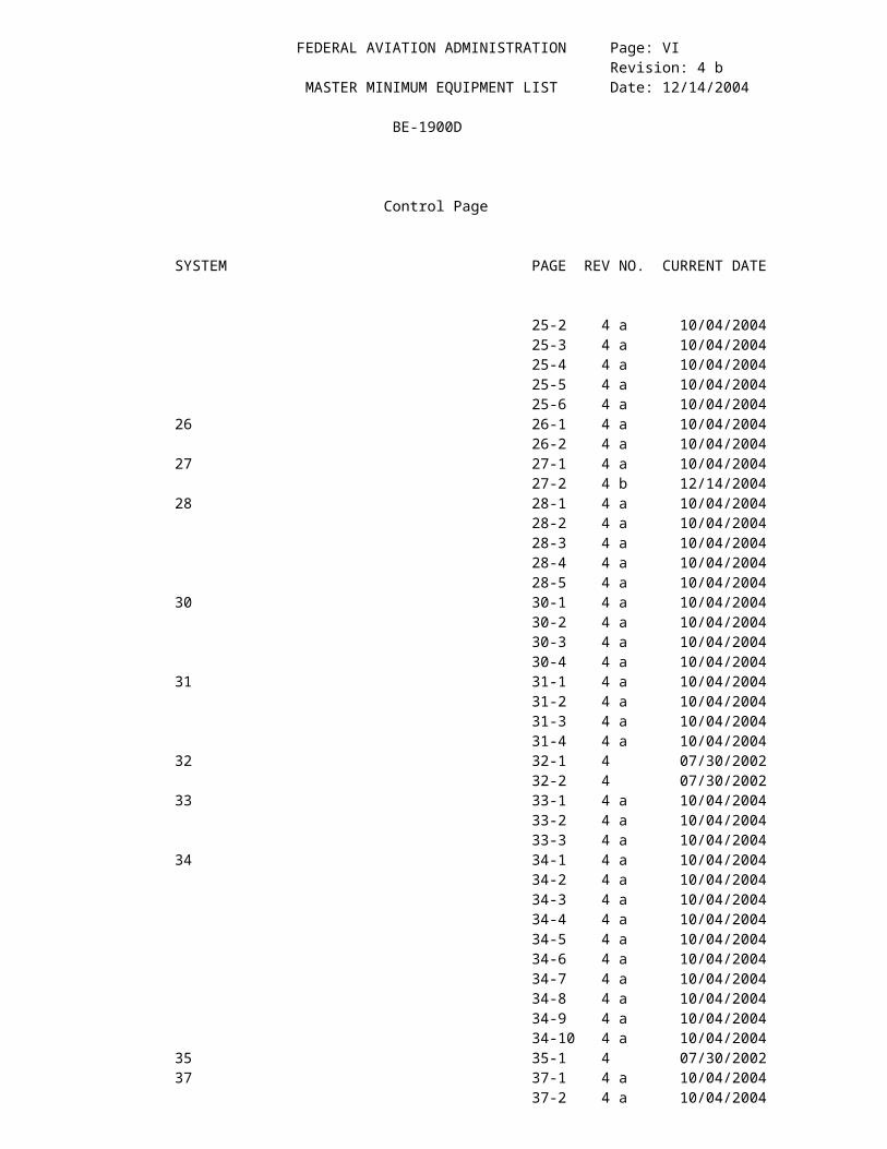
FEDERAL AVIATION ADMINISTRATION Page: VI Revision: 4 b MASTER MINIMUM EQUIPMENT LIST Date: 12/14/2004 BE-1900D Control Page SYSTEM PAGE REV NO. CURRENT DATE 25-2 4 a 10/04/2004 25-3 4 a 10/04/2004 25-4 4 a 10/04/2004 25-5 4 a 10/04/2004 25-6 4 a 10/04/2004 26 26-1 4 a 10/04/2004 26-2 4 a 10/04/2004 27 27-1 4 a 10/04/2004 27-2 4 b 12/14/2004 28 28-1 4 a 10/04/2004 28-2 4 a 10/04/2004 28-3 4 a 10/04/2004 28-4 4 a 10/04/2004 28-5 4 a 10/04/2004 30 30-1 4 a 10/04/2004 30-2 4 a 10/04/2004 30-3 4 a 10/04/2004 30-4 4 a 10/04/2004 31 31-1 4 a 10/04/2004 31-2 4 a 10/04/2004 31-3 4 a 10/04/2004 31-4 4 a 10/04/2004 32 32-1 4 07/30/2002 32-2 4 07/30/2002 33 33-1 4 a 10/04/2004 33-2 4 a 10/04/2004 33-3 4 a 10/04/2004 34 34-1 4 a 10/04/2004 34-2 4 a 10/04/2004 34-3 4 a 10/04/2004 34-4 4 a 10/04/2004 34-5 4 a 10/04/2004 34-6 4 a 10/04/2004 34-7 4 a 10/04/2004 34-8 4 a 10/04/2004 34-9 4 a 10/04/2004 34-10 4 a 10/04/2004 35 35-1 4 07/30/2002 37 37-1 4 a 10/04/2004 37-2 4 a 10/04/2004

FEDERAL AVIATION ADMINISTRATION Page: VII Revision: 4 b MASTER MINIMUM EQUIPMENT LIST Date: 12/14/2004 BE-1900D Control Page SYSTEM PAGE REV NO. CURRENT DATE 38 38-1 4 a 10/04/2004 52 52-1 4 a 10/04/2004 56 56-1 4 a 10/04/2004 61 61-1 4 07/30/2002 73 73-1 4 a 10/04/2004 74 74-1 4 a 10/04/2004 77 77-1 4 07/30/2002

FEDERAL AVIATION ADMINISTRATION Page: VIII Revision: 4 b MASTER MINIMUM EQUIPMENT LIST Date: 12/14/2004 BE-1900D Highlights of Change ATA 27-3 Replaced items that were inadvertently deleted when Items 3 & 4 processing Revision 4a. Change 88.
FEDERAL AVIATION ADMINISTRATION Page: IX Revision: 6 MASTER MINIMUM EQUIPMENT LIST Date: 01/31/1995 BE-1900D Definitions 1. System Definitions. System numbers are based on the Air Transport Association (ATA) Specification Number 100 and items are numbered sequentially. a. "Item" (Column 1) means the equipment, system, component, or function listed in the "Item" column. b. "Number Installed" (Column 2) is the number (quantity) of items normally installed in the aircraft. This number represents the aircraft configuration considered in developing this MMEL. Should the number be a variable (e.g., passenger cabin items) a number is not required. c. "Number Required for Dispatch" (Column 3) is the minimum number (quantity) of items required for operation provided the conditions specified in Column 4 are met. NOTE: Where the MMEL shows a variable number required for dispatch, the MEL must reflect the actual number required for dispatch or an alternate means of configuration control approved by the Administrator. d. "Remarks or Exceptions" (Column 4) in this column includes a statement either prohibiting or permitting operation with a specific number of items inoperative, provisos (conditions and limitations) for such operation, and appropriate notes. e. A vertical bar (change bar) in the margin indicates a change, addition or deletion in the adjacent text for the current revision of that page only. The change bar is dropped at the next revision of that page. 2. "Airplane/Rotorcraft Flight Manual" (AFM/RFM) is the document required for type certification and approved by the responsible FAA Aircraft Certification Office. The FAA approved AFM/RFM for the specific aircraft is listed on the applicable Type

FEDERAL AVIATION ADMINISTRATION Page: X Revision: 6 MASTER MINIMUM EQUIPMENT LIST Date: 01/31/1995 BE-1900D Definitions Certificate Data Sheet. 3. "As required by FAR" means that the listed item is subject to certain provisions (restrictive or permissive) expressed in the Federal Aviation Regulations operating rules. The number of items required by the FAR must be operative. When the listed item is not required by FAR it may be inoperative for time specified by repair category. 4. Each inoperative item must be placarded to inform and remind the crewmembers and maintenance personnel of the equipment condition. NOTE: To the extent practical, placards should be located adjacent to the control or indicator for the item affected; however, unless otherwise specified, placard wording and location will be determined by the operator. 5. "-" symbol in Column 2 and/or Column 3 indicates a variable number (quantity) of the item installed. 6. "Deleted" in the remarks column after a sequence item indicates that the item was previously listed but is now required to be operative if installed in the aircraft. 7. "ER" refers to extended range operations of a two-engine airplane which has a type design approval for ER operations and complies with the provisions of Advisory Circular 120-42A. ¦ 8. "Federal Aviation Regulations" (FAR) means the applicable portions of the Federal Aviation Act and Federal Aviation Regulations. 9. "Flight Day" means a 24 hour period (from midnight to midnight) either Universal Coordinated Time (UCT) or local time, as established by the operator, during which at least one flight is initiated for the affected aircraft. 10. "Icing Conditions" means an atmospheric environment that may cause ice to form on the aircraft or in the engine(s). 11. Alphabetical symbol in Column 4 indicates a proviso (condition or limitation) that must be complied with for

FEDERAL AVIATION ADMINISTRATION Page: XI Revision: 6 MASTER MINIMUM EQUIPMENT LIST Date: 01/31/1995 BE-1900D Definitions operation with the listed item inoperative. 12. "Inoperative" means a system and/or component malfunction to the extent that it does not accomplish its intended purpose and/or is not consistently functioning normally within its approved operating limit(s) or tolerance(s). 13. "Notes:" in Column 4 provides additional information for crewmember or maintenance consideration. Notes are used to identify applicable material which is intended to assist with compliance, but do not relieve the operator of the responsibility for compliance with all applicable requirements. Notes are not a part of the provisos. 14. Inoperative components of an inoperative system: Inoperative items which are components of a system which is inoperative are usually considered components directly associated with and having no other function than to support that system. (Warning/caution systems associated with the inoperative system must be operative unless relief is specifically authorized per the MMEL). 15. "(M)" symbol indicates a requirement for a specific maintenance procedure which must be accomplished prior to operation with the listed item inoperative. Normally these procedures are accomplished by maintenance personnel; however, other personnel may be qualified and authorized to perform certain functions. Procedures requiring specialized knowledge or skill, or requiring the use of tools or test equipment should be accomplished by maintenance personnel. The satisfactory accomplishment of all maintenance procedures, regardless of who performs them, is the responsibility of the operator. Appropriate procedures are required to be published as part of the operator's manual or MEL. 16. "(O)" symbol indicates a requirement for a specific operations procedure which must be accomplished in planning for and/or operating with the listed item inoperative. Normally these procedures are accomplished by the flight crew; however, other personnel may be qualified and authorized to perform certain functions. The satisfactory accomplishment of all procedures, regardless of who performs them, is the responsibility of the operator. Appropriate procedures are

FEDERAL AVIATION ADMINISTRATION Page: XII Revision: 6 MASTER MINIMUM EQUIPMENT LIST Date: 01/31/1995 BE-1900D Definitions required to be published as a part of the operator's manual or MEL. NOTE: The (M) and (O) symbols are required in the operator's MEL unless otherwise authorized by the Administrator. 17. "Deactivated" and "Secured" means that the specified component must be put into an acceptable condition for safe flight. An acceptable method of securing or deactivating will be established by the operator. 18. "Visual Flight Rules" (VFR) is as defined in FAR Part 91. This precludes a pilot from filing an Instrument Flight Rules (IFR) flight plan. 19. "Visual Meteorological Conditions" (VMC) means the atmospheric environment is such that would allow a flight to proceed under the visual flight rules applicable to the flight. This does not preclude operating under Instrument Flight Rules. 20. "Visible Moisture" means an atmospheric environment containing water in any form that can be seen in natural or artificial light; for example, clouds, fog, rain, sleet, hail, or snow. 21. "Passenger Convenience Items" means those items related to passenger convenience, comfort or entertainment such as, but not limited to, galley equipment, movie equipment, ash trays, stereo equipment, overhead reading lamps, etc. 22. Repair Intervals: All users of an MEL approved under FAR 121, 125, 129 and 135 must effect repairs of inoperative systems or components, deferred in accordance with the MEL, at or prior to the repair times established by the following letter designators: Category A. Items in this category shall be repaired within the time interval specified in the remarks column of the operator's approved MEL. Category B. Items in this category shall be repaired within three (3) consecutive calendar days (72 hours), excluding the day the malfunction was recorded in the aircraft maintenance

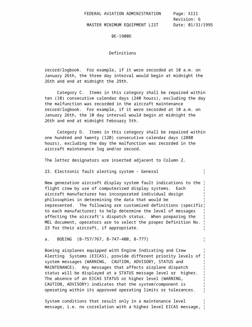
FEDERAL AVIATION ADMINISTRATION Page: XIII Revision: 6 MASTER MINIMUM EQUIPMENT LIST Date: 01/31/1995 BE-1900D Definitions record/logbook. For example, if it were recorded at 10 a.m. on January 26th, the three day interval would begin at midnight the 26th and end at midnight the 29th. Category C. Items in this category shall be repaired within ten (10) consecutive calendar days (240 hours), excluding the day the malfunction was recorded in the aircraft maintenance record/logbook. For example, if it were recorded at 10 a.m. on January 26th, the 10 day interval would begin at midnight the 26th and end at midnight February 5th. Category D. Items in this category shall be repaired within one hundred and twenty (120) consecutive calendar days (2880 hours), excluding the day the malfunction was recorded in the aircraft maintenance log and/or record. The letter designators are inserted adjacent to Column 2. 23. Electronic fault alerting system - General ¦ New generation aircraft display system fault indications to the ¦ flight crew by use of computerized display systems. Each ¦ aircraft manufacturer has incorporated individual design ¦ philosophies in determining the data that would be ¦ represented. The following are customized definitions (specific¦ to each manufacturer) to help determine the level of messages ¦ affecting the aircraft's dispatch status. When preparing the ¦ MEL document, operators are to select the proper Definition No. ¦ 23 for their aircraft, if appropriate. ¦ a. BOEING (B-757/767, B-747-400, B-777) ¦ Boeing airplanes equipped with Engine Indicating and Crew ¦ Alerting Systems (EICAS), provide different priority levels of ¦ system messages (WARNING, CAUTION, ADVISORY, STATUS and ¦ MAINTENANCE). Any messages that affects airplane dispatch ¦ status will be displayed at a STATUS message level or higher. ¦ The absence of an EICAS STATUS or higher level (WARNING, ¦ CAUTION, ADVISORY) indicates that the system/component is ¦ operating within its approved operating limits or tolerances. ¦ System conditions that result only in a maintenance level ¦ message, i.e. no correlation with a higher level EICAS message, ¦

FEDERAL AVIATION ADMINISTRATION Page: XIV Revision: 6 MASTER MINIMUM EQUIPMENT LIST Date: 01/31/1995 BE-1900D Definitions do not affect dispatch and do not require action other than as ¦ addressed within an operators standard maintenance program. ¦ b. DOUGLAS (MD-11) ¦ Some Douglas aircraft are equipped with an alerting function ¦ which is a subsystem within the Electronic Instrument System ¦ (EIS). The alerting function provides various levels of system ¦ condition alerts (WARNING, CAUTION, ADVISORY, MAINTENANCE and ¦ STATUS). ¦ Alerts that affect aircraft dispatch will include WARNING, ¦ CAUTION, STATUS or MAINTENANCE level. MAINTENANCE alerts are ¦ displayed on the status page of the EIS display panel under the ¦ maintenance heading. ¦ A MAINTENANCE alert on the EIS indicates the presence of a ¦ system fault which can be identified by the Central Fault ¦ Display System (CFDS) interrogation. The systems are designed ¦ to be fault tolerant, however, for any MAINTENANCE alert, the ¦ MEL must be verified for dispatch purposes. ¦ c. AIRBUS (A-300-600, A-310, A-320/319/321, A-330, A-340 ¦ Airbus aircraft equipped with Electronic Centralized Aircraft ¦ Monitoring (ECAM) provide different levels of system condition ¦ messages (WARNING, CAUTION, STATUS, and ADVISORY). A-320/319/ ¦ 321, A-330, and A-340 also provide MAINTENANCE status messages. ¦ Any message that effects airplane dispatchability will normally ¦ be at the WARNING, CAUTION or STATUS level. MAINTENANCE ¦ messages (A-320/319/321, A-330, and A-340 only) are also ¦ indicated on ECAM Status Page below the white Maintenance label.¦ A MAINTENANCE status (Class II) message on ECAM indicates the ¦ presence of a system fault which can be identified by CFDS ¦ (A-320/319/321) or CMS (A-330/A-340) interrogation. The systems ¦ are designed to be fault tolerant, however for any MAINTENANCE ¦ status (Class II) message, the A-320/319/321 MEL must be ¦ verified for dispatch capability. For the A-330 and A-340, ¦ MAINTENANCE status messages do not affect dispatch. ¦ d. FOKKER (FK-100) ¦

FEDERAL AVIATION ADMINISTRATION Page: XV Revision: 6 MASTER MINIMUM EQUIPMENT LIST Date: 01/31/1995 BE-1900D Definitions Fokker aircraft are equipped with Multi Function Display System ¦ (MFDS) which provides electronic message referring to the ¦ different priority levels of system information (WARNING (red), ¦ CAUTION (amber), AWARENESS (cyan) AND STATUS (white). Any ¦ messages that affects aircraft dispatch will be at the WARNING, ¦ CAUTION or AWARENESS level. In these cases the MEL must be ¦ verified for dispatch capability and maintenance may be ¦ required. ¦ System conditions that only require maintenance are not ¦ presented on the flight deck. These maintenance ¦ indications/messages may be presented on the Maintenance & Test ¦ Panel (MAP) or the Centralized Fault Display Unit (CFDU) and by ¦ dedicated Built In Test Evaluation (BITE) of systems. ¦ 24. "Administrative control item" means an item listed by the operator in the MEL for tracking and informational purposes. It may be added to an operator's MEL by approval of the Principal Operations Inspector provided no relief is granted, or provided conditions and limitations are contained in an approved document (i.e. Structural Repair Manual, airworthiness directive, etc.). If relief other than that granted by an approved document is sought for an administrative control item, a request must be submitted to the Administrator. If the request results in review and approval by the FOEB, the item becomes an MMEL item rather than an administrative control item. 25. "***" symbol in Column 1 indicates an item which is not required by regulation but which may have been installed on some models of aircraft covered by this MMEL. This item may be included on the operator's MEL after the approving office has determined that the item has been installed on one or more of the operator's aircraft. The symbol, however, shall not be carried forward into the operator's MEL. It should be noted that neither this policy nor the use of this symbol provide authority to install or remove an item from an aircraft. 26. "Excess Items" means those items that have been installed that are redundant to the requirements of the FARs. 27. "Day of Discovery" is the calendar day an equipment/instrument malfunction was recorded in the aircraft
FEDERAL AVIATION ADMINISTRATION Page: XVI Revision: 6 MASTER MINIMUM EQUIPMENT LIST Date: 01/31/1995 BE-1900D Definitions maintenance log and or record. This day is excluded from the calendar days or flight days specified in the MMEL for the repair of an inoperative item of equipment. This provision is applicable to all MMEL items, i.e., categories "A, B, C, and D."

FEDERAL AVIATION ADMINISTRATION Page: XVII Revision: 2 MASTER MINIMUM EQUIPMENT LIST Date: 06/14/1989 BE-1900D Preamble (Effective 6/14/89) The following is applicable for authorized certificate holders operating under Federal Aviation Regulations (FAR) Parts 121, 125, 129, 135: The FAR require that all equipment installed on an aircraft in compliance with the Airworthiness Standards and the Operating Rules must be operative. However, the Rules also permit the publication of a Minimum Equipment List (MEL) where compliance with certain equipment requirements is not necessary in the interests of safety under all operating conditions. Experience has shown that with the various levels of redundancy designed into aircraft, operation of every system or installed component may not be necessary when the remaining operative equipment can provide an acceptable level of safety. A Master Minimum Equipment List (MMEL) is developed by the FAA, with participation by the aviation industry, to improve aircraft utilization and thereby provide more convenient and economic air transportation for the public. The FAA approved MMEL includes those items of equipment related to airworthiness and operating regulations and other items of equipment which the Administrator finds may be inoperative and yet maintain an acceptable level of safety by appropriate conditions and limitations; it does not contain obviously required items such as wings, flaps, and rudders. The MMEL is the basis for development of individual operator MELs which take into consideration the operator's particular aircraft equipment configuration and operational conditions. Operator MELs, for administrative control, may include items not contained in the MMEL; however, relief for administrative control items must be approved by the Administrator. An operator's MEL may differ in format from the MMEL, but cannot be less restrictive than the MMEL. The individual operator's MEL, when approved and authorized, permits operation of the aircraft with inoperative equipment. Equipment not required by the operation being conducted and equipment in excess of FAR requirements are included in the MEL with appropriate conditions and limitations. The MEL must not deviate from the Aircraft Flight Manual Limitations, Emergency Procedures or with Airworthiness Directives. It is important to remember that all equipment related to the airworthiness and the operating regulations of the aircraft not listed on the MMEL must be operative.

FEDERAL AVIATION ADMINISTRATION Page: XVIII Revision: 2 MASTER MINIMUM EQUIPMENT LIST Date: 06/14/1989 BE-1900D Preamble (Effective 6/14/89) Suitable conditions and limitations in the form of placards, maintenance procedures, crew operating procedures and other restrictions as necessary are specified in the MEL to ensure that an acceptable level of safety is maintained. The MEL is intended to permit operation with inoperative items of equipment for a period of time until repairs can be accomplished. It is important that repairs be accomplished at the earliest opportunity. In order to maintain an acceptable level of safety and reliability the MMEL establishes limitations on the duration of and conditions for operation with inoperative equipment. The MEL provides for release of the aircraft for flight with inoperative equipment. When an item of equipment is discovered to be inoperative, it is reported by making an entry in the Aircraft Maintenance Record/Logbook as prescribed by FAR. The item is then either repaired or may be deferred per the MEL or other approved means acceptable to the Administrator prior to further operation. MEL conditions and limitations, do not relieve the operator from determining that the aircraft is in condition for safe operation with items of equipment inoperative. When these requirements are met, an Airworthiness Release, Aircraft Maintenance Record/Logbook entry, or other approved documentation is issued as prescribed by FAR. Such documentation is required prior to operation with any item of equipment inoperative. Operators are responsible for exercising the necessary operational control to ensure that an acceptable level of safety is maintained. When operating with multiple inoperative items, the interrelationships between those items and the effect on aircraft operation and crew workload will be considered. Operators are to establish a controlled and sound repair program including the parts, personnel, facilities, procedures, and schedules to ensure timely repair. WHEN USING THE MEL, COMPLIANCE WITH THE STATED INTENT OF THE PREAMBLE, DEFINITIONS, AND THE CONDITIONS AND LIMITATIONS SPECIFIED IN THE MEL IS REQUIRED.

FEDERAL AVIATION ADMINISTRATION Page XIX Revision: 4 b MASTER MINIMUM EQUIPMENT LIST Date: 12/14/2004 BE-1900D Guidelines for (O) & (M) Procedures The FOEB has identified a need for certain procedures to provide an adequate level of safety while providing relief for the following items. These procedures must be established by the operator. The following guidelines are to help establish these required procedures: 21-3-1 (O) Procedure to verify environmental and instrument air valves are closed prior to each flight. 21-3-2 (O) Procedure to verify environmental and instrument air valves are closed prior to each flight. Procedure to either mask or remove the illuminated light. 21-4 (O) Procedure to verify appropriate environmental bleed air valve is closed prior to every flight. 21-8 (M) Procedure for removing or securing outflow/safety valve in the open position. 21-9 (M) Procedure for removing or securing outflow/safety valve in the open position. 21-9-1 (O) Procedure to ensure each crew (and dispatcher if applicable) is aware of pressurization capability and/or limitations. 21-9-2 (O) Procedure to ensure each crew (and dispatcher if applicable) is aware of pressurization capability and/or limitations. 21-9-3 (O) Procedure to ensure each crew (and dispatcher if applicable) is aware of pressurization capability and/or limitations. 21-9-4 (O) Procedure to ensure first flight is planned assuming aircraft will not pressurize. If aircraft pressurizes normally, appropriate adjustments can be made to the flight plan. Coordination with dispatch, if applicable, should be accomplished. Procedure to ensure each crew (and dispatcher if applicable) is aware of pressurization capability and/or limitations.

FEDERAL AVIATION ADMINISTRATION Page XX Revision: 4 b MASTER MINIMUM EQUIPMENT LIST Date: 12/14/2004 BE-1900D Guidelines for (O) & (M) Procedures 21-14 (O)Procedure to verify appropriate environmental bleed air valve is closed prior to each flight. (O)Procedure to verify environmental bleed air valves are closed. 22-1 (M)Procedure to disable the autopilot and determine that the servos do not cause binding of the control cables. 22-2 (O)Procedure to disable Rudder Boost function. (M)Procedure to disable the yaw damper and determine that the rudder servo does not cause binding of the control cables. Acceptable procedure: Move rudder pedals through full travel to ensure no restrictions and pull and band "servo" circuit breaker. 22-2-1 (O)Procedure to disable the rudder boost function. 22-2-2 (M)Procedure to disable the yaw damper function. 22-2-4 (M)Procedure to disable the yaw damper and determine that the rudder servo does not cause binding of the control cables. Acceptable procedure: Same as 22-2 above. 23-1 (O)Procedure to specify how passengers are to be briefed and to operate within the MMEL restrictions. 23-12 (O)Procedure to ensure remaining Long Range Communications System(s) operate normally.

FEDERAL AVIATION ADMINISTRATION Page XXI Revision: 4 b MASTER MINIMUM EQUIPMENT LIST Date: 12/14/2004 BE-1900D Guidelines for (O) & (M) Procedures 24-3 (O)Procedure to ensure that the electrical load is less than 50% on the operative side generator prior to take-off and at all times during flight and that loads are not added if the generator on the operative side fails. 24-6 (M)Procedure to ensure ground power relay is open. 24-7 (O)Procedure to ensure connection and disconnection of power cart is verified. 24-9 (O)Procedure to verify generator bus tie relay is closed. 25-1-2(O)Procedure to ensure crew awareness of inoperative restraining bar. 25-3 (M)Procedure to disconnect the remote switch from the ELT and manually arm the ELT per manufacturer instructions. Care must be exercised to insure that the G-Switch is NOT disabled. 25-10 (M)Procedure to ensure seat is locked in the appropriate position. 25-13 (O)Procedure to ensure crew awareness of specific airspeed information. 25-14 (M)Procedure to lock the rudder pedals in a position that allows full rudder pedal movement. 25-17 (O)Procedure to ensure sufficient waste receptacles are available for the intended flight. 25-17 (M)Procedure to secure access to the affected waste receptacle. 25-20 (M)Procedure to secure the compartment/closet in closed position. 25-21 (M)Procedure to ensure that cargo is not secured by an inoperative cargo restraint system.

FEDERAL AVIATION ADMINISTRATION Page XXII Revision: 4 b MASTER MINIMUM EQUIPMENT LIST Date: 12/14/2004 BE-1900D Guidelines for (O) & (M) Procedures 26-3 (O)Procedure to ensure waste receptacle is empty and lavatory is used by crewmembers only. (M)Procedure to lock and placard Lavatory Door. 26-4 (O)Procedure to ensure waste receptacle is empty and Lavatory is used by crewmembers only. (M)Procedure to lock and placard Lavatory Door. 27-2 (O)Procedure to verify the flaps are secure and in the UP position, the circuit breaker is pulled and a placard is installed which states the following: "DO NOT SILENCE THE LANDING GEAR WARNING HORN". The placard should be installed near the landing gear warning horn silence button. 27-4 (O)Procedure to ensure there is no binding of the trim cables prior to each flight. Acceptable procedure: Manually operate trim full travel and visually observe to verify full travel. 28-1 (M)Procedure to determine failure will not cause damage to engine or a restriction in fuel flow. 28-5 (O)Procedure to deactivate the pump and ensure no electrical power is supplied to it. Procedure to ensure auxiliary fuel is balanced prior to each flight and is considered unusable for flight planning purposes.

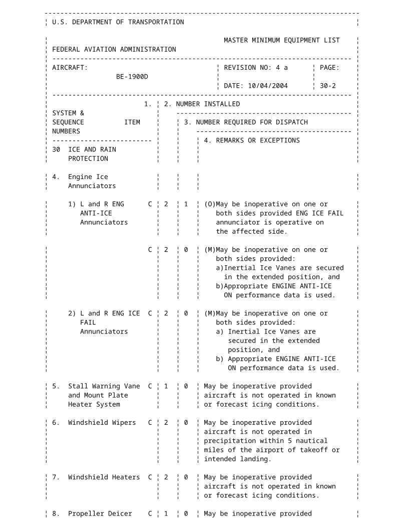
FEDERAL AVIATION ADMINISTRATION Page XXIII Revision: 4 b MASTER MINIMUM EQUIPMENT LIST Date: 12/14/2004 BE-1900D Guidelines for (O) & (M) Procedures 28-7 (O)Procedure to ensure fuel balance is maintained within AFM limits. 28-7-1(O)Procedure to ensure fuel balance is maintained within AFM limits. 28-7-2(O)Procedure to ensure fuel balance is maintained within AFM limits. 28-7-3(O)Procedure to ensure fuel balance is maintained within AFM limits. Acceptable procedure for fuel requirements: Fill fuel tanks and calculate fuel burn from full tanks 30-2 (O)Procedure to determine inoperative motor does not affect other actuator motor. (O)Procedure to ensure ice vanes are in the extended position. (M)Procedure to secure vanes in the extended position. 30-4 (O)Procedure for flight crewmember to verify operation of vanes prior to each departure. (M)Procedure to secure vanes in the extended position. 30-12 (M)Procedure to secure shutoff valves in the closed position. (M)Procedure to disable and band circuit breaker. 31-2 (O)Procedure for recording aircraft time for maintenance purposes. 31-5 (O)Procedure to check operation of individual circuits. 31-11 (M)Procedure to pull and collar CB in the open position. (O)Procedure to ensure that aircraft time entries are made in the aircraft flight log. 32-1 (M)Procedure to ensure nose wheel is in the free caster mode and to operate within MMEL restrictions.

FEDERAL AVIATION ADMINISTRATION Page XXIV Revision: 4 b MASTER MINIMUM EQUIPMENT LIST Date: 12/14/2004 BE-1900D Guidelines for (O) & (M) Procedures 32-3 (O)Procedure to ensure crew awareness that nose steering is in the free caster mode. (M)Procedure to disable and band circuit breaker. 32-4 (O)Procedure to ensure crew awareness of change in nose wheel steering. (M)Procedure to disconnect and secure actuator. 32-5 (M)Maintenance procedure to check hydraulic fluid level at the time of discovery and prior to the first flight of the day. (O)Procedure to check for leaks prior to and after each flight. 32-7 (O)Procedures to secure aircraft during ground emergencies and prior to releasing toe brakes during normal operations. 32-8 (O)Procedure to ensure crew awareness of the requirement to manually move the down lock latch. 33-2-3(O)Procedure to verify switch function is operative. 34-3 (O)Procedure to ensure crew awareness of the need to regularly check/reset directional gyro. NOTE: Do NOT select the Heading input (with the HD Reversionary Switch) of the affected Flightdeck Heading Indicator to a single, common gyro heading source. This is NOT permitted because it reduces the heading source redundancy. 34-12-1(O)Procedure to ensure crew awareness of inoperative G0-AROUND mode. 34-13 (O)Operations procedure to ensure autopilot hold is operative and enroute operations do not require its use. 34-15 (M)Procedure to deactivate and secure the system. (O)Procedure to operate without TCAS I system. 34-16 (M)Procedure to deactivate and secure the system. 34-16 (O)Procedure to operate without TCAS II system.

FEDERAL AVIATION ADMINISTRATION Page XXV Revision: 4 b MASTER MINIMUM EQUIPMENT LIST Date: 12/14/2004 BE-1900D Guidelines for (O) & (M) Procedures 34-16-2 (O)Procedure to ensure non-flying pilot monitors pilot display. (O)Procedure to ensure TA ONLY mode is selected and all TA functions/elements are operative. 34-16-3 (O)Procedure to ensure all RA display/functions are operative. 34-19 (O)Procedure to ensure crew awareness of inoperative GPWS. 34-19-1 (O)Procedure to establish alternate methods of operating without the inoperative mode. 34-19-4 (O)Procedure to establish alternate methods of operating without advisory callouts. 34-19-5 (O)Procedure to establish alternate method of operating without the windshear mode. 34-21 (O)Procedure to establish alternate method of operating without the Multifunction Display (MFD). 34-24-1&2 (O)Procedure to operate with expired Navigation Databases. 35-3 (M)Procedure to prohibit oxygen flow from affected outlet. 37-1 (O)Procedure to insure Left and Right Instrument Air Sources are operative prior to each departure. 37-2 (O)Procedure to verify inoperative valve is in the closed position. 37-3 (O)Procedure to ensure L&R Instrument Air Sources are operative and all provisos are complies with prior to each flight. (O)Procedure to ensure L&R Instrument Air Sources are operative and all provisos are complies with prior to each flight. 38-1 (M)Procedure to deactivate the affected components and ensure there are no leaks. (M) Procedure to drain and ensure the system is not serviced.

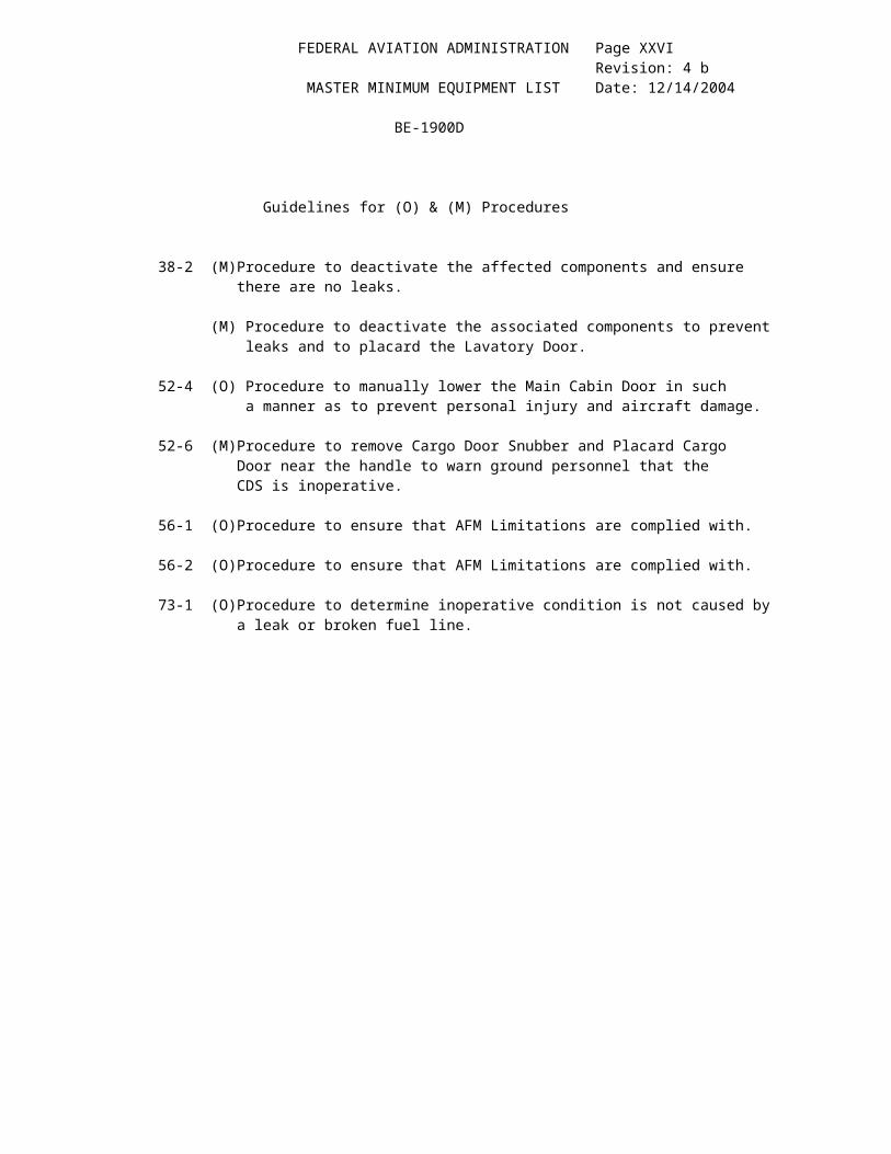
FEDERAL AVIATION ADMINISTRATION Page XXVI Revision: 4 b MASTER MINIMUM EQUIPMENT LIST Date: 12/14/2004 BE-1900D Guidelines for (O) & (M) Procedures 38-2 (M)Procedure to deactivate the affected components and ensure there are no leaks. (M) Procedure to deactivate the associated components to prevent leaks and to placard the Lavatory Door. 52-4 (O) Procedure to manually lower the Main Cabin Door in such a manner as to prevent personal injury and aircraft damage. 52-6 (M)Procedure to remove Cargo Door Snubber and Placard Cargo Door near the handle to warn ground personnel that the CDS is inoperative. 56-1 (O)Procedure to ensure that AFM Limitations are complied with. 56-2 (O)Procedure to ensure that AFM Limitations are complied with. 73-1 (O)Procedure to determine inoperative condition is not caused by a leak or broken fuel line.

-------------------------------------------------------------------------------¦ U.S. DEPARTMENT OF TRANSPORTATION ¦ ¦ MASTER MINIMUM EQUIPMENT LIST ¦¦ FEDERAL AVIATION ADMINISTRATION ¦¦ --------------------------------------------------------------------------- ¦¦ AIRCRAFT: ¦ REVISION NO: 4 ¦ PAGE: ¦¦ BE-1900D ¦ ¦ ¦¦ ¦ DATE: 07/30/2002 ¦ 21-1 ¦¦ --------------------------------------------------------------------------- ¦¦ 1. ¦ 2. NUMBER INSTALLED ¦¦ SYSTEM & ¦ -------------------------------------------- ¦¦ SEQUENCE ITEM ¦ ¦ 3. NUMBER REQUIRED FOR DISPATCH ¦¦ NUMBERS ¦ ¦ --------------------------------------- ¦¦ ------------------------- ¦ ¦ ¦ 4. REMARKS OR EXCEPTIONS ¦¦ 21 AIR CONDITIONING ¦ ¦ ¦ ¦ ¦ 1. Air Cycle Air C ¦ 1 ¦ 0 ¦ May be inoperative for ¦¦ Conditioning System ¦ ¦ ¦ unpressurized flight provided the ¦¦ ¦ ¦ ¦ Environmental Bleed Air Valves are ¦¦ ¦ ¦ ¦ closed. ¦ ¦ 2. Vapor Cycle Air C ¦ 1 ¦ 0 ¦ ¦¦ Conditioning System ¦ ¦ ¦ ¦ ¦ 3. L or R BL AIR FAIL ¦ ¦ ¦ ¦¦ Annunciator System ¦ ¦ ¦ ¦ ¦ 1) Annunciator B ¦ 2 ¦ 1 ¦ (O)One may be inoperative provided: ¦¦ fails to ¦ ¦ ¦ a) Environmental and Instrument ¦¦ illuminate ¦ ¦ ¦ Bleed Air Valves on ¦¦ ¦ ¦ ¦ inoperative side are ¦¦ ¦ ¦ ¦ verified closed before each ¦¦ ¦ ¦ ¦ flight, and ¦¦ ¦ ¦ ¦ b) Aircraft is not operated in ¦¦ ¦ ¦ ¦ known or forecast icing ¦¦ ¦ ¦ ¦ conditions. ¦ ¦ 2) Annunciator B ¦ 2 ¦ 1 ¦ (O)One may be illuminated provided: ¦¦ remains ¦ ¦ ¦ a) Environmental and Instrument ¦¦ illuminated ¦ ¦ ¦ Bleed Air Valves on ¦¦ ¦ ¦ ¦ inoperative side are ¦¦ ¦ ¦ ¦ verified closed before each ¦¦ ¦ ¦ ¦ flight, and ¦¦ ¦ ¦ ¦ b) Aircraft is not operated in ¦¦ ¦ ¦ ¦ known or forecast icing ¦¦ ¦ ¦ ¦ conditions. ¦ ¦ 4. L or R ENVIR FAIL C ¦ 2 ¦ 1 ¦ (O)One may be inoperative provided ¦¦ Annunciator Systems ¦ ¦ ¦ Environmental Bleed Air Valve on ¦¦ ¦ ¦ ¦ inoperative side is closed. ¦ -------------------------------------------------------------------------------

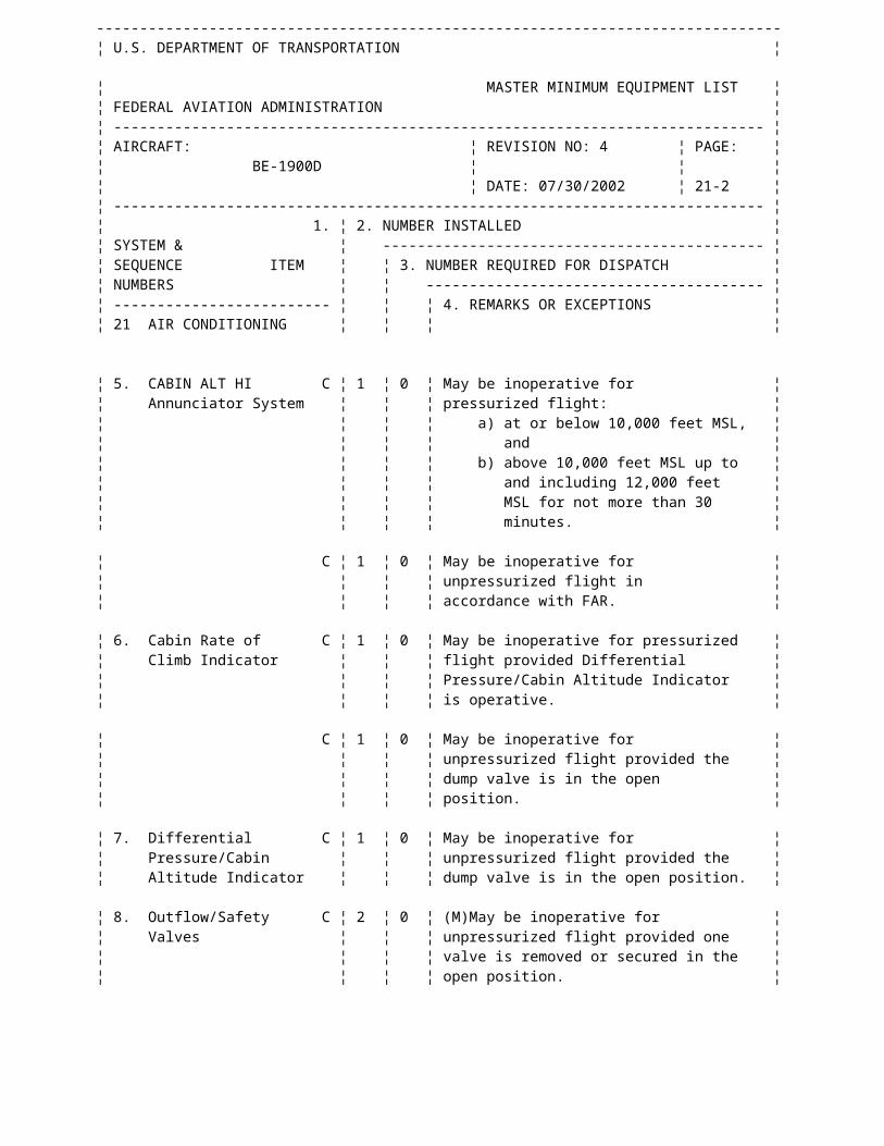
-------------------------------------------------------------------------------¦ U.S. DEPARTMENT OF TRANSPORTATION ¦ ¦ MASTER MINIMUM EQUIPMENT LIST ¦¦ FEDERAL AVIATION ADMINISTRATION ¦¦ --------------------------------------------------------------------------- ¦¦ AIRCRAFT: ¦ REVISION NO: 4 ¦ PAGE: ¦¦ BE-1900D ¦ ¦ ¦¦ ¦ DATE: 07/30/2002 ¦ 21-2 ¦¦ --------------------------------------------------------------------------- ¦¦ 1. ¦ 2. NUMBER INSTALLED ¦¦ SYSTEM & ¦ -------------------------------------------- ¦¦ SEQUENCE ITEM ¦ ¦ 3. NUMBER REQUIRED FOR DISPATCH ¦¦ NUMBERS ¦ ¦ --------------------------------------- ¦¦ ------------------------- ¦ ¦ ¦ 4. REMARKS OR EXCEPTIONS ¦¦ 21 AIR CONDITIONING ¦ ¦ ¦ ¦ ¦ 5. CABIN ALT HI C ¦ 1 ¦ 0 ¦ May be inoperative for ¦¦ Annunciator System ¦ ¦ ¦ pressurized flight: ¦¦ ¦ ¦ ¦ a) at or below 10,000 feet MSL, ¦¦ ¦ ¦ ¦ and ¦¦ ¦ ¦ ¦ b) above 10,000 feet MSL up to ¦¦ ¦ ¦ ¦ and including 12,000 feet ¦¦ ¦ ¦ ¦ MSL for not more than 30 ¦¦ ¦ ¦ ¦ minutes. ¦ ¦ C ¦ 1 ¦ 0 ¦ May be inoperative for ¦¦ ¦ ¦ ¦ unpressurized flight in ¦¦ ¦ ¦ ¦ accordance with FAR. ¦ ¦ 6. Cabin Rate of C ¦ 1 ¦ 0 ¦ May be inoperative for pressurized ¦¦ Climb Indicator ¦ ¦ ¦ flight provided Differential ¦¦ ¦ ¦ ¦ Pressure/Cabin Altitude Indicator ¦¦ ¦ ¦ ¦ is operative. ¦ ¦ C ¦ 1 ¦ 0 ¦ May be inoperative for ¦¦ ¦ ¦ ¦ unpressurized flight provided the ¦¦ ¦ ¦ ¦ dump valve is in the open ¦¦ ¦ ¦ ¦ position. ¦ ¦ 7. Differential C ¦ 1 ¦ 0 ¦ May be inoperative for ¦¦ Pressure/Cabin ¦ ¦ ¦ unpressurized flight provided the ¦¦ Altitude Indicator ¦ ¦ ¦ dump valve is in the open position. ¦ ¦ 8. Outflow/Safety C ¦ 2 ¦ 0 ¦ (M)May be inoperative for ¦¦ Valves ¦ ¦ ¦ unpressurized flight provided one ¦¦ ¦ ¦ ¦ valve is removed or secured in the ¦¦ ¦ ¦ ¦ open position. ¦ -------------------------------------------------------------------------------

-------------------------------------------------------------------------------¦ U.S. DEPARTMENT OF TRANSPORTATION ¦ ¦ MASTER MINIMUM EQUIPMENT LIST ¦¦ FEDERAL AVIATION ADMINISTRATION ¦¦ --------------------------------------------------------------------------- ¦¦ AIRCRAFT: ¦ REVISION NO: 4 ¦ PAGE: ¦¦ BE-1900D ¦ ¦ ¦¦ ¦ DATE: 07/30/2002 ¦ 21-3 ¦¦ --------------------------------------------------------------------------- ¦¦ 1. ¦ 2. NUMBER INSTALLED ¦¦ SYSTEM & ¦ -------------------------------------------- ¦¦ SEQUENCE ITEM ¦ ¦ 3. NUMBER REQUIRED FOR DISPATCH ¦¦ NUMBERS ¦ ¦ --------------------------------------- ¦¦ ------------------------- ¦ ¦ ¦ 4. REMARKS OR EXCEPTIONS ¦¦ 21 AIR CONDITIONING ¦ ¦ ¦ ¦ ¦ 9. Pressurization C ¦ 1 ¦ 0 ¦ (M)May be inoperative provided one ¦¦ System ¦ ¦ ¦ Outflow/Safety valve is removed or ¦¦ ¦ ¦ ¦ secured in the open position. ¦ ¦ 1) Maximum Pressure C ¦ 1 ¦ 0 ¦ (O)May be inoperative, resulting in ¦¦ Differential ¦ ¦ ¦ failure to achieve maximum pressure ¦¦ Function ¦ ¦ ¦ differential, provided: ¦¦ ¦ ¦ ¦ a) Available stabilized maximum ¦¦ ¦ ¦ ¦ differential must be known ¦¦ ¦ ¦ ¦ and considered for dispatch ¦¦ ¦ ¦ ¦ flight planning, and ¦¦ ¦ ¦ ¦ b) Cabin Altitude does not ¦¦ ¦ ¦ ¦ exceed 9,500 feet. ¦ ¦ ¦ ¦ ¦ NOTE: Any available pressurization ¦¦ ¦ ¦ ¦ capability may be used provided ¦¦ ¦ ¦ ¦ system limits are not exceeded. ¦ ¦ 2) Cabin Pressure C ¦ 1 ¦ 0 ¦ (O)May be inoperative, resulting in ¦¦ Control Function ¦ ¦ ¦ failure to pressurize at selected ¦¦ ¦ ¦ ¦ altitude, provided system can ¦¦ ¦ ¦ ¦ maintain cabin altitude at or below ¦¦ ¦ ¦ ¦ 9,500 feet. ¦ ¦ ¦ ¦ ¦ Any available pressurization ¦¦ ¦ ¦ ¦ capability may be used provided ¦¦ ¦ ¦ ¦ system limits are not exceeded. ¦ ¦ 3) Cabin Rate C ¦ 1 ¦ 0 ¦ (O)May be inoperative, resulting in ¦¦ Control Function ¦ ¦ ¦ disagreement between selected rate ¦¦ ¦ ¦ ¦ and actual rate, provided system ¦¦ ¦ ¦ ¦ can maintain cabin altitude at or ¦¦ ¦ ¦ ¦ below 9,500 feet. ¦ ¦ ¦ ¦ ¦ Any available pressurization ¦¦ ¦ ¦ ¦ capability may be used provided ¦¦ ¦ ¦ ¦ system limits are not exceeded. ¦ ¦ (CON'T.) ¦ ¦ ¦ ¦-------------------------------------------------------------------------------
-------------------------------------------------------------------------------¦ U.S. DEPARTMENT OF TRANSPORTATION ¦ ¦ MASTER MINIMUM EQUIPMENT LIST ¦¦ FEDERAL AVIATION ADMINISTRATION ¦¦ --------------------------------------------------------------------------- ¦¦ AIRCRAFT: ¦ REVISION NO: 4 ¦ PAGE: ¦¦ BE-1900D ¦ ¦ ¦¦ ¦ DATE: 07/30/2002 ¦ 21-4 ¦¦ --------------------------------------------------------------------------- ¦¦ 1. ¦ 2. NUMBER INSTALLED ¦¦ SYSTEM & ¦ -------------------------------------------- ¦¦ SEQUENCE ITEM ¦ ¦ 3. NUMBER REQUIRED FOR DISPATCH ¦¦ NUMBERS ¦ ¦ --------------------------------------- ¦¦ ------------------------- ¦ ¦ ¦ 4. REMARKS OR EXCEPTIONS ¦¦ 21 AIR CONDITIONING ¦ ¦ ¦ ¦ ¦ 9. Pressurization ¦ ¦ ¦ ¦¦ System ¦ ¦ ¦ ¦¦ (CON'T.) ¦ ¦ ¦ ¦ ¦ 3) Cabin Rate C ¦ 1 ¦ 0 ¦ (O)May be inoperative, resulting in ¦¦ Control Function ¦ ¦ ¦ fluctuations of rate indicator, ¦¦ ¦ ¦ ¦ provided: ¦¦ ¦ ¦ ¦ a) System can maintain cabin ¦¦ ¦ ¦ ¦ altitude at or below 9,500 ¦¦ ¦ ¦ ¦ feet, and ¦¦ ¦ ¦ ¦ b) Fluctuation cannot cause ¦¦ ¦ ¦ ¦ cabin pressure to exceed ¦¦ ¦ ¦ ¦ maximum differential. ¦ ¦ ¦ ¦ ¦ Any available pressurization ¦¦ ¦ ¦ ¦ capability may be used provided ¦¦ ¦ ¦ ¦ system limits are not exceeded. ¦ ¦ 4) Cabin Pressure C ¦ 1 ¦ 0 ¦ (O)May be inoperative provided ¦¦ TEST Function ¦ ¦ ¦ system can maintain cabin altitude ¦¦ ¦ ¦ ¦ at or below 9,500 feet. ¦ ¦ ¦ ¦ ¦ Any available pressurization ¦¦ ¦ ¦ ¦ capability may be used provided ¦¦ ¦ ¦ ¦ system limits are not exceeded. ¦ ¦ 10. Environmental C ¦ 1 ¦ 0 ¦ May be inoperative for ¦¦ Temperature Control ¦ ¦ ¦ unpressurized flight provided the ¦¦ System ¦ ¦ ¦ Environmental Bleed Air Valves are ¦¦ ¦ ¦ ¦ closed. ¦ ¦ 1) Automatic C ¦ 1 ¦ 0 ¦ May be inoperative provided the ¦¦ Function ¦ ¦ ¦ Manual Function is operative. ¦ ¦ 2) Manual C ¦ 1 ¦ 0 ¦ May be inoperative provided the ¦¦ Function ¦ ¦ ¦ Automatic Function is operative. ¦ -------------------------------------------------------------------------------

-------------------------------------------------------------------------------¦ U.S. DEPARTMENT OF TRANSPORTATION ¦ ¦ MASTER MINIMUM EQUIPMENT LIST ¦¦ FEDERAL AVIATION ADMINISTRATION ¦¦ --------------------------------------------------------------------------- ¦¦ AIRCRAFT: ¦ REVISION NO: 4 ¦ PAGE: ¦¦ BE-1900D ¦ ¦ ¦¦ ¦ DATE: 07/30/2002 ¦ 21-5 ¦¦ --------------------------------------------------------------------------- ¦¦ 1. ¦ 2. NUMBER INSTALLED ¦¦ SYSTEM & ¦ -------------------------------------------- ¦¦ SEQUENCE ITEM ¦ ¦ 3. NUMBER REQUIRED FOR DISPATCH ¦¦ NUMBERS ¦ ¦ --------------------------------------- ¦¦ ------------------------- ¦ ¦ ¦ 4. REMARKS OR EXCEPTIONS ¦¦ 21 AIR CONDITIONING ¦ ¦ ¦ ¦ ¦ 11. Manual Temperature ¦ ¦ ¦ DELETED Combined with ATA 21-10 ¦¦ Control ¦ ¦ ¦ ¦ ¦ 12. Vent Blowers C ¦ 2 ¦ 0 ¦ ¦ ¦ 13. Cabin Temperature C ¦ 1 ¦ 0 ¦ ¦¦ Gauge ¦ ¦ ¦ ¦ ¦ 14. Environmental C ¦ 2 ¦ 1 ¦ (O)One may be inoperative provided: ¦¦ Bleed Air Systems ¦ ¦ ¦ a) Environmental Bleed Air ¦¦ ¦ ¦ ¦ Valve on inoperative side is ¦¦ ¦ ¦ ¦ closed, and ¦¦ ¦ ¦ ¦ b) ENVIR FAIL Annunciator is ¦¦ ¦ ¦ ¦ operative on operative ¦¦ ¦ ¦ ¦ Environmental Bleed Air ¦¦ ¦ ¦ ¦ System. ¦ ¦ C ¦ 2 ¦ 0 ¦ (O)May be inoperative for ¦¦ ¦ ¦ ¦ unpressurized flight provided all ¦¦ ¦ ¦ ¦ Environmental Bleed Air Valves are ¦¦ ¦ ¦ ¦ closed. ¦ ¦ 15. Precooler and ¦ ¦ ¦ DELETED Revision 1. Combined with ¦¦ Bypass Valve Systems ¦ ¦ ¦ ATA 21-14 ¦ ¦ 16. L or R ENVIR OFF C ¦ 2 ¦ 1 ¦ One may be inoperative. ¦¦ Annunciator Systems ¦ ¦ ¦ ¦ ¦ 17. CAB DIFF HI C ¦ 1 ¦ 0 ¦ ¦¦ Annunicator System ¦ ¦ ¦ ¦ -------------------------------------------------------------------------------

-------------------------------------------------------------------------------¦ U.S. DEPARTMENT OF TRANSPORTATION ¦ ¦ MASTER MINIMUM EQUIPMENT LIST ¦¦ FEDERAL AVIATION ADMINISTRATION ¦¦ --------------------------------------------------------------------------- ¦¦ AIRCRAFT: ¦ REVISION NO: 4 a ¦ PAGE: ¦¦ BE-1900D ¦ ¦ ¦¦ ¦ DATE: 10/04/2004 ¦ 22-1 ¦¦ --------------------------------------------------------------------------- ¦¦ 1. ¦ 2. NUMBER INSTALLED ¦¦ SYSTEM & ¦ -------------------------------------------- ¦¦ SEQUENCE ITEM ¦ ¦ 3. NUMBER REQUIRED FOR DISPATCH ¦¦ NUMBERS ¦ ¦ --------------------------------------- ¦¦ ------------------------- ¦ ¦ ¦ 4. REMARKS OR EXCEPTIONS ¦¦ 22 AUTO FLIGHT ¦ ¦ ¦ ¦ ¦ 1. Autopilot System C ¦ - ¦ 0 ¦ (M)As required by FAR. ¦¦ *** ¦ ¦ ¦ ¦ ¦ 2. Yaw Damper/ C ¦ 1 ¦ 0 ¦ (O) ¦¦ Rudder Boost ¦ ¦ ¦ ¦¦ System ¦ ¦ ¦ ¦ ¦ 1) Rudder Boost C ¦ 1 ¦ 0 ¦ (O) ¦¦ Function Only ¦ ¦ ¦ ¦ ¦ 2) Yaw Damper C ¦ 1 ¦ 0 ¦ (M) ¦¦ Function Only ¦ ¦ ¦ ¦ ¦ 3) LEFT/RIGHT YAW C ¦ 2 ¦ 1 ¦ One may be inoperative provided ¦¦ DAMP Computers ¦ ¦ ¦ the operative computer is selected. ¦ ¦ C ¦ 2 ¦ 0 ¦ (O) ¦ ¦ 4) Single YAW C ¦ 1 ¦ 0 ¦ (O) ¦¦ *** DAMP Computer ¦ ¦ ¦ ¦ ¦ 3. Rudder Boost ¦ ¦ ¦ DELETED Revision 1. Combined with ¦¦ ¦ ¦ ¦ Yaw Damper System. ¦ -------------------------------------------------------------------------------
-------------------------------------------------------------------------------¦ U.S. DEPARTMENT OF TRANSPORTATION ¦ ¦ MASTER MINIMUM EQUIPMENT LIST ¦¦ FEDERAL AVIATION ADMINISTRATION ¦¦ --------------------------------------------------------------------------- ¦¦ AIRCRAFT: ¦ REVISION NO: 4 ¦ PAGE: ¦¦ BE-1900D ¦ ¦ ¦¦ ¦ DATE: 07/30/2002 ¦ 23-1 ¦¦ --------------------------------------------------------------------------- ¦¦ 1. ¦ 2. NUMBER INSTALLED ¦¦ SYSTEM & ¦ -------------------------------------------- ¦¦ SEQUENCE ITEM ¦ ¦ 3. NUMBER REQUIRED FOR DISPATCH ¦¦ NUMBERS ¦ ¦ --------------------------------------- ¦¦ ------------------------- ¦ ¦ ¦ 4. REMARKS OR EXCEPTIONS ¦¦ 23 COMMUNICATIONS ¦ ¦ ¦ ¦ ¦ 1. Passenger Address ¦ ¦ ¦ ¦¦ *** System ¦ ¦ ¦ ¦ ¦ 1) Passenger C ¦ 1 ¦ - ¦ (O) May be inoperative provided: ¦¦ Carrying ¦ ¦ ¦ a) PA not required by FAR, and ¦¦ Operations ¦ ¦ ¦ b) Alternate, normal and ¦¦ ¦ ¦ ¦ emergency procedures, and/or ¦¦ ¦ ¦ ¦ operating restrictions ¦¦ ¦ ¦ ¦ are established and used. ¦ ¦ ¦ ¦ ¦ NOTE: Any station that operates ¦¦ ¦ ¦ ¦ normally may be used. ¦ ¦ 2) Other D ¦ 1 ¦ 0 ¦ May be inoperative unless ¦¦ Operations ¦ ¦ ¦ procedures require its use. ¦ ¦ 2. Recorded Passenger D ¦ - ¦ 0 ¦ ¦¦ Briefing Unit ¦ ¦ ¦ ¦¦ *** ¦ ¦ ¦ ¦ ¦ 3. Static Discharge C ¦ - ¦ 17 ¦ Any combination of wicks may be ¦¦ Wicks ¦ ¦ ¦ missing or broken except: ¦¦ ¦ ¦ ¦ a) 4 on each wing (includes ¦¦ ¦ ¦ ¦ aileron and winglet), ¦¦ ¦ ¦ ¦ b) 3 on each side of horizontal ¦¦ ¦ ¦ ¦ stabilizer (includes ¦¦ ¦ ¦ ¦ tailet), ¦¦ ¦ ¦ ¦ c) 1 on horizontal stabilizer ¦¦ ¦ ¦ ¦ aft bullet, and ¦¦ ¦ ¦ ¦ d) 1 on each ventral fin. ¦ ¦ 4. Communications D ¦ - ¦ - ¦ Any in excess of those required by ¦¦ Equipment ¦ ¦ ¦ FAR may be inoperative provided it ¦¦ (VHF, UHF) ¦ ¦ ¦ is not powered by an Emergency ¦¦ ¦ ¦ ¦ Power Supply and is not required ¦¦ ¦ ¦ ¦ for Emergency Procedures. ¦ -------------------------------------------------------------------------------

-------------------------------------------------------------------------------¦ U.S. DEPARTMENT OF TRANSPORTATION ¦ ¦ MASTER MINIMUM EQUIPMENT LIST ¦¦ FEDERAL AVIATION ADMINISTRATION ¦¦ --------------------------------------------------------------------------- ¦¦ AIRCRAFT: ¦ REVISION NO: 4 ¦ PAGE: ¦¦ BE-1900D ¦ ¦ ¦¦ ¦ DATE: 07/30/2002 ¦ 23-2 ¦¦ --------------------------------------------------------------------------- ¦¦ 1. ¦ 2. NUMBER INSTALLED ¦¦ SYSTEM & ¦ -------------------------------------------- ¦¦ SEQUENCE ITEM ¦ ¦ 3. NUMBER REQUIRED FOR DISPATCH ¦¦ NUMBERS ¦ ¦ --------------------------------------- ¦¦ ------------------------- ¦ ¦ ¦ 4. REMARKS OR EXCEPTIONS ¦¦ 23 COMMUNICATIONS ¦ ¦ ¦ ¦ ¦ 5. Flight Deck C ¦ 2 ¦ 1 ¦ One may be inoperative. ¦¦ Speakers ¦ ¦ ¦ ¦¦ C ¦ 2 ¦ 0 ¦ May be inoperative provided ¦¦ ¦ ¦ ¦ an operative headset is used by ¦¦ ¦ ¦ ¦ each flight crew member. ¦ ¦ 6. Cockpit Voice ¦ ¦ ¦ ¦¦ *** Recorder (CVR) ¦ ¦ ¦ ¦ ¦ 1) With Flight A ¦ 1 ¦ 0 ¦ May be inoperative provided: ¦¦ Data Recorder ¦ ¦ ¦ a) Flight Data Recorder (FDR) ¦¦ (FDR) Installed ¦ ¦ ¦ operates normally, and ¦¦ ¦ ¦ ¦ b) Repairs are made within ¦¦ ¦ ¦ ¦ three flight days. ¦ ¦ 2) Without Flight A ¦ 1 ¦ 0 ¦ May be inoperative provided ¦¦ Data Recorder ¦ ¦ ¦ repairs are made within three ¦¦ (FDR) Installed ¦ ¦ ¦ flight days. ¦ ¦ 7. GND COMM PWR D ¦ 1 ¦ 0 ¦ ¦¦ *** System ¦ ¦ ¦ ¦ ¦ 8. Crew Intercom B ¦ 1 ¦ 0 ¦ May be inoperative for operations ¦¦ System ¦ ¦ ¦ not using or requiring a ¦¦ ¦ ¦ ¦ second-in-command. ¦ ¦ 9. SELCAL/CALSEL C ¦ 1 ¦ 0 ¦ ¦¦ *** Systems ¦ ¦ ¦ ¦ -------------------------------------------------------------------------------

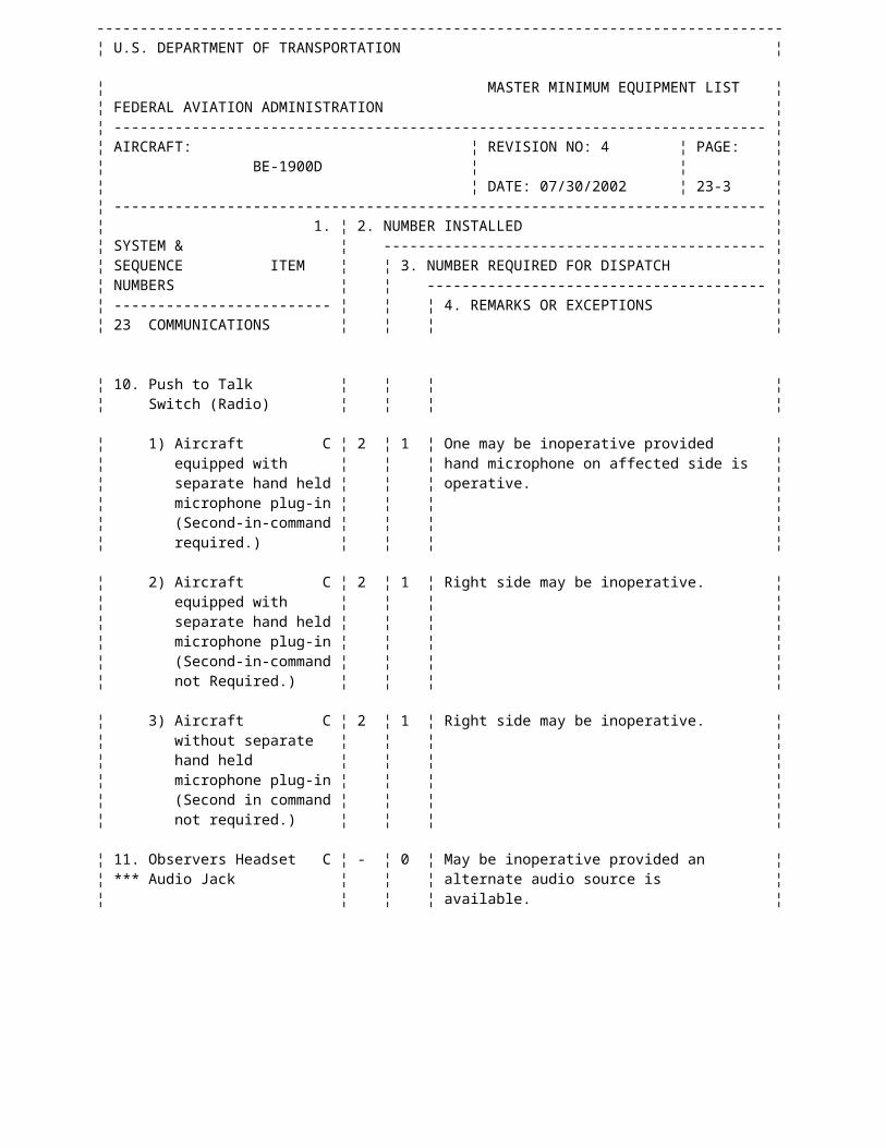
-------------------------------------------------------------------------------¦ U.S. DEPARTMENT OF TRANSPORTATION ¦ ¦ MASTER MINIMUM EQUIPMENT LIST ¦¦ FEDERAL AVIATION ADMINISTRATION ¦¦ --------------------------------------------------------------------------- ¦¦ AIRCRAFT: ¦ REVISION NO: 4 ¦ PAGE: ¦¦ BE-1900D ¦ ¦ ¦¦ ¦ DATE: 07/30/2002 ¦ 23-3 ¦¦ --------------------------------------------------------------------------- ¦¦ 1. ¦ 2. NUMBER INSTALLED ¦¦ SYSTEM & ¦ -------------------------------------------- ¦¦ SEQUENCE ITEM ¦ ¦ 3. NUMBER REQUIRED FOR DISPATCH ¦¦ NUMBERS ¦ ¦ --------------------------------------- ¦¦ ------------------------- ¦ ¦ ¦ 4. REMARKS OR EXCEPTIONS ¦¦ 23 COMMUNICATIONS ¦ ¦ ¦ ¦ ¦ 10. Push to Talk ¦ ¦ ¦ ¦¦ Switch (Radio) ¦ ¦ ¦ ¦ ¦ 1) Aircraft C ¦ 2 ¦ 1 ¦ One may be inoperative provided ¦¦ equipped with ¦ ¦ ¦ hand microphone on affected side is ¦¦ separate hand held ¦ ¦ ¦ operative. ¦¦ microphone plug-in ¦ ¦ ¦ ¦¦ (Second-in-command ¦ ¦ ¦ ¦¦ required.) ¦ ¦ ¦ ¦ ¦ 2) Aircraft C ¦ 2 ¦ 1 ¦ Right side may be inoperative. ¦¦ equipped with ¦ ¦ ¦ ¦¦ separate hand held ¦ ¦ ¦ ¦¦ microphone plug-in ¦ ¦ ¦ ¦¦ (Second-in-command ¦ ¦ ¦ ¦¦ not Required.) ¦ ¦ ¦ ¦ ¦ 3) Aircraft C ¦ 2 ¦ 1 ¦ Right side may be inoperative. ¦¦ without separate ¦ ¦ ¦ ¦¦ hand held ¦ ¦ ¦ ¦¦ microphone plug-in ¦ ¦ ¦ ¦¦ (Second in command ¦ ¦ ¦ ¦¦ not required.) ¦ ¦ ¦ ¦ ¦ 11. Observers Headset C ¦ - ¦ 0 ¦ May be inoperative provided an ¦¦ *** Audio Jack ¦ ¦ ¦ alternate audio source is ¦¦ ¦ ¦ ¦ available. ¦ -------------------------------------------------------------------------------

-------------------------------------------------------------------------------¦ U.S. DEPARTMENT OF TRANSPORTATION ¦ ¦ MASTER MINIMUM EQUIPMENT LIST ¦¦ FEDERAL AVIATION ADMINISTRATION ¦¦ --------------------------------------------------------------------------- ¦¦ AIRCRAFT: ¦ REVISION NO: 4 ¦ PAGE: ¦¦ BE-1900D ¦ ¦ ¦¦ ¦ DATE: 07/30/2002 ¦ 23-4 ¦¦ --------------------------------------------------------------------------- ¦¦ 1. ¦ 2. NUMBER INSTALLED ¦¦ SYSTEM & ¦ -------------------------------------------- ¦¦ SEQUENCE ITEM ¦ ¦ 3. NUMBER REQUIRED FOR DISPATCH ¦¦ NUMBERS ¦ ¦ --------------------------------------- ¦¦ ------------------------- ¦ ¦ ¦ 4. REMARKS OR EXCEPTIONS ¦¦ 23 COMMUNICATIONS ¦ ¦ ¦ ¦ ¦ 12. High Frequency (HF) D ¦ - ¦ - ¦ Any in excess of those required ¦¦ *** Communication ¦ ¦ ¦ by FAR may be inoperative. ¦¦ System ¦ ¦ ¦ ¦¦ C ¦ - ¦ - ¦ (O) May be inoperative while ¦¦ ¦ ¦ ¦ conducting operations that require ¦¦ ¦ ¦ ¦ two LRCS provided: ¦¦ ¦ ¦ ¦ a) SATCOM (High or Low Gain) ¦¦ ¦ ¦ ¦ Data Link system operates ¦¦ ¦ ¦ ¦ normally, and ¦¦ ¦ ¦ ¦ b) SATCOM Data Link ¦¦ ¦ ¦ ¦ communication system ¦¦ ¦ ¦ ¦ operates normally over the ¦¦ ¦ ¦ ¦ intended route of flight. ¦ -------------------------------------------------------------------------------

-------------------------------------------------------------------------------¦ U.S. DEPARTMENT OF TRANSPORTATION ¦ ¦ MASTER MINIMUM EQUIPMENT LIST ¦¦ FEDERAL AVIATION ADMINISTRATION ¦¦ --------------------------------------------------------------------------- ¦¦ AIRCRAFT: ¦ REVISION NO: 4 ¦ PAGE: ¦¦ BE-1900D ¦ ¦ ¦¦ ¦ DATE: 07/30/2002 ¦ 24-1 ¦¦ --------------------------------------------------------------------------- ¦¦ 1. ¦ 2. NUMBER INSTALLED ¦¦ SYSTEM & ¦ -------------------------------------------- ¦¦ SEQUENCE ITEM ¦ ¦ 3. NUMBER REQUIRED FOR DISPATCH ¦¦ NUMBERS ¦ ¦ --------------------------------------- ¦¦ ------------------------- ¦ ¦ ¦ 4. REMARKS OR EXCEPTIONS ¦¦ 24 ELECTRICAL POWER ¦ ¦ ¦ ¦ ¦ 1. AC VOLT/FREQ. ¦ ¦ ¦ DELETED Revision 1. ¦¦ Meter ¦ ¦ ¦ ¦ ¦ 2. L or R DC GEN B ¦ 2 ¦ 1 ¦ One may be inoperative provided: ¦¦ Annunciator System ¦ ¦ ¦ a) Both DC LOAD meters are ¦¦ ¦ ¦ ¦ operative, ¦¦ ¦ ¦ ¦ b) Both Generator Bus Ties are ¦¦ ¦ ¦ ¦ operative, and ¦¦ ¦ ¦ ¦ c) Both L and R GEN TIE OPEN ¦¦ ¦ ¦ ¦ Annunciator Systems are ¦¦ ¦ ¦ ¦ operative. ¦ ¦ 3. DC LOAD Meters B ¦ 2 ¦ 1 ¦ (O)One may be inoperative provided: ¦¦ ¦ ¦ ¦ a) Electrical load is ¦¦ ¦ ¦ ¦ maintained within the ¦¦ ¦ ¦ ¦ capacity of one generator ¦¦ ¦ ¦ ¦ at all times, ¦¦ ¦ ¦ ¦ b) Both L and R DC GEN ¦¦ ¦ ¦ ¦ Annunciator Systems are ¦¦ ¦ ¦ ¦ operative and ¦¦ ¦ ¦ ¦ c) Aircraft is not operated in ¦¦ ¦ ¦ ¦ known or forecast icing ¦¦ ¦ ¦ ¦ conditions. ¦ ¦ 4. Inverters B ¦ 2 ¦ 1 ¦ One may be inoperative for day VFR ¦¦ ¦ ¦ ¦ provided: ¦¦ ¦ ¦ ¦ a) No passengers are carried, ¦¦ ¦ ¦ ¦ and ¦¦ ¦ ¦ ¦ b) Both L and R AC Bus ¦¦ ¦ ¦ ¦ Annunciator Systems are ¦¦ ¦ ¦ ¦ operative. ¦ ¦ 5. L or R AC BUS B ¦ 2 ¦ 0 ¦ May be inoperative provided: ¦¦ Annunciator System ¦ ¦ ¦ a) Both Inverters are ¦¦ ¦ ¦ ¦ operative, and ¦¦ ¦ ¦ ¦ b) AC VOLT/FREQ Meter is ¦¦ ¦ ¦ ¦ operative. ¦ -------------------------------------------------------------------------------

-------------------------------------------------------------------------------¦ U.S. DEPARTMENT OF TRANSPORTATION ¦ ¦ MASTER MINIMUM EQUIPMENT LIST ¦¦ FEDERAL AVIATION ADMINISTRATION ¦¦ --------------------------------------------------------------------------- ¦¦ AIRCRAFT: ¦ REVISION NO: 4 ¦ PAGE: ¦¦ BE-1900D ¦ ¦ ¦¦ ¦ DATE: 07/30/2002 ¦ 24-2 ¦¦ --------------------------------------------------------------------------- ¦¦ 1. ¦ 2. NUMBER INSTALLED ¦¦ SYSTEM & ¦ -------------------------------------------- ¦¦ SEQUENCE ITEM ¦ ¦ 3. NUMBER REQUIRED FOR DISPATCH ¦¦ NUMBERS ¦ ¦ --------------------------------------- ¦¦ ------------------------- ¦ ¦ ¦ 4. REMARKS OR EXCEPTIONS ¦¦ 24 ELECTRICAL POWER ¦ ¦ ¦ ¦ ¦ 6. External Power C ¦ 1 ¦ 0 ¦ (M) ¦¦ System ¦ ¦ ¦ ¦ ¦ 7. EXTERNAL POWER C ¦ 1 ¦ 0 ¦ (O) ¦¦ Annunciator System ¦ ¦ ¦ ¦ ¦ 8. Generator Bus Tie B ¦ 2 ¦ 1 ¦ One may be inoperative for day ¦¦ ¦ ¦ ¦ VMC provided both DC GEN ¦¦ ¦ ¦ ¦ Annunciators are operative. ¦ ¦ 9. L or R GEN TIE B ¦ 2 ¦ 0 ¦ (O)May be inoperative provided: ¦¦ OPEN Annunciator ¦ ¦ ¦ a) Generator Bus Tie Relay is ¦¦ Systems ¦ ¦ ¦ verified closed prior to ¦¦ ¦ ¦ ¦ each departure, and ¦¦ ¦ ¦ ¦ b) Both DC GEN Annunciators ¦¦ ¦ ¦ ¦ are operative. ¦ ¦ 10. AC VOLT/FREQ C ¦ 1 ¦ 0 ¦ May be missing or broken provided ¦¦ Meter Frequency ¦ ¦ ¦ frequency information can be ¦¦ select button ¦ ¦ ¦ obtained from the Meter. ¦ -------------------------------------------------------------------------------

-------------------------------------------------------------------------------¦ U.S. DEPARTMENT OF TRANSPORTATION ¦ ¦ MASTER MINIMUM EQUIPMENT LIST ¦¦ FEDERAL AVIATION ADMINISTRATION ¦¦ --------------------------------------------------------------------------- ¦¦ AIRCRAFT: ¦ REVISION NO: 4 a ¦ PAGE: ¦¦ BE-1900D ¦ ¦ ¦¦ ¦ DATE: 10/04/2004 ¦ 25-1 ¦¦ --------------------------------------------------------------------------- ¦¦ 1. ¦ 2. NUMBER INSTALLED ¦¦ SYSTEM & ¦ -------------------------------------------- ¦¦ SEQUENCE ITEM ¦ ¦ 3. NUMBER REQUIRED FOR DISPATCH ¦¦ NUMBERS ¦ ¦ --------------------------------------- ¦¦ ------------------------- ¦ ¦ ¦ 4. REMARKS OR EXCEPTIONS ¦¦ 25 EQUIPMENT/FURNISHINGS ¦ ¦ ¦ ¦ ¦ 1. Passenger Seat(s) D ¦ - ¦ 0 ¦ May be inoperative provided: ¦¦ ¦ ¦ ¦ a) Seat does not block an ¦¦ ¦ ¦ ¦ Emergency Exit, ¦¦ ¦ ¦ ¦ b) Seat does not restrict any ¦¦ ¦ ¦ ¦ passenger from access to the ¦¦ ¦ ¦ ¦ main aircraft aisle, and ¦¦ ¦ ¦ ¦ c) Affected seat(s) is blocked ¦¦ ¦ ¦ ¦ and placarded ¦¦ ¦ ¦ ¦ "DO NOT OCCUPY". ¦ ¦ ¦ ¦ ¦ NOTE: A seat with an inoperative ¦¦ ¦ ¦ ¦ seat belt is considered to ¦¦ ¦ ¦ ¦ be inoperative. ¦ ¦ ¦ ¦ ¦ NOTE: Affected seat(s) may ¦¦ ¦ ¦ ¦ include the seat(s) behind ¦¦ ¦ ¦ ¦ and/or adjacent to the ¦¦ ¦ ¦ ¦ outboard seats. ¦ ¦ 1) Recline D ¦ - ¦ - ¦ May be inoperative and seat ¦¦ Mechanism ¦ ¦ ¦ occupied provided seat is secured ¦¦ ¦ ¦ ¦ in the upright position. ¦ ¦ 2) Underseat D ¦ - ¦ - ¦ (O)May be inoperative provided: ¦¦ Baggage ¦ ¦ ¦ a) Baggage is not stowed under ¦¦ Restraining Bars ¦ ¦ ¦ seat with inoperative ¦¦ ¦ ¦ ¦ restraining bar, ¦¦ ¦ ¦ ¦ b) Associated seat is placarded ¦¦ ¦ ¦ ¦ "DO NOT STOW BAGGAGE UNDER ¦¦ ¦ ¦ ¦ THIS SEAT", and ¦¦ ¦ ¦ ¦ c) Procedures are established ¦¦ ¦ ¦ ¦ to alert crew of inoperative ¦¦ ¦ ¦ ¦ restraining bar. ¦ ¦ (CON'T.) ¦ ¦ ¦ ¦-------------------------------------------------------------------------------

-------------------------------------------------------------------------------¦ U.S. DEPARTMENT OF TRANSPORTATION ¦ ¦ MASTER MINIMUM EQUIPMENT LIST ¦¦ FEDERAL AVIATION ADMINISTRATION ¦¦ --------------------------------------------------------------------------- ¦¦ AIRCRAFT: ¦ REVISION NO: 4 a ¦ PAGE: ¦¦ BE-1900D ¦ ¦ ¦¦ ¦ DATE: 10/04/2004 ¦ 25-2 ¦¦ --------------------------------------------------------------------------- ¦¦ 1. ¦ 2. NUMBER INSTALLED ¦¦ SYSTEM & ¦ -------------------------------------------- ¦¦ SEQUENCE ITEM ¦ ¦ 3. NUMBER REQUIRED FOR DISPATCH ¦¦ NUMBERS ¦ ¦ --------------------------------------- ¦¦ ------------------------- ¦ ¦ ¦ 4. REMARKS OR EXCEPTIONS ¦¦ 25 EQUIPMENT/FURNISHINGS ¦ ¦ ¦ ¦ ¦ 1. Passenger Seat(s) ¦ ¦ ¦ ¦¦ (CON'T.) ¦ ¦ ¦ ¦ ¦ 3) Forward C ¦ - ¦ 0 ¦ May be inoperative provided: ¦¦ Observer Seat ¦ ¦ ¦ a) Another forward passenger ¦¦ ¦ ¦ ¦ seat is made available to ¦¦ ¦ ¦ ¦ the Administrator for the ¦¦ ¦ ¦ ¦ performance of official ¦¦ ¦ ¦ ¦ duties, and ¦¦ ¦ ¦ ¦ b) An audio source is ¦¦ ¦ ¦ ¦ available. ¦ ¦ 2. Emergency Locator C ¦ 1 ¦ 0 ¦ As required by FAR. ¦¦ *** Transmitter (ELT) ¦ ¦ ¦ ¦¦ C ¦ 1 ¦ 0 ¦ May be inoperative for published ¦¦ ¦ ¦ ¦ scheduled flights in scheduled air ¦¦ ¦ ¦ ¦ carrier service. ¦ ¦ 3. ELT Remote Switch C ¦ 1 ¦ 0 ¦ (M)May be inoperative provided: ¦¦ *** ¦ ¦ ¦ a) Remote switch is ¦¦ ¦ ¦ ¦ disconnected from ELT, and ¦¦ ¦ ¦ ¦ b) ELT switch is placed in ¦¦ ¦ ¦ ¦ ARM position. ¦ ¦ 4. Passenger Convenience ¦ - ¦ - ¦ Passenger convenience items, as ¦¦ *** Item(s) ¦ ¦ ¦ expressed in this MMEL, are those ¦¦ ¦ ¦ ¦ related to passenger convenience, ¦¦ ¦ ¦ ¦ comfort or entertainment such as, ¦¦ ¦ ¦ ¦ but not limited to, galley ¦¦ ¦ ¦ ¦ equipment, movie equipment, ash ¦¦ ¦ ¦ ¦ trays, stereo equipment, overhead ¦¦ ¦ ¦ ¦ reading lamps, etc. Items ¦¦ ¦ ¦ ¦ addressed elsewhere in this ¦¦ ¦ ¦ ¦ document shall not be included. ¦¦ ¦ ¦ ¦ (M) and (O) procedures may be ¦¦ ¦ ¦ ¦ required and included in the ¦¦ ¦ ¦ ¦ air carrier's appropriate ¦¦ ¦ ¦ ¦ document. ¦ -------------------------------------------------------------------------------

-------------------------------------------------------------------------------¦ U.S. DEPARTMENT OF TRANSPORTATION ¦ ¦ MASTER MINIMUM EQUIPMENT LIST ¦¦ FEDERAL AVIATION ADMINISTRATION ¦¦ --------------------------------------------------------------------------- ¦¦ AIRCRAFT: ¦ REVISION NO: 4 a ¦ PAGE: ¦¦ BE-1900D ¦ ¦ ¦¦ ¦ DATE: 10/04/2004 ¦ 25-3 ¦¦ --------------------------------------------------------------------------- ¦¦ 1. ¦ 2. NUMBER INSTALLED ¦¦ SYSTEM & ¦ -------------------------------------------- ¦¦ SEQUENCE ITEM ¦ ¦ 3. NUMBER REQUIRED FOR DISPATCH ¦¦ NUMBERS ¦ ¦ --------------------------------------- ¦¦ ------------------------- ¦ ¦ ¦ 4. REMARKS OR EXCEPTIONS ¦¦ 25 EQUIPMENT/FURNISHINGS ¦ ¦ ¦ ¦ ¦ 5. Emergency Medical D ¦ - ¦ - ¦ Any in excess of those required by ¦¦ Equipment ¦ ¦ ¦ FAR may be incomplete or missing ¦¦ ¦ ¦ ¦ provided required distribution is ¦¦ ¦ ¦ ¦ maintained. ¦ ¦ 6. Flotation Devices D ¦ - ¦ - ¦ Any in excess of those required by ¦¦ ¦ ¦ ¦ FAR may be inoperative or missing ¦¦ ¦ ¦ ¦ provided required distribution is ¦¦ ¦ ¦ ¦ maintained. ¦ ¦ 7. Flashlight/ D ¦ - ¦ - ¦ Any in excess of those required by ¦¦ *** Flashlight Assembly ¦ ¦ ¦ FAR may be inoperative or missing. ¦ ¦ 8. Cockpit Overhead D ¦ - ¦ - ¦ May be inoperative or missing. ¦¦ Crew Assist Straps ¦ ¦ ¦ ¦ ¦ 9. Cockpit Sun Visors C ¦ 2 ¦ 0 ¦ May be inoperative or missing ¦¦ ¦ ¦ ¦ provided there are no visual ¦¦ ¦ ¦ ¦ restrictions to the flight crew. ¦ ¦ 10. Crew Seat A ¦ - ¦ 0 ¦ (M)May be inoperative provided: ¦¦ Adjustment ¦ ¦ ¦ a) Seat(s) are locked in a ¦¦ ¦ ¦ ¦ position that permits normal ¦¦ ¦ ¦ ¦ pilot visibility, ¦¦ ¦ ¦ ¦ b) Full flight control movement ¦¦ ¦ ¦ ¦ is available, ¦¦ ¦ ¦ ¦ c) Position of seat is ¦¦ ¦ ¦ ¦ acceptable to the flight ¦¦ ¦ ¦ ¦ crew, ¦¦ ¦ ¦ ¦ d) Crew Rudder Pedal Adjustment ¦¦ ¦ ¦ ¦ is operative, and ¦¦ ¦ ¦ ¦ e) Repairs are made within one ¦¦ ¦ ¦ ¦ flight day. ¦ ¦ 11. Crew Arm Rests C ¦ - ¦ 0 ¦ May be inoperative provided arm ¦¦ ¦ ¦ ¦ rest is secured in the upright ¦¦ ¦ ¦ ¦ position. ¦ -------------------------------------------------------------------------------

-------------------------------------------------------------------------------¦ U.S. DEPARTMENT OF TRANSPORTATION ¦ ¦ MASTER MINIMUM EQUIPMENT LIST ¦¦ FEDERAL AVIATION ADMINISTRATION ¦¦ --------------------------------------------------------------------------- ¦¦ AIRCRAFT: ¦ REVISION NO: 4 a ¦ PAGE: ¦¦ BE-1900D ¦ ¦ ¦¦ ¦ DATE: 10/04/2004 ¦ 25-4 ¦¦ --------------------------------------------------------------------------- ¦¦ 1. ¦ 2. NUMBER INSTALLED ¦¦ SYSTEM & ¦ -------------------------------------------- ¦¦ SEQUENCE ITEM ¦ ¦ 3. NUMBER REQUIRED FOR DISPATCH ¦¦ NUMBERS ¦ ¦ --------------------------------------- ¦¦ ------------------------- ¦ ¦ ¦ 4. REMARKS OR EXCEPTIONS ¦¦ 25 EQUIPMENT/FURNISHINGS ¦ ¦ ¦ ¦ ¦ 12. Cockpit Doors C ¦ 2 ¦ 0 ¦ May be inoperative provided door ¦¦ ¦ ¦ ¦ is secured open and does not block ¦¦ ¦ ¦ ¦ egress to exit. ¦ ¦ 13. Externally Mounted C ¦ - ¦ 0 ¦ (O)May be inoperative, missing or ¦¦ Airspeed Indicator ¦ ¦ ¦ broken. ¦¦ Bugs ¦ ¦ ¦ ¦ ¦ 14. Crew Rudder Pedal A ¦ - ¦ 0 ¦ (M)May be inoperative provided: ¦¦ Adjustment ¦ ¦ ¦ a) Associated rudder pedal is ¦¦ ¦ ¦ ¦ locked in a position that ¦¦ ¦ ¦ ¦ allows full rudder pedal ¦¦ ¦ ¦ ¦ movement, ¦¦ ¦ ¦ ¦ b) Position of the rudder pedal ¦¦ ¦ ¦ ¦ is acceptable to the flight ¦¦ ¦ ¦ ¦ crew, ¦¦ ¦ ¦ ¦ c) Associated Crew Seat ¦¦ ¦ ¦ ¦ Adjustment must be ¦¦ ¦ ¦ ¦ operative, and ¦¦ ¦ ¦ ¦ d) Repairs are made within ¦¦ ¦ ¦ ¦ one flight day. ¦ ¦ 15. Crew Compartment C ¦ - ¦ - ¦ ¦¦ Adjustable Air Vent ¦ ¦ ¦ ¦¦ Valves (Wemacs) ¦ ¦ ¦ ¦ ¦ 16. Operator Initiated D ¦ - ¦ - ¦ ¦¦ *** Placards. ¦ ¦ ¦ ¦ -------------------------------------------------------------------------------

-------------------------------------------------------------------------------¦ U.S. DEPARTMENT OF TRANSPORTATION ¦ ¦ MASTER MINIMUM EQUIPMENT LIST ¦¦ FEDERAL AVIATION ADMINISTRATION ¦¦ --------------------------------------------------------------------------- ¦¦ AIRCRAFT: ¦ REVISION NO: 4 a ¦ PAGE: ¦¦ BE-1900D ¦ ¦ ¦¦ ¦ DATE: 10/04/2004 ¦ 25-5 ¦¦ --------------------------------------------------------------------------- ¦¦ 1. ¦ 2. NUMBER INSTALLED ¦¦ SYSTEM & ¦ -------------------------------------------- ¦¦ SEQUENCE ITEM ¦ ¦ 3. NUMBER REQUIRED FOR DISPATCH ¦¦ NUMBERS ¦ ¦ --------------------------------------- ¦¦ ------------------------- ¦ ¦ ¦ 4. REMARKS OR EXCEPTIONS ¦¦ 25 EQUIPMENT/FURNISHINGS ¦ ¦ ¦ ¦ ¦ 17. Waste Receptacles C ¦ - ¦ - ¦ (O)(M) May be inoperative provided: ¦¦ *** Access Doors/Covers ¦ ¦ ¦ a) The container is empty and ¦¦ ¦ ¦ ¦ the access is secured to ¦¦ ¦ ¦ ¦ prevent waste introduction ¦¦ ¦ ¦ ¦ into the compartment, and ¦¦ ¦ ¦ ¦ b) Procedures are established ¦¦ ¦ ¦ ¦ to ensure that sufficient ¦¦ ¦ ¦ ¦ waste receptacles are ¦¦ ¦ ¦ ¦ available to accommodate all ¦¦ ¦ ¦ ¦ waste that may be generated ¦¦ ¦ ¦ ¦ on a flight. ¦ ¦ 18. "Fasten Seat Belt C ¦ - ¦ - ¦ One or more signs or placards may ¦¦ *** While Seated" Sign ¦ ¦ ¦ be illegible or missing provided a ¦¦ or Placard ¦ ¦ ¦ legible sign or placard is visible ¦¦ ¦ ¦ ¦ from each occupied seat. ¦ ¦ 19. Flightcrew Hat D ¦ - ¦ - ¦ ¦¦ *** Hooks ¦ ¦ ¦ ¦ -------------------------------------------------------------------------------

-------------------------------------------------------------------------------¦ U.S. DEPARTMENT OF TRANSPORTATION ¦ ¦ MASTER MINIMUM EQUIPMENT LIST ¦¦ FEDERAL AVIATION ADMINISTRATION ¦¦ --------------------------------------------------------------------------- ¦¦ AIRCRAFT: ¦ REVISION NO: 4 a ¦ PAGE: ¦¦ BE-1900D ¦ ¦ ¦¦ ¦ DATE: 10/04/2004 ¦ 25-6 ¦¦ --------------------------------------------------------------------------- ¦¦ 1. ¦ 2. NUMBER INSTALLED ¦¦ SYSTEM & ¦ -------------------------------------------- ¦¦ SEQUENCE ITEM ¦ ¦ 3. NUMBER REQUIRED FOR DISPATCH ¦¦ NUMBERS ¦ ¦ --------------------------------------- ¦¦ ------------------------- ¦ ¦ ¦ 4. REMARKS OR EXCEPTIONS ¦¦ 25 EQUIPMENT/FURNISHINGS ¦ ¦ ¦ ¦ ¦ 20. Cabin and Galley C ¦ - ¦ - ¦ (M) May be inoperative provided: ¦¦ *** Storage Compartments/ ¦ ¦ ¦ a)Procedures are established to ¦¦ Closets ¦ ¦ ¦ secure compartment CLOSED, ¦¦ ¦ ¦ ¦ b)Compartment is not used for ¦¦ ¦ ¦ ¦ storage of Emergency ¦¦ ¦ ¦ ¦ Equipment, and ¦¦ ¦ ¦ ¦ c)Affected compartment is not ¦¦ ¦ ¦ ¦ used for storage of any ¦¦ ¦ ¦ ¦ item(s) except those ¦¦ ¦ ¦ ¦ permanently affixed. ¦ ¦ 21. Cargo Restraint C ¦ - ¦ - ¦ (M)May be inoperative, or missing ¦¦ *** Systems ¦ ¦ ¦ provided acceptable cargo ¦¦ ¦ ¦ ¦ loading limits from an approved ¦¦ ¦ ¦ ¦ source, i.e., an Approved Cargo ¦¦ ¦ ¦ ¦ Loading Manual,Cargo Handling ¦¦ ¦ ¦ ¦ Manual, or Weight and Balance ¦¦ ¦ ¦ ¦ Document are observed. ¦ ¦ C ¦ - ¦ - ¦ May be inoperative, or missing ¦¦ ¦ ¦ ¦ provided cargo compartment remains ¦¦ ¦ ¦ ¦ empty. ¦ ¦ 22. Cargo Door D ¦ - ¦ 0 ¦ May be inoperative or missing. ¦¦ Assist Lanyard ¦ ¦ ¦ ¦ -------------------------------------------------------------------------------

-------------------------------------------------------------------------------¦ U.S. DEPARTMENT OF TRANSPORTATION ¦ ¦ MASTER MINIMUM EQUIPMENT LIST ¦¦ FEDERAL AVIATION ADMINISTRATION ¦¦ --------------------------------------------------------------------------- ¦¦ AIRCRAFT: ¦ REVISION NO: 4 a ¦ PAGE: ¦¦ BE-1900D ¦ ¦ ¦¦ ¦ DATE: 10/04/2004 ¦ 26-1 ¦¦ --------------------------------------------------------------------------- ¦¦ 1. ¦ 2. NUMBER INSTALLED ¦¦ SYSTEM & ¦ -------------------------------------------- ¦¦ SEQUENCE ITEM ¦ ¦ 3. NUMBER REQUIRED FOR DISPATCH ¦¦ NUMBERS ¦ ¦ --------------------------------------- ¦¦ ------------------------- ¦ ¦ ¦ 4. REMARKS OR EXCEPTIONS ¦¦ 26 FIRE PROTECTION ¦ ¦ ¦ ¦ ¦ 1. Portable Fire D ¦ - ¦ - ¦ Any in excess of those required by ¦¦ Extinguisher ¦ ¦ ¦ FAR may be inoperative or missing ¦¦ ¦ ¦ ¦ provided: ¦¦ ¦ ¦ ¦ a) The inoperative fire ¦¦ ¦ ¦ ¦ extinguisher is tagged ¦¦ ¦ ¦ ¦ inoperative, removed from ¦¦ ¦ ¦ ¦ the installed location and ¦¦ ¦ ¦ ¦ placed out of sight so it ¦¦ ¦ ¦ ¦ can not be mistaken for a ¦¦ ¦ ¦ ¦ functional unit, and ¦¦ ¦ ¦ ¦ b) Required distribution is ¦¦ ¦ ¦ ¦ maintained. ¦ ¦ 2. Fire Extinguisher A ¦ 2 ¦ 0 ¦ May be broken, missing or lacking ¦¦ "Push to Extinguish" ¦ ¦ ¦ safety wire provided: ¦¦ Guard ¦ ¦ ¦ a) Broken guard shall not ¦¦ ¦ ¦ ¦ interfere with the proper ¦¦ ¦ ¦ ¦ indication or activation of ¦¦ ¦ ¦ ¦ the extinguisher, and ¦¦ ¦ ¦ ¦ b) Repairs are made within one ¦¦ ¦ ¦ ¦ flight day. ¦ ¦ 3. Lavatory Fire C ¦ - ¦ - ¦ May be inoperative provided ¦¦ *** Extinguisher ¦ ¦ ¦ Lavatory Smoke Detector system ¦¦ System ¦ ¦ ¦ operates normally. ¦ ¦ C ¦ - ¦ - ¦ (M)(O) May be inoperative provided: ¦¦ ¦ ¦ ¦ a) Lavatory waste receptacle ¦¦ ¦ ¦ ¦ is empty, ¦¦ ¦ ¦ ¦ b) Lavatory Door is locked ¦¦ ¦ ¦ ¦ closed and placarded ¦¦ ¦ ¦ ¦ "INOPERATIVE-DO NOT ENTER", ¦¦ ¦ ¦ ¦ and ¦¦ ¦ ¦ ¦ c) Lavatory is used only by ¦¦ ¦ ¦ ¦ crewmembers. ¦ ¦ ¦ ¦ ¦ NOTE 1:These provisos are not ¦¦ ¦ ¦ ¦ intended to prohibit ¦¦ ¦ ¦ ¦ lavatory use or inspections ¦¦ (CON'T.) ¦ ¦ ¦ by crewmembers. ¦-------------------------------------------------------------------------------

-------------------------------------------------------------------------------¦ U.S. DEPARTMENT OF TRANSPORTATION ¦ ¦ MASTER MINIMUM EQUIPMENT LIST ¦¦ FEDERAL AVIATION ADMINISTRATION ¦¦ --------------------------------------------------------------------------- ¦¦ AIRCRAFT: ¦ REVISION NO: 4 a ¦ PAGE: ¦¦ BE-1900D ¦ ¦ ¦¦ ¦ DATE: 10/04/2004 ¦ 26-2 ¦¦ --------------------------------------------------------------------------- ¦¦ 1. ¦ 2. NUMBER INSTALLED ¦¦ SYSTEM & ¦ -------------------------------------------- ¦¦ SEQUENCE ITEM ¦ ¦ 3. NUMBER REQUIRED FOR DISPATCH ¦¦ NUMBERS ¦ ¦ --------------------------------------- ¦¦ ------------------------- ¦ ¦ ¦ 4. REMARKS OR EXCEPTIONS ¦¦ 26 FIRE PROTECTION ¦ ¦ ¦ ¦ ¦ 3. Lavatory Fire ¦ ¦ ¦ ¦¦ ***Extinguisher ¦ ¦ ¦ ¦¦ System ¦ ¦ ¦ ¦¦ (CON'T.) ¦ ¦ ¦ NOTE 2:A Lavatory Fire Extinguisher ¦¦ ¦ ¦ ¦ System is not required for ¦¦ ¦ ¦ ¦ all-cargo operations. ¦ ¦ 4. Lavatory Smoke C ¦ - ¦ - ¦ (O)(M) May be inoperative provided: ¦¦ ***Detection System ¦ ¦ ¦ a) Lavatory Waste Receptacle ¦¦ ¦ ¦ ¦ is empty, ¦¦ ¦ ¦ ¦ b) Lavatory Door is locked ¦¦ ¦ ¦ ¦ closed and placarded, ¦¦ ¦ ¦ ¦ "INOPERATIVE-DO NOT ENTER", ¦¦ ¦ ¦ ¦ and ¦¦ ¦ ¦ ¦ c) Lavatory is used only by ¦¦ ¦ ¦ ¦ crewmembers. ¦ ¦ ¦ ¦ ¦ NOTE 1:These provisos are not ¦¦ ¦ ¦ ¦ intended to prohibit ¦¦ ¦ ¦ ¦ lavatory use or inspections ¦¦ ¦ ¦ ¦ by crewmembers. ¦ ¦ ¦ ¦ ¦ NOTE 2:Lavatory Smoke Detection ¦¦ ¦ ¦ ¦ System is not required for ¦¦ ¦ ¦ ¦ all-cargo operations. ¦ ¦ 5. Cargo Compartment C ¦ - ¦ 0 ¦ May be inoperative provided cargo ¦¦ ***Fire Detection ¦ ¦ ¦ compartment remains empty. ¦¦ System ¦ ¦ ¦ ¦¦ ¦ ¦ ¦ NOTE: Does not preclude the ¦¦ ¦ ¦ ¦ carriage or empty cargo ¦¦ ¦ ¦ ¦ containers, pallets, ballast, ¦¦ ¦ ¦ ¦ etc. ¦ -------------------------------------------------------------------------------
-------------------------------------------------------------------------------¦ U.S. DEPARTMENT OF TRANSPORTATION ¦ ¦ MASTER MINIMUM EQUIPMENT LIST ¦¦ FEDERAL AVIATION ADMINISTRATION ¦¦ --------------------------------------------------------------------------- ¦¦ AIRCRAFT: ¦ REVISION NO: 4 a ¦ PAGE: ¦¦ BE-1900D ¦ ¦ ¦¦ ¦ DATE: 10/04/2004 ¦ 27-1 ¦¦ --------------------------------------------------------------------------- ¦¦ 1. ¦ 2. NUMBER INSTALLED ¦¦ SYSTEM & ¦ -------------------------------------------- ¦¦ SEQUENCE ITEM ¦ ¦ 3. NUMBER REQUIRED FOR DISPATCH ¦¦ NUMBERS ¦ ¦ --------------------------------------- ¦¦ ------------------------- ¦ ¦ ¦ 4. REMARKS OR EXCEPTIONS ¦¦ 27 FLIGHT CONTROLS ¦ ¦ ¦ ¦ ¦ 1. Flap Position B ¦ 1 ¦ 0 ¦ May be inoperative provided: ¦¦ Indicator ¦ ¦ ¦ a) Flaps are visually checked ¦¦ ¦ ¦ ¦ for full travel and flap ¦¦ ¦ ¦ ¦ operation is not affected, ¦¦ ¦ ¦ ¦ and ¦¦ ¦ ¦ ¦ b) Flaps are checked at each ¦¦ ¦ ¦ ¦ preselect setting prior to ¦¦ ¦ ¦ ¦ each departure. ¦ ¦ 2. Flap System B ¦ 1 ¦ 0 ¦ (O)May be inoperative provided: ¦¦ ¦ ¦ ¦ a) Flaps are in full up ¦¦ ¦ ¦ ¦ position, and ¦¦ ¦ ¦ ¦ b) Appropriate performance data ¦¦ ¦ ¦ ¦ for no flap takeoff and ¦¦ ¦ ¦ ¦ landings is uses. ¦¦ ¦ ¦ ¦ CAUTION: DO NOT SILENCE THE ¦¦ ¦ ¦ ¦ LANDING GEAR WARNING ¦¦ ¦ ¦ ¦ HORN. ¦ ¦ 1) Flap Position B ¦ 1 ¦ 0 ¦ May be inoperative provided: ¦¦ Indicator ¦ ¦ ¦ a) Flaps are visually checked ¦¦ ¦ ¦ ¦ for full travel and flap ¦¦ ¦ ¦ ¦ operation is not affected, ¦¦ ¦ ¦ ¦ and ¦¦ ¦ ¦ ¦ b) Flaps are checked at each ¦¦ ¦ ¦ ¦ preselected setting prior ¦¦ ¦ ¦ ¦ to each departure. ¦ ¦ 3. Trim Tab Indicators C ¦ 2 ¦ 0 ¦ May be inoperative provided: ¦¦ (Aileron, Rudder) ¦ ¦ ¦ a) Tab is visually checked for ¦¦ ¦ ¦ ¦ full range of operation, ¦¦ ¦ ¦ ¦ b) Tab operation is not ¦¦ ¦ ¦ ¦ impaired, and ¦¦ ¦ ¦ ¦ c)Tab is positioned to neutral ¦¦ ¦ ¦ ¦ prior to each departure and ¦¦ ¦ ¦ ¦ nuetral position is verified ¦¦ ¦ ¦ ¦ by visual inspection. ¦ -------------------------------------------------------------------------------

-------------------------------------------------------------------------------¦ U.S. DEPARTMENT OF TRANSPORTATION ¦ ¦ MASTER MINIMUM EQUIPMENT LIST ¦¦ FEDERAL AVIATION ADMINISTRATION ¦¦ --------------------------------------------------------------------------- ¦¦ AIRCRAFT: ¦ REVISION NO: 4 b ¦ PAGE: ¦¦ BE-1900D ¦ ¦ ¦¦ ¦ DATE: 12/14/2004 ¦ 27-2 ¦¦ --------------------------------------------------------------------------- ¦¦ 1. ¦ 2. NUMBER INSTALLED ¦¦ SYSTEM & ¦ -------------------------------------------- ¦¦ SEQUENCE ITEM ¦ ¦ 3. NUMBER REQUIRED FOR DISPATCH ¦¦ NUMBERS ¦ ¦ --------------------------------------- ¦¦ ------------------------- ¦ ¦ ¦ 4. REMARKS OR EXCEPTIONS ¦¦ 27 FLIGHT CONTROLS ¦ ¦ ¦ ¦ ¦ 4. Electric Elevator ¦ ¦ ¦ ¦¦ *** Trim System ¦ ¦ ¦ ¦ ¦ 1) With Autopilot C ¦ 1 ¦ 0 ¦ (O)May be inoperative provided: ¦¦ ¦ ¦ ¦ a)Manual trim is operative ¦¦ ¦ ¦ ¦ and unaffected, and ¦¦ ¦ ¦ ¦ b) Autopilot is not used. ¦ ¦ 2) No Autopilot C ¦ 1 ¦ 0 ¦ (O)May be inoperative provided ¦¦ ¦ ¦ ¦ manual trim is operative and ¦¦ ¦ ¦ ¦ unaffected. ¦ ¦ 3) Trim Switches C ¦ - ¦ 0 ¦ NOTE: Any operative trim switch | ¦¦ ¦ ¦ ¦ may be used. | ¦ ¦ 4) PITCH TRIM OFF C ¦ 1 ¦ 0 ¦ | ¦¦ Annunciator ¦ ¦ ¦ | ¦¦ System ¦ ¦ ¦ | ¦ ¦ 5. PITCH TRIM Off ¦ ¦ ¦ DELETED Combined with ATA 27-4 ¦¦ Annunciator System ¦ ¦ ¦ ¦ -------------------------------------------------------------------------------

-------------------------------------------------------------------------------¦ U.S. DEPARTMENT OF TRANSPORTATION ¦ ¦ MASTER MINIMUM EQUIPMENT LIST ¦¦ FEDERAL AVIATION ADMINISTRATION ¦¦ --------------------------------------------------------------------------- ¦¦ AIRCRAFT: ¦ REVISION NO: 4 a ¦ PAGE: ¦¦ BE-1900D ¦ ¦ ¦¦ ¦ DATE: 10/04/2004 ¦ 28-1 ¦¦ --------------------------------------------------------------------------- ¦¦ 1. ¦ 2. NUMBER INSTALLED ¦¦ SYSTEM & ¦ -------------------------------------------- ¦¦ SEQUENCE ITEM ¦ ¦ 3. NUMBER REQUIRED FOR DISPATCH ¦¦ NUMBERS ¦ ¦ --------------------------------------- ¦¦ ------------------------- ¦ ¦ ¦ 4. REMARKS OR EXCEPTIONS ¦¦ 28 FUEL ¦ ¦ ¦ ¦ ¦ 1. Engine Driven Low C ¦ 2 ¦ 1 ¦ (M)One may be inoperative provided: ¦¦ Pressure Fuel Boost ¦ ¦ ¦ a) Standby Electric boost pump ¦¦ Pump ¦ ¦ ¦ is turned on, ¦¦ ¦ ¦ ¦ b) Aviation gasoline is not ¦¦ ¦ ¦ ¦ used, and ¦¦ ¦ ¦ ¦ c) JP4 or Jet B are not used ¦¦ ¦ ¦ ¦ above 8,000 feet MSL. ¦ ¦ 2. L or R FUEL QTY C ¦ 2 ¦ 1 ¦ One may be inoperative provided ¦¦ Annunciator Systems ¦ ¦ ¦ fuel quantity on board is adequate ¦¦ ¦ ¦ ¦ for the intended flight. ¦ ¦ 3. FUEL TRANSFER C ¦ 1 ¦ 0 ¦ May be inoperative provided both ¦¦ Annunciator System ¦ ¦ ¦ Fuel Quantity Indicating Systems ¦¦ ¦ ¦ ¦ are operative. ¦ ¦ 4. Fuel Flow ¦ ¦ ¦ DELETED Revision 4. Moved to ¦¦ Indicators ¦ ¦ ¦ ATA Section 73. ¦ -------------------------------------------------------------------------------

-------------------------------------------------------------------------------¦ U.S. DEPARTMENT OF TRANSPORTATION ¦ ¦ MASTER MINIMUM EQUIPMENT LIST ¦¦ FEDERAL AVIATION ADMINISTRATION ¦¦ --------------------------------------------------------------------------- ¦¦ AIRCRAFT: ¦ REVISION NO: 4 a ¦ PAGE: ¦¦ BE-1900D ¦ ¦ ¦¦ ¦ DATE: 10/04/2004 ¦ 28-2 ¦¦ --------------------------------------------------------------------------- ¦¦ 1. ¦ 2. NUMBER INSTALLED ¦¦ SYSTEM & ¦ -------------------------------------------- ¦¦ SEQUENCE ITEM ¦ ¦ 3. NUMBER REQUIRED FOR DISPATCH ¦¦ NUMBERS ¦ ¦ --------------------------------------- ¦¦ ------------------------- ¦ ¦ ¦ 4. REMARKS OR EXCEPTIONS ¦¦ 28 FUEL ¦ ¦ ¦ ¦ ¦ 5. Auxiliary Fuel ¦ ¦ ¦ ¦¦ Transfer Pump ¦ ¦ ¦ ¦¦ System ¦ ¦ ¦ ¦ ¦ 1) Auxiliary Fuel C ¦ 2 ¦ 0 ¦ (O)May be inoperative provided: ¦¦ Transfer Pumps ¦ ¦ ¦ a) Fuel quantity in main tanks ¦¦ ¦ ¦ ¦ is adequate for the intended ¦¦ ¦ ¦ ¦ flight, ¦¦ ¦ ¦ ¦ b) Auxiliary fuel quantity is ¦¦ ¦ ¦ ¦ balanced and is not used for ¦¦ ¦ ¦ ¦ the flight, and ¦¦ ¦ ¦ ¦ c) Fuel Quantity Indicating ¦¦ ¦ ¦ ¦ System on affected side is ¦¦ ¦ ¦ ¦ operative. ¦ ¦ 2) AUTO mode C ¦ 2 ¦ 0 ¦ May be inoperative provided: ¦¦ ¦ ¦ ¦ a) AUX PUMP ON mode is ¦¦ ¦ ¦ ¦ operative, and ¦¦ ¦ ¦ ¦ b) Fuel Quantity Indicating ¦¦ ¦ ¦ ¦ System on affected side is ¦¦ ¦ ¦ ¦ operative. ¦ ¦ 6. L or R COL TANK C ¦ 2 ¦ 1 ¦ One may be inoperative provided: ¦¦ LOW Annunciator ¦ ¦ ¦ a) Fuel quantity on board is ¦¦ System ¦ ¦ ¦ adequate for the intended ¦¦ ¦ ¦ ¦ flight, and ¦¦ ¦ ¦ ¦ b) FUEL QTY annunciator on ¦¦ ¦ ¦ ¦ failed side is operative. ¦ -------------------------------------------------------------------------------

-------------------------------------------------------------------------------¦ U.S. DEPARTMENT OF TRANSPORTATION ¦ ¦ MASTER MINIMUM EQUIPMENT LIST ¦¦ FEDERAL AVIATION ADMINISTRATION ¦¦ --------------------------------------------------------------------------- ¦¦ AIRCRAFT: ¦ REVISION NO: 4 a ¦ PAGE: ¦¦ BE-1900D ¦ ¦ ¦¦ ¦ DATE: 10/04/2004 ¦ 28-3 ¦¦ --------------------------------------------------------------------------- ¦¦ 1. ¦ 2. NUMBER INSTALLED ¦¦ SYSTEM & ¦ -------------------------------------------- ¦¦ SEQUENCE ITEM ¦ ¦ 3. NUMBER REQUIRED FOR DISPATCH ¦¦ NUMBERS ¦ ¦ --------------------------------------- ¦¦ ------------------------- ¦ ¦ ¦ 4. REMARKS OR EXCEPTIONS ¦¦ 28 FUEL ¦ ¦ ¦ ¦ ¦ 7. Fuel Quantity C ¦ 2 ¦ 1 ¦ (O)One may be inoperative provided: ¦¦ Indicating Systems ¦ ¦ ¦ a) A reliable means is ¦¦ ¦ ¦ ¦ established to determine ¦¦ ¦ ¦ ¦ that fuel quantity on board ¦¦ ¦ ¦ ¦ meets the regulatory ¦¦ ¦ ¦ ¦ requirements for the ¦¦ ¦ ¦ ¦ intended flight, ¦¦ ¦ ¦ ¦ b) Both Fuel Flow Indicators ¦¦ ¦ ¦ ¦ are operative, ¦¦ ¦ ¦ ¦ c) L and R FUEL QTY ¦¦ ¦ ¦ ¦ annunciators are operative, ¦¦ ¦ ¦ ¦ d) Procedures are established ¦¦ ¦ ¦ ¦ to ensure fuel balance ¦¦ ¦ ¦ ¦ remains within AFM limits, ¦¦ ¦ ¦ ¦ and ¦¦ ¦ ¦ ¦ e) FUEL TRANSFER Annunciator ¦¦ ¦ ¦ ¦ System is operative. ¦ ¦ 1) MAIN Fuel Tank C ¦ 2 ¦ 1 ¦ (O)One may be inoperative provided: ¦¦ Indications ¦ ¦ ¦ a) A reliable means is ¦¦ ¦ ¦ ¦ established to determine ¦¦ ¦ ¦ ¦ that fuel quantity on board ¦¦ ¦ ¦ ¦ meets the regulatory ¦¦ ¦ ¦ ¦ requirements for the ¦¦ ¦ ¦ ¦ intended flight, ¦¦ ¦ ¦ ¦ b) Both Fuel Flow indicators ¦¦ ¦ ¦ ¦ are operative, ¦¦ ¦ ¦ ¦ c) L and R FUEL QTY ¦¦ ¦ ¦ ¦ Annunciator Systems are ¦¦ ¦ ¦ ¦ operative, ¦¦ ¦ ¦ ¦ d) Procedures are established ¦¦ ¦ ¦ ¦ to ensure that fuel balance ¦¦ ¦ ¦ ¦ remains within AFM ¦¦ ¦ ¦ ¦ limitations, and ¦¦ ¦ ¦ ¦ e) FUEL TRANSFER Annunciator ¦¦ ¦ ¦ ¦ System is operative. ¦ ¦ (CON'T.) ¦ ¦ ¦ ¦-------------------------------------------------------------------------------

-------------------------------------------------------------------------------¦ U.S. DEPARTMENT OF TRANSPORTATION ¦ ¦ MASTER MINIMUM EQUIPMENT LIST ¦¦ FEDERAL AVIATION ADMINISTRATION ¦¦ --------------------------------------------------------------------------- ¦¦ AIRCRAFT: ¦ REVISION NO: 4 a ¦ PAGE: ¦¦ BE-1900D ¦ ¦ ¦¦ ¦ DATE: 10/04/2004 ¦ 28-4 ¦¦ --------------------------------------------------------------------------- ¦¦ 1. ¦ 2. NUMBER INSTALLED ¦¦ SYSTEM & ¦ -------------------------------------------- ¦¦ SEQUENCE ITEM ¦ ¦ 3. NUMBER REQUIRED FOR DISPATCH ¦¦ NUMBERS ¦ ¦ --------------------------------------- ¦¦ ------------------------- ¦ ¦ ¦ 4. REMARKS OR EXCEPTIONS ¦¦ 28 FUEL ¦ ¦ ¦ ¦ ¦ (CON'T.) ¦ ¦ ¦ ¦¦ 7. Fuel Quantity ¦ ¦ ¦ ¦¦ Indicating System ¦ ¦ ¦ ¦ ¦ 1) Main Fuel Tank A ¦ 2 ¦ 0 ¦ (O) Both may be inoperative ¦¦ Indications ¦ ¦ ¦ provided: ¦¦ ¦ ¦ ¦ a)Both main fuel tanks are ¦¦ ¦ ¦ ¦ visually inspected by a ¦¦ ¦ ¦ ¦ flight crewmember and ¦¦ ¦ ¦ ¦ determined to be fueled to ¦¦ ¦ ¦ ¦ their maximum capacity, ¦¦ ¦ ¦ ¦ b)The required fuel for the ¦¦ ¦ ¦ ¦ flight (to the destination, ¦¦ ¦ ¦ ¦ all required alternates, and ¦¦ ¦ ¦ ¦ required reserves) does not ¦¦ ¦ ¦ ¦ exceed 50% of the rated ¦¦ ¦ ¦ ¦ capacity of the main tanks, ¦¦ ¦ ¦ ¦ c)Repairs are made before the ¦¦ ¦ ¦ ¦ third flight (following ¦¦ ¦ ¦ ¦ discovery), ¦¦ ¦ ¦ ¦ d)The aircraft may not depart ¦¦ ¦ ¦ ¦ any maintenance base ¦¦ ¦ ¦ ¦ authorized to make repairs, ¦¦ ¦ ¦ ¦ e)Both Fuel Flow Indicators ¦¦ ¦ ¦ ¦ are operative, and ¦¦ ¦ ¦ ¦ f)Procedures are established ¦¦ ¦ ¦ ¦ to ensure fuel balance ¦¦ ¦ ¦ ¦ remains within AFM limits. ¦ ¦ (CON'T.) ¦ ¦ ¦ ¦-------------------------------------------------------------------------------
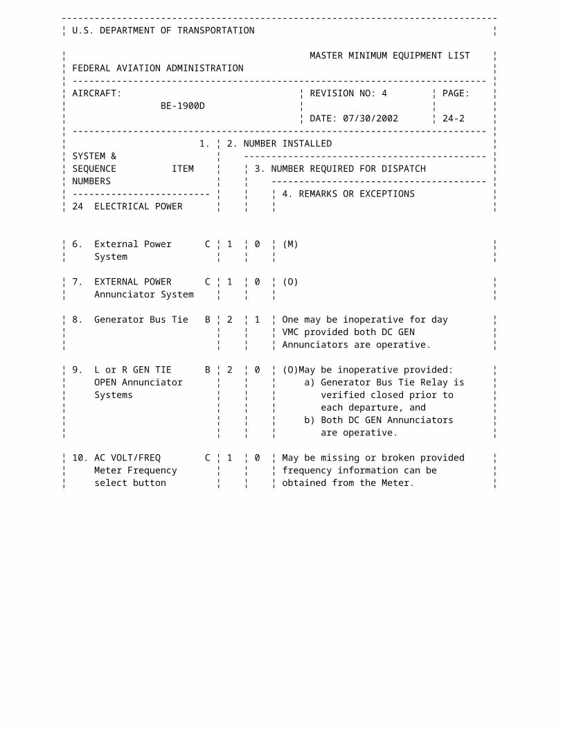
-------------------------------------------------------------------------------¦ U.S. DEPARTMENT OF TRANSPORTATION ¦ ¦ MASTER MINIMUM EQUIPMENT LIST ¦¦ FEDERAL AVIATION ADMINISTRATION ¦¦ --------------------------------------------------------------------------- ¦¦ AIRCRAFT: ¦ REVISION NO: 4 a ¦ PAGE: ¦¦ BE-1900D ¦ ¦ ¦¦ ¦ DATE: 10/04/2004 ¦ 28-5 ¦¦ --------------------------------------------------------------------------- ¦¦ 1. ¦ 2. NUMBER INSTALLED ¦¦ SYSTEM & ¦ -------------------------------------------- ¦¦ SEQUENCE ITEM ¦ ¦ 3. NUMBER REQUIRED FOR DISPATCH ¦¦ NUMBERS ¦ ¦ --------------------------------------- ¦¦ ------------------------- ¦ ¦ ¦ 4. REMARKS OR EXCEPTIONS ¦¦ 28 FUEL ¦ ¦ ¦ ¦ ¦ (CON'T.) ¦ ¦ ¦ ¦¦ 7. Fuel Quantity ¦ ¦ ¦ ¦¦ Indicating System ¦ ¦ ¦ ¦ ¦ 2) AUX Fuel Tank C ¦ 2 ¦ 0 ¦ (O)May be inoperative provided: ¦¦ Indications ¦ ¦ ¦ a)A reliable means is ¦¦ ¦ ¦ ¦ established to determine ¦¦ ¦ ¦ ¦ that fuel quantity on board ¦¦ ¦ ¦ ¦ meets the regulatory ¦¦ ¦ ¦ ¦ requirements for the intended ¦¦ ¦ ¦ ¦ flight, ¦¦ ¦ ¦ ¦ b)FUEL TRANSFER Annunciator ¦¦ ¦ ¦ ¦ System is operative, and ¦¦ ¦ ¦ ¦ c)Procedures are established ¦¦ ¦ ¦ ¦ to ensure fuel balance ¦¦ ¦ ¦ ¦ remains within AFM limits. ¦ -------------------------------------------------------------------------------

-------------------------------------------------------------------------------¦ U.S. DEPARTMENT OF TRANSPORTATION ¦ ¦ MASTER MINIMUM EQUIPMENT LIST ¦¦ FEDERAL AVIATION ADMINISTRATION ¦¦ --------------------------------------------------------------------------- ¦¦ AIRCRAFT: ¦ REVISION NO: 4 a ¦ PAGE: ¦¦ BE-1900D ¦ ¦ ¦¦ ¦ DATE: 10/04/2004 ¦ 30-1 ¦¦ --------------------------------------------------------------------------- ¦¦ 1. ¦ 2. NUMBER INSTALLED ¦¦ SYSTEM & ¦ -------------------------------------------- ¦¦ SEQUENCE ITEM ¦ ¦ 3. NUMBER REQUIRED FOR DISPATCH ¦¦ NUMBERS ¦ ¦ --------------------------------------- ¦¦ ------------------------- ¦ ¦ ¦ 4. REMARKS OR EXCEPTIONS ¦¦ 30 ICE AND RAIN ¦ ¦ ¦ ¦¦ PROTECTION ¦ ¦ ¦ ¦ ¦ 1. Surface De-Ice C ¦ 1 ¦ 0 ¦ May be inoperative provided ¦¦ System ¦ ¦ ¦ aircraft is not operated in known ¦¦ ¦ ¦ ¦ or forecast icing conditions. ¦ ¦ 1) OUTBD WG DEICE C ¦ 1 ¦ 0 ¦ May be inoperative provided boot ¦¦ Annunciator ¦ ¦ ¦ operation is normal and is visually ¦¦ ¦ ¦ ¦ monitored. ¦ ¦ 2) INBD WG DEICE C ¦ 1 ¦ 0 ¦ May be inoperative for two pilot ¦¦ Annunciator ¦ ¦ ¦ day operations provided boot ¦¦ ¦ ¦ ¦ operation is normal and visually ¦¦ ¦ ¦ ¦ monitored. ¦ ¦ 2. Engine Inertial C ¦ 4 ¦ 2 ¦ (O)One actuator motor of each ¦¦ Ice Vane Actuator ¦ ¦ ¦ intake system may be inoperative ¦¦ Motors ¦ ¦ ¦ provided aircraft is not operated ¦¦ ¦ ¦ ¦ in visible moisture below 5 degrees ¦¦ ¦ ¦ ¦ Celsius ¦ ¦ C ¦ 4 ¦ 2 ¦ (O)One actuator motor of each ¦¦ ¦ ¦ ¦ intake system may be inoperative ¦¦ ¦ ¦ ¦ provided: ¦¦ ¦ ¦ ¦ a) Inertial ice vanes are in ¦¦ ¦ ¦ ¦ the extended position, and ¦¦ ¦ ¦ ¦ b) Appropriate ENGINE ANTI-ICE ¦¦ ¦ ¦ ¦ ON performance data is used. ¦ ¦ C ¦ 4 ¦ 0 ¦ (M)Both actuator motors of each ¦¦ ¦ ¦ ¦ intake system may be inoperative ¦¦ ¦ ¦ ¦ on one or both engines provided: ¦¦ ¦ ¦ ¦ a) Inertial ice vanes are ¦¦ ¦ ¦ ¦ secured in the extended ¦¦ ¦ ¦ ¦ position, and ¦¦ ¦ ¦ ¦ b) Appropriate ENGINE ANTI-ICE ¦¦ ¦ ¦ ¦ ON performance data is used. ¦ ¦ 3. Alternate Static C ¦ 1 ¦ 0 ¦ May be inoperative provided ¦¦ Air Source Heater ¦ ¦ ¦ aircraft is not operated in known ¦¦ ¦ ¦ ¦ or forecast icing conditions. ¦ -------------------------------------------------------------------------------

-------------------------------------------------------------------------------¦ U.S. DEPARTMENT OF TRANSPORTATION ¦ ¦ MASTER MINIMUM EQUIPMENT LIST ¦¦ FEDERAL AVIATION ADMINISTRATION ¦¦ --------------------------------------------------------------------------- ¦¦ AIRCRAFT: ¦ REVISION NO: 4 a ¦ PAGE: ¦¦ BE-1900D ¦ ¦ ¦¦ ¦ DATE: 10/04/2004 ¦ 30-2 ¦¦ --------------------------------------------------------------------------- ¦¦ 1. ¦ 2. NUMBER INSTALLED ¦¦ SYSTEM & ¦ -------------------------------------------- ¦¦ SEQUENCE ITEM ¦ ¦ 3. NUMBER REQUIRED FOR DISPATCH ¦¦ NUMBERS ¦ ¦ --------------------------------------- ¦¦ ------------------------- ¦ ¦ ¦ 4. REMARKS OR EXCEPTIONS ¦¦ 30 ICE AND RAIN ¦ ¦ ¦ ¦¦ PROTECTION ¦ ¦ ¦ ¦ ¦ 4. Engine Ice ¦ ¦ ¦ ¦¦ Annunciators ¦ ¦ ¦ ¦ ¦ 1) L and R ENG C ¦ 2 ¦ 1 ¦ (O)May be inoperative on one or ¦¦ ANTI-ICE ¦ ¦ ¦ both sides provided ENG ICE FAIL ¦¦ Annunciators ¦ ¦ ¦ annunciator is operative on ¦¦ ¦ ¦ ¦ the affected side. ¦ ¦ C ¦ 2 ¦ 0 ¦ (M)May be inoperative on one or ¦¦ ¦ ¦ ¦ both sides provided: ¦¦ ¦ ¦ ¦ a)Inertial Ice Vanes are secured ¦¦ ¦ ¦ ¦ in the extended position, and ¦¦ ¦ ¦ ¦ b)Appropriate ENGINE ANTI-ICE ¦¦ ¦ ¦ ¦ ON performance data is used. ¦ ¦ 2) L and R ENG ICE C ¦ 2 ¦ 0 ¦ (M)May be inoperative on one or ¦¦ FAIL ¦ ¦ ¦ both sides provided: ¦¦ Annunciators ¦ ¦ ¦ a) Inertial Ice Vanes are ¦¦ ¦ ¦ ¦ secured in the extended ¦¦ ¦ ¦ ¦ position, and ¦¦ ¦ ¦ ¦ b) Appropriate ENGINE ANTI-ICE ¦¦ ¦ ¦ ¦ ON performance data is used. ¦ ¦ 5. Stall Warning Vane C ¦ 1 ¦ 0 ¦ May be inoperative provided ¦¦ and Mount Plate ¦ ¦ ¦ aircraft is not operated in known ¦¦ Heater System ¦ ¦ ¦ or forecast icing conditions. ¦ ¦ 6. Windshield Wipers C ¦ 2 ¦ 0 ¦ May be inoperative provided ¦¦ ¦ ¦ ¦ aircraft is not operated in ¦¦ ¦ ¦ ¦ precipitation within 5 nautical ¦¦ ¦ ¦ ¦ miles of the airport of takeoff or ¦¦ ¦ ¦ ¦ intended landing. ¦ ¦ 7. Windshield Heaters C ¦ 2 ¦ 0 ¦ May be inoperative provided ¦¦ ¦ ¦ ¦ aircraft is not operated in known ¦¦ ¦ ¦ ¦ or forecast icing conditions. ¦ ¦ 8. Propeller Deicer C ¦ 1 ¦ 0 ¦ May be inoperative provided ¦¦ Ammeter ¦ ¦ ¦ aircraft is not operated in known ¦¦ ¦ ¦ ¦ or forecast icing conditions. ¦-------------------------------------------------------------------------------

-------------------------------------------------------------------------------¦ U.S. DEPARTMENT OF TRANSPORTATION ¦ ¦ MASTER MINIMUM EQUIPMENT LIST ¦¦ FEDERAL AVIATION ADMINISTRATION ¦¦ --------------------------------------------------------------------------- ¦¦ AIRCRAFT: ¦ REVISION NO: 4 a ¦ PAGE: ¦¦ BE-1900D ¦ ¦ ¦¦ ¦ DATE: 10/04/2004 ¦ 30-3 ¦¦ --------------------------------------------------------------------------- ¦¦ 1. ¦ 2. NUMBER INSTALLED ¦¦ SYSTEM & ¦ -------------------------------------------- ¦¦ SEQUENCE ITEM ¦ ¦ 3. NUMBER REQUIRED FOR DISPATCH ¦¦ NUMBERS ¦ ¦ --------------------------------------- ¦¦ ------------------------- ¦ ¦ ¦ 4. REMARKS OR EXCEPTIONS ¦¦ 30 ICE AND RAIN ¦ ¦ ¦ ¦¦ PROTECTION ¦ ¦ ¦ ¦ ¦ 9. Propeller Deice C ¦ 1 ¦ 0 ¦ May be inoperative provided ¦¦ System ¦ ¦ ¦ aircraft is not operated in known ¦¦ ¦ ¦ ¦ or forecast icing conditions. ¦ ¦ 1) Automatic C ¦ 1 ¦ 0 ¦ May be inoperative provided the ¦¦ Function ¦ ¦ ¦ Manual Function is operative. ¦ ¦ 2) Manual C ¦ 1 ¦ 0 ¦ May be inoperative provided the ¦¦ Function ¦ ¦ ¦ Automatic Function is operative. ¦ ¦ 10. Propeller Deice ¦ ¦ ¦ DELETED Combined with ATA 30-9 ¦¦ Systems (Manual) ¦ ¦ ¦ ¦ ¦ 11. Fuel Vent Heaters C ¦ 2 ¦ 0 ¦ May be inoperative provided ¦¦ ¦ ¦ ¦ aircraft is not operated in known ¦¦ ¦ ¦ ¦ or forecast icing conditions. ¦ ¦ 12. Brake Deice System C ¦ 1 ¦ 0 ¦ (M)May be inoperative provided ¦¦ *** ¦ ¦ ¦ shutoff valves are in OFF position. ¦ ¦ 13. Pitot Heater B ¦ 2 ¦ 1 ¦ One may be inoperative provided: ¦¦ ¦ ¦ ¦ a) IFR passenger carrying ¦¦ ¦ ¦ ¦ operations are not ¦¦ ¦ ¦ ¦ conducted and ¦¦ ¦ ¦ ¦ b) Aircraft is not operated in ¦¦ ¦ ¦ ¦ known or forecast icing ¦¦ ¦ ¦ ¦ conditions. ¦ ¦ 14. STALL HEAT C ¦ 1 ¦ 0 ¦ May be inoperative provided ¦¦ Annunciator ¦ ¦ ¦ aircraft is not operated in known ¦¦ ¦ ¦ ¦ or forecast icing conditions. ¦ -------------------------------------------------------------------------------

-------------------------------------------------------------------------------¦ U.S. DEPARTMENT OF TRANSPORTATION ¦ ¦ MASTER MINIMUM EQUIPMENT LIST ¦¦ FEDERAL AVIATION ADMINISTRATION ¦¦ --------------------------------------------------------------------------- ¦¦ AIRCRAFT: ¦ REVISION NO: 4 a ¦ PAGE: ¦¦ BE-1900D ¦ ¦ ¦¦ ¦ DATE: 10/04/2004 ¦ 30-4 ¦¦ --------------------------------------------------------------------------- ¦¦ 1. ¦ 2. NUMBER INSTALLED ¦¦ SYSTEM & ¦ -------------------------------------------- ¦¦ SEQUENCE ITEM ¦ ¦ 3. NUMBER REQUIRED FOR DISPATCH ¦¦ NUMBERS ¦ ¦ --------------------------------------- ¦¦ ------------------------- ¦ ¦ ¦ 4. REMARKS OR EXCEPTIONS ¦¦ 30 ICE AND RAIN ¦ ¦ ¦ ¦¦ PROTECTION ¦ ¦ ¦ ¦ ¦ 15. L and R PITOT ¦ ¦ ¦ ¦¦ HEAT Annunciators ¦ ¦ ¦ ¦ ¦ 1)FAR 121 B ¦ 2 ¦ 0 ¦ May be inoperative provided: ¦¦ Operations ¦ ¦ ¦ a)Both pitot heaters are ¦¦ ¦ ¦ ¦ operative, and ¦¦ ¦ ¦ ¦ b)The aircraft is not operated ¦¦ ¦ ¦ ¦ in known or forecast icing ¦¦ ¦ ¦ ¦ conditions. ¦ ¦ 2)Other operations C ¦ 2 ¦ 0 ¦ May be inoperative provided: ¦¦ ¦ ¦ ¦ a)Both pitot heaters are ¦¦ ¦ ¦ ¦ operative, and ¦¦ ¦ ¦ ¦ b)The aircraft is not operated ¦¦ ¦ ¦ ¦ in known or forecast icing ¦¦ ¦ ¦ ¦ conditions. ¦ -------------------------------------------------------------------------------

-------------------------------------------------------------------------------¦ U.S. DEPARTMENT OF TRANSPORTATION ¦ ¦ MASTER MINIMUM EQUIPMENT LIST ¦¦ FEDERAL AVIATION ADMINISTRATION ¦¦ --------------------------------------------------------------------------- ¦¦ AIRCRAFT: ¦ REVISION NO: 4 a ¦ PAGE: ¦¦ BE-1900D ¦ ¦ ¦¦ ¦ DATE: 10/04/2004 ¦ 31-1 ¦¦ --------------------------------------------------------------------------- ¦¦ 1. ¦ 2. NUMBER INSTALLED ¦¦ SYSTEM & ¦ -------------------------------------------- ¦¦ SEQUENCE ITEM ¦ ¦ 3. NUMBER REQUIRED FOR DISPATCH ¦¦ NUMBERS ¦ ¦ --------------------------------------- ¦¦ ------------------------- ¦ ¦ ¦ 4. REMARKS OR EXCEPTIONS ¦¦ 31 INDICATING/RECORDING ¦ ¦ ¦ ¦¦ SYSTEMS ¦ ¦ ¦ ¦ ¦ 1. Clock with D ¦ - ¦ 0 ¦ As required by FAR. ¦¦ presentation of ¦ ¦ ¦ ¦¦ seconds ¦ ¦ ¦ ¦ ¦ 2. Flight Hour D ¦ 1 ¦ 0 ¦ (O) ¦¦ Recorder ¦ ¦ ¦ ¦¦ *** ¦ ¦ ¦ ¦ ¦ 3. Flight Data C ¦ - ¦ - ¦ Any in excess of those required by ¦¦ *** Recorder (FDR) ¦ ¦ ¦ FAR may be inoperative. ¦ ¦ A ¦ - ¦ 0 ¦ May be inoperative provided: ¦¦ ¦ ¦ ¦ a) Cockpit Voice Recorder (CVR) ¦¦ ¦ ¦ ¦ operates normally, ¦¦ ¦ ¦ ¦ b) Airplane is not dispatched ¦¦ ¦ ¦ ¦ from a designated airport ¦¦ ¦ ¦ ¦ as listed in the operators ¦¦ ¦ ¦ ¦ MEL unless: ¦¦ ¦ ¦ ¦ 1. The FDR failure occurs ¦¦ ¦ ¦ ¦ after pushback but prior ¦¦ ¦ ¦ ¦ to takeoff, or ¦¦ ¦ ¦ ¦ 2. The FDR repair was ¦¦ ¦ ¦ ¦ attempted but was not ¦¦ ¦ ¦ ¦ successful. ¦¦ ¦ ¦ ¦ c) In those cases where repair ¦¦ ¦ ¦ ¦ is attempted but not ¦¦ ¦ ¦ ¦ successful, the aircraft may ¦¦ ¦ ¦ ¦ be dispatched on a flight or ¦¦ ¦ ¦ ¦ series of flights until the ¦¦ ¦ ¦ ¦ next designated airport ¦¦ ¦ ¦ ¦ where repair(s) must be ¦¦ ¦ ¦ ¦ accomplished prior to ¦¦ ¦ ¦ ¦ dispatch, and ¦¦ ¦ ¦ ¦ d) Repairs are made within ¦¦ ¦ ¦ ¦ three flight days. ¦ ¦ (CON'T.) ¦ ¦ ¦ ¦-------------------------------------------------------------------------------

-------------------------------------------------------------------------------¦ U.S. DEPARTMENT OF TRANSPORTATION ¦ ¦ MASTER MINIMUM EQUIPMENT LIST ¦¦ FEDERAL AVIATION ADMINISTRATION ¦¦ --------------------------------------------------------------------------- ¦¦ AIRCRAFT: ¦ REVISION NO: 4 a ¦ PAGE: ¦¦ BE-1900D ¦ ¦ ¦¦ ¦ DATE: 10/04/2004 ¦ 31-2 ¦¦ --------------------------------------------------------------------------- ¦¦ 1. ¦ 2. NUMBER INSTALLED ¦¦ SYSTEM & ¦ -------------------------------------------- ¦¦ SEQUENCE ITEM ¦ ¦ 3. NUMBER REQUIRED FOR DISPATCH ¦¦ NUMBERS ¦ ¦ --------------------------------------- ¦¦ ------------------------- ¦ ¦ ¦ 4. REMARKS OR EXCEPTIONS ¦¦ 31 INDICATING/RECORDING ¦ ¦ ¦ ¦¦ SYSTEMS ¦ ¦ ¦ ¦ ¦ 3. Flight Data ¦ ¦ ¦ ¦¦ *** Recorder (FDR) ¦ ¦ ¦ ¦¦ (CON'T.) ¦ ¦ ¦ ¦ ¦ 1) FDR Recording A ¦ - ¦ - ¦ May be inoperative provided: ¦¦ Parameters ¦ ¦ ¦ a) Cockpit Voice Recorder (CVR) ¦¦ required by FAR ¦ ¦ ¦ operates normally, and ¦¦ ¦ ¦ ¦ b) Repairs are made within 20 ¦¦ ¦ ¦ ¦ calendar days. ¦ ¦ 2) FDR Recording A ¦ - ¦ - ¦ May be inoperative provided repairs ¦¦ Parameters not ¦ ¦ ¦ are made prior to the completion of ¦¦ required by FAR ¦ ¦ ¦ the next heavy maintenance visit. ¦ ¦ 4. RDR PWR ON ¦ ¦ ¦ DELETED Revision 2. Combined with ¦¦ Annunciator System ¦ ¦ ¦ Radar Equipment in ATA 34. ¦ -------------------------------------------------------------------------------

-------------------------------------------------------------------------------¦ U.S. DEPARTMENT OF TRANSPORTATION ¦ ¦ MASTER MINIMUM EQUIPMENT LIST ¦¦ FEDERAL AVIATION ADMINISTRATION ¦¦ --------------------------------------------------------------------------- ¦¦ AIRCRAFT: ¦ REVISION NO: 4 a ¦ PAGE: ¦¦ BE-1900D ¦ ¦ ¦¦ ¦ DATE: 10/04/2004 ¦ 31-3 ¦¦ --------------------------------------------------------------------------- ¦¦ 1. ¦ 2. NUMBER INSTALLED ¦¦ SYSTEM & ¦ -------------------------------------------- ¦¦ SEQUENCE ITEM ¦ ¦ 3. NUMBER REQUIRED FOR DISPATCH ¦¦ NUMBERS ¦ ¦ --------------------------------------- ¦¦ ------------------------- ¦ ¦ ¦ 4. REMARKS OR EXCEPTIONS ¦¦ 31 INDICATING/RECORDING ¦ ¦ ¦ ¦¦ SYSTEMS ¦ ¦ ¦ ¦ ¦ 5. Annunciator Power C ¦ 1 ¦ 0 ¦ (O) May be illuminated provided: ¦¦ Source Annunciator ¦ ¦ ¦ a) Preflight procedures are ¦¦ ¦ ¦ ¦ conducted to check operation ¦¦ ¦ ¦ ¦ of individual annunciation ¦¦ ¦ ¦ ¦ circuits in accordance with ¦¦ ¦ ¦ ¦ Beech Minimum Equipment ¦¦ ¦ ¦ ¦ Procedures (P/N 98-30472 as ¦¦ ¦ ¦ ¦ amended), ¦¦ ¦ ¦ ¦ b) MEL relief is approved and ¦¦ ¦ ¦ ¦ applicable procedures and ¦¦ ¦ ¦ ¦ restrictions observed for ¦¦ ¦ ¦ ¦ all annunciator circuits ¦¦ ¦ ¦ ¦ found to be inoperative, and ¦¦ ¦ ¦ ¦ c) Flight is limited to at or ¦¦ ¦ ¦ ¦ below 10,000 feet MSL or ¦¦ ¦ ¦ ¦ d) Flight above 10,000 feet MSL ¦¦ ¦ ¦ ¦ up to and including 12,000 ¦¦ ¦ ¦ ¦ feet MSL is limited to not ¦¦ ¦ ¦ ¦ more than 30 minutes. ¦ ¦ 6. Unassigned (----) D ¦ - ¦ 0 ¦ ¦¦ Annunciators ¦ ¦ ¦ ¦ ¦ 7. Master Caution C ¦ 2 ¦ 1 ¦ One may be inoperative provided ¦¦ Annunciator ¦ ¦ ¦ left side is operative for single ¦¦ ¦ ¦ ¦ pilot operations. ¦ ¦ 8. Master Warning A ¦ 2 ¦ 1 ¦ One may be inoperative provided: ¦¦ Annunciator ¦ ¦ ¦ a) Left side is operative for ¦¦ ¦ ¦ ¦ single pilot operations, and ¦¦ ¦ ¦ ¦ b) Repairs are made within one ¦¦ ¦ ¦ ¦ flight day. ¦ ¦ 9. EFIS Display D ¦ 2 ¦ 0 ¦ ¦¦ Timer ¦ ¦ ¦ ¦ -------------------------------------------------------------------------------

-------------------------------------------------------------------------------¦ U.S. DEPARTMENT OF TRANSPORTATION ¦ ¦ MASTER MINIMUM EQUIPMENT LIST ¦¦ FEDERAL AVIATION ADMINISTRATION ¦¦ --------------------------------------------------------------------------- ¦¦ AIRCRAFT: ¦ REVISION NO: 4 a ¦ PAGE: ¦¦ BE-1900D ¦ ¦ ¦¦ ¦ DATE: 10/04/2004 ¦ 31-4 ¦¦ --------------------------------------------------------------------------- ¦¦ 1. ¦ 2. NUMBER INSTALLED ¦¦ SYSTEM & ¦ -------------------------------------------- ¦¦ SEQUENCE ITEM ¦ ¦ 3. NUMBER REQUIRED FOR DISPATCH ¦¦ NUMBERS ¦ ¦ --------------------------------------- ¦¦ ------------------------- ¦ ¦ ¦ 4. REMARKS OR EXCEPTIONS ¦¦ 31 INDICATING/RECORDING ¦ ¦ ¦ ¦¦ SYSTEMS ¦ ¦ ¦ ¦ ¦ 10. Aircraft Data D ¦ - ¦ 0 ¦ ¦¦ *** Acquisition System ¦ ¦ ¦ ¦¦ (Installed per ¦ ¦ ¦ ¦¦ STC SA00095BO) ¦ ¦ ¦ ¦ ¦ 11. Electronic D ¦ 1 ¦ 0 ¦ (M)(O)May be inoperative. ¦¦ Aircraft Tracking ¦ ¦ ¦ ¦¦ System ¦ ¦ ¦ ¦ -------------------------------------------------------------------------------

-------------------------------------------------------------------------------¦ U.S. DEPARTMENT OF TRANSPORTATION ¦ ¦ MASTER MINIMUM EQUIPMENT LIST ¦¦ FEDERAL AVIATION ADMINISTRATION ¦¦ --------------------------------------------------------------------------- ¦¦ AIRCRAFT: ¦ REVISION NO: 4 ¦ PAGE: ¦¦ BE-1900D ¦ ¦ ¦¦ ¦ DATE: 07/30/2002 ¦ 32-1 ¦¦ --------------------------------------------------------------------------- ¦¦ 1. ¦ 2. NUMBER INSTALLED ¦¦ SYSTEM & ¦ -------------------------------------------- ¦¦ SEQUENCE ITEM ¦ ¦ 3. NUMBER REQUIRED FOR DISPATCH ¦¦ NUMBERS ¦ ¦ --------------------------------------- ¦¦ ------------------------- ¦ ¦ ¦ 4. REMARKS OR EXCEPTIONS ¦¦ 32 LANDING GEAR ¦ ¦ ¦ ¦ ¦ 1. Power Steering C ¦ 1 ¦ 0 ¦ (M) May be inoperative provided AFM ¦¦ System ¦ ¦ ¦ procedures are observed. ¦¦ *** ¦ ¦ ¦ ¦ ¦ 2. PWR STEER FAIL C ¦ 1 ¦ 0 ¦ May be inoperative provided power ¦¦ Annunciator System ¦ ¦ ¦ steering remains off. ¦¦ *** ¦ ¦ ¦ ¦ ¦ 3. MAN STEER FAIL C ¦ 1 ¦ 0 ¦ (O)(M) May be inoperative provided: ¦¦ Annunciator System ¦ ¦ ¦ a) Power steering is disabled, ¦¦ *** ¦ ¦ ¦ and ¦¦ ¦ ¦ ¦ b) Nose gear must be in free ¦¦ ¦ ¦ ¦ caster mode. (See item 1) ¦ ¦ 4. Manual Steering C ¦ 1 ¦ 0 ¦ (O)(M) ¦¦ Disconnect Actuator ¦ ¦ ¦ ¦¦ *** ¦ ¦ ¦ ¦ ¦ 5. HYD FLUID LOW B ¦ 1 ¦ 0 ¦ (O)(M) ¦¦ Annunciator ¦ ¦ ¦ ¦¦ System ¦ ¦ ¦ ¦ ¦ 6. Anti-skid System C ¦ 1 ¦ 0 ¦ May be inoperative provided: ¦¦ *** ¦ ¦ ¦ a) The OFF-ON switch remains ¦¦ ¦ ¦ ¦ in the Off position, and ¦¦ ¦ ¦ ¦ b) AFM performance charts for ¦¦ ¦ ¦ ¦ operation without ¦¦ ¦ ¦ ¦ anti-skid are used. ¦ ¦ 7. Parking Brake C ¦ 1 ¦ 0 ¦ (O) ¦ ¦ 8. Landing Gear C ¦ 1 ¦ 0 ¦ (O) May be inoperative provided ¦¦ Handle Solenoid ¦ ¦ ¦ down lock latch is operative. ¦ ¦ 9. Auxiliary Landing D ¦ 1 ¦ 0 ¦ May be inoperative provided Landing ¦¦ *** Gear Position ¦ ¦ ¦ Gear Position Indicator System is ¦¦ Indicator System ¦ ¦ ¦ operative. ¦¦ (STC SA00873CH) ¦ ¦ ¦ ¦ -------------------------------------------------------------------------------

-------------------------------------------------------------------------------¦ U.S. DEPARTMENT OF TRANSPORTATION ¦ ¦ MASTER MINIMUM EQUIPMENT LIST ¦¦ FEDERAL AVIATION ADMINISTRATION ¦¦ --------------------------------------------------------------------------- ¦¦ AIRCRAFT: ¦ REVISION NO: 4 ¦ PAGE: ¦¦ BE-1900D ¦ ¦ ¦¦ ¦ DATE: 07/30/2002 ¦ 32-2 ¦¦ --------------------------------------------------------------------------- ¦¦ 1. ¦ 2. NUMBER INSTALLED ¦¦ SYSTEM & ¦ -------------------------------------------- ¦¦ SEQUENCE ITEM ¦ ¦ 3. NUMBER REQUIRED FOR DISPATCH ¦¦ NUMBERS ¦ ¦ --------------------------------------- ¦¦ ------------------------- ¦ ¦ ¦ 4. REMARKS OR EXCEPTIONS ¦¦ 32 LANDING GEAR ¦ ¦ ¦ ¦ ¦ 10. Landing Gear B ¦ 2 ¦ 1 ¦ ¦¦ Handle "Intransit" ¦ ¦ ¦ ¦¦ (Red) Lamps ¦ ¦ ¦ ¦ ¦ 11. Landing Gear C ¦ 1 ¦ 0 ¦ May be inoperative provided: ¦¦ Position Indicator ¦ ¦ ¦ a) Auxiliary Landing Gear ¦¦ System ¦ ¦ ¦ Position Indicator System ¦¦ ¦ ¦ ¦ STC SA00873CH is installed ¦¦ ¦ ¦ ¦ and operative, and ¦¦ ¦ ¦ ¦ b) All Auxiliary Landing Gear ¦¦ ¦ ¦ ¦ Position Indicators are ¦¦ ¦ ¦ ¦ operative including the "EL" ¦¦ ¦ ¦ ¦ (electroluminescent) panel. ¦ ¦ 1)Landing Gear A ¦ - ¦ - ¦ One lamp in each indicator may be ¦¦ Position Indicator ¦ ¦ ¦ inoperative provided: ¦¦ Lamps. ¦ ¦ ¦ a) One lamp in each indicator ¦¦ ¦ ¦ ¦ is operative and provides ¦¦ ¦ ¦ ¦ sufficient illumination for ¦¦ ¦ ¦ ¦ positive down and lock ¦¦ ¦ ¦ ¦ indication, and ¦¦ ¦ ¦ ¦ b) Repairs are made within one ¦¦ ¦ ¦ ¦ flight day. ¦ -------------------------------------------------------------------------------

-------------------------------------------------------------------------------¦ U.S. DEPARTMENT OF TRANSPORTATION ¦ ¦ MASTER MINIMUM EQUIPMENT LIST ¦¦ FEDERAL AVIATION ADMINISTRATION ¦¦ --------------------------------------------------------------------------- ¦¦ AIRCRAFT: ¦ REVISION NO: 4 a ¦ PAGE: ¦¦ BE-1900D ¦ ¦ ¦¦ ¦ DATE: 10/04/2004 ¦ 33-1 ¦¦ --------------------------------------------------------------------------- ¦¦ 1. ¦ 2. NUMBER INSTALLED ¦¦ SYSTEM & ¦ -------------------------------------------- ¦¦ SEQUENCE ITEM ¦ ¦ 3. NUMBER REQUIRED FOR DISPATCH ¦¦ NUMBERS ¦ ¦ --------------------------------------- ¦¦ ------------------------- ¦ ¦ ¦ 4. REMARKS OR EXCEPTIONS ¦¦ 33 LIGHTS ¦ ¦ ¦ ¦ ¦ 1. Cabin Light C ¦ - ¦ - ¦ Individual lights may be ¦¦ Systems (Including ¦ ¦ ¦ inoperative provided lighting ¦¦ Reading Lights) ¦ ¦ ¦ configuration is acceptable to the ¦¦ ¦ ¦ ¦ flight crew. Any operative lights ¦¦ ¦ ¦ ¦ may be used. ¦ ¦ 2. Cockpit/ C ¦ - ¦ - ¦ Individual lights may be ¦¦ Flight Deck/ ¦ ¦ ¦ inoperative provided remaining ¦¦ Flight Compartment ¦ ¦ ¦ lights are: ¦¦ and Instrument ¦ ¦ ¦ a) Sufficient to clearly ¦¦ Lighting System ¦ ¦ ¦ illuminate all required ¦¦ ¦ ¦ ¦ instruments, controls, ¦¦ ¦ ¦ ¦ and other devices for which ¦¦ ¦ ¦ ¦ it is provided, ¦¦ ¦ ¦ ¦ b) Positioned so that direct ¦¦ ¦ ¦ ¦ rays are shielded from ¦¦ ¦ ¦ ¦ flight crewmembers eyes, and ¦¦ ¦ ¦ ¦ c) Lighting configuration and ¦¦ ¦ ¦ ¦ intensity is acceptable to ¦¦ ¦ ¦ ¦ the flight crew. ¦ ¦ 1) Standby Attitude C ¦ 1 ¦ 0 ¦ May be inoperative for day ¦¦ Indicator Internal ¦ ¦ ¦ operations. ¦¦ Illumination ¦ ¦ ¦ ¦¦ System ¦ ¦ ¦ ¦ ¦ 2) Pressurization D ¦ 1 ¦ 0 ¦ May be inoperative for day ¦¦ Controller ¦ ¦ ¦ operations. ¦¦ Internal ¦ ¦ ¦ ¦¦ Illumination D ¦ 1 ¦ 0 ¦ May be inoperative for night ¦¦ System ¦ ¦ ¦ operations provided adjacent post ¦¦ ¦ ¦ ¦ light is operative. ¦ ¦ 3) Emergency Light B ¦ 1 ¦ 0 ¦ (O)Red/Green switch position ¦¦ Switch Position ¦ ¦ ¦ indication may be inoperative ¦¦ (Red/Green) ¦ ¦ ¦ (stuck in either red or green ¦¦ Indication ¦ ¦ ¦ indication) provided switch ¦¦ ¦ ¦ ¦ function is verified operative ¦¦ ¦ ¦ ¦ before each flight at night. ¦ -------------------------------------------------------------------------------
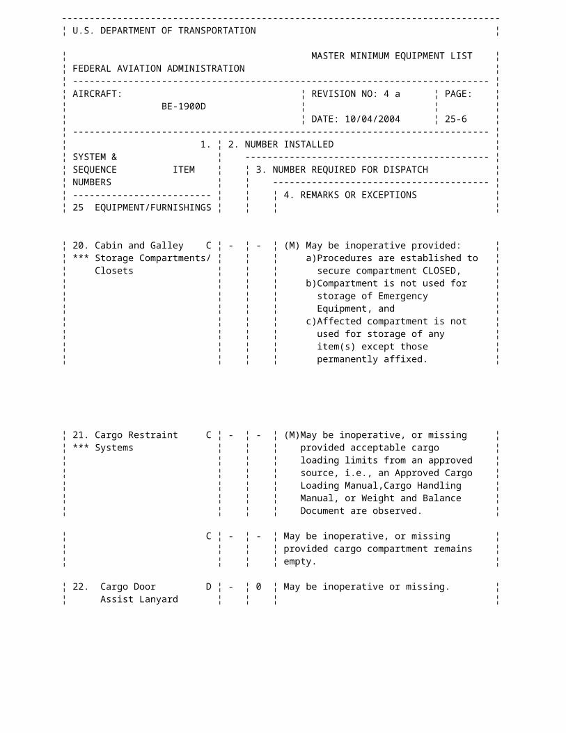
-------------------------------------------------------------------------------¦ U.S. DEPARTMENT OF TRANSPORTATION ¦ ¦ MASTER MINIMUM EQUIPMENT LIST ¦¦ FEDERAL AVIATION ADMINISTRATION ¦¦ --------------------------------------------------------------------------- ¦¦ AIRCRAFT: ¦ REVISION NO: 4 a ¦ PAGE: ¦¦ BE-1900D ¦ ¦ ¦¦ ¦ DATE: 10/04/2004 ¦ 33-2 ¦¦ --------------------------------------------------------------------------- ¦¦ 1. ¦ 2. NUMBER INSTALLED ¦¦ SYSTEM & ¦ -------------------------------------------- ¦¦ SEQUENCE ITEM ¦ ¦ 3. NUMBER REQUIRED FOR DISPATCH ¦¦ NUMBERS ¦ ¦ --------------------------------------- ¦¦ ------------------------- ¦ ¦ ¦ 4. REMARKS OR EXCEPTIONS ¦¦ 33 LIGHTS ¦ ¦ ¦ ¦ ¦ 3. Landing Lights C ¦ 2 ¦ 0 ¦ May be inoperative for day ¦¦ ¦ ¦ ¦ operations. ¦ ¦ C ¦ 2 ¦ 1 ¦ One may be inoperative for night ¦¦ ¦ ¦ ¦ operations provided taxi light is ¦¦ ¦ ¦ ¦ operative. ¦ ¦ 4. Standby Attitude ¦ ¦ ¦ DELETED Revision 1. Combined with ¦¦ *** Indicator Internal ¦ ¦ ¦ Cockpit Instrument Lighting System ¦¦ Illumination System ¦ ¦ ¦ ATA 33-2 ¦ ¦ 5. Navigation C ¦ 6 ¦ 0 ¦ May be inoperative for day ¦¦ Position Lights ¦ ¦ ¦ operations. ¦ ¦ C ¦ 6 ¦ 3 ¦ One may be inoperative at each ¦¦ ¦ ¦ ¦ location for night operations. ¦ ¦ 6. Anti-Collision B ¦ 1 ¦ 0 ¦ May be inoperative for day ¦¦ Beacon Light System ¦ ¦ ¦ operations. ¦ ¦ B ¦ 1 ¦ 0 ¦ May be inoperative for night ¦¦ ¦ ¦ ¦ operations provided Anti-Collision ¦¦ ¦ ¦ ¦ Strobe Light System is operative. ¦ ¦ 7. Anti-Collision D ¦ 1 ¦ 0 ¦ May be inoperative for day ¦¦ *** Strobe Light System ¦ ¦ ¦ operations. Any operative lights ¦¦ ¦ ¦ ¦ may be used. ¦ ¦ D ¦ 1 ¦ 0 ¦ May be inoperative for night ¦¦ ¦ ¦ ¦ operations provided Anti-Collision ¦¦ ¦ ¦ ¦ Beacon Light System is operative. ¦¦ ¦ ¦ ¦ Any operative lights may be used. ¦ ¦ 8. Taxi Light C ¦ 1 ¦ 0 ¦ May be inoperative for day ¦¦ ¦ ¦ ¦ operations. ¦ ¦ C ¦ 1 ¦ 0 ¦ May be inoperative for night ¦¦ ¦ ¦ ¦ operations provided both landing ¦¦ ¦ ¦ ¦ lights are operative. ¦ -------------------------------------------------------------------------------

-------------------------------------------------------------------------------¦ U.S. DEPARTMENT OF TRANSPORTATION ¦ ¦ MASTER MINIMUM EQUIPMENT LIST ¦¦ FEDERAL AVIATION ADMINISTRATION ¦¦ --------------------------------------------------------------------------- ¦¦ AIRCRAFT: ¦ REVISION NO: 4 a ¦ PAGE: ¦¦ BE-1900D ¦ ¦ ¦¦ ¦ DATE: 10/04/2004 ¦ 33-3 ¦¦ --------------------------------------------------------------------------- ¦¦ 1. ¦ 2. NUMBER INSTALLED ¦¦ SYSTEM & ¦ -------------------------------------------- ¦¦ SEQUENCE ITEM ¦ ¦ 3. NUMBER REQUIRED FOR DISPATCH ¦¦ NUMBERS ¦ ¦ --------------------------------------- ¦¦ ------------------------- ¦ ¦ ¦ 4. REMARKS OR EXCEPTIONS ¦¦ 33 LIGHTS ¦ ¦ ¦ ¦ ¦ 9. TAXI LIGHT C ¦ 1 ¦ 0 ¦ ¦¦ Annunciator ¦ ¦ ¦ ¦¦ System ¦ ¦ ¦ ¦ ¦ 10. Recognition Lights D ¦ 2 ¦ 0 ¦ ¦¦ *** ¦ ¦ ¦ ¦¦ 11. Tail Flood Lights D ¦ 2 ¦ 0 ¦ ¦¦ *** ¦ ¦ ¦ ¦ ¦ 12. Wing Ice Lights C ¦ 2 ¦ 0 ¦ May be inoperative except for ¦¦ ¦ ¦ ¦ flight into known or forecast icing ¦¦ ¦ ¦ ¦ conditions at night. ¦ ¦ 13. Master Caution ¦ ¦ ¦ DELETED Revision 1. Moved to ¦¦ Lights ¦ ¦ ¦ ATA section 31. ¦ ¦ 14. Cargo Compartment D ¦ 1 ¦ 0 ¦ Any operative light may be used. ¦¦ Lighting System ¦ ¦ ¦ ¦ ¦ 15. Boarding Lighting C ¦ 1 ¦ 0 ¦ Any operative light may be used. ¦¦ System (including ¦ ¦ ¦ ¦¦ lights within the ¦ ¦ ¦ ¦¦ airstair and in the ¦ ¦ ¦ ¦¦ entryway foyer) ¦ ¦ ¦ ¦ -------------------------------------------------------------------------------

-------------------------------------------------------------------------------¦ U.S. DEPARTMENT OF TRANSPORTATION ¦ ¦ MASTER MINIMUM EQUIPMENT LIST ¦¦ FEDERAL AVIATION ADMINISTRATION ¦¦ --------------------------------------------------------------------------- ¦¦ AIRCRAFT: ¦ REVISION NO: 4 a ¦ PAGE: ¦¦ BE-1900D ¦ ¦ ¦¦ ¦ DATE: 10/04/2004 ¦ 34-1 ¦¦ --------------------------------------------------------------------------- ¦¦ 1. ¦ 2. NUMBER INSTALLED ¦¦ SYSTEM & ¦ -------------------------------------------- ¦¦ SEQUENCE ITEM ¦ ¦ 3. NUMBER REQUIRED FOR DISPATCH ¦¦ NUMBERS ¦ ¦ --------------------------------------- ¦¦ ------------------------- ¦ ¦ ¦ 4. REMARKS OR EXCEPTIONS ¦¦ 34 NAVIGATION ¦ ¦ ¦ ¦ ¦ 1. Vertical Speed B ¦ 2 ¦ 1 ¦ As required by FAR. ¦¦ Indicators ¦ ¦ ¦ ¦¦ ¦ ¦ ¦ NOTE: Left side must be operative ¦¦ ¦ ¦ ¦ for single pilot IFR operations. ¦ ¦ 2. Weather Radar/ C ¦ - ¦ - ¦ As required by FAR. ¦¦ *** Thunderstorm ¦ ¦ ¦ ¦¦ Detection Equipment ¦ ¦ ¦ ¦ ¦ D ¦ - ¦ - ¦ Any in excess of those required by ¦¦ ¦ ¦ ¦ FAR may be inoperative. ¦ ¦ 1) Radar Antenna D ¦ 1 ¦ 0 ¦ May be inoperative provided: ¦¦ Gyro ¦ ¦ ¦ a) Antenna sweep function is ¦¦ Stabilization ¦ ¦ ¦ parallel to aircraft pitch ¦¦ Function ¦ ¦ ¦ axis, and ¦¦ ¦ ¦ ¦ b) Antenna tilt function ¦¦ ¦ ¦ ¦ operates normally. ¦ ¦ 2) RDR PWR ON C ¦ 1 ¦ 0 ¦ ¦¦ *** Annunciator ¦ ¦ ¦ ¦ ¦ 3. Gyroscopic B ¦ 2 ¦ 1 ¦ (O)One may be inoperative in ¦¦ Directional Compass ¦ ¦ ¦ slaved mode provided: ¦¦ System ¦ ¦ ¦ a) DG mode is operative, and ¦¦ ¦ ¦ ¦ b) Non-Stabilized Magnetic ¦¦ ¦ ¦ ¦ Compass is operative. ¦ -------------------------------------------------------------------------------
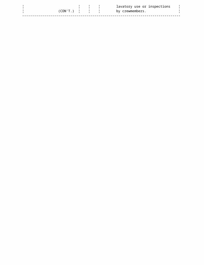
-------------------------------------------------------------------------------¦ U.S. DEPARTMENT OF TRANSPORTATION ¦ ¦ MASTER MINIMUM EQUIPMENT LIST ¦¦ FEDERAL AVIATION ADMINISTRATION ¦¦ --------------------------------------------------------------------------- ¦¦ AIRCRAFT: ¦ REVISION NO: 4 a ¦ PAGE: ¦¦ BE-1900D ¦ ¦ ¦¦ ¦ DATE: 10/04/2004 ¦ 34-2 ¦¦ --------------------------------------------------------------------------- ¦¦ 1. ¦ 2. NUMBER INSTALLED ¦¦ SYSTEM & ¦ -------------------------------------------- ¦¦ SEQUENCE ITEM ¦ ¦ 3. NUMBER REQUIRED FOR DISPATCH ¦¦ NUMBERS ¦ ¦ --------------------------------------- ¦¦ ------------------------- ¦ ¦ ¦ 4. REMARKS OR EXCEPTIONS ¦¦ 34 NAVIGATION ¦ ¦ ¦ ¦ ¦ 4. Non-Stabilized B ¦ 1 ¦ 0 ¦ May be inoperative provided any ¦¦ Magnetic Compass ¦ ¦ ¦ combination of three gyro or INS ¦¦ ¦ ¦ ¦ (IRU) stabilized compass systems ¦¦ ¦ ¦ ¦ are operative. ¦ ¦ B ¦ 1 ¦ 0 ¦ May be inoperative provided: ¦¦ ¦ ¦ ¦ a) Any combination of two ¦¦ ¦ ¦ ¦ stabilized gyro or INS ¦¦ ¦ ¦ ¦ stabilized compass systems ¦¦ ¦ ¦ ¦ are operative, and ¦¦ ¦ ¦ ¦ b) Aircraft is operated with ¦¦ ¦ ¦ ¦ dual independent navigation ¦¦ ¦ ¦ ¦ capability and under ¦¦ ¦ ¦ ¦ positive radar control by ¦¦ ¦ ¦ ¦ ATC on the enroute portion ¦¦ ¦ ¦ ¦ of the flight. ¦ ¦ B ¦ 1 ¦ 0 ¦ May be inoperative for flights ¦¦ ¦ ¦ ¦ that are entirely within areas ¦¦ ¦ ¦ ¦ of magnetic unreliability provided ¦¦ ¦ ¦ ¦ at least two stabilized directional ¦¦ ¦ ¦ ¦ gyro systems are installed, ¦¦ ¦ ¦ ¦ operative, and used in conjunction ¦¦ ¦ ¦ ¦ with approved free gyro navigation ¦¦ ¦ ¦ ¦ techniques. ¦ ¦ 5. Navigation D ¦ - ¦ - ¦ Any in excess of those required by ¦¦ Equipment (VOR/ILS, ¦ ¦ ¦ FAR may be inoperative. ¦¦ Loran, RNAV, INS, GPS ¦ ¦ ¦ ¦¦ Omega/VLF, Doppler, ¦ ¦ ¦ ¦¦ FMS, MLS, TACAN) ¦ ¦ ¦ ¦ -------------------------------------------------------------------------------

-------------------------------------------------------------------------------¦ U.S. DEPARTMENT OF TRANSPORTATION ¦ ¦ MASTER MINIMUM EQUIPMENT LIST ¦¦ FEDERAL AVIATION ADMINISTRATION ¦¦ --------------------------------------------------------------------------- ¦¦ AIRCRAFT: ¦ REVISION NO: 4 a ¦ PAGE: ¦¦ BE-1900D ¦ ¦ ¦¦ ¦ DATE: 10/04/2004 ¦ 34-3 ¦¦ --------------------------------------------------------------------------- ¦¦ 1. ¦ 2. NUMBER INSTALLED ¦¦ SYSTEM & ¦ -------------------------------------------- ¦¦ SEQUENCE ITEM ¦ ¦ 3. NUMBER REQUIRED FOR DISPATCH ¦¦ NUMBERS ¦ ¦ --------------------------------------- ¦¦ ------------------------- ¦ ¦ ¦ 4. REMARKS OR EXCEPTIONS ¦¦ 34 NAVIGATION ¦ ¦ ¦ ¦ ¦ 6. ATC Transponders C ¦ - ¦ 0 ¦ May be inoperative provided: ¦¦ and Automatic ¦ ¦ ¦ a) Enroute operations do not ¦¦ Altitude Reporting ¦ ¦ ¦ require its use, and ¦¦ Systems ¦ ¦ ¦ b) Prior to flight, approval is ¦¦ ¦ ¦ ¦ obtained from ATC facilities ¦¦ ¦ ¦ ¦ having jurisdiction over the ¦¦ ¦ ¦ ¦ planned route of flight. ¦ ¦ D ¦ - ¦ 1 ¦ Any in excess of those required by ¦¦ ¦ ¦ ¦ FAR may be inoperative. ¦ ¦ 7. Marker Beacon D ¦ - ¦ - ¦ Any in excess of those required by ¦¦ ¦ ¦ ¦ FAR may be inoperative. ¦ ¦ 8. Altitude Encoder ¦ ¦ ¦ DELETED Combined with ATA 34-6. ¦ ¦ 9. Distance D ¦ - ¦ - ¦ Any in excess of those required by ¦¦ Measuring Equipment ¦ ¦ ¦ FAR may be inoperative. ¦¦ (DME) Systems ¦ ¦ ¦ ¦ ¦ 10. Automatic D ¦ - ¦ - ¦ Any in excess of those required by ¦¦ Direction Finding ¦ ¦ ¦ FAR may be inoperative. ¦¦ Equipment (ADF) ¦ ¦ ¦ ¦ -------------------------------------------------------------------------------

-------------------------------------------------------------------------------¦ U.S. DEPARTMENT OF TRANSPORTATION ¦ ¦ MASTER MINIMUM EQUIPMENT LIST ¦¦ FEDERAL AVIATION ADMINISTRATION ¦¦ --------------------------------------------------------------------------- ¦¦ AIRCRAFT: ¦ REVISION NO: 4 a ¦ PAGE: ¦¦ BE-1900D ¦ ¦ ¦¦ ¦ DATE: 10/04/2004 ¦ 34-4 ¦¦ --------------------------------------------------------------------------- ¦¦ 1. ¦ 2. NUMBER INSTALLED ¦¦ SYSTEM & ¦ -------------------------------------------- ¦¦ SEQUENCE ITEM ¦ ¦ 3. NUMBER REQUIRED FOR DISPATCH ¦¦ NUMBERS ¦ ¦ --------------------------------------- ¦¦ ------------------------- ¦ ¦ ¦ 4. REMARKS OR EXCEPTIONS ¦¦ 34 NAVIGATION ¦ ¦ ¦ ¦ ¦ 11. Radar Altimeter ¦ ¦ ¦ ¦ ¦ 1) Necessary for A ¦ - ¦ 0 ¦ May be inoperative provided: ¦¦ GPWS operation ¦ ¦ ¦ a) GPWS is considered ¦¦ when GPWS is ¦ ¦ ¦ inoperative, ¦¦ required by FAR ¦ ¦ ¦ b) Alternate procedures are ¦¦ ¦ ¦ ¦ established and used, ¦¦ ¦ ¦ ¦ c) Repairs are made within two ¦¦ ¦ ¦ ¦ flight days, and ¦¦ ¦ ¦ ¦ d) Landing minimums are not ¦¦ ¦ ¦ ¦ based on its use. ¦ ¦ 2) Necessary for C ¦ - ¦ 0 ¦ May be inoperative provided landing ¦¦ GPWS operation ¦ ¦ ¦ minimums are not based on its use. ¦¦ when GPWS is not ¦ ¦ ¦ ¦¦ required by FAR ¦ ¦ ¦ ¦ ¦ 3) Not necessary D ¦ - ¦ 0 ¦ Any in excess of those required by ¦¦ for GPWS ¦ ¦ ¦ FAR may be inoperative. ¦ ¦ 12. Flight Director C ¦ - ¦ 0 ¦ May be inoperative provided ¦¦ System ¦ ¦ ¦ landing minimums are not based on ¦¦ ¦ ¦ ¦ its use. ¦ ¦ ¦ ¦ ¦ NOTE: Any operative mode may be ¦¦ ¦ ¦ ¦ used. ¦ ¦ 1) Go Around C ¦ - ¦ 0 ¦ (O) ¦¦ Function ¦ ¦ ¦ ¦ ¦ 13. Altitude Alerting A ¦ - ¦ 0 ¦ (O)May be inoperative provided: ¦¦ *** System ¦ ¦ ¦ a) Autopilot with altitude hold ¦¦ ¦ ¦ ¦ is operative, ¦¦ ¦ ¦ ¦ b) Enroute operations do not ¦¦ ¦ ¦ ¦ require its use, and ¦¦ ¦ ¦ ¦ c) Repairs are made within ¦¦ ¦ ¦ ¦ three flight days. ¦ ¦ C ¦ - ¦ 0 ¦ May be inoperative provided it is ¦¦ ¦ ¦ ¦ not required by FAR. ¦-------------------------------------------------------------------------------

-------------------------------------------------------------------------------¦ U.S. DEPARTMENT OF TRANSPORTATION ¦ ¦ MASTER MINIMUM EQUIPMENT LIST ¦¦ FEDERAL AVIATION ADMINISTRATION ¦¦ --------------------------------------------------------------------------- ¦¦ AIRCRAFT: ¦ REVISION NO: 4 a ¦ PAGE: ¦¦ BE-1900D ¦ ¦ ¦¦ ¦ DATE: 10/04/2004 ¦ 34-5 ¦¦ --------------------------------------------------------------------------- ¦¦ 1. ¦ 2. NUMBER INSTALLED ¦¦ SYSTEM & ¦ -------------------------------------------- ¦¦ SEQUENCE ITEM ¦ ¦ 3. NUMBER REQUIRED FOR DISPATCH ¦¦ NUMBERS ¦ ¦ --------------------------------------- ¦¦ ------------------------- ¦ ¦ ¦ 4. REMARKS OR EXCEPTIONS ¦¦ 34 NAVIGATION ¦ ¦ ¦ ¦ ¦ 14. RMI C ¦ - ¦ 0 ¦ ¦ ¦ 15. Traffic Alert and B ¦ - ¦ 0 ¦ (M)(O)May be inoperative provided: ¦¦ *** Collision Avoidance ¦ ¦ ¦ a)System is deactivated and ¦¦ System (TCAS I) ¦ ¦ ¦ secured, and ¦¦ ¦ ¦ ¦ b)Enroute or approach ¦¦ ¦ ¦ ¦ procedures do not require its ¦¦ ¦ ¦ ¦ use. ¦ ¦ C ¦ - ¦ 0 ¦ (M)(O)May be inoperative provided: ¦¦ ¦ ¦ ¦ a)Not required by FAR, ¦¦ ¦ ¦ ¦ b)System is deactivated and ¦¦ ¦ ¦ ¦ secured, and ¦¦ ¦ ¦ ¦ b)Enroute or approach ¦¦ ¦ ¦ ¦ procedures do not require its ¦¦ ¦ ¦ ¦ use. ¦ ¦ 16. Traffic Alert and B ¦ - ¦ 0 ¦ (M)May be inoperative provided: ¦¦ Collision Avoidance ¦ ¦ ¦ a)System is deactivated and ¦¦ System (TCAS II) ¦ ¦ ¦ secured, and ¦¦ ¦ ¦ ¦ b)Enroute or approach procedures ¦¦ ¦ ¦ ¦ do not require its use. ¦ ¦ C ¦ - ¦ 0 ¦ (M)(O)May be inoperative provided: ¦¦ ¦ ¦ ¦ a)Not required by FAR, ¦¦ ¦ ¦ ¦ b)System is deactivated and ¦¦ ¦ ¦ ¦ secured, and ¦¦ ¦ ¦ ¦ c)Enroute or approach procedures ¦¦ ¦ ¦ ¦ not require its use. ¦ ¦ 1)Combined Traffic C ¦ 2 ¦ 1 ¦ May be inoperative on the non- ¦¦ Alert (TA) and ¦ ¦ ¦ flying pilot side provided: ¦¦ Resolution ¦ ¦ ¦ a)TA and RA visual display is ¦¦ Advisory (RA) ¦ ¦ ¦ operative on the flying pilot ¦¦ Dual Display ¦ ¦ ¦ side, and ¦¦ System(s) ¦ ¦ ¦ b)TA and RA audio function is ¦¦ ¦ ¦ ¦ operative on the flying pilot ¦¦ ¦ ¦ ¦ side. ¦ ¦ (Continued) ¦ ¦ ¦ ¦-------------------------------------------------------------------------------

-------------------------------------------------------------------------------¦ U.S. DEPARTMENT OF TRANSPORTATION ¦ ¦ MASTER MINIMUM EQUIPMENT LIST ¦¦ FEDERAL AVIATION ADMINISTRATION ¦¦ --------------------------------------------------------------------------- ¦¦ AIRCRAFT: ¦ REVISION NO: 4 a ¦ PAGE: ¦¦ BE-1900D ¦ ¦ ¦¦ ¦ DATE: 10/04/2004 ¦ 34-6 ¦¦ --------------------------------------------------------------------------- ¦¦ 1. ¦ 2. NUMBER INSTALLED ¦¦ SYSTEM & ¦ -------------------------------------------- ¦¦ SEQUENCE ITEM ¦ ¦ 3. NUMBER REQUIRED FOR DISPATCH ¦¦ NUMBERS ¦ ¦ --------------------------------------- ¦¦ ------------------------- ¦ ¦ ¦ 4. REMARKS OR EXCEPTIONS ¦¦ 34 NAVIGATION ¦ ¦ ¦ ¦ ¦ (Continued) ¦ ¦ ¦ ¦¦ 2)Resolution C ¦ 2 ¦ 1 ¦ May be inoperative on non-flying ¦¦ Advisory (RA) ¦ ¦ ¦ pilot side. ¦¦ Display System(s) ¦ ¦ ¦ ¦ ¦ C ¦ - ¦ 0 ¦ (O)May be inoperative provided: ¦¦ ¦ ¦ ¦ a)Traffic Alert (TA) visual ¦¦ ¦ ¦ ¦ display and audio functions ¦¦ ¦ ¦ ¦ are operative, ¦¦ ¦ ¦ ¦ b)TA only mode is selected by ¦¦ ¦ ¦ ¦ the crew, and ¦¦ ¦ ¦ ¦ c)Enroute or approach procedures ¦¦ ¦ ¦ ¦ do not require its use. ¦ ¦ 3)Traffic Alert C ¦ - ¦ 0 ¦ (O)May be inoperative provided: ¦¦ Display ¦ ¦ ¦ a)RA visual display and audio ¦¦ System(s) ¦ ¦ ¦ functions are operative, and ¦¦ ¦ ¦ ¦ b)Enroute or approach procedures ¦¦ ¦ ¦ ¦ do not require its use. ¦ ¦ 17. Standby Attitude C ¦ - ¦ 0 ¦ May be inoperative provided not ¦¦ Indicator ¦ ¦ ¦ required by FAR. ¦ ¦ B ¦ - ¦ 0 ¦ May be inoperative provided: ¦¦ ¦ ¦ ¦ a)Operations are conducted in ¦¦ ¦ ¦ ¦ Day VMC only, and ¦¦ ¦ ¦ ¦ b)Operations are not conducted ¦¦ ¦ ¦ ¦ into known or forecast ¦¦ ¦ ¦ ¦ VFR-on-Top conditions. ¦¦ 1) Sonalert B ¦ 1 ¦ 0 ¦ May be inoperative provided the ¦¦ Standby Power ¦ ¦ ¦ Standby Power Annunciator is ¦¦ Aural Warning ¦ ¦ ¦ operative. ¦ ¦ 2) Standby Power B ¦ 1 ¦ 0 ¦ May be inoperative provided the ¦¦ Annunciator ¦ ¦ ¦ Sonalert Standby Power Aural ¦¦ ¦ ¦ ¦ Warning is operative. ¦ ¦ 18. Flight Profile C ¦ 1 ¦ 0 ¦ ¦¦ *** Advisory System ¦ ¦ ¦ ¦ -------------------------------------------------------------------------------

-------------------------------------------------------------------------------¦ U.S. DEPARTMENT OF TRANSPORTATION ¦ ¦ MASTER MINIMUM EQUIPMENT LIST ¦¦ FEDERAL AVIATION ADMINISTRATION ¦¦ --------------------------------------------------------------------------- ¦¦ AIRCRAFT: ¦ REVISION NO: 4 a ¦ PAGE: ¦¦ BE-1900D ¦ ¦ ¦¦ ¦ DATE: 10/04/2004 ¦ 34-7 ¦¦ --------------------------------------------------------------------------- ¦¦ 1. ¦ 2. NUMBER INSTALLED ¦¦ SYSTEM & ¦ -------------------------------------------- ¦¦ SEQUENCE ITEM ¦ ¦ 3. NUMBER REQUIRED FOR DISPATCH ¦¦ NUMBERS ¦ ¦ --------------------------------------- ¦¦ ------------------------- ¦ ¦ ¦ 4. REMARKS OR EXCEPTIONS ¦¦ 34 NAVIGATION ¦ ¦ ¦ ¦ ¦ 19. Ground Proximity A ¦ - ¦ 0 ¦ (O)May be inoperative provided: ¦¦ *** Warning System ¦ ¦ ¦ a) Alternate Procedures are ¦¦ ¦ ¦ ¦ established and used, and ¦¦ ¦ ¦ ¦ b) Repairs are made within two ¦¦ ¦ ¦ ¦ flight days. ¦ ¦ 1) Modes 1-4 A ¦ - ¦ 0 ¦ (O)May be inoperative provided: ¦¦ ¦ ¦ ¦ a) Alternate procedures are ¦¦ ¦ ¦ ¦ established and used, and ¦¦ ¦ ¦ ¦ b) Repairs are made within two ¦¦ ¦ ¦ ¦ flight days. ¦ ¦ 2) Test mode A ¦ 1 ¦ 0 ¦ May be inoperative provided: ¦¦ ¦ ¦ ¦ a) The GPWS is considered ¦¦ ¦ ¦ ¦ inoperative, and ¦¦ ¦ ¦ ¦ b) Repairs are made within ¦¦ ¦ ¦ ¦ two flight days. ¦ ¦ 3) Glideslope B ¦ - ¦ 0 ¦ ¦¦ Deviation (Mode 5) ¦ ¦ ¦ ¦ ¦ 4) Advisory C ¦ - ¦ 0 ¦ (O)May be inoperative provided ¦¦ Callouts ¦ ¦ ¦ alternate procedures are ¦¦ ¦ ¦ ¦ established and used. ¦ ¦ 5) Windshear Mode C ¦ - ¦ 0 ¦ (O)May be inoperative provided ¦¦ ¦ ¦ ¦ alternate procedures are ¦¦ ¦ ¦ ¦ established and used. ¦ ¦ 6) TAWS C ¦ - ¦ O ¦ ¦ ¦ 20. Weather Storm ¦ ¦ ¦ Deleted Rev. 4. ¦¦ Scope ¦ ¦ ¦ ¦ ¦ 21. Multifunction C ¦ - ¦ 0 ¦ (O)May be inoperative provided ¦¦ *** Display ¦ ¦ ¦ alternate procedures are ¦¦ ¦ ¦ ¦ established and used. ¦-------------------------------------------------------------------------------

-------------------------------------------------------------------------------¦ U.S. DEPARTMENT OF TRANSPORTATION ¦ ¦ MASTER MINIMUM EQUIPMENT LIST ¦¦ FEDERAL AVIATION ADMINISTRATION ¦¦ --------------------------------------------------------------------------- ¦¦ AIRCRAFT: ¦ REVISION NO: 4 a ¦ PAGE: ¦¦ BE-1900D ¦ ¦ ¦¦ ¦ DATE: 10/04/2004 ¦ 34-8 ¦¦ --------------------------------------------------------------------------- ¦¦ 1. ¦ 2. NUMBER INSTALLED ¦¦ SYSTEM & ¦ -------------------------------------------- ¦¦ SEQUENCE ITEM ¦ ¦ 3. NUMBER REQUIRED FOR DISPATCH ¦¦ NUMBERS ¦ ¦ --------------------------------------- ¦¦ ------------------------- ¦ ¦ ¦ 4. REMARKS OR EXCEPTIONS ¦¦ 34 NAVIGATION ¦ ¦ ¦ ¦ ¦ 22. Winshear Warning C ¦ - ¦ 0 ¦ May be inoperative provided: ¦¦ *** and Flight Guidance ¦ ¦ ¦ a) Alternate procedures are ¦¦ System ¦ ¦ ¦ established and used, and ¦¦ ¦ ¦ ¦ b) Windshear Detection and ¦¦ ¦ ¦ ¦ Avoidance System operates ¦¦ ¦ ¦ ¦ normally. ¦ ¦ C ¦ - ¦ 0 ¦ May be inoperative provided: ¦¦ ¦ ¦ ¦ a) Alternate procedures are ¦¦ ¦ ¦ ¦ established and used, and ¦¦ ¦ ¦ ¦ b) Takeoffs and landings are ¦¦ ¦ ¦ ¦ not conducted in known or ¦¦ ¦ ¦ ¦ forecast windshear ¦¦ ¦ ¦ ¦ conditions. ¦ ¦ 23. Windshear Detection C ¦ - ¦ 0 ¦ May be inoperative provided: ¦¦ *** and Avoidance ¦ ¦ ¦ a) Alternate procedures are ¦¦ System ¦ ¦ ¦ established and used, and ¦¦ ¦ ¦ ¦ b) Windshear Warning and ¦¦ ¦ ¦ ¦ Guidance System operates ¦¦ ¦ ¦ ¦ normally. ¦ ¦ C ¦ - ¦ 0 ¦ May be inoperative provided: ¦¦ ¦ ¦ ¦ a) Alternate procedures are ¦¦ ¦ ¦ ¦ established and used, and ¦¦ ¦ ¦ ¦ b) Takeoffs and landings are ¦¦ ¦ ¦ ¦ not conducted in known or ¦¦ ¦ ¦ ¦ forecast windshear. ¦ -------------------------------------------------------------------------------

-------------------------------------------------------------------------------¦ U.S. DEPARTMENT OF TRANSPORTATION ¦ ¦ MASTER MINIMUM EQUIPMENT LIST ¦¦ FEDERAL AVIATION ADMINISTRATION ¦¦ --------------------------------------------------------------------------- ¦¦ AIRCRAFT: ¦ REVISION NO: 4 a ¦ PAGE: ¦¦ BE-1900D ¦ ¦ ¦¦ ¦ DATE: 10/04/2004 ¦ 34-9 ¦¦ --------------------------------------------------------------------------- ¦¦ 1. ¦ 2. NUMBER INSTALLED ¦¦ SYSTEM & ¦ -------------------------------------------- ¦¦ SEQUENCE ITEM ¦ ¦ 3. NUMBER REQUIRED FOR DISPATCH ¦¦ NUMBERS ¦ ¦ --------------------------------------- ¦¦ ------------------------- ¦ ¦ ¦ 4. REMARKS OR EXCEPTIONS ¦¦ 34 NAVIGATION ¦ ¦ ¦ ¦ ¦ 24. Navigation ¦ ¦ ¦ ¦¦ *** Databases ¦ ¦ ¦ ¦ ¦ 1) Flight C ¦ - ¦ - ¦ (O)May be out of currency provided: ¦¦ Management ¦ ¦ ¦ a) Current Aeronautical Charts ¦¦ System ¦ ¦ ¦ are used to verify ¦¦ ¦ ¦ ¦ navigation fixes prior to ¦¦ ¦ ¦ ¦ dispatch, ¦¦ ¦ ¦ ¦ b) Procedures are established ¦¦ ¦ ¦ ¦ and used to verify status ¦¦ ¦ ¦ ¦ and suitability of ¦¦ ¦ ¦ ¦ Navigation Facilities used ¦¦ ¦ ¦ ¦ to define route of flight, ¦¦ ¦ ¦ ¦ and ¦¦ ¦ ¦ ¦ c) Approach Navigation Radios ¦¦ ¦ ¦ ¦ are manually tuned and ¦¦ ¦ ¦ ¦ identified. ¦ ¦ 2) Navigation C ¦ - ¦ - ¦ (O)May be out of currency provided: ¦¦ Management ¦ ¦ ¦ a) Current Aeronautical Charts ¦¦ System ¦ ¦ ¦ are used to verify ¦¦ ¦ ¦ ¦ navigation fixes prior to ¦¦ ¦ ¦ ¦ dispatch, ¦¦ ¦ ¦ ¦ b) Procedures are established ¦¦ ¦ ¦ ¦ and used to verify status ¦¦ ¦ ¦ ¦ and suitability of ¦¦ ¦ ¦ ¦ Navigation Facilities used ¦¦ ¦ ¦ ¦ to define route of flight, ¦¦ ¦ ¦ ¦ and ¦¦ ¦ ¦ ¦ c) Approach Navigation Radios ¦¦ ¦ ¦ ¦ are manually tuned and ¦¦ ¦ ¦ ¦ identified. ¦ -------------------------------------------------------------------------------

-------------------------------------------------------------------------------¦ U.S. DEPARTMENT OF TRANSPORTATION ¦ ¦ MASTER MINIMUM EQUIPMENT LIST ¦¦ FEDERAL AVIATION ADMINISTRATION ¦¦ --------------------------------------------------------------------------- ¦¦ AIRCRAFT: ¦ REVISION NO: 4 a ¦ PAGE: ¦¦ BE-1900D ¦ ¦ ¦¦ ¦ DATE: 10/04/2004 ¦ 34-10 ¦¦ --------------------------------------------------------------------------- ¦¦ 1. ¦ 2. NUMBER INSTALLED ¦¦ SYSTEM & ¦ -------------------------------------------- ¦¦ SEQUENCE ITEM ¦ ¦ 3. NUMBER REQUIRED FOR DISPATCH ¦¦ NUMBERS ¦ ¦ --------------------------------------- ¦¦ ------------------------- ¦ ¦ ¦ 4. REMARKS OR EXCEPTIONS ¦¦ 34 NAVIGATION ¦ ¦ ¦ ¦ ¦ 25. Automatic Dependent D ¦ - ¦ 0 ¦ May be inoperative provided it is ¦¦ *** Surveillance - ¦ ¦ ¦ not required by FAR. ¦¦ Broadcast (ADS-B) ¦ ¦ ¦ ¦¦ ¦ ¦ ¦ NOTE: If ADS-B is installed in lieu ¦¦ ¦ ¦ ¦ of or as a replacement for FAR ¦¦ ¦ ¦ ¦ required equipment, the repair ¦¦ ¦ ¦ ¦ catagory in the operator's MEL will ¦¦ ¦ ¦ ¦ be the same as that of the FAR ¦¦ ¦ ¦ ¦ required equipment. ¦ ¦ 1) Link and Display D ¦ - ¦ 0 ¦ ¦¦ Processor Unit ¦ ¦ ¦ ¦¦ (LDPU) ¦ ¦ ¦ NOTE: Cockpit Display Traffic ¦¦ ¦ ¦ ¦ Information (CDTI) display of data ¦¦ ¦ ¦ ¦ from other aircraft systems may be ¦¦ ¦ ¦ ¦ used. ¦ ¦ 2) Cockpit Display D ¦ - ¦ 0 ¦ ¦¦ and Traffic ¦ ¦ ¦ ¦¦ Information ¦ ¦ ¦ NOTE: ADS-B data transmissions may ¦¦ (CDTI) ¦ ¦ ¦ continue. ¦ ¦ 3) CDTI Control D ¦ - ¦ 0 ¦ May be inoperative provided: ¦¦ Panel ¦ ¦ ¦ a) Flight ID can be set, and ¦¦ ¦ ¦ ¦ b) Screen Display is ¦¦ ¦ ¦ ¦ acceptable to the flight ¦¦ ¦ ¦ ¦ crew. ¦ ¦ 4) Data Link D ¦ - ¦ 0 ¦ ¦¦ Transmitter(s) ¦ ¦ ¦ ¦ ¦ 5) Data Link D ¦ - ¦ 0 ¦ ¦¦ Receiver(s) ¦ ¦ ¦ ¦ -------------------------------------------------------------------------------

-------------------------------------------------------------------------------¦ U.S. DEPARTMENT OF TRANSPORTATION ¦ ¦ MASTER MINIMUM EQUIPMENT LIST ¦¦ FEDERAL AVIATION ADMINISTRATION ¦¦ --------------------------------------------------------------------------- ¦¦ AIRCRAFT: ¦ REVISION NO: 4 ¦ PAGE: ¦¦ BE-1900D ¦ ¦ ¦¦ ¦ DATE: 07/30/2002 ¦ 35-1 ¦¦ --------------------------------------------------------------------------- ¦¦ 1. ¦ 2. NUMBER INSTALLED ¦¦ SYSTEM & ¦ -------------------------------------------- ¦¦ SEQUENCE ITEM ¦ ¦ 3. NUMBER REQUIRED FOR DISPATCH ¦¦ NUMBERS ¦ ¦ --------------------------------------- ¦¦ ------------------------- ¦ ¦ ¦ 4. REMARKS OR EXCEPTIONS ¦¦ 35 OXYGEN ¦ ¦ ¦ ¦ ¦ 1. Oxygen System C ¦ 1 ¦ 0 ¦ As required by FAR. ¦¦ (Passenger) ¦ ¦ ¦ ¦ ¦ 2. External Oxygen C ¦ 1 ¦ 0 ¦ May be inoperative provided a ¦¦ Gauge ¦ ¦ ¦ maintenance or flight crewmember ¦¦ ¦ ¦ ¦ is in the cockpit and monitors the ¦¦ ¦ ¦ ¦ internal oxygen gauge during ¦¦ ¦ ¦ ¦ servicing to avoid over-servicing. ¦ ¦ 3. Passenger Oxygen C ¦ 19 ¦ 0 ¦ (M) May be inoperative provided: ¦¦ Mask ¦ ¦ ¦ a) Corresponding passenger ¦¦ ¦ ¦ ¦ seat is blocked and ¦¦ ¦ ¦ ¦ placarded "DO NOT OCCUPY", ¦¦ ¦ ¦ ¦ and ¦¦ ¦ ¦ ¦ b) Affected mask does not ¦¦ ¦ ¦ ¦ permit flow when cabin ¦¦ ¦ ¦ ¦ oxygen system is ¦¦ ¦ ¦ ¦ activated. ¦ -------------------------------------------------------------------------------

-------------------------------------------------------------------------------¦ U.S. DEPARTMENT OF TRANSPORTATION ¦ ¦ MASTER MINIMUM EQUIPMENT LIST ¦¦ FEDERAL AVIATION ADMINISTRATION ¦¦ --------------------------------------------------------------------------- ¦¦ AIRCRAFT: ¦ REVISION NO: 4 a ¦ PAGE: ¦¦ BE-1900D ¦ ¦ ¦¦ ¦ DATE: 10/04/2004 ¦ 37-1 ¦¦ --------------------------------------------------------------------------- ¦¦ 1. ¦ 2. NUMBER INSTALLED ¦¦ SYSTEM & ¦ -------------------------------------------- ¦¦ SEQUENCE ITEM ¦ ¦ 3. NUMBER REQUIRED FOR DISPATCH ¦¦ NUMBERS ¦ ¦ --------------------------------------- ¦¦ ------------------------- ¦ ¦ ¦ 4. REMARKS OR EXCEPTIONS ¦¦ 37 VACUUM/PRESSURE ¦ ¦ ¦ ¦ ¦ 1. Gyro Suction C ¦ 1 ¦ 0 ¦ (O)May be inoperative provided: ¦¦ Indicator ¦ ¦ ¦ a)Both Instrument Air Valves ¦¦ ¦ ¦ ¦ are operative, ¦¦ ¦ ¦ ¦ b)Both L and R BLeed AIR FAIL ¦¦ ¦ ¦ ¦ Annunciator Systems are ¦¦ ¦ ¦ ¦ operative, ¦¦ ¦ ¦ ¦ c)Both Outflow/Safety Valves ¦¦ ¦ ¦ ¦ are operative, ¦¦ ¦ ¦ ¦ d)The Cabin Pressurization ¦¦ ¦ ¦ ¦ System is operative, and ¦¦ ¦ ¦ ¦ e)Both Environmental Bleed Air ¦¦ ¦ ¦ ¦ Systems are operative. ¦ ¦ 2. Instrument Air C ¦ 2 ¦ 1 ¦ (O)One may be inoperative provided: ¦¦ Valve ¦ ¦ ¦ a)Inoperative valve is ¦¦ ¦ ¦ ¦ verified closed, and ¦¦ ¦ ¦ ¦ b)Aircraft is not operated in ¦¦ ¦ ¦ ¦ known or forecast icing ¦¦ ¦ ¦ ¦ conditions. ¦ -------------------------------------------------------------------------------

-------------------------------------------------------------------------------¦ U.S. DEPARTMENT OF TRANSPORTATION ¦ ¦ MASTER MINIMUM EQUIPMENT LIST ¦¦ FEDERAL AVIATION ADMINISTRATION ¦¦ --------------------------------------------------------------------------- ¦¦ AIRCRAFT: ¦ REVISION NO: 4 a ¦ PAGE: ¦¦ BE-1900D ¦ ¦ ¦¦ ¦ DATE: 10/04/2004 ¦ 37-2 ¦¦ --------------------------------------------------------------------------- ¦¦ 1. ¦ 2. NUMBER INSTALLED ¦¦ SYSTEM & ¦ -------------------------------------------- ¦¦ SEQUENCE ITEM ¦ ¦ 3. NUMBER REQUIRED FOR DISPATCH ¦¦ NUMBERS ¦ ¦ --------------------------------------- ¦¦ ------------------------- ¦ ¦ ¦ 4. REMARKS OR EXCEPTIONS ¦¦ 37 VACUUM/PRESSURE ¦ ¦ ¦ ¦ ¦ 3. Pneumatic C ¦ 1 ¦ 0 ¦ (O)May be inoperative provided: ¦¦ Pressure Gauge ¦ ¦ ¦ a)Aircraft is not operated in ¦¦ ¦ ¦ ¦ known or forecast icing ¦¦ ¦ ¦ ¦ conditions, ¦¦ ¦ ¦ ¦ b)Both Instrument Air Valves are ¦¦ ¦ ¦ ¦ operative, ¦¦ ¦ ¦ ¦ c)Both L and R BLeed AIR FAIL ¦¦ ¦ ¦ ¦ Annunciator Systems are ¦¦ ¦ ¦ ¦ operative, ¦¦ ¦ ¦ ¦ d)Both Outflow/Safety Valves are ¦¦ ¦ ¦ ¦ operative, ¦¦ ¦ ¦ ¦ e)The Pressurization System is ¦¦ ¦ ¦ ¦ operative, and ¦¦ ¦ ¦ ¦ f)Both Environmental Bleed Air ¦¦ ¦ ¦ ¦ Systems are operative. ¦ ¦ C ¦ 1 ¦ 0 ¦ (O)May be inoperative provided: ¦¦ ¦ ¦ ¦ a)The TAIL DEICE Annunciator is ¦¦ ¦ ¦ ¦ operative, ¦¦ ¦ ¦ ¦ b)The INBD WG DEICE and OUTBD ¦¦ ¦ ¦ ¦ WG DEICE Annunciators are ¦¦ ¦ ¦ ¦ operative, ¦¦ ¦ ¦ ¦ c)Both Instrument Air Valves are ¦¦ ¦ ¦ ¦ operative, ¦¦ ¦ ¦ ¦ d)Both L and R BLeed AIR FAIL ¦¦ ¦ ¦ ¦ Annunciator Systems are ¦¦ ¦ ¦ ¦ operative, ¦¦ ¦ ¦ ¦ e)Both Outflow/Safety Valves ¦¦ ¦ ¦ ¦ are operative, ¦¦ ¦ ¦ ¦ f)The Pressurization System is ¦¦ ¦ ¦ ¦ operative, and ¦¦ ¦ ¦ ¦ g)Both Environmental Bleed Air ¦¦ ¦ ¦ ¦ Systems are operative. ¦ -------------------------------------------------------------------------------

-------------------------------------------------------------------------------¦ U.S. DEPARTMENT OF TRANSPORTATION ¦ ¦ MASTER MINIMUM EQUIPMENT LIST ¦¦ FEDERAL AVIATION ADMINISTRATION ¦¦ --------------------------------------------------------------------------- ¦¦ AIRCRAFT: ¦ REVISION NO: 4 a ¦ PAGE: ¦¦ BE-1900D ¦ ¦ ¦¦ ¦ DATE: 10/04/2004 ¦ 38-1 ¦¦ --------------------------------------------------------------------------- ¦¦ 1. ¦ 2. NUMBER INSTALLED ¦¦ SYSTEM & ¦ -------------------------------------------- ¦¦ SEQUENCE ITEM ¦ ¦ 3. NUMBER REQUIRED FOR DISPATCH ¦¦ NUMBERS ¦ ¦ --------------------------------------- ¦¦ ------------------------- ¦ ¦ ¦ 4. REMARKS OR EXCEPTIONS ¦¦ 38 WATER/WASTE ¦ ¦ ¦ ¦ ¦ 1. Potable Water C ¦ - ¦ - ¦ (M) Individual components may be ¦¦ *** Systems ¦ ¦ ¦ inoperative provided: ¦¦ ¦ ¦ ¦ a) Associated components are ¦¦ ¦ ¦ ¦ deactivated or isolated, and ¦¦ ¦ ¦ ¦ b) Associated system components ¦¦ ¦ ¦ ¦ are verified not to have ¦¦ ¦ ¦ ¦ leaks. ¦ ¦ ¦ ¦ ¦ NOTE: Any portion of the system ¦¦ ¦ ¦ ¦ which operates normally may ¦¦ ¦ ¦ ¦ be used. ¦ ¦ C ¦ - ¦ - ¦ (M) May be inoperative provided: ¦¦ ¦ ¦ ¦ a) System is drained, and ¦¦ ¦ ¦ ¦ b) Procedures are established ¦¦ ¦ ¦ ¦ to ensure that system is not ¦¦ ¦ ¦ ¦ serviced. ¦ ¦ 2. Lavatory Waste C ¦ - ¦ - ¦ (M) Individual components may be ¦¦ *** Systems ¦ ¦ ¦ inoperative provided: ¦¦ ¦ ¦ ¦ a) Associated components are ¦¦ ¦ ¦ ¦ deactivated or isolated, and ¦¦ ¦ ¦ ¦ b) Associated system components ¦¦ ¦ ¦ ¦ are verified not to have ¦¦ ¦ ¦ ¦ leaks. ¦ ¦ ¦ ¦ ¦ NOTE: Any portion of the system ¦¦ ¦ ¦ ¦ which operates normally may ¦¦ ¦ ¦ ¦ be used. ¦ ¦ C ¦ - ¦ - ¦ (M) Associated Lavatory system(s) ¦¦ ¦ ¦ ¦ may be inoperative provided: ¦¦ ¦ ¦ ¦ a) Associated components are ¦¦ ¦ ¦ ¦ deactivated or isolated to ¦¦ ¦ ¦ ¦ prevent leaks. ¦¦ ¦ ¦ ¦ b) Lavatory door is secured ¦¦ ¦ ¦ ¦ closed and placarded: ¦¦ ¦ ¦ ¦ "INOPERATIVE - DO NOT USE". ¦ -------------------------------------------------------------------------------

-------------------------------------------------------------------------------¦ U.S. DEPARTMENT OF TRANSPORTATION ¦ ¦ MASTER MINIMUM EQUIPMENT LIST ¦¦ FEDERAL AVIATION ADMINISTRATION ¦¦ --------------------------------------------------------------------------- ¦¦ AIRCRAFT: ¦ REVISION NO: 4 a ¦ PAGE: ¦¦ BE-1900D ¦ ¦ ¦¦ ¦ DATE: 10/04/2004 ¦ 52-1 ¦¦ --------------------------------------------------------------------------- ¦¦ 1. ¦ 2. NUMBER INSTALLED ¦¦ SYSTEM & ¦ -------------------------------------------- ¦¦ SEQUENCE ITEM ¦ ¦ 3. NUMBER REQUIRED FOR DISPATCH ¦¦ NUMBERS ¦ ¦ --------------------------------------- ¦¦ ------------------------- ¦ ¦ ¦ 4. REMARKS OR EXCEPTIONS ¦¦ 52 DOORS ¦ ¦ ¦ ¦ ¦ 1. CABIN DOOR C ¦ 1 ¦ 0 ¦ May be inoperative provided a ¦¦ Annunicator System ¦ ¦ ¦ crewmember confirms, by visual ¦¦ ¦ ¦ ¦ inspection, that the door is ¦¦ ¦ ¦ ¦ latched prior to each departure. ¦ ¦ 2. CARGO DOOR C ¦ 1 ¦ 0 ¦ May be inoperative provided ¦¦ Annunicator System ¦ ¦ ¦ a crewmember confirms, by visual ¦¦ ¦ ¦ ¦ inspection, that the door is ¦¦ ¦ ¦ ¦ latched prior to each departure. ¦ ¦ 3. Cabin Door Lock C ¦ 1 ¦ 0 ¦ May be inoperative provided a ¦¦ Observe Light System ¦ ¦ ¦ flashlight is used by a crewmember ¦¦ ¦ ¦ ¦ to inspect the locking mechanism ¦¦ ¦ ¦ ¦ prior to each departure. ¦ ¦ 4. Entrance Door C ¦ 1 ¦ 0 ¦ (O) ¦¦ Snubber System ¦ ¦ ¦ ¦ ¦ 5. Airstair Door D ¦ - ¦ 0 ¦ May be missing. ¦¦ Cable Coverings ¦ ¦ ¦ ¦ ¦ 6. Cargo Door Snubber A ¦ 4 ¦ 3 ¦ (M) May be inoperative provided ¦¦ ¦ ¦ ¦ repairs are made within two flight ¦¦ ¦ ¦ ¦ days. ¦ -------------------------------------------------------------------------------

-------------------------------------------------------------------------------¦ U.S. DEPARTMENT OF TRANSPORTATION ¦ ¦ MASTER MINIMUM EQUIPMENT LIST ¦¦ FEDERAL AVIATION ADMINISTRATION ¦¦ --------------------------------------------------------------------------- ¦¦ AIRCRAFT: ¦ REVISION NO: 4 a ¦ PAGE: ¦¦ BE-1900D ¦ ¦ ¦¦ ¦ DATE: 10/04/2004 ¦ 56-1 ¦¦ --------------------------------------------------------------------------- ¦¦ 1. ¦ 2. NUMBER INSTALLED ¦¦ SYSTEM & ¦ -------------------------------------------- ¦¦ SEQUENCE ITEM ¦ ¦ 3. NUMBER REQUIRED FOR DISPATCH ¦¦ NUMBERS ¦ ¦ --------------------------------------- ¦¦ ------------------------- ¦ ¦ ¦ 4. REMARKS OR EXCEPTIONS ¦¦ 56 WINDOWS ¦ ¦ ¦ ¦ ¦ 1. Cockpit A ¦ 2 ¦ 1 ¦ (O) Relief is permitted only to the ¦¦ Windshields ¦ ¦ ¦ extent allowed for in the latest ¦¦ ¦ ¦ ¦ revision of the FAA Approved ¦¦ ¦ ¦ ¦ Flight Manual. ¦ ¦ 2. Side Windows A ¦ - ¦ - ¦ (O) Relief is permitted only to the ¦¦ (Cockpit or Cabin) ¦ ¦ ¦ extent allowed for in the latest ¦¦ ¦ ¦ ¦ revision of the FAA Approved ¦¦ ¦ ¦ ¦ Flight Manual. ¦ ¦ ¦ ¦ ¦ PRESSURIZED flight is PROHIBITED ¦¦ ¦ ¦ ¦ due to a cracked side window. ¦ -------------------------------------------------------------------------------
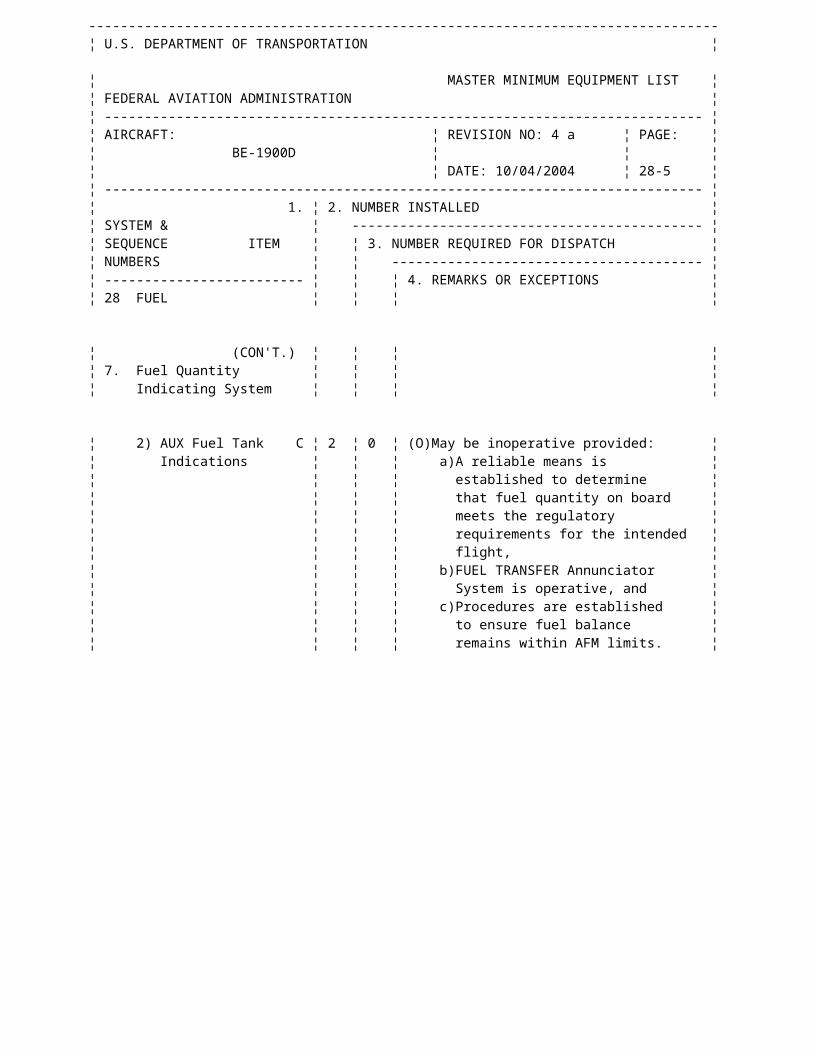
-------------------------------------------------------------------------------¦ U.S. DEPARTMENT OF TRANSPORTATION ¦ ¦ MASTER MINIMUM EQUIPMENT LIST ¦¦ FEDERAL AVIATION ADMINISTRATION ¦¦ --------------------------------------------------------------------------- ¦¦ AIRCRAFT: ¦ REVISION NO: 4 ¦ PAGE: ¦¦ BE-1900D ¦ ¦ ¦¦ ¦ DATE: 07/30/2002 ¦ 61-1 ¦¦ --------------------------------------------------------------------------- ¦¦ 1. ¦ 2. NUMBER INSTALLED ¦¦ SYSTEM & ¦ -------------------------------------------- ¦¦ SEQUENCE ITEM ¦ ¦ 3. NUMBER REQUIRED FOR DISPATCH ¦¦ NUMBERS ¦ ¦ --------------------------------------- ¦¦ ------------------------- ¦ ¦ ¦ 4. REMARKS OR EXCEPTIONS ¦¦ 61 PROPELLERS ¦ ¦ ¦ ¦ ¦ 1. Propeller D ¦ 1 ¦ 0 ¦ ¦¦ Synchrophaser/ ¦ ¦ ¦ ¦¦ Synchronizer System ¦ ¦ ¦ ¦ ¦ 2. Propeller D ¦ 1 ¦ 0 ¦ ¦¦ Synchroscope ¦ ¦ ¦ ¦ ¦ 3. Propeller ¦ ¦ ¦ ¦¦ Auto Feather ¦ ¦ ¦ ¦¦ Indication System ¦ ¦ ¦ ¦ ¦ 1) AFX Indicators C ¦ 2 ¦ 0 ¦ May be inoperative provided L and R ¦¦ ¦ ¦ ¦ Auto Feather Annunciators are ¦¦ ¦ ¦ ¦ operative and illuminated prior to ¦¦ ¦ ¦ ¦ takeoff brake release. ¦ ¦ 2) L or R C ¦ 2 ¦ 0 ¦ May be inoperative provided AFX ¦¦ AUTO FEATHER ¦ ¦ ¦ Indicators are operative. ¦¦ Annunciators ¦ ¦ ¦ ¦ ¦ 3) AUTO FEATHER A ¦ 1 ¦ 0 ¦ May be inoperative provided ¦¦ OFF Annunciator ¦ ¦ ¦ a) Auto Feather switches remain ¦¦ ¦ ¦ ¦ in the ARM position for the ¦¦ ¦ ¦ ¦ entire flight, and ¦¦ ¦ ¦ ¦ b) Repairs are made within ¦¦ ¦ ¦ ¦ three flight days. ¦ -------------------------------------------------------------------------------

-------------------------------------------------------------------------------¦ U.S. DEPARTMENT OF TRANSPORTATION ¦ ¦ MASTER MINIMUM EQUIPMENT LIST ¦¦ FEDERAL AVIATION ADMINISTRATION ¦¦ --------------------------------------------------------------------------- ¦¦ AIRCRAFT: ¦ REVISION NO: 4 a ¦ PAGE: ¦¦ BE-1900D ¦ ¦ ¦¦ ¦ DATE: 10/04/2004 ¦ 73-1 ¦¦ --------------------------------------------------------------------------- ¦¦ 1. ¦ 2. NUMBER INSTALLED ¦¦ SYSTEM & ¦ -------------------------------------------- ¦¦ SEQUENCE ITEM ¦ ¦ 3. NUMBER REQUIRED FOR DISPATCH ¦¦ NUMBERS ¦ ¦ --------------------------------------- ¦¦ ------------------------- ¦ ¦ ¦ 4. REMARKS OR EXCEPTIONS ¦¦ 73 ENGINE FUEL & CONTROL ¦ ¦ ¦ ¦ ¦ 1. Fuel Flow B ¦ 2 ¦ 1 ¦ (O) One may be inoperative provided ¦¦ Indicators ¦ ¦ ¦ both Fuel Quantity Indicating ¦¦ ¦ ¦ ¦ Systems and both Main Fuel Tank ¦¦ ¦ ¦ ¦ Indications are operative. ¦ ¦ B ¦ 2 ¦ 1 ¦ (O) One may be inoperative with one ¦¦ ¦ ¦ ¦ or both Aux Fuel Tank Indications ¦¦ ¦ ¦ ¦ inoperative provided both Fuel ¦¦ ¦ ¦ ¦ Quantity Indicating Systems and ¦¦ ¦ ¦ ¦ both Main Fuel Tank Indications are ¦¦ ¦ ¦ ¦ operative. ¦ -------------------------------------------------------------------------------

-------------------------------------------------------------------------------¦ U.S. DEPARTMENT OF TRANSPORTATION ¦ ¦ MASTER MINIMUM EQUIPMENT LIST ¦¦ FEDERAL AVIATION ADMINISTRATION ¦¦ --------------------------------------------------------------------------- ¦¦ AIRCRAFT: ¦ REVISION NO: 4 a ¦ PAGE: ¦¦ BE-1900D ¦ ¦ ¦¦ ¦ DATE: 10/04/2004 ¦ 74-1 ¦¦ --------------------------------------------------------------------------- ¦¦ 1. ¦ 2. NUMBER INSTALLED ¦¦ SYSTEM & ¦ -------------------------------------------- ¦¦ SEQUENCE ITEM ¦ ¦ 3. NUMBER REQUIRED FOR DISPATCH ¦¦ NUMBERS ¦ ¦ --------------------------------------- ¦¦ ------------------------- ¦ ¦ ¦ 4. REMARKS OR EXCEPTIONS ¦¦ 74 IGNITION ¦ ¦ ¦ ¦ ¦ 1. L or R Auto ¦ ¦ ¦ DELETED Revision 4. ¦¦ Ignition System ¦ ¦ ¦ ¦ -------------------------------------------------------------------------------

-------------------------------------------------------------------------------¦ U.S. DEPARTMENT OF TRANSPORTATION ¦ ¦ MASTER MINIMUM EQUIPMENT LIST ¦¦ FEDERAL AVIATION ADMINISTRATION ¦¦ --------------------------------------------------------------------------- ¦¦ AIRCRAFT: ¦ REVISION NO: 4 ¦ PAGE: ¦¦ BE-1900D ¦ ¦ ¦¦ ¦ DATE: 07/30/2002 ¦ 77-1 ¦¦ --------------------------------------------------------------------------- ¦¦ 1. ¦ 2. NUMBER INSTALLED ¦¦ SYSTEM & ¦ -------------------------------------------- ¦¦ SEQUENCE ITEM ¦ ¦ 3. NUMBER REQUIRED FOR DISPATCH ¦¦ NUMBERS ¦ ¦ --------------------------------------- ¦¦ ------------------------- ¦ ¦ ¦ 4. REMARKS OR EXCEPTIONS ¦¦ 77 ENGINE INDICATING ¦ ¦ ¦ ¦ ¦ 1. Tachometers C ¦ 2 ¦ 0 ¦ Digital display portion may be ¦¦ N1 Indicator ¦ ¦ ¦ inoperative. ¦ -------------------------------------------------------------------------------