diagnostic and fault codes - jetski diagnostics ... sea-doo spark...subsection xx (diagnostic and...
TRANSCRIPT

Subsection XX (DIAGNOSTIC AND FAULT CODES)
DIAGNOSTIC AND FAULT CODESGENERAL
FAULT CODE TABLEPCODE MODULE DESCRIPTION CAUSE ACTION
B2210 CLUSTER Left keypad fault (Switch keptactivated more than 60 seconds)
Problem with leftkeypad.
The switch may be defective,verify the functionality ofthe switch or the wires.Refer to the shop manualfor switch diagnosis/testingprocedure.
B2210 CLUSTER_CAFE
Left keypad fault (Switch keptactivated more than 60 seconds)
Problem with leftkeypad.
The switch may be defective,verify the functionality ofthe switch or the wires.Refer to the shop manualfor switch diagnosis/testingprocedure.
B2211 CLUSTERSuspension UP/DOWN orSPORT / ECO switches shortedto ground fault
Problem with leftkeypad.
Look for pin B if shorted toground or pin C.
B2212 CLUSTERSuspension UP/DOWN orSPORT / ECO switchesdisconnected fault
Problem with leftkeypad.
Look for pin B if disconnected topin 14 on the cluster. Look forpin C if disconnected to pin 15on the cluster .
B2213 CLUSTER VTS UP/DOWN switchesshorted to ground fault
Problem with leftkeypad.
Look for pin A if shorted toground or pin C.
B2213 CLUSTER_CAFE
VTS UP/DOWN switchesshorted to ground fault
Problem with leftkeypad.
Look for pin A if shorted toground or pin C.
B2214 CLUSTER VTS UP/DOWN switchesdisconnected fault
Problem with leftkeypad.
Look for pin A if disconnected topin 13 on the cluster. Look forpin C if disconnected to pin 15on the cluster .
B2214 CLUSTER_CAFE
VTS UP/DOWN switchesdisconnected fault
Problem with leftkeypad.
Look for pin A if disconnected topin 13 on the cluster. Look forpin C if disconnected to pin 15on the cluster .
B2220 CLUSTER Right keypad fault (Switch keptactivated more than 60 seconds)
Problem with rightkeypad.
The switch may be defective,verify the functionality of theswitch or the wires. Refer tothe shop manual for switchdiagnosis/testing procedure.
B2221 CLUSTER MODE/SET switches shorted toground fault
Problem with rightkeypad.
Look for pin B if shorted toground or pin C.
B2222 CLUSTER MODE/SET switchesdisconnected fault
Problem with rightkeypad.
Look for pin B if disconnected topin 17 on the cluster. Look forpin C if disconnected to pin 18on the cluster.
B2223 CLUSTER UP/DOWN switches shorted toground fault
Problem with rightkeypad.
Look for pin A if shorted toground or pin C.
tmr2013-025 1
Subsection XX (DIAGNOSTIC AND FAULT CODES)
PCODE MODULE DESCRIPTION CAUSE ACTION
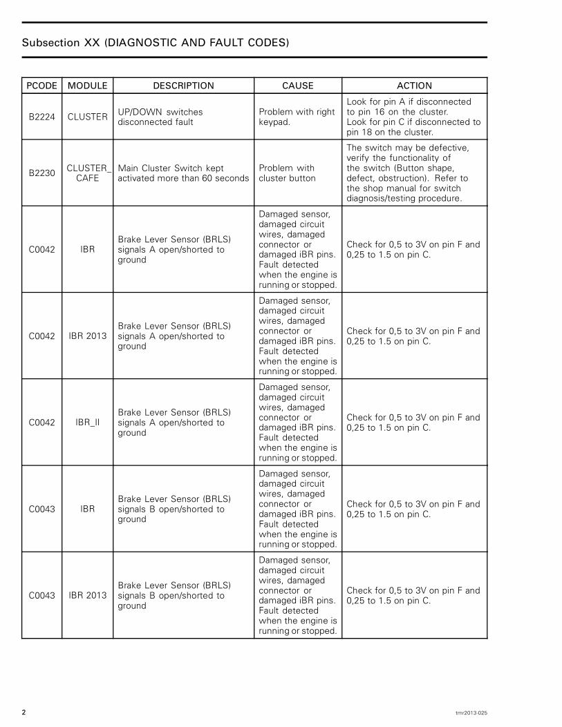
B2224 CLUSTER UP/DOWN switchesdisconnected fault
Problem with rightkeypad.
Look for pin A if disconnectedto pin 16 on the cluster.Look for pin C if disconnected topin 18 on the cluster.
B2230 CLUSTER_CAFE
Main Cluster Switch keptactivated more than 60 seconds
Problem withcluster button
The switch may be defective,verify the functionality ofthe switch (Button shape,defect, obstruction). Refer tothe shop manual for switchdiagnosis/testing procedure.
C0042 IBRBrake Lever Sensor (BRLS)signals A open/shorted toground
Damaged sensor,damaged circuitwires, damagedconnector ordamaged iBR pins.Fault detectedwhen the engine isrunning or stopped.
Check for 0,5 to 3V on pin F and0,25 to 1.5 on pin C.
C0042 IBR 2013Brake Lever Sensor (BRLS)signals A open/shorted toground
Damaged sensor,damaged circuitwires, damagedconnector ordamaged iBR pins.Fault detectedwhen the engine isrunning or stopped.
Check for 0,5 to 3V on pin F and0,25 to 1.5 on pin C.
C0042 IBR_IIBrake Lever Sensor (BRLS)signals A open/shorted toground
Damaged sensor,damaged circuitwires, damagedconnector ordamaged iBR pins.Fault detectedwhen the engine isrunning or stopped.
Check for 0,5 to 3V on pin F and0,25 to 1.5 on pin C.
C0043 IBRBrake Lever Sensor (BRLS)signals B open/shorted toground
Damaged sensor,damaged circuitwires, damagedconnector ordamaged iBR pins.Fault detectedwhen the engine isrunning or stopped.
Check for 0,5 to 3V on pin F and0,25 to 1.5 on pin C.
C0043 IBR 2013Brake Lever Sensor (BRLS)signals B open/shorted toground
Damaged sensor,damaged circuitwires, damagedconnector ordamaged iBR pins.Fault detectedwhen the engine isrunning or stopped.
Check for 0,5 to 3V on pin F and0,25 to 1.5 on pin C.
2 tmr2013-025

Subsection XX (DIAGNOSTIC AND FAULT CODES)
PCODE MODULE DESCRIPTION CAUSE ACTION
C0043 IBR_IIBrake Lever Sensor (BRLS)signals B open/shorted toground
Damaged sensor,damaged circuitwires, damagedconnector ordamaged iBR pins.Fault detectedwhen the engine isrunning or stopped.
Check for 0,5 to 3V on pin F and0,25 to 1.5 on pin C.
C0073 IBR Torque request failure
CPS wires shorted.Bad connection onthe engine coolanttemp sensor.
Perform ECM software update ifavailable. Verify CPS connection.Verify engine temperature if it isplausible. A bad connection withthe CTS can generate this faultwhen the iBR is used.
C0073 IBR 2013 Torque request failure
CPS wires shorted.Bad connection onthe engine coolanttemp sensor.
Perform ECM software update ifavailable. Verify CPS connection.Verify engine temperature if it isplausible. A bad connection withthe CTS can generate this faultwhen the iBR is used.
C0073 IBR_II Torque request failure
CPS wires shorted.Bad connection onthe engine coolanttemp sensor.
Perform ECM software update ifavailable. Verify CPS connection.Verify engine temperature if it isplausible. A bad connection withthe CTS can generate this faultwhen the iBR is used.
C2100 IBR Sensors calibration is corruptedIncompatiblefirmware ormemory failure.
If the fault comes active whenthe iBR is activated and staysactive, verify if a software updateis available. Refer to the servicemanual for more details.
C2100 IBR Actuator movement
The reverse gatecannot move to thedesired position.(stuck or motoropen)
Clean and check fordamage/wear parts in thereverse system and nozzle area.Check iBR electrical motor wiring.Isolate the iBR output shaftfrom the reverse system andactivate the iBR, if the faultcomes active, replace iBR.Refer to the service manual formore details.
C2100 IBR 2013 Sensors calibration is corruptedIncompatiblefirmware ormemory failure.
If the fault comes active whenthe iBR is activated and staysactive, verify if a software updateis available. Refer to the servicemanual for more details.
C2100 IBR_II Sensors calibration is corruptedIncompatiblefirmware ormemory failure.
If the fault comes active whenthe iBR is activated and staysactive, verify if a software updateis available. Refer to the servicemanual for more details.
tmr2013-025 3
Subsection XX (DIAGNOSTIC AND FAULT CODES)
PCODE MODULE DESCRIPTION CAUSE ACTION
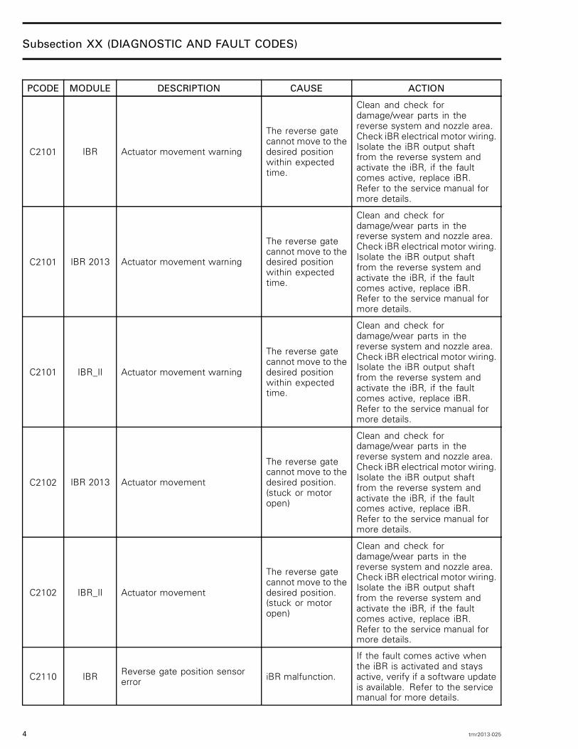
C2101 IBR Actuator movement warning
The reverse gatecannot move to thedesired positionwithin expectedtime.
Clean and check fordamage/wear parts in thereverse system and nozzle area.Check iBR electrical motor wiring.Isolate the iBR output shaftfrom the reverse system andactivate the iBR, if the faultcomes active, replace iBR.Refer to the service manual formore details.
C2101 IBR 2013 Actuator movement warning
The reverse gatecannot move to thedesired positionwithin expectedtime.
Clean and check fordamage/wear parts in thereverse system and nozzle area.Check iBR electrical motor wiring.Isolate the iBR output shaftfrom the reverse system andactivate the iBR, if the faultcomes active, replace iBR.Refer to the service manual formore details.
C2101 IBR_II Actuator movement warning
The reverse gatecannot move to thedesired positionwithin expectedtime.
Clean and check fordamage/wear parts in thereverse system and nozzle area.Check iBR electrical motor wiring.Isolate the iBR output shaftfrom the reverse system andactivate the iBR, if the faultcomes active, replace iBR.Refer to the service manual formore details.
C2102 IBR 2013 Actuator movement
The reverse gatecannot move to thedesired position.(stuck or motoropen)
Clean and check fordamage/wear parts in thereverse system and nozzle area.Check iBR electrical motor wiring.Isolate the iBR output shaftfrom the reverse system andactivate the iBR, if the faultcomes active, replace iBR.Refer to the service manual formore details.
C2102 IBR_II Actuator movement
The reverse gatecannot move to thedesired position.(stuck or motoropen)
Clean and check fordamage/wear parts in thereverse system and nozzle area.Check iBR electrical motor wiring.Isolate the iBR output shaftfrom the reverse system andactivate the iBR, if the faultcomes active, replace iBR.Refer to the service manual formore details.
C2110 IBR Reverse gate position sensorerror iBR malfunction.
If the fault comes active whenthe iBR is activated and staysactive, verify if a software updateis available. Refer to the servicemanual for more details.
4 tmr2013-025

Subsection XX (DIAGNOSTIC AND FAULT CODES)
PCODE MODULE DESCRIPTION CAUSE ACTION
C2110 IBR Angle position sensor warning iBR malfunction.
If the fault comes active whenthe iBR is activated and staysactive, verify if a software updateis available. Refer to the servicemanual for more details.
C2110 IBR iBR overheatiBR coolingsystem failure.iBR unit failure.
Check iBR cooling circuit.Refer to the service manual formore details.
C2110 IBR Monitoring CPU messagetimeout or validity iBR malfunction.
Perform an iBR software updateif available and clear the fault.Replace the iBR unit ifthe fault remains active.Refer to the service manualfor more details.
C2110 IBR Monitoring CPU limp force iBR malfunction.
Perform an iBR softwareupdate if available.Replace the iBR unit ifthe fault remains activeRefer to the service manualfor more details.
C2110 IBR 2013 Reverse gate position sensorerror iBR malfunction.
If the fault comes active whenthe iBR is activated and staysactive, verify if a software updateis available. Refer to the servicemanual for more details.
C2110 IBR_II Reverse gate position sensorerror iBR malfunction.
If the fault comes active whenthe iBR is activated and staysactive, verify if a software updateis available. Refer to the servicemanual for more details.
C2111 IBR ECM erratic RPM signal
RPM signalreceived fromengine ECM notplausible.
Check CPS sensor connection
C2112 IBR 2013 Angle position sensor warning iBR malfunction.
If the fault comes active whenthe iBR is activated and staysactive, verify if a software updateis available. Refer to the servicemanual for more details.
C2112 IBR_II Angle position sensor warning iBR malfunction.
If the fault comes active whenthe iBR is activated and staysactive, verify if a software updateis available. Refer to the servicemanual for more details.
C2113 IBR 2013 iBR overheatiBR coolingsystem failure.iBR unit failure.
Check iBR cooling circuit.Refer to the service manual formore details.
C2113 IBR_II iBR overheatiBR coolingsystem failure.iBR unit failure.
Check iBR cooling circuit.Refer to the service manual formore details.
tmr2013-025 5

Subsection XX (DIAGNOSTIC AND FAULT CODES)
PCODE MODULE DESCRIPTION CAUSE ACTION
C2114 IBR 2013 Monitoring CPU messagetimeout or validity iBR malfunction.
Perform an iBR software updateif available and clear the fault.Replace the iBR unit ifthe fault remains active.Refer to the service manualfor more details.
C2114 IBR_II Monitoring CPU messagetimeout or validity iBR malfunction.
Perform an iBR software updateif available and clear the fault.Replace the iBR unit ifthe fault remains active.Refer to the service manualfor more details.
C2115 IBR 2013 Monitoring CPU limp force iBR malfunction.
Perform an iBR softwareupdate if available.Replace the iBR unit ifthe fault remains activeRefer to the service manualfor more details.
C2115 IBR_II Monitoring CPU limp force iBR malfunction.
Perform an iBR softwareupdate if available.Replace the iBR unit ifthe fault remains activeRefer to the service manualfor more details.
C2120 IBR Application calibration iscorrupted
Incompatiblefirmware ormemory failure.
If the fault comes active whenthe iBR is activated and staysactive, verify if a software updateis available. Refer to the servicemanual for more details.
C2120 IBR 2013 Application calibration iscorrupted
Incompatiblefirmware ormemory failure.
If the fault comes active whenthe iBR is activated and staysactive, verify if a software updateis available. Refer to the servicemanual for more details.
C2120 IBR_II Application calibration iscorrupted
Incompatiblefirmware ormemory failure.
If the fault comes active whenthe iBR is activated and staysactive, verify if a software updateis available. Refer to the servicemanual for more details.
C2121 IBR Application parameterscorrupted (backup #1 or #2)
Unexpectedbattery powerlost or memoryfailure. Ignore faultif "occurred"
Verify starting andcharging system circuits.Clear faultRefer to the service manual formore details.
C2121 IBR 2013 Application parameterscorrupted (backup #1 or #2)
Unexpectedbattery powerlost or memoryfailure. Ignore faultif "occurred"
Verify starting andcharging system circuits.Clear faultRefer to the service manual formore details.
C2121 IBR_II Application parameterscorrupted (backup #1 or #2)
Unexpectedbattery powerlost or memoryfailure. Ignore faultif "occurred"
Verify starting andcharging system circuits.Clear faultRefer to the service manual formore details.
6 tmr2013-025
Subsection XX (DIAGNOSTIC AND FAULT CODES)
PCODE MODULE DESCRIPTION CAUSE ACTION
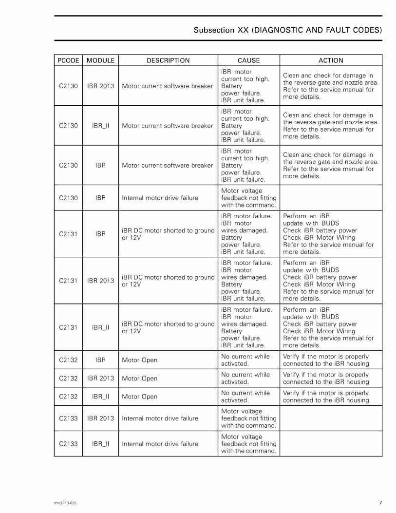
C2130 IBR 2013 Motor current software breaker
iBR motorcurrent too high.Batterypower failure.iBR unit failure.
Clean and check for damage inthe reverse gate and nozzle area.Refer to the service manual formore details.
C2130 IBR_II Motor current software breaker
iBR motorcurrent too high.Batterypower failure.iBR unit failure.
Clean and check for damage inthe reverse gate and nozzle area.Refer to the service manual formore details.
C2130 IBR Motor current software breaker
iBR motorcurrent too high.Batterypower failure.iBR unit failure.
Clean and check for damage inthe reverse gate and nozzle area.Refer to the service manual formore details.
C2130 IBR Internal motor drive failureMotor voltagefeedback not fittingwith the command.
C2131 IBR iBR DC motor shorted to groundor 12V
iBR motor failure.iBR motorwires damaged.Batterypower failure.iBR unit failure.
Perform an iBRupdate with BUDSCheck iBR battery powerCheck iBR Motor WiringRefer to the service manual formore details.
C2131 IBR 2013 iBR DC motor shorted to groundor 12V
iBR motor failure.iBR motorwires damaged.Batterypower failure.iBR unit failure.
Perform an iBRupdate with BUDSCheck iBR battery powerCheck iBR Motor WiringRefer to the service manual formore details.
C2131 IBR_II iBR DC motor shorted to groundor 12V
iBR motor failure.iBR motorwires damaged.Batterypower failure.iBR unit failure.
Perform an iBRupdate with BUDSCheck iBR battery powerCheck iBR Motor WiringRefer to the service manual formore details.
C2132 IBR Motor Open No current whileactivated.
Verify if the motor is properlyconnected to the iBR housing
C2132 IBR 2013 Motor Open No current whileactivated.
Verify if the motor is properlyconnected to the iBR housing
C2132 IBR_II Motor Open No current whileactivated.
Verify if the motor is properlyconnected to the iBR housing
C2133 IBR 2013 Internal motor drive failureMotor voltagefeedback not fittingwith the command.
C2133 IBR_II Internal motor drive failureMotor voltagefeedback not fittingwith the command.
tmr2013-025 7
Subsection XX (DIAGNOSTIC AND FAULT CODES)
PCODE MODULE DESCRIPTION CAUSE ACTION
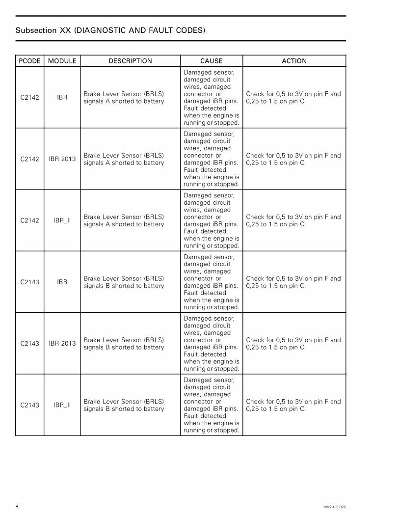
C2142 IBR Brake Lever Sensor (BRLS)signals A shorted to battery
Damaged sensor,damaged circuitwires, damagedconnector ordamaged iBR pins.Fault detectedwhen the engine isrunning or stopped.
Check for 0,5 to 3V on pin F and0,25 to 1.5 on pin C.
C2142 IBR 2013 Brake Lever Sensor (BRLS)signals A shorted to battery
Damaged sensor,damaged circuitwires, damagedconnector ordamaged iBR pins.Fault detectedwhen the engine isrunning or stopped.
Check for 0,5 to 3V on pin F and0,25 to 1.5 on pin C.
C2142 IBR_II Brake Lever Sensor (BRLS)signals A shorted to battery
Damaged sensor,damaged circuitwires, damagedconnector ordamaged iBR pins.Fault detectedwhen the engine isrunning or stopped.
Check for 0,5 to 3V on pin F and0,25 to 1.5 on pin C.
C2143 IBR Brake Lever Sensor (BRLS)signals B shorted to battery
Damaged sensor,damaged circuitwires, damagedconnector ordamaged iBR pins.Fault detectedwhen the engine isrunning or stopped.
Check for 0,5 to 3V on pin F and0,25 to 1.5 on pin C.
C2143 IBR 2013 Brake Lever Sensor (BRLS)signals B shorted to battery
Damaged sensor,damaged circuitwires, damagedconnector ordamaged iBR pins.Fault detectedwhen the engine isrunning or stopped.
Check for 0,5 to 3V on pin F and0,25 to 1.5 on pin C.
C2143 IBR_II Brake Lever Sensor (BRLS)signals B shorted to battery
Damaged sensor,damaged circuitwires, damagedconnector ordamaged iBR pins.Fault detectedwhen the engine isrunning or stopped.
Check for 0,5 to 3V on pin F and0,25 to 1.5 on pin C.
8 tmr2013-025
Subsection XX (DIAGNOSTIC AND FAULT CODES)
PCODE MODULE DESCRIPTION CAUSE ACTION
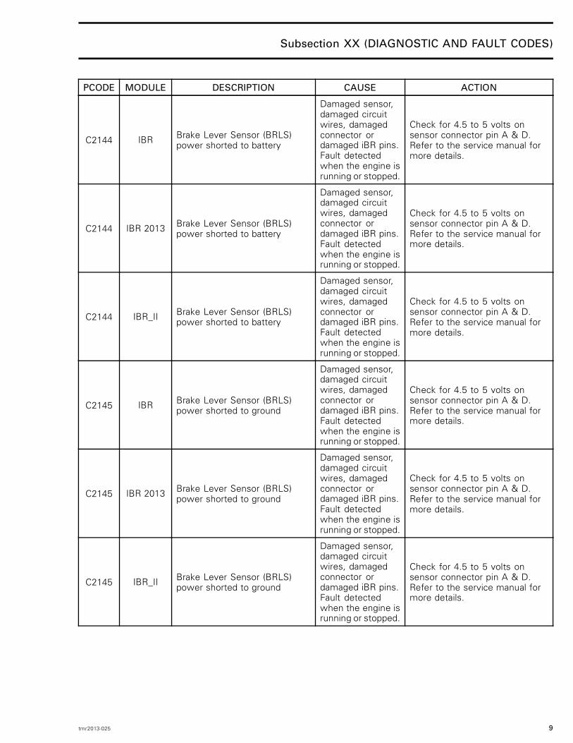
C2144 IBR Brake Lever Sensor (BRLS)power shorted to battery
Damaged sensor,damaged circuitwires, damagedconnector ordamaged iBR pins.Fault detectedwhen the engine isrunning or stopped.
Check for 4.5 to 5 volts onsensor connector pin A & D.Refer to the service manual formore details.
C2144 IBR 2013 Brake Lever Sensor (BRLS)power shorted to battery
Damaged sensor,damaged circuitwires, damagedconnector ordamaged iBR pins.Fault detectedwhen the engine isrunning or stopped.
Check for 4.5 to 5 volts onsensor connector pin A & D.Refer to the service manual formore details.
C2144 IBR_II Brake Lever Sensor (BRLS)power shorted to battery
Damaged sensor,damaged circuitwires, damagedconnector ordamaged iBR pins.Fault detectedwhen the engine isrunning or stopped.
Check for 4.5 to 5 volts onsensor connector pin A & D.Refer to the service manual formore details.
C2145 IBR Brake Lever Sensor (BRLS)power shorted to ground
Damaged sensor,damaged circuitwires, damagedconnector ordamaged iBR pins.Fault detectedwhen the engine isrunning or stopped.
Check for 4.5 to 5 volts onsensor connector pin A & D.Refer to the service manual formore details.
C2145 IBR 2013 Brake Lever Sensor (BRLS)power shorted to ground
Damaged sensor,damaged circuitwires, damagedconnector ordamaged iBR pins.Fault detectedwhen the engine isrunning or stopped.
Check for 4.5 to 5 volts onsensor connector pin A & D.Refer to the service manual formore details.
C2145 IBR_II Brake Lever Sensor (BRLS)power shorted to ground
Damaged sensor,damaged circuitwires, damagedconnector ordamaged iBR pins.Fault detectedwhen the engine isrunning or stopped.
Check for 4.5 to 5 volts onsensor connector pin A & D.Refer to the service manual formore details.
tmr2013-025 9
Subsection XX (DIAGNOSTIC AND FAULT CODES)
PCODE MODULE DESCRIPTION CAUSE ACTION
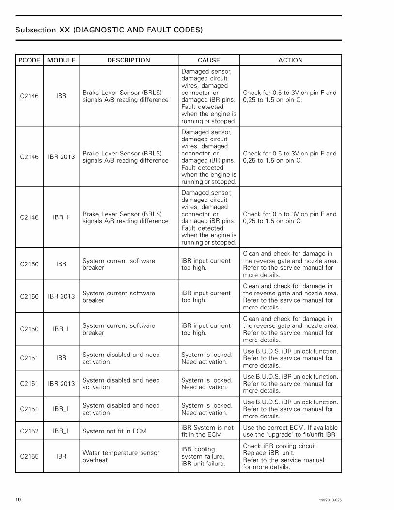
C2146 IBR Brake Lever Sensor (BRLS)signals A/B reading difference
Damaged sensor,damaged circuitwires, damagedconnector ordamaged iBR pins.Fault detectedwhen the engine isrunning or stopped.
Check for 0,5 to 3V on pin F and0,25 to 1.5 on pin C.
C2146 IBR 2013 Brake Lever Sensor (BRLS)signals A/B reading difference
Damaged sensor,damaged circuitwires, damagedconnector ordamaged iBR pins.Fault detectedwhen the engine isrunning or stopped.
Check for 0,5 to 3V on pin F and0,25 to 1.5 on pin C.
C2146 IBR_II Brake Lever Sensor (BRLS)signals A/B reading difference
Damaged sensor,damaged circuitwires, damagedconnector ordamaged iBR pins.Fault detectedwhen the engine isrunning or stopped.
Check for 0,5 to 3V on pin F and0,25 to 1.5 on pin C.
C2150 IBR System current softwarebreaker
iBR input currenttoo high.
Clean and check for damage inthe reverse gate and nozzle area.Refer to the service manual formore details.
C2150 IBR 2013 System current softwarebreaker
iBR input currenttoo high.
Clean and check for damage inthe reverse gate and nozzle area.Refer to the service manual formore details.
C2150 IBR_II System current softwarebreaker
iBR input currenttoo high.
Clean and check for damage inthe reverse gate and nozzle area.Refer to the service manual formore details.
C2151 IBR System disabled and needactivation
System is locked.Need activation.
Use B.U.D.S. iBR unlock function.Refer to the service manual formore details.
C2151 IBR 2013 System disabled and needactivation
System is locked.Need activation.
Use B.U.D.S. iBR unlock function.Refer to the service manual formore details.
C2151 IBR_II System disabled and needactivation
System is locked.Need activation.
Use B.U.D.S. iBR unlock function.Refer to the service manual formore details.
C2152 IBR_II System not fit in ECM iBR System is notfit in the ECM
Use the correct ECM. If availableuse the "upgrade" to fit/unfit iBR
C2155 IBR Water temperature sensoroverheat
iBR coolingsystem failure.iBR unit failure.
Check iBR cooling circuit.Replace iBR unit.Refer to the service manualfor more details.
10 tmr2013-025

Subsection XX (DIAGNOSTIC AND FAULT CODES)
PCODE MODULE DESCRIPTION CAUSE ACTION
C2155 IBR 2013 Water temperature sensoroverheat
iBR coolingsystem failure.iBR unit failure.
Check iBR cooling circuit.Replace iBR unit.Refer to the service manualfor more details.
C2155 IBR_II Water temperature sensoroverheat
iBR coolingsystem failure.iBR unit failure.
Check iBR cooling circuit.Replace iBR unit.Refer to the service manualfor more details.
C2161 IBR Low voltage detected
Battery failure,rectifier failure,damagedcircuit wires,battery terminalconnection,damaged ACgeneratoror damagedconnectors. Ignorefault if "occurred"
Check fuses #6 (REFERTO WIRING DIAGRAM).Check ground continuityto the engine block.Refer to the service manualfor more details.
C2161 IBR 2013 Low voltage detected
Battery failure,rectifier failure,damagedcircuit wires,battery terminalconnection,damaged ACgeneratoror damagedconnectors. Ignorefault if "occurred"
Check fuses #6 (REFERTO WIRING DIAGRAM).Check ground continuityto the engine block.Refer to the service manualfor more details.
C2161 IBR_II Low voltage detected
Battery failure,rectifier failure,damagedcircuit wires,battery terminalconnection,damaged ACgeneratoror damagedconnectors. Ignorefault if "occurred"
Check fuses #6 (REFERTO WIRING DIAGRAM).Check ground continuityto the engine block.Refer to the service manualfor more details.
C2200 IS Sensors calibration is corruptedIncompatiblefirmware ormemory failure.
If the fault comes active whenthe iS is activated and staysactive, verify if a software updateis available. Refer to the servicemanual for more details.
C2210 IS Bridge/CPU temperature sensoroverheat
Hardware failureor external heatsource.
Check for over utilization / heat.
C2220 IS Application calibration iscorrupted
Incompatiblefirmware ormemory failure.
If the fault comes active whenthe iS is activated and staysactive, verify if a software updateis available. Refer to the servicemanual for more details.
tmr2013-025 11

Subsection XX (DIAGNOSTIC AND FAULT CODES)
PCODE MODULE DESCRIPTION CAUSE ACTION
C2221 IS Application parameterscorrupted (backup #1 or #2)
Unexpectedbattery powerlost or memoryfailure. Ignore faultif "occurred"
Verify starting andcharging system circuits.Clear faultRefer to the service manual formore details.
C2230 IS Internal motor drive failureMotor voltagefeedback not fittingwith the command.
If the fault comes active whenthe iS is activated and staysactive, verify if a software updateis available. Refer to the servicemanual for more details.
C2231 IS Motor shorted to ground/batteryCurrent leakdetected whenthe bridge is off.
Check suspension actuator pumpwiring.
C2232 IS Motor open No current whileactivated.
Check suspension actuator pumpand/or wiring.
C2233 IS Motor current software breaker Motor current toohigh.
Check suspension actuatorpump.
C2240 IS Seat position sensor error Open,Shorted to Gnd
Sensor notconnected.
Check systemcircuit at iS module.(REFER TO WIRING DIAGRAM)
C2250 IS System current softwarebreaker
Battery inputcurrent too high.
Check suspension actuatorpump.
C2251 IS System disabled and needactivation
System is lockedfor safety. Needactivation.
Activate iS using B.U.D.S.activation function.
C2252 IS TOPS active
Warning only:TOPS detectedby the system,the suspension isdisable while theTOPS is "ON".
Refer to the service manual formore details.
C2260 IS System under voltage System undervoltage warning.
Check battery and chargingsystem.
C2310 WSM Motor current software breaker
The Weedlesssystem sense anoutput current over15 amps.
Check Weedless actuator
C2320 WSM Application calibration iscorrupted
The systemwas shutdownimproperly
If inactive, do nothing and clearthe fault. If active, close BUDSand wait for complete shutdown.If the fault is still active, look forsoftware update, if not available,replace module
C2325 WSM Maximum activation timer fault
The systemdetected aWeedless cycletoo long (over 22seconds). The faultis set to INACTIVEat every retry.
Check Weedless actuator orposition sensor
12 tmr2013-025

Subsection XX (DIAGNOSTIC AND FAULT CODES)
PCODE MODULE DESCRIPTION CAUSE ACTION
C2326 WSM Maximum deactivation timerfault
The systemdetected a too longdelay to return atthe stored position(over 22 seconds).The fault is set toINACTIVE at everyretry.
Check Weedless actuator orposition sensor
C2327 WSM Position sensor not calibrated Position sensor notcalibrated properly
Follow the procedure to calibratethe sensor using BUDS
C2328 WSM Actuator current sensor notcalibrated
Incompatiblefirmware ormemory failure.
If inactive, do nothing and clearthe fault. If active, close BUDSand wait for complete shutdown.If the fault is still active, look forsoftware update, if not available,replace module
C2329 WSM System current sensor notcalibrated
Incompatiblefirmware ormemory failure.
If inactive, do nothing and clearthe fault. If active, close BUDSand wait for complete shutdown.If the fault is still active, look forsoftware update, if not available,replace module
C2330 WSM Internal motor drive failureMotor voltagefeedback not fittingwith the command.
If inactive, do nothing and clearthe fault. If active, close BUDSand wait for complete shutdown.If the fault is still active, look forsoftware update, if not available,replace module
C2331 WSM Motor short circuit
The Weedlesssystem detect ashort circuit on theoutput (actuator)
Check Weedless actuator
C2332 WSM Motor open circuit
The Weedlesssystem detect anopen circuit on theoutput (actuator)
Check Weedless actuator
C2341 WSM Position sensor shorted to Vcc
The Weedlesssystem detect aposition sensorshorten to Battery+12V
Check position sensor
C2360 WSM System under-voltage
The Weedlesssystem detect avoltage under 7volts
Check battery and chargingsystem.
C2370 WSM Actuator stored position error
One second afterpower up or atthe end of aweedless cycle,if the gate positionis not at the storedposition, the faultwill come active
Check Weedless actuator orposition sensor
tmr2013-025 13
Subsection XX (DIAGNOSTIC AND FAULT CODES)
PCODE MODULE DESCRIPTION CAUSE ACTION
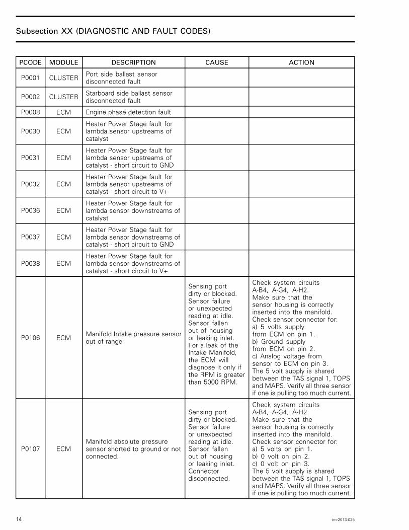
P0001 CLUSTER Port side ballast sensordisconnected fault
P0002 CLUSTER Starboard side ballast sensordisconnected fault
P0008 ECM Engine phase detection fault
P0030 ECMHeater Power Stage fault forlambda sensor upstreams ofcatalyst
P0031 ECMHeater Power Stage fault forlambda sensor upstreams ofcatalyst - short circuit to GND
P0032 ECMHeater Power Stage fault forlambda sensor upstreams ofcatalyst - short circuit to V+
P0036 ECMHeater Power Stage fault forlambda sensor downstreams ofcatalyst
P0037 ECMHeater Power Stage fault forlambda sensor downstreams ofcatalyst - short circuit to GND
P0038 ECMHeater Power Stage fault forlambda sensor downstreams ofcatalyst - short circuit to V+
P0106 ECM Manifold Intake pressure sensorout of range
Sensing portdirty or blocked.Sensor failureor unexpectedreading at idle.Sensor fallenout of housingor leaking inlet.For a leak of theIntake Manifold,the ECM willdiagnose it only ifthe RPM is greaterthan 5000 RPM.
Check system circuitsA-B4, A-G4, A-H2.Make sure that thesensor housing is correctlyinserted into the manifold.Check sensor connector for:a) 5 volts supplyfrom ECM on pin 1.b) Ground supplyfrom ECM on pin 2.c) Analog voltage fromsensor to ECM on pin 3.The 5 volt supply is sharedbetween the TAS signal 1, TOPSand MAPS. Verify all three sensorif one is pulling too much current.
P0107 ECMManifold absolute pressuresensor shorted to ground or notconnected.
Sensing portdirty or blocked.Sensor failureor unexpectedreading at idle.Sensor fallenout of housingor leaking inlet.Connectordisconnected.
Check system circuitsA-B4, A-G4, A-H2.Make sure that thesensor housing is correctlyinserted into the manifold.Check sensor connector for:a) 5 volts on pin 1.b) 0 volt on pin 2.c) 0 volt on pin 3.The 5 volt supply is sharedbetween the TAS signal 1, TOPSand MAPS. Verify all three sensorif one is pulling too much current.
14 tmr2013-025

Subsection XX (DIAGNOSTIC AND FAULT CODES)
PCODE MODULE DESCRIPTION CAUSE ACTION
P0108 ECMManifold absolute pressuresensor open circuit or shortedto battery
Sensing portdirty or blocked.Sensor failureor unexpectedreading at idle.Sensor fallenout of housingor leaking inlet.
Check system circuitsA-B4, A-G4, A-H2.Make sure that thesensor housing is correctlyinserted into the manifold.Check sensor connector for:a) 5 volts on pin 1.b) 0 volt on pin 2.c) 0 volt on pin 3.The 5 volt supply is sharedbetween the TAS signal 1, TOPSand MAPS. Verify all three sensorif one is pulling too much current.
P0112 ECM Intake manifold temperaturesensor shorted to ground
Damaged sensor,damaged circuitwires, damagedconnectoror damagedECM pins.
Check the sensor forapproximately 2280 to 2736ohms at 19 to 21°C (66 to 70°F).Check for approximately 2280to 2736 ohms at 19 to 21°C(66 to 70°F) between ECMconnector pins A-H3 and A-J3.Refer to the service manual formore details.
P0113 ECMIntake manifold temperaturesensor open circuit or shortedto battery
Damaged sensor,damaged circuitwires, damagedconnectoror damagedECM pins.
Check the sensor forapproximately 2280 to 2736ohms at 19 to 21°C (66 to 70°F).Check for approximately 2280to 2736 ohms at 19 to 21°C(66 to 70°F) between ECMconnector pins A-H3 and A-J3.Refer to the service manual formore details.
P0116 ECM Engine coolant temperaturesignal not plausible
Damaged sensor,damaged circuitwires, damagedconnectoror damagedECM pins.
Check for debris orblockage in cooling system.Check the sensor forapproximately 2280 to 2736ohms at 19 to 21°C (66 to 70°F).Check for approximately 2280to 2736 ohms at 19 to 21°C(66 to 70°F) between ECMconnector pins A-A1 and A-J2.Refer to the service manual formore details.
P0117 ECMEngine coolant temperaturesensor fault - Short circuit toGND
Damaged sensor,damaged circuitwires, damagedconnectoror damagedECM pins.
Check for debris orblockage in cooling system.Check the sensor forapproximately 2280 to 2736ohms at 19 to 21°C (66 to 70°F).Check for approximately 2280to 2736 ohms at 19 to 21°C(66 to 70°F) between ECMconnector pins A-A1 and A-J2.Refer to the service manual formore details.
tmr2013-025 15

Subsection XX (DIAGNOSTIC AND FAULT CODES)
PCODE MODULE DESCRIPTION CAUSE ACTION
P0118 ECMEngine coolant temperaturesensor fault - Short circuit to V+or connector disconnected.
Engine overheatedor damagedsensor. Connectordisconnected.
Check for debris orblockage in cooling system.Check the sensor forapproximately 2280 to 2736ohms at 19 to 21°C (66 to 70°F).Check for approximately 2280to 2736 ohms at 19 to 21°C(66 to 70°F) between ECMconnector pins A-A1 and A-J2.Refer to the service manual formore details.
P0122 ECMTAS (Throttle Acceleratorsensor) 1 fault (short circuit toGND)
Damaged sensor,damaged circuitwires, damagedconnectoror damagedECM pins.
Check system circuitsB-E1, B-K1, B-K3.Check for 0 volt onsensor connector pin E.Check for 5 volts on sensorconnector pin D. The 5 voltsupply is shared between theTAS signal 1, TOPS and MAPS.Verify all three sensor if oneis pulling too much current.Check for 0.5 to 3 voltson sensor connector pin F.Refer to the service manual formore details.
P0123 ECMTAS (Throttle Acceleratorsensor) 1 fault (short circuit tobattery)
Damaged sensor,damaged circuitwires, damagedconnectoror damagedECM pins.
Check system circuitsB-E1, B-K1, B-K3.Check for 0 volt onsensor connector pin E.Check for 5 volts on sensorconnector pin D. The 5 voltsupply is shared between theTLS signal 1, TOPS and MAPS.Verify all three sensor if oneis pulling too much current.Check for 0.5 to 3 voltson sensor connector pin F.Refer to the service manual formore details.
P0127 ECM Intercooler system fault
High air intaketemperaturedetected.Fault detectedwhen the engineis runningand stopped.Blocked intercoolerwater circuit.
Clean intercoolerwater circuit system.Refer to the service manualfor more details.
P0130 ECM Lambda Sensor fault upstreamsof catalyst - signal not plausible
P0131 ECM Lambda Sensor fault upstreamsof catalyst - short circuit to GND
P0132 ECM Lambda Sensor fault upstreamsof catalyst - short circuit to V+
16 tmr2013-025

Subsection XX (DIAGNOSTIC AND FAULT CODES)
PCODE MODULE DESCRIPTION CAUSE ACTION
P0133 ECMOxygen sensor upstreamsof catalyst reacts to slow -->contaminated
P0134 ECMOxygen sensor upstreamsof catalyst reacts to slow -->defective
P0135 ECM Lambda Sensor heating faultupstreams of catalyst
P0136 ECMLambda Sensor faultdownstream of catalyst -signal not plausible
P0137 ECMLambda Sensor faultdownstream of catalyst -short circuit to GND
P0138 ECMLambda Sensor faultdownstreams of catalyst -short circuit to V+
P0141 ECM Lambda Sensor heating faultdownstreams of catalyst
P0171 ECMMultiplicative mixture adaptationexceeds upper limit--> mixturetoo lean
An open signal on the Enginecoolant temperature (CTS) cantrigger that fault
P0172 ECMMultiplicative mixture adaptationbelow lower limit--> mixture toorich
An open signal on the Enginecoolant temperature (CTS) cantrigger that fault
P0201 ECM Injection Power Stage fault -open line / Cylinder 1
Damaged injector,damaged circuitwires, damagedconnector ordamaged ECMoutput pins.
Check for 11.4 to 12.6 ohmsbetween engine connector pin2 and ECM connector pin A-B3.Check for 12 volts on pin2 of injector connector.Check FUSE #13 (REFERTO WIRING DIAGRAM)Check for damaged circuit wires.Refer to the service manual formore details.
P0202 ECM Injection Power Stage fault -open line / Cylinder 2
Damaged injector,damaged circuitwires, damagedconnector ordamaged ECMoutput pins.
Check for 11.4 to 12.6 ohmsbetween engine connector pin2 and ECM connector pin A-K1.Check for 12 volts on pin2 of injector connector.Check FUSE #14 (REFERTO WIRING DIAGRAM)Check for damaged circuit wiresRefer to the service manual formore details.
tmr2013-025 17

Subsection XX (DIAGNOSTIC AND FAULT CODES)
PCODE MODULE DESCRIPTION CAUSE ACTION
P0203 ECM Injection Power Stage fault -open line / Cylinder 3
Damaged injector,damaged circuitwires, damagedconnector ordamaged ECMoutput pins.
Check for 11.4 to 12.6 ohmsbetween engine connector pin3 and ECM connector pin A-J1.Check for 12 volts on pin2 of injector connector.Check FUSE #15 (REFERTO WIRING DIAGRAM)Check for damaged circuit wires.Refer to the service manual formore details.
P0217 ECM High engine coolanttemperature detected
High enginecoolanttemperaturedetected
Check for debris orblockage in cooling system.Check the sensor forapproximately 2280 to 2736ohms at 19 to 21°C (66 to 70°F).Check for approximately 2280to 2736 ohms at 19 to 21°C(66 to 70°F) between ECMconnector pins A-A1 and A-J2.Refer to the service manual formore details.
P0222 ECMTAS (Throttle Acceleratorsensor) 2 fault (short circuit toGND)
Damaged sensor,damaged circuitwires, damagedconnectoror damagedECM pins.
Check system circuitsB-A3, B-B3, B-J3.Check for 0 volt onsensor connector pin B.Check for 5 volts onsensor connector pin A.Check for 0.25 to 1.5 voltson sensor connector pin C.Refer to the service manual formore details.
P0223 ECMTAS (Throttle AcceleratorSensor) 2 fault (short circuit tobattery)
Damaged sensor,damaged circuitwires, damagedconnectoror damagedECM pins.
Check system circuitsB-A3, B-B3, B-J3.Check for 0 volt onsensor connector pin B.Check for 5 volts onsensor connector pin A.Check for 0.25 to 1.5 voltson sensor connector pin C.Refer to the service manual formore details.
P0231 ECM Fuel pump open circuit or shortto ground
Damaged pump,damaged circuitwires, damagedconnector ordamaged ECMoutput pins.
Check for approximately 1ohm between pins A and Bof the fuel pump connector.Check FUSE #18 (REFERTO WIRING DIAGRAM)Check for damaged circuit wires.Check for damagedconnector, damaged ECMoutput pins or ECM failure.Refer to the service manual formore details.
18 tmr2013-025

Subsection XX (DIAGNOSTIC AND FAULT CODES)
PCODE MODULE DESCRIPTION CAUSE ACTION
P0232 ECM Fuel pump short circuit tobattery
Damaged pump,damaged circuitwires, damagedconnector ordamaged ECMoutput pins.
Check for approximately 1ohm between pins A and Bof the fuel pump connector.Check FUSE #18 (REFERTO WIRING DIAGRAM)Check for damaged circuit wires.Check for damagedconnector, damaged ECMoutput pins or ECM failure.Refer to the service manual formore details.
P0261 ECM Injector 1 open circuit or shortedto ground
Damaged injector,damaged circuitwires, damagedconnector ordamaged ECMoutput pins.
Check for 11.4 to 12.6 ohmsbetween engine connector pin1 and ECM connector pin A-B3.Check for 12 volts on pin2 of injector connector.Check FUSE #13 (REFERTO WIRING DIAGRAM)Check for damaged circuit wires.Refer to the service manual formore details.
P0262 ECM Injector 1 shorted to battery
Damaged injector,damaged circuitwires, damagedconnector ordamaged ECMoutput pins.
Check for 11.4 to 12.6 ohmsbetween engine connector pin1 and ECM connector pin A-B3.Check for 12 volts on pin2 of injector connector.Check FUSE #13 (REFERTO WIRING DIAGRAM)Check for damaged circuit wires.Refer to the service manual formore details.
P0264 ECM Injector 2 open circuit or shortedto ground
Damaged injector,damaged circuitwires, damagedconnector ordamaged ECMoutput pins.
Check for 11.4 to 12.6 ohmsbetween engine connector pin2 and ECM connector pin A-K1.Check for 12 volts on pin2 of injector connector.Check FUSE #14 (REFERTO WIRING DIAGRAM)Check for damaged circuit wires.Refer to the service manual formore details.
P0265 ECM Injector 2 shorted to battery
Damaged injector,damaged circuitwires, damagedconnector ordamaged ECMoutput pins.
Check for 11.4 to 12.6 ohmsbetween engine connector pin2 and ECM connector pin A-K1.Check for 12 volts on pin2 of injector connector.Check FUSE #14 (REFERTO WIRING DIAGRAM)Check for damaged circuit wires.Refer to the service manual formore details.
tmr2013-025 19
Subsection XX (DIAGNOSTIC AND FAULT CODES)
PCODE MODULE DESCRIPTION CAUSE ACTION
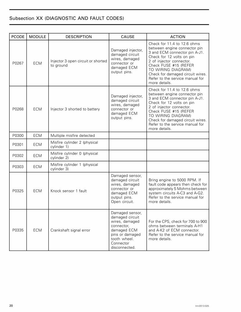
P0267 ECM Injector 3 open circuit or shortedto ground
Damaged injector,damaged circuitwires, damagedconnector ordamaged ECMoutput pins.
Check for 11.4 to 12.6 ohmsbetween engine connector pin3 and ECM connector pin A-J1.Check for 12 volts on pin2 of injector connector.Check FUSE #15 (REFERTO WIRING DIAGRAM)Check for damaged circuit wires.Refer to the service manual formore details.
P0268 ECM Injector 3 shorted to battery
Damaged injector,damaged circuitwires, damagedconnector ordamaged ECMoutput pins.
Check for 11.4 to 12.6 ohmsbetween engine connector pin3 and ECM connector pin A-J1.Check for 12 volts on pin2 of injector connector.Check FUSE #15 (REFERTO WIRING DIAGRAM)Check for damaged circuit wires.Refer to the service manual formore details.
P0300 ECM Multiple misfire detected
P0301 ECM Misfire cylinder 2 (physicalcylinder 1)
P0302 ECM Misfire cylinder 0 (physicalcylinder 2)
P0303 ECM Misfire cylinder 1 (physicalcylinder 3)
P0325 ECM Knock sensor 1 fault
Damaged sensor,damaged circuitwires, damagedconnector ordamaged ECMoutput pins.Open circuit.
Bring engine to 5000 RPM. Iffault code appears then check forapproximately 5 Mohms betweensystem circuits A-C3 and A-G2.Refer to the service manual formore details.
P0335 ECM Crankshaft signal error
Damaged sensor,damaged circuitwires, damagedconnector,damaged ECMpins or damagedtooth wheel.Connectordisconnected.
For the CPS, check for 700 to 900ohms between terminals A-H1and A-K2 of ECM connector.Refer to the service manual formore details.
20 tmr2013-025
Subsection XX (DIAGNOSTIC AND FAULT CODES)
PCODE MODULE DESCRIPTION CAUSE ACTION
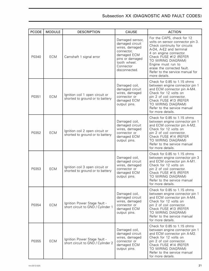
P0340 ECM Camshaft 1 signal error
Damaged sensor,damaged circuitwires, damagedconnector,damaged ECMpins or damagedtooth wheel.Connectordisconnected.
For the CAPS, check for 12volts on sensor connector pin 3.Check continuity for circuitsA-D4, A-E2 and terminal4 on engine connector.Check FUSE #12 (REFERTO WIRING DIAGRAM)Engine must run toerase the corrected fault.Refer to the service manual formore details.
P0351 ECM Ignition coil 1 open circuit orshorted to ground or to battery
Damaged coil,damaged circuitwires, damagedconnector ordamaged ECMoutput pins.
Check for 0.85 to 1.15 ohmsbetween engine connector pin 1and ECM connector pin A-M4.Check for 12 volts onpin 2 of coil connector.Check FUSE #13 (REFERTO WIRING DIAGRAM)Refer to the service manualfor more details.
P0352 ECM Ignition coil 2 open circuit orshorted to ground or to battery
Damaged coil,damaged circuitwires, damagedconnector ordamaged ECMoutput pins.
Check for 0.85 to 1.15 ohmsbetween engine connector pin 1and ECM connector pin A-M2.Check for 12 volts onpin 2 of coil connector.Check FUSE #14 (REFERTO WIRING DIAGRAM)Refer to the service manualfor more details.
P0353 ECM Ignition coil 3 open circuit orshorted to ground or to battery
Damaged coil,damaged circuitwires, damagedconnector ordamaged ECMoutput pins.
Check for 0.85 to 1.15 ohmsbetween engine connector pin 3and ECM connector pin A-M1.Check for 12 volts onpin 2 of coil connector.Check FUSE #15 (REFERTO WIRING DIAGRAM)Refer to the service manualfor more details.
P0354 ECM Ignition Power Stage fault -short circuit to GND / Cylinder 1
Damaged coil,damaged circuitwires, damagedconnector ordamaged ECMoutput pins.
Check for 0.85 to 1.15 ohmsbetween engine connector pin 1and ECM connector pin A-M4.Check for 12 volts onpin 2 of coil connector.Check FUSE #13 (REFERTO WIRING DIAGRAM)Refer to the service manualfor more details.
P0355 ECM Ignition Power Stage fault -short circuit to GND / Cylinder 2
Damaged coil,damaged circuitwires, damagedconnector ordamaged ECMoutput pins.
Check for 0.85 to 1.15 ohmsbetween engine connector pin 1and ECM connector pin A-M2.Check for 12 volts onpin 2 of coil connector.Check FUSE #14 (REFERTO WIRING DIAGRAM)Refer to the service manualfor more details.
tmr2013-025 21
Subsection XX (DIAGNOSTIC AND FAULT CODES)
PCODE MODULE DESCRIPTION CAUSE ACTION
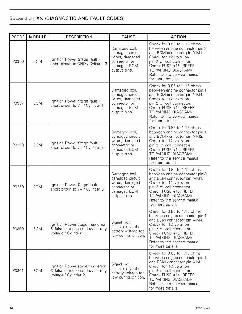
P0356 ECM Ignition Power Stage fault -short circuit to GND / Cylinder 3
Damaged coil,damaged circuitwires, damagedconnector ordamaged ECMoutput pins.
Check for 0.85 to 1.15 ohmsbetween engine connector pin 3and ECM connector pin A-M1.Check for 12 volts onpin 2 of coil connector.Check FUSE #15 (REFERTO WIRING DIAGRAM)Refer to the service manualfor more details.
P0357 ECM Ignition Power Stage fault -short circuit to V+ / Cylinder 1
Damaged coil,damaged circuitwires, damagedconnector ordamaged ECMoutput pins.
Check for 0.85 to 1.15 ohmsbetween engine connector pin 1and ECM connector pin A-M4.Check for 12 volts onpin 2 of coil connector.Check FUSE #13 (REFERTO WIRING DIAGRAM)Refer to the service manualfor more details.
P0358 ECM Ignition Power Stage fault -short circuit to V+ / Cylinder 2
Damaged coil,damaged circuitwires, damagedconnector ordamaged ECMoutput pins.
Check for 0.85 to 1.15 ohmsbetween engine connector pin 1and ECM connector pin A-M2.Check for 12 volts onpin 2 of coil connector.Check FUSE #14 (REFERTO WIRING DIAGRAM)Refer to the service manualfor more details.
P0359 ECM Ignition Power Stage fault -short circuit to V+ / Cylinder 3
Damaged coil,damaged circuitwires, damagedconnector ordamaged ECMoutput pins.
Check for 0.85 to 1.15 ohmsbetween engine connector pin 3and ECM connector pin A-M1.Check for 12 volts onpin 2 of coil connector.Check FUSE #15 (REFERTO WIRING DIAGRAM)Refer to the service manualfor more details.
P0360 ECMIgnition Power stage max error& false detection of low batteryvoltage / Cylinder 1
Signal notplausible, verifybattery voltage toolow during ignition.
Check for 0.85 to 1.15 ohmsbetween engine connector pin 1and ECM connector pin A-M4.Check for 12 volts onpin 2 of coil connector.Check FUSE #13 (REFERTO WIRING DIAGRAM)Refer to the service manualfor more details.
P0361 ECMIgnition Power stage max error& false detection of low batteryvoltage / Cylinder 2
Signal notplausible, verifybattery voltage toolow during ignition.
Check for 0.85 to 1.15 ohmsbetween engine connector pin 1and ECM connector pin A-M2.Check for 12 volts onpin 2 of coil connector.Check FUSE #14 (REFERTO WIRING DIAGRAM)Refer to the service manualfor more details.
22 tmr2013-025

Subsection XX (DIAGNOSTIC AND FAULT CODES)
PCODE MODULE DESCRIPTION CAUSE ACTION
P0362 ECMIgnition Power stage max error& false detection of low batteryvoltage / Cylinder 3
Signal notplausible, verifybattery voltage toolow during ignition.
Check for 0.85 to 1.15 ohmsbetween engine connector pin 3and ECM connector pin A-M1.Check for 12 volts onpin 2 of coil connector.Check FUSE #15 (REFERTO WIRING DIAGRAM)Refer to the service manualfor more details.
P0420 ECM Catalyst conversion insufficient
P0512 ECM Starter power stage detectshigh current
Damaged solenoid,damaged circuitwires, damagedconnector ordamaged ECM.
Verify FUSE #16 (5 AMP).Check for 12 volts onpin 2 of the starter relay.Refer to the service manual formore details.
P0513 ECM Invalid D.E.S.S. Key detectedKey notprogrammed inECU.
Program a good key
P0520 ECM Oil pressure switch functionalproblem
Engine leak, oilpump failure,damaged sensor,damaged circuitwires, damagedconnectoror damagedECM pins.
Check resistance at 0 RPMand above 3500 RPM.Switch is normally closed,ECM connector pin A-E3Refer to the service manual formore details.
P0523 ECM Oil pressure sensor fault
Engine leak, oilpump failure,damaged sensor,damaged circuitwires, damagedconnectoror damagedECM pins.Fault detectedwhen the engine isrunning or stopped.
Check resistance at 0 RPMand above 3500 RPM.
Refer to the servicemanual for more details.
P0524 ECM Low oil pressure conditionLow oil level,engine leak, oilpump fault.
Check oil level.Check impedance of sensor.Refer to the service manual formore details.
P0544 ECM Exhaust gas temperature sensorfunctional problem
Damaged sensor,damaged circuitwires, damagedconnector ordamaged ECMoutput pins.
Check for approximately 2280to 2736 ohms at temperature of19 to 21°C (66 to 70°F) betweensystem circuits A-H4 and A-J4.Refer to the service manual formore details.
tmr2013-025 23
Subsection XX (DIAGNOSTIC AND FAULT CODES)
PCODE MODULE DESCRIPTION CAUSE ACTION
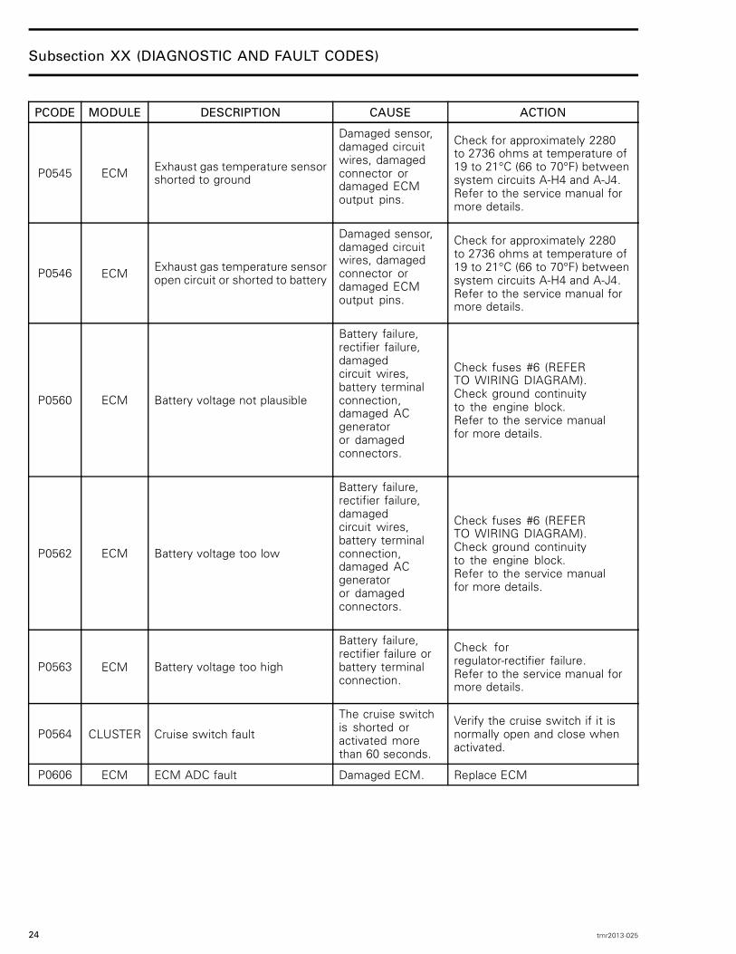
P0545 ECM Exhaust gas temperature sensorshorted to ground
Damaged sensor,damaged circuitwires, damagedconnector ordamaged ECMoutput pins.
Check for approximately 2280to 2736 ohms at temperature of19 to 21°C (66 to 70°F) betweensystem circuits A-H4 and A-J4.Refer to the service manual formore details.
P0546 ECM Exhaust gas temperature sensoropen circuit or shorted to battery
Damaged sensor,damaged circuitwires, damagedconnector ordamaged ECMoutput pins.
Check for approximately 2280to 2736 ohms at temperature of19 to 21°C (66 to 70°F) betweensystem circuits A-H4 and A-J4.Refer to the service manual formore details.
P0560 ECM Battery voltage not plausible
Battery failure,rectifier failure,damagedcircuit wires,battery terminalconnection,damaged ACgeneratoror damagedconnectors.
Check fuses #6 (REFERTO WIRING DIAGRAM).Check ground continuityto the engine block.Refer to the service manualfor more details.
P0562 ECM Battery voltage too low
Battery failure,rectifier failure,damagedcircuit wires,battery terminalconnection,damaged ACgeneratoror damagedconnectors.
Check fuses #6 (REFERTO WIRING DIAGRAM).Check ground continuityto the engine block.Refer to the service manualfor more details.
P0563 ECM Battery voltage too high
Battery failure,rectifier failure orbattery terminalconnection.
Check forregulator-rectifier failure.Refer to the service manual formore details.
P0564 CLUSTER Cruise switch fault
The cruise switchis shorted oractivated morethan 60 seconds.
Verify the cruise switch if it isnormally open and close whenactivated.
P0606 ECM ECM ADC fault Damaged ECM. Replace ECM
24 tmr2013-025

Subsection XX (DIAGNOSTIC AND FAULT CODES)
PCODE MODULE DESCRIPTION CAUSE ACTION
P060D ECM TAS (Throttle Acceleratorsensor) synchronization error
Damaged sensor,damaged circuitwires, damagedconnector ordamaged ECMpins.
Check system circuits B-E1,B-K1, B-K3, B-A3, B-B3, B-J3Check for 0 volt on sensorconnector pin B & E.Check for 5 volts on sensorconnector pin A & D. The 5 voltsupply is shared between theTAS signal 1, TOPS and MAPS.Verify all three sensor if oneis pulling too much current.Check for 0.5 to 3 voltson sensor connector pinFand 0.25 to 1.5 on CRefer to the service manualfor more details.
P060E ECMThrottle Actuator - ControllerFault- digital position controlexceeds limit
P0610 ECM Variant coding fault
P0629 CLUSTER Fuel sensor disconnected fault
Damaged sensor,damaged circuitwires, damagedconnector ordamaged ECMoutput pins.
Check for 2.6 ohms (full tank)to 93.6 ohms (empty tank)between pin C and pin Dat the fuel pump connector.Check system circuit atthe gauge Pin 19 and 20.(REFER TO WIRING DIAGRAM)
P0629 CLUSTER_CAFE Fuel sensor disconnected fault
Damaged sensor,damaged circuitwires, damagedconnector ordamaged ECMoutput pins.
Check for 2.6 ohms (full tank)to 93.6 ohms (empty tank)between pin C and pin Dat the fuel pump connector.Check system circuit atthe gauge Pin 19 and 20.(REFER TO WIRING DIAGRAM)
P062F ECM ECM EEPROM fault - exchangeECM Damaged ECM. Replace ECM.
P06B6 ECM ECM Fast ADC fault (knockdetection line)
P1030 ECMHeater Power Stage fault forlambda sensor upstreams ofcatalyst - open line
P1036 ECMHeater Power Stage fault forlambda sensor downstreams ofcatalyst - open line
P1106 ECM Altitude correction factor (fho)not plausible - out of range
P1120 ECMThrottle positions calculatedfrom TPS 1 and TPS 2 notcorresponding
Damagedthrottle actuator,damaged circuitwires, damagedconnector ordamaged ECM.
Check system circuit, performclosed throttle with B.U.D.S.Replace throttle actuator, replaceECM.
tmr2013-025 25

Subsection XX (DIAGNOSTIC AND FAULT CODES)
PCODE MODULE DESCRIPTION CAUSE ACTION
P1130 ECM Lambda Sensor fault upstreamsof catalyst - open line
P1136 ECMLambda Sensor faultdownstream of catalyst -open line
P1171 ECMAdditive mixture adaptationexceeds upper limit --> mixturetoo lean
An open signal on the Enginecoolant temperature (CTS) cantrigger that fault
P1172 ECMAdditive mixture adaptationbelow lower limit --> mixturetoo rich
An open signal on the Enginecoolant temperature (CTS) cantrigger that fault
P1264 ECM Ignition Power stage overload
Damaged coil,damaged circuitwires, damagedconnector ordamaged ECMoutput pins.Fault detectedwhen the engine isrunning.
P1502 ECM T.O.P.S. functional problem
Boat or sensorupside down,damaged circuitwires, damagedconnector ordamaged ECMoutput pins.
Check continuity forcircuits A-C4, A-G1, A-F4.The 5 volt supply is sharedbetween the TAS signal 1, TOPSand MAPS. Verify all three sensorif one is pulling too much current.Refer to the service manual formore details.
P1503 ECM T.O.P.S. switch short circuit to12V
Boat or sensorupside down,damaged circuitwires, damagedconnector ordamaged ECMoutput pins.
Check continuity forcircuits A-C4, A-G1, A-F4.The 5 volt supply is sharedbetween the TAS signal 1, TOPSand MAPS. Verify all three sensorif one is pulling too much current.Refer to the service manual formore details.
P1504 ECM T.O.P.S. switch short circuitground
Boat or sensorupside down,damaged circuitwires, damagedconnector ordamaged ECMoutput pins.
Check continuity forcircuits A-C4, A-G1, A-F4.The 5 volt supply is sharedbetween the TAS signal 1, TOPSand MAPS. Verify all three sensorif one is pulling too much current.Refer to the service manual formore details.
P1505 ECM T.O.P.S. switch fault nonplausible state
Boat or sensorupside down,damaged circuitwires, damagedconnector ordamaged ECMoutput pins. Opencircuit.
Check continuity forcircuits A-C4, A-G1, A-F4.The 5 volt supply is sharedbetween the TAS signal 1, TOPSand MAPS. Verify all three sensorif one is pulling too much current.Refer to the service manual formore details.
26 tmr2013-025

Subsection XX (DIAGNOSTIC AND FAULT CODES)
PCODE MODULE DESCRIPTION CAUSE ACTION
P1506 ECM T.O.P.S. switch open circuit
Boat or sensorupside down,damaged circuitwires, damagedconnector ordamaged ECMoutput pins. Opencircuit.
Check continuity forcircuits A-C4, A-G1, A-F4.The 5 volt supply is sharedbetween the TAS signal 1, TOPSand MAPS. Verify all three sensorif one is pulling too much current.Refer to the service manual formore details.
P1550 ECM Otas sensor voltage notplausible
Damaged sensor,damaged circuitwires, damagedconnector ordamaged ECM.Open circuit.
Check continuity for circuitsB-H3, B-H1 and FUSE #12.Refer to the service manual formore details.
P1606 ECM ECM ADC fault - exchange ECM Damaged ECM. No service action available forfault P1606.
P160E ECMThrottle Actuator - ControllerFault - digital position controlbelow limit
Damagedthrottle actuator,damaged circuitwires, damagedconnector ordamaged ECM.
Check system circuit, performclosed throttle with B.U.D.S.Replace throttle actuator, replaceECM.
P1610 ECM Throttle Actuator - Power Stagefault
Damagedthrottle actuator,damaged circuitwires, damagedconnector ordamaged ECM.
Check system circuit, performclosed throttle with B.U.D.S.Replace throttle actuator, replaceECM.
P1611 ECM Throttle Actuator - Power Stagefault
Damagedthrottle actuator,damaged circuitwires, damagedconnector ordamaged ECM.
Check system circuit, performclosed throttle with B.U.D.S.Replace throttle actuator, replaceECM.
P1612 ECM Throttle Actuator - Power Stagefault
Damagedthrottle actuator,damaged circuitwires, damagedconnector ordamaged ECM.
Check system circuit, performclosed throttle with B.U.D.S.Replace throttle actuator, replaceECM.
P1613 ECM Throttle Actuator - Power Stagefault
Damagedthrottle actuator,damaged circuitwires, damagedconnector ordamaged ECM.
Check system circuit, performclosed throttle with B.U.D.S.Replace throttle actuator, replaceECM.
P1614 ECMThrottle Actuator - Return-Springcheck not passed / Spring doesnot close
Damagedthrottle actuator,damaged circuitwires, damagedconnector ordamaged ECM.
Check system circuit, performclosed throttle with B.U.D.S.Replace throttle actuator, replaceECM.
tmr2013-025 27

Subsection XX (DIAGNOSTIC AND FAULT CODES)
PCODE MODULE DESCRIPTION CAUSE ACTION
P1615 ECM Throttle Actuator - Positionmonitoring fault
Damagedthrottle actuator,damaged circuitwires, damagedconnector ordamaged ECM.
Check system circuit, performclosed throttle with B.U.D.S.Replace throttle actuator, replaceECM.
P1616 ECM Throttle Actuator - Defaultposition check or learning fault
Damagedthrottle actuator,damaged circuitwires, damagedconnector ordamaged ECM.
Check system circuit, performclosed throttle with B.U.D.S.Replace throttle actuator, replaceECM.
P1619 ECM Throttle Actuator - Adaptation ofupper mechanical limit failed
Damagedthrottle actuator,damaged circuitwires, damagedconnector ordamaged ECM.
Check system circuit, performclosed throttle with B.U.D.S.Replace throttle actuator, replaceECM.
P1620 ECM Throttle Actuator - Adaptation oflower mechanical limit failed
Damagedthrottle actuator,damaged circuitwires, damagedconnector ordamaged ECM.
Check system circuit, performclosed throttle with B.U.D.S.Replace throttle actuator, replaceECM.
P1621 ECM Throttle Actuator - Abortion ofadaptation
Damagedthrottle actuator,damaged circuitwires, damagedconnector ordamaged ECM.
Check system circuit, performclosed throttle with B.U.D.S.Replace throttle actuator, replaceECM.
P1622 ECM Throttle Actuator - Repeatedabortion of adaptation
Damagedthrottle actuator,damaged circuitwires, damagedconnector ordamaged ECM.
Check system circuit, performclosed throttle with B.U.D.S.Replace throttle actuator, replaceECM.
P1654 ECM Voltage of D.E.S.S. key switchout of range
Damaged D.E.S.S.key switch,damaged circuitwires, damagedconnector ordamaged ECMoutput pins.
Remove D.E.S.S. key andcheck system circuit B-B2.Refer to the service manual formore details.
P1657 ECM Electrical fault of D.E.S.S. keycommunication line
Damaged D.E.S.S.key switch,damaged circuitwires, damagedconnector ordamaged ECMoutput pins.
Remove D.E.S.S. key andcheck system circuit B-B2.Refer to the service manual formore details.
28 tmr2013-025

Subsection XX (DIAGNOSTIC AND FAULT CODES)
PCODE MODULE DESCRIPTION CAUSE ACTION
P1658 ECM Faulty D.E.S.S. keycommunication
Damaged D.E.S.S.key switch,damaged circuitwires, damagedconnector ordamaged ECMoutput pins.
Remove D.E.S.S. key andcheck system circuit B-B2.Refer to the service manual formore details.
P1661 ECM iBR malfunction iBR fault detectedby ECM.
Remove D.E.S.S. keyPerform an electrical systemshut down. Clear fault.
P1662 ECM iBR torque request is notplausible
iBR fault detectedby ECM.
Perform iBR software update ifavailable or replace iBR.
P1679 ECM Main Relay StickingPermanent 12V ispresent on ECMPin B-M4.
ECU pin B-M4 is permanentlysupplied thru 15 amp fuse and itshould be accessory 12 Vdc.
P16B6 ECM ECU Fast ADC fault (knockdetection line)
P16B7 ECM ECU Fast ADC fault (knockdetection line)
P16B8 ECM ECU Fast ADC fault (knockdetection line)
P16C0 ECM Fault of ECM ADC
P16C1 ECM Fault of ECM ADC
P16C2 ECM Fault of ECM monitoring module
P16C3 ECM Monitoring fault due toAccelerator Sensor check
P16C4 ECM Monitoring fault due to enginespeed check
P16C5 ECM Safety fuel cut off activ -Monitoring level 1
P16C6 ECM Safety fuel cut off activ -Monitoring level 2
P16C7 ECM Monitoring fault due to throttlevalve plausibility check
Damagedthrottle actuator,damaged circuitwires, damagedconnector ordamaged ECM.
Check system circuit, performclosed throttle with B.U.D.S.Replace throttle actuator, replaceECM.
P16C8 ECMMonitoring fault due toexceeding permitted throttlevalve position
Damagedthrottle actuator,damaged circuitwires, damagedconnector ordamaged ECM.
Check system circuit, performclosed throttle with B.U.D.S.Replace throttle actuator, replaceECM.
tmr2013-025 29

Subsection XX (DIAGNOSTIC AND FAULT CODES)
PCODE MODULE DESCRIPTION CAUSE ACTION
P16C9 ECM Monitoring detected nonplausible D.E.S.S. key state
Damaged D.E.S.S.key switch,damaged circuitwires, damagedconnector ordamaged ECMoutput pins.
Remove D.E.S.S. key andcheck system circuit B-B2.Refer to the service manual formore details.
P16CA ECM ECU detected faulty watch dogline - ECU defect Damaged ECM. Replace ECM.
P16CB ECMECU switch off through watchdog line (hardware fault) - ECUdefect
Damaged ECM. Replace ECM.
P2080 ECM Exhaust temperature notplausible
Damaged sensor,damaged circuitwires, damagedconnector ordamaged ECMoutput pins.
Check for approximately 2280to 2736 ohms at temperature of19 to 21°C (66 to 70°F) betweensystem circuits A-H4 and A-J4.Refer to the service manual formore details.
P2081 ECM Exhaust temperature sensorfault
Intermittentconnection.Damaged sensor,damaged circuitwires, damagedconnector ordamaged ECMoutput pins.
Check for approximately 2280to 2736 ohms at temperature of19 to 21°C (66 to 70°F) betweensystem circuits A-H4 and A-J4.Refer to the service manual formore details.
P212C ECM Electrical lower-range violationTPS 2
Damagedthrottle actuator,damaged circuitwires, damagedconnector ordamaged ECM.
Check system circuit, performclosed throttle with B.U.D.S.Replace throttle actuator, replaceECM
P212D ECM Electrical upper-range violationTPS 2
Damagedthrottle actuator,damaged circuitwires, damagedconnector ordamaged ECM.
Check system circuit, performclosed throttle with B.U.D.S.Replace throttle actuator, replaceECM
P2159 ECM TAS (Throttle Acceleratorsensor) signal not plausible
P2245 ECMLambda Sensor aging faultdownstreams of catalyst -Sensor Voltage too low
P2246 ECMLambda Sensor aging faultdownstreams of catalyst -Sensor Voltage too high
P2279 ECM Air intake manifold leakdownstream of throttle
30 tmr2013-025

Subsection XX (DIAGNOSTIC AND FAULT CODES)
PCODE MODULE DESCRIPTION CAUSE ACTION
P2428 ECM High exhaust temperaturedetected
Exhaust overheat,damaged sensoror damaged circuitwires.
Check coolingsystem for blockage.Check if the exhaust injectionvalve is properly calibrated.Refer to the service manual formore details.
P2620 ECM TPS value not plausible
Damagedthrottle actuator,damaged circuitwires, damagedconnector ordamaged ECM.
Check system circuit, performclosed throttle with B.U.D.S.Replace throttle actuator, replaceECM
P2621 ECM Electrical lower-range violationTPS 1
Damagedthrottle actuator,damaged circuitwires, damagedconnector ordamaged ECM.
Check system circuit, performclosed throttle with B.U.D.S.Replace throttle actuator, replaceECM
P2622 ECM Electrical upper-range violationTPS 1
Damagedthrottle actuator,damaged circuitwires, damagedconnector ordamaged ECM.
Check system circuit, performclosed throttle with B.U.D.S.Replace throttle actuator, replaceECM
U0100 ECMECU could not establish CANcommunication with partnerECU
U0129 ECM CAN communication errorbetween ECM and iBR module
iBR fault detectedby ECM.C.A.N. circuitfailure, iBR orECM failure.Disconnectedconnector.
Check C.A.N. circuits wires.Replace iBR.Refer to the service manualfor more details.
U0129 IS IBR CAN messages timeout orvalidity
Warning only: theiS module lostcommunicationwith the iBR.
If fault ACTIVE, verify CANconnection between iBR and iS
U0300 ECM Exchange security - Wrong ECM Incorrect ECM orcluster for engine.
Install proper recommendedECM or cluster for vehicle.
U0401 IBR ECM CAN messages timeout orvalidity
C.A.N. circuitfailure, ECMsoftware failure.
Check C.A.N. circuits wires.Replace ECM.Refer to the service manualfor more details.
U0401 IS ECM CAN messages timeout orvalidity
Warning only: theiS module lostcommunicationwith the engineECU.
If fault ACTIVE, verify CANconnection between ECM and iS
U0401 IBR 2013 ECM CAN messages timeout orvalidity
C.A.N. circuitfailure, ECMsoftware failure.
Check C.A.N. circuits wires.Replace ECM.Refer to the service manualfor more details.
tmr2013-025 31

Subsection XX (DIAGNOSTIC AND FAULT CODES)
PCODE MODULE DESCRIPTION CAUSE ACTION
U0401 IBR_II ECM CAN messages timeout orvalidity
C.A.N. circuitfailure, ECMsoftware failure.
Check C.A.N. circuits wires.Replace ECM.Refer to the service manualfor more details.
U0402 IBR_II ECM CAN messages timeout orvalidity (320)
C.A.N. circuitfailure, ECMsoftware failure.
Check C.A.N. circuits wires.Replace ECM.Refer to the service manualfor more details.
U0403 IBR_II ECM CAN messages timeout orvalidity (516)
C.A.N. circuitfailure, ECMsoftware failure.
Check C.A.N. circuits wires.Replace ECM.Refer to the service manualfor more details.
U0457 IBR Cluster CAN messages timeoutor validity
C.A.N. circuitfailure, Clustersoftware failure.
Check C.A.N. circuits wires.Replace instrument Cluster.Refer to the service manual formore details.
U0457 IS Cluster CAN messages timeoutor validity
Warning only: theiS module lostcommunicationwith the Cluster.
If fault ACTIVE, verify CANconnection between Cluster andiS
U0457 IBR 2013 Cluster CAN messages timeoutor validity
C.A.N. circuitfailure, Clustersoftware failure.
Check C.A.N. circuits wires.Replace instrument Cluster.Refer to the service manual formore details.
U0457 IBR_II Cluster CAN messages timeoutor validity
C.A.N. circuitfailure, Clustersoftware failure.
Check C.A.N. circuits wires.Replace instrument Cluster.Refer to the service manual formore details.
U1301 ECMSoftware / Data compatibilityerror between starboard andport ECUs
U16A1 ECM Cluster CAN Timeouterror-Missing CAN ID 514h
Cluster faultdetected by ECM.C.A.N. circuitfailure, Instrumentcluster or ECMfailure.
Check C.A.N. circuits wires.Replace instrument Cluster.Refer to the service manual formore details.
U16A2 ECM Cluster CAN Timeouterror-Missing CAN ID 230h
Cluster faultdetected by ECM.C.A.N. circuitfailure, Instrumentcluster or ECMfailure.
Check C.A.N. circuits wires.Replace instrument Cluster.Refer to the service manual formore details.
U16A3 ECM Cluster CAN Timeouterror-Missing CAN ID 408h
Cluster faultdetected by ECM.C.A.N. circuitfailure, Instrumentcluster or ECMfailure.
Check C.A.N. circuits wires.Replace instrument Cluster.Refer to the service manual formore details.
32 tmr2013-025
Subsection XX (DIAGNOSTIC AND FAULT CODES)
PCODE MODULE DESCRIPTION CAUSE ACTION
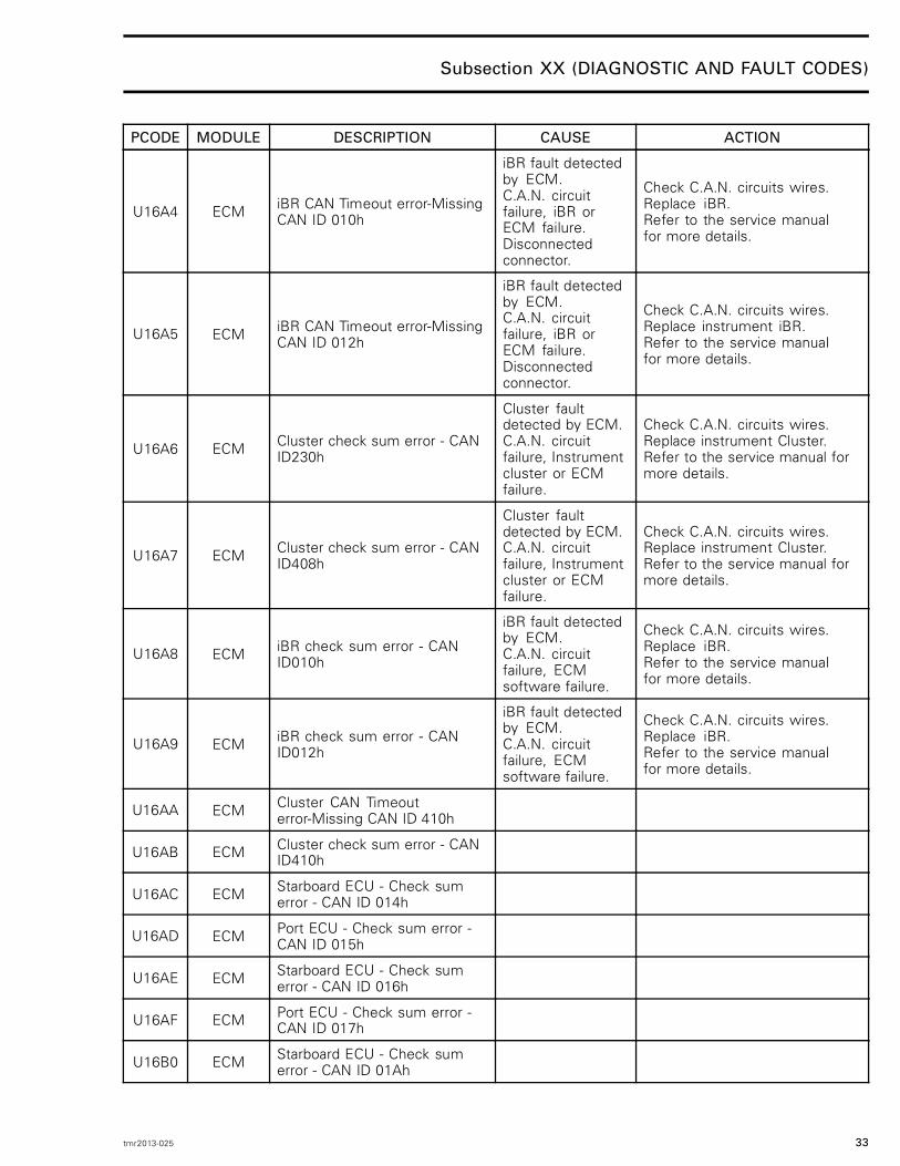
U16A4 ECM iBR CAN Timeout error-MissingCAN ID 010h
iBR fault detectedby ECM.C.A.N. circuitfailure, iBR orECM failure.Disconnectedconnector.
Check C.A.N. circuits wires.Replace iBR.Refer to the service manualfor more details.
U16A5 ECM iBR CAN Timeout error-MissingCAN ID 012h
iBR fault detectedby ECM.C.A.N. circuitfailure, iBR orECM failure.Disconnectedconnector.
Check C.A.N. circuits wires.Replace instrument iBR.Refer to the service manualfor more details.
U16A6 ECM Cluster check sum error - CANID230h
Cluster faultdetected by ECM.C.A.N. circuitfailure, Instrumentcluster or ECMfailure.
Check C.A.N. circuits wires.Replace instrument Cluster.Refer to the service manual formore details.
U16A7 ECM Cluster check sum error - CANID408h
Cluster faultdetected by ECM.C.A.N. circuitfailure, Instrumentcluster or ECMfailure.
Check C.A.N. circuits wires.Replace instrument Cluster.Refer to the service manual formore details.
U16A8 ECM iBR check sum error - CANID010h
iBR fault detectedby ECM.C.A.N. circuitfailure, ECMsoftware failure.
Check C.A.N. circuits wires.Replace iBR.Refer to the service manualfor more details.
U16A9 ECM iBR check sum error - CANID012h
iBR fault detectedby ECM.C.A.N. circuitfailure, ECMsoftware failure.
Check C.A.N. circuits wires.Replace iBR.Refer to the service manualfor more details.
U16AA ECM Cluster CAN Timeouterror-Missing CAN ID 410h
U16AB ECM Cluster check sum error - CANID410h
U16AC ECM Starboard ECU - Check sumerror - CAN ID 014h
U16AD ECM Port ECU - Check sum error -CAN ID 015h
U16AE ECM Starboard ECU - Check sumerror - CAN ID 016h
U16AF ECM Port ECU - Check sum error -CAN ID 017h
U16B0 ECM Starboard ECU - Check sumerror - CAN ID 01Ah
tmr2013-025 33

Subsection XX (DIAGNOSTIC AND FAULT CODES)
PCODE MODULE DESCRIPTION CAUSE ACTION
U16B1 ECM Port ECU - Check sum error -CAN ID 01Bh
U16B2 ECM Starboard ECU - Check sumerror - CAN ID 102h
U16B3 ECM Port ECU - Check sum error -CAN ID 1A2h
U16B4 ECM Starboard ECU - CAN Timeouterror-Missing CAN ID 014h
U16B5 ECM Port ECU - CAN Timeouterror-Missing CAN ID 015h
U16B6 ECM Starboard ECU - CAN Timeouterror-Missing CAN ID 016h
U16B7 ECM Port ECU - CAN Timeouterror-Missing CAN ID 017h
U16B8 ECM Starboard ECU - CAN Timeouterror-Missing CAN ID 01Ah
U16B9 ECM Port ECU - CAN Timeouterror-Missing CAN ID 01Bh
U16BA ECM Starboard ECU - CAN Timeouterror-Missing CAN ID 102h
U16BB ECM Port ECU - CAN Timeouterror-Missing CAN ID 1A2h
U16BC ECM Cluster CAN Timeouterror-Missing CAN ID 5B4h
U16BD ECM
CAN Timeout or Check sumerror of synchronizationmessages (Twin enginevehicles)
U1700 ECM ECU could not detect its position(starboard/port)
U1701 ECM Partner ECU could not detect itsposition (starboard/port)
U1702 ECMBoth ECUs detectedsame installation position(starboard/port)
34 tmr2013-025