development of solar powered notebook salmah binti...
TRANSCRIPT

DEVELOPMENT OF SOLAR POWERED NOTEBOOK
SALMAH BINTI MAHFUL
This thesis is submitted as partial fulfillment of the requirements for the award of the
degree of bachelor of Electrical Engineering (Power System)
Faculty of Electrical & Electronics Engineering
Universiti Malaysia Pahang
NOVEMBER, 2010

“I hereby acknowledge that the scope and quality of this thesis is qualified for the
award of the Bachelor Degree of Electrical Engineering (Power Systems)”
Signature : …………………………..
Name : RAMDAN BIN RAZALI
Date : 30 NOV 2010

ii
“All the trademark and copyrights use herein are property of their respective owner.
References of information from other sources are quoted accordingly; otherwise the
information presented in this report is solely work of the author.”
Signature : ...............................................
Author : SALMAH BINTI MAHFUL
Date : 30 NOV 2010

iv
ACKNOWLEDGEMENT
In the name of ALLAH s.w.t., most gracious, most merciful.
On the completion of this thesis. I wish to great fully acknowledge, by taking
this opportunity to express my sincere gratitude to my supervisor, Mr. Ramdan
whom giving me kind support, encouragement, guidance and useful suggestion that
proved very useful in my project. He has been the main source of motivation in
pursuing my project ideas. Once again thank all the people who have directly or
indirectly help in my project.
Lastly, I sincerely thank all my friends who have always given their
encouraging support and been a great help all the time at various stage of
development of this project. I would like to extend my appreciate to my parent for
always there for me.

v
ABSTRACT
The Notebook powered by it battery is convenience to use where AC outlet is
not available such as in more rural and underdeveloped areas. However,
Notebook can drain it battery with heavy use in just a few hours, leaving the user
searching for power outlet. With development of Solar Powered Notebook, the
sun is the electricity needed to keep the Notebook running for hours longer where
Solar or Photovoltaic (PV) Cells are used to collect solar energy for direct use to
power up the Notebook. The design of the circuit can be summarized into four
distinct circuits that work in tandem to generate the desired output of 20V from a
solar panel input. The first is Boost Converter circuit to take in the input voltage
from the solar panel and step up the voltage to the desired 20V as required by the
Notebook. The second is timer circuit where it utilized the LM555 timer, which
drives the MOSFET that operates as the switch in the Switch-Mode Boost
Converter topology. The third is Active PFC Feedback circuit, this circuit allows
for regulation of the output voltage so that the Boost Converter is only on for as
long as necessary to maintain a voltage of 20V. Finally, there is the Voltage
Clipper Circuit, which is the actual output voltage to the Notebook. This project
suitable for scientists or researchers who work far away from civilization and
power outlet. The Solar Powered Notebook proved to be energy saving because
free energy, environmental benefits which reduce CO2 emissions associated with
global warming and it works where there is no grid available.

vi
ABSTRAK
Notebook yang menggunakan kuasa bateri memberi manfaat di tempat-
tempat yang jauh dari sumber kuasa a.u seperti di pedalaman dan kawasan-kawasan
yang belum membangun. Walau bagaimanapun, kuasa bateri tidak mampu bertahan
lama sekadar beberapa jam sahaja dengan penggunaan maksimum, menyebabkan
pengguna terdesak untuk mencari sumber kuasa. Dengan projek Solar Powered
Notebook, matahari merupakan tenaga elektrik yang diperlukan bagi menghidupkan
Notebook lebih lama di mana Solar atau Photovoltaic (PV) Cell digunakan untuk
mengumpul tenaga suria untuk digunakan secara terus bagi menghidupkan Notebook.
Projek ini terdiri daripada empat litar yang saling berkait bagi menghasilkan keluaran
20V yang diperlukan oleh Notebook. Litar pertama adalah Boost Converter di mana
ia mengambil voltan masukkan dari solar panel dan meninggikan voltan kepada 20V
yang diperlukan oleh Notebook. Litar kedua ialah litar timer yang menggunakan
LM555 timer, di mana memacu MOSFET berfungsi sebagai suis di dalam Switch
Mode Boost Converter. Litar ketiga pula ialah litar Active PFC feedback, litar ini
membenarkan perubahan voltan keluaran supaya Boost Converter akan berfungsi
apabila diperlukan untuk menetapkan pengeluaran voltan 20V sahaja. Akhir sekali,
litar Voltage Clipper, di mana memberi voltan sebenar kepada Notebook. Projek ini
sangat penting dan sesuai kepada para saintis dan para pengkaji yang menjalankan
tugasan jauh dari bandar atau sumber kuasa. Projek ini terbukti menjimatkan tenaga
elektrik kerana menggunakan tenaga suria serta mengelakkan pencemaran kerana
dapat mengurangkan pengeluaran tenaga CO2 di stesen generator dan projek ini juga
mampu berfungsi ketika jauh dari sumber grid.
vii
TABLE OF CONTENT
CHAPTER TITLE PAGE
DECLERATION ii
DEDICATION iii
ACKNOWLEDGEMENT iv
ABSTRACT v
ABSTRAK vi
TABLE OF CONTENTS vii
LIST OF TABLES x
LIST OF FIGURES xi
LIST OF ABBREVIATIONS xiii
LIST OF APPENDICES xiv
1.0 INTRODUCTION
1.1 Overview of The Project 1
1.2 Problems Statement 2
1.3 Objectives 2
1.4 Scope of Work 2
1.5 Thesis Outline 3
2.0 LITERATURES REVIEW
2.1 Introduction 4
2.2 Benefit of Photovoltaic Module (Solar Panel) 4
2.3 Type of Photovoltaic Module (Solar Panel) 5
2.4 Solar Power Supply System Using DC-DC Converter 7
2.4.1 Boost Type Bidirectional DC-DC Converter 8
2.4.2 Buck Converter 11

viii
2.4.2.1 The Downsized Solar PV System 11
2.4.3 Buck-boost Converter 14
3.0 METHODOLOGY
3.1 Introduction 17
3.2 Block Diagram of the Project 18
3.3 Schematic Diagram of the Project 18
3.3.1 Detail Component Description and Function 20
3.3.1.1 Solar Panel 20
3.3.1.2 Boost Converter Circuit 21
3.3.1.3 Timer Circuit 23
3.3.1.4 Active PFC Feedback Circuit 24
3.3.1.5 Output Voltage Clipper 25
3.4 Design Procedure of Development
of Boost Converter Circuit 26
3.4.1 Power Switch 28
3.4.2 Inductor 29
3.4.3 Diode 29
3.4.4 Capacitor 30
3.5 Driver Circuit 30
3.5.1 555 Pin Function 31
3.5.2 Timer Specification 32
3.5.3 Basic Operation 32
3.6 Boost Converter Design Analysis 33
4.0 RESULTS
4.1 Introduction 37
4.2 OrCAD Simulation Result 37
4.3 Driver Circuit Hardware Test 40

ix
4.4 Boost Converter Hardware Test 41
4.5 Overall Hardware Design 42
5.0 CONCLUSIONS
5.1 Conclusions 43
5.2 Future Recommendations 44
5.3 Costing & Commercialization 45
REFERENCES 47

x
LIST OF TABLES
NO. TITLE PAGE
3.1 Solar Panel Specification 21
3.2 555 Timer Specification 32
3.3 Boost Converter Specification 34
3.4 The Parameters of Boost Converter Design 36
4.1 Boost Converter Hardware Test Result 41
5.1 List of Components 46

xi
LIST OF FIGURES
NO. TITLE PAGE
2.1 Monocrystalline Solar Panel 6
2.2 Polycrystalline Solar Panel 6
2.3 Amorphous Solar Panel 7
2.4 Block Diagram of the Solar Power Supply System Using
Boost Converter
9
2.5(a) Block diagram in the charge mode of the solar cell power
supply system η1, and η 2 are the conversion efficiencies
of the unidirectional and the bidirectional converters
9
2.5 (b) Block diagram in the discharge mode I of the solar cell
power supply system
9
2.5 (c) Block diagram in the discharge mode II of the solar cell
power supply system.
10
2.6 Block Diagram of The Proposed Solar PV Energy System
Using Constant Voltage Control (CVC) Method For MPP
12
2.7 Insolation Characteristics of A PV Panel In Relation To
CVC Method
12
2.8 Realization of The Proposed CVC MPPT On a Buck
Converter
13
2.9 Buck-Boost DC-DC converter schematic diagram 14
2.10 (a) The equivalent schematic diagram while switch is on 14
2.10 (b) The equivalent schematic diagram while switch is off 15
3.1 Block Diagram for Solar Powered Notebook 18
3.2 Schematic Design for Solar Powered Notebook 19
3.3 SW 80 mono/R5E Solar Panel 20
3.4 Basic Boost Converter Circuit 23
3.5 Basic LM555 Timer Circuit 24

xii
3.6 Basic Voltage Clipper Circuit 25
3.7 (a) Boost Converter Circuit Configuration 27
3.7 (b) Circuit when the switch is closed 27
3.7 (c) Circuit when the switch is open 27
3.8 IRFP150N terminal pin configuration 28
3.9 Schottky Diode 29
3.10 LM555 Timer With Pin Configuration 30
3.11 555 astable circuit 33
4.1 Output Voltage of Boost Converter Simulation Using
OrCAD
38
4.2 Output Voltage of Boost Converter & Reset Pin VoltageSimulation Using OrCAD
39
4.3 Switching Output Waveform Pulse 40
4.4 Solar Power Notebook Circuit 42

Xii
LIST OF ABBREVIATIONS
PFC −Power Factor Correction
PV −Photovoltaic
DC/dc −Direct Current
SMPS −Switch-Mode Power Supply
CCM −Continuous Current Mode
GND −Ground
MOSFET −Metal–Oxide–Semiconductor Field-Effect Transistor
PWM −Pulse Width Modulation
MPPT −Maximum Power Point Tracker
CVC −Constant Voltage Control
LED −Light Emitting Diode
BIPV −Building Integrated Photovoltaic
AC − Alternating Current
PWM −Pulse Width Modulation
ƒ −Frequency
D −Duty Cycle
L −Inductance
C −Capacitance
R −Resistance
CCM −Continuous Conduction Model
IC −Integrated Circuit

xiii
LIST OF APPENDICES
APPENDIX TITLE
A Solar Powered Notebook Project
B Solar Panel Datasheet
C 555 Timer Datasheet
D IRFP150N Datasheet

CHAPTER 1
INTRODUCTION
This part described introduction an overview of the research work. It will explain
about overview of the project, problems statement, objectives and scope of work that
must be done.
1.1 Overview of The Project
Solar or Photovoltaic (PV) is the one of the renewable energy resources that
recently has become more popular in nowadays technologies. PV has many benefits
especially in environmental, economic and social. In general, a PV system consist of
a PV array which converts sunlight into direct-current (DC) source. There are many
technologies for solar energy application through residential, commercial, industrial,
agricultural and transportation sectors.
But in this project, DC source is used to power up the notebook. With
development of solar powered notebook, the sun is the electricity needed to keep that
notebook running for hours longer after the notebook battery run out. In this project,
Solar or Photovoltaic (PV) cells are used to collect solar energy for direct use.
Although there are numerous commercially available DC-to-DC converters available
in market, most are costly. A combination of four simple circuits is combining to
create a cheaper alternative to the commercially available DC-to-DC converters on
the market. This project sure very useful for scientists or researchers who work far
away from civilization and power source.

2
1.1 Problems Statement
As mentioned previously, Notebook can drain it battery with heavy use in just a
few hours and power source is not available such as in more rural or undeveloped
area to power the notebook. Therefore, since notebook required DC source, solar
panel is the best solution.
1.3 Objectives
The aims of this project are:
i. To design and implement solar power supply system for the notebook using
solar energy.
ii. To design and implement boost converter based of PWM to boost the supply
voltage from 12VDC from solar panel to 20VDC.
1.4 Scope of Work
In this study, by using solar panel, it will produce 80W 17VDC 5A current
output. In my design scope, the boost converter circuit will take in the 13VDC
voltage and step up the voltage to the desired 20VDC as required by the FujiTsu
Notebook model with the specification is 20VDC 3.25A 65W.
Second focused on the project is expected to deliver the power during the day
time only and when sunlight is available.

3
1.5 Thesis Outline
This Development of Solar Powered Notebook thesis is arranged into following
chapter:
Chapter 1 discuss on the background of the project, objectives, scope of the
project, problem statement and also the thesis outline.
Chapter 2 focuses on literature reviews of this project based on journals and
other references.
Chapter 3 main discuss on the system design of the project. Details on the
progress of the project are explained in this chapter.
Chapter 4 presents the results of the project. The discussion focused on the
result based on the experiment and performance of Development of Solar
Powered Notebook.
Chapter 5 concludes overall about the project. Obstacle faces and future
recommendation are also discussed in this chapter.

CHAPTER 2
LITERATURE REVIEW
2.1 Introduction
Power electronics is one of the broadest growth areas in electrical
technology. Today, electronic energy processing circuits are needed for every
computer system, every digital product, industrial systems of all types,
automobiles, home appliances, lamps and lighting equipment, motor controllers,
and just about every possible application of electricity (A.H.M.Yatim, 2006).
T his chapter are the reviews about the study that have been done before developed
the Solar Powered Notebook. Some of the systems look alike with the Solar Power
Notebook project. Other, they are the study about the main components used.
2.2 Benefits of Photovoltaic Module (Solar Panel)
These days, energy crises are growing and all those countries which are
blessed with sunlight can use solar energy for their household items and businesses.
Solar energy is helping a lot of countries that have started developing solar polar for
their convenience to save themselves from pollution. Investing in solar power will
not be a wrong decision and it will be bringing a lot of fruitful results for stabilizing
the economy of a country. The other benefits can be concluded below: [1]

5
i. Solar electricity can supplement or provide all your electrical
consumption.
ii. Additional solar modules can be added later as demand or budget grows.
iii. Solar electricity is generated without emitting greenhouse gases .
iv. Solar panels or modules are silent, without any moving parts.
v. Solar modules can be integrated into the building in the form of
windows, walls and roof tiles and known as Building Integrated PV
(BIPV).
vi. A solar module should last for at least 20–30 years.
2.3 Types of Photovoltaic Module (Solar Panel)
Due to the growing demand for renewable energy sources, the production of
solar cells and photovoltaic arrays has advanced dramatically in recent years.
Practically there are three basic types of PV solar panels; which is
Monocrystalline, Polycrystalline and Amorphous. The consumer can choose the
types of PV based on their need and availability. For this project,
Monocrystalline PV solar panel is chosen.
i. Monocrystalline cells are cut from a single crystal of silicon. They are basically a
slice of crystal. This makes them very smooth in texture and can see the thickness of
the slice. Monocrystalline cells are the most efficient, but also the most expensive to
produce. They are completely rigid and must be mounted in a rigid frame for
protection. Figure 2.1 below show Monocrystalline cells solar panel.

6
Figure 2.1 Monocrystalline Solar Panel
ii. Polycrystalline (or Multicrystalline) cells as show in figure 2.2 are made from a slice
cut from a block of silicon, but whereas Monocrystalline cells are from a single
crystal, these cells consist of a large number of crystals. This gives them a speckled
reflective appearance but, once again you can you see the thickness of the slice.
Photovoltaic solar panels made from these types of cell are slightly less efficient but
also slightly cheaper than Monocrystalline cells. They also need to be mounted in a
rigid frame.
Figure 2.2 Polycrystalline Solar Panel
iii. Finally, Amorphous cells are manufactured by placing a thin film of Amorphous
(non crystalline) silicon onto a wide range of surfaces. These create the least
efficient type of Photovoltaic solar panels but also the cheapest. Due to the
Amorphous nature of the thin layer it is flexible, and if manufactured on a flexible

7
surface, the whole Photovoltaic solar panel can be flexible. One problem with
Amorphous cells, however, is that their power output reduces over time, particularly
during the first few months, after which time they are basically stable. The quoted
output of an Amorphous panel should be that produced after this period. Figure 2.3
below show Amorphous cells solar panel.
Figure 2.3 Amorphous Solar Panel
2.4 Solar Power Supply System Using DC-DC Converter
The solar cell is now being used as power sources for radio relay stations,
light houses, agricultural systems, microwave communication systems, and so forth.
In such solar cell power supply systems, it often requires that the maximum power
point of the solar array is tracked, in spite of the variations in the load and the
sunlight intensity, to make the most efficient use of the solar array and the storage
battery [2]-[6].
A MPPT is a power electronic DC/DC converter inserted between the PV
module and load to achieve optimum matching. By using an intelligent algorithm, it
ensures that the PV module always operates at its maximum power point. Several
MPPT algorithms have been proposed in different literatures like Perturb & Observe
(P&O), Incremental Conductance, Constant Voltage, Constant Current and fuzzy
based algorithms [7]. These techniques differ in many aspects like complexity,

8
convergence speed, hardware implementation, sensors required, cost, range of
effectiveness and need for parameterization. The P&O and Incremental Conductance
algorithms are more common due to effectiveness of extracting maximum power
from the panel, ease of hardware implementation, and less sensor requirement and
consequently relative low cost [5]. But is has problem of oscillation around the
MPP, due to this there is considerable loss of power. Also the response of P&O
algorithms is slow under fast changing environmental condition. Different converter
topologies like buck, boost, buck-boost and cuk converters are implemented for
MPPT design. Boost converter can track MPP with maximum efficiency and can
work for wide range of input voltage [5]. However, other advantages like less
component needed for hardware implementation and cost, makes this topology a
better choice than the buck or buck-boost for MPPT system design.
2.4.1 Boost Type Bidirectional DC-DC Converter [2]
In this solar cell power supply system, the boost type bidirectional converter
as a charger/discharger and the simple control circuit with a small monitor solar cell
are used in order to track the maximum power point of the solar array. The key
point to note is that in the system each converter processes the solar array output
power in parallel, and that the short-circuit current of the monitor solar cell is made
use of as a reference to detect the maximum power point.
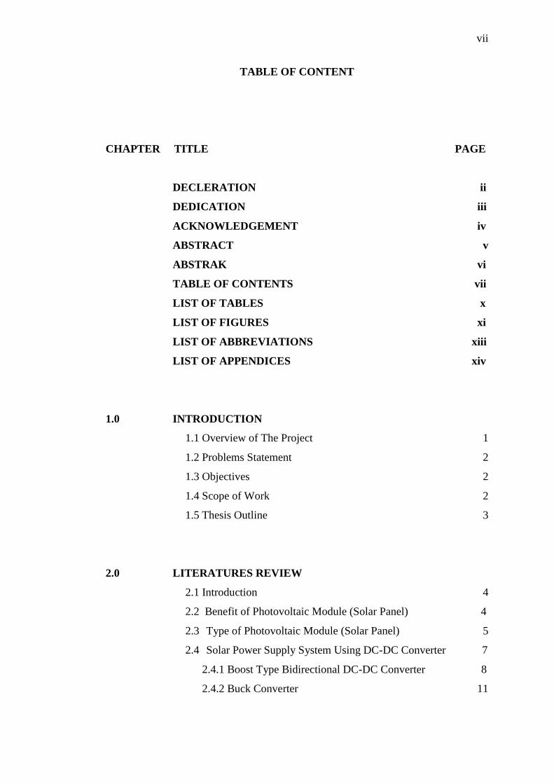
The block diagram of the solar cell power supply system is shown in figure
2.4. In this system, the traditional unidirectional converter is used as a stabilizer and
the bidirectional converter as a maximum power tracker. The operation of this
system is divided broadly into two modes, which are called the charge and discharge
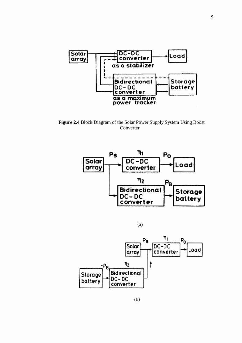
modes. Figure 2.5(a) shows the block diagram in the charge mode of the system,
and the discharge mode is divided further into two submodes as represented by the
block diagrams of figure 2.5(b) and (c). Now we will give the consideration to these
three modes; the charge mode, and the discharge modes I and II.
9
Figure 2.4 Block Diagram of the Solar Power Supply System Using BoostConverter
(a)
(b)

10
(c)
Figure 2.5 (a) Block diagram in the charge mode of the solar cell power supply
system η1, and η 2 are the conversion efficiencies of the unidirectional and the
bidirectional converters (b) Block diagram in the discharge mode I of the solar cell
power supply system. (c) Block diagram in the discharge mode II of the solar cell
power supply system.
First, when the light intensity Ee is sufficiently high, the solar array output
power Ps, is large and, in this case, the bidirectional converter operates in the charge
mode, as illustrated in figure 2.5(a). In this mode, some amount of the power Ps is
transferred to the load only through the unidirectional converter and the excess
power of Ps is sent to and stored in the storage battery only through the bidirectional
converter. Thus the solar array output power Ps is processed by each converter in
parallel.
Next, when the light intensity Ee is so low that the solar array output power Ps
is less than the load power Po, the bidirectional converter operates in the discharge
mode and the storage battery takes over the load power in part as illustrated in figure
2.5 (b). The solar array output power Po is sent to the load through the unidirectional
converter alone but the power -PB from the storage battery is processed by both of
the bidirectional and the unidirectional converters in series.