universiti putra malaysia the development of...
TRANSCRIPT

UNIVERSITI PUTRA MALAYSIA
THE DEVELOPMENT OF UNINTERRUPTIBLE POWER SUPPLY FOR PERSONAL COMPUTERS
ALI MILAD JARUSHI
FK 2000 20

THE DEVELOPMENT OF UNINTERRUPTmLE POWER SUPPLY FOR PERSONAL COMPUTERS
By
ALI MlLAD JARUSBI
Thesis Submitted in FulfIlment of Requirements for the Degree of Master of Science in the Faculty of Engineering
U niversiti Putra Malaysia
October 2000

Dedicated to
My Parents, Wife
andsonAnas
II

Abstract of thesIs presented to the Senate ofUmversltl Putra MalaysIa In fulfilment of the reqUIrements for the degree of Master of SCIence
THE DEVELOPMENT OF UNINTERRUPTffiLE POWER SUPPLY FOR PERSONAL COMPUTERS
By
ALI MILAD JARUSHI
October 2000
Chairman: Dr. Ishak Bin Aris
Faculty: Engineering
Computer systems have become very Important all over the world They are
capable of dOIng comphcated works When the mam power falls, the computer
system cannot support ItS normal operatIOn and It wIll shut down unmedlately
Consequently, all workmg data WIll be lost If they are not saved prevIOusly
Therefore, an unmterruptlble power supply (UPS) should be deSIgned to protect data
loss and to prevent any output mterruptIOn dunng a power failure
The objectIve of thIS project IS to deSIgn, construct, and test UPS for personal
computers The proposed UPS IS cheaper and ItS SIze IS smaller than that of the
conventIOnal UPS avaIlable In the market
111

The proposed UPS consists of rectifiers, a battery charger, an automatic
controller, a sealed lead acid battery, regulators and a boost DC-to-DC converter
The proposed UPS is capable of supporting the nonnal operation of the PC
for 20 minutes during power failure. This 20-minute time is enough for the user to
save the current work on the PC and switch off the PC properly. The detailed
analysis of the design, experimental works and simulation are discussed in this
report.
Results of the experimental and simulation work showed that there was a
good agreement between the hardware and software. This indicated that UPS was
successfully developed.
IV

Abstrak tesis yang dikemukakan kepada Senat Universiti Putra Malaysia sebagai memenuhi keperluan untuk ijazah Master Sains.
PEMBINAAN BEKALAN KUASA TIDAK BOLEH GANGGU (UPS) UNTUK KOMPUTER PERIBADI
Oleh
ALI MILAD JARUSBI
October 2000 Pengerusi : Ishak Aris, Ph. D.
Fakulti: Kejuruteraan
Sistem komputer adalah penting di seluruh dunia. Ia mempunyai kemampuan
melakukan kerja yang kompleks. Apabila kuasa utama gagal, sistem komputer tidak
dapat beroperasi dengan normal dan ia akan terpadam serta-merta. Akibatnya semua
data yang sedang dibuat akan hilang jika sebelumnya tidak disimpan. Oleh itu,
sebuah bekalan kuasa tidak boleh ganggu (Uninterruptible Power Supply, UPS)
direkabentuk untuk melindungi kehilangan data dan mengelakkan daripada
terjadinya gangguan keluaran semasa kegagalan kuasa.
Objektif projek ini ialah untuk merekabentuk, membina dan menguji sebuah bekalan
kuasa tidak boleh ganggu untuk komputer peribadi. Sistem yang dicadangkan adalah
lebih murah dan saiz litarnya lebih kecil berbanding sistem biasa yang terdapat di
pasaran.
v

Umumnya, struktur yang dicadangkan adalah terdiri daripada penerus, sebuah
pengecas bateri, sebuah pengawal automatik, sebuah bateri asid berplumbum,
pengatur, dan sebuah pelonjak penukar arus terus ke arus terus.
Sistem yang dicadangkan berkemampuan menyokong komputer peribadi untuk
beroperasi secara normal selama 20 minit selepas kegagalan kuasa. Masa 20 minit
ini adalah mencukupi untuk pengguna menyimpan data ketja yang sedang dibuat ke
atas komputer peribadi. Kemudian pengguna boleh menutup suis komputer peribadi
dengan lebih selamat. Analisa terperinci tentang rekabentuk, ketja ujikaji dan
simulasi akan dibincang dan dikemukakan di dalam laporan ini.
Keputusan dari ujikaji dan simulasi menunjukkan terdapat persetujuan yang baik di
antara perkakasan dan perisian. Ini menunjukkan UPS tersebut telah berjaya di
hasilkan.
VI

ACKNOWLEDGEMENTS
I thanks Allah (S W T ), the most gracious and merciful, who has given me
the ability to finish this project successfully
I gratefully acknowledge the guidance, advice, support and encouragement
received from my supervisor, Dr Ishak Aris, who has been advising and commenting
on this project until it turns to a real success
I also thank my co-supervisor Dr Norman Mariun, for his advice, remarks,
and encouragement from the beginning to the completion of this work
High appreciation is expressed to my supervisory committee member, Pn
Ratna Kalos Zakiah Sahbudin, for her advice and encouragement
Great thanks to my family members, who have not stopped encouraging and
supporting me to achieve this success
Appreciation is also extended to the Faculty of Engineering for providing the
facilities and the components required for undertaking this project
Finally, I would like to thank everyone, who has given me help, comments
and suggestions
Vll

I certify that an Examination committee met on 25th October 2000 to conduct the final examination of Ali Milad Jarushi on his Master of Science thesis entitled" The Development of Unintenuptible Power Supply for Personal Computers" in accordance with Universiti Pertanian Malaysia (Higher Degree) Act 1980 and Universiti Pertanian Malaysia (Higher Degree) Regulation 1981. The Committee recommends that the candidate be awarded the relevant degree. The Committee Members for the candidate are as follows:
SINAN MAHMUD BASID, Ph. D. Lecturer Faculty of Engineering Universiti Putra Malaysia (Chairman)
ISHAK BIN ARIS, Ph.D. Lecturer Faculty of Engineering Universiti Putra Malaysia (Member)
NORMAN BIN MARIUN, ASSOC. PROF. Ph.D. Lecturer Faculty of Engineering Universiti Putra Malaysia (Member)
RA TNA KALOS ZAKIAH SAHBUDIN, M.Sc. Lecturer Faculty of Engineering Universiti Putra Malaysia (Member)
GHAZALI MORA YIDIN, Ph.D. rl Deputy Dean of Graduate School
Universiti Putra Malaysia
Date' 0 8 NOV 2000
Vlll

This thesis submitted to the Senate of Universiti Putra Malaysia and was accepted as fulfilment of the requirements for the degree of Master of Science.
KAMIS AW ANG, Ph. D. Associate Professor/ Dean of Graduate School Universiti Putra Malaysia
Date: 14 DEC 2000
IX

DECLARA TION
I hereby declare that the thesis is based on my original work except for quotations and citations, which have been dully acknowledged. I declare that this thesis has not been previously or concurrently submitted for any other degree at UPM or any other institutions.
�.� (ALI MILAD JARUSHI)
Date: November 6, 2000, 2000
x
TABLE OF CONTENTS
DEDICATION ABSTRACT
ABSTRAK ACKNOWLEDGEMENTS APPROVEL SHEETS DECLARTION FORM LIST OF TABLES
LIST OF FIGURES LIST OF PLATES LIST OF ABBREVIATIONS
CHAPTER I INTRODUCTION
II
Importance of the Project Problem Statement Objective of the Project Thesis Layout
LITERATURE REVIEW
Concern about Power Quality Power Problems
Causes of Power Quality Problems Types of Power Problems Effects on Sensitive Equipment Solution for the Power Problems
Uninterruptible Power Supply(upS) General Construction of Conventional UPS Systems UPS Types UPS Operation Applications of UPS UPS Characteristics
DC- Uninterruptible Power Supply DC-to-DC Converter
The Importance of DC-to-DC Conversion Types of DC-to-DC Converters The Boost Converter
Power Distribution in Personal Computers Why 5 V and 12 V Only?
Xl
Page 11 III v VII Vll1 x
Xll1 XIV XVl XVll
1
2 4 8 8
10
10 12 13 13 14 16 20 20 34 37 38 40 41 43 43 43 44 50 51

The Power-Good Signal Summary
m MATERIALS AND METHODS
Flowchart of the DC-UPS General Structure of the Proposed System
Rectifier Circuits Sealed Lead Acid Battery Regulators Charger Automatic Controller Circuit DC-to-DC Converter
Printed Circuit Board Pspice Simulation
IV RESULTS AND DISCUSSION
Software Rectifier Circuit DC-to-DC Boost Converter
Hardware Rectifier Circuit Sealed Lead Acid Battery Regulators Charger Automatic Controller Boost Converter Integrated Test
Comparison Between Proposed UPS and Conventional UPS
v CONCLUSION AND FUTURE RECOMMENDATION
REFERENCES
APPENDIX
A B
VITA
Pspice Simulation Program Components Data sheets
XII
53 54
55
58 59 64 67 69 70 79 82 90 92
94
94
94 96 98 98
103 105 107 111 113 116 116
118
119
122
123 128
160
LIST OF TABLES
Table Page
1 Specification of Computers' Manufactures 15
2 Power Problems and Solutions 19
3 Voltage and Current Rating for PC Components of 200 W Power 51 Supply
4 Voltage Requirements of Computer Components. 59 5 Measurement of Discharging Current of the Battery 104 6 Battery Voltage during the Charging Cycle 108 7 Charging Current during the Charging Cycle 109
Xlll

LIST OF FIGURES
Figure Page
1 IDM Study Result 2
2 Effects of Disturbances 3
3 Current Protection of PCs Using Conventional UPS 5
4 Block Diagram of the Proposed UPS 6
5 Connection of Proposed UPS and PC 7
6 General Construction of a Conventional UPS system 20
7 Rectifier with Step Down Converter as a Charger 22
8 Block Diagram ofIC3906 24
9 Charging the Battery after an Outage Causes Discharging 27
10 Various Inverter Arrangement 30 11 Uninterruptible Power Supply Control 30 12 UPS Arrangement Where Charger and Inverter are 31
Combined 13 Static Switch in UPS 32 14 Block Diagram of ICL 7673 33
15 Online UPS 35 16 Offline UPS 36 17 Hybrid UPS 36 18 UPS Operation 38 19 Basic Circuit of Boost Converter 44 20 Inductor Current Waveform 46 21 Arrangement for Boost Operation 46 22 Arrangement for Transfer of Energy 48 23 Power Distribution in a PC 50 24 Power Distribution of PC Power Supply 50 25 Flowchart Showing Project Activities 56 26 Block Diagram of the Proposed UPS 57 27 Flowchart of the Proposed UPS 58 28 File Menu 62 29 Window to Save a File 62 30 Start Menu 63 31 Window of the Shut-down Process 64 32 Circuit Diagram of the Rectifiers 65 33 Connection of the Battery 68 34 Connection of the Regulators 69 35 Charger Circuit Diagram 71 36 Dual-Level Float Charger 71 37 IC3906 as a Dual-Level Float Charger 73
XIV
38 Charger Indicator Circuit 78
39 Construction of Automatic Controller Circuit 80
40 DC-to-DC Boost Converter Circuit 82
41 Configuration of LM2577 83
42 Complete Constructed Circuit of Proposed System 89
43 Printed Circuit Board 91
44 Pspice Schematic Diagram for the Rectifier 93
45 Pspice Schematic Diagram for the DC-to-DC Converter 93
46 Simulated Input Voltage of the Rectifier 95
47 Simulated Output Voltage of the Rectifier without a Filter 95
48 Simulated Output Voltage of the Rectifier with a Filter 96
49 Simulated Input Voltage of the Boost Converter 97
50 Simulated Switched Pulses of the NPN Switch 97 51 Simulated Output Voltage of the Boost Converter 98 52 Measurement Method of the Rectifier Circuit Result 99 53 Input Voltage ofRectifierl 100 54 Input Voltage of Rectifier2 100 55 Output Voltage of Rectifier 1 101 56 Output Voltage of Rectifier2 101 57 Output Voltage of Rectifier 1 with a Filter 102 58 Output Voltage of Rectifier2 with a Filter 102 59 Discharging Current from the Battery 104 60 Method of Measuring the Regulator Voltages 105 61 Input Voltage of the Regulator 106 62 Output Voltage of the Regulator 107 63 Battery Voltage Over One Charging Cycle 109 64 Charging Current during the Charging Cycle 110 65 Measurement Method of Testing the Boost Converter 114 66 Input Voltage of the Boost Converter 115 67 Output Voltage of the Boost Converter 115
xv

LIST OF PLATES
Plate Page
1 Rectifier Circuit 67 2 Connection of the Sealed Lead Acid Battery 68 3 Construction Circuit of the Battery Charger 79 4 Construction Circuit of the Automatic Controller 81 5 Construction of the DC-to-DC Boost Converter 87 6 Construction of the Complete Circuit 88 7 Indication of Red LED when a Battery is Connected 112 8 Indication of Green LED during No Failure 113
XVI

LIST OF ABBREVIATIONS
AC Alternate Current
Ah Ampere hour
c Capacity of the Battery
C Capacitor
C, Input Filter Capacitor
Co Output Capacitor
CPU Central Processor Unit
D Diode
DJ Duty Ratio
DC Direct Current
En Energy
GND Ground
h Hour
Hz Hertz
Ie Capacitor Current
ID Drive Current
1m Input Current
lL Inductor Current
lMAX. Maximum Current
loe Over Charge Current
XVII
IC
k
kVA
K
L
Ll
L2
LED
rnA ms
MG
MOV
PC
PCB
PQ
R
RGI
RG2
Over charge Transition Current
Peak to Peak Current
Integrated Circuit
Constant
Kilo Volt Ampere
Duty Cycle
Inductor
Critical Inductor Value
First Static Logic Latch
Second Static Logic Latch
Light Emitting Diode
Millie Ampere
Millie Second
Motor-Generator set
Metal Oxide Varistor
Personal Computer
Printed Circuit Board
Power Quality
Status Indicator Switch of the Primary Supply
Resistor
Regulator 1
Regulator 2
XVIll

S Switch
Sl Switch 1
S2 Switch 2
Sbar Status Indicator Switch of the Battery
SCR Silicon-Controlled Rectifier
10 On time of the switch
II Time of the Close Switch State
12 Time of the Open Switch State
T Thyristor
UPS Uninterruptible Power Supply
�2 Transition Voltage
Va Average Voltage
VB Battery Voltage
Vdc DC Voltage
Vf Float Voltage
Vz Inductor Voltage
VMax. Maximum Voltage
VMm. Minimum Voltage
Vo Output Voltage
Voc Over Charge Voltage
Vp Primary Voltage
XIX

V REC Output Voltage of Rectifier
VT Threshold Voltage
Vs Input Voltage
fJS Micro second
xx
CHAPTER I
INTRODUCTION
The term power quality (PQ) has become one of the most prolific buzzwords
in the power industry since the late 1980s. This issue has a sharp attention because of
the increase in the number of loads sensitive to power disturbances and has become
tougher as the loads become important causes of degradation of quality.
Modem electronic circuits, such as computers, data processors, and
communication equipment, require extremely reliable power sources. While
commercial power is normally utilised as the basic source for these circuits, many
power problems may occur to this power source and affect the operation of computer
circuits and the like.
To operate this sensitive equipment In a safe operation, a source of
continuous, regulated power having very stable characteristics is needed. This need is
met generally by one of the power conditional devices according to the type of the
power problem.
Unintrruptible Power Supply (UPS) can be used overcome any kind of power
problems. Even during the outage power, UPS can be switched on to maintain the
operation of the system by compensating the total loss of power from the battery.

2
Importance of the Project
Computer systems have become important all over the world due to its
capability of doing complicated work such as: calculation of mathematics, word
processing, and PC based industry automation. The continuity of power supply for
computer systems is very important for some applications. When there is a power
failure, the computer system cannot support its normal operation and it will shut
down immediately. Consequently, all working data will be lost if they are not saved
previously. Therefore, an UPS system is designed to protect data loss and prevent
any output interruption after the main power input fails suddenly.
According to many studies reported in the computer world, power
disturbances have disastrous effects on computers such as: hardware or CPU
damages, hard-disk crashes, short-term memory loss, and permanent memory loss.
128.3 Disturbances per Month
62.6
I CPU damages
[J hard-disk crashes
• short-term memory loss
• permanent loss
Figure 1: mM Study Result (Aykul, 1995)
3
One of the studies conducted by ffiM shown in Figure 1 revealed that on
average, a computer can expect to encounter 128.3 power disturbances per month;
these can be disruptive to its proper operation and cause increased computer service
costs (Aykul, 1995).
An interesting finding of another national study by AT&T is that lightning
causes damaging sags and outages in addition to spikes. The reason is that impulse
suppression equipment in the AC distribution system shortly disconnects the power
line when lightning strikes the system (Aykul, 1995).
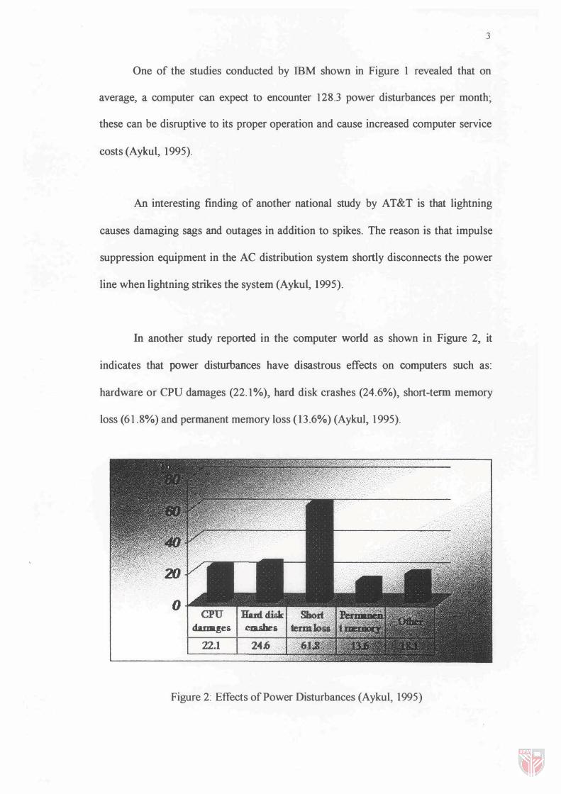
In another study reported in the computer world as shown in Figure 2, it
indicates that power disturbances have disastrous effects on computers such as:
hardware or CPU damages (22.1%), hard disk crashes (24.6%), short-term memory
loss (61.8%) and permanent memory loss (13.6%) (Aykul, 1995).
damLges cm.sbes 22.1 24.6 ,
Figure 2: Effects of Power Disturbances (Aykul, 1995)

4
As a conclusion, the line power should not be fed to the computers,
telecommunication equipment, or other sensitive and critical electronic gear It
causes lost data, downtime, increased service costs and reduces equipment life
The following are examples of applications of computers, which requrre
continuous power supply
1- Life support systems such as monitoring systems
2- Hospital information systems patient history files, treatment schedules
3- Paramedics and fire departments
4- Public utilities electric power, gas, water and sewage
5- Air traffic control
6- Financial institutions banks, stock markets and commodities
Problem Statement
The current protection scheme used by PCs for the power failure problem is
depicted in Figure 3 The conventional UPS is used to provide power supply to a
group of PCs during power failure The disadvantage of this scheme is that it is
expensive and bulky Furthermore, It has a high maintenance cost Consequently, not
many people manage to buy this system to protect their PCs from power failure In order to solve this problem, a low cost and small size UPS is needed