development of capacitance void fraction measurement method … · 2018-09-25 · 4 development of...
TRANSCRIPT

4
Development of Capacitance Void Fraction Measurement Method for BWR Test
Hironori Watanabe1, Hidesada Tamai1, Takashi Satoh1, Mitsuhiko Shibata1 and Toru Mitsutake2
1Japan Atomic Energy Agency, Tokai-mura, Ibarakiken 2Tosiba, Isogoku Yokohama-shi Kanagawaken
Japan
1. Introduction
In the study of two phase flow, void fraction (volume ratio of gas phase to total volume) in the flow channel is important physical value, so many measurements technique have been applied.
In the study of the atomic energy, X-ray, or γ-ray technique have been adopted for measure void fraction under high temperature and high pressure condition.
But in these techniques, real time measurement is difficult and measurement system is complex, therefore practical method have been expected.
In the measurement of the void fraction for BWR thermo- hydraulic test, following measurement under high pressure and high temperature conditions is necessary.
1. Measurement is available for even though pure water 2. Measurement is available 3. Measurement is available for all void fraction regions 4. Measurement is available in real time
Authors have developed capacitance measurement method (C method) that is electric void fraction measurement method to solve above theme.
Applying C method to BWR thermo-hydraulic test and Modified Light Water Reactor develop test had been performed at JAEA.
In former part of this article, we showed clarified measurement characteristic by C method to atmospheric condition, measurement effectiveness in pure water and measurement region can be expanded.
In latter part, we showed adopted electrode・signal cable for high pressure condition and
attained measurement of void fraction on the condition of BWR.
To confirm propriety of C method, we compared measured datum by C method with datum by quick shut method, consequently characteristic function can apply to high pressure conditions.
www.intechopen.com
Flow Measurement
96
Symbol
AX-s :Projeited Area of Flow Channel [m2] C :Capacitance[F]
C* :Rasio of Capacitance[-] C (α) :Capacitance at Void Fractionα[F] d :Inner Diameter of Pipe[m]: I :Current[A] jg :Volume Flux of Gas Phase[m/s] jl :Volume Flux of Liquid Phase[m/s] R :Resistance[Ω] t :Time[s] z :Coodinates in the Flow [m]
α :Void Fraction[-] ρ :Density[kg/m3] BWR :Boiling Water Reactor FBR :Fast Breeder Reactor SG :Steam Genarator QSV :Quick Shut Valve
Attached letter
α=0, ℓ :Liquid Phase 100% α=100, g :Gas Phase 100%
2. C method of void fraction measurement (atmospheric condition)
2.1 Principle of measurement by C method
At first we measured resistance of two phase flow in the flow channel and confirmed that resistance has the relation of definite hyperbolic function (R method) to void fraction both in the atmospheric condition and high temperature and high pressure condition (7MPa). (1)(2)
But there had been the theme that resistance measurement method (R method) do not fit for
discontinuity of liquid phase because conductive pass is cut off at high void fraction
region(more than 70%).
To solve disadvantage in R method, we developed C method, in C method high frequency
AC power charged a pair of electrode.
In C method, it was experimentally confirmed that characteristic curve concluded to definite
hyperbolic function, provided capacitance component in the two phase flow is separately
measured making use of that phase is different between capacitance and resistance(→) (←). C
method has the advantage in measurement sensitivity compared R method as frequency of
AC power changes to higher response current increase.
2.2 Test facility for void fraction measurement characteristics test
4x4 rod bundle simulating BWR fuel rod arrangement is installed in the Rectangular test section.
www.intechopen.com

Development of Capacitance Void Fraction Measurement Method for BWR Test
97
Fig.1 shows characteristic test facility for 4x4 rod bundle. Air-Bubble was introduced from lower nozzle through porous plate to gain uniform small bubble.
Void fraction was regulated by needle valve for inlet air. Void fraction was measured from the water volume in the test section between quick shut valves. Electrode is to measure impedance of two phase flow between a pair of electrode, we adopted different shape for most suitable shape for flow channel (faced plate, plate and rod, rod and rod).
In the test to charge high frequency AC to electrode installed inner wall of the test section, we adopted high frequency type impedance meter (LCR meter) and measured capacitance in the two phase flow.
Fig. 1. Void fraction test facility with 4x4 bundle
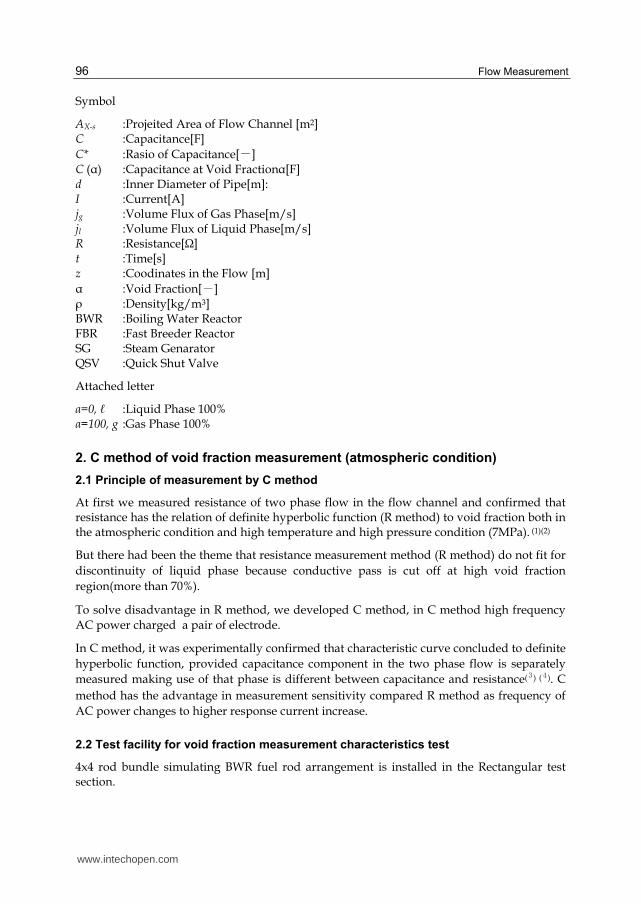
2.3 Frequency response characteristic of test section
Fig.2 shows the frequency response characteristic of the test section by C method. In C method measurement sensitivity improved as the response current increase proportionally to 1/ (ωC).
On the other hand, more than definite frequency wide band, measured result (capacitance)
becomes unstable due to resonance of AC current so 1MHz band was selected. Moreover
multiple frequency of supplied AC (50Hz in this district) was avoided to prevent phasing
interaction. So 1.01MHz was adopted as measurement frequency, consequently performed
stable measurement.
ゲザケ
スザケ
ゲザケ
ゲケケ
コザケ
ゲザ
コゲシ
C
A ir In × 臽
①
ヘモヵユン
ネユカ゚ユロ
臤 臿 𦣝
ゲスシ
ジ ゲ
ヒ ピ プ
ノ ユヴラ パ ロモ ヵユ
ノ ユヴラ
パ ロモ ヵユ
ツ ヰワカ゚ユ ンヵヰ ン
ネ ツ ビ
ノ ユ ヵユ ン
C :臽× 臽 bun莕l莛
□
www.intechopen.com
Flow Measurement
98
ケクゲ
ゲ
ゲケ
ゲケケ
ゲケケケ
ゲ ゲケ ゲケケ ゲケケケ ゲケケケケ
Fンユヲヶユワヤケ゚ 膅ヌHコ゚䐢
バヶ
ヵヱ
ヶヵォヮ
プオ
Aリン ギ ヅモヵモ
ヘモヵユン ォゲクサμヴグヤヮオ
Fig. 2. Frequency characteristics
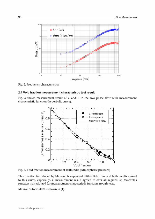
2.4 Void fraction measurement characteristic test result
Fig. 3 shows measurement result of C and R in the two phase flow with measurement characteristic function (hyperbolic curve).
Fig. 3. Void fraction measurement of 4x4bundle (Atmospheric pressure)
This function introduced by Maxwell is expressed with solid curve, and both results agreed to this curve, especially, C measurement result agreed to over all regions, so Maxwell’s function was adopted for measurement characteristic function trough tests.
Maxwell’s formula(5) is shown in (1).
0
0.2
0.4
0.6
0.8
1
0 0.2 0.4 0.6 0.8 1
C成分
R成分
Maxwellの式
Void fraction
C-component
R-component
Maxwell’s func.
www.intechopen.com

Development of Capacitance Void Fraction Measurement Method for BWR Test
99
Formula (1) indicates that relation between current ratio of I (two phase flow) to Io (liquid phase flow) and void fraction is definite hyperbolic function while charging voltage kept constant.
Void fraction can obtain from formula (2) for R measurement and formula (3), (4) for C measurement respectively. Formula (2), (3) are transformed from (1).
0
I 1
I 1 0.5
(Maxwell’s formula) (1)
0
00.5
R R
R R
(R method) (2)
*
*
1 C
1 0.5C (C method) (3)
* 100
0 100
C( )-CC
C C
(4)
3. Void fraction measurement test under high temperature and high pressure condition (7MPa)
With C method we performed void fraction measurement under high temperature and high
pressure condition(6) (7) (8) by using measurement characteristic function showed at formula
(3), (4) applying advanced BWR thermo-hydraulic test facility.
3.1 Advanced BWR thermo-hydraulic test facility
Advanced BWR (Tight-lattice Reduced Moderation Water Reactors) thermo-hydraulic test
facility contains 37 e rods bundle in flow shroud made of ceramic. (9)A pair of opposite
circular electrode made of stainless steel was attached to inner wall of ceramic flow shroud.
Fig.4 shows structure of test section and out line of the void fraction measurement system.
We measured capacitance between a pair of electrode in the two phase flow by LCR meter
as described in 2.2.
3.1.1 Electrode
We developed Mineral insulator (MI) sheath type electrode to keep insulation and resistance
to high temperature and high pressure condition (9).
Fig.5 shows over view and arrangement of MI sheath type electrode. Sensor part of
electrode is circular SUS plates (6mm diameter, 1mm thickness). Sheath is SUS pipe filled
with ceramic inside.
Electrodes were attached to the measurement nozzles of the test section at 3 different
elevations with 2mm interval oppositely to another electrode.
www.intechopen.com

Flow Measurement
100
Fig. 4. 37 Bundle and measurement system
As to durability of electrode in the high temperature and high pressure condition, crack by the thermal stress was prevented as thermal expansion coefficient among composed materials are almost equal, consequently we could gain long life of MI sheath type electrode through autoclave test.
Signal cable was insulated from MI sheath to prevent leakage of measured signal current. Insulating points are following 3.
Ceramic tip of cone shape was inserted between sheath and signal cable.
Ceramic pipe was inserted in the half part of sheath (To cancel the capacitance by insulator between sheath and signal cable)
In the welding of sheath and ceramic, intermediate material (Kovar-Alloy) was adopted as Kovar can be weld with sheath and ceramic.
Flow tube
Electrodes
D=6㎜
Insulator
Emboss
Connection
Flow tube
Electrodes
D=6㎜
Insulator
Emboss
Connection
Fig. 5. MI sheath type electrode
C
α
C
Void fractionZ,Electrode with MI-sheath
Electrode with MI-sheath
High-frequency
Impedance meter
Function operator
C
α
C
Void fractionZ,Z,Electrode with MI-sheath
Electrode with MI-sheath
High-frequency
Impedance meter
Function operator
絶縁材
ォ
オ
Flow
www.intechopen.com

Development of Capacitance Void Fraction Measurement Method for BWR Test
101
3.1.2 Measurement Hi frequency of AC Power
In C method, measurement frequency of AC power should be optimized therefore we adopted 1MHz as stable frequency band as showed at 2.3.
3.1.3 Data acquisition of Liquid phase flow and Gas phase flow
In measurement initial capacitance data of liquid phase flow (Cl) and Gas phase flow (Cg) need to be input into signal conditioner as set up data.(Formula(4) claims Cl and Cg)
C measurement of liquid phase (Cl) C measurement of the liquid phase were performed at 2MPa,4MPa,and 7MPa as steady test conditions.
At transient condition of temperature measured C should be correct as C changes with temperature changes.
C measurement of the gas phase (Cg) In practical measurement Cg means void fraction is 100% and inner wall of the flow channel is wet condition.
In calibration test, Cg condition was realized as follows. Water level dropped enough and electrode exposed by accumulating steam in the test section by shutting of out let valve. Cg condition was confirmed from measured ΔP.
3.2 Response test of void fraction measurement
The response signal characteristics of void fraction measurement system were obtained with the advanced BWR thermo-hydraulic test facility. The results are shown in Fig.6.
From Fig.6, it was known that the measured void fraction follows to power with good response under the transient conditions while heating power of rod bundle is increasing and flow rate of recirculation water is constant. Void fraction measured elevation are 1200mm , this elevation is top in the heating part (Void signal 1), and 900mm in the heating part (Void signal 2). From Fig.6, it was clarified that void fraction measurements can perform in real time way by C method.
0
100
200
300
400
500
600
700
800
0 10 20 30 40 50 60 70 80
time[sec.]
Power[kW], Flow[kg/m
2
s]
70
75
80
85
90
95
100
105
110
Void fraction[%]
Power
Flow rate
Void signal(2)
Void signal(1)
Fig. 6. Response of measurement system (7.2MPa pressure, 600kg/m2s mass velocity)
www.intechopen.com

Flow Measurement
102
3.3 Void fraction measurement result
Pressure 2MPa, 7MPa
Void fractions were successfully measured applying C method to advanced BWR thermo-hydraulic test facility (10) (11) (12). Fig.7 shows void fraction measurement result under heating power transiently controlled as to every mass flow rates of the recirculation water is constant at 2MPa pressure condition.
0
0.2
0.4
0.6
0.8
1
0 0.05 0.1 0.15 0.2 0.25 0.3 0.35
400 kg/m
2
s
600 kg/m
2
s
800 kg/m
2
s
1000 kg/m
2
s
Thermal equilibrium quality
Fig. 7. Void fraction Measurement (2MPa pressure)
From measured result it were showed that with the increasing of mass flow rate of recirculation water、measured void fraction becomes decrease and this result agreed to the
usual knowledge. In this test measured maximum void fraction is 92%. This result shows C method enable to measure large void fraction region with stability. Fig.8 shows void fraction measurement result, in the condition of pressure changed to 7.2MPa in former test. Result shows that with increasing quality void fraction following increase rationally.
ケクケ
ケクコ
ケクサ
ケクシ
ケクス
ゲクケ
ケクケケ ケクケザ ケクゲケ ケクゲザ ケクコケ ケクコザ ケクゴケ ケクゴザ ケクサケ ケクサザ
Tラユンヮモロ ユヲヶリロリャンリヶヮ ヲヶモロリヵケ゚[ギ]
プヰリュ ョンモヤヵリヰワ[ギ]
Fig. 8. Vo id fraction measurement (7.2 MPa pressure, 600 kg/m2s mass velocity)
www.intechopen.com

Development of Capacitance Void Fraction Measurement Method for BWR Test
103
4. Propriety of C method under high temperature (pressure 2MPa)
To confirm propriety of C method, we practically confirmed application of formula (3), (4) to high temperature and high pressure condition, we compared measured result by C method with measured result by quick shut method under the high pressure condition. At the result it was confirmed that C method is available for high temperature and high pressure conditions as well as atmospheric condition. Following is about calibration test for propriety. We adopted two type test section for calibration test. Test section for C method contains heating 37 rods bundle and test section for quick shut method contains non heating 19 rods bundle (Injected steam and water).
Comparison test was performed under 2MPa condition. Dimensions of the both test sections showed in the following.
ノユモヴヶンユヮユワヵ ヮユヵラヰュ ツギヮユヵラヰュ ヒクピク ヮユヵラヰュ
ハヶヮャユン ヰョ ンヰュヴ ゴジ ゲズ
バヶヵユン ンヰュ ュリモヮユヵユン[ヮヮ] ゲゴ ゲコ
ビヰュ ヨモヱ[ヮヮ]
Hケ゚ュンモヶロリヤ ュリモヮユヵユン[ヮヮ] サクゴサ サクコザ
ゲクゴ
Configuration of 37 rods bundle is honeycomb 4 peripheries, and 19 rods bundle is honeycomb 3 peripheries respectively. Effect on the void fraction measurement due to the difference in the hydraulic diameter between 2 test sections was evaluated to be small though calculated result by Drift flux void fractional computing function.(Void fraction change is less than 1% provided quality is more than 5%)
But effect on the void fraction distribution due to heating form of the rod bundle was observed in the measured result.
4.1 Test facility for void fraction measurement by quick shut method
In the quick shut method two phase flow was instantly shut by Quick Shut Valve (QSV) and volume of the water in the test section is measured by differential pressure meter. For practical, Q.S.V is quick shut rotary disk installed to the shaft droved by high pressured air, synchronized actuate time is 0.05 second.
Fig.9 shows the structure of quick shut test section. Test section is composed of two sections to evaluate error of void fraction measurement, upper section is half length of lower section.
Correct void fraction was obtained from difference of the measured void fractions in the two sections, as void fractions correspond to gap between bundle and QSV was canceled.
4.2 Calibrated result of C method by Q.S method
Fig.10 shows measured result by C method and by Q.S method.
In Fig.12, measured void fraction by C method were showed with 娟 (solid line), measured
void fraction by Q.S method were showed with ○ (broken line) , and difference between C
and Q.S approximated logarithmic function were showed with solid line for reference.
www.intechopen.com

Flow Measurement
104
Fig. 9. Test section with quick-shut valve (QSV) for void fraction measurement
Moreover Fig.12 (10) shows that obtained two relational functions between void fraction and quality are equivalent function.
From minute view, measured void fraction by C method is a little larger than measured void fraction by Q.S method. Difference in the measured void fraction was largest at near 0.05 of the quality, difference becomes close up gradationally according to increasing in void fraction and range of difference was 4%~8%. The cause of the difference in the void fraction was
considered that heating condition in the test section is different. 37 rods bundle is heating bundle and 19 rods bundle is non-heating bundle. In heating rods bundle it was observed that void fraction distribution was comparatively uniform. Contrary in non- heating rod bundle it was observed that void fraction distribution was large at the central flow channel and small at the near of the wall. With above reason, it is considered that measured void fraction by Q.S method is a little small than measured void fraction by C method under the region of less than 0.15 of quality. From calibration test C method is considered to be available in the condition of high temperature and high pressure as well as atmospheric condition in conclusion.
Moreover Fig.10 (13) shows that obtained two relational functions between void fraction and
quality are equivalent function. From minute view, measured void fraction by C method is a
little larger than measured void fraction by Q.S method. Difference in the measured void
fraction was largest at near 0.05 of the quality, difference becomes close up gradationally
according to increasing in void fraction and range of difference was 4%~8%. The cause of
the difference in the void fraction was considered that heating condition in the test section is
different. 37 rods bundle is heating bundle and 19 rods bundle is non-heating bundle. In
heating rods bundle it was observed that void fraction distribution was comparatively
uniform. Contrary in non- heating rod bundle it was observed that void fraction distribution
was large at the central flow channel and small at the near of the wall. With above reason, it
is considered that measured void fraction by Q.S method is a little small than measured void
www.intechopen.com

Development of Capacitance Void Fraction Measurement Method for BWR Test
105
fraction by C method under the region of less than 0.15 of quality. From calibration test C
method is considered to be available in the condition of high temperature and high pressure
as well as atmospheric condition in conclusion.
ケ
ケクコ
ケクサ
ケクシ
ケクス
ゲ
ケ ケクゲ ケクコ ケクゴヒヶモロリヵケ゚[ギ]
プヰリュ ョンモヤヵリヰワ[ギ]
ケ
ケクコ
ケクサ
ケクシ
ケクス
ゲ
プヰリュ ョンモヤヵリヰワ ュリョョユンユワヤユキ
ツギヒ
クピ
[ギ]
ツ
ヒクピク
Fig. 10. Compared result between C and Quick-shut valve method void fraction method s (2MPa in pressure, 400~2000kg/m2s in mass flux) (10)
5. Conclusion
We developed C method for practical void fraction measurement, applied to the high
temperature and high pressure condition and following results were obtained.
In C method measurement relational function between void fraction and capacitance in the
two phase flow was confirmed to be definite hyperbolic function (Formula (3),(4)) through
tests under different temperature and pressure conditions.
In C method void fraction measurement is available in the pure water as well as conductive
water and measurement region is almost 0~100%.
In C method void fraction measurement under the condition of high temperature and high
pressure up to 7MPa pressure was achieved by developed MI sheath type electrode.
C method was applied following thermo-hydraulic tests.
BWR stability test, BWR Critical Heat Flux test, and Reactivity Initiated Accident test.
6. Acknowledgments
As to perform void fraction measurement test we would like to express cordial thanks to Dr
Kazuyuki TAKASER, Akira OHNUKI (Now MHI Co., LTD) in Research Group for Thermal
and Fluid Engineering, Dr Masatoshi KURETA in Research Group for Nuclear Sensing and
members in Mechanical Engineering and Electronics Section in Department of Engineering
Services in Japan Atomic Energy Agency (JAEA) respectively. As for making test facility we
express cordial thanks to ART KAGAKU Co., LTD (Precise test section) and SUKEGAWA
ELECTRIC CO., LTD (MI sheath type Electrode).
C
C-Q.S.
Q.S
www.intechopen.com

Flow Measurement
106
7. References
[1] Watanabe, H., Iguchi, T., Kimura, M. and Anoda, Y., Development of quick-response area averaged void fraction meter, JAERI-Research 2000-043 (2000).
[2] Watanabe, H., Iguchi, T. and Kimura, M. , Development of conductance-type void fraction meter, JSME annual meeting, No.4(2002), pp.233- 234.
[3] Watanabe, H., Mitsutake, T., Kakizaki, S. and Takase, K, Experimental study on feasibility of capacitance void fraction meter, Transactions of the Japan Society of Mechanical Engineers, Series B, Vol. 74, No.742 (2008), pp. 435-436
[4] Watanabe, H., Mitsutake, T., Kakizaki, S. and Akimoto, H, Electro-void fraction meter development and application to tight lattice rod assembly within reduced moderation water reactor, Proceedings of the 9th National symposium of power and energy systems(2004), pp.69-70.
[5] Maxwell, J.C., A treatise on electricity and magnetism,3rd ed.,(1954), Vol.1, Chapter 9,
Article 314, Dover, New York [6] Watanabe, H., Mitsutake, T., Kakizaki, S. and Akimoto, H, Electro-void fraction meter
development and application to tight lattice rod assembly within reduced moderation water reactor, Proceedings of the 9th National symposium of power and energy systems(2004), pp.69-70.
[7] Watanabe, H., Mitsutake, T., Kakizaki, S. and Takase, K, Experimental Study on Capacitance Void Fraction Meters for High Temperature and High Pressure Conditions, Transactions of the Japan Society of Mechanical Engineers, Series B, Vol. 76, No.769 (2010), pp. 1379-1385
[8] Kureta, H., Yoshida, H., Tamai, H., Ohnuki, A. and Akimoto, H., Thermal-Hydraulic Estimation in Tight-Lattice Rod Bundles for Development of the Innovative Water Reactor for Flexible Fuel Cycle, Progress in Multiphase Flow Research 3, (2008), pp.99-109.
[9] Watanabe, H., Mitsutake, T., Kakizaki, S. and Takase, K, Experimental study on feasibility of capacitance void fraction meters, Proceedings of the 13th National symposium of power and energy systems (2007), pp.77-78.
[10] Kureta, H., Yoshida, H., Tamai, H., Ohnuki, A. and Akimoto, H.,Thermal-Hydraulic
Estimation in Tight-Lattice Rod Bundles for Development of the Innovative Water Reactor for Flexible Fuel Cycle, Progress in Multiphase Flow Research 3, (2008), pp.99-109.
[11] Cimorelli, L and Evangelisti, R., The application of the capacitance method for void fraction measurement in bulk boiling conditions, International Journal of Heat and Mass Transfer, Vol.10(1967), pp.277-288.
[12] Inoue, A., Kurosu, T., Aoki, T., Yagi, M., Mitsutake, T. and Morooka, S., Void fraction distribution in BWR fuel assembly and evaluation of subchannel code, Journal of Nuclear Science and Technology Vo. 32, No.7( 1995), pp.629-640.
[13] Tamai, S, Takase, K., Shibata, M. and Hayafune, H., Flow instability experiments on
steam generator with straight double-walled heat transfer tube for FBR (2) Experimental Results under High Pressure Conditions, 2007 Fall Meeting of the Atomic Energy Society of Japan, K58, (2007).
www.intechopen.com

Flow MeasurementEdited by Dr. Gustavo Urquiza
ISBN 978-953-51-0390-5Hard cover, 184 pagesPublisher InTechPublished online 28, March, 2012Published in print edition March, 2012
InTech EuropeUniversity Campus STeP Ri Slavka Krautzeka 83/A 51000 Rijeka, Croatia Phone: +385 (51) 770 447 Fax: +385 (51) 686 166www.intechopen.com
InTech ChinaUnit 405, Office Block, Hotel Equatorial Shanghai No.65, Yan An Road (West), Shanghai, 200040, China
Phone: +86-21-62489820 Fax: +86-21-62489821
The Flow Measurement book comprises different topics. The book is divided in four sections. The first sectiondeals with the basic theories and application in microflows, including all the difficulties that such phenomenonimplies. The second section includes topics related to the measurement of biphasic flows, such as separationof different phases to perform its individual measurement and other experimental methods. The third sectiondeals with the development of various experiments and devices for gas flow, principally air and combustiblegases. The last section presents 2 chapters on the theory and methods to perform flow measurementsindirectly by means on pressure changes, applied on large and small flows.
How to referenceIn order to correctly reference this scholarly work, feel free to copy and paste the following:
Hironori Watanabe, Hidesada Tamai, Takashi Satoh, Mitsuhiko Shibata and Toru Mitsutake (2012).Development of Capacitance Void Fraction Measurement Method for BWR Test, Flow Measurement, Dr.Gustavo Urquiza (Ed.), ISBN: 978-953-51-0390-5, InTech, Available from:http://www.intechopen.com/books/flow-measurement/development-of-capacitance-void-fraction-measurement-method-for-bwr-test

© 2012 The Author(s). Licensee IntechOpen. This is an open access articledistributed under the terms of the Creative Commons Attribution 3.0License, which permits unrestricted use, distribution, and reproduction inany medium, provided the original work is properly cited.