estimate of void fraction and air entrainment flux in...
TRANSCRIPT

ARTICLE
Estimate of void fraction and air entrainment flux in hydraulicjump using Froude numberH. Wang and H. Chanson
Abstract: Hydraulic jumps are induced in hydraulic facilities for the purposes of energy dissipation or flow aeration. Presentlythere is no means for a simple estimate of void fraction distribution and air entrainment flux, without detailed physicalmodelling. This paper presents a semi-theoretical model to simulate the void fraction and velocity distributions in hydraulicjumps characterized by partially-developed inflow conditions. Relationships were established between the inflow Froude num-ber, jump roller length and key parameters that determine the full expression of void fraction and velocity profiles. Theproposed model enables accurate prediction of void fraction, longitudinal velocity, and air flux using the inflow Froude number.The results indicated considerable air flux contribution of free-surface aeration, in addition to the singular air entrainment at thejump toe, for moderate to large Froude numbers. A Froude number between 8 and 9 tended to achieve highest aeration rate withmaximum total air flux in the roller.
Key words: hydraulic jumps, void fraction, interfacial velocity, air entrainment flux, self-similarity, Froude number.
Résumé : Les ressauts hydrauliques sont déclenchés dans les installations hydrauliques pour la dissipation de l’énergie oul’aération du débit. Actuellement, il n’y a aucun moyen d’évaluation simple de la distribution du taux de vide et du fluxd’entraînement de l’air, sans avoir recours a la modélisation physique détaillée. Cet article présente un modèle semi-théoriqueayant pour but de simuler la distribution du taux de vide et de la vitesse dans les ressauts hydrauliques se distinguant par desconditions de débit entrant partiellement développées. Des relations ont été établies entre le nombre de Froude du débit entrant,la longueur des rouleaux du ressaut et les paramètres clés qui déterminent l’expression complète des profils du taux de vide etde la vitesse. Le modèle proposé permet la prédiction précise du taux de vide, de la vitesse longitudinale et du flux d’air utilisantle nombre de Froude du débit entrant. Les résultats ont indiqué une contribution considérable du flux d’air provenant del’aération de la surface libre, en plus de l’entraînement de l’air singulier au pied du ressaut, pour des nombres de Froude demodérés a grands. Un nombre de Froude entre 8 et 9 a eu tendance a produire le taux le plus élevé d’aération avec le flux d’airtotal maximal dans le rouleau.
Mots-clés : ressaut hydraulique, taux de vide, vitesse interfaciale, flux d’entraînement de l’air, autosimilitude, nombre de Froude.
IntroductionAir entrainment takes place spontaneously in open channel
flows when the turbulent shear stress next to the air–water inter-face is large enough to overcome the surface tension (Ervine andFalvey 1987; Chanson 2009). A canonical case is the self-aerationassociated with the occurrence of flow singularity, e.g., in a plung-ing jet or hydraulic jump. The singular self-aerated flow is charac-terized by intense turbulent mixing and a large rate of energydissipation, thus widely utilized in industrial processing (chemi-cal mixing, wastewater oxygenation, etc.) and hydraulic struc-tures (Henderson 1966; Hoyt and Sellin 1989). Figure 1 illustratesan application of hydraulic jump as energy dissipator, where thesplashing “white water” appearance of the jump can be seen fromthe aerial view over the dam spillway and stilling basin during aminor flood. Although in most cases the air–water exchange is anuncontrolled process, the aeration rate can be sometimes criticalfor meeting biochemical oxygen demand, prediction of flow bulk-ing or prevention of cavitation erosion. However, the character-ization of air–water flow properties in hydraulic jumps is not easy(Rajaratnam 1962). While the difficulty of prototype measurementis evident, the major challenges for analytical and numerical sim-ulations are associated with the involvement of numerous two-
phase flow parameters and interactive physical processes, as wellas the lack of benchmark data for model validation (Chanson2013). To date, the most constructive information is obtained fromphysical modelling, though the applicable measuring techniquesare far fewer than those broadly used in monophase flows (Boyeret al. 2002).
Well-established air–water flow measuring techniques includedtwo-phase flow visualization, bubble imaging velocimetry (BIV),and intrusive phase-detection probe. Imaging of bubbly flowthrough the transparent sidewall provided the global distributionof void fraction in an observation plane next to the wall (Mossaand Tolve 1998; Leandro et al. 2012). The flow dynamics and veloc-ity field were characterized in weak hydraulic jumps using thebubbles as tracer particles (Rodríguez-Rodríguez et al. 2011). SuchBIV techniques were deemed to be complementary approaches totraditional particle imaging velocimetry (PIV) and acoustic Dopp-ler velocimetry (ADV) that were only functional in weak jumpswith very limited air entrainment (e.g., Liu et al. 2004; Lennon andHill 2006). More detailed information of instantaneous air en-trainment was obtained using conductivity or optical-fibre phase-detection probes that measured the air–water flow locally andintrusively (Rajaratnam 1962; Crowe et al. 1998). A series of previ-ous studies successfully quantified the air–water flow properties
Received 6 June 2016. Accepted 9 January 2017.
H. Wang and H. Chanson. The University of Queensland, School of Civil Engineering, Brisbane QLD 4072, Australia.Corresponding author: H. Wang (email: [email protected]).Copyright remains with the author(s) or their institution(s). Permission for reuse (free in most cases) can be obtained from RightsLink.
105
Can. J. Civ. Eng. 45: 105–116 (2018) dx.doi.org/10.1139/cjce-2016-0279 Published at www.nrcresearchpress.com/cjce on 3 November 2017.
Can
. J. C
iv. E
ng. D
ownl
oade
d fr
om w
ww
.nrc
rese
arch
pres
s.co
m b
y T
HE
UN
IVE
RSI
TY
OF
QU
EE
NSL
AN
D o
n 02
/09/
18Fo
r pe
rson
al u
se o
nly.

of prior interest to industrial engineers, including the void frac-tion, bubble size spectrum, and interfacial velocity distribution(Chanson and Brattberg 2000; Murzyn et al. 2005; Chachereau andChanson 2011; Wang and Chanson 2015). The existing data indi-cated the significance of Froude number, Reynolds number, andinflow turbulence levels affecting the spatial distributions ofthese air–water flow properties (see the next section). These datasets may enable preliminary calibration and justification of theo-retical and numerical models, but are somehow complicated andunsystematic for practical engineering applications. Before thepresent study, the only reliable way to depict quantitatively thevoid fraction distribution and air entrainment flux in highly-aerated hydraulic jumps was to conducting physical modellingunder designed flow conditions, which was often uneconomicaland unpractical. This paper introduces a method combining the-oretical and empirical considerations to estimate the spatial voidfraction distribution and air entrainment flux based simply on theinflow Froude number. The present method is based upon theself-similarity of void fraction and interfacial velocity distribu-tions within the well-defined jump roller length, and involvescalibration of bubble diffusion equation and wall jet velocityequation with experimental results obtained for a broad range offlow conditions.
Physical modelling and experimental setup
Dimensional analysisThe physical modelling of singular aerated flow involves rele-
vant parameters including the fluid properties, channel geome-try, inflow conditions, and local two-phase flow properties (Kobus1984; Wood 1991). For a hydraulic jump with inflow depth d1 andaverage approaching velocity V1, a simplified dimensional analy-sis yields
(1)dd1
, C,VV1
,v ′
V1, ... � F�x � Xt
d1,
yd1
,zd1
,Xt
d1,
�d1
,V1
�g × d1
,
�w × V1 × d1
�w,
g × �w4
�w × �3, ...�
where d is the local depth, C is the void fraction, V is the time-averaged velocity, v= is the velocity fluctuation, x, y, and z arerespectively the longitudinal, vertical, and transverse coordi-nates, Xt is the longitudinal jump toe position, � is the inflow
boundary layer thickness at the jump toe (�/d1 < 1 for partially-developed impinging flow), g is the gravity acceleration, �w and �w
are the water density and dynamic viscosity, and � is the surfacetension between air and water. Equation (1) expresses the basicturbulent aerated flow properties at a position (x, y, z) as functionsof the inflow Froude number Fr1 (6th term on the right-hand sideof eq. (1)), the Reynolds number Re (7th term), and the Mortonnumber Mo (8th term) which is a constant when both air andwater are used in model and prototype. For open channel flows,the traditional application of Froude-similitude implies underes-timate of the Reynolds number in down-scaled models (Liggett1994). Thus a true dynamic similarity is unachievable using undis-torted models, and the potential scale effects must be properlyassessed before extrapolating physical data to prototype condi-tions.
When the dynamic similarity cannot be satisfied, self-similaritiesbecome a powerful tool to characterize aerated flow field in similarhydraulic structures irrespective of the physical scale (Barenblatt1996; Wang 1998). The self-similar relationships were observed forsome flow properties in hydraulic jumps, which enabled theseflow properties to be obtained by similarity transformations un-der changes of length and time scales. It is specifically addressedin this paper the self-similarities in terms of jump roller surfaceprofile and the spatial distributions of void fraction and longitu-dinal velocity. These relationships, as well as the resulting airentrainment flux, may be used for design applications at proto-type scales.
Experimental setup and instrumentationExperimental data were collected in a horizontal open channel
with a rectangular cross section. The channel was 3.2 m long and0.5 m wide, built with smooth HDPE bed and glass side walls.Water was supplied into a head tank then discharged into theexperimental section under a rounded gate of the tank, withoutinducing vena contracta (Fig. 2). The hydraulic jump was gener-ated by controlling a downstream overshoot gate. For a givenupstream gate opening h, the jump toe was set at the longitudinalposition Xt = h/0.024, Xt being the longitudinal distance from theupstream gate (x = 0) to the toe (x = Xt) (Fig. 2). The flow rate wasmeasured with a Venturi meter in the supply pipeline with anaccuracy of ±2%. The inflow depth was read using a pointer gauge,for which the uncertainty was determined by the maximum be-tween 0.2 mm and the free-surface roughness of the impingingflow.
The air–water flow properties were measured using a dual-tipconductivity phase-detection probe. The probe was manufacturedat the University of Queensland. It was equipped with two parallelneedle sensors that discriminated air and water phases based onthe change in electric resistance (Crowe et al. 1998). The diameterof the central electrode of the sensor was 0.25 mm. Each needlesensor recorded the time series of instantaneous void fractiondetected on the sensor tip. The longitudinal distance between theleading and trailing tips was �x = 7.12 mm (Fig. 2b). The two sen-sors were excited simultaneously with a scanning rate of 20 kHzfor 45 s at each measurement location. A correlation between thesensor signals provided the time-averaged interfacial velocity Vxwhen the sensors were aligned against the longitudinal flow di-rection. The vertical position of the probe was monitored using amagnetic digital scale with error less than 0.2 mm.
A total of eight experimental flows were investigated corre-sponding to two upstream gate openings h = 0.02 and 0.03 m. Aconstant inflow length h/Xt = 0.024 was applied, characterizingpartially-developed inflow conditions with �/d1 � 0.7 to 0.8. FiveFroude numbers from 3.8 to 10 were tested for the smaller gateopening, with the Reynolds numbers ranging from 3.5 × 10⁴ to9.5 × 104. The lower three Froude numbers were reproduced forthe larger gate opening, corresponding to 7.0 × 10⁴ < Re < 1.4 × 10⁵.The flow conditions are specified in Table 1.
Fig. 1. Hydraulic jump in the stilling basin at downstream of theHinze Dam in Queensland, Australia; aerial view with flow directionfrom bottom to top right. The jump was generated by a series ofconcrete baffles in the stilling basin to enhance energy dissipationand mitigate bank erosion. [Colour online.]
106 Can. J. Civ. Eng. Vol. 45, 2018
Published by NRC Research Press
Can
. J. C
iv. E
ng. D
ownl
oade
d fr
om w
ww
.nrc
rese
arch
pres
s.co
m b
y T
HE
UN
IVE
RSI
TY
OF
QU
EE
NSL
AN
D o
n 02
/09/
18Fo
r pe
rson
al u
se o
nly.

Self-similarities in void fraction and interfacialvelocity distributions
PresentationImmediately downstream of the depth discontinuity at the
jump toe, the water surface elevation increases gradually alongthe roller until a constant downstream depth d2 is reached. Theratio d2/d1, known as the conjugate depth ratio, derives from massand momentum conservation for a frictionless horizontal two-dimensional flow (Bélanger 1841):
(2)d2
d1�
12
× ��1 8 × Fr12 � 1�
The length of jump roller Lr is defined as the longitudinal dis-tance over which the time-averaged water surface elevation in-creases monotonically (Fig. 2b). Table 1 summarizes the rollerlength data for the present flow conditions, where the water sur-face elevation was measured non-intrusively using acoustic dis-placement meters. A re-analysis of the data of Murzyn et al. (2007),
Fig. 2. Experimental facility and instrumentation setup. (a) Side view of experimental channel in operation — Flow direction: left to right; flowconditions: q = 0.694 m2/s, h = 0.02 m, Xt = 0.83 m, d1 = 0.0206 m, Fr1 = 7.5, Re = 6.8 × 10⁴. (b) Sketch of experimental channel and phase-detectionprobe setup. [Colour online.]
Table 1. Flow conditions and jump roller length results.
q (m2/s) W (m) h (m) Xt (m) d1 (m) V1 (m/s) Fr1 (-) Re (-) Lr (m)
0.0358 0.5 0.020 0.83 0.0206 1.74 3.8 3.5×10⁴ 0.280.0478 0.5 0.020 0.83 0.0209 2.29 5.1 4.8×10⁴ 0.520.0694 0.5 0.020 0.83 0.0206 3.37 7.5 6.8×10⁴ 0.800.0794 0.5 0.020 0.83 0.0208 3.82 8.5 8.0×10⁴ 1.000.0946 0.5 0.020 0.83 0.021 4.50 10 9.5×10⁴ 1.270.0704 0.5 0.030 1.25 0.0326 2.16 3.8 7.0×10⁴ 0.600.0922 0.5 0.030 1.25 0.0322 2.86 5.1 9.2×10⁴ 0.850.1418 0.5 0.030 1.25 0.033 4.30 7.5 1.4×10⁵ 1.45
Note: q = specific flow rate; W = channel width; h = upstream gate opening; Xt = longitudinal jump toeposition; d1 = inflow depth upstream of the jump toe; V1 = cross-sectional average inflow velocity; Fr1 =inflow Froude number; Re = Reynolds number; Lr = length of jump roller.
Wang and Chanson 107
Published by NRC Research Press
Can
. J. C
iv. E
ng. D
ownl
oade
d fr
om w
ww
.nrc
rese
arch
pres
s.co
m b
y T
HE
UN
IVE
RSI
TY
OF
QU
EE
NSL
AN
D o
n 02
/09/
18Fo
r pe
rson
al u
se o
nly.

Kucukali and Chanson (2008), Murzyn and Chanson (2009), andWang and Chanson (2015) suggested the dimensionless rollerlength as a function of the Froude number:
(3)Lr
d1� 6 × (Fr1 � 1) for 2 Fr1 10
In the present study, the air–water flow properties are presented atrelative longitudinal positions (x – Xt)/Lr within a full roller length(0 < (x – Xt)/Lr < 1), allowing for a discussion of self-similarity interms of their spatial distributions.
Void fractionFor partially-developed inflow conditions, the time-averaged
void fraction was measured in a series of previous studies (e.g.,Chanson and Brattberg 2000; Murzyn et al. 2005; Chachereau andChanson 2011). These results were reproduced in the present studywith favourable consistency. Figure 3 presents a set of experimen-tal data in a vertical cross section of jump roller and a sketch ofthe typical void fraction profile. In Fig. 3, the elevation of localtrough void fraction YCmin
divides the roller into a turbulent shearlayer on the bottom and a free-surface region above. The voidfraction profile can be approximated by solving the bubble diffu-sion equation in the turbulent shear layer (y < YCmin
) and free-surface region (y > YCmin
) respectively. In the shear layer, the jumptoe acts as a point source of bubbles, and bubble diffusion takesplace in the vertical direction while the bubbles are advectedlongitudinally. The void fraction thus follows a quasi-normal dis-tribution (Crank 1956; Chanson 2010):
(4a) C � Cmax × exp��1
4 × �Dt(s)/(V1 × d1)
�(y � YCmax
)/d12
(x � Xt)/d1
for y YCmin
where Cmax is the local maximum void fraction in the shear layer,YCmax
is the vertical position of Cmax, and Dt�s� is a depth-averaged
diffusivity for 0 < y < YCmin. The characteristic elevation YCmax
takesimplicitly into account for the effects of buoyancy and the inter-action between vortex shielding and channel bed. In the upperfree-surface region, aeration occurs through the roller surfacebetween air and water phases, and the void fraction distributionfollows the Gaussian error function (Brattberg et al. 1998; Murzynet al. 2005):
(4b) C �12
× �1 erf� (y � Y50)/d1
2 × �Dt(r)/(V1 × d1) × �(x � Xt)/d1
�for y � YCmin
where Y50 is the elevation for C = 0.5, Dt�r� is the diffusivity in the
free-surface region, and the Gaussian error function is defined as
(4c) erf(u) �2
��×
0
u
exp(�t2) × dt
It is acknowledged that the bubble transport in the upper rollerwas more complicated compared to a pure interfacial aerationprocess, with involvement of bubble recirculation from the un-derneath shear layer. In spite of this, eq. (4b) agreed well with theexperimental data when appropriate value of Dt
�r� was selected(Wang and Chanson 2015).
In eq. (4), the void fraction distribution in jump roller is deter-mined by a number of characteristic values including Cmax, YCmax
,Y50, Dt
�s�, and Dt�r�. Figures 4a to 4c plot the longitudinal variations of
these parameters for all tested flow conditions. The local maxi-mum void fraction Cmax decreased with increasing distance fromthe toe (Fig. 4a), while its vertical position YCmax
increased (Fig. 4b).The elevation Y50 increased from d1 to d2 over the roller length(Fig. 4b), and its longitudinal distribution almost overlapped withthe mean roller surface profile measured with acoustic dis-placement meters (not shown). The dimensionless diffusivityDt
�s�/�V1 × d1� was typically between 0.02 and 0.1 in the shear flow,increasing towards downstream, whereas Dt
�r�/�V1 × d1� decreasedfrom 0.08 to 0.0001 in the recirculation region (Fig. 4c). All datashowed some similar monotonic trends within the roller lengthbetween different flow conditions. Table 2 summarizes the best-fitcurves for each characteristic parameter as a function of the rela-tive longitudinal position (x – Xt)/Lr, together with the correlationcoefficient R. In Fig. 4, the present data of Cmax, YCmax
, and Dt�s� are
further compared with the data of Murzyn and Chanson (2009) for5.1 < Fr1 < 8.3, Chanson (2010) for 5.1 < Fr1 < 11.2 and Chachereauand Chanson (2011) for 3.1 < Fr1 < 5.1, for which the roller lengthswere estimated using eq. (3).
Replacing the corresponding parameters in eq. (4) with eqs. (C-1)to (C-5) in Table 2 and noting that the ratios d2/d1 and Lr/d1 arefunctions of the Froude number (eqs. (2) and (3)), the time-averaged void fraction profile at a given longitudinal position (x –Xt)/d1 can be fully expressed for a given Froude number. Figure 5illustrates the analytical void fraction distributions for Fr1 = 5.1and 8.5, with comparison to the present experimental data. Theanalytical prediction corresponding to each experimental dataprofile is highlighted by dotted lines. A summary of correlationcoefficients for all measured void fraction profiles is provided inAppendix A, showing 70% of void fraction profiles fitted withR > 0.95. Some discrepancy was noticed at the local minimum voidfraction Cmin close to the jump toe (e.g., at (x – Xt)/d1 = 4.15, y = YCmin
in Fig. 5b). This was the intermediate area between the shear flowand the free-surface recirculating flow, and the void fraction atsuch locations was also modified by the plunging wave mechanicsunder the impact of severe flow reversal and spray projection.Nevertheless, the present void fraction prediction should satisfythe accuracy requirement for most engineering applications with3.8 < Fr1 < 10. Note that viscous scale effects may take place whenthe Reynolds number is small (e.g., Re < 4 × 10⁴ (Chanson andChachereau 2013)), with significant drop in the maximum voidfraction in the shear layer.
Fig. 3. Vertical distribution of time-averaged void fraction inhydraulic jump roller — Experimental results for Fr1 = 7.5, Re = 6.8 × 10⁴,(x – Xt)/d1 = 4.2 and sketch of typical void fraction profile with keyparameters. [Colour online.]
108 Can. J. Civ. Eng. Vol. 45, 2018
Published by NRC Research Press
Can
. J. C
iv. E
ng. D
ownl
oade
d fr
om w
ww
.nrc
rese
arch
pres
s.co
m b
y T
HE
UN
IVE
RSI
TY
OF
QU
EE
NSL
AN
D o
n 02
/09/
18Fo
r pe
rson
al u
se o
nly.

Longitudinal interfacial velocityThe average longitudinal interfacial velocity was measured be-
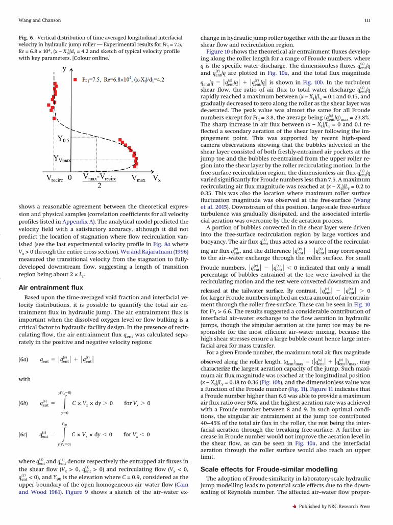
tween the phase-detection probe tips. In high-speed flows, no-slipcondition applies thus the interfacial velocity is considered equalto the flow velocity. Rajaratnam (1965) proposed an analogy be-tween the impinging flow into the jump roller and a wall jet,yielding a theoretical expression of monophase flow velocity dis-tribution, which was later modified by Chanson (2010) to take intoaccount the flow reversal next to the free-surface:
(5a)Vx
Vmax� � y
YVmax�1/N
fory
YVmax
1
(5b)Vx � Vrecirc
Vmax � Vrecirc� exp��
12
× �1.765 × �y � YVmax
Y0.5��2
fory
YVmax
� 1
In eq. (5), Vmax is the maximum velocity in the shear flow, YVmax
is the corresponding elevation characterizing the upper edge ofthe bottom boundary layer, Vrecirc is the depth-averaged recircu-lation velocity, Y0.5 is the elevation where Vx = (Vmax – Vrecirc)/2,and N is a constant between 6 and 10. A typical velocity profile isillustrated in Fig. 6. Note that the negative velocity was not ob-
Fig. 4. Longitudinal variations of characteristic void fraction properties within jump roller length — Comparison with the data of Murzynand Chanson (2009), Chanson (2009), and Chachereau and Chanson (2011). (a) Local maximum void fraction in turbulent shear layer.(b) Elevations of local maximum void fraction in shear layer and void fraction being 0.5 next to roller surface. (c) Dimensionless diffusivitiesin shear layer and free-surface regions. [Colour online.]
Wang and Chanson 109
Published by NRC Research Press
Can
. J. C
iv. E
ng. D
ownl
oade
d fr
om w
ww
.nrc
rese
arch
pres
s.co
m b
y T
HE
UN
IVE
RSI
TY
OF
QU
EE
NSL
AN
D o
n 02
/09/
18Fo
r pe
rson
al u
se o
nly.

served over the whole roller length; the relative length of flowreversal to the jump roller is less than unity and decreases withdecreasing Froude number.
Equation (5) describes a self-similar velocity distribution in ajump with a marked roller (i.e., Vrecirc < 0). The analytical profile isdetermined by characteristic values Vmax, YVmax
, Y0.5, and Vrecirc.The experimental results of these parameters are presented inFigs. 7a to 7c. While the dimensionless values Vmax/V1, YVmax
/d1, andY0.5/d1 showed similar longitudinal distributions among differentflow conditions, the relative recirculation velocity Vrecirc/V1 wasalmost irrelevant to the longitudinal position but overall de-creased with increasing Froude number. Table 3 summarizes thecorrelation relationships where all parameters can be expressedas functions of the Froude number based upon eq. (3). Note that
eq. (V-1) in Table 3 implied a free-stream inflow velocity about 10%higher than the cross-sectional average velocity; i.e., Vx(x = Xt) ≈1.1 × V1, which is quantitatively consistent with Chanson andBrattberg (2000). Using eqs. (V-1) to (V-4), the vertical velocity pro-file (eq. (5)) at a given longitudinal position (x – Xt)/d1 can bedetermined by the Froude number. A comparison between theanalytical solution and experimental data are presented in Fig. 8for Fr1 = 7.5 and 8.5. Here the experimental data in the reversingflow was a combination of two datasets obtained with oppositeprobe sensor orientations pointing upstream and downstream.Meaningless velocity samples were removed, including those inthe transition layer between positive and negative velocity re-gions due to the fault of signal correlation technique when theinstantaneous velocity direction changed frequently. Figure 8
Table 2. Self-similar longitudinal variations of characteristic void fraction proper-ties required for the determination of time-averaged void fraction distributions.
Properties Equation Best-fit curves R
Cmax (C-1) Cmax � 0.5 × exp��3.4 ×x � Xt
Lr� 0.946
YCmax(C-2) YCmax
� d1
d2 � d1� 0.56 ×
x � Xt
Lr
0.872
Y50 (C-3) Y50 � d1
d2 � d1� �x � Xt
Lr�0.536 0.952
Dt�s� (C-4) Dt
�s�
V1 × d1� 0.1 × �1 � exp��2.3 ×
x � Xt
Lr�� 0.644
Dt�r� (C-5) Dt
�r�
V1 × d1� 0.1 × exp��3.56 ×
x � Xt
Lr� 0.938
Fig. 5. Analytical solution of void fraction distribution with comparison to experimental data. (a) Fr1 = 5.1. (b) Fr1 = 8.5. [Colour online.]
110 Can. J. Civ. Eng. Vol. 45, 2018
Published by NRC Research Press
Can
. J. C
iv. E
ng. D
ownl
oade
d fr
om w
ww
.nrc
rese
arch
pres
s.co
m b
y T
HE
UN
IVE
RSI
TY
OF
QU
EE
NSL
AN
D o
n 02
/09/
18Fo
r pe
rson
al u
se o
nly.
shows a reasonable agreement between the theoretical expres-sion and physical samples (correlation coefficients for all velocityprofiles listed in Appendix A). The analytical model predicted thevelocity field with a satisfactory accuracy, although it did notpredict the location of stagnation where flow recirculation van-ished (see the last experimental velocity profile in Fig. 8a whereVx > 0 through the entire cross section). Wu and Rajaratnam (1996)measured the transitional velocity from the stagnation to fully-developed downstream flow, suggesting a length of transitionregion being about 2 × Lr.
Air entrainment fluxBased upon the time-averaged void fraction and interfacial ve-
locity distributions, it is possible to quantify the total air en-trainment flux in hydraulic jump. The air entrainment flux isimportant when the dissolved oxygen level or flow bulking is acritical factor to hydraulic facility design. In the presence of recir-culating flow, the air entrainment flux qent was calculated sepa-rately in the positive and negative velocity regions:
(6a) qent � qent(s) qent
(r)
with
(6b) qent(s) �
y�0
y(Vx�0)
C × Vx × dy � 0 for Vx � 0
(6c) qent(r) �
y(Vx�0)
Y90
C × Vx × dy 0 for Vx 0
where qent�s� and qent
�r� denote respectively the entrapped air fluxes inthe shear flow (Vx > 0, qent
�s� > 0) and recirculating flow (Vx < 0,qent
�r� < 0), and Y90 is the elevation where C = 0.9, considered as theupper boundary of the open homogeneous air–water flow (Cainand Wood 1981). Figure 9 shows a sketch of the air–water ex-
change in hydraulic jump roller together with the air fluxes in theshear flow and recirculation region.
Figure 10 shows the theoretical air entrainment fluxes develop-ing along the roller length for a range of Froude numbers, whereq is the specific water discharge. The dimensionless fluxes qent
�s� /qand qent
�r� /q are plotted in Fig. 10a, and the total flux magnitude
qent/q � qent�s� /q qent
�r� /q is shown in Fig. 10b. In the turbulentshear flow, the ratio of air flux to total water discharge qent
�s� /qrapidly reached a maximum between (x – Xt)/Lr = 0.1 and 0.15, andgradually decreased to zero along the roller as the shear layer wasde-aerated. The peak value was almost the same for all Froudenumbers except for Fr1 = 3.8, the average being �qent
�s� /q�max = 23.8%.The sharp increase in air flux between (x – Xt)/Lr = 0 and 0.1 re-flected a secondary aeration of the shear layer following the im-pingement point. This was supported by recent high-speedcamera observations showing that the bubbles advected in theshear layer consisted of both freshly-entrained air pockets at thejump toe and the bubbles re-entrained from the upper roller re-gion into the shear layer by the roller recirculating motion. In thefree-surface recirculation region, the dimensionless air flux qent
�r� /qvaried significantly for Froude numbers less than 7.5. A maximumrecirculating air flux magnitude was reached at (x – Xt)/Lr = 0.2 to0.35. This was also the location where maximum roller surfacefluctuation magnitude was observed at the free-surface (Wanget al. 2015). Downstream of this position, large-scale free-surfaceturbulence was gradually dissipated, and the associated interfa-cial aeration was overcome by the de-aeration process.
A portion of bubbles convected in the shear layer were driveninto the free-surface recirculation region by large vortices andbuoyancy. The air flux qent
�s� thus acted as a source of the recirculat-
ing air flux qent�r� , and the difference qent
�r� � qent�s� may correspond
to the air–water exchange through the roller surface. For small
Froude numbers, qent�r� � qent
�s� 0 indicated that only a smallpercentage of bubbles entrained at the toe were involved in therecirculating motion and the rest were convected downstream and
released at the tailwater surface. By contrast, qent�r� � qent
�s� � 0for larger Froude numbers implied an extra amount of air entrain-ment through the roller free-surface. These can be seen in Fig. 10for Fr1 > 6.6. The results suggested a considerable contribution ofinterfacial air–water exchange to the flow aeration in hydraulicjumps, though the singular aeration at the jump toe may be re-sponsible for the most efficient air–water mixing, because thehigh shear stresses ensure a large bubble count hence large inter-facial area for mass transfer.
For a given Froude number, the maximum total air flux magnitude
observed along the roller length, �qent�max � � qent�s� qent
�r� �max, maycharacterize the largest aeration capacity of the jump. Such maxi-mum air flux magnitude was reached at the longitudinal position(x – Xt)/Lr = 0.18 to 0.36 (Fig. 10b), and the dimensionless value wasa function of the Froude number (Fig. 11). Figure 11 indicates thata Froude number higher than 6.6 was able to provide a maximumair flux ratio over 50%, and the highest aeration rate was achievedwith a Froude number between 8 and 9. In such optimal condi-tions, the singular air entrainment at the jump toe contributed40–45% of the total air flux in the roller, the rest being the inter-facial aeration through the breaking free-surface. A further in-crease in Froude number would not improve the aeration level inthe shear flow, as can be seen in Fig. 10a, and the interfacialaeration through the roller surface would also reach an upperlimit.
Scale effects for Froude-similar modellingThe adoption of Froude-similarity in laboratory-scale hydraulic
jump modelling leads to potential scale effects due to the down-scaling of Reynolds number. The affected air–water flow proper-
Fig. 6. Vertical distribution of time-averaged longitudinal interfacialvelocity in hydraulic jump roller — Experimental results for Fr1 = 7.5,Re = 6.8 × 10⁴, (x – Xt)/d1 = 4.2 and sketch of typical velocity profilewith key parameters. [Colour online.]
Wang and Chanson 111
Published by NRC Research Press
Can
. J. C
iv. E
ng. D
ownl
oade
d fr
om w
ww
.nrc
rese
arch
pres
s.co
m b
y T
HE
UN
IVE
RSI
TY
OF
QU
EE
NSL
AN
D o
n 02
/09/
18Fo
r pe
rson
al u
se o
nly.

ties include the bubble count rate, bubble size spectrum, andbubble clustering behaviours (Chanson and Chachereau 2013).The air entrainment and transport may be also affected because ofthe close linkage to the turbulence development at the flow dis-continuity (jump toe) and in the shear layer. Figure 12 presents acomparison of the local maximum void fraction Cmax for Froude-similar flow conditions. The maximum void fraction in the shearlayer is shown to increase with increasing Reynolds number,though an upper limit is believed to exist. The scale effects on theoverall air entrainment in the shear flow are deemed to be signif-icant when the Reynolds number drops below 4 × 10⁴ to 6 × 10⁴
(Chanson and Chachereau 2013).The Reynolds number did not appear in the present analytical
model. The model was calibrated using experimental data col-
Fig. 7. Characteristic interfacial velocity properties within jump roller length. (a) Maximum interfacial velocity in shear flow. (b) Characteristicelevations YVmax
and Y0.5. (c) Depth-averaged recirculation velocity in free-surface region as a function of Froude number — Comparison withdata of Chanson (2009) and Chachereau and Chanson (2011). [Colour online.]
Table 3. Self-similar longitudinal variations of characteristic inter-facial velocity properties required for the determination of time-averaged longitudinal velocity distribution.
Properties Equation Best-fit curves R
Vmax (V-1) Vmax
V1� 1.1 × exp��1.2 ×
x � Xt
Lr� 0.950
YVmax(V-2) YVmax
d1� 0.5 0.6 ×
x � Xt
Lr
0.704
Y0.5 (V-3) Y0.5
d1� 1.8 6 ×
x � Xt
Lr
0.951
Vrecirc (V-4) Vrecirc
V1� �0.888 0.273 × ln�Fr1�
0.876
112 Can. J. Civ. Eng. Vol. 45, 2018
Published by NRC Research Press
Can
. J. C
iv. E
ng. D
ownl
oade
d fr
om w
ww
.nrc
rese
arch
pres
s.co
m b
y T
HE
UN
IVE
RSI
TY
OF
QU
EE
NSL
AN
D o
n 02
/09/
18Fo
r pe
rson
al u
se o
nly.

lected for 3.5 × 10⁴ < Re < 1.6 × 10⁵, and the limited range ofReynolds number might be responsible to some extent for thedata scatter of each parameter in Fig. 4, resulting in some bias ofthe prediction of void fraction hence air entrainment flux in theshear layer. In practice, the favourable agreement between modelprediction and experimental results suggested negligible bias as-sociated with the scale effects. This was supported by the shearlayer air flux data (qent
�s� /q � 0) shown in Fig. 12, which appeared tobe independent of the Reynolds number. Herein the air flux datawere directly derived from the experimental void fraction andinterfacial velocity results measured by the phase-detection probe.A further validation of the present model using prototype datawould be valuable for its application under much higher Reynoldsnumbers.
ConclusionIn a hydraulic jump with partially-developed inflow conditions,
the void fraction and velocity distributions can be simply pre-dicted using its inflow Froude number Fr1. This was achieved byselecting the jump roller length Lr as a characteristic length scale,over which a number of characteristic air–water flow propertiesfollowed self-similar distributions. These characteristic air–waterflow properties derived from the theoretical expressions of voidfraction and velocity. The dimensionless roller length Lr/d1, quan-tified based on free-surface profile measurements, was found toincrease linearly with the Froude number. This established a di-rect connection between the void fraction/velocity profiles andthe Froude number. For a given Froude number, the spatial voidfraction and velocity distributions were predicted with satisfac-tory accuracies. The analytical model fitted the majority of pres-ent experimental void fraction profiles with correlation coefficientsgreater than 0.95. The correlation coefficients were typicallyabove 0.90 in terms of fitting the longitudinal velocity profiles.The model applies to a wide range of Froude numbers from 3.8to 10.
The successful simulation of time-averaged void fraction andlongitudinal velocity further yielded the air entrainment flux inthe jump roller. The total air entrainment flux, which is the sumof the positive air flux in the shear layer and the absolute value ofnegative air flux in the free-surface recirculation region, reached aspatial maximum at 1/5 to 1/3 roller length downstream of the toe.The maximum total air flux could reach up to 50–60% of the waterdischarge for Froude numbers greater than 6.6, and the highestaeration rate was achieved with Fr1 = 8 to 9. While the air entrain-
Fig. 8. Analytical solution of longitudinal velocity distribution with comparison to experimental data. (a) Fr1 = 7.5. (b) Fr1 = 8.5. [Colouronline.]
Fig. 9. Sketch of air entrainment and air entrainment flux inhydraulic jump roller.
Wang and Chanson 113
Published by NRC Research Press
Can
. J. C
iv. E
ng. D
ownl
oade
d fr
om w
ww
.nrc
rese
arch
pres
s.co
m b
y T
HE
UN
IVE
RSI
TY
OF
QU
EE
NSL
AN
D o
n 02
/09/
18Fo
r pe
rson
al u
se o
nly.

ment ratio from jump toe was similar between different Froudenumbers, the air flux contribution of free-surface aeration variedsubstantially, negligible for small Froude numbers but significantfor moderate to large Froude numbers.
The analytical model introduced in this paper allows for a sim-ple and accurate prediction of time-averaged void fraction, veloc-ity hence air entrainment flux in hydraulic jump. The model isvaluable in hydraulic engineering applications when air entrain-
ment is a basic concern but onsite measurement is unpractical oruneconomical.
AcknowledgementsThe authors thank Jason Van Der Gevel and Stewart Matthews
(the University of Queensland) for their technical assistance. Thepost-processing of phase-detection probe signal was facilitated bythe software developed by Dr. Stefan Felder (University of NewSouth Wales). The research project was supported by the Austra-lian Research Council (Grant DP120100481).
ReferencesBarenblatt, G.I. 1996. Scaling, self-similarity, and intermediate asymptotics.
Cambridge University Press, Cambridge.Bélanger, J.B. 1841. Notes sur l’hydraulique. [Notes on hydraulic engineering.]
Ecole Royale des Ponts et Chaussées, Paris, France. [In French.]Boyer, C., Duquenne, A.M., and Wild, G. 2002. Measuring techniques in gas-
liquid and gas-liquid-solid reactors. Chemical Engineering Science, 57(16):3185–3215. doi:10.1016/S0009-2509(02)00193-8.
Brattberg, T., Chanson, H., and Toombes, L. 1998. Experimental investigations offree-surface aeration in the developing flow of two-dimensional water jets.Journal of Fluids Engineering, 120(4): 738–744. doi:10.1115/1.2820731.
Cain, P., and Wood, I.R. 1981. Measurements of self-aerated flow on spillways.Journal of the Hydraulics Division, American Society of Civil Engineers,107(HY11): 1425–1444.
Chachereau, Y., and Chanson, H. 2011. Bubbly flow measurements in hydraulicjumps with small inflow Froude numbers. International Journal of Multi-phase Flow, 37(6): 555–564. doi:10.1016/j.ijmultiphaseflow.2011.03.012.
Fig. 10. Longitudinal variation of air entrainment fluxes calculatedwith theoretical void fraction and velocity distributions. (a) Shearflow air flux (positive) and recirculation air flux (negative). (b) Totalair flux magnitude. [Colour online.]
Fig. 11. Ratio of maximum total air flux magnitude to specific waterdischarge as a function of Froude number.
Fig. 12. Effects of Reynolds number on local maximum void fractionand air entrainment flux in turbulent shear layer — experimental data.[Colour online.]
114 Can. J. Civ. Eng. Vol. 45, 2018
Published by NRC Research Press
Can
. J. C
iv. E
ng. D
ownl
oade
d fr
om w
ww
.nrc
rese
arch
pres
s.co
m b
y T
HE
UN
IVE
RSI
TY
OF
QU
EE
NSL
AN
D o
n 02
/09/
18Fo
r pe
rson
al u
se o
nly.

Chanson, H. 2009. Turbulent air-water flows in hydraulic structures: dynamicsimilarity and scale effects. Environmental Fluid Mechanics, 9: 125–142. doi:10.1007/s10652-008-9078-3.
Chanson, H. 2010. Convective transport of air bubbles in strong hydraulic jumps.International Journal of Multiphase Flow, 36(10): 798–814. doi:10.1016/j.ijmultiphaseflow.2010.05.006.
Chanson, H. 2013. Hydraulics of aerated flows: qui pro quo? Journal of HydraulicResearch, 51(3): 223–243. doi:10.1080/00221686.2013.795917.
Chanson, H., and Brattberg, T. 2000. Experimental study of the air-water shearflow in a hydraulic jump. International Journal of Multiphase Flow, 26(4):583–607. doi:10.1016/S0301-9322(99)00016-6.
Chanson, H., and Chachereau, Y. 2013. Scale effects affecting two-phase flowproperties in hydraulic jump with small inflow Froude number. ExperimentalThermal and Fluid Science, 45: 234–242. doi:10.1016/j.expthermflusci.2012.11.014.
Crank, J. 1956. The mathematics of diffusion. Oxford University Press, London.Crowe, C., Sommerfield, M., and Tsuji, Y. 1998. Multiphase flows with droplets
and particles. CRC Press, Boca Raton, Fla.Ervine, D.A., and Falvey, H.T. 1987. Behaviour of turbulent water jets in the
atmosphere and in plunge pools. Proceedings of the Institution of Civil En-gineers, 83: 295–314. doi:10.1680/iicep.1987.353.
Henderson, F.M. 1966. Open channel flow. MacMillan Company, New York.Hoyt, J.W., and Sellin, R.H.J. 1989. Hydraulic jump as “mixing layer”. Journal of
Hydraulic Engineering, 115(12): 1607–1614. doi:10.1061/(ASCE)0733-9429(1989)115:12(1607).
Kobus, H. (Editor). 1984. Scale effects in modelling hydraulic structures. In Pro-ceedings of the International Symposium on Scale Effects in Modelling Hy-draulic Structures, Esslingen, Germany, 3–6 September 1984. InternationalAssociation for Hydraulic Research.
Kucukali, S., and Chanson, H. 2008. Turbulence measurements in the bubblyflow region of hydraulic jumps. Experimental Thermal and Fluid Science,33(1): 41–53. doi:10.1016/j.expthermflusci.2008.06.012.
Leandro, J., Carvalho, R., Chachereau, Y., and Chanson, H. 2012. Estimating voidfraction in a hydraulic jump by measurements of pixel intensity. Experi-ments in Fluids, 52(5): 1307–1318. doi:10.1007/s00348-011-1257-1.
Lennon, J.M., and Hill, D.F. 2006. Particle image velocity measurements of un-dular and hydraulic jumps. Journal of Hydraulic Engineering, 132(12): 1283–1294. doi:10.1061/(ASCE)0733-9429(2006)132:12(1283).
Liggett, J.A. 1994. Fluid mechanics. McGraw-Hill, New York.Liu, M., Rajaratnam, N., and Zhu, D.Z. 2004. Turbulence structure of hydraulic
jumps of low Froude numbers. Journal of Hydraulic Engineering, 130(6):511–520. doi:10.1061/(ASCE)0733-9429(2004)130:6(511).
Mossa, M., and Tolve, U. 1998. Flow visualization in bubbly two-phase hydraulicjump. Journal of Fluids Engineering, 120(1): 160–165. doi:10.1115/1.2819641.
Murzyn, F., and Chanson, H. 2009. Experimental investigation of bubbly flowand turbulence in hydraulic jumps. Environmental Fluid Mechanics, 9(2):143–159. doi:10.1007/s10652-008-9077-4.
Murzyn, F., Mouaze, D., and Chaplin, J.R. 2005. Optical fibre probe measure-ments of bubbly flow in hydraulic jumps. International Journal of Multi-phase Flow, 31(1): 141–154. doi:10.1016/j.ijmultiphaseflow.2004.09.004.
Murzyn, F., Mouaze, D., and Chaplin, J.R. 2007. Air-water interface dynamic andfree surface features in hydraulic jumps. Journal of Hydraulic Research,45(5): 679–685. doi:10.1080/00221686.2007.9521804.
Rajaratnam, N. 1962. An experimental study of air entrainment characteristicsof the hydraulic jump. Journal of Instruction Engineering India, 42(7): 247–273.
Rajaratnam, N. 1965. The hydraulic jump as a wall jet. Journal of the HydraulicsDivision, American Society of Civil Engineering, 91(HY5): 107–132.
Rodríguez-Rodríguez, J., Marugán-Cruz, C., Aliseda, A., and Lasheras, J.C. 2011.Dynamics of large turbulent structures in a steady breaker. ExperimentalThermal and Fluid Science, 35(2): 301–310. doi:10.1016/j.expthermflusci.2010.09.012.
Wang, H., and Chanson, H. 2015. Experimental study of turbulent fluctuations inhydraulic jumps. Journal of Hydraulic Engineering, 141(7): 04015010. doi:10.1061/(ASCE)HY.1943-7900.0001010.
Wang, H., Murzyn, F., and Chanson, H. 2015. Interaction between free-surface,two-phase flow and total pressure in hydraulic jump. Experimental Thermaland Fluid Science, 64: 30–41. doi:10.1016/j.expthermflusci.2015.02.003.
Wang, L. 1998. Self-similarity of fluid flows. Applied Physics Letters, 73(10): 1329–1330. doi:10.1063/1.121885.
Wood, I.R. 1991. Air entrainment in free-surface flows. IAHR Hydraulic Struc-tures Design Manual No. 4. Hydraulic Design Considerations, Balkema Publ.,Rotterdam.
Wu, S., and Rajaratnam, N. 1996. Transition from hydraulic jump to open channelflow. Journal of Hydraulic Engineering, 122(9): 526–528. doi:10.1061/(ASCE)0733-9429(1996)122:9(526).
List of symbols
C time-averaged void fractionCmax local maximum void fraction in shear layer
Dt�r� recirculating flow diffusivity (m2/s)
Dt�s� shear flow diffusivity (m2/s)d1 inflow depth (m)d2 conjugate water depth (m)Fr1 inflow Froude number: Fr1 = V1/(g × d1)0.5
g gravity acceleration (m/s2)h upstream gate opening (m)
Lr jump roller length (m)q specific water discharge (m2/s)
qent air entrainment flux (m2/s)qent
�r� negative air entrainment flux in recirculating flow (m2/s)qent
�s� positive air entrainment flux in shear flow (m2/s)Re Reynolds number: Re = �w × V1 × d1/�wR normalized correlation coefficient
Vmax maximum longitudinal velocity (m/s)Vrecirc recirculation velocity (m/s)
Vx time-averaged longitudinal velocity (m/s)V1 inflow velocity (m/s)W channel width (m)Xt longitudinal jump toe position (m)x longitudinal distance from upstream gate (m)
YCmaxelevation of local maximum void fraction (m)
YCminelevation of local minimum void fraction (m)
YVmaxelevation of maximum longitudinal velocity (m)
Y0.5 elevation of half maximum longitudinal velocity (m)Y50 elevation of void fraction being 0.5 (m)Y90 elevation of void fraction being 0.9 (m)
y vertical distance from channel bed (m)z transverse distance from channel centreline (m)
�x longitudinal sensor separation distance (m)� boundary layer thickness (m)
�w water viscosity (Pa·s)�w water density (m3/s)� surface tension between air and water (N/m)
Appendix AThe analytical model describing the void fraction distribution
for a given Froude number consists of eqs. (2) to (4) and (C-1) to (C-5)(Table 2), while the longitudinal velocity model is a combinationof eqs. (3), (5), (V-1) to (V-4) (Table 3). A measure of the modelaccuracy is the correlation coefficient between the model predic-tion and experimental data. Table A1 summarizes the correlationcoefficients obtained for all vertical profiles of void fraction (cor-relation coefficient denoted as R(C)) and longitudinal interfacialvelocity (correlation coefficient denoted as R(Vx)) in the presentstudy. Herein R(Vx) was obtained after the removal of physically-meaningless velocity samples, and it was not available at somecross sections because of the absence of flow reversal in upperroller. The results showed good agreement between the analyticaland physical data, hence justified the accuracy of the proposedmodel.
Wang and Chanson 115
Published by NRC Research Press
Can
. J. C
iv. E
ng. D
ownl
oade
d fr
om w
ww
.nrc
rese
arch
pres
s.co
m b
y T
HE
UN
IVE
RSI
TY
OF
QU
EE
NSL
AN
D o
n 02
/09/
18Fo
r pe
rson
al u
se o
nly.

Table A1. Correlation coefficients between experimental data andmodel prediction in terms of vertical void fraction and longitudinalvelocity profiles.
Fr1 Re (x – Xt)/Lr R(C) R(Vx) Re (x – Xt)/Lr R(C) R(Vx)
3.8 3.5×10⁴ 0.30 0.954 — 7.0×10⁴ 0.21 0.982 0.9200.60 0.969 — 0.42 0.945 —0.89 0.963 — 0.63 0.954 —
0.94 0.991 —5.1 4.8×10⁴ 0.16 0.965 0.972 9.2×10⁴ 0.15 0.977 0.935
0.32 0.967 0.809 0.29 0.992 0.9330.48 0.954 — 0.44 0.993 0.9470.72 0.971 — 0.66 0.985 —0.96 0.997 — 0.88 0.987 —
7.5 6.8×10⁴ 0.10 0.973 0.969 1.4×10⁵ 0.17 0.849 0.9770.21 0.935 0.970 0.26 0.858 0.9350.31 0.970 0.967 0.39 0.884 0.9170.47 0.997 0.947 0.52 0.959 0.9520.63 0.998 —
8.5 8.0×10⁴ 0.08 0.853 0.9790.17 0.952 0.9360.25 0.986 0.9620.38 0.986 0.9550.50 0.993 0.943
10 9.5×10⁴ 0.13 0.844 0.9610.20 0.872 0.9240.30 0.787 0.9530.39 0.925 0.9300.53 0.896 0.920
Note: R(C) = correlation coefficient between analytical and physical void frac-tion data; R(Vx) = correlation coefficient between analytical and physical longi-tudinal velocity data.
116 Can. J. Civ. Eng. Vol. 45, 2018
Published by NRC Research Press
Can
. J. C
iv. E
ng. D
ownl
oade
d fr
om w
ww
.nrc
rese
arch
pres
s.co
m b
y T
HE
UN
IVE
RSI
TY
OF
QU
EE
NSL
AN
D o
n 02
/09/
18Fo
r pe
rson
al u
se o
nly.