design tools for structural optimization
TRANSCRIPT
Proceedings of the International Association for Shell and Spatial Structures (IASS) Symposium 2009, Valencia Evolution and Trends in Design, Analysis and Construction of Shell and Spatial Structures
28 September – 2 October 2009, Universidad Politecnica de Valencia, Spain Alberto DOMINGO and Carlos LAZARO (eds.)
Design tools for structural optimization
Peter WINSLOW*, Al FISHERa, Shrikant B. SHARMA
b.
*Cambridge University Engineering Department
Trumpington Street, Cambridge CB2 1PZ, UK
a Buro Happold SMART b Buro Happold SMART
Abstract
Free-form computational modelling software places few limits on the imagination of the
architectural designer. Engineers require new digital tools in order to realize these buildings
and sculptures in an efficient and practicable manner. Collaboration between Buro Happold
and Cambridge University has resulted in a toolbox of novel computational design tools
which assist engineers and architects on projects with demanding free-form geometry; this
paper presents two case studies which demonstrate just some of these tools. Outcomes have
included: (a) development of new algorithms for true multi-objective optimization and for
complex geometry synthesis (b) application of state of the art research to real projects,
resulting in fully integrated optimization of structure, facade and internal environment.
Keywords: structural optimization, free-form geometry, multi-disciplinary design, multi-
objective genetic algorithms, discrete differential calculus.
1. Introduction
Computational modelling software allows creation of increasingly complex building
geometries. For any given project it can be a major challenge to synthesise an efficient
structure whilst also meeting aesthetic, economic and construction requirements. It is
widely recognised, both in industry and academia, that new digital design tools are needed
to assist engineers e.g. Baker [2] and Coenders [3]. The focus of this paper is on the
synthesis and optimization of lattice shell structures, for example the Saville Garden roof,
shown in Figure 1.
Over the past four years a link has been established between Cambridge University
Engineering Department and Buro Happold SMART (Software Modelling Analysis
Research Technologies) team to conduct research in this area. The overall aim was to build
a toolbox of novel computational design tools which assist engineers and architects on
projects with demanding free-form geometry.
1175
Proceedings of the International Association for Shell and Spatial Structures (IASS) Symposium 2009, Valencia Evolution and Trends in Design, Analysis and Construction of Shell and Spatial Structures
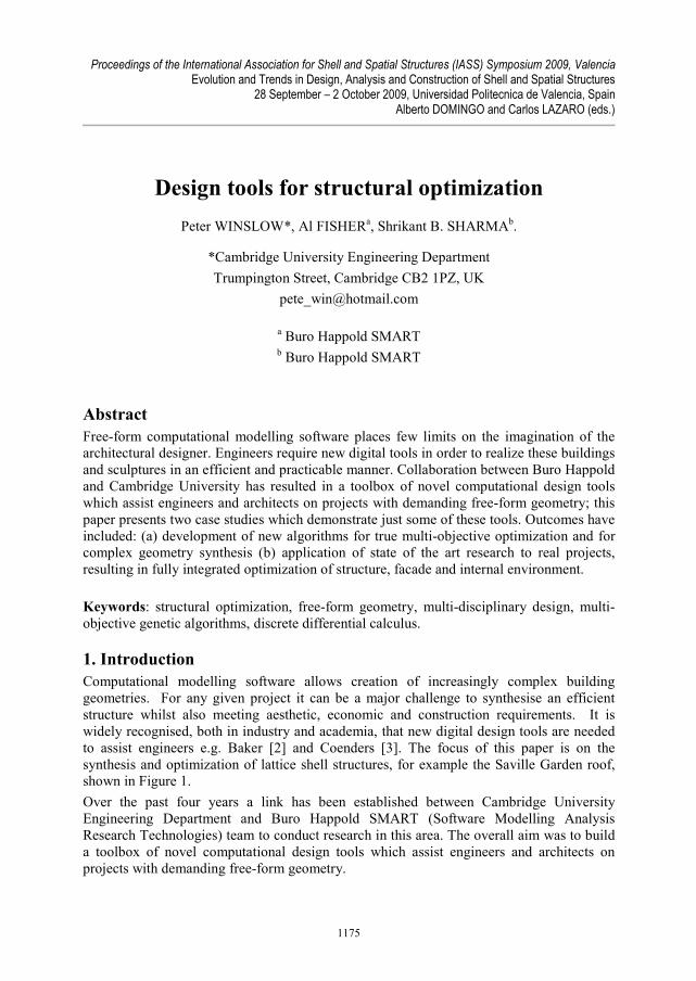
Figure 1: Saville Garden roof (courtesy of Warwick Sweeney).
2. Overview
There were two key objectives in the collaboration between Cambridge and Buro Happold:
(i) Find existing state of the art optimization/geometry methods and implement them in a
practical and user-friendly manner.
(ii) Develop new techniques which address gaps in the literature relating to multi-
disciplinary design optimization of structures with free-form geometry.
Specific outcomes and tools discussed in this paper include:
1) Application of fast structural optimization algorithms to new practical situations,
through the development of the SMART Sizer application, based on virtual work
methods proposed by Baker [1].
2) Implementation of user-friendly tools for generating complex grid geometries on free-
form surfaces, in SMART Form Rhino plug-in. This includes both techniques for
creation of primary structure and for cladding/facades.
3) Creation of novel methods for grid shell synthesis and optimization. These new
algorithms were constructed by drawing on, and further developing, research from
aerospace composites, discrete differential geometry and multi-objective evolutionary
optimization. Technical details have been given in previous IASS conferences and
journal by the authors (Winslow et al. [7, 8]).
These innovative tools allow ever more complex structural geometries to be generated,
analysed and manipulated. They facilitate much greater architectural freedom and
exploration throughout the whole design process, even for unusual free-form surfaces. This
paper now demonstrates the successful application of methods from the toolbox to two case
studies: Elephant House roof, using (3), and Perforated Museum roof, using (1) and (2).
1176
Proceedings of the International Association for Shell and Spatial Structures (IASS) Symposium 2009, Valencia Evolution and Trends in Design, Analysis and Construction of Shell and Spatial Structures
3. Elephant House roof
3.1. Problem definition
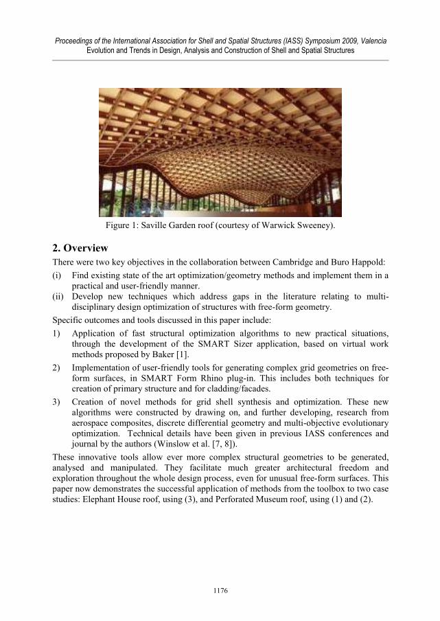
The Elephant House roof surface to be constructed is shown in Figure 2(a) and is
approximately 100 m by 80 m. The concept shown in Figure 2 was a competition bid for a
new elephant house at Zurich Zoo. The surface is highly curved in places (around tops of
columns), will be covered with a `green' sedum bio-diversity roof and contains a number of
holes through which people can view the elephants, Figure 2(c).
It was initially proposed, by the project engineer, that the grid layout should be a vertical
projection from the x-y plane and its topology is based upon two primary sets of rods with
triangulation along both diagonals as shown schematically in Figure 2(b). This case study
considers varying rod orientations on the surface in order to minimize three objectives:
(1) Deflection under self-weight (serviceability criterion). (2) Maximum member stress due to wind + self-weight (ultimate limit state criterion).
(3) Total mass of structure.
Note that buckling load is also important, but initial investigations showed that this closely
correlates with objective (2), so it is not necessary to consider it as a separate objective.
The multi-objective grid layout optimization method proposed and developed by Winslow
[8, 9] is used to tackle this problem (i.e. the third bullet point from Section 2). This new
tool allows exploration of a much wider range of grid layouts on any free-form surface.
Although the initial case study surface is a NURBS Rhino model, the optimization tool has
its own bespoke triangulated surface mesh geometry engine. This facilitates the use of
highly sophisticated discrete mathematical techniques e.g. Ray [5], for robust, automated
grid layout synthesis.
(a) (b)
(c)
Figure 2: Elephant House problem definition. (a) Given surface.
(b) Initially proposed grid layout. (c) Artist’s impression
1177
Proceedings of the International Association for Shell and Spatial Structures (IASS) Symposium 2009, Valencia Evolution and Trends in Design, Analysis and Construction of Shell and Spatial Structures
Twenty one design variables are used:
• Two rod angles at each of the 9 design points
• Rod spacing
• Cross section size for primary rods (chosen from a list of 6 different steel tubes)
• Cross section size for secondary rods (chosen from a list of 6 different steel tubes)
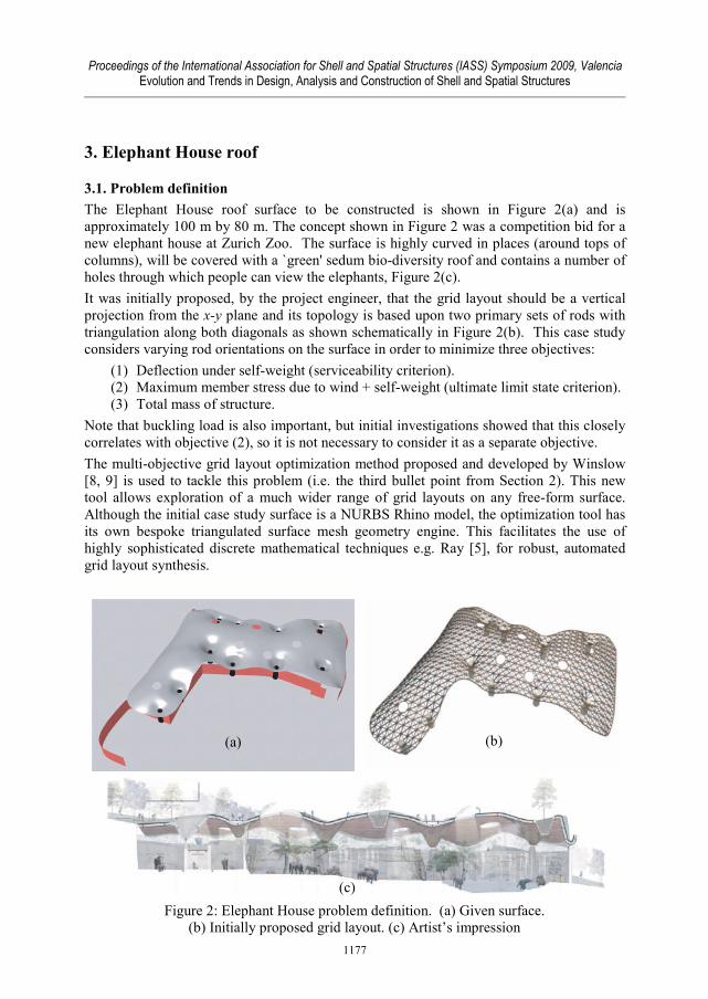
3.2. Design tool initialization
The optimization problem is initialized by manually picking a number of design points on
the surface, at which the directions of the two primary sets of rods are defined; see Figure
3(a). Note that the directions of the red and green arrows show primary rod orientations; in
this figure they are arbitrarily defined but it is easy to see that changing the directions of
these arrows will alter the rod paths; hence the structural layout can be optimized. The user
also picks a number of fixed points which specify the location of supporting columns.
A complete, smooth grid is then automatically generated from these sparsely defined rod
directions using discrete differential geometry techniques (Winslow [8]). An example of
the primary rod paths (which represent a re-parameterization of the surface) is shown in
Figure 3(b). Triangulating rods and locally convergent rods around tops of columns are
then easily added, and a complete FE model is created. Any optimization algorithm could
then be used to change the directions of the red and green arrows in response to the
structural performance. Figure 4 gives an overview of how the grid layout is automatically
optimized over 200 generations using a multi-objective genetic algorithm to simultaneously
minimize the 3 objectives, with no need for an aggregate objective function.
Figure 3: Rod directions defined sparsely at design points. (a) Design
points on surface (perspective view). (b) Complete grid fitted
smoothly to red and green direction arrows (plan view).
(a)
(b)
1178
Proceedings of the International Association for Shell and Spatial Structures (IASS) Symposium 2009, Valencia Evolution and Trends in Design, Analysis and Construction of Shell and Spatial Structures
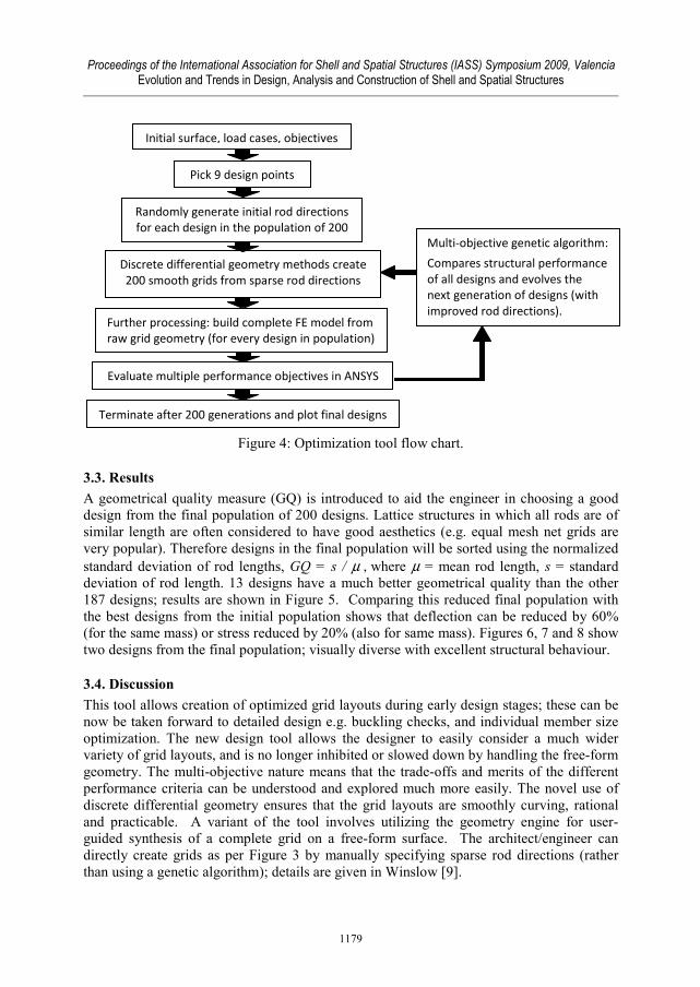
Figure 4: Optimization tool flow chart.
3.3. Results
A geometrical quality measure (GQ) is introduced to aid the engineer in choosing a good
design from the final population of 200 designs. Lattice structures in which all rods are of
similar length are often considered to have good aesthetics (e.g. equal mesh net grids are
very popular). Therefore designs in the final population will be sorted using the normalized
standard deviation of rod lengths, GQ = s / µ , where µ = mean rod length, s = standard
deviation of rod length. 13 designs have a much better geometrical quality than the other
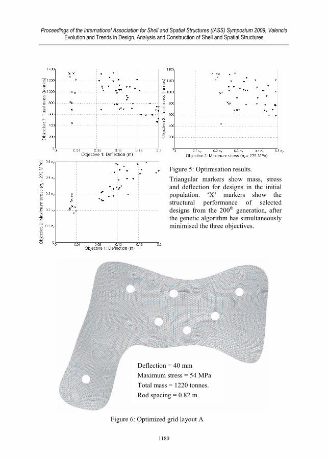
187 designs; results are shown in Figure 5. Comparing this reduced final population with
the best designs from the initial population shows that deflection can be reduced by 60%
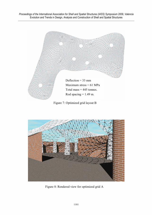
(for the same mass) or stress reduced by 20% (also for same mass). Figures 6, 7 and 8 show
two designs from the final population; visually diverse with excellent structural behaviour.
3.4. Discussion
This tool allows creation of optimized grid layouts during early design stages; these can be
now be taken forward to detailed design e.g. buckling checks, and individual member size
optimization. The new design tool allows the designer to easily consider a much wider
variety of grid layouts, and is no longer inhibited or slowed down by handling the free-form
geometry. The multi-objective nature means that the trade-offs and merits of the different
performance criteria can be understood and explored much more easily. The novel use of
discrete differential geometry ensures that the grid layouts are smoothly curving, rational
and practicable. A variant of the tool involves utilizing the geometry engine for user-
guided synthesis of a complete grid on a free-form surface. The architect/engineer can
directly create grids as per Figure 3 by manually specifying sparse rod directions (rather
than using a genetic algorithm); details are given in Winslow [9].
Initial surface, load cases, objectives
Pick 9 design points
Randomly generate initial rod directions
for each design in the population of 200
Discrete differential geometry methods create
200 smooth grids from sparse rod directions
Further processing: build complete FE model from
raw grid geometry (for every design in population)
Evaluate multiple performance objectives in ANSYS
Multi-objective genetic algorithm:
Compares structural performance
of all designs and evolves the
next generation of designs (with
improved rod directions).
Terminate after 200 generations and plot final designs
1179
Proceedings of the International Association for Shell and Spatial Structures (IASS) Symposium 2009, Valencia Evolution and Trends in Design, Analysis and Construction of Shell and Spatial Structures
Figure 5: Optimisation results.
Triangular markers show mass, stress
and deflection for designs in the initial
population. ‘X’ markers show the
structural performance of selected
designs from the 200th generation, after
the genetic algorithm has simultaneously
minimised the three objectives.
Figure 6: Optimized grid layout A
Deflection = 40 mm
Maximum stress = 54 MPa
Total mass = 1220 tonnes.
Rod spacing = 0.82 m.
1180
Proceedings of the International Association for Shell and Spatial Structures (IASS) Symposium 2009, Valencia Evolution and Trends in Design, Analysis and Construction of Shell and Spatial Structures
Figure 7: Optimized grid layout B
Deflection = 33 mm
Maximum stress = 61 MPa
Total mass = 445 tonnes.
Rod spacing = 1.49 m.
Figure 8: Rendered view for optimized grid A
1181
Proceedings of the International Association for Shell and Spatial Structures (IASS) Symposium 2009, Valencia Evolution and Trends in Design, Analysis and Construction of Shell and Spatial Structures
4. Perforated Museum roof
4.1. Overview
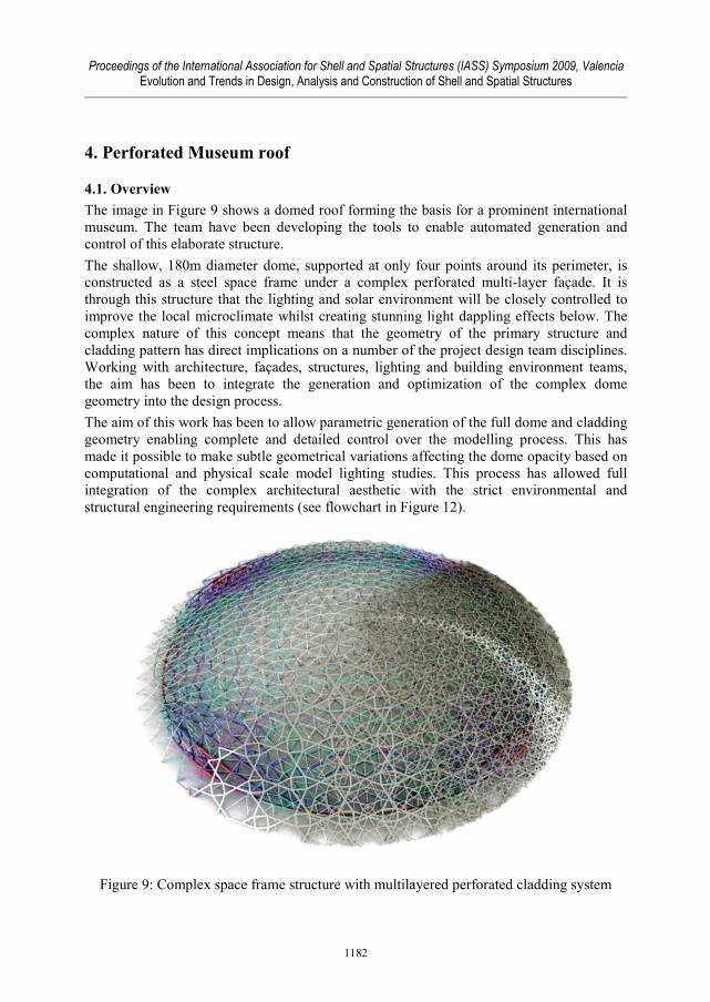
The image in Figure 9 shows a domed roof forming the basis for a prominent international
museum. The team have been developing the tools to enable automated generation and
control of this elaborate structure.
The shallow, 180m diameter dome, supported at only four points around its perimeter, is
constructed as a steel space frame under a complex perforated multi-layer façade. It is
through this structure that the lighting and solar environment will be closely controlled to
improve the local microclimate whilst creating stunning light dappling effects below. The
complex nature of this concept means that the geometry of the primary structure and
cladding pattern has direct implications on a number of the project design team disciplines.
Working with architecture, façades, structures, lighting and building environment teams,
the aim has been to integrate the generation and optimization of the complex dome
geometry into the design process.
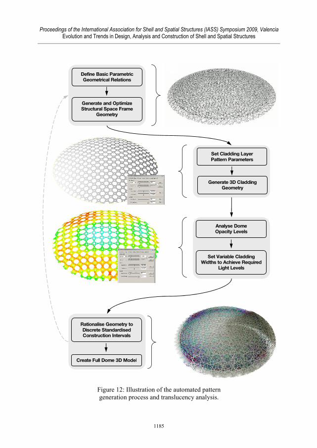
The aim of this work has been to allow parametric generation of the full dome and cladding
geometry enabling complete and detailed control over the modelling process. This has
made it possible to make subtle geometrical variations affecting the dome opacity based on
computational and physical scale model lighting studies. This process has allowed full
integration of the complex architectural aesthetic with the strict environmental and
structural engineering requirements (see flowchart in Figure 12).
Figure 9: Complex space frame structure with multilayered perforated cladding system
1182
Proceedings of the International Association for Shell and Spatial Structures (IASS) Symposium 2009, Valencia Evolution and Trends in Design, Analysis and Construction of Shell and Spatial Structures
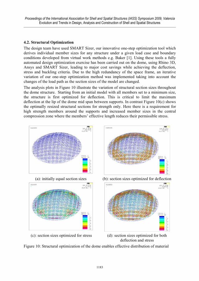
4.2. Structural Optimization
The design team have used SMART Sizer, our innovative one-step optimization tool which
derives individual member sizes for any structure under a given load case and boundary
conditions developed from virtual work methods e.g. Baker [1]. Using these tools a fully
automated design optimization exercise has been carried out on the dome, using Rhino 3D,
Ansys and SMART Sizer, leading to major cost savings while achieving the deflection,
stress and buckling criteria. Due to the high redundancy of the space frame, an iterative
variation of our one-step optimization method was implemented taking into account the
changes of the load path as the section sizes of the model are changed.
The analysis plots in Figure 10 illustrate the variation of structural section sizes throughout
the dome structure. Starting from an initial model with all members set to a minimum size,
the structure is first optimized for deflection. This is critical to limit the maximum
deflection at the lip of the dome mid span between supports. In contrast Figure 10(c) shows
the optimally resized structural sections for strength only. Here there is a requirement for
high strength members around the supports and increased member sizes in the central
compression zone where the members’ effective length reduces their permissible stress.
(a): initially equal section sizes (b): section sizes optimized for deflection
(c): section sizes optimized for stress (d): section sizes optimized for both
deflection and stress
Figure 10: Structural optimization of the dome enables effective distribution of material
1183
Proceedings of the International Association for Shell and Spatial Structures (IASS) Symposium 2009, Valencia Evolution and Trends in Design, Analysis and Construction of Shell and Spatial Structures
The final structural solution, satisfying both stiffness and strength criteria, was achieved by
optimizing for deflection whilst incorporating a robust member check for allowable stress
and local buckling. In addition a sensitivity analysis, optimizing for a range of deflections,
300–600mm, enabled a trade-off between deflection and minimum weight to be achieved.
The allowable members are selected from a finite list of standard section sizes, so no post
rationalization is required. The initial optimization was performed for self weight, cladding
and maintenance loading, the governing load case. The design process then consisted of an
in-depth detailed structural analysis and series of additional optimization iterations ensuring
compliance for multiple load cases.
This approach enabled a dramatic reduction in steel self-weight during conceptual and
design development, however the real benefit of the tool was realized in the increased
efficiency of the design process allowing rapid exploration of numerous design options.
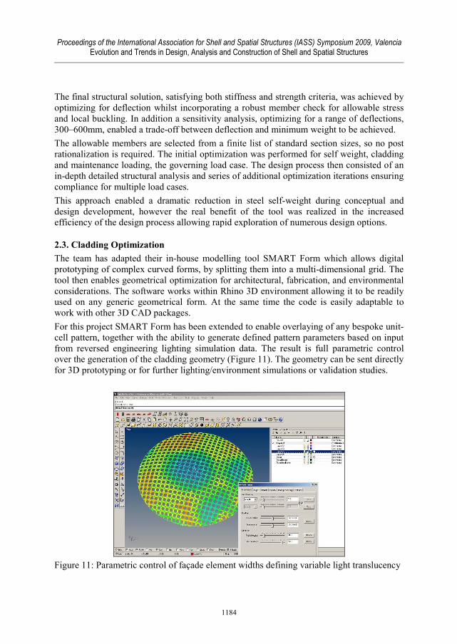
2.3. Cladding Optimization
The team has adapted their in-house modelling tool SMART Form which allows digital
prototyping of complex curved forms, by splitting them into a multi-dimensional grid. The
tool then enables geometrical optimization for architectural, fabrication, and environmental
considerations. The software works within Rhino 3D environment allowing it to be readily
used on any generic geometrical form. At the same time the code is easily adaptable to
work with other 3D CAD packages.
For this project SMART Form has been extended to enable overlaying of any bespoke unit-
cell pattern, together with the ability to generate defined pattern parameters based on input
from reversed engineering lighting simulation data. The result is full parametric control
over the generation of the cladding geometry (Figure 11). The geometry can be sent directly
for 3D prototyping or for further lighting/environment simulations or validation studies.
Figure 11: Parametric control of façade element widths defining variable light translucency
1184
Proceedings of the International Association for Shell and Spatial Structures (IASS) Symposium 2009, Valencia Evolution and Trends in Design, Analysis and Construction of Shell and Spatial Structures
Define Basic Parametric
Geometrical Relations
Generate and Optimize
Structural Space Frame
Geometry
Set Cladding Layer
Pattern Parameters
Analyse Dome
Opacity Levels
Set Variable Cladding
Widths to Achieve Required
Light Levels
Rationalise Geometry to
Discrete Standardised Construction Intervals
Create Full Dome 3D Model
Generate 3D Cladding
Geometry
Figure 12: Illustration of the automated pattern
generation process and translucency analysis.
1185
Proceedings of the International Association for Shell and Spatial Structures (IASS) Symposium 2009, Valencia Evolution and Trends in Design, Analysis and Construction of Shell and Spatial Structures
5. Summary
The two case studies in this paper have shown just some of the novel tools developed
during this collaborative project. Specifically this has included demonstration of:
• State of the art techniques for creating and exploring highly complex but practicable
grid geometries, and for conducting true multi-objective optimization - in ways not
previously possible for free-form structures.
• Advanced SMART Form and SMART Sizer tools, developed from research methods,
which enable integrated optimization of structural and environmental performance in a
rapid, user-friendly manner.
Overall, the project has helped to build up a set of innovative tools enabling simple
solutions to complex problems.
6. Acknowledgements
We would like to thank Sergio Pellegrino and Allan McRobie for their guidance during the
project. Thanks also to Birgit Schaffarra for Elephant House case study data. The financial
support of the UK EPSRC and Buro Happold is gratefully acknowledged.
References
[1] Baker, W. F., Stiffness Optimization Methods for Lateral Systems of Buildings: A
Theoretical Basis, Electronic Computation, 21 Buildings, Towers, and Tanks (CE),
1991; 269-278.
[2] Baker, W., Beghini, A., Besserud, K., Carrion, J., Cotten, J., Mazeika, A., and
Mazurek, A. Design applications of structural optimization methods. In: Symposium
of the IASS, Acapulco, Mexico, October 27-31, 2008.
[3] Coenders, J., and Wagemans, L. The next step in modelling for structural design:
structural design tools. In: Symposium of the IASS, Bucharest, Romania, September 6-
9, 2005.
[4] Michalatos, P., and Kaijima, S. Design in a non homogeneous and anisotropic space.
In: Symposium of the IASS, Venice, Italy, December 3-6, 2007.
[5] Ray, N., Li, W., Levy, B., Sheffer, A., and Alliez, P. Periodic global parameterization.
ACM Transactions on Graphics, 2006; 25(4); 1460-1485.
[6] Winslow, P., Pellegrino, S., and Sharma, S. Free-form grid structures. The Structural
Engineer, 2008; 86(3); 19-20.
[7] Winslow P., Pellegrino S. and Sharma S.B., Mapping two-way grids onto free-form
surfaces. Journal of the IASS, 2008; 49; 123-130.
[8] Winslow P., Pellegrino S. and Sharma S.B., Subdivision techniques for optimisation
of free-form structures. In: Symposium of the IASS, Acapulco, Mexico, October 27-31,
2008.
[9] Winslow P., Synthesis and optimisation of free-form grid structures, PhD Thesis,
Cambridge University Engineering Department, 2009.
1186