design phases 1 i 3.63
TRANSCRIPT
Bradford Perkins is the founder and seniorpartner of Perkins Eastman Architects, a large New York-based $hecture, interior d esign, andplanningfirm that has won many design awards. He lectures regularly at architecture
sdtools and other institutions and has published numerous articles on design and architecture management issues.
Design Phases 1 I 3.63
uilding design is the keystone of architecture practice. Translatil -. Tg need dgets in as well
&a aspirations, theories and technologies, and schedules and bui
I -@propriate and exciting places and buildings requires great skill “ti attention to broader public concerns. ( c F;.: Jhere are many ways of looking at the design process and the design practices in kh h c arc itects engage. Design decision making can be seen as private and intu- #ve-for, in many respects it is-and yet many of the decisions designers make are $$oadly discussed and rationally analyzed. Design can be seen as complex and inac- iaible, and yet it is taught to and practiced by thousands of capable architects- &id hundreds of thousands more in a wide array of other disciplines. Design has [trxxnents of great inspiration and deep insight-but most of all it requires hours, $‘@onths, and years of hard work.
S
!to
Other practice topics in this series:
3.61 Facilities Planning and
Programming
3.62 Site Analysis
!$Iesign is a continuous activity. It “begins” somewhere deep in the recesses of the $roject definition process; somewhere someone has an idea that ultimately takes $rm, Design never really ends; once opened for use, buildings are constantly modi- pd and adapted-redesigned if you will.
@ost proj ects do have beginnings and ends. These points are defined by the con- @acts written to provide planning, design, construction, and facilities management $ervices. Design, however, is the central issue at every step. The design process has !&err compared to a learning curve on which each step exposes the design team to $new opportunities, new problems, and new knowledge about the situation at hand. >
; besign Influences c Every project situation is different. Each presents a different set of requirements and ;:limitations. Each presents a unique set of cultural, environmental, technological, iand aesthetic contexts to be considered. Each presents its own set of challenges and $opportunities. Design brings to the surface the major considerations inherent in a tsituation. It is both a problem-seeking and a problem-solving process. While every F [project has a unique combination of design influences, some of the most important
(* 3.61 Facilities Planning and
Programming views this as a con-
tinuing and cyclical process-from
project planning through develop-
ment (design), implementation (con-
struction), and management-and
as an opportunity for architects to
provide a client support circle of ser-
vices. Page 603.
ARCHITECTURE IS THE ART OF INQUIRY.
Arthur Ericson
[.piogram All buildings have a series of aspirations, program requirements, and lim- [,itations to be met in design. The program may be short or long, general or specific, F’descriptive of needs or suggestive of solutions. 2. i. Communify desires. A growing number of public agency approvals influence design. [,Many owners and their architects must adjust their designs to satisfy community i: groups, neighbors, and public officials. These design adjustments are often ad hoc ? efforts to meet objections or to gain support rather than direct responses to codi- :’ fied requirements.
Bradford Perkins, FAIA, AICP
Rt 3.71 Community Planning
and Environmental Controls,
page 653, and 3.72 Building
Codes and Regulations,
page 663, expand on these
requirements.
kp the project on schedule. In another project, it may be necessary to com- 8 final site plan early in the process-before the building “footprint” drawn nte plan is fully designed.
ent, A central ingredient in most successful design projects is a good client. have a clear idea of program, budget, and other project objectives, in- nal appearance of the building. Others look to their architect to help he project objectives, as well as to design a building that meets these
0th cases, the effectiveness of the marriage between client and architect or factor in making design decisions throughout the project.
/bst every project has a unique set of factors that combine to make each prob- pfferent. For their part, individual architects approach design in different ways !&h different values and attitudes. While design has a certain linear quality blves analysis, synthesis, and evaluation), it is !y acknowledged to have nonlinear qualities as ‘The latter are sometimes described as “flashes eight” and “creative leaps.”
!aingly we recognize that the design process :s with information and ideas simultuneowly
/&y levels. Thus th e architect can be thinking t the overall geometry of the building, the ways
‘which a wheelchair-bound person might expe- the spaces in the building, and the materials ch the building will be constructed all at the
same time, we view designing as reciprocal ac- d reflection. Architects process requirements, and variables and produce tentative design
sals. Examination and criticism of these pro- lead to new proposals. Each proposal reveals bout the problem and suggests an appropri-
lysis. However nonlinear it may be, design in- es analysis. An initial step is to identify, analyze, firm, and organize the factors that will influ-
~~ ettlre the development of a design concept. Architects ; typically take the available data from the econom-
ic feasibility, programming, and site analysis steps and organize them into a form that allows the infor- mation to be used in building design. The data may
In his analyses of ir$uential design- ers, Jim Franklin concludes that they see design as CONSEQUENTIAL,
rather than SEQUENTIAL. New issues
arisefrom decisions just made.
be provided by the owner or developed by the architect in the course of providing predesign or site analysis services. The analyses-often pursued in parallel with one another--are described in the paragraphs that follow.
- 2.1
- 2.3
.- 2.4
-- 2.6
-..:“3.1 In a series of AIA roundtables with
architects in influential design firms,
---- 3.2
3.3
one message came through loud
and clear: Get involved in design
at the predesign phase and extend
this “discovery” phase until the key
design issues emerge, the architect
and client both accept them, and
the base for a strong design con-
cept is laid.
(* 3.52 Project Operations presents
additional findings on how archi-
tects design-and manage design
in their offices. Page 559.
James R. Franklin, Current Practices in Small Firm Management (AIA, 1990)
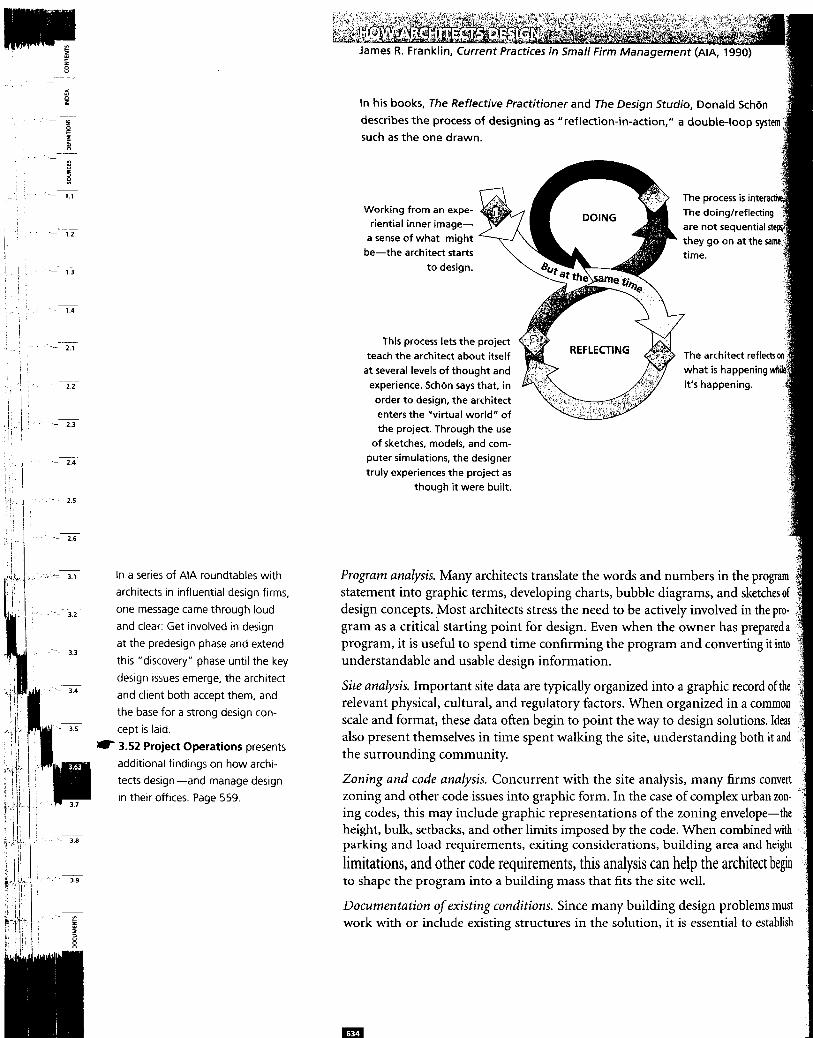
In his books, The Reflective Practitioner and The Design Studio, Donald Sch6n describes the process of designing as “reflection-in-action,” a double-loop system such as the one drawn.
Working from an expe- riential inner image-
a sense of what might be-the architect starts
to design.
The process is inte The doing/reflecti are not sequentia
The architect reflects This process lets the project
teach the architect about itself at several levels of thought and
experience. SchZin says that, in order to design, the architect enters the “virtual world” of the project. Through the use
of sketches, models, and com- puter simulations, the designer truly experiences the project as
though it were built.
Program analysis. Many architects translate the words and numbers in the program statement into graphic terms, developing charts, bubble diagrams, and sketches of design concepts. Most architects stress the need to be actively involved in the pro- gram as a critical starting point for design. Even when the owner has prepareda program, it is useful to spend time confirming the program and converting it into understandable and usable design information.
Site analysis. Important site data are typically organized into a graphic record of the ’ relevant physical, cultural, and regulatory factors. When organized in a common scale and format, these data often begin to point the way to design solutions. Ideas also present themselves in time spent walking the site, understanding both it and the surrounding community.
Zoning and code analysis. Concurrent with the site analysis, many firms convert zoning and other code issues into graphic form. In the case of complex urban zon- ing codes, this may include graphic representations of the zoning envelope-the height, bulk, setbacks, and other limits imposed by the code. When combined with parking and load requirements, exiting considerations, building area and height
limitations, and other code requirements, this analysis can help the architect begin to shape the program into a building mass that fits the site well.
Documentation ofexisting conditions. Since many building design problems must : work with or include existing structures in the solution, it is essential to establish
accurate documentation of existing conditions either by converting existing _ - a”u,e* lllL” VU.,% UIIbbL” IVI UUI 11- .a”‘~,” ..A ‘1
--------b ___I. _**--I-^-- --1-
In addition to providing basic dimensional data for design, this step typi- tifies existing physical and code problems.
ng. The project schedule is a project management tool, but, at times, it can me an important factor in design. Such major scheduling issues as proj-
sing, the time it takes to seek variances, and the sequencing of design deci- o accommodate fast-track construction can all influence the beginning of a
portant to analyze the project budget to understand its implications for g design. Virtually all project budgets are limited. The architect must
of funds, directing them to those decisions that appear to be most e success of the design solution. An experienced analysis of the
t can usually identify the size of this discretionary portion as well as establish elines for the basic system selections to take place during the design.
tion industry practice. Concurrent with schedule and cost analysis, most consider the aspects of local construction industry practice relevant to the
ign assignment. This can range from availability of materials and labor to com-
F nly used materials, systems, and detailing.
iDesign precedents. In many firms, an important aspect of the initial analysis is $he critical assessment of relevant precedents from projects facing similar or relat- red program, site, context, cost, or other design issues. It is common for architects BO familiarize themselves with the design of buildings that deal with similar issues to stimulate solutions for their own design problems.
$ynthesis. Building design begins with the architect’s analysis, understanding, and response to the base data collected and analyzed. The combination of all this into aunified solution is the synthesis that is the core of concept design. The quota- tions included in “Architects on Designing” (page 636) are intended to provide some insight, from different perspectives, to the synthesis process.
JJnderlying these multiple perspectives are some common themes. Most architects start with an analysis of the base data and then work through sketches, talking, and &inking-reciprocal action and reflection-until they reach the level of under-
essary to form a concept. While the particular design stimuli, orga- pies, areas of emphasis, and aesthetic vocabularies may be unique to
ar architect or firm, and while firms may synthesize these in different there are some common tasks in design. These, broadly, are discussed below:
&%rblish~~g design go&. The client and design team have goals, expressed formally br informally, for the project. These goals create functional and aesthetic guide- bes for judging design decisions, and the project objectives help establish prior-
P es when trade-offs must .be accommodated in the design solution. Compromises getween budget and quality, appearance and energy efficiency, and hundreds of $ther decisions have to be made within the context of an understanding of project
THE BEST THINGS HAPPEN WHEN
YOU HAVE TO DEAL WITH REALITY.
Robert Venturi
I
ting a design concept. With the design goals in hand, the architect develops a concept-or perhaps several. This may be a plan concept, the selection of a
c form, a decision to mass the building vertically or horizontally, or the use rganizing element (such as a central mall for the interior spaces). The con-
might be based on a particular image or a historic precedent. It may employ a vocabulary” of formal and aesthetic ideas that will govern the develop- the design. Whatever the underlying principles, it is common for archi-
to develop several representations and variations to help them understand and $nrticulate the evolving design concepts.
~hduating concept alternatives. Working with these possibilities and variations, most #rchitects have developed a process for narrowing them down to a set of workable #ncepts. In some cases, the selection of alternatives is based on a point-by-point $&&on of the concept against the original project objectives. In other cases, it is p”1 intuitive judgment based on experience. In most instances, it is a combination of ; both.
Beyond the first conceptual steps, the process becomes more complex. In all but the smallest and simplest projects, the steps that follow the concept involve a team of people. As the design team is expanded, most firms begin to involve the engineers, specialist consultants, and cost consultants necessary to help test and develop the selected concepts; they agree that early participation leads to a more efficient and coordinated design effort. For example, engineers not only guide the selection of many of the building systems employed but also define the size, area requirements, and preferred location of these systems. In more complex design problems, engi- neers often help analyze the feasibility, relative cost, and other critical factors of major design options.
Contractual Framework Design is undertaken within a contractual framework that I Outlines design tasks and requirements I Identifies specific responsibilities for design, including those of the architect, of the owner, and possibly of third parties
I Establishes a schedule, including starting and completion dates I Often defines design phases with interim milestone dates and owner approvals to
contractual framework is established in the agreement between owner and . Design activities may be described in detail or, in the case of small or lim-
cope projects, in a few sentences. AIA Document B141, the most commonly form of owner-architect agreement, establishes five project phases:
Construction documents Bidding or negotiation Construction contract administration
r 3.5 Project Management focuses
on four interrelated design manage-
ment activities: managing teams,
operations, controls, and disputes.
Page 545.
However the design process is defined, there are inevitably handoffs. Tom Kvan of The Coxe Group suggests this approach to defining the require- ments at the end of a design phase: Make a list of deliverables. Now assume that you have just inherited theprojectfiom anotherfirm that has suddenly gone out of business. What do YOU really need ro know in order to move forward?
AIA Document B141 assumes that a clear definition of the client’s program either the owner brings the program to the start of design or the architect provides the service as part of professional services. It also assumes that the process can move ahead in a linear fashion through a series of phases-each of which results in a more complete definition of the design-until the project is sufficiently detailed to go into documentation for bidding (or negotiation) and construction.
Reality isn’t so orderly. Evolving program requirements, budget realities, increased knowledge of site considerations (such as subsoil problems), public agency reviews, and many other factors make it necessary to go back and modify previous steps. Fast-tracking-breaking design into “packages” and awarding some before others are completed-further complicates matters. Design moves forward, but rarely in the clear linear fashion implied by the contractual phases.
Nonetheless, a contractual framework is important. It does impose an order on the process. When there are phases, the architect brings the design to an interim level of development, the owner reviews and approves it, and the project moves forwan based on mutual understanding.
Schematic Design AL4 Document B141 identifies the first phase of services as schematic design. Whik different projects, clients, and design teams have slightly different definitions o the completion of this phase, certain objectives and products are commonly agreed upon.
Schematic design establishes the general scope, conceptual design, and scale any relationships among the components of the project. The primary objective is tc arrive at a clearly defined, feasible concept and to present it in a form that achiever client understanding and acceptance. The secondary objectives are to clarify the project program, explore the most promising alternative design solutions, and pr! vide a reasonable basis for analyzing the cost of the project.
Typical documentation at the end of this phase can include n A site plan = Plans for each level n All elevations n Key sections n An outline specification n A statistical summary of the design area and other characteristics in comparisQ
to the program .‘i . A preliminary construction cost estimate ,::
n Other illustrative materials-renderings, models, computer simulations, or aa tional drawings-needed to present the concept adequately
Drawings. These are typically presented at the smallest scale that can clearly W trate the concept, perhaps $6” = I’-0” (1:200 in SI units) for larger buildings ap! r/s” = I’-0” (~100) or r/4” = I’-0” (1:50) for smaller buildings and interiors. 4 ;1 *:
mentB163 $d Form of Agree-
ween Owner and
p
El.3
hAdministration and &ement Services @ject Administration
bocutnent Checking
&gency Consulting/ Review/Approval
$$edule Development/ Monitoring
k Preliminary Estimate of .-.-the Cost of the Work
f <‘ Presentation Services
* &tic Design Phase j Architectural
Design/Documentation’
1 Structural Design/Documentation
_ j
2
f
Mechanical Design/Documentation
$ Electrical Design/Documentation
r ~~~~gn/Documentation
38 Landscape j Design/Documentation 1 ; .29 Interior ! Design/Documentation
.30 Special Design/Documentation
31 Materials Research/Specifications
l Each service is further devel- oped. Architectural &sign/ Documentation, during the Schematic Design Phase, consists of responding to program requirements and preparing:
.Of Review of owner’s program and budget
E? .O2 Conceptual&e and building
h plans
k$ .O3 Preliminary sections and
elevations ; .04 Preliminary selection of build-
ing systems and materials i’ .05 Development of approximate .?,. dimensions, areas and volumes
.06 Perspective sketchles) 1 .07 Study model(s)
,chitects
AIA Document 8141 Standard Form of Agree ment Between Owner ai Architect (1987 edition)
Id
AIA Document 8151 Abbreviated Form of Agreement Between Owner and Architect for Construction Projects of Limited Scope (1987 edition)
Article 2 Scope of Architect’s Basic 5ervices
Article 2 Scope of Architect’s Basic Services
AIA Document B155 Standard Form of Agree- ment Between Owner and Architect for a Small Project (1993 edition)
Article 1 Architect’s Responsibilities
Schematic Design Phase 2.2.1 The Architect shall review the program furnished by the Owner to ascertain the require- ments of the Project and shall arrive at a mutual understanding of such requirements with the Owner.
2.2.2 The Architect shall prepare a preliminary evaluation of the Owner’s program, schedule, and construction budget require- ments, each in terms of the other.
2.2.3 The Architect shall review with the Owner alternative approaches to design and con- struction of the Project.
2.2.4 Based on the mutually agreed-upon program, schedule and construction budget require- ments, the Architect shall pre- pare, for approval by the Owner, Schematic Design Documents consisting of drawings and other documents illustrating the scale and relationship of Project com- ponents. 2.2.5 The Architect shall submit to the Owner a preliminary estimate of Construction Cost based on current area, volume, or other unit costs.
Design Phase 2.2.1 The Architect shall review with the Owner alternative approaches to design and construction of the Project.
2.2.2 Based on the mutually agreed-upon program, schedule and construction budget require- ments, the Architect shall pre- pare, for approval of the Owner, Design Documents consisting of drawings and other documents appropriate for the Project, and shall submit to the Owner a preliminary estimate of Construction Cost.
1.1 During the Design Phase, the Architect will perform the following tasks:
.l Describe the project require- ments for the Owner’s approval.
.2 Prepare a design solution based on the approved proj- ect requirements.
.3 Upon the Owner’s approval of the design solution, pre- pare Construction Documents indicating requirements for construction of the Project.
.4 Help the Owner file docu- ments required for the approval of governmental authorities.
.5 Help the owner obtain pro- posals and award contracts for construction.
AIA Document 8163 (continued)
Design Devdopment Phase Services includes Design Services 23 through .31 (same as Schematic Design Phase)
.23 Architectural Design/ Documentation, during the Design Development Phase, consists of contin- ued development and expansion of architectural Schematic Design Oocuments to establish the final scope, relationships, forms, size and appearance of the project through:
.Ol Plans, sections and elevations
.02 Typical construction details
.03 Three-dimensional sketches
.04 Study model(s)
.05 Final materials selection
.06 Equipment layouts
--... _ .._ .._. -- .-_ _ -- Contract Documents Phase Services Includes Design Services .23 through .31 (same as Schematic Design Phase)
.23 Architectural Design/ Documentation, during the Contmct Documents Phase, consists of preparation of drawings based on approved Design Develapment Documents setting forth in detail the architectural con- struction requirements for the project.
. AIA Document B141 (continued)
_._ _-- ___- ..-.- ..___ -_- .___ Design Development Phase
2.3.1 Based on the approved Schematic Design Documents and any adjustments authorized by the Owner in the program, schedule or construction budget, the Architect shall prepare, for approval by the Owner, Design Development Documents con- sisting of drawings and other documents to fix and describe the size and character of the Project as to architectural, structural, mechanical and electrical systems, materials, and such other elements as may be appropriate.
2.3.2 The Architect shall advise the Owner of any adjustments to the preliminary estimate of Construction Cost.
AIA Document 8151 (continued) AIA Document 8155 (continued)
Construction Documents Phase
2.4.1 Based on the approved Design Development Documents and any further adjustments in the scope or quality of the Project or in the construction budget authorized by the Owner, the Architect shall prepare, for approval by the Owner, Con- struction Documents consisting of Drawings and Specifications setting forth in detail the requirements of the Project.
.2.4.2 The Architect shall assist the Owner in the preparation of the necessary bidding infor- mation, bidding forms, the Conditions of the Contract, and the form of Agreement between the Owner and Contractor.
2.4.3 The Architect shall advise the Owner of any adjustments to previous preliminary estimates of Construction Cost indicated by changes in requirements or gen- eral market conditions.
2.4.4 The Architect shall assist the Owner in connecting with the Owner’s responsibility for filing documents required for the approval of governmental authorities having jurisdiction over the Project.
Corrrtruction Documents Phase
2.31 Based on the approved Design Documents, the Archi- tect shall prepare, for approval by the Owner, Construction Documents consisting of Draw- ings and Specifications, setting forth in detail the requirements for the construction of the Project and shall advise the Owner of any adjustments to previous preliminary estimates of Construction Cost.
2.3.2 The Architect shall assist the Owner in connection with the Owner’s responsibility for filing documents required for the approval of governmental authorities having jurisdiction over the Project.
2.3.3 Unless provided in Article 12, the Architect, following the Owner’s approval of the Construction Documents and of the latest preliminary esti- mate of Construction Cost, shall assist the Owner in obtaining bids or negotiated proposals and assist in awarding and preparing contracts for construction.
g David Haviland, Hon. AIA,
Jn is a continuous process, &ail. Here is one view of tl augh design.
&sign
adapted from Life Cycle Cost Analysis 2: Using It in Practice (AIA, 1978)
often broken into phases to gain commitment to more general decisions before they are developed le level of decision making for each of a building’s functional subsystems as the project moves
Early schematics Later schematics or early design development
Design development or early construction documents
General Project objectives
Project scope
Program codes and regulations
‘Project budget
Project schedule
Delivery approach
Program interpretation
Basic design concepts
Siting
Building massing
Blocking and stacking
Access and circulation
Design vocabulary
Style issues and constraints
Sustainability
Design concept elaboration
Schematic floor plan
Schematic sections
Floor plans
Sections
Typical details
ille
Sle selection
Site development criteria
Requirements for access, circulation, parking, utili- ties, landscaping, lighting
Siting concepts
Site forms and massing
Access and circulation
Views to/from buildings
Concepts for grading, planting, paving, etc.
Acoustics and other site issues
Design concept elaboration
Initial site plan
Schematic grading, planting, paving plans
Site plan
Planting plan
Typical site sections
Typical site details
Outline specifications
Foundation and Substructure Performance requirements for foundations, excava- tions, etc.
Subsurface conditions and requirements
Impacts of program, energy on under-ground building
Exploration of special problems
Schematic basement plan
Refinement of special foundation requirements
Selection of foundation system
Foundation plan
Basement floor plan
Sizing of key foundation elements
Outline specifications
1 Superstructure 6 Performance requirements % for floor, roof, stair, other 8 structural elements
Relation of structure to spatial organization, elevations, etc.
Selection of use modules
Basic structural module
initial system selection
Structural system selection
Outline framing plan
Sizes of key elements
Floor framing plans
Roof framing plan
Sizing of elements
Important details
Outline specifications
[ Exterior closure $ Restrictions on exterior f design materials, etc.
. Performance requirements i for walls, doors, windows
Approach to elevations, fenestration
Views to/from building
Initial envelope elements sizing and selection
Design concept elaboration
Selection of wall systems, materials
Schematic elevations fenestration
Elevations
Key exterior details
Outline specifications
. . . .
.
‘,.
. . .
‘..
‘. . .
‘..
. . .
. .
“.
:..
b :.
‘_
‘. .
‘.
l
Predesign
Roofing
Performance requirements for roofing elements
Early schematics
Roof type and pitch
Initial system selection
Later schematics or early design development
Selection of roof system, materials
Design development or ear/y construction documents
Outline specification
Interior construction
Performance requirements Approach to partitioning for partitions, finishes, built-in furnishings specialties interior design vocabulary
Flexibility requirements Layout of key spaces
Room designs
Layout of key areas
Selection of partition systems, finishes
Input to plans and elevations
Key interior elevations
Initial finish schedules
Outline specifications Important fixtures or
theme elements ____
Vertical circulation and conveying systems
Performance requirements for conveying systems
Mechanical systems -
Performance requirements for plumbing, HVAC, fire protection
Need for special mechanical systems
____- _~-~--__.--__-___~..
Basic organization and Input to plans, sections Input to floor plans, framing circulation scheme and elevations plans, sections, elevations
Need for and types of Sizing of exits, other Outline specifications vertical circulation circulation areas
Need for special conveying Basic elevator and escalator systems concepts
Other conveying systems concepts
Impact of mechanical Mechanical systems selection Detailed systems selection concepts on building Refinement of service, Initial system drawings and planning distribution concepts key details
Initial systems selection Input to plans, sections, Distribution and riser Initial distribution ideas and elevations diagrams
Space allocation for Input to floor plans, framing mechanical areas plans, sections, elevations
Outline specifications
Initial equipment list
Electrical and lighting systems
Performance requirements for lighting systems
Performance requirements for electrical systems
Need for special systems
Approaches to natural, artificial lighting
Lighting quality and character
Window, skylight and glazing design
Selection of lighting, electrical systems
Service, power, and distribution concepts
Input to plans, sections, and elevations
Detailed systems selection
Distribution diagrams
Impact of site, design on electrical systems
Space allocation for electrical systems
Key room lighting layouts, ceiling plans
Input to plans, sections, and elevations
Outline specifications
-____- Equipment
Delineation of equipment needs and performance
Impact of key equipment items on siting and design
Impact of key items on room Input to plans, sections, design, framing plans, etc. and elevations
Outline specifications
Initial equipment list
\-Outline specifications. This is a general description of the work that indicates the $ major systems and materials choices for the project and provides the information i necessary to communicate the appearance and function of the building.
~Preliminary estimate ofconstruction cost. The schematic design estimate usually in- ! dudes a preliminary area analysis and a preliminary construction cost estimate. iThe level of detail is necessarily limited; the estimate may be broken down by major g trades or systems (for example, foundations, structure, exterior closure, interior ’ partitions and finishes, plumbing, mechanical, electrical, site work, and equipment). This may also include a preliminary analysis of the owner’s budget, with recom- mendations for changes based on site, marketplace, or other unusual conditions encountered in schematic design. It is common for preliminary cost estimates made at this stage to include contingencies for further design development, market con-
. tingencies, and changes during construction.
;, Other services. As part of schematic design, the architect may agree to provide life cycle cost analyses, energy studies, tenant-related design studies, other economic studies, special renderings, models, brochures, or promotional materials for the owner. These are included as “additional services” (in the AIA B141 form of owner- architect agreement), or they may be chosen from the list of possible designated services (in the B163 form of owner-architect agreement).
Approvals. The final step in schematic design (and, for that matter, each design phase) is to obtain formal client approval-in writing if at all possible. If approval is given verbally, it is a good idea to send the client a letter confirming the archi- tect’s understanding of the approval. (You may ask the client to initial the letter and return a copy.) The importance of this step cannot be emphasized enough. The schematic design presentation has to be clear enough to gain both the understand- ing and the approval of the client.
Design Development Design development is the period in which the design itself achieves the refinement and coordination necessary for a really polished work of architecture. The decisions
T made in schematic design are worked out at a scale that minimizes the possibility of major modifications during the construction contract documents phase. Work-
! ing drawings and specifications are complex and intricately interrelated; changes in those documents are costly and more likely to lead to coordination problems dur- ing construction. Thus, the primary purpose of design development is to further define and describe all important aspects of the project so that what remains is the formal documentation step of construction contract documents. During design development, the design team works out a clear, coordinated de- scription of all aspects of the design. This typically includes fully developed floor plans, sections, exterior elevations, and, for particular areas or aspects of the build- ing, interior elevations, reflected ceiling plans, wall sections, and key details. Often these become the basis for the construction documents to follow. The basic
AlA Document 8141 (1987 edition) calls for (I preliminary estimate of -
1.2 construction cost “based on current area, volume or other unit costs.” -
1.3
- 1.4
2.1
L.2
2.3
- 2.4
2.5
- 3.3
I
ii
i’4
. 21
il’
2.3.
14
i.r
2.a
3.1
3.2-
3.3
3.4
3.5
I 37
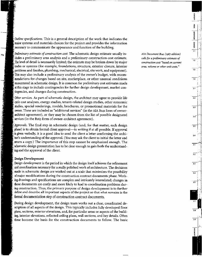
James H. Boniface, AIA, The Freeman-White Architects Reprinted from The /D/J (January 1990)
Schematic design usually results in a site plan, floor plans, elevations, and a perspective.
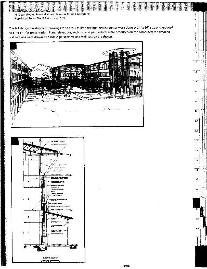
H. Dean Rowe, Rowe Holmes Hammer Russell Architects Reprinted from The IDP (October 1990)
The 141 design development drawings for a $25.5 million regional service center were done at 24” x 36” size and reduced to I 1”~ 17” for presentation. Plans, elevations, sections, and perspectives were produced on the computer; the detailed wall sections were drawn by hand. A perspective and wall section are shown.
I BUILMNG SECTION
i
1.1
1.2
1.3
1.4
2.1
2.2
-i2
-z
Ti
-iYi
3.’
_- 3.;
3..
3.
-:
I 3. -i -i -i 1
I
-.
-, .I
_. ‘..
._ ‘.
I
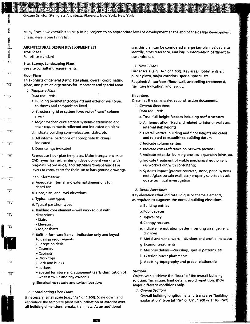
Gruzen Samton Steinqlass Architects, Planners, New York, New York
b
.;.
ii b
B
?I
1 1
1.2
13
14
2.1
2.2
2.3
2.4
2.5
2.6
mi 3.1
32
3.3
_-- 3.4
38
__ ..- 3.3
--.
Many firms have checklists to help bring projects to an appropriate level of development at the end of the design development phase. Here is one firm’s list.
ARCHITECTURAL DESIGN DEVELOPMENT SET Title Sheet Per office standard
Site, Survey, Landscaping Plans See site consultant requirements.
Floor Plans This consists of general (template) plans, overall coordinating plans, and plan enlargements for important and special areas.
7. Template Plans
Data required: a. Building perimeter (footprint) and exterior wall type,
thickness and composition fixed
b. Structural grid or system fixed (with “hard” column sizes)
c. Major mechanical/electrical systems determined and their requirements reflected and indicated on plans
d. Indicate building core-elevators, stairs, etc.
e. All internal partitions of appropriate thickness indicated
f. Door swings indicated
Reproduce floor plan templates. Make transparencies or CAD layers for further design development work (with originals placed aside) and distribute transparencies or layers to consultants for their use as background drawings.
Plan information: a. Adequate internal and external dimensions for
“hard fix”
b. Floor, slab, and level elevations
c. Typical door types
d. Typical partition types
e. Building core element-well worked out with dimensions l Stairs l Elevators l Major shafts
f. Built-in furniture items-indication only and keyed to design requirements l Reception desk l Counters l Cabinets l Work tops l Beds and bunks l Lockers l Special furniture and equipment (early clarification of
what is “NIC” and “by owner”)
g. Electrical receptacle and switch locations
2. Coordinating Floor Plans If necessary. Small scale (e.g., UN” or 1590). Scale down and reproduce the template plans with indication of exterior over- all building dimensions, breaks, tie in, etc. As an additional
use, this plan can be considered a large key plan, valuable to identify, cross reference, and key in information pertinent to the entire set.
3. Detail Plans Larger scale (e.g., l/4” or 1:lOO). Key areas, lobby, entries, public plaza, major corridors, special spaces, etc.
Required: All surfaces (floor, wall, and ceiling treatments), furniture indication, and layout.
Elevations Drawn at the same scales as construction documents.
1. General Elevations Data required:
a. Total full-height facades including roof structures
b. All fenestration fixed and related to interior walls and internal slab heights
c. Overall vertical building and floor heights indicated and related to established building datum
d. Indicate column centers
e. Indicate cross-reference points with sections
f. Indicate setbacks, building profiles, expansion joints, etc.
g. Indicate treatment of visible mechanical equipment (as worked out with consultants)
h. Systems impact (precast concrete, stone, panel systems, metal/glass curtain wall, etc.) properly selected by ade- quate technical investigation
2. Detail Elevations Key elevations that indicate unique or theme elements, as required to augment the normal building elevations:
a. Building entries
b. Public spaces
c. Typical bay
d. Canopy recesses
e. Indicate: fenestration pattern, venting arrangements, divisions
f. Metal and panel work-divisions and profile indication
g. Exterior treatments
h. Masonry details-coursings, special patterns, etc.
i. Exterior louver placements
j. Abutting topography and grade relationship
Sections Objective: to achieve the “look” of the overall building solution. Technique: limit details, avoid repetition, show major different conditions only.
1. Overall Sections Overall building longitudinal and transverse “building explanation” type (at l/16* or l/8”, 1:200 or l:lOO, SC&?).
lrscale (e.g., 114" or 150) vertical and plan sections rofiled for the building “work out” purposes.
scale (e.g., s/4" or 120). Dlominant full-height sec- nveying basic building configuration to indicate
ndation and perimeter treatment
ical wall construction tructure, abutting floor system location and insulatioin methods
ng, masonry coursings
nical penetrations impact (furrings, etc.)
e full (no cut) section. Additional detail sections minimally detailed; provide an adequate num-
I) provide a comprehensive buil’ding perimeter profile. till Isections keyed to building elevations.
ellsd;ale (1112" and 3”, or 1:lO and 15) as required. Indicate 8ditions. Technique: nonrepetitive prefinal design
d, encompassing good technical practice.
indow types: divisions, pattern, mullion profiles, vent detail, glazing type, jamb/head, plan section
ical only; keyed to plans and
~~~’ c, Frame types (typical only; for compatibility and profile)
1 d. Stair types-egress, public, exterior (including railing
e. Metat and glass walls, borrowed lights, etc.; for divi- s/on, profile, and glazing
1’ f. Nontypical design-related heavy-gauge metal work
4 requiring special fabrication, joining, fastening to
~I! other building elements
g. Interior partition types (typical only; keyed to plans I, and schedules)
h. Built-in furniture items, reception desks, work tops, counters, cabinet types, display cases, recesses, wardrobes, millwork, etc.
Iwterior Elevations Typical and special spaces, interfaced with and cross- referan~ced to floor and reflected celling plans. Indicate
a. Suspended ceiling lines reflecting structural and mechanical conditions ab’ove
b. Breaks
c. Level changes
d. Finish floor elevations
e. Pertinent vertical dimensions
f. Interior wall treatments, materials
rhese should be of prefinal quality adequate to convey j’esign intent.
Reflected Ceiling Plans Typical and special spaces. Integrated plans reflecting structural, mechanical, and electrical impacts. Plans to indicate:
a. Lighting layouts
b. Soffits, coves, furrings
c. Skylight locations
d. Ceiling materials
e. Acoustic treatments
f. Relationship with partitions g. interface with window details
h. Perimeter conditions-details, notches
i. Heating and ventilating register, diffuser locations
j. Sprinklers
k. Access panels
I. Exposed structure
Schedules Schedules to be nonrepetitive and comprehensive, with specific keying to floor plans and elevations.
a. Prefinal interior finishes
b. Frame and door
c. Preliminary hardware
d. Window and glazing
Specifications Comprehensive, abbreviated methods, materials, and systems descriptions in tune with the drawings. Use CSI format with applicable section numbers. tnclude all consultant portions as well as those special and supplementary conditions specific to the project.
Preliminary Estimate of Construction Cost Adjustment of the preliminary estimate of construction cost prepared at the end of schematic design.
STRUCTURAL DESIGN DEVELOPMENT SET 1. Floor plans at the same scale as the architectural drawings
2. Typical floor framing plans, including
a. Sizing of beam drops
b. Slab openings
c. Thicknesses
d. Depressions
3. Framing indication and governing sizing at
a. Roof structures
b. Penthouse c. Bulkheads
d. Other
4. Nontypical framing scheme where required:
a. Lobby b. Floors at grade
c. Other
>
5. All column points established
6. Final column schedule
7. Preliminary details and sections to adequately indicate structural system
8. Preliminary details of major unique conditions that affect scheme (as determined by the architect)
9. Details indicating accommodation with mechanical1 electrical at areas of major interface
10. Design development specifications
17. Any necessary recommended adjustments to the preliminary estimate of construction cost
MECHANICAL/ELECTRICAL DESIGN DEVELO’PMENT SET 7. Typical floor plans. Systems representation in diagram-
matic (nondetailed) style, major items of equipment indicated, their space requirements and interface requirements with other systems. Indicate
a. Major shafts (sizes)
b. Chases
c. Mechanical rooms and electric closets
d. Convector/fan coil locations, etc.
2. Required penetrations:
a. Wall
b. Slab
c. Beam
3. Terminal plans (lobby, cellar, roof) with items of heavy equipment shown in diagrammatic styie, with their space requirements indicated:
a. Boiler/heater spaces (include clear h,eight requirements)
b.Transformer vaults (a’pproval obtained from local utility company)
c. Switchgear, emergency generator, water storage tanks, fire pumps, etc.
d. Roof cooling towers, major air conditi,oning and air handling equipment, packaged units, etc.
4. Locations of major roof air-handling equipment: cooling towers, exhaust fans, etc.
5. Site utilities layouts
6. Preliminary details of major and unique conditions that affect scheme (as determined by the architect)
7. Data to be developed in conjunction and in coordination with the project team:
a. Integrated diagrammatic lighting plans indicating all overhead mechanical and electrical equipment for typical floor and special spaces
b. Preliminary electric fixture type schedule and cuts
c. Cuts and explanatory information for interior visual items such as: l Louvers l Heating/cooling units l Registers l Cabinets
d. Exterior louver requirements and proposed locations
ma
8. Design development specifications
9. Any necessary adjustments to the preliminary estimate of construction cost
SITE DESIGN DEVELOPMENT SET 1. Building location plan-building tied down dimensionally
with pertinent adjacencies, street lines and grades, pro- perty lines, required setbacks, easements, rights of way, manholes, sewers, hydrants, light standards, etc., inter- faced with survey
2. Main entry level datum elevation with key exterior grades at building perimeter
3. Site development grading and landscaping plans
4. Overall preliminary site grading and defined design of external elements, properly coordinated and interfaced with mechanicalleiectrica/ for utility entry points
5. Indicate areaways, vaults, access to subgrade spaces
6. Preliminary site and exterior building lighting scheme with identification of fixture types
7. Parking area defined with preliminary plotting
8. indication of path, stairs, ramps, beams, terraces, etc.
9. Plant materials (indication and preliminary schedule)
10. Design development details:
a. Railings
b. Stairs
c. Ramps
d. Paving types and patterns
e. Kiosks
f. Benches
g. Light standards
h. Others
Il. Design development specifications
12. Any necessary adjustments to the preliminary estimate of construction cost
OTHER CONSULTANTS’ DESIGN DEVELOPMENT SETS 1. Kitchen
2. Elevator
3. Laundry
4. Refuse
5. Security
6. Other
Include all preliminary information that allows proper interfaces with major design disciplines.
mechanical, electrical, plumbing, and fire protection systems are accurately Mined if not fully drawn. No major issues that could cause significant restudy luring the construction contract documents phase should be left unresolved.
file deliverables of the design development phase are similar to those of schematic design: drawings and specifications that fix and describe the size and character of be project, as well as any recommended adjustments to the preliminary estimate 3f construction cost. The design development phase usually ends with formal pre- rentation to, and approval by, the owner.
Design development may be a substantial undertaking, or it may be a much briefer iransition from schematic design to construction documents. Some owners require extensive schematic design services, with much of the project “developed” by the ime this phase ends. For some straightforward or repetitive projects, the schematic zlesign may be sufficiently clear for both owner and architect to pro’ceed directly to :onstruction documents with confidence. In these instances, design development may be brief (or in the most extreme cases, nonexistent).
/ In some project delivery approaches, the owner may wish to secure construction / cost commitments before the design is fully developed-thus reducing or even eliminating the design development phase. This reduces one uncertainty but intro-
‘, duces another, for there is likely to be debate about what was included, and not ! included, in the cost estimate made on the basis of preliminary, partial, or “scope”
ing the Impkmentation Phases design issues should be resolved by the end of design development, ntinue to be refined, resolved, or modified during the construction idding and negotiation, and construction contract administration
phases of the project.
During the construction documents phase, additional design issues emerge as the design team works out the final material and system selections, details, and dimen- sions. For example, I The final detailing and specification of an exterior wall, including the selection
of specific products and manufacturers, inevitably leads to modification of the dimensions, color, transparency, and other aspects of the wall.
I The detailing and specification of interior partitions, openings, and finishes in- ~; 1
volves a large number of minute design decisions from the location of joints to the selection of the final materials or acceptable alternates.
1: 11
Once a contractor or construction manager is selected, the need to make design decisions continues. The bidding and negotiation process inevitably leads to pro-
or ”
posed substitutions or modifications in details to achieve cost savings or to simplify
1~ the construction process. Usually some of these are accepted and must be success- fully integrated with the remainder of the design.
1 Design continues even through the construction phase. The construction contract / documents require interpretation and elaboration. Field conditions and other
Manyfirms use in-house checklists to help dejine the level of decision and documentation at the end of the various design phases. One such checklist is shown here.
* 3.22 Delivery Options examines
the pros and cons of early con-
struction contract awards based
on partially developed documents.
Page 389.
SOMETHING IN THE DETAILS WILL
REFINE AND REFRESH THE SOLUTION.
Charles Gwathmey
* 3.8 Design Documentation, page 703, addresses the con-
struction documents phase and
3.9 Construction-related Services, page 743, addresses
bidding/negotiation and construc-
tion contract administration.
This is a planned process-not the result of errors and omissions in earlier stages-and is carefilly delineated in the general conditions of the construction agreement.
1.2
1.3
-- 1.4
2.1
2.2
2.3
2.4
2.5
2.6
=z==
-- 3.2
3.3
3.4
3.5
3.8
-_-. 3.9
B
1
probl .ems m ay fi xce owne !r may reqi aest really stops” but COII
design changes. Confronted with the reality of the project, changes-reinforcing the elemental idea that design “nev@ tinues through construction and everyday use of buildings a~#
facilities.
In its broadest scope, sustainability refers to the ability of a society, ; ecosystem, or other ongoing system to continue functioning into the c indefinite future, without being forced into decline through exhaustion : or overloading of the key resources on which that system depends.
Architects can play a major role in the creation of a sustain- s able society. Environmental deterioration results from a lack of rele-
vant information, and poor design is responsible for many of our environmental problems. To minimize future degradation, and to restore already degraded environments, architects are challenged to
f lead the way into the newly emerging and rapidly flourishing field of environmentally conscious architecture and sustainable development.
The AIAIUIA Declaration of Interdependence for a Sustainable Future, signed at the 1993 World Congress of Architects, was a clarion call to architects around the world to
l Place environmental and social responsibility at the core of their practices and professional responsibilities
l Develop and continually improve practices, procedures, products, curriculums, services, and standards that will enable the implementation of sustainable design
l Educate fellow professionals, the building industry, clients, students, and the public about the critical importance and substantial opportunities of sustainable design
l Establish policies, regulations, and practices in government and business to ensure that sustainable design becomes normal practice
l Bring all existing and future elements of the built environ- ment-and their design, production, use, and eventual reuse -up to sustainable design standards
As major facilitators of the design process, architects have a unique opportunity to shape the built environment. The buildings and communities they design can help heal the landscape and directly influence morale, productivity, and comfort in the places people work, shop, play, and live.
The AIA takes the position that it is imperative to begin the process of sustainable redevelopment of the built environment as rapidly as possible. We need to pioneer new, sustainable building types and town plans, transforming our cultural core.
Where might such a transformation lead us? While there is much yet to be discovered about the character of truly sustainable architecture, it is likely that these characteristics will be part of such an approach:
l All material processes will be cyclical by design. Rather than waste and pollution, outputs from one system will serve as welcome inputs to another.
l The basic energy used by society will be renewable. Carbon- based fossil fuels will become the least desirable form of energy.
l Long-lasting, quality products will allow people to spend less time producing and consuming material goods and more time learning, providing services, and relating to each other and to the natural world.
Such a society would handle its built environment by l Designing buildings so they are minimal consumers, and may
even be generators, of energy and other resources l Using building materials that have a benign impact on the
environment throughout their life cycle-in their acquisition, manufacture, placement, use, recycling, and eventual disposal
l Constructing buildings with internal environments-air quality, lighting, spatial design, aesthetics-that are health- giving and inspiring
l Arranging buildings so they foster community, and so that most people, most of the time, can have high-quality \ives- including work, residence, commerce, and community- within walking or cycling distance
l Developing urban areas and regions so they have natural environments-whether as parks, greenbelts, or country- side-within walking distance of every residence
l Developing the infrastructure of public transit, roads, bike paths, utilities, and communications so that community at the human scale is enhanced, variety is readily accessible, and the automobile is optional for most people, most of the time
As the end of the twentieth century approaches, the architec- ture profession and its allies are synchronizing efforts to confront the challenge of increasing environmental concerns and threats to the quality of life. Superior design and technology are critical agents in successfully translating the requirements of a viable global ecosystem into built environments that not only sustain but also substantially advance our cultural and economic well-being. Sustainable design and technology offer opportunities to make buildings more enjoyable, productive, and intelligent and to restore degraded environments, The full ripple effects of applying sustainable design and advanced tech- nologies in buildings remains unidentified, but the center has been defined: It is good design.
Strategies for sustainable design, and for renovating, retrofitting. and recycling our built environment, are rapidly evolving. The AN’s Environ- mental Resource Guide, updated and delivered on a quarterly basis, offers materials analysis, case studies, and selected reports detailing this fast- moving front. Call (800) 365-ARCH to order this guide.
THE AIA and the building industry have charged the AIA Center for the Environment with maintaining an essential level of involvement in environmental and energy-related areas.
-