design of circularly polarized omnidirec- tional bifilar ... · design of circularly polarized...
TRANSCRIPT

Progress In Electromagnetics Research C, Vol. 39, 119–132, 2013
DESIGN OF CIRCULARLY POLARIZED OMNIDIREC-TIONAL BIFILAR HELIX ANTENNAS WITH OPTIMUMWIDE AXIAL RATIO BEAMWIDTH
Jawad Yousaf *, Muhammad Amin, and Sana Iqbal
Department of Electrical Engineering, Institute of Space Technology,Islamabad Highway, Islamabad 44000, Pakistan
Abstract—In this paper, design and analysis of omnidirectional singlefeed circularly polarized, wide axial ratio beamwidth resonant side-fedbifilar helix antennas that do not require a ground plane is presented.The simulation and measurement results show that side-fed helixantennas of various radii gives near perfect circular polarization (CP)almost over the whole sphere except at and around nulls, at a certainturn angle by properly proportioning the area of loop (A) with theproduct of pitch (ρ) and radianlength (l) of helix. Helix antennaswith smaller radii give axial ratio (AR) close to one at higher valuesof turn angle with lower value of resonant input impedances but CPis less sensitive to inaccuracy in turn angle. However helix antennaswith larger radii results in AR close to one at lower values of turnangle and provides better values of input resistance but its AR is moresensitive to variations in turn angle. The simulated results show thatthe polarization solid angle beamwidth (for AR ≤ 3 dB) varies from3.96π to 4π steradian. The gain and 3 dB beamwidth of the antennasare 2 dBi and 90◦ respectively. The polarization bandwidth variesfrom 34% to 65%. The simulated results are verified by experimentalmeasurements.
1. INTRODUCTION
Omnidirectional antennas are very useful for communication whererelative direction between transmit and receive antenna is not knownor changes continuously and randomly [1–3]. Circularly Polarized (CP)omnidirectional antennas increase the reliability of communicationsystem [2, 4–7] because depolarization of electromagnetic (EM) waves
Received 21 February 2013, Accepted 11 April 2013, Scheduled 17 April 2013* Corresponding author: Jawad Yousaf ([email protected]).

120 Yousaf, Amin, and Iqbal
due to scattering and diffraction does not deteriorate the receptionin circular polarization as adversely as in linear polarization [8, 9].CP omnidirectional antennas provide better performance in multipathenvironment [10–12], because a reflected CP wave changes its senseof rotation [13]. The impedance of CP antennas because of energyreflected from metallic objects (e.g., when used as a feed) also doesnot change [14]. In free space propagation, a polarization misalignedCP antenna will give a maximum of 3 dB loss. Most omnidirectionalantennas are linearly polarized or dual linearly polarized [3, 15–18],of which many configurations require ground plane [9–21]. SimilarlyCP omnidirectional antennas are of two categories, one which requireground plane (slot type or monopole type) [2, 5, 22–25] and otherwhich do not require ground plane (frequency independent antennas,Quadrifilar Helix Antenna (QHA) and orthogonally oriented veedipoles) [26–29]. CP antennas which do not require ground plane areattractive for application where proper ground plane is not available,or ground plane is not suitable for use, such as high speed aerodynamicsurfaces, Unmanned Aerial Vehicles (UAVs), mini UAVs made ofcomposite material, and small handheld devices which cannot provideground plane for monopole operation or devices made of non-metallicmaterial [6].
In this paper, we present the design and analysis of CPomnidirectional helix antennas [30] which do not require ground planebased on the equation described in [31] by Wheeler. The helix antennaprovides AR of nearly unity over the whole 4π steradian solid angleexcept at and around nulls, and to the best knowledge of authorsthis antenna provides maximum solid angle polarization beamwidth(for AR ≤ 3 dB) in the class of omnidirectional resonant antennas inelevation plane at any azimuth angle. The design of various CP helixantennas is validated by Numerical Electromagnetic Code (NEC) [32]simulations and measurements. The CP omnidirectional antenna isa resonant Side-fed Bifilar Helix Antenna (SFBHA) where the feed ison one of the helical arms of the helix such that the current in bothhelical arms is in the same direction like the current in two arms of thefolded dipole antenna. The helix effectively becomes a combinationof a dipole and a loop antenna [Figure 1] [31]. The original fieldresponsible for radiation in case of dipole is electric field and for theloop is magnetic field and these two fields are at quadrature in time-phase so are the two radiated fields. Since the radiated electric fieldsfrom dipole and a loop are also spatially at right angle to each other,CP is achieved if the radiated electric fields are of same magnitude [14].The reported SFBHAs, to the best knowledge of authors, are the lowestprofile CP antennas without ground plane with their heights range from

Progress In Electromagnetics Research C, Vol. 39, 2013 121
Figure 1. Basic helix antenna structure.
0.03λ to 0.1λ. The previously reported CP antennas include frequencyindependent antennas of height ≥ 2λ [27], orthogonally oriented veedipoles of height ≥ 0.5λ [9] and dual polarized omnidirectional antennaof height 0.87λ [33]. The proposed antennas can be scaled for anyfrequency as along as its size remains reasonable. The possible use ofthese proposed antennas include various communication applicationsdeveloped in ISM band, personal communication handsets, cordlessphones, various applications of short range devices such as Wi-Fi,bluetooth etc. [6].
2. HELIX ANTENNA AND CIRCULAR POLARIZATION
CP waves can be generated by a helix antenna by properlyproportioning the area (A) of the loop that has a radius r and is formedwhen helix is given certain turn angle, with the product of pitch (ρ)and radianlength (l = λ/2π) of the helix at a specific frequency asgiven in [31]
A = ρl (1)
Equation (1) is derived from the fact that the amplitude of electric andmagnetic fields of a loop Em, Hm should equal that of dipole Eo, Ho
for CP [14], i.e.,Em
Eo= 1 =
η
Eo/Ho= η
Ho
Eo= η
Hm
Eo(2)
The ratio Hm/Eo will be proportional to their relative magnetic andelectric fluxes of dipole and loop respectively which in turn equals theratio of the magnetic moment of loop and electric moment of the dipole
Bm
Do=
µHm
εEo=
µIA
Iρ/jω= η (3)
The corresponding electric fields in Equation (3) are in phasequadrature as indicated by the differential operator jω which results in

122 Yousaf, Amin, and Iqbal
near perfect CP when additionally the magnitudes of the two fields areequal (Equation (2)) [14, 34, 35]. It can be shown that Equation (1)can be derived from Equation (3) [31].
Substituting pitch of helical antenna (ρ = l2) equal to dipole length
and taking its product with radianlength (l = λ/2π) will produce theCP if the CP conditions are fulfilled by equating it to the area of loopantenna of radius a.
A = pitch× radianlength =(
l
2
)(λ
2π
)= ρl (4)
a =
√lλ
2π(5)
The above expression (1) can also be derived by equating theamplitudes of electric field components of small dipole and loopwith implicit assumption of same current [14] in both the antennas.Equating magnitude of electric field of small dipole with that ofloop [36] results
Edipole = Eloop
ηkIole
−jkr
8πrsin θ =
kAωµIol sin θ
4πre−jkr
ηl
2= Aωµ
With A = πa2, η =√
µε , above simplifies to the fundamental
expression of (1) [31].Alternatively, the same expression (A = ρl) can be derived by
equating radiation resistances of loop and dipole antennas [36] foridentical current Io, i.e.,
Rrdipole = Rrloop
20× π2
(l
λ
)2
= 20× π2
(C
λ
)4
(6)
Here l is the length of dipole and C the circumference of the loop.This too reduces to Equation (1).
3. DESIGN OF SIDE-FED BIFILAR HELIX ANTENNA
A SFBHA can be understood from a rectangular loop antenna whichis fed from one of its vertical sides [Figure 2]. If the base (bottomradial section) of the rectangular loop is held fixed and it is rotatedfrom the top radial section around its vertical axis, the vertical side

Progress In Electromagnetics Research C, Vol. 39, 2013 123
(a) (b) (c)
Figure 2. Helix antenna (d = 55.2mm, Lhel = 114.65mm) withvarious turn angles (a) θt = 0◦, (b) θt = 180◦, (c) θt = 230◦.
of the rectangular loop (its length denoted by Lhel because it formsa helical path as it is given some turn angle) follows a path aroundan imaginary cylindrical surface of diameter d, called diameter of thehelix [Figure 2]. The turn angle is proportional to the amount ofrotation [28], e.g., the rotation through half cycle is equivalent to aturn angle of 180◦ [Figure 2(b)]. In the form of rectangular loop, theturn angle is zero while the pitch is infinite, and the axial length (Lax)equals helical length (Lhel). As the turn angle increases the axial lengthand pitch of the helix decreases.
For a smaller d/Lhel ratio, the helix is to be rotated through higherturn angle to achieve CP, because for a smaller d/Lhel ratio, the areaof loop formed by helix is smaller and to make it equal to the righthand side of Equation (1), its pitch has to be reduced, hence greaterturn angle for smaller d/Lhel ratio and vice versa.
4. MODELING OF SIDE-FED BIFILAR HELIXANTENNA
NEC is used for modeling and simulation of the SFBHAs. Theperimeter length of the loop was chosen such that the helix withdiameter 55.2 mm and 0◦ turn angle resonates around 1 GHz [30]. Thisresults in total perimeter length of 340mm with helical length equal to114.65mm [30]. The d/Lhel ratio for this configuration is 0.48 [30]. Forhelix with other configurations (different dias), the perimeter lengthwas fixed, therefore d/Lhel was different for each helix of differentdiameter.
Helix antennas with six different diameters (d/Lhel ratios) aresimulated. The radianlength for all was calculated using thecorresponding resonant frequency, i.e., 860 MHz. For each case theturn angle was increased gradually. As the turn angle increases, axial
124 Yousaf, Amin, and Iqbal
length (Lax) decreases for a radius r according to the formula [30]
Lax =
√L2
hel −(
rθtπ
180
)2
(7)
The turn angle increases from 0◦ to its maximum value, ideallydetermined by substituting Lax =0 in Equation (7) (for infinitely smallradius of the wire)
θt =Lhel × 180
rπ(8)
Practically, the minimum axial length will depend on wirediameter, number of turns and spacing between the wires. Forincreasing turn angle, the pitch (ρ) and axial length (Lax) decreasesand hence the product ρl. For each d/Lhel, this is plotted in Figure 3,which illustrates the variation in ρl versus turn angle for different helixradii according to Equation (1). The area of each helix is representedas horizontal line in the same legend as the product ρl. The turn angleat which the product ρl intersects the corresponding horizontal line ofthe area A, is the value where near perfect CP (maximum value of AR)is achieved. Turn angle θtCP where maximum value of axial ratio isobtained is higher for smaller d/Lhel ratio (small helix radius) and islower for larger d/Lhel ratio (large helix radius).
5. SIMULATION RESULTS
The simulation of the antenna starts with zero turn angle, i.e., arectangular loop antenna which gives almost pure vertical field. As theturn angle increases the horizontal field starts to become significant.The vertical field is greater than the horizontal field up to a turn anglewhere near CP is achieved. When the turn angle is θtCP , the value ofthe horizontal field becomes approximately equal to the vertical field(as electric dipole moment ×η = magnetic dipole moment, where η isthe intrinsic impedance of the medium) and because the original sourcefield responsible for radiation is electric and magnetic for dipole andloop antenna respectively, an almost pure CP is achieved.
In NEC simulation of helix for a particular d/Lhel ratio, ifthe frequency of operation is taken as frequency where imaginarycomponent of input impedance is minimum, then this frequency variesfor each turn angle and deviates from 860MHz as has been assumedwhile plotting A = ρl in Figure 3. This resonant frequency whereperfect CP is achieved is shown in Figure 4 for different diameters.Figure 4 shows that the input impedance of the antenna is proportionalto the change in helix radius. Slight variation in resonance frequency

Progress In Electromagnetics Research C, Vol. 39, 2013 125
Figure 3. Turn angle θt vs. product of ρ× λ2π (pitch × radianlength).
Figure 4. Resonant frequencyand input impedance variationswith diameter of helices at nearlyperfect CP.
Figure 5. Simulated axial ratiovariations for helices of differentdias in elevation plane at theirrespective resonance frequencies.
produces negligible effect on the ρl product of Figure 3 because of minorvariation in radianlength (λ/2π). If frequency of operation is assumedwhere imaginary part of the input impedance is minimum, than theradianlength (λ/2π) becomes different, that changes the product ρl.This has been simulated in NEC for four cases and graphs have beenshown in Figure 3. It can be inferred that the deviation from theoreticalgraphs is larger for lower radius and minor for larger radius probablybecause of mutual coupling but the point where near-perfect CP isachieved, the deviation is negligible.
Figure 5 shows simulated axial ratio for various diameters ofhelices and cross dipole. The axial ratio of helices has fewer variations

126 Yousaf, Amin, and Iqbal
for smaller radius and as the radius increases, axial ratio variation(within impedance bandwidth for VSWR ≤ 2) increases but remainswithin 0 dB ≤ AR ≤ 2 dB covering almost whole elevation range exceptat and around nulls at any azimuth angle. For comparison in the caseof crossed dipole, the AR ≤ 3 dB only cover 60% of the elevation range.
These antennas provide AR better than 3 dB throughout the 4πsteradian solid angle of the whole sphere except at and around thenulls (AR ≤ 3 dB over solid angle of 0.04π steradian). Hence the 3 dBsolid angle polarization beamwidth varies from 4π steradian to 3.96πsteradian. These antennas therefore provides the best performancewith respect to polarization solid angle beamwidth in the class ofresonant omnidirectional antennas without ground plane. This isdistinctive feature of SFBHAs in comparison to other CP antennas [37]where AR normally deteriorates as one moves away from the boresight(direction of maximum gain). For smaller radius (r = 10mm), the ARis identical on both sides of the elevation plane and on either side isconstant over the whole elevation angle where as for larger radii (20 mmand above), the AR is not identical on both sides of the elevation planeand the difference is proportional to the radius of helix [Figure 5].Furthermore the AR is also not constant on either side because ofthe difference in magnitudes between the vertical and horizontal fieldsand phase difference deviation from 90◦. This is because of the pathdifference [38] (and hence the phase difference) from the two equivalentdipoles that give doughnut shaped radiation pattern, is higher forlarger radius and lower for smaller radius.
The polarization bandwidth (AR ≤ 3 dB) of CP helix antennavaries from 34% (d = 80 mm) to 65% (d = 20 mm). In the azimuthplan the maximum gain variation is < 0.64 dB, which is proportional tothe radius of helix. The gain and beamwidth of the these helix antennasis nearly 2 dBi and 90◦ respectively. The computed/measured resonantfrequencies vary from 855/740 MHz to 787/594 MHz respectively. Theimpedance bandwidth (for VSWR ≤ 2) referenced to the inputresonant resistance of the antennas varies from 0.8% to 4.2% and itis directly proportional to the d/Lhel ratios of the antennas [Figure 6].
6. COMPARISON OF SIMULATED AND MEASUREDRESULTS
Helix antenna models are fabricated by grooving the helical paths ona cylinder equivalent to the diameter of the helix. The antennas aremodeled in Pro-E software and the file of each model, is then convertedinto CNC machine readable format for manufacturing. These cylinderswere fabricated from teflon material. Semi rigid coaxial cable (UT-

Progress In Electromagnetics Research C, Vol. 39, 2013 127
Figure 6. Impedance bandwidthand d/Lhel ratio variations of CPhelix antennas with diameter.
(a) (b)
Figure 7. Photograph of manu-factured models of CP helix an-tennas, (a) d = 30 mm, Lax =15.39 mm, (b) d = 80mm, Lax =38.89 mm.
47-LL) of radius 1.1mm was used to form the helices of requiredturn angle, pitch and radius. An infinite balun type feed (dysonfeed) [30] was used to excite the antennas [Figure 7]. The S-parametermeasurements were carried out using Agilent E8362B vector networkanalyzer. The comparison of measured resonant frequencies and inputimpedances is shown in Figure 4. The measured and simulated inputresistance values at resonance are in fairly good agreement; however,the measured resonant frequencies are on average 12% lower thanthe simulated one. This is because of the dielectric support used tomaintain the precise geometry of the antennas.
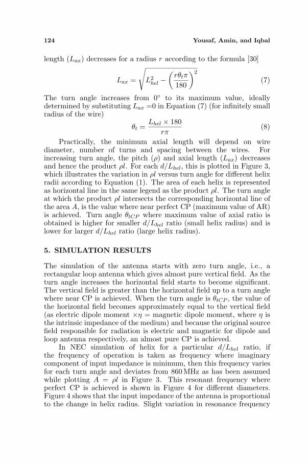
The simulated and measured Return Loss (RL) of both antennasare depicted in Figure 8. The difference in magnitude of RL betweenpredicted and measured results of 30 mm dia helix may be attributed tosignificant ohmic impedance compared with input radiation resistanceof the antenna and reflection from nearby objects as S parametermeasurement was carried out in the lab. The shift in resonancefrequency between measured and simulated result is because of thefact that measurements were done using dielectric support structure,whereas simulations were carried out without support structure. Thishas lowered the measured resonant frequency.
The simulated and measured normalized radiation pattern andphase difference (at resonance frequency) between horizontal andvertical fields for two different helices (dia = 30 mm and 80mm)at turn angles where these achieve near perfect CP [Figure 3] havebeen shown in Figures 9 and 10. The measurements were carried out
128 Yousaf, Amin, and Iqbal
Figure 8. Measured and simu-lated return loss of helix antennas.
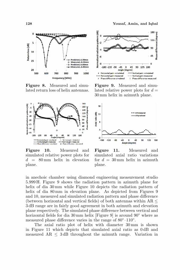
Figure 9. Measured and simu-lated relative power plots for d =30mm helix in azimuth plane.
Figure 10. Measured andsimulated relative power plots ford = 80mm helix in elevationplane.
Figure 11. Measured andsimulated axial ratio variationsfor d = 30 mm helix in azimuthplane.
in anechoic chamber using diamond engineering measurement studio5.999H. Figure 9 shows the radiation pattern in azimuth plane forhelix of dia 30mm while Figure 10 depicts the radiation pattern ofhelix of dia 80 mm in elevation plane. As depicted from Figures 9and 10, measured and simulated radiation pattern and phase difference(between horizontal and vertical fields) of both antennas within AR ≤3 dB range are in fairly good agreement in both azimuth and elevationplane respectively. The simulated phase difference between vertical andhorizontal fields for dia 30mm helix [Figure 9] is around 90◦ where asmeasured phase difference varies in the range of 80◦–110◦.
The axial ratio plot of helix with diameter 30 mm is shownin Figure 11 which depicts that simulated axial ratio as 0 dB andmeasured AR ≤ 3 dB throughout the azimuth range. Variation in

Progress In Electromagnetics Research C, Vol. 39, 2013 129
measured AR for dia 30 mm helix is because of the imbalance in phase[Figure 9] and amplitude of measured signal due to feed discontinuityand various capacitive and inductive effects. Similarly Figure 12 showscomparison of predicted and measured axial ratios for d = 80 mm.The predicted axial ratio of the antenna is less than or equal to 2 dBthroughout the elevation range whereas the measured axial ratio is lessthan or equal to 3 dB in 68% of the elevation range. This measuredperformance is better than the simulated performance of the crossdipole.
Figure 12. Measured and simulated axial ratio variations for d =80mm helix in elevation plane.
7. CONCLUSION
This paper presents the design and analysis of CP omnidirectionalSFBHAs for different d/Lhel ratios. It has been shown that CPSFBHAs can be designed using the equation A = ρl by Wheeler toobtain wide axial ratio beamwidth for AR ≤ 3 dB through most ofazimuth and elevation range. These antennas are of lowest profile(0.03λ to 0.1λ) in the class of CP omnidirectional antennas notrequiring ground plane. The value of turn angle at which near perfectCP is achieved is inversely proportional to the radius of helix and itsAR is less sensitive to the variation in turn angle.
REFERENCES
1. Yousaf, J., M. Amin, and S. Iqbal, “Circularly polarized wide ax-ial ratio beamwidth omnidirectional bifilar helix antennas,” Proc.IEEE First AESS European Conf. on Satellite Telecommunica-tion, 1–6, Oct. 2012.

130 Yousaf, Amin, and Iqbal
2. Row, J.-S. and M.-C. Chan, “Reconfigurable circularly-polarizedpatch antenna with conical beam,” IEEE Trans. on Antennas andPropag., Vol. 58, No. 8, 2753–2757, Aug. 2010.
3. Row, J.-S. and K.-W. Lin, “Low-profile design of dual-frequencyand dual-polarised triangular microstrip antennas,” Electron.Lett., Vol. 40, No. 3, 156–157, Feb. 2004.
4. Iwasaki, H., “A circularly polarized rectangular microstripantenna using single-fed proximity-coupled method,” IEEE Trans.on Antennas and Propag., Vol. 43, No. 8, 895–897, Aug. 1995.
5. Yang, R., R. Mittra, and M. Itoh, “A new omnidirectional CPpatch antenna,” Proc. Int. Symp. on Anennas and Propagation,AP-S Digest, Vol. 3, 1848–1851, Jun. 1994.
6. Iqbal, S., M. Amin, and J. Yousaf, “Designing omnidirectionalbifilar helix antenna for circular polarization,” Proc. IEEEFirst AESS European Conf. on Satellite Telecommunication, 1–6, Oct. 2012.
7. Iqbal, S., M. Amin, and J. Yousaf, “Low profile circularlypolarized side-fed bifilar helix antenna,” Proc. IEEE 9th Int.Bhurban Conf. on Applied Sciences and Technology, 325–328,Jan. 2012.
8. Leung, K. W., W. C. Wong, and H. K. Ng, “Circularly polarizedslot-coupled dielectric resonator antenna with a parasitic patch,”IEEE Antennas Wireless Propag. Lett., Vol. 1, No. 1, 57–59, 2002.
9. Chang, F.-S., K.-L.Wong, and T.-W. Chiou, “Low cost broadbandcircularly polarized patch antenna,” IEEE Trans. on Antennasand Propag., Vol. 51, No. 10, 3006–3009, Oct. 2003.
10. Huang, K.-C. and Z. Wang, “Millimeter-wave circular polar-ized beam-steering antenna array for gigabit wireless communi-cations,” IEEE Trans. on Antennas and Propag., Vol. 54, No. 2,743–746, Feb. 2006.
11. Rappaport, T. S., J. C. Liberti, K. L. Blackard, and B. Tuch,“The effects of antenna gains and polarization on multipath delayspread and path loss at 918 MHz on cross-campus radio links,”Proc. IEEE 42nd Vehicular Technology Conf., 550–555, May 1992.
12. Xidong, W., G. V. Eleftheriades, and E. V. Deventer, “Design andcharacterization of single and multiple beam MM-wave circularlypolarized substrate lens antennas for wireless communications,”Proc. Int. Symp. on Antenna and Propagation Society, Vol. 4,2408–2412, Aug. 1999.
13. Ryu, K. S. and A. A. Kishk, “UWB dielectric resonatorantenna having consistent omnidirectional pattern and low

Progress In Electromagnetics Research C, Vol. 39, 2013 131
crosspolarization characteristics,” IEEE Trans. on Antennas andPropag. Vol. 59, No. 4, 1403–1408, Apr. 2011.
14. Sichak, W. and S. Milazzo, “Antennas for circular polarization,”Proc. IRE, 997–1001, Aug. 1948.
15. Solosko, R. B. and S. R. Laxpati, “A log-periodic antenna withvertically polarized omnidirectional radiation,” IEEE Trans. onAntennas and Propag., Vol. 16, No. 6, 752–753, Nov. 1968.
16. Lin, C.-C., L.-C. Kuo, and H.-R. Chuangl, “A horizontally po-larized omnidirectional printed antenna for WLAN applications,”IEEE Trans. on Antennas and Propag., Vol. 54, No. 11, 3551–3556, Nov. 2006.
17. Hong, W. and K. Sarabandi, “Low profile miniaturized planarantenna with omnidirectional vertically polarized radiation,”IEEE Trans. on Antennas and Propag., Vol. 56, No. 6, 1533–1540,Jun. 2008.
18. Oh, J. and K. Sarabandi, “A novel high gain low profileminiaturized vertically polarized antenna,” Proc. Int. Symp. onAnennas and Propagation, 1–4, Jul. 2010.
19. Wong, K.-L. and C.-H. Wu, “Wide-band omnidirectional squarecylindrical metal-plate monopole antenna,” IEEE Trans. onAntennas and Propag., Vol. 53, No. 8, 2758–2761, Aug. 2005.
20. Herscovici, N., Z. Sipus, and P.-S. Kildal, “The cylindricalomnidirectional patch antenna,” IEEE Trans. on Antennas andPropag., Vol. 49, No. 12, 1746–1753, Dec. 2001.
21. Nakano, H., N. Suzuki, T. Ishii, and J. Yamauchi, “Mesh antennasfor dual polarization,” IEEE Trans. on Antennas and Propag.,Vol. 49, No. 5, 715–723, May 2001.
22. Iwasaki, H. and N. Chiba, “Circularly polarised back-to-backmicrostrip antenna with an omnidirectional pattern,” Proc. IEEMicrow. Antennas Propag., Vol. 146, No. 4, 277–281, Aug. 1999.
23. Kawakami, H., G. Sato, and R. Wakabayashi, “Research oncircularly polarized conical-beam antennas,” IEEE Antennas andPropag. Magaz., Vol. 39, No. 3, 27–39, Jun. 1997.
24. Galindo, V. and K. Green, “A near-isotropic circularly polarizedantenna for space vehicles,” IEEE Trans. on Antennas andPropag., Vol. 18, No. 6, 872–877, Nov. 1965.
25. Wang, C.-J. and C.-H. Lin, “A circularly polarized quasi-loopantenna,” Progress In Electromagnetics Research, Vol. 84, 333–348, 2008.
26. Amin, M., J. Yousaf, and M. K. Amin, “Terrestrial modequadrifilar helix antenna,” Progress In Electromagnetics Research

132 Yousaf, Amin, and Iqbal
Letters, Vol. 27, 179–187, 2011.27. Dyson, J. D. and P. E. Mayes, “New circularly-polarized
frequency-independent antennas with conical beam or omnidi-rectional patterns,” IRE Trans. on Antennas Propag., 334–342,Jul. 1961.
28. Amin, M. and R. Cahill, “Effect of helix turn angle on theperformance of half wavelength quadrifilar helix antenna,” IEEEMicrow. Wireless Compon. Lett., Vol. 16, No. 6, 384–386,Jun. 2006.
29. Tseng, H.-W. and B. A. Munk, “The generation of omnidirectionalcircularly polarized far field by a pair of orthogonally oriented veedipoles,” Proc. Int. Symp. on Antennas and Propagation, AP-SDigest, 1042–1045, Jul. 1993.
30. Amin, M., R. Cahill, and V. Fusco, “Single feed low profileomnidirectional antenna with slant 450 linear polarization,” IEEETrans. on Antennas and Propag., Vol. 55, No. 11, 3087–3090,Nov. 2007.
31. Wheeler, H. A., “A helical antenna for circular polarization,”Proc. IRE, 1484–1488, Dec. 1947.
32. Nec-win Professional (Version 1.6), [Online]. Available: NittanyScientific, 2003.
33. Ando, A., N. Kita, W. Yamada, K. Itokawa, and A. Sato,“Study of dual-polarized omnidirectional antennas for 5.2GHz-band 2×2 MIMO-OFDM systems,” Proc. Int. Symp. on Antennasand Propagation, Vol. 2, 1740–1743, Jun. 2004.
34. Li, R.-L. and V. F. Fusco, “Circularly polarized twisted loopantenna,” IEEE Trans. on Antennas and Propag., Vol. 50, No. 10,1377–1381, Oct. 2002.
35. Atta, L. C. V., R. J. Mailloux, and M. M. Levenson, “Asimple antenna with good circular polarization,” IEEE Trans. onAntennas and Propag., Vol. 17, No. 3, 360–361, May 1969.
36. Balanis, C. A., Antenna Theory, Analysis and Design, 3rd edition,John Wiley and Sons, New York, 2005.
37. Lee, E.-A., “A low cross-polarization circularly polarizedspacecraft TC&R antenna,” Proc. Int. Symp. on Antennas andPropagation, AP-S Digest, Vol. 2, 914–917, Jun. 1994.
38. Huwhrey, L. C., “Characteristic ionospheric multipath phasefluctuations,” IEEE Trans. on Antennas and Propag., 299–300,Mar. 1971.