analysis of circularly-polarized cts arrays
TRANSCRIPT
HAL Id: hal-02865294https://hal-univ-rennes1.archives-ouvertes.fr/hal-02865294
Submitted on 12 Jun 2020
HAL is a multi-disciplinary open accessarchive for the deposit and dissemination of sci-entific research documents, whether they are pub-lished or not. The documents may come fromteaching and research institutions in France orabroad, or from public or private research centers.
L’archive ouverte pluridisciplinaire HAL, estdestinée au dépôt et à la diffusion de documentsscientifiques de niveau recherche, publiés ou non,émanant des établissements d’enseignement et derecherche français ou étrangers, des laboratoirespublics ou privés.
Analysis of Circularly-Polarized CTS ArraysM. del Mastro, F.F. Manzillo, D. Gonzalez-Ovejero, M. Smierzchalski, P.
Pouliguen, P. Potier, R. Sauleau, M. Ettorre
To cite this version:M. del Mastro, F.F. Manzillo, D. Gonzalez-Ovejero, M. Smierzchalski, P. Pouliguen, et al.. Analysisof Circularly-Polarized CTS Arrays. IEEE Transactions on Antennas and Propagation, Institute ofElectrical and Electronics Engineers, 2020, 68 (6), pp.4571-4582. �10.1109/TAP.2020.2972438�. �hal-02865294�
ACCEPTED MANUSCRIPT
This article has been accepted for publication in a future issue of this journal, but has not been fully edited. Content may change prior to final publication. Citation information: DOI 10.1109/TAP.2020.2972438, IEEETransactions on Antennas and Propagation
1
Analysis of Circularly-Polarized CTS ArraysMichele Del Mastro, Francesco Foglia Manzillo, Member, IEEE, David Gonzalez-Ovejero, Senior Member, IEEE,
Maciej Smierzchalski, Philippe Pouliguen, Patrick Potier, Ronan Sauleau, Fellow, IEEE, and Mauro Ettorre,Senior Member, IEEE
Abstract—This paper presents an efficient analysis method fora novel continuous transverse stub (CTS) antenna. As opposed tostate-of-the-art CTS antenna designs, the proposed architectureachieves circular polarization using a single CTS array andwithout any polarization converter. The structure consists of longradiating slots/stubs fed by over-moded parallel-plate waveguides.More precisely, the transverse electromagnetic (TEM) mode andthe first transverse electric (TE1) mode of the feeding waveguidesare used to generate a circularly-polarized field. The array isanalyzed using a spectral mode-matching method. First, theactive reflection coefficient of the infinite array is derived inclosed form. A windowing approach is then adopted to computethe radiation patterns of finite-size arrays. Numerical resultsobtained with this method are in excellent agreement with full-wave simulations, carried out with a commercial software. Theperformance of this class of CTS antennas has been investigatedusing the developed model. It is theoretically demonstrated thatthe proposed array can be designed to attain an axial-ratio (AR)lower than 3 dB over a 52.9% relative bandwidth at broadside.Furthermore, the active input reflection coefficient is lower than-10 dB over a 40.8% relative bandwidth when the array steers itsmain beam at θ0 = 45◦. This solution is an attractive candidatefor next generation satellite communication terminals.
Index Terms—Continuous transverse stub array, circular po-larization, oversized parallel-plate waveguides.
I. INTRODUCTION
THE growth of satellite communication (Satcom) applica-tions in Ka-band has boosted the development of novel
antenna solutions with wide-band performance, wide-anglescanning capabilities, and low-form factor [1]. Continuoustransverse stub (CTS) arrays have received particular attentionfrom the community due to their low profile and widebandperformance [2]–[4]. They consist of arrays of stubs or open-ended parallel-plate waveguides (PPWs), which radiate in freespace and may be fed either in series or in parallel. A series-fed CTS array [5] comprises stubs, finite in height, placed onthe upper plate of a PPW. The beam is spatially steered byvarying the angle of incidence of the wave launched into the
Manuscript received on December 11, 2018; revised on September 09,2019; published on January 24, 2020. “This work was supported by theDirection Generale de l’Armement and by Brittany Region, France.
M. Del Mastro, D. Gonzalez-Ovejero, R. Sauleau, and M. Ettorreare with Univ. Rennes, CNRS, IETR (Institut d’Electronique et deTelecommunication de Rennes) - UMR 6164, F-35000 Rennes, France (e-mail: [email protected]).
F. Foglia Manzillo is with CEA-Leti, MINATEC Campus, 38054 Grenoble,France and also with Universite Grenoble Alpes, 621 av. Centrale, 38400 SaintMartin-d’Heres, France.
M. Smierzchalski are with CEA-LETI, MINATEC Campus, 38054 Greno-ble, France.
P. Pouliguen is with the Strategy Directorate, Direction Generale del’Armement, 75509 Paris, France.
P. Potier is with the Information Superiority, Direction Generale del’Armement, 35170 Bruz, France.
feeding PPW. On the other hand, standard parallel-fed CTSarrays [6], [7] adopt long slots in a metallic plane fed by acorporate network of mono-modal PPWs, supporting the TEMmode. Such network typically excites with the same amplitudeand phase each slot. The parallel-fed architecture exhibits verywide-band capabilities owing to the mutual coupling of theslots [8].
However, the main drawback of CTS arrays is that, dueto their radiation mechanism, they are inherently linearly-polarized. Circular-polarization (CP) has become an essentialfeature for Satcom applications for enhancing the robustnessof the satellite communication links [9]. Existing solutions toachieve CP typically rely on add-on linear-to-circular (LP-to-CP) converters, placed in proximity of the radiating slots [10],[11]. Nevertheless, the use of LP-to-CP converters impacts onthe overall size and thickness of the antenna system and, atthe same time, introduces additional losses.
A novel concept is here proposed for CTS arrays. The mainunderlying idea is based on the bi-modal operation of theantenna. Over-moded PPWs are employed to feed the radiatingelements. In particular, both the slots and PPWs should supportthe fundamental TEM and the first transverse electric (TE1)modes. The transverse electric fields of these two modesare orthogonally-polarized and therefore, if properly excited,are able to radiate a CP field. This novel CTS architecturerelies on a single radiating aperture, rather than on twoarrays geometrically-organized in an egg-crate configuration,as recently proposed in [12]. Indeed, the radiating aperture in[12] consists of orthogonally-oriented long slots, series-fed bya corporate network of mono-modal PPWs. Thus, the radiationmechanism of the CTS antenna that we propose may provideCP fields resorting to a single aperture, which supports twoorthogonally-polarized modes.
An efficient numerical tool is crucial to explore the po-tential of the structure described above. The proposed anal-ysis method is based on a spectral mode-matching technique(MMT). This numerical tool builds on the work in [13], ex-tending it to over-moded CTS arrays. In particular, the modelprovides a closed-form expression for the active impedanceof an infinite array excited by the TE1 mode. The activeimpedance under TEM mode operation is also accurately pre-dicted for slots and PPWs supporting the two selected modes,which also constitutes a futher new contribution with respectto [13]. Furthermore, the radiation patterns of finite-size arraysare derived using a windowing approach. Design guidelines arealso discussed for achieving a wideband impedance matchingand low axial-ratio (AR). Several examples are presented toprovide the reader with an useful deepening for differentdesign goals arising in practical applications. The insight pro-
ACCEPTED MANUSCRIPT
This article has been accepted for publication in a future issue of this journal, but has not been fully edited. Content may change prior to final publication. Citation information: DOI 10.1109/TAP.2020.2972438, IEEETransactions on Antennas and Propagation
2
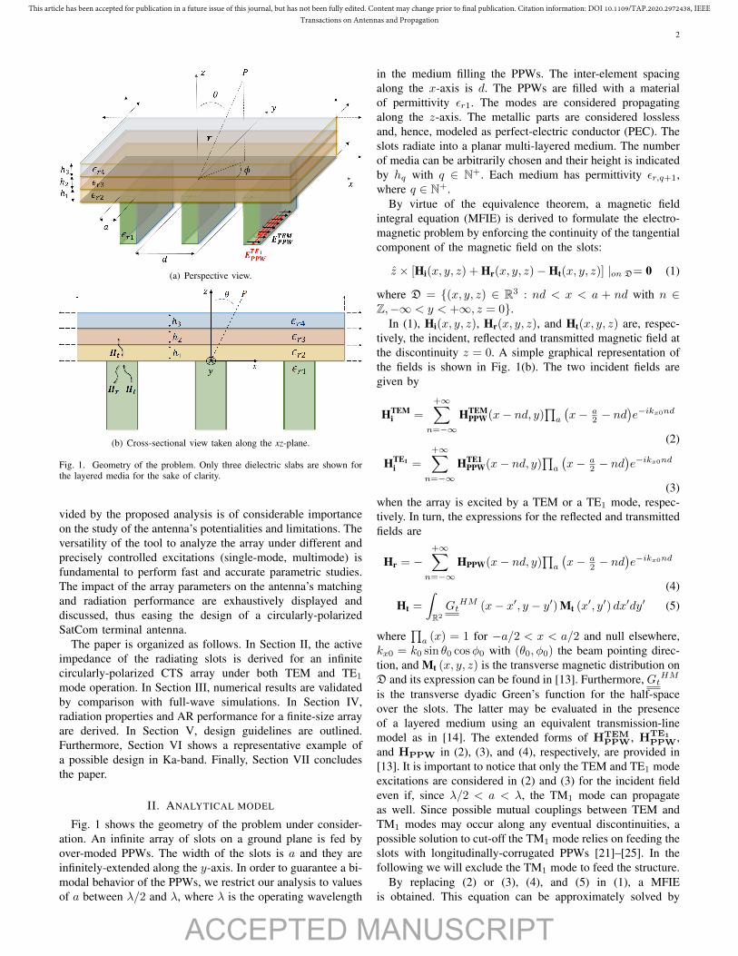
(a) Perspective view.
(b) Cross-sectional view taken along the xz-plane.
Fig. 1. Geometry of the problem. Only three dielectric slabs are shown forthe layered media for the sake of clarity.
vided by the proposed analysis is of considerable importanceon the study of the antenna’s potentialities and limitations. Theversatility of the tool to analyze the array under different andprecisely controlled excitations (single-mode, multimode) isfundamental to perform fast and accurate parametric studies.The impact of the array parameters on the antenna’s matchingand radiation performance are exhaustively displayed anddiscussed, thus easing the design of a circularly-polarizedSatCom terminal antenna.
The paper is organized as follows. In Section II, the activeimpedance of the radiating slots is derived for an infinitecircularly-polarized CTS array under both TEM and TE1
mode operation. In Section III, numerical results are validatedby comparison with full-wave simulations. In Section IV,radiation properties and AR performance for a finite-size arrayare derived. In Section V, design guidelines are outlined.Furthermore, Section VI shows a representative example ofa possible design in Ka-band. Finally, Section VII concludesthe paper.
II. ANALYTICAL MODEL
Fig. 1 shows the geometry of the problem under consider-ation. An infinite array of slots on a ground plane is fed byover-moded PPWs. The width of the slots is a and they areinfinitely-extended along the y-axis. In order to guarantee a bi-modal behavior of the PPWs, we restrict our analysis to valuesof a between λ/2 and λ, where λ is the operating wavelength
in the medium filling the PPWs. The inter-element spacingalong the x-axis is d. The PPWs are filled with a materialof permittivity εr1. The modes are considered propagatingalong the z-axis. The metallic parts are considered losslessand, hence, modeled as perfect-electric conductor (PEC). Theslots radiate into a planar multi-layered medium. The numberof media can be arbitrarily chosen and their height is indicatedby hq with q ∈ N+. Each medium has permittivity εr,q+1,where q ∈ N+.
By virtue of the equivalence theorem, a magnetic fieldintegral equation (MFIE) is derived to formulate the electro-magnetic problem by enforcing the continuity of the tangentialcomponent of the magnetic field on the slots:
z × [Hi(x, y, z) + Hr(x, y, z)−Ht(x, y, z)] |on D= 0 (1)
where D = {(x, y, z) ∈ R3 : nd < x < a + nd with n ∈Z,−∞ < y < +∞, z = 0}.
In (1), Hi(x, y, z), Hr(x, y, z), and Ht(x, y, z) are, respec-tively, the incident, reflected and transmitted magnetic field atthe discontinuity z = 0. A simple graphical representation ofthe fields is shown in Fig. 1(b). The two incident fields aregiven by
HTEMi =
+∞∑n=−∞
HTEMPPW(x− nd, y)
∏a
(x− a
2 − nd)e−ikx0nd
(2)
HTE1i =
+∞∑n=−∞
HTE1PPW(x− nd, y)
∏a
(x− a
2 − nd)e−ikx0nd
(3)when the array is excited by a TEM or a TE1 mode, respec-tively. In turn, the expressions for the reflected and transmittedfields are
Hr = −+∞∑
n=−∞HPPW(x− nd, y)
∏a
(x− a
2 − nd)e−ikx0nd
(4)
Ht =
∫R2
GtHM (x− x′, y − y′) Mt (x′, y′) dx′dy′ (5)
where∏a (x) = 1 for −a/2 < x < a/2 and null elsewhere,
kx0 = k0 sin θ0 cosφ0 with (θ0, φ0) the beam pointing direc-tion, and Mt (x, y, z) is the transverse magnetic distribution onD and its expression can be found in [13]. Furthermore, GtHM
is the transverse dyadic Green’s function for the half-spaceover the slots. The latter may be evaluated in the presenceof a layered medium using an equivalent transmission-linemodel as in [14]. The extended forms of HTEM
PPW, HTE1
PPW,and HPPW in (2), (3), and (4), respectively, are provided in[13]. It is important to notice that only the TEM and TE1 modeexcitations are considered in (2) and (3) for the incident fieldeven if, since λ/2 < a < λ, the TM1 mode can propagateas well. Since possible mutual couplings between TEM andTM1 modes may occur along any eventual discontinuities, apossible solution to cut-off the TM1 mode relies on feeding theslots with longitudinally-corrugated PPWs [21]–[25]. In thefollowing we will exclude the TM1 mode to feed the structure.
By replacing (2) or (3), (4), and (5) in (1), a MFIEis obtained. This equation can be approximately solved by
ACCEPTED MANUSCRIPT
This article has been accepted for publication in a future issue of this journal, but has not been fully edited. Content may change prior to final publication. Citation information: DOI 10.1109/TAP.2020.2972438, IEEETransactions on Antennas and Propagation
3
truncating the series to 2M-1 PPW’s modes and 2Nf+1Floquet’s modes, and applying the Galerkin’s method to (1).Two different linear problems arise for the two selected modes.For each mode, the matrix-based form yields[
Y TE,TE Y TE,TM
Y TM,TE Y TM,TM
] [VTE
VTM
]=
[I01I02
](6)
where VTE =[V TE0 , V TE1 , . . . , V TEM−1
]and VTM =[
V TM1 , . . . , V TMM−1]
are the scalar mode functions of TE andTM modes in the PPWs, respectively. Depending on thetype of impinging field we consider (i.e., TEM (2) or TE1
(3)), the known terms I01 and I02 take a different form. Themathematical expression of the admittance matrix in (6) canbe found in [13].
A. Active admittance for TEM-excitation
For completeness, we report the main results for the TEMmode given in [13]. The constant term in (6) is given by
I01 =
iV TEMinc
√aY TE0
0...0
, I02 =
0...0
(7)
where V TEMinc = 1 (V/√m) and Y TE0 = 1/ζ with ζ the intrin-
sic impedance of the medium inside the PPWs. By inverting(6), the scalar mode functions V TEm=0,...,M−1 and V TMm=1,...,M−1can be calculated and the fields on the aperture expressed ina closed-form. The active admittance of the radiating slotscan be then derived. The mathematical expression of thenormalized active admittance is given by
Y TEMact = − 1∣∣V TE0
√a∣∣2∫D
Ht ·M*t, TEM dxdy (8)
Mt, TEM = − iVTE0√a
∏a
(x− a
2
)e−ky0y y (9)
In (8), Ht takes into account the contribution of all higherorder modes in the PPWs and the mutual coupling amongfeeding waveguides (see (5)). In (9) Mt, TEM considers onlythe effect of the fundamental mode within the PPWs.
The extended form of the normalized active admittance (8)is given in [13].
B. Active admittance for TE1-excitation
When the array is excited by a TE1 mode, the incident fieldsare expressed by (3). In this case, the known term of the linearsystem (6) is given by
I01 =
0V
TE1inc Y TE
1
kTE1
π√2a
0...0
, I02 =
iVincY
TE1
kTE1
2ky0√a
0...0
(10)
where V TE1inc = 1 V/
√m, Y TE1 =
√k2 −
(kTE1
)2/(ζk), and
kTE1 =√
(π/a)2 + k2y0 with ky0 = k0 sin θ0 sinφ0, whereas
k0 and k are wave-numbers in free space and in the mediuminside the PPWs, respectively. In (10), the non-null entry of I02takes into account the coupling between TE and TM modeswhich occurs when the antenna beam is steered in planes φ 6={0◦, 180◦}.
As for TEM mode, by solving (6) the scalar mode functionsV TEm=0,...,M−1 and V TMm=1,...,M−1 are found. The electromag-netic field on the plane of the slots is therefore completelydetermined. The active admittance can be then expressed as
Y TE1act = − 1∣∣V TE1
√a∣∣2∫D
Ht ·M*t, TE1 dxdy (11)
whereMt, TE1 = Mx
t,TE1x+My
t,TE1y (12)
with
Mxt,TE1
= −√
2
a
πaV
TE1 e−iky0y√k2y0 + (π/a)2
+∞∑n=−∞
sin(πa
(x− nd))
×∏a
(x− a
2 − nd)e−ikx0nd
(13)
Myt,TE1
= −√
2
a
iky0VTE1 e−iky0y√
k2y0 + (π/a)2
+∞∑n=−∞
cos(πa
(x− nd))
×∏a
(x− a
2 − nd)e−ikx0nd
(14)The complete expression the active admittance (11) is given
in Appendix A.
III. NUMERICAL RESULTS
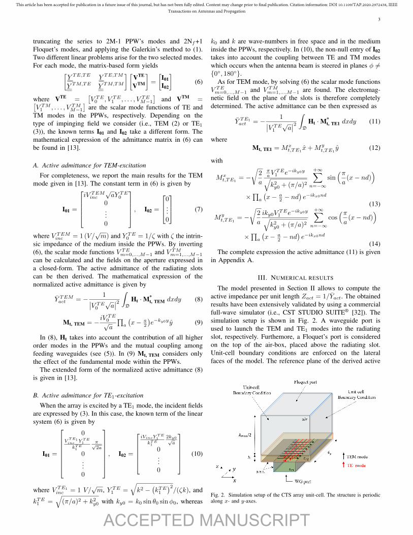
The model presented in Section II allows to compute theactive impedance per unit length Zact = 1/Yact. The obtainedresults have been extensively validated by using a commercialfull-wave simulator (i.e., CST STUDIO SUITE® [32]). Thesimulation setup is shown in Fig. 2. A waveguide port isused to launch the TEM and TE1 modes into the radiatingslot, respectively. Furthemore, a Floquet’s port is consideredon the top of the air-box, placed above the radiating slot.Unit-cell boundary conditions are enforced on the lateralfaces of the model. The reference plane of the derived active
Fig. 2. Simulation setup of the CTS array unit-cell. The structure is periodicalong x- and y-axes.
ACCEPTED MANUSCRIPT
This article has been accepted for publication in a future issue of this journal, but has not been fully edited. Content may change prior to final publication. Citation information: DOI 10.1109/TAP.2020.2972438, IEEETransactions on Antennas and Propagation
4
0.5 0.6 0.7 0.8 0.9 10
0.5
1
1.5
2
frequency/fmax
ℜ{Zact/Z
TEM}
CSTProposed tool
(ǫr1, ǫr2) = (2, 4)
(ǫr1, ǫr2) = (2, 2)
(ǫr1, ǫr2) = (1, 1)
(a) Real part of the active impedance versus frequency.
0.5 0.6 0.7 0.8 0.9 1−1
−0.5
0
0.5
1
frequency/fmax
ℑ{Zact/Z
TEM}
CSTProposed tool
(ǫr1, ǫr2) = (2, 4)
(ǫr1, ǫr2) = (2, 2)
(ǫr1, ǫr2) = (1, 1)
(b) Imaginary part of the active impedance versus frequency.
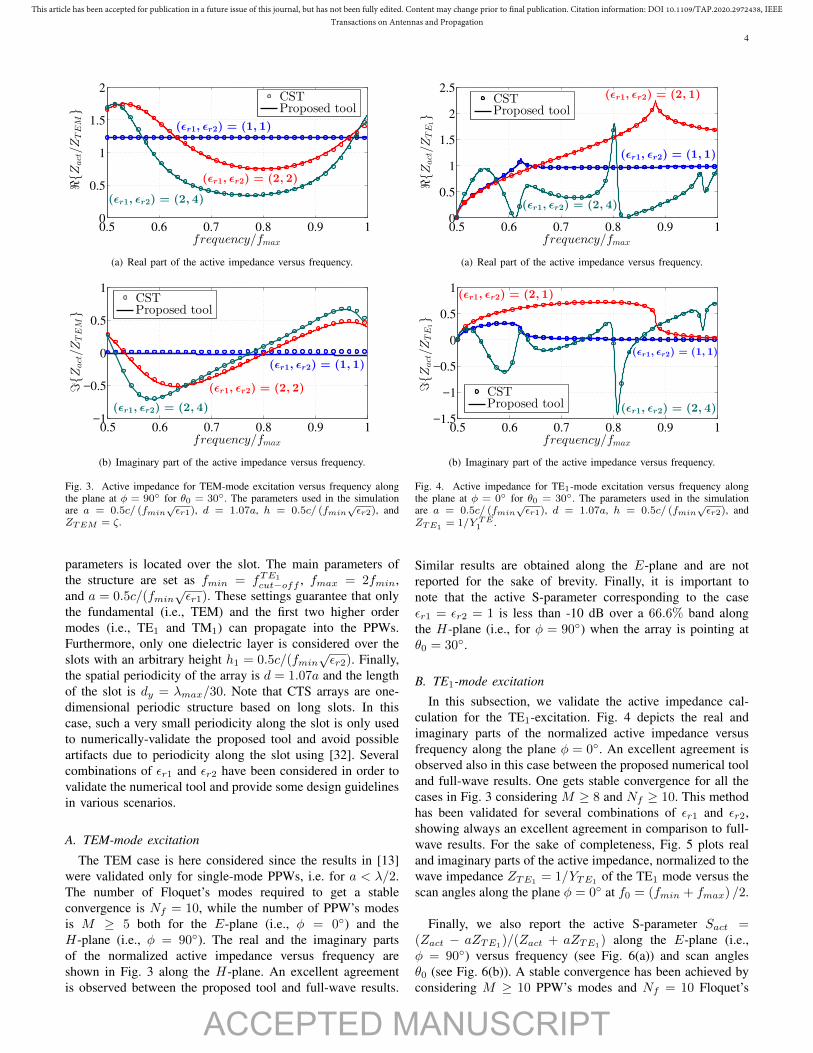
Fig. 3. Active impedance for TEM-mode excitation versus frequency alongthe plane at φ = 90◦ for θ0 = 30◦. The parameters used in the simulationare a = 0.5c/ (fmin
√εr1), d = 1.07a, h = 0.5c/ (fmin
√εr2), and
ZTEM = ζ.
parameters is located over the slot. The main parameters ofthe structure are set as fmin = fTE1
cut−off , fmax = 2fmin,and a = 0.5c/(fmin
√εr1). These settings guarantee that only
the fundamental (i.e., TEM) and the first two higher ordermodes (i.e., TE1 and TM1) can propagate into the PPWs.Furthermore, only one dielectric layer is considered over theslots with an arbitrary height h1 = 0.5c/(fmin
√εr2). Finally,
the spatial periodicity of the array is d = 1.07a and the lengthof the slot is dy = λmax/30. Note that CTS arrays are one-dimensional periodic structure based on long slots. In thiscase, such a very small periodicity along the slot is only usedto numerically-validate the proposed tool and avoid possibleartifacts due to periodicity along the slot using [32]. Severalcombinations of εr1 and εr2 have been considered in order tovalidate the numerical tool and provide some design guidelinesin various scenarios.
A. TEM-mode excitation
The TEM case is here considered since the results in [13]were validated only for single-mode PPWs, i.e. for a < λ/2.The number of Floquet’s modes required to get a stableconvergence is Nf = 10, while the number of PPW’s modesis M ≥ 5 both for the E-plane (i.e., φ = 0◦) and theH-plane (i.e., φ = 90◦). The real and the imaginary partsof the normalized active impedance versus frequency areshown in Fig. 3 along the H-plane. An excellent agreementis observed between the proposed tool and full-wave results.
0.5 0.6 0.7 0.8 0.9 10
0.5
1
1.5
2
2.5
frequency/fmax
ℜ{Zact/Z
TE
1}
CSTProposed tool
(ǫr1, ǫr2) = (1, 1)
(ǫr1, ǫr2) = (2, 1)
(ǫr1, ǫr2) = (2, 4)
(a) Real part of the active impedance versus frequency.
0.5 0.6 0.7 0.8 0.9 1−1.5
−1
−0.5
0
0.5
1
frequency/fmax
ℑ{Zact/Z
TE
1}
CSTProposed tool
(ǫr1, ǫr2) = (2, 1)
(ǫr1, ǫr2) = (2, 4)
(ǫr1, ǫr2) = (1, 1)
(b) Imaginary part of the active impedance versus frequency.
Fig. 4. Active impedance for TE1-mode excitation versus frequency alongthe plane at φ = 0◦ for θ0 = 30◦. The parameters used in the simulationare a = 0.5c/ (fmin
√εr1), d = 1.07a, h = 0.5c/ (fmin
√εr2), and
ZTE1= 1/Y TE1 .
Similar results are obtained along the E-plane and are notreported for the sake of brevity. Finally, it is important tonote that the active S-parameter corresponding to the caseεr1 = εr2 = 1 is less than -10 dB over a 66.6% band alongthe H-plane (i.e., for φ = 90◦) when the array is pointing atθ0 = 30◦.
B. TE1-mode excitation
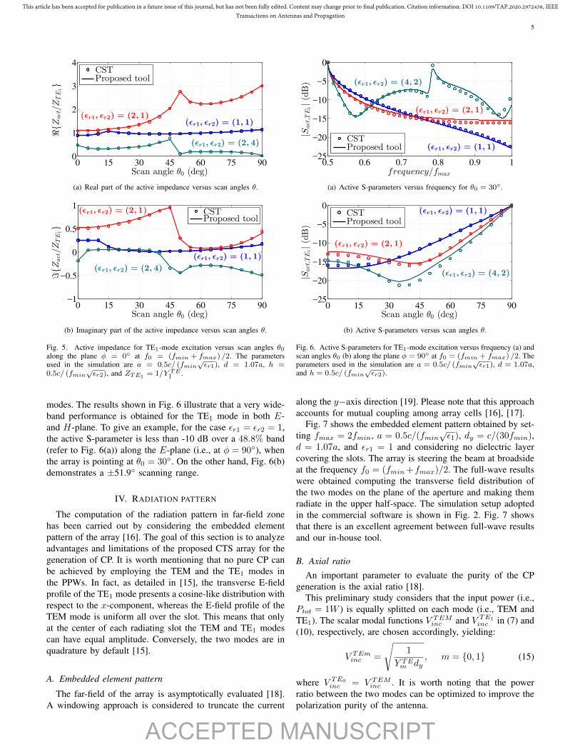
In this subsection, we validate the active impedance cal-culation for the TE1-excitation. Fig. 4 depicts the real andimaginary parts of the normalized active impedance versusfrequency along the plane φ = 0◦. An excellent agreement isobserved also in this case between the proposed numerical tooland full-wave results. One gets stable convergence for all thecases in Fig. 3 considering M ≥ 8 and Nf ≥ 10. This methodhas been validated for several combinations of εr1 and εr2,showing always an excellent agreement in comparison to full-wave results. For the sake of completeness, Fig. 5 plots realand imaginary parts of the active impedance, normalized to thewave impedance ZTE1
= 1/YTE1of the TE1 mode versus the
scan angles along the plane φ = 0◦ at f0 = (fmin + fmax) /2.
Finally, we also report the active S-parameter Sact =(Zact − aZTE1)/(Zact + aZTE1) along the E-plane (i.e.,φ = 90◦) versus frequency (see Fig. 6(a)) and scan anglesθ0 (see Fig. 6(b)). A stable convergence has been achieved byconsidering M ≥ 10 PPW’s modes and Nf = 10 Floquet’s
ACCEPTED MANUSCRIPT
This article has been accepted for publication in a future issue of this journal, but has not been fully edited. Content may change prior to final publication. Citation information: DOI 10.1109/TAP.2020.2972438, IEEETransactions on Antennas and Propagation
5
0 15 30 45 60 75 900
1
2
3
4
Scan angle θ0 (deg)
ℜ{Zact/ZTE
1}
CSTProposed tool
(ǫr1, ǫr2) = (2, 1)(ǫr1, ǫr2) = (1, 1)
(ǫr1, ǫr2) = (2, 4)
(a) Real part of the active impedance versus scan angles θ.
0 15 30 45 60 75 90−1
−0.5
0
0.5
1
Scan angle θ0 (deg)
ℑ{Zact/ZTE
1}
CSTProposed tool
(ǫr1, ǫr2) = (1, 1)
(ǫr1, ǫr2) = (2, 1)
(ǫr1, ǫr2) = (2, 4)
(b) Imaginary part of the active impedance versus scan angles θ.
Fig. 5. Active impedance for TE1-mode excitation versus scan angles θ0along the plane φ = 0◦ at f0 = (fmin + fmax) /2. The parametersused in the simulation are a = 0.5c/ (fmin
√εr1), d = 1.07a, h =
0.5c/ (fmin√εr2), and ZTE1
= 1/Y TE1 .
modes. The results shown in Fig. 6 illustrate that a very wide-band performance is obtained for the TE1 mode in both E-and H-plane. To give an example, for the case εr1 = εr2 = 1,the active S-parameter is less than -10 dB over a 48.8% band(refer to Fig. 6(a)) along the E-plane (i.e., at φ = 90◦), whenthe array is pointing at θ0 = 30◦. On the other hand, Fig. 6(b)demonstrates a ±51.9◦ scanning range.
IV. RADIATION PATTERN
The computation of the radiation pattern in far-field zonehas been carried out by considering the embedded elementpattern of the array [16]. The goal of this section is to analyzeadvantages and limitations of the proposed CTS array for thegeneration of CP. It is worth mentioning that no pure CP canbe achieved by employing the TEM and the TE1 modes inthe PPWs. In fact, as detailed in [15], the transverse E-fieldprofile of the TE1 mode presents a cosine-like distribution withrespect to the x-component, whereas the E-field profile of theTEM mode is uniform all over the slot. This means that onlyat the center of each radiating slot the TEM and TE1 modescan have equal amplitude. Conversely, the two modes are inquadrature by default [15].
A. Embedded element pattern
The far-field of the array is asymptotically evaluated [18].A windowing approach is considered to truncate the current
0.5 0.6 0.7 0.8 0.9 1−25
−20
−15
−10
−5
0
frequency/fmax
|Sact,T
E1|(dB)
CSTProposed tool
(ǫr1, ǫr2) = (4, 2)
(ǫr1, ǫr2) = (1, 1)
(ǫr1, ǫr2) = (2, 1)
(a) Active S-parameters versus frequency for θ0 = 30◦.
0 15 30 45 60 75 90−25
−20
−15
−10
−5
0
Scan angle θ0 (deg)|S
act,T
E1|(dB)
CSTProposed tool
(ǫr1, ǫr2) = (1, 1)
(ǫr1, ǫr2) = (2, 1)
(ǫr1, ǫr2) = (4, 2)
(b) Active S-parameters versus scan angles θ.
Fig. 6. Active S-parameters for TE1-mode excitation versus frequency (a) andscan angles θ0 (b) along the plane φ = 90◦ at f0 = (fmin + fmax) /2. Theparameters used in the simulation are a = 0.5c/ (fmin
√εr1), d = 1.07a,
and h = 0.5c/ (fmin√εr2).
along the y−axis direction [19]. Please note that this approachaccounts for mutual coupling among array cells [16], [17].
Fig. 7 shows the embedded element pattern obtained by set-ting fmax = 2fmin, a = 0.5c/(fmin
√ε1), dy = c/(30fmin),
d = 1.07a, and εr1 = 1 and considering no dielectric layercovering the slots. The array is steering the beam at broadsideat the frequency f0 = (fmin+fmax)/2. The full-wave resultswere obtained computing the transverse field distribution ofthe two modes on the plane of the aperture and making themradiate in the upper half-space. The simulation setup adoptedin the commercial software is shown in Fig. 2. Fig. 7 showsthat there is an excellent agreement between full-wave resultsand our in-house tool.
B. Axial ratio
An important parameter to evaluate the purity of the CPgeneration is the axial ratio [18].
This preliminary study considers that the input power (i.e.,Ptot = 1W ) is equally splitted on each mode (i.e., TEM andTE1). The scalar modal functions V TEMinc and V TE1
inc in (7) and(10), respectively, are chosen accordingly, yielding:
V TEminc =
√1
Y TEm dy, m = {0, 1} (15)
where V TE0inc = V TEMinc . It is worth noting that the power
ratio between the two modes can be optimized to improve thepolarization purity of the antenna.
ACCEPTED MANUSCRIPT
This article has been accepted for publication in a future issue of this journal, but has not been fully edited. Content may change prior to final publication. Citation information: DOI 10.1109/TAP.2020.2972438, IEEETransactions on Antennas and Propagation
6
−90 −60 −30 0 30 60 90−60
−40
−20
0
Angle θ (deg)
|Eφ|/max{|E
φ|}
(dB)
CSTProposed tool
(a) Eφ-component in far-field region.
−90 −60 −30 0 30 60 90−15
−10
−5
0
Angle θ (deg)
|Eθ|/max{|E
θ|}
(dB)
CSTProposed tool
(b) Eθ-component in far-field region.
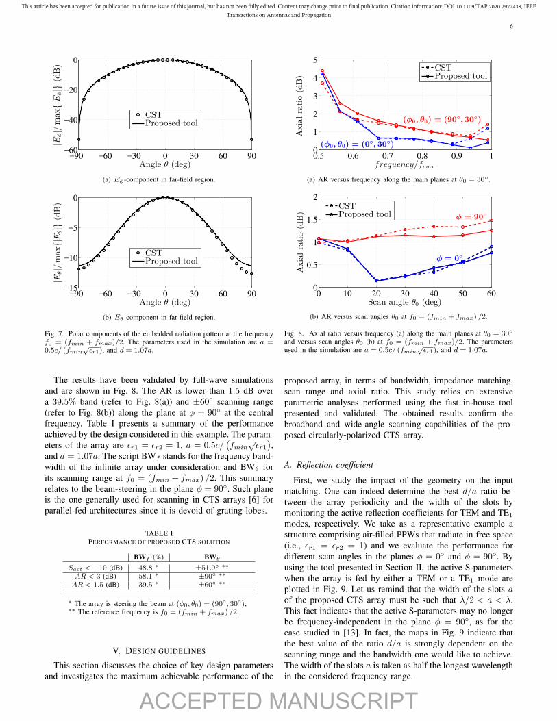
Fig. 7. Polar components of the embedded radiation pattern at the frequencyf0 = (fmin + fmax)/2. The parameters used in the simulation are a =0.5c/ (fmin
√εr1), and d = 1.07a.
The results have been validated by full-wave simulationsand are shown in Fig. 8. The AR is lower than 1.5 dB overa 39.5% band (refer to Fig. 8(a)) and ±60◦ scanning range(refer to Fig. 8(b)) along the plane at φ = 90◦ at the centralfrequency. Table I presents a summary of the performanceachieved by the design considered in this example. The param-eters of the array are εr1 = εr2 = 1, a = 0.5c/
(fmin
√εr1),
and d = 1.07a. The script BWf stands for the frequency band-width of the infinite array under consideration and BWθ forits scanning range at f0 = (fmin + fmax) /2. This summaryrelates to the beam-steering in the plane φ = 90◦. Such planeis the one generally used for scanning in CTS arrays [6] forparallel-fed architectures since it is devoid of grating lobes.
TABLE IPERFORMANCE OF PROPOSED CTS SOLUTION
BWf (%) BWθ
Sact < −10 (dB) 48.8 ∗ ±51.9◦ ∗∗
AR < 3 (dB) 58.1 ∗ ±90◦ ∗∗
AR < 1.5 (dB) 39.5 ∗ ±60◦ ∗∗
∗ The array is steering the beam at (φ0, θ0) = (90◦, 30◦);∗∗ The reference frequency is f0 = (fmin + fmax) /2.
V. DESIGN GUIDELINES
This section discusses the choice of key design parametersand investigates the maximum achievable performance of the
0.5 0.6 0.7 0.8 0.9 10
1
2
3
4
5
frequency/fmax
Axialratio(dB)
CSTProposed tool
(φ0, θ0) = (0◦, 30◦)
(φ0, θ0) = (90◦, 30◦)
(a) AR versus frequency along the main planes at θ0 = 30◦.
0 10 20 30 40 50 600
0.5
1
1.5
2
Scan angle θ0 (deg)Axialratio(dB)
CSTProposed tool
φ = 90◦
φ = 0◦
(b) AR versus scan angles θ0 at f0 = (fmin + fmax) /2.
Fig. 8. Axial ratio versus frequency (a) along the main planes at θ0 = 30◦
and versus scan angles θ0 (b) at f0 = (fmin + fmax)/2. The parametersused in the simulation are a = 0.5c/ (fmin
√εr1), and d = 1.07a.
proposed array, in terms of bandwidth, impedance matching,scan range and axial ratio. This study relies on extensiveparametric analyses performed using the fast in-house toolpresented and validated. The obtained results confirm thebroadband and wide-angle scanning capabilities of the pro-posed circularly-polarized CTS array.
A. Reflection coefficient
First, we study the impact of the geometry on the inputmatching. One can indeed determine the best d/a ratio be-tween the array periodicity and the width of the slots bymonitoring the active reflection coefficients for TEM and TE1
modes, respectively. We take as a representative example astructure comprising air-filled PPWs that radiate in free space(i.e., εr1 = εr2 = 1) and we evaluate the performance fordifferent scan angles in the planes φ = 0◦ and φ = 90◦. Byusing the tool presented in Section II, the active S-parameterswhen the array is fed by either a TEM or a TE1 mode areplotted in Fig. 9. Let us remind that the width of the slots aof the proposed CTS array must be such that λ/2 < a < λ.This fact indicates that the active S-parameters may no longerbe frequency-independent in the plane φ = 90◦, as for thecase studied in [13]. In fact, the maps in Fig. 9 indicate thatthe best value of the ratio d/a is strongly dependent on thescanning range and the bandwidth one would like to achieve.The width of the slots a is taken as half the longest wavelengthin the considered frequency range.
ACCEPTED MANUSCRIPT
This article has been accepted for publication in a future issue of this journal, but has not been fully edited. Content may change prior to final publication. Citation information: DOI 10.1109/TAP.2020.2972438, IEEETransactions on Antennas and Propagation
7
0.5 0.6 0.7 0.8 0.9 11.07
1.27
1.47
1.67
1.87
2 −30
−30
−25
−25
−25−25
−20
−20
−20−20
−15
−15
−15
−10
−10
−10
−5
−5
frequency/fmax
d/a
|Sact,TEM| (dB)
−30
−25
−20
−15
−10
−5
(a) Broadside radiation.
0.5 0.6 0.7 0.8 0.9 11.07
1.27
1.47
1.67
1.87
2
−45
−40
−40
−35
−35
−35
−30
−30
−30
−25
−25
−25
−20
−20
−20
−15
−15
−10
−10
−5
−5
0
0
frequency/fmax
d/a
|Sact,TE1| (dB)
−40
−30
−20
−10
0
(b) Broadside radiation.
0.5 0.6 0.7 0.8 0.9 11.07
1.27
1.47
1.67
1.87
2
−30
−30
−25
−25
−25
−25
−20
−20
−20
−20
−15
−15
−15
−15
−15−15
−10
−10
−10−10
−10
−10
−5
−5
−5
−5
−30
−5
−35
−5
frequency/fmax
d/a
|Sact,TEM| (dB)
−40
−30
−20
−10
(c) (θ0, φ0) = (30◦, 90◦).
0.5 0.6 0.7 0.8 0.9 11.07
1.27
1.47
1.67
1.87
2
−25
−25
−20
−20
−20
−15
−15
−15
−10
−10
−5
−5
0
0
−10
frequency/fmax
d/a
|Sact,TE1| (dB)
−30
−20
−10
0
(d) (θ0, φ0) = (30◦, 90◦).
0.5 0.6 0.7 0.8 0.9 11.07
1.27
1.47
1.67
1.87
2 −30
−30
−30
−30
−30
−25
−25
−25
−25
−25
−25
−20
−20−15
−20
−20
−10
−10
frequency/fmax
d/a
|Sact,TEM| (dB)
−30
−25
−20
−15
−10
−5
(e) (θ0, φ0) = (30◦, 0◦).
0.5 0.6 0.7 0.8 0.9 11.07
1.27
1.47
1.67
1.87
2
−35
−35
−30
−30
−30
−30
−25
−25
−25
−20
−20
−15
−15
−10
−10
−5
−5
00
frequency/fmax
d/a
|Sact,TE1| (dB)
−30
−20
−10
0
(f) (θ0, φ0) = (30◦, 0◦).
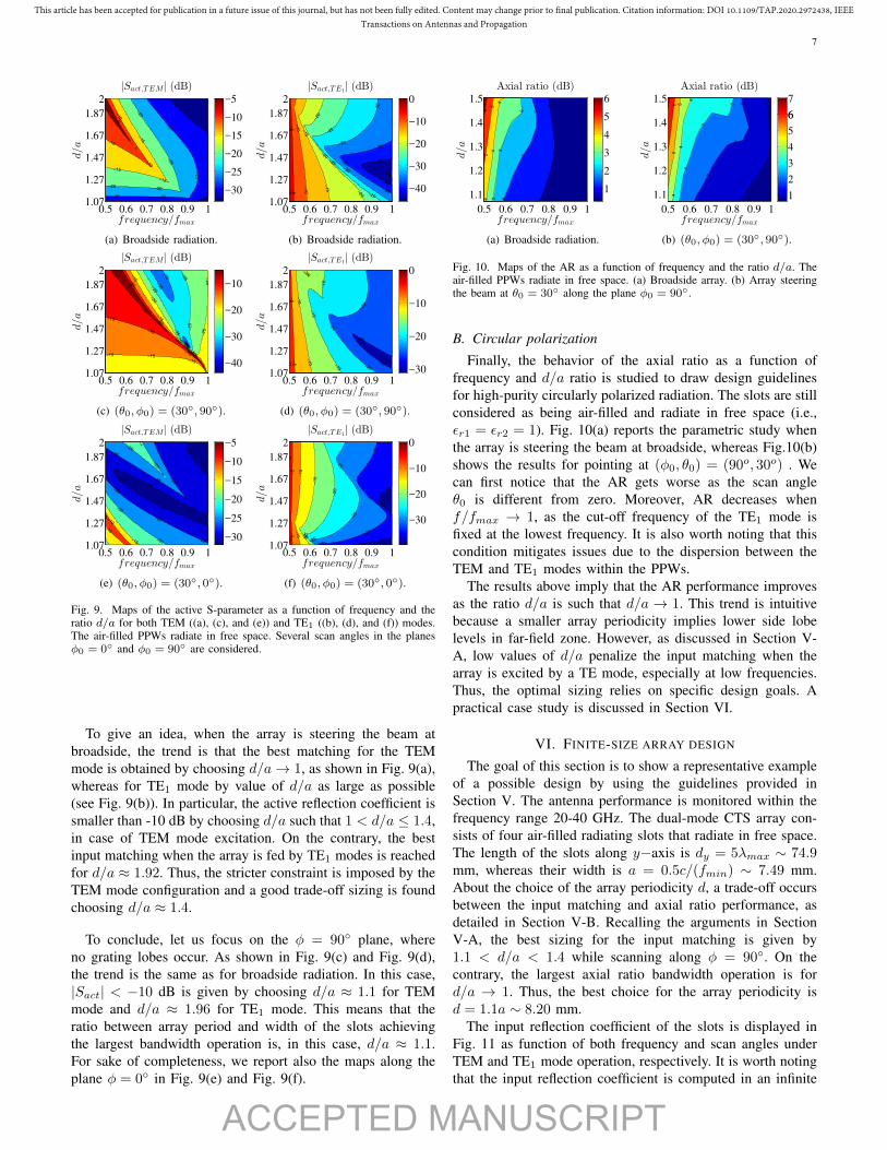
Fig. 9. Maps of the active S-parameter as a function of frequency and theratio d/a for both TEM ((a), (c), and (e)) and TE1 ((b), (d), and (f)) modes.The air-filled PPWs radiate in free space. Several scan angles in the planesφ0 = 0◦ and φ0 = 90◦ are considered.
To give an idea, when the array is steering the beam atbroadside, the trend is that the best matching for the TEMmode is obtained by choosing d/a→ 1, as shown in Fig. 9(a),whereas for TE1 mode by value of d/a as large as possible(see Fig. 9(b)). In particular, the active reflection coefficient issmaller than -10 dB by choosing d/a such that 1 < d/a ≤ 1.4,in case of TEM mode excitation. On the contrary, the bestinput matching when the array is fed by TE1 modes is reachedfor d/a ≈ 1.92. Thus, the stricter constraint is imposed by theTEM mode configuration and a good trade-off sizing is foundchoosing d/a ≈ 1.4.
To conclude, let us focus on the φ = 90◦ plane, whereno grating lobes occur. As shown in Fig. 9(c) and Fig. 9(d),the trend is the same as for broadside radiation. In this case,|Sact| < −10 dB is given by choosing d/a ≈ 1.1 for TEMmode and d/a ≈ 1.96 for TE1 mode. This means that theratio between array period and width of the slots achievingthe largest bandwidth operation is, in this case, d/a ≈ 1.1.For sake of completeness, we report also the maps along theplane φ = 0◦ in Fig. 9(e) and Fig. 9(f).
0.5 0.6 0.7 0.8 0.9 1
1.1
1.2
1.3
1.4
1.5
1
1
1
2
2
2
3
3
3
4
4
4
5
56
frequency/fmax
d/a
Axial ratio (dB)
1
2
3
4
5
6
(a) Broadside radiation.
0.5 0.6 0.7 0.8 0.9 1
1.1
1.2
1.3
1.4
1.5 1
1
1
22
2
3
3
3
4
4
4
5
56
frequency/fmax
d/a
Axial ratio (dB)
1
2
3
4
6
5
6
7
(b) (θ0, φ0) = (30◦, 90◦).
Fig. 10. Maps of the AR as a function of frequency and the ratio d/a. Theair-filled PPWs radiate in free space. (a) Broadside array. (b) Array steeringthe beam at θ0 = 30◦ along the plane φ0 = 90◦.
B. Circular polarization
Finally, the behavior of the axial ratio as a function offrequency and d/a ratio is studied to draw design guidelinesfor high-purity circularly polarized radiation. The slots are stillconsidered as being air-filled and radiate in free space (i.e.,εr1 = εr2 = 1). Fig. 10(a) reports the parametric study whenthe array is steering the beam at broadside, whereas Fig.10(b)shows the results for pointing at (φ0, θ0) = (90o, 30o) . Wecan first notice that the AR gets worse as the scan angleθ0 is different from zero. Moreover, AR decreases whenf/fmax → 1, as the cut-off frequency of the TE1 mode isfixed at the lowest frequency. It is also worth noting that thiscondition mitigates issues due to the dispersion between theTEM and TE1 modes within the PPWs.
The results above imply that the AR performance improvesas the ratio d/a is such that d/a → 1. This trend is intuitivebecause a smaller array periodicity implies lower side lobelevels in far-field zone. However, as discussed in Section V-A, low values of d/a penalize the input matching when thearray is excited by a TE mode, especially at low frequencies.Thus, the optimal sizing relies on specific design goals. Apractical case study is discussed in Section VI.
VI. FINITE-SIZE ARRAY DESIGN
The goal of this section is to show a representative exampleof a possible design by using the guidelines provided inSection V. The antenna performance is monitored within thefrequency range 20-40 GHz. The dual-mode CTS array con-sists of four air-filled radiating slots that radiate in free space.The length of the slots along y−axis is dy = 5λmax ∼ 74.9mm, whereas their width is a = 0.5c/(fmin) ∼ 7.49 mm.About the choice of the array periodicity d, a trade-off occursbetween the input matching and axial ratio performance, asdetailed in Section V-B. Recalling the arguments in SectionV-A, the best sizing for the input matching is given by1.1 < d/a < 1.4 while scanning along φ = 90◦. On thecontrary, the largest axial ratio bandwidth operation is ford/a → 1. Thus, the best choice for the array periodicity isd = 1.1a ∼ 8.20 mm.
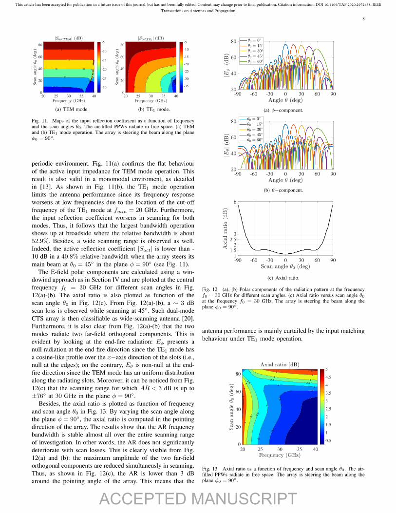
The input reflection coefficient of the slots is displayed inFig. 11 as function of both frequency and scan angles underTEM and TE1 mode operation, respectively. It is worth notingthat the input reflection coefficient is computed in an infinite
ACCEPTED MANUSCRIPT
This article has been accepted for publication in a future issue of this journal, but has not been fully edited. Content may change prior to final publication. Citation information: DOI 10.1109/TAP.2020.2972438, IEEETransactions on Antennas and Propagation
8
-25
-25-25
-20
-20
-15 -15
-15
-10
-10
-5 -5
-5
20 25 30 35 40
0
20
40
60
80
-30
-25
-20
-15
-10
-5
(a) TEM mode.
-35
-30
-25
-20
-15
-15
-10
-10
-10
-5
-5
-5
20 25 30 35 40
0
20
40
60
80
-35
-30
-25
-20
-15
-10
-5
(b) TE1 mode.
Fig. 11. Maps of the input reflection coefficient as a function of frequencyand the scan angles θ0. The air-filled PPWs radiate in free space. (a) TEMand (b) TE1 mode operation. The array is steering the beam along the planeφ0 = 90◦.
periodic environment. Fig. 11(a) confirms the flat behaviourof the active input impedance for TEM mode operation. Thisresult is also valid in a monomodal enviroment, as detailedin [13]. As shown in Fig. 11(b), the TE1 mode operationlimits the antenna performance since its frequency responseworsens at low frequencies due to the location of the cut-offfrequency of the TE1 mode at fmin = 20 GHz. Furthermore,the input reflection coefficient worsens in scanning for bothmodes. Thus, it follows that the largest bandwidth operationshows up at broadside where the relative bandwidth is about52.9%. Besides, a wide scanning range is observed as well.Indeed, the active reflection coefficient |Sact| is lower than -10 dB in a 40.8% relative bandwidth when the array steers itsmain beam at θ0 = 45◦ in the plane φ = 90◦ (see Fig. 11).
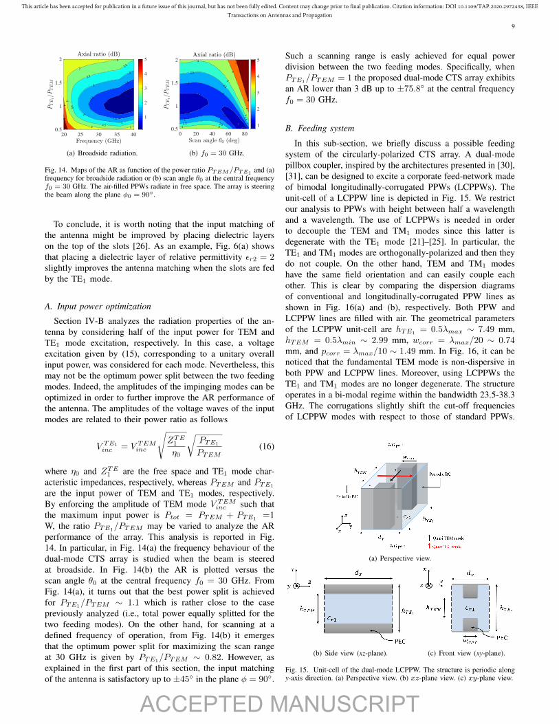
The E-field polar components are calculated using a win-dowind approach as in Section IV and are plotted at the centralfrequency f0 = 30 GHz for different scan angles in Fig.12(a)-(b). The axial ratio is also plotted as function of thescan angle θ0 in Fig. 12(c). From Fig. 12(a)-(b), a ∼ 3 dBscan loss is observed while scanning at 45◦. Such dual-modeCTS array is then classifiable as wide-scanning antenna [20].Furthermore, it is also clear from Fig. 12(a)-(b) that the twomodes radiate two far-field orthogonal components. This isevident by looking at the end-fire radiation: Eφ presents anull radiation at the end-fire direction since the TE1 mode hasa cosine-like profile over the x−axis direction of the slots (i.e.,null at the edges); on the contrary, Eθ is non-null at the end-fire direction since the TEM mode has an uniform distributionalong the radiating slots. Moreover, it can be noticed from Fig.12(c) that the scanning range for which AR < 3 dB is up to±76◦ at 30 GHz in the plane φ = 90◦.
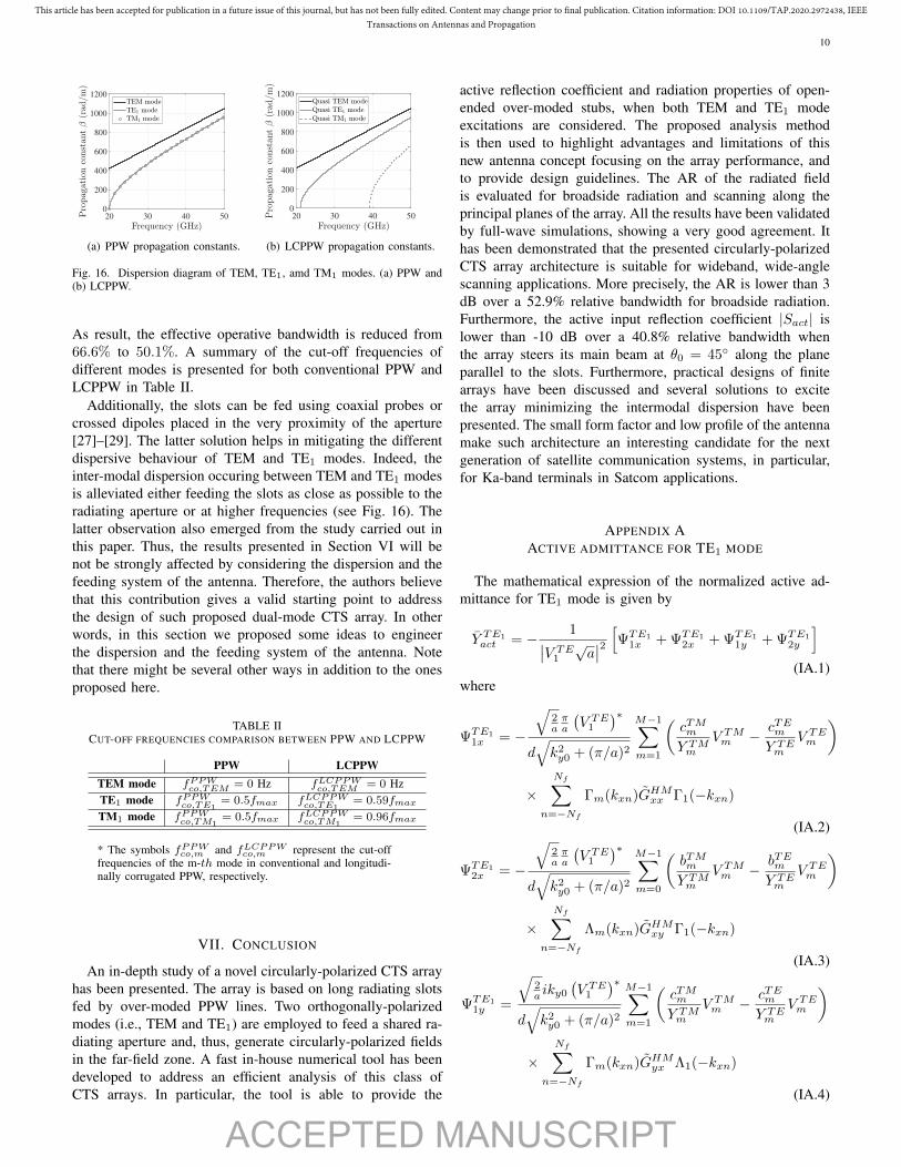
Besides, the axial ratio is plotted as function of frequencyand scan angle θ0 in Fig. 13. By varying the scan angle alongthe plane φ = 90◦, the axial ratio is computed in the pointingdirection of the array. The results show that the AR frequencybandwidth is stable almost all over the entire scanning rangeof investigation. In other words, the AR does not significantlydeteriorate with scan losses. This is clearly visible from Fig.12(a) and (b): the maximum amplitude of the two far-fieldorthogonal components are reduced simultaneusly in scanning.Thus, as shown in Fig. 12(c), the AR is lower than 3 dBaround the pointing angle of the array. This means that the
-90 -60 -30 0 30 60 9020
40
60
80
(a) φ−component.
-90 -60 -30 0 30 60 9020
40
60
80
(b) θ−component.
-90 -60 -30 0 30 60 901
1.5
2
2.5
3
6
(c) Axial ratio.
Fig. 12. (a), (b) Polar components of the radiation pattern at the frequencyf0 = 30 GHz for different scan angles. (c) Axial ratio versus scan angle θ0at the frequency f0 = 30 GHz. The array is steering the beam along theplane φ0 = 90◦.
antenna performance is mainly curtailed by the input matchingbehaviour under TE1 mode operation.
1
1
1.5
1.5
1.5
2
2
22
2.5
2.5
2.5
2.5
3
3
3
3
4
4
4
4
5
5
20 25 30 35 40
0
20
40
60
80
0.5
1
1.5
2
2.5
3
3.5
4
4.5
5
Fig. 13. Axial ratio as a function of frequency and scan angle θ0. The air-filled PPWs radiate in free space. The array is steering the beam along theplane φ0 = 90◦.
ACCEPTED MANUSCRIPT
This article has been accepted for publication in a future issue of this journal, but has not been fully edited. Content may change prior to final publication. Citation information: DOI 10.1109/TAP.2020.2972438, IEEETransactions on Antennas and Propagation
9
1
1
1.5
1.5
1.5
2
2
2
2
2.5
2.5
2.5
2.5
33
3
3
3
45
20 25 30 35 40
0.5
1
1.5
2
1
2
3
4
5
(a) Broadside radiation.
1
1.5
1.5
1.5
1.5
22
2
2
22.52.5
2.5
2.5
2.5
33
3
3
3
4
4
5
5
0 20 40 60 80
0.5
1
1.5
2
1
2
3
4
5
(b) f0 = 30 GHz.
Fig. 14. Maps of the AR as function of the power ratio PTEM/PTE1and (a)
frequency for broadside radiation or (b) scan angle θ0 at the central frequencyf0 = 30 GHz. The air-filled PPWs radiate in free space. The array is steeringthe beam along the plane φ0 = 90◦.
To conclude, it is worth noting that the input matching ofthe antenna might be improved by placing dielectric layerson the top of the slots [26]. As an example, Fig. 6(a) showsthat placing a dielectric layer of relative permittivity εr2 = 2slightly improves the antenna matching when the slots are fedby the TE1 mode.
A. Input power optimization
Section IV-B analyzes the radiation properties of the an-tenna by considering half of the input power for TEM andTE1 mode excitation, respectively. In this case, a voltageexcitation given by (15), corresponding to a unitary overallinput power, was considered for each mode. Nevertheless, thismay not be the optimum power split between the two feedingmodes. Indeed, the amplitudes of the impinging modes can beoptimized in order to further improve the AR performance ofthe antenna. The amplitudes of the voltage waves of the inputmodes are related to their power ratio as follows
V TE1inc = V TEMinc
√ZTE1
η0
√PTE1
PTEM(16)
where η0 and ZTE1 are the free space and TE1 mode char-acteristic impedances, respectively, whereas PTEM and PTE1
are the input power of TEM and TE1 modes, respectively.By enforcing the amplitude of TEM mode V TEMinc such thatthe maximum input power is Ptot = PTEM + PTE1
=1W, the ratio PTE1/PTEM may be varied to analyze the ARperformance of the array. This analysis is reported in Fig.14. In particular, in Fig. 14(a) the frequency behaviour of thedual-mode CTS array is studied when the beam is steeredat broadside. In Fig. 14(b) the AR is plotted versus thescan angle θ0 at the central frequency f0 = 30 GHz. FromFig. 14(a), it turns out that the best power split is achievedfor PTE1
/PTEM ∼ 1.1 which is rather close to the casepreviously analyzed (i.e., total power equally splitted for thetwo feeding modes). On the other hand, for scanning at adefined frequency of operation, from Fig. 14(b) it emergesthat the optimum power split for maximizing the scan rangeat 30 GHz is given by PTE1/PTEM ∼ 0.82. However, asexplained in the first part of this section, the input matchingof the antenna is satisfactory up to ±45◦ in the plane φ = 90◦.
Such a scanning range is easly achieved for equal powerdivision between the two feeding modes. Specifically, whenPTE1
/PTEM = 1 the proposed dual-mode CTS array exhibitsan AR lower than 3 dB up to ±75.8◦ at the central frequencyf0 = 30 GHz.
B. Feeding system
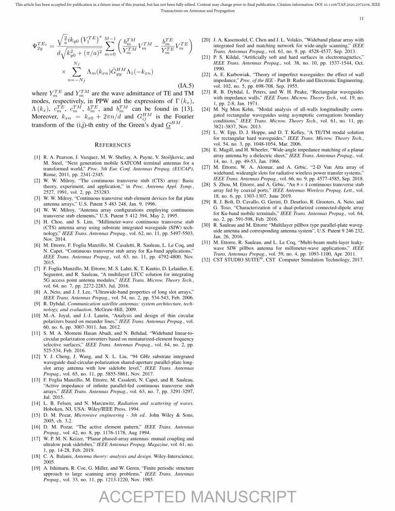
In this sub-section, we briefly discuss a possible feedingsystem of the circularly-polarized CTS array. A dual-modepillbox coupler, inspired by the architectures presented in [30],[31], can be designed to excite a corporate feed-network madeof bimodal longitudinally-corrugated PPWs (LCPPWs). Theunit-cell of a LCPPW line is depicted in Fig. 15. We restrictour analysis to PPWs with height between half a wavelengthand a wavelength. The use of LCPPWs is needed in orderto decouple the TEM and TM1 modes since this latter isdegenerate with the TE1 mode [21]–[25]. In particular, theTE1 and TM1 modes are orthogonally-polarized and then theydo not couple. On the other hand, TEM and TM1 modeshave the same field orientation and can easily couple eachother. This is clear by comparing the dispersion diagramsof conventional and longitudinally-corrugated PPW lines asshown in Fig. 16(a) and (b), respectively. Both PPW andLCPPW lines are filled with air. The geometrical parametersof the LCPPW unit-cell are hTE1 = 0.5λmax ∼ 7.49 mm,hTEM = 0.5λmin ∼ 2.99 mm, wcorr = λmax/20 ∼ 0.74mm, and pcorr = λmax/10 ∼ 1.49 mm. In Fig. 16, it can benoticed that the fundamental TEM mode is non-dispersive inboth PPW and LCPPW lines. Moreover, using LCPPWs theTE1 and TM1 modes are no longer degenerate. The structureoperates in a bi-modal regime within the bandwidth 23.5-38.3GHz. The corrugations slightly shift the cut-off frequenciesof LCPPW modes with respect to those of standard PPWs.
(a) Perspective view.
(b) Side view (xz-plane). (c) Front view (xy-plane).
Fig. 15. Unit-cell of the dual-mode LCPPW. The structure is periodic alongy-axis direction. (a) Perspective view. (b) xz-plane view. (c) xy-plane view.
ACCEPTED MANUSCRIPT
This article has been accepted for publication in a future issue of this journal, but has not been fully edited. Content may change prior to final publication. Citation information: DOI 10.1109/TAP.2020.2972438, IEEETransactions on Antennas and Propagation
10
20 30 40 500
200
400
600
800
1000
1200
(a) PPW propagation constants.
20 30 40 500
200
400
600
800
1000
1200
(b) LCPPW propagation constants.
Fig. 16. Dispersion diagram of TEM, TE1, amd TM1 modes. (a) PPW and(b) LCPPW.
As result, the effective operative bandwidth is reduced from66.6% to 50.1%. A summary of the cut-off frequencies ofdifferent modes is presented for both conventional PPW andLCPPW in Table II.
Additionally, the slots can be fed using coaxial probes orcrossed dipoles placed in the very proximity of the aperture[27]–[29]. The latter solution helps in mitigating the differentdispersive behaviour of TEM and TE1 modes. Indeed, theinter-modal dispersion occuring between TEM and TE1 modesis alleviated either feeding the slots as close as possible to theradiating aperture or at higher frequencies (see Fig. 16). Thelatter observation also emerged from the study carried out inthis paper. Thus, the results presented in Section VI will benot be strongly affected by considering the dispersion and thefeeding system of the antenna. Therefore, the authors believethat this contribution gives a valid starting point to addressthe design of such proposed dual-mode CTS array. In otherwords, in this section we proposed some ideas to engineerthe dispersion and the feeding system of the antenna. Notethat there might be several other ways in addition to the onesproposed here.
TABLE IICUT-OFF FREQUENCIES COMPARISON BETWEEN PPW AND LCPPW
PPW LCPPWTEM mode fPPWco,TEM = 0 Hz fLCPPWco,TEM = 0 HzTE1 mode fPPWco,TE1
= 0.5fmax fLCPPWco,TE1= 0.59fmax
TM1 mode fPPWco,TM1= 0.5fmax fLCPPWco,TM1
= 0.96fmax
* The symbols fPPWco,m and fLCPPWco,m represent the cut-offfrequencies of the m-th mode in conventional and longitudi-nally corrugated PPW, respectively.
VII. CONCLUSION
An in-depth study of a novel circularly-polarized CTS arrayhas been presented. The array is based on long radiating slotsfed by over-moded PPW lines. Two orthogonally-polarizedmodes (i.e., TEM and TE1) are employed to feed a shared ra-diating aperture and, thus, generate circularly-polarized fieldsin the far-field zone. A fast in-house numerical tool has beendeveloped to address an efficient analysis of this class ofCTS arrays. In particular, the tool is able to provide the
active reflection coefficient and radiation properties of open-ended over-moded stubs, when both TEM and TE1 modeexcitations are considered. The proposed analysis methodis then used to highlight advantages and limitations of thisnew antenna concept focusing on the array performance, andto provide design guidelines. The AR of the radiated fieldis evaluated for broadside radiation and scanning along theprincipal planes of the array. All the results have been validatedby full-wave simulations, showing a very good agreement. Ithas been demonstrated that the presented circularly-polarizedCTS array architecture is suitable for wideband, wide-anglescanning applications. More precisely, the AR is lower than 3dB over a 52.9% relative bandwidth for broadside radiation.Furthermore, the active input reflection coefficient |Sact| islower than -10 dB over a 40.8% relative bandwidth whenthe array steers its main beam at θ0 = 45◦ along the planeparallel to the slots. Furthermore, practical designs of finitearrays have been discussed and several solutions to excitethe array minimizing the intermodal dispersion have beenpresented. The small form factor and low profile of the antennamake such architecture an interesting candidate for the nextgeneration of satellite communication systems, in particular,for Ka-band terminals in Satcom applications.
APPENDIX AACTIVE ADMITTANCE FOR TE1 MODE
The mathematical expression of the normalized active ad-mittance for TE1 mode is given by
Y TE1act = − 1∣∣V TE1
√a∣∣2 [ΨTE1
1x + ΨTE12x + ΨTE1
1y + ΨTE12y
](IA.1)
where
ΨTE11x = −
√2aπa
(V TE1
)∗d√k2y0 + (π/a)2
M−1∑m=1
(cTMmY TMm
V TMm − cTEmY TEm
V TEm
)
×Nf∑
n=−Nf
Γm(kxn)GHMxx Γ1(−kxn)
(IA.2)
ΨTE12x = −
√2aπa
(V TE1
)∗d√k2y0 + (π/a)2
M−1∑m=0
(bTMmY TMm
V TMm − bTEmY TEm
V TEm
)
×Nf∑
n=−Nf
Λm(kxn)GHMxy Γ1(−kxn)
(IA.3)
ΨTE11y =
√2a iky0
(V TE1
)∗d√k2y0 + (π/a)2
M−1∑m=1
(cTMmY TMm
V TMm − cTEmY TEm
V TEm
)
×Nf∑
n=−Nf
Γm(kxn)GHMyx Λ1(−kxn)
(IA.4)
ACCEPTED MANUSCRIPT
This article has been accepted for publication in a future issue of this journal, but has not been fully edited. Content may change prior to final publication. Citation information: DOI 10.1109/TAP.2020.2972438, IEEETransactions on Antennas and Propagation
11
ΨTE12y =
√2a iky0
(V TE1
)∗d√k2y0 + (π/a)2
M−1∑m=0
(bTMmY TMm
V TMm − bTEmY TEm
V TEm
)
×Nf∑
n=−Nf
Λm(kxn)GHMyy Λ1(−kxn)
(IA.5)where Y TEm and Y TMm are the wave admittance of TE and TMmodes, respectively, in PPW and the expressions of Γ (kx),Λ (kx), cTEm , cTMm , bTEm , and bTMm can be found in [13].Moreover, kxn = kx0 + 2πn/d and GHMij is the Fouriertransform of the (i,j)-th entry of the Green’s dyad GHM .
REFERENCES
[1] R. A. Pearson, J. Vazquez, M. W. Shelley, A. Payne, V. Stoiljkovic, andM. Steel, “Next generation mobile SATCOM terminal antennas for atransformed world,” Proc. 5th Eur. Conf. Antennas Propag. (EUCAP),Rome, 2011, pp. 2341-2345.
[2] W. W. Milroy, “The continuous transverse stub (CTS) array: Basictheory, experiment, and application,” in Proc. Antenna Appl. Symp.,2527, 1991, vol. 2, pp. 253283.
[3] W. W. Milroy, “Continuous transverse stub element devices for flat plateantenna arrays,” U.S. Patent 5 483 248, Jan. 9, 1996.
[4] W. W. Milroy, “Antenna array configurations employing continuoustransverse stub elements,” U.S. Patent 5 412 394, May 2, 1995.
[5] H. Choe, and S. Lim, “Millimeter-wave continuous transverse stub(CTS) antenna array using substrate integrated waveguide (SIW) tech-nology,” IEEE Trans. Antennas Propag., vol. 62, no. 11, pp. 5497-5503,Nov. 2014.
[6] M. Ettorre, F. Foglia Manzillo, M. Casaletti, R. Sauleau, L. Le Coq, andN. Capet, “Continuous transverse stub array for Ka-band applications,”IEEE Trans. Antennas Propag., vol. 63, no. 11, pp. 4792-4800, Nov.2015.
[7] F. Foglia Manzillo, M. Ettorre, M. S. Lahti, K. T. Kautio, D. Lelaidier, E.Seguenot, and R. Sauleau, “A multilayer LTCC solution for integrating5G access point antenna modules,” IEEE Trans. Microw. Theory Tech.,vol. 64, no. 7, pp. 2272-2283, Jul. 2016.
[8] A. Neto, and J. J. Lee, “Ultrawide-band properties of long slot arrays,”IEEE Trans. Antennas Propag., vol. 54, no. 2, pp. 534-543, Feb. 2006.
[9] R. Dybdal, Communication satellite antennas: system architecture, tech-nology, and evaluation. McGraw-Hill, 2009.
[10] M.-A. Joyal, and J.-J. Laurin, “Analysis and design of thin circularpolarizers based on meander lines,” IEEE Trans. Antennas Propag., vol.60, no. 6, pp. 3007-3011, Jun. 2012.
[11] S. M. A. Momeni Hasan Abadi, and N. Behdad, “Wideband linear-to-circular polarization converters based on miniaturized-element frequencyselective surfaces,” IEEE Trans. Antennas Propag., vol. 64, no. 2, pp.525-534, Feb. 2016.
[12] Y. J. Cheng, J. Wang, and X. L. Liu, “94 GHz substrate integratedwaveguide dual-circular-polarization shared-aperture parallel-plate long-slot array antenna with low sidelobe level,” IEEE Trans. AntennasPropag., vol. 65, no. 11, pp. 5855-5861, Nov. 2017.
[13] F. Foglia Manzillo, M. Ettorre, M. Casaletti, N. Capet, and R. Sauleau,“Active impedance of infinite parallel-fed continuous transverse stubarrays,” IEEE Trans. Antennas Propag., vol. 63, no. 7, pp. 3291-3297,Jul. 2015.
[14] L. B. Felsen, and N. Marcuwitz, Radiation and scattering of waves.Hoboken, NJ, USA: Wiley/IEEE Press, 1994.
[15] D. M. Pozar, Microwave engineering - 3th ed.. John Wiley & Sons,2005, ch. 3.2.
[16] D. M. Pozar, “The active element pattern,” IEEE Trans. AntennasPropag., vol. 42, no. 8, pp. 1176-1178, Aug 1994.
[17] W. P. M. N. Keizer, “Planar phased-array antennas: mutual coupling andultralow peak sidelobes,” IEEE Antennas Propag. Magazine, vol. 61, no.1, pp. 14-28, Feb. 2019.
[18] C. A. Balanis, Antenna theory: analysis and design. Wiley-Interscience,2005.
[19] A. Ishimaru, R. Coe, G. Miller, and W. Geren, “Finite periodic structureapproach to large scanning array problems,” IEEE Trans. AntennasPropag., vol. 33, no. 11, pp. 1213-1220, Nov. 1985.
[20] J. A. Kasemodel, C. Chen and J. L. Volakis, ”Wideband planar array withintegrated feed and matching network for wide-angle scanning,” IEEETrans. Antennas Propag., vol. 61, no. 9, pp. 4528-4537, Sep. 2013.
[21] P. S. Kildal, “Artificially soft and hard surfaces in electromagnetics,”IEEE Trans. Antennas Propag., vol. 38, no. 10, pp. 1537-1544, Oct.1990.
[22] A. E. Karbowiak, “Theory of imperfect waveguides: the effect of wallimpedance,” Proc. of the IEE - Part B: Radio and Electronic Engineering,vol. 102, no. 5, pp. 698-708, Sep. 1955.
[23] R. B. Dybdal, L. Peters, and W. H. Peake, “Rectangular waveguideswith impedance walls,” IEEE Trans. Microw. Theory Tech., vol. 19, no.1, pp. 2-8, Jan. 1971.
[24] M. Ng Mou Kehn, “Modal analysis of all-walls longitudinally corru-gated rectangular waveguides using asymptotic corrugations boundaryconditions,” IEEE Trans. Microw. Theory Tech., vol. 61, no. 11, pp.3821-3837, Nov. 2013.
[25] L. W. Epp, D. J. Hoppe, and D. T. Kelley, “A TE/TM modal solutionfor rectangular hard waveguides,” IEEE Trans. Microw. Theory Tech.,vol. 54, no. 3, pp. 1048-1054, Mar. 2006.
[26] E. Magill, and H. Wheeler, “Wide-angle impedance matching of a planararray antenna by a dielectric sheet,” IEEE Trans. Antennas Propag., vol.14, no. 1, pp. 49-53, Jan. 1966.
[27] M. Ettorre, W. A. Alomar, and A. Grbic, “2-D Van Atta array ofwideband, wideangle slots for radiative wireless power transfer systems,”IEEE Trans. Antennas Propag., vol. 66, no. 9, pp. 4577-4585, Sep. 2018.
[28] S. Zhou, M. Ettorre, and A. Grbic, “An 8×4 continuous transverse stubarray fed by coaxial ports,” IEEE Antennas Wireless Propag. Lett., vol.18, no. 6, pp. 1303-1307, June 2019.
[29] R. J. Bolt, D. Cavallo, G. Gerini, D. Deurloo, R. Grooters, A. Neto, andG. Toso, “Characterization of a dual-polarized connected-dipole arrayfor Ku-band mobile terminals,” IEEE Trans. Antennas Propag., vol. 64,no. 2, pp. 591-598, Feb. 2016.
[30] R. Sauleau and M. Ettorre “Multilayer pillbox type parallel-plate waveg-uide antenna and corresponding antenna system”, U.S. Patent 9 246 232,Jan. 26, 2016.
[31] M. Ettorre, R. Sauleau, and L. Le Coq, “Multi-beam multi-layer leaky-wave SIW pillbox antenna for millimeter-wave applications,” IEEETrans. Antennas Propag., vol. 59, no. 4, pp. 1093-1100, Apr. 2011.
[32] CST STUDIO SUITE®, CST Computer Simulation Technology, 2017.