a simple planar circularly polarized antenna for … · a simple planar circularly polarized...
TRANSCRIPT
Title A simple planar circularly polarized antenna for GPS system
Author(s) Cao, Y; Cheung, SW; Liu, L; Yuk, TI
CitationThe 2014 IEEE International Workshop on Antenna Technology(iWAT 2014), Sydney, Australia, 4-6 March 2014. In ConferenceProceedings, 2014, p. 355-358
Issued Date 2014
URL http://hdl.handle.net/10722/204113
Rights International Workshop on Antenna Technology: SmallAntennas and Novel Metamaterials (iWAT). Copyright © IEEE.
A Simple Planar Circularly Polarized Antenna for GPS System
Y. F. Cao, S. W. Cheung, Li Liu, T.I. Yuk Department of Electrical and Electronic Engineering
The University of Hong Kong Hong Kong
[yfcao, swcheung, liuli, tiyuk]@eee.hku.hk
Abstract—The design of a planar right-handed circularly polarized (RHCP) antenna used for the Global Positioning System (GPS) is presented in this paper. The antenna consists of two meandered monopoles, a feeding network designed using the Wilkinson power divider and a defected ground structure (DGS). These two meandered monopoles resonate at about 1.575 GHz and are placed perpendicular to each other. The Wilkinson power divider divides the input signal into two signals with equal amplitude and phase. A phase difference of 90º between the signals to the monopoles is simply achieved by using a difference in length of λλg/4 (λg is the guide wavelength) in the two feed lines. The DGS is used to increase isolation between the two monopoles. Measured results show that the antenna has an impedance bandwidth (for reflection coefficient S11<-10 dB) from 1.12 to 1.85 GHz and an axial-ratio bandwidth (for axial ratio AR < 3 dB) from 1.53 to 1.66 GHz in the GPS band. The simulated and measured S11, AR, radiation pattern, efficiency and gain are presented.
Keywords—RHCP; monopole antenna; GPS; Wilkinson power divider; isolation
I. INTRODUCTION Circular polarization (CP) is currently being used in the
Global Positioning System (GPS). Different techniques have been proposed to design the CP antennas [1-6]. In [1], an S-shaped slot was cut on the ground plane to achieve a wideband CP antenna. In [2], a monopole antenna with dual-band circular polarization was achieved by adding slits or stubs on the ground plane and monopole radiator. In these designs, no clear procedure or methodology was given to apply the designs to different frequency bands such as the GPS band. In [3], an additional S-shaped impedance matching network and two stacked patches were used to design a CP patch antenna for RFID applications. In [4], a CP crossed dipole antenna with four loop resonators was proposed for broadband applications. In [5,6], a metasurface was placed on a patch or slot antenna to convert linear polarization (LP) into CP. However, the designs in [3-6] required double layers which complicated the fabrication process. In [7], a metamaterial-line based feed-network was used to design a wideband CP antenna which had quite a large area. In [8], a compact CP patch antenna was designed by attaching an unbalanced strip and drilling holes at the corners of the patch, which complicated the fabrication process. The axial-ratio bandwidth (ARBW) was quite narrow.
In this paper, the design of a simple right-handed circularly polarized (RHCP) monopole antenna using planar technology operating at 1.575 GHz for the GPS system is proposed. The operating band of the antenna can be easily adjusted for different frequency bands. The fabrication process is simple and low cost. Simulation results show that the antenna is RHCP in the GPS band from 1.53-1.66 GHz.
II. ANTENNA DESIGN The layout of the proposed CP monopole antenna designed
using planar technology is shown in Fig. 1, which consists of two monopoles in a meandered shape, a feeding network designed using the Wilkinson power divider, and a defected ground structure (DGS) on the ground plane for good isolation between the two monopoles. The operating frequency band of the antenna is determined by the lengths of the two monopoles which are placed in perpendicular to each other to generate two orthogonal electrical field components. The monopoles are fed by two microstrip lines having a characteristic impedance of Z0=50 Ω and a different length of λg/4 (where λg is the guide wavelength at the frequency of 1.575 GHz) to produce a phase difference of 900 at the outputs. The Wilkinson power divider divides the input signal into two output signals with equal phase and power. The two arms of the Wilkinson power divider are λg/4 transformers with impedance 1.414×Z0. A chip resistor with a value of 2Z0=100 Ω is used to connect the two arms at the outputs. Since the signals at the inputs of the two monopoles have equal amplitude but 900 phase difference, two orthogonal electrical field components with equal amplitudes and 90° out of phase will be generated from the two monopoles, resulting in CP.
The design methodology of the proposed antenna for a particular frequency band can be described as follows.
1) Select the dimensions of the Wilkinson power divider according to the desirable frequency.
2) Select the length of the monopole radiator to be λg/4. 3) Select the length (L9+L10+L11/2) of the DGS to be λg/4.
The CP antenna is designed on a substrate with an area of 90×82 mm2, a relative permittivity of 3.6 and a loss tangent of 0.004 using the EM simulation tool CST. The dimensions of the final design are listed in Table I which is used to fabricate
The 2014 International Workshop on Antenna Technology
978-1-4799-2329-8/14/$31.00 ©2014 IEEE 355
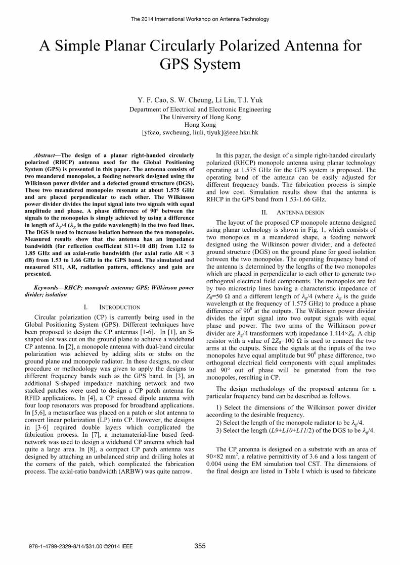
the antenna shown in Fig. 2. The antenna is measured using the antenna measurement system Satimo Starlab.
(a) (b) `
(c)
Fig. 1. Geometry of proposed antenna: (a) top view, (b) side view and (c) bottom view ( metal in front and metal in bottom)
(a) (b)
Fig. 2. Prototyped antenna: (a) top view and (b) bottom view
TABLE I. DIMENSIONS OF PROPOSED ANTENNA (MM)
L1 17.5 L7 5.0 Ls 82.0 g2 2.0 L2 12.6 L8 15.0 W1 1.8 g3 2.0L3 8.6 L9 24.0 W2 0.9 g4 0.8 L4 17.0 L10 10.0 W3 1.8 Ws 90.0 L5 25.7 L11 6.6 W4 2.5 h 0.8 L6 4.0 Lg 55.0 g1 2.0
III. SIMULATION AND MEASUREMENT RESULTS
A. S-parameter and Axial Ratio (AR) The simulated and measured S11 of the proposed CP
antenna are shown in Fig. 3(a) which indicates a good agreement. The simulated and measured impedance bandwidths (for S11<-10 dB) are 640 MHz (1.12-1.76 GHz) and 730 MHz (1.12-1.85 GHz), respectively. The simulated and measured ARs of the antenna are shown in Fig. 3(b). It can be seen that the simulated and measured AR bandwidths (for AR<3 dB) are 130 MHz (1.53-1.66 GHz) and 110 MHz (1.53-1.64 GHz), respectively. Again, the simulation and measurement results agree well.
(a)
(b)
Fig. 3. (a) Measured and simulated S11 and (b) measured and simulated ARs
B. Radiation Pattern The simulated and measured co-polarization and cross-
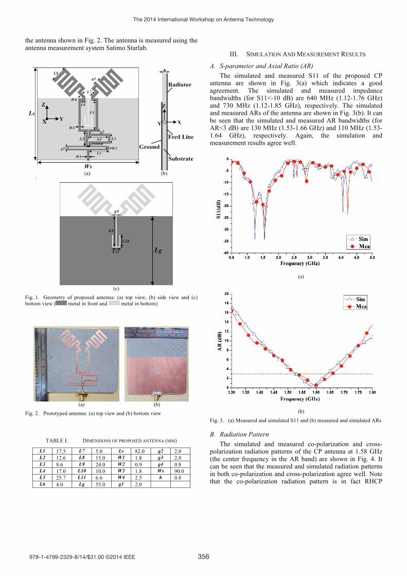
polarization radiation patterns of the CP antenna at 1.58 GHz (the center frequency in the AR band) are shown in Fig. 4. It can be seen that the measured and simulated radiation patterns in both co-polarization and cross-polarization agree well. Note that the co-polarization radiation pattern is in fact RHCP
The 2014 International Workshop on Antenna Technology
978-1-4799-2329-8/14/$31.00 ©2014 IEEE 356
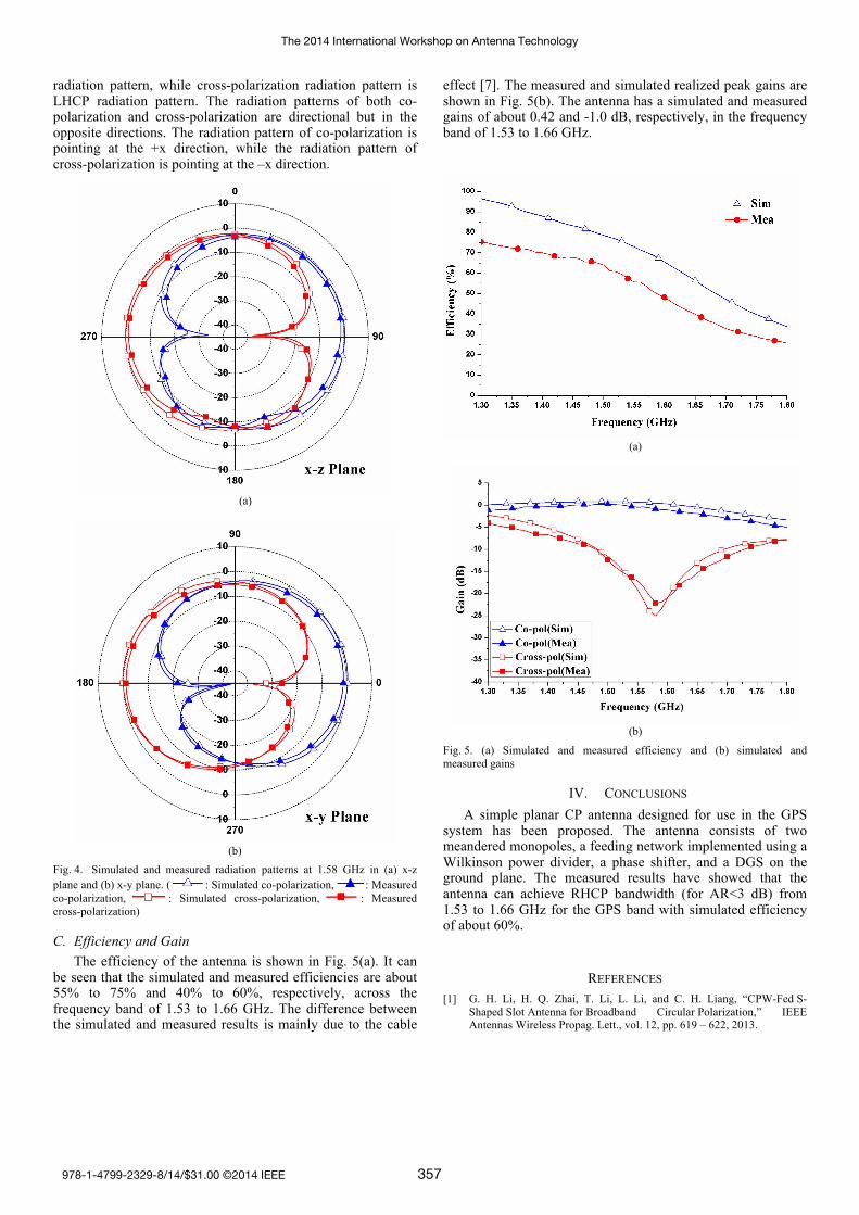
radiation pattern, while cross-polarization radiation pattern is LHCP radiation pattern. The radiation patterns of both co-polarization and cross-polarization are directional but in the opposite directions. The radiation pattern of co-polarization is pointing at the +x direction, while the radiation pattern of cross-polarization is pointing at the –x direction.
(a)
(b)
Fig. 4. Simulated and measured radiation patterns at 1.58 GHz in (a) x-z plane and (b) x-y plane. ( : Simulated co-polarization, : Measured co-polarization, : Simulated cross-polarization, : Measured cross-polarization)
C. Efficiency and Gain The efficiency of the antenna is shown in Fig. 5(a). It can
be seen that the simulated and measured efficiencies are about 55% to 75% and 40% to 60%, respectively, across the frequency band of 1.53 to 1.66 GHz. The difference between the simulated and measured results is mainly due to the cable
effect [7]. The measured and simulated realized peak gains are shown in Fig. 5(b). The antenna has a simulated and measured gains of about 0.42 and -1.0 dB, respectively, in the frequency band of 1.53 to 1.66 GHz.
(a)
(b)
Fig. 5. (a) Simulated and measured efficiency and (b) simulated and measured gains
IV. CONCLUSIONS A simple planar CP antenna designed for use in the GPS
system has been proposed. The antenna consists of two meandered monopoles, a feeding network implemented using a Wilkinson power divider, a phase shifter, and a DGS on the ground plane. The measured results have showed that the antenna can achieve RHCP bandwidth (for AR<3 dB) from 1.53 to 1.66 GHz for the GPS band with simulated efficiency of about 60%.
REFERENCES [1] G. H. Li, H. Q. Zhai, T. Li, L. Li, and C. H. Liang, “CPW-Fed S-
Shaped Slot Antenna for Broadband Circular Polarization,” IEEE Antennas Wireless Propag. Lett., vol. 12, pp. 619 – 622, 2013.
The 2014 International Workshop on Antenna Technology
978-1-4799-2329-8/14/$31.00 ©2014 IEEE 357
[2] C. F. Jou, J. W. Wu, and C. J. Wang, “Novel Broadband Monopole Antennas With Dual-Band Circular Polarization,” IEEE Trans. Antennas Propag., vol.57. no. 4, pp. 1027-1034, Apr. 2009.
[3] T. Q. Wu, H. Su, L. Y. Gan, H. Z. Chen, J. Y. Huang, and H. W. Zhang, “A Compact and Broadband Microstrip Stacked Patch Antenna With Circular Polarization for 2.45-GHz Mobile RFID Reader,” IEEE Antennas Wireless Propag. Lett., vol. 12, pp. 623-626, 2013.
[4] J. W. Baik, T. H. Lee, S. Pyo, S. M. Han, J. Jeong, and Y. S. Kim, “Broadband circularly polarized crossed dipole with parasitic loop resonators and its arrays,” IEEE Trans. Antennas Propag., vol. 59, no. 1, pp. 80–88, Jan. 2011.
[5] H. L. Zhu, S. W. Cheung, K. L. Chung, and T. I. Yuk, “Linear-to-Circular Polarization Conversion Using Metasurface,” IEEE Trans. Antennas Propag., vol. 61, no. 9, pp. 4615-4623, Sep. 2013.
[6] H.L. Zhu, K. L. Chung, X. L. Sun, S. W. Cheung and T. I. Yuk, "CP Metasurfaced Antennas Excited by LP Sources" 2012 IEEE International Symposium on Antennas and Propagation (2012 IEEE AP-S)
[7] K. L. Chung, X. L. Sun, J. Zhang, H.L. Zhu, S. W. Cheung and T. I. Yuk, "Metamaterial-Line Based Feed-Networks for Wideband Circularly Polarized Antennas" 2012 IEEE International Symposium on Antennas and Propagation (2012 IEEE AP-S)
[8] H. Wong, K. K. So, K. B. Ng, K. M. Luk, C. H. Chan, and Q. Xue, “Virtually Shorted Patch Antenna for Circular Polarization,” IEEE Antennas Wireless Propag. Lett., vol. 9, pp. 1213-1216, 2010.
[9] X. L. Sun, L. Liu, S. W. Cheung, and T. I. Yuk, “Dual-band antenna with compact radiator for 2.4/5.2/5.8 GHz WLAN applications,” IEEE Trans. Antennas Propag., vol. 60, no. 12, pp. 5924-5931, Dec. 2012.
The 2014 International Workshop on Antenna Technology
978-1-4799-2329-8/14/$31.00 ©2014 IEEE 358