a new dual circularly polarized antenna at ka band20140210
TRANSCRIPT

A Newdual circularly polarized antenna at Ka band
Guo-sheng Liu
National Key Laboratory of Science and Technology on Millimeter-wave Remote Sensing, Beijing
100854,China
Abstract
A new dual circularly polarized antenna at Ka band is described in the paper. The proposed
antenna consists of a stepped septum polarizer and a current-choking flange slot. The dimensions
of the stepped septum polarizer and the flange slot are optimized by the HFSS software.
Comparing to the traditional antennas with septum circular polarizers, the simulation results
indicate that without increasing the overall size the proposed structure which implements identical
beam-widths for two orthogonal planes, high isolation between ports and smoothing axial-ratio
fluctuations across a 3 GHz bandwidth.
2. Introduction
In recent years, C band and Ku band are widely applied in satellite communication; however,
the resource of C band and Ku band is limited. To meet the requirement of commercial satellite
communication, there has been an increasing research on Ka band satellite communication. The radio
data link between vehicle and satellite should satisfy the requirement of long distance and long time.
As one of the important devices, the antenna transmits data from vehicle to satellite and receives
information from satellite simultaneously. The wideband circularly polarized and wide-beam angle
capability antennas [1-2] can promote the performance of the radio system, especially on a lower
elevation angle. The dual circularly polarized antennas [3-4] transmit and receive signal with different
circularly polarized (right hand circularly polarized and left hand circularly polarized) signal
simultaneously. Dual circularly polarized antennas are generally utilized to avoid fading loss, realize
frequency reuse and enlarge system capability.
Stepped septum polarizers constitute a simple and compact device for converting linear
polarization into circular polarization in the feed waveguide [5-7]. Stepped septum polarizers are
widely applied in antenna feed system because of its compact structure, which provides improved
isolation and broader bandwidth. Compared to the sloped septum polarizer, the stepped septum
polarizer achieves higher isolation and broadband. However, the square waveguide with the stepped
septum circular polarizer failed to implements identical beam-widths for two orthogonal planes, and
the axis ratio of the main beam fluctuates obviously. However, the overall size of horn increasing and
need design center frequency. In this paper, a current-choking flange slot is utilized to improve the
performance of antenna t without increasing height.
3. Stepped Septum Polarizer Design
Stepped septum polarizers, built on a square waveguide with stepped ridged waveguide
junctions, have found many applications in antenna systems and polarization measurement equipment.
Such a configuration is highly acceptable for the antenna applications because it does not require any
matching tools at a flange joint with conical smooth or corrugated horns. Design the stepped septum
polarizers according to the desired specification of the return loss(RL ), isolation (IS ) between input
978-1-4673-5225-3/14/$31.00 ©2014 IEEE
waveguides, axial ratio (AR ) of the resulting field generated by two outgoing orthogonal dominant
modes, and suppression level (SL ) of higher parasitic modes in the output port if the latter is oversized.
By carefully selecting the dimensions of the septum and exciting one of the rectangular
waveguide ports withits dominant TE01 mode, orthogonal TE10 mode and TE01 mode can be
generated when the wave leaves the septum. Since the septum region is equivalent to a ridged
waveguide, the TE10 mode can propagate from rectangular waveguide section to septum-loaded
section unaffected; whereas the propagation constant of the TE01 mode related to the step height and
width of septum. By adjusting the step height and width of septum, the desired circular polarized
electromagnetic wave can achieve.
The fundamental principal of the mechanism of the steppedseptum circular polarizer can be
understood using S matrix analysis. In order to better understand the S matrix analysis of the septum
and its mechanism of generating circularly polarized field, HFSS, a full-wave simulator is employed to
analyze the septum. The stepped septum polarizers constitute a square waveguide and metallic septum,
to simplify analysis, the stepped septum polarizers are regarded as four-port network as shown in Fig.1.
Fig.1Four-ports networkprototype of the stepped septum polarizers
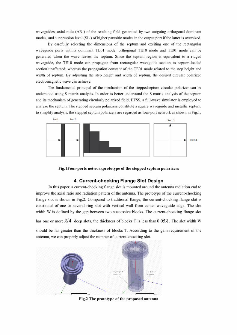
4. Current-chocking Flange Slot Design
In this paper, a current-chocking flange slot is mounted around the antenna radiation end to
improve the axial ratio and radiation pattern of the antenna. The prototype of the current-chocking
flange slot is shown in Fig.2. Compared to traditional flange, the current-chocking flange slot is
constituted of one or several ring slot with vertical wall from center waveguide edge. The slot
width W is defined by the gap between two successive blocks. The current-chocking flange slot
has one or more 4λ deep slots, the thickness of blocks T is less than 0.05λ . The slot width W
should be far greater than the thickness of blocks T. According to the gain requirement of the
antenna, we can properly adjust the number of current-chocking slot.
Fig.2 The prototype of the proposed antenna

5. Simulation and Experiment Results
A Ka band dual circularly polarized antenna was designed, simulated and optimized based
on the designed procedure described in the previous sections. The configuration of the proposed
antenna is shown in Fig. 2 and Fig. 3 shows the simulated VSWR of the proposed antenna. It can
be seen from the figure that the value of voltage standing wave ratio (VSWR) at the center
frequency is 1.02 and the maximum value of VSWR is less than 1.15, which satisfies the
specification of commercial satellite communication. Fig. 5 and Fig. 6 shows the calculated axial
ratio and radiation pattern, where the solid and dotted curves correspond to the dual circularly
polarized antenna with current-chocking flange slot and without current-chocking flange slot,
respectively. The performance of axial ratio and radiation pattern with current-chocking flange slot
was significantly improved compared with that without current-chocking flange slot. The
simulated radiation pattern for two orthogonal planes of the proposed antenna is shown in Fig. 5.
This showed excellent symmetry. Moreover, good agreement can be observed between the two
orthogonal planes. Fig. 5 shows that the front-to-back ratio with current-chocking flange slot is
higher than the front-to-back ratio without current-chocking flange slot. Fig. 6 depicts the axial
ratio for the -10 dB beamwidth(approx ±45°) for various axial planes within a range of 180
degrees, showing excellent circularity. This antenna performance satisfies the specification of
commercial satellite communication. The simulated isolation between ports across a 3 GHz
bandwidth is shown in Fig. 4. A high level of isolation was desirable, since otherwise an increase
excessive energy coupling into the other port when a transmitter is used would be observed.
Figure 3. The simulated VSWR when Port1 Figure 4. The simulated isolation between
is excited for LHCP polarization input ports across a 3GHz bandwidth
f-1.5GHz f+1.5GHz
Figure5. The simulated radiation patterns in principal planes for LHCP polarization

f-1.5GHz f+1.5GHz
Figure 6. The simulated axial ratio in principal planes for LHCP polarization
6. Conclusion
A high-performance, dual circularly polarized antenna for Ka band commercial satellite
communication was designed, and simulated. A five-step septum polarizer in a circular waveguide
was used to achieve right hand circularly polarized and left hand circularly polarized
simultaneously. Furthermore, a current-chocking flange slot is utilized to improve the performance.
The proposed antenna proved to realize excellent impedance characteristic, low axis ratio and high
level isolation across a 3GHz bandwidth. The proposed antenna can also serve as a well performed
antenna feed for its compact structure.
7. Reference
[1] W. Lei, Y. X. Guo,W.Wu. Wideband modified L-probe fed circularly polarized patch antenna
with conical beam radiation pattern. Journal of Electromagnetic Waves and
Applications.2013;27(8):969-977.
[2] L. Sun, Y. H. Huang, J. Y. Li, Q. Z. Liu. A wideband circularly polarized candy-like patch
antenna. Journal of Electromagnetic Waves and Applications. 2011;25(8-9):1113-1121.
[3] L. Sun, B. H. Sun, J. Y. Li, Y. H. Huang, Q. Z. Liu. Reconfigurable dual circularly polarized
microstrip antenna without orthogonal feeding network. Journal of Electromagnetic Waves and
Applications. 2011;25(10):1352-1359.
[4] M. T. Zhang, Y. B. Chen, Y. C. Jiao, F. S. Zhang. Dual circularly polarized antenna of compact
structure for RFID application. Journal of Electromagnetic Waves and
Applications.2006;20(14):1895-1902.
[5] D. Davis, O. Digiondomenico, J. Kempic. A new type of circularly polarized antenna element.
IEEE Antennas and Propagation Society International Symposium. 1967;247:26-33.
[6] N. C. Albertsen, P. Skov-Madsen. A compact septum polarizer. IEEE Transactions on
Microwave Theory and Techniques. 1983;31:654-660.
[7] T. Ege, P. Mcandrew. Analysis of stepped septum polarisers. Electronics
Letters.1985;21(24):1166-1168.