design of a through plate girder - core · 2015. 5. 27. · design of"a throughplategirder by...
TRANSCRIPT


UNIVERSITY OF ILLINOIS
LIBRARY
Class Book Volume
Je 07-10M
4 m

f ' :f
Hi
f f +

Digitized by the Internet Archive
in 2013
http://archive.org/details/designofthroughpOOtorn

DESIGNOF" A
THROUGH PLATE GIRDER
BY
CHARLES HERMAN TORNQUIST
THESIS
FOK
DEGREE OF1 BACHELOR OF SCIENCE
IN
CIVIL ENGINEERING
COLLEGE OF ENGINEERING
UNIVERSITY OF ILLINOIS
PRESENTED JUNE, 1907


COLLEGE OP ENGINEERING
April 30, 1907.
This is to certify that the following thesis prepared under
the immediate direction of Professor P. 0. Dufour, Assistant Pro-
fessor of Structural Engineering, by
CHARLES HERMAN TORMQUIST
entitled DESIGN OP A THROUGH PLATE-GIRDER SPAN
is accepted by me as fulfilling this part of the requirements for
the Decree f Bachelor of Science in Civil Engineering.
c^L^^r^a^^Head of Department of Civil Engineering
102066


no/
CONTENTS.
I. INTRODUCTION. Page 1.
II. THE DETERMINATION OF GENERAL DIMENSIONS. • 2.
1. The Span. • 2.
2. The Depth of the Web. • 2.
3. The Thickness of the Web. 3.
4. The Spacing of the Web Stiffeners. 4.
5. The Composition of the Flanges. 5.
6. Center to Center of Girders. 5.
7. Stringer Construction. 5.
8. The Spacing of the Floor Beams. 7.
III. MAXIMUM SHEARS. • 7.
IV. MAXIMUM MOMENTS. 9.
V. THE FLOOR SYSTEM. • 9.
1. Ties and rails. 11.
2. The Stringers. • 12.
3. The Floor Beams. • 14.
4. The Gusset Plates. 16.
VI. THE FLANGE AREAS AND COVER PLATES. • 18.
VII. THE WEB SPLICE. 19.
VIII. THE PITCH OF RIVETS IN FLANGES. • 21.
IX. THE STIFFENERS. 22.
X. THE LATERAL BRACING. • 24.
XI. THE BEARINGS. 26.
1. The Bolsters. 26.
2. The Rollers. • 26.
3. The Bearing Plates. 26.
4. The Cast Steel Raiser. 27.
5. The Anchor Bolts. 27.
XII. ESTIMATE OF COST. 27.
XIII. THE STRAIN SHEET. 28.


1
I. INTRODUCTION.
It is intended to design a thourough plate girder; the distance
under ooping being 82-feet.
Cooper's Specifications for Steel Railroad Bridges and Viaducts
(1901 Edition) will be used. Article 43 will be changed so as to read,
"Plate girders shall be proportioned upon the supposition that the bending
or chord stresses are resisted by the upper and lower flanges plus one-
eighth of the gross web area, etc.
As Cooper's class E.40 engine loading is heavy enough for ordinary
main line traffio and is very oommonly used, it will be chosen for the load-
ing in this design.
Next to strength comes beauty, and as sharp or protruding cor-
ners do not have an aesthetic effect, the top ends of the girder will be
rounded off with a radius of 1'- 0". This rounding also servos as a pro-
tection against serious injury to cars in case of derailment.


2
II. THE DETERMINATION OF GENERAL DIMENSIONS.
Art. 1. The Span.
The length of the bearing plates varies with that of the girder.
For spans of 80 ft. to 100 ft., the bearing plates are usually made from
25 in. to 36 in* As SO in. is within this limit, it will be used as the
length of the bearing plates in this design. This will make the centers of
the bearings 15 in. beyond the under side of coping. Since the distance
under coping is equal to 82 ft., the distance center to center of span is
equal to 82'+2(l'- 3") or 84*- 6 n . By allowing a three inch slope on
each end of the pedestal, the length of the distance between the end stiff-
eners will be equal to 30 in. minus 6 in. or 24 in. This will make the
ends of the girders 1 ft. beyond the oenter of the bearings. Therefore the
length over all will be equal to (84*- 6*)+(2'- 0"J or 86*- 6".
Art. 2. The Depth of the Web.
Authorities differ as to what depth of web should be used. Us-
ually the depth varies from one-tenth to one-twelfth of the span. When
no other considerations are imposed, such as head room or length of plates,
a depth should be chosen which will give a minimum weight of steel in the
span. If the depth is too small , the weight of flanges will be excessive,
and if the depth is too groat, the weight of the web will be too great in
proportion to the other parts. Between these two extremes the economical
depth will be found. The exact depth can only be found by making several
designs using webs of different depths, and then comparing their weights.
It is qyiouB that this would involve too great an expenditure of time
and labor. To save this work, an empiracal formula has been derived
by the comparison of depths of existing girders which have a minimum a-
mount of steel. Of course, a formula of this character cannot give

3
exact results but thoy will be close enough for practical purposes. The
formula which will be used in this design is,
Ld = . where
0.005+0.543
d = the depth of girder in inches, and L = the length of girder over all in
feet. Substituting in the formula we have,
86.5d =
0.005 + 0.543
d = 88.6-in.
Therefore an 88-in. web plato will be used.
Art. 3. The Thickness of the Web.
The web must have sufficient area to resist shear at any point.
By knowing the maximum shear, the depth having previously been determined,
the thickness can be computed by substituting in the formula,
Vt where
9,000d
t = the minimum thickness,
d * the depth of web,
9,000 - the allowed shearing strain per sq. in.
V the maximum shear at the section, and this can be taken from tables
with sufficient accuracy.
Some authorities suggest that the rivet holes must be deducted in
determining thickness required to resist shear, but this is unnecessary as
the web cannot fail by shearing through the center line of rivets but must
fail at the edges of the rivets. Therefore the gross area of web resists
the shear.
The total end shear equals 132,100 lb. for live load, plus 30,300
lb. for dead load. Substituting in the abovo formula,
162,400t = - -
9,000x88
t = 0.26 in.


Since this thickness is less than the minimum allowed by the specifications
it cannot be used. Three-eighths of an inch is the least allowable thick-
ness, and so it will be used.
Art. 4. The Spacing of the Web Stiffeners.
End St iffoners i-
The spacing of end stiffeners in the best design is made to cor-
respond with the length of the bearing plate. This length has previously
been determined to be 24 in* A sufficient number of stiffeners will be
placed in this distance to carry the stress from the web to the supports.
Intermediate Stiffeners :-
The purpose of the intermediate stiffeners is to prevent the web
from buckling. So far no theoretical method has been determined for com-
puting either the size or the spacing of the stiffeners. The common rule
is to space them five or six feet apart, but in no case shall the distanoe
exceed the depth of the web.
The space between stiffeners is usually called a panel. There
should be an odd number on account of the lateral system which is usually
goverened by the spacing of the floor beams. The spacing can be approx-
imately determined by the following relation,
L x 12
p = d wheren
p = the spacing of the stiffeners,
L = the length in feet, between the center of bearings,
d = the depth of web in inches, and
n = the number of panels,
Substituting, we have
84.5 x 12p =
7
p = 145-in. approximately.
The exact spacing will be determined after deciding upon the spacing of


5
the floor beams.
This distance is greater than the depth of web, but the part of
the web between the floor beams is in tension and therefore does not re-
quire stiffeners.
Art. 5. The Composition of the Flanges.
At least one-half of the required flange area must consist of
angles, or the largest size that can be procured. In this design one-
eighth of the web area is to be considered as flange area in resisting the
moment
.
Taking these things into consideration, the total flange area
which resists the bending strains will be made up. of the following parts :-
one-eighth of the web area, which is to be subtracted from the required a-
rea, and the remaining divided as equally as possible between the flange
angles and the cover plates.
Art. 6. Center to Center of Girders.
The center to center of girders must be sufficient to permit
ample clearance for traffic. This is usually determined by means of the
clearance diagram, Fig. 1.
The base of rail as yet cannot be accurately determined, but in
girders of this type, it is about the center of the web or 44-in. from the
top, in this case. The width of the cover plates for this length and load-
ing is usually 18 inches.
By laying off these dimensions on the diagram, the distance cen-
ter to center is found to be 10'- 6" + 2(15'!- 9") or 14'- 6".
Art. 7. Stringer Construction.
The stringers will consist of rolled I-beams, and will be spaced
6'- 6" between centers.
The length is determined by the spaoing of the floor beams. The
effective length is the distance betwoon the centers of the beans. Their


6


7
size will be determined by means of the formula,
SIM . where
c
M - the moment due to loading,
S - the allowable unit stress,
I the moment of inertia, and
o = the distanoe from the neutral axis to the remotest fibre.
The stringers will be riveted to the webs of the floor beams by
means of connection angles.
Art. 8. The Spacing of the Floor Beams.
To be eoonomical, the girder must be designed to have the least
bending moment possible. A floor beam at the middle ©f the span will in-
crease the bending moment. Since this is not desired, an odd number of
panels must therefore be used. Seven panels will give the desired results,
as well as make the stringers ef an economical length. At the ends, the
floor beams will be placed directly over the center of bearings. The rest
will be spaced at intervals of 12'- 0-3/4" from the center of bearings up
to the middle panel.
*
III. MAXIMUM SHEARS.
The weight of steel in the span is computed by the empiracal for-
mula,
W = (124+ 10L)L, where
W = the total weight of steel in pounds, and
L the span over all in feet.
The rails are assumed to weigh 400 lb.per. lineal foot of track.
This weight plus the weight of steel comprises the dead load.
For live load, Cooper's E. 40. engine is used. In determining
which position of the wheel giveB the maximum shear, the following relation


will be used and the results placed in tabular form. (Table I)
WG1 <— < (G-j+ P-l) where
m
G^= the sum ef loads in panel,
W = the total load en girder,
P^* the load at panel point, and
m = the number of panels.
Table I.
Determination of Wheel Positions for Maximum Shears.
Point Wheel G1
W
m
G P1 1
dv
dx
1 2 10 33.0 30 + +*
3 20 32.0 40 4 -
2
*
2 10 24.6 30 -+- -*
3 20 27.4*
40 + -
3
*
2 10 21.8*
30 + -*
3 20 21.8*
40 -1- -
4*
2 10 18.9*
30 + -*
3 20 21.3*
40 -1- -
indicates the position of wheels for the maximum
shear in the panel to the left of the peint.
The method of computation of the maximum shears is as follows
first find the reaction at the left end of the girder, due to loading as
indioated in Table I. Prom this reaction subtract the loads to the left
of the panel and also the left-end panel-reaction of the loads in the panel.
Where two different loadings are indicated as giving a maximum, the one
which gives the greatest shear will be used. The rosults are given in
Table II.
Substituting the length of the span in the formula for the dead
load of steel, the following result is obtained,
W = (124 +10x86.5)86.5

r
ttwol^l •» ml rr«

9
W = 86,550 lb.
The dead load of one girder equals 1/2 of 86,550 lb. or 46,275 lb.
Since the girder is divided into seven panels, the panel load of steel equals
46,275 -t- 7 or 6,700 lb. The weight of rails and ties is assumed to be
400 lb. per. lin. ft. of track, making 1/2 of 400 or 200 lb. the dead load
of rails and ties per. lin. ft. of girder. Since the panels are 12.09 ft.
in length, the dead panel load of rails and ties will be 12.09x200 = 2,400
lb. The dead panel load of steel, rails and ties equals 6,700 lb. 4- 2,400
lb. = 9,100 lb.
The dead load effective reaotion is 3x9,100 - 27.300 lb. and the
following are the dead load shears:-
Vx= = 27,300 lb.
Vg= 27.300 - 9,100 18,200 lb.
V3= 18,200 - 9,100 = 9,100 lb.
V4= 9,100 - 9,100 = 00 lb.
These values are to be added to the maximum live load shears in order to
obtain the total maximum shear in any panel. The results are given in
Table II.
Table II*
Maximum Shears.
Panel Dead Load Live load Total Maximum
1 27,300 101,600 128,900
2 18,200 71,300 89,500
3 9,100 47,500 56.600
4 00 28,100 28,100
* Results in pounds.
IV. MAXIMUM MOMENTS.
The same live loads as were used in the determination of maximum

\
f 1 tl9\

10
shears, will be used in determining maximum moments.
In determining that position of the wheel which gives the maximum
the following relation will be used, and the results given in Tablemoment
,
III.
Wl'
Gi < < (0.+ P-,),
1x
where
Gj= the sum of loads to left of the point,
W = the total load on the girders,
load at the panel point,
length from the left end to the point, and
total length of the girder.
P1= the
l'a the
1 the
Table III
Determination of Wheel Positions for Maximum Moments.
Point Wheel G1
tin I
1
u r1 1
UV
QX
1 2 10 oVi- i
-P. I
*
o ox*u*
4 40 29.8 60
o o 10 49. 2 30 4- +30 54.8 50 + +
*
50 60. G
*
70 -h-
*
5 70 63.4*
90 + -
6 80 64.3 Zf o
3
*4 50 74.0
*
70 + -*
6 70 82.5*
90 4- -
6 90 99.5*
103 + -*
7 93 95.2*
106 + -
8 10 6 101.0 119
4
*
5 70 86.8*
90 + -*
6 90 98.5 103 + -*
7 103 110.0 116 + ~*
8 xie 133.0*
129 4- -

11
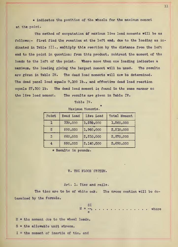
* indicat©8 the position of the wheels for the maximum moment
at the point.
The method of computation of maximum live load moments will be as
follows;- first find the reaction at the left end, due to the loading as in-
dicated in Table III. f multiply this reaction by the distance from the loft
end to the point in question; from this product, subtract the moment of the
loads to the left of the point. Where more than one loading indicates a
maximum, the loading giving the largest moment will be used. The results
are given in Table IV. The dead load moments will now be determined.
The dead panel load equals 9,100 lb., and effective dead load reaction
equals 27,300 lb. The dead load moment is found in the same manner as
the live load moment. The results are given in Table IV.
Table IV.*
Maximum Moments.
Point Dead Load Live Load Total Moment
1 330,000 1,230,000 1,560,000
o 550,000 1,960,000 2,510,000
3 660,000 2,210,000 2,870,000
4 650,000 2,140,000 2,690,000
* Results in pounds.
V. THE FLOOR SYSTEM.
Art. 1. Ties and rails.
The ties are to be of white oak. The cross section will be de-
termined by the formula,
SIM —, where
c
M the moment due to the wheel loads,
S = the allowable unit stress,
I = the moment of inertia of tie, and


12
c = the distance from the neutral axis to the remotest fibre.
s-o
I i
. S--6".
P^fc7/73 of Tie-
For E. 40, the load, equally distributed on two pairs of driving
wheels spaced 6-ft. center to center, is equal to 120,000 lb. This would
make the load taken by one wheel equal to 120,000/4 or 30,000 lb. The
wheel load is considered as being distributed over the ties, thus making
the load taken by each tie equal to 30, 000/3 or 10,000 lb. The moment
at the center of the tie due to the above load equals 10, 000x39-in.minus
10,000x30-in.or 90,000 lb. -in. S is taken as 1,000 lb. per. sq. in. for
timber. Substituting in the above formula we have,2
I M 90,000 bd
c S 10,000 62
bd = 540
7x9x9 = 566
Therefore 7-in. x 9-in. ties will be used, placed on edge. Every other
tie ic to be 8-ft. long. The remaining are to extend the full width of
the bridge or 13-ft. Each tio is to dapped to 8-1/2 inohes and is to be
secured to the stringers by 3/4-in. bolts at distances not over six feet
apart. The ties are to be spaced at a distance apart not exceeding six
inches. Ninty-pound rails will be used.
Art. 2. The Stringers.
The effective length of the stringers is equal to 12*- 0-3/4".

13
Tho maximum livo load moment occurs when wheel 3 or 4 is at tho oenter of
the panel. This makes the maximum live load moment equal to 30,000x60.4
xl2 minus 20,000x5x12 or 974,400 lb. -in. The stringer also carries a dead
load of ties and rails equal to 200 lb. per. lin. ft. The moment due to
this load is2
M = l/8wl , where
w = the dead load per lin. ft., and
1 = the length of stringer in inches.
Substituting in the formula we have,
200x12.09x12x12.09M = — = 43,750 lb. -in.
8
The total moment due to the dead load and live loads is 43,750+974,800 or
1,018,159 lb. -in.
The allowable unit stress for the floor beams is 10,000 lb. per
sq. in. Substituting the above value in the beam formula we have,
M 1,018,150 I= = 101.81 = = the section modulus.
S 10,000 c
The section modulus for an 18-in., 70-lb. I-beam 102.4
The moment at the center of the beam due to its own weight is,
70x12.09x12.09x12M =
8
M = 12,270 lb. -in.
The total moment duo to the dead and live loads equals 12,270 43,750
974,400 or 1,030,420 lb. -in. Substituting again in the formula we have
M 1,030,420 I= or 103.04 = —
c 10,000 c
The section modulus of a 20-in., 65 lb. I-beam 117.0. Therefore a 20-in.,
65-lb. I-beam will be used for stringers, since the metal required is less
for this size than for the 18-in., 70 lb. I-beam.
Rivets 7/8-inch in diameter will be used in securing the stringers
to the floor beams. The value of a 7/8-in. shop rivet in double shear is
equal to 7,200 lb. The bearing value of a 7/8-in. shop rivet in the web

14
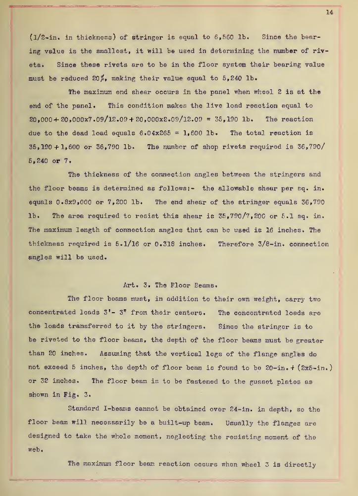
(l/2-in. in thickness) of stringer is equal to 6,560 lb. Since the bear-
ing value is the smallest, it will be used in determining the number of riv-
ets. Sinoe these rivets are to be in the floor system their bearing value
must be reduced 20$, making their value equal to 5,240 lb.
The maximum end shear occurs in the panel when wheel 2 is at the
end of the panel. This condition makes the live load reaction equal to
20,000+20,000x7.09/12.09 + 20,000x2.09/12.09 35,190 lb. The reaction
due to the dead load equals 6.04x265 = 1,600 lb. The total reaction is
35,190 + 1,600 or 36,790 lb. The number of shop rivets required is 36,790/
5,240 or 7.
The thickness of the connection angles between the stringers and
the floor beams is determined as follows:- the allowable shear per sq. in.
equals 0.8x9,000 or 7,200 lb. The end shear of the stringer equals 36,790
lb. The area required to resist this shear is 35,790/7,200 or 6*1 sq. in.
The maximum length of connection angles that can be used is 16 inches. The
thickness required is 5.1/16 or 0.318 inches. Therefore 3/8-in. connection
angles will be used.
Art. 3. The Floor Eeams.
The floor beams must, in addition to their own weight, carry two
concentrated loads 3'- 3" from their centers. The concentrated loads are
the loads transferred to it by the stringers. Since the stringer is to
be riveted to the floor beams, the depth of the floor beams must be greater
than 20 inches. Assuming that the vertical logs of the flange angles do
not exceed 5 inches, the depth of floor beam is found to be 20-in. + (2x5-in.
)
or 32 inches. The floor beam is to be fastened to the gusset plates as
shown in Fig. 3.
Standard I-beams cannot be obtained over 24- in. in depth, so the
floor beam will necessarily be a built-up beam. Usually the flanges are
designed to take the whole moment, neglecting the resisting moment of the
web.
The maximum floor beam reaction occurs whon wheel 3 is directly


15
over the floor beam. This condition makes the maximum floor beam reaction
equal to 12.09x20+ 7 .09x20 + 7 .09x20 + 2. 09x20/12. 09 or 47,700 lb. The dead
load transferred by the stringers to the floor beams is 12.09x265 or 3,200
lb. The total concentrated load equals 47,700+ 3,200 or 50,900 lb. The
The web of the floor beam must bo able to take the shear at any point. The
maximum vertical shear is equal to 50,900 lb., and the thickness of web
required is 50,900/32x9,000x0.8 or 0.22-in. A 3/8-in. web plate will be
used.
The weight of steel in the floor beam is approximately equal to
W = (124+ 10L)L, where
L s the length of the floor beam in feet. Substituting the length of the
floor beam in this formula, the weight is found to be
( 124 4-10x14.50 ) 14.50 or 3,5501b.
The moment at the center due to the stringer reactions equals 50,900x87
minus 50,900x39 or 2,420,000 lb. -in. The moment due to its own weight
equals If = 1/8W1 = 3,550x14.50x12/8 72,400 lb. -in. The total moment at
the oenter is 2,420,000 + 72,400 or 2,492,400 lb. -in. Assuming the effec-
tive depth equal to 32 - 2 or 30-in., the approximately required flange
area is found to be 2,492,400/30x10,000 or 8.28 sq. in.
The aroa required in one flange angle is 8.28/2=4.14 sq. in. In
choosing the size of the angle, one 7/8-in. rivet hole is to be deduced
in finding the net area of the angle. A 5" x 3-1/2" x 5/8"- angle whose
gross area equals 4.93 sq. in. will be tried. Subtracting the area of
of one rivet hole, which is l"x5/8" or 0.62 sq.in., the net area is found
to be 4.93 - 0. 62 or 4.3l3q. in.
The 5-in. leg of the angle will be riveted to the web of the
floor beam. The distance of center of gravity from back of shorter flango
is 1.70 in. This makes the effective depth equal to 32.25 - (2x1.70 ) or
28.75 in.
The actual flange area required is now equal to 2,492,400 / 28.75
xl0,000 or 8.62 sq. in. The area required in one flange anglo is equal to
8.62/2 or 4.31 sq. in. The net area of a 5" x 3-1/2" x 5/8" angle is 4.31


16
sq. in. Thoreforo/5" x 3-1/2" x 5/8"-angles will be used for the flanges
of the floor beams. The spacing of the rivets in the flanges is determin-
ed from the following formula,
bhp = where
V
p = the pitch of rivets in the flange angles,
b = the bearing value of one rivet in the 3/8-in. wob,
h = the distance betwoon rivet lines, and
V = the shear on the section.
The bearing value of 7/8-in. rivets in 3/8-in. web is 4,920 lb. The dis-
tance between the lines of rivets oquals 30.25 - 2(2.875) = 24.50. The
shear at the end section is^- 50,900 -M, 775 or 52,875 lb. Substituting in
the above formula, the spacing at the ends of the floor beams is
4,920x24.50p = or 2.38 in.
52,875Therofore a double row of rivets must be used as assumed. Between the
stringers the rivet spacing can bo the maximum allowed or 6-in. as the ©nly
shear on the middle section is that duo to the weight of the floor beam it-
self. As is customary, a spacing of from 4" to 5" will bo used.
The splice between the web of the floor beam and the gusset plate
will be designed to take the end shear of the floor beam. As the bearing
value of the rivet governs, the number of rivets required to transmit the
shear is 52,875/4,920 or 10.7 shop rivets.
Art. 4. The Gusset Plates.
The gusset plates form the connection between the web of the
floor beam and the girder. They are to extend from the under-side of
the top flange to the upper-side of the lower flange of the girder. They
will be made of the same thickness as that of the web of the floor beam or
3/8-in.
The gusset plates are to be riveted on the side of the stiffeners
with field rivets. Again, the bearing value of the rivets in the 3/8-in.
plate governs. The value of a shop rivet is 4,920 lb., which must be re-


17

I
K
\
IB
duced one-third for field rivets, or the value of a field rivet in a 3/8-in.
plate i3 2/3 of 4,920 or 3,280. The number of rivets required in this con-
nection is 52,875/3,280 = 16.1 field rivets.
Two 3-l/2"x 3-l/2"x 3/8"-angles will be rivited to the exposed
edge of the gusset plate extending from the floor beam to the top of the
girder.
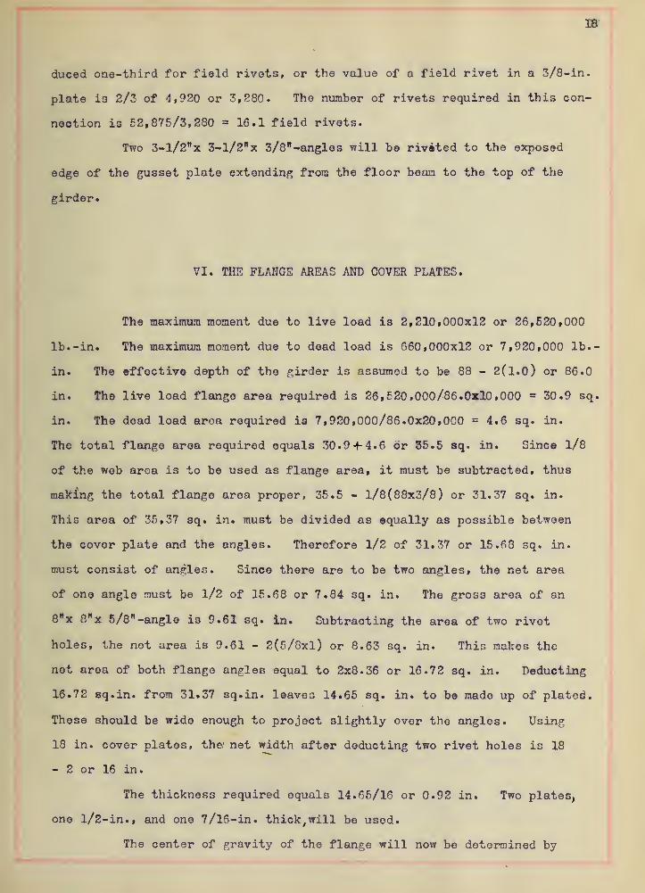
VI. THE FLANGE AREAS AND COVER PLATES.
The maximum moment due to live load is 2,210,000x12 or 26,520,000
lb. -in. The maximum moment due to dead load is 660,000x12 or 7,920,000 lb.-
in. The effective depth of the girder is assumed to be 88 - 2(1.0 ) or 86.0
in. The live load flange area required is 26,520,000/86.0x10,000 = 30.9 sq.
in. The dead load area required is 7,920,000/86.0x20,000 = 4.6 sq. in.
The total flange area required equals 30.9 + 4.6 or 35.5 sq. in. Since 1/8
of the web area is to be used as flange area, it must be subtracted, thus
making the total flange area proper, 35.5 - 1/8(88x3/8) or 31.37 sq. in.
This area of 35,37 sq. in. must be divided as equally as possible between
the cover plute and the angles. Therefore 1/2 of 31.37 or 15.68 sq. in.
must consist of angles. Since there are to be two angles, the net area
of one angle must be l/2 of 15.68 or 7.84 sq. in. The gross area of an
8"x 8"x 5/3"-angle is 9.61 sq. in. Subtracting the area of two rivet
holes, the not area is 9.61 - 2(5/8xl) or 8.63 sq. in. This makes the
net area of both flange angles equal to 2x8.36 or 16.72 sq. in. Deducting
16.72 sq.in. from 31.37 sq.in. leaves 14.65 sq. in. to be made up of plated.
These should be wide enough to project slightly over the angles. Using
18 in. cover plates, the/ net width after deducting two rivet holes is 18
- 2 or 16 in.
The thickness required equals 14.65/16 or 0.92 in. Two plates,
one l/2-in., and one 7/16-in. thick,will be used.
The center of gravity of the flange will now be determined by

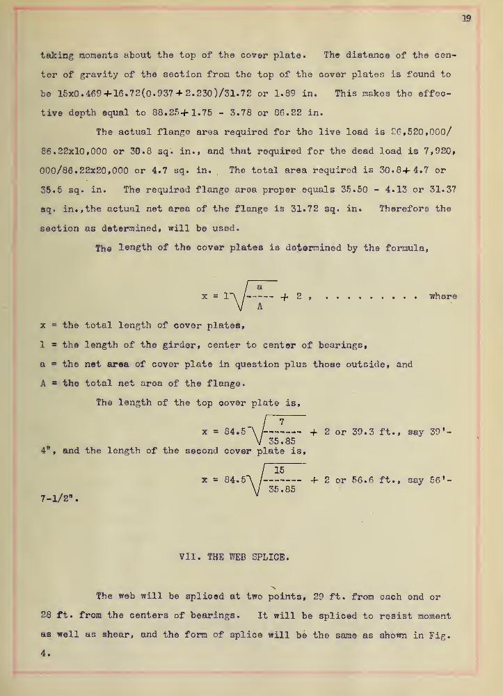
19
taking moments about the top of the cover plate. The distance of the cen-
ter of gravity of the section from the top of the cover plates is found to
be 15x0.469+16.72(0.937 + 2. 230)/31. 72 or 1.89 in. This makes tho effec-
tive depth equal to 88. 25+ 1.75 - 3.78 or 86.22 in.
The actual flange area required for the live load is 26,520,000/
86.22x10,000 or 30.8 sq. in., and that required for the dead load is 7,920,
000/86.22x20,000 or 4.7 sq. in. Tho total area required is 30.8+4.7 or
35.5 sq. in. The required flange area proper equals 35.50 - 4.13 or 31.37
sq. in., the actual net area of the flange is 31.72 sq. in. Therefore the
section as determined, will be used.
The length of the cover plates is determined by the formula,
/ + 2 , whereA
x = the total length of cover plates,
1 a th© length of the girder, center to center of bearings,
a = the net area of cover plate in question plus those outside, and
A - the total net area of the flange.
The length of the top cover plate is,
!4.5"\ / + 2 or 39.3 ft., say 39'-35.85
4", and the length of the second cover plate is,
15x = 84. 5A / + 2 or 56.6 ft., say 56'-
35.857-1/2".
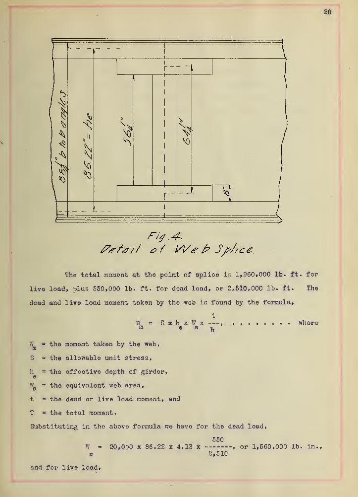
VII. THE WEB SPLICE.
The web will be spliced at two points, 29 ft. from each ond or
28 ft. from the centers of bearings. It will be spliced to resist moment
as well as shear, and the form of splice will be the same as shown in Fig.
4.

20
i
«0
The total moment at the point of splice ir. 1, 960 , 000 lb. ft. for
live load, plus 550,000 lb. ft. for dead load, or 2,510,000 lb. ft. The
dead and lire load moment taken by the web is found by the formula,
= GxhxV/x ,
© a Rwhere
W = the moment taken by the web,m
3 = the allowable unit stress,
h = the effective depth of girder,
V! = the equivalent web area,
t = the dead or live load moment, and
T = the total moment.
Substituting in the above formula we have for the dead load,
550W = 20,000 x 86.22 x 4.13 x , or 1,560,000 lb. in.,m 2,510
and for live load,


1,960W = 10,000 x 86.22 x 4.13 x or 2,780,000 lb. in.m 2,510
The effective depth of the moment splice plates is 88.25 - 24 or
64.25 in. The stress taken by these plates is 1,560,000/64.25 or 24,300
lb. for the dead load, and 2,780,000/64.25 or 43,400 lb. for the live load.
The unit stress for dead load on the remotest fibre is 20,000 lb. The
unit stress on a fibre 64.25/2 in. from the center of web equals 20,000 x
64.25/86.22 or 14,900 lb. The unit stress for the live load equals 7,450
lb. The area required for the dead load is 24,300/14,900 or 1.64 sq. in.
The area required for the live load is 43,400/7,450 or 5.82 sq. in. The
total area required equals 1.64-J-5.82 or 7.46 sq. in. Since a plate is
put on both sides of the girder, the thickness required for one is 7.46/
2 (8-2(1x1/2)) or 0.53 in. The thickness of the flange angles or 5/8 in.,
will be used for the splice plates.
The number of rivets required equals the total stress divided by
the bearing value of a rivet in the web. This gives 24,300+43,400/4,920
= 13.7 rivets.
The total shear at the point of splices is 56,600 lb. The length
of the shear splice-plate is 56.25 in. The thickness of plate required
to resist the shear is 56,600/2x56.25x9,000 or 0.057 in. A 5/8-in. plate
will be used.
The number of rivets required to resist the shear equals 56,600/
4,920 or 12 rivets on each side of the splice.
VIII. THE PITCH OF RIVETS IN FLANGES.
In web:-
The pitch of rivets is determined by the formula,
bh
P where

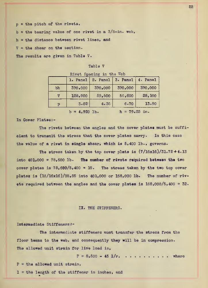
22
p the pitch of the rivets,
b = the bearing value of one rivet in a 3/8-in. wob,
h the distance between rivet lines, and
V the shear on the section.
The results are given in Table V.
Table V
Rivet Spacing in the Web
1. Panel 2. Panel 3. Panel 4. Panel
bh 390,000 390,000 390,000 390,000
V 128,900 89,500 56,600 28,100
P 3.02 4.36 6.70 13.90
b = 4,920 lb. h = 79.25 in.
In Cover Plates :-
The rivets between the angles and the cover plates must be suffi-
cient to transmit the stress that the cover plates carry. In this case
the value of a rivet in single shear, which is 5,400 lb., governs.
The stress taken by the top cover plate is (7/16x16 )/31.72 + 4. 13
into 401,000 78,600 lb. The number of rivets required between the two
cover plates is 78,690/5,400 15. The stress taken by the two top cover
plates is (15/16x16 )/35, 85 into 401,000 or 168,000 lb. The number of riv-
ets required between the angles and the cover plates is 168,000/5,400 32.
IX. THE STIFFENERS.
Intermediate StiffenersJ-
The intermediate stiffeners must transfer the stress from the
floor beams to the web, and consequently they will be in compression.
The allowed unit strain for live load is,
P = 8,500 - 45 l/r where
P = the allowed unit strain,
1 the length of the stiffener in inches, and

\
>X^nla at i«
o fdmtn •rfT

23
r = the radius of gyration of the stiffener.
The value of (r) is very large, both parallel and perpendicular to the axis
of the web as the 3tiffener is strengthened by the web and the gusset plate.
This condition makes the value of l/r very small and it may be neglected,
and P will then equal 8,500 lb. per sq. in. for live load. The allowed
unit strain for dead load is 18,000 - 80 l/r. The same condition is true
for l/r as above and P then oquals 18,000 lb. per sq. in. for dead load.
The live load reaction for each end of the floor beams is 47,700
lb. The area required for the live load is 47,700/8,500 /= 5.53 sq. in.
The dead load reaction at the end of the floor beam is 4,975 lb.,
and the area required for the dead load is 4,975/18,000 = 0.276 sq. in.
The total required area of the intermediate stiffeners is 5.53+0.27 or 6.80
sq. in. The area of 2 - 6" x 3-1/2" x 3/8"-angles iB 6.86 sq. in.,
and so this size will be used for the intermediate stiffeners.
The number of rivets required to join the stiffeners to the web
is obtained by dividing the bearing of a rivet into the total end reaction
or 52,875/4,920 = 10.7 shop rivets.
End Stiffenors:-
The end stiffeners must carry the total end reactions which are,
for the dead load 27,300 lb., and for the live load 101,600 lb. The same
thing is true of the value of l/r as in the case of the intermediate stiff-
eners, and so the allowed unit strains are the same. The area required
for the dead load is 27,300/18,000 = 1.52 sq. in. For the live load the
area required is 101,600/8,500 11.95 sq. in. The total area required
equals 1.52+11.95 or 13.47 sq. in. The top flange angles are bent around
to form a part of the end stiffeners. These angles are 8" x 8" x 5/8",
and the combined area is 2x9.61 or 19.22 sq. in. In addition to this the
top cover plate will extend down along the end of the girder. This gives
enough area to transmit the stress, but no provision is made for fastening
the end floor beam directly over the center of the bearings, and for dis-
tributing the pressure over the bearing, In order to provide for the a-
bove, two stiffener angles, 6" x 3-1/2" x 3/8"willbe used on each side of


24
the web at distances of one and two feet from the end of the girder as shown
in Fig. 5.
\
\
r
4 1
r-o
Fig 5.
// of L/iJ J'/
/
Fferze rj.
X. THE LATERAL BRACING.
The lateral bracing must be designed to take the stress due to
the wind on the train and the bridge. This load is 450 lb. per lin. ft.
on the train, considered as moving, and 150 lb. per lin. ft. on the bridge,
considered as dead load. The laterals will be designed to take compression
as well as tension, and the stresses in each panel will be equally divided
between the two laterals. The lateral system will be arranged as shown in
Fig. 6.
The stresses ere now computed, and their values given in Table VI.

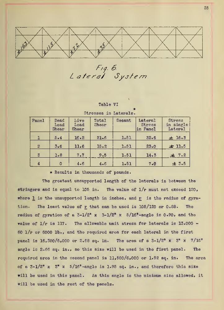
Tablo VI*
Stresses in Laterals.
Panel DeadLoadShear
LivoLoadShear
TotalShear
Secant LateralStress
in Panel
Stressin singleLateral
1 5.4 16.2 21.6 1.61 32.6 =L 16.3
2 3.6 11.6 15.2 1.51 23.0 dt 11.5
3 1.8 7.7 9.5 1.51 14.3 ± 7.2
4 4.6 4.6 1.51 7.0 ± 3.5
* Results in thousands of pounds.
The greatest unsupported length of the laterals is between the
stringer 8 and is equal to 105 in. The value of l/r must not oxcoed 120
»
where 1 is the unsupported length in inches, and r is the radius of gyra-
tion. The least value of v that can be used is 105/120 or 0.88. The
radius of gyration of a 3-1/2" x 3-1/2" x 5/16" -angle is 0.90, and the
value of l/r is 117. The allowable unit stress for laterals is 13.000 -
60 l/r or 6000 lb., and the required area for each lateral in the first
panel is 16,300/6,000 or 2.68 sq. in. The area of a 3-1/2" x 3" x 7/16"
angle is 2.66 sq. in., so this size will be used in the first panel. The
required area in the second panel is 11,500/6,000 or 1.92 sq. in. The area
of a 3-1/2" x 3" x 5/l6"-angle is 1.95 sq. in., and therefore this size
will be used in this panel. As this angle is the minimum size allowed, it
will be used in the rest of the panels.

i

XI. THE BEARINGS.
Art. 1. The Bolsters.
Since the span is over 80 ft., hinged bolsters are required at both
ends. These bolsters will be made of cast steel. The length of bearing
surface on the top half of the bolster is 24 in., and the length of the bot-
tom half or the bearing surface on the rollers is 30 in. The width of the
lower half of the bolster will be the same as the length of the rollers.
The height over all of the bolster will be 16 inohes.
Art. 2. The Rollers.
Rollers are required at one end of the span. They will be 3-in.
in diameter, plus l/4-in. for olearance, making 9 rollers under each bol-
ster. The total length of all the rollers must be proportioned so that the
pressure per lin. in. shall not exceed 300 into the diameter of the roller,
in inches. The pressure on each bolster equals the maximum end shear or
128,900 lb. The total required length of the rollers is 128,900/300 into
3 or 143 in. Since there are 9 rollers, 143/9 or 16.9 in. equals the re-
quired length of one roller. The length of rollers will be made of a length
equal to the width of the lower flange of the girder or 18-3/8 in.
Art. 3. The Bearing Plates.
The bearing plate must be of sufficient size to carry the load to
the pedestal stone without exceeding a pressure of 250 lb. per sq. in. The
mazimum reaction or 128,900/250 gives 510 sq. in. for the required area of
the bearing plate. The smallest that can be used with the rollers as de-
signed, is 30" x 27", and the area of this plate is 810 sq. in., so this
size will be used. The thickness is to be 3/4-in., thereby making the dis-
tance from the pedestal stone to the bottom flange of the girder equal to
19-3/4 in.


27
Art. 4. The Cast Steol Raiser.
At one end, rollers are not required, and in order to make the
masonry the same height at both of the piers, a cast-steel raiser will be
used. The size will be the same as that of the bearing plate and the
height the same as the diameter of the rollers plus the thickness of the
bearing plate or 3" 0-3/4" or 3-3/4 in.
Art. 5. The Anohor Bolts.
Four wedge bolts 1 inch in diameter will be used in securing the
bearing plates to the pedestal stone. They shall be leaded into the stone
to a depth of at least 8 inches.
XII. ESTIMATE OF COST.
The cost will be estimated f. o. b. cars at the bridge plant. In
determining the cost, the weight will be computed, and the different items
placed in tabular form.
The prices of material as indicated in the table are from quota-
tions in Pittsburg.
Cost of Matorial
.
46,000 lb. plates @ 1.86-1/2 $ per lb. — % 857.00
23,560 lb. angles @ 1.96-1/2 <f per lb. — 462.00
11,820 lb. angles @ 1.86-1/2 / per lb. — 222.00
11,000 lb. I-beams @ 1.96-1/2 $ per lb. — 216.00
7,000 lb. 3" round @ 1.86-1/2 ^ per lb. — 130.00
5,100 lb. Cast St'l @ 1.75 f per lb. — 89.00% 1976.00
Shop Cost.
92,400 lb. punching and assembling into
girders @ 0.60 $ per lb. — -3 555.00
Draughting Cost.


50 Tons <§ 2.00 per ton. $ 100.00
Painting.
25 gals. @ § 1.00 per gal. ft 25.00
Total Cost. $ 2656.00
XIII. THE STRAIN SHEET.
The strain sheet following, contains all of the results of the
computations made in this design, together with sketches of the form of
the girder. The information submitted in the strain sheet is all that
is neccessary for the detailing of all the parts of the girder.


cs ^ ^> S1
Cv t-N . KN
it ^
« ^ ^« Sa ^
Nl "O
5
Se333Jilt ^
<5
^ h k § xs
I
^ In ^ «Q \o \ ^


;sjk «jt ->ft.
dfa * <#-
- -i 4-
4w '-^fc. -»k
4
Sir: -Mi <<*C.
MR S^f 1^
+ 1
V * * + 4. * *
