design of a hexapod motion cueing system for the ... - nasa · hexapod geometry optimization...
TRANSCRIPT

1
AMERICAN INSTITUTE OF AERONAUTICS AND ASTRONAUTICS
Copyright © 2002 by the American Institute of Aeronautics andAstronautics, Inc. No copyright is asserted in the United Statesunder Title 17, US Code. The U.S. Government has a royalty-feelicense to exercise all rights under the copyright claimed herein forGovernmental purposes. All other rights are reserved by thecopyright owner.
Design of a Hexapod Motion Cueing System for the NASA Ames Vertical Motion Simulator
By
Sunjoo Advani, Aircraft Development & Systems EngineeringHoofddorp, The Netherlands. [email protected]
Dean Giovannetti, NASA Ames Research CenterMoffett Field, California. [email protected]
Michael Blum, Electrical & Control Systems EngineeringMoffett Field, California. [email protected]
Abstract NASA at Ames Research Center operates the world’slargest motion-base flight simulator, the VerticalMotion Simulator. This simulation facility supports awide variety of research by allowing flexibility inboth hardware and software. As part of a VMSModernization Plan, NASA Ames elected to considermajor alterations to the motion-base configuration.One of these was the incorporation of a hexapod onthe lateral carriage of the vertical beam. This wouldreplace both the longitudinal carriage (that provides±4 feet of surge) as well as the rotational gimbal (thatsimultaneously provides ±18 degrees pitch, ±18degrees roll, and ±24 degrees yaw). However,standard off-the-shelf hexapod geometries did notmeet the requirement for this large simultaneousmotion capability. New geometric designs werecreated based on optimization of the geometry tomaximize workspace and flight metrics.
This paper describes the development andimplementation of these optimization and evaluationmetrics. Design solutions are explored fromworkspace and simulation fidelity perspectives.Kinematic design issues of the hexapod arepresented, including the trade-offs necessary toensure high performance within a safe operationalenvironment. Integration of the design with the VMSpresented its own challenges, and the most relevantof these are also presented.
1 Background/Introduction The Vertical Motion Simulator (VMS) at NASAAmes Research Center has been in operation sincethe mid 1970’s. The VMS is a one-of-a-kindsimulation research and development facility. Itoffers unparalleled capabilities for conductingexperiments involving some of the most challenging
Cab
Gimbal
Carriage
Beam
Figure 1 – Current VMS motion system, showing three-axisgimbal mounted on carriages and beam.
AIAA Modeling and Simulation Technologies Conference and Exhibit5-8 August 2002, Monterey, California
AIAA 2002-4794
Copyright © 2002 by the American Institute of Aeronautics and Astronautics, Inc. No copyright is asserted in the United States under Title 17, U.S. Code.The U.S. Government has a royalty-free license to exercise all rights under the copyright claimed herein for Governmental purposes.All other rights are reserved by the copyright owner.
2
AMERICAN INSTITUTE OF AERONAUTICS AND ASTRONAUTICS
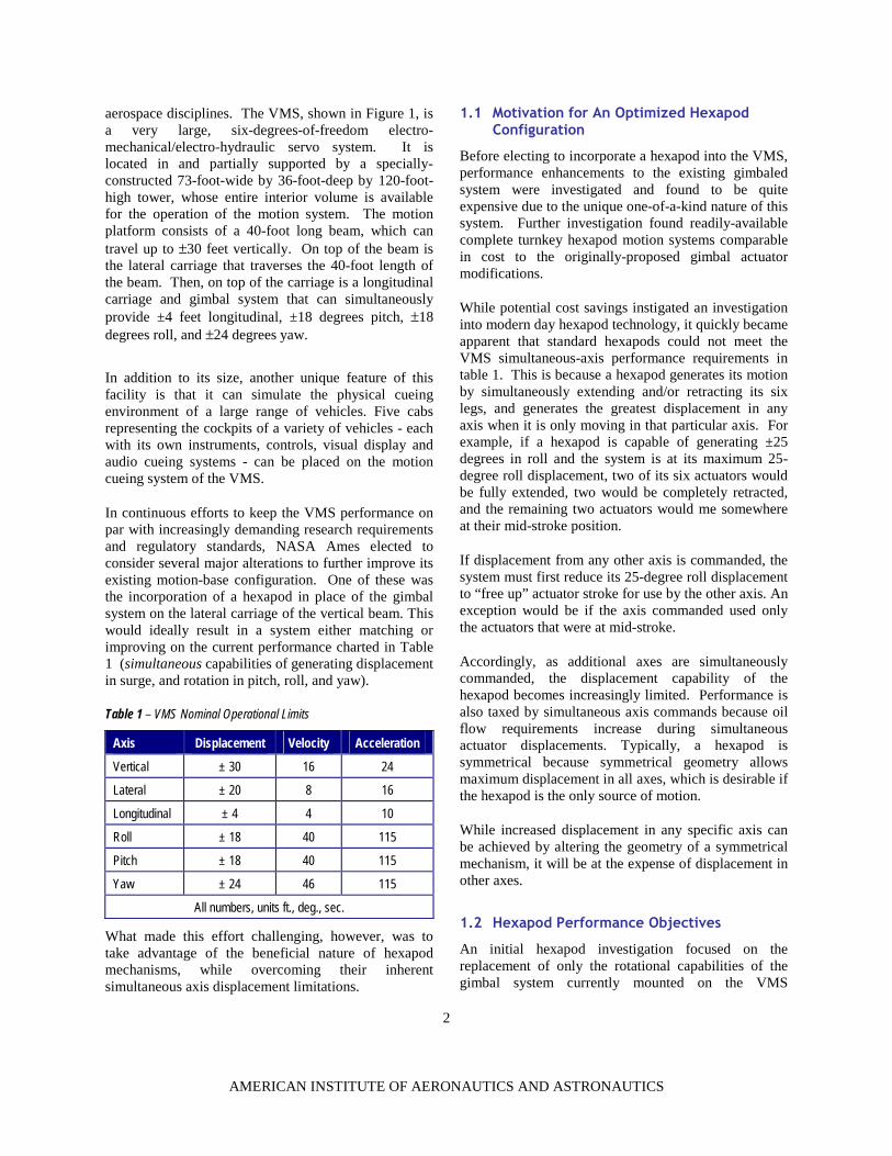
aerospace disciplines. The VMS, shown in Figure 1, isa very large, six-degrees-of-freedom electro-mechanical/electro-hydraulic servo system. It islocated in and partially supported by a specially-constructed 73-foot-wide by 36-foot-deep by 120-foot-high tower, whose entire interior volume is availablefor the operation of the motion system. The motionplatform consists of a 40-foot long beam, which cantravel up to ±30 feet vertically. On top of the beam isthe lateral carriage that traverses the 40-foot length ofthe beam. Then, on top of the carriage is a longitudinalcarriage and gimbal system that can simultaneouslyprovide ±4 feet longitudinal, ±18 degrees pitch, ±18degrees roll, and ±24 degrees yaw.
In addition to its size, another unique feature of thisfacility is that it can simulate the physical cueingenvironment of a large range of vehicles. Five cabsrepresenting the cockpits of a variety of vehicles - eachwith its own instruments, controls, visual display andaudio cueing systems - can be placed on the motioncueing system of the VMS.
In continuous efforts to keep the VMS performance onpar with increasingly demanding research requirementsand regulatory standards, NASA Ames elected toconsider several major alterations to further improve itsexisting motion-base configuration. One of these wasthe incorporation of a hexapod in place of the gimbalsystem on the lateral carriage of the vertical beam. Thiswould ideally result in a system either matching orimproving on the current performance charted in Table1 (simultaneous capabilities of generating displacementin surge, and rotation in pitch, roll, and yaw).
Table 1 – VMS Nominal Operational Limits
Axis Displacement Velocity Acceleration
Vertical ± 30 16 24
Lateral ± 20 8 16
Longitudinal ± 4 4 10
Roll ± 18 40 115
Pitch ± 18 40 115
Yaw ± 24 46 115
All numbers, units ft., deg., sec.
What made this effort challenging, however, was totake advantage of the beneficial nature of hexapodmechanisms, while overcoming their inherentsimultaneous axis displacement limitations.
1.1 Motivation for An Optimized Hexapod Configuration
Before electing to incorporate a hexapod into the VMS,performance enhancements to the existing gimbaledsystem were investigated and found to be quiteexpensive due to the unique one-of-a-kind nature of thissystem. Further investigation found readily-availablecomplete turnkey hexapod motion systems comparablein cost to the originally-proposed gimbal actuatormodifications.
While potential cost savings instigated an investigationinto modern day hexapod technology, it quickly becameapparent that standard hexapods could not meet theVMS simultaneous-axis performance requirements intable 1. This is because a hexapod generates its motionby simultaneously extending and/or retracting its sixlegs, and generates the greatest displacement in anyaxis when it is only moving in that particular axis. Forexample, if a hexapod is capable of generating ±25degrees in roll and the system is at its maximum 25-degree roll displacement, two of its six actuators wouldbe fully extended, two would be completely retracted,and the remaining two actuators would me somewhereat their mid-stroke position.
If displacement from any other axis is commanded, thesystem must first reduce its 25-degree roll displacementto “free up” actuator stroke for use by the other axis. Anexception would be if the axis commanded used onlythe actuators that were at mid-stroke.
Accordingly, as additional axes are simultaneouslycommanded, the displacement capability of thehexapod becomes increasingly limited. Performance isalso taxed by simultaneous axis commands because oilflow requirements increase during simultaneousactuator displacements. Typically, a hexapod issymmetrical because symmetrical geometry allowsmaximum displacement in all axes, which is desirable ifthe hexapod is the only source of motion.
While increased displacement in any specific axis canbe achieved by altering the geometry of a symmetricalmechanism, it will be at the expense of displacement inother axes.
1.2 Hexapod Performance Objectives
An initial hexapod investigation focused on thereplacement of only the rotational capabilities of thegimbal system currently mounted on the VMS

3
AMERICAN INSTITUTE OF AERONAUTICS AND ASTRONAUTICS
Figure 2 – Custom-tailored hexapod developed by this programfor the VMS, designed to allow replacement of boththe rotational gimbal and longitudinal carriage.
longitudinal carriage. This hexapod would havesimultaneously provided ±18, ±15 and ±20 degrees inpitch, roll and yaw, respectively. This envelope wasthought to be sufficient for the range of anticipatedVMS experiments. Nonetheless, there were a fewpotential difficulties with this solution: Combinedmotions of the hexapod and the longitudinal table couldhave led to cab-wall interference, and the complexity ofthe entire system would have increased. It then becameapparent with the optimization tools developed, that thehexapod may be able to provide the requiredlongitudinal motion as well as the rotational motionthereby eliminating the need for the longitudinalcarriage. This potentially reduced system cost andmass.
This paper will now explain the approach developed toanalyze a motion system’s ability to reproduceparticular one-to-one aircraft motion cues, and thehexapod geometry optimization process used to tailor amotion system to maximize this cueing capability in thegiven building volumetric enclosure. Ultimately, theeffort concentrated on a solution requiring four degreesof freedom from a hexapod (roll, pitch, yaw andlongitudinal motion), with the VMS providing the othertwo vertical and lateral axes. The final design is aviable replacement candidate for the gimbal andlongitudinal system currently on the VMS. Figure 2depicts the resultant design from application of thesetools as applied to a Bosch-Rexroth Corporationhexapod.
Typically, motion system performance is described interms of single-axis displacement, velocity, andacceleration. The method for defining VMSperformance was commonly through maximum axislimit tables like Table 1, which imply axesindependence.
Maximum axis limit tables cannot be developed forhexapods because the nonlinear character of hexapodsprevents the parallel application of equivalent tables forhexapods. Therefore, a more thorough and completecomparison method was needed before a validcomparison could be made between the gimbaledcarriage and hexapod mechanisms. The comparisontook the form of two metrics. The first metric focuseson the performance of the machine with respect to thedesired quality of its flight simulation, and will bereferred to herein as the “flight metric”. The secondmetric focuses on a motion envelope, referred to hereinas the “workspace metric”.
2 Optimization of a Hexapod For Flight Simulation Performance
2.1 Definition of Flight Metric
The flight metric was developed on the basis of tuningpractices employed prior to each simulation. Theobjective of tuning is to reduce the flight envelope (trueaircraft motion cues) to fit the physical limitations ofthe simulator workspace while retaining as much flightquality, in terms of fidelity, as possible. Chung2 &Schroeder3 further define and detail mathematics andtechniques for tuning motion simulator systems.
Reducing the motion envelope involves severalparameters referred to as gains. Motion algorithm gainamplitudes are used to control how closely thesimulation achieves the motion cues that the actualaircraft is expected to deliver. Typically, reducing again reduces some aspect of the motion envelope,making it then more likely that the given flightsimulator’s mechanism can accomplish the motion. Asthe motion envelope is reduced, fidelity iscorrespondingly eroded as the motion cues loseamplitude, shape, and phase.
The tuning process is interactive and involvessubjective responses from the pilot making it difficult to

4
AMERICAN INSTITUTE OF AERONAUTICS AND ASTRONAUTICS
forecast the resulting motion quality for a simulatordesign not yet built. To enable answers regarding flightfidelity for that situation, the flight metric methodattempts to extrapolate by using two steps.
In the first step, aircraft model output data is capturedduring a simulation. This data is then run throughmotion algorithms tuned to provide the maximummotion reductions still allowing high-fidelity4 motion(in which the motion sensations are not noticeablydifferent from those of actual flight). At this point, thedata reflects pilot, aircraft model, and researcher tuningpractices, but is not tailored (limited) to run on (or fitwithin the motion capabilities of) a specific simulatormechanism.
The second step multiplies the data by a single reducingfactor, which can be thought of as a spherical gain,since it is applied uniformly to all axes of motion. Thisgain therefore is a flight metric in terms of simulationfidelity, with a gain of 1.0 implying flight quality insidethe ‘high-fidelity’ zone, rather than 1:1 flight cues. Asthis is decreased below 1.0, the simulation fidelity iscorrespondingly decreased. The gain value of interestis the maximum a proposed mechanism can achieve.
2.2 Calculation of the Flight Metric.
The flight metric of a candidate design is calculated byusing a set of high fidelity flight simulation motion filesand an emulator. The motion data set was selected toreflect past, current, and future simulations at AMES.The emulator first assembles the simulator design bytaking a geometric description of the VMS with orwithout a hexapod, and a set of constraints as additionalinputs. It then reads motion data, translates them intoactuator space commands by using vector algebra withrotation matrices, indicates where the actuators have theleast available performance remaining, and listsoccurrences where they would exceed their physicalextension or retraction limits. The simulationparameters are automatically re-tuned with enhancedmaneuver anticipation (an experimental fidelityenhancement method developed in-house at AMES) tomaximize, in our case, the gain while barely eliminatingthose occurrences. The emulator was ‘flown’ for eachgenerated geometry, solving for whicheverdisplacement, velocity, or acceleration limit wouldoccur first in any of the actuators.
The reported gain is thus limited to the highest valuemanageable by the machine. Gain values over 1.0 donot imply a noticeably better simulation, so the
estimated gain achievable for each flight is truncateddown to 1.0 before averaging over all flight profiles ofinterest. The result is the highest average overallestimated simulation fidelity achievable for thosesimulations running on a proposed simulator design. Bycalculating the flight metric of every promising design,eventually the optimum design can be identified basedon superior matching of simulator motion capabilitiesto specific simulations.
2.3 Flight Metric Geometry Optimization Loop
The geometry optimization loop is presented in Figure3, and is achieved by using the flight metric calculation(in our example a simulation (sim) gain estimator) as afilter applied to a set or family of possible hexapoddesigns. A family of designs is a set of hexapodgeometries each using the same actuator dimensions.An infinite number of different hexapod designs is stillpossible given six gimbal points in three dimensions.The term “Hexapod Geometry Generator” refers to any
Actuator design parametersand an initial seed geometry
Does “Hexapod GeometryGenerator” suggest another
design?
RequestNext
Design
Store the design andcondition with the lowest
likely safety factor
Sim gainEstimator. Has the
Gain reached a newmaximum?
Save candidate designas best in class
thus far
yes
yes
no
STOP
no
Figure 3 – Geometry Optimization Loop
5
AMERICAN INSTITUTE OF AERONAUTICS AND ASTRONAUTICS
systematic way of producing a family of designs withvaried gimbal locations for subsequent evaluation. Thenecessary characteristics of this generator are the abilityto export at least one complete hexapod geometricdescription, and an automatic termination ofproduction. Such termination ensures there is a stoppingpoint when either negligible improvement is seen in anyperformance metric (during continued rearrangement ofthe gimbals), or the family of design possibilitiesembodying the common theme is to a level of sufficientresolution exhausted. When a complete family ofdesigns has been generated, tested and emulated, onlythe highest rated, by flight metric, are retained.
This design process was initially carried out manuallyby generating one design at a time. Eventually path-searching routines were developed to read constraintdata and compute the directions in three dimensionsthat two gimbal points at a time could be moved formaximum gain improvement. Automatic terminationoccurred when successive results showedimprovements less than 0.1% per inch of gimbalmovement.
2.4 Multidisciplinary Aspects
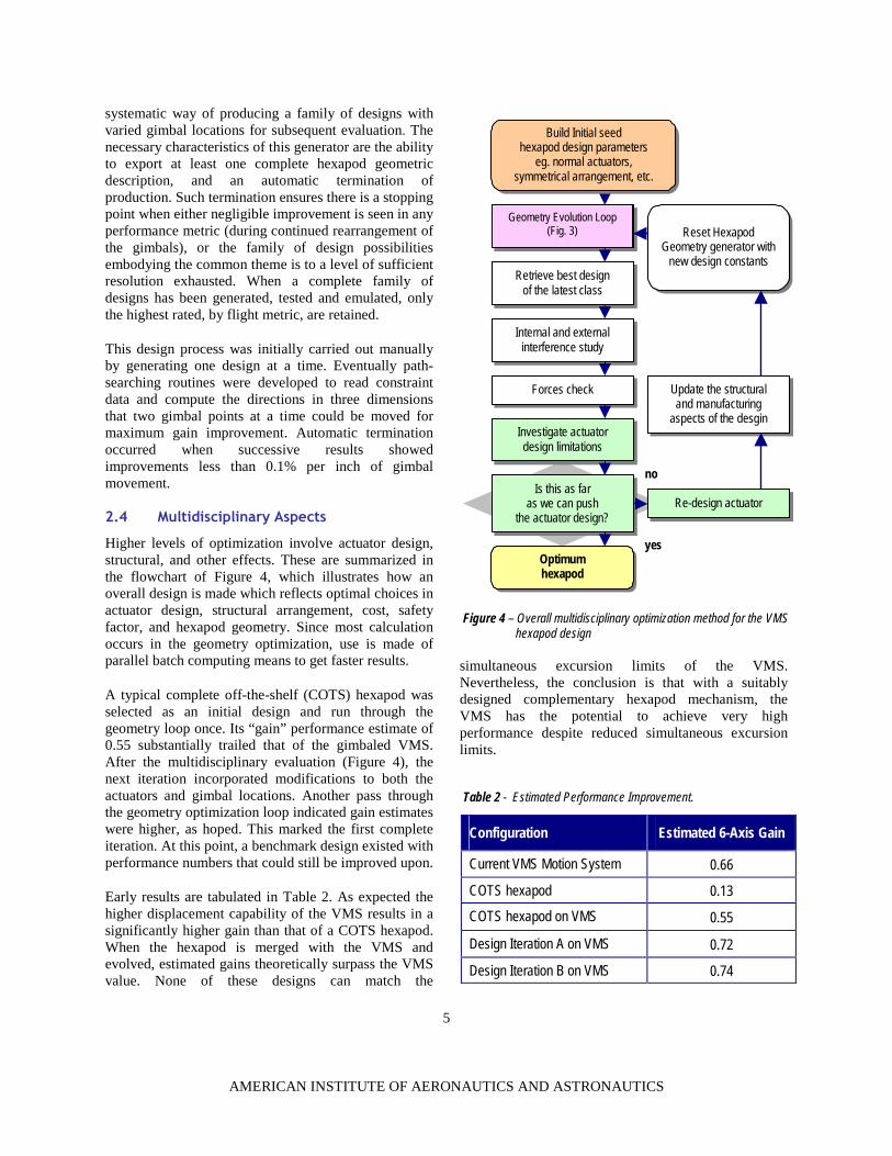
Higher levels of optimization involve actuator design,structural, and other effects. These are summarized inthe flowchart of Figure 4, which illustrates how anoverall design is made which reflects optimal choices inactuator design, structural arrangement, cost, safetyfactor, and hexapod geometry. Since most calculationoccurs in the geometry optimization, use is made ofparallel batch computing means to get faster results.
A typical complete off-the-shelf (COTS) hexapod wasselected as an initial design and run through thegeometry loop once. Its “gain” performance estimate of0.55 substantially trailed that of the gimbaled VMS.After the multidisciplinary evaluation (Figure 4), thenext iteration incorporated modifications to both theactuators and gimbal locations. Another pass throughthe geometry optimization loop indicated gain estimateswere higher, as hoped. This marked the first completeiteration. At this point, a benchmark design existed withperformance numbers that could still be improved upon.
Early results are tabulated in Table 2. As expected thehigher displacement capability of the VMS results in asignificantly higher gain than that of a COTS hexapod.When the hexapod is merged with the VMS andevolved, estimated gains theoretically surpass the VMSvalue. None of these designs can match the
simultaneous excursion limits of the VMS.Nevertheless, the conclusion is that with a suitablydesigned complementary hexapod mechanism, theVMS has the potential to achieve very highperformance despite reduced simultaneous excursionlimits.
Configuration Estimated 6-Axis Gain
Current VMS Motion System 0.66
COTS hexapod 0.13
COTS hexapod on VMS 0.55
Design Iteration A on VMS 0.72
Design Iteration B on VMS 0.74
GeometryEvolution Loop (Fig. 4.]
Retrieve best designof the latest class
Internal and externalinterference study
Forces check
Investigate actuatordesign limitations
Is this as faras we can push
the actuator design?
Optimumhexapod
Reset HexapodGeometry generator with
new design constants
Update the structuraland manufacturing
aspects of the desgin
Re-design actuator
no
Build Initial seedhexapod design parameters
eg. normal actuators,symmetrical arrangement, etc.
yes
Figure 4 – Overall multidisciplinary optimization method for the VMShexapod design
Table 2 - Estimated Performance Improvement.
Geometry Evolution Loop(Fig. 3)

6
AMERICAN INSTITUTE OF AERONAUTICS AND ASTRONAUTICS
3 Hexapod Workspace Kinematic Optimization Problem
The core of this design effort was the generation of aviable hexapod design that would meet the desiredperformance workspace objectives. These objectiveswere given in Table 1. While the hexapod would onlybe required to generate the rotations and thelongitudinal motion, these would have to be generatedsimultaneously, which meant applying a systematicapproach to the design of the hexapod.
A process developed by Advani8, 9 for the optimizationof hexapods with respect to a specific design objectivewas the starting point for this analysis. Thefundamentals will now be explained.
3.1 Workspace of hexapods
The main objective of a mechanism is to impart motionto the end-effector “C” over a specified range ofpositions and orientations. In motion-bases, the end-effector is usually the moving-platform reference point,typically the geometric centre of the upper platformgimbal joints (see Figure 5).
The “workspace” is defined as the totality of points thatthis end-effector can achieve, and is a six-dimensionalvolume describing the maximum excursions androtations of C. Determination of the workspace requires(a) a description of the mechanism, and (b) knowledgeof the ranges of the joint variables.
Many methods have been proposed for thedetermination of robotic workspace10, 11, 12. Particularlyin the case of parallel mechanisms, this is not a trivialtask. The method developed by Haeck13, which solvesfor the workspace boundary in solution space using ray-tracing methods, was applied in this investigation dueto its accuracy and its suitability for the subsequentoptimization problem.
The physical interpretation of the six-dimensionalworkspace is not straightforward, mainly since theangular limits, while having real and finite values, aredifficult to interpret physically. An objective functionmay be used and the actual fitting of a particularmechanism to that function will yield a single quantity.For general motion-cueing systems, an ellipticalobjective function was developed1; however, since wewere interested in the combined extreme motions of thehexapod in this analysis, a cubical function wasdeveloped. It simply compares the actual workspace
(quantified in metres and degrees) of a given hexapodgeometry to the volume of a six-dimensional cubehaving the dimensions of the required simultaneousmotions (Table 1).
In order to tailor the mechanism such as to yield thehighest possible workspace objective, the geometrymust be altered and the allowable range of physicalparameters defined. From a practical point-of-view, thisis by no means a random task. Certain geometricvariables will have a greater impact than others.Furthermore, the mechanism must always remainstable.
Hexapods with specific workspace capabilities can befound in public-domain literature 5, 14.
3.2 Hexapod geometry
Hexapod-type motion-base mechanisms (also referredto as Stewart Platforms) are usually comprised of abase-frame, six prismatic actuator legs (the jacks), andan upper moving platform that carries the payload. Thelegs are attached in pairs, via gimbal joints, to the upperand lower platforms near the vertices of their respectiveframes. All of these elements have kinematic and other
properties that must be taken into account whenmodifying the design. For instance, the gimbals haveallowable excursion ranges, load limits, and mechanicalinterface requirements.
The motion of the six legs of a hexapod is constrainedby their minimum and maximum lengths. Themaximum length of this type of actuator is limited bythe decrease of stiffness with greater length, and theability of manufacturing technologies to produce long
radius Ar
radius Br
O
C
120°
Figure 5 - Kinematic representation of the typical circular layout of asymmetric hexapod mechanism

7
AMERICAN INSTITUTE OF AERONAUTICS AND ASTRONAUTICS
cylinders that are suitable for hydrostatic bearingapplications. In order to prevent excessive forces duringrunaways, the actuators are equipped with safetybuffers, which help decelerate the piston before itreaches the end of the cylinder. From a kinematic point-of-view, the buffer reduces the effective operationalstroke available for normal motion.
Although the workspace is a function of all of the abovekinematic parameters, and each of these parameterslimited by manufacturing and materials technologies,the designer must also ensure the mechanism is wellconditioned. This means that it should behavedeterministically and is controllable at all times.
3.3 Mechanism conditioning
The mechanism must possess a specified level ofstability or “conditioning” throughout its workspace,meaning that its kinematics equations do not becomesingular, and the mechanism remains reasonably distantfrom these singularities16. The conditioning of themechanism varies as a function of the configurationitself, and the instantaneous pose (position andorientation) within the workspace. A well-conditionedplatform is easy to control, provides high positioningaccuracy and does not contain any singularities withinits workspace.
Conditioning can be mathematically described throughthe Jacobian matrix, which maps the rates of a specificpoint on the moving platform (usually the kinematiccentroid of its gimbals), to the rates of the actuators.Hence, in a well-conditioned platform, motion of theactuators will lead to a relatively small motion of theplatform. In a poorly-conditioned system, smallmotions of the actuators will result in large motions ofthe platform.
A mathematical term, commonly used in the field ofrobotics to express the conditioning (poor conditionimplies proximity to a singularity) is referred to asdexterity. It is defined as the inverse of the conditionnumber, which is the ratio of the lowest to the highestsingular values of the Jacobian matrix. The dexterity,
like the Jacobian matrix, varies throughout theworkspace, and the minimum dexterity - the lowestvalue achieved at any point in the (nonlinear)workspace - must be constrained 17.
An analysis of several commercial off-the-shelf flightsimulator motion-bases showed that a minimum
dexterity value of 0.2 is common, and would be areasonable starting point for the optimization. If theensuing loads analysis would demonstrate difficulties inspecific corners of the workspace, the design may thenbe altered.
4 Geometry for Workspace Optimization
When specifying the geometry of a hexapod, one is freeto choose the geometry. Therefore, one can specify inthree-dimensional space the locations of each upper andlower leg attachment point, as well as the properties ofeach leg, all of which influence the resulting workspaceof the motion base.
4.1 Geometric parameters
In this design study, a standard, proven COTS systemwas used as the starting geometry. The workspace wasprogressively tailored by varying the geometry itselfand gradually introducing more parameters. Thegeometry was varied by re-locating and re-orienting thegimbal blocks, and by determining the optimal stroke-length of the actuators.
In Figure 6, the geometric parameters of a generalizedbase platform and upper platform respectively aregiven. The gimbals are arranged in pairs on the upperand lower platform as in conventional hexapod motion-bases. In this case, they are located on two concentriccircles, rather than one. The outer pairs on the upper (orlower) platforms are located from the Y-axis by angle
Figure 6 – Layout of the generalized double-concentric hexapodplatform. Note that the two circles may be non-coplanar.
8
AMERICAN INSTITUTE OF AERONAUTICS AND ASTRONAUTICS
LA LB LC
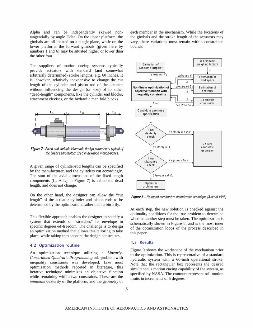
Figure 7 - Fixed and variable kinematic design parameters typical ofthe linear servomotors used in hexapod motion-bases.
Alpha and can be independently skewed non-tangentially by angle Delta. On the upper platform, thegimbals are all located on a single plane, while on thelower platform, the forward gimbals (given here bynumbers 1 and 6) may be situated higher or lower thanthe other four.
The suppliers of motion cueing systems typicallyprovide actuators with standard (and somewhatarbitrarily determined) stroke lengths; e.g. 60 inches. Itis, however, relatively inexpensive to change the cutlength of the cylinder and piston rod of the actuatorwithout influencing the design (or size) of its other“dead-length” components, like the cylinder end blocks,attachment clevises, or the hydraulic manifold blocks.
A given range of cylinder/rod lengths can be specifiedby the manufacturer, and the cylinders cut accordingly.The sum of the axial dimensions of the fixed-lengthcomponents (LA + LC in Figure 7) is called the deadlength, and does not change.
On the other hand, the designer can allow the “cutlength” of the actuator cylinder and piston rods to bedetermined by the optimization, rather than arbitrarily.
This flexible approach enables the designer to specify asystem that extends or “stretches” its envelope inspecific degrees-of-freedom. The challenge is to designan optimization method that allows this tailoring to takeplace, while taking into account the design constraints.
4.2 Optimization routine
An optimization technique utilizing a Linearly-Constrained Quadratic Programming sub-problem withinequality constraints was developed. Like mostoptimization methods reported in literature, thisiterative technique minimizes an objective functionwhile remaining within two constraints. These are theminimum dexterity of the platform, and the geometry of
each member in the mechanism. While the locations ofthe gimbals and the stroke length of the actuators mayvary, these variations must remain within constrainedbounds.
At each step, the new solution is checked against theoptimality conditions for the true problem to determinewhether another step must be taken. The optimization isschematically shown in Figure 8, and is the most innerof the optimization loops of the process described inthis paper.
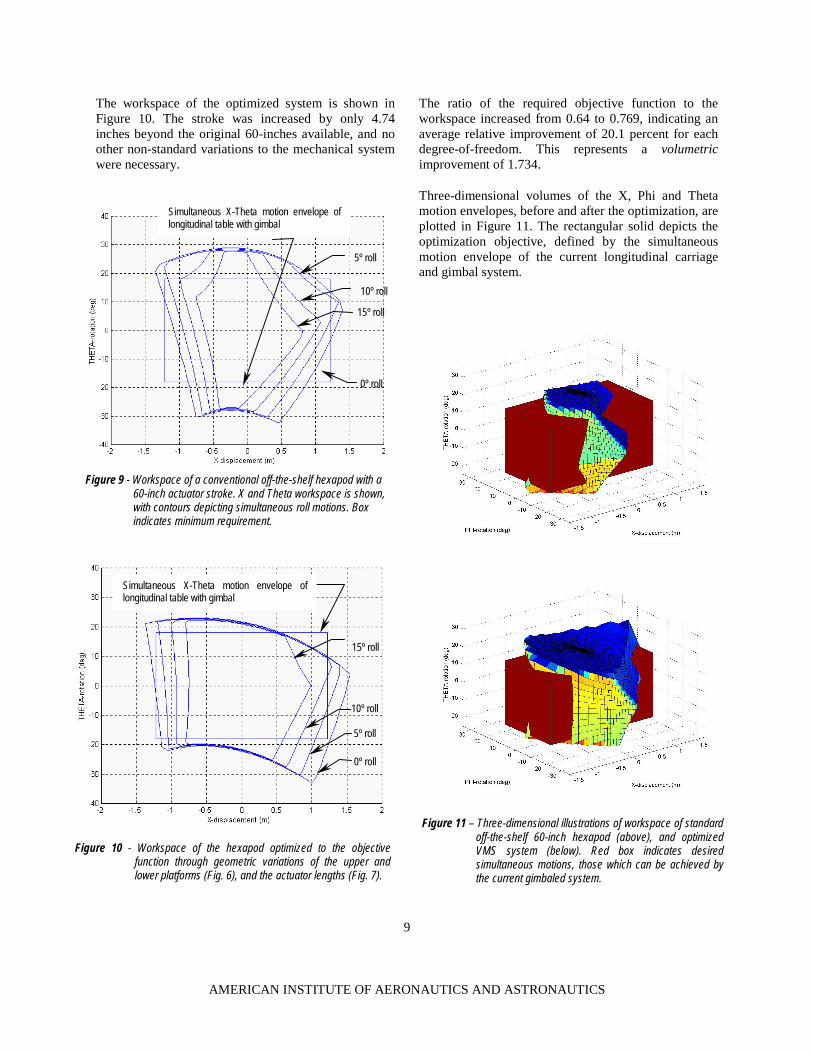
4.3 Results
Figure 9 shows the workspace of the mechanism priorto the optimization. This is representative of a standardhydraulic system with a 60-inch operational stroke.Note that the rectangular box represents the desiredsimultaneous motion cueing capability of the system, asspecified by NASA. The contours represent roll motionlimits in increments of 5 degrees.
Finaldexterity
check
Leg-clearance
check
Non-linear optimization ofobjective function withinequality constraints
Workspaceweighing factors
Estimation ofworkspace
Optimumarchitecture
Candidate geometryspecification
Discardcandidategeometry
Geometricconstraints
Estimation ofdexterity
Selection ofrandom startpoint
startpoint X0
ρ
X
Clearance O.K.
Legs too close
Dexterity too low
Dexterity O.K.
Xoptconstraint G2
constraint G1
objective F
X
X
Figure 8 – Hexapod mechanism optimization technique (Advani 1998)
9
AMERICAN INSTITUTE OF AERONAUTICS AND ASTRONAUTICS
The workspace of the optimized system is shown inFigure 10. The stroke was increased by only 4.74inches beyond the original 60-inches available, and noother non-standard variations to the mechanical systemwere necessary.
The ratio of the required objective function to theworkspace increased from 0.64 to 0.769, indicating anaverage relative improvement of 20.1 percent for eachdegree-of-freedom. This represents a volumetricimprovement of 1.734.
Three-dimensional volumes of the X, Phi and Thetamotion envelopes, before and after the optimization, areplotted in Figure 11. The rectangular solid depicts theoptimization objective, defined by the simultaneousmotion envelope of the current longitudinal carriageand gimbal system.
Figure 10 - Workspace of the hexapod optimized to the objectivefunction through geometric variations of the upper andlower platforms (Fig. 6), and the actuator lengths (Fig. 7).
0º roll
5º roll
10º roll
15º roll
Simultaneous X-Theta motion envelope oflongitudinal table with gimbal
Figure 9 - Workspace of a conventional off-the-shelf hexapod with a60-inch actuator stroke. X and Theta workspace is shown,with contours depicting simultaneous roll motions. Boxindicates minimum requirement.
0º roll
5º roll
10º roll
15º roll
Figure 11 – Three-dimensional illustrations of workspace of standardoff-the-shelf 60-inch hexapod (above), and optimizedVMS system (below). Red box indicates desiredsimultaneous motions, those which can be achieved bythe current gimbaled system.
Simultaneous X-Theta motion envelope oflongitudinal table with gimbal

10
AMERICAN INSTITUTE OF AERONAUTICS AND ASTRONAUTICS
5 CONCLUSIONS This project established that a hexapod is a viablereplacement candidate for the gimbaled systemcurrently on the VMS.
The systematic processes and tools developed for thisproject provide a thorough yet fast method fordeveloping custom motion simulators through minoralterations of a common off-the-shelf hexapod.
The salient conclusions are as follows:
The tools generated numerous designs that affordthe opportunity to make cost, performance, off-the-shelf selection, etc., design trade off decisions.This flexibility is extremely attractive as it providesthe engineer to tailor a system giving priority orweight to those factors most important to thecustomer.
The optimization operates on a large number ofdesign variables and, hence, has a large number oflocal minima that appear close to the globalminimum. This allows the designer to select fromnot only the best mathematical optimum, but nearlyas well-performing solutions that may even offeradvantages from a manufacturing or integrationpoint-of-view.
The original assumption that the minimumallowable dexterity be no lower than 0.20 wasvalid. Subsequent dynamics analyses confirmedthat, in the optimized geometric solution, the forcesin the hexapod would always remain withinacceptable bounds.
The designer must choose carefully the number ofdesign variables, and the geometric constraintsallowed on the system. This must be performed inconcert with the manufacturer in order that realisticand cost-effective trade-offs can be made.
The hexapod may not always achieve thesimultaneous motion capability as, for example, thegimbaled system (as was illustrated in Figures 9,10 and 11). In this particular design example, theoptimized hexapod is tasked with largelongitudinal motions and all three rotations. Thesolution provides significantly greater absolutesingle-degree-of-freedom motion capability.
The designer must carefully choose which designvariables to optimize for a particular simulationobjective.
Workspace is not the only criteria by which tomeasure or compare the performance of a hexapod.This methodology, however, allows the end user tobenefit from the advantages of hexapod solutions -stiff, compact and cost-effective - with themaximum achievable capability from that device.
Final Note:
The methodology, tools and processes developed in thisprogram are mature, tested and ready for application inother hexapod design problems, for simulation, or anyrelevant application.
6 References
1 Stewart, D., “A Platform with six-degrees-of-freedom”, in Proc.Inst. of Mechanical Engineers, vol. 180, part 1, no. 5, 1965-1966,pp. 371-386.
2 Schroeder, J.A., “Helicopter Flight Simulation Motion PlatformRequirements”. NASA/TP-1999-208766 pp. 7-9, 18, 66-67
3 Tran D., Chung, W.Y., Mikula, “Preliminary Investigation of theMotion Fidelity Criterion for a Pitch – Longitudinal TranslationalTask”. AIAA-99-4333 1999
4 Mikula, Chung, Tran, “Motion Fidelity Criteria for Roll – LateralTranslational Tasks”. AIAA 99-4329. 1999. p.5.
5 Advani, S.K., "The Kinematic Design of Flight Simulator Motion-Bases". Ph.D. Thesis, Delft University of Technology, April
1998. Delft University Press. ISBN 90-407-1672-2.
6 Advani, S.K., Nahon, M., Haeck, N., " Optimization of Six-Degrees-of-Freedom Flight Simulator Motion Systems". AIAA J. of
Aircraft, Vol. 36, No. 5, Sept-Oct. 1999.
7 Gosselin, C., “Determination of the Workspace of 6-DOF Parallel Manipulators”, ASME Journal of Mechanical Design, Vol. 112,
No. 3, 1990, pp. 331-336.
8 Kumar, A., Patel, M.S., “Mapping the Manipulator Workspace Using Interactive Computer Graphics”, Int. J. of Robotics Research,
Vol. 5, No. 2, pp 122-130, Summer 1986.
9 Ji, Zhiming, “Workspace Analysis of Stewart Platforms via Vertex Space”. Journal of Robotic Systems, 11(7), pp. 631-639, John
Wiley & Sons, Inc., 1994.
10 Haeck, N., “Optimization of Six-Degrees-of-Freedom Flight Simulator Motion Systems”. Master’s thesis, Dept. of Aerospace Eng.,
Delft University of Technology, 1997.
11 Fichter, E.F., “A Stewart Platform Based Manipulator: General Theory and Practical Construction” Int. J. of Robotics Research,
Vol 5, No. 2, 157-182 (1986).
12 Ma, O. and Angeles, J., “Architecture Singularities of Parallel Manipulators”. Proc. of 1991 IEEE Int. Conf. on Robotics and
Automation, Sacramento, CA, April 1991.
13 Pittens, K.H. and Podhorodeski, R.P., “A Family of Stewart Platforms with Optimal Dexterity”. Journal of Robotics Systems 10(4),
pp. 463-479, John Wiley & Sons, 1993.