objective motion cueing test – experiences of a new user
TRANSCRIPT

American Institute of Aeronautics and Astronautics
1
Objective Motion Cueing Test – Experiences of a New User
Carsten Seehof1, Umut Durak2 and Holger Duda3
German Aerospace Center (DLR), Institute of Flight Systems, Braunschweig, Germany
The aim of the Objective Motion Cueing Test (OMCT) is to demonstrate the frequency response of the complete motion cueing system of a Flight Simulation Training Device (FSTD). The term “complete motion cueing system” implies all, the motion cueing algorithm, the motion platform actuator extension transformation and control laws, and the motion platform hardware. The standard definition for OMCT has been published by the International Civil Aviation Organization (ICAO) as a part of document No. 9625. Since then the test has been performed by several simulator operators and results have been published. However, the overall test procedure is still under development and some individual tests leave room for interpretation how to be conducted. The German Aerospace Center (DLR) has recently developed a research simulator facility in Braunschweig named AVES (Air VEhicle Simulator). AVES is enabling research on rotary- and fixed-wing aircraft with a high level of fidelity. In this paper the experiences of DLR with respect to OMCT applied to the electro-pneumatic motion system of AVES are presented.
Nomenclature 𝑓1,𝑥 Intermediate specific force variable in the Classical Washout Filter Algorithm in surge 𝑓1,𝑦 Intermediate specific force variable in the Classical Washout Filter Algorithm in sway 𝑓𝐴𝐴 Specific force vector of Classical Washout Filter Algorithm input signal 𝑓𝐴𝐴,𝑥 Specific force in surge 𝑓𝐴𝐴,𝑦 Specific force in sway 𝑓𝐴𝐴,𝑧 Specific force in heave 𝑓𝑥 Specific force in surge due to tilt coordination 𝑔𝐻𝑃 High-pass filter transfer function 𝑔𝑆𝑖𝑚 Gravity vector in simulator cabin body-fixed frame 𝑝 Aircraft roll rate �̇� Aircraft roll acceleration 𝑞 Aircraft pitch rate �̇� Aircraft pitch acceleration 𝑟 Aircraft yaw rate �̇� Aircraft yaw acceleration 𝑥𝑃𝐴 Pilot position in x in the aircraft with respect to center of gravity 𝑥𝑆𝑖𝑚 Position of the moving platform reference point in surge 𝑦𝑃𝐴 Pilot position in y in the aircraft with respect to center of gravity 𝑦𝑆𝑖𝑚 Position of the moving platform reference point in sway 𝑧𝑃𝐴 Pilot position in z in the aircraft with respect to center of gravity 𝑧𝑆𝑖𝑚 Position of the moving platform reference point in heave �⃗� Force vector in aircraft center of gravity 𝐹𝑡𝑒𝑠𝑡,𝑖=1,…10(𝑗𝜔) Frequency response of test no. 1 … 10
1 Research Scientist, Flight Dynamics and Simulation, Lilienthalplatz 7, 38108 Braunschweig, Germany, [email protected] 2 Research Scientist, Flight Dynamics and Simulation, Lilienthalplatz 7, 38108 Braunschweig, Germany, [email protected] 3 Head of Department Flight Dynamics and Simulation, Lilienthalplatz 7, 38108 Braunschweig, Germany, [email protected]

American Institute of Aeronautics and Astronautics
2
𝐹𝑥 Force in x in aircraft-fixed frame acting in the aircraft center of gravity 𝐹𝑦 Force in y in aircraft-fixed frame acting in the aircraft center of gravity 𝐹𝑧 Force in z in aircraft-fixed frame acting in the aircraft center of gravity 𝑅�⃗ 𝑃𝐴 Pilot position in the aircraft with respect to center of gravity 𝜔��⃗ 𝐴𝐴 Angular rate vector of Classical Washout Filter Algorithm input signal 𝜙 Aircraft roll angle 𝜙𝑆𝑖𝑚 Moving platform roll angle 𝛩 Aircraft pitch angle 𝛩𝑆𝑖𝑚 Moving platform pitch angle �̇� Aircraft pitch angle rate �̈� Aircraft pitch angle acceleration 𝜓 Aircraft yaw angle 𝜓𝑆𝑖𝑚 Moving platform yaw angle �̈�𝑆𝑖𝑚 Moving platform yaw angle acceleration
I. Introduction ince the late 1920s, when Edwin A. Link built the “Pilot Maker”, flight simulators have been important elements of aviation. The first examples were designed to train pilots for instrumented flight [1]. Even before the digital
era, flight simulators became well accepted as training aids by many aircraft operators. With increasing fidelity, more and more engineering standards for flight simulators are developed to improve the quality of flight training. In the 1980s, the aeronautics research community started to increase the use of flight simulators for developing advanced concepts. Some examples of research flight simulators are DLR’s ATTAS In-Flight and ATTAS Ground Simulators located at Braunschweig/Germany [2] [3], NASA’s Crew-Vehicle Systems Research Facility at the Ames Research Center [4], NASA’s Visual Motion Simulator, and NASA’s Cockpit Motion Facility both at the Langley Research Center [5]. Some of the recent ones are HELIFLIGHT operated by the University of Liverpool [6], NASA Ames’ Vertical Motion Simulator [7], and SIMONA at Delft University of Technology [8].
As flight simulators became accepted tools in flight training, they were also used in aircraft development. After the 1980s, testing and validation of aircraft systems started to be done in engineering flight simulators. Thus potentially dangerous and expensive flight tests could be avoided [1].
In June 2013 DLR’s Air VEhicle Simulator (AVES) went into service as part of the flight simulation center in Braunschweig [9], Figure 1. AVES becomes a core part in several areas of flight research conducted by DLR, like human-centered automation, new training concepts, and new air vehicle concepts.
Figure 1. Air VEhicle Simulator (AVES), Braunschweig
From the early days of flight simulators that are used as training devices, motion simulation was assumed to have an influence on training. Even though the positive impact of motion systems is questioned for tracking maneuvers [10], the benefit of a motion simulation is widely accepted at least for flight tasks in disturbed atmospheric conditions or in case of sudden and unforeseen incidents [11]. Pilot motion perception, including the vestibular,
S
American Institute of Aeronautics and Astronautics
3
proprioceptive and somatosensory systems, is quicker than the visual system, and works in conjunction with the visual system to control the air vehicle. When properly tuned, motion cueing in flight simulators can restore to a great extent, the perception and physical performance of the pilot as compared to the pilot in the real aircraft.
Motion simulation became a mandatory requirement of AVES for the analysis of the dynamic interaction of pilots with different kinds of air vehicles. Hence it is important for DLR to fully understand the impact of motion systems on pilot behavior all the way from kinematic relations of a Stewart-Gough-platform up to a deep understanding of their implications on flight training. This goal in mind, it becomes obvious that an objective measure for the motion cueing system performance is very important for all flight research activities to be conducted with AVES.
In this paper, the first experiences of DLR applying the Objective Motion Cueing Test (OMCT) for the electro-pneumatically driven motion system of AVES are presented. Since OMCT is still under development, some room is left for interpretation how to conduct the 10 individual tests. Hence a detailed review of the test procedures based on the documents ICAO 9625 [12], RAeS Aeroplane Flight Simulation Training Device Evaluation Handbook [13] and the Revised OMCT Test Plan [14] is presented at first. The software implementation to conduct OMCT is briefly described. Finally the results of the OMCT for AVES are presented and compared to other published results leading to the discussion of some specifics of the OMCT.
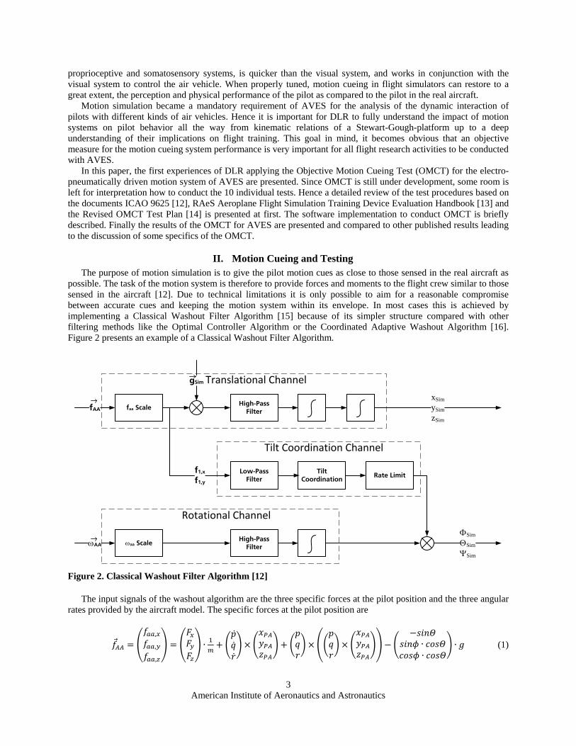
II. Motion Cueing and Testing The purpose of motion simulation is to give the pilot motion cues as close to those sensed in the real aircraft as
possible. The task of the motion system is therefore to provide forces and moments to the flight crew similar to those sensed in the aircraft [12]. Due to technical limitations it is only possible to aim for a reasonable compromise between accurate cues and keeping the motion system within its envelope. In most cases this is achieved by implementing a Classical Washout Filter Algorithm [15] because of its simpler structure compared with other filtering methods like the Optimal Controller Algorithm or the Coordinated Adaptive Washout Algorithm [16]. Figure 2 presents an example of a Classical Washout Filter Algorithm.
faa Scale
ωaa Scale
High-Pass Filter
Low-Pass Filter
High-Pass Filter
Tilt Coordination
Rate Limit
fAA
ωAA
xSimySimzSim
f1,x
f1,y
gSim
ΦSimΘSim
ΨSim
Translational Channel
Tilt Coordination Channel
Rotational Channel
Figure 2. Classical Washout Filter Algorithm [12]
The input signals of the washout algorithm are the three specific forces at the pilot position and the three angular rates provided by the aircraft model. The specific forces at the pilot position are
𝑓𝐴𝐴 = �𝑓𝑎𝑎,𝑥𝑓𝑎𝑎,𝑦𝑓𝑎𝑎,𝑧
� = �𝐹𝑥𝐹𝑦𝐹𝑧� ∙ 1
𝑚+ �
�̇��̇��̇�� × �
𝑥𝑃𝐴𝑦𝑃𝐴𝑧𝑃𝐴
� + �𝑝𝑞𝑟� × ��
𝑝𝑞𝑟� × �
𝑥𝑃𝐴𝑦𝑃𝐴𝑧𝑃𝐴
�� − �−𝑠𝑖𝑛𝛩
𝑠𝑖𝑛𝜙 ∙ 𝑐𝑜𝑠𝛩𝑐𝑜𝑠𝜙 ∙ 𝑐𝑜𝑠𝛩
� ∙ 𝑔 (1)

American Institute of Aeronautics and Astronautics
4
The vector
𝑅�⃗ 𝑃𝐴 = �𝑥𝑃𝐴𝑦𝑃𝐴𝑧𝑃𝐴
� (2)
represents the position vector of the pilot seat with respect to the aircraft center of gravity. The force vector
�⃗� = �𝐹𝑥𝐹𝑦𝐹𝑧� (3)
includes all forces (aerodynamics, landing gear, propulsion) in the body-fixed system and acts on the aircraft’s center of gravity. The three angular rates to be fed into the washout algorithm are the body-fixed roll, pitch and yaw rates of the aircraft model:
𝜔��⃗ 𝐴𝐴 = �𝑝𝑞𝑟� (4)
The main idea of the Classic Washout Filter Algorithm is to let the high-frequency parts of all signals pass. To ensure that acceleration signals do not force the motion system to touch its technical limits the input signals are limited and scaled. After subsequent integration of angular rates and specific forces the platform position is gained as output signal of the cueing algorithm. It should be noted that in the translational channel the gravity vector
�⃗�𝑆𝑖𝑚 = �−𝑠𝑖𝑛𝛩𝑆𝑖𝑚
𝑠𝑖𝑛𝜙𝑆𝑖𝑚 ∙ 𝑐𝑜𝑠𝛩𝑆𝑖𝑚𝑐𝑜𝑠𝜙𝑆𝑖𝑚 ∙ 𝑐𝑜𝑠𝛩𝑆𝑖𝑚
� ∙ 𝑔 (5)
has to be subtracted from the scaled specific force input vector. The tilt coordination channel provides long-lasting specific forces in surge and sway direction sensed by the pilot.
Several constraints prevent the filter transferring the aircraft model accelerations and rates, respectively, to the simulator movement. The first constraint is given by the fact that a motion simulator’s low-frequency specific force is limited to 1 g. The fact that any additional acceleration drives the motion base towards the end of the envelope and therefore has to be stopped at some point impedes any long lasting additional signal. The tilt coordination provides an alternative but is limited, too. Turning the motion base too fast increases the risk of dizziness of the pilot caused by rotational movements. This may lead to disorientation and the tendency to motion sickness. Therefore the angular rates must be limited resulting in a difference between specific forces cued in an aircraft and a corresponding simulator. The trade-off to be found is therefore framed by technical and perceptional limits.
Today the cueing part of the motion system is optimized by subjective tests performed by pilots on the basis of procedures defined by the operator. This inevitably leads to several problems depending on the person evaluating the performance of the simulator. Some influencing parameters are
• pilot’s state of health • history of tests performed previously • ambiguity in identifying the source of error in cues (e.g. “tuning the model”)
All those points indicate that the results of the subjective tests are highly dependent on the person performing the
test and his or her ability to understand and review perceived impressions. In order to get rid of the subjective character of motion tuning the so called Objective Motion Cueing Test (OMCT) has been developed. The OMCT includes the advantages of objective test methods by introducing well defined procedures that take the motion cueing algorithm into account.

American Institute of Aeronautics and Astronautics
5
III. Objective Motion Cueing Test (OMCT) The OMCT has been initially published in 2009 in the ICAO 9625 document [12]. Since the ICAO 9625
working group approved this standard some other documents with definitions of the OMCT were published. In this section the following sources of OMCT definitions are used
• ICAO 9625, 2009 [12] • RAeS Handbook, Ed. 4, 2009 [13] • RAeS Revised OMCT Test Plan, Rev. Jan. 2014 [14]
Some publications are available that report application of the OMCT to different simulators [17], [18] and [19].
A. Test Description OMCT consists of ten tests, all of them to be conducted at 12 frequencies representing sinusoidal input signals to
the motion washout algorithm. The frequency response of each degree of freedom (DOF) has to be determined. Those ten tests represent the most important relations between input and response of a motion system. This leads to six tests evaluating the system behavior of the six rigid-body degrees of freedom, plus four tests aiming at the evaluation of coupling: surge response due to pitch input, pitch response due to surge input, sway response due to roll input, and roll response due to sway input. Table 1 presents those ten tests according to the different references. The wording is directly taken from the three documents.
Test No.
ICAO 9625, 2009 RAeS Handbook, Ed. 4, 2009 Test 3 E(1), Rev. Jan. 2014
1 FSTD pitch response to aircraft pitch input
FSTD pitch response to aeroplane pitch input
FSTD pitch response to aeroplane pitch input
2 FSTD surge specific force response due to aircraft pitch
input
FSTD surge acceleration response due to aeroplane pitch
input
FSTD surge acceleration response due to aeroplane pitch
acceleration input 3 FSTD roll response to aircraft
roll input FSTD roll response to aeroplane
roll input FSTD roll response to aeroplane
roll input 4 FSTD sway specific force
response due to aircraft roll input
FSTD sway specific force response to aeroplane roll input
FSTD sway specific force response due to aeroplane roll
input 5 FSTD yaw response to aircraft
yaw input FSTD yaw response to aeroplane yaw input
FSTD yaw response to aeroplane yaw input
6 FSTD surge specific force response due to aircraft surge
input
FSTD surge response to aeroplane surge input
FSTD surge specific force response to aeroplane surge
input 7 FSTD pitch rate and pitch
acceleration response to aircraft surge input
FSTD pitch response to aeroplane surge input
FSTD pitch attittude to aeroplane surge input
8 FSTD sway specific force response due to aircraft sway
input
FSTD sway response to aeroplane sway input
FSTD sway specific force response to aeroplane sway
input 9 FSTD roll rate and roll4
acceleration response to aircraft sway input
FSTD roll response to aeroplane sway input
FSTD roll attitude response to aeroplane sway input
10 FSTD heave specific force response due to aircraft heave
input
FSTD heave response to aeroplane heave input
FSTD heave response to aeroplane heave input
Table 1. OMCT description according to three different sources (wording directly taken from the references, changes between versions in bold font)
4 The actual ICAO 9625 test description reads „roll rate and pitch acceleration response“ which does not seem to be reasonable within this context

American Institute of Aeronautics and Astronautics
6
It appears that besides different wording (aircraft instead of aeroplane …) the descriptions of the tests in the three
references are quite the same. Looking more into detail the following differences are found:
1. ICAO 9625 to RAeS Handbook Concerning the content, tests no. 1 to 5 show no significant differences except in test no. 2 where the specific
force is replaced by surge acceleration. Tests no. 7 and 9 in the RAeS Handbook take a look at the response to both velocities and accelerations of rotational input signals. With respect to test no. 10 a specific force for heave may be seen as the same as heave response due to the fact that no rotational cross-coupled degree of freedom for this axis exists. The main differences are found in tests no. 6 and 8. Both tests are defined by ICAO 9625 to evaluate the specific force response of a translational input signal. The RAeS Handbook on the other side investigates the linear response to a translational input signal. The acceleration cued due to tilt coordination is not included. 2. RAeS Handbook to Latest OMCT Test Plan
The revised OMCT Test Plan [14] shows some differences to published test 3-E(1) in the RAeS Handbook because OMCT is still under development. The revision reflects the experience of several simulator operators performing the test. Major changes are found in tests no. 6, 8 and 9. The output signals of tests no. 6 and 8 are given more precisely in the description though the output signals themselves didn’t change. In tests no. 7 and 9 the output signals to be observed have been changed to roll and pitch attitude instead of roll and pitch response. Both angular response signals are defined corresponding to the input signal by the test plan. Therefore, at AVES angular accelerations have to be observed. The reason may be that the roll attitude will cause a specific force at the pilot reference point.
The aim of tests no. 7 and 9 is to show the response to a translational input signal generated by the tilt coordination channel. The output signal is assumed to show a low-pass behavior in contrast to tests no. 2 and 4. Some further differences can be found between ICAO 9625, RAeS Handbook and revised test plan looking at the test descriptions.
B. Signal Definition The core of OMCT is to determine the frequency response of the complete motion cueing system for all six DOF
plus four coupled ones resulting from tilt coordination. The definitions of all input signals are given in [12], [13] and [14].
The main difference with respect to input signals between the original ICAO 9625 document and the RAeS Handbook is found in tests no. 1 and 2. In both tests it is assumed that any variation of the aircraft pitch attitude will lead to a change of the specific force in surge direction. As a consequence, not only the rotational channel of the washout algorithm but also the translational channel is exposed to an input signal. The tilt coordination channel as well as the translational channel is therefore affected by this test, Figure 3.
Low-Pass Filter
High-Pass FilterΘ
fAA,x = g sinΘ arcsin(fx/g)
+ Θsim
Motion Cueing Algorithm
ΘΘ
Figure 3. New input signal definition for tests no. 1 and 2 given by [14]: specific force in surge direction due to pitch angle (simplified motion cueing algorithm)

American Institute of Aeronautics and Astronautics
7
Please note that �̈� and �̇� are assumed to be equal to �̇� and 𝑞. Depending on the pitch angle a specific force in
surge direction given by
𝑓𝐴𝐴,𝑥(𝛩) = 𝑔 ∙ 𝑠𝑖𝑛(𝛩) (6)
has to be fed to the washout algorithm. This changed input signal is due to the fact that during typical operation of a transport aircraft, a pitch angle usually leads to a specific force felt by the pilot. This is why it is reasonable to feed the specific force fAA,x(Θ) as additional input signal (dependent on the pitch angle!) into the motion cueing system.
It should be noted that a similar behavior is not considered for roll input because in the given test case the aircraft is assumed to perform a coordinated turn without any specific side force to occur. However, this is not the case for steady-state sideslips. A decrab maneuver for example is not well represented.
C. Motion Cueing Fidelity Criteria The latest version of test 3-E(1) [14] introduces criteria for the successful execution of OMCT. Those criteria are
based on a study [18] covering the results of OMCT performed in ten flight simulators. Boundaries are defined by calculating the mean value of the results plus/minus two times the standard deviation. This straightforward approach leads to a definition of simulation quality as a function of empirically obtained results of subjectively tuned motion systems. The boundaries found may be seen as a strong indication whether a set of washout parameters leads to an acceptable motion perception or not.
Figure 4 presents the fidelity criterion for test no. 1 (FSTD pitch response to aircraft pitch input) according to [18]. Obviously there is one outlier which is probably due to a different test execution. The results of our tests (cf. sec. V) showed that using just the pitch input gave results similar to the outlier case. All the other tests considered the additional specific force in surge direction. Note that the mean value (solid grey line) and the boundaries (dash-dotted lines) include the outlier.
Figure 4. Bode plots for aircraft pitch rotation to simulator pitch rotation Test 1 [18]. Grey Lines indicate the mean value and ±2 times the standard deviation
IV. Application of the OMCT to AVES
A. AVES Washout Algorithm AVES is equipped with an electro-pneumatic motion base of type MOOG MB-EP-6DOF/60/14000KG. The
system is controlled by a proprietary motion control computer running the MOOG Motion Cueing Model. As a part

American Institute of Aeronautics and Astronautics
8
of this model the motion drive algorithm consists of a Washout Filter Algorithm complemented by two vehicle attitude channels and an advanced adaptive algorithm to ensure the motion platform stays within its envelope space without disturbing the pilot perception more than inevitable. For the presented results it is assumed that the setting of the washout algorithm is able to handle the input signals in a way that the adaptive washout does not need to intervene. This assumption is most likely true due to the fact that the amplitudes and the frequencies do not force the system to touch any technical limitations. As a consequence a Classical Washout Filter Algorithm may be assumed to discuss the following results.
The main influencing variables of the motion system response in general are both the motion cueing algorithm and the motion system hardware including the actuator control mechanisms. Due to their natural frequencies the influence of the hardware and actuator controllers will become relevant at higher frequencies. It is expected that at the input signal frequencies according to the OMCT test plan, the influence of the hardware on the output signal is very small, if noticeable at all. The washout algorithm has far more impact. For AVES the washout algorithm parameters were determined by subjective tuning of the motion system employing three A320 pilots. DLR’s generic A320 simulation model was used for the tuning and the 3-days-session was supported by MOOG staff.
B. AVES OMCT Test Architecture AVES has a software architecture that is based on a centralized control and distributed computation philosophy.
The nodes can be modified, added or deleted easily [9]. For executing the test, a dedicated software framework has been developed which provides the motion system with the required data interfaces so that it can be tested without running the other subsystems.
The AVES test system manages all the interfaces of the motion system. It generates test signals, sends them to the motion system and besides test management tasks like starting, pausing and halting test execution, it also records all the test data.
The AVES test system was developed using DLR’s real-time simulation framework 2Simulate [20] and executes on the QNX real-time operating system, thus determinism is guaranteed for signal generation and communication. The test management, the signal generator, the motion system and the data recording tasks were synchronized and executed every 10 ms. There is a User Datagram Protocol (UDP) communication between the motion system and the AVES test system over an Ethernet network that is optimized for low latency. Thus OMCT signals are sent to and the state of the motion system is received from the Motion Control Computer in a deterministic frame time of 10 ms with minimal undesired deviation from true periodicity.
C. OMCT Data Post-Processing The states of the motion system (position and velocity) complemented by the acceleration of the moving
platform at the pilot position are obtained by observing the lengths, velocities and accelerations of the actuators. Given the position, the velocity and acceleration of the platform can be calculated by using kinematic relations presented in [21]. With the velocity and acceleration known the position at the next time step can be estimated. This position is used for an input signal to the iteration algorithm to find the precise position out of the actuator lengths according to [22]
ICAO 9625 gives an example of how input and output data may be analyzed in the time domain to obtain the frequency domain results. Unfortunately, the accuracy of the data resulting from OMCT is usually much less than presented in this example. Due to the very small signal-to-noise ratio at low frequencies (due to the high-pass filter characteristics) the determination of the extreme values according to the ICAO example is imprecise. Instead, a Fourier analysis is used here for a frequency domain examination of the output signal. Again, ref. [21] presents an algorithm to apply a Fourier analysis as well as an example how to implement it.
V. Results of AVES OMCT In this chapter some results of the first OMCT applied to AVES based on the ICAO 9625 document [12] are presented and discussed. The results of tests 1, 5 and 6 are selected as examples.
A. Presentation and Discussion of the Results 1. Test No. 1 (FSTD pitch response to aircraft pitch input)
According to the ICAO 9625 document the aim of the test no. 1 is to show the pitch response due to an aircraft pitch input. The pitch input signal requested by the AVES motion system is aircraft pitch acceleration. The output signal is the simulator pitch acceleration.

American Institute of Aeronautics and Astronautics
9
𝐹𝑡𝑒𝑠𝑡,1(𝑗𝜔) = �̈�𝑆𝑖𝑚(𝑗𝜔)�̇�(𝑗𝜔)
(7)
Figure 5. Results of AVES OMCT Test No. 1 (FSTD pitch response to aircraft pitch input) The modulus5 is very small for low frequencies and the phase angle is above 200°. It should be noted that in this
frequency regime the input signal amplitude is defined to be small, too. E.g. at the first frequency of 0.0159 Hz the amplitude is defined to be 0.06 °/s2. A modulus of less than 10-4 means that the corresponding output signal amplitude is less than 0.000006 °/s2 that hardly may be measured accurately. As consequence, during this test the simulator is almost not moving at input frequencies below 0.1 Hz and therefore, the results at low frequencies are unreliable. With increasing frequency the modulus is growing and the phase angle is falling. This is an obvious result since only the rotational channel of the washout algorithm is activated which is a high-pass filter. A high-pass filter typically shows this kind of frequency response (falling phase and rising modulus with increasing frequency).
The very high phase angle above 200° below 0.1 Hz confirms that a high-pass filter of third order is implemented in the MOOG washout algorithm. A generic third-order high-pass filter with the following transfer function
𝑔𝐻𝑃 = 𝑠3
𝑠3+5∙𝑠2+11∙𝑠+4.5 (8)
shows a quite similar frequency response (Figure 6).
5 The term „modulus“ is used for „amplitude gain“ due to compatibility reasons.

American Institute of Aeronautics and Astronautics
10
Figure 6. Frequency response of a third-order high-pass filter
This demonstrates that the OMCT results of AVES are plausible. The differences to the results presented in [17] are explainable because no specific force has been applied during AVES OMCT and hence the test result is determined by the third-order high-pass filter of the rotational channel only.
By smart design of the low-pass filter in the tilt coordination channel (Figure 3) the frequency response of the cueing system can be designed such that the modulus is almost 1 and the phase almost 0° for the entire frequency range of the OMCT leading to the results presented in [18].
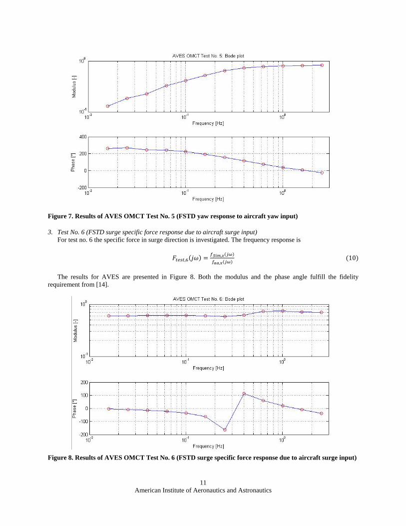
2. Test No. 5 (FSTD yaw response to aircraft yaw input)
Test no. 5 is according to ICAO 9625 quite similar to test no. 1. The response of the simulator in yaw due to a yaw input signal is presented. The frequency response is defined as follows:
𝐹𝑡𝑒𝑠𝑡,5(𝑗𝜔) = �̈�𝑆𝑖𝑚(𝑗𝜔)�̇�(𝑗𝜔)
(9)
Figure 7 presents the results of test no. 5 for AVES. The measured behavior indicates that all, the test and data acquisition methods as well as the data post-processing are done in a way leading to comparable results with respect to [18]. Just like in test no. 1 the input signal is filtered by the high-pass filter of the rotational path of the motion drive algorithm only. This leads to the known Bode plot of a high-pass filtered signal. The calculated modulus is almost within the boundaries given by [14]. The phase is found outside with a lead of 30°-50° for all frequencies except those higher than 1 Hz. This result will be subject to further research. On the one hand the appropriateness of the given boundaries with respect to motion fidelity is to be investigated further. On the other hand the question of how to tune motion cueing settings for dedicated tasks is not answered.
American Institute of Aeronautics and Astronautics
11
Figure 7. Results of AVES OMCT Test No. 5 (FSTD yaw response to aircraft yaw input)
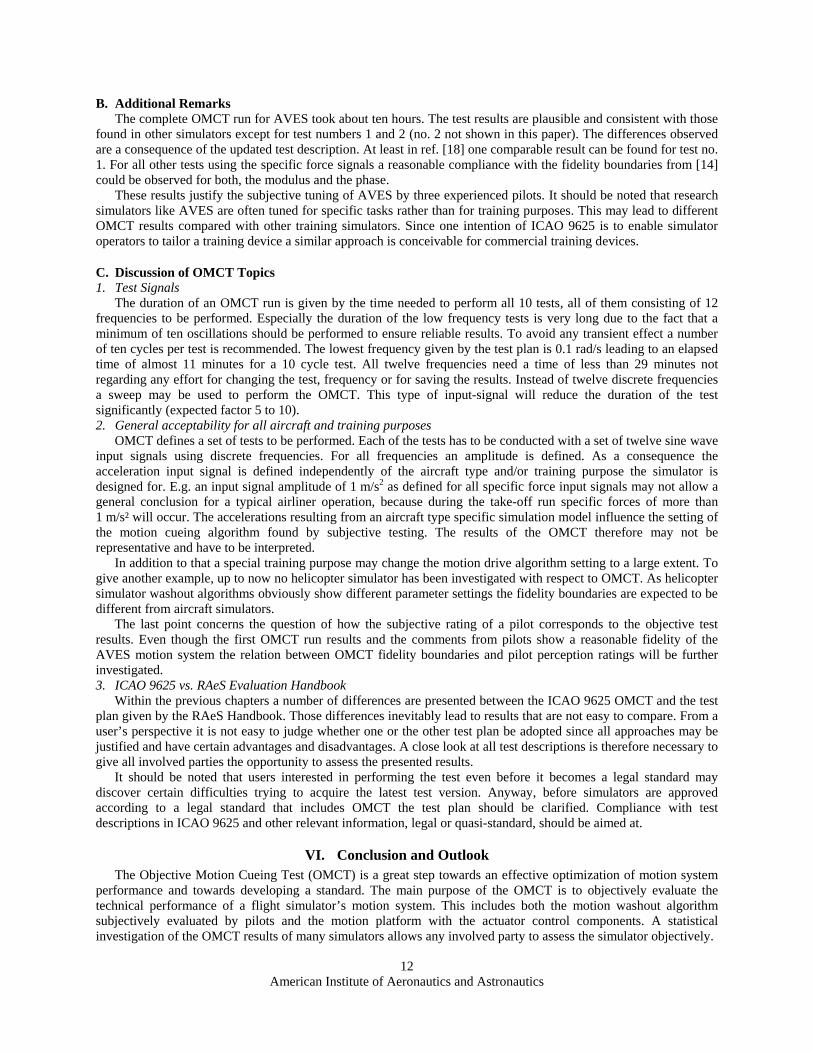
3. Test No. 6 (FSTD surge specific force response due to aircraft surge input)
For test no. 6 the specific force in surge direction is investigated. The frequency response is
𝐹𝑡𝑒𝑠𝑡,6(𝑗𝜔) = 𝑓𝑆𝑖𝑚,𝑥(𝑗𝜔)𝑓𝑎𝑎,𝑥(𝑗𝜔)
(10)
The results for AVES are presented in Figure 8. Both the modulus and the phase angle fulfill the fidelity requirement from [14].
Figure 8. Results of AVES OMCT Test No. 6 (FSTD surge specific force response due to aircraft surge input)
American Institute of Aeronautics and Astronautics
12
B. Additional Remarks The complete OMCT run for AVES took about ten hours. The test results are plausible and consistent with those
found in other simulators except for test numbers 1 and 2 (no. 2 not shown in this paper). The differences observed are a consequence of the updated test description. At least in ref. [18] one comparable result can be found for test no. 1. For all other tests using the specific force signals a reasonable compliance with the fidelity boundaries from [14] could be observed for both, the modulus and the phase.
These results justify the subjective tuning of AVES by three experienced pilots. It should be noted that research simulators like AVES are often tuned for specific tasks rather than for training purposes. This may lead to different OMCT results compared with other training simulators. Since one intention of ICAO 9625 is to enable simulator operators to tailor a training device a similar approach is conceivable for commercial training devices.
C. Discussion of OMCT Topics 1. Test Signals
The duration of an OMCT run is given by the time needed to perform all 10 tests, all of them consisting of 12 frequencies to be performed. Especially the duration of the low frequency tests is very long due to the fact that a minimum of ten oscillations should be performed to ensure reliable results. To avoid any transient effect a number of ten cycles per test is recommended. The lowest frequency given by the test plan is 0.1 rad/s leading to an elapsed time of almost 11 minutes for a 10 cycle test. All twelve frequencies need a time of less than 29 minutes not regarding any effort for changing the test, frequency or for saving the results. Instead of twelve discrete frequencies a sweep may be used to perform the OMCT. This type of input-signal will reduce the duration of the test significantly (expected factor 5 to 10). 2. General acceptability for all aircraft and training purposes
OMCT defines a set of tests to be performed. Each of the tests has to be conducted with a set of twelve sine wave input signals using discrete frequencies. For all frequencies an amplitude is defined. As a consequence the acceleration input signal is defined independently of the aircraft type and/or training purpose the simulator is designed for. E.g. an input signal amplitude of 1 m/s2 as defined for all specific force input signals may not allow a general conclusion for a typical airliner operation, because during the take-off run specific forces of more than 1 m/s² will occur. The accelerations resulting from an aircraft type specific simulation model influence the setting of the motion cueing algorithm found by subjective testing. The results of the OMCT therefore may not be representative and have to be interpreted.
In addition to that a special training purpose may change the motion drive algorithm setting to a large extent. To give another example, up to now no helicopter simulator has been investigated with respect to OMCT. As helicopter simulator washout algorithms obviously show different parameter settings the fidelity boundaries are expected to be different from aircraft simulators.
The last point concerns the question of how the subjective rating of a pilot corresponds to the objective test results. Even though the first OMCT run results and the comments from pilots show a reasonable fidelity of the AVES motion system the relation between OMCT fidelity boundaries and pilot perception ratings will be further investigated. 3. ICAO 9625 vs. RAeS Evaluation Handbook
Within the previous chapters a number of differences are presented between the ICAO 9625 OMCT and the test plan given by the RAeS Handbook. Those differences inevitably lead to results that are not easy to compare. From a user’s perspective it is not easy to judge whether one or the other test plan be adopted since all approaches may be justified and have certain advantages and disadvantages. A close look at all test descriptions is therefore necessary to give all involved parties the opportunity to assess the presented results.
It should be noted that users interested in performing the test even before it becomes a legal standard may discover certain difficulties trying to acquire the latest test version. Anyway, before simulators are approved according to a legal standard that includes OMCT the test plan should be clarified. Compliance with test descriptions in ICAO 9625 and other relevant information, legal or quasi-standard, should be aimed at.
VI. Conclusion and Outlook The Objective Motion Cueing Test (OMCT) is a great step towards an effective optimization of motion system
performance and towards developing a standard. The main purpose of the OMCT is to objectively evaluate the technical performance of a flight simulator’s motion system. This includes both the motion washout algorithm subjectively evaluated by pilots and the motion platform with the actuator control components. A statistical investigation of the OMCT results of many simulators allows any involved party to assess the simulator objectively.

American Institute of Aeronautics and Astronautics
13
Based on DLR’s first experiences applying the OMCT some topics need to be investigated: • Using frequency sweeps instead of discrete sine signals in order to reduce the test time. • Identifying how subjective tuning for particular tasks effects the objective frequency response ratings of
OMCT. • Checking the fidelity boundaries by a study using pilot ratings to correlate objective and subjective data. • Application to platforms with different characteristics, like helicopters. • Finalizing the formal test definition with respect to input signal specification. • Checking input amplitude dependency of the motion system.
DLR will continue motion cueing research activities that will investigate the above topics on AVES.
Acknowledgments The authors would like to thank Olaf Stroosma from Delft University of Technology, Ruud Hosman, President
of AMS Consult, and Sunjoo Advani, President of IDT, for their kind support while executing and discussing OMCT for AVES.
References [1] D. Allerton, “The Design of a Real-Time Engineering Flight Simulator for the Rapid Prototyping of Avionics
Systems and Flight Control Systems,” Transactions of the Institute of Measurement and Control, vol. 2/3, no. 21, pp. 51-62, 1999.
[2] P. Saager, “Real-Time Hardware-in-the-Loop Simulation for 'ATTAS' and 'ATTHeS' Advanced Technology Flight Test Vehicles,” in AGARD Guidance and Control Panel, 50th Symposium, Izmir, Turkey, 1990.
[3] S. Klaes, “ATTAS Ground Based System Simulator -An Update-,” in AIAA Modeling and Simulation Technologies Conference and Exhibit, Denver, CO, 2000.
[4] B. Sullivan and P. Soukup, “The NASA 747-400 Flight Simulator: A Natonal Resource for Aviation Safety Research,” in AIAA Flight Simulation Technologies Conference, San Diego, CA, 1996.
[5] R. Smith, “A Description of the Cockpit Motion Facility and the Research Flight Deck Simulator,” in AIAA Modeling and Simulation Technologies Conference and Exhibit, Denver, CO, 2000.
[6] M. White and G. Padfield, “The Use of Flight Simulation for Research and Teaching in Academia,” in AIAA Atmospheric Flight Mechanics Conference and Exhibit, Keystone, CO, 2006.
[7] B. L. Aponso, S. D. Beard and J. A. Schroeder, “The NASA Vertical Motion Simulator: A Facility Engineered for Realism,” RAeS Spring Flight Simulation Conference, London, UK, 2009.
[8] O. Stroosma, R. van Paassen and M. Mulder, “Using the Simona Research Simulator for Human-Machine Interaction Research,” AIAA Modeling and Simulation Technologies Conference and Exhibit, Austin, TX, 2003.
[9] H. Duda, T. Gerlach, S. Advani and M. Potter, “Design of the DLR AVES Research Flight Simulator,” in AIAA Modeling and Simulation Technologies (MST) Conference, Boston, MA, 2013.
[10] J. Bürki-Cohen, N. N. Soja and T. Longridge, “Simulator Platform Motion - The Need Revisited,” The International Journal of Aviation Psychology, vol. 8, no. 3, pp. 293-317, 1998.
[11] P. R. Grant, B. Yam, R. Hosman and J. A. Schroeder, “Effect of Simulator Motion on Pilot Behavior and Perception,” Journal of Aircraft, vol. 43, no. 6, pp. 1914-1924, 2006.
[12] International Civil Aviation Organization, “Manual of Criteria for the Qualification of Flight Simulation Training Devices,” 3 ed., vol. I, ICAO, Montreal, Canada, 2009.
[13] Royal Aeronautical Society, “Aeroplane Flight Simulation Training Device Evaluation Handbook,” 4 ed., vol. I, London, UK, 2009.
[14] Royal Aeronautical Society, “Revised OMCT Test Plan,” London, UK, 2014. [15] L. D. Reid and M. A. Nahon, “Flight Simulation Motion-Base Drive Algorithms: Part I - Developing and
Testing the Equations,” UTIAS Report No. 296, Toronto, Canada, 1985. [16] M. A. Nahon and L. D. Reid, “Simulator Motion-Drive Algorithms: A Designer's Perspective,” J. Guidance,
American Institute of Aeronautics and Astronautics
14
vol. 13, no. 2, pp. 356-362, 1990. [17] O. Stroosma, M. M. van Paassen, M. Mulder, R. J. A. W. Hosman and S. K. Advani, “Applying the Objective
Motion Cueing Test to a Classical Washout Algorithm,” in AIAA Modeling and Simulation Technologies (MST) Conference, Boston, MA, 2013.
[18] R. J. Hosman and S. K. Advani, “Are Criteria for Motion Cueing and Time Delays Possible? Part 2,” AIAA Modeling and Simulation Technologies (MST) Conference, Boston, MA, 19-22 August 2013.
[19] M. Roza, R. Meiland and J. Field, “Experiences and Perspectives in Using OMCT for Testing and Optimizing Motion Drive Algorithms,” AIAA Modeling and Simulation Technologies (MST) Conference, Boston, MA, 19-22 August 2013.
[20] J. Gotschlich, T. Gerlach and U. Durak, “2Simulate: A Distributed Real-Time Simulation Framework,” in ASIM STS/GMMS Workshop 2014, Reutlingen, Germany, 2014.
[21] C. Seehof, “First Execution and Review of the Objective Motion Cueing Test at AVES According to ICAO 9625,” DLR IB 111-2014/19, Braunschweig, Germany, 2014.
[22] J. E. Dieudonne, R. V. Parrish and R. E. Bardusch, “An Actuator Extension Transformation for a Motion Simulator and an Inverse Transformation Applying Newton-Raphson's Method,” NASA TN D-7067, Washington D. C., 1972.