design, modeling and simulation of a three-layers...
TRANSCRIPT
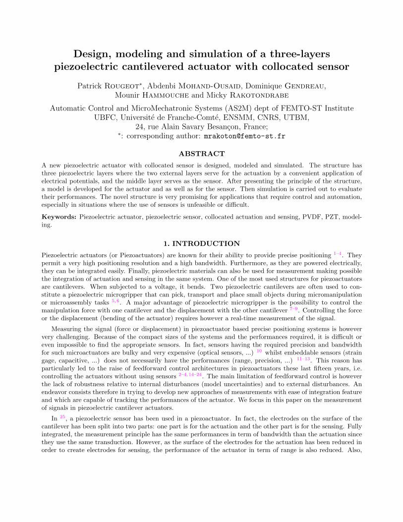
Design, modeling and simulation of a three-layerspiezoelectric cantilevered actuator with collocated sensor
Patrick Rougeot∗, Abdenbi Mohand-Ousaid, Dominique Gendreau,Mounir Hammouche and Micky Rakotondrabe
Automatic Control and MicroMechatronic Systems (AS2M) dept of FEMTO-ST InstituteUBFC, Universite de Franche-Comte, ENSMM, CNRS, UTBM,
24, rue Alain Savary Besancon, France;∗: corresponding author: [email protected]
ABSTRACT
A new piezoelectric actuator with collocated sensor is designed, modeled and simulated. The structure hasthree piezoelectric layers where the two external layers serve for the actuation by a convenient application ofelectrical potentials, and the middle layer serves as the sensor. After presenting the principle of the structure,a model is developed for the actuator and as well as for the sensor. Then simulation is carried out to evaluatetheir performances. The novel structure is very promising for applications that require control and automation,especially in situations where the use of sensors is unfeasible or difficult.
Keywords: Piezoelectric actuator, piezoelectric sensor, collocated actuation and sensing, PVDF, PZT, model-ing.
1. INTRODUCTION
Piezoelectric actuators (or Piezoactuators) are known for their ability to provide precise positioning 1–4. Theypermit a very high positioning resolution and a high bandwidth. Furthermore, as they are powered electrically,they can be integrated easily. Finally, piezoelectric materials can also be used for measurement making possiblethe integration of actuation and sensing in the same system. One of the most used structures for piezoactuatorsare cantilevers. When subjected to a voltage, it bends. Two piezoelectric cantilevers are often used to con-stitute a piezoelectric microgripper that can pick, transport and place small objects during micromanipulationor microassembly tasks 5,6. A major advantage of piezoelectric microgripper is the possibility to control themanipulation force with one cantilever and the displacement with the other cantilever 7–9. Controlling the forceor the displacement (bending of the actuator) requires however a real-time measurement of the signal.
Measuring the signal (force or displacement) in piezoactuator based precise positioning systems is howeververy challenging. Because of the compact sizes of the systems and the performances required, it is difficult oreven impossible to find the appropriate sensors. In fact, sensors having the required precision and bandwidthfor such microactuators are bulky and very expensive (optical sensors, ...) 10 whilst embeddable sensors (straingage, capacitive, ...) does not necessarily have the performances (range, precision, ...) 11–13. This reason hasparticularly led to the raise of feedforward control architectures in piezoactuators these last fifteen years, i.e.controlling the actuators without using sensors 2–4,14–24. The main limitation of feedforward control is howeverthe lack of robustness relative to internal disturbances (model uncertainties) and to external disturbances. Anendeavor consists therefore in trying to develop new approaches of measurements with ease of integration featureand which are capable of tracking the performances of the actuator. We focus in this paper on the measurementof signals in piezoelectric cantilever actuators.
In 25, a piezoelectric sensor has been used in a piezoactuator. In fact, the electrodes on the surface of thecantilever has been split into two parts: one part is for the actuation and the other part is for the sensing. Fullyintegrated, the measurement principle has the same performances in term of bandwidth than the actuation sincethey use the same transduction. However, as the surface of the electrodes for the actuation has been reduced inorder to create electrodes for sensing, the performance of the actuator in term of range is also reduced. Also,

the surface of the electrodes for sensing is too small and provides very small amount of electrical charge makingtricky its exploitation.
Another way to fully integrate a measurement system in a cantilever piezoactuator is to employ the sameelectrodes for actuation and for sensing simultaneously. Called piezoelectric self-sensing, this technique suggestsmore performances in term of actuation (more range of displacement) relative to the previous technique. Fur-thermore, if the self-sensing is appropriately designed, the measurement could be more sensitive. Indeed it offersmore electrical charge than the previous technique for the sensing because of the larger electrodes surface. How-ever, due to the internal leakage of the piezoelectric material, self-sensing is efficient at high frequency making itinitially used for vibrations damping 26–29. Later on, new self-sensing techniques for low frequency and constantdisplacement 30 and for force 31 signals for one degree of freedom (1-DOF) piezoactuator have been proposed.The techniques have later been extended to measure the displacement at low and high frequency 32, and thenthe displacement and the force simultaneously 33, making possible the robust feedback control of the 1-DOFactuator. Finally in 34, a new electrical circuit for self-sensing for 2-DOF piezoactuators has been proposed.Piezoelectric self-sensing permitting to measure the signals at low and at high frequency is not well settled and isstill under research because of the internal leakages, the limited performances of the electrical circuit components(bias current, dielectric absorption...) 35,36 and the couplings between the actuation and sensing electrodes. Theendeavor is focused on the improvement of the electrical circuit as well as on the modeling and on the observerwhich should account for these leakages, limitation and couplings.
Another interesting way to measure the cantilever piezoactuator is to introduce a piezoelectric layer forsensing inside the same cantilever. In this case, the layer for the sensor should have negligible stiffness relative tothe stiffness of the actuator. Polyvinylidene fluoride (PVDF) piezoelectric polymer is a good candidate for suchsensing layer as it has a very high compliance. It has been used to measure the deflection of non-piezoelectriccantilevers 37,38. In this paper, we suggest to use PVDF as measurement of the deflection in a cantileverpiezoelectric actuator. The advantages relative to the measurement in 25 described above is that the electrodessurfaces of the sensing and of the actuation are much larger and thus the sensing sensintivity as well as theactuation performances are much better. Relative to self-sensing techniques, also described above, there are nocouplings between the actuation and the sensing because their electrodes are completely different. This makesthe conditioning (electrical circuit, modeling, observer) easier: the actuation powering is not coupled with thesensing electrical circuit and conditioning. Whilst generalizable into multi-layers cantilever, we focus in thispaper on a three-layers structure that we call actuator with collocated sensor: two external piezoelectric layersare used for the actuation and one middle piezoelectric layer is used for the sensing.
The rest of the paper is organized as follows. In section. 2, we present the principle of the three-layereredactuator with collocated sensor. Section. 3 is devoted to the modeling and the observer derivation that permitsto estimate the displacement and the force. In section. 4, the simulation results are presented. Finally someconclusions and future works are given in Section. 5.
2. PRINCIPLE OF THE THREE-LAYERS ACTUATOR WITH COLLOCATEDSENSOR
2.1 General principle
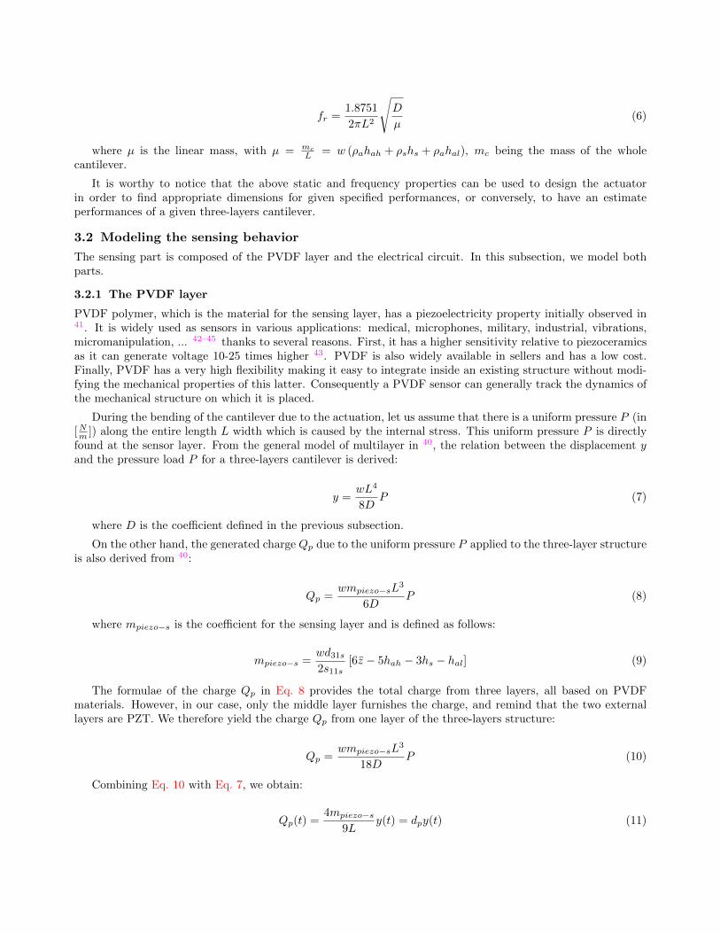
The structure is a cantilever composed of three principal piezoelectric layers (Fig. 1-a). The upper layer aswell as the lower layer serve for the actuation and the middle layer serves for the sensing. In order to avoidinterferences between the electrodes of the sensing layer and the actuation layers, a very thin electrical insulatoris placed between the middle layer and each of the external layers. In fact, this insulator could be an insulatingglue that is used to bond the different layers. The actuation layers should have a stiffness much larger thanthat of the sensing layer. For that, a lead zirconate titanate (PZT) piezoelectric material is suggested for theactuation whilst a PVDF piezoelectric polymer for the sensing. In order to make the study more general, westudy the case where the thickness of the upper actuation layer (denoted hah) is different from the thickness ofthe lower actuation layer (denoted hal) (Fig. 1-b). Fig. 1-c depicts the CAD design of the three-layers structurebefore and after assembly. The cantilever is glued on a support and we assume that the fixation behaves like aclamping. The extremity of the cantilever in a free space above the support is split into three parts such that

we can easily extract the electrodes of the three layers. Let Tab. 1 depict the different geometrical and physicalproperties. In this, we do not consider the glue and will assume that its thickness is negligible relative to hah, tohal and to hs and its stiffness is also negligible relative to those of the three piezoelectric layers. The numericalvalues of the different parameters for the materials are also reported in the table: PZT for the actuation layersand PVDF for the sensing layer. Some of these values will be used for the further simulation. The width, thethicknesses and the length will be varied during the simulation.
support
actuator layer
actuator layer
sensing layer
(a): perspective view (b): side view
(c)
electricalcircuit
observer+
the sensing layer (PVDF)
the actuation layers (PZT) parts for electricalconnections
support
(d)
Figure 1: (a): perspective view. (b): side view. (c): functioning. (d): the CAD design of the three-layersstructure.
The functioning of the actuation is as follows. The two actuation piezoelectric layers (upper and lower) havethe same poling ~p direction, as indicated in Fig. 1-b. Let the internal electrodes of these two layers be the ground.When a positive potential u is applied to the upper electrode of the upper layer, the electric field ~e appearingin this latter is in the same direction than p and consequently it expands. If the same potential u is applied tothe lower electrode of the lower layer, the electric field ~e is in the opposite direction than p and consequentlythis layer contracts. This expansion and contraction of the above and of the lower part of the cantilever resultsin a global bending y of this latter as illustrated in Fig. 1-d. A negative bending of y is therefore obtained byapplying a negative potential u. In the sequel, the voltage u = u[V ] − 0V (potentials difference) will be used.Remind that the expansion and contraction of the layers resulting from the electrical field ~e is thanks to theconverse piezoelectric effect and is quantified by the transverse piezoelectric constant d31.
The functioning of the sensing is as follows. During the bending of the cantilever, the middle layer is subjectedto the same bending y (that we will call displacement) and consequently to internal stress. Due to this stress,
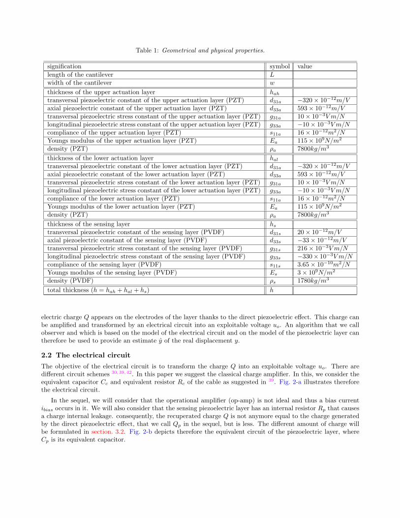
Table 1: Geometrical and physical properties.
signification symbol value
length of the cantilever Lwidth of the cantilever w
thickness of the upper actuation layer hahtransversal piezoelectric constant of the upper actuation layer (PZT) d31a −320 × 10−12m/Vaxial piezoelectric constant of the upper actuation layer (PZT) d33a 593 × 10−12m/Vtransversal piezoelectric stress constant of the upper actuation layer (PZT) g31a 10 × 10−3V m/Nlongitudinal piezoelectric stress constant of the upper actuation layer (PZT) g33a −10 × 10−3V m/Ncompliance of the upper actuation layer (PZT) s11a 16 × 10−12m2/NYoungs modulus of the upper actuation layer (PZT) Ea 115 × 109N/m2
density (PZT) ρa 7800kg/m3
thickness of the lower actuation layer haltransversal piezoelectric constant of the lower actuation layer (PZT) d31a −320 × 10−12m/Vaxial piezoelectric constant of the lower actuation layer (PZT) d33a 593 × 10−12m/Vtransversal piezoelectric stress constant of the lower actuation layer (PZT) g31a 10 × 10−3V m/Nlongitudinal piezoelectric stress constant of the lower actuation layer (PZT) g33a −10 × 10−3V m/Ncompliance of the lower actuation layer (PZT) s11a 16 × 10−12m2/NYoungs modulus of the lower actuation layer (PZT) Ea 115 × 109N/m2
density (PZT) ρa 7800kg/m3
thickness of the sensing layer hstransversal piezoelectric constant of the sensing layer (PVDF) d31s 20 × 10−12m/Vaxial piezoelectric constant of the sensing layer (PVDF) d33s −33 × 10−12m/Vtransversal piezoelectric stress constant of the sensing layer (PVDF) g31s 216 × 10−3V m/Nlongitudinal piezoelectric stress constant of the sensing layer (PVDF) g33s −330× 10−3V m/Ncompliance of the sensing layer (PVDF) s11s 3.65 × 10⁻¹⁰m2/NYoungs modulus of the sensing layer (PVDF) Es 3 × 10⁹N/m2
density (PVDF) ρs 1780kg/m3
total thickness (h = hah + hal + hs) h
electric charge Q appears on the electrodes of the layer thanks to the direct piezoelectric effect. This charge canbe amplified and transformed by an electrical circuit into an exploitable voltage uo. An algorithm that we callobserver and which is based on the model of the electrical circuit and on the model of the piezoelectric layer cantherefore be used to provide an estimate y of the real displacement y.
2.2 The electrical circuit
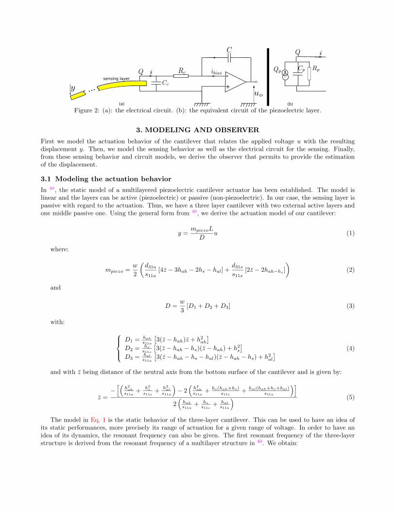
The objective of the electrical circuit is to transform the charge Q into an exploitable voltage uo. There aredifferent circuit schemes 30,39,42. In this paper we suggest the classical charge amplifier. In this, we consider theequivalent capacitor Cc and equivalent resistor Rc of the cable as suggested in 39. Fig. 2-a illustrates thereforethe electrical circuit.
In the sequel, we will consider that the operational amplifier (op-amp) is not ideal and thus a bias currentibias occurs in it. We will also consider that the sensing piezoelectric layer has an internal resistor Rp that causesa charge internal leakage. consequently, the recuperated charge Q is not anymore equal to the charge generatedby the direct piezoelectric effect, that we call Qp in the sequel, but is less. The different amount of charge willbe formulated in section. 3.2. Fig. 2-b depicts therefore the equivalent circuit of the piezoelectric layer, whereCp is its equivalent capacitor.
sensing layer -+...
(a) (b)
Figure 2: (a): the electrical circuit. (b): the equivalent circuit of the piezoelectric layer.
3. MODELING AND OBSERVER
First we model the actuation behavior of the cantilever that relates the applied voltage u with the resultingdisplacement y. Then, we model the sensing behavior as well as the electrical circuit for the sensing. Finally,from these sensing behavior and circuit models, we derive the observer that permits to provide the estimationof the displacement.
3.1 Modeling the actuation behavior
In 40, the static model of a multilayered piezoelectric cantilever actuator has been established. The model islinear and the layers can be active (piezoelectric) or passive (non-piezoelectric). In our case, the sensing layer ispassive with regard to the actuation. Thus, we have a three layer cantilever with two external active layers andone middle passive one. Using the general form from 40, we derive the actuation model of our cantilever:
y =mpiezoL
Du (1)
where:
mpiezo =w
2
(d31as11a
[4z − 3hah − 2hs − hal] +d31ss11s
[2z − 2hah−hs]
)(2)
and
D =w
3[D1 +D2 +D3] (3)
with: D1 = hah
s11a
[3(z − hah)z + h2ah
]D2 = hs
s11s
[3(z − hah − hs)(z − hah) + h2s
]D3 = hal
s11a
[3(z − hah − hs − hal)(z − hah − hs) + h2al
] (4)
and with z being distance of the neutral axis from the bottom surface of the cantilever and is given by:
z =−[(
h2ah
s11a+
h2s
s11s+
h2al
s11a
)− 2
(h2ah
s11a+ hs(hah+hs)
s11s+ hal(hah+hs+hal)
s11a
)]2(
hah
s11a+ hs
s11s+ hal
s11a
) (5)
The model in Eq. 1 is the static behavior of the three-layer cantilever. This can be used to have an idea ofits static performances, more precisely its range of actuation for a given range of voltage. In order to have anidea of its dynamics, the resonant frequency can also be given. The first resonant frequency of the three-layerstructure is derived from the resonant frequency of a multilayer structure in 40. We obtain:
fr =1.8751
2πL2
√D
µ(6)
where µ is the linear mass, with µ = mc
L = w (ρahah + ρshs + ρahal), mc being the mass of the wholecantilever.
It is worthy to notice that the above static and frequency properties can be used to design the actuatorin order to find appropriate dimensions for given specified performances, or conversely, to have an estimateperformances of a given three-layers cantilever.
3.2 Modeling the sensing behavior
The sensing part is composed of the PVDF layer and the electrical circuit. In this subsection, we model bothparts.
3.2.1 The PVDF layer
PVDF polymer, which is the material for the sensing layer, has a piezoelectricity property initially observed in41. It is widely used as sensors in various applications: medical, microphones, military, industrial, vibrations,micromanipulation, ... 42–45 thanks to several reasons. First, it has a higher sensitivity relative to piezoceramicsas it can generate voltage 10-25 times higher 43. PVDF is also widely available in sellers and has a low cost.Finally, PVDF has a very high flexibility making it easy to integrate inside an existing structure without modi-fying the mechanical properties of this latter. Consequently a PVDF sensor can generally track the dynamics ofthe mechanical structure on which it is placed.
During the bending of the cantilever due to the actuation, let us assume that there is a uniform pressure P (in[Nm ]) along the entire length L width which is caused by the internal stress. This uniform pressure P is directlyfound at the sensor layer. From the general model of multilayer in 40, the relation between the displacement yand the pressure load P for a three-layers cantilever is derived:
y =wL4
8DP (7)
where D is the coefficient defined in the previous subsection.
On the other hand, the generated charge Qp due to the uniform pressure P applied to the three-layer structureis also derived from 40:
Qp =wmpiezo−sL
3
6DP (8)
where mpiezo−s is the coefficient for the sensing layer and is defined as follows:
mpiezo−s =wd31s2s11s
[6z − 5hah − 3hs − hal] (9)
The formulae of the charge Qp in Eq. 8 provides the total charge from three layers, all based on PVDFmaterials. However, in our case, only the middle layer furnishes the charge, and remind that the two externallayers are PZT. We therefore yield the charge Qp from one layer of the three-layers structure:
Qp =wmpiezo−sL
3
18DP (10)
Combining Eq. 10 with Eq. 7, we obtain:
Qp(t) =4mpiezo−s
9Ly(t) = dpy(t) (11)
where dp =4mpiezo−s
9L is called displacement-to-charge coefficient. It is also worthy to notice that, because ofthe high flexibility of the PVDF layer, it does not modify (in practice) the behavior of the actuation and it cantrack the dynamics of this latter.
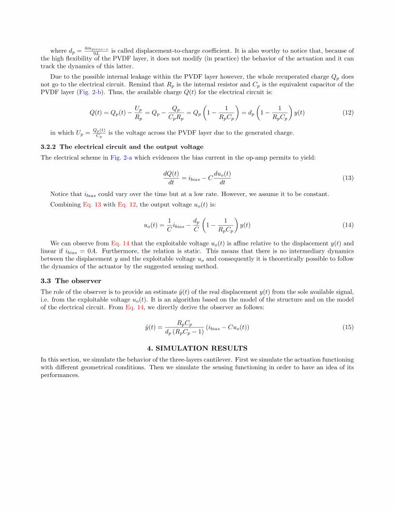
Due to the possible internal leakage within the PVDF layer however, the whole recuperated charge Qp doesnot go to the electrical circuit. Remind that Rp is the internal resistor and Cp is the equivalent capacitor of thePVDF layer (Fig. 2-b). Thus, the available charge Q(t) for the electrical circuit is:
Q(t) = Qp(t) − Up
Rp= Qp −
Qp
CpRp= Qp
(1 − 1
RpCp
)= dp
(1 − 1
RpCp
)y(t) (12)
in which Up =Qp(t)Cp
is the voltage across the PVDF layer due to the generated charge.
3.2.2 The electrical circuit and the output voltage
The electrical scheme in Fig. 2-a which evidences the bias current in the op-amp permits to yield:
dQ(t)
dt= ibias − C
duo(t)
dt(13)
Notice that ibias could vary over the time but at a low rate. However, we assume it to be constant.
Combining Eq. 13 with Eq. 12, the output voltage uo(t) is:
uo(t) =1
Cibias −
dpC
(1 − 1
RpCp
)y(t) (14)
We can observe from Eq. 14 that the exploitable voltage uo(t) is affine relative to the displacement y(t) andlinear if ibias = 0A. Furthermore, the relation is static. This means that there is no intermediary dynamicsbetween the displacement y and the exploitable voltage uo and consequently it is theoretically possible to followthe dynamics of the actuator by the suggested sensing method.
3.3 The observer
The role of the observer is to provide an estimate y(t) of the real displacement y(t) from the sole available signal,i.e. from the exploitable voltage uo(t). It is an algorithm based on the model of the structure and on the modelof the electrical circuit. From Eq. 14, we directly derive the observer as follows:
y(t) =RpCp
dp (RpCp − 1)(ibias − Cuo(t)) (15)
4. SIMULATION RESULTS
In this section, we simulate the behavior of the three-layers cantilever. First we simulate the actuation functioningwith different geometrical conditions. Then we simulate the sensing functioning in order to have an idea of itsperformances.
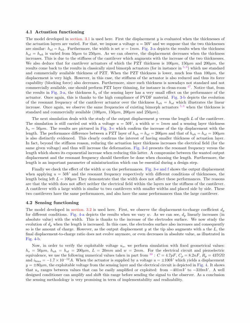
4.1 Actuation functioning
The model developed in section. 3.1 is used here. First the displacement y is evaluated when the thicknesses ofthe actuation layers are varied. For that, we impose a voltage u = 50V and we suppose that the two thicknessesare similar: hal = hah. Furthermore, the width is set w = 1mm. Fig. 3-a depicts the results when the thicknesshal = hah is varied from 50µm to 250µm. As we can observe, the displacement decreases when the thicknessincreases. This is due to the stiffness of the cantilever which augments with the increase of the two thicknesses.We also deduce that for cantilever actuators of which the PZT thickness is 100µm, 150µm and 200µm, theresults come back to the results in classically sized bimorph actuators (for in instance in 5,6) which use standardand commercially available thickness of PZT. When the PZT thickness is lower, much less than 100µm, thedisplacement is very high. However, in this case, the stiffness of the actuator is also reduced and thus its forcecapability (blocking force) also decreases. Furthermore, since such thickness is nowadays not standard and notcommercially available, one should perform PZT layer thinning, for instance in clean-room 47. Notice that, fromthe results in Fig. 3-a, the thickness hs of the sensing layer has a very small effect on the performance of theactuator. Once again, this is thanks to the high compliance of PVDF material. Fig. 3-b depicts the evolutionof the resonant frequency of the cantilever actuator over the thickness hah = hal which illustrates the linearincrease. Once again, we observe the same frequencies of existing bimorph actuators 5,6 when the thickness isstandard and commercially available (100µm, 150µm, 200µm and 250µm).
The next simulation deals with the study of the output displacement y versus the length L of the cantilever.The simulation is still carried out with a voltage u = 50V , a width w = 1mm and a sensing layer thicknesshs = 50µm. The results are pictured in Fig. 3-c which confirm the increase of the tip displacement with thelength. The performance difference between a PZT layer of hah = hal = 200µm and that of hah = hal = 100µmis also distinctly evidenced. This clearly confirms the interest of having smaller thickness of actuation layer.In fact, beyond the stiffness reason, reducing the actuation layer thickness increases the electrical field (for thesame given voltage) and thus will increase the deformation. Fig. 3-d presents the resonant frequency versus thelength which shows its exponential increase when reducing this latter. A compromise between the wanted outputdisplacement and the resonant frequency should therefore be done when choosing the length. Furthermore, thelength is an important parameter of miniaturization which can be essential during a design step.
Finally we check the effect of the width w on the performances. Fig. 3-e and f shows the output displacementwhen applying u = 50V and the resonant frequency respectively with different conditions of thicknesses, thelength being left L = 100µm They demonstrate that the width does not affect these performances. The reasonsare that the width does not affect neither the electrical field within the layers nor the stiffness of the cantilever.A cantilever with a large width is similar to two cantilevers with smaller widths and placed side by side. Thesetwo cantilevers have the same performances, and also have the same performances than the large cantilever.
4.2 Sensing functioning
The model developed in section. 3.2 is used here. First, we observe the displacement-to-charge coefficient dpfor different conditions. Fig. 4-a depicts the results when we vary w. As we can see, dp linearly increases (inabsolute value) with the width. This is thanks to the increase of the electrodes surface. We now study theevolution of dp when the length is increased. In this case, the electrodes surface also increases and consequentlyso is the amount of charge. However, as the output displacement y at the tip also augments with a the L, thefinal displacement-to-charge ratio does not evolve anymore, or even decreases in absolute value, as illustrated inFig. 4-b.
Now, in order to verify the exploitable voltage uo, we perform simulation with fixed geometrical values:hs = 50µm, hah = hal = 200µm, L = 20mm and w = 2mm. For the electrical circuit and piezoelectricequivalence, we use the following numerical values taken in part from 30 : C = 4.7pF , Cp = 8.2nF , Rp = 437GΩand ibias = −1.7× 10⁻¹²A. When the actuator is supplied by a voltage u = ±100V which yields a displacementy = ±80µm, the exploitable voltage from the sensing layer and the electrical circuit is depicted in Fig. 4. It showsthat uo ranges between values that can be easily amplified or exploited: from −401mV to −310mV . A welldesigned conditioner can amplify and shift this range before sending the signal to the observer. As a conclusionthe sensing methodology is very promising in term of implementability and realizability.

5. CONCLUSIONS
This paper presents a piezoelectric actuator with an embedded piezoelectric sensor for micromanipulation andmicroassembly tasks. The whole system has a three-layers cantilever structure. The two external layers whichare based on the PZT material serve for the actuation and the middle layer which is based on the PVDF materialserves for the sensing. An electrical circuit is used to extract the charges from the sensing layer. The actuationbehavior and the sensing functioning, with the electrical circuit, are successively modeled. Then an observer wasderived from the sensing model in order to provide an estimate measure of the actuator displacement. Extensivesimulation is carried out and discussed, and the different results show the significance of the new actuator withcollocated sensors in precise positioning. The results particularly show that the sensing element does not affectthe performances of the actuation and can fully track its performances. Future works include the fabrication ofthe design and the experimental characterizations in order to validate its principle and its model. Future worksalso include the use of methodologies of design such as in 48,49 in order to optimize the structure dimensions andthe performances. These designs are based on control theory tools such as interval techniques .50
Figure 3: Simulation of the actuation behavior.

Figure 4: Simulation of the sensing behavior.
ACKNOWLEDGMENTS
This work is supported by the national ANR-JCJC C-MUMS-project (National young investigator project ANR-12-JS03007.01: Control of Multivariable Piezoelectric Microsystems with Minimization of Sensors). This workis also supported by the LABEX ACTION (ANR-11- LABX-0001-01)..
REFERENCES
[1] J. Agnus, N. Chaillet, C. Clevy, S. Dembele, M. Gauthier, Y. Haddab, G. Laurent, P. Lutz, N. Piat, K.Rabenorosoa, M. Rakotondrabe and B. Tamadazte, “Robotic microassembly and micromanipulation atFEMTO-ST,” Journal of Micro-Bio Robotics, vol. 8, no. 2, pp. 91-106, 2013.
[2] M. Rakotondrabe, Smart materials-based actuators at the micro/nano-scale: characterization, control andapplications, Springer-Verlag, NewYork, 2013.
[3] S. Devasia, E. E. Eleftheriou, R. Moheimani, ”A survey of control issues in nanopositioning”, IEEE Trans-actions on Control Systems Technology, Vol.15, No5, pp.802-823, 2007.
[4] M. Rakotondrabe, ’Piezoelectric systems for precise and high dynamic positioning: design, modeling, esti-mation and control’, HDR halititation thesis, University of Franche-Comte / FEMTO-ST, November 10,2014.
[5] Y. Haddab, N. Chaillet, A. Bourjault, ”A microgripper using smart piezoelectric actuators”, IEEE Interna-tional Conference on Intelligent Robots and Systems, 2000.
[6] J. Agnus, P. Nectoux, N. Chaillet, ”Overview of microgrippers and design of a micromanipulation sta-tion based on a MMOC microgripper”, IEEE International Symposium on Computational Intelligence inRobotics and Automation, 2005.
[7] M. Rakotondrabe and A. Ivan, ’Development and Force/Position Control of a New Hybrid Thermo-Piezoelectric microGripper dedicated to micromanipulation tasks’, IEEE Transactions on Automation Sci-ence and Engineering, 8(4), pp.824-834, 0ctober 2011.
[8] S. Khadraoui, M. Rakotondrabe and P. Lutz, ’Interval force/position modeling and control of a microgrippercomposed of two collaborative piezoelectric actuators and its automation’, International Journal of Control,Automation and Systems, 12(2), Page 358-371, April 2014.
[9] M. Rakotondrabe, C. Clevy and P. Lutz, ’Modelling and robust position/force control of a piezoelectricmicrogripper’, IEEE International Conference on Automation Science and Engineering, Scottsdale AZ USA,2007.
[10] C. Clevy, M. Rakotondrabe and N. Chaillet, ’Signal measurement and estimation techniques issues in themicro/nano world’, edited book, Springer - Verlag, New York, ISBN 978-1-4419-9945-0, August 2011.
[11] F. Arai, A. Kawaji, T. Sugiyama, Y. Onomura, M. Ogawa, T. Fukuda, H. Iwata and K. Itoigawa, ”3dmicromanipulation system under microscope”, IEEE International Symposium on Micromechatronics andHuman Science, 1998.

[12] M. Goldfarb and N. Celanovic, ”A flexure-based gripper for small-scale manipulation”, Robotica, 17, 1999.
[13] Y. Haddab, Q. Chen and P. Lutz, ”Improvement of strain gauges micro-forces measurement using Kalmanoptimal filtering”, Mechatronics, 19(4), 2009.
[14] D. Croft, G. Shed and S. Devasia, ”Creep, hysteresis and vibration compensation for piezoactuators: atomicforce microscopy application”, ASME Journal of Dynamic Systems, Measurement and Control, 2001.
[15] M. Rakotondrabe, C. Clevy and P. Lutz, ’Complete open loop control of hysteretic, creeped and oscillatingpiezoelectric cantilever’, IEEE Transactions on Automation Science and Engineering, Vol.7(3), pp:440-450,July 2010.
[16] D. Habineza, M. Rakotondrabe and Y. Le Gorrec, ’ Simultaneous Suppression of Badly-Damped Vibrationsand Cross-couplings in a 2-DoF piezoelectric actuator, by using Feedforward Standard H-inf approach’, SPIESensing Technology+Applications; Sensors for Next Generation Robots conference , 9494-29, BaltimoreMaryland USA, April 2015.
[17] G. Schitter, A. Stemmer, F. Allgower, ”Robust 2 DOF-control of a piezoelectric tube scanner for high speedatomic force microscopy”, American Control Conference, pp. 3720-3725, June 2003.
[18] M. Al Janaideh, M. Rakotondrabe and O. Al Janaideh, ’Further Results on Hysteresis Compensation ofSmart Micro-Positioning Systems with the Inverse Prandtl-Ishlinskii Compensator’, IEEE Transactions onControl Systems Technology, doi:10.1109/TCST.2015.2446959, 2016.
[19] O. Aljanaideh, D. Habineza, M. Rakotondrabe and M. Al Janaideh, ’Experimental comparison of rate-dependent hysteresis models in characterizing and compensating hysteresis of piezoelectric tube actuators’,Elsevier Physica B: Condensed Matter, doi:10.1016/j.physb.2015.10.021, oct 2015.
[20] W. T. Ang, P. K. Kholsa and C. N. Riviere, Feedforward controller with inverse rate-dependent model forpiezoelectric actuators in trajectory-tracking applications, IEEE/ASME Transactions on Mecha- tronics,Vol.12(2), pages 134-142, April 2007.
[21] Y. Al Hamidi and M. Rakotondrabe, ’Multi-Mode Vibration Suppression in 2-DOF Piezoelectric SystemsUsing Zero Placement Input Shaping Technique’, SPIE Sensing Technology+Applications; Sensors for NextGeneration Robots conference , 9494-27, Baltimore Maryland USA, April 2015.
[22] D. Habineza, M. Rakotondrabe and Y. Le Gorrec, ’Bouc-Wen Modeling and Feedforward Control of multi-variable Hysteresis in Piezoelectric Systems: Application to a 3-DoF Piezotube scanner’, IEEE Transactionson Control Systems Technology, Vol 23, Issue 5, Page 1797-1806, Sept 2015.
[23] M. Rakotondrabe, ’Modeling and Compensation of Multivariable Creep in multi-DOF Piezoelectric Actua-tors’, IEEE International Conference on Robotics and Automation, pp.4577-4581, St Paul Minnesota USA,May 2012.
[24] M. Rakotondrabe, ’Classical Prandtl-Ishlinskii modeling and inverse multiplicative structure to compensatehysteresis in piezoactuators’, American Control Conference, pp.1646-1651, Montral Canada, June 2012.
[25] D. Campolo, R. Sahai and R.S. Fearnig, ’Development of piezoelectric bending actuators with embeddedpiezoelectric sensors for micromechanical flapping mechanisms’, IEEE ICRA, Taipei, Taiwan 2003.
[26] J.J. Dosch, D.J. Inman and E. Garcia, ”A Self-Sensing Piezoelectric Actuator for Collocated Control”,Journal of Intell. Mater. Syst. and Struct., vol 3, pp. 166-185, 1992.
[27] T. Takigami, K. Oshima, Y. Hayakawa and M. Ito, ”Application of self-sensing actuator to control of asoft-handling gripper”, Proc. to IEEE ICCA, pp. 902-906, Italy, 1998. x
[28] Y. Cui, Self-Sensing, ”Compounding Control of Piezoceramic Micro-Motion Worktable Based on Integrator”,Proc. to 6th World Congress on Intell. Cont. and Autom., China, 2006.
[29] A. S. Putra, H. Sunan, T. K. Kok, S.K. Panda and T. H. Lee, Self-sensing actuation with adaptive control inapplications with switching trajectory, IEEE/ASME Trans. on Mechatronics, Vol.13(1), pp.104-110, 2008.
[30] A. Ivan, M. Rakotondrabe, P. Lutz and N. Chaillet, ”Quasi-static displacement self-sensing method forcantilevered piezoelectric actuators”, Review of Scient. Instr., Vol.80(6), 065102, June 2009.
[31] A. Ivan, M. Rakotondrabe, P. Lutz and N. Chaillet, ”Current integration force and displacement self-sensingmethod for cantilevered piezoelectric actuators”, Review of Scient. Instr., Vol.80(12), 2126103, Dec 2009.
[32] M. Rakotondrabe, A. Ivan, S. Khadraoui, C. Clevy, P. Lutz and N. Chaillet, ”Dynamic displacementself-sensing and robust control of cantilevered piezoelectric actuators dedicated to microassembly tasks”,IEEE/ASME Inter. Conf. on Intelligent Mechatronics, pp:557-562, Canada, July 2010.
[33] M. Rakotondrabe, A. Ivan, S. Khadraoui, P. Lutz and N. Chaillet, ’Simultaneous displacement and forceself-sensing in piezoelectric actuators and applications to robust control of the displacement’, IEEE/ASMETransactions on Mechatronics, Vol 20, No 2, Page 519 - 531, April 2015.
[34] A. Ivan, J. Agnus and M. Rakotondrabe, ’Micropositioning device with multidegrees of freedom for piezo-electric actuators and associated method ’, PCT US patent, US20150054520 A1, USA extension of thefrenche patent, INPI FR-N12/52554, delivered in march 2013.
[35] Y. Ishikiriyama and T. Morita, ”Improvement of self-sensing piezoelectric actuator control using permittivitychange detection”, Journal of Advanced Mechanical Design, Systems, and Manufacturing,Vol.4, 2010.
[36] K. Kundert, ”Modeling dielectric absorption in capacitors”, The designer’s guide community, pp.1-19, 2008.
[37] D.H. Kim, D. Kim, S.M. Kim and H. Kang, ”Development of a piezoelectric polymer-based sensorizedmicrogripper for microassembly and micromanipulation”, IROS, 2003.
[38] Y. Shen, N. Xi, C.A. Poumeroy, U.C. Wejinya and W.J. Li, ”An active micro-force sensing system withpiezoelectric servomechanism”, IROS, Barcelona, Spain, April 2005.
[39] J. Karki, ’Signal Conditioning Piezoelectric Sensors’, Texas Instrument, Application report SLOA033A,Sept 2003.
[40] R. G. Ballas, ’Piezoelectric multilayer beam bending actuators: static and dynamic behavior and aspectsof sensor integration’, Springer-Verlag, Berlin 2007.
[41] H. Kawai, ”The piezoelectricity of poly (vinylidene fluoride)”, JPN. J. Appl. Phys. 8, pp. 975-976, 1979.
[42] A.V. Shirinov and W.K. Schomburg, ”Pressure sensor from a PVDF film”, Elsevier Sensors and ActuatorsA: Physical, 142, 4855, 2008.
[43] J. Xu, M.J. Dapino, D. Gallego-Perez and D. Hansford, ”Microphone based on Polyvinylidene Fluoride(PVDF) micro-pillars and patterned electrodes”, Sensors and Actuators A: Physical, 153, 24-32, 2009.
[44] B. Bao, D. Matthews, A. Munyard, H. Sun and J. Pan, ”Visualization of the surface vibrating using aPVDF film array”, Acoustic, Nov 2015.
[45] T. Sharma, S-S. Je, B. Gill and J.X.J. Zhang, ”Patterning piezoelectric thin film PVDFTrFE based pressuresensor for catheter application”, Sensors and Actuators A: Physical, 177, 87-92, 2012.
[46] M. Eastman, ”Smart Sensors Based On Piezoelectric PVDF”, Department of Chemistry, The University ofTexas at El Paso, 2015.
[47] A. Bienaime, V. Chalvet, C. Clevy, L. Manuel-Gauthier, T. Baron and M. Rakotondrabe, ’Static / dynamictrade-off performance of PZT thickfilm micro-actuators’, IOP Journal of Micromechanics and Microengi-neering (JMM), 25 075017 doi:10.1088/0960-1317/25/7/075017.
[48] S. Khadraoui, M. Rakotondrabe and P. Lutz, ’ Optimal design of piezoelectric cantilevered actuators withguaranteed performances by using interval techniques’, IEEE/ASME - Transactions on Mechatronics (T-mech), Volume 19, Issue 5, Page 1660-1668, October 2014.
[49] M. Rakotondrabe and S. Khadraoui, ’Design of piezoelectric actuators with guaranteed performances usingthe performances inclusion theorem and interval tools’, a chapter in ’Smart materials-based actuators atthe micro/nano-scale: characterization, control and applications’ edited by Micky Rakotondrabe, Springer- Verlag, New York, ISBN 978-1-4614-6683-3, 2013.
[50] M. Rakotondrabe, ’Performances inclusion for stable interval systems’, ACC, (American Control Confer-ence), pp.4367-4372, San Francisco CA USA, June-July 2011.