design and prototype development of hybrid … · design and prototype development of hybrid...
TRANSCRIPT
ISSN (e): 2250 – 3005 || Volume, 07 || Issue, 01|| January – 2017 ||
International Journal of Computational Engineering Research (IJCER)
www.ijceronline.com Open Access Journal Page 1
Design and Prototype Development of Hybrid Ploughing, Seeding
and Fertilizing Machine
(Mebrhit A.1 Elias B.
2Bezawit.D
3, Henok.B
4, Samual.N
5, Zenawi.T
6)
1, 2 Ethiopian Institute of Technology-Mekelle, School of Mechanical and Industrial Engineering
Manufacturing Engineering Chair, Mekelle-University, Mekelle – Ethiopia, 3-6
Dire-Dawa Institute of Technology, Industrial engineering department, Dire-Dawa, Ethiopia,
I. INTRODUCTION Agriculture is the foundation of Ethiopian economy. It contributes approximately 46 % to the national GDP and
employs over 80 % of the population. The agriculture sector has grown at a high rate of 8% per year. The
government has created the Agricultural Transformation Agency of Ethiopia to build on this progress and drive
the transformation of the agriculture sector to realize the interconnected goals of food security, poverty
reduction, and human and economic development. Ethiopia‟s current Five Year Growth and Transformation
Plan (GTP) establish ambitious targets for agriculture for 2011-2015. The targets focus on enhancing the
productivity and production of smallholder farmers and pastoralists, Strengthening marketing systems,
improving participation and engagement of the private sector, expanding the amount of land under irrigation,
and reducing the number of chronically food insecure households.
II. LITERATURE SURVEY Different literatures indicated that, the traditional farming is basically not productive, uneconomical and
exasperating for workers involved. As stated by (Dessai et al. 1997) sowing okra by hand increases production
cost as extra man-hours is required for thinning operation as excessive seed is inevitably sown per hill.
Moreover, the traditional planting method is tedious, causing fatigue and backache due to the longer hours
required for careful hand metering of seeds if crowding or bunching is to be avoided. [Kumar et. al. 1986]
ABSTRACT This research work mainly focuses on design and prototype development of hybrid ploughing,
seeding and fertilizing machine for typical Ethiopian farmers. In Ethiopia, the major tasks of
farming include; ploughing, seeding and fertilizing. Since thousands of years until now the
farming is dependent on oxen drawn plough plow. But, this system is labor intensive, time
consuming and its depth of ploughing is shallow. These draw backs of existing agricultural
system result in insufficient productivity. Now a day’s modern agricultural machines are being
imported into the country. But they are used by few organizations, small agriculture investors
and few rich farmers. In collaboration with the Ethiopian Agricultural Transformation Agency,
relevant data was collected on the gap of existing trial mechanisms and the need of farmers. To
analyze the collected data and arrive at final output, methodology procedures followed by the
researchers were; organizing the special design needs of end user, analyzing six alternative
design concepts, selection of one optimal concept, detail dimensional design of selected concept,
force analysis using the mechanics, dynamics and kinematics, preparing 2D and 3D drawings
using Auto CAD and CATIA then finally prototype development. For the case of its economical
applicability for poor Ethiopian farmers, the researchers assured that, it is low cost by
conducting cost analysis. Unique features of this new design include; simultaneous ploughing,
seeding, and fertilizing of multi lines, its mechanism for seeding variable size grains and for
specifying their spacing, its control system relationship with the wheel rotation, its easiness to
operate and maintain, its minimal damage to the seed during the process, its high level of
operational reliability and its suitableness for modification based on capacity of the user.
Therefore, using this machine will result in considerable improvements in productivity of the
majority of Ethiopian farmers at lower cost.
Keywords: Hybrid Ploughing, Ethiopian farmers, Agricultural transformation, seeding,
fertilizing
Design And Prototype Development Of Hybrid Ploughing, Seeding And Fertilizing Machine
www.ijceronline.com Open Access Journal Page 2
developed a manually operated seeding attachment for an animal drawn cultivator. The seed rate was 43.2 kg/hr.
while the field capacity was 0.282ha/h. Tests showed minimal seed damage with good performance for wheat
and barley. [Simalenga and Hatibu 1991] tested the Magulu hand planter on the field and found the work rate of
the planter to be between 18 man-hours per hectare and 27man-hour per hectare when using conventional hand-
hoe planting method. [Gupta and Herwanto 1992] designed and developed a direct paddy seeder to match a two-
wheel tractor. The machine had a field capacity of about 0.5ha/h at a forward speed of 0.81m/s. Damage due to
the metering mechanism was nil for soaked seeds and 3% for peregrinated seeds. [Ladeinde and Verma 1994]
undertook a study to compare the performance of three different models of jab planters with the traditional
method of planting. In terms of field capacity and labor requirements, there was not much difference between
the traditional planting method and the jab planters. However, backache and fatigue were substantially reduced
while using the planters. [Molin and D‟Agostini 1996] developed a rolling punch planter for stony conditions,
using 12 spades radially arranged with cam activated doors and a plate seed meter. Preliminary evaluation
showed important improvement in the planting operation with reduction inhuman effort, more accurate stands
and high field capacity. To attain optimum planting condition for productivity, [Pradhan et. al. 1997] developed
a power tiller-operated groundnut planter cum fertilizer drill with an actual field capacity of 0.160 ha/h. Roshan
v Marode. etal, 2013 work on design and implementation of multi seed sewing machine. However, it has
productivity limitation, its feed rate mechanism is not well analyzed and it doesn‟t include soil covering
mechanism.
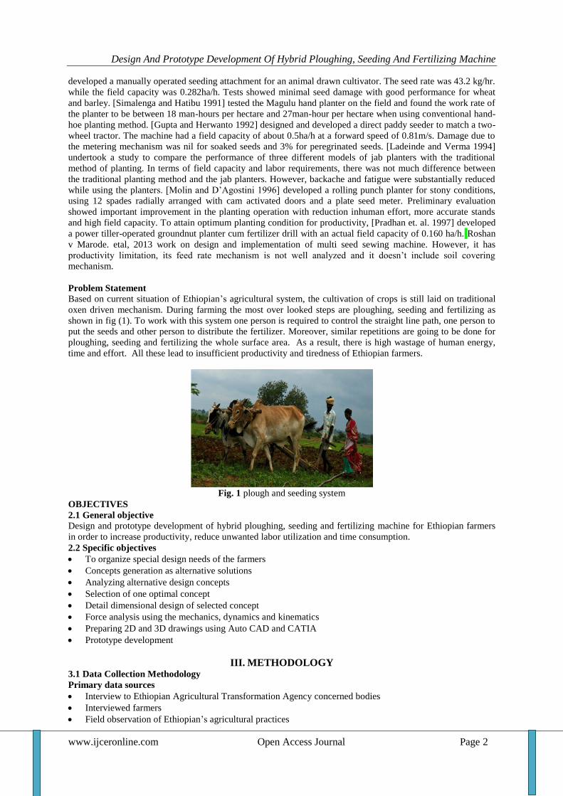
Problem Statement Based on current situation of Ethiopian‟s agricultural system, the cultivation of crops is still laid on traditional
oxen driven mechanism. During farming the most over looked steps are ploughing, seeding and fertilizing as
shown in fig (1). To work with this system one person is required to control the straight line path, one person to
put the seeds and other person to distribute the fertilizer. Moreover, similar repetitions are going to be done for
ploughing, seeding and fertilizing the whole surface area. As a result, there is high wastage of human energy,
time and effort. All these lead to insufficient productivity and tiredness of Ethiopian farmers.
Fig. 1 plough and seeding system
OBJECTIVES
2.1 General objective
Design and prototype development of hybrid ploughing, seeding and fertilizing machine for Ethiopian farmers
in order to increase productivity, reduce unwanted labor utilization and time consumption.
2.2 Specific objectives
To organize special design needs of the farmers
Concepts generation as alternative solutions
Analyzing alternative design concepts
Selection of one optimal concept
Detail dimensional design of selected concept
Force analysis using the mechanics, dynamics and kinematics
Preparing 2D and 3D drawings using Auto CAD and CATIA
Prototype development
III. METHODOLOGY 3.1 Data Collection Methodology
Primary data sources
Interview to Ethiopian Agricultural Transformation Agency concerned bodies
Interviewed farmers
Field observation of Ethiopian‟s agricultural practices
Design And Prototype Development Of Hybrid Ploughing, Seeding And Fertilizing Machine
www.ijceronline.com Open Access Journal Page 3
Secondary data sources
Design text books, reference books, previous researches, and papers
Relevant documents from Agricultural Transformation Agency of Ethiopia
3.2 Data analysis methodology
Technical interpretation of farmer‟s design needs
Concepts generation for design
Analyzing alternative design concepts by assigning weight and selection of one best concept
Detail dimensional design of selected concept
Force analysis using the mechanics, dynamics and kinematics
2D and 3D drawings by Auto CAD and CATIA
Cost analysis using ABC costing method
Prototype development
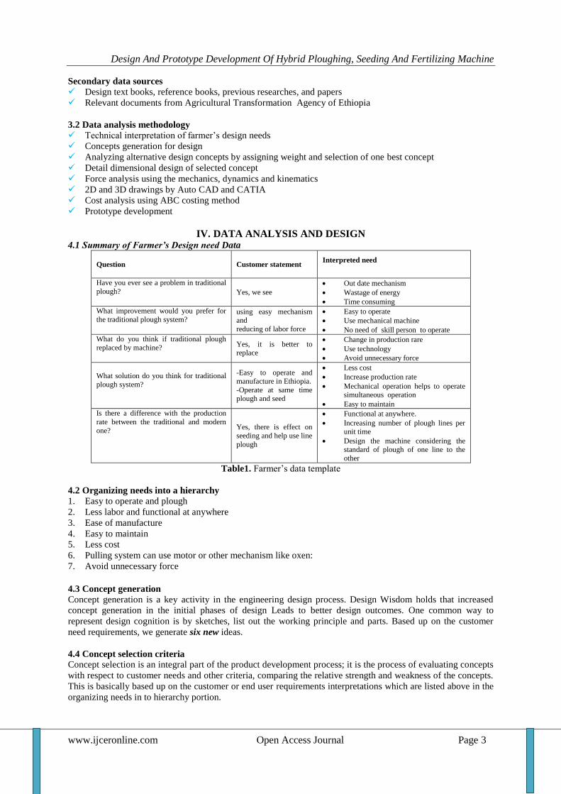
IV. DATA ANALYSIS AND DESIGN 4.1 Summary of Farmer’s Design need Data
Question Customer statement Interpreted need
Have you ever see a problem in traditional
plough? Yes, we see
Out date mechanism
Wastage of energy
Time consuming
What improvement would you prefer for the traditional plough system?
using easy mechanism and
reducing of labor force
Easy to operate
Use mechanical machine
No need of skill person to operate
What do you think if traditional plough
replaced by machine? Yes, it is better to replace
Change in production rare
Use technology
Avoid unnecessary force
What solution do you think for traditional
plough system?
-Easy to operate and manufacture in Ethiopia.
-Operate at same time plough and seed
Less cost
Increase production rate
Mechanical operation helps to operate simultaneous operation
Easy to maintain
Is there a difference with the production
rate between the traditional and modern
one? Yes, there is effect on
seeding and help use line
plough
Functional at anywhere.
Increasing number of plough lines per unit time
Design the machine considering the standard of plough of one line to the
other
Table1. Farmer‟s data template
4.2 Organizing needs into a hierarchy
1. Easy to operate and plough 2. Less labor and functional at anywhere 3. Ease of manufacture 4. Easy to maintain 5. Less cost 6. Pulling system can use motor or other mechanism like oxen: 7. Avoid unnecessary force
4.3 Concept generation
Concept generation is a key activity in the engineering design process. Design Wisdom holds that increased
concept generation in the initial phases of design Leads to better design outcomes. One common way to
represent design cognition is by sketches, list out the working principle and parts. Based up on the customer
need requirements, we generate six new ideas.
4.4 Concept selection criteria
Concept selection is an integral part of the product development process; it is the process of evaluating concepts
with respect to customer needs and other criteria, comparing the relative strength and weakness of the concepts.
This is basically based up on the customer or end user requirements interpretations which are listed above in the
organizing needs in to hierarchy portion.
Design And Prototype Development Of Hybrid Ploughing, Seeding And Fertilizing Machine
www.ijceronline.com Open Access Journal Page 4
Method: Weight assignment and rating
Concepts Performance rating:
Poor – 1, Good- 2, Very good – 4, Satisfactory - 3, Excellent- 5 Selection criteria Weight % Concept
1 2 3 4 5 6
Easy to operate and plough at same time seed and fertilizer. 20
Less labor and functional at anywhere. 10
Ease of manufacture and 10
Easy to maintain.
10
Less cost. 20
Pulling system Can use Motor or other mechanism like oxen 15
Avoid unnecessary force. 15
Table.2. Weighting criteria and concepts rating
Rank the concepts
Once the ratings are entered for each concept, weighted scores are calculated by multiplying the raw scores by
the criteria weights. The total score for each concept is the sum of the weighted scores.
Where
= raw rating of concept j for the ith criteria
Wi = weighting for the ith criteria
n = number of criteria
Total score for concept j
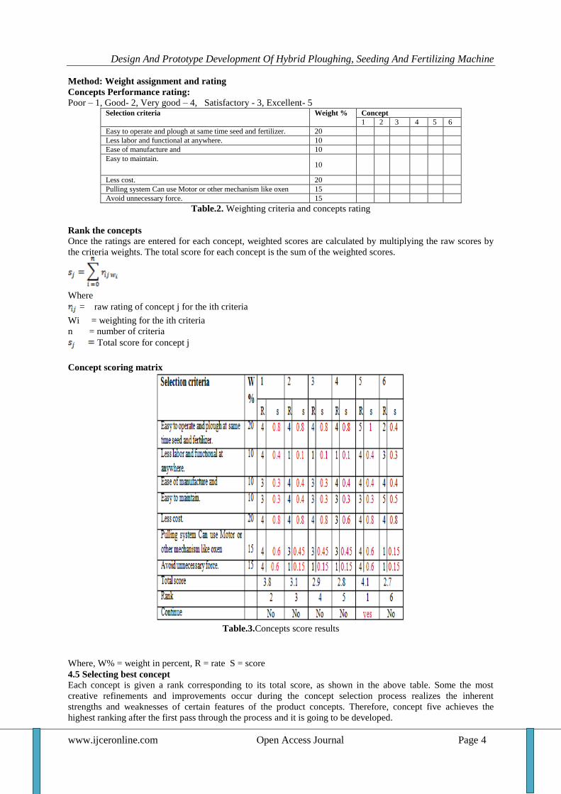
Concept scoring matrix
Table.3.Concepts score results
Where, W% = weight in percent, R = rate S = score
4.5 Selecting best concept
Each concept is given a rank corresponding to its total score, as shown in the above table. Some the most
creative refinements and improvements occur during the concept selection process realizes the inherent
strengths and weaknesses of certain features of the product concepts. Therefore, concept five achieves the
highest ranking after the first pass through the process and it is going to be developed.
Design And Prototype Development Of Hybrid Ploughing, Seeding And Fertilizing Machine
www.ijceronline.com Open Access Journal Page 5
4.6 Designing of the Components
1. Design of axle
2. Design of wheel.
3. Design of horizontal shaft
4. Design of seed and Fertilizer box
5. Design
of Seed controlling system
6. Design of seed covering mechanism
7. Design of the furrow opener
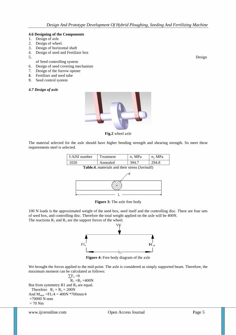
8. Fertilizer and seed tube 9. Seed control system 4.7 Design of axle
Fig.2 wheel axle
The material selected for the axle should have higher bending strength and shearing strength. So meet these
requirements steel is selected.
I:AISI number Treatment σt MPa σy MPa
1020 Annealed 394.7 294.8
Table.4. materials and their stress (Juvinall)
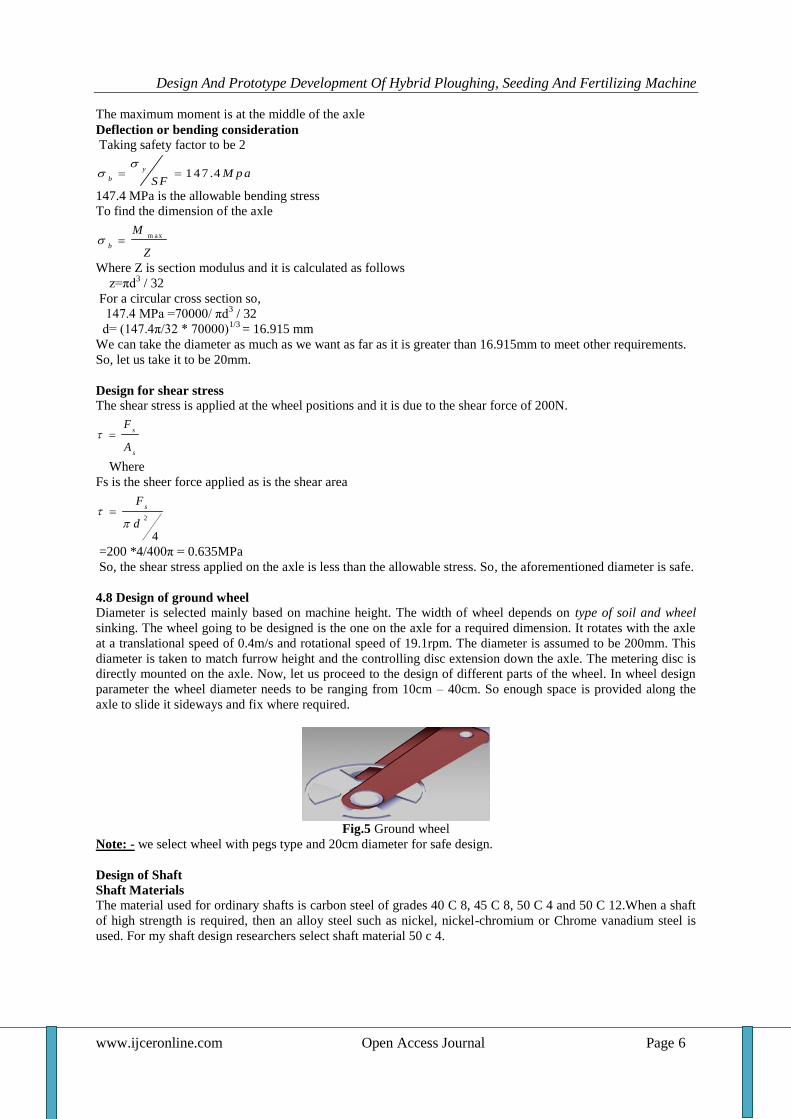
Figure 3: The axle free body
100 N loads is the approximated weight of the seed box, seed itself and the controlling disc. There are four sets
of seed box, and controlling disc. Therefore the total weight applied on the axle will be 400N.
The reactions R1 and R2 are the support forces of the wheel.
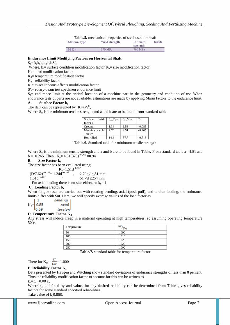
Figure 4: Free body diagram of the axle
We brought the forces applied to the mid-point. The axle is considered as simply supported beam. Therefore, the
maximum moment can be calculated as follows:
∑Fx =0
R1 +R2 =400N
But from symmetry R1 and R2 are equal.
Therefore R1 = R2 = 200N
And Mmax =FL/4 = 400N *700mm/4
=70000 N-mm
= 70 Nm
Design And Prototype Development Of Hybrid Ploughing, Seeding And Fertilizing Machine
www.ijceronline.com Open Access Journal Page 6
The maximum moment is at the middle of the axle
Deflection or bending consideration
Taking safety factor to be 2
1 4 7 .4y
bM p a
S F
147.4 MPa is the allowable bending stress
To find the dimension of the axle
m a x
b
M
Z
Where Z is section modulus and it is calculated as follows
z=πd3 / 32
For a circular cross section so,
147.4 MPa =70000/ πd3 / 32
d= (147.4π/32 * 70000)1/3
= 16.915 mm
We can take the diameter as much as we want as far as it is greater than 16.915mm to meet other requirements.
So, let us take it to be 20mm.
Design for shear stress
The shear stress is applied at the wheel positions and it is due to the shear force of 200N.
s
s
F
A
Where
Fs is the sheer force applied as is the shear area
2
4
sF
d
=200 *4/400π = 0.635MPa
So, the shear stress applied on the axle is less than the allowable stress. So, the aforementioned diameter is safe.
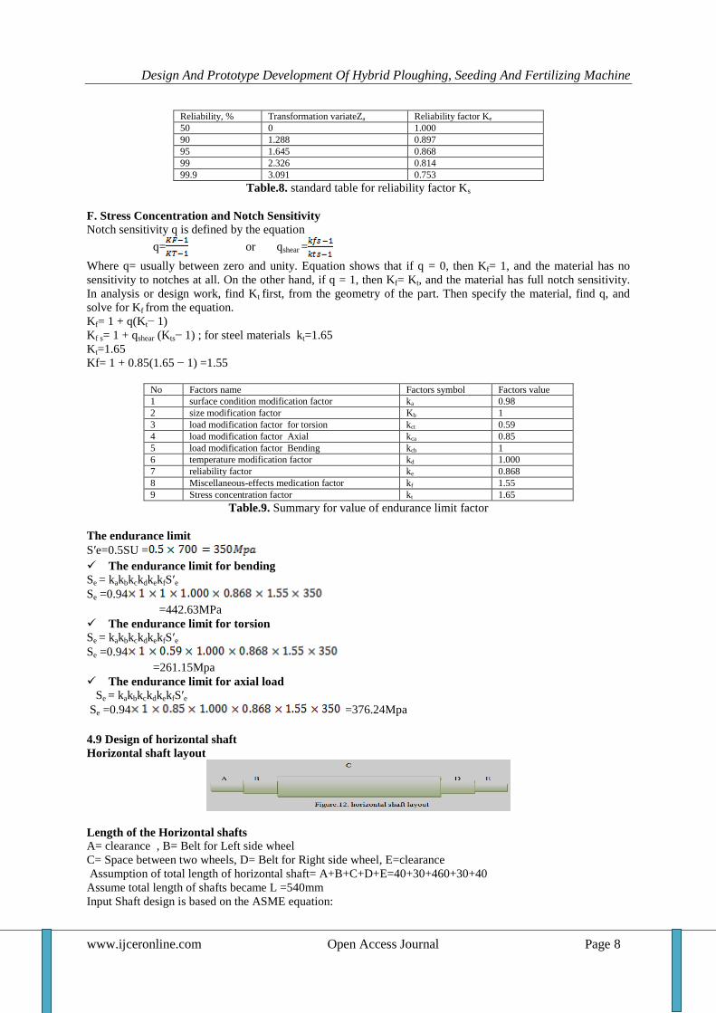
4.8 Design of ground wheel
Diameter is selected mainly based on machine height. The width of wheel depends on type of soil and wheel
sinking. The wheel going to be designed is the one on the axle for a required dimension. It rotates with the axle
at a translational speed of 0.4m/s and rotational speed of 19.1rpm. The diameter is assumed to be 200mm. This
diameter is taken to match furrow height and the controlling disc extension down the axle. The metering disc is
directly mounted on the axle. Now, let us proceed to the design of different parts of the wheel. In wheel design
parameter the wheel diameter needs to be ranging from 10cm – 40cm. So enough space is provided along the
axle to slide it sideways and fix where required.
Fig.5 Ground wheel
Note: - we select wheel with pegs type and 20cm diameter for safe design.
Design of Shaft
Shaft Materials
The material used for ordinary shafts is carbon steel of grades 40 C 8, 45 C 8, 50 C 4 and 50 C 12.When a shaft
of high strength is required, then an alloy steel such as nickel, nickel-chromium or Chrome vanadium steel is
used. For my shaft design researchers select shaft material 50 c 4.
Design And Prototype Development Of Hybrid Ploughing, Seeding And Fertilizing Machine
www.ijceronline.com Open Access Journal Page 7
Table.5. mechanical properties of steel used for shaft Material type Yield strength Ultimate tensile
strength
50 C 4 370 MPa 700 MPa
Endurance Limit Modifying Factors on Horizontal Shaft
Se= kakbkckdkekfS′e
Where, ka= surface condition modification factor Kb= size modification factor
Kc= load modification factor
Kd= temperature modification factor
Ke= reliability factor
Kf= miscellaneous-effects modification factor
S′e= rotary-beam test specimen endurance limit
Se= endurance limit at the critical location of a machine part in the geometry and condition of use When
endurance tests of parts are not available, estimations are made by applying Marin factors to the endurance limit.
A. Surface Factor ka
The data can be represented by Ka=aSbut
Where Sut is the minimum tensile strength and a and b are to be found from standard table
Table.6. Standard table for minimum tensile strength
Where Sut is the minimum tensile strength and a and b are to be found in Table. From standard table a= 4.51 and
b =−0.265. Then, Ka= 4.51(370)−0.265
=0.94
B. Size Factor kb
The size factor has been evaluated using;
Kb=1.51d−0.157
(D/7.62)−0.107
= 1.24d−0.107
, 2.79 ≤d ≤51 mm
1.51d−0.157 ,
51 <d ≤254 mm
For axial loading there is no size effect, so kb= 1
C. Loading Factor kc When fatigue tests are carried out with rotating bending, axial (push-pull), and torsion loading, the endurance
limits differ with Sut. Here, we will specify average values of the load factor as
Kc=
D. Temperature Factor Kd
Any stress will induce creep in a material operating at high temperatures; so assuming operating temperature
500c.
Temperature
50 1.000
100 1.010
150 1.020
200 1.020
250 1.000
Table.7. standard table for temperature factor
There for KD = 1.000
E. Reliability Factor Ke
Data presented by Haugen and Witching show standard deviations of endurance strengths of less than 8 percent.
Thus the reliability modification factor to account for this can be written as
ke= 1 −0.08 za
Where za is defined by and values for any desired reliability can be determined from Table gives reliability
factors for some standard specified reliabilities.
Take value of ke0.868.
Surface finish
factor a
Sut,Kpsi Sut,Mpa B
Ground 1.34 1.58 -0.085
Machine or cold
–drawn
2.70 4.51 -0.265
Hot-rolled 14.4 57.7 -0.718
Design And Prototype Development Of Hybrid Ploughing, Seeding And Fertilizing Machine
www.ijceronline.com Open Access Journal Page 8
Reliability, % Transformation variateZa Reliability factor Ke
50 0 1.000
90 1.288 0.897
95 1.645 0.868
99 2.326 0.814
99.9 3.091 0.753
Table.8. standard table for reliability factor Ks
F. Stress Concentration and Notch Sensitivity
Notch sensitivity q is defined by the equation
q= or qshear =
Where q= usually between zero and unity. Equation shows that if q = 0, then Kf= 1, and the material has no
sensitivity to notches at all. On the other hand, if q = 1, then Kf= Kt, and the material has full notch sensitivity.
In analysis or design work, find Kt first, from the geometry of the part. Then specify the material, find q, and
solve for Kf from the equation.
Kf= 1 + q(Kt− 1)
Kf s= 1 + qshear (Kts− 1) ; for steel materials kt=1.65
Kt=1.65
Kf= 1 + 0.85(1.65 − 1) =1.55
No Factors name Factors symbol Factors value
1 surface condition modification factor ka 0.98
2 size modification factor Kb 1
3 load modification factor for torsion kct 0.59
4 load modification factor Axial kca 0.85
5 load modification factor Bending kcb 1
6 temperature modification factor kd 1.000
7 reliability factor ke 0.868
8 Miscellaneous-effects medication factor kf 1.55
9 Stress concentration factor kt 1.65
Table.9. Summary for value of endurance limit factor
The endurance limit
S′e=0.5SU =
The endurance limit for bending
Se = kakbkckdkekfS′e
Se =0.94
=442.63MPa
The endurance limit for torsion
Se = kakbkckdkekfS′e
Se =0.94
=261.15Mpa
The endurance limit for axial load Se = kakbkckdkekfS′e
Se =0.94 =376.24Mpa
4.9 Design of horizontal shaft
Horizontal shaft layout
Length of the Horizontal shafts
A= clearance , B= Belt for Left side wheel
C= Space between two wheels, D= Belt for Right side wheel, E=clearance
Assumption of total length of horizontal shaft= A+B+C+D+E=40+30+460+30+40
Assume total length of shafts became L =540mm
Input Shaft design is based on the ASME equation:
Design And Prototype Development Of Hybrid Ploughing, Seeding And Fertilizing Machine
www.ijceronline.com Open Access Journal Page 9
T= = = 41.1Nm
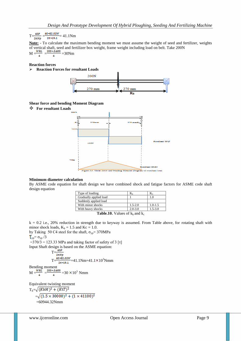
Note: - To calculate the maximum bending moment we must assume the weight of seed and fertilizer, weights
of vertical shaft, seed and fertilizer box weight, frame weight including load on belt. Take 200N
M = = =30Nm
Reaction forces
Reaction Forces for resultant Loads
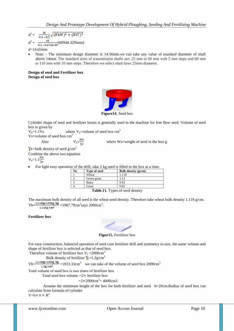
Shear force and bending Moment Diagram
For resultant Loads
Minimum diameter calculation By ASME code equation for shaft design we have combined shock and fatigue factors for ASME code shaft
design equation Type of loading Kb KC
Gradually applied load 1 1.0
Suddenly applied load
With minor shocks 1.5-2.0 1.0-1.5
With heavy shocks 2.0-3.0 1.5-3.0
Table.10. Values of kb and kc
k = 0.2 i.e., 20% reduction in strength due to keyway is assumed. From Table above, for rotating shaft with
minor shock loads, Kb = 1.5 and Kc = 1.0.
by Taking 50 C4 steel for the shaft, σyp= 370MPa
yp= σyp /3
=370/3 = 123.33 MPa and taking factor of safety of 3 [τ]
Input Shaft design is based on the ASME equation:
T=
T= =41.1Nm=41.1 103Nmm
Bending moment
M = = =30 103
Nmm
Equivalent twisting moment
TE=
=
=60944.32Nmm
Design And Prototype Development Of Hybrid Ploughing, Seeding And Fertilizing Machine
www.ijceronline.com Open Access Journal Page 10
d3 =
d3 = (60944.32Nmm)
d=14.65mm
Note: - The minimum design diameter is 14.56mm.we can take any value of standard diameter of shaft
above 14mm. The standard sizes of transmission shafts are: 25 mm to 60 mm with 5 mm steps and 60 mm
to 110 mm with 10 mm steps. Therefore we select shaft have 25mm diameter.
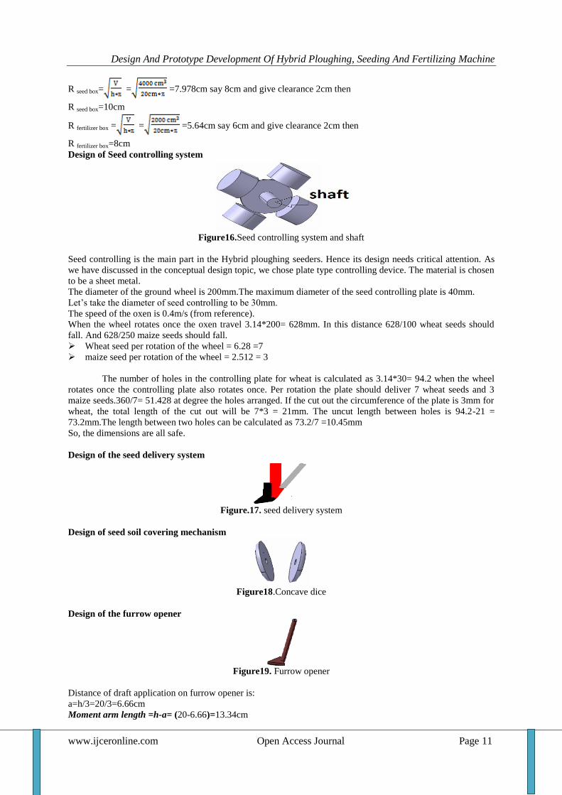
Design of seed and Fertilizer box
Design of seed box
Figure14. Seed box
Cylinder shape of seed and fertilizer boxes is generally used in the machine for free flow seed. Volume of seed
box is given by
Vb=1.1Vs where Vb=volume of seed box cm3
Vs=volume of seed box cm3
Also VS= where Ws=weight of seed in the box g
=bulk density of seed g/cm3
Combine the above two equation
Vb=1.1
For light easy operation of the drill, take 2 kg seed is filled in the box at a time. No Type of seed Bulk density (g/cm)
1 Wheat 1.118
2 Green gram 1.12
3 Bajra 0.62
4 Gram 0.82
Table.11. Types of seed density
The maximum bulk density of all seed is the wheat seed density. Therefore take wheat bulk density 1.118 g/cm.
Vb= =1967.79cm3says 2000cm
3.
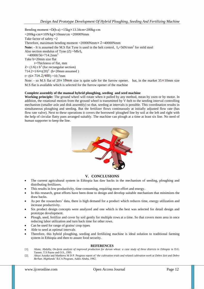
Fertilizer box
Figur15. Fertilizer box
For easy construction, balanced operation of seed cum fertilizer drill and symmetry in size, the same volume and
shape of fertilizer box is selected as that of seed box.
Therefore volume of fertilizer box Vf =2000cm3
Bulk density of fertilizer f=1.2g/cm3
Vb= =1833.33cm3 we can take of the volume of seed box 2000cm
3
Total volume of seed box is two times of fertilizer box
Total seed box volume =2 fertilizer box
=2 2000cm3= 4000cm3
Assume the minimum height of the box for both fertilizer and seed h=20cm.Radius of seed box can
calculate from formula of cylinder
V=h R2
Design And Prototype Development Of Hybrid Ploughing, Seeding And Fertilizing Machine
www.ijceronline.com Open Access Journal Page 11
R seed box= = =7.978cm say 8cm and give clearance 2cm then
R seed box=10cm
R fertilizer box = = =5.64cm say 6cm and give clearance 2cm then
R fertilizer box=8cm
Design of Seed controlling system
Figure16.Seed controlling system and shaft
Seed controlling is the main part in the Hybrid ploughing seeders. Hence its design needs critical attention. As
we have discussed in the conceptual design topic, we chose plate type controlling device. The material is chosen
to be a sheet metal.
The diameter of the ground wheel is 200mm.The maximum diameter of the seed controlling plate is 40mm.
Let‟s take the diameter of seed controlling to be 30mm.
The speed of the oxen is 0.4m/s (from reference).
When the wheel rotates once the oxen travel 3.14*200= 628mm. In this distance 628/100 wheat seeds should
fall. And 628/250 maize seeds should fall.
Wheat seed per rotation of the wheel = 6.28 =7
maize seed per rotation of the wheel = 2.512 = 3
The number of holes in the controlling plate for wheat is calculated as 3.14*30= 94.2 when the wheel
rotates once the controlling plate also rotates once. Per rotation the plate should deliver 7 wheat seeds and 3
maize seeds.360/7= 51.428 at degree the holes arranged. If the cut out the circumference of the plate is 3mm for
wheat, the total length of the cut out will be 7*3 = 21mm. The uncut length between holes is 94.2-21 =
73.2mm.The length between two holes can be calculated as 73.2/7 =10.45mm
So, the dimensions are all safe.
Design of the seed delivery system
Figure.17. seed delivery system
Design of seed soil covering mechanism
Figure18.Concave dice
Design of the furrow opener
Figure19. Furrow opener
Distance of draft application on furrow opener is:
a=h/3=20/3=6.66cm
Moment arm length =h-a= (20-6.66)=13.34cm
Design And Prototype Development Of Hybrid Ploughing, Seeding And Fertilizing Machine
www.ijceronline.com Open Access Journal Page 12
Bending moment =D(h-a) =15kg 13.34cm=200kg-cm
=200kg-cm 10N/kg 10mm/cm =20000Nmm
Take factor of safety =2
Therefore, maximum bending moment =20000Nmm =40000Nmm
Note: - It is assumed the M.S flat Tyne is used in the belt control, fb=56N/mm2 for mild steel
Also section modulus of Tyne (Z) =Mb/fb
=40000/56=714.2mm3
Take b=20mm size flat
t=Thickness of flat, mm
Z= (1/6) t b2 (for rectangular section)
714.2=1/6 t(20)2 (b=20mm assumed )
t= (6 ) =10.7mm
Note: - so M.S flat of 20 size is quite safe for the furrow opener. but, in the market 35 10mm size
M.S flat is available which is selected for the furrow opener of the machine
Complete assembly of the manual hybrid ploughing, seeding and seed machine
Working principle: The ground wheel will rotate when it pulled by any method, mean by oxen or by motor. In
addition, the rotational motion from the ground wheel is transmitted by V-belt to the seeding interval controlling
mechanism (smaller axle and disk assembly) so that, seeding at intervals is possible. This coordination results in
simultaneous ploughing and seeding. But the fertilizer flows continuously at initially adjusted flow rate (has
flow rate valve). Next to these operations it covers the borrowed/ ploughed line by soil at the left and right with
the help of circular flatty pans arranged suitably. The machine can plough at a time at least six line. No need of
human supporter to keep the line.
V. CONCLUSIONS
The current agricultural system in Ethiopia has daw backs in the mechanism of seeding, ploughing and
distributing fertilizers.
This results in low productivity, time consuming, requiring more effort and energy.
In this research, great efforts have been done to design and develop suitable mechanism that minimizes the
draw backs.
As per the researchers‟ data, there is high demand for a product which reduces time, energy utilization and
increase productivity.
Six product design concepts were analyzed and one which is the best was selected for detail design and
prototype development.
Plough, seed, fertilize and cover by soil gently for multiple rows at a time. So that covers more area in once
reducing labor utilization and turn back time for other rows.
Can be used for range of grains/ crop types
Able to seed at optimal intervals
Therefore, this hybrid ploughing, seeding and fertilizing machine is ideal solution to traditional farming
system in Ethiopia and then to assure food security.
REFERENCES [1]. Abate, Abdalla, On-farm analysis of improved production for durum wheat: a case study of three districts in Ethiopia in D.G.
Tanner, T.S Payne and O.S., 1995 [2]. Abiye Astatke and Matthews M D P. Progress report of „the cultivation trials and related cultivation work at Debre Zeit and Debre
Berhan. Highlands‟ ILCA Program, Addis Ababa, 1982.
Design And Prototype Development Of Hybrid Ploughing, Seeding And Fertilizing Machine
www.ijceronline.com Open Access Journal Page 13
[3]. Abiye Astatike and M. A. Mohammed Saleem, „Draught animal power for land use intensification in the Ethiopian highlands‟,
WAR/RMZ 86, 1996.
[4]. Dr. Mohammed Yunus, Dr. Shadi M. Munshi, Sneha R. and Iftekar Hussain H(2015), “Design and Fabrication of Cost Effective Potato Planting Machine to Increase Quality of Potato” International Journal in IT and Engineering, Vol.03 Issue-10, (October,
2015) ISSN: 2321-1776, Impact Factor- 4.747
[5]. J.E. Shigley, Mechanical engineering design, 1st edition, McGraw Hill, New York, 1986. [6]. J.R Murray, J N Tullberg and Basnet, planters and their components, School of Agronomy and Horticulture, University of
Queensland, Australia, 2006.
[7]. Juvinall, Robert c., Fundamental of machine component design, third edition, John Wiley and sons, Inc.New York, 2000 [8]. Ladeinde and
Verma 1994 „performance comparison of jab planter models with traditional method of planting’
[9]. M.Priyadarshini, and Mrs.L.Sheela, (2015) , “COMMAND BASED SELF GUIDED DIGGING AND SEED SOWING ROVER” International Conference on Engineering Trends and Science & Humanities (ICETSH-2015)
[10]. Molin and D‟Agostini, 1996 „Rolling punch planter for stony conditions’
[11]. Nilesh N. Jadhav , Harshal R. Aher , and Amol P. Ghode (2015), “Design and Fabrication of Onion Seed Sowing Machine” International Journal on Recent Technologies in Mechanical and Automobile Engineering (IJRMAE) ISSN: 2349-7947 Volume: 2
001 – 010 Issue: 6
[12]. Pradhan et. al. 1997, „power tiller-operated ground nut planter cum fertilizer drill’ [13]. P.Usha1,V.Maheswari2, Dr.V.Nandagopal, “DESIGN AND IMPLEMENTATION OF SEEDING AGRICULTURAL ROBOT”,
Journal of Innovative Research and Solutions (JIRAS), Print ISSN: 2320 1932 / Online ISSN – 2348 3636 Volume No.1, Issue
No.1. Page No: 138 -143, JULY - 2015
[14]. Roshan V Marode1*, Gajanan P Tayade1 and Swapnil K Agrawal1 (2013) “DESIGN AND IMPLEMENTATION OF MULTI SEED
SOWING MACHINE” International Journal Of Mechanical Engineering and Robotics Research, ISSN 2278 – 0149 Vol. 2, No. 4, October 2013, www.ijmerr.com,