design and optimization of an hsdpa turbo decoder asic
TRANSCRIPT

JOURNAL OF SOLID-STATE CIRCUITS, VOL. X, NO. X, JANUARY 2009 1
Design and Optimization of an HSDPA TurboDecoder ASIC
Christian Benkeser, Student Member, IEEE, Andreas Burg, Member, IEEE, Teo Cupaiuolo,and Qiuting Huang, Fellow, IEEE
Abstract—The turbo decoder is the most challenging com-ponent in a digital HSDPA receiver in terms of computationrequirement and power consumption, where large block sizeand recursive algorithm prevent pipelining or parallelism to beeffectively deployed. This paper addresses the complexity andpower consumption issues at algorithmic, arithmetic and gatelevels of ASIC design, in order to bring power consumptionand die area of turbo decoders to a level commensurate withwireless application. Realized in 0.13µm CMOS technology, theturbo decoder ASIC measures 1.2mm2 excluding pads, and canachieve 10.8Mb/s throughput while consuming only 32mW.
Index Terms—3G Mobile Communication, HSDPA, ChannelDecoding, Turbo Codes, Early Termination, Low Power.
I. INTRODUCTION
MODERN wireless communication standards rely onpowerful channel coding to ensure reliable (error free)
transmission. Channel coding introduces a controlled amountof redundancy into the transmitted data stream, which is thenexploited in the receiver to correct transmission errors inducedby noise or interference present in the wireless channel. Turbocodes, first proposed in 1993 [1], represent a breakthrough inchannel coding techniques, since they have the potential toenable data transmission at rates close to the Shannon limit.They have been adopted for error control coding in the highspeed downlink packet access (HSDPA) standard by the third-generation partnership project (3GPP), which considerablyenhance the throughput for data-centric 3G modems.
The excellent performance of turbo codes however, comesat the expense of significant computational complexity andconsequently high power consumption at the receiver forproper decoding. Indeed, the computational burden of theturbo decoder far exceeds that of any other component in anHSDPA receiver, especially for the higher data rate classes upto 10.8 Mb/s. This places a considerable strain on the totalpower consumption which must be capped in a mobile deviceand efficient realization of turbo decoders for HSDPA has beenthe subject of considerable research in recent years. Publica-tions to date indicate that two distinct approaches are beingpursued: one focuses on realizing turbo decoders for 3GPPon general purpose digital signal processors (DSP) ([2], [3],and [4]). Such realizations have so far failed to reach the highend of HSDPA throughput (10.8 Mb/s1) despite prohibitivelyhigh power consumption and hardware complexity of a fullyprogrammable architecture. The second approach relies on
1[5] specifies a maximum raw data rate of 14.4Mb/s with 16QAM modu-lation and a maximum code rate of 3/4.
dedicated circuits for the turbo decoding operation with somebuilt-in flexibility to handle the different code-block sizesspecified by the 3GPP standard ([6], [7], [8], and [9]). Evenamong these circuits only one [6] met the highest HSDPAthroughput, at a staggering 1W power consumption with acore area of 14mm2.
Typically, the throughput of digital circuits can be in-creased by architectural and circuit-level transformations suchas pipelining or parallel processing. For turbo decoders, theapplicability of pipelining is limited due to the presence offeedback loops and the accompanying extra registers increasethe energy consumption. Parallel processing, on the otherhand, is limited by both data dependencies and the accessbandwidth of standard memories, which causes considerablearea overhead.
In this work, we pursue the increase of throughput viaoptimization and simplification at algorithm, arithmetic, aswell as the gate level to limit the hardware requirements thatgive rise to higher power consumption and larger silicon area.
A. Outline
The paper is organized as follows. In Section II the fun-damentals of the turbo decoding algorithm are revisited. InSection III the high-level architecture of the turbo decoderASIC realized in this work is presented and the key ideasfor optimization and complexity reduction are described. Sec-tion IV is dedicated to adapting the decoding effort to theradio link quality to reduce the power consumption of the im-plemented circuit. Finally, measurement results are presentedand compared to reference and prior-art implementations inSection V. Section VI concludes the paper.
II. ALGORITHM OVERVIEW
HSDPA employs a rate 1/3 parallel concatenated turbocode. The corresponding encoder is comprised of two rate1/2 recursive systematic convolutional encoders, as shownin Fig. 1. The first component encoder receives uncoded(systematic) data bits uk in natural order and outputs a setof parity bits xp1
k . The second component encoder receivesa permutation of the data bits from a block interleaver andoutputs a second set of parity bits xp2
k . The systematic bitsand the two sets of parity bits are then modulated onto ananalog waveform (according to the employed communicationstandard) and sent over the radio channel. On the other sideof the wireless link, a demodulator is responsible for thereconstruction of the transmitted bits from the received signal.

JOURNAL OF SOLID-STATE CIRCUITS, VOL. X, NO. X, JANUARY 2009 2
Fig. 1: Channel encoder specified for HSDPA.
However, since this signal is usually distorted by noise andinterference, the demodulator can only obtain estimates of thesystematic and two sets of parity bits. These estimates areprovided to the subsequent turbo decoder in the form of log-likelihood ratios (LLRs) Ls
k, Lp1
k , and Lp2
k which express theratio between the probabilities of the transmitted bits being 0and being 1, given the received analog signal.
A. The Turbo Decoding Algorithm
The basic idea behind the turbo decoding algorithm is toiterate between two soft-input soft-output (SISO) componentdecoders as illustrated in Fig. 2. A turbo-iteration correspondsto one pass of the first component decoder followed by a passof the second component decoder. The operation performed bya single component decoder is referred to as a half-iteration.
The component decoders compute a-posteriori probabilitiesL(uk) of the transmitted systematic bits from the LLRs ofthe (interleaved) systematic bits, the associated parity bits andthe a-priori information La(uk). The latter is set to zero forthe first half-iteration in the first turbo iteration. In subsequentiterations, each component decoder uses the so-called extrinsicinformation output Le(uk) of the other component decoder inthe preceding half-iteration as a-priori information:
Le(uk) = L(uk) − Lsk − La(uk)
With each half-iteration, the bit error rate (BER) performanceimproves, with diminishing returns after 6 to 8 turbo iterations.
B. The Maximum A-Posteriori (MAP) Algorithm
In the turbo-decoder under consideration in this paper,the maximum a-posteriori (MAP) algorithm of Bahl, Cocke,Jelinek and Raviv [10] (BCJR algorithm) is used for theSISO component decoders, because it shows the best errorrate performance. Unfortunately, the exact MAP algorithmrequires the computation of the log of sums of exponential
Fig. 2: Simplified block diagram of a turbo decoder.
(a) (b)
Fig. 3: Example of the calculation of the forward and backwardstate metrics Ak(s) and Bk(s′).
functions, which is clearly not suitable for integration inhardware. Hence, we shall only consider a slightly suboptimal,low-complexity variation known as max-log-MAP algorithmin the following.
The operation of this max-log-MAP algorithm is similar tothe Viterbi algorithm. The decoder traverses a trellis diagramin which the nodes represent the 8 possible states of the spec-ified encoder and the branches indicate the admissible statetransitions. For the code under consideration, each transitionfrom a state s′ to a state s is associated with one of fourpossible transition metrics2
Γk(s′, s) =
0
Lp0/1
k
La(uk) + Lsk
La(uk) + Lsk + L
p0/1
k
. (1)
The max-log-MAP algorithm traverses the trellis in bothforward and backward directions to compute the state metricsA(si) and B(si). Loosely speaking, these two metrics reflectthe probabilities that the encoder has taken a particular path toarrive at a state or has continued from a state to the end of thetrellis, respectively. In the max-log-MAP algorithm the statemetric update is simplified compared to the computations inthe MAP algorithm using a max-log approximation [11]. Theresulting forward and backward state metric recursion requires
2Since only the difference between these transition metrics is relevant forthe max-log-MAP algorithm, one of the four possible values [11] of Γk(s′, s)can be turned into a zero by subtracting it from the other transition metrics.

JOURNAL OF SOLID-STATE CIRCUITS, VOL. X, NO. X, JANUARY 2009 3
only add-compare-select (ACS) operations to compute
Ak(s) ≈max[Ak−1(s
′
0) + Γk(s′0, s),
Ak−1(s′
1) + Γk(s′1, s)]
(2)Bk(s′) ≈max
[Bk+1(s0) + Γk+1(s
′, s0),
Bk+1(s1) + Γk+1(s′, s1)
], (3)
where s′0 and s′1 are the two possible predecessor states ofs in the forward direction and where s0 and s1 are the twosuccessor states of s′ in the backward direction. An examplefor the procedure is shown in Fig. 3.
In order to avoid storing all Ak(s) and Bk(s) of the entirecode-block, small sub-blocks (windows) are usually processedin a max-log-MAP decoder realization. In the forward recur-sion the state metrics at the end of a specific window canbe used as initial probabilities for the next window. Becausethe backward state metrics are computed in the oppositedirection, a dummy-backward recursion must be performedon some trellis steps in advance to generate a reliable set ofstate metrics as starting points. The constraint length of theconvolutional encoder hereby defines a lower bound for therequired number of trellis steps. Simulations have shown thatfor the codes in HSDPA a dummy-backward recursion on lessthan 24 bits degrades decoding performance significantly. Asan alternative to the dummy-backward recursion, the startingpoints for each window between subsequent turbo iterationscan be stored [12]. However, this approach is less attractivefor HSDPA with code-block sizes of up to 5114 due to theremarkable memory demand.
Once all Ak(s) and Bk(s) of a particular window havebeen obtained, the a-posteriori output L(uk) of the max-log-MAP decoder can be computed. To this end, the decoder mustconsider the state transitions s′ ⇒ s associated with uk =0 and the ones associated with uk = 1 separately and thencomputes
L(uk) ≈ maxs′⇒s,
uk=0
[Ak−1(s
′) + Γk(s′, s) + Bk(s)]
− maxs′⇒s,
uk=1
[Ak−1(s
′) + Γk(s′, s) + Bk(s)]
(4)
C. Extrinsic Scaling
The approximation used in the max-log-MAP algorithmcauses an overestimation of the extrinsic information in theturbo decoder, which results in a decoding performance degra-dation (c.f., Sec. V). This error can be reduced by attenuatingthe extrinsic information with a scaling factor smaller thanone [13]. Furthermore, the corresponding multiplication be-tween subsequent half-iterations reduces the correlation be-tween the inputs of the component decoders.
III. TURBO DECODER ASIC ARCHITECTURE
With low power and small chip size in mind, our real-ization of the 10.8Mb/s HSDPA turbo decoder is based onthe architecture shown in Fig. 4. In this design, three inputRAMs, each with a size of 25kb, store one block of the LLRs
of the systematic and both sets of parity bits using a 5-bitquantization. In each clock cycle, a pair of inputs consistingof the LLR of a systematic bit and the LLR of an associatedparity bit enter the max-log-MAP decoder core together withthe corresponding a-priori information obtained from a fourthRAM that stores the extrinsic information that is passedbetween the successive component decoder iterations. Themax-log-MAP decoder outputs the a-posteriori informationand the extrinsic information. The a-posteriori information isused to derive the binary output of the turbo decoder and tocheck criteria for early termination (c.f., Sec. IV) of the turbodecoding process. The extrinsic information is multiplied witha 6 bit scaling factor (Sec. II-C). The result of this scaling isthen written back to the 30kb3 extrinsic information memorywhich must be run at twice the clock rate of the max-log-mapdecoder to allow for a read- and a write-operation in eachsystem clock cycle.
A. Max-log-MAP Decoder Core
The high-level architecture of the max-log-MAP decoder issimilar to what has been described in [14]. It is designed toprocess, on average, one trellis step per clock cycle using threestate metric recursion units as shown in Fig. 4. These threeunits perform the forward, backward and dummy-backwardcalculations on three successive windows in parallel. To beon the safe side a conservative approach with a window sizeof 40 trellis steps has been adopted in our design to guaran-tee reliable results from the dummy-backward computation(c.f., Section II-B). Similar to what is described in [14],a cache-memory is employed to overcome the memory-access bandwidth bottleneck to the input and the extrinsic-information memories. However, in contrast to the designdescribed in [14], the present implementation first computesLa(uk) + Ls
k and stores only this intermediate result togetherwith L
p0/1
k [15] in three single-port Γ-RAMs. Compared tostoring all three individual terms (La(uk), Ls
k, and Lp0/1
k )that contribute to the computation of the Γ-metrics in (1),this measure reduces cache memory storage requirements andavoids redundant computations. The forward state metrics arecomputed on one window in advance and stored in the A-RAM, making them available for the LLR output computationwhen the backward state metrics of the particular window arecalculated. To achieve a decoding rate of 1 bit/cycle, the A-RAM must operate at twice the clock rate to enable a read-and a write-operation in each system clock cycle.
1) ACS units: In high-speed MAP decoder implementationsthe maximum operating frequency is usually limited by therecursive state metric computation, which can not simply bepipelined or parallelized due to the presence of the feedbackloop. Hence, we shall focus on measures for reducing thecomplexity of the state metric recursions to shorten the criticalpath and to reduce area and power consumption. A prior-art implementation of the ACS unit for state metric recur-sions ([7]) is shown in Fig. 5a, where an error correction
3Note that simulations show that without scaling the word length, theextrinsic memory needs to be 7-bit instead of 6-bit wide, which would resultin 5kb more on-chip memory.

JOURNAL OF SOLID-STATE CIRCUITS, VOL. X, NO. X, JANUARY 2009 4
Fig. 4: Architecture of the implemented turbo decoder with max-log-MAP decoder core.
term is selected from a look-up table (LUT) and added tothe output of the ACS unit to mitigate the performance lossassociated with the use of the max-log approximation. Becausestate metrics increase with time, normalization is performed bysubtracting a bias that is computed outside the ACS recursion,further increasing complexity.
The present realization avoids the significant cost of thelookup table approach by using extrinsic-scaling to close theerror rate performance gap between the MAP and the max-log-MAP algorithm. To solve the problem of increasing statemetrics, the max-log-MAP algorithm has been implementedwith modulo normalization [16] using a 12-bit quantizationfor the state metrics (c.f., [17]). This technique, known fromViterbi decoder implementations, achieves the renormalizationwith a controlled overflow in the data path and requiresonly an additional 3-input XOR gate in each ACS unit. Insummary, the reduced-complexity state metric recursion withthe ACS implementations shown in Fig. 5b achieves a 50%improvement in speed at a 45% reduction in area comparedto the prior-art implementation in Fig. 5a.
B. Interleaver
Interleavers for turbo codes scramble the data in a pseudo-random order to minimize the correlation between the outputsof component encoders. Hence, by design, the interleavedaddress pattern specified for HSDPA [18] exhibits little reg-ularity. Not surprisingly, the rules for generating interleavedaddresses require complex, hardware expensive operations.The complexity of the address generation rule is compoundedby the need to support large code-block sizes up to 5114bits per block. Hence, simply storing the interleaved order ofaddresses requires up to 65kb of dedicated interleaver address
(a) (b)
Fig. 5: Comparison of add-compare-select unit implementationin the state metric recursions.
memory ([6]) and separate logic to load this memory quicklywhen the code-block size (i.e., the interleaver address pattern)changes.
In order to avoid such overhead, our design relies on on-the-fly address generation that is more economic in terms ofarea and that facilitates fast switching between different code-block sizes. Unfortunately, implementation of such a real-timeaddress generator typically introduces a timing bottleneck forthe turbo decoder, which has to be removed.
In the interleaver specification for the turbo codes inHSDPA, an interleaver matrix with R = 5, 10 or 20 rowsand C ≤ 257 columns, depending on the code-block size,is first filled with ascending numbers. Then, intra-row and

JOURNAL OF SOLID-STATE CIRCUITS, VOL. X, NO. X, JANUARY 2009 5
Fig. 6: Low-complexity implementation of the interleaver address generation
inter-row permutations are performed to generate the desiredinterleaved order of addresses, which can be read out of thematrix column-by-column. The interleaver matrix does nothave to be precomputed and stored, because a closed-formexpression for the interleaved address I at a specific position(Rj , Cj) in the matrix can be derived from
I(Rj , Cj) = C · T (Rj) + s[(Cj · r(Q(Rj))) mod p′︸ ︷︷ ︸
X
](5)
using standard-specific patterns Q and T that are stored inlookup tables. The derivation requires a preparatory phase, inwhich a prime number p ≤ 257 (p′ = p−1) is derived directlyfrom the code-block size, the base-sequence for the intra-rowpermutation s is computed and stored in a 256x9b s-RAM,and the sequence r of R permuted 7 bit prime numbers is pre-calculated and stored in registers to be available during theon-the-fly address generation.
Our solution to the main challenge of the preprocessingblock, the recursive generation of s, is to exploit interdepen-dencies and irregular calculation rules given by the standard,as described in [19]. The preparatory phase in our turbodecoder ASIC can be completely hidden during the first non-interleaved max-log-MAP decoder run and therefore does notslow down the decoding process when the code-block size isswitched.
During the on-the-fly address generation the computation ofaddresses X for the s-RAM access is resource intensive due tothe 9b x 7b multiplication and 15b x 9b modulo operation (c.f.equation (5)). Our solution to this critical speed bottleneckuses a similar approach to that used in the processor-basedturbo decoder recently published in [8].
With Y , r(Q(Rj)), the distributivity of the modulooperation
X = (Cj · Y ) mod p′
= (Cj · (Y Q · p′ + Y R)) mod p′
= (Cj · Y R) mod p′
= (Cj · (Y mod p′)) mod p′
(6)
can be exploited together with the fact, that Cj is anincrementing counter, to reduce the generation of X to arecursive structure (r′ , r(Q(Rj)) mod p′):
Xn+1 = (Xn + r′) mod p′
=
{Xn + r′ : Xn + r′ < p′
Xn + r′ − p′ : Xn + r′ ≥ p′
(7)
With a maximum of 20 different r, which repeat with theincrementing row counter Rj , the modulo operation for gen-erating r′ can be realized with a simple recursive subtractionin the preparatory phase. The pre-computed r′ are stored in aregister bank as can be seen in Fig. 6. According to (7) themodulo operation in X of (5) can then be replaced with anACS structure for updating and a register bank for storing theaddresses.
The resulting address generator provides 1 address persystem clock cycle and consumes 1/3 of the logic gatesof the turbo decoder. The share of the interleaver’s powerconsumption is considerably lower, less than 2% of the totalpower, thanks to logic depth reduction by the arithmetictransformations described above, as well as extensive gatingof unused sub-blocks.
IV. SNR DEPENDENT ENERGY SAVING TECHNIQUES
In wireless communication systems the decoding effortrequired to achieve reliable transmission strongly depends onthe quality of the radio link. Due to the iterative nature of turbo

JOURNAL OF SOLID-STATE CIRCUITS, VOL. X, NO. X, JANUARY 2009 6
decoders, controlling the maximum number of turbo iterationsNmax enables the decoding effort to be adjusted in discretesteps. With Nmax and the decoder throughput required fora transmission data rate, the system clock frequency and theassociated minimum supply voltage, as well as the resultingpower consumption of the turbo decoder are defined.
In turbo decoding, the number of decoding iterations isintrinsically linked to the SNR performance. Under higherSNR conditions, the number of iterations needed to achievea given target frame error rate (FER) of the decoded code-blocks (frames) is reduced. However, the actual number ofiterations required for a particular code-block to be decodedis not known until the decoding process is finished.
We introduce an SNR-dependent constraint to set a limitfor Nmax, above which the probability of the needed numberof iterations to achieve a given FER becomes negligible.In Fig. 7 the decoding performance of our turbo decoderimplementation is shown with different Nmax. It can be seen,that Nmax required for a specific FER is indeed a strongfunction of the SNR. An example of an FER limit is shown bythe dashed line against which Nmax can be adjusted accordingto the SNR. An FER limit of 0.5% will satisfy the HSDPArequirements as specified in [20].
Setting an adaptive limit to Nmax that is SNR-dependent,allows the frequency and voltage to be scaled according to theneeded decoding effort and thus, the energy efficiency of theturbo decoder can be improved. Nevertheless, due to the factthat the noise in a radio link is distributed randomly, manycode-blocks require less iterations than Nmax to be decoded.Using an on-line stopping criterion to judge when furtherturbo iterations are redundant enables early termination to beperformed before Nmax and the power to be subsequentlygated off until the next code-block is available for decoding.
One of the stopping criteria suitable for silicon integration isthe hard-decision aided (HDA) stopping criterion, where thehard-decisions of the a-posteriori decoder core output aftersubsequent turbo iterations are compared. When all of themmatch, it is assumed that no changes will occur with furtherturbo iterations and early termination is performed [21]. In avariant of the HDA criterion, the hash HDA criterion, the hard-decisions are fed into a linear feedback shift register (LFSR)to generate a hash sum, which is compared with the hash sumcomputed in the previous iteration.
In our turbo decoder a 16 bit LFSR with the characteristicpolynomial x16 + x12 + x5 + 1 has been implemented for thehash HDA stopping criterion. With regards to the influenceof early termination, the difference between the HDA and thehash HDA criterion implemented in our ASIC is negligible.This is true in terms of the BER and average number of itera-tions Navg at which the decoding process is stopped. Choosinga hash HDA stopping criterion reduces design complexity forthe turbo decoder output stage. The implementation requiresonly two 16-bit register banks, one for generating the hash sumand a further one for storing the hash sum of the previousiteration. Furthermore, decoding is stopped only after half-iterations in natural order, where the bits are always in correctorder and no final re-alignment of out-of-order data needs tobe performed. Compared to the prior-art implementation with
Fig. 7: Decoding performance of the implemented turbo de-coder for different Nmax.
the HDA criterion, more than 5kb of memory has been saved.The combination of an economic stopping criterion imple-
mentation and the new approach of setting a variable limitto the number of turbo iterations to minimize the clockfrequency and the associated supply voltage reduces energydissipation significantly. Setting the SNR-dependent constrainton Nmax is supported by our turbo decoder implementation,however, controlling Nmax according to the SNR estimationis performed on system level. The proposed sequence of stepsused to configure the turbo decoder for minimum energydissipation is summarized in Table I via an example.
V. IMPLEMENTATION RESULTS
Power measurements of fabricated chips (see Fig. 9) havebeen performed on a digital tester and on a circuit boardtest environment. The fixed-point simulation model of theimplemented design has been verified in the test environmentthrough matching intermediate and final soft-outputs in adebug mode and the decoded binary bitstream during normaloperation.
In Fig. 8 the BER of the integrated turbo decoder iscompared with the simulated BER of floating-point models ofturbo decoders using the MAP algorithm, the max-log-MAPalgorithm and the implemented max-log-MAP with extrinsicscaling. It can be seen that the turbo decoder with extrinsicscaling performs 0.3dB better than the turbo decoder with themax-log-MAP algorithm and lies within only 0.1dB of theturbo decoder with the optimum MAP algorithm. Further, animplementation loss of less than 0.02dB has been achievedwith proper quantization and the use of modulo normalizationto avoid saturation in the state metric recursions.
The first column in Table II provides a summary of thekey characteristics of our preferred implementation of turbodecoder ASIC, while column 2 shows an alternative serving asreference point for comparison. Both designs are implementedin the same 0.13µm CMOS technology and based on the

JOURNAL OF SOLID-STATE CIRCUITS, VOL. X, NO. X, JANUARY 2009 7
Step Operation Θ Niter fCLK VDD Power Energy[Mb/s] [MHz] [V ] % %
1) fCLK is set according to throughput requirements 10.8 5.5 135 1.20 100 1002) Nmax is scaled according to the radio link quality 10.8 3.5 90 1.20 65 653) VDD is reduced according to the scaled frequency 10.8 3.5 90 0.72 23 234) Navg is reduced due to early termination 10.8 1.5–3.5 90 0.72 23 16
TABLE I: Example of turbo decoder configuration for minimum energy dissipation at a throughput of Θ = 10.8Mb/s and anadjusted number of turbo iterations Niter .
Fig. 8: Decoding performance comparison of MAP algorithmsand the implemented turbo decoder.
Fig. 9: Die photo of the implemented turbo decoder.
max-log-MAP algorithm and use the same high-level VLSIarchitecture of the turbo decoder and decoder core.
A. Comparison with Reference Design
The reference design in column 2 achieves the requiredthroughput of 10.8Mb/s at the nominal supply voltage of 1.2V.However, the width of the input RAMs and the width of
the extrinsic RAM have been chosen more conservatively(8 instead of 5 bits and 7 instead of 6 bits, respectively).In addition to this, the design provides no support for earlytermination and does not employ the algorithm optimizationsdiscussed in Section III-B. When neglecting the influence ofthe increased RAM size (≈0.23mm2 / ≈10mW), the die areaand power of this design are comparable to the preferred ASICimplementation. However, the preferred turbo decoder showsa better decoding performance (extrinsic scaling) and providessignificant timing-margin to allow voltage scaling. As can beseen from the comparison in the table, the gain in speedis achieved without suffering an increase in area and poweras a result of the low-complexity implementation discussedin Section III-B. The improvement in maximum frequencypermits the supply voltage to be scaled down for the targetthroughput to 0.87V, which reduces the power consumptionby almost 50% to only 32mW.
B. Comparison with Prior Art
In the last three columns of Table II other published 3GPP-compliant turbo decoder ASICs are shown. In [6] two trellissteps are computed in each clock cycle to achieve highthroughputs. Therefore, the chip can easily provide the fastestHSDPA throughput of 10.8Mb/s, but the immense overheadin logic cells and memory causes a high power consumptionand a large die size. The unified Viterbi/turbo decoder ASICin [7] and the processor-based turbo decoder in [8] can notachieve the high throughput requirements for HSDPA. Evenwith scaling the throughput to 0.13µm CMOS with a scalingfactor of
√2 per technology generation4, 10.8Mb/s can barely
be achieved with maximum 6 turbo iterations by [8]. Thepresent turbo decoder implementation provides far more thanthe required HSDPA throughput at the smallest die size, lowestpower consumption and best energy efficiency of all designs.
C. Average Power Consumption over SNR
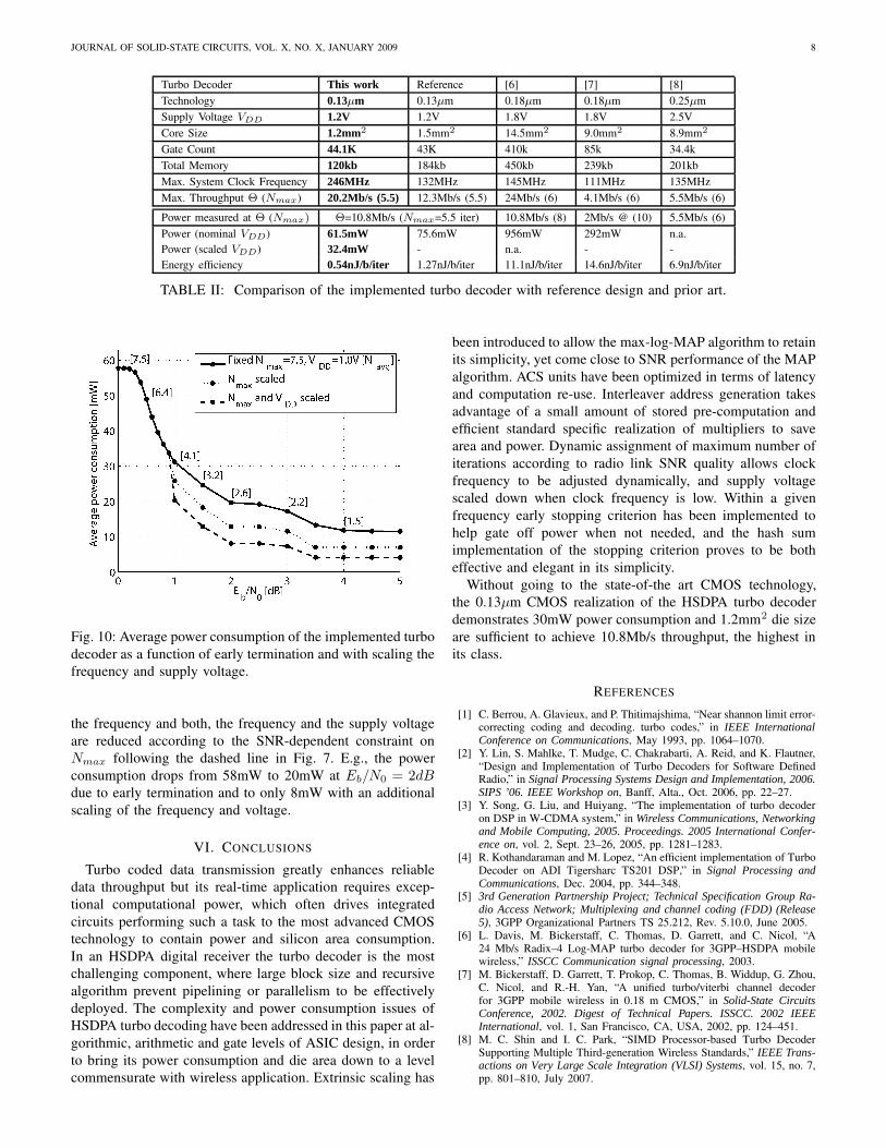
Fig. 10 shows the average power consumption of the imple-mented turbo decoder as a function of the Eb/N0. In the firstcurve, VDD and Nmax have been fixed to 1.0V and 7.5 itera-tions respectively, to show the effect of early termination alone.The power consumption decreases with Navg , because theturbo decoder is shut down instead of performing unnecessaryturbo iterations5. In the second and third curve, additionally
4A detailed table with all designs scaled to 0.13µm CMOS technology hasbeen given in [19].
5The average power consumption as a function of the Eb/N0 has beenobtained as the product of the measured power consumption per turbo-iteration and the number of iterations Navg obtained from bit-true fixed-pointsimulations.
JOURNAL OF SOLID-STATE CIRCUITS, VOL. X, NO. X, JANUARY 2009 8
Turbo Decoder This work Reference [6] [7] [8]Technology 0.13µm 0.13µm 0.18µm 0.18µm 0.25µmSupply Voltage VDD 1.2V 1.2V 1.8V 1.8V 2.5VCore Size 1.2mm2 1.5mm2 14.5mm2 9.0mm2 8.9mm2
Gate Count 44.1K 43K 410k 85k 34.4kTotal Memory 120kb 184kb 450kb 239kb 201kbMax. System Clock Frequency 246MHz 132MHz 145MHz 111MHz 135MHzMax. Throughput Θ (Nmax) 20.2Mb/s (5.5) 12.3Mb/s (5.5) 24Mb/s (6) 4.1Mb/s (6) 5.5Mb/s (6)Power measured at Θ (Nmax) Θ=10.8Mb/s (Nmax=5.5 iter) 10.8Mb/s (8) 2Mb/s @ (10) 5.5Mb/s (6)Power (nominal VDD) 61.5mW 75.6mW 956mW 292mW n.a.Power (scaled VDD) 32.4mW - n.a. - -Energy efficiency 0.54nJ/b/iter 1.27nJ/b/iter 11.1nJ/b/iter 14.6nJ/b/iter 6.9nJ/b/iter
TABLE II: Comparison of the implemented turbo decoder with reference design and prior art.
Fig. 10: Average power consumption of the implemented turbodecoder as a function of early termination and with scaling thefrequency and supply voltage.
the frequency and both, the frequency and the supply voltageare reduced according to the SNR-dependent constraint onNmax following the dashed line in Fig. 7. E.g., the powerconsumption drops from 58mW to 20mW at Eb/N0 = 2dBdue to early termination and to only 8mW with an additionalscaling of the frequency and voltage.
VI. CONCLUSIONS
Turbo coded data transmission greatly enhances reliabledata throughput but its real-time application requires excep-tional computational power, which often drives integratedcircuits performing such a task to the most advanced CMOStechnology to contain power and silicon area consumption.In an HSDPA digital receiver the turbo decoder is the mostchallenging component, where large block size and recursivealgorithm prevent pipelining or parallelism to be effectivelydeployed. The complexity and power consumption issues ofHSDPA turbo decoding have been addressed in this paper at al-gorithmic, arithmetic and gate levels of ASIC design, in orderto bring its power consumption and die area down to a levelcommensurate with wireless application. Extrinsic scaling has
been introduced to allow the max-log-MAP algorithm to retainits simplicity, yet come close to SNR performance of the MAPalgorithm. ACS units have been optimized in terms of latencyand computation re-use. Interleaver address generation takesadvantage of a small amount of stored pre-computation andefficient standard specific realization of multipliers to savearea and power. Dynamic assignment of maximum number ofiterations according to radio link SNR quality allows clockfrequency to be adjusted dynamically, and supply voltagescaled down when clock frequency is low. Within a givenfrequency early stopping criterion has been implemented tohelp gate off power when not needed, and the hash sumimplementation of the stopping criterion proves to be botheffective and elegant in its simplicity.
Without going to the state-of-the art CMOS technology,the 0.13µm CMOS realization of the HSDPA turbo decoderdemonstrates 30mW power consumption and 1.2mm2 die sizeare sufficient to achieve 10.8Mb/s throughput, the highest inits class.
REFERENCES
[1] C. Berrou, A. Glavieux, and P. Thitimajshima, “Near shannon limit error-correcting coding and decoding. turbo codes,” in IEEE InternationalConference on Communications, May 1993, pp. 1064–1070.
[2] Y. Lin, S. Mahlke, T. Mudge, C. Chakrabarti, A. Reid, and K. Flautner,“Design and Implementation of Turbo Decoders for Software DefinedRadio,” in Signal Processing Systems Design and Implementation, 2006.SIPS ’06. IEEE Workshop on, Banff, Alta., Oct. 2006, pp. 22–27.
[3] Y. Song, G. Liu, and Huiyang, “The implementation of turbo decoderon DSP in W-CDMA system,” in Wireless Communications, Networkingand Mobile Computing, 2005. Proceedings. 2005 International Confer-ence on, vol. 2, Sept. 23–26, 2005, pp. 1281–1283.
[4] R. Kothandaraman and M. Lopez, “An efficient implementation of TurboDecoder on ADI Tigersharc TS201 DSP,” in Signal Processing andCommunications, Dec. 2004, pp. 344–348.
[5] 3rd Generation Partnership Project; Technical Specification Group Ra-dio Access Network; Multiplexing and channel coding (FDD) (Release5), 3GPP Organizational Partners TS 25.212, Rev. 5.10.0, June 2005.
[6] L. Davis, M. Bickerstaff, C. Thomas, D. Garrett, and C. Nicol, “A24 Mb/s Radix–4 Log-MAP turbo decoder for 3GPP–HSDPA mobilewireless,” ISSCC Communication signal processing, 2003.
[7] M. Bickerstaff, D. Garrett, T. Prokop, C. Thomas, B. Widdup, G. Zhou,C. Nicol, and R.-H. Yan, “A unified turbo/viterbi channel decoderfor 3GPP mobile wireless in 0.18 m CMOS,” in Solid-State CircuitsConference, 2002. Digest of Technical Papers. ISSCC. 2002 IEEEInternational, vol. 1, San Francisco, CA, USA, 2002, pp. 124–451.
[8] M. C. Shin and I. C. Park, “SIMD Processor-based Turbo DecoderSupporting Multiple Third-generation Wireless Standards,” IEEE Trans-actions on Very Large Scale Integration (VLSI) Systems, vol. 15, no. 7,pp. 801–810, July 2007.
JOURNAL OF SOLID-STATE CIRCUITS, VOL. X, NO. X, JANUARY 2009 9
[9] C.-C. Lin, Y.-H. Shih, H.-C. Chang, and C.-Y. Lee, “A dual modechannel decoder for 3GPP2 mobile wireless communications,” in Solid-State Circuits Conference, 2004. ESSCIRC 2004. Proceeding of the 30thEuropean, Sept. 21–23, 2004, pp. 483–486.
[10] L. Bahl, J. Cocke, F. Jelinek, and J. Raviv, “Optimal decoding oflinear codes for minimizing symbol error rate,” IEEE Transactions oninformation theory, vol. vol. 20, pp. 284–287, Mar. 1974.
[11] J. Woodard and L. Hanzo, “Comparative study of turbo decodingtechniques: An overview,” IEEE Transactions On Vehicular Technology,vol. 49, no. 6, pp. 2208–2233, Nov. 2000.
[12] F. Raouafi, A. Dingninou, and C. Berrou, “Saving memory in turbo-decoders using the max-log-MAP algorithm,” in Turbo Codes in DigitalBroadcasting - Could It Double Capacity? (Ref. No. 1999/165), IEEColloquium on, London, UK, 1999, pp. 1–14.
[13] J. Vogt and A. Finger, “Improving the max-log-MAP turbo decoder,”Electronics Letters, vol. 36, pp. 1937–1939, Nov. 9, 2000.
[14] C.-C. Lin, Y.-H. Shih, H.-C. Chang, and C.-Y. Lee, “A low powerturbo/Viterbi decoder for 3GPP2 applications,” Very Large Scale Integra-tion (VLSI) Systems, IEEE Transactions on, vol. 14, no. 4, pp. 426–430,Apr. 2006.
[15] P. Ituero, M. Lopez-Vallejo, and S. Mujtaba, “A configurable applicationspecific processor for turbo decoding,” Conference Record of the Thirty-Ninth Asilomar Conference on Signals, Systems and Computers, pp.1356–1360, Nov. 2005.
[16] A. P. Hekstra, “An alternative to metric rescaling in Viterbi decoders,”IEEE Transactions on Communications, vol. 37, no. 11, pp. 1220–1222,Nov. 1989.
[17] Y. Wu, B. D. Woerner, and T. K. Blankenship, “Data width requirementsin SISO decoding with module normalization,” IEEE Transactions onCommunications, vol. 49, no. 11, pp. 1861–1868, Nov. 2001.
[18] 3rd Generation Partnership Project; Technical Specification GroupRadio Access Network; Channel coding and Multiplexing examples(Release 4), 3GPP Organizational Partners TS 25.944, Rev. 4.1.0, June2001.
[19] C. Benkeser, A. Burg, T. Cupaiuolo, and Q. Huang, “A 58mW 1.2mm2
HSDPA Turbo Decoder ASIC in 0.13µm CMOS,” in Solid-State CircuitsConference, 2008. ISSCC 2008. Digest of Technical Papers. IEEEInternational, Feb. 3–7, 2008, pp. 264–612.
[20] 3rd Generation Partnership Project; Technical Specification GroupRadio Access Network; User Equipment (UE) radio transmission andreception (FDD) (Release 8), 3GPP Organizational Partners TS 25.101,Rev. 8.1.0, Dec. 2007.
[21] R. Y. Shao, S. Lin, and M. P. C. Fossorier, “Two simple stopping criteriafor turbo decoding,” IEEE Transactions on Communications, vol. 47,no. 8, pp. 1117–1120, Aug. 1999.
Christian Benkeser (S’08) was born in Ottersweier,Germany, in 1977. He received his Dipl.-Ing. degreein Electronical Engineering from the University ofKarlsruhe (TH), Germany, in 2004. In the same year,he joined the Integrated Systems Laboratory of theSwiss Federal Institute of Technology (ETH) Zurich,where he is working towards the Ph.D. degree as aResearch Assistant. His chief areas of interest havebeen algorithms, circuits and systems for wirelesscommunications.
Andreas Burg Andreas Burg (S’97-M’05) was bornin Munich, Germany, in 1975. He received his Dipl.-Ing. degree in 2000 from the Swiss Federal Instituteof Technology (ETH) Zurich, Zurich, Switzerland.He then joined the Integrated Systems Laboratoryof ETH Zurich, from where he graduated with theDr. sc. techn. degree in 2006.
In 1998, he worked at Siemens Semiconductors,San Jose, CA. During his doctoral studies, he was avisiting researcher with Bell Labs Wireless Researchfor a total of one year. From 2006 to 2007, he held
positions as postdoctoral researcher at the Integrated Systems Laboratory andat the Communication Technology Laboratory of the ETH Zurich. In 2007he co-founded Celestrius, an ETH-spinoff in the field of MIMO wirelesscommunication, where he is responsible for the VLSI development. Hisresearch interests include the design of digital VLSI circuits and systems,signal processing for wireless communications, and deep submicron VLSIdesign.
In 2000, Mr. Burg received the “Willi Studer Award” and the ETH Medalfor his diploma and his diploma thesis, respectively. Mr. Burg was alsoawarded an ETH Medal for his Ph.D. dissertation in 2006. In 2008, Dr. Burgwas awarded a 4-years grant from the Swiss National Science Foundation(SNF) on which he will join the ETH Zurich as an SNF Professor.
Teo Cupaiuolo Teo Cupaiuolo received his M.S. de-gree in electrical engineering in 2006 from Politec-nico di Torino, Torino, Italy. He is currently workingwithin the MIMO WLAN team at Advanced SystemTechnologies (AST), STMicroelectronics of Agrate,where he designs VLSI architectures of advancedMIMO detection algorithms.
Qiuting Huang Qiuting Huang (S’86-M’88-SM’96-F’02) received his Ph.D. degree in applied sciencesfrom the Katholieke Universiteit Leuven, Belgium,in 1987. Between 1987 and 1992 he was a lecturerat the University of East Anglia, Norwich, UK.Since January 1993, he has been with the Inte-grated Systems Laboratory, Swiss Federal Instituteof Technology (ETH), Zurich, where he is Professorof Electronics. In 2007 he was also appointed asa part-time Cheung Kong Seminar Professor by theChinese Ministry of Education and the Cheung Kong
Foundation and has been affiliated with the South East University, Nanjing,China.
Prof. Huang’s research interests span RF, analog, mixed analog-digital aswell as digital application specific integrated circuits and systems, with anemphasis on wireless communications applications in recent years. He haspublished widely on those topics in leading solid-state circuits conferencesand journals. He is a member of the technical program committees ofthe International Solid-State Circuits Conference (ISSCC) and the EuropeanSolid-State Circuits Conference (ESSCIRC). He is also a member of theexecutive committee of ISSCC.