design and layout - sawyer/hanson innovations - home conveyor catalog/5 s… · design and layout...
TRANSCRIPT

37
Design andLayout
SECTION IIDESIGN AND LAYOUT SECTION II
Classification of Enclosure Types .................................................................................................37Hand of Conveyors .......................................................................................................................39Classification of Special Continuous Weld Finishes .....................................................................40Detailing of “U” Trough..................................................................................................................41Detailing of Tubular Trough ..........................................................................................................42Detailing of Trough and Discharge Flanges..................................................................................43Bolt Tables ....................................................................................................................................45Pipe Sizes, Dimensions and Weights ...........................................................................................47Screw Conveyor Drive Arrangements ..........................................................................................48Screw Conveyor Sample Horsepower Worksheet........................................................................49
Classes of EnclosuresConveyors can be designed to protect the material being handled from a hazardous surrounding or to protect the surroundings
from a hazardous material being conveyed.This section establishes recommended classes of construction for conveyor enclosures — without regard to their end use or
application. These several classes call for specific things to be done to a standard conveyor housing to provide several degrees ofenclosure protection.
Enclosure ClassificationsClass IE — Class IE enclosures are those provided primarily for the protection of operating personnel or equipment, or where the
enclosure forms an integral or functional part of the conveyor or structure. They are generally used where dust controlis not a factor or where protection for, or against, the material being handled is not necessary — although as convey-or enclosures a certain amount or protection is afforded.
Class IIE — Class IIE enclosures employ constructions which provide some measure of protection against dust or for, or against,the material being handled.
Class IIIE — Class IIIE enclosures employ constructions which provide a higher degree of protection in these classes against dust,and for or against the material being handled.
Class IVE — Class IVE enclosures are for outdoor applications and under normal circumstances provide for the exclusion of waterfrom the inside of the casing. They are not to be construed as being water-tight, as this may not always be the case.
When more than one method of fabrication is shown, either is acceptable.

38
Enclosures
Enclosure Construction
Enclosure Classifications
I E II E III E IV EComponent Classification
A. TROUGH CONSTRUCTIONFormed & Angle Top Flange1. Plate type end flange
a. Continuous arc weld . . . . . . . . . . . . . . . . . . . . . . . . . . . . . . . . . . . . . . . . . . . . . . . . . . . . . X X X Xb. Continuous arc weld on top of end flange and trough top rail . . . . . . . . . . . . . . . . . . . . . X X X X
2. Trough Top Rail Angles(Angle Top trough only)a. Staggered intermittent arc and spot weld . . . . . . . . . . . . . . . . . . . . . . . . . . . . . . . . . . . . . Xb. Continuous arc weld on top leg of angle on inside of trough and intermittent arc weld on
lower leg of angle to outside of trough . . . . . . . . . . . . . . . . . . . . . . . . . . . . . . . . . . . . . . . X X Xc. Staggered intermittent arc weld on top leg of angle on inside of trough and intermittent
arc weld on lower leg of angle to outside of trough, or spot weld when mastic is usedbetween leg of angle and trough sheet . . . . . . . . . . . . . . . . . . . . . . . . . . . . . . . . . . . . . . X X X
B. COVER CONSTRUCTION1. Plain flat
a. Only butted when hanger is at cover joint . . . . . . . . . . . . . . . . . . . . . . . . . . . . . . . . . . . . Xb. Lapped when hanger is not at cover joint . . . . . . . . . . . . . . . . . . . . . . . . . . . . . . . . . . . . . X
2. Semi-Flangeda. Only butted when hanger is at cover joint . . . . . . . . . . . . . . . . . . . . . . . . . . . . . . . . . . . . X X X Xb. Lapped when hanger is not at cover joint . . . . . . . . . . . . . . . . . . . . . . . . . . . . . . . . . . . . . Xc. With buttstrap when hanger is not at cover joint . . . . . . . . . . . . . . . . . . . . . . . . . . . . . . . . X X X
3. Flangeda. Only butted when hanger is at cover joint . . . . . . . . . . . . . . . . . . . . . . . . . . . . . . . . . . . . X X Xb. Buttstrap when hanger is not at cover joint . . . . . . . . . . . . . . . . . . . . . . . . . . . . . . . . . . . X X X
4. Hip Roofa. Ends with a buttstrap connection . . . . . . . . . . . . . . . . . . . . . . . . . . . . . . . . . . . . . . . . . . . X
C. COVER FASTENERS FOR STANDARD GA. COVERS1. Spring, screw or toggle clamp fasteners or bolted construction
a. Max. spacing plain flat covers . . . . . . . . . . . . . . . . . . . . . . . . . . . . . . . . . . . . . . . . . . . . . 60″b. Max. spacing semi-flanged covers . . . . . . . . . . . . . . . . . . . . . . . . . . . . . . . . . . . . . . . . . . 60″ 30″ 18″ 18″c. Max. spacing flanged and hip-roof covers . . . . . . . . . . . . . . . . . . . . . . . . . . . . . . . . . . . . 40″ 24″ 24″
D. GASKETS1. Covers
a. Red rubber or felt up to 230° F . . . . . . . . . . . . . . . . . . . . . . . . . . . . . . . . . . . . . . . . . . . . . X Xb. Neoprene rubber, when contamination is a problem . . . . . . . . . . . . . . . . . . . . . . . . . . . . X Xc. Closed cell foam type elastic material to suit temperature rating of gasket . . . . . . . . . . . X X X
2. Trough End flangesa. Mastic type compounds . . . . . . . . . . . . . . . . . . . . . . . . . . . . . . . . . . . . . . . . . . . . . . . . . . X X Xb. Red rubber up to 230° F . . . . . . . . . . . . . . . . . . . . . . . . . . . . . . . . . . . . . . . . . . . . . . . . . . X X Xc. Neoprene rubber, when contamination is a problem . . . . . . . . . . . . . . . . . . . . . . . . . . . . X Xd. Closed cell foam type elastic material to suit temperature rating of gasket . . . . . . . . . . . X X X
E. TROUGH END SHAFT SEALS*1. When handling non-abrasive materials . . . . . . . . . . . . . . . . . . . . . . . . . . . . . . . . . . . . . . . . . X X2. When handling abrasive materials . . . . . . . . . . . . . . . . . . . . . . . . . . . . . . . . . . . . . . . . . . . . X X X X
*Lip type seals for non-abrasive materialsFelt type for mildly abrasive materialsWaste type for highly abrasive materials

39
HandConveyors
Left Hand Right Hand
Right and Left Hand ScrewsA conveyor screw is either right hand or left hand depending on the form of the helix. The hand of the screw is easily determined
by looking at the end of the screw.
The screw pictured to the left has the flight helix wrapped around the pipe in a counter-clockwise direction, or to your left. Sameas left hand threads on a bolt. This is arbitrarily termed a LEFT hand screw.
The screw pictured to the right has the flight helix wrapped around the pipe in a clockwise direction, or to your right. Same asright hand threads on a bolt. This is termed a RIGHT hand screw.
A conveyor screw viewed from either end will show the same configuration. If the end of the conveyor screw is not readily visible,then by merely imagining that the flighting has been cut, with the cut end exposed, the hand of the screw may be easily determined.
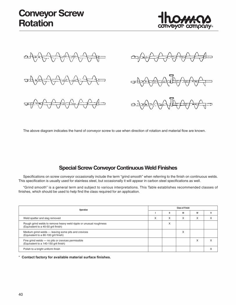
Conveyor Screw RotationFlow Flow
C.W. C.C.W.Rotation Rotation
Left Hand Right Hand
The above diagrams are a simple means of determining screw rotation. When the material flow is in the direction away from theend being viewed, a R.H. screw will turn counter clockwise and a L.H. screw will turn clockwise rotation as shown by the arrows.
40
Conveyor ScrewRotation
The above diagram indicates the hand of conveyor screw to use when direction of rotation and material flow are known.
Special Screw Conveyor Continuous Weld Finishes
Specifications on screw conveyor occasionally include the term “grind smooth” when referring to the finish on continuous welds.This specification is usually used for stainless steel, but occasionally it will appear in carbon steel specifications as well.
“Grind smooth” is a general term and subject to various interpretations. This Table establishes recommended classes offinishes, which should be used to help find the class required for an application.
Class of FinishOperation
I II III IV V
Weld spatter and slag removed X X X X X
Rough grind welds to remove heavy weld ripple or unusual roughness X(Equivalent to a 40-50 grit finish)
Medium grind welds — leaving some pits and crevices X(Equivalent to a 80-100 grit finish)
Fine grind welds — no pits or crevices permissible X X(Equivalent to a 140-150 grit finish)
Polish to a bright uniform finish X
RIGHT HAND
RIGHT HAND
LEFT HAND
LEFT HAND
RIGHT HAND LEFT HAND
RIGHT HAND LEFT HAND
* Contact factory for available material surface finishes.

41
Layout
Trough
4 1 9-101⁄2 10 11⁄2 3⁄8 41⁄2 7⁄8 35⁄8 45⁄8 33⁄4 5 53⁄4 17⁄16 1
6 11⁄2 9-10 10 2 3⁄8 6 13⁄16 41⁄2 55⁄8 5 7 81⁄8 11⁄2 1
11⁄29 2 9-10 10 2 1⁄2 8 15⁄16 61⁄8 7 7⁄8 71⁄8 10 93⁄8 15⁄8 11⁄2
11⁄210 2 9-10 10 2 1⁄2 9 19⁄16 63⁄8 87⁄8 77⁄8 11 91⁄2 13⁄4 13⁄4
2 11-10 2 12 27⁄16 11-9 12 3 5⁄8 101⁄2 13⁄8 73⁄4 95⁄8 87⁄8 13 121⁄4 2 15⁄8
3 11-9 3
27⁄1614 3 11-9 12 3 5⁄8 111⁄2 13⁄8 91⁄4 107⁄8 101⁄8 15 131⁄2 2 15⁄8
16 3 11-9 12 3 5⁄8 131⁄2 13⁄4 105⁄8 12 111⁄8 17 147⁄8 21⁄2 2
3 11-9 318 12 5⁄8 141⁄2 13⁄4 121⁄8 133⁄8 123⁄8 19 16 21⁄2 2
37⁄16 11-8 4
3 11-9 3 20 12 3⁄4 151⁄2 2 131⁄2 15 133⁄8 21 191⁄4 21⁄2 21⁄4
37⁄16 11-8 4
24 37⁄16 11-8 12 4 3⁄4 171⁄2 21⁄4 161⁄2 181⁄8 153⁄8 25 20 21⁄2 21⁄2
Screw clearance at trough end is one half of dimension E
Hanger Bearing Centers
Std. Length Conveyor Screw
Standard Housing Length
(Min.)
G (Min.)
Trough
A BScrew Coupling C D E F G H J K L M N P R
Diameter Diameter Length Length Bolts (Min.)
Screw clearance at trough end is one half of dimension E
Typical Method of Detailing9″ × 2″ × 25´-0″ Conveyor
Cover Lengths
Hanger Spacings
Screw LengthsBare Pipe
Thrust BearingDrive ShaftSeal
Spout Location
Housing Lengths
Total Length
9TCP14 Covers
9S412-R Screws
9CTF10 Troughs
Tail Shaft
Ball Bearing
Seal
9CH2264 Hangers (Typ.)CC4H Couplings
(Typ.)
Bolts F

42
Layout
4 1 9-101⁄2 10 11⁄2 3⁄8 41⁄2 7⁄8 35⁄8 45⁄8 33⁄4 5 53⁄4 17⁄16 1
6 11⁄2 9-10 10 2 3⁄8 6 13⁄16 41⁄2 55⁄8 5 7 81⁄8 11⁄2 1
11⁄29 2 9-10 10 2 1⁄2 8 15⁄16 61⁄8 7 7⁄8 71⁄8 10 93⁄8 15⁄8 11⁄2
11⁄210 2 9-10 10 2 1⁄2 9 19⁄16 63⁄8 87⁄8 77⁄8 11 91⁄2 13⁄4 13⁄4
2 11-10 2 12 27⁄16 11-9 12 3 5⁄8 101⁄2 13⁄8 73⁄4 95⁄8 87⁄8 13 121⁄4 2 15⁄8
3 11-9 3
27⁄1614 3 11-9 12 3 5⁄8 111⁄2 13⁄8 91⁄4 107⁄8 101⁄8 15 131⁄2 2 15⁄8
16 3 11-9 12 3 5⁄8 131⁄2 13⁄4 105⁄8 12 111⁄8 17 147⁄8 21⁄2 2
3 11-9 318 12 5⁄8 141⁄2 13⁄4 121⁄8 133⁄8 123⁄8 19 16 21⁄2 2
37⁄16 11-8 4
3 11-9 3 20 12 3⁄4 151⁄2 2 131⁄2 15 133⁄8 21 191⁄4 21⁄2 21⁄4
37⁄16 11-8 4
24 37⁄16 11-8 12 4 3⁄4 171⁄2 21⁄4 161⁄2 181⁄8 153⁄8 25 20 21⁄2 21⁄2
Hanger Bearing Centers
(Min.)
(Min.)
Tubular Trough Housing
A BScrew Coupling C D E F G H J K L M N P RDia. Dia. Length Length Bolts (Min.)
Std. Length Conveyor Screw
Standard Housing Length
Typical Method of Detailing9″ × 2″ × 15´-0″ Conveyor
Hanger Spacings
Screw Lengths
Bare Pipe
Thrust BearingDrive ShaftSeal
Spout Location
Housing Lengths
Total Length
9CH2264 — Hanger
9S412-R Screws
9CHT10 Troughs
Tail Shaft
Ball Bearing
Seal
Screw clearance at trough end is one half of dimension E
(Bare Pipe)
Bolts F

43
Bolt Patterns
U-Trough End Flanges
Flared Trough End Flanges
6 Bolts
8 Bolts10 Bolts
12 Bolts
4 6 3⁄8 7 35⁄8 11⁄8 31⁄8 31⁄8 31⁄8 — — —
6 6 3⁄8 87⁄8 41⁄2 11⁄32 41⁄8 41⁄16 41⁄16 — — —
9 8 3⁄8 121⁄2 61⁄8 13⁄16 41⁄8 33⁄4 51⁄8 41⁄8 — —
10 8 3⁄8 131⁄4 63⁄8 21⁄4 31⁄2 43⁄16 51⁄16 41⁄8 — —
12 8 1⁄2 157⁄8 73⁄4 11⁄2 55⁄16 41⁄16 73⁄4 53⁄16 — —
14 8 1⁄2 177⁄8 91⁄4 217⁄32 55⁄8 515⁄16 6 515⁄16 — —
16 8 5⁄8 20 105⁄8 25⁄8 63⁄8 65⁄8 71⁄2 65⁄8 — —
18 10 5⁄8 22 121⁄8 223⁄32 515⁄16 57⁄8 57⁄8 57⁄8 57⁄8 —
20 10 5⁄8 243⁄8 131⁄2 225⁄32 61⁄4 611⁄16 611⁄16 611⁄16 611⁄16 —
24 12 5⁄8 281⁄2 161⁄2 225⁄32 61⁄8 65⁄8 65⁄8 65⁄8 65⁄8 65⁄8
Screw Bolts
Diameter Number Diameter A B E F G H J K L
6 3⁄8 6 47⁄16 7 73⁄16 127⁄32 51⁄4 51⁄4 21⁄32 — — —
9 3⁄8 8 61⁄4 9 921⁄32 143⁄64 5 5 29⁄16 5 — —
12 1⁄2 8 715⁄16 10 1113⁄16 113⁄16 53⁄4 53⁄4 37⁄8 53⁄4 — —
14 1⁄2 10 815⁄16 11 1249⁄64 21⁄16 51⁄8 51⁄8 3 51⁄8 51⁄8 —
16 5⁄8 10 10 111⁄2 1411⁄16 215⁄64 51⁄2 51⁄2 33⁄4 51⁄2 51⁄2 —
18 5⁄8 10 11 121⁄8 16 25⁄8 63⁄16 63⁄16 215⁄16 63⁄16 63⁄16 —
20 5⁄8 10 123⁄16 131⁄2 177⁄8 29⁄32 7 7 311⁄32 7 7 —
24 5⁄8 12 141⁄4 161⁄2 2061⁄64 25⁄16 67⁄8 67⁄8 35⁄16 67⁄8 67⁄8 67⁄8
Screw Bolts A B C E F G H J K LDiameter Diameter HolesInches Number Inches
6 Bolts 8 Bolts 10 Bolts 12 Bolts
C/L Screw
C/L Screw
C/L Screw
C/L Screw
C/L Screw
C/L Screw
C/L Screw
C/L Screw
44
Bolt Patterns
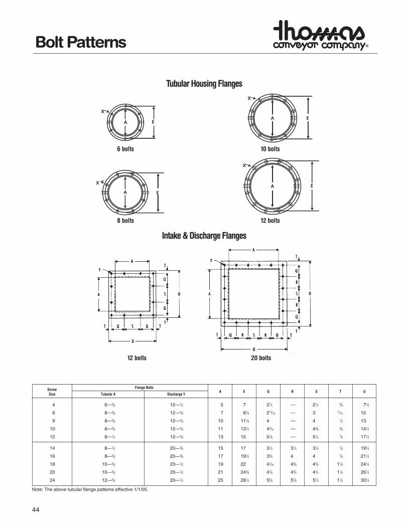
Tubular Housing Flanges
Intake & Discharge Flanges
6 bolts 10 bolts
8 bolts 12 bolts
12 bolts 20 bolts
4 6—3⁄8 12—1⁄4 5 7 21⁄4 — 21⁄4 3⁄8 71⁄2
6 8—3⁄8 12—3⁄8 7 87⁄8 213⁄16 — 3 11⁄16 10
9 8—3⁄8 12—3⁄8 10 117⁄8 4 — 4 1⁄2 13
10 8—3⁄8 12—3⁄8 11 131⁄4 45⁄16 — 43⁄8 5⁄8 141⁄4
12 8—1⁄2 12—3⁄8 13 15 51⁄8 — 51⁄4 7⁄8 171⁄4
14 8—1⁄2 20—3⁄8 15 17 31⁄2 31⁄2 31⁄2 7⁄8 191⁄4
16 8—5⁄8 20—3⁄8 17 191⁄2 33⁄4 4 4 7⁄8 211⁄4
18 10—5⁄8 20—1⁄2 19 22 47⁄16 43⁄8 43⁄8 11⁄8 241⁄4
20 10—5⁄8 20—1⁄2 21 243⁄8 47⁄8 43⁄4 43⁄4 11⁄8 261⁄4
24 12—5⁄8 20—1⁄2 25 281⁄2 55⁄8 55⁄8 51⁄2 11⁄8 301⁄4
Screw Flange BoltsA E Q R S T U
Size Tubular X Discharge Y
Note: The above tubular flange patterns effective 1/1/05.
Part
Nam
e4"
6"9"
10"
12"
14"
16"
18"
20"
24"
Flan
ge, T
roug
h6
- 3/8
x 1
6 - 3
/8 x
18
- 3/8
x 1
8 - 3
/8 x
18
- 1/2
x 1
1/4
8 - 1
/2 x
1 1
/48
- 5/8
x 1
1/2
10 -
5/8
x 1
1/2
10 -
5/8
x 1
1/2
12 -
5/8
x 1
1/2
Flan
ge, T
ubul
ar T
roug
h6
- 3/8
x 1
8 - 3
/8 x
18
- 3/8
x 1
8 - 3
/8 x
18
- 1/2
x 1
1/4
8 - 1
/2 x
1 1
/48
- 5/8
x 1
1/2
10 -
5/8
x 1
1/2
10 -
5/8
x 1
1/2
12 -
5/8
x 1
1/2
Ends
, Tro
ugh
Insi
de6
- 3/8
x 1
6 - 3
/8 x
18
- 3/8
x 1
8 - 3
/8 x
18
- 1/2
x 1
1/4
8 - 1
/2 x
1 1
/48
- 5/8
x 1
1/2
10 -
5/8
x 1
1/2
10 -
5/8
x 1
1/2
12 -
5/8
x 1
1/2
Insi
de D
isch
arge
2 - 3
/8 x
12
- 3/8
x 1
4 - 3
/8 x
14
- 3/8
x 1
4 - 1
/2 x
1 1
/44
- 1/2
x 1
1/4
4 - 5
/8 x
1 1
/24
- 5/8
x 1
1/2
4 - 5
/8 x
1 1
/26
- 5/8
x 1
1/2
Insi
de R
ecta
ngul
ar5
- 3/8
x 1
6 - 3
/8 x
18
- 3/8
x 1
1/4
8 - 3
/8 x
1 1
/410
- 1/
2 x
1 1/
211
- 1/
2 x
1 1/
212
- 5/
8 x
1 1/
212
- 5/
8 x
1 1/
212
- 5/
8 x
1 1/
212
- 5/
8 x
1 1/
2
Outs
ide
6 - 3
/8 x
1 1
/46
- 3/8
x 1
1/4
8 - 3
/8 x
1 1
/48
- 3/8
x 1
1/4
8 - 1
/2 x
1 1
/28
- 1/2
x 1
1/2
8 - 5
/8 x
1 1
/210
- 5/
8 x
1 3/
410
- 5/
8 x
1 3/
412
- 5/
8 x
1 3/
4
Outs
ide
Disc
harg
e2
- 3/8
x 1
1/4
2 - 3
/8 x
1 1
/44
- 3/8
x 1
1/4
4 - 3
/8 x
1 1
/44
- 1/2
x 1
1/2
4 - 1
/2 x
1 1
/24
- 5/8
x 1
1/2
4 - 5
/8 x
1 3
/44
- 5/8
x 1
3/4
6 - 5
/8 x
1 3
/4
Ends
, Tub
ular
Tro
ugh
6 - 3
/8 x
1 1
/48
- 3/8
x 1
1/4
8 - 3
/8 x
1 1
/48
- 3/8
x 1
1/4
8 - 1
/2 x
1 1
/28
- 1/2
x 1
1/2
8 - 5
/8 x
1 1
/210
- 5/
8 x
1 1/
210
- 5/
8 x
1 1/
212
- 5/
8 x
1 1/
2
Hang
er, T
roug
h
Styl
e 60
-4
- 3/8
x 1
1/4
4 - 3
/8 x
1 1
/44
- 3/8
x 1
1/4
4 - 1
/2 x
1 1
/24
- 1/2
x 1
1/2
4 - 1
/2 x
1 1
/24
- 5/8
x 1
3/4
4 - 5
/8 x
1 3
/4-
Styl
e 70
-4
- 3/8
x 1
1/4
4 - 3
/8 x
1 1
/44
- 3/8
x 1
1/4
4 - 1
/2 x
1 1
/24
- 1/2
x 1
1/2
4 - 1
/2 x
1 1
/24
- 5/8
x 1
3/4
4 - 5
/8 x
1 3
/4-
Styl
e 21
64
- 1/4
x 1
4 - 3
/8 x
1 1
/44
- 3/8
x 1
1/4
4 - 3
/8 x
1 1
/44
- 1/2
x 1
1/2
4 - 1
/2 x
1 1
/24
- 1/2
x 1
1/2
4 - 5
/8 x
1 3
/44
- 5/8
x 1
3/4
4 - 5
/8 x
1 3
/4
Styl
e 22
04
- 1/4
x 1
4 - 3
/8 x
1 1
/44
- 3/8
x 1
1/4
4 - 3
/8 x
1 1
/44
- 1/2
x 1
1/2
4 - 1
/2 x
1 1
/24
- 1/2
x 1
1/2
4 - 5
/8 x
1 3
/44
- 5/8
x 1
3/4
4 - 5
/8 x
1 3
/4
Styl
e 22
64
- 1/4
x 1
4 - 3
/8 x
1 1
/44
- 3/8
x 1
1/4
4 - 3
/8 x
1 1
/44
- 1/2
x 1
1/2
4 - 1
/2 x
1 1
/24
- 1/2
x 1
1/2
4 - 5
/8 x
1 3
/44
- 5/8
x 1
3/4
4 - 5
/8 x
1 3
/4
Styl
e 23
04
- 1/4
x 1
4 - 3
/8 x
1 1
/44
- 3/8
x 1
1/4
4 - 3
/8 x
1 1
/44
- 1/2
x 1
1/2
4 - 1
/2 x
1 1
/24
- 1/2
x 1
1/2
4 - 5
/8 x
1 3
/44
- 5/8
x 1
3/4
4 - 5
/8 x
1 3
/4
Styl
e 31
64
- 1/4
x 1
4 - 3
/8 x
14
- 3/8
x 1
4 - 3
/8 x
1 1
/44
- 1/2
x 1
1/4
4 - 1
/2 x
1 1
/44
- 1/2
x 1
1/4
4 - 5
/8 x
1 1
/24
- 5/8
x 1
1/2
4 - 5
/8 x
1 1
/2
Styl
e 32
64
- 1/4
x 1
4 - 3
/8 x
14
- 3/8
x 1
4 - 3
/8 x
1 1
/44
- 1/2
x 1
1/4
4 - 1
/2 x
1 1
/44
- 1/2
x 1
1/4
4 - 5
/8 x
1 1
/24
- 5/8
x 1
1/2
4 - 5
/8 x
1 1
/2
Cove
rs, T
roug
h A/
R - 3
/8 x
1A/
R - 3
/8 x
1A/
R - 3
/8 x
1A/
R - 3
/8 x
1A/
R - 3
/8 x
1A/
R - 3
/8 x
1A/
R - 3
/8 x
1A/
R - 3
/8 x
1A/
R - 3
/8 x
1A/
R - 3
/8 x
1
Sadd
le -
Feet
Flan
ged
Feet
2 - 3
/8 x
1 1
/42
- 3/8
x 1
1/4
2 - 3
/8 x
1 1
/42
- 3/8
x 1
1/4
2 - 1
/2 x
1 1
/22
- 1/2
x 1
1/2
2 - 5
/8 x
1 3
/42
- 5/8
x 1
3/4
2 - 5
/8 x
1 3
/42
- 5/8
x 1
3/4
Sadd
leN/
AN/
AN/
AN/
AN/
AN/
AN/
AN/
AN/
AN/
A
Spou
ts, D
isch
arge
Flan
ge12
- 1/
4 x
112
- 3/
8 x
112
- 3/
8 x
112
- 3/
8 x
112
- 3/
8 x
120
- 3/
8 x
120
- 3/
8 x
120
- 1/
2 x
1 1/
420
- 1/
2 x
1 1/
420
- 1/
2 x
1 1/
4
Flan
ge w
/Slid
e10
- 1/
4 x
110
- 3/
8 x
110
- 3/
8 x
110
- 3/
8 x
110
- 3/
8 x
116
- 3/
8 x
116
- 3/
8 x
116
- 1/
2 x
1 1/
416
- 1/
2 x
1 1/
416
- 1/
2 x
1 1/
4
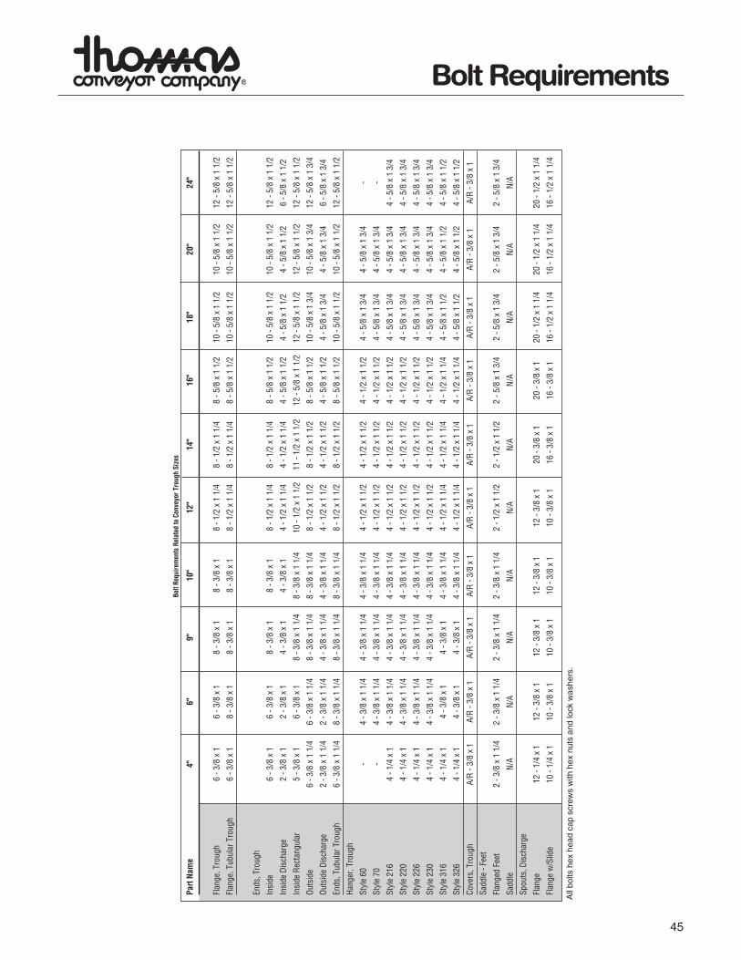
Bolt
Requ
irem
ents
Rel
ated
to C
onve
yor T
roug
h Si
zes
All
bolts
hex
hea
d ca
p sc
rew
s w
ith h
ex n
uts
and
lock
was
hers
.
45
Bolt Requirements

46
Bolt Requirements
Bolt
Requ
irem
ents
Rela
ted
toCo
nvey
orTr
ough
Size
s
All
bolts
hex
head
cap
scre
ws
with
hex
nuts
and
lock
was
hers
.
Part
Nam
e1"
11/
2"2"
27/
16"
3"3
7/16
"
Bear
ings
,End
Disc
harg
eBr
onze
3-3/
8x
11/
43-
1/2
x1
1/2
3-5/
8x
13/
43-
5/8
x1
3/4
3-3/
4x
23-
3/4
x2
1/4
Disc
harg
eBa
ll3-
3/8
x1
1/2
3-1/
2x
13/
43-
5/8
x1
3/4
3-5/
8x
23-
3/4
x2
1/4
3-3/
4x
21/
2
Flan
ged
Bron
ze4-
3/8
x1
1/4
4-1/
2x
11/
24-
5/8
x1
3/4
4-5/
8x
13/
44-
3/4
x2
4-3/
4x
21/
4
Flan
ged
Ball
4-3/
8x
11/
24-
1/2
x1
3/4
4-1/
2x
13/
44-
5/8
x2
4-3/
4x
21/
44-
3/4
x2
1/2
Flan
ged
Rolle
r-
4-1/
2x
21/
44-
1/2
x2
1/4
4-5/
8x
21/
44-
3/4
x3
4-3/
4x
31/
4
Pillo
wBl
ock
Bron
ze2-
3/8
x1
1/2
2-1/
2x
13/
42-
5/8
x2
2-5/
8x
21/
42-
3/4
x2
1/2
2-7/
8x
23/
4
Pillo
wBl
ock
Ball
2-3/
8x
21/
42-
1/2
x2
1/2
2-5/
8x
21/
22-
5/8
x2
3/4
2-7/
8x
31/
42-
7/8
x3
3/4
Pillo
wBl
ock
Rolle
r-
2-1/
2x
23/
42-
5/8
x3
2-5/
8x
31/
42-
3/4
x3
3/4
2-7/
8x
41/
2
Bear
ings
,Thr
ust
Type
"E"R
olle
r-
4-1/
2x
34-
1/2
x3
4-5/
8x
31/
24-
3/4
x3
3/4
4-3/
4x
4
Coup
ling
Bolts
3/8
x2
1/16
1/2
x3
5/8
x3
5/8
5/8
x4
3/8
3/4
x5-
31/
2"Pi
pe7/
8x
51/
2
3/4
x5
1/2-
4"Pi
pe
Seal
s,Sh
afts
Flan
ged
Glan
d-
4-1/
2x
13/
44-
1/2
x1
3/4
4-5/
8x
13/
44-
5/8
x2
4-3/
4x
2
Plat
ew
/Bal
lorB
ronz
e-
4-1/
2x
21/
24-
1/2
x2
1/2
4-5/
8x
23/
44-
3/4
x3
3/4
4-3/
4x
31/
4
Plat
ew
/Rol
ler
-4-
1/2
x3
4-1/
2x
34-
5/8
x3
1/2
4-3/
4x
33/
44-
3/4
x4
Split
Glan
d-
2-1/
2x
22-
1/2
x2
2-5/
8x
21/
42-
5/8
x2
1/4
2-3/
4x
23/
4
Was
tePa
ckw
/Bal
lorB
ronz
e-
4-1/
2x
31/
24-
5/8
x3
1/2
4-5/
8x
33/
44-
3/4
x4
4-3/
4x
5
Was
tePa
ckw
/Rol
ler
-4-
1/2
x4
4-1/
2x
44-
5/8
x4
1/2
4-3/
4x
43/
44-
3/4
x5
1/2
47
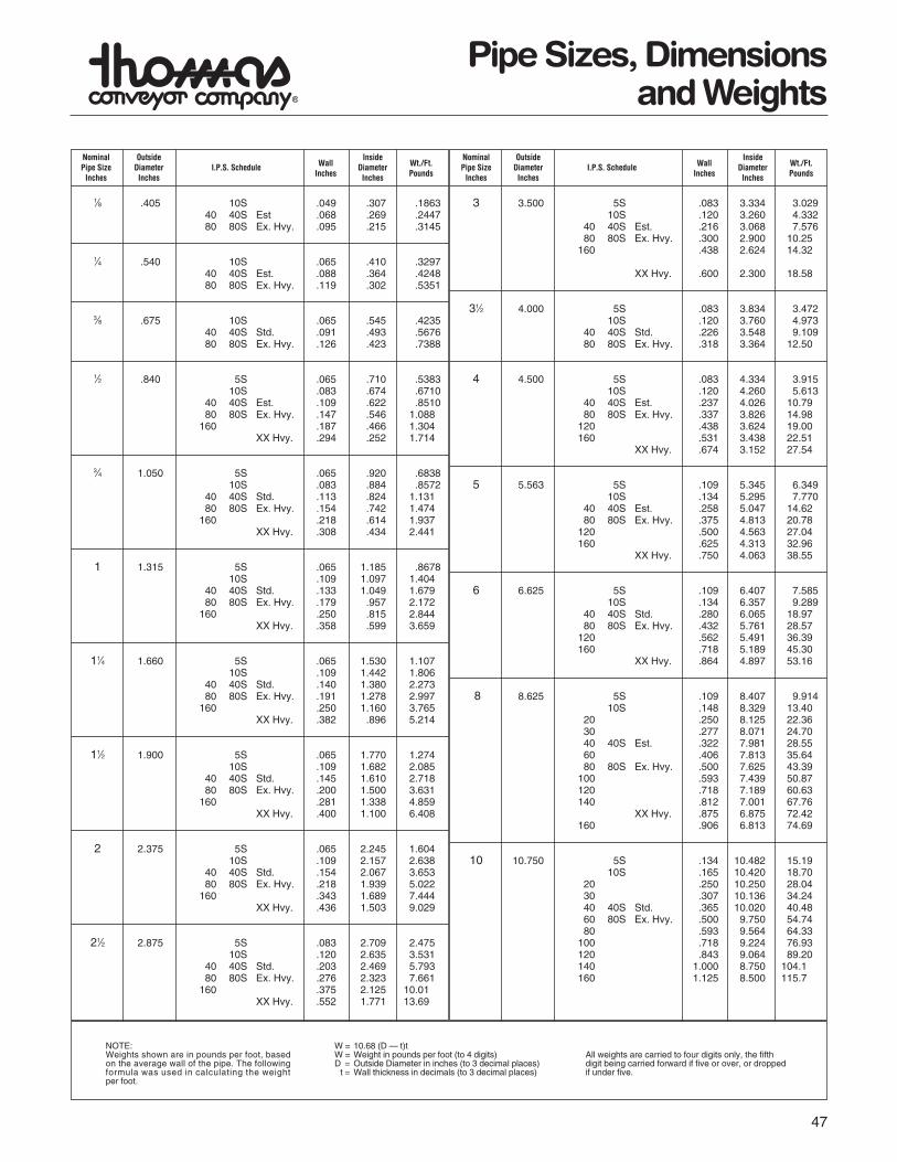
Pipe Sizes, Dimensionsand Weights
1⁄8 .405 10S .049 .307 .1863 40 40S Est .068 .269 .244780 80S Ex. Hvy. .095 .215 .3145
1⁄4 .540 10S .065 .410 .3297 40 40S Est. .088 .364 .424880 80S Ex. Hvy. .119 .302 .5351
3⁄8 .675 10S .065 .545 .423540 40S Std. .091 .493 .5676 80 80S Ex. Hvy. .126 .423 .7388
1⁄2 .840 5S .065 .710 .538310S .083 .674 .6710
40 40S Est. .109 .622 .8510 80 80S Ex. Hvy. .147 .546 1.088
160 .187 .466 1.304XX Hvy. .294 .252 1.714
3⁄4 1.050 5S .065 .920 .6838 10S .083 .884 .8572
40 40S Std. .113 .824 1.13180 80S Ex. Hvy. .154 .742 1.474
160 .218 .614 1.937XX Hvy. .308 .434 2.441
1 1.315 5S .065 1.185 .867810S .109 1.097 1.404
40 40S Std. .133 1.049 1.679 80 80S Ex. Hvy. .179 .957 2.172
160 .250 .815 2.844XX Hvy. .358 .599 3.659
11⁄4 1.660 5S .065 1.530 1.107 10S .109 1.442 1.806
40 40S Std. .140 1.380 2.27380 80S Ex. Hvy. .191 1.278 2.997
160 .250 1.160 3.765XX Hvy. .382 .896 5.214
11⁄2 1.900 5S .065 1.770 1.274 10S .109 1.682 2.085
40 40S Std. .145 1.610 2.71880 80S Ex. Hvy. .200 1.500 3.631
160 .281 1.338 4.859XX Hvy. .400 1.100 6.408
2 2.375 5S .065 2.245 1.60410S .109 2.157 2.638
40 40S Std. .154 2.067 3.65380 80S Ex. Hvy. .218 1.939 5.022
160 .343 1.689 7.444XX Hvy. .436 1.503 9.029
21⁄2 2.875 5S .083 2.709 2.47510S .120 2.635 3.531
40 40S Std. .203 2.469 5.793 80 80S Ex. Hvy. .276 2.323 7.661
160 .375 2.125 10.01 XX Hvy. .552 1.771 13.69
3 3.500 5S .083 3.334 3.02910S .120 3.260 4.332
40 40S Est. .216 3.068 7.57680 80S Ex. Hvy. .300 2.900 10.25
160 .438 2.624 14.32
XX Hvy. .600 2.300 18.58
31⁄2 4.000 5S .083 3.834 3.47210S .120 3.760 4.973
40 40S Std. .226 3.548 9.10980 80S Ex. Hvy. .318 3.364 12.50
4 4.500 5S .083 4.334 3.91510S .120 4.260 5.613
40 40S Est. .237 4.026 10.7980 80S Ex. Hvy. .337 3.826 14.98
120 .438 3.624 19.00160 .531 3.438 22.51
XX Hvy. .674 3.152 27.54
5 5.563 5S .109 5.345 6.34910S .134 5.295 7.770
40 40S Est. .258 5.047 14.6280 80S Ex. Hvy. .375 4.813 20.78
120 .500 4.563 27.04160 .625 4.313 32.96
XX Hvy. .750 4.063 38.55
6 6.625 5S .109 6.407 7.58510S .134 6.357 9.289
40 40S Std. .280 6.065 18.9780 80S Ex. Hvy. .432 5.761 28.57
120 .562 5.491 36.39160 .718 5.189 45.30
XX Hvy. .864 4.897 53.16
8 8.625 5S .109 8.407 9.91410S .148 8.329 13.40
20 .250 8.125 22.3630 .277 8.071 24.7040 40S Est. .322 7.981 28.5560 .406 7.813 35.6480 80S Ex. Hvy. .500 7.625 43.39
100 .593 7.439 50.87120 .718 7.189 60.63140 .812 7.001 67.76
XX Hvy. .875 6.875 72.42160 .906 6.813 74.69
10 10.750 5S .134 10.482 15.1910S .165 10.420 18.70
20 .250 10.250 28.0430 .307 10.136 34.2440 40S Std. .365 10.020 40.4860 80S Ex. Hvy. .500 9.750 54.7480 .593 9.564 64.33
100 .718 9.224 76.93120 .843 9.064 89.20140 1.000 8.750 104.1160 1.125 8.500 115.7
NOTE:Weights shown are in pounds per foot, basedon the average wall of the pipe. The followingformula was used in calculating the weightper foot.
W = 10.68 (D — t)tW = Weight in pounds per foot (to 4 digits)D = Outside Diameter in inches (to 3 decimal places)
t = Wall thickness in decimals (to 3 decimal places)
All weights are carried to four digits only, the fifthdigit being carried forward if five or over, or droppedif under five.
Nominal Outside InsidePipe Size Diameter I.P.S. Schedule Wall Diameter Wt./Ft.
Inches Inches Inches Inches Pounds
Nominal Outside InsidePipe Size Diameter I.P.S. Schedule Wall Diameter Wt./Ft.
Inches Inches Inches Inches Pounds

48
Typical DriveArrangements
The most common types of drives for Screw Conveyors are illustrated below.
In addition to those shown, other types availble are: variable speed drives, hydraulic drives, and take-off drives for connectionto other equipment.
For special drive requirements, consult our Engineering Department.
(Side View)
(End View)
(Side View)
(Top View)
ScrewDriverReducer
ShaftMountedReducer
GearmotorDrive
Base TypeReducerDrive
Reducer mounts on trough end, and is directly con-nected to the conveyor screw and includes integralthrust bearing, seal gland, and drive shaft. Motormount may be positioned at top, either side, orbelow. Separate drive shaft, end bearing, and sealare not required.
Reducer mounts on conveyor drive shaft. Motor and“V”-Belt drive may be in any convenient location.The torque arm may be fastened to the floor, or fittedto trough end. Requires extended drive shaft, endbearing, and seal.
Integral motor-reducer with chain drive to conveyordrive shaft. Usually mounted to top of trough bymeans of an adapter plate.
Motor direct-coupled to base type reducer, withchain drive to conveyor drive shaft. Usually mountedon floor or platform as close as possible to conveyor.

Client: ________________________________________ Date Quote Due:__________________________________
Conveyor No.:__________________________________ Inquiry No.: ______________________________________
Table 1-2
_______ Dia. ´ Length L = ______________________ Recommended % Trough Loading: ___________________
Material: ______________________________________ Materal HP Factor: FM = __________________________
Capacity:______________________________________ Component Series:________________________________
Density: W = ____________________________ Lbs/Ft3 Intermediate Hanger Bearing Series: __________________
Lumps: Max. Size ___________ in. Class (I) (II) (III) ____ Notes: __________________________________________
CFH = TPH x 2000WRequired Capacity = C = ___________ CFH (cubic feet per hour) CFH = Bushels per Hour ´ 1.24
CFH = Pounds per HourW
Tables 1-3, 1-4, 1-5
Equivalent Req’d Capacity CF1
CF2
CF3
Equivalent= × × × =
Capacity __________ __________ __________ __________ __________ CFH Capacity
Table 1-6
Screw Diameter = ___________________Select Diameter from ‘at max RPM’ column where capacity listed equals or exceeds equivalent capacity
Screw RPM = N = ____________ = Equivalent Capacity
Capacity ‘at one RPM’ for diameter selected
Table 1-7
Check lump size and lump class for diameter selected. If larger screw diameter recommended, recalculate RPM per instruc-tions above for selected diameter.
Tables 1-12, 1-13, 1-14, 1-15, 1-16, 1-17
Values to be substituted in formula: ______ ______ ______ ______ ______Fd Fb Ff Fp e
HPf = (L
)(N
)(Fd )(
Fb ) = ____________0000000001,000,0000000000
HPm = (C
)(L
)(W
)(Ff )(
Fm )(Fp ) = ____________
00000000000001,000,0000000000000000000
If HPf + HPm is less than 5.2, select overload factor FO = __________ (If HPf + HPm is greater than 5.2, FO = 1.0)
Total HP = (HPf + HPm) Fo = ____________________________ = ____________e
DRIVE: Use ____________ HP motor with AGMA Class (I) (II) (III) Drive at _____________________ Screw RPM
Tables 1-18, 1-19
Torque = Motor HP0×063,025 =_______________ in.-lbs.Screw RPM
List Minimum Size: Shaft Dia. ____________ Pipe ____________ Bolt/Shear ____________ Bolt/Bearing ____________
Tables 1-8, 1-9, 1-10, 1-11
Select Components:Trough ___________ Screw ___________ Hanger Style ___________ Hanger Bearing ___________ Cover ___________
49
SampleHorsepower Work Sheet
NOTE: Consult factoryfor feederhorsepower
pages 49 - 64 4/7/05 11:29 AM Page 49