description fms / vms modbus interface etamatic / etamatic...
TRANSCRIPT

Description Modbus Interface
FMS / VMS ETAMATIC / ETAMATIC OEM
Burner Control FA 1
Sensors and Systemsfor Combustion Engineering


Table of Contents
Table of Contents
1 GENERAL INFORMATION . . . . . . . . . . . . . . . . . . . . . . . . . . . . . . . . . . . . . . . .4
1.1 Validity of these Instructions. . . . . . . . . . . . . . . . . . . . . . . . . . . . . . . . . . . . . . . . . . . . . . . . . . 4
2 SAFETY . . . . . . . . . . . . . . . . . . . . . . . . . . . . . . . . . . . . . . . . . . . . . . . . . . . . . . .5
2.1 German Law on Device Safety . . . . . . . . . . . . . . . . . . . . . . . . . . . . . . . . . . . . . . . . . . . . . . . . 5
2.2 For Your Safety . . . . . . . . . . . . . . . . . . . . . . . . . . . . . . . . . . . . . . . . . . . . . . . . . . . . . . . . . . . . . 5
3 VERSION HISTORY . . . . . . . . . . . . . . . . . . . . . . . . . . . . . . . . . . . . . . . . . . . . .7
4 SYSTEMBUS-PARAMETER FOR FMS/VMS/ETAMATIC . . . . . . . . . . . . . . . .9
5 MODBUS-PARAMETER IN THE FMS/VMS . . . . . . . . . . . . . . . . . . . . . . . . . .10
6 PARAMETERS OF THE INTERFACE . . . . . . . . . . . . . . . . . . . . . . . . . . . . . .12
7 MODBUS-COMMANDS. . . . . . . . . . . . . . . . . . . . . . . . . . . . . . . . . . . . . . . . . .13
8 REGISTER-NUMBERS . . . . . . . . . . . . . . . . . . . . . . . . . . . . . . . . . . . . . . . . . .14
8.1 Write-Commands (Function 06 or 16) . . . . . . . . . . . . . . . . . . . . . . . . . . . . . . . . . . . . . . . . . . 148.1.1 LSB-Analogue-Output-Module-11 . . . . . . . . . . . . . . . . . . . . . . . . . . . . . . . . . . . . . . . . 168.1.2 LSB-Analogue-Output-Module-12 . . . . . . . . . . . . . . . . . . . . . . . . . . . . . . . . . . . . . . . . 168.1.3 LSB-Digital-Output-Module-6 and 7 . . . . . . . . . . . . . . . . . . . . . . . . . . . . . . . . . . . . . . . 178.1.4 NEMS-Handshake-Out. . . . . . . . . . . . . . . . . . . . . . . . . . . . . . . . . . . . . . . . . . . . . . . . . 178.1.5 NEMS-Key-Functions . . . . . . . . . . . . . . . . . . . . . . . . . . . . . . . . . . . . . . . . . . . . . . . . . . 178.1.6 NEMS-Relay 1...16. . . . . . . . . . . . . . . . . . . . . . . . . . . . . . . . . . . . . . . . . . . . . . . . . . . . 178.1.7 NEMS-Time set . . . . . . . . . . . . . . . . . . . . . . . . . . . . . . . . . . . . . . . . . . . . . . . . . . . . . . 17
8.2 Bit-Commands (Function 05). . . . . . . . . . . . . . . . . . . . . . . . . . . . . . . . . . . . . . . . . . . . . . . . . 18
8.3 Write Commands (Function 03). . . . . . . . . . . . . . . . . . . . . . . . . . . . . . . . . . . . . . . . . . . . . . . 218.3.1 LT1/LT2-Values . . . . . . . . . . . . . . . . . . . . . . . . . . . . . . . . . . . . . . . . . . . . . . . . . . . . . . 358.3.2 Operating mode LT1. . . . . . . . . . . . . . . . . . . . . . . . . . . . . . . . . . . . . . . . . . . . . . . . . . . 368.3.3 Operating mode LT2. . . . . . . . . . . . . . . . . . . . . . . . . . . . . . . . . . . . . . . . . . . . . . . . . . . 368.3.4 Fault states LT1 . . . . . . . . . . . . . . . . . . . . . . . . . . . . . . . . . . . . . . . . . . . . . . . . . . . . . . 368.3.5 Fault states LT2 . . . . . . . . . . . . . . . . . . . . . . . . . . . . . . . . . . . . . . . . . . . . . . . . . . . . . . 378.3.6 Warnings LT1 section 1 . . . . . . . . . . . . . . . . . . . . . . . . . . . . . . . . . . . . . . . . . . . . . . . . 378.3.7 Warnings LT1 section 2 . . . . . . . . . . . . . . . . . . . . . . . . . . . . . . . . . . . . . . . . . . . . . . . . 378.3.8 Warnings LT2 section 1 . . . . . . . . . . . . . . . . . . . . . . . . . . . . . . . . . . . . . . . . . . . . . . . . 388.3.9 Warnings LT2 section 2 . . . . . . . . . . . . . . . . . . . . . . . . . . . . . . . . . . . . . . . . . . . . . . . . 388.3.10 Status-LSB-Output-Modules and PID-Controller-Output . . . . . . . . . . . . . . . . . . . . . . . 388.3.11 Status-LSB-Input-Modules . . . . . . . . . . . . . . . . . . . . . . . . . . . . . . . . . . . . . . . . . . . . . . 388.3.12 LSB-Analogue-Input-Module-14 . . . . . . . . . . . . . . . . . . . . . . . . . . . . . . . . . . . . . . . . . . 398.3.13 LSB-Analogue-Input-Module-15 . . . . . . . . . . . . . . . . . . . . . . . . . . . . . . . . . . . . . . . . . . 398.3.14 LSB-Analogue-Input-Module-16 . . . . . . . . . . . . . . . . . . . . . . . . . . . . . . . . . . . . . . . . . . 398.3.15 LSB-Analogue-Input-Module-1-3-13-14 . . . . . . . . . . . . . . . . . . . . . . . . . . . . . . . . . . . . 398.3.16 NEMS-read-register . . . . . . . . . . . . . . . . . . . . . . . . . . . . . . . . . . . . . . . . . . . . . . . . . . . 39
2

Table of Contents
9 FAULT CONDITIONS . . . . . . . . . . . . . . . . . . . . . . . . . . . . . . . . . . . . . . . . . . .41
10 EXAMPLES FOR WRITE- AND READ-COMMANDS . . . . . . . . . . . . . . . . . .42
11 EXAMPLE FOR A MODBUS-READ-QUERY . . . . . . . . . . . . . . . . . . . . . . . . .43
3

1 General Information
1 General Information
1.1 Validity of these Instructions
This supplementary manual applies to the Modbus. It is only valid in combination with the ba-sic documents of the following devices:
ETAMATIC / ETAMATIC S,
ETAMATIC OEM / ETAMATIC S OEM,
ETAMATIC V / ETAMATIC VS,
Burner Control FA1
the Combustion-Management-System
FMS 4 / FMS 5
and the Fuel and Air Ratio Control
VMS4 / VMS5
in any configuration.
4

2 Safety
2 Safety
2.1 German Law on Device Safety
The German Law on Device Safety regulates the following:
Note the instructions for use!
Use the device only in compliance with the instructions, which are contained in this document for Modbus (publication no. DLT6103-11-aEN-001).If this document is a supplement, use it only in combination with the basic manuals.
Use the devices only for the purpose described in this documentation.
Used by trained personnel only.
Only persons whose knowledge and training qualifies them to do so, are allowed to operate and service the device . Note the safety provisions of the burner manufacturer.
To be used only in a grounded power line network!
Electrical connection with devices that are not mentioned in this operating instructions - only after consultation with the manufactorers or an authorized expert.
Liability for the function of the device shall be transferred to the owner or user.
Liability for the function of the device shall be borne by the owner or user insofar as the device has been used by persons without the necessary knowledge, has been improperly used, serv-iced or repaired or has been handled in a manner that does not conform to proper use.Modifications to the device with type approval render the type approval null and void. Inputs and outputs of the device and associated modules may only be connected as indicated in this manual.
LAMTEC GmbH & Co. KG is not liable for damages occurring as a result of non-compliance with the above instructions. Compliance with the above instructions shall not entail any ex-tension to the warranty and liability provisions of LAMTEC GmbH & Co. KG's terms of sale and delivery.Insofar as reference is made to laws, regulations and standards, the basis for these shall be the law of the Federal Republic of Germany.
2.2 For Your Safety
In this operating instructions, the following symbols are used as important safety instructions to the user. These symbols appear wherever there is a need for this information in a particular section. It is essential to note and comply with the safety instructions, particularly the warnings.
DANGER!
Indicates possible danger to personnel, particularly with regard to electrical equipment
WARNING!
Indicates possible danger to personnel if the system components are not handled correctly.
5

2 Safety
CAUTION!
Indicates danger to system components or possible impairment of functionality.
NOTICE!
Contains important additional information for the user concerning the system or system com-ponents and provides helpful tips
The above-described safety instructions are within the instructional texts.
In performing all tasks:
1 the operator is requested to observe all statutory safety regulations
2 to do everything possible, according to the circumstances, to prevent injury to persons or damage to equipment.
6

3 Version History
3 Version History
Vers. Date KP-Version
Cause and motive for modifications
2.00 11.09.02 K2u001 Developed for Communication Processor Software Version up from KPR2u001 and FMS/VMS/ETAMATIC Software up from A3z104
2.10 25.02.03 # - RelayStatus in Register 8279 replaced by KPR_uiDigitalOut (identically up to bit 9 of RelayStatus)- Detailed description of Interface Parameter and of the Modbus-Transmission-Mode
2.20 06.07.04 M4y00106.07.04
New: Serial Modbus-Line-Configuration via parameter 893
2.30 16.07.04 - Only for pre-dokumentary purposes (custom offer):Write-Command-Register expanded with all GESTRA-Values
2.40 01.11.04 M4f00201.11.04
- Write-Command-Register expanded with all GESTRA-Values- Example added: How to read the Oil-Safety-Chain from register 8280 - Description of bit patterns of registers 8279, 8280, 8281, 8285.- HP-Register write not allowed any more (Register-No. 9487)- Transmission of 13. Bit in the DigitalenEingängen Register-No. 9488 and Bit-Commands as „VMS Continuous ventilating“ with KPW_FAT_Dauerlüften 16 to VMS.- Transmission of 16. Bit in the DigitalenEingängen Register-No. 9488 and Bit-Commands as „ETAMATIC-V Curve Set-1“ to VMS.- SYSTEMBUS-Parameter added.- Table of contents added
2.41 31.05.05 M4m00231.05.05
- New Modbus-Registers 8201...8205 with Actual Values in %
2.42 08.06.05 M4p00208.06.05
Extensions of Register 9489 with curve settings for FMS with modbus-function 6 or 16 and also bit-commands with modbus-function 5
2.50 28.09.05 M5b00128.09.05
- Version-history added- Description of Reg. 8264 moved to register table- Extensions of Read-Registers:8340: O2 actual value (from LSB)1)8341: O2 actual value status (from LSB)1)8342: COe-value (from LSB)1)8343: COe-value status (from LSB)1)8344: Flue gas temperature (from LSB)1)8345: Flue gas temperature status (from LSB)1)8346: Induction air (from LSB)1)8347: Induction air status (from LSB)1)8348: Efficiency (from LSB)1)8349: Efficiency status (from LSB)1)8360-8374: All values from LT1/LT2-1 (Device-09)1)8375-8389: All values from LT1/LT2-2 (Device-10)1)- Chapter 7.2.1...7.2.9 added: Description of all LT1/LT2-values
2.51 13.10.05 # Warning added concerning the actualisation of the value range of the actual values
(2.60) 12.10.05 - Preliminary definition only
(3.00) 16.06.04 - Preliminary definition only
7

3 Version History
1) From communication processor version M5b001 28.09.052) From communication processor version M5e001 21.10.054) From communication processor version M5l001 29.01.06
3.10 21.10.05 M5e00121.10.05
- Warning: From this version upwards bit-commands function-05: Bit-register addressing now with 0...31, instead before 1...32- Warning: From this version upwards Write-registers: Gestra-values at 9476-9485 now moved to 9492-9501- Modbus-register 8256 description of bits added- Chapter „Bit-commands (function 05)” moved to Chapter “Write-commands”Extensions of write-registers:9476: mixing-signal for mixed combustion2)9489.8-.15: CO/O2 controller, oil-pump, FAT-values, curve setting VMS2)9504 – 9512: LSB-modules2)9514 – 9518: PID-Controller2)9520 – 9524: NEMS-devices2)- Chapter 7.1.1 – 7.1.6 addedExtensions of read-registers:8259: KPR_uiZustandInfoLeistungsregler2)8261: KPR_uiTextnummer2)8265: KPR_uiRelaisstatus2)8266: KPR_uiMischKorrWert2)8267: KPR_O2Impuls2)8268: KPR_uiO2CO_Betriebszustand2)8269: KPR_uiKSWechselInfo2)8270: KPR_uiMonitorausgang2)8271: KPR_uiFAT_State2)8272: KPR_uiBrennstoffMengenzaehler2)8273: KPR_uiLSBOutAusblasen2)8400 – 8415: LSB-modules2)8416 – 8447: NEMS-devices2)- Chapter 7.3.10 – 7.3.16 added
3.20 08.11.05 M5f00108.11.05
- Bit-registers extended with 32...255 for all bit-oriented write-values- Read-register 8416 extended with Bit 8...15 for NEMS-input-status-valid-bits- All new values since M5e001 completely tested
3.21 10.11.05 # - Read-Register 8401 description modified LSB-Digital-Eingangsmodul 1,3,13,14- Description of new KPRs added
3.22 07.12.05 M5h00106.12.05
- Chapter „4. Modbus-Parameters in the FMS/VMS“ completely revised and default value of parameter 889 corrected to „100“
3.30 29.01.06 M5l00129.01.06
- New LSB-Addr. for Read-Registers 8201...8205- New Read-Register 8239 with %-Value of internal firing-rate 4)
3.31 22.02.06 # register 8284 (5302.1): description of high-byte contents added
3.32 05.04.06 # registers 8265 and 8279 bit descriptions extended
3.33 18.04.06 M5n00118.04.06
- New Parameter 894 with minimal Query-Response-Time
3.34 28.06.06 M5t00128.06.06
registers 8252, 8253 now not used (before 272.0, 272.1)
3.35 01.09.09 M7q00221.08.09
Fix: NEMS message handshake fixed in Communication Processor unitNEMS status documentation fixed (bit 0 and 2 were swapped). Document for Register 8278 and 8281 updated.
Vers. Date KP-Version
Cause and motive for modifications
8

4 SYSTEMBUS-Parameter for FMS/VMS/ETAMATIC
4 SYSTEMBUS-Parameter for FMS/VMS/ETAMATICWith these parameters in the FMS/VMS the response of the communication processor to the LSB-Systembus can be configured.
1) From communication processor version M5b001 28.09.052) From communication processor version M5e001 21.10.05
FMS para-meter
LSB-para-meter
description Standardvalue
value range
845 1 SYSTEMBUS-Family 1
846 2 LSB-Modules-Occupancy-Configura-tion
6 With versions 1) and before, customer specific value 0...5 is validWith versions 2) and higher this value must be = 6
847 3 LSB-Device-Number 1
848 4 LSB-Analogue-Modules-Input-Output-Range-Configuration
0 see separate description
849 5 various special configurations 0
9

5 Modbus-Parameter in the FMS/VMS
5 Modbus-Parameter in the FMS/VMSWith these parameters in the FMS/VMS the Modbus-Interface can be configured.:
FMS Para-meter
BUS-Para-meter
Description Standard values
Value range
886 1 reserved
887 2 Modbus-Slave-Address 2 1...247
888 3 FMS-TimeoutDefines the response of FMS/VMS/ETAMATIC after disconnection from the modbus communication or after discon-necting the communication processor.In the case of stop receiving queries from the Modbus-Master after the time-out time set in Bus-Parameter-7, this Parameter can be used to shut off the burner by defined time and fault condi-tion.The same reaction occurs if the communication between the communi-cation processor and FMS/VMS/ETA-MATIC is interrupted.NOTE: This Parameter 888 is only used for FMS/VMS/ETAMATIC internally.The communication processor does not use this parameter.
0 0...2550 – The input data will be cleared after 5 seconds. It results in no fault condition and does not shut OFF the burner.1 – After 5 seconds the burner shuts OFF due to fault condition.2 – No reaction. The input data remains at the last values.>2 = Timeout-value [seconds] until one of the following reactions occur:a) for even numbers the input data will be cleared, it results in no fault condition and does not shut OFF the burner.b) for odd numbers it results in a fault condition and the burner shuts OFF.
889 4 KP-TimeoutTimeout value for the communication processor in units of 25 ms (after that time the data for the Modbus-master are set invalid if the communication to the FMS/VMS/ETAMATIC is discon-nected, and the communication proces-sor rejects any Modbus-response to the received Modbus-queries. A zero value (0) disables the timeout, so always Modbus-responses are transmitted with the last valid data.
100(*25ms =
2,5 s)
0...65500 (* 25 ms)
890 5 Baudrate for Modbus 3 entspricht9600 Bit/s
0: 1200, 1: 2400, 2: 48003: 9600, 4: 19200 Bit/s
891 6 Message-TimeoutWhen a started message transmission to the Modbus-Master is sending no more characters and exceeds the time-out value, the communication processor finishes the transmission and starts the evaluation.
5(5 * 1ms =
5ms)
3...20 ms
892 7 Data-Reset-Time for ModbusIf no more queries are received from the Modbus-Master, then the received Modbus-data will be cleared for the FMS/VMS/ETAMATIC after this Data-Reset-Time. A zero value (0) disables the timeout, which means the received Modbus-data is valid permanently.
30(30 * 1 s =
30 s)
0...999s
10

5 Modbus-Parameter in the FMS/VMS
5) From communication processor version M5n001 18.04.06
893 8 Parity and Stop-Bits for Modbus 0 0: 8N1 (no parity, 1 stop-bit)1: 8E1 (even parity, 1 stop-bit)2: 8O1 (odd parity, 1 stop-bit)3: 8N2 (no parity, 2 stop-bits)4: 8E2 (even parity, 2 stop-bits)5: 8O2 (odd parity, 2 stop-bits)
8945) 9 Minimal Query-Response-Time 0 0...999 ms
895 10 reserved
FMS Para-meter
BUS-Para-meter
Description Standard values
Value range
11

6 Parameters of the Interface
6 Parameters of the InterfaceThe Baudrate is adjustable between 1200 Baud and 19200 Baud (Parameter no. 890). The data are sent and received by default with 1 start bit, 8 data bits, No Parity and 1 stop bit. But these serial-line-parameters can be configurated in FMS-Parameter no. 893.For the Modbus Transmission-Mode the RTU (Remote Terminal Unit) is used with the stand-ard-16-Bit-CRC checksum at the end of each telegram. For 16-Bit-Values (i.e. Register-No.) always are transmitted first the high-byte and then the low-byte.
12

7 Modbus-Commands
7 Modbus-CommandsFrom all possible Modbus-commands these are implemented:
Function Command
03 read one or more registers
05 write one bit
06 write one register
08 LOOPBACK Test
16 write several registers
13

8 Register-Numbers
8 Register-Numbers
8.1 Write-Commands (Function 06 or 16)
Register-No. (dec)
LSB-Addr. Value No.
0..2
FMS/VMS/ETAMATICdestination
Description ValueRange
9472 5110.05110.1
KPW_LastvorgabeKPW_Lastvorgabe_Status
GIven firing-rate value 0...999
9473 5111.05111.1
KPW_AussentemperaturvorgabeKPW_Aussentemperaturvorgabe_Status
Given outside temperature (only forweather guided firing-rate controller)
0...999
9474 5125.05125.1
KPW_Korrekturwert_1KPW_Korrekturwert_1_Status
Input value of correction channel 1 0...999
9475 5126.05126.1
KPW_Korrekturwert_2KPW_Korrekturwert_2_Status
Input value of correction channel 2 0...999
94762) 5127.05127.1
KPW_MischsignalKPW_Mischsignal_Status
Mixing signal for mixed combustion 0...999
9477 free
9478 free
9479 free
9480 free
9481 free
9482 free
9483 free
9484 free
9485 free
9486 5210.0 RegisterNr Main Processor register number 0...65535
9487 reserved für register-value
9488 5100.x5101.x5102.x
DigitalIn Bit pattern for digital input signals (see 7.2 Bit-commands bits 0...15)
0...65535see
bit pattern
9489 5101.x5102.x5103.x
DigitalIn_2 Bit pattern for digital input signals 2(see 7.2 Bit-commands bits 16...31)
0...65535see
bit pattern
9490 free
9491 free
9492 5220.0 KPW_ucNRS_140_Flags_Niedrigwasser Gestra-Tank-Value-FlagsBit 0...5: reservedBit 6: Low-water cut off probe2 (NRG16-40)Bit 7: Low-water cut off probe1 (NRG16-40)Bit 8...15: reserved
9493 5221.0 KPW_uiNRG1642_Wasserstand_digital Water level digitalBit 0...3: Water level digital (Bit 0: longest probe... Bit 3: shortest probe)Bit 4...7: reservedBit 8...11: Level in % (20, 40, 60, 80%)Bit 12...15: reserved
14

8 Register-Numbers
9494 5222.0 KPW_uiNRG2640_Wasserstand_analog Water level analogue (0...100%) 0...100
9495 5223.0 KPW_ucNRR_240_Speisewasserventil Feed water valve position in %(0...100%)
0...100
9496 5224.0 KPW_uiLRG1640_kompens_Leitfaehig Compensated conductivity(0...12000 µS)
0...12000
9497 5224.1 KPW_uiLRG1640_Medientemperatur Medium temperature in 1/10 °C
9498 5225.0 KPW_ucLRR_140_Flag_Handbetrieb Flag for manual operation(0x55=active, 0xAA=passive)
0x0055 o.0x00AA
9499 5226.0 KPW_ucNRS_141_Flags_Hochwasser Bit 0...6: reservedBit 7: High-water cut off probe (NRG16-41)Bit 8...15: reserved
9500 5230.0 KPW_uiIstwert_Druck current pressure value
9501 5230.1 KPW_uiIstwert_Temperatur current temperature value
9502 free
9503 free
95042) 4213.1 LSB-Analog-Output-Module-11.1 LSB-analogue-Output-Module-11Output 1
95052) 4213.2 LSB-Analog-Output-Module-11.2 LSB-analogue-Output-Module-11Output 2
95062) 4214.0 LSB-Analog-Output-Module-11.3 LSB-analogue-Output-Module-11Output 3
95072) 4214.1 LSB-Analog-Output-Module-11.4 LSB-analogue-Output-Module-11Output 4
95082) 4214.2 LSB-Analog-Output-Module-12.1 LSB-analogue-Output-Module-12Output 1
95092) 4215.0 LSB-Analog-Output-Module-12.2 LSB-analogue-Output-Module-12Output 2
95102) 4215.1 LSB-Analog-Output-Module-12.3 LSB-analogue-Output-Module-12Output 3
95112) 4215.2 LSB-Analog-Output-Module-12.4 LSB-analogue-Output-Module-12Output 4
95122) 4222.2 LSB-Digital-Outputs-Module-6 and -7 Bit 0...3: reservedBit 4...7: LSB-Digital-Output- Module-6Bit 8...11: LSB-Digital-Output- Module-7Bit 12...15: reserved
95132) free
95142) PID-Controller-Output
95152) PID-Controller-Analog-Output-1
95162) PID-Controller-Analog-Output-2
95172) PID-Controller-Analog-Output-3
95182) PID-Controller-Analog-Output-4
95192) free
Register-No. (dec)
LSB-Addr. Value No.
0..2
FMS/VMS/ETAMATICdestination
Description ValueRange
15

8 Register-Numbers
2) communication processor version M5e001 21.10.05
8.1.1 LSB-Analogue-Output-Module-11
(Register-No. 9504...9507)
These values are sent to LSB-Analog-Output-Module-11 (LSB-Module-address 43). Value 0 corresponds to 0 V output voltage, the value 999 (0x03E7) corresponds to 9,99 V out-put voltage.
8.1.2 LSB-Analogue-Output-Module-12
(Register-No. 9508...9511)
These values are sent to LSB-Analog-Output-Module-12 (LSB-Module-address 47).Value 0 corresponds to 0 V output voltage, the value 999 (0x03E7) corresponds to 9,99 V out-put voltage.
95202) -
6120.0
NEMS-Handshake-OutandNEMS-Key-Functions
NEMS-Handshake-Out:Bit 0: DataRead (new Message reading)Bit 1, 2, 3: free
NEMS-Key-Functions:Bit 4 (0 1):LP lamp-testBit 5 (0 1):HQ signal-horn-quitBit 6 (0 1):EQ first-event-confirmBit 7 (0 1):NQ New-event-confirmBit 8...15: free
95212) 6010.16010.0
NEMS-Relais 1...16 Bit 0: relay 1 device 1 family 1Bit 1: relay 2 device 1 family 1Bit 2: relay 1 device 2 family 1Bit 3: relay 2 device 2 family 1Bit 4: relay 1 device 3 family 1Bit 5: relay 2 device 3 family 1Bit 6: relay 1 device 4 family 1Bit 7: relay 2 device 4 family 1Bit 8: relay 1 device 5 family 1Bit 9: relay 2 device 5 family 1Bit 10: relay 1 device 6 family 1Bit 11: relay 2 device 6 family 1Bit 12: relay 1 device 7 family 1Bit 13: relay 2 device 7 family 1Bit 14: relay 1 device 8 family 1Bit 15: relay 2 device 8 family 1
95222) 257.0 NEMS-Time set NEMS-Day (High-Byte) in BCD,NEMS-month (Low-Byte) in BCD,see description below
95232) 257.1 NEMS-Time set NEMS-Year (High-Byte) in BCD,NEMS-Hour (Low-Byte) in BCD,see description below
95242) 257.2 NEMS-Time set NEMS-Minute (High-Byte) in BCD,NEMS-Second (Low-Byte) in BCD,see description below
Register-No. (dec)
LSB-Addr. Value No.
0..2
FMS/VMS/ETAMATICdestination
Description ValueRange
16

8 Register-Numbers
8.1.3 LSB-Digital-Output-Module-6 and 7
(Register-No. 9512)
Bits 4...7 of this value are sent to LSB-Digital-Output-Module-6 (LSB-Module-address 23) and Bits 8...11 are sent to LSB-Digital-Output-Module-7 (LSB-Module-address 27).
8.1.4 NEMS-Handshake-Out
(Register-No. 9520, Bit 0)
See description under „NEMS-Read-Registers“
8.1.5 NEMS-Key-Functions
(Register-No. 9520, Bit 4...7)
Same functionality as the keys on the NEMS-Devices (only the edge 0 1 of the bits causes the respective action):Bit 4 (0 1): LP: Lamp-TestBit 5 (0 1): HQ: Signal-Horn-QuitBit 6 (0 1): EQ: First-Event-ConfirmBit 7 (0 1): NQ: New-Event-Confirm
8.1.6 NEMS-Relay 1...16
(Register-No. 9521)
Bit 0 is sent to relay 1 of NEMS-Device 1 family 1.Bit 1 is sent to relay 2 of NEMS-Device 1 family 1.Bit 2 is sent to relay 1 of NEMS-Device 2 family 1.Bit 3 is sent to relay 2 of NEMS-Device 2 family 1.Bit 4 is sent to relay 1 of NEMS-Device 3 family 1.Bit 5 is sent to relay 2 of NEMS-Device 3 family 1.Bit 6 is sent to relay 1 of NEMS-Device 4 family 1.Bit 7 is sent to relay 2 of NEMS-Device 4 family 1.Bit 8 is sent to relay 1 of NEMS-Device 5 family 1.Bit 9 is sent to relay 2 of NEMS-Device 5 family 1.Bit 10 is sent to relay 1 of NEMS-Device 6 family 1.Bit 11 is sent to relay 2 of NEMS-Device 6 family 1.Bit 12 is sent to relay 1 of NEMS-Device 7 family 1.Bit 13 is sent to relay 2 of NEMS-Device 7 family 1.Bit 14 is sent to relay 1 of NEMS-Device 8 family 1.Bit 15 is sent to relay 2 of NEMS-Device 8 family 1.
8.1.7 NEMS-Time set
(Register-No. 9522...9524)
The NEMS-Time is always set with the values of the registers 9522-9524 for the NEMS-de-vices, but only when register 9524 is written.Setting the NEMS-Time has to be done by writing the registers 9522-9524 with one write-command using Modbus-Function-16, or with 3 write-commands with Modbus-Function-6 writing the registers 9522, 9523, 9524 in this sequence.
17
8 Register-Numbers
WARNING!
During run-time the register 9524 should not always been written (exchanged), because every time the NEMS-Time is set, the NEMS-devices are running a system-reset operation automat-ically.
NOTICE!
After setting the NEMS-Time the NEMS-Devices are running a system-reset operation auto-matically!!!
NOTICE!
If a remote clock is connected to the NEMS-Devices, the setting of the NEMS-Time via Mod-bus is ignored !!!
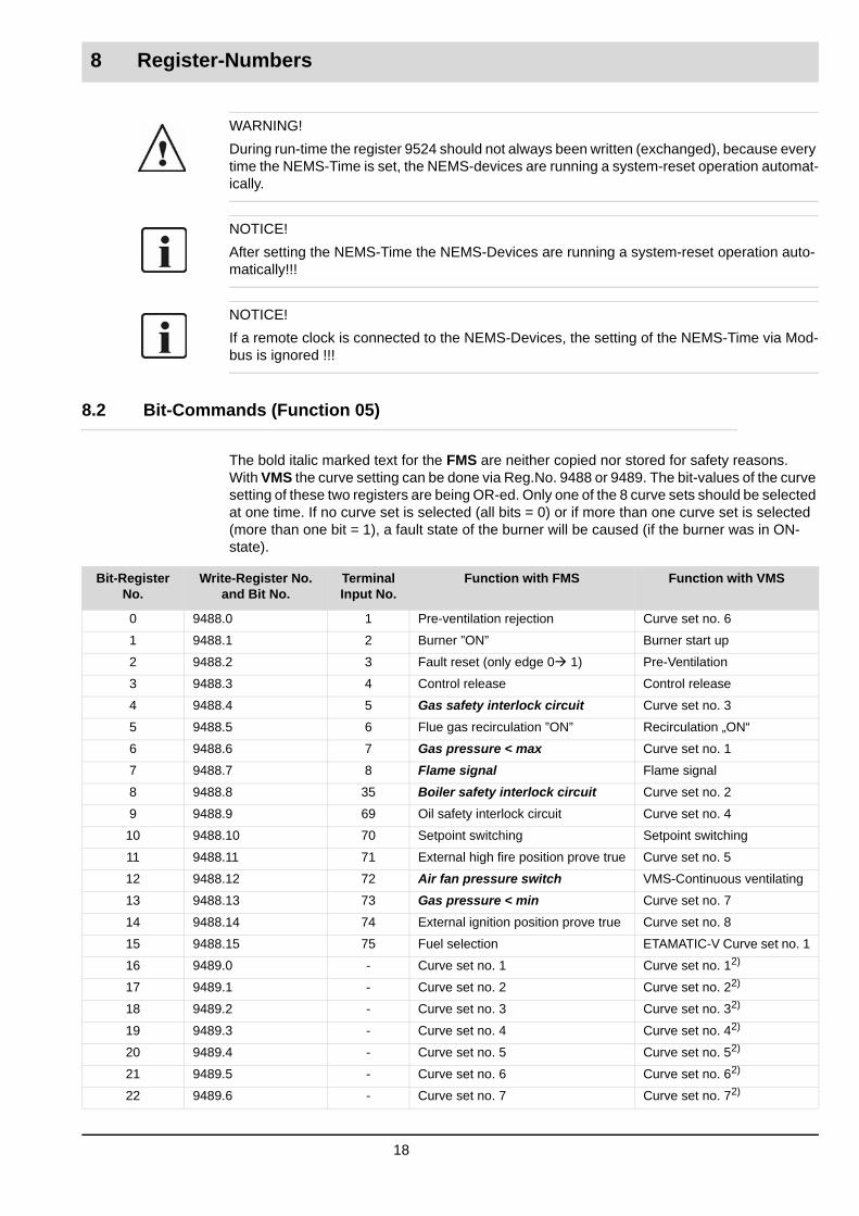
8.2 Bit-Commands (Function 05)
The bold italic marked text for the FMS are neither copied nor stored for safety reasons.With VMS the curve setting can be done via Reg.No. 9488 or 9489. The bit-values of the curve setting of these two registers are being OR-ed. Only one of the 8 curve sets should be selected at one time. If no curve set is selected (all bits = 0) or if more than one curve set is selected (more than one bit = 1), a fault state of the burner will be caused (if the burner was in ON-state).
Bit-RegisterNo.
Write-Register No. and Bit No.
Terminal Input No.
Function with FMS Function with VMS
0 9488.0 1 Pre-ventilation rejection Curve set no. 6
1 9488.1 2 Burner ”ON” Burner start up
2 9488.2 3 Fault reset (only edge 0 1) Pre-Ventilation
3 9488.3 4 Control release Control release
4 9488.4 5 Gas safety interlock circuit Curve set no. 3
5 9488.5 6 Flue gas recirculation ”ON” Recirculation „ON“
6 9488.6 7 Gas pressure < max Curve set no. 1
7 9488.7 8 Flame signal Flame signal
8 9488.8 35 Boiler safety interlock circuit Curve set no. 2
9 9488.9 69 Oil safety interlock circuit Curve set no. 4
10 9488.10 70 Setpoint switching Setpoint switching
11 9488.11 71 External high fire position prove true Curve set no. 5
12 9488.12 72 Air fan pressure switch VMS-Continuous ventilating
13 9488.13 73 Gas pressure < min Curve set no. 7
14 9488.14 74 External ignition position prove true Curve set no. 8
15 9488.15 75 Fuel selection ETAMATIC-V Curve set no. 1
16 9489.0 - Curve set no. 1 Curve set no. 12)
17 9489.1 - Curve set no. 2 Curve set no. 22)
18 9489.2 - Curve set no. 3 Curve set no. 32)
19 9489.3 - Curve set no. 4 Curve set no. 42)
20 9489.4 - Curve set no. 5 Curve set no. 52)
21 9489.5 - Curve set no. 6 Curve set no. 62)
22 9489.6 - Curve set no. 7 Curve set no. 72)
18

8 Register-Numbers
23 9489.7 - Curve set no. 8 Curve set no. 82)
24 9489.8 - O2 Controller on/off2) O2 Controller on/off2)
25 9489.9 - CO Controller on/off2) CO Controller on/off2)
26 9489.10 - Oil pump on/off2) reserved
27 9489.11 - reserved reserved
28 9489.12 - FAT-Standby2) reserved
29 9489.13 - FAT-Continuous ventilating2) VMS-Continuous ventilating2)
30 9489.14 - reserved reserved
31 9489.15 - reserved reserved
32...47 9490.0...15 - reserved for 9490**) reserved for 9490**)
48...63 9491.0...15 - reserved for 9491**) reserved for 9491**)
All the following have the same functionality with FMS and VMS
64...69 9492.0...5 reserved for 9492**)
70 9492.6 Low-water cut off probe 2 (NRG16-40)
71 9492.7 Low-water cut off probe 1 (NRG16-40)
72...79 9492.8...15 reserved for 9492**)
80 9493.0 Water level digital Bit 0: longest probe
81 9493.1 Water level digital Bit 1: second longest probe
82 9493.2 Water level digital Bit 2: second shortest probe
83 9493.3 Water level digital Bit 3: shortest probe
84...87 9493.4...7 reserved for 9493**)
88 9493.8 Level in %, Bit 8: 20 %
89 9493.9 Level in %, Bit 9: 40 %
90 9493.10 Level in %, Bit 10: 60 %
91 9493.11 Level in %, Bit 11: 80 %
92...95 9493.12...15 reserved for 9493**)
96...111 9498.0...15 reserved for 9498**)
112...118 9499.0...6 reserved for 9499**)
119 9499.7 High-water cut off probe (NRG16-41)
120...127 9499.8...15 reserved for 9499**)
128...143 9502.0...15 reserved for 9502**)
144...159 9503.0...15 reserved for 9503**)
160...163 9512.0...3 reserved for 9512**)
164 9512.4 LSB-Digital-Output-Module-6 Output 1
165 9512.5 LSB-Digital-Output-Module-6 Output 2
166 9512.6 LSB-Digital-Output-Module-6 Output 3
167 9512.7 LSB-Digital-Output-Module-6 Output 4
168 9512.8 LSB-Digital-Output-Module-7 Output 1
169 9512.9 LSB-Digital-Output-Module-7 Output 2
170 9512.10 LSB-Digital-Output-Module-7 Output 3
171 9512.11 LSB-Digital-Output-Module-7 Output 4
172...175 9512.12...15 reserved for 9512**)
176...191 9513.0...15 reserved for 9513**)
Bit-RegisterNo.
Write-Register No. and Bit No.
Terminal Input No.
Function with FMS Function with VMS
19

8 Register-Numbers
Example for function-05 byte contents:
2) From communication processor version M5e001 21.10.05**) Future Extensions, not implemented yet
192...207 9514.0...15 reserved for 9514**) (PID-controller-digital-outputs)
208...223 9519.0...15 reserved for 9519**)
224 9520.0 DataRead (new Message reading) NEMS-Handshake-Out Bit 0
225...227 9520.1...3 reserved for 9520**)
228 9520.4 LP Lamp-Test NEMS-Key-Functions Bit 4 (0 1)
229 9520.5 HQ Signal-Horn-Quit (Tasten) NEMS-Key-Functions Bit 5 (0 1)
230 9520.6 EQ First-Event-Confirm NEMS-Key-Functions Bit 6 (0 1)
231 9520.7 NQ New-Event-Confirm NEMS-Key-Functions Bit 7 (0 1)
232...239 9520.8...15 reserved for 9520**)
240 9521.0 NEMS-Relay 1 Device 1 Family 1
241 9521.1 NEMS-Relay 2 Device 1 Family 1
242 9521.2 NEMS-Relay 1 Device 2 Family 1
243 9521.3 NEMS-Relay 2 Device 2 Family 1
244 9521.4 NEMS-Relay 1 Device 3 Family 1
245 9521.5 NEMS-Relay 2 Device 3 Family 1
246 9521.6 NEMS-Relay 1 Device 4 Family 1
247 9521.7 NEMS-Relay 2 Device 4 Family 1
248 9521.8 NEMS-Relay 1 Device 5 Family 1
249 9521.9 NEMS-Relay 2 Device 5 Family 1
250 9521.10 NEMS-Relay 1 Device 6 Family 1
251 9521.11 NEMS-Relay 2 Device 6 Family 1
252 9521.12 NEMS-Relay 1 Device 7 Family 1
253 9521.13 NEMS-Relay 2 Device 7 Family 1
254 9521.14 NEMS-Relay 1 Device 8 Family 1
255 9521.15 NEMS-Relay 2 Device 8 Family 1
Bit-RegisterNo.
Write-Register No. and Bit No.
Terminal Input No.
Function with FMS Function with VMS
Byte-No 1 2 3 4 5 6 7 8
Meaning Addr Function HighByte Register
LowByte Register ON/OFF value zero CRC CRC
Value 04 05 00 01 (for Burner ON) 0xFF (switch on)0x00 (switch off)
00 0x2D 0xAF
20

8 Register-Numbers
8.3 Write Commands (Function 03)
NOTICE!
With one read-command the maximal number of 125 Read-Registers can be read.
Register-No. (dec-
imal)
LSB-Addr. Value No.
0..2
FMS/VMS/ETAMATICSource
Description Value Range
8192 5303.0 KPR_uiInterneLast internal firing-rate value 0..999
8193 5303.1 KPR_uiLastMin base firing-rate point 0..999
8194 5303.2 KPR_uiLastMax high firing-rate point 0..999
8195 5310.0 KPR_uiKesselTemp actual value of firing-rate controller (if avail-able)
0..999
8196 5401.0 KPR_uiIstwert_Kanal_1 actual value, main processor, channel 1 0..999
8197 5402.0 KPR_uiIstwert_Kanal_2 actual value, main processor, channel 2 0..999
8198 5403.0 KPR_uiIstwert_Kanal_3 actual value, main processor, channel 3 0..999
8199 5404.0 KPR_uiIstwert_Kanal_4 actual value, main processor, channel 4 0..999
8200 5405.0 KPR_uiIstwert_Kanal_5 actual value, main processor, channel 5 0..999
8201 5406.2(5406.0)(5406.1)
KPR_uiIstwert_Kanal_1(KPR_uiMinWert_Kanal_1)(KPR_uiMaxWert_Kanal_1)
Actual value main processor channel 1 in %0% = actuator position at low level of value range limit 100% = actuator position at high level of value range limit
0..100
8202 5407.2(5407.0)(5407.1)
KPR_uiIstwert_Kanal_2(KPR_uiMinWert_Kanal_2)(KPR_uiMaxWert_Kanal_2)
Actual value main processor channel 2 in %0% = actuator position at low level of value range limit100% = actuator position at high level of value range limit
0..100
8203 5408.2(5408.0)(5408.1)
KPR_uiInterneLast(KPR_uiMinWert_Kanal_3)(KPR_uiMaxWert_Kanal_3)
Actual value main processor channel 3 in %0% = actuator position at low level of value rang limit100% = actuator position at high level of value range limit
0..100
8204 5409.2(5409.0)(5409.1)
KPR_uiInterneLast(KPR_uiMinWert_Kanal_4)(KPR_uiMaxWert_Kanal_4)
Actual value main processor channel 4 in %0% = actuator position at low level of value range limit100% = actuator position at high level of value range limit
0..100
8205 5410.2(5410.0)(5410.1)
KPR_uiInterneLast(KPR_uiMinWert_Kanal_5)(KPR_uiMaxWert_Kanal_5)
Actual value main processor channel 5 in %0% = actuator position at low level of value range limit100% = actuator position at high level of value range limit
0..100
8206 5401.1 KPR_uiKorrSollwert_Kanal_1 setpoint, main processor, channel 1 0..999
8207 5402.1 KPR_uiKorrSollwert_Kanal_2 setpoint, main processor, channel 2 0..999
8208 5403.1 KPR_uiKorrSollwert_Kanal_3 setpoint, main processor, channel 3 0..999
8209 5404.1 KPR_uiKorrSollwert_Kanal_4 setpoint, main processor, channel 4 0..999
8210 5405.1 KPR_uiKorrSollwert_Kanal_5 setpoint, main processor, channel 5 0..999
8211 free
8212 free
21

8 Register-Numbers
8213 free
8214 free
8215 free
8216 5406.0 KPR_uiMinWert_Kanal_1 lower stop, main processor, channel 1 0..999
8217 5407.0 KPR_uiMinWert_Kanal_2 lower stop, main processor, channel 2 0..999
8218 5408.0 KPR_uiMinWert_Kanal_3 lower stop, main processor, channel 3 0..999
8219 5409.0 KPR_uiMinWert_Kanal_4 lower stop, main processor, channel 4 0..999
8220 5410.0 KPR_uiMinWert_Kanal_5 lower stop, main processor, channel 5 0..999
8221 free
8222 free
8223 free
8224 free
8225 free
8226 5406.1 KPR_uiMaxWert_Kanal_1 upper stop, main processor, channel 1 0..999
8227 5407.1 KPR_uiMaxWert_Kanal_2 upper stop, main processor, channel 2 0..999
8228 5408.1 KPR_uiMaxWert_Kanal_3 upper stop, main processor, channel 3 0..999
8229 5409.1 KPR_uiMaxWert_Kanal_4 upper stop, main processor, channel 4 0..999
8230 5410.1 KPR_uiMaxWert_Kanal_5 upper stop, main processor, channel 5 0..999
8231 free
8232 free
8233 free
8234 free
8235 free
8236 free
8237 free
8238 free
82394) 5303.0(5303.1)(5303.2)
KPR_uiInterneLast(KPR_uiLastMin)(KPR_uiLastMax)
0% = base firing-rate: internal firing-rate- value at low level of value range100% = max. firing-rate: internal firing-rate- value at high level of value range
0..100
8240 5301.0 KPR_uiInterneLast position of the internal firing-rate
8241 5301.1 KPR_uiLastvorgabeDisplay active firing-rate presetting
8242 5301.2 KPR_uiHPLastEingang terminal input of the external firing-rate
8243 5411.0 KPR_Leistungsregler_Sollwert firing-rate controller setpoint
8244 5120.0 O2 actual value (from LSB e.g. LT1) O2 actual value
8245 5120.1 O2 actual value state (from LSB e.g. LT1)
O2 actual value status
8246 5320.0 KPR_uiO2Sollwert O2 setpoint value
8247 5320.1 KPR_O2Betriebsmodus O2 controller operating status
8248 5320.2 KPR_O2Fehlerursache O2 controller warning/fault
8249 5325.1 KPR_COBetriebsmodus CO controller operating status
8250 5325.2 KPR_COFehlerursache CO controller warning/fault
8251 5311.0 KPR_uiAussenTemp outside temperature (unsigned)
82526) free
Register-No. (dec-
imal)
LSB-Addr. Value No.
0..2
FMS/VMS/ETAMATICSource
Description Value Range
22

8 Register-Numbers
82536) free
8254 5420.0 KPR_ucAktFreigabe active access level
8255 5331.0 KPR_uiFlammIntens flame intensity
8256 5305.0(5304.1)
KPR_uiInterneZustandsinfo Bit 0 leakage test is runningBit 1 boiler thermostatBit 2 reserved for curve set change is runningBit 3 reserved for curve set change is runningBit 4 ETAMATIC TRIAC self test is runningBit 5 flame signalBit 6 CO controller is defectiveBit 7 CO controller is defective
8257 5305.1 KPR_uiZustandInfoLSB Information text
8258 5305.2 KPR_uiZustandInfoParameterLSB additional information for the information text (i.e. channel no.)
82592) 5350.0 KPR_uiZustandInfoLeistungsregler additional information for firing-rate controlleractual value of the firing-rate controller is above the switch-on pointBit 0 Def_LR_UEBER_EIN 1
8260 5330.0 KPR_FMS_Brennstoff OIL or GAS active at FMS
82612) 5304.2 KPR_uiTextnummer Information text no.
8262 5422.0 KPR_uiSynchron 0x0001 ignition position main processor0x0002 ignition position monitoring processor0x0004 high firing-rate main processor 0x0008 high firing-rate monitoring processorBit 4...15 reserved
8263 5422.1 KPR_uiAcHandmodus Manual Mode:0x0001 fuel-air ratio control setting via front panel0x0002 O2 setting via front panel0x0004 Given firing-rate at normal operation via front panel0x0100 Given firing-rate for fuel-air ratio control adjustment by Remote Con- trol Software0x0200 Given firing-rate for O2 adjustment by Remote Control Software0x0400 External manual given firing-rate0x0800 External manual given firing-rate0x1000 Manual given firing-rate under con- trol mode operation via Remote Control Software0x2000 Given firing-rate via LSB / Field busRemaining bits are reserved.
Register-No. (dec-
imal)
LSB-Addr. Value No.
0..2
FMS/VMS/ETAMATICSource
Description Value Range
23

8 Register-Numbers
8264 5422.2 Bit-combination of: KPR_uiSynchron andKPR_uiAcHandmodus
0x0200: Ignition position reached Set bit only if following both bits of KPR_uiSynchron simultaneously reach value 1PQ_ZP_HP 0x0001 // Ignition position Main processor reachedPQ_ZP_UE 0x0002 // Ignition position Monitoring processor reached
0x0400: High fire position reachedSet bit only if following both bits of KPR_uiSynchron simultaneously reach value 1PQ_GL_HP 0x0004 // High fire position Main processor reachedPQ_GL_UE 0x0008 // High fire position Monitoring processor reached
0x0800: Manual operationFollowing bits of KPR_uiAcHandmodus are WIRED OR.0x0001 fuel-air ratio control setting via front panel0x0002 O2 setting via front panel0x0004 Manual given burner firing-rate controlled via front panel0x0100 Burner firing-rate given for fuel-air ratio control setting by Remote Software0x0200 Burner firing-rate given for O2 adjustment by Remote-Software0x0400 External manual given firing-rate0x0800 External manual given firing-rate0x1000 Manual given burner firing-rate in control mode via Remote Control Softwaretherefore KPR_uiAcHandmodus & 0x1fff
Register-No. (dec-
imal)
LSB-Addr. Value No.
0..2
FMS/VMS/ETAMATICSource
Description Value Range
24

8 Register-Numbers
82652) 5304.0 KPR_uiRelaisstatus Relay status
FMS
0x0001: oil valve 0x0002: ignition valve0x0004: oil / gas0x0008: end of pre-ventilation period 0x0010: gas10x0020: ignition transformer0x0040: gas20x0080: fault relay0x0100: fan ON(up to bit 9 identical with KPR_uiDigitalOut 149)
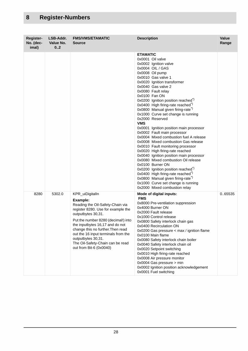
ETAMATIC
0x0001: oil valve0x0002: ignition valve0x0004: oil / gas0x0008: oilpump0x0010: gas10x0020: ignition transformer0x0040: gas20x0080: fault relay0x0100: fan ON(up to bit 9 identical withKPR_uiDigitalOut 149)
VMS
0x0001: ignition position main processor0x0002: fault main processor0x0004: mixed combustion fuel A release0x0008: mixed combustion gas release0x0010: fault monitoring processor 0x0020: reaching high firing-rate0x0040: ignition point monitoring processor0x0080: mixed combustion oil release0x0100: burner ON(up to bit 9 identical with KPR_uiDigitalOut 149)
82662) 5306.2 KPR_uiMischKorrWert correction value of mixing signal
82672) 5321.2 KPR_O2Impuls =, +, -, ! sO2Data.ucImpuls
82682) 5322.0 KPR_uiO2CO_Betriebszustand CO/O2 Status (values are in decimal):
1 measured O2 value too low at pre-ventilation2 measured O2 value too high during pre-ventilation 3 measured O2 value too high after pre-ventilation4 no probe-dynamics: O2 controller inactive5 measured O2 value 1 upper range exceeded6 measured O2 value 2 upper range exceeded7 measured O2 value 1 upper range exceeded 8 measured O2 value 2 lower range exceeded9 half of the air deficiency value reached
Register-No. (dec-
imal)
LSB-Addr. Value No.
0..2
FMS/VMS/ETAMATICSource
Description Value Range
25

8 Register-Numbers
8268 5322.0 KPR_uiO2CO_Betriebszustand
CO/O2 Status (values are in decimal):
10 measured O2 Value defective11 measurement O2 Value defective (LSB defective)12 O2 controller defective, internal error13 air deficiency: O2 controller deactivated14 air deficiency: O2 controller deactivated15 no probe dynamics: increasing air supply16 correction limited:O2 controller deactivated17 O2 controller defective18 O2 setpoint curve not OK19 not defined20 O2 controller defective21 O2 controller defective22 not defined23 not defined24 O2 controller standby25 O2 controller OFF: firing-rate value out of range26 O2 controller OFF27 O2 controller defective28 O2 controller defective29 O2 controller defective30 O2 controller temporarily defective31 O2 controller via LSB OFF32 correction value is run manually33 O2 controller in standby34 O2 controller in operation35 effective CO probe value UCOe defec- tive40 no valid edge-information available at LSB41 probe voltage not in monitoring window42 probe-Offset-Voltage not in the monitoring window43 cell internal resistance not in monitoring window44 cell internal temperature not in monitor- ing window45 probe voltage dynamics is not visible46 internal firing-rate is outside of the parameterized window47 CO controller is deactivated by the monitoring processor48 CO controller is deactivated by LSB 49 CO controller is deactivated by O2 monitoring 50 effective CO probe voltage UCOe is outside the monitoring window 51 CO controller active
Rest: not defined
The text definition is always followed by the corresponding code no.
82692) 5330.2 KPR_uiKSWechselInfo information of the curve set changing
82702) 5331.1 KPR_uiMonitorausgang Monitoring output
82712) 5331.2 KPR_uiFAT_State Status of FAT
Register-No. (dec-
imal)
LSB-Addr. Value No.
0..2
FMS/VMS/ETAMATICSource
Description Value Range
26

8 Register-Numbers
82722) 5351.1 KPR_uiBrennstoffMengenzaehler Fuel amount counter
82732) 5352.0 KPR_uiLSBOutAusblasen LSB Out purgeBit 0: blow out valveBit 1: sprayer valveBit 2: FMS oil pump
8274 free
8275 free
8276 5306.0 KPR_uiKoval_1 value correction channel 1 0..999
8277 5306.1 KPR_uiKoval_2 value correction channel 2 0..999
8278 5300.1 KPR_uiStoerung Last fault code messageOffset 10.000 for Monitoring-ProcessorOffset (0-4) if channel-dependant fault
0..999
8279 5302.2(5422.2)
KPR_uiDigitalOut & 0xF1FF(RelayStatus) | 5422.2 & 0x0E00
Status of relay outputs:0x0001 relay 110x0002 relay 160x0004 relay 360x0008 relay 410x0010 relay 430x0020 relay 450x0040 relay 670x0080 relay 680x0100 relay 760x0200 Ignition position reached*)0x0400 High firing-rate reached*)0x0800 Manual given firing-rate*)0x1000 Curve set change is running0x2000 Mixed combustion relay
FMS
0x0001 Oil valve0x0002 Ignition valve0x0004 OIL / GAS 0x0008 End of per-ventilation period0x0010 Gas valve 10x0020 Ignition transformer0x0040 Gas valve 2 0x0080 Fault relay0x0100 Fan ON0x0200 Ignition position reached*)0x0400 High firing-rate reached*)0x0800 Manual given firing-rate*)0x1000 Curve set change is running0x2000 Mixed combustion relay
0..65535
Register-No. (dec-
imal)
LSB-Addr. Value No.
0..2
FMS/VMS/ETAMATICSource
Description Value Range
27
8 Register-Numbers
ETAMATIC0x0001 Oil valve0x0002 Ignition valve0x0004 OIL / GAS 0x0008 Oil pump0x0010 Gas valve 10x0020 Ignition transformer0x0040 Gas valve 2 0x0080 Fault relay0x0100 Fan ON0x0200 Ignition position reached*)0x0400 High firing-rate reached*)0x0800 Manual given firing-rate*)0x1000 Curve set change is running0x2000 ReservedVMS 0x0001 Ignition position main processor0x0002 Fault main processor0x0004 Mixed combustion fuel A release0x0008 Mixed combustion Gas release0x0010 Fault monitoring processor0x0020 High firing-rate reached0x0040 Ignition position main processor0x0080 Mixed combustion Oil release0x0100 Burner ON0x0200 Ignition position reached*)0x0400 High firing-rate reached*)0x0800 Manual given firing-rate*)0x1000 Curve set change is running0x2000 Mixed combustion relay
8280 5302.0 KPR_uiDigitalIn
Example:Reading the Oil-Safety-Chain via register 8280. Use for example the outputbytes 30,31.
Put the number 8280 (decimal!) into the inputbytes 16,17 and do not change this no further.Then read out the 16 input terminals from the outputbytes 30,31.The Oil-Safety-Chain can be read out from Bit-6 (0x0040)
Mode of digital inputs: FMS0x8000 Pre-ventilation suppression0x4000 Burner ON0x2000 Fault release0x1000 Control release0x0800 Safety interlock chain gas0x0400 Recirculation ON0x0200 Gas pressure < max / ignition flame0x0100 Main flame0x0080 Safety interlock chain boiler0x0040 Safety interlock chain oil0x0020 Setpoint switching0x0010 High firing-rate reached0x0008 Air pressure monitor0x0004 Gas pressure > min0x0002 Ignition position acknowledgement0x0001 Fuel switching
0..65535
Register-No. (dec-
imal)
LSB-Addr. Value No.
0..2
FMS/VMS/ETAMATICSource
Description Value Range
28

8 Register-Numbers
8280 5302.0 KPR_uiDigitalIn Mode of digital inputs:VMS0x8000 Curve set-60x4000 Burner ON0x2000 Pre-ventilation0x1000 Control release0x0800 Curve set-30x0400 Recirculation ON0x0200 Curve set -10x0100 Flame signal0x0080 Curve set -20x0040 Curve set -40x0020 Setpoint switching0x0010 Curve set -50x0008 Continuous ventilation0x0004 Curve set -70x0002 Curve set -80x0001 External firing-rate limit
0..65535
8281 5300.0 KPR_uiBetrModus Operating mode FMS:0x0001 Power ON0x0002 Burner OFF0x0004 Burner standby0x0008 Pre-ventilation0x0010 Run to ignition position0x0020 Ignition0x0040 Base firing-rate0x0080 Control mode0x0200 Fault0x1000 O2 adjustment0x2000 Parameterization0x4000 Setting0x8000 Clear Memory
0..512
8282 5510.0 RegisterNr register number main processor 0..65535
8283 5510.1 RegisterWert register value main processor 0..65535
8284 5302.1 KPR_ucAktBrennstoff active curve selectionvalue = 0: curve set-1value = 1: curve set-2...value= 7: curve set-8
NOTE: since version E4o002:High-Byte is expanded additionally with the bit signalisation of the active curve selection:Bit 8: curve set-1Bit 9: curve set -2Bit 10: curve set -3Bit 11: curve set -4Bit 12: curve set -5Bit 13: curve set -6Bit 14: curve set -7Bit 15: curve set -8
Values: 0x0000, 0x0001...0x0007
New Values:0x01000x02010x04020x08030x10040x20050x40060x8007
Register-No. (dec-
imal)
LSB-Addr. Value No.
0..2
FMS/VMS/ETAMATICSource
Description Value Range
29

8 Register-Numbers
8285 5421.0 KPR_ucSchalter_S5 Position of switch S5:0x0001 display monitoring0x0002 parameterization0x0004 manual0x0008 automatic0x0010 setting0x0020 Clear memory
0..65535
8286 free (NOTE: The Thermostat-Bit in this register is available via register 8263 Bit 1, with Modbus activation via internal bus card)
8287 free
8288 free
8289 free
8290 free
8291 free
8292 free
8293 free
8294 free
8295 free
8296 free
8297 free
8298 free
8299 free
8300 5520.0 KPR_BetrStd_Gesamt_Hi total operating hours
8301 5520.1 KPR_BetrStd_Gesamt_Lo total operating hours
8302 5521.0 KPR_BetrStd_Kurvensatz_1_Hi operating hours curve set-1
8303 5521.1 KPR_BetrStd_Kurvensatz_1_Lo operating hours curve set-1
8304 5522.0 KPR_BetrStd_Kurvensatz_2_Hi operating hours curve set-2
8305 5522.1 KPR_BetrStd_Kurvensatz_2_Lo operating hours curve set-2
8306 5523.0 KPR_BetrStd_Kurvensatz_3_Hi operating hours curve set-3
8307 5523.1 KPR_BetrStd_Kurvensatz_3_Lo operating hours curve set-3
8308 5524.0 KPR_BetrStd_Kurvensatz_4_Hi operating hours curve set-4
8309 5524.1 KPR_BetrStd_Kurvensatz_4_Lo operating hours curve set-4
8310 5525.0 KPR_BetrStd_Kurvensatz_5_Hi operating hours curve set-5
8311 5525.1 KPR_BetrStd_Kurvensatz_5_Lo operating hours curve set-5
8312 5526.0 KPR_BetrStd_Kurvensatz_6_Hi operating hours curve set-6
8313 5526.1 KPR_BetrStd_Kurvensatz_6_Lo operating hours curve set-6
8314 5527.0 KPR_BetrStd_Kurvensatz_7_Hi operating hours curve set-7
8315 5527.1 KPR_BetrStd_Kurvensatz_7_Lo operating hours curve set-7
8316 5528.0 KPR_BetrStd_Kurvensatz_8_Hi operating hours curve set-8
8317 5528.1 KPR_BetrStd_Kurvensatz_8_Lo operating hours curve set-8
8318 5531.0 KPR_AnlZaehl_Kurvensatz_1_Hi start up counter curve set-1
8319 5531.1 KPR_AnlZaehl_Kurvensatz_1_Lo start up counter curve set-1
8320 5532.0 KPR_AnlZaehl_Kurvensatz_2_Hi start up counter curve set-2
Register-No. (dec-
imal)
LSB-Addr. Value No.
0..2
FMS/VMS/ETAMATICSource
Description Value Range
30
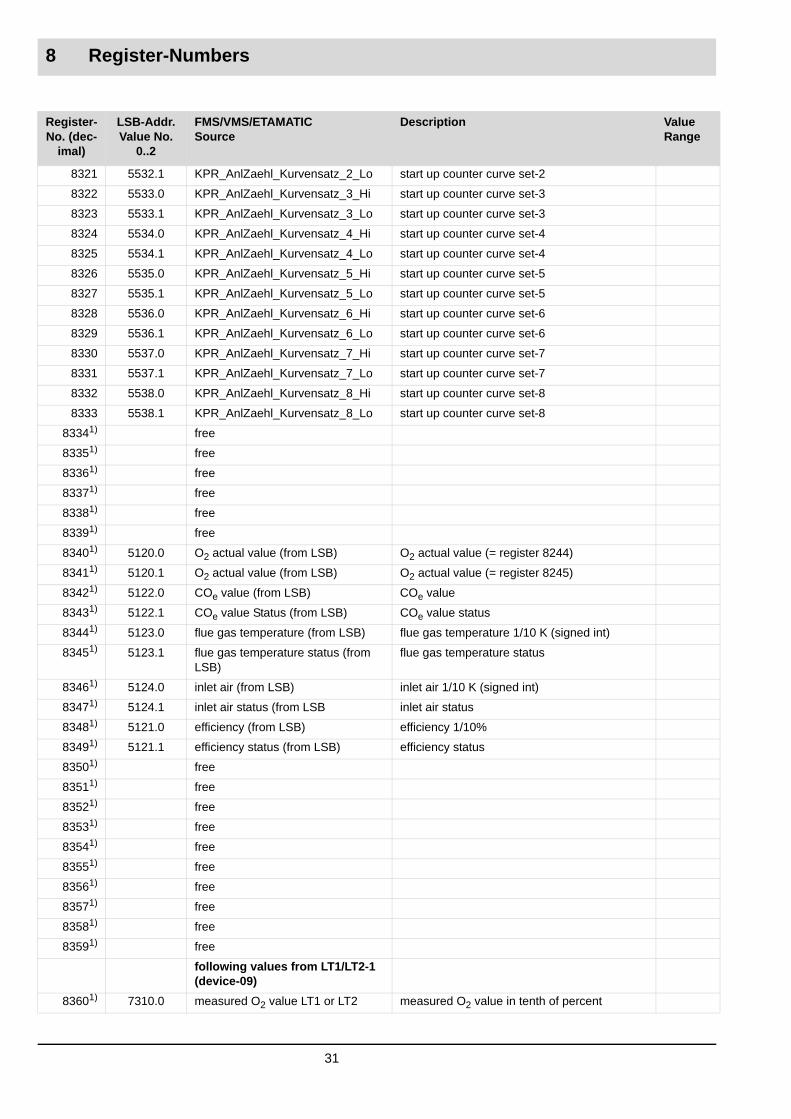
8 Register-Numbers
8321 5532.1 KPR_AnlZaehl_Kurvensatz_2_Lo start up counter curve set-2
8322 5533.0 KPR_AnlZaehl_Kurvensatz_3_Hi start up counter curve set-3
8323 5533.1 KPR_AnlZaehl_Kurvensatz_3_Lo start up counter curve set-3
8324 5534.0 KPR_AnlZaehl_Kurvensatz_4_Hi start up counter curve set-4
8325 5534.1 KPR_AnlZaehl_Kurvensatz_4_Lo start up counter curve set-4
8326 5535.0 KPR_AnlZaehl_Kurvensatz_5_Hi start up counter curve set-5
8327 5535.1 KPR_AnlZaehl_Kurvensatz_5_Lo start up counter curve set-5
8328 5536.0 KPR_AnlZaehl_Kurvensatz_6_Hi start up counter curve set-6
8329 5536.1 KPR_AnlZaehl_Kurvensatz_6_Lo start up counter curve set-6
8330 5537.0 KPR_AnlZaehl_Kurvensatz_7_Hi start up counter curve set-7
8331 5537.1 KPR_AnlZaehl_Kurvensatz_7_Lo start up counter curve set-7
8332 5538.0 KPR_AnlZaehl_Kurvensatz_8_Hi start up counter curve set-8
8333 5538.1 KPR_AnlZaehl_Kurvensatz_8_Lo start up counter curve set-8
83341) free
83351) free
83361) free
83371) free
83381) free
83391) free
83401) 5120.0 O2 actual value (from LSB) O2 actual value (= register 8244)
83411) 5120.1 O2 actual value (from LSB) O2 actual value (= register 8245)
83421) 5122.0 COe value (from LSB) COe value
83431) 5122.1 COe value Status (from LSB) COe value status
83441) 5123.0 flue gas temperature (from LSB) flue gas temperature 1/10 K (signed int)
83451) 5123.1 flue gas temperature status (from LSB)
flue gas temperature status
83461) 5124.0 inlet air (from LSB) inlet air 1/10 K (signed int)
83471) 5124.1 inlet air status (from LSB inlet air status
83481) 5121.0 efficiency (from LSB) efficiency 1/10%
83491) 5121.1 efficiency status (from LSB) efficiency status
83501) free
83511) free
83521) free
83531) free
83541) free
83551) free
83561) free
83571) free
83581) free
83591) free
following values from LT1/LT2-1 (device-09)
83601) 7310.0 measured O2 value LT1 or LT2 measured O2 value in tenth of percent
Register-No. (dec-
imal)
LSB-Addr. Value No.
0..2
FMS/VMS/ETAMATICSource
Description Value Range
31

8 Register-Numbers
83611) 7310.1 operating mode of LT1 or LT2 bit pattern of the LT1/LT2-operating mode, see table
83621) 7310.2 faults of LT1 or LT2 bit pattern of the LT1/LT2-faults, see table
83631) 7311.0 warnings 1 of LT1 or LT2 bit pattern of the LT1/LT2-warning words 1, see table
83641) 7311.1 warnings 2 of LT1 or LT2 bit pattern of the LT1/LT2-warning words 2, see table
83651) 7311.2 absolute pressure LT1 or internal probe resistance LT2
absolute pressure in mbar or internal resist-ance in 0,1 Ohm, the meaning of this LT-value may be modified with parameter 1302 at the LT.
83661) 7312.0 LT1/LT2: custom designed meas-ured value 1
configurable measured value 1 of the LT1/LT2. The allocation of this LT-value may be modified with parameter 1303 at the LT.
83671) 7312.1 LT1/LT2: custom designed meas-ured value 2
configurable measured value 1 of the LT1/LT2. The allocation of this LT-value may be modified with parameter 1304 at the LT.
83681) 7312.2 LT1/LT2: custom designed meas-ured value 3
configurable measured value 1 of the LT1/LT2. The allocation of this LT-value may be modified with parameter 1305 at the LT.
83691) 7313.0 LT1/LT2: custom designed meas-ured value 4
configurable measured value 1 of the LT1/LT2. The allocation of this LT-value may be modified with parameter 1306 at the LT.
83701) 7313.1 LT1/LT2: reserved reserved for future extensions
83711) 7313.2 LT1/LT2: reserved reserved for future extensions
83721) 7314.0 LT1/LT2: reserved reserved for future extensions
83731) 7314.1 LT1/LT2: reserved reserved for future extensions
83741) (7314.2) reserved
following values from LT1/LT2-2 (device-10)
83751) 7320.0 measured O2 value LT1 or. LT2 measured O2 value in tenth of percent
83761) 7320.1 operating mode of LT1 or LT2 bit pattern of the LT1/LT2-operating mode, see table
83771) 7320.2 faults of LT1 or LT2 bit pattern of the LT1/LT2-faults, see table
83781) 7321.0 warnings 1 of LT1 or LT2 bit pattern of the LT1/LT2-warning words 1, see table
83791) 7321.1 warnings 2 of LT1 or LT2 bit pattern of the LT1/LT2-warning words 2, see table
83801) 7321.2 absolute pressure LT1 or internal probe resistance LT2
absolute pressure in mbar or internal resist-ance in 0,1 Ohm, the meaning of this LT-value may be changed with parameter 1302 at the LT
83811) 7322.0 LT1/LT2: custom designed meas-ured value 1
configurable measured value 1 of the LT1/LT2. The allocation of this LT-value may be modified with parameter 1303 at the LT.
83821) 7322.1 LT1/LT2: custom designed meas-ured value 2
configurable measured value 2 of the LT1/LT2. The allocation of this LT-value may be modified with parameter 1304 at the LT.
83831) 7322.2 LT1/LT2: custom designed meas-ured value 3
configurable measured value 3 of the LT1/LT2. The allocation of this LT-value may be modified with parameter 1305 at the LT.
Register-No. (dec-
imal)
LSB-Addr. Value No.
0..2
FMS/VMS/ETAMATICSource
Description Value Range
32

8 Register-Numbers
83841) 7323.0 LT1/LT2: custom designed meas-ured value 4
configurable measured value 4 of the LT1/LT2. The allocation of this LT-value may be modified with parameter 1306 at the LT.
83851) 7323.1 LT1/LT2: reserved reserved for future extensions
83861) 7323.2 LT1/LT2: reserved reserved for future extensions
83871) 7324.0 LT1/LT2: reserved reserved for future extensions
83881) 7324.1 LT1/LT2: reserved reserved for future extensions
83891) (7324.2) reserved
83902) free
83912) free
83922) free
83932) free
83942) free
83952) free
83962) free
83972) free
83982) free
83992) free
84002) Status LSB-Output-Modules and PID-Controller-Analog-Output-Status**)PID-Controller-Digital-Output Sta-tus**)
Status-Bits (0 Offline, 1 Online):Bit 0: LSB-Analog-Output-Module-11Bit 1: LSB-Analog-Output-Module-12Bit 2: LSB-Digital-Output-Module-6Bit 3: LSB-Digital-Output-Module-7Bit 4...7: PID-Controller-Analog-Output**)Bit 8...14: PID-Controller-Digital-Output**)
84012) Status LSB-Analog-ModuleandStatus LSB-Digital-Output-Modules
Status-Bits (0 Offline, 1 Online):Bit 0: reservedBit 1: LSB-Analog-Input-Module-14Bit 2: LSB-Analog-Input-Module-15Bit 3: LSB-Analog-Input-Module-16Bit 4: LSB-Digital-Input-Module-1Bit 5: LSB-Digital-Input-Module-3Bit 6: LSB-Digital-Input-Module-13Bit 7: LSB-Digital-Input-Module-14
84022) LSB-Analog-Input-Module-14.1 LSB-Analog-Input-Module-14 Value 1
84032) LSB-Analog-Input-Module-14.2 LSB-Analog-Input-Module-14 Value 2
84042) LSB-Analog-Input-Module-14.3 LSB-Analog-Input-Module-14 Value 3
84052) LSB-Analog-Input-Module-14.4 LSB-Analog-Input-Module-14 Value 4
84062) LSB-Analog-Input-Module-15.1 LSB-Analog-Input-Module-15 Value 1
84072) LSB-Analog-Input-Module-15.2 LSB-Analog-Input-Module-15 Value 2
84082) LSB-Analog-Input-Module-15.3 LSB-Analog-Input-Module-15 Value 3
84092) LSB-Analog-Input-Module-15.4 LSB-Analog-Input-Module-15 Value 4
84102) LSB-Analog-Input-Module-16.1 LSB-Analog-Input-Module-16 Value 1
84112) LSB-Analog-Input-Module-16.2 LSB-Analog-Input-Module-16 Value 2
84122) LSB-Analog-Input-Module-16.3 LSB-Analog-Input-Module-16 Value 3
84132) LSB-Analog-Input-Module-16.4 LSB-Analog-Input-Module-16 Value 4
Register-No. (dec-
imal)
LSB-Addr. Value No.
0..2
FMS/VMS/ETAMATICSource
Description Value Range
33

8 Register-Numbers
84142) LSB-Digital-Input-Modules-1-3-13-14
Bit 0...3: LSB-Digital-Input-Module-1Bit 4...7: LSB-Digital-Input-Module-3Bit 8..11: LSB-Digital-Input-Module-13Bit12...15: LSB-Digital-Input-Module-14
84152) free
84162) NEMS-Device-StatusandNEMS-Input-Status-Valid
NEMS-Device-Status:Bit 0: Device No. 1 (0 Offline, 1 On)...Bit 7: Device No. 8 (0 Offline, 1 On)NEMS-Input-Status-Valid:Bit 8: Input-Status-Device-No. 1 (0 Input-Status is not valid, 1 Input-Status is valid)...Bit 15: Input-Status-Device-No. 8 (0 Input-Status is not valid, 1 Input-Status is valid)
84172) NEMS-Handshake-IN NEMS-Handshake-IN:Bit 0: NewData (new message arrived)
84182) NEMS-MeldungsInfo NEMS-MessageInfo-Bits:Bit 0: reservedBit 1: TimeStamp valid = 1 / not valid = 0Bit 2: Input unstable = 1 / stable = 0Bit 3: Not confirmed = 1 / confirmed = 0Bit 4: Link-Input = 1 / Not a Link-Input = 0Bit 5: FirstValue = 1 / NewValue = 0 Bit 6: Arrived = 1 / Gone = 0Bit 7: Process signal = 1 / Fault signal = 0
84192) NEMS-Message-No. Message-Number 1...1024
84202) NEMS-Day in BCD (High-Byte)NEMS-Month in BCD (Low-Byte)
Message-Timestamp Day in BCDMessage-Timestamp Month in BCD
84212) NEMS-Year in BCD (High-Byte)NEMS-Hour in BCD (Low-Byte)
Message-Timestamp Year in BCDMessage-Timestamp Hour in BCD
84222) NEMS-Minute in BCD (High-Byte)NEMS-Second in BCD (Low-Byte)
Message-Timestamp Minute in BCDMessage-Timestamp Second in BCD
84232) NEMS-Millisecond in Hex. Message-Timestamp Millisecond in Hex.
84242) NEMS-Input-Status-0 fromNEMS-Device-No. 1
Status-0 of inputs 1-16 Device-No. 1(Bit 0: Input1... Bit 15: Input16)
84252) NEMS-Input-Status-1 fromNEMS-Device-No. 1
Status-1 of inputs 1-16 Device-No. 1(Bit 0: Input1... Bit 15: Input16)
84262) NEMS-Input-Status-2 fromNEMS-Device-No. 1
Status-2 of inputs 1-16 Device-No. 1(Bit 0: Input1... Bit 15: Input16)
84272) NEMS-Input-Status-0 fromNEMS-Device-No. 2
Status-0 of inputs 1-16 Device-No. 2(Bit 0: Input1... Bit 15: Input16)
84282) NEMS-Input-Status-1 fromNEMS-Device-No. 2
Status-1 of inputs 1-16 Device-No. 2(Bit 0: Input1... Bit 15: Input16)
84292) NEMS-Input-Status-2 fromNEMS-Device-No. 2
Status-2 of inputs 1-16 Device-No. 2(Bit 0: Input1... Bit 15: Input16)
84302) NEMS-Input-Status-0 fromNEMS-Device-No. 3
Status-0 of inputs 1-16 Device-No. 3(Bit 0: Input1... Bit 15: Input16)
84312) NEMS-Input-Status-1 fromNEMS-Device-No. 3
Status-1 of inputs 1-16 Device-No. 3(Bit 0: Input1... Bit 15: Input16)
Register-No. (dec-
imal)
LSB-Addr. Value No.
0..2
FMS/VMS/ETAMATICSource
Description Value Range
34

8 Register-Numbers
1) From communication processor version M5b001 28.09.052) From communication processor version M5e001 21.10.054) From communication processor version M5l001 29.01.066) From communication processor version M5t001 28.06.06*) The Bits 0x0200, 0x0400, 0x0800 are generated with KPR_uiSynchron and KPR_uiAcHandmodus (see also register 8264)**) Future Extensions, not implemented yet
8.3.1 LT1/LT2-Values
(Register-No. 8360...8389)
These values are only available if an O2 analyser (LT1 or LT2) is connected via LAMTEC SYS-TEM BUS. The meaning of some values is different, depending on whether an LT1 or LT2 is connected.
84322) NEMS-Input-Status-2 fromNEMS-Device-No. 3
Status-2 of inputs 1-16 Device-No. 3(Bit 0: Input1... Bit 15: Input16)
84332) NEMS-Input-Status-0 fromNEMS-Device-No. 4
Status-0 of inputs 1-16 Device-No. 4(Bit 0: Input1... Bit 15: Input16)
84342) NEMS-Input-Status-1 fromNEMS-Device-No. 4
Status-1 of inputs 1-16 Device-No. 4(Bit 0: Input1... Bit 15: Input16)
84352) NEMS-Input-Status-2 fromNEMS-Device-No. 4
Status-2 of inputs 1-16 Device-No. 4(Bit 0: Input1... Bit 15: Input16)
84362) NEMS-Input-Status-0 fromNEMS-Device-No. 5
Status-0 of inputs 1-16 Device-No. 5(Bit 0: Input1... Bit 15: Input16)
84372) NEMS-Input-Status-1 fromNEMS-Device-No. 5
Status-1 of inputs 1-16 Device-No. 5(Bit 0: Input1... Bit 15: Input16)
84382) NEMS-Input-Status-2 fromNEMS-Device-No. 5
Status-2 of inputs 1-16 Device-No. 5(Bit 0: Input1... Bit 15: Input16)
84392) NEMS-Input-Status-0 fromNEMS-Device-No. 6
Status-0 of inputs 1-16 Device-No. 6(Bit 0: Input1... Bit 15: Input16)
84402) NEMS-Input-Status-1 fromNEMS-Device-No. 6
Status-1 of inputs 1-16 Device-No. 6(Bit 0: Input1... Bit 15: Input16)
84412) NEMS-Input-Status-2 fromNEMS-Device-No. 6
Status-2 of inputs 1-16 Device-No. 6(Bit 0: Input1... Bit 15: Input16)
84422) NEMS-Input-Status-0 fromNEMS-Device-No. 7
Status-0 of inputs 1-16 Device-No. 7(Bit 0: Input1... Bit 15: Input16)
84432) NEMS-Input-Status-1 fromNEMS-Device-No. 7
Status-1 of inputs 1-16 Device-No. 7(Bit 0: Input1... Bit 15: Input16)
84442) NEMS-Input-Status-2 fromNEMS-Device-No. 7
Status-2 of inputs 1-16 Device-No. 7(Bit 0: Input1... Bit 15: Input16)
84452) NEMS-Input-Status-0 fromNEMS-Device-No. 8
Status-0 of inputs 1-16 Device-No. 8(Bit 0: Input1... Bit 15: Input16)
84462) NEMS-Input-Status-1 fromNEMS-Device-No. 8
Status-1 of inputs 1-16 Device-No. 8(Bit 0: Input1... Bit 15: Input16)
84472) NEMS-Input-Status-2 fromNEMS-Device-No. 8
Status-2 of inputs 1-16 Device-No. 8(Bit 0: Input1... Bit 15: Input16)
Register-No. (dec-
imal)
LSB-Addr. Value No.
0..2
FMS/VMS/ETAMATICSource
Description Value Range
35

8 Register-Numbers
8.3.2 Operating mode LT1
(Register-No. 8361, 8376)
The operating mode is bit-coded, combinations of several set bits are possible.0x0001 = Measurement0x0002 = Calibration 0x0004 = Maintenance0x0008 = Heating active0x0010 = Cold start0x0020 = Standby0x0040 = At least one warning active0x0080 = At least one fault active0x0100 = Manual calibration active0x0200 to 0x0800 = not in use yet0x1000 = Limit value 1 active0x2000 = Limit value 2 active0x4000 = Limit value 3 active0x8000 = Limit value 4 active
8.3.3 Operating mode LT2
(Register-No. 8361, 8376)
The operating mode is bit-coded, combinations of several set bits are possible.0x0001 = Measurement0x0002 = Calibration 0x0004 = Maintenance0x0008 = not used0x0010 = Cold start0x0020 = Standby0x0040 = At least one warning active0x0080 = At least one fault active0x0100 to 0x0800 = not in use yet0x1000 = Limit value 1 active0x2000 = Limit value 2 active0x4000 = Limit value 3 active0x8000 = Limit value 4 active
8.3.4 Fault states LT1
(Register-No. 8362, 8377)
The faults are bit-coded, combinations of several set bits are possible.0x0000 = No warning / fault active0x0001 = Probe defective LS 10x0002 = Flow throughput to low IS < 200 mA (1)0x0004 = Vacuum pressure (flue gas pump)0x0008 = LS 1 defective probe heater0x0010 = LS 1 broken wire0x0020 = Current input of pump too high0x0040 = LS 1 Probe: no constant current (dI/dT is not small enough)0x0080 = Fault test gas (check with test gas failed)0x0100 = Dynamic LS 1 is missing0x0200 = Dirty pre-filter (sintered metal preliminary filter dirty)0x0400 = Error analogue output
36

8 Register-Numbers
0x0800 = Error parameters0x1000 = Error analogue inputs0x2000 = Error O2 controller (look at Par. 4002)0x4000 to 0xffff provided for expansions(1) Parameter 51 can be used to read-out the probe current at the last calibration.
8.3.5 Fault states LT2
(Register-No. 8362, 8377)
The faults are bit-coded, combinations of several set bits are possible.0x0001 = Probe voltage < -20 mV0x0002 = Probe heating defective (heating current < 200 mA) 0x0010 = Wire break in probe/probe defective (Ri too high)0x0100 = Probe dynamics missing0x0400 = Fault in analogue outputs
8.3.6 Warnings LT1 section 1
(Register-No. 8363, 8378)
The warnings are bit-coded, combinations of several set bits are possible.0x0000 = No warning0x0001 = Warning 1: LS1 defective heating control (Probe heating control defective, heating with fixed voltage)0x0002 = Warning 2: Dirty pre-filter-heating (filter SEA blocked)0x0004 = Warning 3: Flow throughput too low, IS< 260 mA (1) (par. 51)0x0008 = Warning 4: LS1 O2 sensor used up must be replaced0x0010 = Warning 5: Leakage of flue gas piping0x0020 = Warning 6: Defective MEV-heating0x0040 = Warning 7: Defective pre-filter-heating0x0080 = Warning 8: Cal. Gas flow throughput too low, increase!0x0100 = Warning 9: Pressure at measuring point outside the permissible range (too high / too low)0x0200 = Warning 10: LS1 temperature at measuring point outside the permissible range (too high / too low)0x0400 = Warning 11: Don´t draw stack gas through a cold LS 10x0800 = Warning 12: Defective LS 1 temperature-measuring0x1000 = Warning 13: Defective MEV temperature-measuring (2)0x2000 = Warning 14: Defective pre-filter temperature measuring (SEA filter defective)0x4000 = Warning 15: LS 1 probe current limit active0x8000 = Warning 16: Line voltage too high or too low(1) at the probe current, at the last calibration (2) Option in course of preparation
8.3.7 Warnings LT1 section 2
Register-No. (8364, 8379)
The warnings are bit-coded, combinations of several set bits are possible.0x0001 = Warning 17: Running time definition of flue gas pump active (determination of operating time for measuring gas pump active, measuring value deviations possible)0x0002 = Warning 18: No constant probe current while calibration0x0004 = Warning 19: Value of analogue input 1 too high/low0x0008 = Warning 20: Value of analogue input 2 too high/low0x0010 = Warning 21: Value of analogue input 3 too high/low0x0020 = Warning 22: Value of analogue input 4 too high/low
37

8 Register-Numbers
0x0040 = Warning 23: Configuration error analogue outputs0x0080 = Warning 24: Service warning 10x0100 = Warning 25: Service warning 20x0200 = Warning 26: Dynamic LS1 missing0x0400 = Warning 27: Dynamic test LS1 activated0x0800 = Warning 28: Probe exchange? If yes, activate Par. 1040x1000 = Warning 29: (not assigned yet)0x2000 = Warning 30: (not assigned yet)0x4000 = Warning 31: (not assigned yet)0x8000 = Warning 32: (not assigned yet)
8.3.8 Warnings LT2 section 1
(Register-No. 8363, 8378)
The warnings are bit-coded, combinations of several set bits are possible.0x0001 = Warning 1: Internal resistance LS2 too high0x0002 = Warning 2: LS2 offset voltage air defective0x0100 = Warning 9: Pressure at measuring point outside the permissible range0x0200 = Warning 10: Temperature at measuring point outside the permissible range0x0800 = Warning 12: Temperature sensor probe defective
8.3.9 Warnings LT2 section 2
(Register-No. 8364, 8379)
The warnings are bit-coded, combinations of several set bits are possible.0x0004 = Warning 19: Value of analogue input 1 too high/low0x0008 = Warning 20: Value of analogue input 2 too high/low0x0010 = Warning 21: Value of analogue input 3 too high/low0x0020 = Warning 22: Value of analogue input 4 too high/low0x0080 = Warning 24: Service warning 10x0100 = Warning 25: Service warning 20x0200 = Warning 26: Probe dynamics missing0x0400 = Warning 28: Dynamic test triggered
8.3.10 Status-LSB-Output-Modules and PID-Controller-Output
(Register-No. 8400)
Status-Bits (0 LSB-Module is Offline, 1 LSB-Module is Online):Bit 0: LSB-Analog-Output-Module-11 (LSB-Module-Address 43)Bit 1: LSB-Analog-Output-Module-12 (LSB-Module-Address 47)Bit 2: LSB-Digital-Output-Module-6 (LSB-Module-Address 23)Bit 3: LSB-Digital-Output-Module-7 (LSB-Module-Address 27)Bit 4...7: PID-Controller-Analog-Outputs**)Bit 8...14: PID-Controller-Digital-Outputs**)
8.3.11 Status-LSB-Input-Modules
(Register-No. 8401)
Status-Bits (0 LSB-Module is Offline, 1 LSB-Module is Online):Bit 0: reservedBit 1: LSB-Analog-Input-Module-14 (LSB-Module-address 55)Bit 2: LSB-Analog-Input-Module-15 (LSB-Module-address 59)
38

8 Register-Numbers
Bit 3: LSB-Analog-Input-Module-16 (LSB-Module-address 63)Bit 4: LSB-Digital-Input-Module-1 (LSB-Module-address 3)Bit 5: LSB-Digital-Input-Module-3 (LSB-Module-address 11)Bit 6: LSB-Digital-Input-Module-13 (LSB-Module-address 51)Bit 7: LSB-Digital-Input-Module-14 (LSB-Module-address 55)
8.3.12 LSB-Analogue-Input-Module-14
(Register-No. 8402...8405)
These are the Analog-Input-Values of LSB-Analog-Input-Module-14 (LSB-Module-address 55). Value 0 corresponds to 0 V input voltage, the value 999 (0x03E7) corresponds to 9,99 V input voltage.
8.3.13 LSB-Analogue-Input-Module-15
(Register-No. 8406...8409)
These are the Analog-Input-Values of LSB-Analog-Input-Module-15 (LSB-Module-address 59). Value 0 corresponds to 0 V input voltage, the value 999 (0x03E7) corresponds to 9,99 V input voltage.
8.3.14 LSB-Analogue-Input-Module-16
(Register-No. 8410...8413)
These are the Analog-Input-Values of LSB-Analog-Input-Module-16 (LSB-Module-address 63). Value 0 corresponds to 0 V input voltage, the value 999 (0x03E7) corresponds to 9,99 V input voltage.
8.3.15 LSB-Analogue-Input-Module-1-3-13-14
(Register-No. 8414)
The four Input-Bits of LSB-Digital-Input-Module-1 (LSB-Module-address 3) are sent to the Bits 0...3 of this value.The four Input-Bits of LSB-Digital-Input-Module-3 (LSB-Module-address 11) are sent to the Bits 4...7 of this value.The four Input-Bits of LSB-Digital-Input-Module-13 (LSB-Module-address 51) are sent to the Bits 8...11 of this value.The four Input-Bits of LSB-Digital-Input-Module-14 (LSB-Module-address 55) are sent to the Bits 12...15 of this value.
8.3.16 NEMS-read-register
(Register-No. 8416...8447)
There are 5 areas of NEMS-Read-Data:1. Register-No. 8416 Bit 0...7: NEMS-Device-StatusThe Device-Status is continuously updated and indicates which NEMS-Devices are online.2. Register-No. 8416 Bit 8...15: NEMS-Input-Status-ValidThese bits indicate whether the input-status in register-No. 8424...8447: NEMS-Input-Status-Area of the corresponding NEMS-device is valid or not. (see also following the description un-der „5. Register-No. 8424...8447: NEMS-Input-Status-Area“)3. Register-No. 8417: NEMS-Handshake-Bit for new Messages(see Handshaking-Procedure for Message-Window)
39

8 Register-Numbers
4. Register-No. 8418...8423: NEMS-Message-WindowIt shows all specified data of a new message and is updated via handshaking-procedure from the communication processor.Handshaking-Procedure between Communication Processor (CP) and Modbus-Master (MM) for the Message-Window:
Timeout for new messages: A new message (NewData = 1) in the Message-Window must be fetched by the Modbus-Master (MM) during the configured timeout time (configured in NEMS-Config). Otherwise the messages which possibly follow are being cleared by the NEMS-De-vices. The messages are sent to over to the NEMS-printer (if connected) and are not sent any more to the modbus-interface, until the Modbus-Master (MM) fetches the messages in the message-buffer via the above described handshaking-procedure.5. Register-No. 8424...8447: NEMS-Input-Status-AreaThis area shows the current states of the 16 NEMS-Inputs of all 8 NEMS-Devices with the fol-lowing coding and the continuously updated values.Coding of NEMS-Input-Status0...2 (Bit 0: NEMS-Input 1...Bit 15: NEMS-Input 16)
Example: NEMS-Input-Status0 = 0x0002 NEMS-Input-Status1 = 0x0000 NEMS-Input-Status2 = 0x0003 NEMS-Input1: Fault-State-Input is active and NEMS-Input2: Process-State-Input is active
NOTICE!
If new messages of an NEMS-Device are available in the Message-Window (NewData = 1), then the Input-Status is kept at the previous state until the new messages are fetched com-pletely by the Modbus-Master. After this procedure the Input-Status is continuously updated again.The validity of the Input-Status-Data of each NEMS-Device is signalled in register 8416. (see also the description above „2. Register-No. 8416 Bit 8...15: NEMS-Input-Status-Valid“)
HandshakeBit:„NewData“ Source:CP
Reg.-No. 8417 Bit 0
HandshakeBit:„DataRead“ Source:MM
Reg.-No. 9520 Bit 0
0 0 Normal state (CP can write a new message into the Message-Win-dow (Reg.-No. 8418...8423))
1 0 CP has written a new Message into the Message-Window (Reg.-No. 8418...8423) and sets then NewData = 1
1 1 MM sets DataRead = 1
0 1 MM reads the new message from the Message-Window (Reg.-No. 8418...8423); CP sets NewData = 0
0 0 Having read the complete message the MM checks if NewData = 0 and if so it sets DataRead = 0
Status0 Bit x Status1 Bit x Status2 Bit x Status of the related NEMS-Input x
0 0 0 Process-State-/Fault-State-Input is not active
0 0 1 Fault-State-Input is active
0 1 0 Input bypassed and Input is not active
0 1 1 Input bypassed and Input is active
1 0 0 Input unstable
1 0 1 Process-State-Input is active
1 1 0 reserved
1 1 1 reserved
40

9 Fault Conditions
9 Fault ConditionsThe Modbus protocol has no possibilities to transmit data marked with 'non valid', so there is no answer on the Modbus in a fault condition.Some of these fault conditions are:
• no “new” data from the FMS
• a write command exceeds the max. no. of the registers
• a read command exceeds the max. no. of the registers
• an unknown command was received
• a wrong slave-address was received
• several messages were received without waiting for the response
• a too long message was received
• wrong Baudrate
• wrong COM-Parameter
41

10 Examples for Write- and Read-Commands
10 Examples for Write- and Read-CommandsIn these examples only the commands, the register-no. and the register-contents are listed.
Commandbyte Direction Register-No. Register Value Comment
03 Bus FMS
8281 Recall the operating status of the FMS
03 FMS Bus
8281 512 (HEX:0x0200) The FMS is in fault condition
03 Bus FMS
8278 Recall the fault code
03 FMS Bus
8278 0002 Flame signal-fault
06 Bus FMS
9488 0004 Perform fault reset
06 FMS Bus
9488 0004 Echo of the command
06 Bus FMS
9488 0010 Burner ON & Control Release via Bus
06 FMS Bus
9488 0010 Echo of the command
06 Bus FMS
9473 0500 Preset the outside temperature input to 10mA (moving the setpoint for weather guided firing-rate controller)
06 FMS Bus
9473 0500 Echo of the command
03 Bus FMS
8192 Recall the internal firing-rate
03 FMS Bus
8192 609 The firing-rate is 609
03 Bus FMS
8279 Recall the relay outputs
03 FMS Bus
8279 476 HEX(0x1DC) Relay Terminal 36, 41, 43, 67, 68, 76 - are activated
42

11 Example for a Modbus-Read-Query
11 Example for a Modbus-Read-QueryModbus-Read-Query:
Modbus-Read-Response:
In this example the telegram message means:Fault code: 0x0258 is 600 in decimal, which means „Timeout FMS (burner sequence control)“ Relay status: 0x0004, which means „Fuel indication“ etc.
Byte-No. Value in hex. Description
1. Byte 0x04 modbus-slave address (parameter no: 887)
2. Byte 0x03 function-code (3 means reading several registers)
3. Byte 0x20 high-byte of first register
4. Byte 0x56 low-byte of first register
5. Byte 0x00 high-byte number of registers to read
6. Byte 0x04 low-byte number of registers to read
7. Byte 0xaf CRC16-Checksum
8. Byte 0x8c CRC16-Checksum
Byte-No. Value in hex. Description
1. Byte 0x04 modbus-slave address
2. Byte 0x03 function-code
3. Byte 0x08 number of bytes in the answer
4. Byte 0x02 high-byte first value (fault code)
5. Byte 0x58 low-byte first value (fault code)
6. Byte 0x00 high-byte second value (relay status)
7. Byte 0x04 low-byte second value (relay status)
8. Byte 0xbb high-byte third value (digital input)
9. Byte 0xdb low-byte third value (digital input)
10. Byte 0x02 high-byte fourth value (operating mode)
11. Byte 0x00 low-byte fourth value (operating mode)
12. Byte 0x78 CRC16-Checksum
13. Byte 0x78 CRC16-Checksum
43


LAMTEC Meß- und Regeltechnikfür Feuerungen GmbH & Co. KG
Wiesenstraße 6D-69190 WalldorfTelefon: +49 (0) 6227 6052-0Telefax: +49 (0) 6227 6052-57Internet: www.lamtec.deE-mail: [email protected]
LAMTEC Leipzig GmbH & Co. KG
Schlesierstraße 55D-04299 LeipzigTelefon +49 (0) 341 863294-00Telefax +49 (0) 341 863294-10
Presented by:
Print no. DLT6103-11-aEN-001Printed in Germany