denise sabo - connecticut · denise sabo 199 brickyard rd ... v1. site location: 1 hartford square,...
TRANSCRIPT

Northeast Site Solutions Denise Sabo 199 Brickyard Rd Farmington, CT 06032 860-209-4690 [email protected]
April 21, 2017
Members of the Siting Council Connecticut Siting Council Ten Franklin Square New Britain, CT 06051
RE: Notice of Exempt Modification
1 Hartford Square, New Britain CT 06051 Latitude: 41.666209
Longitude: -72.811634 T-Mobile Site#: CT11351_L1900
Dear Ms. Bachman:
T-Mobile is requesting to file an exempt modification for an existing 175-foot Monopole located at 1 Hartford Square, New Britain CT 06051. T-Mobile currently maintains six (6) antennas at the 152-foot level of the existing 175-foot tower. The monopole is owned by SBA. The property is owned by Hartford Square Associates LLC. T-Mobile now intends to replace three (3) existing antenna with three (3) new 1900/2100 MHz antenna. The new antennas would be installed at the 152-foot and level of the tower. Planned Modifications: Remove: NONE
Remove and Replace: (3) KRC118023-1_B2P_B4A Antenna (Remove) – (3) AIR32DB B66Aa B2a Antenna (Replace)
Install New: (1) 1-1/4” Hybrid
Existing to Remain: (12) 1-5/8” Coax (1) 1-5/8” Hybrid (3) RRU (3) Commscope LNX6515DS A1M Antenna (3) AIR21 KRC118023-1_B2A_B4P Antenna (3) TMA
This facility was approved by the City of New Britain PZC – Dated August 14, 2000. The approval is for a 175-foot communications tower. The City zoning director sent over the files they had available. Please see attached.

Please accept this letter as notification pursuant to Regulations of Connecticut State Agencies§ 16- SOj-73, for construction that constitutes an exempt modification pursuant to R.C.S.A. § 16-50j-72(b)(2). In accordance with R.C.SA. § 16-SOj-73, a copy of this letter is being sent to Mayor Erin Stewart, Elected Official for the City of New Britain and David D. Zajac, City Planning and Building Enforcement as well as the property owner and the tower owner.
The planned modifications to the facility fall squarely within those activities explicitly provided for in R.C.S;A. § 16-50j-72(b)(2).
1. The proposed modifications will not result in an increase in the height of the existing structure.
2. The proposed modifications will not require the extension of the site boundary.
3. The proposed modifications will not increase noise levels at the facility by six decibels or more, or tolevels that exceed state and local criteria.
4. The operation of the replacement antennas will not increase radio frequency emissions at the facility to alevel at or above the Federal Communications Commission safety standard.
5. The proposed modifications will not cause a change or alteration in the physical or environmentalcharacteristics of the site. ·
6. The existing structure and its foundation can support the proposed loading.
For the foregoing reasons, T-Mobile respectfully submits that the proposed modifications to the above referenced telecommunications facility constitute an exempt modification under R.C.S.A. § 16-50j-72(b)(2).
Sincerely,
Denise Sabo Mobile: 860-209-4690 Fax: 413-521-0558 Office: 199 Brickyard Rd, Farmington, CT 06032 Email: [email protected]
Attachments cc: Erin Stewart- Mayor - as elected official David D. Zajac- City Planning & Building
SBA - as tower owner Hartford Square Associates LLC - as property owner


9221 Lyndon B. Johnson Freeway, #204, Dallas, TX 75243 PHONE 972-231-8893 FAX 1-866-364-8375
www.allprocgi.com e-mail: [email protected]
9221 Lyndon B. Johnson Freeway, #204, Dallas, TX 75243, Tel: 972-231-8893, Fax: 866-364-8375 This report is not to be reproduced or copied in whole or in part without the written consent of ACGI. ©
- I –
Tower Structural Analysis Report for
SBA Communications Corporation
Existing 175’ Self Support Tower
SBA Site Name: New Britain 2, CT SBA Site Number: CT04382-S-03
Carrier Name: T-Mobile Carrier Site ID/Name: CT11351C / New Britain
/Rt 72 Wooster App #: 54308, v1.
Site Location:
1 Hartford Square, New Britain,
CT 06052-1161
Latitude: 41.666209° Longitude: -72.811634°
ACGI Job # 17-1365
(Refer Previous Modification Design ACGI Job # 17-0378, dated 03/09/2017)
ANALYSIS RESULTS Tower Components 98.5 % Pass
Tower Foundation Capacity 63.5 % Pass
Net Change in Tower Stress
-0.1 %
Change from previous Modification Design by ACGI Job # 17-0378, dated
03/09/2017
Prepared By: Snehalsinh Vansia, EIT
03/24/2017 Approved By: Joji Geroge, P.E. CT PE #24444
CT04382-S-03 – New Britain 2, CT- 175’ SST
9221 Lyndon B. Johnson Freeway, #204, Dallas, TX 75243, Tel: 972-231-8893, Fax: 866-364-8375 This report is not to be reproduced or copied in whole or in part without the written consent of ACGI. ©
- II –
TABLE OF CONTENTS
ANALYSIS SUMMARY ......................................................................................................... III SCOPE & SOURCE OF INFORMATION ................................................................................. III
SOURCE OF INFORMATION ............................................................................................ III ANALYSIS METHODS & DATA ............................................................................................. IV
SITE DATA ....................................................................................................................... IV
TOWER DATA ................................................................................................................. IV
TOWER HISTORY ............................................................................................................ IV
CONCLUSIONS ..................................................................................................................... V
RESULT SUMMARY .......................................................................................................... V
DISCLAIMER ........................................................................................................................ VI ASSUMPTIONS ................................................................................................................... VI APPURTENANCE LISTING .................................................................................................. VII
EXISTING LOAD DESCRIPTION ....................................................................................... VII FINAL T-MOBILE LOAD DESCRIPTION .......................................................................... VIII
SUMMARY OF WORKING PERCENTAGE OF STRUCTURAL COMPONENTS ........................ IX
APPENDIX ............................................................................................................................ X
COAX LAYOUT ................................................................................................................ XI TOWER ELEVATION DRAWING ..................................................................................... XII MISCELLANEOUS PLOTS ............................................................................................... XIII TNX TOWER CALCULATION PRINTOUT ........................................................................ XIV

CT04382-S-03 – New Britain 2, CT- 175’ SST
9221 Lyndon B. Johnson Freeway, #204, Dallas, TX 75243, Tel: 972-231-8893, Fax: 866-364-8375 This report is not to be reproduced or copied in whole or in part without the written consent of ACGI. ©
- III –
1. ANALYSIS SUMMARY
The existing 175’ Self Support Tower located in New Britain, CT was analyzed by Allpro Consulting Group, Inc (ACGI) for the existing loads and the proposed T-Mobile antennas and coaxes as authorized by SBA Communication Corp. Based on the results of the analysis, the existing tower with mentioned proposed and existing loading is found to be in code compliance with TIA-222-G, Structural Standards for Steel Antenna Towers and Antenna Supporting Structures and IBC 2012. 2. SCOPE & SOURCE OF INFORMATION
The purpose of this structural analysis is to determine whether the existing structure is capable of supporting additional proposed loads.
SOURCE OF INFORMATION
Tower Data: Rohn Industries, Inc. FDH Engineering, Inc. Allpro Consulting Group Inc.,
Original Tower Drawings by Rohn Industries, Inc. (Eng. File No. 44545AE dated 08/18/2000) Previous Structural Analysis by FDH Engineering, Inc.(FDH Project Number 16BICQ1400, dated 05/13/2016) Previous Structural Analysis by Allpro Consulting Group Inc., ACGI # 16-4300, dated 12/07/2016. Previous Modification Design by Allpro consulting Group Inc., ACGI # 17-0378, dated 03/09/2017.
Foundation Data: Rohn Industries, Inc.
Existing MAT foundation data is as per original foundation design by Rohn Industries, Inc. (Eng. File No. 44545AE dated 07/26/2000)
Geotechnical Report:
Jaworski Geotech, Inc Foundation design was based on geotechnical report (No. 00309G dated 07/05/2000)
Loading Data: Allpro Consulting Group Inc., SBA Communication Corp.
Existing Loading as per previous Modification Design by Allpro consulting Group Inc., ACGI # 17-0378, dated 03/09/2017 Proposed final loading for T-Mobile as per SBA Portal, App #54308, v1.
Authorization: SBA Communication Corp.

CT04382-S-03 – New Britain 2, CT- 175’ SST
9221 Lyndon B. Johnson Freeway, #204, Dallas, TX 75243, Tel: 972-231-8893, Fax: 866-364-8375 This report is not to be reproduced or copied in whole or in part without the written consent of ACGI. ©
- IV –
3. ANALYSIS METHODS & DATA
The analysis was performed in accordance with Telecommunication Industry Association specification TIA-222-G. The tower was modeled using TNX Tower, a 3-D finite element program. TNX Tower is a general-purpose modeling, analysis, and design program created specifically for communication towers using the EIA-222-C, EIA-222-D, TIA/EIA-222-F or TIA-222-G standards. The 3-D model included the tower, with existing appurtenances and all proposed loads.
SITE DATA
SBA Site Name: New Britain 2, CT
SBA Site Number: CT04382-S-03
Carrier Site ID: T-Mobile: CT11351C / New Britain / Rt 72 Wooster
City, State: Hartford, CT
County: Hartford County
Code Wind Load Requirement: TIA-222-G &International Building Code (122 mph ultimate wind speed equivalent to 95 mph basic wind speed)
Wind Load Used: TIA-222-G Code:
Basic wind speed of 95 mph (3 second gust wind speed)
Structure Class II.
Exposure Category C.
Topographic Category 1.
Crest Height 0.00 ft.
A wind speed of 50 mph is used in combination with ice
Nominal ice thickness of 1.0 in.
Seismic Check: Ss=0.183 < 1.0, thus seismic loading can be ignored as per 2.7.3 of the TIA-222-G Code
TOWER DATA
Tower Type: Self Support Tower
Height: 175’
Cross Section: Triangular
Steel Strength: Legs – 50 ksi , Braces – 36 ksi
Type of Foundation: Mat Foundation with (3) Pedestals
TOWER HISTORY
Tower Manufacturer / Model: Rohn Industries, Inc.
Date of Original Design: 08/18/2000
Previous Modifications: Allpro Consulting Group Inc., Job # 17-0378, dated 03/03/2017.
Original Design Code Requirements: TIA-222-F 2005, 80 mph wind speed + 1” radical ice 38 mph wind speed
CT04382-S-03 – New Britain 2, CT- 175’ SST
9221 Lyndon B. Johnson Freeway, #204, Dallas, TX 75243, Tel: 972-231-8893, Fax: 866-364-8375 This report is not to be reproduced or copied in whole or in part without the written consent of ACGI. ©
- V –
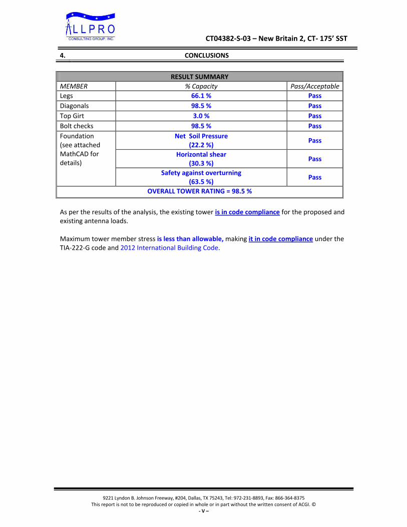
4. CONCLUSIONS
RESULT SUMMARY
MEMBER % Capacity Pass/Acceptable
Legs 66.1 % Pass
Diagonals 98.5 % Pass
Top Girt 3.0 % Pass
Bolt checks 98.5 % Pass
Foundation (see attached MathCAD for details)
Net Soil Pressure (22.2 %)
Pass
Horizontal shear (30.3 %)
Pass
Safety against overturning (63.5 %)
Pass
OVERALL TOWER RATING = 98.5 %
As per the results of the analysis, the existing tower is in code compliance for the proposed and existing antenna loads. Maximum tower member stress is less than allowable, making it in code compliance under the TIA-222-G code and 2012 International Building Code.

CT04382-S-03 – New Britain 2, CT- 175’ SST
9221 Lyndon B. Johnson Freeway, #204, Dallas, TX 75243, Tel: 972-231-8893, Fax: 866-364-8375 This report is not to be reproduced or copied in whole or in part without the written consent of ACGI. ©
- VI –
5. DISCLAIMER
Installation procedures and related loading are not within the scope of this analysis. A contractor experienced in similar work should perform all installation work. The engineering services provided by Allpro Consulting Group, Inc. (ACGI) are limited to the computer analysis and calculations of the structure with the proposed and existing loads. This analysis is considered void if the loading mentioned in this report is changed or is different as installed. It is assumed that the existing structure is properly maintained and is in good condition free of any defects. Scope of this analysis does not include existing connections, except as noted in this report. ACGI does not make any warranties, expressed or implied in connection with this engineering analysis report and disclaims any liability arising from deficiencies or any existing conditions of the original structure. ACGI will not be responsible for consequential or incidental damages sustained by any parties as a result of any data or conclusions included in this Report. The maximum liability of ACGI pursuant to this report shall be limited to the consulting fee received for the preparation of the report. 6. ASSUMPTIONS
This analysis was completed based on the following assumptions:
Tower has been properly maintained.
Tower erection was in accordance to manufacturer drawings and modification reports.
Leg flanges have been properly designed by manufacturer to not be a limiting reaction.
Welds have been properly designed and installed by manufacturer to not be a limiting reaction.
Foundation data was not provided. It is assumed that the foundation is designed to resist the original tower reactions.
Foundation does not have structural damage.
Bolts have been properly tightened according to manufacturer specifications.
Appurtenance, mount and transmission line sizes and weights are best estimates using the tnxTower database and manufacturer information.

CT04382-S-03 – New Britain 2, CT- 175’ SST
9221 Lyndon B. Johnson Freeway, #204, Dallas, TX 75243, Tel: 972-231-8893, Fax: 866-364-8375 This report is not to be reproduced or copied in whole or in part without the written consent of ACGI. ©
- VII –
7. APPURTENANCE LISTING
EXISTING LOAD DESCRIPTION
ELEV (ft.)
Qty. Antenna Description Mount Type & Qty.
TX. LINE (in) TENANT
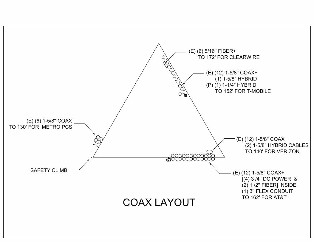
172±
3 Kathrein 840-10054
(3) T-Frames (6) 5/16" Fiber Clearwire 4 Andrew VHLP2.5
3 Samsung U-RAS Flexible RRH
3 Dragonwave Horizon Duo
162±
3 Kathrein 800 10121
(3) T-Frames
(12) 1-5/8" Coax (2) 1/2" Fiber (4) 3/4" DC Power (1) 3" Flex Conduit
AT&T*
3 Quintel Technology QS66512‐2
6 KMW AM‐X‐CD‐16‐65‐00T
3 Ericsson RRUS‐32
3 Ericsson RRUS‐11
3 Ericsson RRUS‐32 B2s
6 Powerwave LGP 21401
6 CCI TPX‐070821
6 Kathrein 860‐10025
2 Raycap DC6‐48‐60‐18‐8F
152±
3 Commscope LNX-6515DS-A1M
(3) T-Frames (12) 1-5/8" Coax (1) 1-5/8" Fiber
T-Mobile
3 Ericsson S11B12
3 Ericsson AIR 21 B2A/B4P
3 Ericsson AIR 21 B4A/B2P
3 Ericsson KRY 112 144/1
140±
6 Andrew SBNHH-1D65B
(3) T-Frames (12) 1-5/8" Coax (2) 1-5/8" Hybrid
Verizon
3 Kathrein 800 10735v01
3 Antel BXA-80080/4CF
3 Alcatel Lucent RRH-2x60-AWS
3 Alcatel Lucent RRH-2x60-PCS
3 Alcatel Lucent RRH-2X60W-700U
1 RFS DB-T1-6Z-8AB-0Z
130± 3 Kathrein 742 213 (3) Pipe Mounts (6) 1-5/8” Coax Metro PCS
*The (2) 1/2” Fiber Cable and (4) 3/4" DC Power Cable for ATT will be Installed in (1) 3” Conduit.
CT04382-S-03 – New Britain 2, CT- 175’ SST
9221 Lyndon B. Johnson Freeway, #204, Dallas, TX 75243, Tel: 972-231-8893, Fax: 866-364-8375 This report is not to be reproduced or copied in whole or in part without the written consent of ACGI. ©
- VIII –
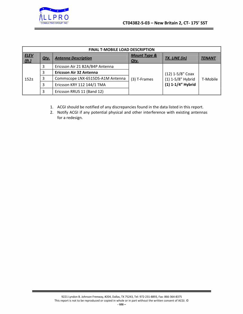
FINAL T-MOBILE LOAD DESCRIPTION
ELEV (ft.)
Qty. Antenna Description Mount Type & Qty.
TX. LINE (in) TENANT
152±
3 Ericsson Air 21 B2A/B4P Antenna
(3) T-Frames (12) 1-5/8" Coax (1) 1-5/8" Hybrid (1) 1-1/4” Hybrid
T-Mobile
3 Ericsson Air 32 Antenna
3 Commscope LNX-6515DS-A1M Antenna
3 Ericsson KRY 112 144/1 TMA
3 Ericsson RRUS 11 (Band 12)
1. ACGI should be notified of any discrepancies found in the data listed in this report. 2. Notify ACGI if any potential physical and other interference with existing antennas
for a redesign.

CT04382-S-03 – New Britain 2, CT- 175’ SST
9221 Lyndon B. Johnson Freeway, #204, Dallas, TX 75243, Tel: 972-231-8893, Fax: 866-364-8375 This report is not to be reproduced or copied in whole or in part without the written consent of ACGI. ©
- IX –
8. SUMMARY OF WORKING PERCENTAGE OF STRUCTURAL COMPONENTS
Section Capacity Table
Section
No.
Elevation
ft
Component
Type
Size Critical
Element
P
K
øPallow
K
%
Capacity
Pass
Fail
T1 176 - 160 Leg ROHN 3 EH 2 -11.58 119.12 9.7 Pass T2 160 - 140 Leg ROHN 4 EH 32 -53.23 183.54 29.0 Pass T3 140 - 120 Leg ROHN 5 EH 66 -102.22 254.38 40.2 Pass T4 120 - 100 Leg ROHN 6 EHS 93 -144.01 274.77 52.4 Pass T5 100 - 93.3333 Leg ROHN 6 EH 114 -157.85 343.10 46.0 Pass T6 93.3333 -
86.6667 Leg ROHN 6 EH 123 -170.92 343.10 49.8 Pass
T7 86.6667 - 80 Leg ROHN 6 EH 132 -183.91 343.10 53.6 Pass T8 80 - 60 Leg ROHN 6 EH 141 -222.13 343.10 64.7 Pass T9 60 - 40 Leg ROHN 8 EHS 162 -255.47 386.39 66.1 Pass T10 40 - 20 Leg ROHN 8 X-STR 177 -291.04 505.55 57.6
59.4 (b) Pass
T11 20 - 0 Leg ROHN 8 EH 192 -325.31 505.55 64.3 Pass T1 176 - 160 Diagonal L2x2x1/4 9 -2.87 19.13 15.0
29.4 (b) Pass
T2 160 - 140 Diagonal L2x2x3/16 37 -4.72 11.91 39.6 68.6 (b)
Pass
T3 140 - 120 Diagonal L2x2x3/16 70 -6.62 7.89 83.9 98.5 (b)
Pass
T4 120 - 100 Diagonal L2 1/2x2 1/2x3/16 97 -7.46 9.76 76.4 94.5 (b)
Pass
T5 100 - 93.3333 Diagonal L2 1/2x2 1/2x3/16 118 -7.56 8.87 85.1 96.5 (b)
Pass
T6 93.3333 - 86.6667
Diagonal L2 1/2x2 1/2x3/16 127 -7.53 8.09 93.0 95.3 (b)
Pass
T7 86.6667 - 80 Diagonal L2.5x2.5x3/16 + L2.5x2.5x3/16 (C-shape)
136 -8.07 32.06 25.2 64.9 (b)
Pass
T8 80 - 60 Diagonal L3x3x1/4 144 -8.30 13.19 62.9 Pass T9 60 - 40 Diagonal L3 1/2x3 1/2x1/4 165 -9.85 14.60 67.5
69.2 (b) Pass
T10 40 - 20 Diagonal L3 1/2x3 1/2x1/4 180 -10.33 12.18 84.8 Pass T11 20 - 0 Diagonal L4x4x1/4 195 -11.07 15.47 71.5
76.5 (b) Pass
T1 176 - 160 Top Girt L2x2x1/4 5 -0.34 12.90 2.6 3.0 (b)
Pass
Summary Leg (T9) 66.1 Pass Diagonal
(T3) 98.5 Pass
Top Girt (T1)
3.0 Pass
Bolt Checks 98.5 Pass RATING = 98.5 Pass
CT04382-S-03 – New Britain 2, CT- 175’ SST
9221 Lyndon B. Johnson Freeway, #204, Dallas, TX 75243, Tel: 972-231-8893, Fax: 866-364-8375 This report is not to be reproduced or copied in whole or in part without the written consent of ACGI. ©
- X –
APPENDIX

CT04382-S-03 – New Britain 2, CT- 175’ SST
9221 Lyndon B. Johnson Freeway, #204, Dallas, TX 75243, Tel: 972-231-8893, Fax: 866-364-8375 This report is not to be reproduced or copied in whole or in part without the written consent of ACGI. ©
- XI –
COAX LAYOUT

CT04382-S-03 – New Britain 2, CT- 175’ SST
9221 Lyndon B. Johnson Freeway, #204, Dallas, TX 75243, Tel: 972-231-8893, Fax: 866-364-8375 This report is not to be reproduced or copied in whole or in part without the written consent of ACGI. ©
- XII –
TOWER ELEVATION DRAWING

Allpro Consulting Group, inc. 9221 Lyndon B. Johnson Fwy, Suite #204
Dallas, TX 75243 Phone: 972-231-8893 FAX: 866-364-8375
Job: 17-1365 Project: CT04382-S-03 New Britain 2, CT Client: SBA Network Services, Inc. Drawn by: sVansia App'd:
Code: TIA-222-G Date: 03/24/17 Scale: NTS Path:
P:\2017\Structural\17-1365 CT04382-S-03 New Britain 2 CT Structural Analysis\Tnx\CT04382-S-03_New Britain_AT&T_03212017.eri Dwg No. E-1
176.0 ft
160.0 ft
140.0 ft
120.0 ft
100.0 ft
93.3 ft
86.7 ft
80.0 ft
60.0 ft
40.0 ft
20.0 ft
0.0 ft
REACTIONS - 95 mph WINDTORQUE 16 kip-ft
56 KSHEAR
5699 kip-ftMOMENT
61 KAXIAL
50 mph WIND - 1.0000 in ICETORQUE 4 kip-ft
17 KSHEAR
1942 kip-ftMOMENT
177 KAXIAL
SHEAR: 31 KUPLIFT: -287 K
SHEAR: 35 KDOWN: 334 K
MAX. CORNER REACTIONS AT BASE:
ARE FACTOREDALL REACTIONS
Sec
tion
T1T2
T3T4
T5T6
T7T8
T9T1
0T1
1
Leg
sR
OH
N 3
EH
RO
HN
4 E
HR
OH
N 5
EH
RO
HN
6 E
HS
RO
HN
6 E
HR
OH
N 8
EH
SR
OH
N 8
X-S
TRR
OH
N 8
EH
Leg
Gra
deA
572-
50
Dia
gona
lsL2
x2x1
/4L2
x2x3
/16
L2 1
/2x2
1/2
x3/1
6A
L3x3
x1/4
L3 1
/2x3
1/2
x1/4
L4x4
x1/4
Dia
gona
l Gra
deA
36A
572-
50
Top
Girt
sL2
x2x1
/4N
.A.
Fac
e W
idth
(ft)
4.68
756.
7265
68.
7656
310
.804
711
.484
412
.164
112
.843
814
.882
816
.921
918
.960
921
# P
anel
s @
(ft)
9 @
44
@ 5
9 @
6.6
6667
6 @
10
Wei
ght (
K)
1.1
1.5
1.9
2.1
0.9
0.9
1.2
3.2
3.4
4.2
4.6
24.9
SYMBOL LISTMARK MARKSIZE SIZE
A L2.5x2.5x3/16 + L2.5x2.5x3/16 (C-shape)
MATERIAL STRENGTHGRADE GRADEFy FyFu Fu
A572-50 50 ksi 65 ksi A36 36 ksi 58 ksi
TOWER DESIGN NOTES1. Tower is located in Hartford County, Connecticut.2. Tower designed for Exposure C to the TIA-222-G Standard.3. Tower designed for a 95 mph basic wind in accordance with the TIA-222-G Standard.4. Tower is also designed for a 50 mph basic wind with 1.00 in ice. Ice is considered to increase
in thickness with height.5. Deflections are based upon a 60 mph wind.6. Tower Structure Class II.7. Topographic Category 1 with Crest Height of 0.00 ft8. TOWER RATING: 98.5%

Allpro Consulting Group, inc. 9221 Lyndon B. Johnson Fwy, Suite #204
Dallas, TX 75243 Phone: 972-231-8893 FAX: 866-364-8375
Job: 17-1365 Project: CT04382-S-03 New Britain 2, CT Client: SBA Network Services, Inc. Drawn by: sVansia App'd:
Code: TIA-222-G Date: 03/24/17 Scale: NTS Path:
P:\2017\Structural\17-1365 CT04382-S-03 New Britain 2 CT Structural Analysis\Tnx\CT04382-S-03_New Britain_AT&T_03212017.eri Dwg No. E-1
176.0 ft
160.0 ft
140.0 ft
120.0 ft
100.0 ft
93.3 ft
86.7 ft
80.0 ft
60.0 ft
40.0 ft
20.0 ft
0.0 ft
REACTIONS - 95 mph WINDTORQUE 16 kip-ft
56 KSHEAR
5699 kip-ftMOMENT
61 KAXIAL
50 mph WIND - 1.0000 in ICETORQUE 4 kip-ft
17 KSHEAR
1942 kip-ftMOMENT
177 KAXIAL
SHEAR: 31 KUPLIFT: -287 K
SHEAR: 35 KDOWN: 334 K
MAX. CORNER REACTIONS AT BASE:
ARE FACTOREDALL REACTIONS
Sec
tion
T1T2
T3T4
T5T6
T7T8
T9T1
0T1
1
Leg
sR
OH
N 3
EH
RO
HN
4 E
HR
OH
N 5
EH
RO
HN
6 E
HS
RO
HN
6 E
HR
OH
N 8
EH
SR
OH
N 8
X-S
TRR
OH
N 8
EH
Leg
Gra
deA
572-
50
Dia
gona
lsL2
x2x1
/4L2
x2x3
/16
L2 1
/2x2
1/2
x3/1
6A
L3x3
x1/4
L3 1
/2x3
1/2
x1/4
L4x4
x1/4
Dia
gona
l Gra
deA
36A
572-
50
Top
Girt
sL2
x2x1
/4N
.A.
Fac
e W
idth
(ft)
4.68
756.
7265
68.
7656
310
.804
711
.484
412
.164
112
.843
814
.882
816
.921
918
.960
921
# P
anel
s @
(ft)
9 @
44
@ 5
9 @
6.6
6667
6 @
10
Wei
ght (
K)
1.1
1.5
1.9
2.1
0.9
0.9
1.2
3.2
3.4
4.2
4.6
24.9
Lightning Rod 176 840-10054 w/ Mount Pipe 172 840-10054 w/ Mount Pipe 172 840-10054 w/ Mount Pipe 172 URAS-FLEXIBLE 172 URAS-FLEXIBLE 172 URAS-FLEXIBLE 172 Horizon Duo 172 Horizon Duo 172 Horizon Duo 172 (3) Empty Pipe Mount 172 (3) Empty Pipe Mount 172 (3) Empty Pipe Mount 172 (3) T-Frames 172 (2) VHLP2.5 Dish 172 VHLP2.5 Dish 172 VHLP2.5 Dish 172 Kathrein 800-10121 162 Kathrein 800-10121 162 Kathrein 800-10121 162 QS65512-2 162 QS65512-2 162 QS65512-2 162 (2) LGP 21401 162 (2) LGP 21401 162 (2) LGP 21401 162 (2) Katherin 860-10025 162 (2) Katherin 860-10025 162 (2) Katherin 860-10025 162 Ericsson RRUS 11 162 Ericsson RRUS 11 162 Ericsson RRUS 11 162 Ericsson RRUS 32 162 Ericsson RRUS 32 162 Ericsson RRUS 32 162 Ericsson RRUS 32 B2s 162 Ericsson RRUS 32 B2s 162 Ericsson RRUS 32 B2s 162 (2) TPX-070821 162 (2) TPX-070821 162 (2) TPX-070821 162 DC6-48-60-18-8F 162 DC6-48-60-18-8F 162 (3) T-Frames 162 (2) AM-X-CD-16-65-00T 162 (2) AM-X-CD-16-65-00T 162 (2) AM-X-CD-16-65-00T 162 AIR 21 B2A/B4P w/ Mount Pipe 152 AIR 21 B2A/B4P w/ Mount Pipe 152 AIR 21 B2A/B4P w/ Mount Pipe 152 Ericsson AIR 32 152 Ericsson AIR 32 152 Ericsson AIR 32 152 Ericsson RRUS 11 (Band 12) 152 Ericsson RRUS 11 (Band 12) 152 Ericsson RRUS 11 (Band 12) 152 KRY 112 144/1 152 KRY 112 144/1 152 KRY 112 144/1 152 Empty Pipe Mount 152 Empty Pipe Mount 152 Empty Pipe Mount 152 (3) T-Frames 152 LNX-6515DS-A1M w/ Mount Pipe 152 LNX-6515DS-A1M w/ Mount Pipe 152 LNX-6515DS-A1M w/ Mount Pipe 152 800 10735v01 w/ Mount Pipe 140 800 10735v01 w/ Mount Pipe 140 800 10735v01 w/ Mount Pipe 140 BXA-80080/4CF w/ Mount Pipe 140 BXA-80080/4CF w/ Mount Pipe 140 BXA-80080/4CF w/ Mount Pipe 140 RRH-2x60-AWS 140 RRH-2x60-AWS 140 RRH-2x60-AWS 140 RRH-2x60-PCS 140 RRH-2x60-PCS 140 RRH-2x60-PCS 140 RRH 2x60-700 140 RRH 2x60-700 140 RRH 2x60-700 140 DB-T1-6Z-8AB-0Z 140 (3) T-Frames 140 (2) SBNHH-1D65B w/ Mount Pipe 140 (2) SBNHH-1D65B w/ Mount Pipe 140 (2) SBNHH-1D65B w/ Mount Pipe 140 (3) Pipe Mounts 130 742 213 w/ Mount Pipe 130 742 213 w/ Mount Pipe 130 742 213 w/ Mount Pipe 130DESIGNED APPURTENANCE LOADINGTYPE TYPEELEVATION ELEVATION
Lightning Rod 176 840-10054 w/ Mount Pipe 172 840-10054 w/ Mount Pipe 172 840-10054 w/ Mount Pipe 172 URAS-FLEXIBLE 172 URAS-FLEXIBLE 172 URAS-FLEXIBLE 172 Horizon Duo 172 Horizon Duo 172 Horizon Duo 172 (3) Empty Pipe Mount 172 (3) Empty Pipe Mount 172 (3) Empty Pipe Mount 172 (3) T-Frames 172 (2) VHLP2.5 Dish 172 VHLP2.5 Dish 172 VHLP2.5 Dish 172 Kathrein 800-10121 162 Kathrein 800-10121 162 Kathrein 800-10121 162 QS65512-2 162 QS65512-2 162 QS65512-2 162 (2) LGP 21401 162 (2) LGP 21401 162 (2) LGP 21401 162 (2) Katherin 860-10025 162 (2) Katherin 860-10025 162 (2) Katherin 860-10025 162 Ericsson RRUS 11 162 Ericsson RRUS 11 162 Ericsson RRUS 11 162 Ericsson RRUS 32 162 Ericsson RRUS 32 162 Ericsson RRUS 32 162 Ericsson RRUS 32 B2s 162 Ericsson RRUS 32 B2s 162 Ericsson RRUS 32 B2s 162 (2) TPX-070821 162 (2) TPX-070821 162 (2) TPX-070821 162 DC6-48-60-18-8F 162 DC6-48-60-18-8F 162 (3) T-Frames 162 (2) AM-X-CD-16-65-00T 162
(2) AM-X-CD-16-65-00T 162 (2) AM-X-CD-16-65-00T 162 AIR 21 B2A/B4P w/ Mount Pipe 152 AIR 21 B2A/B4P w/ Mount Pipe 152 AIR 21 B2A/B4P w/ Mount Pipe 152 Ericsson AIR 32 152 Ericsson AIR 32 152 Ericsson AIR 32 152 Ericsson RRUS 11 (Band 12) 152 Ericsson RRUS 11 (Band 12) 152 Ericsson RRUS 11 (Band 12) 152 KRY 112 144/1 152 KRY 112 144/1 152 KRY 112 144/1 152 Empty Pipe Mount 152 Empty Pipe Mount 152 Empty Pipe Mount 152 (3) T-Frames 152 LNX-6515DS-A1M w/ Mount Pipe 152 LNX-6515DS-A1M w/ Mount Pipe 152 LNX-6515DS-A1M w/ Mount Pipe 152 800 10735v01 w/ Mount Pipe 140 800 10735v01 w/ Mount Pipe 140 800 10735v01 w/ Mount Pipe 140 BXA-80080/4CF w/ Mount Pipe 140 BXA-80080/4CF w/ Mount Pipe 140 BXA-80080/4CF w/ Mount Pipe 140 RRH-2x60-AWS 140 RRH-2x60-AWS 140 RRH-2x60-AWS 140 RRH-2x60-PCS 140 RRH-2x60-PCS 140 RRH-2x60-PCS 140 RRH 2x60-700 140 RRH 2x60-700 140 RRH 2x60-700 140 DB-T1-6Z-8AB-0Z 140 (3) T-Frames 140 (2) SBNHH-1D65B w/ Mount Pipe 140 (2) SBNHH-1D65B w/ Mount Pipe 140 (2) SBNHH-1D65B w/ Mount Pipe 140 (3) Pipe Mounts 130 742 213 w/ Mount Pipe 130 742 213 w/ Mount Pipe 130 742 213 w/ Mount Pipe 130
SYMBOL LISTMARK MARKSIZE SIZE
A L2.5x2.5x3/16 + L2.5x2.5x3/16 (C-shape)
MATERIAL STRENGTHGRADE GRADEFy FyFu Fu
A572-50 50 ksi 65 ksi A36 36 ksi 58 ksi
TOWER DESIGN NOTES1. Tower is located in Hartford County, Connecticut.2. Tower designed for Exposure C to the TIA-222-G Standard.3. Tower designed for a 95 mph basic wind in accordance with the TIA-222-G Standard.4. Tower is also designed for a 50 mph basic wind with 1.00 in ice. Ice is considered to increase
in thickness with height.5. Deflections are based upon a 60 mph wind.6. Tower Structure Class II.7. Topographic Category 1 with Crest Height of 0.00 ft8. TOWER RATING: 98.5%

CT04382-S-03 – New Britain 2, CT- 175’ SST
9221 Lyndon B. Johnson Freeway, #204, Dallas, TX 75243, Tel: 972-231-8893, Fax: 866-364-8375 This report is not to be reproduced or copied in whole or in part without the written consent of ACGI. ©
- XIII –
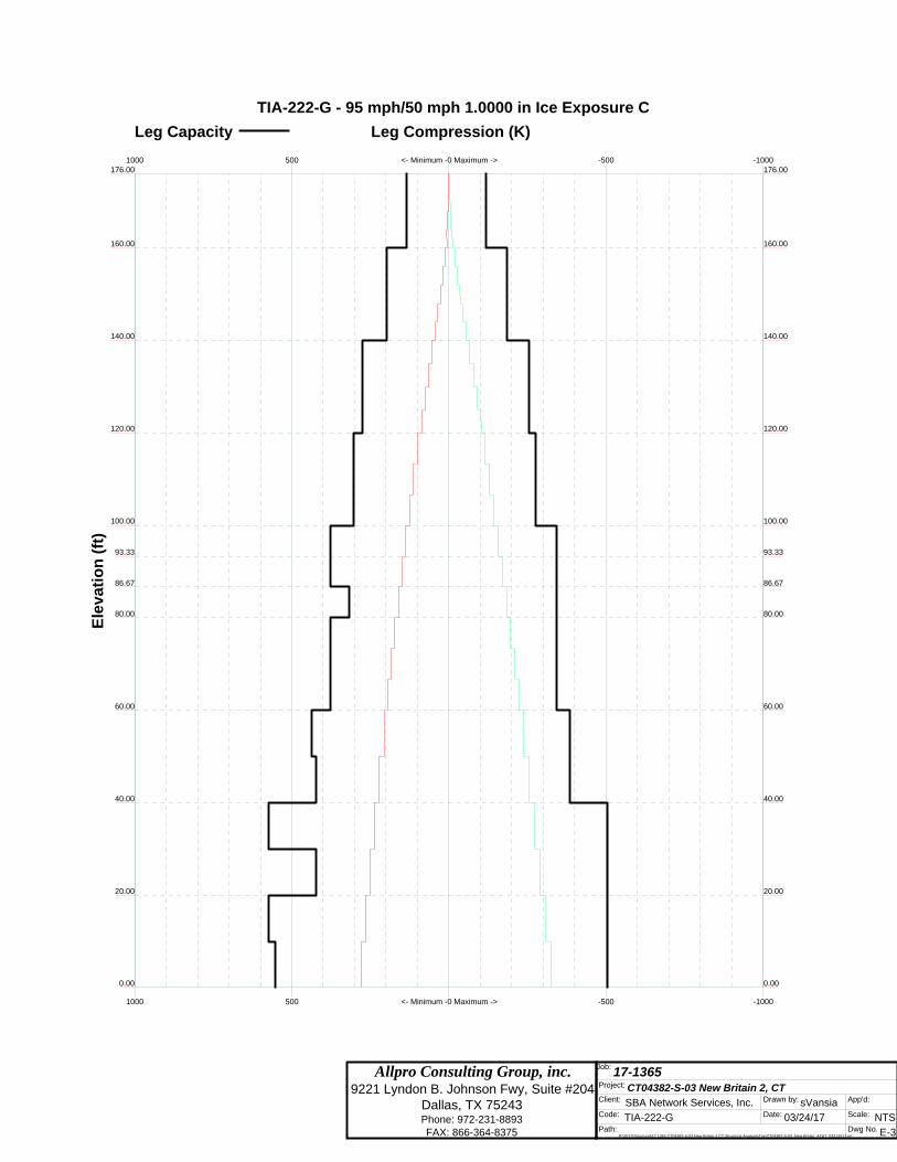
MISCELLANEOUS PLOTS
Allpro Consulting Group, inc. 9221 Lyndon B. Johnson Fwy, Suite #204
Dallas, TX 75243 Phone: 972-231-8893 FAX: 866-364-8375
Job: 17-1365 Project: CT04382-S-03 New Britain 2, CT Client: SBA Network Services, Inc. Drawn by: sVansia App'd:
Code: TIA-222-G Date: 03/24/17 Scale: NTS Path:
P:\2017\Structural\17-1365 CT04382-S-03 New Britain 2 CT Structural Analysis\Tnx\CT04382-S-03_New Britain_AT&T_03212017.eri Dwg No. E-3
<- Minimum -0 Maximum ->
<- Minimum -0 Maximum ->
-500
-500
-1000
-1000
500
500
1000
1000
TIA-222-G - 95 mph/50 mph 1.0000 in Ice Exposure CLeg Capacity Leg Compression (K)
176.00 176.00
160.00 160.00
140.00 140.00
120.00 120.00
100.00 100.00
93.33 93.33
86.67 86.67
80.00 80.00
60.00 60.00
40.00 40.00
20.00 20.00
0.00 0.00
Elev
atio
n (ft
)

Allpro Consulting Group, inc. 9221 Lyndon B. Johnson Fwy, Suite #204
Dallas, TX 75243 Phone: 972-231-8893 FAX: 866-364-8375
Job: 17-1365 Project: CT04382-S-03 New Britain 2, CT Client: SBA Network Services, Inc. Drawn by: sVansia App'd:
Code: TIA-222-G Date: 03/24/17 Scale: NTS Path:
P:\2017\Structural\17-1365 CT04382-S-03 New Britain 2 CT Structural Analysis\Tnx\CT04382-S-03_New Britain_AT&T_03212017.eri Dwg No. E-4
0
0
50
50
100
100
Global Mast Shear (K)176.00
160.00
140.00
120.00
100.00
93.33
86.67
80.00
60.00
40.00
20.00
0.00
Elev
atio
n (ft
)
0
0
5000
5000
10000
10000
Global Mast Moment (kip-ft)176.00
160.00
140.00
120.00
100.00
93.33
86.67
80.00
60.00
40.00
20.00
0.00
TIA-222-G - 95 mph/50 mph 1.0000 in Ice Exposure C Maximum ValuesVx Vz Mx Mz

Allpro Consulting Group, inc. 9221 Lyndon B. Johnson Fwy, Suite #204
Dallas, TX 75243 Phone: 972-231-8893 FAX: 866-364-8375
Job: 17-1365 Project: CT04382-S-03 New Britain 2, CT Client: SBA Network Services, Inc. Drawn by: sVansia App'd:
Code: TIA-222-G Date: 03/24/17 Scale: NTS Path:
P:\2017\Structural\17-1365 CT04382-S-03 New Britain 2 CT Structural Analysis\Tnx\CT04382-S-03_New Britain_AT&T_03212017.eri Dwg No. E-5
TIA-222-G - Service - 60 mph Maximum Values
0
0
5
5
Deflection (in)176.00
160.00
140.00
120.00
100.00
93.33
86.67
80.00
60.00
40.00
20.00
0.00
Elev
atio
n (ft
)
0
0
0.05
0.05
0.1
0.1
0.15
0.15
0.2
0.2
0.25
0.25
Tilt (deg)0
0
0.05
0.05
0.1
0.1
Twist (deg)176.00
160.00
140.00
120.00
100.00
93.33
86.67
80.00
60.00
40.00
20.00
0.00

Allpro Consulting Group, inc. 9221 Lyndon B. Johnson Fwy, Suite #204
Dallas, TX 75243 Phone: 972-231-8893 FAX: 866-364-8375
Job: 17-1365 Project: CT04382-S-03 New Britain 2, CT Client: SBA Network Services, Inc. Drawn by: sVansia App'd:
Code: TIA-222-G Date: 03/24/17 Scale: NTS Path:
P:\2017\Structural\17-1365 CT04382-S-03 New Britain 2 CT Structural Analysis\Tnx\CT04382-S-03_New Britain_AT&T_03212017.eri Dwg No. E-7
Feed Line Distribution Chart0' - 176'
Round Flat App In Face App Out Face Truss Leg
Face A
160.00
140.00
120.00
100.00
93.33
86.67
80.00
60.00
40.00
20.00
0.00
176.00
Elev
atio
n (ft
)
Feed
line
Ladd
er (A
f)
(6) 1
5/8
Face B
130.00
172.00
162.00
130.00
152.00152.00
172.00
140.00140.00
162.00162.00
(2) F
eedl
ine
Ladd
er (A
f)
(26)
1-5
/8'' C
OA
X
(12)
1-5
/8'' C
OA
X
3'' C
ON
DU
IT+2
x1/2
''FIB
ER
+4x3
/4''D
C
Face C
160.00
140.00
120.00
100.00
93.33
86.67
80.00
60.00
40.00
20.00
0.00
176.00
130.00
172.00
162.00
130.00
152.00152.00
172.00
140.00140.00
162.00162.00
Saf
ety
Line
3/8
(2) F
eedl
ine
Ladd
er (A
f)
(13)
1-5
/8'' C
OA
X
1-1/
4" H
ybrid (6
) 5/1
6'' C
OA
X

Allpro Consulting Group, inc. 9221 Lyndon B. Johnson Fwy, Suite #204
Dallas, TX 75243 Phone: 972-231-8893 FAX: 866-364-8375
Job: 17-1365 Project: CT04382-S-03 New Britain 2, CT Client: SBA Network Services, Inc. Drawn by: sVansia App'd:
Code: TIA-222-G Date: 03/24/17 Scale: NTS Path:
P:\2017\Structural\17-1365 CT04382-S-03 New Britain 2 CT Structural Analysis\Tnx\CT04382-S-03_New Britain_AT&T_03212017.eri Dwg No. E-9
Wind Pressures and Ice ThicknessTIA-222-G - 95 mph/50 mph 1.0000 in Ice Exposure C
0
0
10
10
20
20
30
30
Pressure - No Ice (psf)176.00
160.00
140.00
120.00
100.00
93.33
86.67
80.00
60.00
40.00
20.00
0.00
Elev
atio
n (ft
)
0
0
10
10
Pressure - Ice (psf)0
0
2.5
2.5
Ice Thickness (in)176.00
160.00
140.00
120.00
100.00
93.33
86.67
80.00
60.00
40.00
20.00
0.00
CT04382-S-03 – New Britain 2, CT- 175’ SST
9221 Lyndon B. Johnson Freeway, #204, Dallas, TX 75243, Tel: 972-231-8893, Fax: 866-364-8375 This report is not to be reproduced or copied in whole or in part without the written consent of ACGI. ©
- XIV –
TNX TOWER CALCULATION PRINTOUT

ttnnxxTToowweerr Job
17-1365
Page
1 of 22
Allpro Consulting Group, inc. 9221 Lyndon B. Johnson Fwy, Suite #204
Project
CT04382-S-03 New Britain 2, CT
Date
16:25:33 03/24/17
Dallas, TX 75243
Phone: 972-231-8893
FAX: 866-364-8375
Client
SBA Network Services, Inc. Designed by
sVansia
Tower Input Data The main tower is a 3x free standing tower with an overall height of 176.00 ft above the ground line. The base of the tower is set at an elevation of 0.00 ft above the ground line. The face width of the tower is 4.69 ft at the top and 21.00 ft at the base. This tower is designed using the TIA-222-G standard. The following design criteria apply:
Tower is located in Hartford County, Connecticut. ASCE 7-10 Wind Data is used (wind speeds converted to nominal values). Basic wind speed of 95 mph. Structure Class II. Exposure Category C. Topographic Category 1. Crest Height 0.00 ft. Nominal ice thickness of 1.0000 in. Ice thickness is considered to increase with height. Ice density of 56 pcf. A wind speed of 50 mph is used in combination with ice. Temperature drop of 50 °F. Deflections calculated using a wind speed of 60 mph. Pressures are calculated at each section. Stress ratio used in tower member design is 1. Local bending stresses due to climbing loads, feed line supports, and appurtenance mounts are not considered.
Options
Consider Moments - Legs Distribute Leg Loads As Uniform Use ASCE 10 X-Brace Ly Rules Consider Moments - Horizontals Assume Legs Pinned √ Calculate Redundant Bracing Forces Consider Moments - Diagonals √ Assume Rigid Index Plate Ignore Redundant Members in FEA Use Moment Magnification √ Use Clear Spans For Wind Area √ SR Leg Bolts Resist Compression
√ Use Code Stress Ratios √ Use Clear Spans For KL/r All Leg Panels Have Same Allowable √ Use Code Safety Factors - Guys Retension Guys To Initial Tension Offset Girt At Foundation Escalate Ice √ Bypass Mast Stability Checks √ Consider Feed Line Torque Always Use Max Kz √ Use Azimuth Dish Coefficients √ Include Angle Block Shear Check Use Special Wind Profile √ Project Wind Area of Appurt. Use TIA-222-G Bracing Resist. Exemption
√ Include Bolts In Member Capacity Autocalc Torque Arm Areas Use TIA-222-G Tension Splice Exemption Leg Bolts Are At Top Of Section Add IBC .6D+W Combination Poles
√ Secondary Horizontal Braces Leg √ Sort Capacity Reports By Component Include Shear-Torsion Interaction Use Diamond Inner Bracing (4 Sided) Triangulate Diamond Inner Bracing Always Use Sub-Critical Flow SR Members Have Cut Ends Treat Feed Line Bundles As Cylinder Use Top Mounted Sockets SR Members Are Concentric

ttnnxxTToowweerr Job
17-1365
Page
2 of 22
Allpro Consulting Group, inc. 9221 Lyndon B. Johnson Fwy, Suite #204
Project
CT04382-S-03 New Britain 2, CT
Date
16:25:33 03/24/17
Dallas, TX 75243
Phone: 972-231-8893
FAX: 866-364-8375
Client
SBA Network Services, Inc. Designed by
sVansia
Leg B Leg C
Leg A
Face
A Face B
Face C
Triangular Tower
Wind Normal
Wind 90
Wind 180
Z
X
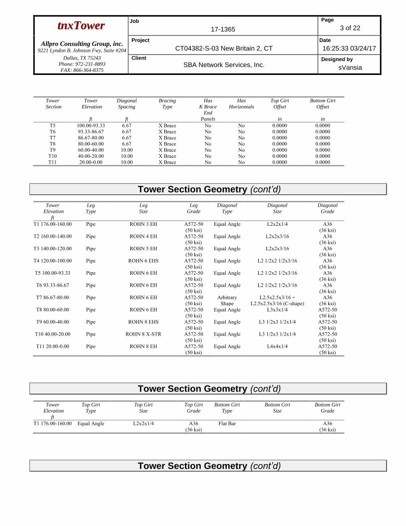
Tower Section Geometry
Tower
Section
Tower
Elevation
ft
Assembly
Database
Description Section
Width
ft
Number
of
Sections
Section
Length
ft
T1 176.00-160.00 4.69 1 16.00 T2 160.00-140.00 4.69 1 20.00 T3 140.00-120.00 6.73 1 20.00 T4 120.00-100.00 8.77 1 20.00 T5 100.00-93.33 10.80 1 6.67 T6 93.33-86.67 11.48 1 6.67 T7 86.67-80.00 12.16 1 6.67 T8 80.00-60.00 12.84 1 20.00 T9 60.00-40.00 14.88 1 20.00
T10 40.00-20.00 16.92 1 20.00 T11 20.00-0.00 18.96 1 20.00
Tower Section Geometry (cont’d)
Tower
Section
Tower
Elevation
ft
Diagonal
Spacing
ft
Bracing
Type
Has
K Brace
End
Panels
Has
Horizontals
Top Girt
Offset
in
Bottom Girt
Offset
in
T1 176.00-160.00 4.00 X Brace No No 0.0000 0.0000 T2 160.00-140.00 4.00 X Brace No No 0.0000 0.0000 T3 140.00-120.00 5.00 X Brace No No 0.0000 0.0000 T4 120.00-100.00 6.67 X Brace No No 0.0000 0.0000
ttnnxxTToowweerr Job
17-1365
Page
3 of 22
Allpro Consulting Group, inc. 9221 Lyndon B. Johnson Fwy, Suite #204
Project
CT04382-S-03 New Britain 2, CT
Date
16:25:33 03/24/17
Dallas, TX 75243
Phone: 972-231-8893
FAX: 866-364-8375
Client
SBA Network Services, Inc. Designed by
sVansia
Tower
Section
Tower
Elevation
ft
Diagonal
Spacing
ft
Bracing
Type
Has
K Brace
End
Panels
Has
Horizontals
Top Girt
Offset
in
Bottom Girt
Offset
in
T5 100.00-93.33 6.67 X Brace No No 0.0000 0.0000 T6 93.33-86.67 6.67 X Brace No No 0.0000 0.0000 T7 86.67-80.00 6.67 X Brace No No 0.0000 0.0000 T8 80.00-60.00 6.67 X Brace No No 0.0000 0.0000 T9 60.00-40.00 10.00 X Brace No No 0.0000 0.0000
T10 40.00-20.00 10.00 X Brace No No 0.0000 0.0000 T11 20.00-0.00 10.00 X Brace No No 0.0000 0.0000
Tower Section Geometry (cont’d)
Tower
Elevation
ft
Leg
Type
Leg
Size
Leg
Grade
Diagonal
Type
Diagonal
Size
Diagonal
Grade
T1 176.00-160.00 Pipe ROHN 3 EH A572-50 (50 ksi)
Equal Angle L2x2x1/4 A36 (36 ksi)
T2 160.00-140.00 Pipe ROHN 4 EH A572-50 (50 ksi)
Equal Angle L2x2x3/16 A36 (36 ksi)
T3 140.00-120.00 Pipe ROHN 5 EH A572-50 (50 ksi)
Equal Angle L2x2x3/16 A36 (36 ksi)
T4 120.00-100.00 Pipe ROHN 6 EHS A572-50 (50 ksi)
Equal Angle L2 1/2x2 1/2x3/16 A36 (36 ksi)
T5 100.00-93.33 Pipe ROHN 6 EH A572-50 (50 ksi)
Equal Angle L2 1/2x2 1/2x3/16 A36 (36 ksi)
T6 93.33-86.67 Pipe ROHN 6 EH A572-50 (50 ksi)
Equal Angle L2 1/2x2 1/2x3/16 A36 (36 ksi)
T7 86.67-80.00 Pipe ROHN 6 EH A572-50 (50 ksi)
Arbitrary Shape
L2.5x2.5x3/16 + L2.5x2.5x3/16 (C-shape)
A36 (36 ksi)
T8 80.00-60.00 Pipe ROHN 6 EH A572-50 (50 ksi)
Equal Angle L3x3x1/4 A572-50 (50 ksi)
T9 60.00-40.00 Pipe ROHN 8 EHS A572-50 (50 ksi)
Equal Angle L3 1/2x3 1/2x1/4 A572-50 (50 ksi)
T10 40.00-20.00 Pipe ROHN 8 X-STR A572-50 (50 ksi)
Equal Angle L3 1/2x3 1/2x1/4 A572-50 (50 ksi)
T11 20.00-0.00 Pipe ROHN 8 EH A572-50 (50 ksi)
Equal Angle L4x4x1/4 A572-50 (50 ksi)
Tower Section Geometry (cont’d)
Tower
Elevation
ft
Top Girt
Type
Top Girt
Size
Top Girt
Grade
Bottom Girt
Type
Bottom Girt
Size
Bottom Girt
Grade
T1 176.00-160.00 Equal Angle L2x2x1/4 A36 (36 ksi)
Flat Bar A36 (36 ksi)
Tower Section Geometry (cont’d)

ttnnxxTToowweerr Job
17-1365
Page
4 of 22
Allpro Consulting Group, inc. 9221 Lyndon B. Johnson Fwy, Suite #204
Project
CT04382-S-03 New Britain 2, CT
Date
16:25:33 03/24/17
Dallas, TX 75243
Phone: 972-231-8893
FAX: 866-364-8375
Client
SBA Network Services, Inc. Designed by
sVansia
Tower
Elevation
ft
Gusset
Area
(per face)
ft2
Gusset
Thickness
in
Gusset Grade Adjust. Factor
Af
Adjust.
Factor
Ar
Weight Mult.
Double Angle
Stitch Bolt
Spacing
Diagonals
in
Double Angle
Stitch Bolt
Spacing
Horizontals
in
Double Angle
Stitch Bolt
Spacing
Redundants
in
T1 176.00-160.00
0.00 0.0000 A36 (36 ksi)
1 1 1.05 36.0000 36.0000 36.0000
T2 160.00-140.00
0.00 0.0000 A36 (36 ksi)
1 1 1.05 36.0000 36.0000 36.0000
T3 140.00-120.00
0.00 0.0000 A36 (36 ksi)
1 1 1.05 36.0000 36.0000 36.0000
T4 120.00-100.00
0.00 0.0000 A36 (36 ksi)
1 1 1.05 36.0000 36.0000 36.0000
T5 100.00-93.33
0.00 0.0000 A36 (36 ksi)
1 1 1.05 36.0000 36.0000 36.0000
T6 93.33-86.67 0.00 0.0000 A36 (36 ksi)
1 1 1.05 36.0000 36.0000 36.0000
T7 86.67-80.00 0.00 0.0000 A36 (36 ksi)
1 1 1.05 36.0000 36.0000 36.0000
T8 80.00-60.00 0.00 0.0000 A36 (36 ksi)
1 1 1.05 36.0000 36.0000 36.0000
T9 60.00-40.00 0.00 0.0000 A36 (36 ksi)
1 1 1.05 36.0000 36.0000 36.0000
T10 40.00-20.00
0.00 0.0000 A36 (36 ksi)
1 1 1.05 36.0000 36.0000 36.0000
T11 20.00-0.00 0.00 0.0000 A36 (36 ksi)
1 1 1.05 36.0000 36.0000 36.0000
Tower Section Geometry (cont’d)
K Factors1
Tower
Elevation
ft
Calc
K
Single
Angles
Calc
K
Solid
Rounds
Legs X
Brace
Diags
X
Y
K
Brace
Diags
X
Y
Single
Diags
X
Y
Girts
X
Y
Horiz.
X
Y
Sec.
Horiz.
X
Y
Inner
Brace
X
Y
T1 176.00-160.00
Yes No 1 1 1
1 1
1 1
1 1
1 1
1 1
1 1
T2 160.00-140.00
Yes No 1 1 1
1 1
1 1
1 1
1 1
1 1
1 1
T3 140.00-120.00
Yes No 1 1 1
1 1
1 1
1 1
1 1
1 1
1 1
T4 120.00-100.00
Yes No 1 1 1
1 1
1 1
1 1
1 1
1 1
1 1
T5 100.00-93.33
Yes No 1 1 1
1 1
1 1
1 1
1 1
1 1
1 1
T6 93.33-86.67
Yes No 1 1 1
1 1
1 1
1 1
1 1
1 1
1 1
T7 86.67-80.00
Yes No 1 1 1
1 1
1 1
1 1
1 1
1 1
1 1
T8 80.00-60.00
Yes No 1 1 1
1 1
1 1
1 1
1 1
1 1
1 1
T9 60.00-40.00
Yes No 1 1 1
1 1
1 1
1 1
1 1
1 1
1 1
T10 40.00-20.00
Yes No 1 1 1
1 1
1 1
1 1
1 1
1 1
1 1
T11 20.00-0.00
Yes No 1 1 1
1 1
1 1
1 1
1 1
1 1
1 1
1Note: K factors are applied to member segment lengths. K-braces without inner supporting members will have the K factor in the out-of-plane direction applied to
the overall length.

ttnnxxTToowweerr Job
17-1365
Page
5 of 22
Allpro Consulting Group, inc. 9221 Lyndon B. Johnson Fwy, Suite #204
Project
CT04382-S-03 New Britain 2, CT
Date
16:25:33 03/24/17
Dallas, TX 75243
Phone: 972-231-8893
FAX: 866-364-8375
Client
SBA Network Services, Inc. Designed by
sVansia
Tower Section Geometry (cont’d)
Tower
Elevation
ft
Leg Diagonal Top Girt Bottom Girt Mid Girt Long Horizontal Short Horizontal
Net Width
Deduct
in
U
Net Width
Deduct
in
U
Net Width
Deduct
in
U
Net
Width
Deduct
in
U
Net
Width
Deduct
in
U
Net
Width
Deduct
in
U
Net
Width
Deduct
in
U
T1 176.00-160.00
0.0000 1 0.0000 0.75 0.0000 0.75 0.0000 0.75 0.0000 0.75 0.0000 0.75 0.0000 0.75
T2 160.00-140.00
0.0000 1 0.0000 0.75 0.0000 0.75 0.0000 0.75 0.0000 0.75 0.0000 0.75 0.0000 0.75
T3 140.00-120.00
0.0000 1 0.0000 0.75 0.0000 0.75 0.0000 0.75 0.0000 0.75 0.0000 0.75 0.0000 0.75
T4 120.00-100.00
0.0000 1 0.0000 0.75 0.0000 0.75 0.0000 0.75 0.0000 0.75 0.0000 0.75 0.0000 0.75
T5 100.00-93.33
0.0000 1 0.0000 0.75 0.0000 0.75 0.0000 0.75 0.0000 0.75 0.0000 0.75 0.0000 0.75
T6 93.33-86.67 0.0000 1 0.0000 0.75 0.0000 0.75 0.0000 0.75 0.0000 0.75 0.0000 0.75 0.0000 0.75 T7 86.67-80.00 0.0000 1 0.0000 0.75 0.0000 0.75 0.0000 0.75 0.0000 0.75 0.0000 0.75 0.0000 0.75 T8 80.00-60.00 0.0000 1 0.0000 0.75 0.0000 0.75 0.0000 0.75 0.0000 0.75 0.0000 0.75 0.0000 0.75 T9 60.00-40.00 0.0000 1 0.0000 0.75 0.0000 0.75 0.0000 0.75 0.0000 0.75 0.0000 0.75 0.0000 0.75
T10 40.00-20.00
0.0000 1 0.0000 0.75 0.0000 0.75 0.0000 0.75 0.0000 0.75 0.0000 0.75 0.0000 0.75
T11 20.00-0.00 0.0000 1 0.0000 0.75 0.0000 0.75 0.0000 0.75 0.0000 0.75 0.0000 0.75 0.0000 0.75
Tower Section Geometry (cont’d)
Tower
Elevation
ft
Leg
Connection
Type
Leg Diagonal Top Girt Bottom Girt Mid Girt Long Horizontal Short Horizontal
Bolt Size
in
No. Bolt Size
in
No. Bolt Size
in
No. Bolt Size
in
No. Bolt Size
in
No. Bolt Size
in
No. Bolt Size
in
No.
T1 176.00-160.00
Flange 0.8750 A325N
4 0.6250 A325N
1 0.6250 A325N
1 0.6250 A325N
0 0.6250 A325N
0 0.6250 A325N
0 0.6250 A325N
0
T2 160.00-140.00
Flange 1.0000 A325N
4 0.6250 A325N
1 0.6250 A325N
0 0.6250 A325N
0 0.6250 A325N
0 0.6250 A325N
0 0.6250 A325N
0
T3 140.00-120.00
Flange 1.0000 A325N
6 0.6250 A325N
1 0.6250 A325N
0 0.6250 A325N
0 0.6250 A325N
0 0.6250 A325N
0 0.6250 A325N
0
T4 120.00-100.00
Flange 1.0000 A325N
6 0.6250 A325N
1 0.6250 A325N
0 0.6250 A325N
0 0.6250 A325N
0 0.6250 A325N
0 0.6250 A325N
0
T5 100.00-93.33
Flange 1.0000 A325N
0 0.6250 A325N
1 0.6250 A325N
0 0.0000 A325N
0 0.6250 A325N
0 0.6250 A325N
0 0.6250 A325N
0
T6 93.33-86.67 Flange 1.0000 A325N
0 0.6250 A325N
1 0.6250 A325N
0 0.0000 A325N
0 0.6250 A325N
0 0.6250 A325N
0 0.6250 A325N
0
T7 86.67-80.00 Flange 1.0000 A325N
6 0.6250 A325N
1 0.6250 A325N
0 0.6250 A325N
0 0.6250 A325N
0 0.6250 A325N
0 0.6250 A325N
0
T8 80.00-60.00 Flange 1.0000 A325N
8 0.7500 A325N
1 0.6250 A325N
0 0.6250 A325N
0 0.6250 A325N
0 0.6250 A325N
0 0.6250 A325N
0
T9 60.00-40.00 Flange 1.0000 A325N
8 0.7500 A325N
1 0.6250 A325N
0 0.6250 A325N
0 0.6250 A325N
0 0.6250 A325N
0 0.6250 A325N
0
T10 40.00-20.00
Flange 1.0000 A325N
8 0.7500 A325N
1 0.6250 A325N
0 0.6250 A325N
0 0.6250 A325N
0 0.6250 A325N
0 0.6250 A325N
0
ttnnxxTToowweerr Job
17-1365
Page
6 of 22
Allpro Consulting Group, inc. 9221 Lyndon B. Johnson Fwy, Suite #204
Project
CT04382-S-03 New Britain 2, CT
Date
16:25:33 03/24/17
Dallas, TX 75243
Phone: 972-231-8893
FAX: 866-364-8375
Client
SBA Network Services, Inc. Designed by
sVansia
Tower
Elevation
ft
Leg
Connection
Type
Leg Diagonal Top Girt Bottom Girt Mid Girt Long Horizontal Short Horizontal
Bolt Size
in
No. Bolt Size
in
No. Bolt Size
in
No. Bolt Size
in
No. Bolt Size
in
No. Bolt Size
in
No. Bolt Size
in
No.
T11 20.00-0.00 Flange 1.0000 A354-BC
10 0.7500 A325N
1 0.6250 A325N
0 0.6250 A325N
0 0.6250 A325N
0 0.6250 A325N
0 0.6250 A325N
0
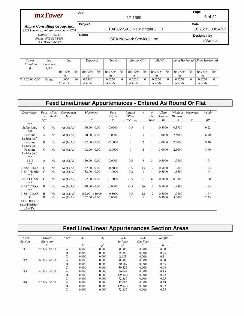
Feed Line/Linear Appurtenances - Entered As Round Or Flat
Description Face
or
Leg
Allow
Shield
Component
Type
Placement
ft
Face
Offset
in
Lateral
Offset
(Frac FW)
# #
Per
Row
Clear
Spacing
in
Width or
Diameter
in
Perimeter
in
Weight
plf
*** Safety Line
3/8 C No Ar (CaAa) 176.00 - 0.00 0.0000 -0.5 1 1 0.5000 0.3750 0.22
Feedline Ladder (Af)
A No Af (CaAa) 130.00 - 0.00 0.0000 0 1 1 3.0000 2.5000 8.40
Feedline Ladder (Af)
B No Af (CaAa) 172.00 - 0.00 -2.0000 0 2 1 3.0000 2.5000 8.40
Feedline Ladder (Af)
C No Af (CaAa) 162.00 - 0.00 -2.0000 0 2 1 3.0000 2.5000 8.40
*** 1 5/8 A No Ar (CaAa) 130.00 - 0.00 0.0000 -0.5 6 3 0.5000 1.9800 1.04 ***
1-5/8'' COAX C No Ar (CaAa) 152.00 - 0.00 -0.5000 -0.5 13 12 0.5000 1.9800 1.04 1-1/4'' Hybrid C No Ar (CaAa) 152.00 - 0.00 -1.0000 -0.2 1 1 0.5000 1.5500 1.04
*** 5/16'' COAX C No Ar (CaAa) 172.00 - 0.00 -1.5000 -0.5 6 6 0.5000 0.0300 1.00
*** 1-5/8'' COAX B No Ar (CaAa) 140.00 - 0.00 0.0000 -0.5 26 12 0.5000 1.9800 1.04
*** 1-5/8'' COAX B No Ar (CaAa) 162.00 - 140.00 -0.5000 -0.5 12 12 0.5000 1.9800 1.04
3'' CONDUIT+2x1/2''FIBER+4
x3/4''DC
B No Ar (CaAa) 162.00 - 0.00 0.0000 0 1 1 0.5000 3.0000 2.25
Feed Line/Linear Appurtenances Section Areas Tower
Section
Tower
Elevation
ft
Face AR
ft2
AF
ft2
CAAA
In Face
ft2
CAAA
Out Face
ft2
Weight
K
T1 176.00-160.00 A B C
0.000 0.000 0.000
0.000 0.000 0.000
0.000 15.352 2.483
0.000 0.000 0.000
0.00 0.23 0.11
T2 160.00-140.00 A B C
0.000 0.000 0.000
0.000 0.000 0.000
0.000 70.187 50.525
0.000 0.000 0.000
0.00 0.63 0.64
T3 140.00-120.00 A B C
0.000 0.000 0.000
0.000 0.000 0.000
16.047 125.627 72.357
0.000 0.000 0.000
0.15 0.92 0.75
T4 120.00-100.00 A B C
0.000 0.000 0.000
0.000 0.000 0.000
32.093 125.627 72.357
0.000 0.000 0.000
0.29 0.92 0.75

ttnnxxTToowweerr Job
17-1365
Page
7 of 22
Allpro Consulting Group, inc. 9221 Lyndon B. Johnson Fwy, Suite #204
Project
CT04382-S-03 New Britain 2, CT
Date
16:25:33 03/24/17
Dallas, TX 75243
Phone: 972-231-8893
FAX: 866-364-8375
Client
SBA Network Services, Inc. Designed by
sVansia
Tower
Section
Tower
Elevation
ft
Face AR
ft2
AF
ft2
CAAA
In Face
ft2
CAAA
Out Face
ft2
Weight
K
T5 100.00-93.33 A B C
0.000 0.000 0.000
0.000 0.000 0.000
10.698 41.876 24.119
0.000 0.000 0.000
0.10 0.31 0.25
T6 93.33-86.67 A B C
0.000 0.000 0.000
0.000 0.000 0.000
10.698 41.876 24.119
0.000 0.000 0.000
0.10 0.31 0.25
T7 86.67-80.00 A B C
0.000 0.000 0.000
0.000 0.000 0.000
10.698 41.876 24.119
0.000 0.000 0.000
0.10 0.31 0.25
T8 80.00-60.00 A B C
0.000 0.000 0.000
0.000 0.000 0.000
32.093 125.627 72.357
0.000 0.000 0.000
0.29 0.92 0.75
T9 60.00-40.00 A B C
0.000 0.000 0.000
0.000 0.000 0.000
32.093 125.627 72.357
0.000 0.000 0.000
0.29 0.92 0.75
T10 40.00-20.00 A B C
0.000 0.000 0.000
0.000 0.000 0.000
32.093 125.627 72.357
0.000 0.000 0.000
0.29 0.92 0.75
T11 20.00-0.00 A B C
0.000 0.000 0.000
0.000 0.000 0.000
32.093 125.627 72.357
0.000 0.000 0.000
0.29 0.92 0.75
Feed Line/Linear Appurtenances Section Areas - With Ice Tower
Section
Tower
Elevation
ft
Face
or
Leg
Ice
Thickness
in
AR
ft2
AF
ft2
CAAA
In Face
ft2
CAAA
Out Face
ft2
Weight
K
T1 176.00-160.00 A B C
2.353 0.000 0.000 0.000
0.000 0.000 0.000
0.000 26.579 24.025
0.000 0.000 0.000
0.00 0.72 0.43
T2 160.00-140.00 A B C
2.327 0.000 0.000 0.000
0.000 0.000 0.000
0.000 128.818 119.052
0.000 0.000 0.000
0.00 2.84 2.55
T3 140.00-120.00 A B C
2.294 0.000 0.000 0.000
0.000 0.000 0.000
27.072 131.453 158.203
0.000 0.000 0.000
0.57 3.57 3.30
T4 120.00-100.00 A B C
2.256 0.000 0.000 0.000
0.000 0.000 0.000
53.726 130.792 157.137
0.000 0.000 0.000
1.12 3.52 3.25
T5 100.00-93.33 A B C
2.227 0.000 0.000 0.000
0.000 0.000 0.000
17.802 43.429 52.108
0.000 0.000 0.000
0.37 1.16 1.07
T6 93.33-86.67 A B C
2.211 0.000 0.000 0.000
0.000 0.000 0.000
17.744 43.337 51.960
0.000 0.000 0.000
0.37 1.16 1.06
T7 86.67-80.00 A B C
2.194 0.000 0.000 0.000
0.000 0.000 0.000
17.682 43.239 51.801
0.000 0.000 0.000
0.37 1.15 1.06
T8 80.00-60.00 A B C
2.156 0.000 0.000 0.000
0.000 0.000 0.000
52.628 129.058 154.340
0.000 0.000 0.000
1.08 3.41 3.11
T9 60.00-40.00 A B C
2.085 0.000 0.000 0.000
0.000 0.000 0.000
51.842 127.818 152.340
0.000 0.000 0.000
1.05 3.32 3.02
T10 40.00-20.00 A B C
1.981 0.000 0.000 0.000
0.000 0.000 0.000
50.698 126.015 149.432
0.000 0.000 0.000
1.00 3.21 2.88
T11 20.00-0.00 A 1.775 0.000 0.000 48.429 0.000 0.92

ttnnxxTToowweerr Job
17-1365
Page
8 of 22
Allpro Consulting Group, inc. 9221 Lyndon B. Johnson Fwy, Suite #204
Project
CT04382-S-03 New Britain 2, CT
Date
16:25:33 03/24/17
Dallas, TX 75243
Phone: 972-231-8893
FAX: 866-364-8375
Client
SBA Network Services, Inc. Designed by
sVansia
Tower
Section
Tower
Elevation
ft
Face
or
Leg
Ice
Thickness
in
AR
ft2
AF
ft2
CAAA
In Face
ft2
CAAA
Out Face
ft2
Weight
K
B C
0.000 0.000
0.000 0.000
122.439 143.670
0.000 0.000
2.98 2.62
Feed Line Center of Pressure
Section Elevation
ft
CPX
in
CPZ
in
CPX
Ice
in
CPZ
Ice
in
T1 176.00-160.00 0.7935 -1.2317 1.6066 -0.4404 T2 160.00-140.00 2.5257 -1.9458 2.4059 -0.6837 T3 140.00-120.00 3.0298 -2.8550 3.2030 -0.5718 T4 120.00-100.00 2.7117 -2.9885 3.2790 -0.6770 T5 100.00-93.33 3.0361 -3.3508 3.6828 -0.7543 T6 93.33-86.67 3.1959 -3.5293 3.8814 -0.7933 T7 86.67-80.00 3.2946 -3.6402 4.1575 -0.8491 T8 80.00-60.00 3.5963 -3.9773 4.4191 -0.9044 T9 60.00-40.00 3.9821 -4.4088 5.0827 -1.0531
T10 40.00-20.00 4.4229 -4.9011 5.6846 -1.2105 T11 20.00-0.00 4.7674 -5.2866 6.2539 -1.4232
Shielding Factor Ka
Tower
Section Feed Line
Record No. Description Feed Line
Segment Elev. Ka
No Ice Ka
Ice T1 2 Safety Line 3/8 160.00 -
176.00 0.6000 0.4161
T1 4 Feedline Ladder (Af) 160.00 - 172.00
0.6000 0.4161
T1 5 Feedline Ladder (Af) 160.00 - 162.00
0.6000 0.4161
T1 12 5/16'' COAX 160.00 - 172.00
0.6000 0.4161
T1 16 1-5/8'' COAX 160.00 - 162.00
0.6000 0.4161
T1 17 3'' CONDUIT+2x1/2''FIBER+4x
3/4''DC
160.00 - 162.00
0.6000 0.4161
T2 2 Safety Line 3/8 140.00 - 160.00
0.6000 0.4841
T2 4 Feedline Ladder (Af) 140.00 - 160.00
0.6000 0.4841
T2 5 Feedline Ladder (Af) 140.00 - 160.00
0.6000 0.4841
T2 9 1-5/8'' COAX 140.00 - 152.00
0.6000 0.4841
T2 10 1-1/4" Hybrid 140.00 - 152.00
0.6000 0.4841
T2 12 5/16'' COAX 140.00 - 160.00
0.6000 0.4841
T2 16 1-5/8'' COAX 140.00 - 160.00
0.6000 0.4841

ttnnxxTToowweerr Job
17-1365
Page
9 of 22
Allpro Consulting Group, inc. 9221 Lyndon B. Johnson Fwy, Suite #204
Project
CT04382-S-03 New Britain 2, CT
Date
16:25:33 03/24/17
Dallas, TX 75243
Phone: 972-231-8893
FAX: 866-364-8375
Client
SBA Network Services, Inc. Designed by
sVansia
Tower
Section Feed Line
Record No. Description Feed Line
Segment Elev. Ka
No Ice Ka
Ice T2 17 3''
CONDUIT+2x1/2''FIBER+4x3/4''DC
140.00 - 160.00
0.6000 0.4841
T3 2 Safety Line 3/8 120.00 - 140.00
0.6000 0.5808
T3 3 Feedline Ladder (Af) 120.00 - 130.00
0.6000 0.5808
T3 4 Feedline Ladder (Af) 120.00 - 140.00
0.6000 0.5808
T3 5 Feedline Ladder (Af) 120.00 - 140.00
0.6000 0.5808
T3 7 1 5/8 120.00 - 130.00
0.6000 0.5808
T3 9 1-5/8'' COAX 120.00 - 140.00
0.6000 0.5808
T3 10 1-1/4" Hybrid 120.00 - 140.00
0.6000 0.5808
T3 12 5/16'' COAX 120.00 - 140.00
0.6000 0.5808
T3 14 1-5/8'' COAX 120.00 - 140.00
0.6000 0.5808
T3 17 3'' CONDUIT+2x1/2''FIBER+4x
3/4''DC
120.00 - 140.00
0.6000 0.5808
T4 2 Safety Line 3/8 100.00 - 120.00
0.6000 0.6000
T4 3 Feedline Ladder (Af) 100.00 - 120.00
0.6000 0.6000
T4 4 Feedline Ladder (Af) 100.00 - 120.00
0.6000 0.6000
T4 5 Feedline Ladder (Af) 100.00 - 120.00
0.6000 0.6000
T4 7 1 5/8 100.00 - 120.00
0.6000 0.6000
T4 9 1-5/8'' COAX 100.00 - 120.00
0.6000 0.6000
T4 10 1-1/4" Hybrid 100.00 - 120.00
0.6000 0.6000
T4 12 5/16'' COAX 100.00 - 120.00
0.6000 0.6000
T4 14 1-5/8'' COAX 100.00 - 120.00
0.6000 0.6000
T4 17 3'' CONDUIT+2x1/2''FIBER+4x
3/4''DC
100.00 - 120.00
0.6000 0.6000
T5 2 Safety Line 3/8 93.33 - 100.00 0.6000 0.6000 T5 3 Feedline Ladder (Af) 93.33 - 100.00 0.6000 0.6000 T5 4 Feedline Ladder (Af) 93.33 - 100.00 0.6000 0.6000 T5 5 Feedline Ladder (Af) 93.33 - 100.00 0.6000 0.6000 T5 7 1 5/8 93.33 - 100.00 0.6000 0.6000 T5 9 1-5/8'' COAX 93.33 - 100.00 0.6000 0.6000 T5 10 1-1/4" Hybrid 93.33 - 100.00 0.6000 0.6000 T5 12 5/16'' COAX 93.33 - 100.00 0.6000 0.6000 T5 14 1-5/8'' COAX 93.33 - 100.00 0.6000 0.6000 T5 17 3''
CONDUIT+2x1/2''FIBER+4x3/4''DC
93.33 - 100.00 0.6000 0.6000
T6 2 Safety Line 3/8 86.67 - 93.33 0.6000 0.6000 T6 3 Feedline Ladder (Af) 86.67 - 93.33 0.6000 0.6000 T6 4 Feedline Ladder (Af) 86.67 - 93.33 0.6000 0.6000 T6 5 Feedline Ladder (Af) 86.67 - 93.33 0.6000 0.6000 T6 7 1 5/8 86.67 - 93.33 0.6000 0.6000

ttnnxxTToowweerr Job
17-1365
Page
10 of 22
Allpro Consulting Group, inc. 9221 Lyndon B. Johnson Fwy, Suite #204
Project
CT04382-S-03 New Britain 2, CT
Date
16:25:33 03/24/17
Dallas, TX 75243
Phone: 972-231-8893
FAX: 866-364-8375
Client
SBA Network Services, Inc. Designed by
sVansia
Tower
Section Feed Line
Record No. Description Feed Line
Segment Elev. Ka
No Ice Ka
Ice T6 9 1-5/8'' COAX 86.67 - 93.33 0.6000 0.6000 T6 10 1-1/4" Hybrid 86.67 - 93.33 0.6000 0.6000 T6 12 5/16'' COAX 86.67 - 93.33 0.6000 0.6000 T6 14 1-5/8'' COAX 86.67 - 93.33 0.6000 0.6000 T6 17 3''
CONDUIT+2x1/2''FIBER+4x3/4''DC
86.67 - 93.33 0.6000 0.6000
T7 2 Safety Line 3/8 80.00 - 86.67 0.6000 0.6000 T7 3 Feedline Ladder (Af) 80.00 - 86.67 0.6000 0.6000 T7 4 Feedline Ladder (Af) 80.00 - 86.67 0.6000 0.6000 T7 5 Feedline Ladder (Af) 80.00 - 86.67 0.6000 0.6000 T7 7 1 5/8 80.00 - 86.67 0.6000 0.6000 T7 9 1-5/8'' COAX 80.00 - 86.67 0.6000 0.6000 T7 10 1-1/4" Hybrid 80.00 - 86.67 0.6000 0.6000 T7 12 5/16'' COAX 80.00 - 86.67 0.6000 0.6000 T7 14 1-5/8'' COAX 80.00 - 86.67 0.6000 0.6000 T7 17 3''
CONDUIT+2x1/2''FIBER+4x3/4''DC
80.00 - 86.67 0.6000 0.6000
T8 2 Safety Line 3/8 60.00 - 80.00 0.6000 0.6000 T8 3 Feedline Ladder (Af) 60.00 - 80.00 0.6000 0.6000 T8 4 Feedline Ladder (Af) 60.00 - 80.00 0.6000 0.6000 T8 5 Feedline Ladder (Af) 60.00 - 80.00 0.6000 0.6000 T8 7 1 5/8 60.00 - 80.00 0.6000 0.6000 T8 9 1-5/8'' COAX 60.00 - 80.00 0.6000 0.6000 T8 10 1-1/4" Hybrid 60.00 - 80.00 0.6000 0.6000 T8 12 5/16'' COAX 60.00 - 80.00 0.6000 0.6000 T8 14 1-5/8'' COAX 60.00 - 80.00 0.6000 0.6000 T8 17 3''
CONDUIT+2x1/2''FIBER+4x3/4''DC
60.00 - 80.00 0.6000 0.6000
T9 2 Safety Line 3/8 40.00 - 60.00 0.6000 0.6000 T9 3 Feedline Ladder (Af) 40.00 - 60.00 0.6000 0.6000 T9 4 Feedline Ladder (Af) 40.00 - 60.00 0.6000 0.6000 T9 5 Feedline Ladder (Af) 40.00 - 60.00 0.6000 0.6000 T9 7 1 5/8 40.00 - 60.00 0.6000 0.6000 T9 9 1-5/8'' COAX 40.00 - 60.00 0.6000 0.6000 T9 10 1-1/4" Hybrid 40.00 - 60.00 0.6000 0.6000 T9 12 5/16'' COAX 40.00 - 60.00 0.6000 0.6000 T9 14 1-5/8'' COAX 40.00 - 60.00 0.6000 0.6000 T9 17 3''
CONDUIT+2x1/2''FIBER+4x3/4''DC
40.00 - 60.00 0.6000 0.6000
T10 2 Safety Line 3/8 20.00 - 40.00 0.6000 0.6000 T10 3 Feedline Ladder (Af) 20.00 - 40.00 0.6000 0.6000 T10 4 Feedline Ladder (Af) 20.00 - 40.00 0.6000 0.6000 T10 5 Feedline Ladder (Af) 20.00 - 40.00 0.6000 0.6000 T10 7 1 5/8 20.00 - 40.00 0.6000 0.6000 T10 9 1-5/8'' COAX 20.00 - 40.00 0.6000 0.6000 T10 10 1-1/4" Hybrid 20.00 - 40.00 0.6000 0.6000 T10 12 5/16'' COAX 20.00 - 40.00 0.6000 0.6000 T10 14 1-5/8'' COAX 20.00 - 40.00 0.6000 0.6000 T10 17 3''
CONDUIT+2x1/2''FIBER+4x3/4''DC
20.00 - 40.00 0.6000 0.6000
T11 2 Safety Line 3/8 0.00 - 20.00 0.6000 0.6000 T11 3 Feedline Ladder (Af) 0.00 - 20.00 0.6000 0.6000 T11 4 Feedline Ladder (Af) 0.00 - 20.00 0.6000 0.6000 T11 5 Feedline Ladder (Af) 0.00 - 20.00 0.6000 0.6000 T11 7 1 5/8 0.00 - 20.00 0.6000 0.6000 T11 9 1-5/8'' COAX 0.00 - 20.00 0.6000 0.6000 T11 10 1-1/4" Hybrid 0.00 - 20.00 0.6000 0.6000

ttnnxxTToowweerr Job
17-1365
Page
11 of 22
Allpro Consulting Group, inc. 9221 Lyndon B. Johnson Fwy, Suite #204
Project
CT04382-S-03 New Britain 2, CT
Date
16:25:33 03/24/17
Dallas, TX 75243
Phone: 972-231-8893
FAX: 866-364-8375
Client
SBA Network Services, Inc. Designed by
sVansia
Tower
Section Feed Line
Record No. Description Feed Line
Segment Elev. Ka
No Ice Ka
Ice T11 12 5/16'' COAX 0.00 - 20.00 0.6000 0.6000 T11 14 1-5/8'' COAX 0.00 - 20.00 0.6000 0.6000 T11 17 3''
CONDUIT+2x1/2''FIBER+4x3/4''DC
0.00 - 20.00 0.6000 0.6000
Discrete Tower Loads
Description Face
or
Leg
Offset
Type
Offsets:
Horz
Lateral
Vert
ft
ft
ft
Azimuth
Adjustment
°
Placement
ft
CAAA
Front
ft2
CAAA
Side
ft2
Weight
K
Lightning Rod C From Leg 0.00 0.00 2.00
0.0000 176.00 No Ice 1/2'' Ice 1'' Ice
0.25 0.66 0.97
0.25 0.66 0.97
0.03 0.03 0.04
*** 840-10054 w/ Mount Pipe A From Leg 3.00
0.00 0.00
0.0000 172.00 No Ice 1/2'' Ice 1'' Ice
5.58 6.03 6.50
2.69 3.25 3.83
0.06 0.10 0.14
840-10054 w/ Mount Pipe B From Leg 3.00 0.00 0.00
0.0000 172.00 No Ice 1/2'' Ice 1'' Ice
5.58 6.03 6.50
2.69 3.25 3.83
0.06 0.10 0.14
840-10054 w/ Mount Pipe C From Leg 3.00 0.00 0.00
0.0000 172.00 No Ice 1/2'' Ice 1'' Ice
5.58 6.03 6.50
2.69 3.25 3.83
0.06 0.10 0.14
URAS-FLEXIBLE A From Leg 3.00 0.00 0.00
0.0000 172.00 No Ice 1/2'' Ice 1'' Ice
1.80 1.99 2.18
0.78 0.92 1.07
0.03 0.04 0.06
URAS-FLEXIBLE B From Leg 3.00 0.00 0.00
0.0000 172.00 No Ice 1/2'' Ice 1'' Ice
1.80 1.99 2.18
0.78 0.92 1.07
0.03 0.04 0.06
URAS-FLEXIBLE C From Leg 3.00 0.00 0.00
0.0000 172.00 No Ice 1/2'' Ice 1'' Ice
1.80 1.99 2.18
0.78 0.92 1.07
0.03 0.04 0.06
Horizon Duo A From Leg 3.00 0.00 0.00
0.0000 172.00 No Ice 1/2'' Ice 1'' Ice
0.55 0.65 0.76
0.34 0.43 0.52
0.01 0.01 0.02
Horizon Duo B From Leg 3.00 0.00 0.00
0.0000 172.00 No Ice 1/2'' Ice 1'' Ice
0.55 0.65 0.76
0.34 0.43 0.52
0.01 0.01 0.02
Horizon Duo C From Leg 3.00 0.00 0.00
0.0000 172.00 No Ice 1/2'' Ice 1'' Ice
0.55 0.65 0.76
0.34 0.43 0.52
0.01 0.01 0.02
(3) Empty Pipe Mount A From Leg 3.00 0.00 0.00
0.0000 172.00 No Ice 1/2'' Ice 1'' Ice
2.00 3.00 4.00
0.90 1.12 1.34
0.07 0.08 0.09
(3) Empty Pipe Mount B From Leg 3.00 0.00 0.00
0.0000 172.00 No Ice 1/2'' Ice 1'' Ice
2.00 3.00 4.00
0.90 1.12 1.34
0.07 0.08 0.09
(3) Empty Pipe Mount C From Leg 3.00 0.00 0.00
0.0000 172.00 No Ice 1/2'' Ice 1'' Ice
2.00 3.00 4.00
0.90 1.12 1.34
0.07 0.08 0.09

ttnnxxTToowweerr Job
17-1365
Page
12 of 22
Allpro Consulting Group, inc. 9221 Lyndon B. Johnson Fwy, Suite #204
Project
CT04382-S-03 New Britain 2, CT
Date
16:25:33 03/24/17
Dallas, TX 75243
Phone: 972-231-8893
FAX: 866-364-8375
Client
SBA Network Services, Inc. Designed by
sVansia
Description Face
or
Leg
Offset
Type
Offsets:
Horz
Lateral
Vert
ft
ft
ft
Azimuth
Adjustment
°
Placement
ft
CAAA
Front
ft2
CAAA
Side
ft2
Weight
K
(3) T-Frames A None 0.0000 172.00 No Ice 1/2'' Ice 1'' Ice
33.11 44.90 56.69
33.11 44.90 56.69
1.54 2.16 2.78
*** (2) AM-X-CD-16-65-00T A From Leg 3.00
0.00 0.00
0.0000 162.00 No Ice 1/2'' Ice 1'' Ice
8.26 8.97 9.60
4.64 5.14 5.69
0.05 0.10 0.14
(2) AM-X-CD-16-65-00T B From Leg 3.00 0.00 0.00
0.0000 162.00 No Ice 1/2'' Ice 1'' Ice
8.26 8.97 9.60
4.64 5.14 5.69
0.05 0.10 0.14
(2) AM-X-CD-16-65-00T C From Leg 3.00 0.00 0.00
0.0000 162.00 No Ice 1/2'' Ice 1'' Ice
8.26 8.97 9.60
4.64 5.14 5.69
0.05 0.10 0.14
Kathrein 800-10121 A From Leg 3.00 0.00 0.00
0.0000 162.00 No Ice 1/2'' Ice 1'' Ice
5.46 6.01 6.57
3.29 3.72 4.18
0.04 0.08 0.11
Kathrein 800-10121 B From Leg 3.00 0.00 0.00
0.0000 162.00 No Ice 1/2'' Ice 1'' Ice
5.46 6.01 6.57
3.29 3.72 4.18
0.04 0.08 0.11
Kathrein 800-10121 C From Leg 3.00 0.00 0.00
0.0000 162.00 No Ice 1/2'' Ice 1'' Ice
5.46 6.01 6.57
3.29 3.72 4.18
0.04 0.08 0.11
QS65512-2 A From Leg 3.00 0.00 0.00
0.0000 162.00 No Ice 1/2'' Ice 1'' Ice
8.40 9.11 9.83
6.80 7.41 8.11
0.11 0.17 0.23
QS65512-2 B From Leg 3.00 0.00 0.00
0.0000 162.00 No Ice 1/2'' Ice 1'' Ice
8.40 9.11 9.83
6.80 7.41 8.11
0.11 0.17 0.23
QS65512-2 C From Leg 3.00 0.00 0.00
0.0000 162.00 No Ice 1/2'' Ice 1'' Ice
8.40 9.11 9.83
6.80 7.41 8.11
0.11 0.17 0.23
(2) LGP 21401 A From Leg 3.00 0.00 0.00
0.0000 162.00 No Ice 1/2'' Ice 1'' Ice
1.95 2.19 2.45
0.53 0.69 0.86
0.03 0.04 0.05
(2) LGP 21401 B From Leg 3.00 0.00 0.00
0.0000 162.00 No Ice 1/2'' Ice 1'' Ice
1.95 2.19 2.45
0.53 0.69 0.86
0.03 0.04 0.05
(2) LGP 21401 C From Leg 3.00 0.00 0.00
0.0000 162.00 No Ice 1/2'' Ice 1'' Ice
1.95 2.19 2.45
0.53 0.69 0.86
0.03 0.04 0.05
(2) Katherin 860-10025 A From Leg 3.00 0.00 0.00
0.0000 162.00 No Ice 1/2'' Ice 1'' Ice
0.14 0.22 0.31
0.12 0.19 0.28
0.00 0.00 0.00
(2) Katherin 860-10025 B From Leg 3.00 0.00 0.00
0.0000 162.00 No Ice 1/2'' Ice 1'' Ice
0.14 0.22 0.31
0.12 0.19 0.28
0.00 0.00 0.00
(2) Katherin 860-10025 C From Leg 3.00 0.00 0.00
0.0000 162.00 No Ice 1/2'' Ice 1'' Ice
0.14 0.22 0.31
0.12 0.19 0.28
0.00 0.00 0.00
Ericsson RRUS 11 A From Leg 3.00 0.00 0.00
0.0000 162.00 No Ice 1/2'' Ice 1'' Ice
2.94 3.42 3.56
1.19 1.40 1.63
0.06 0.07 0.09
Ericsson RRUS 11 B From Leg 3.00 0.00 0.00
0.0000 162.00 No Ice 1/2'' Ice 1'' Ice
2.94 3.42 3.56
1.19 1.40 1.63
0.06 0.07 0.09
Ericsson RRUS 11 C From Leg 3.00 0.00
0.0000 162.00 No Ice 1/2'' Ice
2.94 3.42
1.19 1.40
0.06 0.07

ttnnxxTToowweerr Job
17-1365
Page
13 of 22
Allpro Consulting Group, inc. 9221 Lyndon B. Johnson Fwy, Suite #204
Project
CT04382-S-03 New Britain 2, CT
Date
16:25:33 03/24/17
Dallas, TX 75243
Phone: 972-231-8893
FAX: 866-364-8375
Client
SBA Network Services, Inc. Designed by
sVansia
Description Face
or
Leg
Offset
Type
Offsets:
Horz
Lateral
Vert
ft
ft
ft
Azimuth
Adjustment
°
Placement
ft
CAAA
Front
ft2
CAAA
Side
ft2
Weight
K
0.00 1'' Ice 3.56 1.63 0.09 Ericsson RRUS 32 A From Leg 3.00
0.00 0.00
0.0000 162.00 No Ice 1/2'' Ice 1'' Ice
1.93 2.19 2.47
0.67 0.88 1.11
0.08 0.09 0.10
Ericsson RRUS 32 B From Leg 3.00 0.00 0.00
0.0000 162.00 No Ice 1/2'' Ice 1'' Ice
1.93 2.19 2.47
0.67 0.88 1.11
0.08 0.09 0.10
Ericsson RRUS 32 C From Leg 3.00 0.00 0.00
0.0000 162.00 No Ice 1/2'' Ice 1'' Ice
1.93 2.19 2.47
0.67 0.88 1.11
0.08 0.09 0.10
Ericsson RRUS 32 B2s A From Leg 3.00 0.00 0.00
0.0000 162.00 No Ice 1/2'' Ice 1'' Ice
3.52 3.86 4.22
2.51 2.83 3.16
0.05 0.08 0.11
Ericsson RRUS 32 B2s B From Leg 3.00 0.00 0.00
0.0000 162.00 No Ice 1/2'' Ice 1'' Ice
3.52 3.86 4.22
2.51 2.83 3.16
0.05 0.08 0.11
Ericsson RRUS 32 B2s C From Leg 3.00 0.00 0.00
0.0000 162.00 No Ice 1/2'' Ice 1'' Ice
3.52 3.86 4.22
2.51 2.83 3.16
0.05 0.08 0.11
(2) TPX-070821 A From Leg 3.00 0.00 0.00
0.0000 162.00 No Ice 1/2'' Ice 1'' Ice
0.55 0.68 0.84
0.12 0.19 0.28
0.01 0.01 0.01
(2) TPX-070821 B From Leg 3.00 0.00 0.00
0.0000 162.00 No Ice 1/2'' Ice 1'' Ice
0.55 0.68 0.84
0.12 0.19 0.28
0.01 0.01 0.01
(2) TPX-070821 C From Leg 3.00 0.00 0.00
0.0000 162.00 No Ice 1/2'' Ice 1'' Ice
0.55 0.68 0.84
0.12 0.19 0.28
0.01 0.01 0.01
DC6-48-60-18-8F A From Leg 3.00 0.00 0.00
0.0000 162.00 No Ice 1/2'' Ice 1'' Ice
2.57 2.87 3.18
4.32 4.68 5.06
0.03 0.06 0.10
DC6-48-60-18-8F B From Leg 3.00 0.00 0.00
0.0000 162.00 No Ice 1/2'' Ice 1'' Ice
2.57 2.87 3.18
4.32 4.68 5.06
0.03 0.06 0.10
(3) T-Frames C None 0.0000 162.00 No Ice 1/2'' Ice 1'' Ice
33.11 44.90 56.69
33.11 44.90 56.69
1.54 2.16 2.78
*** LNX-6515DS-A1M w/
Mount Pipe A From Leg 3.00
0.00 0.00
0.0000 152.00 No Ice 1/2'' Ice 1'' Ice
11.45 12.06 12.69
9.36 10.68 11.71
0.08 0.16 0.25
LNX-6515DS-A1M w/ Mount Pipe
B From Leg 3.00 0.00 0.00
0.0000 152.00 No Ice 1/2'' Ice 1'' Ice
11.45 12.06 12.69
9.36 10.68 11.71
0.08 0.16 0.25
LNX-6515DS-A1M w/ Mount Pipe
C From Leg 3.00 0.00 0.00
0.0000 152.00 No Ice 1/2'' Ice 1'' Ice
11.45 12.06 12.69
9.36 10.68 11.71
0.08 0.16 0.25
AIR 21 B2A/B4P w/ Mount Pipe
A From Leg 3.00 0.00 0.00
0.0000 152.00 No Ice 1/2'' Ice 1'' Ice
7.09 7.78 8.37
6.02 7.17 8.03
0.12 0.18 0.25
AIR 21 B2A/B4P w/ Mount Pipe
B From Leg 3.00 0.00 0.00
0.0000 152.00 No Ice 1/2'' Ice 1'' Ice
7.09 7.78 8.37
6.02 7.17 8.03
0.12 0.18 0.25
AIR 21 B2A/B4P w/ Mount Pipe
C From Leg 3.00 0.00 0.00
0.0000 152.00 No Ice 1/2'' Ice 1'' Ice
7.09 7.78 8.37
6.02 7.17 8.03
0.12 0.18 0.25
Ericsson AIR 32 A From Leg 3.00 0.0000 152.00 No Ice 6.51 4.71 0.13

ttnnxxTToowweerr Job
17-1365
Page
14 of 22
Allpro Consulting Group, inc. 9221 Lyndon B. Johnson Fwy, Suite #204
Project
CT04382-S-03 New Britain 2, CT
Date
16:25:33 03/24/17
Dallas, TX 75243
Phone: 972-231-8893
FAX: 866-364-8375
Client
SBA Network Services, Inc. Designed by
sVansia
Description Face
or
Leg
Offset
Type
Offsets:
Horz
Lateral
Vert
ft
ft
ft
Azimuth
Adjustment
°
Placement
ft
CAAA
Front
ft2
CAAA
Side
ft2
Weight
K
0.00 0.00
1/2'' Ice 1'' Ice
6.89 7.27
5.07 5.43
0.18 0.23
Ericsson AIR 32 B From Leg 3.00 0.00 0.00
0.0000 152.00 No Ice 1/2'' Ice 1'' Ice
6.51 6.89 7.27
4.71 5.07 5.43
0.13 0.18 0.23
Ericsson AIR 32 C From Leg 3.00 0.00 0.00
0.0000 152.00 No Ice 1/2'' Ice 1'' Ice
6.51 6.89 7.27
4.71 5.07 5.43
0.13 0.18 0.23
Ericsson RRUS 11 (Band 12) A From Leg 3.00 0.00 0.00
0.0000 152.00 No Ice 1/2'' Ice 1'' Ice
2.52 2.72 2.92
1.07 1.21 1.36
0.06 0.07 0.10
Ericsson RRUS 11 (Band 12) B From Leg 3.00 0.00 0.00
0.0000 152.00 No Ice 1/2'' Ice 1'' Ice
2.52 2.72 2.92
1.07 1.21 1.36
0.06 0.07 0.10
Ericsson RRUS 11 (Band 12) C From Leg 3.00 0.00 0.00
0.0000 152.00 No Ice 1/2'' Ice 1'' Ice
2.52 2.72 2.92
1.07 1.21 1.36
0.06 0.07 0.10
KRY 112 144/1 A From Leg 3.00 0.00 0.00
0.0000 152.00 No Ice 1/2'' Ice 1'' Ice
0.41 0.50 0.60
0.19 0.26 0.33
0.01 0.01 0.02
KRY 112 144/1 B From Leg 3.00 0.00 0.00
0.0000 152.00 No Ice 1/2'' Ice 1'' Ice
0.41 0.50 0.60
0.19 0.26 0.33
0.01 0.01 0.02
KRY 112 144/1 C From Leg 3.00 0.00 0.00
0.0000 152.00 No Ice 1/2'' Ice 1'' Ice
0.41 0.50 0.60
0.19 0.26 0.33
0.01 0.01 0.02
Empty Pipe Mount A From Leg 3.00 0.00 0.00
0.0000 152.00 No Ice 1/2'' Ice 1'' Ice
2.00 3.00 4.00
0.90 1.12 1.34
0.07 0.08 0.09
Empty Pipe Mount B From Leg 3.00 0.00 0.00
0.0000 152.00 No Ice 1/2'' Ice 1'' Ice
2.00 3.00 4.00
0.90 1.12 1.34
0.07 0.08 0.09
Empty Pipe Mount C From Leg 3.00 0.00 0.00
0.0000 152.00 No Ice 1/2'' Ice 1'' Ice
2.00 3.00 4.00
0.90 1.12 1.34
0.07 0.08 0.09
(3) T-Frames A None 0.0000 152.00 No Ice 1/2'' Ice 1'' Ice
33.11 44.90 56.69
33.11 44.90 56.69
1.54 2.16 2.78
*** (2) SBNHH-1D65B w/
Mount Pipe A From Leg 3.00
0.00 0.00
0.0000 140.00 No Ice 1/2'' Ice 1'' Ice
8.86 9.62 10.34
7.30 8.58 9.72
0.07 0.14 0.22
(2) SBNHH-1D65B w/ Mount Pipe
B From Leg 3.00 0.00 0.00
0.0000 140.00 No Ice 1/2'' Ice 1'' Ice
8.86 9.62 10.34
7.30 8.58 9.72
0.07 0.14 0.22
(2) SBNHH-1D65B w/ Mount Pipe
C From Leg 3.00 0.00 0.00
0.0000 140.00 No Ice 1/2'' Ice 1'' Ice
8.86 9.62 10.34
7.30 8.58 9.72
0.07 0.14 0.22
800 10735v01 w/ Mount Pipe A From Leg 3.00 0.00 0.00
0.0000 140.00 No Ice 1/2'' Ice 1'' Ice
8.96 9.60 10.23
5.41 6.60 7.50
0.06 0.12 0.19
800 10735v01 w/ Mount Pipe B From Leg 3.00 0.00 0.00
0.0000 140.00 No Ice 1/2'' Ice 1'' Ice
8.96 9.60 10.23
5.41 6.60 7.50
0.06 0.12 0.19
800 10735v01 w/ Mount Pipe C From Leg 3.00 0.00 0.00
0.0000 140.00 No Ice 1/2'' Ice 1'' Ice
8.96 9.60 10.23
5.41 6.60 7.50
0.06 0.12 0.19

ttnnxxTToowweerr Job
17-1365
Page
15 of 22
Allpro Consulting Group, inc. 9221 Lyndon B. Johnson Fwy, Suite #204
Project
CT04382-S-03 New Britain 2, CT
Date
16:25:33 03/24/17
Dallas, TX 75243
Phone: 972-231-8893
FAX: 866-364-8375
Client
SBA Network Services, Inc. Designed by
sVansia
Description Face
or
Leg
Offset
Type
Offsets:
Horz
Lateral
Vert
ft
ft
ft
Azimuth
Adjustment
°
Placement
ft
CAAA
Front
ft2
CAAA
Side
ft2
Weight
K
BXA-80080/4CF w/ Mount Pipe
A From Leg 3.00 0.00 0.00
0.0000 140.00 No Ice 1/2'' Ice 1'' Ice
5.49 5.94 6.40
4.03 4.65 5.30
0.03 0.08 0.13
BXA-80080/4CF w/ Mount Pipe
B From Leg 3.00 0.00 0.00
0.0000 140.00 No Ice 1/2'' Ice 1'' Ice
5.49 5.94 6.40
4.03 4.65 5.30
0.03 0.08 0.13
BXA-80080/4CF w/ Mount Pipe
C From Leg 3.00 0.00 0.00
0.0000 140.00 No Ice 1/2'' Ice 1'' Ice
5.49 5.94 6.40
4.03 4.65 5.30
0.03 0.08 0.13
RRH-2x60-AWS A From Leg 3.00 0.00 0.00
0.0000 140.00 No Ice 1/2'' Ice 1'' Ice
2.35 2.56 2.79
1.53 1.72 1.92
0.04 0.06 0.08
RRH-2x60-AWS B From Leg 3.00 0.00 0.00
0.0000 140.00 No Ice 1/2'' Ice 1'' Ice
2.35 2.56 2.79
1.53 1.72 1.92
0.04 0.06 0.08
RRH-2x60-AWS C From Leg 3.00 0.00 0.00
0.0000 140.00 No Ice 1/2'' Ice 1'' Ice
2.35 2.56 2.79
1.53 1.72 1.92
0.04 0.06 0.08
RRH-2x60-PCS A From Leg 3.00 0.00 0.00
0.0000 140.00 No Ice 1/2'' Ice 1'' Ice
2.45 2.67 2.90
1.43 1.61 1.81
0.06 0.07 0.09
RRH-2x60-PCS B From Leg 3.00 0.00 0.00
0.0000 140.00 No Ice 1/2'' Ice 1'' Ice
2.45 2.67 2.90
1.43 1.61 1.81
0.06 0.07 0.09
RRH-2x60-PCS C From Leg 3.00 0.00 0.00
0.0000 140.00 No Ice 1/2'' Ice 1'' Ice
2.45 2.67 2.90
1.43 1.61 1.81
0.06 0.07 0.09
RRH 2x60-700 A From Leg 3.00 0.00 0.00
0.0000 140.00 No Ice 1/2'' Ice 1'' Ice
2.57 2.79 3.02
1.93 2.13 2.34
0.03 0.05 0.07
RRH 2x60-700 B From Leg 3.00 0.00 0.00
0.0000 140.00 No Ice 1/2'' Ice 1'' Ice
2.57 2.79 3.02
1.93 2.13 2.34
0.03 0.05 0.07
RRH 2x60-700 C From Leg 3.00 0.00 0.00
0.0000 140.00 No Ice 1/2'' Ice 1'' Ice
2.57 2.79 3.02
1.93 2.13 2.34
0.03 0.05 0.07
DB-T1-6Z-8AB-0Z A From Leg 3.00 0.00 0.00
0.0000 140.00 No Ice 1/2'' Ice 1'' Ice
5.60 5.92 6.24
2.33 2.56 2.79
0.04 0.08 0.12
(3) T-Frames C None 0.0000 140.00 No Ice 1/2'' Ice 1'' Ice
30.02 40.48 50.94
30.02 40.48 50.94
0.95 1.40 1.86
*** 742 213 w/ Mount Pipe A From Leg 1.50
0.00 0.00
0.0000 130.00 No Ice 1/2'' Ice 1'' Ice
5.37 5.95 6.50
4.62 6.00 6.98
0.05 0.09 0.15
742 213 w/ Mount Pipe B From Leg 1.50 0.00 0.00
0.0000 130.00 No Ice 1/2'' Ice 1'' Ice
5.37 5.95 6.50
4.62 6.00 6.98
0.05 0.09 0.15
742 213 w/ Mount Pipe C From Leg 1.50 0.00 0.00
0.0000 130.00 No Ice 1/2'' Ice 1'' Ice
5.37 5.95 6.50
4.62 6.00 6.98
0.05 0.09 0.15
(3) Pipe Mounts C None 0.0000 130.00 No Ice 1/2'' Ice 1'' Ice
5.78 7.37 8.96
5.78 7.37 8.96
0.16 0.18 0.20

ttnnxxTToowweerr Job
17-1365
Page
16 of 22
Allpro Consulting Group, inc. 9221 Lyndon B. Johnson Fwy, Suite #204
Project
CT04382-S-03 New Britain 2, CT
Date
16:25:33 03/24/17
Dallas, TX 75243
Phone: 972-231-8893
FAX: 866-364-8375
Client
SBA Network Services, Inc. Designed by
sVansia
Dishes
Description Face
or
Leg
Dish
Type
Offset
Type
Offsets:
Horz
Lateral
Vert
ft
Azimuth
Adjustment
°
3 dB
Beam
Width
°
Elevation
ft
Outside
Diameter
ft
Aperture
Area
ft2
Weight
K
(2) VHLP2.5 Dish A Paraboloid w/o Radome
From Leg
3.00 0.00 0.00
0.0000 172.00 0.96 No Ice 1/2'' Ice 1'' Ice
0.72 0.85 0.98
0.02 0.02 0.03
VHLP2.5 Dish B Paraboloid w/o Radome
From Leg
3.00 0.00 0.00
0.0000 172.00 0.96 No Ice 1/2'' Ice 1'' Ice
0.72 0.85 0.98
0.02 0.02 0.03
VHLP2.5 Dish C Paraboloid w/o Radome
From Leg
3.00 0.00 0.00
0.0000 172.00 0.96 No Ice 1/2'' Ice 1'' Ice
0.72 0.85 0.98
0.02 0.02 0.03
Load Combinations Comb.
No.
Description
1 Dead Only 2 1.2 Dead+1.6 Wind 0 deg - No Ice 3 0.9 Dead+1.6 Wind 0 deg - No Ice 4 1.2 Dead+1.6 Wind 30 deg - No Ice 5 0.9 Dead+1.6 Wind 30 deg - No Ice 6 1.2 Dead+1.6 Wind 60 deg - No Ice 7 0.9 Dead+1.6 Wind 60 deg - No Ice 8 1.2 Dead+1.6 Wind 90 deg - No Ice 9 0.9 Dead+1.6 Wind 90 deg - No Ice 10 1.2 Dead+1.6 Wind 120 deg - No Ice 11 0.9 Dead+1.6 Wind 120 deg - No Ice 12 1.2 Dead+1.6 Wind 150 deg - No Ice 13 0.9 Dead+1.6 Wind 150 deg - No Ice 14 1.2 Dead+1.6 Wind 180 deg - No Ice 15 0.9 Dead+1.6 Wind 180 deg - No Ice 16 1.2 Dead+1.6 Wind 210 deg - No Ice 17 0.9 Dead+1.6 Wind 210 deg - No Ice 18 1.2 Dead+1.6 Wind 240 deg - No Ice 19 0.9 Dead+1.6 Wind 240 deg - No Ice 20 1.2 Dead+1.6 Wind 270 deg - No Ice 21 0.9 Dead+1.6 Wind 270 deg - No Ice 22 1.2 Dead+1.6 Wind 300 deg - No Ice 23 0.9 Dead+1.6 Wind 300 deg - No Ice 24 1.2 Dead+1.6 Wind 330 deg - No Ice 25 0.9 Dead+1.6 Wind 330 deg - No Ice 26 1.2 Dead+1.0 Ice+1.0 Temp 27 1.2 Dead+1.0 Wind 0 deg+1.0 Ice+1.0 Temp 28 1.2 Dead+1.0 Wind 30 deg+1.0 Ice+1.0 Temp 29 1.2 Dead+1.0 Wind 60 deg+1.0 Ice+1.0 Temp 30 1.2 Dead+1.0 Wind 90 deg+1.0 Ice+1.0 Temp 31 1.2 Dead+1.0 Wind 120 deg+1.0 Ice+1.0 Temp 32 1.2 Dead+1.0 Wind 150 deg+1.0 Ice+1.0 Temp 33 1.2 Dead+1.0 Wind 180 deg+1.0 Ice+1.0 Temp 34 1.2 Dead+1.0 Wind 210 deg+1.0 Ice+1.0 Temp 35 1.2 Dead+1.0 Wind 240 deg+1.0 Ice+1.0 Temp

ttnnxxTToowweerr Job
17-1365
Page
17 of 22
Allpro Consulting Group, inc. 9221 Lyndon B. Johnson Fwy, Suite #204
Project
CT04382-S-03 New Britain 2, CT
Date
16:25:33 03/24/17
Dallas, TX 75243
Phone: 972-231-8893
FAX: 866-364-8375
Client
SBA Network Services, Inc. Designed by
sVansia
Comb.
No.
Description
36 1.2 Dead+1.0 Wind 270 deg+1.0 Ice+1.0 Temp 37 1.2 Dead+1.0 Wind 300 deg+1.0 Ice+1.0 Temp 38 1.2 Dead+1.0 Wind 330 deg+1.0 Ice+1.0 Temp 39 Dead+Wind 0 deg - Service 40 Dead+Wind 30 deg - Service 41 Dead+Wind 60 deg - Service 42 Dead+Wind 90 deg - Service 43 Dead+Wind 120 deg - Service 44 Dead+Wind 150 deg - Service 45 Dead+Wind 180 deg - Service 46 Dead+Wind 210 deg - Service 47 Dead+Wind 240 deg - Service 48 Dead+Wind 270 deg - Service 49 Dead+Wind 300 deg - Service 50 Dead+Wind 330 deg - Service
Maximum Tower Deflections - Service Wind
Section
No.
Elevation
ft
Horz.
Deflection
in
Gov.
Load
Comb.
Tilt
°
Twist
°
T1 176 - 160 4.076 40 0.1977 0.0164 T2 160 - 140 3.412 40 0.1941 0.0161 T3 140 - 120 2.608 40 0.1750 0.0130 T4 120 - 100 1.884 40 0.1495 0.0096 T5 100 - 93.3333 1.285 40 0.1192 0.0071 T6 93.3333 - 86.6667 1.113 40 0.1106 0.0062 T7 86.6667 - 80 0.952 40 0.1017 0.0054 T8 80 - 60 0.810 40 0.0925 0.0050 T9 60 - 40 0.454 39 0.0641 0.0034
T10 40 - 20 0.215 39 0.0388 0.0022 T11 20 - 0 0.066 39 0.0195 0.0010
Critical Deflections and Radius of Curvature - Service Wind
Elevation
ft
Appurtenance Gov.
Load
Comb.
Deflection
in
Tilt
°
Twist
°
Radius of
Curvature
ft
176.00 Lightning Rod 40 4.076 0.1977 0.0164 733930 172.00 (2) VHLP2.5 Dish 40 3.910 0.1974 0.0164 733930 162.00 (2) AM-X-CD-16-65-00T 40 3.495 0.1950 0.0162 257650 152.00 LNX-6515DS-A1M w/ Mount Pipe 40 3.085 0.1880 0.0151 105492 140.00 (2) SBNHH-1D65B w/ Mount Pipe 40 2.608 0.1750 0.0130 58486 130.00 742 213 w/ Mount Pipe 40 2.232 0.1630 0.0112 43635
Maximum Tower Deflections - Design Wind
Section
No.
Elevation
ft
Horz.
Deflection
in
Gov.
Load
Comb.
Tilt
°
Twist
°
T1 176 - 160 16.162 2 0.7824 0.0658

ttnnxxTToowweerr Job
17-1365
Page
18 of 22
Allpro Consulting Group, inc. 9221 Lyndon B. Johnson Fwy, Suite #204
Project
CT04382-S-03 New Britain 2, CT
Date
16:25:33 03/24/17
Dallas, TX 75243
Phone: 972-231-8893
FAX: 866-364-8375
Client
SBA Network Services, Inc. Designed by
sVansia
Section
No.
Elevation
ft
Horz.
Deflection
in
Gov.
Load
Comb.
Tilt
°
Twist
°
T2 160 - 140 13.534 2 0.7679 0.0645 T3 140 - 120 10.350 2 0.6929 0.0523 T4 120 - 100 7.483 2 0.5922 0.0385 T5 100 - 93.3333 5.113 2 0.4721 0.0283 T6 93.3333 - 86.6667 4.428 2 0.4380 0.0250 T7 86.6667 - 80 3.791 2 0.4030 0.0218 T8 80 - 60 3.226 2 0.3662 0.0201 T9 60 - 40 1.811 2 0.2540 0.0138
T10 40 - 20 0.857 2 0.1540 0.0090 T11 20 - 0 0.264 2 0.0774 0.0042
Critical Deflections and Radius of Curvature - Design Wind
Elevation
ft
Appurtenance Gov.
Load
Comb.
Deflection
in
Tilt
°
Twist
°
Radius of
Curvature
ft
176.00 Lightning Rod 2 16.162 0.7824 0.0658 192930 172.00 (2) VHLP2.5 Dish 2 15.503 0.7811 0.0659 192930 162.00 (2) AM-X-CD-16-65-00T 2 13.861 0.7717 0.0650 67640 152.00 LNX-6515DS-A1M w/ Mount Pipe 2 12.237 0.7441 0.0607 27078 140.00 (2) SBNHH-1D65B w/ Mount Pipe 2 10.350 0.6929 0.0523 14871 130.00 742 213 w/ Mount Pipe 2 8.862 0.6455 0.0450 11058
Bolt Design Data
Section
No.
Elevation
ft
Component
Type
Bolt
Grade
Bolt Size
in
Number
Of
Bolts
Maximum
Load per
Bolt
K
Allowable
Load
K
Ratio
Load
Allowable
Allowable
Ratio
Criteria
T1 176 Leg A325N 0.8750 4 1.85 40.59 0.045 1 Bolt Tension Diagonal A325N 0.6250 1 2.68 9.11 0.294 1 Member Block
Shear Top Girt A325N 0.6250 1 0.27 9.11 0.030 1 Member Block
Shear T2 160 Leg A325N 1.0000 4 10.86 53.01 0.205 1 Bolt Tension
Diagonal A325N 0.6250 1 4.69 6.83 0.686 1 Member Block Shear
T3 140 Leg A325N 1.0000 6 14.57 53.01 0.275 1 Bolt Tension Diagonal A325N 0.6250 1 6.73 6.83 0.985 1 Member Block
Shear T4 120 Leg A325N 1.0000 6 20.89 53.01 0.394 1 Bolt Tension
Diagonal A325N 0.6250 1 7.40 7.83 0.945 1 Member Bearing T5 100 Diagonal A325N 0.6250 1 7.55 7.83 0.965 1 Member Bearing T6 93.3333 Diagonal A325N 0.6250 1 7.46 7.83 0.953 1 Member Bearing T7 86.6667 Leg A325N 1.0000 6 26.79 53.01 0.505 1 Bolt Tension
Diagonal A325N 0.6250 1 8.07 12.43 0.649 1 Bolt Shear T8 80 Leg A325N 1.0000 8 24.21 53.01 0.457 1 Bolt Tension
Diagonal A325N 0.7500 1 8.32 14.14 0.588 1 Member Bearing T9 60 Leg A325N 1.0000 8 27.77 53.01 0.524 1 Bolt Tension
Diagonal A325N 0.7500 1 9.78 14.14 0.692 1 Member Bearing T10 40 Leg A325N 1.0000 8 31.49 53.01 0.594 1 Bolt Tension
Diagonal A325N 0.7500 1 10.17 14.14 0.719 1 Member Bearing

ttnnxxTToowweerr Job
17-1365
Page
19 of 22
Allpro Consulting Group, inc. 9221 Lyndon B. Johnson Fwy, Suite #204
Project
CT04382-S-03 New Britain 2, CT
Date
16:25:33 03/24/17
Dallas, TX 75243
Phone: 972-231-8893
FAX: 866-364-8375
Client
SBA Network Services, Inc. Designed by
sVansia
Section
No.
Elevation
ft
Component
Type
Bolt
Grade
Bolt Size
in
Number
Of
Bolts
Maximum
Load per
Bolt
K
Allowable
Load
K
Ratio
Load
Allowable
Allowable
Ratio
Criteria
T11 20 Leg A354-BC 1.0000 10 28.00 55.22 0.507 1 Bolt Tension Diagonal A325N 0.7500 1 10.81 14.14 0.765 1 Member Bearing
Compression Checks
Leg Design Data (Compression) Section
No.
Elevation
ft
Size
L
ft
Lu
ft
Kl/r
A
in2
Pu
K
Pn
K
Ratio
Pu
Pn
T1 176 - 160 ROHN 3 EH 16.00 4.00 42.2 K=1.00
3.0159 -11.58 119.12 0.097 1
T2 160 - 140 ROHN 4 EH 20.03 4.01 32.6 K=1.00
4.4074 -53.23 183.54 0.290 1
T3 140 - 120 ROHN 5 EH 20.03 5.01 32.7 K=1.00
6.1120 -102.22 254.38 0.402 1
T4 120 - 100 ROHN 6 EHS 20.03 6.68 36.0 K=1.00
6.7133 -144.01 274.77 0.524 1
T5 100 - 93.3333 ROHN 6 EH 6.68 6.68 36.5 K=1.00
8.4049 -157.85 343.10 0.460 1
T6 93.3333 - 86.6667
ROHN 6 EH 6.68 6.68 36.5 K=1.00
8.4049 -170.92 343.10 0.498 1
T7 86.6667 - 80 ROHN 6 EH 6.68 6.68 36.5 K=1.00
8.4049 -183.91 343.10 0.536 1
T8 80 - 60 ROHN 6 EH 20.03 6.68 36.5 K=1.00
8.4049 -222.13 343.10 0.647 1
T9 60 - 40 ROHN 8 EHS 20.03 10.02 41.2 K=1.00
9.7193 -255.47 386.39 0.661 1
T10 40 - 20 ROHN 8 X-STR 20.03 10.02 41.8 K=1.00
12.7627 -291.04 505.55 0.576 1
T11 20 - 0 ROHN 8 EH 20.03 10.02 41.8 K=1.00
12.7627 -325.31 505.55 0.643 1
1 P u / Pn controls
Diagonal Design Data (Compression) Section
No.
Elevation
ft
Size
L
ft
Lu
ft
Kl/r
A
in2
Pu
K
Pn
K
Ratio
Pu
Pn
T1 176 - 160 L2x2x1/4 6.16 2.77 93.8 K=1.10
0.9380 -2.87 19.13 0.150 1
T2 160 - 140 L2x2x3/16 7.65 3.61 112.4 K=1.02
0.7148 -4.72 11.91 0.396 1
T3 140 - 120 L2x2x3/16 9.87 4.70 143.1 K=1.00
0.7148 -6.62 7.89 0.839 1
T4 120 - 100 L2 1/2x2 1/2x3/16 12.41 5.96 144.5 0.9023 -7.46 9.76 0.764 1

ttnnxxTToowweerr Job
17-1365
Page
20 of 22
Allpro Consulting Group, inc. 9221 Lyndon B. Johnson Fwy, Suite #204
Project
CT04382-S-03 New Britain 2, CT
Date
16:25:33 03/24/17
Dallas, TX 75243
Phone: 972-231-8893
FAX: 866-364-8375
Client
SBA Network Services, Inc. Designed by
sVansia
Section
No.
Elevation
ft
Size
L
ft
Lu
ft
Kl/r
A
in2
Pu
K
Pn
K
Ratio
Pu
Pn
K=1.00 T5 100 - 93.3333 L2 1/2x2 1/2x3/16 12.99 6.25 151.6
K=1.00 0.9023 -7.56 8.87 0.851 1
T6 93.3333 - 86.6667
L2 1/2x2 1/2x3/16 13.58 6.55 158.7 K=1.00
0.9023 -7.53 8.09 0.930 1
T7 86.6667 - 80 L2.5x2.5x3/16 + L2.5x2.5x3/16 (C-shape)
14.17 6.97 108.2 K=1.00
1.8331 -8.07 32.06 0.252 1
T8 80 - 60 L3x3x1/4 16.00 7.75 157.0 K=1.00
1.4400 -8.30 13.19 0.629 1
T9 60 - 40 L3 1/2x3 1/2x1/4 19.22 9.35 161.7 K=1.00
1.6900 -9.85 14.60 0.675 1
T10 40 - 20 L3 1/2x3 1/2x1/4 20.99 10.24 177.1 K=1.00
1.6900 -10.33 12.18 0.848 1
T11 20 - 0 L4x4x1/4 22.80 11.15 168.3 K=1.00
1.9400 -11.07 15.47 0.715 1
1 P u / Pn controls
Top Girt Design Data (Compression) Section
No.
Elevation
ft
Size
L
ft
Lu
ft
Kl/r
A
in2
Pu
K
Pn
K
Ratio
Pu
Pn
T1 176 - 160 L2x2x1/4 4.69 4.16 127.6 K=1.00
0.9380 -0.34 12.90 0.026 1
1 P u / Pn controls
Tension Checks
Leg Design Data (Tension) Section
No.
Elevation
ft
Size
L
ft
Lu
ft
Kl/r
A
in2
Pu
K
Pn
K
Ratio
Pu
Pn
T1 176 - 160 ROHN 3 EH 16.00 4.00 42.2 3.0159 7.39 135.72 0.054 1 T2 160 - 140 ROHN 4 EH 20.03 4.01 32.6 4.4074 43.46 198.34 0.219 1 T3 140 - 120 ROHN 5 EH 20.03 5.01 32.7 6.1120 87.40 275.04 0.318 1 T4 120 - 100 ROHN 6 EHS 20.03 6.68 36.0 6.7133 125.37 302.10 0.415 1 T5 100 - 93.3333 ROHN 6 EH 6.68 6.68 36.5 8.4049 137.71 378.22 0.364 1 T6 93.3333 -
86.6667 ROHN 6 EH 6.68 6.68 36.5 8.4049 149.35 378.22 0.395 1
T7 86.6667 - 80 ROHN 6 EH 6.68 6.68 36.5 8.4049 160.73 378.22 0.425 1 T8 80 - 60 ROHN 6 EH 20.03 6.68 36.5 8.4049 193.72 378.22 0.512 1 T9 60 - 40 ROHN 8 EHS 20.03 10.02 41.2 9.7193 222.14 437.37 0.508 1
T10 40 - 20 ROHN 8 X-STR 20.03 10.02 41.8 12.7627 251.88 574.32 0.439 1 T11 20 - 0 ROHN 8 EH 20.03 10.02 41.8 12.7627 279.95 574.32 0.487 1

ttnnxxTToowweerr Job
17-1365
Page
21 of 22
Allpro Consulting Group, inc. 9221 Lyndon B. Johnson Fwy, Suite #204
Project
CT04382-S-03 New Britain 2, CT
Date
16:25:33 03/24/17
Dallas, TX 75243
Phone: 972-231-8893
FAX: 866-364-8375
Client
SBA Network Services, Inc. Designed by
sVansia
1 P u / Pn controls
Diagonal Design Data (Tension) Section
No.
Elevation
ft
Size
L
ft
Lu
ft
Kl/r
A
in2
Pu
K
Pn
K
Ratio
Pu
Pn
T1 176 - 160 L2x2x1/4 6.16 2.77 56.9 0.5629 2.68 24.49 0.109 1 T2 160 - 140 L2x2x3/16 7.31 3.44 69.1 0.4307 4.69 18.73 0.250 1 T3 140 - 120 L2x2x3/16 9.44 4.48 89.4 0.4307 6.73 18.73 0.359 1 T4 120 - 100 L2 1/2x2 1/2x3/16 12.41 5.96 93.7 0.5713 7.40 24.85 0.298 1 T5 100 - 93.3333 L2 1/2x2 1/2x3/16 12.99 6.25 98.2 0.5713 7.55 24.85 0.304 1 T6 93.3333 -
86.6667 L2 1/2x2 1/2x3/16 13.58 6.55 102.8 0.5713 7.46 24.85 0.300 1
T7 86.6667 - 80 L2.5x2.5x3/16 + L2.5x2.5x3/16 (C-shape)
14.17 6.97 108.2 1.8331 7.99 59.39 0.135 1
T8 80 - 60 L3x3x1/4 16.00 7.75 101.7 0.9159 8.32 44.65 0.186 1 T9 60 - 40 L3 1/2x3 1/2x1/4 19.22 9.35 104.5 1.1034 9.78 53.79 0.182 1
T10 40 - 20 L3 1/2x3 1/2x1/4 20.99 10.24 114.2 1.1034 10.17 53.79 0.189 1 T11 20 - 0 L4x4x1/4 22.80 11.15 108.3 1.2909 10.81 62.93 0.172 1
1 P u / Pn controls
Top Girt Design Data (Tension) Section
No.
Elevation
ft
Size
L
ft
Lu
ft
Kl/r
A
in2
Pu
K
Pn
K
Ratio
Pu
Pn
T1 176 - 160 L2x2x1/4 4.69 4.16 86.6 0.5629 0.27 24.49 0.011 1
1 P u / Pn controls
Section Capacity Table Section
No.
Elevation
ft
Component
Type
Size Critical
Element
P
K
øPallow
K
%
Capacity
Pass
Fail
T1 176 - 160 Leg ROHN 3 EH 2 -11.58 119.12 9.7 Pass T2 160 - 140 Leg ROHN 4 EH 32 -53.23 183.54 29.0 Pass T3 140 - 120 Leg ROHN 5 EH 66 -102.22 254.38 40.2 Pass T4 120 - 100 Leg ROHN 6 EHS 93 -144.01 274.77 52.4 Pass T5 100 - 93.3333 Leg ROHN 6 EH 114 -157.85 343.10 46.0 Pass T6 93.3333 -
86.6667 Leg ROHN 6 EH 123 -170.92 343.10 49.8 Pass
T7 86.6667 - 80 Leg ROHN 6 EH 132 -183.91 343.10 53.6 Pass T8 80 - 60 Leg ROHN 6 EH 141 -222.13 343.10 64.7 Pass T9 60 - 40 Leg ROHN 8 EHS 162 -255.47 386.39 66.1 Pass T10 40 - 20 Leg ROHN 8 X-STR 177 -291.04 505.55 57.6
59.4 (b) Pass
T11 20 - 0 Leg ROHN 8 EH 192 -325.31 505.55 64.3 Pass T1 176 - 160 Diagonal L2x2x1/4 9 -2.87 19.13 15.0
29.4 (b) Pass

ttnnxxTToowweerr Job
17-1365
Page
22 of 22
Allpro Consulting Group, inc. 9221 Lyndon B. Johnson Fwy, Suite #204
Project
CT04382-S-03 New Britain 2, CT
Date
16:25:33 03/24/17
Dallas, TX 75243
Phone: 972-231-8893
FAX: 866-364-8375
Client
SBA Network Services, Inc. Designed by
sVansia
Section
No.
Elevation
ft
Component
Type
Size Critical
Element
P
K
øPallow
K
%
Capacity
Pass
Fail
T2 160 - 140 Diagonal L2x2x3/16 37 -4.72 11.91 39.6 68.6 (b)
Pass
T3 140 - 120 Diagonal L2x2x3/16 70 -6.62 7.89 83.9 98.5 (b)
Pass
T4 120 - 100 Diagonal L2 1/2x2 1/2x3/16 97 -7.46 9.76 76.4 94.5 (b)
Pass
T5 100 - 93.3333 Diagonal L2 1/2x2 1/2x3/16 118 -7.56 8.87 85.1 96.5 (b)
Pass
T6 93.3333 - 86.6667
Diagonal L2 1/2x2 1/2x3/16 127 -7.53 8.09 93.0 95.3 (b)
Pass
T7 86.6667 - 80 Diagonal L2.5x2.5x3/16 + L2.5x2.5x3/16 (C-shape)
136 -8.07 32.06 25.2 64.9 (b)
Pass
T8 80 - 60 Diagonal L3x3x1/4 144 -8.30 13.19 62.9 Pass T9 60 - 40 Diagonal L3 1/2x3 1/2x1/4 165 -9.85 14.60 67.5
69.2 (b) Pass
T10 40 - 20 Diagonal L3 1/2x3 1/2x1/4 180 -10.33 12.18 84.8 Pass T11 20 - 0 Diagonal L4x4x1/4 195 -11.07 15.47 71.5
76.5 (b) Pass
T1 176 - 160 Top Girt L2x2x1/4 5 -0.34 12.90 2.6 3.0 (b)
Pass
Summary Leg (T9) 66.1 Pass Diagonal
(T3) 98.5 Pass
Top Girt (T1)
3.0 Pass
Bolt Checks 98.5 Pass RATING = 98.5 Pass
Program Version 7.0.7.0 - 7/18/2016 File:P:/2017/Structural/17-1365 CT04382-S-03 New Britain 2 CT Structural Analysis/Tnx/CT04382-S-03_New Britain_AT&T_03212017.eri

CT04382-S-03 – New Britain 2, CT- 175’ SST
9221 Lyndon B. Johnson Freeway, #204, Dallas, TX 75243, Tel: 972-231-8893, Fax: 866-364-8375 This report is not to be reproduced or copied in whole or in part without the written consent of ACGI. ©
- XV –
MATHCAD CALCULATION PRINTOUT

Allpro Consulting Group Inc. 1
Foundation Check for 175' Self Supporting Tower
Customer Name: SBACustomer Site Number: CT04382-S-03 New Britain 2, CT
CarrierName: T-MobileACGI JOB # 17-1365
By:
Allpro Consulting Group, Inc. 9221 Lyndon B. Johnson Freeway, Suite 204
Dallas, TX 75243Tel: 972-231-8893, Fax: 866-364-8375
March 24, 2017
3/24/2017

Allpro Consulting Group Inc. 2
Foundation check
- Foundation Reactions-((As per TNX output results from the Tower Structural Analysis by Allpro ConsultingGroup Inc.,)
Total Shear S 56 kips⋅:= Compression on Pedestal: Pc 334 kips⋅:=
Moment M 5699 ft_K⋅:= Uplift on Pedestal: Pup 287 kips⋅:=
Down load,Tower weight
Pv 61 kips⋅:= Shear on Pedestal: Sh 35 kips⋅:=
- Soil Properties- Soil data as per Geotechnical Evaluation of Subsurface Conditionsreport by Jaworski Geotech, Inc., Project # 16BICQ1400, dated 07/05/2000
Allowable Bearing Capacity Brgallw 5 ksf⋅:= Safety Factor SF 2:= (Estimated)
Umtimate Bearing Capacity Brgultimate Brgallw SF⋅:= Brgultimate 10 ksf⋅=
Internal angle of friction for soil, ϕ 30 deg⋅:=
Unit wt. of soil, γs 0.115 kcf⋅:=
Alowable Passive Pressure see next page
Cohesion of soil, cu 0.0 ksf⋅:=
Friction Factor FF .50:=
Depth to be neglected Lneg 1.0 ft⋅:=
-Reinforcement Data-
Typical concrete cover cc 3in:=
Rebar yield strength, fy 60000 psi⋅:=
- Material Parameters-
Conforming to the design requirements as in ACI 318-10
Unit wt. of concrete, γc 0.150 kcf⋅:=
Concrete compressive strength, fc 3000 psi⋅:=
- Factor of Safety for soil strength-
ϕs_Bear 0.75:= as per TIA-222-G code for bearing, 9.4.1
ϕs_friction 0.75:= as per TIA-222-G code for skin friction resistance, 9.4.1
ϕs_lateral 0.75:= as per TIA-222-G code for lateral resistance, 9.4.1
ϕs_uplift 0.75:= as per TIA-222-G code for lateral resistance, 9.4.1
3/24/2017

Allpro Consulting Group Inc. 3
DIMENSIONS
Tower face width TWFW 21 ft⋅:= Tower ht. Twht 175 ft⋅:=
The tower location is eccentric by Lpe 0 ft⋅:= with respect to the mat foundationcenter towards the base
Type of column, col.t=0 for circular,=1 for rectangular/square colt 0:=
-Foundation Data as per original foundationdrawing by Rohn Industries, Inc., Eng. FileNo. 44545AE, dated 7/26/2000
Depth of mat, Df 3.5 ft⋅:=
Thickness of mat, Tf 4 ft⋅:=
Pedestal size, Peds 0 ft⋅:= No. of pedestals Nped 3:=
Extension above the grade, Eg 0.5 ft⋅:=
Mat Dimensions, LxB L 31.5 ft⋅:= x B L:= B 31.5 ft=
Brgultimate 10 ksf⋅= (From Geotech Report)
MAT CALCULATIONS
Kp tan 45degϕ
2+⎛⎜
⎝⎞⎟⎠
2:= Kp 3=
PpaveDf Tf− Lneg−( ) Kp⋅ γs⋅ Df Lneg−( ) Kp⋅ γs⋅+
2:= Ppave 0.172 ksf⋅=
Calculate safety against overturning and location of resultant on the base
Resisting Moments about mid axis parallel to base
Areaped if colt 1= Peds2,
π
4Peds
2⋅, ⎛⎜⎝
⎞⎟⎠
:= Areaped 0=
component value, kips lever arm, ft resisting moment,ft-kips
1) Concrete wt.
Cw L B⋅ Tf⋅ γc( )⋅ Areaped γc⋅ Df Eg+ Tf−( )⋅ Nped⋅+:= LcL2
:= Rc Cw Lc⋅:=
Cw 595.35 kips⋅= Lc 15.75 ft= Rc 9376.763 ft_K⋅=
2) Soil wt. Sw 0 kips⋅:= LsL2
:= Rs Sw Ls⋅:=
Sw 0 kips⋅= Ls 15.75 ft= Rs 0 ft_K⋅=
3) Wt. of soil wedge
Ww 0kips:= Lw L Df Tf−( ) tan ϕ( )3
⋅⎡⎢⎣
⎤⎥⎦
+⎡⎢⎣
⎤⎥⎦
:= Rw Ww Lw⋅:=
Ww 0 kips⋅= Lw 31.404 ft= Rw 0 ft_K⋅=
3/24/2017

Allpro Consulting Group Inc. 4
4) Passivepressure Pep Df Eg−( ) B⋅ Ppave⋅:= Lp
Tf3
:= Rp Pep Lp⋅:=
Pep 16.301 kips⋅= Lp 1.333 ft= Rp 21.735 ft_K⋅=
5) Vertical loadPv 61 kips⋅=Lv
L2
:= Rv Pv Lv⋅:=Sw1 L B⋅ Df⋅ γs⋅:= Sw1 399.381 kips⋅= <--- for net calcsRv 960750 ft lb⋅=
Total weight=Tw Cw Sw+ Ww+ Pv+:= Tw 656.35 kips⋅= Lv 15.75 ft= Rv 960.75 ft_K⋅=
Total resisting Moment= Mr Rc Rs+ Rw+ Rp+ Rv+:= Mr 10359.248 ft_K⋅=
Overturning Momentsvalue, kips lever arm, ft Overturning Moment
ft-kipscomponent
1) Moment on foundation due to eccentric location of tower
Pv 61 kips⋅= Lpe 0= Mpe Lpe Pv⋅:= Mpe 0 ft_K⋅=
2) Moment on foundation - - M 5699 ft_K⋅=
3) Moment due tohorizontal shear
St S:= Lhs Df Eg+:= Ohs Lhs St⋅:=
Lhs 4 ft= Ohs 224 ft_K⋅=
Total Overturning Moment= Mo M Ohs+ Mpe+:= Mo 5923 ft_K⋅=
Check Safety Factor against Overturning about mid axis parallel to base
SF0.9Mr
Mo:= SF 1.574= > 1.0
1.0SF
63.529 %⋅= O.K!
Calculate eccentricity, e
eMo
Tw:= e 9.024 ft=
Check location of eccentricity and determine pressure distribution under the mat
LlocL6
:= Lloc 5.25 ft= For net bearing calcs Tw1 Sw1 Ww+:= Tw1 399.381 kips⋅=
Pmax1 if e Lloc≤Tw
L B⋅1 6
e
L⋅⎛⎜
⎝⎞⎟⎠
+⎡⎢⎣
⎤⎥⎦
⋅, 4Tw
3 B⋅ L 2 e⋅−( )⋅⋅,
⎡⎢⎣
⎤⎥⎦
:= Pmax1 2.065 ksf⋅=
Pmax2Tw1
L B⋅
⎛⎜⎝
⎞⎟⎠
:= Pmax2 0.402 ksf⋅= Pnet Pmax1 Pmax2−:= Pmax Pnet:=
3/24/2017

Allpro Consulting Group Inc. 5
Net soil pressure, Pnet 1.663 ksf⋅= < ϕs_Bear Brgultimate⋅ 7.5 ksf⋅=Pnet
ϕs_Bear Brgultimate⋅( ) 22.171 %⋅=
O.K.!Pmin if e Lloc≤
Tw
L B⋅1 6
e
L⋅⎛⎜
⎝⎞⎟⎠
−⎡⎢⎣
⎤⎥⎦
⋅, 0 ksf⋅, ⎡⎢⎣
⎤⎥⎦
:= Pmin 0 ksf⋅=
Check for horizontal shear Phor ϕs_lateral Pep Pv Cw+ Sw+( ) 0.35⋅+⎡⎣ ⎤⎦⋅:=
Phor 184.518 kips⋅= > S 56 kips⋅=S
Phor30.349 %⋅= O.K!
Since P.hor > S it is safe!
REINFORCED CONCRETE CHECK CALCULATIONS General Input parameters
Concrete Cover, cc 3.0 in⋅:=
Reduction factors as per respective ACI sections
ϕshear 0.85:= as per ACI 9.3.2.3 Reinforced concrete loadfactor as per EIA 3.1.16
RCfac 1.0:=
ϕcompr 0.75:= as per ACI 9.3.2.2(Loads alreadyfactored underTIA/EIA-222-G Code)
ϕaxten 0.9:= as per ACI 9.3.2.2 a
Check for wide beam or single shear in mat
Allowable shear stress in concrete for wide beam shear criteria=
νwide 2 ϕshear⋅ fc psi⋅⋅:= νwide 93.113 psi⋅=
Leff if e Lloc≤ L, L 2 e⋅−, ( ):= Leff 13.452 ft=Effective depth of steel=d Tf cc−:= d 45 in⋅=
dist if Nped 3=L2
13
sin 60 deg⋅( )⋅ TWFW⋅−12
Peds⋅− d−⎛⎜⎝
⎞⎟⎠
, L2
TWFW2
−12
Peds⋅− d−⎛⎜⎝
⎞⎟⎠
, ⎡⎢⎣
⎤⎥⎦
:=
Factor load by RC fac Pmaxf Pmax RCfac⋅:= Pminf Pmin RCfac⋅:=
shear on the face of concrete=
Shearwide dist( ) B⋅
Pmaxf PmaxfPmaxf Pminf−
Leffdist( )⋅−
⎡⎢⎣
⎤⎥⎦
+
2
⎡⎢⎢⎣
⎤⎥⎥⎦
⋅:= Shearwide 242.371 kips⋅=
Area of concrete in shear=Ashear B d⋅:= Ashear 17010 in2⋅=
Shear stress acting on concrete face= νactShearwide
Ashear:= νact 14.249 psi⋅=
νact 14.249 psi⋅= < νwide 93.113 psi⋅= O.K!
3/24/2017

Allpro Consulting Group Inc. 6
Check for punching or two-way shear in mat
Calculate allowable shear stress in concrete for punching/two-way shear
βL
B:= β 1=
νpunch if 24β
+⎛⎜⎝
⎞⎟⎠
ϕshear⋅ fc psi⋅⋅ 4 ϕshear⋅ fc psi⋅⋅≤ 24β
+⎛⎜⎝
⎞⎟⎠
ϕshear⋅ fc psi⋅⋅, 4 ϕshear⋅ fc psi⋅⋅, ⎡⎢⎣
⎤⎥⎦
:=
νpunch 186.226 psi⋅= Areacol if colt 0=π
4Peds d+( )2⋅, Peds d+( )2, ⎡⎢
⎣⎤⎥⎦
:=
PavgPmaxf Pminf+
2:=
Pericol if colt 0= 2 π⋅Peds d+
2⋅, 4 Peds d+( )⋅,
⎡⎢⎣
⎤⎥⎦
:=
Factor vertical load Pvf RCfac Pv⋅:=
Shear stress acting on the concrete face= νactPc Areacol Pavg⋅−
Pericol d⋅ 4⋅:=
νact 12.765 psi⋅= < νpunch 186.226 psi⋅= O.K!
Check of mat footing Cwped Areaped γc⋅ Df Eg+ Tf−( )⋅ Nped⋅:= Wt. of concrete pedestals
Pupnet PupCwped Sw 0.95⋅+
Nped−:= Pupnet 287 kips⋅= Net uplift acting at mat level creating
bendingmoment in the slab. Soil wt. reduced by5 % to account for variation incompaction .
Calculate bending moment for mat design:
ϕbend 0.9:= Langle if Nped 3= sin 60 deg⋅( ), 1, ( ):= ACI 9.3.2.2
β1 if fc 4000 psi⋅≤ 0.85, if fc 8000 psi⋅≥ 0.65, 0.85fc
psi4000−
⎛⎜⎝
⎞⎟⎠
0.05⋅−, ⎡⎢⎣
⎤⎥⎦
, ⎡⎢⎣
⎤⎥⎦
:= ACI 10.2.7.3
Bmo RCfac TWFW Pupnet⋅( ) Langle⋅ St Df Eg+( )⋅+⎡⎣ ⎤⎦⋅:= Bmo 5443.535 ft_K⋅=
Bmo1Pmax Pmin−
L 2 e⋅−( ) 2⋅TWFW Langle⋅
13
⋅Peds
2+
⎛⎜⎝
⎞⎟⎠
⋅ L 2 e⋅−( ) TWFW Langle⋅13
⋅Peds
2+
⎛⎜⎝
⎞⎟⎠
−⎡⎢⎣
⎤⎥⎦
2
0.5⋅⎡⎢⎣
⎤⎥⎦
⋅ B⋅:=
We TWFW Langle⋅ Peds+:= Reinforcement middlebandwidth.We 18.187 ft= Bmo1 322239.722 ft lb⋅=
required Ru RuBmo
ϕbend B⋅ d2⋅:= Ru 94.821 psi⋅= m
fy
β1 fc⋅:= m 23.529=
required
3/24/2017

Allpro Consulting Group Inc. 7
required area of steel for mat=ρ
1m
1 12 m⋅ Ru⋅
fy
⎛⎜⎝
⎞⎟⎠
−−⎡⎢⎣
⎤⎥⎦
⋅:=ρ 0.002= Astf ρ B⋅ d⋅:= Astf 27.401 in2⋅=
bar size provided fbar 9:= fdiafbar8
in⋅:= fdia 1.125 in⋅=
Bar area= fabar πfdia
2
4⋅:= fabar 0.994 in2⋅=
Number of bars required= NfbarsAstf
fabar:= Nfbars 27.566=
Used Nfbars 32:= > 27 OK!
Foundation Check Summary
- Foundation Reactions-
S 56 kips⋅=
Down load Pv 61 kips⋅= (Weight)
Uplift load Pup 287 kips⋅=
M 5699 ft_K⋅=
Stability Calculations
Safety Factor against Overturning SF 1.574= > 1.0 OK!1.0SF
63.529 %⋅= OK!
Net soil pressure, Pnet 1.663 ksf⋅= < 0.75Brgultimate 7.5 ksf⋅=Pnet
0.75Brgultimate22.171 %⋅= OK!
Check for horizontal shear Phor 184.518 kips⋅= > S 56 kips⋅= S
Phor30.349 %⋅= OK!
3/24/2017


EBI Consulting environmental | engineering | due diligence
21 B Street . Burlington, MA 01803 . Tel: (781) 273.2500 . Fax: (781) 273.3311
RADIO FREQUENCY EMISSIONS ANALYSIS REPORT EVALUATION OF HUMAN EXPOSURE POTENTIAL
TO NON-IONIZING EMISSIONS
T-Mobile Existing Facility
Site ID: CT11351C
New Britain/Rt72 Wooster 1 Hartford Square Street New Britain, CT 06053
February 14, 2017
EBI Project Number: 6217000548
Site Compliance Summary
Compliance Status: COMPLIANT
Site total MPE% of FCC general public
allowable limit: 11.41 %

EBI Consulting environmental | engineering | due diligence
21 B Street . Burlington, MA 01803 . Tel: (781) 273.2500 . Fax: (781) 273.3311
February 14, 2017
T-Mobile USA Attn: Jason Overbey, RF Manager 35 Griffin Road South Bloomfield, CT 06002
Emissions Analysis for Site: CT11351C – New Britain/Rt72 Wooster
EBI Consulting was directed to analyze the proposed T-Mobile facility located at 1 Hartford Square Street, New Britain, CT, for the purpose of determining whether the emissions from the Proposed T-Mobile Antenna Installation located on this property are within specified federal limits.
All information used in this report was analyzed as a percentage of current Maximum Permissible Exposure (% MPE) as listed in the FCC OET Bulletin 65 Edition 97-01and ANSI/IEEE Std C95.1. The FCC regulates Maximum Permissible Exposure in units of microwatts per square centimeter (µW/cm2). The number of µW/cm2 calculated at each sample point is called the power density. The exposure limit for power density varies depending upon the frequencies being utilized. Wireless Carriers and Paging Services use different frequency bands each with different exposure limits, therefore it is necessary to report results and limits in terms of percent MPE rather than power density.
All results were compared to the FCC (Federal Communications Commission) radio frequency exposure rules, 47 CFR 1.1307(b)(1) – (b)(3), to determine compliance with the Maximum Permissible Exposure (MPE) limits for General Population/Uncontrolled environments as defined below.
General population/uncontrolled exposure limits apply to situations in which the general public may be exposed or in which persons who are exposed as a consequence of their employment may not be made fully aware of the potential for exposure or cannot exercise control over their exposure. Therefore, members of the general public would always be considered under this category when exposure is not employment related, for example, in the case of a telecommunications tower that exposes persons in a nearby residential area.
Public exposure to radio frequencies is regulated and enforced in units of microwatts per square centimeter (μW/cm2). The general population exposure limit for the 700 MHz Band is approximately 467 μW/cm2, and the general population exposure limit for the 1900 MHz (PCS) and 2100 MHz (AWS) bands is 1000 μW/cm2. Because each carrier will be using different frequency bands, and each frequency band has different exposure limits, it is necessary to report percent of MPE rather than power density.

EBI Consulting environmental | engineering | due diligence
21 B Street . Burlington, MA 01803 . Tel: (781) 273.2500 . Fax: (781) 273.3311
Occupational/controlled exposure limits apply to situations in which persons are exposed as a consequence of their employment and in which those persons who are exposed have been made fully aware of the potential for exposure and can exercise control over their exposure. Occupational/controlled exposure limits also apply where exposure is of a transient nature as a result of incidental passage through a location where exposure levels may be above general population/uncontrolled limits (see below), as long as the exposed person has been made fully aware of the potential for exposure and can exercise control over his or her exposure by leaving the area or by some other appropriate means.
Additional details can be found in FCC OET 65.
CALCULATIONS
Calculations were done for the proposed T-Mobile Wireless antenna facility located at 1 Hartford Square Street, New Britain, CT, using the equipment information listed below. All calculations were performed per the specifications under FCC OET 65. Since T-Mobile is proposing highly focused directional panel antennas, which project most of the emitted energy out toward the horizon, all calculations were performed assuming a lobe representing the maximum gain of the antenna per the antenna manufactures supplied specifications, minus 10 dB, was focused at the base of the tower. For this report the sample point is the top of a 6-foot person standing at the base of the tower.
For all calculations, all equipment was calculated using the following assumptions:
1) 2 GSM channels (PCS Band - 1900 MHz) were considered for each sector of the proposed installation. These Channels have a transmit power of 30 Watts per Channel.
2) 2 UMTS channels (PCS Band - 1900 MHz) were considered for each sector of the proposed installation. These Channels have a transmit power of 30 Watts per Channel.
3) 2 UMTS channels (AWS Band – 2100 MHz) were considered for each sector of the proposed installation. These Channels have a transmit power of 30 Watts per Channel.
4) 2 LTE channels (PCS Band - 1900 MHz) were considered for each sector of the proposed
installation. These Channels have a transmit power of 60 Watts per Channel. 5) 2 LTE channels (AWS Band – 2100 MHz) were considered for each sector of the proposed
installation. These Channels have a transmit power of 60 Watts per Channel 6) 1 LTE channel (700 MHz Band) was considered for each sector of the proposed installation.
This channel has a transmit power of 30 Watts.

EBI Consulting environmental | engineering | due diligence
21 B Street . Burlington, MA 01803 . Tel: (781) 273.2500 . Fax: (781) 273.3311
7) Since the 2100 MHz UMTS radios are ground mounted there are additional cabling losses accounted for. For each ground mounted 2100 MHz UMTS RF path an additional 1.61 dB of cable loss was factored into the calculations used for this analysis. This is based on manufacturers Specifications for 152 feet of 1-5/8” coax cable on each path.
8) All radios at the proposed installation were considered to be running at full power and were
uncombined in their RF transmissions paths per carrier prescribed configuration. Per FCC OET Bulletin No. 65 - Edition 97-01 recommendations to achieve the maximum anticipated value at each sample point, all power levels emitting from the proposed antenna installation are increased by a factor of 2.56 to account for possible in-phase reflections from the surrounding environment. This is rarely the case, and if so, is never continuous.
9) For the following calculations the sample point was the top of a 6-foot person standing at the base of the tower. The maximum gain of the antenna per the antenna manufactures supplied specifications minus 10 dB was used in this direction. This value is a very conservative estimate as gain reductions for these particular antennas are typically much higher in this direction.
10) The antennas used in this modeling are the Ericsson AIR32 B66Aa/B2A & Ericsson AIR21 B2A/B4P for 1900 MHz (PCS) and 2100 MHz (AWS) channels and the Commscope LNX-6515DS-A1M for 700 MHz channels. This is based on feedback from the carrier with regards to anticipated antenna selection. The Ericsson AIR32 B66Aa/B2A has a maximum gain of 15.9 dBd at its main lobe at 1900 MHz and 2100 MHz. The Ericsson AIR21 B2A/B4P has a maximum gain of 15.9 dBd at its main lobe at 1900 MHz and 2100 MHz. The Commscope LNX-6515DS-A1M has a maximum gain of 14.6 dBd at its main lobe at 700 MHz. The maximum gain of the antenna per the antenna manufactures supplied specifications, minus 10 dB, was used for all calculations. This value is a very conservative estimate as gain reductions for these particular antennas are typically much higher in this direction.
11) The antenna mounting height centerlines of the proposed antennas are 150.5 feet & 152 feet
above ground level (AGL). 12) Emissions values for additional carriers were taken from the Connecticut Siting Council
active database. Values in this database are provided by the individual carriers themselves. 13) All calculations were done with respect to uncontrolled / general public threshold limits.

EBI Consulting environmental | engineering | due diligence
21 B Street . Burlington, MA 01803 . Tel: (781) 273.2500 . Fax: (781) 273.3311
T-Mobile Site Inventory and Power Data
Sector: A Sector: B Sector: C Antenna #: 1 Antenna #: 1 Antenna #: 1
Make / Model: Ericsson AIR32 B66Aa/B2A Make / Model: Ericsson
AIR32 B66Aa/B2A Make / Model: Ericsson AIR32 B66Aa/B2A
Gain: 15.9 dBd Gain: 15.9 dBd Gain: 15.9 dBd Height (AGL): 152 Height (AGL): 152 Height (AGL): 152
Frequency Bands 1900 MHz (PCS) / 2100 MHz (AWS) Frequency Bands 1900 MHz (PCS) /
2100 MHz (AWS) Frequency Bands 1900 MHz (PCS) / 2100 MHz (AWS)
Channel Count 4 Channel Count 4 Channel Count 4 Total TX Power(W): 240 Total TX Power(W): 240 Total TX Power(W): 240
ERP (W): 9,337.08 ERP (W): 9,337.08 ERP (W): 9,337.08 Antenna A1 MPE% 1.57 Antenna B1 MPE% 1.57 Antenna C1 MPE% 1.57
Antenna #: 2 Antenna #: 2 Antenna #: 2
Make / Model: Ericsson AIR21 B2A/B4P Make / Model: Ericsson
AIR21 B2A/B4P Make / Model: Ericsson AIR21 B2A/B4P
Gain: 15.9 dBd Gain: 15.9 dBd Gain: 15.9 dBd Height (AGL): 150.5 Height (AGL): 150.5 Height (AGL): 150.5
Frequency Bands 1900 MHz(PCS) / 2100 MHz (AWS) Frequency Bands 1900 MHz(PCS) /
2100 MHz (AWS) Frequency Bands 1900 MHz(PCS) / 2100 MHz (AWS)
Channel Count 6 Channel Count 6 Channel Count 6 Total TX Power(W): 180 Total TX Power(W): 180 Total TX Power(W): 180
ERP (W): 6,279.75 ERP (W): 6,279.75 ERP (W): 6,279.75 Antenna A2 MPE% 1.08 Antenna B2 MPE% 1.08 Antenna C2 MPE% 1.08
Antenna #: 3 Antenna #: 3 Antenna #: 3
Make / Model: Commscope LNX-6515DS-A1M Make / Model: Commscope
LNX-6515DS-A1M Make / Model: Commscope LNX-6515DS-A1M
Gain: 14.6 dBd Gain: 14.6 dBd Gain: 14.6 dBd Height (AGL): 150.5 Height (AGL): 150.5 Height (AGL): 150.5
Frequency Bands 700 MHz Frequency Bands 700 MHz Frequency Bands 700 MHz Channel Count 1 Channel Count 1 Channel Count 1
Total TX Power(W): 30 Total TX Power(W): 30 Total TX Power(W): 30 ERP (W): 865.21 ERP (W): 865.21 ERP (W): 865.21
Antenna A3 MPE% 0.32 Antenna B3 MPE% 0.32 Antenna C3 MPE% 0.32
T-Mobile Sector A Total: 2.97 % T-Mobile Sector B Total: 2.97 % T-Mobile Sector C Total: 2.97 %
Site Total: 11.41 %
Site Composite MPE% Carrier MPE%
T-Mobile (Per Sector Max) 2.97 % Nextel 0.21 %
Clearwire 0.07 % MetroPCS 0.79 %
Verizon Wireless 3.69 % AT&T 3.68 %
Site Total MPE %: 11.41 %
T-Mobile _Max Values per sector # Channels
Watts ERP (Per Channel)
Height (feet)
Total Power Density
(µW/cm2) Frequency (MHz)
Allowable MPE
(µW/cm2)
Calculated % MPE
T-Mobile AWS - 2100 MHz LTE 2 2,334.27 152 7.87 AWS - 2100 MHz 1000 0.79% T-Mobile PCS - 1900 MHz LTE 2 2,334.27 152 7.87 PCS - 1900 MHz 1000 0.79%
T-Mobile AWS - 2100 MHz UMTS 2 805.60 150.5 2.77 AWS - 2100 MHz 1000 0.28% T-Mobile PCS - 1950 MHz UMTS 2 1,167.14 150.5 4.02 PCS - 1950 MHz 1000 0.40% T-Mobile PCS - 1950 MHz GSM 2 1,167.14 150.5 4.02 PCS - 1950 MHz 1000 0.40%
T-Mobile 700 MHz LTE *NOTE: Totals may vary by 0.01% due to summing of remainders
1 865.21 150.5 1.49 700 MHz 467 0.32% Total*: 2.97%

EBI Consulting environmental | engineering | due diligence
21 B Street . Burlington, MA 01803 . Tel: (781) 273.2500 . Fax: (781) 273.3311
Summary
All calculations performed for this analysis yielded results that were within the allowable limits for general public exposure to RF Emissions.
The anticipated maximum composite contributions from the T-Mobile facility as well as the site composite emissions value with regards to compliance with FCC’s allowable limits for general public exposure to RF Emissions are shown here:
T-Mobile Sector Power Density Value (%) Sector A: 2.97 % Sector B: 2.97 % Sector C: 2.97 %
T-Mobile Per Sector Maximum: 2.97 %
Site Total: 11.41 %
Site Compliance Status: COMPLIANT
The anticipated composite MPE value for this site assuming all carriers present is 11.41% of the allowable FCC established general public limit sampled at the ground level. This is based upon values listed in the Connecticut Siting Council database for existing carrier emissions.
FCC guidelines state that if a site is found to be out of compliance (over allowable thresholds), that carriers over a 5% contribution to the composite value will require measures to bring the site into compliance. For this facility, the composite values calculated were well within the allowable 100% threshold standard per the federal government.