deep sea drilling project initial reports volume 50. schlumberger well-log equipment and the...
TRANSCRIPT

IV. SCHLUMBERGER WELL-LOG EQUIPMENT AND THE ERICSON-VON HERZENTEMPERATURE PROBE USED DURING DEEP SEA DRILLING PROJECT LEG 50
Robert E. Boyce, Deep Sea Drilling Project, Scripps Institution of Oceanography, La Jolla, California
INTRODUCTION
During Leg 50 of the Deep Sea Drilling Project(DSDP/IPOD), we used the Schlumberger Ltd. wire-line well logging tools, and the Ericson-von HerzenTemperature Probe.
The Schlumberger logs were grouped in each lower-ing operation as follows:
1) Borehole Compensated Sonic Log (BHC), Cali-per (unsuccessful), Gamma Ray (GR), and MaximumReading Thermometer (MRT).
2) Compensated Neutron Log (CNL), Compen-sated Formation Density Log (FDC), GR, and MRT.
3) Dual Induction Log (DIL), Laterolog-8, GR,and MRT.
4) High Resolution Temperature Log (HRT).These tools and various problems associated with theiruse are discussed below. Investigators may obtain thefollowing logging data from the DSDP DataRepository:
1) Ozalid copies of original analog records at scalesof 1:200 and 1:1000.
2) The analog records for Hole 415, which were notrecorded on magnetic tape at the time of logging, weredigitized and placed on magnetic tape by SchlumbergerLtd.; each original log is available on magnetic tape.The GR was run singly in Hole 415A and was recordedon magnetic tape at the drill site.
3) The BHC, GR (one tape), CNL-FDC, GR, (twotapes), and DIL, Laterolog-8, and GR (one tape) forHole 416 were recorded on magnetic tapes at the drillsite. The HRT analog record was later digitized andplaced on magnetic tape by Schlumberger Ltd.
4) The Hole 415 BHC, CNL, FDC, DIL, Latero-log-8, and GR are all plotted to a single depth file ad-justed to the same depth using GR for stratigraphic con-trol by Schlumberger Ltd., and all data are available ona single Schlumberger Ltd. standard library tape. Anadditional standard library tape is available, which iscorrected for borehole environment. Environmentalconditions, assumptions, and tool problems are given inTable 1. These "borehole environment" corrections arethe borehole-related adjustments in Schlumberger's(1972b) "Log Interpretation Charts."
5) The Hole 416A BHC, CNL, FDC, DIL, Latero-log-8, and GR are also available as a Schlumberger stan-dard library tape and a standard library tape correctedfor the borehole environment (chart corrections inSchlumberger, 1972b, are applied). Assumptions, toolproblems, and environmental data are listed in Table 1.
TABLE 1Tools, Abbreviations, Caliper Problems, Estimated Hole Diameter,
and Estimated Temperature Gradient Within the Sea Floor
BHCa = Bore Hole Compensated SonicGR = Gamma Ray
FDCb = Compensated Formation Density LogCNL" = Compensated Neutron LogHRT High Resolution ThermometerDIL = Dual Induction and Laterolog-8
Drill bit diameter is 10 inches, therefore, hole diameter is probably12 inches.
Temperature at the sea floor is 3.0°C with increasing gradient of3.0°C/100 m below the sea floor.
The logs were taken from a ship where the drill rig floor is 10 metersabove sea level. Site 415 was in the ocean and had a water depth of2794 meters, and 416 had a water depth of 4191 meters.
aCaliper with sonic was not run.Caliper with FDC-CNL was not run. The caliper and eccentralizingsprings, which are normally used in the FDC-CNL logging com-bination, cannot be used with our logging combination because ofour (DSDP's) pipe restrictions. Only a single bow spring was pres-ent at the bottom of the FDC tool, therefore, if the hole is verti-cal then the CNL data are questionable as the CNL tool may notbe securely held against the side of the hole.
NATURAL GAMMA RADIATION
We used a Gamma Ray Log (Schlumberger iden-tification number SGT-EA), 3-3/8 inches (8.57 cm) indiameter, during Leg 50. It has a scintillation detectorwhich is 6 inches (15.2 cm) long. The GR data are inAmerican Petroleum Institute (API) units (AmericanPetroleum Institute, 1959). The GR detects naturalgamma radiation emitted primarily from potassium,thorium series, and uranium-radium series contained inthe formation. Carbonate and sandstone, without po-tassium feldspars, generally emit very little natural gam-ma radiation compared with clay and shale formationswhich adsorb radioactive isotopes as ions. Therefore,the GR is primarily used to distinguish shale from non-shale formations. The GR tool, problems in interpretingand characteristics of the data, such as time constantand logging speed are discussed in Lynch (1962),Schlumberger (1972a, b) and Kokesh (1951).
The GR (with the BHC, DIL, and FDC-CNL Logs)was run at 30 ft (9.14 m) per minute at Holes 415 and416A; the GR time constant was 2 seconds. At Hole415A, a single GR was run at 20 ft (6.10 m) per minuteand with a time constant of 3 seconds. Because the GRwas run inside the drill string, the slower logging speedand longer time constant were used to statisticallyenhance the data. In addition, the shipboard analog
849

R. E. BOYCE
data at Hole 415 A were presented at an expanded APIscale.
Investigators studying the single deep GR run at Hole415A should note the following:
1) from 0 meters to 73 meters the GR was shieldedfrom the formation by the drill pipe plus a 40.6-cm-diameter casing with the re-entry cone at the surface;
2) from 73 meters to 330 meters the pipe plus29.8-cm-diameter casing was between the GR and theformation;
3) from 330 meters to 395 meters the drill pipe wasbetween the GR and the formation;
4) from 795 to 809 meters heavy wall drill pipe wasbetween the GR and the formation;
5) from 809 meters to total depth the GR wasseparated from the formation by the drill collar, withbumper subs at 837 meters to 847 meters and 874 metersto 880 meters. If the bumper subs are open, they act as a"window" in the drill collar and give higher gammacounts.
Pipe joints occur along the 7-inch (17.8-cm) pipe, at9.5-meter intervals. These joints are extra thick and thusattenuate the GR tool response, which can be seen onthe log as distinct low GR counts at 9.5-meter intervals.
SOUND VELOCITY
During Leg 50, we ran the Borehole CompensatedSonic (BHC) Log (Schlumberger identificationSLC/SLS-KB), which is 3-3/8 inches (8.57 cm) in diam-eter. It was combined with a caliper (Schlumberger iden-tification MCD) which was supposed to be 3-3/8 (8.57cm) inches in diameter. This caliper was also intended tobe the centralizer for the BHC tool. We discovered,however, that the caliper would not pass through a3-15/16-inch (10.00 cm) opening near the end of thedrill string and the BHC was run without it. Thus theLeg 50 logging data have no hole-caliper data.
The BHC tool measures compressional-sound veloci-ty in units of microseconds per foot (30.5 cm). The prin-ciple of the tool and data interpretation characteristicsare described in Schlumberger (1972a), Kokesh et al.(1965), Morris et al. (1963); "noise" and "cycle skip-ping" are discussed in Lynch (1962). The two receiversof the BHC tool were separated by 2 ft (61 cm) and thelogging speed was 30 ft (9.14 m) per min.
The BHC tool can place integrated travel-timetick marks down the record for the entire length of thehole. By adding all the time ticks for a given depth inter-val and dividing that value by the length of the interval,one can obtain an integrated velocity for that interval.Approach this type of data, however, with caution. TheBHC tool did not have a centering device; thus the datahave noise (high-velocity spikes) (Lynch, 1962) and theintegrated time may be inaccurate. Note also any low-velocity spikes (cycle skipping, Lynch, 1962), whichwould also result in inaccurate integrated time ticks.
FORMATION WET-BULK DENSITY
During Leg 50 we used the Compensated FormationDensity Log (FDC) which is 3-1/2 inches (8.89 cm) in di-ameter (Schlumberger identification PGC-F; PGS-F).
This tool is normally held against the side of the hole bytwo eccentralizing arms, and in addition normally has acaliper. Because the inside diameter of DSDP's pipe is3-15/16 inches (10.00 cm), we could not run the caliperor the upper eccentralizer and simply assumed anominal hole diameter of 12 inches (30.5 cm) — ap-propriate for a 10-inch (25.4 cm) bit. A single bow-spring at the bottom of the tool kept it against the sideof the hole. At Site 416 this bow-spring collapsed; thusthe data are not quantitative and should be treated sub-jectively. The FDC analog field data are calibrated fordensity in a limestone matrix with fresh water in thepores. The logging speed was 30 ft (9.14 cm) per minuteand we used a 2-second time constant.
The FDC tool measures wet-bulk density using agamma-ray back-scattering technique. Wet-bulk densityis the ratio of the mass of water-saturated (if in situ gasis not present) formation to its volume, expressed asgrams per cubic centimeter. This technique, descriptionof the logging tool, and interpretation characteristics,assumptions, and precautions are discussed in Schlum-berger (1972a, 1974), Wahl et al. (1964), Sherman andLocke (1975). Additional discussions of general prin-ciples are also found in Baker (1957) and Lynch (1962).
FORMATION POROSITY
On Leg 50 we used the Compensated Neutron Log(CNL), which is 3-3/8 inches (8.57 cm) in diameter(Schlumberger identification CNT-A, bare). This tool isdesigned to be decentralized in the hole. The decentral-izing spring, however, was removed as it did not fitthrough the pipe opening. The GR, CNL, and FDCtools were combined into a single string, and the onlyeccentralizer attached was below the FDC tool, whichwas below the CNL tool (Figure 1). According toSchlumberger personnel (personal communication) theFDC-CNL tools will ride against the hole wall in theproper geometric position if the hole is not vertical. TheCNL will pull away from the side of the hole if the holeis vertical. The CNL data from Hole 415 showed aporosity higher than the scale on the CNL tool. Thisapparently was caused by the tool pulling away from theside of the hole, which was misconstrued as additionalformation porosity.
The CNL data at Hole 416A are not quantitative, be-cause the lower eccentralizer spring on the FDC-CNLtool broke and the tool may have oscillated horizontallyin the hole, thus invalidating the data or at least requir-ing that they be treated subjectively.
The CNL is a thermal-neutron detection tool. (Amore desirable epithermal-neutron tool could not beused with DSDP's pipe restrictions.) The thermalneutrons emitted from the tool are primarily, but notentirely, attenuated by collisions with H+ protons (samemass as neutron) in the pore water. The tool canmeasure an approximate porosity with proper forma-tion matrix corrections. Porosity is the ratio of thevolume of pore space in sediment or rocks to the volumeof the water-saturated (if in situ gas is not present) sedi-ment or rock, expressed as a percentage. The analogdata are in per cent units of porosity calibrated for a
850

SCHLUMBERGER WELL-LOG EQUIPMENT
8 m
CNL
3 m
FDC
Removed
Removed(caliper)
Onlyeccentralizingspring
30 cm
Figure 1. The CNL-FDC device, not drawn to scale,showing location of the only eccentralizer at the bot-tom of the FDC tool.
limestone matrix with fresh pore water. The tool wasrun at 30 ft (9.14 m) per minute using a 2-second timeconstant. Fresh mud was used in these holes. The CNLtool, the techniques, principles, assumptions, precau-tions, and interpretation characteristics are discussed inSchlumberger (1972a), Alger et al. (1972), and Shermanand Locke (1975).
ELECTRICAL RESISTIVITY ANDCONDUCTIVITY
During Leg 50 we used the Dual Induction (DIL) andLaterlog-8 tools, which are 3-3/8 inches (8.57 cm) indiameter (Schlumberger identification DIT-B). The
deep-induction and medium-induction logs measureelectrical conductivity with vertical resolutions of about60 inches (152 cm) and 40 inches (102 cm), respectively.These resolutions vary depending upon the formation^electrical resistivity and resistivity contrasts in the for-mation. Penetration (50% of signal) away from the holeis about 65 inches (165 cm) and 30 inches (76 cm), forthe respective deep and medium logs (Schlumberger,1972a).
Electrical conductivity is the ability of a cube ofgeologic material to conduct electricity when a voltage isapplied; this is reported as mho-mVmeter which re-duces to mho-m. Electrical resistivity is the inverse ofthe conductivity value and is reported as ohm-m. Con-duction is in the form of (1) electron conduction in solidminerals and (2) electrolite conduction in the pore water(see Keller and Frischknecht, 1966, for detailed discus-sions). Normally, in materials with salinities equivalentto sea water, the electrical conduction is primarilythrough the pore water, and thus conductivity andresistivity are related to the porosity of the geologicmaterial. Conduction, however is also influenced byconductive solid minerals, temperature, and salinity.
The Laterlog-8 is a focused electrical log, whichmeasures electrical resistivity with a vertical resolutionof about 24 inches (61 cm). Penetration, 50 per cent ofsignal, is very shallow (approximately 12 inches, 31 cm)and is affected by the resistivities and geometricaldimensions of all the media around the device (Schlum-berger, 1972a).
Data for each electric log are presented in units ofelectrical resistivity on a logarithmic scale (from 0.5 to1000 ohm-m). The logging speed was 30 ft. (9.14 m) perminute and fresh mud was used in the holes. At Hole415 the "Baryte" mud was fresh: resistivity = 1.77ohm-m at 84°F (29°C), density = 10.9 lb/gal (1.31g/cm3), and viscosity = 73 centiposes. At Hole 416Athe mud was fresh: resistivity = 1.04 ohm-m at 75 °F(24°C), mud fluid resistivity = 0.85 ohm-m at 75°F(24°C), resistivity mud cake = 1.21 ohm-m at 75°F(24°C), density = 9.1 lb/gal (1.09 g/cm3), and viscosity= (?)•
Discussions of these electric logging tools, assump-tions, precautions, and interpretations are given in Doll(1949, 1951); Moran and Kunz (1962); and Schlumberg-er (1972a, b). Keller and Frischknecht (1966) and Lynch(1962) also discuss the various types of tools.
TEMPERATURE
High Resolution Temperature Log
On Leg 50 we used the High Resolution TemperatureLog (HRT), which is 1-11/16 inches (4.28 cm) in diame-ter (Schlumberger identification HTT-B). The HRT'sprecision is within ±0.1°C, and it has a nearly instan-taneous equilibrium period. The HRT has an accuracyof ±2 to 3 per cent of the temperature range that iscalibrated, a range of 0°C to 100°C on Leg 50. It has atotal temperature range of 0_C to 176_C. The HRT is aresistance thermometer and is discussed briefly inSchlumberger (1974) and in Lynch (1962).
851
R. E. BOYCE
At Hole 416A, we measured temperature versusdepth in the water column (through pipe) to about 425plus meters below the sea floor. We measured the tem-perature on the way down, but some artifacts are in thedata. The HRT tool would frequently stick in the hole,then suddenly drop. This particularly occurred between425 meters and 459 meters; the HRT would not go anydeeper than 459 meters. Logging speed was erratic andrelatively slow because the tool would stick in the hole iflowered too fast. In the upper part of the hole the tem-perature was measured through the drill pipe plus thecone and casing.
The following drilling sequence is briefly presented sothat investigators can properly interpret the temper-ature-log data. The HRT was run after a long and com-plicated operation (see Site 416 Report, this volume, fordetails). Hole 416A spudded in at 1119 hours, 1 October.The hole was drilled, cored, and re-entered several timesand we reached 1605 meters below the sea floor at 1140hours, 26 October. We stopped drilling, pulled the pipeout of the hole at 1405 hours, 26 October, and at 2155hours we returned to port. We returned to the site andre-entered the hole at 0537 hours on 31 October. Atabout 0400 hours, 1 November, new formation was pen-etrated to 1624 meters. We penetrated no farther. Fol-lowing various problems and re-entry attempts, the bitwas 80 meters above 1624 meters and we stopped drill-ing the hole at 0745 hours on 3 November. Three hun-dred barrels of mud was placed in the hole and the firstsuit of logging tools (sonic tool) began at 2025 hours on3 November. On about 0100 hours, 6 November, theHRT Log was begun. It was finished and on deck at 0510hours, 6 November.
Maximum Reading Thermometer (MRT)
This tool records only the maximum temperature inthe water column or drill hole and it has a range of 0°Cto 177°C and an accuracy of about 1°C to 2°C.Equilibrium time for the thermometer is about 10minutes. This tool records useful data only when down-hole temperatures are significantly greater than theocean water temperature (~21°C). Unfortunately thiswas not the case on Leg 50, during which water temper-atures were about 22 °C. The thermometer is normallyrun with the sonic, density-neutron, and electric logsand is noted as the maximum recorded temperature onthe analog record.
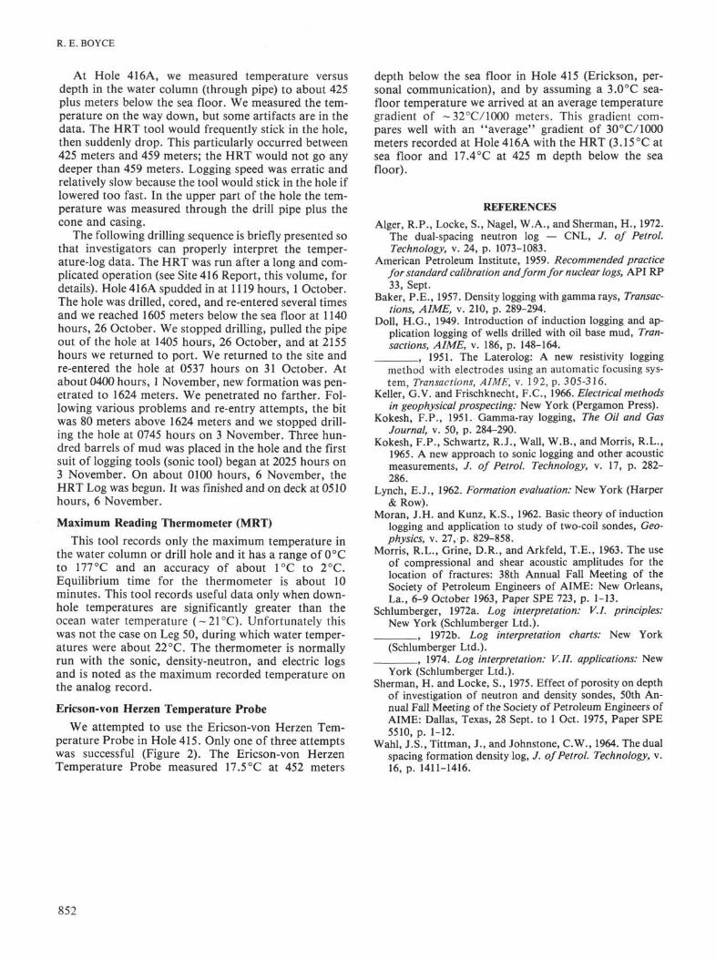
Ericson-von Herzen Temperature Probe
We attempted to use the Ericson-von Herzen Tem-perature Probe in Hole 415. Only one of three attemptswas successful (Figure 2). The Ericson-von HerzenTemperature Probe measured 17.5°C at 452 meters
depth below the sea floor in Hole 415 (Erickson, per-sonal communication), and by assuming a 3.0°C sea-floor temperature we arrived at an average temperaturegradient of ~32°C/1000 meters. This gradient com-pares well with an "average" gradient of 30°C/1000meters recorded at Hole 416A with the HRT (3.15°C atsea floor and 17.4°C at 425 m depth below the seafloor).
REFERENCESAlger, R.P., Locke, S., Nagel, W.A., and Sherman, H., 1972.
The dual-spacing neutron log — CNL, /. of Petrol.Technology, v. 24, p. 1073-1083.
American Petroleum Institute, 1959. Recommended practicefor standard calibration and form for nuclear logs, API RP33, Sept.
Baker, P.E., 1957. Density logging with gamma rays, Transac-tions, AIME, v. 210, p. 289-294.
Doll, H.G., 1949. Introduction of induction logging and ap-plication logging of wells drilled with oil base mud, Tran-sactions, AIME, v. 186, p. 148-164.
, 1951. The Laterolog: A new resistivity loggingmethod with electrodes using an automatic focusing sys-tem, Transactions, AIME, v. 192, p. 305-316.
Keller, G.V. and Frischknecht, F.C., 1966. Electrical methodsin geophysical prospecting: New York (Pergamon Press).
Kokesh, F.P., 1951. Gamma-ray logging, The Oil and GasJournal, v. 50, p. 284-290.
Kokesh, F.P., Schwartz, R.J., Wall, W.B., and Morris, R.L.,1965. A new approach to sonic logging and other acousticmeasurements, / . of Petrol. Technology, v. 17, p. 282-286.
Lynch, E.J., 1962. Formation evaluation: New York (Harper& Row).
Moran, J.H. and Kunz, K.S., 1962. Basic theory of inductionlogging and application to study of two-coil sondes, Geo-physics, v. 27, p. 829-858.
Morris, R.L., Grine, D.R., and Arkfeld, T.E., 1963. The useof compressional and shear acoustic amplitudes for thelocation of fractures: 38th Annual Fall Meeting of theSociety of Petroleum Engineers of AIME: New Orleans,La., 6-9 October 1963, Paper SPE 723, p. 1-13.
Schlumberger, 1972a. Log interpretation: V.I. principles:New York (Schlumberger Ltd.).
, 1972b. Log interpretation charts: New York(Schlumberger Ltd.).
, 1974. Log interpretation: V.II. applications: NewYork (Schlumberger Ltd.).
Sherman, H. and Locke, S., 1975. Effect of porosity on depthof investigation of neutron and density sondes, 50th An-nual Fall Meeting of the Society of Petroleum Engineers ofAIME: Dallas, Texas, 28 Sept. to 1 Oct. 1975, Paper SPE5510, p. 1-12.
Wahl, J.S., Tittman, J., and Johnstone, C.W., 1964. The dualspacing formation density log, J. of Petrol. Technology, v.16, p. 1411-1416.
852

SCHLUMBERGER WELL-LOG EQUIPMENT
o~ 19
17 -
1 1 1 1
Probe travelingdown the hole
: XT- y \ -
1 x
/ Tempeature of theformation
Temperatures as probe is"pulled out of the hole
•
•• •
20 40 60TIME (min)
80 120
Figure 2. Hole 415: Ericson-von Herzen temperature probe at 452.5 meters; temper-ature versus time. Ericson's (personal communication) interpretation of Ericson-von Herzen Temperature Probe data.
853