dd2 lite manual 5 - etbinstruments.com
TRANSCRIPT
© ETB Instruments LTD 2005 DigiDash2 - LITE Manual
Version: 1.01 Page 1
DD2 - LITE
User Manual
www.etbinstruments.com

© ETB Instruments LTD 2005 DigiDash2 - LITE Manual
Version: 1.01 Page 2
1 DD2 - LITE Introduction........................................................................................................................................... 4
1.1 DD2 - LITE Key Features ............................................................................................... 41.1.1 Display Front View ................................................................................................. 51.1.2 Rear View.............................................................................................................. 6
1.2 Packaging Checklist ...................................................................................................... 6
2 DD2 - LITE Installation..............................................................................................................................................7
2.1 Mounting the LITE Dipslay............................................................................................. 7
2.2 Sensor Installation ........................................................................................................ 72.2.1 Speed Sensor ........................................................................................................ 72.2.2 Oil & Water Temperature Sensors........................................................................... 82.2.3 Oil Pressure Sensors............................................................................................. 82.2.4 Fuel Level Sensor................................................................................................... 92.2.5 Lap Timer Receiver (Lap Timer Option)................................................................... 9
2.3 Wiring the DD2 - LITE.................................................................................................. 10
2.4 Ignition Systems / Tachometer Wiring ........................................................................ 10
3 Configuring the DD2 - LITE...................................................................................................................................11
3.1 Configuration via Display ............................................................................................ 113.1.1 Selecting SETUP MODE ........................................................................................113.1.2 Exit Setup Mode....................................................................................................113.1.3 Button Function (Setup Mode)...............................................................................123.1.4 Setup Mode Menu Detail .......................................................................................13
1.2 Configuration Using DigiTools Software ...................................................................... 18
4 Using the Display.................................................................................................................................................... 19
4.1 Button Functions (General Operation) ......................................................................... 19
4.2 RED 3-Digit LED Display.............................................................................................. 204.2.1 Speed...................................................................................................................204.2.2 RPM.....................................................................................................................204.2.3 Engaged Gear .......................................................................................................204.2.4 Warning Alarms ....................................................................................................214.2.5 Mini-Logger Status (Mini-Log Option)....................................................................21
4.3 GREEN LCD Character Display .................................................................................... 224.3.1 LCD Display Screens in Detail ...............................................................................22
4.4 Lap Timing (Race / Track-Day Lap Timer Option) ....................................................... 234.4.1 Manual Lap Timing / Track Day Mode....................................................................234.4.2 Automatic Infra-Red Lap Trigger / Race Day Mode.................................................23
4.5 Acceleration Timer (Timer Package Option) ............................................................... 244.5.1 Acceleration runs: .................................................................................................244.5.2 Braking runs: ........................................................................................................24
4.6 Troubleshooting........................................................................................................... 25
5 DigiTools PC Software......................................................................................................................................... 26
5.1 Connecting the Serial Cable to a PC ............................................................................ 26
5.2 Installing the DigiTools Software................................................................................. 26
5.3 DD2 – LITE Configure .................................................................................................. 27

© ETB Instruments LTD 2005 DigiDash2 - LITE Manual
Version: 1.01 Page 3
5.3.1 Version Tab ..........................................................................................................275.3.2 General Tab ..........................................................................................................295.3.3 Alarms Tab...........................................................................................................295.3.4 Display Tab ..........................................................................................................305.3.5 Shift Lights Tab.....................................................................................................305.3.6 Lap Tab ................................................................................................................315.3.7 Gear Tab...............................................................................................................315.3.8 Fuel Tab ...............................................................................................................325.3.9 Calibrate Tab ........................................................................................................325.3.10 Logger Tab ...........................................................................................................33
5.4 DigiDash2 Calculator.................................................................................................... 33
5.5 DigiDash2 Analysis ..................................................................................................... 345.5.1 Downloading Logged Data from the DigiDash2 .......................................................345.5.2 Download Menu Screen ........................................................................................355.5.3 Data Analysis........................................................................................................35
APPENDIX 1 – Wiring Schematic................................................................................................................................. 36
6.1 Connecting to an Existing Wiring Loom / Switches...................................................... 376.1.1 Sensor Cable Inputs that require switched +12v ...................................................376.1.2 Sensor Cable Inputs that require switch to Ground (-ve).........................................37
7 APPENDIX 2 - Speed Sensor Installation .................................................................................................... 38
7.1 Speed Sensor Alignment ............................................................................................. 39
8 APPENDIX 3 – Display Mounting Template (to scale).......................................................................... 40
9 APPENDIX 4 - ETB Fuel Sender Fitting Instructions ................................................................................ 41
9.1 Fitting the sender to the fuel tank................................................................................ 41
9.2 Fuel Sender Adjustment .............................................................................................. 41
10 Appendix 5 – Lap Trigger Alignment ............................................................................................................42
11 APPENDIX 6 – Specification ...............................................................................................................................4311.1.1 Power Supply .......................................................................................................4311.1.2 Environmental.......................................................................................................4311.1.3 Physical................................................................................................................4311.1.4 Cleaning/Care .......................................................................................................4311.1.5 Warranty...............................................................................................................43
© ETB Instruments LTD 2005 DigiDash2 - LITE Manual
Version: 1.01 Page 4
1 DD2 - LITE Introduction
The LITE is easy to use and install. Most people will get the hang of the unit in a few minutes. Thismanual is provided as guide and reference.
The DigiDash2 consists of a single Display module that combines all the usual dashboardinstruments into one compact and lightweight unit.
The Display is best mounted to a flat surface on the dashboard directly behind the steering wheel.
The LITE can be configured to match your vehicle either using the buttons marked A&B and Setupmode or via a Laptop PC using the software provided.
1.1 DD2 - LITE Key Features
The DigiDash2 – LITE has multi-purpose displays to show a variety of vehicle parameters.
The displays include:
• Speed (MPH or KMH);• Engine Revs (RPM);• Sequential gear shift-up lights;• Engaged Gear;• Water Temperature in °C or °F• Oil Pressure in PSI or BAR• Oil Temperature in °C or °F• Fuel Level;• Battery Voltage;• Odometer;• Trip Distance• Max Holds on all Key Parameters;
• Programmable Speed Warning• 5 Programmable Warning Alarms
Optional Upgrade Functions:• Race / Track-Day Lap Times;*• Acceleration/Deceleration Timer;**• Trip DistanceTimer;**• Engine Hours**
* Lap Timer Option** Timer Package Option
The DigiDash also integrates 6 Warning Lights, of which the Auxiliary (AUX) warning light can beconfigured using the software to display one of 2 different functions:-
• Main Beam;• Fog Lights;• Direction Indicator;• Ignition/Low Battery;• Brake Fail / Handbrake on Warning;• Auxiliary - Over Speed Warning
- Neutral Gear (for bike-engined vehicles)
Before cutting any holes or wires, please read through this manual.
© ETB Instruments LTD 2005 DigiDash2 - LITE Manual
Version: 1.01 Page 5
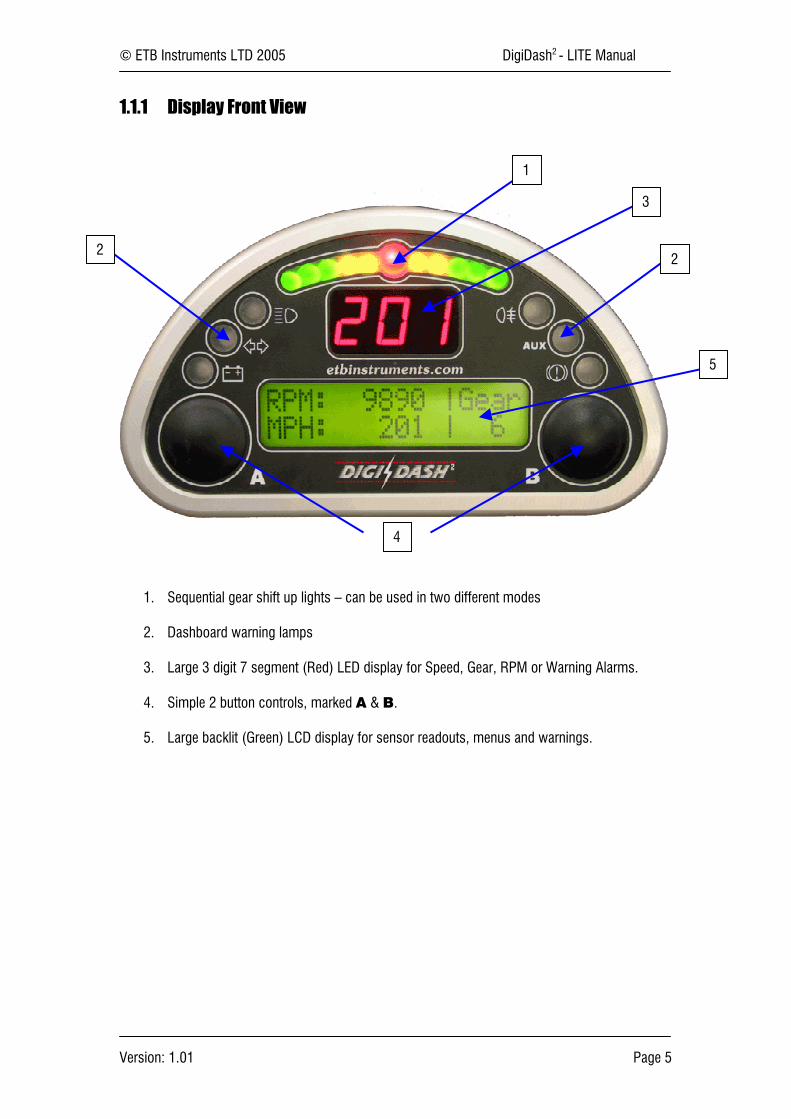
1.1.1 Display Front View
1. Sequential gear shift up lights – can be used in two different modes
2. Dashboard warning lamps
3. Large 3 digit 7 segment (Red) LED display for Speed, Gear, RPM or Warning Alarms.
4. Simple 2 button controls, marked A & B.
5. Large backlit (Green) LCD display for sensor readouts, menus and warnings.
1
2
3
2
4
5

© ETB Instruments LTD 2005 DigiDash2 - LITE Manual
Version: 1.01 Page 6
1.1.2 Rear View
1. Main Power input – RED connector on harness
2. SENSOR INPUT – BLUE Connector on Harness
1.2 Packaging Checklist
Standard Items:
QtyLITE Display Module 1Water Temperature Sender 1Oil Temperature Sender 1Oil Pressure Sensor 1Fuel Level Sender 1Speed Sensor 1Magnets for prop shaft 2Wiring Cables and Connectors 2CDROM (As well as this main manual it includes software for dataanalysis, set-up & speedometer set-up calculator)
1
M3 Mounting Bolts 8Quick Start Guide 1Wiring Schematic
2
M3x5 Mounting Holes (x8)
1
© ETB Instruments LTD 2005 DigiDash2 - LITE Manual
Version: 1.01 Page 7
2 DD2 - LITE Installation
2.1 Mounting the LITE Dipslay
Before cutting any holes in the dashboard, make sure that the location of the LITE Display is easilyvisible from the driver’s final position. Also ensure that there is sufficient clearance behind the unitfor the connectors and loom.
Note : The display should be directed towards the driver. If the dash is mounted at too steep an anglethe shift lights and warning lights will not be easily visible.
The LITE has been designed to mount on a flat dash panel behind the steering wheel and this is therecommended position.
Templates for the fixing screw holes on the Display unit are shown in Appendix 3.
2.2 Sensor Installation
2.2.1 Speed Sensor
The LITE is supplied with a solid state speed sensor and this must be used to provide the speedsignal for the DigiDash2. The sensor consists of a hall-effect magnetic pickup housed in an M12Nylon threaded rod.
Two magnets are provided for attachment to either a propshaft, wheel hub or drive-shaft coupling.The magnets should be fixed in position using either ‘Chemical Metal’ or a suitable Epoxy ResinAdhesive, (For example ‘Araldite’). If you have the choice it is recommended to install the speedsensor on the propshaft as accuracy will be improved.
The magnets have small ‘dots’ on one face. These denote the magnet’s North pole. The magnetMUST be mounted with the dot facing down. For further help in setting up the speed sensor andmagnets, please refer to Appendix 2 (Section 6).
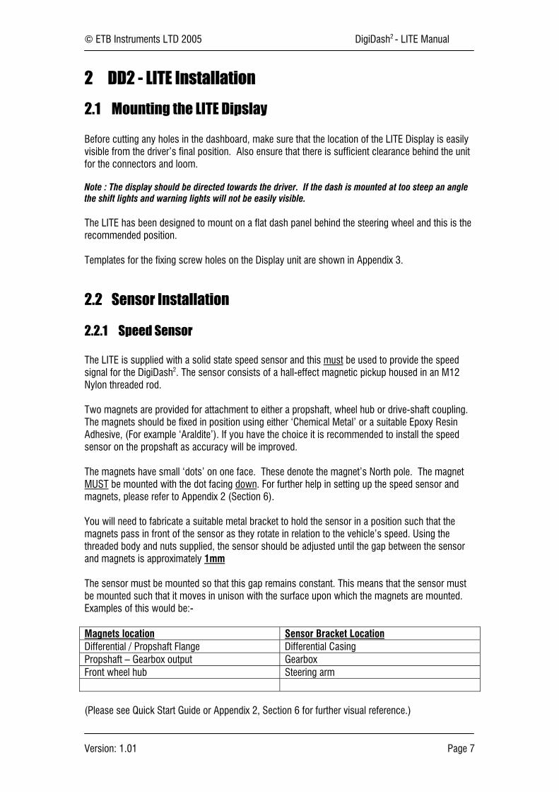
You will need to fabricate a suitable metal bracket to hold the sensor in a position such that themagnets pass in front of the sensor as they rotate in relation to the vehicle’s speed. Using thethreaded body and nuts supplied, the sensor should be adjusted until the gap between the sensorand magnets is approximately 1mm
The sensor must be mounted so that this gap remains constant. This means that the sensor mustbe mounted such that it moves in unison with the surface upon which the magnets are mounted.Examples of this would be:-
Magnets location Sensor Bracket LocationDifferential / Propshaft Flange Differential CasingPropshaft – Gearbox output GearboxFront wheel hub Steering arm
(Please see Quick Start Guide or Appendix 2, Section 6 for further visual reference.)

© ETB Instruments LTD 2005 DigiDash2 - LITE Manual
Version: 1.01 Page 8
2.2.2 Oil & Water Temperature Sensors
Oil and water temperature senders are supplied as standard. To ensure accuracy in the display it isessential that these senders are used with the DigiDash. Use of other senders is not permitted andwill result in inaccurate readings.
Note : The DigiDash2 - LITE is calibrated to provide accurate readings over the range 40ºC to 140ºConly. If the sensor is not connected properly, then the display will show NC (Not Calibrated or NoConnection).
Most engines have the water temperature sender located either in the radiator, or in the cylinderhead. To maintain accuracy please use this sensor in the standard location for your engine. If theexisting water temperature sensor is required by the engine management system, an alternativelocation will need to be found.
Oil / Water Temperature Sender1/8" NPTF Thread
ETB Part# 470010
Thread adapters are available separately from ETB to suit the many engine variants.
2.2.3 Oil Pressure Sensors
A pressure sensor is included with the LITE as standard and measures pressure to a maximum of140 PSI, usually for oil used for engine oil pressure. The DigiDash2 is designed to work correctlywith this sensor only. To ensure accuracy in the display it is essential that this sender is used withthe DigiDash. Use of other senders is not permitted and will result in inaccurate readings.
Note : For motorcycle engined cars, it is essential to remote mount the oil pressure sensor rather thandirectly onto the engine block. This is to prevent premature failure of the sensor caused by the highfrequency vibration generated by high-revving motorcycle engines. A remote mount kit is availableseparately from ETB – please telephone +44 (0)1702 711127 for details.
!! Important - ETB Instruments will not replace faulty oil pressure sensors under warranty unless it can be proved that the sensorwas correctly remote-mounted!!
The body of the sensor must be earthed for the sensor to function correctly. If the sensor is notconnected properly the DigiDash will display ‘NC’.
Oil Pressure Sender(with low pressure switch built in)
1/8" NPTF Thread
ETB Part# 38007025053

© ETB Instruments LTD 2005 DigiDash2 - LITE Manual
Version: 1.01 Page 9
2.2.4 Fuel Level Sensor
The DD2 - LITE is supplied with ETB’s standard 6-hole, top-mount lever-arm fuel sender, and thedefault setting in the DigiTools configuration is set for this sensor.
However, alternative sensors, available separately from ETB, can be used by configuring theDigidash2 using the DigiTools software. These are:-
VDO Lever-Arm Fuel SenderVDO Dip-Pipe Fuel SenderCapacitive Type tube sensor (resistance range 10-180Ω)General - 240Ω Empty to 33Ω Full
To ensure accuracy in the display it is essential that one of these sensors is used with theDigiDash2. Use of other senders is not permitted and will result in inaccurate readings.
If the sensor is not connected properly the DigiDash will display ‘NC’.
Additional Fuel level sender fitting instructions for the standard ETB lever-arm sensor can be foundin Appendix 9.
2.2.5 Lap Timer Receiver (Lap Timer Option)
The Lap timer module uses an infra-red sensor similar to that used in television sets.This is designed to be used with any common track beacon, or the optional infra-red beacon fromETB.
The lap timer receiver module is housed in a small plastic box, which has a cut-out with the sensorclearly visible. This sensor should be firmly fixed to the side of the vehicle that is exposed to thetrackside beacon.
The range of the sensor is around 20 metres so should be sufficient for most tracks.
Problems with the lap timer can be diagnosed using the TEST MODE function in the Setup menuand your TV remote control. (See section ____)
For further details on using the DigiDash2 Lap timing system please refer to section 3.4.
For details on wiring please see the wiring section at the end of the document.Please see the drawing in Appendix 5 for mounting details.
© ETB Instruments LTD 2005 DigiDash2 - LITE Manual
Version: 1.01 Page 10
2.3 Wiring the DD2 - LITE
All main connections are made via two 9-way D-type connectors on the back of the LITE Displaymodule. The connectors are unmarked as the connectors are gendre specific to prevent incorrectconnection.
The BLUE colour connector has 9 wires all of 1 metre length. These wires are intended to be joinedinto the existing wiring of the vehicle. The joints can be made in several ways, includingScotchLocks and soldering. Simply twisting the wires and covering with tape is NOT a goodmethod of wiring the DigiDash and will result in unreliable joints. A well-soldered and insulatedjoint or crimp connectors are the best means of wiring the vehicle.
There are numerous help sites available on the Internet. Below is an example site:
www.users.globalnet.co.uk/~bunce/solderit.htm
The RED connector is supplied with a suitable length of cable to suit most vehicles and does notrequire connection to the existing wiring loom. The cable includes the speedometer sensor, laptrigger input, the RPM input, main power 12v feed and negative ground wire. For motorcycleengined cars a light brown wire is present for connection to the Neutral gear indicator switch.
2.4 Ignition Systems / Tachometer Wiring
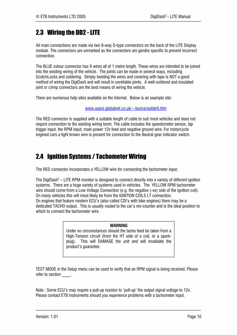
The RED connector incorporates a YELLOW wire for connecting the tachometer input.
The DigiDash2 – LITE RPM monitor is designed to connect directly into a variety of different ignitionsystems. There are a huge variety of systems used in vehicles. The YELLOW RPM tachometerwire should come from a Low Voltage Connection (e.g. the negative (-ve) side of the ignition coil).On many vehicles this will most likely be from the IGNITION COILS LT connection.On engines that feature modern ECU’s (also called CDI’s with bike engines) there may be adedicated TACHO output. This is usually routed to the car’s rev-counter and is the ideal position towhich to connect the tachometer wire.
TEST MODE in the Setup menu can be used to verify that an RPM signal is being received. Pleaserefer to section ____.
Note : Some ECU’s may require a pull-up resistor to ‘pull-up’ the output signal voltage to 12v.Please contact ETB Instruments should you experience problems with a tachometer input.
WARNINGUnder no circumstances should the tacho feed be taken from aHigh-Tension circuit (from the HT side of a coil, or a spark-plug). This will DAMAGE the unit and will invalidate theproduct’s guarantee.
© ETB Instruments LTD 2005 DigiDash2 - LITE Manual
Version: 1.01 Page 11
3 Configuring the DD2 - LITE
The setup and various parameters of DigiDash2 – LITE can be configured either directly using theDisplay or via a Laptop PC using the DigiTools software.
3.1 Configuration via Display
3.1.1 Selecting SETUP MODE
This mode allows the user to define all essential parameters when setting up the LITE to match thevehicle’s specifications. It also allows the user to turn on or off certain functions, or to set therequired display brightness / contrast levels.
(NOTE- If you have a Windows based personal computer, you can use the software supplied to directlychange all the parameters that can be normally accessed via SETUP MODE as well as some extrafeatures. To do this, please refer to the section headed “DigiTools PC Software” on page 20 underSection 4.)
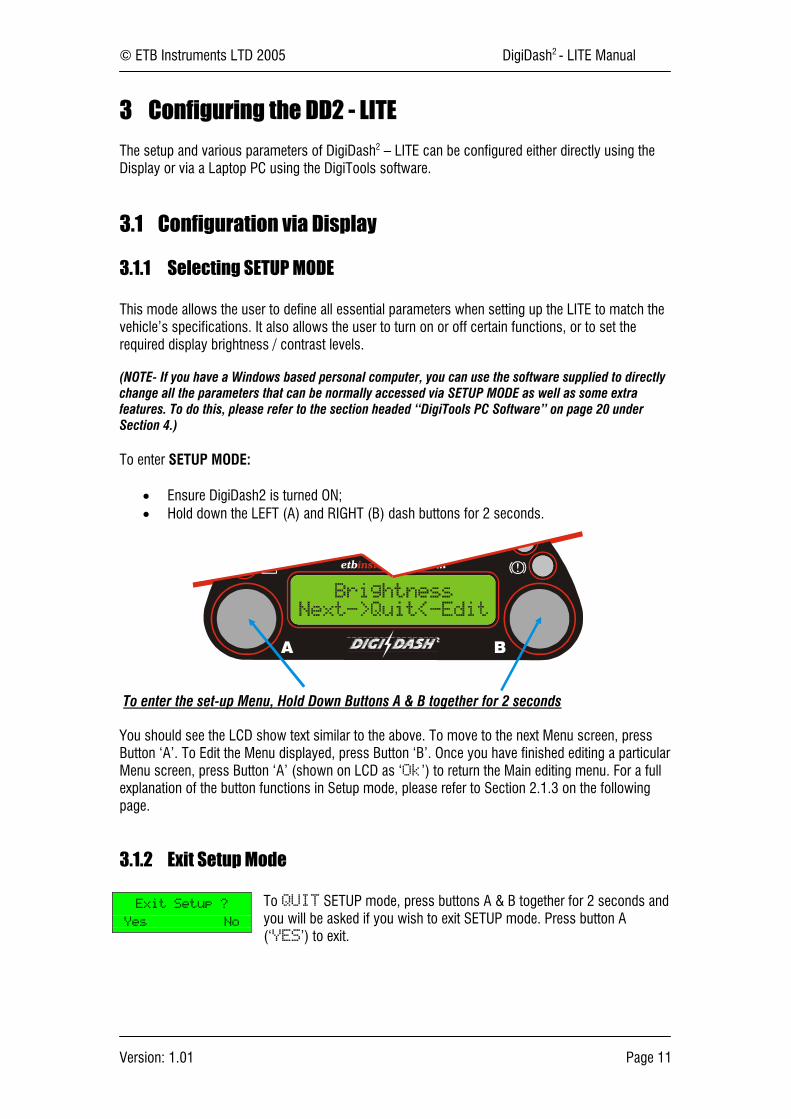
To enter SETUP MODE:
• Ensure DigiDash2 is turned ON;• Hold down the LEFT (A) and RIGHT (B) dash buttons for 2 seconds.
To enter the set-up Menu, Hold Down Buttons A & B together for 2 seconds
You should see the LCD show text similar to the above. To move to the next Menu screen, pressButton ‘A’. To Edit the Menu displayed, press Button ‘B’. Once you have finished editing a particularMenu screen, press Button ‘A’ (shown on LCD as ‘Ok’) to return the Main editing menu. For a fullexplanation of the button functions in Setup mode, please refer to Section 2.1.3 on the followingpage.
3.1.2 Exit Setup Mode
To QUIT SETUP mode, press buttons A & B together for 2 seconds andyou will be asked if you wish to exit SETUP mode. Press button A(‘YES’) to exit.
Exit Setup ?
Yes No
© ETB Instruments LTD 2005 DigiDash2 - LITE Manual
Version: 1.01 Page 12
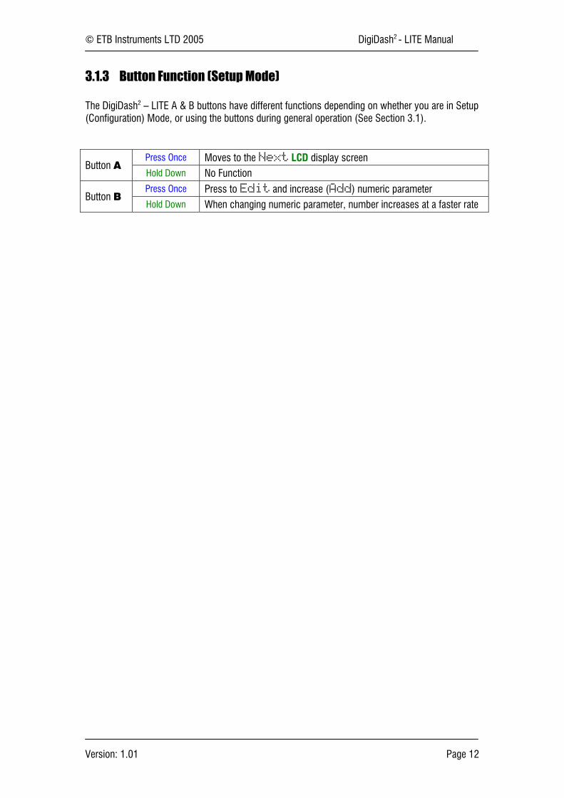
3.1.3 Button Function (Setup Mode)
The DigiDash2 – LITE A & B buttons have different functions depending on whether you are in Setup(Configuration) Mode, or using the buttons during general operation (See Section 3.1).
Press Once Moves to the Next LCD display screenButton A
Hold Down No FunctionPress Once Press to Edit and increase (Add) numeric parameter
Button BHold Down When changing numeric parameter, number increases at a faster rate
© ETB Instruments LTD 2005 DigiDash2 - LITE Manual
Version: 1.01 Page 13
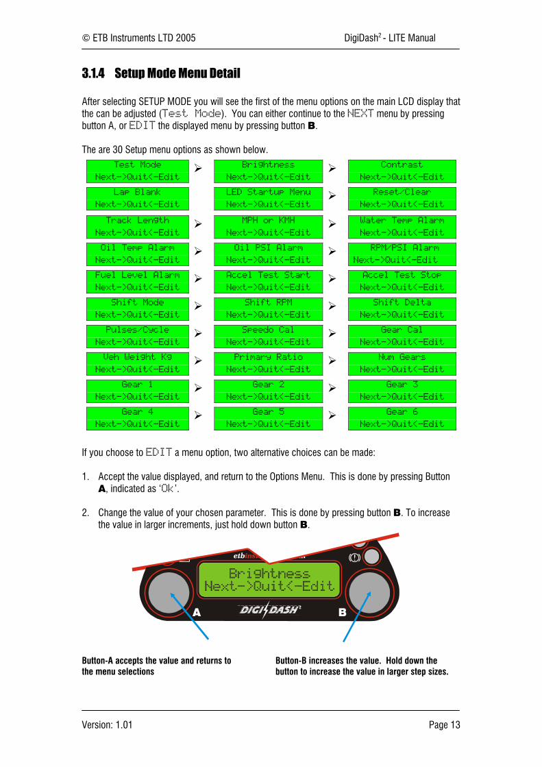
3.1.4 Setup Mode Menu Detail
After selecting SETUP MODE you will see the first of the menu options on the main LCD display thatthe can be adjusted (Test Mode). You can either continue to the NEXT menu by pressingbutton A, or EDIT the displayed menu by pressing button B.
The are 30 Setup menu options as shown below.Test Mode
Next->Quit<-Edit
Brightness
Next->Quit<-Edit
Contrast
Next->Quit<-Edit
Lap Blank
Next->Quit<-Edit
LED Startup Menu
Next->Quit<-Edit
Reset/Clear
Next->Quit<-Edit
Track Length
Next->Quit<-Edit
MPH or KMH
Next->Quit<-Edit
Water Temp Alarm
Next->Quit<-Edit
Oil Temp Alarm
Next->Quit<-Edit
Oil PSI Alarm
Next->Quit<-Edit
RPM/PSI Alarm
Next->Quit<-Edit
Fuel Level Alarm
Next->Quit<-Edit
Accel Test Start
Next->Quit<-Edit
Accel Test Stop
Next->Quit<-Edit
Shift Mode
Next->Quit<-Edit
Shift RPM
Next->Quit<-Edit
Shift Delta
Next->Quit<-Edit
Pulses/Cycle
Next->Quit<-Edit
Speedo Cal
Next->Quit<-Edit
Gear Cal
Next->Quit<-Edit
Veh Weight Kg
Next->Quit<-Edit
Primary Ratio
Next->Quit<-Edit
Num Gears
Next->Quit<-Edit
Gear 1
Next->Quit<-Edit
Gear 2
Next->Quit<-Edit
Gear 3
Next->Quit<-Edit
Gear 4
Next->Quit<-Edit
Gear 5
Next->Quit<-Edit
Gear 6
Next->Quit<-Edit
If you choose to EDIT a menu option, two alternative choices can be made:
1. Accept the value displayed, and return to the Options Menu. This is done by pressing ButtonA, indicated as ‘Ok’.
2. Change the value of your chosen parameter. This is done by pressing button B. To increasethe value in larger increments, just hold down button B.
Button-A accepts the value and returns tothe menu selections
Button-B increases the value. Hold down thebutton to increase the value in larger step sizes.
© ETB Instruments LTD 2005 DigiDash2 - LITE Manual
Version: 1.01 Page 14
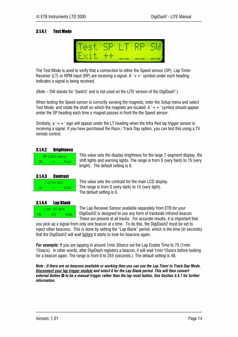
3.1.4.1 Test Mode
The Test Mode is used to verify that a connection to either the Speed sensor (SP), Lap TimerReceiver (LT) or RPM input (RP) are receiving a signal. A ‘++’ symbol under each headingindicates a signal is being received.
(Note – SW stands for ‘Switch’ and is not used on the LITE version of the DigiDash2.)
When testing the Speed sensor is correctly sensing the magnets, enter the Setup menu and selectTest Mode, and rotate the shaft on which the magnets are located. A ’++’ symbol should appearunder the SP heading each time a magnet passes in front the the Speed sensor.
Similarly, a ‘++’ sign will appear under the LT heading when the Infra Red lap trigger sensor isreceiving a signal. If you have purchased the Race / Track Day option, you can test this using a TVremote control.
3.1.4.2 BrightnessThis value sets the display brightness for the large 7-segment display, theshift lights and warning lights. The range is from 0 (very faint) to 15 (verybright). The default setting is 6.
3.1.4.3 ContrastThis value sets the contrast for the main LCD display.The range is from 0 (very dark) to 15 (very light).The default setting is 6.
3.1.4.4 Lap BlankThe Lap Receiver Sensor available separately from ETB for yourDigiDash2 is designed to use any form of trackside infrared beacon.These are present at all tracks. For accurate results, it is important that
you pick up a signal from only one beacon at a time. To do this, the DigiDash2 must be set toreject other beacons. This is done by setting the “Lap Blank” period, which is the time (in seconds)that the DigiDash2 will wait before it starts to look for beacons again.
For example: If you are lapping in around 1min 30secs set the Lap Enable Time to 75 (1min15secs). In other words, after DigiDash registers a beacon, it will wait 1min 15secs before lookingfor a beacon again. The range is from 0 to 255 (seconds.) The default setting is 48.
Note : If there are no beacons available or working then you can use the Lap Timer in Track Day Mode.Disconnect your lap trigger module and select 0 for the Lap Blank period. This will then convertexternal Button D to be a manual trigger rather than the lap reset button. See Section 3.4.1 for furtherinformation.
Brightness
Ok 6 Add
Contrast
Ok 6 Add
Lap Blank
Ok 48 Add

© ETB Instruments LTD 2005 DigiDash2 - LITE Manual
Version: 1.01 Page 15
3.1.4.5 LED Startup MenuThis sub-menu allows you to select which parameter indicated on the 3-digit red LED window is shown by default when the DigiDash2 isswitched on.The choice of displays is SPEED, RPM or GEAR.
3.1.4.6 Reset/ClearThis sub-menu enables you to either directly CLEAR the Logger memory,or RESET all MAX recorded values without having to either use theDigiTools software or visiti each MAX hold screen to reset. CANCEL exitsthe menu.
3.1.4.7 Track LengthTrack Length specifies the length in metres of the race track. The tracklength can be set between 0 and 10,000 metres (10Km).
3.1.4.8 MPH or KMHConfigures the DigiDash2 for either Miles per hour, or Kilometres perhour.
3.1.4.9 Water Temperature AlarmThis allows the user to program a warning alarm point for the WaterTemperature in °C steps. Default = 105°C. To turn off the alarm (notrecommended) set the value to 0. When activated the alarm is indicatedby the letters CTA on the 3-digit red LED display.
3.1.4.10 Oil Temperature AlarmThis allows the user to program a warning alarm point for the OilTemperature in °C steps. Default = 110°C. To turn off the alarm (notrecommended) set the value to 0. When activated the alarm is indicatedby the letters OTA on the 3-digit red LED display.
3.1.4.11 Oil Pressure AlarmThis allows the user to program a warning alarm point for the oil pressurein 1 psi steps. Default = 20psi. To turn off the alarm (not recommended)set the value to 0. When activated the alarm is indicated by the lettersOPA on the 3-digit red LED display.
NOTE – The ETB oil pressure sensor supplied with the DigiDash2 has a mechanical low-pressure switch built-in should aseparate dashboard warning light be required. This is calibrated to operate when oil pressure falls below 7.5 psi. If this switch isactivated, the LED display will show O.I.L. on the 3-digit red LED display.
3.1.4.12 RPM/Oil AlarmThis allows the user to set a minimum RPM value below which the oilpressure alarm (as set in the previous menu option) will NOT operate.This is especially useful should you wish to set the oil pressure to a value
lower than normally experienced when a hot engine is idling and not have the alarm displayedunless the engine RPM is above a certain limit. To turn off the RPM/Oil feature, set the value to 0.
3.1.4.13 Aux Pressure Alarm (DD2 – PRO only)This is used on the DD2 – Pro to set an Auxiliary Pressure Alarm and isnot used on the DD2 – LITE.
LED Startup Menu
Ok SPEED UP
Reset/Clear
Ok CLEAR LOG UP
Track Length
Ok 3120 Add
MPH or KMH
Ok MPH Add
Water Temp Alarm
Ok 105 Add
Oil Temp Alarm
Ok 110 Add
Oil PSI Alarm
Ok 20 Add
RPM/PSI Alarm
Ok 2500 Add
Aux PSI Alarm
Ok 20 Add
© ETB Instruments LTD 2005 DigiDash2 - LITE Manual
Version: 1.01 Page 16
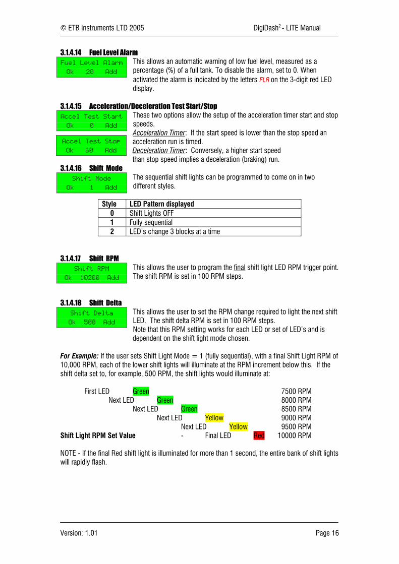
3.1.4.14 Fuel Level AlarmThis allows an automatic warning of low fuel level, measured as apercentage (%) of a full tank. To disable the alarm, set to 0. Whenactivated the alarm is indicated by the letters FLA on the 3-digit red LEDdisplay.
3.1.4.15 Acceleration/Deceleration Test Start/StopThese two options allow the setup of the acceleration timer start and stopspeeds.Acceleration Timer: If the start speed is lower than the stop speed anacceleration run is timed.Deceleration Timer: Conversely, a higher start speedthan stop speed implies a deceleration (braking) run.
3.1.4.16 Shift ModeThe sequential shift lights can be programmed to come on in twodifferent styles.
Style LED Pattern displayed0 Shift Lights OFF1 Fully sequential2 LED’s change 3 blocks at a time
3.1.4.17 Shift RPMThis allows the user to program the final shift light LED RPM trigger point.The shift RPM is set in 100 RPM steps.
3.1.4.18 Shift DeltaThis allows the user to set the RPM change required to light the next shiftLED. The shift delta RPM is set in 100 RPM steps.Note that this RPM setting works for each LED or set of LED’s and isdependent on the shift light mode chosen.
For Example: If the user sets Shift Light Mode = 1 (fully sequential), with a final Shift Light RPM of10,000 RPM, each of the lower shift lights will illuminate at the RPM increment below this. If theshift delta set to, for example, 500 RPM, the shift lights would illuminate at:
First LED Green 7500 RPMNext LED Green 8000 RPM
Next LED Green 8500 RPMNext LED Yellow 9000 RPM
Next LED Yellow 9500 RPMShift Light RPM Set Value - Final LED Red 10000 RPM
NOTE - If the final Red shift light is illuminated for more than 1 second, the entire bank of shift lightswill rapidly flash.
Fuel Level Alarm
Ok 20 Add
Accel Test Start
Ok 0 Add
Accel Test Stop
Ok 60 Add
Shift Mode
Ok 1 Add
Shift RPM
Ok 10200 Add
Shift Delta
Ok 500 Add
© ETB Instruments LTD 2005 DigiDash2 - LITE Manual
Version: 1.01 Page 17
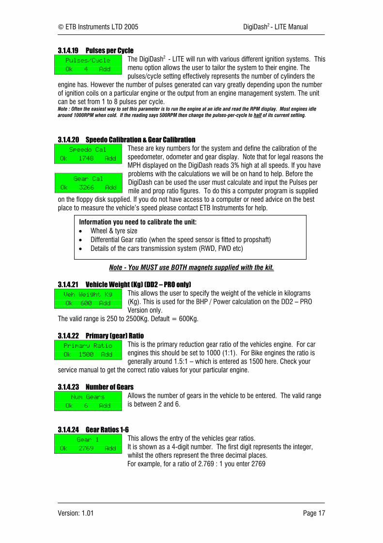
3.1.4.19 Pulses per CycleThe DigiDash2 - LITE will run with various different ignition systems. Thismenu option allows the user to tailor the system to their engine. Thepulses/cycle setting effectively represents the number of cylinders the
engine has. However the number of pulses generated can vary greatly depending upon the numberof ignition coils on a particular engine or the output from an engine management system. The unitcan be set from 1 to 8 pulses per cycle.Note : Often the easiest way to set this parameter is to run the engine at an idle and read the RPM display. Most engines idlearound 1000RPM when cold. If the reading says 500RPM then change the pulses-per-cycle to half of its current setting.
3.1.4.20 Speedo Calibration & Gear CalibrationThese are key numbers for the system and define the calibration of thespeedometer, odometer and gear display. Note that for legal reasons theMPH displayed on the DigiDash reads 3% high at all speeds. If you haveproblems with the calculations we will be on hand to help. Before theDigiDash can be used the user must calculate and input the Pulses permile and prop ratio figures. To do this a computer program is supplied
on the floppy disk supplied. If you do not have access to a computer or need advice on the bestplace to measure the vehicle’s speed please contact ETB Instruments for help.
Note - You MUST use BOTH magnets supplied with the kit.
3.1.4.21 Vehicle Weight (Kg) (DD2 – PRO only)This allows the user to specify the weight of the vehicle in kilograms(Kg). This is used for the BHP / Power calculation on the DD2 – PROVersion only.
The valid range is 250 to 2500Kg. Default = 600Kg.
3.1.4.22 Primary (gear) RatioThis is the primary reduction gear ratio of the vehicles engine. For carengines this should be set to 1000 (1:1). For Bike engines the ratio isgenerally around 1.5:1 – which is entered as 1500 here. Check your
service manual to get the correct ratio values for your particular engine.
3.1.4.23 Number of GearsAllows the number of gears in the vehicle to be entered. The valid rangeis between 2 and 6.
3.1.4.24 Gear Ratios 1-6This allows the entry of the vehicles gear ratios.It is shown as a 4-digit number. The first digit represents the integer,whilst the others represent the three decimal places.For example, for a ratio of 2.769 : 1 you enter 2769
Pulses/Cycle
Ok 4 Add
Speedo Cal
Ok 1748 Add
Gear Cal
Ok 3266 Add
Veh Weight Kg
Ok 600 Add
Primary Ratio
Ok 1500 Add
Num Gears
Ok 6 Add
Gear 1
Ok 2769 Add
Information you need to calibrate the unit:• Wheel & tyre size• Differential Gear ratio (when the speed sensor is fitted to propshaft)• Details of the cars transmission system (RWD, FWD etc)
© ETB Instruments LTD 2005 DigiDash2 - LITE Manual
Version: 1.01 Page 18
3.2 Configuration Using DigiTools Software
The DigiDash2 LITE is best configured using the DigiTools software supplied on the CD-ROM, asthis allows access to all the settable features by the user.
To connect the LITE to a Laptop PC, connect the Serial Connector on the main power harness tothe 9 pin RS232 port on the computer.
Note - If there is no 9 way Serial present on your Laptop, a Serial to USB Converter can bepurchased separately from ETB, allowing you to connect to a USB port instead.
Once connected, ensure that the DD2 – LITE is switched on and start the DigiTools by double-clicking on the ETB logo in the DigiTools folder.
Please refer to section 5 entitled “DigiTools PC software” for instructions on how to use thesoftware for configuration.
© ETB Instruments LTD 2005 DigiDash2 - LITE Manual
Version: 1.01 Page 19
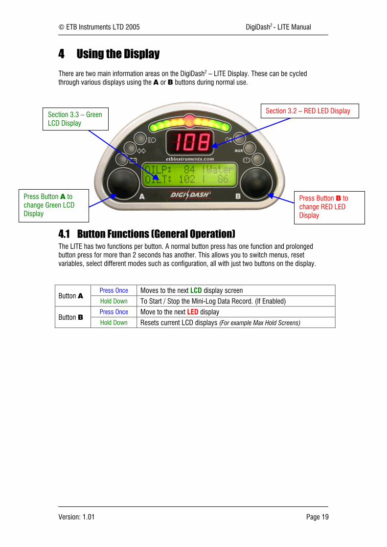
4 Using the Display
There are two main information areas on the DigiDash2 – LITE Display. These can be cycledthrough various displays using the A or B buttons during normal use.
4.1 Button Functions (General Operation)The LITE has two functions per button. A normal button press has one function and prolongedbutton press for more than 2 seconds has another. This allows you to switch menus, resetvariables, select different modes such as configuration, all with just two buttons on the display.
Press Once Moves to the next LCD display screenButton A
Hold Down To Start / Stop the Mini-Log Data Record. (If Enabled)Press Once Move to the next LED display
Button BHold Down Resets current LCD displays (For example Max Hold Screens)
Section 3.2 – RED LED Display
Press Button B tochange RED LEDDisplay
Section 3.3 – GreenLCD Display
Press Button A tochange Green LCDDisplay
© ETB Instruments LTD 2005 DigiDash2 - LITE Manual
Version: 1.01 Page 20
4.2 RED 3-Digit LED Display
The large three-digit (7 segment) display in the middle of the DigiDash2 is used to display one offive parameters:-
1. Speed (MPH or KMH)2. RPM3. Engaged Gear4. Warning Alarms5. Mini-Log Status
Press Button B to cycle between Speed, RPM and Engaged Gear:-
4.2.1 Speed
The RED LED display can be used to indicate the speed of the vehicle. This can either be in milesper hour (MPH) of kilometres per hour (Km/h) depending on the unit of measurement selected.MPH or Km/h can be selected either directly via the display using Setup mode (see 2.1) or by usingthe DigiTools configuration software (See 4.1). The maximum possible indicated speed in MPH is250, or if Km/h is the selected unit of measurement the maximum is 400.
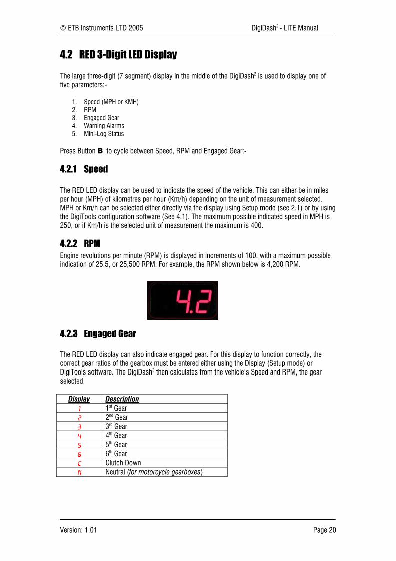
4.2.2 RPMEngine revolutions per minute (RPM) is displayed in increments of 100, with a maximum possibleindication of 25.5, or 25,500 RPM. For example, the RPM shown below is 4,200 RPM.
4.2.3 Engaged Gear
The RED LED display can also indicate engaged gear. For this display to function correctly, thecorrect gear ratios of the gearbox must be entered either using the Display (Setup mode) orDigiTools software. The DigiDash2 then calculates from the vehicle’s Speed and RPM, the gearselected.
Display Description1 1st Gear2 2nd Gear3 3rd Gear4 4th Gear5 5th Gear6 6th GearC Clutch DownN Neutral (for motorcycle gearboxes)
© ETB Instruments LTD 2005 DigiDash2 - LITE Manual
Version: 1.01 Page 21
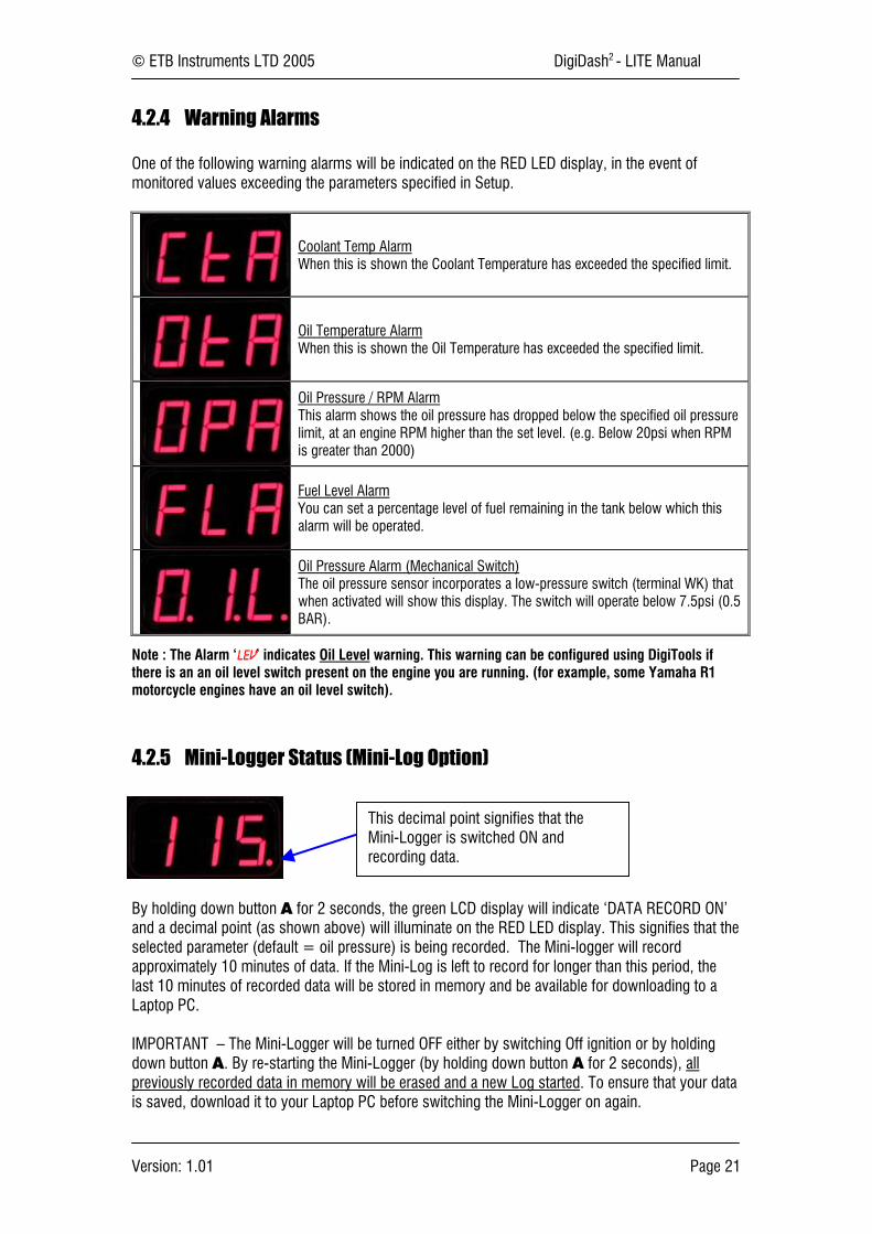
4.2.4 Warning Alarms
One of the following warning alarms will be indicated on the RED LED display, in the event ofmonitored values exceeding the parameters specified in Setup.
Coolant Temp AlarmWhen this is shown the Coolant Temperature has exceeded the specified limit.
Oil Temperature AlarmWhen this is shown the Oil Temperature has exceeded the specified limit.
Oil Pressure / RPM AlarmThis alarm shows the oil pressure has dropped below the specified oil pressurelimit, at an engine RPM higher than the set level. (e.g. Below 20psi when RPMis greater than 2000)
Fuel Level AlarmYou can set a percentage level of fuel remaining in the tank below which thisalarm will be operated.
Oil Pressure Alarm (Mechanical Switch)The oil pressure sensor incorporates a low-pressure switch (terminal WK) thatwhen activated will show this display. The switch will operate below 7.5psi (0.5BAR).
Note : The Alarm ‘LEV’ indicates Oil Level warning. This warning can be configured using DigiTools ifthere is an an oil level switch present on the engine you are running. (for example, some Yamaha R1motorcycle engines have an oil level switch).
4.2.5 Mini-Logger Status (Mini-Log Option)
By holding down button A for 2 seconds, the green LCD display will indicate ‘DATA RECORD ON’and a decimal point (as shown above) will illuminate on the RED LED display. This signifies that theselected parameter (default = oil pressure) is being recorded. The Mini-logger will recordapproximately 10 minutes of data. If the Mini-Log is left to record for longer than this period, thelast 10 minutes of recorded data will be stored in memory and be available for downloading to aLaptop PC.
IMPORTANT – The Mini-Logger will be turned OFF either by switching Off ignition or by holdingdown button A. By re-starting the Mini-Logger (by holding down button A for 2 seconds), allpreviously recorded data in memory will be erased and a new Log started. To ensure that your datais saved, download it to your Laptop PC before switching the Mini-Logger on again.
This decimal point signifies that theMini-Logger is switched ON andrecording data.

© ETB Instruments LTD 2005 DigiDash2 - LITE Manual
Version: 1.01 Page 22
4.3 GREEN LCD Character Display
This is the main display for most sensor readouts. The LCD has several different “screens” ofinformation available. Depending on which display options are enabled (see the DigiTools Configuresection (4.12) of the manual for details) there are various screens that can be displayed. These arecycled between displays by pressing the A button.
4.3.1 LCD Display Screens in Detail
OILP : Oil Pressure in PSI (or BAR)OILT : Oil Temperature in °C (or °F)Water: Water Temperature in °C (or °F)
Odo : Vehicle Odometer (Total)Bat : Battery VoltageFuel : Fuel Level as a percentage of full
RPM : Engine revolutions per minuteMPH : Miles per hour (KMH = Kilometres per hour)Gear : Engaged Gear (‘N’ for neutral, ‘C’ for clutch-down)
** Timer Package OptionEngine : Elapsed Engine Run TimeAux Psi : Auxiliary Pressure in PSI
* Race / Track-Day Lap Timer Package OptionLst : Last lap number and timeBst : Best lap number and time
* Race / Track-Day Lap Timer Package OptionL: Lap Number you are onT: Lap Elapsed TimeS: Current split sector you are in (+ or – sector time from Best Lap)
** Timer Package OptionAccel : Start & Stop Speed (e.g. 0 – 60) (Decel = Deceleration timer)Time : Time Recorded
** Timer Package OptionTrTime : Elapsed Trip Time since last engine start (since last Manual Reset)TrDist : Trip Distance
Max OP : Maximum Oil Pressure recorded (since last reset)Max OT : Maximum Oil Temperature recorded
Max WT : Maximum Water (Coolant)Temperature recordedMax DC : Maximum Battery Voltage recorded
Max RPM : Maximum RPM recordedMax MPH : Maximum Speed recorded
Note – An alternative LCD display can be selected using the DigiTools software in the Configurationmenu. The Alternate Display 1 will indicate WT (Water Temp), OT (Oil Temp), OP (Oil Pressure), SP(Speed) and Gr (Gear) on one LCD screen if selected.

© ETB Instruments LTD 2005 DigiDash2 - LITE Manual
Version: 1.01 Page 23
4.4 Lap Timing (Race / Track-Day Lap Timer Option)
NOTE : In order to use the DigiDash2 – LITE Manual Lap Timing it is necessary to have the external push-button (supplied as part of the Race / Track Day Pacakage Option) connected to the Lap TriggerConnector, as this button functions as your start/stop button. For Automatic timing, the Infra-Red LapTrigger Receiver should be connected instead.
The Lap Timer system can be operated in two different ways:
4.4.1 Manual Lap Timing / Track Day Mode
Track Day Mode involves triggering the timer manually each time the start / finish line is passed bypressing the External Lap Timing Button.
To set the DigiDash2 - LITE to Track Day Mode, the LAP BLANK period must be set to ZERO (0).The LAP BLANK period can be set to zero either directly using the Setup Menu on the display or viathe DigiTools Configure Software.
4.4.2 Automatic Infra-Red Lap Trigger / Race Day Mode
By connecting the Lap Trigger module (supplied with the Race / Track Day Timer Package) to theLap Timer input connector, infra-red trackside beacons can be used to automatically trigger the LapTimer.
The Lap Trigger module must be mounted at the side of the vehicle such that it will be aligned tothe trackside beacon when the car passes by. Note that some tracks have their beacons on theleft-hand side of the track, whilst others have it on the right. If you intend to attend many differentcircuits it is convenient to ensure that the mount is easily changed from side to side.
To ensure the unit only responds to one beacon on a track it is important to set the LAP BLANKperiod correctly in the DigiDash2 Setup:
For example: If you are lapping in around 1min 30secs set the Lap Enable Time to 75 (1min 15secs). This willensure any spurious infra-red beacons detected in the first 75 seconds of a new lap are ignored.
If you wish to purchase your own Infra-red Beacon please contact ETB for details.
4.4.2.1 Testing the Lap Trigger Module
The Test Mode can be used to verify that the Lap Trigger module is receiving a signal. In order todo this you must first select the Setup menu by holding down buttons A and B together, and select‘Test Mode’.Any standard TV remote control handset can be used to test that the Lap Trigger is receiving a goodsignal. Simply point the remote-control at the installed lap timer module and a ‘++’ symbol shouldappear below the ‘LT’ heading.
© ETB Instruments LTD 2005 DigiDash2 - LITE Manual
Version: 1.01 Page 24
4.5 Acceleration Timer (Timer Package Option)
This allows the measurement of different acceleration and deceleration (braking) runs.By default the unit is configured to perform a 0-60mph run.
Using the timer is simple:
4.5.1 Acceleration runs:
Ensure the vehicle is starting below the start speed you have entered. For standing starts ensurethe vehicle is stationary.
Use Button A button to choose the Acceleration-Timer Display. If you are overwriting a run holddown Button B. This will zero the stored value on the display.
The timer will start as soon as one of the magnets passes the speed sensor. The timer willautomatically stop when the chosen stop speed is reached, and the time will be displayed.
4.5.2 Braking runs:
Perform the same procedure as above, making sure that your starting speed is higher than thechosen start speed. As you apply the brakes and the vehicles speed drops below the start speedthe timer will be enabled. Once you have reached the desired stop speed the timer will stop andhold the deceleration time.
Warning
The acceleration timer should be used with great care.Do not use the timer on public roads.
Please ensure you give due consideration to the safety of otherroad users whilst using this feature.
Accidents resulting in the improper use of this featureinvalidate the product guarantee.
© ETB Instruments LTD 2005 DigiDash2 - LITE Manual
Version: 1.01 Page 25
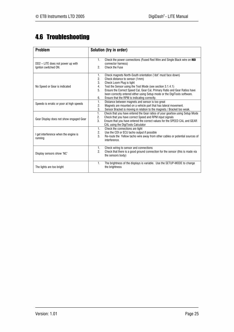
4.6 Troubleshooting
Problem Solution (try in order)
DD2 – LITE does not power up withIgniton switched ON.
1. Check the power connections (Fused Red Wire and Single Black wire on REDconnector harness)
2. Check the Fuse
No Speed or Gear is indicated
1. Check magnets North-South orientation (‘dot’ must face down)2. Check distance to sensor (1mm)3. Check Loom Plug is tight4. Test the Sensor using the Test Mode (see section 3.1.4.1)5. Ensure the Correct Speed Cal, Gear Cal, Primary Ratio and Gear Ratios have
been correctly entered either using Setup mode or the DigiTools software.6. Ensure that the RPM is indicating correctly.
Speedo is erratic or poor at high speeds1. Distance between magnets and sensor is too great2. Magnets are mounted on a vehicle part that has lateral movement.3. Sensor Bracket is moving in relation to the magnets / Bracket too weak.
Gear Display does not show engaged Gear
1. Check that you have entered the Gear ratios of your gearbox using Setup Mode2. Check that you have correct Speed and RPM input signals3. Ensure that you have entered the correct values for the SPEED CAL and GEAR
CAL using the DigiTools Calculator
I get interference when the engine isrunning
1. Check the connections are tight2. Use the CDI or ECU tacho output if possible3. Re-route the Yellow tacho wire away from other cables or potential sources of
interference.
Display sensors show ‘NC’
1. Check wiring to sensor and connections2. Check that there is a good ground connection for the sensor (this is made via
the sensors body)
The lights are too bright1. The brightness of the displays is variable. Use the SETUP-MODE to change
the brightness

© ETB Instruments LTD 2005 DigiDash2 - LITE Manual
Version: 1.01 Page 26
5 DigiTools PC Software
Supplied free with the DD2 – LITE is a comprehensive software package. This software is designedto run on any Microsoft Windows 32bit operating system (Win95, 98, ME, NT, 2000 & XP).Minimum specification for the PC is a P133 with 32MB of memory, and an 800x600 SVGA display.
(Please note that this manual does not contain information about using Windows, and assumes that are already familiar withstandard Windows operations such as click, double-click, right-click, drag and drop etc. For further information on usingWindows please refer to the instructions supplied with your operating software)
5.1 Connecting the Serial Cable to a PC
To configure the LITE, first connect the 9-Way RS232 connector (Black) coming from the REDconnector cable to the 9-pin Serial Port on your Laptop PC.
Note - If there is no 9 way Serial present on your Laptop, a Serial to USB Converter can bepurchased separately from ETB, allowing you to connect to a USB port instead.
5.2 Installing the DigiTools Software
• Insert the DigiTools CD into your CD-ROM Drive.• Using the mouse, Left double-click on “My Computer” Icon• Right-Click on CD-ROM Drive Icon and select “Explore”• Select all files shown on CD-ROM and by Right-Clicking on these files, drag and drop them into
a suitable folder on your Hard Drive.
To start the DigiTools program, double-click using the left mouse button on the ETB icon.
Once the program is running you should see the following Menu with three main sub-programs:-
To select the program you require, left-click on the appropriate button. To exit the DigiTools click onthe EXIT button.
© ETB Instruments LTD 2005 DigiDash2 - LITE Manual
Version: 1.01 Page 27
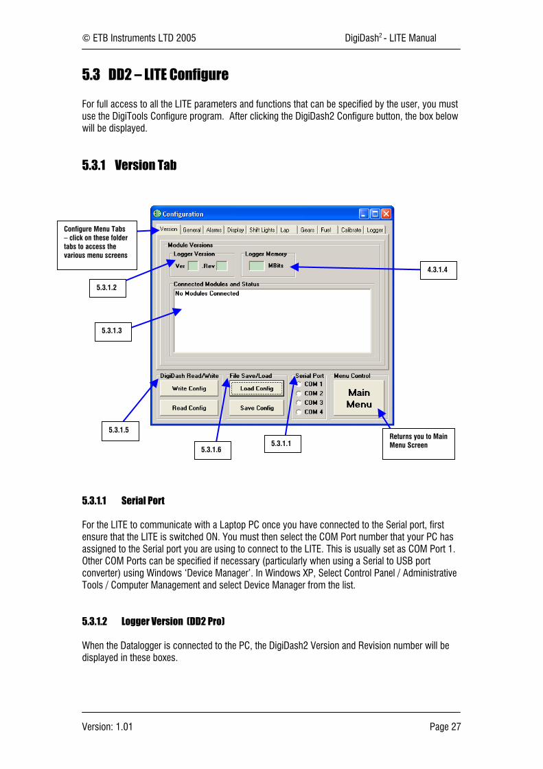
5.3 DD2 – LITE Configure
For full access to all the LITE parameters and functions that can be specified by the user, you mustuse the DigiTools Configure program. After clicking the DigiDash2 Configure button, the box belowwill be displayed.
5.3.1 Version Tab
5.3.1.1 Serial Port
For the LITE to communicate with a Laptop PC once you have connected to the Serial port, firstensure that the LITE is switched ON. You must then select the COM Port number that your PC hasassigned to the Serial port you are using to connect to the LITE. This is usually set as COM Port 1.Other COM Ports can be specified if necessary (particularly when using a Serial to USB portconverter) using Windows ‘Device Manager’. In Windows XP, Select Control Panel / AdministrativeTools / Computer Management and select Device Manager from the list.
5.3.1.2 Logger Version (DD2 Pro)
When the Datalogger is connected to the PC, the DigiDash2 Version and Revision number will bedisplayed in these boxes.
Configure Menu Tabs– click on these foldertabs to access thevarious menu screens
5.3.1.2
5.3.1.3
4.3.1.4
5.3.1.5
5.3.1.65.3.1.1
Returns you to MainMenu Screen

© ETB Instruments LTD 2005 DigiDash2 - LITE Manual
Version: 1.01 Page 28
5.3.1.3 Connected Modules and Status (DD2 Pro)
Information on any modules connected to the Datalogger via the DIGICAN connection (such as theDisplay) will be indicated here, including their version number and serial number.
5.3.1.4 Logger Memory (DD2 Pro)
The maximum available memory installed in the Datalogger will be displayed here when the unit isconnected to a PC. The standard logging memory is 17.3 MB.
5.3.1.5 DigiDash Read/Write
After selecting the correct COM Port (5.3.1.1), you can test the connection using the DigiDash“Read Config” button. The Read Config button is used for downloading or “reading” the currentconfiguration of the DD2 LITE to the DigiTools.
If the Display module is connected, by clicking on the Read Config button you should see thefollowing shown on the Display:
The DigiTools Configuration menus will now be set to the current settings of the DD2 LITE. A boxwill appear confirming that the Configuration has been correctly downloaded.
Once you have accessed the menu screens in the Configuration program and changed theparameters to your desired settings, the “Write Config” button is used to upload or “write” yourconfiguration to the DD2 LITE. A dialog box will appear confirming that your configuration has beencorrectly uploaded or “written” to the DD2 LITE.
5.3.1.6 File Save/Load
You can save files with a particular configuration to your hard drive by clicking on the “SaveConfig” button. These files will be saved as a “.dcf” file type. This will enable you to save differentDD2 LITE configurations and upload them as desired.
To load a previously saved file, simply click on the “Load Config” button, locate the desiredconfiguration file and click “Okay” to load the configuration to the DigiTools software. Rememberthat once the file is loaded, if you wish to program the DD2 LITE to the settings contained in the file,you must then click on “Write Config” in order to upload the settings to the DD2 LITE.
© ETB Instruments LTD 2005 DigiDash2 - LITE Manual
Version: 1.01 Page 29
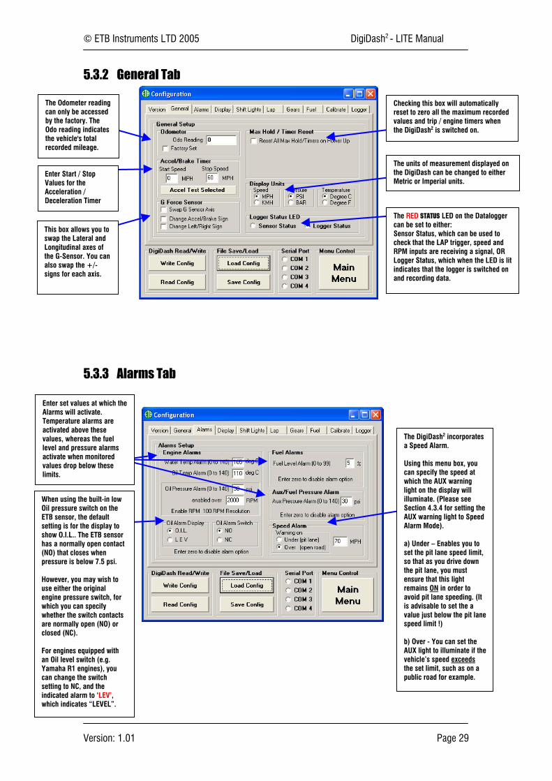
5.3.2 General Tab
5.3.3 Alarms Tab
The Odometer readingcan only be accessedby the factory. TheOdo reading indicatesthe vehicle's totalrecorded mileage.
Enter Start / StopValues for theAcceleration /Deceleration Timer
This box allows you toswap the Lateral andLongitudinal axes ofthe G-Sensor. You canalso swap the +/-signs for each axis.
Checking this box will automaticallyreset to zero all the maximum recordedvalues and trip / engine timers whenthe DigiDash2 is switched on.
The units of measurement displayed onthe DigiDash can be changed to eitherMetric or Imperial units.
The RED STATUS LED on the Dataloggercan be set to either:Sensor Status, which can be used tocheck that the LAP trigger, speed andRPM inputs are receiving a signal, ORLogger Status, which when the LED is litindicates that the logger is switched onand recording data.
Enter set values at which theAlarms will activate.Temperature alarms areactivated above thesevalues, whereas the fuellevel and pressure alarmsactivate when monitoredvalues drop below theselimits.
When using the built-in lowOil pressure switch on theETB sensor, the defaultsetting is for the display toshow O.I.L.. The ETB sensorhas a normally open contact(NO) that closes whenpressure is below 7.5 psi.
However, you may wish touse either the originalengine pressure switch, forwhich you can specifywhether the switch contactsare normally open (NO) orclosed (NC).
For engines equipped withan Oil level switch (e.g.Yamaha R1 engines), youcan change the switchsetting to NC, and theindicated alarm to ‘LEV’,which indicates “LEVEL”.
The DigiDash2 incorporatesa Speed Alarm.
Using this menu box, youcan specify the speed atwhich the AUX warninglight on the display willilluminate. (Please seeSection 4.3.4 for setting theAUX warning light to SpeedAlarm Mode).
a) Under – Enables you toset the pit lane speed limit,so that as you drive downthe pit lane, you mustensure that this lightremains ON in order toavoid pit lane speeding. (Itis advisable to set the avalue just below the pit lanespeed limit !)
b) Over - You can set theAUX light to illuminate if thevehicle’s speed exceedsthe set limit, such as on apublic road for example.
© ETB Instruments LTD 2005 DigiDash2 - LITE Manual
Version: 1.01 Page 30
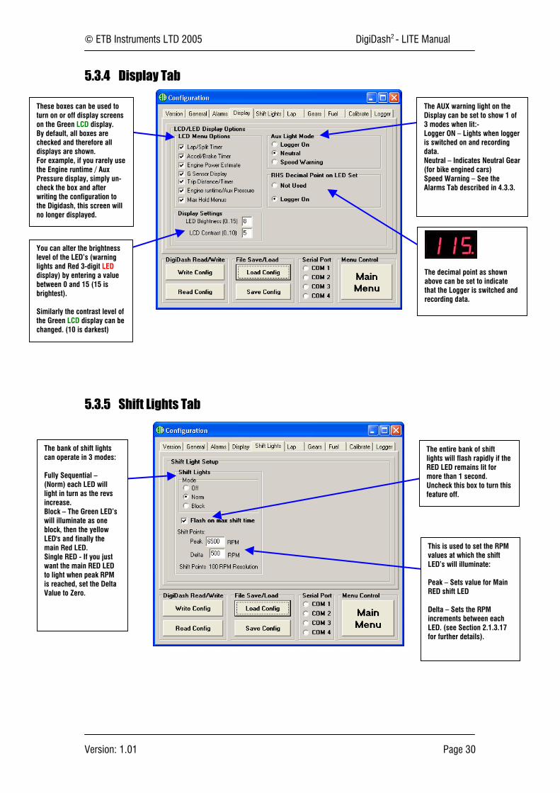
5.3.4 Display Tab
5.3.5 Shift Lights Tab
These boxes can be used toturn on or off display screenson the Green LCD display.By default, all boxes arechecked and therefore alldisplays are shown.For example, if you rarely usethe Engine runtime / AuxPressure display, simply un-check the box and afterwriting the configuration tothe Digidash, this screen willno longer displayed.
You can alter the brightnesslevel of the LED’s (warninglights and Red 3-digit LEDdisplay) by entering a valuebetween 0 and 15 (15 isbrightest).
Similarly the contrast level ofthe Green LCD display can bechanged. (10 is darkest)
The AUX warning light on theDisplay can be set to show 1 of3 modes when lit:-Logger ON – Lights when loggeris switched on and recordingdata.Neutral – Indicates Neutral Gear(for bike engined cars)Speed Warning – See theAlarms Tab described in 4.3.3.
The decimal point as shownabove can be set to indicatethat the Logger is switched andrecording data.
The bank of shift lightscan operate in 3 modes:
Fully Sequential –(Norm) each LED willlight in turn as the revsincrease.Block – The Green LED’swill illuminate as oneblock, then the yellowLED's and finally themain Red LED.Single RED - If you justwant the main RED LEDto light when peak RPMis reached, set the DeltaValue to Zero.
The entire bank of shiftlights will flash rapidly if theRED LED remains lit formore than 1 second.Uncheck this box to turn thisfeature off.
This is used to set the RPMvalues at which the shiftLED’s will illuminate:
Peak – Sets value for MainRED shift LED
Delta – Sets the RPMincrements between eachLED. (see Section 2.1.3.17for further details).

© ETB Instruments LTD 2005 DigiDash2 - LITE Manual
Version: 1.01 Page 31
5.3.6 Lap Tab
5.3.7 Gear Tab
The Gear indicatorsetup page is used forentering the forwardratios of your gearbox.
Input the number offorward gears in thegearbox.
Enter the primary ratio.This ratio is generallyfor motorcyclegearboxes that do nothave a 1:1 primaryratio. For a standardroad car this shouldremain as 1.000.
Input the gear ratio ofeach forward gear.
Lap / Split Timer Setup.Lap Trigger Blanking Period(LAP BLANK). – This is theperiod of seconds from passingyour Lap Beacon that theDigiDash2 will ignore otherinfra-red signals. (for examplefrom other trackside beacons).If this value is set to zero, theDigiDash2 assumes you requireManual Track Day mode. This ismanual lap timing using buttonD as a start/stop button foreach lap.
Lap Display Switch Back Time –After completing a lap, theGreen LCD display willautomatically show your lastlap time and best lap time. Thisis the period of seconds thatthis information will remain onthe LCD display.
Split Timer Mode – There are 2 modes of operation for using split times:Computed Distance 1-32 Sectors – Depending on the number of splits required,(entered in the box below), the DigiDash2 will divide the lap into equal segments(splits).Entered Distance 1-3 Sectors - If you choose to manually enter the distancebetween splits, the box below will automatically change for entering the distancein metres for each sector.
This box will change fromeither Compted SplitDistance to Entered Splitdistance depending on theSplit timer mode selected.
Best Lap Reset.
You can select whether youwant to store the last bestlap until you manually resetthe display using button B,OrSet it to automatically resetthe best lap time when theDigiDash2 is powered up.
© ETB Instruments LTD 2005 DigiDash2 - LITE Manual
Version: 1.01 Page 32
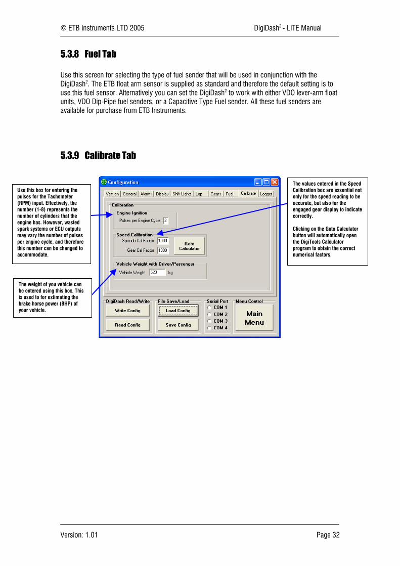
5.3.8 Fuel Tab
Use this screen for selecting the type of fuel sender that will be used in conjunction with theDigiDash2. The ETB float arm sensor is supplied as standard and therefore the default setting is touse this fuel sensor. Alternatively you can set the DigiDash2 to work with either VDO lever-arm floatunits, VDO Dip-Pipe fuel senders, or a Capacitive Type Fuel sender. All these fuel senders areavailable for purchase from ETB Instruments.
5.3.9 Calibrate Tab
Use this box for entering thepulses for the Tachometer(RPM) input. Effectively, thenumber (1-8) represents thenumber of cylinders that theengine has. However, wastedspark systems or ECU outputsmay vary the number of pulsesper engine cycle, and thereforethis number can be changed toaccommodate.
The weight of you vehicle canbe entered using this box. Thisis used to for estimating thebrake horse power (BHP) ofyour vehicle.
The values entered in the SpeedCalibration box are essential notonly for the speed reading to beaccurate, but also for theengaged gear display to indicatecorrectly.
Clicking on the Goto Calculatorbutton will automatically openthe DigiTools Calculatorprogram to obtain the correctnumerical factors.
© ETB Instruments LTD 2005 DigiDash2 - LITE Manual
Version: 1.01 Page 33
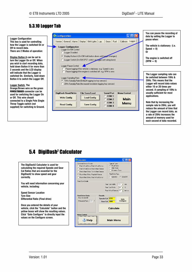
5.3.10 Logger Tab
5.4 DigiDash2 Calculator
Logger ConfigurationThis box is used for controllinghow the Logger is switched On orOff to record data.There are 2 Modes of operation:
Display Button A can be set toturn the Logger On or Off. Whenyou wish to start recording data,hold down Button A for more than2 seconds and the LCD displaywill indicate that the Logger isswitched On. Similarly, hold downButton A to switch the Logger Off.
Logger Switch. TheOrange/Brown wire on the greenPOWER/TRIGGER connector can beused for switching the Logger Onor Off. This wire shouldconnected to a Single Pole SingleThrow Toggle switch (notsupplied) for switching to Ground.
You can pause the recording ofdata by setting the Logger topause when:
The vehicle is stationary (i.e.Speed = 0)Or
The engine is switched off(RPM = 0)
The Logger sampling rate canbe switched between 10Hz &20Hz. This means that theLogger will record data valueseither 10 or 20 times persecond. A sampling of 10Hz isusually sufficient for mostapplications.
Note that by increasing thesample rate to 20Hz, you willreduce the amount of time thatthe Logger can record data, asa rate of 20Hz increases theamount of memory used foreach second of data recorded.
The DigiDash2 Calculator is used forcalculating the required Speedo and GearCal Ratios that are essential for theDigiDash2 to show speed and gearcorrectly.
You will need information concerning yourvehicle, including:
Speed Sensor LocationTyre SizeDifferential Ratio (Final drive)
Once you entered the details of yourvehicle, click the “Calculate” button and theyellow boxes will show the resulting values.Click “Goto Configure” to directly input thevalues on the Configure screen.
© ETB Instruments LTD 2005 DigiDash2 - LITE Manual
Version: 1.01 Page 34
5.5 DigiDash2 Analysis
The standard internal memory capacity of the DigiDash2 is 17.3Mb. Each time the Logger is startedthe DigiDash2 records data for each parameter (as listed below) until it is manually switched off (orwhen ignition is switched off if configured using DigiTools to do so). The DigiDash2 automaticallytreats this as a single session or data set. You can record up to 16 sessions or data sets, providingthat the memory capacity is not exceeded recording previous sessions.
For information on how to start / stop the logger, please refer to Sections 4.3.10 and 3.1, whichexplain how to configure the Logger and the associated button functions.
The vehicle parameters that are logged are:• Engine Revs (RPM);• Speed (MPH or KMH);• Engaged Gear;• Brake %• Oil Pressure;• Oil Temperature;• Water Temperature;• Fuel Level;
• Auxiliary Pressure (Can be used for Fuelor Boost Pressure);
• Battery Voltage;• Lap Number• Lap Times (s)• Split Times (s)• Longitudinal G-Force;• Lateral G-Force
5.5.1 Downloading Logged Data from the DigiDash2
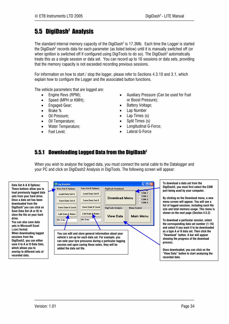
When you wish to analyse the logged data, you must connect the serial cable to the Datalogger andyour PC and click on DigiDash2 Analysis in DigiTools. The following screen will appear:
Data Set A & B Options:These buttons allow you toload previously logged datasets from your hard drive.Once a data set has beendownloaded from theDigiDash2 you can click onSave Data Set (A or B) tostore the file on your harddrive.You can also save datasets in Microsoft Excel(.csv) format.When downloading loggedsessions from theDigiDash2, you can eithersave it to A or B Data Sets,which allows you tooverlay to different sets ofrecorded data.
To download a data set from theDigiDash2, you must first select the COMport being used by your computer.
By clicking on the Download menu, a newmenu screen will appear. You will see alist of logged sessions, including each filesize and total memory usage. This menu isshown on the next page (Section 4.5.2)
To download a particular session, selectthe corresponding data set number (1-16)and select if you want it to be downloadedas a type A or B data set. Then click the“Download” button. A bar will appearshowing the progress of the downloadprocess.
Once downloaded, you can click on the“View Data” button to start analysing therecorded data.
You can edit and store general information about yourvehicle’s set-up for each data set. For example, youcan note your tyre pressures during a particular loggingsession and upon saving these notes, they will beadded the data set file.

© ETB Instruments LTD 2005 DigiDash2 - LITE Manual
Version: 1.01 Page 35
5.5.2 Download Menu Screen
5.5.3 Data Analysis
6
View Data Tab Menus:
• File - Load differentData sets or print theplot area to yourprinter or a file
• Data – Select the Xand Y axis datavariables for plottingon the graph.
• View – Zoom and panthe data plotted onthe graph. You canalso assign asmoothing factor tothe data plottedwhich averages theinputs and simplifiesthe data plot. If youwish to plot all dataand the lap overlaydata, click on the Lapoverlay button in thePlot box.
• Marker – Assignlabels or markers tothe data plot.
• Option – This tabmenu allow you tochange the units ofmeasurement of theplot data, swap the Gsensor axes, ormodify the gridlinesof the plot area.
Plot Data Tab Menus:
• Plot Data – Afterselecting the Lap Timestab, choosing the lap datayou wish to overlay, youcan click on this tab andthe data will be plotted.
• Lap Times – Thisscreen shows your totaland split times of eachrecorded lap. You canoverlay 2 sets of lap databy selecting the lapnumber and data set in the‘Select Laps to Overlay’boxes. To create a filecompatible with BoschLapSim analysis software,click on the Export buttonafter selecting the desiredlap.
• Data Notes (A & B) –These are your notesrelating to your vehicle’sSetup at the time the datawas recorded.
You can change the line characteristics of each data set as plotted on the graph byselecting one of these options.
Note : DigiTools is able to export data that is compatible with LapSim analysis software freely available for download onthe internet from BOSCH Motorsport. You can download this software from the following link:
www.bosch-motorsport.de/englisch/index.htm
The manual for using this software can be downloaded from:
http://www.bosch-motorsport.de/de/downloads/Manual_LapSim_V_2004.pdf
Should you require assistance in importing DigiDash2 files into LapSim software or require general help please do nothesitate to email ETB Instruments at [email protected].
© ETB Instruments LTD 2005 DigiDash2 - LITE Manual
Version: 1.01 Page 36
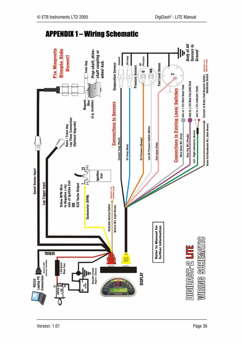
APPENDIX 1 – Wiring Schematic
© ETB Instruments LTD 2005 DigiDash2 - LITE Manual
Version: 1.01 Page 37
6.1 Connecting to an Existing Wiring Loom / Switches
The Blue (Or Yellow) 9 Pin Connector cable has a number of input wires that should be connectedto your existing wiring loom. The DD2 – LITE requires that on some of these inputs, in order tooperate a warning light for example, the input receives 12 volts. This is explained in more detailbelow:
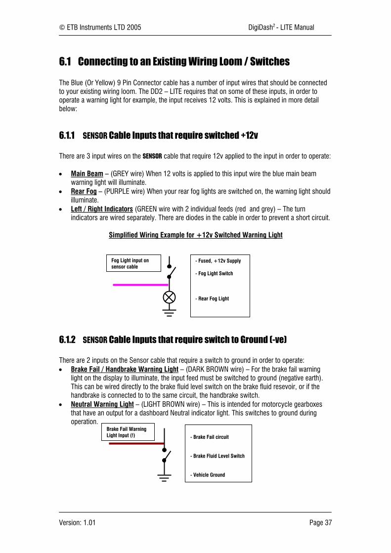
6.1.1 Sensor Cable Inputs that require switched +12v
There are 3 input wires on the Sensor cable that require 12v applied to the input in order to operate:
• Main Beam – (GREY wire) When 12 volts is applied to this input wire the blue main beamwarning light will illuminate.
• Rear Fog – (PURPLE wire) When your rear fog lights are switched on, the warning light shouldilluminate.
• Left / Right Indicators (GREEN wire with 2 individual feeds (red and grey) – The turnindicators are wired separately. There are diodes in the cable in order to prevent a short circuit.
Simplified Wiring Example for +12v Switched Warning Light
6.1.2 Sensor Cable Inputs that require switch to Ground (-ve)
There are 2 inputs on the Sensor cable that require a switch to ground in order to operate:• Brake Fail / Handbrake Warning Light – (DARK BROWN wire) – For the brake fail warning
light on the display to illuminate, the input feed must be switched to ground (negative earth).This can be wired directly to the brake fluid level switch on the brake fluid resevoir, or if thehandbrake is connected to to the same circuit, the handbrake switch.
• Neutral Warning Light – (LIGHT BROWN wire) – This is intended for motorcycle gearboxesthat have an output for a dashboard Neutral indicator light. This switches to ground duringoperation.
- Brake Fail circuit
- Brake Fluid Level Switch
- Vehicle Ground
- Fused, +12v Supply
- Fog Light Switch
- Rear Fog Light
Fog Light input onsensor cable
Brake Fail WarningLight Input (!)
© ETB Instruments LTD 2005 DigiDash2 - LITE Manual
Version: 1.01 Page 38
7 APPENDIX 2 - Speed Sensor Installation
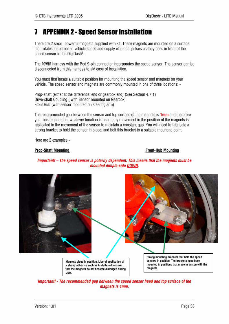
There are 2 small, powerful magnets supplied with kit. These magnets are mounted on a surfacethat rotates in relation to vehicle speed and supply electrical pulses as they pass in front of thespeed sensor to the DigiDash2.
The POWER harness with the Red 9-pin connector incorporates the speed sensor. The sensor can bedisconnected from this harness to aid ease of installation.
You must first locate a suitable position for mounting the speed sensor and magnets on yourvehicle. The speed sensor and magnets are commonly mounted in one of three locations: -
Prop-shaft (either at the differential end or gearbox end) (See Section 4.7.1)Drive-shaft Coupling ( with Sensor mounted on Gearbox)Front Hub (with sensor mounted on steering arm)
The recommended gap between the sensor and top surface of the magnets is 1mm and thereforeyou must ensure that whatever location is used, any movement in the position of the magnets isreplicated in the movement of the sensor to maintain a constant gap. You will need to fabricate astrong bracket to hold the sensor in place, and bolt this bracket to a suitable mounting point.
Here are 2 examples:-
Prop-Shaft Mounting Front-Hub Mounting
Important! – The speed sensor is polarity dependent. This means that the magnets must bemounted dimple-side DOWN.
Important! - The recommended gap between the speed sensor head and top surface of themagnets is 1mm.
Magnets glued in position. Liberal application ofa strong adhesive such as Araldite will ensurethat the magnets do not become dislodged duringuse.
Strong mounting brackets that hold the speedsensors in position. The brackets have beenmounted in positions that move in unison with themagnets.
© ETB Instruments LTD 2005 DigiDash2 - LITE Manual
Version: 1.01 Page 39
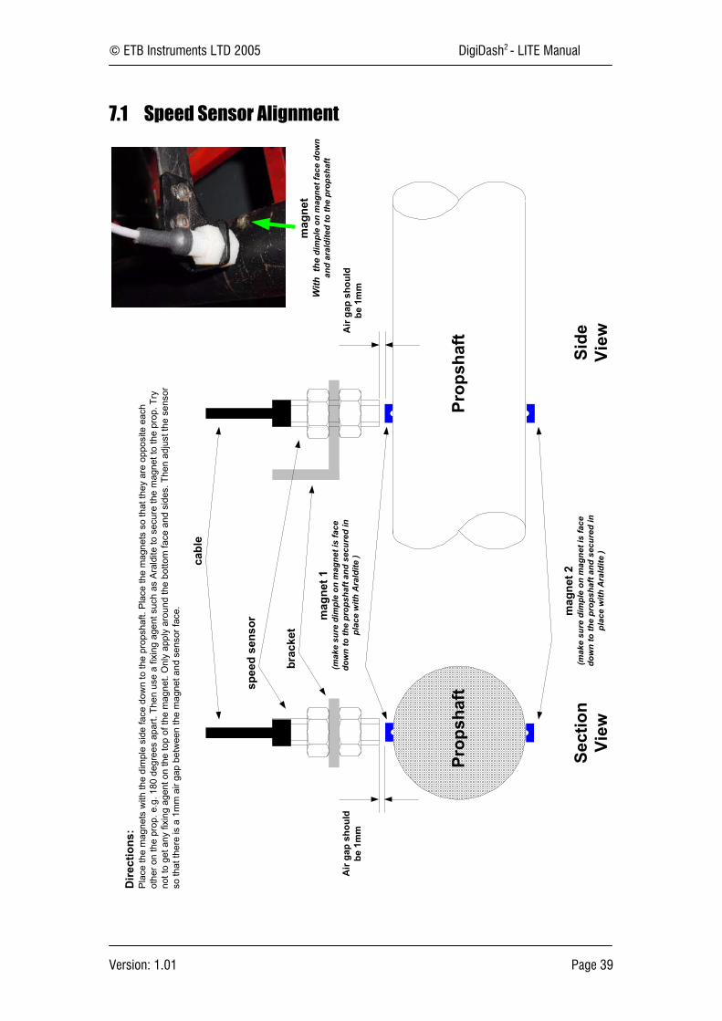
7.1 Speed Sensor Alignment
Sect
ion
View
Side
View
Prop
shaf
tPr
opsh
aft
brac
ket
mag
net 1
(mak
e su
re d
impl
e on
mag
net i
s fa
cedo
wn
to th
e pr
opsh
aft a
nd s
ecur
ed in
plac
e w
ith A
rald
ite )
spee
d se
nsor
Air
gap
shou
ldbe
1m
mA
ir ga
p sh
ould
be 1
mm
mag
net
With
the
dim
ple
on m
agne
t fac
e do
wn
and
aral
dite
d to
the
prop
shaf
t
mag
net 2
(mak
e su
re d
impl
e on
mag
net i
s fa
cedo
wn
to th
e pr
opsh
aft a
nd s
ecur
ed in
plac
e w
ith A
rald
ite )
Dire
ctio
ns:
Plac
e th
e m
agne
ts w
ith th
e di
mpl
e si
de fa
ce d
own
to th
e pr
opsh
aft.
Plac
e th
e m
agne
ts s
o th
at th
ey a
re o
ppos
ite e
ach
othe
r on
the
prop
. e.g
. 180
deg
rees
apa
rt. T
hen
use
a fix
ing
agen
t suc
h as
Ara
ldite
to s
ecur
e th
e m
agne
t to
the
prop
. Try
not t
o ge
t any
fixi
ng a
gent
on
the
top
of th
e m
agne
t. O
nly
appl
y ar
ound
the
botto
m fa
ce a
nd s
ides
. The
n ad
just
the
sens
orso
that
ther
e is
a 1
mm
air
gap
betw
een
the
mag
net a
nd s
enso
r fac
e.
cabl
e

© ETB Instruments LTD 2005 DigiDash2 - LITE Manual
Version: 1.01 Page 40
8 APPENDIX 3 – Display Mounting Template (to scale)There are eight M3 x 5mm threaded holes formounting the DigiDash2 Display. This page shouldprint to scale to enable to use the page as atemplate. However please check with a ruleragainst the dimensions shown that your printer hasprinted the page correctly.
Two holes are required for the connectors whenmounting the Display to flat dashboard. Cut two35mm diameter holes, using the centre of theconnector cut-outs as the centre point of each hole.
© ETB Instruments LTD 2005 DigiDash2 - LITE Manual
Version: 1.01 Page 41
9 APPENDIX 4 - ETB Fuel Sender Fitting Instructions
! Safety InstructionsCaution: No Smoking! No open fire or source of flame!
9.1 Fitting the sender to the fuel tankIf an installation must be made, the fuel tank must be completely drained first. Drain the fuel into anapproved container. REMOVE THE TANK WHENEVER POSSIBLE.Warning : Risk of explosion exists due to the presence of residual gases in the tank!! Make sure that the tank is aired sufficiently
(at least 15 minutes)• Choose the sensor location carefully, making sure that the float arm of the fuel sender will not conflict with any baffles, pipes or
internal obstructions inside the fuel tank. Also ensure that the float unit does not come into conflict with the side walls of the tank.• Make a preliminary hole in the installation opening using a drill and then finish the hole using a compass saw or piercing saw.
Comply with the safety instructions of the tool manufacturer.• The rubber gasket can be used as a template for marking the bolt holes. The main hole in the tank should be cut to 40mm
Diameter. Six Bolt holes (diameter 5mm to 5.5mm) should be drilled around the centre of the main hole on a P.C.D. (pitch circlediameter) of 60.4mm. Pay special attention to the orientation of the float arm in relation to the bolt holes.
• Clean the tank of residue from the drilling or sawing work.• Fix the fuel sender to the tank using M5 Bolts, washers and nuts.
9.2 Fuel Sender Adjustment
Should adjustment to the length or angle of the fuel sender be necessary, please bear in mind thefollowing points:-
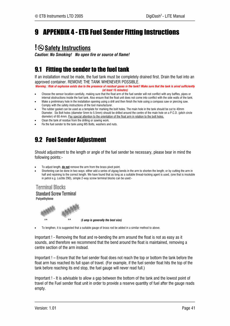
• To adjust length, do not remove the arm from the brass pivot point.• Shortening can be done in two ways: either add a series of zigzag bends in the arm to shorten the length; or by cutting the arm in
half and rejoining to the correct length. We have found that as long as a suitable thread-locking agent is used, (one that is insolublein petrol e.g. Loctite 290), simple 2-way screw terminal blocks can be used:-
(5 amp is generally the best size)
• To lengthen, it is suggested that a suitable gauge of brass rod be added in a similar method to above.
Important ! - Removing the float and re-bending the arm around the float is not as easy as itsounds, and therefore we recommend that the bend around the float is maintained, removing acentre section of the arm instead.
Important ! – Ensure that the fuel sender float does not reach the top or bottom the tank before thefloat arm has reached its full span of travel. (For example, if the fuel sender float hits the top of thetank before reaching its end stop, the fuel gauge will never read full.)
Important ! - It is advisable to allow a gap between the bottom of the tank and the lowest point oftravel of the Fuel sender float unit in order to provide a reserve quantity of fuel after the gauge readsempty.

© ETB Instruments LTD 2005 DigiDash2 - LITE Manual
Version: 1.01 Page 42
10 Appendix 5 – Lap Trigger Alignment
Dire
ctio
ns:
The
lap
trigg
er u
ses
an in
fra-r
ed d
etec
tor t
o se
nse
whe
n th
e la
p ha
s be
en c
ompl
eted
by
star
ting
and
stop
ping
a ti
mer
whe
n it
sees
an
infra
-red
sou
rce.
The
infra
-red
sou
rce
(bea
con)
is c
omm
only
foun
d at
mos
t circ
uits
and
is n
ot s
uppl
ied
with
the
Dig
iDas
h. T
he D
igiD
ash
will
trigg
er o
ff an
y in
fra-r
ed s
ourc
e. T
his
incl
udes
oth
er b
eaco
ns a
t tra
ckor
test
day
s an
d th
e ci
rcui
ts o
wn
split
-tim
e be
acon
(s) i
f it h
as o
ne.
In o
rder
to s
top
the
lap
trigg
er g
ivin
g m
ullti
ple
read
ings
due
to m
ultip
le b
eaco
ns a
lap
timer
ena
ble
time
can
be p
rogr
amm
ed in
to th
e D
igiD
ash.
Thi
s st
ops
the
Dig
iDas
h,on
ce tr
igge
red,
look
ing
for a
ny o
ther
bea
cons
unt
il th
e pr
eset
tim
e ha
s el
apse
d.
For
exam
ple
The
Dig
idas
h w
ill tri
gger
off
the
first
bea
con
on th
e pi
t wal
l, w
heth
er it
is y
our b
eaco
n, a
noth
er c
ompe
titor
s or
the
circ
uit b
eaco
n. S
et th
e la
p en
able
tim
e to
a v
alue
less
than
your
fast
est l
ap s
o th
at th
e un
it ca
nnot
trig
ger u
ntil
you
are
just
abo
ut to
com
plet
e a
lap.
Thi
s st
ops
any
fals
e tri
gger
s on
spl
it tim
e be
acon
s.
If pe
ople
are
usi
ng s
plit
time
beac
ons
then
as
you
are
abou
t to
star
t you
r firs
t tim
ed la
p, p
ress
but
ton
4. T
his
will
rese
t you
r lap
tim
er to
be
read
y fo
r a n
ew ti
med
ses
sion
.Y
ou o
nly
have
to d
o th
is if
peo
ple
are
usin
g sp
lit b
eaco
ns b
ecau
se o
n yo
ur fi
rst l
ap o
ut y
our D
igiD
ash
may
trig
ger o
n a
split
bea
con
and
your
lap
enab
le ti
me
will
prev
ent t
heD
igiD
ash
trigg
erin
g at
the
star
t and
fini
sh li
ne.
Pote
ntia
l Pro
blem
s:Th
e S
un is
the
bigg
est i
nfra
-red
sou
rce
arou
nd a
nd m
ay c
ause
the
unit
to fa
lse
trigg
er if
poi
nted
dire
ctly
at i
t. Tr
y to
kee
p yo
ur la
p tri
gger
poi
ntin
g ho
rizon
tal a
nd if
pos
siib
letil
ted
dow
n sl
ight
ly. T
he p
robl
em o
nly
real
ly o
ccur
rs w
hen
the
Sun
is lo
w in
the
sky
and
shin
ing
dire
ctly
acr
oss
the
star
t and
fini
sh li
ne w
here
you
r bea
con
is s
ituat
ed. T
he la
pen
able
tim
e pr
eset
val
ue w
ill st
op th
e Su
n tri
gger
ing
the
unit
at o
ther
poi
nts
on th
e ci
rcui
t.
Lap
Trig
ger A
lignm
ent
Bea
con
Pit
Wal
l
Lap
trig
ger
Try
to ti
lt do
wn
if yo
u ar
eex
peiri
enci
ng p
robl
ems
with
the
Sun
shi
ne

© ETB Instruments LTD 2005 DigiDash2 - LITE Manual
Version: 1.01 Page 43
11 APPENDIX 6 – Specification
11.1.1 Power Supply
7V - 14V DC Negative Earth onlyMaximum current consumption 400mAFuse value: 1.6A
11.1.2 EnvironmentalIngress Protection Level - Display Front Side - IP54Operational temperature range 0 °C to 40 °CStorage temperature range -10 °C to 60 °CAvoid contact with Oil, Petrol and other solvents.
11.1.3 Physical
Display Dimensions : 160.4mm x 90mm x 28mmWeight (Display) : 400g
11.1.4 Cleaning/Care
Use a damp cloth to clean the unit. Do not use abrasive cleaners or chemicals.The unit is splash proof to water, however it is not designed for submersion.
11.1.5 Warranty