repair manual 125 max dd2 evo - rotax.com.au
TRANSCRIPT

BRP-Rotax GmbH & Co KG | Rotaxstraße 1 | 4623 Gunskirchen, Austria | T: +43 7246 601 0 | F: +43 7246 637 0 www.rotax.com | www.rotax-kart.com
125 MAX DD2 evo
REPAIR MANUAL
for ROTAX®-engines type
Part no. 298063

BRP-RotaxREPAIR MANUAL
Chapter: INTROGENERAL INFORMATION
Preface Before carrying out repair work on the engine, read the Repair Manual carefully.If any passages of the Manual are not clearly understood or if you have questions, pleasecontact an authorized Distribution or Service Center for ROTAX®-kart engines.
Contents This Repair Manual contains instructions for all the necessary repair and maintenancework on the ROTAX®-Engine Type 125 MAX DD2 evo.
Symbols used This Manual uses the following symbols to emphasize particular information. Thisinformation is important and must be observed.
mWARNING
Identifies an instruction, which if not followed may cause injury or endanger thelife of the driver, mechanic or third party.
ATTENTION
Denotes an instruction which if not followed may severely damage the engine.Noncompliance might lead to health hazards under certain conditions.
ENVIRONMENTAL NOTE
Environmental notes give you tips on environmental protection.
NNOOTTEE
Indicates supplementary information which may be needed to fully complete orunderstand an instruction.✔ Denotes a checking operation
TIP This information gives you additional advice and tips
Effectivity: 125 MAX DD2 evoEdition - Febr. 01 2018 /Rev. 0 INTRO
Page 1

NotesPage 2
Effectivity: 125 MAX DD2 evoEdition - Febr. 01 2018 /Rev. 0
NOTES
BRP-RotaxREPAIR MANUAL

BRP-RotaxREPAIR MANUAL
Chapter: Chapter 1GENERAL NOTE
TOPICS IN THIS CHAPTER
Abbreviations and terms used in this Manual..........................................................................................3Safety ......................................................................................................................................................4
Safety notice .........................................................................................................................................4Instruction.............................................................................................................................................5Technical documentation........................................................................................................................6Use for intended purpose .......................................................................................................................6
Technical data .........................................................................................................................................7
Effectivity: 125 MAX DD2 evoEdition - Febr. 01 2018 /Rev. 0 Chapter 1
Page 1

BRP-RotaxREPAIR MANUAL
Purpose This Repair Manual is based on information and the state-of-knowledge of BRP-Rotax ofthe product current at the date of issue.
Documentation For additional information on engines, maintenance or parts, you can also contact yournearest authorized ROTAX®-Engine distributor.
ROTAX®distributors
ROTAX® Authorized Distributors for Kart Engines. See on web at the official Homepagehttp://www.rotax-kart.com.
Engine serialnumber
If you have any concerns or questions, always keep your engine serial number ready forquestions from your dealer, as the manufacturer makes modifications to the engine forproduct improvement. The engine number is stamped on the clutch side housing half. SeeFigure 1.
Figure 1.1: Position of the engine serial number
Chapter 1Page 2
Effectivity: 125 MAX DD2 evoEdition - Febr. 01 2018 /Rev. 0

BRP-RotaxREPAIR MANUAL
ABBREVIATIONS AND TERMS USED IN THIS MANUALAbbreviations Abbreviations Description
°C Degree Celsius (Centigrade)
°F Degree Fahrenheit
rpm Revolutions per minute
e.g. for example
125 MAX DD2 evo see Manual (Type designation)
INTRO Introduction
IPC Illustrated Parts Catalog
i.r. if required
h hours
OM Operators Manual
kg kilograms
MON Motor Octane Numbern.a. not available
Nm Newton meter
Rev. Revision
RON Research Octane Number
RM Repair Manual
S/N Serial Number
SI Service Instruction
SL Service Letter
part no. Part number
V Volt
Effectivity: 125 MAX DD2 evoEdition - Febr. 01 2018 /Rev. 0 Chapter 1
Page 3

BRP-RotaxREPAIR MANUAL
SAFETYGeneral note Although the reading of such information does not eliminate the hazard, the understanding
the information will promote its correct use. Always take care by conducting manual workand use safety equipment. The information and components-/system descriptions con-tained in this Manual are correct at the time of publication. BRP-Rotax, however, main-tains a policy of continuous improvement of its products without imposing upon itself anyobligation to install them on its products previously manufactured.
Revision BRP-Rotax reserves the right at any time, and without incurring obligation, to remove, re-place or discontinue any design, specification, feature or other details.
Specifications Specifications are given in the SI metric system with the USA equivalent in parenthesis.
SAFETY NOTICEGeneral note
mWARNING
Non-compliance can result in serious injuries or death!Comply with the safety advice of the engine and kart manufacturer.
This information relates to the preparation and use of ROTAX® Kart engines and hasbeen utilized safely and effectively by BRP-Rotax. However, BRP-Rotax disclaims liabilityfor all damage and/or injuries resulting from the improper use of the contents. BRP-Rotaxstrongly recommend that any service be carried out and/or verified by a highly skilled pro-fessional mechanic.
Manual This Manual has been prepared as a guide to correctly service and maintain all ROTAX®Kart engines.This Manual uses technical terms which may be slightly different from the ones used inthe Illustrated Parts Catalog.It is understood that this Manual may be translated into another language. In the event ofany discrepancy the English version prevails.
Warning It is your responsibility to be completely familiar with the safety instructions including warn-ings and cautions described in this Manual. These warnings and cautions advise of specif-ic operating and servicing methods that, if not observed, can cause a serious enginemalfunction or cause the engine to lose power which can result in serious injury, damageto equipment or even to death.It is, however, important to understand that these warnings and cautions are carefullychecked. BRP-Rotax can not evaluate and advise the user of all conceivable ways inwhich service might be done or of the possible hazardous consequences that may occur.
Safety instruction In addition to observing the instructions in our Manual, general safety and accident pre-ventative measures, legal regulations and regulations of any superior authority must beobserved.Where differences exist between this Manual and regulations provided by any authority,the more stringent regulation should be applied.
Chapter 1Page 4
Effectivity: 125 MAX DD2 evoEdition - Febr. 01 2018 /Rev. 0

BRP-RotaxREPAIR MANUAL
Illustration The content depicts parts and/or procedures applicable to the particular product at its timeof manufacture. It does not include dealer modifications, whether authorized or not byBRP-Rotax, after manufacturing the product.
Locking devices Locking devices (e.g. locking tab, self-locking fasteners, etc.) must be installed or replacedwith new ones, where specified. If the efficiency of a locking device is impaired, it must bereplaced.
Torque wrenchtightening
Torque wrench tightening specifications must be strictly adhered to.
NNOOTTEE
If not specified otherwise, the threads are not lubricated when fastened.
INSTRUCTIONGeneral note Engines require instructions regarding their application, use, operation, maintenance and
repair.Technical documentation and directions are useful and necessary complementary ele-ments for personal instructions, but can by no means substitute theoretical and practicalinstructions.These instructions should cover explanation of the technical context, advice for operation,maintenance, use and operational safety of the engine.
Safety notice In this technical Manual passages concerning safety are especially marked. Pass onsafety warnings to other users!
Modifications Non-approved modifications to the engine and associated components likewise releasesBRP-Rotax from its warranty obligations.
Accessories This engine must only be operated with accessories supplied, recommended and re-leased by BRP-Rotax. Modifications are only allowed after the exceptional advice or ap-proval by the engine manufacturer.
Spare parts
ATTENTION
Spare parts must comply with the requirements defined by the engine manufacturer.This is only warranted by use of GENUINE ROTAX® spare parts and/or accessories(see IPC) or suitable equivalent in the manufacturer‘ s opinion. Otherwise, any limitedwarranty by BRP-Rotax is null and void (see latest Warranty Conditions). Spare partsare available at the authorized ROTAX® Distribution- and Service Center. Any warrantyby BRP-Rotax becomes null and void if spare parts and or accessories other than GEN-
UINE ROTAX® spare parts and/or accessories are used (see latest WarrantyConditions).
Tools
ATTENTION
Use only tools and appliances which are either cited in this Manual or in the IllustratedParts Catalog of the relevant engine type for exceptional repair work.
Effectivity: 125 MAX DD2 evoEdition - Febr. 01 2018 /Rev. 0 Chapter 1
Page 5
BRP-RotaxREPAIR MANUAL
Engine A fundamental requirement is that on removal of the engine for repair or maintenance pur-poses it should be secured on the Special Tools part no. 877930 (Trestle support) and partno. 676052 (Trestle adapter) available at your authorized Distributor or Service center forROTAX® Kart Engines.
TECHNICAL DOCUMENTATIONGeneral note The information contained is based on data and experience that are considered applicable
for skilled mechanics under normal conditions.Due to the fast technical progress and fulfillment of particular specifications of the custom-ers it may occur that existing laws, safety prescriptions, constructional and operationalregulations cannot be transferred completely to the object bought, in particular for specialconstructions, or may not be sufficient.
Status The current edition of the Manual is shown at the bottom of the pages or on the frontcover.
Reference Any reference to a document refers to the latest edition issued by BRP-Rotax, if not statedotherwise.
Illustrations The illustrations in this Manual are sketches and show a typical arrangement. They maynot represent in full detail or the exact shape of the parts which have the same or similarfunction. Therefore deduction of dimensions or other details from illustrations is not permit-ted as the scale may not be 1:1.
NNOOTTEE
The Illustrations and Documents in this Manual are stored in a database and areprovided with a consecutive number.This number (e.g. KA_125MAX_001) is of no significance for the content.
USE FOR INTENDED PURPOSESafety note
mWARNING
Non-compliance can result in serious injuries or death!
Use The ROTAX Engine Type 125 MAX DD2 has been designed and developed exclusivelyfor use in a Kart. Any other use renders the BRP-Rotax factory limited warranty null andvoid.
Maintenance andrepair conditions
Use for intended purpose also includes observation of the operational, maintenance andrepair conditions prescribed by the manufacturer. This is a crucial factor concerning the re-liability of the engine and can increase the durability of the engine.
Chapter 1Page 6
Effectivity: 125 MAX DD2 evoEdition - Febr. 01 2018 /Rev. 0

BRP-RotaxREPAIR MANUAL
TECHNICAL DATAEngine Type 125 MAX DD2 evo
Bore/stroke 54.00 mm / 54.5 mm
Displacement 125.0 ccm
Nominal power (max.) 25 kW at 12.000 rpm
Torque (max.) 22 Nm at 10.500 rpm
Idle speed 1500 rpm
Highest permissible speed 14000 rpm (at operation on the track, under load)
Ignition unit Contactless, DellOrto digital coil ignition
Spark plug NGK GR9DI-8 part no. 298103
Electrode gap <1 mm
Fuel SUPER, unleaded fuel
RON (min.) Min. 95 Octane
Cooling Liquid cooling: Cooling circuit with integrated coolantpump
Flow rate of the coolant pump approx. 22 liters at 11000 rpm
Coolant mixture 100 %Water (distilled). Drain water after operation incold condition to prevent freezing.
Coolant capaciy 0.9 liter
Engine lubricationOil-in-gasoline lubrication, synthetic 2 Stroke oil (RO-TAX XPS KART-TEC Oil part no. 29460 or ROTAX
SYNMAX Oil recommended).
Mixture ratio 1:50 (2 % oil)
Lubrication of the differential drive SAE Engine oil 15W-40
Engine oil capacity 130 ml
Clutch engagement speed approx. 4000 rpm
Power transmission from centrifugal clutch to the rearaxle of the kart
unsynchronized two speed gearbox
Weight /dry
approx 16.8 kgwithout intake silencer, carburetor, fuel pump, radia-
tor, exhaust and battery.approx 28.8 kg with complete powerpack
Effectivity: 125 MAX DD2 evoEdition - Febr. 01 2018 /Rev. 0 Chapter 1
Page 7

NotesPage 8
Effectivity: 125 MAX DD2 evoEdition - Febr. 01 2018 /Rev. 0
NOTES
BRP-RotaxREPAIR MANUAL

BRP-RotaxREPAIR MANUAL
Chapter: Chapter 2MAINTENANCE
TOPICS IN THIS CHAPTER
General note............................................................................................................................................2Authorized personnel ..............................................................................................................................3Process advice ........................................................................................................................................4Consumable materials.............................................................................................................................6Special tools............................................................................................................................................8Inspection and servicing intervals of the engine components...............................................................10
Contents The information given in the Repair Manual is based on data and experience which areconsidered to be applicable for a skilled mechanic under normal working conditions.
Table of contents In this chapter the repair of engine ROTAX® 125 MAX DD2 evo is described. Someoverlapping maintenance instructions are treated as generally valid information at thebeginning of this section.
Effectivity: 125 MAX DD2 evoEdition - Febr. 01 2018 /Rev. 0 Chapter 2
Page 1

BRP-RotaxREPAIR MANUAL
GENERAL NOTESafety notice
mWARNING
Non-compliance can result in serious injuries or death!Besides our instructions in the documentation supplied, also respect the generally valid
safety and accident preventive directives and legal regulations.
Procedures andlimits
The procedures and limits in this Manual constitute the manufacturers official recommen-dation for engine maintenance and operation
Instruction The guidelines given in the Repair Manual are useful and necessary supplements to train-ing. They, however, cannot substitute competent theoretical and practical personalinstruction.
Modifications Non-authorized modifications as well as the use of components and auxiliary componentsnot corresponding to the installation instructions exclude any liability of the enginemanufacturer
Parts andaccessories
We particularly emphasize that parts and accessories not supplied as genuine BRP-Rotaxparts are not verified for suitability by BRP-Rotax and thus are not authorized for use. In-stallation and/or use of such products may possibly change or negatively influence theconstructive characteristics of the engine. For damages resulting from use of non-genuineparts and accessories manufacturer refuses any liability
Special tools Maintenance of engines and systems requires special knowledge and special tools. Useonly the special tools recommended by BRP-Rotax when disassembling and assemblingthe engine.
Chapter 2Page 2
Effectivity: 125 MAX DD2 evoEdition - Febr. 01 2018 /Rev. 0

BRP-RotaxREPAIR MANUAL
AUTHORIZED PERSONNELGeneral note It is a requirement that all organizations or individuals have the required special tooling
available and the necessary, training or experience to perform all tasks outlined.
Type-specifictraining
Any task outlined herein may be performed if the organization or individual has met the fol-lowing conditions:
Requisite knowledge
• Experience in performing the task and knowledge of ROTAX® Installation/OperatorsManual and Repair Manual
Including:
• Suitable work environment to prevent contamination or damage to engine parts ormodules.
• Appropriate tools and fixtures as outlined in the ROTAX® Repair Manual.
• Reasonable maintenance practices are utilized.
Information Maintenance organizations and individuals are encouraged to contact BRP-Rotax throughits worldwide distribution network for information and guidance on any of the tasks out-lined herein.
Effectivity: 125 MAX DD2 evoEdition - Febr. 01 2018 /Rev. 0 Chapter 2
Page 3

BRP-RotaxREPAIR MANUAL
PROCESS ADVICESafety note
mWARNING
Non-compliance can result in serious injuries or death!When carrying out maintenance and service work, respect without fail the safety
regulations.
Ignition “OFF”
mWARNING
Non-compliance can result in serious injuries or death!This precautionary measure serves to avoid any injuries in case of an unintentional startof the engine. Principally ensure the following at each maintenance event:1.) Ignition
“OFF“ and system grounded, 2) Disconnect battery and secure engine against uninten-tional operation.
Handling of fluids
mWARNING
Non-compliance can result in serious injuries or death!Non-compliance with this instruction may cause severe burns or scalding! Hot engineparts! Always allow the engine to cool down to ambient temperature before starting
work.
At maintenance of cooling-, lubricating and fuel system take care without that no contami-nation, metal chips, foreign material and/or dirt enters the system.
Disassembly At disassembly of the engine, mark the components as necessary to avoid any mix-up.Take care of these marks, do not ruin them.
Tool
ATTENTION
In order to avoid mechanical damages, never loosen or tighten screws and nuts with pli-ers but only with the specified tools.
Safety wiring
ATTENTION
If during diassembling/reassembling the removal of a safety item (e.g. safety wiring,self-locking fastener, etc.) should be necessary, it must be always replaced by a new
one.
Chapter 2Page 4
Effectivity: 125 MAX DD2 evoEdition - Febr. 01 2018 /Rev. 0

BRP-RotaxREPAIR MANUAL
Cleaning of parts
ATTENTION
All metal and synthetic parts are generally washed with suitable cleaning agents. Be-fore using new and unknown cleaning agents check the compatibility of materials.
Removed parts Before re-using disassembled parts, clean, check and refit them as per instructions.Use clean screws and nuts only and inspect face of nuts and thread for damage. Checkthe contact faces and threads for damages. In case of doubt, use new screws and nuts
Measurements When making low tolerance measurements (s<0.1 mm) and in measuring bearing andhousing components, the temperature of the components and their surroundings must bein the range 20 °C - 25 °C (68 °F – 77 °F). Only used certified measuring tools!
Nuts Once loosened, always replace self-securing nuts!
Sealing rings, O-rings
At reassembly of the engine, replace all sealing rings, gaskets, securing elements, O-ringsand oil seals.
Re-assembly Before re-assembly check components whether parts are missing. Only use adhesives,lubricants, cleaning agents and solvents indicated in the maintenance instructions. If notrespected, damage may be the consequence and no warranty claim.
Effectivity: 125 MAX DD2 evoEdition - Febr. 01 2018 /Rev. 0 Chapter 2
Page 5

BRP-RotaxREPAIR MANUAL
CONSUMABLE MATERIALSGeneral note
ATTENTION
Use only the specified or technically equivalentmaterials from BRP-Rotax for allmaintenance work. When handling chemicals, comply with all the customary regula-tions and specifications of the producer, including the expiry date and instruction.
NNOOTTEE
If necessary contact the manufacturer concerning the comparability of the con-sumable materials. In some cases information can be obtained from the local au-thorized distributors and service partners for ROTAX engines.
NNOOTTEE
Respect the manufacturers instruction concerning the curing time and the expiredate of the particular surface sealing compound.
The materials specified have been tested for a long time and are suitable for all operatingconditions indicated by the manufacturer.
No. Part no. Description, Application Qty.
1 897651LOCTITE 243 blue,medium-duty screw securing agent
10 ml (0.003 US gal.)
2 899788LOCTITE 648 geen,high strength screw securing agent
5 ml (0.001 US gal.)
3 297434LOCTITE Anti-Seize 15378,for the prevention of fretting corrosion
50 g (0.11 lb)
4 897161MOLYKOTE 111long-term lubricant for shaft seal
100 g (0.22 lb)
5 897330 Lithium-based grease or DowCorningto prevent leakage current
250 g (0.55 lb)
6 25473XPS Kart TEC DD2 Kart Gear oilLubricant
1000 ml (0.26 USgal)
7 898364Klueber Isoflex Topas Nb52Lubricating grease
400 g (0.88 lb)
8 296160 Engine gasket set 1
– n.a. Cleaning agents as required
Chapter 2Page 6
Effectivity: 125 MAX DD2 evoEdition - Febr. 01 2018 /Rev. 0

BRP-RotaxREPAIR MANUAL
ATTENTION
Use only approved cleaning agents (e.g. kerosine, varsol, etc.) for cleaning allmetal parts.
Do not use lye-based cold cleaner or degreasing agents. Do not clean coolant or oil ho-ses with aggressive solutions. Clean off sealing compound residue with sealant remov-
er. Soak combustion chamber, piston and cylinder head with cleaning agent andremove combustion residues with a bronze brush. Very good results have been
achieved with “Clenvex 2000“. It is a solvent-cold cleaner, free of halogen, on the basisof selected fuel fractions with tensides and is biologically disposable. Never use caustic
or corrosive cleaning.
Figure 2.1
Effectivity: 125 MAX DD2 evoEdition - Febr. 01 2018 /Rev. 0 Chapter 2
Page 7

BRP-RotaxREPAIR MANUAL
SPECIALTOOLS
Figure 2.2
Chapter 2Page 8
Effectivity: 125 MAX DD2 evoEdition - Febr. 01 2018 /Rev. 0
BRP-RotaxREPAIR MANUAL
No. Part no. Description
1 277381 Fixation tool for crankshaft
2 676022 Insertion jig
3 676030 Insertion jig
4 676032 Insertion jig
5 676021 Insertion jig
6 676035 Insertion tool
7 676202 Fixation tool assy. DD2
8 877930 Trestle support
9 676052 Fixing plate for engine
10 251680 Spring hook (For exhaust springs)
11 276051 Crankshaft repair jig
12 276016 Puller assy.
13 276070 Assembly tool bellow spring exhaust v.
14 676110 Wrench adapter 11/8 cylinder
15 297041 ROTAX-SEAL with bar code. With registered serial no.For authorised distributors only.
16 276110 ROTAX SEAL CALLIPERFor authorised distributors only.
17 297240 Engine identity card.For authorised distributors only.
18 580132 Tin wire 3 mm –100 GR
19 580130 Tin wire 2 mm –100 GR
Effectivity: 125 MAX DD2 evoEdition - Febr. 01 2018 /Rev. 0 Chapter 2
Page 9

BRP-RotaxREPAIR MANUAL
INSPECTION AND SERVICING INTERVALS OF THE ENGINECOMPONENTS
Safety note
mWARNING
Non-compliance can result in serious injuries or death!All repair and maintenance work must only be carried out by a qualified technician.
Points of inspection IntervalOperatinghours
ChapterReference
Inspection, remedial action as indicated
1) General
Inspect spark plug, replace ifnecessary
Inspect beforeevery operationof vehicle
Replace spark plug. Every 25 hoursof operation
2) Cooling system
Check coolant level. Inspect beforeevery operationof vehicle
Inspect water pump for sealing, in theevent of egress of oil or coolant fromthe overflow orifice, have the pump re-paired by an authorised service center.
Inspect beforeevery operationof vehicle
Inspect the cooling water connectionson the cooler housing and cylinderhead cover for tightness and sealing.
Inspect beforeevery operationof vehicle
Inspect the radiator hoses and hoseclamps on the engine and radiator fortightness and sealing.
Inspect beforeevery operationof vehicle
3) Carburetor and intake silencer
Inspect the carburetor connections tothe engine and to the intake silencerfor tightness.
Immediatelyafter everycollision
Clean the filter element in the intake si-lencer and lubricate with air filter oil, re-place damaged filter element.
Every 10 hours(depending onthe conditions ofuse)
Chapter 2Page 10
Effectivity: 125 MAX DD2 evoEdition - Febr. 01 2018 /Rev. 0

BRP-RotaxREPAIR MANUAL
Points of inspection IntervalOperatinghours
ChapterReference
Inspection, remedial action as indicated
4) Fuel system
Inspect fuel filter for dirt, replace ifrequired.
Inspect beforeevery operationof vehicle
Inspect fuel screen from thecarburetor.
Every 10 hoursof operation
5) Exhaust system
Inspect exhaust system for sealingand tightness, lubricate with oil to pre-vent corrosion.
Inspect beforeevery operationof vehicle
Replace the silencer matting in the ex-haust system.
Every 10 hoursof operation
6) Outlet control
Clean the exhaust valve and check forfree movement.
Every 10 hoursof operation
7) Gearbox
Check the oil level, top up if necessary. Every 2 hours ofoperation
Renew gear oil. Every 5 hours ofoperation
8) Starter drive
Inspect for wear, replace if necessary. Every 50 hoursof operation (de-pending on theconditions ofuse)
9) Clutch
Inspect clutch drum needle bearing forwear, replace if necessary.
Every 10 hoursof operation
Clean the sealing groove in the startergear assy.
Every 10 hoursof operation
10) Engine inspection
Engine inspection by authorized serv-ice center, replace defective parts.
Every 50 hoursof operation
Effectivity: 125 MAX DD2 evoEdition - Febr. 01 2018 /Rev. 0 Chapter 2
Page 11

NotesPage 12
Effectivity: 125 MAX DD2 evoEdition - Febr. 01 2018 /Rev. 0
NOTES
BRP-RotaxREPAIR MANUAL

BRP-RotaxREPAIR MANUAL
Chapter: Chapter 3ENGINE
TOPICS IN THIS CHAPTER
System description .................................................................................................................................2Preparation for removal...........................................................................................................................3
Removal of the ignition system ...............................................................................................................3Removal of the exhaust system ..............................................................................................................6Removal of radiator with cap assy. ..........................................................................................................6Removal of the fuel line..........................................................................................................................7Removal of the Bowden cable ................................................................................................................8Removal of the overload clutch...............................................................................................................8Removal of the shift mechanism .............................................................................................................9Removal of the engine from kart chassis ...............................................................................................10Positioning the engine on the trestle mounting plate ............................................................................... 11
Preparation for installation....................................................................................................................13Removing the engine from the trestle mounting plate .............................................................................13Installation of the engine on kart chassis ...............................................................................................13
Contents This chapter describes the disassembly and assembly of the ROTAX® 125 MAX DD2 evoengine.
Effectivity: 125 MAX DD2 evoEdition - Febr. 01 2018 /Rev. 0 Chapter 3
Page 1

BRP-RotaxREPAIR MANUAL
SYSTEM DESCRIPTIONOverview Engine
Figure 3.1: Engine components
1 Engine 2 Carburetor
3 Exhaust system 4 Intake silencer
5 Fuel pump 6 Radiator
7 Battery mounting + ECU
Chapter 3Page 2
Effectivity: 125 MAX DD2 evoEdition - Febr. 01 2018 /Rev. 0

BRP-RotaxREPAIR MANUAL
PREPARATION FOR REMOVALSafetyinstructions
mWARNING
Danger of severe burns and scalds!Always allow the engine to cool down to ambient temperature before starting any work.
REMOVAL OF THE IGNITION SYSTEMSafetyinstructions
mWARNING
Risk of electric shock!Ignition “OFF” and system grounded! Disconnect negative terminal of battery.
NNOOTTEE
When disconnecting the battery be sure to always disconnect the negative termi-nal before the positive terminal. Remember that when the engine is running theignition system has a high voltage of 35 kV; the spark plug therefore must not beremoved with the engine running.
Instruction Proceed as follows to disconnect battery. See Figure: Battery.
1. Remove the Allen screw with rounded flange head M6x20 (3) with O-ring 5x2 (2).
2. Remove the battery cover (1).
3. Disconnect the negative battery terminal (5).
Effectivity: 125 MAX DD2 evoEdition - Febr. 01 2018 /Rev. 0 Chapter 3
Page 3

BRP-RotaxREPAIR MANUAL
Figure 3.2: Battery
1 Battery cover 2 O-ring
3 Allen screw with rounded flange head 4 Positive battery terminal
5 Negative battery terminal
______________________________________________________
Instruction See Figure: Ignition system
4. Pull the spark plug connector (1) off the spark plug. Minimum removal force 30 N.
5. Remove the cable tie (14).
6. Disconnect the plug connections (6) on the ignition coil (2).
7. Disconnect the plug connection (7) on the solenoid valve (5).
8. Remove the plastic screw M6x25 (12) from the shift contact assy. Loosen the contact wire(11).
9. Loosen 2 Allen screws M6x25 (8) to release the protection shield (9) from the pick up sensor(3).
10. Disconnect the connector (10) for the pick up sensor (3)
11. Disconnect the connector (13) for the starter (4).
Chapter 3Page 4
Effectivity: 125 MAX DD2 evoEdition - Febr. 01 2018 /Rev. 0

BRP-RotaxREPAIR MANUAL
Figure 3.3: Ignition system
1 Spark plug connector 2 Ignition coil
3 Crankshaft positioning sensor 4 Electric starter
5 Solenoid valve 6 Connector ignition coil
7 Solenoid connector 8 Allen screw M6x25
9 Protection shield 10 CPS connector
11 Contact wire 12 Plastic screw M6x25
13 Starter connector 14 Cable tie
______________________________________________________
Effectivity: 125 MAX DD2 evoEdition - Febr. 01 2018 /Rev. 0 Chapter 3
Page 5

BRP-RotaxREPAIR MANUAL
REMOVAL OF THE EXHAUST SYSTEMGeneral Proceeds follows to dismantle the exhaust system:
Step Procedure
1 Removal of the exhaust system. See Chapter 9.
REMOVAL OF RADIATORWITH CAPASSY.General Proceeds follows to dismantle the radiator with cap assy.:
Step Procedure
1 Removal of radiator with cap assy. See Chapter 8.
Chapter 3Page 6
Effectivity: 125 MAX DD2 evoEdition - Febr. 01 2018 /Rev. 0

BRP-RotaxREPAIR MANUAL
REMOVAL OF THE FUEL LINESafetyinstructions
mWARNING
Danger of explosion and ignition!Overflowing and spoilt gasoline must be absorbed immediately with a binding agentand correctly disposed. Do not work with open flames and sources of ignition. Fuelmust not come into contact with hot parts such as engine or exhaust since this may
cause a fire!.
Instruction Proceed as follows to remove the fuel line:
1. Pull off fuel line (2) from the fuel pump (1).
Figure 3.4: Fuel components
1 Fuel pump 2 Fuel line
3 Impulse hose 4 Fuel filter
______________________________________________________
Effectivity: 125 MAX DD2 evoEdition - Febr. 01 2018 /Rev. 0 Chapter 3
Page 7

BRP-RotaxREPAIR MANUAL
REMOVAL OF THE BOWDEN CABLEInstruction Proceed as follows to remove the Bowden cable:
1. Remove the carburetor cover (1).
2. Release the nipple screw from the slide.
3. Disconnect the Bowden cable (2) from the nipple screw (3).
Figure 3.5: Bowden cable
1 Carburetor cover 2 Bowden cable
3 Nipple screw
______________________________________________________
REMOVAL OF THE OVERLOAD CLUTCHSee Figure: Overload clutch.
1. Release the wheel-side clamping ring (2).
2. Loosen the 6 Allen screws M5x25 (4) evenly and remove the coupling flange assy (1).
Chapter 3Page 8
Effectivity: 125 MAX DD2 evoEdition - Febr. 01 2018 /Rev. 0

BRP-RotaxREPAIR MANUAL
Figure 3.6: Overload clutch
1 Coupling flange assy. 2 Clamping ring
3 Allen screw M6x25 4 Allen screw M5x25
______________________________________________________
REMOVAL OF THE SHIFT MECHANISMSee Figure: Shift mechanism.
1. Push out the locating pin and release the bowden cables (1) from the shift contact guidance(2).
2. Remove spring-loaded shift actuator.
3. Loosen the hex screw M6x12 on the retaining plate (5) and remove along with the springwasher (6).
4. Set the thrust washers and spiral spring (4) to one side.
Effectivity: 125 MAX DD2 evoEdition - Febr. 01 2018 /Rev. 0 Chapter 3
Page 9

BRP-RotaxREPAIR MANUAL
Figure 3.7: Shift mechanism
1 Cable bowden assy. 2 Shift contact guidance
3 Shift contact assy. 4 Compression spring
5 Retaining plate 6 Spring washer B6
7 Hex. screw M6x12
______________________________________________________
REMOVAL OF THE ENGINE FROM KART CHASSISGeneral Loosen the engine from chassis following the chassis manufacturer's instruction.
Remove both screws (engine clamps) and disconnect all cables.
NNOOTTEE
The engine mmuusstt nnoott be removed from the chassis to repair the following parts:
• Centrifugal clutch
• Cylinder with combustion chamber insert and cylinder head cover
• Exhaust valve
• Reed valve
• Piston
• Starter
• Oil Service
Chapter 3Page 10
Effectivity: 125 MAX DD2 evoEdition - Febr. 01 2018 /Rev. 0

BRP-RotaxREPAIR MANUAL
Figure 3.8: Engine clamp (Illustration similar)
1 Engine clamp
______________________________________________________
POSITIONING THE ENGINE ON THE TRESTLE MOUNTING PLATEGeneral
ATTENTION
Do not use flammable liquids and aggressive cleaning agents to clean the engine.
ENVIRONMENTAL NOTE
Generally comply with standard rules for handling of chemicals. Dispose ofchemicals as per local environmental regulations.
Cleaning the engine removes fuel and oil residues and other environmentally damagingsubstances. The waste liquid must be caught and disposed in an environmentally com-
patible method.
Effectivity: 125 MAX DD2 evoEdition - Febr. 01 2018 /Rev. 0 Chapter 3
Page 11

BRP-RotaxREPAIR MANUAL
Special tools The following special tools and equipment are required:
Part no. Description Field of application
877390 Trestle mounting plate(trestle support)
Engine
676052 Fixing plate for engine Engine
Instructions Proceed as follows to position the engine on the trestle mounting plate:
1. Engine cleaning.
2. Unscrew the base plate from the engine, position the engine on the trestle mounting plate,and fix it securely with the 4 fixing screws.
Chapter 3Page 12
Effectivity: 125 MAX DD2 evoEdition - Febr. 01 2018 /Rev. 0

BRP-RotaxREPAIR MANUAL
PREPARATION FOR INSTALLATIONSafetyinstructions
ATTENTION
Clean and inspect disassembled parts and assemble them in accordance with the in-structions. All screws and nuts must always be clean. Inspect surfaces and threads for
damage. In case of doubt use new screws and nuts.
REMOVING THE ENGINE FROM THE TRESTLE MOUNTING PLATEInstructions Proceed as follows to remove the engine from the trestle mounting plate:
1. The engine is removed in reverse order of positioning.See also Chapter Positioning the engine on the trestle mounting plate.
INSTALLATION OF THE ENGINE ON KART CHASSISSafetyinstructions
mWARNING
Non-compliance can result in serious injuries or death!Before installing the engine on the chassis the Installation and Operators Manual forthe engine and the installation instructions of the chassis manufacturer must be read
and understood.
For the Installation of the engine on kart chassis, see latest current Installation and Opera-tors Manual of the engine type 125 MAX DD2.
Effectivity: 125 MAX DD2 evoEdition - Febr. 01 2018 /Rev. 0 Chapter 3
Page 13

NotesPage 14
Effectivity: 125 MAX DD2 evoEdition - Febr. 01 2018 /Rev. 0
NOTES
BRP-RotaxREPAIR MANUAL

BRP-RotaxREPAIR MANUAL
Chapter: Chapter 4CYLINDER COMPONENTS
TOPICS IN THIS CHAPTER
System description .................................................................................................................................2Cylinder removal .....................................................................................................................................3Disassembling the cylinder .....................................................................................................................5
Removal of the spark plug......................................................................................................................5Removal of the cylinder head cover ........................................................................................................5Removal of the thermostat .....................................................................................................................6Removal of the combustion chamber insert .............................................................................................6Removal of the exhaust socket ...............................................................................................................7Removal of the intake socket and reed valve ...........................................................................................8Removal of the exhaust valve.................................................................................................................8Removal of the piston ..........................................................................................................................10
Cylinder components inspection........................................................................................................... 11Inspection of cylinder components ........................................................................................................ 11Inspection of piston and piston ring .......................................................................................................12Inspection of the Piston diameter ..........................................................................................................13Inspection of the Piston and cylinder sizing............................................................................................14Inspection of the Piston pin, circlip ........................................................................................................15Inspection of the spark plug..................................................................................................................15Inspection of the cylinder head cover ....................................................................................................17Inspection of the combustion chamber insert .........................................................................................17Inspection of the exhaust socket ...........................................................................................................18Inspection of the carburetor flange and reed valve .................................................................................19Inspection of exhaust valve ..................................................................................................................20
Cylinder components installation..........................................................................................................21Installation of exhaust valve .................................................................................................................21Installation of exhaust valve, gasket, valve rod housing ..........................................................................22Installation of the exhaust valve piston ..................................................................................................22Installation of piston.............................................................................................................................24Installation of the cylinder.....................................................................................................................25Installation of the exhaust socket ..........................................................................................................26Installation of the carburetor flange and reed valve.................................................................................27Installation of combustion chamber insert ..............................................................................................29Installation of cylinder head cover .........................................................................................................29Inspection and adjustment of squish gap ...............................................................................................31Installation of spark plug ......................................................................................................................34
Contents This chapter describes the disassembly and assembly of the cylinder components of theROTAX® 125 MAX DD2 evo engine. The description is divided into sections.
Effectivity: 125 MAX DD2 evoEdition - Febr. 01 2018 /Rev. 0 Chapter 4
Page 1

BRP-RotaxREPAIR MANUAL
SYSTEM DESCRIPTIONOverview Position on the engine
Figure 4.1
1 Cylinder 2 Cylinder head cover
3 Intake socket 4 E-Rave cover
5 Exhaust socket assy.
Chapter 4Page 2
Effectivity: 125 MAX DD2 evoEdition - Febr. 01 2018 /Rev. 0

BRP-RotaxREPAIR MANUAL
CYLINDER REMOVALGeneral
mWARNING
Danger of severe burns and scalds! Always allow the engine to cool down to am-bient temperature before starting any work.
______________________________________________________
NNOOTTEE
If only the components in the crankcase are to be replaced or inspected, then thecylinder can be removed completely together with the following parts:
• Cylinder head cover
• Intake socket
• E-Rave
• Exhaust socket assy.
• Spark plug
The exhaust socket, carburetor flange and exhaust valve remain installed.
______________________________________________________
Preparation The following preparation is required before removal:
• Removal of the radiator and radiator hoses. See also Chapter 3.
• Removal of the carburetor and intake silencer. See also Chapter 6.
• Removal of the exhaust system. See also Chapter 8.
Instructions
ATTENTION
Drain the coolant from the cylinder and invert the engine to prevent entry of water intothe crankcase.
ATTENTION
Do not damage the piston, piston ring and wall when dismantling these components.
Special tools The following special tools and equipment are required:
Part no. Description Field of application
676110 Socket set Cylinder
Effectivity: 125 MAX DD2 evoEdition - Febr. 01 2018 /Rev. 0 Chapter 4
Page 3

BRP-RotaxREPAIR MANUAL
Instruction See Figure: Cylinder. Proceed as follows to remove the cylinder:
1. Remove the cylinder with the socket set by unscrewing the four M8 collar nuts from thecrankcase.
2. Remove the cylinder (1) from the crankcase.
3. Remove the cylinder base gasket (2).
Figure 4.2: Cylinder
1 Cylinder 2 Gasket
______________________________________________________
Chapter 4Page 4
Effectivity: 125 MAX DD2 evoEdition - Febr. 01 2018 /Rev. 0

BRP-RotaxREPAIR MANUAL
DISASSEMBLING THE CYLINDERGeneral NNOOTTEE
If only the components in the crankcase are to be replaced or inspected, then thecylinder can be removed complete with the peripheral components. The exhaustsocket, carburetor flange and exhaust valve remain installed. See Chapter: Re-moval of the shift mechanism.
______________________________________________________
Proceed as follows to disassemble the cylinder:
REMOVAL OF THE SPARK PLUGInstruction
1. Remove the spark plug connector.
2. Remove the spark plug with the spark plug socket.
REMOVAL OF THE CYLINDER HEAD COVERInstruction See Figure: Cylinder head cover.
1. Remove the cylinder head cover (1) by removing the 3 Allen screws (M6x25) (3) and 1 Allenscrew M6x16 (4) from the cylinder.
2. Remove the cylinder head together with the gasket.
Figure 4.3: Cylinder head cover
1 Cylinder head cover 2 O-ring 105x2.5
3 Allen screw M6x25 4 Allen screw M6x16
______________________________________________________
Effectivity: 125 MAX DD2 evoEdition - Febr. 01 2018 /Rev. 0 Chapter 4
Page 5

BRP-RotaxREPAIR MANUAL
REMOVAL OF THE THERMOSTATInstruction See Figure: Thermostat.
1. Remove the coolant thermostat from the cylinder head cover (1) by removing the 2 TAPTITEscrews M4x8 (6) on the thermostat retaining bracket (5).
2. Remove the compression spring (4).
3. Remove the thermostat (2) from the thermostat holder (3).
Figure 4.4: Thermostat
1 Cylinder head cover 2 Thermostat, 45 Degree celcius
3 Thermostat holder 4 Compression spring
5 Thermostat retaining bracket 6 TAPTITE screw M4x8
______________________________________________________
REMOVAL OF THE COMBUSTION CHAMBER INSERTInstruction See Figure: Combustion chamber insert.
1. Remove the combustion chamber insert (1) by unscrewing the 5 Hex screws M8x30 (4) withthe lock washer (5) crosswise.
2. Lift away the combustion chamber insert with lower (2) and upper O-rings (3).
Chapter 4Page 6
Effectivity: 125 MAX DD2 evoEdition - Febr. 01 2018 /Rev. 0

BRP-RotaxREPAIR MANUAL
Figure 4.5: Combustion chamber insert
1 Combustion chamber insert 2 O-ring 64x2
3 O-ring 23.3x2.4 4 Hex. screw M8x30
5 Lock washer A8
______________________________________________________
REMOVAL OF THE EXHAUST SOCKETInstruction See Figure: Exhaust socket.
1. Remove the exhaust socket (1) from the cylinder (5) by unscrewing the 2 Allen. screws (3).
2. Remove the gasket (4).
Figure 4.6: Exhaust socket
1 Exhaust socket 2 Exhaust gasket
3 Allen screw M8x20 4 Gasket
5 Cylinder
______________________________________________________
Effectivity: 125 MAX DD2 evoEdition - Febr. 01 2018 /Rev. 0 Chapter 4
Page 7

BRP-RotaxREPAIR MANUAL
REMOVAL OF THE INTAKE SOCKETAND REED VALVEInstruction See Figure: Intake socket, Reef valve.
1. Remove the intake socket (6) with the 5 Allen screws M6x25 (4)(5).
2. Remove the reed valve (7) and gasket (8) from the cylinder.
Figure 4.7: Intake socket, Reed valve
1 Exhaust socket assy. 2 Gasket
3 Hex. screw M8x20 4Allen screw M6x25 with hole for sealingthe engine
5 Allen screw M6x25 6 Intake socket
7 Reed valve assy. 8 Gasket
______________________________________________________
REMOVAL OF THE EXHAUST VALVEGeneral The engine has an electronically controlled magnet valve which is opening and closing at
a certain rpm defined by the ECU. The opening rpm can be set to following:
• 9100 rpm if the additional ground cable on the battery box is disconnected.
• 8800 rpm if the additional ground cable is connected to the battery box.
The closed valve improves the performance in the low and mid range. In the upper rpmrange the valve opens to reduce flow resistance of the exhaust gases. For a detailed ex-planation please visit our website and watch our animated video that will explain the func-tion in detail: https://www.rotax-kart.com/de/Community/Videos/Rotax-125-MAX-evo-Engines/124-Rotax-E-RAVE
Instruction See Figure: Exhaust valve.Proceed as follows to remove the exhaust valve:
Chapter 4Page 8
Effectivity: 125 MAX DD2 evoEdition - Febr. 01 2018 /Rev. 0

BRP-RotaxREPAIR MANUAL
1. Release the adjustment screw (1) with the O-ring (2)
2. Remove the 2 TAPTITE screws M5x25 (3).
3. Remove the valve cover (4) and the compression spring (5).
4. Lift away the outer hose spring (6).
5. Unscrew the exhaust valve piston (7).
6. Remove the inner hose spring (9) from the bellows (8), push out the valve bellows from thevalve piston.
7. Release the valve rod housing (10) from the cylinder with the 2 Allen screws M6x25 (11) withspring washers (12). Remove the gasket (13).
8. Remove the exhaust valve (14) with O-ring (16) and stud (15).
Figure 4.8: Exhaust valve
1 Adjustment screw 2 O-ring 15.9–2.3
3 TAPTITE screw M5x25 4 Valve cover
5 Compression spring 48.5/0.8 mm 6 Hose spring 134–3.0–0.65
7 Exhaust valve piston 8 Bellow
9 Hose spring 70–1.7–0.3 10 Valve rod housing assy.
11 Allen screw M6x25 12 Spring washer B6
13 Gasket 14 Exhaust valve
15 Stud M6x52.5 16 O-ring 6x2.5 RED
______________________________________________________
Effectivity: 125 MAX DD2 evoEdition - Febr. 01 2018 /Rev. 0 Chapter 4
Page 9

BRP-RotaxREPAIR MANUAL
REMOVAL OF THE PISTONGeneral See Figure: piston.
ATTENTION
In order to protect the piston pin circlip from unintentional loss, a suitable clean clothshould be used to cover the open cylinder bore in the crankcase.
ATTENTION
Always support the piston with the hand in order to avoid a bending moment or damageof the surface.
Special tools The following special tools and equipment are required:
Part no. Description Field of application
676035 Insertion tool Piston
976380 Circlip puller Circlip
Instructions Proceed as follows to remove the piston:
1. Pull out the circlip (2) with the circlip puller (1). Use safety goggles to protect your eyes!
2. Press the piston pin (4) out of the piston with the point of the special tool (3).
Figure 4.9: Piston
1 Circlip puller 2 Circlip
3 Special tool part no. 676035 4 Piston pin
Chapter 4Page 10
Effectivity: 125 MAX DD2 evoEdition - Febr. 01 2018 /Rev. 0

BRP-RotaxREPAIR MANUAL
CYLINDER COMPONENTS INSPECTIONGeneral
ATTENTION
Components, which have reached or exceeded their wear limits, must be replaced.Components, which are found to be defective in the context of the visual inspection and
might influence the engine's performance, must also be replaced.
INSPECTION OF CYLINDER COMPONENTSInstructions See Figure: Cylinder.
Preparation The following preparation is required before removal.
1. Remove lime deposits (1) from the water cooling of the cylinder.
2. Clean combustion residues from the exhaust valve and slider duct (2).
3. Clean O-ring groove (3).
4. Inspect all threads.
5. All sealing surfaces must be clean and smooth.
6. Inspect the cylinder bore for abnormal wear.
7. Inspect the impulse bore (4).
Figure 4.10: Cylinder
1 Water duct 2 Exhaust valve port
3 Groove for O-ring 4 Impulse bore
______________________________________________________
Effectivity: 125 MAX DD2 evoEdition - Febr. 01 2018 /Rev. 0 Chapter 4
Page 11

BRP-RotaxREPAIR MANUAL
INSPECTION OF PISTON AND PISTON RINGInstructions See Figure: Piston and piston ring.
1. Inspect the piston for cracks and signs of piston seizure.
2. Inspect the bore of the piston pin for damage and wear.
3. Inspect the piston pin ring groove for defects.
4. Check free of movement of the piston ring in the ring groove.
NNOOTTEE
If carbon prevents free movement of the piston ring, the ring groove can becleaned out with a discarded piston ring.
5. Measure the piston ring clearance in the ring groove with a feeler gauge (1).
NNOOTTEE
If the piston ring clearance has reached the wear limit of 0.1 mm, the piston mustbe replaced.
6. Remove the piston ring from the piston, insert it approx. 10 mm from top into the cylinder(use the piston to do so) and check ring-end gap by means of a feeler gauge.
7. Measure clearance with a feeler gauge.
NNOOTTEE
If the wear limit of 0.8 mm has been reached the piston ring must be replaced.8. Check the piston ring locking pin for wear.
Figure 4.11: Piston and piston ring
1 Feeler gauge 2 Piston ring
______________________________________________________
Chapter 4Page 12
Effectivity: 125 MAX DD2 evoEdition - Febr. 01 2018 /Rev. 0

BRP-RotaxREPAIR MANUAL
INSPECTION OF THE PISTON DIAMETERInstructions
1. Measure the piston diameter with a micrometer (1). Conditions of measurement: room tem-perature = 20 °C, measuring point 20 mm from the lower edge of the piston, perpendicular tothe piston pin axis.
2. Determine the piston to cylinder clearance. The wear limit is 0.08 mm.
NNOOTTEE
The piston clearance of a new piston/cylinder pairing should be 0.04 - 0.05 mm.
Figure 1.12: Piston diameter
1 Micrometer
______________________________________________________
Effectivity: 125 MAX DD2 evoEdition - Febr. 01 2018 /Rev. 0 Chapter 4
Page 13
BRP-RotaxREPAIR MANUAL
INSPECTION OF THE PISTON AND CYLINDER SIZINGGeneral
NNOOTTEE
Every new piston has the size classification and a production letter printed on thetop of the piston (piston crown).
NNOOTTEE
Every new cylinder has the size classification stamped on the upper sealingsurface.
Measuring the cylinder diameter:
1. Measure the cylinder diameter 10 mm below the upper edge of the cylinder. This dimensionindicates the selection of the matching piston. If the dimension has reached the wear limit of54.045 mm, the cylinder must be replaced.
2. Measure the piston diameter as described in chapter 4 “Inspection of the piston diameter”and install a piston to match the required clearance at 0.060 mm +/- 0.005 mm between pis-ton and cylinder.
Cylinder classification
Cylinder labeling Cylinder dimension
“A” 54.000 - 54.010 mm
“AB” 54.010 - 54.015 mm
“B” 54.015 - 54.025 mm
Piston classification “f”
Piston labeling Tolerance field(mm)
Minimum dimen-sion (mm)
Maximum dimen-sion (mm)
“f” 53.95 +0.005 / -0.025 mm 53.925 53.955
“f” 53.96 +0.005 / -0.025 mm 53.935 53.965
“f” 53.97 +0.005 / -0.025 mm 53.945 53.975
“f” 53.98 +0.005 / -0.025 mm 53.955 53.985
“f” 53.99 +0.005 / -0.025 mm 53.965 53.995
Chapter 4Page 14
Effectivity: 125 MAX DD2 evoEdition - Febr. 01 2018 /Rev. 0

BRP-RotaxREPAIR MANUAL
Piston classification “h”
Piston labeling Tolerance field(mm)
Minimum dimen-sion (mm)
Maximum dimen-sion (mm)
“h” 53.94 +0.015 / -0.015 mm 53.925 53.955
“h” 53.95 +0.015 / -0.015 mm 53.935 53.965
“h” 53.96 +0.015 / -0.015 mm 53.945 53.975
“h” 53.97 +0.015 / -0.015 mm 53.955 53.985
“h” 53.98 +0.015 / -0.015 mm 53.965 53.995
______________________________________________________
INSPECTION OF THE PISTON PIN, CIRCLIPInstructions See Figure: Piston pin, circlip.
1. Inspect the piston pin (1) for wear and discoloration.
2. Check the needle cage (2) for cracks and abrasion.
3. The circlips (3) are replaced at every repair. Notice the position of the circlip.
NNOOTTEE
Direction of circlips is up or downside direction.
Figure 1.13: Piston pin, circlip
1 Piston pin 2 Needle cage
3 Circlip
______________________________________________________
Effectivity: 125 MAX DD2 evoEdition - Febr. 01 2018 /Rev. 0 Chapter 4
Page 15

BRP-RotaxREPAIR MANUAL
INSPECTION OF THE SPARK PLUGInstructions See Figure: Spark plug.
1. Inspect spark plug connector for cracks, burn-off, dampness and fouling.
2. Visual inspection of the spark plug for carbonization, oil fouling and discoloration of theelectrode.
• Pos. 1 = normal
• Pos. 2 = fouled
• Pos. 3 = insulator breakage
• Pos. 4 = melted electrode
• Pos. 5 = oil carbon / deposits
3. Check the electrode gap of the spark plug with a feeler gauge and adjust if required to s =0.45 mm to 0.7 mm.
ATTENTION
Pay attention to the electrode gap, mentioned in the technical regulation! Bending theelectrode can cause damage or misfire.
Figure 1.14: Spark plug
1 Spark plug 2 Electrode
______________________________________________________
Chapter 4Page 16
Effectivity: 125 MAX DD2 evoEdition - Febr. 01 2018 /Rev. 0
BRP-RotaxREPAIR MANUAL
INSPECTION OF THE CYLINDER HEAD COVERInstructions See Figure: Cylinder head cover.
1. Inspect cylinder head cover for cracks (visual inspection).
2. Inspect the contact surfaces of the two O-rings (1 and 2) for good condition (max. depth ofwear 0.05 mm).
Figure 1.15: Cylinder head cover
1, 2 O-ring contact area
______________________________________________________
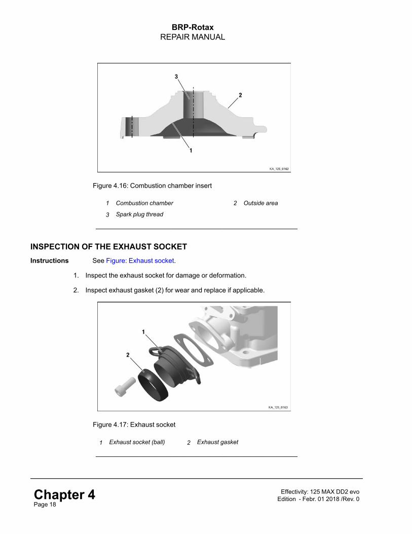
INSPECTION OF THE COMBUSTION CHAMBER INSERTInstructions See Figure: Combustion chamber insert.
NNOOTTEE
The sealing area of the combustion chamber insert is slightly tapered from Ø 63mm.
1. Clean combustion residues and lime deposits from the outer area (1) of the combustionchamber.
2. Inspect combustion chamber insert for cracks (visual inspection).
3. Make sure that spark plug thread (3) is in good condition.
4. Inspect sealing surfaces for flatness and damage.
Effectivity: 125 MAX DD2 evoEdition - Febr. 01 2018 /Rev. 0 Chapter 4
Page 17
BRP-RotaxREPAIR MANUAL
Figure 4.16: Combustion chamber insert
1 Combustion chamber 2 Outside area
3 Spark plug thread
______________________________________________________
INSPECTION OF THE EXHAUST SOCKETInstructions See Figure: Exhaust socket.
1. Inspect the exhaust socket for damage or deformation.
2. Inspect exhaust gasket (2) for wear and replace if applicable.
Figure 4.17: Exhaust socket
1 Exhaust socket (ball) 2 Exhaust gasket
______________________________________________________
Chapter 4Page 18
Effectivity: 125 MAX DD2 evoEdition - Febr. 01 2018 /Rev. 0

BRP-RotaxREPAIR MANUAL
INSPECTION OF THE CARBURETOR FLANGE AND REED VALVEGeneral
ATTENTION
The reed petal should be completely on the valve guide with a little initial tension (a gapshould not be visible when held against the light. If applicable adjust reed valves more
precisely by releasing the tightening torque of the screws.
Instructions See Figure: Carburetor port and valve guide.
1. Inspect rubber lining of reed valves (1) for perishing (if applicable replace complete reedvalve).
2. Check the two reed petal (2) for cracks or damage.
3. Check the oval head screw M3x6 (3) for secure seating. (LOCTITE 648 Tightening torque1.5 –2 Nm (13-18 in.lb)).
4. Inspect carburetor flange (4) for cracks, porosity or swelling and replace if applicable.
Figure 4.18: Carburetor port and valve guide
1 Reed valve assy. 2 Reed petal
3 Oval head screw M3x6 4 Intake socket
______________________________________________________
Effectivity: 125 MAX DD2 evoEdition - Febr. 01 2018 /Rev. 0 Chapter 4
Page 19

BRP-RotaxREPAIR MANUAL
INSPECTION OF EXHAUST VALVESee Figure: Exhaust valve.
1. Clean oil or oil deposits from all parts with a suitable cleaning agent.
2. Check the smooth movement of the exhaust valve (1) in the cylinder, if applicable removecarbon deposits on the outlet valve and in the cylinder.
3. Inspect condition of O-ring (2).
4. Check that the impulse bore in the valve rod housing (3) is open and check the oil seal (4).
5. Inspect bellows (5) for cracks or porous areas and replace if applicable.
6. Inspect exhaust valve piston (6) for cracks or deformation by caused overheating and re-place if applicable.
NNOOTTEE
Overheating may be caused by leaks.7. Inspect valve cover for cracks (7) or deformation caused by overheating.
Figure 4.19: Exhaust valve
1 Exhaust valve 2 O-ring 6x2.5 RED
3 Valve rod housing assy. 4 Oil seal 6x11x3/4.5
5 Bellow 6 Exhaust valve piston
7 Valve cover
______________________________________________________
Chapter 4Page 20
Effectivity: 125 MAX DD2 evoEdition - Febr. 01 2018 /Rev. 0

BRP-RotaxREPAIR MANUAL
CYLINDER COMPONENTS INSTALLATIONINSTALLATION OF EXHAUST VALVE
NNOOTTEE
Make sure that the components are in their correct position.
Special tools The following special tools and equipment are required:
Part no. Description Use
899788 LOCTITE 648 Stud
276070 Installation tool Valve bellows spring
Instruction See Figure: Exhaust valve.
Proceed as follows to install the exhaust valve:
NNOOTTEE
If the exhaust valve or the stud bolt is replaced, the stud bolt must be secured withLOCTITE 648 in the exhaust valve.
1. Lock exhaust valve (1) and stud M6x52.5 (2) with LOCTITE 648.
2. Wipe away the surplus LOCTITE.
3. Make sure the bolt is screwed in completely. Tightening torque 10 Nm (90 in.lb).
Figure 4.20: Exhaust valve.
1 Exhaust valve 2 Stud M6x52.5
3 O-ring 6x2.5 RED
______________________________________________________
Effectivity: 125 MAX DD2 evoEdition - Febr. 01 2018 /Rev. 0 Chapter 4
Page 21

BRP-RotaxREPAIR MANUAL
INSTALLATION OF EXHAUST VALVE, GASKET, VALVE ROD HOUSINGExhaust valve,gasket, valve rodhousing
See Figure: Exhaust valve.
1. Insert exhaust valve into the slot in the cylinder head (1). Pay attention on the installation di-rection and make sure that the valve is not ranging into the exhaust port!
2. Position the gasket (4), making sure that the impulse bore on the cylinder is not covered.Note the installation direction!
3. Insert the valve rod housing (5).Coat both side of oil seal (6) with Engine oil and insert intothe valve rod housing.
4. Screw in 2 Allen screws M6x25 (7) and spring washers (8) onto the cylinder (1) and tighten.
5. Check the movement of the exhaust valve.
6. Tighten Allen screws (7). Tightening torque 10 Nm (90 in.lb).
Figure 4.21: Installation direction of exhaust valve
1 Cylinder head 2 Exhaust valve
3 O-ring 6x2.5 RED 4 Gasket
5 Valve rod housing assy. 6 Oil seal 6x11x3/4.5
7 Allen screw M6x25 8 Spring washers B6
______________________________________________________
INSTALLATION OF THE EXHAUST VALVE PISTONGeneral In order to protect the piston pin circlip from unintentional loss in the crankcase, a suitable
clean cloth should be used to cover the open cylinder bore.
Instruction See Figure: Exhaust valve piston.
1. Degrease the valve rod housing (1), bellows (2) and exhaust valve piston (3).
2. Pull the small hose spring (4) over the bellows.
Chapter 4Page 22
Effectivity: 125 MAX DD2 evoEdition - Febr. 01 2018 /Rev. 0

BRP-RotaxREPAIR MANUAL
3. Fit the bellows over the valve rod housing (1). The bead of the bellows must engage in thegroove in the valve rod housing.
4. Tighten the exhaust valve piston (3) into the valve rod housing (1). Tightening torque 1.2 Nm(10.6 in.lb)
5. Tension the large hose spring (5) with installation tool part no. 276070.
6. Insert compression spring (6).
7. Tighten the valve cover (7) with 2 TAPTITE screw M5x25 (8).
8. Insert the O-ring 15.9-2.3 (9) into the valve cover.
9. Turn the adjustment screw (10) into the valve cover (7).
Figure 4.22: Exhaust valve piston
1 Valve rod housing assy. 2 Bellow
3 Exhaust valve piston 4 Hose spring 70-1.7-0.3
5 Hose spring 134-3.0-0.65 6 Compression spring 48.5/0.8 mm
7 Valve cover 8 TAPTITE screw M5x25
9 O-ring 15.9-2.3 10 Adjustment screw
______________________________________________________
Effectivity: 125 MAX DD2 evoEdition - Febr. 01 2018 /Rev. 0 Chapter 4
Page 23

BRP-RotaxREPAIR MANUAL
INSTALLATION OF PISTONSpecial tools The following special tools and equipment are required:
Part number Description Field of application
676035 Installation tool Pistonn.a. Engine oil Piston pin
NNOOTTEE
Cover your eyes with safety goggles during this work!Mount the piston with the locking pin of the piston ring facing the intake port.
NNOOTTEE
The piston pin is fixed in the piston with two circlips (left and right).
ATTENTION
Always use new circlips. Used or previously installed circlips have too little tan-gential tension, and they may twist and work their way out of the groove in the
piston.
NNOOTTEE
For easier installation we recommend installing one circlip before installing thepiston.
Instruction See Figure: Piston pin.Proceed as follows to install the piston pin:
1. Coat the piston pin needle cage (2) with Engine oil.
2. Insert the piston pin needle cage (2) into the upper connecting rod eye.
3. Mount the piston (3) and piston pin (4) on the con rod.
4. Place the new circlip (1) flat on a level surface.
5. Push the mounting sleeve (5) with the circlip over it.
6. Push the circlip deeper into the mounting sleeve with the tapered side of the installation tool(6).
7. Rotate the installation tool and continue to push the mounting sleeve until the circlip locks in-to the mounting sleeve groove.
8. Place the installation tool with the cutout of the circlip down on the piston (3).
9. Protect the piston with your hand and press into the piston with the hook ring.
NNOOTTEE
The installation tool centers itself in the piston pin.
Chapter 4Page 24
Effectivity: 125 MAX DD2 evoEdition - Febr. 01 2018 /Rev. 0

BRP-RotaxREPAIR MANUAL
NNOOTTEE
Check that the circlip is correctly seated in the piston.
Figure 4.23: Piston pin
1 Circlip 2 Needle cage K 15x19x20
3 Piston 4 Piston pin 15x10x12.5x45.6
5 Mounting sleeve 6 Installation tool
______________________________________________________
INSTALLATION OF THE CYLINDERGeneral
ATTENTION
Use only the piston/cylinder pairings specified by the table in Chapter 4 Section3.2. All other combinations may lead to engine damage.
Special tools The following special tools and equipment are required:
Part no. Description Field of application
897651 LOCTITE 243 Stud bolts
Effectivity: 125 MAX DD2 evoEdition - Febr. 01 2018 /Rev. 0 Chapter 4
Page 25

BRP-RotaxREPAIR MANUAL
Instructions Proceed as follows to install the cylinder head: See Figure: Cylinder head.
1. Coat the stud bolts (1) on the longer thread end with LOCTITE 243 and screw into the crank-case. Tightening torque 5 Nm (44.25 in.lb).
2. Position new cylinder base gasket (0.2 mm) (4). Determine the correct thickness of the basegasket (see Chapter 4 Section: Squish gap measurement) to adjust the squish gap to thecorrect value.
3. Coat cylinder bore and piston (2) with Engine oil.
4. Press piston ring into the piston with two fingers.
ATTENTION
Do not damage the gasket.
5. Position the cylinder (3) over the piston.
6. Screw cylinder crosswise to the crankcase with the four studs. Tightening torque 24 Nm (18ft.lb).
Figure 4.24: Cylinder head
1 Stud bolts 2 Piston
3 Cylinder 4 Gasket
______________________________________________________
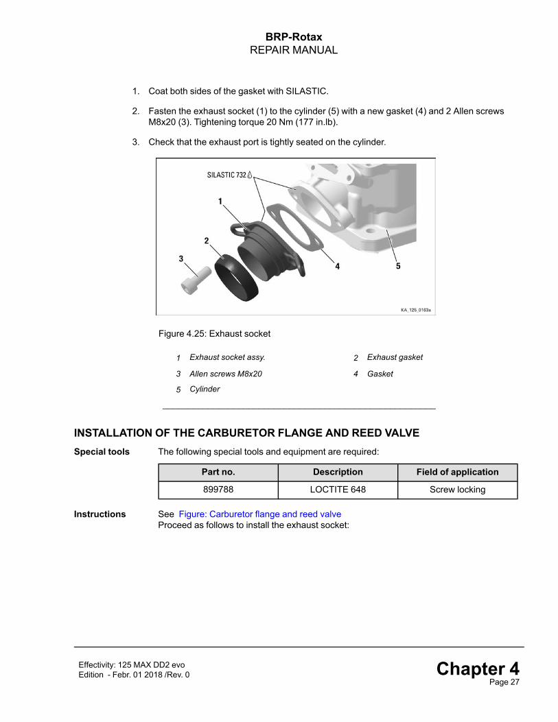
INSTALLATION OF THE EXHAUST SOCKETSpecial tools The following special tools and equipment are required:
Part no. Description Field of application
297386 SILASTIC 732 Gasket
Instructions See Figure: Exhaust socket. Proceed as follows to install the exhaust socket:
Chapter 4Page 26
Effectivity: 125 MAX DD2 evoEdition - Febr. 01 2018 /Rev. 0
BRP-RotaxREPAIR MANUAL
1. Coat both sides of the gasket with SILASTIC.
2. Fasten the exhaust socket (1) to the cylinder (5) with a new gasket (4) and 2 Allen screwsM8x20 (3). Tightening torque 20 Nm (177 in.lb).
3. Check that the exhaust port is tightly seated on the cylinder.
Figure 4.25: Exhaust socket
1 Exhaust socket assy. 2 Exhaust gasket
3 Allen screws M8x20 4 Gasket
5 Cylinder
______________________________________________________
INSTALLATION OF THE CARBURETOR FLANGE AND REED VALVESpecial tools The following special tools and equipment are required:
Part no. Description Field of application
899788 LOCTITE 648 Screw locking
Instructions See Figure: Carburetor flange and reed valveProceed as follows to install the exhaust socket:
Effectivity: 125 MAX DD2 evoEdition - Febr. 01 2018 /Rev. 0 Chapter 4
Page 27

BRP-RotaxREPAIR MANUAL
ATTENTION
The reed petal mounted on the reed valve must be fixed in precisely the correctinstallation position. Incorrect positioning of this valve leads to disturbed run-
ning of the engine due to incomplete combustion.
ATTENTION
The reed petal is bent, not flat. It must be fixed with the concave facing the valveguide. If the valve guide with the correctly fitted reed valve is held up to the light,
it must not be possible to see through it.
1. Attach the reed petal (2) and the valve detent (3) to the valve guide using recessed headscrews (4). Use LOCTITE 648 to lock the screws.
2. Position the gasket (5) on the cylinder.
3. Position the reed valve (1) and intake socket (6) and fasten together with the support bracket(7) using 5 head screws M6x25 (8)(9). Tightening torque 7 Nm (62 in.lb).
Figure 4.26: Carburetor flange and reed valve
1 Reed valve 2 Reed petal
3 Valve detent 4 Recessed head screw M3x6
5 Gasket 6 Carburetor flange
7 Support bracket 8Allen screw M6x25, with hole for sealingthe engine
9 Allen screw M6x25,
Chapter 4Page 28
Effectivity: 125 MAX DD2 evoEdition - Febr. 01 2018 /Rev. 0

BRP-RotaxREPAIR MANUAL
INSTALLATION OF COMBUSTION CHAMBER INSERTGeneral NNOOTTEE
Note the installation position of the combustion chamber insert (2) - “Made in Aus-tria” points to the exhaust port.
Instructions See Figure: Combustion chamber insert.Proceed as follows to install the combustion chamber insert and cylinder head cover:
1. Position O-ring (2) in the groove of the cylinder.
2. Tighten combustion chamber insert (2) crosswise with 5 hex screws (4) and with lock wash-ers (5) to 5 Nm initially, ensuring that the O-ring (3) is not crushed. Tighten to tightening tor-que 30 Nm (22 ft.lb).
Figure 4.27: Combustion chamber insert
1 Combustion chamber insert 2 O-ring 64x2
3 O-ring 23.3x2.4 4 Hex. screw M8x30
5 Lock washer
______________________________________________________
INSTALLATION OF CYLINDER HEAD COVERSpecial tools The following special tools and equipment are required:
Part no. Description Field of application
897651 LOCTITE 243 Screw locking
Preparation The following preparation is required before installation:
• Installation of the coolant thermostat:
Effectivity: 125 MAX DD2 evoEdition - Febr. 01 2018 /Rev. 0 Chapter 4
Page 29

BRP-RotaxREPAIR MANUAL
Instructions See Figure: Coolant thermostat.Installation of the coolant thermostat:
1. Install thermostat (2) with collar nut M8 (3), compression spring (4) and thermostat retainingbracket (5) with 2 screws (6). Lock screws with LOCTITE 243.
Figure 4.28: Coolant thermostat
1 Cylinder head cover red 2 Thermostat 45 degree celcius
3 Collar nut M8 4 Compression spring
5 Thermostat retaining bracket 6 TAPTITE screw M4x8
______________________________________________________
Instructions See Figure: Combustion chamber insert.Proceed as follows to install the combustion chamber insert:
2. Position O-ring (1) on the combustion chamber insert.
3. Grease the O-ring (2) lightly to ensure that it adheres better to the groove of the cylinderhead cover, otherwise fix it with sealant (Silastic).
4. Insert O-ring (2) into the groove of the cylinder head cover (3).
5. Tighten the cylinder head cover (3) crosswise with 4 Allen screws M6x25 (4). Tightening tor-que 10 Nm (90 in.lb).
Chapter 4Page 30
Effectivity: 125 MAX DD2 evoEdition - Febr. 01 2018 /Rev. 0

BRP-RotaxREPAIR MANUAL
Figure 4.29: Combustion chamber insert
1 O-ring 23.3x2.4 2 O-ring 64x2
3 Cylinder head cover red 4 Allen screw M6x25
______________________________________________________
INSPECTION AND ADJUSTMENT OF SQUISH GAPGeneral NNOOTTEE
The gap between the piston (at the TDC of the piston) and the combustion cham-ber insert (= “squish gap”) is partly responsible for the power characteristics of theengine and responsible for smooth running.
NNOOTTEE
The smaller the squish gap the higher the engine compression. This means thatthe engine response to the feed from the carburetor becomes more critical underchanging operating conditions (temperature, air pressure, humidity).
Special tools The following special tools and equipment are required:
Part no. Description Field of application
580130 Solder 2 mm Combustion chamber
580132 Solder 3 mm Combustion chambern.a. Vernier caliper Solder
Instructions See Figure: Crankcase.
1. Use a coin to remove plug screw M18x1.5 together with the O-ring.
Effectivity: 125 MAX DD2 evoEdition - Febr. 01 2018 /Rev. 0 Chapter 4
Page 31

BRP-RotaxREPAIR MANUAL
2. Screw a M8 bolt into crankshaft and rotate it by hand until the piston is approx. 5 mm belowTDC.
Figure 4.30: Crankcase
1 Crankcase 2 Coin
3. Bend the solder as shown in the following picture and insert through the spark plug thread in-to the combustion chamber until the solder is in contact with the cylinder bore.The squeeze edge must always be measured in the direction of the axis of the piston pin.The result of a measurement of the squeeze edge in the direction of the exhaust port will befalsified by the tilt of the piston and is not approved.
4. Remove the solder from the combustion chamber and measure the thickness at the veryend (= “squish gap”) of the crushed end of the solder with a vernier calliper.
Chapter 4Page 32
Effectivity: 125 MAX DD2 evoEdition - Febr. 01 2018 /Rev. 0

BRP-RotaxREPAIR MANUAL
Figure 4.31: Squish gap measurement
1 Solder 2 Vernier caliper
NNOOTTEE
A vernier calliper with an accuracy of min. 1/100 mm is required for thismeasurement.
ATTENTION
The squish gap must be within the specified tolerance.
You find the latest valid reglement on:www.rotax-kart.com/de/Max-Challenge/MAX-Challenge/Regulations.
NNOOTTEE
We recommend setting a squish gap in the upper tolerance range of the relevantmodel.
NNOOTTEE
The squish gap can be set to a different thickness with cylinder base gaskets. Cyl-inder base gaskets are available 0.2 mm (0.008 in.), 0.3 mm (0.01 in.), 0.4 mm(0.015 in.), 0.5 mm (0.02 in.) and 0.8 mm (0.03 in.) thick.
Example A cylinder base gasket 0.5 mm (0.02 in.) thick has been installed. With this cylinder basegasket a squish gap of 0.8 mm (0.03 in.) was measured. A cylinder base gasket 0.8 mmthick is required to set the required value, e.g. 1.1 mm (0.043 in.). Of course a 0.5 mm(0.02 in.) and a 0.3 mm (0.01 in.) seal can be installed.If it is necessary to install a cylinder base gasket with a different thickness, the cylindercan be completely removed by unscrewing the four studs. Follow the directions in the “In-stallation of the cylinder” chapter for installation of the cylinder. All the components at-tached to the cylinder (intake socket, exhaust socket) can remain on the cylinder.
Effectivity: 125 MAX DD2 evoEdition - Febr. 01 2018 /Rev. 0 Chapter 4
Page 33

BRP-RotaxREPAIR MANUAL
Keep in mind that the gasket will settle and reduce the squish over time.
INSTALLATION OF SPARK PLUGInstructions Proceed as follows to install the spark plug:
1. Screw in spark plug hand-tight and use tightening torque to tighten it with 27 Nm (20 ft.lb).
Chapter 4Page 34
Effectivity: 125 MAX DD2 evoEdition - Febr. 01 2018 /Rev. 0

BRP-RotaxREPAIR MANUAL
Chapter: Chapter 5CRANKCASE
TOPICS IN THIS CHAPTER
System description .................................................................................................................................2Removal of the crankcase .......................................................................................................................5Disassembling the crankcase..................................................................................................................6Installation of the crankshaft repair kit ....................................................................................................9
Disassembling of the crankshaft .............................................................................................................9Inspection of the crankshaft..................................................................................................................13Crankshaft not in specification ..............................................................................................................15Crankshaft - assembly .........................................................................................................................16
Crank case inspection ...........................................................................................................................20Inspection of the housing halves...........................................................................................................20Inspection of the gear wheels ...............................................................................................................21
Crank case - assembly ..........................................................................................................................22Installation of bearing and oil seal for shaft ............................................................................................22Installation or Replace sealings ............................................................................................................23Check of the bearings ..........................................................................................................................23Replace of bearing ..............................................................................................................................24Installation of shaft and gears ...............................................................................................................27Assembly of the gearbox housing .........................................................................................................29Installation of crank case assy. .............................................................................................................30
Contents This chapter describes the disassembly and assembly of the crankcase of the ROTAX®125 MAX DD2 evo engine.
Effectivity: 125 MAX DD2 evoEdition - Febr. 01 2018 /Rev. 0 Chapter 5
Page 1

BRP-RotaxREPAIR MANUAL
SYSTEM DESCRIPTIONOverview
Figure 5.1: Position on the engine
Chapter 5Page 2
Effectivity: 125 MAX DD2 evoEdition - Febr. 01 2018 /Rev. 0

BRP-RotaxREPAIR MANUAL
Overview Components of crankcase
Figure 5.2
1 Crank case assy. 2 Gasket
3 Crankshaft assy. 4 Hollow shaft
5 Idle gear 77 T 6 Idle gear 81 T
7 Shifting sleeve 8 Plain bearing 40x44x20
9 Needle bearing K 52x57x12 10 Shift fork assy.
11 Ball bearing 6010 C3 12 Oil seal ASL 50x68x8
13 Ball bearing 6206 14 Ball bearing 6204
Effectivity: 125 MAX DD2 evoEdition - Febr. 01 2018 /Rev. 0 Chapter 5
Page 3

BRP-RotaxREPAIR MANUAL
15 Primary shaft 24/19 T 16 Shift rail detent pin
17 Oil seal AS 30x42x7/7.5 18 Oil seal 12x22x7
19 Allen screw M6x45 20 O-ring 17x1.5
21 Air vent screw M18x1.5 22 Sealing ring A 12x18
23 Magnet drain plug M12x1.5
Chapter 5Page 4
Effectivity: 125 MAX DD2 evoEdition - Febr. 01 2018 /Rev. 0

BRP-RotaxREPAIR MANUAL
REMOVAL OF THE CRANKCASESafetyinformation
mWARNING
Danger of severe burns and scalds! Always allow the engine to cool down to am-bient temperature before starting any work.
Preparation The following preparation is required before removal:
1. Removal of ignition system. See also Chapter 3).
2. Removal of the fuel line. See also Chapter 3).
3. Positioning the engine on the trestle mounting plate. See also Chapter 3).
4. Drain oil. See also Chapter 4).
5. Removal of cylinder head. See also Chapter 4).
6. Removal of carburetor. See also Chapter 6).
7. Removal of starter. See also Chapter 7).
8. Removal of radiator. See also Chapter 8).
Effectivity: 125 MAX DD2 evoEdition - Febr. 01 2018 /Rev. 0 Chapter 5
Page 5

BRP-RotaxREPAIR MANUAL
DISASSEMBLING THE CRANKCASESpecial tools The following special tools and equipment are required:
Part no. Description Field of application
276016 Puller assembly Case halves
n.a. Plastic hammer Crankshaft
Instructions See Figure: Crankcase.
NNOOTTEE
Use two hex. screws to separate the case halves
1. Unscrew all Allen screws M6x45 (2) and remove them.
2. Remove engine housing from trestle mounting plate.
3. Screw 3 Cyl. bolts M8x70 into the left side crankcase as a support.
Figure 5.3: Crankcase
1 Crankcase 2 Allen screws M6x45
3 Cyl. screws M8x70
______________________________________________________
4. Screw 2 jack screws M6x60 (1) evenly into the thread and initiate housing separation.
Chapter 5Page 6
Effectivity: 125 MAX DD2 evoEdition - Febr. 01 2018 /Rev. 0

BRP-RotaxREPAIR MANUAL
5. Separate the housing halves by specific strokes with a plastic hammer.
Figure 5.4
1 Allen screw M6x60 (jack screw)
______________________________________________________
Lay the gearbox housing aside, remove the gasket and the components out of the crankcasein the following order:
6. Remove the idle gear 81 T (2).
7. Pull the shifting sleeve (3) from hollow shaft (5) and the shift fork assy. (4) out of thecrankcase.
8. Pull or knock the hollow shaft (5) carefully out of the ball bearings.
NNOOTTEE
Do not damage the shaft seal, otherwise it must be renewed!
9. Remove the idle gear (6).
10. Remove needle bearings (7) and plain bearings (8) of the idle gears from the hollow shaft(5).
Effectivity: 125 MAX DD2 evoEdition - Febr. 01 2018 /Rev. 0 Chapter 5
Page 7

BRP-RotaxREPAIR MANUAL
Figure 5.5
1 Gasket 2 Idle gear 81 T
3 Shifting sleeve 4 Shift fork assy.
5 Hollow shaft 6 Idle gear 77 T
7 Needle bearing K 52x57x12 8 Plain bearing 40x44x20
______________________________________________________
11. Pull the crankshaft assy (1) out of the ball bearings.
12. Pull or knock the primary shaft (2) carefully out of the ball bearings.
Figure 5.6: Crankcase
1 Crankshaft assy. 2 Primary shaft 24/19 T
______________________________________________________
Chapter 5Page 8
Effectivity: 125 MAX DD2 evoEdition - Febr. 01 2018 /Rev. 0

BRP-RotaxREPAIR MANUAL
INSTALLATION OF THE CRANKSHAFT REPAIR KITDISASSEMBLING OF THE CRANKSHAFTSafetyinstructions
mWARNING
Non-compliance can result in serious injuries or death!Be particularly careful when working with a tool such as a hydraulic press, and followthe instructions of the manufacturer.All repair and maintenance work must only be car-ried out by a qualified technician.Generally speaking, we advise to read manuals care-
fully and follow the instructions.
NNOOTTEE
The parts of the crankshaft repair kit are paired together and must therefore beexclusively used together.
NNOOTTEE
Before disassembling the crankshaft, clean the parts thoroughly with a cleaningagent (grease-free).
Special tools The following special tools and equipment are required:
Part no. Description Field of applicationn.a. Press Crankshaft disassembling
n.a. Dial gauge Crankshaft measurements
276051 crankshaft repair jig Crankshaft
Effectivity: 125 MAX DD2 evoEdition - Febr. 01 2018 /Rev. 0 Chapter 5
Page 9

BRP-RotaxREPAIR MANUAL
Figure 5.7: Crankshaft repair jig
Part Part no. Function1
276051
Bottom section of the repair jig
2 Top section of the repair jig
3 Thrust plate
4 Sleeve
5 Thrust ring
6 Crowbar
7 Thrust pin/old piston pin
NNOOTTEE
Con rod parts are not part of the crankshaft repair jig (part no. 276051).The crankshaft repair kit (con rod) is available at your ROTAX® Dealer.
Chapter 5Page 10
Effectivity: 125 MAX DD2 evoEdition - Febr. 01 2018 /Rev. 0

BRP-RotaxREPAIR MANUAL
Part Part no. Description
685011 Crankshaft repair kit (1x)
consisting of:
1 217431 Con rod (1x)
2 221162 Con rod pin (1x)
3 232884 Needle bearing (1x)
4 227731 Thrust washers (2x)
Figure 5.8: Con rod parts
1 Con rod 2 Con rod pin
3 Needle bearing 4 Thrust washer (2x)
______________________________________________________
Instructions See Figure: Disassembling of the crankshaft.
NNOOTTEE
Position the con rod above the bore of the bottom of the crankshaft repair jig. Oth-erwise the con rod pin, the crankshaft half or the bottom section may bedamaged.
1. Push thrust plate (2) between the two halves of the crankshaft.
2. Position the crankshaft on the thrust plate (3) on bottom section of the tool (4) and make surethat the crankshaft matches the bore in the bottom section at the crankshaft repair jig (4).
3. Position the thrust pin (5) on the connecting rod pin and press the crankshaft apart.
Effectivity: 125 MAX DD2 evoEdition - Febr. 01 2018 /Rev. 0 Chapter 5
Page 11

BRP-RotaxREPAIR MANUAL
NNOOTTEE
Take an available con rod pin (6) and push the old con rod (7) with needle bearingand thrust washer onto the con rod pin. Note the installation instructions.
4. Take the gearbox-end of the crankshaft half (8) and repeat the procedure.
Figure 5.9: TYPICAL – Disassembling of the crankshaft
1 Thrust ring 2 Thrust plate
3 Crankshaft half 4 Bottom section of the crankshaft repair jig
5 Thrust pin 6 Con rod pin
7 Con rod 8 Drive side of the crankshaft half
9 Press
______________________________________________________
Chapter 5Page 12
Effectivity: 125 MAX DD2 evoEdition - Febr. 01 2018 /Rev. 0

BRP-RotaxREPAIR MANUAL
INSPECTION OF THE CRANKSHAFTGeneral • Thoroughly clean the crankshaft with a grease-free cleaning agent.
Instructions See Figure: Crankshaft measurements.
1. Inspect the crankshaft for visible damage and traces of wear:
• Cone/centered thread
• Bearing seats
• Running surface of the bearing
• Contact surface of the shaft seals
• Woodruff key groove
Measuring thecrankshaft
2. Measure values for the two main bearing seats (CS01), the bearing surface of the clutch(CS02) and of the piston pin (CS03).
3. Determine the axial play of the con rod bearing (CS04) using a feeler gauge.
4. Check the specific dimension (CS07).
5. Determine the radial clearance of the connecting rod bearing (CS05).
6. Check the run out of the crankshaft (CS06).
NNOOTTEE
If one of the wear limits CS01 or CS02 is reached, the complete crankshaft mustbe replaced.
NNOOTTEE
If one of the wear limits CS03, CS04 or CS05 is reached, BRP-Rotax recom-mends use of the applicable repair kit. See also Chapter 5 Figure: Con rod parts.
NNOOTTEE
If the maximum approved stroke (CS06) of the crankshaft is exceeded, the crank-shaft must be realigned. See also Chapter 5 Figure: Crankshaft measurements.
Effectivity: 125 MAX DD2 evoEdition - Febr. 01 2018 /Rev. 0 Chapter 5
Page 13

BRP-RotaxREPAIR MANUAL
Figure 5.10: Crankshaft measurements
Description Code New dimension Wear limit
Main bearing seat CS01 29.980 mm -29.995 mm
29.94 mm
Clutch bearing seat CS02 14.98 mm - 15.003mm
14.95 mm
Piston pin bearing seat CS03 18.99 mm - 19.005mm
19.015 mm
Conrod bearing axial play CS04 1.0 mm 1.3 mm
Conrod bearing radial play CS05 0.05 mm 0.08 mm
Stroke of crankshaft CS06 0.0 mm - 0.015 mm 0.03 mm
Chapter 5Page 14
Effectivity: 125 MAX DD2 evoEdition - Febr. 01 2018 /Rev. 0

BRP-RotaxREPAIR MANUAL
Description Code New dimension Wear limit
Distance of crank webs CS07 48.95 mm - 49.05mm
49.05 mm
Thrust washer thinkness CS08 1.0 mm 0.85 mm
CRANKSHAFT NOT IN SPECIFICATIONGeneral NNOOTTEE
If the crankshaft is not 100% aligned or exceeds the tolerance, the crankshaftmust be re-aligned. See CS 07.
Special tools The following special tools and equipment are required:
Part no. Description Field of application
276051 Crankshaft repair jig Crankshaft
n.a. Vise
Instructions See Figure: Aligning the crankshaft.
1. To align the crankshaft, clamp the drive end or engine end of the crankshaft half (1) in a vise(2). Use a soft material to cover the crankshaft inside the vise to project the surface.
2. Use the lever (3) to lift up the upper half of the crankshaft.
Figure 5.11: Aligning the crankshaft
1 Crankshaft half 2 Vise
3 Crowbar
3. The crankshaft can be aligned to the external diameter of the crankshaft webs with targetstrokes of an aluminum hammer.
Effectivity: 125 MAX DD2 evoEdition - Febr. 01 2018 /Rev. 0 Chapter 5
Page 15

BRP-RotaxREPAIR MANUAL
Figure 5.12: Aluminum hammer
1 Crankshaft half 2 Crankshaft
3 Aluminum hammer
______________________________________________________
CRANKSHAFT - ASSEMBLYGeneral NNOOTTEE
Clean the bore for the connecting rod pins of the gearbox-side crankshaft half witha cleaning agent (grease-free).
Special tools The following special tools and equipment are required:
Part no. Description Field of applicationn.a. Press Crankshaft
276051 Crankshaft repair jig Crankshaft
899788 LOCTITE 648 Crank pin
Instructions See Figure: Crankshaft assembly.
1. Apply LOCTITE 648 to the inside of the crank pin bore in both crankshaft halves.
NNOOTTEE
Remove excess LOCTITE after pressing in, otherwise adjacent parts may bedamaged.
2. Insert the new con rod pin (5) into the crankshaft bore.
3. Place the sleeve (6) over it.
Chapter 5Page 16
Effectivity: 125 MAX DD2 evoEdition - Febr. 01 2018 /Rev. 0

BRP-RotaxREPAIR MANUAL
NNOOTTEE
Transfer the new con rod from the old con rod pin to the pressed–in (new) con rodpin in the crankshaft repair jig. (note the installation position).
4. Position the drive end crankshaft half (3) on the thrust plate (2) and press the new con rodpin (5) into the crankshaft until the con rod pin stops moving, then remove the sleeve (6).
5.
NNOOTTEE
Before positioning the con rod on the pressed-in con rod pin check for:- no corrosion damage- no dirt or dust particles- check that all bearing needles are present
Slide the new crankshaft assy. (7) with cage from the con rod pin (mounting device) onto thepressed-in con rod pin (5).
Figure 5.13: Crankshaft assembly
1 Press 2 Thrust plate
3 Drive end crankshaft half 4 Bottom section of the repair jig
5 Con rod pin 6 Sleeve
7 Crankshaft
______________________________________________________
Instructions See Figure: Crankshaft assembly.
6. Slide the gearbox-end crankshaft half (1) into the bottom section of the tool (2).
Effectivity: 125 MAX DD2 evoEdition - Febr. 01 2018 /Rev. 0 Chapter 5
Page 17

BRP-RotaxREPAIR MANUAL
7. Clean the drive end crankshaft web hole with cleaning agent (grease-free).
8. Coat the hole with LOCTITE 648.
NNOOTTEE
Remove excess LOCTITE, otherwise the con rod may be damaged.
Figure 5.14: Crankshaft assembly
1 Crankshaft half (engine end) 2 Bottom section of the repair jig
3 Con rod pin 4 Con rod
______________________________________________________
9. Slide the drive-end crankshaft half (1) into the top section of the repair jig (2).
10. Hold the crankshaft half as shown in following Figure and push the top section of the tool (3)into the bottom section of the tool (2).
NNOOTTEE
A rotary movement of the con rod makes it easy to align the web hole with the conrod pin.
11. Position the thrust ring (4) on the top section of the repair jig and press the two crankshafthalves together (until the crankshaft pin is aligned with the crankshaft web).
Chapter 5Page 18
Effectivity: 125 MAX DD2 evoEdition - Febr. 01 2018 /Rev. 0

BRP-RotaxREPAIR MANUAL
Figure 5.15: Crankshaft assembly
1 Press stamp 2 Bottom section of the repair jig
3 Top section of the repair jig 4 Thrust ring
______________________________________________________
Effectivity: 125 MAX DD2 evoEdition - Febr. 01 2018 /Rev. 0 Chapter 5
Page 19

BRP-RotaxREPAIR MANUAL
CRANK CASE INSPECTIONINSPECTION OF THE HOUSING HALVESInstructions See Figure: Crankcase.
1. Clean both case halves with commercial detergents.
2. Check both halves (1) for cracks and damage (visual inspection).
3. Check sealing surfaces (2) for damage (visual inspection).
4. Check threads (3) for cleanliness and clearance.
5. Check that lubrication holes (4) are open and clean with compressed air as required.
Figure 5.16: Crankcase
1 Case halves 2 Sealing surfaces
3 Thread 4 Main bearing lubrication hole
______________________________________________________
Chapter 5Page 20
Effectivity: 125 MAX DD2 evoEdition - Febr. 01 2018 /Rev. 0

BRP-RotaxREPAIR MANUAL
INSPECTION OF THE GEARWHEELSInstruction See Figure: Gear wheels.
1. Check the following gearbox components in the context of a revision of the engine for corro-sion, damage or wear:
• Gear wheels of primary shaft 24/19 T
• Idle gear 81 T
• Shifting sleeve and shift fork assy.
• Plain bearing 40x44x20
• Hollow shaft
2. Check for discoloration of components, in addition inspect the gearing for pitting.Blue color means that this part was subjected to massive heat and should be replaced.
Figure 5.17: Gear wheels
1 Primary shaft 24/19 T 2 Shift fork assy.
3 Needle bearing K 52x57x12 4 Idle gear 81 T
5 Plain bearing 40x44x20 6 Shifting sleeve
7 Idle gear 77 T 8 Hollow shaft
______________________________________________________
Effectivity: 125 MAX DD2 evoEdition - Febr. 01 2018 /Rev. 0 Chapter 5
Page 21

BRP-RotaxREPAIR MANUAL
CRANK CASE - ASSEMBLYGeneral
NNOOTTEE
Always replace old gaskets, circlips, O-rings and oil seals with new ones afterdisassembling.
Special tools The following special tools and equipment are required:
Part no. Description Usen.a. Convection oven or heating
plateCase halves
676030 Installation tool Needle bearing
676010 Mounting sleeve Shaft seal
676021 Installation tooln.a. 2-stroke engine oil Shaft seal
n.a. MOLYCOTE 111 Shaft seal
INSTALLATION OF BEARING AND OIL SEAL FOR SHAFT
mWARNING
Danger of severe burns and scalds! Always allow the engine to cool down to am-bient temperature before starting any work.
Special tools The following special tools and equipment are required:
Part no. Description Field of applicationn.a. Convection oven e.g. heat-
er plate (if required)Crankshaft
676030 Installation tool Needle bearing
676021 Installation tool Shaft seal, water pump
Chapter 5Page 22
Effectivity: 125 MAX DD2 evoEdition - Febr. 01 2018 /Rev. 0

BRP-RotaxREPAIR MANUAL
INSTALLATION OR REPLACE SEALINGSGeneral Replace sealing rings if:
• they are damaged or leaking
• directly adjacent bearings must be renewed pairwise
• as part of an overhaul – Does not always have to be replaced.
Instruction See Figure: Display of oil seals.
1. Pull out the sealings from the bearing seats of the crankshaft, hollow shaft and shift fork/sleeve with a suitable tool.
2. Grease the new oil seal with Molykote 111 in the area of the sealing lip and install it with asuitable installation tool.
Figure 5.18: Display of oil seals
1 Oil seal AS 30x42x7/7.5 2 Oil seal ASL 50x68x8
3 Oil seal 12x22x7
_______________________________________________________
CHECK OF THE BEARINGSNNOOTTEE
Before the inspection, lubricate the bearings with engine oil.If the bearing on one side is damaged, always replace the adjacent bearings too.Always replace the according oil seal when replacing a bearing!
NNOOTTEE
If one of the bearings has to be replaced, then replace the shaft seal also.
Instruction See Figure: Check of bearing.
Effectivity: 125 MAX DD2 evoEdition - Febr. 01 2018 /Rev. 0 Chapter 5
Page 23
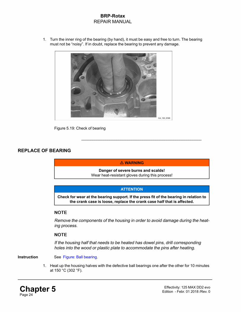
BRP-RotaxREPAIR MANUAL
1. Turn the inner ring of the bearing (by hand), it must be easy and free to turn. The bearingmust not be “noisy”. If in doubt, replace the bearing to prevent any damage.
Figure 5.19: Check of bearing
_______________________________________________________
REPLACE OF BEARING
mWARNING
Danger of severe burns and scalds!Wear heat-resistant gloves during this process!
ATTENTION
Check for wear at the bearing support. If the press fit of the bearing in relation tothe crank case is loose, replace the crank case half that is affected.
NNOOTTEE
Remove the components of the housing in order to avoid damage during the heat-ing process.
NNOOTTEE
If the housing half that needs to be heated has dowel pins, drill correspondingholes into the wood or plastic plate to accommodate the pins after heating.
Instruction See Figure: Ball bearing.
1. Heat up the housing halves with the defective ball bearings one after the other for 10 minutesat 150 °C (302 °F).
Chapter 5Page 24
Effectivity: 125 MAX DD2 evoEdition - Febr. 01 2018 /Rev. 0

BRP-RotaxREPAIR MANUAL
2. Take one housing half out of the oven in correct position and swing it lightly onto a flat sur-face, preferably of wood, then the defective ball bearing will pop out of the crank case by us-ing only little force.
3. Clean the bearing seats carefully.
NNOOTTEE
Components must have cooled to room temperature (20 °C) (68 °F). Otherwise ameasurement is not valid!
4. Measure the inner diameter of the bearing seat and the outer diameter of the bearing. Theinterference fit between the ball bearing and the bearing seat must be at least s = 0.01 mm.
5. Heat up the halves again to 150 °C (302 °F) for 10 minutes.
6. Lay a crank case half on a flat surface, lubricate bearing area with lithium-based grease.
7. Lubricate the ball bearings with engine oil and insert them into the bearing seats carefully.Do not tilt the bearing, otherwise you have to start again!
NNOOTTEE
Crankshaft main bearing: The closed cage side must face the crank web!See Figure: Crankshaft main bearing (next side). The bearing description mustbe visible!
Figure 5.20: Ball bearing
1 Ball bearing (crankshaft) 6206 TVHC4M 2 Ball bearing (hollow shaft) 6010 C3
3 Ball bearing (primary shaft) 6203 C3 4 Ball bearing (primary shaft) 6204 C3
______________________________________________________
Effectivity: 125 MAX DD2 evoEdition - Febr. 01 2018 /Rev. 0 Chapter 5
Page 25

BRP-RotaxREPAIR MANUAL
Figure 5.21: Crankshaft main bearing
1 Ball bearing (crankshaft) 6206 TVHC4M 2 Ball bearing (hollow shaft) 6010 C3
3 Ball bearing (primary shaft) 6204 C3
______________________________________________________
Chapter 5Page 26
Effectivity: 125 MAX DD2 evoEdition - Febr. 01 2018 /Rev. 0

BRP-RotaxREPAIR MANUAL
INSTALLATION OF SHAFTAND GEARSPreparation See Figure: Crank case housing.
Put the crank case housing (ignition side) on the work bench!
1. Screw three Allen screw M8x70 evenly into the extraction thread and use them as pedestal.
Figure 5.22: Crankcase housing
1 Crank case housing 2 Allen screws M8x70
______________________________________________________
Instruction See Figure: Crankshaft assy., Primary shaft.
2. Insert the crankshaft (1) into the ball bearing of the gearbox housing (case).
3. Insert the primary shaft (2) carefully into the ball bearing of the gearbox housing (case).
Figure 5.23: Crankshaft assy, Primary shaft
1 crankshaft assy. 2 Primary shaft
______________________________________________________
Instruction See Figure: Shafts and wheels.
Effectivity: 125 MAX DD2 evoEdition - Febr. 01 2018 /Rev. 0 Chapter 5
Page 27

BRP-RotaxREPAIR MANUAL
Proceed as follows to installation the shafts and gears.
4. Assemble the hollow shaft with bearing sleeves, needle bearings, shifting sleeve, shift fork,idle gears and install it into the gearbox housing.
• First install the hollow shaft (1) with the hexagonal end into the ball bearing of the gearboxhousing - Avoid possible damage to the oil seal (7).
• Pay attention to order and direction when installing the idle gears: First install the idle gear(5) (2.gear) onto the hollow shaft, then install the idle gear (9) (1.gear).Both idle gears indicate with the flat side to the shifting sleeve (4)!
5. Assemble the housing halves. Described in section Assembly of housing valves.
Figure 5.24: Shafts and wheels
1 Hollow shaft 2 Plain bearing 40x44x20
3 Needle bearing K 52x57x12 4 Shifting sleeve
5 Idle gear 77 T 6 Ball bearing 6010 C3
7 Oil seal ASL 50x68x8 8 Shift fork assy.
9 Idle gear 81 T
______________________________________________________
Chapter 5Page 28
Effectivity: 125 MAX DD2 evoEdition - Febr. 01 2018 /Rev. 0

BRP-RotaxREPAIR MANUAL
ASSEMBLY OF THE GEARBOX HOUSINGGeneral NNOOTTEE
When using new studs for the assembly of the cylinder, first screw the long side ofthe threaded studs into the housing and secure them with LOCTITE 243.Tightening torque 10 Nm.
When using new housing halves insert new dowel pins!
Instruction
ATTENTION
Pay attention on the different lengths of the Allen. screws!Tighten the Allen. screws crosswise, start in the middle of the housing.
1. Insert a new housing gasket part no. 630522 included in the gasket set part no. 296162.
2. Mount both housing halves together with 12 Allen screws M6x45 (see mounting plan)together.Tightening torque 10 Nm.
3. Crankcase assy. –cool down.
4. Attach the crankcase assy. on trestle mounting plate with 4 attachment screws.
Figure 5.25: Mounting plan 1-12
______________________________________________________
Effectivity: 125 MAX DD2 evoEdition - Febr. 01 2018 /Rev. 0 Chapter 5
Page 29

BRP-RotaxREPAIR MANUAL
5. Cut off the protruding section of the crankcase gasket with a sharp knife at the cylinder basesurface.
INSTALLATION OF CRANK CASE ASSY.Final tasks
1. Install cylinder assy. See Chapter 4).
2. Install balance drive and centrifugal clutch. See Chapter 7).
3. Take the engine off the assembly stand. See Chapter 3).
4. Install the engine in the kart chassis. See Chapter 3).
5. Filling the gear housing with oil. See Chapter 7).
6. Install the fuel line. See Chapter 3).
7. Install the exhaust system. See Chapter 9).
8. Install the carburetor and air filter. See Chapter 6).
9. Install the water pump hoses. See Chapter 8).
10. Install the ignition system. See Chapter 3).
Chapter 5Page 30
Effectivity: 125 MAX DD2 evoEdition - Febr. 01 2018 /Rev. 0

BRP-RotaxREPAIR MANUAL
Chapter: Chapter 6CARBURETOR AND INTAKE SILENCER
TOPICS IN THIS CHAPTER
System description .................................................................................................................................2Removal of the carburetor and intake silencer ........................................................................................3
Removal of the carburetor, intake silencer ...............................................................................................3Removal of the fuel pump.......................................................................................................................5Disassembly of the carburetor ................................................................................................................5Disassembly of the intake silencer ..........................................................................................................7
Carburetor and intake silencer – inspection of components ...................................................................8Inspection of the carburetor....................................................................................................................8Inspection of the fuel pump ....................................................................................................................9Inspection of the intake silencer..............................................................................................................9
Installing the carburetor and intake silencer.......................................................................................... 11Assembly of carburetor ........................................................................................................................ 11Assembly of float housing .................................................................................................................... 11Assembly of intake silencer ..................................................................................................................12
Installation of fuel pump, carburetor .....................................................................................................13
Contents This chapter describes the removal and installation of the carburetor and intake silencerassembly for the ROTAX® 125 MAX DD2 evo engine. The description is divided intosubsections.
Effectivity: 125 MAX DD2 evoEdition - Febr. 01 2018 /Rev. 0 Chapter 6
Page 1

BRP-RotaxREPAIR MANUAL
SYSTEM DESCRIPTIONOverview Position on engine
Figure 6.1: Position on engine
1 Intake silencer 2 Carburetor
3 Fuel pump 4 Fuel line
5 Impulse pipe
Chapter 6Page 2
Effectivity: 125 MAX DD2 evoEdition - Febr. 01 2018 /Rev. 0

BRP-RotaxREPAIR MANUAL
REMOVAL OF THE CARBURETOR AND INTAKE SILENCERSafetyinstructions
mWARNING
Danger of explosion and ignition!Overflowing and spoilt gasoline must be absorbed immediately with a binding agentand correctly disposed. Do not work with open flames and sources of ignition. Fuelmust not come into contact with hot parts such as engine or exhaust since this may
cause a fire!.
Preparation The following preparations should be carried out before removing the components: SeeFigure: Carburetor and intake silencer.
1. Pull off fuel pipe between the fuel tank and fuel pump from the fuel pump (4) and seal it witha screw.
2. Remove the Bowden cable. See also Chapter 3).
REMOVAL OF THE CARBURETOR, INTAKE SILENCERInstruction See Figure: Carburetor and intake silencer.
ATTENTION
Fuel may spill out when removing the carburetor.
ENVIRONMENTAL NOTE
Protect the environment!Use a container to collect the fuel from the carburetor.
To remove the carburetor and intake silencer the following steps are required:
1. Remove the fuel line (1) between the fuel pump (3) and the carburetor.
2. Loosen the hose clamp (4).
3. Remove the carburetor along with the intake silencer (5).
Effectivity: 125 MAX DD2 evoEdition - Febr. 01 2018 /Rev. 0 Chapter 6
Page 3

BRP-RotaxREPAIR MANUAL
Figure 6.2: Carburetor and intake silencer
1 Fuel line to the carburetor 2 Impulse line
3 Fuel pump 4 Pipe clamp 51
5 Intake silencer
______________________________________________________
Chapter 6Page 4
Effectivity: 125 MAX DD2 evoEdition - Febr. 01 2018 /Rev. 0

BRP-RotaxREPAIR MANUAL
REMOVAL OF THE FUEL PUMPInstruction See Figure: Fuel pump.
To remove the fuel pump the following steps are required:
1. Remove the fuel pump (1) from the retaining plate (5).
1 Fuel pump 2 Washer 6.4
3 Lock nut M6 4 Rubber buffer
5 Retaining plate
Figure 6.3: Fuel pump
DISASSEMBLY OF THE CARBURETOR
1. Disassembly of the carburetor to the parts shown in Figure: Carburetor and clean them withfuel.
Effectivity: 125 MAX DD2 evoEdition - Febr. 01 2018 /Rev. 0 Chapter 6
Page 5
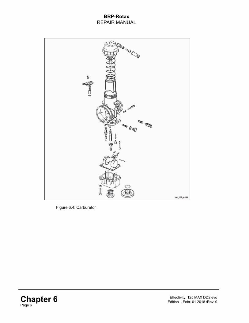
BRP-RotaxREPAIR MANUAL
Figure 6.4: Carburetor
Chapter 6Page 6
Effectivity: 125 MAX DD2 evoEdition - Febr. 01 2018 /Rev. 0

BRP-RotaxREPAIR MANUAL
DISASSEMBLY OF THE INTAKE SILENCERIntake silencer See Figure: Intake silencer.
1. Disassemble the intake silencer to the parts shown in following Figure.
Figure 6.5: Intake silencer
1 Intake silencer case 2 Intake silencer cover
3 Filter element 4 Filter element support
5 Intake silencer tube 6 Carburetor socket
7 Clamp 50–70 8 Lock nut M6
9 Allen screw with rounded flange headM6x16 10 O-ring 59.52x2.62
______________________________________________________
Effectivity: 125 MAX DD2 evoEdition - Febr. 01 2018 /Rev. 0 Chapter 6
Page 7

BRP-RotaxREPAIR MANUAL
CARBURETOR AND INTAKE SILENCER – INSPECTION OFCOMPONENTS
In the case of problems with the fuel supply the carburetor should be checked:First the components should be cleaned and then inspected.
INSPECTION OF THE CARBURETORInstruction See Figure: Carburetor.
1. Clean the fuel filter (1) and make sure that it is in good condition.
2. Blow compressed air through the holes in the carburetor housing (2) and the jets (3, 4, 5, 6and 7) and make sure that there is no pollution to have an easy and free flow.
3. Check that the clip (8) is tightly seated on the jet needle (9).
Figure 6.6: Carburetor
1 Fuel filter 2 Carburetor housing
3 Needle jet DP 267 4 Idling and starter jets
5 Main jet 6 Main jet cup
7Needle valve 150 (standard) 200(optional) 8 Clip
9 Jet needle K 57
______________________________________________________
Chapter 6Page 8
Effectivity: 125 MAX DD2 evoEdition - Febr. 01 2018 /Rev. 0

BRP-RotaxREPAIR MANUAL
INSPECTION OF THE FUEL PUMPGeneral NNOOTTEE
Only the complete membrane and gasket set of the fuel pump can be replaced.
Fuel pump gasket set: Part no. 296165
Instruction See Figure: Fuel pump.
1. Check the condition of the impulse pipe (1), fuel line (2) and fuel overflow line (3) and in caseof doubt replace them.
Figure 6.7: Fuel pump
1 Impulse pipe 2 Fuel line (from fuel tank)
3 Fuel line (to carburetor)
______________________________________________________
INSPECTION OF THE INTAKE SILENCERGeneral
ATTENTION
A damaged filter element must be replaced immediately. Otherwise dirt particlescan enter the intake and cause damage to the engine.
Instruction See Figure: Intake silencer.
1. Inspect the silencer housing (1) and silencer cover (2) for cracks.
2. Inspect the intake silencer tube (5) and carburetor socket (6) for cracks or porosity.
3. Clean the filter element (3) with filter cleaner and oil it afterwards slightly with air filter oil.
4. Inspect the filter element (3) for cracks.
Effectivity: 125 MAX DD2 evoEdition - Febr. 01 2018 /Rev. 0 Chapter 6
Page 9

BRP-RotaxREPAIR MANUAL
Figure 6.8: Intake silencer
1 Intake silencer case 2 Intake silencer cover
3 Filter element 4 Filter element support
5 Intake silencer tube 6 Carburetor socket
______________________________________________________
Chapter 6Page 10
Effectivity: 125 MAX DD2 evoEdition - Febr. 01 2018 /Rev. 0

BRP-RotaxREPAIR MANUAL
INSTALLING THE CARBURETOR AND INTAKE SILENCERASSEMBLY OF CARBURETORInstruction NNOOTTEE
Use ROTAX® gasket set, part no. 293834.
1. Assemble the components in the opposite succession as you disassembled them. See alsoChapter 6) section: Disassembly of the carburetor.
ASSEMBLY OF FLOAT HOUSINGGeneral NNOOTTEE
The tips of the bracket must be at the same height. Adjust them if necessary. Inthis check the float chamber should not have been fitted.
Instruction The following steps are required to install the float housing:
See Figure: Float chamber
1. Check the position of the float attachment (1) in its installed state.
2. When the floats (2) are inserted you should be able to see the word "ALTO" on their topsurfaces.
3. Install and adjust the Bowden cable in accordance with the operating instructions.
4. Set the idle adjuster screw (3) and adjustment screw kit (4).
Figure 6.9: Float chamber
1 Float attachment 2 Float 4.0
3 Adjustment screw 4 Adjustment screw kit
______________________________________________________
Effectivity: 125 MAX DD2 evoEdition - Febr. 01 2018 /Rev. 0 Chapter 6
Page 11

BRP-RotaxREPAIR MANUAL
ASSEMBLY OF INTAKE SILENCERGeneral NNOOTTEE
Before assembly, first immerse the filter element in filter oil. Squeeze out excessoil.
Instruction The following steps are required to install the intake silencer:
1. Assemble the components in the opposite succession as you disassembled them. See alsoChapter 6. section: Disassembly of the intake silencer.
Chapter 6Page 12
Effectivity: 125 MAX DD2 evoEdition - Febr. 01 2018 /Rev. 0

BRP-RotaxREPAIR MANUAL
INSTALLATION OF FUEL PUMP, CARBURETORSafetyinstructions
mWARNING
Danger of explosion and ignition!Overflowing and spoilt gasoline must be absorbed immediately with a binding agentand correctly disposed. Do not work with open flames and sources of ignition. Fuelmust not come into contact with hot parts such as engine or exhaust since this may
cause a fire!.
NNOOTTEE
When assembling the parts make sure that the pipes are connected to the correct terminal!
Preparation The following preparations should be carried out before installing the components:
Installation of fuel pump
➔ Install the fuel pump (8) with 2 rubber buffer and new lock nuts with washers.
Instruction To install the carburetor and intake silencer the following steps are required:
See Figure: Carburetor and intake silencer.
1. Pull the hose clamp (3) over the carburetor flange.
2. Push the carburetor (1) onto the carburetor flange (2) and fasten the hose clamp (3).
3. Secure the intake silencer (4) with the hose clamp (5) on the carburetor.
4. Check the Bowden cable (6) for wear, especially where it bends. Bends can cause the throt-tle to be stuck in fully open. See Chapter 9.
5. Connect the fuel feed line (5) and Bowden cable (6) to the carburetor.
6. Connect the impulse pipe (7).
Effectivity: 125 MAX DD2 evoEdition - Febr. 01 2018 /Rev. 0 Chapter 6
Page 13

BRP-RotaxREPAIR MANUAL
Figure 6.10: Carburetor and intake silencer
1 Carburetor 2 Carburetor flange
3 Hose clamp 4 Intake silencer
5 Fuel feed tube/line 6 Bowden cable
7 Impulse pipe 8 Fuel pump
______________________________________________________
Chapter 6Page 14
Effectivity: 125 MAX DD2 evoEdition - Febr. 01 2018 /Rev. 0

BRP-RotaxREPAIR MANUAL
Chapter: Chapter 7CENTRIFUGAL CLUTCH, PRIMARYAND BALANCE DRIVE
TOPICS IN THIS CHAPTER
System description .................................................................................................................................2Removal of the centrifugal clutch assy. ...................................................................................................4
Drain oil ................................................................................................................................................4Removal of centrifugal clutch, primary and balance drive .......................................................................5Centrifugal clutch assy. – inspection.....................................................................................................10
Inspection of clutch and starter gear......................................................................................................10Check the thrust washers, O-rings and needle cage...............................................................................10Inspection of starter reduction gear ....................................................................................................... 11Inspection of gears ..............................................................................................................................12Inspection of clutch cover.....................................................................................................................12
Centrifugal clutch assy. – installation....................................................................................................14Installation of starter reduction gear ......................................................................................................14
Installation of balance gear, starter gear and clutch plate......................................................................15Installation of balance gear...................................................................................................................15Installation of starter gear.....................................................................................................................16Installation of clutch plate .....................................................................................................................17
Installation of clutch drum and secondary gear.....................................................................................18Installation of support plate and clutch cover........................................................................................20Filling the gear housing with oil.............................................................................................................21
Contents This chapter describes the disassembly and assembly of the centrifugal clutch and theprimary and balance drive for the ROTAX® 125 MAX DD2 evo engine. The description isbroken down into subsections.
Effectivity: 125 MAX DD2 evoEdition - Febr. 01 2018 /Rev. 0 Chapter 7
Page 1

BRP-RotaxREPAIR MANUAL
SYSTEM DESCRIPTIONOverview Position on engine
Figure 7.1: Position on engine
Chapter 7Page 2
Effectivity: 125 MAX DD2 evoEdition - Febr. 01 2018 /Rev. 0

BRP-RotaxREPAIR MANUAL
Figure 7.2
1 Crankshaft assy. 2 Starter gear 70 T 3 Hex. nut M22x1.5
4 Clutch 5 Allen screw M6x16 6 Thrust washer 15.2/25/1
7 O-ring 12x2.5 8 Needle cage 15x19x24 9Clutch primary drivegear
10 Clutch cover, blackcoated 11 Allen screw M6x30 12 Plug screw M18x1.5
13 Allen screw M8x70 14 Support plate 15 Oil level screwM18x1.5
16 Gasket 17 Ball bearing 6302 18 Secondary gear
19 Retaining ring with lug20x1.2 20 Primary shaft 24/19 T 21
Balance gear 50 Tassy.
22 Retaining plate assy. 23 Washer 6.4 24 Allen screw M6x40
25Starter reduction gearassy. 26 Thrust washer 8.5/15/0.5
Effectivity: 125 MAX DD2 evoEdition - Febr. 01 2018 /Rev. 0 Chapter 7
Page 3

BRP-RotaxREPAIR MANUAL
REMOVAL OF THE CENTRIFUGAL CLUTCH ASSY.Safetyinstructions
mWARNING
Danger of severe burns and scalds! Always allow the engine to cool down to am-bient temperature before starting any work.
mWARNING
Danger of explosion and ignition!Overflowing and split gasoline must be absorbed immediately with a binding agent andcorrectly disposed of. Do not work with open flames and sources of ignition. Fuel must
not be allowed to come into contact with hot engine parts and components.
DRAIN OILInstruction See Figure: Drain oil.
1. Remove the Magnetic drain plug (1) with gasket (2) from the crankcase and gearboxhousing.
2. Drain the oil into a suitable vessel and dispose of it in the proper manner.
Figure 7.3: Drain oil
1 Magnetic drain plug M12x1.5 2 Gasket
______________________________________________________
Chapter 7Page 4
Effectivity: 125 MAX DD2 evoEdition - Febr. 01 2018 /Rev. 0

BRP-RotaxREPAIR MANUAL
REMOVAL OF CENTRIFUGAL CLUTCH, PRIMARYAND BALANCE DRIVESpecial tools The following special tools/equipment are required.
Part number Designation Field of application
276016 Puller assy. Starter gear
676202 Fixation tool Starter gear
Instruction See Figure: Clutch cover.
1. Loosen the 4 Allen screws M6x30 (1), 2 Allen screws M6x40 (4) include washer and retain-ing plate on the clutch cover (7).
2. Loosen the 4 Allen screws M8x70 (2) and remove them along with the support plate (3) .
3. Remove the clutch cover (7).
4. Remove the gasket (8).
Figure 7.4: Clutch cover
1 Allen screw M6x30 2 Allen screw M8x70
3 Support plate 4 Allen screw M6x40
5 Washer 6.4 6 Retaining plate assy.
7 Clutch cover, Black coated 8 Gasket
______________________________________________________
Effectivity: 125 MAX DD2 evoEdition - Febr. 01 2018 /Rev. 0 Chapter 7
Page 5

BRP-RotaxREPAIR MANUAL
Instruction See Figure: Primary-Secondary gears.
5. Remove the secondary gear (2) and clutch primary drive gear (1).
6. Remove the retaining ring (4) from the primary shaft (3) using circlip pliers.
Figure 7.5: Primary — Secondary gears
1 Clutch w. primary drive gear 2 Secondary gear
3 Primary shaft 4 Retaining ring 20x1.2
______________________________________________________
Instruction See Figure 7.4: Figure: Clutch cover.
7. Remove the needle cage (1) along with the O-ring (2) and thrust washer (3) from the crank-shaft (4).
Figure 7.6: Clutch cover
Chapter 7Page 6
Effectivity: 125 MAX DD2 evoEdition - Febr. 01 2018 /Rev. 0

BRP-RotaxREPAIR MANUAL
1 Needle cage 15x19x24 2 O-ring 12x2.5
3 Thrust washer 15.2/25/1 4 Crankshaft assy.
______________________________________________________
Instruction See Figure: Clutch plate.
8. Block the starter gear (1) using the fixation tool part no. 676202 (2).
9. Loosen the 3 Allen screws M6x16 (4) and remove the clutch plate (3) using a flatheadscrewdriver.
NNOOTTEE
Screws are stuck in with LOCTITE 648, and can (if necessary) therefore first beheated with a heat gun.
Figure 7.7: Clutch plate
1 Starter gear 70 T 2 Fixation tool
3 Clutch plate 4 Allen screw M6x16
______________________________________________________
Instruction See Figure: Clutch cover.
10. Loosen the hex nut M22x1.5 (3) using a flathead screwdriver.
NNOOTTEE
The hex nut is stuck in with LOCTITE 648, and must therefore first be heated witha heat gun.
Effectivity: 125 MAX DD2 evoEdition - Febr. 01 2018 /Rev. 0 Chapter 7
Page 7

BRP-RotaxREPAIR MANUAL
Figure 7.8: Clutch cover
1 Starter gear 2 Fixation tool
3 Hex. nut M22x1.5
______________________________________________________
Instruction See Figure: Special tool.
11. Pull the starter gear off the crankshaft using the special tool part no. 276016.
Figure 7.9: Special tool
1Special tool part no. 276016 (Pullerassy.) 2 Starter gear
______________________________________________________
Chapter 7Page 8
Effectivity: 125 MAX DD2 evoEdition - Febr. 01 2018 /Rev. 0
BRP-RotaxREPAIR MANUAL
Instruction See Figure: Starter reduction gear.
12. Remove the starter reduction gear (1) along with the thrust washer (2).
Figure 7.10: Starter reduction gear
1 Starter reduction gear 2 Thrust washer
______________________________________________________
Instruction See Figure: Balance gear
13. Remove the shaft retaining ring (2) from the balance gear using circlip pliers.
14. Remove the balance gear (1).
15. Remove the third shaft retaining ring (3) from the primary shaft.
Figure 7.11: Balance gear
1 Balance gear 50 Z 2 Retaining ring 20x1.2
3 Retaining ring 20x1.2
Effectivity: 125 MAX DD2 evoEdition - Febr. 01 2018 /Rev. 0 Chapter 7
Page 9

BRP-RotaxREPAIR MANUAL
CENTRIFUGAL CLUTCH ASSY. – INSPECTIONINSPECTION OF CLUTCH AND STARTER GEARPreparation See Figure: Clutch plate.
1. Check the clutch plate.
NNOOTTEE
Thickness of clutch arm –24.10 mm (0.95 in.)Thickness of clutch plate – min. 14.45 mm (0.57 in.)
2. Check the teeth on the starter gear for damage.
3. Remove any residue of LOCTITE adhesive from the starter gear
Figure 7.12: Clutch plate
______________________________________________________
CHECK THE THRUST WASHERS, O-RINGS AND NEEDLE CAGEInstruction See Figure: Clutch drum.
1. Inspect the thrust washers (1) and O-rings (2) for signs of wear and replace them ifnecessary.
2. Inspect the needle cage (3) for sign of wear and replace if necessary.
Chapter 7Page 10
Effectivity: 125 MAX DD2 evoEdition - Febr. 01 2018 /Rev. 0

BRP-RotaxREPAIR MANUAL
Figure 7.13: Clutch drum
1 Thrust washer 15.2/25/1 2 O-ring 12x2.5
3 Needle cage 15x19x24 4 Clutch w. primary drive gear
______________________________________________________
INSPECTION OF STARTER REDUCTION GEARInstruction See Figure: Starter reduction gear.
1. Clean the starter reduction gear assy. (1).
2. Checking that the starter reduction gear can move freely.
Figure 7.14: Starter reduction gear
1 Starter reduction gear assy. 2 Thrust washer 8.5/15/0.5
______________________________________________________
Effectivity: 125 MAX DD2 evoEdition - Febr. 01 2018 /Rev. 0 Chapter 7
Page 11

BRP-RotaxREPAIR MANUAL
INSPECTION OF GEARSInstruction See Figure: Gears.
1. Check the teeth on the illustrated components for damage, pitting and deformation.
Figure 7.15: Gears
1 Starter gear 70 T 2 Balance gear
3 Secondary gear 4 Clutch w. primary drive gear
______________________________________________________
INSPECTION OF CLUTCH COVERInstruction See Figure: Clutch plate.
1. See Chapter 5 – proceed initially as in Section: Installing of shafts and wheels.
2. Check the halves of the housing.
3. Check the bearings (2) and if necessary replace the bearings.
Chapter 7Page 12
Effectivity: 125 MAX DD2 evoEdition - Febr. 01 2018 /Rev. 0

BRP-RotaxREPAIR MANUAL
Figure 7.16: Clutch plate
1 Clutch cover, black coated 2 Ball bearing 6302
3 Oil level screw M18x1.5 4 Plug screw M18x1.5
5 O-ring 17x1.5 6 Retaining plate assy.
______________________________________________________
Effectivity: 125 MAX DD2 evoEdition - Febr. 01 2018 /Rev. 0 Chapter 7
Page 13

BRP-RotaxREPAIR MANUAL
CENTRIFUGAL CLUTCH ASSY. – INSTALLATIONGeneral NNOOTTEE
The correct sequence MUST be followed. Once the starter gear has been in-stalled it is no longer possible to install the starter reduction gear.
INSTALLATION OF STARTER REDUCTION GEARSpecial tools The following special tools/equipment are required:
Part number Designation Field of application
897330 Lithium-based grease Starter reduction gear
Instruction See Figure: Starter reduction gear.
1. Insert the thrust washer (2) along with the starter reduction gear into the bearing point of thehousing.
2. Grease the starter reduction gear assy. (1) with lithium-based grease in the area around thebearing points.
Figure 7.17: Starter reduction gear
1 Starter reduction gear assy. 2 Thrust washer 8.5/15/0.5
______________________________________________________
Chapter 7Page 14
Effectivity: 125 MAX DD2 evoEdition - Febr. 01 2018 /Rev. 0

BRP-RotaxREPAIR MANUAL
INSTALLATION OF BALANCE GEAR, STARTER GEAR AND CLUTCHPLATE
Special tools The following special tools/equipment are required
Part number Designation Field of applicationn.a. Circlip pliers Shaft retaining rings
676202 Fixation tool Starter gear
899788 LOCTITE 648 Starter gear
INSTALLATION OF BALANCE GEARInstruction See Figure: Balance gear.
1. Fit the shaft retaining ring (3) on position 3 using the circlip pliers.
2. Insert the balance gear (1) onto the primary shaft (4).
3. Fit the outer shaft retaining ring (2) on position 2 using the circlip pliers.
Figure 7.18: Balance gear
1 Balance gear 2 Shaft retaining ring 2
3 Shaft retaining ring 3 4 Primary shaft
______________________________________________________
Effectivity: 125 MAX DD2 evoEdition - Febr. 01 2018 /Rev. 0 Chapter 7
Page 15

BRP-RotaxREPAIR MANUAL
INSTALLATION OF STARTER GEARInstruction See Figure: Starter gear.
1. Insert the starter gear (2) onto the crankshaft, take care to position it correctly in relation tothe balance gear (1).
NNOOTTEE
Both components have a hole that has to overlap. This is to check the correct po-sitioning of the gears.
Figure 7.19: Starter gear
1 Balance gear 50 T 2 Starter gear 70 T
3 Markers 4 Fixation tool
______________________________________________________
Instruction See Figure: Fixation tool.
2. Block the starter gear (2) using the fixation tool (4), part no. 676202.
3. Lubricate LOCTITE 648 on the Hex nut M22x1.5 SW 30 H=6 (3) and fit it using a suitabletool. Tightening torque 180 Nm.
4. Remove excess LOCTITE.
Chapter 7Page 16
Effectivity: 125 MAX DD2 evoEdition - Febr. 01 2018 /Rev. 0

BRP-RotaxREPAIR MANUAL
Figure 7.20: Fixation tool
1 Fixation tool 2 Starter gear 70 T
3 Hex.nut M22x1.5
INSTALLATION OF CLUTCH PLATEInstruction See Figure: Clutch.
1. Lubricate LOCTITE 648 on the new Allen screws M6x16 (2).
2. Insert the clutch (1) on and secure it with 3 Allen screws M6x16 (2). Tightening torque 17Nm.
NNOOTTEE
Strength class of screws: 12.9!3. Remove excess LOCTITE.
Figure 7.21: Clutch
1 Clutch 2 Allen screw M6x16
Effectivity: 125 MAX DD2 evoEdition - Febr. 01 2018 /Rev. 0 Chapter 7
Page 17

BRP-RotaxREPAIR MANUAL
INSTALLATION OF CLUTCH DRUM AND SECONDARY GEARSpecial tools The following special tools/equipment are required:
Part number Designation Field of application
897330 Lithium-based grease Needle cage
Instruction See Figure: Clutch drum.
1. Slide the thrust washer (3) and O-ring (2) onto the crankshaft (4).
2. Lubricate lithium-based grease on the needle cage (1) and slide it onto the crankshaft.
Figure 7.22: Clutch drum
1 Needle cage 15/19/24 2 O-ring 12x2.5
3 Thrust washer 15.2/25/1 4 Crankshaft assy.
______________________________________________________
Instruction See Figure: Secondary gear.
3. Slide the clutch primary drive gear (1) onto the crankshaft.
4. Fit the outer shaft retaining ring (4) on the primary shaft.
5. Engage the secondary gear (2) with the teeth on the primary shaft.
mWARNING
Risk of fatal injury!The engine must not be started without a clutch drum.
Chapter 7Page 18
Effectivity: 125 MAX DD2 evoEdition - Febr. 01 2018 /Rev. 0

BRP-RotaxREPAIR MANUAL
Figure 7.23: Secondary gear
1 Clutch primary drive gear 2 Secondary gear
3 Primary shaft 24/19 T 4 Retaining ring with lug
______________________________________________________
Effectivity: 125 MAX DD2 evoEdition - Febr. 01 2018 /Rev. 0 Chapter 7
Page 19

BRP-RotaxREPAIR MANUAL
INSTALLATION OF SUPPORT PLATE AND CLUTCH COVERSpecial tools The following special tools/equipment are required:
Part number Designation Field of applicationn.a. Torque wrench Clutch cover
Instruction See Figure: Clutch cover, support plate.
1. Fit new gasket (8).
2. Fit the support plate (3) using 4 Allen screws M8x70 (2). Tightening torque 22 Nm.
3. Use 4 Allen screws M6x30 (1) to secure the clutch cover. Tightening torque 10 Nm.
4. Fit the retaining plate assy. (6) using 2 Allen screw M6x40 (4) with washer 6.4 (5). Tighteningtorque 10 Nm.
Figure 7.24: Clutch cover, support plate
1 Allen screw M6x30 2 Allen screw M8x70
3 Support plate 4 Allen screw M6x40
5 Washer 6.4 6 Retaining plate assy.
7 Clutch cover, black coated 8 Gasket
______________________________________________________
Chapter 7Page 20
Effectivity: 125 MAX DD2 evoEdition - Febr. 01 2018 /Rev. 0

BRP-RotaxREPAIR MANUAL
FILLING THE GEAR HOUSING WITH OILGeneral NNOOTTEE
With the engine in a horizontal position pour in 150 ml of gear oil.
Special tools The following special tools/equipment are required:
Part number Designation Field of application
25473 XPS® KART TEC DD2 KARTGEAR OIL
Gear lubrication
Instruction See Figure: Gear housing.
1. Install the oil plug screw (1) with a new O-ring.
2. Install the oil level screw (2) with a new O-ring.
3. Remove the air vent screw (3) with O-ring (4).
4. Add the specified quantity (150 ml) of gear oil through the opening in the housing.
5. Replace the air vent screw (3) with a new O-ring (4).
Figure 7.25: Gear housing
1 Plug screw M18x1.5 2 Oil level screw M18x1.5
3 Air vent screw M18x1.5 4 O-ring 17x1.5
______________________________________________________
Effectivity: 125 MAX DD2 evoEdition - Febr. 01 2018 /Rev. 0 Chapter 7
Page 21

NotesPage 22
Effectivity: 125 MAX DD2 evoEdition - Febr. 01 2018 /Rev. 0
NOTES
BRP-RotaxREPAIR MANUAL

BRP-RotaxREPAIR MANUAL
Chapter: Chapter 8COOLING SYSTEM
TOPICS IN THIS CHAPTER
System description .................................................................................................................................2Removal of radiator .................................................................................................................................4
Removal of radiator with cap assy. ..........................................................................................................4Removal of water pump shaft ..................................................................................................................6Inspection of cooling system ..................................................................................................................8
Radiator – inspection of components ......................................................................................................8Inspection of water pump shaft ...............................................................................................................9
Installing the radiator ............................................................................................................................10Installation of radiator with cap assy. .....................................................................................................10
Installing the water pump shaft ............................................................................................................. 11Replacing the oil seals on the water pump............................................................................................. 11Installation of water pump shaft ............................................................................................................ 11
Final tasks .............................................................................................................................................13
Contents This chapter describes the removal and installation of the cooling system for the ROTAX®125 MAX DD2 evo engine. The description is broken down into subsections.
Effectivity: 125 MAX DD2 evoEdition - Febr. 01 2018 /Rev. 0 Chapter 8
Page 1

BRP-RotaxREPAIR MANUAL
SYSTEM DESCRIPTIONOverview
Figure 8.1: Radiator
1 Radiator 2 Radiator cap with cap assy.
3 Cooling water hose NW18 4 Clamp 16–25
5 Rubber buffer 18x15xM6 6 Washer 6.4
7 Lock nut M6 8 Cable clamp 26/M6
9 Allen screw M6x16 10 Windshield
______________________________________________________
Chapter 8Page 2
Effectivity: 125 MAX DD2 evoEdition - Febr. 01 2018 /Rev. 0

BRP-RotaxREPAIR MANUAL
Overview
Figure 8.2: Water pump
1 Water pump housing 2 TAPTITE screw M6x20 (4x)
3 Rubber ring 61.5x1.5x3.5 4 Dowel 4x16
5 Impeller 6 Oil seal A 10x26x7
7 Water pump shaft assy.
______________________________________________________
Effectivity: 125 MAX DD2 evoEdition - Febr. 01 2018 /Rev. 0 Chapter 8
Page 3

BRP-RotaxREPAIR MANUAL
REMOVAL OF RADIATORSafetyinstructions
mWARNING
Danger of severe burns and scalds! Always allow the engine to cool down to am-bient temperature before starting any work.
Preparation The following preparations should be carried out before removing the components:
1. Open the radiator cap.
REMOVAL OF RADIATORWITH CAPASSY.Safety instruction
ENVIRONMENTAL NOTE
Please observe the disposal regulations applicable in your area.
General NNOOTTEE
Drain the engine coolant in a suitable container.
Instruction See Figure: Radiator.
1. Unscrew the clamps (4). Disconnect the cooling water hose from the radiator. See alsoChapter 8.
2. Disconnect the cooling water hose from the cylinder head cover (3).
3. Disconnect the cooling water hose from the water pump housing (2).
Chapter 8Page 4
Effectivity: 125 MAX DD2 evoEdition - Febr. 01 2018 /Rev. 0

BRP-RotaxREPAIR MANUAL
Figure 8.3: Radiator
1 Radiator with cap assy. 2 Water pump housing
3 Cylinder head cover 4 Clamp 16–25
______________________________________________________
Effectivity: 125 MAX DD2 evoEdition - Febr. 01 2018 /Rev. 0 Chapter 8
Page 5

BRP-RotaxREPAIR MANUAL
REMOVAL OF WATER PUMP SHAFTGeneral NNOOTTEE
Collect the coolant in a suitable vessel.
Instruction See Figure: Water pump housing.
1. Remove the cooling water hose.
2. Release and remove the water pump housing (2) and rubber ring (3) from the housing via 4TAPTITE screws (1).
Figure 8.4: Water pump housing
1 TAPTITE screw M6x20 2 Water pump housing
3 Rubber ring 61.5x1.5x3.5
______________________________________________________
Instruction See Figure: Water pump shaft.
ATTENTION
Water pump shaft has a left hand thread!
3. Unscrew the water pump shaft (1) from the primary shaft. To do so, the primary shaft needsto be prevented from rotation.
4. Remove the two oil seals (2).
Chapter 8Page 6
Effectivity: 125 MAX DD2 evoEdition - Febr. 01 2018 /Rev. 0
BRP-RotaxREPAIR MANUAL
Figure 8.5: Water pump shaft
1 Water pump shaft 2 Oil seal A 10x26x7
3 Primary shaft
______________________________________________________
Effectivity: 125 MAX DD2 evoEdition - Febr. 01 2018 /Rev. 0 Chapter 8
Page 7

BRP-RotaxREPAIR MANUAL
INSPECTION OF COOLING SYSTEMRADIATOR – INSPECTION OF COMPONENTSInstruction See Figure: Radiator.
NNOOTTEE
If some of the cooling fins are slightly bent, they may be gently bent back intoshape.
1. Use compressed air to remove dirt from the cooling fins of the radiator. Never use a high-pressure cleaner.
2. Visual check of the radiator assy. for any cracks or other damage.
3. Check that the radiator cap gasket is in perfect condition.
4. Check the cooling water hoses for porosity and leakage.
5. Check the radiator's windshield for cracks and damage (visual check).
6. Check the rubber buffers for wear and cracks.
Figure 8.6: Radiator
1 Radiator 2 Radiator cap with gasket
3 Cooling water hose NW 18 4 Clamp 16–25
5 Rubber buffer 18x15xM6 6 Washer 6.4
7 Lock nut M6 8 Cable clamp 26/M6
9 Allen screw M6x16 10 Windshield
Chapter 8Page 8
Effectivity: 125 MAX DD2 evoEdition - Febr. 01 2018 /Rev. 0

BRP-RotaxREPAIR MANUAL
INSPECTION OF WATER PUMP SHAFTInstruction See Figure: Water pump shaft.
1. Check the water pump shaft in the areas around the two shaft seal rings; if it is excessivelyworn it must be replaced.
2. Check the impeller for damage and/or any abnormal deformation, and replace it ifnecessary.
Figure 8.7: Water pump shaft
1 Water pump shaft 2 Oil seal A 10x26/7
3 Impeller 4 Dowel 4x16
______________________________________________________
Effectivity: 125 MAX DD2 evoEdition - Febr. 01 2018 /Rev. 0 Chapter 8
Page 9

BRP-RotaxREPAIR MANUAL
INSTALLING THE RADIATORINSTALLATION OF RADIATORWITH CAPASSY.Instruction See Figure: Radiator.
1. Secure the radiator with cap assy. to the kart frame with 3 rubber buffers (5), windshield (10)with Allen screws (9) and washers using lock nuts M6 (7). Tightening torque 10 Nm.
NNOOTTEE
Take care to ensure that the radiator is installed in the correct position. New locknuts must be used. Use washers on the kart frame.
2. Place the cooling water hoses (3) on the sockets on the radiator (4) and align them with thesockets on the engine; then tighten them with the hose clamps (4) to make a watertightconnection.
3. Place 3 cable clamps 26/M6 (8) over the radiator hoses (two below, one above) and securethem to the frame with Allen screws w. rounded flange heads (9).
4. Connect the cooling water hoses (3) with the cable clamp 16–25 (4) on the engine.
Figure 8.8: Radiator
1 Radiator 2 Radiator cap with gasket
3 Cooling water hose NW 18 4 Cable clamp 16–25
5 Rubber buffer 18x15xM6 6 Washer 6.4
7 Lock nut M6 8 Cable clamp 26/M6
9 Allen screw M6x16 10 Windshield
Chapter 8Page 10
Effectivity: 125 MAX DD2 evoEdition - Febr. 01 2018 /Rev. 0

BRP-RotaxREPAIR MANUAL
INSTALLING THE WATER PUMP SHAFTREPLACING THE OIL SEALS ON THE WATER PUMPInstruction See Figure: Shaft seal ring – water pump.
1. Remove the oil seals that need to be replaced from water pump with the insertion jig RO-TAX® part no. 676021.
2. Grease the new oil seals with Molycote 111 near the sealing lip and use an insertion jig topress them back in.
NNOOTTEE
Take care to install them in the correct position. The hose spring on the outer oilseal must face "outwards", and the hose spring on the inner oil seal should not bevisible.
Figure 8.9: Shaft seal ring – water pump
1 “Inner” oil seal 2 Insertion jig
3 “Outer” oil seal
______________________________________________________
INSTALLATION OF WATER PUMP SHAFTInstruction See Figure: Water pump shaft.
1. Secure the impeller of the water pump assy. with spring pin 4x16.
ATTENTION
Water pump shaft has a left hand thread!
2. Fix the water pump shaft (1) to the primary shaft and secure it with LOCTITE 243. Hold upthe primary shaft (2) against this movement.
Effectivity: 125 MAX DD2 evoEdition - Febr. 01 2018 /Rev. 0 Chapter 8
Page 11

BRP-RotaxREPAIR MANUAL
Figure 8.10: Water pump shaft
1 Water pump shaft 2 Primary shaft
______________________________________________________
Instruction See Figure: Water pump housing.
3. Secure the water pump housing (2) and rubber ring (3) to the housing using 4 TAPTITEscrews M6x20 (1) and tighten to 7 Nm.
NNOOTTEE
Use only the special TAPTITE screws as specified. These are self-tapping. Othertypes of screw may destroy the threads in the housing, thus resulting in leaks.
4. Assemble the cooling water hose.
Figure 8.11: Water pump housing
1 TAPTITE screw M6x20 2 Water pump housing
3 Rubber ring 61.5x1.5x3.5
Chapter 8Page 12
Effectivity: 125 MAX DD2 evoEdition - Febr. 01 2018 /Rev. 0
BRP-RotaxREPAIR MANUAL
FINALTASKSInstructions
1. Using a funnel, pour the specified amount of coolant into the filling opening of the radiator.
2. Close the radiator cap.
3. Check that the cooling system is leak-free by warming up the engine.
4. Add some more coolant if necessary.
Effectivity: 125 MAX DD2 evoEdition - Febr. 01 2018 /Rev. 0 Chapter 8
Page 13

NotesPage 14
Effectivity: 125 MAX DD2 evoEdition - Febr. 01 2018 /Rev. 0
NOTES
BRP-RotaxREPAIR MANUAL

BRP-RotaxREPAIR MANUAL
Chapter: Chapter 9EXHAUST SYSTEM
TOPICS IN THIS CHAPTER
System description .................................................................................................................................2Removal of the exhaust system...............................................................................................................3
Checking the exhaust system.................................................................................................................4Disassembling the exhaust system .........................................................................................................4Assembling the exhaust system..............................................................................................................4Installation of the exhaust system ...........................................................................................................5
Contents This chapter describes the removal and installation of the exhaust system module of theROTAX® 125 MAX DD2 evo engine. The description is divided into sections.
Effectivity: 125 MAX DD2 evoEdition - Febr. 01 2018 /Rev. 0 Chapter 9
Page 1

BRP-RotaxREPAIR MANUAL
SYSTEM DESCRIPTIONOverview Exhaust system
Figure 9.1
1Exhaust mufflerassy. 2 Silencer assy. 3 Isolating mat
4Perforated tubeassy. 5 Lock nut M4 6 Allen screw M4x12
7 Spring stainless 8 Tension spring 9 Exhaust gasket
10Exhaust socketassy. 11 Rubber buffer 12 Washer 8.4
13 Lock nut M8 14 Retaining plate 15 Rubber buffer
Chapter 9Page 2
Effectivity: 125 MAX DD2 evoEdition - Febr. 01 2018 /Rev. 0

BRP-RotaxREPAIR MANUAL
REMOVAL OF THE EXHAUST SYSTEMSafetyinstructions
mWARNING
Danger of severe burns and scalds! Always allow the engine to cool down to am-bient temperature before starting any work.
Special tools The following special tools and equipment are required:
Part no. Description Field of application
251680 Spring hook Tension spring
Instruction Proceeds follows to dismantle the exhaust system:
1. Disconnect tension springs (3) with spring hooks from the exhaust socket (2).
2. Loosen the nuts M8 with washer on the rubber buffer and remove the exhaust system.
3. Take care about the exhaust gasket between exhaust socket and exhaust, replace if wornout.
Figure 9.2
1 Exhaust muffler assy. 2 Exhaust socket assy.
3 Spring 4 Rubber buffer 30x30xM8
5 Washer 8.4 6 Lock nut M8
______________________________________________________
Effectivity: 125 MAX DD2 evoEdition - Febr. 01 2018 /Rev. 0 Chapter 9
Page 3

BRP-RotaxREPAIR MANUAL
CHECKING THE EXHAUST SYSTEM
ATTENTION
A worn isolating mat has a major engine damage as result!
Instructions See Figure
1. Check exhaust system for cracks, bending or other damages. Replace if necessary.
2. Clean the ball socket of combustion residue and inspect for wear.
3. Check that the cover rivets are tightly seated.
4. Check exhaust gasket for cracks and inspect for wear. Replace if necessary.
5. Check rubber buffer for cracks and inspect for wear. Replace if necessary.
6. Check the retaining plate for cracks and inspect for wear.
DISASSEMBLING THE EXHAUST SYSTEMGeneral NNOOTTEE
If the exhaust system noise increases, then the silencer baffle mat should bereplaced.
Instructions See Figure: Exhaust system.
1. Disassembly the exhaust muffler assy. and the silencer assy. Using the exhaust springs tool(part no .251680), remove exhaust springs. Remove the exhaust gasket.
2. Remove hex. collar screw M4x12 with lock nut from the silencer assy.
3. Remove old isolating mat.
ASSEMBLING THE EXHAUST SYSTEMInstructions See Figure: Exhaust system.
1. Roll up new isolating mat (3) on the inside silencer assy. (2).
2. Put both into the exhaust system.
3. Install cover with Allen screw M4x12 (6) and new lock nut M4 (5).
4. Install a new exhaust gasket (7).
5. Make sure front exhaust pipe end is properly aligned inside ball socket. Install 3 exhaustspring (8)
Chapter 9Page 4
Effectivity: 125 MAX DD2 evoEdition - Febr. 01 2018 /Rev. 0

BRP-RotaxREPAIR MANUAL
Figure 9.3: Exhaust system
1 Exhaust muffler assy. 2 Silencer assy.
3 Isolating mat 4 Perforated tube assy.
5 Lock nut M4 6 Allen screw M4x12
7 Exhaust gasket 8 Spring stainless
9 Tension spring
______________________________________________________
INSTALLATION OF THE EXHAUST SYSTEMInstructions For installation of the exhaust system, see latest Installation Manual for the engine type
125 MAX DD2 evo.
Effectivity: 125 MAX DD2 evoEdition - Febr. 01 2018 /Rev. 0 Chapter 9
Page 5

NotesPage 6
Effectivity: 125 MAX DD2 evoEdition - Febr. 01 2018 /Rev. 0
NOTES
BRP-RotaxREPAIR MANUAL

Effectivity: 125 MAX DD2 evoEdition - Febr. 01 2018 /Rev. 0 Index
Page 1
IndexAabbreviations ........................................................3Assembling the exhaust system .............................4Assembly of carburetor........................................ 11Assembly of float housing .................................... 11Assembly of housing halves.................................29Assembly of intake silencer..................................12Authorized personnel ............................................3
CCarburetor and intake silencer – inspection ofcomponents ........................................................8Centrifugal clutch assy. – inspection .....................10Check bearings...................................................23Check the thrust washers, O-rings and needlecage .................................................................10Checking the exhaust system.................................4combustion chamber insert installation .................29Consumable materials...........................................6Crank case assembly ..........................................22Crankshaft assembly...........................................16Crankshaft not in specification..............................15cylinder components inspection............................ 11cylinder components installation...........................21Cylinder installation .............................................25Cylinder removal ...................................................3
DDisassembling crankcase ......................................6Disassembling of the crankshaft .............................9Disassembling the cylinder ....................................5Disassembling the exhaust system.........................4Disassembly of the carburetor ................................5Disassembly of the intake silencer..........................7Drain oil................................................................4
EEngage the secondary gear with the teeth onthe primary shaft................................................20Exhaust valve, gasket, valve rod housing ..............22Exhaust valve, piston...........................................22
FFilling the gear housing with oil.............................21Final tasks ..........................................................13
GGeneral note.........................................................2
IInspection and adjustment of squish gap...............31Inspection of clutch and starter gear .....................12Inspection of clutch drum .....................................10Inspection of cooling system ..................................8Inspection of crankshaft .......................................13Inspection of cylinder components........................ 11Inspection of exhaust valve ..................................20Inspection of gears ..............................................12Inspection of intake silencer ...................................9Inspection of piston and piston ring.......................12Inspection of starter reduction gear....................... 11Inspection of the carburetor....................................8Inspection of the carburetor flange and reedvalve ................................................................19Inspection of the combustion chamber insert .........17Inspection of the cylinder head cover ....................17Inspection of the exhaust socket...........................18Inspection of the fuel pump ....................................9Inspection of the gear wheels ...............................21Inspection of the housing halves...........................20Inspection of the spark plug .................................15Inspection of water pump shaft ...............................9Installation of balance gear ..................................15Installation of balance gear, starter gear andclutch plate .......................................................15Installation of bearing and oil seal for shaft ............22Installation of clutch drum and secondary gear ......18Installation of clutch plate.....................................17Installation of crank case assy. .............................30Installation of cylinder head cover.........................29Installation of exhaust valve .................................21Installation of fuel pump, carburetor ......................13Installation of piston.............................................24Installation of radiator with cap assy. .....................10Installation of spark plug ......................................34Installation of starter gear.....................................16Installation of starter reduction gear ......................14
BRP-RotaxREPAIR MANUAL

Effectivity: 125 MAX DD2 evoEdition - Febr. 01 2018 /Rev. 0 Index
Page 2
Installation of the carburetor flange and reedvalve ................................................................27Installation of the crankshaft repair kit .....................9Installation of the engine on kart chassis ...............13Installation of the exhaust socket ..........................26Installation of the exhaust system...........................5Installation of water pump shaft ............................ 11Installation or Replace sealingss ..........................23Installing of shaft and gears .................................27Installing the carburetor and intake silencer........... 11Installing the radiator ...........................................10Installing the water pump shaft ............................. 11Instruction ............................................................5INTRO .................................................................1
PPiston and cylinder sizing.....................................14Piston diameter...................................................13Piston pin, circlip .................................................15Process advice .....................................................4
RRadiator – inspection of components ......................8Removal of centrifugal clutch, primary andbalance drive ......................................................5Removal of radiator ...............................................4Removal of radiator with cap assy....................... 6, 4Removal of the Bowden cable ................................8Removal of the carburetor and intake silencer .........3Removal of the carburetor flange and reed valve .....8Removal of the carburetor, intake silencer...............3Removal of the centrifugal clutch assy.....................4Removal of the clutch assy...................................14
Removal of the combustion chamber insert .............6Removal of the crankcase......................................5Removal of the cylinder head cover ........................5Removal of the engine from kart chassis ...............10Removal of the exhaust socket........................... 7–8Removal of the exhaust system.......................... 6, 3Removal of the fuel line .........................................7Removal of the fuel pump ......................................5Removal of the ignition system...............................3Removal of the overload clutch ..............................8Removal of the piston ..........................................10Removal of the shift mechanism.............................9Removal of the spark plug......................................5Removal of the thermostat .....................................6Removal of water pump shaft .................................6Removing the engine from the trestle mountingplate .................................................................13Replace of bearing ..............................................24Replacing the oil seals on the water pump............. 11
SSafety ..................................................................4Safety notice.........................................................4Special tools .........................................................8
TTechnical data.......................................................7
UUse for intended purpose.......................................6
BRP-RotaxREPAIR MANUAL

BRP-Rotax GmbH & Co KG | Rotaxstraße 1 | 4623 Gunskirchen, Austria | T: +43 7246 601 0 | F: +43 7246 6370 www.rotax.com | www.rotax-kart.com
R and TM are trademarks of BRP-Rotax GmbH & Co KG. © 2018 BRP-Rotax GmbH & Co KG. All rights reserved.