dc1 open-circuit fault diagnosis and maintenance in multi
TRANSCRIPT

1
Abstract-- Transformer Rectifier Units (TRUs) are a reliable
way for DC generation in several electric applications. These units
are formed by multiple three-phase uncontrolled bridge rectifiers
connected according to two main topologies (parallel and series),
and fed by a phase-shifting transformer, which can have different
configurations. Fault diagnosis of the uncontrolled bridge rectifier
diodes is one of the most important concerns on the electronic
devices, nonetheless, rectifier units are inherently not protected in
front of Open-Circuit (O/C) faults, which cause malfunction and
performance deterioration. In order to solve this drawback, the
proposed fault diagnosis method is based on the O/C fault
signature observed in the DC-link output voltage of TRUs
rectifier. It allows detecting the O/C diodes of parallel and series
TRUs with different phase-shifting transformer configurations
and for the most usual fault scenarios. Moreover, it also helps the
prediction of diodes that could be exposed to failure after the fault,
which provides corrective maintenance for the TRU development.
The proposed method is illustrated from MATLABTM numerical
simulations of a 12-pulse TRU, and is validated with experimental
tests.
Index Terms--fault diagnosis, open-circuit faults, TRU, three-
phase uncontrolled bridge rectifier, condition monitoring.
I. INTRODUCTION
ower electronic converters must satisfy some features such
as input harmonic limits, DC-link output voltage ripples,
electromagnetic compatibility (EMC) requirement, efficiency
and size [1]. This trend will provide some benefits regarding the
transmitted power increase, system regulation and smart
controllability improvement (e.g., in fault detection and
diagnosis).
Disturbances caused by various components in electrical
system can inject harmonics into the system and thereby
Transformer Rectifier Units (TRUs) are used for improving
power quality of the system, increasing the number of pulses
per period [2]. Multi-pulse TRUs are used in different
applications, take for instance, aerospace industry [3], [4],
power distribution systems, railways applications and soft
starting of induction motors, [5]–[7]. They are formed by a
multiple phase-shifting transformer, which feeds a set of three-
phase uncontrolled bridge rectifiers connected according to
different topologies [2], [8]–[12]. Multi-pulse TRUs can be
connected in two possible arrangements: series (Type S) and
parallel (Type P) connection as shown in Fig. 1 [7], [13].
Semiconductors are the backbone of multi-pulse TRUs,
which gives more importance to the fault diagnosis especially
for these elements. Semiconductor failure can be divided into
intrinsic and extrinsic failure depending on different factors.
Intrinsic failure related to component design and
manufacturing, however, extrinsic failure is related to static or
dynamic overload events (electrical, thermal, mechanical or
radiative), live cycles, misapplications or accidents [14].
In general, faults in power converters are classified into
Short-Circuit (S/C) and Open-Circuit (O/C) faults. S/C faults
can be easily detected due to the high currents involved in the
process, however, O/C faults are hard to diagnose since large
magnitudes of voltage or current are not reached and the system
usually continues operating after the O/C fault with worse
performance and stress on system components. For this reason,
O/C faults gains more proportion of the maintenance especially
in rectifier units. This is very important in the rectifier of
generator systems where voltage control is done based on the
output voltage of the rectifier. O/C faults in multi-pulse rectifier
Open-Circuit Fault Diagnosis and Maintenance
in Multi-Pulse Parallel and Series TRU
Topologies J. Saura, M. Bakkar, and S. Bogarra
P
Load
L
L
L
VDC_P vb
va
vc
b
a
c Pri
mar
y w
indin
g
a1 b1 c1
an
bn cn
i
L
L
L
VDC_S vb
va
vc
b
a
c
a1 b1 c1
an bn cn
b)
a)
Seco
ndary
Win
din
g 1
Seco
ndary
Win
din
g n
i
Seco
ndary
Win
din
g 1
Seco
ndary
Win
din
g n
Pri
mar
y w
indin
g
Load
Phase shifting transformer
vDC1
+
-
vDCn
+
-
+
-
+
-
vDC1
vDCn
Fig. 1. Multi-pulse TRU: a) Type P. b) Type S.
J. Saura is with the Dept. of Electrical Engineering, ESEIAAT, UPC, C. Colom 1, 08222 Terrassa, Spain (e-mail: [email protected]).
M. Bakkar is PhD student at the Dept. of Electrical Engineering, ESEIAAT, UPC, C. Colom 1, 08222 Terrassa, Spain (e-mail: [email protected]).
S. Bogarra is with the Dept. of Electrical Engineering, ESEIAAT, UPC, C. Colom 1, 08222 Terrassa, Spain (e-mail: [email protected]).

2
have consequences not only on the loads [15], [16] but also on
the generators [17], [18] and intrinsic maintenance [6], [19].
Different studies focused on the effects of O/C faults will be
discussed.
The uncontrolled rectifier faults in variable voltage and
frequency induction motor drives are studied in [15], an
algorithm based on the DC-link output voltage analysis is
proposed, in order to classify S/C and O/C faults. Similar
approach is presented in [16] where a k-means algorithm based
on the Fast Fourier Transform is used to identify all modes of
O/C faults in three-phase rectifiers. In [18] a comparison
between the performance of a five-phase permanent magnet
generator coupled to a full-bridge rectifier circuit and an
equivalent three-phase permanent magnet system is analyzed
under O/C phase failures with the same output voltage, output
power and machine volume. In [6] the authors focused on the
maintenance of some of the faults specially in multi-pulse
rectifiers. Likewise, in [19] the explanation of removing one or
more diodes from the rectifier and the effects of this on the
output DC-link output voltage have been explained.
Several approaches are proposed in the literature for O/C
fault analysis and diagnosis in multi-pulse TRUs [20]–[24].
Some of the aforementioned studies focus on the O/C faults in
inverters [23], [24], in this case the fault detection must be fast
in order to protect the loads. In addition, artificial intelligent
methods (Artificial Neural Network (ANN), Fuzzy Logic
Controller (FLC), Discrete Wavelet Transform (DWT), etc.),
can be used to identify O/C faults in rectifiers, for example in
[23] ANN have been used to identify the fault. In this study,
large amount of failure data needed in order to train ANN,
moreover, the long training time of ANN.
Several fault detection methods have been proposed recently
[20]–[22], [25]–[28]. In [20], a detection algorithm based on the
fault harmonic signature of the DC-link output voltage is
presented for seven different classes of O/C faults. In [21] a
fault detection method has been presented for an open phase in
three-phase diode rectifier including a DC-link. The fault
detection is based on the harmonic components ratio of the 1st
and 2nd order harmonics to the 6th order harmonics of the DC-
link output voltage ripples when any one of three phases is
opened. In [22] an anti-false-alarm method is proposed, which
can detect one or two open switch faults for a doubly fed wind
power converter, which is based on the investigation of the
characteristics of current signals. The proposed strategy is
studied for controlled rectifier in case of three phase and six
pulses, and works for uncontrolled rectifier. The idea is based
on studying of the diagnosis results and compare it with a
threshold value. In [25] a fault diagnosis strategy is proposed
for industrial grid connected power converters. The idea is
based on the harmonic analysis using Fourier transform, and in
order to implement the idea four sensors need to be used to read
the current and voltage after the rectifier and after the boost
converter. In [26] the same idea was used in a real time
application in residential small wind system grid-tied. In [27] a
harmonic analysis fault diagnosis using Goerztel algorithm for
rectifier in three phase synchronous generator is presented.
Only the output DC voltage are measured to identify the faulted
phase but not the faulted diode. Comparing the harmonics of
the DC voltage before and during the fault to identify if the fault
is in the stator or in the rectifier. In [28] a fault diagnosis
analysis based on ANN is proposed for voltage source rectifier.
The drawback is the need of enough historical failure data to
train ANN, the three current vectors are used to train the ANN. Modern high power semiconductor devices have very high
current and voltage ratings, some applications require either
series or parallel connections of devices to obtain the full output
voltage and output current of the equipment. For high power
bridges, there are several diodes connected in order to achieve
the required power, and this is represented as one diode. Typical
examples are HVDC (High Voltage Direct Current)
transmissions and high current rectifiers for Aluminum
smelters. As seen in Table I, the aforementioned studies are
proposed for detection of individual diode, but not all the
methodologies allow identifying every O/C fault diodes. In
addition, these methods need more than a period in order to
measure and to process the obtained data, and then the decision
is taking. In addition, for AI methods many failure data needed
in order to train the controller. However, using the proposed
algorithm, maximum one period is needed to give a decision.
Moreover, the methodologies shown in Table I are proposed for
six pulses rectifier, however the proposed strategy
demonstrated for 6, 12 and 18 pulses.
As shown in the literature, most of the fault diagnoses
methods are based on harmonic analysis of the DC-link output
voltage, which need high calculation procedures, which cause
imprecise decisions in some situations. Moreover, more than
one period is needed to take the appropriate decision.
This paper presents a new method to detect the O/C diodes,
based on the fault signature of the DC-link output voltage. Each
fault produces a different effect on the DC output voltage
according to the number of faulty diode; the DC-link output
voltage signature presents several minimums and its analysis
gives the information for detecting O/C diodes of multi-pulse
TRUs with high fault diagnosis precision. The main benefits of
the proposed algorithm are the ability to detect the exact O/C
fault diode using minimum numbers of sensors, in addition the
decision of the algorithm is updated at the end of each period,
which makes this study faster than the other aforementioned
studies.
TABLE I
Comparison of different methodologies to multi-pulse fault
identification
Methodology Reference Time of
detection
Decision
accuracy
Harmonic analysis:
FFT
energy ratio
Goertzel
[16], [20],
[21], [22], [25], [26],
[27]
>> period
Not in all the
cases O/C diode is
identified
Artificial Neural
Network
[23], [24],
[28] >> period
Need a lot of
training data
Fault characteristics [6] > period Identify the
faulty leg
Interval signatures The proposed
strategy A period
O/C faults
identified in all cases

3
II. MULTI-PULSE TRANSFORMER RECTIFIER UNITS
In the last decades, multi-pulse TRUs became the basis for
DCgeneration of different electric applications [3], [4], [6].
Their operation depends on three-phase uncontrolled bridge
rectifiers fed by a phase-shifting transformer and either
connected in parallel and series topologies (see Fig. 1(a) and
Fig. 1(b), respectively).
The main benefits of uncontrolled rectifier systems using
multi-winding transformer are that for any load the global
power factor is practically enhancing. According to Fig. 1, the next equation describes the DC-link
output voltage for the continuous conduction mode for each
bridge that composes TRU.
( ) max ( ), ( ), ( ) min ( ), ( ), ( ) .DCi ai bi ci ai bi civ t v t v t v t v t v t v t (1)
where vai, vbi, and vci are the abc phase voltages. The value of
DC-link output voltage values vDC_P(t) and vDC_S(t) will vary
according to the connection topology Type P or Type S.
Equations (2) and (3) describe the DC-link output voltage on
the output of the bridge for both connections, respectively.
DC_P DC1 DC DCmax ,.... ,... . 1i nv t v t v t v t i n (2)
DC_S DC
1
.n
i
i
v t v t
(3)
The calculation of the average value for each bridge in
balanced condition for the three-phase voltages feeding the
primary windings of parallel and series connection can be
obtained using (4) and (5) respectively:
DC_P si DCi
1
32 sin
n
i
n p VV L i
n p
(4)
DC_S si DCi
1
32 sin ,
n
i
n p VV L i
p
(5)
where p is the number of pulses, n is the number of bridges, Lsi
is the leakage inductance seen by each bridge, iDCi DC current
of each bridge and V is the grid peak phase voltage.
The analyzed case shown in Fig. 2 corresponds to p=12 and
n=2. For Type P, the DC-link output voltage is the maximum
DC voltage of both bridges. However, for Type S, DC-link
output voltage is the addition of the DC-link output voltage of
the two bridges. The nomenclature used in Fig. 2, for the names
of the diodes in the rectifier is explained in Table II.
Phase-shifting transformers have a single primary and
multiple isolated secondary windings, which are appropriately
connected to obtain the leading and lagging voltages with
respect to primary winding voltages. Table III shows different
transformer configurations of 12-pulse TRUs using clock
reference. Each secondary of the transformer has different
initial angle according to the connection configuration of the
transformer. For example, the second row of Table III shows
one connection (Yy6) of the secondary and the tertiary of the
transformer (Yd11) is shown in row 4. That means that the
initial angle of the two secondary windings of the Yy6d11
transformer are π and π/6 respectively (fifth column in Table
III). For this transformer configuration (Yy6d11), the
instantaneous voltages are defined by following equations:
TABLE III
Transformer Configurations in Clock Reference
Connection group C.E.I
Primary (n1)
Secondary(n2)
Tertiary (n3)
Initial
angle
(rad)
Y
y 0
6
d 5
11
D
y 5 a1 b1 c1
11
d 0
6
a b c
a1 b1 c1 1
2
n
n0
a1 b1 c1
1
2
n
n
a2 b2 c2
1
3
3n
n
5
6
a2 b2 c21
3
3n
n 6
a b c
1
2
1
3
n
n
5
6
a1 b1 c11
2
1
3
n
n 6
a2 b2 c21
3
n
n0
a2 b2 c2
1
3
n
n
L
L
L
vb
va
vc
b
a
c
a1 b1
c1
a)
b)
Primary
winding
Multi -
Secondary
Windings
VDC_P
VDC1
VDC2
Lo
ad
Y
d11
y6
dAy dBy dCy
diAy diBy diCy
dAd dBd dCd
diAd diBd diCd
a2
b2
c2
L
L
L
vb
va
vc
b
a
c
a1
b1 c1
Primary
winding
VDC_S
VDC1
VDC2
Y
d5
y 0
dAy dBy dCy
diAy diBy diCy
dAd dBd dCd
diAd diBd diCd
a2
b2
c2
αa2= π/6
Multi-
Secondary
Windings
αa1= 0
iDC1(t)
iDC2(t)
iDC1(t)
iDC2(t)
L
C
Lo
ad
L
C
αa1=-π
αa2= -5π/6
Fig. 2. 12-pulse TRU: a) Type P with Yy6d11 b) Type S with Yy0d5
transformer configuration. TABLE II
Convention of Assign Diodes Names
Diode Phases Connection Example
Direct→ d A, B, C
Y → y dCy
Inverse→ di ∆→ d diBd

4
Primary
a
b
c
( ) 2 cos( 0) ( 2π ),
2π( ) 2 cos( ),3
2π( ) 2 cos( ).3
a
b
c
v t V t f
v t V t
v t V t
(6)
Secondary
11 a
2
11 b
2
11 c
2
( ) 2 cos(ω π),
2π( ) 2 cos(ω π ),3
2π( ) 2 cos(ω π ).3
a
b
c
nv t V t
n
nv t V t
n
nv t V t
n
(7)
Tertiary
12 a
3
12 b
3
12 c
2
π( ) 2 cos(ω ),6
π 2π( ) 2 cos(ω ),6 3
π 2π( ) 2 cos(ω ).6 3
a
b
c
nv t V t
n
nv t V t
n
nv t V t
n
(8)
Fig. 2 illustrates the most installed TRU that is the 12-pulse
TRU connected in parallel (Fig. 2(a)) and series (Fig. 2(b)).
They are fed through Yy6d11 and Yy0d5, respectively. For
different TRUs configurations, the same methodology can be
used considering the variation in the initial angle.
Fig. 3 and Fig. 4 show a period of the simulated voltages and
currents obtained from MATLAB code, for Type P and Type S
respectively. Fig. 3(a) and Fig. 3(d) show the secondary abc
voltages (va1(t), vb1(t), vc1(t)) and the DC current of the first
bridge, where iDC1(t) marked in Fig. 2 is the positive part of the
current related to the direct diodes. Fig. 3(b) and Fig. 3(e) show
the tertiary abc voltages (va2(t), vb2(t), vc2(t)), and iDC2(t) marked
in Fig. 2 is the positive part of the current related to the direct
diodes. Fig. 3(c) and Fig. 3(f) shows the DC voltage at the
output of the two bridges (vDC1(t), vDC2(t)), and DC-link output
voltage (vDC_P(t)), obtained from (2), and abc primary currents
of the transformer (ia(t), ib(t), ic(t)). Fig. 4 have the same
distribution as Fig. 3, but for the series connection. Considering
that the DC-link output voltage (vDC_S(t)) is obtained from (3).
III. OPEN DIODE FAULTS IN MULTI-PULSE TRANSFORMER
RECTIFIER UNITS
Faults in rectifier unit have a direct effect on the signature of
the DC-link output voltage. These signatures can be analyzed
in order to identify the faulty diode. A methodology has been
developed in order to identify the fault signature, and recognize
the faulty diodes.
The DC-link output voltage of the rectifier resulting from
different sets of faulty diodes has different numbers of
minimums. According to the number of faulty diodes, the
number of minimums is changing, due to loss of diode firing
coordination. During fault, the time of conduction for one of the
diodes will increase and that will cause a minimum value in
rectifier voltage. As seen in Fig. 5, the difference between
healthy and faulty condition is the appearance of the depth
minimums, which are called global minimums. For healthy
conditions there are only expected minimums, there are called
local minimums (Fig. 5(a) and Fig. 5(b) for healthy condition).
At the contrary, in case of one faulty diode in parallel
connection, two global minimums appear with voltage restore
between them (1/12 of period for each in the case of 12 pulses),
at the same time whereby the diode was conducting before the
O/C fault. As shown in Fig. 5(b), every diode of the bridge
conducting 120°, only one time in a period. However, the
current of phase Y of Fig. 5(a) shows that, every diode conducts
1/12 of the period twice per period (for example dAy diode is
shown in gray color), and during the un-conducting time of dAy
of the secondary conducts dCd of the tertiary (thin black color).
Which will produce the two global minimums when dAy is O/C
faulted, as seen in the second row of Fig. 5(a). Nevertheless, for
series connection, in fault condition appear one deeper and
wider global minimum than in the case of parallel connection,
as seen in the second row of Fig. 5(b), because the period of
conduction for every diode is larger and without voltage restore
(1/3 of period for 12 pulses).
20
Tertiary Voltage ∆ (V)
(iDC1) Currents of phase Y (A) Primary Currents (A)
DC voltage with Yy0d5 (V)
-20
0
20
Secondary Voltage Y (V)
-20
0
-5
0
5
0
60
-5
0
5
-5
0
5
(iDC2) Currents of phase ∆ (A)
va1(t) vb1(t) vc1(t) vc2(t) va2(t) vb2(t) vDC_S(t)
vDC1(t)
dAy dBy dCy
diAy diBy
dCd dAd
diCd diAd
dBd ia(t) ib(t) ic(t)
diBddiCy
T T T
vDC2(t)TT
T
(a) (b) (c)
(d) (e) (f) Fig. 4. Y and ∆ voltages and currents, primary currents and DC-link output
voltage for Type S topology with Yy0d5 transformer configuration
-20
0
20
Secondary Voltage Y (V)
0
50
DC voltage with Yy6d11 (V)
(iDC1) Currents of phase Y (A) (iDC2) Currents of phase ∆ (A)
-1
0
1
Primary Currents (A)
-20
0
20
Tertiary Voltage ∆ (V)
T
vc1(t) va1(t) vb1(t) vb2(t) vc2(t) va2(t)
T
T
vDC_P(t)
T
ia(t) ib(t) ic(t)
vDC1(t) vDC2(t)
(a) (b) (c)
(d) (e) (f)-2
0
2
T
dBd dCd
diCd diAd
dAd
diBd-2
0
2
T
dCy dAy dBy
diAy diCy diAydiBy
Fig. 3. Y and ∆ voltages and currents, primary currents and DC-link output
voltage for Type P topology with Yy6d11 transformer configuration
40
50
60
70
80
90
100
110
Healthy condition
0 2T/10 4T/10 6T/10 8T/10 T40
50
60
70
80
90
100
110
Faulty condition
Global
Mínimums
10
20
30
40
50
60Healthy condition
10
20
30
40
50
60Faulty condition
Global
Mínimums
Series connectionParallel connection
0 2T/10 4T/10 6T/10 8T/10 T
DC
Volt
age
(V)
DC
Vo
ltag
e (V
)
Local
Mínimums
Local
Mínimums
Local
Mínimums
Local
Mínimums
β*VDCβ*VDC
(a) (b)Time Time
Fig. 5. minimums in case of healthy and faulty condition for (a) dAy with
Type P (Yy6d11) and (b) diAy with Type S (Yy0d5) connections
5
Each fault produces a different effect on the DC output
voltage according to the number of faulty diodes. In case of
parallel connection, if there are two global minimums, then the
bridge has only one faulty diode. Whereas if there are more than
two global minimums, then the conclusion is there are more
than one faulty diode, for other combination of faulty diodes the
figures are different but the conclusion is the same. In case of 4
faulty diodes, a big drop in voltage can be observed for longer
time than in the case of a lower number of faulty diodes. In
order to know which diodes are in O/C, a good strategy was to
divide the period into intervals and observed to analyze if the
voltage into each of them is less than the fixed limit of the VDC,
as seen in Fig. 5 (dashed line).
For series connection there are four diodes conducting at the
same time, for example in Fig. 4(d) and Fig. 4(e) at t=T/2
conducting (dBy, diAy of the secondary, and dAd, diCd of the
tertiary), instead of the two diodes that are conducting in the
case of parallel connection, because only is conducting the
secondary or the tertiary. Therefore, the analysis of the global
minimum does not give the same conclusion. In this case, it is
preferable to study VDC1 and VDC2 separately. The measured
values and the average value calculated using (4) and (5) are
compared in order to identify the O/C diodes as is explained in
Section IV.
IV. PROCEDURE FOR OPEN DIODE FAULT DETECTION IN
MULTI-PULSE TRANSFORMER RECTIFIER UNITS
Control Monitoring (CM) has already been proven a cost
effective means of enhancing reliability and improving
customer service in power equipment. The proposed fault
diagnosis algorithm can be a perfect tool in order to establish
these objectives for rectifiers. In this section, the theoretical
methodology and implementation of the proposed fault
detection algorithm for series and parallel p-pulse rectifier will
be discussed. The main aim of the proposed algorithm is to
reduce the time and cost of maintenance and prevents more
severe faults occurrence. The proposed algorithm is able to be
used offline by uploading the measurement signals to the
algorithm; moreover, it can be used online by updating its
decision at the end of each period.
In order to identify the faulted diode, a period of rectifier DC
output voltage is measured, (vDC(1:N), where N is the number
of DC voltage values acquired per period). The period started
at (0)° and maximum value of phase a of TRU primary voltage.
This angle could be obtained using a single phase PLL, in order
to be less susceptible to voltage disturbances.
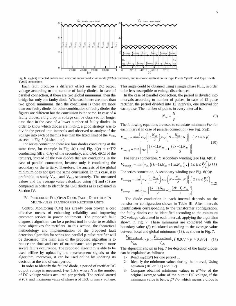
In the case of parallel connection, the period is divided into
intervals according to number of pulses, in case of 12-pulse
rectifier, the period divided into 12 intervals, one interval for
each pulse. The number of points in every interval is:
int
NN
p , (9)
The following equations are used to calculate minimum VDC for
each interval in case of parallel connection (see Fig. 6(a)):
int intmin DC DC1
int intmin DC
min 1: , : , 22 2
1 . 2 1 .min 1: .
2 2k
N NV v v N N k p
k N k NV v
(10)
For series connection, Y secondary winding (see Fig. 6(b)):
Ymin DC int intmin 1 . 1: . , 1 .2k
pV v k N k N k (11)
For series connection, ∆ secondary winding (see Fig. 6(b)):
int intmin DC DC1
int intmin DC
min 1: , : , 222 2
1 . 2 1 .min 1: .
2 2k
N N pV v v N N k
k N k NV v
(12)
The diode conduction in each interval depends on the
transformer configuration shown in Table III. After intervals
identification corresponding to the transformer configuration,
the faulty diodes can be identified according to the minimum
DC voltage calculated in each interval, applying the algorithm
shown in Fig. 7. These minimums are compared with the
boundary value (β) calculated according to the average value
between local and global minimums (13), as shown in Fig. 7.
DCminLocal DCminGlobal
DC DC
, 0.977 > > 0.876V V
V V (13)
The algorithm shown in Fig. 7 for detection of the faulty diodes
can be explained as follows:
1- Read vDC(1:N) for one period T.
2- Identify the minimum values during the interval, Using
equation (10) or (11) and (12).
3- Compare obtained minimum values to β*VDC of the
original average value of the output DC voltage, if the
minimum value is below β*VDC which means a diode is
0 2T/10 4T/10 6T/10 8T/10 T0
10
20
30VDC Parallel connection (V)
(a)
Ein
t(7
)
Ein
t(5
)
Ein
t(1
1)
Ein
t(9
)
Ein
t(3
)
Ein
t(1
)
Ein
t(8
)
Ein
t(6
)
Ein
t(1
2)
Ein
t(1
0)
Ein
t(4
)
Ein
t(2
)
Ein
t(1
)
00
10
20
30VDC Series connection (V)
2T/10 4T/10 6T/10 8T/10 T(b)
Eint(1Y) Eint(2Y) Eint(3Y) Eint(4Y) Eint(5Y) Eint(6Y)
Eint
(1∆)Eint(6∆)Eint(5∆)Eint(4∆)Eint(3∆)Eint(2∆)
Eint
(1∆)
Fig. 6. vDC(ωt) expected on balanced and continuous conduction mode (CCM) conditions, and interval classification for Type P with Yy6d11 and Type S with
Yy0d5 connections
6
O/C, and index Eint(j) is equal to 1, if not then Eint(j) is
equal to 0, which means there is no fault.
4- Increment j by one and compare it to p. if j is less than p
then returns again to calculate the minimum of the next
interval, if yes continue with the following step.
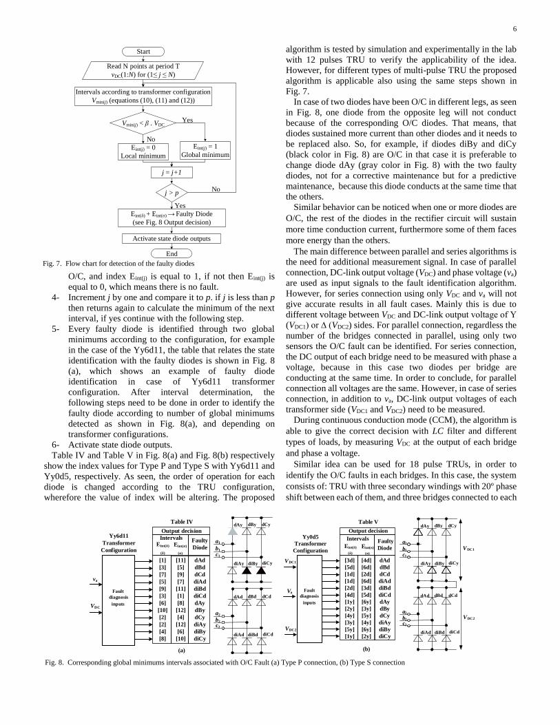
5- Every faulty diode is identified through two global
minimums according to the configuration, for example
in the case of the Yy6d11, the table that relates the state
identification with the faulty diodes is shown in Fig. 8
(a), which shows an example of faulty diode
identification in case of Yy6d11 transformer
configuration. After interval determination, the
following steps need to be done in order to identify the
faulty diode according to number of global minimums
detected as shown in Fig. 8(a), and depending on
transformer configurations.
6- Activate state diode outputs.
Table IV and Table V in Fig. 8(a) and Fig. 8(b) respectively
show the index values for Type P and Type S with Yy6d11 and
Yy0d5, respectively. As seen, the order of operation for each
diode is changed according to the TRU configuration,
wherefore the value of index will be altering. The proposed
algorithm is tested by simulation and experimentally in the lab
with 12 pulses TRU to verify the applicability of the idea.
However, for different types of multi-pulse TRU the proposed
algorithm is applicable also using the same steps shown in
Fig. 7.
In case of two diodes have been O/C in different legs, as seen
in Fig. 8, one diode from the opposite leg will not conduct
because of the corresponding O/C diodes. That means, that
diodes sustained more current than other diodes and it needs to
be replaced also. So, for example, if diodes diBy and diCy
(black color in Fig. 8) are O/C in that case it is preferable to
change diode dAy (gray color in Fig. 8) with the two faulty
diodes, not for a corrective maintenance but for a predictive
maintenance, because this diode conducts at the same time that
the others.
Similar behavior can be noticed when one or more diodes are
O/C, the rest of the diodes in the rectifier circuit will sustain
more time conduction current, furthermore some of them faces
more energy than the others.
The main difference between parallel and series algorithms is
the need for additional measurement signal. In case of parallel
connection, DC-link output voltage (VDC) and phase voltage (va)
are used as input signals to the fault identification algorithm.
However, for series connection using only VDC and va will not
give accurate results in all fault cases. Mainly this is due to
different voltage between VDC and DC-link output voltage of Υ
(VDC1) or ∆ (VDC2) sides. For parallel connection, regardless the
number of the bridges connected in parallel, using only two
sensors the O/C fault can be identified. For series connection,
the DC output of each bridge need to be measured with phase a
voltage, because in this case two diodes per bridge are
conducting at the same time. In order to conclude, for parallel
connection all voltages are the same. However, in case of series
connection, in addition to va, DC-link output voltages of each
transformer side (VDC1 and VDC2) need to be measured.
During continuous conduction mode (CCM), the algorithm is
able to give the correct decision with LC filter and different
types of loads, by measuring VDC at the output of each bridge
and phase a voltage.
Similar idea can be used for 18 pulse TRUs, in order to
identify the O/C faults in each bridges. In this case, the system
consists of: TRU with three secondary windings with 20º phase
shift between each of them, and three bridges connected to each
Intervals according to transformer configuration
Vmin(j) (equations (10), (11) and (12))
Vmin(j) < β . VDC
Start
Eint(δ) + Eint(σ) Faulty Diode
(see Fig. 8 Output decision)
Read N points at period T
vDC(1:N) for (1 j N)
Activate state diode outputs
End
No
Yes
j > p
Eint(j) = 0
Local mínimum
Eint(j) = 1
Global mínimum
Yes
No
j = j+1
Fig. 7. Flow chart for detection of the faulty diodes
va
VDC
Yy6d11
Transformer
Configuration
a1
b1
c1
a2
b2
c2
dAy dBy dCy
diAy diBy diCy
dAd dBd dCd
diAd diBd diCd
[1]
[3]
[7]
[5]
[9]
[3]
[6]
[10]
[2]
[2]
[4]
[8]
Intervals Faulty
Diode
[11]
[5]
[9]
[7]
[11]
[1]
[8]
[12]
[4]
[12]
[6]
[10]
Eint(δ)
(δ)
Eint(σ)
(σ)
dAd
dBd
dCd
diAd
diBd
diCd
dAy
dBy
dCy
diAy
diBy
diCy
Fault
diagnosis
inputs
Output decision
(a)
Table IV
Va
VDC1
Transformer
Configuration
a1
b1
c1
a2
b2
c2
dAy dBy dCy
diAy diBy diCy
dAd dBd dCd
diAd diBd diCd
Intervals Faulty
Diode
dAd
dBd
dCd
diAd
diBd
diCd
dAy
dBy
dCy
diAy
diBy
diCy
VDC2
Fault
diagnosis
inputs
Output decisionYy0d5
Eint(δ)
(δ)
Eint(σ)
(σ)
VDC1
VDC2
[3d] [4d]
[5d] [6d]
[1d] [2d]
[1d] [6d]
[2d] [3d]
[4d] [5d]
[1y] [6y]
[2y] [3y]
[4y] [5y]
[3y] [4y]
[5y] [6y]
[1y] [2y]
Table V
(b)
Fig. 8. Corresponding global minimums intervals associated with O/C Fault (a) Type P connection, (b) Type S connection

7
secondary. The same idea used to construct Table IV and V are
used to build Table VI, as shown in Fig. 9. If dB2 and diB2 are
in O/C fault, the maximums intervals 3 and 6 for dB2, also
intervals 12 and 15 for diB2. In these intervals global
minimums will appear.
The proposed algorithm also identifies S/C faults with
protective fuses. Because fuses normally protect S/C faults,
which will convert S/C to O/C faults.
In addition, during CCM the algorithm is able to give the
correct decision with LC filter and different types of loads.
Fig. 10 shows the working zone is the CCM, which depends on
the configuration of every rectifier and load. If the DC current
is continuous, the proposed strategy works with different types
of loads as shown in Fig. 11, by measuring VDC and va. If the
load impedance is too high, that means the current reduction
will be large, and iDC will be discontinuous, so in this case the
algorithm will not work properly.
V. RESULTS
A. Theoretical Results: Fig. 12 and Fig. 13 show Y and ∆
winding voltages, currents and DC-link output voltage for the
same O/C diode with different transformer configuration, in
case of series and parallel connection, respectively. Different
types of transformer configuration are tested, in order to show
the behavior changes in voltages and currents of Y and Δ
winding connections for series and parallel topologies. Fig. 12
shows the same O/C fault (diAd) for Type S with different
TRUs clock configuration and Fig. 13 shows the same O/C fault
(dBy) for Type P with different TRUs clock configuration. As
seen the conducting intervals will change as the clock
configuration changes, nevertheless, the same behavior is
recognized, and the proposed algorithm can identify the O/C
faults in both cases.
B. Graphical User Interface (GUI): In order to make the
algorithm easier and handful for CM procedure, a graphical
user interface has been developed, in order to satisfy the idea.
The aim of GUI is to be used offline as tool for all possibilities
of transformer configurations with any type of fault and for both
possible topologies. This program can be a useful tool in case
of maintenance procedure for Multi-Pulse Rectifier Units. The
GUI showed in Fig. 14 consists of two main parts, which are
the inputs (parameters, configuration of the system, and signal
upload) and the outputs (decision of the algorithm and plots).
The inputs are: “1” connections (Type P or Type S), “2” line
to line voltages (VL1) and (VL2), frequency, load resistance, “3”
frequency, “4” transformer configuration and “5” faulted
diodes. Another possibility is to upload a measurement signal
of the VDC, in this case, previous inputs will be halted, in this
case “10” which is upload plots and “4” which is the
transformer configuration will be the only inputs.
Z
Y
δ = 20˚
δ = -20˚
LS
Lz
Lz+
-
Idcia3
IA = i’a1 + i’a2
+ i’a3
Z
Yδ = 0˚
Ly ia1
ia2
VC
L
C
Load
Bridge 3
Bridge 1
Bridge 2
va
VDC
Transformer
Configuration a1
b1
c1
a2
b2
c2
dA1 dB1 dC1
diA1 diB1 diC1
dA2 dB2 dC2
diA2 diB2 diC2
[2]
[5]
[8]
[2]
[ 3 ]
[9]
[6]
[3]
Intervals Faulty
Diode
[17]
[8]
[14]
[17]
[5]
[ 6 ]
[ 9 ]
[18]
Eint(δ)
(δ)
Eint(σ)
(σ)
dA1
dB1
dC1
diA1
diB1
diC1
dA2
dB2
dC2
diA2
diB2
diC2
Fault
diagnosis
inputs
Output decision
a3
b3
c3
dA3 dB3 dC3
diA3 diB3 diC3
[1]
[4]
[7]
[1]
[16]
[7]
[16]
dA3
dB3
dC3
diA3
diB3
diC3
[11]
[11]
[14]
[15] [18]
[12]
[12] [15]
[10] [13]
[10]
[13][4]
TRU 18 Pulses
Faultdiagnosis
inputs
Table VI
1.74
1.62
1.7
1.66
0 T/2 T
VDC
[12] [15][ 3 ] [ 6 ]
Fig. 9 Corresponding global minimums intervals associated with O/C Fault for 18 pulse TRUs for Type P connection with Yy6d11 transformer connection
Thermal
protection
zone
Magnetic
protection
zone
Dis
conti
nou
s
Cond
uct
ion
Mode
Continous
Conduction
Mode
(working zone)
iDC (pu)
vDC (pu)
1
1.1 >3 Fig. 10 Different region on ‘DC voltage from the load DC current’ curve
δ = 0˚
δ = 30
LS
Ld
Ly+
-
iay
iad
IA = i’ay + i’ad
LO
AD
VD
C
RLC
Continous IDC
LC
Fil
ter
Fig. 11 Twelve pulses Type P with different types of loads and LC filter

8
The outputs are: “6” decision and fault indicators (black and
gray stands for healthy and faulty diode, respectively), , “7”
plots for primary current, current at Y connection, current at ∆
connection and DC-link output voltage, also, choose harmonics
to be represented and “8” run the algorithm.
C. Experimental Results:
1) Offline Study
In this case GUI has been used to identify the O/C faults
using “10” to upload experimental data for one period to the
algorithm which will be the only input for the algorithm in this
case, with the transformer connection “4”, and the bridge
connection (Type P or Type S) “1”. This is a good tool for CM
to show the reliability of the algorithm.
2) Online Study
In order to verify the theoretical results, an experimental
setup is built in the laboratory with the parameters shown in
Table VII. Fig. 15 shows LAB experimental setup. Three
windings transformer 8000VA, 50/60 Hz is used in validation,
with three-phase supply. The transformer has the flexibility to
be connected either star or delta in the three windings. The
online study is based on using dSPACE 1104 in order to
implement the proposed algorithms using MATLABTM-
Simulink. During one period 120 samples are read, and at the
end of each period the algorithm updates its decision. Fig. 16
shows the online detection of diAy for Type P with Dy11d0
configuration, as seen the algorithm is able to identify the global
minimums in each period in order to update its decision.
In order to verify the ability of the algorithm to identify the
faulty diode with different types of connections, Fig. 17(a)
compares between experimental and theoretical results for Type
P with O/C fault at dCd with Yy6d5 configuration. Fig. 17(b)
compares between experimental and theoretical results for Type
P with O/C fault at dAd with Dy11d6 configuration
respectively. In addition, Fig. 17(c) and Fig. 17(d) compare
between experimental and theoretical results for Type S with
0 0.01 0.02-20
0
20Voltage Y
0 0.01 0.02-20
0
20Voltage ∆
0 0.01 0.02-5
0
5Currents of fase Y
0 0.01 0.020
50
100DC voltage with Yy0d11 (V)
0 0.01 0.02-5
0
5Currents of fase ∆
0 0.01 0.02-5
0
5Primary current
(a) diAd with Yy0d11 transformer configuration
0 0.01 0.02-20
0
20Voltage Y
0 0.01 0.02-20
0
20Voltage ∆
0 0.01 0.02-5
0
5Currents of fase Y
0 0.01 0.020
50
100DC voltage with Yy6d5 (V)
0 0.01 0.02-5
0
5Currents of fase ∆
0 0.01 0.02-5
0
5Primary current
(b) diAd with Yy6d5 transformer configuration
Fig. 12 Y and ∆ winding voltages, currents and DC-link output voltage for the same O/C diode (diAd) with different transformer configuration for Type
S connection
-20
0
20Voltage Y (V)
-20
0
20Voltage ∆ (V)
-20
0
20
40DC voltage with Yy0d11 (V)
-2
0
2Currents of fase Y (A)
-2
0
2Currents of fase ∆ (A)
0.004 0.012 0.02-1
0
1Primary Currents (A)
0.004 0.012 0.020.004 0.012 0.02
0.004 0.012 0.020.004 0.012 0.02
0.004 0.012 0.02
(a) dBy with Yy0d11 transformer configuration
-20
0
20Voltage Y (V)
-20
0
20Voltage ∆ (V)
-20
0
20
40DC voltage with Yy6d11(V)
-2
0
2 Currents of fase Y (A)
-2
0
2Currents of fase ∆ (A)
-1
0
1Primary Currents (A)
0.004 0.012 0.020.004 0.012 0.020.004 0.012 0.02
0.004 0.012 0.02 0.004 0.012 0.020.004 0.012 0.02
(b) dBy with Yy6d11 transformer configuration
Fig. 13 Y and ∆ winding voltages, currents and DC-link output voltage for
the same O/C diode (dBy) with different transformer configuration for Type
P connection
Fig. 14 GUI inputs and outputs
Multi-winding
Transformer
Smart AC
source
12 pulse bridge
rectifier
Voltage and
current sensors
Fig. 15 Experimental setup
Fig. 16 Online detection using dSPACE

9
O/C fault at dBy with Yy0d5 configuration and at dCy and diCy
with Yy6d5 configuration, respectively. As shown in Fig. 17,
the local minimum between the bridge connected to Y and
changed to the bridge connected to Δ is different from the local
minimum between bridges connected to Δ and Y due to the
change in the leakage inductance difference [29]. However, the
global minimum is less than these changes and the proposed
algorithm is able to identify the local minimums in both
experimental and theoretical, as shown in (13). Fig. 17 shows
that the results which prove the good behaviour of the proposed
algorithm to identify the faulty diode correctly. The influence
of PF in DC voltage is shown in Fig. 18(a), (b) and (c), where
several capacitors are used in order to check the proposed
strategy in CCM. Furthermore, the proposed strategy is tested
in the LAB using several filters. Fig. 18(d) shows the DC
voltage of 12 pulse TRU for Type P connecting an LC filter as
it is shown in Fig.11 considering an O/C fault at dCd with
Yy6d5 configuration.
VI. CONCLUSION
This paper proposes a fault detection algorithm for three-
phase diode rectifier unit using theoretical analysis of DC-link
output voltage. The algorithm has been proposed to diagnose
O/C faults with protective fuses in uncontrolled three-phase
rectifiers using measurements of only the first phase voltage of
the primary and the output DC-link output voltage in case of
Type P connection. However, for Type S connection, or Type
P connection with interphase transformer, the DC output
voltage of each bridge need to be measured with the first phase
voltage of the primary. During fault condition, the calculation
of global minimums is obtained using interval calculation.
Then, according to transformer configuration, the faulty diodes
are identified. The proposed algorithm identifies the O/C fault
at the end of every period, however as shown in Table I other
strategies need more than a period. The algorithm is tested for
both series and parallel topologies. This algorithm does not
need to consider the load condition, because the voltages
measured at the output of each bridge. The methodology has
been modelled and verified theoretically and experimentally.
The proposed algorithm is able to identify all fault classes for
series and parallel topologies, which can be a key factor for
maintenance procedure of multi-pulse rectifier with three phase
inputs.
50
70
90
110
ExperimentaldBy
TheoreticaldBy
DC
volt
age
(V)
0
50
70
90
110dCy diCy
0 0.005 0.01 0.015 0.02
dCy diCy
0.005 0.01 0.015 0.02
DC
vo
ltag
e (V
)
Time (s) Time (s)
(c)
(d)
dCdTheoriticalExperimental
Time (s)
DC
vo
ltag
e (V
)D
C v
olt
age
(V)
24
26
28
30
dCd
24
26
28
30
dAd
Time (s)
dAd
0 0.004 0.008 0.012 0.016 0.02
(b)
(a)
0 0.004 0.008 0.012 0.016 0.02
Fig. 17 DC voltage of 12 pulse TRU in case of (a) Type P connection with fault at dCd with Yy6d5 configuration, (b) Type P connection with fault at dAd with
Dy11d6 configuration, (c) Type S connection with fault at dBy with Yy0d5 configuration (d) Type S connection with fault at dCy and diCy with Yy6d5
configuration
022
26
30
022
26
30
022
26
30
022
26
30
Time (s)
DC
volt
age
Time (s)
DC
volt
age
Time (s)
DC
volt
age
Time (s)
DC
volt
age
0.01 0.02 0.01 0.020.01 0.020.01 0.02
(a) (b) (c) (d) Fig. 18 DC voltage of 12 pulse TRU for Type P with different P.F. a) C=4uF, b) C=8uF, C) C=30uF and d) C=30uF, L=9.78mH
TABLE VII
System parameters Transformer Parameters
Power 8000 VA
Input voltage 230~400 V
Output voltage S1/ 230V(D)-400V(Y) “4 KVA”
Frequency 50/60 Hz
Connection group (D/Y) d/y d/y
Three-phase Pacific Smart SourceTM model 345-AMX
Power 4.5-kVA
Input voltage maximum line-to-line voltage of 468 V
Bridge
Diodes SemikronTM model SKKD 46/16
Loads and LC filter
Resistor 10 ~ 42 Ω
Capacitor 4 ~ 120 uF
Inductor 10 mH

10
Moreover, the simplicity of the proposed algorithm is a key
point, as only two signals are needed in order to identify the
faulted device. Using the proposed algorithm will gain many
benefit to not only corrective maintenance but also related to
predictive maintenance.
For the experimental results, the impedances of the secondary
and tertiary windings of the transformer presents unbalance
impedances, which cause small asymmetry in the DC output
voltage of the bridges. Nevertheless, the proposed algorithm
can identify the O/C fault in these cases.
In the future, these signatures can be used to identify the
faulty diodes using artificial intelligent techniques. In addition,
the possibility to combine more than one technique for fault
detection (global minimum, harmonics, continuity … etc.) in
one algorithm, can be an excellent solution for more reliable
system.
VII. ACKNOWLEDGMENT
The work presented in this paper is part of the research
project: Estabilidad de redes mvdc integrando tecnologias de
energias renovables, almacenamiento de energia y
convertidores de fuente de impedancia, (RTI2018-095720-B-
C33), funded by the Ministerio de ciencia, innovación y
universidades and European Union.
VIII. REFERENCES
[1] B. Singh, S. Gairola, B. N. Singh, A. Chandra and K. Al-Haddad,
"Multipulse AC–DC Converters for Improving Power Quality: A Review," in IEEE Transactions on Power Electronics, vol. 23, no. 1,
pp. 260-281, Jan. 2008.
[2] B. Singh, G. K. Kasal and S. Gairola, "Power Quality Improvement in Conventional Electronic Load Controller for an Isolated Power
Generation," in IEEE Transactions on Energy Conversion, vol. 23,
no. 3, pp. 764-773, Sept. 2008. [3] A. Baghramian, A. Cross and A. Forsyth, "Interactions within
heterogeneous systems of uncontrolled rectifiers for aircraft electrical
power systems," in IET Electrical Systems in Transportation, vol. 1, no. 1, pp. 49-60, March 2011.
[4] A. Cross, A. Baghramian and A. Forsyth, "Approximate, average,
dynamic models of uncontrolled rectifiers for aircraft applications," in IET Power Electronics, vol. 2, no. 4, pp. 398-409, July 2009.
[5] Yii-Shen Tzeng, Nanming Chen and Ruay-Nan Wu, "Modes of
operation in parallel-connected 12-pulse uncontrolled bridge rectifiers without an interphase transformer," in IEEE Transactions
on Industrial Electronics, vol. 44, no. 3, pp. 344-355, June 1997.
[6] C. Shu, L. Wei, D. Rong-Jun and C. Te-Fang, "Fault Diagnosis and Fault-Tolerant Control Scheme for Open-Circuit Faults in Three-
Stepped Bridge Converters," in IEEE Transactions on Power
Electronics, vol. 32, no. 3, pp. 2203-2214, March 2017. [7] H. Akagi, "Large static converters for industry and utility
applications," in Proceedings of the IEEE, vol. 89, no. 6, pp. 976-983,
June 2001.
[8] B. Singh and S. Gairola, "A 28-pulse AC-DC converter for line
current harmonic reduction," in IET Power Electronics, vol. 1, no. 2,
pp. 287-295, June 2008. [9] A. D. Gerlando, G. M. Foglia, M. F. Iacchetti and R. Perini,
"Comprehensive steady-state analytical model of a three-phase diode
rectifier connected to a constant DC voltage source," in IET Power Electronics, vol. 6, no. 9, pp. 1927-1938, November 2013.
[10] B. Singh and S. Gairola, "Pulse Doubling in 18-Pulse AC-DC
Converters," 2007 7th International Conference on Power Electronics and Drive Systems, Bangkok, 2007, pp. 533-539.
[11] B. Singh and S. Gairola, "A 44-Pulse AC-DC Converter Based on
Hybrid of Multiphase and Phase Shifting Techniques," 2008 Joint International Conference on Power System Technology and IEEE
Power India Conference, New Delhi, 2008, pp. 1-6.
[12] Sewan Choi, Junyong Oh, Kiyong Kim and Junggoo Cho, "A new 24-pulse diode rectifier for high voltage and high power
applications," 30th Annual IEEE Power Electronics Specialists
Conference. Record. (Cat. No.99CH36321), Charleston, SC, USA, 1999, pp. 169-174.
[13] S. Ebrahimi, N. Amiri, L. Wang and J. Jatskevich, "Efficient
Modeling of Six-Phase PM Synchronous Machine-Rectifier Systems in State-Variable-Based Simulation Programs," in IEEE
Transactions on Energy Conversion, vol. 33, no. 3, pp. 1557-1570,
Sept. 2018. [14] A. Stevenson, Power converter handbook: Theory, design,
application, 1st ed., Bailieboro, Canada, UYK Technologies, 2004.
[15] G. Mahmoud, M. Masoud and I. El-Arabawy, "Rectifier Faults In Variable Voltage Variable Frequency Induction Motor Drives," 2007
IEEE International Electric Machines & Drives Conference,
Antalya, 2007, pp. 1125-1130. [16] M. Rahnama, A. Vahedi, A. M. Alikhani, N. Takorabet and B.
Fazelbakhsheshi, "A novel diode open circuit fault detection in three
phase rectifier based on k-means method," 2018 IEEE International Conference on Industrial Technology (ICIT), Lyon, 2018, pp. 600-
605.
[17] S. Jordan, C. D. Manolopoulos and J. M. Apsley, "Winding Configurations for Five-Phase Synchronous Generators With Diode
Rectifiers," in IEEE Transactions on Industrial Electronics, vol. 63,
no. 1, pp. 517-525, Jan. 2016. [18] N. E. A. M. Hassanain and J. E. Fletcher, "Steady-state performance
assessment of three- and five-phase permanent magnet generators
connected to a diode bridge rectifier under open-circuit faults," in IET Renewable Power Generation, vol. 4, no. 5, pp. 420-427, September
2010. [19] G. Seguier, Power Electronics Converters. AC-DC conversion, 4th
ed. Mexico: McGraw-Hill, 1986.
[20] M. Rahiminejad, C. Diduch, M. Stevenson and L. Chang, "Open-circuit fault diagnosis in 3-phase uncontrolled rectifiers," 2012 3rd
IEEE International Symposium on Power Electronics for Distributed
Generation Systems (PEDG), Aalborg, 2012, pp. 254-259. [21] J. Lee, S. Baek, K. Cho, H. Kim and Jaeho-Choi, "Fault detection of
three phase diode rectifier based on harmonic ratio of DC-link voltage
ripples," 2017 IEEE 12th International Conference on Power Electronics and Drive Systems (PEDS), Honolulu, HI, 2017, pp. 386-
391.
[22] P. Duan, K. Xie, L. Zhang and X. Rong, "Open-switch fault diagnosis and system reconfiguration of doubly fed wind power converter used
in a microgrid," in IEEE Transactions on Power Electronics, vol. 26,
no. 3, pp. 816-821, March 2011. [23] P. Han et al., "Fault Diagnosis and System Reconfiguration Strategy
of a Single-Phase Three-Level Neutral-Point-Clamped Cascaded
Inverter," in IEEE Transactions on Industry Applications, vol. 55, no. 4, pp. 3863-3876, July-Aug. 2019.
[24] Z. Huang, Z. Wang and H. Zhang, "A Diagnosis Algorithm for
Multiple Open-Circuited Faults of Microgrid Inverters Based on Main Fault Component Analysis," in IEEE Transactions on Energy
Conversion, vol. 33, no. 3, pp. 925-937, Sept. 2018.
[25] T. Kamel, Y. Biletskiy and L. Chang, "Fault Diagnoses for Industrial Grid-Connected Converters in the Power Distribution Systems," in
IEEE Transactions on Industrial Electronics, vol. 62, no. 10, pp.
6496-6507, Oct. 2015. [26] T. Kamel, Y. Biletskiy and L. Chang, "Real-Time Diagnosis for
Open-Circuited and Unbalance Faults in Electronic Converters
Connected to Residential Wind Systems," in IEEE Transactions on Industrial Electronics, vol. 63, no. 3, pp. 1781-1792, March 2016.
[27] R. Sabir, D. Rosato, S. Hartmann and C. Gühmann, "Detection and
Localization of Electrical Faults in a Three Phase Synchronous Generator with Rectifier," 2019 International Conference on
Electrical Drives & Power Electronics (EDPE), The High Tatras,
Slovakia, 2019, pp. 18-23. [28] T. Shi, Y. He, T. Wang and B. Li, "Open Switch Fault Diagnosis
Method for PWM Voltage Source Rectifier Based on Deep Learning
Approach," in IEEE Access, vol. 7, pp. 66595-66608, 2019. [29] B. Wu, High-Power Converters and AC Drives, 2nd ed. Hoboken,
New Jersey: IEEE Press., 2006.