date filed: december 9, 2016 filed on behalf of: medtronic...
TRANSCRIPT

Paper No. _________ Date Filed: December 9, 2016
Filed on behalf of: Medtronic Xomed, Inc.
UNITED STATES PATENT AND TRADEMARK OFFICE ____________
BEFORE THE PATENT TRIAL AND APPEAL BOARD
_____________
Medtronic Xomed, Inc. Petitioner
v. Neurovision Medical Products, Inc.
Patent Owner _____________
Case IPR2017-00456 U.S. Patent 8,634,894
_____________
PETITION FOR INTER PARTES REVIEW UNDER 35 U.S.C. §§311-319 AND 37 C.F.R. §42

i
TABLE OF CONTENTS
Table of Contents
I. MANDATORY NOTICES UNDER 37 C.F.R. § 42.8(a)(1) .......................... 1
A. Real Party-in-Interest Under 37 C.F.R. § 42.8(b)(1) ............................ 1
B. Related Matters Under 37 C.F.R. § 42.8(b)(2) ..................................... 1
C. Lead and Back-Up Counsel Under 37 C.F.R. § 42.8(b)(3) .................. 1
D. Service Information Under 37 C.F.R. § 42.8(b)(4) ............................... 2
II. PAYMENT OF FEES UNDER 37 C.F.R. § 42.103 ....................................... 2
III. REQUIREMENTS UNDER 37 C.F.R. § 42.104 ............................................ 2
A. Grounds for Standing Under 37 C.F.R. § 42.104(a) ............................. 2
B. Challenge Under 37 C.F.R. § 42.104(b) and Relief Requested .............................................................................................. 2
C. Statement Addressing 35 U.S.C. § 325(d) ............................................ 3
D. Claim Construction under 37 C.F.R. § 42.104(b)(3) ............................ 9
IV. SUMMARY OF THE ’894 PATENT ............................................................. 9
A. The Background of the Technology ...................................................... 9
B. The Claimed Subject Matter ............................................................... 19
C. Prosecution History ............................................................................. 20
V. ARGUMENTS .............................................................................................. 21
A. Statement of the Law ........................................................................... 21
1. Obviousness .............................................................................. 21
B. Grounds of Unpatentability ................................................................. 22
1. Ground 1: Claims 4, 6 and 7 are Obvious in View of Goldstone and Cook ............................................................. 22

ii
2. Ground 2: Claims 4, 6 and 7 are Obvious in View of Lowery and Goldstone .......................................................... 30
3. Ground 3: Claims 4, 6 and 7 are Obvious in View of Goldstone, Cook and MicroPen® ........................................ 43
4. Ground 4: Claims 4, 6 and 7 are Obvious in View of Lowery, Goldstone and MicroPen® ..................................... 45
5. Ground 5: Claims 6, 7 and 9 are Obvious in View of Goldstone, Cook and Tekra .................................................. 46
6. Ground 6: Claims 6, 7 and 9 are Obvious in View of Goldstone, Cook, MicroPen® and Tekra ............................ 48
VI. Conclusion ..................................................................................................... 49

- iii -
EXHIBITS
1001 ― U.S. Patent No. 8,634,894, issued January 21, 2014 (the “’894 patent”)
1002 ― U.S. Pub. 2009-0227885, published September 10, 2009 (“Lowery”)
1003 ― U.S. Patent No. 5,024,228, issued June 18, 1991 (“Goldstone”)
1004 ― U.S. Patent No. 4,890,623, issued June 2, 1990 (“Cook”)
1005 ― “Direct writing technology – Advances and developments,” Hon, et al.,
CIRP Annals – Manufacturing Technology, Volume 57, Issue 2, pp. 601-
620 (2008) (“Hon”)
1006 ― “Continuous ink-jet printing electronic components using novel
conductive inks,” Mei et al., Fifteenth Solid Freeform Fabrication (SFF)
Symposium held at The University of Texas in Austin on August 2-4,
2004 (“Mei”)
1007 ― RESERVED
1008 ― ConMed, “ECOM – Endotracheal Cardiac Output Monitor” brochure,
published 2008 (“ECOM brochure”)
1009 ― Declaration of Dr. Andrew Goldstone (“Dec. Goldstone”)
1010 ― Response to Office Action, dated October 25, 2013, in prosecution file
history of the ’894 patent (“10/25/13 ROA”)
1011 ― U.S. Provisional App. 61/244,402 (“Rea”)
1012 ― Declaration of Guy Lowery (“Dec. Lowery”)

iv
1013 ― RESERVED
1014 ― “Intraoperative Facial Nerve Monitoring,” Kartush et al., Chapt. 5,
Neuromonitoring in Otology and Head and Neck Surgery, Raven Press,
Ltd., p. 99-120 (1992) (“Kartush Article”)
1015 ― Infringement Contentions, Exhibit A, Neurovision Medical Products, Inc.
v. Medtronic PLC, 2:16-CV-00127 (“Infringement Contentions”)
1016 ― RESERVED
1017 ― RESERVED
1018 ― “Quantitative Estimation of the Recurrent Laryngeal Nerve Irritation by
Employing Spontaneous Intraoperative Electromyographic Monitoring
During Anterior Cervical Discectomy and Fusion,” Dimopoulos et al., J.
Spinal Disorder Tech, Vol. 22, No. 1, pp. 1-7 (February 2009)
(“Dimopoulos Article”)
1019 ― RESERVED
1020 ― Gray’s Anatomy, Churchill Livingstone, pp. 1637-1657 (1995)
1021 ― RESERVED
1022 ― RESERVED
1023 ― RESERVED
1024 ― RESERVED
1025 ― U.S. Patent No. 6,292,689, issued September 18, 2001 (“Wallace”)

v
1026 ― RESERVED
1027 ― “Intraoperative Monitoring of Lower Cranial Nerves in Skull Base
Surgery: Technical Report and Review of 123 Monitored Cases,”
Topsakal et al., Neurosurg. Rev., Vol. 31, pp. 45-52 (2008)
1028 ― Clinical Neurophysiology 3rd Ed., Oxford University Press, Chapts. 25, 43
and 44 (2009)
1029 ― Office Action, dated October 31, 2013, in prosecution file history of the
’894 patent
1030 ― Webster’s Third New International Dictionary, Merriam-Webster, Inc., p.
1621 (1993)
1031 ― Supplemental Declaration of Dr. Andrew Goldstone
1032 ― Supplemental Declaration of Guy Lowery
1033 ― Office Action, dated September 27, 2013, in prosecution file history of the
’894 patent
1034 ― Preliminary Disclosure of Asserted Claims and Infringement Contentions,
Neurovision Medical Products, Inc. v. Medtronic PLC, 2:16-CV-00127
(April 15, 2016)
1035 ― MicroPen® website, Internet Archive, September 5, 2008 (“MicroPen®”)
1036 ― Tekra website, Internet Archive, November 19, 2006 (“Tekra”)
1037 ― A copy of Exhibit 2017 from IPR2016-01405 and IPR2016-01406

vi
1038 ― Information Disclosure Statement, dated June 3, 2013, in prosecution file
history of the ’894 patent

- 1 -
Medtronic Xomed petitions for Inter Partes Review (“IPR”) under 35
U.S.C. §§ 311-319 and 37 C.F.R. § 42 of claims 4, 6, 7 and 9 of U.S. Patent No.
8,634,894 (“’894 patent”) (Ex 1001). For the reasons set forth below, there is a
reasonable likelihood of finding those claims unpatentable.
I. MANDATORY NOTICES UNDER 37 C.F.R. § 42.8(a)(1)
A. Real Party-in-Interest Under 37 C.F.R. § 42.8(b)(1)
Medtronic Xomed, Inc. (“Petitioner”), Medtronic, Inc., and Medtronic PLC
are the real parties-in-interest.
B. Related Matters Under 37 C.F.R. § 42.8(b)(2)
Petitioner is a named defendant in a patent infringement litigation involving
the ’894 patent (currently case No. 2:16-CV-00127 in the Eastern District of
Texas). The ’894 patent was previously challenged in IPR2015-00502, brought by
a different and independent petitioner, which terminated upon settlement. In
addition, the present Petitioner previously filed separate IPR petitions against the
same patent (IPR2016-01405 and IPR2016-01406). Submitted herewith is a
motion to join this case with those pending IPRs.
C. Lead and Back-Up Counsel Under 37 C.F.R. § 42.8(b)(3)
LEAD COUNSEL BACK-UP COUNSEL Justin J. Oliver, Reg. No. 44,986
Fitzpatrick, Cella, Harper & Scinto
975 F Street, NW Fourth Floor
Jason Dorsky, Reg. No. 64,710
Fitzpatrick, Cella, Harper & Scinto
975 F Street, NW Fourth Floor

2
Washington, D.C. 20004
(202) 530-1010 (o)/(202) 530-1055 (f)
Washington, D.C. 20004
(202) 530-1010 (o)/(202) 530-1055 (f)
D. Service Information Under 37 C.F.R. § 42.8(b)(4)
Petitioner consents to service by email at [email protected].
II. PAYMENT OF FEES UNDER 37 C.F.R. § 42.103
The USPTO may charge Deposit Account No. 50-3939 for any fees
associated with the present petition (referencing docket number 03190.008800.2).
III. REQUIREMENTS UNDER 37 C.F.R. § 42.104
A. Grounds for Standing Under 37 C.F.R. § 42.104(a)
Petitioner certifies that the ’894 patent is eligible for IPR and that Petitioner
is not barred or estopped from requesting IPR. This Petition is filed within one
year of service of the above-identified infringement complaint against Petitioner.
B. Challenge Under 37 C.F.R. § 42.104(b) and Relief Requested
Petitioner requests (i) review of claims 4, 6, 7 and 9 of the ’894 patent on the
grounds set forth below and (ii) that each of those claims be found unpatentable.
Ground Claim(s) Basis for Unpatentability
1 4, 6 and 7 Obvious (§103) in view of Goldstone and Cook
2 4, 6 and 7 Obvious (§103) in view of Lowery and Goldstone
3 4, 6 and 7 Obvious (§103) in view of Goldstone, Cook and
MicroPen®

3
4 4, 6 and 7 Obvious (§103) in view of Lowery, Goldstone and
MicroPen®
5 6, 7 and 9 Obvious (§103) in view of Goldstone, Cook and
Tekra©
6 6, 7 and 9 Obvious (§103) in view of Goldstone, Cook,
MicroPen® and Tekra
C. Statement Addressing 35 U.S.C. § 325(d)
Grounds 1 and 2
The references applied for instance, in Grounds 1 and 2 were first applied by
a different petitioner, albeit in combination with an additional reference, in a prior
IPR against the ’894 patent (IPR2015-00502). In that prior IPR, the Board
instituted review of claims 4, 6-11. The prior Board Decision declined to preclude
institution under § 325(d) based on the record during prosecution. IPR2015-
00502, Decision (Paper No. 15) at 6-8 (P.T.A.B. July 16, 2015). That proceeding
settled and was terminated before a final decision issued.
Goldstone, Cook, and Lowery are also being applied in pending IPRs by the
present Petitioner (IPR2016-01405 and IPR2016-01406). There has been no
decision on institution for those IPRs and Petitioner seeks to join the current
grounds with those cases. Petitioner submits that the grounds presented herein

4
should not be precluded under § 325(d) or applicable Board precedent in view of
the pending IPRs or the prosecution record.
To begin, Patent Owner argued during prosecution that all of the
independent claims require one electrode to contact the vocal cords and another to
contact the trachea. Ex. 1010, p. 11. The claims were deemed allowable based on
that argument. Ex. 1033. However, unlike other independent claims, independent
claim 4 does not recite an electrode positioned to contact the trachea. Thus, the
references asserted herein are being applied in a new light not appreciated during
prosecution. See Oracle Corporation v. Clouding IP, LLC, IPR2013-00100, Paper
No. 8, pp. 20-21 (PTAB May 16, 2013) (granting a petition where new arguments
and evidence were presented that shed a different light on references previously
considered).
Moreover, this Petition will not burden the Board’s finite resources
inasmuch as, at least, it is being filed soon enough that it can be consolidated with
the IPR2016-01405 and/or IPR2016-01406, should either or both of those IPRs be
instituted (a Motion for Joinder accompanies this Petition). Furthermore, the
primary declarations submitted herewith are copies of those submitted in the earlier
IPRs, which makes consolidation of the deposition schedule simple and cost
effective for all involved. Patent Owner is not prejudiced inasmuch as the basis for
the combinations and application of the references is not substantively different

5
than that already raised in the prior petitions. In fact, Grounds 1 and 2 do not raise
new prior art, but merely remove one reference that Patent Owner has sought to
swear behind based on an earlier conception argument first raised in its
Preliminary Responses in IPR2016-01405 and IPR2016-01406.
That argument relies on a non-public provisional application that was
previously abandoned and evidence not initially identified in associated litigation.
In the associated litigation, prior to the filing of the pending IPRs, Patent Owner
identified a conception date of September 21, 2009, and produced 6 pages of
documents alleged to relate to conception and reduction to practice. Ex. 1034, pp.
4 and 6. With its Preliminary Responses in IPR2016-01405 and IPR2016-01406,
Patent Owner has now submitted 140 pages of documents it alleges relate to an
earlier invention and claims an undefined reduction to practice date alleged to be
some time in the fall of 2008. Ex. 1037 (Patent Owner’s Ex. 2017); see IPR2016-
01406, Patentee Preliminary Response at pp. 24-25, 31-49 (October 30, 2016).
Thus, Petitioner had no reason to know about the alleged evidence of earlier
invention and this filing is the result of Patent Owner’s holding such evidence back
during trial.
With respect to claims 4, 6 and 7, the reference being removed relative to the
pending IPRs is not absolutely necessary for those claims and was applied against
all of the claims in the prior petitions to maintain consistency in the proceedings

6
(although other grounds herein replace that reference to provide an even stronger
case for obviousness). The present Petition further simplifies the issues with
respect to those claims, does not strain the resources of the Board or Patent Owner,
and was prompted by information only recently submitted by Patent Owner in the
pending IPRs.
Grounds 3 and 4
Grounds 3 and 4 rely on the same base combinations as Grounds 1 and 2,
but further combine published webpages from the MicroPen® website, dated
September 5, 2008 (Ex. 1035). Petitioner asserts that these grounds should not be
precluded under § 325(d) for many of the same reasons discussed above with
respect to Grounds 1 and 2. The further reliance on the MicroPen® web pages
should not be precluded for the following additional reasons.
While Patent Owner cited pages of the MicroPen® website during
prosecution, the Patent Owner indicated that the pages were dated in 2010—after
the claimed priority date. Ex. 1038, p. 3. The only logical inference that can be
made from those facts is that the Examiner did not believe the material to be prior
art.
Additionally, in the pending proceedings (IPR2016-01405 and IPR2016-
01406), Patent Owner submitted evidence alleging an earlier invention date in an
effort to swear behind the Hon reference. Hon discusses MicroPen® printing on

7
medical tubes. The evidence relied upon to swear behind Hon includes emails that
establish that at least one of the inventors was aware of the publication (and
relevance) of the materials in the MicroPen® website at least as early as 2008. Ex.
1037, p. 19. The production of those emails in the pending proceedings led
Petitioner to uncover, through an Internet archive resource, the MicroPen®
publication applied in Grounds 3 and 4, which is prior art under 35 U.S.C. §
102(b). Thus, the information the inventors identified during prosecution as being
dated in 2010 actually published in 2008. This certainly presents the information
in a new light.
Prior to the Preliminary Responses in IPR2016-01405 and IPR2016-01406,
Petitioner was not aware of the relevant date of the publication on the MircoPen®
website (although it was aware of MicroPen®). Further, identification of the
MicroPen® prior art publication was frustrated by Patent Owner’s representation
during prosecution that the MicroPen® information related to printing on catheters
published in 2010, despite an inventor knowing otherwise. Thus, the policy
considerations and factors identified in Nvidia Corp. v. Samsung Elecs. Co. should
not preclude institution of these grounds in view of the pending IPRs, particularly
given Patent Owner’s role in the late identification of this information. IPR2016-
00134, Paper 9, at 6, 12 (P.T.A.B. May 4, 2016).
8
The present petition establishes that claims 4, 6 and 7 remain unpatenable
over the identified prior art even if Patent Owner successfully swears behind
Hon—an attempt that Petitioner vigorously contests, but which was unforeseeable
in view of the non-public status of the prior provisional application, positions taken
by the Patent Owner in IPR2015-00502, statements made during prosecution, and
statements initially made by Patent Owner in the litigation concerning documents
relating to the alleged reduction to practice.
Grounds 5 and 6
Grounds 5 and 6 rely on the same base combinations as Grounds 1 and 3,
but further combine published webpages from the Tekra website, dated November
19, 2006 (Ex. 1036). Petitioner asserts that these grounds should not be precluded
under § 325(d) for many of the same reasons discussed above.
In particular, Petitioner learned of the Tekra website from Patent Owner’s
alleged evidence of diligence in attempting to antedate Hon. The submitted
evidence includes an email to one of the inventors in July 7, 2009 (before the
claimed priority date), which identifies a page from Tekra’s published website
containing information regarding conductive inks for printing flexible electrodes.
Ex. 1037, p. 126. However, this published information was never cited during
prosecution.

9
Petitioner was not aware of the Tekra publication prior to the Patent Owner
providing information concerning the same in its attempt to swear behind Hon.
Thus, Petitioner should not be precluded from relying upon this information for the
same reasons discussed above.
This new Petition is being filed within a short period of learning of this
relevant information. In fact, Exhibit 1037 (the alleged diligence evidence from
the pending IPRs), which led to MicroPen® and Tekra, was only provided by
Patent Owner in a redacted form that could be used herein on November 23, 2016.
Further, the grounds presented herein are not redundant in view of the grounds in
IPR2016-01405 and IPR2016-01406, inasmuch as MicroPen® and Tekra are not
susceptible to any attempt to swear behind (unlike Hon).
D. Claim Construction under 37 C.F.R. § 42.104(b)(3)
Petitioner asserts that the application of the prior art in the manner set forth
below does not rest on any particular construction of the terms of claims 4, 6, 7, or
9.
IV. SUMMARY OF THE ’894 PATENT
A. The Background of the Technology
The ’894 patent is directed to endotracheal tubes, which “are commonly
used during anesthesia and intensive care in order to support respiration of a
human patient who may be unable to breathe without the use of mechanical

10
breathing support devices.” Ex. 1001, 1:12-15. In particular, the patent is directed
to the incorporation of electrodes on an endotracheal tube. As acknowledged in
the ’894 patent, electrodes on endotracheal tubes “are currently used in various
surgical procedures to provide monitoring of the electromyographic signals from
the muscles of the vocal cords, or larynx.” Ex. 1001, 1:19-23.
Endotracheal tubes have long been used during surgeries, intensive care
situations, and medical emergencies to ventilate a patient’s lungs. Ex. 1003, 1:32-
40; 4:29-35. These tubes are inserted into a patient’s trachea, typically through the
mouth, through a process called intubation. Ex. 1009, ¶¶ 27, 34-38; Ex. 1012, ¶¶
32-33. Endotracheal tubes are typically secured in position using an inflatable
cuff/balloon that is inflated once the tube is in the trachea. Ex. 1002, ¶ [0025]; Ex.
1020, Fig. 11.25 and pp. 1653-1657. An example of Goldstone’s endotracheal
tube 10 with an inflated cuff 13 (left) is shown below next to the tube from the
’894 patent (right).

11
Ex. 1003, Fig. 6 (electrodes 43) Ex. 1001, Fig 6 (electrodes 14)
In addition to securing the tube in place, the cuff prevents air (and gaseous
anesthesia) from escaping the lungs from around sides of the tube, allowing
medical personnel to control (and ensure) proper air flow into and out of the lungs
through the tube. Ex. 1003, 1:32-40; Ex. 1002, ¶ [0026]; Ex. 1009, ¶ 36. To
achieve this end, the proximal end of the tube (outside of the patient’s mouth)
connects to a respirator that mechanically replicates breathing patterns for the
patient. Ex. 1003, 5:1-13.

12
The prior art (including Goldstone and Lowery) described the use of
electrodes on endotracheal tubes long before the ’894 patent. See Ex. 1009, ¶¶ 12,
25-26; Ex. 1031, ¶ 2-3. In fact, such endotracheal tubes were commonly used in
surgery well before the ’894 patent. Ex. 1009, ¶¶ 34-38. The electrodes were
provided at various positions along the tube to contact different anatomical
structures, in order to monitor electrical events associated with various health
considerations. Ex. 1009, ¶¶ 39-49; Ex. 1012, ¶¶ 34-36; Ex. 1032, ¶ 2-3; Ex. 1027,
p. 47, col. 2, ln. 6-51; Ex. 1028, p. 746, col.1, ln. 15 – col. 2, ln. 6.
Cardiac Output
To monitor cardiac output, it was known to place electrodes on the shaft
and/or balloon of the tube in order to contact the patient’s trachea. Ex. 1002, ¶¶
[0003]-[0004]; Ex. 1012, ¶¶ 69-75; see Ex. 1025, 4:34-45, 8:54-56. Measuring
cardiac output during and after surgery provides information concerning the
patient’s hemodynamic status. Hemodynamic failure (i.e., a dangerous drop in
cardiac output) is a risk for critically ill patients or patients undergoing or
recovering from surgery. Ex. 1009, ¶¶ 48-49, 58-61; Ex. 1025, 6:14-38; see
generally Ex. 1008. A drop in cardiac output may be due to hemorrhages, cardiac
arrest, strokes, etc.
A known method for monitoring cardiac output involves bioelectric
impedance analysis, in which electrodes on an endotracheal tube contact the

13
trachea to provide an electrical current at one position and to measure a response at
another position. Ex. 1002, ¶ [0004]; ¶ [0052]; Ex. 1012, ¶¶ 74-75. Changes in the
measured voltage response indicate changes in impedance through the tissue,
which is affected by the amount of blood flowing through the aorta (positioned
adjacent the trachea). Ex. 1002, ¶ [0004]; ¶ [0052]; Ex. 1009, ¶ 61. If the
electrical response to the stimulus changes, it indicates a change in blood volume
through the aorta—cardiac output. Such changes notify medical professionals as
to potentially dangerous drops in blood flow.
Nerve Detection
It was also known to use electrodes on endotracheal tubes to avoid damage
to the recurrent laryngeal nerve (RLN), which controls laryngeal muscles such as
the vocal cords. Ex. 1009, ¶¶ 41-47. The laryngeal muscles are located in the
larynx, which is positioned directly above the trachea. Ex. 1009, ¶¶ 28-33.
Damage to the RLN during surgery on or near the neck may result in loss of
control over the vocal cords—causing speech loss. Ex. 1003, 1:5-31. To prevent
such damage, it is important for the surgeon to avoid significant contact with or
manipulation of the RLN. However, identification and avoidance of nerves during
surgery can be difficult, given their sizes and resemblance to other tissue
structures. For that reason, it has become common to use methods for detecting
nerves in the surgical field using electromyography (EMG). EMG detection

14
methods have been used in a wide array of surgeries in which nerve damage is a
risk, including surgeries on the face, spine, and neck. Ex. 1014, pp. 99-100; Ex.
1009, ¶¶ 41-43. In each context, to alert the surgeon to the proximity of nerves or
to identify a nerve, stimulating electrodes are provided on surgical
instruments/probes and EMG sensing electrodes are provided at the muscles
innervated by the at-risk nerve(s).
For instance, in neck surgery, if the stimulating instrument contacts the
RLN, the electrical stimulus causes the nerve to depolarize. Ex. 1003, 3:59-4:35.
The depolarization results in signals being sent along the motor nerve to the
corresponding muscle, causing a detectable muscle contraction (EMG response).
In the case of the RLN, the associated muscles (including the vocal cords) are in
the larynx. Ex. 1009, ¶¶ 30, 43-45; Ex. 1018, p. 1, col. 2-p. 2, col. 1. Alternatively,
the mere physical manipulation of the nerve may result in a detectable EMG
response. Ex. 1003, 4:4-15; see Ex. 1018, p. 4, col. 2. In either case, an EMG
sensing electrode at the muscle is needed to detect a contraction. Alternatively, for
surgery near the hypoglossal nerve, depolarization causes EMG activity in the
muscles of the tongue. Ex. 1009, ¶ 71.
Dr. Goldstone developed an endotracheal tube with integrated sensing
electrodes that monitor EMG activity in laryngeal muscles (e.g., vocal cords) to

15
avoid damage to the recurrent laryngeal nerve during surgery. See generally, Ex.
1003. This was achieved by providing electrodes on the endotracheal tube.
Goldstone also described methods for printing or painting the electrodes
directly on the surface of the tubes. Ex. 1003, 5:14-21. Lowery also described
using conductive inks to print electrodes. Ex. 1002, ¶[0048]. Printing achieved
thin electrodes that conformed to the tube’s shape and avoided altering the size of
the tube. In some early iterations, the electrodes were printed on flat substrates and
then applied to the surface of a tube (either face up or face down). Ex. 1004, 2:51-
67; 6:1-16.
The prior art describes applying the conductive material along one or more
portions of the length of an endotracheal tube. This can be seen, for example, with
respect to conductive electrode element 42 in the following illustration.

16
Ex. 1002, Fig. 1
The conductive element (42) printed along a portion of tube 12 includes an
electrode (electrode patch 44) and a trace (electrode runner 48). The electrode (44)
is defined by the fact that the conductive material is exposed at that section, where
the trace (48) is covered by an insulating material. Ex. 1002, ¶ [0034]. In essence,
the trace (48) acts as a connecting wire printed on the tube, which connect the
electrode to the associated monitoring equipment, through external leads (30).

17
This standard insulation design limits the exposed electrode area to only
section 44—which is positioned at the anatomy of interest—while allowing
electrical signals to be conducted along the trace to/from the monitoring equipment
without interference from activity emanating from other anatomical structures that
may lie along the path. A connection point (34) provides a conductive connection
between the trace (48) and one of the wires 30, for connection to the monitoring
equipment.
Goldstone, which is applied in Ground 1 below, shows a similar design, with
electrodes (43) provided proximal of balloon (13). Traces (42) connect the
electrodes to external lead (16).

18
Ex. 1003, Fig. 1
The placement of electrodes was a simple matter of relative positioning
along the tube so as to contact the anatomical structures of interest when inserted
in the patient. That anatomy could be the tongue, laryngeal muscles, or trachea,
depending the use and design. Ex. 1009, ¶¶ 44-45, 49.

19
B. The Claimed Subject Matter
Independent claim 4 recites a method of forming an electrode bearing
endotracheal tube for laryngeal electromyography. The method generally includes
the following steps:
providing an endotracheal tube having a retention balloon at or adjacent a
distal end thereof
forming first and second electrodes on an exterior surface of the tube
a first of one or more electrically conductive traces attached to the first
electrodes and a second of one or more electrically conductive traces
attached to the second electrodes
first and second connection points at a proximal end of the first and second
traces
the first and second electrodes located proximal of the retaining balloon
the connection points located at the proximal end of the traces
the electrodes, traces and connection points formed by applying a
conductive ink or paint to the exterior surface of the endotracheal tube
forming an electrically insulating barrier over the traces, the barrier
extending from a point of connection of the traces to the electrodes to the
connection points on the proximal end of the traces.

20
C. Prosecution History
The ’894 patent issued from U.S. Appl. 13/909,966 (filed June 4, 2013),
which is designated as a division of U.S. Patent 8,467,844 (filed September 21,
2010). The ’894 patent also claims priority to U.S. Appln. No. 61/244,402 (filed
September 21, 2009) (Ex. 1011). Petitioner does not waive its right to challenge
whether any earlier filed application supports each claim.
During prosecution, Patent Owner argued that “Goldstone does not show or
suggest electrodes printed on the surface of the endotracheal tube.” Ex. 1010, 8:1-
2. However, as explained below, Goldstone describes that surface electrodes on an
endotracheal tube may be applied using “any type of electrically conducting lead
suitable for use as an electrode, including metal paint.” Ex. 1003, 3:14-24; 5:18-21.
Patent Owner acknowledged during prosecution that metal paint and ink were the
same. Ex. 1010, 11:10-12 (stating that certain claims require electrodes formed
“using a conductive ink or paint”).
In addition, to obtain allowance of the claims, Patent Owner argued that
“independent claims 1, 4, 11 and 15 all require … one or more additional
electrodes in contact with the tissue in the trachea.” Ex. 1010, p. 11. Claim 4, in
fact, does not include that feature. The claims were deemed allowable in response
to that argument. Ex. 1029, p. 4.

21
V. ARGUMENTS
A. Statement of the Law
1. Obviousness
The proposed grounds of unpatentability rely on obviousness under 35
U.S.C. § 103. A claim is obvious when “the differences between the claimed
invention and the prior art are such that the claimed invention as a whole would
have been obvious before the filing date of the claimed invention to a person
having ordinary skill in the art to which the claimed invention pertains.” 35 U.S.C.
§ 103(a); see KSR Int’l Co. v. Teleflex Inc., 550 U.S. 398 (2007); Ex. 1009, ¶¶ 13-
19; Ex. 1012, ¶¶ 22-28.
In the present case, Petitioner submits that a person of ordinary skill would
have had a degree in engineering science of medicine, and at least 3 years of
experience in the product development and/or use of ET tubes with electrodes. Ex.
2009, ¶¶15-19; Ex. 2012, ¶¶22-28. Nevertheless, Petitioner submits that the claims
are obvious in view of any reasonable definition of a person of ordinary skill in the
art (POSA).

22
B. Grounds of Unpatentability
1. Ground 1: Claims 4, 6 and 7 are Obvious in View of Goldstone and Cook
Goldstone and Cook are prior art under 35 U.S.C. §102(b) (pre-AIA)
because they published more than one year prior to the ’894 Patent’s earliest
asserted filing date.
Goldstone describes endotracheal tubes with electrodes for detecting EMG
activity in the vocal cords, particularly in response to electrical stimulation of the
laryngeal nerve. Ex. 1009, ¶¶ 50-52. As discussed above, such monitoring is
intended to prevent nerve damage that can lead to paralysis of laryngeal muscles,
which can result in speech loss and breathing disruption for the patient. Ex. 1003,
1:5-40. Goldstone’s design provides longitudinally extending electrodes 43 for
measuring EMG activity. Electrodes 43 contact, at least, the vocal cords of the
larynx when the tube is positioned in the trachea. Ex. 1003, 3:40-46.
Goldstone describes that the electrodes and other conductive elements (e.g.,
traces and connection points) may be applied on the exterior surface of the tube.
Specifically, while describing an embodiment in which portion of the conductive
elements are embedded in the tube wall, Goldstone also describes forming
electrodes by applying a metal paint to the tube. Ex. 1003, 5:1-46; Figs. 2, 3, 5.
The term paint is understood as a mixture of a compound and a liquid carrier,
which is similar to the language used in claim 6. Ex. 1030, p. 1621 (defining paint

23
as “a mixture of a pigment and a suitable vehicle (as oil, water) that together form
a liquid”)
Ex. 1003, Fig. 1 (electrodes 43).
In Fig. 1, Goldstone also depicts points at which external wires connect with
the traces (wires 42) leading to electrodes 43. While Goldstone does not refer to
specific “connections points” that connect traces (wires 42) to the external wires
(16), such connection points would have been obvious to a POSA in light of the
prior art. To begin, the ’894 patent describes that the electrodes, traces and
connection points are just different areas of one printed structure, with different

24
portions of that unitary printed structure serving as the different elements. Ex.
1001, 5:38-61; Fig. 1. Thus, the ’894 patent does not distinguish
features/structures of the electrodes, traces and connection points other than being
printed of a conductive material. Thus, Goldstone’s paint and disclosure of wires
in electrical connection with the electrodes suggests connection points (i.e., the
portion of the paint that connects to external elements).
Further, a POSA would have appreciated that, for the embodiment in which
traces/wires 42 are painted on the surface of the tube, there would need to be a
conductive connection between such paint and the external wires that connect to
monitoring equipment. Such electrical connections are described in more detail in
Cook, which describes printed circuits including electrodes, traces, and connection
points. Ex. 1004, Fig. 3; 4:25-32 (“The printed circuit pattern … consists of eight
electrode pads [electrodes], 12A-12H, each of which is connected by a printed
circuit wire 32 [trace] to a corresponding terminal pad 34 [connection points].”);
Ex. 1009, ¶¶ 53-55.
In fact, Cook is directed to sensing electrodes to be used on medical
devices—including “tube-shaped” elements—during surgery and other medical
procedures. Ex. 1004, 1:6-23 (“Such potentials are normally sensed by placing an
electrode in contact with or adjacent to the area being monitored and connecting
the electrode through a wire to a terminal”); see also 2:64-67. A POSA would

25
have appreciated that, when forming (e.g., painting) electrodes and traces on
Goldstone’s endotracheal tube, it would have been obvious to use Cook’s
techniques for forming circuits on a medical tube. Ex. 1009, ¶¶ 53-55, 75-79. In
particular, a POSA would have had reason to use Cook’s connection points (and
printing techniques in general), which enable such printed/painted elements on
medical tubes to communicate with associated monitoring equipment. Goldstone
calls for the application of electrodes on a tube using metal paints, and a POSA
would have looked to suitable techniques to achieve that goal. Ex. 1004, 6:47-65
(stating that advantages of the Cook technology include that printed circuit
technology (i) “permits the size, shape and orientation of each electrode to be
individually controlled to provide a sensing device which is optimal for each
application” and (ii) allows for designs “many times less expensive than existing
devices”). There would have been no technical hurdles to such a combination. Ex.
1012, ¶49.
Consequently, the combination of Cook’s disclosure of printing electrodes
on medical tubes with Goldstone’s medical tube having conductive electrodes
merely combines prior art elements to yield predictable results by using a “known
technique to improve a similar device.” Examination Guidelines for Determining
Obviousness …, 72 Fed. Reg. 57526 (Oct. 10, 2007).

26
While Cook describes an example of a tube application in which the
electrodes are deposited on a flat substrate (30) and then wrapped around a tube—
such that the substrate is positioned between the circuitry and the tube surface—
Cook also discusses an embodiment in which the circuitry side of the substrate
faces the tube surface. Ex. 1004, 2:51-66; 6:1-41; 4:13-24. In that latter
embodiment, the substrate serves as the insulation, saving the need for a separate
insulation layer. Thus, Cook also describes applying the printed circuitry to the
exterior surface of the tube.
For the Board’s convenience, provided below is a claim chart that sets forth
the manner in which the combination of Goldstone and Cook applies to claims 4, 6
and 7 of the ’894 patent. The claim chart is for illustrative purposes and it should
be understood that the explanations of the application against an element in one
claim applies equally to similar elements in other claims, even if not fully repeated
elsewhere in the chart.

27
USP 8,634,894 Goldstone and Cook 4. A method of forming an electrode bearing endotracheal tube for laryngeal electromyography comprising:
Goldstone describes forming electrodes on an endotracheal tube for laryngeal electromyography (“EMG”). Ex. 1003, 1:5-8 (“The present invention relates generally to electrodes for detecting electromyographic (EMG) signals of the laryngeal muscles, and more particularly to electrodes which are mounted on an endotracheal tube.”); 3:3-6. Cook generally describes printing electrodes in medical catheters and tubes for measuring various body potentials. Ex. 1004, 1:11-24; 2:51-67. Ex. 1009, ¶¶ 94-98; Ex. 1012, ¶¶ 35-41, 7-21.
providing an endotracheal tube having a retaining balloon at a distal end thereof,
Goldstone describes an endotracheal tube with a retaining balloon (inflatable cuff 13) “located near distal end 12.” Ex. 1003, 1:5-8; 5:3-13; 5:64-6:16; 1:32-40; see also Ex. 1004, 2:64-67 (“tube-shaped member”); 3:11-17 (“balloon”). Ex. 1009, ¶¶ 95-96, 65; Ex. 1012, ¶ 38.
forming first and second electrodes on an exterior surface of the endotracheal tube,
Goldstone describes providing first and second conductive electrodes 43 on tube 10. Ex. 1003, 5:3-13; 5:41-46; Fig. 1. Those electrodes may be applied to the outer surface of the tube using metal paint. Ex. 1003, 5:29-31 (“A second wire portion 43 is located between distal end 12 and first wire portion 42, on outer surface 23 of tube 10.”); 5:18-21. Cook also describes methods for forming electrodes and other circuitry on surgical tubes. Ex. 1004, Fig. 3; 4:25-32 (“The printed circuit pattern … consists of eight electrode pads [electrodes], 12A-12H, each of which is connected by a printed circuit wire 32 [trace] to a corresponding terminal pad 34 [connection points].”); 2:51-3:17. Ex. 1009, ¶¶ 95-100, 66, 72, 75-79; Ex. 1012, ¶¶ 36-41, 52-53, 48-49.

28
a first of one or more electrically conductive traces attached to the first electrodes and a second of one or more electrically conductive traces attached to the second electrodes,
Goldstone describes electrically conductive traces (wire portions 42) extending along tube 10 from (and integral with) respective electrodes 43. Ex. 1003, Fig. 1; 3:14-18; 5:14-46. In a preferred embodiment, Goldstone describes four electrodes corresponding to wires 16A-D. Ex. 1003, Figs. 2-4. Cook describes printed sensing circuits that include integrated traces, electrodes, and connection points. Ex. 1004, Fig. 3; 4:25-32; 1:41-55. Ex. 1009, ¶¶ 95-99, 66, 72-73, 77-78; Ex. 1012, ¶¶ 43-44.
first and second connection points at a proximal end of the first and second traces,
Goldstone’s Fig. 1 depicts where proximal ends of wire portions 42 (traces) depart tube 10 as wires 16 to connect to EMG equipment. Ex. 1003, 5:14-46 (“[e]ach electrode wire has a first portion 42, located between proximal end 11 and distal end 12”); 5:58-63. While Goldstone does not explicitly refer to a “connection point” where portions 42 transition to wires 16, Cook describes that such sensing circuits may be constructed such that “[t]he printed circuit pattern … consists of eight electrode pads [electrodes], 12A-12H, each of which is connected by a printed circuit wire 32 [trace] to a corresponding terminal pad 34 [connection points].” Ex. 1004, 4:25-32; Figs. 3 and 11B. Thus, Cook teaches using connection points where printed circuits transition to external wires. Ex. 1009, ¶¶ 95, 98, 66-68, 77-79; Ex. 1012, ¶ 46, 52-53.
the first and second electrodes located proximal of the retaining balloon, the connection points located at the proximal end of the traces,
Goldstone’s electrodes 43 are proximal of the balloon (cuff 13). Ex. 1003, 5:3-13; 5:41-46; Fig. 1. Further, the connection to wires 16 takes place at proximal ends of wire/traces 42. Cook describes that such sensing circuits may be constructed such that “[t]he printed circuit pattern … consists of eight electrode pads [electrodes], 12A-12H,

29
each of which is connected by a printed circuit wire 32 [trace] to a corresponding terminal pad 34 [connection points].” Ex. 1004, 4:25-32; Figs. 3 and 11B. Thus, Cook teaches using connection points where proximal ends of printed traces transition to external wires. Ex. 1009, ¶¶ 95, 98-99, 65-66, 77-79; Ex. 1012, ¶¶ 43-44, 46, 68, 69.
the electrodes, traces and connection points formed by applying a conductive ink or paint to the exterior surface of the endotracheal tube, and
Goldstone’s electrodes and wires may be applied to the outer surface of the tube using metal paint. Ex. 1003, 5:29-31; 5:18-21. Cook also describes methods for applying printed electrodes and other circuitry on medical tubes used in surgery, including where the circuitry is applied directly to the tube. Ex. 1004, Fig. 3; 4:25-32; 2:51-3:17; 6:34-41 (“wiring can be placed on the underside” of the substrate). Cook describes printing using “known techniques” including photolithography. Ex. 1004, 4:13-24. Ex. 1009, ¶¶ 95, 96-99, 75, 77-79; Ex. 1012, ¶¶ 48-49, 52-53, 56, 78.
forming an electrically insulating barrier over the traces, the barrier extending from a point of connection of the traces to the electrodes to the connection points on the proximal end of the traces.
Goldstone indicates that the electrically conductive traces (wire portions 42) are insulated along their lengths starting from electrodes 43 and up to the transition to wires 16. Ex. 1003, 5:22-25 (“Each electrode wire has a first portion 42, located between proximal end 11 and distal end 12, and insulated against electrical contact.”); 3:16-18. Cook describes that insulation may be used along wires/traces associated with electrodes to protect the signals transferred to the connection points (pads 34). Ex. 1004, 1:41-45 (“each discrete wire in such sensing devices normally has separate insulation”); 5:8-15 (“further insulate and protect the substrate and wiring”). In fact, Cook’s substrate may act as the insulation when applied wire side down. Ex. 1004, 6:34-41. The insulation extends from electrodes (e.g., pads 82) to connection

30
points (e.g., terminal pads 88). Ex. 1004, Fig. 11A; 4:67-5:15; 6:1-16. Ex. 1009, ¶¶ 95, 98-99, 66-68, 74, 77, 84-86; Ex. 1012, ¶¶ 58-60.
6. The method of claim 4 wherein the conductive ink or paint comprises electrically conductive particles in a liquid carrier.
Goldstone describes use of a “metal paint.” Ex. 1003, 5:18-21. As discussed, paint is understood as a mixture containing a compound delivered in a liquid carrier. Cook describes the use of gold as conductive particles for a medical electrode, as well as printing or plating the same. Ex. 1004, 4:13-24; 4:43-53. Ex. 1009, ¶¶ 50, 97, 74-75; Ex. 1012, ¶¶ 7-13, 48, 50, 78; Ex. 1032, ¶¶ 2-3 Ex. 1031, ¶¶ 2-3.
7. The method of claim 6 wherein electrically conductive particles comprise finely divided particles or flakes of elemental silver, silver salts, silver oxide, gold, copper, copper chloride, platinum, carbon or graphite.
Cook describes that the particles used in printing circuitry are preferably gold or platinum. Ex. 1004, 4:43-47; Ex. 1032, ¶¶ 2-3; Ex. 1031, ¶¶ 2-3; Ex.1012, ¶¶ 8-12
2. Ground 2: Claims 4, 6 and 7 are Obvious in View of Lowery and Goldstone
Lowery is prior art under at least 35 U.S.C. §§102(a) and 102(e) (pre-AIA).
In the previous Institution Decision on the ’894 patent, the Board agreed
with the argument that a POSA would have found it obvious to combine Lowery’s

31
and Goldstone’s disclosures. IPR2015-00502, Decision (Paper No. 15) at pp. 17-
20 (P.T.A.B. July 16, 2015).
Both Lowery and Goldstone are directed to endotracheal tubes with
electrodes (and other conductive elements) positioned on the exterior surfaces of
the tubes. As discussed above, those electrodes monitor electrical potentials from
anatomical structures when the tube is positioned in a patient’s trachea. Ex. 1012,
¶¶ 16, 17.
Lowery’s electrodes (e.g., electrode patch 44) are provided at various
positions on the tube to contact the patient’s trachea. The electrodes variously
stimulate anatomical structures and sense responses indicative of bioelectric
impedance, which responses indicate changes in cardiac output.

32
Ex. 1002, Fig.1
As discussed above, when an electrical stimulus is applied to the trachea, a
measurement at a different part of the trachea is used to monitor any changes in
impedance through the tissue, which results from changes in the volume of blood
traveling through the aorta (i.e., cardiac output). Changes in cardiac output during
or after surgery can indicate a risk of hemodynamic failure resulting from sepsis,
cardiac arrest, hemorrhage, etc. Ex. 1009, ¶¶ 48-49, 58-61; Ex. 1025, 6:14-38.
33
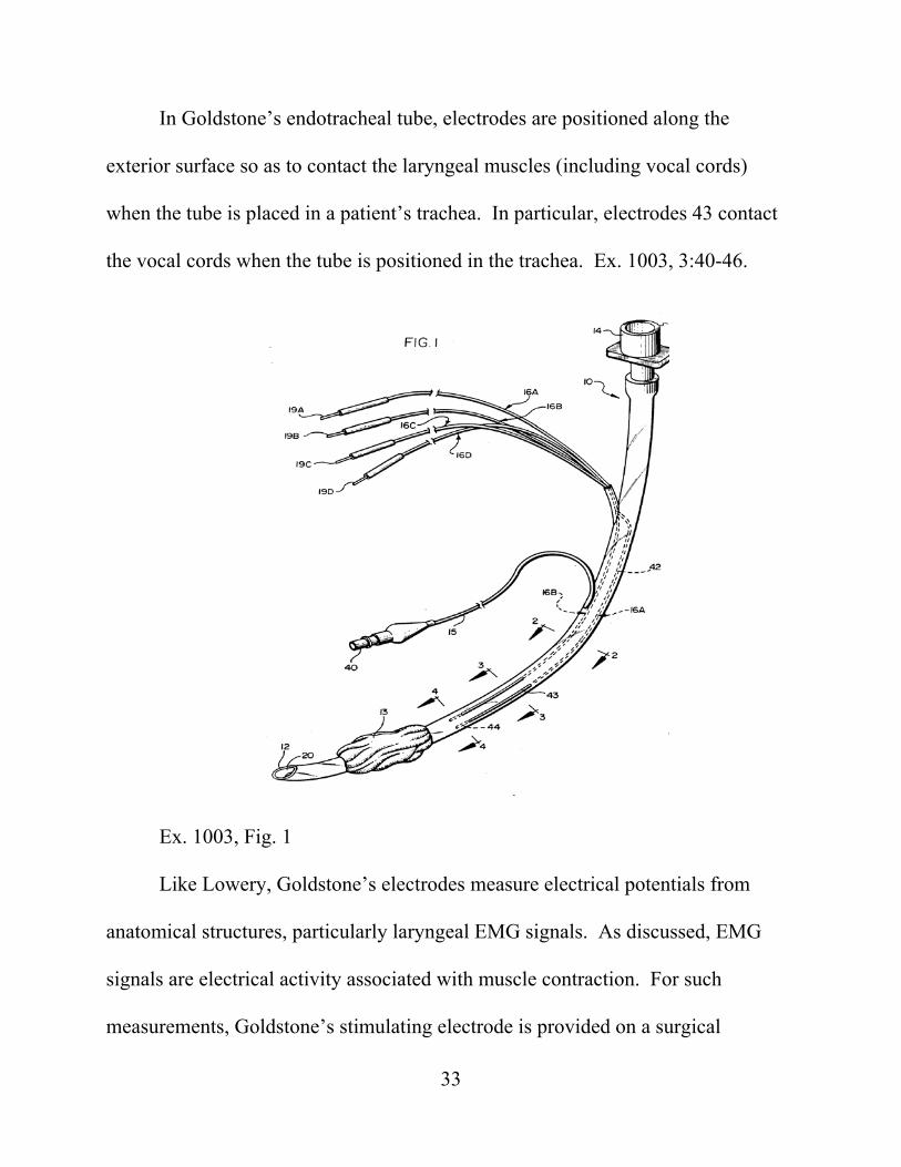
In Goldstone’s endotracheal tube, electrodes are positioned along the
exterior surface so as to contact the laryngeal muscles (including vocal cords)
when the tube is placed in a patient’s trachea. In particular, electrodes 43 contact
the vocal cords when the tube is positioned in the trachea. Ex. 1003, 3:40-46.
Ex. 1003, Fig. 1
Like Lowery, Goldstone’s electrodes measure electrical potentials from
anatomical structures, particularly laryngeal EMG signals. As discussed, EMG
signals are electrical activity associated with muscle contraction. For such
measurements, Goldstone’s stimulating electrode is provided on a surgical

34
instrument used in, typically, neck surgery. Ex. 1009, ¶¶ 50-52. Current from the
stimulating instrument applied to the RLN causes an action potential, which results
in contraction of laryngeal muscles. Thus, detection of an EMG response in the
vocal cords through the electrodes on the endotracheal tube helped the surgeon
locate or identify the nerve in the surgical field to help avoid nerve damage. Ex.
1009, ¶¶ 39-44; Ex. 1012, ¶¶ 98-99. Thus, Goldstone and Lowery describe
providing electrodes on endotracheal tubes in order to address two different risks
to a patient. A POSA would have had reason to use both electrodes on a single
endotracheal tube to prevent both types of injuries. Ex. 1009, ¶¶ 135-137, 139,
140, 147; Ex. 1012, ¶¶ 74-75, 99. Specifically, a single endotracheal tube is used
at a time in a patient undergoing neck surgery or prolonged intubation. That
patient would have been at risk for both complications. Rather than choose
between risks, a POSA would have had reason to use both technologies on a single
tube to mitigate both complications. Not only would doing so have provided the
benefits of both designs, but it would have saved manufacturing costs. Ex. 1009,
¶¶135-136; Ex. 1012, ¶¶ 99, 74-75. Moreover, the doctor could choose the
monitoring option needed for a particular patient. A POSA would have also
appreciated that selecting one type of monitoring or operating both types of
monitoring either at the same time would not have presented any technical issues.
Ex. 1012, ¶¶ 99, 74-75. In particular, both references describe providing multiple

35
electrodes at various positions along an endotracheal tube. Ex. 1002, ¶¶ [0008];
[0010]; [0030]; Ex. 1003, 7:15-42, 5:47-57. And the electrodes used in both
references are simply general purpose electrodes that measure electrical activity,
which would present no significant technological barrier to integration of the
electrode designs on a single tube. Ex. 1012, ¶ 74, 47, 48. The combination would
simply have involved the relative positioning of the multiple electrodes called for
in each reference to achieve the benefits of both stated goals in a predictable
manner.
Further, simply forming Goldstone’s electrodes using the techniques
described in Lowery (including connection points), on either described tube, would
establish the features of the claims. Given that Goldstone calls for painting of the
circuitry, the use of Lowery’s printing techniques and materials would have been
an obvious choice for a POSA and led to a predictable result, inasmuch as various
printing and painting techniques were known at the time. Ex. 1012, ¶¶ 45, 47-48;
Ex. 1009, ¶¶ 137, 144. Goldstone invites such techniques for forming electrodes
and other circuits.
Forming electrodes on the Tube Surface
Lowery indicates that, while electrodes 44 “may be separated from tube” by
an underlayer, the electrodes may also be printed directly on the substrate using
any known teachings, including the use of printing heads. Ex. 1002, ¶¶ [0034]

36
(emphasis added), [0039]-[0042]. In fact, Lowery’s Fig. 3A shows an electrode
runner 28 formed directly on tube 12. Ex. 1002, Fig. 3A; ¶ [0028] (“the electrode
runners 28 are printed on the tube 12.”). The distal end of runner 28 forms a
connection point.
As for Goldstone, while describing an embodiment in which electrodes are
partially embedded in the tube wall, the reference also describes forming
electrodes on an endotracheal tube by applying a metal paint to the tube, as
discussed above.
Lowery explicitly calls for MicroPen® printing techniques. Ex. 1002, ¶
[0013]. Lowery also invites electrode application using any of “the methods
described herein and the teachings of the art.” Ex. 1002, ¶ [0027]. Lowery also
describes printing circuitry on an endotracheal tube using an ink formed from
silver particles suspended in a resin. Ex. 1002, ¶[0009].
With respect to claim 1’s recitation that the traces run along the length of the
tube to a proximal end, Goldstone shows that its traces (e.g., wire portions 42) run

37
along the tube from distal end 12 to proximal end 11. Ex. 1003, 5:14-46. Lowery
also show a trace (e.g., runner 48) that extends along the length of the tube from a
distal portion 16 toward a proximal portion 14. While it is not explicit that
Lowery’s trace/runner 48 (or connection point 34) reaches the proximal portion of
the tube (e.g., beyond the midpoint), a POSA (particularly in view of Goldstone)
would have appreciated that a trace preferably connects to leads at a proximal
position on the tube that is outside the patient’s mouth. This avoids loose wires in
the patient’s mouth and throat. Ex. 1009, ¶ 150. Moreover, as discussed above, the
’894 patent merely describes these various elements as different sections of a
continuous printed area (claim 4 states that the structures may be painted or
printed).
With respect to the formation of “connection points” directly on the tube
surface, the Examiner originally indicated that neither Goldstone nor Lowery
taught “conductive pads” directly formed on the tube. Ex. 1033, p. 3. However,
the applicant subsequently amended “conductive pads” in claim 1 to read
“connection points.” A general connection point is explicitly taught by Lowery, as
detailed in the claim chart below. Moreover, as discussed above, the ’894 patent
merely describes these various elements as different sections of a continuous
printed area and claim 4 also states that these structures are painted or printed. Ex.
1001, 4:62-5:1. Thus, a connection point would be a proximal portion of, for

38
instance, runner 28 in Lowery (shown above). See IPR2015-00502, Decision
(Paper No. 15), p. 28 (P.T.A.B. 2015).
For the Board’s convenience, provided below is a claim chart that sets forth
the manner in which the combination of Lowery and Goldstone applies to claims 4,
6 and 7 of the ’894 patent. The claim chart is for illustrative purposes and it should
be understood that the explanations for one claim applies equally to similar
elements in other claims, even if not repeated elsewhere in the chart.
USP 8,634,894 Lowery and Goldstone 4. A method of forming an electrode bearing endotracheal tube for laryngeal electromyography comprising:
Lowery discloses a method of forming an electrode-bearing endotracheal tube using “conductive material … applied by a positive displacement dispensing system” such as the MicroPen® device. Ex. 1002, ¶¶ [0012]-[0013]; Ex. 1009, ¶ 139. Goldstone describes forming electrodes on an endotracheal tube for laryngeal electromyography (“EMG”). Ex. 1003, 1:5-8 (“The present invention relates generally to electrodes for detecting electromyographic (EMG) signals of the laryngeal muscles, and more particularly to electrodes which are mounted on an endotracheal tube.”); 3:3-6. Ex. 1009, ¶¶ 157-158, 142-146, 94-98, 63, 67-72; Ex. 1012, ¶¶ 16, 17, 76, 78, 79.
providing an endotracheal tube having a retaining balloon at a distal end thereof,
Lowery discloses an endotracheal tube with a retention balloon (inflatable cuff 22) at a distal end. Ex. 1002, ¶ [0026] (“FIG. 1 contains tube 12 having … distal portion 16”) (“Connected to the distal portion 16 is an inflatable cuff 22 that, when inflated, causes occlusion of the airway … thereby fixing the tube in correct position.”); ¶ [0008]; ¶ [0025] (“endotracheal tube”); ¶ [0031].

39
Goldstone describes an endotracheal tube with a retaining balloon (inflatable cuff 13) “located near distal end 12.” Ex. 1003, 1:5-8; 5:3-13; 5:64-6:16; 1:32-40. Ex. 1009, ¶¶ 158, 159, 142, 96, 65; Ex. 1012, ¶¶ 37-38.
forming first and second electrodes on an exterior surface of the endotracheal tube,
Lowery’s electrode patch 44 and the ground electrode (at least) are provided on the surface of the shaft of tube 12. Ex. 1002, ¶ [0034]; ¶ [0010]; ¶ [0008]; Fig. 1. A POSA would also have appreciated that the sense electrodes on the balloon portion of the tube could also be positioned on the shaft surface. Ex. 1002, ¶¶ [0027]; [0030]. The electrodes in Lowery may be printed on the tube using writing head 64. Ex. 1002, ¶¶ [0048]; [0002]; [0044]; ¶ [0027] (“electrode patch that can be fabricated using the methods described herein and the teachings of the art”) (“electrodes” are “printed on the tube”); ¶ [0034]; ¶¶ [0008]-[0010]. This, Lowery suggests forming multiple electrodes on the shaft of the tube. Goldstone describes providing four conductive electrodes 43 on tube 10. Ex. 1003, 5:3-19; 5:41-46; Fig. 1. Those electrodes may be applied to the outer surface of the tube using metal paint. Ex. 1003, 5:29-31 (“A second wire portion 43 is located between distal end 12 and first wire portion 42, on outer surface 23 of tube 10.”); 5:18-21. Ex. 1009, ¶¶ 158-159, 144, 96-98, 66, 72-73; Ex. 1012, ¶¶ 35-36, 39, 40, 51-52, 56, 76, 78.
a first of one or more electrically conductive traces attached to the first electrodes and a second of one or more electrically conductive traces attached to the second electrodes,
Lowery discloses conductive traces (electrode runners 28 and 48) on the surface of the tube. Ex. 1002, ¶¶ [0034]; [0027]. For instance, electrode runner 48 is electrically integral with electrode patch 44. Ex. 1002, ¶ [0034] (“The current electrode 42 also includes an electrode runner 48 extending distally from the flex circuit 30 of the apparatus to the electrode patch 44 of the current electrode 42.”); ¶ [0029]; ¶¶ [0048-49]; see also Figs. 1-2. Goldstone describes electrically conductive traces (wire

40
portions 42) extending along tube 10 from (and integral with) respective electrodes 43. Ex. 1003, Fig. 1; 3:14-18; 5:14-46; 3:14-24; 5:14-57; 8:7-12; 8:31-34. In a preferred embodiment, Goldstone describes four electrodes corresponding to wires 16A-D. Ex. 1003, Figs. 2-4. Ex. 1009, ¶¶ 50, 158, 146, 96-98, 66, 72-73; Ex. 1012, ¶¶ 42-43.
first and second connection points at a proximal end of the first and second traces,
Fig. 3A in Lowery shows the connection points on tube 12 between conductive traces (e.g., electrode runners 28 and 48) and electrical leads (wires 30). Ex. 1002, ¶ [0027]; ¶ [0028] (“In certain embodiments, electrode runners 28 and external wires 30 are connected using a conductive compound. An exemplary embodiment of the connection between the electrode runners 28 and the external wires 30 is schematically depicted in FIGS. 3A and 3B.”). Lowery’s connection point is provided directly on the surface of tube 11 as a distal end of runner/trace 28, which connects to wire 30 through conductive circuit material 70, support material 72, conductive polymeric material 34, and insulating tape 78. Ex. 1002, Fig. 3A, ¶ [0028]; see also Fig. 1 (showing runner 48 also connected to wires 30 through material 34). Goldstone’s Fig. 1 depicts connections at which ends of wire portions 42 (traces) depart tube 10, at a proximal end, as wires 16 to connect to EMG equipment. Ex. 1003, 5:14-46 (“[e]ach electrode wire has a first portion 42, located between proximal end 11 and distal end 12”) (“[t]he term ‘wires’ includes any type of electrically conducting lead suitable for use as an electrode, including metal paint, metallic tape, or metal strips.”); 5:58-63. Ex. 1009, ¶¶ 50, 158, 146-147, 98, 66, 68, 72-73, 75; Ex. 1012, ¶ 45, 47, 51-52.
the first and second electrodes located proximal of the
Lowery’s electrode patch 44 is located proximal of the balloon (cuff 22). Ex. 1002, Fig. 1; ¶ [0034]. Lowery’s connection points with wires 30 are located at proximal

41
retaining balloon, the connection points located at the proximal end of the traces,
ends of the traces (electrode runner 48). Ex. 1002, Fig. 1. Goldstone’s electrodes 43 are proximal of the balloon (cuff 13). Ex. 1003, 5:3-13; 5:41-46; Fig. 1. Further, the connection to wires 16 takes place at proximal ends of wire/traces 42. Ex. 1003, Fig. 1. Ex. 1009, ¶¶ 158-159, 143, 150, 98, 65-66; Ex. 1012, ¶¶ 42-43, 45, 58.
the electrodes, traces and connection points formed by applying a conductive ink or paint to the exterior surface of the endotracheal tube, and
Lowery describes that elements such as electrode patch 44, electrode runner 48, and conductive material 34 are formed using conductive materials/inks that are printed on the surface of the tube. Ex. 1002, ¶ [0034]; ¶ [0002] (“The electrodes are printed on the tube”); ¶ [0009] (“In certain embodiments … the electrode contains electrically conductive silver particles suspended in a resin and a volatile solvent that forms a polymeric matrix material once cured”); ¶ [0028]; ¶ [0044] (“writing head 64 writes a thin, narrow layer of materials directly on the … tube”); ¶ [0048]; ¶ [0027]. Goldstone describes conductive metal paint that is used to form conductive components on the surface of a tube. Ex. 1003, 5:18-21; 5:29-31. Ex. 1009, ¶¶ 158-159, 146, 144, 147, 96-98, 75; Ex. 1012, ¶¶ 47-48, 51-52, 56, 76, 78.
forming an electrically insulating barrier over the traces, the barrier extending from a point of connection of the traces to the electrodes to the connection points on the proximal end of the traces.
Lowery’s conductive traces (e.g., runner 48) are insulated with an “overlayer.” Ex. 1002, ¶ [0034] (“Furthermore, the current electrode runner 48 is covered by a polymeric overlayer applied to the conductive material.”); ¶¶ [0042-44]; ¶ [0049] (stating that polymeric overlayer 76 prevents signals from the runner); Fig 3A (overlayer 76). The overlayer extends along the length of the runner, from electrode patch 44 to the connection point. Ex. 1002, ¶ [0034]; Figs. 1-2. Goldstone indicates that the electrically conductive traces

42
(wire portions 42) are insulated along their lengths starting from electrodes 43 and up to the connection to wires 16. Ex. 1003, 5:22-25 (“insulated against electrical contact.”); 3:16-18. Ex. 1009, ¶¶ 158, 146, 149, 98, 66-68, 74, 85-86; Ex. 1012, ¶¶ 57-58, 60.
6. The method of claim 4 wherein the conductive ink or paint comprises electrically conductive particles in a liquid carrier.
Lowery’s electrodes are preferably printed on the tube using writing head 64, which prints using “any … electrically conductive particles such as silver or gold particles that are suspended in a resin and a solvent.” Ex. 1002, ¶¶ [0048]; [0002]; [0044]; ¶ [0027] (“electrode patch that can be fabricated using the methods described herein and the teachings of the art”); ¶ [0034]; ¶¶ [0008]-[0010]. Goldstone describes use of a metal paint. Ex. 1003, 5:18-21. Ex. 1009, ¶¶ 50, 58, 163-164, 74-75; Ex. 1012, ¶¶ 8-10, 16, 17, 47-48; Ex. 1032, ¶ 2-3; Ex. 1031, ¶ 2-3.
7. The method of claim 6 wherein electrically conductive particles comprise finely divided particles or flakes of elemental silver, silver salts, silver oxide, gold, copper, copper chloride, platinum, carbon or graphite.
Lowery’s electrodes are preferably printed using “electrically conductive particles such as silver or gold particles.” Ex. 1002, ¶¶ [0048]; [0002]; [0044]; ¶ [0027]; ¶ [0034]; ¶¶ [0008]-[0010]. Ex. 1009, ¶¶ 58, 165-166; Ex. 1012, ¶¶ 16, 47-48; Ex. 1032, ¶ 2-3; Ex. 1031, ¶ 2-3.
Petitioner submits that Ground 2 is not redundant in view of Ground 1
inasmuch as Lowery provides a more detailed description of printing techniques

43
and ink compositions for forming electrodes on medical tube than Cook or
Goldstone, but is 102(a) prior art, while Cook provides more detail on connection
points. Thus, the different combinations account for different potential rebuttals
from the Patent Owner. If the Board should find any redundancy, Petitioner elects
the combination(s) containing Cook.
3. Ground 3: Claims 4, 6 and 7 are Obvious in View of Goldstone, Cook and MicroPen®
MicroPen® is prior art under 35 U.S.C. §102(b) (pre-AIA) because it
published more than one year prior to the ’894 Patent’s earliest asserted filing date,
as evidenced by the declaration accompanying that exhibit. The declaration
establishes that the pages in the exhibit were published on the Internet in that form
at least as early as September 5, 2008. Ex. 1035, p. 1.
MicroPen® describes an available technique for applying conductive
paint/ink on medical catheters to form a sensing electrode. Ex. 1035, pp. 4 and 7.
The conductive paint/ink may be formed with gold, silver, or platinum and applied
on “irregular surfaces” such as medical balloons and catheters. Ex. 1035, p. 4, ll. 4-
12. Because Goldstone calls for painting electrodes on the surface of a medical
catheter, a POSA would look to available technologies for achieving that goal. Ex.
1003, 5:1-46; Ex. 1012, ¶¶ 7-12. MicroPen® describes a commercially available
method for performing the painting called for in Goldstone. Ex. 1012, ¶¶ 10, 48-

44
49, 56. In addition, Cook describes printing electrodes, traces, and connection
points on medical catheters. Ex. 1004, Fig. 3; 4:25-32 (“The printed circuit pattern
… consists of eight electrode pads [electrodes], 12A-12H, each of which is
connected by a printed circuit wire 32 [trace] to a corresponding terminal pad 34
[connection points].”); Ex. 1009, ¶¶ 53-55. MicroPen® provides more detail for
accomplishing Cook’s stated goal. Ex. 1012, ¶ 49. For those reasons, a POSA
would have had reason to combine MicroPen® with Goldstone and Cook,
particularly because MicroPen® provides known techniques for manufacturing
devices in the manner called for, with no technical barriers to the combination.
Ex. 1012, ¶ 49; 72 Fed. Reg. at 57529.
With respect to claim 4, as discussed above, MicroPen® explicitly describes
applying a conductive ink on the surface of a flexible medical tube to form an
electrode, including on a tube with a balloon. With respect to claim 6, MicroPen®
describes using conductive particles such as gold in a flowable delivery agent. Ex.
1035, pp. 4 (“flowable materials”) and 7 (“MicroPenning electrodes to medical
devices”, “patterned with silver, gold, platinum or nickel thick film material”, and
“silver filled polymer”). With respect to claim 7, MicroPen® describes using
platinum, gold, and silver particles in the ink, including a “silver filled polymer.”
Ex. 1035, p. 7 (“Sense” section).

45
Petitioner submits that this ground is not redundant in view of Ground 1
inasmuch as MicroPen® provides a more explicit description of ink printing
directly on medical tubes than Goldstone and Cook. Moreover, as compared to
Goldstone and Cook, the reference provides a more explicit description of the ink
properties recited in claims 6 and 7.
4. Ground 4: Claims 4, 6 and 7 are Obvious in View of Lowery, Goldstone and MicroPen®
MicroPen® is relevant and it would have been obvious to combine its
disclosure with Lowery and Goldstone for reasons already discussed above with
respect to Ground 3. Furthermore, a POSA would have had additional reasons to
combine MicroPen® with Lowery inasmuch as Lowery explicitly calls for
MicroPen® printing techniques. Ex. 1002, ¶ [0013]; Ex.1012, ¶¶10, 47, 49, 56.
Lowery also invites an electrode application using any of “the methods described
herein and the teachings of the art.” Ex. 1002, ¶ [0027]; Ex. 1009, ¶¶ 144, 164,
166.
MicroPen® describes features of claims 4, 6 and 7 for the reasons already
addressed above in Ground 3.
Petitioner submits that this ground is not redundant in view of Ground 2 (or
1) inasmuch as MicroPen® provides a more explicit description of ink printing
(and ink compositions) on medical tubes than Lowery and Goldstone. The ground

46
is not redundant in view of Ground 3 for reasons discussed in Ground 2
(distinguishing Lowery from Cook). Also, Lowery is 102(e) prior art, unlike
Goldstone and Cook.
5. Ground 5: Claims 6, 7 and 9 are Obvious in View of Goldstone, Cook and Tekra
Tekra is prior art under 35 U.S.C. §102(b) (pre-AIA) because it published
more than one year prior to the ’894 Patent’s earliest asserted filing date, as
evidenced by the declaration accompanying that exhibit. The declaration
establishes that the pages in the exhibit were published on the Internet in that form
on November 19, 2006. Ex. 1036, pp. 1, 4, 5.
Tekra describes available “conductive inks (also called polymer thick
films)” that allow for printing electrodes onto materials such as polyester to form
“flexible printed circuits.” Ex. 1036, p. 4, ll. 1-17. The inks contain a “polymer
binder, conductive phase, and solvent.” Ex. 1036, p. 4, ll. 1-17. The reference also
explains that, for the conductive material, silver is the least resistive. Ex. 1036, p.
4, ll. 1-17.
Because Goldstone calls for painting conductive electrodes on the surface of
a flexible medical catheter, a POSA would look to available technology for
achieving that goal. Ex. 1003, 5:1-46; Ex. 1012, ¶¶ 7-12, 48. Tekra describes a
commercially available method for printing, through screen printing or the like,

47
flexible electrodes on a flexible surface. Ex. 1036, p. 4, ll. 1-17. In addition, Cook
describes printing electrodes, traces, and connection points on medical catheters.
Ex. 1004, Fig. 3; 4:25-32 (“The printed circuit pattern … consists of eight
electrode pads [electrodes], 12A-12H, each of which is connected by a printed
circuit wire 32 [trace] to a corresponding terminal pad 34 [connection points].”);
Ex. 1009, ¶¶ 53-55. Tekra provides a description of the available inks and
techniques for accomplishing that goal. Thus, a POSA would have had reason to
combine Tekra with Goldstone and Cook, particularly because Tekra provides
known techniques for manufacturing devices in the manner called for, with no
technical barriers to the combination. 72 Fed. Reg. at 57529; see Ex. 1012, ¶¶ 48-
49.
With respect to claims 6 and 7, Tekra describes using conductive particles
such as silver provided in a solvent. Ex. 1036, p. 4, ll. 1-17, p. 6 (silver inks). In
particular, Tekra describes using “silver flakes” with “[p]article sizes [that] range
from 0.5 microns to 8.0 microns,” wherein in the particles “are randomly spaced
through the liquid.” Ex. 1036, p. 4, ll. 1-17. “Once the solvent is evaporated, they
condense, forming a conductive path or circuit.” Ex. 1036, p. 4, ll. 1-17.
Claim 9, which depends from claim 6, recites “wherein the conductive
particles comprises at least about 60% of the ink.” Tekra describes inks having 60-
80% by weight of silver. Ex. 1036, p. 6, Inks 5021, 5025, 5028, 5029, 9145 and

48
APP11. That description is on the conductive inks data sheet accessed at the
hyperlink “PDF Overview of Conductive Inks” at page 4 of Ex. 1036.
Petitioner submits that this ground is not redundant in view of Ground 3 and
other grounds inasmuch as Tekra provides a more explicit description of ink
compositions in claims 6 and 7 than MicroPen® (or other references).
MicroPen®, however, is more explicit concerning the types of medical devices to
be formed by electrode printing techniques. Thus, MicroPen® and Tekra provide
different strengths.
6. Ground 6: Claims 6, 7 and 9 are Obvious in View of Goldstone, Cook, MicroPen® and Tekra
Ground 6 is similar to Ground 5, but further combines MicroPen®. The
reasons for combining MicroPen® and Tekra with Goldstone and Cook is already
set forth above. Further, the manner of applying the references to the claims is also
described above. See Ex. 1012, ¶¶ 7-12, 56.
Petitioner submits that Ground 6 is not redundant inasmuch as MicroPen®
provides details of printing specifically on medical tubes with balloons, while
Tekra provides details of the content of the inks used in such processes. No other
grounds combines both MicroPen® and Tekra. In particular, while MicroPen®
more explicitly describes the process of printing on medical tubes, Tekra provides

49
a more explicit description of the ink properties describes in claims 6, 7 and 9,
which are used in printing processes.
VI. Conclusion
For the reasons set forth above, Petitioner submits that claims 4, 6, 7, and 9
of the ’894 patent are unpatentable under 35 U.S.C. § 103. Accordingly, Petitioner
requests institution of Inter Partes Review of these claims for each ground
presented herein.
Respectfully submitted, /Justin J. Oliver/ Justin J. Oliver Counsel for Petitioner Registration No. 44,986
FITZPATRICK, CELLA, HARPER & SCINTO 1290 Avenue of the Americas New York, New York 10104-3800 Facsimile: (212) 218-2200

CERTIFICATE OF WORD COUNT
Pursuant to 37 C.F.R. § 42.24(d), the undersigned certifies that the foregoing
document, excluding the portions exempted under 37 C.F.R. § 42.24(a)(1),
contains 9,797 words, which is under the limit of 14,000 words set by 37 C.F.R. §§
42.24(a)(1)(i) and 42.24(b)(1).
Dated: December 9, 2016 /Justin J. Oliver/
Justin J. Oliver Counsel for Patent Owner Registration No. 44,986
Fitzpatrick, Cella, Harper & Scinto 1290 Avenue of the Americas New York, NY 10104 Tel: (212) 218-2100 Fax: (212) 218-2200

CERTIFICATE OF SERVICE
Pursuant to 37 C.F.R. §§ 42.6(e)(4) and 42.105, the undersigned certifies
that on this date, a true and correct copy of this Petition for Inter Partes Review
and all supporting exhibits were served via Express Mail on the Patent Owner at
the correspondence address of record for U.S. Patent No. 8,634,894.
Koppel, Patrick, Heybl & Philpott 2815 Townsgate Road Suite 215 Westlake Village, CA 91361-5827
Dated: December 9, 2016 /Justin J. Oliver/ Justin J. Oliver Counsel for Petitioner Registration No. 44,986
FCHS_WS 13026567v1.doc